An analytical solution for thermally fully developed combined pressure – electroosmotically driven flow in microchannels Azad Qazi Zade, Mehrdad T. Manzari * , Siamak K. Hannani Center of Excellence in Energy Conversion, School of Mechanical Engineering, Sharif University of Technology, P.O. Box 11365-3567, Tehran, Iran Received 19 December 2005; received in revised form 27 June 2006 Available online 27 October 2006 Abstract An analytical solution is presented to study the heat transfer characteristics of the combined pressure – electroosmotically driven flow in planar microchannels. The physical model includes the Joule heating effect to predict the convective heat transfer coefficient in two dimensional microchannels. The velocity field, which is a function of external electrical field, electroosmotic mobility, fluid viscosity and the pressure gradient, is obtained by solving the hydrodynamically fully-developed laminar Navier–Stokes equations considering the electrokinetic body force for low wall zeta potentials. Then, assuming a thermally fully-developed flow, the temperature distribution and the Nusselt number is obtained for a constant wall heat flux boundary condition. The fully-developed temperature profile and the Nusselt number depend on velocity field, channel height, solid/liquid interface properties and the imposed wall heat flux. A parametric study is presented to evaluate the significance of various parameters and in each case, the maximum heat transfer rate is obtained. Ó 2006 Elsevier Ltd. All rights reserved. Keywords: Heat transfer; Electrokinetic; Joule heating; Microchannel 1. Introduction The rise in microelectronic heat fluxes and the non-uni- formities in heat dissipation have increased the demand for highly efficient electronic cooling technologies. Because of the push to increase the functionality and to decrease the floor space consumed, there is an ever increasing demand for higher power-density, which in turn requires compact, reliable and efficient heat sinks. Also, it is known that the operation efficiency of an electronic component is highly temperature dependent. In recent years, there has been an extensive research into the design of microfluidics systems for compact cooling technologies. Investigations have been conducted to better understand the fluid flow and heat transfer characteristics in silicon-based microchannel heat sinks designed for applications in electronic cooling. These silicon based microchannel heat sinks combine the attri- butes of high material compatibility, high surface area per unit volume ratios, and large potential heat transfer performance, with highly sophisticated and economic fab- rication processes. Such advantages make these silicon based microchannel heat sinks highly attractive for a wide variety of commercial applications. Also at the microscale, generation of fluid motion is a challenge since the working pressure is substantially high. Although micropumps which are capable of delivering such pressures exist [1], their mov- ing components are complicated to design and fabricate, and they are prone to mechanical failure due to fatigue and fabrication defects which in turn make them unsuitable for microfluidic applications. On the other hand, electroos- motic flow presents a feasible alternative to pressure driven flow in liquid delivery systems, featuring better flow control with no moving parts. Several previous studies have reported successful demonstration of electro-osmotic pumping systems [1–4]. First observed by Reuss [5], electroosmosis is the pro- cess of inducing motion to ionized liquid, adjacent to a 0017-9310/$ - see front matter Ó 2006 Elsevier Ltd. All rights reserved. doi:10.1016/j.ijheatmasstransfer.2006.07.037 * Corresponding author. Tel.: +98 21 6616 5689; fax: +98 21 6600 0021. E-mail address: [email protected] (M.T. Manzari). www.elsevier.com/locate/ijhmt International Journal of Heat and Mass Transfer 50 (2007) 1087–1096

Welcome message from author
This document is posted to help you gain knowledge. Please leave a comment to let me know what you think about it! Share it to your friends and learn new things together.
Transcript
www.elsevier.com/locate/ijhmt
International Journal of Heat and Mass Transfer 50 (2007) 1087–1096
An analytical solution for thermally fully developed combined pressure– electroosmotically driven flow in microchannels
Azad Qazi Zade, Mehrdad T. Manzari *, Siamak K. Hannani
Center of Excellence in Energy Conversion, School of Mechanical Engineering, Sharif University of Technology, P.O. Box 11365-3567, Tehran, Iran
Received 19 December 2005; received in revised form 27 June 2006Available online 27 October 2006
Abstract
An analytical solution is presented to study the heat transfer characteristics of the combined pressure – electroosmotically driven flowin planar microchannels. The physical model includes the Joule heating effect to predict the convective heat transfer coefficient in twodimensional microchannels. The velocity field, which is a function of external electrical field, electroosmotic mobility, fluid viscosityand the pressure gradient, is obtained by solving the hydrodynamically fully-developed laminar Navier–Stokes equations consideringthe electrokinetic body force for low wall zeta potentials. Then, assuming a thermally fully-developed flow, the temperature distributionand the Nusselt number is obtained for a constant wall heat flux boundary condition. The fully-developed temperature profile and theNusselt number depend on velocity field, channel height, solid/liquid interface properties and the imposed wall heat flux. A parametricstudy is presented to evaluate the significance of various parameters and in each case, the maximum heat transfer rate is obtained.� 2006 Elsevier Ltd. All rights reserved.
Keywords: Heat transfer; Electrokinetic; Joule heating; Microchannel
1. Introduction
The rise in microelectronic heat fluxes and the non-uni-formities in heat dissipation have increased the demand forhighly efficient electronic cooling technologies. Because ofthe push to increase the functionality and to decrease thefloor space consumed, there is an ever increasing demandfor higher power-density, which in turn requires compact,reliable and efficient heat sinks. Also, it is known that theoperation efficiency of an electronic component is highlytemperature dependent. In recent years, there has been anextensive research into the design of microfluidics systemsfor compact cooling technologies. Investigations have beenconducted to better understand the fluid flow and heattransfer characteristics in silicon-based microchannel heatsinks designed for applications in electronic cooling. Thesesilicon based microchannel heat sinks combine the attri-
0017-9310/$ - see front matter � 2006 Elsevier Ltd. All rights reserved.
doi:10.1016/j.ijheatmasstransfer.2006.07.037
* Corresponding author. Tel.: +98 21 6616 5689; fax: +98 21 6600 0021.E-mail address: [email protected] (M.T. Manzari).
butes of high material compatibility, high surface areaper unit volume ratios, and large potential heat transferperformance, with highly sophisticated and economic fab-rication processes. Such advantages make these siliconbased microchannel heat sinks highly attractive for a widevariety of commercial applications. Also at the microscale,generation of fluid motion is a challenge since the workingpressure is substantially high. Although micropumps whichare capable of delivering such pressures exist [1], their mov-ing components are complicated to design and fabricate,and they are prone to mechanical failure due to fatigueand fabrication defects which in turn make them unsuitablefor microfluidic applications. On the other hand, electroos-motic flow presents a feasible alternative to pressure drivenflow in liquid delivery systems, featuring better flow controlwith no moving parts. Several previous studies havereported successful demonstration of electro-osmoticpumping systems [1–4].
First observed by Reuss [5], electroosmosis is the pro-cess of inducing motion to ionized liquid, adjacent to a
Nomenclature
cp fluid specific heatD channel heightEx external electrical fieldg dimensionless volumetric heat generationh convective heat transfer coefficientie current densityk thermal conductivityNu Nusselt numberp pressurePe Peclet numberq00 wall heat fluxq000 volumetric heat generationT temperatureTm bulk mean temperatureTw wall temperatureu local fluid velocityueo electroosmotic velocityU average velocity
x streamwise coordinatey wall – normal coordinateY dimensionless wall – normal coordinate
Greek symbols
a thermal diffusivitye fluid dielectric constant/ charge distributionC channel height to Debye length ratiokD Debye lengthl dynamic viscosityleo electroosmotic mobilityq fluid densityr liquid electrical resistivityh normalized temperaturehw wall normalized temperaturew auxiliary dimensionless functionf wall zeta potential
1088 A.Q. Zade et al. / International Journal of Heat and Mass Transfer 50 (2007) 1087–1096
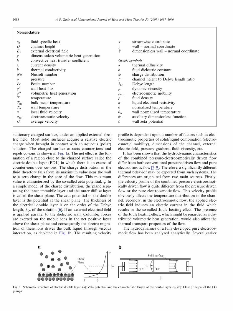
stationary charged surface, under an applied external elec-tric field. Most solid surfaces acquire a relative electriccharge when brought in contact with an aqueous (polar)solution. The charged surface attracts counter-ions andrepels co-ions as shown in Fig. 1a. The net effect is the for-mation of a region close to the charged surface called theelectric double layer (EDL) in which there is an excess ofcounter-ions over co-ions. The charge distribution in thefluid therefore falls from its maximum value near the wallto a zero charge in the core of the flow. This maximumvalue is characterized by the so-called zeta potential, B. Ina simple model of the charge distribution, the plane sepa-rating the inner immobile layer and the outer diffuse layeris called the shear plane. The zeta potential of the doublelayer is the potential at the shear plane. The thickness ofthe electrical double layer is on the order of the Debyelength, kD, of the solution [6]. If an external electrical fieldis applied parallel to the dielectric wall, Columbic forcesare exerted on the mobile ions in the net positive layerabove the shear plane and consequently the electro-migra-tion of these ions drives the bulk liquid through viscousinteraction, as depicted in Fig. 1b. The resulting velocity
Fig. 1. Schematic structure of electric double layer: (a): Zeta potential and thepumps.
profile is dependent upon a number of factors such as elec-troosmotic properties of solid/liquid combination (electro-osmotic mobility), dimensions of the channel, externalelectric field, pressure gradient, fluid viscosity, etc.
It has been shown that the hydrodynamic characteristicsof the combined pressure-electroosmotically driven flowdiffer from both conventional pressure driven flow and pureelectroosmotic flow [7–9]. Therefore, a significantly differentthermal behavior may be expected from such systems. Thedifferences are originated from two main sources. Firstly,the velocity profile of the combined pressure-electroosmot-ically driven flow is quite different from the pressure drivenflow or the pure electroosmotic flow. This velocity profileobviously affects the temperature distribution in the chan-nel. Secondly, in the electroosmotic flow, the applied elec-tric field induces an electric current in the fluid whichresults in the so-called Joule heating effect. The presenceof the Joule heating effect, which might be regarded as a dis-tributed volumetric heat generation, would also affect thethermal transport properties of the flow.
The hydrodynamics of a fully-developed pure electroos-motic flow has been analyzed analytically. Several earlier
characteristic length of the double layer kD, (b): Flow principal of the EO
2q′′
′′ 2q
y
xD
Fig. 2. Problem definition.
A.Q. Zade et al. / International Journal of Heat and Mass Transfer 50 (2007) 1087–1096 1089
papers discussed the hydrodynamic behavior of pure elec-troosmotic flow in capillaries [10–12]. More recent workare by Mala et al. [7] on parallel-plate microchannels,and Yang et al. [13] on microchannels with rectangularcross section where they invoked the classic Debye–Huckelapproximation to allow for an analytical solution.Recently, several other aspects of the hydrodynamics ofelectroosmotic flow were studied analytically. Among theseare transient behavior of the flow field [8,9,14], electricalconductivity gradient in the streamwise direction [15],developing flow field in the entry region [3,16] and the effectof variable wall zeta potential on the flow field [17,18].Also, experimental studies on the characteristics of thesteady-state electroosmotic flow have been reported [18–24].
A detailed discussion about the thermal behavior of theconventional pressure driven flow can be found in heattransfer textbooks. Also, for the case in which the Debyelength is small compared to the channel dimensions andthe pressure gradient is negligible, i.e. when the slug flowprevails [3], solutions for laminar thermally developingand fully developed cases exist [25]. The effect of theEDL and the flow-induced electrokinetic field on the flowand heat transfer characteristics in microchannels has beenstudied in [13,26,27]. It was reported that the flow inducedelectrokinetic potential increases the resistance on the flowand hence exhibits higher friction factor and moreover, theNusselt number is lower compared to the conventionalpressure driven flow. Only little work can be found in theliterature concerning the thermal behavior of the fullydeveloped electroosmotic flow. Maynes and Webb [28,29]presented analytical solutions for thermally fully developedelectroosmotic flow in circular and parallel plate micro-channels considering the Joule heating effect and viscousdissipation. They also studied the convective heat transferof thermally (and hydrodynamically) fully developed com-bined pressure-electroosmotically driven flow in circularmicrochannels [30]. In this latter work, Maynes and Webbstudied the effect of various parameters such as the ratio ofDebye length to the tube radius, liquid electrical resistivityand the ratio of the pressure to electroosmotic drivingforces on the heat transfer characteristics of the combinedpressure-electroosmotically driven flow. They reported thatat high channel height to Debye length ratios, the velocityprofile is essentially a superposition of the slug flow and thepressure driven flow. Also, their results show that the Nus-selt number is strongly dependent on the magnitude of thevolumetric heat generation. Their work however was aparametric study considering the effect of one parameterat a time, which is not the case in practical situations whenboth flow and heat transfer effects are dealt with. More-over, the maximum attainable heat transfer was not inves-tigated. In reality, as the external electrical field varies,both the velocity profile and volumetric heat generationchange. As a consequence, the temperature distributionand heat transfer coefficient change. In fact, all these vari-ations are coupled and occur simultaneously and their
mutual relations should be taken into account in the anal-ysis. To the best of authors’ knowledge, such a couplingwhich takes into account all the variations simultaneouslyhas not been investigated yet. This is addressed in the cur-rent paper.
This paper presents an analytical solution for a ther-mally (and hydrodynamically) fully developed combinedpressure electroosmotic driven flow between parallel platesfor a constant wall heat flux boundary condition. The heattransfer characteristics of the problem are described andmaximum heat transfer rate is obtained for a range ofdesign parameters.
2. Mathematical model
2.1. Flow model
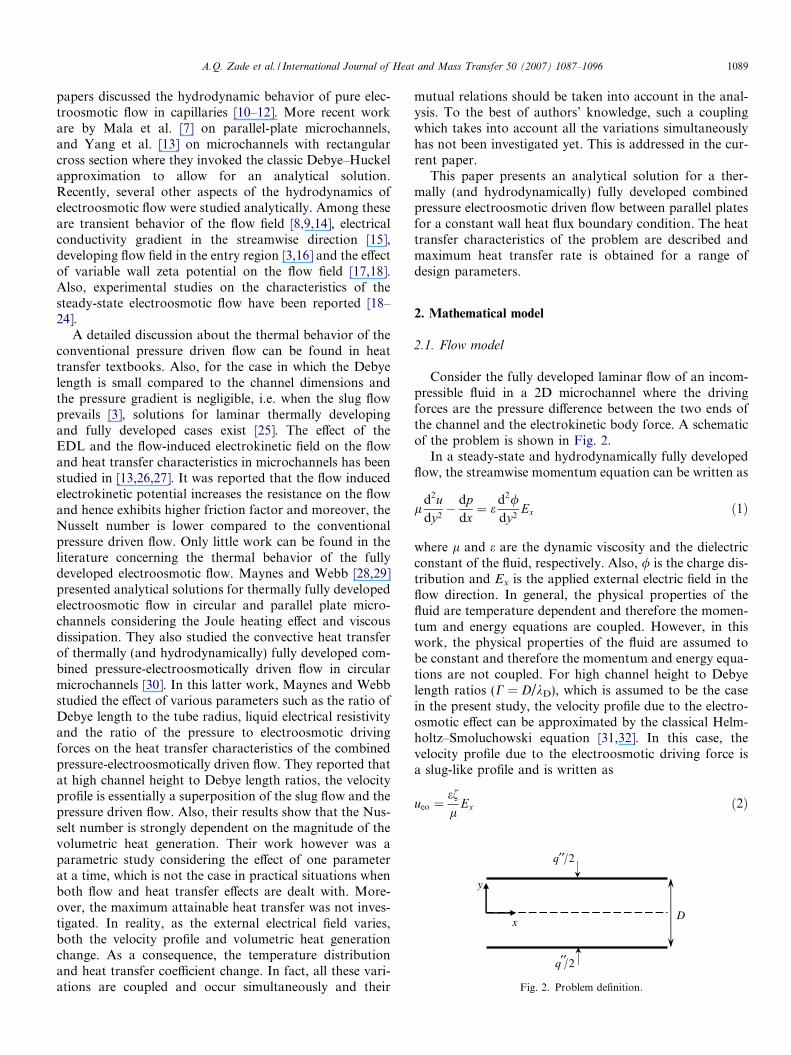
Consider the fully developed laminar flow of an incom-pressible fluid in a 2D microchannel where the drivingforces are the pressure difference between the two ends ofthe channel and the electrokinetic body force. A schematicof the problem is shown in Fig. 2.
In a steady-state and hydrodynamically fully developedflow, the streamwise momentum equation can be written as
ld2udy2� dp
dx¼ e
d2/dy2
Ex ð1Þ
where l and e are the dynamic viscosity and the dielectricconstant of the fluid, respectively. Also, / is the charge dis-tribution and Ex is the applied external electric field in theflow direction. In general, the physical properties of thefluid are temperature dependent and therefore the momen-tum and energy equations are coupled. However, in thiswork, the physical properties of the fluid are assumed tobe constant and therefore the momentum and energy equa-tions are not coupled. For high channel height to Debyelength ratios (C = D/kD), which is assumed to be the casein the present study, the velocity profile due to the electro-osmotic effect can be approximated by the classical Helm-holtz–Smoluchowski equation [31,32]. In this case, thevelocity profile due to the electroosmotic driving force isa slug-like profile and is written as
ueo ¼efl
Ex ð2Þ
1090 A.Q. Zade et al. / International Journal of Heat and Mass Transfer 50 (2007) 1087–1096
where f is the wall zeta potential and the term ef/l is usu-ally referred to as the electroosmotic mobility, leo. Theabove velocity distribution is fairly accurate for C P 100[28,31]. Since the magnitude of the Debye length is nomi-nally 10–500 nm, all the channel heights considered hereare higher than 50 lm to meet the criterion. Therefore,the velocity distribution for the combined pressure-electro-osmotic driven flow is given by
u ¼ leoEx �D2
8ldpdxð1� 4Y 2Þ ð3Þ
where Y = y/D is the dimensionless channel height and thesecond term on the right hand side of Eq. (3) is due to thepressure gradient and is the classical parabolic distributionssimilar to the Poiseuille flow.
2.2. Thermal transport
Considering the steady-state hydrodynamically fully-developed flow with constant physical properties in a 2Dchannel, the energy equation with volumetric heat genera-tion can be expressed as
ua
oTox¼ o2T
ox2þ o2T
oy2þ q000
kð4Þ
where T is the temperature, k and a are thermal conductiv-ity and diffusivity of the fluid, respectively, and q000 is thevolumetric heat generation in the fluid. In general, q000 con-sists of both the Joule heating and the viscous dissipationterms. For large values of C the viscous dissipation termcan be neglected compared to the Joule heating effect[29]. Therefore, in the present study, the viscous dissipationis neglected and the volumetric heat generation is only dueto Joule heating effect and is equal to q000 ¼ ri2
e in which ie isthe current density and r is the liquid electrical resistivity.For low zeta potentials, the current density is essentiallyuniform across the channel height [6,10]. According toOhm’s law ie = Ex/r, therefore, the uniform volumetricheat generation can be expressed as q000 ¼ E2
x=r. An overallenergy balance on the fluid yields
dT m
dx¼ 1
DqUcp
ðq00 þ Dq000Þ ð5Þ
where q00 represents the heat flux rate per unit area and q, cp
and U are fluid density, specific heat and average velocity,respectively. Also, the bulk mean temperature Tm is definedas
T m ¼1
U
ZuT dY ð6Þ
If the flow is thermally fully-developed, the classical dimen-sionless temperature becomes invariant with x [25]
o
oxT w � T
T w � T m
� �¼ 0 ð7Þ
where Tw is the wall temperature. This yields
oTox¼ dT w
dx� T w � T
T w � T m
dT w
dxþ T w � T
T w � T m
dT m
dxð8Þ
Also, invoking the definition of a thermally fully-developedflow, Eq. (7), the temperature distribution can be written inthe following form
T ¼ T w �q00
hwðY Þ ð9Þ
where w is a function of Y only and h = q00/(Tw � Tm) is theconvective heat transfer coefficient. In order to proceed, therelevant boundary conditions need to be specified. Usuallytwo typical boundary conditions are used in connectionwith the energy equation; constant wall heat flux and con-stant wall temperature. However, in order to achieve ananalytical solution for the constant wall temperatureboundary condition, the axial conduction term, o2T/ox2,in the energy equation is neglected compared to the axialconvection term, (u/a)oT/ox. This assumption is true onlywhen the Peclet number, Pe = (uD)/a, is far greater than1. In the problems considered in this article, the velocitiesare of orders of cm/s and the channels height is of orderof 100 lm. This means that the Peclet number is of O(1)and the axial conduction cannot be neglected. Therefore,only the constant wall heat flux boundary condition is con-sidered here.
If the imposed wall heat flux q00 is constant, it can beeasily shown that in a thermally fully-developed flowoT/ox = dTm/dx = constant and o2T/ox2 = 0 [25]. Also,using Eq. (9), the energy equation reduces to
d2w
dY 2¼ Nu g � uðY Þ
Uð1þ gÞ
� �ð10Þ
where g = (q000D)/q00 is the dimensionless volumetric heatgeneration and Nu = hD/k is the Nusselt number. Consid-ering Eq. (9), the boundary conditions can be written as
owoY
����Y¼0
¼ 0 and wjY¼�12¼ 0 ð11Þ
Substituting Eq. (3) into Eq. (10) and integrating it twicesubjected to boundary conditions (11), yields
w ¼ Nu A1
4� Y 2
� �þ B
1
16� Y 4
� �� �ð12Þ
where the parameters A and B are functions of the dimen-sionless volumetric heat generation and are defined as
A ¼ 1þ g2U
leoE � D2
8ldpdx
� �� g
2ð13aÞ
B ¼ 1þ gU
D2
24ldpdx
ð13bÞ
The unknown Nusselt number Nu in Eq. (12) is determinedby evaluating the bulk mean temperature, Eq. (6), whichresults in
1 ¼ 1
U
Z 1=2
�1=2
wuðY ÞdY ð14Þ
A.Q. Zade et al. / International Journal of Heat and Mass Transfer 50 (2007) 1087–1096 1091
Therefore the Nusselt number can be expressed as
Nu ¼ UI
ð15Þ
where
I ¼Z 1=2
�1=2
uðY Þ A1
4� Y 2
� �þ B
1
16� Y 4
� �� �dY ð16Þ
This integral can be evaluated analytically to compute theNusselt number. Substituting the velocity field, Eq. (3),into Eq. (16), results in
I ¼ AleoE
6� D2
60ldpdx
� �� �þ B
leoE20� D2
210ldpdx
� �� �ð17Þ
It should be noted that the resulting Nusselt number is afunction of the dimensionless volumetric heat generation,g, and as a result it is a function of the external electricfield.
3. Results and Discussion
In this section, a parametric study is presented to evalu-ate the variation of the temperature and velocity profilesand the Nusselt number. The channel geometry and thecorresponding coordinate system are shown in Fig. 2.Here, the total flow rate is constant and equal to 10�3 l/s.As the external electric field is increased, the pressure gra-dient is decreased accordingly in order to keep the flow rateconstant. The electrical resistivity of water is set tor = 104 Xm. For the glass/deionized water interface, theelectroosmotic mobility leo = 8 lm cm/Vs is chosen [33].The wall heat flux in microchannels, however, can varyover several orders of magnitude. In the present study,the results are presented for three values of wall heat flux,i.e., 1, 10 and 100 W/cm2.
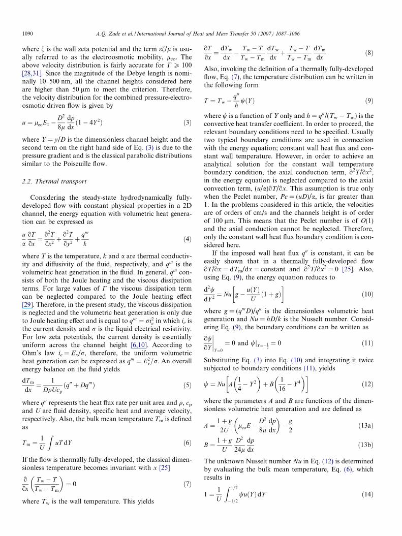
Fig. 3 shows the velocity and normalized temperatureh = (T � Tm)/(q00D/k) profiles across the channel for differ-ent external electrical fields, Ex. Note that the velocity fieldand the normalized temperature distributions correspond-
Fig. 3. (a) Velocity field and (b) Normalized temperatu
ing to Ex = 0 are the same as the conventional pressure dri-ven flow.
As it is observed in Fig. 3a, all velocity profiles intersectwith each other at a common point. This point, in fact, isindependent of the channel, flow and fluid properties andis the same for all velocity distributions of combined pres-sure-electroosmotically driven flows described by Eq. (3).If, in Eq. (3), the velocity is set equal to the average veloc-ity, the position of this point is computed as u = U andY ¼ �1=
ffiffiffiffiffi12p
. Also, in Fig. 3b, it is observed that as theexternal electrical field is increased, the difference betweenthe centerline temperature and the wall temperaturedecreases and consequently the difference between the walltemperature and the bulk mean temperature Tw � Tm
declines. As a result, the convective heat transfer coefficientis expected to increase.
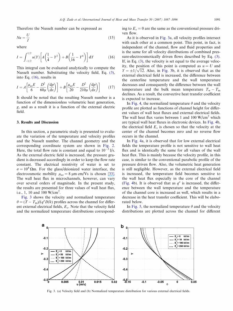
In Fig. 4, the normalized temperature h and the velocityprofile are plotted as functions of channel height for differ-ent values of wall heat fluxes and external electrical fields.The wall heat flux varies between 1 and 100 W/cm2 whichare typical wall heat fluxes in electronic devices. In Fig. 4b,the electrical field Ex is chosen so that the velocity at thecenter of the channel becomes zero and no reverse flowoccurs in the channel.
In Fig. 4a, it is observed that for low external electricalfields the temperature profile is not sensitive to wall heatflux and is identically the same for all values of the wallheat flux. This is mainly because the velocity profile, in thiscase, is similar to the conventional parabolic profile of thepressure driven flow. Also, the volumetric heat generationis still negligible. However, as the external electrical fieldis increased, the temperature field becomes sensitive tothe wall heat flux especially in the core of the channel(Fig. 4b). It is observed that as q00 is increased, the differ-ence between the wall temperature and the temperatureof the channel core is increased as well, which results in adecrease in the heat transfer coefficient. This will be elabo-rated below.
In Fig. 5, the normalized temperature h and the velocitydistributions are plotted across the channel for different
re distribution for various external electrical fields.
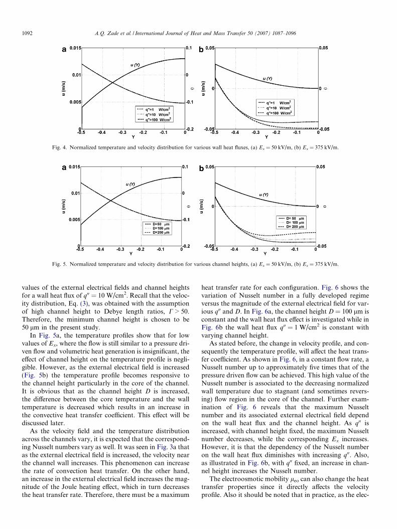
Fig. 5. Normalized temperature and velocity distribution for various channel heights, (a) Ex = 50 kV/m, (b) Ex = 375 kV/m.
Fig. 4. Normalized temperature and velocity distribution for various wall heat fluxes, (a) Ex = 50 kV/m, (b) Ex = 375 kV/m.
1092 A.Q. Zade et al. / International Journal of Heat and Mass Transfer 50 (2007) 1087–1096
values of the external electrical fields and channel heightsfor a wall heat flux of q00 = 10 W/cm2. Recall that the veloc-ity distribution, Eq. (3), was obtained with the assumptionof high channel height to Debye length ratios, C > 50.Therefore, the minimum channel height is chosen to be50 lm in the present study.
In Fig. 5a, the temperature profiles show that for lowvalues of Ex, where the flow is still similar to a pressure dri-ven flow and volumetric heat generation is insignificant, theeffect of channel height on the temperature profile is negli-gible. However, as the external electrical field is increased(Fig. 5b) the temperature profile becomes responsive tothe channel height particularly in the core of the channel.It is obvious that as the channel height D is increased,the difference between the core temperature and the walltemperature is decreased which results in an increase inthe convective heat transfer coefficient. This effect will bediscussed later.
As the velocity field and the temperature distributionacross the channels vary, it is expected that the correspond-ing Nusselt numbers vary as well. It was seen in Fig. 3a thatas the external electrical field is increased, the velocity nearthe channel wall increases. This phenomenon can increasethe rate of convection heat transfer. On the other hand,an increase in the external electrical field increases the mag-nitude of the Joule heating effect, which in turn decreasesthe heat transfer rate. Therefore, there must be a maximum
heat transfer rate for each configuration. Fig. 6 shows thevariation of Nusselt number in a fully developed regimeversus the magnitude of the external electrical field for var-ious q00 and D. In Fig. 6a, the channel height D = 100 lm isconstant and the wall heat flux effect is investigated while inFig. 6b the wall heat flux q00 = 1 W/cm2 is constant withvarying channel height.
As stated before, the change in velocity profile, and con-sequently the temperature profile, will affect the heat trans-fer coefficient. As shown in Fig. 6, in a constant flow rate, aNusselt number up to approximately five times that of thepressure driven flow can be achieved. This high value of theNusselt number is associated to the decreasing normalizedwall temperature due to stagnant (and sometimes revers-ing) flow region in the core of the channel. Further exam-ination of Fig. 6 reveals that the maximum Nusseltnumber and its associated external electrical field dependon the wall heat flux and the channel height. As q00 isincreased, with channel height fixed, the maximum Nusseltnumber decreases, while the corresponding Ex increases.However, it is that the dependency of the Nusselt numberon the wall heat flux diminishes with increasing q00. Also,as illustrated in Fig. 6b, with q00 fixed, an increase in chan-nel height increases the Nusselt number.
The electroosmotic mobility leo can also change the heattransfer properties since it directly affects the velocityprofile. Also it should be noted that in practice, as the elec-
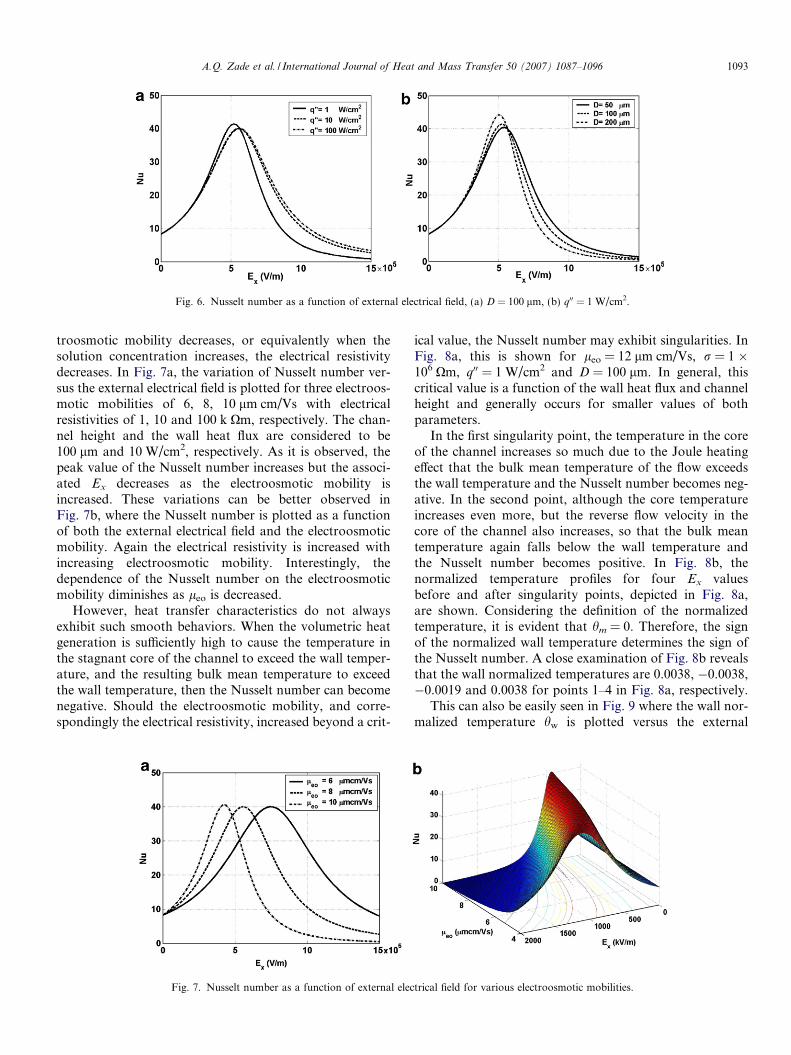
Fig. 6. Nusselt number as a function of external electrical field, (a) D = 100 lm, (b) q00 = 1 W/cm2.
A.Q. Zade et al. / International Journal of Heat and Mass Transfer 50 (2007) 1087–1096 1093
troosmotic mobility decreases, or equivalently when thesolution concentration increases, the electrical resistivitydecreases. In Fig. 7a, the variation of Nusselt number ver-sus the external electrical field is plotted for three electroos-motic mobilities of 6, 8, 10 lm cm/Vs with electricalresistivities of 1, 10 and 100 k Xm, respectively. The chan-nel height and the wall heat flux are considered to be100 lm and 10 W/cm2, respectively. As it is observed, thepeak value of the Nusselt number increases but the associ-ated Ex decreases as the electroosmotic mobility isincreased. These variations can be better observed inFig. 7b, where the Nusselt number is plotted as a functionof both the external electrical field and the electroosmoticmobility. Again the electrical resistivity is increased withincreasing electroosmotic mobility. Interestingly, thedependence of the Nusselt number on the electroosmoticmobility diminishes as leo is decreased.
However, heat transfer characteristics do not alwaysexhibit such smooth behaviors. When the volumetric heatgeneration is sufficiently high to cause the temperature inthe stagnant core of the channel to exceed the wall temper-ature, and the resulting bulk mean temperature to exceedthe wall temperature, then the Nusselt number can becomenegative. Should the electroosmotic mobility, and corre-spondingly the electrical resistivity, increased beyond a crit-
Fig. 7. Nusselt number as a function of external elec
ical value, the Nusselt number may exhibit singularities. InFig. 8a, this is shown for leo = 12 lm cm/Vs, r = 1 �106 Xm, q00 = 1 W/cm2 and D = 100 lm. In general, thiscritical value is a function of the wall heat flux and channelheight and generally occurs for smaller values of bothparameters.
In the first singularity point, the temperature in the coreof the channel increases so much due to the Joule heatingeffect that the bulk mean temperature of the flow exceedsthe wall temperature and the Nusselt number becomes neg-ative. In the second point, although the core temperatureincreases even more, but the reverse flow velocity in thecore of the channel also increases, so that the bulk meantemperature again falls below the wall temperature andthe Nusselt number becomes positive. In Fig. 8b, thenormalized temperature profiles for four Ex valuesbefore and after singularity points, depicted in Fig. 8a,are shown. Considering the definition of the normalizedtemperature, it is evident that hm = 0. Therefore, the signof the normalized wall temperature determines the sign ofthe Nusselt number. A close examination of Fig. 8b revealsthat the wall normalized temperatures are 0.0038, �0.0038,�0.0019 and 0.0038 for points 1–4 in Fig. 8a, respectively.
This can also be easily seen in Fig. 9 where the wall nor-malized temperature hw is plotted versus the external
trical field for various electroosmotic mobilities.
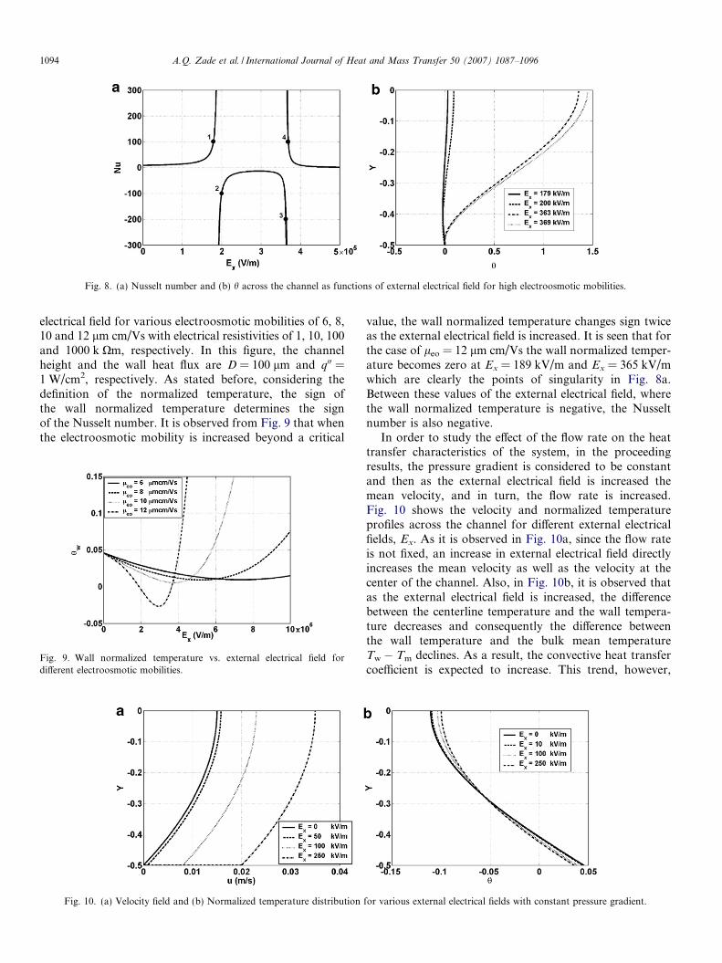
Fig. 8. (a) Nusselt number and (b) h across the channel as functions of external electrical field for high electroosmotic mobilities.
1094 A.Q. Zade et al. / International Journal of Heat and Mass Transfer 50 (2007) 1087–1096
electrical field for various electroosmotic mobilities of 6, 8,10 and 12 lm cm/Vs with electrical resistivities of 1, 10, 100and 1000 k Xm, respectively. In this figure, the channelheight and the wall heat flux are D = 100 lm and q00 =1 W/cm2, respectively. As stated before, considering thedefinition of the normalized temperature, the sign ofthe wall normalized temperature determines the signof the Nusselt number. It is observed from Fig. 9 that whenthe electroosmotic mobility is increased beyond a critical
Fig. 9. Wall normalized temperature vs. external electrical field fordifferent electroosmotic mobilities.
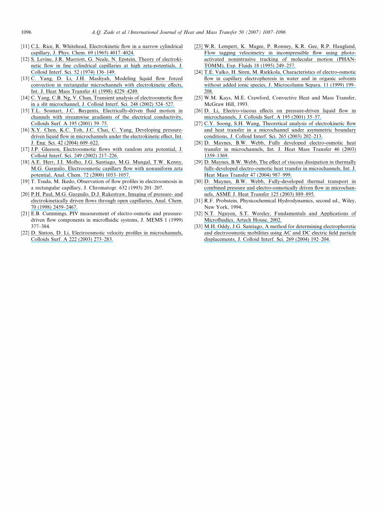
Fig. 10. (a) Velocity field and (b) Normalized temperature distribution
value, the wall normalized temperature changes sign twiceas the external electrical field is increased. It is seen that forthe case of leo = 12 lm cm/Vs the wall normalized temper-ature becomes zero at Ex = 189 kV/m and Ex = 365 kV/mwhich are clearly the points of singularity in Fig. 8a.Between these values of the external electrical field, wherethe wall normalized temperature is negative, the Nusseltnumber is also negative.
In order to study the effect of the flow rate on the heattransfer characteristics of the system, in the proceedingresults, the pressure gradient is considered to be constantand then as the external electrical field is increased themean velocity, and in turn, the flow rate is increased.Fig. 10 shows the velocity and normalized temperatureprofiles across the channel for different external electricalfields, Ex. As it is observed in Fig. 10a, since the flow rateis not fixed, an increase in external electrical field directlyincreases the mean velocity as well as the velocity at thecenter of the channel. Also, in Fig. 10b, it is observed thatas the external electrical field is increased, the differencebetween the centerline temperature and the wall tempera-ture decreases and consequently the difference betweenthe wall temperature and the bulk mean temperatureTw � Tm declines. As a result, the convective heat transfercoefficient is expected to increase. This trend, however,
for various external electrical fields with constant pressure gradient.

Fig. 11. Nusselt number as a function of external electrical field, (a) D = 100 lm, (b) q00 = 1 W/cm2 with constant pressure gradient.
A.Q. Zade et al. / International Journal of Heat and Mass Transfer 50 (2007) 1087–1096 1095
does continue up to a point where excessive volumetricheat generation due to increased external electrical fieldovercomes the increase in flow rate. This dependency isobserved clearly in Fig. 11.
In Fig. 11 the flow rate is free to change and consideringthe range of external electrical field applied, the mean veloc-ity varies from 0.01 m/s to 4 m/s. If there were no volumet-ric heat generation, as the external electrical field isincreased, the velocity profile would tend to become aslug-like flow and the corresponding Nusselt numberasymptotically reaches 12. However due to volumetric heatgeneration, this theoretical value is not reached and theNusselt number decreases before reaching this theoreticalvalue. This behavior is shown in Fig. 11. From this figureit is also apparent that the Nusselt number depends onthe wall heat flux and the channel height. As q00 is increased,with channel height fixed, the maximum Nusselt numberincreases. Also, as illustrated in Fig. 11b, with q00 fixed, anincrease in channel height decreases the Nusselt number.
It should be noted that when the pressure gradient isconstant the Nusselt number does not exhibit any singular-ity. This is mainly because the velocity of the core of theflow does not vanish, unlike the case of prescribed flowrate.
4. Conclusion
Hydrodynamically and thermally fully-developed flowof combined pressure-electroosmotically driven flow in pla-nar microchannels was investigated analytically for a con-stant wall heat flux boundary condition. Also, themaximum achievable Nusselt number for a range of prob-lem parameters has been investigated. It is shown that thethermally fully-developed temperature distribution and thecorresponding Nusselt number are identified by fourparameters: the channel height, the imposed wall heat flux,the electroosmotic mobility and the external electrical field.It was also revealed that for a prescribed flow rate the Nus-selt number computed for a combined pressure-electroosm-otically driven flow can reach up to approximately fivetimes that of the pressure driven flow. It was also shown
that the maximum Nusselt number increases by decreasingthe wall heat flux, increasing the channel height or increas-ing the electroosmotic mobility. For a prescribed pressuregradient it was shown that the maximum Nusselt numberincreases by decreasing the channel height and by increas-ing the wall heat flux. In the case of a prescribed pressuregradient the Nusselt number increases solely due to anincrease in the near wall velocity. In the case of a prescribedflow rate, however, an increase in the near wall velocitydecreases the velocity in the core region of the channelwhich results in much higher Nusselt numbers. Also, itwas demonstrated that under certain circumstances, theNusselt number may become negative and exhibit singular-ities as the external electrical field varies. This phenomenonoccurs when the Joule heating effect (volumetric heat gen-eration) is high enough so that the temperature in the stag-nant or slow-moving core of the channel and the resultingbulk mean temperature exceed the wall temperature.
References
[1] D.J. Laser, J.G. Santiago, A review of micropumps, J. Micromech.Microeng. 14 (2004) R35–R64.
[2] P.K. Dasgupta, L. Shaorong, Electroosmosis: A reliable fluidpropulsion system for flow injection analysis, Anal. Chem. 66(1994) 1792–1798.
[3] S. Arulanandam, D. Li, Liquid transport in rectangular microchan-nels by electroosmotic pumping, J. Colloids Surf. 161 (2000) 29–102.
[4] C.H. Chen, J.G. Santiago, A planar electroosmotic micropump, J.MEMS 11 (2002) 672–683.
[5] F.F. Reuss, Charge-induced flow, Proceedings of the Imperial Societyof Naturalists of Moscow 3 (1809) 327–344.
[6] R.J. Hunter, Zeta Potential in Colloidal Science: Principles andApplications, Academic, London, 1981, pp. 1–58.
[7] G.M. Mala, D. Li, C. Werner, H.J. Jacobasch, Y.B. Ning, Flowcharacteristics of water through a microchannel between two parallelplates with electrokinetic effects, Int. J. Heat Fluid Flow 18 (1997)489–496.
[8] O. Soderman, B. Jonsson, Electro-osmosis, velocity profiles indifferent geometries with both temporal and spatial resolution, J.Chem. Phys. 105 (1996) 10300.
[9] J.G. Santiago, Electroosmotic flows in microchannels with finiteinertial and pressure forces, Anal. Chem. 73 (2001) 2353–2365.
[10] D. Burgreen, F.R. Nakache, Electrokinetic flow in ultra fine capillaryslits, J. Phys. Chem. 68 (1964) 1084–1091.
1096 A.Q. Zade et al. / International Journal of Heat and Mass Transfer 50 (2007) 1087–1096
[11] C.L. Rice, R. Whitehead, Electrokinetic flow in a narrow cylindricalcapillary, J. Phys. Chem. 69 (1965) 4017–4024.
[12] S. Levine, J.R. Marriott, G. Neale, N. Epstein, Theory of electroki-netic flow in fine cylindrical capillaries at high zeta-potentials, J.Colloid Interf. Sci. 52 (1974) 136–149.
[13] C. Yang, D. Li, J.H. Masliyah, Modeling liquid flow forcedconvection in rectangular microchannels with electrokinetic effects,Int. J. Heat Mass Transfer 41 (1998) 4229–4249.
[14] C. Yang, C.B. Ng, V. Chan, Transient analysis of electroosmotic flowin a slit microchannel, J. Colloid Interf. Sci. 248 (2002) 524–527.
[15] T.L. Sounart, J.C. Baygents, Electrically-driven fluid motion inchannels with streamwise gradients of the electrical conductivity,Colloids Surf. A 195 (2001) 59–75.
[16] X.Y. Chen, K.C. Toh, J.C. Chai, C. Yang, Developing pressure-driven liquid flow in microchannels under the electrokinetic effect, Int.J. Eng. Sci. 42 (2004) 609–622.
[17] J.P. Gleeson, Electroosmotic flows with random zeta potential, J.Colloid Interf. Sci. 249 (2002) 217–226.
[18] A.E. Herr, J.I. Molho, J.G. Santiago, M.G. Mungal, T.W. Kenny,M.G. Garguilo, Electroosmotic capillary flow with nonuniform zetapotential, Anal. Chem. 72 (2000) 1053–1057.
[19] T. Tsuda, M. Ikedo, Observation of flow profiles in electroosmosis ina rectangular capillary, J. Chromatogr. 632 (1993) 201–207.
[20] P.H. Paul, M.G. Garguilo, D.J. Rakestraw, Imaging of pressure- andelectrokinetically driven flows through open capillaries, Anal. Chem.70 (1998) 2459–2467.
[21] E.B. Cummings, PIV measurement of electro-osmotic and pressure-driven flow components in microfluidic systems, J. MEMS 1 (1999)377–384.
[22] D. Sinton, D. Li, Electroosmotic velocity profiles in microchannels,Colloids Surf. A 222 (2003) 273–283.
[23] W.R. Lempert, K. Magee, P. Ronney, K.R. Gee, R.P. Haugland,Flow tagging velocimetry in incompressible flow using photo-activated nonintrusive tracking of molecular motion (PHAN-TOMM), Exp. Fluids 18 (1995) 249–257.
[24] T.E. Valko, H. Siren, M. Riekkola, Characteristics of electro-osmoticflow in capillary electropheresis in water and in organic solventswithout added ionic species, J. Microcolumn Separa. 11 (1999) 199–208.
[25] W.M. Kays, M.E. Crawford, Convective Heat and Mass Transfer,McGraw Hill, 1993.
[26] D. Li, Electro-viscous effects on pressure-driven liquid flow inmicrochannels, J. Colloids Surf. A 195 (2001) 35–57.
[27] C.Y. Soong, S.H. Wang, Theoretical analysis of electrokinetic flowand heat transfer in a microchannel under asymmetric boundaryconditions, J. Colloid Interf. Sci. 265 (2003) 202–213.
[28] D. Maynes, B.W. Webb, Fully developed electro-osmotic heattransfer in microchannels, Int. J. Heat Mass Transfer 46 (2003)1359–1369.
[29] D. Maynes, B.W. Webb, The effect of viscous dissipation in thermallyfully-developed electro-osmotic heat transfer in microchannels, Int. J.Heat Mass Transfer 47 (2004) 987–999.
[30] D. Maynes, B.W. Webb, Fully-developed thermal transport incombined pressure and electro-osmotically driven flow in microchan-nels, ASME J. Heat Transfer 125 (2003) 889–895.
[31] R.F. Probstein, Physicochemical Hydrodynamics, second ed., Wiley,New York, 1994.
[32] N.T. Nguyen, S.T. Wereley, Fundamentals and Applications ofMicrofluidics, Artech House, 2002.
[33] M.H. Oddy, J.G. Santiago, A method for determining electrophoreticand electroosmotic mobilities using AC and DC electric field particledisplacements, J. Colloid Interf. Sci. 269 (2004) 192–204.
Related Documents