NEI 15-01 [Rev 1] An Analytical Approach for Establishing Degraded Voltage Relay (DVR) Settings November 2015

Welcome message from author
This document is posted to help you gain knowledge. Please leave a comment to let me know what you think about it! Share it to your friends and learn new things together.
Transcript
NEI 15-01 [Rev 1]
An Analytical Approach for Establishing Degraded Voltage Relay (DVR) Settings
November 2015

[BLANK PAGE]

Nuclear Energy Institute, 1201 F Street N.W., Suite 1100, Washington D.C. (202.739.8000)
NEI 15-01 [Rev 1]
Nuclear Energy Institute
An Analytical Approach for Establishing
Degraded Voltage Relay (DVR) Settings
November 2015
ACKNOWLEDGEMENTS
NEI appreciates the extensive efforts of the utility members of the Degraded Voltage Task Force in developing and reviewing this document, as well as their utility management in supporting the members’ participation.
Mark D. Bowman, Tennessee Valley Authority
David Gladey, Pennsylvania Power & Light (Talon Energy)
Tammy Womack, Tennessee Valley Authority
George Attarian, Duke Energy, Retired
Timothy M. Lensmire, NextEra Energy Point Beach
Wayne E. Johnson, Electrical Power Research Institute
Robert M. Carritte, MPR Associates, Inc.
Gordon Clefton, Nuclear Energy Institute
Steven P. Hutchins, Nuclear Energy Institute
NEI also extends its thanks to the following organizations for playing important roles in the completion of this guidance:
• PP&L Drafting for providing the Graphics used in the document
• MPR Associates for providing Figure 3, which charts out the three areas covered by the text.
NOTICE
Neither NEI, nor any of its employees, members, supporting organizations, contractors, or consultants make any warranty, expressed or implied, or assume any legal responsibility for the accuracy or completeness of, or assume any liability for damages resulting from any use of, any information apparatus, methods, or process disclosed in this report or that such may not infringe privately owned rights.

Nuclear Energy Institute, 1201 F Street N.W., Suite 1100, Washington D.C. (202.739.8000)
[BLANK PAGE]


NEI 15-01 (Rev 1) November 2015
i
EXECUTIVE SUMMARY
On February 2, 2012, Nuclear Energy Institute (NEI) wrote a letter to the Nuclear Regulatory Commission Staff (NRC) outlining concerns that NEI has with the content and application of NRC Regulatory Issue Summary (RIS) 2011-12, Revision 1 (ML113050583). This RIS was issued on December 29, 2011, and was intended to clarify the NRC staff’s technical positions on existing regulatory requirements specified in General Design Criteria (GDC) 17 to 10 CFR Part 50, Appendix A. The Industry concerns at that time had been expressed previously on draft versions of the RIS through the public comment process and during public meetings. The industry’s main concern, at that time, was that implementation of methods identified in the RIS could have resulted in plant changes that would have been contrary to safety. It was noted that implementation would have resulted in increased instances of separation from offsite power, unnecessarily stress the emergency diesel generators, and increase the likelihood of “double sequencing”. These concerns were generally dismissed by staff statements that “proper design of the plant electrical system…should provide more than adequate operating margin, preventing unnecessary separation from offsite power.” While this statement was valid, we believe that the methods called for by the RIS fail to recognize that proper design of electrical systems requires margin to be established for all facets of operation and that a balance must be maintained for often competing demands on the system.
As a result of that initial interaction, NEI formed a Degraded Voltage Task Force and drafted a “White Paper” in an effort to provide an acceptable technical resolution to the concerns identified by both the NRC and the Industry. After many revisions to the “White Paper”, Public Meetings and fruitful discussions during a number of IEEE Nuclear Power Engineering Committee (NPEC) Working Group Meetings, an analytical approach for establishing degraded voltage relay (DVR) settings, found acceptable to the NRC and the Industry, was established.
This Technical Guidance Document provides at least one approach found acceptable that can be used to establish the settings for the degraded voltage protection scheme in order to demonstrate the design basis of safety-related equipment (running and starting voltage requirements) is in accordance with NRC regulatory guidance documents. The analytical techniques in this document should apply to a variety of plant power system designs (bus arrangements and configurations) with degraded voltage protection schemes. It is recognized that a plant’s unique design basis, unique degraded voltage protection scheme, or unique relationship between the offsite and onsite power supplies may demand additional calculations beyond those discussed.

NEI 15-01 (Rev 1) November 2015
ii
[BLANK PAGE]
NEI 15-01 (Rev 1) November 2015
iii
TABLE OF CONTENTS
EXECUTIVE SUMMARY ........................................................................................................ i
1 INTRODUCTION ............................................................................................................ 1
1.1 PURPOSE
1.2 BACKGROUND ..................................................................................................................2
1.3 DEFINITIONS ....................................................................................................................2 1.3.1 Degraded Voltage Relay (DVR) .......................................................................2 1.3.2 Loss of Voltage Relay (LVR) ...........................................................................2 1.3.3 Minimum Required Grid Voltage .....................................................................3 1.3.4 Analytical Limit ................................................................................................3 1.3.5 DVR Dropout Setting .......................................................................................3 1.3.6 DVR Reset Setting ............................................................................................3 1.3.7 LVR Dropout Setting ........................................................................................3
1.4 OTHER CONSIDERATIONS .................................................................................................3 1.4.1 DVR Protection ...............................................................................................3 1.4.2 Principal Design Criteria and Requirements ...................................................3 1.4.3 Testing and Surveillance ..................................................................................4
2 DEGRADED VOLTAGE RELAY (DVR) ANALYSES ........................................................ 4
2.1 ESTABLISH DVR DROPOUT SETTING ...............................................................................5 2.1.1 Analytical Technique ........................................................................................5
2.2 CONFIRM ADEQUACY OF DVR DROPOUT SETTING FOR MOTOR STARTING .....................6 2.2.1 Analytical Technique ........................................................................................6
2.3 CONFIRM DVR TIME DELAY (WITH ACCIDENT SIGNAL) ADEQUATE FOR TRANSFER TO ONSITE POWER SUPPLY ...................................................................................................7 2.3.1 Analytical Technique ........................................................................................8
2.4 CONFIRM RESET OF DVR WITH MINIMUM REQUIRED GRID VOLTAGE ............................9 2.4.1 Analytical Technique ........................................................................................9
2.5 CONFIRM LVR SETPOINT PREVENTS MOTOR STALLING ................................................10 2.5.1 Analytical Technique ......................................................................................10
3 DVR SUMMARY ......................................................................................................... 11

NEI 15-01 (Rev 1) November 2015
iv
[BLANK PAGE]

NEI 15-01 (Rev 1) November 2015
1
AN ANALYTICAL APPROACH FOR ESTABLISHING DEGRADED VOLTAGE RELAY (DVR) SETTINGS
1 INTRODUCTION
The nuclear power industry has evolved since the early 1990s implementation of degraded voltage relay (DVR) protective schemes and supporting analysis to demonstrate protection of Class 1E loads and circuits. An industry standard (IEEE Standard 741-19971) provided guidance on the use of the relays in protective schemes and was based on the understanding of events that had occurred at operating plants. The recommendations in IEEE Standard 741-1997 required the DVR to monitor steady-state running voltage and to protect equipment from sustained degraded voltage conditions. This guidance was not endorsed by the NRC. The intent of recent NRC guidance2 was to clarify the regulatory requirements provided in earlier documents and to preclude different interpretations as some inspection findings have challenged licensees’ original commitments as stated in their licensing basis. However, this NRC guidance did not detail any specific analytical approach that would meet the requirements. Through the Nuclear Energy Institute (NEI), industry subject matter experts have been working with NRC staff to better understand the specific analysis that would ensure DVR protection requirements are met.
1.1 PURPOSE
The purpose of this document is to provide one analytical approach that can be used to establish the settings for the degraded voltage protection scheme in order to demonstrate the design basis of safety-related equipment (running and starting voltage requirements) is in accordance with NRC regulatory guidance.2345 The analytical techniques in this document should apply to a variety of plant power system designs (bus arrangements and configurations) with degraded voltage protection schemes as described in the referenced NRC documents. It is recognized that a plant’s unique design basis, degraded voltage protection scheme, or relationship between the offsite and onsite power supplies may warrant additional calculations beyond those discussed. This document does not address the potential consequences of a delayed loss of offsite power with double load sequencing; however, using these calculations and analyses will limit the probability of double sequencing.6
1 IEEE Standard 741-1997 “IEEE Standard Criteria for the Protection of Class 1E Power Systems and Equipment in Nuclear Power Generating Stations” 2 NRC RIS 2011-12, Revision 1, “Adequacy of Station Electric Distribution System Voltages” 3 NRC Letter dated June 2, 1977, “Statement of Staff Positions Relative to Emergency Power Systems for Operating Reactors” 4 NRC NUREG 0800, Branch Technical Position PSB-1, “Adequacy of Station Electric Distribution System Voltages” 5 NRC Generic Letter 79-36, “Adequacy of Station Electric Distribution System Voltages” 6 NRC Generic Safety Issue -171 “ESF Failure from LOOP Subsequent to a LOCA”
NEI 15-01 (Rev 1) November 2015
2
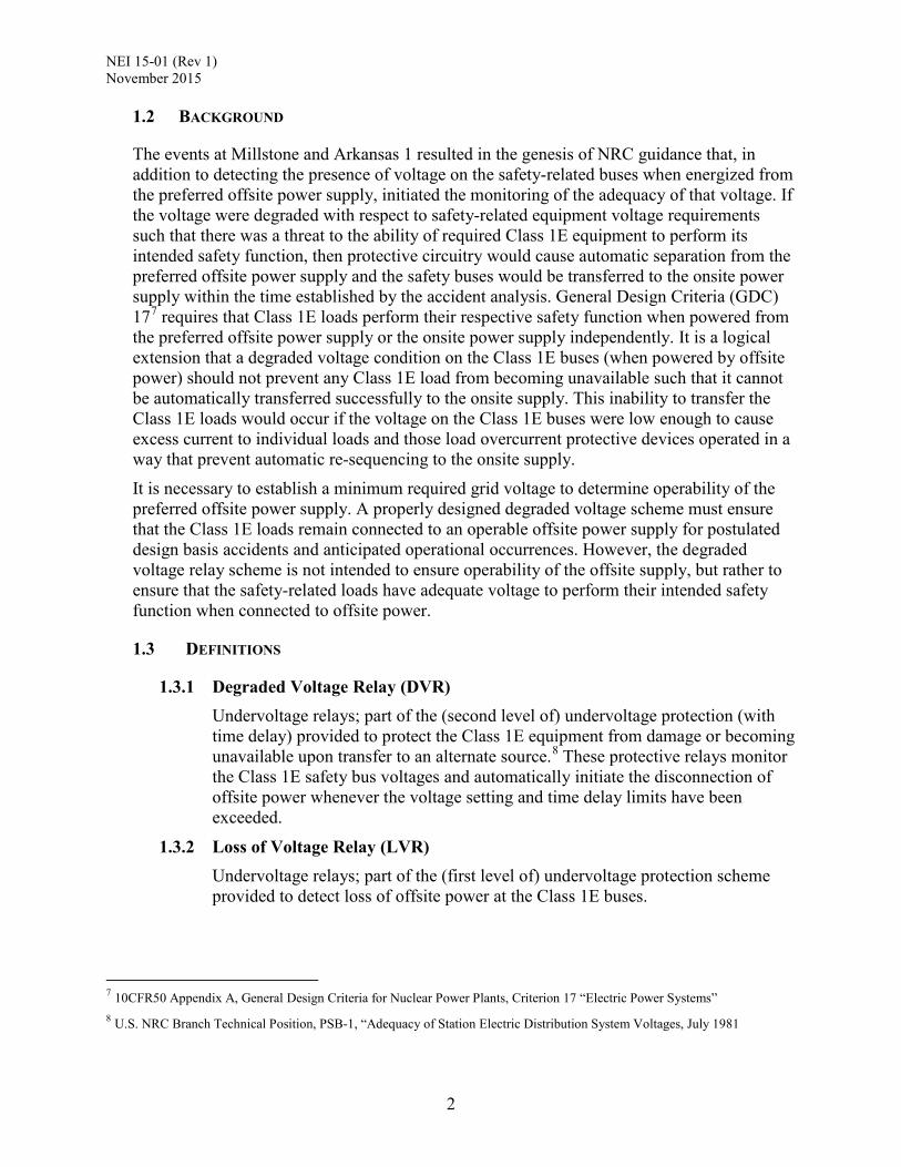
1.2 BACKGROUND
The events at Millstone and Arkansas 1 resulted in the genesis of NRC guidance that, in addition to detecting the presence of voltage on the safety-related buses when energized from the preferred offsite power supply, initiated the monitoring of the adequacy of that voltage. If the voltage were degraded with respect to safety-related equipment voltage requirements such that there was a threat to the ability of required Class 1E equipment to perform its intended safety function, then protective circuitry would cause automatic separation from the preferred offsite power supply and the safety buses would be transferred to the onsite power supply within the time established by the accident analysis. General Design Criteria (GDC) 177 requires that Class 1E loads perform their respective safety function when powered from the preferred offsite power supply or the onsite power supply independently. It is a logical extension that a degraded voltage condition on the Class 1E buses (when powered by offsite power) should not prevent any Class 1E load from becoming unavailable such that it cannot be automatically transferred successfully to the onsite supply. This inability to transfer the Class 1E loads would occur if the voltage on the Class 1E buses were low enough to cause excess current to individual loads and those load overcurrent protective devices operated in a way that prevent automatic re-sequencing to the onsite supply.
It is necessary to establish a minimum required grid voltage to determine operability of the preferred offsite power supply. A properly designed degraded voltage scheme must ensure that the Class 1E loads remain connected to an operable offsite power supply for postulated design basis accidents and anticipated operational occurrences. However, the degraded voltage relay scheme is not intended to ensure operability of the offsite supply, but rather to ensure that the safety-related loads have adequate voltage to perform their intended safety function when connected to offsite power.
1.3 DEFINITIONS
1.3.1 Degraded Voltage Relay (DVR) Undervoltage relays; part of the (second level of) undervoltage protection (with time delay) provided to protect the Class 1E equipment from damage or becoming unavailable upon transfer to an alternate source.8 These protective relays monitor the Class 1E safety bus voltages and automatically initiate the disconnection of offsite power whenever the voltage setting and time delay limits have been exceeded.
1.3.2 Loss of Voltage Relay (LVR) Undervoltage relays; part of the (first level of) undervoltage protection scheme provided to detect loss of offsite power at the Class 1E buses.
7 10CFR50 Appendix A, General Design Criteria for Nuclear Power Plants, Criterion 17 “Electric Power Systems” 8 U.S. NRC Branch Technical Position, PSB-1, “Adequacy of Station Electric Distribution System Voltages, July 1981

NEI 15-01 (Rev 1) November 2015
3
1.3.3 Minimum Required Grid Voltage The minimum switchyard voltage required to maintain an operable preferred offsite power supply such that the supply can perform its intended safety function per GDC-17. This requires the offsite supply to have sufficient capacity and capability to perform its intended function, including the ability to maintain voltage while accepting the accident loads. It also requires the supply to accept all required safety-related loads without causing the DVR to time out and trip thereby causing separation of the offsite supply.
1.3.4 Analytical Limit A limit of a measured or calculated variable established by the analysis to ensure that a safety limit is not exceeded9.
1.3.5 DVR Dropout Setting The voltage setpoint of the DVR that causes the relay to actuate and automatically disconnect offsite power after the DVR voltage limit and the DVR time delay limit are reached.
1.3.6 DVR Reset Setting The voltage value that causes the DVR to reset following relay actuation. If this voltage value is reached prior to DVR timeout, it will prevent automatic disconnection of offsite power.
1.3.7 LVR Dropout Setting The voltage setpoint of the LVR that causes the relay to actuate and automatically disconnect offsite power after the LVR voltage limit and LVR time delay limit are reached.
1.4 OTHER CONSIDERATIONS
1.4.1 DVR Protection As used in this guidance document, DVR protection refers to the sense, command, and execute features with their associated interconnections. This protection is provided to minimize Class 1E equipment damage and to ensure independence of the offsite and on-site power sources required by GDC-17 during any interruption of electrical service resulting in a degraded voltage. This includes mechanical or electrical failures or other unacceptable conditions.
1.4.2 Principal Design Criteria and Requirements This guidance document is intended to be used in conjunction with IEEE 741-200710. While the goal of the document is to provide at least one approach that can be used to establish the settings for the degraded voltage protection scheme in order to demonstrate the design basis of safety-related equipment (running and
9 ANSI/ISA Standard 67.04.01-2000, Setpoints for Nuclear Safety-Related Instrumentation. 10 IEEE 741-2007 – “IEEE Standard Criteria for the Protection of Class 1E Power Systems and Equipment in Nuclear Power Generating Stations.”
NEI 15-01 (Rev 1) November 2015
4
starting voltage requirements) is in accordance with NRC regulatory guidance documents, it does not contain all of the factors that must be considered. Specifically, IEEE 741, Section 5: “Principal Design Criteria and Requirements” should be reviewed to obtain the additional design considerations and criteria that must be considered when determining protection requirements.
1.4.3 Testing and Surveillance Similarly, this guidance document is intended to be used in conjunction with Standard IEEE 741-2007, specifically, Section 6: “Testing and Surveillance” to obtain the testing and surveillance requirements that also must be in place as an integral part of the DVR protection process to maintain continued functionally.
2 DEGRADED VOLTAGE RELAY (DVR) ANALYSES
The five analyses needed to demonstrate adequate DVR protection are:
1. Establish DVR Dropout Setting
2. Confirm Adequacy of DVR Dropout Setting for Motor Starting
3. Establish DVR Time Delay (with accident signal)
4. Confirm Reset of DVR with Minimum Required Grid Voltage
5. Confirm LVR Setpoint Prevents Motor Stalling
Collectively, these five analyses establish/confirm proper settings for the undervoltage protection scheme and ultimately ensure that the Class 1E buses and safety-related components are supplied with adequate voltage under any grid conditions. This is true for steady-state conditions as well as transient (motor starting) conditions. The established undervoltage protection scheme settings will ensure that no required safety related loads will stall or trip and lock-out, and thereby be unable to reconnect to the onsite power supply.
For steady-state conditions (fixed grid voltage, fixed plant loading, no motor starting), determination of required voltage at the DVR monitored bus to maintain adequate voltage for a given safety-related component (see section 2.1) is considered straightforward and should not need further discussion. For any motor starting event (single motor or group of motors, including accident-initiated loading), consider that there are only three “regions” of possible transient voltage response (see Figure 3):
Region 1 - Minimum required grid voltage is available (offsite power supply is operable). The voltage dip and subsequent recovery on the Class 1E buses will always be within the allowable response predicted by the offsite power system analysis (see section 2.4). No additional analysis is needed for this region.
Region 2 - Minimum required grid voltage is not available (offsite power is inoperable, whether known or unknown). The voltage response may or may not be beyond that predicted by the offsite power analysis, depending on the actual motor starting scenario (number/size of motors started, actual system loading, grid voltage capability, etc.). Nonetheless, there are only three possible outcomes for the Class 1E bus voltage response:
NEI 15-01 (Rev 1) November 2015
5
• The voltage decreases to the DVR dropout setting or above (DVR does not actuate). This outcome is bounded by the analyses discussed in sections 2.1 and 2.2.
• The voltage decreases below the DVR dropout setting and subsequently recovers above DVR reset setting prior to the DVR time delay limit being exceeded (DVR initiates but does not time out). This outcome is covered by the analyses discussed in sections 2.1, 2.2, and 2.5.
• The voltage decreases below the DVR dropout setting but does not recover above the DVR reset setting prior to the DVR time delay limit being exceeded (DVR initiates and times out, causing automatic disconnection of offsite power and automatic transfer to the onsite power supply). This outcome is covered by the analysis discussed in section 2.3.
Region 3 - the Class 1E bus voltage is already degraded prior to any motor starting event. The actual transient voltage response is immaterial since the bus voltage is inadequate to begin with. All Class 1E loads will auto-transfer to the onsite power supply as demonstrated by the DVR time delay setting analysis (see section 2.3). No additional analysis is needed for this region.
2.1 ESTABLISH DVR DROPOUT SETTING This analysis determines the minimum steady-state voltage at the DVR monitored bus to ensure operating (running) voltages are adequate for all Class 1E loads required to support postulated design basis accidents and anticipated operational occurrences. This “bottom up” analysis uses the minimum operating voltage for the required loads as a pass/fail criteria, and is consistent with the methodology of IEEE Standard 741-1997.
2.1.1 Analytical Technique Since this is a steady-state analysis, upstream system voltage drop can be accounted for by simply connecting a fixed voltage source to the DVR monitored bus (see Figure 2.1.1). Using steady-state load flow analysis, the fixed voltage source should be set as low as possible while still keeping the operating (running) voltages of all required Class 1E loads within their design requirements. This establishes the lower analytical limit for the DVR dropout setting.
This method precludes crediting any voltage regulating equipment upstream of the Class 1E buses (e.g., automatic Load Tap Changing (LTC) transformers or capacitor banks). This analysis must consider system loading under all postulated accident and operating scenarios, identifying whichever produces the most severe voltage drop (i.e., highest loading on the Class 1E distribution system).

NEI 15-01 (Rev 1) November 2015
6
Figure 2.1.1
2.2 CONFIRM ADEQUACY OF DVR DROPOUT SETTING FOR MOTOR STARTING This analysis will demonstrate that all Class 1E motors required for postulated design basis accidents or anticipated operational occurrences are capable of being started individually when the voltage at the DVR monitored bus is at the DVR dropout setting (lower analytical limit). It is recognized that at this voltage, the starting of even one individual motor could cause the bus voltage to further degrade below the DVR dropout setting, which would result in DVR actuation and disconnection of the offsite power supply. However, the analysis is not intended to demonstrate the power system response to this scenario but rather to act as a bounding technique that demonstrates equipment capability at the DVR dropout setting.
2.2.1 Analytical Technique This analytical technique is intended to bound any voltage transient scenario caused by a motor starting event, where the voltage never dips below the DVR dropout setting, or where it dips below and then recovers above the DVR dropout setting. This is accomplished by performing a motor starting analysis for each individual Class 1E motor required for postulated design basis accidents and anticipated operational occurrences. Using maximum system loading, each motor is started individually (one at a time). Since this bounding technique already accounts for system voltage drop, a fixed voltage source can be connected to the DVR monitored bus (see Figure 2.2.1). The fixed voltage source should be set to the lower analytical limit for the DVR dropout setting (analysis 2.1.1). The analysis must consider all postulated accident and operating scenarios, whichever produces the most severe voltage drop (i.e. highest loading on the Class 1E distribution system). This method precludes crediting any voltage regulating equipment upstream of

NEI 15-01 (Rev 1) November 2015
7
the Class 1E buses (e.g., automatic Load Tap Changing (LTC) transformers or capacitor banks).
Following the guidance of IEEE Standard 1792-201111, the motor starting analysis can be either a dynamic simulation that demonstrates each motor can be successfully started within its required time period or a static “snapshot” load flow analysis that demonstrates the calculated starting voltage at locked rotor conditions is within design requirements (i.e. all components have adequate voltage).
Figure 2.2.1
2.3 CONFIRM DVR TIME DELAY (WITH ACCIDENT SIGNAL) ADEQUATE FOR TRANSFER TO ONSITE POWER SUPPLY
This analysis demonstrates that all Class 1E loads required for postulated design basis accidents (including control equipment) will successfully auto-transfer to the onsite power supply if the DVR monitored bus experiences degraded voltage conditions. The upper analytical limit of the DVR time delay should be optimized to ensure accident analyses (core cooling) requirements are not exceeded. For this analysis, it is not necessary to demonstrate adequate terminal voltage for the Class 1E equipment exposed to the degraded voltage condition. Instead, this is a protective device analysis to essentially show coordination between the DVR time delay and any protective devices that are capable of preventing transfer to the onsite supply (e.g. overcurrent devices that could trip and require a manual reset).
11 IEEE Standard 1792-2011, “IEEE Recommended Practice for Nuclear Power Generating Station (NPGS) Preferred Power Supply (PPS) Reliability”

NEI 15-01 (Rev 1) November 2015
8
2.3.1 Analytical Technique A protective device coordination analysis is performed. By evaluating the overcurrent protective devices for those Class 1E motors that auto-start upon receipt of an accident signal, the analysis ensures that those capable of locking-out and preventing transfer (automatic restart) to the onsite supply will not trip if the degraded voltage occurs at the initiation of that motor. A conservative approach is to simply assume that these motors continue to draw starting current until the DVR times out. It is acceptable to use a reduced starting current which correlates with the minimum design starting voltage12. The protective device must not trip for a duration equal to the upper analytical limit of the DVR time delay plus the additional time needed to accelerate the motor on the onsite power supply (at rated starting current) (See Figure 2.3.1).
Example: A given accident-initiated motor is protected by an overcurrent device that will lock-out if tripped. The motor has a rated locked-rotor current of 100A and a minimum design starting voltage of 80%. The motor takes 2.5s to accelerate on the onsite power supply. The DVR time delay upper analytical limit is 11.5s. Using a starting current of 80A, the overcurrent device trip time is determined to be 18s. Therefore, the motor will not lock-out prior to successful transfer to the onsite power supply.
Note: Since the upper analytical limit of the DVR time delay is typically only a few seconds, it is not normally required to review lock-out of protective devices associated with any required Class 1E motors that remain running during the transfer.
Protective devices associated with Class 1E non-motor loads (e.g. battery chargers) protective devices should also be evaluated to ensure they will not lock-out during the degraded voltage timeout period.
Control power circuits powered from Class 1E AC Motor Control Centers should also be evaluated for the Class 1E accident-initiated motors to ensure that their control circuit fuses won’t blow if the starter doesn’t have sufficient voltage to pick-up during the degraded voltage timeout period. A conservative technique is to simply assume the fuse is carrying rated inrush current of the starter (plus the current from any other energized devices) for durations equal to the upper analytical limit of the DVR time delay.
12 The minimum voltage needed to meet design-required acceleration time. Typically much higher than the minimum voltage needed to start motor rotation.

NEI 15-01 (Rev 1) November 2015
9
Figure 2.3.1
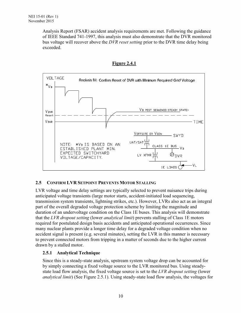
2.4 CONFIRM RESET OF DVR WITH MINIMUM REQUIRED GRID VOLTAGE The offsite power voltage analysis establishes the minimum required grid voltage (minimum operable grid) to start and accelerate required accident-initiated Class 1E motors within required time periods. This analysis is typically performed as part of the calculations to verify the offsite power system’s capacity and capability to mitigate design basis accidents and demonstrates that adequate starting voltage will be available to those Class 1E motors that auto-start in response to an accident signal, when powered by the preferred (offsite) power supply at minimum voltage and capacity (minimum operable grid) (See Figure 2.4.1). Depending of the design basis at the particular station, credit can be taken for the operation of various voltage support equipment (e.g. LTC, CAP Bank, etc.) when performing this analysis. With respect to degraded voltage protection settings, this analysis must also confirm that the minimum required grid voltage can reset the DVR prior to the automatic disconnection of offsite power. The minimum required grid voltage established in these calculations are provided to the Station’s Transmission Provider has part of the Interface Agreement established under the requirements of the NERC Standard NUC-00113
2.4.1 Analytical Technique Following the guidance of IEEE Standard 1792-201114, the offsite power supply capability (voltage and impedance) is modeled at minimum capacity and voltage (assuming postulated contingencies) and motor starting analyses are performed. This analysis demonstrates adequate motor starting voltages to ensure the Final Safety
13 North American Electric Reliability Corporation (NERC) Standard NUC-001-3 — Nuclear Plant Interface Coordination 14 IEEE Standard 1792 – “IEEE Recommended Practice for Nuclear Power Generating Station (NPGS) Preferred Power Supply (PPS) Reliability”
NEI 15-01 (Rev 1) November 2015
10
Analysis Report (FSAR) accident analysis requirements are met. Following the guidance of IEEE Standard 741-1997, this analysis must also demonstrate that the DVR monitored bus voltage will recover above the DVR reset setting prior to the DVR time delay being exceeded.
Figure 2.4.1
2.5 CONFIRM LVR SETPOINT PREVENTS MOTOR STALLING LVR voltage and time delay settings are typically selected to prevent nuisance trips during anticipated voltage transients (large motor starts, accident-initiated load sequencing, transmission system transients, lightning strikes, etc.). However, LVRs also act as an integral part of the overall degraded voltage protection scheme by limiting the magnitude and duration of an undervoltage condition on the Class 1E buses. This analysis will demonstrate that the LVR dropout setting (lower analytical limit) prevents stalling of Class 1E motors required for postulated design basis accidents and anticipated operational occurrences. Since many nuclear plants provide a longer time delay for a degraded voltage condition when no accident signal is present (e.g. several minutes), setting the LVR in this manner is necessary to prevent connected motors from tripping in a matter of seconds due to the higher current drawn by a stalled motor.
2.5.1 Analytical Technique Since this is a steady-state analysis, upstream system voltage drop can be accounted for by simply connecting a fixed voltage source to the LVR monitored bus. Using steady-state load flow analysis, the fixed voltage source is set to the LVR dropout setting (lower analytical limit) (See Figure 2.5.1). Using steady-state load flow analysis, the voltages for

NEI 15-01 (Rev 1) November 2015
11
all required Class 1E motors are confirmed to be higher than their respective stall voltage. The analysis must consider postulated all design basis accident and operating scenarios, whichever produces the most severe voltage drop (i.e. highest loading on the Class 1E distribution system). This method precludes crediting any voltage regulating equipment upstream of the Class 1E buses (e.g., automatic Load Tap Changing (LTC) transformers or capacitor banks).
Note: Motor stall voltage is typically greater than 70.7% of motor rated voltage. This is because the breakdown torque for typical motors15 is at least 200% of full-load torque. Since developed torque can be considered proportional to the square of motor terminal voltage, a terminal voltage of 70.7% will provide 100% breakdown torque, and prevent motor stalling. For other (Non NEMA MG-1) motors, a review of the specific torque-speed characteristics must be performed to determine the actual breakdown torque and resulting stall voltage.
Figure 2.5.1
3 DVR SUMMARY This document provides one analytical approach that can be used to establish the settings for the degraded voltage protection scheme in order to demonstrate the design basis of safety-related equipment (running, and starting voltage requirements) in accordance with NRC regulatory guidance documents.
15 NEMA Standard MG-1, Design “B” motors, 200 HP and less

NEI 15-01 (Rev 1) November 2015
12

NEI 15-01 (Rev 1) November 2015
13
[BLANK PAGE]
Related Documents