i AN ANALYSIS OF VIVALDI RCS ANTENNA AT 6GHZ FOR SATELLITE COMMUNICATION ETTIE ATHIRA BINTI HADLIN This Report Is Submitted In Partial Fufillment Of Requirement For The Bachelor of Degree of Electronic Engineering (Wireless Communication) Fakulti Kejuruteraan Elektronik dan Kejuruteraan Komputer Universiti Teknikal Malaysia Melaka JUNE 2015

Welcome message from author
This document is posted to help you gain knowledge. Please leave a comment to let me know what you think about it! Share it to your friends and learn new things together.
Transcript
i
AN ANALYSIS OF VIVALDI RCS ANTENNA AT 6GHZ FOR SATELLITE COMMUNICATION
ETTIE ATHIRA BINTI HADLIN
This Report Is Submitted In Partial Fufillment Of Requirement For The Bachelor of Degree of Electronic Engineering (Wireless Communication)
Fakulti Kejuruteraan Elektronik dan Kejuruteraan Komputer Universiti Teknikal Malaysia Melaka
JUNE 2015
ii
AN ANALYSIS OF VIVALDI RCS ANTENNA AT 6GHZ FOR SATELLITE
COMMUNICATION
ETTIE ATHIRA BINTI HADLIN
This Report Is Submitted In Partial Fulfillment of Requirement for the
Bachelor Degree of Electronic Engineering (Wireless Communication) With
Honours
Fakulti Kejuruteraan Elektronik Dan Kejuruteraan Komputer
Universiti Teknikal Malaysia Melaka
June 2015

iii

iv
v

vi
To my beloved parents and family, Supervisor, and all my friends for their continous support, advice, and guidance to complete this final year project.

vii
ACKNOWLEDGEMENT
All praises are due to ALLAH SWT who had given blessing, strength, and
knowledge in finishing this final year report entitiled “ An Analysis of RCS Vivaldi
Antenna at 6GHz for satellite communication system”.
I would like to thanks to Dr. Mohd Azlishah Bin Othman for his valuable
supervision and support throughout the development and improvement for this
project. Besides that, i would like to thank my parents, for giving me the money,
strength and courage to finished this project. Last but not least, special thank also to
all my friends that always support and help me until i managed to finished up my
final year project report.

viii
ABSTRACT
This project is conduct to reduced the large RCS of conventional antenna by
using stealthy design. Many methods have been proposed to reduces the radar cross
section (RCS). However, the reduction of RCS will increase the complexity of an
antenna system or degrade the antenna performance. The main objective for this
project is to develop the Vivaldi RCS Antenna by using the suitable method to
reduces the RCS and analyzed these antenna performance in simulation and
measurement fabrication. To obtain the simulation result, the antenna was designed
on the CST 2014 Software. While, FR-4 was used to implement the hardware
fabrication. This project only cover the frequency in C-band range (4-8GHz) and the
resonant frequency at 6GHz. Antenna performances that will discuss in this report is
the value of gain, return loss, bandwidth, and radiation pattern.

ix
ABSTRAK
Projek ini dijalankan untuk mengurangkan keratan rentas radar (RCS) dengan menggunakan teknik bentuk. Banyak kaedah telah dicadangkan untuk mengurangkan keratan rentas radar (RCS). walau bagaimanapun, pengurangan RCS akan meningkatkan kerumitan sistem antena atau menjejaskan prestasi antenna. Objektif utama projek ini adalah untuk membuat Vivaldi RCS Antena dengan menggunakan kaedah yang sesuai untuk mengurangkan RCS dan dianalisis prestasi antenna ini dalam simulasi dan pengukuran fabrikiasi. Untuk mendapatkan hasil simulasi, antena telah direka pada perisian CST 2014. Walaupun FR-4 telah digunakan untuk melaksanakan fabrikasi perkakasan. Projek ini hanya meliputi frekuensi dalam julat C-band (4-8GHz) dan frekuensi salunan pada 6GHz. Antena yang dihasilkan akan membincangkan nilai keuntungan, kehilangan gelombang semasa menghantar data, dan corak sinaran.
x
TABLE OF CONTENT
CHAPTER TITLE PAGE
TITLE OF PROJECT ii
DECLARATION iv
DEDICATION vi
ACKNOWLEDGEMENT vii
ABSTRACT viii
ABSTRAK ix
TABLE OF CONTENT x
LIST OF TABLES xiv
LIST OF FIGURES xv
LIST OF ABBREVIATIONS xvii
I. INTRODUCTION
1.1 Project Introduction 1
1.2 Objective 2
1.3 Problem Statement 2
1.4 Scope of Work 2
1.5 Thesis Outline 4
II. LITERATURE REVIEW

xi
2.1 Introduction 5
2.2 Method to Reduces RCS of an Antenna 6
2.2.1 A novel Stealth Design 6
2.2.2 Half Mode Substrate Integrated
Waveguide 6
2.2.3 A novel Wideband Radar with Absorbing
Material 7
2.2.4 Using a Phase Switched Screen (PSS)
Boundary 7
2.2.5 Use EBG structure 8
III. METHODOLOGY
3.1 Introduction 9
3.2 Flowchart 10
3.3 Project Planning 11
3.4 Design of the antenna 12
3.3.1 Substrate Materials and Thickness 12
3.3.2 Design Specification 13
3.3.3 Design Structure 13
3.3.4 Design Parameter 14
3.3.5 Design Process 15
3.5 Design Simulation CST Software 17
3.6 Final Design For Vivaldi Antenna 21
IV. RESULT AND ANALYSIS
4.0 Introduction 22
4.1 Design of the Vivaldi Antenna 22
4.1.1 Measuing Result for Vivaldi Antenna 26
4.1.2 Comparing the Result of Simulation
Vivaldi antenna and Measured Vivaldi
xii
Antenna 29
4.2 Design of Vivaldi Antenna with Low Radar
Cross Section 30
4.2.1 Vivaldi RCS with Ecliptic Cylinder
Shape 30
4.2.2 Vivaldi RCS Antenna with Rectangular
Shape 33
4.2.3 Vivaldi RCS Antenna with Hexagon
Shape 36
4.3 Comparison Result Vivaldi RCS Antenna 37
4.4 Measuring Result Using Vivaldi Antenna with
Low Radar Cross Section (RCS) 38
4.5 Comparison Between Vivaldi RCS Antenna
Simulation and Fabrication 40
4.6 Comparison Between Simulation Vivaldi
Antenna with RCS 41
4.7 Combination Result for Both Simulation and
Measurement of Vivaldi Antenna and Vivaldi
Antenna with RCS 42
4.8 Comparison Between Measurement Fabrication
Vivaldi Antenna and Vivaldi Antenna with RCS 43
4.9 Achieving Low Radar Cross Section 44
xiii
V. FUTURE WORK AND CONCLUSION
5.0 Conclusion 48
5.1 Future Work 49
REFERENCES 51

xiv
LIST OF TABLES
NO TITLE PAGE
Table 3.1: Parameters Substrate of FR-4 12
Table 3.2: Design specification of Vivaldi Antenna 30
Table 4.1: Comparisob for result simulation and measurement for
Vivaldi Antenna 29
Table 4.2: Comparison for Vvaldi RCS Antenna 38
Table 4.3: Comparison between result simulation and fabrication of
Vivaldi Antenna 41
Table 4.4: Comparison the measurement between Vivaldi Antenna and
Vivaldi RCS Antenna 43
Table 4.5: Comparison between gain of both Vivaldi Antenna 44
xv
LIST OF FIGURES
NO TITLE PAGE
2.1 Organization Chart for Category Antenna 6
3.1 Flow Chart of Methodolgy 11
3.2 Gant Chart 12
3.7 The Simulation Process on CST 18
3.8 The back view and parameter value 19
3.9 Graph return loss (S11) and resonant frequency 20
3.10 Graph return loss (S11) and bandwidth 14
3.11 Figure 3.11: Change the value of Rs by using parameter
sweep to get desired resonant frequency 21
3.12 Graph of return loss (S11) at desired resonant frequency 22
4.1 Front dimension and value of parameter 24
4.2 Return loss (S11) and resonant frequency 24
4.3 Return loss (S11) and bandwidth 25
4.4 Simulated radiations pattern of the antenna 27
20
4.5 Graph of return loss (S11) and resonant frequency 28
4.6 Graph of return loss (S11) and bandwidth 28
4.7 Radiation pattern for simulation E-plane and H- plane 29
4.8 Graph of return loss (S11) and resonant frequency 30

xvi
4.9 Front and Back View of Vivaldi RCS Antenna with
Ecliptic Shape 31
4.10 graph of return loss (S11) and resonant frequency 32
4.11 Graph of return loss (S11) and bandwidth 33
4.12 the result simulation for radiation pattern of the antenna. 34
4.13 Front and back view Vivaldi RCS Antenna with rectangular
Shape 34
4.14 Graph return loss (S11) and resonant frequency 35
4.15 graph of return loss (S11) and bandwidth . 35
4.16 3D radiation pattern 36
4.17 2D Radiation Pattern 36
4.18 Front and back view Vivaldi RCS Antenna with rectangular
shape 37
4.19 Graph return loss (S11) and resonant frequency 37
4.20 the result simulation for radiation pattern of the antenna 40
4.21 Graph of return loss (S11) and resonant frequency 41
4.22 Oscilloscope Result Taken At Distance 2cm 37
4.23 Graph return loss (S11) and bandwidth 42
4.24 Measurement radiation pattern for Vivaldi Antenna with RCS 42
4.25 Graph return loss (S11) and resonant frequency of simulation
Of Vivaldi Antenna and Vivaldi Antenna with Low RCS 43
4.26 Graph return loss (S11) for the Combination result of simulation
and measurement for both Antenna 44
xvii
LIST OF ABBREVIATIONS
CDMA - Code Division Multiple Access
CST - Computer Simulation Technology
EBG - Electronic Band Gap
FR4 - Fire Retardant 4
FSS - Frequency Selective Surfaces
HPBW - Half Power Beamwidth
PCB - Printed Circuit Board
PEC - Printed Electronic Circuit
PSS - Phase Switched Screen
RAM - Random Access Memory
RCS - Radar Cross Section
VSWR - Voltage Standing Wave Ratio
1
CHAPTER I
INTRODUCTION
1.1 Introduction
Antenna is an electrical devices that convert the electric power into a radio
waves and vice versa. There are many type of antenna such as wire antenna, long
periodic antenna, travelling wire antenna, aperture antenna, reflector antenna,
microstrip antenna and other antenna. Vivaldi antenna is the planar antenna that can
provide the ultra wide bandwidth. Vivaldi antenna was firstly invent by P.J Gibson
and was discussed in IEEE European Microwave Conference paper on 1979 [2].
Sometime, vivaldi antenna are known as tapered slot antenna (TSA) or vivaldi notch
antenna. This antenna are type of fire control system and widely used in remote
sensing, wireless communication, ground penetrating radar, and microwave imaging.
Vivaldi antenna was classified into three main categories which is coplanar vivaldi
antenna, antipodal vivaldi antenna and balanced antipodal vivaldi antenna [9].
Vivaldi have an broadbandwith and small physical dimension. Thus, the stealth
design of an antenna is recommended
As a development of the detection technology today, a reduction of a low
radar cross has gain an interests. There are many technique can be used to reduces
RCS, but the reduction of the RCS can cause degradation of the radiation
antenna and make antenna more complex. This effect from the degradation can cause

2
the shifting of the resonance frequency, tha value of the gain decreased and narrow
for the frequency bandwith[2].
1.2 Objective of the Project
The main objectives of this research is to design and analyze the vivaldi RCS
antenna at frequency of 6 GHz for the satellit communication, to develop the vivaldi
RCS antenna by using the suitable method to reduces the RCS and to analyze the
performance of Vivldi RCS antenna at 6GHz.
1.3 Problem Statement
Recently day, the detection and stealth technology is rapidly growth and
cause the attention to the reduction af radar cross sectional area. However, the the
RCS reduction will lead to the degradation of an antenna performances and increase
the complexity of an antenna. The effect by the degradation of antenna performances
is narrow bandwith, the value of the gain decrease and shifting the resonance
frequency. In addition, antenna is a special scatter and difficult to balance the
reduction of RCS simulataneously with the good of antenna radiation performances.
1.4 Scope of Project
The scope of this project is to design and analysis of the RCS Vivaldi antenna
at 6 GHz (range in the C-band frequency). Those following below are scope of this
project:
i. Literature review
Firstly, to start this project all the theory and related information like antenna
parameter, design process, design structure of the RCS vivaldi antenna was studied

3
by referring to various type of source such as jurnals, letters, articles, books, and
technical report that regarding to the fundamental of the antenna.
ii. Calculation
Some calculation and equation are needed to find the parameter of this antenna. This
is important before the designing the antenna in simulation part.
iii. Simulation and design process
The simulation process was done by using the Computer Simulation Technology
(CST) Microwave Studio Suite 2014 [7]. The operated frequency of RCS antenna at
6 GHz ( in the range of freuency in the C-band which is in the range 4GHz-8GHz).
iv. Fabrication
The optimum design of RCS Vivaldi antenna was fabricate on the FR4 printed circuit
board by using the technique of chemical etching.
v. Test analysis and measurement
Transient Solver was used for conduct simulation to anlyze the antenna
performances. The antenna parameter like gain, return loss, and radiation pattern was
measured. To get the desired antenna performances, some modification such as, the
length and tapered slot of the antenna have been make [7].

4
1.5 Thesis Outline
For the part of the thesis outline, it will covered five chapter. Chapter 1 is an
introduction. In this chapter, it will include the background of this project, the
objective of project, problem statement, and scope of the project in terms of planning
schedule.
In chapter 2, topic that will be discuss is literature review. This is a
theoritically part and explained about the basic of Vivaldi antenna and method that
can be used to reduce the RCS.
For chapter 3, it covered the design of the Vivaldi antenna. It includes the
design structure, design parameter, design process, and measurement process.
Next is chapter 4, in this chapter it discussed and explain about the result
obtain, analysis of the result and discussion. The last last chapter for this report
project is chapter 5. This chapter will conclude all about this project and give some
rcommendation for the future work

5
CHAPTER II
LITERATURE REVIEW
2.1 Introduction
This chapter about the literature review, which is the first step before conduct
this project. All the data of the performances antenna that get from the various type
of source like journal, techincal report, and letter was analyze. There are several
method that can be used to reduces an RCS Vivaldi antenna. For an example, a novel
stealth design, half mode substrate integrated waveguide, a novel wideband radar
with absorbing material, using a Phase switched screen (PSS) boundary, and use
EBG structure [2]-[6]. All of the method were analyzed according to the result that
had published in each of the individual paper that include the antenna parameter and
reduction of a RCS.
The outcome from the literature review give an idea how to reduce the RCS
antenna with the best method that can be use. In addition, from the literature review
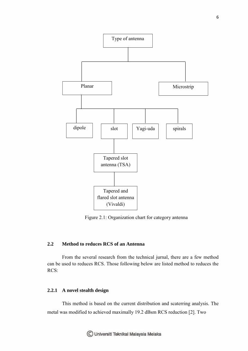
it give knowledge about the antenna especially for RCS antenna. Figure below show
the organization chart for category of antenna[11].
6
Figure 2.1: Organization chart for category antenna
2.2 Method to reduces RCS of an Antenna
From the several research from the technical jurnal, there are a few method can be used to reduces RCS. Those following below are listed method to reduces the RCS: 2.2.1 A novel stealth design
This method is based on the current distribution and scaterring analysis. The
metal was modified to achieved maximally 19.2 dBsm RCS reduction [2]. Two
Type of antenna
Planar Microstrip
dipole slot Yagi-uda spirals
Tapered slot antenna (TSA)
Tapered and flared slot antenna
(Vivaldi)

7
symmetrical ellipses was cut out from the metal patch to reduces the RCS. However,
when the ellipses was cut too big from the metal patch it can cause high side lobe and
dispersive gain in wide frequency range. To overcome this problem a rectangle strip
is place. This method is an effective method to reduces RCS for Vivaldi antenna.
However, this method also potential for another type of antenna such as microstrip
antenna. Besides that, the gain achieved by using this method is 4 dB and the return
loss is only slightly larger and can be further improve by impedance matching.
2.2.2 Half mode substrate integrated waveguide
This design method is the first design method use for Vivaldi antenna to
reduce the RCS. The method can reduces the RCS as much as 24 dB compare to
traditional method. This method modified the vivaldi antenna by making a hole. The
holes is make between the two rows of the metallic patch [3]. The advantages by
using this technique is, no degradation on the antenna performances and more easy to
design it on bilateral vivaldi antenna without the degradation on antenna
performances. In addition, from the voltage standing wave ratio (VSWR) the
bandwith produces bt this method also more wider.
2.2.3 A novel wideband radar with absorbing material
Another method that can be used to reduces RCS for Vivaldi and Yagi-Uda
antenna by using the absorbing material with frequency selective surfaces (FSS).
FSS are widely used to reduces the RCS for narrowband antenna but rarely use for a
wideband antenna. To reduces the RCS, wideband RAM was integrated at the
ground plane of an antenna [4]. This method is rarely use for wideband. However,
substantial reduction of an antenna gain may be produced by lossy ground with
RAM. This technique can maximally reduces the RCS to 16 dB at the operating
frequency 7.9 GHz. Even do this method are efficient and more easy to implement
for end fire antenna, but it can degrades the antenna performances like decreasing the
value of the gain [3]. In addition, according to Hong Kyu Jang [2] another weekness
if using this method is the operating band is almost unchanged.
Related Documents


![[Rcs Iot] Rcs-e v1-2- Joyn](https://static.cupdf.com/doc/110x72/577cd0231a28ab9e78917fbc/rcs-iot-rcs-e-v1-2-joyn.jpg)