1 An analysis of coated particles fuel compact-general purpose heat source (CPFC-GPHS) Mohamed S. El-Genk # and Jean-Michel Tournier Institute for Space and Nuclear Power Studies and Chemical and Nuclear Engineering Dept. The University of New Mexico, Farris Engineering center, Albuquerque, NM, 87131 Abstract The Coated Particles Fuel Compact (CPFC) offers performance advantages for use in the Radioisotope Heater Unit (RHU) and General Purpose Heat Source (GPHS) for Advanced Radioisotope Power Systems (ARPSs), generating a few milliwatts or a few hundred watts of electrical power, respectively, for future planetary exploration. It comprises 238 PuO 2 fuel kernels with 5-μm thick PyC inner coating and a strong ZrC outer coating, dispersed in a graphite matrix. The fuel kernels in the compact could be either of a single size (< 1200 μm) or binary sizes (300 and 1200 μm) for particles’ volume compaction of 62.5% and 72%, respectively. The ZrC coating serves as a pressure vessel for containing the fuel kernels and the helium gas generated by the radioactive decay of 238 Pu for the storage time before launch and the mission lifetime (15-25 years). The thickness of the ZrC coating and, hence, the specific thermal power of the CPFC depend on the estimated maximum fuel temperature during reentry following a launch accident, the storage time before launch and mission duration, and the helium release fraction from the kernels. This paper investigates the advantage of replacing the four iridium- clad 238 PuO 2 fuel pellets, the two floating graphite membranes, and the two graphite impact shells in current State-Of-the-Art (SOA) GPHS with CPFC. The mass, thermal power, and specific thermal power of the CPFC-GPHS are calculated as functions of the helium release fraction from the fuel matrix, up to a full release, and the maximum compact temperature during reentry, from 1500 K to 2400 K. For the same mass and volume, the single-size particles CPFC- GPHS could generate 260 W at Beginning-Of-Mission (BOM), following 10 years of storage, versus 231 W for SOA GPHS. For an additional 10% higher mass, the CPFC-GPHS could generate 340 W at BOM at a specific thermal power of 214 W/kg, which are 47% and 34% higher than those of the SOA GPHS, respectively. # Corresponding Author, Tel.: +1-505-277-5442; fax: +1-505-277-2814. E-mail address: [email protected] (M.S. El-Genk)

Welcome message from author
This document is posted to help you gain knowledge. Please leave a comment to let me know what you think about it! Share it to your friends and learn new things together.
Transcript
1
An analysis of coated particles fuel compact-general purpose heat source (CPFC-GPHS)
Mohamed S. El-Genk# and Jean-Michel Tournier
Institute for Space and Nuclear Power Studies and Chemical and Nuclear Engineering Dept.
The University of New Mexico, Farris Engineering center, Albuquerque, NM, 87131
Abstract
The Coated Particles Fuel Compact (CPFC) offers performance advantages for use in the
Radioisotope Heater Unit (RHU) and General Purpose Heat Source (GPHS) for Advanced
Radioisotope Power Systems (ARPSs), generating a few milliwatts or a few hundred watts of
electrical power, respectively, for future planetary exploration. It comprises 238
PuO2 fuel kernels
with 5-µm thick PyC inner coating and a strong ZrC outer coating, dispersed in a graphite
matrix. The fuel kernels in the compact could be either of a single size (< 1200 µm) or binary
sizes (300 and 1200 µm) for particles’ volume compaction of 62.5% and 72%, respectively. The
ZrC coating serves as a pressure vessel for containing the fuel kernels and the helium gas
generated by the radioactive decay of 238
Pu for the storage time before launch and the mission
lifetime (15-25 years). The thickness of the ZrC coating and, hence, the specific thermal power
of the CPFC depend on the estimated maximum fuel temperature during reentry following a
launch accident, the storage time before launch and mission duration, and the helium release
fraction from the kernels. This paper investigates the advantage of replacing the four iridium-
clad 238
PuO2 fuel pellets, the two floating graphite membranes, and the two graphite impact
shells in current State-Of-the-Art (SOA) GPHS with CPFC. The mass, thermal power, and
specific thermal power of the CPFC-GPHS are calculated as functions of the helium release
fraction from the fuel matrix, up to a full release, and the maximum compact temperature during
reentry, from 1500 K to 2400 K. For the same mass and volume, the single-size particles CPFC-
GPHS could generate 260 W at Beginning-Of-Mission (BOM), following 10 years of storage,
versus 231 W for SOA GPHS. For an additional 10% higher mass, the CPFC-GPHS could
generate 340 W at BOM at a specific thermal power of 214 W/kg, which are 47% and 34%
higher than those of the SOA GPHS, respectively.
# Corresponding Author, Tel.: +1-505-277-5442; fax: +1-505-277-2814.
E-mail address: [email protected] (M.S. El-Genk)
2
Nomenclature
Df Fuel kernel diameter (m)
F Fraction of helium released from fuel matrix
M Mass (kg)
Tmax Maximum CPFC temperature during an accidental reentry (K)
tPyC Thickness of pyrolytic carbon inner coating (m)
tZrC Thickness of zirconium carbide outer coating (m)
YZrC Yield strength of zirconium carbide coating (Pa)
εf As-fabricated volume porosity of fuel kernel
Acronyms
ARPS Advanced Radioisotope Power System
BOM Beginning of Mission (after 10 years storage)
CBCF Carbon Bonded Carbon Fiber
CPFC Coated Particles Fuel Compact
CVD Chemical Vapor Deposition
FPSE Free-Piston Stirling Engine
FWPF Fine Weaved Pierced Fabric
GIS Graphite Impact Shell
GPHS General Purpose Heat Source
LWRHU Light Weight Radioisotope Heater Unit
RTG Radioisotope Thermoelectric Generator
SOA State-Of-the-Art
1. Introduction
The current State-Of-The-Art (SOA) Radioisotope Heater Unit (RHU) and General Purpose
Heat Source (GPHS) are of rugged design and have served the U.S. space exploration and
planetary surface missions very reliably for more than forty years. The RHUs have been used
primarily for the thermal management of spacecraft and surface exploration rovers, and currently
are being considered, in conjunction with Bismuth Telluride thermoelectric converters, for
generating milliwatts of electrical power for surface sensors and other space and terrestrial
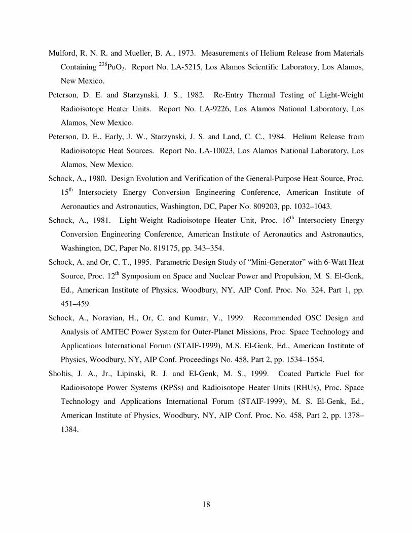
applications (Schock and Or, 1995; Allen et al., 2000). The GPHS modules have been used in
SOA Radioisotope Thermoelectric Generators (RTGs) which generate up to 280 We each
3
(Schock, 1980). These RTGs with 18 GPHS modules each have recently been used to power a
number of spacecraft. Examples are the Ulysses spacecraft (launched in October 1990) to
explore the polar regions and the magnetic atmosphere of the Sun; the Galileo spacecraft to
Jupiter (launched in October 1989), and the Cassini spacecraft (launched in October 1997) for
exploring the Saturnian system. Cassini will begin orbiting Saturn on July 1, 2004, and will
release its Huygens probe about 6 months later for descent through the thick atmosphere of
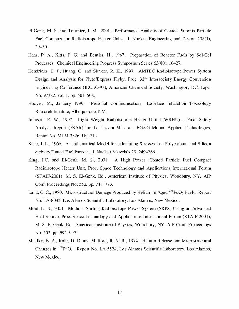
Satrun’s moon Titan. Figures 1 and 2 show cross-sectional views of the SOA Light Weight
Radioisotope Heater Unit (LWRHU), rated to 1 watt thermal, and of the GPHS-RTG,
respectively.
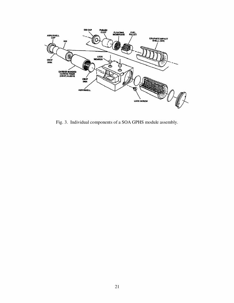
In current SOA LWRU (Fig. 1) and GPHS (Fig. 3), the refractory claddings of the 238
PuO2
fuel pellets, although very rugged and had served the design objectives very well, are heavy.
They are kept at relatively high temperatures to maintain sufficient ductility during an accidental
reentry. The density of the iridium cladding of the fuel pellets in SOA GPHS is 22.65 g/cm3 and
that of the platinum-30% rhodium cladding in SOA LWRHU is 17.62 g/cm3, versus only 9.7
g/cm3 for the
238PuO2 fuel (85% of theoretical density). The temperature of the iridium cladding
needs to be kept at ~ 1648 K, and not below 1173 K, during nominal operation to ensure
sufficient ductility when impacting solid surfaces following a reentry. Three concentric graphite
insulation sleeves surrounding the clad fuel pellet in the LWRHU (Fig. 1) keep the platinum-
30% rhodium clad temperature high enough (~ 800 K) to maintain ductility during reentry, and
together with the aeroshell made of Fine Weave Pierced Fabric (FWPF) carbon-carbon
composite, minimize overheating of the fuel pellet and the cladding during reentry (Johnson,
1997).
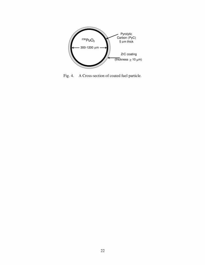
The Coated Particles Fuel Compact (CPFC) is comprised of 238
PuO2 fuel kernels with 5-µm
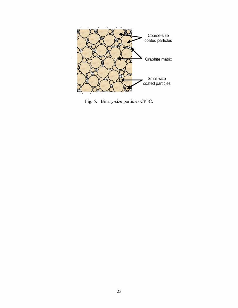
thick PyC inner coating and a strong ZrC outer coating, dispersed in a graphite matrix (Figs. 4
and 5). The fuel kernels in the compact could be either of a single size (<1200 µm) or binary
sizes (300 and 1200 µm) for particles’ volume compaction of 62.5% and 72%, respectively. The
ZrC coating serves as a pressure vessel for containing the fuel kernel and the helium gas
generated by the radioactive decay of 238
Pu over the design time of the compact (15-25 years).
This includes a storage time before launch of up to 10 years, and the actual duration of the space
mission of 5-15 years. Therefore, the thickness of the ZrC and, hence, the specific thermal
power of the CPFC depend on the expected maximum fuel temperature during an accidental
4
reentry, the storage time before launch and the mission duration, and the helium release fraction
from the fuel kernels.
The 238
PuO2 fuel volume fraction in the CPFC is < 0.5, due to the volumes of the PyC and
ZrC coatings and the graphite matrix in the compact, causing the specific thermal power of the
CPFC to be inherently low (220-310 W/kg). Despite the low specific thermal power of the
CPFC, replacing the clad fuel pellet and the inner insulation sleeve in the LWRHU with single-
size particles compact could result in a significantly higher thermal power and specific thermal
power for the CPFC-LWRHU of > 2.3 W and > 60 W/kg, respectively. Using binary size
particles CPFC increases the thermal power of the CPFC-LWRHU by an additional 15% (El-
Genk and Tournier, 2001).
The 238
PuO2 fuel kernels in the coated particles of the compact (Figs. 4 and 5) are
intentionally sized to prevent any adverse radiological effects in the event of an atmospheric
reentry (Hoover, 1999; Sholtis et al., 1999). The coated fuel particles in the compact consist of
polycrystalline 238
PuO2 kernels (300-1200 µm in diameter) fabricated using sol-gel techniques
(Haas et al., 1967; El-Genk and Tournier, 2000a). The thin (5 µm) inner coating of porous
Pyrolytic graphite (PyC) and the strong ZrC (10-70 µm thick) outer coating are both applied by
Chemical Vapor Deposition (CVD). The PyC layer (Fig. 4) protects the fuel kernels during the
application of the ZrC coating by CVD. In addition, the porosity of the PyC (25–50%) provides
additional volume for accommodating the helium gas released from the fuel kernels. The
polycrystalline microstructure of the sol-gel fuel kernels has tiny intragranular voids whose
volume fraction is adjusted during the sintering process of the kernels before applying the PyC
and ZrC coatings. It is estimated that polycrystalline 238
PuO2 will retain the generated helium
gas, dissolved in the fuel and within the as-fabricated tiny voids, up to very high temperatures.
Projected helium releases are < 0.8% at 1024 K and < 7% at 1723 K (El-Genk and Tournier,
2000a). By contrast, the helium release from the granular 238
PuO2 fuel in the pellets of the
LWRHU and GPHS, with an average grain size of 7-40 µm, could be as much as 80-90% at
>1723 K and ~ 10% at a fuel temperature of 1042 K. These helium release fractions have been
confirmed with experiments conducted at the Los Alamos National Laboratory for SOA GPHS
and LWRHU fuel pellets (Angelini et al., 1970; Land, 1980; Mueller et al., 1974; Mulford and
Mueller, 1973; Peterson and Starzynski, 1982; Peterson et al., 1984). Additional operation and
cost advantages of the sol-gel fuel kernels' fabrication are the ability to recycle most of the
5
chemicals used, significantly reducing the clean up and waste disposal cost. This also eliminates
the cost of cleaning up and replacing the hot cells used in the fabrication of the SOA fuel pellets
for LWRHU and GPHS using granular metallurgy methods. The cost saving of considering and
implementing sol-gel fabrication processes of the 238
PuO2 fuel microspheres for CPFC pellets in
SOA LWRHU and GPHS could run into the millions of dollars.
In addition to being made into pellets for potential use in SOA GPHS and LWRHU, the
CPFC could be made into buttons and molded into suitable shapes for optimal integration with
converters at a high thermal efficiency, e.g. with the Free Piston Stirling Engines (FPSEs) in a
100-We Advanced Radioisotope Power System (ARPS) (Dobry and Walberg, 2001; Moul,
2001). The CPFC could also be fabricated into heating tapes and even heating paints, to provide
thermal power from a few milliwatts to tens or even hundreds of watts (El-Genk and Tournier,
2000a and 2001). Thus, the CPFC offers excellent design flexibility and potential performance
advantages when used in current SOA RHUs and GPHS.
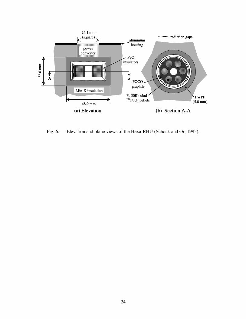
Recent studies have been performed, which explored the potential performance advantages of
using CPFC in LWRHU (Fig. 1), high power RHU (Fig. 6), and as a cylindrical heat source for
two 55 We, FPSEs in an ARPS (Dobry and Walberg, 2001). Results showed that replacing with
CPFC the six platinum-30% rhodium clad fuel pellets and the POCO graphite support structure
in the Hexa-RHU (Fig. 6), proposed by Schock and Or (1995) to provide 6 W of thermal power,
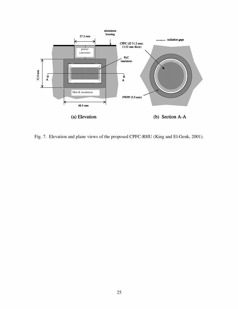
significantly increases the thermal power of the RHU, at almost the same total mass (Fig. 7)
(King and El-Genk, 2001). In addition, both the thermal efficiency of the high power CPFC-
RHU and the hot side temperature for the thermoelectric converters increase. Results also
showed that this CPFC-RHU could generate 2.9 to 4.5 times the thermal power of the Hexa-
RHU. When operating at the same thermoelectric converters’ temperature of 473 K, the CPFC-
RHU could generate ~ 17.6 W at a thermal efficiency of ~ 90%, versus only 6 W at 75% for the
Hexa-RHU (Fig. 6). The thermal power of this CPFC-RHU (Fig. 7) could reach 27.4 W at a
thermal efficiency as high as 93%. The high power CPFC-RHU could also provide for a high
converter temperature of 773 K, which translates into a higher efficiency for converting the RHU
thermal power to electricity. At this temperature, the thermal efficiencies are 62% and 75% at
the thermal powers of 17.6 W and 28 W, respectively. At the latter thermal power, the CPFC-
RHU could provide for a converter temperature as high as 973 K, but at a lower thermal
efficiency of ~ 58%.
6
The use of a cylindrical CPFC heater head for the two, 55 We FPSEs in an ARPS has
recently been investigated (Dobry and Walberg, 2001; Moul, 2001). These FPSEs have a
demonstrated conversion efficiency of ~ 23% at a heat input temperature of ~ 950 K and a waste
heat rejection temperature of ~ 350 K. This high conversion efficiency is very desirable. For
the 100-We ARPS it significantly reduces the amount of 238
PuO2 needed, requiring only two
GPHS modules versus as much as 8 modules for the SOA RTG with SiGe thermoelectric
converters, having a conversion efficiency < 7%. However, the specific electrical power of this
FPSE ARPS (~ 4.1 We/kg) is slightly lower than that of the SOA RTG (~ 4.6 We/kg) (El-Genk,
2003). One of the contributing factors to the low specific electrical power of the FPSE-ARPS is
the mass of the additional structures to support the two GPHS modules and the low thermal
efficiency of transmitting the heat from the modules to the FPSEs. The GPHS have been
designed with flat surfaces, which is suited for use with SiGe thermoelectric generators and
Alkali Metal Thermal-to-Electric Converters (AMTEC) (Hendricks et al., 1997; Schock et al.,
1999; El-Genk and Tournier, 2000b), but not with FPSEs, which requires the heat to input into a
narrow annular band at the displacers of the FPSEs. A cylindrical CPFC heat source has been
proposed to replace the two GPHS modules, which could increase the thermal efficiency of the
FPSE-ARPS and decrease its total mass by more than 1.5 kg. Such a mass reduction is due to
the smaller mass of the CPFC heat source and the elimination of the additional structure needed
to support the GPHS modules. As a result, the specific power of the CPFC-FPSEs ARPS
increases to ~ 7 We/kg (Dobry and Walberg, 2001; Moul, 2001), which is more than 60% higher
than that of the GPHS-FPSEs ARPS.
Since the flat surfaces of SOA GPHS modules are suitable for use with thermoelectric
converters as well as AMTECs, increasing the thermal power output and/or decreasing the mass
of the GPHS modules, without compromising safety, would be extremely desirable for future
development of light weight and high specific power ARPSs. This paper examines the potential
performance advantages of replacing with CPFC the four iridium-clad fuel pellets, the two
floating graphite membranes, and the two surrounding Graphite Impact Shells (GIS) in the SOA
GPHS module (Fig. 3). The calculated performance parameters include the total mass, thermal
power, and specific thermal power of the CPFC-GPHS. These parameters are calculated as
functions of the helium fraction released from the fuel kernels and retained by the ZrC coating,
and the assumed maximum fuel temperature during reentry for both single-size and binary-size
7
particles compacts. The calculated performance parameters for the beginning of mission (BOM),
following 10 years of storage, are compared with those of the SOA GPHS, which is designed to
readily vent the helium gas released from the 238
PuO2 pellets, through the iridium clad to space.
In addition to retaining the helium released during storage, the thickness of the ZrC coating is
sized to retain the helium released during the subsequent 5-15 year mission lifetime. The
calculated thickness of the ZrC coating also accounts for the effect of the maximum CPFC
temperature during a reentry at BOM. Since these temperatures depend on the reentry scenario,
they are varied in the analysis from 1500 K to 2400 K. The 1500 K temperature is ~100-150 K
higher than the expected nominal operating temperature of the CPFC in the GPHS, and the 2400
K temperature is 350 K higher than that expected for the fuel in the SOA GPHS during reentry
(Schock, 1980).
2. Analysis and Assumptions
In order to calculate the thermal power and specific thermal power of the CPFC, the present
analysis uses a stress analysis model which determines the thickness of the ZrC coating as a
function of the as-fabricated fuel porosity, the helium release fraction from the 238
PuO2 fuel
kernels, and the maximum fuel temperature during reentry. For all calculations, the diameter of
the fuel kernel in the single-size particles compact is taken as 1.2 mm, and in the binary-size
particles compact the fuel kernel diameters are 1.2 mm and 0.3 mm, for a diameter ratio of the
coated particles of ~ 4. Besides the difference in the fuel loading, the packing density of the
coated fuel particles in these compacts is different; it is about 62.5 vol% and 72 vol% in the
single-size and binary-size particles compacts, respectively (El-Genk and Tournier, 2001).
Another factor that strongly impacts the results of the analysis is the storage time of the CPFC-
GPHS before launch. Because of programmatic and scheduling reasons, launch time of a
spacecraft is often delayed. Such a delay could vary from a few months to several years (e.g. the
Galileo mission following the Shuttle accident in the early 1980’s). The present performance
analysis of the CPFC conservatively assumes a storage time before launch of 10 years and a
mission lifetime of 15 years. Such assumptions cause the thickness of the ZrC coating to be
large (40–70 µm), decreasing the thermal power density of the CPFC (El-Genk and Tournier,
2001).
8
In the present analysis, the as-fabricated fuel porosity is varied from 0.10 to as much as 0.35,
the helium release fraction is varied from zero (full retention) to 1.0 (full release), and the
maximum fuel temperature during a reentry is varied from 1500 K to 2400 K. For a specified
helium release fraction, the assumed maximum fuel temperature during reentry affects the yield
strength of the ZrC (which decreases exponentially with temperature) and the effective pressure
of the helium gas retained by the ZrC coating. Since the nominal operating temperature of the
CPFC is much lower than during reentry when the aeroshell of the GPHS module is subjected to
atmospheric heating, the present analysis for determining the ZrC coating thickness is based on
the assumed maximum fuel temperature during reentry. In addition, the present analysis of the
coated particles in the CPFC conservatively assumes that the fuel kernels and the released helium
gas are constrained solely by the ZrC coating (Fig. 4). No credit is taken for the strength of the
PyC inner coating or for the constraint by the surrounding graphite matrix (Fig. 5). The
thickness of the ZrC coating is not allowed to drop below 10 µm. The induced tangential stress
in the ZrC coating is calculated as a function of temperature using a spherical shell model (Kaae,
1966; El-Genk and Tournier, 2001), since the coating thickness (10-70 µm) is much smaller than
the diameter of the fuel kernels (300-1200 µm) in the CPFC. Also, the design thickness of the
ZrC coating is that for which the maximum tangential stress does not exceed 80% of the yield
strength of the ZrC material at the maximum fuel temperature.
3. Results and discussion
The results presented in this section include those on the effects of the fuel kernel diameter,
the as-fabricated porosity of the fuel, the helium gas release fraction, and the maximum CPFC
temperature during reentry. The performance results for the CPFC-GPHS with single-size and
binary-size particles compacts are presented and compared with those for the SOA GPHS at
BOM, following 10 years of storage time.
3.1. Effect of fuel kernel diameter
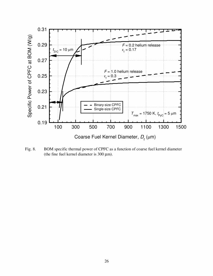
Figure 8 presents the calculated specific thermal powers of the single-size and binary-size
particles CPFCs as functions of the diameter of the coarse 238
PuO2 fuel kernels and for two
different combinations of the helium gas release fraction, F and the as-fabricated fuel porosity,
εf. These calculations are performed for a maximum CPFC temperature, Tmax of 1750 K during
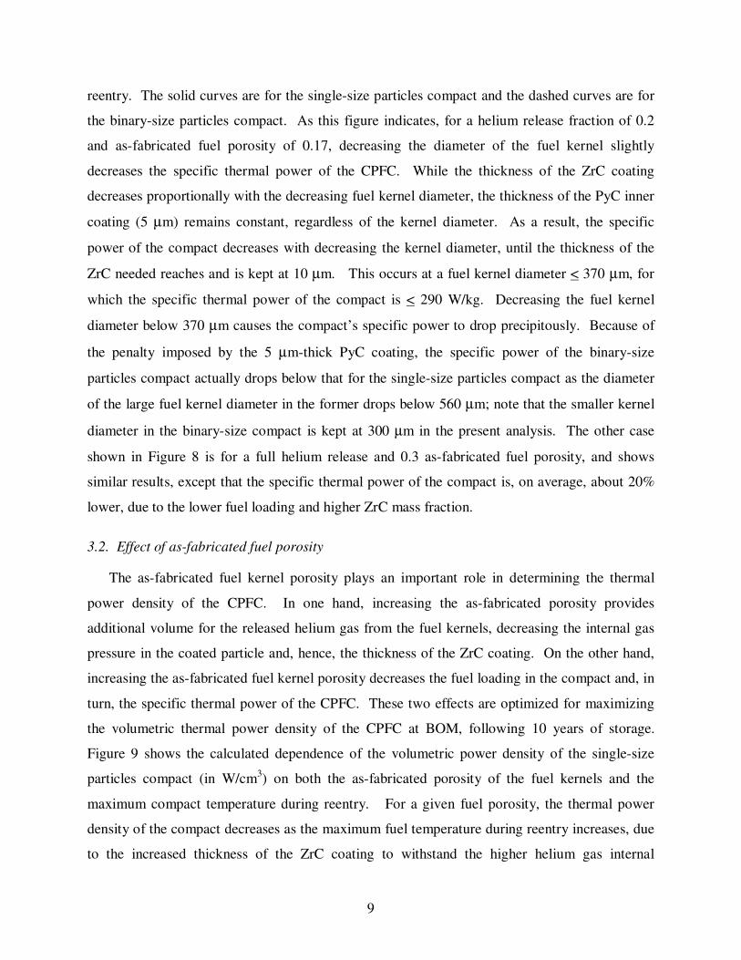
9
reentry. The solid curves are for the single-size particles compact and the dashed curves are for
the binary-size particles compact. As this figure indicates, for a helium release fraction of 0.2
and as-fabricated fuel porosity of 0.17, decreasing the diameter of the fuel kernel slightly
decreases the specific thermal power of the CPFC. While the thickness of the ZrC coating
decreases proportionally with the decreasing fuel kernel diameter, the thickness of the PyC inner
coating (5 µm) remains constant, regardless of the kernel diameter. As a result, the specific
power of the compact decreases with decreasing the kernel diameter, until the thickness of the
ZrC needed reaches and is kept at 10 µm. This occurs at a fuel kernel diameter < 370 µm, for
which the specific thermal power of the compact is < 290 W/kg. Decreasing the fuel kernel
diameter below 370 µm causes the compact’s specific power to drop precipitously. Because of
the penalty imposed by the 5 µm-thick PyC coating, the specific power of the binary-size
particles compact actually drops below that for the single-size particles compact as the diameter
of the large fuel kernel diameter in the former drops below 560 µm; note that the smaller kernel
diameter in the binary-size compact is kept at 300 µm in the present analysis. The other case
shown in Figure 8 is for a full helium release and 0.3 as-fabricated fuel porosity, and shows
similar results, except that the specific thermal power of the compact is, on average, about 20%
lower, due to the lower fuel loading and higher ZrC mass fraction.
3.2. Effect of as-fabricated fuel porosity
The as-fabricated fuel kernel porosity plays an important role in determining the thermal
power density of the CPFC. In one hand, increasing the as-fabricated porosity provides
additional volume for the released helium gas from the fuel kernels, decreasing the internal gas
pressure in the coated particle and, hence, the thickness of the ZrC coating. On the other hand,
increasing the as-fabricated fuel kernel porosity decreases the fuel loading in the compact and, in
turn, the specific thermal power of the CPFC. These two effects are optimized for maximizing
the volumetric thermal power density of the CPFC at BOM, following 10 years of storage.
Figure 9 shows the calculated dependence of the volumetric power density of the single-size
particles compact (in W/cm3) on both the as-fabricated porosity of the fuel kernels and the
maximum compact temperature during reentry. For a given fuel porosity, the thermal power
density of the compact decreases as the maximum fuel temperature during reentry increases, due
to the increased thickness of the ZrC coating to withstand the higher helium gas internal
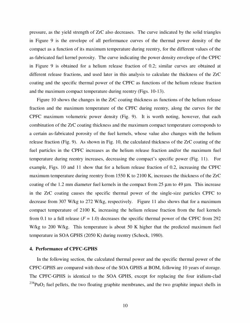
10
pressure, as the yield strength of ZrC also decreases. The curve indicated by the solid triangles
in Figure 9 is the envelope of all performance curves of the thermal power density of the
compact as a function of its maximum temperature during reentry, for the different values of the
as-fabricated fuel kernel porosity. The curve indicating the power density envelope of the CPFC
in Figure 9 is obtained for a helium release fraction of 0.2; similar curves are obtained at
different release fractions, and used later in this analysis to calculate the thickness of the ZrC
coating and the specific thermal power of the CPFC as functions of the helium release fraction
and the maximum compact temperature during reentry (Figs. 10-13).
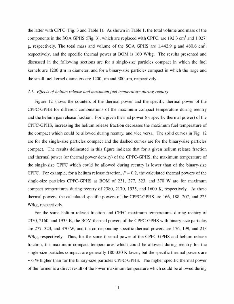
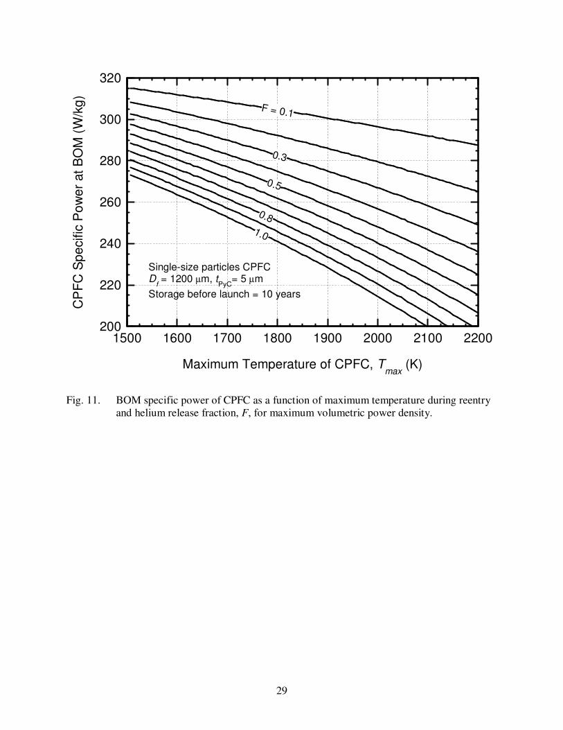
Figure 10 shows the changes in the ZrC coating thickness as functions of the helium release
fraction and the maximum temperature of the CPFC during reentry, along the curves for the
CPFC maximum volumetric power density (Fig. 9). It is worth noting, however, that each
combination of the ZrC coating thickness and the maximum compact temperature corresponds to
a certain as-fabricated porosity of the fuel kernels, whose value also changes with the helium
release fraction (Fig. 9). As shown in Fig. 10, the calculated thickness of the ZrC coating of the
fuel particles in the CPFC increases as the helium release fraction and/or the maximum fuel
temperature during reentry increases, decreasing the compact’s specific power (Fig. 11). For
example, Figs. 10 and 11 show that for a helium release fraction of 0.2, increasing the CPFC
maximum temperature during reentry from 1550 K to 2100 K, increases the thickness of the ZrC
coating of the 1.2 mm diameter fuel kernels in the compact from 25 µm to 49 µm. This increase
in the ZrC coating causes the specific thermal power of the single-size particles CPFC to
decrease from 307 W/kg to 272 W/kg, respectively. Figure 11 also shows that for a maximum
compact temperature of 2100 K, increasing the helium release fraction from the fuel kernels
from 0.1 to a full release (F = 1.0) decreases the specific thermal power of the CPFC from 292
W/kg to 200 W/kg. This temperature is about 50 K higher that the predicted maximum fuel
temperature in SOA GPHS (2050 K) during reentry (Schock, 1980).
4. Performance of CPFC-GPHS
In the following section, the calculated thermal power and the specific thermal power of the
CPFC-GPHS are compared with those of the SOA GPHS at BOM, following 10 years of storage.
The CPFC-GPHS is identical to the SOA GPHS, except for replacing the four iridium-clad
238PuO2 fuel pellets, the two floating graphite membranes, and the two graphite impact shells in
11
the latter with CPFC (Fig. 3 and Table 1). As shown in Table 1, the total volume and mass of the
components in the SOA GPHS (Fig. 3), which are replaced with CPFC, are 192.3 cm3 and 1,027.
g, respectively. The total mass and volume of the SOA GPHS are 1,442.9 g and 480.6 cm3,
respectively, and the specific thermal power at BOM is 160 W/kg. The results presented and
discussed in the following sections are for a single-size particles compact in which the fuel
kernels are 1200 µm in diameter, and for a binary-size particles compact in which the large and
the small fuel kernel diameters are 1200 µm and 300 µm, respectively.
4.1. Effects of helium release and maximum fuel temperature during reentry
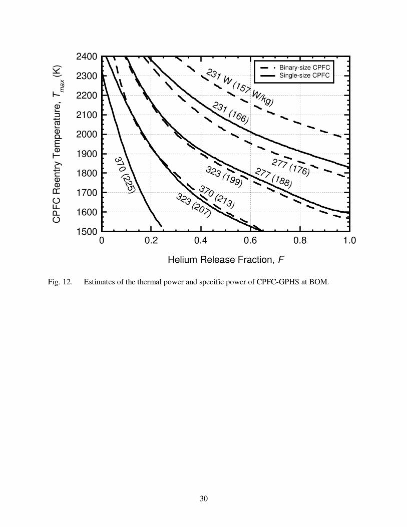
Figure 12 shows the counters of the thermal power and the specific thermal power of the
CPFC-GPHS for different combinations of the maximum compact temperature during reentry
and the helium gas release fraction. For a given thermal power (or specific thermal power) of the
CPFC-GPHS, increasing the helium release fraction decreases the maximum fuel temperature of
the compact which could be allowed during reentry, and vice versa. The solid curves in Fig. 12
are for the single-size particles compact and the dashed curves are for the binary-size particles
compact. The results delineated in this figure indicate that for a given helium release fraction
and thermal power (or thermal power density) of the CPFC-GPHS, the maximum temperature of
the single-size CPFC which could be allowed during reentry is lower than of the binary-size
CPFC. For example, for a helium release fraction, F = 0.2, the calculated thermal powers of the
single-size particles CPFC-GPHS at BOM of 231, 277, 323, and 370 W are for maximum
compact temperatures during reentry of 2380, 2170, 1935, and 1600 K, respectively. At these
thermal powers, the calculated specific powers of the CPFC-GPHS are 166, 188, 207, and 225
W/kg, respectively.
For the same helium release fraction and CPFC maximum temperatures during reentry of
2350, 2160, and 1935 K, the BOM thermal powers of the CPFC-GPHS with binary-size particles
are 277, 323, and 370 W, and the corresponding specific thermal powers are 176, 199, and 213
W/kg, respectively. Thus, for the same thermal power of the CPFC-GPHS and helium release
fraction, the maximum compact temperatures which could be allowed during reentry for the
single-size particles compact are generally 180-330 K lower, but the specific thermal powers are
~ 6 % higher than for the binary-size particles CPFC-GPHS. The higher specific thermal power
of the former is a direct result of the lower maximum temperature which could be allowed during
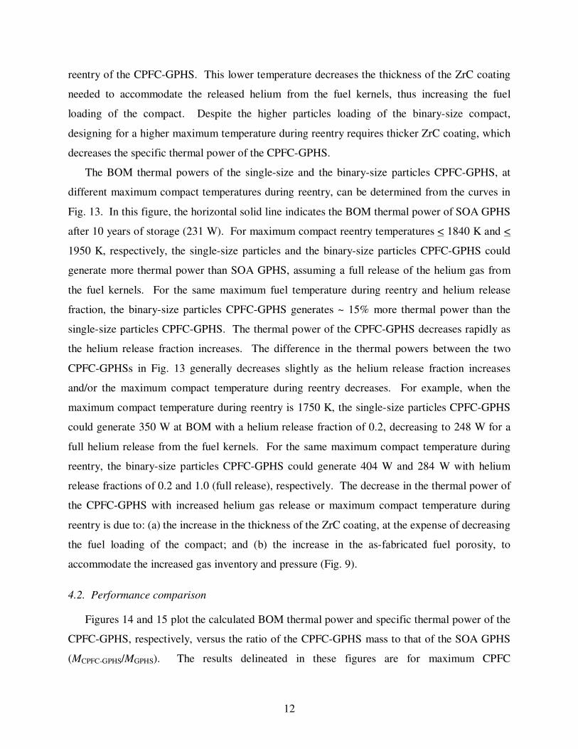
12
reentry of the CPFC-GPHS. This lower temperature decreases the thickness of the ZrC coating
needed to accommodate the released helium from the fuel kernels, thus increasing the fuel
loading of the compact. Despite the higher particles loading of the binary-size compact,
designing for a higher maximum temperature during reentry requires thicker ZrC coating, which
decreases the specific thermal power of the CPFC-GPHS.
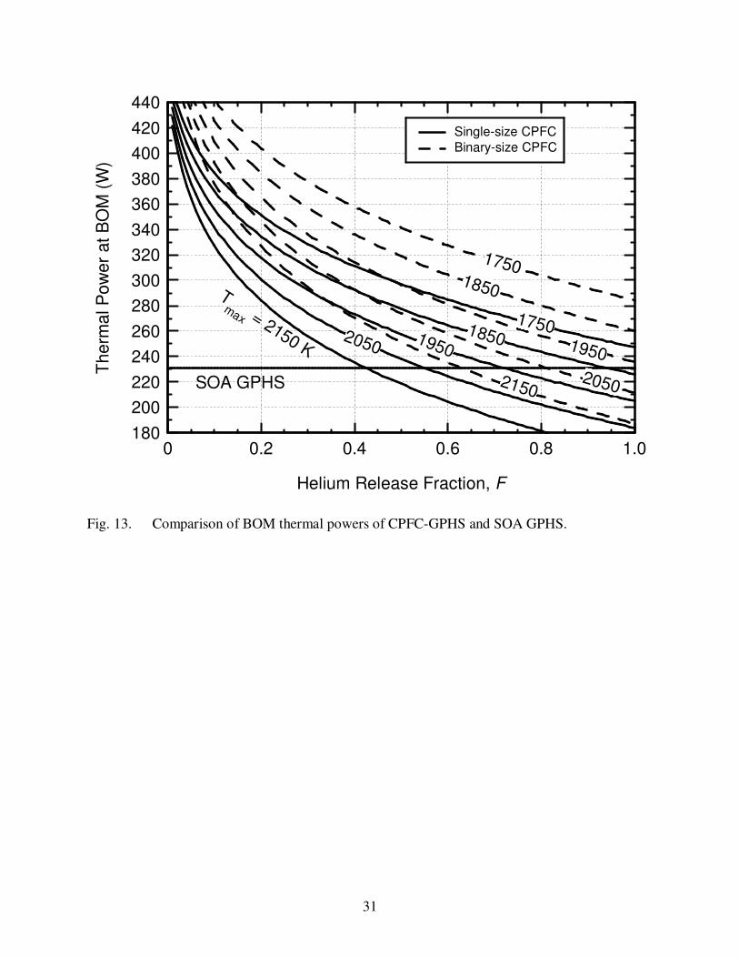
The BOM thermal powers of the single-size and the binary-size particles CPFC-GPHS, at
different maximum compact temperatures during reentry, can be determined from the curves in
Fig. 13. In this figure, the horizontal solid line indicates the BOM thermal power of SOA GPHS
after 10 years of storage (231 W). For maximum compact reentry temperatures < 1840 K and <
1950 K, respectively, the single-size particles and the binary-size particles CPFC-GPHS could
generate more thermal power than SOA GPHS, assuming a full release of the helium gas from
the fuel kernels. For the same maximum fuel temperature during reentry and helium release
fraction, the binary-size particles CPFC-GPHS generates ~ 15% more thermal power than the
single-size particles CPFC-GPHS. The thermal power of the CPFC-GPHS decreases rapidly as
the helium release fraction increases. The difference in the thermal powers between the two
CPFC-GPHSs in Fig. 13 generally decreases slightly as the helium release fraction increases
and/or the maximum compact temperature during reentry decreases. For example, when the
maximum compact temperature during reentry is 1750 K, the single-size particles CPFC-GPHS
could generate 350 W at BOM with a helium release fraction of 0.2, decreasing to 248 W for a
full helium release from the fuel kernels. For the same maximum compact temperature during
reentry, the binary-size particles CPFC-GPHS could generate 404 W and 284 W with helium
release fractions of 0.2 and 1.0 (full release), respectively. The decrease in the thermal power of
the CPFC-GPHS with increased helium gas release or maximum compact temperature during
reentry is due to: (a) the increase in the thickness of the ZrC coating, at the expense of decreasing
the fuel loading of the compact; and (b) the increase in the as-fabricated fuel porosity, to
accommodate the increased gas inventory and pressure (Fig. 9).
4.2. Performance comparison
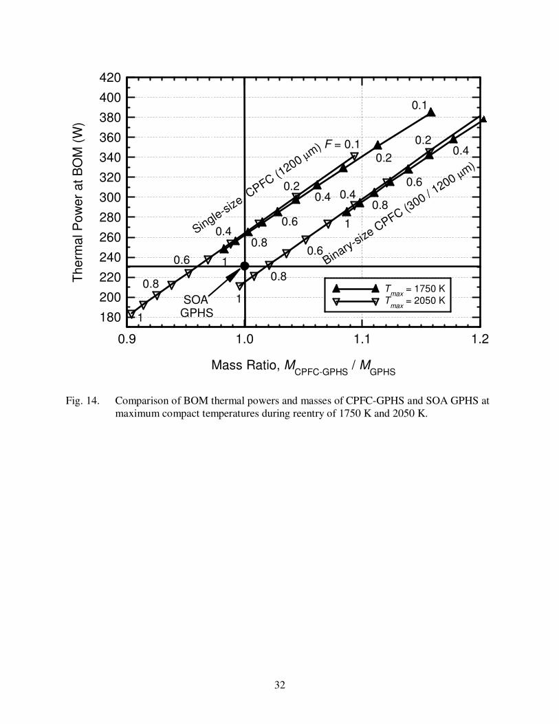
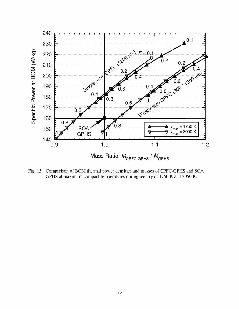
Figures 14 and 15 plot the calculated BOM thermal power and specific thermal power of the
CPFC-GPHS, respectively, versus the ratio of the CPFC-GPHS mass to that of the SOA GPHS
(MCPFC-GPHS/MGPHS). The results delineated in these figures are for maximum CPFC
13
temperatures during reentry of 1750 K and 2050 K. The open inverted triangles are for the
maximum CPFC temperature of 2050 K, and the solid triangles are for the maximum CPFC
temperature of 1750 K. For the same helium release fraction and maximum compact
temperature during reentry, the binary-size particles CPFC-GPHS could operate at ~ 5% higher
specific thermal power, but is ~ 12% heavier than the single-size particles CPFC-GPHS.
For a maximum compact temperature during reentry of 1750 K, the single-size particles
CPFC-GPHS could provide a BOM thermal power of 263 W, with a helium release fraction as
high as 0.82, versus 231 W for SOA GPHS, for the same total mass (Fig. 14). The same results
are attainable at a higher compact temperature during reentry of 2050 K, but with a lower helium
release fraction of 0.35 (Fig. 14). In the most conservative case of assuming full helium release
from the fuel kernels, the calculated BOM thermal power of the single-size particles CPFC-
GPHS is 247 W when the maximum compact temperature during reentry is 1750 K, versus only
184 at the higher temperature of 2050 K, for 98% and 90% of the total mass of SOA GPHS,
respectively. Slightly higher thermal powers could be generated by the binary-size particles
CPFC-GPHS, but at higher masses than those of the single-size particles CPFC-GPHS and SOA
GPHS. When the emphases are on increasing the thermal power and/or decreasing the total
GPHS mass, comparing the specific thermal powers of the CPFC-GPHS and the SOA GPHS
(160 W/kg) is quite useful (Fig. 15).
Figure 15 shows that for a maximum compact temperature during reentry of 1750 K, the
BOM specific thermal power of the single-size particles CPFC-GPHS decreases from 218 to 174
W/kg as the helium release fraction increases from 0.2 to 1.0 (full release), versus only 160 W/kg
for the SOA GPHS. At a higher maximum compact temperature during reentry of 2050 K, the
BOM specific thermal power of the single-size particles CPFC-GPHS decreases from 200 to 141
W/kg as the helium release fraction increases from 0.2 to unity. When the maximum
temperature of the binary-size particles compact during reentry is 1750 K, the BOM specific
thermal power of the CPFC-GPHS decreases from 218 to 182 W/kg as the helium release
fraction increases from 0.3 to 1. For a maximum compact temperature during reentry of 2050
K, however, the BOM specific thermal powers of the binary-size particles CPFC-GPHS are 195
and 147 W/kg at helium release fractions of 0.3 and 1.0, respectively. At the maximum compact
temperatures during reentry of 1750 K and 2050 K, the BOM specific thermal powers of single-
size particles CPFC-GPHS are identical at 183 W/kg, but the helium release fractions are
14
different: 0.82 and 0.35, respectively, and the total mass is the same as that of the SOA GPHS
(Fig. 15). These results suggest that for the same or 10% higher total mass, the single-size
particles CPFC-GPHS could provide up to 50% higher thermal power and up to 35% higher
specific thermal power than the SOA GPHS.
The advantage of the higher specific thermal power of the CPFC-GPHS is increasing the
electrical power output of the ARPS for the same volume and mass of the heat source. Although
the mass of the 238
PuO2 fuel in the CPFC-GPHS increases linearly with the thermal power, the
mass saving of eliminating the heavy iridium cladding (Table 1) compensates for the increase in
the fuel mass in the CPFC-GPHS.
Tables 2 and 3 list the design parameters of the CPFC and the calculated mass breakdown
and performance data of single-size and binary-size particles CPFC-GPHSs for maximum
compact temperatures during reentry of 1750 K and 2050 K, and a helium release fraction from
the fuel kernels of 0.2. Note that the performance results in Table 3 are those indicated by the
performance envelope curves at the selected maximum compact temperatures during reentry
(Figs. 9-11). The as-fabricated porosity of the 238
PuO2 fuel kernels is 0.17 and 0.245 for the
maximum CPFC temperatures during reentry of 1750 K and 2050 K, respectively (Table 2). The
former temperature is close to that predicted during the reentry of a LWRHU (Schock, 1981),
while the later temperature is the same as that predicted during reentry of the SOA GPHS
(Schock, 1980). The major differences are: (a) the helium gas generated by the radioactive
decay of the 238
PuO2 fuel in the SOA GPHS is readily vented to space, while it is fully retained
within the fuel particles in the CPFC by the strong ZrC coating designed for that purpose; and (b)
at these temperatures the helium gas has been shown to be fully released from the fuel pellets in
the SOA GPHS (Land, 1980; Mueller et al., 1974; Mulford and Mueller, 1973; Peterson and
Starzynski, 1982; Peterson et al., 1984), but the release fraction is expected to be < 0.10 from the
fuel kernels fabricated using sol-gel processes at > 1700 K (El-Genk and Tournier, 2000a).
5. Summary and conclusions
Potential improvements in the thermal power and the specific thermal power of the SOA
GPHS modules, by replacing with CPFC the four iridium-clad fuel pellets, the two floating
graphite membranes, and the two surrounding graphite impact shells, are investigated. The
CPFC consists of ZrC-coated 238
PuO2 fuel kernels, 300–1200 µm in diameter, dispersed in a
15
graphite matrix. The strong ZrC coating serves as a pressure vessel for containing the fuel kernel
and the helium gas released from the fuel matrix and retained in the particles. The helium gas is
generated by the radioactive decay of the 238
Pu isotope in the fuel. The thickness of the ZrC
coating increases and, hence the specific thermal power of the CPFC decreases as the maximum
temperature of the compact during reentry, the storage time before launch, and the as-fabricated
porosity of the fuel increase. The polycrystalline fuel kernels fabricated using sol-gel processes
could effectively retain the helium gas within the fuel kernels to very high temperature with an
estimated release fraction < 0.10. In addition, the fuel kernels are intentionally sized to avoid
any radiological effects following a reentry accident.
The total mass, BOM thermal power, and specific thermal power of the CPFC-GPHS are
calculated as functions of the helium release fraction from the fuel kernels, and the maximum
fuel temperature during reentry from 1500 K to 2400 K, for both single-size and binary-size
particles CPFC. The 1500 K temperature is close to the fuel temperature in CPFC-GPHS during
nominal operation, while the 2400 K temperature is much higher than the predicted maximum
fuel temperature in the SOA GPHS during reentry (~ 2050 K). The present BOM performance
estimates follow a storage time of 10 years before launch. For a maximum compact temperature
during reentry of 1750 K, the BOM specific thermal powers of single-size particles CPFC-GPHS
are 218 to 174 W/kg at helium release fractions of 0.2 and unity, respectively, versus 160 W/kg
for SOA GPHS. At a higher compact temperature during reentry of 2050 K, the BOM specific
thermal power of single-size particles CPFC-GPHS is lower, decreasing from 200 to 141 W/kg
as the helium release fraction increases from 0.2 to unity. For binary-size particles CPFC-GPHS
and a maximum compact temperature during reentry of 1750 K, the BOM specific thermal
power decreases from 218 to 182 W/kg as the helium release fraction increases from 0.3 to 1.
As the maximum fuel compact temperature during reentry increases to 2050 K, the specific
thermal power of the binary-size particle CPFC-GPHS decreases to 195 W/kg and 147 W/kg as
the helium release fraction increases from 0.3 to 1.0, respectively.
For the same or 10% higher total mass as the SOA GPHS, a single-size particles CPFC-
GPHS could generate up to 52% higher thermal power and has up to 35% higher specific power,
depending on the assumed maximum fuel temperature during reentry and the helium release
fraction from the fuel kernels. These performance figures of the CPFC-GPHS are conservative
as they assume 10 years storage time before launch, and take no credit for the strength of the
16
PyC inner coating nor for the constraints imposed by the graphite matrix of the compact. The
advantage of the high specific thermal power of the CPFC-GPHS is increasing the electrical
power output of an ARPS, for the same volume and mass as the SOA GPHS. Although the mass
of 238
PuO2 fuel in the CPFC-GPHS increases commensurate with the increase in thermal power,
the mass saving resulting from eliminating the heavy iridium cladding more than compensates
for the increase in the 238
PuO2 fuel mass in the higher power CPFC-GPHS.
Acknowledgements
This research is funded by the University of New Mexico’s Institute for Space and Nuclear
Power Studies.
References
Allen, D. T., Bass, J. C., Elsner, N. B., Ghamaty, S. and Morris, C. C., 2000. Milliwatt
Thermoelectric Generator for Space Applications, Proc. Space Technology and Applications
International Forum (STAIF-2000), M. S. El-Genk, Ed., American Institute of Physics,
Melville, NY, AIP Conf. Proceedings No. 504, pp. 1476–1481.
Angelini, P., McHenry, R. E., Scott, J. L., Ernst, W. S., Jr. and Prados, J. W., 1970. Helium
Release from 238
PuO2 Microspheres, Report No. ORNL-4507, Oak Ridge National
Laboratory, Oak Ridge, Tennessee.
Dobry, T. J. and Walberg, G., 2001. Advanced Radioisotope Heat Source for Stirling Engines,
Proc. Space Technology and Applications International Forum (STAIF-2001), M. S. El-
Genk, Ed., American Institute of Physics, Woodbury, NY, AIP Conf. Proceedings No. 552,
pp. 1029–1032.
El-Genk, M. S., 2003. Energy Conversion Options for Advanced Radioisotope Power Systems,
Proc. Space Technology and Applications International Forum (STAIF-2003), M. S. El-
Genk, Ed., American Institute of Physics, Melville, NY, to appear.
El-Genk, M. S. and Tournier, J.-M., 2000a. Estimates of Helium Gas Release in 238
PuO2 Fuel
Particles for Radioisotope Heat Sources and Heater Units. J. Nuclear Materials 280(1), 1–17.
El-Genk, M. S. and Tournier, J.-M., 2000b. Design Optimization and Integration of
nickel/Haynes-25 AMTEC Cells into Radioisotope Power Systems. J. Energy Conversion
and Management 41, 1703-1728.
17
El-Genk, M. S. and Tournier, J.-M., 2001. Performance Analysis of Coated Plutonia Particle
Fuel Compact for Radioisotope Heater Units. J. Nuclear Engineering and Design 208(1),
29–50.
Haas, P. A., Kitts, F. G. and Beutler, H., 1967. Preparation of Reactor Fuels by Sol-Gel
Processes. Chemical Engineering Progress Symposium Series 63(80), 16–27.
Hendricks, T. J., Huang, C. and Sievers, R. K., 1997. AMTEC Radioisotope Power System
Design and Analysis for Pluto/Express Flyby, Proc. 32nd
Intersociety Energy Conversion
Engineering Conference (IECEC-97), American Chemical Society, Washington, DC, Paper
No. 97382, vol. 1, pp. 501–508.
Hoover, M., January 1999. Personal Communications, Lovelace Inhalation Toxicology
Research Institute, Albuquerque, NM.
Johnson, E. W., 1997. Light Weight Radioisotope Heater Unit (LWRHU) – Final Safety
Analysis Report (FSAR) for the Cassini Mission. EG&G Mound Applied Technologies,
Report No. MLM-3826, UC-713.
Kaae, J. L., 1966. A mathematical Model for calculating Stresses in a Polycarbon- and Silicon
carbide-Coated Fuel Particle. J. Nuclear Materials 29, 249–266.
King, J.C. and El-Genk, M. S., 2001. A High Power, Coated Particle Fuel Compact
Radioisotope Heater Unit, Proc. Space Technology and Applications International Forum
(STAIF-2001), M. S. El-Genk, Ed., American Institute of Physics, Woodbury, NY, AIP
Conf. Proceedings No. 552, pp. 744–783.
Land, C. C., 1980. Microstructural Damage Produced by Helium in Aged 238
PuO2 Fuels. Report
No. LA-8083, Los Alamos Scientific Laboratory, Los Alamos, New Mexico.
Moul, D. S., 2001. Modular Stirling Radioisotope Power System (SRPS) Using an Advanced
Heat Source, Proc. Space Technology and Applications International Forum (STAIF-2001),
M. S. El-Genk, Ed., American Institute of Physics, Woodbury, NY, AIP Conf. Proceedings
No. 552, pp. 995–997.
Mueller, B. A., Rohr, D. D. and Mulford, R. N. R., 1974. Helium Release and Microstructural
Changes in 238
PuO2. Report No. LA-5524, Los Alamos Scientific Laboratory, Los Alamos,
New Mexico.
18
Mulford, R. N. R. and Mueller, B. A., 1973. Measurements of Helium Release from Materials
Containing 238
PuO2. Report No. LA-5215, Los Alamos Scientific Laboratory, Los Alamos,
New Mexico.
Peterson, D. E. and Starzynski, J. S., 1982. Re-Entry Thermal Testing of Light-Weight
Radioisotope Heater Units. Report No. LA-9226, Los Alamos National Laboratory, Los
Alamos, New Mexico.
Peterson, D. E., Early, J. W., Starzynski, J. S. and Land, C. C., 1984. Helium Release from
Radioisotopic Heat Sources. Report No. LA-10023, Los Alamos National Laboratory, Los
Alamos, New Mexico.
Schock, A., 1980. Design Evolution and Verification of the General-Purpose Heat Source, Proc.
15th Intersociety Energy Conversion Engineering Conference, American Institute of
Aeronautics and Astronautics, Washington, DC, Paper No. 809203, pp. 1032–1043.
Schock, A., 1981. Light-Weight Radioisotope Heater Unit, Proc. 16th Intersociety Energy
Conversion Engineering Conference, American Institute of Aeronautics and Astronautics,
Washington, DC, Paper No. 819175, pp. 343–354.
Schock, A. and Or, C. T., 1995. Parametric Design Study of “Mini-Generator” with 6-Watt Heat
Source, Proc. 12th Symposium on Space and Nuclear Power and Propulsion, M. S. El-Genk,
Ed., American Institute of Physics, Woodbury, NY, AIP Conf. Proc. No. 324, Part 1, pp.
451–459.
Schock, A., Noravian, H., Or, C. and Kumar, V., 1999. Recommended OSC Design and
Analysis of AMTEC Power System for Outer-Planet Missions, Proc. Space Technology and
Applications International Forum (STAIF-1999), M.S. El-Genk, Ed., American Institute of
Physics, Woodbury, NY, AIP Conf. Proceedings No. 458, Part 2, pp. 1534–1554.
Sholtis, J. A., Jr., Lipinski, R. J. and El-Genk, M. S., 1999. Coated Particle Fuel for
Radioisotope Power Systems (RPSs) and Radioisotope Heater Units (RHUs), Proc. Space
Technology and Applications International Forum (STAIF-1999), M. S. El-Genk, Ed.,
American Institute of Physics, Woodbury, NY, AIP Conf. Proc. No. 458, Part 2, pp. 1378–
1384.
19
Fig. 1. Schematic of 1-watt Light Weight Radioisotope Heater Unit (LWRHU) (Johnson, 1997).
FWPF aeroshell (H = 32 mm, D = 26 mm, t = 4.5 mm)
End cap (FWPF)
Insulator plug (PyC)
PyC insulator sleeves (3)
238PuO2 fuel pellet (H = 9.4 mm D = 6.6 mm)
Insulator plug (PyC)
Pt-30%Rh clad (t = 1 mm)
Pt-30%Rh shim
Vent
Frit (Pt)
20
Fig. 2. General Purpose Heat Source (GPHS) Radioisotope Thermoelectric Generator (RTG).
21
Fig. 3. Individual components of a SOA GPHS module assembly.
22
Pyrolytic
Carbon (PyC)
5 µm thick
ZrC coating
(thickness > 10 µm)
300-1200 µm
238PuO2
Fig. 4. A Cross-section of coated fuel particle.
23
Coarse-size
coated particles
Small-sizecoated particles
Graphite matrix
Fig. 5. Binary-size particles CPFC.
24
POCO
graphite
FWPF
(5.0 mm)
(b) Section A-A
radiation gaps
Pt-30Rh clad238PuO2 pellets
PyC
insulators
24.1 mm
(square)
48.9 mm
32.0
mm
aluminum
housing
(a) Elevation
A A
Min-K insulation
power
converter
POCO
graphite
FWPF
(5.0 mm)
(b) Section A-A
radiation gapsradiation gaps
Pt-30Rh clad238PuO2 pellets
PyC
insulators
24.1 mm
(square)
48.9 mm
32.0
mm
aluminum
housing
(a) Elevation
A AA A
Min-K insulationMin-K insulation
power
converter
power
converter
Fig. 6. Elevation and plane views of the Hexa-RHU (Schock and Or, 1995).
25
FWPF (5.0 mm)
(b) Section A-A
radiation gaps
CPFC (∅ 31.2 mm;
13.52 mm thick)
PyC
insulators
27.2 mm
48.9 mm
32
.0 m
m
aluminum
housing
(a) Elevation
A A
Min-K insulation
power
converter
FWPF (5.0 mm)
(b) Section A-A
radiation gaps
CPFC (∅ 31.2 mm;
13.52 mm thick)
FWPF (5.0 mm)
(b) Section A-A
radiation gapsradiation gaps
CPFC (∅ 31.2 mm;
13.52 mm thick)
PyC
insulators
27.2 mm
48.9 mm
32
.0 m
m
aluminum
housing
(a) Elevation
A A
Min-K insulation
power
converter
PyC
insulators
27.2 mm
48.9 mm
32
.0 m
m
aluminum
housing
(a) Elevation
A AA A
Min-K insulationMin-K insulation
power
converter
power
converter
Fig. 7. Elevation and plane views of the proposed CPFC-RHU (King and El-Genk, 2001).
26
0.19
0.21
0.23
0.25
0.27
0.29
0.31
100 300 500 700 900 1100 1300 1500
Binary-size CPFC
Single-size CPFC
tZrC
= 10 µm
Tmax
= 1750 K, tPyC
= 5 µm
F = 1.0 helium releaseε
f = 0.3
F = 0.2 helium releaseε
f = 0.17
Coarse Fuel Kernel Diameter, Df (µm)
Spe
cific
Pow
er
of C
PF
C a
t B
OM
(W
/g)
Fig. 8. BOM specific thermal power of CPFC as a function of coarse fuel kernel diameter
(the fine fuel kernel diameter is 300 µm).
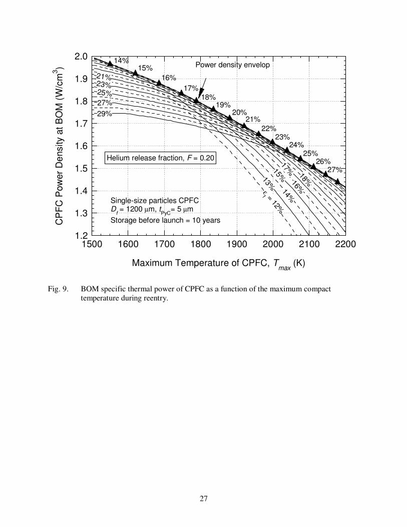
27
1.2
1.3
1.4
1.5
1.6
1.7
1.8
1.9
2.0
1500 1600 1700 1800 1900 2000 2100 2200
21%23%25%
27%
14%
15%
16%
17%
18%
29%
13%ε
f = 12%
27%26%
25%24%
23%22%
21%20%
19%18%
17%
16%
15%14%
Power density envelop
Helium release fraction, F = 0.20
Single-size particles CPFCD
f = 1200 µm, t
PyC= 5 µm
Storage before launch = 10 years
Maximum Temperature of CPFC, Tmax
(K)
CP
FC
Pow
er
De
nsity
at
BO
M (
W/c
m3)
Fig. 9. BOM specific thermal power of CPFC as a function of the maximum compact
temperature during reentry.
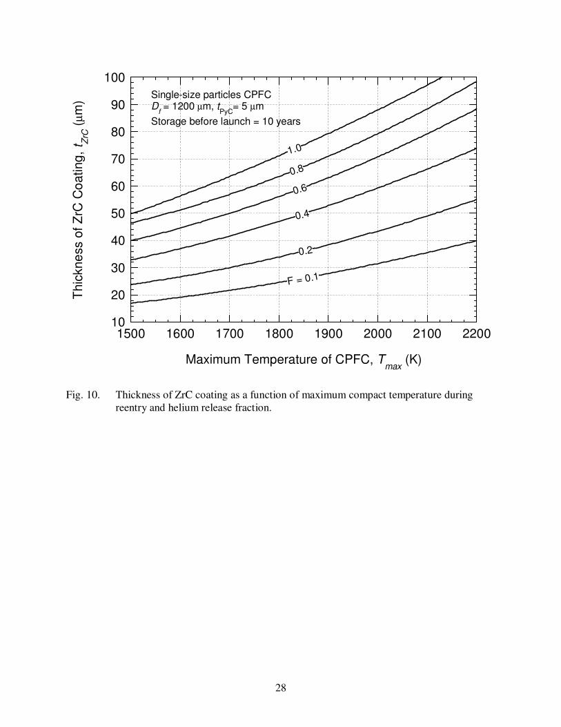
28
10
20
30
40
50
60
70
80
90
100
1500 1600 1700 1800 1900 2000 2100 2200
0.8
1.0
0.6
0.4
F = 0.1
0.2
Single-size particles CPFCD
f = 1200 µm, t
PyC= 5 µm
Storage before launch = 10 years
Maximum Temperature of CPFC, Tmax
(K)
Thic
kne
ss o
f Z
rC C
oating
, t Z
rC (
µm
)
Fig. 10. Thickness of ZrC coating as a function of maximum compact temperature during
reentry and helium release fraction.
29
200
220
240
260
280
300
320
1500 1600 1700 1800 1900 2000 2100 2200
0.8
1.0
0.3
0.5
F = 0.1
Single-size particles CPFCD
f = 1200 µm, t
PyC= 5 µm
Storage before launch = 10 years
Maximum Temperature of CPFC, Tmax
(K)
CP
FC
Sp
ecific
Po
we
r at
BO
M (
W/k
g)
Fig. 11. BOM specific power of CPFC as a function of maximum temperature during reentry
and helium release fraction, F, for maximum volumetric power density.
30
1500
1600
1700
1800
1900
2000
2100
2200
2300
2400
0 0.2 0.4 0.6 0.8 1.0
Binary-size CPFC
Single-size CPFC
370 (213)
370 (2
25)
323 (199)
323 (207)
277 (176)277 (188)
231 W (157 W/kg)231 (166)
Helium Release Fraction, F
CP
FC
Reentr
y T
em
pera
ture
, T
ma
x (
K)
Fig. 12. Estimates of the thermal power and specific power of CPFC-GPHS at BOM.
31
180
200
220
240
260
280
300
320
340
360
380
400
420
440
0 0.2 0.4 0.6 0.8 1.0
Single-size CPFC
Binary-size CPFC
2050
2150
175018501950
2050
1950
1850
1750
SOA GPHS
Tmax = 2150 K
Helium Release Fraction, F
Th
erm
al P
ow
er
at
BO
M (
W)
Fig. 13. Comparison of BOM thermal powers of CPFC-GPHS and SOA GPHS.
32
180
200
220
240
260
280
300
320
340
360
380
400
420
0.9 1.0 1.1 1.2
Tmax
= 1750 K
Tmax
= 2050 K
0.2
0.8
0.6
0.4 0.4
0.1
0.4
0.6
0.8
0.80.8
1
1
1
1
0.6
F = 0.1
0.6
0.4
0.2
0.2
Single-size C
PFC (1200 µm)
Binary-siz
e CPFC (3
00 / 1200 µm)
SOA GPHS
Mass Ratio, MCPFC-GPHS
/ MGPHS
Th
erm
al P
ow
er
at
BO
M (
W)
Fig. 14. Comparison of BOM thermal powers and masses of CPFC-GPHS and SOA GPHS at
maximum compact temperatures during reentry of 1750 K and 2050 K.
33
140
150
160
170
180
190
200
210
220
230
240
0.9 1.0 1.1 1.2
Tmax
= 1750 K
Tmax
= 2050 K
0.4
0.2
0.8
0.6
0.4
0.1
0.4
0.6
0.8
0.80.8
1
1
1
1
0.6
F = 0.1
0.6
0.4
0.2
0.2
Single-s
ize C
PFC (1200 µ
m)
Binary-siz
e CPFC (3
00 / 1200 µm
)
SOAGPHS
Mass Ratio, MCPFC-GPHS
/ MGPHS
Sp
ecific
Po
we
r a
t B
OM
(W
/kg
)
Fig. 15. Comparison of BOM thermal power densities and masses of CPFC-GPHS and SOA
GPHS at maximum compact temperatures during reentry of 1750 K and 2050 K.
Related Documents