Pergamon International Journal of Plasticity, Vol. 10, No. 7, pp. 795-805, 1994 Copyright © 1994 Elsevier Science Ltd Printed in the USA. All rights reserved 0749-6419/94 $6.00 + .00 0749-6419(94)00026-3 AN ALTERNATIVE FORMULATION FOR INTERPOLATING EXPERIMENTAL YIELD SURFACES N. K. GUPTA* and A. MEYERS~" *Indian Institute of Technology-Delhi, and tRuhr University-Bochum Abstract- In an earlier article (see GLrPTA & MEW~S [1992]), a yield function of second and third invariants of translated deviatoric stress tensor was presented that describes the secondary effects in initial yield surfaces as well as the distortions, rotations, and translations in the subsequent yield surfaces quite well. In this article, we present an alternative formulation that is relatively simple and is also able to interpolate the experimental yield surfaces quite well. Its applicabil- ity is demonstrated by the comparison with initial and subsequent yield surfaces obtained after partial and total unloading from uniaxial and biaxial prestrains. I. INTRODUCTION Experiments to determine yield surfaces have mostly been carried out by subjecting the tubular specimens to Axial Load-Torsion, Axial Load-Internal Pressure and Axial Load- Torsion-Internal Pressure. A review of experimental results up to about 1978 has been given by IKEG~I [19821. In the initial yield surfaces, these studies (e.g. see OrIASrII ~ TOKUDA [1973]) reveal existence of secondary effects that manifest in deviations from von Mises criterion. These deviations are described quite well by the formulations of Prager (see HILl, [1950] and DstrcrEg [1949]), wherein they have considered the influence of third invariant of stress deviators. The subsequent yield surfaces of prestrained materials have been reported in many experimental studies to be quite distorted, translated, and rotated (see IKEGA~ [1982]). Extent of these changes in the size and shape of the surfaces is a function of given stress tensor, preloading tensor, definition of yield point, and the manner in which yield sur- faces have been determined. Surfaces determined after partial unloading from a large prestrain do not enclose the stress origin for proportional limit or small offset strain defining the yield point, while those determined from total unloading contain it. Experiments have shown that a rounded corner may appear in the direction of pre- loading, whereas the surface may tend to be flat in the direction opposite to it. To be able to describe these experimentally observed effects, a yield function (see GUPTA & MEYERS [1992]) was proposed earlier, which considered the summation of a finite number of functions of the second and third invariants of translated stress devi- ators. This implied that the final yield surface was considered as interaction of a finite number of surfaces. It was shown in GUPTA and MEYERS [1992] that this formulation described variously obtained yield surfaces very well. Single summation term of the func- tion (see eqn (1) later) was shown to be sufficient to describe the initial yield surfaces, whereas a maximum of three terms was seen to be sufficient for the description of the subsequent yield surfaces considered. In this article, however, we propose an alterna- 795

Welcome message from author
This document is posted to help you gain knowledge. Please leave a comment to let me know what you think about it! Share it to your friends and learn new things together.
Transcript
Pergamon International Journal of Plasticity, Vol. 10, No. 7, pp. 795-805, 1994
Copyright © 1994 Elsevier Science Ltd Printed in the USA. All rights reserved
0749-6419/94 $6.00 + .00
0749-6419(94)00026-3
A N A L T E R N A T I V E F O R M U L A T I O N F O R I N T E R P O L A T I N G
E X P E R I M E N T A L Y I E L D S U R F A C E S
N. K. GUPTA* and A. MEYERS~"
*Indian Institute of Technology-Delhi, and tRuhr University-Bochum
Abs t r ac t - In an earlier article (see GLrPTA & MEW~S [1992]), a yield function of second and third invariants of translated deviatoric stress tensor was presented that describes the secondary effects in initial yield surfaces as well as the distortions, rotations, and translations in the subsequent yield surfaces quite well. In this article, we present an alternative formulation that is relatively simple and is also able to interpolate the experimental yield surfaces quite well. Its applicabil- ity is demonstrated by the comparison with initial and subsequent yield surfaces obtained after partial and total unloading from uniaxial and biaxial prestrains.
I. INTRODUCTION
Experiments to determine yield surfaces have mostly been carried out by subjecting the tubular specimens to Axial Load-Torsion, Axial Load-Internal Pressure and Axial Load- Torsion-Internal Pressure. A review of experimental results up to about 1978 has been given by IKEG~I [19821.
In the initial yield surfaces, these studies (e.g. see OrIASrII ~ TOKUDA [1973]) reveal existence of secondary effects that manifest in deviations from von Mises criterion. These deviations are described quite well by the formulations of Prager (see HILl, [1950] and DstrcrEg [1949]), wherein they have considered the influence of third invariant of stress deviators.
The subsequent yield surfaces of prestrained materials have been reported in many experimental studies to be quite distorted, translated, and rotated (see IKEGA~ [1982]). Extent of these changes in the size and shape of the surfaces is a function of given stress tensor, preloading tensor, definition of yield point, and the manner in which yield sur- faces have been determined. Surfaces determined after partial unloading from a large prestrain do not enclose the stress origin for proportional limit or small offset strain defining the yield point, while those determined from total unloading contain it.
Experiments have shown that a rounded corner may appear in the direction of pre- loading, whereas the surface may tend to be flat in the direction opposite to it.
To be able to describe these experimentally observed effects, a yield function (see GUPTA & MEYERS [1992]) was proposed earlier, which considered the summation of a finite number of functions of the second and third invariants of translated stress devi- ators. This implied that the final yield surface was considered as interaction of a finite number of surfaces. It was shown in GUPTA and MEYERS [1992] that this formulation described variously obtained yield surfaces very well. Single summation term of the func- tion (see eqn (1) later) was shown to be sufficient to describe the initial yield surfaces, whereas a maximum of three terms was seen to be sufficient for the description of the subsequent yield surfaces considered. In this article, however, we propose an alterna-
795
7 9 6 N . K . G U P T A a n d A . MEYERS
tive formulation that is relatively simple and is able to describe the experimentally observed deviations in both initial and subsequent yield surfaces very well. Attempt has also been made to relate the variations in parameters involved in the new formulation with the changes in prestrain, by interpolating the experimental yield surfaces taken from literature and that have been determined by loading the tubular specimens in tension- torsion or tension-torsion-internal pressure, after these had been uniaxially or biaxially prestrained.
I I . P R O P O S E D F O R M U L A T I O N
In the earlier article (see GUPTA & MEYERS [1992]), the yield function, written as sum of n terms involving functions of second and third invariants of shifted stress deviators, was proposed to represent the experimental yield surfaces. The function was of the form
,=, aT/ 1 J (1)
Here, J2, and J3, are second and third invariants of translated stress deviators, defined as
J21 = ,]2( S - S i ) ,
J3, = J3 (S - S , ) , (2)
where S is stress deviator and S; is deviator related to preloading tensor; a i and bi are material- and history-dependent parameters; and the exponents m; in eqn (1) are posi- tive integers.
When there is zero translation and only one term is considered, eqn (1) reduces to Prager formula (a = l /k2) . It further reduces to von Mises yield condition when influ- ence of third invariant is ignored.
In what follows, we consider that in three-dimensional stress space, deviator S is derived from the symmetrical stress tensor as,
1 S = O -- ~ 0"ii 1, (3)
where I is the unity tensor. The second stress deviator invariant is expressed by
J2 = s i jg j i = 2(0"21 4" 0"22 4" 0"23 - 0"110"22 - 0"220"33 - 0"33011)
+ 2(0"22 + 0"23 + 0"~1)- (4)
For J2, = J2 ( ; - ,r* ), where ,,* is the shift related to prestress tensor, one may obtain
[aiJ2,] = ~ ] l a , [ 2 (0,1 -- a f l , ) 2 + ] (022 -- 02*2) 2 + 2 (033 - 0 3 ~ i ) 2 i=1 i=1
- - ( a l l - - O 7 1 / ) ( O 2 2 - - 02*2/) - - (0 -22 - - 02*2/ ) (0"33 - - 0"~3i)
- - (0"33 - - 0"3"3/)(0"11 - - 0 " f l i )
4" 2 ( 0 " 1 2 - - O.1.2i) 4" 2 (O-23 - - 02*3 i) 4" 2 ( 0 " 3 1 - - 0 " ~ 1 / ) ] i '
(5)

Interpolating experimental yield surfaces 797
that is, the summation terms are of the form,
[ a i ( ayk -- a fk i ) ( f lm -- f l* i ) ] " i=1
For one such summation term we evaluate,
[ai ( f f jk - - f j * k i ) ( a l m - - a~m,)] i=1
n ~ " L .~[ai(a;kflm * - - * - - * * - - a j k f l m i film a j k i f j k i a im i )] (6) i = l
= [ a i ( f j k a l m - - a j kO~m i - - a l m a j k i ) ] -~ [ ( l i ~ k i f l m i ] . i=1 i=1
Taking a = ~7=l ai , we may write,
[ a i ( a j k - - a j * k i ) ( a l m - - f l * i ) ] i=1
[ / " = a f j k a l m a f j k [ a i a l m i ] a im [ ( l i a ; k i ] Jr [ a i f j k i f l m i ] i=1 a i=1
= a(~ j~ - f ;k ) (a , ,~ -- a,*~) -- a f A a ~ + ~ , {a,f;k,a,*mA, i=1
(7)
where ffk = ~,,n=l [(ai/a)afki] and a~m = ~in=l [(ai/a)ot*i]. Because the same relation applies to each single summation term, therefore we may
write,
[ a i J 2 i ] = a ( J ~ - K2), (8) i= l
where
J ~ = J 2 ( S - s* ) with S* = a* 1 - ~ ~;,I,
1 with S~ = a* - ~ a~k,I.
(9)
Considering the eqn (8), and introducing k 2 = ( 1 / a ) + K 2, the yield function given by eqn (1) can now be written as
k 2 = J2 q- biJ2, i=1 \ u / \ J 2 i /
(10)
798 N . K . GUPTA and A. MEYERS
Further, a simplification has been introduced by defining parameters ci as:
a, ( 1y"' ci = - - b iJ2 - - a ' .]32/2 ] " ( l l )
ci in eqn (11) are thus material- and load history-dependent parameters. The proposed alternative formulation given later for the description of initial and sub-
sequent yield surfaces is obtained by introducing the simplification in eqn (10), and the proposed yield function then takes the form,
r/
= J; + E cjg,. 02) i = 1
The first term on the right side of eqn (12) gives translated von Mises representation and distortions from it are given by the other summation terms. Eqn (12) represents the initial yield surfaces quite well, however, unlike eqn (1) it cannot be reduced to Prager's formulation.
III. COMPARISON WITH EXPERIMENTAL RESULTS
For the validation of the proposed description of the initial and subsequent yield sur- faces by eqn (12), in what follows, we have taken some typical experimental yield sur- faces from literature. These surfaces have been determined after partial or full unloading from prestrains in e, r, or o~ - 02 directions, and the magnitudes of the prestrains have been varied for determining successive yield surfaces.
The development of the parameters in eqn (12) with the increase in prestrain in each case has been presented. In interpolating the variously obtained surfaces, it was seen that a single summation term in eqn (12) was sufficient for the description of initial and sub- sequent yield surfaces. This was an interesting observation, and, as consequence, the pro- posed alternative formulation given by eqn (12) can be written as;
* t t l 1 kZ = J2 + ClJ3, • (13)
In fitting of experimental results, it was found that the yield surfaces are described very well with the value of the exponent of the third invariant, m~ = 2. The proposed formulation can be written in a further simplified form as:
k 2 = J~ + c l J ~ l . (14)
Cl in eqn (14) has dimensions of (stress) -4.
III. 1. Y i e l d s u r f a c e s in o - r p l a n e : P r e s t r a i n in o o r r d i r e c t i o n
In these surfaces, the prestrain is in only a or r direction, while its magnitude is suc- cessively increased for determining successive yield surfaces. Here we denote the shifts
Interpolating experimental yield surfaces 799
in the case of second invariant (J~) by a~ and z~; and in the case of third invariant (J3~) by a~ and r~. The second and third invariants in a-r plane take the form,
J ; = ~ Ca - a~) 2 + Cr - ¢~)2, (15)
J3, = ~ t a - of) [ ~ ( a - a~) 2 + t r - ~7)2]. (16)
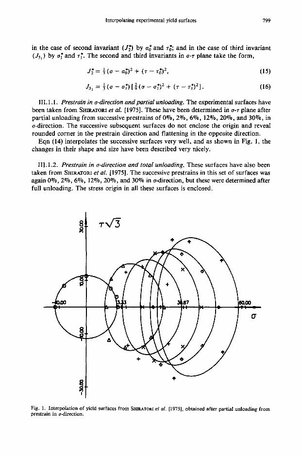
III. 1.1. Prestrain in a-direction andpartial unloading. The experimental surfaces have been taken from SnmArORI et al. [1975]. These have been determined in a-r plane after partial unloading from successive prestrains of 00/0, 2°70, 6°70, 12°/o, 20°70, and 30°70, in a-direction. The successive subsequent surfaces do not enclose the origin and reveal rounded corner in the prestrain direction and flattening in the opposite direction.
Eqn (14) interpolates the successive surfaces very well, and as shown in Fig. 1, the changes in their shape and size have been described very nicely.
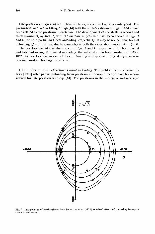
III. 1.2. Prestrain in o-direction and total unloading. These surfaces have also been taken from SnmAXORI et aL [1975]. The successive prestrains in this set of surfaces was again 00/0, 2%, 6°70, 12070, 20070, and 30% in a-direction, but these were determined after full unloading. The stress origin in all these surfaces is enclosed.
Fig. 1. Interpolation of yield surfaces from SHIRATORI et al. [1975], obtained after partial unloading from prestrain in a-direction.
800 N.K. GUPTA and A. MEYERS
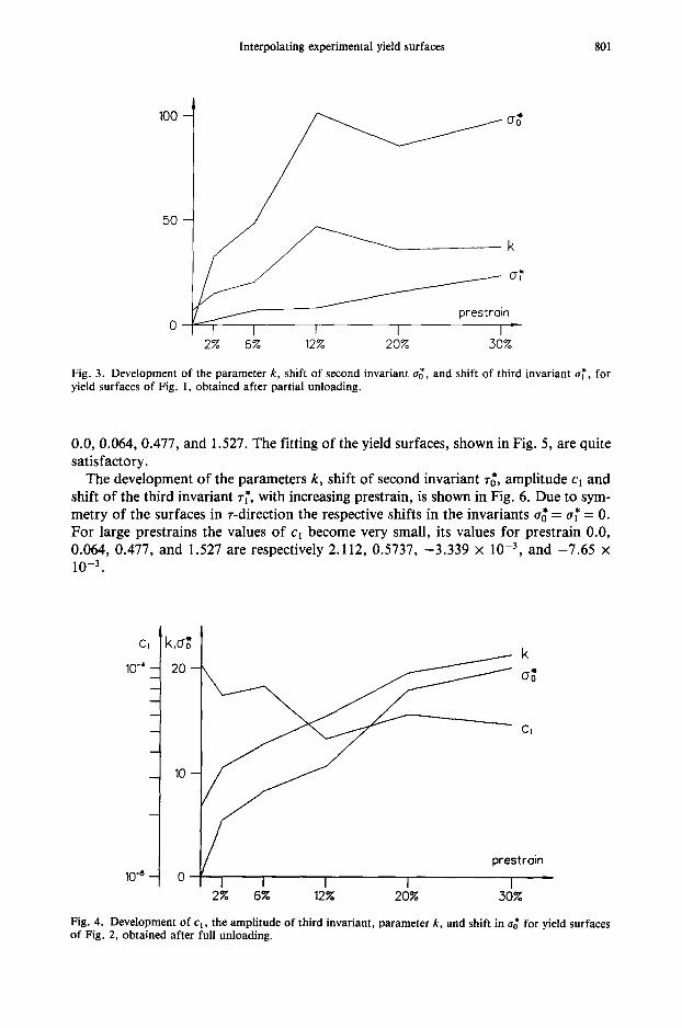
Interpolation of eqn (14) with these surfaces, shown in Fig. 2 is quite good. The parameters involved in fitting of eqn (14) with the surfaces shown in Figs. 1 and 2 have been related to the prestrain in each case. The development of the shifts in second and third invariants, 05 and a~', with the increase in prestrain have been shown in Figs. 3 and 4, for both partial and total unloading, respectively. It may be noticed that for full
* - 0. Further, due to symmetry in both the cases about o-axis, r~ = r~' --- 0. unloading o0 - The development of k is also shown in Figs. 3 and 4, respectively, for both partial
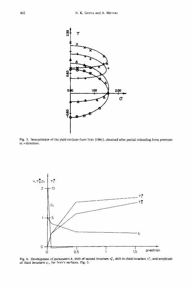
and total unloading. For partial unloading, the value of c~ has been constantly 1.035 x 10 -4 . Its development in case of total unloading is displayed in Fig. 4. cl is seen to become constant for large prestrains.
III. 1.3. Prestrain in r-direction: Partial unloading. The yield surfaces obtained by IvEY [1961] after partial unloading from prestrain in torsion direction have been con- sidered for interpolation with eqn (14). The prestrains in the successive surfaces were
-40,00 4O.00 ----4---
(7
Fig. 2. Interpolation of yield surfaces from SHIRATORI et al. [1975], obtained after total unloading from pre- strain in a-direction.
Interpolating experimental yield surfaces 801
100 -
5 0 -
cr~
k
/ prest ro in
I I I I I ~ 2% 6% 12% 20% 30%
Fig. 3. Development of the parameter k, shift of second invariant try, and shift of third invariant a~', for yield surfaces of Fig. 1, obtained after partial unloading.
0.0, 0.064, 0.477, and 1.527. The fitting of the yield surfaces, shown in Fig. 5, are quite satisfactory.
The development of the parameters k, shift of second invariant r~, amplitude c~ and shift of the third invariant r~, with increasing prestrain, is shown in Fig. 6. Due to sym- metry of the surfaces in r-direction the respective shifts in the invariants a~ = a~ = 0. For large prestrains the values of c~ become very small, its values for prestrain 0.0, 0.064, 0.477, and 1.527 are respectively 2.112, 0.5737, -3 .339 x 10 -3, and -7 .65 x 10 -3"
C l
10-' -
10 .5 - -
k
Cl
t ra in !
I J J I J 2% 6 ~ 12% 20% 30%
Fig. 4. Development of c 1, the amplitude of third invariant, parameter k, and shift in o~ for yield surfaces of Fig. 2, obtained after full unloading.
802 N.K. GUPTA and A. MEYERS
T
X
&
tOO 2.OO
Fig. 5. Interpolation of the yield surfaces from |VEY [1961], obtained after partial unloading from prestrain in T-direction.
k,To*,C, I "r; 2 ~ 10 ~ "T~
1 5 _ _ " k
0 0.5 t 1.5 prestrain
Fig. 6. Development of parameters k, shift of second invariant T~, shift in third invariant r~', and amplitude of third invariant cl, for IvEv's surfaces, Fig. 5.
Interpolating experimental yield surfaces 803
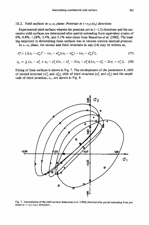
III.2. Yield surfaces in o1-02 plane: Prestrain in (-al)-(oe) directions
Experimental yield surfaces wherein the prestrain are in ( -1 ,1) directions and the suc- cessive yield surfaces are determined after partial unloading from equivalent strains of 0%0, 0.8%, 1.18%, 3.4%, and 5.1% were taken from Snno.rom et al. [1982]. The load- ing employed in determining these surfaces was in tension-torsion-internal pressure.
In 01-~2 plane, the second and third invariants in eqn (14) may be written as,
j ~ = 1 [(0.1 _ O t t o ) 2 _ ( 0 . 1 - - O . l o ) ( O r 2 _ 62*o) _ (0. 2 _ 0 . ] o ) 2 ] , (17)
* * - * - 2(02 * - * - 2(ol - ( ~ l ) ] . (18) . . . . o21)] [02 o21 J31 U7 (0"1 0"11 "Jr" 0" 2 0"21 ) [0" 1 0"11
Fitting of these surfaces is shown in Fig. 7. The developments of the parameters k, shift of second invariant (a~o and O~o), shift of third invariant (o~1 and o~z ) and the ampli- tude of third invariant, Cl, are shown in Fig. 8.
O
-2..~o I / ~ / / / / / - o . r l I too
I ®
0"1
O
Fig. 7. Interpolation of the yield surfaces SHIRATOR! et al. [1982] obtained after partial unloading from pre- strain in ( - o l )- (o2) directions.

804 N.K. GUPTA and A. MEYERS
-1
o~,
~ k
2 3 4 5 oh,
aro
L
prestrain
Fig. 8. Development of parameters k; shifts of second invariant, o~" o and o~0; shifts of third invariant, ~ and o~, and amplitude of third invariant c~, for surfaces of Fig. 7.
IV. NUMERICAL PROCEDURE
The experimental surfaces taken from literature were in Cartesian coordinate system, that is, the ol-a2 plane or the a - r plane. For a given set of yield points in a surface we first found a center that gave the best fit yon Mises ellipse. With this as center, the exper- imental data were transformed into polar coordinate system r, ¢. Additional data points were generated when there was general symmetry in an experimental yield surface and experimental data showed some gap on one side of the symmetry axis. An Akima inter- polation adapted to interpolate periodical curves was used to get a first outline of the yield surface through the set of data points. From the center of the polar coordinate sys- tem a number of uniformly distributed radial lines were drawn up to the above outline. The interactions of these lines generated a new set of data points of a hypothetical yield surface. The interpolation of these points was then performed by a variable metric opti- mization procedure which gave the set of parameters in eqn (14). The weight function of the optimizing procedure was taken as the sum of the square of differences between the radii up to the surface through data points and the corresponding ones generated through proposed formula.
V. CONCLUSIONS
An alternative formulation of second and third invariants of deviatoric stress tensor is presented for describing initial and subsequent yield surfaces. The proposed function is relatively simple. The actual fittings reveal that a single summation term is sufficient for describing variously obtained yield surfaces. That the function describes the yield surfaces well is demonstrated by considering experimental yield surfaces taken from lit- erature and which have been obtained after partial and total unloading from prestrains

Interpolating experimental yield surfaces 805
in uniaxial and biaxial direction. These show very good interpolation. The parameters involved in the formulation have also been related to the prestrain in each case.
REFERENCES
1949 DRUCKER, D.C., "Stress-Strain Relations for Strain Hardening Materials: Discussions and Proposed Experiments," Proc. 1st Annual Symposium for Appl. Math., Amer. Math. Soc., p. 181.
1950 HILL, R., "The Mathematical Theory of Plasticity," Oxford Press, New York. 1961 Iv~Y, H. J., "Plastic Stress Strain Relations and Yield Surfaces for Aluminium Alloys," J. Mech. Engi-
neering, 2, 15. 1973 OnAsm, Y., and TOKUDA, M., "Precise Measurement of Plastic Behaviour of Mild Steel Tubular Spec-
imens Subjected to Combined Torsion and Axial Force," J. Mech. Phys. Solids, 21,241. 1975 SmsAroaI, E., Ir,~GAm, K., KANmCO, K., and StraloAYASm, T., "Subsequent Yield Surfaces After Large
Tensile or Torsional Prestrain," Preprint of Japan Soc. Mech. Engnrs. 41, 75-7-2. 1982 Ird~OA~, K., "Experimental Plasticity, on the Anisotropy of Metals," in BOEHLER, J.-P. (ed.), Proc.
Euromech. Coll. 115, Villard-de-Lans, June 19-22, Colloques Internationaux du CNRS 295, p. 202. 1982 SmsAro~, E., II~EOAm, K., and KA~EKO, K., "Subsequent Yield Surface Determined in Consider-
ation of the Bauschinger Effect," in BOEHLER, J.-P. (ed.), Proc. Euromech. Coll. 115, Villard-de- Lans, June 19-22, Colloques Internationaux du CNRS 295, p. 477.
1992 GUPTA, N. K., and MEYERS, A., "Considerations of Translated Stress Deviators in Describing Yield Surfaces," Int. J. Plast. 8, 729.
Department of AppliedMechanics Indian Institute of Technology, Delhi Hauz Khas New Delhi-110016, India
Ruhr-Universit~it Bochum Lehrstuhl fiir Technische Mechanik 44780 Bochum, Germany
(Received in final revised form 4 January 1994)
Related Documents