DrAFT: An Algorithmic Framework for Facade Design Inês Alexandra do Côrro Caetano Thesis to obtain the Master of Science Degree in Architecture Supervisor: Prof. Dr. António Paulo Teles de Menezes Correia Leitão Examination Committee Chairperson: Prof. Dr. Francisco Manuel Caldeira Pinto Teixeira Bastos Supervisor: Prof. Dr. António Paulo Teles de Menezes Correia Leitão Member of the Committee: Prof. Dr. Ana Paula Filipe Tomé June 2015

Welcome message from author
This document is posted to help you gain knowledge. Please leave a comment to let me know what you think about it! Share it to your friends and learn new things together.
Transcript
DrAFT: An Algorithmic Framework for Facade Design
Inês Alexandra do Côrro Caetano
Thesis to obtain the Master of Science Degree in
Architecture
Supervisor: Prof. Dr. António Paulo Teles de Menezes Correia Leitão
Examination Committee
Chairperson: Prof. Dr. Francisco Manuel Caldeira Pinto Teixeira Bastos
Supervisor: Prof. Dr. António Paulo Teles de Menezes Correia Leitão
Member of the Committee: Prof. Dr. Ana Paula Filipe Tomé
June 2015


iii
ABSTRACT
The history of Architecture provides many examples of styles that were adopted, rejected, and then re-
adopted in a similar or changed form. Before Modernism, buildings' facades were the canvas where
architectural style was celebrated. However, with the birth of Modernism, and its hygienic and austere
aesthetic, composing a facade was an architectural task that lost some of its prestige. After Modernism
(or since Post-modernism), we witness an increasing interest in facade composition and, nowadays,
designing a facade is reassuming an important role in architecture practice due, in part, to the support
of digital technologies.
This dissertation discusses the development of a framework for the design of facades. Our work
started with an analysis of a large corpus of contemporary facades, which were classified into different
categorical dimensions that we considered computationally relevant. This classification generates a
multi-dimensional space where the parts of a facade can be located. The important result of our work
comes, then, from the identification and implementation of a set of fundamental algorithms and
strategies that address the needs of the different dimensions of this space. Some of the locations in
this multi-dimensional space can use a specific computing approach that is adequate for the creation
of the designs that match the intended facade. Other locations, representing less common kinds of
facades, might not have a specific computational solution, but our experience shows that is possible,
using the range of tools that we developed, to quickly implement the particular solution required by
that facade.
In practical terms, the end result of our research is a library of operators usable in different
programming languages and a set of guidelines that helps a designer select and combine the most
useful operators to implement a design for a particular facade. Some of these operators are
implemented as higher-order functions, making them applicable to a wide variety of problems. Our
work is implemented using Rosetta, a programming environment for generative design, allowing us to
explore the generation of facades in common CAD applications, thus promoting the integration of the
generative design approach in the more traditional working environment.
Keywords: Algorithm, Higher-Order Function, Generative Design, Facade

v
RESUMO
A história da Arquitetura proporciona vários exemplos de estilos que foram adotados, rejeitados e,
mais tarde, readotados novamente de forma semelhante ou alterada. Antes do Movimento Moderno
fachadas eram as telas onde os estilos arquitetónicos eram celebrados, mas a partir daí compor uma
fachada tornou-se uma tarefa arquitetónica que perdera o seu prestigio. A seguir ao Modernismo (ou
a partir do Pós-Modernismo) assistimos a um interesse crescente na composição da fachada e, hoje
em dia desenhar uma fachada está a reassumir um papel importante na prática arquitetónica, devido
principalmente ao suporte das tecnologias digitais.
Esta dissertação discute o desenvolvimento de uma infraestrutura digital para o desenho de fachadas.
O nosso trabalho começou com uma análise de uma vasta gama de fachadas contemporâneas, as
quais classificámos em diferentes dimensões categóricas, que considerámos ser computacionalmente
relevantes. Esta classificação gera um espaço multidimensional onde as diversas partes da fachada
podem ser localizadas. A relevância do nosso trabalho vem, então, da identificação e da
implementação de um conjunto de algoritmos e estratégias fundamentais que resolvem as
necessidades das diferentes dimensões deste espaço. Algumas das localizações neste espaço
multidimensional podem usar uma abordagem computacional especifica que seja adequada para a
criação dos desenhos que correspondem aos da fachada desejada. Outras localizações, que
representam desenhos de fachadas menos comuns, podem não ter uma solução computacional
específica, mas a nossa experiência mostra que é possível, usando a variedade de ferramentas que
desenvolvemos, implementar rapidamente a solução particular necessária para gerar essa fachada.
Em termos práticos, o resultado final da nossa pesquisa é uma biblioteca de operações que se pode
usar em diferentes linguagens de programação e um conjunto de normas que ajudam os arquitetos a
selecionar e a combinar os operadores mais úteis para a implementação do desenho de uma fachada.
Alguns desses operadores são implementados como funções de ordem superior, tornando-os assim
aplicáveis a uma vasta gama de problemas. O nosso trabalho é implementado usando o Rosetta, um
ambiente de programação para desenho generativo, permitindo-nos assim explorar a geração de
modelos de fachadas em aplicações de CAD comuns, promovendo a integração da abordagem do
desenho generativo em ambientes de trabalho mais tradicionais.
Palavras-chave: Algoritmo, Funções de Ordem Superior, Desenho Generativo, Fachada

vii
ACKNOWLEDGMENT
A special acknowledgment to Professor António Leitão, the supervisor of this thesis, for introducing
me such an interesting topic, for everything he taught me during the course of this work, for his
supportive and ever-present guidance, for the availability that he ever had for any clarification or
doubt, and also for his dedication, patience and enthusiasm that helped me a lot until the conclusion
of this thesis.
To my parents for their understanding and support during the development of this work.
To the members of GAC for the relevant comments and advices.
To my friends for their understanding and patience.
This work was partially supported by national funds through Fundação para a Ciência e a Tecnologia
(FCT) with reference UID/CEC/50021/2013, and by the Rosetta project under contract PTDC/ATP-
AQI/5224/2012.
AGRADECIMENTOS
Um especial agradecimento ao Professor António Leitão, o orientador desta tese, por me introduzir
um tópico tão interessante como este, por tudo o que me ensinou no decorrer deste trabalho, pelo
suporte e supervisão sempre presentes, pela disponibilidade total que sempre teve para qualquer
esclarecimento ou dúvida, e ainda pela sua dedicação, paciência e entusiasmo que me ajudaram
bastante até à conclusão desta tese.
Aos meus pais pelo seu suporte e compreensão durante o desenvolvimento deste trabalho.
Aos membros do GAC pelos comentários e conselhos relevantes.
Aos meus amigos pela sua compreensão e paciência.
Este trabalho foi suportado parcialmente por fundos nacionais através da Fundação para a Ciência e a
Tecnologia (FCT) com referencia UID/CEC/50021/2013, e pelo projeto Rosetta sob o contrato
PTDC/ATP-AQI/5224/2012.

ix
CONTENTS
ABSTRACT ................................................................................................................................................................................................................ iii
RESUMO ..................................................................................................................................................................................................................... v
CONTENTS................................................................................................................................................................................................................ ix
LIST OF FIGURES ................................................................................................................................................................................................ xiii
LIST OF TABLES .................................................................................................................................................................................................. xxv
ABBREVIATIONS ............................................................................................................................................................................................. xxvii
GLOSSARY OF TERMS .................................................................................................................................................................................. xxvii
INTRODUCTION ............................................................................................................................................................................................... xxix
OBJECTIVES .............................................................................................................................................................................................. xxxiii
METHODOLOGY .................................................................................................................................................................................... xxxiii
STRUCTURE .............................................................................................................................................................................................. xxxiv
PART I. BACKGROUND ..................................................................................................................................................................................... 1
1 ORNAMENT ............................................................................................................................................................................................. 3
1.1 ORNAMENT, DECORATION AND PATTERNS ................................................................................................................ 3
1.2 ORNAMENT IN ARCHITECTURE ........................................................................................................................................... 4
2 THE CONTEMPORARY FACADE: NEW EXPRESSIONS IN ARCHITECTURE ......................................................... 11
2.1 FACADE: THE OUTER LAYER OF ARCHITECTURE ........................................................................................................ 12
2.2 NEW ARCHITECTURAL EXPRESSIONS ............................................................................................................................ 14
2.2.1 NEW GEOMETRIES ............................................................................................................................................................. 16
2.2.2 PERFORMATIVE ARCHITECTURE................................................................................................................................. 18
2.2.2.1 Performative Architecture as Performance-Based Design ................................................................... 19
2.2.2.2 Performative Design as an Architecture of Performance ...................................................................... 21
2.2.2.3 Architecture as Both Performance and Performance-Based Design ................................................. 22
x
2.2.3 KINETIC OR ADAPTIVE ARCHITECTURE .................................................................................................................... 24
2.2.3.1 INSTITUT DU MONDE ARABE ........................................................................................................................ 25
2.2.3.2 NEW ESKENAZI HOSPITAL PARKING STRUCTURE ................................................................................ 26
2.2.4 PARAMETRIC ARCHITECTURE ...................................................................................................................................... 27
3 NEW TECHNOLOGIES ...................................................................................................................................................................... 29
3.1 GENERATIVE DESIGN ............................................................................................................................................................. 30
3.2 GENERATIVE SYSTEMS .......................................................................................................................................................... 32
3.3 PARAMETRIC SYSTEMS ........................................................................................................................................................ 35
3.3.1 HISTORY OF PARAMETRIC TOOLS ............................................................................................................................. 36
3.3.2 PARAMETRIC TOOLS: FINDING A MEANING .......................................................................................................... 37
4 GENERATIVE DESIGN: ARCHITECTURAL PRACTICE ........................................................................................................ 41
4.1 GENERATIVE DESIGN STRATEGIES .................................................................................................................................... 41
4.2 CASE STUDY 1: AVIVA STADIUM ...................................................................................................................................... 44
4.3 CASE STUDY 2: BEIJING NATIONAL AQUATIC CENTER ........................................................................................... 47
PART II. A FRAMEWORK FOR THE GENERATION OF CONTEMPORARY FACADES ............................................... 51
5 INTRODUCTION ................................................................................................................................................................................... 53
6 ALGORITHMIC FACADES ................................................................................................................................................................ 55
6.1 CLASSIFICATION STRATEGY ............................................................................................................................................... 56
6.2 DESIGN STAGES & CATEGORICAL DIMENSIONS ...................................................................................................... 58
6.2.1 FACADE'S GEOMETRY ..................................................................................................................................................... 60
6.2.2 ELEMENT'S GEOMETRY .................................................................................................................................................... 63
6.2.3 ELEMENT'S DEFORMATION ........................................................................................................................................... 64
6.2.4 ELEMENT'S SIZE ................................................................................................................................................................... 66
6.2.5 ELEMENT'S DISTRIBUTION ............................................................................................................................................. 68
xi
6.2.6 ELEMENT'S ROTATION ..................................................................................................................................................... 72
6.2.7 FACADE'S ARTICULATION .............................................................................................................................................. 74
6.2.8 FACADE'S MATERIAL AND COLOR ............................................................................................................................. 77
6.3 CLASSIFICATION SYNTHESIS ............................................................................................................................................... 79
7 THE APPLICATION OF THE FACADE'S CLASSIFICATION ............................................................................................... 81
7.1 CLASSIFICATION OF FACADES ........................................................................................................................................... 82
EXAMPLE 1 CAMPUS NETZWERK OFFICE, GERMANY ............................................................................................. 82
EXAMPLE 2 MEDIOPADANA STATION, ITALY ............................................................................................................. 83
EXAMPLE 3 GANTENBEIN VINEYARD, SWITZERLAND ............................................................................................ 84
EXAMPLE 4 CASCAIS HOUSE, PORTUGAL ...................................................................................................................... 86
EXAMPLE 5 QUALITY HOTEL FRIENDS, SWEDEN ....................................................................................................... 87
EXAMPLE 6 SUZHOU SND DISTRICT URBAN PLANNING EXHIBITION HALL, CHINA .................................. 88
EXAMPLE 7 UTRECHT UNIVERSITY LIBRARY, NETHERLANDS .............................................................................. 89
EXAMPLE 8 LOUIS VUITTON STORE, JAPAN ................................................................................................................ 90
7.1.2 ANALYSIS OF THE PRACTICAL EXAMPLES ............................................................................................................. 91
8 FACADES GENERATION PROCESS ............................................................................................................................................. 93
8.1 ANALYSIS OF THE FACADE'S DESIGN ............................................................................................................................. 93
8.2 FACADE'S CLASSIFICATION ................................................................................................................................................. 96
8.3 IMPLEMENTATION OF THE ALGORITHMS .................................................................................................................... 97
8.4 MODEL EXPLORATION .......................................................................................................................................................... 99
9 THE GENERATION OF CONTEMPORARY FACADES ...................................................................................................... 105
9.1 PRACTICAL APPLICATION.................................................................................................................................................. 105
9.2 THE APPLICATION ON REAL FACADES ........................................................................................................................ 115
9.2.1 QUALITY HOTEL FRIENDS, SWEDEN ....................................................................................................................... 115

xii
9.2.2 CAMPUS NETZWERK, GERMANY .............................................................................................................................. 121
9.2.3 HOUSE AAG, SPAIN ........................................................................................................................................................ 127
9.2.4 GANTENBEIN VINEYARD, SWITZERLAND ............................................................................................................. 133
9.2.5 FACIM WATERFRONT IN MAPUTO, MOZAMBIQUE ......................................................................................... 140
10 OTHER APPLICATIONS ........................................................................................................................................................... 147
11 EVALUATION ................................................................................................................................................................................. 153
11.1 EVALUATING THE FRAMEWORK’S FLEXIBILITY ........................................................................................................ 154
11.2 TRADITIONAL VS. ALGORITHMIC APPROACH ......................................................................................................... 158
11.2.1 THE MODELS GENERATION TIME ..................................................................................................................... 158
11.2.2 THE VARIATION OF THE MODELS ................................................................................................................................. 160
11.3 THE PORTABILITY OF THE FRAMEWORK .................................................................................................................... 163
11.4 OTHER EXISTING TOOLS .................................................................................................................................................... 165
12 CONCLUSION AND FUTURE WORK .................................................................................................................................. 167
12.1 CONCLUSION.......................................................................................................................................................................... 167
12.2 FUTURE WORK........................................................................................................................................................................ 169
12.3. CONTRIBUTIONS .................................................................................................................................................................... 170
BIBLIOGRAPHY ........................................................................................................................................................................................ 173
xiii
LIST OF FIGURES
Fig.1 - The FACIM WaterFront Project by Bak Gordon, in Maputo, Mozambique (source: http://www.bakgordon.com/)..............xxxii
Fig.2 – An image of the towers’ interior with the patterned skin visible. (source: Bak Gordon's Studio)…………………………………….xxxii
Fig.3 - The skin pattern based on African motifs (source: Bak Gordon's Studio)………………………………………………………………………...xxxii
Fig.1.1 - Manueline Ornamentation in the cloisters of Jerónimos Monastery in Belém, Portugal (source:
https://www.pinterest.com).......................................................................................................................................................................................................... 3
Fig.1.2 - Patterns in Architecture: Portuguese Tiles (source: https://www.pinterest.com/pin/)........................................................................ 3
Fig.1.3 - Baroque: the Queen's room in the Versailles Palace in France. The ornamentation exuberance is very characteristic of
this style (source: http://en.wikipedia.org/wiki/Palace_of_Versailles/)........................................................................................................................ 4
Fig.1.4 – Roman Empire: Statues were used to ornament temples. (source: http://www.2020site.org/).................................................... 4
Fig.1.5 – Rossio Station’s in Lisbon: the doors are ornamented so as to recreate the Portuguese Manueline style (source:
https://www.flickr.com/)................................................................................................................................................................................................................. 4
Fig.1.6 - Parametric patterns and facades: Erwin Hauer- continua architectural screens and walls (http://www.erwinhauer.com/)..8
Fig.1.7 - Contemporary Ornament: John Lewis department store in Leicester, UK, by Foreign Office Architects (source:
http://designresearch.sva.edu/research/patterns-of-ornament-technology-and-theory-in-contemporary-architectural-
decoration-2/).................................................................................................................................................................................................................................... 9
Fig.2.1 - Photography of the Guggenheim Museum by Frank Gehry in Bilbao, Spain (source: http://www.guggenheim-
bilbao.es/en/the-building/outside-the-museum/)........................................................................................................................................................... 12
Fig.2.2 - Photography of the Beijing National Stadium (source: www. http://21stcenturyarchitecture.blogspot.pt)............................ 13
Fig.2.3 - A digital image of the Beijing National Stadium project by Herzog & De Meuron (source: www.openbuildings.com).... 13
Fig.2.4 – The patterned skin of the Federation Square buildings in Melbourne, Australia (2002), by LAB Architecture Studio
(source: http://www.architravel.com/).................................................................................................................................................................................... 13
Fig.2.5 – The Serpentine Pavillion in London (2002) by Cecil Belmond and Toyo Ito (source: http://www.archdaily.com/) ……… 13
Fig.2.6 – Image of the Eiffel Tower in Paris by Gustave Eiffel (source: www.smithsonianmag.com)........................................................... 15
Fig.2.7 - Image of the Crystal Palace built by Joseph Paxton (source: www.telegraph.co.uk) ……………………………………………………… 15
Fig.2.8 - Vodafone building in Oporto (Portugal) designed by Barbosa e Guimarães Architects (source:
http://21stcenturyarchitecture.blogspot.pt)........................................................................................................................................................................ 15
Fig.2.9 – Troia Design Hotel in Troia, Portugal, by Promontório Arquitectos (source: http://www.troiadesignhotel.com/) ……… 15
xiv
Fig.2.10 - Image of the Archigram's Plug-in City (1964): This provocative project suggests a hypothetical fantasy city, containing
modular residential units that “plug in” to a central infrastructural mega machine. The Plug-in City is in fact not a city, but a
constantly evolving megastructure that incorporates residences, transportation and other essential services–all movable by giant
cranes (source: http://www.archdaily.com).......................................................................................................................................................................... 16
Fig.2.11 – ICD/TKE Research Pavilion (2011) Stuttgart University by Achim Menges and J. Knippers (source:
http://www.achimmenges.net/)................................................................................................................................................................................................ 17
Fig.2.12 – 3D Spacer Textile Composites by Nico Reinhardt (source: http://www.achimmenges.net/) ……………………………………… 17
Fig.2.13 - Image of a NURBS surface with its controllable vertices in red (source: www.3dmax-tutorials.com)..................................... 17
Fig.2.14 - Photography of BMW Welt in Munich by Coop Himmelb(l)au (source: http://www.archithings.com) ……………………… 17
Fig.2.15 – Different screens designed with algorithmic tools, which helped the manipulation of the contours, dimensions, angles
and the sequence of openings. The screens were produced with robotic cutting. Designed and produced by Gramazio & Kohler
Research (source: http://gramaziokohler.arch.ethz.ch/)................................................................................................................................................ 18
Fig.2.16 - Photography of the City Hall in London, designed by Foster+Partners (source: http://www.fosterandpartners.com)... 20
Fig.2.17 - Photography of the Kunsthaus dynamic display surface of lights, in Graz, Austria (source: www.aracnob.blogspot.pt) 21
Fig.2.18 – An exploded view of the lights matrix as a part of the Kunsthaus facade (source: (Edler, 2005))………………………………… 22
Fig.2.19 - Photography of Southern Cross Station in Melbourne, Australia (source: http://openbuildings.com) ……………………… 23
Fig.2.20 – An example of Kinetic architecture of the past: Drawbridge at the fort of Ponta da Bandeira in Lagos, Portugal (source:
http://en.wikipedia.org/wiki/Drawbridge)............................................................................................................................................................................ 24
Fig.2.21 - The kinetic Mashrabiya (source: http://www.archdaily.com/)................................................................................................................ 25
Fig.2.22 – The diaphragms of the Mashrabiya units (source: www.archdaily.com)........................................................................................... 25
Fig.2.23 - Photography of the Institut du Monde Arabe in Paris, France (1981–1987) (source: http://www.archdaily.com/) …….. 25
Fig.2.24 - Photography of the New Eskenazi Hospital Parking Structure by Urbana Architects (source: www.arch2o.com) …..… 26
Fig.2.25 - Some of the different effects produced by the facade depending on the viewers place of view (source:
www.arch2o.com)........................................................................................................................................................................................................................... 27
Fig.2.26 - Rendered view of the Engineering Research Institute at the Minho University (Guimarães) by Cláudio Vilarinho
Architects (source: www.claudiovilarinho.com). The building's skin was inspired by the microscopic image of titanium nanotubes.
………………………………………………………………………………………………………………………………………………………………………………………………………. 27
Fig.2.27 - Photography of Airspace Tokyo by Faulders Studio (source: www.arch20.com). The building's skin manifests organicity,
thereby resembling a neurological system……………………………………………………………………………………………………………………………………. 28
Fig.2.28 - Image of a Parametric Form Finding technique (source: http://designontopic.files.wordpress.com).................................... 28
xv
Fig.2.29 – The “Bubble” BMW pavilion in Frankfurt, Germany. Its form inspiration was based on two drops of water joined
together. The pavilion was designed by Bernhard Franken (source: http://www.itaproject.eu/)…………………………………………............. 28
Fig.3.1 - Synthetic Scheme of Generative Design…………………………………………………………………………………………………………………………. 30
Fig.3.2 - An example of the process of Genetic Algorithms (source: (Chouchoulas & Day, 2007))………………………………………………. 33
Fig.3.3 - An example of a shape grammar (source: www.andrew.li)......................................................................................................................... 33
Fig.3.4 - Serpinski Lsystem (source: Wikipedia)……………………………………………………………………………………………………………………………. 34
Fig.3.5 - Cellular automata from the Game of Life, 1970 (source: www.joshiscorner.com)............................................................................. 34
Fig.3.6 - An example of a parametric surface……………………………………………………………………………………………………………………………….. 35
Fig.3.7 - Frei Otto's form finding technique, foam bubbles (source: http://www.plataformadeartecontemporaneo.com/) ……… 36
Fig.3.8 - Ivan Sutherland’s Sketchpad console (1962). Sketchpad is operated with a light pen and a command button box (under
left hand). The four black knobs below the screen control position and scale of the picture (source: www.mprove.de).................... 36
Fig.3.9 - Pro/Engineer in 1988 (source: www.deskeng.com)........................................................................................................................................ 37
Fig.3.10 – AutoCAD 2000 environment (source: http://www.eurocitysoftware.com/)..................................................................................... 37
Fig.3.11 – Rhino5 environment (source: http://3.bp.blogspot.com/)....................................................................................................................... 37
Fig.3.12 - Parametric Variations: The number of stripes in each model varies between 6 and 11 stripes……………………………………. 38
Fig.4.1 - A photography of the interior of Sagrada Familia in Barcelona (source: http://archinect.com/)................................................ 41
Fig.4.2 - Smithsonian Institution by Foster+Partners in Washington DC, USA (2007) (source: www.fosterandpartners.com/)........ 42
Fig.4.3 - City Hall or Greater London Authority by Foster+Partners (source: www.fosterandpartners.com)............................................ 42
Fig.4.4 - Serpentine Gallery Pavilion (2005) by Alvaro Siza and Eduardo Souto Moura with Cecil Balmond – Arup (source:
http://www.telegraph.co.uk/).................................................................................................................................................................................................... 43
Fig.4.5 - The Barcelona Fish by Frank Gehry and Partners (source: www.buildingsatire.com) ……………………………………………………… 43
Fig.4.6 - Computer and built models for Gehry´s fish sculpture 1992 Barcelona (source: https://mafana.wordpress.com).............. 43
Fig.4.7 – Aviva Stadium in Dublin by Populous architecture (source: www.archilovers.com) ……………………………………………………… 44
Fig.4.8 – Parametric definition of the stadium’s geometry: a- radial grid of the structure of the roof bays; b- definition of the
footprint of the stadium; c- definition of the inner edge of the roof; d- definition of the origin of each sectional curve; e-
definition of the section curve; f- definition of the vertical coordinates for each section curve; g,h- construction of each sectional
curve and then the lofting of a surface through those curves; i- subdivision of the radial roof bay grid into mullion grid lines
(source: (Shepherd, et al., 2011))……………………………………………………………………………………………………………………………………………………. 45
Fig.4.9 – Structural elements output from parametric model (source: (Shepherd, et al., 2011))………………………………………………… 46
xvi
Fig.4.10 – A photography of Beijing National Aquatic Center (source: http://www.archello.com/)............................................................ 47
Fig.4.11 – Weaire and Phelan’s proposal for portioning 3D space. The image on the left represents a cluster of repetitive units
and, the image on the right represents the repetitive module (source: (Eastman, et al., 2008))…………………………………………………. 47
Fig.4.12 - CAD model of the structural system of the Water Cube Project (source: http://architectureau.com/)................................ 48
Fig.4.13 – Building’s structure prototyping (source: http://www.e-architect.co.uk/)........................................................................................ 48
Fig.4.14 – Interior view of the Water Cube pavilion showing the almost complete structure (source: (Eastman, et al., 2008)).. 49
Fig.4.15 – Interior of the Water Cube pavilion (source: http://www.arup.com/Projects/).............................................................................. 49
Fig.6.1 - Continua Screen, design 1 - pattern developed by Erwin Hauer in the 1950’s (source: (Hauer, 2004)) ……………………… 54
Fig.6.2 – P-wall (2006) developed in Banvard Gallery, Knowlton School of Architecture, Ohio State University, USA (source:
http://matsysdesign.com/)......................................................................................................................................................................................................... 54
Fig.6.3 – Sawdust Screen in Walnut material, by Emerging Objects (source: http://www.emergingobjects.com/) ……………………… 54
Fig.6.4 - Selfridges Building in Birmingham, UK (source: http://www.contemporist.com/)............................................................................. 55
Fig.6.5 - Monteagudo Museum in Murcia, Spain (source: http://www.archdaily.com/)................................................................................... 55
Fig.6.6 - French Pavilion in Expo Shanghai 2010 (source: http://www.tridonic.com/)....................................................................................... 55
Fig.6.7 - Louis Vuitton Flagship Store in Fifth Avenue in New York, USA (source: http://www.archdaily.com)....................................... 56
Fig.6.8 – Image synthesis of the classification’s categorical dimensions. The eight dimensions are organized in four different sets,
which correspond to the design stages: 1- definition of the facade’s geometry; 2- definition of the facade’s elements; 3-
distribution of the elements; 4- facade’s final appearance……………………………………………………………………………………………………………. 59
Fig.6.9 - Facade Geometry: Straight Facade - Formestelle Office Building in Töging am Inn, Germany (source: www.dezeen.com/)
………………………………………………………………………………………………………………………………………………………………………………………………………. 60
Fig.6.10 - Facade Geometry: Cylindrical Facade - Suzhou SND District Urban Planning Exhibition Hall in Jiangsu, China (source:
http://www.archdaily.com/)........................................................................................................................................................................................................ 60
Fig.6.11 - Facade Geometry: Facade with horizontal waving - Apartment house in Tokyo (source: https://www.japlusu.com/).... 61
Fig.6.12 - Facade Geometry: Facade with vertical waving - GT Tower East, in Seoul (source: http://www.contemporist.com/)...... 61
Fig.6.13 - Facade Geometry: Sinusoidal and co-sinusoidal Facade - Boiler House at Guy's Hospital in London, UK (source:
http://www.dezeen.com/)........................................................................................................................................................................................................... 61
Fig.6.14 – Facade’s Geometry: Facade with vertical and horizontal waving - Mediopadana Station in Bologna, Italy (source:
www.ediliziaeterritorio.ilsole24ore.com/) ………………………………………………………………………………………………………………………………………. 62
Fig.6.15 - Selfridges Building in Birmingham, UK (source: http://www.contemporist.com/) ……………………………………………………… 62
xvii
Fig.6.16 – Scheme of the process behind the Facade’s Geometry dimension: an initial surface is then submitted to a sampling
process, from which results a mesh of points. Then, it is organized in a quadrangular matrix, defined by sets of four points……. 62
Fig.6.17 - Element's Geometry: Circular Elements - New Center for Manufacturing Innovation in Monterrey, Mexico. (source:
http://www.archilovers.com/).................................................................................................................................................................................................... 63
Fig.6.18 - Element's Geometry: Hexagonal Elements - The Cube in Milan, Italy (source: http://www.e-architect.co.uk/)................. 63
Fig.6.19 - Element's Geometry: Spherical elements - Hanjie Wanda Square in China (source: http://www.archdaily.com/) ……… 63
Fig.6.20 - Element's Geometry: Stripes Elements - Aspen Art Museum in Aspen, USA (source: http://www.archilovers.com/)..... 64
Fig.6.21 - Element's Geometry: Pictorial Elements - Mayfair House in London, United Kingdom (source: www.archilovers.com) 64
Fig.6.22 - Element's Deformation: Twisted Elements - Huaxin Business Center in Xuhui, China (source: http://openbuildings.com)
............................................................................................................................................................................................................................................................... 65
Fig.6.23 - Element's Deformation: Undulated Elements - Visitor Pavilion National Museum Palace in Het Loo, Apeldoorn,
Netherlands (source: http://www.archilovers.com/) ………………………………………………………………………………………………………………………. 65
Fig.6.24 - Element's Deformation: Interlaced Elements - Argul Weave Building in Bursa, Turkey (source: www.archdaily.com)..... 65
Fig.6.25 - Element's Deformation: Bended Elements - Pan American Health Organization Building, Washington DC , USA (source:
http://flickrhivemind.net/Tags/dc,paho) ………………………………………………………………………………………………………………………………………. 66
Fig.6.26 - Element's Size: Increasing Elements - The Tourist Office and Landscaping of Quinta do Aido, Portugal (source:
http://www.archdaily.com/)........................................................................................................................................................................................................ 66
Fig.6.27 - Element's Size: Attracted Elements - Quality Hotel Friends in Sweden (source: www.archilovers.com)............................... 66
Fig.6.28 - Element's Size: Random Elements - Cascais House, Portugal (source: www.guedescruzarquitecto.wix.com/).................. 67
Fig.6.29 - Element's Size: Pictorial Elements - Hästsportens Hus in Sweden (source: http://notedesignstudio.se/)........................... 67
Fig.6.30 - Element's Distribution: In Rows - commercial block in Tokyo by Japanese firm Amano Design Office, Japan (source:
http://www.dezeen.com/)........................................................................................................................................................................................................... 68
Fig.6.31 – Synthesis of the type of 1D distributions available within our framework…………………………………………………………………… 68
Fig.6.32 – The grid of points controls the size of the elements in order to fit the metrics…………………………………………………………… 69
Fig.6.33 – Creation of an element between the four points (left-side) and the mapping of the element on the grid of points with
random rotations (right-side)………………………………………………………………………………………………………………………………………………………… 70
Fig.6.34 - Element's Distribution: in Chess-Grid - Knowledge Center at St. Olav's Hospital, Norway (source: www.archdaily.com/)
……………………………………………………………………………………………………………………………………………………………………………………………………… 70
Fig.6. 35 - Element's Distribution: Recursive Grid - The Cube in Birmingham, UK (source: http://www.wicona.co.uk/)...................... 70
Fig.6.36 – The type of distributions in 2D available in the Framework…………………………………………………………………………………………. 71
xviii
Fig.6.37 - Element's Distribution: Pictorial Grid - Podcetrtek Sports Hall in Slovenia (source: http://www.archdaily.com/) ……… 72
Fig.6.38 - Element's Distribution: 3D distribution - MegaFaces Pavilion Sochi 2014 Winter Olympics in Russia (source:
https://www.pinterest.com/)...................................................................................................................................................................................................... 72
Fig.6.39 - Element's Rotation: Horizontal Rotation - Huaxin Business Center in China (source: http://www.archdaily.com/) ……… 72
Fig.6.40 - Element's Rotation: Pictorial Rotation - Winery Gantenbein by Gramazio & Kohler in Switzerland (source:
http://www.gramaziokohler.com/).......................................................................................................................................................................................... 73
Fig.6.41 - Facade's Articulation: Perforated Facade - House 77 by Diniso Lab in Póvoa do Varzim, Portugal (source:
http://www.dezeen.com/)........................................................................................................................................................................................................... 74
Fig.6.42 - Facade's Articulation: Applied Facade - Mayfair House in London, UK (source: http://www.archdaily.com/)..................... 74
Fig.6.43 - Facade's Articulation: Printed Facade - Utrecht University Library in Netherlands (source: www.e-architect.co.uk/)...... 75
Fig.6.44 - Facade's Articulation: Stacked Articulation - South Asian Human Rights Documentation Centre, New Delhi (source:
http://anagramarchitects.com/)............................................................................................................................................................................................... 75
Fig.6.45 - Facade's Articulation: Juxtaposed Articulation - Aquacenter in Mantes La Jolie, France (source: http://www.e-
architect.co.uk/).............................................................................................................................................................................................................................. 75
Fig.6.46 - Facade's Articulation: Web Articulation - French Pavilion in Expo Shanghai 2010 (source: www.assets.inhabitat.com). 75
Fig.6.47 - Facade's Articulation: Layered Articulation - Dior Ginza, Tokyo (source: http://archidose.blogspot.pt/2013/).................. 76
Fig.6.48 - Facade's perforations of Dior Ginza (source: http://www.arcspace.com/)......................................................................................... 76
Fig.6.49 - Facade's Material: Metal, an example of a perforated facade - Het Bushok in Netherlands (source:
www.archilovers.com)................................................................................................................................................................................................................... 77
Fig.6.50 - Facade's Material: Metal, an example of a facade with a complex geometry - Soumaya Museum in Mexico City (source:
http://www.archilovers.com/).................................................................................................................................................................................................... 78
Fig.6.51 - Facade's Material: Glass, an example of a printed facade - Historical Archive of the Basque Country in Bilbao, Spain
(source: http://www.archilovers.com/)................................................................................................................................................................................... 78
Fig.6.52 - Facade's Colors: Pictorial Color, The Bisazza Foundation in Alte di Montecchio Maggiore, Italy (source:
http://www.archilovers.com/).................................................................................................................................................................................................... 78
Fig.6.53 - Facade's Color: Random Color, The Museum Brandhorst in Munich, Germany (source: http://www.archilovers.com/) 79
Fig.6.54 - Image Synthesis of the Facade's Classification: The names in the dark grey rectangles are the Dimensions and the
names in the corresponding light grey rectangles are the options for each dimension……………………………………………………………..… 80
Fig.7.1 - Phography of the Campus Netzwerk Office, Germany (source: www.dezeen.com)......................................................................... 82
Fig.7.2 - Hexagonal Perforations of the Campus Netzwerk Office (source: http://static.dezeen.com/) ……………………………………… 83
xix
Fig.7.3 - Photography of the Stazione Mediopadana in Bologna (source: www.archilovers.com)............................................................... 83
Fig.7.4 - Photography of Gantenbein Vineyard (source: http://www.gramaziokohler.com)........................................................................... 84
Fig.7.5 - Photography of the Cascais House in Cascais, Portugal (source: http://www.archilovers.com/)................................................. 86
Fig.7.6 - An image of the facade where it is visible the concrete slabs with different sizes and the produced empty spaces
(source: http://guedescruzarquitecto.wix.com/pt)............................................................................................................................................................ 86
Fig.7. 7 - Photography of the Quality Hotel Friends, in Sweden (source: www.archdaily.com)..................................................................... 87
Fig.7.8 - Photography of the Suzhou SND District Urban Planning Exhibition Hall in China (source: http://www.archdaily.com/) 88
Fig.7.9 - Photography of Utrecht University Library (source: www.archdaily.com)............................................................................................. 89
Fig.7.10 - Image of Louis Vuitton Shop in Tokyo (source: www.dezeen.com)...................................................................................................... 90
Fig.8.1 - Photography of the Library of Birmingham (source: http://www.archilovers.com/)......................................................................... 93
Fig.8.2 - Scheme of the rings distribution…………………………………………………………………………………………………………………………………….. 94
Fig.8.3 - Division of the facade's pattern into squares…………………………………………………………………………………………………………………. 94
Fig.8.4 - The facade's element is composed by four arcs, which are represented in four different colors…………………………..………. 94
Fig.8.5 - The subtraction of two surface arcs. The left arc has a bigger radius than the middle arc. The subtraction of the middle
arc from the left arc creates the arc on the right — a ring……………………………………………………………………………………………………………. 94
Fig.8.6 - Scheme of an element's extrusion………………………………………………………………………………………………………………………………….. 95
Fig.8.7 - A photography of the facade's rings: Along the radius of a black ring, it fit three golden rings (source:
http://www.archilovers.com/).................................................................................................................................................................................................... 95
Fig.8.8 - A layer of overlapped rings…………………………………………………………………………………………………………………………………………….. 97
Fig.8.9 - The overlapping of the two layers of rings………………………………………………………………………………………………………………...…… 98
Fig.8.10 - Example of the production of the Library's model with the different layers………………………………………………………………… 99
Fig.8.11 - The model's structure: the definition of the main volumes, points (P P1 and P2) and the function's parameters —
length, width and height……………………………………………………………………………………………………………………………………………………………….. 99
Fig.8.12 - The Library's Model: generated with the first set of parameters (table above)………………………………………………………….. 100
Fig.8.13 - The Library's Model: generated with the second set of parameters (radius=15m)…………………………………………………….. 101
Fig.8.14- The Library's Model: generated with the third set of parameters (radius=30m)…………………………………………………………. 101
Fig.8.15 - The Library's Model: generated with the fourth set of parameters (table above)………………………………………………………. 102
Fig.8.16 - The Library's Model: generated with the parameters summarized in the table above………………………………………………. 103
xx
Fig.8.17 – The Library’s Model generated with the set of parameters in the table above………………………………………………………….. 103
Fig.9.1 - An image of a pattern produced by the classification in the table.9.1………………………………………………………………………….107
Fig.9.2 - An image of the pattern produced by the classification in the table.9.2. (with an Alternated-Grid distribution)……….… 107
Fig.9.3 - An image of the pattern produce by the classification in the table.9.3. (with a Chess-Grid distribution). ……………………. 108
Fig.9.4 - An image of the pattern produced by the classification in the table.9.4.– with a Pictorial Size variation. ……………………. 108
Fig.9.5- An example of a facade generated through the framework operations: Straight facade; pictorial elements with
increasing sizes; regular-grid distribution; Color gray and juxtaposed surface…………………………………………………………………………… 109
Fig.9.6 - An example of a facade generated through the framework operations: Straight facade; pictorial elements with random
sizes; regular-grid distribution; Color gray and juxtaposed surface……………………………………………………………………………………………. 110
Fig.9.7 - An example of a facade generated through the framework operations: Straight facade; pictorial elements with
increasing sizes; recursive-grid distribution; Color gray and juxtaposed surface………………………………………………………………………… 111
Fig.9.8 - An example of a facade generated through the framework operations: Layered facade with undulated geometry, where
each layer is composed by a juxtaposed surface; pictorial elements with increasing sizes; chess-grid distribution; Color black for
the first layer and gray for the second………………………………………………………………………………………………………………………………………….112
Fig.9.9 - An example of a facade generated through the framework operations: Straight facade; pictorial elements with
increasing sizes; chess-grid distribution; Color gray and juxtaposed surface……………………………………………………………………………… 113
Fig.9.10 - An example of a facade generated through the framework operations: Layered facade with undulated geometry,
where each layer is composed by a juxtaposed surface; pictorial elements with increasing sizes; chess-grid distribution; Color
black for the first layer and gray for the second………………………………………………………………………………………………………………………… 113
Fig.9.11 - An example of the pattern application on a cylindrical surface………………………………………………………………………………… 114
Fig.9.12 - An example of the pattern application on a horizontally undulated surface……………………………………………………………… 114
Fig.9.13 - An example of the model produced by the function surfaceGeometry. ……………………………………………………………………. 117
Fig.9.14 - An example of the model produced by the function regularGrid………………………………………………………………………………. 117
Fig.9.15 - Synthesis of the generation process of the Quality Hotel Friends' facade: The subtraction of the elements (middle
image) from the facade's surface (image on the left) generates the final model of the Quality Hotel Friends (image on the
right)……………………………………………………………………………………………………………………………………………………………………………………………. 117
Fig.9.16 - An example of the Quality Hotel Friends facade produced by us: with 13X25 windows, the attractor point is (15 0 60)
and the magnitude is 4 ………………………………………………………………………………………………………………………………………………………………. 118
Fig.9.17 - An example of the Quality Hotel Friends facade produced by us: with 20X37 windows, the attractor point is (15 0 60)
and the magnitude is 4 ………………………………………………………………………………………………………………………………………………………………. 119
Fig.9.18 - An example of the Quality Hotel Friends facade produced by us: with 13X25 windows, the attractor point is (15 0 60)
and the magnitude is 2 ………………………………………………………………………………………………………………………………………………………………. 119
xxi
Fig.9.19 - An example of the Quality Hotel Friends facade produced by us: with 13X25 windows, the attractor point is (15 0 60)
and the magnitude is 5 ………………………………………………………………………………………………………………………………………………………………. 119
Fig.9.20 - An example of the Quality Hotel Friends facade produced by us: with 13X25 windows, the attractor point is (30 0 15)
and the magnitude is 4 ………………………………………………………………………………………………………………………………………………………………. 120
Fig.9.21 - An example of the Quality Hotel Friends facade produced by us: with 13X25 windows, the attractor point is (22 0 37)
and the magnitude is 4 ………………………………………………………………………………………………………………………………………………………………. 120
Fig.9.22 – The attractor line and its effect on the surrounding geometries……………………………………………………………………………..… 122
Fig.9.23 – The end result of the function alternatedGrid……………………………………………………………………………………………………………. 122
Fig.9.24 - An example of the Campus Netzwerk Office similar to the original facade……………………………………………………………… 123
Fig.9.25 – An example of the Campus Netzwerk facade with the attractor-line at its bottom…………………………………………………. 124
Fig.9.26 – An example of the Campus Netzwerk with the attractor-line placed in the diagonal……………………………………………….. 124
Fig.9.27 – An example of the Campus Netzwerk with the attractor-line in the facade’s center but with the magnitude’s value
inverted……………………………………………………………………………………………………………………………………………………………………………………….. 125
Fig.9. 28 – An example of the Campus Netzwerk Office with a sinusoidal attractor-line…………………………………………………………… 125
Fig.9.29 – An example of the Campus Netzwerk Office with a sinusoidal attractor-line with inverted magnitude……………………. 125
Fig.9.30 – An example of Campus Netzwerk Office with half the perforations………………………………………………………………………… 126
Fig.9.31 – An example of Campus Netzwerk Office with circular perforations…………………………………………………………………………… 127
Fig.9.32 - Photography of the House AAG (source: www.archilovers.com/)....................................................................................................... 127
Fig.9.33 - The placement of the cylinders: they are placed at the points where the stripes have their maximum amplitude……. 128
Fig.9.34 - Representation of the facade's articulation: the metal stripes are placed horizontally and side by side and the cylinders
are placed vertically…………………………………………………………………………………………………………………………………………………………………… 129
Fig.9.35 - The model of the House AAG with a size of 7.5x5.3m, with 80 horizontal stripes of frequency=8 and amplitude=0.06m
…………………………………………………………………………………………………………………………………………………………………………………………………….. 130
Fig.9.36 - The model of House AAG with 30 metal stripes…………………………………………………………………………………………………………. 131
Fig.9.37 - The model of House AGG with 130 stripes…………………………………………………………………………………………………………………. 131
Fig.9. 38 - The model of the House AAG with an amplitude of 0.14m……………………………………………………………………………………….. 132
Fig.9.39 - The model of the House AAG with an amplitude of 0.02m……………………………………………………………………………………… 132
Fig.9.40 - The model of the House AAG with a frequency of 5 …………………………………………………………………………………………………. 133
Fig.9.41 - The model of the House AAG with a frequency of 11 ……………………………………………………………………………………………… 133
xxii
Fig.9.42 - The parameters of the brick: Height, Width and Length…………………………………………………………………………………………… 134
Fig.9.43 - The stacking of the bricks in an alternated-grid…………………………………………………………………………………………………………. 134
Fig.9.44 - Photography of purple balls (source: http://www.candymachines.com/)........................................................................................ 134
Fig.9.45 – The pattern created by the rotated bricks (above) and the picture selected for the function pictorialRotation (bellow)
…………………………………………………………………………………………………………………………………………………………………………………………………… 135
Fig.9.46 - The model of the Gantenbein Vineyard with 19m of length and 5m of height…………………………………………………………. 135
Fig.9. 47 - The model of the Gantenbein Vineyard with bricks placed backward and forward………………………………………………….. 136
Fig.9.48 - The model of the Gantenbein Vineyard with squared perforations…………………………………………………………………………… 137
Fig.9.49 - The model of the Gantenbein Vineyard with circular perforations……………………………………………………………………………. 137
Fig.9.50 - The model of the Gantenbein Vineyard with squared Appliques……………………………………………………………………………… 138
Fig.9.51 - The model of the Gantenbein Vineyard with circular appliques………………………………………………………………………………… 138
Fig.9.52 - The positioning of the cylinders in order to create the grid………………………………………………………………………………………. 139
Fig.9.53 - The model of the Gantenbein Vineyard with a grid producing the facade pattern of the grapes……………………………... 139
Fig.9.54 - A Rendering of the FACIM WaterFront Project by Bak Gordon (source: http://www.bakgordon.com/200_projects/) 140
Fig.9.55 - The African Motif that inspired the pattern………………………………………………………………………………………………………………… 140
Fig.9.56 - The gradation of the skin's pattern: each module corresponds to a different scale and the modules are organized in
descending order of scales………………………………………………………………………………………………………………………………………………………… 141
Fig.9.57 - The pattern fragmentation into parts to find the element base…………………………………………………………………………………. 141
Fig.9.58 - The pattern element…………………………………………………………………………………………………………………………………………………… 141
Fig.9.59 - The overlapping of two grids of elements: elements distribution in Alternated-Grid………………………………………………… 141
Fig.9.60 – The tower with the increasing size variation along its length…………………………………………………………………………………….. 142
Fig.9.61 – The pattern with a horizontal increasing size variation……………………………………………………………………………………………… 142
Fig.9.62 – An example of a tower’s skin with an increasing size variation along its height………………………………………………………... 142
Fig.9.63 - An example of a tower’s skin with a decreasing size variation along its height………………………………………………………… 142
Fig.9.64 - An example of a tower’s skin with an attracted size variation: the attractor-point is placed approximately in the
facade’s center…………………………………………………………………………………………………………………………………………………………………………….. 143
Fig.9.65 - An example of a tower’s skin with an attracted size variation: the attractor-point is placed on the facade’s left side. 143
xxiii
Fig.9.66 – An example of a tower’s skin with a sinusoidal attractor-line……………………………………………………………………………………. 144
Fig.9.67 – An example of the tower’s skin with a Cylindrical geometry……………………………………………………………………………………… 145
Fig.9.68 – Three examples of the tower’s skin with Sinusoidal and Co-sinusoidal geometries………………………………………………….. 145
Fig.10.1 – False Ceiling: Bar Bô Zen in Braga by Central Arquitetos (source: http://centralarquitectos.com/)..................................... 147
Fig.10.2 – False Ceiling: Hexcell Fabric Ceiling, Heavybit Industries, Lisa Iwamoto & Craig Scoot…………………………………………….. 147
Fig.10.3 – False Ceiling: Common Weathers NYSCI, SOFTLab (source: http://softlabnyc.com/)................................................................ 148
Fig.10.4 – The pattern generated by using our framework………………………………………………………………………………………………………… 148
Fig.10.5 – Tsujita LA Ceiling by Takeshi Sano: An image of clouds produced by wooden sticks with different lengths (source:
www.contemporist.com)........................................................................................................................................................................................................... 148
Fig.10.6 - Jeff Dah-Yue SHI design: An interior with the same pattern on all the surfaces (source: www.plataformaarquitectura.cl)
…………………………………………………………………………………………………………………………………………………………………………………………………… 149
Fig.10.7 – Interior Walls: Roka Akor SF Bar Wall, Matsys Design (source: http://matsysdesign.com/)..................................................... 149
Fig.10.8 – Interior walls and ceiling: M.A.C YQ Store, Lisa Iwamoto & Craig Scott (source: http://www.iwamotoscott.com/)....... 149
Fig.10.9 – Parametric pattern on a restaurant’s counter: Oliva Palito Coffe Shop by DigitaLAB (source:
www.facebook.com/digitalab.pt)........................................................................................................................................................................................... 149
Fig.10.10 – Screen wall pattern: Uniopt Pachleitner Group Headquarters by GS Architects (source: www.archdaily.com)............. 150
Fig.10.11 – Parametric Stair Rail + Corian screen by MARCC FORNES/THEVERYMANY (source: http://theverymany.com/)......... 150
Fig.10.12 – Stair Rails (www.architonic.com)................................................................................................................................................................... 150
Fig.10.13 – Carpets: River Rock Carpet by Bev Hisey (www. http://mocoloco.com/)...................................................................................... 151
Fig.10.14 – Furniture: Voronoi Chair by Torabi Architect (source: http://www.torabiarchitect.com/)..................................................... 151
Fig.10.15 – A site specific installation for the San Gennaro North Gate, in New York, designed and produced by SOFTlab (source:
http://softlabnyc.com/)............................................................................................................................................................................................................. 151
Fig.10.16 – Vousoir Shell project by Lisa Iwamoto & Craig Scott to the Artists Space Gallery, New York, 2008 (source:
http://www.iwamotoscott.com/)............................................................................................................................................................................................ 151
Fig.10.17 – Louis Vuitton Pop-up Store in Selfridges, London, by Marc Fornes/THEVERYMANY, 2012 (source:
www.theverymany.com)............................................................................................................................................................................................................ 151
Fig.11.1 - Synthesis of the models produced based on real facades with their corresponding classification and real project… 155
Fig.11.2 – A set of several different patterns developed using our framework………………………………………………………………………….. 156
Fig.11.3 – MODEL 1: Straight surface, circular elements, fixed sizes, regular distribution………………………………………………………… 159
xxiv
Fig.11.4 - MODEL2: Straight geometry, circular elements, increasing size, alternated-grid distribution…………………………………… 160
Fig.11.5 – CHANGING MODEL1: changing the type of size variation of the circles to became attracted to one point.................... 161
Fig.11.6 – CHANGING MODEL1: changing the elements’ geometry and the type of size variation…………………………………………… 161
Fig.11.7 – MODEL 3: in this section this model is used to prove the portability of our framework……………………………………………. 163
Fig.11.8 – A print screen of the environment of DrRacket, with the corresponding backend. We simply have to write the name
of the software that we want to use to change the environment backend…………………………………………………………………………………. 163
Fig.11.9 – Print Screens of three different environments with the same model: AutoCAD, REVIT and Rhino5…………………………. 164
xxv
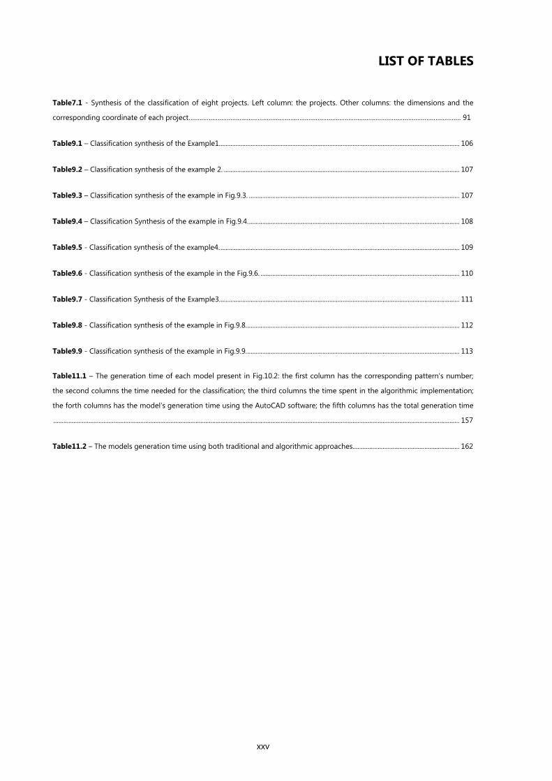
LIST OF TABLES
Table7.1 - Synthesis of the classification of eight projects. Left column: the projects. Other columns: the dimensions and the
corresponding coordinate of each project…………………………………………………………………………………………………………………………………… 91
Table9.1 – Classification synthesis of the Example1................................................................................................................................................ 106
Table9.2 – Classification synthesis of the example 2. ............................................................................................................................................. 107
Table9.3 – Classification synthesis of the example in Fig.9.3. .............................................................................................................................. 107
Table9.4 – Classification Synthesis of the example in Fig.9.4. .............................................................................................................................. 108
Table9.5 - Classification synthesis of the example4. ............................................................................................................................................... 109
Table9.6 - Classification synthesis of the example in the Fig.9.6. ....................................................................................................................... 110
Table9.7 - Classification Synthesis of the Example3................................................................................................................................................ 111
Table9.8 - Classification synthesis of the example in Fig.9.8. ............................................................................................................................... 112
Table9.9 - Classification synthesis of the example in Fig.9.9. ............................................................................................................................... 113
Table11.1 – The generation time of each model present in Fig.10.2: the first column has the corresponding pattern’s number;
the second columns the time needed for the classification; the third columns the time spent in the algorithmic implementation;
the forth columns has the model’s generation time using the AutoCAD software; the fifth columns has the total generation time
................................................................................................................................................................................................................................................... 157
Table11.2 – The models generation time using both traditional and algorithmic approaches................................................................ 162


xxvii
ABBREVIATIONS
CAD – Computer Aided Design
CAM – Computer Aided Manufacturing
CNC – Computer Numerical Control
GD – Generative Design
GS – Generative System
NURBS – Non Uniform Rational Basis Spline
PM – Parametric Model
SG – Shape Grammars
GLOSSARY OF TERMS
Facade – The outer layer of a building, which can be structural or non-structural.
Generative Design – A design process through which several potential design solutions can be
created determined by algorithms, normally by using a computer program.
Generative System – A system that generates possible solutions for design problems.
Traditional approach for using CAD tools – An approach to design in which CAD tools are used to
represent or conceive a design based on abstract models produced with explicit modeling operations.
Algorithmic system – An approach to design that is controllable and can easily handle change, which
allows the generation of several different variations of the same design.
Parametric Design – A design process based on algorithmic thinking that enables the expression of
parameters and rules that, together, define, encode and clarify the relationship between design intent
and design response.
Design Instance – One possible variation of a parametric design.
Design Parameters/Variables – Values or design proprieties that can be edited to manipulate or alter
the end result of a design.
xxviii
Program – A formal representation of a design. An algorithm written in a way that the computer
understands (a programming language) with specific and rigorous instructions that tells the computer
what specific steps to perform.
Programming – The act of translating algorithms into a programming language so that they can be
performed by the computer.
Performative Architecture – An architecture that uses digital technologies to challenge the way the
building environment is designed.
Kinetic Architecture – A concept through which buildings are designed to allow parts of the structure
to move, without reducing the overall structural integrity.

xxix
INTRODUCTION
Since the origins of Architecture that ornament has been used as a connection between nature and the
society's culture. The prehistoric man already adorned his cave walls with drawings, which transmitted
messages and gave meaning to the primitive ornamentation. Since the Classic epoch, along the
Romanesque and Gothic periods and reaching the periods of Neoclassic and Revival in architecture, it
is noticeable that ornament was always present in a more or less exuberant way. Ornamentation has
been carrying out values throughout History, such as symbolism, function, space and culture. In
addition, ornament has given meaning to architecture by creating architectural "moments"
(McNicholas, 2006). With the arrival of the 20th century, ornament began to disappear from
architecture. With the support of some theorists, among them Adolf Loos with his famous work
"Ornament and crime", Modern Architecture became undressed of ornament and obsessed with
transparency (Moussavi & Kubo, 2006), without unnecessary detail and where "Form follows function",
as Louis Sullivan described. This position was later criticized by the post-modernisms, which appealed
for an architecture with meaning that communicated with the cities and the citizens (Venturi, 1966)
and that accompanied the times that were being experienced.
The interest and disinterest in ornament is directly related with the status of the architectural Facade
which, although considered an important element until the turn of the 20th century, lost its status with
the birth of Modernism. Nowadays, the Facade is reassuming an important role, in large part, due to
the use of digital technologies (Pell, 2010).
Architecture has always followed the times and their innovations and, currently, an architecture based
on digital technologies has been emerging and has increasingly explored architectural skins, which is
visible in the latest buildings with attractive facades full of complexity and new patterns. The
development of CAD tools has had an important role in the generation of these contemporary skins
because they allow the constant exploration of new shapes and patterns, which would not be viable to
produce manually. In addition, they also increase the design efficiency and their evolution has been
changing, not only the design process, as also the architectural thinking (Kolarevic, 2003).
This emphasis on building skins with complex geometries requires a design process that allows
change, experimentation and rapid visualization of different results. Unfortunately, the traditional
design tools do not properly support the increased complexity of current facades, nor the continuous
experimentation and testing of ideas, as they require too much effort and time to change models. The
manual labor of the past using a large number of highly skilled men to produce splendid historic
facades is not viable nowadays, because it becomes extremely expensive. The computer became a very
important tool of the design process which changed, and still changes, the way architects design

xxx
(Kolarevic, 2003) and, nowadays this same work can be done quickly and minutely with the use of both
Generative Design (an approach to design based on algorithms) and new production techniques.
New technologies allow the design exploration to go far beyond the traditional possibilities and
human imagination and it has recently focused on the reintroduction of architectural patterns and in
the rebirth of building skins. Nevertheless, there are still some
limitations in the architectural practice, mainly in the production
of more complex designs. This situation frequently forces the
architect to keep the first solution that was produced, because it
would take too much time to generate a variation of the same
design. We had the good fortune of witnessing this situatin on a
visit to Bak Gordon's Studio, in Lisbon. The architect showed us a
project for Maputo — the FACIM WaterFront Project (Fig.1) —
which consisted of a set of towers, where the skin of the towers
(Fig.2) had a pattern inspired in African motifs (Fig.3). The skin
consisted of several metallic profiles shaped in order to produce a
pattern where the repeated element became gradually smaller
along the facade's length. However, the architect was not entirely
satisfied with the final result and he would like to have tested
other possible variations for the tower’s skin, but postponed the
idea because it would have taken too much time and effort. This
situation became the problem we would like to solve. As we will
show the solution required the development of a framework for
the generation of buildings skins that was easy to use and also
allowed the user to quickly change a design, in order to
experiment several results.
In this thesis, we discuss the development of a computational
framework for the design of facades and we present two
important contributions. The first contribution is a classification of
facades into different categorical dimensions that we consider
computationally relevant, which was based on an analysis of a
large corpus of contemporary facades. The second contribution is
the identification and implementation of a set of algorithms and
strategies that address the needs of the different dimensions.
Fig.1 - The FACIM WaterFront project: a
project of Bak Gordon Studio together
with FVA and PROAP for the city of
Maputo, Mozambique (source:
www.bakgordon.com)
Fig.2 – An image of the towers’ interior
with the patterned skin visible (source: Bak
Gordon's Studio)
Fig.3 - The skin pattern based on African
motifs (source: Bak Gordon's Studio)
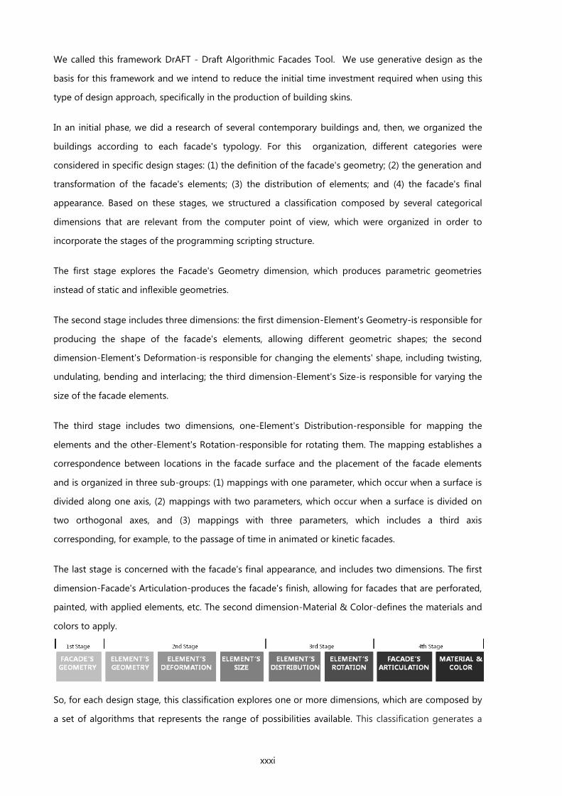
xxxi
We called this framework DrAFT - Draft Algorithmic Facades Tool. We use generative design as the
basis for this framework and we intend to reduce the initial time investment required when using this
type of design approach, specifically in the production of building skins.
In an initial phase, we did a research of several contemporary buildings and, then, we organized the
buildings according to each facade's typology. For this organization, different categories were
considered in specific design stages: (1) the definition of the facade's geometry; (2) the generation and
transformation of the facade's elements; (3) the distribution of elements; and (4) the facade's final
appearance. Based on these stages, we structured a classification composed by several categorical
dimensions that are relevant from the computer point of view, which were organized in order to
incorporate the stages of the programming scripting structure.
The first stage explores the Facade's Geometry dimension, which produces parametric geometries
instead of static and inflexible geometries.
The second stage includes three dimensions: the first dimension-Element's Geometry-is responsible for
producing the shape of the facade's elements, allowing different geometric shapes; the second
dimension-Element's Deformation-is responsible for changing the elements' shape, including twisting,
undulating, bending and interlacing; the third dimension-Element's Size-is responsible for varying the
size of the facade elements.
The third stage includes two dimensions, one-Element's Distribution-responsible for mapping the
elements and the other-Element's Rotation-responsible for rotating them. The mapping establishes a
correspondence between locations in the facade surface and the placement of the facade elements
and is organized in three sub-groups: (1) mappings with one parameter, which occur when a surface is
divided along one axis, (2) mappings with two parameters, which occur when a surface is divided on
two orthogonal axes, and (3) mappings with three parameters, which includes a third axis
corresponding, for example, to the passage of time in animated or kinetic facades.
The last stage is concerned with the facade's final appearance, and includes two dimensions. The first
dimension-Facade's Articulation-produces the facade's finish, allowing for facades that are perforated,
painted, with applied elements, etc. The second dimension-Material & Color-defines the materials and
colors to apply.
So, for each design stage, this classification explores one or more dimensions, which are composed by
a set of algorithms that represents the range of possibilities available. This classification generates a
xxxii
multi-dimensional space where an entire facade or parts of a facade can be located. The second
important contribution of our work then comes from the elaboration of a set of fundamental
algorithms and strategies that address the needs of the different dimensions of this space. Some of the
locations in this multi-dimensional space can use a specific computing approach that is adequate for
the creation of the designs that match the intended facade. Other locations, representing less common
kinds of facades, might not have a specific computational solution, but our experience shows that it is
possible, using the tools available in our framework, to quickly implement the particular solution
required by that facade.
In practical terms, the end result of our research is a library of operators usable in different
programming languages and a set of guidelines that helps a designer select and combine the most
useful operators to implement a design for a particular facade.
As a simple example, consider a perforated facade. This facade can be classified, at the very minimum,
according to the shape of the facade itself, the distribution of the perforations, and the shape of the
perforations. For each of these dimensions, we provide specific algorithms that can be combined to
achieve the intended result. The shape of the facade and the shape of the perforation are described by
independent functions, selected (or implemented) by the designer. The distribution of the perforations
and its application to the shape of the facade is achieved by the functional composition of these
functions.
Our work is implemented using Rosetta, a programming environment for generative design, allowing
us to explore the generation of facades in common CAD applications, thus promoting the integration
of the generative design approach in a more traditional working environment.
Our proposal does not exclude other approaches for the design process, it is simply an additional
stage specialized in the generation of buildings skins. Instead, it allows the designer to go further in
the exploration of different design solutions to apply on architectural facades, such as complex
geometries, intricate patterns and new textures.
xxxiii
OBJECTIVES
The main objective of this dissertation is to develop a methodology that helps architects in the
generation of facades by using an algorithmic approach to design. We explore and evaluate the
different design stages that constitute an algorithmic-based design approach, more specifically, for the
generation of building skins, and based on those stages, we propose a classification of facades. The
aim of the classification is to help designers in the selection of the algorithms that better suit their
design intent.
Our approach is evaluated both on several case studies already constructed and on more abstract
examples idealized by us. The selected case studies have either a particular skin pattern or an unusual
texture or shape. The application of the framework on each of the case studies also shows how to
easily change the original design, whether it is a small or a large change, with repercussions in all the
design parts, such as geometry, number of elements, size, etc.
The construction of our framework has three main goals:
1. Create a classification of facades that organizes the design process into substantial phases
that guide the selection of the algorithms that better suit each design intent.
2. Provide several pre-defined functions to generate different design solutions of facades.
3. Inspire a future wider framework (with more design options) from which architects can select
functions already defined. In addition, it would be possible to implement other functions that
meet more specific design solutions and add them to the framework, so it becomes
increasingly more complete.
METHODOLOGY
We followed a methodology based on four main phases: (1) literature review, (2) explanation of the
framework’s strategy and a detailed description of the classification, (3) practical application of the
framework, (4) evaluation and conclusions.
The first phase, the literature review, consists in a review of bibliography focused on the relevance of
the architectural facade, on new architectural expressions and on new design tools, particularly
Generative Design. The research allowed the understanding of the connection between (1) the building
skins and new ornamentations and (2) the emerging paradigms in architectural practice, such as
parametric architecture and performative architecture, and (3) the tools that allowed this fusion, like
Generative Systems.
The second phase starts with the motivation of the framework and the explanation of the process
behind the classification of facades. We explain the structure of the classification, which was divided in
xxxiv
several categorical dimensions, and we describe each dimension’s functionalities and the pre-defined
functions provided. In the end, we summarize all the dimensions to present an overview of the
classification’s possibilities.
The third phase starts with some practical examples of the application of the classification on existing
building skins. Then, we explain the process behind the generation of a facade design and we divide it
in four phases: from the stage of the design analysis to the experimentation of the model’s possible
instances. For this, we use an existing building as an example, the Library of Birmingham. We follow
with a practical application of the framework, first in the generation of abstract examples and, then, in
the generation of real examples. In the end, we suggest other possible applications for our framework,
besides the generation of facade’s models.
The last phase, the evaluation and conclusions, starts with the review of the work developed and, then,
we evaluate our framework and compare to other existing applications. In the end, based on the
evaluation, we present the conclusions and the future work.
STRUCTURE
This dissertation is divided into two main parts: I. Background and II. A Framework for the generation of
Contemporary Facades. We also added to these two parts the Introduction, Conclusions and
Bibliography sections.
The Background is divided in four chapters:
1 Ornament | In this chapter we define ornament, decoration and pattern. We analyze the
presence of ornament and its theoretic evolution in the history of Architecture.
2 The Contemporary Facade: New Expressions in Architecture | In this chapter we focus on
the status and evolution of the architectural facade. We also describe some of the
contemporary expressions in the architecture field, like performative, parametric, adaptive, and
kinetic architecture.
3 New Technologies | In this chapter we define Generative Design (GD), the beginnings of
Generative Systems in architecture and their maturity. We explain the main characteristics of
several GSs, such as Algorithmic Systems, Parametric Systems, Shape Grammars, Genetic
Algorithms, Cellular Automata and L-Systems.
4 Generative Design: Architectural Practice | In the last chapter of this part we characterize
some of the strategies that are being used to apply GD in architectural practice. We also
include two case studies of well-known and documented projects, the Aviva Stadium and
Water Cube, which are examples of an integrated approach in which GD was used from the
initial stage of the project to its construction.

xxxv
The Second part of this dissertation, A Framework for the Generation of Contemporary Facades, is
divided in seven chapters:
5 Introduction | In this chapter we reintroduced the main objective of this dissertation to
contextualize the second part.
6 Algorithmic Facades | In this chapter we introduce the framework and we structure the
classification for facades. We explain the inspiration and the main objective of the classification
and we describe in detail all the categorical dimensions that constitute the classification. In the
end we summarize all the classification in a single table, in order to promote an overview of its
whole structure.
7 The Application of the Facade’s Classification | In this chapter we classify several existing
facades in order to promote a better understanding of how the classification works.
8 Facades Generation Process | In this chapter we pick the Library of Birmingham project as an
example on which we explain the whole process behind the generation of a building’s skin.
This process was divided into four phases: (1) design analysis, (2) the application of the
classification, (3) the implementation of the algorithms to generate the model and (4) the
variation of the model’s design.
9 The Generation of Contemporary Facades | In this chapter we apply the algorithms available
within the framework to generate some example of building skins. We produce a first set of
more abstract skins, because we aim to explain how to use the classification and the
corresponding algorithms in the generation of a facade’s design. The second set of facades
that we generate corresponds to real projects, which we try to reproduce and, then, use to
experiment other design possibilities.
10 Other Applications | In this chapter we suggest other applications for our framework, more
specifically in interior design.
11 Evaluation | In this chapter we evaluate our work in several stages: we start by evaluating (1)
the flexibility of our framework, i.e. its capacity to generate a wide range of possible designs
for facades. Then, we analyze (2) its advantageous use comparing with the traditional
approach, i.e. how fast and easily we can generate models using the framework, and finally (3)
its portability, i.e. its capacity to be used with different CAD tools.

PART I BACKGROUND

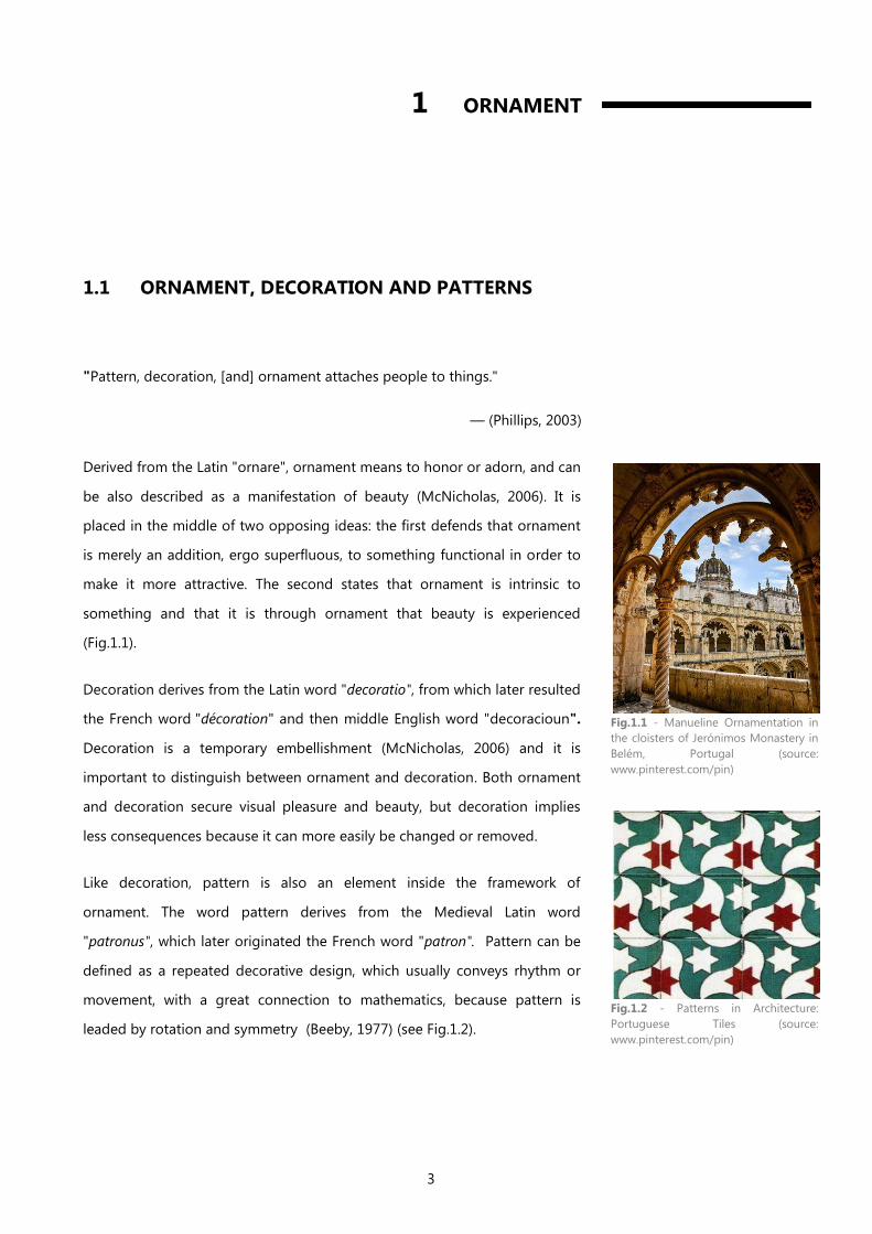
3
1 ORNAMENT
1.1 ORNAMENT, DECORATION AND PATTERNS
"Pattern, decoration, [and] ornament attaches people to things."
— (Phillips, 2003)
Derived from the Latin "ornare", ornament means to honor or adorn, and can
be also described as a manifestation of beauty (McNicholas, 2006). It is
placed in the middle of two opposing ideas: the first defends that ornament
is merely an addition, ergo superfluous, to something functional in order to
make it more attractive. The second states that ornament is intrinsic to
something and that it is through ornament that beauty is experienced
(Fig.1.1).
Decoration derives from the Latin word "decoratio", from which later resulted
the French word "décoration" and then middle English word "decoracioun".
Decoration is a temporary embellishment (McNicholas, 2006) and it is
important to distinguish between ornament and decoration. Both ornament
and decoration secure visual pleasure and beauty, but decoration implies
less consequences because it can more easily be changed or removed.
Like decoration, pattern is also an element inside the framework of
ornament. The word pattern derives from the Medieval Latin word
"patronus", which later originated the French word "patron". Pattern can be
defined as a repeated decorative design, which usually conveys rhythm or
movement, with a great connection to mathematics, because pattern is
leaded by rotation and symmetry (Beeby, 1977) (see Fig.1.2).
Fig.1.1 - Manueline Ornamentation in
the cloisters of Jerónimos Monastery in
Belém, Portugal (source:
www.pinterest.com/pin)
Fig.1.2 - Patterns in Architecture:
Portuguese Tiles (source:
www.pinterest.com/pin)
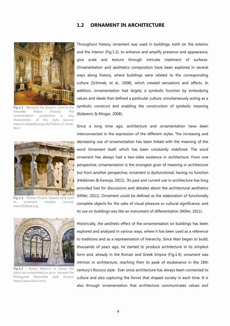
4
1.2 ORNAMENT IN ARCHITECTURE
Throughout history, ornament was used in buildings, both on the exterior
and the interior (Fig.1.3), to enhance and amplify presence and appearance,
give scale and texture through intricate treatment of surfaces.
Ornamentation and aesthetics composition have been explored in several
ways along history, where buildings were related to the corresponding
culture (Schimek, et al., 2008), which created sensations and affects. In
addition, ornamentation had largely a symbolic function by embodying
values and ideals that defined a particular culture, simultaneously acting as a
symbolic construct and enabling the construction of symbolic meaning
(Kolarevic & Klinger, 2008).
Since a long time ago, architecture and ornamentation have been
interconnected in the expression of the different styles. The increasing and
decreasing use of ornamentation has been linked with the meaning of the
word Ornament itself, which has been constantly redefined. The word
ornament has always had a two-sides existence in architecture. From one
perspective, ornamentation is the strongest giver of meaning in architecture
but from another perspective, ornament is dysfunctional, having no function
(Heikkinen & Kareoja, 2011). Its past and current use in architecture has long
provided fuel for discussions and debates about the architectural aesthetics
(Miller, 2011). Ornament could be defined as the elaboration of functionally
complete objects for the sake of visual pleasure or cultural significance, and
its use on buildings was like an instrument of differentiation (Miller, 2011).
Historically, the aesthetic effect of the ornamentation on buildings has been
explored and analyzed in various ways, where it has been used as a reference
to traditions and as a representation of hierarchy. Since Man began to build,
thousands of years ago, he started to produce architecture in its simplest
form and, already in the Roman and Greek Empire (Fig.1.4), ornament was
intrinsic in architecture, reaching then its peak of exuberance in the 18th
century's Rococo style. Ever since architecture has always been connected to
culture and also capturing the forces that shaped society in each time. It is
also through ornamentation that architecture communicates values and
Fig.1.3 - Baroque: the Queen's room in the
Versailles Palace (France). The
ornamentation exuberance is very
characteristic of this style (source:
www.en.wikipedia.org/wiki/Palace_of_Versai
lles/)
Fig.1.4 – Roman Empire: Statues were used
to ornament temples (source:
www.2020site.org)
Fig.1.5 – Rossio Station’s in Lisbon: the
doors are ornamented so as to recreate the
Portuguese Manueline style (source:
https://www.flickr.com/)
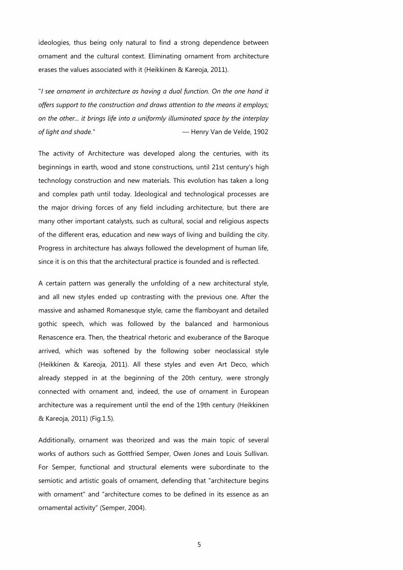
5
ideologies, thus being only natural to find a strong dependence between
ornament and the cultural context. Eliminating ornament from architecture
erases the values associated with it (Heikkinen & Kareoja, 2011).
"I see ornament in architecture as having a dual function. On the one hand it
offers support to the construction and draws attention to the means it employs;
on the other... it brings life into a uniformly illuminated space by the interplay
of light and shade." — Henry Van de Velde, 1902
The activity of Architecture was developed along the centuries, with its
beginnings in earth, wood and stone constructions, until 21st century's high
technology construction and new materials. This evolution has taken a long
and complex path until today. Ideological and technological processes are
the major driving forces of any field including architecture, but there are
many other important catalysts, such as cultural, social and religious aspects
of the different eras, education and new ways of living and building the city.
Progress in architecture has always followed the development of human life,
since it is on this that the architectural practice is founded and is reflected.
A certain pattern was generally the unfolding of a new architectural style,
and all new styles ended up contrasting with the previous one. After the
massive and ashamed Romanesque style, came the flamboyant and detailed
gothic speech, which was followed by the balanced and harmonious
Renascence era. Then, the theatrical rhetoric and exuberance of the Baroque
arrived, which was softened by the following sober neoclassical style
(Heikkinen & Kareoja, 2011). All these styles and even Art Deco, which
already stepped in at the beginning of the 20th century, were strongly
connected with ornament and, indeed, the use of ornament in European
architecture was a requirement until the end of the 19th century (Heikkinen
& Kareoja, 2011) (Fig.1.5).
Additionally, ornament was theorized and was the main topic of several
works of authors such as Gottfried Semper, Owen Jones and Louis Sullivan.
For Semper, functional and structural elements were subordinate to the
semiotic and artistic goals of ornament, defending that "architecture begins
with ornament" and “architecture comes to be defined in its essence as an
ornamental activity” (Semper, 2004).
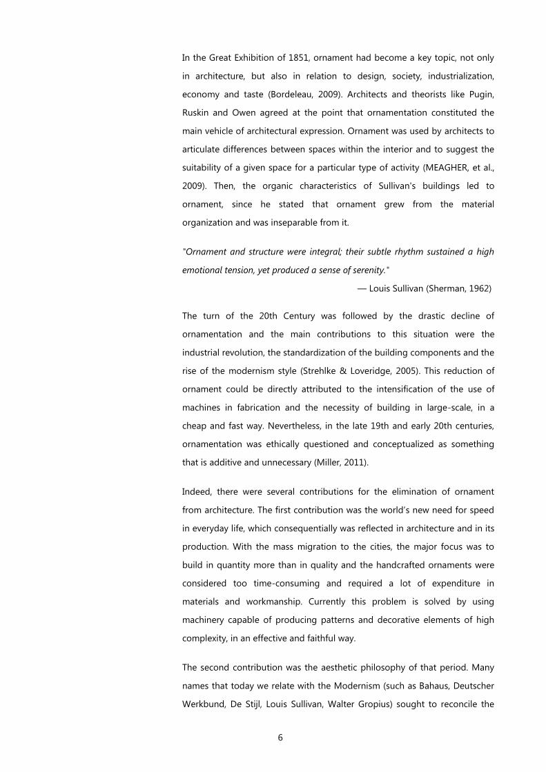
6
In the Great Exhibition of 1851, ornament had become a key topic, not only
in architecture, but also in relation to design, society, industrialization,
economy and taste (Bordeleau, 2009). Architects and theorists like Pugin,
Ruskin and Owen agreed at the point that ornamentation constituted the
main vehicle of architectural expression. Ornament was used by architects to
articulate differences between spaces within the interior and to suggest the
suitability of a given space for a particular type of activity (MEAGHER, et al.,
2009). Then, the organic characteristics of Sullivan's buildings led to
ornament, since he stated that ornament grew from the material
organization and was inseparable from it.
"Ornament and structure were integral; their subtle rhythm sustained a high
emotional tension, yet produced a sense of serenity."
— Louis Sullivan (Sherman, 1962)
The turn of the 20th Century was followed by the drastic decline of
ornamentation and the main contributions to this situation were the
industrial revolution, the standardization of the building components and the
rise of the modernism style (Strehlke & Loveridge, 2005). This reduction of
ornament could be directly attributed to the intensification of the use of
machines in fabrication and the necessity of building in large-scale, in a
cheap and fast way. Nevertheless, in the late 19th and early 20th centuries,
ornamentation was ethically questioned and conceptualized as something
that is additive and unnecessary (Miller, 2011).
Indeed, there were several contributions for the elimination of ornament
from architecture. The first contribution was the world’s new need for speed
in everyday life, which consequentially was reflected in architecture and in its
production. With the mass migration to the cities, the major focus was to
build in quantity more than in quality and the handcrafted ornaments were
considered too time-consuming and required a lot of expenditure in
materials and workmanship. Currently this problem is solved by using
machinery capable of producing patterns and decorative elements of high
complexity, in an effective and faithful way.
The second contribution was the aesthetic philosophy of that period. Many
names that today we relate with the Modernism (such as Bahaus, Deutscher
Werkbund, De Stijl, Louis Sullivan, Walter Gropius) sought to reconcile the
7
arts and crafts with the new methods of mass production. In addition, Adolf
Loos wrote a theory of no ornamentation in 1908, where he described
ornament as a need of the primitive man, because it did not reflect the
modern times and it made the buildings quickly out of style. For him,
producing something that quickly would stay out of fashion was a waste of
time and effort and there was no place for these things in modern society.
For him the lack of decoration was a manifestation of a progressive,
advanced culture (Loos, 1908), where ornamentation had lost its social
function, becoming unnecessary. Consequentially, the Modern Movement
believed that to be authentically “modern” one has to remove all ornament
(Kolarevic & Klinger, 2008), which led to the barren surfaces of much
twentieth-century architecture. To sum up, Modernists eliminated ornament
to provide an architectural experience of true space (more sincere
architecture) based on transparency but not on ornamentation (Moussavi &
Kubo, 2006), which aimed to achieve the direct representation of
architectural elements, such as space, structure and function.
Contrary to this perspective, Postmodernism architecture used
ornamentation again to support the desire of communication, thus
celebrating the use of ornament (Miller, 2011). The strength of mass-
communication was in its apogee, and the society was influenced by the
media more than ever. Postmodernists believed in an architecture that
communicated its function and underlined the importance of
communication in our lives. The modernism transparency was replaced for
decor, thus helping the integration of buildings within the urban realm and
simultaneously giving them meaning. They defended that, such as language,
text, design and performance communicate with us, so does architecture and
mostly through the use of ornament.
"If the structure and composition is the plot, it is the details that turn it into a
tale. Only by careful detailing can we make the tale interesting and worth
listening to, without that it is just an empty string of events to which we can
find no emotional attachment. We can hate the ornamentation in question or
we can love it, but the important thing is that it doesn't leave us cold and
indifferent."
— (Frascari, 1983)
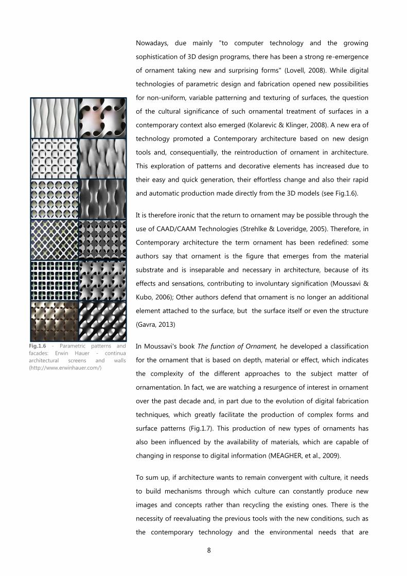
8
Nowadays, due mainly "to computer technology and the growing
sophistication of 3D design programs, there has been a strong re-emergence
of ornament taking new and surprising forms" (Lovell, 2008). While digital
technologies of parametric design and fabrication opened new possibilities
for non-uniform, variable patterning and texturing of surfaces, the question
of the cultural significance of such ornamental treatment of surfaces in a
contemporary context also emerged (Kolarevic & Klinger, 2008). A new era of
technology promoted a Contemporary architecture based on new design
tools and, consequentially, the reintroduction of ornament in architecture.
This exploration of patterns and decorative elements has increased due to
their easy and quick generation, their effortless change and also their rapid
and automatic production made directly from the 3D models (see Fig.1.6).
It is therefore ironic that the return to ornament may be possible through the
use of CAAD/CAAM Technologies (Strehlke & Loveridge, 2005). Therefore, in
Contemporary architecture the term ornament has been redefined: some
authors say that ornament is the figure that emerges from the material
substrate and is inseparable and necessary in architecture, because of its
effects and sensations, contributing to involuntary signification (Moussavi &
Kubo, 2006); Other authors defend that ornament is no longer an additional
element attached to the surface, but the surface itself or even the structure
(Gavra, 2013)
In Moussavi's book The function of Ornament, he developed a classification
for the ornament that is based on depth, material or effect, which indicates
the complexity of the different approaches to the subject matter of
ornamentation. In fact, we are watching a resurgence of interest in ornament
over the past decade and, in part due to the evolution of digital fabrication
techniques, which greatly facilitate the production of complex forms and
surface patterns (Fig.1.7). This production of new types of ornaments has
also been influenced by the availability of materials, which are capable of
changing in response to digital information (MEAGHER, et al., 2009).
To sum up, if architecture wants to remain convergent with culture, it needs
to build mechanisms through which culture can constantly produce new
images and concepts rather than recycling the existing ones. There is the
necessity of reevaluating the previous tools with the new conditions, such as
the contemporary technology and the environmental needs that are
Fig.1.6 - Parametric patterns and
facades: Erwin Hauer - continua
architectural screens and walls
(http://www.erwinhauer.com/)

9
emerging nowadays (Moussavi & Kubo, 2006). Contemporary ornamentation
rejects the superficial applications of previous architectural genres or styles
and, simultaneously, seeks for a new authenticity.
Fig.1.7 - Contemporary Ornament: John Lewis department store in Leicester, UK, Foreign Office
Architects (source: http://designresearch.sva.edu/research/patterns-of-ornament-technology-
and-theory-in-contemporary-architectural-decoration-2/)


11
2 THE CONTEMPORARY FACADE:
New expressions in Architecture
Originating from the Italian word faccia, which means face, and its derivate
word facciata, the French word façade (and then the English word facade)
can be defined as the exterior side or skin of a building. Before Modernism,
buildings' facades were the canvas where architectural style was celebrated.
On this canvas, architects imprinted their personal interpretation of the
current cultural stylistic models, with their metrics and canons. With the
arrival of the 20th century, architects began to diverge from the symbolisms
carried by the facade and the modernism facade became an abstraction
without ornament. It was with Modernism and its hygienic and austere
aesthetic that the architectural task of composing a facade lost some of its
prestige. As a result, the architectural facade lost its status (Pell, 2010).
After Modernism (or since Post-modernism), we have been witnessing an
increasing interest in facade composition and, nowadays, designing a facade
is reassuming an important role in architecture practice due, in part, to the
support of digital technologies (Pell, 2010).
This trend of highly textured building envelopes celebrates, again, the
ornament in architecture and the composition of architectural facades. There
are historical and cultural reasons for this renewed interest, such as the
reinterpretation of Modernist aesthetics, the reintroduction of symbolism
and historical precedent by Post-Modernism (Venturi, 1966), and the diligent
look and revisit of vernacular precedent proposed by Critical Regionalism
(Frampton, 1983). However, there is also a technological reason: algorithmic
approaches made it easier to conceive, deploy and adapt the design of
architectural surfaces with complex and intricate textures, and differentiated
levels of porosity.
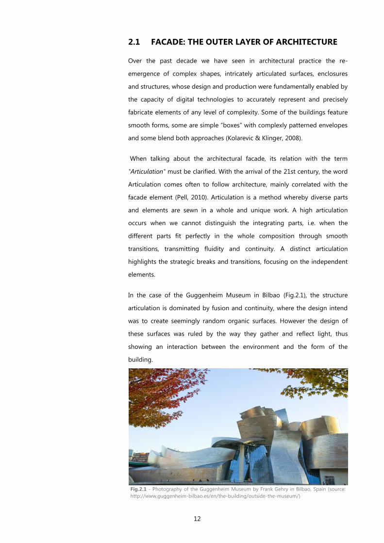
12
2.1 FACADE: THE OUTER LAYER OF ARCHITECTURE
Over the past decade we have seen in architectural practice the re-
emergence of complex shapes, intricately articulated surfaces, enclosures
and structures, whose design and production were fundamentally enabled by
the capacity of digital technologies to accurately represent and precisely
fabricate elements of any level of complexity. Some of the buildings feature
smooth forms, some are simple “boxes” with complexly patterned envelopes
and some blend both approaches (Kolarevic & Klinger, 2008).
When talking about the architectural facade, its relation with the term
"Articulation" must be clarified. With the arrival of the 21st century, the word
Articulation comes often to follow architecture, mainly correlated with the
facade element (Pell, 2010). Articulation is a method whereby diverse parts
and elements are sewn in a whole and unique work. A high articulation
occurs when we cannot distinguish the integrating parts, i.e. when the
different parts fit perfectly in the whole composition through smooth
transitions, transmitting fluidity and continuity. A distinct articulation
highlights the strategic breaks and transitions, focusing on the independent
elements.
In the case of the Guggenheim Museum in Bilbao (Fig.2.1), the structure
articulation is dominated by fusion and continuity, where the design intend
was to create seemingly random organic surfaces. However the design of
these surfaces was ruled by the way they gather and reflect light, thus
showing an interaction between the environment and the form of the
building.
Fig.2.1 - Photography of the Guggenheim Museum by Frank Gehry in Bilbao, Spain (source:
http://www.guggenheim-bilbao.es/en/the-building/outside-the-museum/)
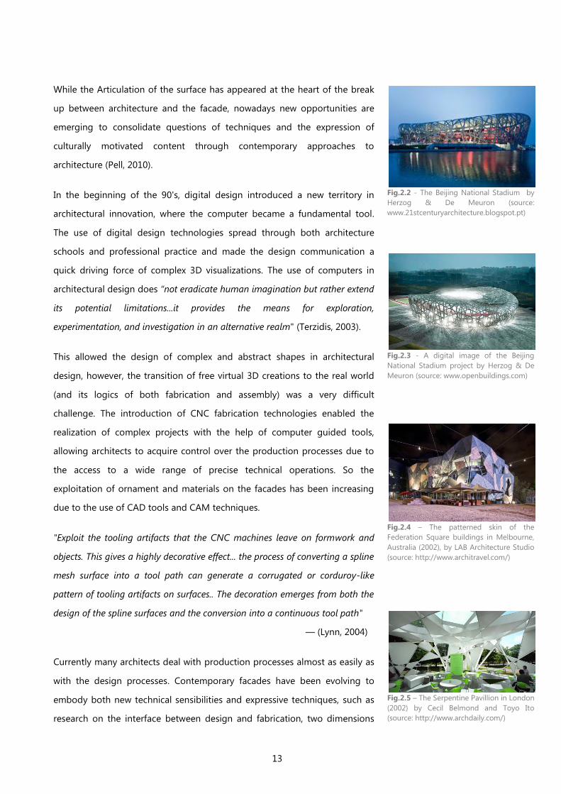
13
While the Articulation of the surface has appeared at the heart of the break
up between architecture and the facade, nowadays new opportunities are
emerging to consolidate questions of techniques and the expression of
culturally motivated content through contemporary approaches to
architecture (Pell, 2010).
In the beginning of the 90's, digital design introduced a new territory in
architectural innovation, where the computer became a fundamental tool.
The use of digital design technologies spread through both architecture
schools and professional practice and made the design communication a
quick driving force of complex 3D visualizations. The use of computers in
architectural design does “not eradicate human imagination but rather extend
its potential limitations...it provides the means for exploration,
experimentation, and investigation in an alternative realm" (Terzidis, 2003).
This allowed the design of complex and abstract shapes in architectural
design, however, the transition of free virtual 3D creations to the real world
(and its logics of both fabrication and assembly) was a very difficult
challenge. The introduction of CNC fabrication technologies enabled the
realization of complex projects with the help of computer guided tools,
allowing architects to acquire control over the production processes due to
the access to a wide range of precise technical operations. So the
exploitation of ornament and materials on the facades has been increasing
due to the use of CAD tools and CAM techniques.
"Exploit the tooling artifacts that the CNC machines leave on formwork and
objects. This gives a highly decorative effect... the process of converting a spline
mesh surface into a tool path can generate a corrugated or corduroy-like
pattern of tooling artifacts on surfaces.. The decoration emerges from both the
design of the spline surfaces and the conversion into a continuous tool path"
— (Lynn, 2004)
Currently many architects deal with production processes almost as easily as
with the design processes. Contemporary facades have been evolving to
embody both new technical sensibilities and expressive techniques, such as
research on the interface between design and fabrication, two dimensions
Fig.2.2 - The Beijing National Stadium by
Herzog & De Meuron (source:
www.21stcenturyarchitecture.blogspot.pt)
Fig.2.3 - A digital image of the Beijing
National Stadium project by Herzog & De
Meuron (source: www.openbuildings.com)
Fig.2.4 – The patterned skin of the
Federation Square buildings in Melbourne,
Australia (2002), by LAB Architecture Studio
(source: http://www.architravel.com/)
Fig.2.5 – The Serpentine Pavillion in London
(2002) by Cecil Belmond and Toyo Ito
(source: http://www.archdaily.com/)
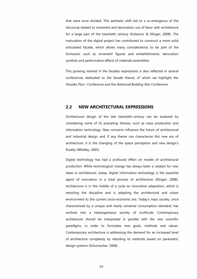
14
that were once divided. This aesthetic shift led to a re-emergence of the
discourse related to ornament and decoration, out of favor with architecture
for a large part of the twentieth century (Kolarevic & Klinger, 2008). The
maturation of the digital project has contributed to construct a more solid
articulated facade, which allows many considerations to be part of the
formwork, such as ornament figures and embellishments, decoration
symbols and performative effects of materials assemblies.
This growing interest in the facades expressions is also reflected in several
conferences dedicated to the facade theme, of which we highlight the
Facades Plus+ Conference and the Advanced Building Skin Conference.
2.2 NEW ARCHITECTURAL EXPRESSIONS
Architectural design of the late twentieth-century can be analyzed by
considering some of its prevailing themes, such as mass production and
information technology. New concerns influence the future of architectural
and industrial design and, if any theme can characterize this new era of
architecture, it is the changing of the space perception and new design's
fluidity (Whalley, 2005).
Digital technology has had a profound effect on modes of architectural
production. While technological change has always been a catalyst for new
ideas in architecture, today, digital information technology is the essential
agent of innovation in a total process of architecture (Klinger, 2008).
Architecture is in the middle of a cycle on innovative adaptation, which is
retooling the discipline and is adapting the architectural and urban
environment to the current socio-economic era. Today’s mass society, once
characterized by a unique and nearly universal consumption standard, has
evolved into a heterogeneous society of multitude. Contemporary
architecture should be interpreted in parallel with the new scientific
paradigms, in order to formulate new goals, methods and values.
Contemporary architecture is addressing the demand for an increased level
of architecture complexity by retooling its methods based on parametric
design systems (Schumacher, 2008).
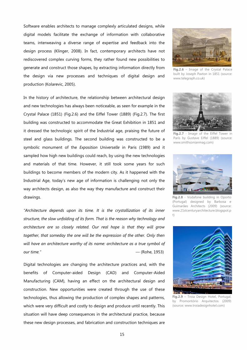
15
Software enables architects to manage complexly articulated designs, while
digital models facilitate the exchange of information with collaborative
teams, interweaving a diverse range of expertise and feedback into the
design process (Klinger, 2008). In fact, contemporary architects have not
rediscovered complex curving forms, they rather found new possibilities to
generate and construct those shapes, by extracting information directly from
the design via new processes and techniques of digital design and
production (Kolarevic, 2005).
In the history of architecture, the relationship between architectural design
and new technologies has always been noticeable, as seen for example in the
Crystal Palace (1851) (Fig.2.6) and the Eiffel Tower (1889) (Fig.2.7). The first
building was constructed to accommodate the Great Exhibition in 1851 and
it dressed the technologic spirit of the Industrial age, praising the future of
steel and glass buildings. The second building was constructed to be a
symbolic monument of the Exposition Universelle in Paris (1989) and it
sampled how high new buildings could reach, by using the new technologies
and materials of that time. However, it still took some years for such
buildings to become members of the modern city. As it happened with the
Industrial Age, today’s new age of information is challenging not only the
way architects design, as also the way they manufacture and construct their
drawings.
“Architecture depends upon its time. It is the crystallization of its inner
structure, the slow unfolding of its form. That is the reason why technology and
architecture are so closely related. Our real hope is that they will grow
together, that someday the one will be the expression of the other. Only then
will have an architecture worthy of its name: architecture as a true symbol of
our time.” — (Rohe, 1953)
Digital technologies are changing the architecture practices and, with the
benefits of Computer-aided Design (CAD) and Computer-Aided
Manufacturing (CAM), having an effect on the architectural design and
construction. New opportunities were created through the use of these
technologies, thus allowing the production of complex shapes and patterns,
which were very difficult and costly to design and produce until recently. This
situation will have deep consequences in the architectural practice, because
these new design processes, and fabrication and construction techniques are
Fig.2.6 – Image of the Crystal Palace
built by Joseph Paxton in 1851 (source:
www.telegraph.co.uk)
Fig.2.7 - Image of the Eiffel Tower in
Paris by Gustave Eiffel (1889) (source: www.smithsonianmag.com)
Fig.2.8 - Vodafone building in Oporto
(Portugal) designed by Barbosa e
Guimarães Architects (2009) (source:
www.21stcenturyarchitecture.blogspot.p
t)
Fig.2.9 – Troia Design Hotel, Portugal,
by Promontório Arquitectos (2009)
(source: www.troiadesignhotel.com)
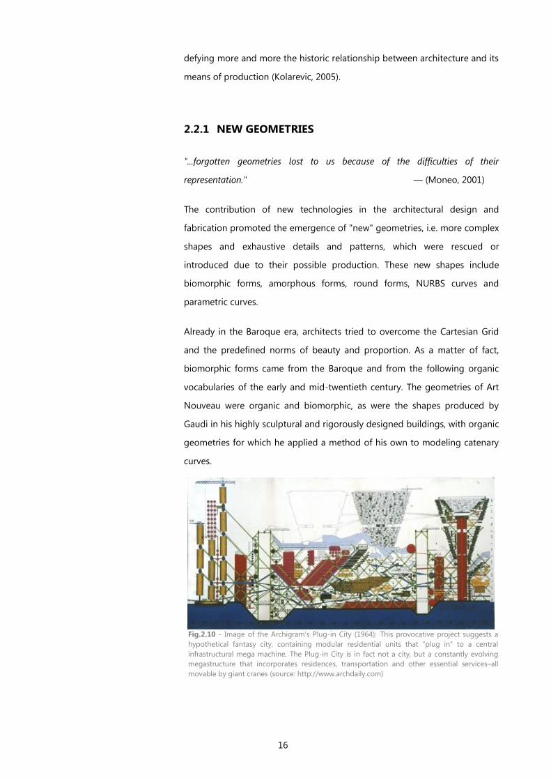
16
defying more and more the historic relationship between architecture and its
means of production (Kolarevic, 2005).
2.2.1 NEW GEOMETRIES
"...forgotten geometries lost to us because of the difficulties of their
representation." — (Moneo, 2001)
The contribution of new technologies in the architectural design and
fabrication promoted the emergence of "new" geometries, i.e. more complex
shapes and exhaustive details and patterns, which were rescued or
introduced due to their possible production. These new shapes include
biomorphic forms, amorphous forms, round forms, NURBS curves and
parametric curves.
Already in the Baroque era, architects tried to overcome the Cartesian Grid
and the predefined norms of beauty and proportion. As a matter of fact,
biomorphic forms came from the Baroque and from the following organic
vocabularies of the early and mid-twentieth century. The geometries of Art
Nouveau were organic and biomorphic, as were the shapes produced by
Gaudi in his highly sculptural and rigorously designed buildings, with organic
geometries for which he applied a method of his own to modeling catenary
curves.
Fig.2.10 - Image of the Archigram's Plug-in City (1964): This provocative project suggests a
hypothetical fantasy city, containing modular residential units that “plug in” to a central
infrastructural mega machine. The Plug-in City is in fact not a city, but a constantly evolving
megastructure that incorporates residences, transportation and other essential services–all
movable by giant cranes (source: http://www.archdaily.com)

17
The “formless” designs of the 60's and 70's also reviewed themselves in
Contemporary architecture. Groups such as Archigram, Superstudio and
Metabolism, gave birth to an utopian architecture based on the fusion
between new technologies and architecture. This emphasizes the tendency
of architectural practice to exploit and adapt new technological advances.
Archigram's projects have introduced new visions and interpretations of
what should be the place of technology in the society and culture (see
Fig.2.10). Their works constituted games of meaning between mechanics and
organics, which then originated utopian projects that broke with the norms
of beauty and function of their time.
Throughout the history of architecture, specially up until the later periods of
the 19th
century, we can see a great presence of round shapes in buildings,
but those have since then been diminished and excluded. In present times
however, round shapes have been rescued by the new architecture, in great
part due to the help of 3D modeling tools. With them the industrial
production and manufacturing of smooth curved structures was facilitated
and achievable. Complex curvilinear shapes are produced as easily as the
traditional geometries and are described mathematically as NURBS curves
(Non-Uniform - Rational B-Splines). The attractiveness of these geometries is
the ability to easily control their shape, through the manipulation of control
points, and also the attainable production of these coherent forms (see
Fig2.13).
The use of parametric surfaces is also rising in the field of Contemporary
architecture: the design of parametric shapes has an intent behind it, which
dictates the parameters for a sort of design instead of the shape itself. The
configuration of parametric design depends on the parameters given values
and this design approach adopts an exploitation of infinitely different results,
instead of fixed solutions (Kolarevic, 2005).
In addition to these highly complex forms, there is also a tendency for the
production of architectural screen walls, which can have linear or complex
shapes but with intricate patterns (see Fig2.15). Screens became a common
and rich architectural device that can separate spaces, while maintaining a
certain visual. In contrast to glass, screens have a strong presence and offer
the possibility to vary their materials, color, texture, etc. They can assume
Fig.2.11 – ICD/TKE Research Pavilion
(2011) in Stuttgart University by Achim
Menges and J. Knippers (source:
www.achimmenges.net/)
Fig.2.12– 3D Spacer Textile Composites
by Nico Reinhardt (source:
www.achimmenges.net/)
Fig.2.13 - Image of a NURBS surface
with its controllable vertices in red
(source: www.3dmax-tutorials.com)
Fig.2.14 - Photography of BMW Welt in
Munich by Coop Himmelb(l)au (source:
www.archithings.com)
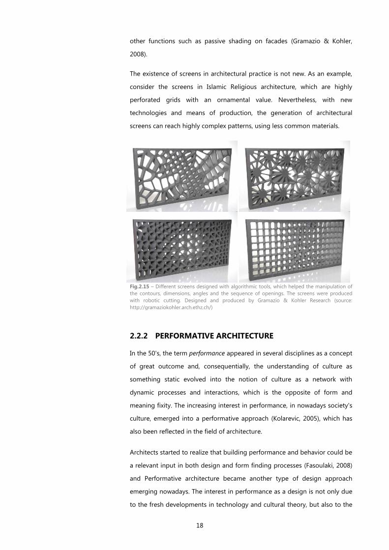
18
other functions such as passive shading on facades (Gramazio & Kohler,
2008).
The existence of screens in architectural practice is not new. As an example,
consider the screens in Islamic Religious architecture, which are highly
perforated grids with an ornamental value. Nevertheless, with new
technologies and means of production, the generation of architectural
screens can reach highly complex patterns, using less common materials.
Fig.2.15 – Different screens designed with algorithmic tools, which helped the manipulation of
the contours, dimensions, angles and the sequence of openings. The screens were produced
with robotic cutting. Designed and produced by Gramazio & Kohler Research (source:
http://gramaziokohler.arch.ethz.ch/)
2.2.2 PERFORMATIVE ARCHITECTURE
In the 50's, the term performance appeared in several disciplines as a concept
of great outcome and, consequentially, the understanding of culture as
something static evolved into the notion of culture as a network with
dynamic processes and interactions, which is the opposite of form and
meaning fixity. The increasing interest in performance, in nowadays society's
culture, emerged into a performative approach (Kolarevic, 2005), which has
also been reflected in the field of architecture.
Architects started to realize that building performance and behavior could be
a relevant input in both design and form finding processes (Fasoulaki, 2008)
and Performative architecture became another type of design approach
emerging nowadays. The interest in performance as a design is not only due
to the fresh developments in technology and cultural theory, but also to the
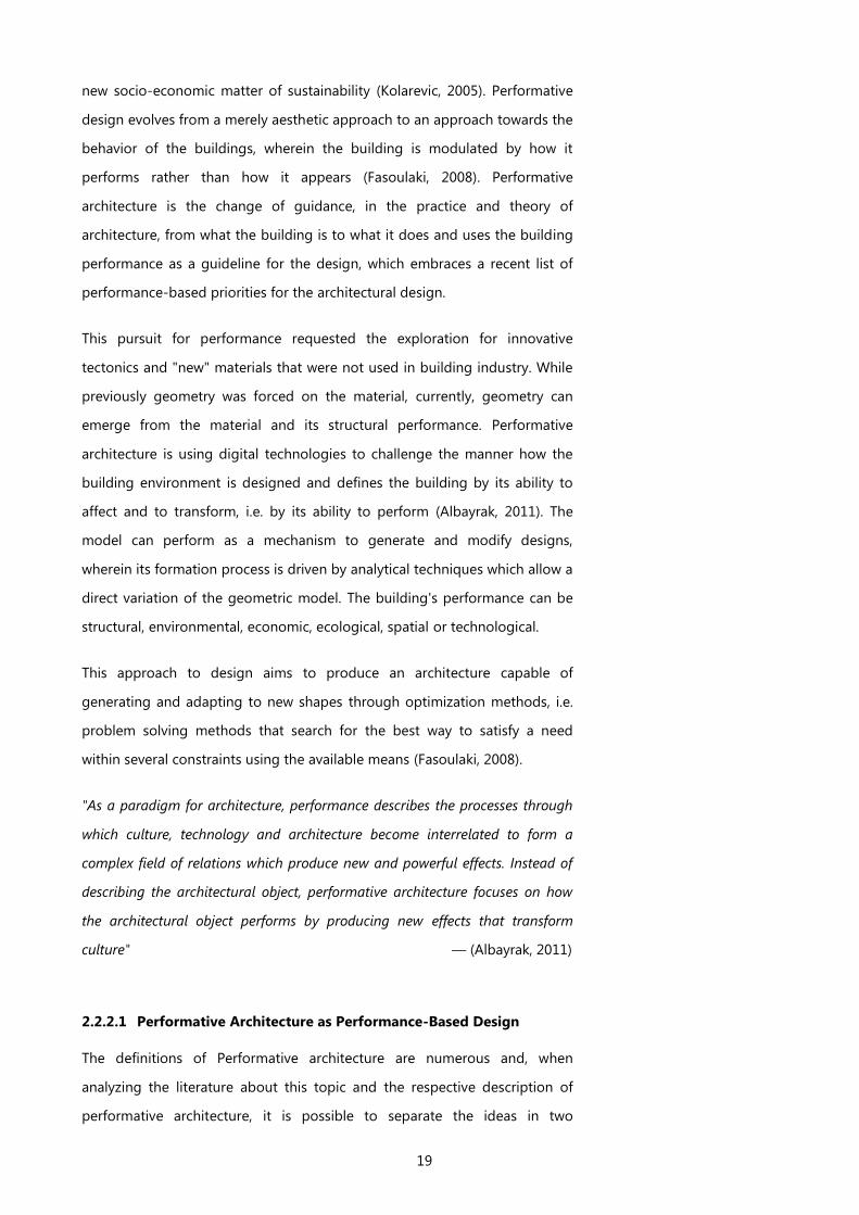
19
new socio-economic matter of sustainability (Kolarevic, 2005). Performative
design evolves from a merely aesthetic approach to an approach towards the
behavior of the buildings, wherein the building is modulated by how it
performs rather than how it appears (Fasoulaki, 2008). Performative
architecture is the change of guidance, in the practice and theory of
architecture, from what the building is to what it does and uses the building
performance as a guideline for the design, which embraces a recent list of
performance-based priorities for the architectural design.
This pursuit for performance requested the exploration for innovative
tectonics and "new" materials that were not used in building industry. While
previously geometry was forced on the material, currently, geometry can
emerge from the material and its structural performance. Performative
architecture is using digital technologies to challenge the manner how the
building environment is designed and defines the building by its ability to
affect and to transform, i.e. by its ability to perform (Albayrak, 2011). The
model can perform as a mechanism to generate and modify designs,
wherein its formation process is driven by analytical techniques which allow a
direct variation of the geometric model. The building's performance can be
structural, environmental, economic, ecological, spatial or technological.
This approach to design aims to produce an architecture capable of
generating and adapting to new shapes through optimization methods, i.e.
problem solving methods that search for the best way to satisfy a need
within several constraints using the available means (Fasoulaki, 2008).
"As a paradigm for architecture, performance describes the processes through
which culture, technology and architecture become interrelated to form a
complex field of relations which produce new and powerful effects. Instead of
describing the architectural object, performative architecture focuses on how
the architectural object performs by producing new effects that transform
culture" — (Albayrak, 2011)
2.2.2.1 Performative Architecture as Performance-Based Design
The definitions of Performative architecture are numerous and, when
analyzing the literature about this topic and the respective description of
performative architecture, it is possible to separate the ideas in two
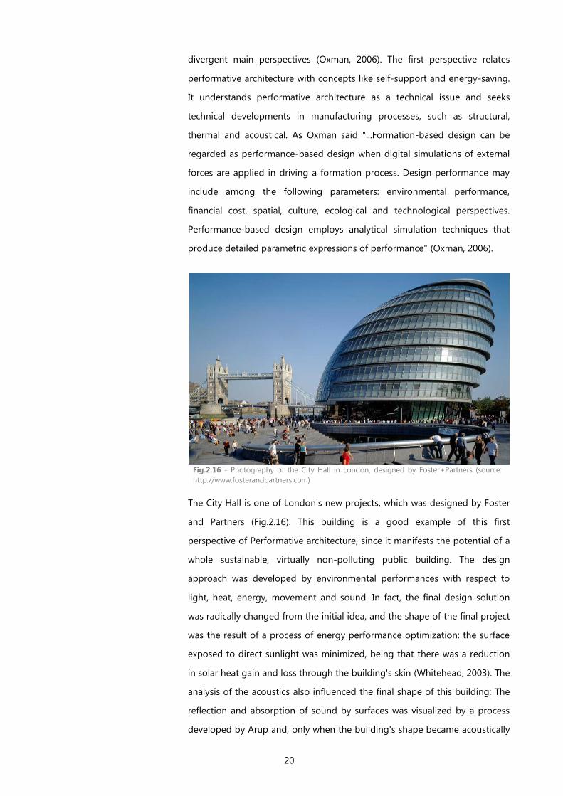
20
divergent main perspectives (Oxman, 2006). The first perspective relates
performative architecture with concepts like self-support and energy-saving.
It understands performative architecture as a technical issue and seeks
technical developments in manufacturing processes, such as structural,
thermal and acoustical. As Oxman said "...Formation-based design can be
regarded as performance-based design when digital simulations of external
forces are applied in driving a formation process. Design performance may
include among the following parameters: environmental performance,
financial cost, spatial, culture, ecological and technological perspectives.
Performance-based design employs analytical simulation techniques that
produce detailed parametric expressions of performance" (Oxman, 2006).
The City Hall is one of London's new projects, which was designed by Foster
and Partners (Fig.2.16). This building is a good example of this first
perspective of Performative architecture, since it manifests the potential of a
whole sustainable, virtually non-polluting public building. The design
approach was developed by environmental performances with respect to
light, heat, energy, movement and sound. In fact, the final design solution
was radically changed from the initial idea, and the shape of the final project
was the result of a process of energy performance optimization: the surface
exposed to direct sunlight was minimized, being that there was a reduction
in solar heat gain and loss through the building's skin (Whitehead, 2003). The
analysis of the acoustics also influenced the final shape of this building: The
reflection and absorption of sound by surfaces was visualized by a process
developed by Arup and, only when the building's shape became acoustically
Fig.2.16 - Photography of the City Hall in London, designed by Foster+Partners (source:
http://www.fosterandpartners.com)
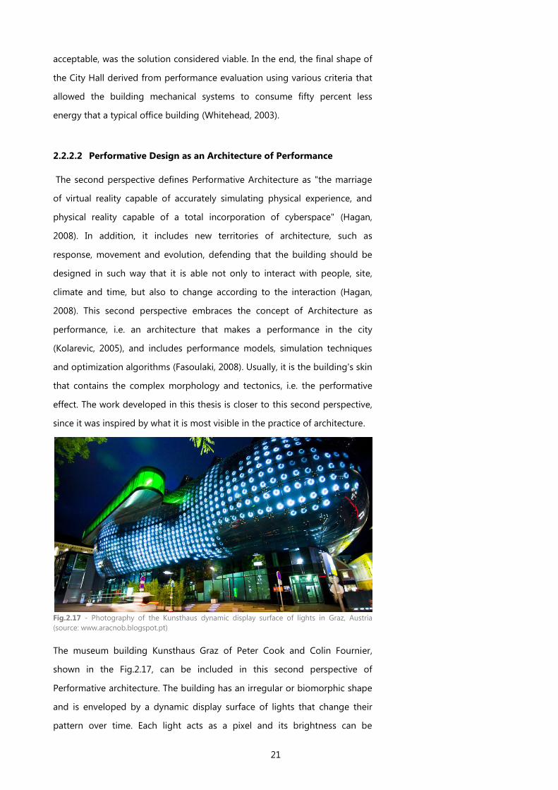
21
acceptable, was the solution considered viable. In the end, the final shape of
the City Hall derived from performance evaluation using various criteria that
allowed the building mechanical systems to consume fifty percent less
energy that a typical office building (Whitehead, 2003).
2.2.2.2 Performative Design as an Architecture of Performance
The second perspective defines Performative Architecture as "the marriage
of virtual reality capable of accurately simulating physical experience, and
physical reality capable of a total incorporation of cyberspace" (Hagan,
2008). In addition, it includes new territories of architecture, such as
response, movement and evolution, defending that the building should be
designed in such way that it is able not only to interact with people, site,
climate and time, but also to change according to the interaction (Hagan,
2008). This second perspective embraces the concept of Architecture as
performance, i.e. an architecture that makes a performance in the city
(Kolarevic, 2005), and includes performance models, simulation techniques
and optimization algorithms (Fasoulaki, 2008). Usually, it is the building's skin
that contains the complex morphology and tectonics, i.e. the performative
effect. The work developed in this thesis is closer to this second perspective,
since it was inspired by what it is most visible in the practice of architecture.
The museum building Kunsthaus Graz of Peter Cook and Colin Fournier,
shown in the Fig.2.17, can be included in this second perspective of
Performative architecture. The building has an irregular or biomorphic shape
and is enveloped by a dynamic display surface of lights that change their
pattern over time. Each light acts as a pixel and its brightness can be
Fig.2.17 - Photography of the Kunsthaus dynamic display surface of lights in Graz, Austria
(source: www.aracnob.blogspot.pt)
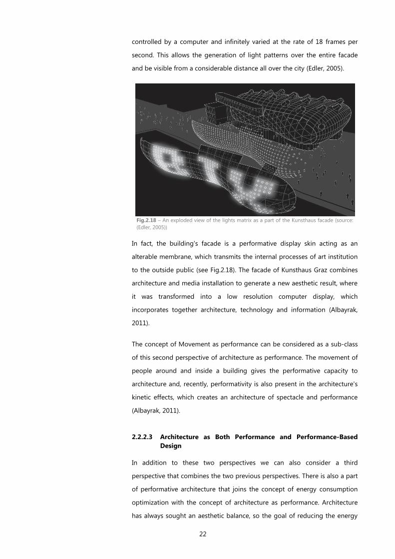
22
controlled by a computer and infinitely varied at the rate of 18 frames per
second. This allows the generation of light patterns over the entire facade
and be visible from a considerable distance all over the city (Edler, 2005).
In fact, the building's facade is a performative display skin acting as an
alterable membrane, which transmits the internal processes of art institution
to the outside public (see Fig.2.18). The facade of Kunsthaus Graz combines
architecture and media installation to generate a new aesthetic result, where
it was transformed into a low resolution computer display, which
incorporates together architecture, technology and information (Albayrak,
2011).
The concept of Movement as performance can be considered as a sub-class
of this second perspective of architecture as performance. The movement of
people around and inside a building gives the performative capacity to
architecture and, recently, performativity is also present in the architecture's
kinetic effects, which creates an architecture of spectacle and performance
(Albayrak, 2011).
2.2.2.3 Architecture as Both Performance and Performance-Based
Design
In addition to these two perspectives we can also consider a third
perspective that combines the two previous perspectives. There is also a part
of performative architecture that joins the concept of energy consumption
optimization with the concept of architecture as performance. Architecture
has always sought an aesthetic balance, so the goal of reducing the energy
Fig.2.18 – An exploded view of the lights matrix as a part of the Kunsthaus facade (source:
(Edler, 2005))
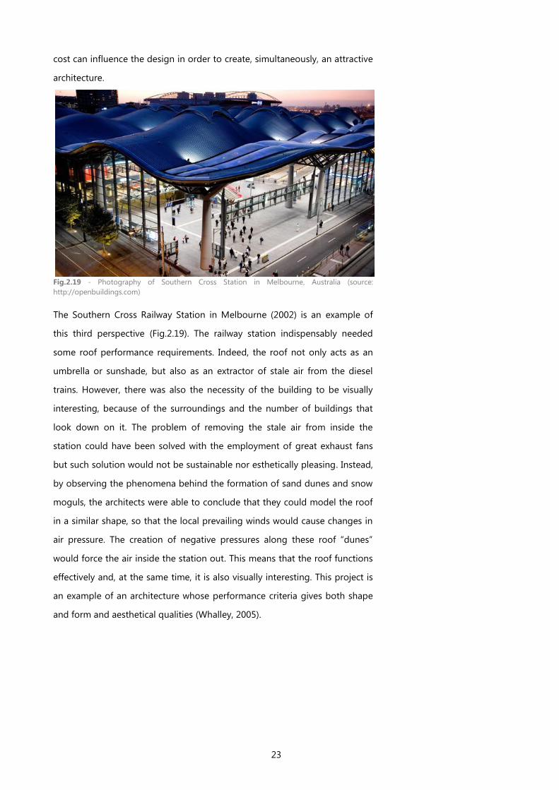
23
cost can influence the design in order to create, simultaneously, an attractive
architecture.
Fig.2.19 - Photography of Southern Cross Station in Melbourne, Australia (source:
http://openbuildings.com)
The Southern Cross Railway Station in Melbourne (2002) is an example of
this third perspective (Fig.2.19). The railway station indispensably needed
some roof performance requirements. Indeed, the roof not only acts as an
umbrella or sunshade, but also as an extractor of stale air from the diesel
trains. However, there was also the necessity of the building to be visually
interesting, because of the surroundings and the number of buildings that
look down on it. The problem of removing the stale air from inside the
station could have been solved with the employment of great exhaust fans
but such solution would not be sustainable nor esthetically pleasing. Instead,
by observing the phenomena behind the formation of sand dunes and snow
moguls, the architects were able to conclude that they could model the roof
in a similar shape, so that the local prevailing winds would cause changes in
air pressure. The creation of negative pressures along these roof “dunes”
would force the air inside the station out. This means that the roof functions
effectively and, at the same time, it is also visually interesting. This project is
an example of an architecture whose performance criteria gives both shape
and form and aesthetical qualities (Whalley, 2005).
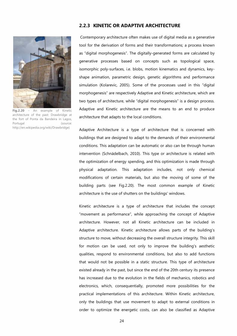
24
2.2.3 KINETIC OR ADAPTIVE ARCHITECTURE
Contemporary architecture often makes use of digital media as a generative
tool for the derivation of forms and their transformations; a process known
as “digital morphogenesis”. The digitally-generated forms are calculated by
generative processes based on concepts such as topological space,
isomorphic poly-surfaces, i.e. blobs, motion kinematics and dynamics, key-
shape animation, parametric design, genetic algorithms and performance
simulation (Kolarevic, 2005). Some of the processes used in this “digital
morphogenesis” are respectively Adaptive and Kinetic architecture, which are
two types of architecture, while “digital morphogenesis” is a design process.
Adaptive and Kinetic architecture are the means to an end to produce
architecture that adapts to the local conditions.
Adaptive Architecture is a type of architecture that is concerned with
buildings that are designed to adapt to the demands of their environmental
conditions. This adaptation can be automatic or also can be through human
intervention (Schnädelbach, 2010). This type or architecture is related with
the optimization of energy spending, and this optimization is made through
physical adaptation. This adaptation includes, not only chemical
modifications of certain materials, but also the moving of some of the
building parts (see Fig.2.20). The most common example of Kinetic
architecture is the use of shutters on the buildings' windows.
Kinetic architecture is a type of architecture that includes the concept
“movement as performance”, while approaching the concept of Adaptive
architecture. However, not all Kinetic architecture can be included in
Adaptive architecture. Kinetic architecture allows parts of the building's
structure to move, without decreasing the overall structure integrity. This skill
for motion can be used, not only to improve the building's aesthetic
qualities, respond to environmental conditions, but also to add functions
that would not be possible in a static structure. This type of architecture
existed already in the past, but since the end of the 20th century its presence
has increased due to the evolution in the fields of mechanics, robotics and
electronics, which, consequentially, promoted more possibilities for the
practical implementations of this architecture. Within Kinetic architecture,
only the buildings that use movement to adapt to external conditions in
order to optimize the energetic costs, can also be classified as Adaptive
Fig.2.20 – An example of Kinetic
architecture of the past: Drawbridge at
the fort of Ponta da Bandeira in Lagos,
Portugal (source:
http://en.wikipedia.org/wiki/Drawbridge)
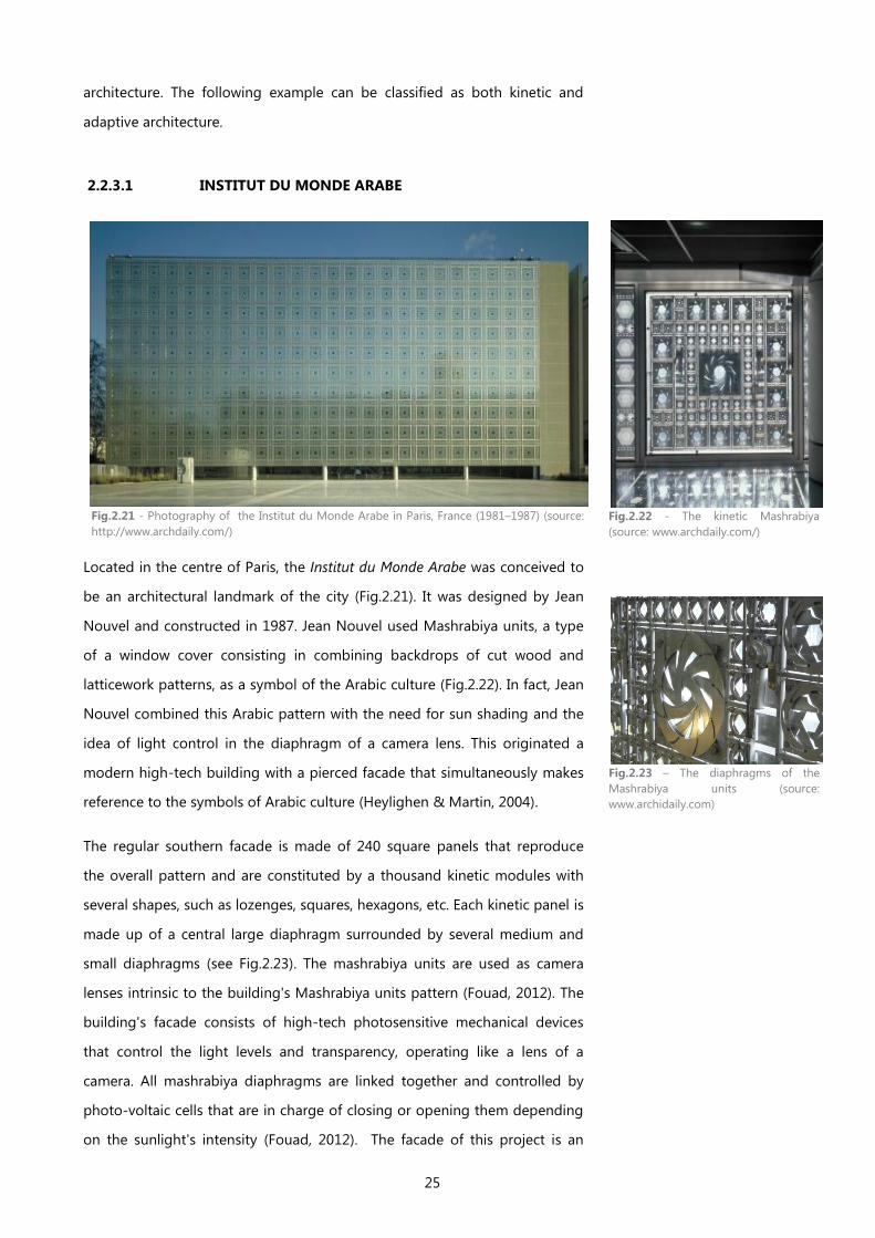
25
architecture. The following example can be classified as both kinetic and
adaptive architecture.
2.2.3.1 INSTITUT DU MONDE ARABE
Fig.2.21 - Photography of the Institut du Monde Arabe in Paris, France (1981–1987) (source:
http://www.archdaily.com/)
Located in the centre of Paris, the Institut du Monde Arabe was conceived to
be an architectural landmark of the city (Fig.2.21). It was designed by Jean
Nouvel and constructed in 1987. Jean Nouvel used Mashrabiya units, a type
of a window cover consisting in combining backdrops of cut wood and
latticework patterns, as a symbol of the Arabic culture (Fig.2.22). In fact, Jean
Nouvel combined this Arabic pattern with the need for sun shading and the
idea of light control in the diaphragm of a camera lens. This originated a
modern high-tech building with a pierced facade that simultaneously makes
reference to the symbols of Arabic culture (Heylighen & Martin, 2004).
The regular southern facade is made of 240 square panels that reproduce
the overall pattern and are constituted by a thousand kinetic modules with
several shapes, such as lozenges, squares, hexagons, etc. Each kinetic panel is
made up of a central large diaphragm surrounded by several medium and
small diaphragms (see Fig.2.23). The mashrabiya units are used as camera
lenses intrinsic to the building's Mashrabiya units pattern (Fouad, 2012). The
building's facade consists of high-tech photosensitive mechanical devices
that control the light levels and transparency, operating like a lens of a
camera. All mashrabiya diaphragms are linked together and controlled by
photo-voltaic cells that are in charge of closing or opening them depending
on the sunlight's intensity (Fouad, 2012). The facade of this project is an
Fig.2.22 - The kinetic Mashrabiya
(source: www.archdaily.com/)
Fig.2.23 – The diaphragms of the
Mashrabiya units (source:
www.archidaily.com)
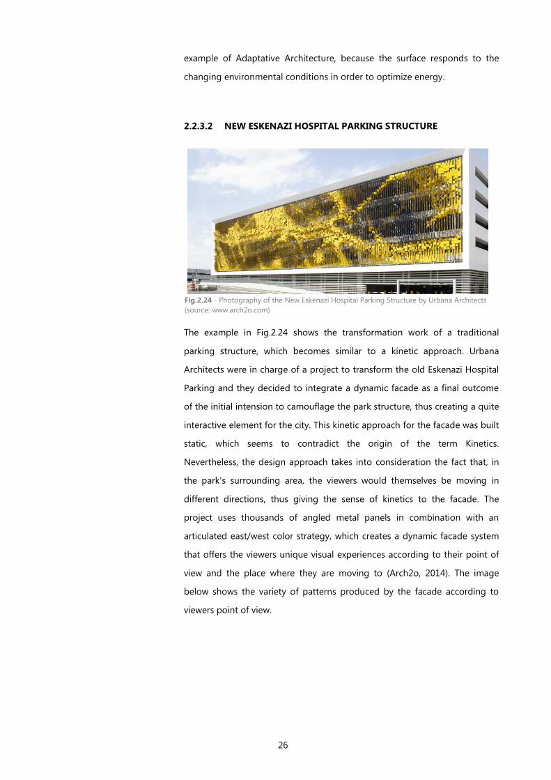
26
example of Adaptative Architecture, because the surface responds to the
changing environmental conditions in order to optimize energy.
2.2.3.2 NEW ESKENAZI HOSPITAL PARKING STRUCTURE
The example in Fig.2.24 shows the transformation work of a traditional
parking structure, which becomes similar to a kinetic approach. Urbana
Architects were in charge of a project to transform the old Eskenazi Hospital
Parking and they decided to integrate a dynamic facade as a final outcome
of the initial intension to camouflage the park structure, thus creating a quite
interactive element for the city. This kinetic approach for the facade was built
static, which seems to contradict the origin of the term Kinetics.
Nevertheless, the design approach takes into consideration the fact that, in
the park's surrounding area, the viewers would themselves be moving in
different directions, thus giving the sense of kinetics to the facade. The
project uses thousands of angled metal panels in combination with an
articulated east/west color strategy, which creates a dynamic facade system
that offers the viewers unique visual experiences according to their point of
view and the place where they are moving to (Arch2o, 2014). The image
below shows the variety of patterns produced by the facade according to
viewers point of view.
Fig.2.24 - Photography of the New Eskenazi Hospital Parking Structure by Urbana Architects
(source: www.arch2o.com)
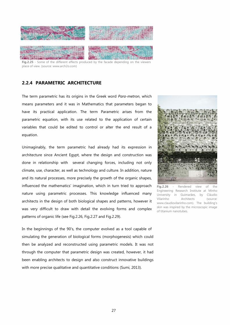
27
2.2.4 PARAMETRIC ARCHITECTURE
The term parametric has its origins in the Greek word Para-metron, which
means parameters and it was in Mathematics that parameters began to
have its practical application. The term Parametric arises from the
parametric equation, with its use related to the application of certain
variables that could be edited to control or alter the end result of a
equation.
Unimaginably, the term parametric had already had its expression in
architecture since Ancient Egypt, where the design and construction was
done in relationship with several changing forces, including not only
climate, use, character, as well as technology and culture. In addition, nature
and its natural processes, more precisely the growth of the organic shapes,
influenced the mathematics’ imagination, which in turn tried to approach
nature using parametric processes. This knowledge influenced many
architects in the design of both biological shapes and patterns, however it
was very difficult to draw with detail the evolving forms and complex
patterns of organic life (see Fig.2.26, Fig.2.27 and Fig.2.29).
In the beginnings of the 90's, the computer evolved as a tool capable of
simulating the generation of biological forms (morphogenesis) which could
then be analyzed and reconstructed using parametric models. It was not
through the computer that parametric design was created, however, it had
been enabling architects to design and also construct innovative buildings
with more precise qualitative and quantitative conditions (Sumi, 2013).
Fig.2.25 - Some of the different effects produced by the facade depending on the viewers
place of view. (source: www.arch2o.com)
Fig.2.26 - Rendered view of the
Engineering Research Institute at Minho
University in Guimarães, by Cláudio
Vilarinho Architects (source:
www.claudiovilarinho.com). The building's
skin was inspired by the microscopic image
of titanium nanotubes.
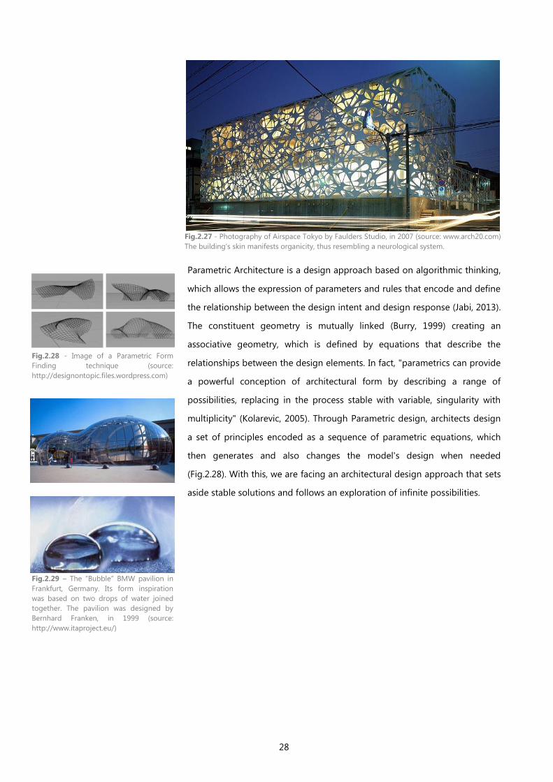
28
Parametric Architecture is a design approach based on algorithmic thinking,
which allows the expression of parameters and rules that encode and define
the relationship between the design intent and design response (Jabi, 2013).
The constituent geometry is mutually linked (Burry, 1999) creating an
associative geometry, which is defined by equations that describe the
relationships between the design elements. In fact, "parametrics can provide
a powerful conception of architectural form by describing a range of
possibilities, replacing in the process stable with variable, singularity with
multiplicity" (Kolarevic, 2005). Through Parametric design, architects design
a set of principles encoded as a sequence of parametric equations, which
then generates and also changes the model's design when needed
(Fig.2.28). With this, we are facing an architectural design approach that sets
aside stable solutions and follows an exploration of infinite possibilities.
Fig.2.27 - Photography of Airspace Tokyo by Faulders Studio, in 2007 (source: www.arch20.com)
The building's skin manifests organicity, thus resembling a neurological system.
Fig.2.28 - Image of a Parametric Form
Finding technique (source:
http://designontopic.files.wordpress.com)
Fig.2.29 – The “Bubble” BMW pavilion in
Frankfurt, Germany. Its form inspiration
was based on two drops of water joined
together. The pavilion was designed by
Bernhard Franken, in 1999 (source:
http://www.itaproject.eu/)
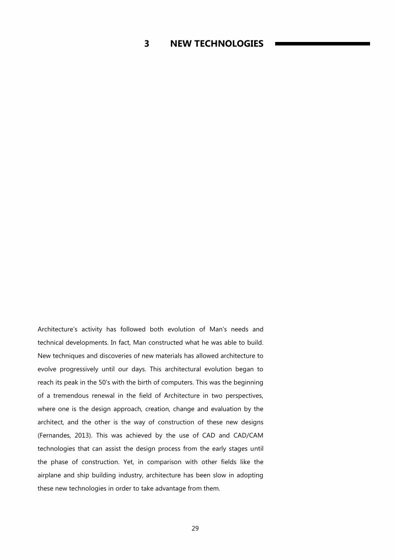
29
3 NEW TECHNOLOGIES
Architecture's activity has followed both evolution of Man's needs and
technical developments. In fact, Man constructed what he was able to build.
New techniques and discoveries of new materials has allowed architecture to
evolve progressively until our days. This architectural evolution began to
reach its peak in the 50's with the birth of computers. This was the beginning
of a tremendous renewal in the field of Architecture in two perspectives,
where one is the design approach, creation, change and evaluation by the
architect, and the other is the way of construction of these new designs
(Fernandes, 2013). This was achieved by the use of CAD and CAD/CAM
technologies that can assist the design process from the early stages until
the phase of construction. Yet, in comparison with other fields like the
airplane and ship building industry, architecture has been slow in adopting
these new technologies in order to take advantage from them.

30
3.1 GENERATIVE DESIGN
"Generative Design is the transformation of computational energy into creative
exploration energy empowering human designers to explore greater number of
design possibilities within modifiable constrains"
— (Krish, 2013)
Fig.3.1 - Synthetic Scheme of Generative Design.
Design is an evolutionary process (Alfaris, 2009) from the initial and
conceptual idea to complex and concrete results. Generative Design (GD) is a
design process where the output is generated with the help of a computer
and through the use of algorithms (Terzidis, 2003). Through the use of
Generative Design architects design the system that originates the building,
instead of designing the building (Stocking, 2009). It enables the generation
of several solutions in a short period of time, avoiding the tedious and
repetitive tasks needed when the modeling work is done manually, even with
state-of-the-art CAD/BIM (Computer Aided Design/Building Information
Modeling) software. With this control of change, the designer can quickly
compare and evaluate multiple solutions, which helps him to make a more
informed choice. In addition, GD enables and facilitates the manufacturing
of complex solutions, by extracting documentation directly from the model
to the phase of CAM (Computer Aided Manufacturing) or Digital Fabrication.
Generative design is used in the production of digital ornament and complex
facades, seen in many contemporary buildings, however, in order to take
advantage of the computational power of computers, algorithms must be
implemented in programming languages (Leitão, 2014). To use this new
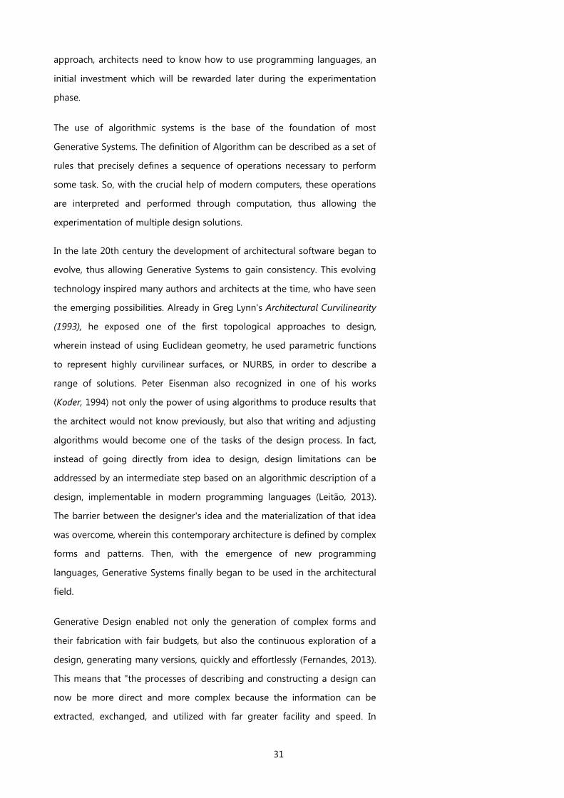
31
approach, architects need to know how to use programming languages, an
initial investment which will be rewarded later during the experimentation
phase.
The use of algorithmic systems is the base of the foundation of most
Generative Systems. The definition of Algorithm can be described as a set of
rules that precisely defines a sequence of operations necessary to perform
some task. So, with the crucial help of modern computers, these operations
are interpreted and performed through computation, thus allowing the
experimentation of multiple design solutions.
In the late 20th century the development of architectural software began to
evolve, thus allowing Generative Systems to gain consistency. This evolving
technology inspired many authors and architects at the time, who have seen
the emerging possibilities. Already in Greg Lynn's Architectural Curvilinearity
(1993), he exposed one of the first topological approaches to design,
wherein instead of using Euclidean geometry, he used parametric functions
to represent highly curvilinear surfaces, or NURBS, in order to describe a
range of solutions. Peter Eisenman also recognized in one of his works
(Koder, 1994) not only the power of using algorithms to produce results that
the architect would not know previously, but also that writing and adjusting
algorithms would become one of the tasks of the design process. In fact,
instead of going directly from idea to design, design limitations can be
addressed by an intermediate step based on an algorithmic description of a
design, implementable in modern programming languages (Leitão, 2013).
The barrier between the designer's idea and the materialization of that idea
was overcome, wherein this contemporary architecture is defined by complex
forms and patterns. Then, with the emergence of new programming
languages, Generative Systems finally began to be used in the architectural
field.
Generative Design enabled not only the generation of complex forms and
their fabrication with fair budgets, but also the continuous exploration of a
design, generating many versions, quickly and effortlessly (Fernandes, 2013).
This means that "the processes of describing and constructing a design can
now be more direct and more complex because the information can be
extracted, exchanged, and utilized with far greater facility and speed. In

32
short, with the use of digital technologies, the design information is the
construction information" (Kolarevic, 2003).
3.2 GENERATIVE SYSTEMS
The basic system of most Generative systems is the Algorithmic system. Their
definition is sequences of instructions for solving a certain problem or
reaching some end, that are written in a fixed vocabulary detailed step-by-
step or in distinct steps. In computers, algorithms are fundamental to the
way computers process information, in which they can handle numbers,
alphabets and geometric entities. Algorithmic systems used for design need
clear design intentions expressed in its steps and units, but their use is still
good for creating complex geometries with small amounts of data, such as
locations, shapes, shape proprieties, etc. The communication between the
elements is made through rules, constraints and associations (Fernandes,
2013). The use of algorithms in design requests a rationalization process that
forces designers to organize and coordinate their thinking around relations
and sequences of tasks. However, as Algorithmic Systems do not constrain
the relationship or structure, they are the most customizable and flexible of
all Generative Systems.
Another kind of Generative system are Shape Grammars (SG), a formalism
published for the first time in a paper written by Stiny and Gips in 1972.
Shape grammars can be very briefly defined as the combination of a
vocabulary of shapes, plus a set of shape rules and an initial shape (see
Fig.3.3). The goal of the rules is to transform a shape, or a collection of
shapes, into a new shape (Chouchoulas & Day, 2007). So, in computation,
shape grammars are a type of production systems that produce shapes.
During the first decades, Shape Grammars had applications focused mainly
on analysis, however SGs can have two other purposes, such as synthesis and
the combination of synthesis and analysis. The use for analysis is to identify
some existing design languages in order to produce multiple solutions
belonging to the same language. The use for synthesis is to create original
designs, i.e. new design languages (Fernandes, 2013).
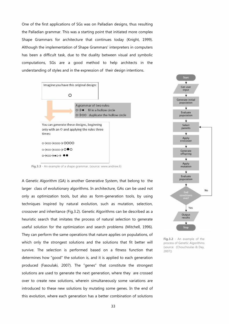
33
One of the first applications of SGs was on Palladian designs, thus resulting
the Palladian grammar. This was a starting point that initiated more complex
Shape Grammars for architecture that continues today (Knight, 1999).
Although the implementation of Shape Grammars' interpreters in computers
has been a difficult task, due to the duality between visual and symbolic
computations, SGs are a good method to help architects in the
understanding of styles and in the expression of their design intentions.
A Genetic Algorithm (GA) is another Generative System, that belong to the
larger class of evolutionary algorithms. In architecture, GAs can be used not
only as optimization tools, but also as form-generation tools, by using
techniques inspired by natural evolution, such as mutation, selection,
crossover and inheritance (Fig.3.2). Genetic Algorithms can be described as a
heuristic search that imitates the process of natural selection to generate
useful solution for the optimization and search problems (Mitchell, 1996).
They can perform the same operations that nature applies on populations, of
which only the strongest solutions and the solutions that fit better will
survive. The selection is performed based on a fitness function that
determines how "good" the solution is, and it is applied to each generation
produced (Fasoulaki, 2007). The "genes" that constitute the strongest
solutions are used to generate the next generation, where they are crossed
over to create new solutions, wherein simultaneously some variations are
introduced to these new solutions by mutating some genes. In the end of
this evolution, where each generation has a better combination of solutions
Fig.3.2 - An example of the
process of Genetic Algorithms
(source: (Chouchoulas & Day,
2007))
Fig.3.3 - An example of a shape grammar. (source: www.andrew.li)
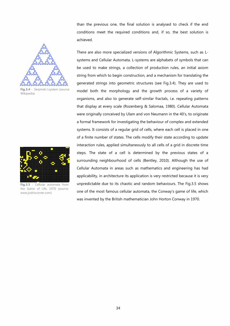
34
than the previous one, the final solution is analysed to check if the end
conditions meet the required conditions and, if so, the best solution is
achieved.
There are also more specialized versions of Algorithmic Systems, such as L-
systems and Cellular Automata. L-systems are alphabets of symbols that can
be used to make strings, a collection of production rules, an initial axiom
string from which to begin construction, and a mechanism for translating the
generated strings into geometric structures (see Fig.3.4). They are used to
model both the morphology and the growth process of a variety of
organisms, and also to generate self-similar fractals, i.e. repeating patterns
that display at every scale (Rozenberg & Salomaa, 1980). Cellular Automata
were originally conceived by Ulam and von Neumann in the 40's, to originate
a formal framework for investigating the behaviour of complex and extended
systems. It consists of a regular grid of cells, where each cell is placed in one
of a finite number of states. The cells modify their state according to update
interaction rules, applied simultaneously to all cells of a grid in discrete time
steps. The state of a cell is determined by the previous states of a
surrounding neighbourhood of cells (Bentley, 2010). Although the use of
Cellular Automata in areas such as mathematics and engineering has had
applicability, in architecture its application is very restricted because it is very
unpredictable due to its chaotic and random behaviours. The Fig.3.5 shows
one of the most famous cellular automata, the Conway's game of life, which
was invented by the British mathematician John Horton Conway in 1970.
Fig.3.4 - Serpinski Lsystem (source:
Wikipedia)
Fig.3.5 - Cellular automata from
the Game of Life, 1970 (source:
www.joshiscorner.com)
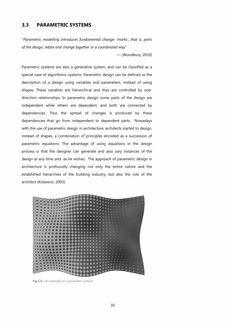
35
3.3 PARAMETRIC SYSTEMS
"Parametric modelling introduces fundamental change: 'marks', that is, parts
of the design, relate and change together in a coordinated way"
— (Woodbury, 2010)
Parametric systems are also a generative system, and can be classified as a
special case of algorithmic systems. Parametric design can be defined as the
description of a design using variables and parameters, instead of using
shapes. These variables are hierarchical and they are controlled by one-
direction relationships. In parametric design some parts of the design are
independent while others are dependent, and both are connected by
dependencies. Thus the spread of changes is produced by these
dependencies that go from independent to dependent parts. Nowadays
with the use of parametric design in architecture, architects started to design,
instead of shapes, a combination of principles encoded as a succession of
parametric equations. The advantage of using equations in the design
process is that the designer can generate and also vary instances of the
design at any time and as he wishes. The approach of parametric design in
architecture is profoundly changing not only the entire nature and the
established hierarchies of the building industry, but also the role of the
architect (Kolarevic, 2003).
Fig.3.6 - An example of a parametric surface.
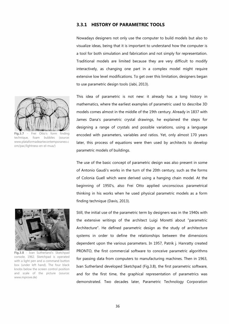
36
3.3.1 HISTORY OF PARAMETRIC TOOLS
Nowadays designers not only use the computer to build models but also to
visualize ideas, being that it is important to understand how the computer is
a tool for both simulation and fabrication and not simply for representation.
Traditional models are limited because they are very difficult to modify
interactively, as changing one part in a complex model might require
extensive low level modifications. To get over this limitation, designers began
to use parametric design tools (Jabi, 2013).
This idea of parametric is not new: it already has a long history in
mathematics, where the earliest examples of parametric used to describe 3D
models comes almost in the middle of the 19th century. Already in 1837 with
James Dana's parametric crystal drawings, he explained the steps for
designing a range of crystals and possible variations, using a language
encoded with parameters, variables and ratios. Yet, only almost 170 years
later, this process of equations were then used by architects to develop
parametric models of buildings.
The use of the basic concept of parametric design was also present in some
of Antonio Gaudi's works in the turn of the 20th century, such as the forms
of Colonia Guell which were derived using a hanging chain model. At the
beginning of 1950's, also Frei Otto applied unconscious parametrical
thinking in his works when he used physical parametric models as a form
finding technique (Davis, 2013).
Still, the initial use of the parametric term by designers was in the 1940s with
the extensive writings of the architect Luigi Moretti about "parametric
Architecture". He defined parametric design as the study of architecture
systems in order to define the relationships between the dimensions
dependent upon the various parameters. In 1957, Patrik j. Hanratty created
PRONTO, the first commercial software to conceive parametric algorithms
for passing data from computers to manufacturing machines. Then in 1963,
Ivan Sutherland developed Sketchpad (Fig.3.8), the first parametric software,
and for the first time, the graphical representation of parametrics was
demonstrated. Two decades later, Parametric Technology Corporation
Fig.3.7 - Frei Otto's form finding
technique, foam bubbles (source:
www.plataformadeartecontemporaneo.c
om/pac/lightness-en-el-mua/)
Fig.3.8 - Ivan Sutherland’s Sketchpad
console, 1962. Sketchpad is operated
with a light pen and a command button
box (under left hand). The four black
knobs below the screen control position
and scale of the picture (source:
www.mprove.de)
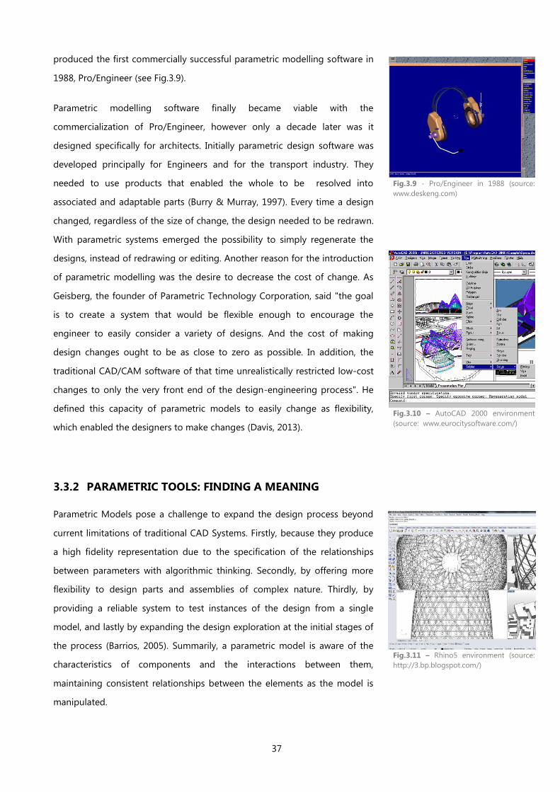
37
produced the first commercially successful parametric modelling software in
1988, Pro/Engineer (see Fig.3.9).
Parametric modelling software finally became viable with the
commercialization of Pro/Engineer, however only a decade later was it
designed specifically for architects. Initially parametric design software was
developed principally for Engineers and for the transport industry. They
needed to use products that enabled the whole to be resolved into
associated and adaptable parts (Burry & Murray, 1997). Every time a design
changed, regardless of the size of change, the design needed to be redrawn.
With parametric systems emerged the possibility to simply regenerate the
designs, instead of redrawing or editing. Another reason for the introduction
of parametric modelling was the desire to decrease the cost of change. As
Geisberg, the founder of Parametric Technology Corporation, said "the goal
is to create a system that would be flexible enough to encourage the
engineer to easily consider a variety of designs. And the cost of making
design changes ought to be as close to zero as possible. In addition, the
traditional CAD/CAM software of that time unrealistically restricted low-cost
changes to only the very front end of the design-engineering process". He
defined this capacity of parametric models to easily change as flexibility,
which enabled the designers to make changes (Davis, 2013).
3.3.2 PARAMETRIC TOOLS: FINDING A MEANING
Parametric Models pose a challenge to expand the design process beyond
current limitations of traditional CAD Systems. Firstly, because they produce
a high fidelity representation due to the specification of the relationships
between parameters with algorithmic thinking. Secondly, by offering more
flexibility to design parts and assemblies of complex nature. Thirdly, by
providing a reliable system to test instances of the design from a single
model, and lastly by expanding the design exploration at the initial stages of
the process (Barrios, 2005). Summarily, a parametric model is aware of the
characteristics of components and the interactions between them,
maintaining consistent relationships between the elements as the model is
manipulated.
Fig.3.9 - Pro/Engineer in 1988 (source:
www.deskeng.com)
Fig.3.10 – AutoCAD 2000 environment
(source: www.eurocitysoftware.com/)
Fig.3.11 – Rhino5 environment (source:
http://3.bp.blogspot.com/)
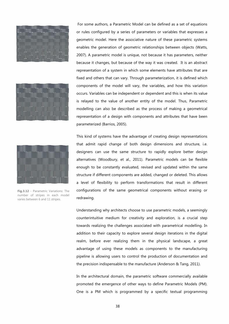
38
For some authors, a Parametric Model can be defined as a set of equations
or rules configured by a series of parameters or variables that expresses a
geometric model. Here the associative nature of these parametric systems
enables the generation of geometric relationships between objects (Watts,
2007). A parametric model is unique, not because it has parameters, neither
because it changes, but because of the way it was created. It is an abstract
representation of a system in which some elements have attributes that are
fixed and others that can vary. Through parameterization, it is defined which
components of the model will vary, the variables, and how this variation
occurs. Variables can be independent or dependent and this is when its value
is relayed to the value of another entity of the model. Thus, Parametric
modelling can also be described as the process of making a geometrical
representation of a design with components and attributes that have been
parameterized (Barrios, 2005).
This kind of systems have the advantage of creating design representations
that admit rapid change of both design dimensions and structure, i.e.
designers can use the same structure to rapidly explore better design
alternatives (Woodbury, et al., 2011). Parametric models can be flexible
enough to be constantly evaluated, revised and updated within the same
structure if different components are added, changed or deleted. This allows
a level of flexibility to perform transformations that result in different
configurations of the same geometrical components without erasing or
redrawing.
Understanding why architects choose to use parametric models, a seemingly
counterintuitive medium for creativity and exploration, is a crucial step
towards realizing the challenges associated with parametrical modelling. In
addition to their capacity to explore several design iterations in the digital
realm, before ever realizing them in the physical landscape, a great
advantage of using these models as components to the manufacturing
pipeline is allowing users to control the production of documentation and
the precision indispensable to the manufacture (Anderson & Tang, 2011).
In the architectural domain, the parametric software commercially available
promoted the emergence of other ways to define Parametric Models (PM).
One is a PM which is programmed by a specific textual programming
Fig.3.12 - Parametric Variations: The
number of stripes in each model
varies between 6 and 11 stripes.
39
language (TPL), and the other is a PM generated by algorithms that were
represented by diagrams or graphs created by visual programming
languages (VPL). These visual languages have a greater initial power of
attraction than the textual programming languages, due to them requiring a
lower level of abstraction. Still, its use turns out to be more limited, since we
are limited to the pre-defined scripts and modules, which we cannot change.
As a consequence, we may be working with tools that may not suit our goal.
On the other hand, when we use TPLs, we construct our own tools, which we
can change and adapt according to our necessities. Therefore, TPLs are more
abstract than VPLs, but more powerful.
Parametric scripting is a way to generate architectural artefacts that can be
realized in the physical landscape through various techniques, such as digital
fabrication and industrial manufacturing, by defining, in addition to the
design, the documentation needed for fabrication too. The implications that
script has on the construction process is something to take into great
account. As Woodbury said, although initially the use of programming
languages in parametric design is more hard-working, the long practice in
using programming languages and in teaching parametric systems shows
that designers will often need or will want to write algorithms to generate
their own particular ideas. Indeed, nowadays it is easy to produce artefacts
that were typically considered too complex, costly and time consuming
(Anderson & Tang, 2011).

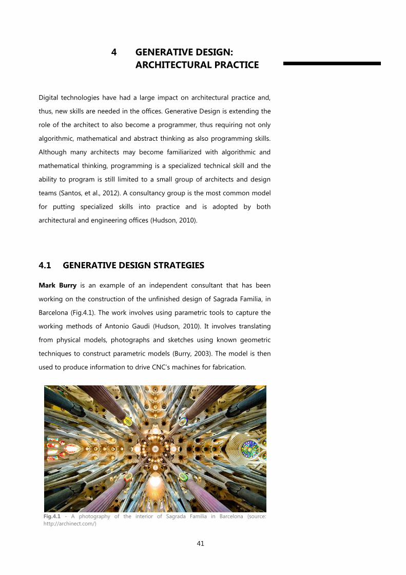
41
4 GENERATIVE DESIGN:
ARCHITECTURAL PRACTICE
Digital technologies have had a large impact on architectural practice and,
thus, new skills are needed in the offices. Generative Design is extending the
role of the architect to also become a programmer, thus requiring not only
algorithmic, mathematical and abstract thinking as also programming skills.
Although many architects may become familiarized with algorithmic and
mathematical thinking, programming is a specialized technical skill and the
ability to program is still limited to a small group of architects and design
teams (Santos, et al., 2012). A consultancy group is the most common model
for putting specialized skills into practice and is adopted by both
architectural and engineering offices (Hudson, 2010).
4.1 GENERATIVE DESIGN STRATEGIES
Mark Burry is an example of an independent consultant that has been
working on the construction of the unfinished design of Sagrada Familia, in
Barcelona (Fig.4.1). The work involves using parametric tools to capture the
working methods of Antonio Gaudi (Hudson, 2010). It involves translating
from physical models, photographs and sketches using known geometric
techniques to construct parametric models (Burry, 2003). The model is then
used to produce information to drive CNC’s machines for fabrication.
Fig.4.1 - A photography of the interior of Sagrada Familia in Barcelona (source:
http://archinect.com/)
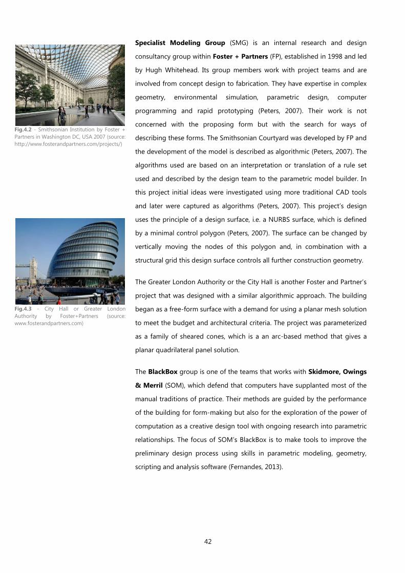
42
Specialist Modeling Group (SMG) is an internal research and design
consultancy group within Foster + Partners (FP), established in 1998 and led
by Hugh Whitehead. Its group members work with project teams and are
involved from concept design to fabrication. They have expertise in complex
geometry, environmental simulation, parametric design, computer
programming and rapid prototyping (Peters, 2007). Their work is not
concerned with the proposing form but with the search for ways of
describing these forms. The Smithsonian Courtyard was developed by FP and
the development of the model is described as algorithmic (Peters, 2007). The
algorithms used are based on an interpretation or translation of a rule set
used and described by the design team to the parametric model builder. In
this project initial ideas were investigated using more traditional CAD tools
and later were captured as algorithms (Peters, 2007). This project’s design
uses the principle of a design surface, i.e. a NURBS surface, which is defined
by a minimal control polygon (Peters, 2007). The surface can be changed by
vertically moving the nodes of this polygon and, in combination with a
structural grid this design surface controls all further construction geometry.
The Greater London Authority or the City Hall is another Foster and Partner’s
project that was designed with a similar algorithmic approach. The building
began as a free-form surface with a demand for using a planar mesh solution
to meet the budget and architectural criteria. The project was parameterized
as a family of sheared cones, which is a an arc-based method that gives a
planar quadrilateral panel solution.
The BlackBox group is one of the teams that works with Skidmore, Owings
& Merril (SOM), which defend that computers have supplanted most of the
manual traditions of practice. Their methods are guided by the performance
of the building for form-making but also for the exploration of the power of
computation as a creative design tool with ongoing research into parametric
relationships. The focus of SOM’s BlackBox is to make tools to improve the
preliminary design process using skills in parametric modeling, geometry,
scripting and analysis software (Fernandes, 2013).
Fig.4.2 - Smithsonian Institution by Foster +
Partners in Washington DC, USA 2007 (source:
http://www.fosterandpartners.com/projects/)
Fig.4.3 - City Hall or Greater London
Authority by Foster+Partners (source:
www.fosterandpartners.com)
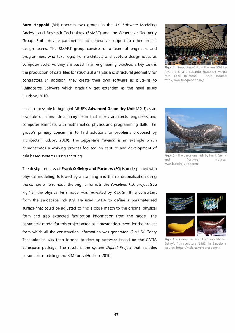
43
Buro Happold (BH) operates two groups in the UK: Software Modeling
Analysis and Research Technology (SMART) and the Generative Geometry
Group. Both provide parametric and generative support to other project
design teams. The SMART group consists of a team of engineers and
programmers who take logic from architects and capture design ideas as
computer code. As they are based in an engineering practice, a key task is
the production of data files for structural analysis and structural geometry for
contractors. In addition, they create their own software as plug-ins to
Rhinoceros Software which gradually get extended as the need arises
(Hudson, 2010).
It is also possible to highlight ARUP’s Advanced Geometry Unit (AGU) as an
example of a multidisciplinary team that mixes architects, engineers and
computer scientists, with mathematics, physics and programming skills. The
group’s primary concern is to find solutions to problems proposed by
architects (Hudson, 2010). The Serpentine Pavilion is an example which
demonstrates a working process focused on capture and development of
rule based systems using scripting.
The design process of Frank O Gehry and Partners (FG) is underpinned with
physical modeling, followed by a scanning and then a rationalization using
the computer to remodel the original form. In the Barcelona Fish project (see
Fig.4.5), the physical Fish model was recreated by Rick Smith, a consultant
from the aerospace industry. He used CATIA to define a parameterized
surface that could be adjusted to find a close match to the original physical
form and also extracted fabrication information from the model. The
parametric model for this project acted as a master document for the project
from which all the construction information was generated (Fig.4.6). Gehry
Technologies was then formed to develop software based on the CATIA
aerospace package. The result is the system Digital Project that includes
parametric modeling and BIM tools (Hudson, 2010).
Fig.4.4 - Serpentine Gallery Pavilion 2005 by
Alvaro Siza and Eduardo Souto de Moura
with Cecil Balmond – Arup (source:
http://www.telegraph.co.uk/)
Fig.4.5 - The Barcelona Fish by Frank Gehry
and Partners (source:
www.buildingsatire.com)
Fig.4.6 - Computer and built models for
Gehry´s fish sculpture (1992) in Barcelona
(source: https://mafana.wordpress.com)
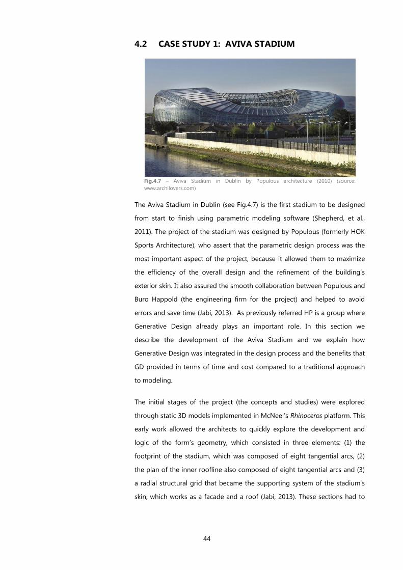
44
4.2 CASE STUDY 1: AVIVA STADIUM
Fig.4.7 – Aviva Stadium in Dublin by Populous architecture (2010) (source:
www.archilovers.com)
The Aviva Stadium in Dublin (see Fig.4.7) is the first stadium to be designed
from start to finish using parametric modeling software (Shepherd, et al.,
2011). The project of the stadium was designed by Populous (formerly HOK
Sports Architecture), who assert that the parametric design process was the
most important aspect of the project, because it allowed them to maximize
the efficiency of the overall design and the refinement of the building’s
exterior skin. It also assured the smooth collaboration between Populous and
Buro Happold (the engineering firm for the project) and helped to avoid
errors and save time (Jabi, 2013). As previously referred HP is a group where
Generative Design already plays an important role. In this section we
describe the development of the Aviva Stadium and we explain how
Generative Design was integrated in the design process and the benefits that
GD provided in terms of time and cost compared to a traditional approach
to modeling.
The initial stages of the project (the concepts and studies) were explored
through static 3D models implemented in McNeel’s Rhinoceros platform. This
early work allowed the architects to quickly explore the development and
logic of the form’s geometry, which consisted in three elements: (1) the
footprint of the stadium, which was composed of eight tangential arcs, (2)
the plan of the inner roofline also composed of eight tangential arcs and (3)
a radial structural grid that became the supporting system of the stadium’s
skin, which works as a facade and a roof (Jabi, 2013). These sections had to
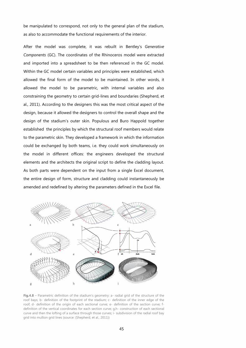
45
be manipulated to correspond, not only to the general plan of the stadium,
as also to accommodate the functional requirements of the interior.
After the model was complete, it was rebuilt in Bentley’s Generative
Components (GC). The coordinates of the Rhinoceros model were extracted
and imported into a spreadsheet to be then referenced in the GC model.
Within the GC model certain variables and principles were established, which
allowed the final form of the model to be maintained. In other words, it
allowed the model to be parametric, with internal variables and also
constraining the geometry to certain grid-lines and boundaries (Shepherd, et
al., 2011). According to the designers this was the most critical aspect of the
design, because it allowed the designers to control the overall shape and the
design of the stadium’s outer skin. Populous and Buro Happold together
established the principles by which the structural roof members would relate
to the parametric skin. They developed a framework in which the information
could be exchanged by both teams, i.e. they could work simultaneously on
the model in different offices: the engineers developed the structural
elements and the architects the original script to define the cladding layout.
As both parts were dependent on the input from a single Excel document,
the entire design of form, structure and cladding could instantaneously be
amended and redefined by altering the parameters defined in the Excel file.
Fig.4.8 – Parametric definition of the stadium’s geometry: a- radial grid of the structure of the
roof bays; b- definition of the footprint of the stadium; c- definition of the inner edge of the
roof; d- definition of the origin of each sectional curve; e- definition of the section curve; f-
definition of the vertical coordinates for each section curve; g,h- construction of each sectional
curve and then the lofting of a surface through those curves; i- subdivision of the radial roof bay
grid into mullion grid lines (source: (Shepherd, et al., 2011))
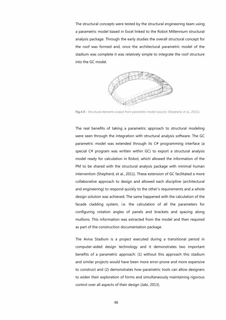
46
The structural concepts were tested by the structural engineering team using
a parametric model based in Excel linked to the Robot Millennium structural
analysis package. Through the early studies the overall structural concept for
the roof was formed and, once the architectural parametric model of the
stadium was complete it was relatively simple to integrate the roof structure
into the GC model.
Fig.4.9 – Structural elements output from parametric model (source: (Shepherd, et al., 2011))
The real benefits of taking a parametric approach to structural modeling
were seen through the integration with structural analysis software. The GC
parametric model was extended through its C# programming interface (a
special C# program was written within GC) to export a structural analysis
model ready for calculation in Robot, which allowed the information of the
PM to be shared with the structural analysis package with minimal human
intervention (Shepherd, et al., 2011). These extension of GC facilitated a more
collaborative approach to design and allowed each discipline (architectural
and engineering) to respond quickly to the other’s requirements and a whole
design solution was achieved. The same happened with the calculation of the
facade cladding system, i.e. the calculation of all the parameters for
configuring rotation angles of panels and brackets and spacing along
mullions. This information was extracted from the model and then required
as part of the construction documentation package.
The Aviva Stadium is a project executed during a transitional period in
computer-aided design technology and it demonstrates two important
benefits of a parametric approach: (1) without this approach this stadium
and similar projects would have been more error-prone and more expensive
to construct and (2) demonstrates how parametric tools can allow designers
to widen their exploration of forms and simultaneously maintaining rigorous
control over all aspects of their design (Jabi, 2013).
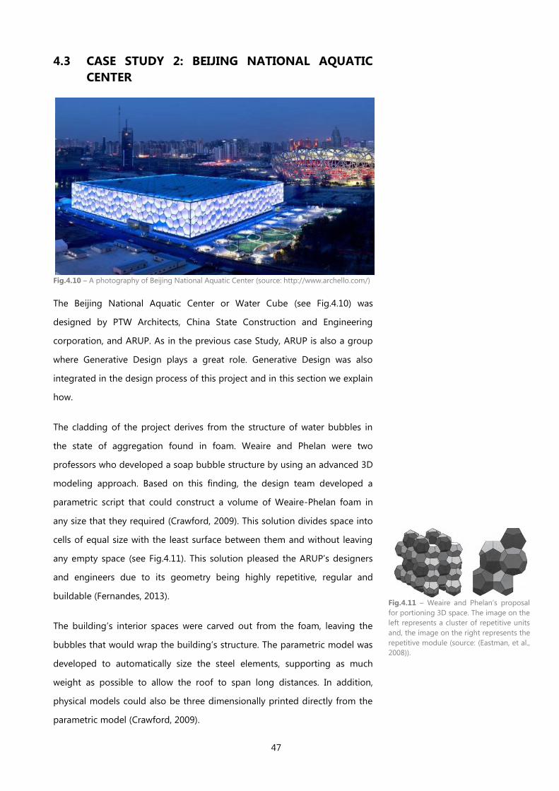
47
4.3 CASE STUDY 2: BEIJING NATIONAL AQUATIC
CENTER
Fig.4.10 – A photography of Beijing National Aquatic Center (source: http://www.archello.com/)
The Beijing National Aquatic Center or Water Cube (see Fig.4.10) was
designed by PTW Architects, China State Construction and Engineering
corporation, and ARUP. As in the previous case Study, ARUP is also a group
where Generative Design plays a great role. Generative Design was also
integrated in the design process of this project and in this section we explain
how.
The cladding of the project derives from the structure of water bubbles in
the state of aggregation found in foam. Weaire and Phelan were two
professors who developed a soap bubble structure by using an advanced 3D
modeling approach. Based on this finding, the design team developed a
parametric script that could construct a volume of Weaire-Phelan foam in
any size that they required (Crawford, 2009). This solution divides space into
cells of equal size with the least surface between them and without leaving
any empty space (see Fig.4.11). This solution pleased the ARUP’s designers
and engineers due to its geometry being highly repetitive, regular and
buildable (Fernandes, 2013).
The building’s interior spaces were carved out from the foam, leaving the
bubbles that would wrap the building’s structure. The parametric model was
developed to automatically size the steel elements, supporting as much
weight as possible to allow the roof to span long distances. In addition,
physical models could also be three dimensionally printed directly from the
parametric model (Crawford, 2009).
Fig.4.11 – Weaire and Phelan’s proposal
for portioning 3D space. The image on the
left represents a cluster of repetitive units
and, the image on the right represents the
repetitive module (source: (Eastman, et al.,
2008)).

48
The project was developed in two main stages: the competition submission
and the design development. The competition period was limited due to the
deadlines, so the team simply developed a method to generate a 3D model
and the drawings for presentation in which they applied a scripting-base
representation to model a wire-frame, in order to provide the 3D model of
the structure (Fernandes, 2013). The 3D model created by the scripts
consisted of elements and node spheres of the same size while rules defined
how to handle elements of various lengths (Eastman, et al., 2008). To
communicate the idea to the competition’s jury, they used rapid prototyping
to model the building’s structure.
Fig.4.13 – Building’s structure prototyping (source: http://www.e-architect.co.uk/)
During the competition period the team was concerned with the model and
did not analyze the structure. However, in the beginning of the design
development, the team used a wire-frame model not only to prove the
geometry worked, but also to analyze and optimize the structure. They
developed scripts to export the information to several type of files. The
scripts were also used to create a 3D model which allowed them to visualize
the model in different representations such as surfaces, solids or structural
elements. The detailed drawings for construction and schedules were
produced automatically from the 3D model and, indeed, they had created a
system that took less than a week to generate the model and all the
drawings even when a change was made to the model (Fernandes, 2013).
ARUP proposed prefabrication to ease the construction of the Water Cube
project, however, the idea was rejected by the client in China. In this case the
construction process was done manually with approximately 3000 workers
onsite (Eastman, et al., 2008), instead of using CNC machinery to shorten the
fabrication time, as it was done in other countries (Fernandes, 2013).
Fig.4.12 - CAD model of the structural
system of the Water Cube Project
(source: http://architectureau.com/)
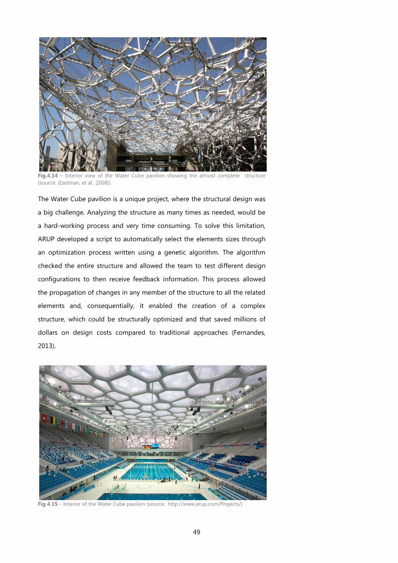
49
Fig.4.14 – Interior view of the Water Cube pavilion showing the almost complete structure
(source: (Eastman, et al., 2008))
The Water Cube pavilion is a unique project, where the structural design was
a big challenge. Analyzing the structure as many times as needed, would be
a hard-working process and very time consuming. To solve this limitation,
ARUP developed a script to automatically select the elements sizes through
an optimization process written using a genetic algorithm. The algorithm
checked the entire structure and allowed the team to test different design
configurations to then receive feedback information. This process allowed
the propagation of changes in any member of the structure to all the related
elements and, consequentially, it enabled the creation of a complex
structure, which could be structurally optimized and that saved millions of
dollars on design costs compared to traditional approaches (Fernandes,
2013).
Fig.4.15 – Interior of the Water Cube pavilion (source: http://www.arup.com/Projects/)

PART II A FRAMEWORK FOR THE
GENERATION OF CONTEMPORARY FACADES

53
5 INTRODUCTION
Facade designs might still require a lot of effort to invent, experiment, and
produce. It is important, then, that this effort be as small as possible. The
work presented here proposes a systematic methodology for the
development and composition of algorithmically-based facade patterns.
As we will show, our methodology promotes the design exploration of
facades and simplifies its adaptation to the ever-changing design process
conditions.
Algorithmic-based Processes in Architecture
Creativity is characterized by unconsciousness and inaccuracy (Bukhari, 2011)
and, thus, is better served by a design process that embraces change.
Traditional tools do not easily support change because they require too
much time and effort to change models. On the other hand, the computer
became a very important tool of the design process which changed, and still
changes, the way architects design (Kolarevic, 2003). The new technologies
allow design exploration to go far beyond the traditional possibilities, thus
promoting the development and spread of complex shapes, new patterns
and advanced production technologies. Computers "do not eradicate human
imagination but rather extend its potential limitations...it provides the means
for exploration, experimentation, and investigation in an alternative realm"
(Terzidis, 2003).
Through Generative Design, instead of going directly from the idea to the
design, architects produce an intermediate algorithmic-based description of
a design (Leitão, 2013). Parametric design is a type of GD in which the
parameters of a particular design are declared, rather than its shape
(Kolarevic, 2003). This approach has the ability to generate different
instances of a design. Each instance represents a unique set of
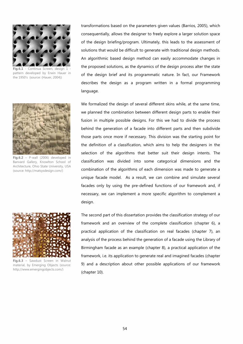
54
transformations based on the parameters given values (Barrios, 2005), which
consequentially, allows the designer to freely explore a larger solution space
of the design briefing/program. Ultimately, this leads to the assessment of
solutions that would be difficult to generate with traditional design methods.
An algorithmic based design method can easily accommodate changes in
the proposed solutions, as the dynamics of the design process alter the state
of the design brief and its programmatic nature. In fact, our Framework
describes the design as a program written in a formal programming
language.
We formalized the design of several different skins while, at the same time,
we planned the combination between different design parts to enable their
fusion in multiple possible designs. For this we had to divide the process
behind the generation of a facade into different parts and then subdivide
those parts once more if necessary. This division was the starting point for
the definition of a classification, which aims to help the designers in the
selection of the algorithms that better suit their design intents. The
classification was divided into some categorical dimensions and the
combination of the algorithms of each dimension was made to generate a
unique facade model. As a result, we can combine and simulate several
facades only by using the pre-defined functions of our framework and, if
necessary, we can implement a more specific algorithm to complement a
design.
The second part of this dissertation provides the classification strategy of our
framework and an overview of the complete classification (chapter 6), a
practical application of the classification on real facades (chapter 7), an
analysis of the process behind the generation of a facade using the Library of
Birmingham facade as an example (chapter 8), a practical application of the
framework, i.e. its application to generate real and imagined facades (chapter
9) and a description about other possible applications of our framework
(chapter 10).
Fig.6.1 - Continua Screen, design 1 -
pattern developed by Erwin Hauer in
the 1950’s (source: (Hauer, 2004))
Fig.6.2 – P-wall (2006) developed in
Banvard Gallery, Knowlton School of
Architecture, Ohio State University, USA
(source: http://matsysdesign.com/)
Fig.6.3 – Sawdust Screen in Walnut
material, by Emerging Objects (source:
http://www.emergingobjects.com/)
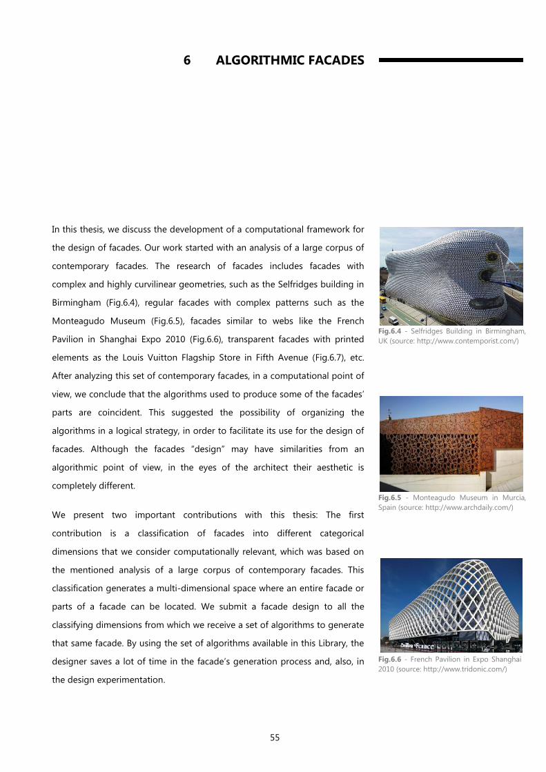
55
6 ALGORITHMIC FACADES
In this thesis, we discuss the development of a computational framework for
the design of facades. Our work started with an analysis of a large corpus of
contemporary facades. The research of facades includes facades with
complex and highly curvilinear geometries, such as the Selfridges building in
Birmingham (Fig.6.4), regular facades with complex patterns such as the
Monteagudo Museum (Fig.6.5), facades similar to webs like the French
Pavilion in Shanghai Expo 2010 (Fig.6.6), transparent facades with printed
elements as the Louis Vuitton Flagship Store in Fifth Avenue (Fig.6.7), etc.
After analyzing this set of contemporary facades, in a computational point of
view, we conclude that the algorithms used to produce some of the facades’
parts are coincident. This suggested the possibility of organizing the
algorithms in a logical strategy, in order to facilitate its use for the design of
facades. Although the facades “design” may have similarities from an
algorithmic point of view, in the eyes of the architect their aesthetic is
completely different.
We present two important contributions with this thesis: The first
contribution is a classification of facades into different categorical
dimensions that we consider computationally relevant, which was based on
the mentioned analysis of a large corpus of contemporary facades. This
classification generates a multi-dimensional space where an entire facade or
parts of a facade can be located. We submit a facade design to all the
classifying dimensions from which we receive a set of algorithms to generate
that same facade. By using the set of algorithms available in this Library, the
designer saves a lot of time in the facade’s generation process and, also, in
the design experimentation.
Fig.6.4 - Selfridges Building in Birmingham,
UK (source: http://www.contemporist.com/)
Fig.6.5 - Monteagudo Museum in Murcia,
Spain (source: http://www.archdaily.com/)
Fig.6.6 - French Pavilion in Expo Shanghai
2010 (source: http://www.tridonic.com/)
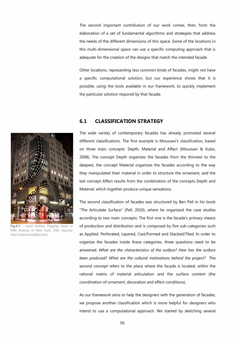
56
The second important contribution of our work comes, then, from the
elaboration of a set of fundamental algorithms and strategies that address
the needs of the different dimensions of this space. Some of the locations in
this multi-dimensional space can use a specific computing approach that is
adequate for the creation of the designs that match the intended facade.
Other locations, representing less common kinds of facades, might not have
a specific computational solution, but our experience shows that it is
possible, using the tools available in our framework, to quickly implement
the particular solution required by that facade.
6.1 CLASSIFICATION STRATEGY
The wide variety of contemporary facades has already promoted several
different classifications. The first example is Moussavi's classification, based
on three main concepts: Depth, Material and Affect (Moussavi & Kubo,
2008). The concept Depth organizes the facades from the thinnest to the
deepest, the concept Material organizes the facades according to the way
they manipulated their material in order to structure the ornament, and the
last concept Affect results from the combination of the concepts Depth and
Material, which together produce unique sensations.
The second classification of facades was structured by Ben Pell in his book
"The Articulate Surface" (Pell, 2010), where he organized the case studies
according to two main concepts: The first one is the facade's primary means
of production and distribution and is composed by five sub-categories such
as Applied, Perforated, Layered, Cast/Formed and Stacked/Tiled. In order to
organize the facades inside these categories, three questions need to be
answered: What are the characteristics of the surface? How has the surface
been produced? What are the cultural motivations behind the project? The
second concept refers to the place where the facade is located, within the
rational matrix of material articulation and the surface content (the
coordination of ornament, decoration and effect conditions).
As our framework aims to help the designers with the generation of facades,
we propose another classification which is more helpful for designers who
intend to use a computational approach. We started by sketching several
Fig.6.7 - Louis Vuitton Flagship Store in
Fifth Avenue in New York, USA. (source:
http://www.archdaily.com)
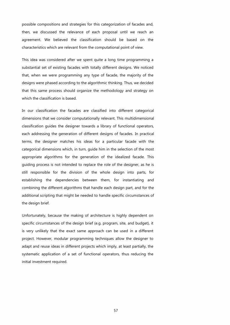
57
possible compositions and strategies for this categorization of facades and,
then, we discussed the relevance of each proposal until we reach an
agreement. We believed the classification should be based on the
characteristics which are relevant from the computational point of view.
This idea was considered after we spent quite a long time programming a
substantial set of existing facades with totally different designs. We noticed
that, when we were programming any type of facade, the majority of the
designs were phased according to the algorithmic thinking. Thus, we decided
that this same process should organize the methodology and strategy on
which the classification is based.
In our classification the facades are classified into different categorical
dimensions that we consider computationally relevant. This multidimensional
classification guides the designer towards a library of functional operators,
each addressing the generation of different designs of facades. In practical
terms, the designer matches his ideas for a particular facade with the
categorical dimensions which, in turn, guide him in the selection of the most
appropriate algorithms for the generation of the idealized facade. This
guiding process is not intended to replace the role of the designer, as he is
still responsible for the division of the whole design into parts, for
establishing the dependencies between them, for instantiating and
combining the different algorithms that handle each design part, and for the
additional scripting that might be needed to handle specific circumstances of
the design brief.
Unfortunately, because the making of architecture is highly dependent on
specific circumstances of the design brief (e.g. program, site, and budget), it
is very unlikely that the exact same approach can be used in a different
project. However, modular programming techniques allow the designer to
adapt and reuse ideas in different projects which imply, at least partially, the
systematic application of a set of functional operators, thus reducing the
initial investment required.
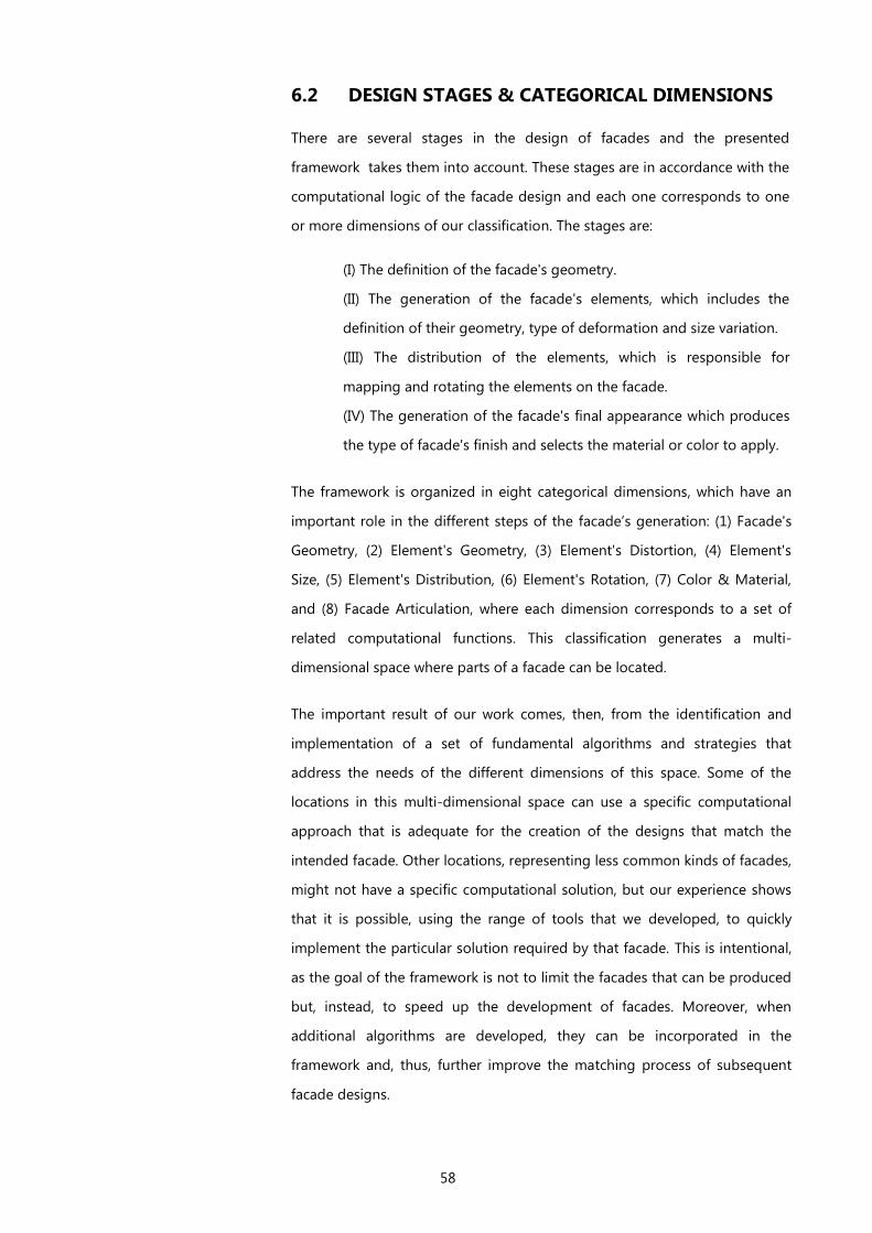
58
6.2 DESIGN STAGES & CATEGORICAL DIMENSIONS
There are several stages in the design of facades and the presented
framework takes them into account. These stages are in accordance with the
computational logic of the facade design and each one corresponds to one
or more dimensions of our classification. The stages are:
(I) The definition of the facade's geometry.
(II) The generation of the facade's elements, which includes the
definition of their geometry, type of deformation and size variation.
(III) The distribution of the elements, which is responsible for
mapping and rotating the elements on the facade.
(IV) The generation of the facade's final appearance which produces
the type of facade's finish and selects the material or color to apply.
The framework is organized in eight categorical dimensions, which have an
important role in the different steps of the facade’s generation: (1) Facade's
Geometry, (2) Element's Geometry, (3) Element's Distortion, (4) Element's
Size, (5) Element's Distribution, (6) Element's Rotation, (7) Color & Material,
and (8) Facade Articulation, where each dimension corresponds to a set of
related computational functions. This classification generates a multi-
dimensional space where parts of a facade can be located.
The important result of our work comes, then, from the identification and
implementation of a set of fundamental algorithms and strategies that
address the needs of the different dimensions of this space. Some of the
locations in this multi-dimensional space can use a specific computational
approach that is adequate for the creation of the designs that match the
intended facade. Other locations, representing less common kinds of facades,
might not have a specific computational solution, but our experience shows
that it is possible, using the range of tools that we developed, to quickly
implement the particular solution required by that facade. This is intentional,
as the goal of the framework is not to limit the facades that can be produced
but, instead, to speed up the development of facades. Moreover, when
additional algorithms are developed, they can be incorporated in the
framework and, thus, further improve the matching process of subsequent
facade designs.
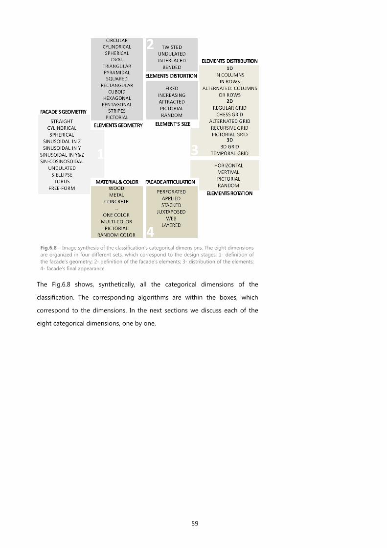
59
Fig.6.8 – Image synthesis of the classification’s categorical dimensions. The eight dimensions
are organized in four different sets, which correspond to the design stages: 1- definition of
the facade’s geometry; 2- definition of the facade’s elements; 3- distribution of the elements;
4- facade’s final appearance.
The Fig.6.8 shows, synthetically, all the categorical dimensions of the
classification. The corresponding algorithms are within the boxes, which
correspond to the dimensions. In the next sections we discuss each of the
eight categorical dimensions, one by one.
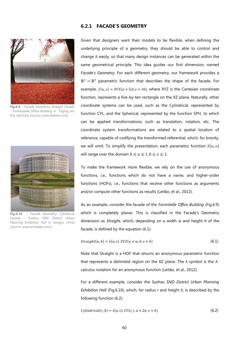
60
6.2.1 FACADE'S GEOMETRY
Given that designers want their models to be flexible, when defining the
underlying principle of a geometry, they should be able to control and
change it easily, so that many design instances can be generated within the
same geometrical principle. This idea guides our first dimension, named
Facade's Geometry. For each different geometry, our framework provides a
parametric function that describes the shape of the facade. For
example, , where XYZ is the Cartesian coordinate
function, represents a five-by-ten rectangle on the XZ plane. Naturally, other
coordinate systems can be used, such as the Cylindrical, represented by
function CYL, and the Spherical, represented by the function SPH, to which
can be applied transformations, such as translation, rotation, etc. The
coordinate system transformations are related to a spatial location of
reference, capable of codifying the transformed referential, which, for brevity,
we will omit. To simplify the presentation, each parametric function
will range over the domain
To make the framework more flexible, we rely on the use of anonymous
functions, i.e., functions which do not have a name, and higher-order
functions (HOFs), i.e., functions that receive other functions as arguments
and/or compute other functions as results (Leitão, et al., 2012).
As an example, consider the facade of the Formstelle Office Building (Fig.6.9)
which is completely planar. This is classified in the Facade's Geometry
dimension as Straight, which, depending on a width w and height h of the
facade, is defined by the equation (6.1):
(6.1)
Note that Straight is a HOF that returns an anonymous parametric function
that represents a delimited region on the XZ plane. The λ symbol is the λ-
calculus notation for an anonymous function (Leitão, et al., 2012).
For a different example, consider the Suzhou SND District Urban Planning
Exhibition Hall (Fig.6.10), which, for radius r and height h, is described by the
following function (6.2):
(6.2)
Fig.6.9 - Facade Geometry: Straight Facade
- Formestelle Office Building in Töging am
Inn, Germany (source: www.dezeen.com)
Fig.6.10 - Facade Geometry: Cylindrical
Facade - Suzhou SND District Urban
Planning Exhibition Hall in Jiangsu, China
(source: www.archdaily.com/)
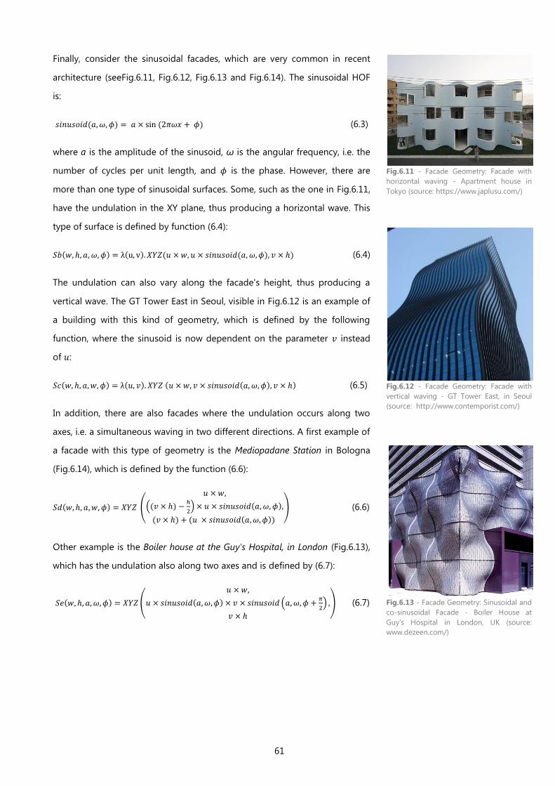
61
Finally, consider the sinusoidal facades, which are very common in recent
architecture (seeFig.6.11, Fig.6.12, Fig.6.13 and Fig.6.14). The sinusoidal HOF
is:
(6.3)
where a is the amplitude of the sinusoid, ω is the angular frequency, i.e. the
number of cycles per unit length, and is the phase. However, there are
more than one type of sinusoidal surfaces. Some, such as the one in Fig.6.11,
have the undulation in the XY plane, thus producing a horizontal wave. This
type of surface is defined by function (6.4):
(6.4)
The undulation can also vary along the facade's height, thus producing a
vertical wave. The GT Tower East in Seoul, visible in Fig.6.12 is an example of
a building with this kind of geometry, which is defined by the following
function, where the sinusoid is now dependent on the parameter instead
of :
(6.5)
In addition, there are also facades where the undulation occurs along two
axes, i.e. a simultaneous waving in two different directions. A first example of
a facade with this type of geometry is the Mediopadane Station in Bologna
(Fig.6.14), which is defined by the function (6.6):
(6.6)
Other example is the Boiler house at the Guy's Hospital, in London (Fig.6.13),
which has the undulation also along two axes and is defined by (6.7):
(6.7)
Fig.6.11 - Facade Geometry: Facade with
horizontal waving - Apartment house in
Tokyo (source: https://www.japlusu.com/)
Fig.6.12 - Facade Geometry: Facade with
vertical waving - GT Tower East, in Seoul
(source: http://www.contemporist.com/)
Fig.6.13 - Facade Geometry: Sinusoidal and
co-sinusoidal Facade - Boiler House at
Guy's Hospital in London, UK (source:
www.dezeen.com/)
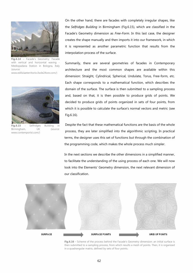
62
On the other hand, there are facades with completely irregular shapes, like
the Selfridges Building in Birmingham (Fig.6.15), which are classified in the
Facade's Geometry dimension as Free-Form. In this last case, the designer
creates the shape manually and then imports it into our framework, in which
it is represented as another parametric function that results from the
interpolation process of the surface.
Summarily, there are several geometries of facades in Contemporary
architecture and the most common shapes are available within this
dimension: Straight, Cylindrical, Spherical, Undulate, Torus, Free-form, etc.
Each shape corresponds to a mathematical function, which describes the
domain of the surface. The surface is then submitted to a sampling process
and, based on that, it is then possible to produce grids of points. We
decided to produce grids of points organized in sets of four points, from
which it is possible to calculate the surface’s normal vectors and metric (see
Fig.6.16).
Despite the fact that these mathematical functions are the basis of the whole
process, they are later simplified into the algorithmic scripting. In practical
terms, the designer uses this set of functions but through the combination of
the programming code, which makes the whole process much simpler.
In the next sections we describe the other dimensions in a simplified manner,
to facilitate the understanding of the using process of each one. We will now
look into the Elements’ Geometry dimension, the next relevant dimension of
our classification.
Fig.6.14 – Facade’s Geometry: Facade
with vertical and horizontal waving -
Mediopadana Station in Bologna, Italy
(source:
www.ediliziaeterritorio.ilsole24ore.com/)
Fig.6.15 - Selfridges Building in
Birmingham, UK (source:
www.contemporist.com/)
Fig.6.16 – Scheme of the process behind the Facade’s Geometry dimension: an initial surface is
then submitted to a sampling process, from which results a mesh of points. Then, it is organized
in a quadrangular matrix, defined by sets of four points.
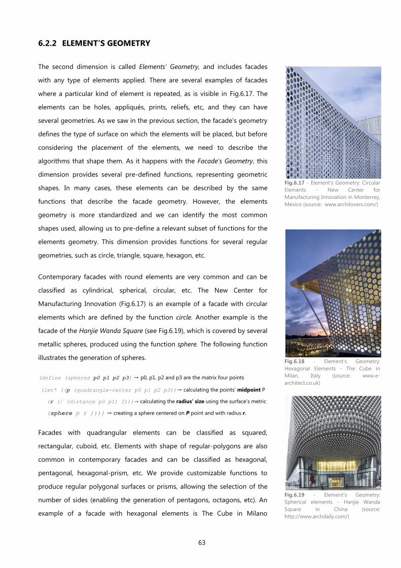
63
6.2.2 ELEMENT'S GEOMETRY
The second dimension is called Elements' Geometry, and includes facades
with any type of elements applied. There are several examples of facades
where a particular kind of element is repeated, as is visible in Fig.6.17. The
elements can be holes, appliqués, prints, reliefs, etc, and they can have
several geometries. As we saw in the previous section, the facade's geometry
defines the type of surface on which the elements will be placed, but before
considering the placement of the elements, we need to describe the
algorithms that shape them. As it happens with the Facade's Geometry, this
dimension provides several pre-defined functions, representing geometric
shapes. In many cases, these elements can be described by the same
functions that describe the facade geometry. However, the elements
geometry is more standardized and we can identify the most common
shapes used, allowing us to pre-define a relevant subset of functions for the
elements geometry. This dimension provides functions for several regular
geometries, such as circle, triangle, square, hexagon, etc.
Contemporary facades with round elements are very common and can be
classified as cylindrical, spherical, circular, etc. The New Center for
Manufacturing Innovation (Fig.6.17) is an example of a facade with circular
elements which are defined by the function circle. Another example is the
facade of the Hanjie Wanda Square (see Fig.6.19), which is covered by several
metallic spheres, produced using the function sphere. The following function
illustrates the generation of spheres.
(define (spheres p0 p1 p2 p3) → p0, p1, p2 and p3 are the matrix four points
(let* ((p (quadrangle-center p0 p1 p2 p3))→ calculating the points’ midpoint P
(r (/ (distance p0 p1) 2)))→ calculating the radius’ size using the surface’s metric
(sphere p r )))) → creating a sphere centered on P point and with radius r.
Facades with quadrangular elements can be classified as squared,
rectangular, cuboid, etc. Elements with shape of regular-polygons are also
common in contemporary facades and can be classified as hexagonal,
pentagonal, hexagonal-prism, etc. We provide customizable functions to
produce regular polygonal surfaces or prisms, allowing the selection of the
number of sides (enabling the generation of pentagons, octagons, etc). An
example of a facade with hexagonal elements is The Cube in Milano
Fig.6.17 - Element's Geometry: Circular
Elements - New Center for
Manufacturing Innovation in Monterrey,
Mexico (source: www.archilovers.com/)
Fig.6.18 - Element's Geometry:
Hexagonal Elements - The Cube in
Milan, Italy (source: www.e-
architect.co.uk)
Fig.6.19 - Element's Geometry:
Spherical elements - Hanjie Wanda
Square in China (source:
http://www.archdaily.com/)
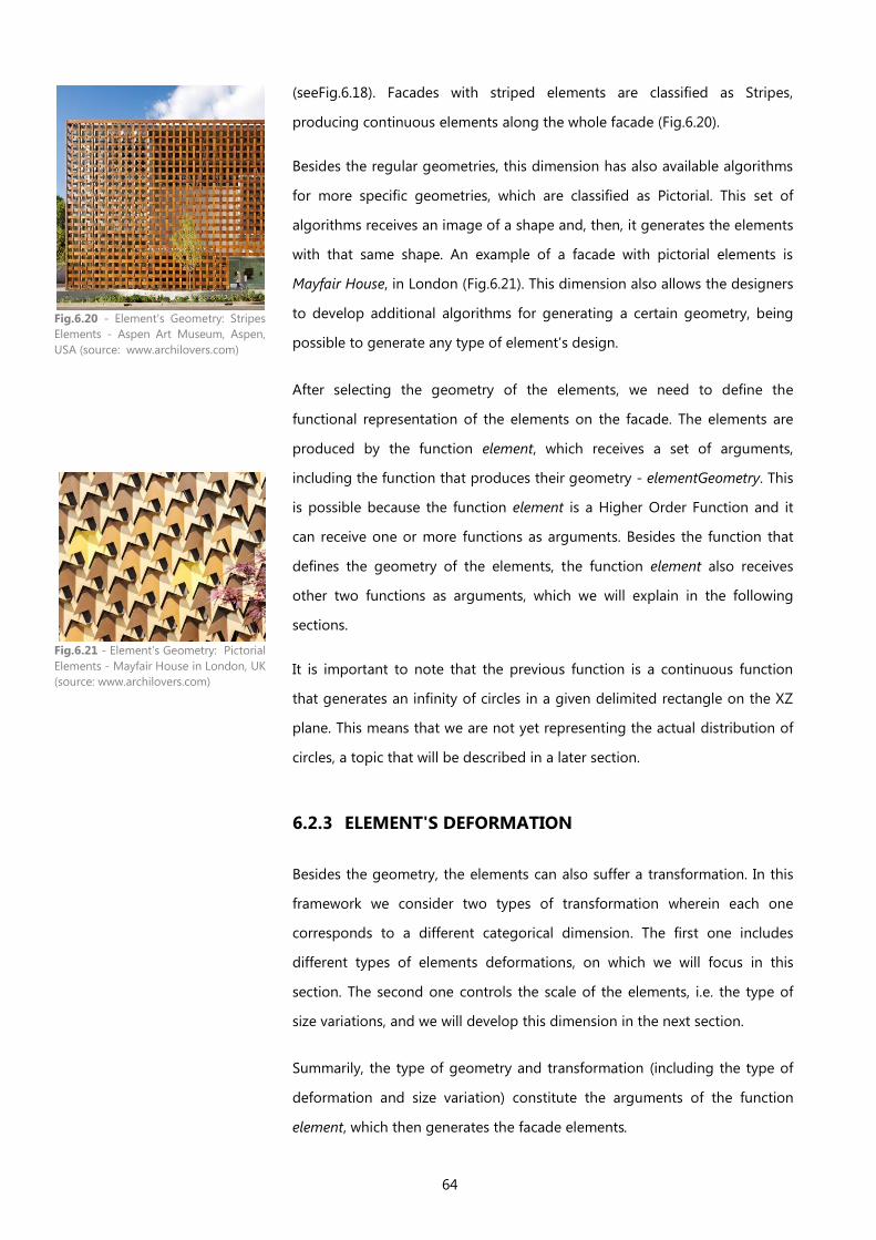
64
(seeFig.6.18). Facades with striped elements are classified as Stripes,
producing continuous elements along the whole facade (Fig.6.20).
Besides the regular geometries, this dimension has also available algorithms
for more specific geometries, which are classified as Pictorial. This set of
algorithms receives an image of a shape and, then, it generates the elements
with that same shape. An example of a facade with pictorial elements is
Mayfair House, in London (Fig.6.21). This dimension also allows the designers
to develop additional algorithms for generating a certain geometry, being
possible to generate any type of element’s design.
After selecting the geometry of the elements, we need to define the
functional representation of the elements on the facade. The elements are
produced by the function element, which receives a set of arguments,
including the function that produces their geometry - elementGeometry. This
is possible because the function element is a Higher Order Function and it
can receive one or more functions as arguments. Besides the function that
defines the geometry of the elements, the function element also receives
other two functions as arguments, which we will explain in the following
sections.
It is important to note that the previous function is a continuous function
that generates an infinity of circles in a given delimited rectangle on the XZ
plane. This means that we are not yet representing the actual distribution of
circles, a topic that will be described in a later section.
6.2.3 ELEMENT'S DEFORMATION
Besides the geometry, the elements can also suffer a transformation. In this
framework we consider two types of transformation wherein each one
corresponds to a different categorical dimension. The first one includes
different types of elements deformations, on which we will focus in this
section. The second one controls the scale of the elements, i.e. the type of
size variations, and we will develop this dimension in the next section.
Summarily, the type of geometry and transformation (including the type of
deformation and size variation) constitute the arguments of the function
element, which then generates the facade elements.
Fig.6.20 - Element's Geometry: Stripes
Elements - Aspen Art Museum, Aspen,
USA (source: www.archilovers.com)
Fig.6.21 - Element's Geometry: Pictorial
Elements - Mayfair House in London, UK
(source: www.archilovers.com)
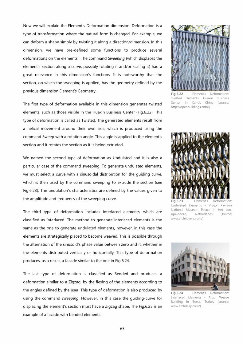
65
Now we will explain the Element’s Deformation dimension. Deformation is a
type of transformation where the natural form is changed. For example, we
can deform a shape simply by twisting it along a direction/dimension. In this
dimension, we have pre-defined some functions to produce several
deformations on the elements. The command Sweeping (which displaces the
element’s section along a curve, possibly rotating it and/or scaling it) had a
great relevance in this dimension’s functions. It is noteworthy that the
section, on which the sweeping is applied, has the geometry defined by the
previous dimension Element's Geometry.
The first type of deformation available in this dimension generates twisted
elements, such as those visible in the Huaxin Business Center (Fig.6.22). This
type of deformation is called as Twisted. The generated elements result from
a helical movement around their own axis, which is produced using the
command Sweep with a rotation angle. This angle is applied to the element's
section and it rotates the section as it is being extruded.
We named the second type of deformation as Undulated and it is also a
particular case of the command sweeping. To generate undulated elements,
we must select a curve with a sinusoidal distribution for the guiding curve,
which is then used by the command sweeping to extrude the section (see
Fig.6.23). The undulation’s characteristics are defined by the values given to
the amplitude and frequency of the sweeping curve.
The third type of deformation includes interlaced elements, which are
classified as Interlaced. The method to generate interlaced elements is the
same as the one to generate undulated elements, however, in this case the
elements are strategically placed to become weaved. This is possible through
the alternation of the sinusoid's phase value between zero and π, whether in
the elements distributed vertically or horizontally. This type of deformation
produces, as a result, a facade similar to the one in Fig.6.24.
The last type of deformation is classified as Bended and produces a
deformation similar to a Zigzag, by the flexing of the elements according to
the angles defined by the user. This type of deformation is also produced by
using the command sweeping. However, in this case the guiding-curve for
displacing the element's section must have a Zigzag shape. The Fig.6.25 is an
example of a facade with bended elements.
Fig.6.22 - Element's Deformation:
Twisted Elements: Huaxin Business
Center in Xuhui, China (source:
http://openbuildings.com/)
Fig.6.23 - Element's Deformation:
Undulated Elements - Visitor Pavilion
National Museum Palace in Het Loo,
Apeldoorn, Netherlands (source:
www.archilovers.com/)
Fig.6.24 - Element's Deformation:
Interlaced Elements - Argul Weave
Building in Bursa, Turkey (source:
www.archdaily.com/)
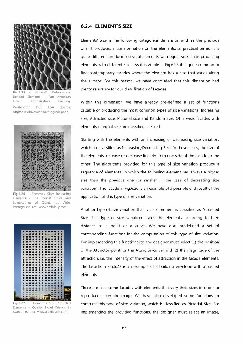
66
6.2.4 ELEMENT'S SIZE
Elements' Size is the following categorical dimension and, as the previous
one, it produces a transformation on the elements. In practical terms, it is
quite different producing several elements with equal sizes than producing
elements with different sizes. As it is visible in Fig.6.26 it is quite common to
find contemporary facades where the element has a size that varies along
the surface. For this reason, we have concluded that this dimension had
plenty relevancy for our classification of facades.
Within this dimension, we have already pre-defined a set of functions
capable of producing the most common types of size variations: Increasing
size, Attracted size, Pictorial size and Random size. Otherwise, facades with
elements of equal size are classified as Fixed.
Starting with the elements with an increasing or decreasing size variation,
which are classified as Increasing/Decreasing Size. In these cases, the size of
the elements increase or decrease linearly from one side of the facade to the
other. The algorithms provided for this type of size variation produce a
sequence of elements, in which the following element has always a bigger
size than the previous one (or smaller in the case of decreasing size
variation). The facade in Fig.6.26 is an example of a possible end result of the
application of this type of size variation.
Another type of size variation that is also frequent is classified as Attracted
Size. This type of size variation scales the elements according to their
distance to a point or a curve. We have also predefined a set of
corresponding functions for the computation of this type of size variation.
For implementing this functionality, the designer must select (1) the position
of the Attractor-point, or the Attractor-curve, and (2) the magnitude of the
attraction, i.e. the intensity of the effect of attraction in the facade elements.
The facade in Fig.6.27 is an example of a building envelope with attracted
elements.
There are also some facades with elements that vary their sizes in order to
reproduce a certain image. We have also developed some functions to
compute this type of size variation, which is classified as Pictorial Size. For
implementing the provided functions, the designer must select an image,
Fig.6.25 - Element's Deformation:
Bended Elements - Pan American
Health Organization Building,
Washington DC , USA (source:
http://flickrhivemind.net/Tags/dc,paho)
Fig.6.26 - Element's Size: Increasing
Elements - The Tourist Office and
Landscaping of Quinta do Aido,
Portugal (source: www.archdaily.com)
Fig.6.27 - Element's Size: Attracted
Elements - Quality Hotel Friends in
Sweden (source: www.archilovers.com)
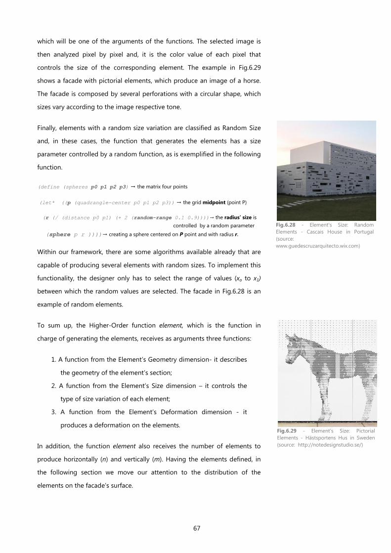
67
which will be one of the arguments of the functions. The selected image is
then analyzed pixel by pixel and, it is the color value of each pixel that
controls the size of the corresponding element. The example in Fig.6.29
shows a facade with pictorial elements, which produce an image of a horse.
The facade is composed by several perforations with a circular shape, which
sizes vary according to the image respective tone.
Finally, elements with a random size variation are classified as Random Size
and, in these cases, the function that generates the elements has a size
parameter controlled by a random function, as is exemplified in the following
function.
(define (spheres p0 p1 p2 p3) → the matrix four points
(let* ((p (quadrangle-center p0 p1 p2 p3)) → the grid midpoint (point P)
(r (/ (distance p0 p1) (+ 2 (random-range 0.1 0.9))))→ the radius’ size is
controlled by a random parameter
(sphere p r ))))→ creating a sphere centered on P point and with radius r.
Within our framework, there are some algorithms available already that are
capable of producing several elements with random sizes. To implement this
functionality, the designer only has to select the range of values (xo to x1)
between which the random values are selected. The facade in Fig.6.28 is an
example of random elements.
To sum up, the Higher-Order function element, which is the function in
charge of generating the elements, receives as arguments three functions:
1. A function from the Element’s Geometry dimension- it describes
the geometry of the element’s section;
2. A function from the Element’s Size dimension – it controls the
type of size variation of each element;
3. A function from the Element’s Deformation dimension - it
produces a deformation on the elements.
In addition, the function element also receives the number of elements to
produce horizontally (n) and vertically (m). Having the elements defined, in
the following section we move our attention to the distribution of the
elements on the facade’s surface.
Fig.6.28 - Element's Size: Random
Elements - Cascais House in Portugal
(source:
www.guedescruzarquitecto.wix.com)
Fig.6.29 - Element's Size: Pictorial
Elements - Hästsportens Hus in Sweden
(source: http://notedesignstudio.se/)
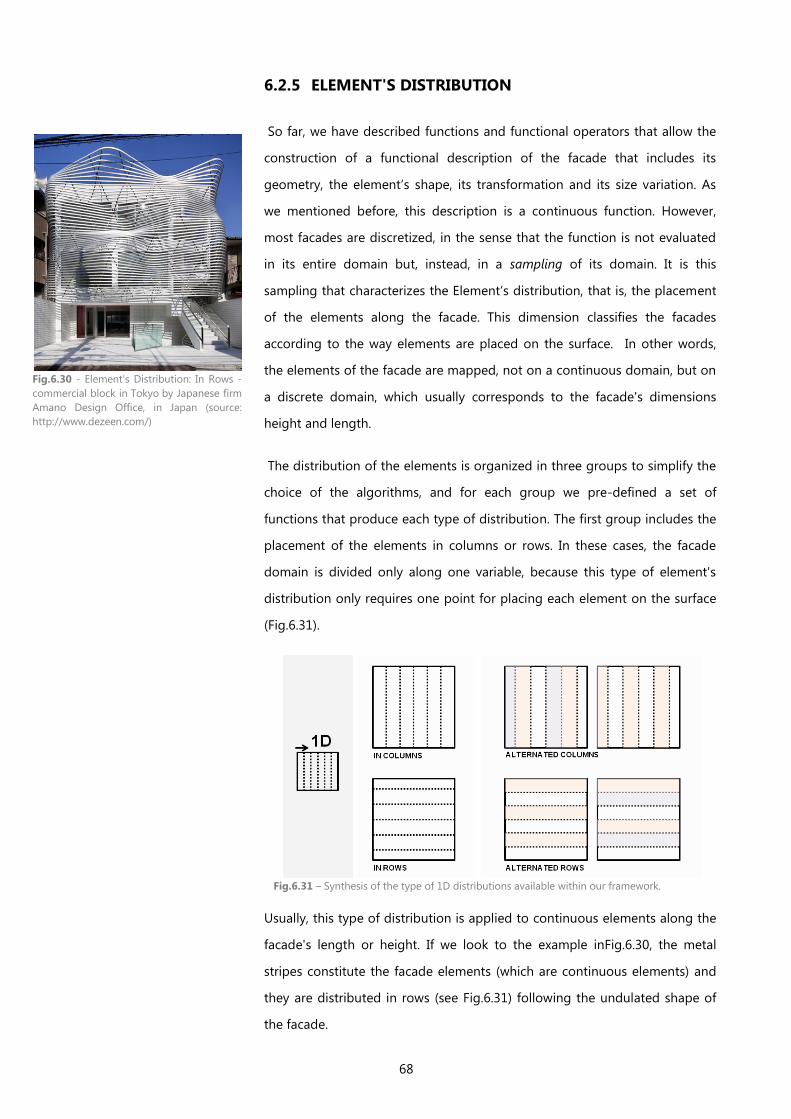
68
6.2.5 ELEMENT'S DISTRIBUTION
So far, we have described functions and functional operators that allow the
construction of a functional description of the facade that includes its
geometry, the element’s shape, its transformation and its size variation. As
we mentioned before, this description is a continuous function. However,
most facades are discretized, in the sense that the function is not evaluated
in its entire domain but, instead, in a sampling of its domain. It is this
sampling that characterizes the Element’s distribution, that is, the placement
of the elements along the facade. This dimension classifies the facades
according to the way elements are placed on the surface. In other words,
the elements of the facade are mapped, not on a continuous domain, but on
a discrete domain, which usually corresponds to the facade's dimensions
height and length.
The distribution of the elements is organized in three groups to simplify the
choice of the algorithms, and for each group we pre-defined a set of
functions that produce each type of distribution. The first group includes the
placement of the elements in columns or rows. In these cases, the facade
domain is divided only along one variable, because this type of element's
distribution only requires one point for placing each element on the surface
(Fig.6.31).
Fig.6.31 – Synthesis of the type of 1D distributions available within our framework.
Usually, this type of distribution is applied to continuous elements along the
facade's length or height. If we look to the example inFig.6.30, the metal
stripes constitute the facade elements (which are continuous elements) and
they are distributed in rows (see Fig.6.31) following the undulated shape of
the facade.
Fig.6.30 - Element's Distribution: In Rows -
commercial block in Tokyo by Japanese firm
Amano Design Office, in Japan (source:
http://www.dezeen.com/)
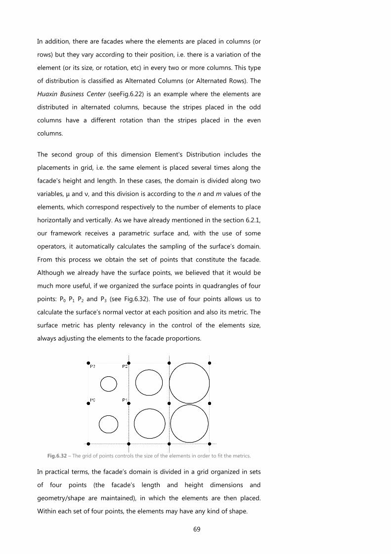
69
In addition, there are facades where the elements are placed in columns (or
rows) but they vary according to their position, i.e. there is a variation of the
element (or its size, or rotation, etc) in every two or more columns. This type
of distribution is classified as Alternated Columns (or Alternated Rows). The
Huaxin Business Center (seeFig.6.22) is an example where the elements are
distributed in alternated columns, because the stripes placed in the odd
columns have a different rotation than the stripes placed in the even
columns.
The second group of this dimension Element's Distribution includes the
placements in grid, i.e. the same element is placed several times along the
facade's height and length. In these cases, the domain is divided along two
variables, μ and ν, and this division is according to the n and m values of the
elements, which correspond respectively to the number of elements to place
horizontally and vertically. As we have already mentioned in the section 6.2.1,
our framework receives a parametric surface and, with the use of some
operators, it automatically calculates the sampling of the surface’s domain.
From this process we obtain the set of points that constitute the facade.
Although we already have the surface points, we believed that it would be
much more useful, if we organized the surface points in quadrangles of four
points: P0 P1 P2 and P3 (see Fig.6.32). The use of four points allows us to
calculate the surface’s normal vector at each position and also its metric. The
surface metric has plenty relevancy in the control of the elements size,
always adjusting the elements to the facade proportions.
In practical terms, the facade’s domain is divided in a grid organized in sets
of four points (the facade’s length and height dimensions and
geometry/shape are maintained), in which the elements are then placed.
Within each set of four points, the elements may have any kind of shape.
Fig.6.32 – The grid of points controls the size of the elements in order to fit the metrics.
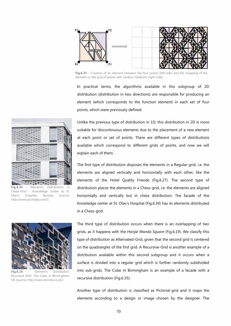
70
In practical terms, the algorithms available in this subgroup of 2D
distribution (distribution in two directions) are responsible for producing an
element (which corresponds to the function element) in each set of four
points, which were previously defined.
Unlike the previous type of distribution in 1D, this distribution in 2D is more
suitable for discontinuous elements due to the placement of a new element
at each point or set of points. There are different types of distributions
available which correspond to different grids of points, and now we will
explain each of them.
The first type of distribution disposes the elements in a Regular-grid, i.e. the
elements are aligned vertically and horizontally with each other, like the
elements of the Hotel Quality Friends (Fig.6.27). The second type of
distribution places the elements in a Chess-grid, i.e. the elements are aligned
horizontally and vertically but in chess distribution. The facade of the
Knowledge center at St. Olav's Hospital (Fig.6.34) has its elements distributed
in a Chess-grid.
The third type of distribution occurs when there is an overlapping of two
grids, as it happens with the Hanjie Wanda Square (Fig.6.19). We classify this
type of distribution as Alternated-Grid, given that the second grid is centered
on the quadrangles of the first grid. A Recursive-Grid is another example of a
distribution available within this second subgroup and it occurs when a
surface is divided into a regular grid which is further randomly subdivided
into sub-grids. The Cube in Birmingham is an example of a facade with a
recursive distribution (Fig.6.35).
Another type of distribution is classified as Pictorial-grid and it maps the
elements according to a design or image chosen by the designer. The
Fig.6.33 – Creation of an element between the four points (left-side) and the mapping of the
element on the grid of points with random rotations (right-side)
Fig.6.34 - Element's Distribution: in
Chess-Grid - Knowledge center at St.
Olav's Hospital, Norway (source:
http://www.archdaily.com/)
Fig.6.35 - Element's Distribution:
Recursive Grid- The Cube, in Birmingham,
UK (source: http://www.wicona.co.uk/)
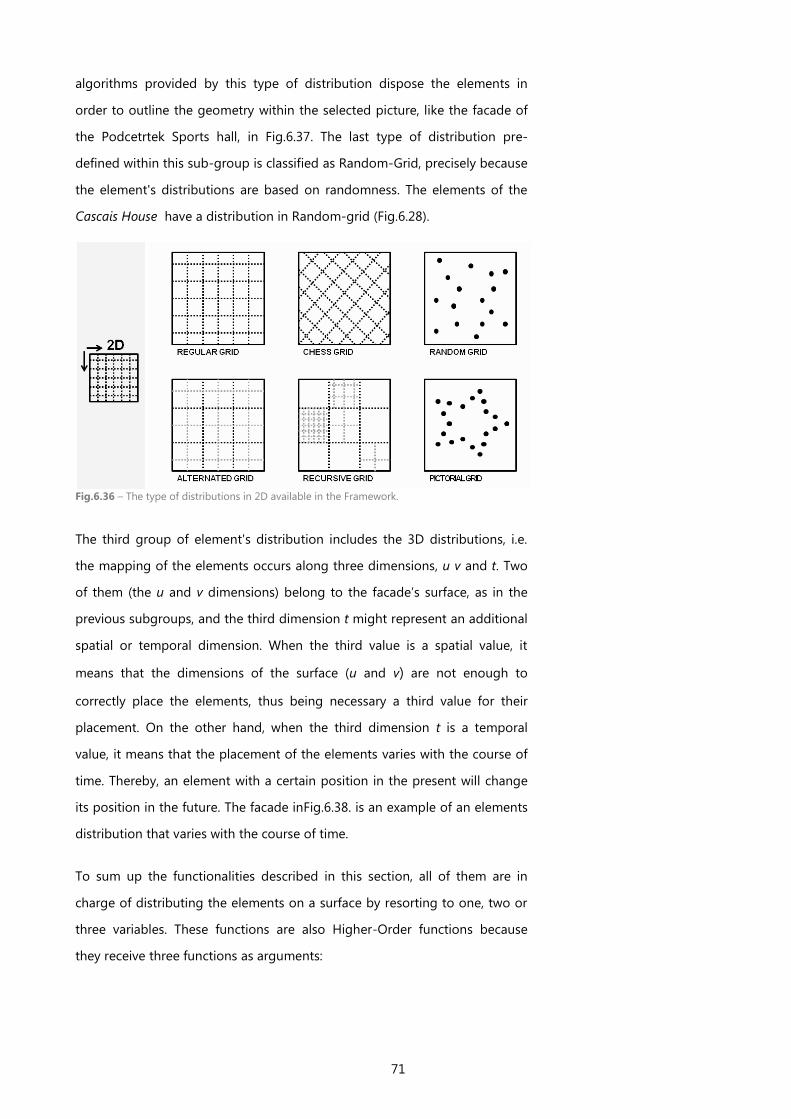
71
algorithms provided by this type of distribution dispose the elements in
order to outline the geometry within the selected picture, like the facade of
the Podcetrtek Sports hall, in Fig.6.37. The last type of distribution pre-
defined within this sub-group is classified as Random-Grid, precisely because
the element's distributions are based on randomness. The elements of the
Cascais House have a distribution in Random-grid (Fig.6.28).
The third group of element's distribution includes the 3D distributions, i.e.
the mapping of the elements occurs along three dimensions, u v and t. Two
of them (the u and v dimensions) belong to the facade’s surface, as in the
previous subgroups, and the third dimension t might represent an additional
spatial or temporal dimension. When the third value is a spatial value, it
means that the dimensions of the surface (u and v) are not enough to
correctly place the elements, thus being necessary a third value for their
placement. On the other hand, when the third dimension t is a temporal
value, it means that the placement of the elements varies with the course of
time. Thereby, an element with a certain position in the present will change
its position in the future. The facade inFig.6.38. is an example of an elements
distribution that varies with the course of time.
To sum up the functionalities described in this section, all of them are in
charge of distributing the elements on a surface by resorting to one, two or
three variables. These functions are also Higher-Order functions because
they receive three functions as arguments:
Fig.6.36 – The type of distributions in 2D available in the Framework.
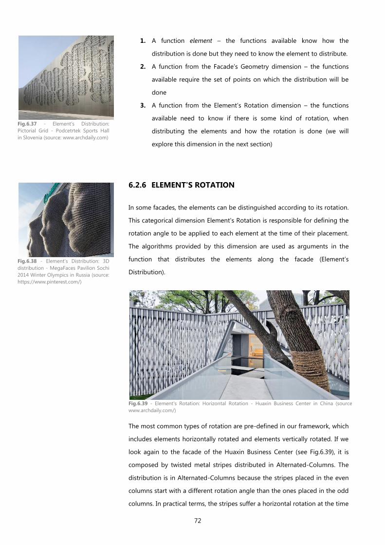
72
1. A function element – the functions available know how the
distribution is done but they need to know the element to distribute.
2. A function from the Facade’s Geometry dimension – the functions
available require the set of points on which the distribution will be
done
3. A function from the Element’s Rotation dimension – the functions
available need to know if there is some kind of rotation, when
distributing the elements and how the rotation is done (we will
explore this dimension in the next section)
6.2.6 ELEMENT'S ROTATION
In some facades, the elements can be distinguished according to its rotation.
This categorical dimension Element's Rotation is responsible for defining the
rotation angle to be applied to each element at the time of their placement.
The algorithms provided by this dimension are used as arguments in the
function that distributes the elements along the facade (Element’s
Distribution).
The most common types of rotation are pre-defined in our framework, which
includes elements horizontally rotated and elements vertically rotated. If we
look again to the facade of the Huaxin Business Center (see Fig.6.39), it is
composed by twisted metal stripes distributed in Alternated-Columns. The
distribution is in Alternated-Columns because the stripes placed in the even
columns start with a different rotation angle than the ones placed in the odd
columns. In practical terms, the stripes suffer a horizontal rotation at the time
Fig.6.37 - Element's Distribution:
Pictorial Grid - Podcetrtek Sports Hall
in Slovenia (source: www.archdaily.com)
Fig.6.38 - Element's Distribution: 3D
distribution - MegaFaces Pavilion Sochi
2014 Winter Olympics in Russia (source:
https://www.pinterest.com/)
Fig.6.39 - Element's Rotation: Horizontal Rotation - Huaxin Business Center in China (source:
www.archdaily.com/)
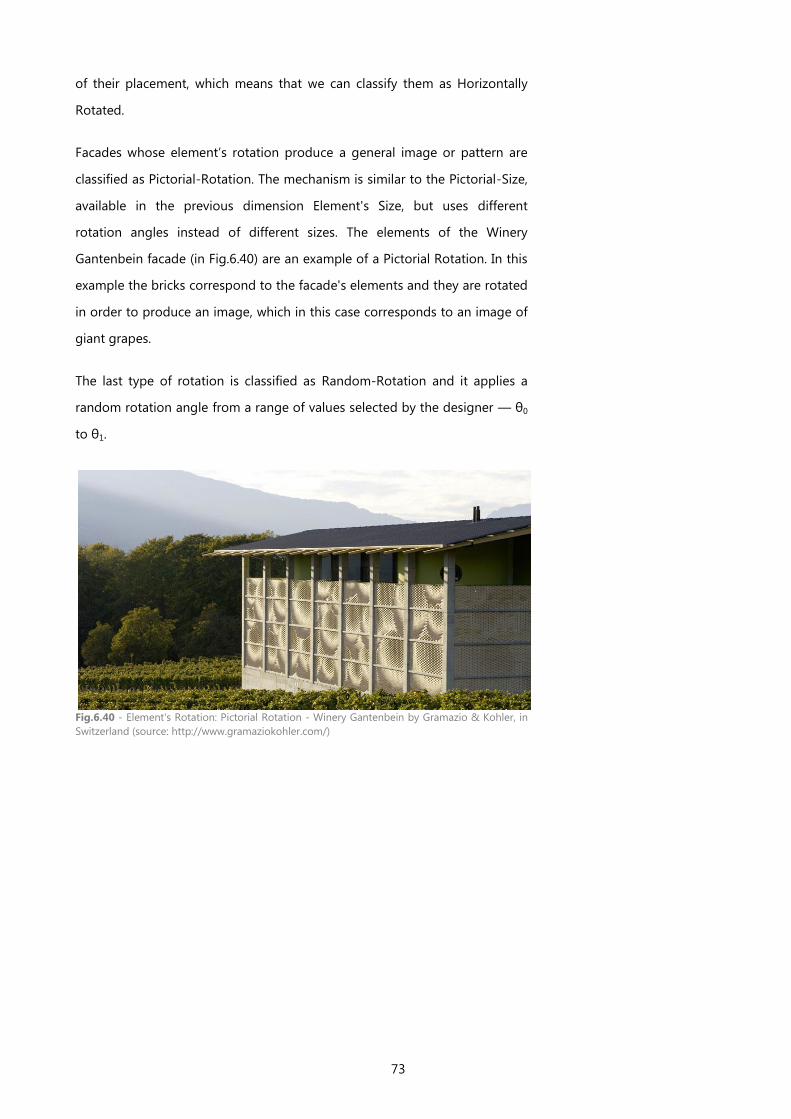
73
of their placement, which means that we can classify them as Horizontally
Rotated.
Facades whose element’s rotation produce a general image or pattern are
classified as Pictorial-Rotation. The mechanism is similar to the Pictorial-Size,
available in the previous dimension Element's Size, but uses different
rotation angles instead of different sizes. The elements of the Winery
Gantenbein facade (in Fig.6.40) are an example of a Pictorial Rotation. In this
example the bricks correspond to the facade's elements and they are rotated
in order to produce an image, which in this case corresponds to an image of
giant grapes.
The last type of rotation is classified as Random-Rotation and it applies a
random rotation angle from a range of values selected by the designer — θ0
to θ1.
Fig.6.40 - Element's Rotation: Pictorial Rotation - Winery Gantenbein by Gramazio & Kohler, in
Switzerland (source: http://www.gramaziokohler.com/)
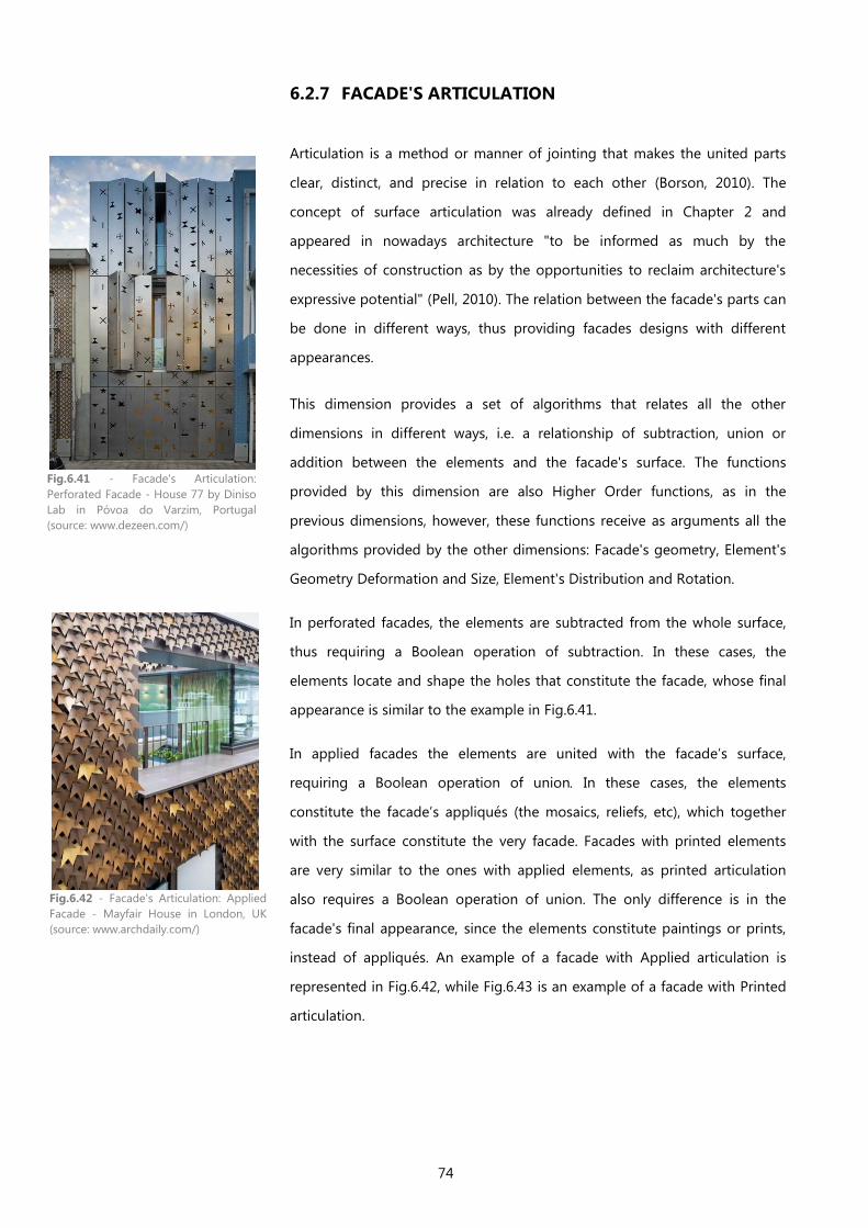
74
6.2.7 FACADE'S ARTICULATION
Articulation is a method or manner of jointing that makes the united parts
clear, distinct, and precise in relation to each other (Borson, 2010). The
concept of surface articulation was already defined in Chapter 2 and
appeared in nowadays architecture "to be informed as much by the
necessities of construction as by the opportunities to reclaim architecture's
expressive potential" (Pell, 2010). The relation between the facade's parts can
be done in different ways, thus providing facades designs with different
appearances.
This dimension provides a set of algorithms that relates all the other
dimensions in different ways, i.e. a relationship of subtraction, union or
addition between the elements and the facade's surface. The functions
provided by this dimension are also Higher Order functions, as in the
previous dimensions, however, these functions receive as arguments all the
algorithms provided by the other dimensions: Facade's geometry, Element's
Geometry Deformation and Size, Element's Distribution and Rotation.
In perforated facades, the elements are subtracted from the whole surface,
thus requiring a Boolean operation of subtraction. In these cases, the
elements locate and shape the holes that constitute the facade, whose final
appearance is similar to the example in Fig.6.41.
In applied facades the elements are united with the facade’s surface,
requiring a Boolean operation of union. In these cases, the elements
constitute the facade’s appliqués (the mosaics, reliefs, etc), which together
with the surface constitute the very facade. Facades with printed elements
are very similar to the ones with applied elements, as printed articulation
also requires a Boolean operation of union. The only difference is in the
facade's final appearance, since the elements constitute paintings or prints,
instead of appliqués. An example of a facade with Applied articulation is
represented in Fig.6.42, while Fig.6.43 is an example of a facade with Printed
articulation.
Fig.6.41 - Facade's Articulation:
Perforated Facade - House 77 by Diniso
Lab in Póvoa do Varzim, Portugal
(source: www.dezeen.com/)
Fig.6.42 - Facade's Articulation: Applied
Facade - Mayfair House in London, UK
(source: www.archdaily.com/)
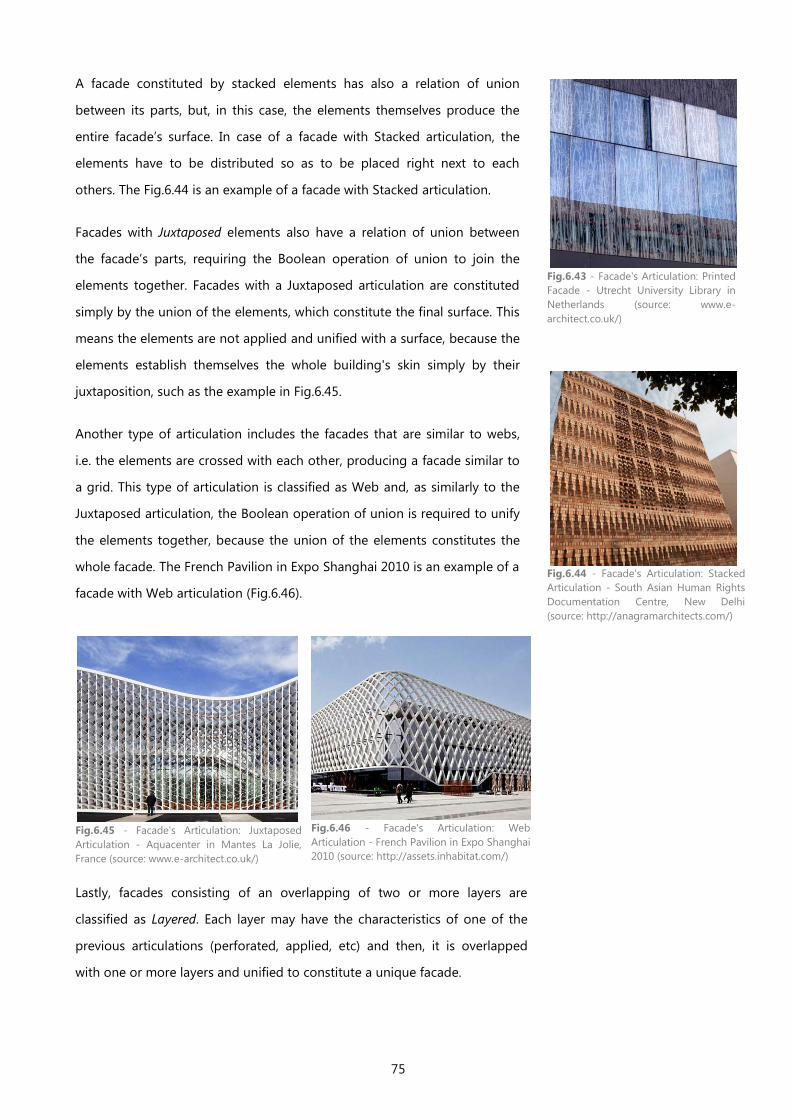
75
A facade constituted by stacked elements has also a relation of union
between its parts, but, in this case, the elements themselves produce the
entire facade’s surface. In case of a facade with Stacked articulation, the
elements have to be distributed so as to be placed right next to each
others. The Fig.6.44 is an example of a facade with Stacked articulation.
Facades with Juxtaposed elements also have a relation of union between
the facade’s parts, requiring the Boolean operation of union to join the
elements together. Facades with a Juxtaposed articulation are constituted
simply by the union of the elements, which constitute the final surface. This
means the elements are not applied and unified with a surface, because the
elements establish themselves the whole building's skin simply by their
juxtaposition, such as the example in Fig.6.45.
Another type of articulation includes the facades that are similar to webs,
i.e. the elements are crossed with each other, producing a facade similar to
a grid. This type of articulation is classified as Web and, as similarly to the
Juxtaposed articulation, the Boolean operation of union is required to unify
the elements together, because the union of the elements constitutes the
whole facade. The French Pavilion in Expo Shanghai 2010 is an example of a
facade with Web articulation (Fig.6.46).
Lastly, facades consisting of an overlapping of two or more layers are
classified as Layered. Each layer may have the characteristics of one of the
previous articulations (perforated, applied, etc) and then, it is overlapped
with one or more layers and unified to constitute a unique facade.
Fig.6.43 - Facade's Articulation: Printed
Facade - Utrecht University Library in
Netherlands (source: www.e-
architect.co.uk/)
Fig.6.44 - Facade's Articulation: Stacked
Articulation - South Asian Human Rights
Documentation Centre, New Delhi
(source: http://anagramarchitects.com/)
Fig.6.45 - Facade's Articulation: Juxtaposed
Articulation - Aquacenter in Mantes La Jolie,
France (source: www.e-architect.co.uk/)
Fig.6.46 - Facade's Articulation: Web
Articulation - French Pavilion in Expo Shanghai
2010 (source: http://assets.inhabitat.com/)
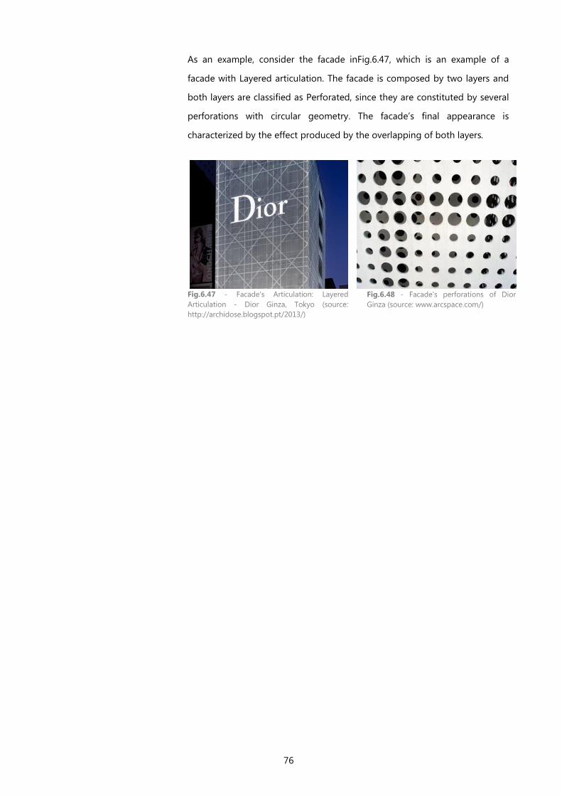
76
As an example, consider the facade inFig.6.47, which is an example of a
facade with Layered articulation. The facade is composed by two layers and
both layers are classified as Perforated, since they are constituted by several
perforations with circular geometry. The facade’s final appearance is
characterized by the effect produced by the overlapping of both layers.
Fig.6.47 - Facade's Articulation: Layered
Articulation - Dior Ginza, Tokyo (source:
http://archidose.blogspot.pt/2013/)
Fig.6.48 - Facade's perforations of Dior
Ginza (source: www.arcspace.com/)
77
6.2.8 FACADE'S MATERIAL AND COLOR
The last categorical dimension of our classification of facades is called as
Material and Color and it gives the materiality or color to the facade's model.
If the facade’s final appearance has materials in sight, the corresponding
layer, or layers, will have the name of the chosen material and, thus,
presenting the chosen materiality.
On the other hand, if the facade has colors as its finishing, the corresponding
layer(s) will have the chosen color(s) as name(s) and, the facade’s model will
present the corresponding color(s) on its final appearance.
The algorithms provided by the dimension Material and Color constitute the
third argument received by the function that generates the whole facade
model (which is available in the Facade’s Articulation dimension).
The materials used in a facade seem not to be directly connected with the
selection of the algorithms. However, the material selected for a facade is
often connected with the design of the facade. Since a certain type of design
corresponds to a particular way of organizing the operations (which were
used for generating a certain design) the selected materials turn out to be
related with the type of algorithms used in the generation of the facade’s
model.
As an example, most of the perforated facades are made of metal (Fig.6.49).
The same happens with facades of Web articulation and also facades with a
complex geometry (see Fig.6.50).
Fig.6.49 - Facade's Material: Metal - an example of a perforated facade - Het Bushok in
Netherlands (source: http://www.archilovers.com/)
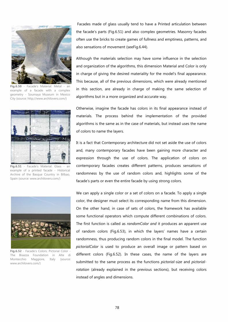
78
Facades made of glass usually tend to have a Printed articulation between
the facade’s parts (Fig.6.51) and also complex geometries. Masonry facades
often use the bricks to create games of fullness and emptiness, patterns, and
also sensations of movement (seeFig.6.44).
Although the materials selection may have some influence in the selection
and organization of the algorithms, this dimension Material and Color is only
in charge of giving the desired materiality for the model’s final appearance.
This because, all of the previous dimensions, which were already mentioned
in this section, are already in charge of making the same selection of
algorithms but in a more organized and accurate way.
Otherwise, imagine the facade has colors in its final appearance instead of
materials. The process behind the implementation of the provided
algorithms is the same as in the case of materials, but instead uses the name
of colors to name the layers.
It is a fact that Contemporary architecture did not set aside the use of colors
and, many contemporary facades have been gaining more character and
expression through the use of colors. The application of colors on
contemporary facades creates different patterns, produces sensations of
randomness by the use of random colors and, highlights some of the
facade’s parts or even the entire facade by using strong colors.
We can apply a single color or a set of colors on a facade. To apply a single
color, the designer must select its corresponding name from this dimension.
On the other hand, in case of sets of colors, the framework has available
some functional operators which compute different combinations of colors.
The first function is called as randomColor and it produces an apparent use
of random colors (Fig.6.53), in which the layers’ names have a certain
randomness, thus producing random colors in the final model. The function
pictorialColor is used to produce an overall image or pattern based on
different colors (Fig.6.52). In these cases, the name of the layers are
submitted to the same process as the functions pictorial-size and pictorial-
rotation (already explained in the previous sections), but receiving colors
instead of angles and dimensions.
Fig.6.50 - Facade's Material: Metal - an
example of a facade with a complex
geometry - Soumaya Museum in Mexico
City (source: http://www.archilovers.com/)
Fig.6.51 - Facade's Material: Glass - an
example of a printed facade - Historical
Archive of the Basque Country in Bilbao,
Spain (source: www.archilovers.com/)
Fig.6.52 - Facade's Colors: Pictorial Color -
The Bisazza Foundation in Alte di
Montecchio Maggiore, Italy (source:
www.archilovers.com/)
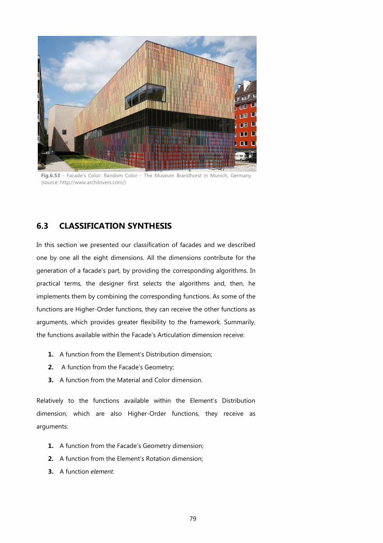
79
Fig.6.53 - Facade's Color: Random Color - The Museum Brandhorst in Munich, Germany
(source: http://www.archilovers.com/)
6.3 CLASSIFICATION SYNTHESIS
In this section we presented our classification of facades and we described
one by one all the eight dimensions. All the dimensions contribute for the
generation of a facade’s part, by providing the corresponding algorithms. In
practical terms, the designer first selects the algorithms and, then, he
implements them by combining the corresponding functions. As some of the
functions are Higher-Order functions, they can receive the other functions as
arguments, which provides greater flexibility to the framework. Summarily,
the functions available within the Facade’s Articulation dimension receive:
1. A function from the Element’s Distribution dimension;
2. A function from the Facade’s Geometry;
3. A function from the Material and Color dimension.
Relatively to the functions available within the Element’s Distribution
dimension, which are also Higher-Order functions, they receive as
arguments:
1. A function from the Facade’s Geometry dimension;
2. A function from the Element’s Rotation dimension;
3. A function element.
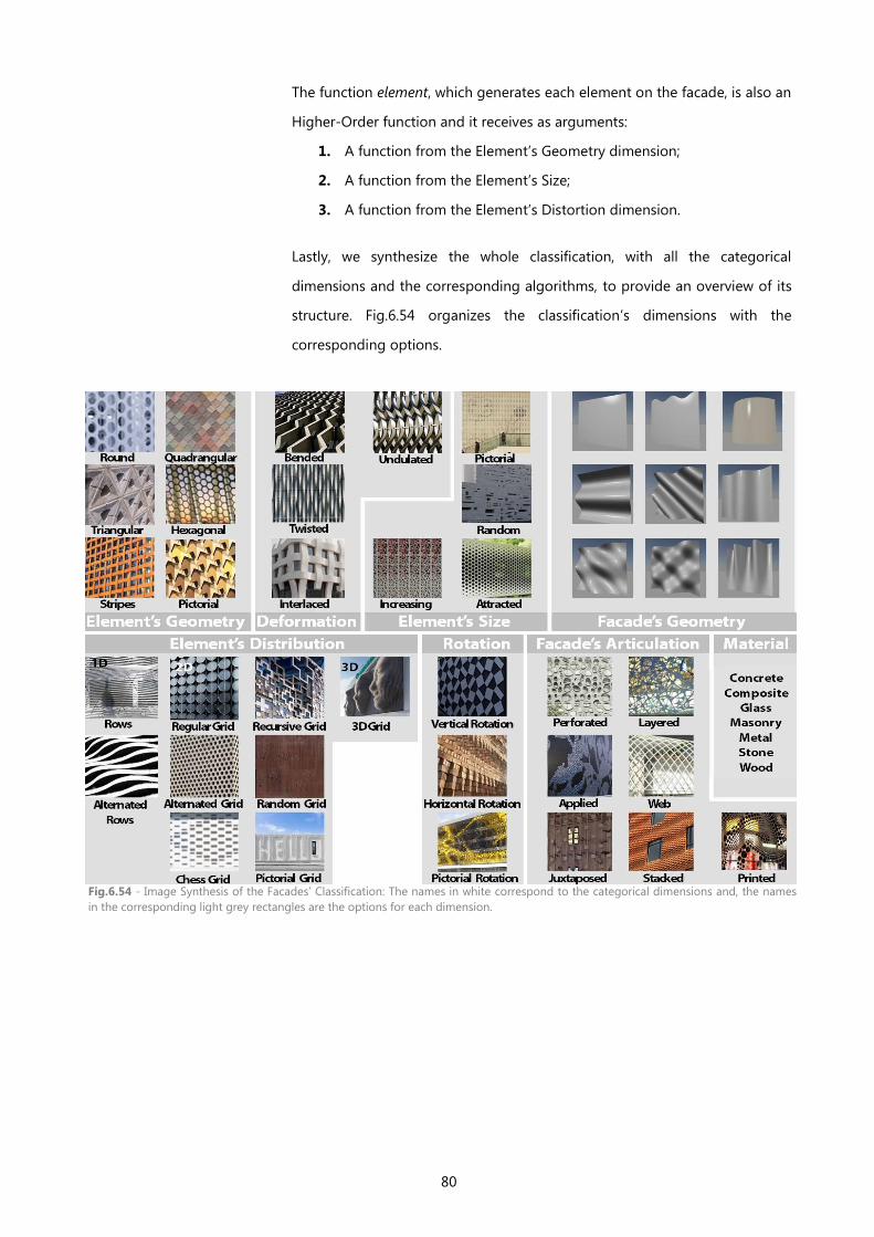
80
The function element, which generates each element on the facade, is also an
Higher-Order function and it receives as arguments:
1. A function from the Element’s Geometry dimension;
2. A function from the Element’s Size;
3. A function from the Element’s Distortion dimension.
Lastly, we synthesize the whole classification, with all the categorical
dimensions and the corresponding algorithms, to provide an overview of its
structure. Fig.6.54 organizes the classification’s dimensions with the
corresponding options.
Fig.6.54 - Image Synthesis of the Facades’ Classification: The names in white correspond to the categorical dimensions and, the names
in the corresponding light grey rectangles are the options for each dimension.
81
7 THE APPLICATION OF THE FACADE'S
CLASSIFICATION
In the last chapter we presented our classification of facades and the
corresponding categorical dimensions. We started with a description of the
classification's basic structure, then we made a detailed explanation of each
of the categorical dimensions and we mentioned the functional operators
available within each dimension, always illustrating with a real example.
In this section, we give some practical examples of how to use this
classification of facades. The goal is to clarify how a facade design is
classified/categorized. For this, we selected a set of Contemporary buildings,
on which we apply our classification, i.e. we classify the building’s facades
according to all the categorical Dimensions.
These examples are intended to explain how this classification is applied in a
design and, as this framework was created to help designers in the
generation of facades, it is not intended to be applied on existing facades.
Nevertheless, if we understand the process behind this classification by its
application on existing facades, we also realize the methodology to have
during the generation of a new facade design.
In the next two chapters, we describe the methodology behind the
generation of a facade and we explain how the categorical dimensions
contribute for the implementation of the functional operators, which then
generates the whole facade model. Thereafter, we make practical examples
of the intended application of this framework, i.e. how to generate a facade's
model using some of the algorithms provided by this framework.
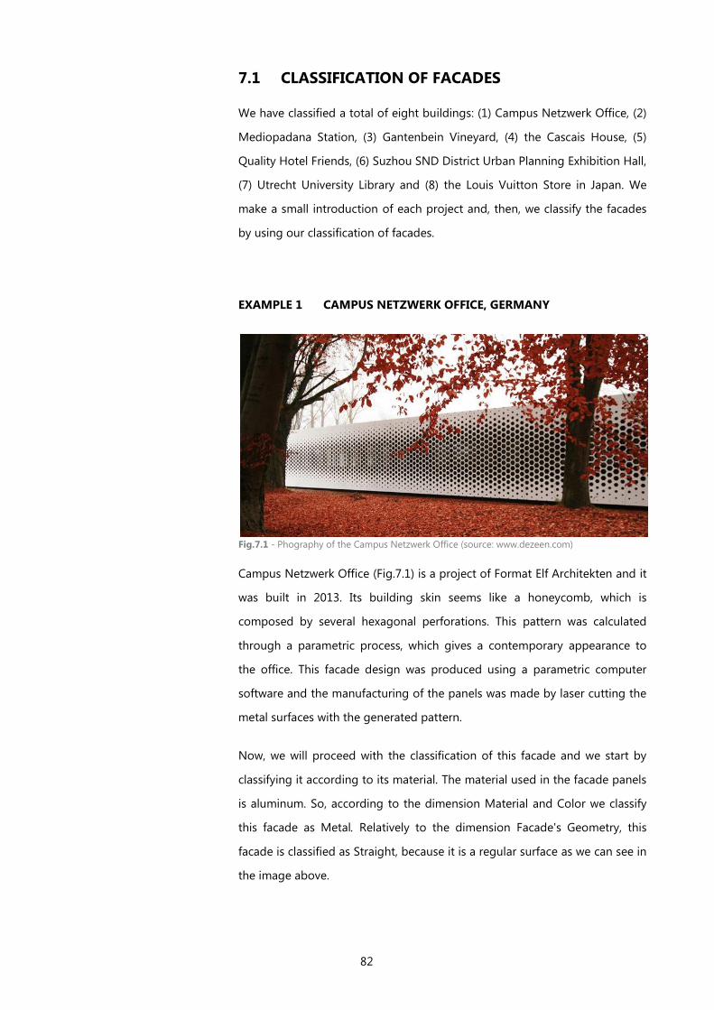
82
7.1 CLASSIFICATION OF FACADES
We have classified a total of eight buildings: (1) Campus Netzwerk Office, (2)
Mediopadana Station, (3) Gantenbein Vineyard, (4) the Cascais House, (5)
Quality Hotel Friends, (6) Suzhou SND District Urban Planning Exhibition Hall,
(7) Utrecht University Library and (8) the Louis Vuitton Store in Japan. We
make a small introduction of each project and, then, we classify the facades
by using our classification of facades.
EXAMPLE 1 CAMPUS NETZWERK OFFICE, GERMANY
Fig.7.1 - Phography of the Campus Netzwerk Office (source: www.dezeen.com)
Campus Netzwerk Office (Fig.7.1) is a project of Format Elf Architekten and it
was built in 2013. Its building skin seems like a honeycomb, which is
composed by several hexagonal perforations. This pattern was calculated
through a parametric process, which gives a contemporary appearance to
the office. This facade design was produced using a parametric computer
software and the manufacturing of the panels was made by laser cutting the
metal surfaces with the generated pattern. (Anon., 2014)
Now, we will proceed with the classification of this facade and we start by
classifying it according to its material. The material used in the facade panels
is aluminum. So, according to the dimension Material and Color we classify
this facade as Metal. Relatively to the dimension Facade's Geometry, this
facade is classified as Straight, because it is a regular surface as we can see in
the image above.
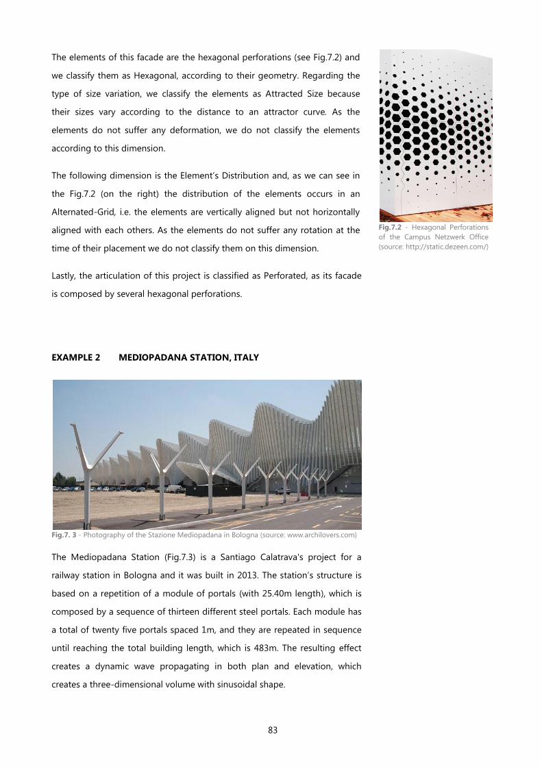
83
The elements of this facade are the hexagonal perforations (see Fig.7.2) and
we classify them as Hexagonal, according to their geometry. Regarding the
type of size variation, we classify the elements as Attracted Size because
their sizes vary according to the distance to an attractor curve. As the
elements do not suffer any deformation, we do not classify the elements
according to this dimension.
The following dimension is the Element’s Distribution and, as we can see in
the Fig.7.2 (on the right) the distribution of the elements occurs in an
Alternated-Grid, i.e. the elements are vertically aligned but not horizontally
aligned with each others. As the elements do not suffer any rotation at the
time of their placement we do not classify them on this dimension.
Lastly, the articulation of this project is classified as Perforated, as its facade
is composed by several hexagonal perforations.
EXAMPLE 2 MEDIOPADANA STATION, ITALY
Fig.7. 3 - Photography of the Stazione Mediopadana in Bologna (source: www.archilovers.com)
The Mediopadana Station (Fig.7.3) is a Santiago Calatrava's project for a
railway station in Bologna and it was built in 2013. The station’s structure is
based on a repetition of a module of portals (with 25.40m length), which is
composed by a sequence of thirteen different steel portals. Each module has
a total of twenty five portals spaced 1m, and they are repeated in sequence
until reaching the total building length, which is 483m. The resulting effect
creates a dynamic wave propagating in both plan and elevation, which
creates a three-dimensional volume with sinusoidal shape.
Fig.7.2 - Hexagonal Perforations
of the Campus Netzwerk Office
(source: http://static.dezeen.com/)
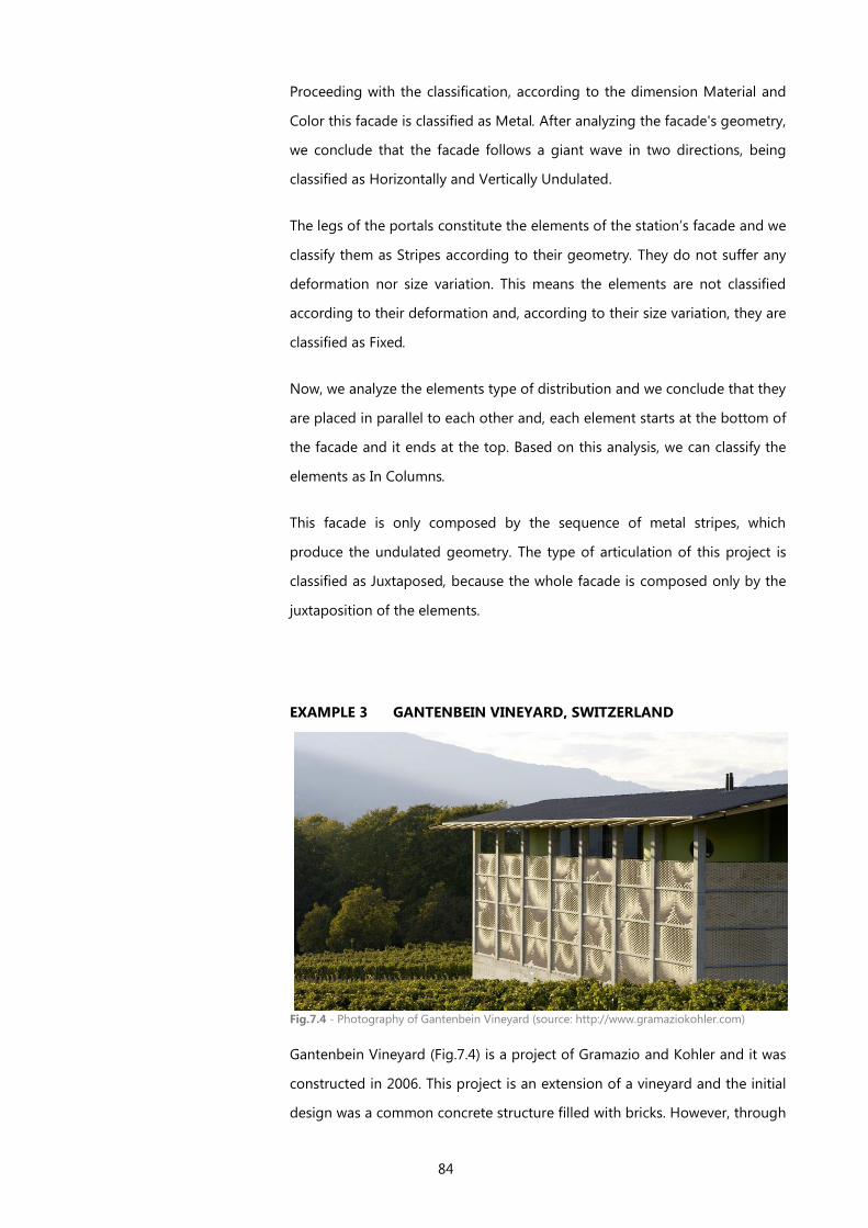
84
Proceeding with the classification, according to the dimension Material and
Color this facade is classified as Metal. After analyzing the facade's geometry,
we conclude that the facade follows a giant wave in two directions, being
classified as Horizontally and Vertically Undulated.
The legs of the portals constitute the elements of the station’s facade and we
classify them as Stripes according to their geometry. They do not suffer any
deformation nor size variation. This means the elements are not classified
according to their deformation and, according to their size variation, they are
classified as Fixed.
Now, we analyze the elements type of distribution and we conclude that they
are placed in parallel to each other and, each element starts at the bottom of
the facade and it ends at the top. Based on this analysis, we can classify the
elements as In Columns.
This facade is only composed by the sequence of metal stripes, which
produce the undulated geometry. The type of articulation of this project is
classified as Juxtaposed, because the whole facade is composed only by the
juxtaposition of the elements.
EXAMPLE 3 GANTENBEIN VINEYARD, SWITZERLAND
Fig.7.4 - Photography of Gantenbein Vineyard (source: http://www.gramaziokohler.com)
Gantenbein Vineyard (Fig.7.4) is a project of Gramazio and Kohler and it was
constructed in 2006. This project is an extension of a vineyard and the initial
design was a common concrete structure filled with bricks. However, through
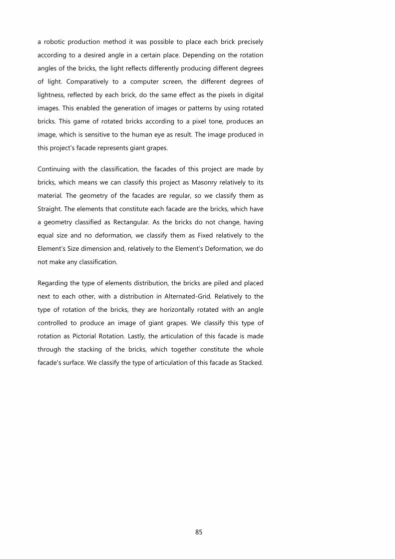
85
a robotic production method it was possible to place each brick precisely
according to a desired angle in a certain place. Depending on the rotation
angles of the bricks, the light reflects differently producing different degrees
of light. Comparatively to a computer screen, the different degrees of
lightness, reflected by each brick, do the same effect as the pixels in digital
images. This enabled the generation of images or patterns by using rotated
bricks. This game of rotated bricks according to a pixel tone, produces an
image, which is sensitive to the human eye as result. The image produced in
this project’s facade represents giant grapes.
Continuing with the classification, the facades of this project are made by
bricks, which means we can classify this project as Masonry relatively to its
material. The geometry of the facades are regular, so we classify them as
Straight. The elements that constitute each facade are the bricks, which have
a geometry classified as Rectangular. As the bricks do not change, having
equal size and no deformation, we classify them as Fixed relatively to the
Element’s Size dimension and, relatively to the Element’s Deformation, we do
not make any classification.
Regarding the type of elements distribution, the bricks are piled and placed
next to each other, with a distribution in Alternated-Grid. Relatively to the
type of rotation of the bricks, they are horizontally rotated with an angle
controlled to produce an image of giant grapes. We classify this type of
rotation as Pictorial Rotation. Lastly, the articulation of this facade is made
through the stacking of the bricks, which together constitute the whole
facade's surface. We classify the type of articulation of this facade as Stacked.
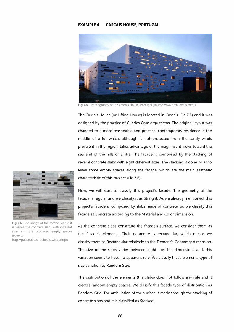
86
EXAMPLE 4 CASCAIS HOUSE, PORTUGAL
Fig.7.5 - Photography of the Cascais House, Portugal (source: www.archilovers.com/)
The Cascais House (or Lifting House) is located in Cascais (Fig.7.5) and it was
designed by the practice of Guedes Cruz Arquitectos. The original layout was
changed to a more reasonable and practical contemporary residence in the
middle of a lot which, although is not protected from the sandy winds
prevalent in the region, takes advantage of the magnificent views toward the
sea and of the hills of Sintra. The facade is composed by the stacking of
several concrete slabs with eight different sizes. The stacking is done so as to
leave some empty spaces along the facade, which are the main aesthetic
characteristic of this project (Fig.7.6).
Now, we will start to classify this project’s facade. The geometry of the
facade is regular and we classify it as Straight. As we already mentioned, this
project’s facade is composed by slabs made of concrete, so we classify this
facade as Concrete according to the Material and Color dimension.
As the concrete slabs constitute the facade's surface, we consider them as
the facade's elements. Their geometry is rectangular, which means we
classify them as Rectangular relatively to the Element’s Geometry dimension.
The size of the slabs varies between eight possible dimensions and, this
variation seems to have no apparent rule. We classify these elements type of
size variation as Random Size.
The distribution of the elements (the slabs) does not follow any rule and it
creates random empty spaces. We classify this facade type of distribution as
Random-Grid. The articulation of the surface is made through the stacking of
concrete slabs and it is classified as Stacked.
Fig.7.6 - An image of the facade, where it
is visible the concrete slabs with different
sizes and the produced empty spaces
(source:
http://guedescruzarquitecto.wix.com/pt)
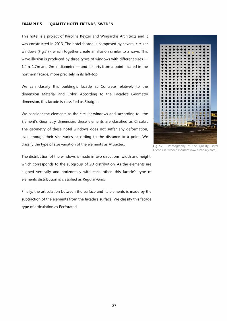
87
EXAMPLE 5 QUALITY HOTEL FRIENDS, SWEDEN
This hotel is a project of Karolina Keyzer and Wingardhs Architects and it
was constructed in 2013. The hotel facade is composed by several circular
windows (Fig.7.7), which together create an illusion similar to a wave. This
wave illusion is produced by three types of windows with different sizes —
1.4m, 1.7m and 2m in diameter — and it starts from a point located in the
northern facade, more precisely in its left-top.
We can classify this building's facade as Concrete relatively to the
dimension Material and Color. According to the Facade's Geometry
dimension, this facade is classified as Straight.
We consider the elements as the circular windows and, according to the
Element’s Geometry dimension, these elements are classified as Circular.
The geometry of these hotel windows does not suffer any deformation,
even though their size varies according to the distance to a point. We
classify the type of size variation of the elements as Attracted.
The distribution of the windows is made in two directions, width and height,
which corresponds to the subgroup of 2D distribution. As the elements are
aligned vertically and horizontally with each other, this facade’s type of
elements distribution is classified as Regular-Grid.
Finally, the articulation between the surface and its elements is made by the
subtraction of the elements from the facade’s surface. We classify this facade
type of articulation as Perforated.
Fig.7.7 - Photography of the Quality Hotel
Friends in Sweden (source: www.archdaily.com)
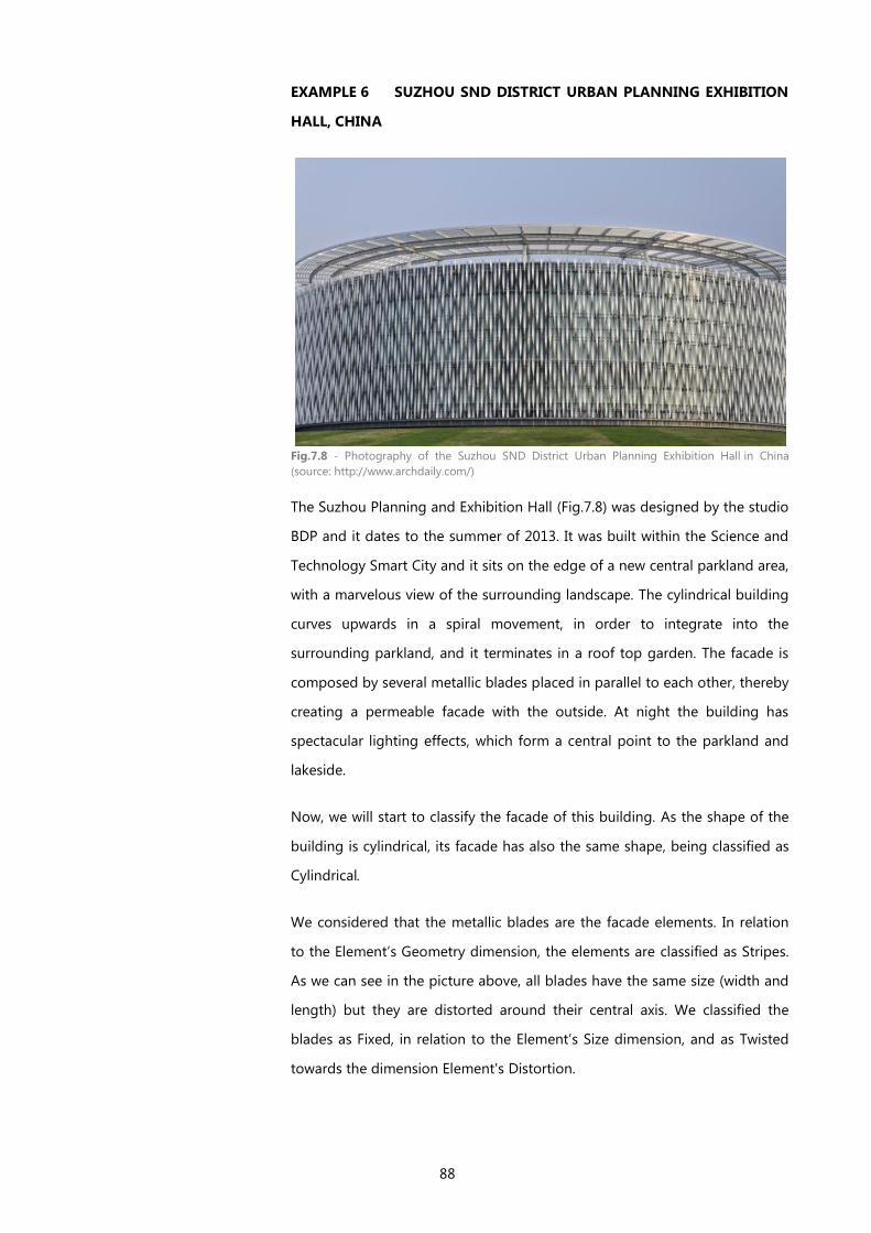
88
EXAMPLE 6 SUZHOU SND DISTRICT URBAN PLANNING EXHIBITION
HALL, CHINA
Fig.7.8 - Photography of the Suzhou SND District Urban Planning Exhibition Hall in China
(source: http://www.archdaily.com/)
The Suzhou Planning and Exhibition Hall (Fig.7.8) was designed by the studio
BDP and it dates to the summer of 2013. It was built within the Science and
Technology Smart City and it sits on the edge of a new central parkland area,
with a marvelous view of the surrounding landscape. The cylindrical building
curves upwards in a spiral movement, in order to integrate into the
surrounding parkland, and it terminates in a roof top garden. The facade is
composed by several metallic blades placed in parallel to each other, thereby
creating a permeable facade with the outside. At night the building has
spectacular lighting effects, which form a central point to the parkland and
lakeside.
Now, we will start to classify the facade of this building. As the shape of the
building is cylindrical, its facade has also the same shape, being classified as
Cylindrical.
We considered that the metallic blades are the facade elements. In relation
to the Element’s Geometry dimension, the elements are classified as Stripes.
As we can see in the picture above, all blades have the same size (width and
length) but they are distorted around their central axis. We classified the
blades as Fixed, in relation to the Element’s Size dimension, and as Twisted
towards the dimension Element's Distortion.
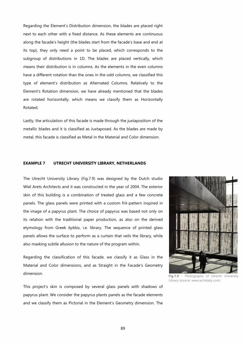
89
Regarding the Element’s Distribution dimension, the blades are placed right
next to each other with a fixed distance. As these elements are continuous
along the facade’s height (the blades start from the facade’s base and end at
its top), they only need a point to be placed, which corresponds to the
subgroup of distributions in 1D. The blades are placed vertically, which
means their distribution is in columns. As the elements in the even columns
have a different rotation than the ones in the odd columns, we classified this
type of element's distribution as Alternated Columns. Relatively to the
Element's Rotation dimension, we have already mentioned that the blades
are rotated horizontally, which means we classify them as Horizontally
Rotated.
Lastly, the articulation of this facade is made through the juxtaposition of the
metallic blades and it is classified as Juxtaposed. As the blades are made by
metal, this facade is classified as Metal in the Material and Color dimension.
EXAMPLE 7 UTRECHT UNIVERSITY LIBRARY, NETHERLANDS
The Utrecht University Library (Fig.7.9) was designed by the Dutch studio
Wiel Arets Architects and it was constructed in the year of 2004. The exterior
skin of this building is a combination of treated glass and a few concrete
panels. The glass panels were printed with a custom frit-pattern inspired in
the image of a papyrus plant. The choice of papyrus was based not only on
its relation with the traditional paper production, as also on the derived
etymology from Greek byblos, i.e. library. The sequence of printed glass
panels allows the surface to perform as a curtain that veils the library, while
also masking subtle allusion to the nature of the program within.
Regarding the classification of this facade, we classify it as Glass in the
Material and Color dimensions, and as Straight in the Facade's Geometry
dimension.
This project’s skin is composed by several glass panels with shadows of
papyrus plant. We consider the papyrus plants panels as the facade elements
and we classify them as Pictorial in the Element’s Geometry dimension. The
Fig.7.9 - Photography of Utrecht University
Library (source: www.archdaily.com)
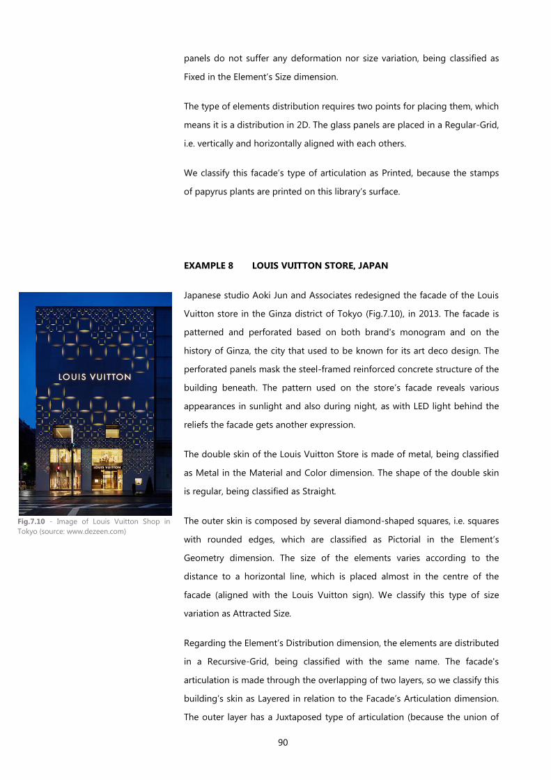
90
panels do not suffer any deformation nor size variation, being classified as
Fixed in the Element’s Size dimension.
The type of elements distribution requires two points for placing them, which
means it is a distribution in 2D. The glass panels are placed in a Regular-Grid,
i.e. vertically and horizontally aligned with each others.
We classify this facade’s type of articulation as Printed, because the stamps
of papyrus plants are printed on this library’s surface.
EXAMPLE 8 LOUIS VUITTON STORE, JAPAN
Japanese studio Aoki Jun and Associates redesigned the facade of the Louis
Vuitton store in the Ginza district of Tokyo (Fig.7.10), in 2013. The facade is
patterned and perforated based on both brand's monogram and on the
history of Ginza, the city that used to be known for its art deco design. The
perforated panels mask the steel-framed reinforced concrete structure of the
building beneath. The pattern used on the store’s facade reveals various
appearances in sunlight and also during night, as with LED light behind the
reliefs the facade gets another expression.
The double skin of the Louis Vuitton Store is made of metal, being classified
as Metal in the Material and Color dimension. The shape of the double skin
is regular, being classified as Straight.
The outer skin is composed by several diamond-shaped squares, i.e. squares
with rounded edges, which are classified as Pictorial in the Element’s
Geometry dimension. The size of the elements varies according to the
distance to a horizontal line, which is placed almost in the centre of the
facade (aligned with the Louis Vuitton sign). We classify this type of size
variation as Attracted Size.
Regarding the Element’s Distribution dimension, the elements are distributed
in a Recursive-Grid, being classified with the same name. The facade's
articulation is made through the overlapping of two layers, so we classify this
building’s skin as Layered in relation to the Facade’s Articulation dimension.
The outer layer has a Juxtaposed type of articulation (because the union of
Fig.7.10 - Image of Louis Vuitton Shop in
Tokyo (source: www.dezeen.com)
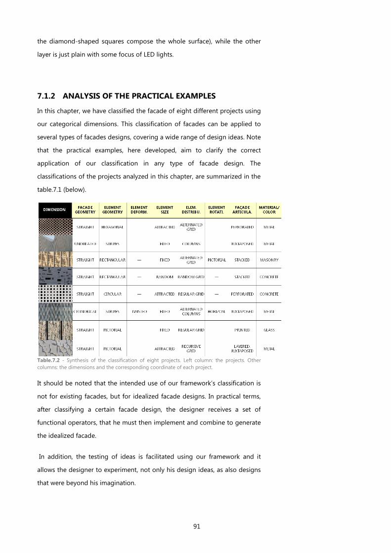
91
the diamond-shaped squares compose the whole surface), while the other
layer is just plain with some focus of LED lights.
7.1.2 ANALYSIS OF THE PRACTICAL EXAMPLES
In this chapter, we have classified the facade of eight different projects using
our categorical dimensions. This classification of facades can be applied to
several types of facades designs, covering a wide range of design ideas. Note
that the practical examples, here developed, aim to clarify the correct
application of our classification in any type of facade design. The
classifications of the projects analyzed in this chapter, are summarized in the
table.7.1 (below).
It should be noted that the intended use of our framework’s classification is
not for existing facades, but for idealized facade designs. In practical terms,
after classifying a certain facade design, the designer receives a set of
functional operators, that he must then implement and combine to generate
the idealized facade.
In addition, the testing of ideas is facilitated using our framework and it
allows the designer to experiment, not only his design ideas, as also designs
that were beyond his imagination.
Table.7.2 - Synthesis of the classification of eight projects. Left column: the projects. Other
columns: the dimensions and the corresponding coordinate of each project.

92
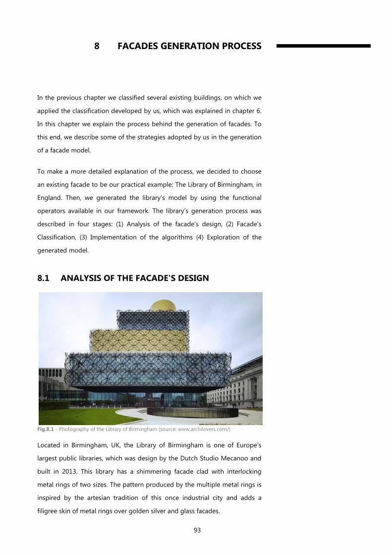
93
8 FACADES GENERATION PROCESS
In the previous chapter we classified several existing buildings, on which we
applied the classification developed by us, which was explained in chapter 6.
In this chapter we explain the process behind the generation of facades. To
this end, we describe some of the strategies adopted by us in the generation
of a facade model.
To make a more detailed explanation of the process, we decided to choose
an existing facade to be our practical example: The Library of Birmingham, in
England. Then, we generated the library’s model by using the functional
operators available in our framework. The library’s generation process was
described in four stages: (1) Analysis of the facade's design, (2) Facade's
Classification, (3) Implementation of the algorithms (4) Exploration of the
generated model.
8.1 ANALYSIS OF THE FACADE'S DESIGN
Fig.8.1 - Photography of the Library of Birmingham (source: www.archilovers.com/)
Located in Birmingham, UK, the Library of Birmingham is one of Europe's
largest public libraries, which was design by the Dutch Studio Mecanoo and
built in 2013. This library has a shimmering facade clad with interlocking
metal rings of two sizes. The pattern produced by the multiple metal rings is
inspired by the artesian tradition of this once industrial city and adds a
filigree skin of metal rings over golden silver and glass facades.
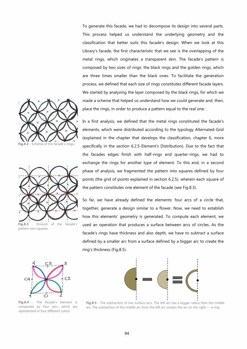
94
To generate this facade, we had to decompose its design into several parts.
This process helped us understand the underlying geometry and the
classification that better suits this facade's design. When we look at this
Library's facade, the first characteristic that we see is the overlapping of the
metal rings, which originates a transparent skin. The facade’s pattern is
composed by two sizes of rings: the black rings and the golden rings, which
are three times smaller than the black ones. To facilitate the generation
process, we defined that each size of rings constitutes different facade layers.
We started by analyzing the layer composed by the black rings, for which we
made a scheme that helped us understand how we could generate and, then,
place the rings, in order to produce a pattern equal to the real one.
In a first analysis, we defined that the metal rings constituted the facade's
elements, which were distributed according to the typology Alternated-Grid
(explained in the chapter that develops the classification, chapter 6, more
specifically in the section 6.2.5-Element's Distribution). Due to the fact that
the facades edges finish with half-rings and quarter-rings, we had to
exchange the rings for another type of element. To this end, in a second
phase of analysis, we fragmented the pattern into squares defined by four
points (the grid of points explained in section 6.2.5), wherein each square of
the pattern constitutes one element of the facade (see Fig.8.3).
So far, we have already defined the elements: four arcs of a circle that,
together, generate a design similar to a flower. Now, we need to establish
how this elements’ geometry is generated. To compute each element, we
used an operation that produces a surface between arcs of circles. As the
facade’s rings have thickness and also depth, we have to subtract a surface
defined by a smaller arc from a surface defined by a bigger arc to create the
ring's thickness (Fig.8.5).
Fig.8.2 - Scheme of the facade’s rings.
Fig.8.3 - Division of the facade's
pattern into squares.
Fig.8.4 - The facade's element is
composed by four arcs, which are
represented in four different colors.
Fig.8.5 - The subtraction of two surface arcs. The left arc has a bigger radius than the middle
arc. The subtraction of the middle arc from the left arc creates the arc on the right — a ring.
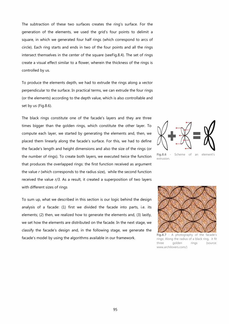
95
The subtraction of these two surfaces creates the ring's surface. For the
generation of the elements, we used the grid’s four points to delimit a
square, in which we generated four half rings (which correspond to arcs of
circle). Each ring starts and ends in two of the four points and all the rings
intersect themselves in the center of the square (seeFig.8.4). The set of rings
create a visual effect similar to a flower, wherein the thickness of the rings is
controlled by us.
To produce the elements depth, we had to extrude the rings along a vector
perpendicular to the surface. In practical terms, we can extrude the four rings
(or the elements) according to the depth value, which is also controllable and
set by us (Fig.8.6).
The black rings constitute one of the facade's layers and they are three
times bigger than the golden rings, which constitute the other layer. To
compute each layer, we started by generating the elements and, then, we
placed them linearly along the facade’s surface. For this, we had to define
the facade's length and height dimensions and also the size of the rings (or
the number of rings). To create both layers, we executed twice the function
that produces the overlapped rings: the first function received as argument
the value r (which corresponds to the radius size), while the second function
received the value r/3. As a result, it created a superposition of two layers
with different sizes of rings
To sum up, what we described in this section is our logic behind the design
analysis of a facade: (1) first we divided the facade into parts, i.e. its
elements; (2) then, we realized how to generate the elements and, (3) lastly,
we set how the elements are distributed on the facade. In the next stage, we
classify the facade’s design and, in the following stage, we generate the
facade's model by using the algorithms available in our framework.
Fig.8.6 - Scheme of an element's
extrusion.
Fig.8.7 - A photography of the facade's
rings: Along the radius of a black ring, it fit
three golden rings (source:
www.archilovers.com/)
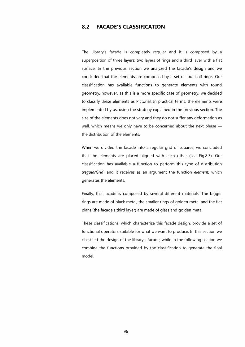
96
8.2 FACADE'S CLASSIFICATION
The Library's facade is completely regular and it is composed by a
superposition of three layers: two layers of rings and a third layer with a flat
surface. In the previous section we analyzed the facade's design and we
concluded that the elements are composed by a set of four half rings. Our
classification has available functions to generate elements with round
geometry, however, as this is a more specific case of geometry, we decided
to classify these elements as Pictorial. In practical terms, the elements were
implemented by us, using the strategy explained in the previous section. The
size of the elements does not vary and they do not suffer any deformation as
well, which means we only have to be concerned about the next phase —
the distribution of the elements.
When we divided the facade into a regular grid of squares, we concluded
that the elements are placed aligned with each other (see Fig.8.3). Our
classification has available a function to perform this type of distribution
(regularGrid) and it receives as an argument the function element, which
generates the elements.
Finally, this facade is composed by several different materials: The bigger
rings are made of black metal, the smaller rings of golden metal and the flat
plans (the facade's third layer) are made of glass and golden metal.
These classifications, which characterize this facade design, provide a set of
functional operators suitable for what we want to produce. In this section we
classified the design of the library's facade, while in the following section we
combine the functions provided by the classification to generate the final
model.
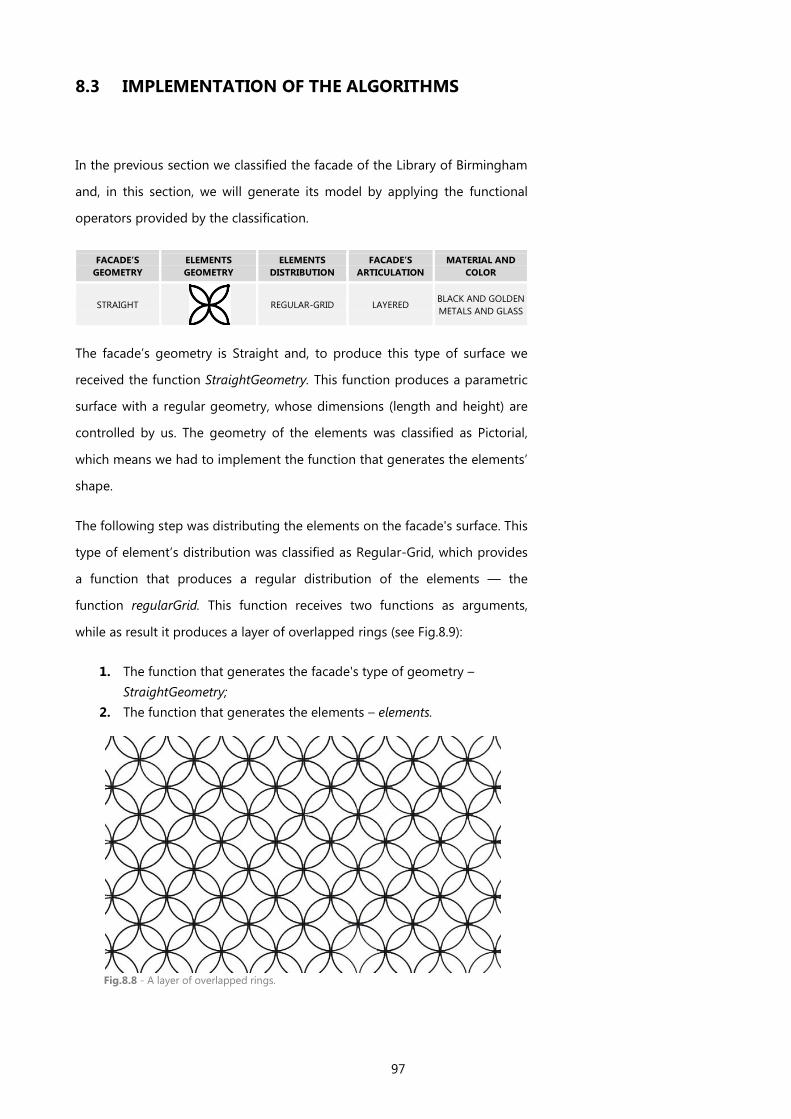
97
8.3 IMPLEMENTATION OF THE ALGORITHMS
In the previous section we classified the facade of the Library of Birmingham
and, in this section, we will generate its model by applying the functional
operators provided by the classification.
FACADE’S
GEOMETRY
ELEMENTS
GEOMETRY
ELEMENTS
DISTRIBUTION
FACADE’S
ARTICULATION
MATERIAL AND
COLOR
STRAIGHT
REGULAR-GRID LAYERED BLACK AND GOLDEN
METALS AND GLASS
The facade’s geometry is Straight and, to produce this type of surface we
received the function StraightGeometry. This function produces a parametric
surface with a regular geometry, whose dimensions (length and height) are
controlled by us. The geometry of the elements was classified as Pictorial,
which means we had to implement the function that generates the elements’
shape.
The following step was distributing the elements on the facade's surface. This
type of element’s distribution was classified as Regular-Grid, which provides
a function that produces a regular distribution of the elements — the
function regularGrid. This function receives two functions as arguments,
while as result it produces a layer of overlapped rings (see Fig.8.9):
1. The function that generates the facade's type of geometry –
StraightGeometry;
2. The function that generates the elements – elements.
Fig.8.8 - A layer of overlapped rings.
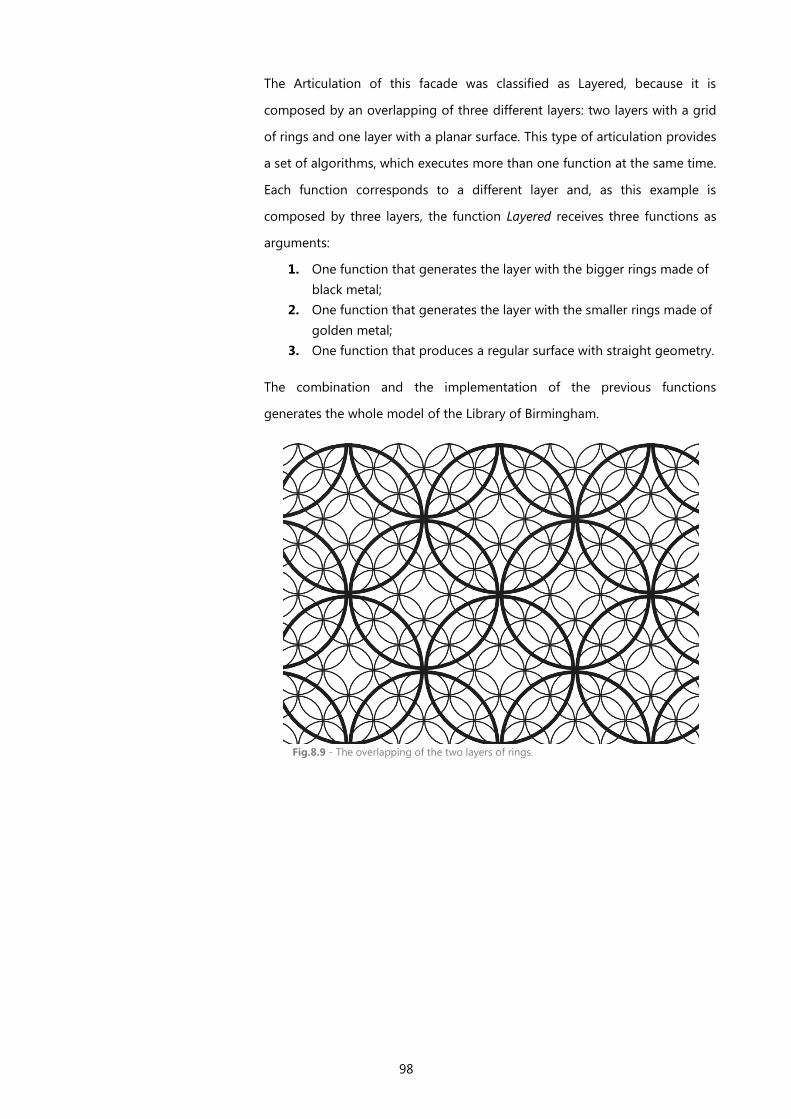
98
The Articulation of this facade was classified as Layered, because it is
composed by an overlapping of three different layers: two layers with a grid
of rings and one layer with a planar surface. This type of articulation provides
a set of algorithms, which executes more than one function at the same time.
Each function corresponds to a different layer and, as this example is
composed by three layers, the function Layered receives three functions as
arguments:
1. One function that generates the layer with the bigger rings made of
black metal;
2. One function that generates the layer with the smaller rings made of
golden metal;
3. One function that produces a regular surface with straight geometry.
The combination and the implementation of the previous functions
generates the whole model of the Library of Birmingham.
Fig.8.9 - The overlapping of the two layers of rings.
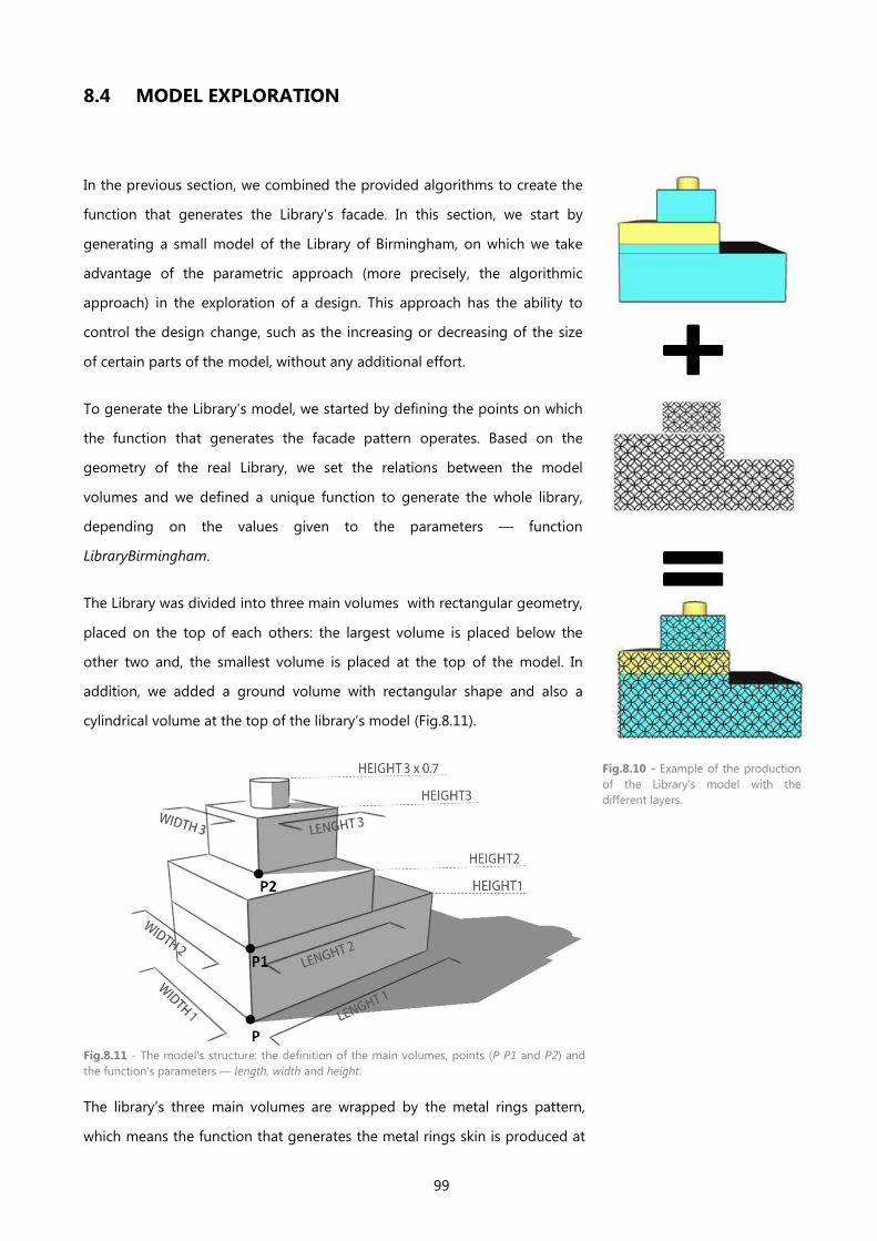
99
8.4 MODEL EXPLORATION
In the previous section, we combined the provided algorithms to create the
function that generates the Library's facade. In this section, we start by
generating a small model of the Library of Birmingham, on which we take
advantage of the parametric approach (more precisely, the algorithmic
approach) in the exploration of a design. This approach has the ability to
control the design change, such as the increasing or decreasing of the size
of certain parts of the model, without any additional effort.
To generate the Library's model, we started by defining the points on which
the function that generates the facade pattern operates. Based on the
geometry of the real Library, we set the relations between the model
volumes and we defined a unique function to generate the whole library,
depending on the values given to the parameters — function
LibraryBirmingham.
The Library was divided into three main volumes with rectangular geometry,
placed on the top of each others: the largest volume is placed below the
other two and, the smallest volume is placed at the top of the model. In
addition, we added a ground volume with rectangular shape and also a
cylindrical volume at the top of the library’s model (Fig.8.11).
The library’s three main volumes are wrapped by the metal rings pattern,
which means the function that generates the metal rings skin is produced at
Fig.8.10 - Example of the production
of the Library's model with the
different layers.
Fig.8.11 - The model's structure: the definition of the main volumes, points (P P1 and P2) and
the function's parameters — length, width and height.
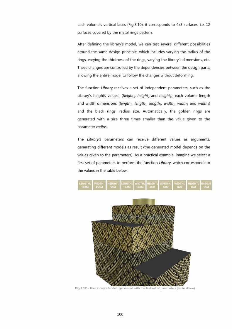
100
each volume's vertical faces (Fig.8.10): it corresponds to 4x3 surfaces, i.e. 12
surfaces covered by the metal rings pattern.
After defining the library’s model, we can test several different possibilities
around the same design principle, which includes varying the radius of the
rings, varying the thickness of the rings, varying the library’s dimensions, etc.
These changes are controlled by the dependencies between the design parts,
allowing the entire model to follow the changes without deforming.
The function Library receives a set of independent parameters, such as the
Library's heights values (height1, height2 and height3), each volume length
and width dimensions (length1, length2, length3, width1, width2 and width3)
and the black rings’ radius size. Automatically, the golden rings are
generated with a size three times smaller than the value given to the
parameter radius.
The Library’s parameters can receive different values as arguments,
generating different models as result (the generated model depends on the
values given to the parameters). As a practical example, imagine we select a
first set of parameters to perform the function Library, which corresponds to
the values in the table below:
LENGTH1
120M
WIDTH1
150M
HEIGHT1
50M
LENGTH2
120M
WIDTH2
120M
HEIGHT2
60M
LENGTH3
90M
WIDTH3
90M
HEIGHT3
30M
RADIUS
10M
Fig.8.12 - The Library's Model : generated with the first set of parameters (table above).
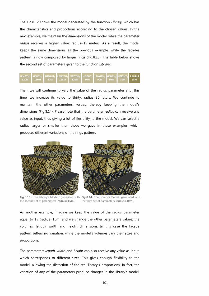
101
The Fig.8.12 shows the model generated by the function Library, which has
the characteristics and proportions according to the chosen values. In the
next example, we maintain the dimensions of the model, while the parameter
radius receives a higher value: radius=15 meters. As a result, the model
keeps the same dimensions as the previous example, while the facades
pattern is now composed by larger rings (Fig.8.13). The table below shows
the second set of parameters given to the function Library:
LENGTH1
120M
WIDTH1
150M
HEIGHT1
50M
LENGTH2
120M
WIDTH2
120M
HEIGHT2
60M
LENGTH3
90M
WIDTH3
90M
HEIGHT3
30M
RADIUS
15M
Then, we will continue to vary the value of the radius parameter and, this
time, we increase its value to thirty: radius=30meters. We continue to
maintain the other parameters’ values, thereby keeping the model's
dimensions (Fig.8.14). Please note that the parameter radius can receive any
value as input, thus giving a lot of flexibility to the model. We can select a
radius larger or smaller than those we gave in these examples, which
produces different variations of the rings pattern.
Fig.8.13 - The Library's Model : generated with
the second set of parameters (radius=15m).
Fig.8.14- The Library's Model : generated with
the third set of parameters (radius=30m).
As another example, imagine we keep the value of the radius parameter
equal to 15 (radius=15m) and we change the other parameters values: the
volumes’ length, width and height dimensions. In this case the facade
pattern suffers no variation, while the model’s volumes vary their sizes and
proportions.
The parameters length, width and height can also receive any value as input,
which corresponds to different sizes. This gives enough flexibility to the
model, allowing the distortion of the real library's proportions. In fact, the
variation of any of the parameters produce changes in the library’s model,
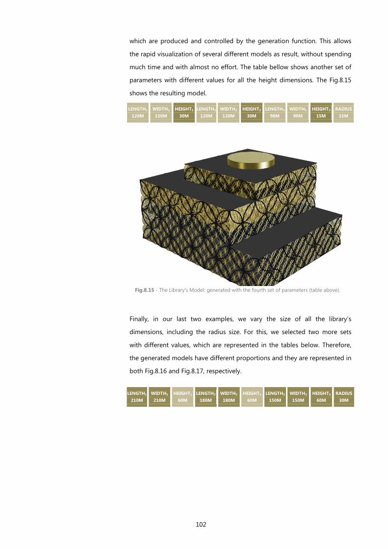
102
which are produced and controlled by the generation function. This allows
the rapid visualization of several different models as result, without spending
much time and with almost no effort. The table bellow shows another set of
parameters with different values for all the height dimensions. The Fig.8.15
shows the resulting model.
LENGTH1
120M
WIDTH1
150M
HEIGHT1
30M
LENGTH2
120M
WIDTH2
120M
HEIGHT2
30M
LENGTH3
90M
WIDTH3
90M
HEIGHT3
15M
RADIUS
15M
Finally, in our last two examples, we vary the size of all the library’s
dimensions, including the radius size. For this, we selected two more sets
with different values, which are represented in the tables below. Therefore,
the generated models have different proportions and they are represented in
both Fig.8.16 and Fig.8.17, respectively.
LENGTH1
210M
WIDTH1
210M
HEIGHT1
60M
LENGTH2
180M
WIDTH2
180M
HEIGHT2
60M
LENGTH3
150M
WIDTH3
150M
HEIGHT3
60M
RADIUS
30M
Fig.8.15 - The Library's Model: generated with the fourth set of parameters (table above).

103
Fig.8.16 - The Library's Model: generated with the parameters summarized in the table above.
LENGTH1
120M
WIDTH1
150M
HEIGHT1
70M
LENGTH2
120M
WIDTH2
120M
HEIGHT2
80M
LENGTH3
80M
WIDTH3
80M
HEIGHT3
40M
RADIUS
10M
Fig.8.17 – The Library’s Model generated with the set of parameters in the table above.

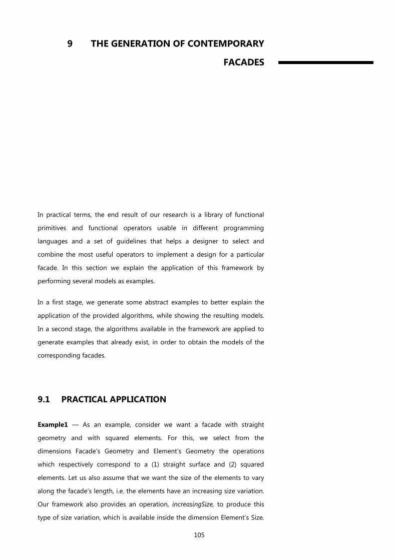
105
9 THE GENERATION OF CONTEMPORARY
FACADES
In practical terms, the end result of our research is a library of functional
primitives and functional operators usable in different programming
languages and a set of guidelines that helps a designer to select and
combine the most useful operators to implement a design for a particular
facade. In this section we explain the application of this framework by
performing several models as examples.
In a first stage, we generate some abstract examples to better explain the
application of the provided algorithms, while showing the resulting models.
In a second stage, the algorithms available in the framework are applied to
generate examples that already exist, in order to obtain the models of the
corresponding facades.
9.1 PRACTICAL APPLICATION
Example1 — As an example, consider we want a facade with straight
geometry and with squared elements. For this, we select from the
dimensions Facade’s Geometry and Element’s Geometry the operations
which respectively correspond to a (1) straight surface and (2) squared
elements. Let us also assume that we want the size of the elements to vary
along the facade’s length, i.e. the elements have an increasing size variation.
Our framework also provides an operation, increasingSize, to produce this
type of size variation, which is available inside the dimension Element’s Size.
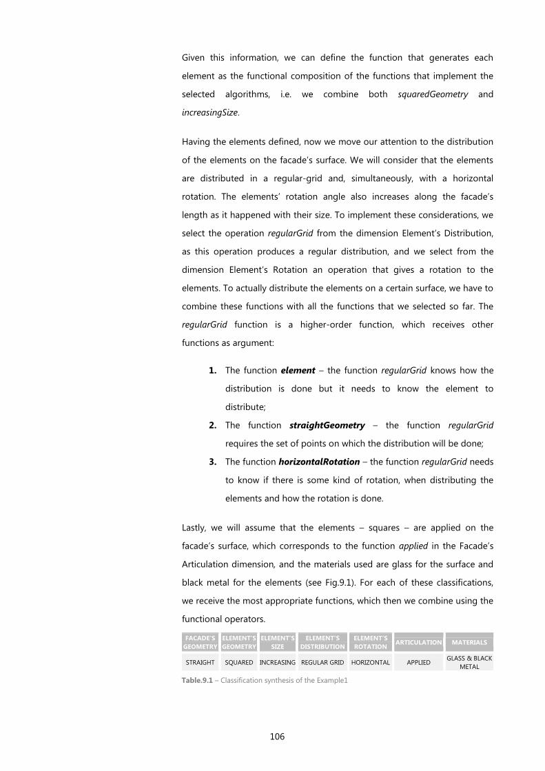
106
Given this information, we can define the function that generates each
element as the functional composition of the functions that implement the
selected algorithms, i.e. we combine both squaredGeometry and
increasingSize.
Having the elements defined, now we move our attention to the distribution
of the elements on the facade’s surface. We will consider that the elements
are distributed in a regular-grid and, simultaneously, with a horizontal
rotation. The elements’ rotation angle also increases along the facade’s
length as it happened with their size. To implement these considerations, we
select the operation regularGrid from the dimension Element’s Distribution,
as this operation produces a regular distribution, and we select from the
dimension Element’s Rotation an operation that gives a rotation to the
elements. To actually distribute the elements on a certain surface, we have to
combine these functions with all the functions that we selected so far. The
regularGrid function is a higher-order function, which receives other
functions as argument:
1. The function element – the function regularGrid knows how the
distribution is done but it needs to know the element to
distribute;
2. The function straightGeometry – the function regularGrid
requires the set of points on which the distribution will be done;
3. The function horizontalRotation – the function regularGrid needs
to know if there is some kind of rotation, when distributing the
elements and how the rotation is done.
Lastly, we will assume that the elements – squares – are applied on the
facade’s surface, which corresponds to the function applied in the Facade’s
Articulation dimension, and the materials used are glass for the surface and
black metal for the elements (see Fig.9.1). For each of these classifications,
we receive the most appropriate functions, which then we combine using the
functional operators.
FACADE’S
GEOMETRY
ELEMENT’S
GEOMETRY
ELEMENT’S
SIZE
ELEMENT’S
DISTRIBUTION
ELEMENT’S
ROTATION ARTICULATION MATERIALS
STRAIGHT SQUARED INCREASING REGULAR GRID HORIZONTAL APPLIED GLASS & BLACK
METAL
Table.9.1 – Classification synthesis of the Example1
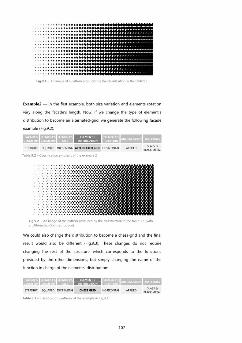
107
Fig.9.1 - An image of a pattern produced by the classification in the table.9.1.
Example2 — In the first example, both size variation and elements rotation
vary along the facade’s length. Now, if we change the type of element's
distribution to become an alternated-grid, we generate the following facade
example (Fig.9.2):
FACADE’S
GEOMETRY
ELEMENT’S
GEOMETRY
ELEMENT’S
SIZE
ELEMENT’S
DISTRIBUTION
ELEMENT’S
ROTATION ARTICULATION MATERIALS
STRAIGHT SQUARED INCREASING ALTERNATED GRID HORIZONTAL APPLIED GLASS &
BLACK METAL
Fig.9.2 - An image of the pattern produced by the classification in the table.9.2. (with
an Alternated-Grid distribution).
We could also change the distribution to become a chess-grid and the final
result would also be different (Fig.9.3). These changes do not require
changing the rest of the structure, which corresponds to the functions
provided by the other dimensions, but simply changing the name of the
function in charge of the elements’ distribution:
FACADE’S
GEOMETRY
ELEMENT’S
GEOMETRY
ELEMENT’S
SIZE
ELEMENT’S
DISTRIBUTION
ELEMENT’S
ROTATION ARTICULATION MATERIALS
STRAIGHT SQUARED INCREASING CHESS GRID HORIZONTAL APPLIED GLASS &
BLACK METAL
Table.9.2 – Classification synthesis of the example 2.
Table.9.3 – Classification synthesis of the example in Fig.9.3.
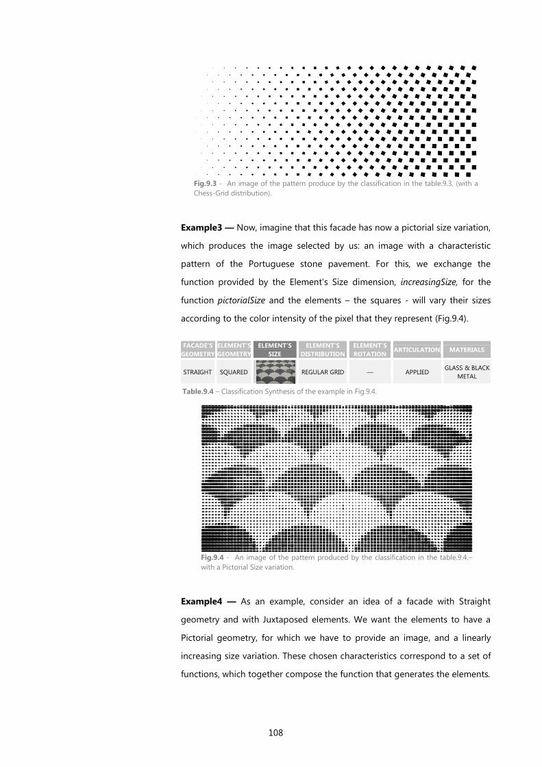
108
Fig.9.3 - An image of the pattern produce by the classification in the table.9.3. (with a
Chess-Grid distribution).
Example3 — Now, imagine that this facade has now a pictorial size variation,
which produces the image selected by us: an image with a characteristic
pattern of the Portuguese stone pavement. For this, we exchange the
function provided by the Element’s Size dimension, increasingSize, for the
function pictorialSize and the elements – the squares - will vary their sizes
according to the color intensity of the pixel that they represent (Fig.9.4).
FACADE’S
GEOMETRY
ELEMENT’S
GEOMETRY
ELEMENT’S
SIZE
ELEMENT’S
DISTRIBUTION
ELEMENT’S
ROTATION ARTICULATION MATERIALS
STRAIGHT SQUARED
REGULAR GRID — APPLIED GLASS & BLACK
METAL
Example4 — As an example, consider an idea of a facade with Straight
geometry and with Juxtaposed elements. We want the elements to have a
Pictorial geometry, for which we have to provide an image, and a linearly
increasing size variation. These chosen characteristics correspond to a set of
functions, which together compose the function that generates the elements.
Table.9.4 – Classification Synthesis of the example in Fig.9.4.
Fig.9.4 - An image of the pattern produced by the classification in the table.9.4.–
with a Pictorial Size variation.
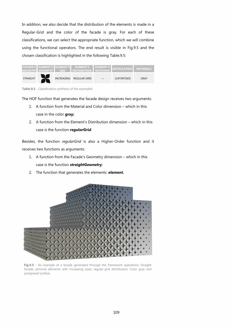
109
In addition, we also decide that the distribution of the elements is made in a
Regular-Grid and the color of the facade is gray. For each of these
classifications, we can select the appropriate function, which we will combine
using the functional operators. The end result is visible in Fig.9.5 and the
chosen classification is highlighted in the following Table.9.5:
FACADE’S
GEOMETRY
ELEMENT’S
GEOMETRY
ELEMENT’S
SIZE
ELEMENT’S
DISTRIBUTION
ELEMENT’S
ROTATION ARTICULATION MATERIALS
STRAIGHT
INCREASING REGULAR GRID — JUXTAPOSED GRAY
The HOF function that generates the facade design receives two arguments:
1. A function from the Material and Color dimension – which in this
case in the color gray;
2. A function from the Element’s Distribution dimension – which in this
case is the function regularGrid.
Besides, the function regularGrid is also a Higher-Order function and it
receives two functions as arguments:
1. A function from the Facade’s Geometry dimension – which in this
case is the function straightGeometry;
2. The function that generates the elements: element.
Fig.9.5 - An example of a facade generated through the framework operations: Straight
facade; pictorial elements with increasing sizes; regular-grid distribution; Color gray and
juxtaposed surface.
Table.9.5 - Classification synthesis of the example4.
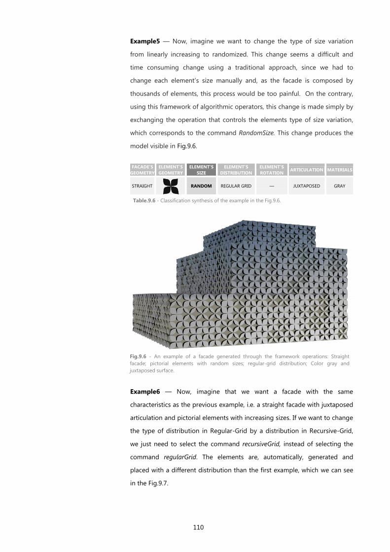
110
Example5 — Now, imagine we want to change the type of size variation
from linearly increasing to randomized. This change seems a difficult and
time consuming change using a traditional approach, since we had to
change each element’s size manually and, as the facade is composed by
thousands of elements, this process would be too painful. On the contrary,
using this framework of algorithmic operators, this change is made simply by
exchanging the operation that controls the elements type of size variation,
which corresponds to the command RandomSize. This change produces the
model visible in Fig.9.6.
FACADE’S
GEOMETRY
ELEMENT’S
GEOMETRY
ELEMENT’S
SIZE
ELEMENT’S
DISTRIBUTION
ELEMENT’S
ROTATION ARTICULATION MATERIALS
STRAIGHT
RANDOM REGULAR GRID — JUXTAPOSED GRAY
Example6 — Now, imagine that we want a facade with the same
characteristics as the previous example, i.e. a straight facade with juxtaposed
articulation and pictorial elements with increasing sizes. If we want to change
the type of distribution in Regular-Grid by a distribution in Recursive-Grid,
we just need to select the command recursiveGrid, instead of selecting the
command regularGrid. The elements are, automatically, generated and
placed with a different distribution than the first example, which we can see
in the Fig.9.7.
Table.9.6 - Classification synthesis of the example in the Fig.9.6.
Fig.9.6 - An example of a facade generated through the framework operations: Straight
facade; pictorial elements with random sizes; regular-grid distribution; Color gray and
juxtaposed surface.
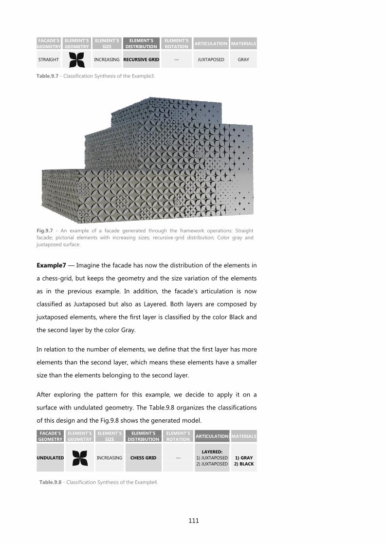
111
FACADE’S
GEOMETRY
ELEMENT’S
GEOMETRY
ELEMENT’S
SIZE
ELEMENT’S
DISTRIBUTION
ELEMENT’S
ROTATION ARTICULATION MATERIALS
STRAIGHT
INCREASING RECURSIVE GRID — JUXTAPOSED GRAY
Example7 — Imagine the facade has now the distribution of the elements in
a chess-grid, but keeps the geometry and the size variation of the elements
as in the previous example. In addition, the facade's articulation is now
classified as Juxtaposed but also as Layered. Both layers are composed by
juxtaposed elements, where the first layer is classified by the color Black and
the second layer by the color Gray.
In relation to the number of elements, we define that the first layer has more
elements than the second layer, which means these elements have a smaller
size than the elements belonging to the second layer.
After exploring the pattern for this example, we decide to apply it on a
surface with undulated geometry. The Table.9.8 organizes the classifications
of this design and the Fig.9.8 shows the generated model.
FACADE’S
GEOMETRY
ELEMENT’S
GEOMETRY
ELEMENT’S
SIZE
ELEMENT’S
DISTRIBUTION
ELEMENT’S
ROTATION ARTICULATION MATERIALS
UNDULATED
INCREASING CHESS GRID —
LAYERED:
1) JUXTAPOSED
2) JUXTAPOSED
1) GRAY
2) BLACK
Table.9.7 - Classification Synthesis of the Example3.
Fig.9.7 - An example of a facade generated through the framework operations: Straight
facade; pictorial elements with increasing sizes; recursive-grid distribution; Color gray and
juxtaposed surface.
Table.9.8 - Classification Synthesis of the Example4.
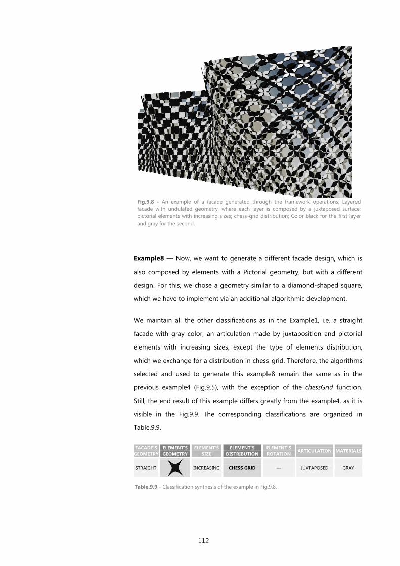
112
Fig.9.8 - An example of a facade generated through the framework operations: Layered
facade with undulated geometry, where each layer is composed by a juxtaposed surface;
pictorial elements with increasing sizes; chess-grid distribution; Color black for the first layer
and gray for the second.
Example8 — Now, we want to generate a different facade design, which is
also composed by elements with a Pictorial geometry, but with a different
design. For this, we chose a geometry similar to a diamond-shaped square,
which we have to implement via an additional algorithmic development.
We maintain all the other classifications as in the Example1, i.e. a straight
facade with gray color, an articulation made by juxtaposition and pictorial
elements with increasing sizes, except the type of elements distribution,
which we exchange for a distribution in chess-grid. Therefore, the algorithms
selected and used to generate this example8 remain the same as in the
previous example4 (Fig.9.5), with the exception of the chessGrid function.
Still, the end result of this example differs greatly from the example4, as it is
visible in the Fig.9.9. The corresponding classifications are organized in
Table.9.9.
FACADE’S
GEOMETRY
ELEMENT’S
GEOMETRY
ELEMENT’S
SIZE
ELEMENT’S
DISTRIBUTION
ELEMENT’S
ROTATION ARTICULATION MATERIALS
STRAIGHT
INCREASING CHESS GRID — JUXTAPOSED GRAY
Table.9.9 - Classification synthesis of the example in Fig.9.8.
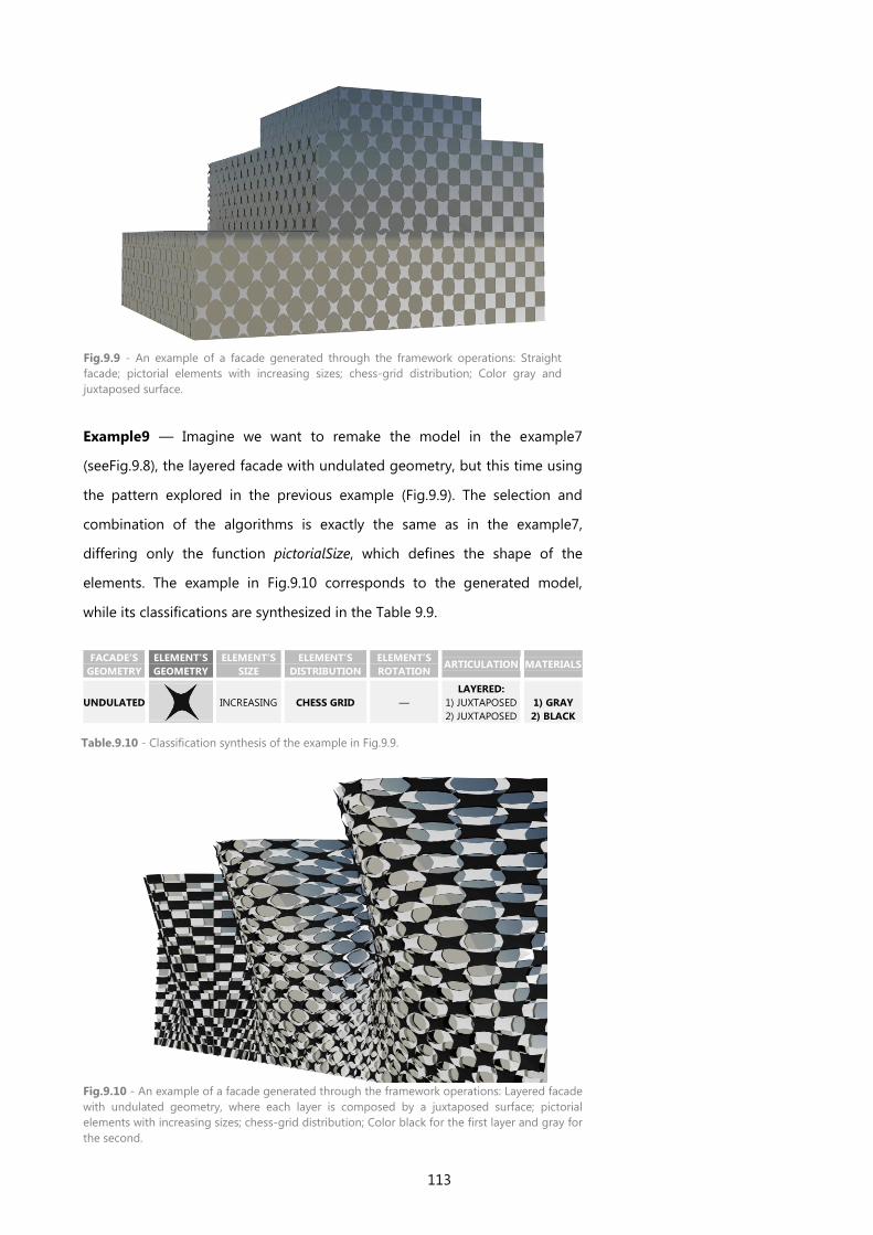
113
Fig.9.9 - An example of a facade generated through the framework operations: Straight
facade; pictorial elements with increasing sizes; chess-grid distribution; Color gray and
juxtaposed surface.
Example9 — Imagine we want to remake the model in the example7
(seeFig.9.8), the layered facade with undulated geometry, but this time using
the pattern explored in the previous example (Fig.9.9). The selection and
combination of the algorithms is exactly the same as in the example7,
differing only the function pictorialSize, which defines the shape of the
elements. The example in Fig.9.10 corresponds to the generated model,
while its classifications are synthesized in the Table 9.9.
Fig.9.10 - An example of a facade generated through the framework operations: Layered facade
with undulated geometry, where each layer is composed by a juxtaposed surface; pictorial
elements with increasing sizes; chess-grid distribution; Color black for the first layer and gray for
the second.
FACADE’S
GEOMETRY
ELEMENT’S
GEOMETRY
ELEMENT’S
SIZE
ELEMENT’S
DISTRIBUTION
ELEMENT’S
ROTATION ARTICULATION MATERIALS
UNDULATED
INCREASING CHESS GRID —
LAYERED:
1) JUXTAPOSED
2) JUXTAPOSED
1) GRAY
2) BLACK
Table.9.10 - Classification synthesis of the example in Fig.9.9.
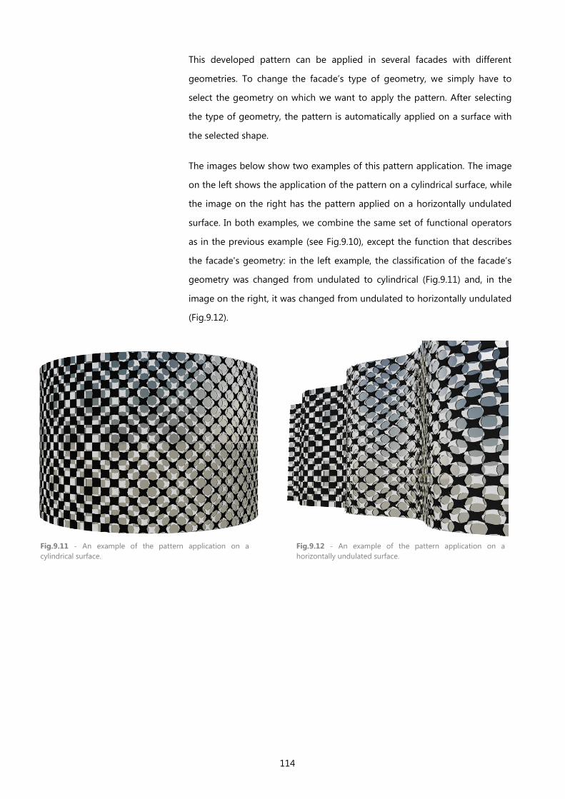
114
This developed pattern can be applied in several facades with different
geometries. To change the facade’s type of geometry, we simply have to
select the geometry on which we want to apply the pattern. After selecting
the type of geometry, the pattern is automatically applied on a surface with
the selected shape.
The images below show two examples of this pattern application. The image
on the left shows the application of the pattern on a cylindrical surface, while
the image on the right has the pattern applied on a horizontally undulated
surface. In both examples, we combine the same set of functional operators
as in the previous example (see Fig.9.10), except the function that describes
the facade's geometry: in the left example, the classification of the facade’s
geometry was changed from undulated to cylindrical (Fig.9.11) and, in the
image on the right, it was changed from undulated to horizontally undulated
(Fig.9.12).
Fig.9.11 - An example of the pattern application on a
cylindrical surface.
Fig.9.12 - An example of the pattern application on a
horizontally undulated surface.
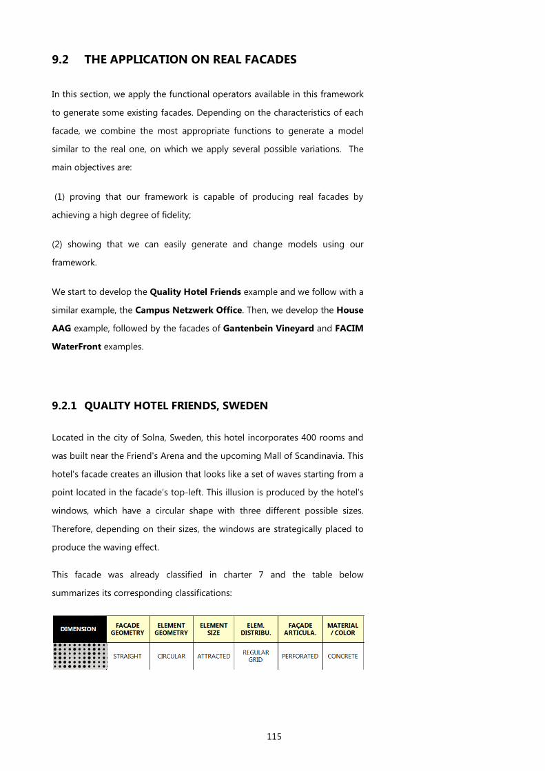
115
9.2 THE APPLICATION ON REAL FACADES
In this section, we apply the functional operators available in this framework
to generate some existing facades. Depending on the characteristics of each
facade, we combine the most appropriate functions to generate a model
similar to the real one, on which we apply several possible variations. The
main objectives are:
(1) proving that our framework is capable of producing real facades by
achieving a high degree of fidelity;
(2) showing that we can easily generate and change models using our
framework.
We start to develop the Quality Hotel Friends example and we follow with a
similar example, the Campus Netzwerk Office. Then, we develop the House
AAG example, followed by the facades of Gantenbein Vineyard and FACIM
WaterFront examples.
9.2.1 QUALITY HOTEL FRIENDS, SWEDEN
Located in the city of Solna, Sweden, this hotel incorporates 400 rooms and
was built near the Friend's Arena and the upcoming Mall of Scandinavia. This
hotel's facade creates an illusion that looks like a set of waves starting from a
point located in the facade’s top-left. This illusion is produced by the hotel’s
windows, which have a circular shape with three different possible sizes.
Therefore, depending on their sizes, the windows are strategically placed to
produce the waving effect.
This facade was already classified in charter 7 and the table below
summarizes its corresponding classifications:
116
These classifications provide the most suitable algorithms to generate the
hotel’s facade. In this section we combine and implement the selected
algorithms to, first, generate the model and, then, explore some possible
variations of the original design.
The function provided by the Facade’s Geometry dimension produces a
parametric surface with straight geometry, which height and length
dimensions are defined by us: we select for this facade a length of 45 meters
and a height of 75 meters (Fig.9.13).
The following step is defining the elements that constitute the hotel’s facade,
which in this case are the circular windows. The function provided by the
Element’s Geometry dimension gives shape to the windows, while the
function received by the Element’s Size dimension controls their sizes.
Thereby, we receive two functions, one that generates circular elements –
circularGeometry - and the other varies their sizes according to the distance
to a point – attractedSize. In order to generate a function capable of
producing the facade elements (a function element) we have to combine
these two functions together.
So far, we define the facade's surface and the function element to produce
the elements. In addition, we must also implement the elements type of
distribution, for which we received a function capable of mapping the
elements in a Regular-grid. This Higher-Order Function receives other two
functions as arguments:
1) The function element - which generates the elements that are going
to be distributed;
2) The function StraightGeometry, which defines the geometry of the
surface on which the elements are mapped (Fig.9.13).
Moreover, the function regularGrid also receives the number of elements to
produce horizontally (n) and vertically (m), for which we choose thirteen and
twenty-five elements, respectively (see Fig.9.14)
Continuing with the design implementation, the classification tells us that the
hotel’s facade has a relation of subtraction between its parts. This means that
the circular elements correspond to the facade's holes and, indeed they
correspond to the hotel’s windows. As we have to subtract the elements
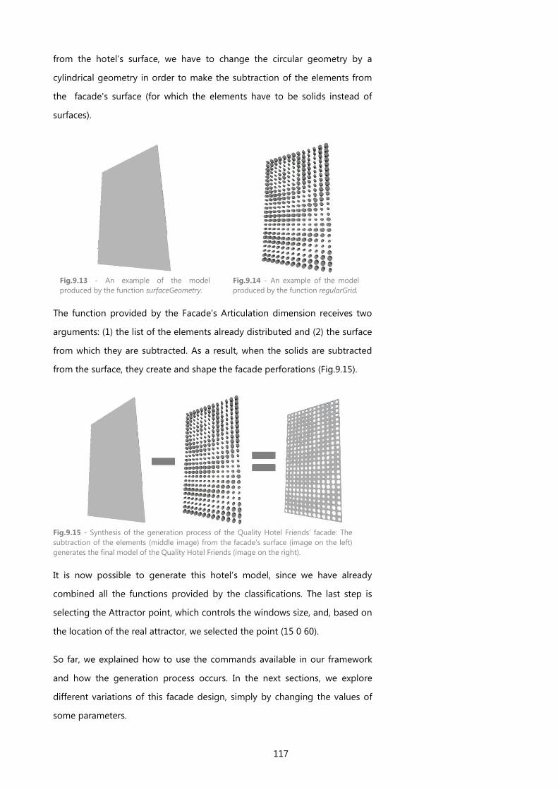
117
from the hotel’s surface, we have to change the circular geometry by a
cylindrical geometry in order to make the subtraction of the elements from
the facade's surface (for which the elements have to be solids instead of
surfaces).
The function provided by the Facade’s Articulation dimension receives two
arguments: (1) the list of the elements already distributed and (2) the surface
from which they are subtracted. As a result, when the solids are subtracted
from the surface, they create and shape the facade perforations (Fig.9.15).
It is now possible to generate this hotel’s model, since we have already
combined all the functions provided by the classifications. The last step is
selecting the Attractor point, which controls the windows size, and, based on
the location of the real attractor, we selected the point (15 0 60).
So far, we explained how to use the commands available in our framework
and how the generation process occurs. In the next sections, we explore
different variations of this facade design, simply by changing the values of
some parameters.
Fig.9.13 - An example of the model
produced by the function surfaceGeometry.
Fig.9.14 - An example of the model
produced by the function regularGrid.
Fig.9.15 - Synthesis of the generation process of the Quality Hotel Friends' facade: The
subtraction of the elements (middle image) from the facade's surface (image on the left)
generates the final model of the Quality Hotel Friends (image on the right).

118
HOTEL1 – Now, imagine the attractor point is changed to another point in
the facade, the number of windows is increased or decreased, or the
magnitude intensity of the waving effect is changed by another value. All of
these parameters can be changed by us, receiving any value as input and
producing many possible design variations.
First, we start by varying the number of windows which compose the facade.
Fig.9.16 (above) shows an image of the hotel’s facade with 13X25 windows. If
we change the value n=13 by n=20 and the value m=25 by m=37, we create
a facade similar to the one in Fig.9.16, but with more windows (see Fig.9.17).
We can further increase the number of windows that compose the facade, by
selecting bigger values for the n and m values and, otherwise, we can also
decrease their number in both directions (n and m values). These variations
of the n and m values produce automatic changes to the generated model,
which are always adjusted to the design principle, without deforming the
overall model and without unbalancing the distribution of the elements.
Fig.9.16 - An example of the Quality Hotel Friends facade produced by us: with 13X25 windows,
the attractor point is (15 0 60) and the magnitude is 4.
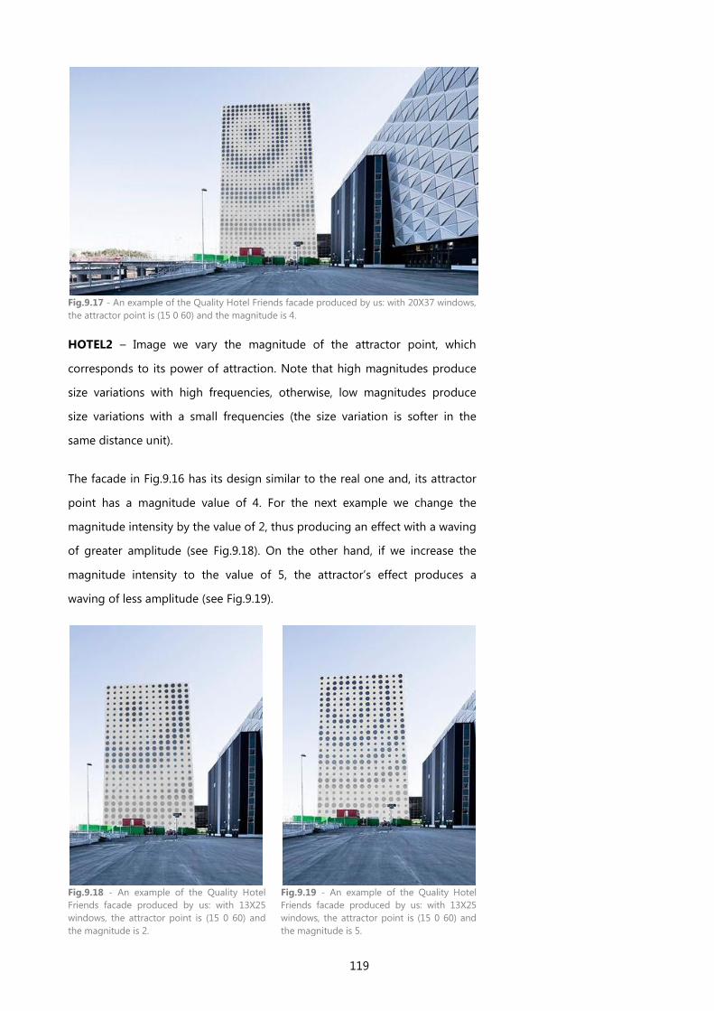
119
Fig.9.17 - An example of the Quality Hotel Friends facade produced by us: with 20X37 windows,
the attractor point is (15 0 60) and the magnitude is 4.
HOTEL2 – Image we vary the magnitude of the attractor point, which
corresponds to its power of attraction. Note that high magnitudes produce
size variations with high frequencies, otherwise, low magnitudes produce
size variations with a small frequencies (the size variation is softer in the
same distance unit).
The facade in Fig.9.16 has its design similar to the real one and, its attractor
point has a magnitude value of 4. For the next example we change the
magnitude intensity by the value of 2, thus producing an effect with a waving
of greater amplitude (see Fig.9.18). On the other hand, if we increase the
magnitude intensity to the value of 5, the attractor’s effect produces a
waving of less amplitude (see Fig.9.19).
Fig.9.18 - An example of the Quality Hotel
Friends facade produced by us: with 13X25
windows, the attractor point is (15 0 60) and
the magnitude is 2.
Fig.9.19 - An example of the Quality Hotel
Friends facade produced by us: with 13X25
windows, the attractor point is (15 0 60) and
the magnitude is 5.
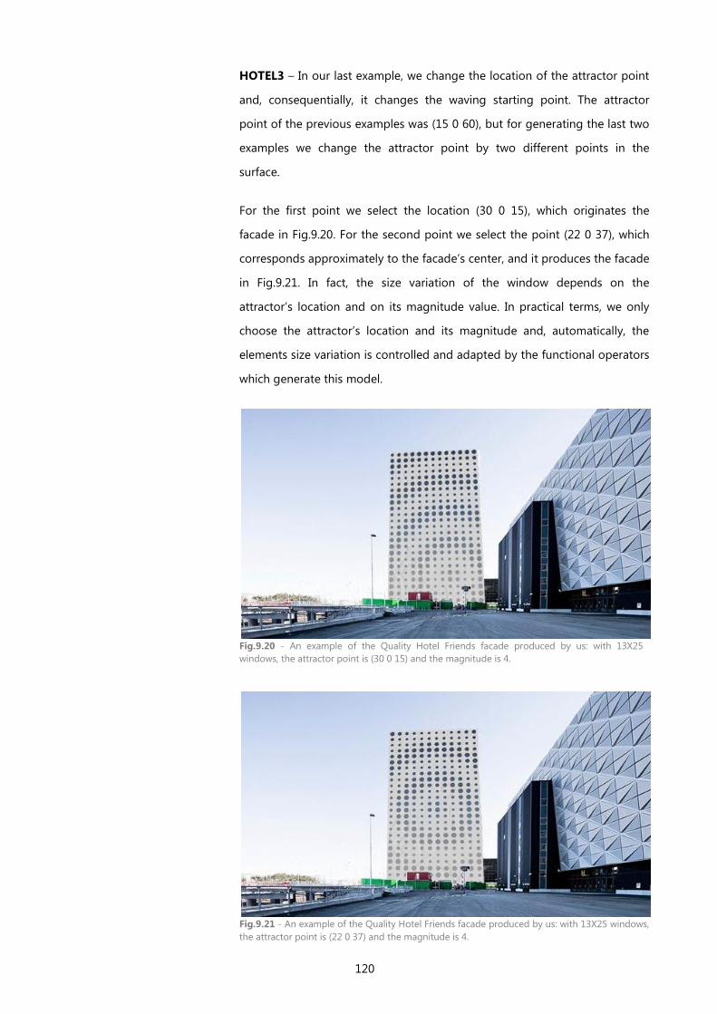
120
HOTEL3 – In our last example, we change the location of the attractor point
and, consequentially, it changes the waving starting point. The attractor
point of the previous examples was (15 0 60), but for generating the last two
examples we change the attractor point by two different points in the
surface.
For the first point we select the location (30 0 15), which originates the
facade in Fig.9.20. For the second point we select the point (22 0 37), which
corresponds approximately to the facade’s center, and it produces the facade
in Fig.9.21. In fact, the size variation of the window depends on the
attractor’s location and on its magnitude value. In practical terms, we only
choose the attractor’s location and its magnitude and, automatically, the
elements size variation is controlled and adapted by the functional operators
which generate this model.
Fig.9.20 - An example of the Quality Hotel Friends facade produced by us: with 13X25
windows, the attractor point is (30 0 15) and the magnitude is 4.
Fig.9.21 - An example of the Quality Hotel Friends facade produced by us: with 13X25 windows,
the attractor point is (22 0 37) and the magnitude is 4.
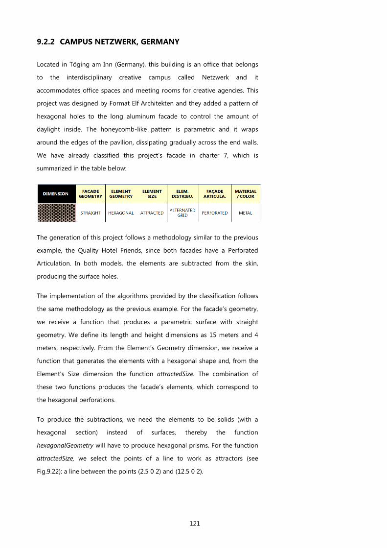
121
9.2.2 CAMPUS NETZWERK, GERMANY
Located in Töging am Inn (Germany), this building is an office that belongs
to the interdisciplinary creative campus called Netzwerk and it
accommodates office spaces and meeting rooms for creative agencies. This
project was designed by Format Elf Architekten and they added a pattern of
hexagonal holes to the long aluminum facade to control the amount of
daylight inside. The honeycomb-like pattern is parametric and it wraps
around the edges of the pavilion, dissipating gradually across the end walls.
We have already classified this project’s facade in charter 7, which is
summarized in the table below:
The generation of this project follows a methodology similar to the previous
example, the Quality Hotel Friends, since both facades have a Perforated
Articulation. In both models, the elements are subtracted from the skin,
producing the surface holes.
The implementation of the algorithms provided by the classification follows
the same methodology as the previous example. For the facade’s geometry,
we receive a function that produces a parametric surface with straight
geometry. We define its length and height dimensions as 15 meters and 4
meters, respectively. From the Element’s Geometry dimension, we receive a
function that generates the elements with a hexagonal shape and, from the
Element’s Size dimension the function attractedSize. The combination of
these two functions produces the facade’s elements, which correspond to
the hexagonal perforations.
To produce the subtractions, we need the elements to be solids (with a
hexagonal section) instead of surfaces, thereby the function
hexagonalGeometry will have to produce hexagonal prisms. For the function
attractedSize, we select the points of a line to work as attractors (see
Fig.9.22): a line between the points (2.5 0 2) and (12.5 0 2).

122
Fig.9.22 – The attractor line points and its effect on the surrounding
geometries.
So far, we have defined the facade's surface and the function that generates
the hexagonal and attracted elements. Therefore, we still need to define the
function that places the elements on the facade. For this, we receive a
function that distributes the elements in an Alternated-Grid. The function
alternatedGrid is a Higher-Order Function and it receives four arguments:
1. the function element, which generates hexagonal elements with
attracted size;
2. the function straightGeometry;
3. the number of elements to produce horizontally (n);
4. the number of elements to produce vertically (m).
Fig.9.23 – The end result of the function alternatedGrid.
This facade is also Perforated, which means we have to subtract the set of
elements (already distributed in an alternated-grid) from the straight surface
produced by the function straightGeometry. As a result, we a obtain a model
as the one in Fig.9.24.
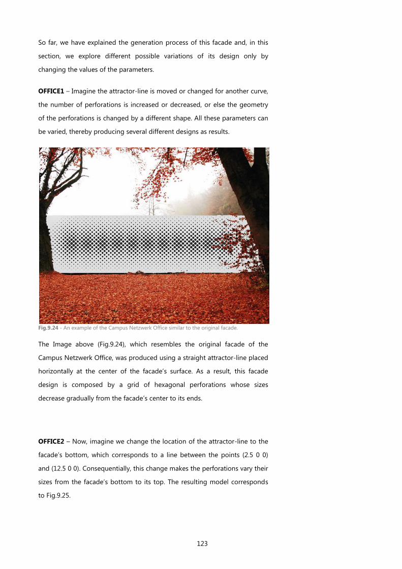
123
So far, we have explained the generation process of this facade and, in this
section, we explore different possible variations of its design only by
changing the values of the parameters.
OFFICE1 – Imagine the attractor-line is moved or changed for another curve,
the number of perforations is increased or decreased, or else the geometry
of the perforations is changed by a different shape. All these parameters can
be varied, thereby producing several different designs as results.
Fig.9.24 - An example of the Campus Netzwerk Office similar to the original facade.
The Image above (Fig.9.24), which resembles the original facade of the
Campus Netzwerk Office, was produced using a straight attractor-line placed
horizontally at the center of the facade’s surface. As a result, this facade
design is composed by a grid of hexagonal perforations whose sizes
decrease gradually from the facade’s center to its ends.
OFFICE2 – Now, imagine we change the location of the attractor-line to the
facade’s bottom, which corresponds to a line between the points (2.5 0 0)
and (12.5 0 0). Consequentially, this change makes the perforations vary their
sizes from the facade’s bottom to its top. The resulting model corresponds
to Fig.9.25.
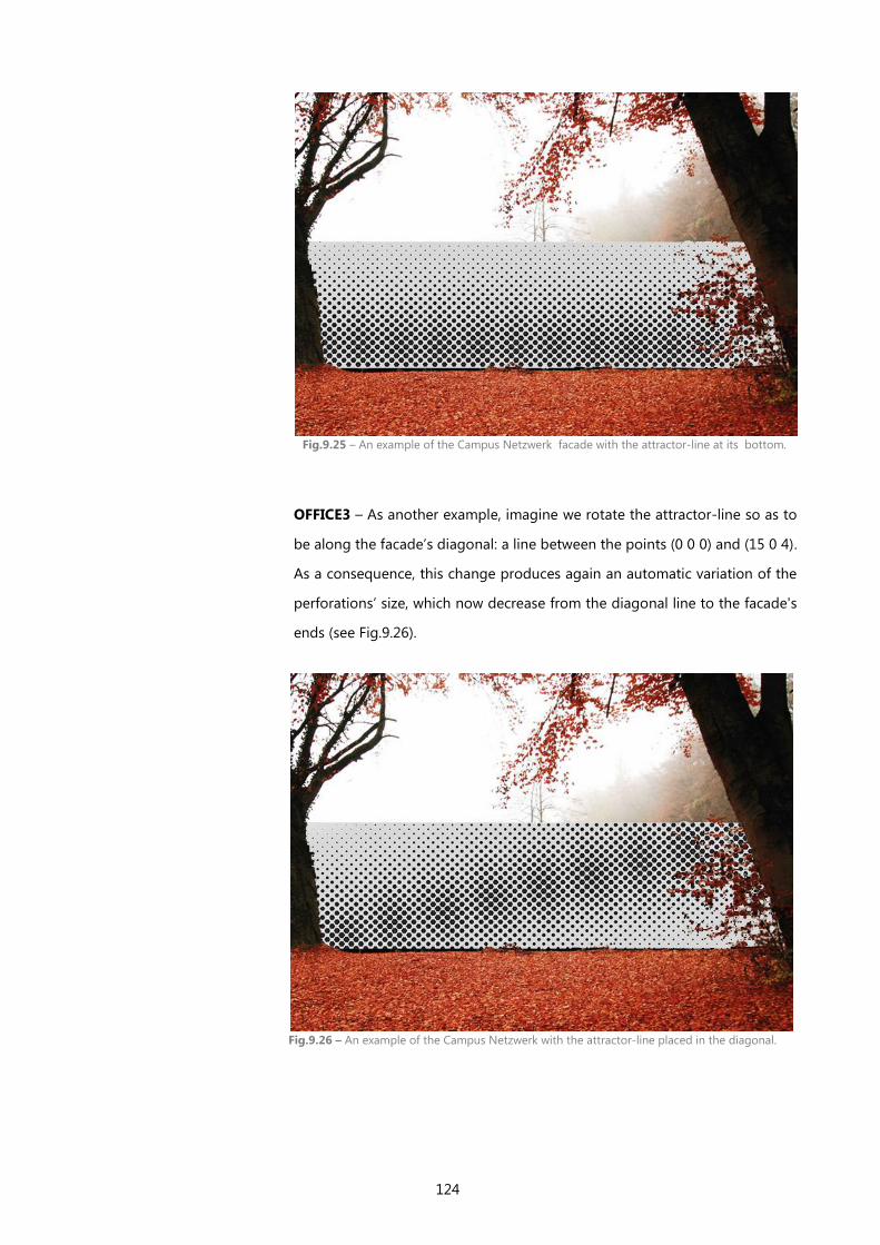
124
OFFICE3 – As another example, imagine we rotate the attractor-line so as to
be along the facade’s diagonal: a line between the points (0 0 0) and (15 0 4).
As a consequence, this change produces again an automatic variation of the
perforations’ size, which now decrease from the diagonal line to the facade's
ends (see Fig.9.26).
Fig.9.25 – An example of the Campus Netzwerk facade with the attractor-line at its bottom.
Fig.9.26 – An example of the Campus Netzwerk with the attractor-line placed in the diagonal.
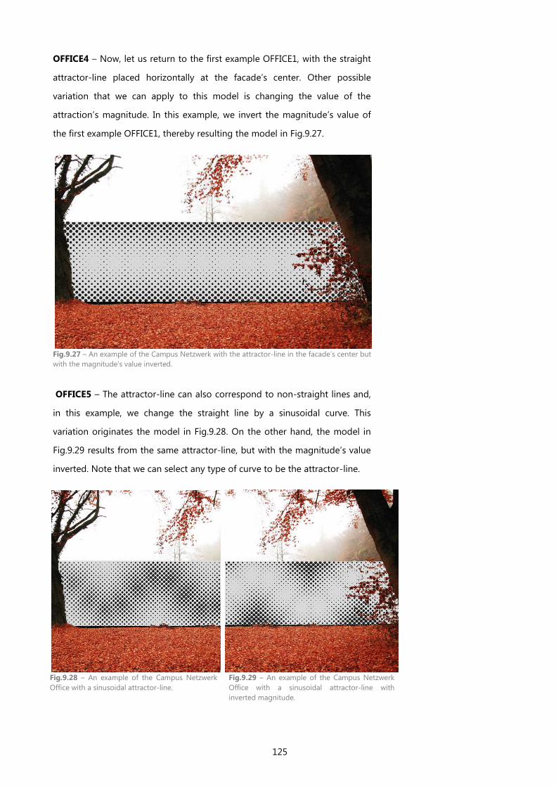
125
OFFICE4 – Now, let us return to the first example OFFICE1, with the straight
attractor-line placed horizontally at the facade’s center. Other possible
variation that we can apply to this model is changing the value of the
attraction’s magnitude. In this example, we invert the magnitude’s value of
the first example OFFICE1, thereby resulting the model in Fig.9.27.
Fig.9.27 – An example of the Campus Netzwerk with the attractor-line in the facade’s center but
with the magnitude’s value inverted.
OFFICE5 – The attractor-line can also correspond to non-straight lines and,
in this example, we change the straight line by a sinusoidal curve. This
variation originates the model in Fig.9.28. On the other hand, the model in
Fig.9.29 results from the same attractor-line, but with the magnitude’s value
inverted. Note that we can select any type of curve to be the attractor-line.
Fig.9.28 – An example of the Campus Netzwerk
Office with a sinusoidal attractor-line.
Fig.9.29 – An example of the Campus Netzwerk
Office with a sinusoidal attractor-line with
inverted magnitude.
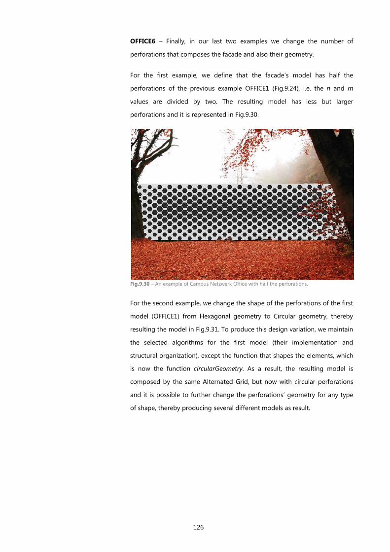
126
OFFICE6 – Finally, in our last two examples we change the number of
perforations that composes the facade and also their geometry.
For the first example, we define that the facade’s model has half the
perforations of the previous example OFFICE1 (Fig.9.24), i.e. the n and m
values are divided by two. The resulting model has less but larger
perforations and it is represented in Fig.9.30.
Fig.9.30 – An example of Campus Netzwerk Office with half the perforations.
For the second example, we change the shape of the perforations of the first
model (OFFICE1) from Hexagonal geometry to Circular geometry, thereby
resulting the model in Fig.9.31. To produce this design variation, we maintain
the selected algorithms for the first model (their implementation and
structural organization), except the function that shapes the elements, which
is now the function circularGeometry. As a result, the resulting model is
composed by the same Alternated-Grid, but now with circular perforations
and it is possible to further change the perforations’ geometry for any type
of shape, thereby producing several different models as result.
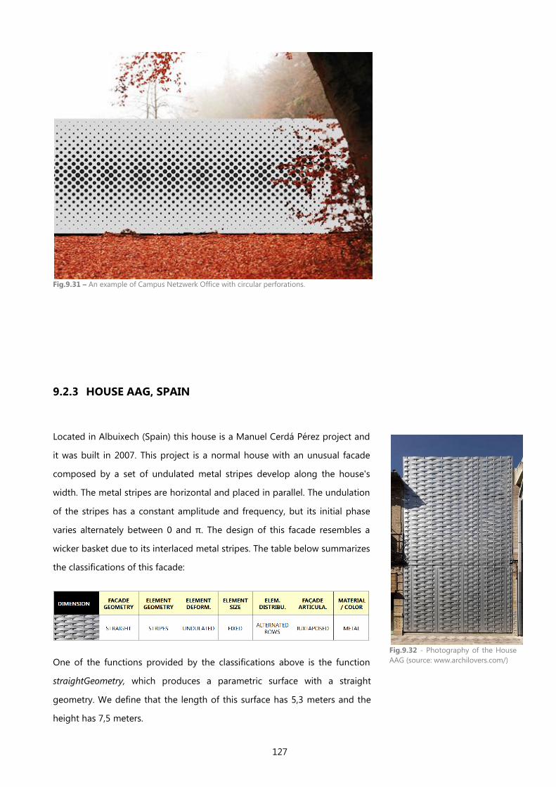
127
Fig.9.31 – An example of Campus Netzwerk Office with circular perforations.
9.2.3 HOUSE AAG, SPAIN
Located in Albuixech (Spain) this house is a Manuel Cerdá Pérez project and
it was built in 2007. This project is a normal house with an unusual facade
composed by a set of undulated metal stripes develop along the house's
width. The metal stripes are horizontal and placed in parallel. The undulation
of the stripes has a constant amplitude and frequency, but its initial phase
varies alternately between 0 and π. The design of this facade resembles a
wicker basket due to its interlaced metal stripes. The table below summarizes
the classifications of this facade:
One of the functions provided by the classifications above is the function
straightGeometry, which produces a parametric surface with a straight
geometry. We define that the length of this surface has 5,3 meters and the
height has 7,5 meters.
Fig.9.32 - Photography of the House
AAG (source: www.archilovers.com/)
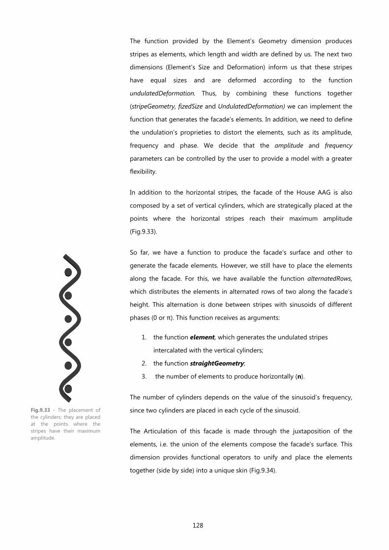
128
The function provided by the Element’s Geometry dimension produces
stripes as elements, which length and width are defined by us. The next two
dimensions (Element’s Size and Deformation) inform us that these stripes
have equal sizes and are deformed according to the function
undulatedDeformation. Thus, by combining these functions together
(stripeGeometry, fizedSize and UndulatedDeformation) we can implement the
function that generates the facade’s elements. In addition, we need to define
the undulation’s proprieties to distort the elements, such as its amplitude,
frequency and phase. We decide that the amplitude and frequency
parameters can be controlled by the user to provide a model with a greater
flexibility.
In addition to the horizontal stripes, the facade of the House AAG is also
composed by a set of vertical cylinders, which are strategically placed at the
points where the horizontal stripes reach their maximum amplitude
(Fig.9.33).
So far, we have a function to produce the facade's surface and other to
generate the facade elements. However, we still have to place the elements
along the facade. For this, we have available the function alternatedRows,
which distributes the elements in alternated rows of two along the facade’s
height. This alternation is done between stripes with sinusoids of different
phases (0 or π). This function receives as arguments:
1. the function element, which generates the undulated stripes
intercalated with the vertical cylinders;
2. the function straightGeometry;
3. the number of elements to produce horizontally (n).
The number of cylinders depends on the value of the sinusoid’s frequency,
since two cylinders are placed in each cycle of the sinusoid.
The Articulation of this facade is made through the juxtaposition of the
elements, i.e. the union of the elements compose the facade's surface. This
dimension provides functional operators to unify and place the elements
together (side by side) into a unique skin (Fig.9.34).
Fig.9.33 - The placement of
the cylinders: they are placed
at the points where the
stripes have their maximum
amplitude.
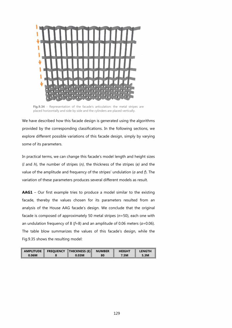
129
Fig.9.34 - Representation of the facade's articulation: the metal stripes are
placed horizontally and side by side and the cylinders are placed vertically.
We have described how this facade design is generated using the algorithms
provided by the corresponding classifications. In the following sections, we
explore different possible variations of this facade design, simply by varying
some of its parameters.
In practical terms, we can change this facade’s model length and height sizes
(l and h), the number of stripes (n), the thickness of the stripes (e) and the
value of the amplitude and frequency of the stripes’ undulation (a and f). The
variation of these parameters produces several different models as result.
AAG1 – Our first example tries to produce a model similar to the existing
facade, thereby the values chosen for its parameters resulted from an
analysis of the House AAG facade’s design. We conclude that the original
facade is composed of approximately 50 metal stripes (n=50), each one with
an undulation frequency of 8 (f=8) and an amplitude of 0.06 meters (a=0.06).
The table blow summarizes the values of this facade’s design, while the
Fig.9.35 shows the resulting model:
AMPLITUDE
0.06M
FREQUENCY
8
THICKNESS (E)
0.03M
NUMBER
80
HEIGHT
7.5M
LENGTH
5.3M
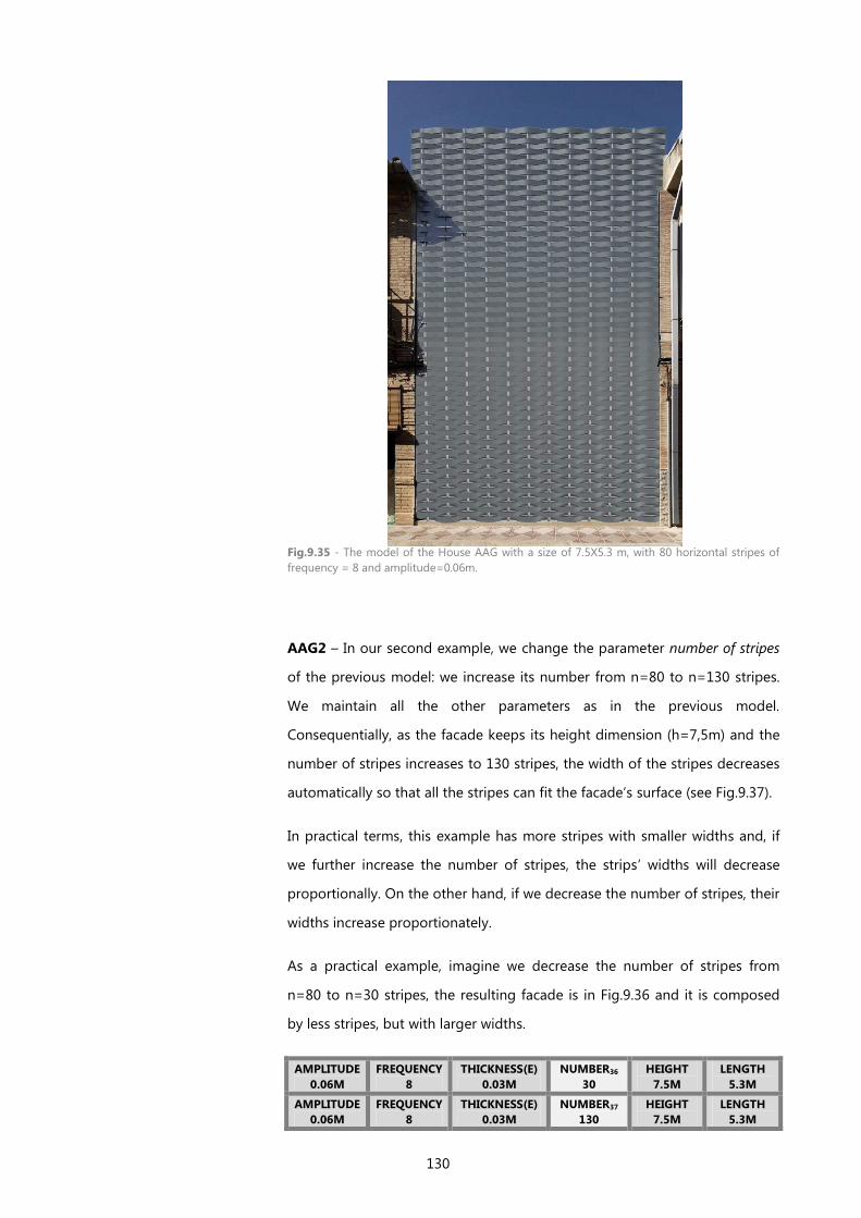
130
Fig.9.35 - The model of the House AAG with a size of 7.5X5.3 m, with 80 horizontal stripes of
frequency = 8 and amplitude=0.06m.
AAG2 – In our second example, we change the parameter number of stripes
of the previous model: we increase its number from n=80 to n=130 stripes.
We maintain all the other parameters as in the previous model.
Consequentially, as the facade keeps its height dimension (h=7,5m) and the
number of stripes increases to 130 stripes, the width of the stripes decreases
automatically so that all the stripes can fit the facade’s surface (see Fig.9.37).
In practical terms, this example has more stripes with smaller widths and, if
we further increase the number of stripes, the strips’ widths will decrease
proportionally. On the other hand, if we decrease the number of stripes, their
widths increase proportionately.
As a practical example, imagine we decrease the number of stripes from
n=80 to n=30 stripes, the resulting facade is in Fig.9.36 and it is composed
by less stripes, but with larger widths.
AMPLITUDE
0.06M
FREQUENCY
8
THICKNESS(E)
0.03M
NUMBER36
30
HEIGHT
7.5M
LENGTH
5.3M
AMPLITUDE
0.06M
FREQUENCY
8
THICKNESS(E)
0.03M
NUMBER37
130
HEIGHT
7.5M
LENGTH
5.3M
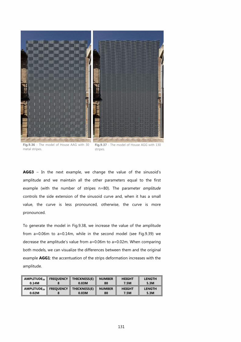
131
Fig.9.36 - The model of House AAG with 30
metal stripes.
Fig.9.37 - The model of House AGG with 130
stripes.
AGG3 – In the next example, we change the value of the sinusoid’s
amplitude and we maintain all the other parameters equal to the first
example (with the number of stripes n=80). The parameter amplitude
controls the side extension of the sinusoid curve and, when it has a small
value, the curve is less pronounced, otherwise, the curve is more
pronounced.
To generate the model in Fig.9.38, we increase the value of the amplitude
from a=0.06m to a=0.14m, while in the second model (see Fig.9.39) we
decrease the amplitude’s value from a=0.06m to a=0.02m. When comparing
both models, we can visualize the differences between them and the original
example AGG1: the accentuation of the strips deformation increases with the
amplitude.
AMPLITUDE38
0.14M
FREQUENCY
8
THICKNESS(E)
0.03M
NUMBER
80
HEIGHT
7.5M
LENGTH
5.3M
AMPLITUDE39
0.02M
FREQUENCY
8
THICKNESS(E)
0.03M
NUMBER
80
HEIGHT
7.5M
LENGTH
5.3M
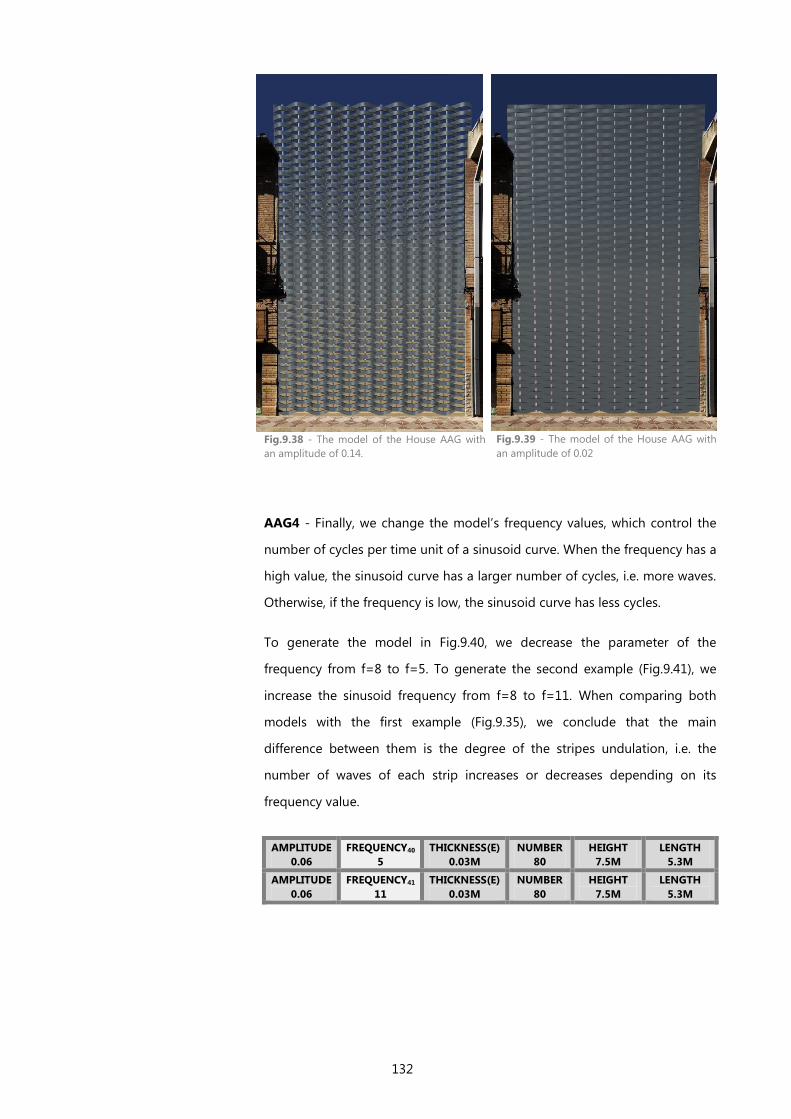
132
Fig.9.38 - The model of the House AAG with
an amplitude of 0.14.
Fig.9.39 - The model of the House AAG with
an amplitude of 0.02
AAG4 - Finally, we change the model’s frequency values, which control the
number of cycles per time unit of a sinusoid curve. When the frequency has a
high value, the sinusoid curve has a larger number of cycles, i.e. more waves.
Otherwise, if the frequency is low, the sinusoid curve has less cycles.
To generate the model in Fig.9.40, we decrease the parameter of the
frequency from f=8 to f=5. To generate the second example (Fig.9.41), we
increase the sinusoid frequency from f=8 to f=11. When comparing both
models with the first example (Fig.9.35), we conclude that the main
difference between them is the degree of the stripes undulation, i.e. the
number of waves of each strip increases or decreases depending on its
frequency value.
AMPLITUDE
0.06
FREQUENCY40
5
THICKNESS(E)
0.03M
NUMBER
80
HEIGHT
7.5M
LENGTH
5.3M
AMPLITUDE
0.06
FREQUENCY41
11
THICKNESS(E)
0.03M
NUMBER
80
HEIGHT
7.5M
LENGTH
5.3M
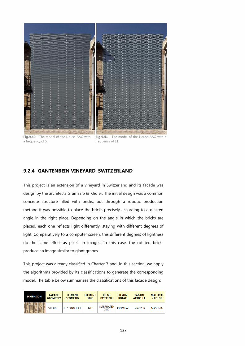
133
Fig.9.40 - The model of the House AAG with
a frequency of 5.
Fig.9.41 - The model of the House AAG with a
frequency of 11.
9.2.4 GANTENBEIN VINEYARD, SWITZERLAND
This project is an extension of a vineyard in Switzerland and its facade was
design by the architects Gramazio & Kholer. The initial design was a common
concrete structure filled with bricks, but through a robotic production
method it was possible to place the bricks precisely according to a desired
angle in the right place. Depending on the angle in which the bricks are
placed, each one reflects light differently, staying with different degrees of
light. Comparatively to a computer screen, this different degrees of lightness
do the same effect as pixels in images. In this case, the rotated bricks
produce an image similar to giant grapes.
This project was already classified in Charter 7 and, In this section, we apply
the algorithms provided by its classifications to generate the corresponding
model. The table below summarizes the classifications of this facade design:
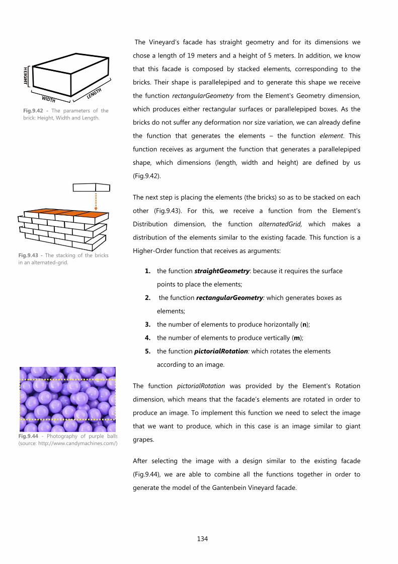
134
The Vineyard’s facade has straight geometry and for its dimensions we
chose a length of 19 meters and a height of 5 meters. In addition, we know
that this facade is composed by stacked elements, corresponding to the
bricks. Their shape is parallelepiped and to generate this shape we receive
the function rectangularGeometry from the Element's Geometry dimension,
which produces either rectangular surfaces or parallelepiped boxes. As the
bricks do not suffer any deformation nor size variation, we can already define
the function that generates the elements – the function element. This
function receives as argument the function that generates a parallelepiped
shape, which dimensions (length, width and height) are defined by us
(Fig.9.42).
The next step is placing the elements (the bricks) so as to be stacked on each
other (Fig.9.43). For this, we receive a function from the Element's
Distribution dimension, the function alternatedGrid, which makes a
distribution of the elements similar to the existing facade. This function is a
Higher-Order function that receives as arguments:
1. the function straightGeometry: because it requires the surface
points to place the elements;
2. the function rectangularGeometry: which generates boxes as
elements;
3. the number of elements to produce horizontally (n);
4. the number of elements to produce vertically (m);
5. the function pictorialRotation: which rotates the elements
according to an image.
The function pictorialRotation was provided by the Element's Rotation
dimension, which means that the facade’s elements are rotated in order to
produce an image. To implement this function we need to select the image
that we want to produce, which in this case is an image similar to giant
grapes.
After selecting the image with a design similar to the existing facade
(Fig.9.44), we are able to combine all the functions together in order to
generate the model of the Gantenbein Vineyard facade.
Fig.9.42 - The parameters of the
brick: Height, Width and Length.
Fig.9.43 - The stacking of the bricks
in an alternated-grid.
Fig.9.44 - Photography of purple balls
(source: http://www.candymachines.com/)
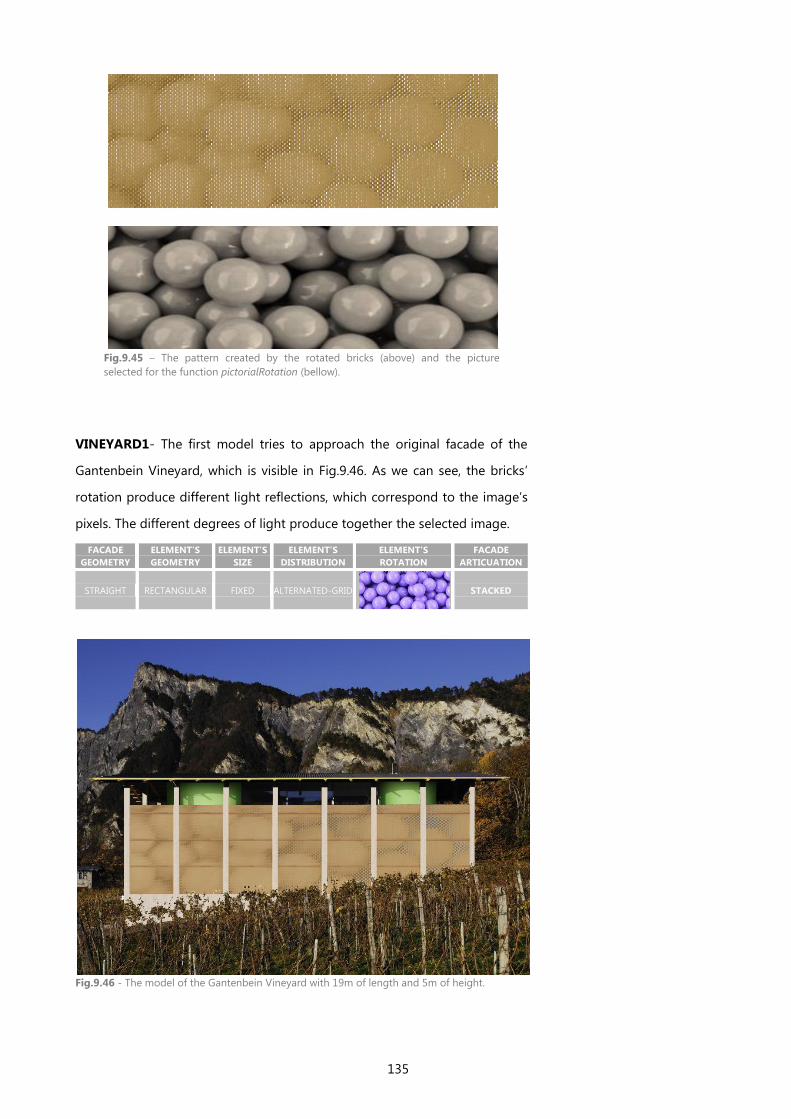
135
Fig.9.45 – The pattern created by the rotated bricks (above) and the picture
selected for the function pictorialRotation (bellow).
VINEYARD1- The first model tries to approach the original facade of the
Gantenbein Vineyard, which is visible in Fig.9.46. As we can see, the bricks’
rotation produce different light reflections, which correspond to the image’s
pixels. The different degrees of light produce together the selected image.
FACADE
GEOMETRY
ELEMENT’S
GEOMETRY
ELEMENT’S
SIZE
ELEMENT’S
DISTRIBUTION
ELEMENT’S
ROTATION
FACADE
ARTICUATION
STRAIGHT RECTANGULAR FIXED ALTERNATED-GRID
STACKED
Fig.9.46 - The model of the Gantenbein Vineyard with 19m of length and 5m of height.

136
VINEYARD2 - There are several ways to produce images on a facade and, in
the next examples, we explore other possibilities for the generation of this
same image. In this section, we produce the selected pattern using different
strategies:
1. by using perforations with different sizes;
2. by using appliqués with different sizes;
3. by using a grid that narrows or expands according to the color
intensity of the corresponding pixel;
4. by placing the bricks more forward or backward.
In the first example, we produce the pattern through the movement of the
bricks forward or backward, according to the color of the corresponding
pixels. This produces a pictorial effect similar to the one produced by the
rotated bricks (visible in the Fig.9.47).
Fig.9.47 - The model of the Gantenbein Vineyard with bricks placed backward and forward.
VINEYARD3 - In the following example, we produce the pattern of the
“giant grapes” using squared perforations with different sizes, according to
the color of the corresponding pixel. In this example, the elements have a
size variation controlled by a function provided by the Element’s Size
dimension, the function pictorialSize. Then, these elements are subtracted
from the facade’s surface, instead of being stacked. In this example, the
facade’s type of articulation is changed from Stacked to Perforated, while the

137
elements’ geometry is changed from Fixed to Pictorial. The resulting model is
represented in Fig.9.48.
FACADE
GEOMETRY
ELEMENT’S
GEOMETRY ELEMENT’S SIZE
ELEMENT’S
DISTRIBUTION
ELEMENT’S
ROTATION
FACADE
ARTICUATION
STRAIGHT SQUARED
REGULAR-GRID — PERFORATED
In addition, we can produce this same pattern by using circular perforations
instead of squared perforations (see Fig.9.49). For this, we change the
Element’s Geometry from Squared to Circular and we maintain all the other
parameters.
Fig.9.48 - The model of the Gantenbein Vineyard with squared perforations.
Fig.9.49 - The model of the Gantenbein Vineyard with circular perforations.
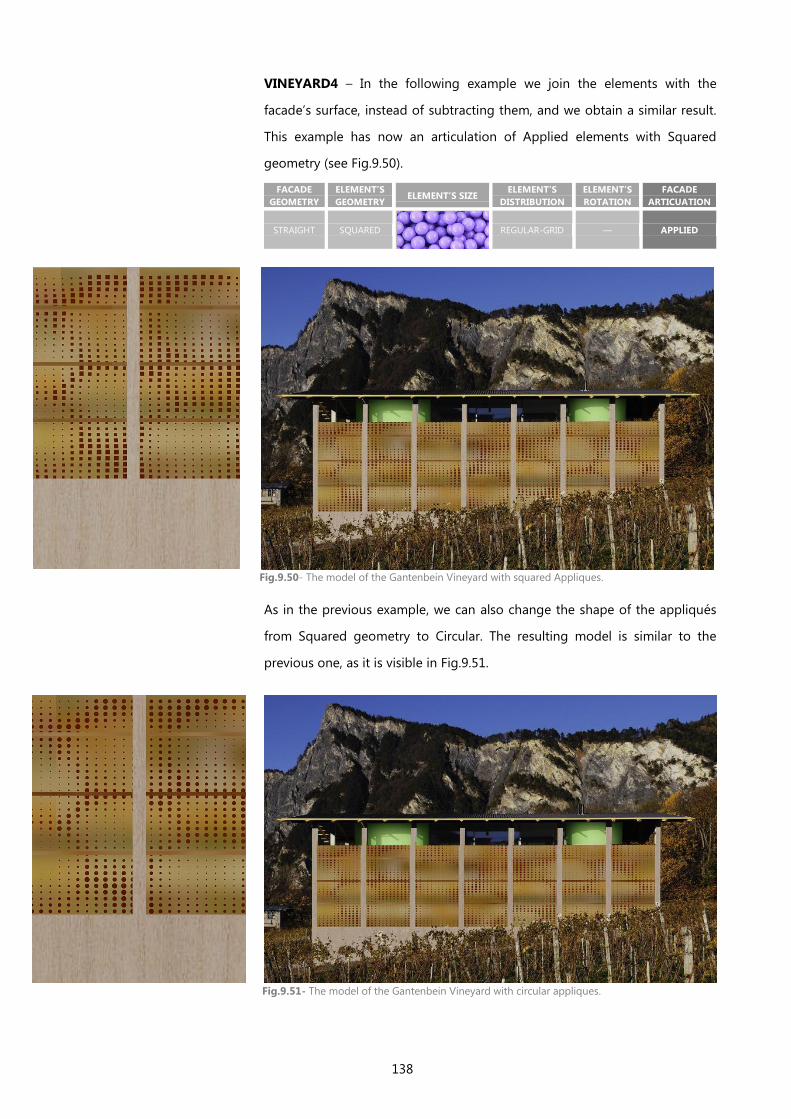
138
VINEYARD4 – In the following example we join the elements with the
facade’s surface, instead of subtracting them, and we obtain a similar result.
This example has now an articulation of Applied elements with Squared
geometry (see Fig.9.50).
FACADE
GEOMETRY
ELEMENT’S
GEOMETRY ELEMENT’S SIZE
ELEMENT’S
DISTRIBUTION
ELEMENT’S
ROTATION
FACADE
ARTICUATION
STRAIGHT SQUARED
REGULAR-GRID — APPLIED
As in the previous example, we can also change the shape of the appliqués
from Squared geometry to Circular. The resulting model is similar to the
previous one, as it is visible in Fig.9.51.
Fig.9.50- The model of the Gantenbein Vineyard with squared Appliques.
Fig.9.51- The model of the Gantenbein Vineyard with circular appliques.
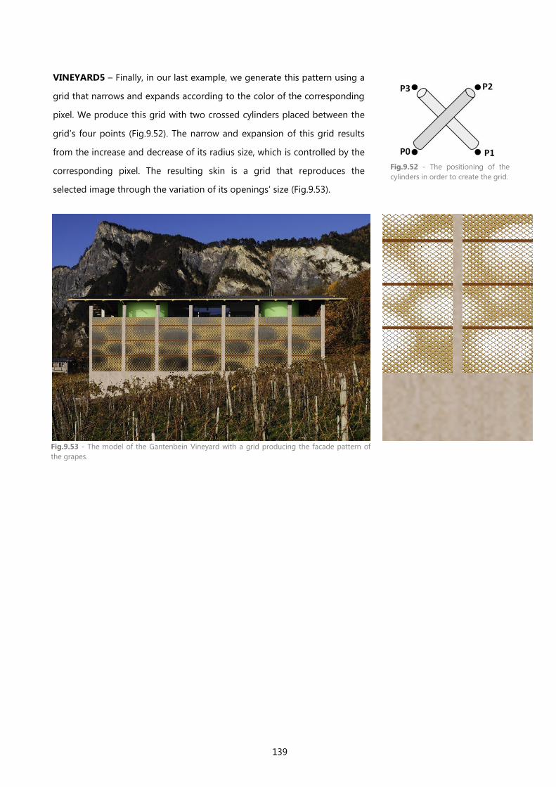
139
VINEYARD5 – Finally, in our last example, we generate this pattern using a
grid that narrows and expands according to the color of the corresponding
pixel. We produce this grid with two crossed cylinders placed between the
grid’s four points (Fig.9.52). The narrow and expansion of this grid results
from the increase and decrease of its radius size, which is controlled by the
corresponding pixel. The resulting skin is a grid that reproduces the
selected image through the variation of its openings’ size (Fig.9.53).
Fig.9.52 - The positioning of the
cylinders in order to create the grid.
Fig.9.53 - The model of the Gantenbein Vineyard with a grid producing the facade pattern of
the grapes.

140
9.2.5 FACIM WATERFRONT IN MAPUTO, MOZAMBIQUE
Fig.9.54 - A Rendering of the FACIM WaterFront Project by Bak Gordon (source:
http://www.bakgordon.com/200_projects/)
Our last example is a project of Bak Gordon’s Studio together with FVA and
PROAP for the city of Maputo (Fig.9.54), which has not yet been built. As we
explained in this thesis introduction, this project was the starting point of our
work, thereby inspiring us to create this framework. The project consists of a
big quarter, whose functional program includes areas of business, commerce,
housing and hotels. This wide functional program led to an urban planning
solution in which the vertical buildings stand out as the fundamental project
image.
The towers' skin is characterized by a pattern inspired in African motifs
(Fig.9.55), which is produced using metallic profiles. This pattern suffers a
scale variation from one side of the facade to the other, which is produced
by a sequence of several modules with patterns with a gradually smaller
scale (see Fig.9.56). Although this sequence of patterns creates an interesting
effect, if its size variation was produced using an algorithmic approach, the
resulting skin would be more continuous and controllable. In addition, it
would also facilitate the testing of other possible variations of this pattern,
with almost no effort and time spent.
In this section, we explore and generate the skin pattern of the FACIM
WaterFront project using an algorithmic approach. For this, we apply some
of the functions available in our framework and, when necessary, we develop
some additional algorithms.
Fig.9.55 - The African Motif that inspired
the pattern (source: Bak Gordon Studio).
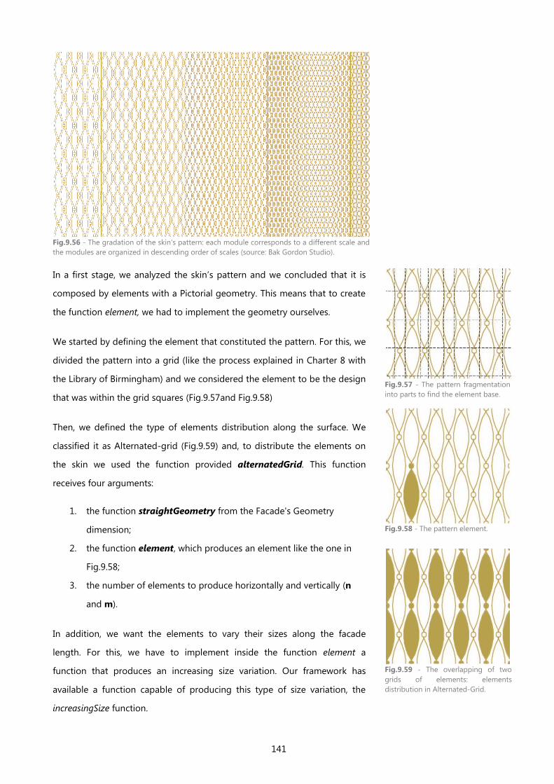
141
Fig.9.56 - The gradation of the skin's pattern: each module corresponds to a different scale and
the modules are organized in descending order of scales (source: Bak Gordon Studio).
In a first stage, we analyzed the skin’s pattern and we concluded that it is
composed by elements with a Pictorial geometry. This means that to create
the function element, we had to implement the geometry ourselves.
We started by defining the element that constituted the pattern. For this, we
divided the pattern into a grid (like the process explained in Charter 8 with
the Library of Birmingham) and we considered the element to be the design
that was within the grid squares (Fig.9.57and Fig.9.58)
Then, we defined the type of elements distribution along the surface. We
classified it as Alternated-grid (Fig.9.59) and, to distribute the elements on
the skin we used the function provided alternatedGrid. This function
receives four arguments:
1. the function straightGeometry from the Facade's Geometry
dimension;
2. the function element, which produces an element like the one in
Fig.9.58;
3. the number of elements to produce horizontally and vertically (n
and m).
In addition, we want the elements to vary their sizes along the facade
length. For this, we have to implement inside the function element a
function that produces an increasing size variation. Our framework has
available a function capable of producing this type of size variation, the
increasingSize function.
Fig.9.57 - The pattern fragmentation
into parts to find the element base.
Fig.9.58 - The pattern element.
Fig.9.59 - The overlapping of two
grids of elements: elements
distribution in Alternated-Grid.
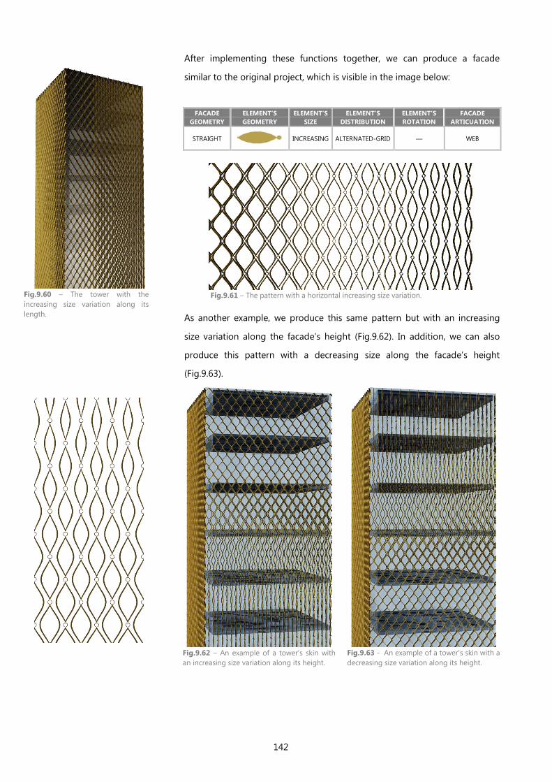
142
After implementing these functions together, we can produce a facade
similar to the original project, which is visible in the image below:
FACADE
GEOMETRY
ELEMENT’S
GEOMETRY
ELEMENT’S
SIZE
ELEMENT’S
DISTRIBUTION
ELEMENT’S
ROTATION
FACADE
ARTICUATION
STRAIGHT
INCREASING ALTERNATED-GRID — WEB
Fig.9.61 – The pattern with a horizontal increasing size variation.
As another example, we produce this same pattern but with an increasing
size variation along the facade’s height (Fig.9.62). In addition, we can also
produce this pattern with a decreasing size along the facade’s height
(Fig.9.63).
Fig.9.62 – An example of a tower’s skin with
an increasing size variation along its height.
Fig.9.63 - An example of a tower’s skin with a
decreasing size variation along its height.
Fig.9.60 – The tower with the
increasing size variation along its
length.
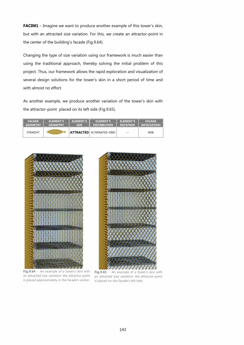
143
FACIM1 – Imagine we want to produce another example of this tower’s skin,
but with an attracted size variation. For this, we create an attractor-point in
the center of the building’s facade (Fig.9.64).
Changing the type of size variation using our framework is much easier than
using the traditional approach, thereby solving the initial problem of this
project. Thus, our framework allows the rapid exploration and visualization of
several design solutions for the tower’s skin in a short period of time and
with almost no effort.
As another example, we produce another variation of the tower’s skin with
the attractor-point placed on its left side (Fig.9.65).
FACADE
GEOMETRY
ELEMENT’S
GEOMETRY
ELEMENT’S
SIZE
ELEMENT’S
DISTRIBUTION
ELEMENT’S
ROTATION
FACADE
ARTICUATION
STRAIGHT
ATTRACTED ALTERNATED-GRID — WEB
Fig.9.64 - An example of a tower’s skin with
an attracted size variation: the attractor-point
is placed approximately in the facade’s center.
Fig.9.65 - An example of a tower’s skin with
an attracted size variation: the attractor-point
is placed on the facade’s left side.
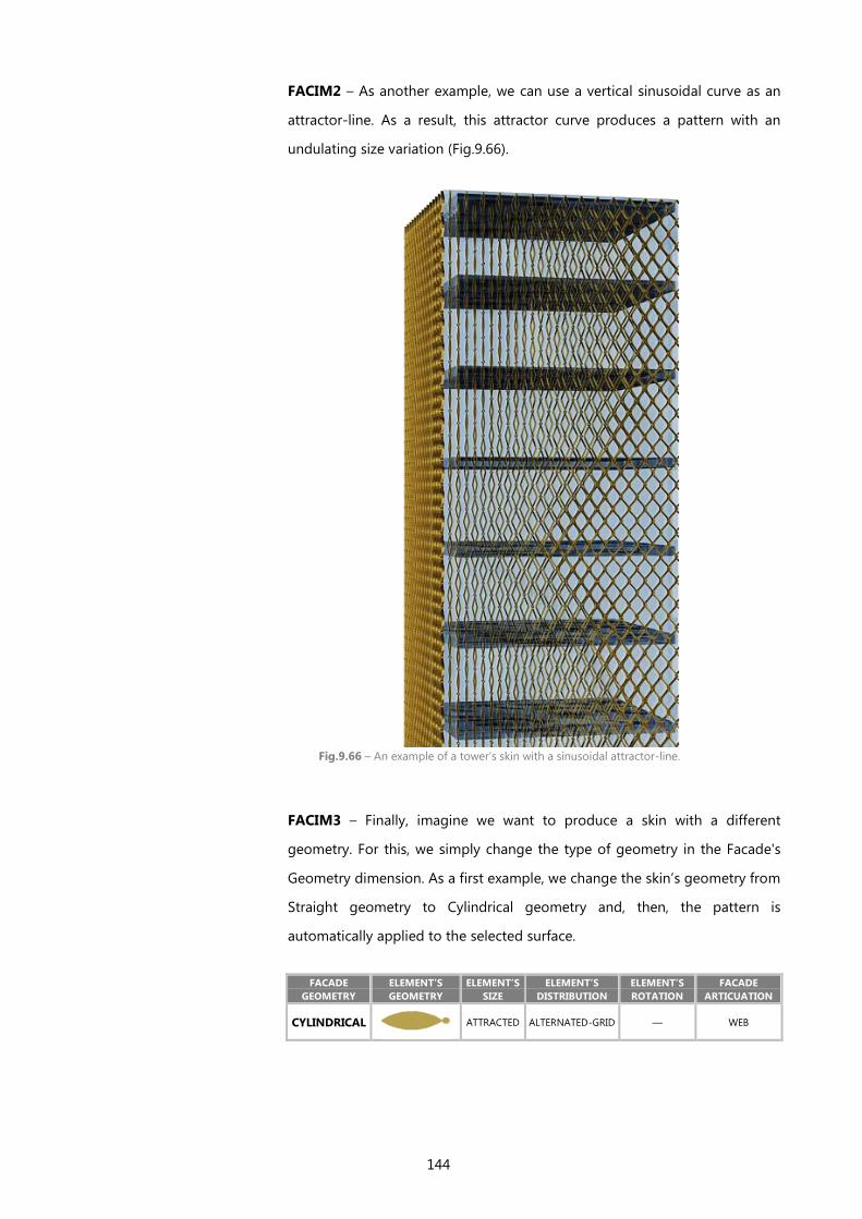
144
FACIM2 – As another example, we can use a vertical sinusoidal curve as an
attractor-line. As a result, this attractor curve produces a pattern with an
undulating size variation (Fig.9.66).
Fig.9.66 – An example of a tower’s skin with a sinusoidal attractor-line.
FACIM3 – Finally, imagine we want to produce a skin with a different
geometry. For this, we simply change the type of geometry in the Facade's
Geometry dimension. As a first example, we change the skin’s geometry from
Straight geometry to Cylindrical geometry and, then, the pattern is
automatically applied to the selected surface.
FACADE
GEOMETRY
ELEMENT’S
GEOMETRY
ELEMENT’S
SIZE
ELEMENT’S
DISTRIBUTION
ELEMENT’S
ROTATION
FACADE
ARTICUATION
CYLINDRICAL
ATTRACTED ALTERNATED-GRID — WEB
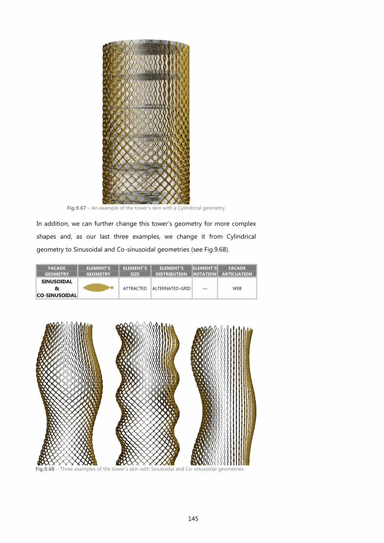
145
Fig.9.67 – An example of the tower’s skin with a Cylindrical geometry.
In addition, we can further change this tower’s geometry for more complex
shapes and, as our last three examples, we change it from Cylindrical
geometry to Sinusoidal and Co-sinusoidal geometries (see Fig.9.68).
FACADE
GEOMETRY
ELEMENT’S
GEOMETRY
ELEMENT’S
SIZE
ELEMENT’S
DISTRIBUTION
ELEMENT’S
ROTATION
FACADE
ARTICUATION
SINUSOIDAL
&
CO-SINUSOIDAL
ATTRACTED ALTERNATED-GRID — WEB
Fig.9.68 – Three examples of the tower’s skin with Sinusoidal and Co-sinusoidal geometries.

146
To sum up, in this section we explored a set of different variations for each of
the selected projects. Still, the design changes that we explored here are only
a small part of all possible variations, since our framework is based on an
algorithmic approach, which gives us the maximum flexibility for the design
exploration and where the changes are automatically updated to the models.
We can produce these variations simply by changing the values of the
parameters, thereby not being necessary to erase and redraw the designs as
in the traditional approach.
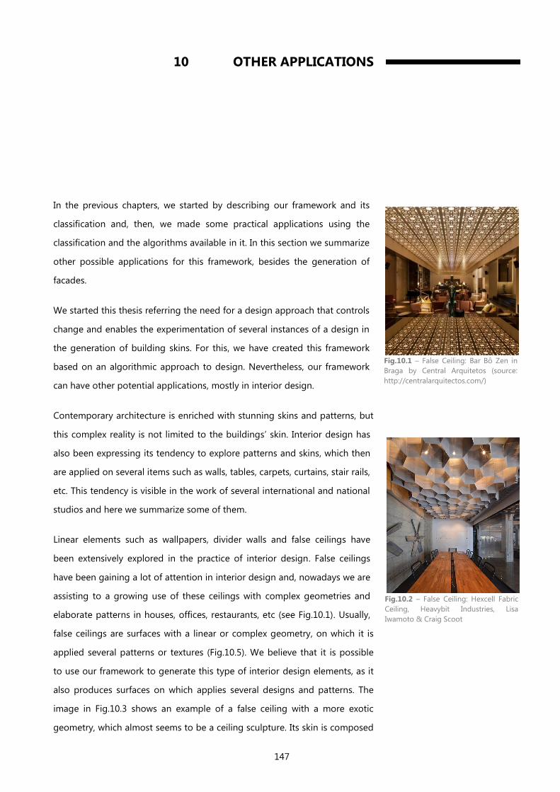
147
10 OTHER APPLICATIONS
In the previous chapters, we started by describing our framework and its
classification and, then, we made some practical applications using the
classification and the algorithms available in it. In this section we summarize
other possible applications for this framework, besides the generation of
facades.
We started this thesis referring the need for a design approach that controls
change and enables the experimentation of several instances of a design in
the generation of building skins. For this, we have created this framework
based on an algorithmic approach to design. Nevertheless, our framework
can have other potential applications, mostly in interior design.
Contemporary architecture is enriched with stunning skins and patterns, but
this complex reality is not limited to the buildings’ skin. Interior design has
also been expressing its tendency to explore patterns and skins, which then
are applied on several items such as walls, tables, carpets, curtains, stair rails,
etc. This tendency is visible in the work of several international and national
studios and here we summarize some of them.
Linear elements such as wallpapers, divider walls and false ceilings have
been extensively explored in the practice of interior design. False ceilings
have been gaining a lot of attention in interior design and, nowadays we are
assisting to a growing use of these ceilings with complex geometries and
elaborate patterns in houses, offices, restaurants, etc (see Fig.10.1). Usually,
false ceilings are surfaces with a linear or complex geometry, on which it is
applied several patterns or textures (Fig.10.5). We believe that it is possible
to use our framework to generate this type of interior design elements, as it
also produces surfaces on which applies several designs and patterns. The
image in Fig.10.3 shows an example of a false ceiling with a more exotic
geometry, which almost seems to be a ceiling sculpture. Its skin is composed
Fig.10.1 – False Ceiling: Bar Bô Zen in
Braga by Central Arquitetos (source:
http://centralarquitectos.com/)
Fig.10.2 – False Ceiling: Hexcell Fabric
Ceiling, Heavybit Industries, Lisa
Iwamoto & Craig Scoot

148
by a pattern similar to one already exemplified in this thesis, more precisely
in Chapter 9, in one of the framework’s application examples. This example
proves that our framework can also be used in the practice of interior design.
Fig.10.3 – False Ceiling: Common Weathers NYSCI, SOFTLab (source:
http://softlabnyc.com/)
Fig.10.4 – The pattern generated by using our framework.
The same happens with wallpapers and wall decorations. Generative design
has been also present in the generation of this type of interior elements, by
showing its potential in the decoration of home interiors, cafés, exhibitions,
etc. In addition, the application of high reliefs in interior walls is a field that
has been re-explored in current architecture and it uses shapes and patterns
based on a parametric approach (see Fig.10.7). In some cases, the textures
applied on the walls are continued to other elements, such as ceilings, floors
and counters, using the same design discourse (pattern) and, sometimes,
using a unique skin that comprises all the elements in an unique surface
(Fig.10.8).
Fig.10.5 – Tsujita LA Ceiling by Takeshi Sano: An image of clouds produced by wooden sticks
with different lengths (source: www.contemporist.com)
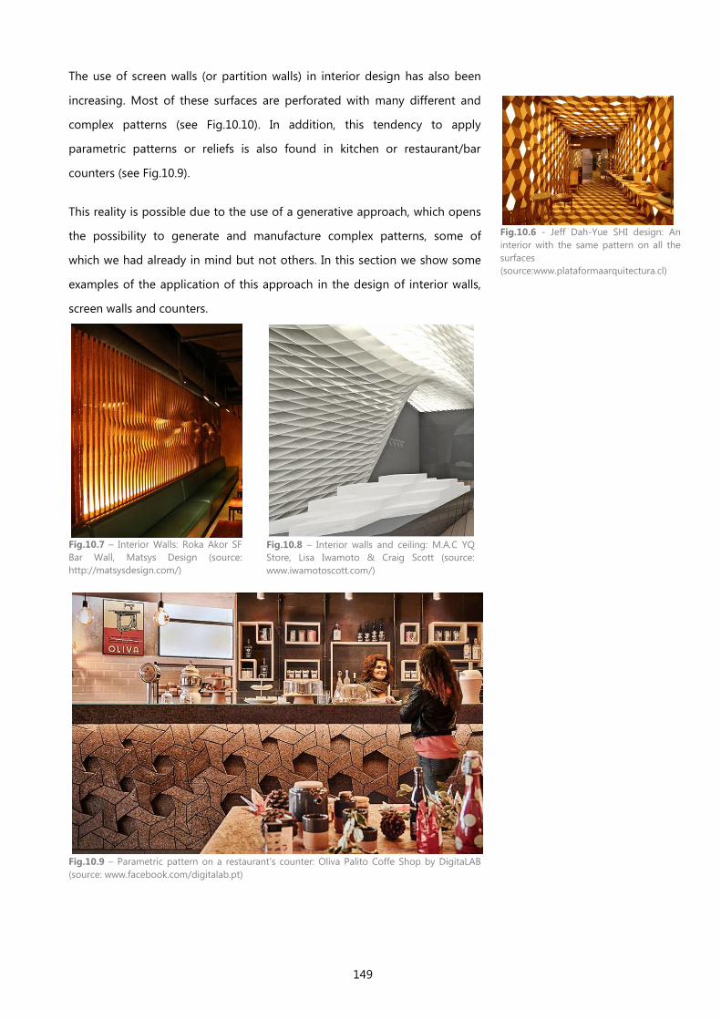
149
The use of screen walls (or partition walls) in interior design has also been
increasing. Most of these surfaces are perforated with many different and
complex patterns (see Fig.10.10). In addition, this tendency to apply
parametric patterns or reliefs is also found in kitchen or restaurant/bar
counters (see Fig.10.9).
This reality is possible due to the use of a generative approach, which opens
the possibility to generate and manufacture complex patterns, some of
which we had already in mind but not others. In this section we show some
examples of the application of this approach in the design of interior walls,
screen walls and counters.
Fig.10.7 – Interior Walls: Roka Akor SF
Bar Wall, Matsys Design (source:
http://matsysdesign.com/)
Fig.10.8 – Interior walls and ceiling: M.A.C YQ
Store, Lisa Iwamoto & Craig Scott (source:
www.iwamotoscott.com/)
Fig.10.9 – Parametric pattern on a restaurant’s counter: Oliva Palito Coffe Shop by DigitaLAB
(source: www.facebook.com/digitalab.pt)
Fig.10.6 - Jeff Dah-Yue SHI design: An
interior with the same pattern on all the
surfaces
(source:www.plataformaarquitectura.cl)

150
Fig.10.10 – Screen wall pattern: Uniopt Pachleitner Group Headquarters by GS Architects
(source: www.archdaily.com)
In practical terms, the application of our framework is similar in both exterior
facades and interior design. Moreover, in interior design practice, we can use
our framework to explore further designs, such as organic patterns, exotic
and intricate geometries, stair rails (Fig.10.11 and Fig.10.12) and several types
of furniture (see Fig.10.14).
To sum up, we believe there is a wide range of objects and elements in
interior design that we can generate using our framework and, in this
section, we have exemplified different types of possible applications.
Fig.10.11 – Parametric Stair Rail + Corian
screen by MARCC FORNES/THEVERYMANY
(source: http://theverymany.com/)
Fig.10.12 – Stair Rails (www.architonic.com)
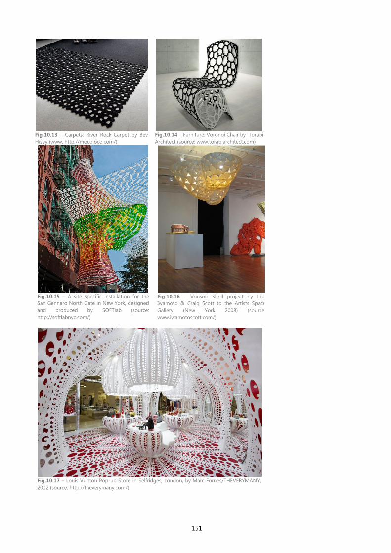
151
Fig.10.15 – A site specific installation for the
San Gennaro North Gate in New York, designed
and produced by SOFTlab (source:
http://softlabnyc.com/)
Fig.10.16 – Vousoir Shell project by Lisa
Iwamoto & Craig Scott to the Artists Space
Gallery (New York 2008) (source:
www.iwamotoscott.com/)
Fig.10.17 – Louis Vuitton Pop-up Store in Selfridges, London, by Marc Fornes/THEVERYMANY,
2012 (source: http://theverymany.com/)
Fig.10.13 – Carpets: River Rock Carpet by Bev
Hisey (www. http://mocoloco.com/)
Fig.10.14 – Furniture: Voronoi Chair by Torabi
Architect (source: www.torabiarchitect.com)

152
153
11 EVALUATION
In this section we make a brief evaluation of the work developed in this
thesis. In a first stage, we developed a methodology to simplify the
generation of building skins. Thus, we felt the need to define a classification
of facades and we agreed to divide it according to the design stages that we
found when using an algorithmic approach. The goal of this classification
was to help the designers in the selection of the algorithms that better suit
their design intent. In a second phase, we applied the algorithms available in
our framework to generate several models as examples, including abstract
and existing facades. In addition, we showed the advantages of using, our
framework, whether in the creation of new skins or in the exploration of
already generated models.
In this chapter we evaluate if our framework is complete and sound. For the
first one, we analyze the framework’s flexibility i.e. the range of design
possibilities and its capacity to generate real facades. We also evaluate the
efficiency of our framework’s practical application, i.e. the time required for
the generation of a facade model.
To evaluate if our work is sound, we compare the time spent in both
traditional and algorithmic approaches: we compare the time required to
generate a model using our framework with the time required when using a
traditional approach. For this, we select two designs of facades, which we
produce using both approaches.
Finally, we evaluate the portability of our framework, i.e. its capacity to
generate the same model in several CAD environments, such as AutoCAD,
Rhino and REVIT. For this, we select another model as an example, which we
then generate by using all supported CAD environments.
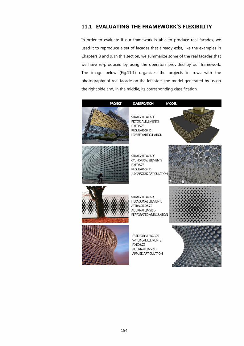
154
11.1 EVALUATING THE FRAMEWORK’S FLEXIBILITY
In order to evaluate if our framework is able to produce real facades, we
used it to reproduce a set of facades that already exist, like the examples in
Chapters 8 and 9. In this section, we summarize some of the real facades that
we have re-produced by using the operators provided by our framework.
The image below (Fig.11.1) organizes the projects in rows with the
photography of real facade on the left side, the model generated by us on
the right side and, in the middle, its corresponding classification.

155
We may conclude from the comparison between the real projects and the
corresponding models (generated using our framework) that we can achieve
a high degree of fidelity.
To evaluate the flexibility of our framework, we have produced several
variations on the designs, i.e. the application of changes to the models for
analyzing different possible results. In addition, these variations
demonstrated the ease and speed with which it is possible to implement
changes in the models. Since the variations produced correspond to different
values given to the design’s parameters, we only have to vary those input
values to test different possible results. This is a great advantage of our
framework and its design approach: we invest some time implementing the
Fig.11.1 - Synthesis of the models produced based on real facades, with their corresponding
classification and real project.
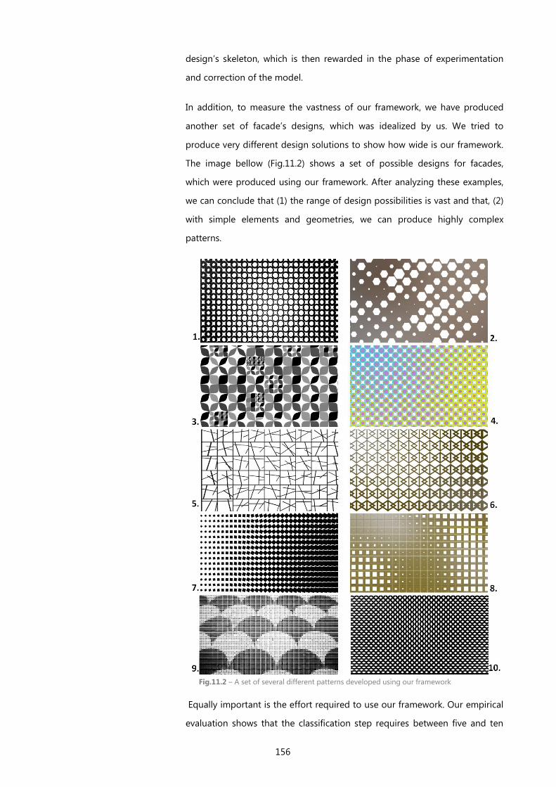
156
design’s skeleton, which is then rewarded in the phase of experimentation
and correction of the model.
In addition, to measure the vastness of our framework, we have produced
another set of facade’s designs, which was idealized by us. We tried to
produce very different design solutions to show how wide is our framework.
The image bellow (Fig.11.2) shows a set of possible designs for facades,
which were produced using our framework. After analyzing these examples,
we can conclude that (1) the range of design possibilities is vast and that, (2)
with simple elements and geometries, we can produce highly complex
patterns.
Fig.11.2 – A set of several different patterns developed using our framework
Equally important is the effort required to use our framework. Our empirical
evaluation shows that the classification step requires between five and ten
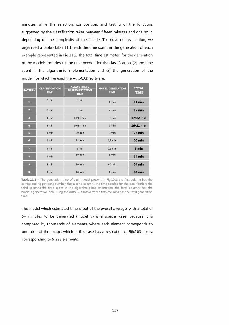
157
minutes, while the selection, composition, and testing of the functions
suggested by the classification takes between fifteen minutes and one hour,
depending on the complexity of the facade. To prove our evaluation, we
organized a table (Table.11.1) with the time spent in the generation of each
example represented in Fig.11.2. The total time estimated for the generation
of the models includes (1) the time needed for the classification, (2) the time
spent in the algorithmic implementation and (3) the generation of the
model, for which we used the AutoCAD software.
PATTERN CLASSIFICATION
TIME
ALGORITHMIC
IMPLEMENTATION
TIME
MODEL GENERATION
TIME
TOTAL
TIME
1. 2 min 8 min
1 min 11 min
2. 2 min 8 min 2 min 12 min
3. 4 min 10/15 min 3 min 17/22 min
4. 4 min 10/15 min 2 min 16/21 min
5. 3 min 20 min 2 min 25 min
6. 3 min 15 min 1,5 min 20 min
7. 3 min 5 min 0.5 min 9 min
8. 3 min 10 min 1 min
14 min
9. 4 min 10 min 40 min 54 min
10. 3 min 10 min 1 min 14 min
The model which estimated time is out of the overall average, with a total of
54 minutes to be generated (model 9) is a special case, because it is
composed by thousands of elements, where each element corresponds to
one pixel of the image, which in this case has a resolution of 96x103 pixels,
corresponding to 9 888 elements.
Table.11.1 – The generation time of each model present in Fig.10.2: the first column has the
corresponding pattern’s number; the second columns the time needed for the classification; the
third columns the time spent in the algorithmic implementation; the forth columns has the
model’s generation time using the AutoCAD software; the fifth columns has the total generation
time
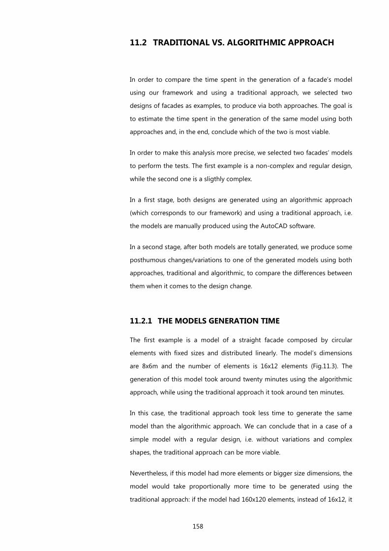
158
11.2 TRADITIONAL VS. ALGORITHMIC APPROACH
In order to compare the time spent in the generation of a facade’s model
using our framework and using a traditional approach, we selected two
designs of facades as examples, to produce via both approaches. The goal is
to estimate the time spent in the generation of the same model using both
approaches and, in the end, conclude which of the two is most viable.
In order to make this analysis more precise, we selected two facades’ models
to perform the tests. The first example is a non-complex and regular design,
while the second one is a sligthly complex.
In a first stage, both designs are generated using an algorithmic approach
(which corresponds to our framework) and using a traditional approach, i.e.
the models are manually produced using the AutoCAD software.
In a second stage, after both models are totally generated, we produce some
posthumous changes/variations to one of the generated models using both
approaches, traditional and algorithmic, to compare the differences between
them when it comes to the design change.
11.2.1 THE MODELS GENERATION TIME
The first example is a model of a straight facade composed by circular
elements with fixed sizes and distributed linearly. The model’s dimensions
are 8x6m and the number of elements is 16x12 elements (Fig.11.3). The
generation of this model took around twenty minutes using the algorithmic
approach, while using the traditional approach it took around ten minutes.
In this case, the traditional approach took less time to generate the same
model than the algorithmic approach. We can conclude that in a case of a
simple model with a regular design, i.e. without variations and complex
shapes, the traditional approach can be more viable.
Nevertheless, if this model had more elements or bigger size dimensions, the
model would take proportionally more time to be generated using the
traditional approach: if the model had 160x120 elements, instead of 16x12, it
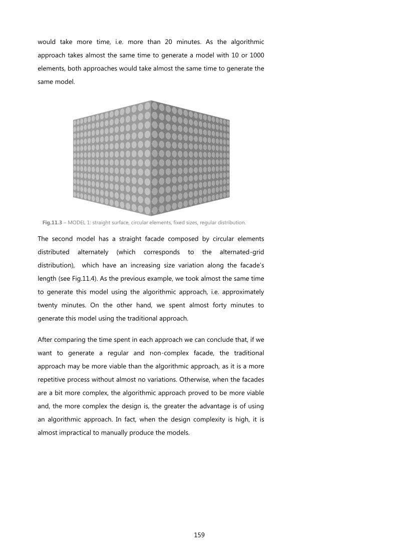
159
would take more time, i.e. more than 20 minutes. As the algorithmic
approach takes almost the same time to generate a model with 10 or 1000
elements, both approaches would take almost the same time to generate the
same model.
Fig.11.3 – MODEL 1: straight surface, circular elements, fixed sizes, regular distribution.
The second model has a straight facade composed by circular elements
distributed alternately (which corresponds to the alternated-grid
distribution), which have an increasing size variation along the facade’s
length (see Fig.11.4). As the previous example, we took almost the same time
to generate this model using the algorithmic approach, i.e. approximately
twenty minutes. On the other hand, we spent almost forty minutes to
generate this model using the traditional approach.
After comparing the time spent in each approach we can conclude that, if we
want to generate a regular and non-complex facade, the traditional
approach may be more viable than the algorithmic approach, as it is a more
repetitive process without almost no variations. Otherwise, when the facades
are a bit more complex, the algorithmic approach proved to be more viable
and, the more complex the design is, the greater the advantage is of using
an algorithmic approach. In fact, when the design complexity is high, it is
almost impractical to manually produce the models.
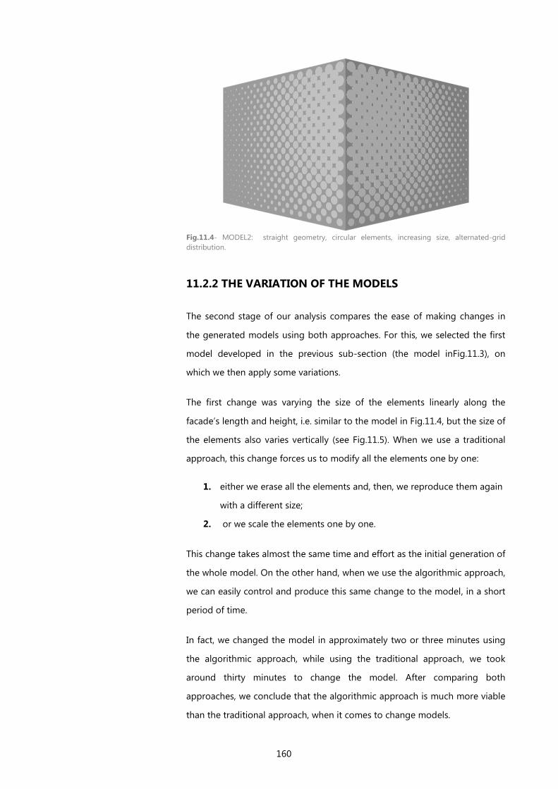
160
11.2.2 THE VARIATION OF THE MODELS
The second stage of our analysis compares the ease of making changes in
the generated models using both approaches. For this, we selected the first
model developed in the previous sub-section (the model inFig.11.3), on
which we then apply some variations.
The first change was varying the size of the elements linearly along the
facade’s length and height, i.e. similar to the model in Fig.11.4, but the size of
the elements also varies vertically (see Fig.11.5). When we use a traditional
approach, this change forces us to modify all the elements one by one:
1. either we erase all the elements and, then, we reproduce them again
with a different size;
2. or we scale the elements one by one.
This change takes almost the same time and effort as the initial generation of
the whole model. On the other hand, when we use the algorithmic approach,
we can easily control and produce this same change to the model, in a short
period of time.
In fact, we changed the model in approximately two or three minutes using
the algorithmic approach, while using the traditional approach, we took
around thirty minutes to change the model. After comparing both
approaches, we conclude that the algorithmic approach is much more viable
than the traditional approach, when it comes to change models.
Fig.11.4- MODEL2: straight geometry, circular elements, increasing size, alternated-grid
distribution.
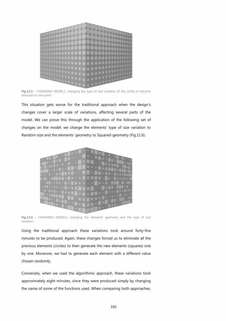
161
Fig.11.5 – CHANGING MODEL1: changing the type of size variation of the circles to became
attracted to one point.
This situation gets worse for the traditional approach when the design’s
changes cover a larger scale of variations, affecting several parts of the
model. We can prove this through the application of the following set of
changes on the model: we change the elements’ type of size variation to
Random-size and the elements’ geometry to Squared-geometry (Fig.11.6).
Fig.11.6 – CHANGING MODEL1: changing the elements’ geometry and the type of size
variation.
Using the traditional approach these variations took around forty-five
minutes to be produced. Again, these changes forced us to eliminate all the
previous elements (circles) to then generate the new elements (squares) one
by one. Moreover, we had to generate each element with a different value
chosen randomly.
Conversely, when we used the algorithmic approach, these variations took
approximately eight minutes, since they were produced simply by changing
the name of some of the functions used. When comparing both approaches,
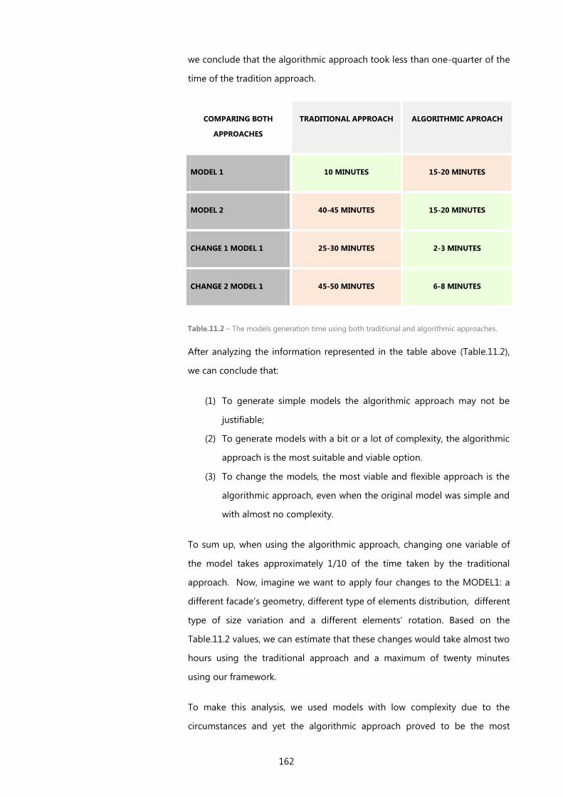
162
we conclude that the algorithmic approach took less than one-quarter of the
time of the tradition approach.
COMPARING BOTH
APPROACHES
TRADITIONAL APPROACH ALGORITHMIC APROACH
MODEL 1 10 MINUTES 15-20 MINUTES
MODEL 2 40-45 MINUTES 15-20 MINUTES
CHANGE 1 MODEL 1 25-30 MINUTES 2-3 MINUTES
CHANGE 2 MODEL 1 45-50 MINUTES 6-8 MINUTES
After analyzing the information represented in the table above (Table.11.2),
we can conclude that:
(1) To generate simple models the algorithmic approach may not be
justifiable;
(2) To generate models with a bit or a lot of complexity, the algorithmic
approach is the most suitable and viable option.
(3) To change the models, the most viable and flexible approach is the
algorithmic approach, even when the original model was simple and
with almost no complexity.
To sum up, when using the algorithmic approach, changing one variable of
the model takes approximately 1/10 of the time taken by the traditional
approach. Now, imagine we want to apply four changes to the MODEL1: a
different facade’s geometry, different type of elements distribution, different
type of size variation and a different elements’ rotation. Based on the
Table.11.2 values, we can estimate that these changes would take almost two
hours using the traditional approach and a maximum of twenty minutes
using our framework.
To make this analysis, we used models with low complexity due to the
circumstances and yet the algorithmic approach proved to be the most
Table.11.2 – The models generation time using both traditional and algorithmic approaches.
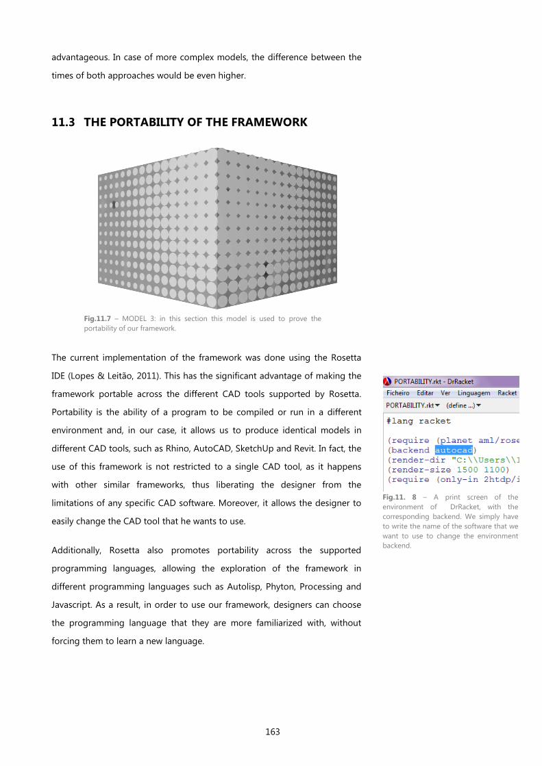
163
advantageous. In case of more complex models, the difference between the
times of both approaches would be even higher.
11.3 THE PORTABILITY OF THE FRAMEWORK
Fig.11.7 – MODEL 3: in this section this model is used to prove the
portability of our framework.
The current implementation of the framework was done using the Rosetta
IDE (Lopes & Leitão, 2011). This has the significant advantage of making the
framework portable across the different CAD tools supported by Rosetta.
Portability is the ability of a program to be compiled or run in a different
environment and, in our case, it allows us to produce identical models in
different CAD tools, such as Rhino, AutoCAD, SketchUp and Revit. In fact, the
use of this framework is not restricted to a single CAD tool, as it happens
with other similar frameworks, thus liberating the designer from the
limitations of any specific CAD software. Moreover, it allows the designer to
easily change the CAD tool that he wants to use.
Additionally, Rosetta also promotes portability across the supported
programming languages, allowing the exploration of the framework in
different programming languages such as Autolisp, Phyton, Processing and
Javascript. As a result, in order to use our framework, designers can choose
the programming language that they are more familiarized with, without
forcing them to learn a new language.
Fig.11. 8 – A print screen of the
environment of DrRacket, with the
corresponding backend. We simply have
to write the name of the software that we
want to use to change the environment
backend.
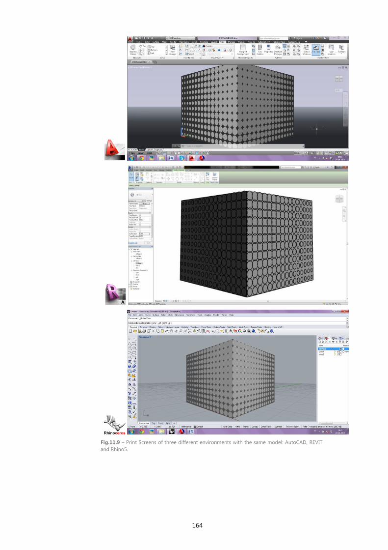
164
Fig.11.9 – Print Screens of three different environments with the same model: AutoCAD, REVIT
and Rhino5.
165
11.4 OTHER EXISTING TOOLS
There are already some tools that attempt to solve the problems here
described, such as the Paneling Tools plug-in for Rhino and Grasshopper, the
Lunch Box add-on to Grasshopper, and ParaCloud Gem, a stand-alone
toolkit that adds generative capabilities to any CAD system that supports
*.obj, *.stl, *.collada, and *.dxf file formats. All of them are capable of creating
grids of points on a surface, mapping elements in different ways, applying
attractors to control elements size, etc.
The nature of their limitations is three-folded: (1) its use is entirely manual,
thus mainly promoting iterative user-driven processes, which can be
tiresome and error-prone; (2) when using such toolkits in the context of an
Application Programming Interface (API) or as plug-ins to a domain-specific
programming language, such as Grasshopper, a certain level of automation
is obtained, however, the designer is always bound to the specific
functionalities provided by the tool, thus limiting its agency in exploring
different combinations of operations and extending the capabilities of the
tool’s pre-defined operations; (3) these tools are more used for generic
panelization, subdivision, and population of surfaces thus, although they
have been used to generate complex facade patterns, they are not fully
architectural oriented which means that they do not directly address relevant
concepts in facade design such as materiality or the tectonic relation
between the facade elements
We should also mention recent domain-specific programming languages,
such as Dynamo for Revit and Grasshopper for Rhino, which allow users to
implement the functionalities proposed in this paper. In addition, some of
the pre-defined components have similar purpose to some of the HOFs
which we presented. However, the freedom of connection allowed by these
tools becomes difficult to manage in complex facades (Leitão, et al., 2012). In
these cases, a more structured and systematic approach like the one we
propose is more manageable.
In summary, with the current framework the architect is limited by the non-
domain specificity of existing tools or in order to extend their capabilities he

166
needs to build from scratch the necessary functionalities or use a mix of
different tools that most of the time are not compatible. This work extends
the state-of-the-art by: (1) systematizing and structuring, in an architectural-
oriented framework, the parametric generation of a wide range of facade
typologies, and by (2) operationalizing it resorting to a simple algorithmic
approach that uses and combines different functional operators that directly
implement facade design concepts.

167
12 CONCLUSION AND FUTURE WORK
12.1 CONCLUSION
The current exploration of architectural facades is not new. However, by
resorting to recent digital technologies, architects can once again focus on
facade design, promoting a growing interest in the exploration of complex
patterns and geometries. Architectural practice has been increasingly
focusing on the expression of buildings skins, which are characterized by
complex geometries, textures and patterns. The majority of these highly
textured facades are produced via a generative approach, however, as only a
small percentage of the architectural studios is already using generative
design, we found this topic of simplifying the generation of facades very
interesting.
This dissestation presents a methodological framework that helps designers
in the generation of different facade designs and geometries. We propose an
algorithmic approach to design that overcomes the limitations of a
traditional approach: The framework is composed by a set of functional
operators and the current implementation was done using the Rosetta IDE
(Lopes & Leitão, 2011), allowing its exploration in different programming
languages and different CAD tools.
In order to systematize and simplify the use of the framework, we propose a
classification of facades based on several categorical dimensions which we
consider to be computationally relevant. These categorical dimensions guide
us in the selection of the functional algorithms that handle each part of the
facade. These might then be used directly, or might be combined using
functional operators, promoting a systematic exploration of designs which
ultimately aims to a higher productivity by: (1) improving the time of
scripting tasks, and (2) adding flexibility to the designers’ workflow. Due to
the simplicity of the functional composition, this framework accommodates
168
the ever-changing nature of a design process by facilitating the test of
several design concepts, or instantiations of the same idea, in any design
stage.
To evaluate the framework, we produced several models of facades with
different designs and several possible variations. These simulations allowed
us to prove the applicability of our framework in the early stages of the
facade’ design, as also in the exploration of the model’s flexibility.
With this evaluation we proved that our framework:
(1) is sufficiently flexible: it accommodates changes previously
anticipated and changes that were not planned, which are our major
focus, because architectural practice is characterize by changes
frequently without being anticipated;
(2) supports complex designs: the creation and experimentation of new
designs using the operators provided by our framework can achieve
both idealized and unthought designs. The framework also achieves a
high level of design fidelity;
(3) increases the range of designs that can be generated and
experimented: when the designs are complex (like the examples
developed in this thesis), it is impractical to use a traditional approach
to generate them because the work becomes too difficult and the time
spent is too large.
(4) is portable: it enables the generation of the same design/model in
different backend, such as AutoCAD, Rhino and REVIT. This promotes
even more possibilities for the end purpose of our framework.
Our proposal do not excludes other approaches for the design process, it
simply is an additional stage specialized in the generation of buildings skins.
Instead, it allows the designer to go farther in the exploration of different
design solution to apply on architectural facades, such as complex
geometries, intricate patterns and new textures.
In the near future, we plan to expand the set of functional algorithms and
operators, covering a wider range of facades. In order to make this
framework more usable, we are particularly interested in conducting a larger
169
field study of its application, to identify weaknesses of the proposed
processes and opportunities for extensions.
12.2 FUTURE WORK
Future work should improve the evaluation and development of the
algorithmic framework for the generation of facades. Below, we present
some topics that might help achieving that goal.
1. Extend the framework and the corresponding facade’s classification
1.1. We developed a classification for facades and also a set of operators
for the generation of facades’ designs. The main aim was to facilitate and
accelerate the generation and exploration of facades’ models. For this, we
created the classification, which was inspired on the most commons designs
and patterns found in contemporary facades. The framework also enables
the implementation of operators for more specific designs, which are not
found in our framework’s space. It will be interesting to pre-define more
operators that will achieve more specific designs and geometries, thereby
increasing the framework’s space and the corresponding classification
(including more categorical dimensions or options within each of the existing
dimensions).
1.2. The framework’s operators were predefined in terms of parametric
functions, however, it will also be interesting to have functionality within our
framework that takes hand-crafted surfaces and, then, translates them into
parametric functions controllable by the designers.
1.3. It will be interesting to organize the framework into a more visually
attractive and friendly application environment, which allowed its use by
designers who are not familiarized with programming languages.
2. Connecting the framework with manufacturing
2.1. The framework was developed to help and facilitate the generation
process of facades models. Thus, in order to further complement the
framework’s application, it will be useful to develop an extension for the
framework that suggests solutions to (1) the structure and (2) the application
170
of the generated models to constitute real facades. This includes the
methods whereby the facades should be applied and fixed, when passing the
stage of the 3D model to the stage of construction.
2.2. We developed this framework with focus on the design process.
However, after the exploration and definition of a facade’s design, there are
always some external factors which influence the design’s final selection,
such as economic factors. It will be interesting to add an extension to the
framework that would be in charge of calculating the estimated cost for the
generated model. This estimate should consider (1) the quantities of the
selected materials, (2) the type of fabrication required to produce each
facade and (3) the approximate time required for its construction.
2.3. Complex designs and geometries sometimes seem to have a rather
difficult fabrication and designers have to look for fabrication processes that
suit their design solutions. Another important feature for the extension of
this framework will suggest the type of fabrication process that best suits
each facade according to its type of design and selected materials.
Briefly, future work can follow three different routes, extending the
classification and the corresponding functional operators, developing new
features to help the passage of the models to the manufacturing phase, or
both.
12.3. CONTRIBUTIONS
This dissertation proves the relevance of generative Design, in particular, the
algorithmic approach, as an auxiliary tool that supports both exploration of
designs and decision-making activities in architectural practice.
In this dissertation we discussed the development of a computational
framework based on an algorithmic approach for the design of facades and
we presented two important contributions.
The first contribution is a classification of facades into different categorical
dimensions that we consider computationally relevant, which was based on
an analysis of a large corpus of contemporary facades.

171
The second one is the identification and implementation of a set of
algorithms and strategies that address the needs of the different dimensions,
generating then different designs of facades.
As the framework uses an algorithmic approach, it is also useful to allow the
exploration of different design solutions with almost no effort and time, only
by combining the functional operators provided by the classification.

173
BIBLIOGRAPHY
Albayrak, C., (2011) Performative Architecture as a Guideline for Transformation of the Defence Line of Amsterdam,
s.l.: Delft University of Technology.
Alfaris, A., (2009) Emergence through conflict: the Multi-Disciplinary Design System (MDDS), s.l.: Massachusetts
Institute of Technology.
Anderson, J. & Tang, M. (2011) Form Follows Parameters: Parametric modeling for fabrication and manufacturing
processes. s.l., CAADRIA.
Arch2o. [Online] Available at: http://www.arch2o.com/re-appreciating-infrastructure-the-may-september-art-
facade-urbana-architects/ [Accessed em 28 Agosto 2014].
ARC239 Parametricism. [Online] Available at: www.arc239parametricism.wordpress.com/author/taf123/ [Accessed
in October 2014]
Barrios, C., (2005) Transformations on Parametric Design Models: A Case Study on the Sagrada Familia Columns.
s.l., Springer- CAAD Futures.
Beeby, T. H., (1977) The Grammar of Ornament/ Ornament As Grammar. VIA III Ornament, pp. 11-29.
Bentley, P.(2010) London's Global University. [Online] Available at:
http://www0.cs.ucl.ac.uk/staff/p.bentley/teaching [Accessed on 07 December 2010].
Bordeleau, A., (2009) Charles Robert Cockerell's architecture and the language of ornaments. The Journal of
Architecture, Volume 14, pp. 465-490.
Borson, B., (2010) Life of an Architect. [Online] Available at: http://www.lifeofanarchitect.com/words-that-
architects-use/
Bukhari, F. A., (2011) A Hierarchical Evolutionary Algorithmic Design (HEAD) System for Generating and Evolving
Buildings Design Models, s.l.: Queensland University of Technology.
Burry, M., (1999) Paramorph. In: Hypersurfaces 2. s.l.:Academy Editions , pp. 78-83.
Burry, M., (2003) Between intuition and process: Parametric design and rapid prototyping.. In: B. Kolarevic, ed.
Architecture in the digital age - design and manufacturing.. s.l.:s.n.
Burry, M. & Murray, (1997) Computer aided architectural design using prametric variation and associative
geometry. Vienna, Austria , ECAADE conference Proceedings.
174
Chouchoulas, O. & Day, A., (2007) Design exploration using a shape grammar with a genetic algorithm. Open
house International Vol 32, 2007 jun.
Crawford, S., (2009) An Architecture of Relationships Built on the Use of Parametric Modeling and Evaluative
Analysis in Design, USA: University of Washington.
Davis, D., (2013) Modelled on Software Engineering: Flexible Parametric Models in the Practice of Architecture.
s.l.:RMIT University.
Designing Buildings. [Online] Available at: http://www.designingbuildings.co.uk/wiki/Beijing_National_Stadium
[Accessed in April 2015].
Dezeen Magazine. [Online] Available at: http://www.dezeen.com/2014/08/29/campus-netzwerk-office-format-elf-
architekten-perforated-aluminium/ [Accessed on 29 August 2014].
Eastman, C., Teicholz, P., Sacks, R. & Liston, K., (2008) BIM Handbook: A guide to Building Information Modeling
for Owners, Managers, Designers, Engineers, and Contractors. 1º ed. New Jersey: John Wiley & SOns, Inc..
Edler, J.,(2005) Communicative Display Skin for Buildings: BIX at the Kunsthaus Graz. In: B. K. &. A. M. Malkawi, ed.
Performative Achitecture Beyond Instrumentality. New York: Spon Press, pp. 150 - 160.
Fasoulaki, E., 2007. Genetic Algorithms in Architecture: a Necessity or a Trend?. [Online] Available at:
http://www.generativeart.com/on/cic/papersGA2007/09.pdf,.
Fasoulaki, E., (2008) Integrated Design: A Generative Multi-Performative Design Approach, s.l.: Massachusetts
Institute of Technology.
Fernandes, R., (2013) Generative Design: a New Stage in the Design Process, Lisboa: Instituto Superior Técnico.
Fouad, S., (2012) Design Methodology: Kinetic Architecture, s.l.: Alexandria University.
Frampton, K. (1983) Towards a Critical Regionalism: Six Points for an Architecture of Resistence. The Anti-
Aesthetic: Essays on Postmodern Culture.
Frascari, M. (1983) The Tell-the-tale Detail. In: J. Deely & M. Lenhart, edits. Semiotics. s.l.:Springer US, pp. 325-336.
Gavra, H. (2013) Contemporary Ornament: from the Object Towards a quasi-object. s.l., IDEA@UdeM 2013.
Gramazio, F. & Kohler, M. (2008) Chapter9. Towards a Digital Materiality . In: B. Kolarevic & K. Klinger, edits.
Manufacturing Material Effects: rethinking Design and Making in Architecture. New York: Routldge, pp. 101 - 118.
Hagan, S., (2008) Digitalia - Architecture and the Digital, The environmental and the Avant-Garde. s.l.:s.n.
Hauer, E., (2004) Erwin Hauer: Continua, Architectural Screens and Walls. s.l.:Princeton Architectural Press.
175
Heikkinen, M. & Kareoja, P., (2011) The Aalto Ornament Studio - Theory as a Design Tool. Helsinki, Filand: Aalto
University School of Engineering.
Heylighen, A. & Martin, G., (2004) That Elusive Concept of Concept in Architecture. Netherlands, Design
Computing and Cognition.
Hudson, R., (2010) Strategies for Parametric Design in Architecture: An application of practice led research., s.l.:
University of Bath, Department of Architecture and Civil Engineering.
Hudson, R., Shepherd, P. & Hines, D. (2011) Aviva Stadium: A case study in integrated parametric design.
International Journal of Architectural computing, Volume 09, pp. 187- 204.
Jabi, W., (2013) Parametric Design for Architecture. London: Laurence King Publishing.
Klinger, K. R.(2008) Chapter2. Relations: Information Exchange in Designing and Making Architecture. In: B.
Kolarevic & K. Klinger, edits. Manufacturing Material Effects: Rethinking Design and Making in Architecture. New
York: Routledge, pp. 25 -36.
Knight, T., (1999) Applications in Architectural design, and Education and Practice, s.l.: NSF/MIT.
Kolarevic, B., (2003) Architecture in the Digital Age - Designing and Manufacturing. London, UK, Spon Press.
Kolarevic, B., (2005) 15. Towards the Performative in Architecture. In: Performative Architecture . Beyond
Instrumentality. s.l.:Spon Press.
Kolarevic, B. & Klinger, K. R., (2008) 1. Manufacturing/ Materials/ Effects. In: B. Kolarevic & K. R. Klinger, edits.
Manufacturing Materials Effects: Rethinking Design and Making in Architecture. New York: Routledge, pp. 5 - 24.
Krish, S., (2013) Generative Design. [Online] Available at: www.generativedesign.wordpress.com
Leitão, A., (2013) Teaching Computer Science for Architecture. s.l., Future Traditions - 1st ECAADE Regional
International Workshop.
Leitão, A., (2014) Improving Generative Design by Combining Abstract Geometry and Higher-Order Proramming.
Kyoto, Japan, CAADRIA.
Leitão, A., Santos, L. & Lopes, J. (2012) Programming languages for generative design: A comparative study.
International Journal of Architectural Computing, 10(1), pp. 139-162.
Loos, A., (1908) Ornament and Crime, Vienna: s.n.
Lopes, J. & Leitão, A., (2011) Portable Generative Design for CAD Applications. Calgary, Canada, s.n.
Lovell, S., (2008) Re-Sampling Ornament. Blueprint, September, p. 34.
176
Lynn, G., (2004) The Structure of Ornament. s.l.:s.n.
McNicholas, M. T., (2006) The Relevance and Transcendence of Ornament: A new Public, s.l.: University of Notre
Dame.
Meagher, M., Maas, D. V. D., Abegg, C. & Huang, J., (2009) Dynamic Ornament: Climatically responsive surfaces
in architectural design. s.l., CAAD Futures.
Miller, K., (2011) Organized Crime: The Role of Ornament n Contemporary Architecture. s.l., ACADIA Regional.
Mitchell, M., (1996) An Introduction to Genetic Algorithms. Cambridge: MIT Press.
Moneo, R., (2001) The Thing Called Architecture. Anyone Corporation New York, pp. 120 - 123.
Moussavi, F. & Kubo, M., (2006) The function of Ornament. s.l.:Actar.
Oxman, R., (2006) Theory and design in the first digital age. In: Design Studies Vol. 27. s.l.:s.n., pp. 229-265.
Pell, B., (2010) The Articulate Surface - Ornament and technology in Contemporary Architecture. s.l.:Birkhauser.
Peters, B., (2007) The Smithsonian Courtyard Enclosure. Nova Scotia, CANADA, s.n.
Phillips, T., (2003) Ornament on Trial. The Architectural Review, April, pp. 79-87.
Rohe, M., (1953) A Speech to IIT (1950). In: P. Johnson, ed. Mies van der Rohe. s.l.:New York: Museum of Modern
Art.
Rozenberg & Salomaa, (1980) The Mathematical Theory of L Systems. New York: Academic Press.
Santos, L., Lopes, J. & Leitão, A., (2012) Collaborative Digital Design: When the architect meets the software
engineer. Prague, Czech Republic, Digital Physicality - Proceedings of the 30th eCAADe Conference.
Schimek, H., Stavric, M. & Wiltsche, A., (2008) The Inteligence of Ornaments: Exploring ornamental ways of
Affordable Non-Standard Building Envelops. s.l., CAADRIA.
Schnädelbach, H., (2010) Adaptive Architecture - A Conceptual Framework, s.l.: University of Nottingham.
Schumacher, P., (2008) Parametricism as Style - Parametricist Manifesto. s.l., s.n.
Semper, G.,(2004) Style in the Technical and Tectonic Arts (originally published in 1860-1863). Los Angeles: Getty
Research Institute.
Shepherd, P., Hudson, R. & Hines, D., (2011) Aviva Stadium: A parametric success. International Journal of
Architectural Computing, Volume 09, no. 2, pp. 167 - 186.
177
Sherman, P., (1962) Louis Sullivan: An Architect in American Thought. s.l.:Prentice-Hall.
Stocking, A., (2009) Generative Design is Changing the Face of Architecture. [Online] Available at:
http://www.cadalyst.com/cad/building-design/generative-design-is-changing-face-architecture-12948
[Accessed in December 2014].
Strehlke, K. & Loveridge, R., (2005) The redefinition of Ornament. s.l., Netherlands, Springer - CAAD Futures.
Sumi, K., (2013) Parametric Design - A new Paradigm in Architecture. [Online] Available at:
https://www.academia.edu/2644485/parametric_design [Accessed in November 2014]
Terzidis, K., (2003) Introduction. In: Expressive Form - A conceptual approach to computational design. s.l.:Spoon
Press, pp. 1 - 8.
Terzidis, K., (2006) Algorithmic Architecture. s.l.:Architectural Press.
Venturi, R., (1966) Complexity and Contradiction in Architecture. s.l.:s.n.
Watts, A.,(2007) Scratching the Surface: New London Facades by London Architects. England: Springer Wien New
York .
Whalley, A., (2005) Chapter2. Product and Process: Performance-Based Architecture. In: B. Kolarevic & A. M.
Malkawi, edits. Performative Architecture - Beyond Instrumentality. s.l.:Spoon Press, pp. 22-40.
Whitehead, H., (2003) Laws of Form. In: B. Kolarevic, ed. Architecture in the Digital Age: Design and Manufacturing
. New York: Spon Press, pp. 82-100.
Woodbury, R., (2010) Elements of Parametric Design. s.l.: Routledge.
Woodbury, R. et al., (2011) Change detection in 3D parametric systems: Human Centered interfaces for change
Visualization. s.l., CAAD Futures.
Related Documents