An Algorithm for Three-Dimensional Voronoi S-Network N. N. MEDVEDEV, 1 V. P. VOLOSHIN, 1 V. A. LUCHNIKOV, 1,2 M. L. GAVRILOVA 3 1 Institute of Chemical Kinetics and Combustion SB RAS, Novosibirsk, Russia 2 Leibniz Institute of Polymer Research, Dresden, Germany 3 Department of Computer Science, University of Calgary, Calgary, Alberta, Canada Received 22 February 2006; Accepted 19 April 2006 DOI 10.1002/jcc.20484 Published online 9 August 2006 in Wiley InterScience (www.interscience.wiley.com). Abstract: The paper presents an algorithm for calculating the three-dimensional Voronoi–Delaunay tessellation for an ensemble of spheres of different radii (additively-weighted Voronoi diagram). Data structure and output of the algorithm is oriented toward the exploration of the voids between the spheres. The main geometric construct that we develop is the Voronoi S-network (the network of vertices and edges of the Voronoi regions determined in relation to the surfaces of the spheres). General scheme of the algorithm and the key points of its realization are discussed. The principle of the algorithm is that for each determined site of the network we find its neighbor sites. Thus, start- ing from a known site of the network, we sequentially find the whole network. The starting site of the network is easily determined based on certain considerations. Geometric properties of ensembles of spheres of different radii are discussed, the conditions of applicability and limitations of the algorithm are indicated. The algorithm is capable of working with a wide variety of physical models, which may be represented as sets of spheres, including computer models of complex molecular systems. Emphasis was placed on the issue of increasing the efficiency of algorithm to work with large models (tens of thousands of atoms). It was demonstrated that the experimental CPU time increases linearly with the number of atoms in the system, O(n). q 2006 Wiley Periodicals, Inc. J Comput Chem 27: 1676–1692, 2006 Key words: algorithm; additively-weighted Voronoi diagram; Delaunay simplex; structure; voids; polydisperse packings; computer models of molecular systems Introduction Wide application of computer simulation techniques in the con- densed matter, material science, and molecular biology stimulates increasing interest in Voronoi–Delaunay method, which is a con- venient technique to study the structure of computer models of various atomic systems. The method allows gaining information both on the mutual location of atoms, and on the interatomic voids. We note only some of the recent researches that utilized the method in its different aspects: the study of the structure of liquids and glasses, 1–4 the problems of crystallization, 5–8 the com- position of granular 9–12 and colloid systems, 13–15 the analysis of complex molecular systems and polymers, 16–19 the study of inter- molecular voids in liquids, 20–22 in lipid membranes, 23–26 in pro- teins, 27–30 and some other interesting applications. 31,32 The method exploits an evident geometrical fact that for each atom in a system of atoms it is always possible to distinguish a part of the space closest to this atom. This region is called the Vor- onoi polyhedron or, in general case, the Voronoi region, and their partitioning, built for all the atoms, is called the Voronoi tessella- tion or Voronoi diagram, see for instance, ref. 33. For the Voronoi tessellation, there exists dual tessellation (Delaunay tessellation), consisting of simplexes (the most simple elements of 3D space)— tetrahedrons, whose vertices are the atoms of the system. These simplexes are called Delaunay simplexes. A significant feature of the Delaunay simplexe is the fact that it determines the simplest interatomic cavity (between four atoms). These tessellations are ba- sic geometrical data for structure investigations. The mathematical foundations of the method were laid by G.F. Voronoi and B.N. Delaunay. The former explored in detail the properties of these tessellations by using analytical methods for lattice systems, and the latter proved the correctness of Voro- noi’s main theorems for random position of points in space. 34–36 At present both tessellations are used successfully in different branches of mathematics, computational geometry, graphics, ge- ography, GIS, and many other applications, where geometrical Correspondence to: N. Medvedev; e-mail: [email protected] Contract/grant sponsor: INTAS Project; contract/grant number: 2001-0067 Contract/grant sponsor: Russian Foundation for Fundamental Research; contract/grant numbers: 01-03-32903 and 05-03-32647 q 2006 Wiley Periodicals, Inc.

Welcome message from author
This document is posted to help you gain knowledge. Please leave a comment to let me know what you think about it! Share it to your friends and learn new things together.
Transcript
An Algorithm for Three-Dimensional Voronoi S-Network
N. N. MEDVEDEV,1 V. P. VOLOSHIN,1 V. A. LUCHNIKOV,1,2 M. L. GAVRILOVA3
1Institute of Chemical Kinetics and Combustion SB RAS, Novosibirsk, Russia2Leibniz Institute of Polymer Research, Dresden, Germany
3Department of Computer Science, University of Calgary, Calgary, Alberta, Canada
Received 22 February 2006; Accepted 19 April 2006DOI 10.1002/jcc.20484
Published online 9 August 2006 in Wiley InterScience (www.interscience.wiley.com).
Abstract: The paper presents an algorithm for calculating the three-dimensional Voronoi–Delaunay tessellation for
an ensemble of spheres of different radii (additively-weighted Voronoi diagram). Data structure and output of the
algorithm is oriented toward the exploration of the voids between the spheres. The main geometric construct that we
develop is the Voronoi S-network (the network of vertices and edges of the Voronoi regions determined in relation
to the surfaces of the spheres). General scheme of the algorithm and the key points of its realization are discussed.
The principle of the algorithm is that for each determined site of the network we find its neighbor sites. Thus, start-
ing from a known site of the network, we sequentially find the whole network. The starting site of the network is
easily determined based on certain considerations. Geometric properties of ensembles of spheres of different radii
are discussed, the conditions of applicability and limitations of the algorithm are indicated. The algorithm is capable
of working with a wide variety of physical models, which may be represented as sets of spheres, including computer
models of complex molecular systems. Emphasis was placed on the issue of increasing the efficiency of algorithm
to work with large models (tens of thousands of atoms). It was demonstrated that the experimental CPU time
increases linearly with the number of atoms in the system, O(n).
q 2006 Wiley Periodicals, Inc. J Comput Chem 27: 1676–1692, 2006
Key words: algorithm; additively-weighted Voronoi diagram; Delaunay simplex; structure; voids; polydisperse
packings; computer models of molecular systems
Introduction
Wide application of computer simulation techniques in the con-
densed matter, material science, and molecular biology stimulates
increasing interest in Voronoi–Delaunay method, which is a con-
venient technique to study the structure of computer models of
various atomic systems. The method allows gaining information
both on the mutual location of atoms, and on the interatomic
voids. We note only some of the recent researches that utilized
the method in its different aspects: the study of the structure of
liquids and glasses,1–4 the problems of crystallization,5–8 the com-
position of granular9–12 and colloid systems,13–15 the analysis of
complex molecular systems and polymers,16–19 the study of inter-
molecular voids in liquids,20–22 in lipid membranes,23–26 in pro-
teins,27–30 and some other interesting applications.31,32
The method exploits an evident geometrical fact that for each
atom in a system of atoms it is always possible to distinguish a
part of the space closest to this atom. This region is called the Vor-
onoi polyhedron or, in general case, the Voronoi region, and their
partitioning, built for all the atoms, is called the Voronoi tessella-
tion or Voronoi diagram, see for instance, ref. 33. For the Voronoi
tessellation, there exists dual tessellation (Delaunay tessellation),
consisting of simplexes (the most simple elements of 3D space)—
tetrahedrons, whose vertices are the atoms of the system. These
simplexes are called Delaunay simplexes. A significant feature of
the Delaunay simplexe is the fact that it determines the simplest
interatomic cavity (between four atoms). These tessellations are ba-
sic geometrical data for structure investigations.
The mathematical foundations of the method were laid by
G.F. Voronoi and B.N. Delaunay. The former explored in detail
the properties of these tessellations by using analytical methods
for lattice systems, and the latter proved the correctness of Voro-
noi’s main theorems for random position of points in space.34–36
At present both tessellations are used successfully in different
branches of mathematics, computational geometry, graphics, ge-
ography, GIS, and many other applications, where geometrical
Correspondence to: N. Medvedev; e-mail: [email protected]
Contract/grant sponsor: INTAS Project; contract/grant number: 2001-0067
Contract/grant sponsor: Russian Foundation for Fundamental Research;
contract/grant numbers: 01-03-32903 and 05-03-32647
q 2006 Wiley Periodicals, Inc.

properties of a system of discrete points given on plane or in the
space have to be explored.33,37,38
The wide utilization of the method to atomic and molecular
systems was started by J. Bernal, who was the first to use the
Voronoi polyhedra to study the structure of disordered packings
of spheres.39–41 However, the representation of atoms as points
(their centers) is not sufficient for some physical problems. Spe-
cifically, when studying the empty interatomic space, one needs
to know not only the coordinates of the centers, but also the radii
of atoms, since it is exactly the van der Waals surfaces of atoms
that determines the boundaries of the voids. Research papers42,43
demonstrated that classic Voronoi polyhedra (built for the system
of centers of atoms) do not result in correct the closest regions of
atoms of different size; they may intersect surfaces of atoms. All
this stimulated the generalization of the classic Voronoi–Delaunay
approach for the system of differently sized spheres.
At first, to take into account radii of atoms, it was suggested
to use radical polyhedra instead of classic Voronoi polyhedra.44
In this case the distance from a point in space to the sphere is
measured by a segment of a tangent to this sphere.45 In mathe-
matics this generalization of Voronoi tessellation is called radi-
cal, weighted, power, or Laguerre one.33,46,47 The radical poly-
hedrons, contrary to the classic Voronoi polyhedrons, do not
intersect the surfaces of the spheres for any system of spheres of
different radii. In this sense they can be reasonably used for
characterization of free volume of atoms.48–53 The advantage of
the radical polyhedrons is their simplicity. To calculate them, a
small modification of algorithms of calculation of classic Voro-
noi polyhedrons is sufficient. The disadvantage lies in the fact
that the proposed method of ‘‘measuring distance’’ to the atom
does not have a clear physical meaning. Nevertheless, this
approach is quite applicable as a simple method of partitioning
space between atoms of different size.
From the physical point of view, it is more accurate to assign
those points in space to the given sphere that, according to the
Euclidian measure, are closer to its surface, than to the surfaces
of other spheres. Such region, determined by the surfaces of
objects, may be denoted as Voronoi S-region.54–56 These
regions, in full analogy with the classic Voronoi polyhedrons,
cover space without gaps and superposition, that is, they form
Voronoi S-tessellation. Such generalization of Voronoi tessella-
tion is well known in mathematics. For a system of spheres it
corresponds to the so called additively-weighted Voronoi dia-
gram.33,57 However, the concept of Voronoi S-region is wider; it
may be determined for objects of any shape, for instance, for
cylinders.58 In physics such kind of regions are known in
kinetics of crystallization, in processes of nucleation and growth.
If nuclei are born in different moments, but all of them grow
with a constant velocity, then final mosaic of the nuclei-filled
space will be the additively-weighted Voronoi diagram, and such
final nuclei are called Johnson–Mehl cells.59–61
The vertices and edges of all Voronoi S-regions of a given sys-
tem form a network, which would be natural to be denoted as Voro-
noi S-network. By construction, it is the navigation map of the
empty interatomic space. Its vertices lie ‘‘in depth’’ between atoms,
and its edges serve as fairways from one vertex to the neighboring
one.54,56,62,63 In other terminology, it represents medial axes for
the voids between the atoms,33 that is, moving along the edges of
the Voronoi S-network we are always maximally removed from the
surfaces of neighboring atoms. This network is the main tool for the
analysis of the empty space within a system of spherical atoms and
any convex objects.58,64
Regardless of its physical significance, Voronoi S-tessellation
has not been used, until recently, to a full extent. The reason is
that the algorithm of calculation of the S-tessellation is more
complicated than that used for the calculation of classic Voronoi
diagram. Dealing with the surfaces of objects, we have to solve
a nonlinear problem (the system of equations of second order in
the case of spheres). Besides, the geometrical properties of a set
of spheres of different radii in some aspects differ significantly
from the properties of a system of discrete points or of equal
spheres. In this paper we solve these problems. We discuss the
properties of a system of spheres of different sizes, and propose
an algorithm, applicable to exploration of the structure and
empty space between spheres.
Many algorithms have been devised for the calculation of
classic Voronoi diagram, and for its multiple generalizations,33,38
see also some recent papers on this issue in refs. 65–68. How-
ever, there are relatively few papers dedicated to the construc-
tion of the Voronoi S-regions. Additive-weighted diagrams have
been explored in sufficient detail only for 2D.69–72 For 3D the
problem provided to be more complicated. The first calculation
of 3D additive-weighted diagram (Voronoi S-network) was per-
formed in an earlier paper54 to explore the structure of voids in
the packings of polydispersed spheres. The idea of algorithm
was borrowed from refs. 73 and 74, where in order to build Vor-
onoi polyhedron, the first vertex is determined initially, and
then, step by step, all the other vertices are found. When calcu-
lating the network, similarly, the starting vertex of the network
is determined first, and all the other vertices and their connectiv-
ity are determined by sequential determination of the neighbors
of the known vertices of the network. The works65,75,76 have
been dedicated to the calculation of 3D additively-weighted dia-
gram, where, specifically the issue of the accuracy of calculating
the vertices of the network is considered. A recent paper77 sug-
gested the algorithm utilizing the idea of sequential determina-
tion of the vertices for the construction of additive-weighted dia-
gram. However, its realization is somewhat different from that
of ours. Besides, it provides for an apparent presentation of seg-
ments of curves and pieces of surfaces representing edges and
faces of Voronoi S-regions as output data, thus helping to visu-
alize Voronoi S-region. Individual Voronoi S-regions are also
calculated for different problems. The papers78–81 are dedi-
cated to the calculation of their volume and surface for molecu-
lar biology. Volume and surface of cavities inside polydisperse
packings of spheres are calculated in ref. 82. A comparative
analysis of characteristics of classic, radical, and Voronoi S-
regions for binary packings of spheres was made in ref. 83. The
volume of the Voronoi S-regions and areas of its faces are inter-
esting physical parameters. They are determined unambiguously
by vertexes of the S-region and radii of atoms. However, we do
not know a simple analytical formula to calculate them; numeri-
cal methods are usually used.77,82,83
The calculation of Voronoi S-network for a system of non-
spherical object in a 3D (straight lines and spherocylinders) was
realized in previous works.58,84 However, the efficiency of the
1677Algorithm for Three-Dimensional Voronoi S-Network
Journal of Computational Chemistry DOI 10.1002/jcc

calculation of the network there turns out to be significantly lower
than that for a system of spheres. It is caused by the fact that the
analytical formula for the calculation of the coordinates of a Vor-
onoi S-network vertex can be obtained only for spheres, while for
the objects of other forms, in general, no explicit formula exists.
That is why the method of numeric determination of vertexes and
step-by-step calculation of edges was developed in ref. 58.
In a previous work85 the algorithm of calculating Voronoi S-
network for a packing of spheres in a cylindrical container is
suggested. In this case, the walls of the cylinder are regarded as
one of the objects of the ensemble, and are used equally for the
calculation of the network. In this particular case it was possible
to receive an explicit formula for the calculation of the Voronoi
vertices between spheres and the cylinder.
Thus, in this paper we propose an algorithm for calculating
Voronoi S-network for a system of spheres of different radii. It
exploits a simple idea of sequential determination of the ver-
texes, which was used earlier for calculation of the classical
Voronoi network64 and Voronoi polyhedra73,74 for systems of
points or identical spheres. Implementation of this idea to
spheres of different radii is not obvious because of specific ge-
ometry of such systems. In the paper we examine geometrical
properties of such systems in detail and also discuss nontrivial
peculiarities of the algorithm, induced by this problem. The pa-
per contains complete geometrical and technical information,
which is necessary for understanding of the algorithm and also
for its independent implementation.
For the first time this algorithm was used in our works54,55 for
studying polydisperse packings of hard spheres. A possibility of
application of the algorithm to systems of overlapping atoms (mo-
lecular systems) has been described in refs. 23 and 86. Recently
the algorithm was used to study voids in computer models of
lipid membranes.23–25 A demonstration program for the calcula-
tion of the Voronoi S-network is accessed at a website.87
In the following section we discuss geometric properties of
spheres of different radii in 3D. Then, the algorithm scheme and
the key steps of the algorithm are discussed. Also, the computa-
tional peculiarities of the algorithm and the problem of increasing
algorithm efficiency to work with large systems are considered.
Preliminary Remarks
System of Balls (Atoms)
Source information for the analysis is a 3D system of balls
(atoms) {A}, where each ball is defined by its Cartesian coordi-
nates and its radius. (We use here a term ‘‘ball’’ instead of mathe-
matical word ‘‘sphere’’ to avoid misunderstanding between objects
of the system and interstitial empty spheres inscribed between
balls). Notation nA stands for the number of balls in the system,
and arrays A and Ra stand for the set of coordinates and radii.
For simplicity we assume that the balls do not intersect each
other. The case of partially overlapping balls can be easily
reduced to the case of nonoverlapping balls, see for instance,
refs. 23, 80, and 82. We do not consider cases when one ball is
located entirely within another one, since such a ball does not
participate in the formation of empty space between the balls.
It is assumed that system {A} is nondegenerate, i.e., an
empty sphere can be tangent simultaneously to no more than
four balls of the system. Regardless of the fact that it is easy to
imagine a multitude of configurations where an empty sphere
can be tangent simultaneously to any number of balls, these con-
figurations are not encountered in models resulting from com-
puter experiment. Such degenerative configurations decompose
into nondegenerate from the infinitely small shift of balls or var-
iation of their radii. The assumption of nondegeneracy of the
system significantly simplifies the algorithm.
In this paper we leave aside the issue of the boundaries of
system {A}. This problem is not relevant for the essence of the
algorithm, and it is easily resolved in each specific case. Thus,
periodic boundary conditions are usually used in the computer
modeling of liquids, and in this case no problems with boundary
atoms arise. If a system has open boundaries, for instance while
examining a single molecule of protein, it suffices to specifically
mark the edges of the Voronoi diagram extending to infinity.
The problem becomes more complicated when the system has a
wall (a container). However, in some special cases, for instance
for balls in a cylinder, or at a flat wall, it is possible to explicitly
take into account the boundary.85
Finally, we assume that system {A} does not contain small
balls in the narrow gap between a pair of larger balls. As
becomes clear from the following, the occurrence of such con-
figurations may result in the disconnection of the Voronoi S-net-
work. By the way, this feature concerns directly to the known
fact that faces of the additive-weighted Voronoi regions may
have ‘‘holes’’.64,80 Fortunately, models of molecular systems, as
a rule, do not have such features. We mention this property of
the system of balls of different sizes, because our algorithm is
intended for the computation of simply connected network.
Auxiliary Geometrical Constructions
First of all, let us discuss the necessary geometrical concepts
and their properties for sets of three and four balls in the space,
since it is crucial for the understanding of the algorithm. The
proofs of the main properties may be found elsewhere, in partic-
ular, in some previous papers,33,57,75 as well as in ref. 64.
Voronoi S-Surface (Voronoi Hyperboloid)
The geometric locus of points, equidistant from the surfaces of
two balls i and j, is defined as Voronoi S-surface (Voronoi
bisector, Voronoi hyperboloid) Hij (see Fig. 1). It divides the
space into two parts, so that points of one half-space are closer
to the surface of their ball than to the surface of the ball in the
other half-space. This surface in 3D represents an axial–symmet-
rical hyperboloid. For balls with equal radii it becomes obvi-
ously a plane.
Voronoi S-Channel
Geometric locus of points equidistant from the surfaces of three
balls i, j, k is defined as Voronoi S-channel and is denoted as
Cijk. It may be represented as a trajectory of movement of the
center of an empty sphere simultaneously tangent to this set of
three balls. S-channel is the common line of intersection of all
1678 Medvedev et al. • Vol. 27, No. 14 • Journal of Computational Chemistry
Journal of Computational Chemistry DOI 10.1002/jcc

the three Voronoi hyperboloids (Hij, Hik, and Hjk) of pairs of these
balls. Below are the necessary properties of Voronoi S-channel.
C1. Voronoi S-channel is simply-connected line. It can beeither nonclosed, i.e., with endpoints extended into infinity, orclosed. The property of the S-channel is substantially utilized in
our algorithm. It is worth noting that for objects of other shape,
for instance cylinders, Voronoi S-channel may not be con-
nected.84 For equal balls, Voronoi S-channel is apparently a
straight line, and for different balls nonclosed channel is a hy-
perbole, and a closed one is an ellipse. (Parabola and circle are
also possible for degenerate configurations.) Figure 2 demon-
strates Voronoi S-channels and corresponding configurations of
sets of three balls. Three types of configurations may be distin-
guished: (a) planar, with nonclosed channel; note that each of
these configurations has two tangential planes; (b) nonplanar,
with closed channel, without a tangential plane, and finally, (c)
configurations without S-channel.
It is worth mentioning that in 2D, when the Voronoi S-chan-
nel is determined by two disks, S-channels exist for any pair of
disk. Besides, in 2D S-channels may be only nonclosed. This
determines the significant difference between additively-weighted
Voronoi diagrams in 2D and 3D.
C2. Voronoi S-channel is symmetrical in relation to the cen-tral plane for the given set of three balls. This useful property
of the S-channel reflects the symmetry of any set of three balls
in relation to its central plane, i.e., the plane passing through the
centers of these spheres (Fig. 2).
It is convenient to define radius of Voronoi S-channel. It is
determined at each point of the channel and is equal to the dis-
tance from this point to the surfaces of the balls. In other words,
it is the radius of a sphere with the center at this point tangent
to the set of three balls. The minimal value of this radius deter-
mines the bottleneck on S-channel. The following property is
important for applications of the method, since it determines the
location of the bottleneck in the channel.
Figure 1. Two-dimensional illustration of Voronoi S-surface for
two balls of different radii. It divides the space into two parts.
Points of one part of space are located closer to the surface of the
first ball, and points of the other one are closer to surface of the sec-
ond ball. For any point p on this surface the difference of distances
from this point to the centers of the balls (R1 þ r) – (R2 þ r) ¼R1 � R2 is a constant value, i.e., Voronoi S-surface is a hyperboloid
(hyperbole in 2D case).
Figure 2. Different types of configurations of sets of three balls and
corresponding Voronoi S-channels. (a) Planar set of three balls (one
that may be placed on a plane) has a nonclosed channel. (b) Nonpla-
nar set of three balls with a closed channel. (c) Configuration with-
out channels. Voronoi S-channel is always symmetrical in relation
to the central plane of the set of three balls. [Color figure can be
viewed in the online issue, which is available at www.interscience.
wiley.com.]
1679Algorithm for Three-Dimensional Voronoi S-Network
Journal of Computational Chemistry DOI 10.1002/jcc
C3. Bottleneck on the Voronoi S-channel is realized at thepoint of its intersection with the central plane of the given set ofthree balls. If S-channel is nonclosed, it intersects the central
plane only in one point, where bottleneck is realized. We shall
call this point the beginning point (beginning) of Voronoi S-
channel. Upon moving away from this point the radius of the
channel, apparently, steadily grows.
If S-channel is closed, it intersects the central plane twice. At
that, the minimum value of the S-channel radius is to be realized
in one point, and the maximum value in the other. We also call
the first point as the beginning point (beginning), and the second
as end point (end) of the Voronoi S-channel.
Voronoi S-Vertex
It is known from elementary geometry that two nonoverlapping
spheres, when touching, are tangent at one common point. It also
known that four noncoplanar points in space uniquely determine a
sphere. This means that a set of four balls in space specifically fixes
the empty sphere tangent to all four balls in the space enclosed by the
four balls. The center of this sphere is defined as Voronoi S-vertex
for the given set of four spheres. For balls i, j, k, l it is denoted asVijkl.
The following simple but significant property of Voronoi S-
vertex is utilized in the algorithm.
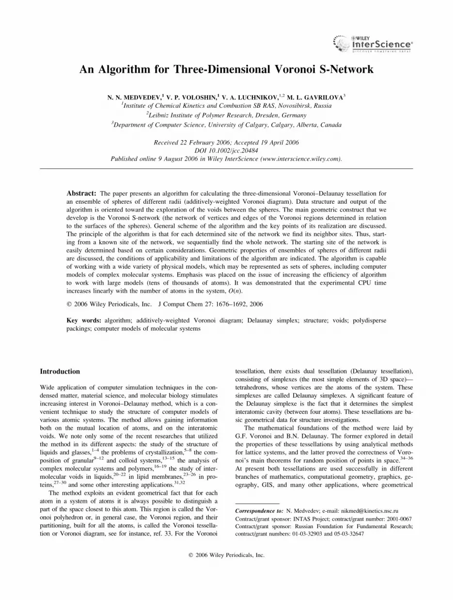
V1. Exactly four Voronoi S-channels intersect in each Voro-noi S-vertex. Indeed, a set of four balls i, j, k, l determines four
different sets of triplets of balls: i, j, k, y, i, j, l, y, i, k, l, and j, k, l, eachone with its Voronoi S-channel: Cijk, Cijl, Cikl, and Cjkl. The cen-
ter of the empty sphere tangent to all the four balls has to be
located simultaneously at each of these channels, and this means
that all the four channels intersect in this point (see Fig. 3). It is
worth mentioning that this statement is true not only for spheres,
but also for any convex bodies. A convex body, for instance a
cylinder or an ellipse, just like a sphere, has only one point of
contact with the empty sphere. That is why in this case, too, a
set of four bodies determines the tangent sphere, and therefore,
the four Voronoi S-channels converging in its center.
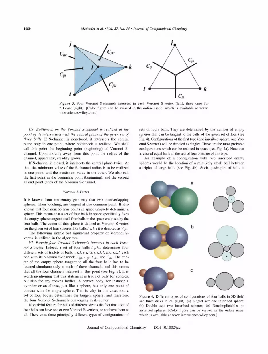
Nontrivial feature for balls of different size is the fact that a set of
four balls can have one or two Voronoi S-vertices, or not have them at
all. There exist three principally different types of configurations of
sets of fours balls. They are determined by the number of empty
spheres that can be tangent to the balls of the given set of four (see
Fig. 4). Configurations of the first type (one inscribed sphere, one Vor-
onoi S-vertex) will be denoted as singlet. These are the most probable
configurations which can be realized in space (see Fig. 4a). Note that
in case of equal balls all the sets of four ones are of this type.
An example of a configuration with two inscribed empty
spheres would be the location of a relatively small ball between
a triplet of large balls (see Fig. 4b). Such quadruplet of balls is
Figure 3. Four Voronoi S-channels intersect in each Voronoi S-vertex (left), three ones for
2D case (right). [Color figure can be viewed in the online issue, which is available at www.
interscience.wiley.com.]
Figure 4. Different types of configurations of four balls in 3D (left)
and three disks in 2D (right). (a) Singlet set: one inscribed sphere;
(b) Double set: two inscribed spheres; (c) Nonsimpliciable: no
inscribed spheres. [Color figure can be viewed in the online issue,
which is available at www.interscience.wiley.com.]
1680 Medvedev et al. • Vol. 27, No. 14 • Journal of Computational Chemistry
Journal of Computational Chemistry DOI 10.1002/jcc

denoted as doublet, and the corresponding pair of Voronoi S-
vertices as doublet vertices. Occurrence of such configurations is
not fatal for the method application. Both doublet S-vertices
may be considered as equivalent. Such configurations occur
quite often in the models of molecular systems. Configurations
of the third type (see Fig. 4c) are obtained when relatively small
balls ‘‘hide’’ from each other at different sides of the big one.
We refer to such configurations as nonsimpliciable (not resulting
in Delaunay S-simplex; see later).
Voronoi–Delaunay S-Tessellation
(Voronoi Additive-Weighted Diagram)
Having considered geometry for two, three, and four balls, we
now move on to the system of many balls.
Voronoi S-Region
Voronoi additively-weighted or S-region for a system of balls is
a region of space whose points are closer to the surface of a
given ball than to the surfaces of other balls of this system. The
faces of the Voronoi S-region are represented by pieces of Voro-
noi hyperboloids, the edges are segments of Voronoi S-channels,
and the vertices are Voronoi S-vertices of the quadruplets of
balls whose S-regions meet in this vertex (see Fig. 5).
Voronoi S-region is a generalization of the Voronoi polyhe-
dron known for a system of discrete points. For systems of balls
of equal size they identically coincide. However, in a general
case of different balls, the faces and edges of the S-region are
curves; moreover, some topological properties may differ from
the properties of the classical polyhedrons: specifically, there are
dihedrons (two faces without vertex), trihedrons (two vertices
with three diangular faces), as well as, in theory, there may exist
arbitrarily complex formations combining all the above-men-
tioned characteristics; see for instance, refs. 64 and 80. Study of
Voronoi S-regions presents a separate topic of research. In this
paper we focus on another aspect of the problem.
Voronoi S-Tessellation
Voronoi S-regions generated for all the balls of the system cover
space without gaps or overlapping, resulting in the partition (tes-
sellation) of space. In analogy with the classic Voronoi tessella-
tion, four Voronoi S-regions converge in each vertex, and three
at each common edge. For a system of balls this construction is
the known in mathematics additively-weighted partition, which
is determined for a system of discrete points (centers) by substi-
tuting the Cartesian measure of distance ri between a point in
space and the center i with riaw ¼ ri þ Wi, that is a constant
value Wi, individual for each center of the system. Additive-
weighted partition will coincide with S-tessellation if the value
of the radius of the ball is taken as Ri ¼ �Wi.
Delaunay S-Simplex
In analogy with the classic Voronoi tessellation, a dual partition
occurs here too. In this case a simplicial quadruplet of balls is
determined by the Voronoi S-regions, sharing a common vertex.
Centers of these balls are vertices of Delaunay S-simplex.
Empty space between the balls is occupied by an inscribed (in-
terstitial) sphere. This sphere is an important characteristic of
the S-simplex.
It should be emphasized that Delaunay S-simplex is a tetra-
hedron with flat faces. They differ from classic Delaunay sim-
plexes only in that they may correspond to different balls of the
system (see Fig. 6).
Note that M. I. Karavelas,71 working in a 2D space, defines a
dual element of Voronoi S- tessellation somewhat differently. Its
vertices are chosen in the same way; however, the edges are
curves. Such elements realize partition of a system of disks
without gaps or overlapping. However, a simplex with flat faces
is more convenient for physical application regardless of some
difficulties with the partition (see below).
Delaunay S-Covering
The sum total of all Delaunay S-simplexes constructed for a
given system of balls forms a mosaic covering the entire space.
In this aspect S-simplexes are similar to classic Delaunay sim-
plexes. A difference between them is that in some cases Delau-
nay S-simplexes can overlap. This happens, in particular, due to
the existence of doublet quadruplets of spheres; that is close
Figure 5. 2D illustration of Voronoi S-region: closed region around
a central disk (solid line). Dotted line depicts Voronoi polyhedron
built for the centers of the spheres.
Figure 6. Partition of configurations shown in Figure 5 into Delau-
nay S-simplexes (left) and classic Delaunay simplexes (right). They
may be determined by different atoms.
1681Algorithm for Three-Dimensional Voronoi S-Network
Journal of Computational Chemistry DOI 10.1002/jcc

proximity of small balls to big ones (see Fig. 7). It should be
emphasized that S-simplexes may superimpose, but there are no
gaps between them. So, one can say that they form a covering
of space, but not a tessellation in the strict mathematical sense.
In a previous work71 this issue is resolved in 2D; however, for
3D space this question has not yet been researched in detail.
The fact that S-simplexes may superimpose should be taken
into consideration in applications while calculating the volume
of the void as the sum of empty volumes of Delaunay S-sim-
plexes. Our experience shows that superimposing simplexes do
occur in the models of molecular systems, but it happens rarely.
The error in the calculation of the volume of system as the sum
of volumes of all Delaunay S-simplexes amounts to tenths of
percent.23 If superimposing S-simplexes are essential for a prob-
lem, it is not difficult to establish all of them; for instance, by
marking them while plotting Voronoi S-network.
Voronoi S-Network
Voronoi S-network is a grid of vertices and edges of Voronoi S-
regions. It is depicted by solid lines in Figure 5. Voronoi S-net-
work fully determines the entire Voronoi-Delaunay S-tessellation
of the system and is a convenient way of presenting geometric
data for solving physical problems. In the course of working with
networks, the words ‘‘site’’ and ‘‘bond’’ are typically used instead
of ‘‘vertex’’ and ‘‘edge.’’ Thus, each vertex of Voronoi S-tessella-
tion is a site of the Voronoi S-network, and each edge is a bond.
General Properties of Voronoi S-Network
The following are the properties of Voronoi S-network that are
explicitly or implicitly used in our algorithm.
N1. Each site of Voronoi S-network is a center of an intersti-tial sphere determining Delaunay S-simplex in the given system ofballs. This statement allows to connect a Delaunay S-simplex
(quadruplet of atoms) to a single point (site of the Voronoi net-
work). Because of this, any task of studying spatial distribution of
the simplicial quadruplets of atoms can be converted to studying
clusters of sites on the network (site-percolation problem).88,89
N2. Exactly four bonds converge in each site of Voronoi S-net-work. This statement follows from the property V1 of Voronoi S-
vertex (see earlier). It means that any Voronoi S-network (as sim-
ply connected as well as unconnected) has the power of all vertices
equal to four in complete analogy with the classic Voronoi net-
work. It is worth mentioning that Voronoi S-network for system of
any nonspherical convex bodies has the same feature.58,64 It should
be remembered that we deal with nondegenerate systems.
N3. Each bond of the Voronoi S-network is a fairway on theway between the neighboring sites. This statement reflects
the fact that each bond of Voronoi S-network is a segment of
the Voronoi S-channel. This property guaranties that the most
‘‘passable’’ ways between the atoms are realized only along the
bonds of the Voronoi S-network.62,63,82
Peculiarities of Voronoi S-Network
First of all, we recall that bonds of the S-network are segments
of curves as distinct from classic Voronoi network where they
are segments of straight lines. However, this fact does not play a
major role in many applications. In particular, for interatomic
space analysis it can be suffice to know the radius of the bottle-
neck at the bond, while the functional type of the representing
segment of curve is not that important.62,90
A more significant fact is that the topology of S-network may
differ from the topology of the classic one (see Fig. 8). It can
have binomial cycles not possible in classic case. Such cycles are
manifestations of Voronoi doublet S-vertices (see above). We
shall call them doublet sites. This, however, does not result in
crucial complication of the network. Doublet sites have the same
characteristic as ordinary singlet sites. Each of them is the center
Figure 7. 2D illustration of superimposing Delaunay S-simplexes.
The simplex formed by disks 2, 3, and 4, is located inside the sim-
plex formed by disks 1, 2, and 3.
Figure 8. Binomial cycles in Voronoi S-network (right). Configura-
tions of balls resulting in such cycles (left): a small ball in the nar-
row channel between a triplet of large balls and two small balls
between a pair of large ones. [Color figure can be viewed in the
online issue, which is available at www.interscience.wiley.com.]
1682 Medvedev et al. • Vol. 27, No. 14 • Journal of Computational Chemistry
Journal of Computational Chemistry DOI 10.1002/jcc
of its interstitial sphere, and four bonds of the network converge
in each of them. The only peculiarity lies in the fact that the same
quadruple of spheres corresponds to both of them.
An unpleasant characteristic of Voronoi S-network is that, in
general case, it can be unconnected, that is, it can consist of sep-
arate fragments not connected with bonds to each other. Discon-
nectedness occurs when one (or many) small ball happens to be
located between a pair of big balls (see Fig. 9). It is worth not-
ing that this happens only in a 3D case; Voronoi S-network is
always simply connected on the plane.
Our algorithm calculates only the simply connected part of
the network (see later). However, it can be used to find all the
isolated parts of the network. To determine whether the S-net-
work is simply connected, it is sufficient to check whether, after
it has been plotted, any ‘‘unused’’ balls of the system {A}remain, but did not take part in the construction of the network.
If all the balls of the system took part in the construction of the
network, the S-network is simply connected and fully represents
the Voronoi-Delaunay S-tessellation of the system. If a sub-sys-
tem of unutilized spheres was left, we can apply our algorithm
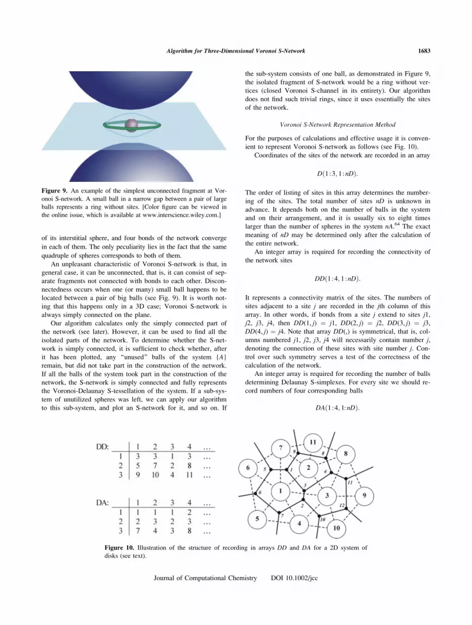
to this sub-system, and plot an S-network for it, and so on. If
the sub-system consists of one ball, as demonstrated in Figure 9,
the isolated fragment of S-network would be a ring without ver-
tices (closed Voronoi S-channel in its entirety). Our algorithm
does not find such trivial rings, since it uses essentially the sites
of the network.
Voronoi S-Network Representation Method
For the purposes of calculations and effective usage it is conven-
ient to represent Voronoi S-network as follows (see Fig. 10).
Coordinates of the sites of the network are recorded in an array
Dð1 :3; 1 :nDÞ:
The order of listing of sites in this array determines the number-
ing of the sites. The total number of sites nD is unknown in
advance. It depends both on the number of balls in the system
and on their arrangement, and it is usually six to eight times
larger than the number of spheres in the system nA.64 The exact
meaning of nD may be determined only after the calculation of
the entire network.
An integer array is required for recording the connectivity of
the network sites
DDð1 :4; 1 :nDÞ:
It represents a connectivity matrix of the sites. The numbers of
sites adjacent to a site j are recorded in the jth column of this
array. In other words, if bonds from a site j extend to sites j1,j2, j3, j4, then DD(1, j) ¼ j1, DD(2, j) ¼ j2, DD(3, j) ¼ j3,DD(4, j) ¼ j4. Note that array DD(,) is symmetrical, that is, col-
umns numbered j1, j2, j3, j4 will necessarily contain number j,denoting the connection of these sites with site number j. Con-trol over such symmetry serves a test of the correctness of the
calculation of the network.
An integer array is required for recording the number of balls
determining Delaunay S-simplexes. For every site we should re-
cord numbers of four corresponding balls
Figure 9. An example of the simplest unconnected fragment at Vor-
onoi S-network. A small ball in a narrow gap between a pair of large
balls represents a ring without sites. [Color figure can be viewed in
the online issue, which is available at www.interscience.wiley.com.]
Figure 10. Illustration of the structure of recording in arrays DD and DA for a 2D system of
disks (see text).
DAð1 :4; 1:nDÞ:
1683Algorithm for Three-Dimensional Voronoi S-Network
Journal of Computational Chemistry DOI 10.1002/jcc

It represents an incidence matrix for the sites and balls of a sys-
tem. The indexes of balls incident to the j site of the network
are recorded in the jth column of the array. Thus, if site j is a
Voronoi S-vertex for balls number A1, A2, A3, A4, then DA(1, j) ¼A1, DA(2, j) ¼ A2, DA(3, j) ¼ A3, DA(4, j) ¼ A4.
The radii of interstitial spheres are computed in the process
of algorithm application and are recorded in an array
Rið1 :nDÞ:
At the calculation of the network it is convenient to calculate
straight away the values of bottlenecks of the bonds, and to re-
cord them in an array
Rbð1 :4; 1 :nDÞ:
It has the structure similar to array DD(,), that is, the radii of
bottlenecks corresponding to the bonds originating from the jsite of the network are recorded in jth column.
Algorithm Scheme
Our algorithm realizes the simple idea of sequential determina-
tion of the sites of Voronoi S-network. First, based on certain
considerations, the first site of the network is determined. Then
neighboring sites are located, and so on, step-by-step, neighbor-
ing sites join the established ones. The procedure continues until
all neighbors are determined for each site.
For simply connected network such sequential determination
of sites will inevitably result in the determination of all the sites of
the network. However, as discussed above, there are systems of
spheres where Voronoi S-network is not simply connected (see
Peculiarities of Voronoi S-Network). In this case, evidently, our
algorithm will generate that simply connected piece of the Voronoi
S-network, to which the starting site of the network belonged.
Figure 11 demonstrates the scheme of the algorithm indicating
the main stages of the calculation. The first nontrivial step of the
work is the determination of the starting site of the network; it is
convenient to distinguish it in a separate block (BLOCK1). After
the determination of the starting site, the rest of the work can be
compactly combined in one block (BLOCK2), where for each of
the newly determined site (cycle in sites), all the bonds, originat-
ing in this site are examined (cycle in bonds), and for each such
bond (Voronoi S-channels) a new site is found by sorting the
atoms of the system (cycle in atoms). The bulk of the computa-
tional effort of the algorithm is the determination of Voronoi S-
vertexes, that is, the finding of an inscribed sphere between a ran-
dom quadruple of balls. This is realized as a separate subroutine
SPHERE (see later). For the determination of Voronoi S-channel
the CIRCLE procedure is used, which finds the circle tangent to
the three balls and located in the central plane of these balls.
Key Steps of the Algorithm
Procedure SPHERE
Procedure SPHERE finds an inscribed sphere (spheres) between
a random quadruple of different-sized balls, that is, it solves the
Apollonian problem in a 3D space. The answer is obtained
through solving a system of equations
ðx� xiÞ2 þ ðy� yiÞ2 þ ðz� ziÞ2 ¼ ðRþ RiÞ2; i ¼ 1; 2; 3; 4 (1)
where xi, yi, zi, and Ri are the coordinates of the centers and radii
for a given quadruple of balls, and x,y,z and R are coordinates of
the center and radius of the sought inscribed sphere. This system
is solved in an explicit form. Subtracting, for instance, the first
equation from the rest, we can obtain a system of linear equations
for three variables. By solving it, we express these variables
through the fourth one. As a result, the coordinates of the center
of the sought sphere may be represented as follows
x ¼ A1Rþ B1
Det; y ¼ A2Rþ B2
Det; z ¼ A3Rþ B3
Det; (2)
Here variables Ai, Bi (i ¼ 1,2,3), and Det depend only on the
coordinates and radii of the original quadruple of balls. By sub-
stituting these expressions into the first equation we get a square
expression for R, the solution of which is represented by the fol-
lowing formula
R ¼ �G�ffiffiffiffiffiffiffiffiffiffiffiffiffiffiffiffiffiffi
G2 � EFp
E; (3)
Figure 11. The scheme of the Voronoi S-network generation.
1684 Medvedev et al. • Vol. 27, No. 14 • Journal of Computational Chemistry
Journal of Computational Chemistry DOI 10.1002/jcc

where variables G, F, and E also depend only on the original
quadruple of spheres. By substituting the determined value of Rin formulas (2), we find the required coordinates of the center.
Expression (3), depending on the configuration of the
spheres, gives one, two, or none real solutions for R. This resultserves as an analytical confirmation of the existence of three
types of configurations of quadruples of balls shown in Figure 4.
For our problem, evidently, only positive values of R make
sense. Negative values of R determine a sphere circumscribed
about a quadruple of balls, while complex values mean that it is
impossible to inscribe a sphere between this quadruple of balls.
In spite of eq. (1) being a task of elementary geometry, we do
not know general geometrical books where it was examined. For
details of the solution of system (1) and ways of improving the
accuracy of the solution refer to refs. 64 and 69.
Procedure CIRCLE
Procedure CIRCLE for a triple of random balls finds a circle
(sphere) inscribed between them and located in the central plane
of these three balls. To do this, the following system of equation
is solved
ðx� xiÞ2 þ ðy� yiÞ2 þ ðz� ziÞ2 ¼ ðRþ RiÞ2; i ¼ 1; 2; 3
P1xþ P2yþ P3z ¼ P0: (4)
Here too, xi, yi, zi, and Ri are the coordinates of the centers of
balls and radii of the given quadruple of balls, and x, y, z and Rare the coordinates of the center and the radius of the sought
circle. The latter equation is the equation of the central plane,
where all the coefficients Pk (k ¼ 0,1,2,3) are expressed by the
usual way through the coordinates of the centers of the given tri-
ple of balls. System (4) is solved in an explicit form similarly to
system (1), whereby the required coordinates of the center of the
circle and its radius are defined by formulas similar to (2) and
(3). As a result, for the radius of the sought circle also one, two,
or none solutions are possible, depending on the specific values
of the coordinates and radii of the balls. Unique solution means
that the given set of three balls has Voronoi S-channel that inter-
sects the central plane once (nonclosed channel). The point
obtained (x, y, z) is the beginning point of the S-channel, and
variable R determines its bottleneck radius (see Preliminary
Remarks). The existence of two positive solutions for the radius
of the sought circle means that S-channel is closed. The center
of the circle of smaller radius R1 represents the beginning point
of this channel and determines the bottleneck at this channel.
The center of the larger circle determines the ending point of
the channel. Corresponding value of radius R2 is the maximum
value of radius for this S-channel. Absence of positive solutions
for R signifies that the given set of three spheres does not have
the Voronoi S-channel. Possible types of triples of balls and cor-
responding channels are shown in Figure 2.
Determination of the First Site of Voronoi
S-Network: BLOCK1
The first (starting) site for the generation of the Voronoi S-network
can be any one of its sites. For simplicity, we choose this site closer
to the center of the system (away from borders) and make sure that
it is not doublet. All this can be easily done by the selection of the
starting ball in the procedure of searching for the first site.
Thus, the first site of Voronoi S-network is determined as
follows:
1. We choose in the system {A} a ball i.2. Sorting through all the other balls of the system, we find
among them ball j, such that the distance between the surfa-
ces of balls i and j were minimal among all the distances
between the ball i and any other ball of the system.
3. Sorting through the remaining balls, we find among them a
ball k, such that the radius of the Voronoi S-channel bottle-
neck for the triple i, j, k were minimal. Procedure CIRCLE
is utilized for the solution of this problem.
4. Sorting through the remaining balls we find among them a
ball l, such that the sphere inscribed between balls i, j, k, lhad a minimum radius. Procedure SPHERE is utilized here.
The quadruple of balls found in this way i, j, k, l forms a
Delaunay S-simplex for system {A}, and the center of the found
sphere is the sought site of the Voronoi S-network. The proof of
correctness of such a method of finding the first site of the S-
network may be presented similarly to the way it had been done
for the calculation of the classic Voronoi network.64
After the determination of the first site we can write its coor-
dinates x,y,z into array D, numbers of balls i,j,k,l incident to this
site, into array DA, and radius ri of the determined inscribed
sphere into Ri. Symbolically it can be represented as follows:
Dð�; 1Þ ¼ ðx; y; zÞDAð�; 1Þ ¼ ði; j; k; lÞRið1Þ ¼ ri:
Determination of the New Sites: BLOCK2
Calculation of a New Site
After the first site is determined, we can proceed to the determi-
nation of the remaining sites of the network. Thus, let us assume
that we know a site Vijkl, with corresponding balls i, j, k, l. FourVoronoi S-channels originate from this site: Cijk, Cijl, Cikl, and
Cjkl. Let us assume, for instance, that the neighboring site has
not yet been determined at channel Cijk. Our task is to find this
neighboring site, that is to select a ball m, which, together withballs i,j,k has an empty inscribed sphere.
To find the neighboring site it is convenient to use the con-
sideration that this site is the Voronoi S-vertex which is closest
to a given original site. Thus, we have to find such ball m of the
system {A}, which, together with balls i, j, k produces S-vertex
Vijkm closest to the starting site Vijkl. It must be emphasized that
all the Voronoi S-vertices, in which the triple of balls i, j, k, par-ticipates, are located at S-channel Cijk, and the distance to these
vertices from the starting site has to be measured along this
channel. In other words, a ball m is the required one if there are
no other Voronoi S-vertices between Vijkl and Vijkm at the Voronoi
S-channel Cijk. Figure 12 demonstrates the aforesaid for a 2D.
1685Algorithm for Three-Dimensional Voronoi S-Network
Journal of Computational Chemistry DOI 10.1002/jcc

Coordinates x, y, z of the new network site are recorded in
array D. Simultaneously, numbers of balls i, j, k,m incident to
the site (they determine new Delaunay S-simplex) are recorded
in array DA. Finding of a new site determines a new bond of
Voronoi network, which is recorded in array DD. To do that, in
the column, corresponding to the ordinal number of site Vijkl, the
index of the determined site Vijkm is recorded, and in the column
corresponding to the index Vijkm the ordinal number of the start-
ing site Vijkl is recorded. The radius ri of the new interstitial
sphere is recorded in array Ri, and the radius of the bottleneck
rb on the way from one site to the other—in array Rb. To illus-
trate the above, the sample of data recording after the determina-
tion of the second site of the network is shown.
Dð�; 2Þ ¼ ðx; y; zÞDAð�; 2Þ ¼ ði; j; k;mÞDDð1; 1Þ ¼ 2
DDð1; 2Þ ¼ 1
Rið2Þ ¼ ri
Rbð1; 1Þ ¼ rb
Rbð1; 2Þ ¼ rb:
The radius of the bottleneck is recorded twice; however,
these expenses are justified by the convenience of the subse-
quent work with array Rb.
Verification of the Calculated Site
In our algorithm the sequence of the determination of the network
sites is not controlled in any way, that is why it is necessary each
time to check if the found site is really new, or if it had been estab-
lished before. Indeed, one and the same site may be calculated
several times (four in the worst case scenario), since it may be
found through any of the four Voronoi channels entering it.
We can compare the new site with the known sites based on the
coincidence of coordinates. However, to increase the reliability of
the algorithm, we identify the sites by integers: by four numbers of
balls it corresponds to, and the fifth integer, necessary to distinguish
between doublet sites corresponding to the same quadruple of
atoms. For singlet sites it equals 0, and for doublet: 1 and 2.
Thus, if the newly found site already exists under number
nd_old, this means that a new bond of the network is deter-
mined, between sites nd_old and nd_current, starting from which
we were searching for a new site. This is recorded as follows:
DDðni; nd�currentÞ ¼ nd�oldDDðnj; nd�oldÞ ¼ nd�currentRbðni; currentÞ ¼ rb
Rbðnj; nd�oldÞ ¼ rb:
Here indices ni and nj may have values from 1 to 4 and
denote the ordinal number of the bond determined at this site,
and rb is the radius of the bottleneck at this bond.
If the determined site is new, and its ordinal number turned out to
be equal to nd_new, then the recording in the arrays looks like this.
Dð�; nd�newÞ ¼ ðx; y; zÞDAð�; nd�newÞ ¼ ði; j; k;mÞDDðl; nd�newÞ ¼ nd�currentDDðni; nd�currentÞ ¼ nd�newRiðnd�newÞ ¼ ri
Rbðl; nd�newÞ ¼ rb
Rbðni; nd�currentÞ ¼ rb:
Here x, y, z and i, j, k, m are the coordinates and numbers of
balls for the determined site, ni is a number of bond at site
nd_current where we were looking for the site, and ri is a radius
of the interstitial sphere of this site. It is worth mentioning that
for site nd_new the determined bond is the first, and so it has
the ordinal number 1 in array DD.
Computational Peculiarities of the Algorithm
Let us consider the main computational details of the algorithm,
important for its realization, and distinguishing the computation
of the Voronoi S-network from the classic case.
Measurement of Distance Between the Sites
along Voronoi S-Channel
Computation of a distance between two points along a curve is
not a simple task. However, in this case we do not need to know
the concrete value of the distance; our goal is to choose the min-
imal one. For this reason we suggest, instead the length of a seg-
ment of the curve, calculating a simple measure of the length of
the segment. In case of convex curves, this task is solved easily:
a segment of a curve may be approximated either by one seg-
ment of a straight line, or by a broken line.
In the case of a nonclosed Voronoi S-channel (Fig. 13) the
problem is easily solved. If the distance is to be measured between
the points that are located at one side of the central plane (Fig. 13
(left)) then it would suffice to use a usual Cartesian measurement
Figure 12. 2D illustration of determining a new S-network site at a
given Voronoi S-channel. Let a known site Vijk have a S-channel Cij.Points m, n, q at this channel are Voronoi S-vertices for disks i, j withthe disks m, n, q, correspondingly. Vertex m, closest to the starting site
Vijk, determines the neighboring network site Vijm. The inscribed
circle for disks i, j,m is empty. [Color figure can be viewed in the
online issue, which is available at www.interscience.wiley.com.]
1686 Medvedev et al. • Vol. 27, No. 14 • Journal of Computational Chemistry
Journal of Computational Chemistry DOI 10.1002/jcc

as a distance between them, that is, the measurement can be done
along a straight line. This is evident, since a nonclosed channel is
a hyperbole: a flat convex curve. If the points are located at differ-
ent sides of the central plane, then, to avoid a situation shown with
a dotted line in Figure 13 (right), we should use, as a measure of
distance along the channel, two linear segments passing through
the beginning point of channel b.To estimate the distance at a closed Voronoi S-channel it is
also possible to use linear segment. However, here it is neces-
sary to take into consideration all the existing possibilities of re-
ciprocal location of the sites in relation to the central plane (see
Fig. 14). (In our experience all of them are realized in molecular
systems.) First, the original and the sought sites may be either
on one, or on different sides of the central plane. Second, for a
closed channel the direction along which the distance is calcu-
lated is significant (see below). Thus, for instance, in Figure 14
points vq and vm are located to the same side of the central plane
as the initial point vl; however, the distance along the channel to
point vm is estimated by one segment, and to point vq by three.
The alternative estimate of the distance along the closed
channel is the measurement of the angle between the rays pass-
ing through the points under study (Fig. 15). As a vertex of the
angle we can choose, for instance, the symmetry center of this
S-channel. The distance along the channel from initial point vlto any other point is symbate to the value of the angle between
corresponding rays. The correctness of this method of distance
estimation is evident, since we know that a closed Voronoi S-
channel is a flat convex curve (an ellipse).
Determination of the Correct Direction
at Voronoi S-Channel
There are two opposite directions from the site on the Voronoi S-
channel along the channel. The question then arises: in what
Figure 13. Estimation of the length of a segment on a nonclosed Voronoi S-channel. Point vl is aknown site of the network, points vn and vm are Voronoi S-vertices, from among which the one closest
to site vl has to be selected. In case when a segment of the channel is located entirely at one side of the
central plane, to estimate the distance it is sufficient to use the segment of the straight line, connecting
these points (left). If the points are located at both sides of the central plane, then it is necessary to use
two linear segments passing through the beginning point of the channel (right). This allows to avoid a
situation shown by a dotted line, where the distance vl vn along the strait line is shorter than vl vm, whilealong the channel point vm is closer to vl, than vn. Point bmarks the beginning point of the channel.
Figure 14. Estimation of the length of a segment on closed Voronoi
S-channel. Point vl is the known site of the network, points vq, vn,and vm are Voronoi S–vertices, from among these the closest to site
vl should be selected. The arrow shows the direction along which to
measure the distance (correct direction). In case when both points are
located to the same side of the central plane, and the distance has to
be selected in the direction indicated by the arrow, it is sufficient to
use the linear segment (vl vm) to estimate the distance. If points are
located at different sides of the central plane (point vn), then two lin-
ear segments (vl e) and (e vn) should be used. If the points are located
at one side, but in wrong direction, (point vq), then the sum of three
segments: (vl e), (e b), and (b vq) should be used. Points b and e mark
the beginning and the end points of the channel.
Figure 15. Estimation of the distance between Voronoi vertices at
closed Voronoi S-channel by measuring the angle between rays origi-
nating in the center of the channel (see comments to Figure 14).
1687Algorithm for Three-Dimensional Voronoi S-Network
Journal of Computational Chemistry DOI 10.1002/jcc
direction should a new site of the network be sought? The differ-
ence between the correct and wrong direction of search for a new
site lies in the fact that in one direction the shift of an empty
sphere along Voronoi S-channel is possible (while maintaining its
contact with the triple of balls of this channel), and in another it
is not. In this latter case we will immediately run into the fourth
ball determining this site of Voronoi network (Fig. 16).
The following actions may be followed in order to find the
correct direction along Voronoi S-channel Cijk from the given
site Vijkl determined by balls i, j, k, l. Let us draw a vector tijktangent to S-channel in the point of location of this site. It is
directed along the channel and can be pointed in one of two
possible directions. Let us draw vector l directed from this site
to the fourth ball (l, in this example). If the scalar product of
these vectors (tijk*l) < 0, then vector tijk specifies the correct
direction at the channel; otherwise a new site should be sought
in the opposite direction.
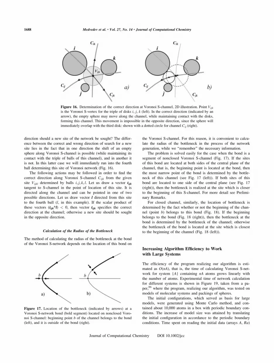
Calculation of the Radius of the Bottleneck
The method of calculating the radius of the bottleneck at the bond
of the Voronoi S-network depends on the location of this bond on
the Voronoi S-channel. For this reason, it is convenient to calcu-
late the radius of the bottleneck in the process of the network
generation, while we ‘‘remember’’ the necessary information.
The problem is solved easily for the case when the bond is a
segment of nonclosed Voronoi S-channel (Fig. 17). If the sites
of this bond are located at both sides of the central plane of the
channel, that is, the beginning point is located at the bond, then
the most narrow point of the bond is determined by the bottle-
neck of this channel (see Fig. 17 (left)). If both sites of this
bond are located to one side of the central plane (see Fig. 17
(right)), then the bottleneck is realized at the site which is closer
to the beginning of this S-channel. For more detail see Prelimi-
nary Remarks.
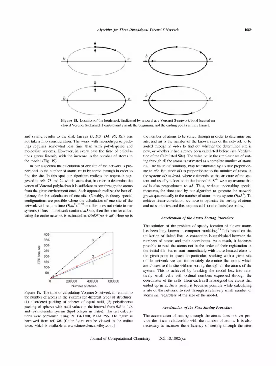
For closed channel, similarly, the location of bottleneck is
determined by the fact whether or not the beginning of the chan-
nel (point b) belongs to this bond (Fig. 18). If the beginning
belongs to the bond (Fig. 18 (right)), then the bottleneck at the
bond is determined by the bottleneck of the channel; otherwise
the bottleneck of the bond is located at the site which is closest
to the beginning of the channel (Fig. 18 (left)).
Increasing Algorithm Efficiency to Work
with Large Systems
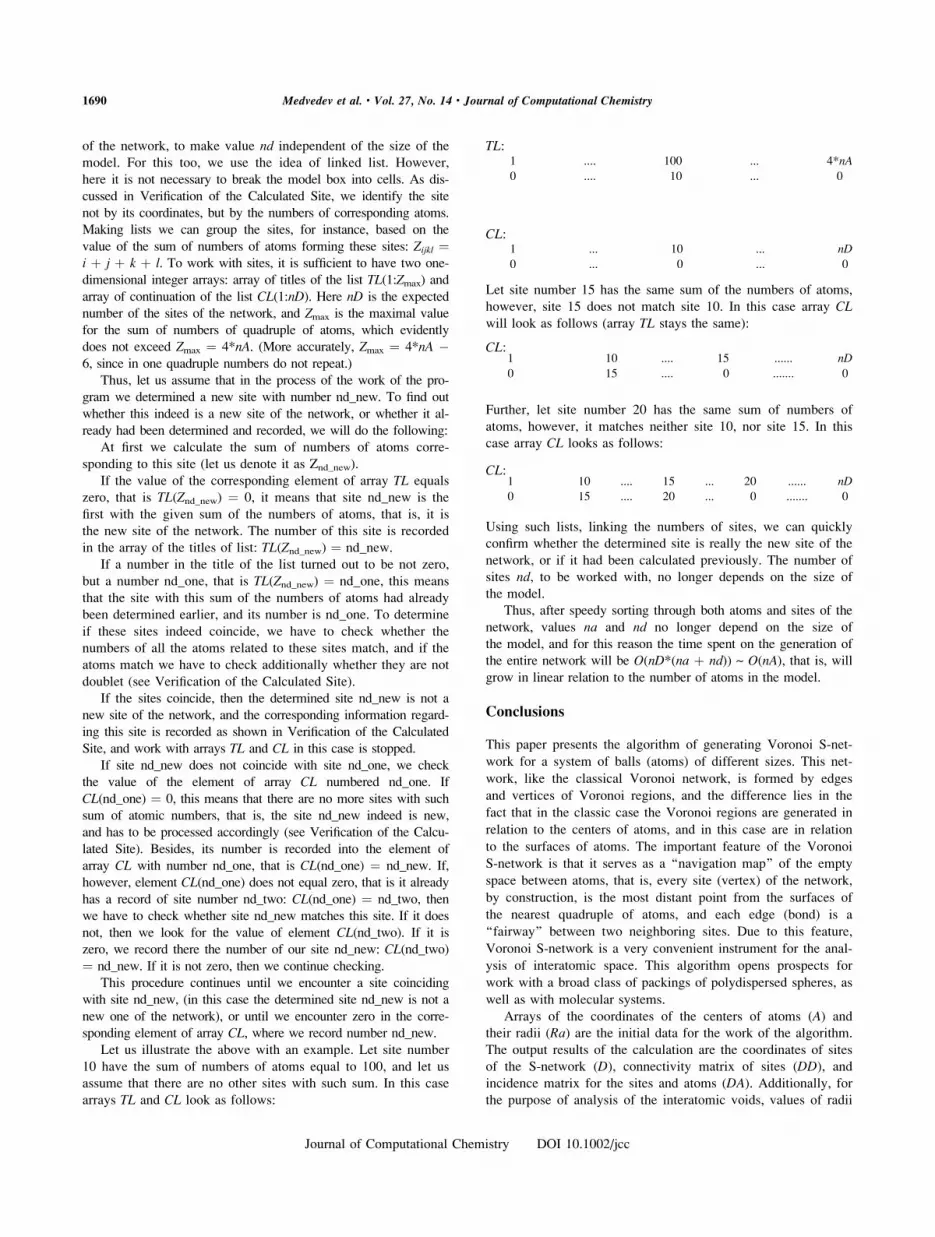
The efficiency of the program realizing our algorithm is esti-
mated as O(nA), that is, the time of calculating Voronoi S-net-
work for system {A} containing nA atoms grows linearly with
the number of atoms. Experimental time of network calculation
for different systems is shown in Figure 19, taken from a pa-
per,86 where the program, realizing our algorithm, was tested on
models of molecular systems and packings of spheres.
The initial configurations, which served as basis for large
models, were generated using Monte Carlo method, and con-
tained about 10,000 atoms in a box with periodic boundary con-
ditions. The increase of model size was attained by translating
the initial configuration in accordance to the periodic boundary
conditions. Time spent on reading the initial data (arrays A, Ra)
Figure 16. Determination of the correct direction at Voronoi S-channel, 2D illustration. Point Vijk
is the Voronoi S-vertex for the triple of disks i, j, k (left). In the correct direction (indicated by an
arrow), the empty sphere may move along the channel, while maintaining contact with the disks,
forming this channel. This movement is impossible in the opposite direction, since the sphere will
immediately overlap with the third disk: shown with a dotted circle for channel Cij (right).
Figure 17. Location of the bottleneck (indicated by arrows) at a
Voronoi S-network bond (bold segment) located on nonclosed Voro-
noi S-channel: beginning point b of the channel belongs to the bond
(left), and it is outside of the bond (right).
1688 Medvedev et al. • Vol. 27, No. 14 • Journal of Computational Chemistry
Journal of Computational Chemistry DOI 10.1002/jcc
and saving results to the disk (arrays D, DD, DA, Ri, Rb) was
not taken into consideration. The work with monodisperse pack-
ings requires somewhat less time than with polydisperse and
molecular systems. However, in every case the time of calcula-
tions grows linearly with the increase in the number of atoms in
the model (Fig. 19).
In our algorithm the calculation of one site of the network is pro-
portional to the number of atoms na to be sorted through in order to
find the site. In this spot our algorithm realizes the approach sug-
gested in refs. 73 and 74 which states that, in order to determine the
vertex of Voronoi polyhedron it is sufficient to sort through the atoms
from the given environment once. Such approach realizes the best ef-
ficiency for the calculation of one site. (Notably, in theory special
configurations are possible where the calculation of one site of the
network will require time O(na2),91,92 but this does not relate to our
systems.) Thus, if a network contains nD site, then the time for calcu-
lating the entire network is estimated as O(nD*(na þ nd). Here na is
the number of atoms to be sorted through in order to determine one
site, and nd is the number of the known sites of the network to be
sorted through in order to find out whether the determined site is
new, or whether it had already been calculated before (see Verifica-
tion of the Calculated Site). The value na, in the simplest case of sort-
ing through all the atoms is estimated as a complete number of atoms
nA. The value nd, similarly, may be estimated by a value proportion-
ate to nD. But since nD is proportionate to the number of atoms in
the system: nD ¼ k*nA, where k depends on the structure of the sys-
tem and usually is located in the interval 6–8,64 we may assume that
nd is also proportionate to nA. Thus, without undertaking special
measures, the time used by our algorithm to generate the network
grows quadratically to the number of atoms in the system O(nA2). To
achieve linear correlation, we have to optimize the sorting of atoms
and network sites, and this requires additional efforts (see below).
Acceleration of the Atoms Sorting Procedure
The solution of the problem of speedy location of closest atoms
has been long known in computer modeling.93 It is based on the
utilization of linked lists. A connection is established between the
numbers of atoms and their coordinates. As a result, it becomes
possible to read the atoms not in the order of their registration in
the initial file, but to start immediately with those located close to
the given point in space. In particular, working with a given site
of the network we can immediately determine the atoms which
are closest to this site without sorting through all the atoms of the
system. This is achieved by breaking the model box into rela-
tively small cells with ordinal numbers expressed through the
coordinates of the cells. Then each cell is assigned the atoms that
ended up in it. As a result, it becomes possible while calculating
a site of the network, to sort through a relatively small number of
atoms na, regardless of the size of the model.
Acceleration of the Sites Sorting Procedure
The acceleration of sorting through the atoms does not yet pro-
vide the linear relationship with the number of atoms. It is also
necessary to increase the efficiency of sorting through the sites
Figure 18. Location of the bottleneck (indicated by arrows) at a Voronoi S-network bond located on
closed Voronoi S-channel. Points b and e mark the beginning and the ending points at the channel.
Figure 19. The time of calculating Voronoi S-network in relation to
the number of atoms in the systems for different types of structures:
(1) disordered packing of spheres of equal radii, (2) polydisperse
packing of spheres with radii values in the interval from 0.5 to 1.0,
and (3) molecular system (lipid bilayer in water). The test calcula-
tions were performed using PC P4-1700, RAM 256. The figure is
borrowed from ref. 86. [Color figure can be viewed in the online
issue, which is available at www.interscience.wiley.com.]
1689Algorithm for Three-Dimensional Voronoi S-Network
Journal of Computational Chemistry DOI 10.1002/jcc
of the network, to make value nd independent of the size of the
model. For this too, we use the idea of linked list. However,
here it is not necessary to break the model box into cells. As dis-
cussed in Verification of the Calculated Site, we identify the site
not by its coordinates, but by the numbers of corresponding atoms.
Making lists we can group the sites, for instance, based on the
value of the sum of numbers of atoms forming these sites: Zijkl ¼i þ j þ k þ l. To work with sites, it is sufficient to have two one-
dimensional integer arrays: array of titles of the list TL(1:Zmax) and
array of continuation of the list CL(1:nD). Here nD is the expected
number of the sites of the network, and Zmax is the maximal value
for the sum of numbers of quadruple of atoms, which evidently
does not exceed Zmax ¼ 4*nA. (More accurately, Zmax ¼ 4*nA �6, since in one quadruple numbers do not repeat.)
Thus, let us assume that in the process of the work of the pro-
gram we determined a new site with number nd_new. To find out
whether this indeed is a new site of the network, or whether it al-
ready had been determined and recorded, we will do the following:
At first we calculate the sum of numbers of atoms corre-
sponding to this site (let us denote it as Znd_new).
If the value of the corresponding element of array TL equals
zero, that is TL(Znd_new) ¼ 0, it means that site nd_new is the
first with the given sum of the numbers of atoms, that is, it is
the new site of the network. The number of this site is recorded
in the array of the titles of list: TL(Znd_new) ¼ nd_new.
If a number in the title of the list turned out to be not zero,
but a number nd_one, that is TL(Znd_new) ¼ nd_one, this means
that the site with this sum of the numbers of atoms had already
been determined earlier, and its number is nd_one. To determine
if these sites indeed coincide, we have to check whether the
numbers of all the atoms related to these sites match, and if the
atoms match we have to check additionally whether they are not
doublet (see Verification of the Calculated Site).
If the sites coincide, then the determined site nd_new is not a
new site of the network, and the corresponding information regard-
ing this site is recorded as shown in Verification of the Calculated
Site, and work with arrays TL and CL in this case is stopped.
If site nd_new does not coincide with site nd_one, we check
the value of the element of array CL numbered nd_one. If
CL(nd_one) ¼ 0, this means that there are no more sites with such
sum of atomic numbers, that is, the site nd_new indeed is new,
and has to be processed accordingly (see Verification of the Calcu-
lated Site). Besides, its number is recorded into the element of
array CL with number nd_one, that is CL(nd_one) ¼ nd_new. If,
however, element CL(nd_one) does not equal zero, that is it alreadyhas a record of site number nd_two: CL(nd_one) ¼ nd_two, then
we have to check whether site nd_new matches this site. If it does
not, then we look for the value of element CL(nd_two). If it is
zero, we record there the number of our site nd_new: CL(nd_two)¼ nd_new. If it is not zero, then we continue checking.
This procedure continues until we encounter a site coinciding
with site nd_new, (in this case the determined site nd_new is not a
new one of the network), or until we encounter zero in the corre-
sponding element of array CL, where we record number nd_new.
Let us illustrate the above with an example. Let site number
10 have the sum of numbers of atoms equal to 100, and let us
assume that there are no other sites with such sum. In this case
arrays TL and CL look as follows:
Let site number 15 has the same sum of the numbers of atoms,
however, site 15 does not match site 10. In this case array CLwill look as follows (array TL stays the same):
Further, let site number 20 has the same sum of numbers of
atoms, however, it matches neither site 10, nor site 15. In this
case array CL looks as follows:
Using such lists, linking the numbers of sites, we can quickly
confirm whether the determined site is really the new site of the
network, or if it had been calculated previously. The number of
sites nd, to be worked with, no longer depends on the size of
the model.
Thus, after speedy sorting through both atoms and sites of the
network, values na and nd no longer depend on the size of
the model, and for this reason the time spent on the generation of
the entire network will be O(nD*(na þ nd)) ~ O(nA), that is, willgrow in linear relation to the number of atoms in the model.
Conclusions
This paper presents the algorithm of generating Voronoi S-net-
work for a system of balls (atoms) of different sizes. This net-
work, like the classical Voronoi network, is formed by edges
and vertices of Voronoi regions, and the difference lies in the
fact that in the classic case the Voronoi regions are generated in
relation to the centers of atoms, and in this case are in relation
to the surfaces of atoms. The important feature of the Voronoi
S-network is that it serves as a ‘‘navigation map’’ of the empty
space between atoms, that is, every site (vertex) of the network,
by construction, is the most distant point from the surfaces of
the nearest quadruple of atoms, and each edge (bond) is a
‘‘fairway’’ between two neighboring sites. Due to this feature,
Voronoi S-network is a very convenient instrument for the anal-
ysis of interatomic space. This algorithm opens prospects for
work with a broad class of packings of polydispersed spheres, as
well as with molecular systems.
Arrays of the coordinates of the centers of atoms (A) and
their radii (Ra) are the initial data for the work of the algorithm.
The output results of the calculation are the coordinates of sites
of the S-network (D), connectivity matrix of sites (DD), and
incidence matrix for the sites and atoms (DA). Additionally, forthe purpose of analysis of the interatomic voids, values of radii
1 .... 100 ... 4*nA
0 .... 10 ... 0
TL:
CL:1 ... 10 ... nD
0 ... 0 ... 0
CL:1 10 .... 15 ...... nD
0 15 .... 0 ....... 0
CL:1 10 .... 15 ... 20 ...... nD0 15 .... 20 ... 0 ....... 0
1690 Medvedev et al. • Vol. 27, No. 14 • Journal of Computational Chemistry
Journal of Computational Chemistry DOI 10.1002/jcc
of interstitial spheres (empty inscribed spheres) are stored in
array (Ri), and radii of the bottlenecks for each bond of the net-
work are recorded in (Rb).The idea of the algorithm is that, for a given known (deter-
mined) site of the network we find its neighbors, that is, new
sites located at the bonds originating from this site. Thus, start-
ing from a known site of the network, we sequentially find the
whole network. The starting site is easily determined based on
certain considerations.
Voronoi S-network for a system of atoms of different radii
may differ significantly from its classic analog built for the centers
of the same atoms. First, the bonds of the S-network are curves
(they are segments of hyperbole or of ellipse). In the classic case
the bonds of Voronoi network are always straight lines. Second,
the topology of Voronoi S-network has its special features. In par-
ticular, ‘‘doublet’’ sites corresponding to the same quadruple of
atoms may exist. This results in the occurrence of binomial rings
at the network, which is impossible in the classic case. Neverthe-
less, the degree of the sites of the network always equals to four
for any nondegenerate systems. For some unique systems of
atoms, such, where one (or many) small sphere is contained in a
narrow gap between a pair of large spheres, the Voronoi S-net-
work may turn out to be not simply connected. We do not work
with such systems, since the majority of physically interesting
objects, in particular molecular systems, are not like that.
We examined the issue of increasing the efficiency of the
algorithm to work with large models. Using some tricks, in par-
ticular the idea of linked lists, we managed to obtain linear rela-
tionship between the time of calculation of network and the
number of atoms in a model, O(N). This algorithm was used in
research papers23–25 to analyze interatomic voids in the models
of lipid bilayers.
Acknowledgments
The authors thank Dr. S.V. Anishchik for helpful discussions,
and one of the authors (N. Medvedev) thanks Alexander von
Humboldt Foundation (Germany) whose support partly promoted
appearance of this paper.
References
1. Starr, F. W.; Sastry, S.; Douglas, J. F.; Glotzer, S. C. Phys Rev Lett
2002, 89, 125501.
2. Yang, R. Y.; Zou, R. P.; Yu, A. B. Phys Rev E 2002, 65, 041302.
3. Ojovan, I. JETP Lett 2004, 79, 632.
4. Kolokol, A. C.; Shimkevich, A. L. At Energ (Russian) 2005, 98, 197.
5. Matsumoto, M.; Saito, S.; Ohmine, I. Nature 2002, 416, 409.
6. O’Malley, B.; Snook, I. Phys Rev Lett 2003, 90, 085702.
7. Masakova, Z.; Patera, J.; Zich, J. J Phys A: Math Gen 2005, 38, 1947.
8. Anikeenko, A. V.; Gavrilova, M. L.; Medvedev, N. N. Lect Notes
Comp Sci 2005, 3480, 816.
9. Thompson, K. E. AIChE J 2002, 48, 1370.
10. Olson, C. J.; Reichhardt, C.; Mccloskey, M., Zieve, R. J. Europhys
Lett 2002, 57, 904.
11. Reis, P. M.; Ehrhardt, G.; Stephenson, A.; Mullin, T. Europhys Lett
2004, 66, 357.
12. Aste, T. J Phys: Condens Matter 2005, 17, S2361.
13. Weeks, E. R.; Weitz, D. A. Phys Rev Lett 2002, 89, 095704.
14. Roel, P.; Dullens, A.; Willem, K. K. Phys Rev Lett 2004, 92,
195702.
15. Huerta, A.; Naumis, G. G.; Wasan, D. T.; Hendersona, D.;
Trokhymchukb, A. J Chem Phys 2004, 120, 1506.
16. Putta, S.; Nemat-Nasser, S. Mater Sci Eng A 2001, 317, 70.
17. Sega, M.; Jedlovszky, P.; Medvedev, N. N., Vallauri, R. J Chem
Phys 2004, 212, 2422.
18. Tokita, N.; Hirabayashi, M.; Azuma, C.; Dotera T. J Chem Phys
2004, 120, 496.
19. Baburin, I. A.; Blatov, V. A. Acta Crystallogr B 2004, 60, 447.
20. Voloshin, V. P.; Beaufils, S.; Medvedev, N. N. J Mol Liq 2002, 96/97, 101.
21. Vishnyakov, A.; Debenedetti, P. G.; Neimark, A. V. Phys Rev E
2000, 62, 538–543.
22. Neimark, A.; Vishnyakov, A. J Chem Phys 2005, 122, 054707.
23. Alinchenko, M. G.; Anikeenko, A. V.; Medvedev N. N.; Voloshin,
V. P.; Mezei, M.; Jedlovszky, P. J Phys Chem B 2004, 108, 19056.
24. Alinchenko, M. G.; Voloshin, V. P.; Medvedev, N. N.; Mezei, M.;
Partay, L.; Jedlovszky, P. J Phys Chem B 2005, 109, 16490.
25. Rabinovich, A. L.; Balabaev, N. K.; Alinchenko, M. G.; Voloshin,
V. P.; Medvedev, N. N.; Jedlovszky, P. J Chem Phys 2005, 122,
084906.
26. Lopez, C. F.; Nielsen, S. O.; Ensing, B.; Moore, P. B.; Klein M. L.
Biophys J 2005, 88, 3083.
27. Angelov, B.; Sadoc, J.-F.; Jullien, R.; Soyer, A.; Mornon, J.-P.;
Chomilier, J. Proteins: Struct Funct Genet 2002, 49, 446.
28. Chelli, R.; Gervasio, F. L.; Procacci, P.; Schettino, V. J Am Chem
Soc 2002, 124, 6133.
29. Bosticka, D.; Vaisman, I. I. Biochem Biophys Res Commun 2003,
304, 320.
30. Voss, N. R.; Gerstein, M. J Mol Biol 2005, 346, 477.
31. Kraynik, A. M.; Reinelt, D. A.; van Swol, F. Phys Rev E 2003, 67,
031403.
32. Karch, R.; Neumann, F.; Neumann, N.; Szawlowski, P.; Schreiner,
W. Ann Biomed Eng 2003, 31, 548.
33. Okabe, A.; Boots, B.; Sugihara, K. S.; Chiu, N. Spatial Tessella-
tions: Concepts and Applications of Voronoi Diagrams. Probability
and Statistics, 2nd ed.; Wiley: New York, 2000.
34. (a) Voronoi, G. F. J Reine Angew Math 1908, 134, 198; (b) Voro-
noi, G. F. J Reine Angew Math 1909, 136, 67.
35. Delaunay, B. N. In Proceedings of the International Congress of
Mathematicians, Toronto, August 11–16, 1924; University of Toronto
Press: Toronto, 1928; pp. 695–700.
36. Delaunay, B. N. Izv Akad Nauk SSSR Otd Mat i Estestv nauk 1934,
7, 793.
37. Engel, P.; Syta, H., Eds. Voronoi’s Impact on Modern Science,
Book 1–2; Institute of Mathematics of the National Academy of Sci-
ences of Ukraine: Kiev, 1998.
38. Aurenhammer, F.; Klein, R. In Handbook of Computational Geome-
try; Sack, J.; Urrutia, G., Eds.; Elsevier: Amsterdam, 2000; Ch. 5,
pp. 201–290.
39. Bernal, J. D. Nature 1959, 183, 141.
40. Bernal, J. D. Proc Royal Soc London A 1964, 280, 299.
41. (a) Finney, J. L. Proc Royal Soc London 1970, 319, 479; (b) Finney,
J. L. Proc Royal Soc London 1970, 319, 495.
42. Richards, F. M. J Mol Biol 1974, 82, 1.
43. Richards, F. M. Methods Enzymol 1985, 115, 440.
44. Gellatly, B. J.; Finney, J. L. J Non-Cryst Solids 1982, 50, 313.
45. Fischer, W.; Koch, E. Z. Kristallografiya 1979, 150, 245.
46. Aurenhammer, F.; Edelsbruner, H. Pattern Recogn 1984, 17, 251.
47. Telley, H.; Liebling, T. M. Philos Mag B 1996, 73, 395.
48. Mezei, M. Mol Simul 1988, 1, 327.
49. Gavrilova, M.; Rokne, J. Int J Comput Math 1997, 61, 49.
50. Liang, J.; Edelsbrunner, H.; Fu, P.; Sudhakar, P. V.; Subramaniam, S.
Proteins 1998, 33, 1.
1691Algorithm for Three-Dimensional Voronoi S-Network
Journal of Computational Chemistry DOI 10.1002/jcc

51. Oger, L.; Richard, P.; Ttroadec, J. P.; Gervois, A. Eur Phys J B 2000,
14, 403.
52. Sadoc, J. F.; Jullien, R.; Rivier, N. Eur Phys J B 2003, 33, 355.
53. Edelsbrunner, H.; Koehl, P. Discrete Comput Geom 2005, 52, 241.
54. Medvedev, N. N. Doklady Academ Nauk 1994, 337, 767 (in Russian).
55. Anishchik, S. V.; Medvedev, N. N. Phys Rev Lett 1995, 75, 4314.
56. Medvedev N. N. In Voronoi’s Impact on Modern Science, Book 1–2;
Engel, P.; Syta, H., Eds.; Institute of Mathematics: Kiev, 1998;
pp. 164–175.
57. Aurenhammer, F. ACM Comput Surv 1991, 23, 345.
58. Luchnikov, V. A.; Medvedev, N. N.; Oger, L.; Troadec, J. P. Phys
Rev E 1999, 59, 7205.
59. Johnson, W. A.; Mehl, R. F. Trans Am Inst Min Metall Pet Eng
1939, 135, 416.
60. Hermann, H.; Mattern, N.; Roth, S.; Ubele, P. Phys Rev B 1997, 56,
13888.
61. Kashchiev, D.; Sato, K. J. Chem Phys 1998, 109, 8530.
62. Bryant, S.; Blunt, M. Phys Rev A 1992, 46, 2004.
63. Voloshin, V. P.; Naberukhin, Y. I.; Medvedev, N. N. Zh Phys Khim
1992, 66, 155 (in Russian).
64. Medvedev, N. N. Voronoi-Delaunay Method for Non-Crystalline Struc-
tures; Russian Academy of Science: Novosibirsk, 2000 (in Russian).
65. Gavrilova, M.; Rokne, J. J Comput Aided Geom Des 2003, 20, 231.
66. Mostafavia, M. A.; Gold, C.; Dakowicz, M. Comput Geosci 2003, 29, 523.
67. Schaller, G.; Meyer-Hermann, M. Comput Phys Commun 2004, 162, 9.
68. Poupon, A. Curr Opin Struct Biol 2004, 14, 233.
69. Gavrilova, M.; Rokne, J. J Comput Aided Geom Des 1999, 16, 89.
70. (a) Kim, D. S.; Kim, D.; Sugihara, K. J Comput Aided Geom Des 2001,
18, 541; (b) Kim, D. S.; Kim, D.; Sugihara, K. J Comput Aided Geom
Des 2001, 18, 563.
71. (a) Karavelas, M. I.; Emiris, I. Z. Prototype implementation for the
planar additively weighted voronoi diagrams; Technical Report ECG-
TR-122201-01, INRIA Sophia-Antipolis, 2002; (b) Karavelas, M. I.;
Emiris, I. Z. Project PRISME 2004.
72. Anton, F.; Kirkpatrick, D.; Mioc, D. The Fourteenth Canadian Conference on
Computational Geometry, Lethbridge, AB, Canada, August 2002, pp. 72–76.
73. Tanemura, M.; Ogawa, T.; Ogita, N. J Comput Phys 1983, 51, 191.
74. Medvedev, N. N. J Comput Phys 1986, 67, 223.
75. Gavrilova, M. Ph.D. Thesis, Department of Computer Science, The
University of Calgary, Calgary, AB, Canada, 1999.
76. Gavrilova, M. Proceedings of the 14th Canadian Conference on Com-
putational Geometry, Lethbridge, Canada, August 2002; pp. 82–87.
77. Kim, D. S.; Cho, Y.; Kim, D. J Comput Aided Des 2005, 37, 1412.
78. Goede, A.; Preissner, R.; Frommel, C. J Comput Chem 1997, 18, 1113.
79. Rother, K.; Preissner, R.; Goede, A.; Frommel, C. Bioinformatics
2003, 19, 2112.
80. Will, H.-M. Lect Notes Comput Sci 1998, 1432, 310.
81. (a) Will, H.-M. Technical Report Dep. No. 300, Informatik, ETH Zurich;
(b) Will, H.-M. Technical Report Dep. No. 302, Informatik, ETH Zurich.
82. Sastry, S.; Corty, D. S.; Debenedetty, P. G.; Stillinger, F. H. Phys
Rev E 1997, 56, 5524.
83. Richard, P.; Oger, L.; Troadec, J. P.; Gervois, A. Eur Phys J E 2001, 6, 295.
84. Voloshin, V. P.; Luchnikov, V. A.; Medvedev, N. N. In Modern
Approaches to Investigation the Drying Processes of Porous Materi-
als; Parmon V. N., Ed.; Russian Academy of Science: Novosibirsk,
2001, Ch. 2; pp. 90–122 (in Russian).
85. Luchnikov, V. A.; Gavrilova, M. L.; Medvedev, N. N.; Voloshin, V.
P. In Future Generation Computer Systems, Vol. 18. Special Issue
on Computer Modeling, Algorithms and Supporting Environments;
Elsevier: Amsterdam, 2002; pp. 673–679.
86. Anikeenko, A. V.; Alinchenko, M. G.; Voloshin, V. P.; Medvedev, N. N.;
Gavrilova, M. L.; Jedlovszky, P. Lect Notes Comput Sci 2004, 3045, 217.
87. http://www.kinetics.nsc.ru/mvd/SOFTS/softs_eng.html.
88. Medvedev, N. N.; Naberukhin, Y. I. J Phys A: Math Gen 1988, 21,
L247.
89. Naberukhin, Y. I.; Voloshin, V. P.; Medvedev, N. N. Mol Phys 1991,
73, 917.
90. Richard, P.; Oger, L.; Lemaitre, J.; Samson, L.; Medvedev, N. N.
Granular Matter, 1999, 1, 203.
91. Kim, D. S.; Kim, D.; Sugihara, K.; Ryu, J. The International Confer-
ence on Computational Science San Francisco, CA, USA, 2001.
92. Dwyer, R. A. Discrete Comput Geom 1991, 6, 343.
93. Allen, M. P.; Tildesley, D. J. In Computer Simulation of Liquids; Clar-
endon Press: Oxford, 1987; Ch. 5.
1692 Medvedev et al. • Vol. 27, No. 14 • Journal of Computational Chemistry
Journal of Computational Chemistry DOI 10.1002/jcc
Related Documents


![A parallel algorithm for constructing Voronoi diagrams ... › manage › uploadfile › File › ... · Fortune [7] proposed a sweepline algorithm for constructing Voronoi diagrams.](https://static.cupdf.com/doc/110x72/5f1169120273b0207c355cef/a-parallel-algorithm-for-constructing-voronoi-diagrams-a-manage-a-uploadfile.jpg)


