(c)2001 American Institute of Aeronautics & Astronautics or Published with Permission of Author(s) and/or Author(s)' Sponsoring Organization. 42nd AIAA/ASMBASCE/AHS/ASC Structures, n t\ ji OfTOCO Structural Dynamics, and Materials Conference and AUI m £ 0 *5 O o Ex nibit "^ Seattle, WA 16-19 April 2001 AIAA-2001-1666 AN ADVANCED BUFFET LOAD ALLEVIATION SYSTEM Jay K. Burnham*, Dale M. Pitt f , Edward V. White 1 The Boeing Company St. Louis, MO Douglas A. Henderson* Air Force Research Laboratory Wright-Patterson AFB, OH Robert W. Moses* NASA Langley Research Center Hampton, VA Abstract This paper describes the development of an advanced buffet load alleviation (BLA) system that utilizes distributed piezoelectric actuators in conjunction with an active rudder to reduce the structural dynamic response of the F/A-18 aircraft vertical tails to buffet loads. The BLA system was defined analytically with a detailed finite-element-model of the tail structure and piezoelectric actuators. Oscillatory aerodynamics were included along with a buffet forcing function to complete the aeroservoelastic model of the tail with rudder control surface. Two single-input-single-output (SISO) controllers were designed, one for the active rudder and one for the active piezoelectric actuators. The results from the analytical open and closed loop simulations were used to predict the system performance. The objective of this BLA system is to extend the life of vertical tail structures and decrease their life-cycle costs. This system can be applied to other aircraft designs to address suppression of structural vibrations on military and commercial aircraft. Nomenclature A,B,C,D state space model matrices A aerodynamic inertia B aerodynamic damping b semi-chord c control surface, rudder F] 3U f buffet forcing function Fpiezo buffet forcing function g structural damping H transfer function I identity matrix K generalized stiffness k reduced frequency M generalized mass Q generalized aerodynamic force s Laplace variable t time U,u system input V true airspeed p air density co frequency cp modeshape displacement q, q generalized displacement, acceleration Introduction Buffet Background The capability of modern fighter aircraft to sustain flight at high angles of attack and/or moderate angles of sideslip often results in immersion of part of the aircraft in unsteady, separated, vortical flow emanating from the aircraft's forebody or wings, Figure 1. The flow from these surfaces becomes turbulent and separated when the aircraft is flying at these conditions. This flow contains significant levels of energy over a frequency bandwidth coincident with low-order structural vibration modes of wings, fins, and control surfaces. The induced unsteady pressures that are applied to these lifting surfaces due to the turbulent flow are commonly referred to as buffet. The interaction of the buffet and the structure produces a structural-mode response known as buffeting. Prolonged exposure to the buffet loads has resulted in fatigue of structures on several aircraft. Damage to aircraft due to buffeting has led to redesigns of aircraft structure and increased support costs for the US Air Force and Navy as well as the armed forces of other * Member, AIAA f Associate Fellow, AIAA Copyright © 2001 by the American Institute of Aeronautics and Astronautics, Inc. All rights reserved. 1 American Institute of Aeronautics and Astronautics

Welcome message from author
This document is posted to help you gain knowledge. Please leave a comment to let me know what you think about it! Share it to your friends and learn new things together.
Transcript

(c)2001 American Institute of Aeronautics & Astronautics or Published with Permission of Author(s) and/or Author(s)' Sponsoring Organization.
42nd AIAA/ASMBASCE/AHS/ASC Structures,n t\ ji OfTOCO Structural Dynamics, and Materials Conference andAUI m£ 0 *5 O o Exnibit"^ Seattle, WA 16-19 April 2001
AIAA-2001-1666
AN ADVANCED BUFFET LOAD ALLEVIATION SYSTEMJay K. Burnham*, Dale M. Pittf, Edward V. White1
The Boeing CompanySt. Louis, MO
Douglas A. Henderson*Air Force Research Laboratory
Wright-Patterson AFB, OH
Robert W. Moses*NASA Langley Research Center
Hampton, VA
Abstract
This paper describes the development of an advancedbuffet load alleviation (BLA) system that utilizesdistributed piezoelectric actuators in conjunction withan active rudder to reduce the structural dynamicresponse of the F/A-18 aircraft vertical tails to buffetloads. The BLA system was defined analytically with adetailed finite-element-model of the tail structure andpiezoelectric actuators. Oscillatory aerodynamics wereincluded along with a buffet forcing function tocomplete the aeroservoelastic model of the tail withrudder control surface. Two single-input-single-output(SISO) controllers were designed, one for the activerudder and one for the active piezoelectric actuators.The results from the analytical open and closed loopsimulations were used to predict the systemperformance. The objective of this BLA system is toextend the life of vertical tail structures and decreasetheir life-cycle costs. This system can be applied toother aircraft designs to address suppression ofstructural vibrations on military and commercialaircraft.
Nomenclature
A,B,C,D state space model matricesA aerodynamic inertiaB aerodynamic dampingb semi-chordc control surface, rudderF]3Uf buffet forcing functionFpiezo buffet forcing functiong structural dampingH transfer function
I identity matrixK generalized stiffnessk reduced frequencyM generalized massQ generalized aerodynamic forces Laplace variablet timeU,u system inputV true airspeedp air densityco frequencycp modeshape displacementq, q generalized displacement, acceleration
Introduction
Buffet BackgroundThe capability of modern fighter aircraft to sustainflight at high angles of attack and/or moderate angles ofsideslip often results in immersion of part of the aircraftin unsteady, separated, vortical flow emanating from theaircraft's forebody or wings, Figure 1. The flow fromthese surfaces becomes turbulent and separated when theaircraft is flying at these conditions. This flow containssignificant levels of energy over a frequency bandwidthcoincident with low-order structural vibration modes ofwings, fins, and control surfaces. The induced unsteadypressures that are applied to these lifting surfaces due tothe turbulent flow are commonly referred to as buffet.The interaction of the buffet and the structure producesa structural-mode response known as buffeting.Prolonged exposure to the buffet loads has resulted infatigue of structures on several aircraft. Damage toaircraft due to buffeting has led to redesigns of aircraftstructure and increased support costs for the US AirForce and Navy as well as the armed forces of other
* Member, AIAAf Associate Fellow, AIAACopyright © 2001 by the American Institute of Aeronautics and Astronautics, Inc. All rights reserved.
1American Institute of Aeronautics and Astronautics

(c)2001 American Institute of Aeronautics & Astronautics or Published with Permission of Author(s) and/or Author(s)' Sponsoring Organization.
countries. Time spent inspecting, repairing, andreplacing structure impacts the mission availability ofthe aircraft.
Figure 1. High-Performance Aircraft at High Angleof Attack.
For the F/A-18A-D aircraft, unsteady buffet loads fromhigh angle of attack (20 to 44 degrees) flight impingeon the vertical tails as shown in Figure 1. These buffetloads contribute to the fatigue of the vertical tailstructure along with the steady aircraft maneuver loads.The two primary vibration modes that account for thebuffet fatigue damage are mode 1, tail 1st bending at-15 Hz, and mode 2, tail tip torsion at -45 Hz.
Buffet Load Alleviation BackgroundSeveral methods have been investigated previously inan effort to reduce the buffet response and increase thefatigue life of vertical tails on military aircraft. Oneapproach to solving this issue was to add passivedamping material to the tails while they are beingmanufactured.1 Another approach increased thebending stiffness of the tails.2 The F/A-18A-D aircrafthave additional structure added to the vertical tails inconjunction with a fence on the wing leading edgeextension (LEX) that disperses the vortex prior toimpinging on the vertical tail.3'4 The additionalstructure in combination with the LEX fence produces avertical tail that exceeds the fatigue requirements of theU.S. Navy (6000-hour lifetime). More recently, theF/A-18E/F aircraft has replaced the LEX fence with an
actuated spoiler on the LEX. These techniques havebeen successful at reducing the buffet response of thevertical tails but have increased the cost and grossweight of the vehicle in varying degrees.
Another method to reduce the buffet responseincorporated an active control system that deflects therudder in response to measured motion at the tip of thetail.5'6 This method increases the fatigue life at mostangles of attack through control of mode 1 (F/A-18vertical tail 1st bending) at 15 Hz. This method islimited to controlling the response of the structuralmodes within the rudder actuation bandwidth (< 20 Hzon F/A-18A-D aircraft). Therefore, it is not effectivefor reducing the fatigue damage from mode 2 at 45 Hz(vertical tail tip torsion).
Investigations and tests of active control of the verticaltail vibration response using "smart" materials(piezoelectric actuators) distributed over the vertical tailstructure has proven successful at reducing the overallbuffet response.7'8 A full scale test on the F/A-18vertical tail with a piezoelectric actuator-based activecontrol system was completed during 1997 and 1998 atthe International Follow-On Structural Test Program(IFOSTP) facility in Melbourne, Australia.8 Theresults from this test indicated that the piezoelectricactuators attached to the skin were more effective atreducing the response of mode 2 (tip torsion at 45 Hz)than mode 1 (1st bending at 15 Hz).
The major problem with using the piezoelectricactuators attached to the tail skin for controlling mode 1arises from the strain energy distribution for this modeand the stifrhess of the tail structure near the root.From the finite element model results, 40% of themodal strain energy for mode 1 is in the root springs ofthe model that represents the aircraft aft fuselagecompliance and 50% of the modal strain energy is inthe tail skins. Of this 50%, the majority of the modalstrain energy is located near the root of the tail. Thepiezoelectric actuators are ineffective near the tail rootbecause of the large structural stifrhess in this region(skins greater than 0.2 inches thick supported by the tailattachment root rib). In contrast to this, thepiezoelectric actuators are very effective for mode 2because this mode has 60% of the modal strain energyin the tail skins and this strain energy is concentrated inthe upper third of the vertical tail where the skinthickness is closer to a tenth of an inch (0.07 to 0.15inches).
American Institute of Aeronautics and Astronautics

(c)2001 American Institute of Aeronautics & Astronautics or Published with Permission of Author(s) and/or Author(s)' Sponsoring Organization.
System Design
System DevelopmentThe development of the buffet load alleviation (BLA)system for the F/A-18 vertical tail began with researchinto existing BLA systems to establish a benchmark forsystem design. Extensive research and testing has beencompleted in the past ten years on the development ofan active BLA system for vertical tails of fighteraircraft as described previously. The results from thisresearch identified two systems that have been effectiveat actively reducing the buffet response of a verticaltail. The first system employs the rudder controlsurface to actively control the vertical tail dynamicresponse5'6 and the second system utilizes piezoelectricactuators attached to the skin.7'8 NASA LaRCdeveloped the combination of these two systems underthe Scaling Influences Derived from ExperimentallyKnown Impact of Controls (SIDEKIC) program.9
The blended system of the rudder and piezoelectricactuator technologies9 was selected for the design of theF/A-18 vertical tail buffet load alleviation systempresented in this paper, Figure 2. The application ofthis combined system, in which the rudder actuator isused to control the response of the tail mode 1 (1st
bending near 15 Hz) and the piezoelectric actuators areused to control mode 2 (tip torsion mode near 45 Hz),uses the most effective features of each system.
Figure 2 Major Components of BLA System
The major components of the active BLA system areshown in Figure 2. The blended actuator systemincludes a separate single-input, single-output (SISO)controller for each system. The existing aircraft rudderactuator and servo system is combined with a SISOcontroller, sensors and signal conditioner to completethe active rudder system. The piezoelectric actuatorsystem is similar except that the switch mode amplifier,which is connected to the aircraft power supply, drivesthe piezoelectric actuators. Both systems utilize the
response of the two accelerometers and strain gageshown in Figure 2. The rudder actuation systemincludes the rotary variable displacement transducer(RVDT) to provide rudder position feedback.
System RequirementsThe objective of the BLA system design is to reduce thebuffet response of the F/A-18 vertical tail and extendthe operational life of the structure. The BLA systemperformance goal was established as a 25% reduction inthe buffet response at the fatigue critical condition.The fatigue critical condition is not the condition ofpeak buffet response but is determined from thecombination of buffet response and aircraft usage.This combination produces fatigue damage tables,which identify the critical fatigue condition for eachvibration mode of the vertical tail.
The analytical performance objective was doubled from25% to 50% reduction at the fatigue critical conditionto account for differences between the analyticalrepresentation and the actual hardware of the BLAsystem.9 The use of free strain parameters for thepiezoelectric actuators leads to over predicting theperformance along with unaccounted for losses due tostacking the actuators and the general nonlinearbehavior of the piezoelectric actuators.9 Also, theanalytical representation of the rudder aeroservoelasticmodel tends to over predict the rudder effectiveness.5The analytical model can be improved with correlationto measured flight test data.
Technical Approach
The modal equations for aeroelastic response were usedto develop a state space representation of the buffetload alleviation (BLA) system, similar to previousresearch.5"8 The total degrees of freedom of thestructural dynamic equations of motion for a flexiblestructure are greatly reduced by transforming theequations from physical coordinates, xyz, to modalcoordinates, q. Several controllers were designed andanalytical simulations were completed to evaluate theBLA system. The modeling tools used at Boeing in theF/A-18 Structural Dynamics group were utilized tocomplete this task, namely NASTRAN for structuralmodeling, N5KM (doublet lattice) for aerodynamicmodeling11, FAMUSS for aeroservoelastic modeling12,MATLAB and SBVIULINK for controller design andsystem simulation.
The starting point for the analysis was with an existingF/A-18 vertical tail structure NASTRAN plate/shellmodel with root springs for the cantilevered boundary.
American Institute of Aeronautics and Astronautics

(c)2001 American Institute of Aeronautics & Astronautics or Published with Permission of Author(s) and/or Author(s)' Sponsoring Organization.
The results from a normal modes analysis comparedwell with measured results. The normal modes analysisin NASTRAN produces vibratory frequencies, co, andmode shapes, (p.
The unsteady aerodynamics of the vertical tail wererepresented using a linear doublet lattice computercode, N5KM.11 The unsteady aerodynamic forces onthe tail result from the tail vibratory motion and are notto be confused with the buffet aerodynamic force on thetail. The unsteady aerodynamic forces on the tail aretransformed from physical coordinates, xyz, to modalcoordinates, q. The NASTRAN vibratory modeshapes, cp, were combined with the unsteadyAerodynamic mfluence Coefficient (AIC) to generategeneralized aerodynamic forces at a series of reducedfrequencies (k=cob/V; where co=oscillatory frequency,b=semi-chord, and V=Velocity). These generalizedaerodynamic forces were combined with thegeneralized mass, M, and generalized stiffness, K.Modal damping is expressed as structural damping, g,and is part of the complex stiffness term. The initialequation of motion for the flexible tail in modalcoordinates, q(t), is in equation 1.
= -/>V2Q(k)q(t) (1)
Equation 1 is solved to assess the aeroelastic stability ofthe flexible tail. A flutter analysis was completed andthe results compared well with the Boeing F/A-18Project analysis.
The buffet aerodynamic force on the vertical tail wasmodeled with a similar approach as used in previousresearch.8 The buffet force is modeled as a Gaussianwhite noise process with shaping filters and is appliedto the vertical tail model at the same location as theIFOSTP shaker attachment.8 The shaping filters werescaled to match measured response from flight test datafor the six flight conditions analyzed. The unit buffetforce, F (t), was added to the right hand side ofequation 1 to obtain equation 2.
Mq(t)+K(l+gVj)q(t)-^/?V2Q(k)q(t)=Fbuf(t) (2)
the model were multiplied by the correspondingvibration modeshape for each degree-of-freedom todetermine the piezoelectric modal force, Fpiezo. Thepiezoelectric actuator force was added to the right handside of equation 2.
Mq(t) + K(l + gVJ )q(t) - p V2Q(k)q(t) = Fbuf (t) + Fpiezo(t) (3)
The next step was the addition of the aeroservoelasticmodel for rudder control. Because the vertical tailstructural modes are excited by the rudder controlsurface deflections, the equations of motion were re-written to account for the aircraft control surfacedeflections. The control surface inertia effects, MC,and aerodynamic effects, Qc(k) are included inequation 4 on the right hand side with the commandedsystem input U(t).
- /> V2Q(k)q(t) =
-McU(t) +l/?V2Qc(k)U(t) +Fbuf (t) +Fpiezo(t)(4)
The transfer function frequency response of equation 4was computed from the Laplace transform as given byequation 5. This is the technique used in FAMUSS.12
-Mcs2 + / > V 2buf xpiezo
]q(s) .=
Fpiezo ks)(5)
Equation 5 can be re-written as a transfer function,output/input. The output is the modal coordinates q andthe input is u. This produces the modal transferfunction response of the modal coordinates for a rudderinput, buffet force input, and piezoelectric actuatorinput, where s=jco and k=cob/V.
Hq(s) = q(s)u(s)
Hq(s) =
(6)
(7)-Mcs2 +
The modal force from the piezoelectric actuators wasdetermined from the analytical actuation of thepiezoelectric elements on the vertical tail model. Themodel was loaded with a delta temperature across thepiezoelectric elements that produced a specified strainin these elements. The resulting grid point forces in
The modal transfer function is transformed to thephysical coordinate system using the vibratory modeshapes, (p. The transfer function in the physicalcoordinates is given by equation 8.
American Institute of Aeronautics and Astronautics

(c)2001 American Institute of Aeronautics & Astronautics or Published with Permission of Author(s) and/or Author(s)' Sponsoring Organization.
u(s) u(s)H
Vc q (8)
Equation 7 was solved in FAMUSS12, over thefrequency range of interest, 0.5 to 100 Hz. Thetransfer function is calculated over a series offrequencies, CD, or Laplace variables, S=JCD. This processinvolves interpolating the tabulated unsteadyaerodynamic terms of Q(k) and Qc(k), which are afunction of k=CDb/V, over the frequency range ofinterest, CD. A separate transfer function is calculatedfor each input-output pair.
The next step in FAMUSS was to create an equivalentstate space model that could be used in the subsequenttime domain transient analysis, SIMULINK. The statespace equations are written as:
x(t) = Ax(t) + Bu(t)y(t) = Cx(t) + Du(t) (9)
Again, FAMUSS was used to develop an equivalentstate space model, equation 9, which matched theoriginal transfer function response, equation 8. Thetransfer function frequency response for a MIMO statespace model is shown in matrix form in equation 10.
(10)
FAMUSS,12 uses a nonlinear optimization technique todetermine the individual terms of the state matrices A,B, C, and D to fit the transfer function response at eachtabulated frequency, CD. The resulting aeroservoelasticstate space model from FAMUSS had three inputs: 1)rudder rotation, 2) buffet force, and 3) piezoelectricactuator force.
The state space model was incorporated into theMATLAB® SIMULINK toolbox and time historysimulations of the vertical tail buffet response werecompleted. The design of the rudder and piezoelectriccontrollers were also completed in SIMULINK.
Structure Model
Vertical Tail Structure ModelThe F/A-18 vertical tail structure was modeled with adetailed NASTRAN plate/shell finite element model.The detailed model includes the skin elements, sparsand ribs. The total weight of the model was 284 Ibs.The model is cantilevered with attachment springs
along the root to represent the compliance of the aftfuselage. The rudder is modeled along the rudderelastic axis with bar elements and attached to thevertical tail with a rotational spring, which representsthe rudder actuator.
The results from the normal modes analysis of themodel are listed in Table 1 along with the measuredfrequencies from a ground vibration test of an F/A-18aircraft. The analytical-to-measured percent differencein frequency is less than 3% for the buffet criticalmodes 1 and 2. The modeshapes of the first twomodes of the analytical model are displayed in Figure 3
Vert. Tail ModeDescription1 - 1st Bending2 - Tip Torsion3 - Rudder Rot.
AnalyticalFreq. - Hz
15.344.749.6
MeasuredFreq. - Hz
15.346.049.6
PercentDifference
0.0%-2.8%0.0%
Table 1 Analytical and Measured Frequency
Figure 3 Analytical Modeshape for Modes 1 and 2
Piezoelectric Actuator ModelThe first step in modeling the piezoelectric actuatorswas to determine the vertical tail skin area for attachingthe actuators. This was accomplished by using theresults from the normal modes analysis along with therestrictions on where actuators can be physicallyattached to the vertical tail skin. A shaded contour ofthe strain energy density for Mode 2 is displayed inFigure 4 for the model skin elements. This contourreveals the strain energy is in the upper half of thevertical tail skin and the highest densities are in theupper third. The initial area selected for piezoelectricactuators is also shown in Figure 4.
The candidate piezoelectric actuators for the BLAsystem could be subdivided into two categories forfinite element modeling, 1) isotropic plates (d31piezoelectric actuation) and 2) orthotropic plates (d33
American Institute of Aeronautics and Astronautics

(c)2001 American Institute of Aeronautics & Astronautics or Published with Permission of Author(s) and/or Author(s)' Sponsoring Organization.
piezoelectric actuation). The isotropic plates wereused to represent the monolithic piezoceramic materialwith solid plate electrodes that uses the d31piezoelectric charge constant. The orthotropic plateswere used to represent the piezoelectric actuators withinterdigitated electrodes (IDE) in lieu of the solid plateelectrodes. The IDE creates an electric field along thepiezoceramic material to utilize the d33 piezoelectriccharge constant. A comparison of the two differentpiezoelectric actuation mechanisms is shown in Figure5. The solid line depicts the undeflected shape of thepiezoelectric actuator and the dotted line depicts thepowered, deflected shape (not to scale) for a fixedvoltage polarity. The deflected shapes would changesign for a reversal in voltage polarity. It is important tonote that the longitudinal (3 axis) and transverse (2axis) strains for the IDE actuators are out of phase witheach other.
Figure 4 Mode 2 Strain Energy Density and InitialArea for Piezoelectric Actuator Attachment
3 Axis
2 Axis.,
Electric Field
1 Axis
d3j Actuator (isotropic)
1 Axis
d33 IDE Actuator (orthotropic)
Figure 5 Piezoelectric Actuator d31 (isotropic) andd33 (orthotropic) Mechanisms
The piezoelectric actuators were modeled inNASTRAN as structural plate elements (CQUAD4,PSHELL, MAT1 and MATS) and were offset from theexisting skin elements, similar to previous modelingpractices8'10. Since the d33 IDE actuators producedirectional strain, these actuators were modeled withthe orthotropic material MATS card. The direction ofthe principal skin strain for the vertical tail 2nd modewas used to determine the orientation of the
piezoelectric d33 IDE axis. The orientation angle wasaveraged over three application regions.
The analytical actuation of the piezoelectric elementswas accomplished using a thermal analogy.8 Thepiezoelectric elements had a nonzero coefficient ofthermal expansion (CTE) while the rest of the modelhad a zero CTE. The CTE was determined from thepiezoelectric actuator free strain properties at themanufacturer recommended actuation limits. A staticsolution was performed with the loading of a deltatemperature, producing the limit strains in thepiezoelectric elements. The results from the staticanalysis for a d31 isotropic piezoelectric actuatorproduced a deflected shape similar to the tail firstbending mode and the results for a d33 IDE orthotropicactuator produced a shape similar to the 2nd mode, tiptorsion. The results from this comparison aresignificant because the piezoelectric actuators in theBLA system are required to reduce the response ofmode 2 and not mode 1. This comparison explains theresults found during the BLA system performanceanalysis, that the d33 IDE actuators out performed thed31 isotropic actuators in mode 2 response.
Aerodynamic Model
Oscillatory AerodynamicsThe dynamic motion of the vertical tail in flightgenerates oscillatory aerodynamic forces. These forceswere included in the BLA equations of motion for thevertical tail and rudder control surface as definedpreviously in equations 1 and 4. The oscillatoryaerodynamic forces were computed using the subsonicDoublet-Lattice Method and the Boeing programN5KM.11 This is consistent with the current methodsused on the Boeing F/A-18 project Structural Dynamicsteam.
The doublet lattice aerodynamic model was completedfor the vertical tail planform with 656 boxes. The flatplate aerodynamic model consisted of 4 panels, two onthe vertical tail, one for the rudder and one for thefuselage interference. The model verification wascompleted by performing a flutter solution (equation 2)at Mach 0.80 and by comparing the results with theBoeing F/A-18 project Structural Dynamics correlatedflutter analysis. The detailed BLA model comparedwell with the existing project analysis. The only majordifference between the two solutions was the dampingfor mode 2, tip torsion. This difference can beattributed to the two structural models, detailed plateFEM for the BLA analysis versus an elastic axis beam
American Institute of Aeronautics and Astronautics

(c)2001 American Institute of Aeronautics & Astronautics or Published with Permission of Author(s) and/or Author(s)' Sponsoring Organization.
for the project analysis. The detailed FEM produceschordwise bending for increased aerodynamic forces inthe tip torsion mode as compared to the rigid chordrepresentation of the beam model.
Buffet AerodynamicsThe buffet aerodynamic force was modeled with aGaussian white noise process and shaping filter tomatch the response of measured flight test data.8 Themeasured flight test data used for selecting the analysisconditions and scaling the buffet force was obtainedfrom the Boeing F/A-18 project Structural Dynamicsdatabase. As described previously, the primary buffetaerodynamic force from flight originates from the wingleading edge extension (LEX) and impinges on thevertical tail as shown in Figure 1. This buffetaerodynamic excitation has been successfully simulatedin the full scale ground test facility (IFOSTP) inMelbourne Austrailia.8 Because of this and theprobability of future testing of BLA systems at theIFOSTP facility, the buffet aerodynamic force for theBLA system was analytically modeled as a point forcecoinciding with the IFOSTP shaker attachmentlocation, intersection of the vertical tail mid-rib and46% spar.8 The buffet force of unit magnitude wasadded to the BLA system equations of motion as aninput quantity varying with time, Fbuf(t) as shownpreviously in equation 2.
The Boeing F/A-18 project Structural Dynamicdatabase was queried to select the flight test conditionsfor analysis of the BLA system. The fatigue damage ofthe F/A-18 vertical tail is based on the band-passfiltered response for mode 1 (10-20 Hz) and mode 2(32-52 Hz) of the vertical tail aft-tip accelerometerKS16,3'4 shown in Figure 2. Therefore, the flight testconditions for analysis were based on the measuredflight test response of this same parameter, KS16.
The final step in defining the buffet aerodynamic forcewas to run "open loop" analytical simulations of theBLA system in SIMULINK as described previously.The buffet force analytical shaping filters were scaledto produce the G's RMS response from the measuredflight test data. A final check was completed bycomputing the frequency response of the simulated timehistory for KS16 and by comparing this to the measuredfrequency response. Based on these results, the finaladjustments were made to the buffet force shapingfilters.
Aeroservoelastic Model
The analytical aeroservoelastic model of the BLAsystem was created in FAMUSS12, which is the toolused for the F18 aircraft aeroservoelastic analysis. Theinputs to FAMUSS include the terms listed inequation 4. The left hand (Ih) side of equation 4includes the structural mass, stiffness, damping, andoscillatory aerodynamic force from the motion of theflexible tail. The right hand (rh) side of equation 4includes the commanded rudder inertia and oscillatoryaerodynamic force, along with the buffet aerodynamicforce and piezoelectric actuator force. These threeforces on the rh side of equation 4 represent the inputsto the aeroservoelastic model as described previously.The subsequent transfer function analysis and statespace model development are described in theTechnical Approach, equations 6-10. For the open andclosed loop analysis in SIMULINK, the analyticalrudder actuator model from the Boeing F18 project wasincluded to complete the rudder control model. Therudder actuator model represents the commanded inputand output of the rudder hydraulic actuator.
- |/?V2Q(k)q(t) =(4)
- McU(t) +1 p V2QC (k)U(t) + Fbuf (t) + Fpiezo (t)
Additional analyses were completed in FAMUSS toverify the vertical tail response and commanded ruddersign convention. With only commanded rudder inertiaforce on the rh side of equation 4, -McU(t), therudder response from the Ih side of equation 4 is inphase and the tail response is out of phase with thecommanded rudder. Similarly, with only commandedrudder aerodynamic force on the rh side of equation 4,0.5*/?V2Qc(k)U(t), the Ih side rudder response andvertical tail response are out of phase with thecommanded rudder. A plot of commanded rudderforce and its two components, inertia and aero, versusfrequency revealed the crossover frequency is about 7Hz. For frequencies less than 7 Hz, the aerodynamiccomponent comprises the majority of the commandedrudder force and for frequencies above 7 Hz, thecommanded rudder inertia force dominates. Becausethe active rudder is used to control the tail first bendingmode at 15 Hz and at this frequency, the commandedrudder aerodynamic force is small compared to theinertia force, the rudder aerodynamic effectiveness wasnot reduced as done in previous work.5
American Institute of Aeronautics and Astronautics
(c)2001 American Institute of Aeronautics & Astronautics or Published with Permission of Author(s) and/or Author(s)' Sponsoring Organization.
Model VerificationThe completed aeroservoelastic model was validated bycomparison of the analytical results with measuredresults from the full scale ground test at IFOSTP8,measured aircraft buffet flight test response4, andmeasured aircraft response from a commanded rudderfrequency sweep on the NASA Dryden F-18 HARVaircraft.
To validate the buffet force model, the analytical statespace model without aerodynamics was forced inSIMULINK with the measured shaker load cell timehistory from the full scale IFOSTP ground test.8 Theanalytical model with a structural damping of 8%compared well with the measured vertical tail responseat IFOSTP.
The oscillatory aerodynamic force was validated bycomparison with measured buffet flight test response ofthe F18 vertical tail.4 The analytical state space modelpoles of frequency and damping were compared withthe measured frequency and damping from flight forseveral buffet flight conditions. The analytical andmeasured results agreed well for mode 2, tip torsion at45 Hz. The results for mode 1 indicated the oscillatoryaerodynamic force was low and could be increased toaccount for the increased aerodynamic force on the firstbending mode at high angle of attack, which increasesthe spanwise flow across the tail.
The rudder control surface aeroservoelastic model wasvalidated by comparison with the measured responsefrom an in-flight rudder sweep on the F/A-18 HARVaircraft. In order to get good agreement with themeasured results, the analytical rudder response inSIMULINK was changed to include the commandedresponse (Ih side of equation 4) added to the flexibleresponse (rh side of equation 4). Response transferfunctions computed from this total rudder position inthe denominator agreed well with the measured transferfunctions.
Controller Design
The classical control laws were developedindependently as single-input, single-output (SISO) forthe rudder to control mode 1 at 15 Hz and thepiezoelectric actuators to control mode 2 at 45 Hz. Thefeedback sensor for each control law was selected asthe vertical tail aft tip acceleration (KS16 in Figure 2)because it is used to assess fatigue damage of thevertical tail. The control law development was
completed in MATLAB with the aeroservoelastic statespace model.
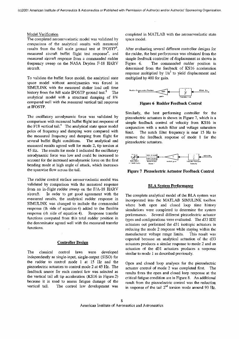
After evaluating several different controller designs forthe rudder, the best performance was obtained from thesimple feedback controller of displacement as shown inFigure 6. The commanded rudder position isdetermined from the feedback of KS16 accelerationresponse multiplied by 1/s2 to yield displacement andmultiplied by 400 for gain.
gain
Figure 6 Rudder Feedback Control
Similarly, the best performing controller for thepiezoelectric actuators is shown in Figure 7, which is asimple feedback control of velocity from KS16 inconjunction with a notch filter and voltage saturationlimit. The notch filter frequency is near 15 Hz toremove the feedback response of mode 1 for thepiezoelectric actuators.
Transfer FunctionVelocity
Figure 7 Piezoelectric Actuator Feedback Control
BLA System Performance
The complete analytical model of the BLA system wasincorporated into the MATLAB SIMULINK toolboxwhere both open and closed loop time historysimulations were completed to determine the systemperformance. Several different piezoelectric actuatortypes and configurations were evaluated. The d33 IDEactuators out performed the d31 isotropic actuators inreducing the mode 2 response while staying within themanufacturer voltage range limits. This result wasexpected because an analytical actuation of the d33actuators produces a similar response to mode 2 and anactuation of the d31 actuators produces a responsesimilar to mode 1 as described previously.
Open and closed loop analyses for the piezoelectricactuator control of mode 2 was completed first. Theresults from the open and closed loop response at thecritical fatigue condition are in Figure 8. An additionalresult from the piezoelectric control was the reductionin response of the tail 2nd torsion mode around 93 Hz.
American Institute of Aeronautics and Astronautics

(c)2001 American Institute of Aeronautics & Astronautics or Published with Permission of Author(s) and/or Author(s)' Sponsoring Organization.
A plot of the commanded piezoelectric actuator voltageis included in the lower half of Figure 8. Theperformance objective of 50% reduction in Mode 2response was met using the NASA LaRC MFCactuators13 (d33 IDE) over an area of 538 in2 (269 in2 X2 sides) and with an active piezoelectric materialthickness of 0.060 inches. This equates to a totalactuator weight of about 10 Ibs. The piezoelectricactuator attachment area is shown in Figure 4 as theshaded region above the notched void (fuel vent, strobelight, and antenna). A voltage range limit of ±1500volts was used for this analysis, which is well withinthe manufacturer limit of ±2000 volts. The 0.060 inchthickness was established from the maximum thicknessused during the previous IFOSTP ground test8 andrepresents the stacking of 3 layers of 0.020 inchactuators. Similar results could be obtained by halvingthe actuator thickness to 0.030 inches and by doublingthe application area to include 600 in2 (2 X 300 in2 perside) of area below the fuel vent, Figure 4.
BLA Fit Cond. 04, 538in2 Piezo Control (-1/s, 5.0 gain, Notchl)
BLA Fit Cond 03 with Rudder Control (1/s2, Gain +400, Notch 2)
Figure 8 Open/Closed Loop Piezo Control
The results from the open and closed loop response atthe critical condition for rudder actuator control ofmode 1 are in Figure 9. A plot of the commandedrudder position is included at the bottom of Figure 9.The performance objective of 50% reduction in mode 1response was accomplished with a maximum of ±2degrees of commanded rudder. Because of the rudderinertia response to the commanded rudder position, themaximum rudder response was ±3.6 degrees for ±2degrees of commanded input.
QCOQ.
0 10 20 30 40 50 60 70 80 90 100
7v/ I
1AAA11
30 10 20 30 40 50 60 70 80 90 10001 Frequency-Hz
Figure 9 Open/Closed Loop Rudder Control
The final analysis was completed with both thepiezoelectric and rudder actuator control systemsactive. The performance from the combined conditionwas better than the individual conditions because of theimproved isolation for each feedback controller. Theresults for the critical mode 2 condition with combinedcontrol are in Figure 10. Also included at the bottomof this figure are the commanded inputs for thepiezoelectric (top) and rudder (bottom). The overallperformance of the combined feedback control systemproduced 70% to 30% vertical tail buffet responsereductions for flight conditions ranging from moderateto severe buffet. This was accomplished with amaximum commanded rudder position of ±2 degrees(15 Hz) and about 10 Ibs of piezoelectric actuatorsoperating at a peak power level of 2000 watts.
BLA Fit Cond 04 with Rudder and Piezo Control
40Frequency - Hz
Figure 10 Open/Closed Loop Piezo-Rudder Control
American Institute of Aeronautics and Astronautics

(c)2001 American Institute of Aeronautics & Astronautics or Published with Permission of Author(s) and/or Author(s)' Sponsoring Organization.
Conclusions
The development of an advanced buffet load alleviation(BLA) system for use on the F-18 vertical tail has beencompleted. The BLA system uses the most effectivefeatures of two systems, the rudder actuator and controlsurface are used to control the response of the tail firstbending mode near 15 Hz, and piezoelectric actuatorsare used to control the response of the second tail mode,tip torsion, near 45 Hz. The analytical aeroservoelasticmodel was validated by good agreement with measuredresults from a full scale ground test,8 measured aircraftbuffet flight test response,4 and an in-flight commandedrudder frequency sweep.
The overall performance of the BLA system produced70% to 30% vertical tail buffet response reductions forflight conditions ranging from moderate to severebuffet. This was accomplished with a maximumcommanded rudder position of ±2 degrees (15 Hz) andabout 10 Ibs of piezoelectric actuators attached to thevertical tail skin and operating at a peak power level of2000 watts. By meeting the design objective, thissystem would extend the vertical tail fatigue life beyondtwo aircraft lifetimes. This system is also adaptable toother aircraft surfaces and vehicle platforms.
Acknowledgement
This work was primarily accomplished under theresearch and development contract, F33615-95-D-3216,between the USAF Research Laboratory, WrightPatterson AFB and the Boeing Company.
References
1. Liguore, S., Ferman, M., and Yurkovich, R.,"Integral damping treatment for primary aircraftstructures," Damping '91 Conference, San Diego, CA,13-15 February 1991.2. Ferman, M. A., et al., "Composite xExoskin'Doubler Extends F-15 Vertical Tail Fatigue Life,"AIAA Paper 93-1341.3. Scanlon, R.W.., "F/A-18 Vertical Tail/LEX FenceDynamic Response Wind Tunnel Test Program,"Boeing Co. Report MDC B1393, 31 January 1989.4. Levesque, G. S., "F/A-18 Vertical Tail/LEXFence Dynamic Response Flight Test Program,"Boeing Co. Report MDC B1430, 1 March 1989.
5. Ashley, H., Rock, H., Digumarthi, R., Chaney, K.,and Eggers, A., "Active control for fin buffetalleviation," United States Air Force ResearchLaboratory Report WL-TR-93-3099, January 1994.6. Pado, L E. and Lichtenwalner, P. F., "NeuralPredictive Control for Active Buffet Alleviation,"AIAA-99-1319, 40th AIAA Structures, StructuralDynamics, and Materials Conference, St. Louis, MO,12-15 April 1999.7. Moses, R. W., "Vertical Tail Buffeting AlleviationUsing Piezoelectric Actuators - Some Results of theActively Controlled Response of Buffet-Affected Tails(ACROBAT) Program," SPIE's 4th Annual Symposiumon Smart Structures and Materials, Industrial andCommercial Applications of Smart StructuresTechnologies Conference, San Diego, CA, 4-6 Mar 97.8. Spangler, R. L., "An Active Smart MaterialSystem for Buffet Load Alleviation," United States AirForce Research Laboratory Report AFRL-VA-WP-TR-1998-3079, November 1998.9. Moses, R. W., "Contributions to Active BuffetingAlleviation Programs by the NASA Langley ResearchCenter," 40th AIAA Structures, Structural Dynamics,and Materials Conference, St. Louis, MO, 12-15 April1999.10. Barmac, T.K., and Campbell, J.F., "Non-LinearFinite Element Modeling of THUNDER PiezoelectricActuators", SPIE Conference on Smart Structures andIntegrated Systems, Newport Beach, CA, Mar 99.11. Kalman, T.P., Giesing, J.P,., Subsonic Steady andOscillatory Aerodynamics for Multiple InterferingWings and Bodies, Boeing Report MDC-J7295,Volume I, Oct. 1976.12. Pitt, D.M., and Goodman, C.E., FAMUSS: A NewAeroservoelastic Modeling Tool, AIAA Paper 92-2395.13. Wilkie, W.K., et al, "Low-Cost PiezocompositeActuator for Structural Control Applications", SPIE 7th
International Symposium on Smart Structures andMaterials, Newport Beach, CA, March 5-9, 2000.
10American Institute of Aeronautics and Astronautics
Related Documents