1 An Adaptive Inpainting Algorithm Based on DCT Induced Wavelet Regularization Yan-Ran Li, Lixin Shen, and Bruce W. Suter Abstract—In this work, we propose an image inpainting opti- mization model whose objective function is a smoothed ℓ 1 norm of the weighted non-decimated discrete cosine transform (DCT) coefficients of the underlying image. By identifying the objective function of the proposed model as a sum of a differentiable term and a non-differentiable term, we give a basic algorithm inspired by Beck and Teboulle’s recent work [1] for the model. Based on this basic algorithm, we propose an automatic way to determine the weights involved in the model and update them in each iteration. The discrete cosine transform as an orthogonal transform is used in various applications. We view the rows of a discrete cosine transform matrix as the filters associated with a multiresolution analysis. Non-decimated wavelet transforms with these filters are explored to analyze images to be inpainted. Our numerical experiments verify that under the proposed framework, the filters from a discrete cosine transform matrix demonstrate promise for the task of image inpainting. Index Terms—Discrete Cosine Transform, Framelet, Moreau envelope, Inpainting, ℓ 1 minimization. I. I NTRODUCTION In many applications, only partial data are available in an image due to a variety of reasons including impulsive noise caused by malfunctioning pixels in camera sensors, faulty memory locations in hardware, transmission in a noisy channel, text or signature superposed on an image, and a scratch in a picture [2], [3]. Recovery of missing pixels is called image inpainting, an active area of research in image processing. Applications of image inpainting include old film restoration, video inpainting [4], de-interlacing of video sequences [5], and cloud removal from remotely sensed images [6]. Restoring missing pixels becomes indispensable in the above applications. Many successful algorithms for image inpainting have been developed in the past decade. These inpainting algorithms can be roughly classified into three groups: geometric partial The work of Y.-R. Li was supported by Shenzhen Fundamental Research Program (JC201105130443A) and Guangdong Natural Science Foundation (S2012040006740). The work of L. Shen was supported by the US National Science Foundation under grant DMS-0712827 and DMS-1115523, by the 2011 Air Force Summer Faculty Fellowship Program, and by Guangdong Provincial Government of China through the “Computational Science Inno- vative Research Team” program. Y.-R. Li is with College of Computer Science and Software Engi- neering, Shenzhen University, Shenzhen, 518060 P. R. China (E-mail: [email protected]). L. Shen (Corresponding author) is with Department of Mathematics, Syracuse University, Syracuse, NY 13244. School of Mathematics and Com- putational Sciences, Sun Yat-sen University, Guangzhou 510275, P. R. China (Email: [email protected]). Bruce W. Suter is with Air Force Research Laboratory. AFRL/RITB, Rome, NY 13441-4505 (Email: [email protected]). Copyright (c) 2012 IEEE. Personal use of this material is permitted. However, permission to use this material for any other purposes must be obtained from the IEEE by sending a request to [email protected]. differential equation (PDE), patch, and sparse representation based ones. Classical, yet popular, methods for image inpaint- ing use PDEs and variational formulations to propagate avail- able image information from observed domains into missing regions as a way of smoothly transporting the contours of the image into the regions being inpainted [3], [7], [8], [9], [10], [11], [12]. Within the category of PDE-based methods, there are a number of approaches which perform well for piecewise smooth images with sharp edges. Patch-based (or exemplar-based) inpainting methods fill in missing pixels of an image from known non-local observed data by exploring local repetitions of local information. Recent work in this direction includes [13], [14], [15], [16], [17] and the references therein. Algorithms in this category propagate the known patches into missing patches gradually in a fashion of cut- and-paste, and perform well, especially for missing regions with texture and large sizes. Sparse representation for image inpainting was recently addressed in [18], [19], [20], [21], [22], [23], [24], [25], [26], [27], [28], and the references therein. The main idea of these algorithms is to sparsely represent an image by a redundant system which is formed by a set of transforms such as the discrete cosine transform, wavelets, framelets, and curvelets. The missing pixels are then inferred by shrinking coefficients adaptively and iteratively from this sparse representation. In this paper, we propose an inpainting method which could be viewed as a sort of combination of a variational approach and a sparse representation based approach. The proposed inpainting method is developed based upon an optimization model whose objective functional is a smoothed ℓ 1 norm of the coefficients of the underlying image under a given redundant system. The redundant system is generated from the discrete cosine transform (DCT) matrix of second type [29]. More precisely, we identify the rows of a given DCT matrix as the filters associated with a multiresolution analysis which is referred to as the DCT-Haar wavelet system in the following discussion. The non-decimated transform using the DCT-Haar wavelet filters yields a redundant system that is used in our model. We show that this redundant system incorporated with the proposed model performs particularly well for inpainting images with incomplete information. We propose an adaptive inpainting algorithm to solve the proposed model. We also propose a way to automatically tune the parameters appearing in our algorithm. The remainder of this paper is organized as follows. In Section II, we begin with reviewing several variational inpaint- ing models based on sparse representations. We then propose our model for inpainting which is regularized by DCT-Haar wavelets. In Section III, we develop an adaptive iterative algo-

Welcome message from author
This document is posted to help you gain knowledge. Please leave a comment to let me know what you think about it! Share it to your friends and learn new things together.
Transcript
1
An Adaptive Inpainting Algorithm Based on DCTInduced Wavelet Regularization
Yan-Ran Li, Lixin Shen, and Bruce W. Suter
Abstract—In this work, we propose an image inpainting opti-mization model whose objective function is a smoothed ℓ1 normof the weighted non-decimated discrete cosine transform (DCT)coefficients of the underlying image. By identifying the objectivefunction of the proposed model as a sum of a differentiableterm and a non-differentiable term, we give a basic algorithminspired by Beck and Teboulle’s recent work [1] for the model.Based on this basic algorithm, we propose an automatic wayto determine the weights involved in the model and updatethem in each iteration. The discrete cosine transform as anorthogonal transform is used in various applications. We viewthe rows of a discrete cosine transform matrix as the filtersassociated with a multiresolution analysis. Non-decimated wavelettransforms with these filters are explored to analyze images tobe inpainted. Our numerical experiments verify that under theproposed framework, the filters from a discrete cosine transformmatrix demonstrate promise for the task of image inpainting.
Index Terms—Discrete Cosine Transform, Framelet, Moreauenvelope, Inpainting, ℓ1 minimization.
I. INTRODUCTION
In many applications, only partial data are available inan image due to a variety of reasons including impulsivenoise caused by malfunctioning pixels in camera sensors,faulty memory locations in hardware, transmission in a noisychannel, text or signature superposed on an image, and ascratch in a picture [2], [3]. Recovery of missing pixelsis called image inpainting, an active area of research inimage processing. Applications of image inpainting includeold film restoration, video inpainting [4], de-interlacing ofvideo sequences [5], and cloud removal from remotely sensedimages [6]. Restoring missing pixels becomes indispensablein the above applications.
Many successful algorithms for image inpainting have beendeveloped in the past decade. These inpainting algorithmscan be roughly classified into three groups: geometric partial
The work of Y.-R. Li was supported by Shenzhen Fundamental ResearchProgram (JC201105130443A) and Guangdong Natural Science Foundation(S2012040006740). The work of L. Shen was supported by the US NationalScience Foundation under grant DMS-0712827 and DMS-1115523, by the2011 Air Force Summer Faculty Fellowship Program, and by GuangdongProvincial Government of China through the “Computational Science Inno-vative Research Team” program.
Y.-R. Li is with College of Computer Science and Software Engi-neering, Shenzhen University, Shenzhen, 518060 P. R. China (E-mail:[email protected]).
L. Shen (Corresponding author) is with Department of Mathematics,Syracuse University, Syracuse, NY 13244. School of Mathematics and Com-putational Sciences, Sun Yat-sen University, Guangzhou 510275, P. R. China(Email: [email protected]).
Bruce W. Suter is with Air Force Research Laboratory. AFRL/RITB, Rome,NY 13441-4505 (Email: [email protected]).
Copyright (c) 2012 IEEE. Personal use of this material is permitted.However, permission to use this material for any other purposes must beobtained from the IEEE by sending a request to [email protected].
differential equation (PDE), patch, and sparse representationbased ones. Classical, yet popular, methods for image inpaint-ing use PDEs and variational formulations to propagate avail-able image information from observed domains into missingregions as a way of smoothly transporting the contours ofthe image into the regions being inpainted [3], [7], [8], [9],[10], [11], [12]. Within the category of PDE-based methods,there are a number of approaches which perform well forpiecewise smooth images with sharp edges. Patch-based (orexemplar-based) inpainting methods fill in missing pixels ofan image from known non-local observed data by exploringlocal repetitions of local information. Recent work in thisdirection includes [13], [14], [15], [16], [17] and the referencestherein. Algorithms in this category propagate the knownpatches into missing patches gradually in a fashion of cut-and-paste, and perform well, especially for missing regionswith texture and large sizes. Sparse representation for imageinpainting was recently addressed in [18], [19], [20], [21], [22],[23], [24], [25], [26], [27], [28], and the references therein.The main idea of these algorithms is to sparsely representan image by a redundant system which is formed by a setof transforms such as the discrete cosine transform, wavelets,framelets, and curvelets. The missing pixels are then inferredby shrinking coefficients adaptively and iteratively from thissparse representation.
In this paper, we propose an inpainting method which couldbe viewed as a sort of combination of a variational approachand a sparse representation based approach. The proposedinpainting method is developed based upon an optimizationmodel whose objective functional is a smoothed ℓ1 norm of thecoefficients of the underlying image under a given redundantsystem. The redundant system is generated from the discretecosine transform (DCT) matrix of second type [29]. Moreprecisely, we identify the rows of a given DCT matrix asthe filters associated with a multiresolution analysis which isreferred to as the DCT-Haar wavelet system in the followingdiscussion. The non-decimated transform using the DCT-Haarwavelet filters yields a redundant system that is used in ourmodel. We show that this redundant system incorporated withthe proposed model performs particularly well for inpaintingimages with incomplete information. We propose an adaptiveinpainting algorithm to solve the proposed model. We alsopropose a way to automatically tune the parameters appearingin our algorithm.
The remainder of this paper is organized as follows. InSection II, we begin with reviewing several variational inpaint-ing models based on sparse representations. We then proposeour model for inpainting which is regularized by DCT-Haarwavelets. In Section III, we develop an adaptive iterative algo-
2
rithm for solving the proposed model. Numerical experimentsfor the proposed algorithm are presented in Section IV. Ourconclusions are drawn in Section V.
II. AN INPAINTING MODEL REGULARIZED BY DCT-HAARWAVELETS
Our inpainting model is formulated as an optimizationproblem in which the variational objective functional has aregularization term formed by a sparse representation of theunderlying image. We point out that the proposed optimizationmodel is connected with the reweighted ℓ1 minimization model[30], but with several distinct and promising properties.
We begin with introducing some notation used in the fol-lowing. Let forg the original image be defined on the domainΩ = 1, 2, . . . , n and a nonempty proper subset D of Ω begiven. The observed image g is modeled as
g[k] =
forg[k], k ∈ Ω \ D;h[k], k ∈ D, (1)
where h[k] with k ∈ D could represent any types of degrada-tions to the original image including impulsive noise and textssuperposed on forg .
Associated with the sets Ω and D, we define an n × ndiagonal matrix, denoted by PD, whose k-th diagonal entry is1 if k ∈ Ω \ D and 0 if k ∈ D. The goal of image inpaintingis to seek an image f such that PDf = PDg while f cantruthfully retain original information of forg .
Prior to introducing our variational model for image in-painting, we review some sparse representation based imageinpainting models which are most related to ours.
A. A Brief Review of Three Inpainting Models
The first example among these models is the morphologicalcomponent analysis based simultaneous cartoon and textureimage inpainting [18]. The minimization task in [18] is
f⋆c , f⋆t = argminfc,ft
1
2∥PD(g − fc − ft)∥22 + λ∥Wcfc∥1
+ λ∥Wtft∥1 + γ∥fc∥TV
, (2)
where λ and γ are positive regularization parameters, Wc is aredundant system leading to sparse representations for cartoon-like images, Wt is a redundant system able to representtexture-like images sparsely, and ∥ · ∥TV is the total variation.The image f⋆c + f⋆t will be the inpainted outcome. A worksimilar to the one in [18] was also formulated in [22].
The second example is from [31], [20], [23] using tightframelets. The corresponding minimization task is
x⋆ = argminx
1
2∥PD(g −W⊤x)∥22
+1
2∥(Id−WW⊤)x)∥22 + ∥Γx∥1
, (3)
where W is a tight framelet system with W⊤W = Id and Γis a diagonal matrix with non-negative diagonal components.The inpainted image reads as PDg + (Id − PD)W
⊤x⋆. The
numerical experiments in [31], [20], [23] showed that model(3) is particularly suitable for cartoon-like images.
The third example from [28] is an extension of the first twoexamples for tackling images having both cartoon and texturecontents. The proposed model is
x⋆c , x⋆t = argminxc,xt
1
2∥PD(g −
∑k∈c,t
W⊤k xk)∥22
+1
2
∑k∈c,t
∥(Id−WkW⊤k )xk)∥22 +
∑k∈c,t
∥Γkxk∥1
, (4)
where Wc and Wt are framelet systems favoring cartoonand texture contents of images, respectively, Γc and Γt arediagonal matrices with non-negative diagonal components.The inpainted image resulting from model (4) is PDg+(Id−PD)(W
⊤c x
⋆c +W⊤
t x⋆t ).
The success of models (2) and (4) fully relies on theselection of appropriate redundant systems Wc and Wt. Therationale of choosing desirable Wc and Wt is that Wc shouldyield sparse representations for the cartoon parts of the un-derlying image while Wt should yield sparse representationsfor the texture parts of the image. However, two issues arisefrom using models (2) and (4). The first issue is that there is alack of precise mathematical definitions of cartoon and texturecomponents of an image. This leads to a difficulty in separatingan image exactly into its cartoon part and texture part. Hence,it affects the choice of appropriate systems Wc and Wt. Thesecond issue is that the regularization parameter λ in (2) andthe diagonal matrices Γc and Γt in (4) are essential, but shouldbe pre-determined. An automatic way of determining λ, Γc
and Γt is not available yet. Both issues need to be addressedif models (2) and (4) are adopted for image inpainting.
Instead of directly addressing the aforementioned two is-sues, we take a different point of view about image inpainting.As usual, we infer each missing pixel on D using the knowninformation from its neighborhood. Our approach is to choosea redundant system associated with a multiresolution analysissuch that the filters from the multiresolution analysis has theability to extract information from neighborhoods of pixelswith different sizes. The candidates of redundant systemsare associated with multiresolution analysis generated fromthe DCTs that will be presented in detail in the followingsubsection.
B. DCT-Haar Multiresolution Analysis
Discrete cosine transforms are frequently used orthogo-nal transforms in applied mathematics and engineering [29].Among various types of the DCTs, the discrete cosine trans-form of second type (DCT-II) is the most popular one of alland will be chosen below in our discussion.
The standard m×m DCT-II matrix C is given by
C :=1√m
[ϵk cos
(k − 1)(2j − 1)π
2m: k, j = 1, 2, . . . ,m
],
where ϵ1 = 1 and ϵk =√2 for k = 2, 3, . . . ,m. The matrix
C is orthogonal, i.e., C⊤C = I . Denoting by ck the k-th row
3
of 1√mC, we can directly verify that the sum of entries of
ck is 1 for k = 1 and zero for k = 2, 3, . . . ,m. Hence, thevector c1 can be viewed as a low-pass filter while the otherscan be viewed as high-pass filters. In particular, when m = 2,c1 and c2 are low-pass and high-pass filters correspondingto the well-known Haar multiresolution analysis. Indeed, c1and ck, k = 2, 3, . . . ,m, from a general m × m DCT-IImatrix, are the low-pass and high-pass filters associated witha multiresolution analysis of dilation m, which is called theDCT-Haar multiresolution analysis in the following discussion.
We denote by Pk the matrix representation of the filtersck, k = 1, 2, . . . ,m, under a proper boundary condition. Fora simple exposition, we adopt the periodic condition for theconstruction of the Pk in this paper. In this scenario, Pk is asize of ℓ× ℓ circulant matrix with
[ck 01×(ℓ−m)
]as its first
row. For such the matrices Pk, we have the following result.Proposition 1: Let C be the m×m DCT-II matrix and ck
be the k-th row of 1√mC. Then we have that
m∑k=1
P⊤k Pk = Id.
Proof: Let us denote by pk the first column of the matrixPk, for k = 1, 2, . . . ,m. From the orthogonality of C, we havethat
m∑k=1
p2k[β] =
1m , if β = 1 or β > ℓ−m+ 1;0, otherwise. (5)
m∑k=1
pk[β]pk[τ ] = 0 for all 1 ≤ β < τ ≤ ℓ. (6)
Let U be the ℓ × ℓ Fourier transform matrix, i.e., U :=1√ℓ[exp(− 2π(α−1)(β−1)i
ℓ ) : α, β = 1, 2, . . . , ℓ]. Since anycirculant matrix can be diagonalized by the Fourier transformmatrix, we have that
m∑k=1
P⊤k Pk = ℓU∗
(m∑
k=1
diag(U∗pk)diag(Upk)
)U.
By the equation U∗U = Id, we just need to show∑mk=1 diag(U
∗pk)diag(Upk) = 1ℓ Id. It suffices to prove
that∑m
k=1 |(U∗pk)[α]|2 = 1ℓ for each α ∈ 1, 2, . . . , ℓ.
Let us denote by uα the αth column of U . Note that|(U∗pk)[α]|2 = p⊤k uαu
∗αpk =
∑ℓβ=1 |uα[β]|2p2k[β] +
2∑
1≤β<τ≤ℓ Re(uα[β]u∗α[τ ])pk[β]pk[τ ]. Summing this equa-
tion for k from 1 to m, interchanging the order of thesummations
∑mk=1 with
∑ℓβ=1 and
∑1≤β<τ≤ℓ, and using
equations (5)-(6) together with the fact of |uα[β]| = 1√ℓ
for allα and β, we get that
∑mk=1 |(U∗pk)[α]|2 = 1
ℓ . This completesthe proof.
For a given one-dimensional vector x ∈ Rℓ, the vectorPkx is the non-decimated DCT-Haar wavelet coefficients ofx produced by the filter ck. From the coefficients Pkx,k = 1, 2, . . . ,m, the vector x can be perfectly reconstructedfrom Pkx due to Proposition 1.
The two dimensional DCT-Haar multiresolution analysis,constructed by the one dimensional DCT-Haar multiresolutionanalysis through the tensor product technique, will be usedto represent images. The matrices Q1 := P1 ⊗ P1 and
Q(i−1)m+j = Pi ⊗ Pj with i, j = 1, 2, . . . ,m and (i, j) =(1, 1) are, respectively, the low-pass and high-pass filtersassociated with the two dimensional DCT-Haar multiresolutionanalysis. Here, the symbol ⊗ denotes matrix tensor product.For an ℓ× ℓ image x, we can view it as a vector (denoted itby x again) in Rn with n = ℓ2 by concatenating its columns.The vectors Qkx, k = 1, 2, . . . ,m2, are the non-decimatedDCT-Haar wavelet coefficients of x and satisfy the perfectreconstruction formula, i.e., x =
∑m2
k=1Q⊤k Qkx.
With these matrices Qk, we form a matrix W of the sizem2n× n as follows
W := [Q⊤1 , Q
⊤2 , . . . , Q
⊤m2 ]⊤. (7)
By Proposition 1, we have the perfect reconstruction conditionfor the matrices Qk, that is, W⊤W = Id. Therefore, W is atight framelet transform matrix.
C. The Proposed Inpainting Model
The proposed inpainting model with a redundant system Wgenerated from the DCT-II is as follows:
minf,d
1
2∥Wf − d∥22 + ∥Γd∥1 : PDf = PDg
, (8)
where Γ is a diagonal matrix with non-negative diagonalcomponents and d is an auxiliary vector.
Let us explain model (8) in detail. The requirement PDf =PDg says that the solution to be found should interpolate theobserved data g exactly on the set Ω \ D, in other words, thesolution of model (8) is in the set
C := f : f ∈ Rn and PDf = PDg, (9)
which is convex. In the set C, the solution f to be sought issparse in the sense that its transformed coefficients Wf areclose to a sparse vector d with respect to the weight matrix Γ.
Model (8) can be written into a compact and unconstrainedform by using the notion of an indicator function and theMoreau envelope in convex analysis. The indicator functionιC on the convex set C is defined as
ιC(f) :=
0, if f ∈ C;+∞, otherwise.
Then, the objective functional in model (8) becomes
minf,d
1
2∥Wf − d∥22 + ∥Γd∥1 + ιC(f)
. (10)
Next, for a proper convex function φ defined on Rm2n, that is,φ : Rm2n → R∪+∞, having a non-empty domain (the seton which φ is finite), the Moreau envelope [32] of φ, denotedby envφ, is a function from Rm2n to R, defined for a givenu ∈ Rm2n by
envφ(u) := minv
1
2∥u− v∥22 + φ(v)
.
By identifying Wf , d , and ∥ · ∥1 Γ in (10) as u, v, andφ, respectively, in the definition of the Moreau envelope,model (8) is written as
minf
env∥·∥1Γ(Wf) + ιC(f)
. (11)
4
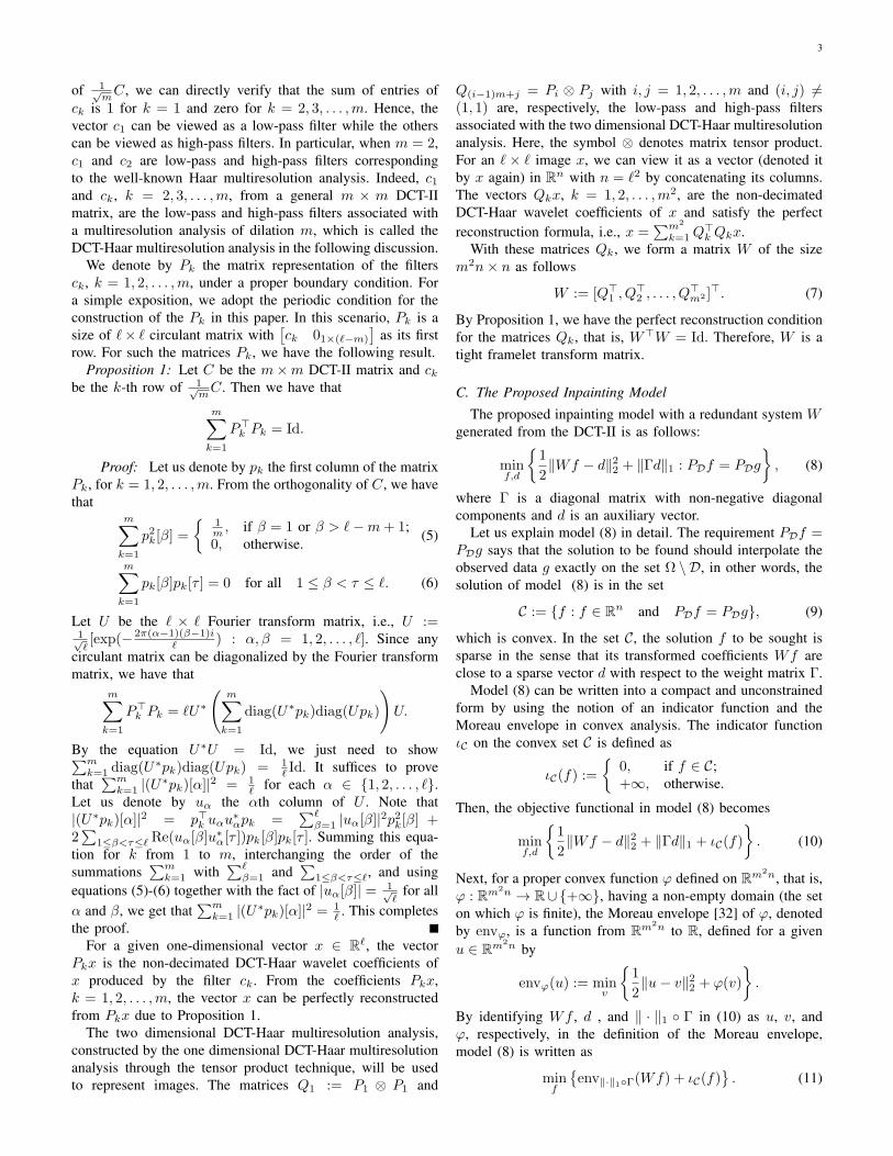
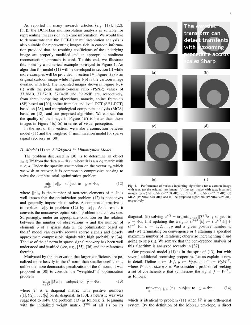
As reported in many research articles (e.g. [18], [22],[33]), the DCT-Haar multiresolution analysis is suitable forrepresenting images rich in texture information. We would liketo demonstrate that the DCT-Haar multiresolution analysis isalso suitable for representing images rich in cartoon informa-tion provided that the resulting coefficients of the underlyingimage are properly modified and an appropriate nonlinearreconstruction approach is used. To this end, we illustratethis point by a numerical example portrayed in Figure 1. Analgorithm for model (11) will be developed in section III whilemore examples will be provided in section IV. Figure 1(a) is anoriginal cartoon image while Figure 1(b) is the cartoon imageoverlaid with text. The inpainted images shown in Figure 1(c)-(f) with the peak signal-to-noise ratio (PSNR) values of37.38dB, 37.37dB, 37.04dB and 39.96dB are, respectively,from three competing algorithms, namely, spline framelets(SF) based on [20], spline framelet and local DCT (SF-LDCT)based on [28], and morphological component analysis (MCA)based on [18], and our proposed algorithm. We can see thatthe quality of the image in Figure 1(f) is better than thoseimages in Figure 1(c)-(e) in terms of visual perception.
In the rest of this section, we make a connection betweenmodel (11) and the weighted ℓ1 minimization model for sparsesignal recovery in [30].
D. Model (11) vs. A Weighted ℓ1 Minimization Model
The problem discussed in [30] is to determine an objectx0 ∈ Rq from the data y = Φx0, where Φ is a n×q matrix withn < q. Under the sparsity assumption on the vector x0 whichwe wish to recover, it is common in compressive sensing tosolve the combinatorial optimization problem
minx∈Rq
∥x∥0 subject to y = Φx, (12)
where ∥x∥0 is the number of non-zero elements of x. It iswell known that the optimization problem (12) is nonconvexand generally impossible to solve. A common alternative isto replace ∥x∥0 in problem (12) by ∥x∥1. As a result, itconverts the nonconvex optimization problem to a convex one.Surprisingly, under an appropriate condition on the relationbetween the number of observations n and the number ofelements q of a sparse data x, the optimization based onthe ℓ1 model can exactly recover sparse signals and closelyapproximate compressible signals with high probability [34].The use of the ℓ1 norm in sparse signal recovery has been wellunderstood and justified (see, e.g., [35], [36] and the referencestherein).
Motivated by the observation that larger coefficients are pe-nalized more heavily in the ℓ1 norm than smaller coefficients,unlike the more democratic penalization of the ℓ0 norm, it wasproposed in [30] to consider the “weighted” ℓ1 optimizationproblem
minx∈Rq
∥Tx∥1 subject to y = Φx, (13)
where T is a diagonal matrix with positive numberst[1], t[2], . . . , t[q] on its diagonal. In [30], a heuristic way wassuggested to solve the problem (13) as follows: (i) beginningwith the initialized weight matrix T (0) of all 1’s on its
(a) (b)
(c) (d)
(e) (f)Fig. 1. Performance of various inpainting algorithms for a cartoon imagewith text. (a) the original test image; (b) the test image with text; inpaintedimages by (c) SF (PSNR=37.38 dB); (d) SF-LDCT (PSNR=37.37 dB); (e)MCA (PSNR=37.04 dB); and (f) the proposed algorithm (PSNR=39.96 dB),respectively.
diagonal; (ii) solving x(ℓ) = argminx∈Rq ∥T (ℓ)x∥1 subject toy = Φx; (iii) updating the weights t(ℓ+1)[k] := (|x(ℓ)[k]| +ϵ)−1 for k = 1, 2, . . . , q and a given positive number ϵ;and (iv) terminating on convergence or ℓ attaining a specifiedmaximum number of iterations; otherwise incrementing ℓ andgoing to step (ii). We remark that the convergence analysis ofthis algorithm is analyzed recently in [37].
Our proposed model (11) is in the sprit of (13), but withseveral additional promising properties. Let us explain it nowin detail. Define x := Wf , y := PDg, and Φ := PDW
⊤,where W is of size q × n. We consider a problem of seekinga set of coefficients x that synthesizes the signal f = W⊤xas follows:
minx
env∥·∥1Γ(x) subject to y = Φx, (14)
which is identical to problem (11) when W is an orthogonalsystem. By the definition of the Moreau envelope, a direct
5
calculation gives, for a nonnegative number a,
enva|·|(u) =
a|u| − 1
2a2, if |u| ≥ a;
12 |u|
2, otherwise. (15)
Since Γ is an n×n diagonal matrix with non-negative diagonalelements, then ∥ · ∥1 Γ is separable. Hence env∥·∥1Γ(x) =∑q
k=1 envγ[k]|·|(x[k]). Further, by using formula (15), wedefine a diagonal matrix T with diagonal elements as
t[k] :=
γ[k]
(2|x[k]|−γ[k]
2|x[k]|
), if |x[k]| ≥ γ[k];
12 |x[k]|, otherwise.
(16)
With this weight matrix T , we have that env∥·∥1Γ(x) =∥Tx∥1. This is the reason why we call Γ the weight matrixas well. By comparing the formulation (14) together with(16) to that of (13), one can view (14) as a weighted ℓ1
minimization problem. The strategy in determining the weightT is obviously different from the one given in [30]. InStep (iii) of the aforementioned approach in [30], the weightcorresponding to an entry of a sparse signal is simply thereversal of the sum of the magnitude of the entry and a smallpositive number ϵ. The weight for an entry of a sparse signalin (16) is determined by a pre-determined threshold, i.e., thematrix Γ that will be estimated in an automatic way in thenext section. On the other hand, unlike the objective functionalin (13), the one in (14) is differentiable and its gradient isLipschitz continuous. This property is particularly important indeveloping a fast and efficient numerical algorithm for solvingthe optimization problem (14). Again, this will be illustratedin the next section.
III. ALGORITHMS
In this section, we propose an iterative algorithm for solvingmodel (11) which involves a redundant system W generatedfrom the DCT and a weight matrix Γ. We further suggest avariant of the algorithm with a varying weight matrix Γ initerations.
A. Algorithm for Model (11)
This subsection presents a fast algorithm for solvingmodel (11). The cost function of the model is the sum of thefunctions env∥·∥1Γ W and ιC . By the definition of indicatorfunction, ιC is not differentiable. We will show that env∥·∥1ΓW is differentiable and its gradient is Lipschitz continuous.Hence, Beck and Teboulle’s gradient descent method knownas accelerated proximal descent gradient (APDG) algorithm[1] is suitable for solving model (11).
The accelerated proximal gradient algorithm is developedfor a general nonsmooth convex optimization model
minf
ψ(f) + ϕ(f), (17)
where ϕ : Rn → R∪+∞ is a convex function, ψ : Rn → Ris continuously differentiable with Lipschitz continuous gra-dient L(ψ), i.e., ∥∇ψ(f1) − ∇ψ(f2)∥2 ≤ L(ψ)∥f1 − f2∥2for every f1, f2 ∈ Rn. The corresponding APDG algorithmproposed in [1] is given in Algorithm 1.
Algorithm 1 (Accelerated proximal decent gradient (APDG)):
1) set τ1 = 1, f0 = PDg + (Id − PD)X , where X isa matrix whose entries are uniformly distributed onthe interval [0, 255];
2) Take u1 = f0 and L = L(ψ) as a Lipschitz constantof ∇ψ;
3) For k = 1, 2, . . ., computea) fk = argminfϕ(f) + L
2 ∥f −(uk − 1
L∇ψ(uk))∥22
b) τk+1 =1+
√1+4τ2
k
2
c) uk+1 = fk +(
τk−1τk+1
)(fk − fk−1)
To apply APDG Algorithm 1 for model (11), we need toidentify the corresponding functions ψ and ϕ in model (11). Tothis end, we give some properties of the functions env∥·∥1Γ W and ιC in model (11).
Lemma 1: If Γ is a diagonal matrix with nonnegative diag-onal entries and W is the tight framelet transform matrix givenin (7), then env∥·∥1Γ W is continuously differentiable andits gradient is Lipschitz continuous with the Lipschitz constant1.
Proof: It is well-known that the Moreau envelopeof any function is always differentiable and the gradient ofthe Moreau envelope is Lipschitz continuous with Lipschitzconstant 1 [32], [38]. Thus, the chain rule yields ∇(env∥·∥1ΓW ) = W⊤∇env∥·∥1Γ W . Therefore, for any f1 and f2 inRn, we have that
∥∇(env∥·∥1Γ W )(f1)−∇(env∥·∥1Γ W )(f2)∥2≤ ∥W⊤∥2∥W∥2∥f1 − f2∥2.
Notice that ∥W⊤∥22 = ∥W∥22 = ∥W⊤W∥2 = 1 due toW⊤W = Id. Hence, the Lipschitz constant of the gradient∇(env∥·∥1Γ W ) is 1. This completes the proof.
The following result explains how to compute ∇env∥·∥1Γ.Lemma 2: If Γ is an n × n diagonal matrix with non-
negative diagonal entries, then the kth entry, k = 1, 2, . . . , n,of the gradient of env∥·∥1Γ at f ∈ Rn is
∇env∥·∥1Γ(f)[k] =
γksign(f [k]), if |f [k]| ≥ γk;f [k], otherwise,
where γk is the kth diagonal entry of Γ.Proof: Since Γ is a diagonal matrix with non-
negative diagonal elements, then we have that env∥·∥1Γ(f) =∑nk=1 env|γk·|(f [k]). Hence, the conclusion of the lemma
follows immediately from (15).Lemma 3: If g, as shown in (1), is an image to be inpainted
on the domain D and the convex set C is given in (9), thenfor any α > 0 and f ∈ Rn we have that
PDg + (Id− PD)f = argminu
α2∥u− f∥22 + ιC(u)
(18)
Proof: By the definition of the indicator function, weknow that
α
2∥u− f∥22 + ιC(u) =
α2 ∥u− f∥22, if u ∈ C;+∞, otherwise.
6
Because PD(Id−PD) = 0, then ∥u−f∥22 = ∥PD(u−f)∥22+∥(Id − PD)(u − f)∥22 ≥ ∥PD(g − f)∥22 for any u ∈ C. Theequality in the above holds when we choose u = PDg+(Id−PD)f . This completes the proof.
With Lemmas 1 and 3, we identity the functions env∥·∥1ΓW and ιC in model (11) as ψ and ϕ in model (17), respectively.By using Lemmas 1-3, an algorithm based on APDG formodel (11) is proposed in Algorithm 2.
Algorithm 2 (Algorithm for Model (11)):1) set τ1 = 1, f0 = PDg + (Id − PD)X , where X is
a matrix whose entries are uniformly distributed onthe interval [0, 255], and a pre-determined matrix Γ;
2) Take u1 = f0;3) For k = 1, 2, . . ., compute
a) fk = PDg + (Id − PD)(uk −W⊤∇env∥·∥1Γ(Wuk))
b) τk+1 =1+
√1+4τ2
k
2
c) uk+1 = fk +(
τk−1τk+1
)(fk − fk−1)
Let fk be the sequence generated by Algorithm 2. Then allelements in the sequence are in C. Let f⋆ be the point at whichthe function env∥·∥1Γ(Wf)+ιC(f) in model (11) achieves itsminimal value. Then f⋆ must be in C as well. For Algorithm 2,the rate of convergence of the sequence of function valuesenv∥·∥1Γ(Wfk) to the optimal value env∥·∥1Γ(Wf⋆) isgiven as follows:
env∥·∥1Γ(Wfk)− env∥·∥1Γ(Wf⋆) ≤ 2∥fk − f⋆∥22(k + 1)2
for all k ≥ 1. The proof of the above estimate is given in [1].The remaining problem for Algorithm 2 is how to choose
the matrix Γ. We plan to use the procedure proposed in ourrecent work [39] to automatically estimate Γ associated withevaluating env∥·∥1Γ(Wu) for an input image u. To this end,let us denote by v the Wu. For any non-negative integer p andpositive integer q, we denote by quot (p, q) and rem (p, q) thequotient and the remainder, respectively, when p is divided byq. For the ℓth entry of v, we can identify this entry by thetriplets (ℓ1, ℓ2, ℓ3) where ℓ1 = quot(quot(ℓ − 1, n),m) + 1,ℓ2 = rem(quot(ℓ− 1, n),m)+1, and ℓ3 = rem(ℓ− 1, n)+1.The pair of indexes (ℓ1, ℓ2) indicates that v[ℓ] the ℓth entryof v is from the subband generated by Pℓ1 ⊗ Pℓ2 and theindex ℓ3 indicates that this entry v[ℓ] is the ℓ3th entry of thevector Q(ℓ1−1)m+ℓ2u = (Pℓ1 ⊗ Pℓ2)u. With this notation, assuggested in [39], γℓ the ℓth entry of Γ is estimated as follows:
γℓ =
0, if 1 ≤ ℓ ≤ n;√
2σ2u
m2σv[ℓ], otherwise,
(19)
where σ2u is the noise variance of the image u and σ2
v[ℓ] isthe variance of v[ℓ] with the assumption of v[ℓ] being Laplacedistributed. Here, σ2
v[ℓ] can be estimated by [40], [39]
σ2v[ℓ] = max
∑k∈R(v[ℓ])
√2|v[k]|
|R(v[ℓ])|
2
− σ2u/m
2, 10−6
,
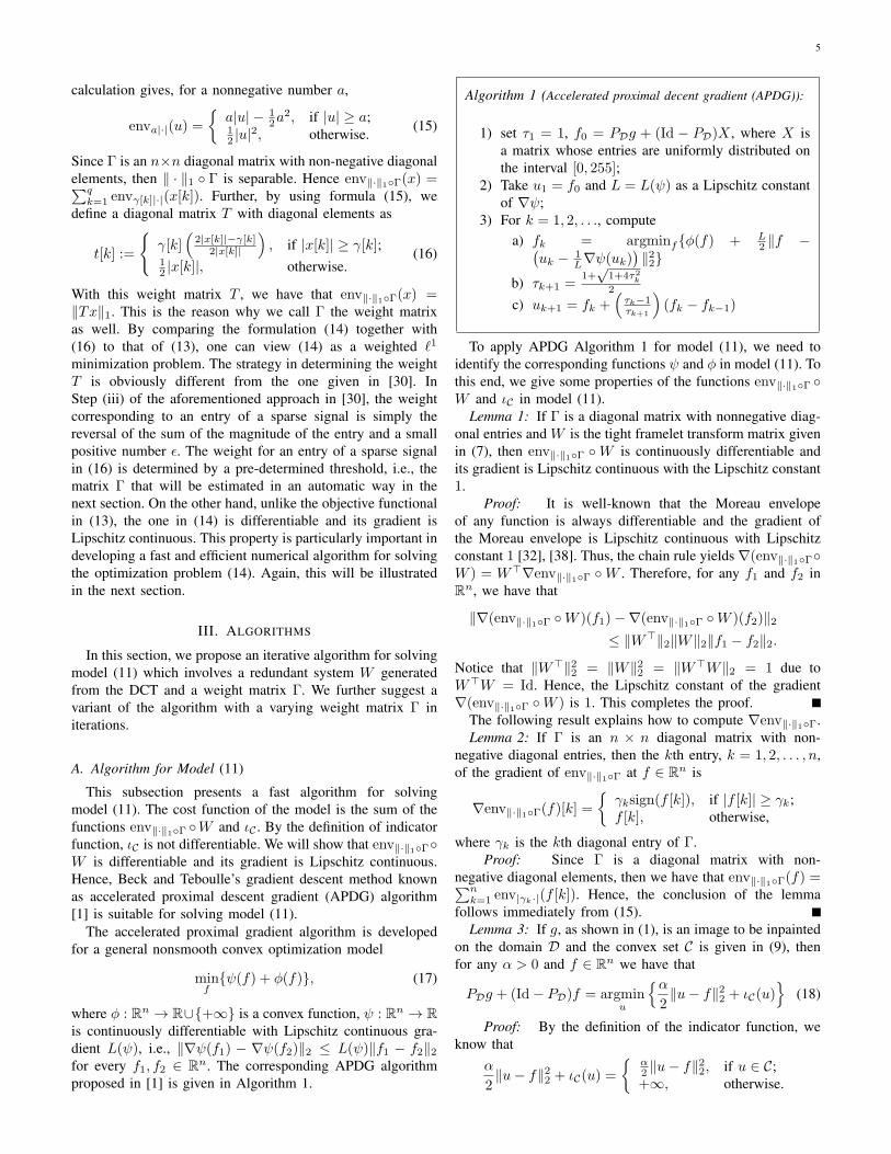
Fig. 2. The test images superposed by “Text 1” (the first column) and “Text2” (the second column). The square region in each image is the part of thecorresponding image zoomed in.
where the index set R(v[ℓ]) is the neighborhood of thecoefficient v[ℓ] in the corresponding (ℓ1, ℓ2) subband and|R(v[ℓ])| is the cardinality of the set R(v[ℓ]). The windowR(v[ℓ]) of size (m+2)×(m+2) is adopted in our experiments.
Based on the formula (19), Algorithm 3 is presented as avariant of Algorithm 2 with adaptive updating the matrix Γ initerations.
Algorithm 3 (Adaptive Algorithm for Model (11)):1) Set τ1 = 1, f0 = PDg + (Id − PD)X , where X is
a matrix whose entries are uniformly distributed onthe interval [0, 255], and a pre-given positive integers;
2) Take u1 = f0;3) For k = 1, 2, . . ., compute
a) Estimate Γk from the input image uk′ basedon (19) with k′ = s · quot (k − 1, s) + 1
b) fk = PDg + (Id − PD)(uk −W⊤∇env∥·∥1Γk
(Wuk))
c) τk+1 =1+
√1+4τ2
k
2
d) uk+1 = fk +(
τk−1τk+1
)(fk − fk−1)
7
(R1-a) (R1-b) (R1-c) (R1-d) (R1-e) (R1-f)
(R2-a) (R2-b) (R2-c) (R2-d) (R2-e) (R2-f)
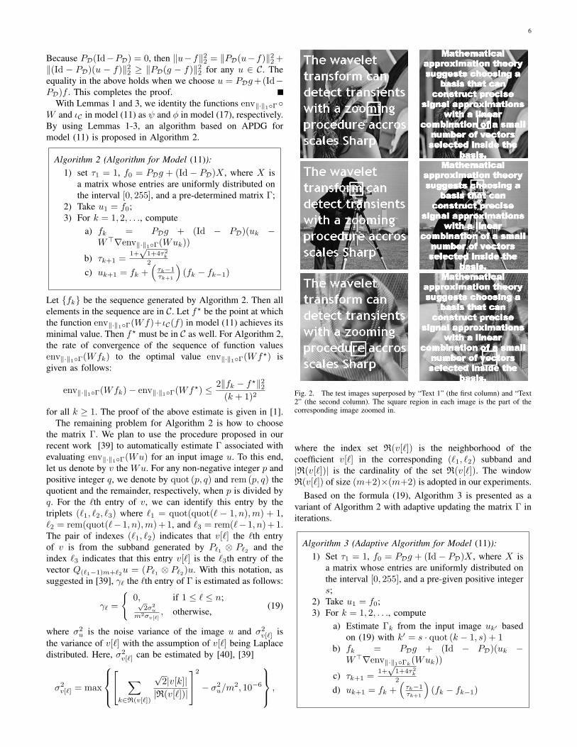
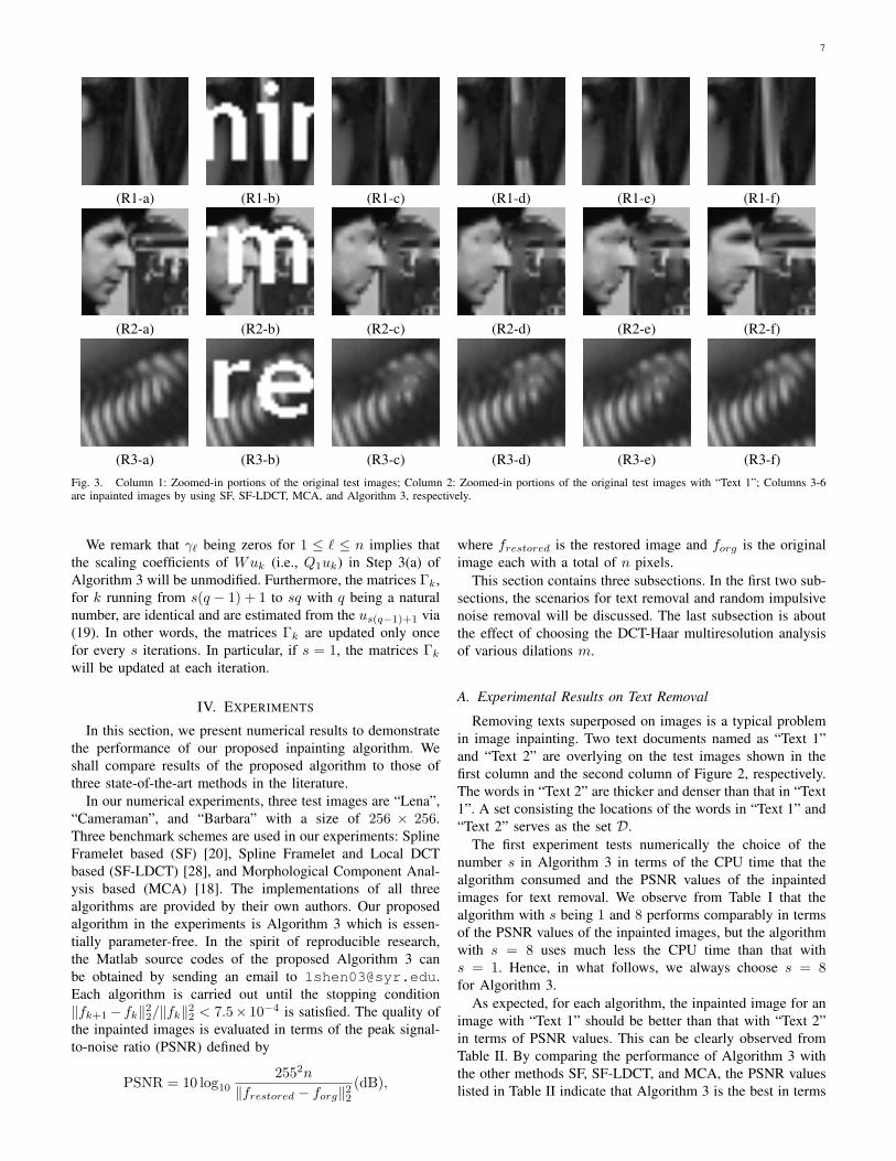
(R3-a) (R3-b) (R3-c) (R3-d) (R3-e) (R3-f)Fig. 3. Column 1: Zoomed-in portions of the original test images; Column 2: Zoomed-in portions of the original test images with “Text 1”; Columns 3-6are inpainted images by using SF, SF-LDCT, MCA, and Algorithm 3, respectively.
We remark that γℓ being zeros for 1 ≤ ℓ ≤ n implies thatthe scaling coefficients of Wuk (i.e., Q1uk) in Step 3(a) ofAlgorithm 3 will be unmodified. Furthermore, the matrices Γk,for k running from s(q − 1) + 1 to sq with q being a naturalnumber, are identical and are estimated from the us(q−1)+1 via(19). In other words, the matrices Γk are updated only oncefor every s iterations. In particular, if s = 1, the matrices Γk
will be updated at each iteration.
IV. EXPERIMENTS
In this section, we present numerical results to demonstratethe performance of our proposed inpainting algorithm. Weshall compare results of the proposed algorithm to those ofthree state-of-the-art methods in the literature.
In our numerical experiments, three test images are “Lena”,“Cameraman”, and “Barbara” with a size of 256 × 256.Three benchmark schemes are used in our experiments: SplineFramelet based (SF) [20], Spline Framelet and Local DCTbased (SF-LDCT) [28], and Morphological Component Anal-ysis based (MCA) [18]. The implementations of all threealgorithms are provided by their own authors. Our proposedalgorithm in the experiments is Algorithm 3 which is essen-tially parameter-free. In the spirit of reproducible research,the Matlab source codes of the proposed Algorithm 3 canbe obtained by sending an email to [email protected] algorithm is carried out until the stopping condition∥fk+1 − fk∥22/∥fk∥22 < 7.5× 10⁻⁴ is satisfied. The quality ofthe inpainted images is evaluated in terms of the peak signal-to-noise ratio (PSNR) defined by
PSNR = 10 log102552n
∥frestored − forg∥22(dB),
where frestored is the restored image and forg is the originalimage each with a total of n pixels.
This section contains three subsections. In the first two sub-sections, the scenarios for text removal and random impulsivenoise removal will be discussed. The last subsection is aboutthe effect of choosing the DCT-Haar multiresolution analysisof various dilations m.
A. Experimental Results on Text Removal
Removing texts superposed on images is a typical problemin image inpainting. Two text documents named as “Text 1”and “Text 2” are overlying on the test images shown in thefirst column and the second column of Figure 2, respectively.The words in “Text 2” are thicker and denser than that in “Text1”. A set consisting the locations of the words in “Text 1” and“Text 2” serves as the set D.
The first experiment tests numerically the choice of thenumber s in Algorithm 3 in terms of the CPU time that thealgorithm consumed and the PSNR values of the inpaintedimages for text removal. We observe from Table I that thealgorithm with s being 1 and 8 performs comparably in termsof the PSNR values of the inpainted images, but the algorithmwith s = 8 uses much less the CPU time than that withs = 1. Hence, in what follows, we always choose s = 8for Algorithm 3.
As expected, for each algorithm, the inpainted image for animage with “Text 1” should be better than that with “Text 2”in terms of PSNR values. This can be clearly observed fromTable II. By comparing the performance of Algorithm 3 withthe other methods SF, SF-LDCT, and MCA, the PSNR valueslisted in Table II indicate that Algorithm 3 is the best in terms
8
(R1-a) (R1-b) (R1-c) (R1-d) (R1-e) (R1-f)
(R2-a) (R2-b) (R2-c) (R2-d) (R2-e) (R2-f)
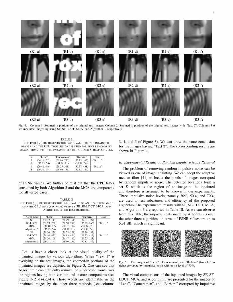
(R3-a) (R3-b) (R3-c) (R3-d) (R3-e) (R3-f)Fig. 4. Column 1: Zoomed-in portions of the original test images; Column 2: Zoomed-in portions of the original test images with “Text 2”; Columns 3-6are inpainted images by using SF, SF-LDCT, MCA, and Algorithm 3, respectively.
TABLE ITHE PAIR (·, ·) REPRESENTS THE PSNR VALUE OF THE INPAINTED
IMAGES AND THE CPU TIME (SECONDS) USED FOR TEXT REMOVAL BYALGORITHM 3 WITH THE PARAMETER s BEING 1 AND 8, RESPECTIVELY.
s “Lena” “Cameraman” “Barbara.” Case1 (34.16, 203) (31.96, 213) (37.15, 162) “Text 1”8 (33.95, 76) (31.96, 81) (36.98, 64)1 (29.41, 446) (28.55, 368) (30.37, 438) “Text 2”8 (29.31, 144) (28.60, 135) (30.12, 142)
of PSNR values. We further point it out that the CPU timesconsumed by both Algorithm 3 and the MCA are comparablefor all tested cases.
TABLE IITHE PAIR (·, ·) REPRESENTS THE PSNR VALUE OF AN INPAINTED IMAGE
AND THE CPU TIME (SECONDS) USED BY SF, SF-LDCT, MCA, ANDALGORITHM 3 FOR TEXT REMOVAL.
Algorithms “Lena” “Cameraman” “Barbara.” CaseSF (32.12, 143) (30.29, 151) (32.81, 127)
SF-LDCT (31.73, 260) (30.58, 282) (35.22, 266) “Text 1”MCA (32.48, 92) (30.63, 88) (35.37, 89)
Algorithm 3 (33.95, 76) (31.96, 81) (36.98, 64)SF (28.36, 228) (26.78, 221) (27.79, 183)
SF-LDCT (28.10, 425) (26.83, 426) (29.27, 415) “Text 2”MCA (28.20, 109) (26.47, 110) (29.25, 123)
Algorithm 3 (29.31, 144) (28.60, 135) (30.12, 142)
Let us have a closer look at the visual quality of theinpainted images by various algorithms. When “Text 1” isoverlying on the test images, the zoomed-in portions of theinpainted images are depicted in Figure 3. One can see thatAlgorithm 3 can efficiently remove the superposed words overthe regions having both cartoon and texture components (seeFigure 3(R1-f)-(R3-f)). Those words are identifiable in theinpainted images by the other three methods (see columns
3, 4, and 5 of Figure 3). We can draw the same conclusionfor the images having “Text 2”. The corresponding results areshown in Figure 4.
B. Experimental Results on Random Impulsive Noise Removal
The problem of removing random impulsive noise can beviewed as one of image inpainting. We can adopt the adaptivemedian filter [41] to locate the pixels of images corruptedby random impulsive noise. The detected locations form aset D which is the region of an image to be inpaintedand therefore is assumed to be known in our experiments.Three impulsive noise levels, namely 30%, 50%, and 70%,are used to test robustness and efficiency of the proposedalgorithm. The experimental results with SF, SF-LDCT, MCA,and Algorithm 3 are reported in Table III. As we can observefrom this table, the improvements made by Algorithm 3 overthe other three algorithms in terms of PSNR values are up to5.31 dB, which is significant.
Fig. 5. The images of “Lena”, “Cameraman”, and “Barbara” (from left toright) corrupted by impulsive noise with noise level of 70%.
The visual comparisons of the inpainted images by SF, SF-LDCT, MCA, and Algorithm 3 are presented for the images of“Lena”, “Cameraman”, and “Barbara” corrupted by impulsive
9
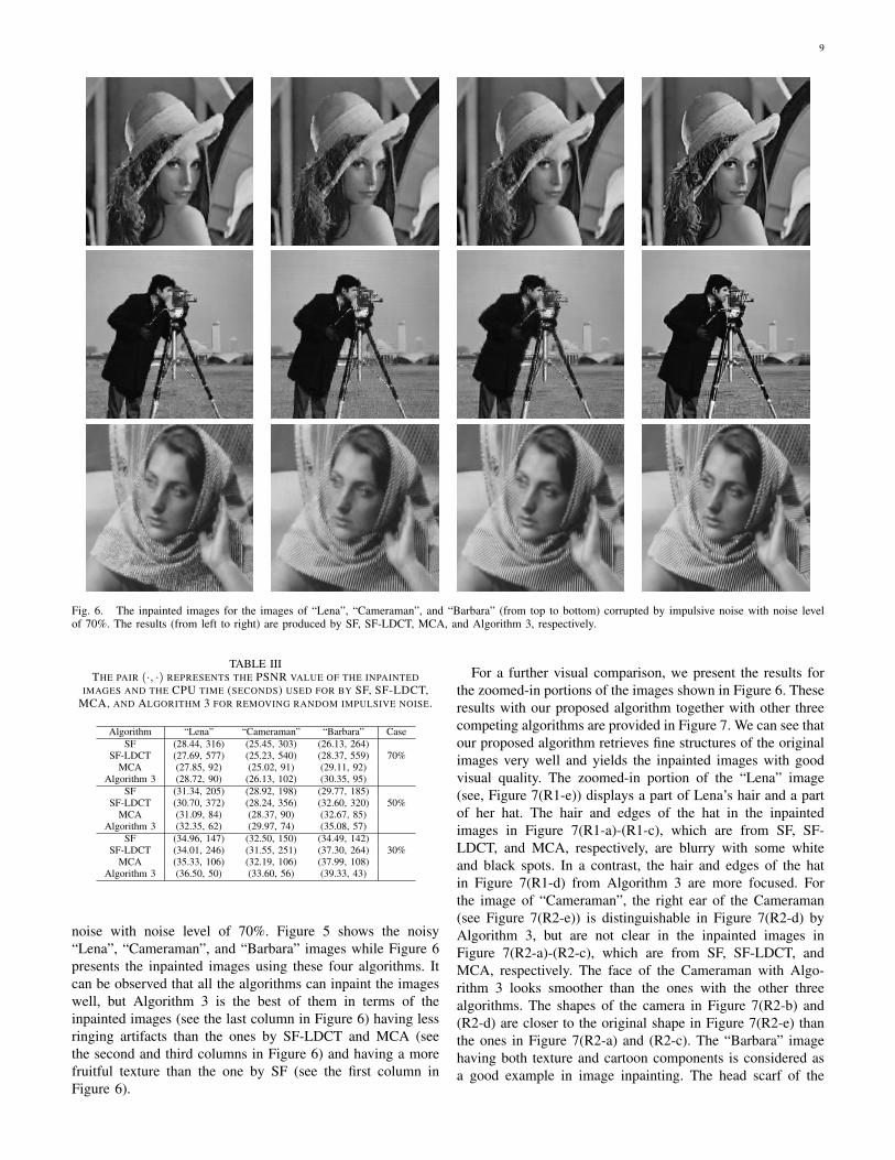
Fig. 6. The inpainted images for the images of “Lena”, “Cameraman”, and “Barbara” (from top to bottom) corrupted by impulsive noise with noise levelof 70%. The results (from left to right) are produced by SF, SF-LDCT, MCA, and Algorithm 3, respectively.
TABLE IIITHE PAIR (·, ·) REPRESENTS THE PSNR VALUE OF THE INPAINTED
IMAGES AND THE CPU TIME (SECONDS) USED FOR BY SF, SF-LDCT,MCA, AND ALGORITHM 3 FOR REMOVING RANDOM IMPULSIVE NOISE.
Algorithm “Lena” “Cameraman” “Barbara” CaseSF (28.44, 316) (25.45, 303) (26.13, 264)
SF-LDCT (27.69, 577) (25.23, 540) (28.37, 559) 70%MCA (27.85, 92) (25.02, 91) (29.11, 92)
Algorithm 3 (28.72, 90) (26.13, 102) (30.35, 95)SF (31.34, 205) (28.92, 198) (29.77, 185)
SF-LDCT (30.70, 372) (28.24, 356) (32.60, 320) 50%MCA (31.09, 84) (28.37, 90) (32.67, 85)
Algorithm 3 (32.35, 62) (29.97, 74) (35.08, 57)SF (34.96, 147) (32.50, 150) (34.49, 142)
SF-LDCT (34.01, 246) (31.55, 251) (37.30, 264) 30%MCA (35.33, 106) (32.19, 106) (37.99, 108)
Algorithm 3 (36.50, 50) (33.60, 56) (39.33, 43)
noise with noise level of 70%. Figure 5 shows the noisy“Lena”, “Cameraman”, and “Barbara” images while Figure 6presents the inpainted images using these four algorithms. Itcan be observed that all the algorithms can inpaint the imageswell, but Algorithm 3 is the best of them in terms of theinpainted images (see the last column in Figure 6) having lessringing artifacts than the ones by SF-LDCT and MCA (seethe second and third columns in Figure 6) and having a morefruitful texture than the one by SF (see the first column inFigure 6).
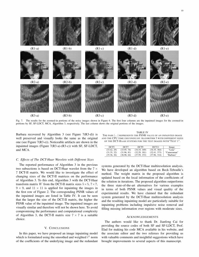
For a further visual comparison, we present the results forthe zoomed-in portions of the images shown in Figure 6. Theseresults with our proposed algorithm together with other threecompeting algorithms are provided in Figure 7. We can see thatour proposed algorithm retrieves fine structures of the originalimages very well and yields the inpainted images with goodvisual quality. The zoomed-in portion of the “Lena” image(see, Figure 7(R1-e)) displays a part of Lena’s hair and a partof her hat. The hair and edges of the hat in the inpaintedimages in Figure 7(R1-a)-(R1-c), which are from SF, SF-LDCT, and MCA, respectively, are blurry with some whiteand black spots. In a contrast, the hair and edges of the hatin Figure 7(R1-d) from Algorithm 3 are more focused. Forthe image of “Cameraman”, the right ear of the Cameraman(see Figure 7(R2-e)) is distinguishable in Figure 7(R2-d) byAlgorithm 3, but are not clear in the inpainted images inFigure 7(R2-a)-(R2-c), which are from SF, SF-LDCT, andMCA, respectively. The face of the Cameraman with Algo-rithm 3 looks smoother than the ones with the other threealgorithms. The shapes of the camera in Figure 7(R2-b) and(R2-d) are closer to the original shape in Figure 7(R2-e) thanthe ones in Figure 7(R2-a) and (R2-c). The “Barbara” imagehaving both texture and cartoon components is considered asa good example in image inpainting. The head scarf of the
10
(R1-a) (R1-b) (R1-c) (R1-d) (R1-e)
(R2-a) (R2-b) (R2-c) (R2-d) (R2-e)
(R3-a) (R3-b) (R3-c) (R3-d) (R3-e)Fig. 7. The results for the zoomed-in portions of the noisy images shown in Figure 6. The first four columns are the inpainted images for the zoomed-inportions by SF, SF-LDCT, MCA, Algorithm 3, respectively. The last column shows the original portions of the images.
Barbara recovered by Algorithm 3 (see Figure 7(R3-d)) iswell preserved and visually looks the same as the originalone (see Figure 7(R3-e)). Noticeable artifacts are shown in theinpainted images (Figure 7(R3-a)-(R3-c)) with SF, SF-LDCT,and MCA.
C. Effects of The DCT-Haar Wavelets with Different Sizes
The reported performance of Algorithm 3 in the previoustwo subsections is based on DCT-Haar wavelet from the 7×7 DCT-II matrix. We would like to investigate the effect ofchanging sizes of the DCT-II matrices on the performanceof Algorithm 3. To this end, Algorithm 3 with the DCT-Haartransform matrix W from the DCT-II matrix sizes 5×5, 7×7,9 × 9, and 11 × 11 is applied for inpainting the images inthe first row of Figure 2. The corresponding PSNR values ofthe inpainted images are listed in Table IV. It can be seenthat the larger the size of the DCT-II matrix, the higher thePSNR value of the inpainted image. The inpainted images arevisually similar and therefore will not be shown here. To avoidcompromising the performance and computational complexityof Algorithm 3, the DCT-II matrix size 7 × 7 is a suitablechoice.
V. CONCLUSIONS
In this paper, we have proposed an image inpainting modelwhich is formulated using the smoothed and weighted ℓ1 normof the coefficients of the underlying image and the redundant
TABLE IVTHE PAIR (·, ·) REPRESENTS THE PSNR VALUE OF AN INPAINTED IMAGE
AND THE CPU TIME (SECONDS) BY ALGORITHM 3 WITH DIFFERENT SIZESOF THE DCT-HAAR SYSTEMS FOR THE TEST IMAGES WITH“TEXT 1”.
DCT5 DCT7 DCT9 DCT11 Image(33.42, 29) (33.95, 76) (34.19, 169) (34.35, 364) “Lena”(31.35, 32) (31.96, 81) (32.29, 181) (32.41, 373) “Cameraman”(35.36, 26) (36.98, 64) (37.59, 153) (37.96, 314) “Barbara”
systems generated by the DCT-Haar multiresolution analysis.We have developed an algorithm based on Beck-Teboulle’smethod. The weight matrix in the proposed algorithm isupdated based on the local information of the coefficients ofthe solution in iterations. The proposed algorithm outperformsthe three state-of-the-art alternatives for various examplesin terms of both PSNR values and visual quality of theexperimental results. We have claimed that the redundantsystem generated by the DCT-Haar multiresolution analysisand the resulting inpainting model are particularly suitable forinpainting problems including impulsive noise removal andfilling missing information over regions with moderate sizes.
ACKNOWLEDGEMENTS
The authors would like to thank Dr. Jianfeng Cai forproviding the source codes of both SF and SF-LDCT, Prof.Elad for making his code MCA available in his website, andthe associate editor and the two referees for providing uswith valuable comments and insightful suggestions which havebrought improvements to several aspects of this manuscript.
11
The views and conclusions contained herein are those ofthe authors and should not be interpreted as necessarily repre-senting the official policies or endorsement, either expressedor implied, of the Air Force Research Laboratory or the U.S.Government.
REFERENCES
[1] A. Beck and M. Teboulle, “A fast iterative shrinkage-thresholding algo-rithm for linear inverse problems,” SIAM Journal on Imaging Sciences,vol. 2, no. 1, pp. 183–202, 2009.
[2] A. Bovik, Handbook of Image and Video Processing. Academic Press,San Diego, 2000.
[3] M. Bertalmio, G. Sapiro, V. Caselles, and C. Ballester, “Image inpaint-ing,” in Proceedings of SIGGRAPH, New Orleans, LA, 2000, pp. 417–424.
[4] X. Li and Y. Zheng, “Patch-based video processing: a variationalbayesian approach,” IEEE Transactions on Circuits and Systems forVideo Technology, vol. 19, no. 1, pp. 27–40, 2009.
[5] C. Ballester, M. Bertalmio, V. Caselles, L. Garrido, A. Marques, andF. Ranchin, “An inpainting-based deinterlacing method,” IEEE Transac-tions on Image Processing, vol. 16, no. 10, pp. 2476–2491, 2007.
[6] A. Maalouf, P. Carre, B. Augereau, and C. Fernandez-Maloigne, “Abandelet-based inpainting technique for clouds removal from remotelysensed images,” IEEE Transactions on Geoscience and Remote Sensing,vol. 47, no. 7, pp. 2363–2371, 2009.
[7] S. Masnou, “Disocclusion: a variational approach using level lines,”IEEE Transactions on Image Processing, vol. 11, no. 2, pp. 68–76, 2002.
[8] T. F. Chan and J. Shen, “Mathematical models for local nontextureinpaintings,” SIAM Journal on Applied Mathematics, vol. 62, no. 3, pp.1019–1043, 2002.
[9] T. F. Chan, S.-H. Kang, and J. Shen, “Euler’s elastica and curvature-based image inpainting,” SIAM Journal on Applied Mathematics, vol. 63,no. 2, pp. 564–592, 2002.
[10] T. F. Chan, J. Shen, and H.-M. Zhou, “Total variation wavelet inpaint-ing,” Journal of Mathematical Imaging and Vision, vol. 25, no. 1, 2006.
[11] A. Bertozzi, S. Esedoglu, and A. Gillette, “Inpainting of binary imagesusing the cahnchilliard equation,” IEEE Transactions on Image Process-ing, vol. 16, no. 1, pp. 285–291, 2007.
[12] J. A. Dobrosotskaya and A. L. Bertozzi, “A wavelet-laplace variationaltechnique for image deconvolution and inpainting,” IEEE Transactionson Image Processing, vol. 17, no. 5, pp. 657–663, 2008.
[13] M. Ashikhmin, “Synthesizing natural textures,” in Proceedings of the2001 symposium on Interactive 3D graphics, ACM New York, NY, USA,2001, pp. 217–226.
[14] A. Criminisi, P. Perez, and K. Toyama, “Region filling and objectremoval by exemplar-based inpainting,” IEEE Transactions on ImageProcessing, vol. 13, no. 9, pp. 1200–1212, 2004.
[15] N. Komodakis and G. Tziritas, “Image completion using efficientbelief propagation via priority scheduling and dynamic pruning,” IEEETransactions on Image Processing, vol. 16, no. 11, pp. 2649–2661, 2007.
[16] Y. Wexler, E. Shechtman, and M. Irani, “Space-time completion ofvideo,” IEEE Transactions on Pattern Analysis and Machine Intelli-gence, vol. 29, no. 3, pp. 463–476, 2007.
[17] A. Bugeau, M. Bertalmio, V. Caselles, and G. Sapiro, “A comprehensiveframework for image inpainting,” IEEE Transactions on Image Process-ing, vol. 19, no. 10, pp. 2634–2645, 2010.
[18] M. Elad, J. L. Starck, P. Querre, and D. L. Donoho, “Simultaneouscartoon and texture image inpainting using morphological compo-nent analysis (MCA),” Applied and Computational Harmonic Analysis,vol. 19, no. 3, pp. 340–358, 2005.
[19] O. G. Guleryuz, “Nonlinear approximation based image recovery usingadaptive sparse reconstruction and iterated denoising: part I − theory,”IEEE Transaction on Image Processing, vol. 15, no. 3, pp. 539–554,2006.
[20] J. F. Cai, R. H. Chan, and Z. Shen, “A framelet-based image inpaintingalgorithm,” Applied and Computational Harmonic Analysis, vol. 24,no. 2, pp. 131–149, 2008.
[21] J. Mairal, M. Elad, and G. Sapiro, “Sparse representation for color imagerestoration,” IEEE Transactions on Image Processing, vol. 17, no. 1, pp.53–69, 2008.
[22] M. J. Fadili, J. L. Starck, and F. Murtagh, “Inpainting and zoomingusing sparse representations,” The Computer Journal, vol. 52, no. 1, pp.64–79, 2009.
[23] J. F. Cai, R. H. Chan, L. Shen, and Z. Shen, “Convergence analysisof tight framelet approach for missing data recovery,” Advances inComputational Mathematics, vol. 31, no. 1-3, pp. 87–133, 2009.
[24] ——, “Simultaneously inpainting in image and transformed domains,”Numerische Mathematik, vol. 112, no. 4, pp. 509–533, 2009.
[25] M. Elad, M. A. T. Figueiredo, and Y. Ma, “On the role of sparse andredundant representations in image processing,” in Proceedings of theIEEE, vol. 98, no. 6, 2010, pp. 972–982.
[26] Z. Xu and J. Sun, “Image inpainting by patch propagation using patchsparsity,” IEEE Transactions on Image Processing, vol. 19, no. 5, pp.1153–1165, 2010.
[27] G. Peyre, “Texture synthesis with grouplets,” IEEE Transactions onPattern Analysis and Machine Intelligence, vol. 32, no. 4, pp. 733–746,2010.
[28] J. F. Cai, R. H. Chan, and Z. Shen, “Simultaneous cartoon and textureinpainting,” Inverse Problems and Imaging, vol. 4, no. 3, pp. 379–395,2010.
[29] N. Ahmed and K. R. Rao, Orthogonal Transforms for Digital SignalProcessing. New York: Springer-Verlag, 1975.
[30] E. J. Candes, M. B. Wakin, and S. P. Boyd, “Enhancing sparsity byreweighted ℓ1 minimization,” Journal of Fourier Analysis and Applica-tions, vol. 14, no. 5, pp. 877–905, 2008.
[31] R. H. Chan, L. Shen, and Z. Shen, “A framelet-based approach for imageinpainting,” The Chinese University of Hong Kong, Tech. Rep. 2005-4,Feb. 2005.
[32] J.-J. Moreau, “Proximite et dualite dans un espace hilbertien,” Bull. Soc.Math. France, vol. 93, pp. 273–299, 1965.
[33] Q. Lian, L. Shen, Y. Xu, and L. Yang, “Filters of wavelets on invariantsets for image denoising,” Applicable Analysis, vol. 90, no. 8, pp. 1299–1322, 2011.
[34] E. J. Candes, J. Romberg, and T. Tao, “Stable signal recovery fromincomplete and inaccurate measurements,” Communications on Pure andApplied Mathematics,, vol. 59, no. 8, pp. 1207–1223, 2006.
[35] ——, “Robust uncertainty principles: exact signal reconstruction fromhighly incomplete frequency information,” IEEE Transactions on Infor-mation Theory, vol. 52, no. 2, pp. 489–509, 2006.
[36] M. Lustig, D. L. Donoho, J. Santos, and J. Pauly, “Compressed sensingMRI,” IEEE Signal Processing Magazine, vol. 25, no. 2, pp. 72–82,2008.
[37] I. Daubechies, R. DeVore, M. Fornasier, and C. Gunturk, “Iterativelyreweighted least squares minimization for sparse recovery,” Communi-cations on Pure and Applied Mathematics,, vol. 63, no. 1, pp. 1–38,2010.
[38] H. L. Bauschke and P. L. Combettes, Convex Analysis and MonotoneOperator Theory in Hilbert Spaces, ser. AMS Books in Mathematics.Springer, New York, 2011.
[39] Y. R. Li, L. Shen, D. Q. Dai, and B. W. Suter, “Framelet algorithmsfor de-blurring images corrupted by impulse plus gaussian noise,” IEEETransactions on Image Processing, vol. 20, no. 7, pp. 1822–1837, 2011.
[40] Y. R. Li, D. Q. Dai, and L. Shen, “Multiframe super-resolution recon-struction using sparse directional regularization,” IEEE Transactions onCircuits and Systems for Video Technology, vol. 20, no. 7, pp. 945–956,2010.
[41] R. Gonzalez and R. Woods, Digital Image Processing. Addison-Wesley,Boston, MA, 1993.
Yan-Ran Li received the Ph.D. degree in communi-cations and information systems from the ElectronicDepartment, School of Information Science andTechnology, Sun Yat-Sen (Zhongshan) University,Guangzhou, China, in 2009. His field of study wasimage and video processing.
He was a Visiting Scholar with the National Uni-versity of Singapore, Kent Ridge, Singapore in 2008and the Chinese University of Hong Kong, Shatin,NT, Hong Kong, in 2011 and 2012. Currently, heis a Lecturer with the College of Computer Science
and Software Engineering, Shenzhen University, Shenzhen, China. His currentresearch interests include image processing, medical image processing, andembedded system software design.
12
Lixin Shen received the B.S. and M.S. degrees fromPeking University, Beijing, China, in 1987 and 1990,respectively, and the Ph.D. degree from ZhongshanUniversity, Guangzhou, China, in 1996, all in math-ematics. From 1996 to 2001, he was a ResearchFellow with the Center for Wavelets, Approximation,and Information Processing, National University ofSingapore, Singapore. From 2001 to 2002, he was aPost-Doctoral Fellow with the Virtual EnvironmentsResearch Institute, University of Houston, Houston,TX. From 2002 to 2004, he was a Research Assistant
Professor with the Department of Mathematics, West Virginia University,Morgantown. From 2004 to 2006, he was an Assistant Professor with theDepartment of Mathematics, Western Michigan University, Kalamazoo. Heis currently an Associate Professor with the Department of Mathematics,Syracuse University, Syracuse, NY. His research has been supported bythe National Science Foundation, Arlington, VA, and Air Force ResearchLaboratory, Rome, New York. His current research interests include multiscaleanalysis, convex analysis, and their applications in image processing.
Bruce W. Suter received the B.S. and M.S. degreesin electrical engineering in 1972, and the Ph.D. de-gree in computer science in 1988 from the Universityof South Florida, Tampa, U.S.A. In 1998, he joinedthe technical staff at the U.S. Air Force ResearchLaboratory, Rome, New York, where he was thefounding Director of the Center for Integrated Trans-mission and Exploitation (CITE). He has held avisiting appointments at Harvard University and theMassachusetts Institute of Technology. His currentresearch interests are focused on wireless computing
networks and their applications to signal and image processing. His previouspositions include academia at the U. S. Air Force Institute of Technology andthe University of Alabama at Birmingham, together with industrial positionsat Honeywell Inc. and Litton Industries. He is a former associate editor ofIEEE Transactions on Signal Processing and the author of a widely acceptedmonograph Multirate and Wavelet Signal Processing, Academic Press, 1998.
Dr. Suter is a Senior Member of IEEE, and a member of Tau Beta Piand Eta Kappa Nu. He has received a number of awards for his engineeringand research contributions. These include the Air Force Research Laboratory(AFRL) Fellow, an AFRL-wide award for his accomplishments in the theory,application, and implementation of signal processing algorithms, the ArthurS. Flemming Award, a government-wide award for his pioneering Hankeltransform research, the General Ronald W. Yates Award for Excellence inTechnology Transfer for his patented Fourier transform processor, and theFred I. Diamond Award for best laboratory research publication. He is authorof over a hundred technical publications.
Related Documents