AN 810: Intel FPGA JESD204B IP Core and ADI AD9208 Hardware Checkout Report Subscribe Send Feedback AN-810 | 2017.12.18 Latest document on the web: PDF | HTML

Welcome message from author
This document is posted to help you gain knowledge. Please leave a comment to let me know what you think about it! Share it to your friends and learn new things together.
Transcript

AN 810: Intel FPGA JESD204B IPCore and ADI AD9208 HardwareCheckout Report
SubscribeSend Feedback
AN-810 | 2017.12.18Latest document on the web: PDF | HTML

Contents
Intel FPGA JESD204B IP Core and ADI AD9208 Hardware Checkout Report....................... 3Hardware Requirements................................................................................................3Hardware Setup...........................................................................................................3Hardware Checkout Methodology................................................................................... 5
Receiver Data Link Layer......................................................................................5Receiver Transport Layer......................................................................................8Descrambling..................................................................................................... 8
Deterministic Latency (Subclass 1).................................................................................9JESD204B IP Core and ADC Configurations.................................................................... 11Test Results...............................................................................................................12Test Result Comments.................................................................................................20Document Revision History for AN 810: Intel FPGA JESD204B IP Core and ADI AD9208
Hardware Checkout Report................................................................................. 21Appendix...................................................................................................................21
Contents
AN 810: Intel FPGA JESD204B IP Core and ADI AD9208 Hardware Checkout Report2
Intel FPGA JESD204B IP Core and ADI AD9208 HardwareCheckout Report
The Intel FPGA JESD204B IP Core is a high-speed point-to-point serial interfaceintellectual property (IP).
The JESD204B IP core has been hardware-tested with a number of selectedJESD204B-compliant ADC (analog-to-digital converter) devices.
This report highlights the interoperability of the JESD204B IP core with the AD9208converter evaluation module (EVM) from Analog Devices Inc. (ADI). The followingsections describe the hardware checkout methodology and test results.
Related Links
JESD204B IP Core User Guide
Hardware Requirements
The hardware checkout test requires the following hardware and software tools:
• Intel® Arria® 10 GX FPGA Development Kit
• ADI AD9208 EVM
• Mini-USB cable
• SMA cables
• Clock source card capable of generating device clock frequencies
Related Links
Arria 10 GX FPGA Development KitDevelopment kit information and ordering code.
Hardware Setup
An Intel Arria 10 GX FPGA Development Kit is used with the ADI AD9208 daughtercard module installed to the development board’s FMC connector.
• The AD9208 EVM derives power from FMC pins.
• The FPGA and ADC device clocks are supplied by external clock source cardthrough SMA connectors on Intel Arria 10 FPGA kit and AD9208 EVM.
• Both FPGA and ADC device clocks must be sourced from the same clock sourcecard with two different frequencies, one for FPGA, and one for ADC.
• For subclass 1, FPGA generates SYSREF for the JESD204B IP as well as theAD9208 device.
• SYSREF is provided to ADC through SMA connector.
AN-810 | 2017.12.18
Intel Corporation. All rights reserved. Intel, the Intel logo, Altera, Arria, Cyclone, Enpirion, MAX, Nios, Quartusand Stratix words and logos are trademarks of Intel Corporation or its subsidiaries in the U.S. and/or othercountries. Intel warrants performance of its FPGA and semiconductor products to current specifications inaccordance with Intel's standard warranty, but reserves the right to make changes to any products and servicesat any time without notice. Intel assumes no responsibility or liability arising out of the application or use of anyinformation, product, or service described herein except as expressly agreed to in writing by Intel. Intelcustomers are advised to obtain the latest version of device specifications before relying on any publishedinformation and before placing orders for products or services.*Other names and brands may be claimed as the property of others.
ISO9001:2008Registered

Figure 1. Hardware setup
Arria 10 GX development kit
AD9208 EVM
ADC samplingclock
SYNC_INSYSREF in
SYSREF to ADC
FPGA deviceclock
The following system-level diagram shows how the different modules connect in thisdesign.
Intel FPGA JESD204B IP Core and ADI AD9208 Hardware Checkout Report
AN-810 | 2017.12.18
AN 810: Intel FPGA JESD204B IP Core and ADI AD9208 Hardware Checkout Report4

Figure 2. System Diagram
Note: The IOPLL input reference clock is sourcing from device clock through the global clock network. Sourcingreference clock from a cascaded PLL output, global clock or core clock network might introduce additional jitterto the IOPLL and transceiver PLL output. Refer to this KDB Answer for a workaround you should apply to the IPcore in your design.
ADCsampling clock
SMA cableExternal Clock Source
User I/OPB0
Oscillator100 MHz
global_rst_n
mgmt_clk
ADC
DAC
AD9208 EVMIntel Arria 10 GXDevelopment Kit
Intel Arria 10 Device (10AX115S1F45I1SG)
Avalon-ST
Avalon-ST
Avalon-ST32 bits perTransceiverLane
Avalon-ST32 bits perTransceiverLanePattern
Checker
Deassembler(RX Transport
Layer)
Avalon-STUser Data
Avalon-STUser Data JESD
DuplexIP Core
SPI Master
Core PLL
Nios IISubsystem
JESD204BSubsystem
Top-Level PlatformDesigner System
jesd204b_ed_qsys.qsys
Top-Level RTL (jesd204b_ed.sv)
PatternGenerator
Assembler(TX Transport
Layer)
FMC B
AD9208
JESD204BInterface
SPI Slave
Lane 0 - Lane 8, Lane Rate 16.0 Gbps
adc_sync_in
ADC sampling clock
4
FPGAdevice clock
ConversionCircuit
3
frame_clk link_clk
frame_clk
Sysref generator
CLK INSMA port J6
CLK OUTSMA port J7
device_clk 400 MHz
SYSREF input
SMA cable
SMA cable
ADC
ADC
In this setup, where LMF=882, the data rate of transceiver lanes is 16 Gbps. Anexternal clock source card provides 400 MHz clock to the FPGA and 1600 MHzsampling clock to AD9208 device. A periodic SYSREF is generated by the FPGA andprovided to the ADC through SMA connector.
Hardware Checkout Methodology
The following section describes the test objectives, procedure, and the passingcriteria. The test covers the following areas:
• Receiver data link layer
• Receiver transport layer
• Descrambling
• Deterministic latency (Subclass 1)
Receiver Data Link Layer
This test area covers the test cases for code group synchronization (CGS) and initialframe and lane synchronization (ILA).
Intel FPGA JESD204B IP Core and ADI AD9208 Hardware Checkout Report
AN-810 | 2017.12.18
AN 810: Intel FPGA JESD204B IP Core and ADI AD9208 Hardware Checkout Report5

On link start up, the receiver issues a synchronization request and the transmittertransmits /K/ (K28.5) characters. The Signal Tap II Logic Analyzer tool monitors thereceiver data link layer operation.
Code Group Synchronization (CGS)
Table 1. CGS Test Cases
Test Case Objective Description Passing Criteria
CGS.1 Check whether syncrequest is de-assertedafter correct receptionof four successive /K/characters.
The following signals in<ip_variant_name>_inst_phy.v aretapped:• jesd204_rx_pcs_data[(L*32)-1:0]• jesd204_rx_pcs_data_valid[L-1:0]• jesd204_rx_pcs_kchar_data[(L*4)-1
:0] (1) The following signals in<ip_variant_name>.v are tapped:• rx_dev_sync_n• jesd204_rx_intThe rxlink_clk is used as the samplingclock for the Signal Tap.Each lane is represented by 32-bit databus in jesd204_rx_pcs_data signal. The32-bit data bus for is divided into 4octets.
• /K/ character or K28.5 (0xBC) isobserved at each octet of thejesd204_rx_pcs_data bus.
• The jesd204_rx_pcs_data_validsignal is asserted to indicate datafrom the PCS is valid.
• The jesd204_rx_pcs_kchar_datasignal is asserted whenevercontrol characters like /K/, /R/, /Q/, or /A/ characters areobserved.
• The rx_dev_sync_n signal is de-asserted after correct receptionof at least four successive /K/characters.
• The jesd204_rx_int signal isdeasserted if there is no error.
CGS.2 Check full CGS at thereceiver after correctreception of anotherfour 8B/10Bcharacters.
The following signals in<ip_variant_name>_inst_phy.v aretapped:• jesd204_rx_pcs_errdetect[(L*4)-1:0
]• jesd204_rx_pcs_disperr[(L*4)-1:0] (
1)
The following signals in<ip_variant_name>.v are tapped:• jesd204_rx_intThe rxlink_clk is used as the samplingclock for the Signal Tap.
The jesd204_rx_pcs_errdetect,jesd204_rx_pcs_disperr andjesd204_rx_int signals should not beasserted during CGS phase.
(1) L is the number of lanes.
Intel FPGA JESD204B IP Core and ADI AD9208 Hardware Checkout Report
AN-810 | 2017.12.18
AN 810: Intel FPGA JESD204B IP Core and ADI AD9208 Hardware Checkout Report6

Initial Frame and Lane Synchronization (ILA)
Table 2. Initial Frame and Lane Synchronization Test Cases
Test Case Objective Description Passing Criteria
ILA.1 Check whether theinitial framesynchronization statemachine entersFS_DATA state uponreceiving non /K/characters.
The following signals in<ip_variant_name>_inst_phy.v aretapped:• jesd204_rx_pcs_data[(L*32)-1:0]• jesd204_rx_pcs_data_valid[L-1:0]• jesd204_rx_pcs_kchar_data[(L*4)-1
:0] (2)
The following signals in<ip_variant_name>.v are tapped:• rx_dev_sync_n• jesd204_rx_intThe rxlink_clk is used as the samplingclock for the Signal TapEach lane is represented by 32-bit databus in jesd204_rx_pcs_data. The 32-bitdata bus for is divided into 4 octets.
• /R/ character or K28.0 (0x1C) isobserved after /K/ character atthe jesd204_rx_pcs_data bus.
• The jesd204_rx_pcs_data_validsignal must be asserted toindicate that data from the PCS isvalid.
• The rx_dev_sync_n andjesd204_rx_int signals aredeasserted.
• Each multiframe in ILAS phaseends with /A/ character or K28.3(0x7C).
• The jesd204_rx_pcs_kchar_datasignal is asserted whenevercontrol characters like /K/, /R/, /Q/, or /A/ characters areobserved.
ILA.2 Check the JESD204Bconfigurationparameters from ADCin second multiframe.
The following signals in<ip_variant_name>_inst_phy.v aretapped:• jesd204_rx_pcs_data[(L*32)-1:0]• jesd204_rx_pcs_data_valid[L-1:0] (2)
The following signal in<ip_variant_name>.v is tapped:• jesd204_rx_intThe rxlink_clk is used as the samplingclock for the Signal Tap.The Nios console accesses the followingregisters:• ilas_octet0• ilas_octet1• ilas_octet2• ilas_octet3The content of 14 configuration octets insecond multiframe is stored in these 32-bit registers - ilas_octet0, ilas_octet1,ilas_octet2 and ilas_octet3.
• /R/ character is followed by /Q/character or K28.4 (0x9C) at thebeginning of second multiframe.
• The jesd204_rx_int is deassertedif there is no error.
• Octets 0-13 read from theseregisters match with theJESD204B parameters in eachtest setup.
ILA.3 Check the lanealignment
The following signals in<ip_variant_name>_inst_phy.v aretapped:• jesd204_rx_pcs_data[(L*32)-1:0]• jesd204_rx_pcs_data_valid[L-1:0] (2)
The following signals in<ip_variant_name>.v are tapped:• rx_somf[3:0]• dev_lane_aligned• jesd204_rx_intThe rxlink_clk is used as the samplingclock for the Signal Tap.
• The dev_lane_aligned is assertedupon the last /A/ character of theILAS is received, which isfollowed by the first data octet.
• The rx_somf marks the start ofmultiframe in user data phase.
• The jesd204_rx_int is deassertedif there is no error.
(2) L is the number of lanes.
Intel FPGA JESD204B IP Core and ADI AD9208 Hardware Checkout Report
AN-810 | 2017.12.18
AN 810: Intel FPGA JESD204B IP Core and ADI AD9208 Hardware Checkout Report7

Receiver Transport Layer
To check the data integrity of the payload data stream through the JESD204B receiverIP Core and transport layer, the ADC is configured to output PRBS-9 and Ramp testdata pattern. The ADC is also set to operate with the same configuration as set in theJESD204B IP Core. The PRBS checker/Ramp checker in the FPGA fabric checks dataintegrity for one minute.
This figure shows the conceptual test setup for data integrity checking.
Figure 3. Data Integrity Check Using PRBS/Ramp Checker
ADC
FPGA
JESD204B RX IP CoreFunction
PHY and Link Layer
TXTransport Layer
RXTransport Layer
TXPHY and Link Layer
PRBS/Ramp Checker
PRBS/Ramp Generator
Table 3. Transport Layer Test Cases
Test Case Objective Description Passing Criteria
TL.1 Check the transportlayer mapping usingRamp test pattern.
The following signals inaltera_jesd204_transport_rx_top.sv aretapped:• jesd204_rx_data_validThe following signals in jesd204b_ed.svare tapped:• data_error• jesd204_rx_intThe rxframe_clk is used as the samplingclock for the Signal Tap.The data_error signal indicates a pass orfail for the PRBS checker.
• The jesd204_rx_data_valid signalis asserted.
• The data_error andjesd204_rx_int signals aredeasserted.
TL.2 Check the transportlayer mapping usingPRBS-9 test pattern.
The following signals inaltera_jesd204_transport_rx_top.sv aretapped:• jesd204_rx_data_validThe following signals in jesd204b_ed.svare tapped:• data_error• jesd204_rx_intThe rxframe_clk is used as the samplingclock for the Signal Tap.The data_error signal indicates a pass orfail for the PRBS checker.
• The jesd204_rx_data_valid signalis asserted.
• The data_error andjesd204_rx_int signals aredeasserted.
Descrambling
The PRBS/Ramp checker at the receiver transport layer checks the data integrity ofdescrambler.
Intel FPGA JESD204B IP Core and ADI AD9208 Hardware Checkout Report
AN-810 | 2017.12.18
AN 810: Intel FPGA JESD204B IP Core and ADI AD9208 Hardware Checkout Report8

The Signal Tap Logic Analyzer tool monitors the operation of the receiver transportlayer.
Table 4. Descrambler Test Cases
Test Case Objective Description Passing Criteria
SCR.1 Check thefunctionality of thedescrambler usingRamp test pattern.
Enable scrambler at the ADC anddescrambler at the JESD204B receiverIP Core.The signals that are tapped in this testcase are similar to test case TL.1
• The jesd204_rx_data_valid signalis asserted.
• The data_error andjesd204_rx_int signals aredeasserted.
SCR.2 Check thefunctionality of thedescrambler usingPRBS-9 test pattern.
Enable scrambler at the ADC anddescrambler at the JESD204B receiverIP Core.The signals that are tapped in this testcase are similar to test case TL.2
• The jesd204_rx_data_valid signalis asserted.
• The data_error andjesd204_rx_int signals aredeasserted.
Deterministic Latency (Subclass 1)
The figure below shows the block diagram of deterministic latency test setup. ASYSREF generator in the FPGA provides a periodic SYSREF pulse for both the AD9208and JESD204B IP Core. The SYSREF generator is running in the link clock domain andthe period of SYSREF pulse is configured to the desired multiframe size. The SYSREFpulse restarts the LMF counter and realigns it to the LMFC boundary.
Figure 4. Deterministic Latency Test Setup Block Diagram
ADCsampling clock
SMA cableExternal Clock Source
User I/OPB0
Oscillator100 MHz
global_rst_n
mgmt_clk
ADC
DAC
AD9208 EVMIntel Arria 10 GXDevelopment Kit
Intel Arria 10 Device (10AX115S1F45I1SG)
Avalon-ST
Avalon-ST
Avalon-ST32 bits perTransceiverLane
Avalon-ST32 bits perTransceiverLanePattern
Checker
Deassembler(RX Transport
Layer)
Avalon-STUser Data
Avalon-STUser Data JESD
DuplexIP Core
SPI Master
Core PLL
Nios IISubsystem
JESD204BSubsystem
Top-Level PlatformDesigner System
jesd204b_ed_qsys.qsys
Top-Level RTL (jesd204b_ed.sv)
PatternGenerator
Assembler(TX Transport
Layer)
FMC B
AD9208
JESD204BInterface
SPI Slave
Lane 0 - Lane 8, Lane Rate 16.0 Gbps
adc_sync_in
ADC sampling clock
4
FPGAdevice clock
ConversionCircuit
3
frame_clk link_clk
frame_clk
Sysref generator
CLK INSMA port J6
CLK OUTSMA port J7
device_clk 400 MHz
SYSREF input
SMA cable
SMA cable
ADC
ADC
DeterministicLatency
Measurement
Signal Tap
Intel FPGA JESD204B IP Core and ADI AD9208 Hardware Checkout Report
AN-810 | 2017.12.18
AN 810: Intel FPGA JESD204B IP Core and ADI AD9208 Hardware Checkout Report9

The deterministic latency measurement block checks deterministic latency bymeasuring the number of link clock counts between the start of de-assertion of SYNC~to the first user data output.
Figure 5. Deterministic Latency Measurement Timing Diagram
Link clk
SYNC~
rx valid
1sync_to_rxvalid_cnt 2 3 n - 1 n
USER_DATAILASState
With the setup above, four test cases were defined to prove deterministic latency. TheJESD204B IP Core does continuous SYSREF detection. The SYSREF N-shot mode isenabled on the AD9208 for this deterministic latency measurement.
Table 5. Deterministic Latency Test Cases
Test Case Objective Description Passing Criteria
DL.1 Check the FPGA SYSREF singledetection.
Check that the FPGA detectsthe first rising edge of SYSREFpulse.Read the status ofsysref_singledet (bit[2])identifier in syncn_sysref_ctrlregister at address 0x54.Read the status ofcsr_sysref_lmfc_ err (bit[1])identifier in the rx_err0register at address 0x60.
The value of sysref_singledetidentifier should be zero.The value ofcsr_sysref_lmfc_err identifiershould be zero.
DL.2 Check the SYSREF capture. Check that FPGA and ADCcapture SYSREF correctly andrestart the LMF counter. BothFPGA and ADC are alsorepetitively reset.Read the value of rbd_count(bit[10:3]) identifier inrx_status0 register at address0x80.
If the SYSREF is capturedcorrectly and the LMF counterrestarts, for every reset, therbd_count value should onlydrift within 1-2 link clocks dueto word alignment.
DL.3 Check the latency from startof SYNC~ deassertion to firstuser data output.
Check that the latency is fixedfor every FPGA and ADC resetand power cycle.Record the number of linkclocks count from the start ofSYNC~ deassertion to the firstuser data output, which is theassertion ofjesd204_rx_link_valid signal.The deterministic latencymeasurement block in Figure4 on page 9 has a counter tomeasure the link clock count.
Consistent latency from thestart of SYNC~ deassertion tothe assertion ofjesd204_rx_link_valid signal.
DL.4 Check the data latency duringuser data phase.
Check that the data latency isfixed during user data phase.
The ramp pattern should be inperfect shape with nodistortion.
continued...
Intel FPGA JESD204B IP Core and ADI AD9208 Hardware Checkout Report
AN-810 | 2017.12.18
AN 810: Intel FPGA JESD204B IP Core and ADI AD9208 Hardware Checkout Report10

Test Case Objective Description Passing Criteria
Observe the ramp patternfrom the Signal Tap LogicAnalyzer.
Related Links
Test Results on page 12
JESD204B IP Core and ADC Configurations
The JESD204B IP Core parameters (L, M, and F) in this hardware checkout arenatively supported by the AD9208 device's quick configuration register at address0x570. The transceiver data rate, sampling clock frequency, and other JESD204Bparameters comply with the AD9208 operating conditions
The hardware checkout testing implements the JESD204B IP Core with the followingparameter configuration.
Global setting for all configuration:
• N’ = 16
• CS = 0
• CF = 0
• Subclass = 1
• FPGA Management Clock (MHz) = 100
• Character Replacement = Enabled
• PCS Option = Soft PCS
Table 6. Parameter Configuration
LMF HD S N ADCSampling Clock(MHz)
FPGADeviceClock
(MHz) (3)
FPGALinkClock
(MHz) (4)
FPGAFrameClock
(MHz) (4)
LaneRate
(Gbps)
DDCenabled
Decimation factor
Data Pattern
112 0 1 14 800 400 400 400 16 No 1 PRBS-9 Ramp
114 0 2 14 800 400 400 400 16 No 1 PRBS-9 Ramp
211 1 1 14 1600 400 400 400 16 No 1 PRBS-9 Ramp
212 0 2 14 1600 400 400 400 16 No 1 PRBS-9 Ramp
411 1 2 14 3000 375 375 375 15 No 1 PRBS-9 Ramp
412 0 4 14 3000 375 375 375 15 No 1 PRBS-9 Ramp
811 1 4 14 3000 187.5 187.5 187.5 7.5 No 1 PRBS-9 Ramp
812 0 8 14 3000 187.5 187.5 187.5 7.5 No 1 PRBS-9 Ramp
124 0 1 14 400 400 400 400 16 No 1 PRBS-9 Ramp
continued...
(3) The device clock is used to clock the transceiver.
(4) The frame clock and link clock is derived from the device clock using an internal PLL.
Intel FPGA JESD204B IP Core and ADI AD9208 Hardware Checkout Report
AN-810 | 2017.12.18
AN 810: Intel FPGA JESD204B IP Core and ADI AD9208 Hardware Checkout Report11

LMF HD S N ADCSampling Clock(MHz)
FPGADeviceClock
(MHz) (3)
FPGALinkClock
(MHz) (4)
FPGAFrameClock
(MHz) (4)
LaneRate
(Gbps)
DDCenabled
Decimation factor
Data Pattern
128 0 2 14 400 400 400 200 16 No 1 PRBS-9 Ramp
222 0 1 14 800 400 400 400 16 No 1 PRBS-9 Ramp
224 0 2 14 800 400 400 400 16 No 1 PRBS-9 Ramp
421 1 1 14 1600 400 400 400 16 No 1 PRBS-9 Ramp
422 0 2 14 1600 400 400 400 16 No 1 PRBS-9 Ramp
821 1 2 14 3000 375 375 375 15 No 1 PRBS-9 Ramp
822 0 4 14 3000 375 375 375 15 No 1 PRBS-9 Ramp
148 0 1 16 400 400 400 200 16 Yes 2 PRBS-9 Ramp
244 0 1 16 800 400 400 400 16 Yes 2 PRBS-9 Ramp
248 0 2 16 800 400 400 200 16 Yes 2 PRBS-9 Ramp
442 0 1 16 1600 400 400 400 16 Yes 2 PRBS-9 Ramp
444 0 2 16 1600 400 400 400 16 Yes 2 PRBS-9 Ramp
841 1 1 16 3000 375 375 375 15 Yes 2 PRBS-9 Ramp
842 0 2 16 3000 375 375 375 15 Yes 2 PRBS-9 Ramp
288 0 1 16 400 400 400 200 16 Yes 2 PRBS-9 Ramp
484 0 1 16 800 400 400 400 16 Yes 2 PRBS-9 Ramp
488 0 2 16 800 400 400 200 16 Yes 2 PRBS-9 Ramp
882 0 1 16 1600 400 400 400 16 Yes 2 PRBS-9 Ramp
884 0 2 16 1600 400 400 400 16 Yes 2 PRBS-9 Ramp
Test Results
The following table contains the possible results and their definition.
Table 7. Results Definition
Result Definition
PASS The Device Under Test (DUT) was observed to exhibit conformant behavior.
PASS with comments The DUT was observed to exhibit conformant behavior. However, an additionalexplanation of the situation is included, such as due to time limitations only aportion of the testing was performed.
FAIL The DUT was observed to exhibit non-conformant behavior.
Warning The DUT was observed to exhibit behavior that is not recommended.
Refer to comments From the observations, a valid pass or fail could not be determined. An additionalexplanation of the situation is included.
(3) The device clock is used to clock the transceiver.
(4) The frame clock and link clock is derived from the device clock using an internal PLL.
Intel FPGA JESD204B IP Core and ADI AD9208 Hardware Checkout Report
AN-810 | 2017.12.18
AN 810: Intel FPGA JESD204B IP Core and ADI AD9208 Hardware Checkout Report12

The following table shows the results for test cases CGS.1, CGS.2, ILA.1, ILA.2, ILA.3,TL.1, TL.2, SCR.1, and SCR.2 with different values of L, M, F, K, subclass, data rate,sampling clock, link clock, and SYSREF frequencies.
Table 8. Results for Test Cases CGS.1, CGS.2, ILA.1, ILA.2, ILA.3, TL.1, TL.2, SCR.1,and SCR.2
Test L M F SCR K Data rate(Gbps)
ADCSampling
Clock (MHz)
Link Clock(MHz)
Result
1 1 1 2 0 32 16 800 400 PASS
2 1 1 2 1 32 16 800 400 PASS
3 1 1 2 0 16 16 800 400 PASS
4 1 1 2 1 16 16 800 400 PASS
1 1 1 4 0 32 16 800 400 PASS
2 1 1 4 1 32 16 800 400 PASS
3 1 1 4 0 16 16 800 400 PASS
4 1 1 4 1 16 16 800 400 PASS
1 2 1 1 0 32 16 1600 400 PASS
2 2 1 1 1 32 16 1600 400 PASS
3 2 1 1 0 20 16 1600 400 PASS
4 2 1 1 1 20 16 1600 400 PASS
1 2 1 2 0 32 16 1600 400 PASS
2 2 1 2 1 32 16 1600 400 PASS
3 2 1 2 0 16 16 1600 400 PASS
4 2 1 2 1 16 16 1600 400 PASS
1 4 1 1 0 32 15 3000 375 PASS
2 4 1 1 1 32 15 3000 375 PASS
3 4 1 1 0 20 15 3000 375 PASS
4 4 1 1 1 20 15 3000 375 PASS
1 4 1 2 0 32 15 3000 375 PASS
2 4 1 2 1 32 15 3000 375 PASS
3 4 1 2 0 16 15 3000 375 PASS
4 4 1 2 1 16 15 3000 375 PASS
1 8 1 1 0 32 7.5 3000 187.5 PASS
2 8 1 1 1 32 7.5 3000 187.5 PASS
3 8 1 1 0 20 7.5 3000 187.5 PASS
4 8 1 1 1 20 7.5 3000 187.5 PASS
1 8 1 2 0 32 7.5 3000 187.5 PASS
2 8 1 2 1 32 7.5 3000 187.5 PASS
3 8 1 2 0 16 7.5 3000 187.5 PASS
continued...
Intel FPGA JESD204B IP Core and ADI AD9208 Hardware Checkout Report
AN-810 | 2017.12.18
AN 810: Intel FPGA JESD204B IP Core and ADI AD9208 Hardware Checkout Report13

Test L M F SCR K Data rate(Gbps)
ADCSampling
Clock (MHz)
Link Clock(MHz)
Result
4 8 1 2 1 16 7.5 3000 187.5 PASS
1 1 2 4 0 32 16 400 400 PASS
2 1 2 4 1 32 16 400 400 PASS
3 1 2 4 0 16 16 400 400 PASS
4 1 2 4 1 16 16 400 400 PASS
1 1 2 8 0 32 16 400 400 PASS
2 1 2 8 1 32 16 400 400 PASS
3 1 2 8 0 16 16 400 400 PASS
4 1 2 8 1 16 16 400 400 PASS
1 2 2 2 0 32 16 800 400 PASS
2 2 2 2 1 32 16 800 400 PASS
3 2 2 2 0 16 16 800 400 PASS
4 2 2 2 1 16 16 800 400 PASS
1 2 2 4 0 32 16 800 400 PASS
2 2 2 4 1 32 16 800 400 PASS
3 2 2 4 0 16 16 800 400 PASS
4 2 2 4 1 16 16 800 400 PASS
1 4 2 1 0 32 16 1600 400 PASS
2 4 2 1 1 32 16 1600 400 PASS
3 4 2 1 0 20 16 1600 400 PASS
4 4 2 1 1 20 16 1600 400 PASS
1 4 2 2 0 32 16 1600 400 PASS
2 4 2 2 1 32 16 1600 400 PASS
3 4 2 2 0 16 16 1600 400 PASS
4 4 2 2 1 16 16 1600 400 PASS
1 8 2 1 0 32 15 3000 375 PASS
2 8 2 1 1 32 15 3000 375 PASS
3 8 2 1 0 20 15 3000 375 PASS
4 8 2 1 1 20 15 3000 375 PASS
1 8 2 2 0 32 15 3000 375 PASS
2 8 2 2 1 32 15 3000 375 PASS
3 8 2 2 0 16 15 3000 375 PASS
4 8 2 2 1 16 15 3000 375 PASS
1 1 4 8 0 32 16 400 400 PASS
2 1 4 8 1 32 16 400 400 PASS
continued...
Intel FPGA JESD204B IP Core and ADI AD9208 Hardware Checkout Report
AN-810 | 2017.12.18
AN 810: Intel FPGA JESD204B IP Core and ADI AD9208 Hardware Checkout Report14

Test L M F SCR K Data rate(Gbps)
ADCSampling
Clock (MHz)
Link Clock(MHz)
Result
3 1 4 8 0 16 16 400 400 PASS
4 1 4 8 1 16 16 400 400 PASS
1 2 4 4 0 32 16 800 400 PASS
2 2 4 4 1 32 16 800 400 PASS
3 2 4 4 0 16 16 800 400 PASS
4 2 4 4 1 16 16 800 400 PASS
1 2 4 8 0 32 16 800 400 PASS
2 2 4 8 1 32 16 800 400 PASS
3 2 4 8 0 16 16 800 400 PASS
4 2 4 8 1 16 16 800 400 PASS
1 4 4 2 0 32 16 1600 400 PASS
2 4 4 2 1 32 16 1600 400 PASS
3 4 4 2 0 16 16 1600 400 PASS
4 4 4 2 1 16 16 1600 400 PASS
1 4 4 4 0 32 16 1600 400 PASS
2 4 4 4 1 32 16 1600 400 PASS
3 4 4 4 0 16 16 1600 400 PASS
4 4 4 4 1 16 16 1600 400 PASS
1 8 4 1 0 32 15 3000 375 PASS
2 8 4 1 1 32 15 3000 375 PASS
3 8 4 1 0 20 15 3000 375 PASS
4 8 4 1 1 20 15 3000 375 PASS
1 8 4 2 0 32 15 3000 375 PASS
2 8 4 2 1 32 15 3000 375 PASS
3 8 4 2 0 16 15 3000 375 PASS
4 8 4 2 1 16 15 3000 375 PASS
1 2 8 8 0 32 16 400 400 PASS
2 2 8 8 1 32 16 400 400 PASS
3 2 8 8 0 16 16 400 400 PASS
4 2 8 8 1 16 16 400 400 PASS
1 4 8 4 0 32 16 800 400 PASS
2 4 8 4 1 32 16 800 400 PASS
3 4 8 4 0 16 16 800 400 PASS
4 4 8 4 1 16 16 800 400 PASS
1 4 8 8 0 32 16 800 400 PASS
continued...
Intel FPGA JESD204B IP Core and ADI AD9208 Hardware Checkout Report
AN-810 | 2017.12.18
AN 810: Intel FPGA JESD204B IP Core and ADI AD9208 Hardware Checkout Report15

Test L M F SCR K Data rate(Gbps)
ADCSampling
Clock (MHz)
Link Clock(MHz)
Result
2 4 8 8 1 32 16 800 400 PASS
3 4 8 8 0 16 16 800 400 PASS
4 4 8 8 1 16 16 800 400 PASS
1 8 8 2 0 32 16 1600 400 PASS withcomments (5)
2 8 8 2 1 32 16 1600 400 PASS withcomments (5)
3 8 8 2 0 16 16 1600 400 PASS
4 8 8 2 1 16 16 1600 400 PASS
1 8 8 4 0 32 16 1600 400 PASS withcomments (5)
2 8 8 4 1 32 16 1600 400 PASS withcomments (5)
3 8 8 4 0 16 16 1600 400 PASS
4 8 8 4 1 16 16 1600 400 PASS
The following table shows the results for test cases DL.1, DL.2, DL.3 and DL.4 withdifferent values of L, M, F, K, subclass, data rate, sampling clock, link clock andSYSREF frequencies.
Table 9. Results for Deterministic Latency Test
Test L M F Subclass K Data rate(Gbps)
SamplingClock(MHz)
Link Clock(MHz)
Result Latency(Link Clock Cycles)
DL.1 1 1 2 1 16/32 16 800 400 PASS 75 (K=16)115 (K=32)
DL.2 1 1 2 1 16/32 16 800 400 PASS
DL.3 1 1 2 1 16/32 16 800 400 PASS
DL.4 1 1 2 1 16/32 16 800 400 PASS
DL.1 1 1 4 1 16/32 16 800 400 PASS 115 (K=16)195 (K=32)
DL.2 1 1 4 1 16/32 16 800 400 PASS
DL.3 1 1 4 1 16/32 16 800 400 PASS
DL.4 1 1 4 1 16/32 16 800 400 PASS
DL.1 2 1 1 1 20/32 16 1600 400 PASS 58 (K=20)67 (K=32)
DL.2 2 1 1 1 20/32 16 1600 400 PASS
DL.3 2 1 1 1 20/32 16 1600 400 PASS
DL.4 2 1 1 1 20/32 16 1600 400 PASS
DL.1 2 1 2 1 16/32 16 1600 400 PASS 73 (K=16)103 (K=32)
DL.2 2 1 2 1 16/32 16 1600 400 PASS
continued...
(5) Refer to Test Result Comments section for details.
Intel FPGA JESD204B IP Core and ADI AD9208 Hardware Checkout Report
AN-810 | 2017.12.18
AN 810: Intel FPGA JESD204B IP Core and ADI AD9208 Hardware Checkout Report16

Test L M F Subclass K Data rate(Gbps)
SamplingClock(MHz)
Link Clock(MHz)
Result Latency(Link Clock Cycles)
DL.3 2 1 2 1 16/32 16 1600 400 PASS
DL.4 2 1 2 1 16/32 16 1600 400 PASS
DL.1 4 1 1 1 20/32 15 3000 375 PASS 53 (K=20)67 (K=32)
DL.2 4 1 1 1 20/32 15 3000 375 PASS
DL.3 4 1 1 1 20/32 15 3000 375 PASS
DL.4 4 1 1 1 20/32 15 3000 375 PASS
DL.1 4 1 2 1 16/32 15 3000 375 PASS 67 (K=16)99 (K=32)
DL.2 4 1 2 1 16/32 15 3000 375 PASS
DL.3 4 1 2 1 16/32 15 3000 375 PASS
DL.4 4 1 2 1 16/32 15 3000 375 PASS
DL.1 8 1 1 1 20/32 7.5 3000 187.5 PASS 53 (K=20)67 (K=32)
DL.2 8 1 1 1 20/32 7.5 3000 187.5 PASS
DL.3 8 1 1 1 20/32 7.5 3000 187.5 PASS
DL.4 8 1 1 1 20/32 7.5 3000 187.5 PASS
DL.1 8 1 2 1 16/32 7.5 3000 187.5 PASS 67 (K=16)99 (K=32)
DL.2 8 1 2 1 16/32 7.5 3000 187.5 PASS
DL.3 8 1 2 1 16/32 7.5 3000 187.5 PASS
DL.4 8 1 2 1 16/32 7.5 3000 187.5 PASS
DL.1 1 2 4 1 16/32 16 400 400 PASS 99 (K=16)195 (K=32)
DL.2 1 2 4 1 16/32 16 400 400 PASS
DL.3 1 2 4 1 16/32 16 400 400 PASS
DL.4 1 2 4 1 16/32 16 400 400 PASS
DL.1 1 2 8 1 16/32 16 400 400 PASS 195 (K=16)323 (K=32)
DL.2 1 2 8 1 16/32 16 400 400 PASS
DL.3 1 2 8 1 16/32 16 400 400 PASS
DL.4 1 2 8 1 16/32 16 400 400 PASS
DL.1 2 2 2 1 16/32 16 800 400 PASS 75 (K=16)115 (K=32)
DL.2 2 2 2 1 16/32 16 800 400 PASS
DL.3 2 2 2 1 16/32 16 800 400 PASS
DL.4 2 2 2 1 16/32 16 800 400 PASS
DL.1 2 2 4 1 16/32 16 800 400 PASS 115 (K=16)195 (K=32)
DL.2 2 2 4 1 16/32 16 800 400 PASS
DL.3 2 2 4 1 16/32 16 800 400 PASS
DL.4 2 2 4 1 16/32 16 800 400 PASS
DL.1 4 2 1 1 20/32 16 1600 400 PASS 53 (K=20)70 (K=32)
continued...
Intel FPGA JESD204B IP Core and ADI AD9208 Hardware Checkout Report
AN-810 | 2017.12.18
AN 810: Intel FPGA JESD204B IP Core and ADI AD9208 Hardware Checkout Report17

Test L M F Subclass K Data rate(Gbps)
SamplingClock(MHz)
Link Clock(MHz)
Result Latency(Link Clock Cycles)
DL.2 4 2 1 1 20/32 16 1600 400 PASS
DL.3 4 2 1 1 20/32 16 1600 400 PASS
DL.4 4 2 1 1 20/32 16 1600 400 PASS
DL.1 4 2 2 1 16/32 16 1600 400 PASS 67 (K=16)103 (K=32)
DL.2 4 2 2 1 16/32 16 1600 400 PASS
DL.3 4 2 2 1 16/32 16 1600 400 PASS
DL.4 4 2 2 1 16/32 16 1600 400 PASS
DL.1 8 2 1 1 20/32 15 3000 375 PASS 55 (K=20)67 (K=32)
DL.2 8 2 1 1 20/32 15 3000 375 PASS
DL.3 8 2 1 1 20/32 15 3000 375 PASS
DL.4 8 2 1 1 20/32 15 3000 375 PASS
DL.1 8 2 2 1 16/32 15 3000 375 PASS 67 (K=16)99 (K=32)
DL.2 8 2 2 1 16/32 15 3000 375 PASS
DL.3 8 2 2 1 16/32 15 3000 375 PASS
DL.4 8 2 2 1 16/32 15 3000 375 PASS
DL.1 1 4 8 1 16/32 16 400 400 PASS 195 (K=16)323 (K=32)
DL.2 1 4 8 1 16/32 16 400 400 PASS
DL.3 1 4 8 1 16/32 16 400 400 PASS
DL.4 1 4 8 1 16/32 16 400 400 PASS
DL.1 2 4 4 1 16/32 16 800 400 PASS 115 (K=16)195 (K=32)
DL.2 2 4 4 1 16/32 16 800 400 PASS
DL.3 2 4 4 1 16/32 16 800 400 PASS
DL.4 2 4 4 1 16/32 16 800 400 PASS
DL.1 2 4 8 1 16/32 16 800 400 PASS 195 (K=16)323 (K=32)
DL.2 2 4 8 1 16/32 16 800 400 PASS
DL.3 2 4 8 1 16/32 16 800 400 PASS
DL.4 2 4 8 1 16/32 16 800 400 PASS
DL.1 4 4 2 1 16/32 16 1600 400 PASS 67 (K=16)99 (K=32)
DL.2 4 4 2 1 16/32 16 1600 400 PASS
DL.3 4 4 2 1 16/32 16 1600 400 PASS
DL.4 4 4 2 1 16/32 16 1600 400 PASS
DL.1 4 4 4 1 16/32 16 1600 400 PASS 103 (K=16)163 (K=32)
DL.2 4 4 4 1 16/32 16 1600 400 PASS
DL.3 4 4 4 1 16/32 16 1600 400 PASS
DL.4 4 4 4 1 16/32 16 1600 400 PASS
continued...
Intel FPGA JESD204B IP Core and ADI AD9208 Hardware Checkout Report
AN-810 | 2017.12.18
AN 810: Intel FPGA JESD204B IP Core and ADI AD9208 Hardware Checkout Report18

Test L M F Subclass K Data rate(Gbps)
SamplingClock(MHz)
Link Clock(MHz)
Result Latency(Link Clock Cycles)
DL.1 8 4 1 1 20/32 15 3000 375 PASS 55 (K=20)67 (K=32)
DL.2 8 4 1 1 20/32 15 3000 375 PASS
DL.3 8 4 1 1 20/32 15 3000 375 PASS
DL.4 8 4 1 1 20/32 15 3000 375 PASS
DL.1 8 4 2 1 16/32 15 3000 375 PASS 67 (K=16)99 (K=32)
DL.2 8 4 2 1 16/32 15 3000 375 PASS
DL.3 8 4 2 1 16/32 15 3000 375 PASS
DL.4 8 4 2 1 16/32 15 3000 375 PASS
DL.1 2 8 8 1 16/32 16 400 400 PASS 195 (K=16)323 (K=32)
DL.2 2 8 8 1 16/32 16 400 400 PASS
DL.3 2 8 8 1 16/32 16 400 400 PASS
DL.4 2 8 8 1 16/32 16 400 400 PASS
DL.1 4 8 4 1 16/32 16 800 400 PASS 115 (K=16)195 (K=32)
DL.2 4 8 4 1 16/32 16 800 400 PASS
DL.3 4 8 4 1 16/32 16 800 400 PASS
DL.4 4 8 4 1 16/32 16 800 400 PASS
DL.1 4 8 8 1 16/32 16 800 400 PASS 195 (K=16)323 (K=32)
DL.2 4 8 8 1 16/32 16 800 400 PASS
DL.3 4 8 8 1 16/32 16 800 400 PASS
DL.4 4 8 8 1 16/32 16 800 400 PASS
DL.1 8 8 2 1 16/32 16 1600 400 PASS 67 (K=16)103 (K=32)
DL.2 8 8 2 1 16/32 16 1600 400 PASS
DL.3 8 8 2 1 16/32 16 1600 400 PASS
DL.4 8 8 2 1 16/32 16 1600 400 PASS
DL.1 8 8 4 1 16/32 16 1600 400 PASS 103 (K=16)163 (K=32)
DL.2 8 8 4 1 16/32 16 1600 400 PASS
DL.3 8 8 4 1 16/32 16 1600 400 PASS
DL.4 8 8 4 1 16/32 16 1600 400 PASS
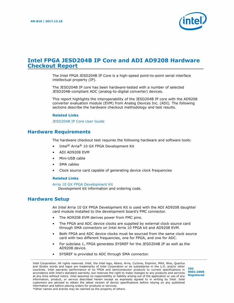
The following figure shows the Signal Tap waveform of the clock count from thedeassertion of SYNC~ to the assertion of the jesd204_rx_link_valid signal, the firstoutput of the ramp test pattern (DL.3 test case). The clock count measures the firstuser data output latency.
Intel FPGA JESD204B IP Core and ADI AD9208 Hardware Checkout Report
AN-810 | 2017.12.18
AN 810: Intel FPGA JESD204B IP Core and ADI AD9208 Hardware Checkout Report19

Figure 6. Deterministic Latency Measurement Ramp Test Pattern Diagram
Related Links
Deterministic Latency (Subclass 1) on page 9Provides information on how DL validation is performed.
Test Result Comments
In each test case, the JESD204B receiver IP core successfully initialize from CGSphase, ILA phase, and until user data phase.
No data integrity issue is observed by the PRBS and Ramp checker for all JESDconfigurations except where LMF=882, 884, and K=32. In these two configurations,momentary running disparity and 'Not in Table' errors are observed when link isrunning for durations longer than 15 minutes. These errors are random and onlyobserved when Ramp data pattern is being transmitted by the converter. With PRBS-9data pattern, no such errors are observed even when link has operated for longdurations. The above mentioned configurations have been marked as PASS withcomments for this reason.
In the deterministic latency measurement, consistent total latency is observed acrossmultiple power cycles or resets.
For a few JESD configurations, in order to avoid lane de-skew error or achievedeterministic latency on FPGA, RBD offset register needs to be programmed. Themodes and the corresponding values used are tabled below.
Intel FPGA JESD204B IP Core and ADI AD9208 Hardware Checkout Report
AN-810 | 2017.12.18
AN 810: Intel FPGA JESD204B IP Core and ADI AD9208 Hardware Checkout Report20

Mode (LMF) csr_rbd_offset (syncn_sysref_ctrl [10:3])
212-K32 0xC
212-K16 0x2
421-K32 0x5
422-K32 0xC
444-K16 0xC
821-K20 0x3
841-K20 0x3
882-K32 0xC
884-K16 0xC
Document Revision History for AN 810: Intel FPGA JESD204B IPCore and ADI AD9208 Hardware Checkout Report
Date Version Changes
December 2017 2017.12.18 • Renamed the document as AN 810: Intel FPGA JESD204B IP Coreand ADI AD9371 Hardware Checkout Report.
• Added a note to clarify that the IOPLL input reference clock issourcing from device clock through global clock network in theHardware Setup topic.
• Updated Figure: Deterministic Latency Test Setup Block Diagram.• Updated for latest branding standards.• Made editorial updates and restructuring to the document to improve
clarity.
June 2017 2017.06.19 Initial release.
Appendix
Timing Closure Details
To achieve timing closure, the following Synthesis and Fitter settings are used. Someof the settings used, varies with each JESD configuration design (e.g., Fitter seedvalue 1-10).
Table 10. Synthesis and Fitter Settings of Quartus
Compiler setting Value used Default value
Router Timing Optimization Level MAXIMUM Normal
Spectra-Q Physical Synthesis On Off
Programmable Power Technology Optimization Force All Tiles with Failing TimingPaths to High Speed
Automatic
Auto Packed Registers Sparse Auto Auto
Fitter Effort Standard Fit Auto Fit
Logic Cell Insertion - Logic Duplication On Auto
Optimization Technique Speed Balanced
continued...
Intel FPGA JESD204B IP Core and ADI AD9208 Hardware Checkout Report
AN-810 | 2017.12.18
AN 810: Intel FPGA JESD204B IP Core and ADI AD9208 Hardware Checkout Report21

Compiler setting Value used Default value
Fitter Initial Placement Seed 1-10 1
Placement effort multiplier 1.0-8.0 1.0
Optimization mode Aggressive/High effort/Balanced Balanced
Device Used and Quartus Tool Version
For interoperability with ADC AD9208, two device variants of Intel Arria 10 are used.
• For lane rates above 15G and up to 16G: 10AX115S1F45I1SG (Transceiver speedgrade -1 device)
• For lane rates of 15G and lower: 10AX115S2F45I2SG (Transceiver speed grade -2device)
Intel Quartus® Prime Version 16.1.1 Build 200 Standard Edition is used for compilationof designs.
PMA Settings Used
Using default PMA settings leads to erroneous link operation.
To get an error free link with AD9208, the following PMA parameters were adjusted asshown in the table below:
Note: No PMA settings on AD9208 ADC are modified.
PMA setting (as in QSF assignments) Value used
Receiver High Gain Mode Equalizer DC Gain Control NO_DC_GAIN
Receiver High Gain Mode Equalizer AC Gain Control 1-2(‘2’ is used only for LMF=882/884 modes)
VCCR_GXB/VCCT_GXB Voltage 1.0 V
Receiver High Data Rate Mode Equalizer OFF
Additional JESD modes supported by ADC
The modes enlisted here have not been validated in this IOT, but they are supportedby the ADC. These have been tabulated here for future reference.
L M F S N N' Comments
1 8 16 1 14 16 F=16 configuration is not supportedby transport layer of Intel exampledesign.
1 1 1 1 8 8 N’=8 configuration is not supportedby transport layer of Intel exampledesign1 1 2 2 8 8
2 1 1 2 8 8
2 1 2 4 8 8
2 1 4 8 8 8
4 1 1 4 8 8
continued...
Intel FPGA JESD204B IP Core and ADI AD9208 Hardware Checkout Report
AN-810 | 2017.12.18
AN 810: Intel FPGA JESD204B IP Core and ADI AD9208 Hardware Checkout Report22

L M F S N N' Comments
4 1 2 8 8 8
1 2 2 1 8 8
2 2 1 1 8 8
2 2 2 2 8 8
4 2 1 2 8 8
4 2 2 4 8 8
4 2 4 8 8 8
Intel FPGA JESD204B IP Core and ADI AD9208 Hardware Checkout Report
AN-810 | 2017.12.18
AN 810: Intel FPGA JESD204B IP Core and ADI AD9208 Hardware Checkout Report23
Related Documents