PUBLISHED BY THE AMERICAN WELDING SOCIETY TO ADVANCE THE SCIENCE, TECHNOLOGY AND APPLICATION OF WELDING AND ALLIED JOINING AND CUTTING PROCESSES, INCLUDING BRAZING, SOLDERING, AND THERMAL SPRAYING April 2007 Welding Education •Recruiting •Training •Student Research Lean Manufacturing BONUS: American Welder Welding Education •Recruiting •Training •Student Research Lean Manufacturing BONUS: American Welder

Welcome message from author
This document is posted to help you gain knowledge. Please leave a comment to let me know what you think about it! Share it to your friends and learn new things together.
Transcript
PUBLISHED BY THE AMERICAN WELDING SOCIETY TO ADVANCE THE SCIENCE, TECHNOLOGY AND APPLICATION OF WELDINGAND ALLIED JOINING AND CUTTING PROCESSES, INCLUDING BRAZING, SOLDERING, AND THERMAL SPRAYING
WE
LD
ING
JOU
RN
AL
• VO
LU
ME
86 NU
MB
ER
4 • AP
RIL
2007
April 2007
Welding Education•Recruiting•Training•Student Research
Lean Manufacturing
BONUS: American Welder
Welding Education•Recruiting•Training•Student Research
Lean Manufacturing
BONUS: American Welder
Cover April 07:4/06 Cover 3/12/07 10:59 AM Page C1
Circle No. 46 on Reader Info-Card
SELECT ARC 1:FP_TEMP 3/9/07 5:37 PM Page C2

Circle No. 45 on Reader Info-Card
NATIONAL STANDARD:FP_TEMP 3/9/07 5:36 PM Page 1

Circle No. 33 on Reader Info-Card
HYPERTHERM:FP_TEMP 3/9/07 5:15 PM Page 2
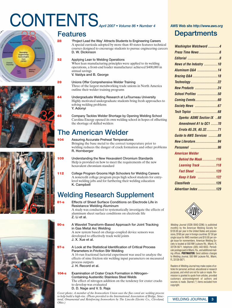
CONTENTS28 ‘Project Lead the Way’ Attracts Students to Engineering Careers
A special curricula adopted by more than 40 states features technical courses designed to encourage students to pursue engineering careersD. W. Dickinson
32 Applying Lean to Welding OperationsWhen lean manufacturing principles were applied to its welding operations, a front-end loader manufacturer achieved $400,000 in annual savingsV. Vaidya and B. George
39 Unions Offer Comprehensive Welder TrainingThree of the largest metalworking trade unions in North Americaoutline their welder training programs
44 Undergraduate Welding Research at LeTourneau UniversityHighly motivated undergraduate students bring fresh approaches to solving welding problemsY. Adonyi
46 Company Tackles Welder Shortage by Opening Welding SchoolCarolina Energy opened its own welding school in hopes of offsettingthe shortage of skilled welders
Welding Journal (ISSN 0043-2296) is publishedmonthly by the American Welding Society for$120.00 per year in the United States and posses-sions, $160 per year in foreign countries: $7.50 persingle issue for AWS members and $10.00 per sin-gle issue for nonmembers. American Welding So-ciety is located at 550 NW LeJeune Rd., Miami, FL33126-5671; telephone (305) 443-9353. Periodi-cals postage paid in Miami, Fla., and additional mail-ing offices. POSTMASTER: Send address changesto Welding Journal, 550 NW LeJeune Rd., Miami,FL 33126-5671.
Readers of Welding Journal may make copies of ar-ticles for personal, archival, educational or researchpurposes, and which are not for sale or resale. Per-mission is granted to quote from articles, providedcustomary acknowledgment of authors andsources is made. Starred (*) items excluded fromcopyright.
Departments
Washington Watchword ..........4
Press Time News ..................6
Editorial ............................8
News of the Industry ............10
Aluminum Q&A ..................14
Brazing Q&A ......................18
Technology........................22
New Products ....................24
School Profiles ..................50
Coming Events....................60
Society News ....................67
Tech Topics ......................68
Sperko: ASME Section IX ..68
Amendment A1 to QC1 ......70
Errata A5.28, A5.32..........71
Guide to AWS Services ........88
New Literature....................94
Personnel ........................96
American Welder
Behind the Mask ............116
Learning Track ..............118
Fact Sheet ..................120
Keep it Safe ................122
Classifieds ......................126
Advertiser Index ................129
81-s Effects of Sheet Surface Conditions on Electrode Life inResistance Welding AluminumA study was conducted to systematically investigate the effects ofaluminum sheet surface conditions on electrode lifeZ. Li et al.
90-s A Wavelet Transform-Based Approach for Joint Trackingin Gas Metal Arc WeldingA new system based on charge-coupled device sensors was developed to effectively track weld jointsJ. X. Xue et al.
97-s A Look at the Statistical Identification of Critical ProcessParameters in Friction Stir WeldingA 16-run fractional factorial experiment was used to analyze theeffects of nine friction stir welding input parameters on measured process outputsJ. H. Record et al.
104-s Examination of Crater Crack Formation in Nitrogen-Containing Austenitic Stainless Steel WeldsThe effect of nitrogen addition on the tendency for crater cracks to develop was evaluatedD. D. Nage and V. S. Raja
Features
104 Assuring Accurate Preheat TemperaturesBringing the base metal to the correct temperature prior to welding reduces the danger of crack formation and other problemsR. Hornberger
109 Understanding the New Hexavalent Chromium StandardsHelp is provided on how to meet the requirements of the new hexavalent chromium standard
112 College Program Grooms High Schoolers for Welding CareersA noncredit college program preps high school students for entry-level welding jobs and for furthering their welding educationK. Campbell
The American Welder
Welding Research Supplement
28
32
46
3WELDING JOURNAL
April 2007 • Volume 86 • Number 4 AWS Web site http://www.aws.org
Cover photo: A member of the Ironworkers Union uses the flux cored arc welding processto help build a high-rise. (Photo provided to the International Association of Bridge, Struc-tural, Ornamental and Reinforcing Ironworkers by The Lincoln Electric Co., Cleveland,Ohio.)
April 07 TOC:TOC 4/06 Layout 3/14/07 8:52 AM Page 3
Record Set for Lobbying Expenditures
More than $1.26 billion was spent lobbying the U.S. Congressin the first half of 2006, according to disclosure reports filed underthe federal Lobbying Disclosure Act. This represents a 5% in-crease over the previous 6-month period, and is a record amount.The top lobbying issue, in terms of money spent, was healthcare,and the largest lobbying organization was the U.S. Chamber ofCommerce.
Revised Final ElectricalEquipment Standard
The U.S. Occupational Safety and Health Administration haspublished a final rule on the design and installation of electricequipment in the workplace. The current standard, 29 CFR 1910,had not been updated in more than 25 years. The revised rulelargely reflects the 2000 edition of the National Fire ProtectionAssociation’s Electrical Safety Requirements for Employee Work-places (NFPA 70E®) and the 2002 edition of the National Elec-trical Code®.
There are several references towelding equipment in the Pream-ble to the rule, which is publishedin the Federal Register, 72 Fed.Reg. 7135-7221.
Hexavalent ChromiumLitigation MovesSlowly
The deadline for filing briefs inthe lawsuits challenging the Occu-pational Safety and Health Ad-ministration’s final hexavalentchromium rule has been extendedonce again, this time until mid-April. Both organized labor andindustry representatives have challenged the standard’s permis-sible exposure limit (PEL) of five micrograms per cubic meter ofair, with labor arguing the PEL is too high to protect workers,and affected industries maintaining that it is too low and infeasible.
The rule became generally effective in November 2006, ex-cept for firms with fewer than 20 employees, which have untilMay 30, 2007. The engineering control provisions will not be ef-fective until May 31, 2010.
Export Controls Considered for ‘DiversionDestinations’
The U.S. Department of Commerce is considering imposing ad-ditional license requirements for exports to certain countries thathave recently been involved in the redirection or transshipment ofgoods to terrorists and state sponsor of terrorism. Recently pro-posed amendments to the Export Administration Regulationswould create a new “Country Group C” consisting of countries thatare considered ‘‘Destinations of Diversion Concern.’’ Exports tothe countries likely to be included in this new Group C currentlyare not subject to burdensome licensing requirements.
As a result of being placed into Country Group C, the cur-rent, relatively relaxed licensing policy would likely change foritems going to any country designated as a ‘‘Destination of Di-version Concern.’’ Such changes could mean that more license
applications might be required; more stringent license reviewpolicies might be implemented, which could result in less ap-provals or more conditions on licenses; authorizations may bedelayed because of increased end-user checks; or authorizationsmay decrease because of diversion risks for such countries.
OSHA Violation CitationsThe U.S. Occupational Safety and Health Administration is-
sued more than 9000 citations to employers last year for viola-tions of its hazard communication regulations, the most citedOSHA regulation for fiscal year 2006. Other leading areas ofOSHA citations were as follows: fall protection (unprotectedsides and edges); machine guarding (guarding methods); headprotection (protective helmets); scaffolds; and general safe andhealthful conditions.
Lawsuit Regarding Payment for PersonalProtective Equipment
A lawsuit has been filed against the Occupational Safety andHealth Administration (OSHA)based on the failure of OSHA toissue a final rule regarding re-sponsibility for payment for per-sonal protective equipment(PPE). A decision issued by theOccupational Safety and HealthReview Commission in October1997 determined that employersneed not pay for employees’ per-sonal protective equipment, butin March 1999, OSHA formallyproposed a standard requiringemployers to pay for the costs ofPPE (64 Fed. Reg. 15,401). It isthat standard that the union
plaintiffs are asking a court to compel OSHA to finalize. In April2006, the agency said it planned final action on the rule by Sep-tember 2006, but the most recent regulatory agenda released inDecember says final action is now slated for May 2007.
New Ethics Rules for Large FederalContractors
The Civilian Agency Acquisition Council and the Defense Ac-quisition Regulations Council, which oversee the Federal Acquisi-tion Regulation (FAR), are planning amendments to the FAR thatwould require federal contractors receiving awards worth morethan $5 million and involving work in excess of 120 days to adopt awritten “code of ethics and business conduct” and fraud hotlineposters. Citing “the significant sums of federal dollars spent byagencies to acquire goods and services,” the Councils expressedthe view that a “clear and consistent policy regarding contractor codeof ethics and business conduct [and] responsibility to avoid im-proper business practices” is reasonable and necessary.
The use of federal contractors has increased significantly inrecent years, with the amount spent by the government havingdoubled since 2000, from $207 to $400 billion. ♦
WASHINGTONWATCHWORD
APRIL 20074
BY HUGH K. WEBSTERAWS WASHINGTON GOVERNMENT AFFAIRS OFFICE
Contact the AWS Washington Government Affairs Office at 1747 Pennsylvania Ave. NW, Washington, DC 20006; e-mail [email protected]; FAX (202) 835-0243.
The deadline for filing briefs in thelawsuits challenging the OSHA’s
final hexavalent chromium rule hasbeen extended until mid-April.Organized labor and industry
representatives have challengedthe standard’s permissible
exposure limit of five microgramsper cubic meter of air.
Washington Watchword April 2007corr:Layout 1 3/9/07 5:31 PM Page 4

Circle No. 50 on Reader Info-Card
TREGASKISS:FP_TEMP 3/9/07 5:38 PM Page 593

PRESS TIMENEWS
Orders for Robots Fell in 2006
According to statistics from the Robotic Industries Association (RIA), Ann Arbor,Mich., North American robotics companies experienced a record year for orders fromnonautomotive users in 2006, but it was not enough to offset the steep decline in robotsales to automotive companies. As a result, new orders to North American companiesfell 30% for the year.
In 2006, a total of 12,765 robots valued at $904.2 million were sold to North Ameri-can companies, a decline of 30% in units and 22% in revenue from 2005. When sales tocompanies outside North America are added in, North American robotics companiestotal sales were 13,791 robots valued at $958.4 million, down 29% in units and 22% inrevenue.
“The most interesting result from 2006 is that nonautomotive orders reached thehighest mark since we’ve been tracking the data this way,” said Donald A. Vincent, ex-ecutive vice president of RIA. Nonautomotive orders accounted for 44% of total orderslast year, compared with just 30% in 2005.
“Our members understand that while the automotive industry has traditionally beenand remains the largest customer for robotics, changes are occurring in the auto indus-try that may negatively impact future robot sales to automotive OEMs and their suppli-ers,” said Vincent. “Therefore, it becomes more important than ever to find new mar-kets, which is what we’re seeing happen.”
General Dynamics NASSCO Delivers Second T-AKE Ship
General Dynamics NASSCO, San Diego, Calif., a wholly owned subsidiary of Gen-eral Dynamics, recently delivered USNS Sacagawea (T-AKE 2) to the U.S. Navy. Theship is named in honor of the Native American woman who helped guide and interpretfor Meriwether Lewis and William Clark during their legendary exploration of the Amer-ican West in the early 1800s.
Construction of USNS Sacagawea began in September 2004. The ship is the secondin an expected class of 11 dry cargo-ammunition ships for the Navy. The T-AKE classincorporates international marine technologies and commercial ship-design features tominimize operating costs during its projected 40-year service life.
Sacagawea’s primary mission will be to deliver food, ammunition, fuel, and otherprovisions from shore stations to combat ships at sea. The 689-ft-long ship has modularcargo holding and handling systems onboard and can carry more than 6600 tons of drycargo and nearly 23,500 barrels of fuel.
Toyota to Build Highlanders in Mississippi
Mississippi Governor Haley Barbour recently joined Toyota officials to announcethat the company has chosen a 1700-acre site in Blue Springs, Miss., to build its eighthNorth American vehicle assembly plant.
The facility will have the capacity to build 150,000 vehicles annually of Toyota’s High-lander sport utility vehicle. Production is scheduled to begin by 2010.
Also, the plant represents a $1.3 billion investment by the company and is expectedto create approximately 2000 new jobs for the region and indirectly create work for manymore. Operations at the plant will include stamping, body weld, plastics, paint, and assembly.
BOC Gases Expands Distributor Network
BOC, Murray Hill, N.J., a member of The Linde Group, a global industrial gases andengineering company, recently signed a multiyear supply agreement with Superior Weld-ing Supply Co. of Waterloo, Iowa.
Superior is a privately owned retailer of welding equipment, safety supplies, and in-dustrial, medical, and specialty gases. The company has been in business since 1929, andit employs 46 people in two locations in Dubuque and Waterloo, Iowa.
In addition, Superior chose to join the Airco Distributor Association, the buyinggroup exclusively available to BOC distributors.
APRIL 20076
MEMBER
Publisher Andrew Cullison
Publisher Emeritus Jeff Weber
EditorialEditor/Editorial Director Andrew Cullison
Senior Editor Mary Ruth JohnsenAssociate Editor Howard M. Woodward
Assistant Editor Kristin CampbellPeer Review Coordinator Erin Adams
Graphics and Production Managing Editor Zaida Chavez
Senior Production Coordinator Brenda Flores
AdvertisingNational Sales Director Rob Saltzstein
Advertising Sales Representative Lea Garrigan BadwyAdvertising Production Manager Frank Wilson
American Welding Society550 NW LeJeune Rd., Miami, FL 33126
(305) 443-9353 or (800) 443-9353
Publications, Expositions, Marketing CommitteeD. L. Doench, Acting Chair
Hobart Brothers Co.J. D. Weber, Secretary
American Welding SocietyR. L. Arn, WELDtech InternationalT. A. Barry, Miller Electric Mfg. Co.
R. Durda, The Nordam GroupJ. R. Franklin, Sellstrom Mfg. Co.J. Horvath, Thermadyne IndustriesJ. Mueller, Thermadyne Industries
R. G. Pali, J. P. Nissen Co.J. F. Saenger Jr., ConsultantS. Smith, Weld-Aid ProductsD. Wilson, Wilson Industries
H. Castner, Ex Off., Edison Welding InstituteD. C. Klingman, Ex Off., The Lincoln Electric Co.
L. G. Kvidahl, Ex Off., Northrup Grumman Ship SystemsG. E. Lawson, Ex Off., ESAB Welding & Cutting Products
E. C. Lipphardt, Ex Off., ConsultantS. Liu, Ex Off., Colorado School of Mines
R. W. Shook, Ex Off., American Welding SocietyG. D. Uttrachi, Ex Off., WA Technology, LLC
Copyright © 2007 by American Welding Society in both printed and elec-tronic formats. The Society is not responsible for any statement made oropinion expressed herein. Data and information developed by the authorsof specific articles are for informational purposes only and are not in-tended for use without independent, substantiating investigation on thepart of potential users.
Press Time News April corr:Layout 1 3/9/07 4:20 PM Page 6

Circle No. 43 on Reader Info-Card
MILLER:FP_TEMP 3/9/07 5:35 PM Page 7

EDITORIAL
Most American Welding Society officers have special concerns or causes that areimportant to them as they serve the Society. Those concerns or causes usually reflect theportion of the welding industry we are involved in and does not mean we are single mind-ed — they are in addition to the general good of the Society. For instance, my back-ground mostly has been related to sales and working directly with people (customers) tohelp solve problems and promote the products I represent. The term “salesman” some-times seems to be a throwaway — think used-car salesman or door-to-door salesman —rather than denoting a profession. That’s why I’m standing up for the “welding productssalesman.”
We sell to the smartest customers in industry, who are welding ships, buildings,bridges, refineries …well the list just gets too long. The sales part doesn’t just happen, itrequires training, practice, and, most of all, preparation. Recently, a territory sales man-ager in the Northwest, who has been in the industry for more than 25 years, wanted tobring more to the table for his customers. Therefore, he took the AWS Certified WeldingInspector prep course and the CWI test. (I’d like to send my congratulations to himbecause he passed and now is a CWI.) His motivation was not to work as an inspector,but about bringing more credentials to the job and knowing that this additional knowl-edge may come in handy when helping customers.
More of us in sales need to take whatever training we can. I realize much of the train-ing available to salespeople is vendor related as to the company they work for or, ifyou’re a salesperson for a welding distributor, through the vendor your company sendsyou to. This training can be excellent, so take as many classes as you can as often as youcan. I have a wall full of certificates for courses taken over my 34 years in the industry. Idid take the CWI training class 20 years ago, but didn’t take the test. Why not you ask?Well, I was in sales and figured it wasn’t my job, but I wish I had paid the money to testbecause I respect the title of CWI.
I believe there are many salespeople out there who think “certifications” are only forthe engineers or production managers. My thought today is that they are mistaken.You’ll do yourself a great service if you get training from the AWS in the form of certifi-cations or through the technical sessions that are a big part of the FABTECHInternational & AWS Welding Show. I realize doing so is not easy, but it is rewarding ifyou can pull it off.
I hope the American Welding Society can soon offer a certification aimed at “sales-men.” Work is being done to create a Certified Welding Salesman (CWS) program thatwould provide salespeople who passed the test with a card to carry that would serve as arecord of their knowledge and accomplishments. I think any certification programregarding sales should look at all aspects of a job, for instance, gases, electricity, metal-lurgy, welding, cutting, and removal. To be of value, the test would have to be difficultlike the one for Certified Welding Inspectors. If developed properly, I believe employersand customers would appreciate and respect the certification. I just want “us” salespeo-ple to be the best we can be. Programs like this are put together by volunteer commit-tees of people such as yourself. You can easily provide your input by becoming a volun-teer. Believe me, there are plenty of committees that could benefit from your knowledge.
Currently, there are about 600,000 welders in the United States, with another 200,000needed. There are also at least 80,000 people involved in management and sales that
make the connection to the market. We must be thebest we can be to help make sure the right products getto the right people and that those same people haveconfidence in those of us who are in the supply chain.
APRIL 20078
Founded in 1919 to Advance the Science,Technology and Application of Welding
Learn All You Can
Gene E. LawsonAWS vice president
OfficersPresident Gerald D. Uttrachi
WA Technology, LLC
Vice President Gene E. LawsonESAB Welding & Cutting Products
Vice President Victor Y. MatthewsThe Lincoln Electric Co.
Vice President John C. BruskotterBruskotter Consulting Services
Treasurer Earl C. LipphardtConsultant
Executive Director Ray W. ShookAmerican Welding Society
DirectorsB. P. Albrecht (At Large), Miller Electric Mfg. Co.
O. Al-Erhayem (At Large), JOM
A. J. Badeaux Sr. (Dist. 3), Charles Cty. Career & Tech. Center
H. R. Castner (At Large), Edison Welding Institute
N. A. Chapman (Dist. 6), Entergy Nuclear Northeast
N. C. Cole (At Large), NCC Engineering
J. D. Compton (Dist. 21), College of the Canyons
L. P. Connor (Dist. 5), Consultant
G. Fairbanks (Dist. 9), Gonzalez Industrial X-Ray
D. Flood (Dist. 22), Tri Tool, Inc.
J. E. Greer (Past President), Moraine Valley C. C.
M. V. Harris (Dist. 15), Reynolds Welding Supply
R. A. Harris (Dist. 10), Penton Publishing Co.
W. E. Honey (Dist. 8), Anchor Research Corp.
D. C. Howard (Dist. 7), Concurrent Technologies Corp.
W. A. Komlos (Dist. 20), ArcTech LLC
D. J. Kotecki (Past President), The Lincoln Electric Co.
D. Landon (Dist. 16), Vermeer Mfg. Co.
R. C. Lanier (Dist. 4), Pitt C.C.
J. L. Mendoza (Dist. 18), CPS Energy
S. P. Moran (Dist. 12), Miller Electric Mfg. Co.
R. L. Norris (Dist. 1), Merriam Graves Corp.
T. C. Parker (Dist. 14), Miller Electric Mfg. Co.
W. R. Polanin (Dist. 13), Illinois Central College
O. P. Reich (Dist. 17), Texas State Technical College at Waco
W. A. Rice (At Large), OKI Bering, Inc.
E. Siradakis (Dist. 11), Airgas Great Lakes
N. S. Shannon (Dist. 19), Carlson Testing of Portland
K. R. Stockton (Dist. 2), PSE&G, Maplewood Testing Serv.
D. R. Wilson (At Large), Wilson Industries
Editorial for April 2007corr:Layout 1 3/9/07 4:10 PM Page 8

Circle No. 28 on Reader Info-Card
ESAB 1:FP_TEMP 3/9/07 5:12 PM Page 9

APRIL 200710
NEWS OF THEINDUSTRY
Aluminum Stretch Former to Manufacture Aircraft Components in China
Erie Press Systems, Erie, Pa., has shipped a 440-ton aluminum sheetstretch forming machine to Changhe Aircraft Industries in JiangxiProvince, China. The press will be used to form fuselage sectionsfor the company’s new series helicopters. The sheet stretch former isa combination longitudinal/transverse type press with “curving jaws”used to stretch-form sheet metal panels and large extrusions. Thebase machine, STC400M – 3200-6000 CNC, includes independentjaw rotation for flexibility, and a full floor-plate with coverage be-tween the forming jaws to protect workers and provide convenientdie changes. The system also includes spare parts, a fully automaticpowered die table rotation, a 1200 KN ton gantry-type bulldozer,and 1600-mm-long and 100-metric-ton-capacity accessory jaws.
Asian Welding Show Celebrating 20th Anniversary in China
The Beijing Essen Welding & Cutting Fair is celebrating its20th anniversary in Shanghai, China.
Debuting in 1987, the show has grown steadily at the samepace as the Chinese economy. Now a yearly event, alternatelyheld in Beijing and Shanghai, it ranks as the second-largest weld-ing show worldwide, trailing its sister show Schweissen & Schnei-den in Essen, Germany.
The 12th Beijing Essen Welding & Cutting Fair will be heldthis year at the Shanghai New International Expo Center fromJune 19 to 22. A 17% increase in exhibition space with about 700exhibitors from 20 countries and about 30,000 visitors from morethan 70 countries and regions are expected.
This show is sponsored by the Chinese Mechanical Engineer-ing Society (CMES); Welding Institution of CMES; China Weld-ing Association; Electric Welding Machine Committee of CEEIA;German Welding Society; and Messe Essen GmbH; and cospon-sored by the American Welding Society; Korea Welding Indus-try Cooperative; and The Japan Welding Engineering Society.
For more information, visit http://essen.cmes.org.
College of DuPage and Caterpillar Team to Offer Students Practical Experience
College of DuPage (C.O.D.), Glen Ellyn, Ill., recently joinedforces with Caterpillar Inc.’s Education to Careers (ETC) pro-gram to offer high school seniors and first-semester college stu-dents a chance to work at the Aurora, Ill., plant while obtaininga degree from the college in the technical/manufacturing field.
Lincoln Electric Forms Agreement with Robert Yates Racing
With this year’s NASCAR racing seasonramping up, Lincoln Electric, Cleveland,Ohio, has formed a team-supplier agreementwith Robert Yates Racing.
The partnership begins immediately withthe company supplying the team with a fullrange of welding and cutting equipment,technical training, and welding applicationsupport.
In addition, the program will help ensurethe team maintains a high standard of safety,weld integrity, and performance on the trackand in the shop.
Robert Yates Racing is owned by indus-try veteran Robert Yates, who is also consid-ered one of the sport’s premier enginebuilders. He runs the business with his son,Doug Yates.
“This relationship guarantees that ourguys have access to the latest welding andcutting technology and equipment, a vitallink to our teams’ success,” said RobertYates.
Lincoln Electric recently formed a team-supplier agreement with Robert Yates Racing,home of three NASCAR teams, including David Gilliland of the #38 M&M’s car.
News of the Industry April 2007:Layout 1 3/9/07 1:15 PM Page 10
11WELDING JOURNAL
The internship program pays for two years of tuition and fees,as students work part time at Caterpillar and earn their associ-ate’s degree. Additionally, the students take part in a paid, full-time summer internship to round out their hands-on training andincorporate the variety of skills they have learned during the program.
“This is a great opportunity for students who are interestedin having a hands-on career in a technical field of some sort, butaren’t exactly sure which area would be best for them,” said MarkMeyer, who coordinates the ETC Caterpillar internship programfor C.O.D. “During the internship, students are rotated throughdifferent jobs, positions and departments at Caterpillar so theycan experience first-hand the types of opportunities that existwithin a world-class manufacturing environment.”
The company’s 350-acre Aurora site is the largest of the morethan 100 Caterpillar facilities located in the United States and22 countries worldwide. The 4500-sq-ft plant mainly manufac-tures wheel loaders and excavators.
Currently, the need for employees in the technical/manufac-turing field at Caterpillar Inc. is “at an all-time high,” said NevMilanovic, Education to Careers coordinator at the Aurora, Inc.,manufacturing facility.
KUKA to Provide Robotics for Center atOhio Northern University
KUKA Robotics Corp., Clinton Township, Mich., has beenselected by Ohio Northern University (ONU) to provide robot-ics for its newly remodeled and expanded robotics technologycenter.
The center — to be named the “ONU Robotics TechnologyCenter of Excellence, powered by KUKA Robotics Corporation”— will provide students with hands-on design and programmingexperience using the company’s robots, controllers, and software.The university opened the center located in Taft Memorial Hallon South Union Street in Ada, Ohio, on January 26.
The ONU center is a part of its Department of TechnologicalStudies, and is in the College of Arts and Sciences. Currently, ithas seven KR3 robots. Five of the robots are being interfaced toPLCs and CNC machines in a simulated manufacturing environ-ment; performing loading, unloading, and part-transfer func-tions. Two are slated to be used by ONU’s award-winning com-petitive traveling robotics team for competitions.
Circle No. 4 on Reader Info-Card
Dr. Kendall L. Baker, president of Ohio Northern University, cutsthe ribbon at the university’s new robotics technology center withthe help of Leroy Rodgers, president of KUKA Robotics. The cen-ter, powered by KUKA Robotics technology, provides hands-on au-tomation design and programming experience.
News of the Industry April 2007:Layout 1 3/12/07 2:05 PM Page 11

APRIL 200712
Industry Notes• The National Center for Construction Education and Research,
Gainesville, Fla., and FMI have partnered to develop a com-prehensive career development map with joint credentialingfor the construction industry. The map will outline recom-mended training, education, and development programs fromentry-level craft professionals to executive leadership. This in-dustry tool will also help employers and employees with mak-ing decisions about investing in training and informed careerchoices.
• ATI Industrial Automation, Apex, N.C., an engineering-baseddeveloper of robotic peripheral equipment, is breaking groundon a new plant expansion. “High demand for our robotic end-effector products dictated the need for additional engineer-ing, manufacturing, and inventory capacity,” said Keith Mor-ris, the company’s president. “Our new facility will double ourspace with a provision to triple our space in the future.”
• Mid-State Chemical Supply Corp., Indianapolis, Ind., haschanged its name to MS Fluid Technologies, an initiative com-plemented with a revised logo and new tagline ‘Solutions forManufacturing.’ The company continues to be led by CEOPaul Bosler Jr. and owned by Bosler and his three brothers.
• Fronius USA LLC, an Austrian-established company, a sup-plier of welding technology equipment, has moved to largerfacilities in Brighton, Mich.
• Abbott Furnace Co., St. Marys, Pa., a manufacturer of contin-uous belt industrial furnaces, has launched an upgrade and ex-pansion of its Web site at www.abbottfurnace.com. Among the
site’s features are the following: updated and expanded prod-uct pages covering the range of the company’s products; a fullsuite of downloadable brochures; and easier, more direct nav-igation with pull-down menus.
• AK Steel Corp. will move its corporate headquarters into anew, technology-ready building totaling 136,000 sq ft currentlyunder construction at Centre Pointe in Union Centre, WestChester, Ohio. The company will relocate about 300 corpo-rate office positions housed in Middletown, Ohio, to the newbuilding in the third quarter of 2007.
• August Mack Environmental, Inc., a full-service environmen-tal, health, and safety consulting firm, has opened a new officein St. Louis, Mo. It is targeted to serve Missouri, southern Illi-nois, and eastern Kansas. Environmental Engineer and Proj-ect Manager Eric Emmett, P.E., has been named manager ofthe office.
Circle No. 22 on Reader Info-Card
Author Corrects Article on Gas Purging
M. Fletcher submits the following correction to his article,Gas Purging Optimizes Root Welds, published in the Decem-ber 2006 Welding Journal pp. 38–40.
Further to communications received from the AWS WeldingJournal, I agree that for successful welding of most stainless steels,an oxygen content in the purge gas of less than 0.1% is desirable. Toclarify the situation on page 40 (bottom of second column), I offerthe following amended text: While 1% residual oxygen is a suitableworking level for some ferrous materials, most stainless steels canonly be successfully welded with a purge gas oxygen level below 0.1%.The level needs to be as low as 20 ppm when welding the more sen-sitive alloys based on titanium and other reactive metals.
News of the Industry April 2007:Layout 1 3/12/07 2:29 PM Page 12

Circle No. 31 on Reader Info-Card
GEDIK:FP_TEMP 3/9/07 5:14 PM Page 13

ALUMINUMQ&A BY TONY ANDERSON
Q: Recently, I moved into the aluminumfabrication industry. I have worked withsteel fabrication for many years, and I amvery familiar with the common structuralsteel alloys; however, I do not know thealloy numbering system for aluminum.Can you please explain how the aluminummaterial numbering system works and ad-vise me on where I can find detailed in-formation about the aluminum alloys?
A: In North America, The Aluminum As-sociation, Inc., is responsible for the allo-cation and registration of aluminum al-loys. Currently, there are more than 400wrought aluminum and wrought alu-minum alloys and more than 200 alu-minum alloys in the form of castings andingots registered with the Aluminum As-sociation. The alloy chemical compositionlimits for all of these registered alloys arecontained in The Aluminum Association’sTeal Sheets — International Alloy Designa-tions and Chemical Composition Limits forWrought Aluminum and Wrought Alu-minum Alloys, and in its Pink Sheets —Designations and Chemical CompositionLimits for Aluminum Alloys in the Form ofCastings and Ingot. These publications can
be extremely useful to the welding en-gineer when developing welding proce-dures and when considering chemistry forcrack sensitivity purposes.
The Aluminum Association catego-rizes aluminum alloys into a number ofgroups based on the particular material’scharacteristics, such as its ability to re-spond to thermal and mechanical treat-ment, and the primary alloying elementadded to the aluminum alloy. The num-bering/identification system used for alu-minum alloys recognizes the above char-acteristics. The wrought and cast alu-
minums have different systems of identi-fication — the wrought having a 4-digitsystem, and the castings having a 3-digitand 1-decimal place system.
Wrought Alloy DesignationSystem
In the 4 digit wrought aluminum alloyidentification system, the first digit (Xxxx)indicates the principal alloying element,which has been added to the aluminumalloy and is often used to describe the alu-
Table 1 — Wrought Aluminum Alloy Designation System
Alloy Series Principal Alloying Element1xxx 99.000% Minimum Aluminum2xxx Copper3xxx Manganese4xxx Silicon5xxx Magnesium6xxx Magnesium + Silicon7xxx Zinc8xxx Other Elements
Table 2 — Cast Aluminum Alloy Designation System
Alloy Series Principal Alloying Element1xx.x 99.000% Minimum Aluminum2xx.x Copper3xx.x Silicon + Copper and/or Magnesium4xx.x Silicon5xx.x Magnesium6xx.x Unused Series7xx.x Zinc8xx.x Tin9xx.x Other Elements
APRIL 200714Circle No. 51 on Reader Info-Card
Aluminum Q and A April 2007:Layout 1 3/9/07 1:56 PM Page 14
15WELDING JOURNAL
minum alloy series, i.e., 1000 series, 2000series, 3000 series, up to 8000 series (Table 1).
The second single digit (xXxx), if dif-ferent from 0, indicates a modification ofthe specific alloy, and the third and fourthdigits (xxXX) are arbitrary numbers givento identify a specific alloy in the series.For example: In Alloy 5183, the number5 indicates that it is of the magnesium alloyseries, the 1 indicates that it is the 1st mod-ification to the original Alloy 5083, andthe 83 is the materials number within the5xxx series alloys.
The only exception to this alloy num-bering system is with the 1xxx series alu-minum alloys (pure aluminums), in whichcase, the last 2 digits provide the minimumaluminum percentage above 99%, i.e.,Alloy 1350 (99.50% minimum aluminum).
Cast Alloy Designation
The cast alloy designation system isbased on a 3 digit-plus decimal designa-tion xxx.x (i.e., 356.0). The first digit(Xxx.x) indicates the principal alloying el-ement, which has been added to the alu-minum alloy (Table 2).
The second and third digits (xXX.x)are arbitrary numbers given to identify aspecific alloy in the series. The numberfollowing the decimal point indicateswhether the alloy is a casting (.0) or an
ingot (.1 or .2). A capital letter prefix in-dicates a modification to a specific alloy.
For example, in Alloy A356.0, the cap-ital A (Axxx.x) indicates a modification ofAlloy 356.0. The number 3 (A3xx.x) indi-cates that it is of the silicon plus copperand/or magnesium series. The 56 (Ax56.0)identifies the alloy within the 3xx.x series,and the .0 (Axxx.0) indicates that it is afinal shape casting and not an ingot.
The Aluminum TemperDesignation System
Considering the different series of alu-
minum alloys, there are significant differ-ences in their characteristics and conse-quent applications. After understandingthe identification system, recognize thereare two distinctly different types of alu-minum within the series mentioned above.These are the heat-treatable aluminum al-loys (those which can gain strengththrough the addition of thermal treat-ment) and the nonheat-treatable alu-minum alloys. This distinction is particu-larly important when considering the ef-fects of arc welding on these two types ofmaterials.
The 1xxx, 3xxx, and 5xxx series wrought
Table 3 — The Basic Temper Designations
Letter MeaningF As fabricated — Applies to products of a forming process in which no special
control over thermal or strain-hardening conditions is employed.O Annealed — Applies to product that has been heated to produce the lowest
strength condition to improve ductility and dimensional stability.H Strain Hardened — Applies to products that are strengthened through
cold working. The strain hardening may be followed by supplementary thermal treatment, which produces some reduction in strength. The “H” is always followed by two or more digits (see Table 4).
W Solution Heat Treated — An unstable temper applicable only to alloys thatage spontaneously at room temperature after solution heat treatment.
T Thermally Treated — To produce stable tempers other than F, O, or H. Appliesto product that has been heat treated, sometimes with supplementary strain hardening, to produce a stable temper. The “T” is always followed byone or more digits (see Table 5).
Circle No. 26 on Reader Info-CardCircle No. 40 on Reader Info-Card
Aluminum Q and A April 2007:Layout 1 3/9/07 1:57 PM Page 15

APRIL 200716
aluminum alloys are nonheat treatableand are strain hardenable only. The 2xxx,6xxx, and 7xxx series wrought aluminumalloys are heat treatable and the 4xxx se-ries consist primarily of nonheat-treatablealloys but contain some alloys that areheat treatable. The 2xx.x, 3xx.x, 4xx.x, and7xx.x series cast alloys are heat treatable.Strain hardening is not generally appliedto castings.
The heat-treatable alloys acquire theiroptimum mechanical properties througha process of thermal treatment. The mostcommon thermal treatments are solutionheat treatment and artificial aging.
Solution heat treatment is the processof heating the alloy to an elevated tem-perature (around 990°F) in order to putthe alloying elements or compounds intosolution. This is followed by quenching,usually in water, to produce a supersatu-rated solution at room temperature. So-lution heat treatment is usually followedby aging. Aging involves the precipitationof a portion of the elements or compoundsfrom a supersaturated solution in orderto yield desirable properties. The agingprocess is divided into two types: aging atroom temperature, which is termed natu-ral aging, and aging at elevated tempera-tures termed artificial aging. Artificialaging temperatures are typically about320°F. Many heat-treatable aluminum al-loys are used for welding fabrication intheir solution heat treated and artificiallyaged condition.
The nonheat-treatable alloys acquiretheir optimum mechanical propertiesthrough strain hardening. Strain harden-ing is the method of increasing strength
through the application of cold working.The temper designation system ad-
dresses the material conditions calledtempers. This is an extension of the alloynumbering system and consists of a seriesof letters and numbers, which follow thealloy designation number and are con-nected by a hyphen. Examples are as fol-lows: 6061-T6, 6063-T4, 5052-H32, 5083-H112, 4043-F, and 6063-O. The basic tem-per designations are F, O, H, W, and T, andare described in Table 3.
In addition to the basic temper desig-nation, there are two subdivision cate-gories — one addressing the “H” temper— strain hardening (as shown in Tables4A and 4B) and the other addressing the“T” temper — thermally treated designa-tion (as shown in Tables 5A and 5B).
Summary
Today’s aluminum alloys, together withtheir various tempers, comprise a wideand versatile range of manufacturing ma-terials. For optimum product design andsuccessful welding procedure develop-ment, it is important to understand thedifferences between the many alloys avail-able and their various performance andweldability characteristics. When devel-oping arc welding procedures for thesedifferent alloys, give consideration to thespecific alloy being welded. It is often saidthat arc welding of aluminum is not diffi-cult, “it’s just different.” I believe that animportant part of understanding these dif-ferences is to become familiar with thevarious alloys, their characteristics, andtheir identification system.
Where to Find Information aboutthe Aluminum Alloys
There are a number of excellent refer-ence sources available exclusively address-ing aluminum and aluminum welding. TheAluminum Association’s Welding Alu-minum: Theory and Practice provides abroad selection of aluminum welding top-ics. Another source is the American Weld-ing Society’s (AWS) D1.2, Structural Weld-ing Code — Aluminum. This documentprovides information related to weldingprocedure and welder performance qual-ification and inspection and testing foraluminum welding. Other documentsavailable from The Aluminum Associa-tion that assist with the design of alu-minum structures are the Aluminum De-sign Manual and Aluminum Standards andData. These documents along with thealloy designation documents mentionedearlier in the article can be obtained di-rectly from the AWS through WEX Ltd.at (888) 935-3464, www.awspubs.com, orThe Aluminum Association at (703) 358-2977, www.aluminum.org, as appropriate.
Table 4A — Subdivisions of H Temper — Strain Hardened(a)
Number MeaningH1 Strain Hardened OnlyH2 Strain Hardened and Partially AnnealedH3 Strain Hardened and StabilizedH4 Strain Hardened and Lacquered or Painted
(a) The first digit after the H indicates a basic operation.
Table 4B — Subdivisions of H Temper —Strain Hardened(a)
Number MeaningHX2 Quarter HardHX4 Half HardHX6 Three-Quarters HardHX8 Full HardHX9 Extra Hard
(a) The second digit after the H indicates thedegree of strain hardening.
Table 5A — Subdivisions of T Temper — Thermally Treated(a)
Number MeaningT1 Naturally aged after cooling from an elevated temperature shaping process,
such as extrudingT2 Worked after cooling from an elevated temperature shaping process and then
naturally aged coldT3 Solution heat treated, cold worked, and naturally agedT4 Solution heat treated and naturally agedT5 Artificially aged after cooling from an elevated temperature shaping processT6 Solution heat treated and artificially agedT7 Solution heat treated and stabilized (overaged)T8 Solution heat treated, cold worked, and artificially agedT9 Solution heat treated, artificially aged and cold workedT10 Cold worked after cooling from an elevated temperature shaping process
and then artificially aged
(a) The first digit after the T indicates the operations used during heat treatment.
Table 5B — Subdivisions of T Temper —Thermally Treated(a)
Numbers MeaningTX51 or Stress relieved by stretchingTXX51TX52 or Stress relieved by compressingTXX52
(a) Additional digits after the T indicate stressrelief.
TONY ANDERSON is corporate technicaltraining manager for ESAB North America andcoordinates specialized training in aluminumwelding technology for AlcoTec Wire Corpora-tion. He is a Senior Member of TWI and a Reg-istered Chartered Engineer. He is chairman ofthe Aluminum Association Technical AdvisoryCommittee for Welding and holds numerous po-sitions including chairman, vice chairman, andmember of various AWS technical committees.Questions may be sent to Mr. Anderson c/o Weld-ing Journal, 550 NW LeJeune Rd., Miami, FL33126, or via e-mail at [email protected].
Aluminum Q and A April 2007:Layout 1 3/9/07 1:57 PM Page 16

Circle No. 29 on Reader Info-Card
ESAB 2:FP_TEMP 3/9/07 5:13 PM Page 17

BRAZINGQ&A BY R. L. PEASLEE
Q: When brazing assemblies for the nu-clear industry, we are having a problemwith the yield strength dropping below therequired 30,000 lb/in.2 (206.8 MPa). Ourcustomer purchased material with theproper yield strength, but after brazing,the yield strength drops by varyingamounts. What would be the cause of thedrop in yield strength?
A: This has been a perplexing problem.We have experienced the same drop inyield strength after brazing. In one braze-ment the yield strength reported by thesupplier was 33,000 lb/in.2 (227.5 MPa)and after brazing at 1950°F (1066°C) theyield strength had dropped to 22,000lb/in.2 (151.7 MPa).
In another brazement the yieldstrength was reported to be 35,000 lb/in.2(241.3 MPa) and after brazing at 2150°F(1121°C) it dropped to 25,000 lb/in.2(172.4 MPa). Other brazements had vary-ing drops in the yield strength after braz-ing that appeared to make no sense.
We talked to many manufacturers ofthe stainless steel and nickel-based metals
before getting a clue to the problem. Wefound that during processing, the millshot worked and cold worked the basemetal and that increased the tensilestrength and the yield strength of the basemetal. At the end of the processing, thebase metal was given an in-process annealto bring the material to the required phys-ical properties. This worked very wellwhen the base metal was fabricated bymachining, or other processes, where theparts did not see high temperatures laterduring processing.
It was found that the in-processannealing temperature varied from heatto heat, and when some heats were in-process annealed, the annealing tempera-ture could be below the brazing tempera-ture. When brazements were made fromthese lots of base metal, the higher braz-ing temperature annealed the base metalmore, and therefore the yield strengthdropped. While these brazements wereaccepted, it was necessary to assure thatthe yield strength did not drop below thespecified 30,000 lb/in.2 (206.8 MPa) yieldminimum, on assemblies that were
brazed. Therefore, it became standard tostipulate on any purchase order to a sup-plier that the in-process annealing tem-perature be above the required brazingtemperature, when the assembly was tobe brazed.♦
R. L. PEASLEE is vice president emeritus, WallColmonoy Corp., Madison Heights, Mich.Readers may send questions to Mr. Peaslee c/o Welding Journal, 550 NW LeJeune Rd., Miami, FL 33126 or via e-mail [email protected].
APRIL 200718
Change of Address?Moving?
Make sure delivery of your WeldingJournal is not interrupted. Contact theMembership Department with yournew address information — (800) 443-9353, ext. 217; [email protected].
Circle No. 55 on Reader Info-Card
Brazing April:Layout 1 3/9/07 3:54 PM Page 18
Circle No. 38 on Reader Info-Card
KOIKE:FP_TEMP 3/9/07 5:16 PM Page 19
©Am
eric
anW
eldi
ngSo
ciet
y20
07
Founded in 1919 to advance the science, technologyand application of welding and allied joining and cuttingprocesses, including brazing, soldering and thermal spraying.
AWS Joining Dissimilar Metals ConferenceOrlando, Florida • Grosvenor ResortMay 22–23, 2007
Circle No. 10 on Reader Info-Card
Page 20-21:FP_TEMP 3/12/07 11:15 AM Page 20
Conference price is $550 for AWS members, $680 fornonmembers. To register or to receive a descriptive brochure,call (800) 443-9353 ext. 223, (outside North America, call 305-443-9353), or visit www.aws.org/conferences
One of the most discussed topics and sources ofmisunderstanding involves joining dissimilar materials bywelding. Vendors probably receive more phone calls withquestions on this subject than any other. The traditionalcodes are nearly silent on the issue. Many design, shop, orfield organizations do not have—or have lost—expertisein this area.
This conference will address issues including materialproperties, weld properties, preheat/post-weld heattreatment, corrosion, the use of transition joints, serviceconditions, and practical considerations.
Even the most difficult-to-weld of all materialcombinations—steel to aluminum—has been weldedsatisfactorily using such techniques as explosion weldingand magnetic pulse welding. New chemistries are comingto the aid of existing filler metals, making them moreamenable to dissimilar metals welding. Filler metalsbased on nickel-base superalloy chemistries are alsomeeting the challenge. Advances in brazing technologyare taking care of a host of metallurgical problems aswell.
The problems are there, but so are the solutions.
The conference keynote address will be presented by Dr. Thomas Eagar from MIT, a noted expert in this mostdifficult area of welding.
AWS Joining Dissimilar Metals ConferenceOrlando, Florida • Grosvenor Resort
May 22–23, 2007Dissimilar Metal Weld Failures Involving Grade 91 SteelJeff Henry, Structural Integrity Associates, Inc., Chattanooga, TN
Advances in Friction Stir Welding and Application toDissimilar Metal JoiningWilliam J. Arbegast, NSAF Center for Friction Stir Processing,and Advanced Materials Processing and Joining Center, RapidCity, SD
Large-Area Soldering and Brazing of Dissimilar Materialswith a Novel Heat SourceDr. Timothy P. Weihs, Reactive NanoTechnologies, Inc., HuntValley, MD
CSC-Controlled Short Circuit Transfer – A New GMAWProcess That Solves Old Weld ProblemsTom Rankin, ITW Jetline Engineering, Irvine, CA
Tensile Properties Evaluation of Dissimilar Welds in AL-6XN, DH-36, and A514 Gr. 2 PlateKim Tran, Surface Warfare Center Carderock Division (NSWC-CD), West Bethesda, MD
Magnetic Pulse Welding: Design and AnalysisDr. James R. Dydo, Advanced Computational and EngineeringServices, LCC (ACES), Gahanna, OH
Prediction of DMW MicrosturcturesDr. Damian J. Kotecki, The Lincoln Electric Company, Cleveland,OH
Explosion Welding – A Highly Versatile Welding TechnologyJohn G. Banker, DMC Clad Metal, Boulder, CO
Alternative Filler Materials for DMWs Involving P91MaterialsKent Coleman, Electric Power Research Institute, Charlotte, NC
Ultrasonic Welding of Dissimilar MetalsDr. Karl Graff, Edison Welding Institute, Columbus, OH
The Way We Were – NDE from the BeginningMike Turnbow, Tennessee Valley Authority, Chattanooga, TN
Applications of Dissimilar Joint Metallurgy in the ChemicalProcess IndustryDavid Oulton, NOVA Chemicals (Canada) Ltd, Ontario, Canada
Inertia Friction WeldingAl Wadleigh, Interface Welding, Carson, CA
Keynote address: Dealing with Diversity in the Joining of DissimilarMetalsThomas W. Eagar, Professor, MIT, Cambridge, MA
“As product life cycles increase, and the need for fuel-efficient lightweight structures increases, designers arespecifying both higher strength metals, as well as agreater diversity of metals. Fabrication of thesestructures in an economically efficient manner posessignificant challenges, as our favored fusion weldingprocesses are simply not practical (or possible) for manyof these combinations of metals. Meeting thesechallenges requires both greater expertise of thefabrication engineer but also earlier involvement in theproduct design process.”
Page 20-21:FP_TEMP 3/12/07 11:16 AM Page 21

APRIL 200722
TECHNOLOGY
Typical changes in shielding gas flow restrictions caused byspatter in the welding gun nozzle, spatter clogging some of thewelding gun gas diffuser ports, bends in the welding cable, or de-bris in the welding gun gas hose passages can be automaticallycompensated to maintain a preset flow. From the time theGMAW process was introduced, typical shielding gas flow sys-tems utilize a minimum pressure of 170 kPa (25 lb/in.2) as theoutput of regulator/flowmeters and flow gauge regulators forcylinder use or in pipeline gas supply. This pressure provides au-tomatic flow compensation for the inevitable gas restrictions thatoccur in production.
Automatic Gas Flow Control
Self-compensating or automatic flow control is achieved byemploying a minimum gas delivery pressure upstream of theshielding gas control orifice or valve. The phenomenon that cre-ates this automatic flow compensation is referred to as criticalorifice flow. In general, flow though an orifice is dependent onthe upstream and downstream pressures. That is until the gas ve-locity in the orifice reaches the speed of sound. Once this flowvelocity is reached, for a given upstream pressure, the flow ratestays the same regardless of the downstream pressure changes.When critical orifice flow is maintained, typical changes in flowrestrictions caused by spatter in welding gun parts, gas hose bends,etc., have no effect on shielding gas flow. The downstream pres-sure automatically increases to compensate. No interaction bythe welder is required.
Defining the pressure needed to have automatic flow com-pensation for restrictions that occur in production; the pressureupstream of the orifice or flow control valve must be more than2.1 times (approximately twice) the downstream pressure. Bothare measured as absolute pressure, which adds atmospheric pres-sure to the normal gauge reading — Fig. 1. The typical pressure
needed to flow shielding gas at normal rates through a gas sole-noid, plumbing, and welding gun is about 35 kPa (5 lb/in.2) orstated as absolute pressure 135 kPa (20 lb/in.2 atm). Therefore,the pressure upstream of the flow control device should be abouttwice that amount or an absolute pressure of 270 kPa (40 lb/in.2atm). When stated as normal gauge pressure, that is a minimumupstream pressure of 170 kPa (25 lb/in.2).
In flow tests reported by WA Technology with a typical sys-tem having a delivery pressure of 170 kPa (25 lb/in.2), the flowsremained consistent and at a preset level when the solenoidthrough gun restrictions were varied from 21 to 55 kPa (3 to 8lb/in.2). In similar tests conducted with a low-pressure systemover the same restriction range, there was more than a 65% flowchange with no manual change in the flow setting. When restric-tions with the low-pressure system were varied over a smallerrange of 24 to 48 kPa (4 to 7 lb/in.2) the flow changed more than35%.
Extra Shielding Gas Needed at Weld Start
It is important to have some extra shielding gas supplied atthe weld start to quickly purge the welding gun nozzle and weldstart area of moisture-ladened air. Stauffer, in a U.S. Patent in1982 (Ref. 1), described the need, stating “... air leaks back intothe torch and lines when welding is stopped. The air must bequickly purged and replaced with inert gas to produce high-quality welds. Also, it is critical to displace the air at the weldzone of the workpiece upon initiating the weld.”
In normal gas delivery systems, extra gas flow is created bythe higher delivery pressure building in the gas delivery hosewhen welding stops. Unfortunately, this excess gas exits the weld-ing gun at a high velocity that creates turbulence in the shieldingstream. This turbulence defeats the objective by pulling moisture-ladened air into the gas stream. Once started, the tur-bulent flow will continue for a short time even after the flow re-turns to the proper preset level. This entrained moist air createsinferior starts with excess spatter and possibly internal or evenvisible porosity. The high surge flow also wastes significant shield-ing gas (Ref. 2). The volume of excess gas in the delivery hose,measured at standard temperature and pressure, is much morethan the physical hose volume due to the higher pressure devel-oped in the hose when welding stops. Much of this excess vol-ume exits at high velocity and is wasted on each weld start. Theextra gas should exit the welding gun at a flow rate that produceslaminar flow. To achieve this objective, the maximum flow rate isonly somewhat higher than that typically employed during weld-ing. Preflow can be utilized to accomplish the objective of hav-ing a gas purge. However, it must be set sufficiently long to over-come the time it takes for the surge flow to reduce below a tur-bulent flow rate. Depending on the delivery hose length, this hasbeen measured to be up to several seconds. Preflow is often anirritant to a welder, particularly for tack or short welds, and may
GMAW Shielding Gas Flow Control SystemsBY GERALD D. UTTRACHI
GERALD D. UTTRACHI ([email protected]) is president, WA Technology LLC, Florence, S.C., and president, American Welding Society.
Fig. 1 — Automatic flow compensation requires the pressure up-stream of the orifice or flow control valve to be greater than (ap-proximately twice) the downstream pressure. Measured as absolutepressure = gauge reading + atmospheric pressure.
Uttrachi Tech 4 07:Layout 1 3/9/07 2:14 PM Page 22
be circumvented since there is a delay when the welding gunswitch is pulled.
Methods of achieving a controlled amount of extra shieldinggas at the start are defined in the Stauffer patent. Other morerecent patents describe devices to control the volume and veloc-ity of this extra gas while maintaining the pressure needed forautomatic flow compensation (Ref. 3). For details of productsthat eliminate gas waste at the weld start while maintaining theminimum pressure needed for automatic flow compensation seewww.NetWelding.com. Examples are presented of users of GMAWwho reduced their total shielding gas use (waste) by up to 63%with improved weld starts.♦
References
1. Stauffer, H. R. 1982. Application and Method for Reducing theWaste of Shielding Gas. U.S. Patent Number 4,341,237.
2. Standifer, L. R. 2000. Shielding gas consumption efficiency. Fabri-cator 30(6).
3. Uttrachi, G. D. Welding Shielding Gas Flow Control Devices. U.S.Patent Numbers 6,610,957, 7,015,412, and 7,019,248. Also refer towww.NetWelding.com
23WELDING JOURNAL
Circle No. 32 on Reader Info-Card
Dear Readers:
The Welding Journal encourages an exchange of ideasthrough letters to the editor. Please send your lettersto the Welding Journal Dept., 550 NW LeJeune Rd.,Miami, FL 33126. You can also reach us by FAX at (305)443-7404 or by sending an e-mail to Kristin Campbellat [email protected].
Circle No. 20 on Reader Info-Card
Uttrachi Tech 4 07:Layout 1 3/12/07 1:57 PM Page 23
NEWPRODUCTS
Gas Apparatus ToolboxOutfits Include Torches
The company’s two toolbox outfits aredesigned for use with its hand-held, oxy-acetylene welding and cutting productline. The PUROX® GT-510 outfit offersa combination of welding and cutting com-ponents, featuring PUROX® cutting tips.It includes the W-300 torch suitable forwelding thin-gauge to 3⁄8-in. material; theRosebud Jr. heating head with a heatingrange up to 30 ft3/h acetylene (44,000Btu/h); a CW-300 cutting attachment forcutting up to 11⁄2-in. steel; 4200 series noz-zle; and R-72 oxygen and acetylene regu-lators. The OXWELD® GT-510 outfit of-fers a combination of heavy-duty compo-
nents. This kit includes the W-400 torch;CW-400 cutting attachment; 1500 seriestip; the Rosebud Jr. heating head; andTrimline® R-76 oxygen and acetylene reg-ulators. It offers a welding range up to 1⁄4in. and a cutting range up to 11⁄2 in.
ESAB Welding & Cutting Products 101PO Box 100545, 411 S. Ebenezer Rd., Florence, SC 29501-0545
Sensing System IncreasesProductivity of RoboticMaterial Handling
The ROBO-PAL smart hybrid sensingsystem is a noncontact digital part locatorand measurement tool designed to in-crease the productivity and reliability of
robotic material handling. The sensor sys-tem control is embedded and communi-cates with the process engineering controlplatform where integrators can benefitfrom preengineered function libraries todevelop the application. This sensor headalso includes an ultrasonic long-range de-vice, a dual 3D laser vision system formedium-range precision measurements,and a smart camera module for audio andvideo monitoring of the work cell.
Servo-Robot, Inc. 1021370 rue Hocquart, St-Bruno, QC, Canada J3V 6E1
Ceramic Weld BackingEliminates Grinding
The KATBAK® ceramic weld backinglets users produce x-ray quality back beadson their root pass while welding from oneside only. More metal is deposited whiledefects and rework are reduced, eliminat-ing gouging and grinding. Ceramic tilesare available in a variety of sizes and con-figurations and are mounted on wide heat-receptive, pressure-sensitive adhesive foilfor easy, accurate application to the work-piece. The product can be used on flat orcurved surfaces as well.
Gullco International, Inc. 10321568 Alexander Rd., Cleveland, OH 44146
Barrier Door FeaturesSafety Interlock Switch
The Flash-Fold™, a safety barrier doorsystem, protects personnel from machin-ery operations, but also recesses into asubgrade pit for forklift and crane load-ing access. Its compatible operating sys-tem is interfaceable with most machineryintegration. A safety interlock switch au-tomatically shuts down or idles a poten-tially dangerous cutting, forming, stamp-ing, or welding application when breachedby unauthorized personnel or impactedby machinery or flying debris. In addition,its NFPA-701-rated, high-speed fabric
FOR MORE INFORMATION, CIRCLE NUMBER ON READER INFORMATION CARD.
APRIL 200724
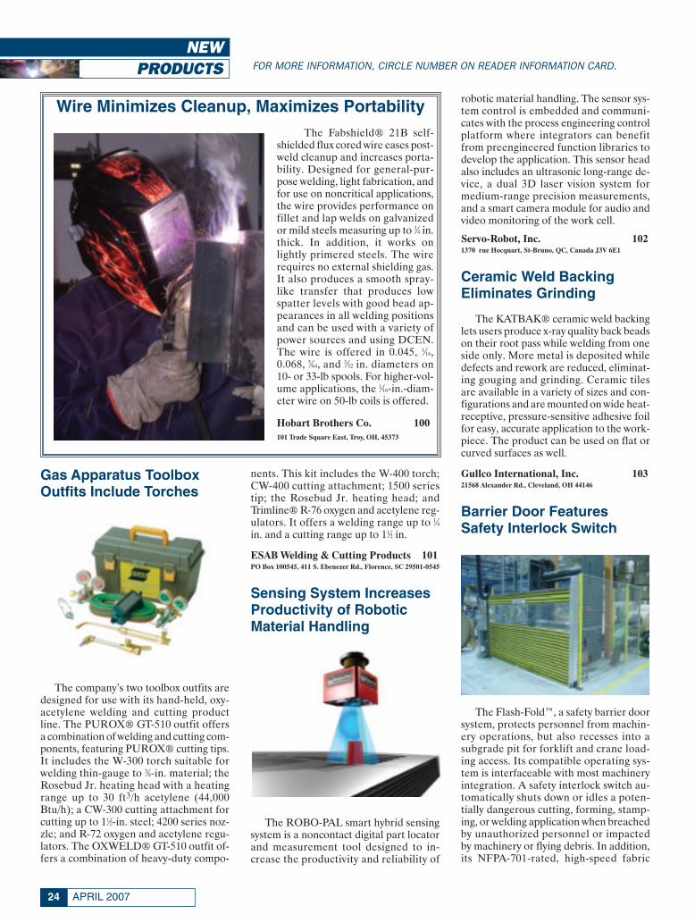
Wire Minimizes Cleanup, Maximizes PortabilityThe Fabshield® 21B self-
shielded flux cored wire eases post-weld cleanup and increases porta-bility. Designed for general-pur-pose welding, light fabrication, andfor use on noncritical applications,the wire provides performance onfillet and lap welds on galvanizedor mild steels measuring up to 3⁄4 in.thick. In addition, it works onlightly primered steels. The wirerequires no external shielding gas.It also produces a smooth spray-like transfer that produces lowspatter levels with good bead ap-pearances in all welding positionsand can be used with a variety ofpower sources and using DCEN.The wire is offered in 0.045, 1⁄16,0.068, 5⁄64, and 3⁄32 in. diameters on10- or 33-lb spools. For higher-vol-ume applications, the 1⁄16-in.-diam-eter wire on 50-lb coils is offered.
Hobart Brothers Co. 100101 Trade Square East, Troy, OH, 45373
New Products April 2007:Layout 1 3/9/07 1:22 PM Page 24

25WELDING JOURNAL
door’s cycling speed is 36 in./s. The prod-uct comes in standard sizes ranging from6 to 18 ft wide and can protect areas up to12 ft high.
Frommelt Safety Products 1044343 Chavenelle Rd., Dubuque, IA 52002
Stackers Come in TwoConfigurations
The company’s stackers allow workersto lift, transport, and position up to 3000
lb at a time. Available with manual or elec-tric drive, they feature battery-poweredelectric lift with lifting heights of up to 80in. The stackers are available in two basicconfigurations — the fork-over designworks with any type of open-bottom pal-let or skid, and the straddle style accom-modates any pallet or skid. Standard forklengths are 45 in. for fork-over models and42 in. for straddle units. They are maneu-verable and feature an ergonomically con-toured pallet-truck-style handle, a high-visibility mast, and dual-wheel casters withtoe guards for easy, safe positioning. Ashort overall length (63–66 in.) and largeturning angle make it possible to lift andstack in confined areas.
Southworth Products Corp. 105PO Box 1380, Portland, ME 04104-1380
Plasma, Oxyfuel CuttingMachines Upgraded
The company has upgraded the Edge-Mate® and EdgeMaster® plasma andoxyfuel cutting machines with its CNCcontrol, the Global Control S. This con-trol is based on the technology of the orig-inal MG Global Control, the Global Con-trol Plus. The product provides an easy-to-use touch screen interface and the Win-
Circle No. 48 on Reader Info-CardCircle No. 41 on Reader Info-Card
New Products April 2007:Layout 1 3/9/07 1:22 PM Page 25
APRIL 200726
dows® screen layout. Also, it features theremote diagnostic software, Virtual Serv-ice, to allow advanced troubleshooting ca-pability to minimize downtime. Addi-tional upgrades to the plasma and oxyfuelcutting machines include powerful drivesand faster lifters.
MG Systems and Welding, Inc. 106W141 N9427 Fountain Blvd., Menomonee Falls, WI 53051
Conductor Tube ProvidesHeavy-Duty Performance
The design of the company’s conduc-tor tube is a reliable, flexible, durablepatent-pending mechanical ball andsocket joint that enables the user toachieve virtually infinite adjustment andfirm positioning. It does not suffer fromearly fatigue-related failure after repeated
readjustment to new positions. Each con-ductor tube is a series of mechanical con-nections that allow gradual bending of thetube to any angle from straight out of aGMAW gun to a maximum of 80 deg. Theconductor tube has been engineered toallow bending while minimizing restric-tion on wire feeding. Each of the threeconnector designs allows a maximum of60 deg of bend, and four connector tubesare suitable for a maximum 80-deg bend.
Tweco 1072800 Airport Rd., Denton, TX 76207
Punch Stripper Pierces aVariety of Materials
The True Strip die-spring-actuated me-
chanical stripper for punches effectivelyand cleanly strips the workpiece to pro-long tool life and avoid double hits or partsstacked in the die. It is a precision-machined device that is compact, inter-changeable, and fits directly onto indus-try standard retainers with one screw. Theproduct is used with a single punch designor custom multihole pierce punch appli-cations. The unit’s design has a stripperguided not only by the land of the steelcan, but also by the stripper head. It canpierce and strip a variety of materials to2 mm thick with unlimited production re-quirements. By changing the spring, strip-ping force is adjustable.
Moeller Mfg. Co. 10843938 Plymouth Oaks Blvd., Plymouth, MI 48170-2584
Gas Detector Useful forIndustrial Applications
The Series 3000 XPIS (ExplosionProof, Intrinsically Safe) gas detector uti-lizes existing two-wire systems to monitorfor toxic and oxygen gas hazards in poten-tially flammable environments. Operatingon a standard two-wire 4–20 mA loop thatmakes it suitable for new and retrofit ap-plications, the product serves a variety ofindustrial environments. It requires mini-mal sensor replacement/downtime. Thegas sensors available for the product in-clude oxygen, hydrogen sulfide, carbonmonoxide, ammonia, and sulfur dioxide.It uses smart gas sensors that configure au-tomatically when they are plugged into thedevice. Additionally, onboard diagnostics
Circle No. 19 on Reader Info-Card
New Products April 2007:Layout 1 3/9/07 1:23 PM Page 26

provide useful information during opera-tion and fault finding routines, plus thepatented “Reflex” sensors test algorithms.
Honeywell Analytics 109553 N. North Ct., Ste. 110, Palatine, IL 60067
Valve Available in Brass,Stainless Steel
The KFPV050 Series proportionalcontrol valves provide stepless variablecontrol of gases and liquids. The valve isa direct acting two-port plunger type witha body available in brass or stainless steel.The solenoid can be oriented 360 deg, andits elbow electrical terminal can be posi-tioned every 90 deg top to bottom and leftto right for maximum wiring versatility.The valves are designed for use with theKFPC1 controller; this accepts standardinput signals of 4–20 mA or 0–10 V. On-board support circuits make initial settingpossible without any external input.
Humphrey Products Co. 110PO Box 2008, Kalamazoo, MI 49003
Wire Dispensing SystemOptimizes Production Time
The Non-Stop™ wire dispensing sys-
tem, constructed with heavy-duty ex-truded aluminum, utilizes a process thatjoins the end wire from an empty drumwith the start wire of the next full drum,eliminating downtime for wire changeoverand optimizing production time. Asmooth operating wire guide arm handlesthe wire transfer during the automaticchange, with no manual operator actionrequired. The system works with eitherone or two station robotic cells (two orfour drums), and it is available for both500- and 1000-lb Accu-Pak drums.
ELCo Enterprises, Inc. 1115750 Marathon Dr., Jackson, MI 49201
27WELDING JOURNAL
Diamond Saw Works manufactures the Sterling® family of world class sawblade products.
Constant research and development of application specific products combined withstate of the art manufacturing equipment and methods provides cost effective productsto the material sawing industry.
We have designed and developed a series of bands specifically for fabrication shop applications.
�New Wave™ series, with an modified wavytooth set is ideal for smaller structural shapes.� Cut Master™ bands with a modified progressiveclose tolerance set provides smoother finishes, aggressive performance and resists tooth strippage.� Kerf Plus™ extra set bands are ideal for larger shapes that tend to close into the cut and reducing blade damage when sawing bundles.
Diamond Saw Works, Inc.12290 Olean RoadChaffee, NY 14030Phone: (800) 828-1180Fax: (800) 237-6158E-mail: [email protected]
Circle No. 5 on Reader Info-CardCircle No. 25 on Reader Info-Card
New Products April 2007:Layout 1 3/9/07 1:23 PM Page 27

APRIL 200728
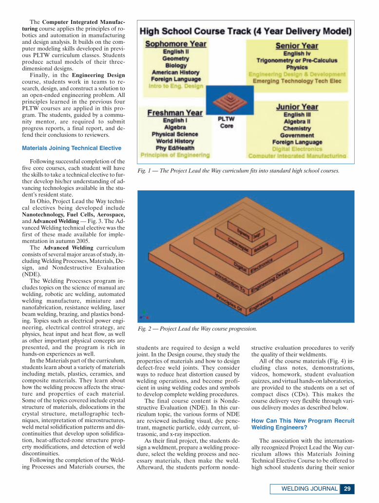
There has been a shortage of engineersin the United States for more than adecade. To help encourage middle andhigh school students to consider careers inengineering, a national initiative calledProject Lead the Way (PLTW) has beenadopted by more than 40 states. ThePLTW curriculum engages students in sci-entific study coupled with hands-on expe-rience and teamwork with other studentsand mentors from industry. The success ofthis program is gaining international attention.
The high school core consists of fivecourses in emerging engineering tech-nologies traditionally taken over the fouryears of high school, together with a seriesof high school senior-level technical elec-tives available for each state. These tech-nical electives augment the basic engi-neering curricula in PLTW. The electivecourses 1) build on the entire PLTW cur-riculum knowledge base, 2) tie topics to-gether for better student comprehension,and 3) offer real-world applications forthe concepts. The advanced welding tech-nical elective described more fully below isone of these advanced technologies.
Project Lead the Way Core Courses
In the typical four-year high schooltrack, as illustrated in Fig. 1, freshman stu-dents take the usual English, algebra,physical science, world history, and physi-cal education or health classes, but alsoenroll in the first PLTW course, Principlesof Engineering.
Sophomore students take an Introduc-tion to Engineering Design class in addi-tion to their regular courses.
Junior year students take two addi-tional PLTW classes: Digital Electronicsand Computer Integrated Manufacturing.
Senior year students attend Engineer-ing Design and Development, a research-oriented class, and an Emerging Technol-ogy technical elective class.
The benefits of such a sound core pro-gram in engineering include the fact thatthis is a nationally recognized preengi-neering program taught in more than 40states with the curricula updated annuallyby PLTW. The programs feature hands-on, team-oriented classes that stimulatecontinued career development. In addi-tion, students can receive up to 15 hours ofcollege credit from many accredited universities.
The following presents a closer look ateach of the basic courses in the PLTW Core.
Each of the five PLTW courses buildson the others, as illustrated in Fig. 2 anddescribed in the following, giving a soundbackground in engineering.
Principles of Engineering is a broad-based survey course designed to help stu-dents understand the field of engineeringand engineering technology and its careerpossibilities. The curriculum developsproblem-solving skills used in postsec-ondary education programs and engineer-ing careers. It explores various engineer-ing systems and manufacturing processes.Students learn how engineers addressconcerns about the social and politicalconsequences of technological changes.
Some of the specific topics covered inthis course include definitions of engi-neering principles and descriptions of var-ious types of engineering. The course de-scribes the importance of accuratecommunication and documentation oftest results. It introduces the understand-ing of the design process as an engineeringprinciple, and introduces some of themore recent and emerging engineeringsystems. Described are static design and
the importance of strength of materials inthat design. The course addresses how ma-terials can be tested to determine their fit-ness for purpose, and serves as an intro-duction to dynamics and kinematics forapplications in real systems.
Introduction to Engineering Design,the second course in the core, uses a com-puter-based solid modeling approachusing the software program Inventor fromthe Autocad computer-aided design pack-age. Students are stimulated to developproblem-solving skills with an emphasison three-dimensional solid model sketch-ing and visualization techniques. Theyprogress from sketching simple geometricshapes to using the solid modeling com-puter software package.
Moving on to assembly modeling, thestudents learn a problem-solving designprocess and how it is used in industrialmanufacturing. Marketing the finishedproduct is also considered. Each studentthen prepares his/her individual portfoliodetailing the complete engineering designprocess.
Digital Electronics, the third course inthe PLTW core, offers study in applieddigital logic. The students study the cir-cuitry found in digital electronic devices,such as video games, wristwatches, calcu-lators, and digital cameras. They study theapplications for digital logic and how dig-ital devices are used to control automatedequipment. Some of the specific topicscovered in the digital electronics courseinclude number systems and how they areprocessed by digital electronic devices.They study electronic gates and the use ofBoolean algebra in digital processing.Students design control, flip-flop, andcounting circuits, and investigate the useof microprocessors in manufacturing andcontrol applications.
‘Project Lead the Way’Attracts Students toAttracts Students toEngineering CareersEngineering Careers
A nationwide initiative enhances high school curricula with technical coursesexpressly designed to lead students to pursue careers in engineering
BY DAVID W. DICKINSON
DAVID W. DICKINSON ([email protected]) is a professor, College of Engineering, The Ohio State University, Columbus, Ohio.
Dickinson corr:Layout 1 3/8/07 2:36 PM Page 28
29WELDING JOURNAL
The Computer Integrated Manufac-turing course applies the principles of ro-botics and automation in manufacturingand design analysis. It builds on the com-puter modeling skills developed in previ-ous PLTW curriculum classes. Studentsproduce actual models of their three-dimensional designs.
Finally, in the Engineering Designcourse, students work in teams to re-search, design, and construct a solution toan open-ended engineering problem. Allprinciples learned in the previous fourPLTW courses are applied in this pro-gram. The students, guided by a commu-nity mentor, are required to submitprogress reports, a final report, and de-fend their conclusions to reviewers.
Materials Joining Technical Elective
Following successful completion of thefive core courses, each student will havethe skills to take a technical elective to fur-ther develop his/her understanding of ad-vancing technologies available in the stu-dent’s resident state.
In Ohio, Project Lead the Way techni-cal electives being developed includeNanotechnology, Fuel Cells, Aerospace,and Advanced Welding — Fig. 3. The Ad-vanced Welding technical elective was thefirst of these made available for imple-mentation in autumn 2005.
The Advanced Welding curriculumconsists of several major areas of study, in-cluding Welding Processes, Materials, De-sign, and Nondestructive Evaluation(NDE).
The Welding Processes program in-cludes topics on the science of manual arcwelding, robotic arc welding, automatedwelding manufacture, miniature andnanofabrication, resistance welding, laserbeam welding, brazing, and plastics bond-ing. Topics such as electrical power engi-neering, electrical control strategy, arcphysics, heat input and heat flow, as wellas other important physical concepts arepresented, and the program is rich inhands-on experiences as well.
In the Materials part of the curriculum,students learn about a variety of materialsincluding metals, plastics, ceramics, andcomposite materials. They learn abouthow the welding process affects the struc-ture and properties of each material.Some of the topics covered include crystalstructure of materials, dislocations in thecrystal structure, metallographic tech-niques, interpretation of microstructures,weld metal solidification patterns and dis-continuities that develop upon solidifica-tion, heat-affected-zone structure prop-erty modifications, and detection of welddiscontinuities.
Following the completion of the Weld-ing Processes and Materials courses, the
students are required to design a weldjoint. In the Design course, they study theproperties of materials and how to designdefect-free weld joints. They considerways to reduce heat distortion caused bywelding operations, and become profi-cient in using welding codes and symbolsto develop complete welding procedures.
The final course content is Nonde-structive Evaluation (NDE). In this cur-riculum topic, the various forms of NDEare reviewed including visual, dye pene-trant, magnetic particle, eddy current, ul-trasonic, and x-ray inspection.
As their final project, the students de-sign a weldment, prepare a welding proce-dure, select the welding process and nec-essary materials, then make the weld.Afterward, the students perform nonde-
structive evaluation procedures to verifythe quality of their weldments.
All of the course materials (Fig. 4) in-cluding class notes, demonstrations,videos, homework, student evaluationquizzes, and virtual hands-on laboratories,are provided to the students on a set ofcompact discs (CDs). This makes thecourse delivery very flexible through vari-ous delivery modes as described below.
How Can This New Program RecruitWelding Engineers?
The association with the internation-ally recognized Project Lead the Way cur-riculum allows this Materials JoiningTechnical Elective Course to be offered tohigh school students during their senior
Fig. 1 — The Project Lead the Way curriculum fits into standard high school courses.
Fig. 2 — Project Lead the Way course progression.
Dickinson corr:Layout 1 3/8/07 2:37 PM Page 29

year — at the time when students are mak-ing their career decisions.
The welding course is flexible in that itcan be presented to large groups of stu-dents in a classroom, with a teacher and allnecessary instructional materials.
All classroom teachers are required totake a two-week summer training coursewhere they receive the supplementary materials.
Also, the course can be taught usingthe Internet. High schools with only a fewstudents who wish to enroll in this pro-gram can select the Internet option. In ad-dition, the CDs include a whole series ofvirtual laboratories such that the need forhigh schools to purchase expensive labo-ratory equipment is reduced.
Visuals Make This New Program Work
Dr. Richard Felder at North CarolinaState University has completed a signifi-cant study regarding engineering students’learning styles. Using his model, the learn-ing styles of freshman engineering stu-dents at The Ohio State University havebeen evaluated over the past four years. Inthree categories (Active vs. ReflectiveLearners, Sensing vs. Intuitive Learners,and Sequential vs. Global Learners), therewere midlevel scores, reflecting engineer-ing students’ ability to accommodate mostlearning styles. The only exception was theVisual vs. Verbal Learning style where en-gineering students were decidedly “vi-sual.” Thus, to be most effective, engi-neering course materials should have asignificant visual component. Lecture-based courses alone do not offer the visualcontent that a course using electronicmedia can. The CD-based Materials Join-ing Course with its visual content, virtuallaboratories, and real-world problem-solving exercises fills this need.
Summary
The linking of the Materials JoiningTechnical Elective with the Project Leadthe Way High School Core EngineeringProgram gives an exceptional means forrecruiting high school students into engi-neering, welding, welding engineering,and welding engineering technology ca-reers. Since the course is available on CDs,it is ideal for welding and engineering stu-dents who are best served by extensive visual-based learning materials and virtualhands-on laboratories. A complimentarydemonstration disk is available for a testrun of the course material. E-mail your re-quest to [email protected].
Visit the Project Lead the Way Website, www.pltw.org, for more informationon this nationwide program, and where itis being presented in your state. ♦
Fig. 3 — Technical elective courses being developed to augment the PLTW curriculum inOhio.
Fig. 4 — Some of the course materials provided.
APRIL 200730
Dickinson corr:Layout 1 3/8/07 2:38 PM Page 30

Circle No. 49 on Reader Info-Card
thermadyne:FP_TEMP 3/12/07 5:18 PM Page 31

APRIL 200732
This case study shows how the prin-ciples of Lean can be applied towelding operations in a plant pro-
ducing front-end loaders (see lead photo).A systematic approach to measuring weld-ing process parameters and welder skillswas used to diagnose areas of applyingKaizen or the process of continuous im-provement. Welder training and optimiza-tion of welding parameters resulted in asignificant improvement in quality and re-duction of waste. Design changes facili-tating ease of welding and reduction ofgrinding were made. Weld process moni-toring was used to measure deviation from
optimized parameters and corrective ac-tion was implemented through weldercoaching on the job. Welding duty cycleswere measured to justify robotics in spe-cific areas. Annual savings of $400,000were achieved in a shop employing 35welders.
Introduction
Lean manufacturing is focused oneliminating waste in the entire manufac-turing process. It deals with minimizingwork-in-process, eliminating processes
that do not add value to the product, mak-ing the process flexible enough to makeproducts of different design without com-promising quality or cost. Historically,many manufacturing companies havebeen able to maintain bloated or ineffi-cient methods because of a protected mar-ket, strong brand strength, or huge profitmargins. Global competition is forcingthese manufacturers to change their meth-ods to be less wasteful, and provide valueto their customers through customizationand reduced cycle or delivery times.
In the early 1980s, the Lean paradigmwas invented at the Massachusetts Insti-
VIWEK VAIDYA ([email protected]) is director of welding technology and business development, Air Liquide Canada, Inc.BRYAN GEORGE ([email protected]) is packaged gas technical division manager, Air Liquide America LP.
Applying Lean toWelding Operations
BY VIWEK VAIDYA AND BRYAN GEORGE
The welder pictured aboveis shown welding on a tank.In the inset are front-endloaders on a truck.
Vaidya Feature April 2007corr:Layout 1 3/9/07 3:43 PM Page 32
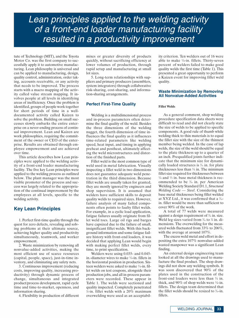
33WELDING JOURNAL
tute of Technology (MIT), and the ToyotaMotor Co. was the first company to suc-cessfully apply it to automotive manufac-turing. Lean philosophy is universal andcan be applied to manufacturing, design,quality control, administration, order tak-ing, accounts receivable, or any activitythat needs to be improved. The processstarts with a macro mapping of the activ-ity called value stream mapping. It in-volves people at all levels in identifyingareas of inefficiency. Once the problem isidentified, groups of people work togetherfor short periods of time in a well-documented activity called Kaizen tosolve the problem. Building on small suc-cesses slowly embarks the entire enter-prise on a never-ending process of contin-ual improvement. Lean and Kaizen arework philosophies, requiring the commit-ment of the owner or CEO of the enter-prise. Results are obtained through em-ployee empowerment and are achievedover time.
This article describes how Lean prin-ciples were applied to the welding activ-ity of a front-end loader manufacturingfacility. The five key Lean principles wereapplied to the welding process as outlinedbelow. The plant manager was the mostvisible promoter of the process and suc-cess was largely related to the appropria-tion of the continual improvement by theemployees at all levels, specific to thewelding activity.
Key Lean Principles
1. Perfect first-time quality through thequest for zero defects, revealing and solv-ing problems at their ultimate source,achieving higher quality and productivitysimultaneously, teamwork, and workerempowerment.
2. Waste minimization by removing allnonvalue-added activities, making themost efficient use of scarce resources(capital, people, space), just-in-time in-ventory, and eliminating any safety nets.
3. Continuous improvement (reducingcosts, improving quality, increasing pro-ductivity) through dynamic process ofchange, simultaneous and integratedproduct/process development, rapid cycletime and time-to-market, openness, andinformation sharing.
4. Flexibility in production of different
mixes or greater diversity of productsquickly, without sacrificing efficiency atlower volumes of production, throughrapid setup and manufacturing at smalllot sizes.
5. Long-term relationships with sup-pliers and primary producers (assemblers,system integrators) through collaborativerisk-sharing, cost-sharing, and informa-tion-sharing arrangements.
Perfect First-Time Quality
Welding is a multidimensional processand in-process parameters often deter-mine the final quality of the weld. Besidesthe three dimensions of the weldingnugget, the fourth dimension of time in-fluences the final quality as it influencestime-related parameters like weldingspeed, heat input, and timing in applyingpreheat and postheat, ultimately affect-ing the weld microstructures and distor-tion of the finished parts.
Fillet weld is the most common type ofweld used in metal fabrication. Visuallyinspecting a fillet weld in two dimensionsdoes not guarantee adequate weld pene-tration in the third dimension. Becausefillet welds are usually taken for granted,they are mostly ignored by engineers andshop supervision. It is assumed thatwelders have sufficient skills to depositquality welds to required sizes. However,failure analysis of many failed compo-nents often points to faulty fillet welds.For example, in a cyclic load application,fatigue failures usually originate from fil-let weld toes. Large oil rigs and bargeshave capsized due to the failure of small,insignificant fillet welds. With this back-ground information and some fatigue fail-ure history with front-end loaders, it wasdecided that applying Lean would beginwith making perfect fillet welds, everytime, to print specification.
Welders were using 0.035- and 0.045-in.-diameter wires to make ¼-in. fillets inthe horizontal position in production. Six-teen welders were asked to make ¼-in. fil-let welds on test coupons, alongside theirproduction jobs, and all in-process param-eters were recorded. These appear inTable 1. The welds were sectioned andquality inspected. Completely penetrated1⁄4-in. fillet welds with a 20% maximumoverwelding were used as an acceptabil-
ity criterion. Ten welders out of 16 wereable to make ¼-in. fillets. Thirty-sevenpercent of welders failed to make goodquality welds the first time (Table 1). Thispresented a great opportunity to performa Kaizen event for improving fillet weldquality.
Waste Minimization by RemovingAll Nonvalue-Added Activities
Fillet Welds
As a general comment, shop weldingprocedure specification data sheets weredifficult to read and did not clearly statethe size of welds to be applied to specificcomponents. A good rule of thumb whilewelding thick to thin materials is to equalthe fillet size with the size of the thinnestmember being welded. In the case of lapwelds, the size of the weld should be equalto the plate thickness up to a quarter ofan inch. Prequalified joints further indi-cate that the minimum size for dynami-cally loaded structures is 3⁄16 in. for platethicknesses less than ¼ in. The minimumfillet size required for thicknesses between¼ and ½ in. base metal thickness is rec-ommended to be 3⁄16 in. per AmericanWelding Society Standard D1.1, StructuralWelding Code — Steel. Considering thebase metal thicknesses being fillet weldedat XYZ Ltd., it was confirmed that a 3⁄16-in. fillet would be more than sufficient tocover 90% of the work.
A total of 77 welds were measuredagainst a design requirement of 3⁄16 in. size.Weld leg sizes varied from 3⁄16 to 3⁄8 in. di-mensions. The overwelding for the meas-ured welds fluctuated from 33% to 206%,with the average at around 107%.
The excess weld metal and effort in de-positing the extra 107% nonvalue-addedwasted manpower was a significant Leanfinding.
An external design engineering teamlooked at all the drawings used to manu-facture the final product. The shop draw-ings did not show any welding symbols. Itwas soon discovered that 90% of theplates used in the construction of thefront-end loaders were less than ¼ in.thick, and 90% of shop welds were ¼-in.fillets. The design team determined thatthe fillet welds should be resized to 3⁄16-in.fillets.
Lean principles applied to the welding activity of a front-end loader manufacturing facility
resulted in a productivity improvement
Vaidya Feature April 2007corr:Layout 1 3/9/07 3:44 PM Page 33
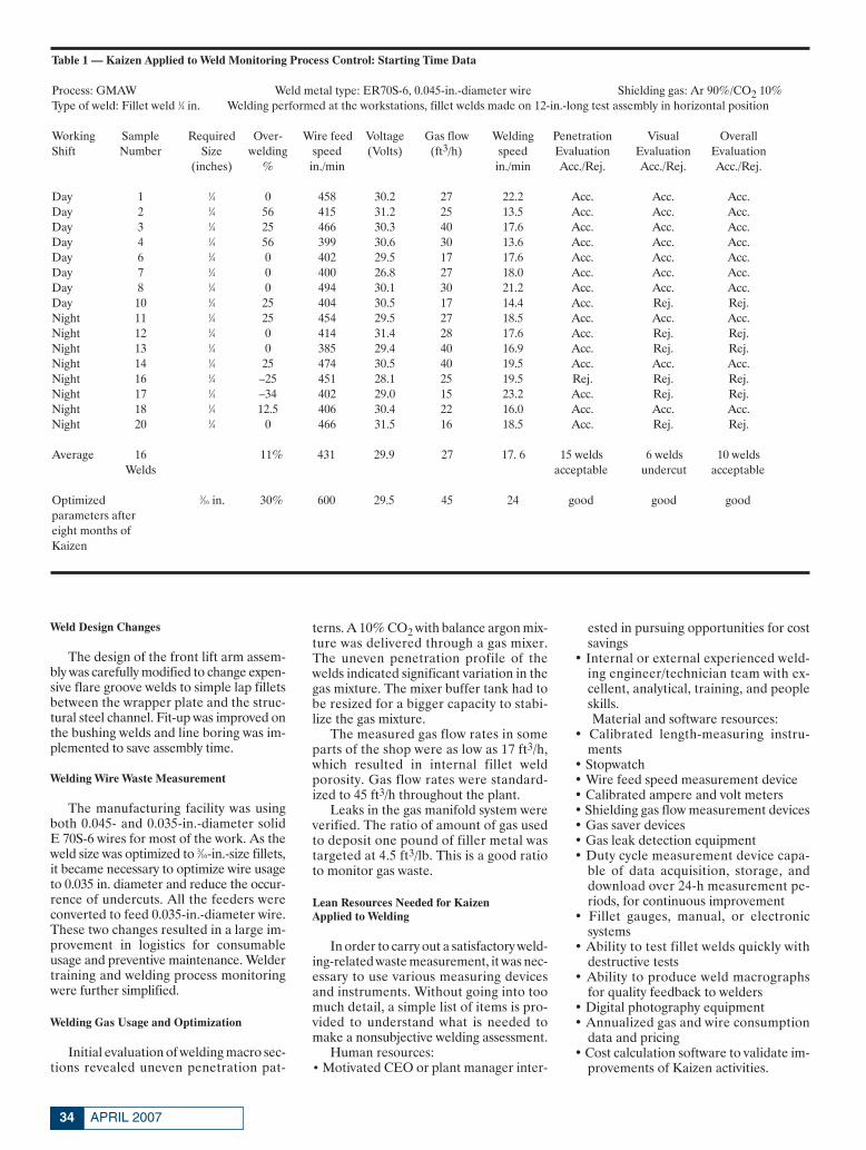
APRIL 200734
Weld Design Changes
The design of the front lift arm assem-bly was carefully modified to change expen-sive flare groove welds to simple lap filletsbetween the wrapper plate and the struc-tural steel channel. Fit-up was improved onthe bushing welds and line boring was im-plemented to save assembly time.
Welding Wire Waste Measurement
The manufacturing facility was usingboth 0.045- and 0.035-in.-diameter solidE 70S-6 wires for most of the work. As theweld size was optimized to 3⁄16-in.-size fillets,it became necessary to optimize wire usageto 0.035 in. diameter and reduce the occur-rence of undercuts. All the feeders wereconverted to feed 0.035-in.-diameter wire.These two changes resulted in a large im-provement in logistics for consumableusage and preventive maintenance. Weldertraining and welding process monitoringwere further simplified.
Welding Gas Usage and Optimization
Initial evaluation of welding macro sec-tions revealed uneven penetration pat-
terns. A 10% CO2 with balance argon mix-ture was delivered through a gas mixer.The uneven penetration profile of thewelds indicated significant variation in thegas mixture. The mixer buffer tank had tobe resized for a bigger capacity to stabi-lize the gas mixture.
The measured gas flow rates in someparts of the shop were as low as 17 ft3/h,which resulted in internal fillet weldporosity. Gas flow rates were standard-ized to 45 ft3/h throughout the plant.
Leaks in the gas manifold system wereverified. The ratio of amount of gas usedto deposit one pound of filler metal wastargeted at 4.5 ft3/lb. This is a good ratioto monitor gas waste.
Lean Resources Needed for Kaizen Applied to Welding
In order to carry out a satisfactory weld-ing-related waste measurement, it was nec-essary to use various measuring devicesand instruments. Without going into toomuch detail, a simple list of items is pro-vided to understand what is needed tomake a nonsubjective welding assessment.
Human resources:• Motivated CEO or plant manager inter-
ested in pursuing opportunities for costsavings
• Internal or external experienced weld-ing engineer/technician team with ex-cellent, analytical, training, and peopleskills.Material and software resources:
• Calibrated length-measuring instru-ments
• Stopwatch• Wire feed speed measurement device• Calibrated ampere and volt meters• Shielding gas flow measurement devices• Gas saver devices • Gas leak detection equipment• Duty cycle measurement device capa-
ble of data acquisition, storage, anddownload over 24-h measurement pe-riods, for continuous improvement
• Fillet gauges, manual, or electronic systems
• Ability to test fillet welds quickly withdestructive tests
• Ability to produce weld macrographsfor quality feedback to welders
• Digital photography equipment• Annualized gas and wire consumption
data and pricing• Cost calculation software to validate im-
provements of Kaizen activities.
Table 1 — Kaizen Applied to Weld Monitoring Process Control: Starting Time Data
Process: GMAW Weld metal type: ER70S-6, 0.045-in.-diameter wire Shielding gas: Ar 90%/CO2 10%Type of weld: Fillet weld 1⁄4 in. Welding performed at the workstations, fillet welds made on 12-in.-long test assembly in horizontal position
Working Sample Required Over- Wire feed Voltage Gas flow Welding Penetration Visual OverallShift Number Size welding speed (Volts) (ft3/h) speed Evaluation Evaluation Evaluation
(inches) % in./min in./min Acc./Rej. Acc./Rej. Acc./Rej.
Day 1 1⁄4 0 458 30.2 27 22.2 Acc. Acc. Acc.Day 2 1⁄4 56 415 31.2 25 13.5 Acc. Acc. Acc.Day 3 1⁄4 25 466 30.3 40 17.6 Acc. Acc. Acc.Day 4 1⁄4 56 399 30.6 30 13.6 Acc. Acc. Acc.Day 6 1⁄4 0 402 29.5 17 17.6 Acc. Acc. Acc.Day 7 1⁄4 0 400 26.8 27 18.0 Acc. Acc. Acc.Day 8 1⁄4 0 494 30.1 30 21.2 Acc. Acc. Acc.Day 10 1⁄4 25 404 30.5 17 14.4 Acc. Rej. Rej.Night 11 1⁄4 25 454 29.5 27 18.5 Acc. Acc. Acc.Night 12 1⁄4 0 414 31.4 28 17.6 Acc. Rej. Rej.Night 13 1⁄4 0 385 29.4 40 16.9 Acc. Rej. Rej.Night 14 1⁄4 25 474 30.5 40 19.5 Acc. Acc. Acc.Night 16 1⁄4 –25 451 28.1 25 19.5 Rej. Rej. Rej.Night 17 1⁄4 –34 402 29.0 15 23.2 Acc. Rej. Rej.Night 18 1⁄4 12.5 406 30.4 22 16.0 Acc. Acc. Acc.Night 20 1⁄4 0 466 31.5 16 18.5 Acc. Rej. Rej.
Average 16 11% 431 29.9 27 17. 6 15 welds 6 welds 10 weldsWelds acceptable undercut acceptable
Optimized 3⁄16 in. 30% 600 29.5 45 24 good good goodparameters aftereight months ofKaizen
Vaidya Feature April 2007corr:Layout 1 3/9/07 3:44 PM Page 34
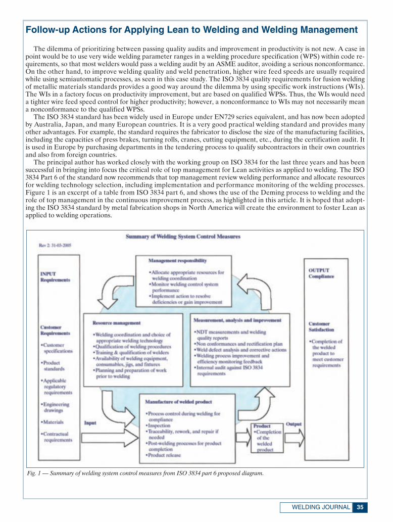
35WELDING JOURNAL
Follow-up Actions for Applying Lean to Welding and Welding Management
The dilemma of prioritizing between passing quality audits and improvement in productivity is not new. A case inpoint would be to use very wide welding parameter ranges in a welding procedure specification (WPS) within code re-quirements, so that most welders would pass a welding audit by an ASME auditor, avoiding a serious nonconformance.On the other hand, to improve welding quality and weld penetration, higher wire feed speeds are usually requiredwhile using semiautomatic processes, as seen in this case study. The ISO 3834 quality requirements for fusion weldingof metallic materials standards provides a good way around the dilemma by using specific work instructions (WIs).The WIs in a factory focus on productivity improvement, but are based on qualified WPSs. Thus, the WIs would needa tighter wire feed speed control for higher productivity; however, a nonconformance to WIs may not necessarily meana nonconformance to the qualified WPSs.
The ISO 3834 standard has been widely used in Europe under EN729 series equivalent, and has now been adoptedby Australia, Japan, and many European countries. It is a very good practical welding standard and provides manyother advantages. For example, the standard requires the fabricator to disclose the size of the manufacturing facilities,including the capacities of press brakes, turning rolls, cranes, cutting equipment, etc., during the certification audit. Itis used in Europe by purchasing departments in the tendering process to qualify subcontractors in their own countriesand also from foreign countries.
The principal author has worked closely with the working group on ISO 3834 for the last three years and has beensuccessful in bringing into focus the critical role of top management for Lean activities as applied to welding. The ISO3834 Part 6 of the standard now recommends that top management review welding performance and allocate resourcesfor welding technology selection, including implementation and performance monitoring of the welding processes.Figure 1 is an excerpt of a table from ISO 3834 part 6, and shows the use of the Deming process to welding and therole of top management in the continuous improvement process, as highlighted in this article. It is hoped that adopt-ing the ISO 3834 standard by metal fabrication shops in North America will create the environment to foster Lean asapplied to welding operations.
Fig. 1 — Summary of welding system control measures from ISO 3834 part 6 proposed diagram.
Vaidya Feature April 2007corr:Layout 1 3/9/07 3:46 PM Page 35

APRIL 200736
Continuous Improvementthrough the Dynamic Process of Change
Welding Wire Size
Once the initial welding parameters
were recorded, as shown in Table 1, thetask of continuous improvement beganwith plant supervision. All welders wereusing water-cooled welding guns of Euro-pean design. These guns never leaked anywater; however, a lot of undercutting wasnoticed on fillet welds. Arbitrarily used in
production were 0.045- and 0.035-in. di-ameters. The welders on the floor had im-plemented a “smart” solution to this prob-lem. On a four-drive roll feeder system,two rolls were 0.035-in. and the other twowere 0.045-in. diameter, so any diameterof the wire could be fed. As a corrective
Table 2 — Actual Shop Conditions
Welding position: Horizontal
DataFillet weld size in decimal inches 0.25 in.Welding process GMAWProcess efficiency 95%Filler metal cost per pound $0.75/lbWire diameter 0.045 in.Wire feed speed in inches per minute 425 in./minCalculated deposition rate at 100% shop efficiency 10.93 lb/hCost of shielding gas in dollars per cubic feet $0.06/ft3
Shielding gas flow rate in cubic feet per hour 20 ft3/h Shop charge out labor rate $25.00/hFillet weld weight per linear foot 0.106 lb/ftFillet weld weight with 19.5% overwelding per linear foot 0.127 lb/ftCalculated fillet weld cross section in square inches 0.037 in.2Calculated fillet weld size including allowable overwelding 0.273 in.Welding arc travel speed in inches per minute 17.20 in./minMeasure shop duty cycle from CAP audit 20% observed from CAP auditEffective welding speed reflecting duty cycle from CAP audit 17.20 ft/hShop effective deposition rate reflecting measured duty cycle 2.19 lb/h
Calculations and results Cost per hour & repartition Cost per pound & repartition Cost per foot & repartitionLabor $25.00 92.71% $11.44 92.71% $1.454 92.71%Wire or filler metal $1.73 6.40% $0.79 6.40% $0.100 6.40%Gas $0.24 0.89% $0.11 0.89% $0.014 0.89%Total $26.97 100% $12.34 100% $1.57 100%
Welding cost calculator: Kaizen event for fillet welds. Customer: XYZ Ltd.
Customer information: XYZ Ltd.GMAW: 1⁄4-in. 2F shop actual-19.5% overwelding
Table 3 — Optimized Shop Condition after Kaizen Event and Training
Welding position: Horizontal
DataFillet Weld size in decimal inches 0.1875 in.Welding process GMAWProcess efficiency 95%Filler metal cost per pound $0.81/lbWire diameter 0.035 in.Wire feed speed in inches per minute 600 in./minCalculated deposition rate at 100% shop efficiency 9.33 lb/hCost of shielding gas in dollars per cubic feet $0.06 ft3
Shielding gas flow rate in cubic foot per hour 45 ft3/h Shop charge out labor rate $25.00/hFillet weld weight per linear foot 0.060 lb/ftFillet weld weight with 30% over welding per linear foot 0.078 lb/ftCalculated fillet weld cross section in square in. 0.023 in.2Calculated fillet weld size including allowable over welding 0.214 in.Welding arc travel speed in inches per minute 24 in./min.Measure shop duty cycle from CAP Audit 20% observed from CAP auditEffective welding speed reflecting duty cycle from CAP Audit 24 ft/hShop effective deposition rate reflecting measured duty cycle 1.87 lb/h
Calculations and results Cost per hour & repartition Cost per pound & repartition Cost per foot & repartitionLabor $25.00 92.14% $13.40 92.14% $1.042 92.14%Wire or filler metal $1.59 5.87% $0.85 5.87% $0.066 5.87%Gas $0.54 1.99% $0.29 1.99% $0.023 1.99%Total $27.13 100% $14.54 100% $1.13 100%
Welding cost calculator: CAP CONSULTANT. Customer: XYZ Ltd.
Customer information: XYZ Ltd.GMAW: 3⁄16-in. fillet with 30% overwelding
Vaidya Feature April 2007corr:Layout 1 3/9/07 3:46 PM Page 36
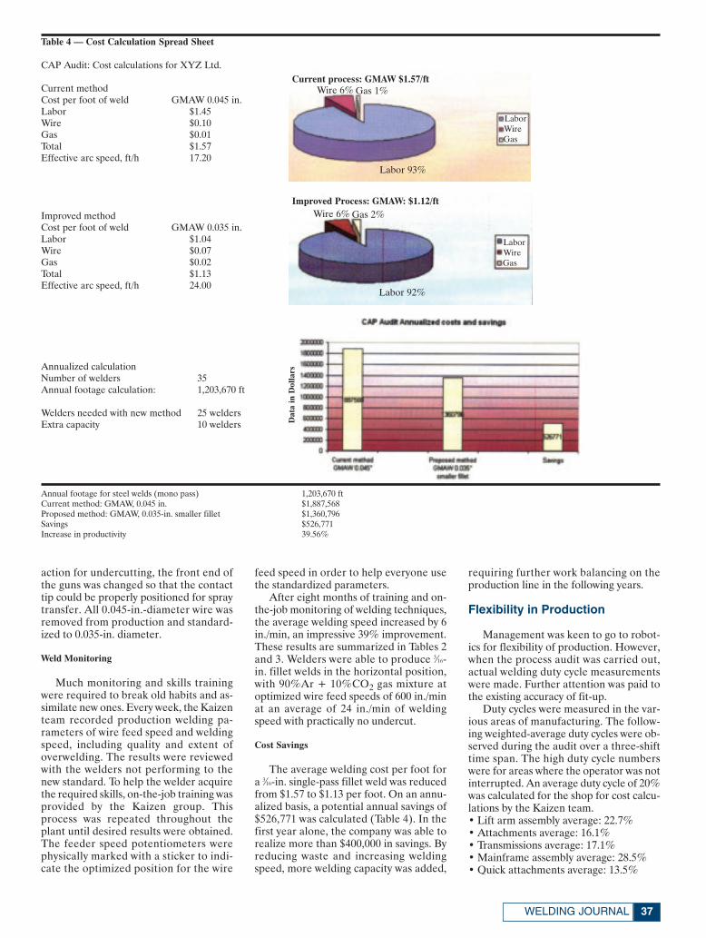
37WELDING JOURNAL
action for undercutting, the front end ofthe guns was changed so that the contacttip could be properly positioned for spraytransfer. All 0.045-in.-diameter wire wasremoved from production and standard-ized to 0.035-in. diameter.
Weld Monitoring
Much monitoring and skills trainingwere required to break old habits and as-similate new ones. Every week, the Kaizenteam recorded production welding pa-rameters of wire feed speed and weldingspeed, including quality and extent ofoverwelding. The results were reviewedwith the welders not performing to thenew standard. To help the welder acquirethe required skills, on-the-job training wasprovided by the Kaizen group. Thisprocess was repeated throughout theplant until desired results were obtained.The feeder speed potentiometers werephysically marked with a sticker to indi-cate the optimized position for the wire
feed speed in order to help everyone usethe standardized parameters.
After eight months of training and on-the-job monitoring of welding techniques,the average welding speed increased by 6in./min, an impressive 39% improvement.These results are summarized in Tables 2and 3. Welders were able to produce 3⁄16-in. fillet welds in the horizontal position,with 90%Ar + 10%CO2 gas mixture atoptimized wire feed speeds of 600 in./minat an average of 24 in./min of weldingspeed with practically no undercut.
Cost Savings
The average welding cost per foot fora 3⁄16-in. single-pass fillet weld was reducedfrom $1.57 to $1.13 per foot. On an annu-alized basis, a potential annual savings of$526,771 was calculated (Table 4). In thefirst year alone, the company was able torealize more than $400,000 in savings. Byreducing waste and increasing weldingspeed, more welding capacity was added,
requiring further work balancing on theproduction line in the following years.
Flexibility in Production
Management was keen to go to robot-ics for flexibility of production. However,when the process audit was carried out,actual welding duty cycle measurementswere made. Further attention was paid tothe existing accuracy of fit-up.
Duty cycles were measured in the var-ious areas of manufacturing. The follow-ing weighted-average duty cycles were ob-served during the audit over a three-shifttime span. The high duty cycle numberswere for areas where the operator was notinterrupted. An average duty cycle of 20%was calculated for the shop for cost calcu-lations by the Kaizen team.• Lift arm assembly average: 22.7%• Attachments average: 16.1%• Transmissions average: 17.1%• Mainframe assembly average: 28.5%• Quick attachments average: 13.5%
Table 4 — Cost Calculation Spread Sheet
CAP Audit: Cost calculations for XYZ Ltd.
Current methodCost per foot of weld GMAW 0.045 in.Labor $1.45Wire $0.10Gas $0.01Total $1.57Effective arc speed, ft/h 17.20
Improved methodCost per foot of weld GMAW 0.035 in.Labor $1.04Wire $0.07Gas $0.02Total $1.13Effective arc speed, ft/h 24.00
Annualized calculationNumber of welders 35Annual footage calculation: 1,203,670 ft
Welders needed with new method 25 weldersExtra capacity 10 welders
Annual footage for steel welds (mono pass) 1,203,670 ftCurrent method: GMAW, 0.045 in. $1,887,568Proposed method: GMAW, 0.035-in. smaller fillet $1,360,796Savings $526,771Increase in productivity 39.56%
Current process: GMAW $1.57/ft
LaborWireGas
Wire 6% Gas 1%
Labor 93%
Improved Process: GMAW: $1.12/ftWire 6% Gas 2%
Labor 92%
LaborWireGas
Dat
a in
Dol
lars
Vaidya Feature April 2007corr:Layout 1 3/9/07 3:47 PM Page 37
• Tanks average: 22.3%The overall throughput of the plant
was eight units per day. In order to im-prove this performance, the initial surveyshowed that the shop floor layout wouldhave to be significantly improved, reduc-ing a very large amount of work in process.Robotic welding was discouraged at thisstage, as part fit-up was less than accept-able and the floor layout was inadequateto feed the robot parts and then removethe finished parts efficiently without cre-ating further work-in-process pileups.
The overall operation needed to bemore balanced. It was found that even ifthe welding operation could be signifi-cantly improved from a productivity pointof view, the bottleneck was still frequentat the final assembly of the machines.More Kaizen needed to be done for thelogistics of all electrical, mechanical, andhydraulic systems. After the initial year ofwelding improvements, it was decided todefer the automation projects until otheroperations could produce a pull effect onwelding to really make flexible roboticwelding worthwhile.
Long-Term Relationships with Suppliers
Further to the initial process audit, thepresident of XYZ Ltd. was very keen toimplement corrective actions through fo-cused Kaizen activities. The process wassupported with a long-term four-year con-tract with the local gas and welding prod-ucts supplier, who could provide not onlyconsumables, but also welding engineer-ing expertise.
The first Kaizen activity was focused onwire feed speeds and reducing undercuts.
The second Kaizen activity was focusedon welding speeds and fillet weld sizes.
After the first eight months of assis-tance from the external welding engineer-ing support, the plant inspectors weretaught to measure and report key param-eters targeted by the two Kaizen activitiesto ensure that the higher productivitystandard was maintained over the four-year period.
ConclusionWhile applying Lean principles to a
metal fabrication facility employing arcwelding in the manufacture of front-endloaders, a dramatic improvement in pro-ductivity was achieved over a 12-month pe-riod. The key to success was the keen in-terest of the management team to succeedin the continuous improvement process.
The auditors performed similar auditsin more than 100 metal fabrication shopswith good results whenever the plant man-ager or the CEO of the corporation waskeenly involved in the results.♦
APRIL 200738
Stainless, Nickel,Aluminum, and
Low Alloy WeldingConsumables
• Consistent High
Quality Products
• Technical Support
In stock: St. Louis or Houston
1.800.776.3300www.midalloy.com
Circle No. 30 on Reader Info-Card
Circle No. 42 on Reader Info-Card
Vaidya Feature April 2007corr:Layout 1 3/9/07 3:47 PM Page 38
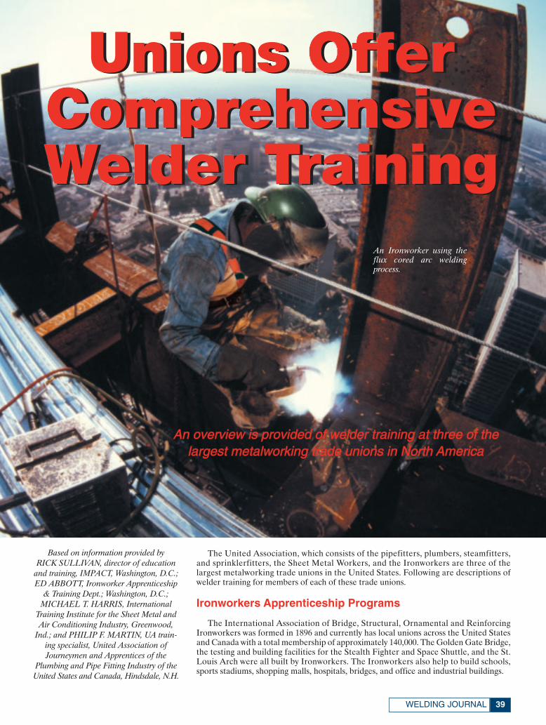
39WELDING JOURNAL
The United Association, which consists of the pipefitters, plumbers, steamfitters,and sprinklerfitters, the Sheet Metal Workers, and the Ironworkers are three of thelargest metalworking trade unions in the United States. Following are descriptions ofwelder training for members of each of these trade unions.
Ironworkers Apprenticeship Programs
The International Association of Bridge, Structural, Ornamental and ReinforcingIronworkers was formed in 1896 and currently has local unions across the United Statesand Canada with a total membership of approximately 140,000. The Golden Gate Bridge,the testing and building facilities for the Stealth Fighter and Space Shuttle, and the St.Louis Arch were all built by Ironworkers. The Ironworkers also help to build schools,sports stadiums, shopping malls, hospitals, bridges, and office and industrial buildings.
Based on information provided by RICK SULLIVAN, director of education
and training, IMPACT, Washington, D.C.;ED ABBOTT, Ironworker Apprenticeship
& Training Dept.; Washington, D.C.;MICHAEL T. HARRIS, International
Training Institute for the Sheet Metal andAir Conditioning Industry, Greenwood,
Ind.; and PHILIP F. MARTIN, UA train-ing specialist, United Association of Journeymen and Apprentices of the
Plumbing and Pipe Fitting Industry of theUnited States and Canada, Hindsdale, N.H.
Unions OfferComprehensiveWelder Training
Unions OfferComprehensiveWelder Training
An overview is provided of welder training at three of thelargest metalworking trade unions in North America
An Ironworker using theflux cored arc weldingprocess.
Union Training Feature April 2007:Layout 1 3/12/07 1:52 PM Page 39
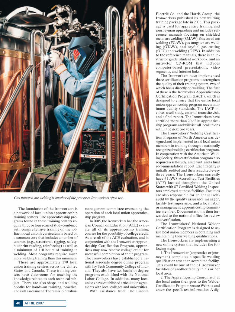
APRIL 200740
The foundation of the Ironworkers isa network of local union apprenticeshiptraining centers. The apprenticeship pro-grams found in these training centers re-quire three or four years of study combinedwith comprehensive training on the job.Each local union’s curriculum is based ona common core that includes a number ofcourses (e.g., structural, rigging, safety,blueprint reading, reinforcing) as well asa minimum of 110 hours of training inwelding. Most programs require muchmore welding training than this minimum.
There are approximately 170 localunion training centers across the UnitedStates and Canada. These training cen-ters have classrooms for teaching theknowledge related to each technical sub-ject. There are also shops and weldingbooths for hands-on training, practice,and skill assessment. There is a joint labor-
management committee overseeing theoperation of each local union apprentice-ship program.
In 2005, the Ironworkers had the Amer-ican Council on Education (ACE) evalu-ate all of its apprenticeship trainingcourses for the possibility of college credit.As a result of the ACE evaluation, and inconjunction with the Ironworker Appren-ticeship Certification Program, appren-tices may now receive college credit forsuccessful completion of their program.The Ironworkers have established a na-tional associate degree online programwith Ivy Tech Community College of Indi-ana. They also have two bachelor degreeprograms established with the NationalLabor College. In addition, many localunions have established articulation agree-ments with local colleges and universities.
With assistance from The Lincoln
Electric Co. and the Harris Group, theIronworkers published its new weldingtraining package late in 2006. This pack-age is used for apprentice training andjourneyman upgrading and includes ref-erence manuals focusing on shieldedmetal arc welding (SMAW), flux cored arcwelding (FCAW), gas tungsten arc weld-ing (GTAW), and oxyfuel gas cutting(OFC) and welding (OFW). In additionto the reference manuals, there is an in-structor guide, student workbook, and aninstructor CD-ROM that includes computer-based presentations, video segments, and Internet links.
The Ironworkers have implementedthree certification programs to strengthenthe quality of their training system, two ofwhich focus directly on welding. The firstof these is the Ironworker ApprenticeshipCertification Program (IACP), which isdesigned to ensure that the entire localunion apprenticeship program meets min-imum quality standards. The IACP in-volves a self-study, external team site visit,and a final report. The Ironworkers havecertified more than 20 of its apprentice-ship programs and will visit all local unionswithin the next two years.
The Ironworkers’ Welding Certifica-tion Program of North America was de-signed and implemented to aid local unionmembers in training through a nationallyrecognized welding certification program.In cooperation with the American Weld-ing Society, this certification program alsorequires a self-study, a site visit, and a finalrecommendation report. Each facility isinitially audited and then reaudited everythree years. The Ironworkers currentlyhave 61 AWS-Accredited Test Facilities(ATF) located throughout the UnitedStates with 87 Certified Welding Inspec-tors employed at these facilities. Facilitiesare also responsible for an annual self-audit by the quality assurance manager,facility test supervisor, and a local laboror management apprenticeship commit-tee member. Documentation is then for-warded to the national office for reviewand verification.
The Ironworkers’ National WelderCertification Program is designed to as-sist local union members in obtaining andmaintaining their welding qualifications.
The Ironworkers are implementing anew online system that includes the fol-lowing steps:
1. The Ironworker (apprentice or jour-neyman) completes a specific weldingqualification test at an accredited facility.This could be one of the 61 Ironworkerfacilities or another facility in his or herlocal area.
2. The Apprenticeship Coordinator atthe local union then goes to the WelderCertification Program secure Web site andenters the specific test information. A dig-
Gas tungsten arc welding is another of the processes Ironworkers often use.
Union Training Feature April 2007:Layout 1 3/8/07 4:41 PM Page 40
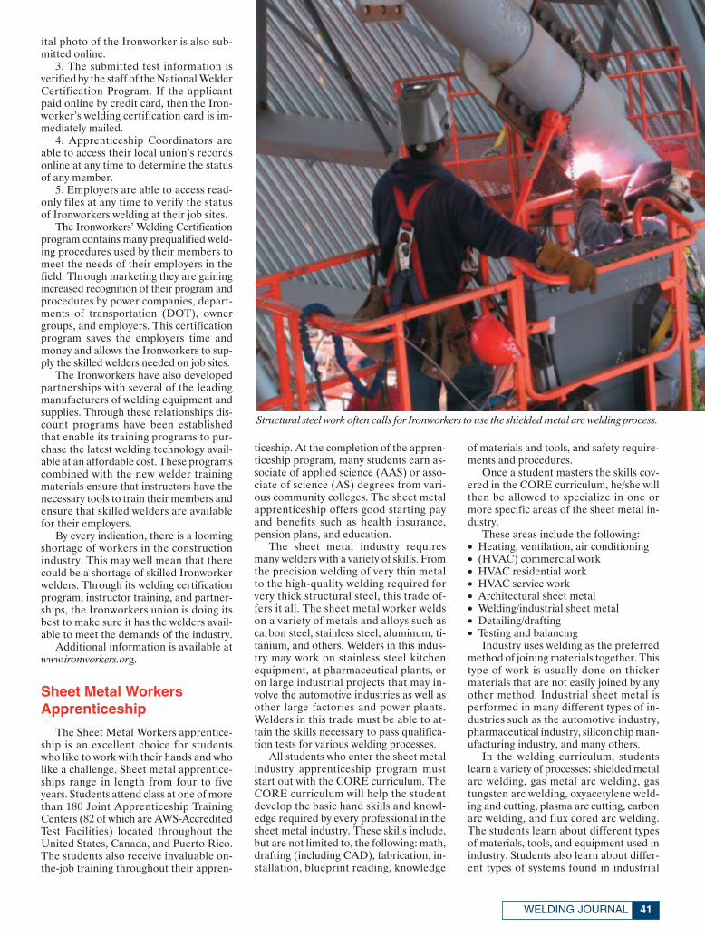
41WELDING JOURNAL
ital photo of the Ironworker is also sub-mitted online.
3. The submitted test information isverified by the staff of the National WelderCertification Program. If the applicantpaid online by credit card, then the Iron-worker’s welding certification card is im-mediately mailed.
4. Apprenticeship Coordinators areable to access their local union’s recordsonline at any time to determine the statusof any member.
5. Employers are able to access read-only files at any time to verify the statusof Ironworkers welding at their job sites.
The Ironworkers’ Welding Certificationprogram contains many prequalified weld-ing procedures used by their members tomeet the needs of their employers in thefield. Through marketing they are gainingincreased recognition of their program andprocedures by power companies, depart-ments of transportation (DOT), ownergroups, and employers. This certificationprogram saves the employers time andmoney and allows the Ironworkers to sup-ply the skilled welders needed on job sites.
The Ironworkers have also developedpartnerships with several of the leadingmanufacturers of welding equipment andsupplies. Through these relationships dis-count programs have been establishedthat enable its training programs to pur-chase the latest welding technology avail-able at an affordable cost. These programscombined with the new welder trainingmaterials ensure that instructors have thenecessary tools to train their members andensure that skilled welders are availablefor their employers.
By every indication, there is a loomingshortage of workers in the constructionindustry. This may well mean that therecould be a shortage of skilled Ironworkerwelders. Through its welding certificationprogram, instructor training, and partner-ships, the Ironworkers union is doing itsbest to make sure it has the welders avail-able to meet the demands of the industry.
Additional information is available atwww.ironworkers.org.
Sheet Metal WorkersApprenticeship
The Sheet Metal Workers apprentice-ship is an excellent choice for studentswho like to work with their hands and wholike a challenge. Sheet metal apprentice-ships range in length from four to fiveyears. Students attend class at one of morethan 180 Joint Apprenticeship TrainingCenters (82 of which are AWS-AccreditedTest Facilities) located throughout theUnited States, Canada, and Puerto Rico.The students also receive invaluable on-the-job training throughout their appren-
ticeship. At the completion of the appren-ticeship program, many students earn as-sociate of applied science (AAS) or asso-ciate of science (AS) degrees from vari-ous community colleges. The sheet metalapprenticeship offers good starting payand benefits such as health insurance,pension plans, and education.
The sheet metal industry requiresmany welders with a variety of skills. Fromthe precision welding of very thin metalto the high-quality welding required forvery thick structural steel, this trade of-fers it all. The sheet metal worker weldson a variety of metals and alloys such ascarbon steel, stainless steel, aluminum, ti-tanium, and others. Welders in this indus-try may work on stainless steel kitchenequipment, at pharmaceutical plants, oron large industrial projects that may in-volve the automotive industries as well asother large factories and power plants.Welders in this trade must be able to at-tain the skills necessary to pass qualifica-tion tests for various welding processes.
All students who enter the sheet metalindustry apprenticeship program muststart out with the CORE curriculum. TheCORE curriculum will help the studentdevelop the basic hand skills and knowl-edge required by every professional in thesheet metal industry. These skills include,but are not limited to, the following: math,drafting (including CAD), fabrication, in-stallation, blueprint reading, knowledge
of materials and tools, and safety require-ments and procedures.
Once a student masters the skills cov-ered in the CORE curriculum, he/she willthen be allowed to specialize in one ormore specific areas of the sheet metal in-dustry.
These areas include the following:• Heating, ventilation, air conditioning• (HVAC) commercial work• HVAC residential work• HVAC service work• Architectural sheet metal• Welding/industrial sheet metal• Detailing/drafting• Testing and balancing
Industry uses welding as the preferredmethod of joining materials together. Thistype of work is usually done on thickermaterials that are not easily joined by anyother method. Industrial sheet metal isperformed in many different types of in-dustries such as the automotive industry,pharmaceutical industry, silicon chip man-ufacturing industry, and many others.
In the welding curriculum, studentslearn a variety of processes: shielded metalarc welding, gas metal arc welding, gastungsten arc welding, oxyacetylene weld-ing and cutting, plasma arc cutting, carbonarc welding, and flux cored arc welding.The students learn about different typesof materials, tools, and equipment used inindustry. Students also learn about differ-ent types of systems found in industrial
Structural steel work often calls for Ironworkers to use the shielded metal arc welding process.
Union Training Feature April 2007:Layout 1 3/8/07 4:42 PM Page 41
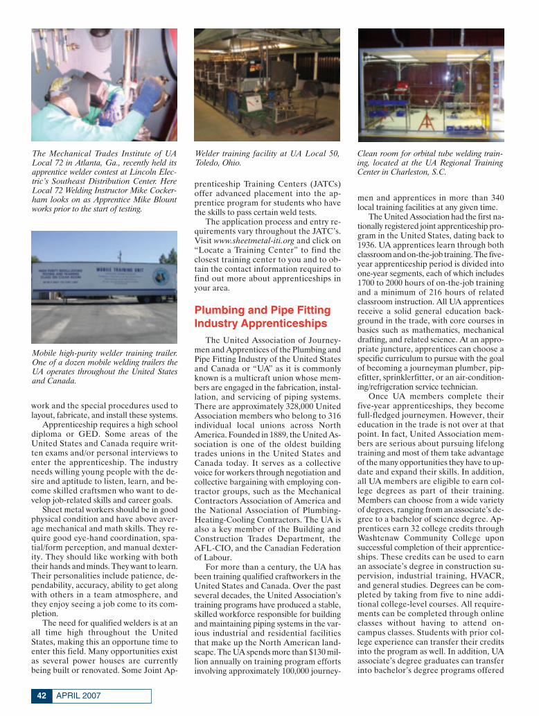
APRIL 200742
work and the special procedures used tolayout, fabricate, and install these systems.
Apprenticeship requires a high schooldiploma or GED. Some areas of theUnited States and Canada require writ-ten exams and/or personal interviews toenter the apprenticeship. The industryneeds willing young people with the de-sire and aptitude to listen, learn, and be-come skilled craftsmen who want to de-velop job-related skills and career goals.
Sheet metal workers should be in goodphysical condition and have above aver-age mechanical and math skills. They re-quire good eye-hand coordination, spa-tial/form perception, and manual dexter-ity. They should like working with boththeir hands and minds. They want to learn.Their personalities include patience, de-pendability, accuracy, ability to get alongwith others in a team atmosphere, andthey enjoy seeing a job come to its com-pletion.
The need for qualified welders is at anall time high throughout the UnitedStates, making this an opportune time toenter this field. Many opportunities existas several power houses are currentlybeing built or renovated. Some Joint Ap-
prenticeship Training Centers (JATCs)offer advanced placement into the ap-prentice program for students who havethe skills to pass certain weld tests.
The application process and entry re-quirements vary throughout the JATC’s.Visit www.sheetmetal-iti.org and click on“Locate a Training Center” to find theclosest training center to you and to ob-tain the contact information required tofind out more about apprenticeships inyour area.
Plumbing and Pipe FittingIndustry Apprenticeships
The United Association of Journey-men and Apprentices of the Plumbing andPipe Fitting Industry of the United Statesand Canada or “UA” as it is commonlyknown is a multicraft union whose mem-bers are engaged in the fabrication, instal-lation, and servicing of piping systems.There are approximately 328,000 UnitedAssociation members who belong to 316individual local unions across NorthAmerica. Founded in 1889, the United As-sociation is one of the oldest buildingtrades unions in the United States andCanada today. It serves as a collectivevoice for workers through negotiation andcollective bargaining with employing con-tractor groups, such as the MechanicalContractors Association of America andthe National Association of Plumbing-Heating-Cooling Contractors. The UA isalso a key member of the Building andConstruction Trades Department, theAFL-CIO, and the Canadian Federationof Labour.
For more than a century, the UA hasbeen training qualified craftworkers in theUnited States and Canada. Over the pastseveral decades, the United Association’straining programs have produced a stable,skilled workforce responsible for buildingand maintaining piping systems in the var-ious industrial and residential facilitiesthat make up the North American land-scape. The UA spends more than $130 mil-lion annually on training program effortsinvolving approximately 100,000 journey-
men and apprentices in more than 340local training facilities at any given time.
The United Association had the first na-tionally registered joint apprenticeship pro-gram in the United States, dating back to1936. UA apprentices learn through bothclassroom and on-the-job training. The five-year apprenticeship period is divided intoone-year segments, each of which includes1700 to 2000 hours of on-the-job trainingand a minimum of 216 hours of relatedclassroom instruction. All UA apprenticesreceive a solid general education back-ground in the trade, with core courses inbasics such as mathematics, mechanicaldrafting, and related science. At an appro-priate juncture, apprentices can choose aspecific curriculum to pursue with the goalof becoming a journeyman plumber, pip-efitter, sprinklerfitter, or an air-condition-ing/refrigeration service technician.
Once UA members complete theirfive-year apprenticeships, they becomefull-fledged journeymen. However, theireducation in the trade is not over at thatpoint. In fact, United Association mem-bers are serious about pursuing lifelongtraining and most of them take advantageof the many opportunities they have to up-date and expand their skills. In addition,all UA members are eligible to earn col-lege degrees as part of their training.Members can choose from a wide varietyof degrees, ranging from an associate’s de-gree to a bachelor of science degree. Ap-prentices earn 32 college credits throughWashtenaw Community College uponsuccessful completion of their apprentice-ships. These credits can be used to earnan associate’s degree in construction su-pervision, industrial training, HVACR,and general studies. Degrees can be com-pleted by taking from five to nine addi-tional college-level courses. All require-ments can be completed through onlineclasses without having to attend on-campus classes. Students with prior col-lege experience can transfer their creditsinto the program as well. In addition, UAassociate’s degree graduates can transferinto bachelor’s degree programs offered
The Mechanical Trades Institute of UALocal 72 in Atlanta, Ga., recently held itsapprentice welder contest at Lincoln Elec-tric’s Southeast Distribution Center. HereLocal 72 Welding Instructor Mike Cocker-ham looks on as Apprentice Mike Blountworks prior to the start of testing.
Welder training facility at UA Local 50,Toledo, Ohio.
Clean room for orbital tube welding train-ing, located at the UA Regional TrainingCenter in Charleston, S.C.
Mobile high-purity welder training trailer.One of a dozen mobile welding trailers theUA operates throughout the United Statesand Canada.
Union Training Feature April 2007:Layout 1 3/8/07 4:42 PM Page 42

43WELDING JOURNAL
through the National Labor College andFerris State University.
To provide for comprehensive train-ing and qualification of its memberwelders, the United Association estab-lished the UA Welder Training and Cer-tification Program. There are more than300 training schools owned and/or sup-ported by the UA throughout NorthAmerica. The program trains and quali-fies welders in SMAW, GTAW, GMAW,FCAW, machine, semiautomatic, auto-matic, and orbital welding. Since its in-ception in 1993, the UA’s welder trainingand certification program has providedmore than 120,000 welding tests and hasqualified more than 16,000 welders. Ap-plicants are tested on the weldingprocesses most commonly used on themajority of construction projects.Welders can choose to seek certificationin any or all processes. The flexible pro-gram can accommodate special require-ments of users and contractors. A usercan request that welders be tested andcertified for a specialized procedure thatmay be needed on a new or uniqueprocess. The program provides fullytrained, pretested, certified, and imme-diately available journeymen weldersthroughout the United States and Canadaat no cost to the construction user. As ademonstration of industry’s recognition
of the significant benefits of the programthe Construction Users Roundtable(CURT) presented its prestigious 2005Workforce Development Award to thejoint UA/NCPWB Welder CertificationProgram.
There is a critical shortage of qualifiedwelders today and America’s power com-panies are leading the way in signing ontothe United Association Welder Certifica-tion Program. With the energy industry’sincreasing need for improved quality andsafety standards to protect the public, UA-trained welders are prepared to meet andexceed these requirements. Breweries andother beverage and food producers; phar-maceutical, educational, medical, and cor-rectional facilities; malls, and other largecommercial developments all depend onthis quality of workmanship. United As-sociation General President William P.Hite is fully committed to meeting the de-mands of industry, and has instituted anew formal policy of the United Associa-tion entitled “UA Standard for Excel-lence.” The UA Standard for Excellenceis a joint labor-management pledge to up-hold the highest industry standard in theworkplace, with the ultimate goal of en-suring customer satisfaction.
For additional information regardingUA apprentice training, visitwww.ua.org.♦
Circle No. 21 on Reader Info-CardCircle No. 52 on Reader Info-Card
Union Training Feature April 2007:Layout 1 3/8/07 4:47 PM Page 43
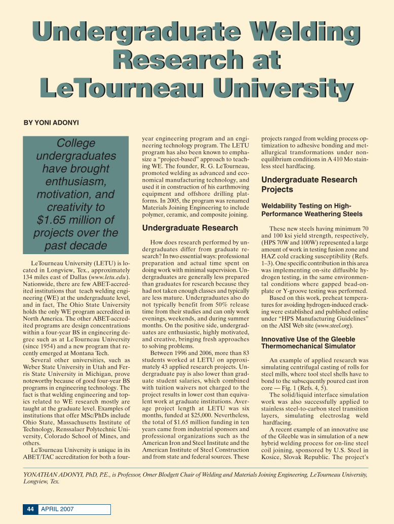
APRIL 200744
LeTourneau University (LETU) is lo-cated in Longview, Tex., approximately134 miles east of Dallas (www.letu.edu).Nationwide, there are few ABET-accred-ited institutions that teach welding engi-neering (WE) at the undergraduate level,and in fact, The Ohio State Universityholds the only WE program accredited inNorth America. The other ABET-accred-ited programs are design concentrationswithin a four-year BS in engineering de-gree such as at LeTourneau University(since 1954) and a new program that re-cently emerged at Montana Tech.
Several other universities, such asWeber State University in Utah and Fer-ris State University in Michigan, provenoteworthy because of good four-year BSprograms in engineering technology. Thefact is that welding engineering and top-ics related to WE research mostly aretaught at the graduate level. Examples ofinstitutions that offer MSc/PhDs includeOhio State, Massachusetts Institute ofTechnology, Renssalaer Polytechnic Uni-versity, Colorado School of Mines, andothers.
LeTourneau University is unique in itsABET/TAC accreditation for both a four-
year engineering program and an engi-neering technology program. The LETUprogram has also been known to empha-size a “project-based” approach to teach-ing WE. The founder, R. G. LeTourneau,promoted welding as advanced and eco-nomical manufacturing technology, andused it in construction of his earthmovingequipment and offshore drilling plat-forms. In 2005, the program was renamedMaterials Joining Engineering to includepolymer, ceramic, and composite joining.
Undergraduate Research
How does research performed by un-dergraduates differ from graduate re-search? In two essential ways: professionalpreparation and actual time spent ondoing work with minimal supervision. Un-dergraduates are generally less preparedthan graduates for research because theyhad not taken enough classes and typicallyare less mature. Undergraduates also donot typically benefit from 50% releasetime from their studies and can only workevenings, weekends, and during summermonths. On the positive side, undergrad-uates are enthusiastic, highly motivated,and creative, bringing fresh approachesto solving problems.
Between 1996 and 2006, more than 83students worked at LETU on approxi-mately 43 applied research projects. Un-dergraduate pay is also lower than grad-uate student salaries, which combinedwith tuition waivers not charged to theproject results in lower cost than equiva-lent work at graduate institutions. Aver-age project length at LETU was sixmonths, funded at $25,000. Nevertheless,the total of $1.65 million funding in tenyears came from industrial sponsors andprofessional organizations such as theAmerican Iron and Steel Institute and theAmerican Institute of Steel Constructionand from state and federal sources. These
projects ranged from welding process op-timization to adhesive bonding and met-allurgical transformations under non-equilibrium conditions in A 410 Mo stain-less steel hardfacing.
Undergraduate ResearchProjects
Weldability Testing on High-Performance Weathering Steels
These new steels having minimum 70and 100 ksi yield strength, respectively,(HPS 70W and 100W) represented a largeamount of work in testing fusion zone andHAZ cold cracking susceptibility (Refs.1–3). One specific contribution in this areawas implementing on-site diffusible hy-drogen testing, in the same environmen-tal conditions where gapped bead-on-plate or Y-groove testing was performed.
Based on this work, preheat tempera-tures for avoiding hydrogen-induced crack-ing were established and published onlineunder “HPS Manufacturing Guidelines”on the AISI Web site (www.steel.org).
Innovative Use of the GleebleThermomechanical Simulator
An example of applied research wassimulating centrifugal casting of rolls forsteel mills, where tool steel shells have tobond to the subsequently poured cast ironcore — Fig. 1 (Refs. 4, 5).
The solid/liquid interface simulationwork was also successfully applied tostainless steel-to-carbon steel transitionlayers, simulating electroslag weldhardfacing.
A recent example of an innovative useof the Gleeble was in simulation of a newhybrid welding process for on-line steelcoil joining, sponsored by U.S. Steel inKosice, Slovak Republic. The project’s
Undergraduate WeldingResearch at
LeTourneau University
Undergraduate WeldingResearch at
LeTourneau University
YONATHAN ADONYI, PhD, P.E., is Professor, Omer Blodgett Chair of Welding and Materials Joining Engineering, LeTourneau University,Longview, Tex.
Collegeundergraduateshave broughtenthusiasm,
motivation, andcreativity to
$1.65 million ofprojects over the
past decade
BY YONI ADONYI
Adonyi 4 07:Layout 1 3/8/07 3:40 PM Page 44
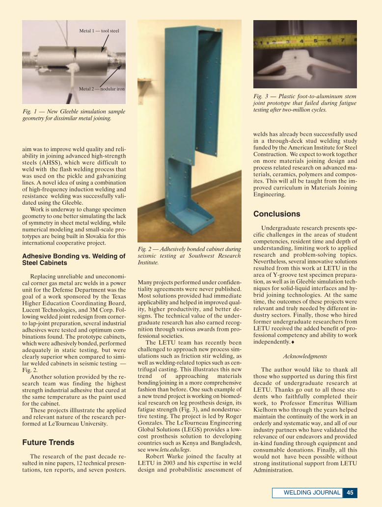
45WELDING JOURNAL
aim was to improve weld quality and reli-ability in joining advanced high-strengthsteels (AHSS), which were difficult toweld with the flash welding process thatwas used on the pickle and galvanizinglines. A novel idea of using a combinationof high-frequency induction welding andresistance welding was successfully vali-dated using the Gleeble.
Work is underway to change specimengeometry to one better simulating the lackof symmetry in sheet metal welding, whilenumerical modeling and small-scale pro-totypes are being built in Slovakia for thisinternational cooperative project.
Adhesive Bonding vs. Welding ofSteel Cabinets
Replacing unreliable and uneconomi-cal corner gas metal arc welds in a powerunit for the Defense Department was thegoal of a work sponsored by the TexasHigher Education Coordinating Board,Lucent Technologies, and 3M Corp. Fol-lowing welded joint redesign from corner-to lap-joint preparation, several industrialadhesives were tested and optimum com-binations found. The prototype cabinets,which were adhesively bonded, performedadequately in static testing, but wereclearly superior when compared to simi-lar welded cabinets in seismic testing —Fig. 2.
Another solution provided by the re-search team was finding the higheststrength industrial adhesive that cured atthe same temperature as the paint usedfor the cabinet.
These projects illlustrate the appliedand relevant nature of the research per-formed at LeTourneau University.
Future Trends
The research of the past decade re-sulted in nine papers, 12 technical presen-tations, ten reports, and seven posters.
Many projects performed under confiden-tiality agreements were never published.Most solutions provided had immediateapplicability and helped in improved qual-ity, higher productivity, and better de-signs. The technical value of the under-graduate research has also earned recog-nition through various awards from pro-fessional societies.
The LETU team has recently beenchallenged to approach new process sim-ulations such as friction stir welding, aswell as welding-related topics such as cen-trifugal casting. This illustrates this newtrend of approaching materialsbonding/joining in a more comprehensivefashion than before. One such example ofa new trend project is working on biomed-ical research on leg prosthesis design, itsfatigue strength (Fig. 3), and nondestruc-tive testing. The project is led by RogerGonzales. The LeTourneau EngineeringGlobal Solutions (LEGS) provides a low-cost prosthesis solution to developingcountries such as Kenya and Bangladesh,see www.letu.edu/legs.
Robert Warke joined the faculty atLETU in 2003 and his expertise in welddesign and probabilistic assessment of
welds has already been successfully usedin a through-deck stud welding studyfunded by the American Institute for SteelConstruction. We expect to work togetheron more materials joining design andprocess related research on advanced ma-terials, ceramics, polymers and compos-ites. This will all be taught from the im-proved curriculum in Materials JoiningEngineering.
Conclusions
Undergraduate research presents spe-cific challenges in the areas of studentcompetencies, resident time and depth ofunderstanding, limiting work to appliedresearch and problem-solving topics.Nevertheless, several innovative solutionsresulted from this work at LETU in thearea of Y-groove test specimen prepara-tion, as well as in Gleeble simulation tech-niques for solid-liquid interfaces and hy-brid joining technologies. At the sametime, the outcomes of these projects wererelevant and truly needed by different in-dustry sectors. Finally, those who hiredformer undergraduate researchers fromLETU received the added benefit of pro-fessional competency and ability to workindependently.♦
Acknowledgments
The author would like to thank allthose who supported us during this firstdecade of undergraduate research atLETU. Thanks go out to all those stu-dents who faithfully completed theirwork, to Professor Emeritus WilliamKielhorn who through the years helpedmaintain the continuity of the work in anorderly and systematic way, and all of ourindustry partners who have validated therelevance of our endeavors and providedin-kind funding through equipment andconsumable donations. Finally, all thiswould not have been possible withoutstrong institutional support from LETUAdministration.
Fig. 1 — New Gleeble simulation samplegeometry for dissimilar metal joining.
Fig. 2 — Adhesively bonded cabinet duringseismic testing at Southwest Research Institute.
Fig. 3 — Plastic foot-to-aluminum stemjoint prototype that failed during fatiguetesting after two-million cycles.
Metal 2 — nodular iron
Metal 1 — tool steel
Adonyi 4 07:Layout 1 3/8/07 3:40 PM Page 45
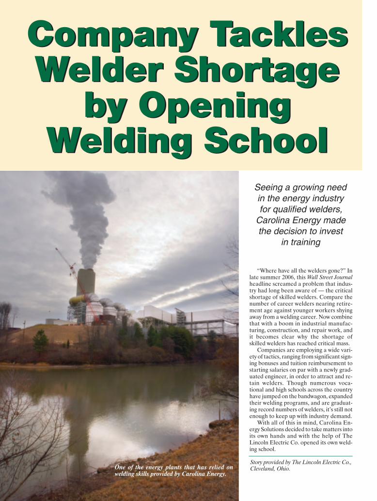
“Where have all the welders gone?” Inlate summer 2006, this Wall Street Journalheadline screamed a problem that indus-try had long been aware of — the criticalshortage of skilled welders. Compare thenumber of career welders nearing retire-ment age against younger workers shyingaway from a welding career. Now combinethat with a boom in industrial manufac-turing, construction, and repair work, andit becomes clear why the shortage ofskilled welders has reached critical mass.
Companies are employing a wide vari-ety of tactics, ranging from significant sign-ing bonuses and tuition reimbursement tostarting salaries on par with a newly grad-uated engineer, in order to attract and re-tain welders. Though numerous voca-tional and high schools across the countryhave jumped on the bandwagon, expandedtheir welding programs, and are graduat-ing record numbers of welders, it’s still notenough to keep up with industry demand.
With all of this in mind, Carolina En-ergy Solutions decided to take matters intoits own hands and with the help of TheLincoln Electric Co. opened its own weld-ing school.
Company TacklesWelder Shortage
by OpeningWelding School
Company TacklesWelder Shortage
by OpeningWelding School
Story provided by The Lincoln Electric Co.,Cleveland, Ohio.One of the energy plants that has relied on
welding skills provided by Carolina Energy.
Seeing a growing needin the energy industry for qualified welders,
Carolina Energy madethe decision to invest
in training
(Lincoln) 4 07:Layout 1 3/9/07 1:07 PM Page 46

47WELDING JOURNAL
Energy Industry Demands
Based in Rock Hill, S.C., Carolina En-ergy Solutions (Fig. 1) works in one of theworld’s fastest-growing areas — the en-ergy industry. With a focus on issues suchas rising gas prices, U.S. foreign oil de-pendence, and alternative power sources,the energy industry is seeing unprece-dented growth on all fronts. New plantsare being constructed, and older plants arebeing upgraded and renovated. All of thisactivity has created exceptional demandfor contractors such as Carolina Energy.
The ten-year-old firm, started by agroup of welders from the nuclear powerplant boom in the 1970s, offers a completerange of welding, machining, and post-weld heat treating services for the nuclear,fossil, hydropower, waste-to-energy,petrochemical, gas, and general fabrica-tion industries. The company contracts di-rectly with utility companies across thecountry for outage work, new construc-tion, and retrofits. It also subcontractswith some of the leading national and in-ternational construction/engineeringfirms, including Bechtel, Jacobs, Shaw,TIC, Fluor, and Zachry. Carolina En-ergy’s technicians handle preweld andpostweld heat treating, field machiningand welding of piping, boilers, turbines,valve repair, fabrication and installationboth at the company’s South Carolina fa-cility and in the field throughout theUnited States and abroad.
Whereas for some contractors weldingis just one part of their overall services,welding is front and center at Carolina En-ergy and integral to the company’s over-all success. More than 80% of the firm’s400 employees are welders, making theshortage of skilled welders all that moresignificant.
“So we decided that since we couldn’trecruit enough skilled welders fast enoughto keep up with customer demand, wewould just create our own,” said DannySechler, a welding specialist and Construc-tion Institute of America’s coordinator.
In late 2006, Carolina Energy wel-comed the first welding students to its newConstruction Institute of America, a sep-arate nonprofit entity managed by Car-olina Energy staff and partially fundedthrough the federal government’s Work-force Investment Act. The institute ishoused at the company’s South Carolinacampus and consists of 50 fully outfittedwelding booths — Fig. 2. Carolina Energybelieves its graduates will be the “weldingleaders of the future.” Al Lovins, who suc-cessfully operated several welding schoolsduring the boom in the late 1970s and early1980s, manages the school and lends 30years of welding experience to help thesestudents prepare for their new careers.
From the Ground Up
Opening a new welding school meanta significant investment for Carolina En-ergy. It meant building the school fromthe ground up, hiring a full-time team ofexperienced instructors, marketing itsprogram to potential students, and pur-chasing all new equipment.
The firm planned the school to openwith 50 booths outfitted and ready forhands-on work starting on day one. Withthis in mind, the company talked to majorwelding manufacturers, and in the end,chose The Lincoln Electric Co. for its newventure.
Carolina Energy’s welders are skilledin the typical welding processes, shieldedmetal arc (SMA), gas metal arc (GMA),gas tungsten arc (GTA), and flux cored
arc welding (FCAW) — Fig. 3. Becauseof the type of projects they handle, thewelders also work with a number of spe-cialty welding applications, such as orbitalwelding. (Carolina Energy was recentlychosen by orbital welding equipment man-ufacturer, Liburdi Dimetrics, to becomeits authorized training and repair center.)For its arc welding equipment, the Con-struction Institute of America purchasedand installed 50 Lincoln Invertec® V350-PRO welding machines. The school is alsousing Lincoln Excalibur™ electrodes andUltraCore™ welding wire.
Fig. 1 — This South Carolina firm specializes in providing services tothe energy industry.
Fig. 2 — The startup welding school outfitted 50 welding booths forthe students.
Fig. 3 — A student practices his gas tung-sten arc welding skills on pipe.
(Lincoln) 4 07:Layout 1 3/9/07 1:07 PM Page 47

A Good Deal
Students entering the new school startout at $18/hour or about $37,500/year andsign on to work for the company for oneyear following graduation. If they stay onafter their first year, they move up to$28–$30/hour or about $60,000/year,which is in line with the starting salary ofan engineer graduating with a four-yeardegree.
“In addition to extremely competitivepay, many of our students will also havethe opportunity to travel, as we send ourtechnicians out to jobs around the coun-try,” Sechler stated. “It’s a great oppor-tunity for them.”
The school has a waiting list, so as soonas it sends one graduate out into the field,his or her place is taken by another. Withhigh demand from the industry and cus-tomers, Carolina Energy is consideringdoubling the school’s capacity to 100booths.
Students spend a minimum of fivehours a day welding, with the balance con-sisting of classroom work. Students startout SMA welding, move onto flux core,then to open-butt GTA welding on pipe.They are tested after each stage and are
required to meet the appropriate ASMESection IX acceptance criteria in order tomove on.
“Because customer demand is so high,our students have even had the opportu-nity to get hands-on field experience be-fore completing our entire program. Forexample, we had a project in Wisconsinthat only required stick welding, so thestudents who had passed the ASME Sec-tion IX test were sent north to work side-by-side with our experienced welders,”Sechler explained. “The customer appre-ciated that we were able to meet theirtight schedule, and the students spent acouple of weeks on-site putting theirtraining to work.”
Once that project was completed,those students returned back to theirwelding booths completing the next stageof training.
“Opening our own school has given usgreat versatility and flexibility we didn’tpreviously have,” Sechler summarized.“Everybody benefits, Carolina Energyand our customers from having a readilyavailable, skilled workforce, and our stu-dents receiving excellent training andguaranteed job placement.”♦
APRIL 200748
Circle No. 35 on Reader Info-CardCircle No. 37 on Reader Info-Card
Cir
cle
No
. 1 o
n R
ead
er In
fo-C
ard
(Lincoln) 4 07:Layout 1 3/9/07 1:08 PM Page 48

Circle No. 53 on Reader Info-Card
MAGNATECH:FP_TEMP 3/9/07 5:17 PM Page 49
University of Alaska Anchorage Welding
and NDT TechnologyFounded 1970
The Welding/NDT program at UAA offers a choice of certificates and an Associate of Applied Science degreethat centers on welding skills, weldinginspection and nondestructive testing.Program courses include skill develop-ment in major welding processes, pipefitting and basic metallurgy, as well ashands-on NDT training in the RT, UT,MT and PT processes. Our programserves about 175 students each year.
3211 Providence Drive GHH 111Anchorage, AK 99508
(907) 786-6475Fax: (907) 786-6474
www.uaa.alaska.edu/ctc/programs/cdt/welding
Atlanta Technical CollegeMaking Great Welders
Founded 1967
Atlanta Technical College offers top-notch Welding Programs to students inthe metro Atlanta area. Day and eveningclasses are available, and students mayearn a Diploma or Technical Certificateof Credit. Atlanta Tech's state-of-the-artWelding Lab is the ideal setting for ourhands-on, individualized approach to in-struction. Atlanta Tech faculty are Certi-fied Welding Instructors and Certified
Welding Educators. Consultation in un-derwater cutting and welding is available.
1560 Metropolitan Parkway SWAtlanta, GA 30310
(404) 225-4518E-mail: [email protected]
www.atlantatech.edu
Atlantic Technical CenterFounded 1973
Atlantic Technical Center provides a review for persons currently employedin welding occupations who wish to takean AWS test to become a CertifiedWelder, or first time students who areinterested in learning advanced andbasic welding skills techniques. Shopactivities are an integral part of thiscourse and provide instruction to de-velop skills in Industrial, Structural, Air-craft, Marine, Petroleum and NuclearWelding. At the successful completionof laboratory activities, an AWS Weld-ing Certification test is available. Ac-credited by the Commission of theCouncil on Occupational Education.
4700 Coconut Creek ParkwayCoconut Creek, Florida 33063
(754) 321-5100 Fax: (754) 321-5380
Contact: Frank Rose, Welding Instructor, Ext. 3108www.atlantictechcenter.com
Beaufort County Community College was granted community college
status in 1979.
Since 2001, the welding program hasplaced over 190 students with local industries. Our welding facilities
incorporate state of the art equipmentand our courses cover all of the weldingtrades from the beginner to the ad-vanced welder that meet industry stan-dards. We offer an associate degree,diploma, and six certificates in welding.We make a difference in the future ofour students.
P.O. Box 1069Washington, NC 27889
(252) 940-6224Fax: (252) 946-4405
Email: [email protected]
Bellingham Technical College Welding Technology
ProgramFounded in 1956
Bellingham Technical College’s WeldingTechnology Program offers AAS andAAS-T degrees in Certified Welding andFabrication for a vibrant community of Pipelines and Northwest WashingtonRefineries, Ship building and Repair,Transportation, and shops and fabrica-tors. This Award-Winning program ispoised for an April, 2007 expansion intoan 80,000 sq. ft. State-of-the-Art facilityto house our 200 plus enrollment in PipeWelding, Aluminum Welding and Fabri-cation, Steel Fabrication, and CreativeWelding. Our 6th Annual WeldingRodeo Sculpture Contest is a one-of-a-kind experience for Amateurs and Professional Artists throughout the Pacific Northwest.
Welding Technology Dept.3028 Lindbergh Ave.
Bellingham, WA 98225-1599(360) 752-8346
www.btc.ctc.edu orwww.weldingrodeo.com [email protected]
SCHOOL PROFILES
EmployersAre you in need of
good welders?
Students Are you searching for away to hone your skills?
Below are welding schools across thecountry that, for a nominal fee, havetaken the opportunity to promotetheir resources both to industry inneed of welders and to those searchingfor a solid career path to employment.Contact them and take advantage ofthe services they can provide.
APRIL 2007
APRIL 200750
AprilSchoolProfiles2007-3:April School Profiles 2007 3/8/07 4:43 PM Page 50
Butte-Glenn Community College
Founded 1967
The Welding Technology Program is a vo-cational core of courses designed to pro-duce qualified personnel for certifiedwelding jobs. Program performance stan-dards for certification are in accordance tothose established by the American Weld-ing Society and/or American Society ofMechanical Engineers. Courses are heldin a completely modern and well-equipped welding lab. This program is de-signed to produce an entry-level weldingtechnicians in the 6-G pipe position (qual-ifies for all positions in plate and pipe)Heavy Plate 3G and 4G are also obtain-able. The student will be able to weld withSMAW, FCAW, GMAW, GTAW, OAW,OFC, PAC and AAC in all positions witha variety of metals and alloys. Studentswill be able to certify under at least one ofthe following codes: API, AWS, andASME, according to individual skills.
3536 Butte Campus DriveOroville, CA 95965
Mike Rabo, [email protected](530) 895-2360 Fax: (530) 895-2302
Don Robinson, [email protected] (530) 895-2469 Fax: (530) 895-2302
Central Piedmont Community College
Founded 1963
The James Turner Institute of WeldingTechnology at CPCC provides studentswith a sound understanding of the sci-ence, technology, and applications es-sential for successful employment inthe welding and metal industry. Instruc-tion includes consumable and non-con-sumable electrode welding and cuttingprocesses. Additional courses in math,writing, computer technology, blueprintreading, metallurgy, welding inspec-tion, and non-destructive examinationprovide the student with industry-stan-dard skills developed through class-room and practical applications. CPCCis an AWS QC7 accredited test facility.
P. O. Box 35009Charlotte, NC 28235 USA(704) 330-CPCC (2722)
Email: [email protected]
Chippewa Valley Technical College
Chippewa Valley Technical College'sWelding program provides training inSMAW (stick), GMAW (wirefeed),GTAW (TIG), oxy-acetylene weldingand cutting, pipe welding, and roboticwelding. There are two section formatsavailable, a one-year day section and atwo-year (four semester) evening sec-tion. Students graduate with a technicaldiploma and the opportunity for a Wis-consin state welding certification. In-structors are Jon Will ([email protected]),AWS CWI/CWE; Brent Rosenberg(brosenberg @cvtc.edu); and WalterQuaschnick ([email protected]).
620 West ClairemontEau Claire, WI 54701
(715) 858-1814www.cvtc.edu
College of the Canyons
College of the Canyons, an AWS Accredited Testing Facility, has trainedwelders for 31-plus years. Courses coverindustrial welding, pipe, metallurgy, weldinspection, certification preparation andmetal sculpturing, as well as technologiessuch as oxyacetylene, laser, shieldedmetal arc, gas tungsten arc, gas metal arc,orbital gas tungsten arc and controlledatmosphere chamber welding. Instruc-tors are AWS-certified. Certificates anddegrees are offered. Courses are offeredday and night, and programs can oftenbe completed in one year.
26455 Rockwell Canyon RoadSanta Clarita, CA 91355
(661) 259-7800Email: [email protected]
www.canyons.edu
Cosumnes River College
Cosumnes River College offers a certifi-cate in welding. Our classes begin withthe Basic Introduction to weldingWELD 100, and then the student canchoose to take Advanced SMAW,FCAW and GMAW in WELD 110. Weoffer an in house welding certificationWELD 114 in all welding process, andwe have a welding class that specializesin GMAW and GTAW. Our program isdedicated to meeting the needs of in-dustry. Currently, our students areworking on certifications for Flux corearc welding with NR 232, SMAW withE-7018 and GMAW on sheet steels.The welding instructor, Mr. Jason MRoberts is a certified welding educator,certified welding inspector and cur-rently earning a certificate in OSHAsafety training to be able to offer a certified safety training program for Fall 2007.
8401 Center ParkwaySacramento, CA 95823-7146
www.crc.losrios.edu/
CTC Lackawanna Co, (Formerly Lackawanna Co AVTS)
Founded in 1973
CTC serves the secondary students and adult community of the greaterScranton (PA) region. Emphasis isplaced on safety as well as blueprintreading, properties of metal, metalidentification, types and use of elec-trodes, welding rods, electrical princi-ples, and welding symbols. Secondaryand Adult students are prepared to takeAWS certification exams.
3201 Rockwell Ave Scranton PA 18508
(570) 346-8471Email: [email protected]
www.ctclc.edu.
SCHOOL PROFILES APRIL 2007
51WELDING JOURNAL
AprilSchoolProfiles2007-3:April School Profiles 2007 3/8/07 4:51 PM Page 51
Dabney S. Lancaster Community College
Founded 1967
Dabney S. Lancaster Community College offers welding training on itswestern Virginia campus. Earn a certifi-cate or associate in applied science de-gree. Employer-driven curriculumteaches the skills needed in today’sworkforce: oxy fuel, SMAW, GTAW,GMAW and pipe welding. Key supportcourses such as metallurgy, blueprintreading and quality control. Benefitfrom free qualification testing. Enjoysmall classes, free tutoring and personalattention. Customized courses availablefor employers. Offering quality, afford-able education and training since 1967.
1000 Dabney Drive, Interstate 64, exit 24
Clifton Forge, VA 24422-1000(540)863-2895
Email: [email protected]
Del Mar CollegeFounded 1935
Del Mar College is a comprehensivecommunity college in Corpus Christi,Texas. Our welding program offers skilldevelopment in SMAW, GMAW,GTAW, FCAW, and various otherprocesses on plate and pipe welding toindustry standards. Certificate and As-sociate Degree programs offered. Visitus on the website or call 1-800-652-3357for information.
101 Baldwin Blvd.Corpus Christi, TX 78404-3897
(800) 652-3357www.delmar.edu
The Divers Academy International
The Divers Academy offers the highestquality training in the shortest amountof time to jumpstart your career. It isknown for its full-immersion trainingmethodology and its modern trainingfacilities. Underwater Cutting andWelding is just one part of a compre-hensive 5-month curriculum. Foundedin 1977, the Divers Academy Interna-tional trains divers for CommercialDeep Sea Diving and Wet Welding, pro-viding students with an employer’s mostsought-after qualification: on-the-jobexperience. Financial aid is availablefor those who qualify.
Lakeside Business Park1500 Liberty Place
Erial, NJ 08081-1139(800) 238-DIVE
Doña Ana Community College
Founded 1973
The Doña Ana Community CollegeWelding Technology program has a national reputation for excellence, andis taught by top-notch AWS CWE's andCWI's. Our 75-90 full and part-time students take courses in: SMAW,GMAW, GTAW, FCAW, SAW, steel,stainless, aluminum, pipe, metallurgy,NDT and DT, welding Codes, weldingsymbols and blueprint reading, pipewelding, fabrication, and welder quali-fication. Graduates leave asAWS/ASME certified welders. Coursesare offered days or evenings. Certificateand Associate Degrees offered.
MSC 3DA, 3400 S. Espina St.
Las Cruces, N.M. 88003-8001(505) 527-7500
David Twitty: [email protected] Mount: [email protected]
www.dabcc.nmsu.edu
El Camino CollegeFounded 1947
The El Camino College welding department strives to meet diverse student needs by providing quality instruction in morning, afternoon, andevening classes. Introductory, interme-diate, and advanced welding courses inoxy acetylene welding and cutting, gastungsten arc, shielded metal arc, gasmetal arc, and flux cored arc weldingare offered. Students can earn a weld-ing certificate or AS Degree.
Welding Department16007 Crenshaw Boulevard
Torrance, CA 90506(310) 660-3600
www.elcamino.edu
Frank Phillips College
The Frank Phillips College WeldingTechnology Department is dedicated to providing students with superior performance-paced training in our newstate-of-the-art facility. FPC providesthe latest training in metallurgy, fab and layout, SMAW, GTAW (TIG) ,GMAW (MIG), Oxyfuels and thePipePro System. Located in a hub ofoil and gas industries, our team has an excellent reputation for high job placement of quality craft personnel.
“Start Here…Go Anywhere!”
Welding Technology Department,Borger, TX
(806) 457-4200, ext. 782 Email: [email protected]
SCHOOL PROFILES APRIL 2007
APRIL 200752
AprilSchoolProfiles2007-3:April School Profiles 2007 3/8/07 4:34 PM Page 52

The Grand River Technical School
The welding technology course is designed to prepare students for entry-level employment in the welding field.Students will acquire knowledge andhands-on experience in welding/cuttingprocesses that are in high demand. Students will receive instruction on safetypractices, printreading, work ethics, andpre-employment preparation. Upon suc-cessful completion students receive a cer-tificate for 1080 hours, may becomecertified, and have the opportunity to re-ceive an associates degree through a col-lege articulation agreement.
1200 Fair StreetChillicothe, MO. 64601
(660) 646-3414Fax: (660) 646-3568
www.grts.org
Great Basin College Welding Founded 1967
Great Basin College offers an Associ-ates of Applied Science Degree and aOne Year Certificate in Welding Tech-nology, established in 1990. Currently,20 students are enrolled in a programthat prepare them with skills to createnew products; repair existing products;and work in the mining, manufacturing,construction, transportation and agri-cultural industries. Program highlightsinclude instruction in welding theory,blueprint reading, fabrication, qualitycontrol, metallurgy, qualification test-ing, destructive and nondestructive test-ing principles, and safety.
Elko, Nevada(775) 753-2207 or (775) 753-2170
Rich Barton e-mail:[email protected]
Jon Licht e-mail:[email protected]
www.gbcnv.edu
Harper College
Harper College's 16 credit-hour certifi-cate program provides students withentry-level skills in welding repair. Theprogram emphasizes advanced weldingtheory, extensive practice in major arcwelding process, and out-of-positionand multi-pass arc welding includingGMAW, SMAW, and GTAW. Uponcompletion, students are prepared topass guided bend tests to become certi-fied welders in accordance with AWS (American Welding Society) D1.1Structural Welding Code.
1200 W. Algonquin Road Palatine, IL 60067-7398
(847) 925-6507 E-mail: [email protected]
Web: harpercollege.edu
Hobart Institute of Welding Technology
Founded 1930
Hobart Institute of Welding Technol-ogy’s course offerings is available in a42-page catalog that explains in detailthe wide range of welding classes offered. More than 25 separate weldingcourses are described by course objec-tive, content and testing requirements.Inside the 2007 catalog is course sched-ules, training rates, and enrollmentforms. Training may be done at our facility or yours.
400 Trade Square EastTroy, OH 45373 (800) 332-9448
FAX: (937) 332-5200Website: www.welding.org
Ivy Tech Community College Founded 1963
The Welding Training Program at IvyTech Community College offers a tech-nical certificate, and associate of ap-plied science degrees in Manufacturingand Industrial Technology with a concen-tration in Welding. Skills taught at our facility could lead to AWS and ASMEcertification. Ivy Tech Community College, Lafayette is an AWS educa-tional institution member and have AWScertified welding inspectors and certifiedwelding educators on staff. Our weldingprogram has sustained a steady enroll-ment of over one-hundred students eachsemester for the past several years.
3101 South Creasy LaneLafayette, IN 47905
(765) 269-5146Dennis A. Nance,
Email: [email protected]
Kenai Peninsula College
Kenai Peninsula College is a branch ofthe University of Alaska located 150miles South of Anchorage on the KenaiPeninsula. KPC offers certification onAWS D1.1 .375 steel plate 3G & 4GSMAW, ASME Section IX pipe certifi-cation on steel 6-inch schedule 80 6GSMAW. Our certificate program includes Math, Blueprint, and English(students must certify on pipe to complete certificate). KPC students areprovided with 3M® powered air purifying respirator welding hoods.
34820 College DriveSoldotna, Alaska 99669
(907) 262-0300Fax: (907) 262-0395
Fritz Miller, Welding Instructor(907) 262-0356
SCHOOL PROFILES APRIL 2007
53WELDING JOURNAL
AprilSchoolProfiles2007-3:April School Profiles 2007 3/8/07 5:14 PM Page 53
Lansing Community CollegeFounded 1957
Lansing Community College offers anAssociates Degree in Welding Technol-ogy as well as a Certificate of Achieve-ment one year Degree in Welding. Ournine Welding Classes consist of BasicOxyacetylene, Brazing, Torch Cutting /Plasma Cutting and SMAW in our 1stcourse and the other courses advanceinto the Advanced SMAW, Pipe Welding,GMAW, GTAW, Structural Fabrication,blueprint Reading, Rigging, and Metal-lurgy. We do customized training with In-dustries. We have over 500 students peryear. Instructors are CWI’s and instruc-tors with many years of experience.
P.O. BOX 40010Lansing, MI 48901-7210
(517) 483-9682Fax: (517) 483-1320William Eggleston,
Email: [email protected]
Lincoln Electric Welding SchoolFounded 1917
Learn to weld at the Lincoln ElectricWelding School. We have trained over100,000 welders in many differenttrades (ironworkers, boilermakers, pip-efitters, sheet metal, etc). You will learnto weld with the latest technology inequipment,on different base metals(carbon steel, stainless, aluminum,cr/mo tubing, etc) and many differentprocesss (SMAW, GMAW, GTAW,FCAW, SAW). Our instructors have realworld experiance doing trackside weld-ing at motorsports events like Daytona(NASCAR,ROLEX), INDY (500,BRICKYARD 400), we also do job sitetraining at your location.
22801 St. Clair Ave.Cleveland, Ohio 44117
Bill West: (216) 383-2259Jennifer Howell (216) 383-8325
www.lincolnelectric.com
Locklin Tech
Locklin Tech offers secondary and post-secondary training for a broad range ofcareers in the welding industry.NCCER Contren® Learning Seriescurriculum helps students gain valuableglobal skills. Industry recognized cre-dentials are maintained throughNCCER’s National Registry. InstructorJames Sullivan is active in SkillsUSAand has been the recipient of the AWSHoward E. Adkins Instructor Award atthe section, district and national levels.
5330 Berryhill RoadMilton, FL 32570
(850) 983-5700www.locklintech.com
Maysville Community andTechnical CollegeRowan Campus
This program offers plate and pipe weldtraining using the SMAW, GMAW, andGTAW processes. Training can lead toa certificate, diploma, or Associate De-gree as well as certification on structuralsteel with the SMAW and GMAWprocesses. Program is certified by theAWS as an Educational InstitutionMember and certified by the United As-sociation of Plumbers and Pipefitters asan orbital tube welding training/certifi-cation center.
Welding Technology609 Viking Dr.
Morehead, KY 40351Dean Howard / Stanley Click
(606) 783-1538 ext. 66347 or [email protected]@kctcs.edu
Mesabi Range Community & Technical College
Mesabi Range offers a rigorous weldingcurriculum following national skillsstandards developed by the AmericanWelding Society. The Entry LevelWelder Diploma and the AdvancedWelder Diploma, established in 1997,give the successful graduate very mar-ketable skills in the welding industry.Experienced, knowledgeable instruc-tors, a great staff, up-to date equipment,and a modern shop provide a greatlearning environment. We have 100%job placement in the last nine years.Welding certifications are available.
P.O. Box 6481100 Industrial Park Drive
Eveleth, MN 55734(218) 741-3095
Fax: (218) 744-7644Website: www.mr.mnscu.edu
Moraine Park Technical College
Moraine Park Technical College offers a 1-year welding diploma program thatfocuses on GMAW, SMAW, and GTAWon steel, stainless, and aluminium. Theprogram includes Print Reading andFabrication courses that focus on themanufacturing process of a productfrom conception to final production viabasic layout tools and CNC equipment.Instruction includes AWS and ASMEwelding codes, including qualificationtests and writing WPS's, with the oppor-tunity to weld-certify upon completionof the program.
700 Gould StreetBeaver Dam, WI 53916
920-887-4494Larry Clark,
920-887-4490Sue Silverstein,
SCHOOL PROFILES APRIL 2007
APRIL 200754
AprilSchoolProfiles2007-3:April School Profiles 2007 3/8/07 4:35 PM Page 54
North Dakota State College of Science
The North Dakota State College of Sci-ence is a two-year, comprehensive, resi-dential college that offers degrees,certificates and diplomas in over 80 aca-demic options in traditional career andtechnical studies and in the liberal arts.NDSCS offers a one-year certificate andtwo-year diplomas and degrees in Weld-ing Technology. The college is an Amer-ican Welding Society S.E.N.S.E.certified facility. Last year, 99 percent ofNDSCS graduates entered the work-force or continued their college educa-tion. Unlike most two-year colleges,NDSCS offers a university atmospherefor students — residence halls, clubs andorganizations, fine arts, athletics and nu-merous social activities.
800 Sixth St. NorthWahpeton ND 58076-0002
(701) 671-2483www.ndscs.edu
North Georgia Technical College
Founded 1907
North Georgia Technical College’s Welding and Joining Technology DiplomaProgram is designed to prepare studentsfor careers in the welding industry. Theprogram offers learning opportunities todevelop academic, technical and profes-sional knowledge and skills required forjob acquisition, retention and advance-ment. Welding theory and practical application necessary for successful employment is emphasized. Graduateshave the qualifications of a welding andjoining technician and are prepared totake qualification tests.
P.O. Box 65Clarkesville, GA 30523
(706) 754-7700www.northgatech.edu
Northland Community &Technical College
Northland Community & TechnicalCollege is located in East Grand Forksand Thief River Falls, MN. NCTC’sWelding Technology diploma programin East Grand Forks is accredited by theAWS and designated as a S.E.N.S.E(Schools Excelling through NationalSkills Education) Level 1 and 2 pro-gram. This program is taught by a C.W.Iand C.W.E. Welding students coverprocesses of SMAW, GMAW, FCAW,GTAW and SMAW Pipe. In addition,students complete course work in Cut-ting Processes, Blueprint Reading, Met-allurgy, Fabrication, Human Relationsand First Aid/CPR. Program enroll-ment is currently set at 41 students.
[email protected] Grand Forks, MN Campus
Thief River Falls, MN Campus1-800-959-6282
www.northlandcollege.edu
Odessa College Welding Technology
The Odessa College Welding TechnologyDepartment in Odessa, Texas offers a fullrange of certificate and associate degreeoptions. Labs are equipped with 15 OFWstations and 45 modern welding stationsfor training in SMAW, GMAW, FCAWand GTAW processes. Classes are offeredin the mornings and evenings accommo-dating an average of 100 students each se-mester. Odessa College recently receiveda $1.75 million Department of LaborGrant for the West Texas Welding Train-ing Center. Opening in October 2007, thenew 30-station facility will offer special-ized short courses through the ContinuingEducation Division.
201 W. UniversityOdessa, TX 79764
(432) 335-6474James Mosman – Department Chair
Email: [email protected]
Orange Coast CollegeFounded 1947
The Orange Coast College welding cur-riculum has been a part of this collegecurriculum since the college was first con-ceived. Our program offerings includeboth a Welding Certificate of Achieve-ment and an Associate in Science De-gree. We are proud to offer acomprehensive welding program whichincludes Oxy-acetylene welding and cut-ting, SMAW, GMAW, FCAW, GTAW,Orbital welding and Plasma cutting. Onour academic side we teach Metallurgyfor welders, Codes and Specifications forwelders, Math and Science for weldersand Testing and Inspection for welders.Our instructors have AWS QC-1 CWIand CWE credentials as well as Califor-nia Community College teaching creden-tials. We qualify welders to ANSIstandards and we are a licensed Los An-geles City testing laboratory. Our testinglaboratory does both destructive andnon-destructive examinations.
2701 Fairview RoadCosta Mesa, CA 92626
(714) 432-5820
Owens Community College
Owens Community College WeldingTechnologies provides students withknowledge and skills for job placement inthe welding industry. Students are edu-cated in all aspects of welding includingSMAW, MIG and TIG welding, torchand plasma cutting as well as brazing.Students who excel in their welding skillsare encouraged to complete their plateand pipe welding certification. Studentsmay also chose from coursework in weld-ing fabrication, welding codes and proce-dures and Certified Welding Inspector.
Welding TechnologiesP.O. Box 10,000Oregon Road
Toledo, Ohio 43699-1947(567) 661-7729
Email: [email protected]
SCHOOL PROFILES APRIL 2007
55WELDING JOURNAL
AprilSchoolProfiles2007-3:April School Profiles 2007 3/8/07 4:36 PM Page 55

Pennsylvania College ofTechnology
Founded 1989
Pennsylvania College of Technology, aPenn State affiliate since 1989, has a rep-utation for excellent graduate place-ment, “degrees that work” in more than100 careers, and a modern campus andhas a student body of 6,500. Penn Col-lege offers a complete welding educa-tion. In addition to an associate degreeand certificate, Penn College offers aunique Bachelor of Science degree inWelding and Fabrication EngineeringTechnology that prepares graduates fortechnical careers and positions in mid-management, supervision, sales, service,and research. Contact us for more infor-mation, or visit our Web site.
One College AvenueWilliamsport, PA 17701
(800) 367-9222Email: [email protected] www.pct.edu/schools/iet/weld/
Pulaski Technical College
The Welding Program at Pulaski Tech-nical College in North Little Rock,Arkansas focuses on structural weldingand offers AWS Level I and II certifi-cation. The two-semester TechnicalCertificate program includes instruc-tion in welding processes, joint designand metallurgy. The Certificate of Pro-ficiency will allow an individual to com-plete certification requirements in 3G(vertical) positioning.
Technical and Industrial Programs3000 West Scenic Drive
North Little Rock, AR 72118501-812-2200
www.pulaskitech.edu [email protected]
Rock Valley College
RVC’s welding program currently in-cludes 60 students trained in the facilitywhich includes a lab with 28 weldingbooths. Welding processes being taughtinclude: MIG, TIG, Stick, Flux Core,and Oxyacetylene. RVC is an AWS Cer-tified Accredited Testing Facility. Thewelding lab has been at current locationfor six years staffed by one full time andfive part-time faculty. RVC is a certifiedICAR welding testing center. For infor-mation, contact Mike Merriman.
Rockford, Illinois(815) 921-3015
Mike Merriman Email: [email protected].
www.rockvalleycollege.edu
Santa Fe Community College
Founded 1966
The Applied Welding Technologies Program is a one and one-half year certificate program that consists ofSMAW, GMAW, GTAW, FCAW, Oxy-Fuel Welding/Cutting, blueprint readingand power tool and equipment opera-tion performed on carbon steel, stainlesssteel and aluminum. The training helpsprepare students to pass nationally rec-ognized plate and pipe welding certifi-cation tests. The welding lab at SFCC isan AWS Accredited Testing Facility
3000 NW 83rd StreetGainesville, FL 32606
(352) 395-5253Fax: (352) 395-5364
South Plains CollegeFounded: 1957
The SPC Welding Technology Programoffers basic and advanced certificatesalong with an Associate of Applied Sci-ence degree. Entry level and advancedtraining certificates through AWS arealso awarded to those who qualify.Specific areas of training include: OFC,PAC, SMAW plate and pipe, GMAWplate and pipe, FCAW plate and pipe,GTAW sheet and pipe, welding symbols, blueprint reading, weldingmetallurgy and structural and pipe layout and fabrication.
South Plains College1401 S. College, Box 88Levelland, Texas 79336806-894-9611, ext: 2284
[email protected]/welding/index.htm
SouthWest Collegiate Institute for the Deaf of Howard College
Founded in 1980
The Welding Technology Program isunique in that we specialize in educat-ing only deaf and hard of hearing stu-dents. The program offers a Level ICertificate which requires 31 semestercredit hours of course work. Some ofthe courses offered are: BlueprintReading, Oxy-fuel Welding and Cutting,Welding safety, Metal Arc Welding,MIG Welding.
Randy Key
3200 Ave. CBig Spring, Texas 79720(432) 264-3700 V/TTY
(432) [email protected]
SCHOOL PROFILES APRIL 2007
APRIL 200756
AprilSchoolProfiles2007-3:April School Profiles 2007 3/8/07 5:04 PM Page 56

Tri-County Technical CollegeFounded 1965
The welding department at Tri-CountyTechnical College has trainied weldersfor industry since 1965. We offer an as-sociates degree, diploma, and twoshorter certificate programs. With twoCWI / CWE's on staff we can providewelder certification testing, as well ascustomized company training.
7900 Highway 76P.O. Box 587
Pendleton, SC 29670(864) 646-1405
Trident Technical CollegeFounded in 1964
Trident Technical College's weldingtechnology program offers an associatedegree in occupational technology witha welding career path and certificates inshielded metal arc, gas tungsten arc, gasmetal arc and flux cored arc welding, aswell as advanced certificates. The pro-gram is an AWS S.E.N.S.E. Level I andLevel II program. With a student body of more than 11,000 students, TTC iscommitted to providing diverse and in-novative educational programs and serv-ices in a highly technical and competitiveglobal environment.
P.O. Box 118067Charleston, SC 29423
(843) 574-6139 Fax: (843) 574-6173
Tulsa Welding SchoolFounded 1949
Tulsa Welding School is the largest accredited* welding institution inAmerica with training centers in Tulsa,OK and Jacksonville, FL. Founded 58years ago, diploma and Associate de-grees are awarded. Welding competen-cies include structural, pipe, pipeline,and thin alloy welding. Associate levelalso includes numerous NDT tech-niques plus QA/QC methods. Gradu-ates are available every three weeksalong with thousands of alumni whocontact TWS. *ACCSCT
Tulsa, OKAnnie Arnett
918.587.6789, X260Email: [email protected]
orJacksonville, FL
Drew Duffy904.646.9353, X260
Email: [email protected]
The Ketchikan Campus of the
University of Alaska Southeast
The Ketchikan Campus of the Univer-sity of Alaska Southeast is the primarypost secondary welding department inthe region. AWS Entry and AdvancedLevel classes are offered each semester.The eight stations are state of the art.Students are prepared for immediateemployment in entry level welding jobs.Classes are geared for employment inproduction and construction industries.Welders will be needed on new projectsin Alaska. Information available fromSteve Brandow.
(907) 228-4534Steve Brando
Welder Training andTesting Institute
Founded in 1968
WTTI maintains a freestanding campusin Pennsylvania housing a weld labequipped with sixty-five work stations.Training is provided in all major weldingprocesses. Classrooms are fullyequipped to support lessons in theory,blueprint-reading, and fitting. Special-ized on-site training is available to in-dustry with the option of a 10 stationmulti-process mobile welding lab.WTTI also offers CWI and NDT train-ing and certification, as well as, welder cer-tification through our AWS AccreditedTest Facility.
729 E. Highland StreetAllentown, PA 18109
(800)223-WTTIEmail: [email protected]
SCHOOL PROFILES APRIL 2007
Attention: Welding School Administrators
This is the first Welding School Profileof this type that AWS Welding Journalhas published. If you would like for usto send you information on how yourschool can be included in the 2008 edition, just e-mail a note to RobSaltzstein at [email protected] or to LeaGarrigan Badwy at [email protected] can send us a fax at 1-305-443-7559. Please include the name of yourwelding school, the mailing address,the contact person, phone, fax and e-mail information.
We will be sure your school is on themailing list and e-mail list to receiveadvance information on the 2008Welding School Profile edition ofWelding Journal.
57WELDING JOURNAL
AprilSchoolProfiles2007-3:April School Profiles 2007 3/8/07 4:40 PM Page 57
(There’s more to D1 than D1.1)
AWS D1.1/D1.1M:2006 Structural Welding Code—Steelhas been the authoritative American National Standardin steel construction for more than 75 years. The newestedition contains 540 pages of crucial data and insight.
AWS D1.2/D1.2M:2003 Structural Welding Code—Aluminum is the single most important referenceavailable on welding requirements for any type ofaluminum alloy structure, except pressure vesselsand fluid-carrying pipelines.
2007 EDITION AVAILABLE SOON! AWS D1.3/D1.3M:2007 Structural Welding Code—SheetSteel, among other things, defines the allowablecapacities used in sheet steel applications inwhich the transfer of calculated load occurs.
AWS D1.4/D1.4M:2005 Structural Welding Code—Reinforcing Steel contains a comprehensiveapproach to radiographic testing of reinforcingsteel welds and a section on weld cleaning.
AWS D1.8/D1.8M:2005 Structural Welding Code—Seismic Supplement complements AISC SeismicProvisions to help ensure that welded jointsdesigned to undergo significant repetitive inelasticstrains as a result of earthquakes have adequatestrength, notch toughness, and integrity to perform as intended.
AWS D1.5/D1.5M:2002 Bridge Welding Codecovers welding requirements of the AmericanAssociation of State Highway and TransportationOfficials (AASHTO) for welded highway bridges.
2007 EDITION AVAILABLE SOON! AWS D1.6/D1.6M:2007 Structural Welding Code—StainlessSteel covers requirements for welding stainlesssteel assemblies and components (excludingpressure vessels and piping) using GMAW, FCAW,SAW, and stud welding.
Order today. Call 888-WELDING (935-3464).Outside North America, call 305-824-1177.Or order online at www.aws.org/standards
©20
07Am
eric
anW
eldi
ngSo
ciet
yTE
C143
5
s
The power of D1: Working under ANSI procedures, thecontributors and reviewers of AWS D1 codes have built upon thework of hundreds of prior experts who, since the first D1 code in1928, have continuously labored to represent proven practices.The result is a resource that provides a consensus of the finestminds in the industry on the most reliable approaches toachieving a successful final outcome. That’s why D1 code bookshave been mandated by local, state, and overseas codes,approved by ANSI, adopted by the Defense Department,preferred by NASA, and required by contracts for countlessindustrial and construction applications.
AVAILABLE SOON! AWS D1.9/D1.9M:2007Structural Welding Code—Titanium coversrequirements for design, welding, and inspectionof any type of titanium structure. Includesqualification requirements for weld procedures and personnel.
Page 58:FP_TEMP 3/12/07 3:14 PM Page 58

Circle No. 23 on Reader Info-Card
DESTACO:FP_TEMP 3/9/07 5:10 PM Page C3

COMINGEVENTS
IEEE Int’l Conf. on Robotics and Automation. April 10–14, Angelicum University, Rome, Italy. Visit www.icra07.org.
♦Int’l Conf. on Welding and Joining of Materials. April 16–18,Cusco, Peru. Sponsors: AWS Peru Section, University of Illinois— Chicago, and Pontificia Universidad Católica del Perú. Visitwww.pucp.edu.pe/acad/ingesold/icwjm_2007/ingles/index.php.
World Trade Fair for Industrial Technology. April 16–20, Han-nover Fairgrounds, Hannover, Germany. Organized by DeutscheMesse AG. Visit www.messe.de.
Automotive Laser Applications Workshop: Lasers — UltimateFlexibility. April 17–19, St. John’s Inn, Plymouth, Mich. Visitwww.alawlaser.org.
MoldMaking Expo. April 18, 19, Donald E. Stephens Conven-tion Center, Rosemont, Ill. Sponsored by MoldMaking Technol-ogy, Plastics Technology, and Modern Machine Shop magazines.Visit www.moldmakingexpo.com.
ALUMEX 2007, 4th Int’l Aluminum Exhibition. April 22–24,Dubai Int’l Convention Center, Dubai, UAE. Visit: www.alumex-dubai.com.
14th Int’l Conf. on the Joining of Materials (JOM-14), and 5thInt’l Conf. on Education in Welding. April 29–May 2, at LO-Skolen, Helsingör, Denmark. Visit [email protected].
62nd STLE Annual Meeting. May 6–10, Marriott Hotel (down-town), Philadelphia, Pa. Contact: Society of Tribologists and Lu-brication Engineers, (847) 825-5536, ext. 201; www.stle.org.
Materials Joining: Building for the Manufacturing Future. May8, 9, Greater Columbus Convention Center, Columbus, Ohio.Contact: Edison Welding Institute, www.ewi.org/conference07.
Int’l Welding and Joining Conf. — Korea 2007. May 10–12,COEX Convention Center, Seoul, Korea. Visit www.iwjc2007.org.
PowderMet 2007, Int’l Conf. on Powder Metallurgy & Particu-late Materials. May 13–16, Denver, Colo. Visit www.mpif.org.
Marine Log’s Tugs & Barges 2007 Conference & Expo. May 15,16, Stamford Marriott, Stamford, Conn. Details vessel design,construction, and regulation. Visit www.marinelog.com.
Automotive Industry Advancements with NDT Conf. May 16, 17,Doubletree Hotel, Dearborn, Mich. Contact: American Societyfor Nondestructive Testing, (800) 222-2768; www.asnt.org.
XXXVIII Int’l Steelmaking Seminar. May 20–23, Belo Horizonte,Minas Gerais, Brazil. Sponsored by Associação Brasileira de Met-alurgia e Materials. Simultaneous translations in English andPortuguese. Visit www.abmbrasil.com.br/seminarios.
♦Joining Dissimilar Metals Conf. May 22, 23, Orlando, Fla. Talks
NOTE: A DIAMOND (♦) DENOTES AN AWS-SPONSORED EVENT.
APRIL 200760
Circle No. 34 on Reader Info-Card Circle No. 36 on Reader Info-Card
CE April:Layout 1 3/9/07 4:31 PM Page 60

61WELDING JOURNAL
will detail latest innovations and appropriate welding processesand metallurgy. Keynote speaker will be Dr. Thomas Eagar. Con-tact: AWS Conferences and Seminars Business Unit, (800) 443-9353, ext. 223; www.aws.org/conferences.
♦National Robotics Arc Welding Conf. May 22, 23, Milwaukee,Wis. Sponsored by the AWS Milwaukee Section and the AWS D16Committee for Robotic and Automatic Welding. Includes a tourof the John Deere plant in Horicon, Wis. For complete informa-tion, to register, or exhibit, visit www.aws.org/sections/milwaukee.
Tube Russia 2007. May 28–31, ZAO Expocenter, Moscow, Rus-sia. Tube manufacture, raw materials, and measuring and con-trol technology. Contact Messe Düsseldorf North America, (312)781-5180; www.mdna.com.
Int’l Robots & Vision Show, 38th Int’l Symposium on Robots,and Sensors Expo. June 12–14, Donald E. Stephens ConventionCenter, Rosemont, Ill. Visit www.robots-vision-show.info.
Duplex 2007, Int’l Conf. and Expo. June 18–20, Grado andAquileia, Italy. English is the official language. Sponsored by theItalian Metallurgical Assn. Visit www.aimnet.it/duplex2007.htm.
♦8th Int’l Conf. on Brazing, High-Temperature Brazing, and Dif-fusion Bonding (LÖT 2007). June 19–21, Aachen, Germany.Sponsors include American Welding Society and ASM Int’l. Con-tact: DVS (German Welding Society), [email protected];www.dvs-ev/loet2007.
♦12th Beijing Essen Welding & Cutting Fair. June 19–22, Shang-hai New Int’l Expo Center, Shanghai, China. Sponsored by AWS.Visit http://essen.cmes.org.
♦Explosion of New Processes Conf. Aug. 14, 15, San Diego, Calif. To include higher-powered ultrasonic welding, laser and varioustypes of friction stir welding, fiber laser, additive manufacture, hy-brid welding, and GMA “buried” arc welding. Contact: AWS Con-ferences and Seminars Business Unit, (800) 443-9353, ext. 223;www.aws.org/conferences.
Metariciclo 2007: Second Run; Int’l Exhibition on Technologiesfor the Recovery and Recycling of Ferrous and Nonferrous Met-als. Sept. 13–15, Garda Exhibition Centre, Montichiari, Brescia,Italy. Contact: www.metalririclo.com.
EMO Hannover — World of Machine Tools and Metalworking.Sept. 17–22, Hannover Fairgrounds, Hannover, Germany. Visitwww.hf-usa.com/emo.
24th Annual ASM Heat Treating Society Conf. and Exposition.Sept. 17–19, Cobo Hall, Detroit, Mich. Visit www.asminterna-tional.org/heattreat.
3rd Annual Careers in Construction Week. Oct. 15–19,Gainesville, Fla. Contact: National Center for Construction, Ed-ucation, and Research, www.nccer.org.
Southeast Asia Wire and Tube Trade Fairs. Oct. 16–18, Bangkok,Thailand. Contact: Messe Düsseldorf North America,[email protected]; www.mdna.com.
♦Weld Cracking VI Conf. Oct. 16, 17, Imperial Palace Hotel, LasVegas, Nev. To include conditions that trigger cracking in weld-ments and steps to prevent cracking in steel, stainless steels, alu-minum, and titanium. Contact: AWS Conferences and SeminarsBusiness Unit, (800) 443-9353, ext. 223; www.aws.org/conferences.
Circle No. 24 on Reader Info-Card
THE ANSWER FORINDEPENDENT WELDING
SHOPS!
THE ANSWER FORINDEPENDENT WELDING
SHOPS!
AWS Affiliate Company Members receive:AWS Individual Membership
Group of AWS Pocket Handbooks 62% discount on shipping
And much more...
For more information, please call(800) 443-9353, ext. 480, or
(305) 443-9353, ext. 480
Circle No. 15 on Reader Info-Card
CE April:Layout 1 3/9/07 4:31 PM Page 61

APRIL 200762
ICALEO® 2007 Conf. Oct. 29–Nov. 1, Hilton Hotel, Walt Dis-ney World Resort, Orlando, Fla. Contact: Laser Institute ofAmerica, Conference Dept., [email protected].
Kiev Industrial Week 2007. Oct. 31–Nov. 2, National ComplexExpocenter of Ukraine, Kiev, Ukraine. Contactwww.weldexpo.com.ua.
16th Steelmaking Conf. and 6th Ironmaking Conf. Nov. 6–8,Metropolitano Convention Center, Rosario, Argentina.www.siderurgia.org.ar.
♦FABTECH International & AWS Welding Show. Nov. 11–14,McCormick Place, Chicago, Ill. This show is the largest event inNorth America dedicated to showcasing a full spectrum of metalforming, fabricating, tube and pipe, and welding equipment andtechnology. Contact: American Welding Society, (800/305) 443-9353, ext. 462; www.aws.org.
♦Friction Welding. Nov. 12, 13, Chicago, Ill., during theFABTECH Int’l and AWS Welding Show. Will include numerousshort presentations on linear friction, friction stir, and conven-tional friction welding. Contact: AWS Conferences and SeminarsBusiness Unit, (800) 443-9353, ext. 223; www.aws.org/conferences.
Educational OpportunitiesASME Section IX Seminars. May 22–24, Pittsburgh, Pa.; Oct.23–25, Houston, Tex.; Dec. 3–5, Atlanta, Ga.; April 8–10, 2008,Las Vegas, Nev. Contact: ASME Continuing Education Institute,(800) 843-2763; www.asme.org/education.
Aluminum Brazing Course. June 12, 13, Hartford, Conn. Detailsfurnace, torch, induction, and dip brazing. Contact: Kay &Associates, www.kaybrazing.com; (860) 651-5595.
The Implementation of Robot MIG Weld Best Practices andWeld Process Controls Workshop. June 14, 15, Ft. Collins, Colo.A Rimrock-Wolf Robotics Work Shop presented by Ed Craig.Call (828) 658-3574, or visit www.weldreality.com.
AISC Building Standard and Bridge Criteria Course. June19–21, Chicago, Ill. Atema, Inc. Contact: atemasolutions.com.
Automotive Body in White Training for Skilled Trades andEngineers. Orion, Mich. A 5-day course covers operations, trou-bleshooting, error recovery programs, and safety procedures forautomotive lines and integrated cells. Contact: Applied Mfg.Technologies, Inc., (248) 409-2000; www.appliedmfg.com
Boiler and Pressure Vessel Inspectors Training Courses andSeminars. Columbus, Ohio. Contact: Richard McGuire, (614)888-8320; [email protected]; www.nationalboard.org.
Certified Laser Safety Officer® Exams. June 8, Baltimore, Md.;Sept. 21, San Francisco, Calif.; Nov. 2, Orlando, Fla. Contact:Board of Laser Safety®, www.lasersafety.org.
Continuing Education for Welding Inspectors and CWIs. Nov.27–30, Chicago, Ill. Atema, Inc. Contact: atemasolutions.com..
CWI/CWE Course and Exam. This 10-day program prepares stu-dents for the AWS CWI/CWE exam. Contact: Hobart Instituteof Welding Technology, (800) 332-9448; www.welding.org.
CWI Preparation. Courses on ultrasonic, eddy current, radiogra-phy, dye penetrant, magnetic particle, and visual at Levels 1–3.Meet SNT-TC-1A and NAS-410 requirements. Contact: T.E.S.T.NDT, Inc., (714) 255-1500; [email protected]; www.testndt.com.
CWI Preparatory and Visual Weld Inspection Courses. Classespresented in Pascagoula, Miss., Houston, Tex., and Houma andSulphur, La. Contact: Real Educational Services, Inc., (800) 489-2890; [email protected].
Environmental Health and Safety-Related Web Seminars. These30-min-long Web seminars on various topics are online, real-timeevents conducted by industry experts. Most seminars are free.Visit www.augustmack.com/Web%20Seminars.htm.
EPRI NDE Training Seminars. EPRI offers NDE technical skillstraining in visual examination, ultrasonic examination, ASMESection XI, and UT operator training. Contact: Sherryl Stogner,(704) 547-6174; [email protected].
Essentials of Safety Seminars. Courses are held at numerouslocations nationwide to address federal and California OSHAsafety regulations. Contact: American Safety Training, Inc., (800)896-8867; www.trainosha.com.
Fabricators and Manufacturers Assn. and Tube and Pipe Assn.Courses. Contacts: (815) 399-8775; [email protected];www.fmametalfab.org.
Fundamentals of Brazing Course. This 3-day course begins onthese dates: April 17, Phoenix, Ariz.; May 15, Hartford, Conn.;Sept. 11, Cincinnati, Ohio; Oct. 16, Greenville, S.C.; Nov. 13,Hartford, Conn. Includes furnace, torch, dip, resistance, andinduction brazing of metals based on Ni, Al, Ag, Cu, Ag, etc.Contact: Kay & Associates, www.kaybrazing.com; (860) 651-5595.
Gas Detection Made Easy Courses. Web-based and classroomcourses for managing a gas monitor program from technology ofgas detection to confined-space safety. Contact: IndustrialScientific Corp., (800) 338-3287; www.indsci.com/serv_train.asp.
Hellier NDT Courses. Contact: Hellier, 277 W. Main St., Ste. 2,Niantic, CT 06357; (860) 739-8950; FAX: (860) 739-6732.
Laser Safety Training Courses. Courses based on ANSI Z136.1,Safe Use of Lasers, presented in Orlando, Fla., or at customer’ssite. Contact: Laser Institute of America, (800) 345-3737;www.laserinstitute.org.
Machining and Grinding Courses. Contact: TechSolve,www.TechSolve.org.
Machine Safeguarding Seminars. Contact: Rockford Systems,Inc., (800) 922-7533; www.rockfordsystems.com.
Motorsports Welding School, Advanced Materials Course.Cleveland, Ohio. This 5-day course begins on these dates: April30, Sept. 17, Oct. 15, Dec. 10. Contact: The Lincoln Electric.Co.,www.lincolnelectric.com/focus/motorsports/school/school.asp;(216) 383-8325.
Motorsports Welding School, Basic Materials Course.Cleveland, Ohio. All are 5-day courses beginning on these dates:April 23, May 21, June 11, July 30, Sept. 10, Sept. 24, Oct. 8, Nov.12, Dec. 3. Contact: The Lincoln Electric.Co., (216) 383-8325;www.lincolnelectric.com/focus/motorsports/school/school.asp.
NACE Int’l Training and Certification Courses. Contact: Nat’lAssoc. of Corrosion Engineers, (281) 228-6223; www.nace.org.
NDT and CWI/CWE Courses and Exams. Welder Training andTesting Institute, Allentown, Pa., and at customer’s facility,nationwide. Contact: (800) 223-9884; www.wtti.edu.
CE April:Layout 1 3/9/07 4:32 PM Page 62

Founded in 1919 to advance the science, technology andapplication of welding and allied joining and cuttingprocesses, including brazing, soldering and thermal spraying.
Certified Welding Inspector (CWI)LOCATION SEMINAR DATE EXAM DATE
Jacksonville, FL Apr. 29-May 4 May 5Baltimore, MD Apr. 29-May 4 May 5Waco, TX EXAM ONLY May 5Detroit, MI May 6-11 May 12Miami, FL May 6-11 May 12Corpus Christi, TX EXAM ONLY May 19Albuquerque, NM May 20-25 May 26San Francisco, CA May 20-25 May 26Oklahoma City, OK May 20-25 May 26Long Beach, CA EXAM ONLY May 26Birmingham, AL Jun. 3-8 Jun. 9Hartford, CT Jun. 3-8 Jun. 9Miami, FL EXAM ONLY Jun. 14Fargo, ND Jun. 10-15 Jun. 16Kansas City, MO Jun. 10-15 Jun. 16Phoenix, AZ Jun. 24-29 Jun. 30Miami, FL EXAM ONLY Jul. 12Orlando, FL Jul. 8-13 Jul. 14Spokane, WA Jul. 8-13 Jul. 14Bakersfield, CA Jul. 15-20 Jul. 21Louisville, KY Jul. 15-20 Jul. 21Beaumont, TX Jul. 22-27 Jul. 28Milwaukee, WI Jul. 22-27 Jul. 28Denver, CO Jul. 29-Aug. 3 Aug. 4San Antonio, TX Aug. 5-10 Aug. 11Pittsburgh, PA Aug. 5-10 Aug. 11Columbus, OH* Aug. 6-10 Aug. 11San Diego, CA Aug. 12-17 Aug. 18Miami, FL Aug. 12-17 Aug. 18Rochester, NY EXAM ONLY Aug. 18Charlotte, NC Aug. 19-24 Aug. 25Portland, ME Aug. 19-24 Aug. 25Corpus Christi, TX EXAM ONLY Sep. 1Miami, FL EXAM ONLY Sep. 20Anchorage, AK EXAM ONLY Sep. 22Salt Lake City, UT Sep. 23-28 Sep. 29Philadelphia, PA Sep. 23-28 Sep. 29Tulsa, OK EXAM ONLY Sep. 29Seattle, WA Sep. 30-Oct. 5 Oct. 6Minneapolis, MN Sep. 30-Oct. 5 Oct. 6St. Louis, MO Oct. 14-19 Oct. 20Miami, FL Oct. 14-19 Oct. 20Baton Rouge, LA Oct. 21-26 Oct. 27Long Beach, CA Oct. 21-26 Oct. 27Newark, NJ Oct. 28-Nov. 2 Nov. 3Roanoke, VA Oct. 28-Nov. 2 Nov. 3Corpus Christi, TX EXAM ONLY Nov. 3Nashville, TN Nov. 25-30 Dec. 1Dallas, TX Nov. 25-30 Dec. 1Portland, OR Dec. 2-7 Dec. 8Columbus, OH* Dec. 3-7 Dec. 8Sacramento, CA Dec. 9-14 Dec. 15Miami, FL Dec. 9-14 Dec. 15Syracuse, NY Dec. 9-14 Dec. 15Reno, NV Dec. 16-21 Dec. 22Houston, TX Dec. 16-21 Dec. 22
* Mail seminar registration and fees for Columbus seminars only to National Board ofBoiler & Pressure Vessel Inspectors, 1055 Crupper Ave., Columbus, OH 43229-1183.Phone (614) 888-8320. Exam application and fees should be mailed to AWS.
9-Year Recertification for CWI and SCWILOCATION SEMINAR DATES EXAM DATE
Sacramento, CA Apr. 23-28 NO EXAM**Pittsburgh, PA Jun. 11-16 NO EXAM**San Diego, CA Aug. 13-18 NO EXAM**Dallas, TX Oct. 29-Nov. 3 NO EXAM**Orlando, FL Dec. 3-8 NO EXAM**
**For current CWIs needing to meet education requirements without taking the exam. If needed, recertification exam can be taken at any sitelisted under Certified Welding Inspector.
Certified Welding Supervisor (CWS)LOCATION SEMINAR DATES EXAM DATE
Nashville, TN Apr. 16-20 Apr. 21Atlanta, GA Apr. 23-27 Apr. 28Columbus, OH May 7-11 May 12Minneapolis, MN Jun. 11-15 Jun. 16Philadelphia, PA Jul. 16-20 Jul. 21Atlanta, GA Jul. 23-27 Jul. 28Seattle, WA Aug. 13-17 Aug. 18Atlanta, GA Sept. 24-28 Sept. 29Tulsa, OK Oct. 15-19 Oct. 20Atlanta, GA Nov. 12-16 Nov. 17Long Beach, CA Nov. 26-30 Dec. 1
CWS exams are also given at all CWI exam sites.
Certified Radiographic Interpreter (RI)LOCATION SEMINAR DATES EXAM DATE
Philadelphia, PA Apr. 30-May 4 May 5Nashville, TN Jun. 4-8 Jun. 9Manchester, NH Jul. 23-27 Jul. 28St. Louis, MO Sept. 24-28 Sept. 29Philadelphia, PA Oct. 22-26 Oct. 27Jacksonville, FL Nov. 26-30 Dec. 1Radiographic Interpreter certification can be a stand-alone credential or canexempt you from your next 9-Year Recertification.
Certified Welding Educator (CWE)Seminar and exam are given at all sites listed under CertifiedWelding Inspector. Seminar attendees will not attend the CodeClinic portion of the seminar (usually first two days).
Senior Certified Welding Inspector (SCWI)Exam can be taken at any site listed under Certified WeldingInspector. No preparatory seminar is offered.
Certified Welding FabricatorThis program is designed to certify companies to specificrequirements in the ANSI standard AWS B5.17, Specification for theQualification of Welding Fabricators. There is no seminar or exam forthis program. Call ext. 448 for more information.
Code Clinics & Individual Prep CoursesThe following workshops are offered at all sites where the CWIseminar is offered (code books not included with individual prepcourses): Welding Inspection Technology (general knowledge andprep course for CWI Exam-Part A); Visual Inspection Workshop(prep course for CWI Exam-Part B); and D1.1 and API-1104 CodeClinics (prep courses for CWI Exam-Part C).
On-site Training and ExaminationOn-site training is available for larger groups or for programs thatare customized to meet specific needs of a company. Call ext. 219for more information.
For information on any of our seminars and certification programs, visit our websiteat www.aws.org/certification or contact AWS at (800/305) 443-9353, Ext. 273 forCertification and Ext. 224 for Seminars.
Please apply early to save Fast Track fees. This schedule is subject to change withoutnotice. Please verify the dates with the Certification Dept. and confirm your coursestatus before making final travel plans.
AWS Certification ScheduleCertification Seminars, Code Clinics and Examinations
Application deadlines are six weeks before the scheduled seminar or exam. Late applications will be assessed a $250 Fast Track fee.
© AWS 2007 CER1324-03
Circle No. 6 on Reader Info-Card
Page 63:FP_TEMP 3/12/07 11:25 AM Page 63

Friends and Colleagues:
The American Welding Society established the honor of Counselor to recognize individualmembers for a career of distinguished organizational leadership that has enhanced the image and impactof the welding industry. Election as a Counselor shall be based on an individual’s career of outstandingaccomplishment.
To be eligible for appointment, an individual shall have demonstrated his or her leadership in thewelding industry by one or more of the following:
• Leadership of or within an organization that has made a substantial contribution to the weldingindustry. The individual’s organization shall have shown an ongoing commitment to the industry, asevidenced by support of participation of its employees in industry activities.
• Leadership of or within an organization that has made a substantial contribution to training andvocational education in the welding industry. The individual’s organization shall have shown an ongoingcommitment to the industry, as evidenced by support of participation of its employees in industryactivities.
For specifics on the nomination requirements, please contact Wendy Sue Reeve at AWSheadquarters in Miami, or simply follow the instructions on the Counselor nomination form in this issueof the Welding Journal. The deadline for submission is July 1, 2007. The committee looks forward toreceiving these nominations for 2008 consideration.
Sincerely,
Alfred F. FleuryChairman, Counselor Selection Committee
AmericanWelding Society
Counselor Letter:Layout 1 3/12/07 3:54 PM Page 64

SOCIETYNEWSSOCIETYNEWSBY HOWARD M. WOODWARDBY HOWARD M. WOODWARD
67WELDING JOURNAL
Officers’ Transition Ceremony Held in MiamiBY KRISTIN CAMPBELLassistant editor, Welding Journal
Gerald D. Uttrachi was honored asthe incoming AWS president atthe 2007 transition ceremony that
took place February 9 at AWS headquar-ters in Miami, Fla.
In Uttrachi’s talk, he reflected on his40 years of working with the Society. Aspart of his new responsibilities, he willrepresent the Society at functions to beheld in Peru, Denmark, Korea, China,and Russia.
Uttrachi said one of his objectives isto discuss the shortage of welders andhow to attract more women into the in-dustry. He stated that these dialoguescould be a good way to entice more peo-ple to consider welding and convincethem that it is a nice industry to be in. Ut-trachi concluded, “I will do my best in thenext year, and hopefully when I return,there will be some fun things to talk aboutand some successes.”
Damian J. Kotecki reflected on his 19-month term in office. He recalled hisspeaking engagements at 26 AWS Sec-tions, and his international lecture tours.Kotecki said, “We have made a lot of con-tacts in many parts of the world, and thereis great potential in countries like Indiaand China in addition to others.” Hestressed that it is important for AWS tocontinue a strong presence in the U.S.while at the same time realizing that weare in a “global economy,” and we needto optimize the opportunities we haveinternationally.
Uttrachi agreed with Kotecki on thismatter, and said it is very important thatAWS keeps its name in front of the inter-national societies.
John C. Bruskotter, accompanied byhis wife, Donna, was formally installedfor his first term as a vice president. Alsopresent at the event were past presidentJames E. Greer (2004–2005); treasurerEarl C. Lipphardt; and vice presidentsVictor Y. Matthews and Gene E. Lawson.
Ronald C. Pierce, AWS Foundationchair, and Sam Gentry, AWS Foundationexecutive director, named Alexis Victo-ria Tabares (daughter of AWS employeeNeida Herrera), and Pricilla Yaniz
Gerald Uttrachi expressed his plans for hisyear as president of the Society.
Ronald Pierce presented AWS Foundationscholarships to Pricilla Yaniz (left) andAlexis Victoria Tabares.
(daughter of AWS employee SissibethLopez), as recipients of the Carol J. De-Laurier Memorial Scholarship. Thisscholarship guarantees a college educa-tion under the Florida Prepaid CollegePlan to children of AWS employees.
The presentation of the Michael A.Rowland Exemplary Employee of theYear Award is a highlight of the annualtransition program. The award recognizesan AWS employee who has demonstratedexceptional service or has made outstand-ing contributions to the Society, as nomi-nated by his/her peers.
Doris Moore accepted the award fromDamian Kotecki and Ray Shook, AWS ex-ecutive director. Moore, manager of ad-ministrative services, joined AWS in 1981.Her peers wrote about her, “Doris has thebest attitude of any employee. She is al-ways willing to lend a hand and never com-plains. She does her job with a positive,professional attitude and works with greatattention to detail. She makes people feelwelcome and at ease and never brings anegative attitude to her job, and has beena true inspiration to us all. No one deservesthis award more than Doris Moore.”
Moore was overwhelmed by winningthe award. “Thank you very much,” shesaid. “I love my job, and I love workingfor the American Welding Society.”♦
You are urged to participate in anonline survey to evaluate ideas forfuture AWS products and services.
Please take a few minutes to answer thequestions posted at www.aws.org/educa-tion/pdc07-survey.html.
Conducted by the AWS Product De-velopment Committee, your responses tothe survey questions will help the Soci-ety generate products that will bettermeet your needs as AWS members, andbetter serve the welding community.
Thank you in advance for your partic-ipation — Harvey Castner, chairman,Product Development Committee, andan AWS director-at-large.♦
Doris Moore accepts the Michael A. Row-land Exemplary Employee of the YearAward from Damian Kotecki, outgoingpresident.
What’s Your Idea?
xSociety News April 2007:Layout 1 3/12/07 3:50 PM Page 67
APRIL 200768
Welding Procedure (QW-200) Changes
Since 1978 it has been required thatthe organization that qualified a WPS ora welder certify the qualification recordsby signature. These addenda recognizethat there are ways to certify a documentby means other than by signature. QW-103.2 has been modified to allow certifi-cation by signature or by other means asdescribed in the manufacturer’s or con-tractor’s Quality Assurance System. Thiswould largely allow electronic or anyother form of certification that onechooses to use as an alternative to signa-ture. A certification statement similar tothat found on forms QW-483 and QW-484 found in the nonmandatory Appen-dix B, however, still needs to be on quali-fication record regardless of the certifi-cation method.
QW-407.4, which governs the thick-ness of base metal qualified when theweld will be heat treated above the uppertransformation temperature, has been re-vised to make life easier for nonmetallur-gist users of Section IX to specificallyidentify the materials to which this vari-able applies. Previously, the variable usedthe term “upper transformation temper-ature” with the intent that it only appliedto steels that went through a solid-statephase change. It would not, therefore,apply to austenitic stainless steel, such atType 304L, since those materials do notgo through any phase change during heat-ing or cooling. However, some aluminumalloys can be heat treated above the uppertransformation temperature during solu-tionizing, and QW-407.4 was never in-tended to apply to aluminum alloys. It hasbeen revised to apply only to ferrous ma-terials except for those that are classifiedas P-numbers 7, 8, or 45.
Impact-Tested Qualifications
The first change is in QW-403.5 anddeals with Group numbers. Code materi-als are assigned P or S numbers, and iron-based alloys are also assigned Groupnumbers. When an impact-tested qualifi-cation of a WPS is required, QW-403.5requires that testing be performed usingmaterials from the same P number and
Group number as the material that willbe used in production. This revision clar-ifies that, if one has a WPS already qual-ified with impact testing using, for exam-ple, P-1, Group 1 material, one can addan additional PQR showing the same P-number material but a different groupnumber such as P-1, Group 2. If the es-sential and supplementary essential vari-ables are the same in both PQRs (exceptfor the Group numbers), the WPS is qual-ified to weld not only P-1 Group 1 mate-rials to themselves and P-1 Group 2 ma-terials to themselves, but it is also quali-fied to weld P-1 Group 1 materials to P-1Group 2 materials.
When welding P-11 materials(quenched and tempered high-strengthlow-alloy steels), there has always been arequirement buried in QW-213 that, ifthermal cutting or thermal backgougingis going to be used in production welding,those practices had to be included in theprocedure qualification test coupon. QW-213 has been deleted in these addenda,but the requirement has been moved intothe tables of variables in QW-250 as es-sential variable QW-410.64 for allprocesses. This should make it more ob-vious to users and less likely to be missed.
Heat input measurement has been tra-ditionally measured using the heat inputformula, V × A × 60/travel speed. SectionIX, QW-409.1 provides control of thelength of the weld bead per unit length ofdeposit (a real simple way to control heatinput with SMAW) or bead size. WhileQW-409.1 has always permitted usingbead size, it has never said that the beadsize is measured by multiplying the widthof the bead by the thickness of the bead;that has been clarified in these addenda.
Tube-to-Tubesheet Welding
For those who build heat exchangers,Section IX has added rules to QW-193 formaking tube-to-tubesheet welds. Theserules are very similar to those found inSection VIII, Division 2, Article F-3, andidentical to the rules in Section III,NB/C/D-4350.
Tube-to-tubesheet welding is qualifiedby welding ten mock-ups of the tube-to-tubesheet joints using the same geome-try holes in the tubesheet and the same
tube size and thickness as that to be usedin production. Testing consists of per-forming liquid penetrant examination fol-lowed by cross sectioning of each jointand examining it at ten-× magnificationfor cracks or flaws. The minimum leakpath (distance from the root of the weldto the surface nearest the root) mustequal that required by the design or bythe construction code, typically two-thirdsof the tube thickness.
The new Section IX tube-to-tubesheetwelding rules only become mandatorywhen the applicable construction code(Section VIII, Section III, etc.) invokesthem. If they are not invoked, tube totubesheet welds have to be qualified bygroove or fillet weld testing. Both Sec-tions VIII and III are proceeding to droptheir rules for tube-to-tubesheet weldingand will be referring to the Section IXrules in the future. Those accustomed tofollowing the Section VIII rules shouldbe aware that the Section IX rules haveadded current, current type and polarity,type of welding (manual, machine, etc.),diameter, progression, cleaning method,and the addition of expansion prior towelding to the list of essential variables.Whether WPSs qualified under old Sec-tion VIII would be acceptable for newwork once the Section IX rules areadopted would have to be addressed bySubcommittee VIII by inquiry. For welderand welding operator qualification, QW-305.5 specifies that the standard rules forgroove and fillet weld qualification applywhen the WPS is qualified by groove orfillet weld test, but if the WPS is qualifiedby mock-up, the welder or welding oper-ator has to be qualified by mock-up.
High-Performance Cr-Mo Welding
Those who work with Grade 91 andthe other high-performance chromium-molybdenum (Cr-Mo) steels (Grades 92,911, etc.) need to pay attention to twochanges that have been made in the con-struction codes (Section I, PW-39, andB31.1, Table 132) regarding postweld heattreatment (PWHT) of these materials.
When joining the high-chromium al-loys to lower-chromium alloys or carbonsteel, carbon in the lower-chromiumsteels will migrate to the higher-
Summary of Changes in ASME Section IX, 2006 AddendaBY WALTER J. SPERKO
Tech Topics
WALTER J. SPERKO ([email protected]), P.E., is president of Sperko Engineering, and vice chair of Subcommittee IX. Readers are advisedthat these are Mr. Sperko’s opinions and not the official opinions of Subcommittee IX. These changes became mandatory January 1, 2007.
xSociety News April 2007:Layout 1 3/12/07 10:37 AM Page 68
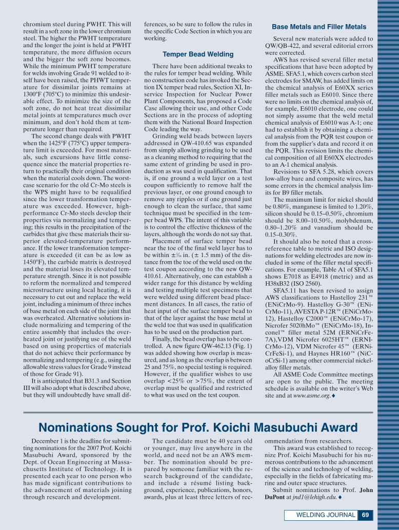
69WELDING JOURNAL
chromium steel during PWHT. This willresult in a soft zone in the lower chromiumsteel. The higher the PWHT temperatureand the longer the joint is held at PWHTtemperature, the more diffusion occursand the bigger the soft zone becomes.While the minimum PWHT temperaturefor welds involving Grade 91 welded to it-self have been raised, the PHWT temper-ature for dissimilar joints remains at1300°F (705°C) to minimize this undesir-able effect. To minimize the size of thesoft zone, do not heat treat dissimilarmetal joints at temperatures much overminimum, and don’t hold them at tem-perature longer than required.
The second change deals with PWHTwhen the 1425°F (775°C) upper tempera-ture limit is exceeded. For most materi-als, such excursions have little conse-quence since the material properties re-turn to practically their original conditionwhen the material cools down. The worst-case scenario for the old Cr-Mo steels isthe WPS might have to be requalifiedsince the lower transformation temper-ature was exceeded. However, high-performance Cr-Mo steels develop theirproperties via normalizing and temper-ing; this results in the precipitation of thecarbides that give these materials their su-perior elevated-temperature perform-ance. If the lower transformation temper-ature is exceeded (it can be as low as1450°F), the carbide matrix is destroyedand the material loses its elevated tem-perature strength. Since it is not possibleto reform the normalized and temperedmicrostructure using local heating, it isnecessary to cut out and replace the weldjoint, including a minimum of three inchesof base metal on each side of the joint thatwas overheated. Alternative solutions in-clude normalizing and tempering of theentire assembly that includes the over-heated joint or justifying use of the weldbased on using properties of materialsthat do not achieve their performance bynormalizing and tempering (e.g., using theallowable stress values for Grade 9 insteadof those for Grade 91).
It is anticipated that B31.3 and SectionIII will also adopt what is described above,but they will undoubtedly have small dif-
ferences, so be sure to follow the rules inthe specific Code Section in which you areworking.
Temper Bead Welding
There have been additional tweaks tothe rules for temper bead welding. Whileno construction code has invoked the Sec-tion IX temper bead rules, Section XI, In-service Inspection for Nuclear PowerPlant Components, has proposed a CodeCase allowing their use, and other CodeSections are in the process of adoptingthem with the National Board InspectionCode leading the way.
Grinding weld beads between layersaddressed in QW-410.65 was expandedfrom simply allowing grinding to be usedas a cleaning method to requiring that thesame extent of grinding be used in pro-duction as was used in qualification. Thatis, if one ground a weld layer on a testcoupon sufficiently to remove half theprevious layer, or one ground enough toremove any ripples or if one ground justenough to clean the surface, that sametechnique must be specified in the tem-per bead WPS. The intent of this variableis to control the effective thickness of thelayers, although the words do not say that.
Placement of surface temper beadnear the toe of the final weld layer has tobe within ±1⁄16 in. (± 1.5 mm) of the dis-tance from the toe of the weld used on thetest coupon according to the new QW-410.61. Alternatively, one can establish awider range for this distance by weldingand testing multiple test specimens thatwere welded using different bead place-ment distances. In all cases, the ratio ofheat input of the surface temper bead tothat of the layer against the base metal atthe weld toe that was used in qualificationhas to be used on the production part.
Finally, the bead overlap has to be con-trolled. A new figure QW-462.13 (Fig. 1)was added showing how overlap is meas-ured, and as long as the overlap is between25 and 75%, no special testing is required.However, if the qualifier wishes to useoverlap <25% or >75%, the extent ofoverlap must be qualified and restrictedto what was used on the test coupon.
Base Metals and Filler Metals
Several new materials were added toQW/QB-422, and several editorial errorswere corrected.
AWS has revised several filler metalspecifications that have been adopted byASME. SFA5.1, which covers carbon steelelectrodes for SMAW, has added limits onthe chemical analysis of E60XX seriesfiller metals such as E6010. Since therewere no limits on the chemical analysis of,for example, E6010 electrode, one couldnot simply assume that the weld metalchemical analysis of E6010 was A-1; onehad to establish it by obtaining a chemi-cal analysis from the PQR test coupon orfrom the supplier’s data and record it onthe PQR. This revision limits the chemi-cal composition of all E60XX electrodesto an A-1 chemical analysis.
Revisions to SFA 5.28, which coverslow-alloy bare and composite wires, hassome errors in the chemical analysis lim-its for B9 filler metals.
The maximum limit for nickel shouldbe 0.80%, manganese is limited to 1.20%,silicon should be 0.15–0.50%, chromiumshould be 8.00–10.50%, molybdenum,0.80–1.20% and vanadium should be0.15–0.30%.
It should also be noted that a cross-reference table to metric and ISO desig-nations for welding electrodes are now in-cluded in some of the filler metal specifi-cations. For example, Table A1 of SFA5.1shows E7018 as E4918 (metric) and asH38xB32 (ISO 2560).
SFA5.11 has been revised to assignAWS classifications to Hastelloy 231™(ENiCrMo-9). Hastelloy G-30™ (ENi-CrMo-11), AVESTA P-12R™ (ENiCrMo-12), Hastelloy C2000™ (ENiCrMo-17),Nicrofer 5020hMo™ (ENiCrMo-18), In-conel™ filler metal 52M (ERNiCrFe-7A),VDM Nicrofer 6025HT™ (ERNI-CrMo-12), VDM Nicrofer 45™ (ERNi-CrFeSi-1), and Haynes HR160™ (NiC-oCrSi-1) among other commercial nickel-alloy filler metals.
All ASME Code Committee meetingsare open to the public. The meetingschedule is available on the writer’s Website and at www.asme.org.♦
Nominations Sought for Prof. Koichi Masubuchi AwardDecember 1 is the deadline for submit-
ting nominations for the 2007 Prof. KoichiMasubuchi Award, sponsored by theDept. of Ocean Engineering at Massa-chusetts Institute of Technology. It ispresented each year to one person whohas made significant contributions tothe advancement of materials joiningthrough research and development.
The candidate must be 40 years oldor younger, may live anywhere in theworld, and need not be an AWS mem-ber. The nomination should be pre-pared by someone familiar with the re-search background of the candidate,and include a résumé listing back-ground, experience, publications, honors,awards, plus at least three letters of rec-
ommendation from researchers. This award was established to recog-
nize Prof. Koichi Masubuchi for his nu-merous contributions to the advancementof the science and technology of welding,especially in the fields of fabricating ma-rine and outer space structures.
Submit nominations to Prof. JohnDuPont at [email protected].♦
xSociety News April 2007:Layout 1 3/12/07 10:38 AM Page 69

APRIL 200770
Amendment A1 to QC1:2006, Standard for the Certification of Welding Inspectors(To download this Amendment, visit www.aws.org/certification/docs/qc1-06-a.pdf.)
(All changes are shown in underlined text.)
Statement on Use (paragraph added as shown between the extracted text)
Certification is achieved by satisfying a combination of defined education, experience, and/or examination re-quirements. Certification is not an assurance of future competence or ability.
An endorsement to a certification adds to a certification by indicating demonstration of ability in a particularskill area that is not sufficiently broad or unique to support a separate and distinct certification designation, nor isit a core area of expertise or knowledge such that it be included as part of the underlying certification itself. An en-dorsement is not an indication of approval by AWS or an assurance of future performance.
AWS disclaims liability for any injury to persons or to property, or other damages of any nature whatsoever, in-cluding special, indirect, consequential, or compensatory damages, directly or indirectly resulting from the negli-gent conduct or other acts or omissions of any individual certified by AWS.
3. Definitionsendorsement. Indication of an additional skill documented in writing and added to ones certification creden-
tial(s).
6.2.2 Applicants shall pass the examination(s) as follows:
Examination Minimum Number of Minimum Percentage of Questions Correct Answers
Part A — Fundamentals 150 72%Part B — Practical 46 72%Part C — Code Book 46 72%Code Book Endorsements NA 72%Other Endorsements NA As defined in the
endorsement specifications
6.2.5 Re-examinations shall be considered as retaking the same exam. Candidates may take one (1) re-examinationwithin one year of the original test date without further training. Any additional re-tests taken will require docu-mentation of 40 hours of further training received in welding inspection meeting the requirements of 16.5.1. Themaximum number of re-tests taken in any three-year period is three (3).
16.3.1 CWI recertification by taking the Part B Practical examination or by taking a Committee-approved endorse-ment, and meeting the requirements of 6.2.2 of this standard.
16.7 CWIs failing to meet the alternative requirements for recertification using experience and continuing educa-tion shall be required to recertify by taking the Part B Practical examination or by taking an endorsement approvedby the Committee for re-certification, and meet the minimum scores in 6.2.2 to maintain certification at the CWIlevel. CWIs failing to meet the requirements of 6.2.2 may take re-examinations (Part B or endorsement) in accor-dance with 6.2.5 to re-certify. CWIs failing to meet the requirements of 6.2.2 but who meet the requirements of 7.1shall receive new certification at the CAWI level and will be subject to the requirements of 15.1 of this standard.Individuals failing to meet the requirements of 6.2.2 or 7.1 shall no longer be certified at any level after their certi-fication expires. Such individuals will be notified of their status in writing.
Tech Topics (continued)
xSociety News April 2007:Layout 1 3/12/07 10:38 AM Page 70
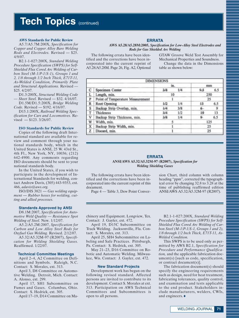
AWS Standards for Public ReviewA5.7/A5.7M:200X, Specification for
Copper and Copper Alloy Bare WeldingRods and Electrodes. Revised — $25.4/9/07.
B2.1-1-027:200X, Standard WeldingProcedure Specification (SWPS) for Self-Shielded Flux Cored Arc Welding of Car-bon Steel (M-1/P-1/S-1), Groups 1 and2, 1/8 through 1/2 Inch Thick, E71T-11,As-Welded Condition, Primarily Plateand Structural Applications. Revised —$25. 4/2/07.
D1.3:200X, Structural Welding Code— Sheet Steel. Revised — $32. 4/16/07.
D1.5M/D1.5:200X, Bridge WeldingCode. Revised — $192. 4/16/07.
D15.1:200X, Railroad Welding Spec-ification for Cars and Locomotives. Re-vised — $123. 3/26/07.
ISO Standards for Public ReviewCopies of the following draft Inter-
national standard are available for re-view and comment through your na-tional standards body, which in theUnited States is ANSI, 25 W. 43rd St.,4th Fl., New York, NY, 10036; (212)642-4900. Any comments regardingISO documents should be sent to yournational standards body.
In the United States, if you wish toparticipate in the development of In-ternational Standards for welding, con-tact Andrew Davis, (305) 443-9353, ext.466, [email protected].
ISO/DIS 3821 — Gas welding equip-ment — Rubber hoses for welding, cut-ting and allied processes.
Standards Approved by ANSID8.1M:2007, Specification for Auto-
motive Weld Quality — Resistance SpotWelding of Steel. New. 1/12/07.
A5.2/A5.2M:2007, Specification forCarbon and Low Alloy Steel Rods forOxyfuel Gas Welding. Revised. 2/12/07.
A5.32/A5.32M-97 (R2007), Specifi-cation for Welding Shielding Gases.Reaffirmed. 1/22/07.
Technical Committee MeetingsApril 2–4, A2 Committee on Defi-
nitions and Symbols. Raleigh, N.C.Contact: S. Morales, ext. 313.
April 3, D8 Committee on Automo-tive Welding. Detroit, Mich. Contact:A. Alonso, ext. 299.
April 17, SH1 Subcommittee onFumes and Gases. Columbus, Ohio.Contact: S. Hedrick, ext. 305.
April 17–19, D14 Committee on Ma-
71WELDING JOURNAL
ERRATAAWS A5.28/A5.28M:2005, Specification for Low-Alloy Steel Electrodes and
Rods for Gas Shielded Arc Welding
The following errata have been iden-tified and the corrections have been in-corporated into the current reprint ofA5.28/A5.28M. Page 26, Fig. A2, Optional
GTAW Groove Weld Test Assembly forMechanical Properties and Soundness.
Change the data in the Dimensionstable as shown below:
The following errata have been iden-tified and the corrections have been in-corporated into the current reprint of thisdocument.
Page 4 — Table 3, Dew Point Conver-
sion Chart, third column with columnheading “ppm”, corrected the typograph-ical error by changing 32.8 to 3.28 at thetime of publishing reaffirmed editionANSI/AWS A5.32/A5.32M-97 (R2007).
ERRATAANSI/AWS A5.32/A5.32M-97 (R2007), Specification for
Welding Shielding Gases
chinery and Equipment. Longview, Tex.Contact: J. Gayler, ext. 472.
April 19, D15C Subcommittee onTrack Welding. Jacksonville, Fla. Con-tact: S. Morales, ext. 313.
April 25, SH4 Subcommittee on La-beling and Safe Practices. Pittsburgh,Pa. Contact: S. Hedrick, ext. 305.
May 21–23, D16 Committee on Ro-botic and Automatic Welding. Milwau-kee, Wis. Contact: J. Gayler, ext. 472.
New Standard ProjectsDevelopment work has begun on the
following revised standard. Affectedpersons are invited to contribute to itsdevelopment. Contact S. Morales at ext.313. Participation on AWS TechnicalCommittees and Subcommittees isopen to all persons.
B2.1-1-027:200X, Standard WeldingProcedure Specification (SWPS) for Self-Shielded Flux Cored Arc Welding of Car-bon Steel (M-1/P-1/S-1, Groups 1 and 2),1/8 through 1/2 Inch Thick, E71T-11, As-Welded Condition.
This SWPS is to be used only as per-mitted by AWS B2.1, Specification forProcedure and Performance Qualifica-tion, and the applicable fabrication doc-ument(s) [such as code, specification,or contract document(s)].
The fabrication document(s) shouldspecify the engineering requirementssuch as design, need for heat treatment,fabricating tolerances, quality control,and examination and tests applicableto the end product. Stakeholders in-clude manufacturers, welders, CWIs,and engineers.♦
Tech Topics (continued)
xSociety News April 2007:Layout 1 3/12/07 10:39 AM Page 71
APRIL 200772
New AWS Supporters
Sustaining CompaniesCPS Energy145 Navarro
San Antonio, TX 78205www.cpsenergy.com
Representative: John L. MendozaCPS Energy is the nation’s largest mu-
nicipally owned energy company. It pro-vides electricity to more than 600,000 cus-tomers and natural gas to more than300,000 customers. The company’s pro-ceeds remain in San Antonio where it ac-counts for more than a fifth of the city’soperating budgets for police and fire pro-tection, street improvements, parks, andother services. The company’s mission isto produce and deliver competitive en-ergy products and services to meet thechanging expectations of our customers.
Diversified Storage Systems1135 E. Wooley Rd.Oxward, CA 93030
Representative: Sheryl Feldhanswww.cementsilos.com
Diversified Storage Systems is a man-ufacturer of silos for the storage of pow-der bulk materials, equipment for thetransfer of powder materials, portableand fixed silos, guppys, PD tanks, trans-fer pods, load out systems, gas and dieselblowers, bulk bag transfer systems, anddust collectors.
Educational InstitutionsAbilene High School
1300 N. Cedar Abilene, KS 67410
CUASMEXGral. Felipe Angeles 463
Fracc. Amp. Fco. I. MaderoSaltillo, Coahuila 25120, Mexico
Dodge City High School2201 Russ Blvd.
Dodge City, KS 67801
Hays High School2300 E. 13th St.Hays, KS 67601
Hutchinson Vo-Tech USD 3081500 Plaza Way
Hutchinson, KS 67501
Jefferson West High School619 Condray
Meriden, KS 66512
Manhattan High School2100 Poyntz Ave.
Manhattan, KS 66502
Membership Counts
Member As of Grades 3/1/07
Sustaining ..........................................449Supporting ........................................282Educational ......................................420Affiliate ..............................................386Welding distributor ............................ 48Total corporate members .................. 1,585
Individual members......................45,528Student + transitional members ........5,231Total members ............................ 50,759
Millcreek Center Welding Technology311 E. Park
Olathe, KS 66061
Newton High School 900 W. 12th St.
Newton, KS 67114
Parson High School District #5033030 Morton
Parsons, KS 67357
Wichita Heights High School5301 N. Hillside
Wichita, KS 67219
Wichita High School — Southeast901 S. Edgemoor
Wichita, KS 67218
Zephyr Products, Inc.3030 Wilson Ave.
Leavenworth, KS 66048
Affiliate CompaniesA. M. Gambao & Son
620 N. Elm St.W. Bridgewater, MA 02379
Adam Steel LLC1235 Sandwood Ave.Florence, SC 29506
B & K Installations, Inc.246 SW 4th Ave.
Homestead, FL 33030
C & B Welders, Inc.2643-5 W. Monroe St.
Chicago, IL 60612
Complete Automation, Inc.1776 D. W. Clarkson Rd.
Lake Orion, MI 48362
Dimension Fabricators, Inc.1910 Maxon Rd.
Schenectady, NY 12308
Integrated Welding Systems, Inc.34314 Oak Knoll Rd.Burlington, WI 53105
Jetson, Inc.13414 Hwy. 65 NE
Ham Lake, MN 55304
Johnson Mfg. Co.114 Lost Grove Rd.Princeton, IA 52768
Krause Manufacturing6059 Guide Meridian
Bellingham, WA 98226
North Industrial MachinePO Box 1734
Hartsville, SC 29551
OEM Remanufacturing13315 156 St. NW
Edmonton, AB, T5V 1V2, Canada
Service Engineering Repair Co., Inc.PO Box 1110, 1430 N. Main St.
Borger, TX 79007
Tashjian Towers Corp.2183 S. Highland Ave.
Sanger, CA 93657
Young’s Welding, Inc.4115 S. Johnson Rd.Chanute, KS 66720
Supporting Companies Autotool, Inc.
8150 Business WayPlain City, OH 43064
Cassimus Co.14492 Wicks Blvd.
San Leandro, CA 94577
Conewago Enterprises, Inc.576 Edgegrove Rd.Hanover, PA 17331
Mechelonic Welders Pvt. Ltd.#237, A-7, KIADB Industrial Area
Bommasandra, Hosur Rd.Bangalore, Karnataka 560099, India
Metalpol, SA de CVSantiago Papasquiaro #158
Parque Ind. LaguneroGomez Palacio 35070, Mexico
Rocky’s Welding, Inc.7726 W. Dahlia Dr.Peoria, AZ 85381
xSociety News April 2007:Layout 1 3/12/07 10:39 AM Page 72
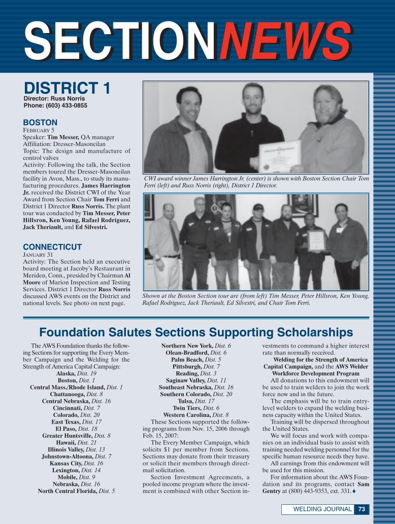
SECTIONNEWSSECTIONNEWS
73WELDING JOURNAL
DISTRICT 1Director: Russ NorrisPhone: (603) 433-0855
Foundation Salutes Sections Supporting Scholarships The AWS Foundation thanks the follow-
ing Sections for supporting the Every Mem-ber Campaign and the Welding for theStrength of America Capital Campaign:
Alaska, Dist. 19Boston, Dist. 1
Central Mass./Rhode Island, Dist. 1Chattanooga, Dist. 8
Central Nebraska, Dist. 16Cincinnati, Dist. 7Colorado, Dist. 20
East Texas, Dist. 17El Paso, Dist. 18
Greater Huntsville, Dist. 8Hawaii, Dist. 21
Illinois Valley, Dist. 13Johnstown-Altoona, Dist. 7
Kansas City, Dist. 16Lexington, Dist. 14
Mobile, Dist. 9Nebraska, Dist. 16
North Central Florida, Dist. 5
Northern New York, Dist. 6Olean-Bradford, Dist. 6
Palm Beach, Dist. 5Pittsburgh, Dist. 7
Reading, Dist. 3Saginaw Valley, Dist. 11
Southeast Nebraska, Dist. 16Southern Colorado, Dist. 20
Tulsa, Dist. 17Twin Tiers, Dist. 6
Western Carolina, Dist. 8These Sections supported the follow-
ing programs from Nov. 15, 2006 throughFeb. 15, 2007:
The Every Member Campaign, whichsolicits $1 per member from Sections.Sections may donate from their treasuryor solicit their members through direct-mail solicitation.
Section Investment Agreements, apooled income program where the invest-ment is combined with other Section in-
vestments to command a higher interestrate than normally received.
Welding for the Strength of AmericaCapital Campaign, and the AWS Welder
Workforce Development ProgramAll donations to this endowment will
be used to train welders to join the workforce now and in the future.
The emphasis will be to train entry-level welders to expand the welding busi-ness capacity within the United States.
Training will be dispersed throughoutthe United States.
We will focus and work with compa-nies on an individual basis to assist withtraining needed welding personnel for thespecific human resource needs they have.
All earnings from this endowment willbe used for this mission.
For information about the AWS Foun-dation and its programs, contact SamGentry at (800) 443-9353, ext. 331.♦
BOSTONFEBRUARY 5Speaker: Tim Messer, QA managerAffiliation: Dresser-MasoneilanTopic: The design and manufacture ofcontrol valvesActivity: Following the talk, the Sectionmembers toured the Dresser-Masoneilanfacility in Avon, Mass., to study its manu-facturing procedures. James HarringtonJr. received the District CWI of the YearAward from Section Chair Tom Ferri andDistrict 1 Director Russ Norris. The planttour was conducted by Tim Messer, PeterHillsron, Ken Young, Rafael Rodriguez,Jack Theriault, and Ed Silvestri.
CONNECTICUTJANUARY 31Activity: The Section held an executiveboard meeting at Jacoby’s Restaurant inMeriden, Conn., presided by Chairman AlMoore of Marion Inspection and TestingServices. District 1 Director Russ Norrisdiscussed AWS events on the District andnational levels. See photo on next page.
CWI award winner James Harrington Jr. (center) is shown with Boston Section Chair TomFerri (left) and Russ Norris (right), District 1 Director.
Shown at the Boston Section tour are (from left) Tim Messer, Peter Hillsron, Ken Young,Rafael Rodriguez, Jack Theriault, Ed Silvestri, and Chair Tom Ferri.
xSociety News April 2007:Layout 1 3/12/07 3:51 PM Page 73

APRIL 200774
MAINEJANUARY 4Speaker: Tom Cormier, CWIAffiliation: Metso PaperTopic: SkillsUSA test preparationActivity: The attendees discussed the re-quirements and processes that will be usedin the March 16th welding trials to be heldin Bangor, Maine.
JANUARY 25Activity: The Maine Section hosted its sec-ond annual vendors’ night program in thewelding lab at Southern Maine Commu-nity College, South Portland, Maine. CWIMark Legel, a welding instructor at thecollege, demonstrated welding tools andequipment suitable for home and shopuse, along with a discussion of safety top-ics. The attendees had hands-on opportu-nities to work with various products fromAdvantage Gases, Hobart Brothers, Lin-coln Electric, Makita Tools, Miller Elec-tric, Smith Cutting Equipment, WalterAbrasives, and Arc One Helmets.
Shown at the Connecticut Section’s board meeting are (from left) John Matthews, BobCullen, Kathie McGirr, and Chairman Al Moore.
Shown at the New Jersey Section program are (from left) Troy Saylor, speaker Ed Starkey,and Vince Murray, Section chair.
Frank Simone (left) receives the SectionMeritorious Award from Jim Korchowsky,Philadelphia Section chair.
DISTRICT 2Director: Kenneth R. StocktonPhone: (732) 787-0805
Speaker Gary Gresko (right) is shownwith Jim Korchowsky, Philadelphia Sec-tion chairman .
NEW JERSEYJANUARY 16Speaker: Ed Starkey, product managerAffiliation: Inweld, Coplay, Pa.Topic: The future of InweldActivity: The Section will sponsor a semi-nar on welding codes April 12 at Somer-set County Vocational School. ContactChairman Vince Murray at (973) 478-5000; or [email protected] meeting was held at L’Affaire Restau-rant in Mountainside, N.J.
PHILADELPHIAJANUARY 10Speaker: Gary Gresko, director of train-ingAffiliation: Boilermakers Local 13Topic: Employment opportunities in thewelding fieldActivity: Following the talk, the attendeestoured the apprentice training weld shopand union hall at Boilermakers Local 13.Frank Simone, Section treasurer andboard member, was presented the SectionMeritorious Award from Chairman JimKorchowsky. Rick Davis received the Dal-ton E. Hamilton Memorial District CWIof the Year Award.
FEBRUARY 7Speaker: Jim HenryAffiliation: Stoody Co.Topic: Hardfacing and buildupActivity: At this Philadelphia Section pro-
xSociety News April 2007:Layout 1 3/12/07 10:40 AM Page 74

75WELDING JOURNAL
gram, District 2 Director Ken Stocktonand Section Chair Jim Korchowsky pre-sented Hobert Hoops and David Vinsonthe District Dalton E. Hamilton Memo-rial CWI of the Year Award. The DistrictEducator Award was given to DanRoskiewich, and Section EducatorAwards were presented to Bob Sandelierand James Rynex.
LANCASTERJANUARY 24Activity: The Section members touredTurkey Hill Dairy in Conestoga, Pa. Chair-man John Ament arranged the tour thatwas conducted by Ernie Pinckney andDerek Frey. The tour concluded with atasting of freshly made ice cream. JohnBoyer received the Section and the Dis-trict Educator of the Year Awards. Boyeris a welding instructor at LancasterCounty Career and Tech Center, Mt. JoyCampus. Reading Section ChairmanChris Ochs was presented the Section andthe District Private Educator Awards.
DISTRICT 3Director: Alan J. Badeaux Sr.Phone: (301) 753-1759
Rick Davis displays his District CWI of theYear Award presented to him at the Philadel-phia Section program.
Philadelphia Section Chair Jim Kor-chowsky (left) is shown with speaker JimHenry at the February meeting.
Shown at the February Philadelphia Section program are (from left) Chair Jim Korchowsky,CWI award winners Hobert Hoops and David Vinson, and Ken Stockton, District 2 director.
Shown at the February Philadelphia Section meeting are (from left) James Rynex, ChairJim Korchowsky, Dan Roskiewich, District 2 Director Ken Stockton, and Bob Sandelier.
Lancaster Section members are shown enjoying some freshly made Turkey Hill Dairy icecream following their tour of the facility in January.
READINGJANUARY 18Speaker: Robert S. Brown, consultantAffiliation: RBS Alloy Applications, LLCTopic: Techniques for welding stainlesssteelActivity: The Section hosted its annualPast Chairmen’s Night program at SuperKing Buffet Restaurant in Reading, Pa.Past chairs in attendance included Meri-lyn McLaughlin, Steve Gammon, Dave
Hibshman, Francis Butkus, Peter Shaub,Larry Hefner, Paul Levengood, DanDeAntonio, John Miller, and RobertBrown. See photos on next page.
YORK CENTRAL PA.FEBRUARY 1Speaker: Larry Lowe, district salesmanagerAffiliation: Walter Surface Technology
xSociety News April 2007:Layout 1 3/12/07 10:41 AM Page 75

APRIL 200776
Topic: Safety when working with abrasivesActivity: The York Central PennsylvaniaSection hosted its annual students’ nightprogram at York County School of Tech-nology. Every student received a compli-
DISTRICT 6Director: Neal A. ChapmanPhone: (315) 349-6960
DISTRICT 4Director: Roy C. LanierPhone: (252) 321-4285
DISTRICT 5Director: Leonard P. ConnorPhone: (954) 981-3977
Past Reading Section chairs are (seated) Merilyn McLaughlin and Steve Gammon, and(standing, from left) Dave Hibshman, Francis Butkus, Peter Shaub, Larry Hefner, Paul Le-vengood, Dan DeAntonio, John Miller, and Robert Brown.
Shown at the Reading Section program areChair Chris Ochs (left) and speaker RobertS. Brown.
Larry Lowe accepts a speaker gift from Mar-garet Malehorn, York Central PennsylvaniaSection chair.
Shown at the York Central Pennsylvania Section’s students’ night program are (far left)Chair Margaret Malehorn and (back row) Advisor Brian Yarrison. Far right is Advisor JoshSeitzer.
mentary dinner and a pair of ArcOneglasses. Organizing the event were SectionChair Margaret Malehorn, and StudentChapter Advisors Brian Yarrison and JoshSeitzer.
SOUTH CAROLINAJANUARY 18Speaker: Tom Thebe, CFOAffiliation: Protected Vehicles, Inc.Topic: Overview and history of PVI andits productsActivity: Following the talk, Jimmy Lamband Jim Tuten conducted a tour of the fa-cility for the 42 attendees.
PALM BEACHJANUARY 17Speaker: Dave SorensonAffiliation: Harris ProductsTopic: Brazing and soldering filler mealsand equipmentActivity: The program was held at PalmBeach Community College.
NIAGARA FRONTIERFEBRUARY 3Activity: The Section participated in theBatavia Area BOCES student weldingcompetition held in Batavia, N.Y. Theprize winners included Jeff Kohorst,Spencer Reyna, and Tim Baker, who tookfirst, second, and third places in the Sen-ior division, respectively. In the Junior di-vision, Rick Smith, Dewayne Wilcox, andR. J. Steams, took first, second, and thirdplace, respectively.
NORTHERN NEW YORKFEBRUARY 13Speaker: Timothy A. Gray, senior engi-neer and group coordinator for ultrasonicapplicationsAffiliation: Center for NondestructiveEvaluation at Iowa State UniversityTopic: The nondestructive examination offriction stir welds with model-assisted ap-proaches for computing probability of de-fect detectionActivity: This was the annual joint meet-ing with members of the Eastern NewYork Chapter of ASM International. Theprogram was held at Mill Road Restau-rant and Tavern in Latham, N.Y.
xSociety News April 2007:Layout 1 3/12/07 10:41 AM Page 76
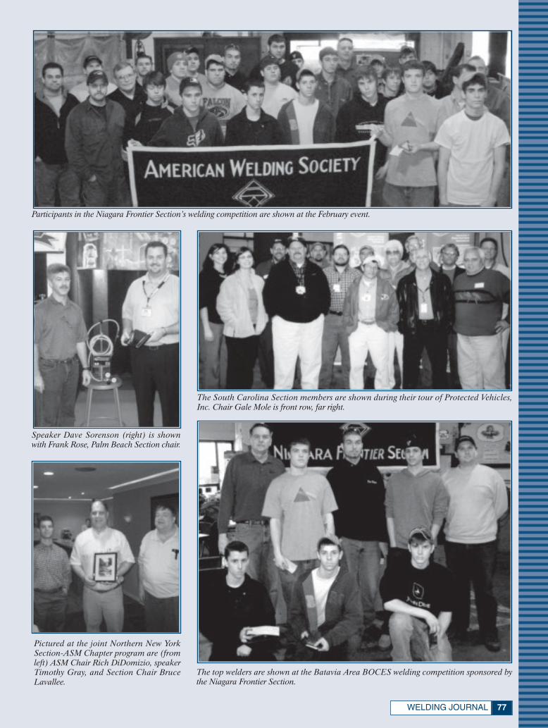
77WELDING JOURNAL
The South Carolina Section members are shown during their tour of Protected Vehicles,Inc. Chair Gale Mole is front row, far right.
Participants in the Niagara Frontier Section’s welding competition are shown at the February event.
Speaker Dave Sorenson (right) is shownwith Frank Rose, Palm Beach Section chair.
The top welders are shown at the Batavia Area BOCES welding competition sponsored bythe Niagara Frontier Section.
Pictured at the joint Northern New YorkSection-ASM Chapter program are (fromleft) ASM Chair Rich DiDomizio, speakerTimothy Gray, and Section Chair BruceLavallee.
xSociety News April 2007:Layout 1 3/12/07 10:42 AM Page 77
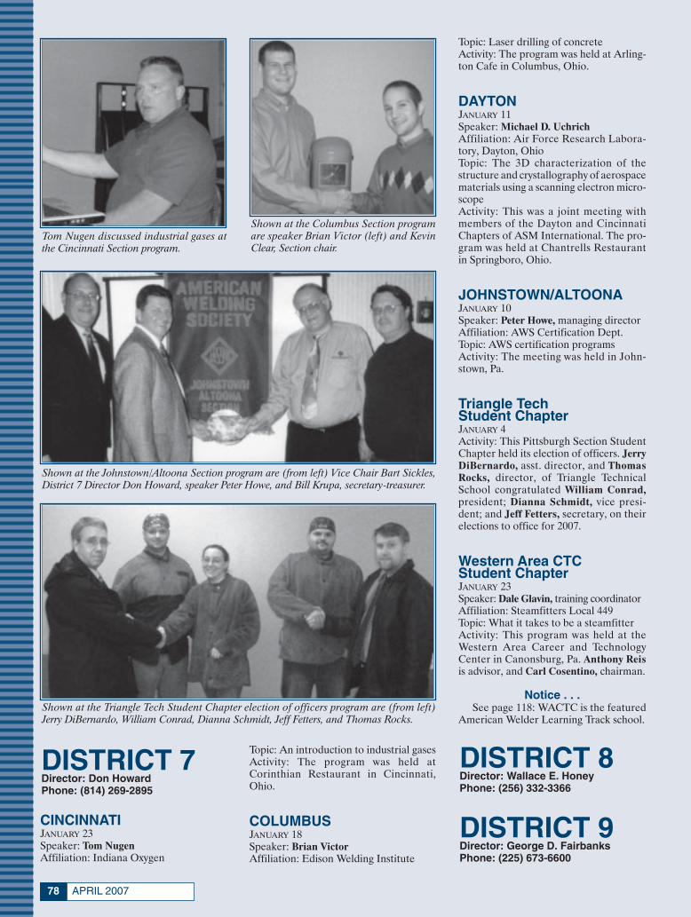
APRIL 200778
DISTRICT 8Director: Wallace E. HoneyPhone: (256) 332-3366
DISTRICT 9Director: George D. FairbanksPhone: (225) 673-6600
Tom Nugen discussed industrial gases atthe Cincinnati Section program.
Shown at the Columbus Section programare speaker Brian Victor (left) and KevinClear, Section chair.
Shown at the Johnstown/Altoona Section program are (from left) Vice Chair Bart Sickles,District 7 Director Don Howard, speaker Peter Howe, and Bill Krupa, secretary-treasurer.
Shown at the Triangle Tech Student Chapter election of officers program are (from left)Jerry DiBernardo, William Conrad, Dianna Schmidt, Jeff Fetters, and Thomas Rocks.
DISTRICT 7Director: Don HowardPhone: (814) 269-2895
CINCINNATIJANUARY 23Speaker: Tom NugenAffiliation: Indiana Oxygen
Topic: An introduction to industrial gasesActivity: The program was held atCorinthian Restaurant in Cincinnati,Ohio.
COLUMBUSJANUARY 18Speaker: Brian VictorAffiliation: Edison Welding Institute
Topic: Laser drilling of concreteActivity: The program was held at Arling-ton Cafe in Columbus, Ohio.
DAYTONJANUARY 11Speaker: Michael D. UchrichAffiliation: Air Force Research Labora-tory, Dayton, OhioTopic: The 3D characterization of thestructure and crystallography of aerospacematerials using a scanning electron micro-scopeActivity: This was a joint meeting withmembers of the Dayton and CincinnatiChapters of ASM International. The pro-gram was held at Chantrells Restaurantin Springboro, Ohio.
JOHNSTOWN/ALTOONAJANUARY 10Speaker: Peter Howe, managing directorAffiliation: AWS Certification Dept.Topic: AWS certification programsActivity: The meeting was held in John-stown, Pa.
Triangle Tech Student ChapterJANUARY 4Activity: This Pittsburgh Section StudentChapter held its election of officers. JerryDiBernardo, asst. director, and ThomasRocks, director, of Triangle TechnicalSchool congratulated William Conrad,president; Dianna Schmidt, vice presi-dent; and Jeff Fetters, secretary, on theirelections to office for 2007.
Western Area CTC Student ChapterJANUARY 23Speaker: Dale Glavin, training coordinatorAffiliation: Steamfitters Local 449Topic: What it takes to be a steamfitterActivity: This program was held at theWestern Area Career and TechnologyCenter in Canonsburg, Pa. Anthony Reisis advisor, and Carl Cosentino, chairman.
Notice . . .See page 118: WACTC is the featured
American Welder Learning Track school.
xSociety News April 2007:Layout 1 3/12/07 10:42 AM Page 78
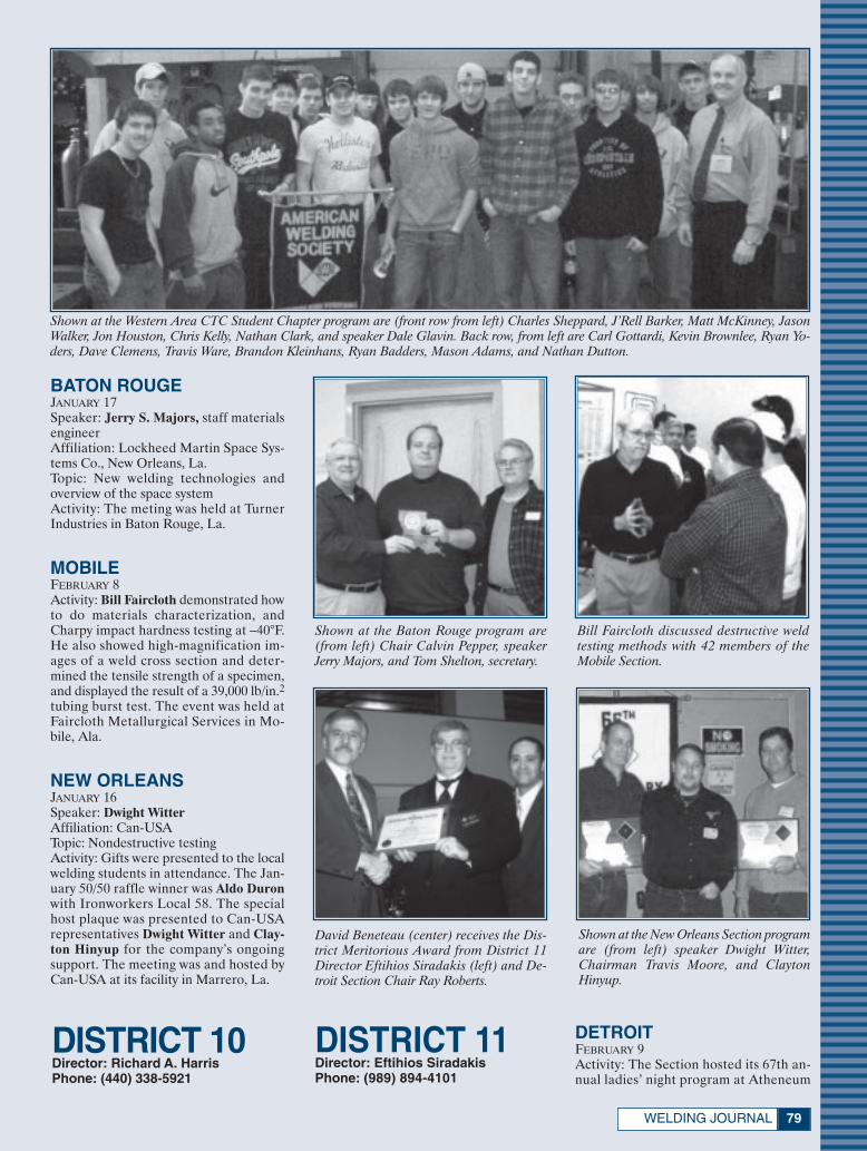
79WELDING JOURNAL
Shown at the Western Area CTC Student Chapter program are (front row from left) Charles Sheppard, J’Rell Barker, Matt McKinney, JasonWalker, Jon Houston, Chris Kelly, Nathan Clark, and speaker Dale Glavin. Back row, from left are Carl Gottardi, Kevin Brownlee, Ryan Yo-ders, Dave Clemens, Travis Ware, Brandon Kleinhans, Ryan Badders, Mason Adams, and Nathan Dutton.
Shown at the Baton Rouge program are(from left) Chair Calvin Pepper, speakerJerry Majors, and Tom Shelton, secretary.
Bill Faircloth discussed destructive weldtesting methods with 42 members of theMobile Section.
Shown at the New Orleans Section programare (from left) speaker Dwight Witter,Chairman Travis Moore, and ClaytonHinyup.
BATON ROUGEJANUARY 17Speaker: Jerry S. Majors, staff materialsengineerAffiliation: Lockheed Martin Space Sys-tems Co., New Orleans, La.Topic: New welding technologies andoverview of the space systemActivity: The meting was held at TurnerIndustries in Baton Rouge, La.
MOBILEFEBRUARY 8Activity: Bill Faircloth demonstrated howto do materials characterization, andCharpy impact hardness testing at –40°F.He also showed high-magnification im-ages of a weld cross section and deter-mined the tensile strength of a specimen,and displayed the result of a 39,000 lb/in.2tubing burst test. The event was held atFaircloth Metallurgical Services in Mo-bile, Ala.
NEW ORLEANSJANUARY 16Speaker: Dwight WitterAffiliation: Can-USATopic: Nondestructive testingActivity: Gifts were presented to the localwelding students in attendance. The Jan-uary 50/50 raffle winner was Aldo Duronwith Ironworkers Local 58. The specialhost plaque was presented to Can-USArepresentatives Dwight Witter and Clay-ton Hinyup for the company’s ongoingsupport. The meeting was and hosted byCan-USA at its facility in Marrero, La.
DISTRICT 10Director: Richard A. HarrisPhone: (440) 338-5921
David Beneteau (center) receives the Dis-trict Meritorious Award from District 11Director Eftihios Siradakis (left) and De-troit Section Chair Ray Roberts.
DISTRICT 11Director: Eftihios SiradakisPhone: (989) 894-4101
DETROITFEBRUARY 9Activity: The Section hosted its 67th an-nual ladies’ night program at Atheneum
xSociety News April 2007:Layout 1 3/12/07 10:43 AM Page 79
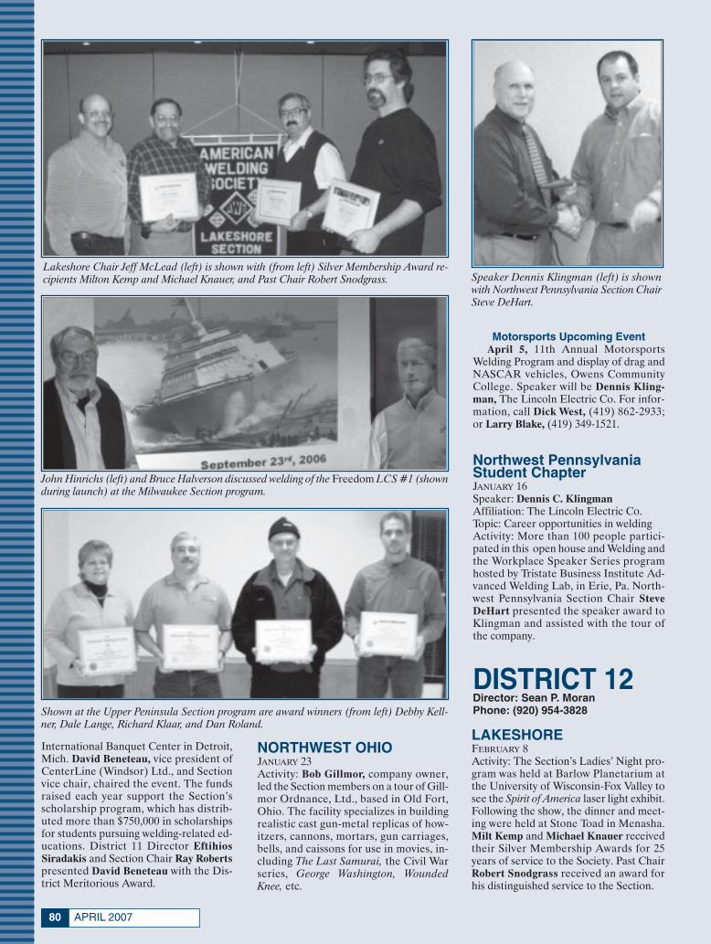
APRIL 200780
Motorsports Upcoming EventApril 5, 11th Annual Motorsports
Welding Program and display of drag andNASCAR vehicles, Owens CommunityCollege. Speaker will be Dennis Kling-man, The Lincoln Electric Co. For infor-mation, call Dick West, (419) 862-2933;or Larry Blake, (419) 349-1521.
Northwest Pennsylvania Student ChapterJANUARY 16Speaker: Dennis C. KlingmanAffiliation: The Lincoln Electric Co.Topic: Career opportunities in weldingActivity: More than 100 people partici-pated in this open house and Welding andthe Workplace Speaker Series programhosted by Tristate Business Institute Ad-vanced Welding Lab, in Erie, Pa. North-west Pennsylvania Section Chair SteveDeHart presented the speaker award toKlingman and assisted with the tour ofthe company.
Speaker Dennis Klingman (left) is shownwith Northwest Pennsylvania Section ChairSteve DeHart.
Lakeshore Chair Jeff McLead (left) is shown with (from left) Silver Membership Award re-cipients Milton Kemp and Michael Knauer, and Past Chair Robert Snodgrass.
John Hinrichs (left) and Bruce Halverson discussed welding of the Freedom LCS #1 (shownduring launch) at the Milwaukee Section program.
Shown at the Upper Peninsula Section program are award winners (from left) Debby Kell-ner, Dale Lange, Richard Klaar, and Dan Roland.
International Banquet Center in Detroit,Mich. David Beneteau, vice president ofCenterLine (Windsor) Ltd., and Sectionvice chair, chaired the event. The fundsraised each year support the Section’sscholarship program, which has distrib-uted more than $750,000 in scholarshipsfor students pursuing welding-related ed-ucations. District 11 Director EftihiosSiradakis and Section Chair Ray Robertspresented David Beneteau with the Dis-trict Meritorious Award.
NORTHWEST OHIOJANUARY 23Activity: Bob Gillmor, company owner,led the Section members on a tour of Gill-mor Ordnance, Ltd., based in Old Fort,Ohio. The facility specializes in buildingrealistic cast gun-metal replicas of how-itzers, cannons, mortars, gun carriages,bells, and caissons for use in movies, in-cluding The Last Samurai, the Civil Warseries, George Washington, WoundedKnee, etc.
DISTRICT 12Director: Sean P. MoranPhone: (920) 954-3828
LAKESHOREFEBRUARY 8Activity: The Section’s Ladies’ Night pro-gram was held at Barlow Planetarium atthe University of Wisconsin-Fox Valley tosee the Spirit of America laser light exhibit.Following the show, the dinner and meet-ing were held at Stone Toad in Menasha.Milt Kemp and Michael Knauer receivedtheir Silver Membership Awards for 25years of service to the Society. Past ChairRobert Snodgrass received an award forhis distinguished service to the Section.
xSociety News April 2007:Layout 1 3/12/07 10:43 AM Page 80

81WELDING JOURNAL
MILWAUKEEFEBRUARY 15Speakers: John Hinrichs and BruceHalversonAffiliation: Friction Stir Link, Inc., andMarinette Marine Corp., respectivelyTopic: Friction stir welding of the alu-minum upper deck structures of the Lit-toral Combat Ship (LCS) #1 FreedomActivity: The program was held at TannerPaull Post in West Allis, Wis.
UPPER PENINSULAJANUARY 11Speaker: Ron Myers, sales engineerAffiliation: The Lincoln Electric Co.Topic: Welder safetyActivity: Four members received awards.Debby Kellner received the District Mer-itorious Award, Dan Roland was pre-sented the Private Sector InstructorAward, Dale Lange earned the DistrictEducator Award, and Richard Klaar ac-cepted the District Dalton E. HamiltonMemorial CWI of the Year Award.
The Indiana Section hosted its annualCWI/CWE testing program in February.
Ronald Briddell (left), St. Louis Section treasurer, gives an appreciation gift to tour guidesTom Tweedy, Bill Wertheimer, and Michael Nowak, at LaBarge Products, Inc.
Shown during the Northwest Section tourof OEM Fabricators are (from left) ThomasAaby, Scott Exner, and Section SecretaryLogan Kucerak.
Winning bowlers at the Nebraska fund rais-ing event were Aaron and Lori Rodgers.
INDIANAJANUARY 17Activity: The Section held a roundtablediscussion to plan for its 29th Annual Mid-West Team Welding Tournament, and toselect officers for the upcoming year.
FEBRUARY 3Activity: The Section hosted its annualCWI/CWE testing at the Holiday Inn Se-lect in Indianapolis, Ind., for 33 appli-cants. Chairman Gary Dugger was the testsupervisor, with Indiana Section mem-bers serving as proctors.
ST. LOUISJANUARY 25Activity: The Section members touredLaBarge Products, Inc., in St. Louis, Mo.The facility manufactures military supplyfuel and water transport pump systems.The tour was conducted by Tom Tweedy,foreman, and LaBarge Vice PresidentsBill Wertheimer and Michael Nowak.
DISTRICT 13Director: W. Richard PolaninPhone: (309) 694-5404
DISTRICT 14Director: Tully C. ParkerPhone: (618) 667-7744
DISTRICT 15Director: Mace V. HarrisPhone: (952) 925-1222
NORTHWESTJANUARY 17Activity: The Section members touredthe Woodville, Wis., headquarters ofOEM Fabricators, to study its machining,welding, sawing, oxygen, laser, plasma arccutting, painting, and assembly opera-tions. The guides included ChristianGausman, Tom Aaby, Chris Kronberger,Kim Shields, Mike Wendt, Mike Finch,and Jaime Burr. Special thanks to ScottExner for organizing the event.
DISTRICT 16Director: David LandonPhone: (641) 621-7476
KANSAS CITYJANUARY 11Activity: The Section members touredAcuren’s Testing Facility in Shawnee,Kans., to study its radiographic testingprocedures, and the trucks used to per-form weld testing in the field.
FEBRUARY 8Activity: Brian McKee led the KansasCity Section on a tour of the Harley-Davidson facility in Kansas City, Mo.
NEBRASKAJANUARY 20Activity: The Section hosted its First An-nual Bowling Fund Raiser at MaplewoodLanes in Omaha, Neb., to support itsscholarship program. The event featured12 teams and a silent auction. Items weredonated by Praxair, Olsson and Assoc.,Metropolitan Community College, andLinweld. The tournament winners wereAaron and Lori Rodgers who donatedtheir cash winnings to support the schol-
xSociety News April 2007:Layout 1 3/12/07 10:44 AM Page 81
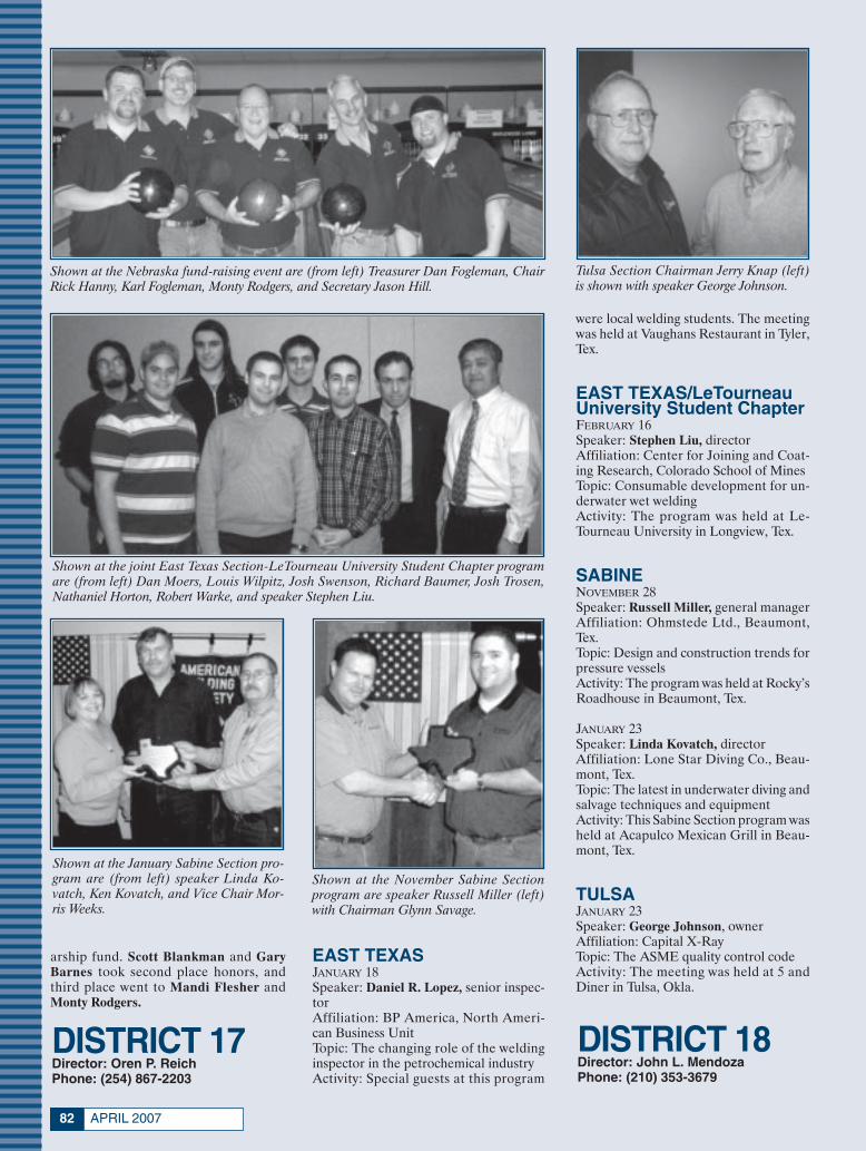
APRIL 200782
Shown at the Nebraska fund-raising event are (from left) Treasurer Dan Fogleman, ChairRick Hanny, Karl Fogleman, Monty Rodgers, and Secretary Jason Hill.
Shown at the joint East Texas Section-LeTourneau University Student Chapter programare (from left) Dan Moers, Louis Wilpitz, Josh Swenson, Richard Baumer, Josh Trosen,Nathaniel Horton, Robert Warke, and speaker Stephen Liu.
Shown at the January Sabine Section pro-gram are (from left) speaker Linda Ko-vatch, Ken Kovatch, and Vice Chair Mor-ris Weeks.
Shown at the November Sabine Sectionprogram are speaker Russell Miller (left)with Chairman Glynn Savage.
arship fund. Scott Blankman and GaryBarnes took second place honors, andthird place went to Mandi Flesher andMonty Rodgers.
EAST TEXASJANUARY 18Speaker: Daniel R. Lopez, senior inspec-torAffiliation: BP America, North Ameri-can Business UnitTopic: The changing role of the weldinginspector in the petrochemical industryActivity: Special guests at this program
DISTRICT 17Director: Oren P. ReichPhone: (254) 867-2203
Tulsa Section Chairman Jerry Knap (left)is shown with speaker George Johnson.
were local welding students. The meetingwas held at Vaughans Restaurant in Tyler,Tex.
EAST TEXAS/LeTourneauUniversity Student ChapterFEBRUARY 16Speaker: Stephen Liu, directorAffiliation: Center for Joining and Coat-ing Research, Colorado School of MinesTopic: Consumable development for un-derwater wet weldingActivity: The program was held at Le-Tourneau University in Longview, Tex.
SABINENOVEMBER 28Speaker: Russell Miller, general managerAffiliation: Ohmstede Ltd., Beaumont,Tex.Topic: Design and construction trends forpressure vesselsActivity: The program was held at Rocky’sRoadhouse in Beaumont, Tex.
JANUARY 23Speaker: Linda Kovatch, directorAffiliation: Lone Star Diving Co., Beau-mont, Tex.Topic: The latest in underwater diving andsalvage techniques and equipmentActivity: This Sabine Section program washeld at Acapulco Mexican Grill in Beau-mont, Tex.
TULSAJANUARY 23Speaker: George Johnson, ownerAffiliation: Capital X-RayTopic: The ASME quality control codeActivity: The meeting was held at 5 andDiner in Tulsa, Okla.
DISTRICT 18Director: John L. MendozaPhone: (210) 353-3679
xSociety News April 2007:Layout 1 3/12/07 10:45 AM Page 82
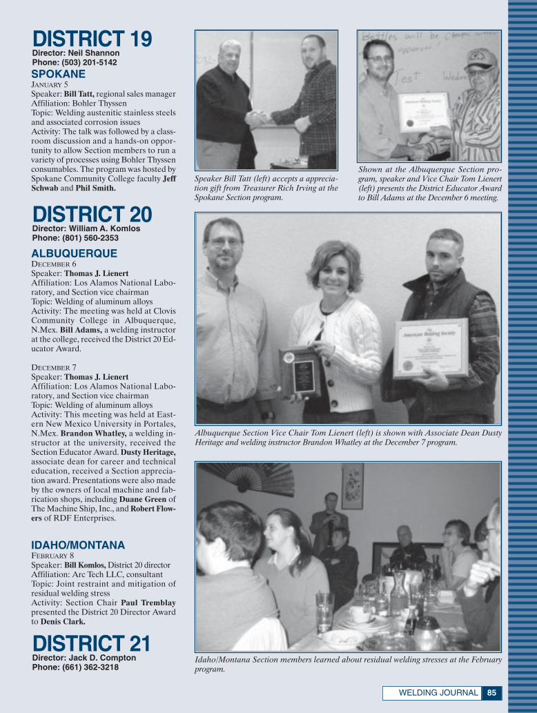
85WELDING JOURNAL
Speaker Bill Tatt (left) accepts a apprecia-tion gift from Treasurer Rich Irving at theSpokane Section program.
Shown at the Albuquerque Section pro-gram, speaker and Vice Chair Tom Lienert(left) presents the District Educator Awardto Bill Adams at the December 6 meeting.
Albuquerque Section Vice Chair Tom Lienert (left) is shown with Associate Dean DustyHeritage and welding instructor Brandon Whatley at the December 7 program.
SPOKANEJANUARY 5Speaker: Bill Tatt, regional sales managerAffiliation: Bohler ThyssenTopic: Welding austenitic stainless steelsand associated corrosion issuesActivity: The talk was followed by a class-room discussion and a hands-on oppor-tunity to allow Section members to run avariety of processes using Bohler Thyssenconsumables. The program was hosted bySpokane Community College faculty JeffSchwab and Phil Smith.
DISTRICT 19Director: Neil ShannonPhone: (503) 201-5142
DISTRICT 20Director: William A. KomlosPhone: (801) 560-2353
ALBUQUERQUEDECEMBER 6Speaker: Thomas J. LienertAffiliation: Los Alamos National Labo-ratory, and Section vice chairmanTopic: Welding of aluminum alloysActivity: The meeting was held at ClovisCommunity College in Albuquerque,N.Mex. Bill Adams, a welding instructorat the college, received the District 20 Ed-ucator Award.
DECEMBER 7Speaker: Thomas J. LienertAffiliation: Los Alamos National Labo-ratory, and Section vice chairmanTopic: Welding of aluminum alloysActivity: This meeting was held at East-ern New Mexico University in Portales,N.Mex. Brandon Whatley, a welding in-structor at the university, received theSection Educator Award. Dusty Heritage,associate dean for career and technicaleducation, received a Section apprecia-tion award. Presentations were also madeby the owners of local machine and fab-rication shops, including Duane Green ofThe Machine Ship, Inc., and Robert Flow-ers of RDF Enterprises.
IDAHO/MONTANAFEBRUARY 8Speaker: Bill Komlos, District 20 directorAffiliation: Arc Tech LLC, consultantTopic: Joint restraint and mitigation ofresidual welding stressActivity: Section Chair Paul Tremblaypresented the District 20 Director Awardto Denis Clark.
Idaho/Montana Section members learned about residual welding stresses at the Februaryprogram.
DISTRICT 21Director: Jack D. ComptonPhone: (661) 362-3218
xSociety News April 2007:Layout 1 3/12/07 10:45 AM Page 85
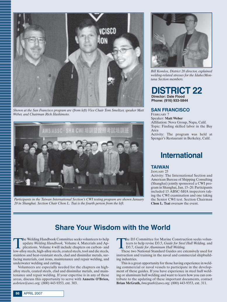
APRIL 200786
Shown at the San Francisco program are (from left) Vice Chair Tom Smeltzer, speaker MattWeber, and Chairman Rich Hashimoto.
Participants in the Taiwan International Section’s CWI testing program are shown January20 in Shanghai. Section Chair Chon L. Tsai is the fourth person from the left.
Bill Komlos, District 20 director, explainedwelding-related stresses for the Idaho/Mon-tana Section members.
DISTRICT 22Director: Dale FloodPhone: (916) 933-5844
SAN FRANCISCOFEBRUARY 7Speaker: Matt WeberAffiliation: Nova Group, Napa, Calif.Topic: Finding skilled labor in the BayAreaActivity: The program was held atSpenger’s Restaurant in Berkeley, Calif.
InternationalTAIWAN JANUARY 25Activity: The International Section andAmerican Bureau of Shipping Consulting(Shanghai) jointly sponsored a CWI pro-gram in Shanghai, Jan. 15–20. Participantsincluded 15 ABSC-SHA inspectors tak-ing the CWI examination and one takingthe Senior CWI test. Section ChairmanChon L. Tsai oversaw the event.
Share Your Wisdom with the World
The Welding Handbook Committee seeks volunteers to helpupdate Welding Handbook, Volume 4, Materials and Ap-plications. Volume 4 will include chapters on carbon- and
low-alloy steels, high-alloy steels, coated steels, tool and die steels,stainless and heat-resistant steels, clad and dissimilar metals, sur-facing materials, cast irons, maintenance and repair welding, andunderwater welding and cutting.
Volunteers are especially needed for the chapters on high-alloy steels, coated steels, clad and dissimilar metals, and main-tenance and repair welding. If your expertise is in any of theseareas, discuss this opportunity to serve with Annette O’Brien,[email protected]; (800) 443-9353, ext. 303.
The D3 Committee for Marine Construction seeks volun-teers to help revise D3.5, Guide for Steel Hull Welding, andD3.7, Guide for Aluminum Hull Welding.
These two National Standard Guides are extensively used forinstruction and training in the naval and commercial shipbuild-ing industries.
This is a great opportunity for those having experience in weld-ing commercial or naval vessels to participate in the develop-ment of these guides. If you have experience in steel hull weld-ing or aluminum hull welding and want to learn how you can con-tribute to the updating of these important documents, contactBrian McGrath, [email protected]; (800) 443-9353, ext. 311.
xSociety News April 2007:Layout 1 3/12/07 10:46 AM Page 86
87WELDING JOURNAL
Member-Get-A-Member Campaign
Listed are the members participat-ing in the 2006–2007 Campaignfor the period June 1, 2006,
through May 31, 2007. See page 83 forrules and the prize list. Call the Mem-bership Dept. (800/305) 443-9353, ext.480, for information about your statusas a member proposer. Listings are forFebruary 16, 2007.
Winner’s CircleAWS Members who have sponsored
20 or more new members, per year, since6/1/1999. The superscript denotes thenumber of times Winners Circle statushas been earned if more than once.
J. Compton, San Fernando Valley6E. Ezell, Mobile4J. Merzthal, Peru2
G. Taylor, Pascagoula2B. Mikeska, HoustonR. Peaslee, Detroit
W. Shreve, Fox ValleyM. Karagoulis, Detroit
S. McGill, NE TennesseeT. Weaver, Johnstown/Altoona
G. Woomer, Johnstown/AltoonaR. Wray, Nebraska
M. Haggard, Inland EmpireNote: The superscript indicates the num-
ber of times an Individual Member hasachieved Winner’s Circle status. Statusawards will be determined at the close ofeach membership campaign year.
President’s GuildAWS Members sponsoring 20 or more
new Individual Members between June1, 2006, and May 31, 2007.
L. Taylor, Pascagoula — 45J. Compton, San Fernando Valley — 20
President’s RoundtableAWS Members sponsoring 9–19 new
Individual Members between June 1,2006, and May 31, 2007.
M. Palko, Detroit — 16R. Myers, L.A./Inland Empire — 11
R. Ellenbecker, Fox Valley — 9A. Hoover, Northwestern Pa. — 9
L. Mathieu, International — 9
President’s ClubAWS Members sponsoring 3–8 new
Individual Members between June 1,2006, and May 31, 2007.
G. Fudala, Philadelphia — 8W. Shreve, Fox Valley — 8
E. Ezell, Mobile — 7R. Wilsdorf, Tulsa — 7
J. Bruskotter, New Orleans — 5G. Taylor, Pascagoula — 5B. Converse, Detroit — 4
T. Ferri, Boston — 4H. Jackson, L.A./Inland Empire — 4
J. Leen, Chicago — 4P. Zammit, Spokane — 4
S. Chuk, International — 3J. Goldsberry Jr., SE Nebraska — 3
G. Lau, Cumberland Valley — 3T. White, Pittsburgh — 3
President’s Honor RollAWS Members sponsoring 1 or 2 new
Individual Members between June 1,2006, and May 31, 2007. Only those spon-soring 2 AWS Individual Members arelisted.
C. Amick, Columbia — 2A. Badeaux, Washington, D.C. — 2
W. Cash, Fresno — 2G. Cottrell, South Florida — 2
G. Cunningham, North Texas — 2J. Dolan, New Jersey — 2
D. Gillies, Green & White Mts. — 2R. Gollihue, Tri-State — 2
D. Irvin, Mid-Ohio Valley — 2G. Koza, Houston — 2
M. Lamarre, Palm Beach — 2E. Lamont, Detroit — 2
D. Lawrence, Peoria — 2J. Little, British Columbia — 2
D. Malkiewicz, Niagara Frontier — 2P. Newhouse, British Columbia — 2
R. Pierce, Mobile — 2M. Rieb, Inland Empire — 2
D. Shackelford, L.A/Inland Empire — 2L. Weathers, Tulsa — 2
D. Wright, Kansas City — 2R. Wright, San Antonio — 2
Student Member SponsorsAWS Members sponsoring 3 or more
new AWS Student Members betweenJune 1, 2006, and May 31, 2007.
C. Daily, Puget Sound — 196D. Williams, North Texas — 63
A. Demarco, New Orleans — 45G. Euliano, Northwestern Pa. — 43
H. Jackson, L.A./Inland Empire — 43H. Hughes, Mahoning Valley — 40
S. Burdge, Stark Central — 34S. Siviski, Maine — 30
B. Yarrison, York-Central Pa. — 30J. Ciaramitaro, N. Central Florida — 27
B. Suckow, Northern Plains — 26A. Zinn, Eastern Iowa — 24T. Kienbaum, Colorado — 22
A. Reis, Pittsburgh — 22M. Anderson, Indiana — 21
T. Geisler, Pittsburgh — 21D. Ketler, Willamette Valley — 20
B. Lavallee, Northern New York — 19G. Smith, Lehigh Valley — 18
R. Boyer, Nevada — 17M. Pointer, Sierra Nevada — 17
W. Harris, Pascagoula — 16R. Robles, Corpus Christi — 16
M. Arand, Louisville — 15C. Donnell, Northwest Ohio — 15
B. Butela, Pittsburgh — 14S. Robeson, Cumberland Valley — 14D. Zabel, Southeast Nebraska — 14A. Badeaux, Washington D.C. — 13
J. Daugherty, Louisville — 13L. Collins, Puget Sound — 11D. Kowalski, Pittsburgh — 11M. Koehler, Milwaukee — 10
G. Koza Jr., Houston — 10S. Luis Jr., Calif. Central Coast — 10
J. Cox, Northern Plains — 9L. Davis, New Orleans — 8A. Mattox, Lexington — 8
G. Putnam, Green & White Mts. — 8D. Newman, Ozark — 7
J. Robillard, Columbus — 7C. Schiner, Wyoming — 7
W. Younkins, Mid-Ohio Valley — 7D. Combs, Santa Clara Valley — 6
G. Gammill, Northeast Mississippi — 6R. Grays, Kern — 6
R. Hutchison, Long Beach/Or Cty. — 6C. Kipp, Lehigh Valley — 6
G. Saari, Inland Empire — 6J. Angelo, El Paso — 5
T. Buchanan, Mid-Ohio Valley — 5J. Carney, Western Michigan — 5
C. Chancy, Long Beach/Or Cty. — 5J. Boyer, Lancaster — 4
A. Dropik, Northern Plains — 4C. Neichol, Houston — 4
M. Rahn, Iowa — 4R. Richwine, Indiana — 4C. Schiner, Wyoming — 4
J. Swoyer, Lehigh Valley — 4D. Wright, Kansas City — 4C. Yaeger, NE Carolina — 4T. Zablocki, Pittsburgh — 4
C. Bridwell, Ozark — 3S. Click, Lexington — 3
T. Garcia, New Orleans — 3F. Gorglione, Connecticut — 3
L. Gross, Milwaukee — 3L. Ibarra, San Francisco — 3
W. Menegus, Lehigh Valley — 3S. Miner, San Francisco — 3T. Moore, New Orleans — 3R. Rowe, Kansas City — 3
M. Vann, South Carolina — 3R. Vann, South Carolina — 3♦
xSociety News April 2007:Layout 1 3/12/07 10:46 AM Page 87
APRIL 200788
Guide to AWS Services550 NW LeJeune Rd., Miami, FL 33126
www.aws.org; phone (800/305) 443-9353; FAX (305) 443-7559(Phone extensions are shown in parentheses.)
AWS PRESIDENTGerald D. [email protected]
WA Technology, LLC4313 Byrnes Blvd., Florence, SC 29506
ADMINISTRATIONExecutive Director
Ray W. Shook.. [email protected] . . . . . . .(210)
CFO/Deputy Executive DirectorFrank R. Tarafa.. [email protected] . . . . . . .(252)
Deputy Executive DirectorCassie R. Burrell.. [email protected] . . . .(253)
Associate Executive DirectorJeff Weber.. [email protected] . . . . . . . . . .(246)
Executive Assistant for Board ServicesGricelda Manalich.. [email protected] . .(294)
Administrative ServicesManaging Director
Jim Lankford.. [email protected] . . . . . . . . . .(214)
IT Network DirectorArmando [email protected] .(296)
DirectorHidail [email protected] . . . . . . . . . . . . .(287)
Human ResourcesDirector, Compensation and Benefits
Luisa Hernandez.. [email protected] . . . . . .(266)
Manager, Human Resources Dora Shade.. [email protected] . . . . . . . . .(235)
INT’L INSTITUTE of WELDINGSenior Coordinator
Sissibeth Lopez . . [email protected] . . . . . .(319)Provides liaison services with other national andinternational professional societies and standardsorganizations.
GOVERNMENT LIAISON SERVICESHugh K. Webster. . . . . . . . . [email protected], Chamberlain & Bean, Washington, DC
(202) 466-2976; FAX (202) 835-0243Identifies funding sources for welding educa-tion, research, and development. Monitors leg-islative and regulatory issues of importance tothe industry.
Brazing and Soldering Manufacturers’ Committee
Jeff Weber.. [email protected] . . . . . . . . . .(246)
RWMA — Resistance Welding Manufacturing Alliance
ManagerSusan Hopkins.. [email protected] . . . . . . .(295)
WEMCO — Welding EquipmentManufacturers Committee
ManagerNatalie Tapley.. [email protected] . . . . . . . .(444)
CONVENTION and EXPOSITIONSAssociate Executive Director
Jeff Weber.. [email protected] . . . . . . . . . .(246)
Corporate Director, Exhibition SalesJoe Krall.. [email protected] . . . . . . . . . . . . . .(297)Organizes the annual AWS Welding Show and
Convention, regulates space assignments, regis-tration items, and other Expo activities.
PUBLICATION SERVICESDepartment Information . . . . . . . . . . . . . .(275)
Managing DirectorAndrew Cullison.. [email protected] . . . .(249)
Welding JournalPublisher/Editor
Andrew Cullison.. [email protected] . . . .(249)
National Sales DirectorRob Saltzstein.. [email protected] . . . . . . . . .(243)
Society and Section News EditorHoward [email protected] (244)
Welding HandbookWelding Handbook Editor
Annette O’Brien.. [email protected] . . . .(303)
Publishes the Society’s monthly magazine, Weld-ing Journal, which provides information on thestate of the welding industry, its technology, andSociety activities. Publishes Inspection Trends, theWelding Handbook, and books on general weld-ing subjects.
MARKETING COMMUNICATIONSDirector
Ross Hancock.. [email protected] . . . .(226)
Assistant DirectorAdrienne Zalkind.. [email protected] . . .(416)
MEMBER SERVICESDepartment Information . . . . . . . . . . . . . .(480)
Deputy Executive DirectorCassie R. Burrell.. [email protected] . . . .(253)
DirectorRhenda A. Mayo... [email protected] . . . .(260) Serves as a liaison between Section members andAWS headquarters. Informs members about AWSbenefits and activities.
EDUCATION SERVICES Director, Education Services Administration
and Convention OperationsJohn Ospina.. [email protected] . . . . . . . .(462)
Director, Education Product DevelopmentChristopher Pollock.. [email protected] (219)
Tracks effectiveness of programs and developsnew products and services. Coordinates in-plantseminars and workshops. Administers theS.E.N.S.E. program. Assists Government LiaisonCommittee with advocacy efforts. Works with Ed-ucation Committees to disseminate informationon careers, national education and trainingtrends, and schools that offer welding training,certificates, or degrees.Also responsible for conferences, exhibitions,
and seminars on topics ranging from the basicsto the leading edge of technology. OrganizesCWI, SCWI, and 9-year renewal certification-dri-ven seminars.
AWS AWARDS, FELLOWS, COUNSELORSSenior Manager
Wendy S. Reeve.. [email protected] . . . . .(293)Coordinates AWS awards and AWS Fellow andCounselor nominees.
CERTIFICATION OPERATIONSDepartment Information . . . . . . . . . . . . . .(273)
Managing DirectorPeter Howe.. [email protected] . . . . . . . . . .(309)
Director, OperationsTerry Perez.. [email protected] . . . . . . . . . .(470)
Director, Int’l Business Accreditation and Welder Certification
Walter Herrera.. [email protected] . . . . . . .(475)Provides information on personnel certificationand accreditation services.
TECHNICAL SERVICESDepartment Information . . . . . . . . . . . . . .(340)
Managing DirectorAndrew R. Davis.. [email protected] . . . . .(466)Int’l Standards Activities, American Council ofthe International Institute of Welding (IIW)
Director, National Standards ActivitiesJohn L. Gayler.. [email protected] . . . . . . .(472)Structural Welding, Machinery and EquipmentWelding, Robotic and Automatic Welding, Com-puterization of Welding Information
Manager, Safety and HealthStephen P. Hedrick.. [email protected] . .(305)Metric Practice, Personnel and Facilities Qualification, Safety and Health, Joining of Plas-tics and Composites
Technical PublicationsAWS publishes about 200 documents widely
used throughout the welding industry.Senior Manager
Rosalinda O’Neill.. [email protected] . . . .(451)
Staff Engineers/Standards Program ManagersAnnette Alonso.. [email protected] . . . ..(299)Welding in Sanitary Applications, Automotive
Welding, Resistance Welding, High-Energy BeamWelding, Aircraft and Aerospace, Oxyfuel GasWelding and Cutting
Stephen Borrero.. [email protected] . . ..(334)Welding Iron Castings, Joining of Metals and Al-loys, Brazing and Soldering, Brazing Filler Met-als and Fluxes, Brazing Handbook, SolderingHandbook
Rakesh Gupta.. [email protected] . . . . . . .(301)Filler Metals and Allied Materials, Int’l Filler
Metals, Instrumentation for Welding, UNS Num-bers Assignment
Brian McGrath . [email protected] . . . .(311)Methods of Inspection, Mechanical Testing of
Welds, Thermal Spray, Arc Welding and Cutting,Welding in Marine Construction, Piping and Tub-ing, Titanium and Zirconium Filler Metals, FillerMetals for Naval Vessels
Selvis [email protected] . . .(313)Welding Qualification, Friction Welding, Rail-road Welding, Definitions and Symbols
Note: Official interpretations of AWS standardsmay be obtained only by sending a request in writ-ing to the Managing Director, Technical Services.Oral opinions on AWS standards may be ren-dered. However, such opinions represent only thepersonal opinions of the particular individualsgiving them. These individuals do not speak onbehalf of AWS, nor do these oral opinions con-stitute official or unofficial opinions or interpre-tations of AWS. In addition, oral opinions areinformal and should not be used as a substitutefor an official interpretation.
xSociety News April 2007:Layout 1 3/12/07 10:47 AM Page 88

89WELDING JOURNAL
Nominees for National Office
Only Sustaining Members, Members,Honorary Members, Life Members,or Retired Members who have been
members for a period of at least three yearsshall be eligible for election as a director ornational officer.
It is the duty of the National NominatingCommittee to nominate candidates for na-tional office. The committee shall hold anopen meeting, preferably at the Annual Meet-ing, at which members may appear to presentand discuss the eligibility of all candidates.
To be considered a candidate for the po-sitions of president, vice president, treasurer,or director-at-large, the following qualifica-tions and conditions apply:
President: To be eligible to hold the officeof president, an individual must have servedas a vice president for at least one year.
Vice President: To be eligible to hold theoffice of vice president, an individual musthave served at least one year as a director,other than executive director and secretary.
Treasurer: To be eligible to hold the of-fice of treasurer, an individual must be a
member of the Society, other than a Stu-dent Member, must be frequently availableto the national office, and should be of ex-ecutive status in business or industry withexperience in financial affairs.
Director-at-Large: To be eligible forelection as a director-at-large, an individ-ual shall previously have held office aschairman of a Section; as chairman or vicechairman of a standing, technical, or spe-cial committee of the Society; or as Districtdirector.
Interested persons should submit a let-ter stating which office they seek, includinga statement of qualifications, their willing-ness and ability to serve if nominated andelected, and a biographical sketch.
E-mail the letter to Gricelda Manalich,[email protected], c/o Damian J. Kotecki,chair, National Nominating Committee.
The next meeting of the National Nom-inating Committee is scheduled for Novem-ber 2007. The terms of office for candidatesnominated at this meeting will commenceJanuary 1, 2009.
AWS Publications Sales
Purchase AWS Standards, books, andother publications from
World Engineering Xchange (WEX), Ltd. Toll-free (888) 935-3464 (U.S., Canada)
(305) 824-1177; FAX (305) 826-6195www.awspubs.com
Welding Journal ReprintsCopies of Welding Journal articles may be
purchased from Ruben Lara. Call toll-free
(800/305) 443-9353, ext. 288; [email protected]
Custom reprints of Welding Journalarticles, in quantities of 100 or more,
may be purchased from FosteReprints
Toll-free (866) 879-9144, ext. [email protected]
AWS Foundation, Inc.
The AWS Foundation is a not-for-profit corporation established to provide support
for educational and scientific endeavors of the American Welding Society.
Information on gift-giving programs is available upon request.
Chairman, Board of TrusteesRonald C. Pierce
Executive Director, AWSRay Shook
Executive Director, FoundationSam Gentry
550 NW LeJeune Rd., Miami, FL 33126(305) 445-6628; (800) 443-9353, ext. 293
e-mail: [email protected] information:
(800) 443-9353, ext. 689
AWS Mission Statement
The mission of the American WeldingSociety is to advance the science,
technology, and application of weldingand allied processes, including
joining, brazing, soldering, cutting, and thermal spraying.
It is the intent of the American Welding Society to build AWS to the
highest quality standards possible. The Society welcomes your suggestions.
Please contact any staff member or AWS President Gerald D. Uttrachi,
as listed on the previous page.
Honorary Meritorious Awards
The Honorary-Meritorious Awards Committee makes recommendations for thenominees presented for Honorary Membership, National MeritoriousCertificate, William Irrgang Memorial, and the George E. Willis Awards. These
awards are presented during the FABTECH International & AWS Welding Show heldeach fall. The deadline for submissions is December 31 prior to the year of awards pre-sentations. Send candidate materials to Wendy Sue Reeve ([email protected]), secretary,Honorary-Meritorious Awards Committee, 550 NW LeJeune Rd., Miami, FL 33126.Descriptions of the awards follow.
National Meritorious Certificate Award:This award is given in recognition of thecandidate’s counsel, loyalty, and devotionto the affairs of the Society, assistance inpromoting cordial relations with industryand other organizations, and for the contri-bution of time and effort on behalf of theSociety.
William Irrgang Memorial Award: Thisaward is administered by the American Weld-ing Society and sponsored by The LincolnElectric Co. to honor the late William Ir-rgang. It is awarded each year to the indi-vidual who has done the most over the pastfive-years to enhance the American Weld-ing Society’s goal of advancing the scienceand technology of welding.
George E. Willis Award: This award is ad-ministered by the American Welding Societyand sponsored by The Lincoln Electric Co.to honor George E. Willis. It is awarded eachyear to an individual for promoting the ad-vancement of welding internationally by fos-tering cooperative participation in areas suchas technology transfer, standards rationaliza-tion, and promotion of industrial goodwill.
International Meritorious CertificateAward: This award is given in recognitionof the recipient’s significant contributionsto the worldwide welding industry. Thisaward reflects “Service to the Interna-tional Welding Community” in the broad-est terms. The awardee is not required tobe a member of the American WeldingSociety. Multiple awards can be given peryear as the situation dictates. The awardconsists of a certificate to be presentedat the awards luncheon or at another timeas appropriate in conjunction with theAWS president’s travel itinerary, and, ifappropriate, a one-year membership inthe American Welding Society.
Honorary Membership Award: AnHonorary Member shall be a person ofacknowledged eminence in the weldingprofession, or who is accredited with ex-ceptional accomplishments in the devel-opment of the welding art, upon whomthe American Welding Society sees fit toconfer an honorary distinction. An Hon-orary Member shall have full rights ofmembership.
xSociety News April 2007:Layout 1 3/12/07 10:48 AM Page 89

EWI Implements Software for Managing Welding DataAs a leading developer of materials join-
ing solutions for a diverse client base,
EWI has built an extensive
knowledgebase of welding and joining
applications, processes, and procedures.
Understandably, managing the wealth of
welding information resulting from years
of R&D had gradually become a more
cumbersome and complex task.
To solve this challenge, EWI recently
implemented WeldEye,® a commercial
welding data management software pack-
age. Utilization of the software will pro-
vide a robust, secure, searchable, and ex-
pandable electronic archive of welding
information to improve efficiency and re-
duce documentation management costs.
Chris Conrardy, EWI’s Director of Tech-
nology and Innovation, believes “This
software will enhance EWI’s ability to
protect, maintain, search, and retrieve
material joining information for our cli-
ents.” WeldEye will allow EWI to se-
curely manage clients’ confidential data
as well as EWI’s data developed over the
past twenty years under its Cooperative
Research Program.
EWI selected WeldEye based on its flex-
ibility. The software package is deployed
on a secure web server, allowing multiple
authorized users to simultaneously ac-
You’re Invited...Materials Joining: Building for the Manufacturing FutureMay 8-9, 2007 Greater Columbus Convention Center
Manufacturers faced with new technical and financialchallenges will want to attend EWI’s biennial conference todiscuss and review the latest developments and applicationsin materials joining and allied technologies. In addition tonearly 60 technical presentations, the 2007 program offersnetworking opportunities, demonstrations of advancedtechnologies, a poster session, and a half-day tour of EWIfacilities.
For more information: www.ewi.org/conference07
cess welding data from any computer via a
secure internet connection. The software
package allows a variety of records to be
captured, including: procedure qualification
records; welding procedure specifications;
welder performance qualifications; inspec-
tor qualifications; inspection records; weld
production status records.
Importantly, the software also allows the user
to attach other types of information to the
records, such as photographs, mechanical
test results, NDE reports, and spreadsheets.
This feature provides flexibility to capture
the types of data that are important to par-
ticular clients. The software also provides
flexible search tools, allowing a record to be
quickly located. Once located, records can
be printed or emailed in Adobe pdf format.
At present, the software is designed to record
primarily arc welding information, however
EWI is working with the manufacturer to in-
corporate other modules for friction stir weld-
ing, laser welding, and brazing.
Most recently, EWI facilitated the deploy-
ment of WeldEye at Rock Island Arsenal and
Picatinny Arsenal. The software is also used
to manage weld procedures and documenta-
tion for a Navy Joining Center (NJC) project
that focused on developing practical tech-
niques for Gas Metal Arc Welding
(GMAW) large titanium structures.
Left: Mainnavigationbar of WeldEye®
Optimized GMAW parameters were re-
quired for a number of combinations of
titanium grade, thickness, joint type,
welding position, and weld size. EWI
managed these large parameter sets and
accompanying data using the WeldEye
software. For more information, contact
Candice Mehmetli by email at:
Circle No. 56 on • Info-Card
ADVERTISEMENT
Page 90:FP_TEMP 3/12/07 12:23 PM Page 90

AN INVITATION TO AUTHORS
to present Brazing and Soldering Abstracts at the AWS 36th International Brazing and Soldering Symposium (IBSS)
November 13-14, 2007 - Chicago, Illinois
The American Welding Society's C3 Committee on Brazing and
Soldering invites you to submit your work for consideration in the
Symposium. The program organizers are accepting on a separate piece
of paper 500-600-word abstracts describing original, previously
unpublished work. The work may pertain to current research, actual or
potential applications, new developments, or outlook into some actual
technical areas.
A Symposium Proceedings will be published as a part of the book
“AWS Abstracts of Papers” together with other Symposiums and
Technical Sessions being held at FABTECH International & AWS
Welding Show.
All abstract submissions must be completed by April 20, 2007. A final
abstract with requested revisions and will be due on June 1, 2007.
Before submitting your abstract, we ask that you carefully consider your
ability to present your work at the Symposium. Speakers are not
required to pay a registration fee for the AWS Professional Program, but
are responsible for their travel, housing and any other related expenses.
Return your application and abstract via email to [email protected] or fax
it to 305-648-1655 by April 20th.
Page 91-92:FP_TEMP 3/13/07 2:38 PM Page 91

AUTHOR APPLICATION FORM
FOR
36th INTERNATIONAL BRAZING AND SOLDERING SYMPOSIUM
Chicago, Illinois - November 13-14, 2007
Please complete this form legibly. This completed form is to accompany the 500–600 word summary as described on the back. Please fax it to 305-648-1655 or via email to [email protected] by no later than April 20, 2007.
Primary Author (full name): Dr. Professor
Affiliation:
Mailing Address:
City State/Province Zip/Mail Code Country
E-mail:
Coauthor(s) Name: _________________________________ Coauthor(s) Name: _________________________________ Affiliation: ________________________________________ Affiliation: ________________________________________ Address:__________________________________________ Address:__________________________________________ City: _____________________________________________ City: _____________________________________________ State/Province: ____________________________________ State/Province: ____________________________________ Zip/Mail Code: ____________________________________ Zip/Mail Code: ____________________________________ Country: ____________ Email:_______________________ Country: ____________ Email:_______________________ Coauthor(s) Name: _________________________________ Coauthor(s) Name: _________________________________ Affiliation: ________________________________________ Affiliation: ________________________________________ Address:__________________________________________ Address:__________________________________________ City: _____________________________________________ City: _____________________________________________ State/Province: ____________________________________ State/Province: ____________________________________ Zip/Mail Code: ____________________________________ Zip/Mail Code: ____________________________________ Country: ____________ Email:_______________________ Country: ____________ Email:_______________________
PROPOSED TITLE (10 words or less):
Keywords: Please indicate the top four keywords associated with your research below:
Guidelines for abstract submittal and selection criteria: Only those abstracts submitted on this form will be considered. Follow the guidelines and word limits indicated. Complete this form and submit it electronically via email to [email protected] or via fax 305-648-1655. SUBJECT CLASSIFICATIONS: 1. Classify your paper by choosing one of the appropriate boxes in each of the following two groups (a) and (b):
a. Applied Technology Education Research Oriented
b. Original Contribution Progress Report Review Tutorial
2. Brazing process (es) used: _________________________________________________________________________
3. Materials used: __________________________________________________________________________________
4. The main emphasis is more: process oriented materials oriented
5. Industries this paper most applies to are:
6. Has material in this paper ever been published or presented previously? Yes
Below are some of the topical areas covered at IBSS:
__Aircraft and Aerospace __Automotive and Transportation __Ceramic / Glass to Metal Joining __Electronic Packaging / Sensors __Fuel Cells __Filler Metal Properties
__Fluxes and Atmospheres __Furnace / Vacuum Brazing __Joint Reliability __Lead Free Solders __Light Metals __Materials and Process Design / Control
__Modeling and Process Control __Power and Electrical Equipment __Sensors / Micro-Electronics __Solder Joining Methods __Special / Advanced Brazing Processes __Test Methods and Evaluation
Page 91-92:FP_TEMP 3/13/07 2:39 PM Page 92

600 Enterprise DriveP.O. Box 259
Fort Loramie, OH 45845-0259Phone: (937) 295-5215
Fax: (937) 295-5217www.select-arc.com
Rising solid wireprices have madespecifying Select-Arc’s higherproductivity metal-coredelectrodes an evensmarter choice.
Select-Arc metal-coredelectrodes have earnedtheir outstandingreputation by deliveringan exceptional combina-tion—the efficiencies ofsolid wire and the high
productivityof flux cored.Additionalsignificant
benefits include:
• Virtually no spatteremission meansreduced cleanup costs
• Very smooth spraytransfer
• Low fumegeneration
• Superb beadgeometry
• Fastertravelspeedforgreaterproductivity
Discover for yourselfthe many reasons toswitch from solid wireto Select-Arc’s premium
line of metal-cored electrodes.Call us today at1-800-341-5215.
The Time Is Rightto Switch...
to Select-Arc Metal-Cored Electrodes
Circle No. 47 on Reader Info-Card
SELECT ARC 2:FP_TEMP 3/9/07 5:38 PM Page 93

NEWLITERATURE
Welding End Prep ToolsDisplayed in Catalog
The 28-page, 2007 Millhog® PortableEnd Prep Tools and Abrasive Saws Catalogfeatures a variety of new tools and acces-sories. Included are a full line of tools forcutting and machining pipe, tube, sheet,vessels, and boiler panels. New special-purpose tools include the Commander®,which bevels heavy-wall tube and is avail-able in pneumatic- and hydraulic-drivemodels, and the Dictator® model de-signed to prep heavy-wall pipe, includingsuperduplex alloys. New to this edition isthe Fin Millhog®, which removes fin fromthe tube OD and bevels in one step. Pro-vided are in-depth product descriptions,photographs, specifications, and orderinginformation. Visit www.escotool.com.
ESCO Tool 112PO Box 530, Medfield, MA 02052
CD on OSHA Cr(VI) Compliance Released
The company has released a new ArcWelding Safety CD (MC06-209) featuringindustry and product news, including thelatest information on the new OSHA
hexavalent chromium [Cr(VI)] standardsand OSHA’s Small Entity Compliance forHexavalent Chromium Standard. The cur-rent standard lowers the permissible ex-posure limit (PEL) for Cr(VI) compoundsto 5 μg/m3 of air as an 8-h time-weightedaverage, which is one-tenth of the previ-ous PEL. The CD also provides safety in-formation on arc welding and fume-extraction equipment, plus provides use-ful links to MSDS on hardfacing consum-ables, stainless and high-alloy consum-ables, and low-alloy consumables, as wellas various safety and health topics. TheCD may be requested at the company’sWeb site www.lincolnelectric.com (clickQuick Links, then select Welding Safety).
The Lincoln Electric Co. 11322801 St. Clair Ave., Cleveland, OH 44117
Tools and Abrasives Featured in New Catalog
The Enco 2007 Master Catalog containsmore than 40,000 items including 5000new products in the company’s lines ofcutting tools, abrasives, raw materials,measuring, and machine tools. New itemsinclude Seco carbide indexable cuttingtools and Osborn abrasive brushes plusnew products in the Dewalt power toolsand raw material product lines. Also dis-played are new lines of Emerson Motorsand Rong-Fu CNC mill-drills. Other prod-ucts detailed are drills, end mills, calipers,and lathe chucks.
Enco 114PO Box 357, Farmingdale, NY 11735
Hardfacing ProductsDetailed in Brochure
A new 12-page brochure details thecompany’s complete line of hardfacingelectrode products. Information is pro-vided on the processes and specific prod-uct data on buildup, hardfacing, nickel-based, and roll rebuilding alloy wires. Newproducts include the SelectWear 420-Sand 423-S for steel mill caster rolls, idlerrolls, and table rolls, and the SelectWearZucar-O, designed specifically for hard-facing sugar cane crusher rolls. Visitwww.select-arc.com.
Select-Arc, Inc. 115PO Box 259, Fort Loramie, OH 45845-0259
View Ultrasonic WeldingVideo Online
A 4-minute-long video shows theunique performance advantages of thecompany’s ultrasonic wire splicer and dig-ital metal spot welding machine. Thev ideo shows the microprocessor -controlled machines forming metallurgi-cal bonds in seconds without melting, arcs,sparks, or fumes. Shown is the Wedge-Reed coupling system that combines highvibratory force with low-amplitude ultra-sonics to create reliably accurate welds,and the flexibility of the power suppliesprogrammed to store and recall up to 250job settings. Displayed is the SonoWeld®digital spot welding machine capable ofprecision welding up to ten stranded wiresin a single pulse. The SpliceRite™ ultra-sonic wire welding machine is shown tohandle wire-to-wire applications withoutcrimping, including tin-coated or oxidizedwires. Visit the Sonobond UltrasonicsWeb site www.sonobondultrasonics.com.
FOR MORE INFORMATION, CIRCLE NUMBER ON READER INFORMATION CARD.
APRIL 200794
New Lit April:Layout 1 3/9/07 3:52 PM Page 94

95WELDING JOURNAL
Technical Posters FeatureCovered Electrodes
Designed to help educate end-users onimportant information about coveredelectrodes, the company offers a series oftechnical posters. The first poster clarifiesterms and procedures, including yield andtensile strength, and testing techniques inconcise and easy-to-understand language.Diagrams are used to illustrate how weld-ing industry engineers use destructiveweld tests, all-weld-metal tension tests,and the Charpy V-notch impact method toensure the integrity of its covered elec-trodes. Visit www.hobartbrothers.com.
Hobart Brothers Co. 116101 Trade Square East, Troy, OH 45373
Catalog Pictures Knobs,Cranks, and Handwheels
A 64-page catalog depicts the com-pany’s lines of handwheels, handles,
levers, cranks, plus a wide variety of knobs.Included are full specifications in bothU.S. Customary and metric measure-ments, along with application tips. Techni-cal information details the materials, andprovides schematic drawings, photos, andother value-added features. The com-pany’s Web site, www.jergensinc.com, pro-vides 3-D models for all of its handwheel,handle, and knob models.
Jergens, Inc. 117Jergens Way, 15700 S. Waterloo Rd., Cleveland, OH 44110-3898
Now there’s an AWS certification for welders, foremen andother personnel who want to lead their company’s weldingteam to new heights of productivity, quality and safety. Afive-day prep course focuses on knowledge of the scienceand economics of high-throughput welding. As an AWSCertified Welding Supervisor, you can make a difference!
©20
06Am
eric
anW
eldi
ngSo
ciet
yCE
R128
0
Consider the AWS Certified Welding Supervisor Program.
For more information on the AWS Certified Welding Supervisorprogram, visit our website at www.aws.org/certification/cws or call 1-800-443-9353 ext 470 (outside the U.S. call 305-443-9353). See a schedule of certification seminars coming to yourarea in the ‘Coming Events’ pages of this Welding Journal.
Consider the AWS Certified Welding Supervisor Program.
Impress myfriends…
Maybe savemy employermillions…
Do You Have Some Newsto Tell Us?
If you have a news item that mightinterest the readers of the Welding Jour-nal, send it to the following address:
Welding Journal Dept.Attn: Mary Ruth Johnsen550 NW LeJeune Rd.Miami, FL 33126.Items can also be sent via FAX to
(305) 443-7404 or by e-mail [email protected].
Circle No. 7 on Reader Info-Card
New Lit April:Layout 1 3/9/07 3:52 PM Page 95

PERSONNEL
Rimrock-Wolf RoboticsStaffs Customer Support
Rimrock-Wolf Ro-botics, Fort Collins,Colo., recently hiredNathan Nicholas andDale Lockwood ascustomer support en-gineers, and TomHanner as a customersupport technician.Nicholas, based inFort Collins, previ-ously worked for Gen-eral Motors and Gen-
eral Electric. Lockwood and Hanner,based in the New York area, will servicethe northeastern area of the country.
Bosch Rexroth Names Division Controller
Bosch RexrothCorp., Charlotte,N.C., has announcedthe appointment ofMike Hall to divisioncontroller — linearmotion and assemblytechnologies. Withthe company for 15years, Hall has servedin various accountingand finance roles of
increasing responsibility.
Tregaskiss Hires Product Engineer
Tregaskiss WeldingProducts, Windsor,Ont., Canada, hashired Ryan Lizotte asa product engineer.Lizotte brings sixyears of experience inmanufacturing as wellas CAD experience tothe position.
VP Buildings Names Manager for GeorgiaDistrict
VP Buildings,Memphis, Tenn., amanufacturer of steelbuilding systems forlow-rise commercialapplications, hasnamed Josh Mundyits district managerfor metro Atlanta andsouthern Georgia.Before joining thecompany, Mundy
worked in sales and project managementin commercial construction in the Atlantaarea.
Progressive Systems TapsNational Sales Manager
Progressive Sys-tems, Inc., Berea, Ky.,a robotic systems in-tegrator, has hiredDavid DiBiase as na-tional sales manager.DiBiase brings 28years of experience insales and marketingto the position.
Oxford Alloys HiresSales Director
Oxford Alloys, Inc., Baton Rouge, La.,a supplier of welding filler metals, has ap-pointed Beth Haupt director of sales andmarketing. Prior to joining the company,Haupt worked 20 years in customer serv-ice and sales in the welding industry.
NACE Officers Named for2007–2008
NACE International, Houston, Tex.,has announced its slate of officers to servethe 2007–2008 term beginning March 16.Named are Louis D. Vincent, president;Robert W. Herbert, vice president; PhilFouche, treasurer; and David Webster,past president. Vincent is president of L.D. “Lou” Vincent PhD, Inc., and seniorcoating consultant for Corrpro Compa-nies, Inc., Lafayette, La. Herbert is an in-dependent corrosion consultant for Ash-land Performance Materials, Dublin,Ohio. Fouche is owner of Quatro Paints
Products, Odessa, Tex. Webster is man-ager of Corrosion and Integrity Servicesfor Colt Engineering Corp., Calgary, Alberta, Canada.
NCCER Announces Board of Trustees Chairs
The National Center for ConstructionEducation and Research (NCCER),Gainesville, Fla., has elected Mark Smallchairman of its board of trustees. Small issenior vice president and CFO of Cleve-land Construction, Mentor, Ohio. He suc-ceeds Ron McKenzie, chairman and CEOof The Industrial Co., in SteamboatSprings, Colo. Steve Halverson will serveas vice chairman of the board. He is pres-ident and CEO of the Haskell Co., Jack-sonville, Fla.
Bug-O Appoints CanadaSales Manager
Bug-O Sytems Inc.,Pittsburgh, Pa., a sup-plier of automatedwelding equipment,has appointed ClayCable as its sales man-ager for Canada. For-merly, Cable servedas an inside salesagent.
Gibraltar Industries FillsTwo Key Posts
Gibraltar Indus-tries, Inc., Buffalo,N.Y., has appointedAndy Blanchard aspresident, processedmetals group, andHoward May to vicepresident of opera-tions for AlabamaMetal IndustriesCorp., a division ofGibraltar Industries.Blanchard will over-
see three steel processing facilities, SCMMetal Products, Hubbell Steel, and a ma-terials management operation in the De-troit, Mich., area. Previously, Blanchardserved for ten years in leadership posi-tions at ESAB Welding and Cutting Prod-ucts. May previously worked 12 years atTextron in various positions, most re-cently as senior vice president of opera-tions for Jacobsen.
Nathan Nicholas
Mike Hall
Ryan Lizotte
David DiBiase
Josh Mundy
Clay Cable
Andy Blanchard
APRIL 200796
Dale Lockwood
Tom Hanner
Personnel April:Layout 1 3/9/07 2:56 PM Page 96
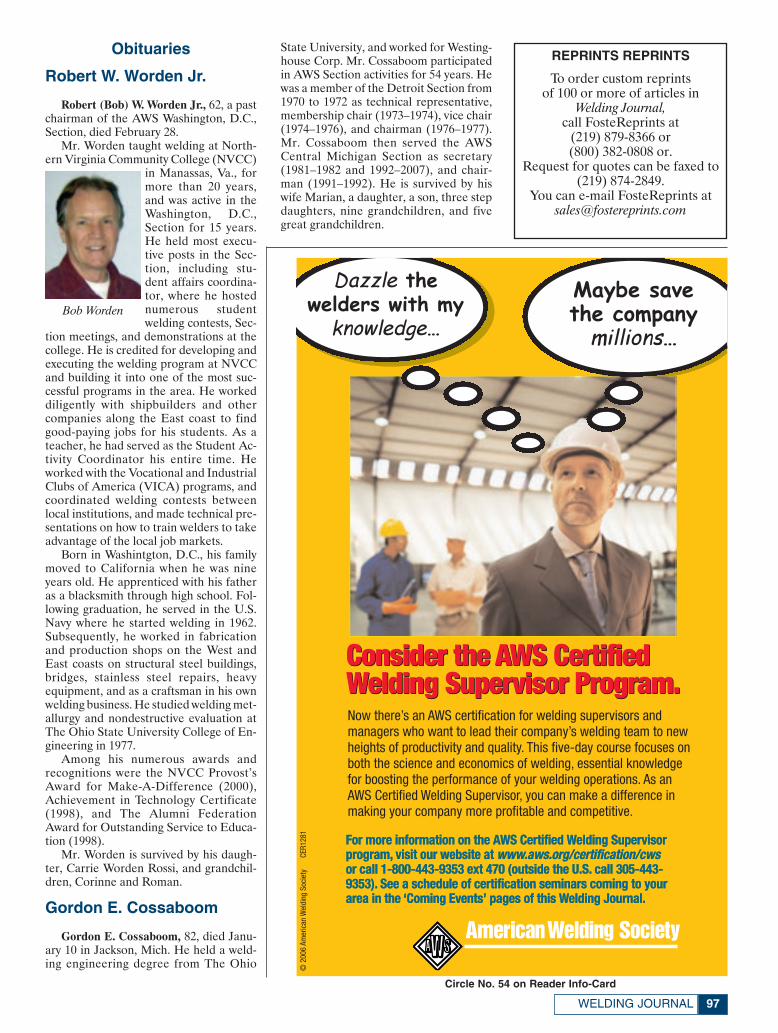
Obituaries
Robert W. Worden Jr.
Robert (Bob) W. Worden Jr., 62, a pastchairman of the AWS Washington, D.C.,Section, died February 28.
Mr. Worden taught welding at North-ern Virginia Community College (NVCC)
in Manassas, Va., formore than 20 years,and was active in theWashington, D.C.,Section for 15 years.He held most execu-tive posts in the Sec-tion, including stu-dent affairs coordina-tor, where he hostednumerous studentwelding contests, Sec-
tion meetings, and demonstrations at thecollege. He is credited for developing andexecuting the welding program at NVCCand building it into one of the most suc-cessful programs in the area. He workeddiligently with shipbuilders and othercompanies along the East coast to findgood-paying jobs for his students. As ateacher, he had served as the Student Ac-tivity Coordinator his entire time. Heworked with the Vocational and IndustrialClubs of America (VICA) programs, andcoordinated welding contests betweenlocal institutions, and made technical pre-sentations on how to train welders to takeadvantage of the local job markets.
Born in Washintgton, D.C., his familymoved to California when he was nineyears old. He apprenticed with his fatheras a blacksmith through high school. Fol-lowing graduation, he served in the U.S.Navy where he started welding in 1962.Subsequently, he worked in fabricationand production shops on the West andEast coasts on structural steel buildings,bridges, stainless steel repairs, heavyequipment, and as a craftsman in his ownwelding business. He studied welding met-allurgy and nondestructive evaluation atThe Ohio State University College of En-gineering in 1977.
Among his numerous awards andrecognitions were the NVCC Provost’sAward for Make-A-Difference (2000),Achievement in Technology Certificate(1998), and The Alumni FederationAward for Outstanding Service to Educa-tion (1998).
Mr. Worden is survived by his daugh-ter, Carrie Worden Rossi, and grandchil-dren, Corinne and Roman.
Gordon E. Cossaboom
Gordon E. Cossaboom, 82, died Janu-ary 10 in Jackson, Mich. He held a weld-ing engineering degree from The Ohio
State University, and worked for Westing-house Corp. Mr. Cossaboom participatedin AWS Section activities for 54 years. Hewas a member of the Detroit Section from1970 to 1972 as technical representative,membership chair (1973–1974), vice chair(1974–1976), and chairman (1976–1977).Mr. Cossaboom then served the AWSCentral Michigan Section as secretary(1981–1982 and 1992–2007), and chair-man (1991–1992). He is survived by hiswife Marian, a daughter, a son, three stepdaughters, nine grandchildren, and fivegreat grandchildren.
97WELDING JOURNAL
Now there’s an AWS certification for welding supervisors andmanagers who want to lead their company’s welding team to newheights of productivity and quality. This five-day course focuses onboth the science and economics of welding, essential knowledgefor boosting the performance of your welding operations. As anAWS Certified Welding Supervisor, you can make a difference inmaking your company more profitable and competitive.
©20
06Am
eric
anW
eldi
ngSo
ciet
yCE
R128
1
Dazzle thewelders with my
knowledge…
Maybe save the company millions…
Consider the AWS Certified Welding Supervisor Program.
For more information on the AWS Certified Welding Supervisorprogram, visit our website at www.aws.org/certification/cws or call 1-800-443-9353 ext 470 (outside the U.S. call 305-443-9353). See a schedule of certification seminars coming to yourarea in the ‘Coming Events’ pages of this Welding Journal.
Consider the AWS Certified Welding Supervisor Program.
Bob Worden
Circle No. 54 on Reader Info-Card
REPRINTS REPRINTS
To order custom reprints of 100 or more of articles in
Welding Journal,call FosteReprints at
(219) 879-8366 or(800) 382-0808 or.
Request for quotes can be faxed to(219) 874-2849.
You can e-mail FosteReprints at [email protected]
Personnel April:Layout 1 3/12/07 1:56 PM Page 97

©Am
eric
anW
eldi
ngSo
ciet
y20
07ES
V148
1S
Founded in 1919 to advance the science, technology and application of welding and allied joining and cuttingprocesses, including brazing, soldering and thermal spraying.
Conference on the Explosion of New ProcessesSan Diego • Doubletree Golf ResortAugust 14-15, 2007
Circle No. 11 on Reader Info-Card
Page 98-99:FP_TEMP 3/12/07 11:36 AM Page 98

Conference price is $550 for AWS members, $680 fornonmembers.To register or to receive a descriptive brochure,call (800) 443-9353 ext. 224, (outside North America, call 305-443-9353), or visit www.aws.org/conferences
Conference on the Explosion of New ProcessesSan Diego • Doubletree Golf Resort
August 14-15, 2007
The welding industry is now in the midst of anexplosion of new welding technologies, many ofwhich have made quick passage from the research lab to the production line. This kind of activity has not beenseen for decades. Presentations on many of thesetechnologies will form the body of this first-of-its-kindconference. Two of the main thrusts will exploreinteresting variations and improvements on lasertechnologies and on friction stir welding.
Friction Stir Welding and Processing—An Update ofRecent DevelopmentsWilliam J. Arbegast, Director, NSAF Center for FrictionStir Processing, and Director, Advanced MaterialsProcessing and Joining Center, South Dakota School ofMines and Technology
The Deformation Resistance Welding ProcessMenachem Kimchi, Technology Leader, Edison WeldingInstitute
A New Approach (Double Electrode) to HighProductivity GMAWDr. YuMing Zhang, James R. Boyd Professor, Director ofGraduate Studies, Center for Manufacturing,Department of Electrical and Computer Engineering,College of Engineering, University of Kentucky
Magnetic Pulse Welding Extends Its List ofApplicationsErik de Jongh, Vice President, Sales and FieldOperations, Pulsar Ltd.
The Fiber Laser Opens Up New Opportunities forLaser WeldingBill Shiner, Director, Industrial Market Development, IPGPhotonics Corp.
Ultrasonic Joining of Metals: Advances in Welding,Soldering and BrazingMatt Short, Project Engineer, Edison Welding Institute
Friction Stir Welding and Processing of AdvancedMaterials—Advances and ChallengesDr. S. A. David, Corporate Fellow and Group Leader,Materials Joining Group, Oak Ridge National Laboratory
Friction Stir Welded Components Are Headed toMarsMike Skinner, Business Development Manager, MTSSystems Corp.
Single-Sided Plasma Spot Welding and PlasmaBrazing Process—A Review of ApplicationsR. V. Hughes, Technical Director, Camarc LLC
Laser Stir Welding of Aluminum AlloysR. P. Martukanitz, Head, Laser Processing Division,Applied Research Laboratory, Pennsylvania StateUniversity; and Israel Stol, Senior ManufacturingSpecialist, Joining and Assembly, Alcoa Technical Center
Novel Heat Source Enables Brazing at RoomTemperatureDr. Timothy P. Weihs, President, ReactiveNanoTechnologies Inc.
CSC-Controlled Short Circuit Transfer—A NewGMAW Process That Solves Old Weld ProblemsTom Rankin, Vice President and General Manager, ITWJetline Engineering
A New Process (Ultrasonic Impact Treatment) forImproving Fatigue Strength of WeldsSougata Roy, Research Scientist III, ATLSS Center,Lehigh University
Page 98-99:FP_TEMP 3/12/07 11:37 AM Page 99
Friends and Colleagues:
I want to encourage you to submit nomination packages for those individuals whom you feel havea history of accomplishments and contributions to our profession consistent with the standards set by theexisting Fellows. In particular, I would make a special request that you look to the most senior membersof your Section or District in considering members for nomination. In many cases, the colleagues andpeers of these individuals who are the most familiar with their contributions, and who would normallynominate the candidate, are no longer with us. I want to be sure that we take the extra effort required tomake sure that those truly worthy are not overlooked because no obvious individual was available to startthe nomination process.
For specifics on the nomination requirements, please contact Wendy Sue Reeve at AWSheadquarters in Miami, or simply follow the instructions on the Fellows nomination form in this issue ofthe Welding Journal. Please remember, we all benefit in the honoring of those who have made majorcontributions to our chosen profession and livelihood. The deadline for submission is July 1, 2007. TheCommittee looks forward to receiving numerous Fellow nominations for 2008 consideration.
Sincerely,
Nancy C. ColeChair, AWS Fellows Selection Committee
AmericanWelding Society
Fellow Letter:Layout 1 3/12/07 3:55 PM Page 100
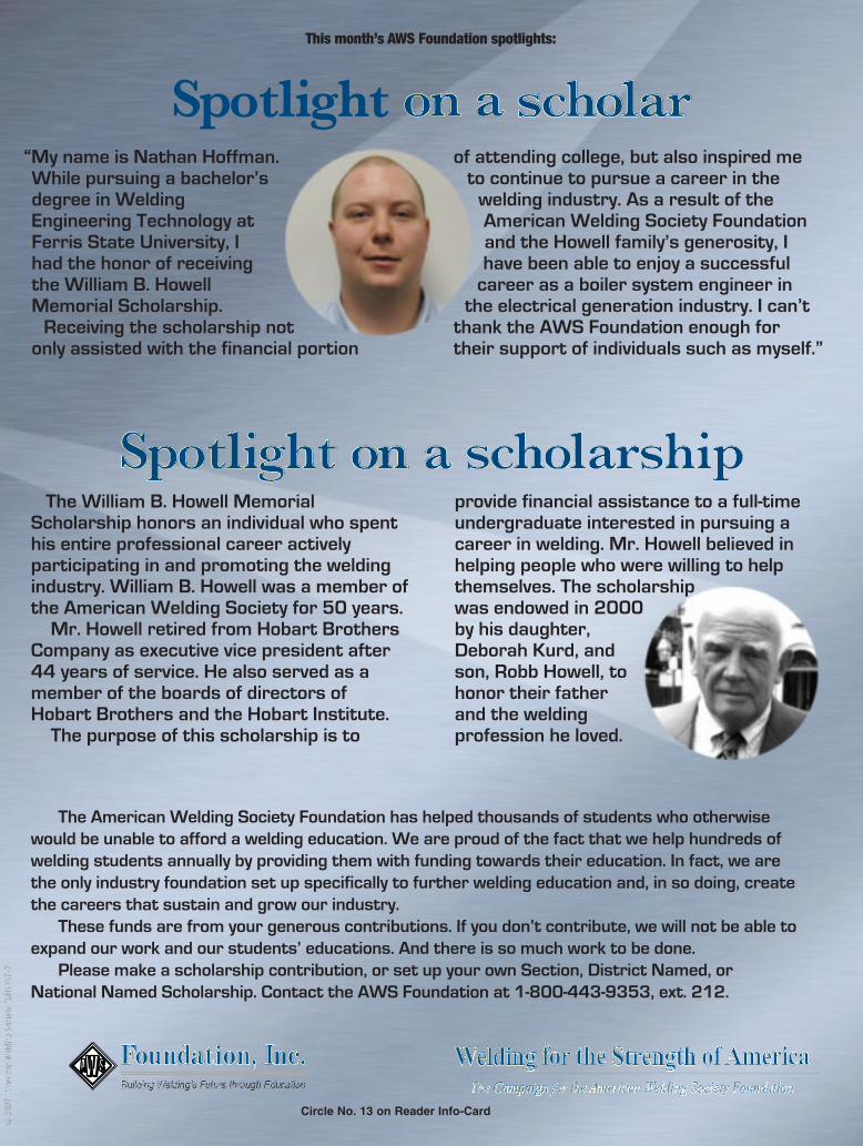
©20
07Am
eric
anW
eldi
ngSo
ciet
yFD
N139
7-7
The American Welding Society Foundation has helped thousands of students who otherwisewould be unable to afford a welding education. We are proud of the fact that we help hundreds ofwelding students annually by providing them with funding towards their education. In fact, we arethe only industry foundation set up specifically to further welding education and, in so doing, createthe careers that sustain and grow our industry.
These funds are from your generous contributions. If you don’t contribute, we will not be able toexpand our work and our students’ educations. And there is so much work to be done.
Please make a scholarship contribution, or set up your own Section, District Named, orNational Named Scholarship. Contact the AWS Foundation at 1-800-443-9353, ext. 212.
“My name is Nathan Hoffman.While pursuing a bachelor’sdegree in WeldingEngineering Technology atFerris State University, Ihad the honor of receivingthe William B. HowellMemorial Scholarship.
Receiving the scholarship notonly assisted with the financial portion
of attending college, but also inspired meto continue to pursue a career in the
welding industry. As a result of theAmerican Welding Society Foundationand the Howell family’s generosity, Ihave been able to enjoy a successful
career as a boiler system engineer inthe electrical generation industry. I can’t
thank the AWS Foundation enough fortheir support of individuals such as myself.”
The William B. Howell MemorialScholarship honors an individual who spenthis entire professional career activelyparticipating in and promoting the weldingindustry. William B. Howell was a member ofthe American Welding Society for 50 years.
Mr. Howell retired from Hobart BrothersCompany as executive vice president after44 years of service. He also served as amember of the boards of directors ofHobart Brothers and the Hobart Institute.
The purpose of this scholarship is to
provide financial assistance to a full-timeundergraduate interested in pursuing acareer in welding. Mr. Howell believed inhelping people who were willing to helpthemselves. The scholarshipwas endowed in 2000by his daughter,Deborah Kurd, andson, Robb Howell, tohonor their fatherand the weldingprofession he loved.
Welding for the Strength of AmericaThe Campaign for the American Welding Society Foundation
This month’s AWS Foundation spotlights:
Spotlight on a scholar
Spotlight on a scholarship
Circle No. 13 on Reader Info-Card
Page 103:FP_TEMP 3/12/07 11:41 AM Page 103
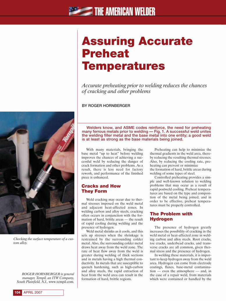
THE AMERICAN WELDER
APRIL 2007104
With many materials, bringing thebase metal “up to heat” before weldingimproves the chances of achieving a suc-cessful weld by reducing the danger ofcrack formation and other problems. As aresult, there is less need for factoryrework, and performance of the finishedpiece is enhanced.
Cracks and How They Form
Weld cracking may occur due to ther-mal stresses imposed on the weld metaland adjacent heat-affected zones. Inwelding carbon and alloy steels, crackingoften occurs in conjunction with the for-mation of hard, brittle areas — the resultof rapid cooling during welding and thepresence of hydrogen.
Weld metal shrinks as it cools, and thissets up stresses when the shrinkage isrestrained by the surrounding coldermetal. Also, the surrounding colder metaldraws heat away from the weld zone. Therate of heat flow away from the weld isgreater during welding of thick sectionsand in metals having a high thermal con-ductivity. In metals that are susceptible toquench hardening, such as high-carbonand alloy steels, the rapid extraction ofheat from the weld area can result in theformation of hard, brittle regions.
Preheating can help to minimize thethermal gradients in the weld area, there-by reducing the resulting thermal stresses.Also, by reducing the cooling rate, pre-heating can prevent or minimizethe formation of hard, brittle areas duringwelding of some types of steel.
Controlled preheating provides a sim-ple and well-known solution to weldingproblems that may occur as a result ofrapid postweld cooling. Preheat tempera-tures are based on the type and composi-tion of the metal being joined, and inorder to be effective, preheat tempera-tures must be properly controlled.
The Problem withHydrogen
The presence of hydrogen greatlyincreases the possibility of cracking in theweld metal or heat-affected zone in weld-ing carbon and alloy steels. Root cracks,toe cracks, underbead cracks, and trans-verse cracks are all common, given ther-mal stress and the presence of hydrogen.
In welding these materials, it is impor-tant to keep hydrogen away from the weldarea. Hydrogen can come from electrodecoatings, fluxes, base-metal contamina-tion — even the atmosphere — and, inthe case of a repair weld, from materialswhich were contained or handled by the
Assuring AccuratePreheatTemperatures
Accurate preheating prior to welding reduces the chancesof cracking and other problems
BY ROGER HORNBERGER
ROGER HORNBERGER is generalmanager, Tempil, an ITW Company,
South Plainfield, N.J., www.tempil.com.
Checking the surface temperature of a cus-tom alloy.
Welders know, and ASME codes reinforce, the need for preheatingmany ferrous metals prior to welding — Fig. 1. A successful weld unitesthe welding filler metal and the base metal into one entity; a good weldis at least as strong as the base materials being joined.
Hornberger Feature April 2007:Layout 1 3/8/07 3:55 PM Page 104
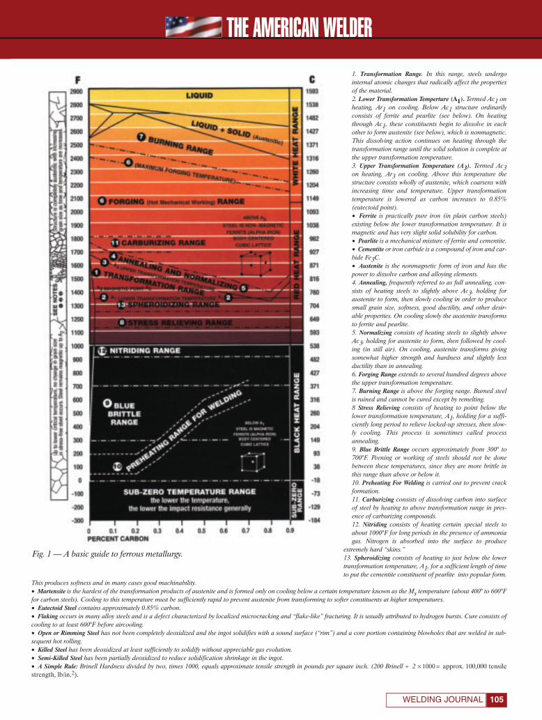
THE AMERICAN WELDER
105WELDING JOURNAL
1. Transformation Range. In this range, steels undergointernal atomic changes that radically affect the propertiesof the material.2. Lower Transformation Temperture (A1). Termed Ac1 onheating, Ar1 on cooling. Below Ac1 structure ordinarilyconsists of ferrite and pearlite (see below). On heatingthrough Ac1, these constituents begin to dissolve in eachother to form austenite (see below), which is nonmagnetic.This dissolving action continues on heating through thetransformation range until the solid solution is complete atthe upper transformation temperature. 3. Upper Transformation Temperature (A3). Termed Ac3on heating, Ar3 on cooling. Above this temperature thestructure consists wholly of austenite, which coarsens withincreasing time and temperature. Upper transformationtemperature is lowered as carbon increases to 0.85%(eutectoid point).• Ferrite is practically pure iron (in plain carbon steels)existing below the lower transformation temperature. It ismagnetic and has very slight solid solubility for carbon.• Pearlite is a mechanical mixture of ferrite and cementite.• Cementite or iron carbide is a compound of iron and car-bide Fe3C.• Austenite is the nonmagnetic form of iron and has thepower to dissolve carbon and alloying elements.4. Annealing, frequently referred to as full annealing, con-sists of heating steels to slightly above Ac3, holding foraustenite to form, then slowly cooling in order to producesmall grain size, softness, good ductility, and other desir-able properties. On cooling slowly the austenite transformsto ferrite and pearlite.5. Normalizing consists of heating steels to slightly aboveAc3, holding for austenite to form, then followed by cool-ing (in still air). On cooling, austenite transforms givingsomewhat higher strength and hardness and slightly lessductility than in annealing. 6. Forging Range extends to several hundred degrees abovethe upper transformation temperature.7. Burning Range is above the forging range. Burned steelis ruined and cannot be cured except by remelting.8 Stress Relieving consists of heating to point below thelower transformation temperature, A1, holding for a suffi-ciently long period to relieve locked-up stresses, then slow-ly cooling. This process is sometimes called processannealing.9. Blue Brittle Range occurs approximately from 300° to700°F. Peening or working of steels should not be donebetween these temperatures, since they are more brittle inthis range than above or below it.10. Preheating For Welding is carried out to prevent crackformation.11. Carburizing consists of dissolving carbon into surfaceof steel by heating to above transformation range in pres-ence of carburizing compounds.12. Nitriding consists of heating certain special steels toabout 1000°F for long periods in the presence of ammoniagas. Nitrogen is absorbed into the surface to produce
extremely hard “skins.”13. Spheroidizing consists of heating to just below the lowertransformation temperature, A1, for a sufficient length of timeto put the cementite constituent of pearlite into popular form.
This produces softness and in many cases good machinability.• Martensite is the hardest of the transformation products of austenite and is formed only on cooling below a certain temperature known as the Ms temperature (about 400° to 600°Ffor carbon steels). Cooling to this temperature must be sufficiently rapid to prevent austenite from transforming to softer constituents at higher temperatures.• Eutectoid Steel contains approximately 0.85% carbon.• Flaking occurs in many alloy steels and is a defect characterized by localized microcracking and “flake-like” fracturing. It is usually attributed to hydrogen bursts. Cure consists ofcooling to at least 600°F before aircooling.• Open or Rimming Steel has not been completely deoxidized and the ingot solidifies with a sound surface (“rim”) and a core portion containing blowholes that are welded in sub-sequent hot rolling.• Killed Steel has been deoxidized at least sufficiently to solidify without appreciable gas evolution.• Semi-Killed Steel has been partially deoxidized to reduce solidification shrinkage in the ingot.• A Simple Rule: Brinell Hardness divided by two, times 1000, equals approximate tensile strength in pounds per square inch. (200 Brinell ÷ 2 × 1000 = approx. 100,000 tensilestrength, lb/in.2).
Fig. 1 — A basic guide to ferrous metallurgy.
Hornberger Feature April 2007:Layout 1 3/8/07 3:57 PM Page 105
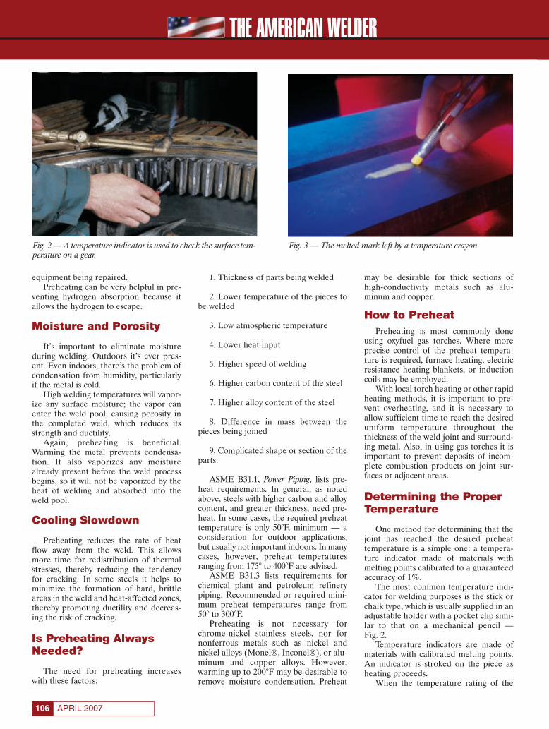
THE AMERICAN WELDER
APRIL 2007106
equipment being repaired.Preheating can be very helpful in pre-
venting hydrogen absorption because itallows the hydrogen to escape.
Moisture and Porosity
It’s important to eliminate moistureduring welding. Outdoors it’s ever pres-ent. Even indoors, there’s the problem ofcondensation from humidity, particularlyif the metal is cold.
High welding temperatures will vapor-ize any surface moisture; the vapor canenter the weld pool, causing porosity inthe completed weld, which reduces itsstrength and ductility.
Again, preheating is beneficial.Warming the metal prevents condensa-tion. It also vaporizes any moisturealready present before the weld processbegins, so it will not be vaporized by theheat of welding and absorbed into theweld pool.
Cooling Slowdown
Preheating reduces the rate of heatflow away from the weld. This allowsmore time for redistribution of thermalstresses, thereby reducing the tendencyfor cracking. In some steels it helps tominimize the formation of hard, brittleareas in the weld and heat-affected zones,thereby promoting ductility and decreas-ing the risk of cracking.
Is Preheating AlwaysNeeded?
The need for preheating increaseswith these factors:
1. Thickness of parts being welded
2. Lower temperature of the pieces tobe welded
3. Low atmospheric temperature
4. Lower heat input
5. Higher speed of welding
6. Higher carbon content of the steel
7. Higher alloy content of the steel
8. Difference in mass between thepieces being joined
9. Complicated shape or section of theparts.
ASME B31.1, Power Piping, lists pre-heat requirements. In general, as notedabove, steels with higher carbon and alloycontent, and greater thickness, need pre-heat. In some cases, the required preheattemperature is only 50°F, minimum — aconsideration for outdoor applications,but usually not important indoors. In manycases, however, preheat temperaturesranging from 175° to 400°F are advised.
ASME B31.3 lists requirements forchemical plant and petroleum refinerypiping. Recommended or required mini-mum preheat temperatures range from50° to 300°F.
Preheating is not necessary forchrome-nickel stainless steels, nor fornonferrous metals such as nickel andnickel alloys (Monel®, Inconel®), or alu-minum and copper alloys. However,warming up to 200°F may be desirable toremove moisture condensation. Preheat
may be desirable for thick sections ofhigh-conductivity metals such as alu-minum and copper.
How to PreheatPreheating is most commonly done
using oxyfuel gas torches. Where moreprecise control of the preheat tempera-ture is required, furnace heating, electricresistance heating blankets, or inductioncoils may be employed.
With local torch heating or other rapidheating methods, it is important to pre-vent overheating, and it is necessary toallow sufficient time to reach the desireduniform temperature throughout thethickness of the weld joint and surround-ing metal. Also, in using gas torches it isimportant to prevent deposits of incom-plete combustion products on joint sur-faces or adjacent areas.
Determining the ProperTemperature
One method for determining that thejoint has reached the desired preheattemperature is a simple one: a tempera-ture indicator made of materials withmelting points calibrated to a guaranteedaccuracy of 1%.
The most common temperature indi-cator for welding purposes is the stick orchalk type, which is usually supplied in anadjustable holder with a pocket clip simi-lar to that on a mechanical pencil — Fig. 2.
Temperature indicators are made ofmaterials with calibrated melting points.An indicator is stroked on the piece asheating proceeds.
When the temperature rating of the
Fig. 2 — A temperature indicator is used to check the surface tem-perature on a gear.
Fig. 3 — The melted mark left by a temperature crayon.
Hornberger Feature April 2007:Layout 1 3/8/07 3:58 PM Page 106
THE AMERICAN WELDER
107WELDING JOURNAL
selected indicator is reached, the dryopaque mark undergoes a phase changeto a distinct melted appearance — Fig. 3.
Phase-Change Accuracy
A wide variety of electric, electronic,infrared, and other instrumentation isavailable for temperature determination.However, none of these methods is wide-ly employed in welding. Phase-changetemperature indicators are preferredbecause they are accurate, simple to use,inexpensive, and make good thermalequilibrium with the surface to which theyare in contact — Fig. 4.
Melting point, the temperature wherephase change occurs, is a physical proper-ty of the raw material. It is not influencedby static electricity, ionized air, humidity,or being dropped on the floor — factorsthat can make electrical and electronicinstrumentation function erratically. Nosetup time, calibration, and recalibrationare required, and no operator training or
experience are neces-sary. All the operatorhas to do is observethat the chalk markhas melted. The indi-cators are accuratewithin 1% of theirstated temperatureratings measured inaccordance withM T L - S T D - 4 5 6 6 2 .The materials usedare calibrated onapparatus traceable tothe National Instituteof Standards &Technology.
Many practitionersconsider welding anart as well as a sci-ence. Two or morepieces of metal are joined, with a bondthat is as strong or stronger than the com-ponent materials. But in order to achievethis, weld quality must be good.
Preheating is often necessary. With theready availability of accurate, inexpensivetemperature indicators, the correct pre-heat temperature can be assured.♦
Fig. 4 — A welder uses a temperature crayon to mark a piece closeto a weld.
Circle No. 16 on Reader Info-Card
Hornberger Feature April 2007:Layout 1 3/8/07 3:59 PM Page 107

Conference price is $550 for AWS members, $680 fornonmembers.To register or to receive a descriptive brochure,call (800) 443-9353 ext. 224, (outside North America, call 305-443-9353), or visit www.aws.org/conferences
Weld cracking is everybody’s problem and there is more than one way to tackle it. The popular AWS-sponsoredWeld Cracking Conference will move to Las Vegas this fall. Now known as Weld Cracking VI, this conference will differfrom previous weld cracking conferences, with greater emphasis on the role of the heat-affected zone in suchproblems. Many solutions will be presented.
©Am
eric
anW
eldi
ngSo
ciet
y20
07ES
V149
3
Founded in 1919 to advance the science, technology and application of welding and allied joining and cuttingprocesses, including brazing, soldering and thermal spraying.
Conference on Weld CrackingLas Vegas • Imperial Palace Hotel & CasinoOctober 16-17, 2007
Circle No. 9 on Reader Info-Card
Page 108:FP_TEMP 3/13/07 9:55 AM Page 108
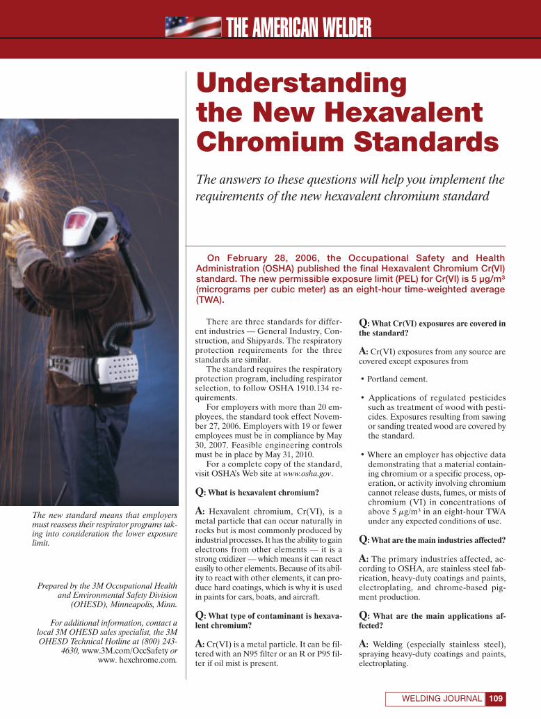
THE AMERICAN WELDER
109WELDING JOURNAL
There are three standards for differ-ent industries — General Industry, Con-struction, and Shipyards. The respiratoryprotection requirements for the threestandards are similar.
The standard requires the respiratoryprotection program, including respiratorselection, to follow OSHA 1910.134 re-quirements.
For employers with more than 20 em-ployees, the standard took effect Novem-ber 27, 2006. Employers with 19 or feweremployees must be in compliance by May30, 2007. Feasible engineering controlsmust be in place by May 31, 2010.
For a complete copy of the standard,visit OSHA’s Web site at www.osha.gov.
Q: What is hexavalent chromium?
A: Hexavalent chromium, Cr(VI), is ametal particle that can occur naturally inrocks but is most commonly produced byindustrial processes. It has the ability to gainelectrons from other elements — it is astrong oxidizer — which means it can reacteasily to other elements. Because of its abil-ity to react with other elements, it can pro-duce hard coatings, which is why it is usedin paints for cars, boats, and aircraft.
Q: What type of contaminant is hexava-lent chromium?
A: Cr(VI) is a metal particle. It can be fil-tered with an N95 filter or an R or P95 fil-ter if oil mist is present.
Q: What Cr(VI) exposures are covered inthe standard?
A: Cr(VI) exposures from any source arecovered except exposures from
• Portland cement.
• Applications of regulated pesticidessuch as treatment of wood with pesti-cides. Exposures resulting from sawingor sanding treated wood are covered bythe standard.
• Where an employer has objective datademonstrating that a material contain-ing chromium or a specific process, op-eration, or activity involving chromiumcannot release dusts, fumes, or mists ofchromium (VI) in concentrations ofabove 5 μg/m³ in an eight-hour TWAunder any expected conditions of use.
Q: What are the main industries affected?
A: The primary industries affected, ac-cording to OSHA, are stainless steel fab-rication, heavy-duty coatings and paints,electroplating, and chrome-based pig-ment production.
Q: What are the main applications af-fected?
A: Welding (especially stainless steel),spraying heavy-duty coatings and paints,electroplating.
Understandingthe New HexavalentChromium StandardsThe answers to these questions will help you implement therequirements of the new hexavalent chromium standard
Prepared by the 3M Occupational Healthand Environmental Safety Division
(OHESD), Minneapolis, Minn.
For additional information, contact alocal 3M OHESD sales specialist, the 3MOHESD Technical Hotline at (800) 243-
4630, www.3M.com/OccSafety orwww. hexchrome.com.
On February 28, 2006, the Occupational Safety and Health
Administration (OSHA) published the final Hexavalent Chromium Cr(VI)
standard. The new permissible exposure limit (PEL) for Cr(VI) is 5 μg/m³
(micrograms per cubic meter) as an eight-hour time-weighted average
(TWA).
The new standard means that employersmust reassess their respirator programs tak-ing into consideration the lower exposurelimit.
3M Amweld Feature April 2007:Layout 1 3/8/07 4:04 PM Page 109
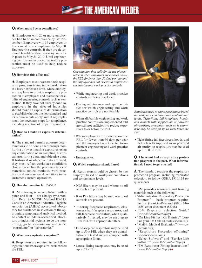
Q: When must I be in compliance?
A: Employers with 20 or more employ-ees had to be in compliance by last No-vember. Employers with 19 employees orfewer must be in compliance by May 30.Engineering controls, if they are deter-mined feasible and/or necessary, must bein place by May 31, 2010. Until engineer-ing controls are in place, respiratory pro-tection must be used to help reduce exposure.
Q: How does this affect me?
A: Employers must reassess their respi-rator programs taking into considerationthe lower exposure limit. More employ-ers may have to provide respiratory pro-tection to employees and assess the feasi-bility of engineering controls such as ven-tilation. If they have not already done so,employers in the affected industriesshould make an exposure determinationto establish whether the new standard andits requirements apply and, if so, imple-ment the necessary steps for compliance,including selection of proper respirators.
Q: How do I make an exposure determi-nation?
A: The standard permits exposure deter-minations to be done either through mon-itoring or by estimating exposures usingany combination of air sampling, histori-cal monitoring data, and objective data.If historical or objective data are used,they must reflect workplace conditionsclosely resembling the processes, types ofmaterials, control methods, work prac-tices, and environmental conditions in thecustomer’s current operations.
Q: How do I monitor for Cr(VI)?
A: Monitoring is accomplished with apump and filter — not a badge-type mon-itor. Refer to NIOSH Method ID-215.Consult an American Industrial HygieneAssociation (AIHA) accredited labora-tory for assistance in selection of the ap-propriate sampling and analytical method.To contact an AIHA-accredited labora-tory or industrial hygienist to do the mon-itoring, go to www.aiha.org and select“consultants” or “laboratories.”
Q: When are respirators required?
A: Respirators are required in the follow-ing situations when exposure levels exceedthe PEL:
• While engineering and work practicecontrols are being developed.
• During maintenance and repair activi-ties for which engineering and workpractice controls are not feasible.
• When all feasible engineering and workpractice controls are implemented andare still not sufficient to reduce expo-sures to or below the PEL.
• When employees are exposed above thePEL for fewer than 30 days per yearand the employer has not elected to im-plement engineering and work practicecontrols.
• Emergencies.
Q: Which respirator should I use?
A: Respirators should be chosen by theemployer based on workplace conditionsand contaminant levels.
• N95 filters may be used where no oilaerosols are present.
• R or P95 filters may be used where oilaerosols are present.
• Filtering-facepiece respirators, elas-tomeric half-facepiece respirators, andfull-facepiece respirators, when quali-tatively fit tested, may be used up to 10 × PEL with appropriate filters.
• Full-facepiece respirators may be usedup to 50 × PEL when they are quanti-tatively fit tested and are equipped withappropriate filters.
• Loose-fitting facepieces may be usedup to 25 × PEL.
• Tight-fitting full facepieces, hoods, andhelmets with supplied air or poweredair-purifying respirators may be usedup to 1000 × PEL.
Q: I have not had a respiratory protec-tion program in the past. What informa-tion do I need to get started?
A: The standard requires the respiratoryprotection program, including respiratorselection, to follow OSHA 1910.134 re-quirements.
3M provides resources and trainingmaterials such as the following:• “Administrative Respiratory Protection
Program” — basic program require-ments. (Fax-On-Demand (800) 646-1655, enter document #2018)
• “3M Respirator Selection Guide”(www.3M.com/OccSafety)
• “On Line Fit Test Kit Training” (con-tact your 3M OHESD sales specialist)
• “Mail-in Medical Evaluation” (www.re-spexam.com)
• “Respiratory Protection eTraining”(www.respexam.com)
• “Select Software” and “Service LifeSoftware” (www.3M.com/OccSafety)
• “3M Respirator Fitting Instructions”(www.3M.com/OccSafety)♦
Employers need to choose respirators basedon workplace conditions and contaminantlevels. Tight-fitting full facepieces, hoods,and helmets with supplied-air or poweredair-purifying respirators such as is shownhere may be used for up to 1000 times thePEL.
One situation that calls for the use of respi-rators is when employees are exposed abovethe PEL for fewer than 30 days per year andthe employer has not elected to implementengineering and work practice controls.
APRIL 2007110
THE AMERICAN WELDER
3M Amweld Feature April 2007:Layout 1 3/8/07 4:04 PM Page 110
CHICAGO 2007
NOVEMBER 11 — 14, 2007
McCORMICK PLACE
CHICAGO, ILLINOIS USA
North America’s Largest Metal Forming,
Fabricating & Welding Trade Show Is Back
in Chicago for 2007.
Reserve your booth now! Space is limited.
Call today for details, 800-443-9353 ext. 297
Complete exhibit details at www.aws.org/show
SAVE THE DATES!
BROUGHT TO YOU BY
THE INDUSTRY LEADERS
photo courtesy of Jason Bartholme, ©2006
Circle No. 12 on Reader Info-Card
Page 111:FP_TEMP 3/12/07 11:59 AM Page 111

THE AMERICAN WELDER
APRIL 2007112
The two students attend the programat the FRCC Larimer Campus in FortCollins, Colo. It is one of twelve differentprograms offered to juniors and seniorsfrom public high schools in Larimer andWeld counties.
To get accepted, Kolarek and Farrandeach had to fill out an application and beselected by their home high schools. Theywere each awarded a $2800 scholarshipfrom the Poudre School District to attendthe program.
Interest in the Field
Kolarek is originally from New York.Her mother Christine Nossoughi, a sculp-tor, used to take her to the foundry as achild.
“I would watch them pour the meltedbronze into the sculpture molds and thenweld together the pieces,” Kolarek said. “Ialways had somewhat of an interestbecause to me it was so amazing to watch.”
Kolarek moved to Fort Collins in 1999.She decided to pursue the Ironworking andIndustrial Welding program because shethought welding would be a great skill tohave and it would be a way to get morefamiliar with foundry work. At the time,her family had an 11-acre farm, so shethought knowing how to weld would beuseful to help her fix items there.
On the other hand, Farrand is origi-nally from Fort Collins. She has watchedher father Greg Farrand, a large-animalveterinarian, weld items for his business,Northern Colorado Veterinary Services,and around the family’s house, ever sinceshe can remember.
“When I was little I loved just puttingon a helmet and watching him work,”Farrand said. “It looked like fun.”
She wanted to get into the program be-cause she thought welding was a skill thatcould come in handy later on in life.
Program Details
The Ironworking and IndustrialWelding program started five years ago inresponse to a request from Rocky Turner,the president of LPR Construction Co. inLoveland, Colo. He came to The HighSchool Programs with this idea becausehe was short on employees. Today, thiscompany, along with many others,recruits students who have completed theprogram to work for them.
“We’re preparing students to be ableto put on their green hats, their hard hats,put on all their ironworking equipment,and be able to walk on the job with entry-level skills,” Dr. Gary Cagle, executive di-rector of The High School ScholarshipPrograms at FRCC, said.
College ProgramGrooms HighSchoolers forWelding CareersThrough a special noncredit college program, high schoolstudents Ashley Kolarek and Molly Farrand haveexperienced the exciting fields of ironworking and welding
BY KRISTIN CAMPBELL
KRISTIN CAMPBELL([email protected]) is assistant editor
of the Welding Journal.
Fig. 1 — A — Ashley Kolarek (left) andMolly Farrand are sitting on I-beams andcolumns built into a structure. The setupsimulates a real work site. They are attachedto body harnesses and safety cables. B —Farrand practices gas metal arc welding onscraps of metal.
Ambitious high school juniors Ashley Kolarek and Molly Farrand, both
16, are eager to learn and be successful in all they do. Currently, they
are the only two females in the Ironworking and Industrial Welding pro-
gram available through The High School Programs at Front Range Com-
munity College (FRCC) — Fig. 1A, B.
A
B
AW April 2007 feature on Colorado girls:Layout 1 3/8/07 3:44 PM Page 112

THE AMERICAN WELDER
113WELDING JOURNAL
The two-semester program takes placeMonday through Friday from 8 to 10 a.m.(Mountain Time). Because it serves as anextension of the students’ home highschool experience, college credit is not re-ceived for finishing it.
Kolarek and Farrand started the pro-gram in August 2006, and when they com-plete it this May, they will receive a one-year completion certificate listing all thecompetencies they have learned.
Hands-On Experience
Students spend a majority of theirclass time at FRCC’s 4600-sq-ft weldinglab — Fig. 2. The lab underwent a$400,000 renovation, completed inSeptember 2005; this included installing anew ventilation system and buying newmachines. However, the lab’s walls werenot expanded, and the floor design didnot change. “The state of Colorado doesnot allow you to do that,” Cagle said.
The lab has twelve traditional shieldedmetal arc welding (SMAW) stations,twelve gas metal arc welding (GMAW)stations, and eight gas tungsten arc weld-ing (GTAW) stations. Numerous brandsof equipment are available for use here.
This particular program is limited to20 students a year and can only be takenonce. “We have a large waiting list,” Caglesaid. “We could probably double our en-rollment if we had the space.”
Ruben Vinton, Jason Walsh, and KeithDowney are the program’s instructors.Kolarek and Farrand are glad for theirguidance.
“They want to see all the students suc-ceed in welding, so they do all that theycan to make us excellent welders,” Far-rand said.
So far, Kolarek and Farrand havelearned SMAW, GMAW, and GTAW. Pri-marily they weld on steel. They also havelearned how to weld in different positionssuch as horizontal, uphill, and overhead.
“It’s probably 95% hands on,” Caglesaid. Kolarek and Farrand really like thisaspect of the program.
“I learn much better with getting outthere in the shop and being able to go atmy own pace learning from my own mis-takes as well,” Kolarek said.
In addition, they have learned to cutmetal with an oxyacetylene torch using reg-ular and scarfing tips, to use a track torchand cut with a plasma torch, and to use dif-ferent machines to cut metal — Fig. 3.
Kolarek and Farrand have also gainedan understanding for building steel struc-tures. In fact, outside the welding lab thereis a small-scale steel structure that is being
expanded into a large steel structure.In the classroom, they study modules
on topics such as metallurgy.They hope to become qualified soon
and are working hard on perfecting theirtechniques. Kolarek and Farrand wouldboth like to be qualified in overhead anduphill using SMAW.
Important Aspects
“We stress a work ethic here, whichalso makes us unique,” Cagle said, refer-ring to the Applied Work Ethics Program.This educates students in the importanceof cultivating ten key traits, such as atten-dance, respect, and teamwork. They evenget a grade for this course.
Safety is another area that is stressed.Students must wear the proper weldingattire; understand fall-protection setupand inspection of fall-protection devices/systems; learn about the OccupationalSafety and Heath Administration regula-tions; and participate in the CSUChallenge Course to develop coordinationand physical stamina.
Thus far, 97 males and 3 females havecompleted this program. Based on follow-up surveys, when former students firstcame into this program, only about 30%wanted to go on to college or pursueadditional postsecondary education.After completing the program, about65% go on to earn a two- or four-yeardegree or join the military.
About one-third of the class immedi-ately goes to work upon graduation. “Iwould say our success rate is about fourout of every 20 make it a career pathway,”Cagle said.
More information about The HighSchool Programs can be obtained throughFRCC’s Web site at www.frontrange.edu.
Being a Female Welder
Kolarek and Farrand are not intimi-dated being the only two females in theprogram. They both think the males havethe potential to become great welders.
“I look at it as competition for me todo my best and give it my all,” Kolareksaid. She mentioned the males give herand Farrand tips on how to weld betterbeads and offer encouragement.
“With these boys having so much tal-ent in welding, it makes me strive to domy best,” Farrand added. She said a lot ofthe males are helpful and supportive.
“I like being a woman welder,” Kolareksaid. “To me, it’s no different except for thefact that I am barely 5 feet tall and am tinyfor my age. The only challenge I have is
being so small so I can’t carry those hugetanks of gas or oxygen, but overall I am verystrong for my size.”
Farrand enjoys it, too.“Being a womanwelder is not very different from anythingelse I do,” she said. “I can’t really think ofany challenges that I have encountered.It is really easy being one of the only girls.”
Busy Schedules
After finishing the program in themorning, Kolarek goes to RockyMountain High School in Fort Collins
Fig. 2 — Ironworking student Andy Keirnsfrom Loveland High School in Loveland,Colo., is performing a shielded metal arcqualification weld on an overhead V-groovewith a backing plate.
Fig. 3 — Farrand (left) and Kolarek areusing the oxyacetylene cutting process to cuta 45-deg bevel on 3⁄8-in. plate. These platesare set up with a backing plate to practicewelding on either uphill or overhead position.
AW April 2007 feature on Colorado girls:Layout 1 3/8/07 3:45 PM Page 113
THE AMERICAN WELDER
APRIL 2007114
and takes Spanish, English literature, andhumanities.
Kolarek now lives on a three-acrefarm, where she enjoys taking care of thefamily’s pets, including four SouthAfrican Boerboel dogs, two ponies, andthree horses. In her free time she hangsout with friends, draws, and paints.
Farrand attends Fossil Ridge HighSchool, also located in Fort Collins, in theafternoon. There she takes anatomy andphysiology, math, U.S. literature, and U.S.history.
She loves spending time with her fam-ily, including her sister and two littlecousins, working out, hanging out withfriends, watching all kinds of sports,working a part-time job at Espresso DiCincotta, a coffee shop, and helping herfather work on animals.
Applying Welding to Real Life
Recently, Kolarek welded a steel plateusing SMAW to cover a drainage hole inthe warehouse of Poudre Pet & Feed
Supply, where she holds a part-time job,that the forklift kept getting its wheelstuck in.
Her employer appreciates this. “It’sbeen great ever since,” Kolarek said. “Wehaven’t had any problems because of it.”
Farrand has helped her father welditems for his veterinary business. He hasone GMAW and two SMAW machines.She has used GMAW to fix corrals, as wellas repair chutes for the cattle and stallsfor horses.
“He gets really excited when I can goout there and actually help him,” she said.
Future Aspirations
For her senior year of high school,Kolarek would like to get into The HighSchool Programs Industrial and DesignTechnology program.
For college, Kolarek would like toattend The Cooper Union for theAdvancement of Science and Art in NewYork, N.Y. She is not really sure whatkind of art-related career she wants topursue, but she definitely wants a degreein business.
Afterward, she would like to comeback to Fort Collins and start her ownbusiness to sell her art.
“I’d like to get into metal art,” she saidand work with aluminum, stainless steel,and bronze. “I think that would be reallyneat to do, now that I know how to weld.”
She may even start working with afoundry. “Welding is a great skill and willcome in handy throughout my entire life,”Kolarek said.
Farrand wants to be in The HighSchool Programs Med-Prep CertifiedNurse Aide program her senior year ofhigh school.
“In the near future, I hope to go to col-lege and study nursing, specifically laborand delivery,” she said. “I also am goingto join the United States Air Force.”
Farrand will not forget what she haslearned in welding. “When I get older andcan afford welding equipment, I hope tobe able to make things for fun and maybesell them somewhere,” she said.
Farrand would like to use welding onthe ranch she plans to have someday inWalden, Colo. “I am planning on usingwelding all through my life,” she said.♦
Circle No. 14 on Reader Info-Card
AW April 2007 feature on Colorado girls:Layout 1 3/8/07 3:45 PM Page 114

Circle No. 27 on Reader Info-Card
EASTEC:FP_TEMP 3/9/07 5:11 PM Page 115
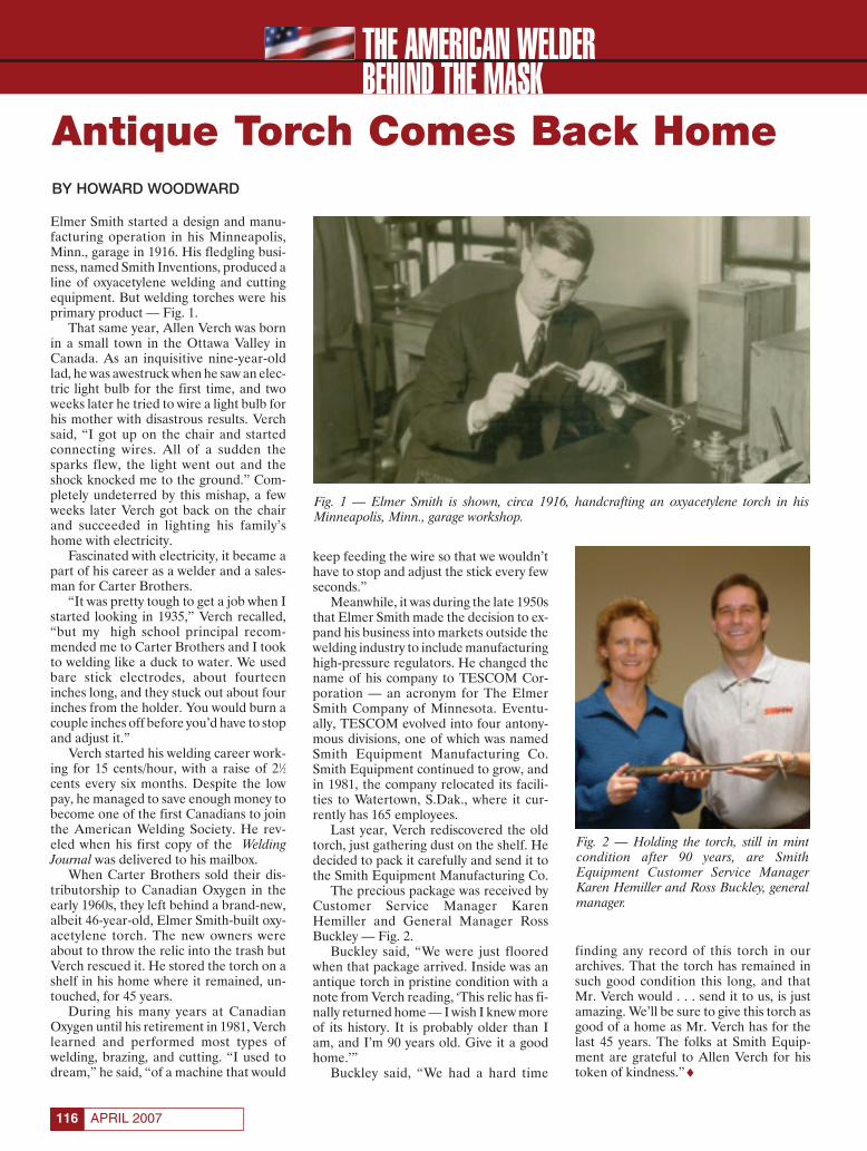
THE AMERICAN WELDERBEHIND THE MASK
APRIL 2007116
Elmer Smith started a design and manu-facturing operation in his Minneapolis,Minn., garage in 1916. His fledgling busi-ness, named Smith Inventions, produced aline of oxyacetylene welding and cuttingequipment. But welding torches were hisprimary product — Fig. 1.
That same year, Allen Verch was bornin a small town in the Ottawa Valley inCanada. As an inquisitive nine-year-oldlad, he was awestruck when he saw an elec-tric light bulb for the first time, and twoweeks later he tried to wire a light bulb forhis mother with disastrous results. Verchsaid, “I got up on the chair and startedconnecting wires. All of a sudden thesparks flew, the light went out and theshock knocked me to the ground.” Com-pletely undeterred by this mishap, a fewweeks later Verch got back on the chairand succeeded in lighting his family’shome with electricity.
Fascinated with electricity, it became apart of his career as a welder and a sales-man for Carter Brothers.
“It was pretty tough to get a job when Istarted looking in 1935,” Verch recalled,“but my high school principal recom-mended me to Carter Brothers and I tookto welding like a duck to water. We usedbare stick electrodes, about fourteeninches long, and they stuck out about fourinches from the holder. You would burn acouple inches off before you’d have to stopand adjust it.”
Verch started his welding career work-ing for 15 cents/hour, with a raise of 21⁄2cents every six months. Despite the lowpay, he managed to save enough money tobecome one of the first Canadians to jointhe American Welding Society. He rev-eled when his first copy of the WeldingJournal was delivered to his mailbox.
When Carter Brothers sold their dis-tributorship to Canadian Oxygen in theearly 1960s, they left behind a brand-new,albeit 46-year-old, Elmer Smith-built oxy-acetylene torch. The new owners wereabout to throw the relic into the trash butVerch rescued it. He stored the torch on ashelf in his home where it remained, un-touched, for 45 years.
During his many years at CanadianOxygen until his retirement in 1981, Verchlearned and performed most types ofwelding, brazing, and cutting. “I used todream,” he said, “of a machine that would
keep feeding the wire so that we wouldn’thave to stop and adjust the stick every fewseconds.”
Meanwhile, it was during the late 1950sthat Elmer Smith made the decision to ex-pand his business into markets outside thewelding industry to include manufacturinghigh-pressure regulators. He changed thename of his company to TESCOM Cor-poration — an acronym for The ElmerSmith Company of Minnesota. Eventu-ally, TESCOM evolved into four antony-mous divisions, one of which was namedSmith Equipment Manufacturing Co.Smith Equipment continued to grow, andin 1981, the company relocated its facili-ties to Watertown, S.Dak., where it cur-rently has 165 employees.
Last year, Verch rediscovered the oldtorch, just gathering dust on the shelf. Hedecided to pack it carefully and send it tothe Smith Equipment Manufacturing Co.
The precious package was received byCustomer Service Manager KarenHemiller and General Manager RossBuckley — Fig. 2.
Buckley said, “We were just flooredwhen that package arrived. Inside was anantique torch in pristine condition with anote from Verch reading, ‘This relic has fi-nally returned home — I wish I knew moreof its history. It is probably older than Iam, and I’m 90 years old. Give it a goodhome.’”
Buckley said, “We had a hard time
finding any record of this torch in ourarchives. That the torch has remained insuch good condition this long, and thatMr. Verch would . . . send it to us, is justamazing. We’ll be sure to give this torch asgood of a home as Mr. Verch has for thelast 45 years. The folks at Smith Equip-ment are grateful to Allen Verch for histoken of kindness.”♦
Fig. 2 — Holding the torch, still in mintcondition after 90 years, are SmithEquipment Customer Service ManagerKaren Hemiller and Ross Buckley, generalmanager.
Fig. 1 — Elmer Smith is shown, circa 1916, handcrafting an oxyacetylene torch in hisMinneapolis, Minn., garage workshop.
Antique Torch Comes Back HomeBY HOWARD WOODWARD
Behind the Mask 04/07:Layout 1 3/9/07 3:57 PM Page 116

Circle No. 44 on Reader Info-Card
MILWAUKEE:FP_TEMP 3/9/07 5:36 PM Page 117

THE AMERICAN WELDERLEARNING TRACK
APRIL 2007118
Western Area Career and Technology CenterEmploys Work-Based Learning Techniques
The Western Area Career and Tech-nology Center (WACTC) is located inCanonsburg, Pa., about 25 miles south ofPittsburgh. The Center was created in1967 when nine sending school districtswere united. The districts include Avella,Burgettstown, Canon McMillan,Chartiers-Houston, Fort Cherry, McGuffey, Peters Township, Trinity, and Washington.
Overview of the Center’s Welding Education Program
Tony Reis (Fig. 1) is the primary weld-ing instructor, and Mario Colaizzoteaches the evening classes — Fig. 1. Reis,who is advisor for the Center’s AWS Stu-dent Chapter, said his students are pre-pared for working with all of the basicwelding and cutting processes — Fig. 2.Tenth- through twelfth-grade studentslearn the proper use of measuring instru-ments, hand tools, and portable grinders.They learn the basics of metallurgy, blue-print reading, electrical principles, layoutand design, fabrication, and quality assur-ance methods. They also do practicalmath problems, prepare materials lists,and estimate costs. The bottom line is theylearn all of the tools necessary to succeedin the real world of manufacturing.
Reis’s successful students are given theopportunity to qualify to the requirementsof AWS D1.1, Structural Welding Code —Steel, and AWS D1.5, Bridge Welding Code.
The numerous postsecondary trainingoptions include the Community Collegeof Allegheny County, Hobart Institute ofWelding Technology, The Lincoln ElectricCo., Pennsylvania College of Technology,Triangle Tech, Inc., and Welder Trainerand Testing Institute, and the Center hasarticulation agreements with MillwrightUnion 2235, Community College of Al-legheny County — Welding Technology,and Westmoreland County CommunityCollege — Welding.
Reis said, “I have been the welding in-structor at WACTC for 18 years. Duringthis time, I have seen the welding programgrow from 15 students to well over 40 attimes. The welding program is a three-year course incorporating 10th-, 11th-,and 12th-grade students. The students
learn oxyfuel, shielded metal arc welding,gas metal arc welding, gas tungsten arcwelding, flux core arc welding, plasma arccutting, carbon arc, brazing, manual andautomatic machine cutting, blueprintreading, and basic fabrication. On aver-age, 90 to 100% of the graduating classstudents have jobs waiting for them upongraduation.
“Currently, the companies that employmy students are DBT, Multifab & Ma-chine Inc., Heslin Steel, Barr Canon,Thermo-Electric Co., and C & J Metals,just to name a few.”
The Welding Facilities
Reis’s welding shop includes the tradi-tional training equipment, plus a varietyof specialized items, including a squarewave gas tungsten arc welding machine,inverter technology for shielded metal arcand gas metal arc welding, an ironwork-ing shear, and press and punch. The facil-ity offers 17 different technical courses in-cluding Cooperative Education andYouth Apprenticeships. David Adamsonof the cooperative education departmentsaid, “We can assist students in gainingemployment and applying their skills tothe real world of work. This is done withtwo work-based learning programs thatare combined with the career and techni-cal class areas. They are cooperative edu-
cation and registered apprenticeships.These programs place students at worksites, filling both a need for the employerand student-learner. Western Area workshard to maintain and strengthen ties withbusiness and industry through these pro-grams.”
Dr. Joseph P. Iannetti, director of vo-cational education, said, “Manufacturingis still a viable industry and a major sourceof employment in our region. There justaren’t enough welders being trained tomeet industry needs. Tony Reis’s welding
BY HOWARD M. WOODWARD
Fig. 1 — Evening welding instructor MarioColaizzo (left) and Tony Reis, daytimewelding instructor, are shown in theWACTC workshop.
Fig. 2 — Shown are some of Tony Reis’s welding students who also participate in theWestern Area Career and Technology Center’s Student Chapter.
Learning Track WACTC:Layout 1 3/9/07 4:37 PM Page 118
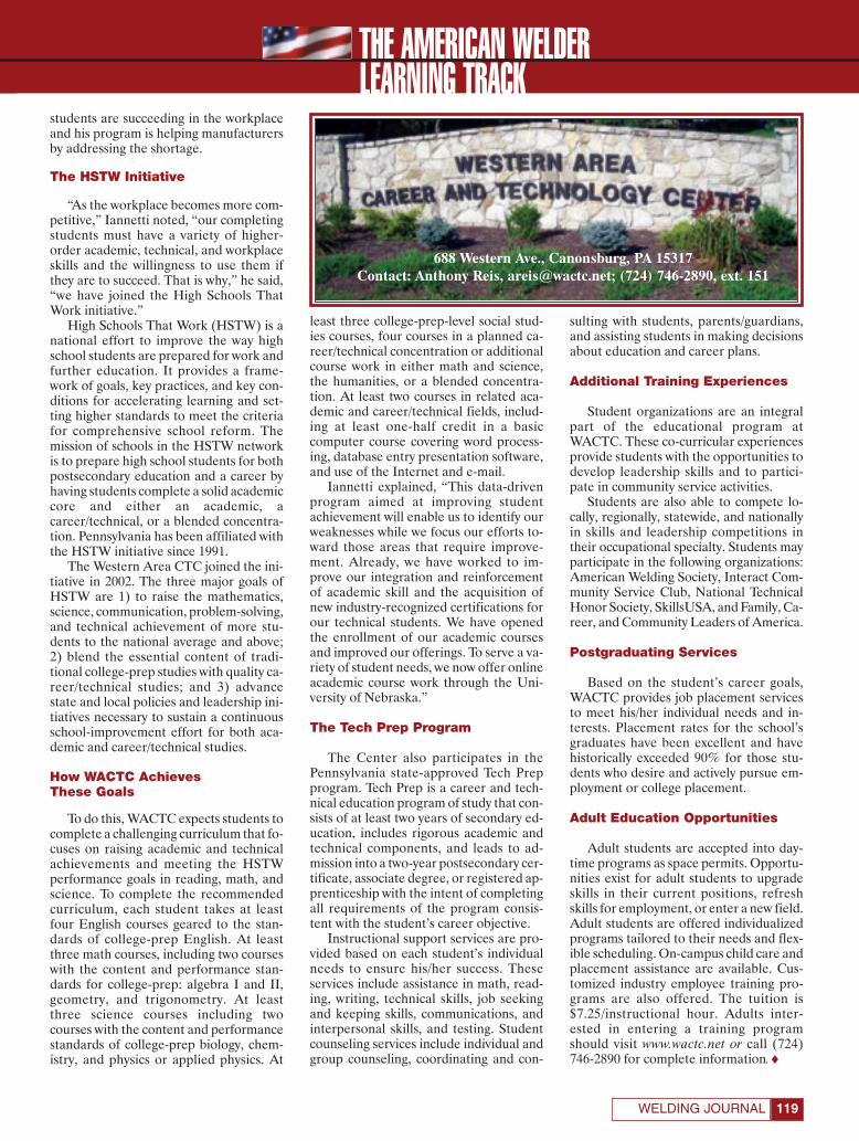
THE AMERICAN WELDER
119WELDING JOURNAL
students are succeeding in the workplaceand his program is helping manufacturersby addressing the shortage.
The HSTW Initiative
“As the workplace becomes more com-petitive,” Iannetti noted, “our completingstudents must have a variety of higher-order academic, technical, and workplaceskills and the willingness to use them ifthey are to succeed. That is why,” he said,“we have joined the High Schools ThatWork initiative.”
High Schools That Work (HSTW) is anational effort to improve the way highschool students are prepared for work andfurther education. It provides a frame-work of goals, key practices, and key con-ditions for accelerating learning and set-ting higher standards to meet the criteriafor comprehensive school reform. Themission of schools in the HSTW networkis to prepare high school students for bothpostsecondary education and a career byhaving students complete a solid academiccore and either an academic, acareer/technical, or a blended concentra-tion. Pennsylvania has been affiliated withthe HSTW initiative since 1991.
The Western Area CTC joined the ini-tiative in 2002. The three major goals ofHSTW are 1) to raise the mathematics,science, communication, problem-solving,and technical achievement of more stu-dents to the national average and above;2) blend the essential content of tradi-tional college-prep studies with quality ca-reer/technical studies; and 3) advancestate and local policies and leadership ini-tiatives necessary to sustain a continuousschool-improvement effort for both aca-demic and career/technical studies.
How WACTC Achieves These Goals
To do this, WACTC expects students tocomplete a challenging curriculum that fo-cuses on raising academic and technicalachievements and meeting the HSTWperformance goals in reading, math, andscience. To complete the recommendedcurriculum, each student takes at leastfour English courses geared to the stan-dards of college-prep English. At leastthree math courses, including two courseswith the content and performance stan-dards for college-prep: algebra I and II,geometry, and trigonometry. At leastthree science courses including twocourses with the content and performancestandards of college-prep biology, chem-istry, and physics or applied physics. At
least three college-prep-level social stud-ies courses, four courses in a planned ca-reer/technical concentration or additionalcourse work in either math and science,the humanities, or a blended concentra-tion. At least two courses in related aca-demic and career/technical fields, includ-ing at least one-half credit in a basiccomputer course covering word process-ing, database entry presentation software,and use of the Internet and e-mail.
Iannetti explained, “This data-drivenprogram aimed at improving studentachievement will enable us to identify ourweaknesses while we focus our efforts to-ward those areas that require improve-ment. Already, we have worked to im-prove our integration and reinforcementof academic skill and the acquisition ofnew industry-recognized certifications forour technical students. We have openedthe enrollment of our academic coursesand improved our offerings. To serve a va-riety of student needs, we now offer onlineacademic course work through the Uni-versity of Nebraska.”
The Tech Prep Program
The Center also participates in thePennsylvania state-approved Tech Prepprogram. Tech Prep is a career and tech-nical education program of study that con-sists of at least two years of secondary ed-ucation, includes rigorous academic andtechnical components, and leads to ad-mission into a two-year postsecondary cer-tificate, associate degree, or registered ap-prenticeship with the intent of completingall requirements of the program consis-tent with the student’s career objective.
Instructional support services are pro-vided based on each student’s individualneeds to ensure his/her success. Theseservices include assistance in math, read-ing, writing, technical skills, job seekingand keeping skills, communications, andinterpersonal skills, and testing. Studentcounseling services include individual andgroup counseling, coordinating and con-
sulting with students, parents/guardians,and assisting students in making decisionsabout education and career plans.
Additional Training Experiences
Student organizations are an integralpart of the educational program atWACTC. These co-curricular experiencesprovide students with the opportunities todevelop leadership skills and to partici-pate in community service activities.
Students are also able to compete lo-cally, regionally, statewide, and nationallyin skills and leadership competitions intheir occupational specialty. Students mayparticipate in the following organizations:American Welding Society, Interact Com-munity Service Club, National TechnicalHonor Society, SkillsUSA, and Family, Ca-reer, and Community Leaders of America.
Postgraduating Services
Based on the student’s career goals,WACTC provides job placement servicesto meet his/her individual needs and in-terests. Placement rates for the school’sgraduates have been excellent and havehistorically exceeded 90% for those stu-dents who desire and actively pursue em-ployment or college placement.
Adult Education Opportunities
Adult students are accepted into day-time programs as space permits. Opportu-nities exist for adult students to upgradeskills in their current positions, refreshskills for employment, or enter a new field.Adult students are offered individualizedprograms tailored to their needs and flex-ible scheduling. On-campus child care andplacement assistance are available. Cus-tomized industry employee training pro-grams are also offered. The tuition is$7.25/instructional hour. Adults inter-ested in entering a training programshould visit www.wactc.net or call (724)746-2890 for complete information.♦
688 Western Ave., Canonsburg, PA 15317Contact: Anthony Reis, [email protected]; (724) 746-2890, ext. 151
LEARNING TRACK
Learning Track WACTC:Layout 1 3/9/07 4:38 PM Page 119
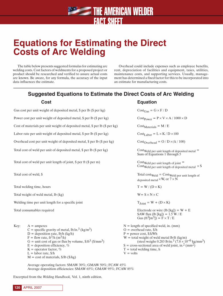
THE AMERICAN WELDER
APRIL 2007120
FACT SHEET
Equations for Estimating the Direct Costs of Arc Welding
The table below presents suggested formulas for estimating arcwelding costs. Cost factors of weldments for a proposed project orproduct should be researched and verified to assure actual costsare known. Be aware, for any formula, the accuracy of the inputdata influences the estimate.
Overhead could include expenses such as employee benefits,rent, depreciation of facilities and equipment, taxes, utilities,maintenance costs, and supporting services. Usually, manage-ment has determined a fixed factor for this to be incorporated intoan estimate for manufacturing costs.
Suggested Equations to Estimate the Direct Costs of Arc WeldingCost Equation
Gas cost per unit weight of deposited metal, $ per lb ($ per kg) CostGas = G × F / D
Power cost per unit weight of deposited metal, $ per lb ($ per kg) CostPower = P × V × A / 1000 × D
Cost of materials per unit weight of deposited metal, $ per lb ($ per kg) CostMaterials = M / E
Labor rate per unit weight of deposited metal, $ per lb ($ per kg) CostLabor = L × K / D × 100
Overhead cost per unit weight of deposited metal, $ per lb ($ per kg) CostOverhead = O / D × ( k / 100)
Total cost of weld per unit of deposited metal, $ per lb ($ per kg) CostWeld per unit length of deposited metal =Sum of Equations 1 through 5
Total cost of weld per unit length of joint, $ per ft ($ per m) CostWeld per unit length of joint =CostWeld per unit length of deposited metal × S
Total cost of weld, $ Total costWeld = CostWeld per unit length of deposited metal × W, or 7 × N
Total welding time, hours T = W / (D × K)
Total weight of weld metal, lb (kg) W= S × N × C
Welding time per unit length for a specific joint TJoint = W + (D × K)
Total consumables required Electrode or wire (lb [kg]) = W + ESAW flux (lb [kg]) = 1.5 W / EGas (ft3[m3]) = F × T / E
Key: A = amperes N = length of specified weld, in. (mm)C = specific gravity of metal, lb/in.3 (kg/m3) O = overhead rate, $/hD = deposition rate, lb/h (kg/h) P = power cost, $/kWhF = flow rate, ft3/h (m3/h) W = total weight of weld metal lb/ft (kg/m)G = unit cost of gas or flux by volume, $/ft3 ($/mm3) (steel weighs 0.283 lb/in.3 (7.8 × 10⁻⁶ kg/mm3)E = deposition efficiency, % S = cross-sectional area of weld joint, in.2 (mm2)K = operator factor, % T = total welding time, hL = labor rate, $/h V = voltsM = cost of materials, $/lb ($/kg)
Average operating factors: SMAW 30%; GMAW 50%; FCAW 45%Average deposition efficiencies: SMAW 65%; GMAW 95%; FCAW 85%
Excerpted from the Welding Handbook, Vol. 1, ninth edition.
Fact Sheet April corr:Layout 1 3/9/07 4:07 PM Page 120

Conference price is $345 for AWS members, $480 fornonmembers.To register or to receive a descriptive brochure,call (800) 443-9353 ext. 229, (outside North America, call 305-443-9353), or visit www.aws.org/conferences
An AWS-sponsored conference on friction welding will be held at the Fabtech Int’l & AWS Welding Show in Chicago.Thisdaylong conference will be packed with a number of short presentations on various facets of conventional friction weld-ing, linear friction welding, and friction stir welding. Among the presentations will be talks on such topics as direct drivevs. inertia friction welding, the friction welding of automotive pistons, the linear friction welding of blades onto discs inaircraft engines, the marriage of robotics and friction stir welding, and the ability of any process within this family to weldjust about any metal or alloy—or even plastic, for that matter—and to do it without creating fumes. Also, experts willbe on hand to discuss the ability to use these processes to weld dissimilar metals on the fly.
©Am
eric
anW
eldi
ngSo
ciet
y20
07ES
V149
3R
Founded in 1919 to advance the science, technology and application of welding and allied joining and cuttingprocesses, including brazing, soldering and thermal spraying.
Conference on Friction WeldingChicago • McCormick PlaceNovember 12, 2007
Circle No.8 on Reader Info-Card
Page 121:FP_TEMP 3/12/07 12:02 PM Page 121

THE AMERICAN WELDERKEEP IT SAFE
APRIL 2007122
Fumes and Gases
Arc cutting and gouging produce fumes and gases that may behazardous to your health. The fume and gas byproducts usuallyconsist of the oxides of the metal being cut, ozone, and oxides ofnitrogen, including nitrogen dioxide. Phosgene gas could be pres-ent as a result of the thermal or ultraviolet decomposition ofchlorinated hydrocarbon cleaning agents.
The metal fumes generated by the arc cutting processes canbe controlled by natural ventilation, local exhaust ventilation,and respiratory protective equipment as described in SafePractices in Welding, Cutting, and Allied Practices, ANSI Z49.1.The concentration of ozone usually increases with an increase incurrent and when cutting or gouging aluminum. Tests haveshown high concentrations of nitrogen dioxide close to the arc.Cutters should keep their heads out of the fumes whenever pos-sible. With some applications this might not be possible. In suchinstances fumes must be removed at the source by using anexhaust system or respiratory equipment should be used.
Protective Apparel
The arc emits intense ultraviolet and infrared radiation that ispotentially harmful to the eyes and skin. Operators should wearadequate eye and face protection. A standard welding helmet fit-ted with filter glass (see table) appropriate to the current used issufficient. Heavy gloves should be worn as gouging radiates a sig-nificant amount of heat. Exposed areas of skin should be cov-ered, and heavy, flame-retardant clothing should be worn to pro-tect against molten metal. Leather and wool clothing that is darkis recommended to reduce reflection.
Fire Hazards
Fire prevention measures are necessary for all cutting andgouging operations. Cutting and gouging processes produce sig-nificant heat, metal sparks, and hot spatter, all of which create afire hazard. Personnel should wear fire-retardant clothing andfire extinguishers should be readily available near the cutting orgouging operation.
Air carbon arc cutting or gouging require special fire preven-tion precautions because of the nature of the removal process.All combustibles within 35 ft (11 m) of the work area should beremoved. Protection such as metal screens should be placed inline of the hot metal ejected by the compressed air stream ifample room for dissipation is not available. Additional informa-tion on this topic is presented in Fire Prevention during Welding,Cutting, and Other Hot Work, NFPA 51B.
Electrical Hazards
Electric shock can be fatal. Safety precautions for all cuttingand gouging processes include the following:
1) All electrical circuits must be kept dry, as moisture can providean unexpected path for current flow. Equipment cabinets that
contain water, as well as gas lines and electrical circuits, shouldbe checked periodically for leaks.
2) Equipment must be properly grounded and connected as rec-ommended by the manufacturer.
3) All electrical connections should be kept mechanically tight, aspoor electrical connections can generate heat and start fires.
4) High-voltage cable must be used, and cables and wires must bekept in good repair. The manufacturer’s instructions should beconsulted for the proper cable and wire sizes.
5) Personnel must not touch live circuits. Equipment panels mustbe kept in place, and access doors must be kept closed.
6) Only trained personnel should be permitted to operate ormaintain the equipment.
The risk of electrical shock is probably the greatest whenreplacing used torch parts. Operators must make sure that theprimary power to the power sources and the power to the controlcircuitry is turned off when replacing torch parts. Operators andmaintenance personnel should be aware that plasma arc cuttingequipment presents a greater hazard than conventional weldingequipment because it uses higher voltages. The voltages used inplasma arc cutting equipment range from 150 to 400 V DC.
Emergency first aid should be readily available. Prompt,trained emergency response may reduce the extent of injury inthe event of electrical shock. Additional information can befound in the National Electrical Safety Code, ANSI C2.♦
Arc Cutting and Gouging
Excerpted from Welding Handbook, Vol. 2, Welding Processes, Part 1.
Recommended Eye Protection for Plasma ArcCutting and Air Carbon Arc Cutting
Minimum SuggestedShade Shade
Plasma ArcCutting Current (A)
Less than 300 8 9300 to 400 9 12400 to 800 10 14
Air Carbon Arc Cutting Current (A)
Less than 500 10 12500 to 1000 11 14
Keep Safe AmWeld 4/07:Layout 1 3/9/07 5:04 PM Page 122

Circle No. 2 on Reader Info-Card
AIST:FP_TEMP 3/9/07 5:09 PM Page 123

Save Time. Save Purge Gas. Save Money. Get Ahead of Schedule with EZ Purge™!
EZ Purge™ changes the way welds are prepared, drastically reduces the amountof gas used as well as improves project timelines. With EZ Purge™ preparation isinstantaneous! Because is EZ Purge™ is the ONLY pre-formed and ready to usepurge dam, application is as easy aspeel, insert and press. Since the purgedams are placed 8-12” from the rootgap, your savings multiply as less gas isused. Contact us for a Time and CostSavings Calculation Sheet.
Arcos Coated Electrodes
Arcos, the premier supplier of stan-dard and customized high-integrityalloys, offers a wide selection ofnickel, stainless steel and coppernickel alloys. These superior qualitycoated electrodes deliver thesuperb slag release, wetting actionand weld profile characteristics yourequire with a smooth, stable arc.
Arcos Industries, LLC One Arcos Drive Mt. Carmel, PA 17851 (800) 233-8460 FAX: (570) 339-5206 Website: www.arcos.us
Fischer Feritscope® MP30 for Measuring Ferrite Content In Austenitic and Duplex SteelsWith Improved Features
A new four-color, four-page brochure fromFischer Technology fully describes therugged Feritscope® MP30, the fast andaccurate hand-held solution for measuringferrite content in constructional steels,welded claddings, austenitic stainlesssteels and duplex steels.
Fischer Technology750 Marshall Phelps Dr.Windsor, CT 06095(800) 243-8417FAX: (860) 688-8496Website: www.fischer-technology.com Circle No. 155
Bradford Derustit Stainless Steel Cleaners
Achieve maximum corrosion resistance to valuable stainless steel. Save money by reducing costs due to labor intensive grinding and polishing of stainless after welding. Derustit products are simple and easy to use. No expensive machines or abrasive materials. Fast and efficient.Clean. Protect. Preserve.
Circle No. 152
New Edition Of An Essential Welding Resource
Industrial Press publishes key welding refer-ences that will help you help you work efficiently and effectively. New in 2007 isWelding Essentials: Questions and Answers,Second Edition which makes welding easyfor beginners and is a handy reference forprofessionals. To order or for more informa-tion go to: www.industrialpress.com/en/BookDetails/tabid/54/CatalogItemID/394/Default.aspx
INDUSTRIAL PRESS INC.(212) 889-6330, Fax: (212) 545-8327Website: www.industrialpress.com
Circle No. 151
Circle No. 150
PRODUCTIVITY SHOWCASE April 2007
124
New Paint Marker Designed to Disappear in Pre-Galvanizing Picking BathThe Galvanizer’s Feltip Paint Marker containspaint specially formulated by J.P. Nissen Co. forfabricators who have their material galvanized.The valve action marker writes easily on roughor smooth steel, even if the surfaces are wet oroily. The marks won’t chip, peel, fade or rub off.They will withstand heat and weathering.However, they are completely removed by thepickling bath prior to galvanizing. The marks willnot interfere with the plating process or mar thefinished plated surface.J.P. Nissen Co.2544 Fairhill AveP.O. Box 3399Glenside PA, 19038(215) 886-2025Fax: (215) 886-0707www.nissenmarkers.com
Introducing theBoreClad Welding Systemfor I.D. cladding. A complete welding & positioning system for symmetrical, chucked parts.Angled design optimizes bead quality & deposition rate. Ideal for cladding with stainless steel, nickel alloys & other exotic metals.Designed for parts with a max. O.D. of 12" and min. I.D. of 2". 18", 24" & 36" welding stroke models are available.
Bortech Corporation66 Victoria St. • Keene, NH 03431888-265-1202 • Fax: 603-358-4007
Website: www.bortech.comE-mail: [email protected]
Five Hundred and Fifty SevenBand and Blade Products
The new 24-page STERLING® prod-uct catalog from Diamond SawWorks, Inc. includes wood, timberand metal cutting band saw blades,knife edge bands, small tool bladesas well as bi-metal and carbide tippedhole saws. The Product Catalog and aComprehensive Guide to Band SawCutting are now available.
Diamond Saw Works, Inc.12290 Olean RoadChaffee, NY 14030(800) 828-1180 Fax: (800) 237-8853www.sterlingsawblades.com Circle No. 154
Circle No. 157
Circle No. 156
Aquasol Corporation80 Thompson StreetNorth Tonawanda, NY 14120(800) 564-9353 Fax: (716) 564-8889www.aquasolcorporation.com
Bradford Derustit® Corp.P.O. Box 280
Tualatin, OR 97062-0280(877) 899-5315 FAX: (877) 285-2080
Website: www.derustit.comE-MAIL: [email protected]
Circle No. 153
ProductivityApril2007:PLR Spring 2006 3/8/07 9:52 AM Page 124
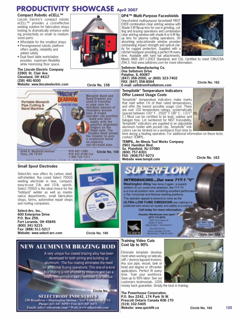
Training Video CutsCost Up to 90%
Eliminate template develop-ment when working on laterals,stiff / dummy legsand trunions.Any size pipe, vessel, tank orhead and degree or off-center-applications. Perfect fit every-time. Train your workforce.Save up to 90% labor. See ourcustomers testimonials. 100%money back guarantee. Simply the best in training.
The Powerhouse Corporation.P.O. Box 2242, 174 Park St W.Prescott Ontario Canada K0E-1T0(519) 332-5405 Website: www.quickfit.ca
Small Spool Electrodes
Select-Arc now offers its carbon steel,self-shielded, flux cored Select 700GSwelding electrode in new, compact,easy-to-use 2-lb. and 10-lb. spools.Select 700GS is the ideal choice for the"hobbyist" welder as well as mainte-nance departments, small fabricationshops, farms, automotive repair shopsand roofing companies.
Select-Arc, Inc., 600 Enterprise Drive P.O. Box 259, Fort Loramie, OH 45845 (800) 341-5215 Fax: (888) 511-5217Website: www.select-arc.com
Circle No. 165
Circle No. 164
DP4™ Multi-Purpose FaceshieldsOne-of-a-kind multi-purpose faceshield! FIRSTEVER combination clear anti-fog window withShade 5 IR flip-up lens for use in grinding, cut-ting and brazing operations and combinationclear anti-fog window with shade 8 or 6 IR flip-up lens for plasma cutting operations. UVabsorbing polycarbonate window providesoutstanding impact strength and optical clar-ity for rugged protection. Supplied with aratchet headgear providing a perfect fit everytime. Available with hard hat attachments.Meets ANSI Z87.1-2003 Standards and CUL Certified to meet CAN/CSA-Z94.3. Visit www.sellstrom.com for more information.Sellstrom Manufacturing Co.One Sellstrom DrivePalatine, IL 60067(847) 358-2000, or (800) 323-7402FAX: (847) 358-8564 E-mail: [email protected]
Circle No. 162
Circle No. 160
PRODUCTIVITY SHOWCASE April 2007
125
Tempilstik° Temperature Indicators Offer Lowest Usage CostsTempilstik° temperature indicators make marksthat melt within 1% of their rated temperatures,and offer the lowest possible usage cost. Thereare over 100 temperature ratings, systematicallyspaced between 100° F - 2500° F (38° C - 1371°C.) Most can be certified to be lead, sulphur andhalogen free. Lot numbered for NIST traceability,Tempilstik° indicators are supplied in an adjustablealuminum holder with pocket clip. Tempilstik° indi-cators can be stroked on a workpiece from time totime during a heating operation. For additional information on these testscontact TEMPIL.TEMPIL, An Illinois Tool Works Company 2901 Hamilton Blvd. So. Plainfield, NJ 07080 (800) 757-8301 FAX: (908)757-9273 Website www.tempil.com Circle No. 163
Circle No. 161
Compact Robotic eCELL™Lincoln Electric’s compact roboticeCELL™ provides a cost-effectivewelding solution for fabrication shopslooking to dramatically enhance weld-ing productivity on small- to medium-sized parts: • Affordable for the smallest shops • Pre-engineered robotic platform
offers quality, reliability and added safety
• Dual fixed table workstation provides maximum flexibility while minimizing floor space.
The Lincoln Electric Company22801 St. Clair Ave.Cleveland, OH 44117(216) 481-8100Website: www.lincolnelectric.com Circle No. 158
Circle No. 159
ProductivityApril2007:PLR Spring 2006 3/8/07 9:53 AM Page 125
CLASSIFIEDS
CAREER OPPORTUNITIES
Put Your Products andServices to Work for You
in July 2007
Generate sales leads by showcas-ing your full-color product photo, aproduct description, Website, orother sales literature. These show-cases reach 70,000 qualified buy-ers. Great exposure for just penniesa contact.
Closes May 15, 2007
Call our sales team at:1-800-443-9353
Rob Saltzstein at ext. [email protected]
Lea Garrigan Badwy atext. 220
Technical Sales RepsEutectic Corporation, recognized as a worldleader in providing maintenance and repairsolutions, currently has openings for openterritories throughout the USA. The idealcandidates for the sales positions will havepractical experience in welding and/or ther-mal spray processes with an industrialbackground. Principal responsibilities willinclude providing technical support to endusers within specified key customers / in-dustries as well as coordinating distributionactivities in the region. Full product andsales training will be provided. Along withprospective career development opportu-nities, we offer a competitive salary andbenefits package. Please visit our websiteat www.eutectic-na.com. For considerationplease mail, fax or e-mail resume withsalary requirements to: Human ResourcesDept., Eutectic Corporation, N94 W14355Garwin Mace Dr., Menomonee Falls, WI53051.
Fax: (262) 532-4692 E-mail: [email protected]
Structural Metals Fabrication Shop Manager
Structural/miscellaneous metals fabricationshop seeking an experienced individual to manage operations, staff and projects.Responsible for process, estimating, projectmanagement as well as crew managementand field support. Minimum of 5 years experience required, must be motivated andorganized. Must possess a background inall phases of job estimating, layout andfabrication. Must have excellent communi-cation skills and be dependable. Must passa drug screen and background check.
Please call (954) 714 - 8833 or Fax resume to (954) 714-8003
Structural FabricationInspector
Come work for the Minnesota Depart-ment of Transportation, the nation’sleader in the Transportation Industry.We currently have two openings forStructural Fabrication Inspectors.Applicants must possess a CertifiedWelding Inspector certificate and have3 years exp. in bridge component fabrication.
For detailed information and to submityour resume, go to:https://statejobs.doer.state.mn.us.
OUTSIDE SALES REPFamily owned and operatedBased in Central CaliforniaLooking for a salesman with
experience in Welding & IndustrialSupplies to join our energeticfamily and growing company!
Valley Welding & Industrial Supply(661) 410-9353
Fax: (661) 410-4691
AWS JobFind
www.aws.org/jobfindJob categories for welders, engineers, inspectors, and more than 17
other materials joining industry classifications!
@Post Jobs.
Find Jobs.
Place Your Classified Ad Here!
Contact Frank Wilson,Advertising Production
Manager
(800) 443-9353,ext. 465
APRIL 2007126
APR 2007 CLASSIFIEDS:Classified Template 3/12/07 5:12 PM Page 126

EQUIPMENT FOR SALE OR RENT
Turning RollsPositioners
& ManipulatorsNew and Used
Joe Fuller LLC@ www.joefuller.com
or email [email protected] Phone: 979-277-8343
Fax: 281-290-6184
Welding Positioners & Turning RollsNew and Used
Large selection in stock forimmediate delivery.
www.allfabcorp.com
Call, Fax or Email for a free catalog.
Email: [email protected]: www.allfabcorp.comPhone: 269-673-6572Fax: 269-673-1644
REPRINTS REPRINTS
To order custom reprints of 100 or more of articles in
Welding Journal,call FosteReprints at
(219) 879-8366 or(800) 382-0808 or.
Request for quotes can befaxed to (219) 874-2849.
You can e-mailFosteReprints at
TOOLS & SUPPLIESFOR SALE OR RENT
127WELDING JOURNAL
APR 2007 CLASSIFIEDS:Classified Template 3/12/07 5:13 PM Page 127
SERVICESLITERATURE
CERTIFICATION & TRAINING
The AWSCertification Committee
Is seeking the donation of sets ofShop and Erection drawings ofhighrise buildings greater than tenstories with Moment Connectionsincluding Ordinary MomentResistant Frame (OMRF) andSpecial Moment Resistant Frame(SMRF) for use in AWS trainingand certification activities.Drawings should be in CAD for-mat for reproduction purposes.Written permission for unrestrictedreproduction, alteration, andreuse as training and testingmaterial is requested from theowner and others holding intellec-tual rights.
For further information, contact:
Joseph P. Kane (631) 265-3422 (office) (516) 658-7571 (cell) [email protected]
CWI PREPARATORYGuarantee - Pass or Repeat FREE!
2-WEEK COURSE (10 DAYS)MORE HANDS-ON/PRACTICAL APPLICATIONS
Pascagoula, MS, June 20–29 Aug. 8–17Atlanta, GA, May 30–June 8Houston, TX, Apr. 25–May 4Houma, LA, Mar. Sep 12–21
Beaumont, TX, July 18–27
SAT–FRI COURSE (7 DAYS)EXTRA INSTRUCTION TO GET A HEAD START
Pascagoula, MS, June 23–29 Aug. 11–17Atlanta, GA, June 2–8
Houston, TX, Apr. 28-May 4 July 7–13Houma, LA, Sep. 15–21
Beaumont, TX, July 21–27
MON–FRI COURSE (5 DAYS)GET READY - FAST PACED COURSEPascagoula, MS, June 25-29 Aug. 13–17
Atlanta, GA, June 4–8Houston, TX, Apr. 30–May 4 July 9–13
Houma, LA, Sep. 17–21Beaumont, TX, July 23–27
(Test follows on Saturday at same facility)
SENIOR CWI PREPARATORYHouston, TX Apr. 30–May 4 July 9–13
Beaumont, TX July 23–27
FOR DETAILS CALL OR E-MAIL:
1-800-489-2890
Call AboutCourses for
9-Year Renewal
MITROWSKI RENTSAronson Scarab welding manipulator 14ft x 14ft
Lincoln 1000-amp subarc for rent
800-218-9620713-943-8032
Purchase on our website at www.specialwelds.com
A Diver-Welder’s Companion
Place Your Classified Ad Here!
Contact Frank Wilson,Advertising Production
Manager
(800) 443-9353,ext. 465
APRIL 2007128
APR 2007 CLASSIFIEDS:Classified Template 3/12/07 5:13 PM Page 128
ADVERTISERINDEX
Aelectronic Bonding, Inc. . . . . . . . . .www.abiusa.net . . . . . . . . . . . . . . .48AIST/Assoc. for Iron & Steel Tech. .www.aist.org . . . . . . . . . . . . . . . .123Aquasol Corp. . . . . . . . . . . . . . . . . . .www.aquasolcorporation.com . .124Arcos Industries, LLC . . . . . . . . . . . .www.arcos.us . . . . . . . . . . .124, IBCAstro Arc Polysoude . . . . . . . . . . . . .www.astroarc.com . . . . . . . . . . . .11Atlas Welding Accessories, Inc. . . . .www.atlasweld.com . . . . . . . . . . .27AWS Certification Services . . . . . . . .www.aws.org . . . . . . . . . . .63, 95, 97AWS Education Services . . . . . . . . . .www.aws.org .20, 21, 98, 99, 108, 121AWS Foundation . . . . . . . . . . . . . . . .www.aws.org . . . . . . . . . . . . . . . .103AWS Member Services . . . . . . . . . . .www.aws.org . . . . . .61, 107, 114, 130AWS Marketing Services . . . . . . . . .www.aws.org . . . . . . . . . . . . . . . .111AWS Milaukee Section . . . . . . . . . . .www.aws.org/sections/milwaukee .117AWS Technical Services . . . . . . . . . .www.aws.org . . . . . . . . . . . . . . . . .58Bortech Corporation . . . . . . . . . . . . .www.bortech.com . . . . . . . . .26, 124Bradford Derustit Corp. . . . . . . . . . .www.derustit.com . . . . . . . . . . . .124Centerline Ltd. . . . . . . . . . . . . . . . . . .www.cntrline.com . . . . . . . . . . . . .RICollege of Oceaneering . . . . . . . . . . .www.natpoly.edu . . . . . . . . . . . . . .23Commercial Diving Academy . . . . . .www.commercialdivingacademy.com .43Cor-Met . . . . . . . . . . . . . . . . . . . . . . .www.cor-met.com . . . . . . . . . . . . .12DE-STA-CO . . . . . . . . . . . . . . . . . . .www.destaco.com . . . . . . . . . . . . .59Diamond Ground Products, Inc. . . .www.diamondground.com . . . . . .61Diamond Saw Works, Inc. . . . . . . . . .www.diamondsaw.com . . . . .27, 124Divers Academy International . . . . .www.diversacademy.com . . . . . . .15EASTEC Advance Productivity Exh. www.sme.org/eastec . . . . . . . . . .115Edison Welding Institute . . . . . . . . .www.ewi.org . . . . . . . . . . . . . . . . .90ESAB Welding & Cutting Products .www.esabna.com . . . . . . . . . . . .9, 17Fischer Technology Co. . . . . . . . . . . .www.Fischer-Technology.com .38, 124Gedik Welding, Inc. . . . . . . . . . . . . . .www.gedikwelding.com . . . . . . . .13Hobart Inst. of Welding Tech. . . . . . .www.welding.org . . . . . . . . . . . . . .23Hypertherm . . . . . . . . . . . . . . . . . . . .www.hypertherm.com . . . . . . . . . .2Industrial Press, Inc. . . . . . . . . . . . .www.industrialpress.com . . .60, 124Jancy Engineering, Inc. . . . . . . . . . . .www.jancy.com . . . . . . . . . . . . . . .48Joe Fuller, LLC . . . . . . . . . . . . . . . . .www.joefuller.com . . . . . . . . . . . .60J. P. Nissen Jr. Co. . . . . . . . . . . . . . . .www.nissenmarkers.com . . .48, 124Koike Aronson Inc./Ransome . . . . . .www.koike.com . . . . . . . . . . . . . . .19LA-CO Industries, Inc. . . . . . . . . . . .www.laco.com . . . . . . . . . . . . . . . .18Lincoln Electric Co. . . . . . . . . . . . . . .www.lincolnelectric.com .125, OBCMagnatech Limited Partnership . . .www.magnatech-lp.com . . . . . . . .49Mathey Dearman . . . . . . . . . . . . . . . .www.mathey.com . . . . . . . . . .15, 125Mennekes . . . . . . . . . . . . . . . . . . . . . .www.gomennekes.com . . . . . . . . .25Midalloy . . . . . . . . . . . . . . . . . . . . . . .www.midalloy.com . . . . . . . . . . . .38Miller Electric Mfg. Co. . . . . . . . . . .www.MillerWelds.com . . . . . . . . . .7National Standard . . . . . . . . . . . . . . .www.nationalstandard.com . . . . . .1Powerhouse Corp. . . . . . . . . . . . . . . .www.quickfit.ca . . . . . . . . . . . . .125Select Arc, Inc. . . . . . . . . . . . . . . . . . .www.select-arc.com . . .IFC, 93, 125Selectrode Industries . . . . . . . . . . . .www.selectrode.com . . . . . . .25, 125Sellstrom Manufacturing Co. . . . . . .www.sellstrom.com . . . . . . . . . . .125Tempil . . . . . . . . . . . . . . . . . . . . . . . . .www.tempil.com . . . . . . . . . . . . .125Thermadyne Industries . . . . . . . . . . .www.thermadyne.com . . . . . . . . .31Tregaskiss . . . . . . . . . . . . . . . . . . . . . .www.toughgun.com . . . . . . . . . . . .5Washington Alloy/U. S. Alloy, Co. . . .www.weldingwire.com . . . . .14, 125Weld Hugger, LLC . . . . . . . . . . . . . . .www.weldhugger.com . . . . . . . . . .43
IFC = Inside Front CoverIBC = Inside Back CoverOBC = Outside Back CoverRI = Reader Information Card
WELDING SCHOOL PROFILES
University of Anchorage/Alaska Community & Technical College . . . .50
Atlanta Technical College . . . . . . . . . . . . . . . . . . . . . . . . . . . . . . . . . . . . .50
Atlantic Technical Center . . . . . . . . . . . . . . . . . . . . . . . . . . . . . . . . . . . . .50
Beaufort County Community College . . . . . . . . . . . . . . . . . . . . . . . . . . .50
Bellingham Technical College . . . . . . . . . . . . . . . . . . . . . . . . . . . . . . . . . .50
Butte-Glenn Community College . . . . . . . . . . . . . . . . . . . . . . . . . . . . . . .51
Central Piedmont Community College . . . . . . . . . . . . . . . . . . . . . . . . . .51
Chippewa Valley Technical College . . . . . . . . . . . . . . . . . . . . . . . . . . . . .51
College of the Canyons . . . . . . . . . . . . . . . . . . . . . . . . . . . . . . . . . . . . . . .51
Cosumnes River College . . . . . . . . . . . . . . . . . . . . . . . . . . . . . . . . . . . . . .51
Career Technical Center (CTC) Lackawanna County . . . . . . . . . . . . . .51
Dabney S. Lancaster Community College . . . . . . . . . . . . . . . . . . . . . . . .52
Del Mar College . . . . . . . . . . . . . . . . . . . . . . . . . . . . . . . . . . . . . . . . . . . . .52
Divers Academy International . . . . . . . . . . . . . . . . . . . . . . . . . . . . . . . . .52
Dona Ana Community College . . . . . . . . . . . . . . . . . . . . . . . . . . . . . . . . .52
El Camino College . . . . . . . . . . . . . . . . . . . . . . . . . . . . . . . . . . . . . . . . . . .52
Frank Phillips College . . . . . . . . . . . . . . . . . . . . . . . . . . . . . . . . . . . . . . . .52
Grand River Technical School . . . . . . . . . . . . . . . . . . . . . . . . . . . . . . . . .53
Great Basin College . . . . . . . . . . . . . . . . . . . . . . . . . . . . . . . . . . . . . . . . . .53
Harper College . . . . . . . . . . . . . . . . . . . . . . . . . . . . . . . . . . . . . . . . . . . . . .53
Hobart Institute of Welding Technology . . . . . . . . . . . . . . . . . . . . . . . . .53
Ivy Tech Community College . . . . . . . . . . . . . . . . . . . . . . . . . . . . . . . . . .53
Kenai Peninsula College . . . . . . . . . . . . . . . . . . . . . . . . . . . . . . . . . . . . . .53
Ketchikan Campus/University of Alaska . . . . . . . . . . . . . . . . . . . . . . . . .57
Lansing Community College . . . . . . . . . . . . . . . . . . . . . . . . . . . . . . . . . . .54
Lincoln Electric Welding School . . . . . . . . . . . . . . . . . . . . . . . . . . . . . . .54
Locklin Tech . . . . . . . . . . . . . . . . . . . . . . . . . . . . . . . . . . . . . . . . . . . . . . . .54
Maysville Community and Technical College . . . . . . . . . . . . . . . . . . . . .54
Mesabi Range Community & Technical College . . . . . . . . . . . . . . . . . . .54
Moraine Park Technical College . . . . . . . . . . . . . . . . . . . . . . . . . . . . . . .54
North Dakota State College of Science . . . . . . . . . . . . . . . . . . . . . . . . . .55
North Georgia Technical College . . . . . . . . . . . . . . . . . . . . . . . . . . . . . . .55
Northland Community & Technical College . . . . . . . . . . . . . . . . . . . . . .55
Odessa College Welding Technology . . . . . . . . . . . . . . . . . . . . . . . . . . . .55
Orange Coast College . . . . . . . . . . . . . . . . . . . . . . . . . . . . . . . . . . . . . . . .55
Owens Community College . . . . . . . . . . . . . . . . . . . . . . . . . . . . . . . . . . . .55
Pennsylvania College of Technology . . . . . . . . . . . . . . . . . . . . . . . . . . . . .56
Pulaski Technical College . . . . . . . . . . . . . . . . . . . . . . . . . . . . . . . . . . . . .56
Rock Valley College . . . . . . . . . . . . . . . . . . . . . . . . . . . . . . . . . . . . . . . . . .56
Santa Fe Community College . . . . . . . . . . . . . . . . . . . . . . . . . . . . . . . . . .56
South Plains College . . . . . . . . . . . . . . . . . . . . . . . . . . . . . . . . . . . . . . . . .56
SouthWest Collegiate Institute for the Deaf of Howard College . . . . . .56
Tri-County Technical College . . . . . . . . . . . . . . . . . . . . . . . . . . . . . . . . . .57
Trident Technical College . . . . . . . . . . . . . . . . . . . . . . . . . . . . . . . . . . . . .57
University of Alaska Southeast . . . . . . . . . . . . . . . . . . . . . . . . . . . . . . . . .57
Tulsa Welding School . . . . . . . . . . . . . . . . . . . . . . . . . . . . . . . . . . . . . . . . .57
Welder Training & Testing Institute . . . . . . . . . . . . . . . . . . . . . . . . . . . .57
129WELDING JOURNAL
˜
APR 2007 CLASSIFIEDS:Classified Template 3/12/07 5:14 PM Page 129

Circle No. 17 on Reader Info-Card
Page 130:FP_TEMP 3/12/07 1:46 PM Page 130

WELDING RESEARCH
-s81WELDING JOURNAL
ABSTRACT. The relatively short elec-trode life in welding aluminum sheets hasbeen a bottleneck for large-scale produc-tion of aluminum vehicles. The rapid de-terioration of electrodes during resistancewelding aluminum is the collective conse-quence of high pressure, high tempera-ture, and a rapid metallurgical (alloying)process. This study systematically investi-gated the effects of sheet surface condi-tions on electrode life. Using 2-mm 5A02aluminum sheets, a schedule conducive toelectrode life was used for testing the ef-fects of sheet surface conditions. A three-phase, direct-current pedestal-type resis-tance spot welding machine was used, andthe electrodes lasted for about 200 weldsfor sheets with untreated or original sur-faces, up to 1700 welds when they wereelectric-arc cleaned, and more than 2000welds if the sheets were degreased orchemically cleaned. This investigation alsoshows that the appearance of an electrodeafter a small number of welds providesuseful information on the electrode lifeusing the same welding schedule.
Introduction
With the advantages of high specificstrength, low density, high corrosion resis-tance, and low-energy formability, alu-minum has been widely used in almostevery aspect of daily life. The constantlyincreasing demands in weight reductionfor fuel economy, and emission controlhave led to a wider application of alu-
minum sheets in automobile manufacture.Many automakers have attempted to re-place steels with aluminum. For instance,Audi has successfully produced all-alu-minum Models A2 and A8 cars.
Resistance spot welding has been themajor joining process in automotive bodyconstruction because of its low cost, ro-bustness, and many other advantages.However, the experience obtained inwelding steels is not readily transferable towelding aluminum, mainly due to the sig-nificant physical and metallurgical differ-ences in both the bulk material and sur-faces. Because aluminum has higherelectrical and thermal conductivities thansteels, high electric current and short weldtime have to be used in welding aluminumalloys. For example, a current of about10,000 A may be needed to weld a 2-mmto 2-mm steel sheet combination, butmore than 40,000 A are usually requiredto weld similar combinations of aluminumsheets (Ref. 1). Such a high current pro-duces high temperature in the weldmentand at the interfaces between aluminumsheets and copper electrodes. This greatlyaffects the electrode life considering themetallurgical reaction between aluminumand copper. Aluminum has a high chemi-cal affinity for copper to form a brittle
alloy (bronze) with lower electrical andthermal conductivities than copper. Theoxide layer, which is inherent to aluminumsheets, also plays an important role. AnAl2O3 layer on the surface of an aluminumsheet at the as-fabricated state is usuallynot uniform and may break under an elec-trode force during welding. As a ceramic,Al2O3 is highly insulating with a high melt-ing temperature. A nonuniform or brokenAl2O3 layer on a sheet surface results inuneven distribution of electric current,with very high electric current density atlow resistance locations, and produces sig-nificantly localized heating or even melt-ing on the surface (Refs. 2, 3). The elec-trode face deteriorates rapidly due toalloying and material depletion underhigh pressure (electrode force) and hightemperature. In a continuous weldingprocess, a repeated and accelerated (dueto accumulative alloying and material de-pletion) deterioration of the electrodesurfaces makes electrode life so short thatsuch electrodes and sheets cannot directlybe used in automated, large-volume auto-motive production.
Controlling aluminum sheet surfaceconditions is the key to increasing elec-trode life as it determines the heating ofthe interface between a copper electrodeand an aluminum sheet. A surface withoutthe Al2O3 layer is preferred concerningelectrode life. Or, if that is difficult toachieve, a thin, uniform layer can be tol-erated as it will result in a uniform heat-ing. According to the German StandardDVS 2929 (Ref. 4), a stable weldingprocess with uniform weld nuggets can beachieved if the sheet-sheet contact resis-tance is controlled between 20 and 50 μΩ.Such contact resistance can only beachieved if the sheet surface is properly
SUPPLEMENT TO THE WELDING JOURNAL, APRIL 2007Sponsored by the American Welding Society and the Welding Research Council
Effects of Sheet Surface Conditions on Electrode Life in Resistance
Welding Aluminum
The surface of aluminum sheet was cleaned with three different methods, then each surface was tested as to its effect on electrode life
BY Z. LI, C. HAO, J. ZHANG, AND H. ZHANG
KEYWORDS
AluminumResistance WeldElectrode LifeSurface Condition
Z. LI, C. HAO, and J. ZHANG are with Institute ofMetal Research, Chinese Academy of Sciences,Shenyang, P. R. China. H. ZHANG([email protected]) is with Dept. ofMIME, University of Toledo, Toledo, Ohio.
Li 4 07corr:Layout 1 3/12/07 8:37 AM Page 81
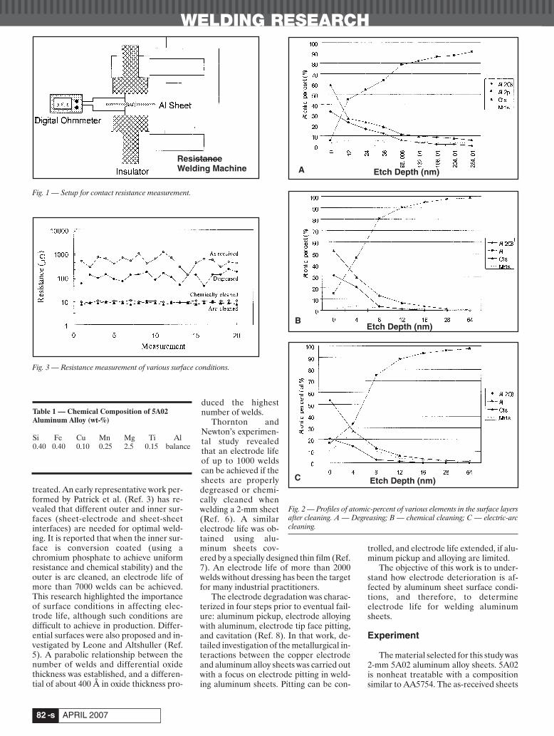
WELDING RESEARCH
APRIL 2007-s82
treated. An early representative work per-formed by Patrick et al. (Ref. 3) has re-vealed that different outer and inner sur-faces (sheet-electrode and sheet-sheetinterfaces) are needed for optimal weld-ing. It is reported that when the inner sur-face is conversion coated (using achromium phosphate to achieve uniformresistance and chemical stability) and theouter is arc cleaned, an electrode life ofmore than 7000 welds can be achieved.This research highlighted the importanceof surface conditions in affecting elec-trode life, although such conditions aredifficult to achieve in production. Differ-ential surfaces were also proposed and in-vestigated by Leone and Altshuller (Ref.5). A parabolic relationship between thenumber of welds and differential oxidethickness was established, and a differen-tial of about 400 Å in oxide thickness pro-
duced the highestnumber of welds.
Thornton andNewton’s experimen-tal study revealedthat an electrode lifeof up to 1000 weldscan be achieved if thesheets are properlydegreased or chemi-cally cleaned whenwelding a 2-mm sheet(Ref. 6). A similarelectrode life was ob-tained using alu-minum sheets cov-ered by a specially designed thin film (Ref.7). An electrode life of more than 2000welds without dressing has been the targetfor many industrial practitioners.
The electrode degradation was charac-terized in four steps prior to eventual fail-ure: aluminum pickup, electrode alloyingwith aluminum, electrode tip face pitting,and cavitation (Ref. 8). In that work, de-tailed investigation of the metallurgical in-teractions between the copper electrodeand aluminum alloy sheets was carried outwith a focus on electrode pitting in weld-ing aluminum sheets. Pitting can be con-
trolled, and electrode life extended, if alu-minum pickup and alloying are limited.
The objective of this work is to under-stand how electrode deterioration is af-fected by aluminum sheet surface condi-tions, and therefore, to determineelectrode life for welding aluminumsheets.
Experiment
The material selected for this study was2-mm 5A02 aluminum alloy sheets. 5A02is nonheat treatable with a compositionsimilar to AA5754. The as-received sheets
Table 1 — Chemical Composition of 5A02Aluminum Alloy (wt-%)
Si Fe Cu Mn Mg Ti Al0.40 0.40 0.10 0.25 2.5 0.15 balance
Fig. 1 — Setup for contact resistance measurement.
Fig. 2 — Profiles of atomic-percent of various elements in the surface layersafter cleaning. A — Degreasing; B — chemical cleaning; C — electric-arccleaning.
A
B
C
Fig. 3 — Resistance measurement of various surface conditions.
Resistance Welding Machine Etch Depth (nm)
Etch Depth (nm)
Etch Depth (nm)
Li 4 07corr:Layout 1 3/12/07 8:39 AM Page 82
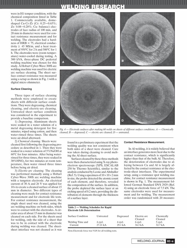
were in H1 temper condition, with thechemical composition listed in Table1. Commercially available, dome-shaped Cu-Cr-Zr (Cr: 0.25~0.65%;Zr: 0.08~0.20%; Cu: balance) elec-trodes of face radius of 100 mm, and20 mm in diameter were used for con-tact resistance measurement and forwelding. The electrodes had a hard-ness of HRB = 75, electrical conduc-tivity ≥ 45 MS/m, and a heat treat-ment of 950°C for 2 h and 500°C for 1h. The electrodes were (room temper-ature) water-cooled during testing. A300 kVA, three-phase DC pedestalwelding machine was chosen for thisstudy. A Hobart Cyber-Wave 300S arcwelding machine was used for electricarc surface cleaning. The sheet sur-face contact resistance was measuredusing a setup as shown in Fig. 1 with adigital micro ohmmeter.
Surface Cleaning
Three types of surface cleaningmethods were employed to createsheets with different surface condi-tions. They were degreasing, chemicalcleaning, and electric-arc cleaning.Untreated sheet surface conditionwas considered in the experiment toprovide a baseline comparison.
1) Degreasing. Aluminum sheetswere soaked in a water solution of ametal degreasing detergent for fiveminutes, wiped using cotton, and thenwater-rinsed three times. The sheetswere air-dried afterward.
2) Chemical cleaning. Sheets werecleaned first following the degreasing pro-cedure as described in 1. Then they weresoaked in a water solution of 5%NaOH at60°C for four minutes. After being water-rinsed for three times, they were soaked in30%HNO3 for two minutes at room tem-perature, then water rinsed three timesbefore being air dried.
3) Electric-arc cleaning. The cleaningwas performed manually using a HobartCyber-Wave 300S arc welding machinewith a tungsten electrode. An electricalcurrent of 30 A and 26 V was applied for10 s to create a cleaned surface of about 15mm in diameter. Two different types ofcleaning were made for contact resistancemeasurement and for electrode life tests.For contact resistance measurement, thesingle sheet used was cleaned, using thearc welding machine on both sides, whichwere to contact with the electrodes. A cir-cular area of about 15 mm in diameter wascleaned on each side. For the sheets usedfor welding, only the side of a sheet thatwas to be in contact with the electrodeduring welding was cleaned. The sheet-sheet interface was not cleaned as it was
found in a preliminary experiment that thewelding quality was not consistent whenboth sides of a sheet were cleaned. Carewas taken during cleaning to avoid melt-ing the Al sheet surface.
Surfaces cleaned by these three methodswere then characterized using X-ray photo-electron spectroscopy (XPS, ESCALAB250 by Thermo Scientific), similar to theanalysis conducted by Leone and Altshuller(Ref. 5). Using a specimen of 10 ×10×2 mmin size, the probe detected the atomic countof each element, and therefore, revealedthe composition of the surface. In addition,the probe depleted the surface layer at anetching speed of 0.2 nm/s, providing the dis-tribution of elements through the thicknessof a surface layer.
Contact Resistance Measurement.
In Al welding, it is widely believed thatan interface generates more heat due to thecontact resistance, which is significantlyhigher than that of the bulk Al. Therefore,the deterioration of electrodes due to al-loying between Cu and Al is largely af-fected by the contact resistance at the elec-trode-sheet interfaces. The experimentalsetup, using a resistance spot welding ma-chine, for contact resistance measurementis shown in Fig. 1. The measurement fol-lowed German Standard DVS 2929 (Ref.4) using an electrode force of 7.5 kN. Thesame electrodes were used for measure-ment and for welding. The measurementorder was randomized with 20 measure-
-s83WELDING JOURNAL
WELDING RESEARCH
Fig. 4 — Electrode surfaces after making 60 welds on sheets of different surface conditions. A — Chemicallycleaned; B — degreased; C — electric-arc cleaned; D — untreated.
Table 2 — Welding Schedules for Rapid Electrode Life Determination
Surface Condition Untreated Degreased Electric-arc ChemicallyCleaned Cleaned
Welding Time and 4 cycl. 4 cycl. 6 cycl. 5 cycl.Current 27.21 kA 29.1 kA 34.3 kA 32.7 kA
Note:Electrode force was 9 kN for all welding tests.
A B
C D
Li 4 07corr:Layout 1 3/12/07 8:39 AM Page 83

WELDING RESEARCH
APRIL 2007-s84
ments taken for each surface cleaning con-dition. In order to make consistent mea-surements, the electrodes were cleanedafter each measurement using the same gritsandpapers.
Rapid Electrode Life Determination
Before conducting electrode life tests,a set of electrodes was used to make asmall number of welds, i.e., 60 welds undereach of the four surface conditions. Theelectrodes were then compared with thosetested for life, and such a comparison mayprovide a possibility of determining elec-trode life after making 60 welds only.
An electrode life is closely related tothe welding parameters used. For in-stance, high electric current or long weld-ing time generates more heat at the elec-trode-sheet interface, and promotes theformation of bronze through the acceler-ated diffusion between Cu and Al, andtherefore, shortens electrode life. How-ever, such unfavorable conditions cannotbe avoided in spot welding aluminum as a
certain level of welding current and weld-ing time is necessary to produce an ac-ceptable weld nugget. An experiment wasconducted first to determine appropriatewelding schedules, as listed in Table 2, withthe minimum weld size of 5√t (t is Al sheetthickness in millimeters) maintained foreach surface condition during the first 60welds. The unit of welding time was 50 Hzcycles, i.e., 1 cycle = 20 ms. An identicalelectrode force of 9 kN was used for allwelding, and welding times of 4, 5, or 6 cy-cles were chosen with appropriate weldingcurrent levels in order to achieve stableand sizeable weld nuggets.
Electrode Life Tests
Using the same schedules as listed inTable 2, electrode life tests were con-ducted on sheets with four different sur-face conditions. The test coupon size was40×500 mm. All welds were peel-tested tomeasure the weld size. A “failure” was de-fined as when there is no weld or a weldproduced is smaller than 3.5√t. When 5%
or more of 100 welds failed, the end of anelectrode life was reached. For specimensof chemically cleaned, electric-arccleaned, and degreased, one of every 100welds was tensile-shear tested, and one ofevery 50 welds was tested on specimenswith untreated surfaces.
Results and Discussion
The various surfaces were characterizedfirst by their composition, depth, and con-tact resistance. The electrode life was thenevaluated through measuring the quality ofthe welds on the aluminum sheets with var-ious surfaces. The surface features of theelectrodes were linked to the measuredelectrode life in order to predict electrodelife by making a small number of welds.
Surface Layers after Cleaning
The profiles of atomic-percent mea-sured by XPS are shown in Fig. 2A–C. Thethickness of a surface layer after cleaningcan be easily determined in Fig. 2 through
Fig. 5 — Composition profiles of electrode surfaces after 60 welds using the schedules of A — F = 4.5 kN, τ = 60 ms; B — F = 4.5 kN, τ = 180 ms; C — F= 9.0 kN, τ = 60 ms; D — F = 9.0 kN, τ = 180 ms. The red line is for Cu, green is for Al, and blue is for Mg.
A B
C D
(WT
)%
(WT
)%
(WT
)%
(WT
)%
Li 4 07corr:Layout 1 3/12/07 8:40 AM Page 84

-s85WELDING JOURNAL
WELDING RESEARCH
the changes in atomic-percent of Al2O3along the etching depth. The thickness ofthe Al2O3 layer is estimated around 170nm for the degreased surface, and it isabout 12 nm for both the chemicallycleaned and electric-arc cleaned. It can beseen that the percent of aluminum in-creases approaching the base metal as theamount of Al2O3 decreases with depth.The amount of oxygen changes in a simi-lar manner as Al2O3. However, oxygenalso exists in Mg oxides, in addition toAl2O3, although at a much smaller por-tion. In general, the chemically and electric-arc cleaned surfaces have muchthinner and more uniform Al2O3 layersthan a degreased surface does. The uni-formity of aluminum oxide layers wastested by measurements at different loca-tions on a treated surface.
Contact Resistance
The measured resistances of varioussurface conditions are plotted in Fig. 3,using a setup as shown in Fig. 1. As shown
in the figure, there is a significant differ-ence in contact resistance among thesheets of different surface conditions.Electric-arc cleaning resulted in the low-est contact resistance, possibly due to thefact that the layer of grease and oxides onthe surface was burned off under the in-tensive heat of the electric arc. The basemetal was exposed and little oxidation oc-curred after cleaning as the cleaning wasperformed under the protection of Ar gas.The time elapsed between cleaning andmeasurement (and welding for the testson electrode life) was a few hours in whichonly a thin layer of Al2O3 was expected toform as revealed in Fig. 2A–C by XPSmeasurement. Softening of the base metalin the cleaned surface area occurredunder the electric-arc heat. In fact, mea-surements showed that the hardness of anelectric-arc-cleaned surface (Vickershardness of 60) is about two-thirds of thatof a degreased surface (Vickers hardnessof 90). This makes the contact area be-tween the electrode and sheet larger thanwould be for untreated sheets or treated
by other means. The resistance of chemically cleaned
surfaces is fairly uniform with a magnitudeslightly higher than those electric-arccleaned. Degreased surfaces have a highercontact resistance, which is still signifi-cantly lower than that of untreated sur-faces. The contact resistance of degreasedand untreated surfaces is not as uniform asthose chemically or electric-arc cleaned.The resistance values for chemicallycleaned, degreased, and untreated surfaceconditions are consistent with those pub-lished in literature.
Rapid Electrode Life Evaluation
The electrode faces after 60 weldsusing the schedules listed in Table 2 onfour different surface conditions areshown in Fig. 4. The upper and lower elec-trodes after 60 welds under each conditionhad very similar appearances, and there-fore, only the upper electrodes were usedto characterize the influence of surfaceconditions on electrodes, as shown in the
Fig. 6 — Electrode life testing results. A — Chemically cleaned; B — degreased; C — electric-arc cleaned; D — untreated surfaces. The dashed lines representthe minimum weld diameter (3.5√t) for the sheets.
A B
C D
Li 4 07corr:Layout 1 3/12/07 8:42 AM Page 85

WELDING RESEARCH
APRIL 2007-s86
figure. These electrodes show a clear re-gion of metallurgical changes on theirfaces, due to an intensive heating and apressurized contact with the Al sheets. Insuch a zone, a silver-colored ring of alu-minum pickup is visible on all electrodes.However, the appearance of such a ring isdifferent in the four electrodes used toweld the sheets with four different surfaceconditions. The ring is thin and clear withthe chemically cleaned surfaces, thicker,yet still clear, with the degreased. The ringbecomes blurry and thicker for electric-arc cleaned, and very fuzzy and thick forthat with untreated condition. The changeof the electrode surface is a direct result ofmetallurgical reactions occurring duringwelding, and therefore, the appearanceprovides a possibility of understanding themetallurgical processes and the trend ofelectrode deterioration if the electrodesare to be used for more welding using thesame schedule. A thick and blurry ring ofAl pickup may represent an unstable elec-trode-sheet contact during a continuouswelding process, as resulting from alloyingbetween Cu and Al and removing the re-sultant bronze from the electrode surfaceat many locations.
On the other hand, a clearly definedand narrow silver band may be the resultof a consistent contact between the elec-trode and the sheets, with a lesser amountof material removed from the surface. Ox-
idation of Cu is also observed on the elec-trode faces. Fig. 4A and B appears less ox-idized than Figure 4C and D. The surfacesof the electrodes show a significant rough-ening (in the form of small craters) onthose using untreated and electric-arccleaned sheets, while the electrodes usedon chemically cleaned and degreasedsheets are much smoother.
Figure 4 clearly shows that weldingusing sheets of different surface condi-tions creates distinctively different ap-pearances of electrode faces. Recognizingsuch differences may help in predictingelectrode life after making only a smallnumber of welds. This is possible by link-ing the features of these electrodes to theirrespective electrode lives produced inelectrode life tests.
Effect of Welding Schedules
The alloying between copper elec-trodes and aluminum sheets is also influ-enced by electrode force and weldingtime. As shown in Fig. 5, the profiles of Cu,Al, and Mg along a line through the elec-trode center, measured through a linescanning of chemical composition, de-pend on both factors. Low electrode force(4.5 kN) and long welding time (180 ms)generate more heat at the electrode-sheetinterface, and therefore a larger amountof alloying with Al and Mg (Fig. 5B) than
with a shorter welding time — Fig. 5A. Asimilar effect of welding time is also ob-served with higher electrode force (9.0 kN,as in Fig. 5C, D), but the severity of alloy-ing is significantly lessened with high elec-trode force, as can be seen by comparingFig. 5A with 5C, and 5B with 5D. A largeelectrode force creates low contact resis-tance, and therefore less heat generationand alloying at the electrode-sheet inter-face. Thus, a large electrode force is pre-ferred for electrode life.
Effect of Surface Conditions on Electrode Life
The electrode lives determined by weld-ing using sheets of four different surfaceconditions are shown in Fig. 6. In weldingchemically cleaned sheets more than 2300quality welds were produced; the electrodeswere slightly worn and they were still farfrom the end of their lives as shown in Fig.6A. Electrodes used to weld degreasedsheets have a life of more than 2000 welds— Fig. 6B. In this case, the variation of welddiameters grows large at the end of the elec-trode life, but is significantly smaller thanthose for electric-arc cleaned and untreatedsheets — Fig. 6C, D. As shown in Fig. 6C,the electrode life is about 1700 welds whensheets were electric-arc cleaned. When un-treated sheets were used, the electrode lifeis about 200 welds, which is significantly
Fig. 7 — Electrode surface morphology after life tests. A — Chemically cleaned; B — degreased; C — electric-arc cleaned; D — untreated aluminum sheets.The electrodes on the left side are from the lower arm of the welding machine (negative), and those on the right side are from the upper arm (positive).
A B
C D
Li 4 07corr:Layout 1 3/12/07 8:43 AM Page 86

WELDING RESEARCH
-s87WELDING JOURNAL
shorter than any of those treated sheets.Therefore, the surface condition of sheetsplays a key role in determining electrode lifein welding Al..
The faces of electrodes after electrodelife tests using various surface conditionsare shown in Fig. 7, arranged in the sameorder as their electrode lives — Fig. 6. Theelectrodes used in welding untreated sheets(Fig. 7D) appear less worn than others.However, they were used to make onlyabout 200 welds, while the others made1700 welds (electric-arc cleaning, Fig. 7C)or more than 2000 welds (chemical clean-ing, Fig. 7A; and degreasing, Fig. 7B).
The effects of surface conditions onelectrode life can be evaluated by consid-ering the magnitude and uniformity ofcontact resistance between the electrodeand sheet. The contact resistance can bedirectly measured, or it can be indirectlyestimated using the linear relationship be-tween the contact resistance and oxidethickness established by Leone and Alt-shuller (Ref. 5). Chemically cleaned sur-faces have the thinnest oxide layer (Fig.2), and therefore, the lowest contact resis-tance, as shown in Fig. 3, and they pro-
duced the longest electrode life. On theother hand, untreated sheets exhibited thehighest contact resistance and yielded theshortest electrode life.
The impact of contact resistance isclearly shown by the appearance of theelectrodes at the end of their respectivelives in Fig. 7. Low contact resistance ben-efits the electrode life primarily due to lessoxidation and alloying, which results inless heating at the contact interface andlong electrode life. The electrodes used toweld chemically cleaned sheets have slightalloying and oxidation on the surface afterthe life test, and those for degreasedsheets have craters due to depletion ofbronze, and a large area of Cu-Al alloying.The electric-arc cleaned sheets deterio-rated the electrodes the most, as evi-denced by the large number of craters andAl pickup/alloying on the electrode surfaces.
The consistency and uniformity of elec-trode-sheet contact play an important rolein determining electrode life. As discussedin previous sections, nonuniformly distrib-uted contact resistance on a sheet surfaceinduces uneven, localized heating be-
tween the sheet and a Cu electrode duringwelding. Severe oxidation and alloyingmay occur at these locations, resulting in anonuniform distribution of surface resis-tivity on the Cu electrode face, which inturn, affects subsequent welding. Oxida-tion and alloying occur on the electrodesurface during every welding cycle. An ac-cumulative effect of such a process is thecontinuous deterioration of the electrodesurface. As a result, the current distribu-tion changes from weld to weld and pro-duces inconsistent welds if the electrodesurface damage is severe enough.
Although Fig. 3 shows that electric-arccleaned sheets have a lower, and moreconsistent contact resistance than de-greased sheets, it is not always possible tocreate a uniform and consistent surface byelectric-arc cleaning, especially when it’sperformed manually while trying toachieve sufficient cleaning without melt-ing the surface. The rough surface of theelectrode after 60 welds shown in Fig. 4Cmay be the result of the inconsistently arc-cleaned sheet surfaces. This explains thatelectric-arc cleaning produces lower con-tact resistance but shorter electrode life
A B
C D
Fig. 8 — Average diameters and standard deviations of welds. A — Chemical cleaning; B — degreasing; C — electric-arc cleaning methods; D — untreatedsheets.
Li 4 07corr:Layout 1 3/12/07 8:43 AM Page 87

WELDING RESEARCH
APRIL 2007-s88
than degreasing. Another possible reasonis that the thin aluminum oxide layer re-maining on the sheets after degreasingwould serve as a protection layer, whichprohibits the interdiffusion between Cuand Al, while not producing much local-ized heating in the contact area.
The modified surface properties of theelectric-arc cleaned sheets may be responsi-ble for the relatively short electrode life.The surface of such a treated sheet is soft-ened by electric-arc heating, which results ina large contact area between the electrodeand the sheet under an electrode force of 9kN. Therefore, welding such sheets needshigh electric current in order to achieve aminimum current density for making aweld. As shown in Table 2, welding electric-arc cleaned sheets requires the highestwelding current and longest welding timeamong all surface conditions. The surfacesof the electrodes used to weld electric-arccleaned sheets in Fig. 7 have significantlymore damage than those using other clean-ing methods. There are many large anddeep craters, large area of Al deposit, andthe contact area appears significantly largerthan others. When intensive alloying and
alloy depletion from an electrode surfaceoccur, the effective contact area betweenthe electrode and a sheet surface becomesunstable — it can be small at one weld andresult in a large current density, and it canbe large at the next weld and result in verylow electric current density producing lowweld penetration or an undersized weld.Such changes in contact area are randomand produce large variations in the weldscreated.
Electrical polarity appears to have someeffects on the electrode deterioration. Sim-ilar effects were discussed by Lum et al.(Ref. 8). In Fig. 7, for each pair of elec-trodes, the one on the left side was takenfrom the lower or negative electrode arm.These electrodes appear less damaged thanthose on the right side, which were takenfrom the upper, or positive electrode arm.This phenomenon might be explained con-sidering the micro morphology of the con-tact interface and the dynamics of resistanceheating, and is not a subject of this study.
The variability of weld quality in awelding process is an important index inproduction. It may also provide a usefulindicator for electrode life, as a large vari-
ability indicates that the welding processbecomes unstable, and it may be close tothe end of electrode life. In order to un-derstand the influence of surface condi-tions, both average weld diameters andstandard deviations are plotted in Fig. 8.These quantities were calculated on every50 welds in the electrode life tests. Weld-ing chemically cleaned sheets producedfairly consistent welds and a small, but al-most constant standard deviation — Fig.8A. It can be seen, when welding underother surface conditions, that accompany-ing a drop in the average weld diameterwhen an electrode life approached its end,the standard deviation of diameters in-creased dramatically. From the figure, itcan be seen that an increase of about300% in standard deviation is observed forall surface conditions when the electrodelife was reached. The standard deviationbefore the sudden increase is about 0.4mm, and it jumps to about 1.4 mm ormore, accompanied by a visible drop inweld diameters when it’s close to an elec-trode life. In the case of electric-arc clean-ing, the first such increase in standard de-viation doesn’t correspond to an average
Fig. 9 — Tensile-shear strengths of welds. A — Chemically cleaned; B — degreased; C — electric-arc cleaned; D — untreated sheets, taken during electrode lifetests.
A B
C D
Li 4 07corr:Layout 1 3/12/07 8:44 AM Page 88

WELDING RESEARCH
-s89WELDING JOURNAL
weld diameter falling below the desiredvalue. However, this occurrence is fairlyclose to the end of the electrode life.Therefore, the change in standard devia-tion of weld diameters during welding canbe a useful index for electrode life.
Tensile-shear strengths of the welds ofvarious surface conditions are shown inFig. 9. One of every 100 welds during elec-trode life tests was tested, except for un-treated sheets for which one of every 50welds was tested. Chemical cleaning againproduced the highest strength with theleast variability. Degreasing has lowerstrength and larger variability, and electric-arc cleaned is quite unstable, sim-ilar to those observed in Fig. 6 for mea-sured weld sizes. Such differences can beattributed to the magnitude and distribu-tion of contact resistivity of the sheetscleaned using different methods.
Relation between 60-Weld Electrodes andElectrode Lives
As seen in Fig. 4, the electrodes used toweld sheets of different surface conditionshave distinctively different characteristics.The subsequent electrode life tests provedthat the electrode lives are different.Therefore, it is possible to predict theelectrode life for a particular stack-up ofsheets and welding schedule, only after asmall number of welds, such as 60 welds,as in this study. By analyzing the featuresshown in Fig. 4 and linking them to thecorresponding electrode lives, the follow-ing observations can be made:
1) The border of the reaction area onthe electrode face. An electrode of longlife tends to have a small, thin, yet clear sil-ver band on the surface after a small num-ber of welds. Such a band indicates a sta-ble contact between the electrode and thesheet. On the other hand, a large, thick,and fuzzy silver band may indicate a shortelectrode life, as in the cases of electric-arccleaning and untreated sheets because ofthe repeated alloying and removal of thealloy.
2) Black oxidation (burning) marks atthe center of an electrode face. Inside thesilver band there is usually an area of oxi-dation that is directly related to the clean-ness of the electrode-sheet interface.Greases and other organic compounds atthe interface may be burned under the in-tensive heating during welding. As suchreaction is due to low conductive or eveninsulating substances at the interface, it di-rectly reflects the contact resistivity or re-sistance. Therefore, it affects the deterio-ration of electrodes and electrode life. Bycomparing Figs. 4 and 6, it can be seen thatsmall and light burning marks on the elec-trode face after 60 welds indicate a longelectrode life, and large and dark burningmarks correspond to a short electrode life.
Such an understanding may help pre-dict the electrode life for a combination ofsheets, electrodes, and welding parame-ters by conducting a small number ofwelds that produce visible characteristicson the electrode faces, as observed in thisstudy. However, a detailed and quantita-tive relationship between electrode sur-face features and electrode life needs amore thorough and well-designed investi-gation to develop.
Summary
In this study, the effects of sheet sur-face conditions on electrode life havebeen investigated. Using four types of sur-face treatments, namely, chemical clean-ing, degreasing, electric-arc cleaning, andoriginal (untreated), drastically differentelectrode lives were obtained. The effectsof surface conditions on electrode life canbe attributed to the influences of the mag-nitude and distribution of surface resistiv-ity, as summarized in the following.
Chemical cleaning. It produced thethinnest and most uniform layer of Al2O3on sheet surfaces. The greases on surfacesare also largely removed in the process. Asa result, very little alloying and oxidationoccur during welding, yielding a long elec-trode life (more than 2300 welds, yet farfrom the electrode life).
Degreasing. It did not change the thick-ness or the uniformity of Al2O3 on sheetsurfaces. Welding using degreased Alsheets can produce an electrode life ofmore than 2000 welds in this study.
Electric-arc cleaning. It produces simi-lar contact resistance compared withchemical cleaning, and a significantlylonger electrode life (about 1700 welds)than untreated surfaces. However, elec-trode life shorter than those using the de-greasing cleaning method, which has ahigher surface contact resistance.
Original surface. The untreated sheetshave both greases and oxides on the sur-faces, and the electrode life in weldingsuch sheets was about 200 welds.
In general, the surface condition of Alsheets plays an important role in affectingthe electrode life. From this study it can beconcluded that welding untreated sheetswithout dressing the electrodes is notpractical. The electric-arc cleaned sur-faces produced a shorter life than de-greased, and therefore, a low-contact re-sistance doesn’t guarantee a longelectrode life. Although chemical cleaningproduced desirable electrode life, it iscostly, time-consuming, and environmen-tally unfriendly. Degreasing is more prac-tical than other cleaning methods and itmay be adopted in large-volume produc-tion, such as automobile manufacture.
The tensile strength of welds testedduring electrode life tests shows a similar
trend as the weld diameter. This study alsoshows that together with the average welddiameter, the change in standard devia-tion of weld diameters provides a feasibleindication of electrode life. The rapidelectrode life determination method usingonly 60 welds provides a possibility of se-lecting appropriate welding schedules,sheet stackups, and surface conditions forprolonged electrode life.
Acknowledgment
The authors would like to express theirsincere gratitude for the financial supportof the Ministry of Science and Technologyof China (the 10th Five-Year Plan).
References
1. Welding Handbook. 1992. Chinese Weld-ing Society. Vol. 1, 1st Edition. pp. 229–233.
2. Dilthey, U., Aachen, and Hicken, S. 1998.Metallographic investigations into wearprocesses on electrodes during the resistancespot welding of aluminum. Welding and Cutting.Munich, 1, pp. 34–40.
3. Patrick, E. P., Auhl, J. R., and Sun, T. S.1984. Understanding the process mechanisms iskey to reliable resistance spot welding alu-minum auto body components, SAE TechnicalPaper 840291.
4. Resistance welding: Measurement of thetransition resistance in aluminum materials.1985. DVS 2929. Deustscher Verband furSchweisstechnik e.V Dusseldorf (in German).
5. Leone, G. L., and Altshuller, B. 1984. Im-provement on the resistance spot weldability ofaluminum body sheet, SAE Technical Paper840292.
6. Thornton, M. C., Newton, C. J., Keay, B.F. P., Sheasby, P. G., and Evans, J. T. 1997. Somesurface factors that affect the spot welding ofaluminum. Trans IMF 75(4): 165–170.
7. Ikeda, R., Yasuda, K., and Hashiguchi, K.1998. Resistance spot weldability and electrodewear characteristics of aluminum alloy sheets.Welding in the World 41: 492–498.
8. Lum, I., Fukumoto, S., Biro, E., Boomer,D. R., and Zhou, Y. 2004. Electrode pitting inresistance spot welding of aluminum alloy 5182,Metallurgical and Materials Transactions A,35(1): 217–226.
Li 4 07corr:Layout 1 3/12/07 8:45 AM Page 89
WELDING RESEARCH
APRIL 2007-s90
ABSTRACT. Effective tracking of theweld joint is crucial to the development ofa high-performance control system for thegas metal arc welding (GMAW) process.This paper presents a new approach to ef-fectively track weld joints based on chargecoupled device (CCD) sensors. Due to thepresence of spatter, dust, and strong arcnoises in welding environments, it hasproved to be difficult to detect the weldjoint from the CCD images captured inreal time. In order to improve the robust-ness of weld joint tracking, this paper pre-sents a novel approach, based on the Bub-ble and M-band wavelet transform, fordetecting the image edge of molten weldpools from the images captured duringGMAW. The experimental results showthat the effectiveness of the proposedmethod in detecting the edges of moltenweld pools and identifying weld jointseven when the welding images are pre-sented with much noise. Based on the weldjoint identification, a PID control ap-proach is employed to manipulate thewelding gun in order to produce a desiredweld joint. The control experimentsdemonstrate that, based on the proposedjoint tracking, the control of an S-shapedweld joint has been effectively deliveredwith good precision.
Introduction
Extensive research has been per-formed for developing efficient and effec-tive techniques for tracking and control-ling the welding process. Many systemshave been developed in research labora-tories; however, they are still challengedby a variety of uncertainties and complex-
ities when used in industrial environ-ments. The objective of this research is todevelop effective and efficient algorithmsfor the online identification of weld joints,based on the processing of the moltenpool images and to facilitate the intelli-gent control of the welding process (Refs.1–4). For the development of systems withgreat value for industrial applications, it isdesired to develop approaches capable oftracking the weld joint without using anadditional light source (i.e., directly usingthe light produced by the welding arc) inorder to reduce the cost, although it wouldincrease the complexity and difficulty ofweld joint tracking.
Most of the existing techniques havebeen developed for tracking and controlof the gas tungsten arc (GTA) and gasmetal arc (GMA) welding processes. Thearc sensing method is an effective tech-nique that can identify weld defects andtrack weld joints exactly through arc scan-ning. Based on this, many joint trackingsystems have been developed and practi-cally applied for gas metal arc and CO2welding. In practice, the arc sensor re-quires a set of weaving arc devices, whichhas a complex structure and is more easilyimplemented with a welding robot. It is re-stricted on the aspect of mechanism andits weaving frequency is rather low, so it isonly suitable for bevels, corner joints, lapjoints, etc., and is not effective for high-speed and sheet joint tracking of buttjoints. Vision sensor methods can directlyobserve the area of the weld joint to facil-itate artificial intelligence (Refs. 5–7). Inthe GMAW process, the molten pool im-ages are presented with much noise (suchas bright spots and lines due to spatters).
As a result, the weld joint is usually verydifficult to identify in real time. Kim et al.(Ref. 8) developed a robot visual trackingsystem for arc welding in which a CCDsensor is used to capture the positional in-formation of the joint. In this system, anadditional laser light was used. Gao et al.(Ref. 9) developed a fuzzy logic controllerfor a welding robot. Tao and Levick (Ref.10) developed a method to assess the feed-back variables for arc joint tracking in a ro-botic GMAW system. They investigatedthe use of a welding power source for feed-back control of welding current and volt-age. Cheng et al. (Ref. 11) developed animage processing algorithm for joint de-tecting and tracking in a pulse GTAWprocess. Their algorithm has been testedwhen the current waveform was con-trolled under a strictly level (the moltenpool image was presented with very littlearc noise). Recently, Kim et al. (Ref. 12)and Matsui et al. (Ref. 13) developed athree-dimensional sensor system for therecognition of operating conditions andweld joint tracking. Matsui’s GMAW sys-tem has been tested on thin steel sheets.
For effective identification of the weldjoint, this paper proposes a new approachto detect the edge of molten pools fromthe images obtained during the GMAWprocess by applying wavelet transformtechniques to extract the space and fre-quency information of the images. Basedon the excellent capability of extractingthe space-frequency information from im-ages (Refs. 14, 15), the arc welding imagesignals with strong noise can be depictedwith the wavelet coefficients through theprocess of multiresolution decomposition.On the other hand, the image noise can beeliminated according to the signal energyestimated based on the associated waveletcoefficients.
In this study, a Windows®-based systemhas been developed for joint tracking con-trol of the GMAW process, in which a high-performance A/D image converter and anovel edge detection algorithm are embed-ded. The wavelet transform algorithm is
A Wavelet Transform-Based Approach forJoint Tracking in Gas Metal Arc Welding
A new system was developed for joint tracking and control of the GMA welding process based on CCD sensors
without an external light source
BY J. X. XUE, L. L. ZHANG, Y. H. PENG, AND L. JIA
KEYWORDS
Gas Metal Arc WeldingJoint TrackingProcess ControlProcess MonitoringC-Mn Steels
JIA XIANG XUE ([email protected]) iswith School of Mechanical Engineering, SouthChina University of Technology, Guangzhou,China. LI LING ZHANG is with Department ofMechanical and Power engineering, NanchangInstitute of Technology, Nanchang, China. YONGHONG PENG is with University of Bradford, UK.LIN JIA is with, South China University of Tech-nology Library, Guangzhou, China.
Xue April 2007 corr:Layout 1 3/12/07 9:07 AM Page 90
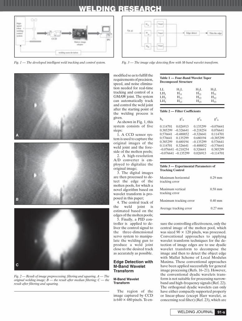
WELDING RESEARCH
-s91WELDING JOURNAL
modified so as to fulfill therequirements of precision,speed, and noise elimina-tion needed for real-timetracking and control of aGMAW joint. The systemcan automatically trackand control the weld jointafter the starting point ofthe welding process isgiven.
As shown in Fig. 1, thissystem consists of fivesteps:
1. A CCD sensor sys-tem is used to capture theoriginal images of theweld joint and the fore-side of the molten pools;
2. A high-resolutionA/D converter is em-ployed to digitalize theoriginal image;
3. The digital imagesare then processed to de-tect the edge of themolten pools, for which anovel algorithm based onwavelet transform is pro-posed in this paper;
4. The central track ofthe weld joint is estimated based on theedges of the molten pools;
5. Finally, a PID con-troller is applied to de-liver the control signal tothe three-dimensionalservo system to manipu-late the welding gun toproduce a weld jointclose to the desired trackas accurately as possible.
Edge Detection withM-Band WaveletTransform
M-Band Wavelet Transform
The region of theimage captured by CCDis 640 × 480 pixels. To en-
sure the controlling effectiveness, only thecentral image of the molten pool, whichwas sized 90 × 120 pixels, was processed.Conventional approaches to applyingwavelet transform techniques for the de-tection of image edges are to use dyadicwavelet transform to decompose theimage and then to detect the object edgewith Mallat Scheme of Local ModulusMaxima. These conventional approacheshave been applied successfully for generalimage processing (Refs. 16–21). However,the conventional dyadic wavelets trans-form is not suitable for processing narrow-band and high-frequency signals (Ref. 22).The orthogonal dyadic wavelets can onlyhave either compactly supported propertyor linear-phase (except Harr wavelet, asconcerning real filter) (Ref. 23), which are
A
B
C
Fig. 1 — The developed intelligent weld tracking and control system.
Fig. 2 — Result of image preprocessing: filtering and squaring. A — Theoriginal welding image; B — the result after median filtering; C — theresult after filtering and squaring.
Fig. 3 — The image edge detecting flow with M-band wavelet transform.
Table 1 — Four-Band Wavelet Taper Decomposed Structure
LL H1L H2L H3LLH1 H11 H21 H31LH2 H12 H22 H32LH3 H13 H23 H33
Table 2 — Filter Coefficients
hn g1n g2
n g3n
0.114701 0.026913 0.135299 –0.0766410.385299 –0.326641 –0.218254 0.0766410.576641 –0.488852 –0.326641 0.1147010.576641 0.135299 0.680194 –0.3852990.385299 0.680194 –0.135299 0.5766410.114701 0.326641 –0.488852 –0.576641–0.076641 –0.218254 0.326641 0.385299–0.076641 –0.135299 0.026913 –0.114701
Table 3 — Experimental Parameters of Tracking Control
Maximum horizontal 0.29 mmtracking error
Maximum vertical 0.58 mmtracking error
Maximum tracking error 0.40 mm
Average tracking error 0.27 mm
Xue April 2007 corr:Layout 1 3/12/07 9:07 AM Page 91
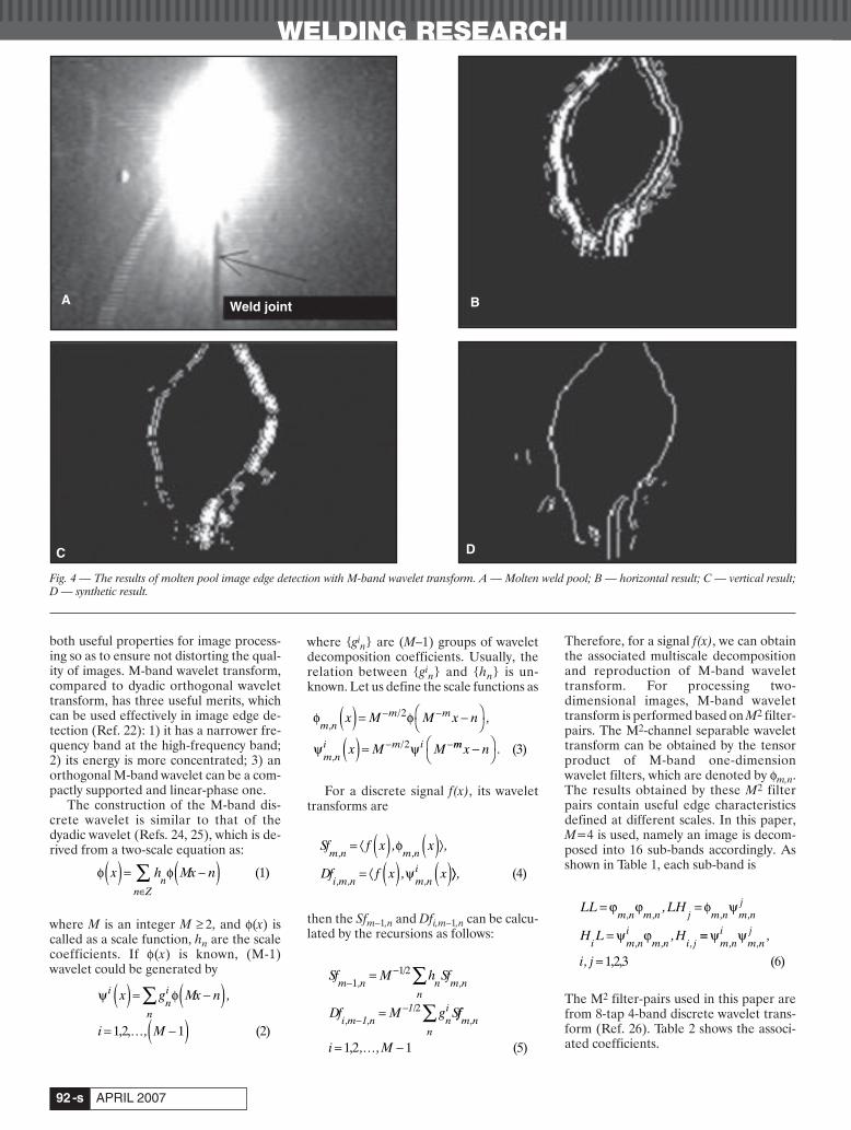
both useful properties for image process-ing so as to ensure not distorting the qual-ity of images. M-band wavelet transform,compared to dyadic orthogonal wavelettransform, has three useful merits, whichcan be used effectively in image edge de-tection (Ref. 22): 1) it has a narrower fre-quency band at the high-frequency band;2) its energy is more concentrated; 3) anorthogonal M-band wavelet can be a com-pactly supported and linear-phase one.
The construction of the M-band dis-crete wavelet is similar to that of thedyadic wavelet (Refs. 24, 25), which is de-rived from a two-scale equation as:
where M is an integer M ≥ 2, and φ(x) iscalled as a scale function, hn are the scalecoefficients. If φ(x) is known, (M-1)wavelet could be generated by
where {gin} are (M–1) groups of wavelet
decomposition coefficients. Usually, therelation between {gi
n} and {hn} is un-known. Let us define the scale functions as
For a discrete signal f(x), its wavelettransforms are
then the Sfm–1,n and Dfi,m–1,n can be calcu-lated by the recursions as follows:
Therefore, for a signal f(x), we can obtainthe associated multiscale decompositionand reproduction of M-band wavelettransform. For processing two-dimensional images, M-band wavelettransform is performed based on M2 filter-pairs. The M2-channel separable wavelettransform can be obtained by the tensorproduct of M-band one-dimensionwavelet filters, which are denoted by φm,n.The results obtained by these M2 filterpairs contain useful edge characteristicsdefined at different scales. In this paper,M=4 is used, namely an image is decom-posed into 16 sub-bands accordingly. Asshown in Table 1, each sub-band is
The M2 filter-pairs used in this paper arefrom 8-tap 4-band discrete wavelet trans-form (Ref. 26). Table 2 shows the associ-ated coefficients.
LL LH
H L H
m n m n j m n m nj
i m ni
m n i j
= =
=
ϕ ϕ φ ψ
ψ ϕ
, , , ,
, , ,
,
, ==
=
ψ ψm ni
m nj
i j, ,
,
, 1,2,3 (6)Sf M h Sf
Df M g S
m n nn
m n
i m n ni
n
−−
−−
=
=
∑
∑
11/2
/2
, ,
, ,11 ff
i M
m n,
, ,= −1,2 1 (5)…
φ φx h Mx nn
n Z( ) = −( )
∈∑ (1)
φ φ
ψ ψ
m nm m
m ni m i
x M M x n
x M M
,/
,/
,( ) = −⎛⎝
⎞⎠
( ) =
− −
− −
2
2 mm x n−⎛⎝
⎞⎠ . (3)
ψ φini
n
x g Mx n
i M
( ) = −( )= … −( )
∑ ,
,1,2, 1 (2)
Sf f x x
Df f x x
m n m n
i m n m ni
, ,
, , ,
, ,
,
= ⟨ ( ) ( )⟩
= ⟨ ( ) ( )φ
ψ ⟩⟩ , (4)
WELDING RESEARCH
APRIL 2007-s92
Fig. 4 — The results of molten pool image edge detection with M-band wavelet transform. A — Molten weld pool; B — horizontal result; C — vertical result;D — synthetic result.
A B
C D
Weld joint
Xue April 2007 corr:Layout 1 3/12/07 9:08 AM Page 92
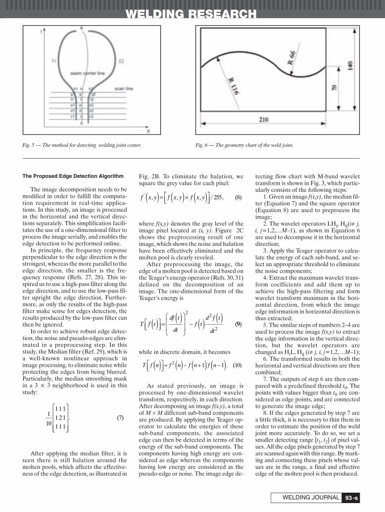
WELDING RESEARCH
-s93WELDING JOURNAL
The Proposed Edge Detection Algorithm
The image decomposition needs to bemodified in order to fulfill the computa-tion requirement in real-time applica-tions. In this study, an image is processedin the horizontal and the vertical direc-tions separately. This simplification facili-tates the use of a one-dimensional filter toprocess the image serially, and enables theedge detection to be performed online.
In principle, the frequency responseperpendicular to the edge direction is thestrongest, whereas the more parallel to theedge direction, the smaller is the fre-quency response (Refs. 27, 28). This in-spired us to use a high-pass filter along theedge direction, and to use the low-pass fil-ter upright the edge direction. Further-more, as only the results of the high-passfilter make sense for edges detection, theresults produced by the low-pass filter canthen be ignored.
In order to achieve robust edge detec-tion, the noise and pseudo-edges are elim-inated in a preprocessing step. In thisstudy, the Median filter (Ref. 29), which isa well-known nonlinear approach inimage processing, to eliminate noise whileprotecting the edges from being blurred.Particularly, the median smoothing maskin a 3 × 3 neighborhood is used in thisstudy:
After applying the median filter, it isseen there is still halation around themolten pools, which affects the effective-ness of the edge detection, as illustrated in
Fig. 2B. To eliminate the halation, wesquare the grey value for each pixel:
where f(x,y) denotes the gray level of theimage pixel located at (x, y). Figure 2Cshows the preprocessing result of oneimage, which shows the noise and halationhave been effectively eliminated and themolten pool is clearly reveled.
After preprocessing the image, theedge of a molten pool is detected based onthe Teager’s energy operator (Refs. 30, 31)defined on the decomposition of animage. The one-dimensional form of theTeager’s energy is
while in discrete domain, it becomes
As stated previously, an image isprocessed by one-dimensional wavelettransform, respectively, in each direction.After decomposing an image f(x,y), a totalof M × M different sub-band componentsare produced. By applying the Teager op-erator to calculate the energies of thesesub-band components, the associatededge can then be detected in terms of theenergy of the sub-band components. Thecomponents having high energy are con-sidered as edge whereas the componentshaving low energy are considered as thepseudo-edge or noise. The image edge de-
tecting flow chart with M-band wavelettransform is shown in Fig. 3, which partic-ularly consists of the following steps:
1. Given an image f(x,y), the median fil-ter (Equation 7) and the square operator(Equation 8) are used to preprocess theimage;
2. The wavelet operators LHj, Hij(i≠ j,i, j=1,2,…M–1), as shown in Equation 6are used to decompose it in the horizontaldirection;
3. Apply the Teager operator to calcu-late the energy of each sub-band, and se-lect an appropriate threshold to eliminatethe noise components;
4. Extract the maximum wavelet trans-form coefficients and add them up toachieve the high-pass filtering and formwavelet transform maximum in the hori-zontal direction, from which the imageedge information in horizontal direction isthus extracted;
5. The similar steps of numbers 2–4 areused to process the image f(x,y) to extractthe edge information in the vertical direc-tion, but the wavelet operators arechanged as HiL, Hij (i≠ j, i, j=1,2,…M–1);
6. The transformed results in both thehorizontal and vertical directions are thencombined;
7. The outputs of step 6 are then com-pared with a predefined threshold t0. Thepoints with values bigger than t0 are con-sidered as edge points, and are connectedto generate the image edge;
8. If the edges generated by step 7 area little thick, it is necessary to thin them inorder to estimate the position of the weldjoint more accurately. To do so, we set asmaller detecting range [t1, t2] of pixel val-ues. All the edge pixels generated by step 7are scanned again with this range. By mark-ing and connecting these pixels whose val-ues are in the range, a final and effectiveedge of the molten pool is then produced.
T f tdf t
dtf t
d f t
dt( )⎡
⎣⎢⎤⎦⎥ =
( )⎛
⎝
⎜⎜
⎞
⎠
⎟⎟
− ( ) ( )22
2(99)
T f n f n f n f n( )⎡⎣⎢
⎤⎦⎥ = ( ) − +( ) −( )2 1 1 (10).
f x y f x y f x y' , , , / ,( ) = ( ) ( )⎡⎣⎢
⎤⎦⎥× 255 (8)
1
10
1 1 11 2 11 1 1
(7)
⎡
⎣
⎢⎢⎢⎢
⎤
⎦
⎥⎥⎥⎥
.
Fig. 5 — The method for detecting welding joint center. Fig. 6 — The geometry chart of the weld joint.
Xue April 2007 corr:Layout 1 3/13/07 3:05 PM Page 93

WELDING RESEARCH
APRIL 2007-s94
Joint Tracking and Control ofGMAW
Joint Tracking Based on Molten PoolEdge Detection
The procedure of the proposed edge de-tection algorithm for weld joint tracking isillustrated by the example shown in Fig. 4.Figure 4A shows the original image of awelding molten pool and the weld joint. Fig-ure 4B and C show, respectively, the resultsof the edge of the molten pool detected inhorizontal and vertical directions. Both ofthem are produced by combining the resultsof three sub-band components with thehighest Teager energies. It is shown that thejoint edge detected in the horizontal direc-tion is clearer than the edge detected in thevertical direction (which is not so obvious inmany ranges).
As the orthogonal M-band wavelet trans-form has a linear phase, the results of theedge detected in different directions can beadded up directly, without any positionaldeviation. Figure 4D is the synthetic resultbased on combining the results obtained inhorizontal and vertical directions. Compar-
ing Fig. 4D with the results of Fig. 4B andC, the result of edge detection is signifi-cantly improved. These results demonstratethat the edge information obtained in thevertical and horizontal directions can wellcomplement each other, and the proposedmethod is able to improve obviously the de-tection of edges of molten pools.
Based on the detected edge of moltenpools, the weld joint track, defined by a setof central points of molten pools, can thenbe determined. To do so, the CCD scanssuccessively along the X-axis with a dis-tance of three pixels. As illustrated by Fig.5, based on the detected edges of a moltenpool (denoted by curves S1 and S2), eachscan line generates a pair of characteristicpoints such as c1, c2, and d1, d2, and so on,and the associated central points, such aspoints c and d defined by c1, c2, and d1, d2.The weld joint track is then obtained byconnecting all these central points, such asthe curve AB shown in Fig. 5.
Control of Weld Joint
In our system, the control variable is thepositional deviation of the welding torch,
which is measured at the upright to the weldjoint’s direction. When the weld joint hasbeen identified by means of the edge detec-tion algorithm, the position of welding torchis adjusted by a PID close control loop. Thecontroller adjusts the torch movement inreal time according to the positional devia-tion, in order to produce a weld joint asclose as possible to the desired weld joint.The PID controller used a discrete form as
where Kp = 0.6, Ti = 0.25, Td = 0.05, T =0.1.
Experimental Results
Experimental Condition
A 2-mm-thick Q235 steel workpiecewith a narrow joint was used in our exper-iments to make the tracking method more
u t k eTk
Te
k T
Te e
p kp
ij
j
k
p dk k
( ) = +
+ −( )=
−
∑1
1(11)
Fig. 7 — Pictures of the following: A — Original position of the weld joint; B — the calibration.
Fig. 8 — The front photo of the practical joint tracking. Fig. 9 — The curve of tracking deviation.
A B
Xue April 2007 corr:Layout 1 3/12/07 9:10 AM Page 94
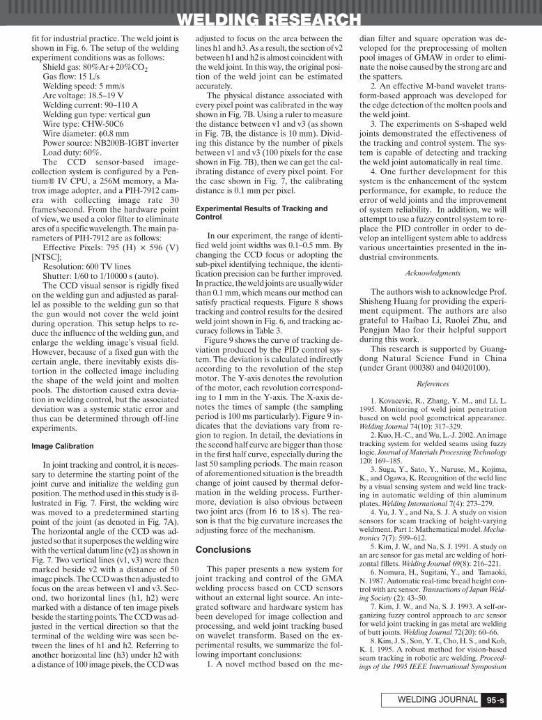
WELDING RESEARCH
-s95WELDING JOURNAL
fit for industrial practice. The weld joint isshown in Fig. 6. The setup of the weldingexperiment conditions was as follows:
Shield gas: 80%Ar+20%CO2Gas flow: 15 L/sWelding speed: 5 mm/sArc voltage: 18.5–19 VWelding current: 90–110 AWelding gun type: vertical gunWire type: CHW-50C6Wire diameter: φ0.8 mmPower source: NB200B-IGBT inverterLoad duty: 60%.The CCD sensor-based image-
collection system is configured by a Pen-tium® IV CPU, a 256M memory, a Ma-trox image adopter, and a PIH-7912 cam-era with collecting image rate 30frames/second. From the hardware pointof view, we used a color filter to eliminatearcs of a specific wavelength. The main pa-rameters of PIH-7912 are as follows:
Effective Pixels: 795 (H) × 596 (V)[NTSC];
Resolution: 600 TV linesShutter: 1/60 to 1/10000 s (auto).The CCD visual sensor is rigidly fixed
on the welding gun and adjusted as paral-lel as possible to the welding gun so thatthe gun would not cover the weld jointduring operation. This setup helps to re-duce the influence of the welding gun, andenlarge the welding image’s visual field.However, because of a fixed gun with thecertain angle, there inevitably exists dis-tortion in the collected image includingthe shape of the weld joint and moltenpools. The distortion caused extra devia-tion in welding control, but the associateddeviation was a systemic static error andthus can be determined through off-lineexperiments.
Image Calibration
In joint tracking and control, it is neces-sary to determine the starting point of thejoint curve and initialize the welding gunposition. The method used in this study is il-lustrated in Fig. 7. First, the welding wirewas moved to a predetermined startingpoint of the joint (as denoted in Fig. 7A).The horizontal angle of the CCD was ad-justed so that it superposes the welding wirewith the vertical datum line (v2) as shown inFig. 7. Two vertical lines (v1, v3) were thenmarked beside v2 with a distance of 50image pixels. The CCD was then adjusted tofocus on the areas between v1 and v3. Sec-ond, two horizontal lines (h1, h2) weremarked with a distance of ten image pixelsbeside the starting points. The CCD was ad-justed in the vertical direction so that theterminal of the welding wire was seen be-tween the lines of h1 and h2. Referring toanother horizontal line (h3) under h2 witha distance of 100 image pixels, the CCD was
adjusted to focus on the area between thelines h1 and h3. As a result, the section of v2between h1 and h2 is almost coincident withthe weld joint. In this way, the original posi-tion of the weld joint can be estimated accurately.
The physical distance associated withevery pixel point was calibrated in the wayshown in Fig. 7B. Using a ruler to measurethe distance between v1 and v3 (as shownin Fig. 7B, the distance is 10 mm). Divid-ing this distance by the number of pixelsbetween v1 and v3 (100 pixels for the caseshown in Fig. 7B), then we can get the cal-ibrating distance of every pixel point. Forthe case shown in Fig. 7, the calibratingdistance is 0.1 mm per pixel.
Experimental Results of Tracking andControl
In our experiment, the range of identi-fied weld joint widths was 0.1–0.5 mm. Bychanging the CCD focus or adopting thesub-pixel identifying technique, the identi-fication precision can be further improved.In practice, the weld joints are usually widerthan 0.1 mm, which means our method cansatisfy practical requests. Figure 8 showstracking and control results for the desiredweld joint shown in Fig. 6, and tracking ac-curacy follows in Table 3.
Figure 9 shows the curve of tracking de-viation produced by the PID control sys-tem. The deviation is calculated indirectlyaccording to the revolution of the stepmotor. The Y-axis denotes the revolutionof the motor, each revolution correspond-ing to 1 mm in the Y-axis. The X-axis de-notes the times of sample (the samplingperiod is 100 ms particularly). Figure 9 in-dicates that the deviations vary from re-gion to region. In detail, the deviations inthe second half curve are bigger than thosein the first half curve, especially during thelast 50 sampling periods. The main reasonof aforementioned situation is the breadthchange of joint caused by thermal defor-mation in the welding process. Further-more, deviation is also obvious betweentwo joint arcs (from 16 to 18 s). The rea-son is that the big curvature increases theadjusting force of the mechanism.
Conclusions
This paper presents a new system forjoint tracking and control of the GMAwelding process based on CCD sensorswithout an external light source. An inte-grated software and hardware system hasbeen developed for image collection andprocessing, and weld joint tracking basedon wavelet transform. Based on the ex-perimental results, we summarize the fol-lowing important conclusions:
1. A novel method based on the me-
dian filter and square operation was de-veloped for the preprocessing of moltenpool images of GMAW in order to elimi-nate the noise caused by the strong arc andthe spatters.
2. An effective M-band wavelet trans-form-based approach was developed forthe edge detection of the molten pools andthe weld joint.
3. The experiments on S-shaped weldjoints demonstrated the effectiveness ofthe tracking and control system. The sys-tem is capable of detecting and trackingthe weld joint automatically in real time.
4. One further development for thissystem is the enhancement of the systemperformance, for example, to reduce theerror of weld joints and the improvementof system reliability. In addition, we willattempt to use a fuzzy control system to re-place the PID controller in order to de-velop an intelligent system able to addressvarious uncertainties presented in the in-dustrial environments.
Acknowledgments
The authors wish to acknowledge Prof.Shisheng Huang for providing the experi-ment equipment. The authors are alsograteful to Haibao Li, Ruolei Zhu, andPengjun Mao for their helpful supportduring this work.
This research is supported by Guang-dong Natural Science Fund in China(under Grant 000380 and 04020100).
References
1. Kovacevic, R., Zhang, Y. M., and Li, L.1995. Monitoring of weld joint penetrationbased on weld pool geometrical appearance.Welding Journal 74(10): 317–329.
2. Kuo, H.-C., and Wu, L.-J. 2002. An imagetracking system for welded seams using fuzzylogic. Journal of Materials Processing Technology120: 169–185.
3. Suga, Y., Sato, Y., Naruse, M., Kojima,K., and Ogawa, K. Recognition of the weld lineby a visual sensing system and weld line track-ing in automatic welding of thin aluminumplates. Welding International 7(4): 273–279.
4. Yu, J. Y., and Na, S. J. A study on visionsensors for seam tracking of height-varyingweldment. Part 1: Mathematical model. Mecha-tronics 7(7): 599–612.
5. Kim, J. W., and Na, S. J. 1991. A study onan arc sensor for gas metal arc welding of hori-zontal fillets. Welding Journal 69(8): 216–221.
6. Nomura, H., Sugitani, Y., and Tamaoki,N. 1987. Automatic real-time bread height con-trol with arc sensor. Transactions of Japan Weld-ing Society (2): 43–50.
7. Kim, J. W., and Na, S. J. 1993. A self-or-ganizing fuzzy control approach to arc sensorfor weld joint tracking in gas metal arc weldingof butt joints. Welding Journal 72(20): 60–66.
8. Kim, J. S., Son, Y. T., Cho, H. S., and Koh,K. I. 1995. A robust method for vision-basedseam tracking in robotic arc welding. Proceed-ings of the 1995 IEEE International Symposium
Xue April 2007 corr:Layout 1 3/12/07 9:11 AM Page 95
WELDING RESEARCH
APRIL 2007-s96
363–368.9. Xiangdong, G., Yamamoto, M., and
Mohri, A. 1997. Application of fuzzy logic con-troller in the seam tracking of arc-weldingrobot. 23rd International Conference 3:1367–1372.
10. Tao, J., and Levick, P. 1999. Assessmentof feedback variables for through the arc seamtracking in robotic gas metal arc welding. Pro-ceedings of the 1999 IEEE International Confer-ence 4: 3050–3052.
11. Nian, C., Zhen-guo, S., and Qiang, C.2001. A visual sensor based weld seam trackingmethod for precision pulse TIG weld. Transac-tions of the China Welding Institution 22(4): 17-s to 20-s.
12. Kim, M. Y., Cho, H. S., and Ki, J-h. 2001.Neural network-based recognition of naviga-tion environment for intelligent shipyard weld-ing robots. Proceedings of 2001 IEEE/RSJ Inter-national Conference 1: 446–45.
13. Matsui, S., and Goktug, G. 2002. Slitlaser sensor guided real-time seam tracking arcwelding robot system for non-uniform jointgaps. 2002 IEEE International Conference 1:159–162.
14. Cotronei, M., Montefusco, L. B., andPuccio, L. 1998. Multiwavelet analysis and sig-nal processing. IEEE Trans. On Circuits and Sys-tems — II: Analog and Digital Processing 45(8):970-s to 987-s.
15. Witkin, A. 1983. Scale space filtering.
Proc. Int. Joint Conf. Artificial Intell.16. Meyer, Y. 1992. Wavelets and Operators.
Cambridge University Press. 17. Fusheng, Y. 1999. Engineering Analysis
and Application of Wavelet Transform. Beijing,Academic Press (in Chinese).
18. Berman, Z., and John, S. 1993. Proper-ties of the multiscale maxima and zero-cross-ings representations. IEEE Trans on Signal Pro-cessing 41(12): 3216-s to 3231-s.
19. Mallat, S., and Hwang, W. L. Singularitydetection and processing with wavelets. IEEETrans. Inform. Theory 38(2): 617-s to 643-s.
20. Canny, J. 1986. A computational ap-proach to edge detection. IEEE Trans. On Pat-tern Analysis and Machine Intelligence 8(6): 619-s to 691-s.
21. Shensa, M. J. 1992. The discrete wavelettransform: Wedding the A Trous and Mallat al-gorithm. IEEE Trans. on Signal Processing40(10): 2464-s to 2482-s.
22. Zhang, J. K., and Bao, Z. 1999. The the-ory of M-band orthogonal compactly supportedwavelet. China Science (E) 29(5): 427-s to 441-s.
23. Xia, X. G., and Zhang, Z. 1993. On sam-pling theorem, wavelets, and wavelet trans-forms. IEEE Trans on Signal Processing 41(12):3524-s to 3535-s.
24. Steffen, P., Heller, P. N., Gopinath, R. A.,and Burrus, C. S. 1993. Theory of regular M-band wavelet bases. IEEE Transactions on Sig-
nal Processing 41(12): 3497-s to 3511-s.25. Zou, Z., and Tewfik, A. H. 1992. Dis-
crete orthogonal M-band wavelet decomposi-tion. Proc. ICASSP, San Francisco, Calif. 4(4):605–608.
26. Aydin, T., Yemez, Y., Anarim, E., andSankur, B. 1996. Multidirectional and multi-scale edge detection via M-band wavelet trans-form. IEEE Transactions on Image Processing5(9): 1370-s to 1377-s.
27. Ikonomopoulos, A., and Kunt, M. Imagecoding via directional filtering. IEEE Trans. OnSignal Processing 8(2): 179–202.
28. Tang, X. H., Gong, Y., and Gong, Y. H.1997. Image edge detection by using M-bandwavelet transform. Journal of UEST of China26(2): 117-s to 120-s.
29. Wang, Y., and Mitra, S. K. 1991. Edgedetection based on orientation disturbance ofgradient images. 1991 IEEE International Con-ference on Acoustics, Speech, and Signal Pro-cessing 4: 2569–2572.
30. Akarun, L., and Haddad, R. A. 1993.Adaptive decimated median filters for imageprocessing. 1993 IEEE International Conferenceon Acoustics, Speech, and Signal Processing 5:69–72.
31. Alkin, O., and Caglar, H. 1995. Design ofefficient M-band coders with linear-phase andperfect-reconstruction properties. IEEE Trans-actions on Signal Processing 43(7): 1579-s to1590-s.
Correction to Article Titled‘Fabrication of a Carbon Steel-to-Stainless Steel Transition JointUsing Direct Laser Deposition —A Feasibility Study,’
by J. D. Farren, J. N. DuPont, and F. F. Noecker
This article was published in the March 2007edition of the Welding Journal and utilizedthe WRC Constitution Diagram as an aid tointerpreting microstructures that formedbetween a transition joint. The transition jointhad carbon steel on one end and stainless steelon the other end. The diagram appears inFigure 9A, and experimental compositionmeasurements were plotted directly on thediagram. In this diagram, the lines of constantferrite contents were mistakenly labeled aspercent ferrite. The WRC Diagram usesFerrite Number, not percent ferrite. Thus, thepercent values labeled on the diagram areincorrect, and the values actually representFerrite Number.
Dear Readers:
The Welding Journal encourages an exchangeof ideas through letters to the editor. Please sendyour letters to the Welding Journal Dept., 550NW LeJeune Rd., Miami, FL 33126. You canalso reach us by FAX at (305) 443-7404 or bysending an e-mail to Kristin Campbell at [email protected].
REPRINTS REPRINTS
To order custom reprints of 100 or more of articles in
Welding Journal,call FosteReprints at
(219) 879-8366 or(800) 382-0808 or.
Request for quotes can be faxed to(219) 874-2849.
You can e-mail FosteReprints at [email protected]
Xue April 2007 corr:Layout 1 3/12/07 9:36 AM Page 96

WELDING RESEARCH
-s97WELDING JOURNAL
ABSTRACT. Many fundamental physicalrelationships governing the friction stirwelding (FSW) process remain largely un-explored. Recent studies have aided in thediscovery and clarification of manyprocess fundamentals. A 16-run fractionalfactorial experiment was used to analyzethe effects of nine FSW input parameterson measured process outputs. It was con-firmed that the most significant input pa-rameters are spindle speed, feed rate, andtool depth. In addition, the distance be-tween the weld and side of the plate had asignificant effect on measured Z-forceand shoulder depth, and thus should beconsidered in future studies.
Introduction
Friction stir welding (FSW) is a solid-state joining process having many desir-able attributes. It involves forcing a rotat-ing cylindrical tool with a protruding pininto the joint to be welded. Once sub-merged in the material, the tool is ad-vanced along the joint line. Frictionalheating is sufficient to locally soften theworkpieces and the rotating motion of thetool ‘stirs’ the workpieces together. Theresult is a fully consolidated weld with su-perior quality and properties to those oftraditional arc welds.
There are three primary control para-meters available in FSW: spindle speed,feed rate, and tool vertical position. Dur-
ing the FSW process, a number of othervariables can be measured, includingmotor power, tool temperature, andforces. The relationships between the fun-damental control parameters and themeasured process variables have neverbeen completely explored. The relation-ship between the inputs and outputs isshown in Fig. 1.
For efficient application of FSW, it isdesired that all important process para-meters that affect a weld outcome be iden-tified and the sensitivity of operating con-ditions to these process parameters becharacterized. In addition to the threemost fundamental parameters, it is be-lieved that there are ‘environmental’ vari-ables that may need to be controlled. En-vironmental variables are those notreadily controlled during a weld as op-posed to variables such as spindle speedthat are easily controlled. Perhaps a modelsimilar to that shown in Fig. 1 with the ad-dition of environmental variables is a bet-ter representation of the FSW process.The environmental variables may have animpact on the process and affect the finalweld quality and performance.
Researchers have previously studiedvarious ‘input’ control parameters and theirrelation to many ‘output’ responses. Theirobjectives all differ but the underlying pur-pose is to further analyze fundamentals ofthe FSW process and explore the relation-ship between inputs and outputs.
Nishihara and Nagasaka (Ref. 1) var-
ied spindle speed and feed rate and wereable to measure tool and anvil tempera-tures. Nishihara and Nagasaka (Ref. 1)along with Lienert et al. (Refs. 2–4) in-cluded tool temperatures as a response,which has not been common during ex-perimentation. Tang et al. (Ref. 5) variedwelding load (Z-force), spindle speed, andtools with or without a pin in an effort toinvestigate the workpiece temperaturedistribution and heat input. Jandric et al.(Ref. 6) studied the effects of spindlespeed and feed rate on weld quality andtemperature distribution. Colligan et al.(Ref. 7) investigated the effects of pin de-sign, spindle speed, and feed rate on spe-cific energy, power, plunge force, torque,and X- and Y-forces. Johnson (Ref. 8) var-ied different plunge depths, feed rates,and spindle speeds to explore their effectson forces and torques. Others have in-cluded workpiece alloy as part of theirstudies (Refs. 2, 8, 9). From these studiesand others, a wealth of information is ac-quired that aids in further studies and inunderstanding the FSW process.
To date, no known study has taken astatistical approach to accomplish the taskof relating inputs and outputs. As previ-ously discussed, there was a need to iden-tify and study primary variables that affectwelds. Thus, in the current study, a screen-ing design of experiments was chosen toidentify the effect of various weld inputson selected outputs in an effort to identifycritical process parameters.
A screening design of experiments(DOE) is a statistical method used tostudy many variables simultaneously andquantify their effects on a given responserelative to each other. By identifyingwhich variables have a large effect on a re-sponse, one can conclude which variablesare key input parameters.
This paper utilizes a 16-run screeningDOE to analyze the effects of nine inputson selected outputs. No duplication of ex-periments is used because the intent is toidentify the largest effects and not to com-
A Look at the Statistical Identificationof Critical Process Parameters in
Friction Stir WeldingTo analyze the effects of nine friction stir welding input
parameters on measured process outputs, a 16-run fractional factorial experiment was used
BY J. H. RECORD, J. L. COVINGTON, T. W. NELSON, C. D. SORENSEN, AND B. W. WEBB
KEYWORDS
Friction Stir Welding (FSW)Main EffectsProcess ParametersDesign of Experiments (DOE)
J. H. RECORD ([email protected]), formerly with Brigham Young Uni-versity’s Department of Mechanical Engineering,is now with *Lockheed Martin Missiles and FireControl. J. L. COVINGTON, formerly withBrigham Young University’s Department of Me-chanical Engineering, is now with W. L. Gore andAssociates, Inc. T. W. NELSON, C. D.SORENSEN, and B. W. WEBB are with Depart-ment of Mechanical Engineering, Brigham YoungUniversity, Provo, Utah.
*The opinions and conclusions expressed hereinare solely those of the author and do not neces-sarily reflect those of Lockheed Martin.
Record et al April 2007 corr:Layout 1 3/9/07 5:19 PM Page 97
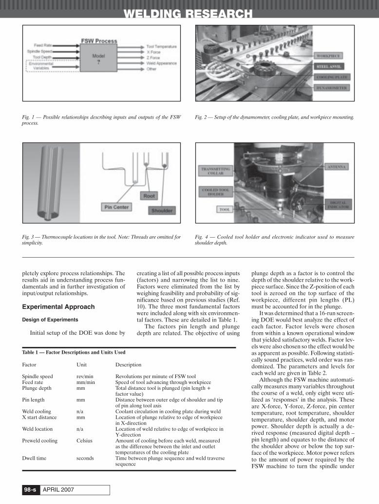
WELDING RESEARCH
APRIL 2007-s98
pletely explore process relationships. Theresults aid in understanding process fun-damentals and in further investigation ofinput/output relationships.
Experimental Approach
Design of Experiments
Initial setup of the DOE was done by
creating a list of all possible process inputs(factors) and narrowing the list to nine.Factors were eliminated from the list byweighing feasibility and probability of sig-nificance based on previous studies (Ref.10). The three most fundamental factorswere included along with six environmen-tal factors. These are detailed in Table 1.
The factors pin length and plungedepth are related. The objective of using
plunge depth as a factor is to control thedepth of the shoulder relative to the work-piece surface. Since the Z-position of eachtool is zeroed on the top surface of theworkpiece, different pin lengths (PL)must be accounted for in the plunge.
It was determined that a 16-run screen-ing DOE would best analyze the effect ofeach factor. Factor levels were chosenfrom within a known operational windowthat yielded satisfactory welds. Factor lev-els were also chosen so the effect would beas apparent as possible. Following statisti-cally sound practices, weld order was ran-domized. The parameters and levels foreach weld are given in Table 2.
Although the FSW machine automati-cally measures many variables throughoutthe course of a weld, only eight were uti-lized as ‘responses’ in the analysis. Theseare X-force, Y-force, Z-force, pin centertemperature, root temperature, shouldertemperature, shoulder depth, and motorpower. Shoulder depth is actually a de-rived response (measured digital depth –pin length) and equates to the distance ofthe shoulder above or below the top sur-face of the workpiece. Motor power refersto the amount of power required by theFSW machine to turn the spindle under
Fig. 1 — Possible relationships describing inputs and outputs of the FSWprocess.
Fig. 2 — Setup of the dynamometer, cooling plate, and workpiece mounting.
Table 1 — Factor Descriptions and Units Used
Factor Unit Description
Spindle speed rev/min Revolutions per minute of FSW toolFeed rate mm/min Speed of tool advancing through workpiecePlunge depth mm Total distance tool is plunged (pin length +
factor value)Pin length mm Distance between outer edge of shoulder and tip
of pin along tool axisWeld cooling n/a Coolant circulation in cooling plate during weldX start distance mm Location of plunge relative to edge of workpiece
in X-directionWeld location n/a Location of weld relative to edge of workpiece in
Y-directionPreweld cooling Celsius Amount of cooling before each weld, measured
as the difference between the inlet and outlettemperatures of the cooling plate
Dwell time seconds Time between plunge sequence and weld traversesequence
Fig. 3 — Thermocouple locations in the tool. Note: Threads are omitted forsimplicity.
Fig. 4 — Cooled tool holder and electronic indicator used to measure shoulder depth.
Record et al April 2007 corr:Layout 1 3/9/07 5:20 PM Page 98
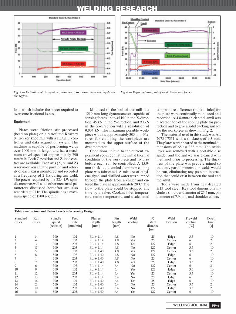
-s99WELDING JOURNAL
WELDING RESEARCH
load, which includes the power required toovercome frictional losses.
Equipment
Plates were friction stir processed(bead on plate) on a retrofitted Kearney& Trecker knee mill with a PLC/PC con-troller and data acquisition system. Themachine is capable of performing weldsover 1000 mm in length and has a maxi-mum travel speed of approximately 790mm/min. Both Z-position and Z-load con-trol are available. Each axis (X, Y, and Z)is servo-driven and the position and veloc-ity of each axis is monitored and recordedat a frequency of 2 Hz during any weld.The power required by the 22.4-kW spin-dle motor as well as all other measured pa-rameters discussed hereafter are alsorecorded at 2 Hz. The spindle has a maxi-mum speed of 1500 rev/min.
Mounted to the bed of the mill is a1219-mm-long dynamometer capable ofsensing forces up to 45 kN in the X-direc-tion, 45 kN in the Y-direction, and 90 kNin the Z-direction with a resolution of0.004 kN. The maximum possible work-piece width is approximately 305 mm. Fix-tures for clamping the workpiece aremounted to the upper surface of thedynamometer.
Conditions unique to the current ex-periment required that the initial thermalcondition of the workpiece and fixturesbefore each run be controlled. A 15.9-mm-thick liquid-cooled aluminum coolingplate was fabricated. A mixture of ethyl-ene glycol and distilled water was pumpedthrough the plate from a chiller and en-tered the plate at approximately 20°C. Theflow to the plate could be stopped anytime by a valve. Coolant inlet tempera-ture, outlet temperature, and a calculated
temperature difference (outlet – inlet) forthe plate were continually monitored andrecorded. A 4.8-mm-thick steel anvil wasplaced on top of the cooling plate for pro-tection and to give a solid backing surfacefor the workpiece as shown in Fig. 2.
The material used in this study was AL7075-T7351 with a thickness of 9.5 mm.The plates were sheared to the nominal di-mensions of 680 × 222 mm. The oxidelayer was removed with a portable discsander and the surface was cleaned withmethanol prior to processing. The thick-ness of the plate was predetermined sothat only partial penetration welds wouldbe run, eliminating any possible interac-tion that could exist between the tool andthe anvil.
Tools were made from heat-treatedH13 tool steel. Key tool dimensions in-clude a shoulder diameter of 25.4 mm, pindiameter of 7.9 mm, and shoulder concav-
Fig. 5 — Definition of steady-state region used. Responses were averaged overthis region.
Fig. 6 — Representative plot of weld depths and forces.
Table 2 — Factors and Factor Levels in Screening Design
Standard Run Spindle Feed Plunge Pin Weld X Weld Preweld Dwellorder order speed rate depth length cooling start location cooling time
[rev/min] [mm/min] [mm] [mm] distance [°C] [s][mm]
1 14 300 102 PL + 1.14 4.8 No 25 Edge 3.5 102 4 500 102 PL + 1.14 4.8 Yes 25 Center 6 23 3 300 203 PL + 1.14 4.8 Yes 127 Edge 6 24 15 500 203 PL + 1.14 4.8 No 127 Center 3.5 105 5 300 102 PL + 1.40 4.8 Yes 127 Center 3.5 26 8 500 102 PL + 1.40 4.8 No 127 Edge 6 107 1 300 203 PL + 1.40 4.8 No 25 Center 6 108 7 500 203 PL + 1.40 4.8 Yes 25 Edge 3.5 29 6 300 102 PL + 1.14 6.4 No 127 Center 6 210 9 500 102 PL + 1.14 6.4 Yes 127 Edge 3.5 1011 12 300 203 PL + 1.14 6.4 Yes 25 Center 3.5 1012 13 500 203 PL + 1.14 6.4 No 25 Edge 6 213 16 300 102 PL + 1.40 6.4 Yes 25 Edge 6 1014 2 500 102 PL + 1.40 6.4 No 25 Center 3.5 215 10 300 203 PL + 1.40 6.4 No 127 Edge 3.5 216 11 500 203 PL + 1.40 6.4 Yes 127 Center 6 10
Record et al April 2007 corr:Layout 1 3/9/07 5:20 PM Page 99

WELDING RESEARCH
APRIL 2007-s100
ity angle of 6 deg. The pins were threadedwith a pitch of 0.91 mm. Pin lengths were6.4 and 4.8 mm. The tool was used at a tiltangle of 2.5 deg.
Tools were modified to accommodateType K thermocouples for temperaturemeasurement at three locations within thetool. An EDM drill was used to cut long,straight, squared-bottomed holes to ac-commodate 1.59-mm-diameter stainlesssteel sheathed thermocouples at the loca-tions defined in Fig. 3. The titles of each lo-cation should be noted (pin center, root,and shoulder). The distance between thethermocouple and tool/workpiece inter-face at each location was less than 1.27 mm.
A liquid-cooled tool holder was used tominimize heat flow into the machine head,as seen in Fig. 4. The coolant flow rate wasapproximately 1.9 L/min and is such thatwhile welding there was typically less than1°C rise in coolant temperature from the
inlet of the toolholder to the out-let. Access holesnear the top of thetool holder allowedthe tool thermo-couples to be in-serted through theback of the tool.
A transmit-ting collar assem-bly is clamped tothe rotating por-tion of the toolholder and housesRF transmitters,which broadcastthe thermocouplereadings as FMsignals. The sig-nals are capturedby the receiver byway of a stationary
loop antenna. The data are then trans-ferred to the data-acquisition system.
Mounted to the tool holder is an elec-tronic digital indicator for tool depth mea-surement. It has a range of 25.4 mm and aresolution of 0.02 mm. An extensionadapter is connected to the indicator sothat weld depth is measured as close to thetool as possible to account for any localchanges in tool depth. Readout error asso-ciated with attaching such an adapter is es-timated to be 0.03 mm or less. The indica-tor readings are transferred to the dataacquisition system throughout the weld.
This digital indicator is used to measurethe actual plunge and weld depth as seen inFig. 4. Due to machine deflection, the pro-grammed plunge depth will not actually beachieved. Thus, it is important to measurethe actual tool depth throughout the weld.The indicator is zeroed when the tip of thepin comes into contact with the workpiece.
Friction Stir Processing Procedure
Plates were friction stir processed(FSP) in the following manner. A platewas secured at a predetermined locationon the anvil. Preweld cooling was per-formed to meet the condition specified inthe DOE. The plunge sequence was per-formed at 500 rev/min and at a plunge rateof 12.7 mm/min to the specified depth.The spindle speed during the dwell re-mained at 500 rev/min. After the dwell,the spindle speed was adjusted to thevalue dictated by the DOE and the toolbegan to traverse at a rate of 51 mm/min.The feed rate was then increased at a con-stant acceleration over a distance of 76mm until the desired feed rate was ob-tained. No adjustments in load control ortool depth control were made throughoutthe processing. Each extract sequence wasperformed at a spindle speed of 500rev/min.
Upon completing the 16 welds, the rawdata were plotted and organized using aspreadsheet. For each weld, a steady-state(SS) region was identified starting at 127mm into the weld and ending at 25.4 mmfrom the end of the weld. For each responseof interest, values were averaged over thatsteady-state region for use in further analy-sis. This steady-state region, along with theaveraged values for three selected re-sponses, is shown in Fig. 5 for the weldlisted as standard order 9 (see Table 2).
All extracted data were analyzed usingMinitab, a statistical software package ca-pable of DOE factorial design analysis. Theprincipal effects of all nine input factorswere calculated, and a Pareto chart was cre-ated for each given response. This methodof analysis shows graphically which factorsare most important and significant inreaching a desired response. Conclusionswere drawn from the Pareto charts.
Fig. 7 — Representative plot of tool temperatures and motor power.
Table 3 — Measured Responses Shown in Standard Order (nonrandomized order)
Standard SS X-force SS Y-force SS Z-force SS pin center SS root SS shoulder SS motor Shoulderorder [kN] [kN] [kN] temp. temp. temp. power depth
[°C] [°C] [°C] [kW] [mm]
1 4.942 –0.813 36.453 483 455 446 4.5 0.2422 4.956 0.089 37.168 515 481 476 5.7 0.2003 5.558 –0.024 33.719 457 437 435 4.6 0.2824 7.699 0.542 36.750 503 471 466 5.9 0.3365 5.320 –0.692 41.987 487 461 454 4.8 0.1336 4.423 0.155 37.597 515 479 475 5.7 0.0737 6.518 –0.660 43.879 477 455 447 5.2 0.1578 7.361 –0.164 44.434 511 478 474 6.4 0.2369 5.137 –0.374 35.812 480 453 435 4.6 0.27610 5.394 1.021 33.295 507 470 459 5.6 0.26111 7.060 0.290 37.617 465 447 438 5.0 0.29112 8.390 1.115 36.949 501 468 460 6.0 0.30513 5.371 –0.540 36.218 478 454 440 4.6 0.24714 6.103 0.956 39.995 513 475 469 5.9 0.08415 7.237 –0.019 40.560 468 449 439 5.1 0.27316 8.246 1.219 42.572 506 472 464 6.4 0.174
Shoulder Temp (C)
Record et al April 2007 corr:Layout 1 3/9/07 5:21 PM Page 100

-s101WELDING JOURNAL
WELDING RESEARCH
A B
C D
E F
Fig. 8 — Pareto charts of effects of inputs on (A) shoulder depth, (B) motor power, (C) root temperature, (D) X-force, (E) pin center temperature, (F) Y-force,(G) shoulder temperature, and (H) Z-force.
G H
Record et al April 2007 corr:Layout 1 3/9/07 5:22 PM Page 101
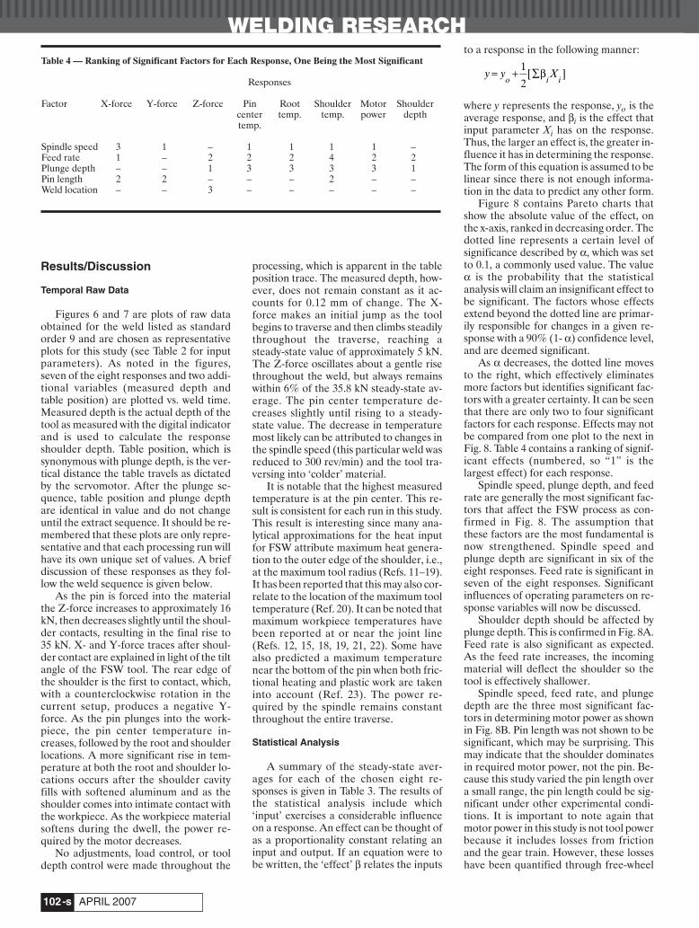
WELDING RESEARCH
APRIL 2007-s102
Results/Discussion
Temporal Raw Data
Figures 6 and 7 are plots of raw dataobtained for the weld listed as standardorder 9 and are chosen as representativeplots for this study (see Table 2 for inputparameters). As noted in the figures,seven of the eight responses and two addi-tional variables (measured depth andtable position) are plotted vs. weld time.Measured depth is the actual depth of thetool as measured with the digital indicatorand is used to calculate the responseshoulder depth. Table position, which issynonymous with plunge depth, is the ver-tical distance the table travels as dictatedby the servomotor. After the plunge se-quence, table position and plunge depthare identical in value and do not changeuntil the extract sequence. It should be re-membered that these plots are only repre-sentative and that each processing run willhave its own unique set of values. A briefdiscussion of these responses as they fol-low the weld sequence is given below.
As the pin is forced into the materialthe Z-force increases to approximately 16kN, then decreases slightly until the shoul-der contacts, resulting in the final rise to35 kN. X- and Y-force traces after shoul-der contact are explained in light of the tiltangle of the FSW tool. The rear edge ofthe shoulder is the first to contact, which,with a counterclockwise rotation in thecurrent setup, produces a negative Y-force. As the pin plunges into the work-piece, the pin center temperature in-creases, followed by the root and shoulderlocations. A more significant rise in tem-perature at both the root and shoulder lo-cations occurs after the shoulder cavityfills with softened aluminum and as theshoulder comes into intimate contact withthe workpiece. As the workpiece materialsoftens during the dwell, the power re-quired by the motor decreases.
No adjustments, load control, or tooldepth control were made throughout the
processing, which is apparent in the tableposition trace. The measured depth, how-ever, does not remain constant as it ac-counts for 0.12 mm of change. The X-force makes an initial jump as the toolbegins to traverse and then climbs steadilythroughout the traverse, reaching asteady-state value of approximately 5 kN.The Z-force oscillates about a gentle risethroughout the weld, but always remainswithin 6% of the 35.8 kN steady-state av-erage. The pin center temperature de-creases slightly until rising to a steady-state value. The decrease in temperaturemost likely can be attributed to changes inthe spindle speed (this particular weld wasreduced to 300 rev/min) and the tool tra-versing into ‘colder’ material.
It is notable that the highest measuredtemperature is at the pin center. This re-sult is consistent for each run in this study.This result is interesting since many ana-lytical approximations for the heat inputfor FSW attribute maximum heat genera-tion to the outer edge of the shoulder, i.e.,at the maximum tool radius (Refs. 11–19).It has been reported that this may also cor-relate to the location of the maximum tooltemperature (Ref. 20). It can be noted thatmaximum workpiece temperatures havebeen reported at or near the joint line(Refs. 12, 15, 18, 19, 21, 22). Some havealso predicted a maximum temperaturenear the bottom of the pin when both fric-tional heating and plastic work are takeninto account (Ref. 23). The power re-quired by the spindle remains constantthroughout the entire traverse.
Statistical Analysis
A summary of the steady-state aver-ages for each of the chosen eight re-sponses is given in Table 3. The results ofthe statistical analysis include which‘input’ exercises a considerable influenceon a response. An effect can be thought ofas a proportionality constant relating aninput and output. If an equation were tobe written, the ‘effect’ β relates the inputs
to a response in the following manner:
where y represents the response, yo is theaverage response, and βi is the effect thatinput parameter Xi has on the response.Thus, the larger an effect is, the greater in-fluence it has in determining the response.The form of this equation is assumed to belinear since there is not enough informa-tion in the data to predict any other form.
Figure 8 contains Pareto charts thatshow the absolute value of the effect, onthe x-axis, ranked in decreasing order. Thedotted line represents a certain level ofsignificance described by α, which was setto 0.1, a commonly used value. The valueα is the probability that the statisticalanalysis will claim an insignificant effect tobe significant. The factors whose effectsextend beyond the dotted line are primar-ily responsible for changes in a given re-sponse with a 90% (1- α) confidence level,and are deemed significant.
As α decreases, the dotted line movesto the right, which effectively eliminatesmore factors but identifies significant fac-tors with a greater certainty. It can be seenthat there are only two to four significantfactors for each response. Effects may notbe compared from one plot to the next inFig. 8. Table 4 contains a ranking of signif-icant effects (numbered, so “1” is thelargest effect) for each response.
Spindle speed, plunge depth, and feedrate are generally the most significant fac-tors that affect the FSW process as con-firmed in Fig. 8. The assumption thatthese factors are the most fundamental isnow strengthened. Spindle speed andplunge depth are significant in six of theeight responses. Feed rate is significant inseven of the eight responses. Significantinfluences of operating parameters on re-sponse variables will now be discussed.
Shoulder depth should be affected byplunge depth. This is confirmed in Fig. 8A.Feed rate is also significant as expected.As the feed rate increases, the incomingmaterial will deflect the shoulder so thetool is effectively shallower.
Spindle speed, feed rate, and plungedepth are the three most significant fac-tors in determining motor power as shownin Fig. 8B. Pin length was not shown to besignificant, which may be surprising. Thismay indicate that the shoulder dominatesin required motor power, not the pin. Be-cause this study varied the pin length overa small range, the pin length could be sig-nificant under other experimental condi-tions. It is important to note again thatmotor power in this study is not tool powerbecause it includes losses from frictionand the gear train. However, these losseshave been quantified through free-wheel
y y Xo i i
= + ∑1
2[ ]β
Table 4 — Ranking of Significant Factors for Each Response, One Being the Most Significant
Responses
Factor X-force Y-force Z-force Pin Root Shoulder Motor Shouldercenter temp. temp. power depthtemp.
Spindle speed 3 1 – 1 1 1 1 –Feed rate 1 – 2 2 2 4 2 2Plunge depth – – 1 3 3 3 3 1Pin length 2 2 – – – 2 – –Weld location – – 3 – – – – –
Record et al April 2007 corr:Layout 1 3/9/07 5:22 PM Page 102

experiments to be 1 kW or less for thespindle speeds used in this study.
Common among X- and Z-forces is thesignificance of feed rate. The most impor-tant factors for X-force are feed rate, pinlength, and spindle speed as shown in Fig.8D, 8F, and 8H. The faster a tool is driventhrough the workpiece and the longer thepin, the larger the required force. It is in-teresting that plunge depth is not significantfor X-force because it has been observedthat there is an effect of depth on X-force.Again, there is a heavy dependence of theseresults on the ranges of parameters usedand experimental conditions.
Factors affecting Z-force includeplunge depth and feed rate. An unex-pected significant effect is weld location.This is likely a good candidate to furtherconsider as an ‘environmental’ variablethat needs to be considered more closelyin future studies. It is noted that in weld-ing applications, weld location cannot becontrolled. Another unexpected result isthat for Z-force, spindle speed has no sig-nificant effect as it does for X-force.
For all three thermocouple locations inthe tool, spindle speed was the most sig-nificant factor in determining tempera-ture. Also common at all three locations isthe effect of plunge depth and feed rate. Itmight be speculated that significant ef-fects for all three temperature locationswould be the same. However, this is notthe case. Unexpectedly, pin length was asignificant factor for the shoulder temper-ature (Fig. 8G) but not for the pin centerand root temperatures.
It is essential to note that this studydoes not clarify interaction effects be-tween factors. There may be important in-teractions that are not elucidated here.The screening experiments used in thisstudy do not fully explore all relationships,but only allow identification of the mostimportant ones. Therefore, no conclusionmay be made regarding complete rela-tionships. Also, it is vital to note that thesignificance of these factors is true only forthe conditions of this study. For example,a dwell time of 60 s could affect some re-sponses but this study only included 2 and10 s dwell times.
Weld location and pin length are goodcandidates to be further controlled as the‘environmental’ variables that need to beconsidered more closely in future studiesbecause of their effect on responses.
This research was performed to pro-vide basic information. It does not seek tocomment much on its findings as com-pared to previous research or to fully ex-plore parameter relationships. This is be-cause results have been contradictory attimes. The authors’ intent is to 1) identifycritical process parameters through a sta-
tistical study, 2) present the results pub-licly, and 3) provide information thatother studies may use to fully exploreprocess parameter relationships.
Conclusions
This study used statistical experimen-tation to study important process parame-ters and the sensitivity of operating condi-tions to these process parameters. It isconcluded that for the conditions of thisstudy (tool, material, methods, levels,etc.):• Spindle speed, feed rate, and plunge
depth are the three most significant fac-tors of the FSW process.
• Z-force is most affected by plungedepth; feed rate and weld location hadsecondary effects.
• Spindle speed had no effect on Z-force.• X-force is most affected by feed rate, fol-
lowed by pin length, and spindle speed.• Shoulder temperature is most affected
by spindle speed, followed by pinlength, plunge depth, and feed rate.
• The location of the weld relative to thesides of the plate affects Z-force.
• The tool temperature at the axis near theend of the pin is higher than the tem-perature near the root of the pin and atthe outside edge of the shoulder.
Acknowledgments
The authors acknowledge financialsupport for this work from the Office ofNaval Research, contract No. N00014-03-1-0792, and Dr. Julie Christodoulou, pro-gram manager.
References
1. Nishihara, T., and Nagasaka, Y. May14–16, 2003. Proceedings of the Fourth Interna-tional Symposium on Friction Stir Welding. ParkCity, Utah: TWI.
2. Lienert, T. J., and Stellwag, W. L. Jr.May6–10, 2001. 2001 AWS Convention. Cleveland,Ohio: AWS.
3. Lienert, T. J., Stellwag, W. L. Jr., Grim-mett, B. B., and Warke, R. W. 2003. Friction stirwelding studies on mild steel. Welding Journal82(1): 1-s to 9-s.
4. Lienert, T. J., Stellwag, W. L. Jr., andLehman, L. R. May 14–16, 2003. Proceedings ofthe Fourth International Symposium on FrictionStir Welding. Park City, Utah: TWI.
5. Tang, W., Guo, X., McClure, J. C., Murr,L. E., and Nunes, A. C. 1998. J. Mater. Process-ing Manufacturing, Sci. 7: 163–172.
6. Jandric, D., Ouyang, J. H., Valant, M.,and Kovacevic, R. December 5, 6, 2001. 11th In-ternational Conference on Computer Technologyin Welding. Columbus, Ohio.
7. Colligan, K. J., Xu, J., and Pickens, J. R.:in Friction Stir Welding and Processing II, Jata,K. V., Mahoney, M. W., Mishra, R. S., Semiatin,S. L., and Lienert, T., TMS, Warrendale, Pa.,2003, pp. 181–190.
8. Johnson, R. September 26–28, 2001. Pro-ceedings of the Third International Symposiumon Friction Stir Welding. Kobe, Japan: TWI.
9. Reynolds, A. P., and Tang, W.: Friction StirWelding and Processing, Jata, K. V., Mahoney,M. W., Mishra, R. S., Semiatin, S. L., and Field,D. P., TMS, 2001, pp. 15–23.
10. Record, J., Covington, J., Nelson, T., andSorensen, C. 2003. Unpublished work.
11. Chen, C., and Kovacevic, R. 2003. Int. J.Mach. Tool. Manu. 43: 1319–1326.
12. Chao, Y. J., and Qi, X. 1998. J. Mater.Processing Manufacturing, Sci. 7: 215–233.
13. Chao, Y. J., Qi, X., and Tang, W. Febru-ary 2003. J. Manu. Sci. E-T ASME 25(1):138–145.
14. Colegrove, P. June 26–28, 2000. Pro-ceedings of the Second International Symposiumon Friction Stir Welding. Gothenburg, Sweden:TWI.
15. Khandkar, M. Z. H., Khan, J. A., andReynolds, A. P. 2003. Sci. Technol. Weld Joi.8(3): 165–174.
16. Khandkar, M. Z. H., and Khan, J. A.2001. J. Mater. Processing Manufacturing, Sci. 10:91–105.
17. Reynolds, A. P., Khankdar, Z., Long, T.,Tang, W., and Khan, J. 2003. Mater. Sci. Forum426–432(4): 2959–2964.
18. Shi, Q., Dickerson, T., and Shercliff, H.R. May 14–16, 2003. Proceedings of the FourthInternational Symposium on Friction Stir Weld-ing. Park City, Utah: TWI.
19. Song, M., and Kovacevic, R. 2003. ProcInstn Mech Engrs Part B: J Eng Manuf 217(1):73–85.
20. Ulysse, P. 2002. Int. J. Mach. Tool. Manu.42(14): 1549–1557.
21. Askari, A., Silling, S., London, B., andMahoney, M.: Friction Stir Welding and Process-ing, Jata, K. V., Mahoney, M. W., Mishra, R. S.,Semiatin, S. L., and Field, D. P., TMS, 2001, pp.43–54.
22. McClure, J. C., Tang, W., Murr, L. E.,Guo, X., Feng, Z., and Gould, J. E. June 1998.Trends in Welding Research, ASM International,pp. 590–595.
23. Dong, P., Lu, F., Hong, J. K., and Cao, Z.2001. Sci. Technol. Weld Joi. 6(5): 281–287.
WELDING RESEARCH
-s103WELDING JOURNAL
Record et al April 2007 corr:Layout 1 3/9/07 5:23 PM Page 103

WELDING RESEARCH
APRIL 2007-s104
ABSTRACT. A systematic study of the ef-fect of nitrogen addition on the cratercracking tendency of 317L and 904Laustenitic stainless steel welds was carriedout. To conduct the experiment, nitrogencontent of the welds was altered duringwelding by introducing various levels of N2(up to 5 vol-%) into the argon shieldinggas. Crater cracking tendency was deter-mined using FISCO test setup. The extentof solidification cracking was determinedby using the hot cracking sensitivity factor,fs. In the case of 317L welds, no apprecia-ble rise in hot cracking sensitivity was no-ticed until 3 vol-% N2 was added to theshielding gas. In the case of the 904L weld,crack sensitivity initially decreased for anaddition of 0.5 vol-% N2 and then in-creased gradually with further N2 addi-tion. The explanation for this observed be-havior is discussed in this paper.
Introduction
Welding is a commonly adopted tech-nique for joining austenitic stainless steelcomponents. Solidification cracking orhot cracking due to welding is a major con-cern of these materials. It is known fromthe literature that hot cracking can beavoided if the weld solidifies by primaryferritic mode (requiring Creq/Nieq >1.5)(Refs. 1–6) and if the trace impurities likeP and S are controlled (such that P+S re-mains lower than 0.02 wt-%) in the weld(Refs. 2, 7–11). Unfortunately, ferrite isnot desirable for some process applica-tions, as it may be subjected to preferen-tial attack. Also, in high-temperature ser-vices, ferrite may transform intoembrittling sigma and intermetallicphases. Hence, to attain fully austeniticwelds, nitrogen, an austenite stabilizer, isintroduced through the shielding gas.
The role of nitrogen toward hot crack-
ing is controversial. There is no firm evi-dence supporting the advantages of nitro-gen in preventing hot cracking. Many in-vestigators have found nitrogen additionsto be undesirable against hot cracking, asnitrogen makes δ ferrite unstable (Refs.5, 11–14), and a few have found nitrogento be beneficial toward hot cracking resis-tance (Refs. 8, 15, 16). It is well known thatnitrogen influences weld microstructure,decreasing its delta ferrite contents,changing the solidification mode, and de-creasing the secondary dendrite arm spacing.
Matsuda et al. reported that nitrogenadditions up to 0.2 wt-% in 304 stainlesssteels made it resemble 310 welds, whichsolidify by the fully austenitic mode. Thisleads to segregation of trace impuritieslike S and P, enhancing hot cracking ten-dency (Ref. 17). Shankar et al. reportedthat interaction between P and nitrogen isdeleterious for hot cracking resistance andthe presence of Nb enhances the detri-mental effects of N (Refs. 8, 11). On thecontrary, Lundin et al. found that nitrogenhad relatively little effect on fissuring evenwhen the Ferrite Number (FN) was re-duced to 0.5 from 5 (Ref. 15). Ogawa andTsunetomi also found addition of nitrogento decrease the crack length for 1 to 10%strain rate than those welds preparedwithout nitrogen in Ar shielding gas (Ref.11). In 316L welds, nitrogen actually re-duces cracking susceptibility accompaniedby refinement of solidification substruc-ture (Refs. 8, 18). A few authors have evenindicated that the γ/γ interfaces act as sinksfor harmful impurities (Refs. 8, 16). Simi-
larly, Borland and Younger reported that0.05–0.06 wt-% N in 18:8 stainless steelwelds does not exhibit harmful influenceon cracking in absence of Nb (Ref. 18).One reason for reduction in hot crackingtendency is that nitrogen inhibits Si atgrain boundaries (Ref. 11).
It must be noted that a weld disconti-nuity termed as crater crack is found at theend of the solidifying weld pool in thosewelds that are said to be free from solidi-fication cracks. The examination ofcraters would be interesting because thelength of the craters when exceeding a cer-tain minimum length, is termed a hotcrack or solidification crack. The presentpaper examines the effect of nitrogen ad-dition on the crater cracking tendency of317L and 904L welds, which solidify byprimary delta ferrite and primary austen-ite mode, respectively. These filler metalswere welded onto a 316L base plate.
Experimental
Stainless steel 316L sheets of 200-mmlength, 100-mm width, and 3.15-mm thick-ness, and 317L and 904L welding wires of3.2 mm diameter were used in the presentstudy. The nominal chemical composi-tions of the base metal and filler metal aregiven in Table 1. The edge preparation wasa U geometry made at the center, alongthe length of the plate. A sectional view ofthis U-groove, giving various dimensions,is shown in Fig. 1. U edge preparation overcommonly used V edge was preferred asthe former gave rise to lower weld dilution(~60%) than the latter (90%) under thepresent welding conditions. The dimen-sions of the U-groove allowed the weldingwire to fit very well in it. Welding was car-ried out using an automatic Transarc 500(Fronius) gas tungsten arc (GTA) weldingmachine with direct current electrodenegative (DCEN) polarity. Argon gas at aflow rate of 8 L/min was used as a shield-ing gas. Nitrogen was also introduced intothe Ar shielding gas. For this, the nitrogen
Examination of Crater Crack Formation in Nitrogen-Containing Austenitic
Stainless Steel Welds
Cracking sensitivity in 317L and 904L was evaluated for welds introduced with nitrogen up to 5 vol-%
BY D. D. NAGE AND V. S. RAJA
D. D. NAGE and V. S. RAJA ([email protected])are with Corrosion Science and Engineering, In-dian Institute of Technology, Bombay, India.
KEYWORDS
Austenitic Stainless SteelCrater CracksFISCO TestHot Cracking Sensitivity Nitrogen
Nage 4 07corr:Layout 1 3/12/07 3:45 PM Page 104
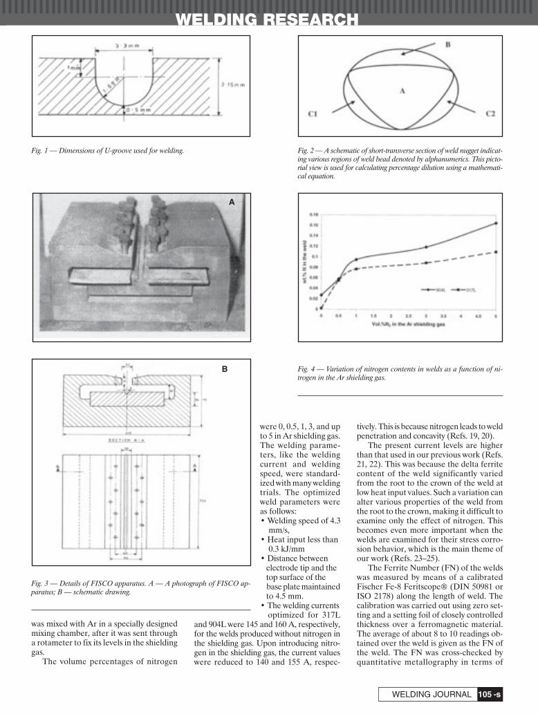
WELDING RESEARCH
-s105WELDING JOURNAL
was mixed with Ar in a specially designedmixing chamber, after it was sent througha rotameter to fix its levels in the shieldinggas.
The volume percentages of nitrogen
were 0, 0.5, 1, 3, and upto 5 in Ar shielding gas.The welding parame-ters, like the weldingcurrent and weldingspeed, were standard-ized with many weldingtrials. The optimizedweld parameters wereas follows: • Welding speed of 4.3
mm/s,• Heat input less than
0.3 kJ/mm• Distance between
electrode tip and the top surface of the base plate maintainedto 4.5 mm.
• The welding currents optimized for 317L
and 904L were 145 and 160 A, respectively,for the welds produced without nitrogen inthe shielding gas. Upon introducing nitro-gen in the shielding gas, the current valueswere reduced to 140 and 155 A, respec-
tively. This is because nitrogen leads to weldpenetration and concavity (Refs. 19, 20).
The present current levels are higherthan that used in our previous work (Refs.21, 22). This was because the delta ferritecontent of the weld significantly variedfrom the root to the crown of the weld atlow heat input values. Such a variation canalter various properties of the weld fromthe root to the crown, making it difficult toexamine only the effect of nitrogen. Thisbecomes even more important when thewelds are examined for their stress corro-sion behavior, which is the main theme ofour work (Refs. 23–25).
The Ferrite Number (FN) of the weldswas measured by means of a calibratedFischer Fe-8 Feritscope® (DIN 50981 orISO 2178) along the length of weld. Thecalibration was carried out using zero set-ting and a setting foil of closely controlledthickness over a ferromagnetic material.The average of about 8 to 10 readings ob-tained over the weld is given as the FN ofthe weld. The FN was cross-checked byquantitative metallography in terms of
Fig. 1 — Dimensions of U-groove used for welding. Fig. 2 — A schematic of short-transverse section of weld nugget indicat-ing various regions of weld bead denoted by alphanumerics. This picto-rial view is used for calculating percentage dilution using a mathemati-cal equation.
Fig. 3 — Details of FISCO apparatus. A — A photograph of FISCO ap-paratus; B — schematic drawing.
A
B Fig. 4 — Variation of nitrogen contents in welds as a function of ni-trogen in the Ar shielding gas.
Nage 4 07corr:Layout 1 3/12/07 3:46 PM Page 105
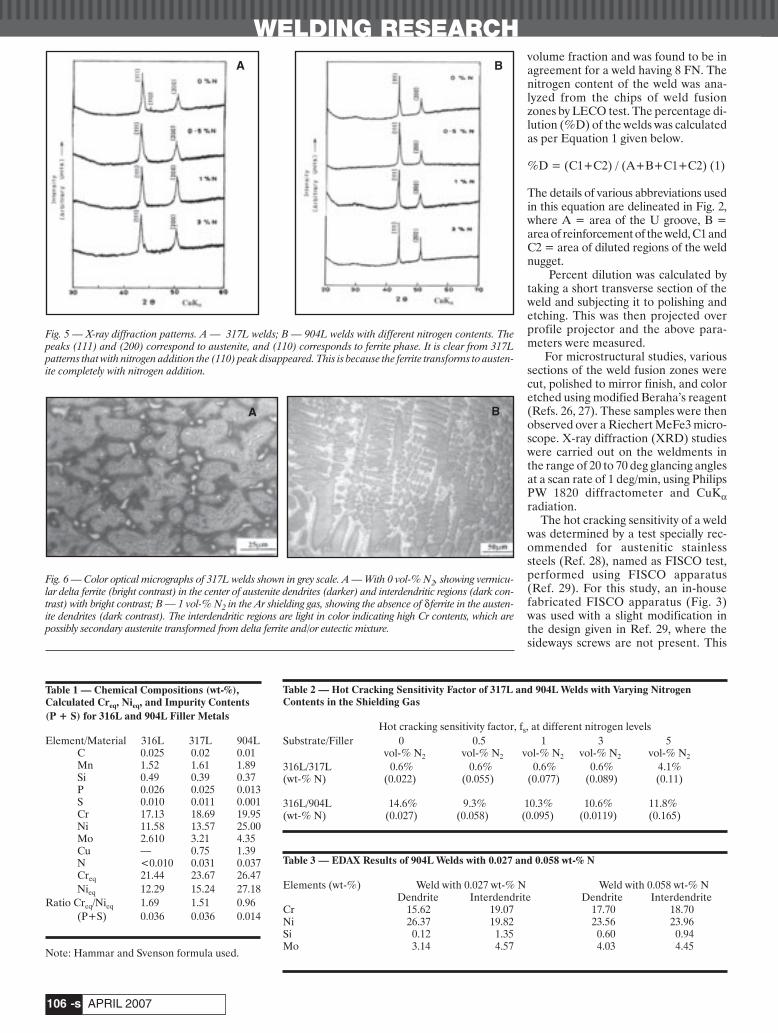
volume fraction and was found to be inagreement for a weld having 8 FN. Thenitrogen content of the weld was ana-lyzed from the chips of weld fusionzones by LECO test. The percentage di-lution (%D) of the welds was calculatedas per Equation 1 given below.
%D = (C1+C2) / (A+B+C1+C2) (1)
The details of various abbreviations usedin this equation are delineated in Fig. 2,where A = area of the U groove, B =area of reinforcement of the weld, C1 andC2 = area of diluted regions of the weldnugget.
Percent dilution was calculated bytaking a short transverse section of theweld and subjecting it to polishing andetching. This was then projected overprofile projector and the above para-meters were measured.
For microstructural studies, varioussections of the weld fusion zones werecut, polished to mirror finish, and coloretched using modified Beraha’s reagent(Refs. 26, 27). These samples were thenobserved over a Riechert MeFe3 micro-scope. X-ray diffraction (XRD) studieswere carried out on the weldments inthe range of 20 to 70 deg glancing anglesat a scan rate of 1 deg/min, using PhilipsPW 1820 diffractometer and CuKαradiation.
The hot cracking sensitivity of a weldwas determined by a test specially rec-ommended for austenitic stainlesssteels (Ref. 28), named as FISCO test,performed using FISCO apparatus(Ref. 29). For this study, an in-housefabricated FISCO apparatus (Fig. 3)was used with a slight modification inthe design given in Ref. 29, where thesideways screws are not present. This
WELDING RESEARCH
APRIL 2007-s106
Table 2 — Hot Cracking Sensitivity Factor of 317L and 904L Welds with Varying NitrogenContents in the Shielding Gas
Hot cracking sensitivity factor, fs, at different nitrogen levelsSubstrate/Filler 0 0.5 1 3 5
vol-% N2 vol-% N2 vol-% N2 vol-% N2 vol-% N2
316L/317L 0.6% 0.6% 0.6% 0.6% 4.1%(wt-% N) (0.022) (0.055) (0.077) (0.089) (0.11)
316L/904L 14.6% 9.3% 10.3% 10.6% 11.8%(wt-% N) (0.027) (0.058) (0.095) (0.0119) (0.165)
Table 3 — EDAX Results of 904L Welds with 0.027 and 0.058 wt-% N
Elements (wt-%) Weld with 0.027 wt-% N Weld with 0.058 wt-% NDendrite Interdendrite Dendrite Interdendrite
Cr 15.62 19.07 17.70 18.70Ni 26.37 19.82 23.56 23.96Si 0.12 1.35 0.60 0.94Mo 3.14 4.57 4.03 4.45
BA
A B
Fig. 5 — X-ray diffraction patterns. A — 317L welds; B — 904L welds with different nitrogen contents. Thepeaks (111) and (200) correspond to austenite, and (110) corresponds to ferrite phase. It is clear from 317Lpatterns that with nitrogen addition the (110) peak disappeared. This is because the ferrite transforms to austen-ite completely with nitrogen addition.
Fig. 6 — Color optical micrographs of 317L welds shown in grey scale. A — With 0 vol-% N2, showing vermicu-lar delta ferrite (bright contrast) in the center of austenite dendrites (darker) and interdendritic regions (dark con-trast) with bright contrast; B — 1 vol-% N2 in the Ar shielding gas, showing the absence of δ ferrite in the austen-ite dendrites (dark contrast). The interdendritic regions are light in color indicating high Cr contents, which arepossibly secondary austenite transformed from delta ferrite and/or eutectic mixture.
Table 1 — Chemical Compositions (wt-%),Calculated Creq, Nieq, and Impurity Contents(P + S) for 316L and 904L Filler Metals
Element/Material 316L 317L 904LC 0.025 0.02 0.01Mn 1.52 1.61 1.89Si 0.49 0.39 0.37P 0.026 0.025 0.013S 0.010 0.011 0.001Cr 17.13 18.69 19.95Ni 11.58 13.57 25.00Mo 2.610 3.21 4.35Cu — 0.75 1.39N <0.010 0.031 0.037Creq 21.44 23.67 26.47Nieq 12.29 15.24 27.18
Ratio Creq/Nieq 1.69 1.51 0.96(P+S) 0.036 0.036 0.014
Note: Hammar and Svenson formula used.
Nage 4 07corr:Layout 1 3/14/07 10:26 AM Page 106

WELDING RESEARCH
-s107WELDING JOURNAL
variation was required because asingle 316L plate with central Ugroove along the length was usedin the present study; unlike the twoseparate plates normally usedwhen two individual plates are buttjoint welded. The sideways screwsin the design given in Ref. 29, helpto change the root opening.
In this study, the 316L plate wasplaced over the cogged plate insuch a way that the U-groove wasover the furrow of the FISCO ap-paratus over which rests the weld-ing wire. In order to get more startsand ends, four beads each of 40-mm length and 5-mm interwelddistance were deposited. Weldingwas carried out using the stan-dardized welding parameters men-tioned before. After welding, thewelded plate was clamped in a viceand the beads were bent by strikingthe other side with a hammer. Theends of the beads were examinedby the naked eye and a magnifyinglens for the presence of any cracksbefore and after hammering. Inorder to reveal the microcracks, adye penetration test (Ref. 30) wascarried out on the bent plates. Thecrack lengths of the bent plateswere measured with verniercalipers and the crack sensitivityfactor, fs (Ref. 29), was calculatedas follows:
fs = (total crack length/totallength of 4 weld beads) × 100 (2)
If fs < 20%, the cracks were con-fined to craters and were catego-rized as crater cracks. Over thisvalue, if cracks extended beyondthe crater, the cracks were classi-fied as solidification cracks (Ref.29).
The test severity depends onplate thickness (0–40 mm), cham-fer shape, and gap between theplates (Ref. 29). These parameterswere constant and the only variablewas the nitrogen introduced in thewelds through the shielding gas.The crater crack ends of the weldbeads were later examined using aCameca SU 30 scanning electronmicroscope (SEM). For this study,polished samples were etched bymethanolic aqua regia (45 mL HCl, 15mLHNO3, 20 mL 1N methanol) (Ref. 27).The wave dispersive spectra (WDS) werecarried to get an idea of the segregation ordistribution of various elements. In somecases, energy dispersive analysis by X-rays(EDAX) was also carried out using LEO1455 SEM.
Results and Discussion
The nitrogen content variation in theweld is shown in Fig. 4. The figure showsthat the wt-% nitrogen in both 317L and904L welds increased as the nitrogen inthe shielding gas was increased. Such a rise
in nitrogen content of the weld is in agree-ment with the earlier work (Refs. 13, 15,31).
The X-ray diffractograms obtained forboth 317L and 904L welds with varying ni-trogen contents are shown in Fig. 5A and B,respectively. The patterns in both the cases
Fig. 7 — Effect of nitrogen additions on the Ferrite Num-ber (FN) of 317L welds.
Fig. 8 — Color metallographs of 904L weld in grey scaleshowing green austenitic dendrites (dark contrast), indi-cating austenitic mode of solidification. Interdendritic re-gions are in bright contrast.
Fig. 9 — Plot of secondary dendrite arm spacing vs. vol-% N2 in the Ar shielding gas demonstrating effect of ni-trogen on the secondary dendrite arm spacing (microm-eter). The secondary arm spacing decreases as the wt-%nitrogen in 317L and 904L weld increases.
Fig. 10 — Dye penetrant tested (DPT) plate used for mea-suring crack length for calculating hot cracking sensitivityfactor. Red coloration (dark contrast) highlights the cratercracks and the interweld gap in between two beads.
Fig. 12 — Scanning electron micrograph of crater crackformed at the centerline in case of 904L weld. This crackseems to propagate interdendritically.
Fig. 11 — (P+S) vs. Creq/Nieq, showing location of316L, 317L, and 904L consumables and the resultantwelds with increasing nitrogen, toward susceptibility forhot cracking. (Legends ♣ and ◆ represent 317L weldsand 904L welds, respectively. The addition of N is ex-pected to shift these points toward the left. The legend •represents 904L filler metal and 316L alloys.) (Ref. 2).
Nage 4 07corr:Layout 1 3/12/07 3:47 PM Page 107

WELDING RESEARCH
APRIL 2007-s108
can be indexed satisfactorily for anaustenite phase. However, a smallamount of δ ferrite, as revealed by thepresence of (110) peak in the case of the317L weld obtained without N2 in theshielding gas. Upon the addition of ni-trogen, this peak corresponding to δ fer-rite disappeared. Microscopic and ferri-toscopic studies further confirmed theX-ray diffraction data. The formershowed ferrite in the dendrites with ver-micular morphology (Fig. 6A), and thelatter measured a Ferrite Number (FN)of 8. With the addition of nitrogen, theferrite in the dendrites disappeared (Fig.6B), and the FN dropped to 0.3. This ef-fect of nitrogen on the FN is showngraphically in Fig. 7. A typical micro-graph of 904L weld obtained with no N2in the shielding gas is shown in Fig. 8 forcomparison with 317L weld. Accordingto the literature, Ni-rich phases (mostlyaustenite) exhibit color contrast varyingfrom blue to green and Cr-rich phasesexhibiting color contrast varying fromreddish to yellow (Refs. 26, 27). Basedon the above criteria, it can be said that317L welds with nitrogen addition andall the 904L welds, obtained with andwithout N2 in the shielding gas, exhibitNi-rich austenite dendrites (green incolor) with dark contrast, and Cr-rich in-terdendritic (yellow in color) regionswith bright/light contrast. Though theCr-rich phases can be δ-ferrite, the in-terdendritic regions may not completelybelong to this phase, as XRD and Fer-itscope® data too did not show the cor-responding amount of delta-ferrite.
The variation in secondary dendritearm spacing of the 317L and 904Lwelds without and with nitrogen in theAr shielding gas was also measuredusing a calibrated scale of the eyepiece.As the nitrogen content increased, thesecondary dendrite arm spacing wasfound to decrease — Fig. 9. The sec-ondary dendrite arm spacing is reportedto be a function of cooling rate and themobility factor (Ref. 32). As the heatinput of all the welds was almost same,the variation in cooling rate is assumedto remain constant, it being less signifi-cant (Ref. 33). The mobility factor hasbeen related to surface tension of themelt and partition coefficient of the el-ements. These two factors in turn de-pend on the composition of the weld.The present welds are obtained withvarious N levels. Hence, the decrease inthe secondary dendrite arm spacing canbe attributed to the N. A detailed calcu-lation of the change in the mobility fac-tor upon nitrogen addition to austeniticstainless steel welds has been communi-cated by the authors (Ref. 34). A photograph of a typical plate sub-
jected to dye penetration test is shown inFig. 10 and the data of hot crack sensitiv-ity factors of 317L and 904L welds as afunction of volume percentage nitrogen inthe shielding gas and wt-% is summarizedin Table 2. As the hot crack sensitivity fac-tor in all these cases is lower than 20%, thewelds can be considered to be resistant to-ward hot cracking. Visual examination ofthese welds showed the absence of solidi-fication cracks, but craters were noticed inall cases irrespective of whether or not theN was added to the welds. The 317L weldsshowed negligible intensity of cratercracks even up to 5 vol-% N2 addition tothe shielding gas. This can be attributed topossible presence of δ-ferrite at high tem-perature along with the effect of nitrogenin decreasing secondary dendrite armspacing. The 904L welds were found to ex-hibit higher cracking tendency than 317Lwelds though these cracks were within thecritical limit to call them solidificationcracks. Notably, the hot cracking sensitivityof 904L was minimal with 0.5 vol-% N2 inthe shielding gas.
Hot cracking in a weld depends on var-ious factors like thermomechanicalstresses, welding process, welding para-meters, and chemistry of the weld (Refs.35–38). It was reported by Lundin et al.that cold fed GTA-welded beads are lesssusceptible to hot cracking as was used inthe present study (Ref. 15). The hot crack-ing propensity can be reduced by the pres-ence of high-temperature delta ferrite(Cr-rich) (Refs. 2, 3, 6). The higher Crcontent in the interdendritic regions canbe seen in the following manner. It is pos-sible that at high temperatures, these re-gions existed as delta ferrite, although theCr content of these regions is not suffi-cient enough to retain its BCC structure atroom temperature. It can transform toaustenite by solid-state transformation.Therefore, under these conditions, Cr ininterdendritic regions can dissolve moresulfur. Moreover, ferrite is ductile enoughto resist the growth of cracks (Ref. 3). Sul-fur is soluble in Cr-rich delta ferrite or itcan form compounds (inclusions) with Cr,apart from Mn in Fe-Cr-Ni system (Ref.14). Wilken and Kliestner and Astrom etal. have reported that the presence of eu-tectic ferrite (Ref. 28) and inclusions (Ref.13) both are desirable as they pin the crackgrowth or complicate the crack path. Thecrack morphology changes to brittle fromductile as the Cr content in interdendriticregions keeps on decreasing (Ref. 17).Other elements that have detrimental ef-fects on hot cracking resistance include Si(up to 2 wt-%) (Ref. 11), Fe and Ni in thepresence of trace impurities like S and P.The mechanism for exacerbating hotcracking in many instances is formation oflow melting point films (sulfides, phos-
Fig. 13 — Scanning electron micrograph of an end ofthe crater crack of 317L. The crack seems to propagateacross the dendrites at some places.
Fig. 14 — WDS patterns of 317L welds prepared withoutnitrogen in the shielding gas for (A) Cr, (B) S, and (C) Ni.Cr is seen in dendrites as well as in interdendritic regions.Sulfur was not detected at the interdendritic regions andfound in dendrites and at triple junctions of grains. Ni isless at interdentritic regions.
A
B
C
Nage 4 07corr:Layout 1 3/14/07 9:49 AM Page 108
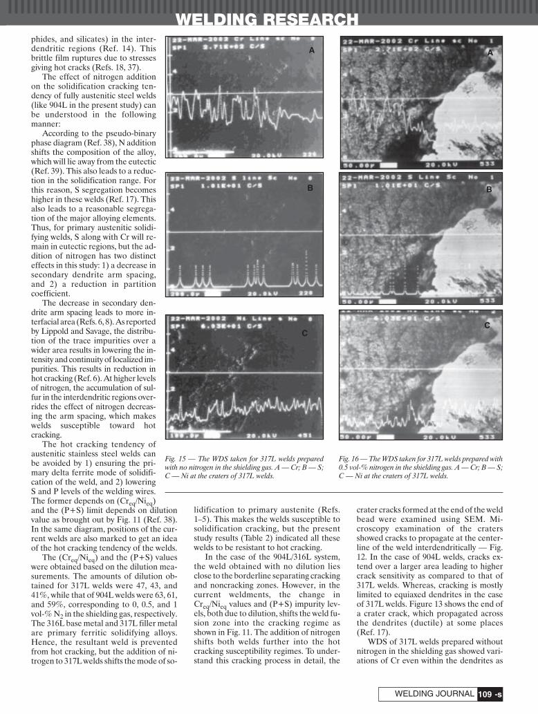
phides, and silicates) in the inter-dendritic regions (Ref. 14). Thisbrittle film ruptures due to stressesgiving hot cracks (Refs. 18, 37).
The effect of nitrogen additionon the solidification cracking ten-dency of fully austenitic steel welds(like 904L in the present study) canbe understood in the following manner:
According to the pseudo-binaryphase diagram (Ref. 38), N additionshifts the composition of the alloy,which will lie away from the eutectic(Ref. 39). This also leads to a reduc-tion in the solidification range. Forthis reason, S segregation becomeshigher in these welds (Ref. 17). Thisalso leads to a reasonable segrega-tion of the major alloying elements.Thus, for primary austenitic solidi-fying welds, S along with Cr will re-main in eutectic regions, but the ad-dition of nitrogen has two distincteffects in this study: 1) a decrease insecondary dendrite arm spacing,and 2) a reduction in partition coefficient.
The decrease in secondary den-drite arm spacing leads to more in-terfacial area (Refs. 6, 8). As reportedby Lippold and Savage, the distribu-tion of the trace impurities over awider area results in lowering the in-tensity and continuity of localized im-purities. This results in reduction inhot cracking (Ref. 6). At higher levelsof nitrogen, the accumulation of sul-fur in the interdendritic regions over-rides the effect of nitrogen decreas-ing the arm spacing, which makeswelds susceptible toward hot cracking.
The hot cracking tendency ofaustenitic stainless steel welds canbe avoided by 1) ensuring the pri-mary delta ferrite mode of solidifi-cation of the weld, and 2) loweringS and P levels of the welding wires.The former depends on (Creq/Nieq)and the (P+S) limit depends on dilutionvalue as brought out by Fig. 11 (Ref. 38).In the same diagram, positions of the cur-rent welds are also marked to get an ideaof the hot cracking tendency of the welds.
The (Creq/Nieq) and the (P+S) valueswere obtained based on the dilution mea-surements. The amounts of dilution ob-tained for 317L welds were 47, 43, and41%, while that of 904L welds were 63, 61,and 59%, corresponding to 0, 0.5, and 1vol-% N2 in the shielding gas, respectively.The 316L base metal and 317L filler metalare primary ferritic solidifying alloys.Hence, the resultant weld is preventedfrom hot cracking, but the addition of ni-trogen to 317L welds shifts the mode of so-
lidification to primary austenite (Refs.1–5). This makes the welds susceptible tosolidification cracking, but the presentstudy results (Table 2) indicated all thesewelds to be resistant to hot cracking.
In the case of the 904L/316L system,the weld obtained with no dilution liesclose to the borderline separating crackingand noncracking zones. However, in thecurrent weldments, the change inCreq/Nieq values and (P+S) impurity lev-els, both due to dilution, shifts the weld fu-sion zone into the cracking regime asshown in Fig. 11. The addition of nitrogenshifts both welds further into the hotcracking susceptibility regimes. To under-stand this cracking process in detail, the
crater cracks formed at the end of the weldbead were examined using SEM. Mi-croscopy examination of the cratersshowed cracks to propagate at the center-line of the weld interdendritically — Fig.12. In the case of 904L welds, cracks ex-tend over a larger area leading to highercrack sensitivity as compared to that of317L welds. Whereas, cracking is mostlylimited to equiaxed dendrites in the caseof 317L welds. Figure 13 shows the end ofa crater crack, which propagated acrossthe dendrites (ductile) at some places(Ref. 17).
WDS of 317L welds prepared withoutnitrogen in the shielding gas showed vari-ations of Cr even within the dendrites as
WELDING RESEARCH
-s109WELDING JOURNAL
Fig. 15 — The WDS taken for 317L welds preparedwith no nitrogen in the shielding gas. A — Cr; B — S;C — Ni at the craters of 317L welds.
B
C
Fig. 16 — The WDS taken for 317L welds prepared with0.5 vol-% nitrogen in the shielding gas. A — Cr; B — S;C — Ni at the craters of 317L welds.
A
B
C
A
Nage 4 07corr:Layout 1 3/14/07 10:02 AM Page 109

WELDING RESEARCH
APRIL 2007-s110
well as interdendrites — Fig. 14A. Thisvariation could be possibly due to the pres-ence of vermicular δ ferrite in the dendriteof the predominantly austenite phase andeutectic mixture of austenite and delta fer-rite in interdendritic regions. This is com-parable to XRD, Feritscope® data, andoptical micrograph shown in Fig. 6A hav-ing vermicular ferrite in dendrites. How-ever, it is interesting that sulfur was not
detected at the interdendritic regionsand found within the dendrites and atsome triple junctions ofdendrites/grains — Fig. 14B. Nickelscans show a reverse of Cr, indicatingthe interdendritic regions have lowerNi content than the dendritic regions— Fig. 14C. This combination is re-sponsible for no cracking in this weld.
WDS of Cr, S, and Ni obtained at thecraters of 317L welds without and with0.5 vol-% N2 in the shielding gas showsome trends — Figs. 15A–C and16A–C. With nitrogen additions, Crand S content in the crack increases(Fig. 16A, B), whereas, the Ni contentdecreases (Fig. 16C) in the crack.Though this weld showed no ferritefrom ferritoscopic studies, it did solid-ify through a path having ferrite, whichis responsible for solidification crack-ing resistance.
With further addition up to 5 vol-%nitrogen, the weld solidified by the fullyaustenitic mode, which is in agreementwith the optical microscopic studies andFeritscope® data. The WDS patterns ofCr and Ni too showed the presence ofhigher Cr (Fig. 17A) and lower Ni in theinterdendritic regions (Fig. 17B). Thisweld can be comparable to 904L in termsof solidification and cracking behavior.
The 904L welds prepared without ni-
trogen in the shielding gas had ahigher Cr content in the interden-dritic regions (by 3.45 wt-%) andlower Ni content (by 6.54 wt-%)than the dendrites. The trace im-purities (S, P, and Si) accumulatedat the interdendritic regions thatcould form compounds preferen-tially with Cr than with Fe and Ni,thus avoiding hot cracking. A fewWDS results support this trendshowing higher Cr (Fig. 18A), S(Fig. 18B), and Si (Fig. 18C) in in-terdendritic regions. All these el-ements do not show an incrementin the same location, possibly dueto differences in local solidifica-tion rates in a weld.
At 0.5 vol-%N2 in the shieldinggas, a significant reduction in Siwas found from 1.23 to 0.34 wt-%(difference between dendrite andinterdendritic region) in weldswith 0.027 wt-% N and 0.058 wt-%N, respectively (Table 3). The dropin Si content possibly could con-tribute toward enhancing the hotcracking resistance of the weld(Ref. 11), although a marginal de-crease in Cr and a rise in Ni con-tent had a very minor counteref-fect. Other beneficial effects are areduction in Fe content in this re-gion — Fig. 19A. Sulfur showedmarked localization at some loca-
tions and was not present preferentially atinterdendritic regions — Fig. 19B. This fa-vorable distribution of these elements re-sulted in the lowest hot cracking sensitiv-ity in the 904L/316L system.
At 1 vol-% N2 in the shielding gas, theNi content in the interdendritic regionshad gone up (by 1.03 wt-%) at the expenseof Cr (by 0.76 wt-%). This presence ofhigher Ni is suspected to enhance thecracking tendency.
Conclusions
The effect of N on the crater crack for-mation was investigated using hot crack-ing sensitivity factor. In the case of 317Lwelds, no appreciable rise in cracking sen-sitivity was noticed until 3 vol-% N2 wasadded to the shielding gas. In the case of904L weld, crack sensitivity initially de-creased with an addition of 0.5 vol-% N2and then increased gradually with furtherN2 additions. The explanations for the be-haviors of each are as follows:
The 317L solidifies through a pathwhere high-temperature delta ferrite mayexist, even though less or no delta ferriteis retained at ambient temperature. In ad-dition, nitrogen reduces the secondarydendrite arm spacing. The reduction inthe secondary dendrite arm spacing re-
Fig. 17 — WDS patterns of 317L welds prepared with 5 vol-% nitrogen in the shielding gas. A — Cr; B — Ni. The WDSpattern shows the presence of Cr at the interdendritic regions and Ni at the interdendritic regions was leaner.
Fig. 18 — Various WDS patterns of 904L welds preparedwith no nitrogen in the shielding gas. A — Cr; B — S;C — Si. Cr and Si are higher in interdendritic regions. Sdistribution is uniform.
A B
A B
C
Nage 4 07corr:Layout 1 3/12/07 3:48 PM Page 110

WELDING RESEARCH
-s111WELDING JOURNAL
tained to reduce the accumulation of sul-fides in the interdendritic regions.
In the case of 904L welds, the resis-tance to solidification cracking arises dueto a reduction in the secondary dendritearm spacing as well as a decrease in Si inthe interdendritic region. Notably athigher N levels, Ni tends to partition moreat interdendritic regions in preference toCr, contributing toward the solidificationcracking tendency of the welds.
Acknowledgments
The authors acknowledge the financialsupport received from Department of Sci-ence and Technology, Government ofIndia, to carry out the main project on lo-calized corrosion behavior of welds inhigh-temperature and high-pressurewater conditions. Authors would also liketo acknowledge and thank Prof. R. Ramanfor providing the welding facilities, andIGCAR, Kalpakkam for supplying the316L stainless steel plates.
References
1. Suutala, N., Takalo, T., and Moisio, T.1988. Ferritic austenitic solidification mode inaustenitic stainless steel welds. MetallurgicalTransactions A. 11A(5): 717–725.
2. Takalo, T., Suutala, N., and Moiso, T.1979. Austenitic solidification mode inaustenitic stainless steel welds. MetallurgicalTransactions A. 10A(8): 1173–1190.
3. David, S. A. 1981. Ferrite morphology inaustenitic stainless steel welds. Welding Journal51(4): 63-s to 71-s.
4. Nayal, G., and Beech, J. 1988. Hot crack-ing in austenitic stainless steels — Solidificationprocessing. Proceedings of Third InternationalConference. Dept. of Metallurgy, University of
Sheffield, Ranmoon House, London: 384–387. 5. Arata, Y., Matsuda, F., and Katayama, S.
1976. Solidification crack susceptibility in weldmetals of fully austenitic stainless steels (Re-port I). Transactions of Japanese Welding Re-search Institute 5(2): 79-88.
6. Lippold, J. C., and Savage, W. F. 1982. So-lidification of austenitic stainless steel weld-ments: Part III — The effect of solidificationbehavior on hot cracking susceptibility. WeldingJournal 50(12): 388-s to 396-s.
7. Dixon, B. 1988. Initiation and growth ofweld metal solidification cracks — Solidifica-tion processing. Proceedings of Third Interna-tional Conference. Dept. of Metallurgy, Univer-sity of Sheffield, Ranmoon House, London, pp.381–383.
8. Shankar, V., Gill, T. P. S., Mannan, S. L.,and Sudarsen, S. 1998. Evaluation of hot crack-ing in nitrogen bearing and fully austeniticstainless steel weldments. Welding Journal66(5): 193-s to 201-s.
9. Kunjaapaa, V. P. 1984. Weld discontinu-ities in austenitic stainless steel sheets — Effectof impurities and solidification mode. WeldingJournal 52(12): 369-s to 375-s.
10. Li, L., and Messler, R. W. Jr. 1999. Theeffects of phosphorus and sulfur on susceptibil-ity to weld hot cracking in austenitic stainlesssteels. Welding Journal 67(12): 387-s to 396-s.
11. Ogawa, T., and Tsunetomi, E. 1982. Hotcracking susceptibility of austenitic stainlesssteels. Welding Journal 50(3): 82-s to 94-s.
12. Matsuda, F., Nakagawa, H., Katayama,S., and Arata, Y. 1962. Solidification crack sus-ceptibility in weld metals of fully austeniticstainless steels (Report VII). Transactions ofJapanese Welding Research Institute 11(2):79–85.
13. Astrom, H., Loberg, B., Bengtsson, B.,and Easterling, K. E. 1976. Hot cracking andmicrosegregation in 18-10 stainless steel welds.Metal Science 10(7): 225–234.
14. Folkhard, E. 1984. Welding Metallurgy ofStainless Steels. Springer Verlag Wien, NewYork: 162–171.
15. Lundin, C. D., Chou, C.-P. D., and Sulli-van, C. J. 1980. Hot cracking resistance ofaustenitic stainless steel weld metals. WeldingJournal 59(8): 226-s to 232-s.
16. Mudali, K. U., Dayal, R. K., Gill, T. P. S.,and Gnanamorrthy, J. B. 1986. Influence of ni-trogen additions on microstructure and pittingcorrosion resistance of austenitic weld metals.Werkstoffe and Korrosion 37(12): 637–643.
17. Matsuda, F., Nakagawa, H., Katayama,S., and Arata, Y. 1983. Solidification crack sus-ceptibility in weld metals of fully austeniticstainless steels (Report VIII). Transactions ofJapanese Welding Research Institute 12(1):89–95.
18. Borland, J. C., and Younger, R. N. 1960.Some aspects of cracking in welded Cr-Niaustenitic steels. British Welding Journal, pp.22–50.
19. Kuwana, T., Kokawa, H., and Mura-matsu, N. 1989. Effects of chromium and nickelon nitrogen absorption of arc melted iron.Transactions of Japan Welding Society 20(1):10–16.
20. Kuwana, T., and Kokawa, H. 1988. Thenitrogen absorption of arc melted iron andstainless steel. Transactions of Japan Welding So-ciety 19(2): 92–99.
21. Raja, V. S., Varshney, S. K., Raman, R.,and Kulkarni, S. D. 1998. Influence of nitrogenon the pitting corrosion behavior of 904L weldclad. Corrosion Science 40(10): 1609–1625.
22. Nage, D. D., Reddy, S., Raman, R., andRaja, V. S. 2002. Effect of variation of nitrogencontent on pitting and stress corrosion crackingbehavior of AISI 312 weldments. Transactionsof Indian Institute of Metals 55(5): 447–454.
23. Nage, D. D., Raja, V. S., and Raman, R.2003. Stress corrosion cracking studies of 904Laustenitic stainless steel welds with different ni-trogen contents in 2880C deaerated distilledwater. Proceedings of 13th Asian Pacific Corro-sion Control Conference, Osaka, pp. 16–21,Paper No. 106.
24. Nage, D. D., Raja, V. S., and Raman, R.2006. Effect of nitrogen addition on the stress
Fig. 19 — Various WDS patterns of 904L welds prepared with 0.5 vol-% nitrogen in the shielding gas. A — Fe; B — S. Fe remains on the lower side for primaryaustenitic solidifying welds. S seems to get locked; might be as inclusions and shows peaks at certain regions.
A B
Nage 4 07corr:Layout 1 3/12/07 3:49 PM Page 111
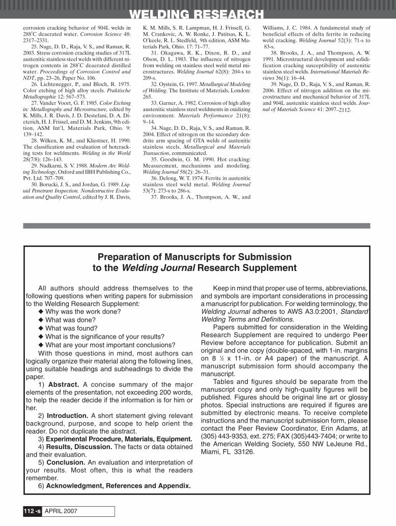
WELDING RESEARCH
APRIL 2007-s112
corrosion cracking behavior of 904L welds in288°C deaerated water. Corrosion Science 48:2317–2331.
25. Nage, D. D., Raja, V. S., and Raman, R.2003. Stress corrosion cracking studies of 317Laustenitic stainless steel welds with different ni-trogen contents in 288°C deaerated distilledwater. Proceedings of Corrosion Control andNDT, pp. 23–26, Paper No. 106.
26. Lichtenegger, P., and Bloch, R. 1975.Color etching of high alloy steels. PraktischeMetallographie 12: 567–573.
27. Vander Voort, G. F. 1985. Color Etchingin: Metallography and Microstructure, edited byK. Mills, J. R. Davis, J. D. Destefani, D. A. Di-eterich, H. J. Frissel, and D. M. Jenkins, 9th edi-tion, ASM Int’l, Materials Park, Ohio. 9:139–142.
28. Wilken, K. M., and Kliestner, H. 1990.The classification and evaluation of hotcrack-ing tests for weldments. Welding in the World28(7/8): 126–143.
29. Nadkarni, S. V. 1988. Modern Arc Weld-ing Technology, Oxford and IBH Publishing Co.,Pvt. Ltd. 707–709.
30. Borucki, J. S., and Jordan, G. 1989. Liq-uid Penetrant Inspection. Nondestructive Evalu-ation and Quality Control, edited by J. R. Davis,
K. M. Mills, S. R. Lampman, H. J. Frissell, G.M. Crankovic, A. W. Ronke, J. Patitsas, K. L.O’keele, R. L. Stedfeld, 9th edition, ASM Ma-terials Park, Ohio. 17: 71–77.
31. Okagawa, R. K., Dixon, R. D., andOlson, D. L. 1983. The influence of nitrogenfrom welding on stainless steel weld metal mi-crostructures. Welding Journal 62(8): 204-s to209-s.
32. Oystein, G. 1997. Metallurgical Modelingof Welding. The Institute of Materials, London:265.
33. Garner, A. 1982. Corrosion of high alloyaustenitic stainless steel weldments in oxidizingenvironment. Materials Performance 21(8):9–14.
34. Nage, D. D., Raja, V. S., and Raman, R.2004. Effect of nitrogen on the secondary den-drite arm spacing of GTA welds of austeniticstainless steels. Metallurgical and MaterialsTransaction, communicated.
35. Goodwin, G. M. 1990. Hot cracking:Measurement, mechanisms and modeling.Welding Journal 58(2): 26–31.
36. Delong, W. T. 1974. Ferrite in austeniticstainless steel weld metal. Welding Journal53(7): 273-s to 286-s.
37. Brooks, J. A., Thompson, A. W., and
Williams, J. C. 1984. A fundamental study ofbeneficial effects of delta ferrite in reducingweld cracking. Welding Journal 52(3): 71-s to83-s.
38. Brooks, J. A., and Thompson, A. W.1991. Microstructural development and solidi-fication cracking susceptibility of austeniticstainless steel welds. International Materials Re-views 36(1): 16–44.
39. Nage, D. D., Raja, V. S., and Raman, R.2006. Effect of nitrogen addition on the mi-crostructure and mechanical behavior of 317Land 904L austenitic stainless steel welds. Jour-nal of Materials Science 41: 2097–2112.
All authors should address themselves to thefollowing questions when writing papers for submissionto the Welding Research Supplement:
◆ Why was the work done?◆ What was done?◆ What was found?◆ What is the significance of your results?◆ What are your most important conclusions?With those questions in mind, most authors can
logically organize their material along the following lines,using suitable headings and subheadings to divide thepaper.
1) Abstract. A concise summary of the majorelements of the presentation, not exceeding 200 words,to help the reader decide if the information is for him orher.
2) Introduction. A short statement giving relevantbackground, purpose, and scope to help orient thereader. Do not duplicate the abstract.
3) Experimental Procedure, Materials, Equipment.4) Results, Discussion. The facts or data obtained
and their evaluation.5) Conclusion. An evaluation and interpretation of
your results. Most often, this is what the readersremember.
6) Acknowledgment, References and Appendix.
Keep in mind that proper use of terms, abbreviations,and symbols are important considerations in processinga manuscript for publication. For welding terminology, theWelding Journal adheres to AWS A3.0:2001, StandardWelding Terms and Definitions.
Papers submitted for consideration in the WeldingResearch Supplement are required to undergo PeerReview before acceptance for publication. Submit anoriginal and one copy (double-spaced, with 1-in. marginson 8 1⁄2 x 11-in. or A4 paper) of the manuscript. Amanuscript submission form should accompany themanuscript.
Tables and figures should be separate from themanuscript copy and only high-quality figures will bepublished. Figures should be original line art or glossyphotos. Special instructions are required if figures aresubmitted by electronic means. To receive completeinstructions and the manuscript submission form, pleasecontact the Peer Review Coordinator, Erin Adams, at(305) 443-9353, ext. 275; FAX (305)443-7404; or write tothe American Welding Society, 550 NW LeJeune Rd.,Miami, FL 33126.
Preparation of Manuscripts for Submissionto the Welding Journal Research Supplement
Nage 4 07corr:Layout 1 3/12/07 3:49 PM Page 112

Circle No. 3 on Reader Info-Card
ARCOS:FP_TEMP 3/9/07 5:10 PM Page C3
Circle No. 39 on Reader Info-Card
LINCOLN:FP_TEMP 3/9/07 5:16 PM Page C4
Related Documents


