AMENDMENT NO. 2 TO AIS – 044 (Part 1) Automotive Vehicles – Pneumatic Tyres for Commercial Vehicles. 1.0 Page No. 6 and 7, cl. 6.1 Dimension of Tyres: Substitute following text for the existing text of entire clause 6.1: “ 6.1 Tyre Dimensions 6.1.1 Tyre dimensions and profiles shall be compatible with the appropriate rims. The tyre dimensions namely section width and outer diameter shall meets the requirements given in Annexure A and method of measurement given in Annexure E. 6.1.1.1 Section Width of Tyre: Tyre size designation shall be as per tables given in Annexure A, the section width shall be deemed to be that opposite the tyre size designation in those tables. NOTE - Adjustment to tyre section width/overall width –Within the parameters of specified permissibility of a wider or narrower rim than the recommended rim size, the guidelines for the necessary adjustment are – Sectional width or overall width: 5mm increase or reduction (as applicable) for every 0.50 difference in nominal rim width. 6.1.1.2 Tyre outer diameter: Tyre size designation shall be as per tables given in Annexure A. The outer diameter shall not be exceed the minimum and maximum diameter values specified in Annexure A. 6.1.2 For the sizes listed in Annexure A, but tolerance are not given and the tyres sizes which are not listed in Annexure A, the section width and outer diameter shall be calculated by using following formulae: 6.1.2.1 Section width of tyre 6.1.2.1.1 The section width shall be calculated by using following formula S = S 1 + K (A - A 1 ), Where, S = “Section width” expressed in millimeters measured on measuring rim S 1 = “Nominal section width” in millimeters, as set out on the tyre sidewall in the tyre size designation A = Width of the measuring rim in millimeters, as shown by the manufacturer in the technical specification A 1 = Theoretical rim width expressed in millimeters A1 shall be taken to equal S 1 multiplied by the factor X as specified by the manufacturer, and K shall be taken to equal 0.4. 1/10

Welcome message from author
This document is posted to help you gain knowledge. Please leave a comment to let me know what you think about it! Share it to your friends and learn new things together.
Transcript

AMENDMENT NO. 2
TO AIS – 044 (Part 1)
Automotive Vehicles – Pneumatic Tyres for Commercial Vehicles. 1.0 Page No. 6 and 7, cl. 6.1 Dimension of Tyres: Substitute following text for the existing text of entire clause 6.1: “ 6.1 Tyre Dimensions 6.1.1 Tyre dimensions and profiles shall be compatible with the appropriate rims.
The tyre dimensions namely section width and outer diameter shall meets the requirements given in Annexure A and method of measurement given in Annexure E.
6.1.1.1 Section Width of Tyre: Tyre size designation shall be as per tables given in
Annexure A, the section width shall be deemed to be that opposite the tyre size designation in those tables.
NOTE - Adjustment to tyre section width/overall width –Within the parameters of specified
permissibility of a wider or narrower rim than the recommended rim size, the guidelines for the necessary adjustment are – Sectional width or overall width: 5mm increase or reduction (as applicable) for every 0.50 difference in nominal rim width.
6.1.1.2 Tyre outer diameter: Tyre size designation shall be as per tables given in
Annexure A. The outer diameter shall not be exceed the minimum and maximum diameter values specified in Annexure A.
6.1.2 For the sizes listed in Annexure A, but tolerance are not given and the tyres
sizes which are not listed in Annexure A, the section width and outer diameter shall be calculated by using following formulae:
6.1.2.1 Section width of tyre 6.1.2.1.1 The section width shall be calculated by using following formula
S = S1 + K (A - A1),
Where,
S = “Section width” expressed in millimeters measured on measuring rim
S1 = “Nominal section width” in millimeters, as set out on the tyre sidewall in the tyre size designation
A = Width of the measuring rim in millimeters, as shown by the manufacturer in the technical specification
A1 = Theoretical rim width expressed in millimeters
A1 shall be taken to equal S1 multiplied by the factor X as specified by the manufacturer, and K shall be taken to equal 0.4.
1/10

6.1.2.1.2 For the existing types of tyres whose designation is given in the first column of
the table in Annexure A to this standard, the section width shall be deemed to be that given opposite the tyre designation in those tables.
6.1.2.1.3 The actual measured overall width of the tyre may be less than the section width
determined as detailed in para 6.1.2.1.1 and 6.1.2.1.2. 6.1.2.1.4 The measured overall width may exceed by value of 4% in case of radial ply tyre
and by 8% in case of diagonal (bias-ply) tyres. However, for tyres for normal section width exceeding 305 mm intended for dual mounting (twinning), the value determined as detailed in para 6.1.2.1.1 and 6.1.2.1.2 shall not exceed by more than 2% for radial ply tyres with nominal aspect ratio higher than 60, or 4% for diagonal (bias-ply) tyres.
6.1.2.2 Outer diameter of the tyre 6.1.2.2.1 The outer diameter of the tyre shall be calculated by using following formula:-
D = d + 2H,
Where, D = outer diameter expressed in mm
d = nominal rim diameter expressed in mm H = nominal tyre height = S1 × 0.01 Ra, S1 = nominal section width Ra = nominal aspect ratio as set out in the description on the tyre
sidewall.
6.1.2.2.2 For the existing types of tyres whose designation is given in the first column of the table in Annexure A to this standard, the outer diameter shall be deemed to be that given opposite the tyre designation in those tables.
6.1.2.2.3 The outer tyre diameter shall not be outside the minimum and maximum diameter values obtained from the following formulae:
Dmin = d + (2H × a)
Dmax = d + (2H × b),
Where,
(a) For the sizes listed in Annexure-A H = 0.5 (D-d) for references see paragraph 6.1.2.2.1
(b) For other sizes which are not listed in Annexure-A `H’ and `d’ are as defined in paragraph 6.1.2.2.1
(c) Coefficients `a’ and `b’ are respectively
Coefficient `a’ 0.97 Radial Diagonal For normal use tyres 1.04 1.07
Coefficient `b’
For special use tyres 1.06 1.09
2/10

2..0 Page No. 7, cl. 6.3.1 Substitute following text for the existing text:
“ 6.3.1 Each type of pneumatic tyre having Load Index (Max load rating )121 or less and a
speed category 150km/h and below shall undergo load/speed tests carried out by the procedure in Annexure G to this standard.”
3.0 Page No. 9, cl. 6.5.3 Add following text and tables after the existing tables::
“ Tyre Strength – Ultra Light Truck, Light Truck and Truck and Bus tyres
(For which the load capability index is not shown)
Ultra Light truck Tyre , Light truck Tyre Truck and Bus Sr. No.
PR Nominal rim diameter under 13 Joules (Kgf.cm)
Nominal rim diameter 13 to 14 Joules (Kgf.cm)
Nominal rim diameter 14.5 or more Joules (Kgf.cm)
Tubeless Joules
(Kgf.cm)
With Tube Joules (Kgf.cm)
i) 4 136 (1385) 192 (1960) 294 (3000) -- - ii) 6 203 (2072) 271 (2765) 362 (3690) 576(5875) 768(7830) iii) 8 271 (2765) 384 (3915) 514(5240) 734(7485) 893(9105) iv) 10 - - 576 (5875) 972(9910) 1412 (14400) v) 12 - - 644 (6565) 1412(14400) 1785 (18200) vi) 14 - - 712(7260) 1695(17285) 2282 (23270) vii) 16 - - - 2090(21310) 2599 (26500) viii) 18 - - - 2203(22465) 2825 (28805) ix) 20 - - - - 3051(31100) x) 22 - - - - 3220(32835) xi) 24 - - - - 3390(34560)
Diameter of Plunger
(for the tyre of which the load capability index is not shown)
Truck and Bus Tyres Ultra Light Truck Tyre , Light Truck Tyre 12 PR or less 14 PR or more
19 ± 0.2mm 32 ± 0.3mm 38± 0.3mm
4.0 Page No. 10, cl. 6.6, Tyre Uniformity Test
Delete entire clause 6.6 and Annexure K 5.0 Page No. 10, cl. 6.7, Tyre Stiffness Test
Delete entire clause 6.7 and Annexure L
3/10

6.0 Page No. 13 to 19 Annexure : A
Substitute following text and tables for existing text and tables:
Annexure A ( Refer clause 6.1)
Tyres for Trucks, Buses and Trailers for use in Normal Highway Service (Diagonal Ply)
Dimension NEW TYRE- INFLATED
Section Width in mm Overall Diameter in mm Sr. No
Tyre Size Designation
Rim Rec Alt Design
Width Min. Width
Max. Width
Design Dia. Std./ Prem
Min. Dia. Std./ Prem
Max. Dia. Std./ Prem
PR Max. Load (kg) Single/ Dual
Max Cold I. P. (1) (kpa) Single/ Dual
(1) (2) (3) (4) (5) (6) (7) (8) (9) (10) (11) (12) i) 7.00-20 5.5
5.0
199
194
193
188
209
204
904/
---
892/
---
924/
---
10 1430/1250 620/550
10 1600/1405 620/550 ii) 7.50-20 6.0
5.5
215
210
209
204
226
221
935/
952
922/
939
956/
974 12 1775/1555 725/655
12 2040/1790 690/620 iii) 8.25-20 6.5
6.0
236
231
229
224
248
243
974/
992
960/
977
997/
1016 14 2230/1960 795/725
12 2335/2050 655/585
14 2570/2255 760/690
iv) 9.00-20 7.0
6.5
259
254
251
246
272
267
1019/
1038
1004/
1022
1045/
1065
16 2650/2325 795/725
14 2740/2405 690/620
16 3000/2630 795/725
v) 10.00-20 7.5
7.0
278
273
270
265
292
287
1054/
1073
1038/
1056
1081/
1101
18 3080/2700 825/760
14 2990/2620 690/620
16 3265/2865 795/725
vi) 11.00-20 8.0
7.5
293
288
284
279
308
303
1085/
1104
1068/
1086
1114/
1134
18 3355/2945 825/760
vii) 11.00-24 8.0
7.5
293
288
284
279
308
303
1186/
---
1169/
---
1215/
---
14 3370/2960 690/620
14 3175/2785 620/550
16 3510/3080 725/655
viii) 12.00-20 8.5
8.0
315
310
306
301
331
326
1125/
1146
1106/
1127
1156/
1178
18 3725/3265 795/725
Notes
1 Recommended shown underlined 2 Rims: Sizes not underlined above are permitted, but one and the same tyre may not be suitable for more than two rim
widths or flange profiles. Before deciding a rim size/type, the tyre manufacturer should be consulted regarding suitability of the size/type intended to be used with a Permitted Rim. SDC rims provide ease of tyre mounting/demounting, particularly important for the high Ply Rating tyres.
(1) Inflation pressure
4/10

Tyres for Light Truck Commercial Vehicles
(Diagonal Ply)
General Dimension
NEW TYRE- INFLATED Section Width in mm Overall Diameter in mm
Sr. No.
Tyre Size Designation
Rim
Design Width
Min. Width
Max. Width
Design Dia. Std./ Prem
Min. Dia. Std./ Prem
Max. Dia. Std./ Prem
PR Max. Load (kg) Single/ Dual
Max Cold I. P. (1) (kpa) Single/ Dual
(1) (2) (3) (4) (5) (6) (7) (8) (9) (10) (11) (12) 6 650/570 310/310 i) 6.00-16 4.50E
4.50E
166 161 174 737/
748
727/
738
754/
765 8 765/670 415/415
6 730/645 310/310 ii) 6.50-16 4.50E
4.50E
5K
175
180
170
175
184
189
760/
771
749/
760
778/
789 8 860/755 415/415
6 600/530 310/310 iii) 6.40-15 4.50E 168 163 176 698/
706
688/
696
714/
722 8 710/625 415/415
6 695/615 310/310 iv) 6.70-15 5K
5.50F
180
185
175
180
189
194
715/
724
705/
----
732/
---- 8 820/725 415/415
6 780/690 310/310
8 925/815 415/415
10 1050/925 515/515
v) 7.00-15 5.50F
5.50F
5K
199
194
193
188
209
204
758/
769
747/
758
777/
788
12 1175/103
0
620/620
6 815/715 310/310
8 965/850 415/415
10 1100/965 515/515
12 1215/106
5
620/620
vi) 7.00-16 5.50F
5.50F
6.00G
199
204
193
198
209
214
784/
795
773/
783
803/
814
14 1315/116
0
690/690
vii) 9.00-16 8DC
6.50H
257 249 270 891/
903
877/
888
915/
928
16 2130/187
5
725/725
1 Recommended shown underlined 2 Rims: Sizes not underlined above are permitted, but one and the same tyre may not be suitable for more than two rim
widths or flange profiles. Before deciding a rim size/type, the tyre manufacturer should be consulted regarding suitability of the size/type intended to be used with a Permitted Rim. SDC rims provide ease of tyre mounting/demounting, particularly important for the high Ply Rating .tyres.
3 Well Base Wheels: Strength- The load and inflation pressure imposed on a rim or wheel must not exceed the rim
manufacturer’s recommendation. Whenever a high ply rating size is decided for original equipment or replacement of a lower P.R. for O.E., the rim manufacturer must be consulted. To insure that the rim/wheel is of sufficient strength for the load, inflation and service intended. This applies particularly to 6.00-16, 8PR, 6.50-16, 8PR, 7.00-15, 10 PR & 12 PR, 7.00-16, 10 PR, 12PR & 14 PR, 7. 50-16, 10 PR, 12 PR, 14PR & 16 PR tyres on W.B.Rims.
(1) Inflation pressure
5/10

Tyres for Light Truck Commercial Vehicles
(Diagonal Ply)
NEW TYRE- INFLATED Section Width in mm Overall Dimeter in mm
Sr. No.
Tyre Size Designation
Rim
Design Width
Min. Width
Max. Width Std./ Prem
Design Dia. Std./ Prem
Min. Dia. Std./ Prem
Max. Dia. Std./ Prem
PR Max. Load (kg) Single/ Dual
Max Cold I. P. (1)
(kpa) Single/ Dual
(1) (2) (3) (4) (5) (6) (7) (8) (9) (10) (11) (12) 8 1105/970 415/415
10 1260/1105 515/515
12 1405/1240 620/620
14 1495/1315 690/690
i) 7.50-16 5.50F
6.00G
5.50F
211
206
205
200
222
217
813/
824
801/
811
833/
845
16 1580/1390 760/760
ii) 8.25-16 6.50
6.0
234
229
227
222
241
236
854/
863
845/
854
863/
872
16 1845/1755 655/655
Notes:
1 Recommended shown underlined
2 Rims: Sizes not underlined above are permitted, but one and the same tyre may not be suitable for more than two rim widths or flange profiles. Before deciding a rim size/type, the tyre manufacturer should be consulted regarding suitability of the size/type intended to be used with a Permitted Rim. SDC rims provide ease of tyre mounting/demounting, particularly important for the high Ply Rating .tyres.
3 Well Base Wheels: Strength- The load and inflation pressure imposed on a rim or wheel must not exceed the rim manufacturer’s recommendation. Whenever a high ply rating size is decided for original equipment or replacement of a lower P.R. for O.E., the rim manufacturer must be consulted. To insure that the rim/wheel is of sufficient strength for the load, inflation and service intended. This applies particularly to 6.00-16, 8PR, 6.50-16, 8PR, 7.00-15, 10 PR & 12 PR, 7.00-16, 10 PR, 12PR & 14 PR, 7. 50-16, 10 PR, 12 PR, 14 PR & 16 PR tyres on W.B.Rims.
(1) Inflation pressure
Ultra Light Truck Tyres (Diagonal Ply) General Dimension
NEW TYRE- INFLATED Section Width in mm Overall Dimeter in
mm
Sr. No.
Tyre Size Designation
Rim Rec Alt
Design Width
Min. Width
Max. Width
Design Dia.
Min. Dia.
Max. Dia.
PR Max. Load (kg) Single/ Dual
Max Cold I. P. (1) (kpa) Single/ Dual
(1) (2) (3) (4) (5) (6) (7) (8) (9) (10) (11) (12) 6 355/340 300/300 i) 4.50-12
ULT
3½J
4J
128
133
124
129
136
141
545 537 553
8 415/395 400/400
Notes:
1 Recommended shown underlined
2 Rims: Sizes not underlined above are permitted, but one and the same tyre may not be suitable for more than two rim widths or flange profiles. Before deciding a rim size/type, the tyre manufacturer should be consulted regarding suitability of the size/type intended to be used with a Permitted Rim. SDC rims provide ease of tyre mounting/demounting, particularly important for the high Ply Rating .tyres.
(1) Inflation pressure
6/10

Alpha Numeric Light Truck Tyres (Diagonal Ply) General Dimension
NEW TYRE- INFLATED
Section Width in mm Overall Dimeter in mm
Sr. No.
Tyre Size Designation
Rim Rec Alt
Design Width
Min. Width
Max. Width
Design Dia.
Min. Dia.
Max. Dia.
PR Max. Load (kg) Single
Max Cold I. P. (1) (kpa) Single
(1) (2) (3) (4) (5) (6) (7) (8) (9) (10) (11) (12) 6 705 310 i) F78 – 15 LT 5.50 202 196 212 698 689 714
8 835 415
(1) Inflation pressure
7/10

Tyres for Trucks, Buses and Trailers in Highway Service Numeric Sizes (Radial Ply)
NEW TYRE-INFLATED
Section Width in mm Overall Diameter in mm
Sr.
No.
Tyre Size
Desig.
Rim
Sec
Design
width
Min.
Width
Max.
width
Design
Dia.
HW/
HT/
TR (2)
Min.
Dia.
HW/
HT/
TR (2)
Max.
Dia
HW/
HT/
TR(2)
PR Max load
(kg)
Single/
Dual
Max.
Cold
I.P (1)
Single/
Dual
(1) (2) (3) (4) (5) (6) (7) (8) (9) (10) (11) (12) 8 1850/1750 480/480
10 2120/2000 590/590
12 2360/2240 690/690
i) 9.00 R20 7.00 259 251 272 1019/ 1024/ 1030
1004/ 1009/ 1014
1034/ 1039/ 1046
14 2575/2430 790/790
12 2500/2360 620/620
14 2800/2650 720/720 ii) 10.00R20 7.5 278 270 292 1054/
1059/ 1065
1038/ 1042/ 1048
1070/ 1076/ 1082
16 3000/2725 830/830
12 2725/2575 620/620
14 3000/2725 720/720 iii) 11.00R20 8.00 293 284 308 1085/
1090/ 1096
1068/ 1073/ 1078
1102/ 1107/ 1114
16 3350/3075 830/830
14 3250/3000 660/660
16 3550/3250 760/760
iv) 12.00R20 8.5 315 306 331 1125/ ------/ 1136
1106/ ------/ 1117
1144/ ------/ 1155
18 3750/3450 830/830
12 2900/2650 620/620
14 3250/3000 720/720 v) 11.00R22 8.00 293 284 308 1135/
1141/ 1147
1118/ 1124/ 1129
1152/ 1158/ 1165
16 3550/3250 830/830
14 3650/3350 660/660
16 4000/3650 760/760 vi) 12.00R24 8.5 315 306 331 1226/
------/ 1238
1208/ ------/ 1219
1244/ ------/ 1257
18 4250/3875 830/830
12 2500/2360 620/620
14 2800/2650 720/720
vii) 11.00R22.5 8.25 279 271 293 1054/
1059/
1065
1040/
1044/
1050
1068/
1074/
1080 16 3000/2725 830/830
(1) Inflation pressure
(2) HW – Highway, HT- Heavy Tread, TR-Traction
8/10

Tyres for Light Truck Numeric Sizes (Radial Ply) General Dimension Data
NEW TYRE- INFLATED
Section Width in mm Overall Dimeter in mm
Sr. No.
Tyre Size Designation
Rim Rec Alt SDC/WB Design
Width Min. Width
Max. Width
Design Dia. Sts/ Prem.
Min. Dia. Sts/ Prem.
Max. Dia. Sts/ Prem.
PR Max. Load (kg) Single/ Dual
Max Cold I. P. (1) (kpa) Single/ Dual
(1) (2) (3) (4) (5) (6) (7) (8) (9) (10) (11) (12) 6 780/690 345/345 8 925/815 450/450 10 1050/925 550/550
i) 7.00R15 5.50F 5.50F 5K
202 197
192 187
216 211
752/ 760
741/ 749
763/ 771
12 1175/1030 655/655 6 815/715 345/345 8 965/850 450/450
ii) 7.00R16 5.50F 6.00G 5.50F
202 207
192 197
216 221
778/ 785
767/ 774
789/ 796
10 1100/965 550/550 6 935/825 345/345 8 1105/970 450/450 10 1260/1105 550/550 12 1405/1240 655/655
iii) 7.50R16 6.00 5.50F 5.50F
211 206
200 195
226 221
808/ 815
796/ 803
820/ 827
14 1495/1315 725/725 Notes:
1 Recommended shown underlined
2 Rims: Sizes not underlined above are permitted, but one and the same tyre may not be suitable for more than two rim widths or flange profiles. Before deciding a rim size/type, the tyre manufacturer should be consulted regarding suitability of the size/type intended to be used with a Permitted Rim. SDC rims provide ease of tyre mounting/demounting, particularly important for the high Ply Rating .tyres.
(1) Inflation pressure
Millimetric Light Truck Tyres (Radial Ply)
NEW TYRE- INFLATED
Section Width in mm Overall Dimeter in mm Sr. No.
Tyre Size Designation
Rim Rec Alt Design
Width Min. Width
Max. Width
Design Dia.
Min. Dia.
Max. Dia.
Max. Load (kg) Single/ Dual
Max Cold I. P. (1) (kpa) Single/ Dual
(1) (2) (3) (4) (5) (6) (7) (8) (9) (10) (11) i) 215/70 R15LT 6½J
7J 221 226
214 219
228 233
683 674 692 975 925
450 450
ii) 205/75 R16LT 5½J 6J
203 208
197 202
209 214
714 705 723 1150 1090
600 600
iii) 215/75 R15 LT 6J 6½J
216 221
210 215
222 227
703 693 713 1215 1150
600 600
iv) 225/75 R15 LT 6J 6½J
223 228
216 221
230 235
719 709 729 1000 900
450 450
v) 195/80 R15 LT 5½J 6J
196 201
190 195
202 207
693 684 702 975 925
450 450
vi) 215/80 R14 LT 6J 6½J
216 221
210 215
222 227
700 690 710 1120 1060
450 450
vii) 185/85 R16 LT 5J 5½J
184 189
178 183
190 195
720 711 729 925 875
450 450
(1) Inflation pressure
9/10

Metric Size Designated Light Truck Tyres (Radial Ply)
NEW TYRE- INFLATED
Section Width in mm Overall Dimeter in mm
Sr. No.
Tyre Size Designation
Rim Rec Alt
Design Width
Min. Width
Max. Width
Design Dia.
Min. Dia.
Max. Dia.
PR Max. Load (kg) Single/ Dual
Max Cold I. P. (1)
(kpa) Single/ Dual
(1) (2) (3) (4) (5) (6) (7) (8) (9) (10) (11) (12) i) 145 R12 LT 4J
3½J 145 140
141 136
149 144
543 535 550 6 8
450/425 530/500
515/515 450/450
ii) 155 R13 LT 4½J 5J
157 162
152 157
165 170
582 574 590 6 8
515/487 600/580
350/350 450/450
iii) 175 R14LT 5J 5½J
178 183
173 178
187 192
638 630 646 6 8
710/670 775/750
375/375 450/450
iv) 185 R14 LT 5½J 6J
188 193
182 187
197 202
653 643 662 6 8
775/730 850/800
375/375 450/450
v) 215 R14 LT 6J 6½J
216 221
210 215
227 232
704 694 715 8 1120/1060 450/450
Notes:
1 Recommended shown underlined
2 Rims: Sizes not underlined above are permitted, but one and the same tyre may not be suitable for more than two rim widths or flange profiles. Before deciding a rim size/type, the tyre manufacturer should be consulted regarding suitability of the size/type intended to be used with a Permitted Rim. SDC rims provide ease of tyre mounting/demounting, particularly important for the high Ply Rating .tyres.
(1) Inflation pressure
PRINTED BY THE AUTOMOTIVE RESEARCH ASSOCIATION OF INDIA
P.B. NO. 832, PUNE 412 004
ON BEHALF OF AUTOMOTIVE INDUSTRY STANDARDS COMMITTEE
UNDER
CENTRAL MOTOR VEHICLE RULES - TECHNICAL STANDING COMMITTEE
SET-UP BY MINISTRY OF SHIPPING, ROAD TRANSPORT & HIGHWAYS
( DEPARTMENT OF ROAD TRANSPORT & HIGHWAYS ) GOVERNMENT OF INDIA
September 2005
10/10

AMENDMENT NO. 1
TO AIS – 044 (Part 1)
Automotive Vehicles – Pneumatic Tyres for Commercial Vehicles. 1. Page no. 6, Add new cl. 4.3.1 as follows:
4.3.1 Family of Tyre The understanding of “ Family / Range of Tyres ” would mean tyres which do not differ in the following parameters: a) Registered name of the company b) Manufacturing country c) Manufacturing plant d) Application category ( ordinary or snow ) e) Construction type ( Standard or reinforced ) f) Construction cord material ( Nylon / Polyester / Polyamide
– one type and any other material different family ) g) Structure ( Diagonal / Radial / Bias belted ) h) Tyre size designation i) Speed category j) Tube / Tubeless ( worst case is tubeless ) k) Load index or Load capacity l) Ply rating of tyres
but having different brand names / trade names and trade descriptions or trade marks.
PRINTED BY:
THE AUTOMOTIVE RESEARCH ASSOCIATION OF INDIA P. B. NO. 832. PUNE 411 004
ON BEHALF OF :
AUTOMOTIVE INDUSTRY STANDARDS COMMITTEE
UNDER CENTRAL MOTOR VEHICLE RULES - TECHNICAL STANDING COMMITTEE
SET-UP BY
MINISTRY OF ROAD TRANSPORT & HIGHWAYS GOVERNMENT OF INDIA
October 2004
1

AIS-044 (Part 1)
AUTOMOTIVE INDUSTRY STANDARD
Automotive Vehicles – Pneumatic Tyres for Commercial Vehicles
PRINTED BY:
THE AUTOMOTIVE RESEARCH ASSOCIATION OF INDIA P.B.NO.832, PUNE 411 004
ON BEHALF OF:
AUTOMOTIVE INDUSTRY STANDARDS COMMITTEE
UNDER CENTRAL MOTOR VEHICLES RULES – TECHNICAL STANDING COMMITTEE
SET-UP BY
MINISTRY OF ROAD TRANSPORT & HIGHWAYS GOVERNMENT OF INDIA
March 2004

AIS–044 (Part 1)
Status chart of the Standard to be used by the purchaser for updating
the record Sr.No.
Corri-genda
Amend- ment
Revision Date Remark Misc.
General remarks:

AIS–044 (Part 1)
Introduction
The Government of India felt the need for a permanent agency to expedite the publication of standards and development of test facilities in parallel when the work on the preparation of the standards is going on, as the development of improved safety critical parts can be undertaken only after the publication of the standard and commissioning of test facilities. To this end, the Ministry of Surface Transport (MoST) has constituted a permanent Automotive Industry Standards Committee (AISC) vide order No. RT-11028/11/97-MVL dated September 15, 1997. The standards prepared by AISC will be approved by the permanent CMVR Technical Standing Committee (CTSC). After approval, the Automotive Research Association of India, (ARAI), Pune, being the secretariat of the AIS Committee, has published this standard. For better dissemination of this information ARAI may publish this document on their Web site. The pneumatic tyre is an important safety critical item. With the new generation vehicles and development in road infrastructure facilities the vehicle speeds are increasing day by day. To ensure, safety of operation of tyres and vehicles, there was a need for a standard specifying the performance requirements of the pneumatic tyres. Considerable assistance has been taken from ECE R-54 “Uniform provisions concerning the approval of pneumatic tyres for commercial vehicles and their trailers” and National, International standards of tyres. The Automotive Industry Standards Committee (AISC) responsible for preparation of this standard is given in Annexure :N.

AIS–044 (Part 1)
Automotive Vehicles – Pneumatic Tyres for Commercial Vehicles 1.0 SCOPE 1.1 This standard prescribes the general, dimensional and performance
requirements of new pneumatic tyres designed for vehicles in categories M2, M3, N, T3 & T4.
2.0 DEFINITIONS
2.1 "Type of Pneumatic Tyre" means a category of pneumatic tyres, which
do not differ in such essential respects as: 2.1.1 The manufactures name and brand name.
2.1.2 Tyre-size designation
2.1.3 Category of use
Normal: normal-road-use tyres; Special: special-use tyre e.g. tyre for mixed use (both on and off the
road) and/or at restricted speed: Snow tyre: 2.1.4 Structure (diagonal (bias-ply), radial);
2.1.5 Speed category
2.1.6 Load-capacity indices or maximum load and ply rating
2.1.7 Cross-section; Dimension when fitted to a specified rim
2.2 “Snow tyre” means a tyre whose tread pattern and whose structure are
primarily designed to ensure in mud and fresh or melting snow a performance better than of an ordinary (road-type) tyre. The tread pattern of a snow tyre generally consists of groove (rib) and /or solid block elements more widely spaced than on an ordinary (road type) tyre.
2.3 "Structure" of a pneumatic tyre means the technical characteristics of the
tyres carcass. A distinction is made between the following structure in particular:
2.3.1 "Diagonal" or "bias-ply" describes a pneumatic-tyre structure in which
the ply cords extend to the beads and are laid at alternate angles substantially less than 90 ° to the centerline of the tread.
1

AIS–044 (Part 1)
2.3.2 "Radial" describes a pneumatic-tyre structure in which the ply cords
extend to the beads and are laid substantially at 90° to the centerline of the tread, the carcass being stabilized by an essentially inextensible circumferential belt.
2.4 "Bead" means the part of a pneumatic tyre which is of such shape and
structure as to fit the rim and to hold the tyre on it; see Figure 1. 2.5 "Cord" means the strands forming the fabric of the plies in the pneumatic
tyre; see Figure 1. 2.6 "Ply" means a layer of rubber-coated parallel cords; see Figure 1. 2.7 "Carcass" means that part of a pneumatic tyre other than the tread and the
rubber sidewalls which, when inflated, bears the load; see Figure 1. 2.8 "Tread" means that part of a pneumatic tyre which comes into contact
with the ground protects the carcass against mechanical damage and contributes to ground adhesion; see Figure 1.
2.9 "Sidewall" means the part of a pneumatic tyre between the tread and the
area designed to be covered by the rim flange; see Figure 1. 2.10 "Lower Sidewall" means the area included between the line of maximum
section width of the tyre and the area designed to be covered by the rim flange;
2.11 "Tread Groove’ means the space between two adjacent ribs and/or blocks
in the tread pattern; see Figure 1. 2.12 "Section Width (S)"means the linear distance between the outsides of the
sidewalls of an inflated pneumatic tyre, excluding elevations due to labeling (marking), decoration or protective bands or ribs; see Figure 1.
2.13 "Overall Width" means the linear distance between the outsides of the
sidewalls of an inflated pneumatic tyre, including labeling (marking), decoration and protective bands or ribs; see Figure 1.
2.14 "Section Height (H)" means a distance equal to half the difference between
the outer diameter of the tyre and the nominal rim diameter. 2.15 "Nominal Aspect Ratio (Ra)" means one hundred times the number
obtained by dividing the number expressing the section height (H) by the number expressing the nominal section width (S1), both dimensions expressed in the same units.
2

AIS–044 (Part 1)
2.16 "Outer Diameter (D) means the overall diameter of an inflated new
pneumatic tyre. see Figure 1. 2.17 "Tyre-size Designation" means 2.17.1 A designation showing: 2.17.1.1 The nominal tyre section width – means a tyre section width indicated
in the tyre size –designation (Refer Annexure - D). 2.17.1.2 The nominal aspect ratio. 2.17.1.3 The nominal rim diameter code. 2.18 "Nominal Rim Diameter (d)" means the diameter of the rim on which a
tyre is designed to be mounted; see Figure 1. 2.19 "Rim" means the support for a tyre-and-tube assembly, or for a tubeless
tyre, on which support the tyre beads are seated; see Figure 1. 2.20 “Theoretical Rim” means a rim whose width would be equal to ‘x’ times
the nominal section width of a tyre, the value of ‘x’ shall be specified by the manufacturer of the tyre.
2.21 "Measuring Rim" means the rim on which a tyre must be fitted for
dimensional measurements; 2.22 "Test Rim" means the rim on which a tyre must be fitted for endurance
testing, load / speed test, plunger test; 2.23 "Chunking" means the breaking away of pieces of rubber from the tread; 2.24 "Cord separation" means the parting of the cords from their coating; 2.25 "Ply separation" means the parting of adjacent plies; 2.26 “Tread separation” means the pulling away of the tread from the carcass; 2.27 “Load-Capacity Index" means one or two numbers which indicate the
load the tyre can carry in single or in single and dual operation at the speed corresponding to the associated speed category and when operated in conformity with the requirements governing utilisation specified by the manufacturer.
The list of the Load –capacity indices and their corresponding loads is given in Annexure - B.
2.28 “ Speed Category” means: 2.28.1 The speeds, indicated by a symbol, at which the tyre can carry the load
indicated by the associated load-capacity index or maximum rated load; 3

AIS–044 (Part 1)
2.28.2 The speed categories are as shown in the table below.
Speed-category symbol Corresponding speed (km/h) F 80 G 90 J 100 K 110 L 120 M 130 N 140 P 150 Q 160 R 170 S 180 T 190 U 200 H 210
2.29 “ Table Load-Capacity Variation with Speed” means: The table, in Annexure C, showing as a function of the load-capacity
indices and nominal-speed-category symbols the load variations which a pneumatic tyre can withstand when used at speeds different from that conforming to its nominal-speed-category symbol.
2.30 “ International Tyre Standard” means any one of the following standard
documents:
a) The European Tyre and Rim Technical Organisation (ETRTO): ‘Standard Manual’ b) The Tire and Rim Association Inc. (TRA):‘Year Book’ c) The Japanese Automobile Tire Manufacturers Association (JATMA):
‘Year Book’ d) Economic Commission of Europe Regulation (ECE R-54):
3.0 MARKINGS 3.1 Pneumatic tyres submitted for approval shall display on both sidewall in the
case of symmetrical tyres and at least on the outer sidewall in the case of asymmetrical tyres following markings:
3.1.1 The manufacturer’ s name or trade name (may be placed on one side wall
only). 3.1.2 The tyre size designation as defined in para. 2.17.
4

AIS–044 (Part 1)
3.1.3 An indication of the structure as follows: 3.1.3.1 On diagonal (bias-ply) tyres: No marking or the letter “–“, or the
letter “D” placed in front of the rim-diameter marking 3.1.3.2 On radial-ply tyres: the letter “R” placed in front of the rim-
diameter marking and, optionally, the word “RADIAL”, 3.1.4 The speed –category symbol; 3.1.4.1 An indication of the tyre’ s nominal speed category in the form of
the symbol prescribed in para. 2.28 above 3.1.5 The load-capacity indices as defined in para 2.27 of this Regulation or
maximum permissible load in kg and ply rating. 3.1.6 The inscription M+S or M.S or M&S in the case of a snow tyre. 3.1.7 Tyre inflation pressure in kPa or bar or kg/cm2 or any combination of this
units. 3.1.8 The word “TUBELESS” if the tyre is designed for use without an inner
tube; 3.1.9 Manufacturer’ s code (may be placed on one side wall only). 3.1.10 Week and year code or Month and Year code of Manufacture (may be
placed on one side wall only). 3.1.11 In the case of tyres which can be regrooved , symbol “U” at least 20 mm
in diameter, or the word “ REGROOVABLE” , moulded into or on to each sidewall.
3.1.12 Tread wear indicators mark shall be provided at minimum six/four (as
applicable) places along the circumference to give indication to the user for location of tread wear indicator.
3.2 Annexure D provides layout for the tyre markings. 3.3 The markings referred to in para 3.1 and the approval mark prescribed
in AIS-037 shall be moulded into or onto the tyres. They shall be clearly legible and shall, except for the marking referred in para 3.1.1 above, be located on at least one lower sidewall.
3.4 Tyre shall exhibit a free space sufficiently large to accommodate an
approval mark. 3.5 Examples of tyre size designations are given in Annexure J.
5

AIS–044 (Part 1)
4.0 APPLICATION FOR TYPE APPROVAL 4.1 The manufacturer shall submit the details as specified in Annexure M. 4.2 Number of tyre to be provided shall be minimum “ 3 ” numbers or at the
discretion of test agency. 4.3 For Type Approval of tyre belonging to one family of tyre, brand of the tyre
to be selected for type approval shall be left to test agency. Worst-case selection may be made at the discretion of the test agency.
4.4 Type approval procedure shall be as decided by Central Motor Vehicles
Rules - Technical Standing Committee (CMVR-TSC) and Ministry of Road Transport and Highways (MoRT&H).
5.0 TYPE APPROVAL 5.1 If the type of pneumatic tyre submitted for approval in pursuance of this
standard meets the requirements of para 3.1 above and para 6.0 below, approval of that type of tyre shall be granted. However, uniformity test mentioned at para 6.6 shall be carried out, when test facility is established by test agency
5.2 Approval number shall be as decided by CMVR-TSC and MoRT&H. 6.0 REQUIREMENTS 6.1 Dimensions of Tyres 6.1.1 Section width of a tyre 6.1.1.1 For the existing types of tyre whose size designation shall be as per
the tables in Annexure A, the section width shall be deemed to be that given opposite the tyre size designation in those tables.
6.1.2 Tyre section width specifications: 6.1.2.1 The overall width of a tyre shall conform to dimensions mentioned
in Annexure A 6.1.3 Tyre outer diameter 6.1.3.1 For the existing types of tyre whose size designation shall be as per
the tables in Annexure A, the outer diameter shall be deemed to be that given opposite the tyre size designation in those tables.
6.1.4 Tyre outer diameter specifications: 6.1.4.1 The outer diameter of a tyre shall conform to dimensions
mentioned in Annexure A 6

AIS–044 (Part 1)
6.1.5 Tyre Measuring Method The tyre dimensions shall be measured by the procedure as specified in
Annexure E. 6.1.6 Tyre sizes covered in other International tyre standard (ECE, JATMA,
ETRTO and T&RA) shall meet the dimensional requirements of respective standards. Further, if same size of tyre with different dimensions appears in more than one standard. It shall meet the dimension requirement of any one standard as per priority ITTAC, T&RA, JATMA, ECE, ETRTO.
6.2 Endurance Test 6.2.1 Each type of pneumatic tyre shall undergo at least one endurance tests
carried out by the procedure described in Annexure F to this Standard. 6.2.2 A tyre which, after undergoing the endurance test, does not exhibit any
tread separation, ply separation, cord separation, chunking or broken cords shall be deemed to have passed the test.
6.2.3 The outer diameter of the tyre, measured six hours after the endurance test,
must not differ by more than ± 3.5% from the outer diameter as measured before the test.
6.2.4 Where application is made for the approval of a type of pneumatic tyre for
the load/speed combination given in the table in Annexure C, the endurance test prescribed in para 6.2.1 above need not be carried out for load and speed values other than the nominal values
6.3 Load / Speed Test 6.3.1 Each type of pneumatic tyre having
a) Load index (Max load rating) 122 or more,
b) Load index (Max load rating) 121 or less and a speed category 150 km/h and below,
shall undergo load / speed tests carried out by the procedure described in Annexure G to this Standard.
6.3.2 A tyre which, after undergoing the load / speed test, does not exhibit any
tread separation, ply separation, cord separation, chunking or broken cords shall be deemed to have passed the test.
7

AIS–044 (Part 1)
6.4 Tread-wear Indicators 6.4.1 The pneumatic tyre shall include not less than six transverse rows of wear
indicators, approximately equally spaced and situated in the principal grooves of the tread. The tread-wear indicators shall be such that they cannot be confused with the rubber ridges between the ribs or blocks of the tread.
6.4.2 However, in the case of tyres of dimensions appropriate for mounting on
rims of a nominal diameter of 12 or less, minimum 4 no of tread-wear indicators shall be accepted.
6.4.3 The tread-wear indicators must provide a means of indicating with a
tolerance of + 0.60/-0.00 mm., when the tread grooves are no longer more than 1.6 mm. deep.
6.4.4 The height of tread-wear indicators is determined by measuring the
difference between the depth, from the tread’ s surface, to the top of the tread-wear indicator and to the bottom of the tread groove close to the slope at the base of the tread-wear indicator.
6.5 Tyre Strength Test 6.5.1 The tyre strength test (Plunger Test) shall be carried out on a tyre in
accordance with the method set out in Annexure H. 6.5.2 Tyre should conform to the following requirements as mentioned below
(for which load index is not shown) when tested as per Annexure H. 8

AIS-044 (Part 1)
NOTES: 1. Inflate to the pressure corresponding to the maximum load, or maximum dual load where
there is both single and dual load marked on the tyre. 2. For rayon tyres, the minimum requirement shall be 60 percent of the above values for the
corresponding size and ply rating tested under identical conditions. 3. MSP – Maximum schedule pressure applicable to the tyre size and ply rating.
6.5.3 Tyre strength of Light Truck and Truck and Bus tyres (for which the load
capability index is shown). Load capability index (single wheel) 121
max. Air pressure
corresponding to the maximum load capability
kPa
Nominal rim diameter under 13
kgfcm (Joules)
Nominal rim diameter 13 or more
kgfcm (Joules)
Load capability index (single wheel)
122 or more kgfcm (Joules)
250 or less 1385 (136) 3000 (294) - 251 to 350 2072 (203) 3690 (362) - 351 to 450 2765 (271) 5240 (514) - 451 to 550 - 5875 (576) 9910 (972) 551 to 650 - 6565 (644) 14400 (1412) 651 to 750 - 7260 (712) 17285 (1695) 751 to 850 - - 21310 (2090)
851 or more - - 22465 (2203) 9
Plunger diameter
Test inflation pressure
Breaking energy (min.) Tyre range and size
designations
Ply rating (PR) mm. kPa J
Ultra Light Trucks 4.50-12 4.50-12
6 8
19 ± 0.2 19 ± 0.2
MSP MSP
203 271
Light truck All Sizes All Sizes All Sizes All Sizes All Sizes All Sizes
6 8 10 12 14 16
19 ± 0.2 19 ± 0.2 19 ± 0.2 19 ± 0.2 19 ± 0.2 19 ± 0.2
MSP MSP MSP MSP MSP MSP
362 514 576 644 721 768
Truck/Bus All Sizes All Sizes All Sizes All Sizes All Sizes All Sizes All Sizes All Sizes
10 12 14 16 18 20 22 24
32 ± 0.3 32 ± 0.3 38 ± 0.3 38 ± 0.3 38 ± 0.3 38 ± 0.3 38 ± 0.3 38 ± 0.3
MSP MSP MSP MSP MSP MSP MSP MSP
1412 1785 2282 2599 2825 3051 3220 3390

AIS–044 (Part 1)
Diameter of plunger (for the tyre of which the load capability index is shown)
Light Truck, Truck and Bus Tyres
Load capability index (single wheel)
Load capability index (single wheel)
Load capability index (single wheel)
121 or less 122 or 134 135 or more 19 mm 32 mm 38 mm
6.6 Tyre Uniformity Test 6.6.1 Each type of pneumatic tyre shall undergo tyre uniformity test carried out
by the procedure described in Annexure K to this Standard. 6.6.2 This test shall be for record only. 6.7 Tyre Stiffness Test 6.7.1 Each type of pneumatic tyre shall undergo tyre stiffness test carried out by
the procedure described in Annexure L to this Standard. 6.7.2 This test shall be for record only. 7.0 MODIFICATIONS AND EXTENSION OF APPROVAL OF TYRE
TYPE 7.1 Every modification of the type of pneumatic tyre shall be notified to testing
agency which approved the type of pneumatic tyre. The test agency may then either;
7.1.1 Consider that the modifications made are unlikely to have an appreciable
adverse effect and that in any case, the pneumatic tyre still compiles with the requirements; or
7.1.2 Require a further test report from the testing agency responsible for conducting the test.
7.2 A modification of the tread pattern of the tyre shall not be considered to
necessitate a repetition of the tests prescribed in para 6 of this standard. For considering whether any further verification is required or not, guide-lines given in para 7.3 (Criteria for Extension of Approval) may be used.
7.3 Criteria for Extension of Approval 7.3.1 In case of following changes, the verification shall be carried out for
establishing compliance of the changed parameters to the requirements specified in this standard:
10

AIS–044 (Part 1)
7.3.1.1 Size designation: 7.3.1.2 If the rim diameter is within, and the section is not more than
already type approved sizes, test need not be carried out for approval
7.3.1.3 Material-Fabric Style (e.g. Rayon, nylon etc.) 7.3.1.4 Tyre Construction (e.g. diagonal / bias ply, radial, reinforced, etc.) 7.3.1.5 Increase in Speed category. 7.3.1.6 Increase in Load Capacity Index/ Maximum load carrying capacity. 7.3.1.7 Colour of side wall if changed to white. 8.0 CONFORMITY OF PRODUCTION 8.1 Tyres approved under this regulation shall be so manufactured as to conform
to the type approved, by meeting the requirements set forth in paras. 6.1 and 3.0, 6.2, 6.3 and 6.5 for the following tests respectively:
8.1.1 Dimensions and marking 8.1.2 Endurance Test 8.1.3 Load / Speed Test 8.1.4 Tyre Strength Test 8.2 The authority, which has granted type approval, may at any time verify the
conformity control methods applied in each production facility . 8.3 Conformity of Production Procedure shall be as decided by CMVR-TSC
and MoRT&H.
9.0 PENALTIES FOR NON-CONFORMITY OF PRODUCTION 9.1 As and when decided by CMVR-TSC and MoRT&H. 10.0 PRODUCTION DEFINITELY DISCONTINUED 10.1 As and when decided by CMVR-TSC and MoRT&H.
11

AIS–044 (Part 1)
12
(Refer Para. 2.0)

AIS–044 (Part 1)
ANNEXURE – A
(Refer Para 6.1) TYRES FOR TRUCKS, BUSES AND TRAILERS FOR USE IN
NORMAL HIGHWAY SERVICE (Diagonal Ply)
General Dimension Data
NEW TYRE- INFLATED Design
Overall Dia. Min.
Overall Dia Max.
Overall Dia Min.
Section Width
Max. Overall Width Std. Prem. Std. Prem. Std. Prem.
Tyre Size Designa-
Tion
RIM Rec. Alt.
Design Section Width
mm mm Mm mm Mm mm mm Mm mm 7.00-20 5.5
5.0
199
194
193
188
209
204
904 - 892 - 924 -
7.50-20 6.0
5.5
215
210
209
204
226
221
935 - 922 - 956 -
8.25-20 6.5
6.0
236
231
229
224
248
243
974 992 960 977 997 1016
9.00-20 7.0
6.5
259
254
251
246
272
267
1019 1038 1004 1022 1045 1065
10.00-20 7.5
7.0
278
273
270
265
292
287
1054 1073 1038 1056 1081 1101
11.00-20 8.0
7.5
293
288
284
279
308
303
1085 1104 1068 1086 1114 1134
11.00-24 8.0
7.5
293
288
284
279
308
303
1186 - 1169 - 1215 -
12.00-20 8.5
8.0
315
310
306
301
331
326
1125 1146 1106 1127 1156 1178
13

AIS–044 (Part 1)
TYRES FOR LIGHT TRUCK COMMERCIAL VEHICLES
(Diagonal Ply) General Dimension Data
RIMS NEW TYRE- INFLATED Design
Overall Dia. Min.
Overall Dia. Max.
Overall Dia. Design Section Width
Min. Section Width
Max. Overall Width Std. Prem. Std. Prem. Std. Prem. Tyre Size
Designation
Recommended shown
underlined WB SDC
See NOTES 1&2
mm Mm mm mm Mm mm mm mm mm
6.00-16 4.50E 4.50E 166 161 174 737 748 727 738 754 765
6.50-16 4.50E
4.50E
5K
175
180
170
175
184
189
760 771 749 760 778 789
6.70-15 5K
5.50F
180
185
175
180
189
194
715 724 705 - 732 -
7.00-15 5.50F 5.50F
5K
199
194
193
188
209
204
758 769 747 758 777 788
7.00-16 5.50 F 5.50F
6.00G
199
204
193
198
209
214
784 795 773 783 803 814
14

AIS–044 (Part 1)
TYRES FOR LIGHT TRUCK COMMERCIAL VEHICLES (Diagonal Ply)
General Dimension Data
NOTE 1:Rims: Sizes not underlined above are permitted, but one and the same tyre may not be suitable for more than two rim widths or flange profiles. Before deciding a rim size/type, the tyre manufacturer should be consulted regarding suitability of the size/type intended to be used with a Permitted Rim. SDC (Semi Drop Center) rims provide case of tyre mounting/demounting, particularly important for the high P.R. tyres.
NOTE 2: Well Base (WB) Wheels Strength: The load and inflation pressure imposed on a Rim or
wheel must not exceed the rim manufacturer’ s recommendation. Whenever a high ply rating size is decided for original equipment or Replacement of a lower P.R. for O.E., the rim manufacturer must be consulted. To insure that the rim/wheel is of sufficient strength for the load, inflation and service intended. This applies particularly to 6.00-16, 8PR, 6.50-16 8PR, 7.00-15, 10 PR & 12 PR 7.00-16. 10 PR, 12PR & 14 PR, 7. 50-16. 10 PR, 12 PR, 14PR & 16 PR tyres on W.B. Rims.
15
‘RIMS NEW TYRE- INFLATED Design
Overall Dia. Min.
Overall Dia. Max.
Overall Dia. Design Section Width
Min. Section Width
Max. Overall Width Std. Prem. Std. Prem. Std. Prem.
Tyre Size
Desig- Nation
Recommended shown
underlined WB SDC
See NOTES 1&2
mm mm mm mm mm mm mm mm mm
7.50-16 5.50F 6.00G
5.50F
211
206
205
200
222
217
813 824 801 811 833 845
8.25-16 6.50
6.0
234
229
227
222
241
236
854 863 845 854 863 872

AIS–044 (Part 1)
ULTRA LIGHT TRUCK TYRES (Diagonal Ply) General Dimension Data
NEW TYRE- INFLATED
Tyre Size Designation
RIM Rec. Alt.
Design Section Width
mm
Min. Section Width
mm
Max. Overall Width
mm
Design Overall
Dia. mm
Min. Overall
Dia. mm
Max. Overall
Dia. mm
4.50-12
ULT
3½ J
4 J
128
133
124
129
136
141
545 537 553
ALPHA NUMERIC LIGHT TRUCK TYRES (Diagonal Ply) General Dimension Data
NEW TYRE- INFLATED
Tyre Size Designation
RIM Rec.
Design Section Width
mm
Min. Section Width Mm
Max. Overall Width
mm
Design Overall
Dia. mm
Min. Overall
Dia mm
Max. Overall
Dia mm
F78 – 15 LT 5.50 202 196 212 698 689 714
TYRES FOR TRUCKS, BUSES AND TRAILERS
IN HIGHWAY SERVICE Numeric sizes (Radial Ply) General Dimension Data
NEW TYRE- INFLATED Tyre Size Designa-
tion
RIM Rec.
Design Section Width Mm
Min. Section Width
mm
Max. Overall Width
mm
Design Overall
Dia. mm
Min. Overall
Dia mm
Max. Overall
Dia mm
HW HT TR HW HT TR HW HT TR
9.00 R20 7.00 259 251 272 1019 1024 1030 1004 1009 1014 1034 1039 1046
10.00R20 7.5 278 270 292 1054 1059 1065 1038 1042 1048 1070 1076 1082
11.00R20 8.00 293 284 308 1085 1090 1096 1068 1073 1078 1102 1107 1114
12.00R20 8.5 315 306 331 1125 - 1136 1106 - 1117 1144 - 1155
11.00R22 8.00 293 284 308 1135 1141 1147 1118 1124 1129 1152 1158 1165
12.00R24 8.5 315 306 331 1226 - 1238 1208 - 1219 1244 - 1257
HW – Highway HT - Heavy Tread TR - Trac.
16

AIS–044 (Part 1)
TYRES FOR LIGHT TRUCK Numeric sizes (Radial Ply)
General Dimension Data
NEW TYRE- INFLATED Design Overall Dia.
Min. Overall Dia
Max. Overall Dia.
RIMS Rec. Shown underlined
Design Section Width
Min. Section Width
Max. Overall Width Std. Prem. Std. Prem. Std. Prem.
Tyre Size Designation
WB SDC mm mm mm mm Mm mm mm mm mm 7.00R15 5.50F
5K
5.50F 202
197
192
187
216
211
752 760 741 749 763 771
7.00R16 5.50F 5.50F
6.00G
202
207
192
197
216
221
778 785 767 774 789 796
7.50R16 5.50F 6.00
5.50F
211
206
200
195
226
221
808 815 796 803 820 827
17

AIS–044 (Part 1)
MILLIMETRIC LIGHT TRUCK TYRES (Radial Ply)
General Dimension Data NEW TYRE- INFLATED
Tyre Size Designation
RIM Rec. Alt.
Design Section Width
mm
Min. Section Width
mm
Max. Overall Width
mm
Design Overall
Dia. mm
Min. Overall
Dia. mm
Max. Overall
Dia. mm
215/70 R15LT 6½J
7J
221
226
214
219
228
233
683 674 692
205/75 R16LT 5½J
6J
203
208
197
202
209
214
714 705 723
215/75 R15 LT 6J
6½J
216
221
210
215
222
227
703 693 713
225/75 R15 LT 6J
6½J
223
228
216
221
230
235
719 709 729
195/80 R15 LT 5½J
6J
196
201
190
195
202
207
693 684 702
215/80 R14 LT 6J
6½J
216
221
210
215
222
227
700 690 710
185/85 R16 LT 5J
5½J
184
189
178
183
190
195
720 711 729
18

AIS–044 (Part 1)
METRIC SIZE DESIGNATED LIGHT TRUCK TYRES (Radial Ply)
General Dimension Data NEW TYRE- INFLATED
Tyre Size Designation
RIM Rec. Alt.
Design Section Width
mm
Min. Section Width
mm
Max. Overall Width
mm
Design Overall
Dia. mm
Min. Overall
Dia. Mm
Max. Overall
Dia. mm
155 R13 LT 4½J
5J
157
162
152
157
165
170
582 574 590
175 R14LT 5J
5½J
178
183
173
178
187
192
638 630 646
185 R14 LT 5½J
6J
188
193
182
187
197
202
653 643 662
215 R14 LT 6J
6½J
216
221
210
215
227
232
704 694 715
19

AIS–044 (Part 1)
ANNEXURE B (Refer Para 2.27)
LIST OF SYMBOLS OF LOAD-CAPACITY INDICES
Load-capacity index Corresponding maximum mass to be carried (kg)
60 250 61 257 62 265 63 272 64 280 65 290 66 300 67 307 68 315 69 325 70 335 71 345 72 355 73 365 74 375 75 387 76 400 77 412 78 425 79 437 80 450 81 462 82 475 83 487 84 500 85 515 86 530 87 545 88 560 89 580 90 600 91 615 92 630 93 650 94 670 95 690 96 710 97 730 98 750 99 775
20
AIS–044 (Part 1)
Load-capacity index Corresponding maximum mass to be carried (kg)
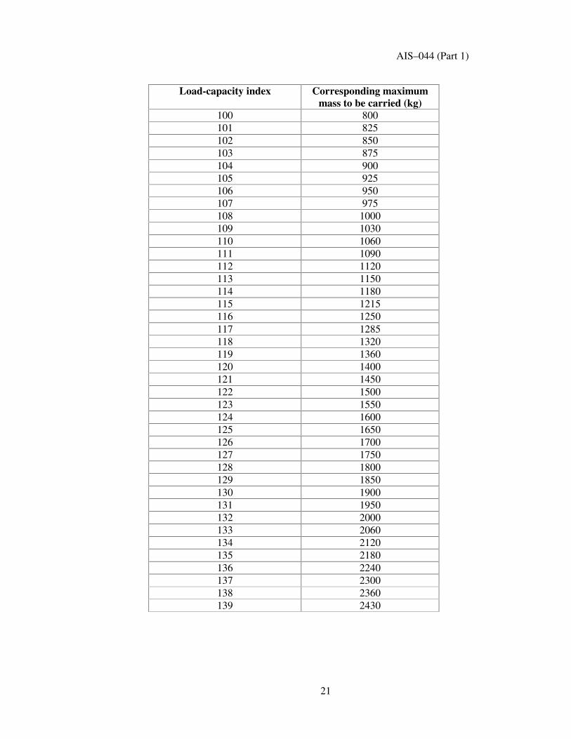
100 800 101 825 102 850 103 875 104 900 105 925 106 950 107 975 108 1000 109 1030 110 1060 111 1090 112 1120 113 1150 114 1180 115 1215 116 1250 117 1285 118 1320 119 1360 120 1400 121 1450 122 1500 123 1550 124 1600 125 1650 126 1700 127 1750 128 1800 129 1850 130 1900 131 1950 132 2000 133 2060 134 2120 135 2180 136 2240 137 2300 138 2360 139 2430
21

AIS–044 (Part 1)
Load-capacity index Corresponding maximum
mass to be carried (kg) 140 2500 141 2575 142 2650 143 2725 144 2800 145 2900 146 3000 147 3075 148 3150 149 3250 150 3350 151 3450 152 3550 153 3650 154 3750 155 3875 156 4000 157 4125 158 4250 159 4375 160 4500 161 4625 162 4750 163 4875 164 5000 165 5150 166 5300 167 5450 168 5600 169 5800 170 6000 171 6150 172 6300 173 6500 174 6700 175 6900 176 7100 177 7300 178 7500 179 7750
22

AIS–044 (Part 1)
Load-capacity index Corresponding maximum
mass to be carried (kg) 180 8000 181 8250 182 8500 183 8750 184 9000 185 9250 186 9500 187 9750 188 10000 189 10300 190 10600 191 10900 192 11200 193 11500 194 11800 195 12150 196 12500 197 12850 198 13200 199 13600 200 14000
23

AIS–044 (Part 1)
ANNEXURE C (Refer Paras 2.27, 2.29 & 6.2.4)
VARIATION OF LOAD CAPACITY WITH SPEED COMMERCIAL VEHICLES TYRES – RADIAL AND DIAGONAL
Variation of load capacity ( %) All load indices Load indices
t 122 (1) Load indices ������(1)
Speed category symbol
Speed category symbol
Speed category symbol
Speed (km/h)
F G J K L M L M N P (2 ) 0 +150 +150 +150 +150 +150 +150 +110 +110 +110 +110 5 +110 +110 +110 +110 +110 +110 +90 +90 +90 +90
10 +80 +80 +80 +80 +80 +80 +75 +75 +75 +75 15 +65 +65 +65 +65 +65 +65 +60 +60 +60 +60 20 +50 +50 +50 +50 +50 +50 +50 +50 +50 +50 25 +35 +35 +35 +35 +35 +35 +42 +42 +42 +42 30 +25 +25 +25 +25 +25 +25 +35 +35 +35 +35 35 +19 +19 +19 +19 +19 +19 +29 +29 +29 +29 40 +15 +15 +15 +15 +15 +15 +25 +25 +25 +25 45 +13 +13 +13 +13 +13 +13 +22 +22 +22 +22 50 +12 +12 +12 +12 +12 +12 +20 +20 +20 +20 55 +11 +11 +11 +11 +11 +11 +17.5 +17.5 +17.5 +17.5 60 +10 +10 +10 +10 +10 +10 +15.0 +15.0 +15.0 +15.0 65 +7.5 +8.5 +8.5 +8.5 +8.5 +8.5 +13.5 +13.5 +13.5 +13.5 70 +5.0 +7.0 +7.0 +7.0 +7.0 +7.0 +12.5 +12.5 +12.5 +12.5 75 +2.5 +5.5 +5.5 +5.5 +5.5 +5.5 +11.0 +11.0 +11.0 +11.0 80 0 +4.0 +4.0 +4.0 +4.0 +4.0 +10.0 +10.0 +10.0 +10.0 85 +2.0 +3.0 +3.0 +3.0 +3.0 +8.5 +8.5 +8.5 +8.5 90 0 +2.0 +2.0 +2.0 +2.0 +7.5 +7.5 +7.5 +7.5 95 +1.0 +1.0 +1.0 +1.0 +6.5 +6.5 +6.5 +6.5 100 0 0 0 0 +5.0 +5.0 +5.0 +5.0 105 0 0 0 +3.75 +3.75 +3.75 +3.75 110 0 0 0 +2.5 +2.5 +2.5 +2.5 115 0 0 +1.25 +1.25 +1.25 +1.25 120 0 0 0 0 0 0 125 0 0 0 0 130 0 0 0 0 135 0 0 140 0 0 145 0 150 0 155 160
(1) The load capacity indices refer to a single operation. (2) Load variations are not allowed for speeds above 160 km/h. For speed category
symbols “ Q” and above the speed category corresponding to the speed category symbol (See para 2.28.2) specifies the maximum speed permitted for the tyre.
24

AIS–044 (Part 1)
ANNEXURE D (Refer Para. 2.17 & 3.2)
ARRANGEMENT OF TYRE MARKINGS
b 250/70 R 20 149/145 J d TUBELESS c
C MAR 02 620 kPa ( 6.32Kg/cm2) c/2
��These markings define a pneumatic tyre:
��Having a nominal section width of 250;
��Having a nominal aspect ratio of 70;
��Of radial-ply structure (R);
��Having a nominal rim diameter of 514.4mm, for which the symbol
is 20;
��Having load capacities of 3250 kg when single and 2900 kg when twinned (dual), corresponding respectively to the load indices 149 and 145 shown in Annexure B to this Standard;
��Classified in the nominal speed Category J (reference speed
100 km/h);
��Capable of being fitted without an inner tube (“ TUBELESS” );
��Manufactured during the month MARCH of year 2002; ��Max pressure of 620 kPa or 6.2 bar or 6.32 kg/cm2.
Note: Arrangement of tyre marking relates to the tyre size
designation. Other markings location will be left to the discretion of the tyre manufacturer.
25
MINIMUM HEIGHTS OF MARKINGS (mm) Tyres of rim diameter < 20” or
<514.4 mm or of section width � 235 mm or � 9”
Tyres of rim diameter t 20” or t 514.4 mm or of section width >235
mm or >9” b 6 9 c 4 d 6

AIS–044 (Part 1)
ANNEXURE E
(Refer Para. 6.1.5) METHOD OF MEASURING PNEUMATIC TYRES
E.1.0 The tyre is mounted on the measuring rim specified by the manufacturer
pursuant to para.4.1 of this standard. and is inflated to a pressure specified by the manufacturer pursuant to Para.4.1 of this standard.
E.2.0 The tyre fitted on its rim is conditioned to the ambient temperature of the
laboratory for at least 24 hours. E.3.0 The pressure is readjusted to the value specified in Para.1 above.
E.4.0 The overall width is measured by caliper at six equally-spaced points,
account being taken of the thickness of the protective ribs or bands. The highest measurement so obtained is taken as the overall width.
E.5.0 The outer diameter is calculated from the maximum circumference.
26

AIS–044 (Part 1)
ANNEXURE F (Refer Para. 6.2.1)
PROCEDURE FOR ENDURANCE TEST
F.1.0 PREPARING THE TYRE F.1.1 Mount a new tyre on the test rim specified by the manufacturer pursuant to
para.4.1 of this standard. F.1.2 Use a new inner tube or combination of inner tube, valve and flap (as
required) when testing tyres with inner tubes. F.1.3 Inflate the tyre to the pressure corresponding to the pressure specified by
the manufacturer. F.1.4 Condition the tyre-and-wheel assembly at test-room temperature for not
less than three hours. F.1.5 Readjust the tyre pressure to that specified in para.F.1.3 F.2.0 TEST PROCEDURE F 2.1 Mount the tyre-and wheel assembly on the test axle and press it against the
outer face of a smooth power-driven test drum 1.70 ± 1% in diameter having a surface at least as wide as the tyre tread.
F.2.2 Apply to the test axle a series of test loads expressed in percent of the load
indicated, in Annexure B to this Regulation, opposite the load index or max load engraved on the sidewall of the tyre, in accordance with the test programme below. Where the tyre has load-capacity indices for both single and twinned utilisation, the reference load for single utilisation shall be taken as the basis for the test loads.
F.2.2.1 In the case of a tyre with a load capacity index 121 or less and a speed
category above P, test procedures are as specified in para. F.3.0. F.2.2.2 For all other tyre types, the endurance test programme is shown in
Appendix 1 to this annexure. F.2.2.3 The tyre pressure must not be corrected throughout the test and the test
load must be kept constant throughout each of the three test stages. F.2.3 During the test the temperature in the test-room must be maintained at
between 20 °C and 40 °C or at a higher temperature if the manufacturer so agrees.
F.2.4 The endurance-test programme shall be carried out without interruption.
27

AIS–044 (Part 1)
F.3.0 LOAD/SPEED TEST PROGRAMME FOR TYRE WITH A LOAD
CAPACITY INDEX 121 OR LESS AND A SPEED CATEGORY Q AND ABOVE.
F.3.1 Load placed on the wheel as a percentage of the load corresponding to the
load index: F.3.1.1 90% when tested on a test drum 1.70 m ± 1% in diameter; F.3.1.2 92% when tested on a test drum 2.0 m ± 1%in diameter. F.3.2 Initial test speed: speed corresponding to the speed category symbol less
20km/h; F.3.2.1 Time to reach the initial test speed 10 min. F.3.2.2 Duration of the first step = 10 min F.3.3 Second test speed: speed corresponding to the speed category symbol less
10 km/h;
F.3.3.1 Duration of the second step = 10 min. F.3.4 Final test speed: speed corresponding to the speed category symbol: F.3.4.1 Duration of the final step = 30 min. F.3.5 Total test duration: 1 H
28

AIS–044 (Part 1)
APPENDIX – 1 TO ANNEXURE F
ENDURANCE TEST PROGRAMME
Test-drum speed Load placed on the wheel as a percentage of the load
corresponding to the load index
Load index
Tyre speed category
Radial-ply min –1
Diagonal (bias-ply)
min –1
7 h. 16 h. 24 h.
F 100 100 G 125 100 J 150 125 K 175 150 L 200 -
122 or more
M 225 - F 100 100 G 125 125 J 150 150 K 175 175
66% 84% 101%
70% 88% 106% L 200 175 4h. 6 h. 24h
M 250 200 75% 97% 114% N 275 - 75% 97% 114%
121 or less
P 300 - 75% 97% 114%
Notes: (1) “ Special-use” tyres (see para 2.1.3 of the Standard) should be tested at a speed equal to 85% of the speed prescribed for equivalent normal tyres.
(2) Tyres with a Load Index of 122 or more of speed categories above M are
not yet produced. Approval cannot be granted to them under this Standard.
29

AIS–044 (Part 1)
ANNEXURE G
(Refer Para. 6.3.1) LOAD / SPEED TEST
G.1.0 PREPARING THE TYRE G.1.1 Mount a new tyre on the test rim specified by the manufacturer
pursuant to Para.4.1 of this standard. G.1.2 Use a new inner tube or combination of inner tube, valve and flap (as
required) when testing tyres with inner tubes. G.1.3 Inflate the tyre to the pressure corresponding to the pressure specified
by the manufacturer. G.1.4 Condition the tyre-and-wheel assembly at test-room temperature for not
less than three hours. G.1.5 Read just the tyre pressure to that specified in para.G.1.3 above.
G.2.0 TEST PROCEDURE G.2.1 Load placed on the wheel as a percentage of the load corresponding to
the load index:
G.2.1.1 90% when tested on a test drum 1.70 m ± 1% in diameter;
G.2.1.2 92% when tested on a test drum 2.0 m ± 1%in diameter.
G.2.2 Initial test speed: speed corresponding to the speed category symbol less 20km/h;
G.2.2.1 Time to reach the initial test speed 10 min.
G.2.2.2 Duration of the first step = 10 min
G.2.3 Second test speed: speed corresponding to the speed category symbols less by 10 km/hr;
G.2.3.1 Duration of the second step = 20 min.
G.2.4 Final test speed: speed corresponding to the speed category symbol (Reference speed).
G.2.4.1 Duration of the final step = 20 min.
G.2.5 Total test duration: 1 H
30
AIS–044 (Part 1)
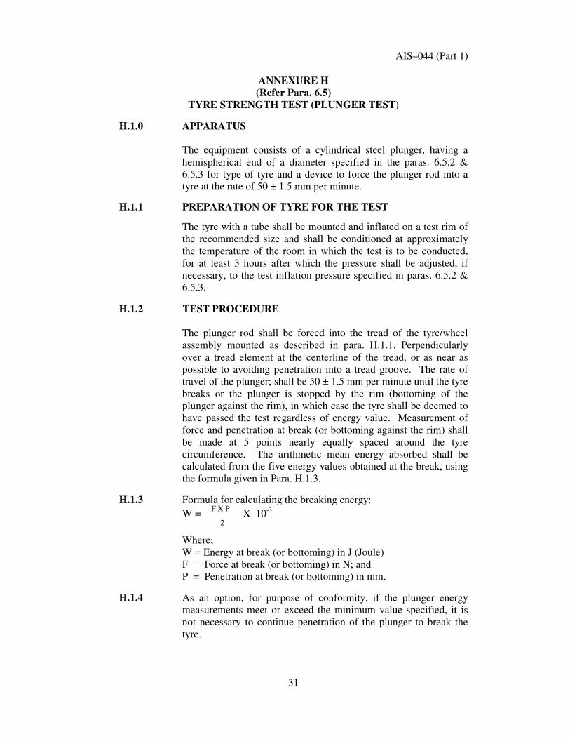
ANNEXURE H (Refer Para. 6.5)
TYRE STRENGTH TEST (PLUNGER TEST) H.1.0 APPARATUS
The equipment consists of a cylindrical steel plunger, having a hemispherical end of a diameter specified in the paras. 6.5.2 & 6.5.3 for type of tyre and a device to force the plunger rod into a tyre at the rate of 50 ± 1.5 mm per minute.
H.1.1 PREPARATION OF TYRE FOR THE TEST
The tyre with a tube shall be mounted and inflated on a test rim of the recommended size and shall be conditioned at approximately the temperature of the room in which the test is to be conducted, for at least 3 hours after which the pressure shall be adjusted, if necessary, to the test inflation pressure specified in paras. 6.5.2 & 6.5.3.
H.1.2 TEST PROCEDURE
The plunger rod shall be forced into the tread of the tyre/wheel assembly mounted as described in para. H.1.1. Perpendicularly over a tread element at the centerline of the tread, or as near as possible to avoiding penetration into a tread groove. The rate of travel of the plunger; shall be 50 ± 1.5 mm per minute until the tyre breaks or the plunger is stopped by the rim (bottoming of the plunger against the rim), in which case the tyre shall be deemed to have passed the test regardless of energy value. Measurement of force and penetration at break (or bottoming against the rim) shall be made at 5 points nearly equally spaced around the tyre circumference. The arithmetic mean energy absorbed shall be calculated from the five energy values obtained at the break, using the formula given in Para. H.1.3.
H.1.3 Formula for calculating the breaking energy:
W = F X P X 10-3
2
Where; W = Energy at break (or bottoming) in J (Joule) F = Force at break (or bottoming) in N; and P = Penetration at break (or bottoming) in mm.
H.1.4 As an option, for purpose of conformity, if the plunger energy measurements meet or exceed the minimum value specified, it is not necessary to continue penetration of the plunger to break the tyre.
31

AIS–044 (Part 1)
ANNEXURE J
(Refer Para. 3.5) EXAMPLES OF TYRE SIZE DESIGNATIONS
MILLIMETRIC 205 / 80 R 15 LT/C 108/104 J - Speed symbol SERIES (RADIAL) load Index (Single/Dual) Vehicle C- Light Truck/Commercial Nominal rim diameter code Radial (D if. Diagonal) Nominal Section Width Code/
Nominal Aspect Ratio NUMERIC 7.50 _ 16 14PR LT/C (BIAS) Vehicle C- Light Truck/Commercial Ply rating Nominal rim diameter code Construction code “ _” Diagonal Nominal Section Width Code NUMERIC 10.00 R 20 14PR (RADIAL) Ply rating Nominal rim diameter code Construction code “ R” Radial
Nominal Section Width Code NUMERIC 14.00 _ 20 16PR (BIAS) Ply Rating Nominal rim diameter code Construction code “ _” Diagonal Nominal Section Width Code
32

AIS–044 (Part 1)
ANNEXURE K
(Refer Para. 6.6.1) TYRE UNIFORMITY TEST
K.1.0 PREPARING THE TYRE K 1.1 Mount a new tyre on the test rim specified by the manufacturer pursuant to
para.4.1 of this standard. K.1.2 Use a new inner tube or combination of inner tube, valve and flap (as
required) when testing tyres with inner tubes. K.1.3 Inflate the tyre to the pressure corresponding to the pressure specified by
the manufacturer. K.1.4 Condition the tyre-and-wheel assembly at test-room temperature for not
less than three hours. K.2.0 TEST PROCEDURE K.2.1 Apply a load of 85% of rated load (for rim up to 14 inch) and 88% of rated
Load (for rim above 15 inch) to the tyre and warm up the tyre for two minutes at 300-400 rpm of tyre rotating speed.
K2.2 Outer diameter of test drum shall be 854.1 ± 2.5 mm for rim diameter up to
14 inches and 1600.2 ± 2.5 mm for rim diameter above 15 or more and drum surface shall have High friction coarse textured surface
K.2.2 Adjust the inflation pressure and rotating speed of tyre to 60 rpm. K.2.3 The distance between the axis of the tyre and the axis of the drum shall be
held constant. K.2.4 Rotate the tyre at 60 rpm and measure the components and variations
of the following generated force with indicators and recorders Radial force variation Lateral force variation Tractive force variation Conicity and Ply steer If necessary, repeat the measurements after reversing the tyre on the
machine, or reversing the direction of the rotation.
33
AIS–044 (Part 1)
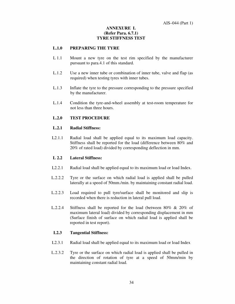
ANNEXURE L (Refer Para. 6.7.1)
TYRE STIFFNESS TEST
L.1.0 PREPARING THE TYRE
L 1.1 Mount a new tyre on the test rim specified by the manufacturer pursuant to para.4.1 of this standard.
L.1.2 Use a new inner tube or combination of inner tube, valve and flap (as required) when testing tyres with inner tubes.
L.1.3 Inflate the tyre to the pressure corresponding to the pressure specified by the manufacturer.
L.1.4 Condition the tyre-and-wheel assembly at test-room temperature for not less than three hours.
L.2.0 TEST PROCEDURE
L.2.1 Radial Stiffness:
L2.1.1 Radial load shall be applied equal to its maximum load capacity. Stiffness shall be reported for the load (difference between 80% and 20% of rated load) divided by corresponding deflection in mm.
L 2.2 Lateral Stiffness:
L2.2.1 Radial load shall be applied equal to its maximum load or load Index.
L.2.2.2 Tyre or the surface on which radial load is applied shall be pulled laterally at a speed of 50mm./min. by maintaining constant radial load.
L.2.2.3 Load required to pull tyre/surface shall be monitored and slip is recorded when there is reduction in lateral pull load.
L.2.2.4 Stiffness shall be reported for the load (between 80% & 20% of maximum lateral load) divided by corresponding displacement in mm (Surface finish of surface on which radial load is applied shall be reported in test report).
L2.3 Tangential Stiffness:
L2.3.1 Radial load shall be applied equal to its maximum load or load Index
L.2.3.2 Tyre or the surface on which radial load is applied shall be pulled in the direction of rotation of tyre at a speed of 50mm/min by maintaining constant radial load.
34

AIS–044 (Part 1)
L.2.3.3 Load required to pull tyre/surface shall be monitored and slip is
recorded when there is reduction in tangential pull load.
L.2.3.4 Stiffness shall be reported for the load (between 80% & 20% of maximum lateral load) divided by corresponding displacement in mm. (surface finish of surface on which radial load is applied shall be reported in test report).
35

AIS–044 (Part 1)
ANNEXURE M ( Refer Para 4.1)
TECHNICAL SPECIFICATION TO BE SUBMITTED
BY MANUFACTURER
M.1 Tyre make (trade name), brand name and type M.2 Manufacturers name and address M.3 Tyre-size designation as defined in para 2.17 of this standard M.4 The category of use (normal or special or snow); M.5 The Structure: diagonal (bias ply) or radial; M.6 The speed category; M.7 The load-capacity index or Max Permissible load; M.8 Whether the tyre is intended to be used with or without an inner tube; M.9 Normal or Reinforced M.10 Ply-Rating M.11 The overall dimensions: overall section width and outer diameter; M.12 The rims on which the tyre can be mounted; M.13 The measuring rim and test rim; M.14 The measuring pressure and test pressure; M.15 Number and height of tread wear indicators M.16 Drawing or photographs of sidewall showing marking. M.17 Drawing or photographs of tread, which can identify tread pattern M.18 Dimensional drawing of tyre cross-section.
36

AIS–044 (Part 1)
ANNEXURE N (See Introduction)
COMMITTEE COMPOSITION Automotive Industry Standards Committee
Chairman Shri B. Bhanot Director
The Automotive Research Association of India, Pune Members Representing Shri Alok Rawat Ministry of Road Transport & Highways, New Delhi
Shri Sushil Kumar Department of Heavy Industry, Ministry of Heavy
Industries & Public Enterprises, New Delhi Director Office of the Development Commissioner
Small Scale Industries, Ministry of Small Scale Industries, New Delhi
Shri L. R. Singh Bureau of Indian Standards, New Delhi
Shri A. S. Lakra Shri D. G. Shirke (Alternate)
Central Institute of Road Transport, Pune
Director Indian Institute of Petroleum, Dehra Dun Shri R.C. Sethi Shri N. Karuppaiah (Alternate)
Vehicles Research & Development Establishment, Ahmednagar
Shri Rajat Nandi Society of Indian Automobile Manufacturers Shri T.C. Gopalan Shri Ramakant Garg (Alternate)
Tractor Manufacturers Association, New Delhi
Shri K.N.D. Nambudiripad
Automotive Components Manufacturers Association, New Delhi
Shri G. P. Banerji Automotive Components Manufacturers Association, New Delhi
Member Secretary
Mrs. Rashmi Urdhwareshe Sr. Assistant Director
The Automotive Research Association of India, Pune
37
Related Documents


