AMIAD Water Systems AMIAD AMC FLUSHING CONTROLLERS 6 Solenoid Models User Guide Arkal Amiad AMC 6-12 AC & DC Controllers for: Spin Klin, SK, Filtomat, SAF, TAF, Sigma, Omega Filters. Click for new orders and spare parts amiad arkal:

Welcome message from author
This document is posted to help you gain knowledge. Please leave a comment to let me know what you think about it! Share it to your friends and learn new things together.
Transcript
AMIAD Water Systems
AMIAD AMC FLUSHING CONTROLLERS 6 Solenoid Models
User Guide
Original Instructions - Ref.910101-000499 - 09.2013
Arkal Amiad AMC 6-12 AC & DC Controllers for: Spin Klin, SK, Filtomat, SAF, TAF, Sigma, Omega Filters.Click for new orders and spare parts amiad arkal:

AMC Controllers 6 Sol 09.2013 Page 2 of 46
AMIAD AMC FLUSHING CONTROLLERS 6 solenoid Models - User Manual
Disclaimer: This document and the information enclosed within it contain restricted and/or privileged information that are intended only for usage by authorized Amiad technicians. If you are not a qualified Amiad technician you must not take nay action in reliance to this document, unless permitted by Amiad. None of the procedures provided on this file may be used in any form or by any means without permission from Amiad. If you received this file in error please notify Amiad immediately. ([email protected]) The confidential nature of and/or privilege in the file enclosed is not waived or lost as a result of a mistake or error in this file. Amiad accepts no liability whatsoever, whether it was caused by: 1. Accessing or other related actions to this file. 2. Any links, procedures or materials provided/attached to this file. Amiad assumes that all users understand risks involved within this file and/or its attached materials. All the procedures, drawings, pictures and/or any other information provided in this document are presented as general information only; they can be altered, removed or changed without any further notice by Amiad. This document does not replace any certified drawing, procedure or information provided by Amiad in reference to a specific customer, site or project. All rights reserved.

AMC Controllers 6 Sol 09.2013 Page 3 of 46
Introduction & How to use this manual Amiad’s AC/DC AMC FLUSHING CONTROLLERS are electronic devices capable of controlling the back-flush process of various automatic filter models installed in various configurations. Amiad’s AMC SOLENOIDS FLUSHING CONTROLLERS supplied in three basic configurations: DC controller, 110VAC controller and 220VAC controller and in two solenoid configurations: 6 and 12 solenoids. This document is the user-manual of the 6 solenoid models and it describes their configuration and the operation procedures. Before operating the controller please read this manual carefully. Make sure that:
You are familiar with the safety instructions
You know how to use the control’s User-Interface panel
This manual consists of the following chapters:
1. Safety instructions .......................................................................................................................... 4
2. General Description - Capabilities, Configuration options, Types of controlled filters ...................................... 7
3. Flushing methods – Flushing sequences possible with the controller .................................................... 9
4. The User Interface Panel - How to use the panel .............................................................................. 12
5. Entering data - How to modify numbers and parameters ................................................................... 15
6. Flushing program – How to enter a flushing sequence program ......................................................... 16
7. Monitoring – How to monitor the controller operation ...................................................................... 18
8. Handling faults – How to identify and handle flushing faults ............................................................... 21
9. Configuration – How to configure the controller for a specific filter model ........................................... 22
10. Technical data – Connection drawing, I/O data, etc ......................................................................... 33
11. Annex A. Chaining Amiad Controllers .......................................................................................... 41
12. Annex B. Terminal Strips & Installation Instructions ................................................................... 42

AMC Controllers 6 Sol 09.2013 Page 4 of 46
1. Safety instructions
General Safety Instructions Amiad filtration products always operate as components in a larger system. It is essential for the system designers, installers and operators to
comply with all the relevant safety standards.
Prior to installation, operation, maintenance or any other type of action carried out on the filter, read carefully the safety, installation and operation instructions.
During installation, operation or maintenance of the filter all conventional safety instructions should be observed in order to avoid danger to the workers, the public or to property in the vicinity.
Please note: The filter enters into a flushing mode automatically, without prior warning.
No change or modification to the equipment is permitted without a written notification given in advance by the manufacturer or by its representative, on the manufacturer’s behalf.
Always observe standard safety instructions and good engineering practices whilst working in the filter’s vicinity.
Use the filter only for its intended use as designed by Amiad, any misuse of the filter may lead to undesired damage and may affect your warranty coverage. Please consult with Amiad prior to any non-regular use of this equipment.
Installation
General Install the filter according to the detailed Installation Instructions provided with the filter by the manufacturer and according to the description
given in this manual.
Make sure to leave enough clearance so as to enable easy access for future treatments and safe maintenance operations.
The user should arrange suitable lighting at the area of the filter to enable good visibility and safe maintenance.
The user should arrange suitable platforms, ladders and safety barriers to enable easy and safe access to the filter without climbing on pipes and other equipment. The user should verify that any platform, barrier, ladder or other such equipment is built, installed and used in accordance with the relevant local authorized standards.
Check and re-tighten all bolts during commissioning and after the first week of operation.
Use only appropriate standard tools and equipment operated by qualified operators when installing, operating and maintaining the filter.
When installation is required in hazardous environment sites, underground or high above ground, make sure that the site design and the auxiliary equipment are appropriate and that installation procedures are carried out in accordance with the relevant standards and regulations.
Ensure walking areas about the installation are slip free when wet.
Shipment and transporting Shipping and transporting the filter must be done in a safe and stable manner and in accordance with the relevant standards and regulations.
For shipping, lifting and positioning the filter, use only approved lifting equipment and authorized employees and contractors.
Electricity
General Electric wiring should be performed by an authorized electrician only, using standardized and approved components.
Install a lockable main power cut-off switch close to the control panel.
If due to site constraints, the control panel is installed without a clear line-of sight of the filter, an additional lockable power disconnect cut-off switch should be installed near each filter unit.
Installation of the filter should be performed so as to avoid direct water splashing on the electrical components or on the control panel.
Additional instructions for Amiad Controllers
Use the controller only for its intended use as designed by Amiad, any misuse of the controller may lead to undesired damage and may affect your warranty coverage. Please consult with Amiad prior to any non-regular use of this equipment.
The terminals enclosure lid of the unit must remain closed at all times.
Only a qualified technician may remove this lid and only when the controller is properly disconnected from its power source.
Servicing the unit can be done only by Amiad’s qualified technician.
AMC Controllers 6 Sol 09.2013 Page 5 of 46
Make sure that the filters controlled by the controller are disconnected from the water system whenever servicing the controller.
In case the controller is connected to an external AC power supply unit, make sure that the power supply connection is done only by a licensed electrician and the connection complies with your local standards for High Voltage out-doors connection.
Warnings!
o Use only the built-in transformer
o In case the controller is supplied with a power supply cable connected to it, the controller is for indoor installations only!
o In order to use the controller for outdoor installation, a licensed electrician must disconnect the power supply cable, and connect the controller according to the instructions given in the installation chapter of this document and in compliance with all the safety instructions and the local standards for High Voltage out-door connection.
o If the plug doesn’t comply with your local regulation it must be replaced with suitable plug by licensed electrician only.
Notice!
o It is necessary to connect a two pole switch between the 110VAC/220VAC power supply and the controller.
o The 110VAC/220VAC supply point, the circuit and connection to the transformer must be performed according to “Field Electrical Regulations” by a licensed electrician who is accredited with a license according to the Electrical Bill and security requirements.
When using an internal transformer, minimal wire diameter must be 0.7mm. Check with standard measuring equipment that there is no voltage in the electric circuit.
Never cut, connect or disconnect any wire at the controller’s vicinity.
Make sure that the controller is not exposed to water splashes.
Keep the keyboard cover closed at all times when not using the keyboard.
Pneumatics
Install a lockable main cut-off switch, featured with a pressure release mechanism, on the compressed air supply line close to the control panel.
If the control panel is installed far away and there is no eye contact with the filter, a lockable compressed air cut-off switch, featured with a pressure release mechanism, should be installed near each filter unit.
The user should make sure that the compressed air supplied to the filter never exceeds the maximum designated pressure for this filter. An air-pressure reduction valve should be installed on the compressed air supply line upstream of the filter’s pneumatic inlet port.
Hydraulics Extra safety devices should be installed on hot water applications to avoid skin burn danger.
The user should install a manual Water Cut-off Valve next to the filter’s inlet port.
In cases where the downstream piping network downstream of the filter is pressurized an additional manual Water Cut-off Valve should be installed next to the filter outlet port.
The user should make sure that the system includes a Pressure Release / Drainage Valve to enable release of residual pressure prior to any maintenance procedure performed on the filter.
The user should make sure that the filter is never exposed to water pressure exceeding the maximum designated pressure for this filter, if needed a Pressure Reduction Valve should be installed upstream of the filter’s water inlet port.
Please note that the maximum working pressure indicated at the filter’s specifications table includes the pressure caused by fluid hammer and pressure surge effects.
Civil Engineering Make sure that the filter installation is done by Amiad qualified technicians.
Make sure that any civil engineering work at the installation site such as construction, lifting, welding, etc. is done by qualified workers / technicians / contractors and in accordance with the relevant local standards.
While using lifting equipment, make sure that the filter or the lifted part is chained securely and in a safe manner.
Do not leave lifted equipment if there is no necessity. Avoid working below lifted equipment.
Wear a safety helmet while using lifting equipment.
Make sure that the flooring is sloped for drainage and to avoid accumulation of liquids.
Commissioning Read carefully the Commissioning and the First Start-up Operation instructions prior to any attempt to operate the filter.

AMC Controllers 6 Sol 09.2013 Page 6 of 46
In order to achieve maximum performance and smooth operation of the filter it is crucial to perform the Startup and First Operation procedures exactly as described in this manual.
Commissioning the filter should be done by an authorized Amiad technician, do not attempt to commission the filter unaccompanied since this may lead to undesired damage and may affect your warranty coverage.
Operation and Control
Do not operate the filter before reading carefully and being familiar with its operation instructions.
Observe the safety stickers on the filter and never perform any operation contradicting the instructions given.
Never operate or use the filter for purposes other than its original design and operational envelope.
Maintenance Before any maintenance or non-regular operation please read the following:
Servicing the filter should be done only by technicians authorized by Amiad.
Disconnect the filter from the power supply and lock the Main Power Switch.
Disconnect the compressed air supply, release the residual pressure and lock the Pneumatics Main Valve.
Disconnect the filter from the water system by closing and securing the Manual Inlet Valve. In cases where the downstream piping network is pressurized, close and secure the Manual Outlet Valve also.
Release the residual water pressure by opening the Pressure Release / Drainage Valve.
Empty the filter by opening the Drainage Valve.
In hot water systems wait till the filter components cool off to a safe temperature.
Place warning signs around the work area as required by the local standards and procedures.
Inspect the filter’s safety stickers and replace any damaged or faded sticker.
Mechanical
When working on the filter use only appropriate standard tools.
Always open and close valves slowly and gradually.
Remove grease and fat material residues in order to avoid slipping.
Before disconnecting the filter from the water supply, electricity and pneumatics and before releasing the filter’s residual pressure do NOT:
o loosen or unscrew bolts
o remove any protection cover
o open any service port flange
Avoid splashing and water leakage so as to minimize slippage, electrification or damage to the equipment, caused by moisture.
While using lifting equipment, make sure that the filter or the lifted part is chained securely and in a safe manner.
Do not leave lifted equipment if there is no necessity. Avoid working below lifted equipment.
Wear a safety helmet, goggles, gloves, and any other personal safety equipment required by the local standards and regulations.
Human entry into a filter must be done in accordance with the relevant local safety instructions, standards and regulations for working in hazardous environment.
Manual cleaning of filter media using high water pressure or steam should be performed in accordance with the cleaning system instructions, the local standards and regulations and without endangering the operator or the vicinity
Manual cleaning of filter element using acid or other chemical agents should be performed in accordance with the relevant material safety instructions, the local standards and regulations and without endangering the operator or his vicinity.
Before returning to regular operation Re-assemble any protection covers or protection mechanisms removed during service or maintenance operations.
Make sure that all the tools, ladders, lifting devices, etc. used during the maintenance procedures are taken away from the filter area and stored
In order to return the filter to regular operation, follow the First Start-up Operation instructions as detailed in your user manual.
For filters used in potable water systems it is required to disinfect the filter according to the local water authority standards and regulations before putting it back to service.

AMC Controllers 6 Sol 09.2013 Page 7 of 46
2. General Description Amiad’s AMC FLUSHING CONTROLLERS are electronic devices capable of controlling the back-flush process of various automatic filter models installed in various configurations. The configuration of these controllers is factory defined according to the filtration systems’ types to be controlled. Due to the pre-defined controller parameters the installation, operation, monitoring and maintenance of these controllers is easy and simple while ensuring reliable long-term operation. These controllers are capable of controlling 6 Solenoids which enables them to operate the following types of filters:
Arkal Spin-Klin Automatic Disc Filters batteries, up to 6 units each. Filtomat M100/M300 Automatic Screen Filters batteries, up to 6 units each. Single Amiad TAF unit or battery of TAF-H Automatic Filters, up to 6 units each. Gravel media filters batteries, up to 6 units each. SIGMA Automatic Screen Filters batteries, up to 6 units each.
Basically the operation method of these filters is similar, however the timings of the various operation stages vary according to the filter type as described in the flushing methods chapter. This controller supports flushing processes that can be triggered by:
Differential Pressure (DP) signal Time Interval parameter Manual Start command
Beside the filters’ outputs and the DP input the controller is also capable of controlling the following additional functions:
Main/Downstream Valve (replaces one of the 6 maximum filter units outputs) Delay Valve (replaces one of the 6 maximum filter units outputs) Alarm output End of cycle chaining output
The controllers’ enclosures are made of ABS and are designed for outdoor use (IP 65). Additional functions description: Main/Downstream Valve - The controllers are capable of operating one of their outputs as a main or downstream valve. Downstream Valve is usually installed at the outlet port of the filtration system. It is energized during the back-flush process in order to ensure sufficient water pressure during flushing. A Main Valve enables the operation of a valve or a pump (through a dry contact latch relay) for increasing the pressure or supplying additional water source during the flushing process. Note: in case of a pump connected to the Main Valve output it is important to make sure that the relay operating the pump control loop draws no more than 0.5 Ampere from the Main valve output. Delay Valve - The controllers are capable of operating one of their outputs as a Delay Valve together with the flushing filter, for example delay Valve can be used for sampling the flushing water or for controlling an Air pressure operated back-flush system. Alarm Output - The controllers are equipped with a special dry contact output (up to 0.2 Ampere) that is switched on in case of a system fault. End of cycle chaining output- The controllers are equipped with a special dry contact output (up to 0.2 Ampere) that is switched on for 5 seconded at the end of each flushing cycle. This output can be chained to the DP input of another controller for starting a flush cycle on that controller in a sequence to the first controller. See Annex A.
AMC Controllers 6 Sol 09.2013 Page 8 of 46
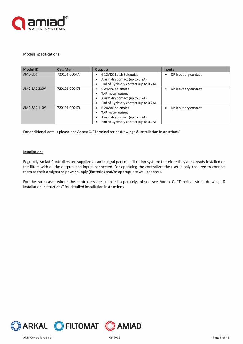
Models Specifications:
Model ID Cat. Mum Outputs Inputs AMC-6DC 720101-000477 6 12VDC Latch Solenoids
Alarm dry contact (up to 0.2A)
End of Cycle dry contact (up to 0.2A)
DP Input dry contact
AMC-6AC 220V 720101-000475 6 24VAC Solenoids
TAF motor output
Alarm dry contact (up to 0.2A)
End of Cycle dry contact (up to 0.2A)
DP Input dry contact
AMC-6AC 110V 720101-000476 6 24VAC Solenoids
TAF motor output
Alarm dry contact (up to 0.2A)
End of Cycle dry contact (up to 0.2A)
DP Input dry contact
For additional details please see Annex C. “Terminal strips drawings & Installation instructions” Installation: Regularly Amiad Controllers are supplied as an integral part of a filtration system; therefore they are already installed on the filters with all the outputs and inputs connected. For operating the controllers the user is only required to connect them to their designated power supply (Batteries and/or appropriate wall adapter). For the rare cases where the controllers are supplied separately, please see Annex C. “Terminal strips drawings & Installation instructions” for detailed installation instructions.
AMC Controllers 6 Sol 09.2013 Page 9 of 46
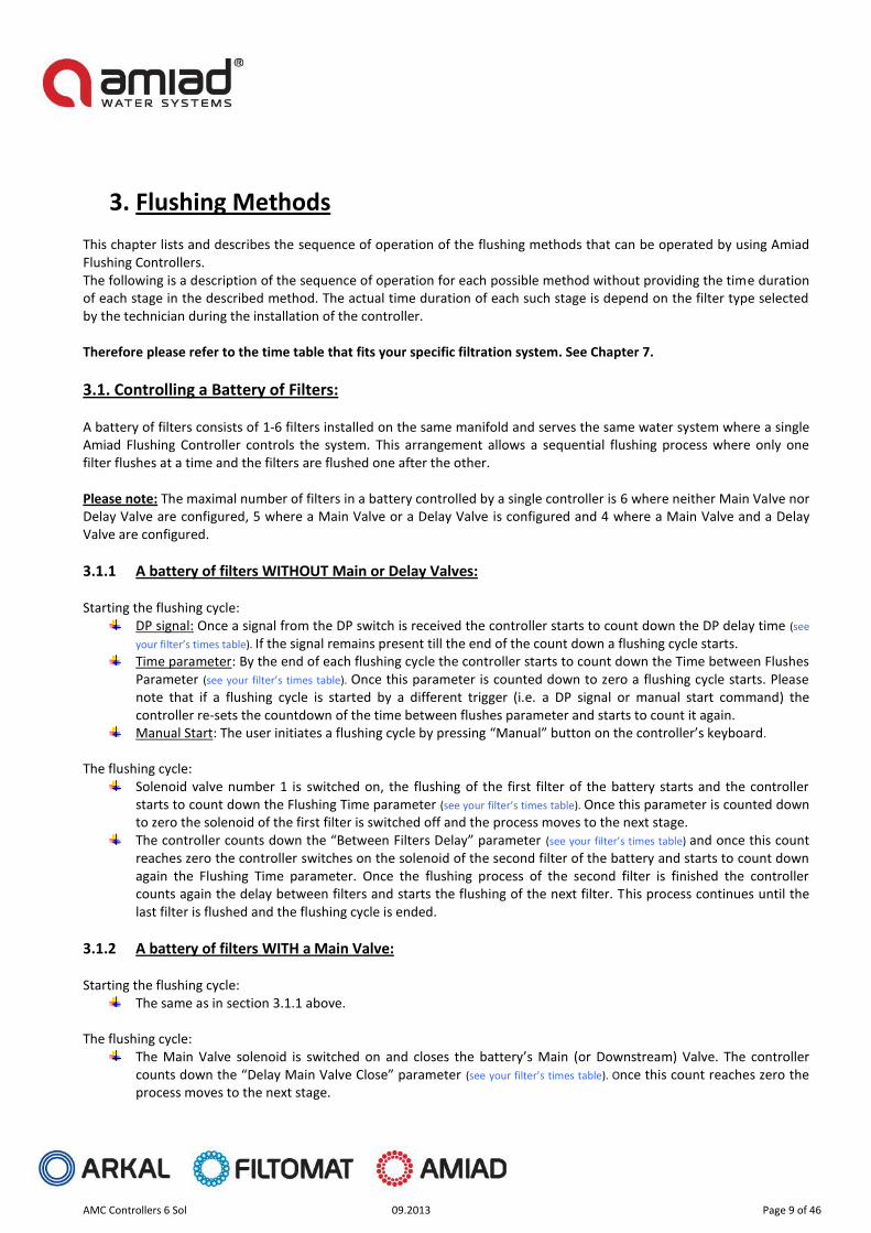
3. Flushing Methods This chapter lists and describes the sequence of operation of the flushing methods that can be operated by using Amiad Flushing Controllers. The following is a description of the sequence of operation for each possible method without providing the time duration of each stage in the described method. The actual time duration of each such stage is depend on the filter type selected by the technician during the installation of the controller. Therefore please refer to the time table that fits your specific filtration system. See Chapter 7.
3.1. Controlling a Battery of Filters: A battery of filters consists of 1-6 filters installed on the same manifold and serves the same water system where a single Amiad Flushing Controller controls the system. This arrangement allows a sequential flushing process where only one filter flushes at a time and the filters are flushed one after the other. Please note: The maximal number of filters in a battery controlled by a single controller is 6 where neither Main Valve nor Delay Valve are configured, 5 where a Main Valve or a Delay Valve is configured and 4 where a Main Valve and a Delay Valve are configured.
3.1.1 A battery of filters WITHOUT Main or Delay Valves: Starting the flushing cycle:
DP signal: Once a signal from the DP switch is received the controller starts to count down the DP delay time (see
your filter’s times table). If the signal remains present till the end of the count down a flushing cycle starts. Time parameter: By the end of each flushing cycle the controller starts to count down the Time between Flushes
Parameter (see your filter’s times table). Once this parameter is counted down to zero a flushing cycle starts. Please note that if a flushing cycle is started by a different trigger (i.e. a DP signal or manual start command) the controller re-sets the countdown of the time between flushes parameter and starts to count it again.
Manual Start: The user initiates a flushing cycle by pressing “Manual” button on the controller’s keyboard.
The flushing cycle:
Solenoid valve number 1 is switched on, the flushing of the first filter of the battery starts and the controller starts to count down the Flushing Time parameter (see your filter’s times table). Once this parameter is counted down to zero the solenoid of the first filter is switched off and the process moves to the next stage.
The controller counts down the “Between Filters Delay” parameter (see your filter’s times table) and once this count reaches zero the controller switches on the solenoid of the second filter of the battery and starts to count down again the Flushing Time parameter. Once the flushing process of the second filter is finished the controller counts again the delay between filters and starts the flushing of the next filter. This process continues until the last filter is flushed and the flushing cycle is ended.
3.1.2 A battery of filters WITH a Main Valve: Starting the flushing cycle:
The same as in section 3.1.1 above. The flushing cycle:
The Main Valve solenoid is switched on and closes the battery’s Main (or Downstream) Valve. The controller counts down the “Delay Main Valve Close” parameter (see your filter’s times table). Once this count reaches zero the process moves to the next stage.

AMC Controllers 6 Sol 09.2013 Page 10 of 46
Solenoid valve number 1 is switched on, the flushing of the first filter of the battery starts and the controller starts to count down the Flushing Time parameter (see your filter’s times table). Once this parameter is counted down to zero the solenoid of the first filter is switched off and the process moves to the next stage.
The controller counts down the “Between Filters Delay” parameter (see your filter’s times table) and once this count reaches zero the controller switches on the solenoid of the second filter of the battery and starts to count down again the Flushing Time parameter. Once the flushing process of the second filter is finished the controller counts again the delay between filters and starts the flushing of the next filter. This process continues till the last filter is flushed and its solenoid is switched off. The Main Valve solenoid is switched off and the flushing cycle ends.
3.1.3 A battery of filters WITH a Delay Valve: Starting the flushing cycle:
The same as in section 3.1.1 above. The flushing cycle:
Solenoid valve number 1 is switched on, the flushing of the first filter of the battery starts and the controller starts to count down the Flushing Time parameter (see your filter’s times table). The controller also starts to count down the “Delay valve delay” parameter (see your filter’s times table) once this parameter is counted down to zero the solenoid of the Delay Valve is switched on and the process moves to the next stage.
The controller calculates the time for closing the delay valve by subtracting the “Delay valve delay” parameter form the Flushing Time parameter. Once the countdown of the Flushing Time parameter reaches this point the Delay valve closes and the controller starts to countdown the “Delay valve delay” again. When this parameter is counted down to zero the solenoid Valve number 1 is switched off and the controller moves to the next stage.
Solenoid valve number 2 is switched on, the flushing of the second filter of the battery starts and the controller starts to count down the Flushing Time parameter (see your filter’s times table). The controller also starts to count down the “Delay valve delay” parameter (see your filter’s times table) once this parameter is counted down to zero the solenoid of the Delay Valve is switched on and the process moves to the next stage.
The controller calculates the time for closing the delay valve by subtracting the “Delay valve delay” parameter form the Flushing Time parameter. Once the countdown of the Flushing Time parameter reaches this point the Delay valve closes and the controller starts to countdown the “Delay valve delay” again. When this parameter is counted down to zero the solenoid Valve number 2 is switched off and the controller moves to the next stage.
The controller continues to flush the rest of the filters in the battery in the same manner. Once the last valve solenoid is switched off the flushing cycle ends.
3.1.4 A battery of filters WITH a Main & Delay Valves: Starting the flushing cycle:
The same as in section 3.1.1 above. The flushing cycle:
The Main Valve solenoid is switched on and closes the battery’s Main (or Downstream) Valve. The controller counts down the “Delay Main Valve Close” parameter (see your filter’s times table). Once this count reaches zero the process moves to the next stage.
Solenoid valve number 1 is switched on, the flushing of the first filter of the battery starts and the controller starts to count down the Flushing Time parameter (see your filter’s times table). The controller also starts to count down the “Delay valve delay” parameter (see your filter’s times table) once this parameter is counted down to zero the solenoid of the Delay Valve is switched on and the process moves to the next stage.
The controller calculates the time for closing the delay valve by subtracting the “Delay valve delay” parameter form the Flushing Time parameter. Once the countdown of the Flushing Time parameter reaches this point the

AMC Controllers 6 Sol 09.2013 Page 11 of 46
Delay valve closes and the controller starts to countdown the “Delay valve delay” again. When this parameter is counted down to zero the solenoid Valve number 1 is switched off and the controller moves to the next stage.
Solenoid valve number 2 is switched on, the flushing of the second filter of the battery starts and the controller starts to count down the Flushing Time parameter (see your filter’s times table). The controller also starts to count down the “Delay valve delay” parameter (see your filter’s times table) once this parameter is counted down to zero the solenoid of the Delay Valve is switched on and the process moves to the next stage.
The controller calculates the time for closing the delay valve by subtracting the “Delay valve delay” parameter form the Flushing Time parameter. Once the countdown of the Flushing Time parameter reaches this point the Delay valve closes and the controller starts to countdown the “Delay valve delay” again. When this parameter is counted down to zero the solenoid Valve number 2 is switched off and the controller moves to the next stage.
The controller continues to flush the rest of the filters in the battery in the same manner. Once the last valve solenoid is switched off the controller switches off the Main Valve solenoid and the flushing cycle ends.

AMC Controllers 6 Sol 09.2013 Page 12 of 46
4. The User Interface Panel Amiad’s Flushing Controller User Interface Panel consists of:
1. Display screen - a rectangular LCD display. (See picture below) 2. Keyboard – a 7 keys keyboard; forward, backward, minus, plus, arrow, manual and pause. 3. Headlines – along the left and right edges of the LCD screen some headlines are printed on the panel surface.
AMC Controllers 6 Sol 09.2013 Page 13 of 46
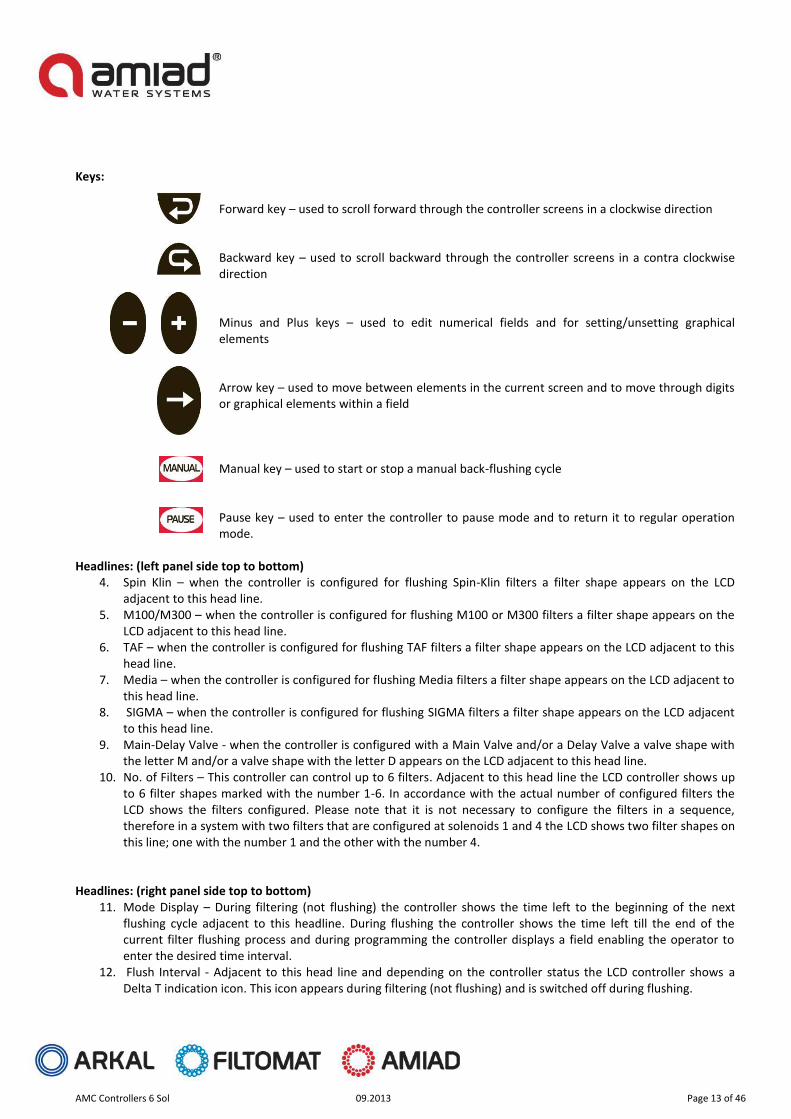
Keys:
Forward key – used to scroll forward through the controller screens in a clockwise direction
Backward key – used to scroll backward through the controller screens in a contra clockwise direction
Minus and Plus keys – used to edit numerical fields and for setting/unsetting graphical elements
Arrow key – used to move between elements in the current screen and to move through digits or graphical elements within a field Manual key – used to start or stop a manual back-flushing cycle Pause key – used to enter the controller to pause mode and to return it to regular operation mode.
Headlines: (left panel side top to bottom)
4. Spin Klin – when the controller is configured for flushing Spin-Klin filters a filter shape appears on the LCD adjacent to this head line.
5. M100/M300 – when the controller is configured for flushing M100 or M300 filters a filter shape appears on the LCD adjacent to this head line.
6. TAF – when the controller is configured for flushing TAF filters a filter shape appears on the LCD adjacent to this head line.
7. Media – when the controller is configured for flushing Media filters a filter shape appears on the LCD adjacent to this head line.
8. SIGMA – when the controller is configured for flushing SIGMA filters a filter shape appears on the LCD adjacent to this head line.
9. Main-Delay Valve - when the controller is configured with a Main Valve and/or a Delay Valve a valve shape with the letter M and/or a valve shape with the letter D appears on the LCD adjacent to this head line.
10. No. of Filters – This controller can control up to 6 filters. Adjacent to this head line the LCD controller shows up to 6 filter shapes marked with the number 1-6. In accordance with the actual number of configured filters the LCD shows the filters configured. Please note that it is not necessary to configure the filters in a sequence, therefore in a system with two filters that are configured at solenoids 1 and 4 the LCD shows two filter shapes on this line; one with the number 1 and the other with the number 4.
Headlines: (right panel side top to bottom) 11. Mode Display – During filtering (not flushing) the controller shows the time left to the beginning of the next
flushing cycle adjacent to this headline. During flushing the controller shows the time left till the end of the current filter flushing process and during programming the controller displays a field enabling the operator to enter the desired time interval.
12. Flush Interval - Adjacent to this head line and depending on the controller status the LCD controller shows a Delta T indication icon. This icon appears during filtering (not flushing) and is switched off during flushing.

AMC Controllers 6 Sol 09.2013 Page 14 of 46
13. Flush Counter - Adjacent to this head line the controller displays the number of flush cycles performed since the last reset of the counter.
14. Delta P on - Adjacent to this head line and depending on the controller status the LCD controller shows a Delta P indication icon. This icon appears whenever the DP sensor that is connected to the system sends a high DP signal to the controller.
15. Alert - Adjacent to this head line the controller may show one or two of the following icons; a battery icon for indicating a low battery status and/or a DP icon indicating a DP fault status or too many consecutive flush cycles due to high DP.
When the controller’s power supply is switched on a screen similar to the following screen appears: (the actual screen depends on the controller configuration; filters type and number)
AMC Controllers 6 Sol 09.2013 Page 15 of 46
5. Entering Data This controller is pre-configured at the factory so for regular operation there is no need to change anything. However two modes of entering/changing data exist in the software: User mode and Technician mode. The user may change the following parameters only:
16. Set the flushing duration of the filters 17. Set the time interval of the flushing by time parameter
A technician may also change the following parameters:
18. Set the filters type (select one of 5 options) 19. Selecting the number of filters controlled by the controller 20. Set the DP delay time 21. Set the “Ignore DP Fault” parameter and the number of continuous flush cycles to fault 22. Selecting a Main valve 23. Set the Main valve open time 24. Selecting a Delay Valve 25. Set the open time and the delay time of the Delay Valve 26. Reset the controller to factory default 27. Set the delay between filters time 28. Perform outputs check 29. Reset the flush counter
Two types of data entry are possible in this controller; entering numerical data and graphically selecting data items: Numerical data entry is done by using the Arrow key and the Plus and Minus Keys. Move to the desired digit with the Arrow key and change it with the Plus / Minus Keys. Press the Forward key to save the new number to the controller’s memory. Please note that when the numerical data is changed but the user remains in the screen the new value will also be automatically saved to the controller’s memory after 5 seconds. In graphical data entry the Arrow Key is used for moving along the possible options (the graphic icons) and the Plus / Minus Keys are used to enable or disable the blinking option.

AMC Controllers 6 Sol 09.2013 Page 16 of 46
6. Flushing Program This controller is pre-configured at the factory so for regular operation there is no need to change anything. The flushing program is pre-configured according to the specific filter type selected during the initial set-up of the controller (at the factory or by Amiad technician). The following tables display the default flushing programs of the different filters that this controller can operate; please refer to the table that resembles your filtration system.
Spin-Klin filters:
Parameter Time between flush cycles
Flushing Time Delay Between Filters
PD Delay Time
Set-point 8 hours 25 seconds 10 seconds 30 seconds Description Set the time
between scheduled flushing cycles
The duration of the back-flushing process per single filter in the system
The delay between the flushing end of a filter and the flushing start of the consecutive filter in the battery
The time required for the DP signal to remain ON until the controller responds by activating the flushing cycle
M100 / M300 filters:
Parameter Time between flush cycles
Flushing Time Delay Between Filters
PD Delay Time
Set-point 8 hours 15 seconds 10 seconds 3 seconds Description Set the time
between scheduled flushing cycles
The duration of the back-flushing process per single filter in the system
The delay between the flushing end of a filter and the flushing start of the consecutive filter in the battery
The time required for the DP signal to remain ON until the controller responds by activating the flushing cycle
TAF filters:
Parameter Time between flush cycles
Flushing Time Delay Between Filters (*)
PD Delay Time
Set-point 8 hours 16 seconds 10 seconds 3 seconds Description Set the time
between scheduled flushing cycles
The duration of the back-flushing process per single filter in the system
The delay between the flushing end of a filter and the flushing start of the consecutive filter in the battery (*) Only TAF-H
The time required for the DP signal to remain ON until the controller responds by activating the flushing cycle
AMC Controllers 6 Sol 09.2013 Page 17 of 46
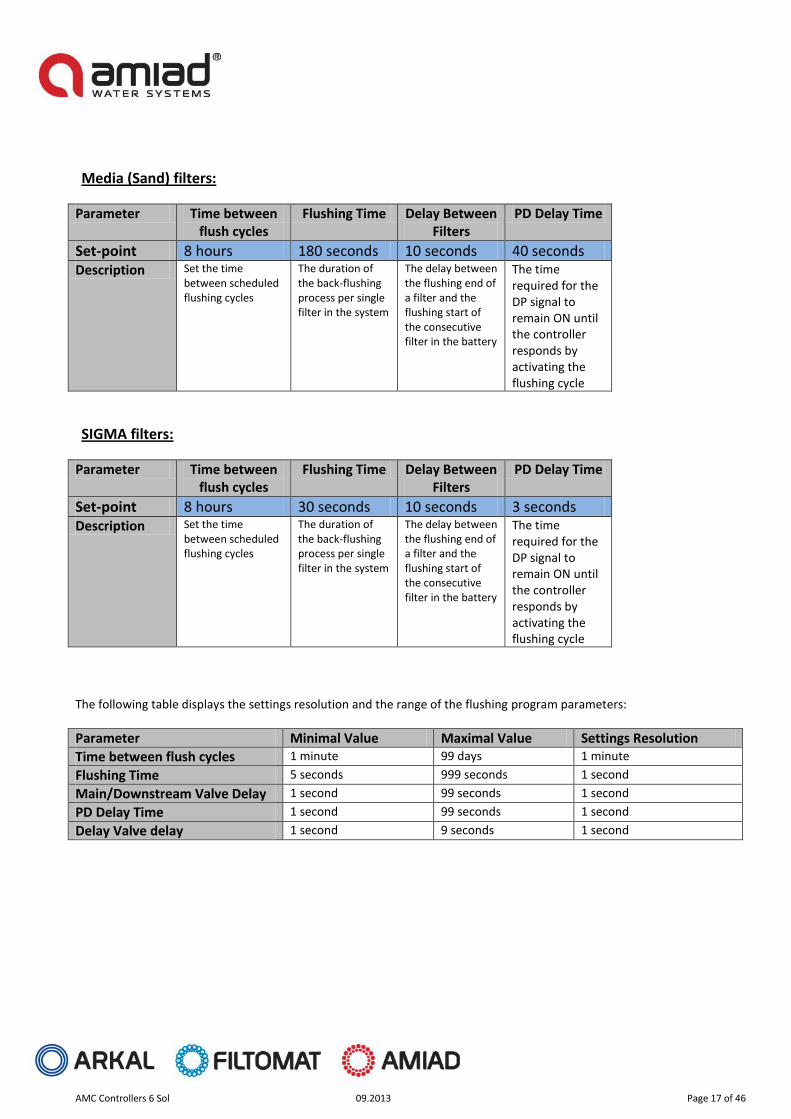
Media (Sand) filters:
Parameter Time between flush cycles
Flushing Time Delay Between Filters
PD Delay Time
Set-point 8 hours 180 seconds 10 seconds 00 seconds Description Set the time
between scheduled flushing cycles
The duration of the back-flushing process per single filter in the system
The delay between the flushing end of a filter and the flushing start of the consecutive filter in the battery
The time required for the DP signal to remain ON until the controller responds by activating the flushing cycle
SIGMA filters:
Parameter Time between flush cycles
Flushing Time Delay Between Filters
PD Delay Time
Set-point 8 hours 30 seconds 10 seconds 3 seconds Description Set the time
between scheduled flushing cycles
The duration of the back-flushing process per single filter in the system
The delay between the flushing end of a filter and the flushing start of the consecutive filter in the battery
The time required for the DP signal to remain ON until the controller responds by activating the flushing cycle
The following table displays the settings resolution and the range of the flushing program parameters:
Parameter Minimal Value Maximal Value Settings Resolution
Time between flush cycles 1 minute 99 days 1 minute
Flushing Time 5 seconds 999 seconds 1 second
Main/Downstream Valve Delay 1 second 99 seconds 1 second
PD Delay Time 1 second 99 seconds 1 second
Delay Valve delay 1 second 9 seconds 1 second

AMC Controllers 6 Sol 09.2013 Page 18 of 46
7. Monitoring During the regular operation of the controller it is possible to:
Monitor the current status of the controller Read information on past activities of the system Perform manual operation and intervene in the flushing process
The main screen of the controller: This screen shows the current status of the controller. Filtering Mode When the system is in filtering mode (not flushing) the main screen shows the following parameters:
1. The type of the filtration system controlled by this controller 2. Main Valve and Delay valve; appear only if configured for this installation 3. The number of filters in the battery controlled by this controller 4. The time left till the next scheduled flush cycle. When the time is less than a day the “Days” head line and
counter disappear 5. Indication that the controller is monitoring the time between flush cycles parameter 6. Indication that the differential pressure sensor sends a high differential pressure signal to the controller 7. Faults indications; (appear only when these faults exist) low battery indication and DP sensor fault.
4
5
6
7
1
2
3
AMC Controllers 6 Sol 09.2013 Page 19 of 46
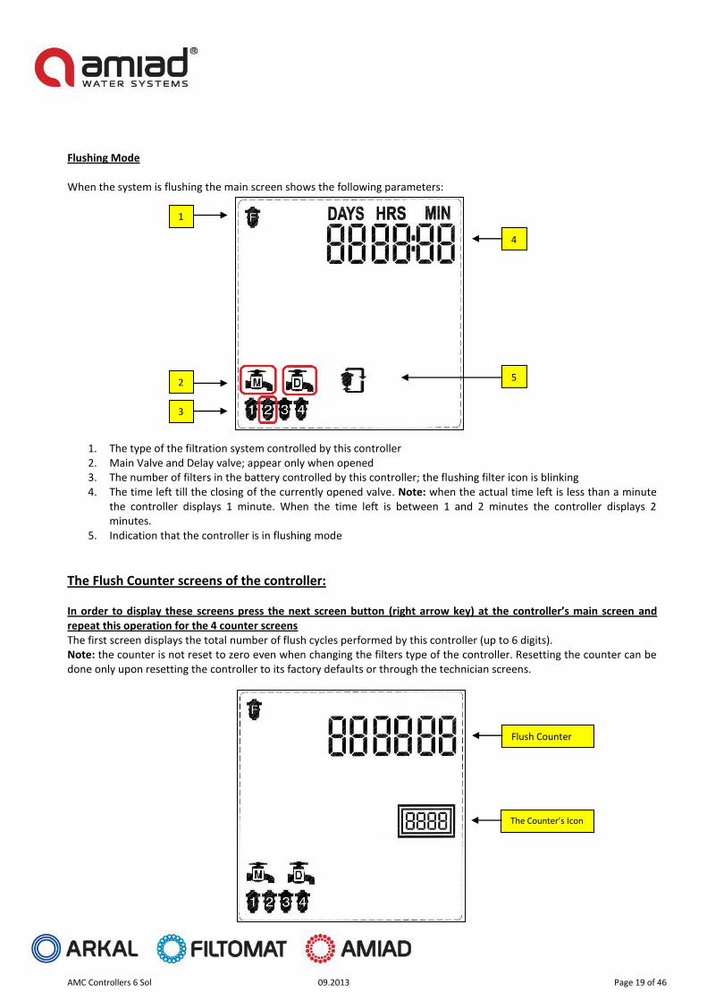
Flushing Mode When the system is flushing the main screen shows the following parameters:
1. The type of the filtration system controlled by this controller 2. Main Valve and Delay valve; appear only when opened 3. The number of filters in the battery controlled by this controller; the flushing filter icon is blinking 4. The time left till the closing of the currently opened valve. Note: when the actual time left is less than a minute
the controller displays 1 minute. When the time left is between 1 and 2 minutes the controller displays 2 minutes.
5. Indication that the controller is in flushing mode
The Flush Counter screens of the controller: In order to display these screens press the next screen button (right arrow key) at the controller’s main screen and repeat this operation for the 4 counter screens The first screen displays the total number of flush cycles performed by this controller (up to 6 digits). Note: the counter is not reset to zero even when changing the filters type of the controller. Resetting the counter can be done only upon resetting the controller to its factory defaults or through the technician screens.
1
2
3
4
5
Flush Counter
The Counter’s Icon
AMC Controllers 6 Sol 09.2013 Page 20 of 46
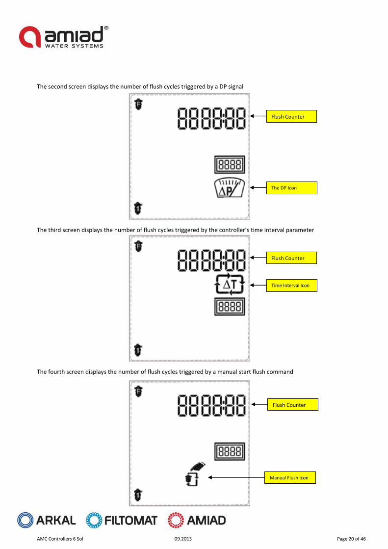
The second screen displays the number of flush cycles triggered by a DP signal
The third screen displays the number of flush cycles triggered by the controller’s time interval parameter
The fourth screen displays the number of flush cycles triggered by a manual start flush command
Flush Counter
The DP Icon
Flush Counter
Time Interval Icon
Flush Counter
Manual Flush Icon
AMC Controllers 6 Sol 09.2013 Page 21 of 46
Manual Operations: This operator can perform the following manual operations:
Starting a Flushing Cycle - Press the Manual key on the keyboard for 5 seconds. This starts a new flushing cycle Stopping a Flushing Cycle – when the controller is in flushing mode pressing the Manual key for 5 seconds stops
the current flush cycle immediately. Exit DP Fault – when the controller is in DP fault mode pressing the Manual key for 5 seconds resets the fault
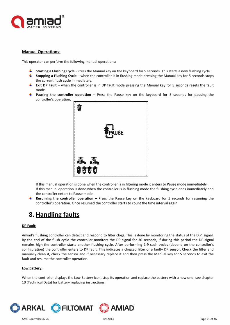
mode. Pausing the controller operation – Press the Pause key on the keyboard for 5 seconds for pausing the
controller’s operation. If this manual operation is done when the controller is in filtering mode it enters to Pause mode immediately. If this manual operation is done when the controller is in flushing mode the flushing cycle ends immediately and the controller enters to Pause mode.
Resuming the controller operation – Press the Pause key on the keyboard for 5 seconds for resuming the controller’s operation. Once resumed the controller starts to count the time interval again.
8. Handling faults DP Fault: Amiad’s flushing controller can detect and respond to filter clogs. This is done by monitoring the status of the D.P. signal. By the end of the flush cycle the controller monitors the DP signal for 30 seconds, if during this period the DP-signal remains high the controller starts another flushing cycle. After performing 1-9 such cycles (depend on the controller’s configuration) the controller enters to DP fault. This indicates a clogged filter or a faulty DP sensor. Check the filter and manually clean it, check the sensor and if necessary replace it and then press the Manual key for 5 seconds to exit the fault and resume the controller operation. Low Battery: When the controller displays the Low Battery Icon, stop its operation and replace the battery with a new one, see chapter 10 (Technical Data) for battery replacing instructions.

AMC Controllers 6 Sol 09.2013 Page 22 of 46
9. Configuration Amiad’s flushing controller can configured for operation with various filter types; furthermore the operation parameters of each such filter type can be changed according to the specific conditions at the actual installation site. Changing the filter basic configuration or operation parameters are done via two separated modes; Operator Mode and Technician Mode.
User mode The user may change the following parameters: Selecting the time interval of the flushing program: When in the main screen of the controller press the Forward Key till the following screen appears. This requires two forward key pressings, first movement from the main screen to the flush duration screen and second movement to the flush counter screen. Upon entry this screen displays the current time interval settings.
1. Press the Arrow Key to move through the digits. 2. Move to the desired digit, the digit starts to blink for 10 seconds. 3. While the digit is blinking press the Plus Key to increase the number by one, or press the Minus Key to decrease
the number by one. 4. Move to the next desired digit and repeat the selection operation described above. 5. Press the Forward Key to exit this screen and move to the next screen or press the Backward Key to exit this
screen and move to the previous screen. Please Note: The new time interval is activated once exiting this screen. Press the Manual and Pause keys together for a second in order to return to the main screen.
AMC Controllers 6 Sol 09.2013 Page 23 of 46
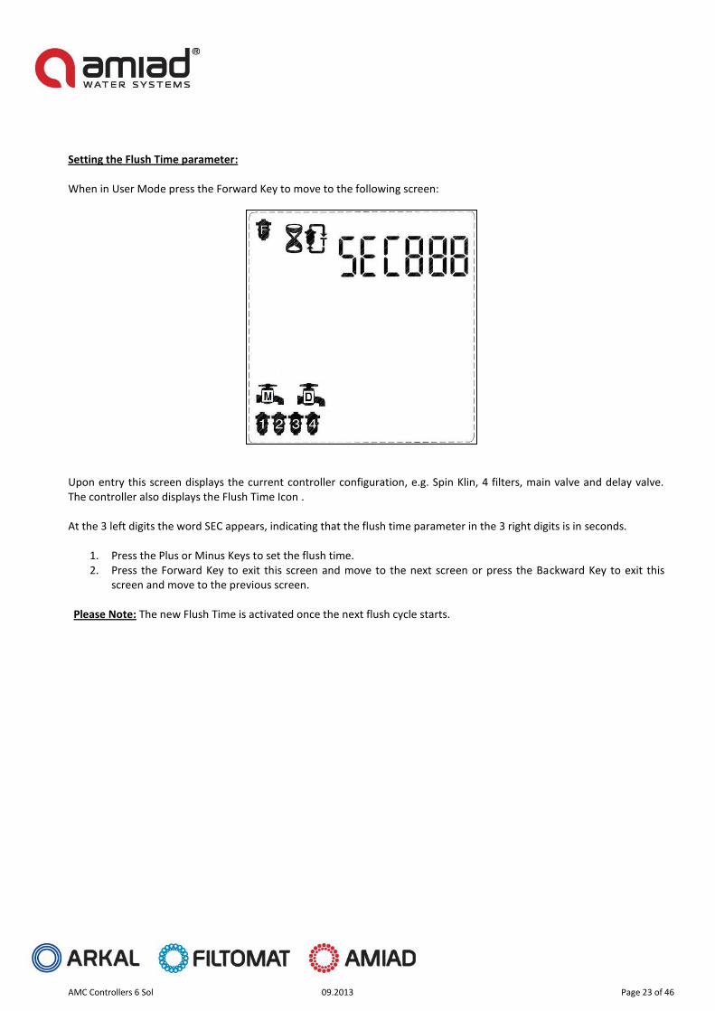
Setting the Flush Time parameter: When in User Mode press the Forward Key to move to the following screen: Upon entry this screen displays the current controller configuration, e.g. Spin Klin, 4 filters, main valve and delay valve. The controller also displays the Flush Time Icon . At the 3 left digits the word SEC appears, indicating that the flush time parameter in the 3 right digits is in seconds.
1. Press the Plus or Minus Keys to set the flush time. 2. Press the Forward Key to exit this screen and move to the next screen or press the Backward Key to exit this
screen and move to the previous screen.
Please Note: The new Flush Time is activated once the next flush cycle starts.

AMC Controllers 6 Sol 09.2013 Page 24 of 46
Technician mode Configuring the basic controller configuration is done via Technician Mode as described in the following paragraphs. Entering the Technician Mode screens: Enter to Technician Mode by simultaneously pressing the Plus Minus and Manual keys for 5 seconds from the main user screen. When in Technician Mode 60 seconds without any key pressed automatically returns the controller to regular operation mode. Selecting the filter type: When entering Technician Mode the following screen appears:
SIGMA Upon entry this screen displays the current controller configuration, e.g. Spin Klin.
1. Press the Plus or Minus Keys to select the filter type. 2. Press the Forward Key to exit this screen and move to the next screen or press the Backward Key to exit this
screen and move to the previous screen.
Spin Klin
M100/M300
TAF
Media

AMC Controllers 6 Sol 09.2013 Page 25 of 46
Setting the DP Delay Time parameter: When in Technician Mode press the Forward Key to move to the following screen:
Upon entry this screen displays the current controller configuration, e.g. Spin Klin, 4 filters, main valve and delay valve. The controller also displays the DP Delay Icon. At the 3 left digits the word SEC appears, indicating that the DP Delay parameter in the 2 right digits is in seconds.
1. Press the Plus or Minus Keys to set the DP delay. 2. Press the Forward Key to exit this screen and move to the next screen or press the Backward Key to exit this
screen and move to the previous screen.

AMC Controllers 6 Sol 09.2013 Page 26 of 46
Setting the DP Fault parameter: When in Technician Mode press the Forward Key to move to the following screen: Upon entry this screen displays the current controller configuration, e.g. Spin Klin, 4 filters, main valve and delay valve. The controller also displays the DP Fault Delay Icon and the activation status of the fault, e.g. OFF (DP fault is not enabled).
1. Press the Plus or Minus Keys to set the DP fault. a. Off – The controller does not check the DP sensor for faults and will never enter to DP fault. b. On1 – the controller checks the DP sensor for faults and will enter to DP fault if the DP signal remains
high at the end of a flushing cycle for 1 consecutive flush. c. On2 – the controller checks the DP sensor for faults and will enter to DP fault if the DP signal remains
high at the end of a flushing cycle for 2 consecutive flush. d. On3 – the controller checks the DP sensor for faults and will enter to DP fault if the DP signal remains
high at the end of a flushing cycle for 3 consecutive flush. e. ------ f. On9 – the controller checks the DP sensor for faults and will enter to DP fault if the DP signal remains
high at the end of a flushing cycle for 9 consecutive flush. 2. Press the Minus Key to go through the options in reverse order. 3. Press the Forward Key to exit this screen and move to the next screen or press the Backward Key to exit this
screen and move to the previous screen.
AMC Controllers 6 Sol 09.2013 Page 27 of 46
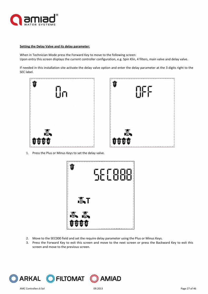
Setting the Delay Valve and its delay parameter: When in Technician Mode press the Forward Key to move to the following screen: Upon entry this screen displays the current controller configuration, e.g. Spin Klin, 4 filters, main valve and delay valve. If needed in this installation site activate the delay valve option and enter the delay parameter at the 3 digits right to the SEC label.
1. Press the Plus or Minus Keys to set the delay valve.
2. Move to the SEC000 field and set the require delay parameter using the Plus or Minus Keys. 3. Press the Forward Key to exit this screen and move to the next screen or press the Backward Key to exit this
screen and move to the previous screen.
AMC Controllers 6 Sol 09.2013 Page 28 of 46
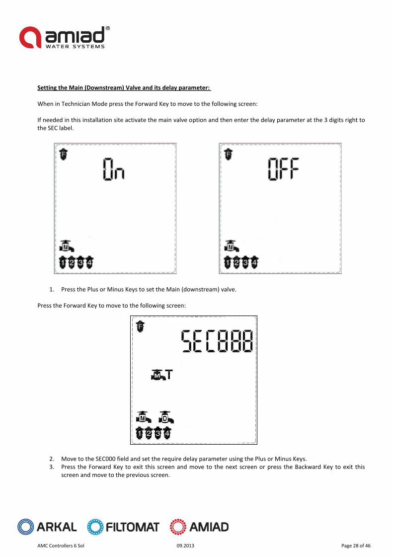
Setting the Main (Downstream) Valve and its delay parameter: When in Technician Mode press the Forward Key to move to the following screen: If needed in this installation site activate the main valve option and then enter the delay parameter at the 3 digits right to the SEC label.
1. Press the Plus or Minus Keys to set the Main (downstream) valve. Press the Forward Key to move to the following screen:
2. Move to the SEC000 field and set the require delay parameter using the Plus or Minus Keys. 3. Press the Forward Key to exit this screen and move to the next screen or press the Backward Key to exit this
screen and move to the previous screen.

AMC Controllers 6 Sol 09.2013 Page 29 of 46
Selecting the number of filter units and valves controlled by the controller: When in the main screen of the controller press the Forward key till the following screen appears. Upon entry this screen displays the current controller configuration, e.g. 4 filter units, main valve and delay valve.
1. Press the Arrow Key to move through the elements on the screen. 2. Move first to the group of the Main Valve and the Delay Valve icons 3. Move to the desired element, the element starts to blink for 10 seconds. 4. While the element is blinking press the Plus Key to select (enable) it or press the Minus Key to unselect (disable)
it. 5. Set your desired configuration of main valve and delay valve. 6. Move to the filters group of icons and repeat the selection operation described above, set the number of desired
filter units. 7. Press the Forward Key to exit this screen and move to the next screen or press the Backward Key to exit this
screen and move to the previous screen.
Please Note: The controller can operate maximum of 6 solenoids so the maximal number of valves and filters is 6.

AMC Controllers 6 Sol 09.2013 Page 30 of 46
Setting the Delay between Filters parameter: When in Technician Mode press the Forward Key to move to the following screen: Upon entry this screen displays the current controller configuration, e.g. Spin Klin, 4 filters, main valve and delay valve. The controller also displays the Delay between Filters Icon. At the 3 left digits the word SEC appears, indicating that the flush time parameter in the 3 right digits is in seconds.
1. Press the Plus or Minus Keys to set the delay between filters. 2. Press the Forward Key to exit this screen and move to the next screen or press the Backward Key to exit this
screen and move to the previous screen.

AMC Controllers 6 Sol 09.2013 Page 31 of 46
Checking the I/Os of the controller: This action can be done only when in Technician Mode and it is used to verify the correct operation of the controller’s Inputs and Outputs. When in Technician Mode press the Forward Key to move to the following screen: Press the arrow key to display the current controller configuration, e.g. Spin Klin, 4 filters, main valve and delay valve. The controller also displays the TEST Icon. 1. Press the Arrow Key to move between the solenoids icons. 2. While the icon is blinking press the Plus Key to switch its output on, or press the Minus Key to switch the output off. 3. Move to the next desired icon and repeat the selection operation described above. 4. Note that the Main valve icon operates in this screen the Fault output and the Delay valve icon operates the end of
cycle output 5. In an AC controller that is configured to operate a TAF filter the icon indicates the filter motor operation. 6. Press the Forward Key to exit this screen and move to the next screen or press the Backward Key to exit this screen
and move to the previous screen.
Please Note: All outputs are switched off when exiting this screen.
AMC Controllers 6 Sol 09.2013 Page 32 of 46
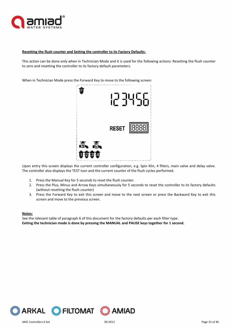
Resetting the flush counter and Setting the controller to its Factory Defaults: This action can be done only when in Technician Mode and it is used for the following actions: Resetting the flush counter to zero and resetting the controller to its factory default parameters. When in Technician Mode press the Forward Key to move to the following screen: Upon entry this screen displays the current controller configuration, e.g. Spin Klin, 4 filters, main valve and delay valve. The controller also displays the TEST Icon and the current counter of the flush cycles performed.
1. Press the Manual Key for 5 seconds to reset the flush counter. 2. Press the Plus, Minus and Arrow Keys simultaneously for 5 seconds to reset the controller to its factory defaults
(without resetting the flush counter) 3. Press the Forward Key to exit this screen and move to the next screen or press the Backward Key to exit this
screen and move to the previous screen.
Notes: See the relevant table of paragraph 6 of this document for the factory defaults per each filter type. Exiting the technician mode is done by pressing the MANUAL and PAUSE keys together for 1 second.
AMC Controllers 6 Sol 09.2013 Page 33 of 46
10. Technical data
I/O list: DC models: Outputs: OUT1-OUT6: These are the terminals for the Two Wire 12V DC Latching Solenoids. If a main valve or a delay valve has been designated during the controller’s configuration process, it's solenoid's output will always assigned to output number 6 If a main valve and a delay valve are configured the main valve will be assigned to output number 5 and the delay valve to output number 6 Alarm: This output is a Dry Contact Relay (a free potential contact); it provides a command pulse to an external alarm device. The alarm is activated in two cases:
When a selected number of consecutive flushing cycles have taken place due to continuous differential pressure input signal, which usually occurs when the filters are clogged.
When the battery voltage is lower than 4.7 VDC End of Cycle: This output is a Dry Contact Relay (a free potential contact); it provides a command pulse for 5 seconds and can be used to chain controllers. See Annex A. for details Inputs: See the terminal connection drawing Annex. C. below D.P.: This is the connection to the differential pressure switch.
AMC Controllers 6 Sol 09.2013 Page 34 of 46
AC models: Outputs: OUT1-OUT6: These are the terminals for the Two Wire 24VAC Solenoids. If a main valve or a delay valve has been designated during the controller’s configuration process, it's solenoid's output will always assigned to output number 6 If a main valve and a delay valve are configured the main valve will be assigned to output number 5 and the delay valve to output number 6 Alarm: This output is a Dry Contact Relay (a free potential contact); it provides a command pulse to an external alarm device. The alarm is activated in two cases:
When a selected number of consecutive flushing cycles have taken place due to continuous differential pressure input signal, which usually occurs when the filters are clogged.
End of Cycle: This output is a Dry Contact Relay (a free potential contact); it provides a command pulse for 5 seconds and can be used to chain controllers. See Annex A. for details Inputs: See the terminal connection drawing in Annex. B. below D.P.: This is the connection to the differential pressure switch.
TAF Motor Control: The AC models feature an ability to control the operation of TAF filters motor S7I15GX-TCE SPG
NOTE: Amiad’s AMC controller is an outdoor model; it is a water and weather (IP65).
Connecting the controller to the primary power should be done by a licensed electrician following all local codes. Improper installation could result in shock or fire hazard. This device is not intended for use by young children. Never let children play with this device.
NOTE: Amiad’s AMC AC controllers are intended to be supplied AC power with a 15A rated over current protective device.

AMC Controllers 6 Sol 09.2013 Page 35 of 46
External Power supply
DC models:
6-12 VDC: The connection terminal of the DC models is used to connect, when available, a 7.2-12 VDC 1000 milliamp external power supply unit to the controller. Once such external power supply is connected the internal batteries of the controller are used only for a back up and not for the actual operation of the controller.
AMC Controllers 6 Sol 09.2013 Page 36 of 46
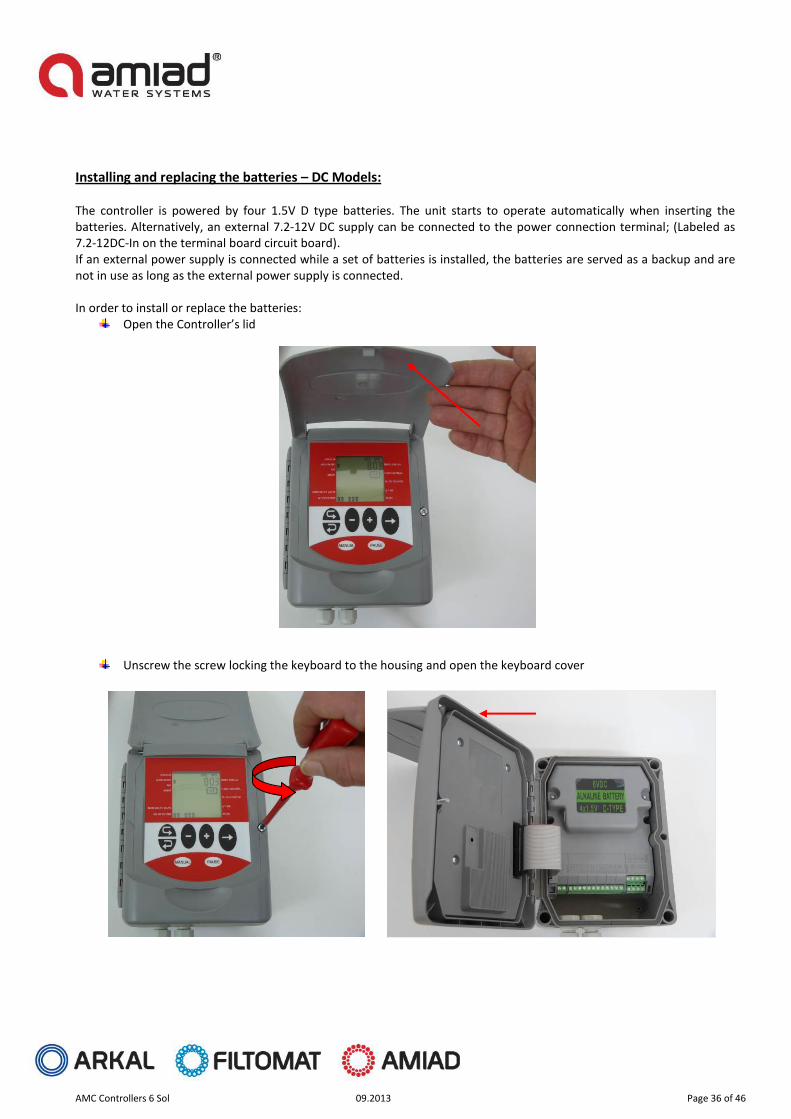
Installing and replacing the batteries – DC Models: The controller is powered by four 1.5V D type batteries. The unit starts to operate automatically when inserting the batteries. Alternatively, an external 7.2-12V DC supply can be connected to the power connection terminal; (Labeled as 7.2-12DC-In on the terminal board circuit board). If an external power supply is connected while a set of batteries is installed, the batteries are served as a backup and are not in use as long as the external power supply is connected. In order to install or replace the batteries:
Open the Controller’s lid
Unscrew the screw locking the keyboard to the housing and open the keyboard cover

AMC Controllers 6 Sol 09.2013 Page 37 of 46
Unscrew the two bolts and remove the batteries compartment lid
Pull out the batteries holder and Insert (or replace) 4 D type 1.5VDC batteries according to the (+) and (–) marks on the compartment.
AMC Controllers 6 Sol 09.2013 Page 38 of 46
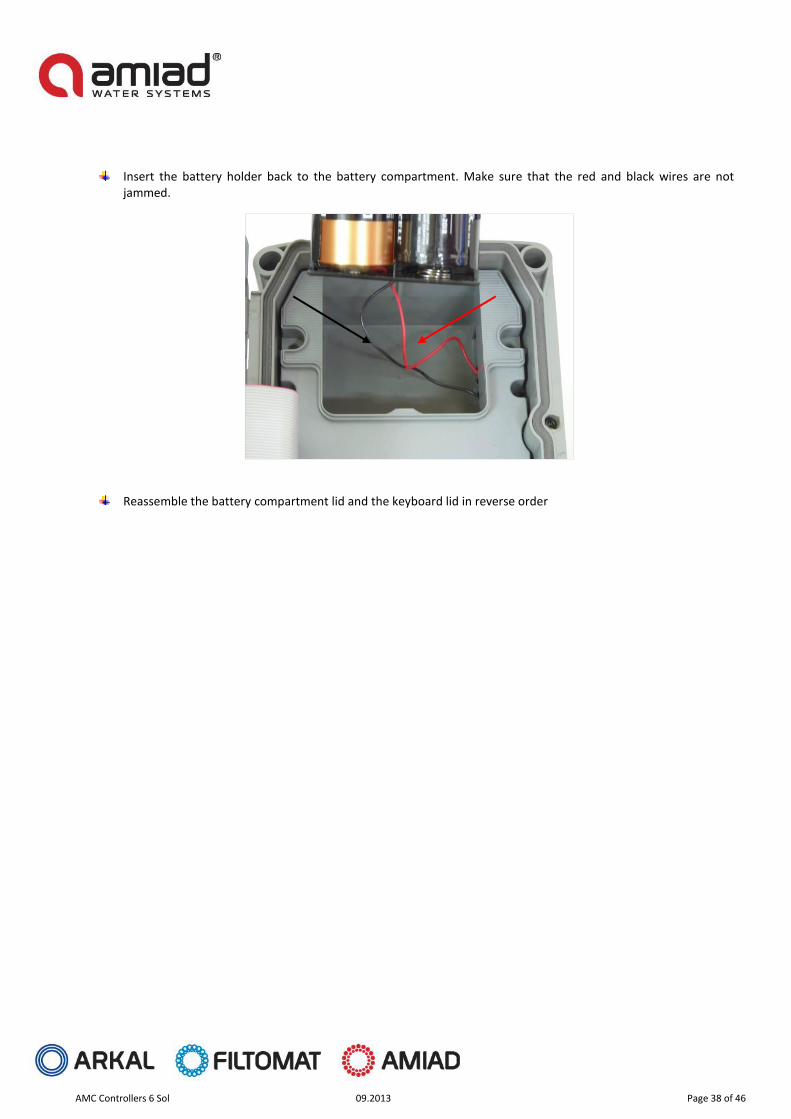
Insert the battery holder back to the battery compartment. Make sure that the red and black wires are not jammed.
Reassemble the battery compartment lid and the keyboard lid in reverse order
AMC Controllers 6 Sol 09.2013 Page 39 of 46
Power connection – AC Models:
Prior to the installation of the controller please make sure that you are familiar with the safety instructions given in this document and you comply with the instructions given regarding the power supply connection.
Especially make sure to comply with the following:
In case the controller is connected to an external AC power supply unit, make sure that the power supply connection is done only by a licensed electrician and the connection complies with your local standards for High Voltage out-doors connection.
Warnings!
o Use only the built-in transformer
o In case the controller is supplied with a power supply cable connected to it, the controller is for indoor installations only!
o If the supply cord is damaged, it must be replaced by the manufacturer or service agent or a similarly qualified person in order to avoid hazard.
o In order to use the controller for outdoor installation, a licensed electrician must disconnect the power supply cable, and connect the controller according to the instructions given in the installation chapter of this document and in compliance with all the safety instructions and the local standards for High Voltage out-door connection.
o If the plug doesn’t comply with your local regulation it must be replaced with suitable plug by licensed electrician only.
Notice!
o It is necessary to connect a two pole switch between the 110VAC/220VAC power supply and the controller.
o The 110VAC/220VAC supply point, the circuit and connection to the transformer must be performed according to “Field Electrical Regulations” by a licensed electrician who is accredited with a license according to the Electrical Bill and security requirements.
When using an internal transformer, minimal wire diameter must be 0.7mm. Check with standard measuring equipment that there is no voltage in the electric circuit.
Never cut, connect or disconnect any wire at the controller’s vicinity.
Make sure that the controller is not exposed to water splashes.
Keep the keyboard cover closed at all times when not using the keyboard.
Make sure that the cable pass at the lower housing wall of the controller is directed downwards.
NOTE: Amiad’s AMC controller is an outdoor model; it is a water and weather (IP65).
Connecting the controller to the primary power should be done by a licensed electrician following all local codes. Improper installation could result in shock or fire hazard. This device is not intended for use by young children. Never let children play with this device.
NOTE: Amiad’s AMC AC controllers are intended to be supplied AC power with a 15A rated over current protective device.

AMC Controllers 6 Sol 09.2013 Page 40 of 46
AC Controller power connection: Route an AC power cable and conduit through the conduit opening at the bottom side of the cabinet. Connect the wires to the transformer wires located inside the cabinet. The Controller units are supplied with a built in terminal strip. Always use a UL listed conduit adapter when installing the AC wiring. See Annex B. for the appropriate installation drawing.
AC Solenoids/Valves power connection: Regularly Amiad Controllers are supplied as an integral part of a filtration system; therefore they are already installed on the filters with all the outputs and inputs connected. For the rare cases where the controllers are supplied separately the solenoids / valves should be wired according to following instructions:
1. Route valve wires between control valve location and controller. 2. At the solenoids / valves, attach a common wire to each solenoid’s common wire. Attach a separate control wire
to the remaining wire of each solenoid / valve. All wire splice connections should be done using waterproof connectors.
3. Route valve wires through the conduit and attach conduit to one of the openings on the bottom of the cabinet. Strip some insulation from the ends of all wires and secure each valve’s common wire to its designated “COM” (Common) terminal. Attach all individual valve control wires to their appropriate station terminals.
See Annex B. for the appropriate installation drawing.

AMC Controllers 6 Sol 09.2013 Page 41 of 46
Annex A. Chaining Amiad Controllers: In order to operate a battery of screen, disc or gravel media filters that include a larger number of filters than one Amiad’s Flushing Controller can handle, it is possible to daisy-chain few controllers for the job. The D.P. switch that reads the pressure drop across the battery is connected to the first controller of the chain (the Master). The EC (or End of Cycle) output of the master controller is connected to the D.P. input of the second controller of the chain (the first slave) and this controller EC output is connected to the D.P. input of the nest. This type of connection can be spanned over as many controllers as needed. When the actual D.P. switch send a signal the master controller starts a flushing cycle. Once this cycle is completed the master controller sends a signal through its EC output to the second controller to start its flushing cycle, and so on till the last controller in the chain as illustrated in the following drawing.
Important Note: Please make sure that the PD delay in the chained controllers is set to not longer than 5 seconds. This ensures proper transition from the last filter in the first controller to the first filter in the next controller.
Standard DP Switch
DP Input
EC Output
DP Input
EC Output
DP Input
EC Output
Master Controller Slave 1 Controller Slave N Controller

AMC Controllers 6 Sol 09.2013 Page 42 of 46
11. Annex B. Installation:
Terminal Strips drawings Amiad Flushing Controller Model AMC-6DC

AMC Controllers 6 Sol 09.2013 Page 43 of 46
Amiad Flushing Controller Model AMC-6AC 220V

AMC Controllers 6 Sol 09.2013 Page 44 of 46
Amiad Flushing Controller Model AMC-6AC 110V
AMC Controllers 6 Sol 09.2013 Page 45 of 46
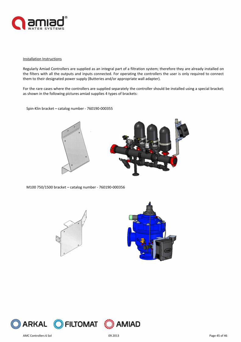
Installation Instructions
Regularly Amiad Controllers are supplied as an integral part of a filtration system; therefore they are already installed on the filters with all the outputs and inputs connected. For operating the controllers the user is only required to connect them to their designated power supply (Butteries and/or appropriate wall adapter). For the rare cases where the controllers are supplied separately the controller should be installed using a special bracket; as shown in the following pictures amiad supplies 4 types of brackets:
Spin-Klin bracket – catalog number - 760190-000355
M100 750/1500 bracket – catalog number - 760190-000356

AMC Controllers 6 Sol 09.2013 Page 46 of 46
M100 / M300 bracket – catalog number - 760190-000354
TAF bracket – catalog number - 760190-000354
AMC 6-12 AC & DC Controllers for: Spin Klin, Filtomat, SAF, TAF, Sigma, Omega Filters.For orders and spare parts Arkal Amiad Click here:
Related Documents