AMAX 2100 / 3000 / 4000 en Installation Manual

Welcome message from author
This document is posted to help you gain knowledge. Please leave a comment to let me know what you think about it! Share it to your friends and learn new things together.
Transcript
AMAX 2100 / 3000 / 4000
en Installation Manual

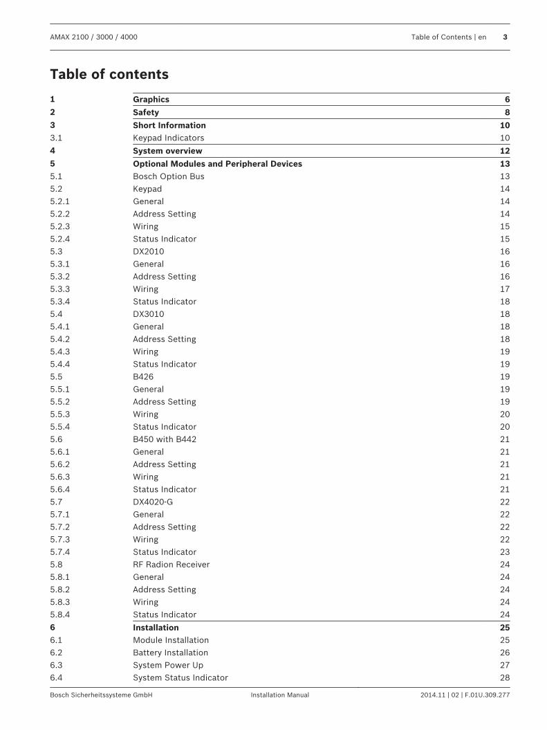
Table of contents
1 Graphics 62 Safety 83 Short Information 103.1 Keypad Indicators 10
4 System overview 125 Optional Modules and Peripheral Devices 135.1 Bosch Option Bus 135.2 Keypad 145.2.1 General 145.2.2 Address Setting 145.2.3 Wiring 155.2.4 Status Indicator 155.3 DX2010 165.3.1 General 165.3.2 Address Setting 165.3.3 Wiring 175.3.4 Status Indicator 185.4 DX3010 185.4.1 General 185.4.2 Address Setting 185.4.3 Wiring 195.4.4 Status Indicator 195.5 B426 195.5.1 General 195.5.2 Address Setting 195.5.3 Wiring 205.5.4 Status Indicator 205.6 B450 with B442 215.6.1 General 215.6.2 Address Setting 215.6.3 Wiring 215.6.4 Status Indicator 215.7 DX4020-G 225.7.1 General 225.7.2 Address Setting 225.7.3 Wiring 225.7.4 Status Indicator 235.8 RF Radion Receiver 245.8.1 General 245.8.2 Address Setting 245.8.3 Wiring 245.8.4 Status Indicator 24
6 Installation 256.1 Module Installation 256.2 Battery Installation 266.3 System Power Up 276.4 System Status Indicator 28
AMAX 2100 / 3000 / 4000 Table of Contents | en 3
Bosch Sicherheitssysteme GmbH Installation Manual 2014.11 | 02 | F.01U.309.277
6.5 Certification 286.5.1 EN 50131-3 Grade 2, Environmental Class 2 - AMAX 2100 / 3000 / 4000 296.5.2 NFA2P AFNOR / CNPP - AMAX 2100 / 3000 / 4000 296.5.3 INCERT - AMAX 4000 306.5.4 SFF – AMAX 2100 / 3000 / 4000 30
7 Settings 327.1 Communication and Reporting 327.1.1 Receivers 327.1.2 Reports 387.1.3 Automatic Test Report 427.1.4 Dual IP 427.1.5 Remote Access 437.1.6 Remote PC 437.1.7 Call back and Domestic Call 447.1.8 Ring Times 447.2 Users and Codes 457.2.1 User Code 457.2.2 Installer Code 457.2.3 Code Length 487.2.4 Code Reporting 487.2.5 Code Permissions 487.2.6 Macro Configuration 497.3 Zones 497.3.1 Add / Delete Zone 497.3.2 Pulse Count Duration 607.3.3 Cross Zone Timer 607.3.4 Zone Function Settings 607.3.5 Zone Indication Keypad and Event Log 647.4 Keypads and Areas 657.4.1 Keypad Area 657.4.2 Area Timing 657.4.3 Common Area 657.4.4 Keypad Indication 667.4.5 Keypad Lockout 667.5 System 667.5.1 System Setting 667.5.2 System View 697.5.3 System Factory Default 707.6 Outputs and Sirens 717.6.1 Outputs 717.6.2 Sirens 787.7 RF Devices 787.7.1 RF Options 787.7.2 RF Devices / User 787.8 Key Programming 79
8 Configuration 818.1 Programming with the Keypad 818.1.1 Text Keypad Programming 818.1.2 LED/LCD Keypad Programming 92
4 en | Table of Contents AMAX 2100 / 3000 / 4000
2014.11 | 02 | F.01U.309.277 Installation Manual Bosch Sicherheitssysteme GmbH
8.2 PC Programming 938.2.1 Direct Connection 958.2.2 Modem Connection 988.2.3 IP Connection 101
9 Address Programming 1059.1 Communication and Report Programming 1059.1.1 Receiver Programming 1059.1.2 Reports Programming 1089.1.3 Communication Operations Programming 1099.2 User and Code Programming 1129.2.1 User Code Programming 1129.2.2 Installer Code Programming 1169.2.3 Code Length Programming 1169.2.4 Code Permission Programming 1169.2.5 Macro Programming 1179.3 Zone Programming 1189.3.1 Add/Delete Zone Programming 1189.3.2 Zone Function Programming 1239.3.3 Pulse Count Duration Programming 1269.3.4 Zone Cross Timer Programming 1269.4 Keypad and Area Programming 1279.4.1 Keypad Area Programming 1279.4.2 Area Timing Programming 1279.4.3 Common Area Programming 1289.4.4 Keypad Indication Programming 1289.4.5 Keypad Lockout Programming 1299.5 System Programming 1299.5.1 System Setting Programming 1299.5.2 System Factory Default Programming 1329.6 Output and Siren Programming 1329.6.1 Output Programming 1329.6.2 Siren Programming 1349.7 RF Device Programming 134
10 Troubleshooting 13710.1 General Trouble 13710.2 Trouble Fault Inquiry 140
11 Maintenance 15311.1 Firmware Upgrade with the ICP-EZRU2 Upgrade Key 153
12 Technical Data 154
AMAX 2100 / 3000 / 4000 Table of Contents | en 5
Bosch Sicherheitssysteme GmbH Installation Manual 2014.11 | 02 | F.01U.309.277
Graphics
Figure 1.1: Wiring diagram for AMAX panel 2100 / 3000
1
6 en | Graphics AMAX 2100 / 3000 / 4000
2014.11 | 02 | F.01U.309.277 Installation Manual Bosch Sicherheitssysteme GmbH
Program Key Port
GND
-
+
A C
A C
Tra
nsfo
rme
r
Battery
Tamper
L2 COM COM COML1a L3 L4 L5 L6 L7 L8
L9
COM
COM
COM
COM
L10
L11
L12
L13
L14
L15
L16
P0+4
R
B
G
Y
AUX1
-
AUX2
-
AUX1
+12VYGBRRINGRHTHTIP
L1b
P0+3
P0+
P0-2
P0-1
Zones
Bosch Option
Bus 2 < 900mA
+12V
+ 0 V
1
2
3
3
1 Tamper Switch
2 Zone Switch
3 EOL 2,2 k
4 NO + NC
3
2
3
2
Fuse 1 A
PO+4: < 750mAPO+3: < 750mA
PO -2: < 500mA
PO -1: < 500mA
230V ~50Hz
230mA
Wachdog
output
<100mA
12V < 18Ah
18VAC@50VA
Zones
AUX 1: < 900mA
AUX 2: < 900mA
AUX Power
Fire
Intrusion
3
3
2Slow flash: Normal state
On: Trouble state
Off: Trouble state
_
_
_
_
_
_
_
_
+12V
+12V
+12V
COM
_
12V 7Ah
AUX2
+12V
_
COM supervised
PO-5
Z12
2 3
3
Keypads:
IUI-AMAX4-TEXT
IUI-SOL-TEXT
IUI-AMAX3-LED16
IUI-AMAX3-LED8
Keypads:
IUI-AMAX-LED8
IUI-AMAX-LCD8
I/O Moduls:
DX2010 Adr. 103 - 108
DX3010 Adr. 150 - 151
DX4010 Adr. 253
Communicators:
DX4020G Adr. 134
B426 Adr. 134(6) / 250(9)
RF Receiver:
RF3227E 1=
RFRC-OPT 1= (1)
1 =
2 =
3 =
4 =
1 =
2 =
Bosch Option
Bus 1 < 900mA
CO
MR
BG
Y
R
B
G
Y
R B G Y
♥
IUI-AMAX3 +4 Keypad
3
1
2
1
Factory
Default
5-16 Inst. Guide
I
2000mA
100 Ω - 2,2 k
_ <
∑
3
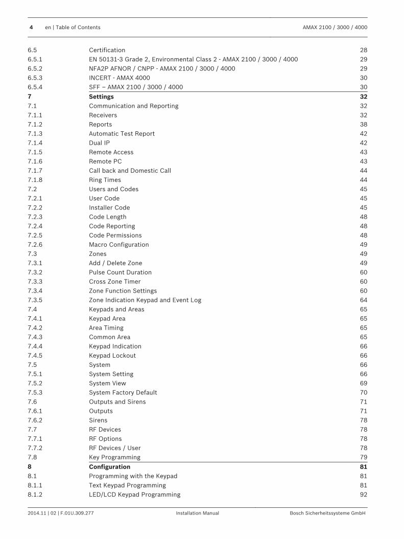
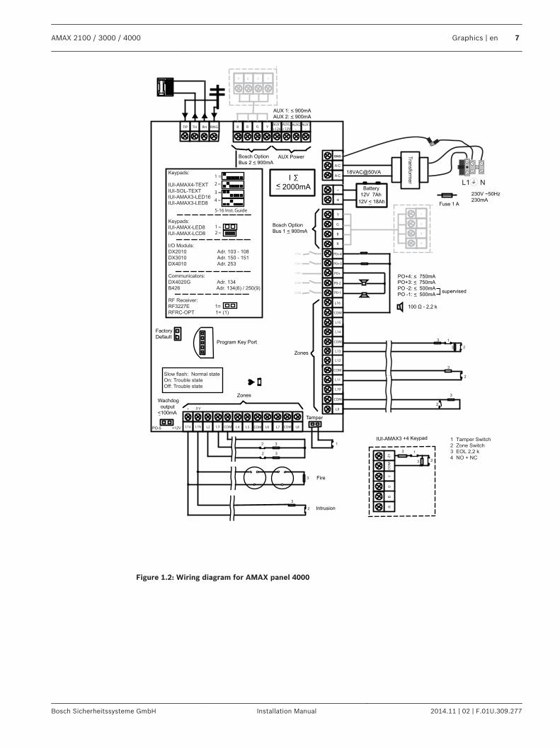
Figure 1.2: Wiring diagram for AMAX panel 4000
AMAX 2100 / 3000 / 4000 Graphics | en 7
Bosch Sicherheitssysteme GmbH Installation Manual 2014.11 | 02 | F.01U.309.277
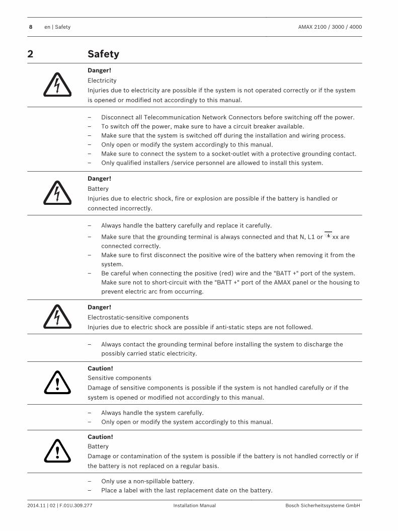
SafetyDanger!
Electricity
Injuries due to electricity are possible if the system is not operated correctly or if the system
is opened or modified not accordingly to this manual.
– Disconnect all Telecommunication Network Connectors before switching off the power.– To switch off the power, make sure to have a circuit breaker available.– Make sure that the system is switched off during the installation and wiring process.– Only open or modify the system accordingly to this manual.– Make sure to connect the system to a socket-outlet with a protective grounding contact.– Only qualified installers /service personnel are allowed to install this system.
Danger!
Battery
Injuries due to electric shock, fire or explosion are possible if the battery is handled or
connected incorrectly.
– Always handle the battery carefully and replace it carefully.
– Make sure that the grounding terminal is always connected and that N, L1 or xx areconnected correctly.
– Make sure to first disconnect the positive wire of the battery when removing it from thesystem.
– Be careful when connecting the positive (red) wire and the "BATT +" port of the system.Make sure not to short-circuit with the "BATT +" port of the AMAX panel or the housing toprevent electric arc from occurring.
Danger!
Electrostatic-sensitive components
Injuries due to electric shock are possible if anti-static steps are not followed.
– Always contact the grounding terminal before installing the system to discharge thepossibly carried static electricity.
!
Caution!
Sensitive components
Damage of sensitive components is possible if the system is not handled carefully or if the
system is opened or modified not accordingly to this manual.
– Always handle the system carefully.– Only open or modify the system accordingly to this manual.
!
Caution!
Battery
Damage or contamination of the system is possible if the battery is not handled correctly or if
the battery is not replaced on a regular basis.
– Only use a non-spillable battery.– Place a label with the last replacement date on the battery.
2
8 en | Safety AMAX 2100 / 3000 / 4000
2014.11 | 02 | F.01U.309.277 Installation Manual Bosch Sicherheitssysteme GmbH
– Under normal conditions of use, replace the battery every 3-5 years.– Recycle the battery after replacement according to local regulations.
!
Caution!
Installation
Damage or malfunction of the system is possible if the system is not mounted and installed
correctly.
– Place the system inside the monitored area on a stable surface.– Make sure to mount keypads on the inner side of the monitored area.– Once the system is tested and ready to use, secure the enclosure door and additional
enclosures with screws.
!
Caution!
Maintenance
Damage or malfunction of the system is possible if it is not maintained on a regular basis.
– It is recommended to test the system once a week.– Make sure to get the system maintained four times a year.– Only qualified installers /service personnel are allowed to maintain this system.
AMAX 2100 / 3000 / 4000 Safety | en 9
Bosch Sicherheitssysteme GmbH Installation Manual 2014.11 | 02 | F.01U.309.277
Short InformationCongratulations on selecting the AMAX panel for your installation. Spend some time readingthrough this guide and familiarize yourself with the outstanding installation and operationfeatures of this system so that you can get the most from your unit. In all aspects of planning,engineering, styling, operation, convenience, and adaptability, we try to anticipate your everypossible requirement. Programming simplicity and speed are our major considerations. Webelieve that our objectives have been attained. This installation guide explains all aspects ofprogramming the AMAX panel from factory default to final commissioning. All systemparameters and options are dealt with in detail, but, adaptability differs with individuals. EachAMAX panel can be tailored to meet your requirements quickly and easily. The programmingsimplicity makes your installation quick, accurate, and rewarding.This Installation Guide contains detailed and advanced information on the system installationand programming and the setup of the AMAX panel together with other modules and devices.For the main steps on how to get the system into operation easily and quickly, please alsorefer to the Quick Start Guide. For information on how to operate the system, please refer tothe User Guide.
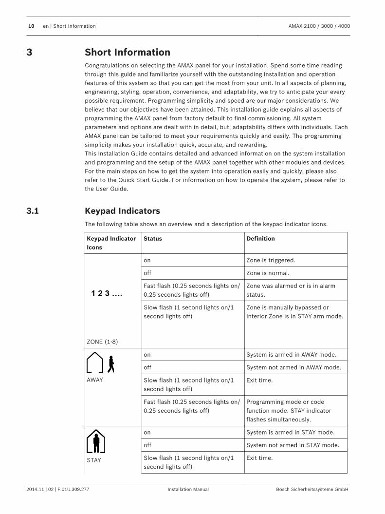
Keypad IndicatorsThe following table shows an overview and a description of the keypad indicator icons.
Keypad IndicatorIcons
Status Definition
1 2 3 ….
ZONE (1-8)
on Zone is triggered.
off Zone is normal.
Fast flash (0.25 seconds lights on/0.25 seconds lights off)
Zone was alarmed or is in alarmstatus.
Slow flash (1 second lights on/1second lights off)
Zone is manually bypassed orinterior Zone is in STAY arm mode.
AWAY
on System is armed in AWAY mode.
off System not armed in AWAY mode.
Slow flash (1 second lights on/1second lights off)
Exit time.
Fast flash (0.25 seconds lights on/0.25 seconds lights off)
Programming mode or codefunction mode. STAY indicatorflashes simultaneously.
STAY
on System is armed in STAY mode.
off System not armed in STAY mode.
Slow flash (1 second lights on/1second lights off)
Exit time.
3
3.1
10 en | Short Information AMAX 2100 / 3000 / 4000
2014.11 | 02 | F.01U.309.277 Installation Manual Bosch Sicherheitssysteme GmbH
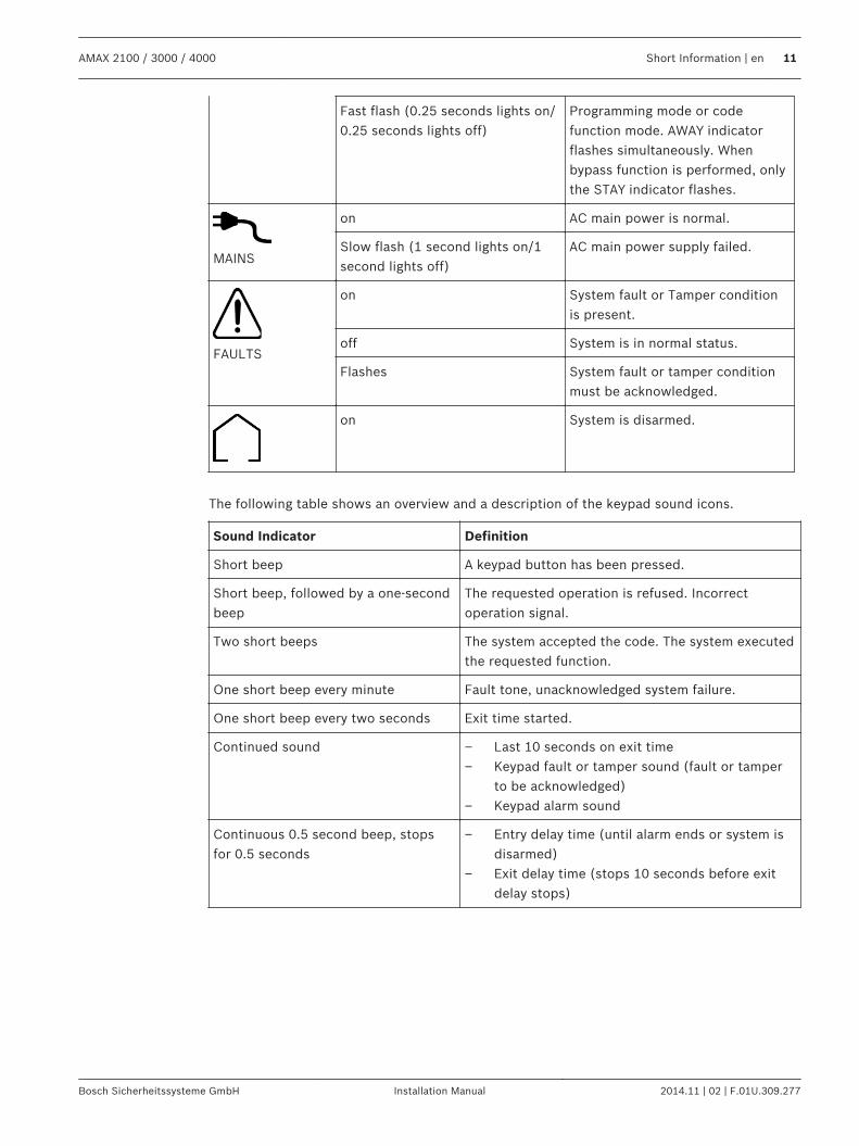
Fast flash (0.25 seconds lights on/0.25 seconds lights off)
Programming mode or codefunction mode. AWAY indicatorflashes simultaneously. Whenbypass function is performed, onlythe STAY indicator flashes.
MAINS
on AC main power is normal.
Slow flash (1 second lights on/1second lights off)
AC main power supply failed.
FAULTS
on System fault or Tamper conditionis present.
off System is in normal status.
Flashes System fault or tamper conditionmust be acknowledged.
on System is disarmed.
The following table shows an overview and a description of the keypad sound icons.
Sound Indicator Definition
Short beep A keypad button has been pressed.
Short beep, followed by a one-secondbeep
The requested operation is refused. Incorrectoperation signal.
Two short beeps The system accepted the code. The system executedthe requested function.
One short beep every minute Fault tone, unacknowledged system failure.
One short beep every two seconds Exit time started.
Continued sound – Last 10 seconds on exit time– Keypad fault or tamper sound (fault or tamper
to be acknowledged)– Keypad alarm sound
Continuous 0.5 second beep, stopsfor 0.5 seconds
– Entry delay time (until alarm ends or system isdisarmed)
– Exit delay time (stops 10 seconds before exitdelay stops)
AMAX 2100 / 3000 / 4000 Short Information | en 11
Bosch Sicherheitssysteme GmbH Installation Manual 2014.11 | 02 | F.01U.309.277
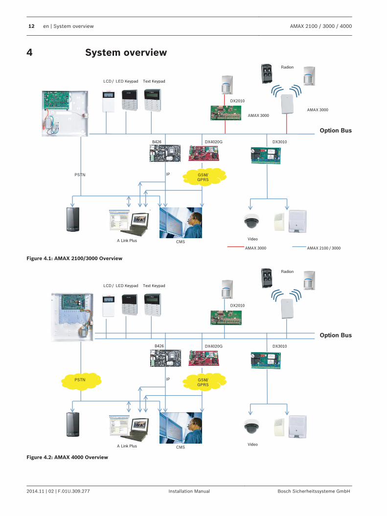
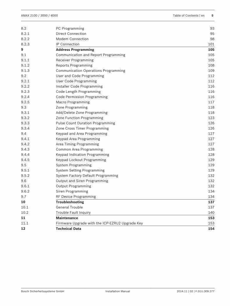
System overview
DX2010
Option Bus
B426
A Link Plus CMS
IP
Video
DX4020G
PSTN GSM/GPRS
AMAX 3000 AMAX 2100 / 3000
Radion
DX3010
Text KeypadLCD / LED Keypad
AMAX 3000
AMAX 3000
Figure 4.1: AMAX 2100/3000 Overview
DX2010
Option Bus
B426
A Link Plus CMS
IP
Video
DX4020G
PSTN GSM/GPRS
Radion
DX3010
Text KeypadLCD / LED Keypad
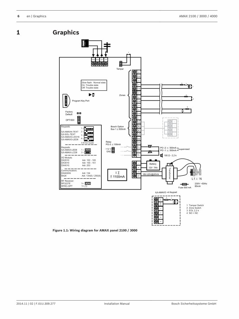
Figure 4.2: AMAX 4000 Overview
4
12 en | System overview AMAX 2100 / 3000 / 4000
2014.11 | 02 | F.01U.309.277 Installation Manual Bosch Sicherheitssysteme GmbH
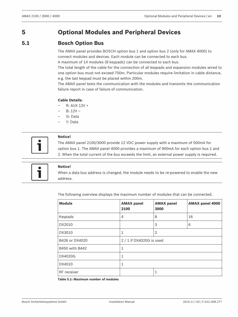
Optional Modules and Peripheral Devices
Bosch Option BusThe AMAX panel provides BOSCH option bus 1 and option bus 2 (only for AMAX 4000) toconnect modules and devices. Each module can be connected to each bus.A maximum of 14 modules (8 keypads) can be connected to each bus.The total length of the cable for the connection of all keypads and expansion modules wired toone option bus must not exceed 700m. Particular modules require limitation in cable distance,e.g. the last keypad must be placed within 200m.The AMAX panel tests the communication with the modules and transmits the communicationfailure report in case of failure of communication. Cable Details:– R: AUX 12V +– B: 12V –– G: Data– Y: Data
Notice!
The AMAX panel 2100/3000 provide 12 VDC power supply with a maximum of 500mA for
option bus 1. The AMAX panel 4000 provides a maximum of 900mA for each option bus 1 and
2. When the total current of the bus exceeds the limit, an external power supply is required.
Notice!
When a data bus address is changed, the module needs to be re-powered to enable the new
address.
The following overview displays the maximum number of modules that can be connected.
Module AMAX panel2100
AMAX panel3000
AMAX panel 4000
Keypads 4 8 16
DX2010 3 6
DX3010 1 2
B426 or DX4020 2 / 1 if DX4020G is used
B450 with B442 1
DX4020G 1
DX4010 1
RF receiver 1
Table 5.1: Maximum number of modules
5
5.1
AMAX 2100 / 3000 / 4000 Optional Modules and Peripheral Devices | en 13
Bosch Sicherheitssysteme GmbH Installation Manual 2014.11 | 02 | F.01U.309.277
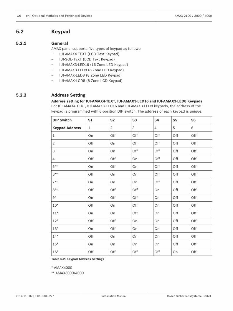
Keypad
GeneralAMAX panel supports five types of keypad as follows:– IUI-AMAX4-TEXT (LCD Text Keypad)– IUI-SOL-TEXT (LCD Text Keypad)– IUI-AMAX3-LED16 (16 Zone LED Keypad)– IUI-AMAX3-LED8 (8 Zone LED Keypad)– IUI-AMAX-LED8 (8 Zone LED Keypad)– IUI-AMAX-LCD8 (8 Zone LCD Keypad)
Address SettingAddress setting for IUI-AMAX4-TEXT, IUI-AMAX3-LED16 and IUI-AMAX3-LED8 KeypadsFor IUI-AMAX4-TEXT, IUI-AMAX3-LED16 and IUI-AMAX3-LED8 keypads, the address of thekeypad is programmed with 6-position DIP switch. The address of each keypad is unique.
DIP Switch S1 S2 S3 S4 S5 S6
Keypad Address 1 2 3 4 5 6
1 On Off Off Off Off Off
2 Off On Off Off Off Off
3 On On Off Off Off Off
4 Off Off On Off Off Off
5** On Off On Off Off Off
6** Off On On Off Off Off
7** On On On Off Off Off
8** Off Off Off On Off Off
9* On Off Off On Off Off
10* Off On Off On Off Off
11* On On Off On Off Off
12* Off Off On On Off Off
13* On Off On On Off Off
14* Off On On On Off Off
15* On On On On Off Off
16* Off Off Off Off On Off
Table 5.2: Keypad Address Settings
* AMAX4000** AMAX3000/4000
5.2
5.2.1
5.2.2
14 en | Optional Modules and Peripheral Devices AMAX 2100 / 3000 / 4000
2014.11 | 02 | F.01U.309.277 Installation Manual Bosch Sicherheitssysteme GmbH
On Off
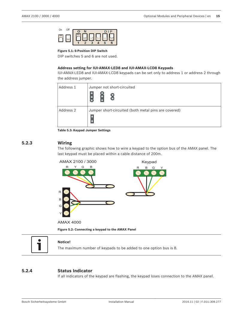
Figure 5.1: 6-Position DIP Switch
DIP switches 5 and 6 are not used.
Address setting for IUI-AMAX-LED8 and IUI-AMAX-LCD8 KeypadsIUI-AMAX-LED8 and IUI-AMAX-LCD8 keypads can be set only to address 1 or address 2 throughthe address jumper.
Address 1 Jumper not short-circuited
Address 2 Jumper short-circuited (both metal pins are covered)
Table 5.3: Keypad Jumper Settings
WiringThe following graphic shows how to wire a keypad to the option bus of the AMAX panel. Thelast keypad must be placed within a cable distance of 200m.
AMAX 4000
Y
R
Y
G
B
AMAX 2100 / 3000 Keypad
R BG R B G Y
Figure 5.2: Connecting a keypad to the AMAX Panel
Notice!
The maximum number of keypads to be added to one option bus is 8.
Status IndicatorIf all indicators of the keypad are flashing, the keypad loses connection to the AMAX panel.
5.2.3
5.2.4
AMAX 2100 / 3000 / 4000 Optional Modules and Peripheral Devices | en 15
Bosch Sicherheitssysteme GmbH Installation Manual 2014.11 | 02 | F.01U.309.277
DX2010
GeneralThe AMAX panel supports DX2010 input expansion modules. Each expansion module supportsup to 8 zone inputs. For information on the installation, refer to Module Installation, page 25.
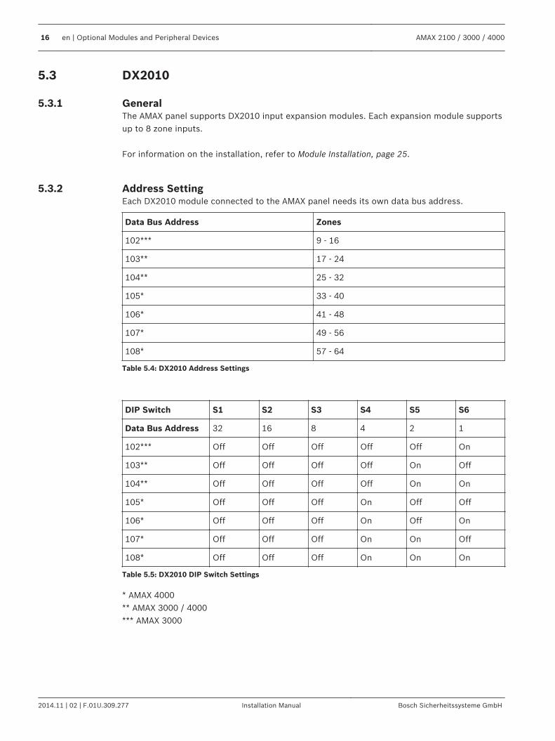
Address SettingEach DX2010 module connected to the AMAX panel needs its own data bus address.
Data Bus Address Zones
102*** 9 - 16
103** 17 - 24
104** 25 - 32
105* 33 - 40
106* 41 - 48
107* 49 - 56
108* 57 - 64
Table 5.4: DX2010 Address Settings
DIP Switch S1 S2 S3 S4 S5 S6
Data Bus Address 32 16 8 4 2 1
102*** Off Off Off Off Off On
103** Off Off Off Off On Off
104** Off Off Off Off On On
105* Off Off Off On Off Off
106* Off Off Off On Off On
107* Off Off Off On On Off
108* Off Off Off On On On
Table 5.5: DX2010 DIP Switch Settings
* AMAX 4000** AMAX 3000 / 4000*** AMAX 3000
5.3
5.3.1
5.3.2
16 en | Optional Modules and Peripheral Devices AMAX 2100 / 3000 / 4000
2014.11 | 02 | F.01U.309.277 Installation Manual Bosch Sicherheitssysteme GmbH
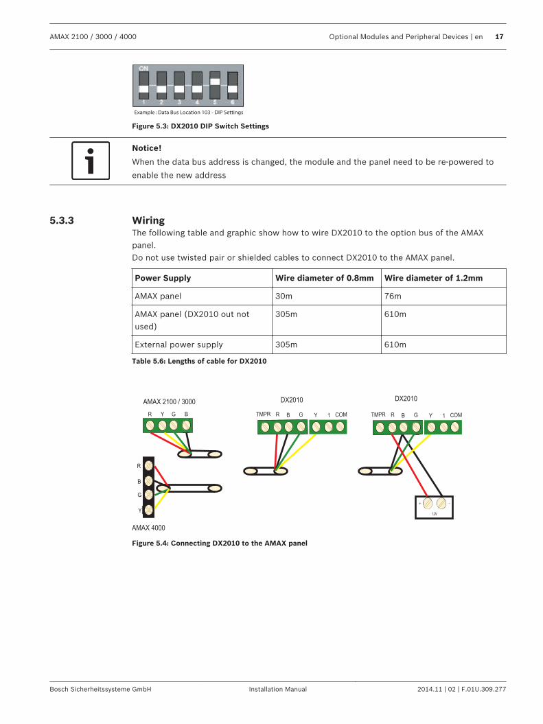
Example : Data Bus Location 103 - DIP Settings
Figure 5.3: DX2010 DIP Switch Settings
Notice!
When the data bus address is changed, the module and the panel need to be re-powered to
enable the new address
WiringThe following table and graphic show how to wire DX2010 to the option bus of the AMAXpanel.Do not use twisted pair or shielded cables to connect DX2010 to the AMAX panel.
Power Supply Wire diameter of 0.8mm Wire diameter of 1.2mm
AMAX panel 30m 76m
AMAX panel (DX2010 out notused)
305m 610m
External power supply 305m 610m
Table 5.6: Lengths of cable for DX2010
+
12V
AMAX 4000
Y
R
Y
G
B
R BG
_
R B G Y 1 COMTMPR R B G Y 1 COMTMPR
AMAX 2100 / 3000DX2010DX2010
Figure 5.4: Connecting DX2010 to the AMAX panel
5.3.3
AMAX 2100 / 3000 / 4000 Optional Modules and Peripheral Devices | en 17
Bosch Sicherheitssysteme GmbH Installation Manual 2014.11 | 02 | F.01U.309.277
Status Indicator
LED Condition Denotation
On Trouble Condition:– Grounding Conductor is not connected or there is a
communication failure between the module and the AMAXpanel
– No zones distributed– Module address setting error
Stable flash Normal Operation
Off Power failure
DX3010
GeneralThe AMAX panel supports DX3010 output expansion modules. Each module supports 8 fullyprogrammable relay outputs. For information on the installation, refer to Module Installation, page 25.
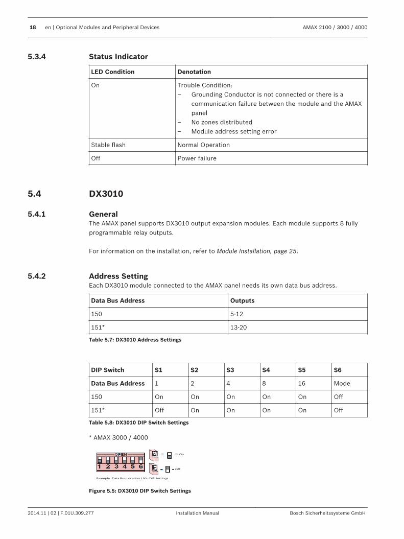
Address SettingEach DX3010 module connected to the AMAX panel needs its own data bus address.
Data Bus Address Outputs
150 5-12
151* 13-20
Table 5.7: DX3010 Address Settings
DIP Switch S1 S2 S3 S4 S5 S6
Data Bus Address 1 2 4 8 16 Mode
150 On On On On On Off
151* Off On On On On Off
Table 5.8: DX3010 DIP Switch Settings
* AMAX 3000 / 4000
Example : Data Bus Location 150 - DIP Settings
On
Off
Figure 5.5: DX3010 DIP Switch Settings
5.3.4
5.4
5.4.1
5.4.2
18 en | Optional Modules and Peripheral Devices AMAX 2100 / 3000 / 4000
2014.11 | 02 | F.01U.309.277 Installation Manual Bosch Sicherheitssysteme GmbH
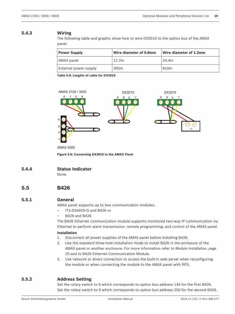
WiringThe following table and graphic show how to wire DX3010 to the option bus of the AMAXpanel.
Power Supply Wire diameter of 0.8mm Wire diameter of 1.2mm
AMAX panel 12.2m 24.4m
External power supply 305m 610m
Table 5.9: Lengths of cable for DX3010
+
12V
AMAX 4000
Y
R
Y
G
B
AMAX 2100 / 3000 DX3010
R BG
DX3010
R B G Y R B G Y
_
Figure 5.6: Connecting DX3010 to the AMAX Panel
Status IndicatorNone.
B426
GeneralAMAX panel supports up to two communication modules:– ITS-DX4020-G and B426 or– B426 and B426The B426 Ethernet communication module supports monitored two-way IP communication viaEthernet to perform alarm transmission, remote programming, and control of the AMAX panel.
Installation1. Disconnect all power supplies of the AMAX panel before installing B426.2. Use the standard three-hole installation mode to install B426 in the enclosure of the
AMAX panel or another enclosure. For more information refer to Module Installation, page25 and to B426 Ethernet Communication Module.
3. Use network or direct connection to access the built-in web server when reconfiguringthe module or when connecting the module to the AMAX panel with RPS.
Address SettingSet the rotary switch to 6 which corresponds to option bus address 134 for the first B426.Set the rotary switch to 9 which corresponds to option bus address 250 for the second B426.
5.4.3
5.4.4
5.5
5.5.1
5.5.2
AMAX 2100 / 3000 / 4000 Optional Modules and Peripheral Devices | en 19
Bosch Sicherheitssysteme GmbH Installation Manual 2014.11 | 02 | F.01U.309.277
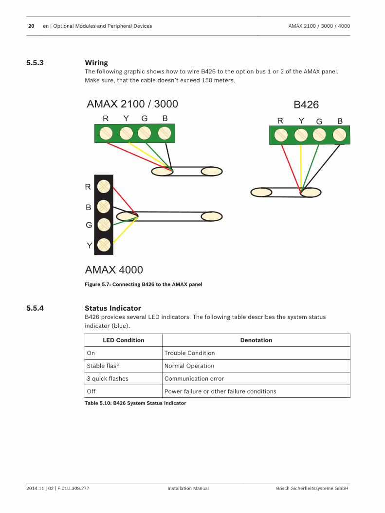
WiringThe following graphic shows how to wire B426 to the option bus 1 or 2 of the AMAX panel.Make sure, that the cable doesn’t exceed 150 meters.
AMAX 4000
Y
R
Y
G
B
AMAX 2100 / 3000 B426
R BG R BGY
Figure 5.7: Connecting B426 to the AMAX panel
Status IndicatorB426 provides several LED indicators. The following table describes the system statusindicator (blue).
LED Condition Denotation
On Trouble Condition
Stable flash Normal Operation
3 quick flashes Communication error
Off Power failure or other failure conditions
Table 5.10: B426 System Status Indicator
5.5.3
5.5.4
20 en | Optional Modules and Peripheral Devices AMAX 2100 / 3000 / 4000
2014.11 | 02 | F.01U.309.277 Installation Manual Bosch Sicherheitssysteme GmbH
B450 with B442
GeneralUse B450 in combination with a plug-in communicator for primary or backup alarmcommunication, remote panel programming and other remote applications. The B450 supportsConettix IP protocol with full authentication, 256 bit AES encryption and resistance to Denialof Service attacks. It is a reliable way to add cellular network communications to existing ornew commercial security and fire installations.For the AMAX panel B450 is used in combination with B442, which provides IP communicationover a GSM (GPRS) cellular network.
Installation1. Disconnect all power supplies of the AMAX panel before installing B450.2. Use the standard three-hole installation mode to install B450 in the enclosure of the
AMAX panel or another enclosure. For more information refer to Module Installation, page25 and to B450 Conettix Plug-in Communicator Interface.
3. Instert SIM card into B442.4. Insert B442 into B50.P B442 clicks and the module combination is ready to be wired.
Address SettingSet the rotary switch to 6 which corresponds to option bus address 134.
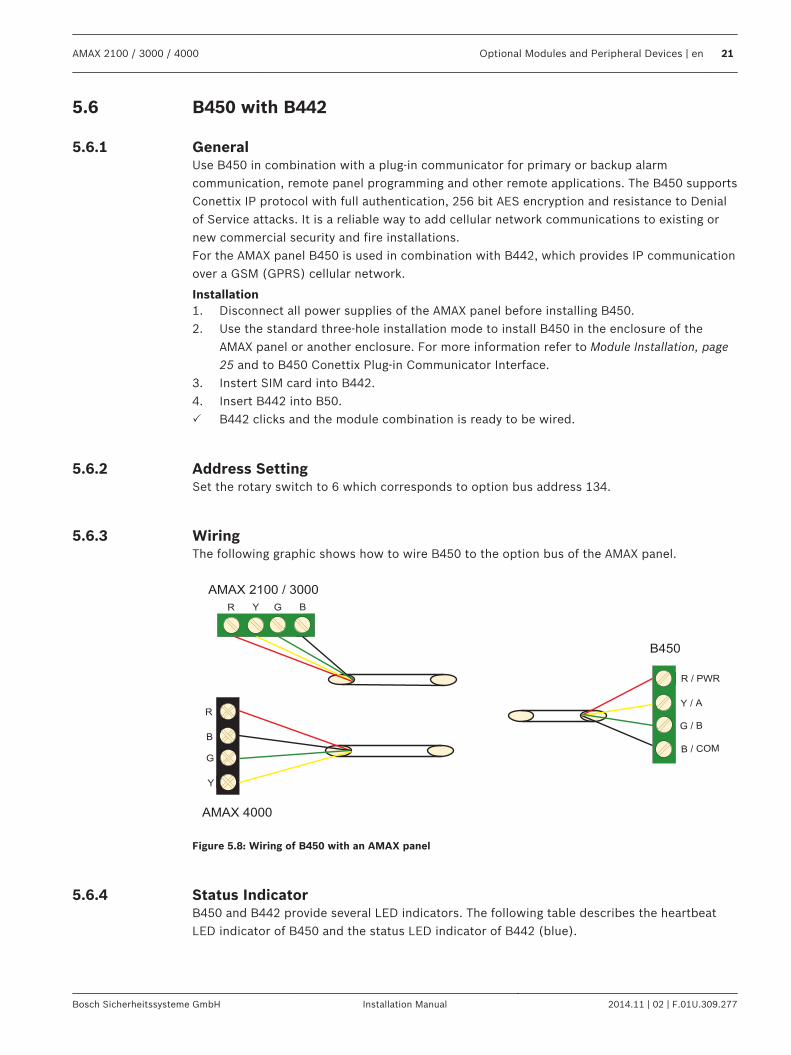
WiringThe following graphic shows how to wire B450 to the option bus of the AMAX panel.
AMAX 4000
Y
R
Y
G
B
AMAX 2100 / 3000
R BG
B450
R / PWR
B / COM
G / B
Y / A
Figure 5.8: Wiring of B450 with an AMAX panel
Status IndicatorB450 and B442 provide several LED indicators. The following table describes the heartbeatLED indicator of B450 and the status LED indicator of B442 (blue).
5.6
5.6.1
5.6.2
5.6.3
5.6.4
AMAX 2100 / 3000 / 4000 Optional Modules and Peripheral Devices | en 21
Bosch Sicherheitssysteme GmbH Installation Manual 2014.11 | 02 | F.01U.309.277
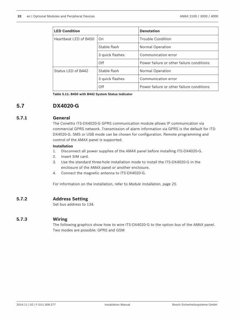
LED Condition Denotation
Heartbeat LED of B450 On Trouble Condition
Stable flash Normal Operation
3 quick flashes Communication error
Off Power failure or other failure conditions
Status LED of B442 Stable flash Normal Operation
3 quick flashes Communication error
Off Power failure or other failure conditions
Table 5.11: B450 with B442 System Status Indicator
DX4020-G
GeneralThe Conettix ITS-DX4020-G GPRS communication module allows IP communication viacommercial GPRS network. Transmission of alarm information via GPRS is the default for ITS-DX4020-G. SMS or USB mode can be chosen for configuration. Remote programming andcontrol of the AMAX panel is supported.
Installation1. Disconnect all power supplies of the AMAX panel before installing ITS-DX4020-G.2. Insert SIM card.3. Use the standard three-hole installation mode to install the ITS-DX4020-G in the
enclosure of the AMAX panel or another enclosure.4. Connect the magnetic antenna to ITS-DX4020-G. For information on the installation, refer to Module Installation, page 25.
Address SettingSet bus address to 134.
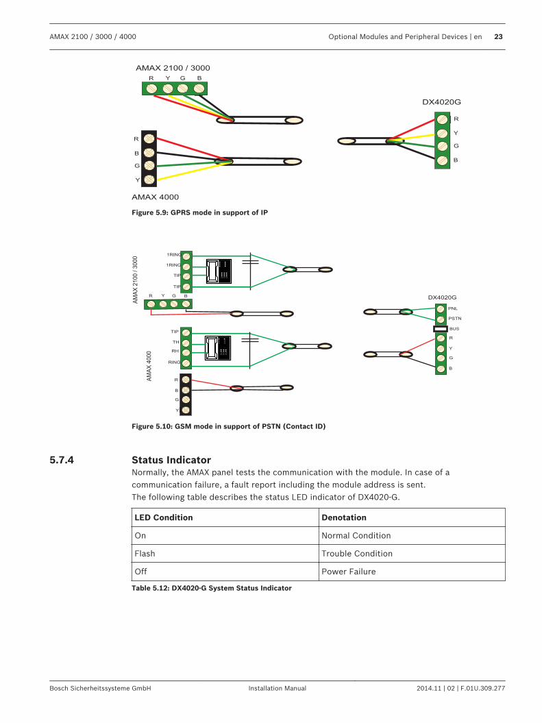
WiringThe following graphics show how to wire ITS-DX4020-G to the option bus of the AMAX panel.Two modes are possible: GPRS and GSM
5.7
5.7.1
5.7.2
5.7.3
22 en | Optional Modules and Peripheral Devices AMAX 2100 / 3000 / 4000
2014.11 | 02 | F.01U.309.277 Installation Manual Bosch Sicherheitssysteme GmbH
AMAX 4000
Y
R
Y
G
B
AMAX 2100 / 3000
R BG
DX4020G
R
B
G
Y
Figure 5.9: GPRS mode in support of IP
DX4020G
BUS
AM
AX
4000
R
Y
G
B
RING
TIP
RH
TH
R
B
G
Y
PNL
PSTN
TIP
TIP
1RING
1RING
R Y G B
AM
AX
2100 /
3000
Figure 5.10: GSM mode in support of PSTN (Contact ID)
Status IndicatorNormally, the AMAX panel tests the communication with the module. In case of acommunication failure, a fault report including the module address is sent.The following table describes the status LED indicator of DX4020-G.
LED Condition Denotation
On Normal Condition
Flash Trouble Condition
Off Power Failure
Table 5.12: DX4020-G System Status Indicator
5.7.4
AMAX 2100 / 3000 / 4000 Optional Modules and Peripheral Devices | en 23
Bosch Sicherheitssysteme GmbH Installation Manual 2014.11 | 02 | F.01U.309.277
RF Radion Receiver
GeneralThe RADION receiver OP is a wireless receiver that connects the RADION wireless systemcomponents to the AMAX panel 3000/4000. Features include the following:– Cover and wall tamper protection– RFID and configuration data contained in persistent memory– Detection and reporting of radio frequency interference– Support of two types of device enrollment
Installation1. Disconnect all power supplies of the AMAX panel before installing B450.2. Mount the receiver onto a wall in a location accessible for future maintenance using the
provided anchors and screws. For best reception, place the receiver in a central locationamong the transmitters. In situations where there is a large distance between thetransmitter and receiver, it might be necessary to install receivers for optimum results.
Address SettingSet the rotary switch to 1. The AMAX panel supports only one receiver.
Wiring1. Connect the RADION receiver to the option bus.2. Make sure that the cable distance to the AMAX panel doesn’t exceed 300 meters.
Status IndicatorThe following table describes the system status indicator of the RFRC-OPT Radion receiver.
LED Condition Denotation
On Normal operation
Stable flash
Receiver is being programmed with the zone and transmitter IDsfrom the AMAX panel.
Turns off momentarily Receiver has obtained a valid transmission from a RADIONtransmitter.
3 quick flashes Communication error and/or self-test failureCauses:– A communication failure between the AMAX panel and the
receiver or– An invalid address switch setting
Off Power failure or wiring failure
Table 5.13: RFRC-OPT Radion Receiver System Status Indicator
5.8
5.8.1
5.8.2
5.8.3
5.8.4
24 en | Optional Modules and Peripheral Devices AMAX 2100 / 3000 / 4000
2014.11 | 02 | F.01U.309.277 Installation Manual Bosch Sicherheitssysteme GmbH
InstallationThis chapter describes the installation and the system power up of the AMAX panel.
Danger!
Electricity
Injuries due to electricity are possible if the system is not operated correctly or if the system
is opened or modified not accordingly to this manual.
– Disconnect all Telecommunication Network Connectors before switching off the power.– To switch off the power, make sure to have a circuit breaker available.– Make sure that the system is switched off during the installation and wiring process.– Only open or modify the system accordingly to this manual.– Make sure to connect the system to a socket-outlet with a protective grounding contact.– Only qualified installers /service personnel are allowed to install this system.
!
Caution!
Installation
Damage or malfunction of the system is possible if the system is not mounted and installed
correctly.
– Place the system inside the monitored area on a stable surface.– Make sure to mount keypads on the inner side of the monitored area.– Once the system is tested and ready to use, secure the enclosure door and additional
enclosures with screws. For the main steps on how to get the system into operation easily and quickly, please alsorefer to the Quick Start Guide.
Module InstallationThe enclosure contains only PCBs and transformers of the fixed AMAX panel for installation,no other hardware.1. Open the knockout holes for wiring in the module.2. Position two upper mounting holes on the installation wall with the module.3. Pre-install screws on the mounting holes (provided by the installer).4. Mount the screws on the module.5. Fasten the screws.6. Fix the two lower mounting holes with screws.
Notice!
Make sure to choose a appropriate positioning screw kit when you install the system in a non-
load bearing wall.
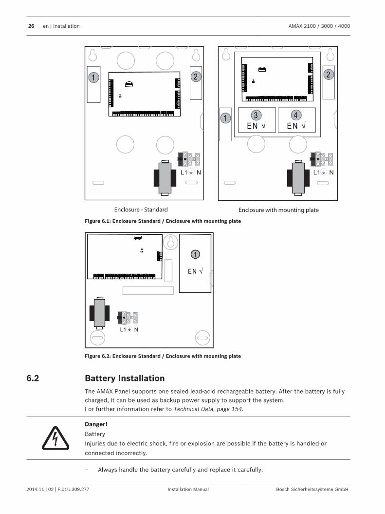
Expansion modules can be placed in the enclosure of the AMAX panel. Several places areavailable. Figure 6.1. and figure 6.2 show the standard enclosure installation and theenclosure installation with a mounting plate.
6
6.1
AMAX 2100 / 3000 / 4000 Installation | en 25
Bosch Sicherheitssysteme GmbH Installation Manual 2014.11 | 02 | F.01U.309.277
E N √ E N √
2
Enclosure - Standard Enclosure with mounting plateGND
-+
AC
AC
L2
CO
MC
OM
CO
ML
1a
L3
L4
L5
L6
L7
L8
L9
CO
M
CO
M
CO
M
CO
M
L1
0
L1
1
L1
2
L1
3
L1
4
L1
5
L1
6
P0
+4
R B G Y
AU
X1
-
AU
X2
-
AU
X1
+1
2V
YG
BR
RIN
GR
HT
HT
IP
L1
b
P0
+3
P0
+
P0
-2
P0
-1
AU
X2
+1
2V
♥
GND
-+
AC
AC
L2
CO
MC
OM
CO
ML
1a
L3
L4
L5
L6
L7
L8
L9
CO
M
CO
M
CO
M
CO
M
L1
0
L1
1
L1
2
L1
3
L1
4
L1
5
L1
6
P0
+4
R B G Y
AU
X1
-
AU
X2
-
AU
X1
+1
2V
YG
BR
RIN
GR
HT
HT
IP
L1
b
P0
+3
P0
+
P0
-2
P0
-1
AU
X2
+1
2V
♥1 2
1 3 4
Figure 6.1: Enclosure Standard / Enclosure with mounting plate
GND
-+AC L8
12
V
R BGY
1R
ING
TIP
P0
+
P0
-2
P0
-1
TIP
CO
M
L7
L6
CO
M
L5
CO
M
L4L3
L2
CO
M
L1
AC
CO
MBA
PW
R
1R
ING
♥
E N √
1
Figure 6.2: Enclosure Standard / Enclosure with mounting plate
Battery InstallationThe AMAX Panel supports one sealed lead-acid rechargeable battery. After the battery is fullycharged, it can be used as backup power supply to support the system.For further information refer to Technical Data, page 154.
Danger!
Battery
Injuries due to electric shock, fire or explosion are possible if the battery is handled or
connected incorrectly.
– Always handle the battery carefully and replace it carefully.
6.2
26 en | Installation AMAX 2100 / 3000 / 4000
2014.11 | 02 | F.01U.309.277 Installation Manual Bosch Sicherheitssysteme GmbH
– Make sure that the grounding terminal is always connected and that N, L1 or xx areconnected correctly.
– Make sure to first disconnect the positive wire of the battery when removing it from thesystem.
– Be careful when connecting the positive (red) wire and the "BATT +" port of the system.Make sure not to short-circuit with the "BATT +" port of the AMAX panel or the housing toprevent electric arc from occurring.
!
Caution!
Battery
Damage or contamination of the system is possible if the battery is not handled correctly or if
the battery is not replaced on a regular basis.
– Only use a non-spillable battery.– Place a label with the last replacement date on the battery.– Under normal conditions of use, replace the battery every 3-5 years.– Recycle the battery after replacement according to local regulations.
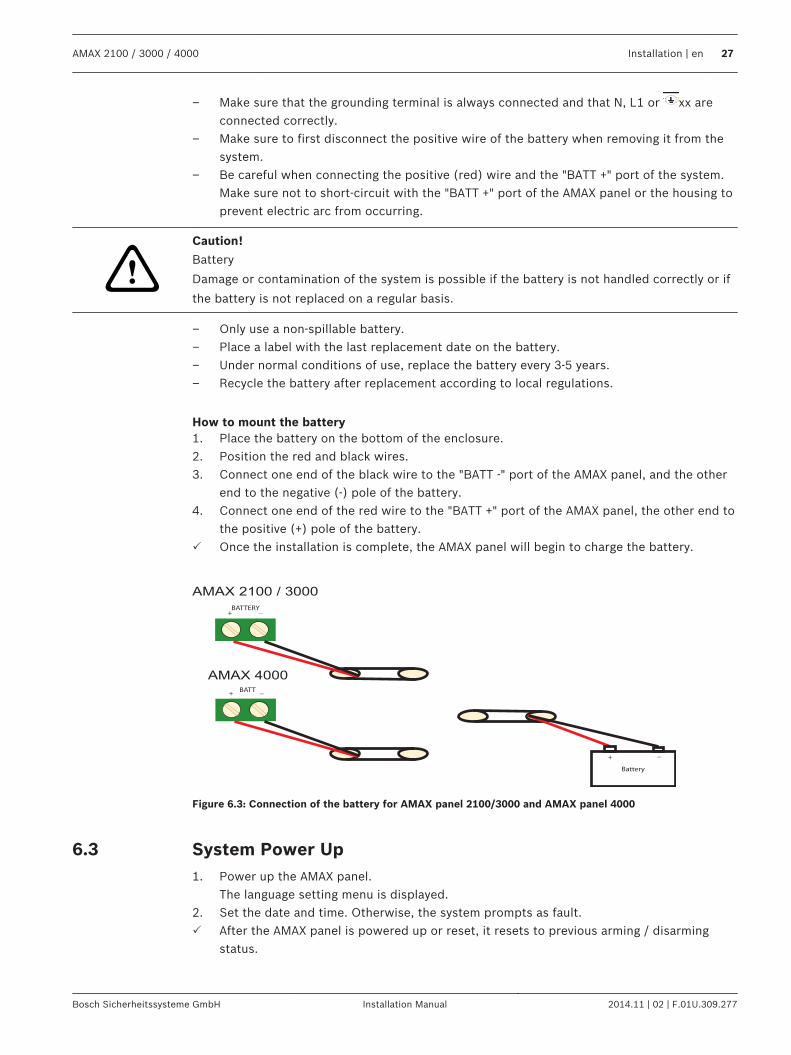
How to mount the battery1. Place the battery on the bottom of the enclosure.2. Position the red and black wires.3. Connect one end of the black wire to the "BATT -" port of the AMAX panel, and the other
end to the negative (-) pole of the battery.4. Connect one end of the red wire to the "BATT +" port of the AMAX panel, the other end to
the positive (+) pole of the battery.P Once the installation is complete, the AMAX panel will begin to charge the battery.
AMAX 2100 / 3000
AMAX 4000
+ _BATTERY
+ _BATT
+
Battery
_
Figure 6.3: Connection of the battery for AMAX panel 2100/3000 and AMAX panel 4000
System Power Up1. Power up the AMAX panel.
The language setting menu is displayed.2. Set the date and time. Otherwise, the system prompts as fault.P After the AMAX panel is powered up or reset, it resets to previous arming / disarming
status.
6.3
AMAX 2100 / 3000 / 4000 Installation | en 27
Bosch Sicherheitssysteme GmbH Installation Manual 2014.11 | 02 | F.01U.309.277
To reduce false alarms caused by system power up (or by power supply restoration after bothmains supply and AUX power supply fail), the AMAX panel is does not perform zone testswithin one minute after the system power up.
System Status IndicatorThe AMAX panel indicates the system status by using the LED status indicator on the systemmain board.Slow flash of red on status indicator (repeating on and off with an interval of one second)indicates a normal system operation.
CertificationPrerequisites for Certification Conform InstallationThe AMAX panel is certified. To realize a usage of the system conformable to the certificationdescribed in this chapter, the following prerequisites have to be fulfilled:– Use one of the following possibilities for devices:
– Two supervised warning devices (PO-1 PO-2 & PO+) and one ATS 2 communicator(onboard dialer, B426, D4020 or DX4020G)
– One self powered warning device and one ATS 2 communicator (onboard dialer,B426, D4020 or DX4020G)
– Two communicators, one ATS 2 (onboard dialer, B426, D4020 or DX4020G) and oneATS 1 (onboard dialer, B426, D4020 or DX4020G)
– One ATS 3 communicator (DX4020 or B426)– Connect all communicators to a central monitoring station.– Only use the onboard dialer and the option bus communicator for alarm transmission.– Connect one 12V / 7AH or one 12V / 18Ah battery to the system.– Ensure the maximum current for all components with a 7Ah Battery to be 550mA.– Ensure the maximum current for all components with a 18Ah Battery to be 1500mA
(standby 12h, recharge battery 80% in 72h) (PCB =l 00mA, IUI-AMAX Keypads = 31mA,DX2010 = 35mA, DX3010 = 10mA, B426 = 100mA, DX4020G = 65mA, RF3227E = 30mA,RFRC-OPT = 30mA).
– Make sure to have an indication of the arm / disarm status accessible from outside themonitored area (this indication can be time limited).
– Use one of the following methods for the access to the monitored area:– Starting the entry procedure by opening a door– Indicating the arm / disarm status– Preventing the access to the monitored area (e.g. mechanical door strike)
– Only use the enclosure lock only in non EN setup.– Only use the telephone arming in non EN setup.– Only mount additional modules (except input module DX2010) inside the enclosure.– Install the tamper skirt on the PCB of the input module DX2010, if the input module
DX2010 is mounted on the external enclosure (AE20).– Program the system with the EN settings indicated on the programming sheet.– Remove the EN indication (on label) if the system is set without EN parameters.– Connect no more than 10 devices to one zone input (Panel, Keypad, Input Module, RFUN,
…)
6.4
6.5
28 en | Installation AMAX 2100 / 3000 / 4000
2014.11 | 02 | F.01U.309.277 Installation Manual Bosch Sicherheitssysteme GmbH
EN 50131-3 Grade 2, Environmental Class 2 - AMAX 2100 / 3000 / 4000Certification Body:VDS SchadenverhütungAmsterdamer Str. 17250735 KölnWebsite: www.vds.de
The panel complies with the following standards:EN 50131-3EN 50131-6EN 50136-2-1EN 50136-2-3
NFA2P AFNOR / CNPP - AMAX 2100 / 3000 / 4000Certification Body:AFNOR Certification11, rue Francis de Pressensé93571 LA PLAINE Saint Denis CedexTel: + 33 (0) 1 41 62 80 00Fax: + 33 (0) 1 49 17 90 00Website: www.afnor.org, www.marquenf.comE-mail: [email protected]
Certification Body:CNPP – Certification Department – CNPP Cert.Route de la Chapelle RéanvilleCS 2226527950 SAINT MARCELTel: + 33 (0) 2 32 53 63 63Fax: +33 (0) 2 32 53 64 46
6.5.1
6.5.2
AMAX 2100 / 3000 / 4000 Installation | en 29
Bosch Sicherheitssysteme GmbH Installation Manual 2014.11 | 02 | F.01U.309.277
Website: www.cnpp.comE-mail: [email protected] The panel complies with the following standards:RTC 50131-3 NF3248H58-2011 V1RTC 50131-6 NF3248H58-2011 V1 Reference:
NF324 H58 2.5 Option 3: Grade 2 (European EN standards) + RTC
Certification Number: 1223400001A0 AMAX 4000
xxxxxxxxxxxxxx AMAX 3000
xxxxxxxxxxxxxx AMAX 2100
Prerequisites for an NFa2p conform installation:When an NFa2p conform installation is made, the environmental class of the panel is “1”
INCERT - AMAX 4000
SFF – AMAX 2100 / 3000 / 4000Certification Body:VDS SchadenverhütungAmsterdamer Str. 17250735 KölnWebsite: www.vds.de
Certification Body:SSF StöldskyddsföreningenTegeluddsvägen 100115 87 StockholmWebsite: www.stoldskyddsfpreningen.se
6.5.3
6.5.4
30 en | Installation AMAX 2100 / 3000 / 4000
2014.11 | 02 | F.01U.309.277 Installation Manual Bosch Sicherheitssysteme GmbH
The panel complies with the following standards:SSF 1014 Edition 4 Alarm class 1
AMAX 2100 / 3000 / 4000 Installation | en 31
Bosch Sicherheitssysteme GmbH Installation Manual 2014.11 | 02 | F.01U.309.277
SettingsThis chapter describes the settings of the AMAX panel in the same order as they appear in themenu structure of the text keypad. For an overview of the menu structure, refer to Text KeypadProgramming, page 81.The settings can be configured either via a text keypad or via the PC software A-Link Plus.For information on how to configure the settings via a text keypad and how to navigate a textkeypad, refer to Text Keypad Programming, page 81.For information on how to connect the AMAX panel to a PC, refer to PC Programming, page93.
Communication and ReportingThis section outlines the programming information required for the AMAX panel whencommunicating with a base station receiver. These parameters specify the telephonenumbers/IP address to be called, transmission formats, and internet communication options.
ReceiversReceiver Telephone number / IP Address and PortThe AMAX panel can report event information from four on-board dialers. The dialers report toreceiver 1 to receiver 4 by programming. You can program each dialer with 4 separatetelephone numbers/IP addresses and ports, reporting format type and subscriber ID number,and internet communication options if necessary.
ExampleYou can set up dialer 1 to report to receiver 1 in Bosch Network (Conettix) format and set updialer 2, dialer 3, and dialer 4 to report to a receiver of a central monitoring station in ContactID format only, if dialer 1 is unsuccessful.
How to program a telephone number:Each address in the telephone numbers stores one digit of the telephone number.Insert “15” at the end of a telephone number to indicate to the dialer that the end of thetelephone number is reached. The dialing sequence is terminated when “15” appears.
Example1. To program the telephone number “9672 1055” as the telephone number for receiver 1,
program the following sequence into address 000 - 016:[9 6 7 2 1 0 5 5 15 x x x x x x x x] (x stands for any digit)
2. To enter a 4-sec pause in the dialing sequence, insert “13”.A pause might be necessary when the dialer communicates through an old (slower) telephoneexchange or when a PABX system is in place.
Example4 To program the number “02 pause 9672 1055”, enter:
[0 2 13 9 6 7 2 1 0 5 5 15 x x x x x] The following table shows how to program the numbers, keys, and functions for a telephonenumber.
7
7.1
7.1.1
32 en | Settings AMAX 2100 / 3000 / 4000
2014.11 | 02 | F.01U.309.277 Installation Manual Bosch Sicherheitssysteme GmbH
Digit Required Number to Program Digit Required Number to Program
0 0 8 8
1 1 9 9
2 2 * 11
3 3 # 12
4 4 4 sec pause 13
5 5 Terminal 15
6 6
7 7
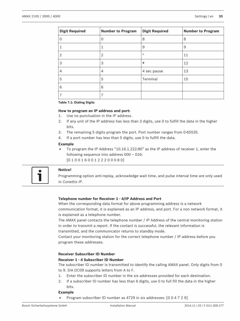
Table 7.1: Dialing Digits
How to program an IP address and port:1. Use no punctuation in the IP address.2. If any unit of the IP address has less than 3 digits, use 0 to fulfill the data in the higher
bits.3. The remaining 5 digits program the port. Port number ranges from 0-65535.4. If a port number has less than 5 digits, use 0 to fulfill the data.
Example4 To program the IP Address “10.16.1.222:80” as the IP address of receiver 1, enter the
following sequence into address 000 – 016:[0 1 0 0 1 6 0 0 1 2 2 2 0 0 0 8 0]
Notice!
Programming option anti-replay, acknowledge wait time, and pulse interval time are only used
in Conettix IP.
Telephone number for Receiver 1 - 4/IP Address and PortWhen the corresponding data format for above programming address is a networkcommunication format, it is explained as an IP address, and port. For a non network format, itis explained as a telephone number.The AMAX panel contacts the telephone number / IP Address of the central monitoring stationin order to transmit a report. If the contact is successful, the relevant information istransmitted, and the communicator returns to standby mode.Contact your monitoring station for the correct telephone number / IP address before youprogram these addresses.
Receiver Subscriber ID Number
Receiver 1 - 4 Subscriber ID NumberThe subscriber ID number is transmitted to identify the calling AMAX panel. Only digits from 0to 9. SIA DC09 supports letters from A to F.1. Enter the subscriber ID number in the six addresses provided for each destination.2. If a subscriber ID number has less than 6 digits, use 0 to full fill the data in the higher
bits.Example4 Program subscriber ID number as 4729 in six addresses: [0 0 4 7 2 9]
AMAX 2100 / 3000 / 4000 Settings | en 33
Bosch Sicherheitssysteme GmbH Installation Manual 2014.11 | 02 | F.01U.309.277
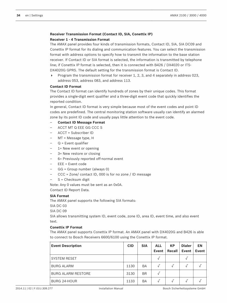
Receiver Transmission Format (Contact ID, SIA, Conettix IP)
Receiver 1 - 4 Transmission FormatThe AMAX panel provides four kinds of transmission formats, Contact ID, SIA, SIA DC09 andConettix IP format for its dialing and communication features. You can select the transmissionformat with address options to specify how to transmit the information to the base stationreceiver. If Contact ID or SIA format is selected, the information is transmitted by telephoneline; if Conettix IP format is selected, then it is connected with B426 / DX4020 or ITS-DX4020G GPRS. The default setting for the transmission format is Contact ID.4 Program the transmission format for receiver 1, 2, 3, and 4 separately in address 023,
address 053, address 083, and address 113.
Contact ID FormatThe Contact ID format can identify hundreds of zones by their unique codes. This formatprovides a single-digit eent qualifier and a three-digit event code that quickly identifies thereported condition.In general, Contact ID format is very simple because most of the event codes and point IDcodes are predefined. The central monitoring station software usually can identify an alarmedzone by its point ID code and usually pays little attention to the event code.– Contact ID Message Format– ACCT MT Q EEE GG CCC S– ACCT = Subscriber ID– MT = Message type, H– Q = Event qualifier– 1= New event or opening– 3= New restore or closing– 6= Previously reported off-normal event– EEE = Event code– GG = Group number (always 0)– CCC = Zone/ contact ID, 000 is for no zone / ID message– S = Checksum digitNote: Any 0 values must be sent as an 0x0A.Contact ID Report Data.
SIA FormatThe AMAX panel supports the following SIA formats:SIA DC 03SIA DC 09SIA allows transmitting system ID, event code, zone ID, area ID, event time, and also eventtext.
Conettix IP FormatThe AMAX panel supports Conettix IP format. An AMAX panel with DX4020G and B426 is ableto connect to Bosch Receivers 6600/6100 using the Conettix IP format.
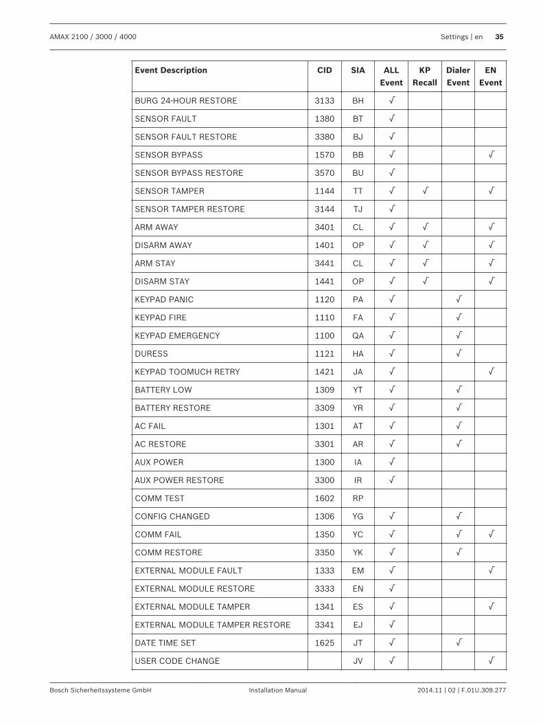
Event Description CID SIA ALLEvent
KPRecall
DialerEvent
ENEvent
SYSTEM RESET √ √
BURG ALARM 1130 BA √ √ √ √
BURG ALARM RESTORE 3130 BR √
BURG 24-HOUR 1133 BA √ √ √ √
34 en | Settings AMAX 2100 / 3000 / 4000
2014.11 | 02 | F.01U.309.277 Installation Manual Bosch Sicherheitssysteme GmbH
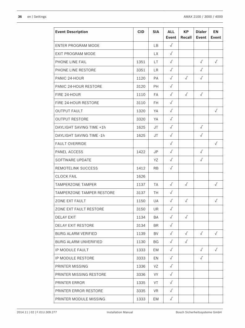
Event Description CID SIA ALLEvent
KPRecall
DialerEvent
ENEvent
BURG 24-HOUR RESTORE 3133 BH √
SENSOR FAULT 1380 BT √
SENSOR FAULT RESTORE 3380 BJ √
SENSOR BYPASS 1570 BB √ √
SENSOR BYPASS RESTORE 3570 BU √
SENSOR TAMPER 1144 TT √ √ √
SENSOR TAMPER RESTORE 3144 TJ √
ARM AWAY 3401 CL √ √ √
DISARM AWAY 1401 OP √ √ √
ARM STAY 3441 CL √ √ √
DISARM STAY 1441 OP √ √ √
KEYPAD PANIC 1120 PA √ √
KEYPAD FIRE 1110 FA √ √
KEYPAD EMERGENCY 1100 QA √ √
DURESS 1121 HA √ √
KEYPAD TOOMUCH RETRY 1421 JA √ √
BATTERY LOW 1309 YT √ √
BATTERY RESTORE 3309 YR √ √
AC FAIL 1301 AT √ √
AC RESTORE 3301 AR √ √
AUX POWER 1300 IA √
AUX POWER RESTORE 3300 IR √
COMM TEST 1602 RP
CONFIG CHANGED 1306 YG √ √
COMM FAIL 1350 YC √ √ √
COMM RESTORE 3350 YK √ √
EXTERNAL MODULE FAULT 1333 EM √ √
EXTERNAL MODULE RESTORE 3333 EN √
EXTERNAL MODULE TAMPER 1341 ES √ √
EXTERNAL MODULE TAMPER RESTORE 3341 EJ √
DATE TIME SET 1625 JT √ √
USER CODE CHANGE JV √ √
AMAX 2100 / 3000 / 4000 Settings | en 35
Bosch Sicherheitssysteme GmbH Installation Manual 2014.11 | 02 | F.01U.309.277
Event Description CID SIA ALLEvent
KPRecall
DialerEvent
ENEvent
ENTER PROGRAM MODE LB √
EXIT PROGRAM MODE LX √
PHONE LINE FAIL 1351 LT √ √ √
PHONE LINE RESTORE 3351 LR √ √
PANIC 24-HOUR 1120 PA √ √ √
PANIC 24-HOUR RESTORE 3120 PH √
FIRE 24-HOUR 1110 FA √ √ √
FIRE 24-HOUR RESTORE 3110 FH √
OUTPUT FAULT 1320 YA √ √
OUTPUT RESTORE 3320 YA √
DAYLIGHT SAVING TIME +1h 1625 JT √ √
DAYLIGHT SAVING TIME -1h 1625 JT √ √
FAULT OVERRIDE √ √
PANEL ACCESS 1422 JP √ √
SOFTWARE UPDATE YZ √ √
REMOTELINK SUCCESS 1412 RB √
CLOCK FAIL 1626
TAMPERZONE TAMPER 1137 TA √ √ √
TAMPERZONE TAMPER RESTORE 3137 TH √
ZONE EXT FAULT 1150 UA √ √ √
ZONE EXT FAULT RESTORE 3150 UR √
DELAY EXIT 1134 BA √ √
DELAY EXIT RESTORE 3134 BR √
BURG ALARM VERIFIED 1139 BV √ √ √ √
BURG ALARM UNVERIFIED 1130 BG √ √
IP MODULE FAULT 1333 EM √ √ √
IP MODULE RESTORE 3333 EN √ √
PRINTER MISSING 1336 VZ √
PRINTER MISSING RESTORE 3336 VY √
PRINTER ERROR 1335 VT √
PRINTER ERROR RESTORE 3335 VR √
PRINTER MODULE MISSING 1333 EM √
36 en | Settings AMAX 2100 / 3000 / 4000
2014.11 | 02 | F.01U.309.277 Installation Manual Bosch Sicherheitssysteme GmbH
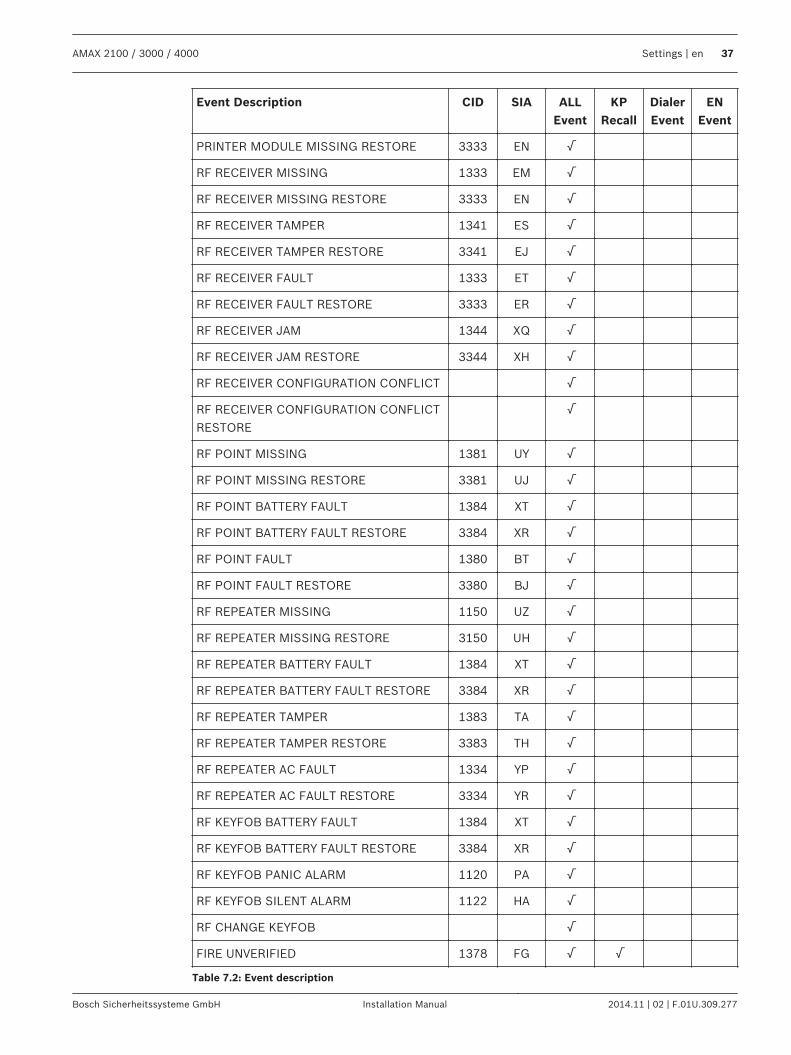
Event Description CID SIA ALLEvent
KPRecall
DialerEvent
ENEvent
PRINTER MODULE MISSING RESTORE 3333 EN √
RF RECEIVER MISSING 1333 EM √
RF RECEIVER MISSING RESTORE 3333 EN √
RF RECEIVER TAMPER 1341 ES √
RF RECEIVER TAMPER RESTORE 3341 EJ √
RF RECEIVER FAULT 1333 ET √
RF RECEIVER FAULT RESTORE 3333 ER √
RF RECEIVER JAM 1344 XQ √
RF RECEIVER JAM RESTORE 3344 XH √
RF RECEIVER CONFIGURATION CONFLICT √
RF RECEIVER CONFIGURATION CONFLICTRESTORE
√
RF POINT MISSING 1381 UY √
RF POINT MISSING RESTORE 3381 UJ √
RF POINT BATTERY FAULT 1384 XT √
RF POINT BATTERY FAULT RESTORE 3384 XR √
RF POINT FAULT 1380 BT √
RF POINT FAULT RESTORE 3380 BJ √
RF REPEATER MISSING 1150 UZ √
RF REPEATER MISSING RESTORE 3150 UH √
RF REPEATER BATTERY FAULT 1384 XT √
RF REPEATER BATTERY FAULT RESTORE 3384 XR √
RF REPEATER TAMPER 1383 TA √
RF REPEATER TAMPER RESTORE 3383 TH √
RF REPEATER AC FAULT 1334 YP √
RF REPEATER AC FAULT RESTORE 3334 YR √
RF KEYFOB BATTERY FAULT 1384 XT √
RF KEYFOB BATTERY FAULT RESTORE 3384 XR √
RF KEYFOB PANIC ALARM 1120 PA √
RF KEYFOB SILENT ALARM 1122 HA √
RF CHANGE KEYFOB √
FIRE UNVERIFIED 1378 FG √ √
Table 7.2: Event description
AMAX 2100 / 3000 / 4000 Settings | en 37
Bosch Sicherheitssysteme GmbH Installation Manual 2014.11 | 02 | F.01U.309.277
Receiver Network Programming OptionsWhen the AMAX panel transmits a report via a network, the following options should beprogrammed other than the IP address and port.
Anti ReplyAnti replay prevents unauthorized messages from being sent to the Central Monitoring Stationand being recognized as originating from the AMAX panel.4 Contact your central monitoring station for the correct setting.
Acknowledge Wait TimeWhen no callback from the receiver after the acknowledge time is reached, the AMAX paneltakes it as an unsuccessful communication and makes another attempt. The time ranges from5 to 99 sec.4 Contact your central monitoring station for the correct setting.
Network Polling TimeThe polling is used for both panel and remote receiver to know whether the networkconnection is good or not. Each time when polling is due, the AMAX panel will send a pollingmessage. The polling time ranges from 1 to 999 minutes.1. For time less than 3 digits, use 0 to fulfill.2. Contact your central monitoring station for the correct setting.
ReportsSystem ReportingReport Transmission SequenceIf the event has disabled the report (option 0), no report is sent out. If the report has anydestination to contact the panel (option 1, 2, 3, 4, 5, 6, 7), It will call the related destinationby related reporting format type and subscriber ID Number.Attempt rules:1. Attempt times and duration
– Within the report expiring time the AMAX panel will retry sending the report to eachenabled destination till the report has been sent to the destination, or till the reportbuffer overflows and the old report is replaced by new incoming reports.
– For each enabled destination, the retry interval time between two retries is 15seconds for the 1st retry to 4th retry, and the retry interval time between two retriesis 10 minutes for the 5th retry to 8th retry, after the 8th retry the retry interval timebetween two retries is 60 minutes.
2. Attempt Priority– The attempt priority is destination 1, 2, 3, 4 Domestic. The disabled destinations will
be ignored.3. Communication Fail Fault
– If the attempt times for one destination reaches 4, the system will cause thecommunication fail fault for this destination.
4. Backup Destination Process– The AMAX panel can save up to a maximum of 50 un-reported events. If the un-
reported events are more than 50, it will delete earlier event and only save the last50 events in the buffer to send out.
Sequential Logic to Send Report– If the event reporting path is set to 0, the relevant reports will not be sent
7.1.2
38 en | Settings AMAX 2100 / 3000 / 4000
2014.11 | 02 | F.01U.309.277 Installation Manual Bosch Sicherheitssysteme GmbH
– If the event reporting path is set to a single path (receiver 1, 2, 3, or 4), the AMAX panelwill send reports to corresponding paths
– If the event reporting path is set to all paths (receiver 1, 2, 3, 4) and any one of thesepaths fails, the communication path will fail
– If the event reporting path is set to sending report to receiver 1, with receiver 2, 3, 4 asbackup, the AMAX panel will send report to receiver 1 first. Only if send report to receiver1 fails,the AMAX panel attempts to send report to 2, 3 and 4 in succession.Communication path fault will occur when all valid paths fail. Communication path faultwill recover when any one of the paths recovers
Display of faultsWhen multiple reports are queued for delivery, the communication path fault is displayed as alogic or relationship. Example:Set zone status recovery report to send report to receiver 1. Set keypad emergency report tosend report to receiver 1, with receiver 2, 3, and 4 as backup.Communication path fault is as follows: When communication paths 1, 2, 3, and 4 all fail, onlythe illumination of zone indicator 1 expresses that communication path 1 of the zone statusrecovery report fails and the all communication paths 1, 2, 3 and 4 of the keypad emergencyreport fail as well.Communication path fault recovery is as follows:– When communication path 1 fault recovers, zone indicator 1 goes off, indicating that the
communication path 1 fault of the zone status recovery report recovers and thecommunication part 1 fault of the keypad emergency report recovers
– When any one path fault of communication paths 2, 3, and 4 recover, as thecommunication path fault is displayed as a logic or relationship, zone indicator 1 stillilluminates, indicating that the communication path 1 fault of the zone status recoveryreport has not be recovered, but the path fault of the keypad emergency report has beenrecovered
Zone Status Reporting and Zone Recovery ReportingAlarm ReportIn arming status, in case of alarm event, the alarm report will be sent. Alarm Recovery ReportIn arming status, when a zone is restored, a zone recovery report is sent either if the lock-outoption for the zone is disabled or if the lock-out option for the zone is enabled and the alarmoutput time has ended.If the non-24-hour zone is not recovered in disarming, the system will automatically send azone recovery report. The 24-hour zone sends the recovery report only when the zonerecovers. Zone Fault ReportIf the zone is triggered at the end of exit delay, a zone fault report will be sent, indicating thatthe zone is automatically bypassed by the system. At the end of exit delay time, the 24-hourzone in triggering status will not send the fault report, i.e. the 24-hour zone will not beautomatically bypassed.The non 24-hour zone fault recovery report will be sent when the zone recovers or the systemdisarms. For the 24-hour zone, only the alarm recovery event will occur.The zone fault occurs when the zone is triggered and recovers when the zone is normal. Zonefault will occur when one of the following conditions is met:
AMAX 2100 / 3000 / 4000 Settings | en 39
Bosch Sicherheitssysteme GmbH Installation Manual 2014.11 | 02 | F.01U.309.277
– For 24-hour zone, (internal) instant zone, if the forced arming option is set to allow, thezone fault event will occur when the arming operation is executed while the zone is intriggering status
– When the zone is locked– For (internal) delay and (internal) follow zone, if they are still in triggering status at the
end of exit delay, zone fault event will occur– For 24-hour zone, if it is in triggering status when the bypass is cancelled, zone fault
event will occurFault recovery conditions:– Zone resumes to normal conditions– When the failed (internal) delay zone, (internal) instant zone and (internal) follow zone
are disarmed, the fault recovery event will occur even if the zone is still in triggeringstatus
Zone Bypass ReportAfter a manual zone bypass operation is executed, the zone is bypassed and a relevant zonebypass report is sent. The zone bypass report will be sent at the end of exit delay time.The zone bypass will be recovered when the system is disarmed and the zone bypass recoveryreport will also be sent while disarming. Zone Tamper AlarmIn case of zone tamper event, the tamper report will be sent. When zone tamper recovers, thesystem status report will be sent.
Arming / Disarming Reporting (System)The system disarming report is sent at the disarming command and the system arming reportis sent when the arming succeeds.Duress ReportThe duress report is sent at the disarming command. The duress report will not be sent in theoperation of arming, but sent with ordinary disarming report. The duress report has nocorresponding alarm recovery report.Key Switch ArmingSends system arming report when the transient key switch or locking key switch is used toarm areas.Quick ArmingSends system arming report when the keypad is used for quick arming.Telephone ArmingSends system arming report when the telephone is used for arming of the panel.Telephone arming is only available when there is Area 1 and 1 Area alternatively in the system.RPC ArmingSends system arming report when the remote PC is used to arm areas through network ortelephone connection.
Arming / Disarming Reporting (Perimeter)The perimeter disarming report is sent at the disarming command and the perimeter armingreport is sent when the arming succeeds.Quick ArmingSends perimeter arming report when the keypad is used for quick arming.RPC Arming
40 en | Settings AMAX 2100 / 3000 / 4000
2014.11 | 02 | F.01U.309.277 Installation Manual Bosch Sicherheitssysteme GmbH
Sends perimeter arming report when the remote PC is used to arm areas through network ortelephone connection.
System Status ReportingExternal Module Fault Report– System tamper report: In case of case tamper event, the system tamper report will be
sent. When case tamper recovers, a tamper recovery report will be sent– Zone Expansion Module Fault: When zone expansion module 1 – 6 fails, the report will be
sent. After the fault is recovered, the recovery report will be sent– Output Expansion Module Fault: When output expansion module 1 or 2 fails, the report
will be sent. After the fault is recovered, the recovery report will be sent– Network Module Fault: When network module 1 or 2 fails, the report will be sent. After
the fault is recovered, the recovery report will be sent– Keypad Fault: When fault occurs between the keypad and the AMAX panel, the report will
be sent. After the fault is recovered, the recovery report will be sent– Zone Expansion Module Tamper: When tamper occurs in the zone expansion module, the
tamper report will be sent. After the tamper recovers, a tamper recovery report will besent
– Keypad Tamper: When tamper occurs in any keypads, the tamper report will be sent.After the tamper recovers, a tamper recovery report will be sent
Auxiliary Power Fault ReportWhen the system detects auxiliary power fault, the report will be sent.Auxiliary Power Fault Restore ReportWhen the system detects auxiliary power fault recovery, the report will be sent.AC Power Fault ReportWhen the system detects disconnection of AC power and after the AC fault delay time hasended, the report will be sent.AC Power Fault Recovery ReportWhen the system detects a recovery of the AC power that lasts longer than the AC powerdelay report time, the report will be sent.Battery Low Voltage Fault ReportWhen the battery voltage is lower than 11.0V or battery low voltage is detected in the dynamicbattery test, the AMAX panel will send the battery low voltage report.The system continuously monitors the battery voltage and will perform a dynamic battery testeach time the system is armed, when the system is reset or in every battery check interval.Battery Low Voltage Fault Recovery ReportWhen the battery voltage is lower than 12.0V or recovery to normal voltage is detected in thedynamic battery test, the battery low voltage fault recovery report will be sent.Times of Wrong Code Entry Exceeding LimitWhen the times of entering wrong code reaches a specific value, an access denial report willbe generated and alarm will be made.This function is used to prevent unwanted users from accessing the system. When the numberof incorrectly entered codes reaches a specific value, the AMAX panel will execute followingactions:– Activate alarm siren and other alarm outputs– Lock the keypad in which the incorrect codes have been entered for 3 minutes– Send an access denial reportOn-board Output 1 – 2 Fault
AMAX 2100 / 3000 / 4000 Settings | en 41
Bosch Sicherheitssysteme GmbH Installation Manual 2014.11 | 02 | F.01U.309.277
When on-board output 1 or 2 fails, the report will be sent. When the on-board output resumesto normal conditions, the programmable output fault recovery report will be sent.Communication Path 1 - 4 FaultWhen any communication path fails, the report will be sent. When communication resumes tonormal conditions, the communication fault recovery report will be sent.Changing Programming ParametersWhen the programming parameters are changed and take effect, the report will be sent.
Keypad Emergency Alarm ReportingIf you press and hold both 1 and 3 for 3 seconds, or press and hold both [#] and [*] for 3seconds, the emergency alarm report will be sent.The emergency alarm report has no corresponding alarm recovery report.
Keypad Fire Alarm ReportingIf you press and hold both 4 and 6 for 3 seconds, the fire alarm report will be sent.The fire alarm report has no corresponding alarm recovery report.
Keypad Medical Aid ReportingIf you press and hold both 7 and 9 for 3 seconds, the medical aid alarm report will be sent.The medical aid alarm report has no corresponding alarm recovery report.
Automatic Test ReportingThe system supports sending automatic test report.For more information about test report time programming, refer to Reports Programming, page108.
Report Expiry TimeIf the report expiry time expires and the report path has not been connected to, the report willbe lost and not be sent. It can be maintained for 1 to 255 minutes. The system is defaulted to000, indicating that the report has been tried to send without limit in expiry time.
Report Delay Entry TimeThis option defines the delay time until a report is send when an alarm occurs during entrytime. The possible value range is 00-99 seconds. If 00 is selected and an alarm occurs duringentry time, a report is send immediately after the entry time ends.
Automatic Test ReportThere are two types of automatic test reports, periodic and regular daily reports.Periodic automatic test reports are sent every hour specified in the test report interval. If 0 isselected, the periodic test report is disabled.Regular daily automatic test reports are sent at the same time every day. This option is onlypossible if the date and time of the system is set correctly.
Dual IP Dual IP Settings are valid only when used with Conettix IP communication format. IP module 1is ITS-DX4020-G module or B426 module; IP module 2 is B426 module. IP module 2 does notsupport RPC connection.
7.1.3
7.1.4
42 en | Settings AMAX 2100 / 3000 / 4000
2014.11 | 02 | F.01U.309.277 Installation Manual Bosch Sicherheitssysteme GmbH
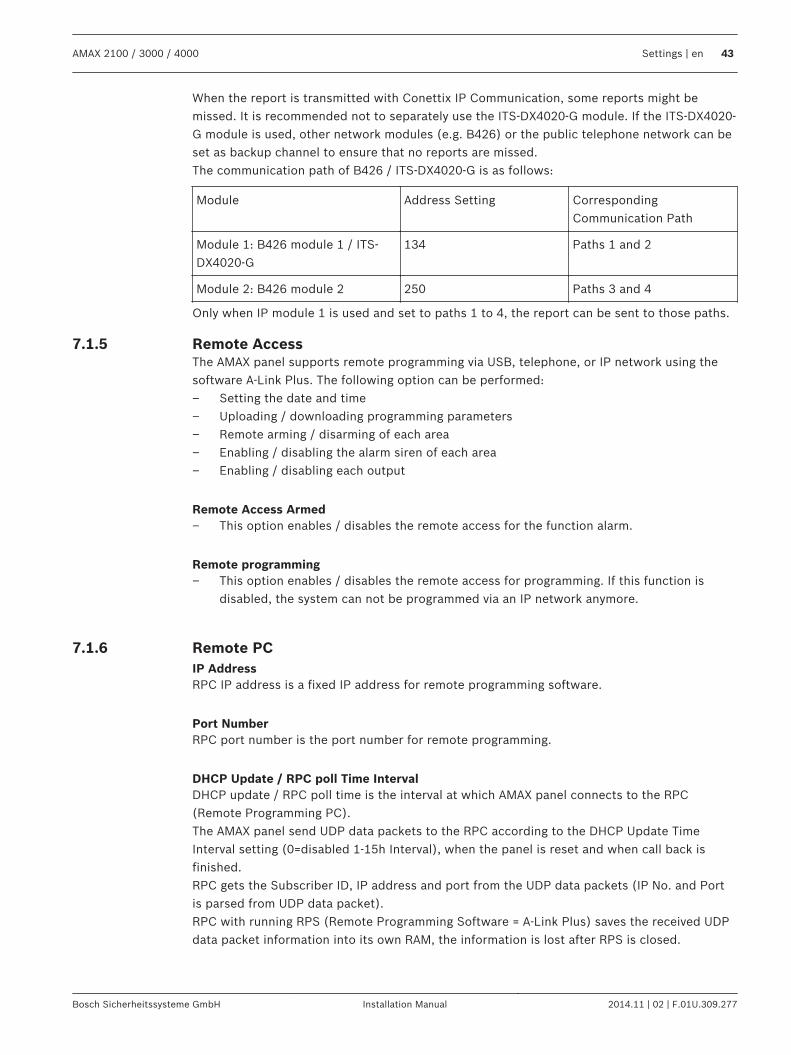
When the report is transmitted with Conettix IP Communication, some reports might bemissed. It is recommended not to separately use the ITS-DX4020-G module. If the ITS-DX4020-G module is used, other network modules (e.g. B426) or the public telephone network can beset as backup channel to ensure that no reports are missed.The communication path of B426 / ITS-DX4020-G is as follows:
Module Address Setting CorrespondingCommunication Path
Module 1: B426 module 1 / ITS-DX4020-G
134 Paths 1 and 2
Module 2: B426 module 2 250 Paths 3 and 4
Only when IP module 1 is used and set to paths 1 to 4, the report can be sent to those paths.
Remote AccessThe AMAX panel supports remote programming via USB, telephone, or IP network using thesoftware A-Link Plus. The following option can be performed:– Setting the date and time– Uploading / downloading programming parameters– Remote arming / disarming of each area– Enabling / disabling the alarm siren of each area– Enabling / disabling each output
Remote Access Armed– This option enables / disables the remote access for the function alarm.
Remote programming– This option enables / disables the remote access for programming. If this function is
disabled, the system can not be programmed via an IP network anymore.
Remote PCIP AddressRPC IP address is a fixed IP address for remote programming software.
Port NumberRPC port number is the port number for remote programming.
DHCP Update / RPC poll Time IntervalDHCP update / RPC poll time is the interval at which AMAX panel connects to the RPC(Remote Programming PC).The AMAX panel send UDP data packets to the RPC according to the DHCP Update TimeInterval setting (0=disabled 1-15h Interval), when the panel is reset and when call back isfinished.RPC gets the Subscriber ID, IP address and port from the UDP data packets (IP No. and Portis parsed from UDP data packet).RPC with running RPS (Remote Programming Software = A-Link Plus) saves the received UDPdata packet information into its own RAM, the information is lost after RPS is closed.
7.1.5
7.1.6
AMAX 2100 / 3000 / 4000 Settings | en 43
Bosch Sicherheitssysteme GmbH Installation Manual 2014.11 | 02 | F.01U.309.277
When a connection is started and the IP address set in the customer information doesn’tmatch with the IP Address from the RAM, the A-Link opens a window to ask if the new IPAddress and Port should be used.When RPS is opened, a connection can only be established when the IP address and portnumber of the AMAX panel have not changed, after RPS received previous data.If the IP address has changed RPC with running RPS must wait for the next UDP Data packagesend from the Panel. When the connection is established, the AMAX panel sends a pollingtelegram of 25 bytes.
Call back and Domestic CallCall back Telephone NumberThis address stores the telephone number to call when upload / download is requested or theuser enters his code + [5] [7] and presses [#] to initiate a modem call from the AMAX panel toestablish a communication link with the remote computer. The computer must be running A-Link Plus RPS software and must be set to waiting for an incoming call. The call backtelephone number is also necessary if remote connect with call back verification is required.
Domestic CallFour recordable voice messages for four dialing telephone numbers are supported. Each of thefour recordable voice messages can take up to 9 seconds. The voice messages are recordedon a PC and are transferred via A-Link Plus to the AMAX panel. They can only be transferredvia USB or network connection.When the AMAX panel is activated into zone tamper / zone alarm, the programmed telephonenumber is dialed and the recorded voice message is played.All alarm events only need one report / acknowledgement.The transmission sequence is repeated until the AMAX panel receives an acknowledgementtone.The AMAX panel automatically hangs up after about 45 seconds if it cannot detect theacknowledgement tone and redial later.The user presses any key on the telephone between two acknowledgement tones to confirmthe alarming.The acknowledgement tone is the DTMF signal sent by the remote user with any key ([0] - [1]or [*] or [#]).If the AMAX panel got the [#] acknowledgement from the user, it will send a 2 seconds longconfirmation beep as an acknowledge tone and hang up the line.
Ring TimesRing CountThis function defines the number of rings before the AMAX panel answers an incoming call. Itis necessary to enable remote arming and remote upload/download to use this function.The following values are selectable:– 0 = The panel does not answer any incoming calls.– 1 – 13 = Number of rings until the control panel answers.– 14 = The control panel is called, the phone is allowed to ring only twice and hangs up.
After 8 seconds the control panel is called again and answers to the first ring.– 15 = The control panel is called and the phone is allowed to ring only four times.
7.1.7
7.1.8
44 en | Settings AMAX 2100 / 3000 / 4000
2014.11 | 02 | F.01U.309.277 Installation Manual Bosch Sicherheitssysteme GmbH
Users and CodesThe AMAX system provides two types of access codes, the installer codes and user codes.Each of them allows specific access and operation of the AMAX panel functions.
User CodeThe default user code is “2580”. This code should be changed to an individual code. If a newuser is assigned, an individual user code is assigned to this user.
Notice!
Identical codes are not allowed. User codes are not permitted to be the same as the installer
code.
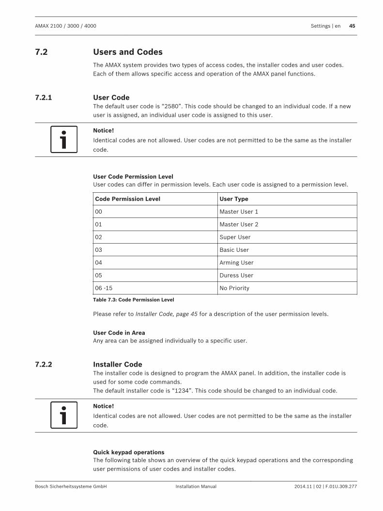
User Code Permission LevelUser codes can differ in permission levels. Each user code is assigned to a permission level.
Code Permission Level User Type
00 Master User 1
01 Master User 2
02 Super User
03 Basic User
04 Arming User
05 Duress User
06 -15 No Priority
Table 7.3: Code Permission Level
Please refer to Installer Code, page 45 for a description of the user permission levels.
User Code in AreaAny area can be assigned individually to a specific user.
Installer CodeThe installer code is designed to program the AMAX panel. In addition, the installer code isused for some code commands.The default installer code is “1234”. This code should be changed to an individual code.
Notice!
Identical codes are not allowed. User codes are not permitted to be the same as the installer
code.
Quick keypad operationsThe following table shows an overview of the quick keypad operations and the correspondinguser permissions of user codes and installer codes.
7.2
7.2.1
7.2.2
AMAX 2100 / 3000 / 4000 Settings | en 45
Bosch Sicherheitssysteme GmbH Installation Manual 2014.11 | 02 | F.01U.309.277
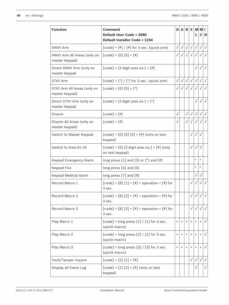
Function CommandDefault User Code = 2580Default Installer Code = 1234
D A B S M1
M2
IN
AWAY Arm [code] + [#] / [#] for 3 sec. (quick arm) √ √ √ √ √ √ √
AWAY Arm All Areas (only onmaster keypad)
[code] + [0] [0] + [#] √ √ √ √ √ √ √
Direct AWAY Arm (only onmaster keypad
[code] + [2-digit area no.] + [#] √ √ √
STAY Arm [code] + [*] / [*] for 3 sec. (quick arm) √ √ √ √ √ √ √
STAY Arm All Areas (only onmaster keypad)
[code] + [0] [0] + [*] √ √ √ √ √ √ √
Direct STAY Arm (only onmaster keypad
[code] + [2-digit area no.] + [*] √ √ √
Disarm [code] + [#] √ √ √ √ √ √
Disarm All Areas (only onmaster keypad)
[code] + [#] √ √ √ √ √ √
Switch to Master Keypad [code] + [0] [0] [0] + [#] (only on textkeypad)
√ √ √
Switch to Area 01-16 [code] + [0] [2-digit area no.] + [#] (onlyon text keypad)
√ √ √
Keypad Emergency Alarm long press [1] and [3] or [*] and [#] * *
Keypad Fire long press [4] and [6] * *
Keypad Medical Alarm long press [7] and [9] √ √
Record Macro 1 [code] + [8] [1] + [#] + operation + [#] for3 sec.
√ √ √ √
Record Macro 2 [code] + [8] [2] + [#] + operation + [#] for3 sec.
√ √ √ √
Record Macro 3 [code] + [8] [3] + [#] + operation + [#] for3 sec.
√ √ √ √
Play Macro 1 [code] + long press [1] / [1] for 3 sec.(quick macro)
+ + + + + + √
Play Macro 2 [code] + long press [2] / [2] for 3 sec.(quick macro)
+ + + + + + √
Play Macro 3 [code] + long press [3] / [3] for 3 sec.(quick macro)
+ + + + + + √
Fault/Tamper Inquire [code] + [2] [1] + [#] √ √ √ √
Display all Event Log [code] + [2] [2] + [#] (only on textkeypad)
√ √
46 en | Settings AMAX 2100 / 3000 / 4000
2014.11 | 02 | F.01U.309.277 Installation Manual Bosch Sicherheitssysteme GmbH
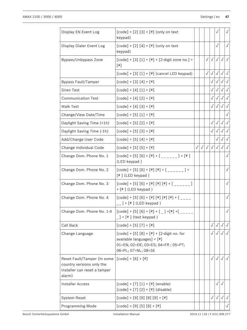
Display EN Event Log [code] + [2] [3] + [#] (only on textkeypad)
√ √
Display Dialer Event Log [code] + [2] [4] + [#] (only on textkeypad)
√ √
Bypass/Unbypass Zone [code] + [3] [1] + [#] + [2-digit zone no.] +[#]
√ √ √ √ √
[code] + [3] [1] + [#] (cancel LED keypad) √ √ √ √ √
Bypass Fault/Tamper [code] + [3] [4] + [#] √ √ √ √
Siren Test [code] + [4] [1] + [#] √ √ √ √
Communication Test [code] + [4] [2] + [#] √ √ √ √
Walk Test [code] + [4] [3] + [#] √ √ √ √
Change/View Date/Time [code] + [5] [1] + [#] √
Daylight Saving Time (+1h) [code] + [5] [2] + [#] √ √ √ √
Daylight Saving Time (-1h) [code] + [5] [3] + [#] √ √ √ √
Add/Change User Code [code] + [5] [4] + [#] √ √ √
Change Individual Code [code] + [5] [5] + [#] √ √ √ √ √ √ √
Change Dom. Phone No. 1 [code] + [5] [6] + [#] + [ _ _ _ _ _ _ ] + [# ](LED keypad )
√
Change Dom. Phone No. 2 [code] + [5] [6] + [#] [#] + [ _ _ _ _ _ _ ] +[# ] (LED keypad )
√
Change Dom. Phone No. 3 [code] + [5] [6] + [#] [#] [#] + [ _ _ _ _ _ _ ]+ [# ] (LED keypad )
√
Change Dom. Phone No. 4 [code] + [5] [6] + [#] [#] [#] [#] + [ _ _ _ __ _ ] + [# ] (LED keypad )
√
Change Dom. Phone No. 1-4 [code] + [5] [6] + [#] + [ _ ] +[#] +[ _ _ _ _ __ ] + [# ] (text keypad )
√
Call Back [code] + [5] [7] + [#] √ √ √ √
Change Language [code] + [5] [8] + [#] + [2-digit no. foravailable languages] + [#]01=EN; 02=DE; 03=ES; 04=FR ; 05=PT;06=PL; 07=NL; 08=SE
√ √ √ √
Reset Fault/Tamper (In somecountry versions only theinstaller can reset a tamperalarm)
[code] + [6] + [#] √ √ √ √
Installer Access [code] + [7] [1] + [#] (enable)[code] + [7] [2] + [#] (disable)
√ √
System Reset [code] + [9] [9] [8] [9] + [#] √ √ √ √
Programming Mode [code] + [9] [5] [8] + [#] √
AMAX 2100 / 3000 / 4000 Settings | en 47
Bosch Sicherheitssysteme GmbH Installation Manual 2014.11 | 02 | F.01U.309.277
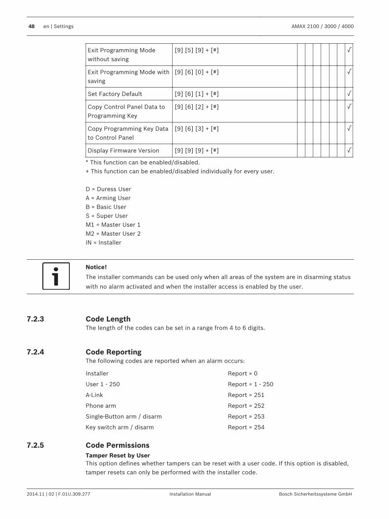
Exit Programming Modewithout saving
[9] [5] [9] + [#] √
Exit Programming Mode withsaving
[9] [6] [0] + [#] √
Set Factory Default [9] [6] [1] + [#] √
Copy Control Panel Data toProgramming Key
[9] [6] [2] + [#] √
Copy Programming Key Datato Control Panel
[9] [6] [3] + [#] √
Display Firmware Version [9] [9] [9] + [#] √
* This function can be enabled/disabled.+ This function can be enabled/disabled individually for every user. D = Duress UserA = Arming UserB = Basic UserS = Super UserM1 = Master User 1M2 = Master User 2IN = Installer
Notice!
The installer commands can be used only when all areas of the system are in disarming status
with no alarm activated and when the installer access is enabled by the user.
Code LengthThe length of the codes can be set in a range from 4 to 6 digits.
Code ReportingThe following codes are reported when an alarm occurs:
Installer Report = 0
User 1 - 250 Report = 1 - 250
A-Link Report = 251
Phone arm Report = 252
Single-Button arm / disarm Report = 253
Key switch arm / disarm Report = 254
Code PermissionsTamper Reset by UserThis option defines whether tampers can be reset with a user code. If this option is disabled,tamper resets can only be performed with the installer code.
7.2.3
7.2.4
7.2.5
48 en | Settings AMAX 2100 / 3000 / 4000
2014.11 | 02 | F.01U.309.277 Installation Manual Bosch Sicherheitssysteme GmbH
Arm / Disarm InstallerThis option defines whether the arm / disarm function can be performed with a installer code.If this option is disabled, the arm / disarm function can not be performed with an installercode.
Macro ConfigurationMacros are used to assign complicated or often used operation to one button to simplify theoperation of the system. It is possible to record up to three macros.
Input Macro NumberIn this option the number of the macro to be configured is selected. (Possible numbers are 1,2 and 3.)
Macro without CodeThis option enables/disables the quick play function of the macro. If this function is enabled,the user can press the number of the macro for three seconds to execute the macro playingfunction without entering a code.
Macro Recording TimeoutThis option defines the timeout of the macro recording process. (Possible values are 01 – 99seconds.) The timeout defines the time after which the macro recording process is cancelleddue to inactivity of the user.
Play Pause TimeThis option defines the speed of the macro playing process. If a user wants to observe themacro playing process more closely, it can be adjusted to display the single operations longer.The default setting is 03=300ms and can be adjusted to 01=100ms, 02=200ms and so on.
Code inside Macro EnableThis option enables/disables the code inside a macro. This function is relevant only if themacro without code function is disabled.If this function is enabled, a code will be recorded during the macro recording process andwill be executed during the macro playing process. This means that a user switch is possiblewhen the macro playing function is executed.If this function is disabled, there will be no code recorded during the macro recording processand the operation assigned to the macro will be executed without a code. This means thatthere is no user switch possible in the macro playing function and that the user who isexecuting the macro playing function is also executing the operation assigned to the macro.
Zones
Add / Delete ZoneWhen adding or changing a zone, it is required to select the area, the zone functions and themodule of the zone source, based on zone numbers.When the zone is specified as “0”, i.e. the zone is not used; any address set on the zonefunction and module selection is invalid.Zone ModuleThe AMAX panel supports onboard zones, keypad zones, AMAX 3000 / 4000, and DX2010zones and RF zones.
Zone Function / Type
Zone Function Option Description
Zone Type 00 Not used
7.2.6
7.3
7.3.1
AMAX 2100 / 3000 / 4000 Settings | en 49
Bosch Sicherheitssysteme GmbH Installation Manual 2014.11 | 02 | F.01U.309.277
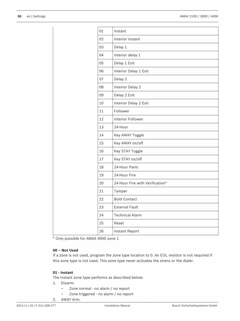
01 Instant
02 Interior instant
03 Delay 1
04 Interior delay 1
05 Delay 1 Exit
06 Interior Delay 1 Exit
07 Delay 2
08 Interior Delay 2
09 Delay 2 Exit
10 Interior Delay 2 Exit
11 Follower
12 Interior Follower
13 24-Hour
14 Key AWAY Toggle
15 Key AWAY on/off
16 Key STAY Toggle
17 Key STAY on/off
18 24-Hour Panic
19 24-Hour Fire
20 24-Hour Fire with Verification*
21 Tamper
22 Bold Contact
23 External Fault
24 Technical Alarm
25 Reset
26 Instant Report
* Only possible for AMAX 4000 zone 1
00 – Not UsedIf a zone is not used, program the zone type location to 0. An EOL resistor is not required ifthis zone type is not used. This zone type never activates the sirens or the dialer.
01 - InstantThe instant zone type performs as described below:1. Disarm:
– Zone normal - no alarm / no report– Zone triggered - no alarm / no report
2. AWAY Arm:
50 en | Settings AMAX 2100 / 3000 / 4000
2014.11 | 02 | F.01U.309.277 Installation Manual Bosch Sicherheitssysteme GmbH
– Zone normal - no alarm / no report– Zone triggered - alarm / report– (Zone triggered during exit time no alarm / no report)– (Zone triggered during entry time alarm / report is delayed for 30 second or entry
time is expired, when system is disarmed before, no report)3. STAY Arm:
– Zone normal - no alarm / no report– Zone triggered - alarm / report– (Zone triggered during exit time no alarm / no report)– (Zone triggered during entry time alarm / report is delayed for 30 second / entry time
is expired, when system is disarmed before, no report) When zone is triggered, notbypassed and system is forced to arm, a zone fault report is sent.
– When the system is disarmed and zone is not restored before, a Zone fault restorereport is sent.
02 - Interior InstantThe interior instant zone type performs as described below:1. Disarm:
– same as the instant zone disarm status2. AWAY Arm:
– same as the instant zone AWAY arm status3. STAY Arm:
– This zone will be ignored and performed as disarm. Refer to Keypad Indicators to seehow the zone is displayed during exit time.
– When zone is triggered, not bypassed and system is forced to arm, a zone faultreport is send.
– When system is disarmed and zone is not restored before, a zone fault restore reportis sent.
03 – Delay 1The delay 1 zone type performs as described below:1. Disarm: same as instant zone disarm status2. AWAY Arm:
– Zone normal - no alarm / no report– Zone triggered - entry time starts - no alarm / no report– Disarming during entry time - no alarm / no report– Zone triggered - during exit time - no alarm / no report– Zone triggered - during entry time - no alarm / no report– Zone triggered - entry time is expired - alarm / report– (report is delayed for a specified time (default: 30s; value range: 00-99), when
system is disarmed before, no report)3. STAY Arm: same as AWAY arm performance.
– First delay zone will start the entry time; all other delay zones will follow.– When system is disarmed and zone is not restored before, a zone restore report is
sent.
04 - Interior Delay 1The interior delay 1 zone type performs as described below:1. Disarm: same as the instant zone disarm status
AMAX 2100 / 3000 / 4000 Settings | en 51
Bosch Sicherheitssysteme GmbH Installation Manual 2014.11 | 02 | F.01U.309.277
2. AWAY Arm: same as the delay zone AWAY arm status3. STAY Arm:
– This zone will be ignored and performed as disarm.– Refer to Keypad Indicators to see how the zone is displayed during exit time.
05 – Delay 1 ExitThe delay 1 exit zone type performs as described below:1. DISARM: same as instant zone disarm status2. AWAY Arm:
– Zone normal - no alarm / no report– Zone triggered - entry time starts - no alarm / no report– Disarming during entry time - no alarm / no report– Zone triggered - during exit time - no alarm / no report / abbreviates remaining time
for exit to 5 seconds– Zone triggered - during entry time - no alarm / no report– Zone triggered - entry time is expired - alarm / report (report is delayed for 30
second, when system is disarmed before, no report)3. STAY Arm: same as AWAY arm performance
– First delay zone will start the entry time; all other delay zones will follow.– When system is disarmed and zone is not restored before, a zone restore report is
sent.
06 – Interior Delay 1 ExitThe Interior delay 1 exit zone type performs as described below:1. Disarm: same as the instant zone disarm status2. AWAY Arm: same as the delay exit zone AWAY arm status3. STAY Arm:
– This zone will be ignored and performed as disarm.– Refer to Keypad Indicators to see how the zone is displayed during exit time.
07 - Delay 2The delay 2 zone type performs as described below:1. Disarm: same as instant zone disarm status2. AWAY Arm:
– Zone normal - no alarm / no report– Zone triggered - entry time starts - no alarm / no report– Disarming during entry time - no alarm / no report– Zone triggered - during exit time - no alarm / no report– Zone triggered - during entry time - no alarm / no report– Zone triggered - entry time is expired - alarm / report– (report is delayed for a specified time (default: 30s; value range: 00-99), when
system is disarmed before, no report)3. STAY Arm: same as AWAY arm performance.
– First delay zone will start the entry time; all other delay zones will follow.– When system is disarmed and zone is not restored before, a zone restore report is
sent
08 – Interior Delay 2The interior delay 2 zone type performs as described below:
52 en | Settings AMAX 2100 / 3000 / 4000
2014.11 | 02 | F.01U.309.277 Installation Manual Bosch Sicherheitssysteme GmbH
1. Disarm: same as the instant zone disarm status2. AWAY Arm: same as the delay zone AWAY arm status3. STAY Arm:
– This zone will be ignored and performed as disarm.– Refer to Keypad Indicators to see how the zone is displayed during exit time.
09 – Delay 2 ExitThe delay 2 exit zone type performs as described below:1. DISARM: same as instant zone disarm status2. AWAY Arm:
– Zone normal - no alarm / no report– Zone triggered - entry time starts - no alarm / no report– Disarming during entry time - no alarm / no report– Zone triggered - during exit time - no alarm / no report / abbreviates remaining time
for exit to 5 seconds– Zone triggered - during entry time - no alarm / no report– Zone triggered - entry time is expired - alarm / report (report is delayed for 30
second, when system is disarmed before, no report)3. STAY Arm: same as AWAY arm performance
– First delay zone will start the entry time; all other delay zones will follow.– When system is disarmed and zone is not restored before, a zone restore report is
sent.
10 – Interior Delay 2 ExitThe Interior delay 2 exit zone type performs as described below:1. Disarm: same as the instant zone disarm status2. AWAY Arm: same as the delay exit zone AWAY arm status3. STAY Arm:
– This zone will be ignored and performed as disarm.– Refer to Keypad Indicators to see how the zone is displayed during exit time.
11 - FollowerThe follower zone type performs as described below:1. Disarm:
– same as the instant zone disarm status2. AWAY Arm:
– Zone normal - no alarm / no report– Zone triggered – alarm / report– Zone triggered - during exit time - no alarm / no report– Zone triggered - during entry time - no alarm / no report– The remaining delay time is handed over from the delay zone to the follower zone.– The follower zone performance as the same as a delay zone.– If there are two or more zones programmed as delay zones and both are triggered,
the follower zone will follow the first triggered delay zone.3. STAY Arm: same as the delay zone.
12 – Interior FollowerThe interior follower zone type performs as described below:1. Disarm: same as the instant zone disarm status
AMAX 2100 / 3000 / 4000 Settings | en 53
Bosch Sicherheitssysteme GmbH Installation Manual 2014.11 | 02 | F.01U.309.277
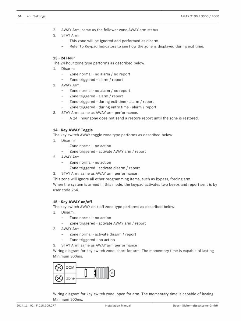
2. AWAY Arm: same as the follower zone AWAY arm status3. STAY Arm:
– This zone will be ignored and performed as disarm.– Refer to Keypad Indicators to see how the zone is displayed during exit time.
13 - 24 HourThe 24-hour zone type performs as described below:1. Disarm:
– Zone normal - no alarm / no report– Zone triggered - alarm / report
2. AWAY Arm:– Zone normal - no alarm / no report– Zone triggered - alarm / report– Zone triggered - during exit time - alarm / report– Zone triggered - during entry time - alarm / report
3. STAY Arm: same as AWAY arm performance.– A 24 - hour zone does not send a restore report until the zone is restored.
14 - Key AWAY ToggleThe key switch AWAY toggle zone type performs as described below:1. Disarm:
– Zone normal - no action– Zone triggered - activate AWAY arm / report
2. AWAY Arm:– Zone normal - no action– Zone triggered - activate disarm / report
3. STAY Arm: same as AWAY arm performanceThis zone will ignore all other programming items, such as bypass, forcing arm.When the system is armed in this mode, the keypad activates two beeps and report sent is byuser code 254.
15 - Key AWAY on/offThe key switch AWAY on / off zone type performs as described below:1. Disarm:
– Zone normal - no action– Zone triggered - activate AWAY arm / report
2. AWAY Arm:– Zone normal - activate disarm / report– Zone triggered - no action
3. STAY Arm: same as AWAY arm performanceWiring diagram for key-switch zone: short for arm. The momentary time is capable of lastingMinimum 300ms.
COM
Zone
Wiring diagram for key-switch zone: open for arm. The momentary time is capable of lastingMinimum 300ms.
54 en | Settings AMAX 2100 / 3000 / 4000
2014.11 | 02 | F.01U.309.277 Installation Manual Bosch Sicherheitssysteme GmbH
COM
Zone
When the key-switch operates the arm/disarm, the keypad sounds two beeps and report sentto the system by user code 254.
Notice!
When the key-switch operates the arm/disarm successfully, the siren sounds short to indicate
it.
16 – Key STAY ToggleThe key switch momentary STAY zone type performs as described below:1. Disarm:
– Zone normal - no action– Zone triggered - activate STAY arm / report
2. AWAY Arm:– Zone normal - no action– Zone triggered - activate disarm / report
3. STAY Arm: same as AWAY arm performanceThis zone will ignore all other programming items, such as bypass, forcing arm.When the system is armed in this mode, the keypad activates two beeps and report sent is byuser code 254.
17 – Key STAY on/offThe key switch on/off STAY zone type performs as described below:1. Disarm:
– Zone normal - no action– Zone triggered - activate STAY arm / report
2. AWAY Arm:– Zone normal - activate disarm / report– Zone triggered - no action
3. STAY Arm: same as AWAY arm performanceWhen the key-switch operates the arm / disarm, the keypad sounds two beeps and report sentto the system by User Code 254.
Notice!
When the key-switch operates the arm / disarm successfully, the siren sounds short to
indicate it.
18 – 24-Hour PanicThe 24-hour panic zone type performs as described below:1. Disarm:
– Zone normal - no alarm / no report– Zone triggered – silent alarm / report
2. AWAY Arm:
AMAX 2100 / 3000 / 4000 Settings | en 55
Bosch Sicherheitssysteme GmbH Installation Manual 2014.11 | 02 | F.01U.309.277
– Zone normal - no alarm / no report– Zone triggered – silent alarm / report– Zone triggered - during exit time – silent alarm / report– Zone triggered - during entry time – silent alarm / report
3. STAY Arm: same as AWAY arm performance– A 24-hour panic zone has no restore report until the zone is restored.
19 – 24 Hour FireThe 24-hour fire zone type performs as described below:1. Disarm:
– Zone normal - no alarm / no report– Zone triggered - alarm / report
2. AWAY Arm:– Zone normal - no alarm / no report– Zone triggered - alarm / report– Zone triggered - during exit time - alarm / report– Zone triggered - during entry time - alarm / report
3. STAY Arm: same as AWAY arm performance– A fire zone does not send a restore report until the zone is restored.
20 – 24-Hour Fire with Verification(Only possible for AMAX 4000 zone 1)The 24-hour fire with verification zone type performs as described below:1. Disarm:
– Zone normal - no alarm / no report– Zone triggered: After the first alarm, the AMAX panel performs a fire verification reset
(10 seconds) and then waits a period up to two minutes for a second alarm. If asecond alarm occurs within this period, the AMAX panel indicates a fire alarm.Otherwise, the AMAX panel resets back to its normal condition. At the end of the twominute period an unverified fire alarm is logged and reported. A fire zone does notsend a restore report until the zone is restored.
2. AWAY Arm: same as disarm performance3. STAY Arm: same as disarm performance
21 - TamperThe tamper zone type performs as described below:1. Disarm:
– Zone normal - no alarm / no report– Zone triggered - alarm / report
2. AWAY Arm:– Zone normal - no alarm / no report– Zone triggered - alarm / report– Zone triggered - during exit time - alarm / report– Zone triggered - during entry time - alarm / report
3. STAY Arm: same as AWAY arm performance– A tamper zone does not send a restore report until the zone is restored.
22 - Bolt ContactThe bolt-contact zone type performs as described below:
56 en | Settings AMAX 2100 / 3000 / 4000
2014.11 | 02 | F.01U.309.277 Installation Manual Bosch Sicherheitssysteme GmbH
1. Disarm:– Zone normal - no alarm / no report– Zone triggered - no alarm / no report
2. AWAY Arm:– Zone normal - no alarm / no report– Zone triggered - no alarm / no report– Zone triggered - during exit time - no alarm / no report– Zone triggered - during entry time - no alarm / no report
3. STAY Arm: same as AWAY Arm performance.– This zone is mainly for prevention of arming (to ensure exit/entry door is locked
before arming the system and no alarm occurs when entering the premise throughthe entry/exit door).
23 - External FaultThe external fault zone type performs as described below:1. Disarm:
– Zone normal - no alarm / no report– Zone triggered - fault / report
2. AWAY Arm:– Zone normal - no alarm / no report– Zone triggered - alarm / report– Zone triggered - during exit time - fault / report– Zone triggered - during entry time - fault / report
3. STAY Arm: same as AWAY Arm performance– The restore report will be sent when the zone is restored.
24 - Technical AlarmThe technical alarm zone type performs as described below:1. Disarm:
– Zone normal - no alarm / no report– Zone triggered - alarm / report
2. AWAY Arm:– Zone normal - no alarm / no report– Zone triggered - alarm / report– Zone triggered - during exit time - alarm / report– Zone triggered - during entry time - alarm / report
3. STAY Arm: same as AWAY arm performance.– A technical zone does not send a restore report until the zone is restored.
25 - ResetThe reset zone type performs as described below:1. Disarm:
– Zone normal - no alarm / no report– Zone triggered – performs system reset / no report
2. AWAY Arm:– Zone normal - no alarm / no report
3. STAY Arm: same as AWAY arm performance
AMAX 2100 / 3000 / 4000 Settings | en 57
Bosch Sicherheitssysteme GmbH Installation Manual 2014.11 | 02 | F.01U.309.277
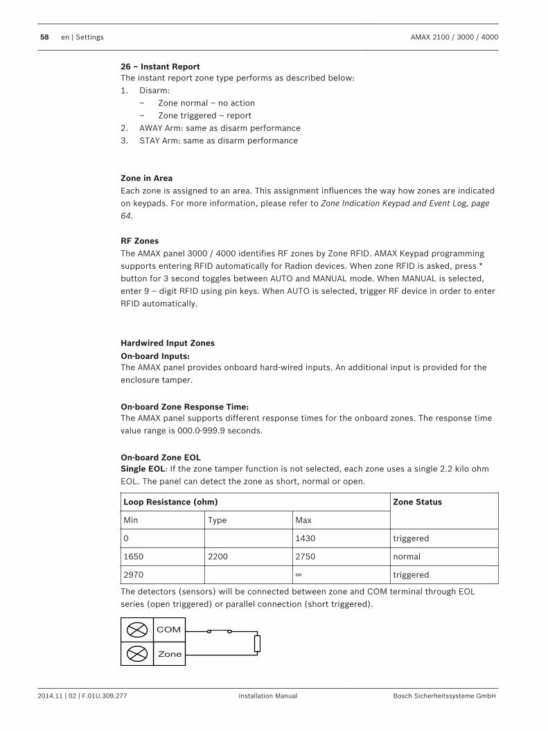
26 – Instant ReportThe instant report zone type performs as described below:1. Disarm:
– Zone normal – no action– Zone triggered – report
2. AWAY Arm: same as disarm performance3. STAY Arm: same as disarm performance Zone in AreaEach zone is assigned to an area. This assignment influences the way how zones are indicatedon keypads. For more information, please refer to Zone Indication Keypad and Event Log, page64. RF ZonesThe AMAX panel 3000 / 4000 identifies RF zones by Zone RFID. AMAX Keypad programmingsupports entering RFID automatically for Radion devices. When zone RFID is asked, press *button for 3 second toggles between AUTO and MANUAL mode. When MANUAL is selected,enter 9 – digit RFID using pin keys. When AUTO is selected, trigger RF device in order to enterRFID automatically.
Hardwired Input Zones
On-board Inputs:The AMAX panel provides onboard hard-wired inputs. An additional input is provided for theenclosure tamper.
On-board Zone Response Time:The AMAX panel supports different response times for the onboard zones. The response timevalue range is 000.0-999.9 seconds.
On-board Zone EOLSingle EOL: If the zone tamper function is not selected, each zone uses a single 2.2 kilo ohmEOL. The panel can detect the zone as short, normal or open.
Loop Resistance (ohm) Zone Status
Min Type Max
0 1430 triggered
1650 2200 2750 normal
2970 ∞ triggered
The detectors (sensors) will be connected between zone and COM terminal through EOLseries (open triggered) or parallel connection (short triggered).
COM
Zone
58 en | Settings AMAX 2100 / 3000 / 4000
2014.11 | 02 | F.01U.309.277 Installation Manual Bosch Sicherheitssysteme GmbH
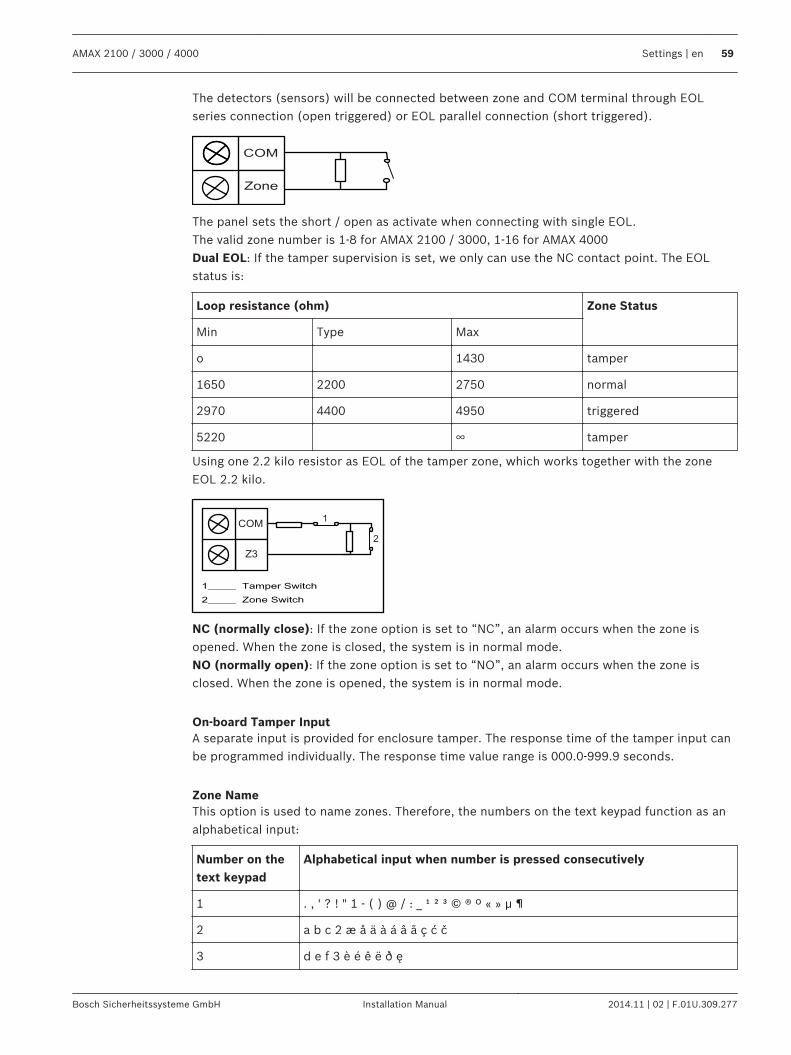
The detectors (sensors) will be connected between zone and COM terminal through EOLseries connection (open triggered) or EOL parallel connection (short triggered).
COM
Zone
The panel sets the short / open as activate when connecting with single EOL.The valid zone number is 1-8 for AMAX 2100 / 3000, 1-16 for AMAX 4000Dual EOL: If the tamper supervision is set, we only can use the NC contact point. The EOLstatus is:
Loop resistance (ohm) Zone Status
Min Type Max
o 1430 tamper
1650 2200 2750 normal
2970 4400 4950 triggered
5220 ∞ tamper
Using one 2.2 kilo resistor as EOL of the tamper zone, which works together with the zoneEOL 2.2 kilo.
COM
Z3
1
2
NC (normally close): If the zone option is set to “NC”, an alarm occurs when the zone isopened. When the zone is closed, the system is in normal mode.NO (normally open): If the zone option is set to “NO”, an alarm occurs when the zone isclosed. When the zone is opened, the system is in normal mode.
On-board Tamper InputA separate input is provided for enclosure tamper. The response time of the tamper input canbe programmed individually. The response time value range is 000.0-999.9 seconds.
Zone NameThis option is used to name zones. Therefore, the numbers on the text keypad function as analphabetical input:
Number on thetext keypad
Alphabetical input when number is pressed consecutively
1 . , ' ? ! " 1 - ( ) @ / : _ ¹ ² ³ © ® º « » µ ¶
2 a b c 2 æ å ä à á â ã ç ć č
3 d e f 3 è é ê ë ð ę
AMAX 2100 / 3000 / 4000 Settings | en 59
Bosch Sicherheitssysteme GmbH Installation Manual 2014.11 | 02 | F.01U.309.277
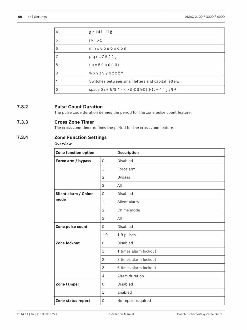
4 g h i 4 ì í î ï ğ
5 j k l 5 £
6 m n o 6 ö ø ò ó ô õ ñ
7 p q r s 7 ß š ś ş
8 t u v 8 ù ú û ü ű ţ
9 w x y z 9 ý þ ź ż ž Ÿ
* Switches between small letters and capital letters
0 space 0 ; + & % * = < > £ € $ ¥¤ [ ]\ ~ ^ ` ¿ ¡ § # |
Pulse Count DurationThe pulse code duration defines the period for the zone pulse count feature.
Cross Zone TimerThe cross zone timer defines the period for the cross zone feature.
Zone Function SettingsOverview
Zone function option Description
Force arm / bypass 0 Disabled
1 Force arm
2 Bypass
3 All
Silent alarm / Chimemode
0 Disabled
1 Silent alarm
2 Chime mode
3 All
Zone pulse count 0 Disabled
1-9 1-9 pulses
Zone lockout 0 Disabled
1 1 times alarm lockout
2 3 times alarm lockout
3 6 times alarm lockout
4 Alarm duration
Zone tamper 0 Disabled
1 Enabled
Zone status report 0 No report required
7.3.2
7.3.3
7.3.4
60 en | Settings AMAX 2100 / 3000 / 4000
2014.11 | 02 | F.01U.309.277 Installation Manual Bosch Sicherheitssysteme GmbH
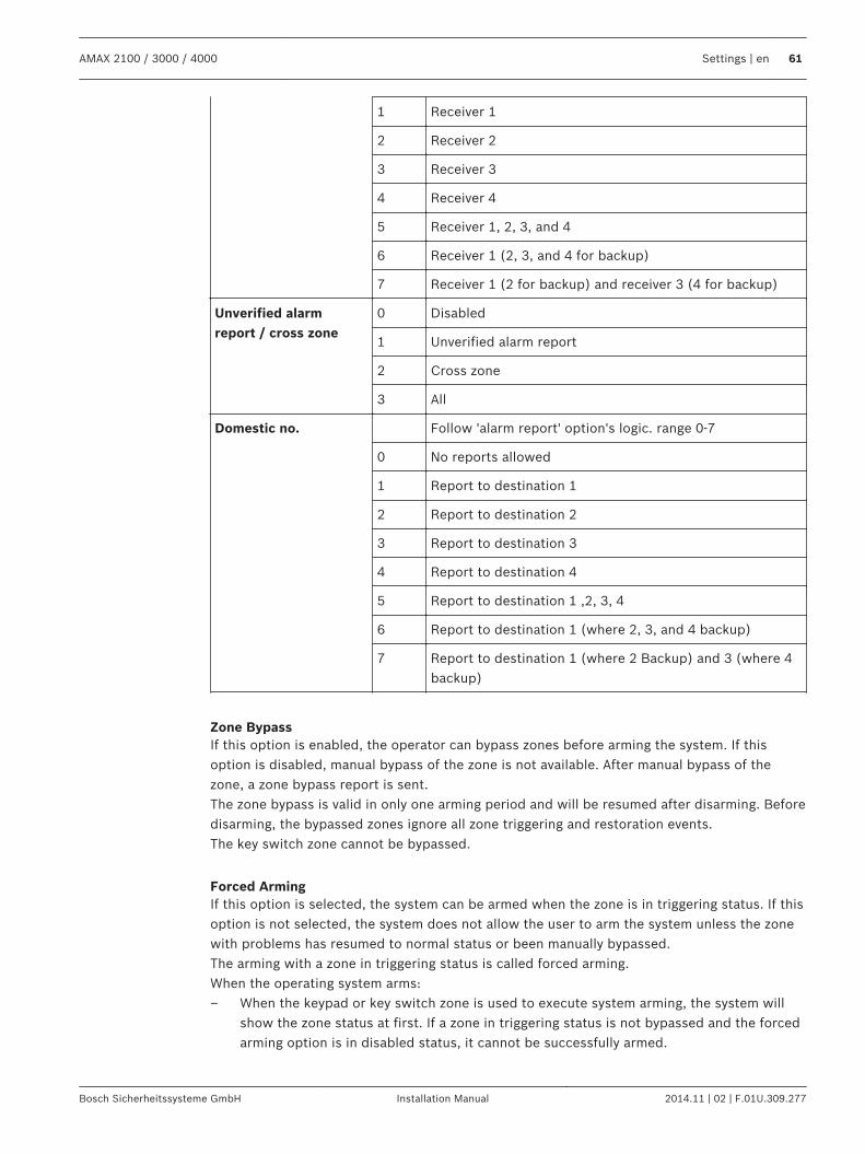
1 Receiver 1
2 Receiver 2
3 Receiver 3
4 Receiver 4
5 Receiver 1, 2, 3, and 4
6 Receiver 1 (2, 3, and 4 for backup)
7 Receiver 1 (2 for backup) and receiver 3 (4 for backup)
Unverified alarmreport / cross zone
0 Disabled
1 Unverified alarm report
2 Cross zone
3 All
Domestic no. Follow 'alarm report' option's logic. range 0-7
0 No reports allowed
1 Report to destination 1
2 Report to destination 2
3 Report to destination 3
4 Report to destination 4
5 Report to destination 1 ,2, 3, 4
6 Report to destination 1 (where 2, 3, and 4 backup)
7 Report to destination 1 (where 2 Backup) and 3 (where 4backup)
Zone BypassIf this option is enabled, the operator can bypass zones before arming the system. If thisoption is disabled, manual bypass of the zone is not available. After manual bypass of thezone, a zone bypass report is sent.The zone bypass is valid in only one arming period and will be resumed after disarming. Beforedisarming, the bypassed zones ignore all zone triggering and restoration events.The key switch zone cannot be bypassed.
Forced ArmingIf this option is selected, the system can be armed when the zone is in triggering status. If thisoption is not selected, the system does not allow the user to arm the system unless the zonewith problems has resumed to normal status or been manually bypassed.The arming with a zone in triggering status is called forced arming.When the operating system arms:– When the keypad or key switch zone is used to execute system arming, the system will
show the zone status at first. If a zone in triggering status is not bypassed and the forcedarming option is in disabled status, it cannot be successfully armed.
AMAX 2100 / 3000 / 4000 Settings | en 61
Bosch Sicherheitssysteme GmbH Installation Manual 2014.11 | 02 | F.01U.309.277
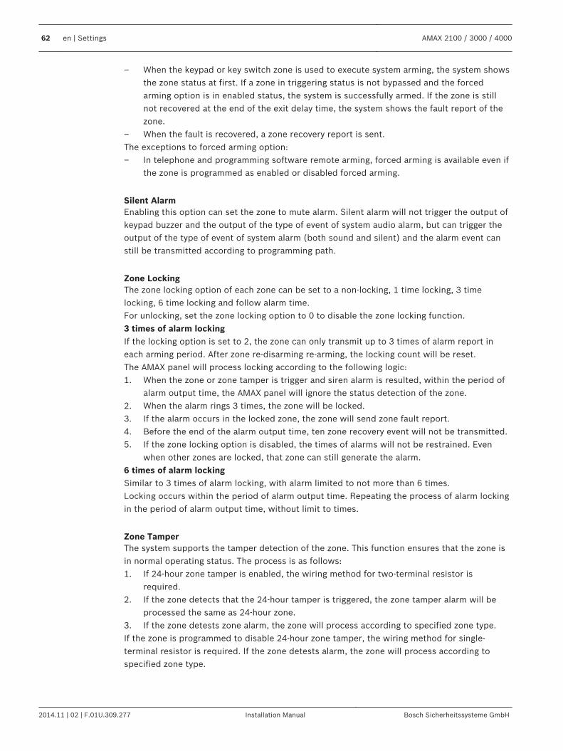
– When the keypad or key switch zone is used to execute system arming, the system showsthe zone status at first. If a zone in triggering status is not bypassed and the forcedarming option is in enabled status, the system is successfully armed. If the zone is stillnot recovered at the end of the exit delay time, the system shows the fault report of thezone.
– When the fault is recovered, a zone recovery report is sent.The exceptions to forced arming option:– In telephone and programming software remote arming, forced arming is available even if
the zone is programmed as enabled or disabled forced arming.
Silent AlarmEnabling this option can set the zone to mute alarm. Silent alarm will not trigger the output ofkeypad buzzer and the output of the type of event of system audio alarm, but can trigger theoutput of the type of event of system alarm (both sound and silent) and the alarm event canstill be transmitted according to programming path.
Zone LockingThe zone locking option of each zone can be set to a non-locking, 1 time locking, 3 timelocking, 6 time locking and follow alarm time.For unlocking, set the zone locking option to 0 to disable the zone locking function.3 times of alarm lockingIf the locking option is set to 2, the zone can only transmit up to 3 times of alarm report ineach arming period. After zone re-disarming re-arming, the locking count will be reset.The AMAX panel will process locking according to the following logic:1. When the zone or zone tamper is trigger and siren alarm is resulted, within the period of
alarm output time, the AMAX panel will ignore the status detection of the zone.2. When the alarm rings 3 times, the zone will be locked.3. If the alarm occurs in the locked zone, the zone will send zone fault report.4. Before the end of the alarm output time, ten zone recovery event will not be transmitted.5. If the zone locking option is disabled, the times of alarms will not be restrained. Even
when other zones are locked, that zone can still generate the alarm.6 times of alarm lockingSimilar to 3 times of alarm locking, with alarm limited to not more than 6 times.Locking occurs within the period of alarm output time. Repeating the process of alarm lockingin the period of alarm output time, without limit to times.
Zone TamperThe system supports the tamper detection of the zone. This function ensures that the zone isin normal operating status. The process is as follows:1. If 24-hour zone tamper is enabled, the wiring method for two-terminal resistor is
required.2. If the zone detects that the 24-hour tamper is triggered, the zone tamper alarm will be
processed the same as 24-hour zone.3. If the zone detests zone alarm, the zone will process according to specified zone type.If the zone is programmed to disable 24-hour zone tamper, the wiring method for single-terminal resistor is required. If the zone detests alarm, the zone will process according tospecified zone type.
62 en | Settings AMAX 2100 / 3000 / 4000
2014.11 | 02 | F.01U.309.277 Installation Manual Bosch Sicherheitssysteme GmbH
Zone Status ReportingThe AMAX panel reports the zone status according to the specified path, including alarm, zonefault, zone bypass and zone tamper alarm.
Zone Chime ModeThe system will support the chime mode.The process is as follows:– If the chime mode is used and a zone is triggered the keypad buzzer will sound for 1
second (only in disarmed status).
Zone Pulse CountThe system will support the pulse count mode.The process is as follows:– Pulse count duration time must be configured (refer to Pulse Count Duration Programming,
page 126)– Pulse count for a zone can be set to a value between 1 and 9 (0 = disabled)The process is as follows:– An alarm is created only if the zone is triggered as many times as the value “pulse count”
within the time “count duration”
Domestic no.The system will support the domestic call mode.The process is as follows:– If the domestic call mode is configured for a zone and an alarm from this zone is created
the alarm will be reported to the destination(s) configured and needs acknowledgement
Cross ZoneThe cross zone option works as follows:Prerequisites:– At least two zones in the same area have option cross zone enabled– System option cross zone timer is set to a value higher than 0When one of these zones is triggered for more than 20 seconds, an alarm is created.When one of these zones (the first zone) is triggered for a shorter time than 20 seconds, thecross zone timer starts, no alarm is created at this time– When no more zones (with cross zone option) are triggered within the cross zone time,
no alarm is created– When the first zone is triggered twice or more within the cross zone time, no alarm is
created– When a second zone or further zones (with cross zone option) is / are triggered within
the cross zone time, then an alarm is created for all triggered zones– When the first zone or one of the other zones (with cross zone option) is / are triggered
twice or more after cross zone time is expired, the timer restarts
Unverified Alarm ReportEnables / disables the option unverified alarm report. When a cross zone is triggered, but noalarm is created, system creates an unverified alarm in order to report. System reportsunverified alarms if option unverified alarm report is enabled.
AMAX 2100 / 3000 / 4000 Settings | en 63
Bosch Sicherheitssysteme GmbH Installation Manual 2014.11 | 02 | F.01U.309.277

Zone Indication Keypad and Event LogZones may be indicated on LED/LCD keypads and in event logs with a number that aredifferent from the zone number used for programming and hardware input.
One area systemZones are indicated on LED/LCD keypads according to the zone numbers. When one zone isdisabled the indication number of all following (higher) zone numbers will shift to a valuedecreased by one.
Multi area systemOnly zones assigned to one area are indicated on an area LED/LCD keypad in order beginningwith 1 and by following the order of zone numbers.
Examples:AMAX 3000 / 4000:In a one area or area 1 system keypad the zone number 17 is indicated on a 16 zone LED/LCDkeypad. After disabling zone 16 (or another one in range 1 to 16), zone number 17 is indicatedon the LED/LCD keypad as zone number 16.AMAX 2100:In a one area system keypad the zone number 17 is indicated on an 8 zone LED/LCD keypad.After disabling zone 5, zone number 17 is indicated on the LED/LCD keypad as zone number5.The following table shows the area assignment and keypad indication of zones in a multi areasystem:
Zone Number Area Indication keypad area 1 Indication keypad area 1
1 2 1
2 2 2
3 1 1
4 1 2
5 1 3
6 1 4
7 2 3
8 2 4
9 2 5
10 2 6
11 1 5
12 1 6
7.3.5
64 en | Settings AMAX 2100 / 3000 / 4000
2014.11 | 02 | F.01U.309.277 Installation Manual Bosch Sicherheitssysteme GmbH
Keypads and Areas
Keypad AreaMaster KeypadThe AMAX panel supports master keypads. User access to a master keypad differs from useraccess to an area keypad. The master keypad switches to the master keypad mode or to thearea that the user declares after entering the user code. The arming/disarming, area alarm, ACpower fault, system fault and system event of each area can be displayed on the masterkeypad. The master keypad can also enter the user menu.It is possible to execute arming/disarming on a master keypad. It is possible to either arm allareas or to arm only a single area via the direct arm function.It is not possible to perform a bypass operation on a master keypad. When relevant operationsare made to an area, the master keypad should be switched to the corresponding area.
Area KeypadIt is possible to operate each area with a single or multiple independent keypads.Each area keypad can only operate the corresponding programmed area.When the area keypad has no corresponding zones, the area keypad cannot be used toexecute zone-related operations such as arming/disarming and bypassing, but can be used toexecute operations unrelated to zones, e.g. event inquiry.Each area keypad can display the status of the zone belonging to the area. However, for IUI-AMAX3- LED8 keypad, IUI-AMAXLED 8 keypad and IUI-AMAX-LCD 8 keypad, each area candisplay up to 8 zones and cannot display other zones, but can report zone events. For IUI-AMAX3LED16 keypad, each area can display up to 16 zones and cannot display other zones,but can report zone events. Keypad IUI -AMAX4-TEXT can display up to 64 zones. For any area, the logic numbers of the zones are displayed on the LED/LCD keypad and logicnumbers or zone names of the zones are displayed on the keypad instead of actual physicalnumbers. For example: The zones 1, 2, and 3 of 1 area or area 1 displayed on the keypad areactually zones 20, 31, and 37.
Area TimingThe AMAX panel supports separate entry and exit delay times for each area.
Exit DelayThe programming range is 0 - 255 seconds. In the mode of system arming, the keypad willbeep during exit and will make continuous long beep sound in the last 10 seconds to notifythe exit time is coming to an end.
Entry DelayThe programming range is 0 - 255 seconds. Entry delay time starts when a delay zone istriggered in armed state.
Common AreaArea 1 can be used as a common area or an independent area. Common area ancillary acts areas follows:– Only all belonged independent areas are armed, the common area can be armed– When a relevant ancillary area is perimeter arming, the common area will be perimeter
arming too– When a relevant ancillary area is disarmed, the common area will be armed
7.4
7.4.1
7.4.2
7.4.3
AMAX 2100 / 3000 / 4000 Settings | en 65
Bosch Sicherheitssysteme GmbH Installation Manual 2014.11 | 02 | F.01U.309.277
– If any zones under common zones are in triggered or tamper status and the forced armingis disabled, the common area cannot be armed
Keypad IndicationKeypad Alarm ToneThis option enables/disables the keypad alarm tone.
Audible Entry EnableThis option enables/disables a keypad warning tone during entry time when the system is inSTAY arm mode. If this option is enabled, a keypad warning tone occurs when the system is inSTAY arm mode and the entry time starts.
STAY Zone Alarm IndicationThis option enables/disables the keypad alarm indication. If this option is enabled, informationis displayed on the keypad, when the system is in STAY arm mode.
Entry Delay Backlight onThis option enables/disables the keypad backlight during entry time. If this option is enabled,the keypad backlight turns on when the system is in STAY arm mode and the entry time startsand turns off when the entry time ends and no other button is pressed.
Keypad LockoutKeypad Lock CountThe number of attempts to enter a wrong user code can be set from 1 to 15 in order tosupervise valid user access. The keypad will be locked for 3 minutes, when the number ofattempts reaches the declared value.
System
System SettingThis chapter describes the system settings that can be accessed via the SYSTEM SETTINGS 1and the SYSTEM SETTINGS 2 menu and their submenus if available.
Date and TimeThe AMAX panel has a 24-hour clock and a 12-month calendar that need to be set after powerup. The order is day, month, year, hour, and minute, with each item occupying two digits [DD][MM] [YY] [HH] [MM].
Fault Configuration
Fault Sound ReminderWhen the command [2] [1] is used for fault inquiry, the keypad can be programmed to soundprompt tone to indicate new system fault. The system is defaulted to enable. In case of a newfault, all keypads will sound a short beep once a minute.
AC Fault Delay TimeThe fault report to display on the keypad will be delayed for the selected time (01 – 98minutes; default = 60 minutes; disabled = 99).
7.4.4
7.4.5
7.5
7.5.1
66 en | Settings AMAX 2100 / 3000 / 4000
2014.11 | 02 | F.01U.309.277 Installation Manual Bosch Sicherheitssysteme GmbH
Date/Time FaultIn case of date/time settings fault, it is possible to choose to display the fault or transmit faultprompt tone at the same time, or to not display and stop fault prompt tone. If it is chosen tonot display, the fault prompt tone is set, and the system will prompt nothing if no date andtime are set after power-up.
Battery Check IntervalThis option defines the time interval in which the battery test is carried out (01 – 15 minutes;00 = disabled). The battery test is also carried out when the system is armed or during systempower up.
Phone Line MonitorIf this option is enabled, the system supervises whether the phone line is broken ordisconnected.
Siren SupervisionIf this option is enabled, the system supervises whether the siren is shortened ordisconnected.
AC Fault Auto ResetThis option enables/disables the automatic AC fault reset function.If this option is enabled, an AC fault indication is restored automatically after the AC powersupply is restored.If this option is disabled, an AC fault indication has to be reset manually after the AC powersupply is restored.
Communication Fault Auto ResetThis option enables/disables the automatic communication fault reset function.If this option is enabled, a communication fault indication is restored automatically after thecommunication is restored.If this option is disabled, a communication fault indication has to be reset manually after thecommunication is restored.
Phone Fault Auto ResetThis option enables/disables the automatic phone fault reset function.If this option is enabled, a phone fault indication is restored automatically after the phone isrestored.If this option is disabled, a phone fault indication has to be reset manually after the phone isrestored.
General Fault Auto ResetThis option enables/disables the automatic general fault reset function.If this option is enabled, any fault indication is restored automatically after the fault isrestored.If this option is disabled, any fault indication has to be reset manually after the fault isrestored.
Quick ArmingThis option enables/disables the quick arm function via which the user can arm the system bypressing and holding [*] / [#] for three seconds without entering the code.
Installer Access until Next ArmingBefore using installer access, a standard user has to enable installer access first. If the optioninstaller access until next arming is enabled, installer access permission is limited to nextarming.
AMAX 2100 / 3000 / 4000 Settings | en 67
Bosch Sicherheitssysteme GmbH Installation Manual 2014.11 | 02 | F.01U.309.277
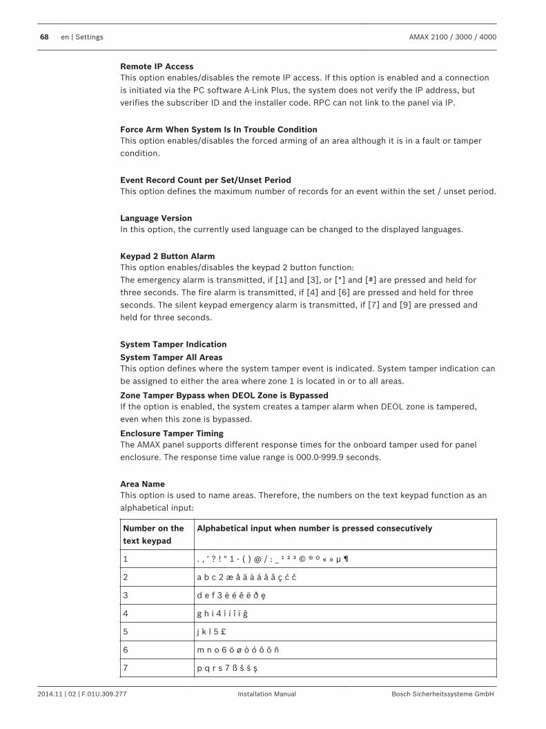
Remote IP AccessThis option enables/disables the remote IP access. If this option is enabled and a connectionis initiated via the PC software A-Link Plus, the system does not verify the IP address, butverifies the subscriber ID and the installer code. RPC can not link to the panel via IP.
Force Arm When System Is In Trouble ConditionThis option enables/disables the forced arming of an area although it is in a fault or tampercondition.
Event Record Count per Set/Unset PeriodThis option defines the maximum number of records for an event within the set / unset period.
Language VersionIn this option, the currently used language can be changed to the displayed languages.
Keypad 2 Button AlarmThis option enables/disables the keypad 2 button function:The emergency alarm is transmitted, if [1] and [3], or [*] and [#] are pressed and held forthree seconds. The fire alarm is transmitted, if [4] and [6] are pressed and held for threeseconds. The silent keypad emergency alarm is transmitted, if [7] and [9] are pressed andheld for three seconds.
System Tamper Indication
System Tamper All AreasThis option defines where the system tamper event is indicated. System tamper indication canbe assigned to either the area where zone 1 is located in or to all areas.
Zone Tamper Bypass when DEOL Zone is BypassedIf the option is enabled, the system creates a tamper alarm when DEOL zone is tampered,even when this zone is bypassed.
Enclosure Tamper TimingThe AMAX panel supports different response times for the onboard tamper used for panelenclosure. The response time value range is 000.0-999.9 seconds.
Area NameThis option is used to name areas. Therefore, the numbers on the text keypad function as analphabetical input:
Number on thetext keypad
Alphabetical input when number is pressed consecutively
1 . , ' ? ! " 1 - ( ) @ / : _ ¹ ² ³ © ® º « » µ ¶
2 a b c 2 æ å ä à á â ã ç ć č
3 d e f 3 è é ê ë ð ę
4 g h i 4 ì í î ï ğ
5 j k l 5 £
6 m n o 6 ö ø ò ó ô õ ñ
7 p q r s 7 ß š ś ş
68 en | Settings AMAX 2100 / 3000 / 4000
2014.11 | 02 | F.01U.309.277 Installation Manual Bosch Sicherheitssysteme GmbH
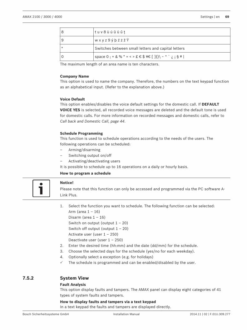
8 t u v 8 ù ú û ü ű ţ
9 w x y z 9 ý þ ź ż ž Ÿ
* Switches between small letters and capital letters
0 space 0 ; + & % * = < > £ € $ ¥¤ [ ]\ ~ ^ ` ¿ ¡ § # |
The maximum length of an area name is ten characters.
Company NameThis option is used to name the company. Therefore, the numbers on the text keypad functionas an alphabetical input. (Refer to the explanation above.)
Voice DefaultThis option enables/disables the voice default settings for the domestic call. If DEFAULTVOICE YES is selected, all recorded voice messages are deleted and the default tone is usedfor domestic calls. For more information on recorded messages and domestic calls, refer toCall back and Domestic Call, page 44.
Schedule ProgrammingThis function is used to schedule operations according to the needs of the users. Thefollowing operations can be scheduled:– Arming/disarming– Switching output on/off– Activating/deactivating usersIt is possible to schedule up to 16 operations on a daily or hourly basis.
How to program a schedule
Notice!
Please note that this function can only be accessed and programmed via the PC software A-
Link Plus.
1. Select the function you want to schedule. The following function can be selected:Arm (area 1 – 16)Disarm (area 1 – 16)Switch on output (output 1 – 20)Switch off output (output 1 – 20)Activate user (user 1 – 250)Deactivate user (user 1 – 250)
2. Enter the desired time (hh:mm) and the date (dd/mm) for the schedule.3. Choose the selected days for the schedule (yes/no for each weekday).4. Optionally select a exception (e.g. for holidays)P The schedule is programmed and can be enabled/disabled by the user.
System ViewFault AnalysisThis option display faults and tampers. The AMAX panel can display eight categories of 41types of system faults and tampers.
How to display faults and tampers via a text keypadIn a text keypad the faults and tampers are displayed directly.
7.5.2
AMAX 2100 / 3000 / 4000 Settings | en 69
Bosch Sicherheitssysteme GmbH Installation Manual 2014.11 | 02 | F.01U.309.277
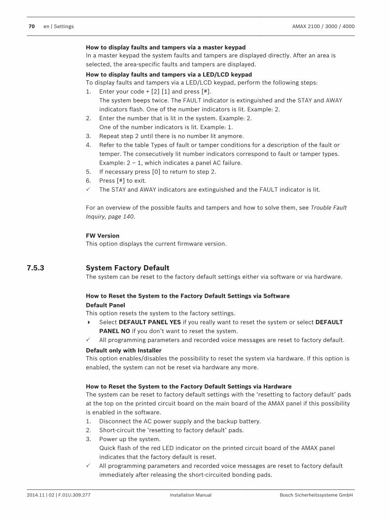
How to display faults and tampers via a master keypadIn a master keypad the system faults and tampers are displayed directly. After an area isselected, the area-specific faults and tampers are displayed.
How to display faults and tampers via a LED/LCD keypadTo display faults and tampers via a LED/LCD keypad, perform the following steps:1. Enter your code + [2] [1] and press [#].
The system beeps twice. The FAULT indicator is extinguished and the STAY and AWAYindicators flash. One of the number indicators is lit. Example: 2.
2. Enter the number that is lit in the system. Example: 2.One of the number indicators is lit. Example: 1.
3. Repeat step 2 until there is no number lit anymore.4. Refer to the table Types of fault or tamper conditions for a description of the fault or
temper. The consecutively lit number indicators correspond to fault or tamper types.Example: 2 – 1, which indicates a panel AC failure.
5. If necessary press [0] to return to step 2.6. Press [#] to exit.P The STAY and AWAY indicators are extinguished and the FAULT indicator is lit.
For an overview of the possible faults and tampers and how to solve them, see Trouble FaultInquiry, page 140.
FW VersionThis option displays the current firmware version.
System Factory DefaultThe system can be reset to the factory default settings either via software or via hardware.
How to Reset the System to the Factory Default Settings via Software
Default PanelThis option resets the system to the factory settings.4 Select DEFAULT PANEL YES if you really want to reset the system or select DEFAULT
PANEL NO if you don’t want to reset the system.P All programming parameters and recorded voice messages are reset to factory default.
Default only with InstallerThis option enables/disables the possibility to reset the system via hardware. If this option isenabled, the system can not be reset via hardware any more.
How to Reset the System to the Factory Default Settings via HardwareThe system can be reset to factory default settings with the ‘resetting to factory default’ padsat the top on the printed circuit board on the main board of the AMAX panel if this possibilityis enabled in the software.1. Disconnect the AC power supply and the backup battery.2. Short-circuit the ‘resetting to factory default’ pads.3. Power up the system.
Quick flash of the red LED indicator on the printed circuit board of the AMAX panelindicates that the factory default is reset.
P All programming parameters and recorded voice messages are reset to factory defaultimmediately after releasing the short-circuited bonding pads.
7.5.3
70 en | Settings AMAX 2100 / 3000 / 4000
2014.11 | 02 | F.01U.309.277 Installation Manual Bosch Sicherheitssysteme GmbH
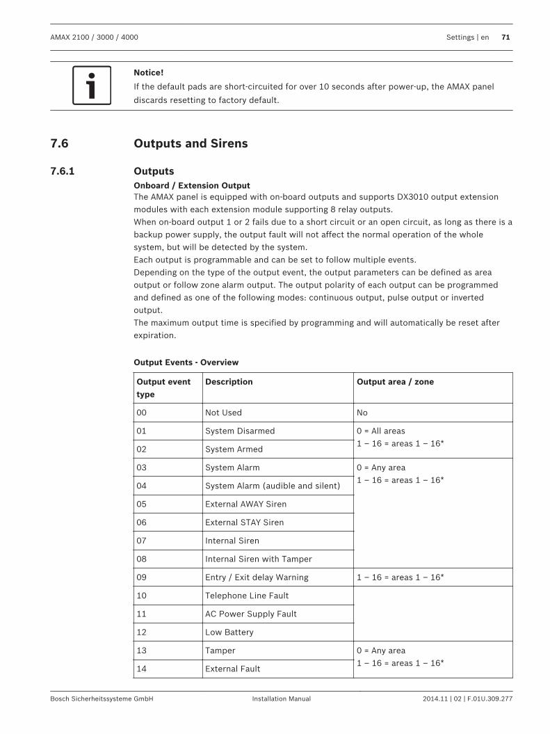
Notice!
If the default pads are short-circuited for over 10 seconds after power-up, the AMAX panel
discards resetting to factory default.
Outputs and Sirens
OutputsOnboard / Extension OutputThe AMAX panel is equipped with on-board outputs and supports DX3010 output extensionmodules with each extension module supporting 8 relay outputs.When on-board output 1 or 2 fails due to a short circuit or an open circuit, as long as there is abackup power supply, the output fault will not affect the normal operation of the wholesystem, but will be detected by the system.Each output is programmable and can be set to follow multiple events.Depending on the type of the output event, the output parameters can be defined as areaoutput or follow zone alarm output. The output polarity of each output can be programmedand defined as one of the following modes: continuous output, pulse output or invertedoutput.The maximum output time is specified by programming and will automatically be reset afterexpiration.
Output Events - Overview
Output eventtype
Description Output area / zone
00 Not Used No
01 System Disarmed 0 = All areas1 – 16 = areas 1 – 16*
02 System Armed
03 System Alarm 0 = Any area1 – 16 = areas 1 – 16*
04 System Alarm (audible and silent)
05 External AWAY Siren
06 External STAY Siren
07 Internal Siren
08 Internal Siren with Tamper
09 Entry / Exit delay Warning 1 – 16 = areas 1 – 16*
10 Telephone Line Fault
11 AC Power Supply Fault
12 Low Battery
13 Tamper 0 = Any area1 – 16 = areas 1 – 16*
14 External Fault
7.6
7.6.1
AMAX 2100 / 3000 / 4000 Settings | en 71
Bosch Sicherheitssysteme GmbH Installation Manual 2014.11 | 02 | F.01U.309.277
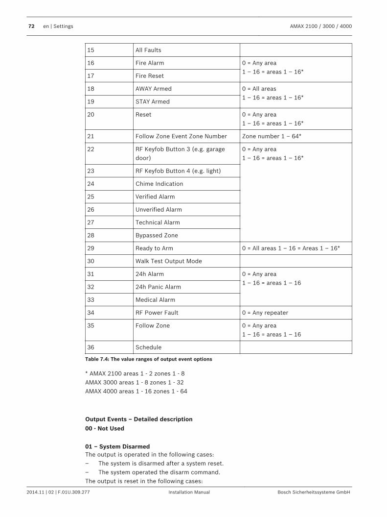
15 All Faults
16 Fire Alarm 0 = Any area1 – 16 = areas 1 – 16*
17 Fire Reset
18 AWAY Armed 0 = All areas1 – 16 = areas 1 – 16*
19 STAY Armed
20 Reset 0 = Any area1 – 16 = areas 1 – 16*
21 Follow Zone Event Zone Number Zone number 1 – 64*
22 RF Keyfob Button 3 (e.g. garagedoor)
0 = Any area1 – 16 = areas 1 – 16*
23 RF Keyfob Button 4 (e.g. light)
24 Chime Indication
25 Verified Alarm
26 Unverified Alarm
27 Technical Alarm
28 Bypassed Zone
29 Ready to Arm 0 = All areas 1 – 16 = Areas 1 – 16*
30 Walk Test Output Mode
31 24h Alarm 0 = Any area1 – 16 = areas 1 – 16
32 24h Panic Alarm
33 Medical Alarm
34 RF Power Fault 0 = Any repeater
35 Follow Zone 0 = Any area1 – 16 = areas 1 – 16
36 Schedule
Table 7.4: The value ranges of output event options
* AMAX 2100 areas 1 - 2 zones 1 - 8AMAX 3000 areas 1 - 8 zones 1 - 32AMAX 4000 areas 1 - 16 zones 1 - 64
Output Events – Detailed description
00 - Not Used
01 – System DisarmedThe output is operated in the following cases:– The system is disarmed after a system reset.– The system operated the disarm command.The output is reset in the following cases:
72 en | Settings AMAX 2100 / 3000 / 4000
2014.11 | 02 | F.01U.309.277 Installation Manual Bosch Sicherheitssysteme GmbH
– The system is armed.– The programmed output time ends.
02 - System ArmedThe output is operated in the following cases:– The system is armed after a system reset.– The system operated the arm command. (After the exit time ends.)The output is reset in the following cases:– The system is disarmed.– The programmed output time ends.If the output time is set to 000, the output will continue until the system is disarmed.
03 - System AlarmThis output is operated when an alarm occurs.The output is reset in the following cases:– The system is disarmed and alarm is reset.– The programmed output time ends.In case of a new alarm, the output time will be reset.If the output time is set to 000, the output will continue until the zone is restored or thesystem is disarmed.
04 - System Alarm (audible and silent)This output is operated in case of an audio alarm of the system:– Zone (alarm or tamper) programmed to disable zone silent alarm– System tamper / DX2010 tamper / keypad tamper– Keypad alarm (emergency alarm, fire alarm, medical aid alarm)This output also operates in case of a silent alarm of the system:– Zone (alarm or tamper) programmed to enable zone silent alarm.The output is reset in the following cases:– The alarm is reset.– The system is armed.– The system is disarmed.In case of a new alarm, the output time will be reset.If the output time is set to 000 and the alarm siren sounds time to 0, the output will continueuntil the alarm output is reset or the system is disarmed by entering your code + [3] [2] + [#].The output of the following system alarms is only one second:– Alarm siren test– Pacing (tamper / alarm / reset)– Key switch arming or locking key switch disarming
05 - External AWAY SirenThe output is operated in the following cases:– The system is in AWAY mode and a zone intruder alarm (intruder alarm = instant / interior
instant / delay / interior delay / delay exit / interior delay exit / follower / interiorfollower / 24h (can be silenced) / fire (can be silenced) / technical alarm (can besilenced)) occurs.
– The system is in AWAY mode and a tamper alarm occurs.(No output is operated when the system is disarmed.)
AMAX 2100 / 3000 / 4000 Settings | en 73
Bosch Sicherheitssysteme GmbH Installation Manual 2014.11 | 02 | F.01U.309.277
06 - External STAY SirenThe output is operated in the following cases:– The system is in STAY mode and a zone intruder alarm (intruder alarm = instant / interior
instant / delay / interior delay / delay exit / interior delay exit / follower / interiorfollower / 24h (can be silenced) / fire (can be silenced) / technical alarm (can besilenced)) occurs.
– The system is in STAY mode and a tamper alarm occurs.(No output is operated when the system is disarmed.)
07 - Internal SirenThe output is operated in the following cases:– The system is in AWAY mode and a zone intruder alarm (intruder alarm = instant / interior
instant / delay / interior delay / delay exit / interior delay exit / follower / interiorfollower / 24h (can be silenced) / fire (can be silenced) / technical alarm (can besilenced)) occurs.
– The system is in AWAY mode and a tamper alarm occurs.– The system is in STAY mode and a zone intruder alarm (intruder alarm = instant / interior
instant / delay / interior delay / delay exit / interior delay exit / follower / interiorfollower / 24h (can be silenced) / fire (can be silenced) / technical alarm (can besilenced)) occurs.
– The system is in AWAY mode and a tamper alarm occurs.– The system is disarmed and a zone tamper alarm occurs.When the system is armed the output mode is a one pulse activation (1sec) (enabled / disableoption can be combined with disarm).When the system is disarmed the output mode is a two pulse activation (1sec) (enabled /disable option can be combined with arm).When programming mode is entered the output mode is a one pulse activation (1sec)(enabled / disable option).
08 - Internal Siren with TamperThe output is operated when an internal siren with tamper occurs.
09 - Entry/Exit Delay Warning
Entry Delay WarningThis output is operated during the entry time.The output is reset in the following cases:– The system is disarmed.– The entry time expires.– The programmed output time ends.
Exit Delay WarningThis output is operated during the exit time when the system is armed.The output is reset in the following cases:– The system is disarmed.– The exit time expires.– The programmed output time ends.If the output time is set to 000, the output will continue until the delay warning time ends.
10 - Telephone Line FaultThis output is operated when a telephone line fault occurs.
74 en | Settings AMAX 2100 / 3000 / 4000
2014.11 | 02 | F.01U.309.277 Installation Manual Bosch Sicherheitssysteme GmbH
The output is reset in the following cases:– The telephone line is restored and the fault is reset.– The programmed output time ends.If the output time is set to 000, the output will continue until the telephone line is restoredand the fault is reset.
11 - AC Power Supply FaultThis output is operated when an AC power fault occurs.The output is reset in the following cases:– The AC power supply is restored and the fault is reset.– The programmed output time ends.If the output time is set to 000, the output will continue until the AC power supply is restoredand the fault is reset.
12 – Battery faultThis output is operated when a low battery fault occurs.The dynamic battery test is performed every four hours after the system is powered up andevery time the system is armed.The output is reset in the following cases:– A dynamic battery test reports that the backup battery voltage is normal and the fault is
reset.– The programmed output time ends.If the output time is set to 000, the output will continue until the battery is restored and thefault is reset.
13 - TamperThis output is operated when a tamper occurs.The output is reset when the programmed output time ends.If the output time is set to 000, the output will continue until the tamper condition is restoredand the tamper is reset.
14 - External FaultThis output is operated when an external fault occurs.The output is reset when the programmed output time ends.If the output time is set to 000, the output will continue until the external fault is restored andthe fault is reset.
15 - All FaultsThis output is operated when a fault occurs.The output is reset when the programmed output time ends.If the output time is set to 000, the output will continue until the fault is restored and the faultis reset.
16 - Fire AlarmThis output is operated when a fire alarm occurs.
17 - Fire ResetThis output is operated when a fire alarm is reset.
AMAX 2100 / 3000 / 4000 Settings | en 75
Bosch Sicherheitssysteme GmbH Installation Manual 2014.11 | 02 | F.01U.309.277
18 - AWAY ArmedThis output is operated when the system is in AWAY mode.The output is reset when the programmed output time ends.If the output time is set to 000, the output will continue until the system is disarmed.
19 - STAY ArmedThis output is operated when system is in STAY mode.The output is reset when the programmed output time ends.If the output time is set to 000, the output will continue until the system is disarmed.
20 - ResetThis output is operated when a reset is performed in the system.
21 - Follow Zone Event Zone NumberThis output imitates the zone alarm state. The output is operated when an alarm or a tamperis generated in the corresponding zone.The output is reset when the system arming or disarming or the output time ends.
22 - RF Keyfob Button 3If the output time of this output is set to 000, the keyfob button 3 works as a toggle:This output is operated when the keyfob button 3 is pressed.The output is reset when the keyfob button 3 is pressed again.
23 - RF Keyfob Button 4If the output time of this output is set to 000, the keyfob button 4 works as a toggle:This output is operated when keyfob button 4 is pressed.The output is reset when the keyfob button 4 is pressed again.
24 - Chime IndicationThis output is operated when a chime indication occurs.
25 - Verified AlarmThis output is operated when a verified alarm occurs.
26 - Unverified AlarmThis output is operated when an unverified alarm occurs.
27 - Technical AlarmThis output is operated when a technical alarm occurs.
28 - Bypassed ZoneThis output is operated when a zone is bypassed.
29 - Ready to ArmThis output is operated when the system is in ready to arm state.
30 – Walk Test Output ModeThis output is operated when the system is in walk test mode.
76 en | Settings AMAX 2100 / 3000 / 4000
2014.11 | 02 | F.01U.309.277 Installation Manual Bosch Sicherheitssysteme GmbH
31 – 24h AlarmThis output is operated when a 24h alarm occurs. This output works only a 24-hour zone.The output is reset when the 24h alarm is reset or the output time ends.
32 – 24h Panic AlarmThis output is operated when a 24h panic alarm occurs. This output works only on zone type10.The output is reset when the 24h panic alarm is reset or the output time ends.
33 – Medical AlarmThis output is operated when a medical alarm occurs.The output is reset when the medical alarm is reset or the output time ends.
34 – RF Power FaultThe output is operated in the following cases:– The battery of the RF transmitter is low.– The battery of the RF repeater is low.– An AC power fault of the RF repeater occurs.The output is reset in the following cases:– The RF power is normal and the system is reset.– The programmed output time ends.
35 – Follow ZoneThis output imitates the zone state. The output is operated according to the correspondingzone.The output is reset according to the corresponding zone.
36 - ScheduleThis output is operated when a schedule is enabled.The output is reset when the schedule is reset or the output time ends.
Output ModeThree different output modes are available.
0 - Continuous outputThe output is continuous, the level is high.
1 - Pulse outputThe output occurs in pulses, the period is 1 second.
2- Continuous inverted outputThe output is continuous, the level is low (level is high in idle state). When PO-1 or PO-2 is setto inverted, supervision is disabled for these outputs.
Output TimeEach output is operated for a specific time and resets at the end of output time.The actual output time of system audio alarm, system alarm, and follow zone event is relatedto the ringing of the alarm siren.The possible output time value range is 0 – 999 seconds.
AMAX 2100 / 3000 / 4000 Settings | en 77
Bosch Sicherheitssysteme GmbH Installation Manual 2014.11 | 02 | F.01U.309.277
SirensAlarm Siren Ringing TimeThe alarm siren ringing time is valid only when the keypad alarm tone is enabled. When anaudio alarm occurs in the system, the alarm siren begins to ring. After a valid arming /disarming command, an alarm reset or after the alarm siren ringing duration ends, the alarmsiren stops ringing.For programming of alarm time, refer to Output Programming, page 132.
Beep For Warning DevicesEnables / disables beep for warning devices when the system is armed, disarmed, or duringwalk test.
Internal Siren Beep as IndicationEnables / disables internal siren beep as indication when the system is armed, disarmed, orprogramming mode is entered.
Silence Warning Device When DisarmedEnables / disables silence warning device when disarmed or by pressing any key.
RF Devices
RF Options RF Receiver FunctionalityEnables or disables RF receiver functionality.
RF Supervision IntervalDisables or defines RF Supervision Interval. The interval can be set to 1, 2, 4, 12, 24, or 25hours.
RF Jam Detect LevelDefines RF jam detect level. The range is from 0 to 15 where 0 is most sensitive.
RF Device Low Level Battery ResoundDisables or sets the interval for keypad acoustic indication of RF device low level battery fault.
Siren Beep Arm / Disarm (RF Keyfob)Enables or disables keypad acoustic indication on arm / disarm.
Keyfob Panic OptionDefines the behavior when keyfob panic button is pressed. The option can be set to no alarm,silent alarm, or non silent alarm.
RF Devices / UserRF UserKeyfobs are designed for arming and disarming the system remotely, trigger a panic alarm, orfor additional control functionality.To operate the buttons, press and hold either button for at least one sec in order to use thedesired feature.The AMAX panel identifies keyfob users by device RFID. AMAX Keypad programming supportsentering RFID automatically for Radion devices.
7.6.2
7.7
7.7.1
7.7.2
78 en | Settings AMAX 2100 / 3000 / 4000
2014.11 | 02 | F.01U.309.277 Installation Manual Bosch Sicherheitssysteme GmbH
4 When the keyfob RFID is asked for, press [*] for 3s to toggle between AUTO andMANUAL mode.When MANUAL is selected, enter the 9-digit RFID manually.When AUTO is selected, trigger the RF device and the RFID is entered automatically.
RF RepeaterThe AMAX panel identifies repeater devices by device RFID. AMAX Keypad programmingsupports entering RFID automatically for Radion devices.4 When the repeater RFID is asked for, press [*] for 3s to toggle between AUTO and
MANUAL mode.When MANUAL is selected, enter the 9-digit RFID manually.When AUTO is selected, trigger the RF device and the RFID is entered automatically.
RF Sensor DiagnoseThe AMAX panel supports diagnostic feature for RF sensors. The keypad diagnose displayssignal/noise ratio distance. In dependency of the rating, the AMAX panel displays the numbersof the RFID or RELOCATE. The AMAX panel keeps on polling for the signal and updates theindication on a regular basis. RF Repeater DiagnoseThe AMAX panel supports diagnostic feature for RF repeaters. The keypad diagnose displayssignal/noise ratio distance. In dependency of the rating, the AMAX panel displays the numbersof the RFID or RELOCATE. The AMAX panel keeps on polling for the signal and updates theindication on a regular basis. Clear RF devicesThe AMAX panel provides the option to clear all RF devices in a step.
Key ProgrammingProgramming with the ICP-EZPK Programming KeyThe ICP-EZPK Programming Key allows you to save or copy programming information fromyour AMAX panel. After saving information in the programming key, you can easily programother AMAX panels with the same programming data. You can also use the programming key toback up existing information.4 If you have a new programming key, enter the programming mode, program the system as
required, and connect the programming key to the AMAX panel.To connect the programming key:4 Connect the programming key to the plug on top of the printed circuit board (PCB) of the
AMAX panel.
Notice!
Please note that the direction of the programming key should be consistent with the direction
marked on the PCB.
For example: How to copy data from the AMAX panel to the programming key:1. Enter the installer code [1234] + [958] and press [#] to enter the programming mode.2. Enter [962] + [#].3. Copy the AMAX panel memory to the programming key.
7.8
AMAX 2100 / 3000 / 4000 Settings | en 79
Bosch Sicherheitssysteme GmbH Installation Manual 2014.11 | 02 | F.01U.309.277
4. Enter [960] + [#] to exit the programming mode.P The system resets and returns to the disarmed state. The programming key becomes your
standard data pattern for future AMAX panel programming.
!
Caution!
If you do not enter the programming mode first, which connects the blank ICP-EZPK
Programming Key (blue) to the AMAX panel, no data can be uploaded / downloaded.
An unknown error may be caused if the programming mode is not exited before removing the
programming key.
Programming KeyWith the programming key, the programming parameters of the current AMAX panel can betransferred to other systems with the same applications.
Copying Parameters of the Alarm AMAX Panel to the KeyHow to copy the programming data of the memory of the AMAX panel onto the programmingkey with the keypad:1. Connect the programming key to the plug on top of the Printed Circuit Board (PCB) of
the AMAX panel. Please note that the direction of the programming key should beconsistent with the direction marked on the PCB.
2. Select text keypad installation menu ADDRESS / KEY PROGR – COPY DATA TO KEY andpress [#].After successfully copying the programming data of the AMAX panel to the programmingkey, a confirmation tone occurs. Wrong prompt tone and display of Failure of AMAXPanel Parameters to Key indicate a damage of the programming key data. In this case,the data needs to be copied onto the programming key again.
3. Unplug the programming key from the AMAX panel.LED/LCD keypads can also be used to copy the AMAX panel parameters to key parameters.
Copying Key Parameters to the AMAX PanelHow to copy the programming data of the programming key onto the alarm center.1. Connect the programming key to the Printed Circuit Board (PCB) plug of the AMAX panel.
Please note that the direction of the programming key should be consistent with thedirection marked on the PCB.
2. Select text keypad installation menu ADDRESS / KEY PROGRAM – COPY DATA TOPANEL and press [#].After successfully copying the programming data in the programming key to the AMAXpanel, a confirmation tone occurs. Wrong prompt tone and display of Failure of KeyParameters to AMAX Panel indicate a damage of the programming key data. In this case,the data needs to be copied onto the AMAX panel again.
3. Unplug the programming key from the AMAX panel.LED/LCD keypads can also be used to copy key parameters to the AMAX panel.
80 en | Settings AMAX 2100 / 3000 / 4000
2014.11 | 02 | F.01U.309.277 Installation Manual Bosch Sicherheitssysteme GmbH
ConfigurationThis chapter describes how to configure the settings of the AMAX panel. The settings can beconfigured either via a text keypad or via the PC software A-Link Plus.For detailed description of the possible settings please refer to Settings, page 32.
Programming with the Keypad
Text Keypad ProgrammingAccess to the Menus
Accessing the Programming Menu1. Confirm that the system is disarmed.2. Enter the installer code. The default setting for the installer code is [1234].
The system displays [958] PROGR. MODE [-EXIT].3. Enter [958] + press [#].P You have now access to the programming menu for configuring the AMAX system.
P The STAY and AWAY indicators flash to indicate the programming mode.
Accessing the User Menu4 Enter the user code. The default setting for the user code is [2580].
P The system displays [/] USER MENU *STAY #AWAY [-] INFO.
P You have now access to the user menu for operating the AMAX system.
Navigation of the MenusThis section provides an overview of how to navigate the programming menu of a text keypad.
Selecting a Menu1. Select the menu and operate according to the menu prompt.2. Press [] or [] to navigate to the desired menu.3. Press [#] to enter a menu.
Exiting a Menu4 Press [–] to get back to the previous menu.
Confirming the Input4 Press [#] to confirm the input.
Switching between Settings4 Press and hold [*] for 3 seconds to switch between settings.
Operating a Menu1. Operate according to the menu prompt.
Select the menu and enter data for specific programming items according to the displayon the keypad to complete the programming, step by step.
2. Press [#] to confirm each step.
Exiting the Programming Menu1. Complete all programming input by repeating the programming steps above and press [–]
to get back to the current main menu level by level.2. Press [–] to get to the EXIT PROG. +SAVE menu.It is optional to save or not to save the programming data.1. Select EXIT PROG. +SAVE and press [#] to save the data and to exit the programming
mode.2. Select EXIT PROG. UNSAVED and press [#] to exit programming mode without saving
the data.
8
8.1
8.1.1
AMAX 2100 / 3000 / 4000 Configuration | en 81
Bosch Sicherheitssysteme GmbH Installation Manual 2014.11 | 02 | F.01U.309.277
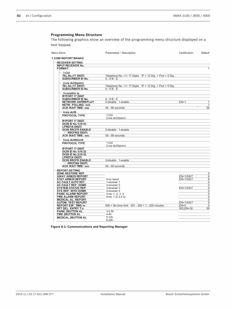
Programming Menu StructureThe following graphics show an overview of the programming menu structure displayed on atext keypad.
Figure 8.1: Communications and Reporting Manager
82 en | Configuration AMAX 2100 / 3000 / 4000
2014.11 | 02 | F.01U.309.277 Installation Manual Bosch Sicherheitssysteme GmbH
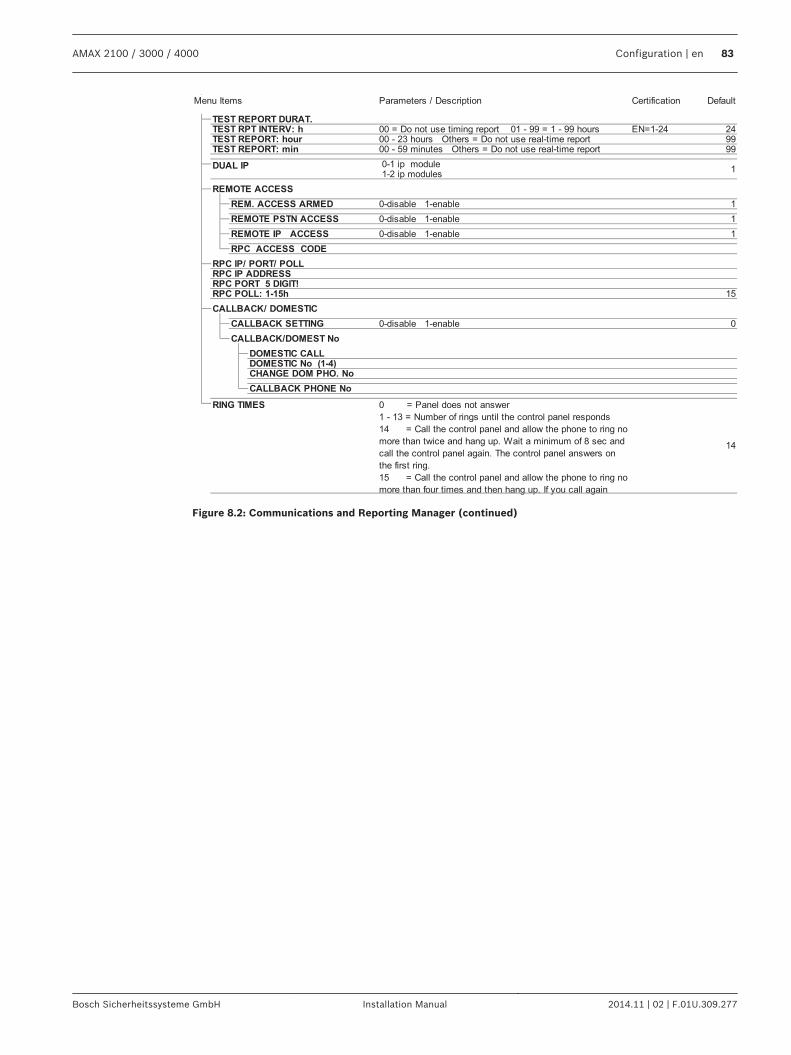
Figure 8.2: Communications and Reporting Manager (continued)
AMAX 2100 / 3000 / 4000 Configuration | en 83
Bosch Sicherheitssysteme GmbH Installation Manual 2014.11 | 02 | F.01U.309.277
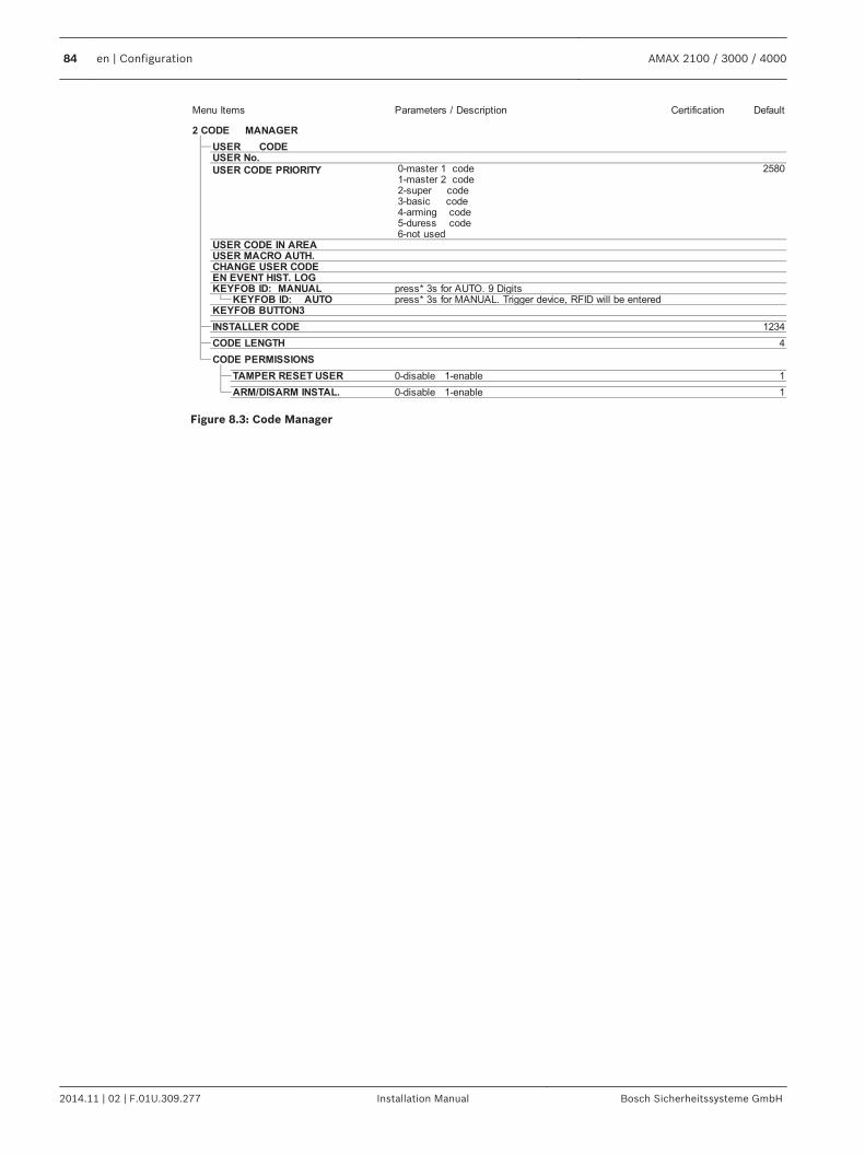
Figure 8.3: Code Manager
84 en | Configuration AMAX 2100 / 3000 / 4000
2014.11 | 02 | F.01U.309.277 Installation Manual Bosch Sicherheitssysteme GmbH
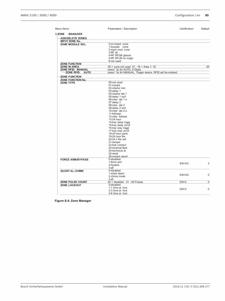
Figure 8.4: Zone Manager
AMAX 2100 / 3000 / 4000 Configuration | en 85
Bosch Sicherheitssysteme GmbH Installation Manual 2014.11 | 02 | F.01U.309.277
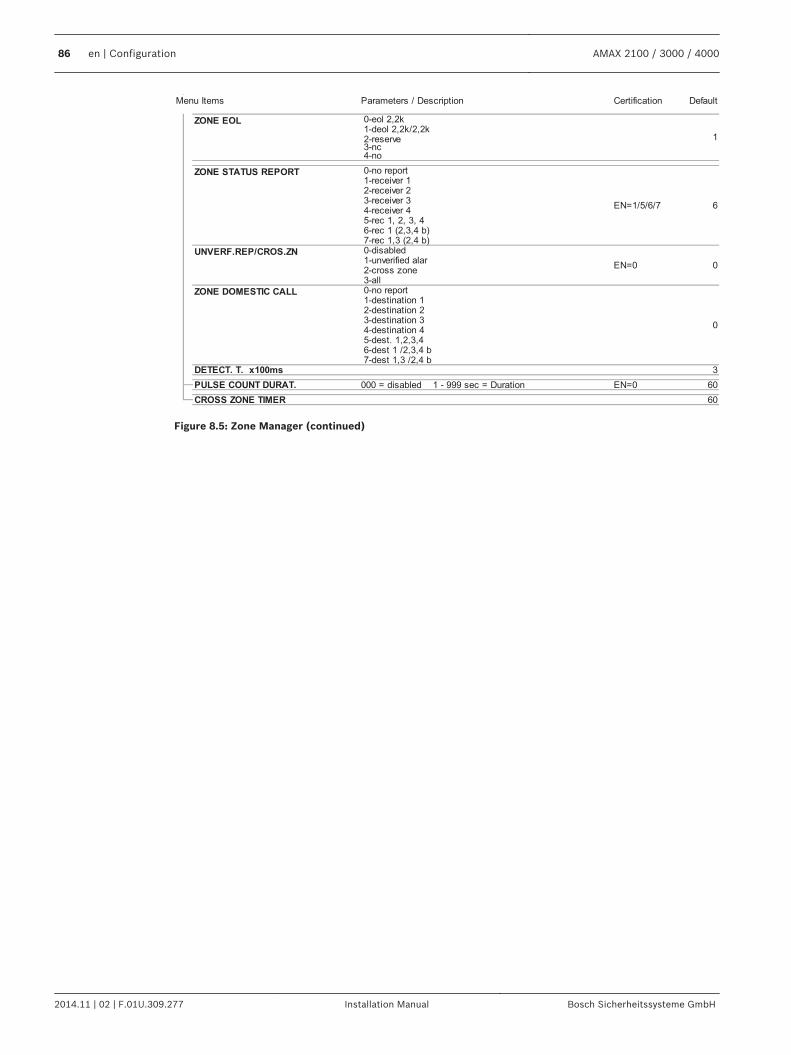
Figure 8.5: Zone Manager (continued)
86 en | Configuration AMAX 2100 / 3000 / 4000
2014.11 | 02 | F.01U.309.277 Installation Manual Bosch Sicherheitssysteme GmbH
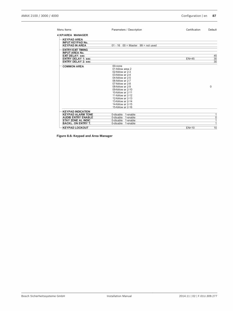
Figure 8.6: Keypad and Area Manager
AMAX 2100 / 3000 / 4000 Configuration | en 87
Bosch Sicherheitssysteme GmbH Installation Manual 2014.11 | 02 | F.01U.309.277
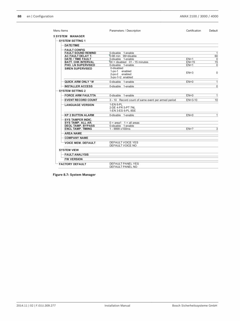
Figure 8.7: System Manager
88 en | Configuration AMAX 2100 / 3000 / 4000
2014.11 | 02 | F.01U.309.277 Installation Manual Bosch Sicherheitssysteme GmbH
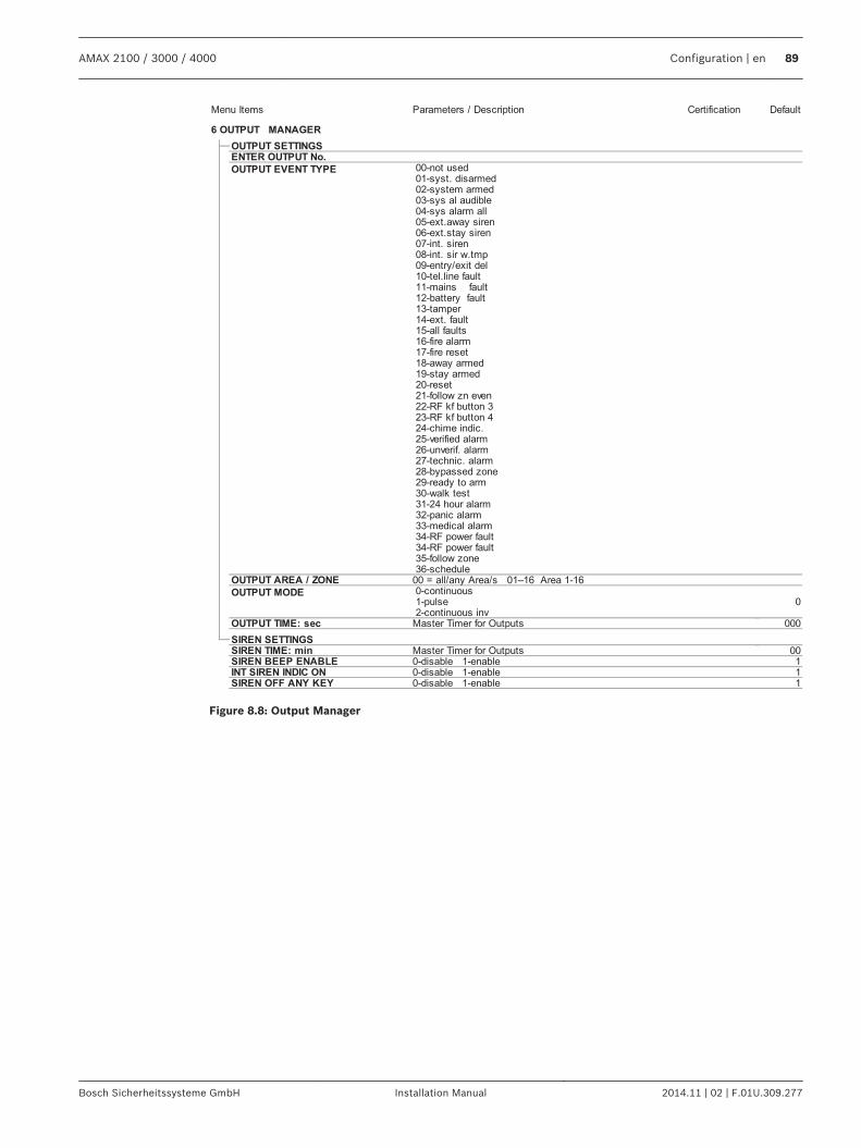
Figure 8.8: Output Manager
AMAX 2100 / 3000 / 4000 Configuration | en 89
Bosch Sicherheitssysteme GmbH Installation Manual 2014.11 | 02 | F.01U.309.277
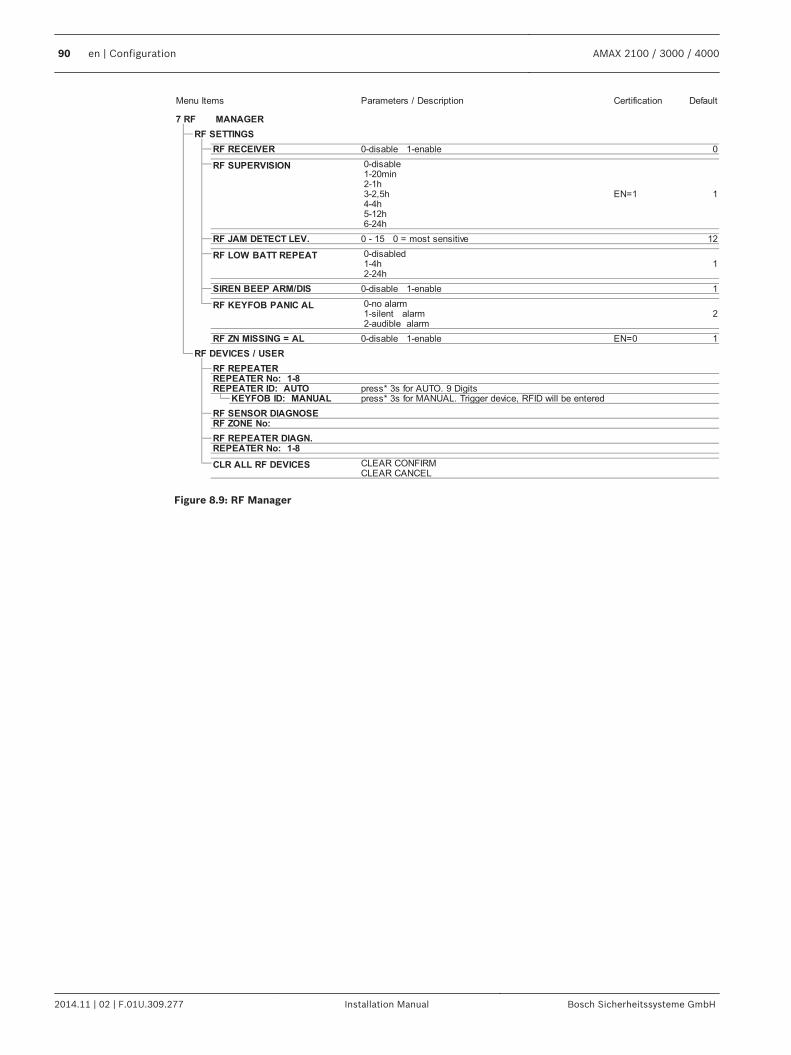
Figure 8.9: RF Manager
90 en | Configuration AMAX 2100 / 3000 / 4000
2014.11 | 02 | F.01U.309.277 Installation Manual Bosch Sicherheitssysteme GmbH
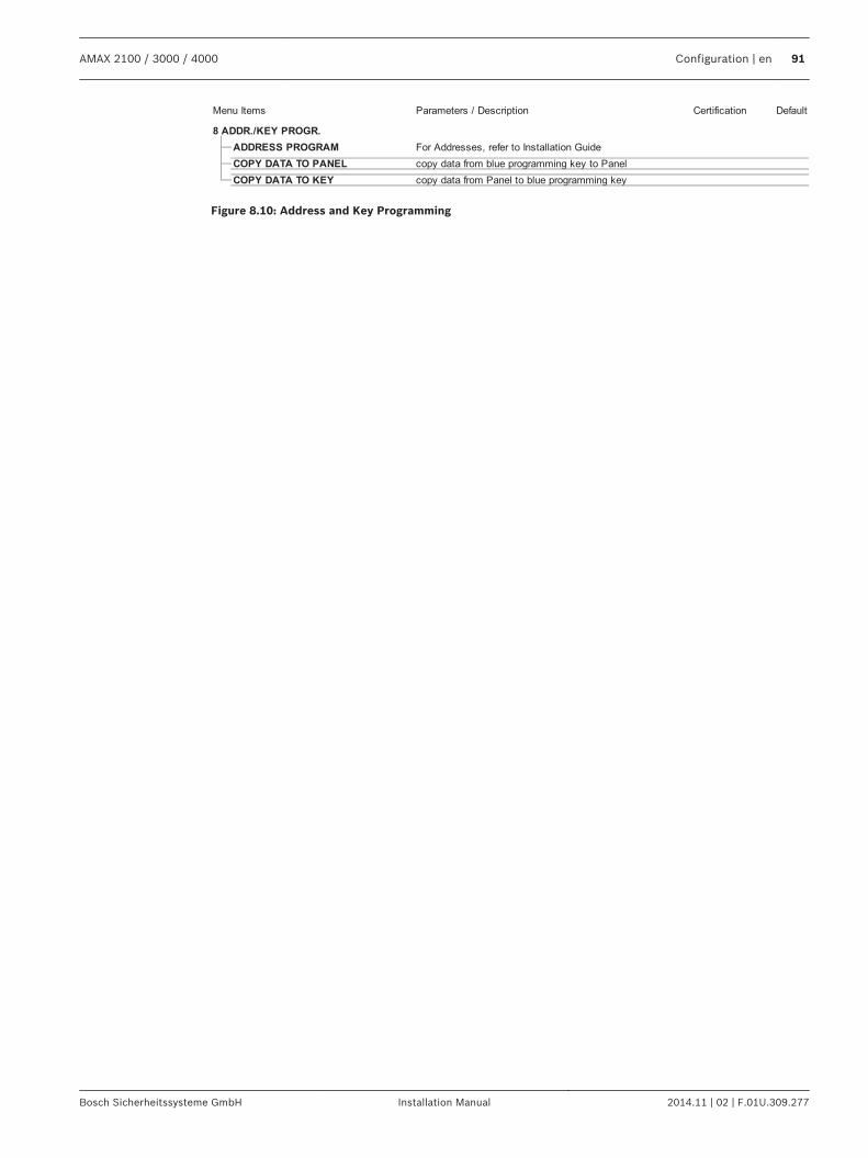
Figure 8.10: Address and Key Programming
AMAX 2100 / 3000 / 4000 Configuration | en 91
Bosch Sicherheitssysteme GmbH Installation Manual 2014.11 | 02 | F.01U.309.277
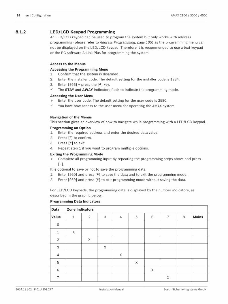
LED/LCD Keypad ProgrammingAn LED/LCD keypad can be used to program the system but only works with addressprogramming (please refer to Address Programming, page 105) as the programming menu cannot be displayed on the LED/LCD keypad. Therefore it is recommended to use a text keypador the PC software A-Link Plus for programming the system.
Access to the Menus
Accessing the Programming Menu1. Confirm that the system is disarmed.2. Enter the installer code. The default setting for the installer code is 1234.3. Enter [958] + press the [#] key.P The STAY and AWAY indicators flash to indicate the programming mode.
Accessing the User Menu4 Enter the user code. The default setting for the user code is 2580.
P You have now access to the user menu for operating the AMAX system.
Navigation of the MenusThis section gives an overview of how to navigate while programming with a LED/LCD keypad.
Programming an Option1. Enter the required address and enter the desired data value.2. Press [*] to confirm.3. Press [#] to exit.4. Repeat step 1 if you want to program multiple options.
Exiting the Programming Mode4 Complete all programming input by repeating the programming steps above and press
[–].It is optional to save or not to save the programming data.1. Enter [960] and press [#] to save the data and to exit the programming mode.2. Enter [959] and press [#] to exit programming mode without saving the data. For LED/LCD keypads, the programming data is displayed by the number indicators, asdescribed in the graphic below.
Programming Data Indicators
Data Zone Indicators
Value 1 2 3 4 5 6 7 8 Mains
0
1 X
2 X
3 X
4 X
5 X
6 X
7 X
8.1.2
92 en | Configuration AMAX 2100 / 3000 / 4000
2014.11 | 02 | F.01U.309.277 Installation Manual Bosch Sicherheitssysteme GmbH
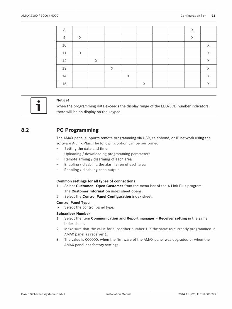
8 X
9 X X
10 X
11 X X
12 X X
13 X X
14 X X
15 X X
Notice!
When the programming data exceeds the display range of the LED/LCD number indicators,
there will be no display on the keypad.
PC ProgrammingThe AMAX panel supports remote programming via USB, telephone, or IP network using thesoftware A-Link Plus. The following option can be performed:– Setting the date and time– Uploading / downloading programming parameters– Remote arming / disarming of each area– Enabling / disabling the alarm siren of each area– Enabling / disabling each output
Common settings for all types of connections1. Select Customer –Open Customer from the menu bar of the A-Link Plus program.
The Customer Information index sheet opens.2. Select the Control Panel Configuration index sheet.
Control Panel Type4 Select the control panel type.
Subscriber Number1. Select the item Communication and Report manager – Receiver setting in the same
index sheet.2. Make sure that the value for subscriber number 1 is the same as currently programmed in
AMAX panel as receiver 1.3. The value is 000000, when the firmware of the AMAX panel was upgraded or when the
AMAX panel has factory settings.
8.2
AMAX 2100 / 3000 / 4000 Configuration | en 93
Bosch Sicherheitssysteme GmbH Installation Manual 2014.11 | 02 | F.01U.309.277
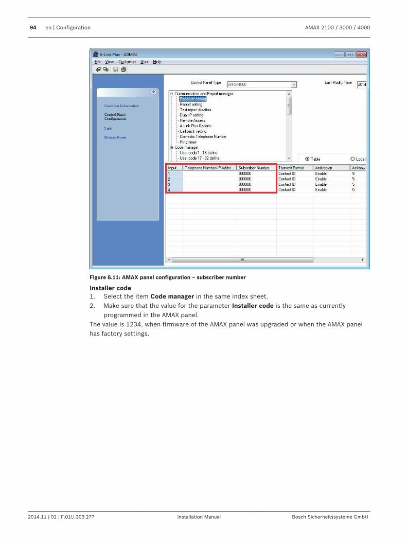
Figure 8.11: AMAX panel configuration – subscriber number
Installer code1. Select the item Code manager in the same index sheet.2. Make sure that the value for the parameter Installer code is the same as currently
programmed in the AMAX panel.The value is 1234, when firmware of the AMAX panel was upgraded or when the AMAX panelhas factory settings.
94 en | Configuration AMAX 2100 / 3000 / 4000
2014.11 | 02 | F.01U.309.277 Installation Manual Bosch Sicherheitssysteme GmbH
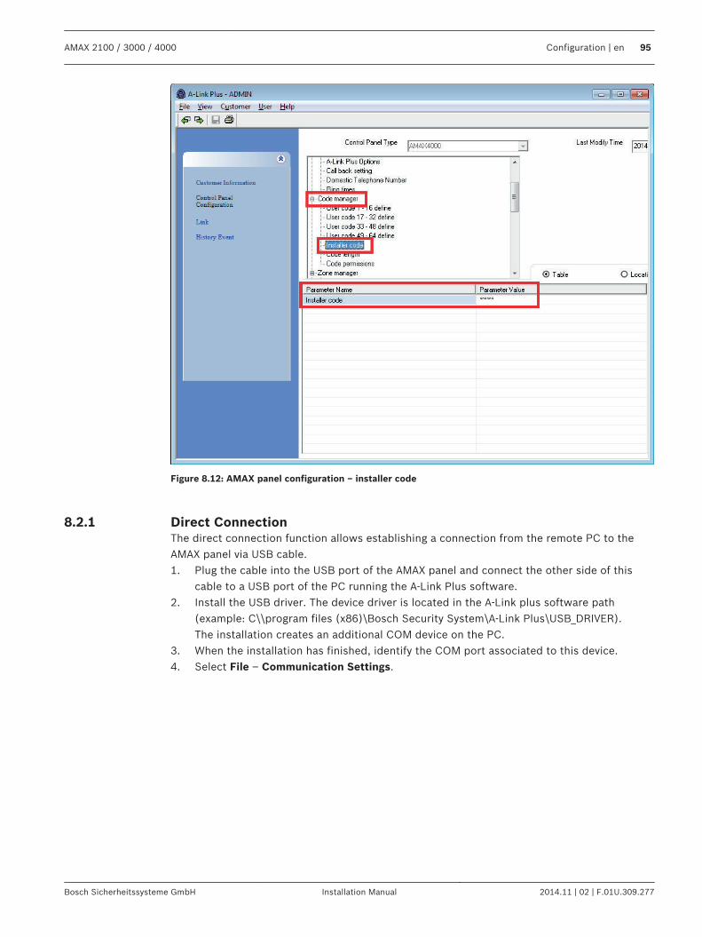
Figure 8.12: AMAX panel configuration – installer code
Direct ConnectionThe direct connection function allows establishing a connection from the remote PC to theAMAX panel via USB cable.1. Plug the cable into the USB port of the AMAX panel and connect the other side of this
cable to a USB port of the PC running the A-Link Plus software.2. Install the USB driver. The device driver is located in the A-Link plus software path
(example: C\\program files (x86)\Bosch Security System\A-Link Plus\USB_DRIVER).The installation creates an additional COM device on the PC.
3. When the installation has finished, identify the COM port associated to this device.4. Select File – Communication Settings.
8.2.1
AMAX 2100 / 3000 / 4000 Configuration | en 95
Bosch Sicherheitssysteme GmbH Installation Manual 2014.11 | 02 | F.01U.309.277
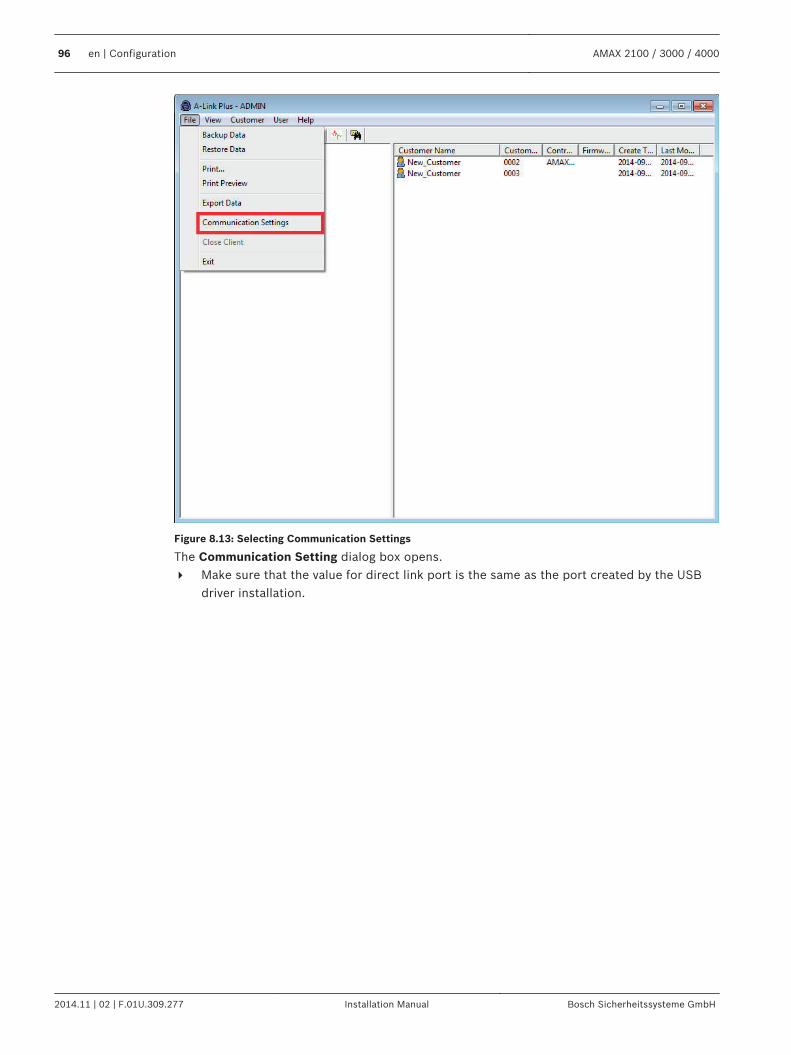
Figure 8.13: Selecting Communication Settings
The Communication Setting dialog box opens.4 Make sure that the value for direct link port is the same as the port created by the USB
driver installation.
96 en | Configuration AMAX 2100 / 3000 / 4000
2014.11 | 02 | F.01U.309.277 Installation Manual Bosch Sicherheitssysteme GmbH
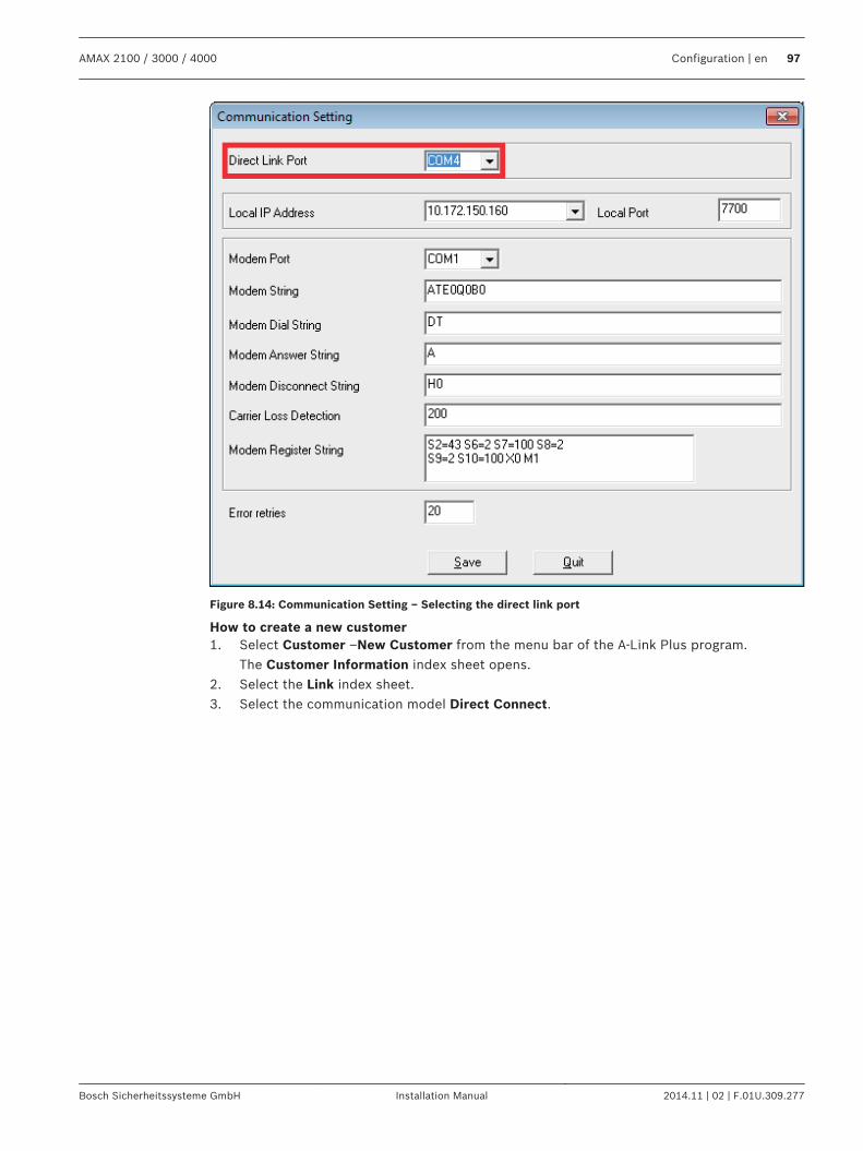
Figure 8.14: Communication Setting – Selecting the direct link port
How to create a new customer1. Select Customer –New Customer from the menu bar of the A-Link Plus program.
The Customer Information index sheet opens.2. Select the Link index sheet.3. Select the communication model Direct Connect.
AMAX 2100 / 3000 / 4000 Configuration | en 97
Bosch Sicherheitssysteme GmbH Installation Manual 2014.11 | 02 | F.01U.309.277
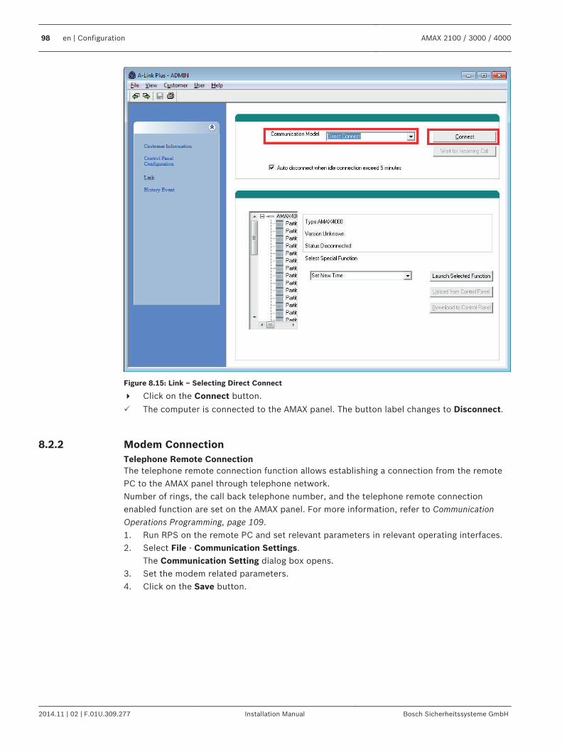
Figure 8.15: Link – Selecting Direct Connect
4 Click on the Connect button.
P The computer is connected to the AMAX panel. The button label changes to Disconnect.
Modem ConnectionTelephone Remote ConnectionThe telephone remote connection function allows establishing a connection from the remotePC to the AMAX panel through telephone network.Number of rings, the call back telephone number, and the telephone remote connectionenabled function are set on the AMAX panel. For more information, refer to CommunicationOperations Programming, page 109.1. Run RPS on the remote PC and set relevant parameters in relevant operating interfaces.2. Select File - Communication Settings.
The Communication Setting dialog box opens.3. Set the modem related parameters.4. Click on the Save button.
8.2.2
98 en | Configuration AMAX 2100 / 3000 / 4000
2014.11 | 02 | F.01U.309.277 Installation Manual Bosch Sicherheitssysteme GmbH
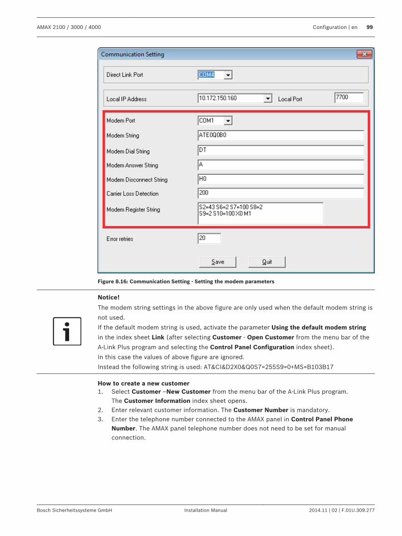
Figure 8.16: Communication Setting - Setting the modem parameters
Notice!
The modem string settings in the above figure are only used when the default modem string is
not used.
If the default modem string is used, activate the parameter Using the default modem string
in the index sheet Link (after selecting Customer - Open Customer from the menu bar of the
A-Link Plus program and selecting the Control Panel Configuration index sheet).
In this case the values of above figure are ignored.
Instead the following string is used: AT&CI&D2X0&Q0S7=255S9=0+MS=B103B17
How to create a new customer1. Select Customer –New Customer from the menu bar of the A-Link Plus program.
The Customer Information index sheet opens.2. Enter relevant customer information. The Customer Number is mandatory.3. Enter the telephone number connected to the AMAX panel in Control Panel Phone
Number. The AMAX panel telephone number does not need to be set for manualconnection.
AMAX 2100 / 3000 / 4000 Configuration | en 99
Bosch Sicherheitssysteme GmbH Installation Manual 2014.11 | 02 | F.01U.309.277
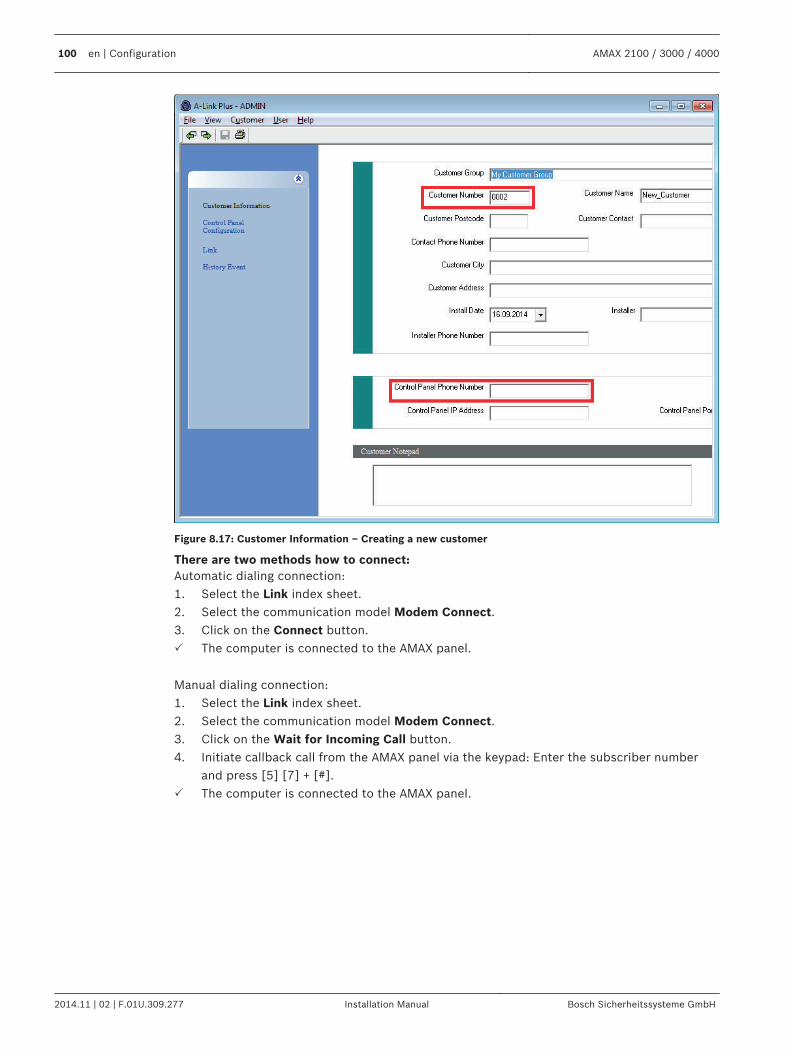
Figure 8.17: Customer Information – Creating a new customer
There are two methods how to connect:Automatic dialing connection:1. Select the Link index sheet.2. Select the communication model Modem Connect.3. Click on the Connect button.P The computer is connected to the AMAX panel.
Manual dialing connection:1. Select the Link index sheet.2. Select the communication model Modem Connect.3. Click on the Wait for Incoming Call button.4. Initiate callback call from the AMAX panel via the keypad: Enter the subscriber number
and press [5] [7] + [#].P The computer is connected to the AMAX panel.
100 en | Configuration AMAX 2100 / 3000 / 4000
2014.11 | 02 | F.01U.309.277 Installation Manual Bosch Sicherheitssysteme GmbH
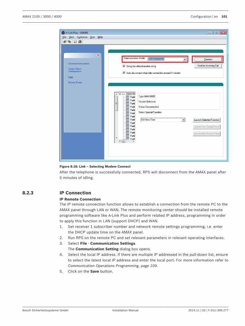
Figure 8.18: Link – Selecting Modem Connect
After the telephone is successfully connected, RPS will disconnect from the AMAX panel after5 minutes of idling.
IP ConnectionIP Remote ConnectionThe IP remote connection function allows to establish a connection from the remote PC to theAMAX panel through LAN or WAN. The remote monitoring center should be installed remoteprogramming software like A-Link Plus and perform related IP address, programming in orderto apply this function in LAN (support DHCP) and WAN.1. Set receiver 1 subscriber number and network remote settings programming, i.e. enter
the DHCP update time on the AMAX panel.2. Run RPS on the remote PC and set relevant parameters in relevant operating interfaces.3. Select File - Communication Settings.
The Communication Setting dialog box opens.4. Select the local IP address. If there are multiple IP addressed in the pull-down list, ensure
to select the latest local IP address and enter the local port. For more information refer toCommunication Operations Programming, page 109.
5. Click on the Save button.
8.2.3
AMAX 2100 / 3000 / 4000 Configuration | en 101
Bosch Sicherheitssysteme GmbH Installation Manual 2014.11 | 02 | F.01U.309.277
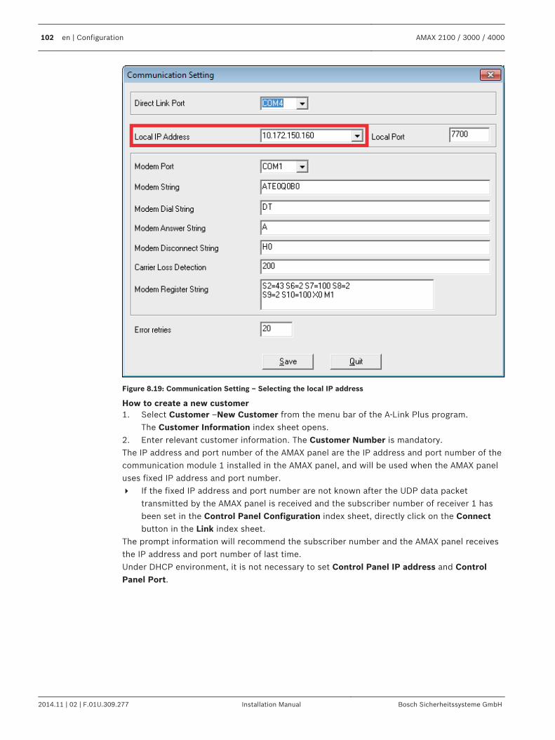
Figure 8.19: Communication Setting – Selecting the local IP address
How to create a new customer1. Select Customer –New Customer from the menu bar of the A-Link Plus program.
The Customer Information index sheet opens.2. Enter relevant customer information. The Customer Number is mandatory.The IP address and port number of the AMAX panel are the IP address and port number of thecommunication module 1 installed in the AMAX panel, and will be used when the AMAX paneluses fixed IP address and port number.4 If the fixed IP address and port number are not known after the UDP data packet
transmitted by the AMAX panel is received and the subscriber number of receiver 1 hasbeen set in the Control Panel Configuration index sheet, directly click on the Connectbutton in the Link index sheet.
The prompt information will recommend the subscriber number and the AMAX panel receivesthe IP address and port number of last time.Under DHCP environment, it is not necessary to set Control Panel IP address and ControlPanel Port.
102 en | Configuration AMAX 2100 / 3000 / 4000
2014.11 | 02 | F.01U.309.277 Installation Manual Bosch Sicherheitssysteme GmbH
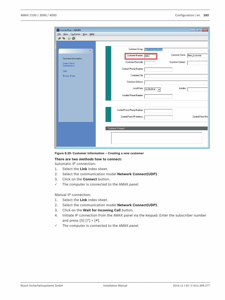
Figure 8.20: Customer Information – Creating a new customer
There are two methods how to connect:Automatic IP connection:1. Select the Link index sheet.2. Select the communication model Network Connect(UDP).3. Click on the Connect button.P The computer is connected to the AMAX panel.
Manual IP connection:1. Select the Link index sheet.2. Select the communication model Network Connect(UDP).3. Click on the Wait for Incoming Call button.4. Initiate IP connection from the AMAX panel via the keypad: Enter the subscriber number
and press [5] [7] + [#].P The computer is connected to the AMAX panel.
AMAX 2100 / 3000 / 4000 Configuration | en 103
Bosch Sicherheitssysteme GmbH Installation Manual 2014.11 | 02 | F.01U.309.277
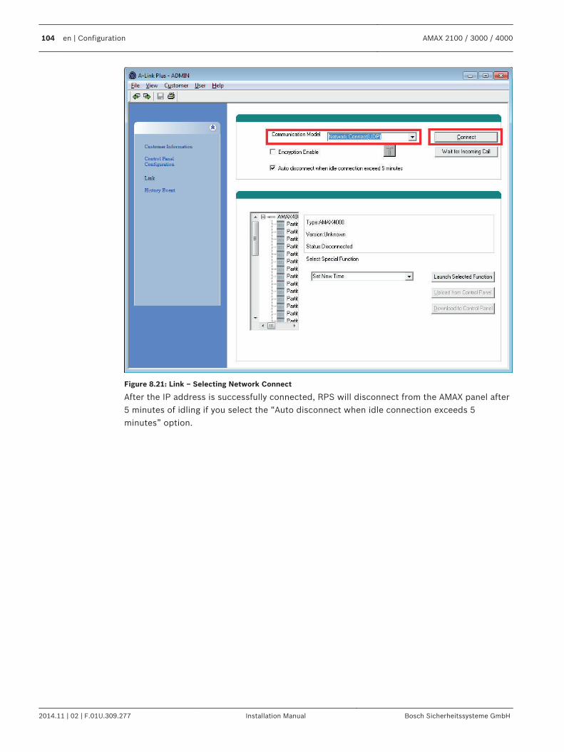
Figure 8.21: Link – Selecting Network Connect
After the IP address is successfully connected, RPS will disconnect from the AMAX panel after5 minutes of idling if you select the “Auto disconnect when idle connection exceeds 5minutes” option.
104 en | Configuration AMAX 2100 / 3000 / 4000
2014.11 | 02 | F.01U.309.277 Installation Manual Bosch Sicherheitssysteme GmbH
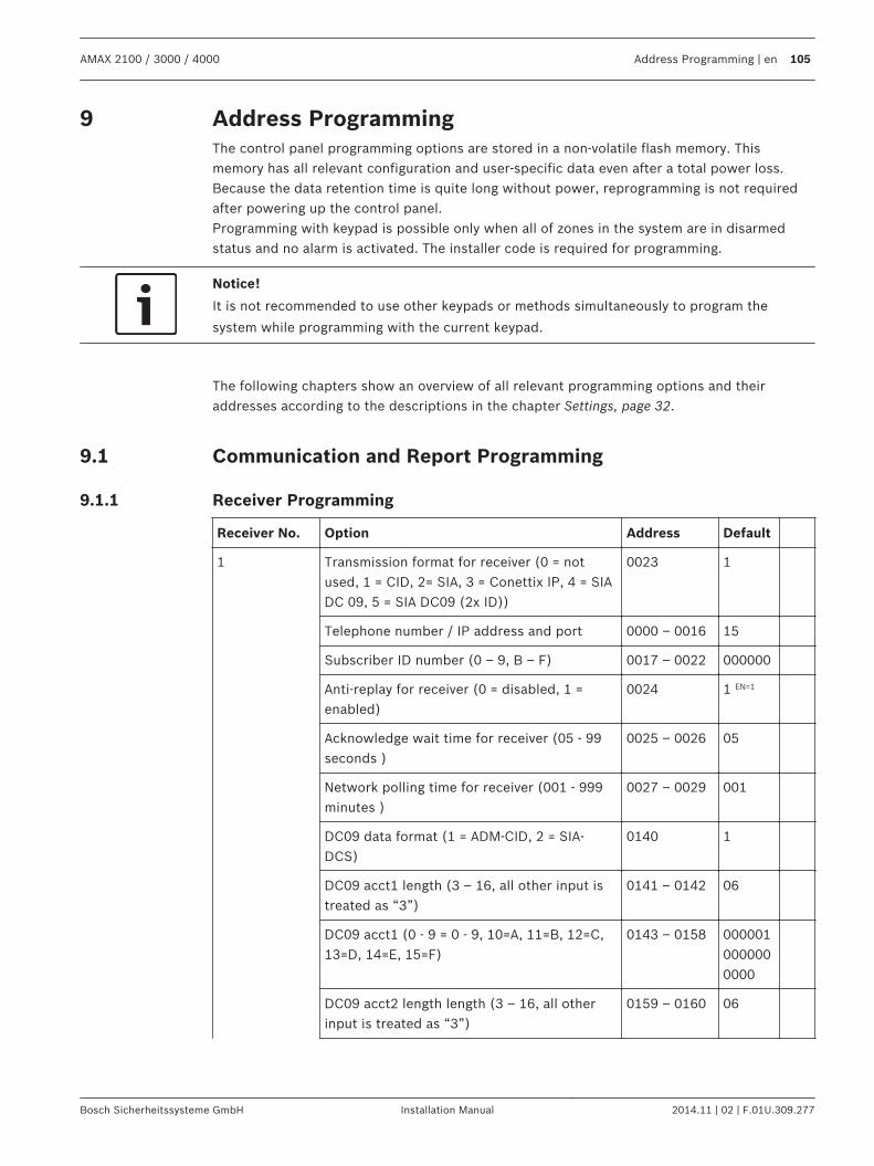
Address ProgrammingThe control panel programming options are stored in a non-volatile flash memory. Thismemory has all relevant configuration and user-specific data even after a total power loss.Because the data retention time is quite long without power, reprogramming is not requiredafter powering up the control panel.Programming with keypad is possible only when all of zones in the system are in disarmedstatus and no alarm is activated. The installer code is required for programming.
Notice!
It is not recommended to use other keypads or methods simultaneously to program the
system while programming with the current keypad.
The following chapters show an overview of all relevant programming options and theiraddresses according to the descriptions in the chapter Settings, page 32.
Communication and Report Programming
Receiver Programming
Receiver No. Option Address Default
1 Transmission format for receiver (0 = notused, 1 = CID, 2= SIA, 3 = Conettix IP, 4 = SIADC 09, 5 = SIA DC09 (2x ID))
0023 1
Telephone number / IP address and port 0000 – 0016 15
Subscriber ID number (0 – 9, B – F) 0017 – 0022 000000
Anti-replay for receiver (0 = disabled, 1 =enabled)
0024 1 EN=1
Acknowledge wait time for receiver (05 - 99seconds )
0025 – 0026 05
Network polling time for receiver (001 - 999minutes )
0027 – 0029 001
DC09 data format (1 = ADM-CID, 2 = SIA-DCS)
0140 1
DC09 acct1 length (3 – 16, all other input istreated as “3”)
0141 – 0142 06
DC09 acct1 (0 - 9 = 0 - 9, 10=A, 11=B, 12=C,13=D, 14=E, 15=F)
0143 – 0158 0000010000000000
DC09 acct2 length length (3 – 16, all otherinput is treated as “3”)
0159 – 0160 06
9
9.1
9.1.1
AMAX 2100 / 3000 / 4000 Address Programming | en 105
Bosch Sicherheitssysteme GmbH Installation Manual 2014.11 | 02 | F.01U.309.277
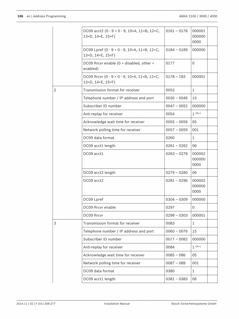
DC09 acct2 (0 - 9 = 0 - 9, 10=A, 11=B, 12=C,13=D, 14=E, 15=F)
0161 – 0176 0000010000000000
DC09 Lpref (0 - 9 = 0 - 9, 10=A, 11=B, 12=C,13=D, 14=E, 15=F)
0184 – 0189 000000
DC09 Rrcvr enable (0 = disabled, other =enabled)
0177 0
DC09 Rrcvr (0 - 9 = 0 - 9, 10=A, 11=B, 12=C,13=D, 14=E, 15=F)
0178 – 183 000001
2 Transmission format for receiver 0053 1
Telephone number / IP address and port 0030 – 0046 15
Subscriber ID number 0047 – 0052 000000
Anti-replay for receiver 0054 1 EN=1
Acknowledge wait time for receiver 0055 – 0056 05
Network polling time for receiver 0057 – 0059 001
DC09 data format 0260 1
DC09 acct1 length 0261 – 0262 06
DC09 acct1 0263 – 0278 0000020000000000
DC09 acct2 length 0279 – 0280 06
DC09 acct2 0281 – 0296 0000020000000000
DC09 Lpref 0304 – 0309 000000
DC09 Rrcvr enable 0297 0
DC09 Rrcvr 0298 – 0303 000001
3 Transmission format for receiver 0083 1
Telephone number / IP address and port 0060 – 0076 15
Subscriber ID number 0077 – 0082 000000
Anti-replay for receiver 0084 1 EN=1
Acknowledge wait time for receiver 0085 – 086 05
Network polling time for receiver 0087 – 089 001
DC09 data format 0380 1
DC09 acct1 length 0381 – 0383 06
106 en | Address Programming AMAX 2100 / 3000 / 4000
2014.11 | 02 | F.01U.309.277 Installation Manual Bosch Sicherheitssysteme GmbH
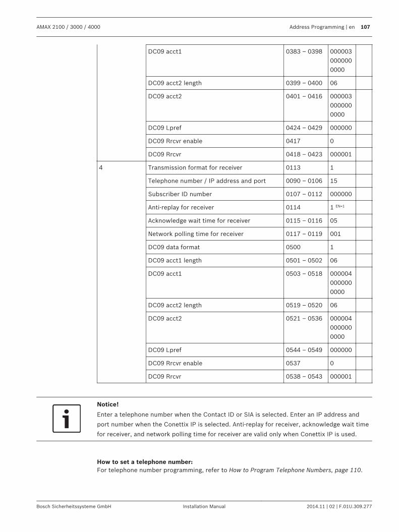
DC09 acct1 0383 – 0398 0000030000000000
DC09 acct2 length 0399 – 0400 06
DC09 acct2 0401 – 0416 0000030000000000
DC09 Lpref 0424 – 0429 000000
DC09 Rrcvr enable 0417 0
DC09 Rrcvr 0418 – 0423 000001
4 Transmission format for receiver 0113 1
Telephone number / IP address and port 0090 – 0106 15
Subscriber ID number 0107 – 0112 000000
Anti-replay for receiver 0114 1 EN=1
Acknowledge wait time for receiver 0115 – 0116 05
Network polling time for receiver 0117 – 0119 001
DC09 data format 0500 1
DC09 acct1 length 0501 – 0502 06
DC09 acct1 0503 – 0518 0000040000000000
DC09 acct2 length 0519 – 0520 06
DC09 acct2 0521 – 0536 0000040000000000
DC09 Lpref 0544 – 0549 000000
DC09 Rrcvr enable 0537 0
DC09 Rrcvr 0538 – 0543 000001
Notice!
Enter a telephone number when the Contact ID or SIA is selected. Enter an IP address and
port number when the Conettix IP is selected. Anti-replay for receiver, acknowledge wait time
for receiver, and network polling time for receiver are valid only when Conettix IP is used.
How to set a telephone number:For telephone number programming, refer to How to Program Telephone Numbers, page 110.
AMAX 2100 / 3000 / 4000 Address Programming | en 107
Bosch Sicherheitssysteme GmbH Installation Manual 2014.11 | 02 | F.01U.309.277
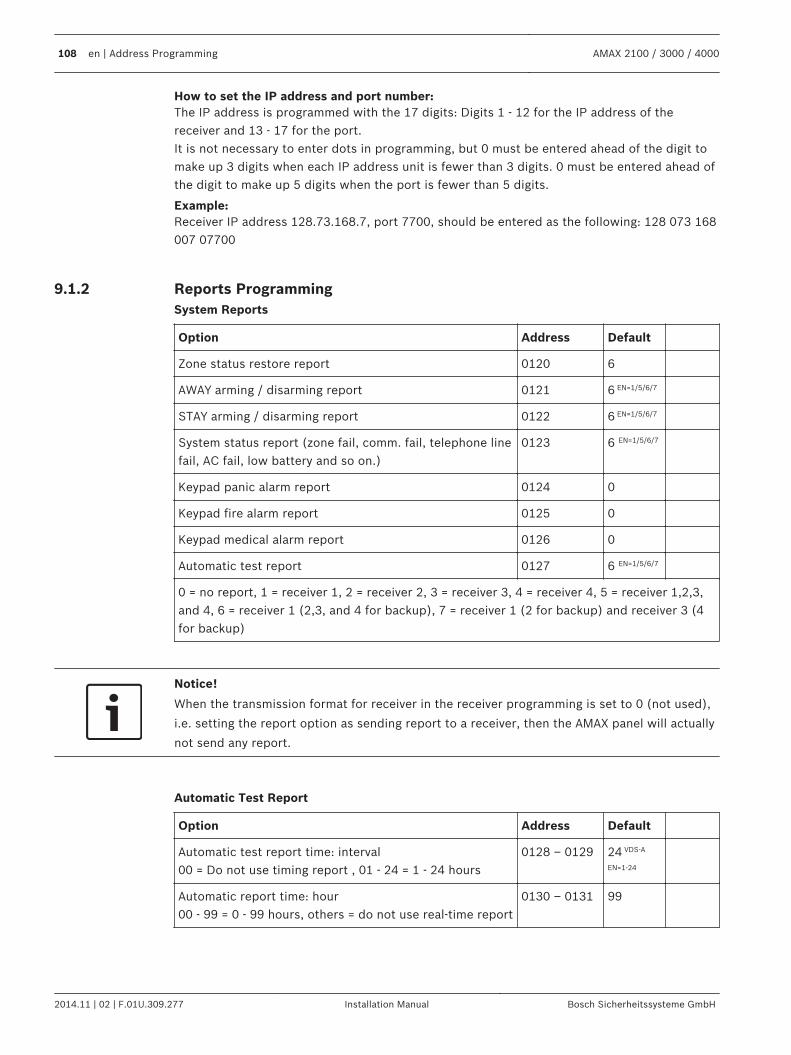
How to set the IP address and port number:The IP address is programmed with the 17 digits: Digits 1 - 12 for the IP address of thereceiver and 13 - 17 for the port.It is not necessary to enter dots in programming, but 0 must be entered ahead of the digit tomake up 3 digits when each IP address unit is fewer than 3 digits. 0 must be entered ahead ofthe digit to make up 5 digits when the port is fewer than 5 digits.
Example:Receiver IP address 128.73.168.7, port 7700, should be entered as the following: 128 073 168007 07700
Reports ProgrammingSystem Reports
Option Address Default
Zone status restore report 0120 6
AWAY arming / disarming report 0121 6 EN=1/5/6/7
STAY arming / disarming report 0122 6 EN=1/5/6/7
System status report (zone fail, comm. fail, telephone linefail, AC fail, low battery and so on.)
0123 6 EN=1/5/6/7
Keypad panic alarm report 0124 0
Keypad fire alarm report 0125 0
Keypad medical alarm report 0126 0
Automatic test report 0127 6 EN=1/5/6/7
0 = no report, 1 = receiver 1, 2 = receiver 2, 3 = receiver 3, 4 = receiver 4, 5 = receiver 1,2,3,and 4, 6 = receiver 1 (2,3, and 4 for backup), 7 = receiver 1 (2 for backup) and receiver 3 (4for backup)
Notice!
When the transmission format for receiver in the receiver programming is set to 0 (not used),
i.e. setting the report option as sending report to a receiver, then the AMAX panel will actually
not send any report.
Automatic Test Report
Option Address Default
Automatic test report time: interval00 = Do not use timing report , 01 - 24 = 1 - 24 hours
0128 – 0129 24 VDS-A
EN=1-24
Automatic report time: hour00 - 99 = 0 - 99 hours, others = do not use real-time report
0130 – 0131 99
9.1.2
108 en | Address Programming AMAX 2100 / 3000 / 4000
2014.11 | 02 | F.01U.309.277 Installation Manual Bosch Sicherheitssysteme GmbH
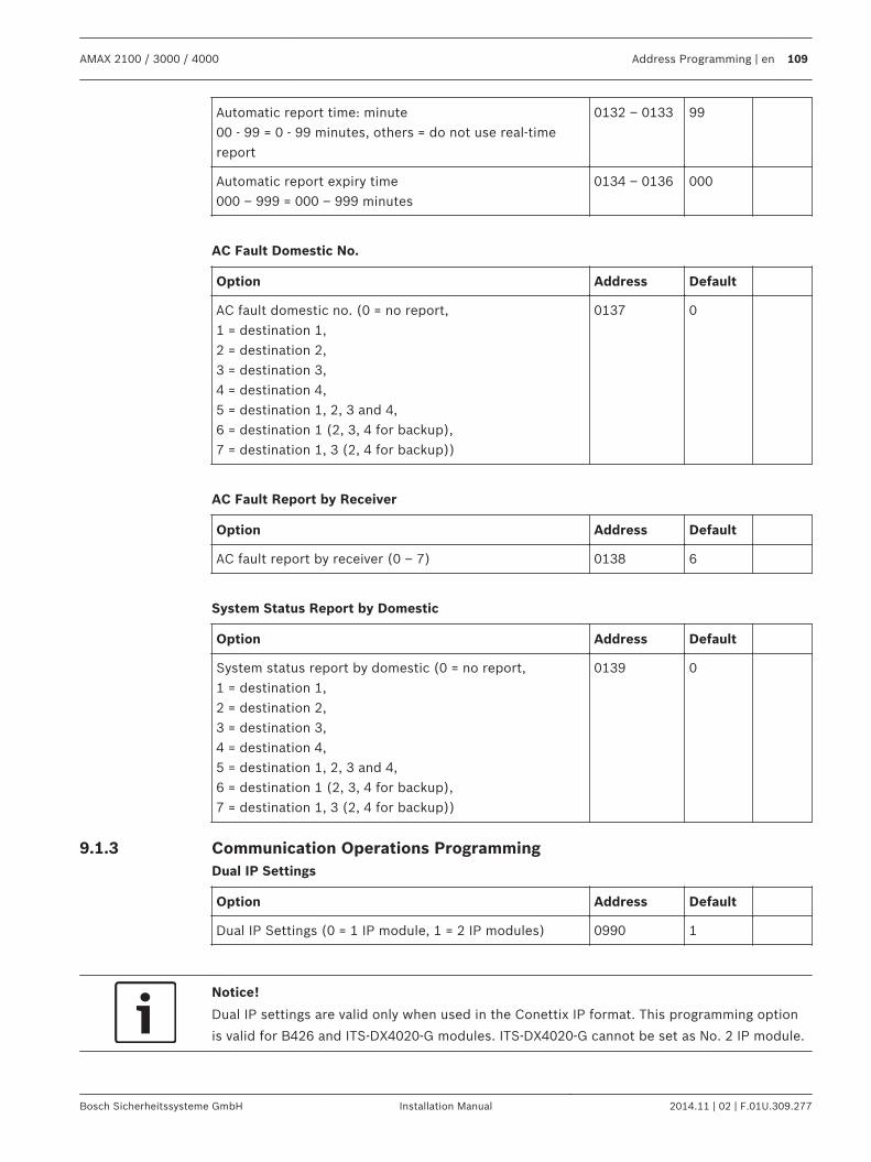
Automatic report time: minute00 - 99 = 0 - 99 minutes, others = do not use real-timereport
0132 – 0133 99
Automatic report expiry time000 – 999 = 000 – 999 minutes
0134 – 0136 000
AC Fault Domestic No.
Option Address Default
AC fault domestic no. (0 = no report,1 = destination 1,2 = destination 2,3 = destination 3,4 = destination 4,5 = destination 1, 2, 3 and 4,6 = destination 1 (2, 3, 4 for backup),7 = destination 1, 3 (2, 4 for backup))
0137 0
AC Fault Report by Receiver
Option Address Default
AC fault report by receiver (0 – 7) 0138 6
System Status Report by Domestic
Option Address Default
System status report by domestic (0 = no report,1 = destination 1,2 = destination 2,3 = destination 3,4 = destination 4,5 = destination 1, 2, 3 and 4,6 = destination 1 (2, 3, 4 for backup),7 = destination 1, 3 (2, 4 for backup))
0139 0
Communication Operations ProgrammingDual IP Settings
Option Address Default
Dual IP Settings (0 = 1 IP module, 1 = 2 IP modules) 0990 1
Notice!
Dual IP settings are valid only when used in the Conettix IP format. This programming option
is valid for B426 and ITS-DX4020-G modules. ITS-DX4020-G cannot be set as No. 2 IP module.
9.1.3
AMAX 2100 / 3000 / 4000 Address Programming | en 109
Bosch Sicherheitssysteme GmbH Installation Manual 2014.11 | 02 | F.01U.309.277
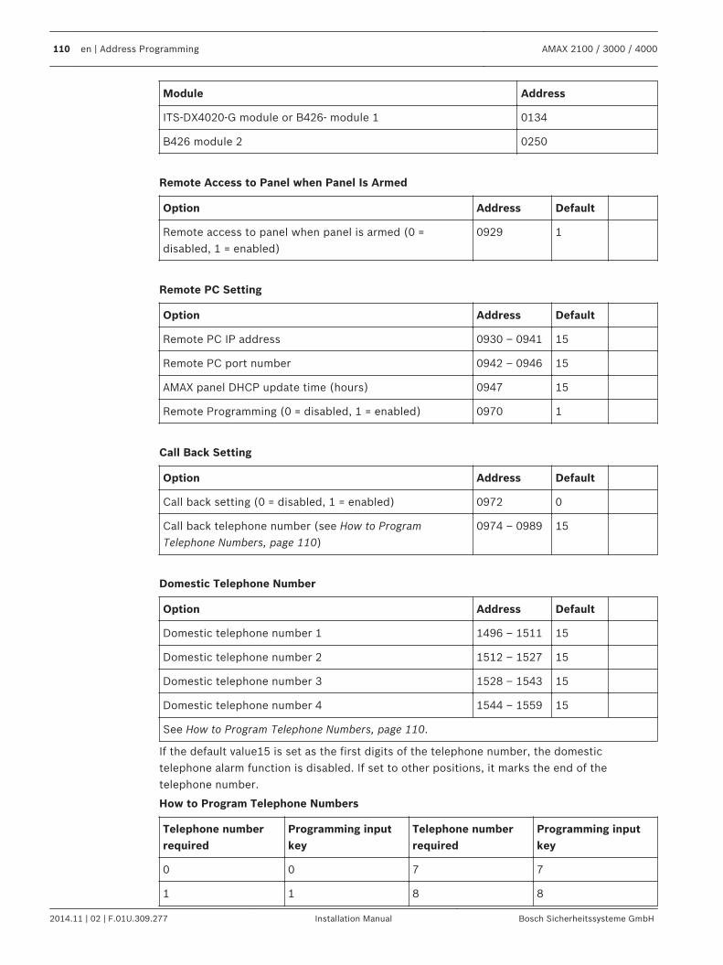
Module Address
ITS-DX4020-G module or B426- module 1 0134
B426 module 2 0250
Remote Access to Panel when Panel Is Armed
Option Address Default
Remote access to panel when panel is armed (0 =disabled, 1 = enabled)
0929 1
Remote PC Setting
Option Address Default
Remote PC IP address 0930 – 0941 15
Remote PC port number 0942 – 0946 15
AMAX panel DHCP update time (hours) 0947 15
Remote Programming (0 = disabled, 1 = enabled) 0970 1
Call Back Setting
Option Address Default
Call back setting (0 = disabled, 1 = enabled) 0972 0
Call back telephone number (see How to ProgramTelephone Numbers, page 110)
0974 – 0989 15
Domestic Telephone Number
Option Address Default
Domestic telephone number 1 1496 – 1511 15
Domestic telephone number 2 1512 – 1527 15
Domestic telephone number 3 1528 – 1543 15
Domestic telephone number 4 1544 – 1559 15
See How to Program Telephone Numbers, page 110.
If the default value15 is set as the first digits of the telephone number, the domestictelephone alarm function is disabled. If set to other positions, it marks the end of thetelephone number.
How to Program Telephone Numbers
Telephone numberrequired
Programming inputkey
Telephone numberrequired
Programming inputkey
0 0 7 7
1 1 8 8
110 en | Address Programming AMAX 2100 / 3000 / 4000
2014.11 | 02 | F.01U.309.277 Installation Manual Bosch Sicherheitssysteme GmbH
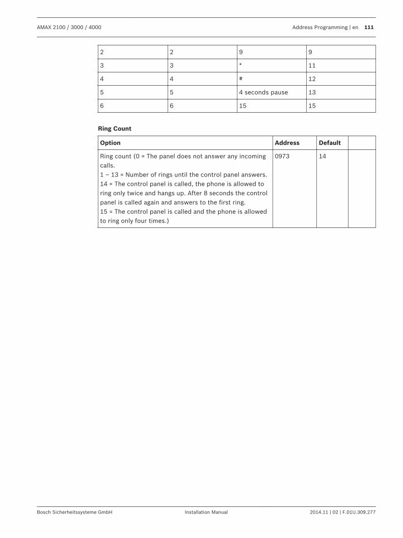
2 2 9 9
3 3 * 11
4 4 # 12
5 5 4 seconds pause 13
6 6 15 15
Ring Count
Option Address Default
Ring count (0 = The panel does not answer any incomingcalls.1 – 13 = Number of rings until the control panel answers.14 = The control panel is called, the phone is allowed toring only twice and hangs up. After 8 seconds the controlpanel is called again and answers to the first ring.15 = The control panel is called and the phone is allowedto ring only four times.)
0973 14
AMAX 2100 / 3000 / 4000 Address Programming | en 111
Bosch Sicherheitssysteme GmbH Installation Manual 2014.11 | 02 | F.01U.309.277
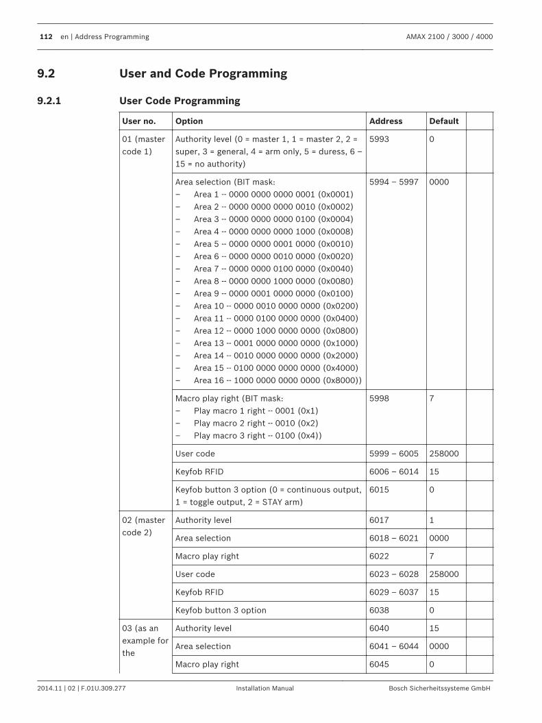
User and Code Programming
User Code Programming
User no. Option Address Default
01 (mastercode 1)
Authority level (0 = master 1, 1 = master 2, 2 =super, 3 = general, 4 = arm only, 5 = duress, 6 –15 = no authority)
5993 0
Area selection (BIT mask:– Area 1 -- 0000 0000 0000 0001 (0x0001)– Area 2 -- 0000 0000 0000 0010 (0x0002)– Area 3 -- 0000 0000 0000 0100 (0x0004)– Area 4 -- 0000 0000 0000 1000 (0x0008)– Area 5 -- 0000 0000 0001 0000 (0x0010)– Area 6 -- 0000 0000 0010 0000 (0x0020)– Area 7 -- 0000 0000 0100 0000 (0x0040)– Area 8 -- 0000 0000 1000 0000 (0x0080)– Area 9 -- 0000 0001 0000 0000 (0x0100)– Area 10 -- 0000 0010 0000 0000 (0x0200)– Area 11 -- 0000 0100 0000 0000 (0x0400)– Area 12 -- 0000 1000 0000 0000 (0x0800)– Area 13 -- 0001 0000 0000 0000 (0x1000)– Area 14 -- 0010 0000 0000 0000 (0x2000)– Area 15 -- 0100 0000 0000 0000 (0x4000)– Area 16 -- 1000 0000 0000 0000 (0x8000))
5994 – 5997 0000
Macro play right (BIT mask:– Play macro 1 right -- 0001 (0x1)– Play macro 2 right -- 0010 (0x2)– Play macro 3 right -- 0100 (0x4))
5998 7
User code 5999 – 6005 258000
Keyfob RFID 6006 – 6014 15
Keyfob button 3 option (0 = continuous output,1 = toggle output, 2 = STAY arm)
6015 0
02 (mastercode 2)
Authority level 6017 1
Area selection 6018 – 6021 0000
Macro play right 6022 7
User code 6023 – 6028 258000
Keyfob RFID 6029 – 6037 15
Keyfob button 3 option 6038 0
03 (as anexample forthe
Authority level 6040 15
Area selection 6041 – 6044 0000
Macro play right 6045 0
9.2
9.2.1
112 en | Address Programming AMAX 2100 / 3000 / 4000
2014.11 | 02 | F.01U.309.277 Installation Manual Bosch Sicherheitssysteme GmbH
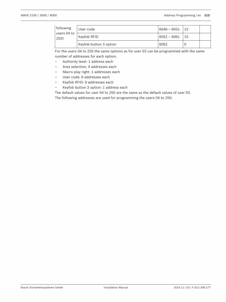
followingusers 04 to250)
User code 6046 – 6051 15
Keyfob RFID 6052 – 6061 15
Keyfob button 3 option 6062 0
For the users 04 to 250 the same options as for user 03 can be programmed with the samenumber of addresses for each option:– Authority level: 1 address each– Area selection: 4 addresses each– Macro play right: 1 addresses each– User code: 6 addresses each– Keyfob RFID: 9 addresses each– Keyfob button 3 option: 1 address eachThe default values for user 04 to 250 are the same as the default values of user 03.The following addresses are used for programming the users 04 to 250:
AMAX 2100 / 3000 / 4000 Address Programming | en 113
Bosch Sicherheitssysteme GmbH Installation Manual 2014.11 | 02 | F.01U.309.277
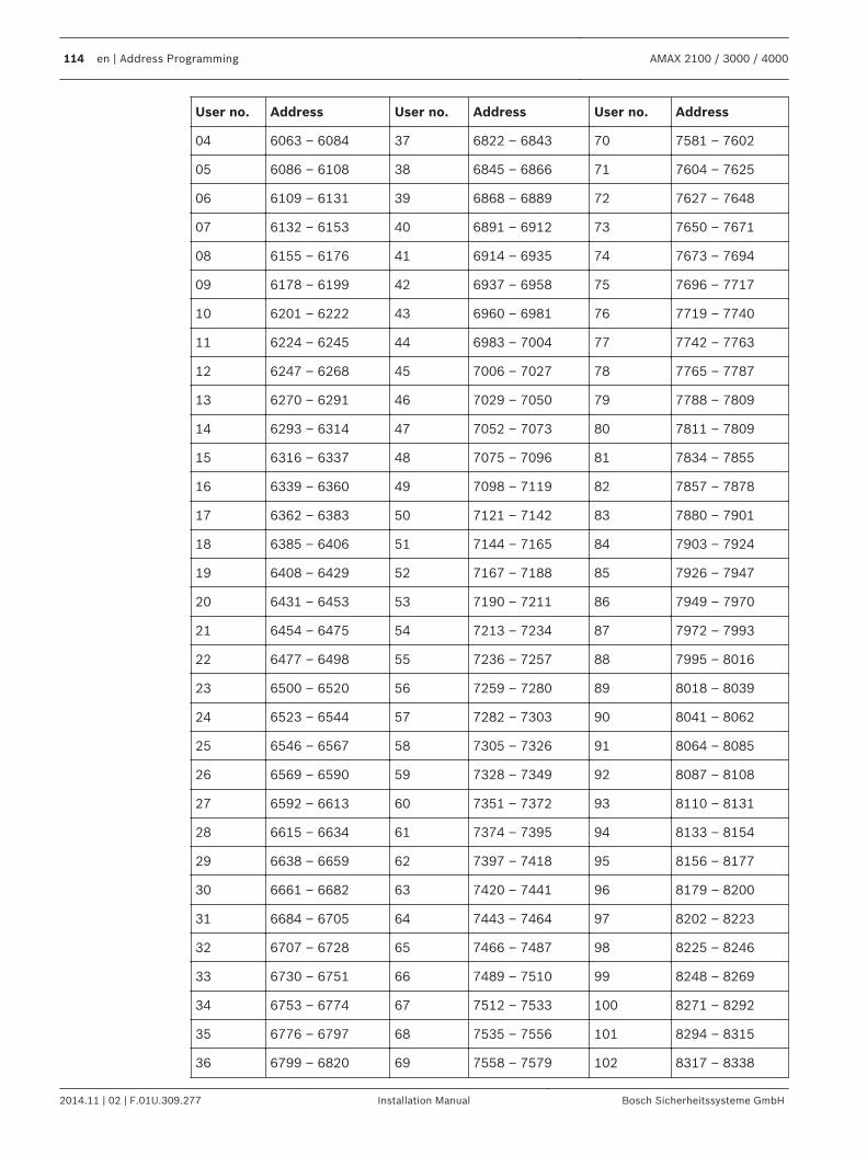
User no. Address User no. Address User no. Address
04 6063 – 6084 37 6822 – 6843 70 7581 – 7602
05 6086 – 6108 38 6845 – 6866 71 7604 – 7625
06 6109 – 6131 39 6868 – 6889 72 7627 – 7648
07 6132 – 6153 40 6891 – 6912 73 7650 – 7671
08 6155 – 6176 41 6914 – 6935 74 7673 – 7694
09 6178 – 6199 42 6937 – 6958 75 7696 – 7717
10 6201 – 6222 43 6960 – 6981 76 7719 – 7740
11 6224 – 6245 44 6983 – 7004 77 7742 – 7763
12 6247 – 6268 45 7006 – 7027 78 7765 – 7787
13 6270 – 6291 46 7029 – 7050 79 7788 – 7809
14 6293 – 6314 47 7052 – 7073 80 7811 – 7809
15 6316 – 6337 48 7075 – 7096 81 7834 – 7855
16 6339 – 6360 49 7098 – 7119 82 7857 – 7878
17 6362 – 6383 50 7121 – 7142 83 7880 – 7901
18 6385 – 6406 51 7144 – 7165 84 7903 – 7924
19 6408 – 6429 52 7167 – 7188 85 7926 – 7947
20 6431 – 6453 53 7190 – 7211 86 7949 – 7970
21 6454 – 6475 54 7213 – 7234 87 7972 – 7993
22 6477 – 6498 55 7236 – 7257 88 7995 – 8016
23 6500 – 6520 56 7259 – 7280 89 8018 – 8039
24 6523 – 6544 57 7282 – 7303 90 8041 – 8062
25 6546 – 6567 58 7305 – 7326 91 8064 – 8085
26 6569 – 6590 59 7328 – 7349 92 8087 – 8108
27 6592 – 6613 60 7351 – 7372 93 8110 – 8131
28 6615 – 6634 61 7374 – 7395 94 8133 – 8154
29 6638 – 6659 62 7397 – 7418 95 8156 – 8177
30 6661 – 6682 63 7420 – 7441 96 8179 – 8200
31 6684 – 6705 64 7443 – 7464 97 8202 – 8223
32 6707 – 6728 65 7466 – 7487 98 8225 – 8246
33 6730 – 6751 66 7489 – 7510 99 8248 – 8269
34 6753 – 6774 67 7512 – 7533 100 8271 – 8292
35 6776 – 6797 68 7535 – 7556 101 8294 – 8315
36 6799 – 6820 69 7558 – 7579 102 8317 – 8338
114 en | Address Programming AMAX 2100 / 3000 / 4000
2014.11 | 02 | F.01U.309.277 Installation Manual Bosch Sicherheitssysteme GmbH
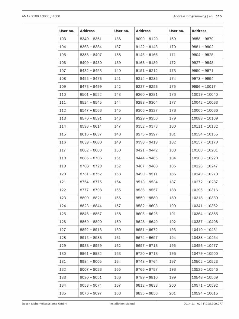
User no. Address User no. Address User no. Address
103 8340 – 8361 136 9099 – 9120 169 9858 – 9879
104 8363 – 8384 137 9122 – 9143 170 9881 – 9902
105 8386 – 8407 138 9145 – 9166 171 9904 – 9925
106 8409 – 8430 139 9168 – 9189 172 9927 – 9948
107 8432 – 8453 140 9191 – 9212 173 9950 – 9971
108 8455 – 8476 141 9214 – 9235 174 9973 – 9994
109 8478 – 8499 142 9237 – 9258 175 9996 – 10017
110 8501 – 8522 143 9260 – 9281 176 10019 – 10040
111 8524 – 8545 144 9283 – 9304 177 10042 – 10063
112 8547 – 8568 145 9306 – 9327 178 10065 – 10086
113 8570 – 8591 146 9329 – 9350 179 10088 – 10109
114 8593 – 8614 147 9352 – 9373 180 10111 – 10132
115 8616 – 8637 148 9375 – 9397 181 10134 – 10155
116 8639 – 8680 149 9398 – 9419 182 10157 – 10178
117 8662 – 8683 150 9421 – 9442 183 10180 – 10201
118 8685 – 8706 151 9444 – 9465 184 10203 – 10220
119 8708 – 8729 152 9467 – 9488 185 10226 – 10247
120 8731 – 8752 153 9490 – 9511 186 10249 – 10270
121 8754 – 8775 154 9513 – 9534 187 10272 – 10287
122 8777 – 8798 155 9536 – 9557 188 10295 – 10316
123 8800 – 8821 156 9559 – 9580 189 10318 – 10339
124 8823 – 8844 157 9582 – 9603 190 10341 – 10362
125 8846 – 8867 158 9605 – 9626 191 10364 – 10385
126 8869 – 8890 159 9628 – 9649 192 10387 – 10408
127 8892 – 8913 160 9651 – 9672 193 10410 – 10431
128 8915 – 8936 161 9674 – 9697 194 10433 – 10454
129 8938 – 8959 162 9697 – 9718 195 10456 – 10477
130 8961 – 8982 163 9720 – 9718 196 10479 – 10500
131 8984 – 9005 164 9743 – 9764 197 10502 – 10523
132 9007 – 9028 165 9766 – 9787 198 10525 – 10546
133 9030 – 9051 166 9789 – 9810 199 10548 – 10569
134 9053 – 9074 167 9812 – 9833 200 10571 – 10592
135 9076 – 9097 168 9835 – 9856 201 10594 – 10615
AMAX 2100 / 3000 / 4000 Address Programming | en 115
Bosch Sicherheitssysteme GmbH Installation Manual 2014.11 | 02 | F.01U.309.277
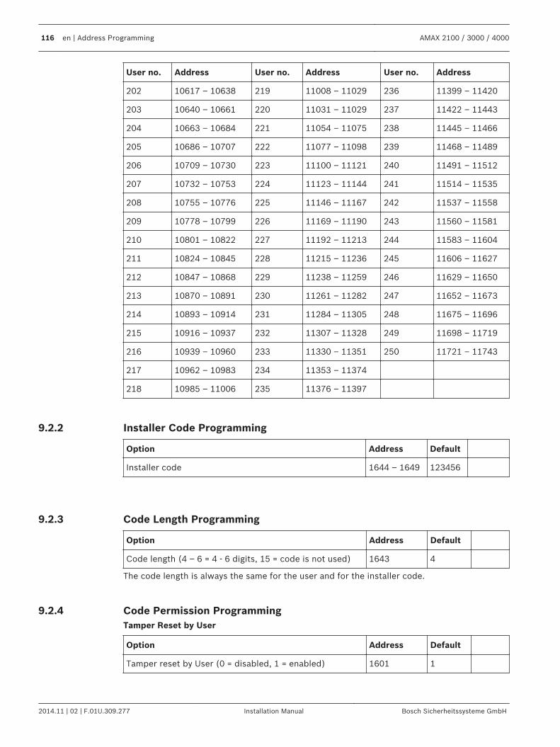
User no. Address User no. Address User no. Address
202 10617 – 10638 219 11008 – 11029 236 11399 – 11420
203 10640 – 10661 220 11031 – 11029 237 11422 – 11443
204 10663 – 10684 221 11054 – 11075 238 11445 – 11466
205 10686 – 10707 222 11077 – 11098 239 11468 – 11489
206 10709 – 10730 223 11100 – 11121 240 11491 – 11512
207 10732 – 10753 224 11123 – 11144 241 11514 – 11535
208 10755 – 10776 225 11146 – 11167 242 11537 – 11558
209 10778 – 10799 226 11169 – 11190 243 11560 – 11581
210 10801 – 10822 227 11192 – 11213 244 11583 – 11604
211 10824 – 10845 228 11215 – 11236 245 11606 – 11627
212 10847 – 10868 229 11238 – 11259 246 11629 – 11650
213 10870 – 10891 230 11261 – 11282 247 11652 – 11673
214 10893 – 10914 231 11284 – 11305 248 11675 – 11696
215 10916 – 10937 232 11307 – 11328 249 11698 – 11719
216 10939 – 10960 233 11330 – 11351 250 11721 – 11743
217 10962 – 10983 234 11353 – 11374
218 10985 – 11006 235 11376 – 11397
Installer Code Programming
Option Address Default
Installer code 1644 – 1649 123456
Code Length Programming
Option Address Default
Code length (4 – 6 = 4 - 6 digits, 15 = code is not used) 1643 4
The code length is always the same for the user and for the installer code.
Code Permission ProgrammingTamper Reset by User
Option Address Default
Tamper reset by User (0 = disabled, 1 = enabled) 1601 1
9.2.2
9.2.3
9.2.4
116 en | Address Programming AMAX 2100 / 3000 / 4000
2014.11 | 02 | F.01U.309.277 Installation Manual Bosch Sicherheitssysteme GmbH
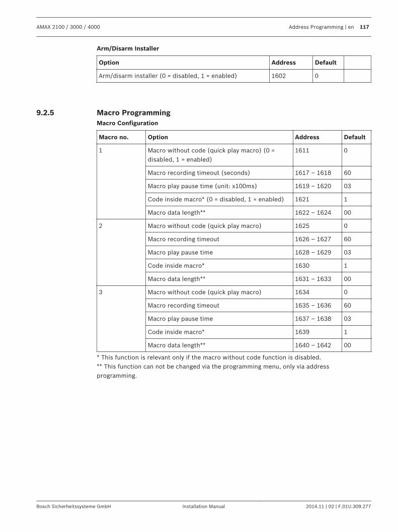
Arm/Disarm Installer
Option Address Default
Arm/disarm installer (0 = disabled, 1 = enabled) 1602 0
Macro ProgrammingMacro Configuration
Macro no. Option Address Default
1 Macro without code (quick play macro) (0 =disabled, 1 = enabled)
1611 0
Macro recording timeout (seconds) 1617 – 1618 60
Macro play pause time (unit: x100ms) 1619 – 1620 03
Code inside macro* (0 = disabled, 1 = enabled) 1621 1
Macro data length** 1622 – 1624 00
2 Macro without code (quick play macro) 1625 0
Macro recording timeout 1626 – 1627 60
Macro play pause time 1628 – 1629 03
Code inside macro* 1630 1
Macro data length** 1631 – 1633 00
3 Macro without code (quick play macro) 1634 0
Macro recording timeout 1635 – 1636 60
Macro play pause time 1637 – 1638 03
Code inside macro* 1639 1
Macro data length** 1640 – 1642 00
* This function is relevant only if the macro without code function is disabled.** This function can not be changed via the programming menu, only via addressprogramming.
9.2.5
AMAX 2100 / 3000 / 4000 Address Programming | en 117
Bosch Sicherheitssysteme GmbH Installation Manual 2014.11 | 02 | F.01U.309.277
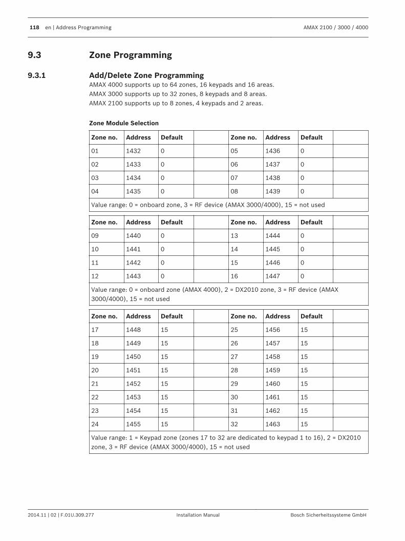
Zone Programming
Add/Delete Zone ProgrammingAMAX 4000 supports up to 64 zones, 16 keypads and 16 areas.AMAX 3000 supports up to 32 zones, 8 keypads and 8 areas.AMAX 2100 supports up to 8 zones, 4 keypads and 2 areas.
Zone Module Selection
Zone no. Address Default Zone no. Address Default
01 1432 0 05 1436 0
02 1433 0 06 1437 0
03 1434 0 07 1438 0
04 1435 0 08 1439 0
Value range: 0 = onboard zone, 3 = RF device (AMAX 3000/4000), 15 = not used
Zone no. Address Default Zone no. Address Default
09 1440 0 13 1444 0
10 1441 0 14 1445 0
11 1442 0 15 1446 0
12 1443 0 16 1447 0
Value range: 0 = onboard zone (AMAX 4000), 2 = DX2010 zone, 3 = RF device (AMAX3000/4000), 15 = not used
Zone no. Address Default Zone no. Address Default
17 1448 15 25 1456 15
18 1449 15 26 1457 15
19 1450 15 27 1458 15
20 1451 15 28 1459 15
21 1452 15 29 1460 15
22 1453 15 30 1461 15
23 1454 15 31 1462 15
24 1455 15 32 1463 15
Value range: 1 = Keypad zone (zones 17 to 32 are dedicated to keypad 1 to 16), 2 = DX2010zone, 3 = RF device (AMAX 3000/4000), 15 = not used
9.3
9.3.1
118 en | Address Programming AMAX 2100 / 3000 / 4000
2014.11 | 02 | F.01U.309.277 Installation Manual Bosch Sicherheitssysteme GmbH
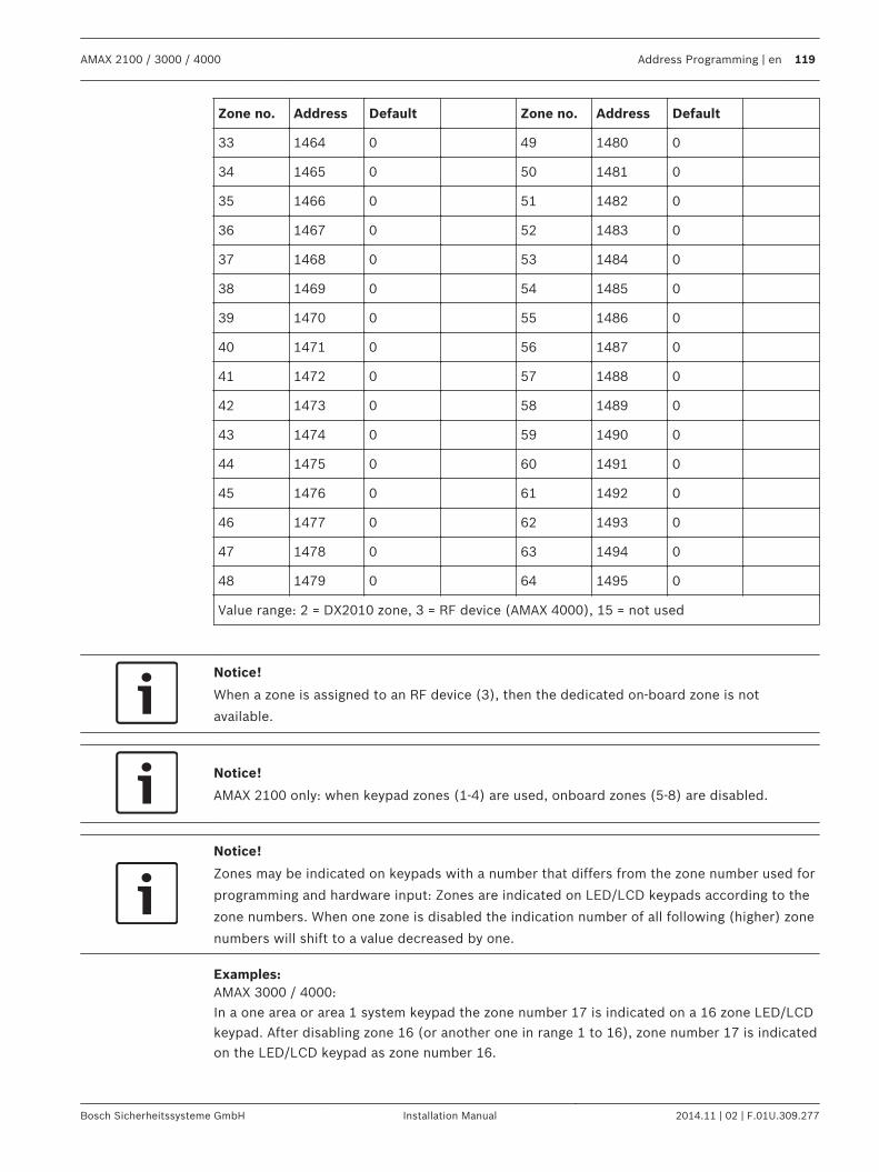
Zone no. Address Default Zone no. Address Default
33 1464 0 49 1480 0
34 1465 0 50 1481 0
35 1466 0 51 1482 0
36 1467 0 52 1483 0
37 1468 0 53 1484 0
38 1469 0 54 1485 0
39 1470 0 55 1486 0
40 1471 0 56 1487 0
41 1472 0 57 1488 0
42 1473 0 58 1489 0
43 1474 0 59 1490 0
44 1475 0 60 1491 0
45 1476 0 61 1492 0
46 1477 0 62 1493 0
47 1478 0 63 1494 0
48 1479 0 64 1495 0
Value range: 2 = DX2010 zone, 3 = RF device (AMAX 4000), 15 = not used
Notice!
When a zone is assigned to an RF device (3), then the dedicated on-board zone is not
available.
Notice!
AMAX 2100 only: when keypad zones (1-4) are used, onboard zones (5-8) are disabled.
Notice!
Zones may be indicated on keypads with a number that differs from the zone number used for
programming and hardware input: Zones are indicated on LED/LCD keypads according to the
zone numbers. When one zone is disabled the indication number of all following (higher) zone
numbers will shift to a value decreased by one.
Examples:AMAX 3000 / 4000:In a one area or area 1 system keypad the zone number 17 is indicated on a 16 zone LED/LCDkeypad. After disabling zone 16 (or another one in range 1 to 16), zone number 17 is indicatedon the LED/LCD keypad as zone number 16.
AMAX 2100 / 3000 / 4000 Address Programming | en 119
Bosch Sicherheitssysteme GmbH Installation Manual 2014.11 | 02 | F.01U.309.277
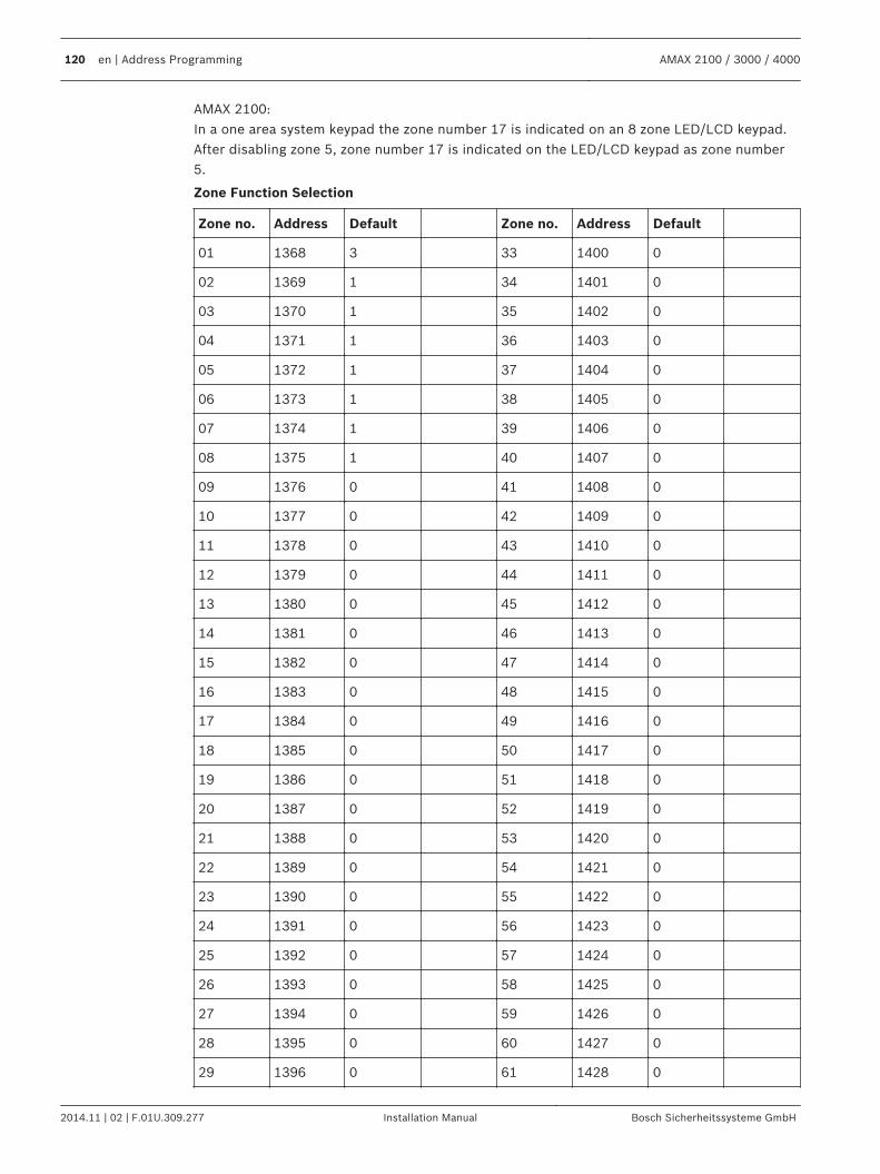
AMAX 2100:In a one area system keypad the zone number 17 is indicated on an 8 zone LED/LCD keypad.After disabling zone 5, zone number 17 is indicated on the LED/LCD keypad as zone number5.
Zone Function Selection
Zone no. Address Default Zone no. Address Default
01 1368 3 33 1400 0
02 1369 1 34 1401 0
03 1370 1 35 1402 0
04 1371 1 36 1403 0
05 1372 1 37 1404 0
06 1373 1 38 1405 0
07 1374 1 39 1406 0
08 1375 1 40 1407 0
09 1376 0 41 1408 0
10 1377 0 42 1409 0
11 1378 0 43 1410 0
12 1379 0 44 1411 0
13 1380 0 45 1412 0
14 1381 0 46 1413 0
15 1382 0 47 1414 0
16 1383 0 48 1415 0
17 1384 0 49 1416 0
18 1385 0 50 1417 0
19 1386 0 51 1418 0
20 1387 0 52 1419 0
21 1388 0 53 1420 0
22 1389 0 54 1421 0
23 1390 0 55 1422 0
24 1391 0 56 1423 0
25 1392 0 57 1424 0
26 1393 0 58 1425 0
27 1394 0 59 1426 0
28 1395 0 60 1427 0
29 1396 0 61 1428 0
120 en | Address Programming AMAX 2100 / 3000 / 4000
2014.11 | 02 | F.01U.309.277 Installation Manual Bosch Sicherheitssysteme GmbH
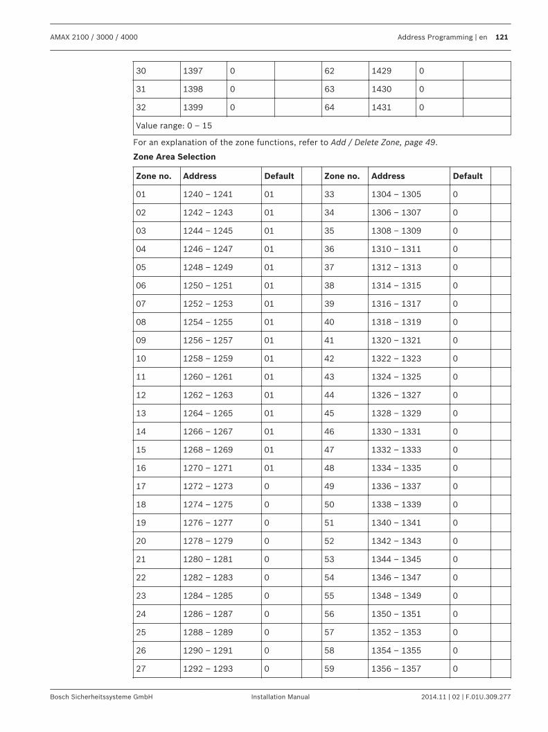
30 1397 0 62 1429 0
31 1398 0 63 1430 0
32 1399 0 64 1431 0
Value range: 0 – 15
For an explanation of the zone functions, refer to Add / Delete Zone, page 49.
Zone Area Selection
Zone no. Address Default Zone no. Address Default
01 1240 – 1241 01 33 1304 – 1305 0
02 1242 – 1243 01 34 1306 – 1307 0
03 1244 – 1245 01 35 1308 – 1309 0
04 1246 – 1247 01 36 1310 – 1311 0
05 1248 – 1249 01 37 1312 – 1313 0
06 1250 – 1251 01 38 1314 – 1315 0
07 1252 – 1253 01 39 1316 – 1317 0
08 1254 – 1255 01 40 1318 – 1319 0
09 1256 – 1257 01 41 1320 – 1321 0
10 1258 – 1259 01 42 1322 – 1323 0
11 1260 – 1261 01 43 1324 – 1325 0
12 1262 – 1263 01 44 1326 – 1327 0
13 1264 – 1265 01 45 1328 – 1329 0
14 1266 – 1267 01 46 1330 – 1331 0
15 1268 – 1269 01 47 1332 – 1333 0
16 1270 – 1271 01 48 1334 – 1335 0
17 1272 – 1273 0 49 1336 – 1337 0
18 1274 – 1275 0 50 1338 – 1339 0
19 1276 – 1277 0 51 1340 – 1341 0
20 1278 – 1279 0 52 1342 – 1343 0
21 1280 – 1281 0 53 1344 – 1345 0
22 1282 – 1283 0 54 1346 – 1347 0
23 1284 – 1285 0 55 1348 – 1349 0
24 1286 – 1287 0 56 1350 – 1351 0
25 1288 – 1289 0 57 1352 – 1353 0
26 1290 – 1291 0 58 1354 – 1355 0
27 1292 – 1293 0 59 1356 – 1357 0
AMAX 2100 / 3000 / 4000 Address Programming | en 121
Bosch Sicherheitssysteme GmbH Installation Manual 2014.11 | 02 | F.01U.309.277
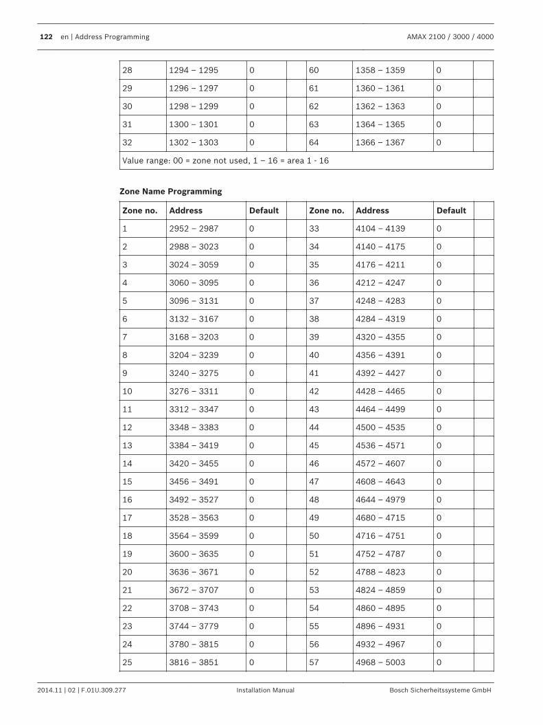
28 1294 – 1295 0 60 1358 – 1359 0
29 1296 – 1297 0 61 1360 – 1361 0
30 1298 – 1299 0 62 1362 – 1363 0
31 1300 – 1301 0 63 1364 – 1365 0
32 1302 – 1303 0 64 1366 – 1367 0
Value range: 00 = zone not used, 1 – 16 = area 1 - 16
Zone Name Programming
Zone no. Address Default Zone no. Address Default
1 2952 – 2987 0 33 4104 – 4139 0
2 2988 – 3023 0 34 4140 – 4175 0
3 3024 – 3059 0 35 4176 – 4211 0
4 3060 – 3095 0 36 4212 – 4247 0
5 3096 – 3131 0 37 4248 – 4283 0
6 3132 – 3167 0 38 4284 – 4319 0
7 3168 – 3203 0 39 4320 – 4355 0
8 3204 – 3239 0 40 4356 – 4391 0
9 3240 – 3275 0 41 4392 – 4427 0
10 3276 – 3311 0 42 4428 – 4465 0
11 3312 – 3347 0 43 4464 – 4499 0
12 3348 – 3383 0 44 4500 – 4535 0
13 3384 – 3419 0 45 4536 – 4571 0
14 3420 – 3455 0 46 4572 – 4607 0
15 3456 – 3491 0 47 4608 – 4643 0
16 3492 – 3527 0 48 4644 – 4979 0
17 3528 – 3563 0 49 4680 – 4715 0
18 3564 – 3599 0 50 4716 – 4751 0
19 3600 – 3635 0 51 4752 – 4787 0
20 3636 – 3671 0 52 4788 – 4823 0
21 3672 – 3707 0 53 4824 – 4859 0
22 3708 – 3743 0 54 4860 – 4895 0
23 3744 – 3779 0 55 4896 – 4931 0
24 3780 – 3815 0 56 4932 – 4967 0
25 3816 – 3851 0 57 4968 – 5003 0
122 en | Address Programming AMAX 2100 / 3000 / 4000
2014.11 | 02 | F.01U.309.277 Installation Manual Bosch Sicherheitssysteme GmbH
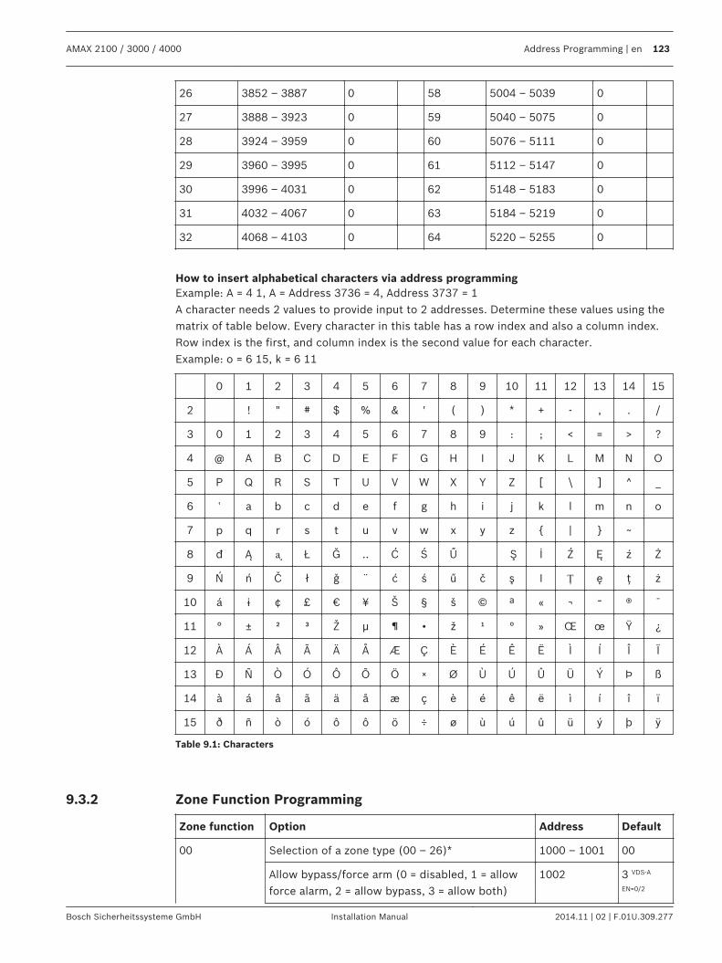
26 3852 – 3887 0 58 5004 – 5039 0
27 3888 – 3923 0 59 5040 – 5075 0
28 3924 – 3959 0 60 5076 – 5111 0
29 3960 – 3995 0 61 5112 – 5147 0
30 3996 – 4031 0 62 5148 – 5183 0
31 4032 – 4067 0 63 5184 – 5219 0
32 4068 – 4103 0 64 5220 – 5255 0
How to insert alphabetical characters via address programmingExample: A = 4 1, A = Address 3736 = 4, Address 3737 = 1A character needs 2 values to provide input to 2 addresses. Determine these values using thematrix of table below. Every character in this table has a row index and also a column index.Row index is the first, and column index is the second value for each character.Example: o = 6 15, k = 6 11
0 1 2 3 4 5 6 7 8 9 10 11 12 13 14 15
2 ! " # $ % & ' ( ) * + - , . /
3 0 1 2 3 4 5 6 7 8 9 : ; < = > ?
4 @ A B C D E F G H I J K L M N O
5 P Q R S T U V W X Y Z [ \ ] ^ _
6 ‛ a b c d e f g h i j k l m n o
7 p q r s t u v w x y z | ~
8 đ Ą ᶏ Ł Ğ .. Ć Ś Ű Ş İ Ź Ę ź Ż
9 Ń ń Č ł ǧ ¨ ć ś ű č ş I Ț ę ţ ż
10 á ɨ ¢ £ € ¥ Š § š © ª « ¬ ־ ® ¯
11 ° ± ² ³ Ž µ ¶ • ž ¹ ° » Œ œ Ÿ ¿
12 À Á Â Ã Ä Å Æ Ç È É Ê Ë Ì Í Î Ï
13 Đ Ñ Ò Ó Ô Õ Ö × Ø Ù Ú Û Ü Ý Þ ß
14 à á â ã ä å æ ç è é ê ë ì í î ï
15 ð ñ ò ó ô ô ö ÷ ø ù ú û ü ý þ ÿ
Table 9.1: Characters
Zone Function Programming
Zone function Option Address Default
00 Selection of a zone type (00 – 26)* 1000 – 1001 00
Allow bypass/force arm (0 = disabled, 1 = allowforce alarm, 2 = allow bypass, 3 = allow both)
1002 3 VDS-A
EN=0/2
9.3.2
AMAX 2100 / 3000 / 4000 Address Programming | en 123
Bosch Sicherheitssysteme GmbH Installation Manual 2014.11 | 02 | F.01U.309.277
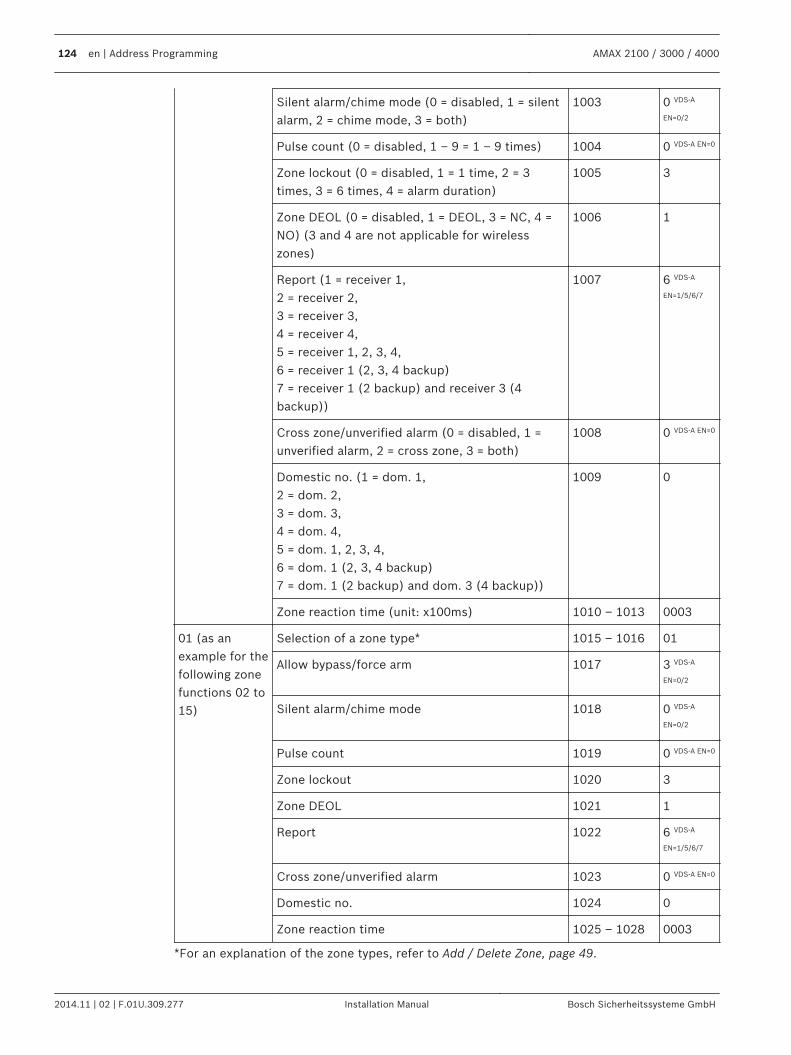
Silent alarm/chime mode (0 = disabled, 1 = silentalarm, 2 = chime mode, 3 = both)
1003 0 VDS-A
EN=0/2
Pulse count (0 = disabled, 1 – 9 = 1 – 9 times) 1004 0 VDS-A EN=0
Zone lockout (0 = disabled, 1 = 1 time, 2 = 3times, 3 = 6 times, 4 = alarm duration)
1005 3
Zone DEOL (0 = disabled, 1 = DEOL, 3 = NC, 4 =NO) (3 and 4 are not applicable for wirelesszones)
1006 1
Report (1 = receiver 1,2 = receiver 2,3 = receiver 3,4 = receiver 4,5 = receiver 1, 2, 3, 4,6 = receiver 1 (2, 3, 4 backup)7 = receiver 1 (2 backup) and receiver 3 (4backup))
1007 6 VDS-A
EN=1/5/6/7
Cross zone/unverified alarm (0 = disabled, 1 =unverified alarm, 2 = cross zone, 3 = both)
1008 0 VDS-A EN=0
Domestic no. (1 = dom. 1,2 = dom. 2,3 = dom. 3,4 = dom. 4,5 = dom. 1, 2, 3, 4,6 = dom. 1 (2, 3, 4 backup)7 = dom. 1 (2 backup) and dom. 3 (4 backup))
1009 0
Zone reaction time (unit: x100ms) 1010 – 1013 0003
01 (as anexample for thefollowing zonefunctions 02 to15)
Selection of a zone type* 1015 – 1016 01
Allow bypass/force arm 1017 3 VDS-A
EN=0/2
Silent alarm/chime mode 1018 0 VDS-A
EN=0/2
Pulse count 1019 0 VDS-A EN=0
Zone lockout 1020 3
Zone DEOL 1021 1
Report 1022 6 VDS-A
EN=1/5/6/7
Cross zone/unverified alarm 1023 0 VDS-A EN=0
Domestic no. 1024 0
Zone reaction time 1025 – 1028 0003
*For an explanation of the zone types, refer to Add / Delete Zone, page 49.
124 en | Address Programming AMAX 2100 / 3000 / 4000
2014.11 | 02 | F.01U.309.277 Installation Manual Bosch Sicherheitssysteme GmbH
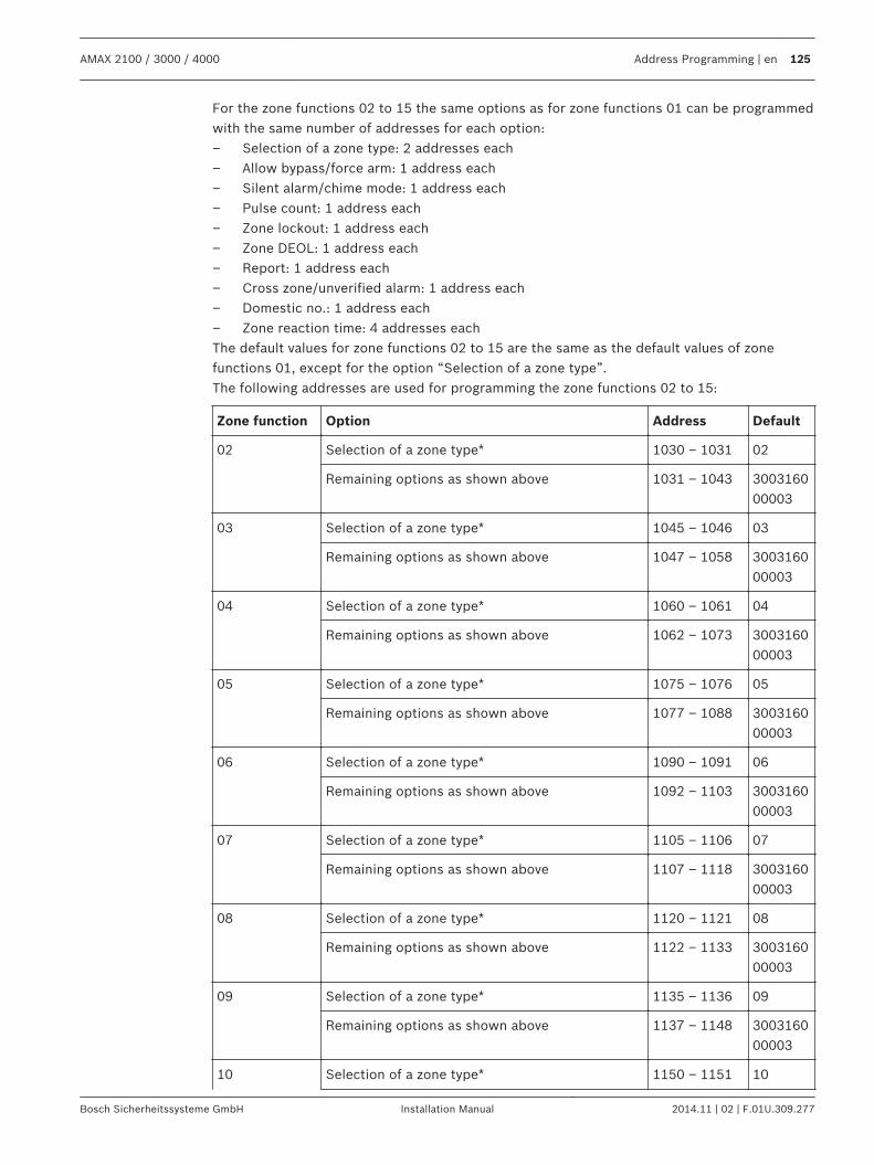
For the zone functions 02 to 15 the same options as for zone functions 01 can be programmedwith the same number of addresses for each option:– Selection of a zone type: 2 addresses each– Allow bypass/force arm: 1 address each– Silent alarm/chime mode: 1 address each– Pulse count: 1 address each– Zone lockout: 1 address each– Zone DEOL: 1 address each– Report: 1 address each– Cross zone/unverified alarm: 1 address each– Domestic no.: 1 address each– Zone reaction time: 4 addresses eachThe default values for zone functions 02 to 15 are the same as the default values of zonefunctions 01, except for the option “Selection of a zone type”.The following addresses are used for programming the zone functions 02 to 15:
Zone function Option Address Default
02 Selection of a zone type* 1030 – 1031 02
Remaining options as shown above 1031 – 1043 300316000003
03 Selection of a zone type* 1045 – 1046 03
Remaining options as shown above 1047 – 1058 300316000003
04 Selection of a zone type* 1060 – 1061 04
Remaining options as shown above 1062 – 1073 300316000003
05 Selection of a zone type* 1075 – 1076 05
Remaining options as shown above 1077 – 1088 300316000003
06 Selection of a zone type* 1090 – 1091 06
Remaining options as shown above 1092 – 1103 300316000003
07 Selection of a zone type* 1105 – 1106 07
Remaining options as shown above 1107 – 1118 300316000003
08 Selection of a zone type* 1120 – 1121 08
Remaining options as shown above 1122 – 1133 300316000003
09 Selection of a zone type* 1135 – 1136 09
Remaining options as shown above 1137 – 1148 300316000003
10 Selection of a zone type* 1150 – 1151 10
AMAX 2100 / 3000 / 4000 Address Programming | en 125
Bosch Sicherheitssysteme GmbH Installation Manual 2014.11 | 02 | F.01U.309.277
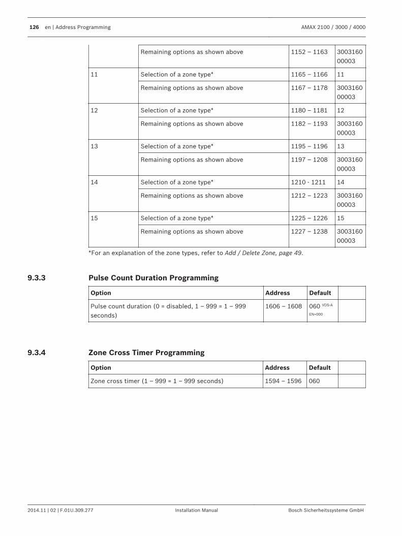
Remaining options as shown above 1152 – 1163 300316000003
11 Selection of a zone type* 1165 – 1166 11
Remaining options as shown above 1167 – 1178 300316000003
12 Selection of a zone type* 1180 – 1181 12
Remaining options as shown above 1182 – 1193 300316000003
13 Selection of a zone type* 1195 – 1196 13
Remaining options as shown above 1197 – 1208 300316000003
14 Selection of a zone type* 1210 - 1211 14
Remaining options as shown above 1212 – 1223 300316000003
15 Selection of a zone type* 1225 – 1226 15
Remaining options as shown above 1227 – 1238 300316000003
*For an explanation of the zone types, refer to Add / Delete Zone, page 49.
Pulse Count Duration Programming
Option Address Default
Pulse count duration (0 = disabled, 1 – 999 = 1 – 999seconds)
1606 – 1608 060 VDS-A
EN=000
Zone Cross Timer Programming
Option Address Default
Zone cross timer (1 – 999 = 1 – 999 seconds) 1594 – 1596 060
9.3.3
9.3.4
126 en | Address Programming AMAX 2100 / 3000 / 4000
2014.11 | 02 | F.01U.309.277 Installation Manual Bosch Sicherheitssysteme GmbH
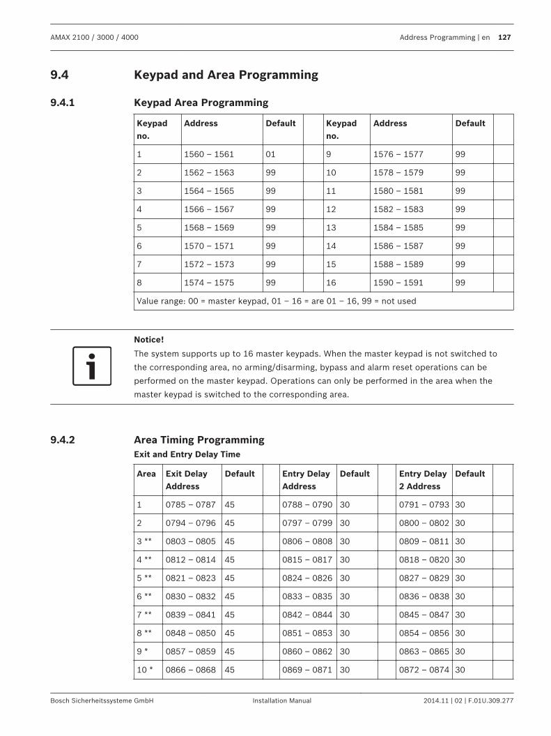
Keypad and Area Programming
Keypad Area Programming
Keypadno.
Address Default Keypadno.
Address Default
1 1560 – 1561 01 9 1576 – 1577 99
2 1562 – 1563 99 10 1578 – 1579 99
3 1564 – 1565 99 11 1580 – 1581 99
4 1566 – 1567 99 12 1582 – 1583 99
5 1568 – 1569 99 13 1584 – 1585 99
6 1570 – 1571 99 14 1586 – 1587 99
7 1572 – 1573 99 15 1588 – 1589 99
8 1574 – 1575 99 16 1590 – 1591 99
Value range: 00 = master keypad, 01 – 16 = are 01 – 16, 99 = not used
Notice!
The system supports up to 16 master keypads. When the master keypad is not switched to
the corresponding area, no arming/disarming, bypass and alarm reset operations can be
performed on the master keypad. Operations can only be performed in the area when the
master keypad is switched to the corresponding area.
Area Timing ProgrammingExit and Entry Delay Time
Area Exit DelayAddress
Default Entry DelayAddress
Default Entry Delay2 Address
Default
1 0785 – 0787 45 0788 – 0790 30 0791 – 0793 30
2 0794 – 0796 45 0797 – 0799 30 0800 – 0802 30
3 ** 0803 – 0805 45 0806 – 0808 30 0809 – 0811 30
4 ** 0812 – 0814 45 0815 – 0817 30 0818 – 0820 30
5 ** 0821 – 0823 45 0824 – 0826 30 0827 – 0829 30
6 ** 0830 – 0832 45 0833 – 0835 30 0836 – 0838 30
7 ** 0839 – 0841 45 0842 – 0844 30 0845 – 0847 30
8 ** 0848 – 0850 45 0851 – 0853 30 0854 – 0856 30
9 * 0857 – 0859 45 0860 – 0862 30 0863 – 0865 30
10 * 0866 – 0868 45 0869 – 0871 30 0872 – 0874 30
9.4
9.4.1
9.4.2
AMAX 2100 / 3000 / 4000 Address Programming | en 127
Bosch Sicherheitssysteme GmbH Installation Manual 2014.11 | 02 | F.01U.309.277
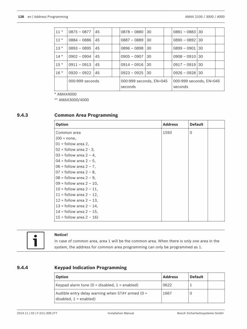
11 * 0875 – 0877 45 0878 – 0880 30 0881 – 0883 30
12 * 0884 – 0886 45 0887 – 0889 30 0890 – 0892 30
13 * 0893 – 0895 45 0896 – 0898 30 0899 – 0901 30
14 * 0902 – 0904 45 0905 – 0907 30 0908 – 0910 30
15 * 0911 – 0913 45 0914 – 0916 30 0917 – 0919 30
16 * 0920 – 0922 45 0923 – 0925 30 0926 – 0928 30
000-999 seconds 000-999 seconds, EN=045seconds
000-999 seconds, EN=045seconds
* AMAX4000** AMAX3000/4000
Common Area Programming
Option Address Default
Common area(00 = none,01 = follow area 2,02 = follow area 2 - 3,03 = follow area 2 – 4,04 = follow area 2 – 5,06 = follow area 2 – 7,07 = follow area 2 – 8,08 = follow area 2 – 9,09 = follow area 2 – 10,10 = follow area 2 – 11,11 = follow area 2 – 12,12 = follow area 2 – 13,13 = follow area 2 – 14,14 = follow area 2 – 15,15 = follow area 2 – 16)
1593 0
Notice!
In case of common area, area 1 will be the common area. When there is only one area in the
system, the address for common area programming can only be programmed as 1.
Keypad Indication Programming
Option Address Default
Keypad alarm tone (0 = disabled, 1 = enabled) 0622 1
Audible entry delay warning when STAY armed (0 =disabled, 1 = enabled)
1667 0
9.4.3
9.4.4
128 en | Address Programming AMAX 2100 / 3000 / 4000
2014.11 | 02 | F.01U.309.277 Installation Manual Bosch Sicherheitssysteme GmbH
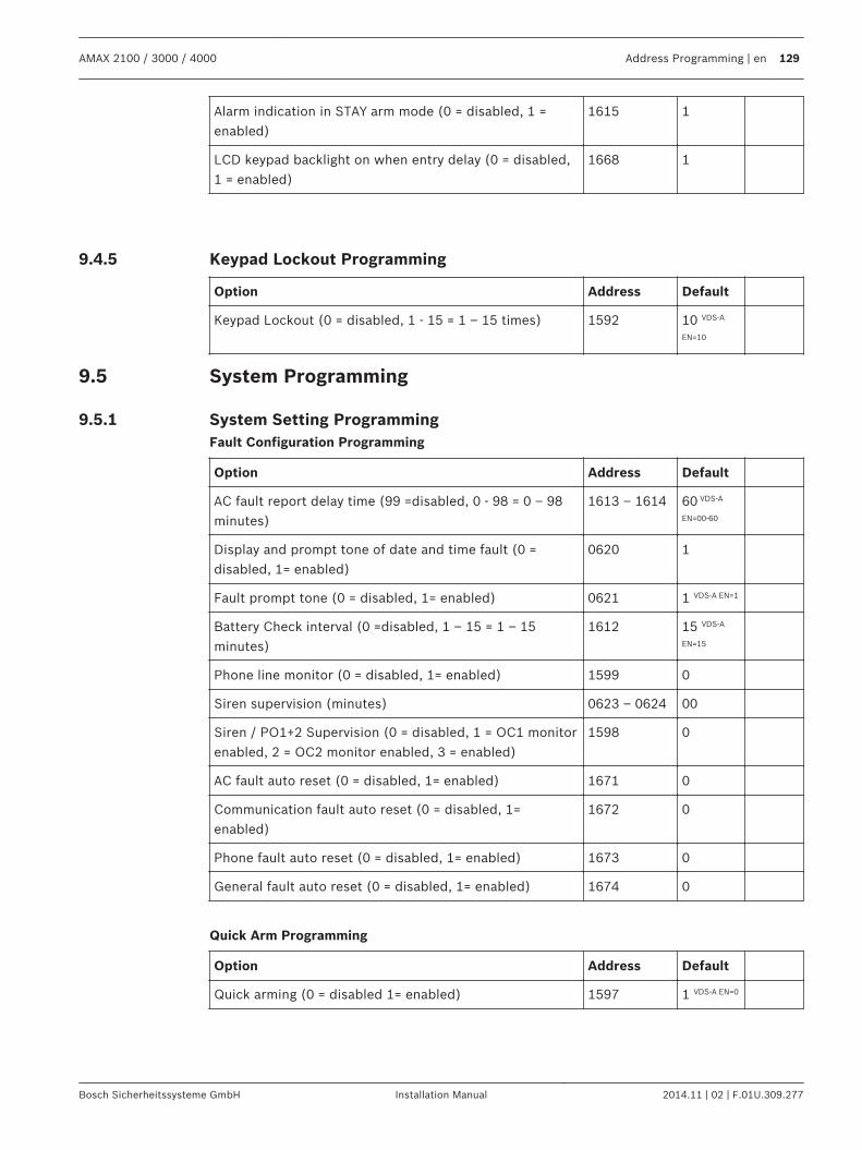
Alarm indication in STAY arm mode (0 = disabled, 1 =enabled)
1615 1
LCD keypad backlight on when entry delay (0 = disabled,1 = enabled)
1668 1
Keypad Lockout Programming
Option Address Default
Keypad Lockout (0 = disabled, 1 - 15 = 1 – 15 times) 1592 10 VDS-A
EN=10
System Programming
System Setting ProgrammingFault Configuration Programming
Option Address Default
AC fault report delay time (99 =disabled, 0 - 98 = 0 – 98minutes)
1613 – 1614 60 VDS-A
EN=00-60
Display and prompt tone of date and time fault (0 =disabled, 1= enabled)
0620 1
Fault prompt tone (0 = disabled, 1= enabled) 0621 1 VDS-A EN=1
Battery Check interval (0 =disabled, 1 – 15 = 1 – 15minutes)
1612 15 VDS-A
EN=15
Phone line monitor (0 = disabled, 1= enabled) 1599 0
Siren supervision (minutes) 0623 – 0624 00
Siren / PO1+2 Supervision (0 = disabled, 1 = OC1 monitorenabled, 2 = OC2 monitor enabled, 3 = enabled)
1598 0
AC fault auto reset (0 = disabled, 1= enabled) 1671 0
Communication fault auto reset (0 = disabled, 1=enabled)
1672 0
Phone fault auto reset (0 = disabled, 1= enabled) 1673 0
General fault auto reset (0 = disabled, 1= enabled) 1674 0
Quick Arm Programming
Option Address Default
Quick arming (0 = disabled 1= enabled) 1597 1 VDS-A EN=0
9.4.5
9.5
9.5.1
AMAX 2100 / 3000 / 4000 Address Programming | en 129
Bosch Sicherheitssysteme GmbH Installation Manual 2014.11 | 02 | F.01U.309.277
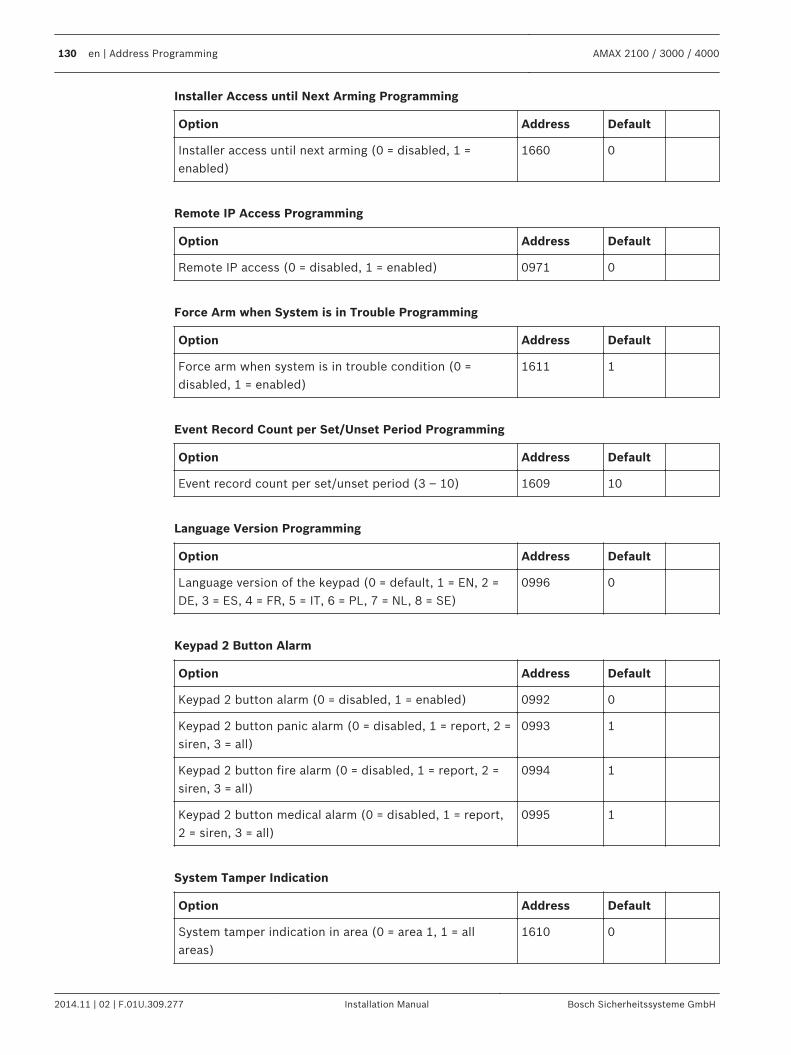
Installer Access until Next Arming Programming
Option Address Default
Installer access until next arming (0 = disabled, 1 =enabled)
1660 0
Remote IP Access Programming
Option Address Default
Remote IP access (0 = disabled, 1 = enabled) 0971 0
Force Arm when System is in Trouble Programming
Option Address Default
Force arm when system is in trouble condition (0 =disabled, 1 = enabled)
1611 1
Event Record Count per Set/Unset Period Programming
Option Address Default
Event record count per set/unset period (3 – 10) 1609 10
Language Version Programming
Option Address Default
Language version of the keypad (0 = default, 1 = EN, 2 =DE, 3 = ES, 4 = FR, 5 = IT, 6 = PL, 7 = NL, 8 = SE)
0996 0
Keypad 2 Button Alarm
Option Address Default
Keypad 2 button alarm (0 = disabled, 1 = enabled) 0992 0
Keypad 2 button panic alarm (0 = disabled, 1 = report, 2 =siren, 3 = all)
0993 1
Keypad 2 button fire alarm (0 = disabled, 1 = report, 2 =siren, 3 = all)
0994 1
Keypad 2 button medical alarm (0 = disabled, 1 = report,2 = siren, 3 = all)
0995 1
System Tamper Indication
Option Address Default
System tamper indication in area (0 = area 1, 1 = allareas)
1610 0
130 en | Address Programming AMAX 2100 / 3000 / 4000
2014.11 | 02 | F.01U.309.277 Installation Manual Bosch Sicherheitssysteme GmbH
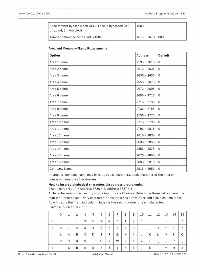
Zone tamper bypass when DEOL zone is bypassed (0 =disabled, 1 = enabled)
1603 1
Tamper debounce time (unit: x100s) 1675 – 1678 0003
Area and Company Name Programming
Option Address Default
Area 1 name 2595 – 2615 0
Area 2 name 2616 – 2635 0
Area 3 name 2636 – 2655 0
Area 4 name 2656 – 2675 0
Area 5 name 2676 – 2695 0
Area 6 name 2696 – 2715 0
Area 7 name 2716 – 2735 0
Area 8 name 2736 – 2755 0
Area 9 name 2756 – 2775 0
Area 10 name 2776 – 2795 0
Area 11 name 2796 – 2815 0
Area 12 name 2816 – 2835 0
Area 13 name 2836 – 2855 0
Area 14 name 2856 – 2875 0
Area 15 name 2876 – 2895 0
Area 16 name 2896 – 2915 0
Company Name 2916 – 2951 0
An area or company name may have up to 18 characters. Each character of the area orcompany name uses 2 addresses.
How to insert alphabetical characters via address programmingExample: A = 4 1, A = Address 3736 = 4, Address 3737 = 1A character needs 2 values to provide input to 2 addresses. Determine these values using thematrix of table below. Every character in this table has a row index and also a column index.Row index is the first, and column index is the second value for each character.Example: o = 6 15, k = 6 11
0 1 2 3 4 5 6 7 8 9 10 11 12 13 14 15
2 ! " # $ % & ' ( ) * + - , . /
3 0 1 2 3 4 5 6 7 8 9 : ; < = > ?
4 @ A B C D E F G H I J K L M N O
5 P Q R S T U V W X Y Z [ \ ] ^ _
6 ‛ a b c d e f g h i j k l m n o
AMAX 2100 / 3000 / 4000 Address Programming | en 131
Bosch Sicherheitssysteme GmbH Installation Manual 2014.11 | 02 | F.01U.309.277
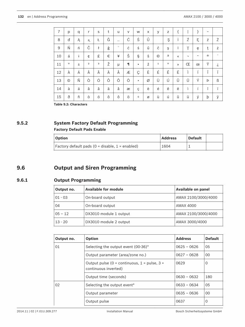
7 p q r s t u v w x y z | ~
8 đ Ą ᶏ Ł Ğ .. Ć Ś Ű Ş İ Ź Ę ź Ż
9 Ń ń Č ł ǧ ¨ ć ś ű č ş I Ț ę ţ ż
10 á ɨ ¢ £ € ¥ Š § š © ª « ¬ ־ ® ¯
11 ° ± ² ³ Ž µ ¶ • ž ¹ ° » Œ œ Ÿ ¿
12 À Á Â Ã Ä Å Æ Ç È É Ê Ë Ì Í Î Ï
13 Đ Ñ Ò Ó Ô Õ Ö × Ø Ù Ú Û Ü Ý Þ ß
14 à á â ã ä å æ ç è é ê ë ì í î ï
15 ð ñ ò ó ô ô ö ÷ ø ù ú û ü ý þ ÿ
Table 9.2: Characters
System Factory Default ProgrammingFactory Default Pads Enable
Option Address Default
Factory default pads (0 = disable, 1 = enabled) 1604 1
Output and Siren Programming
Output Programming
Output no. Available for module Available on panel
01 - 03 On-board output AMAX 2100/3000/4000
04 On-board output AMAX 4000
05 – 12 DX3010 module 1 output AMAX 2100/3000/4000
13 - 20 DX3010 module 2 output AMAX 3000/4000
Output no. Option Address Default
01 Selecting the output event (00-36)* 0625 – 0626 05
Output parameter (area/zone no.) 0627 – 0628 00
Output pulse (0 = continuous, 1 = pulse, 3 =continuous inverted)
0629 0
Output time (seconds) 0630 – 0632 180
02 Selecting the output event* 0633 – 0634 05
Output parameter 0635 – 0636 00
Output pulse 0637 0
9.5.2
9.6
9.6.1
132 en | Address Programming AMAX 2100 / 3000 / 4000
2014.11 | 02 | F.01U.309.277 Installation Manual Bosch Sicherheitssysteme GmbH
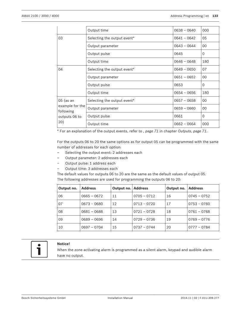
Output time 0638 – 0640 000
03 Selecting the output event* 0641 – 0642 05
Output parameter 0643 – 0644 00
Output pulse 0645 0
Output time 0646 – 0648 180
04 Selecting the output event* 0649 – 0650 07
Output parameter 0651 – 0652 00
Output pulse 0653 0
Output time 0654 – 0656 180
05 (as anexample for thefollowingoutputs 06 to20)
Selecting the output event* 0657 – 0658 00
Output parameter 0659 – 0660 00
Output pulse 0661 0
Output time 0662 – 0664 000
* For an explanation of the output events, refer to , page 71 in chapter Outputs, page 71. For the outputs 06 to 20 the same options as for output 05 can be programmed with the samenumber of addresses for each option:– Selecting the output event: 2 addresses each– Output parameter: 2 addresses each– Output pulse: 1 address each– Output time: 3 addresses eachThe default values for outputs 06 to 20 are the same as the default values of output 05.The following addresses are used for programming the outputs 06 to 20:
Output no. Address Output no. Address Output no. Address
06 0665 – 0672 11 0705 – 0712 16 0745 – 0752
07 0673 – 0680 12 0713 – 0720 17 0753 – 0760
08 0681 – 0688 13 0721 – 0728 18 0761 – 0768
09 0689 – 0696 14 0729 – 0736 19 0769 – 0776
10 0697 – 0704 15 0737 – 0744 20 0777 – 0784
Notice!
When the zone activating alarm is programmed as a silent alarm, keypad and audible alarm
have no output.
AMAX 2100 / 3000 / 4000 Address Programming | en 133
Bosch Sicherheitssysteme GmbH Installation Manual 2014.11 | 02 | F.01U.309.277
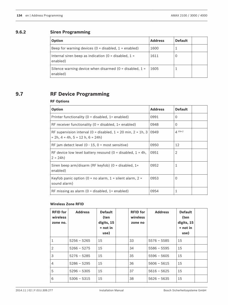
Siren Programming
Option Address Default
Beep for warning devices (0 = disabled, 1 = enabled) 1600 1
Internal siren beep as indication (0 = disabled, 1 =enabled)
1611 0
Silence warning device when disarmed (0 = disabled, 1 =enabled)
1605 1
RF Device ProgrammingRF Options
Option Address Default
Printer functionality (0 = disabled, 1= enabled) 0991 0
RF receiver functionality (0 = disabled, 1= enabled) 0948 0
RF supervision interval (0 = disabled, 1 = 20 min, 2 = 1h, 3= 2h, 4 = 4h, 5 = 12 h, 6 = 24h)
0949 4 EN=2
RF jam detect level (0 - 15, 0 = most sensitive) 0950 12
RF device low level battery resound (0 = disabled, 1 = 4h,2 = 24h)
0951 2
Siren beep arm/disarm (RF keyfob) (0 = disabled, 1=enabled)
0952 1
Keyfob panic option (0 = no alarm, 1 = silent alarm, 2 =sound alarm)
0953 0
RF missing as alarm (0 = disabled, 1= enabled) 0954 1
Wireless Zone RFID
RFID forwirelesszone no.
Address Default(ten
digits, 15= not in
use)
RFID forwirelesszone no
Address Default(ten
digits, 15= not in
use)
1 5256 – 5265 15 33 5576 – 5585 15
2 5266 – 5275 15 34 5586 – 5595 15
3 5276 – 5285 15 35 5596 – 5605 15
4 5286 – 5295 15 36 5606 – 5615 15
5 5296 – 5305 15 37 5616 – 5625 15
6 5306 – 5315 15 38 5626 – 5635 15
9.6.2
9.7
134 en | Address Programming AMAX 2100 / 3000 / 4000
2014.11 | 02 | F.01U.309.277 Installation Manual Bosch Sicherheitssysteme GmbH
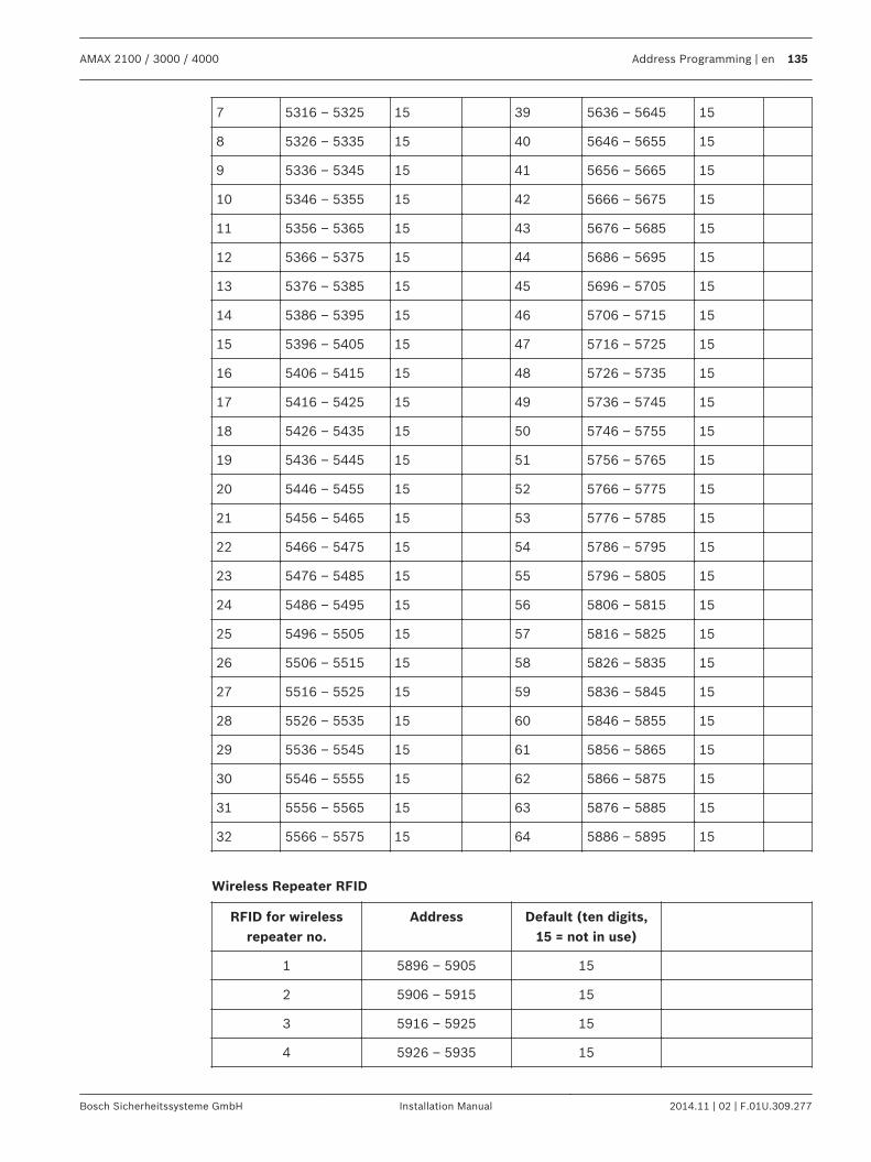
7 5316 – 5325 15 39 5636 – 5645 15
8 5326 – 5335 15 40 5646 – 5655 15
9 5336 – 5345 15 41 5656 – 5665 15
10 5346 – 5355 15 42 5666 – 5675 15
11 5356 – 5365 15 43 5676 – 5685 15
12 5366 – 5375 15 44 5686 – 5695 15
13 5376 – 5385 15 45 5696 – 5705 15
14 5386 – 5395 15 46 5706 – 5715 15
15 5396 – 5405 15 47 5716 – 5725 15
16 5406 – 5415 15 48 5726 – 5735 15
17 5416 – 5425 15 49 5736 – 5745 15
18 5426 – 5435 15 50 5746 – 5755 15
19 5436 – 5445 15 51 5756 – 5765 15
20 5446 – 5455 15 52 5766 – 5775 15
21 5456 – 5465 15 53 5776 – 5785 15
22 5466 – 5475 15 54 5786 – 5795 15
23 5476 – 5485 15 55 5796 – 5805 15
24 5486 – 5495 15 56 5806 – 5815 15
25 5496 – 5505 15 57 5816 – 5825 15
26 5506 – 5515 15 58 5826 – 5835 15
27 5516 – 5525 15 59 5836 – 5845 15
28 5526 – 5535 15 60 5846 – 5855 15
29 5536 – 5545 15 61 5856 – 5865 15
30 5546 – 5555 15 62 5866 – 5875 15
31 5556 – 5565 15 63 5876 – 5885 15
32 5566 – 5575 15 64 5886 – 5895 15
Wireless Repeater RFID
RFID for wirelessrepeater no.
Address Default (ten digits,15 = not in use)
1 5896 – 5905 15
2 5906 – 5915 15
3 5916 – 5925 15
4 5926 – 5935 15
AMAX 2100 / 3000 / 4000 Address Programming | en 135
Bosch Sicherheitssysteme GmbH Installation Manual 2014.11 | 02 | F.01U.309.277
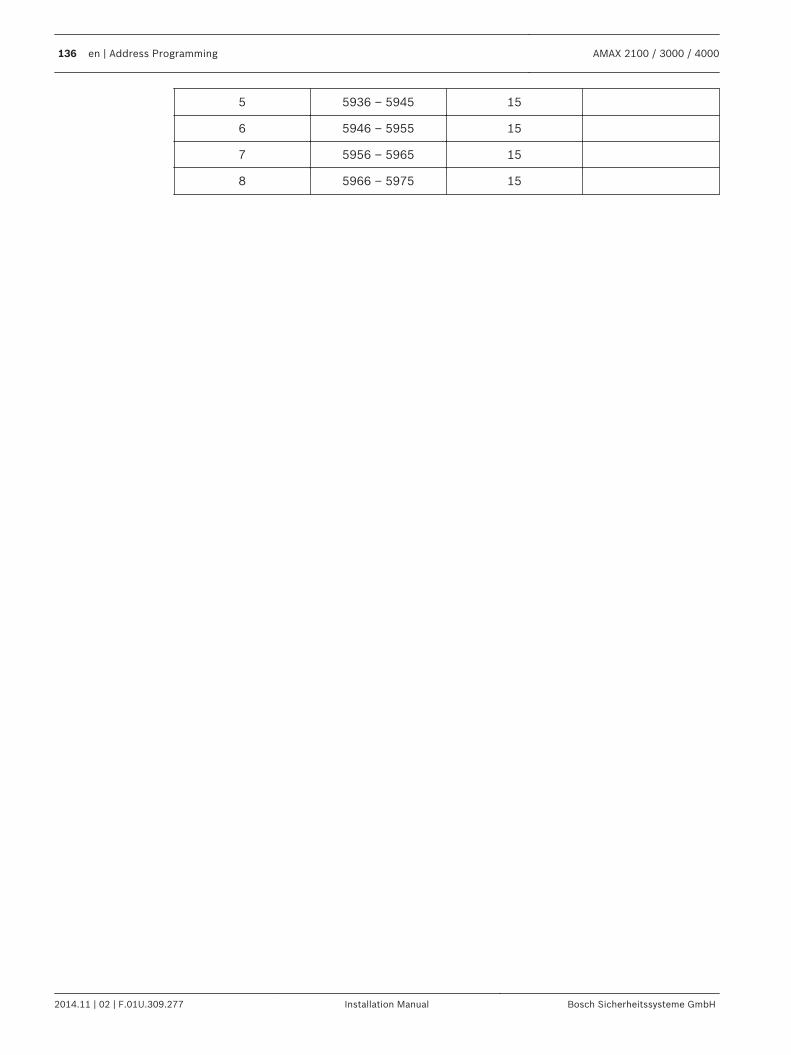
5 5936 – 5945 15
6 5946 – 5955 15
7 5956 – 5965 15
8 5966 – 5975 15
136 en | Address Programming AMAX 2100 / 3000 / 4000
2014.11 | 02 | F.01U.309.277 Installation Manual Bosch Sicherheitssysteme GmbH
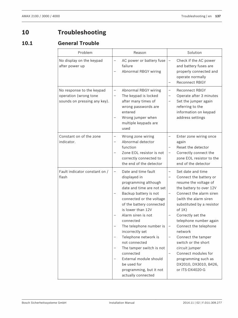
Troubleshooting
General Trouble
Problem Reason Solution
No display on the keypadafter power up
– AC power or battery fusefailure
– Abnormal RBGY wiring
– Check if the AC powerand battery fuses areproperly connected andoperate normally
– Reconnect RBGY
No response to the keypadoperation (wrong tonesounds on pressing any key).
– Abnormal RBGY wiring– The keypad is locked
after many times ofwrong passwords areentered
– Wrong jumper whenmultiple keypads areused
– Reconnect RBGY– Operate after 3 minutes– Set the jumper again
referring to theinformation on keypadaddress settings
Constant on of the zoneindicator.
– Wrong zone wiring– Abnormal detector
function– Zone EOL resistor is not
correctly connected tothe end of the detector
– Enter zone wiring onceagain
– Reset the detector– Correctly connect the
zone EOL resistor to theend of the detector
Fault indicator constant on /flash
– Date and time faultdisplayed inprogramming althoughdate and time are not set
– Backup battery is notconnected or the voltageof the battery connectedis lower than 12V
– Alarm siren is notconnected
– The telephone number isincorrectly set
– Telephone network isnot connected
– The tamper switch is notconnected
– External module shouldbe used forprogramming, but it notactually connected
– Set date and time– Connect the battery or
resume the voltage ofthe battery to over 12V
– Connect the alarm siren(with the alarm sirensubstituted by a resistorof 1K)
– Correctly set thetelephone number again
– Connect the telephonenetwork
– Connect the tamperswitch or the shortcircuit jumper
– Connect modules forprogramming such asDX2010, DX3010, B426,or ITS-DX4020-G
10
10.1
AMAX 2100 / 3000 / 4000 Troubleshooting | en 137
Bosch Sicherheitssysteme GmbH Installation Manual 2014.11 | 02 | F.01U.309.277
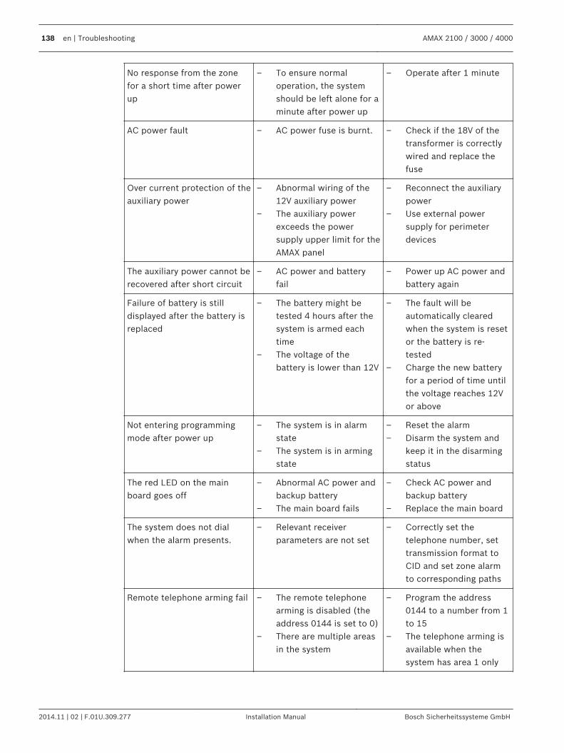
No response from the zonefor a short time after powerup
– To ensure normaloperation, the systemshould be left alone for aminute after power up
– Operate after 1 minute
AC power fault – AC power fuse is burnt. – Check if the 18V of thetransformer is correctlywired and replace thefuse
Over current protection of theauxiliary power
– Abnormal wiring of the12V auxiliary power
– The auxiliary powerexceeds the powersupply upper limit for theAMAX panel
– Reconnect the auxiliarypower
– Use external powersupply for perimeterdevices
The auxiliary power cannot berecovered after short circuit
– AC power and batteryfail
– Power up AC power andbattery again
Failure of battery is stilldisplayed after the battery isreplaced
– The battery might betested 4 hours after thesystem is armed eachtime
– The voltage of thebattery is lower than 12V
– The fault will beautomatically clearedwhen the system is resetor the battery is re-tested
– Charge the new batteryfor a period of time untilthe voltage reaches 12Vor above
Not entering programmingmode after power up
– The system is in alarmstate
– The system is in armingstate
– Reset the alarm– Disarm the system and
keep it in the disarmingstatus
The red LED on the mainboard goes off
– Abnormal AC power andbackup battery
– The main board fails
– Check AC power andbackup battery
– Replace the main board
The system does not dialwhen the alarm presents.
– Relevant receiverparameters are not set
– Correctly set thetelephone number, settransmission format toCID and set zone alarmto corresponding paths
Remote telephone arming fail – The remote telephonearming is disabled (theaddress 0144 is set to 0)
– There are multiple areasin the system
– Program the address0144 to a number from 1to 15
– The telephone arming isavailable when thesystem has area 1 only
138 en | Troubleshooting AMAX 2100 / 3000 / 4000
2014.11 | 02 | F.01U.309.277 Installation Manual Bosch Sicherheitssysteme GmbH
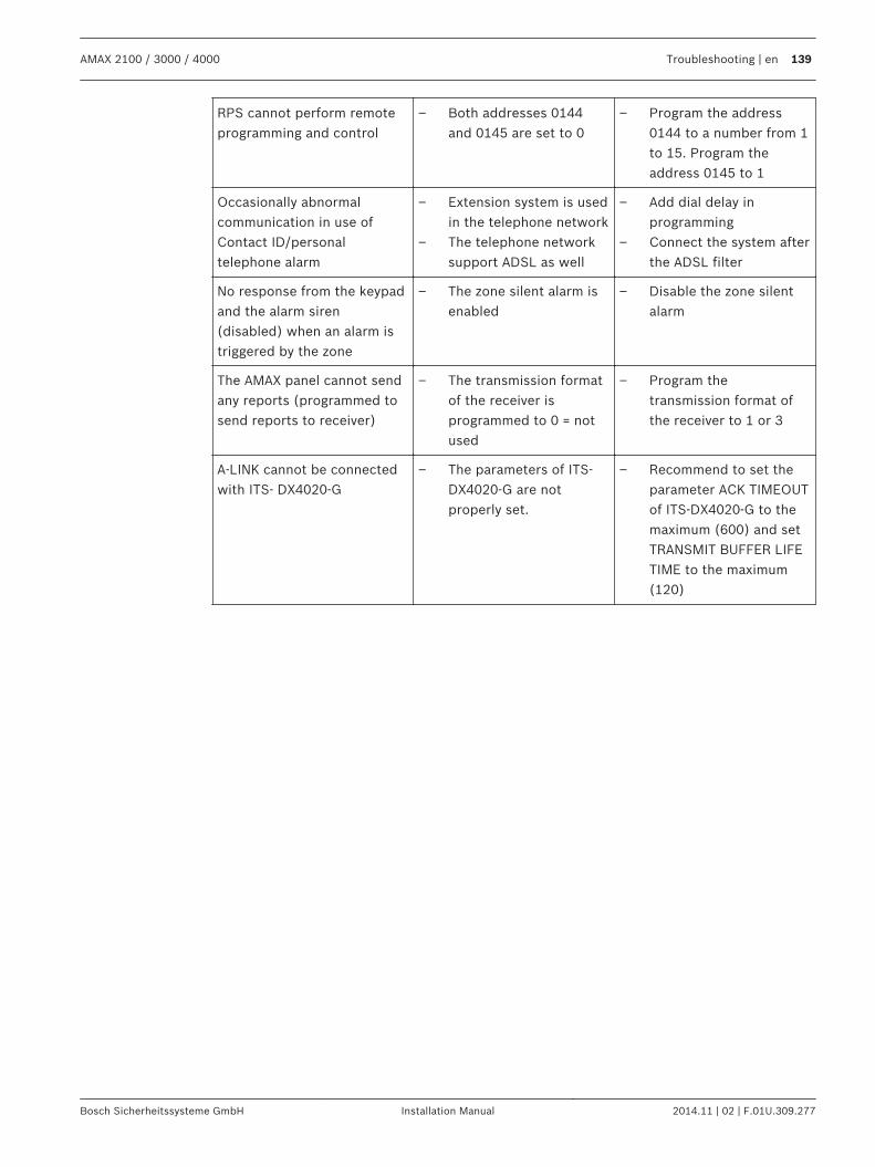
RPS cannot perform remoteprogramming and control
– Both addresses 0144and 0145 are set to 0
– Program the address0144 to a number from 1to 15. Program theaddress 0145 to 1
Occasionally abnormalcommunication in use ofContact ID/personaltelephone alarm
– Extension system is usedin the telephone network
– The telephone networksupport ADSL as well
– Add dial delay inprogramming
– Connect the system afterthe ADSL filter
No response from the keypadand the alarm siren(disabled) when an alarm istriggered by the zone
– The zone silent alarm isenabled
– Disable the zone silentalarm
The AMAX panel cannot sendany reports (programmed tosend reports to receiver)
– The transmission formatof the receiver isprogrammed to 0 = notused
– Program thetransmission format ofthe receiver to 1 or 3
A-LINK cannot be connectedwith ITS- DX4020-G
– The parameters of ITS-DX4020-G are notproperly set.
– Recommend to set theparameter ACK TIMEOUTof ITS-DX4020-G to themaximum (600) and setTRANSMIT BUFFER LIFETIME to the maximum(120)
AMAX 2100 / 3000 / 4000 Troubleshooting | en 139
Bosch Sicherheitssysteme GmbH Installation Manual 2014.11 | 02 | F.01U.309.277
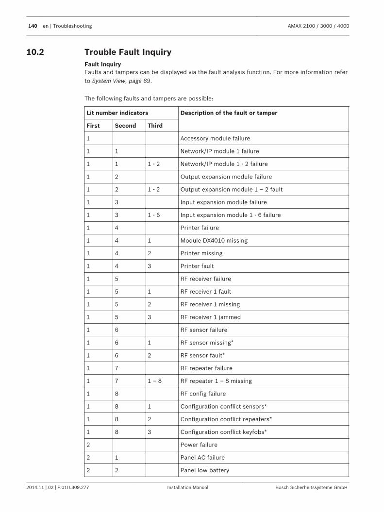
Trouble Fault InquiryFault InquiryFaults and tampers can be displayed via the fault analysis function. For more information referto System View, page 69. The following faults and tampers are possible:
Lit number indicators Description of the fault or tamper
First Second Third
1 Accessory module failure
1 1 Network/IP module 1 failure
1 1 1 - 2 Network/IP module 1 - 2 failure
1 2 Output expansion module failure
1 2 1 - 2 Output expansion module 1 – 2 fault
1 3 Input expansion module failure
1 3 1 - 6 Input expansion module 1 - 6 failure
1 4 Printer failure
1 4 1 Module DX4010 missing
1 4 2 Printer missing
1 4 3 Printer fault
1 5 RF receiver failure
1 5 1 RF receiver 1 fault
1 5 2 RF receiver 1 missing
1 5 3 RF receiver 1 jammed
1 6 RF sensor failure
1 6 1 RF sensor missing*
1 6 2 RF sensor fault*
1 7 RF repeater failure
1 7 1 – 8 RF repeater 1 – 8 missing
1 8 RF config failure
1 8 1 Configuration conflict sensors*
1 8 2 Configuration conflict repeaters*
1 8 3 Configuration conflict keyfobs*
2 Power failure
2 1 Panel AC failure
2 2 Panel low battery
10.2
140 en | Troubleshooting AMAX 2100 / 3000 / 4000
2014.11 | 02 | F.01U.309.277 Installation Manual Bosch Sicherheitssysteme GmbH
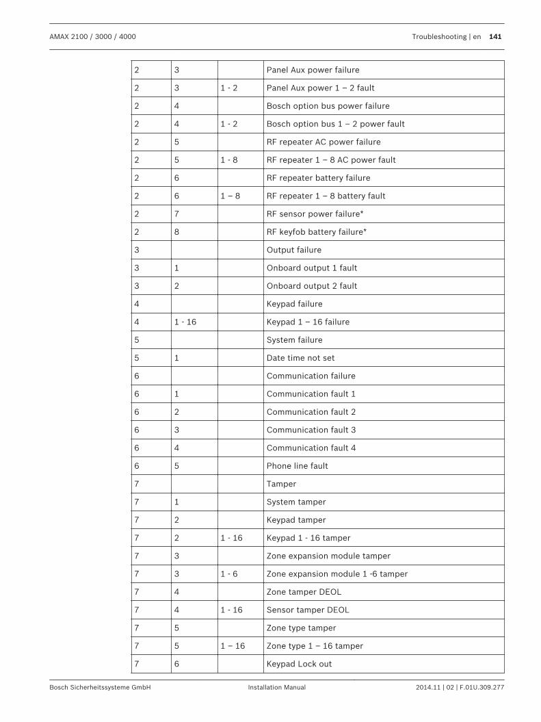
2 3 Panel Aux power failure
2 3 1 - 2 Panel Aux power 1 – 2 fault
2 4 Bosch option bus power failure
2 4 1 - 2 Bosch option bus 1 – 2 power fault
2 5 RF repeater AC power failure
2 5 1 - 8 RF repeater 1 – 8 AC power fault
2 6 RF repeater battery failure
2 6 1 – 8 RF repeater 1 – 8 battery fault
2 7 RF sensor power failure*
2 8 RF keyfob battery failure*
3 Output failure
3 1 Onboard output 1 fault
3 2 Onboard output 2 fault
4 Keypad failure
4 1 - 16 Keypad 1 – 16 failure
5 System failure
5 1 Date time not set
6 Communication failure
6 1 Communication fault 1
6 2 Communication fault 2
6 3 Communication fault 3
6 4 Communication fault 4
6 5 Phone line fault
7 Tamper
7 1 System tamper
7 2 Keypad tamper
7 2 1 - 16 Keypad 1 - 16 tamper
7 3 Zone expansion module tamper
7 3 1 - 6 Zone expansion module 1 -6 tamper
7 4 Zone tamper DEOL
7 4 1 - 16 Sensor tamper DEOL
7 5 Zone type tamper
7 5 1 – 16 Zone type 1 – 16 tamper
7 6 Keypad Lock out
AMAX 2100 / 3000 / 4000 Troubleshooting | en 141
Bosch Sicherheitssysteme GmbH Installation Manual 2014.11 | 02 | F.01U.309.277
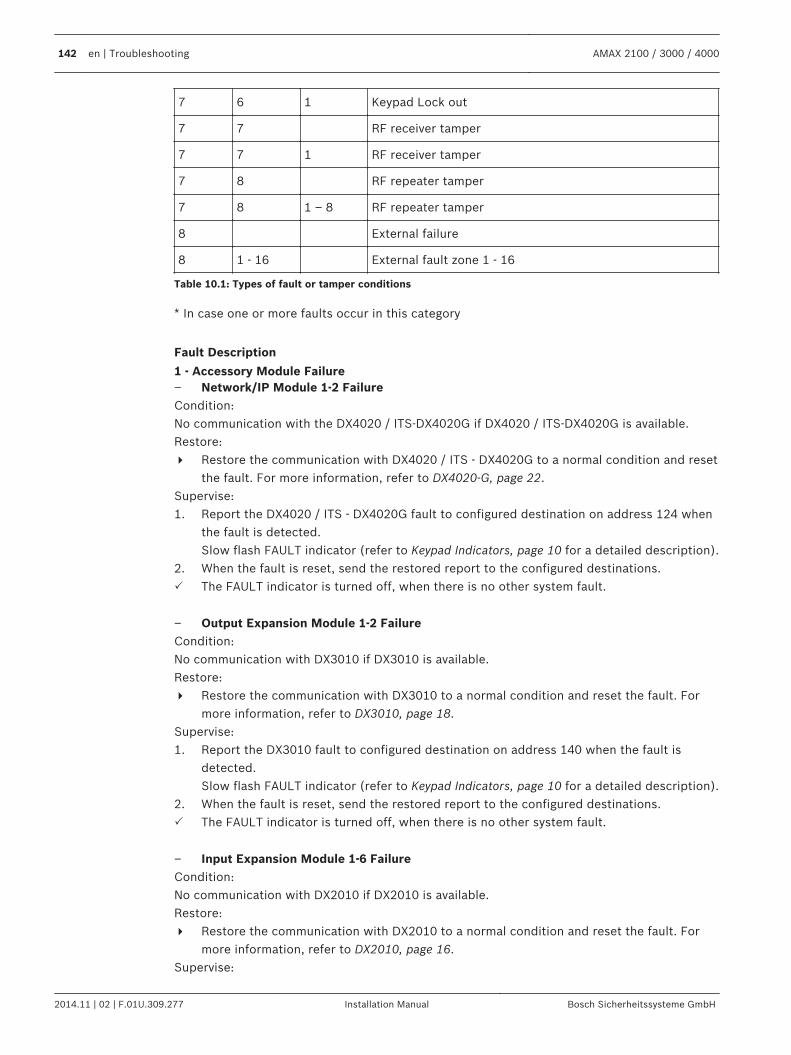
7 6 1 Keypad Lock out
7 7 RF receiver tamper
7 7 1 RF receiver tamper
7 8 RF repeater tamper
7 8 1 – 8 RF repeater tamper
8 External failure
8 1 - 16 External fault zone 1 - 16
Table 10.1: Types of fault or tamper conditions
* In case one or more faults occur in this category
Fault Description
1 - Accessory Module Failure– Network/IP Module 1-2 FailureCondition:No communication with the DX4020 / ITS-DX4020G if DX4020 / ITS-DX4020G is available.Restore:4 Restore the communication with DX4020 / ITS - DX4020G to a normal condition and reset
the fault. For more information, refer to DX4020-G, page 22.Supervise:1. Report the DX4020 / ITS - DX4020G fault to configured destination on address 124 when
the fault is detected.Slow flash FAULT indicator (refer to Keypad Indicators, page 10 for a detailed description).
2. When the fault is reset, send the restored report to the configured destinations.P The FAULT indicator is turned off, when there is no other system fault.
– Output Expansion Module 1-2 FailureCondition:No communication with DX3010 if DX3010 is available.Restore:4 Restore the communication with DX3010 to a normal condition and reset the fault. For
more information, refer to DX3010, page 18.Supervise:1. Report the DX3010 fault to configured destination on address 140 when the fault is
detected.Slow flash FAULT indicator (refer to Keypad Indicators, page 10 for a detailed description).
2. When the fault is reset, send the restored report to the configured destinations.P The FAULT indicator is turned off, when there is no other system fault.
– Input Expansion Module 1-6 FailureCondition:No communication with DX2010 if DX2010 is available.Restore:4 Restore the communication with DX2010 to a normal condition and reset the fault. For
more information, refer to DX2010, page 16.Supervise:
142 en | Troubleshooting AMAX 2100 / 3000 / 4000
2014.11 | 02 | F.01U.309.277 Installation Manual Bosch Sicherheitssysteme GmbH
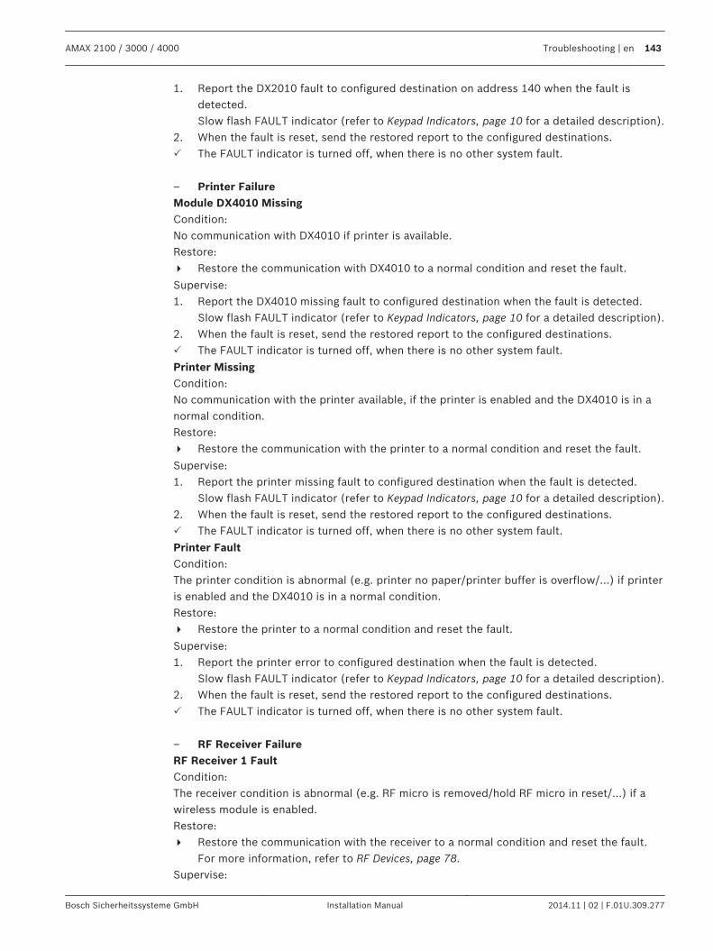
1. Report the DX2010 fault to configured destination on address 140 when the fault isdetected.Slow flash FAULT indicator (refer to Keypad Indicators, page 10 for a detailed description).
2. When the fault is reset, send the restored report to the configured destinations.P The FAULT indicator is turned off, when there is no other system fault.
– Printer FailureModule DX4010 MissingCondition:No communication with DX4010 if printer is available.Restore:4 Restore the communication with DX4010 to a normal condition and reset the fault.
Supervise:1. Report the DX4010 missing fault to configured destination when the fault is detected.
Slow flash FAULT indicator (refer to Keypad Indicators, page 10 for a detailed description).2. When the fault is reset, send the restored report to the configured destinations.P The FAULT indicator is turned off, when there is no other system fault.
Printer MissingCondition:No communication with the printer available, if the printer is enabled and the DX4010 is in anormal condition.Restore:4 Restore the communication with the printer to a normal condition and reset the fault.
Supervise:1. Report the printer missing fault to configured destination when the fault is detected.
Slow flash FAULT indicator (refer to Keypad Indicators, page 10 for a detailed description).2. When the fault is reset, send the restored report to the configured destinations.P The FAULT indicator is turned off, when there is no other system fault.
Printer FaultCondition:The printer condition is abnormal (e.g. printer no paper/printer buffer is overflow/...) if printeris enabled and the DX4010 is in a normal condition.Restore:4 Restore the printer to a normal condition and reset the fault.
Supervise:1. Report the printer error to configured destination when the fault is detected.
Slow flash FAULT indicator (refer to Keypad Indicators, page 10 for a detailed description).2. When the fault is reset, send the restored report to the configured destinations.P The FAULT indicator is turned off, when there is no other system fault.
– RF Receiver FailureRF Receiver 1 FaultCondition:The receiver condition is abnormal (e.g. RF micro is removed/hold RF micro in reset/...) if awireless module is enabled.Restore:4 Restore the communication with the receiver to a normal condition and reset the fault.
For more information, refer to RF Devices, page 78.Supervise:
AMAX 2100 / 3000 / 4000 Troubleshooting | en 143
Bosch Sicherheitssysteme GmbH Installation Manual 2014.11 | 02 | F.01U.309.277
1. Report the receiver fault to configured destination when the fault is detected.Slow flash FAULT indicator (refer to Keypad Indicators, page 10 for a detailed description).
2. When the fault is reset, send the restored report to the configured destinations.P The FAULT indicator is turned off, when there is no other system fault.
RF Receiver 1 MissingCondition:1. No communication with receiver available if a wireless module is enabled.2. A RF zone, repeater or keyfob is configured, but the wireless module is disabled.Restore:4 Restore the communication with the receiver to a normal condition, enable the wireless
module and reset the fault. For more information, refer to RF Devices, page 78.Supervise:1. Report the receiver missing fault to configured destination when the fault is detected.
Slow flash FAULT indicator (refer to Keypad Indicators, page 10 for a detailed description).2. When the fault is reset, send the restored report to the configured destinations.P The FAULT indicator is turned off when there is no other system fault.RF Receiver 1 JammedCondition:A signal is disturbing the receiver if a wireless module is enabled.Restore:4 Remove the disturbing signal around the receiver, enable the wireless module and reset
the fault. For more information, refer to RF Devices, page 78.Supervise:1. Report the receiver jam fault to configured destination when the fault is detected.
Slow flash FAULT indicator (refer to Keypad Indicators, page 10 for a detailed description).2. When the fault is reset, send the restored report to the configured destinations.P The FAULT indicator is turned off when there is no other system fault.
– RF Sensor FailureRF Sensor MissingCondition:A wireless zone sends no status report to the receiver in the RF supervision interval if awireless module is enabled.Restore:4 Make sure that all wireless zones are sending status reports to the receiver in the RF
supervision interval and reset the fault. For more information, refer to RF Devices, page78.
Supervise:1. Report the wireless zone missing fault to configured destination when the fault is
detected.Slow flash FAULT indicator (refer to Keypad Indicators, page 10 for a detailed description).
2. When the fault is reset, send the restored report to the configured destinations.P The FAULT indicator is turned off when there is no other system fault.
RF Sensor FaultCondition:A wireless zone is in an abnormal condition (e.g. Remove the pyro from the smokedetector/...) and a wireless module is enabled.Restore:
144 en | Troubleshooting AMAX 2100 / 3000 / 4000
2014.11 | 02 | F.01U.309.277 Installation Manual Bosch Sicherheitssysteme GmbH
4 Restore all wireless zones to a normal condition and reset the fault. For moreinformation, refer to RF Devices, page 78.
Supervise:1. Report the wireless zone fault to configured destination when the fault is detected.
Slow flash FAULT indicator (refer to Keypad Indicators, page 10 for a detailed description).2. When the fault is reset, send the restored report to the configured destinations.P The FAULT indicator is turned off when there is no other system fault.
– RF Repeater Failure1-8 RF Repeater 1-8 MissingCondition:No status report is send to the receiver in the RF supervision interval if a wireless module isenabled.Restore:4 Make sure that status reports are sent to the receiver in the RF supervision interval and
reset the fault. For more information, refer to RF Devices, page 78.Supervise:1. Report the repeater missing fault to configured destination when the fault is detected.
Slow flash FAULT indicator (refer to Keypad Indicators, page 10 for a detailed description).2. When the fault is reset, send the restored report to the configured destinations.P The FAULT indicator is turned off when there is no other system fault.
– RF Config FailureConfiguration Conflict SensorsCondition:A wireless zone configuration is in error condition.Restore:4 Restore all wireless zones to a normal condition and reset the fault. For more
information, refer to RF Devices, page 78.Supervise:Slow flash FAULT indicator (refer to Keypad Indicators, page 10 for a detailed description).4 Reset the fault.
P The FAULT indicator is turned off when there is no other system fault.
Configuration Conflict RepeatersCondition:A repeater configuration is in error condition.Restore:4 Restore all repeaters to a normal condition and reset the fault. For more information,
refer to RF Devices, page 78.Supervise:Slow flash FAULT indicator (refer to Keypad Indicators, page 10 for a detailed description).4 Reset the fault.
P The FAULT indicator is turned off when there is no other system fault.
Configuration Conflict KeyfobsCondition:A keyfob configuration is in error condition.Restore:4 Restore all keyfobs to a normal condition and reset the fault. For more information, refer
to RF Devices, page 78.
AMAX 2100 / 3000 / 4000 Troubleshooting | en 145
Bosch Sicherheitssysteme GmbH Installation Manual 2014.11 | 02 | F.01U.309.277
Supervise:Slow flash FAULT indicator (refer to Keypad Indicators, page 10 for a detailed description).4 Reset the fault.
P The FAULT indicator is turned off when there is no other system fault.
2 - Power Failure– Panel AC FailureCondition:1. AC supply deficiency caused by a transformer.2. Power supply fuse is broken (230V).3. Power supply is disconnected (230V).Restore:1. Reconnect the AC supply and reset the fault. For more information refer to Installation,
page 25.2. Monitor the voltage by MPU.Supervise:1. If the AC supply is not restored one hour after the fault occurred, report the fault to
configured destination on address 124.Slow flash FAULT indicator (refer to Keypad Indicators, page 10 for a detailed description).When the AC supply is reconnected, the MAINS indicator lights up (except inprogramming mode or in code functions mode).
2. When the fault is reset, send the restored report to the configured destinations.P The FAULT indicator is turned off when there is no other system fault.
– Battery Low BatteryCondition:1. The battery voltage is lower than 11V+-1%.2. No battery is connected.Restore:1. Connect a battery. For more information, refer to Battery Installation, page 26.2. Raise battery voltage to 12V+-1%, perform a dynamic battery test (time set in
programming address 204) and reset the fault.Supervise:1. Set the system to perform a dynamic battery test on a regular basis (time set in
programming address 204) and every time the system is armed or reset.2. Report the low battery to the configured destination programmed on address 124.
Slow flash FAULT indicator (refer to Keypad Indicators, page 10 for a detailed description).3. When the fault is reset, send the restored report to the configured destinations.P The FAULT indicator is turned off when there is no other system fault.
– Panel Aux Power 1-2 FailureCondition:The Aux power supply voltage is lower than 9V.Restore:4 Raise the voltage to 12V and reset the fault.
Supervise:1. Monitor the voltage by MPU.2. Report the AUX power fault to the configured destination programmed on address 124.
146 en | Troubleshooting AMAX 2100 / 3000 / 4000
2014.11 | 02 | F.01U.309.277 Installation Manual Bosch Sicherheitssysteme GmbH
Slow flash FAULT indicator (refer to Keypad Indicators, page 10 for a detailed description).3. When the fault is reset, send the restored report to the configured destinations.P The FAULT indicator is turned off when there is no other system fault.
– Bosch Option Bus Power 1-2 FailureCondition:Bosch option bus power supply voltage is lower than 9V+-5%.Restore:4 Raise the voltage to 12V and reset the fault. For more information refer to Bosch Option
Bus, page 13.Supervise:1. Monitor the voltage by MPU.2. Report the Bosch Option Bus Power Supply fault to the configured destination
programmed on address 124.Slow flash FAULT indicator (refer to Keypad Indicators, page 10 for a detailed description).
3. When the fault is reset, send the restored report to the configured destinations.P The FAULT indicator is turned off when there is no other system fault.
– RF Repeater 1-8 AC Power FailureCondition:1. AC power failure to the repeater.2. The repeater is not wired correctly, if a wireless module is enabled.Restore:4 Restore the repeater AC power and reset the fault.
Supervise:1. Report the repeater AC power fault to configured destination when the fault is detected.
Slow flash FAULT indicator (refer to Keypad Indicators, page 10 for a detailed description).2. When the fault is reset, send the restored report to the configured destinations.P The FAULT indicator is turned off when there is no other system fault.
– RF Repeater 1-8 Battery FailureCondition:The repeater is in a low battery condition if a wireless module is enabled.Restore:4 Restore the repeater battery and reset the fault. For more information refer to RF Devices,
page 78.Supervise:1. Report the repeater battery fault to configured destination when the fault is detected.
Slow flash FAULT indicator (refer to Keypad Indicators, page 10 for a detailed description).2. When the fault is reset, send the restored report to the configured destinations.P The FAULT indicator is turned off when there is no other system fault.
– RF Sensor Power FailureCondition:The sensor is in a low battery condition if a wireless module is enabled.Restore:4 Restore the sensor battery and reset the fault. For more information refer to RF Devices,
page 78.Supervise:
AMAX 2100 / 3000 / 4000 Troubleshooting | en 147
Bosch Sicherheitssysteme GmbH Installation Manual 2014.11 | 02 | F.01U.309.277
1. Report the sensor power fault to configured destination when the fault is detected.Slow flash FAULT indicator (refer to Keypad Indicators, page 10 for a detailed description).
2. When the fault is reset, send the restored report to the configured destinations.P The FAULT indicator is turned off when there is no other system fault.
– RF Keyfob Battery FailureCondition:The keyfob is in a low battery condition if a wireless module is enabled.Restore:4 Restore the keyfob battery and reset the fault. For more information refer to RF Devices,
page 78.Supervise:1. Report the keyfob battery fault to configured destination when the fault is detected.
Slow flash FAULT indicator (refer to Keypad Indicators, page 10 for a detailed description).2. When the fault is reset, send the restored report to the configured destinations.P The FAULT indicator is turned off when there is no other system fault.
3 -Output Failure– Onboard Output 1-2 FaultCondition:An onboard output is in a short circuit or open circuit condition.Restore:4 Restore the onboard output to a normal condition and reset the fault. For more
information refer to Outputs, page 71.Supervise:1. Report the onboard output 1-2 fault to configured destination when the fault is detected.
Slow flash FAULT indicator (refer to Keypad Indicators, page 10 for a detailed description).2. When the fault is reset, send the restored report to the configured destinations.P The FAULT indicator is turned off when there is no other system fault.
4 -Keypad Failure– Keypad 1-16 failureCondition:No communication between the panel and a keypad.Restore:4 Restore the communication between the panel and the keypad and reset the fault. For
more information refer to Keypad Area, page 65.Supervise:1. Report the keypad fault to the configured destination programmed on address 124.
Slow flash FAULT indicator (refer to Keypad Indicators, page 10 for a detailed description).2. When the fault is reset, send the restored report to the configured destinations.P The FAULT indicator is turned off when there is no other system fault.
5- System Failure– Date and Time not setCondition:
148 en | Troubleshooting AMAX 2100 / 3000 / 4000
2014.11 | 02 | F.01U.309.277 Installation Manual Bosch Sicherheitssysteme GmbH
Date and time is not set after the system is powered on.Restore:4 Program date and time and reset the fault. For more information refer to System Setting,
page 66.Supervise:1. Report the date and time fault to the configured destination programmed on location
124.2. Slow flash FAULT indicator (refer to Keypad Indicators, page 10 for a detailed description)3. No report to the AMAX panel system, when date and time setting is recorded in
nonvolatile memory and AMAX Panel is reset. The FAULT indicator is turned off whenthere is no other system fault.
6 - Communication Failure– Communication Fault 1 - 4Condition:The panel can not send the report to the destination 1 after four attempts.Restore:Make sure that reports can be sent and reset the fault. For more information refer to SystemSetting, page 66.Supervise:1. Report the fault to configured destination on address 124 when the fault is detected.
Slow flash FAULT indicator (refer to Keypad Indicators, page 10 for a detailed description).2. When the fault is reset, send the restored report to the configured destinations.P The FAULT indicator is turned off when there is no other system fault.
7- Tamper– System TamperCondition:Onboard panel tamper input is open.Restore:4 Close the panel tamper input and reset the fault.
Supervise:1. Report the tamper condition to configured destination on address 124 when the tamper
condition is detected.Slow flash FAULT indicator (refer to Keypad Indicators, page 10 for a detailed description).
2. When the tamper condition is reset, send the restored report to the configureddestinations.
P The FAULT indicator is turned off when there is no other system fault.
– Keypad 1-16 TamperCondition:Keypad 1 is open and the tamper contact is triggered.Restore:4 Close the keypad and reset the tamper condition.
Supervise:1. Report the tamper condition to configured destination on address 124 when the tamper
condition is detected.
AMAX 2100 / 3000 / 4000 Troubleshooting | en 149
Bosch Sicherheitssysteme GmbH Installation Manual 2014.11 | 02 | F.01U.309.277
Slow flash FAULT indicator (refer to Keypad Indicators, page 10 for a detailed description).2. When the tamper condition is reset, send the restored report to the configured
destinations.P The FAULT indicator is turned off when there is no other system fault.
– Zone Expansion Module 1-6 TamperCondition:A disassembly of DX2010 module 1, 2, 3, 4, 5, or 6 is detected and the occurrence of zoneextension module 1, 2, 3, 4, 5 or 6 is considered as a tamper condition.Restore:4 Restore the DX2010 module 1, 2, 3, 4, 5, or 6 to a normal condition and reset the fault.
For more information, refer to DX2010, page 16.Supervise:1. Report the tamper condition to configured destination on address 0124 when the tamper
condition is detected.Slow flash FAULT indicator (refer to Keypad Indicators, page 10 for a detailed description).
2. When the tamper condition is reset, send the restored report to the configureddestinations.
P The FAULT indicator is turned off when there is no other system fault.
– Zone Tamper 1-16 DEOLCondition:Tamper contact is triggered (if the corresponding zone is programmed as DEOL).Restore:4 Restore the tamper contact and reset the tamper condition.
Supervise:1. Report the sensor tamper to configured destination on address 124 when the sensor
tamper is detected.Slow flash FAULT indicator (refer to Keypad Indicators, page 10 for a detailed description).
2. When the tamper condition is reset, send the restored report to the configureddestinations.
P The FAULT indicator is turned off when there is no other system fault.
– Zone type 1-16 TamperCondition:Tamper contact (directly connected to the zone) is triggered (zone type = tamper).Restore:4 Restore the tamper contact and reset the tamper condition.
Supervise:1. Report the tamper condition to configured destination on address 124 when the tamper
condition is detected.Slow flash FAULT indicator (refer to Keypad Indicators, page 10 for a detailed description).
2. When the tamper condition is reset, send the restored report to the configureddestinations.
P The FAULT indicator is turned off when there is no other system fault.
– Keypad Lock outCondition:
150 en | Troubleshooting AMAX 2100 / 3000 / 4000
2014.11 | 02 | F.01U.309.277 Installation Manual Bosch Sicherheitssysteme GmbH
If the number of incorrect code entries reaches the specified limit (programmed in address0499), the keypad locks.Restore:4 Wait until the keypad lockout time (3min) expires and reset the fault.
Supervise:1. Report the keypad lock out to configured destination on address 124 when the keypad
lock out is detected.Slow flash FAULT indicator (refer to Keypad Indicators, page 10 for a detailed description).
2. When the keypad lock out condition is reset, send the restored report to the configureddestinations.
P The FAULT indicator is turned off when there is no other system fault.
– RF Receiver TamperCondition:A receiver is in tamper condition (e.g. when someone removes the device from its base orpulls it out of the wall) if a wireless module is enabled.Restore:4 Restore the receiver and reset the tamper condition. For more information refer to RF
Devices, page 78.Supervise:1. Report receiver tamper fault to configured destination when the fault is detected.
Slow flash FAULT indicator (refer to Keypad Indicators, page 10 for a detailed description).2. When the fault is reset, send the restored report to the configured destinations.P The FAULT indicator is turned off when there is no other system fault.
– RF Repeater TamperCondition:A repeater is in tamper condition (e.g. when someone removes the device from its base orpulls it out of the wall) if a wireless module is enabled.Restore:4 Restore the repeater and reset the tamper condition. For more information refer to RF
Devices, page 78.Supervise:1. Report repeater tamper fault to configured destination when the fault is detected.
Slow flash FAULT indicator (refer to Keypad Indicators, page 10 for a detailed description).2. When the fault is reset, send the restored report to the configured destinations.P The FAULT indicator is turned off when there is no other system fault.
8 - External Failure– External Fault Zone 1-16Condition:A fault contact (direct connected to the zone) is triggered (zone type = external fault).Restore:4 Restore the fault contact and reset the fault.
Supervise:1. Report the fault condition to configured destination on address 124 when the fault
condition is detected.Slow flash FAULT indicator (refer to Keypad Indicators, page 10 for a detailed description).
AMAX 2100 / 3000 / 4000 Troubleshooting | en 151
Bosch Sicherheitssysteme GmbH Installation Manual 2014.11 | 02 | F.01U.309.277
2. When the fault is reset, send the restored report to the configured destinations.P The FAULT indicator is turned off when there is no other system fault.
152 en | Troubleshooting AMAX 2100 / 3000 / 4000
2014.11 | 02 | F.01U.309.277 Installation Manual Bosch Sicherheitssysteme GmbH
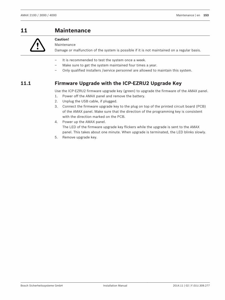
Maintenance
!
Caution!
Maintenance
Damage or malfunction of the system is possible if it is not maintained on a regular basis.
– It is recommended to test the system once a week.– Make sure to get the system maintained four times a year.– Only qualified installers /service personnel are allowed to maintain this system.
Firmware Upgrade with the ICP-EZRU2 Upgrade KeyUse the ICP-EZRU2 firmware upgrade key (green) to upgrade the firmware of the AMAX panel.1. Power off the AMAX panel and remove the battery.2. Unplug the USB cable, if plugged.3. Connect the firmware upgrade key to the plug on top of the printed circuit board (PCB)
of the AMAX panel. Make sure that the direction of the programming key is consistentwith the direction marked on the PCB.
4. Power up the AMAX panel.The LED of the firmware upgrade key flickers while the upgrade is sent to the AMAXpanel. This takes about one minute. When upgrade is terminated, the LED blinks slowly.
5. Remove upgrade key.
11
11.1
AMAX 2100 / 3000 / 4000 Maintenance | en 153
Bosch Sicherheitssysteme GmbH Installation Manual 2014.11 | 02 | F.01U.309.277
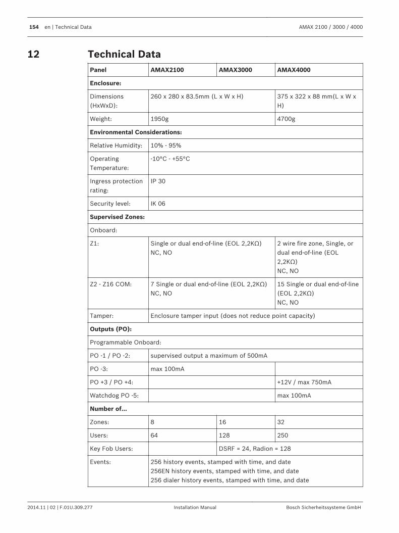
Technical DataPanel AMAX2100 AMAX3000 AMAX4000
Enclosure:
Dimensions(HxWxD):
260 x 280 x 83.5mm (L x W x H) 375 x 322 x 88 mm(L x W xH)
Weight: 1950g 4700g
Environmental Considerations:
Relative Humidity: 10% - 95%
OperatingTemperature:
-10°C - +55°C
Ingress protectionrating:
IP 30
Security level: IK 06
Supervised Zones:
Onboard:
Z1: Single or dual end-of-line (EOL 2,2KΩ)NC, NO
2 wire fire zone, Single, ordual end-of-line (EOL2,2KΩ)NC, NO
Z2 - Z16 COM: 7 Single or dual end-of-line (EOL 2,2KΩ)NC, NO
15 Single or dual end-of-line(EOL 2,2KΩ)NC, NO
Tamper: Enclosure tamper input (does not reduce point capacity)
Outputs (PO):
Programmable Onboard:
PO -1 / PO -2: supervised output a maximum of 500mA
PO -3: max 100mA
PO +3 / PO +4: +12V / max 750mA
Watchdog PO -5: max 100mA
Number of...
Zones: 8 16 32
Users: 64 128 250
Key Fob Users: DSRF = 24, Radion = 128
Events: 256 history events, stamped with time, and date256EN history events, stamped with time, and date256 dialer history events, stamped with time, and date
12
154 en | Technical Data AMAX 2100 / 3000 / 4000
2014.11 | 02 | F.01U.309.277 Installation Manual Bosch Sicherheitssysteme GmbH
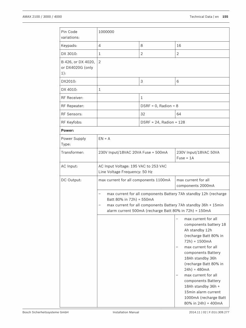
Pin Codevariations:
1000000
Keypads: 4 8 16
DX 3010: 1 2 2
B 426, or DX 4020,or DX4020G (only1):
2
DX2010: 3 6
DX 4010: 1
RF Receiver: 1
RF Repeater: DSRF = 0, Radion = 8
RF Sensors: 32 64
RF Keyfobs: DSRF = 24, Radion = 128
Power:
Power SupplyType:
EN = A
Transformer: 230V Input/18VAC 20VA Fuse = 500mA 230V Input/18VAC 50VAFuse = 1A
AC Input: AC Input Voltage: 195 VAC to 253 VACLine Voltage Frequency: 50 Hz
DC Output: max current for all components 1100mA max current for allcomponents 2000mA
– max current for all components Battery 7Ah standby 12h (rechargeBatt 80% in 72h) = 550mA
– max current for all components Battery 7Ah standby 36h + 15minalarm current 500mA (recharge Batt 80% in 72h) = 150mA
– max current for allcomponents battery 18Ah standby 12h(recharge Batt 80% in72h) = 1500mA
– max current for allcomponents Battery18Ah standby 36h(recharge Batt 80% in24h) = 480mA
– max current for allcomponents Battery18Ah standby 36h +15min alarm current1000mA (recharge Batt80% in 24h) = 400mA
AMAX 2100 / 3000 / 4000 Technical Data | en 155
Bosch Sicherheitssysteme GmbH Installation Manual 2014.11 | 02 | F.01U.309.277
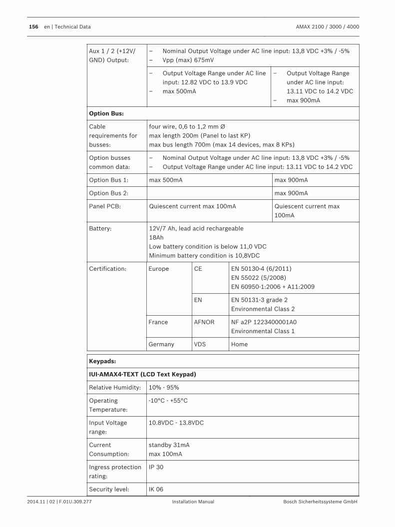
Aux 1 / 2 (+12V/GND) Output:
– Nominal Output Voltage under AC line input: 13,8 VDC +3% / -5%– Vpp (max) 675mV
– Output Voltage Range under AC lineinput: 12.82 VDC to 13.9 VDC
– max 500mA
– Output Voltage Rangeunder AC line input:13.11 VDC to 14.2 VDC
– max 900mA
Option Bus:
Cablerequirements forbusses:
four wire, 0,6 to 1,2 mm Ømax length 200m (Panel to last KP)max bus length 700m (max 14 devices, max 8 KPs)
Option bussescommon data:
– Nominal Output Voltage under AC line input: 13,8 VDC +3% / -5%– Output Voltage Range under AC line input: 13.11 VDC to 14.2 VDC
Option Bus 1: max 500mA max 900mA
Option Bus 2: max 900mA
Panel PCB: Quiescent current max 100mA Quiescent current max100mA
Battery: 12V/7 Ah, lead acid rechargeable18AhLow battery condition is below 11,0 VDCMinimum battery condition is 10,8VDC
Certification: Europe CE EN 50130-4 (6/2011)EN 55022 (5/2008)EN 60950-1:2006 + A11:2009
EN EN 50131-3 grade 2Environmental Class 2
France AFNOR NF a2P 1223400001A0 Environmental Class 1
Germany VDS Home
Keypads:
IUI-AMAX4-TEXT (LCD Text Keypad)
Relative Humidity: 10% - 95%
OperatingTemperature:
-10°C - +55°C
Input Voltagerange:
10.8VDC - 13.8VDC
CurrentConsumption:
standby 31mAmax 100mA
Ingress protectionrating:
IP 30
Security level: IK 06
156 en | Technical Data AMAX 2100 / 3000 / 4000
2014.11 | 02 | F.01U.309.277 Installation Manual Bosch Sicherheitssysteme GmbH
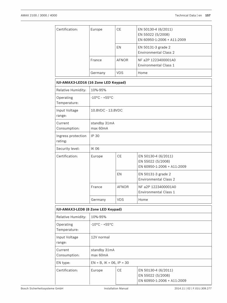
Certification: Europe CE EN 50130-4 (6/2011)EN 55022 (5/2008)EN 60950-1:2006 + A11:2009
EN EN 50131-3 grade 2Environmental Class 2
France AFNOR NF a2P 1223400001A0 Environmental Class 1
Germany VDS Home
IUI-AMAX3-LED16 (16 Zone LED Keypad)
Relative Humidity: 10%-95%
OperatingTemperature:
-10°C - +55°C
Input Voltagerange:
10.8VDC - 13.8VDC
CurrentConsumption:
standby 31mAmax 60mA
Ingress protectionrating:
IP 30
Security level: IK 06
Certification: Europe CE EN 50130-4 (6/2011)EN 55022 (5/2008)EN 60950-1:2006 + A11:2009
EN EN 50131-3 grade 2Environmental Class 2
France AFNOR NF a2P 1223400001A0 Environmental Class 1
Germany VDS Home
IUI-AMAX3-LED8 (8 Zone LED Keypad)
Relative Humidity: 10%-95%
OperatingTemperature:
-10°C - +55°C
Input Voltagerange:
12V normal
CurrentConsumption:
standby 31mAmax 60mA
EN type: EN = B, IK = 06, IP = 30
Certification: Europe CE EN 50130-4 (6/2011)EN 55022 (5/2008)EN 60950-1:2006 + A11:2009
AMAX 2100 / 3000 / 4000 Technical Data | en 157
Bosch Sicherheitssysteme GmbH Installation Manual 2014.11 | 02 | F.01U.309.277
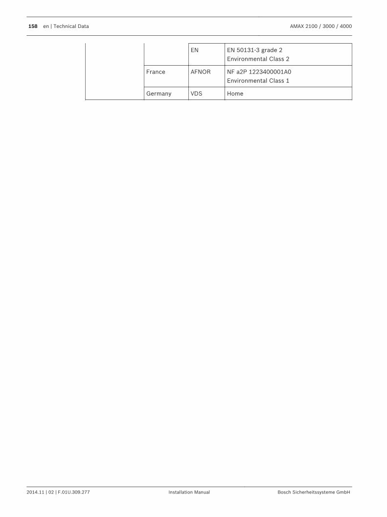
EN EN 50131-3 grade 2Environmental Class 2
France AFNOR NF a2P 1223400001A0 Environmental Class 1
Germany VDS Home
158 en | Technical Data AMAX 2100 / 3000 / 4000
2014.11 | 02 | F.01U.309.277 Installation Manual Bosch Sicherheitssysteme GmbH

Bosch Sicherheitssysteme GmbHRobert-Bosch-Ring 585630 GrasbrunnGermanywww.boschsecurity.com© Bosch Sicherheitssysteme GmbH, 2014
Related Documents