Extra Class Exam Study Guide July 2020 to June 2024 Page 1

Welcome message from author
This document is posted to help you gain knowledge. Please leave a comment to let me know what you think about it! Share it to your friends and learn new things together.
Transcript

Extra Class Exam Study Guide July 2020 to June 2024
Page 2
Amateur Extra Class Workshop
All Amateur Radio Operators,
Amateur radio has been around for a long time and has grown itself into a worldwide community of licensed
hams on the airwaves with all sorts of communications technology. Ham radio attracts those who have
never held a microphone as well as deep technical experts who grew up with a soldering iron and computer.
Your United States Amateur Service license gives you the most powerful wireless communications
capability available to any private citizen anywhere in the world. In the United States, amateur radio
licensing is governed by the Federal Communications Commission (FCC) under strict federal regulations.
Licenses to operate amateur stations for personal use are granted to individuals of any age once they
demonstrate an understanding of both pertinent FCC regulations and knowledge of radio station operation
and safety considerations. December 2012 marked one hundred years of amateur radio operator and
station licensing by the United States government. Operator licenses are divided into different classes, each
of which correlates to an increasing degree of knowledge and corresponding privileges. Over the years, the
details of the classes have changed significantly, leading to the current system of three open classes and
two grandfathered but closed to new applicants. The top US license class is Amateur Extra Class. The
Extra Class license requires an applicant pass 35 of a 50-question multiple-choice theory exam. Those with
Amateur Extra licenses are granted all privileges on all US amateur bands.
The ARRL Extra Class License description says it best; “General licensees may upgrade to Extra Class
by passing a 50-question multiple-choice examination. No Morse code test is required. In addition to
some of the more obscure regulations, the test covers specialized operating practices, advanced
electronics theory and radio equipment design. Non-licensed individuals must pass Element 2, Element
3 and Element 4 written exams to earn an Extra License. The FCC grants exam element 3 credit to
individuals that previously held certain older types of licenses. The HF bands can be awfully crowded,
particularly at the top of the solar cycle. Once one earns HF privileges, one may quickly yearn for
more room. The Extra Class license is the answer. Extra Class licensees are authorized to operate on
all frequencies allocated to the Amateur Service.”
The Extra Class workshop is specially presented for those with amateur radio experience who want to learn
more. The workshop will cover a vast amount of material in five classes. It is intended to help members
advance in the hobby we love and give a little boost to those on the fence.
Looking forward to congratulating you in your advancement to Amateur Extra Class,
Mike KM4ZTE
Mike Regan
President
The Villages Amateur Radio Club
PS All amateur radio operators are welcome to use and share this document. Comments about this
document can be sent by means of the club website contact form; https://www.k4vrc.com/contact-us.html
Please include; a detailed description of the issue with exam question ID and page number.

Extra Class Exam Study Guide July 2020 to June 2024
Page 3
Table of Contents
MESSAGE FROM THE VILLAGES AMATEUR RADIO CLUB PRESIDENT ........................................................... 2
INTRODUCTION ............................................................................................................................................. 5 Just Enough for Understanding ....................................................................................................... 5 Less Math for more Comprehension ............................................................................................... 5 Five Classes ...................................................................................................................................... 5 Learning Aids .................................................................................................................................... 6 Memory Retention ........................................................................................................................... 6
CLASS 1 –REGULATIONS E1A Operating Standards ................................................................................................................. 7 E1B Station restrictions and special operations ............................................................................ 10 E1C Rules pertaining to automatic and remote control ................................................................ 14 E1F Miscellaneous rules ................................................................................................................ 16 E1D Amateur space and Earth stations; telemetry and telecommand rules ................................ 19 E1E Volunteer examiner program ................................................................................................. 22 E2C Operating methods ................................................................................................................. 24 E2D Operating methods ................................................................................................................. 25 E2E Operating methods ................................................................................................................. 27 Class One Fundamentals and Substance ....................................................................................... 30
CLASS 2 - RADIO COMPONENTS AND SUBSYSTEMS E6A Semiconductor materials and devices .................................................................................... 35 E6B Diodes .................................................................................................................................... 38 E6C Digital ICs ................................................................................................................................ 41 E7A Digital circuits: digital circuit principles and logic circuits ...................................................... 44 E6F Electro-optical technology: photoconductivity ....................................................................... 46 E6D Toroidal and Solenoidal Inductors .......................................................................................... 48 E6E Analog ICs: MMICs, IC packaging characteristics ................................................................... 51 E7B Amplifiers ................................................................................................................................ 53 E7F DSP filtering and other operations .......................................................................................... 57 E7H Oscillators and signal sources ................................................................................................. 62 E7C Filters and matching networks ............................................................................................... 65 E7D Power supplies and voltage regulators .................................................................................. 69 E7G Active filters and op-amp circuits .......................................................................................... 72 Class Two Fundamentals and Substance ....................................................................................... 75
CLASS 3 – WAVEFORMS, MODULATION, RECEIVERS, OPERATING METHODS, SPACE AND TELEVISION E8A AC Waveforms ........................................................................................................................ 83 E4A Test equipment ....................................................................................................................... 87 E4B Measurement technique and limitations ............................................................................... 90 E7E Modulation and Demodulation............................................................................................... 93 E8B Modulation and Demodulation .............................................................................................. 96 E8C Digital signals ....................................................................................................................... 100 E8D Keying defects and overmodulation of digital signals .......................................................... 103

Extra Class Exam Study Guide July 2020 to June 2024
Page 4
E4C Receiver performance characteristics .................................................................................. 106 E4D Receiver performance characteristics ................................................................................. 110 E4E Noise suppression and interference .................................................................................... 114 E2A Amateur radio in space ......................................................................................................... 117 E2B Television practices ............................................................................................................... 120 Class Three Fundamentals and Substance ................................................................................... 123
CLASS 4 - AC WAVEFORM TRANSMISSION CHARACTERISTICS AND QUANTIFICATION Using the Language of Waveforms as a HAM .............................................................................. 129 E5D AC and RF energy in real circuits ......................................................................................... 141 E5A Resonance and Q ................................................................................................................. 145 E5B Time constants and phase relationships .............................................................................. 149 E5C Coordinate systems and phasors in electronics ................................................................... 155 E9E Matching: matching antennas to feed lines ......................................................................... 159 E9F Transmission lines ................................................................................................................. 162 E9G The Smith chart .................................................................................................................... 164 Class Four Fundamentals and Substance ..................................................................................... 167
CLASS 5 – ANTENNAS, PROPOGATION AND SAFETY E9A Basic Antenna parameters .................................................................................................... 171 E3A Electromagnetic waves ......................................................................................................... 176 E9B Antenna patterns and designs ............................................................................................. 180 E9C Practical wire antennas ........................................................................................................ 184 E9D Yagi antennas ........................................................................................................................ 189 E9H Receiving Antennas .............................................................................................................. 193 E3B Transequatorial propagation ................................................................................................ 196 E3C Radio horizon ........................................................................................................................ 199 E0A Safety .................................................................................................................................... 204 Class Five Fundamentals and Substance...................................................................................... 208
MATH EQUATIONS FOR EXTRA CLASS ...................................................................................................... 213
INDEX ........................................................................................................................................................ 214
GLOSSARY.................................................................................................................................................. 218
Revisions
Original Release – 6/24/20
Incorporated comments, errata updates and typographical errors – 11/2/20
Added Glossary, Incorporated comments – 6/9/21

Extra Class Exam Study Guide July 2020 to June 2024
Page 5
Introduction
Just Enough for Understanding
Studying for the Amateur Extra is not easy for most people and this class is designed to help you with the
difficult parts. Normally the class size is small allowing more time to address the how and why questions.
This is not intended to be traditional classroom experience instead you should expect a much more informal
discussions about electronics as it relates to HAM radio not Electrical Engineering. Too bad most of the
well-known ham radio license manuals spend way too much content on theory and fail to stay within the
scope of the exam. This is not to say just teach the test. A good example is the diode, you need to know
the types, forward voltage and reverse bias. You do not need an understanding of semiconductor theory.
Simply put there is only five classes (about 15 Hours in class room time) to gain an introductory level
understanding of the technology and the Code of Federal Regulations Title 47, Telecommunication. Part
97, Amateur Radio Service. The class format is just enough information for context and essential
understanding needed to pass the licensing test.
Less Math for more Comprehension
Historically most HAMs have problems passing the license exam due to the math required. It may relieve
some of your concerns to know the question pool has reduced the number of questions requiring
calculations in favor of comprehension questions in the last three releases. You still need to use a small
amount of math to solve problems but just add, subtract, multiple and divide. This class will focus on thinking
through the questions and avoiding the trigonometry to solve problems. Working the example problems in
class will help you be at ease with using the math required. Thinking carefully about the wording of the
question will often lead to the only correct answer without any math! This means many multiple-choice
questions can be solved logically without doing the math and the discussion from this class will help you
avoid selecting the wrong answer.
Five Classes
The five classes will meet for about three hours once a week. Each topic begins with an overview of the
homework assignment for context followed by review of the questions covered. Understanding is reinforced
with your questions and discussion. To prepare for class;
• Individual reading of chapter prior to class
• Pay attention to the BLUE text, they are the phrases used on the exam
• The Editors Notes are included for context and more understanding but are not test questions • Work sample problems prior to class • When reviewing the questions make a “I need help” list for discussion in class • Use the Fundamentals and Substance section to supplement your reading and take notes • Class Review of assignment, discussion and help with problems • Individual practice tests (online or Apps) at home between classes
If you attend all classes, keep up with readings, and take practice tests conscientiously, preparing can be
a relatively pain-free process. Pain-free does not mean work-free! Take practice tests online from multiple
sites or different APPs. Many past students have found that preparing for the exam for 60 minutes per day,
five or six days per week, will leave them well-prepared at exam time. Don’t cram at the end as hitting hard
at the last minute simply don't work for most people and they experience declining returns on their efforts
when they attempt to study for two and three hours straight.

Extra Class Exam Study Guide July 2020 to June 2024
Page 6
Learning Aids
You are encouraged to use every study resource that works for you. In general people retain more details
from a hard copy document. Print the Fundamentals and Substance section so you can take it with you
to study, write on it, underline or highlight the text for reference later. Place a copy of this guide on an
eReader. Purchased books are not required but if you do have questions from other sources they will be
discussed during the open review at the end of each class.
Take online practice tests online, but not more than once a day. http://arrlexamreview.appspot.com/
https://hamexam.org/ https://hamstudy.org/
Many people have found using a test App on their phone or tablet is a helpful tool
https://play.google.com/store/apps https://www.apple.com/ios/app-store/
Dave Casler KE0OG Videos lectures on YouTube are highly recommended.
https://dcasler.com/ham-radio/
Memory Retention
Make sure to review and expand upon the Fundamentals and Substance section after completing each
class. The Fundamentals and Substance subsection that was solely created as a tool for test preparation
by helping you make connections between topics and serves as quality review material for after each class.
The information is in the form of class notes with all of the important information you need to know. The
notes are organized into easily digestible headings and bullet points to organize topics with the key words,
main subpoints and summary are all written in one place. You should find using will be most useful when
learning about new topics that include a lot of detail. This section is not intended to be a substitute for
studying the class material in fact you will need to complete your reading assignment and attend class in
order to effectively use these notes.

Extra Class Exam Study Guide July 2020 to June 2024
Class One Page 7
CLASS 1 – REGULATIONS
============================================================================
E1A Operating Standards
E1B Station restrictions and special operations
E1C Rules pertaining to automatic and remote control
E1F Miscellaneous rules
E1D Amateur space and Earth stations; telemetry and telecommand rules
E1E Volunteer examiner program
E2C, E2D, E2E Operating methods
Class One Fundamentals and Substance
============================================================================
E1A Operating Standards
============================================================================
Upper Sideband (USB) emissions will be 3 kHz above the carrier frequency
Lower Sideband (LSB) emissions will be 3 kHz below the carrier frequency
18.068 MHz is illegal for LSB AFSK emissions on the 17M band RTTY
Transceivers display LSB carrier frequency of phone signals 3 KHz above the lower band edge
14.149 MHz is the maximum legal carrier 20M frequency for 1 KHz BW USB AFSK digital signals
3.601 MHz LSB Phone is beyond the edge of the phone band segment ============================================================================
E1A01 (A) [97.305, 97.307(b)] Which of the following carrier frequencies is illegal for LSB AFSK emissions on the 17 meter band RTTY and data segment of 18.068 to 18.110 MHz? A. 18.068 MHz B. 18.100 MHz C. 18.107 MHz D. 18.110 MHz
E1A02 (D) [97.301, 97.305] When using a transceiver that displays the carrier frequency of phone signals, which of the following displayed frequencies represents the lowest frequency at which a properly adjusted LSB emission will be totally within the band? A. The exact lower band edge B. 300 Hz above the lower band edge C. 1 kHz above the lower band edge D. 3 kHz above the lower band edge
E1A03 (C) [97.305, 97.307(b)] What is the maximum legal carrier frequency on the 20 meter band for transmitting USB AFSK digital signals having a 1 kHz bandwidth? A. 14.070 MHz B. 14.100 MHz C. 14.149 MHz D. 14.349 MHz
Extra Class Exam Study Guide July 2020 to June 2024
Class One Page 8
E1A04 (C) [97.301, 97.305] With your transceiver displaying the carrier frequency of phone signals, you hear a DX station calling CQ on 3.601 MHz LSB. Is it legal to return the call using lower sideband on the same frequency? A. Yes, because the DX station initiated the contact B. Yes, because the displayed frequency is within the 75 meter phone band segment C. No, the sideband will extend beyond the edge of the phone band segment D. No, U.S. stations are not permitted to use phone emissions below 3.610 MHz
============================================================================
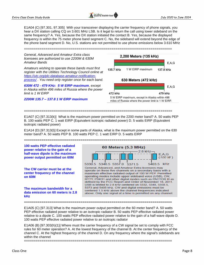
General, Advanced and Amateur Extra class licensees are authorized to use 2200M & 630M Amateur Bands
Amateurs wishing to operate these bands must first register with the Utilities Technology Council online at https://utc.org/plc-database-amateur-notification-process/ . You need only register once for each band.
630M 472 - 479 KHz: 5 W EIRP maximum, except in Alaska within 496 miles of Russia where the power limit is 1 W EIRP
2200M 135.7 – 137.8 1 W EIRP maximum
============================================================================
E1A07 (C) [97.313(k)] What is the maximum power permitted on the 2200 meter band? A. 50 watts PEP B. 100 watts PEP C. 1 watt EIRP (Equivalent isotropic radiated power) D. 5 watts EIRP (Equivalent isotropic radiated power)
E1A14 (D) [97.313(l)] Except in some parts of Alaska, what is the maximum power permitted on the 630 meter band? A. 50 watts PEP B. 100 watts PEP C. 1 watt EIRP D. 5 watts EIRP
============================================================================
100 watts PEP effective radiated power relative to the gain of a half-wave dipole is the maximum power output permitted on 60M
The CW carrier must be at the center frequency of the channel on 60M
The maximum bandwidth for a data emission on 60 meters is 2.8 kHz
============================================================================
E1A05 (C) [97.313] What is the maximum power output permitted on the 60 meter band? A. 50 watts PEP effective radiated power relative to an isotropic radiator B. 50 watts PEP effective radiated power relative to a dipole C. 100 watts PEP effective radiated power relative to the gain of a half-wave dipole D. 100 watts PEP effective radiated power relative to an isotropic radiator
E1A06 (B) [97.303(h)(1)] Where must the carrier frequency of a CW signal be set to comply with FCC rules for 60 meter operation? A. At the lowest frequency of the channel B. At the center frequency of the channel C. At the highest frequency of the channel D. On any frequency where the signal's sidebands are within the channel ============================================================================
Extra Class Exam Study Guide July 2020 to June 2024
Class One Page 9
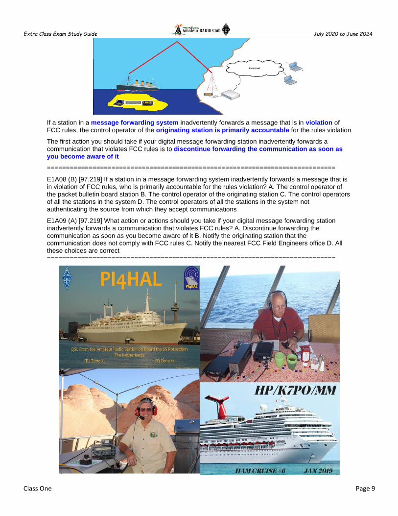
If a station in a message forwarding system inadvertently forwards a message that is in violation of FCC rules, the control operator of the originating station is primarily accountable for the rules violation
The first action you should take if your digital message forwarding station inadvertently forwards a communication that violates FCC rules is to discontinue forwarding the communication as soon as you become aware of it
============================================================================
E1A08 (B) [97.219] If a station in a message forwarding system inadvertently forwards a message that is in violation of FCC rules, who is primarily accountable for the rules violation? A. The control operator of the packet bulletin board station B. The control operator of the originating station C. The control operators of all the stations in the system D. The control operators of all the stations in the system not authenticating the source from which they accept communications
E1A09 (A) [97.219] What action or actions should you take if your digital message forwarding station inadvertently forwards a communication that violates FCC rules? A. Discontinue forwarding the communication as soon as you become aware of it B. Notify the originating station that the communication does not comply with FCC rules C. Notify the nearest FCC Field Engineers office D. All these choices are correct ============================================================================

Extra Class Exam Study Guide July 2020 to June 2024
Class One Page 10
Operation of an amateur station is installed aboard a ship or aircraft must be approved by the master of the ship or the pilot in command of the aircraft
An FCC-issued amateur license or a reciprocal permit for an alien amateur licensee is required when operating an amateur station aboard a US-registered vessel in international waters
An FCC-issued amateur license or a reciprocal permit for an alien amateur licensee is required when operating an amateur station aboard any vessel or craft that is documented or registered in the United States
============================================================================
E1A10 (A) [97.11] If an amateur station is installed aboard a ship or aircraft, what condition must be met before the station is operated? A. Its operation must be approved by the master of the ship or the pilot in command of the aircraft B. The amateur station operator must agree not to transmit when the main radio of the ship or aircraft is in use C. The amateur station must have a power supply that is completely independent of the main ship or aircraft power supply D. The amateur operator must have an FCC Marine or Aircraft endorsement on his or her amateur license
E1A11 (B) [97.5] Which of the following describes authorization or licensing required when operating an amateur station aboard a U.S.-registered vessel in international waters? A. Any amateur license with an FCC Marine or Aircraft endorsement B. Any FCC-issued amateur license C. Only General Class or higher amateur licenses D. An unrestricted Radiotelephone Operator Permit
E1A13 (B) [97.5] Who must be in physical control of the station apparatus of an amateur station aboard any vessel or craft that is documented or registered in the United States? A. Only a person with an FCC Marine Radio license grant B. Any person holding an FCC issued amateur license or who is authorized for alien reciprocal operation C. Only a person named in an amateur station license grant D. Any person named in an amateur station license grant or a person holding an unrestricted Radiotelephone Operator Permit ============================================================================
E1B Station restrictions and special operations
============================================================================
An emission outside its necessary bandwidth that can be reduced or eliminated without affecting the information transmitted constitutes a spurious emission
The mean power of any spurious emission must be at least - 43 dB relative to the mean power of the fundamental emission from a station transmitter or external RF amplifier installed after January 1, 2003, and transmitting on a frequency below 30 MHZ
============================================================================
E1B01 (D) [97.3] Which of the following constitutes a spurious emission? A. An amateur station transmission made without the proper call sign identification B. A signal transmitted to prevent its detection by any station other than the intended recipient C. Any transmitted signal that unintentionally interferes with another licensed radio station D. An emission outside the signal's necessary bandwidth that can be reduced or eliminated without affecting the information transmitted
============================================================================

Extra Class Exam Study Guide July 2020 to June 2024
Class One Page 11
DRM SSTV SSB transmissions in the HF phone bands DRM must conform to the maximum 2.8 kHz occupied bandwidth
============================================================================
E1B02 (A) [97.307(f)(2)] Which of the following is an acceptable bandwidth for Digital Radio Mondiale (DRM) based voice or SSTV digital transmissions made on the HF amateur bands? A. 3 kHz B. 10 kHz C. 15 kHz D. 20 kHz
============================================================================
If you are installing an amateur station antenna at a site at or near a public use airport you may have to notify the Federal Aviation Administration and register it with the FCC as required by Part 17 of FCC rules
============================================================================
E1B06 (A) [97.15] Which of the following additional rules apply if you are installing an amateur station antenna at a site at or near a public use airport? A. You may have to notify the Federal Aviation Administration and register it with the FCC as required by Part 17 of the FCC rules B. You must submit engineering drawings to the FAA C. You must file an Environmental Impact Statement with the EPA before construction begins D. You must obtain a construction permit from the airport zoning authority
============================================================================
An Environmental Assessment must be submitted to the FCC before placing an amateur station within an officially designated wilderness area or wildlife preserve, or an area listed in the National Register of Historical Places
============================================================================
E1B04 (C) [97.13, 1.1305-1.1319] What must be done before placing an amateur station within an officially designated wilderness area or wildlife preserve, or an area listed in the National Register of Historic Places? A. A proposal must be submitted to the National Park Service B. A letter of intent must be filed with the Environmental Protection Agency C. An Environmental Assessment must be submitted to the FCC D. A form FSD-15 must be submitted to the Department of the Interior
============================================================================

Extra Class Exam Study Guide July 2020 to June 2024
Class One Page 12
Editor’s note: FCC monitoring facility must protect that facility from harmful interference. Failure to do so could result in imposition of operating restrictions upon the amateur station by an EIC pursuant to Sec. 97.121 of this part. Geographical coordinates of the facilities that require protection are listed in Sec. 0.121 (c) of this chapter. There are 14 such stations listed in 47 CFR 0.121(b) and are shown below.
The National Radio Astronomy Observatory sites are located in Green Bank West Virginia, Socorro New Mexico, and Charlottesville NC.
The National Radio Quiet Zone is an area surrounding the National Radio Astronomy Observatory
Within 1 mile an amateur station must protect an FCC monitoring facility from harmful interference
============================================================================
E1B05 (C) [97.3] What is the National Radio Quiet Zone? A. An area in Puerto Rico surrounding the Arecibo Radio Telescope B. An area in New Mexico surrounding the White Sands Test Area C. An area surrounding the National Radio Astronomy Observatory D. An area in Florida surrounding Cape Canaveral
E1B03 (A) [97.13] Within what distance must an amateur station protect an FCC monitoring facility from harmful interference? A. 1 mile B. 3 miles C. 10 miles D. 30 miles
============================================================================
An amateur station could be required to avoid transmitting during certain hours on frequencies that cause the interference if its signal causes interference to domestic broadcast reception, assuming that the receiver(s) involved are of good engineering design
=============================================================
E1B08 (D) [97.121] What limitations may the FCC place on an amateur station if its signal causes interference to domestic broadcast reception, assuming that the receivers involved are of good engineering design? A. The amateur station must cease operation B. The amateur station must cease operation on all frequencies below 30 MHz C. The amateur station must cease operation on all frequencies above 30 MHz D. The amateur station must avoid transmitting during certain hours on frequencies that cause the interference
E1B12 (A) [97.303(b)] What must the control operator of a repeater operating in the 70 cm band do if a radiolocation system experiences interference from that repeater? A. Cease operation or make changes to the repeater to mitigate the interference B. File an FAA NOTAM (Notice to Airmen) with the repeater system's ERP, call sign, and six-character grid locator C. Reduce the repeater antenna HAAT (Height Above Average Terrain) D. All these choices are correct

Extra Class Exam Study Guide July 2020 to June 2024
Class One Page 13
============================================================================
Any FCC-licensed amateur station certified by the responsible civil defense organization for the area served may be operated in RACES
All amateur service frequencies authorized to the control operator are authorized to an amateur station participating in RACES
============================================================================
E1B09 (C) [97.407] Which amateur stations may be operated under RACES rules? A. Only those club stations licensed to Amateur Extra Class operators B. Any FCC-licensed amateur station except a Technician Class C. Any FCC-licensed amateur station certified by the responsible civil defense organization for the area served D. Any FCC-licensed amateur station participating in the Military Auxiliary Radio System (MARS)
E1B10 (A) [97.407] What frequencies are authorized to an amateur station operating under RACES rules? A. All amateur service frequencies authorized to the control operator B. Specific segments in the amateur service MF, HF, VHF and UHF bands C. Specific local government channels D. Military Auxiliary Radio System (MARS) channels
============================================================================
PRB-1 require state and local government zoning regulations to make reasonable accommodations affecting amateur radio (Does not apply for HOA & CCR)
============================================================================
E1B07 (C) [97.15] To what type of regulations does PRB-1 apply? A. Homeowners associations B. FAA tower height limits C. State and local zoning D. Use of wireless devices in vehicles
E1B11 (B) [97.15] What does PRB-1 require of regulations affecting amateur radio? A. No limitations may be placed on antenna size or placement B. Reasonable accommodations of amateur radio must be made C. Amateur radio operations must be permitted in any private residence D. Use of wireless devices in a vehicle is exempt from regulation
============================================================================

Extra Class Exam Study Guide July 2020 to June 2024
Class One Page 14
E1C Rules pertaining to automatic and remote control
============================================================================
Editor’s note: The question(s) below are addressed in E1A Operating Standards
E1C01 (D) [97.303] What is the maximum bandwidth for a data emission on 60 meters? A. 60 Hz B. 170 Hz C. 1.5 kHz D. 2.8 kHz
============================================================================
The use of devices and procedures for control so that the control operator does not have to be present at a control point is automatic control of a station
An automatically controlled station may NOT originate third party communications
3 minutes is the maximum permissible duration of a remotely controlled station’s transmissions if its control link malfunctions
Editor’s note: Station Control and Repeaters
A control operator must be present at the control point of a remotely controlled amateur station
A station controlled indirectly through a control link is a remotely controlled station
Direct manipulation of the transmitter by a control operator is meant by local control
Under automatic control the control operator is not required to be present at the control point
An automatically controlled station may retransmit third party communications when transmitting RTTY or data emissions
29.500 - 29.700 MHz are available for an automatically controlled repeater operation
Only auxiliary, repeater or space stations may automatically retransmit the radio signals of other amateur stations
============================================================================
E1C03 (B) [97.109(d)] How do the control operator responsibilities of a station under automatic control differ from one under local control? A. Under local control there is no control operator B. Under automatic control the control operator is not required to be present at the control point C. Under automatic control there is no control operator D. Under local control a control operator is not required to be present at a control point
E1C05 (A) [97.221(c)(1), 97.115(c)] When may an automatically controlled station originate third party communications? A. Never B. Only when transmitting RTTY or data emissions C. When agreed upon by the sending or receiving station D. When approved by the National Telecommunication and Information Administration
E1C08 (B) [97.213] What is the maximum permissible duration of a remotely controlled station's transmissions if its control link malfunctions? A. 30 seconds B. 3 minutes C. 5 minutes D. 10 minutes
============================================================================

Extra Class Exam Study Guide July 2020 to June 2024
Class One Page 15
Communications incidental to the purpose of the amateur service and remarks of a personal nature may be transmitted to amateur stations in foreign countries
Non-US Operating Agreements
European Conference of Postal and Telecommunications Administrations (CEPT) license Allows US amateurs to travel and operate from most of European countries Amateurs from CEPT countries can operate in the USA
International Amateur Radio Permit (IARP) Allows for operations in certain countries in Central and South America without seeking a special license or permit to enter and operate from that country
International Telecommunication Union Reciprocal Permit is an agreement between the US and a country that does not participate in either CEPT or IARP agreements
============================================================================
E1C02 (C) [97.117] Which of the following types of communications may be transmitted to amateur stations in foreign countries? A. Business-related messages for non-profit organizations B. Messages intended for users of the maritime satellite service C. Communications incidental to the purpose of the amateur service and remarks of a personal nature D. All these choices are correct
E1C04 (A) What is meant by IARP? A. An international amateur radio permit that allows U.S. amateurs to operate in certain countries of the Americas B. The internal amateur radio practices policy of the FCC C. An indication of increased antenna reflected power D. A forecast of intermittent aurora radio propagation
E1C06 (C) Which of the following is required in order to operate in accordance with CEPT rules in foreign countries where permitted? A. You must identify in the official language of the country in which you are operating B. The U.S. embassy must approve of your operation C. You must bring a copy of FCC Public Notice DA 16-1048 D. You must append "/CEPT" to your call sign
E1C11 (A) [97.5] Which of the following operating arrangements allows an FCC-licensed U.S. citizen to operate in many European countries, and alien amateurs from many European countries to operate in the U.S.? A. CEPT agreement B. IARP agreement C. ITU reciprocal license D. All these choices are correct
============================================================================
Editor’s note: The question(s) below are addressed in E1B Station restrictions and special operations
E1C10 (A) [97.307] What is the permitted mean power of any spurious emission relative to the mean power of the fundamental emission from a station transmitter or external RF amplifier installed after January 1, 2003 and transmitting on a frequency below 30 MHz? A. At least 43 dB below B. At least 53 dB below C. At least 63 dB below D. At least 73 dB below
============================================================================
Editor’s note: The question(s) below are addressed in E8B Modulation and Demodulation
E1C07 (D) [97.3(a)(8)] At what level below a signal's mean power level is its bandwidth determined according to FCC rules? A. 3 dB B. 6 dB C. 23 dB D. 26 dB
E1C09 (B) [97.307] What is the highest modulation index permitted at the highest modulation frequency for angle modulation below 29.0 MHz? A. 0.5 B. 1.0 C. 2.0 D. 3.0
============================================================================
Editor’s note: The question(s) below are addressed in E1A Operating Standards
E1C12 (D) [97.305(c)] On what portion of the 630 meter band are phone emissions permitted? A. None B. Only the top 3 kHz C. Only the bottom 3 kHz D. The entire band
E1C13 (C) [97.303(g)] What notifications must be given before transmitting on the 630 meter or 2200 meter bands? A. A special endorsement must be requested from the FCC B. An environmental impact statement must be filed with the Department of the Interior C. Operators must inform Utilities Technology Council (UTC) of their call sign and coordinates of the station D. Operators must inform the FAA of their intent to operate, giving their call sign and distance to the nearest runway

Extra Class Exam Study Guide July 2020 to June 2024
Class One Page 16
E1C14 (B) [97.303(g)] How long must an operator wait after filing a notification with the Utilities Technology Council (UTC) before operating on the 2200 meter or 630 meter band? A. Operators must not operate until approval is received B. Operators may operate after 30 days, providing they have not been told that their station is within 1 km of PLC systems using those frequencies C. Operators may not operate until a test signal has been transmitted in coordination with the local power company D. Operations may commence immediately, and may continue unless interference is reported by the UTC
============================================================================
E1F Miscellaneous rules
============================================================================
Only Technician, General, Advanced or Amateur Extra Class operators may be the control operator of an auxiliary station
Editor’s note: Auxiliary Stations
Auxiliary Stations are amateur station, other than in a message forwarding system, that transmit communications point-to-point within a system of cooperating amateur stations
Links to remotely controlled stations
Cross-band repeat stations
============================================================================
E1F10 (B) [97.201] Who may be the control operator of an auxiliary station? A. Any licensed amateur operator B. Only Technician, General, Advanced or Amateur Extra Class operators C. Only General, Advanced or Amateur Extra Class operators D. Only Amateur Extra Class operators
============================================================================
Spread spectrum transmissions permitted on amateur frequencies above 222 MHz
A station transmitting SS emission must not cause harmful interference
The transmitting station must be in an area regulated by the FCC
The transmission must not be used to obscure the meaning
10 W is the maximum transmitter power for an amateur station transmitting spread spectrum
============================================================================
E1F01 (B) [97.305] On what frequencies are spread spectrum transmissions permitted? A. Only on amateur frequencies above 50 MHz B. Only on amateur frequencies above 222 MHz C. Only on amateur frequencies above 420 MHz D. Only on amateur frequencies above 144 MHz
E1F09 (D) [97.311] Which of the following conditions apply when transmitting spread spectrum emissions? A. A station transmitting SS emission must not cause harmful interference to other stations employing other authorized emissions B. The transmitting station must be in an area regulated by the FCC or in a country that permits SS emissions C. The transmission must not be used to obscure the meaning of any communication D. All these choices are correct
============================================================================

Extra Class Exam Study Guide July 2020 to June 2024
Class One Page 17
Canadian amateurs operating in the USA cannot exceed U.S. Amateur Extra Class privileges
LINE A is an area roughly parallel to of the US-Canadian border and about 75 miles south
North of Line A Amateur stations may not transmit on 420 - 430 MHz
============================================================================
E1F02 (C) [97.107] What privileges are authorized in the U.S. to persons holding an amateur service license granted by the government of Canada? A. None, they must obtain a U.S. license B. All privileges of the Amateur Extra Class license C. The operating terms and conditions of the Canadian amateur service license, not to exceed U.S. Amateur Extra Class license privileges D. Full privileges, up to and including those of the Amateur Extra Class license, on the 80, 40, 20, 15, and 10 meter bands
E1F04 (A) [97.3] Which of the following geographic descriptions approximately describes "Line A"? A. A line roughly parallel to and south of the border between the U.S. and Canada B. A line roughly parallel to and west of the U.S. Atlantic coastline C. A line roughly parallel to and north of the border between the U.S. and Mexico D. A line roughly parallel to and east of the U.S. Pacific coastline
E1F05 (D) [97.303] Amateur stations may not transmit in which of the following frequency segments if they are located in the contiguous 48 states and north of Line A? A. 440 MHz - 450 MHz B. 53 MHz - 54 MHz C. 222 MHz - 223 MHz D. 420 MHz - 430 MHz
============================================================================
External Power Amplifiers (Linears)
Dealers may sell non-certified linear amplifiers if they were purchased in used condition and resold to another amateur
Linears must satisfy the spurious emission standards ( -43 dBc)
Editor’s note: External Power Amplifiers (Linears)
Amateurs my build their own amplifier or modify amplifiers for use in an Amateur Radio station
RF power amplifiers capable of operating on frequencies below 144 MHz may require FCC certification
Must not be capable of amplifying the input signal by more than 15dB
Must not amplify between 26 and 28 MHz (CB)
============================================================================

Extra Class Exam Study Guide July 2020 to June 2024
Class One Page 18
E1F03 (A) [97.315] Under what circumstances may a dealer sell an external RF power amplifier capable of operation below 144 MHz if it has not been granted FCC certification? A. It was purchased in used condition from an amateur operator and is sold to another amateur operator for use at that operator's station B. The equipment dealer assembled it from a kit C. It was imported from a manufacturer in a country that does not require certification of RF power amplifiers D. It was imported from a manufacturer in another country and was certificated by that country's government
E1F11 (D) [97.317] Which of the following best describes one of the standards that must be met by an external RF power amplifier if it is to qualify for a grant of FCC certification? A. It must produce full legal output when driven by not more than 5 watts of mean RF input power B. It must be capable of external RF switching between its input and output networks C. It must exhibit a gain of 0 dB or less over its full output range D. It must satisfy the FCC's spurious emission standards when operated at the lesser of 1500 watts or its full output power
============================================================================
Special Temporary Authority can be granted for experimental amateur communications
Editor’s note: Special Temporary Authority (STA)
Occasionally, a new mode is developed that is not covered under existing FCC rules
STAs are temporary, lasting long enough for experiments to be performed and information accumulated
STAs don’t give amateurs exclusive use of a frequency nor does it wave all the rules
STAs may result in changes to the FCC rules but is not a waiver of any rule
============================================================================
E1F06 (A) [1.931] Under what circumstances might the FCC issue a Special Temporary Authority (STA) to an amateur station? A. To provide for experimental amateur communications B. To allow regular operation on Land Mobile channels C. To provide additional spectrum for personal use D. To provide temporary operation while awaiting normal licensing
============================================================================
No compensation for communications directly or indirectly (Not for Hire or Trade)
No transmissions are permitted in which you or your employer have a pecuniary (monetary) interest
Editor’s note: Business & Payment
Your personal activities don’t count as business
Talking to your spouse about shopping
Order a pizza over a phone patch
Radio swap nets on the air
Don’t do it regularly or can become a business
============================================================================
E1F07 (D) [97.113] When may an amateur station send a message to a business? A. When the total money involved does not exceed $25 B. When the control operator is employed by the FCC or another government agency C. When transmitting international third-party communications D. When neither the amateur nor his or her employer has a pecuniary interest in the communications
E1F08 (A) [97.113(c)] Which of the following types of amateur station communications are prohibited? A. Communications transmitted for hire or material compensation, except as otherwise provided in the rules B. Communications that have political content, except as allowed by the Fairness Doctrine C. Communications that have religious content D. Communications in a language other than English
============================================================================

Extra Class Exam Study Guide July 2020 to June 2024
Class One Page 19
============================================================================
E1D Amateur space and Earth stations; telemetry and telecommand rules
============================================================================
Radio communications service using satellites for the same purpose as the amateur service.
Editor’s note: Amateur Satellite Service Definitions: Earth Stations: Stations operating at or within 50 km of the Earth’s surface Space Station: Amateur station located above 50 km from the Earth’s surface Telecommand: One-way Tx initiate, modify or terminate functions of a device at a distance Telecommand Station: An amateur station that transmits telecommand control functions Telemetry: One-way transmission of measurements from measuring instruments
A telecommand station transmits communications to initiate, modify or terminate functions of a space station
A telecommand station may transmit special codes intended to obscure the meaning of messages
A telecommand station is designated by the space station licensee, subject to the privileges of the class of operator license held by the control operator
1 Watt is the maximum transmitter power when operating a model craft by telecommand
Space Station more than 50 kilometers above the surface of the Earth
Earth Station less than 50 kilometers above the surface of the Earth
============================================================================
E1D02 (A) [97.211(b)] Which of the following may transmit special codes intended to obscure the meaning of messages? A. Telecommand signals from a space telecommand station B. Data containing personal information C. Auxiliary relay links carrying repeater audio D. Binary control characters
E1D03 (B) [97.3(a)(45)] What is a space telecommand station? A. An amateur station located on the surface of the Earth for communication with other Earth stations by means of Earth satellites B. An amateur station that transmits communications to initiate, modify or terminate functions of a space station C. An amateur station located in a satellite or a balloon more than 50 kilometers above the surface of the Earth D. An amateur station that receives telemetry from a satellite or balloon more than 50 kilometers above the surface of the Earth
E1D06 (A) [97.215(c)] What is the maximum permitted transmitter output power when operating a model craft by telecommand? A. 1 watt B. 2 watts C. 5 watts D. 100 watts
E1D10 (B) [97.211] Which amateur stations are eligible to be telecommand stations of space stations (subject to the privileges of the class of operator license held by the control operator of the station)? A. Any amateur station designated by NASA B. Any amateur station so designated by the space station licensee C. Any amateur station so designated by the ITU D. All these choices are correct
============================================================================
Extra Class Exam Study Guide July 2020 to June 2024
Class One Page 20
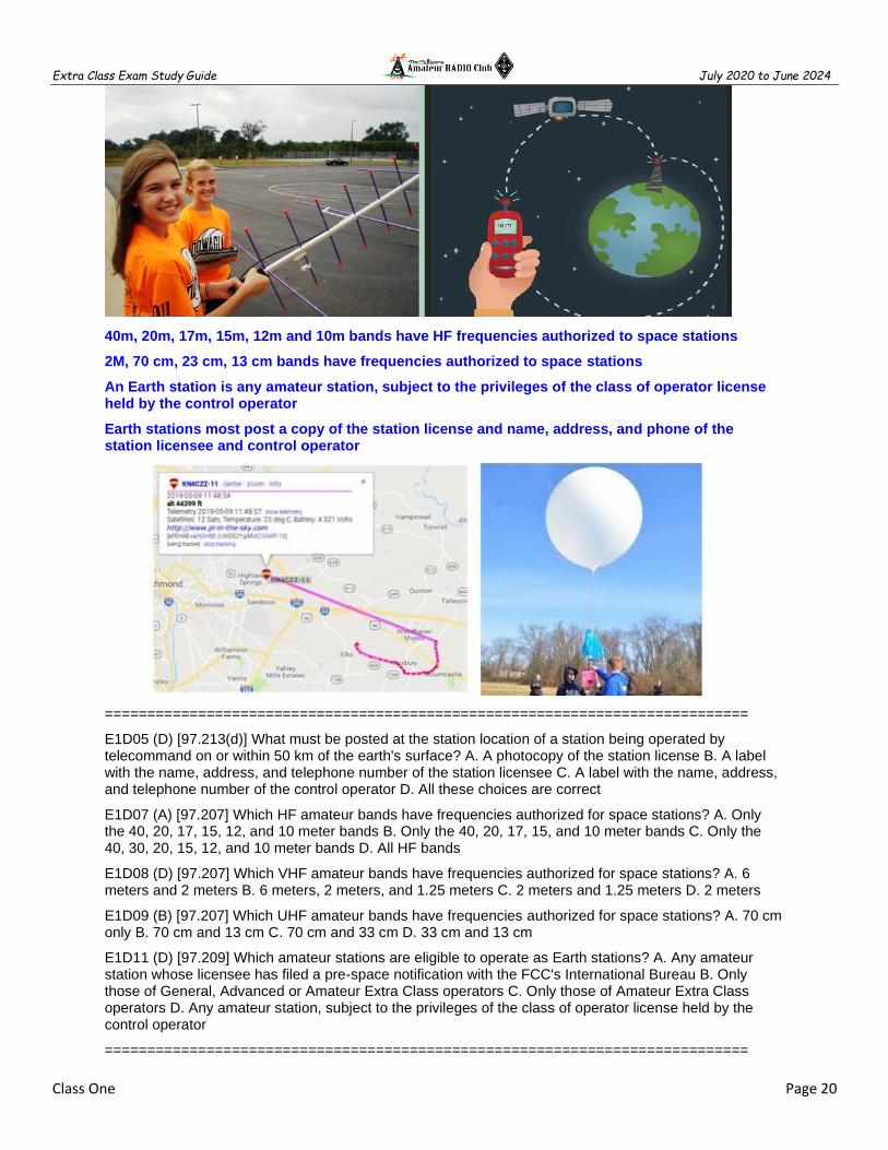
40m, 20m, 17m, 15m, 12m and 10m bands have HF frequencies authorized to space stations
2M, 70 cm, 23 cm, 13 cm bands have frequencies authorized to space stations
An Earth station is any amateur station, subject to the privileges of the class of operator license held by the control operator
Earth stations most post a copy of the station license and name, address, and phone of the station licensee and control operator
============================================================================
E1D05 (D) [97.213(d)] What must be posted at the station location of a station being operated by telecommand on or within 50 km of the earth's surface? A. A photocopy of the station license B. A label with the name, address, and telephone number of the station licensee C. A label with the name, address, and telephone number of the control operator D. All these choices are correct
E1D07 (A) [97.207] Which HF amateur bands have frequencies authorized for space stations? A. Only the 40, 20, 17, 15, 12, and 10 meter bands B. Only the 40, 20, 17, 15, and 10 meter bands C. Only the 40, 30, 20, 15, 12, and 10 meter bands D. All HF bands
E1D08 (D) [97.207] Which VHF amateur bands have frequencies authorized for space stations? A. 6 meters and 2 meters B. 6 meters, 2 meters, and 1.25 meters C. 2 meters and 1.25 meters D. 2 meters
E1D09 (B) [97.207] Which UHF amateur bands have frequencies authorized for space stations? A. 70 cm only B. 70 cm and 13 cm C. 70 cm and 33 cm D. 33 cm and 13 cm
E1D11 (D) [97.209] Which amateur stations are eligible to operate as Earth stations? A. Any amateur station whose licensee has filed a pre-space notification with the FCC's International Bureau B. Only those of General, Advanced or Amateur Extra Class operators C. Only those of Amateur Extra Class operators D. Any amateur station, subject to the privileges of the class of operator license held by the control operator
============================================================================
Extra Class Exam Study Guide July 2020 to June 2024
Class One Page 21
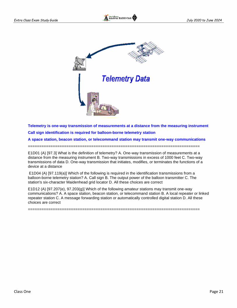
Telemetry is one-way transmission of measurements at a distance from the measuring instrument
Call sign identification is required for balloon-borne telemetry station
A space station, beacon station, or telecommand station may transmit one-way communications
============================================================================
E1D01 (A) [97.3] What is the definition of telemetry? A. One-way transmission of measurements at a distance from the measuring instrument B. Two-way transmissions in excess of 1000 feet C. Two-way transmissions of data D. One-way transmission that initiates, modifies, or terminates the functions of a device at a distance
E1D04 (A) [97.119(a)] Which of the following is required in the identification transmissions from a balloon-borne telemetry station? A. Call sign B. The output power of the balloon transmitter C. The station's six-character Maidenhead grid locator D. All these choices are correct
E1D12 (A) [97.207(e), 97.203(g)] Which of the following amateur stations may transmit one-way communications? A. A space station, beacon station, or telecommand station B. A local repeater or linked repeater station C. A message forwarding station or automatically controlled digital station D. All these choices are correct
============================================================================

Extra Class Exam Study Guide July 2020 to June 2024
Class One Page 22
E1E Volunteer examiner program
============================================================================
A Volunteer Examiner Coordinator (VEC) is an organization that has entered into an agreement with the FCC to coordinate amateur operator license examinations
The Volunteer Examiner (VE) accreditation process is the procedure by which a VEC confirms that the VE applicant meets FCC requirements to serve as an examiner
Three is the minimum number of qualified VEs required to administer an Element 4 amateur operator license examination
Three VEs must certify that the examinee is qualified for the license grant and that they have complied with the administering VE requirements
Preparing, processing, administering and coordinating an examination for an amateur radio license are out-of-pocket expenses that may be reimbursed VEs and VECs
The questions for all written US amateur license examinations are listed in a question pool maintained by all the VECs
A score of 74% is the minimum passing score on amateur operator license examinations
Each administering VE is responsible for the proper conduct and necessary supervision during an amateur operator license examination session
Immediately terminate the candidate’s examination if a candidate fails to comply with the examiner’s instructions during an amateur operator license examination
A VE cannot administer an examination to relatives of the VE as listed in the FCC rules
The penalty for a VE who fraudulently administers or certifies an examination is revocation of the VE’s amateur station license grant and the suspension of the VE’s amateur operator license grant
The administering VEs must submit the application document to the coordinating VEC according to the coordinating VEC instructions after the administration of a successful examination for an amateur operator license
The VE team must return the application document to the examinee with the application form if the examinee DOES NOT PASS THE EXAM
============================================================================
E1E01 (A) [97.527] For which types of out-of-pocket expenses do the Part 97 rules state that VEs and VECs may be reimbursed? A. Preparing, processing, administering, and coordinating an examination for an amateur radio operator license B. Teaching an amateur operator license examination preparation course C. No expenses are authorized for reimbursement D. Providing amateur operator license examination preparation training materials
E1E02 (C) [97.523] Who does Part 97 task with maintaining the pools of questions for all U.S. amateur license examinations? A. The VEs B. The FCC C. The VECs D. The ARRL
E1E03 (C) [97.521] What is a Volunteer Examiner Coordinator? A. A person who has volunteered to administer amateur operator license examinations B. A person who has volunteered to prepare amateur operator license examinations C. An organization that has entered into an agreement with the FCC to coordinate, prepare, and administer amateur operator license examinations D. The person who has entered into an agreement with the FCC to be the VE session manager
E1E04 (D) [97.509, 97.525] Which of the following best describes the Volunteer Examiner accreditation process? A. Each General, Advanced and Amateur Extra Class operator is automatically accredited as a VE when the license is granted B. The amateur operator applying must pass a VE examination administered by the FCC Enforcement Bureau C. The prospective VE obtains accreditation from the FCC D. The procedure by which a VEC confirms that the VE applicant meets FCC requirements to serve as an examiner

Extra Class Exam Study Guide July 2020 to June 2024
Class One Page 23
E1E05 (B) [97.503] What is the minimum passing score on all amateur operator license examinations? A. Minimum passing score of 70% B. Minimum passing score of 74% C. Minimum passing score of 80% D. Minimum passing score of 77%
E1E06 (C) [97.509] Who is responsible for the proper conduct and necessary supervision during an amateur operator license examination session? A. The VEC coordinating the session B. The FCC C. Each administering VE D. The VE session manager
E1E07 (B) [97.509] What should a VE do if a candidate fails to comply with the examiner's instructions during an amateur operator license examination? A. Warn the candidate that continued failure to comply will result in termination of the examination B. Immediately terminate the candidate's examination C. Allow the candidate to complete the examination, but invalidate the results D. Immediately terminate everyone's examination and close the session
E1E08 (C) [97.509] To which of the following examinees may a VE not administer an examination? A. Employees of the VE B. Friends of the VE C. Relatives of the VE as listed in the FCC rules D. All these choices are correct
E1E09 (A) [97.509] What may be the penalty for a VE who fraudulently administers or certifies an examination? A. Revocation of the VE's amateur station license grant and the suspension of the VE's
amateur operator license grant B. A fine of up to $1000 per occurrence C. A sentence of up to one year in prison D. All these choices are correct
E1E10 (C) [97.509(h)] What must the administering VEs do after the administration of a successful examination for an amateur operator license? A. They must collect and send the documents to the NCVEC for grading B. They must collect and submit the documents to the coordinating VEC for grading C. They must submit the application document to the coordinating VEC according to the coordinating VEC instructions D. They must collect and send the documents to the FCC according to instructions
E1E11 (B) [97.509(m)] What must the VE team do if an examinee scores a passing grade on all examination elements needed for an upgrade or new license? A. Photocopy all examination documents and forward them to the FCC for processing B. Three VEs must certify that the examinee is qualified for the license grant and that they have complied with the administering VE requirements C. Issue the examinee the new or upgrade license D. All these choices are correct
E1E12 (A) [97.509(j)] What must the VE team do with the application form if the examinee does not pass the exam? A. Return the application document to the examinee B. Maintain the application form with the VEC's records C. Send the application form to the FCC and inform the FCC of the grade D. Destroy the application form ============================================================================
Extra Class Exam Study Guide July 2020 to June 2024
Class One Page 24
E2C Operating methods
============================================================================
“self-spotting” is the prohibited practice of posting one’s own call sign and frequency on a call sign spotting network
30 meters bands is amateur radio contesting generally excluded
During a VHF/UHF contest the weak signal segment of the band, with most of the activity near the calling frequency would have the highest level of activity
Send your full call sign once or twice when attempting to contact a DX station working a pileup or in a contest
Why might a DX station state that they are listening on another frequency? A. Because the DX station may be transmitting on a frequency that is prohibited to some responding stations B. To separate the calling stations from the DX station C. To reduce interference, thereby improving operating efficiency D. All of these choices are correct
The function of a DX QSL Manager is to handle the receiving and sending of confirmation cards for a DX station
Cabrillo format is a standard for submission of electronic contest logs
Ham radio mesh network uses frequencies shared with unlicensed wireless data services (WIFI)
A wireless router running custom firmware is used to implement an amateur radio mesh network
Discovery and link establishment protocols are used to form a mesh network
============================================================================
E2C01 (D) What indicator is required to be used by U.S.-licensed operators when operating a station via remote control and the remote transmitter is located in the U.S.? A. / followed by the USPS two-letter abbreviation for the state in which the remote station is located B. /R# where # is the district of the remote station C. / followed by the ARRL Section of the remote station D. No additional indicator is required
E2C02 (A) Which of the following best describes the term self-spotting? in connection with HF contest operating? A. The often-prohibited practice of posting one's own call sign and frequency on a spotting network B. The acceptable practice of manually posting the call signs of stations on a spotting network C. A manual technique for rapidly zero beating or tuning to a station's frequency before calling that station D. An automatic method for rapidly zero beating or tuning to a station's frequency before calling that station
E2C03 (A) From which of the following bands is amateur radio contesting generally excluded? A. 30 meters B. 6 meters C. 2 meters D. 33 centimeters
E2C04 (B) Which of the following frequencies are sometimes used for amateur radio mesh networks? A. HF frequencies where digital communications are permitted B. Frequencies shared with various unlicensed wireless data services C. Cable TV channels 41 through 43 D. The 60 meter band channel centered on 5373 kHz
E2C05 (B) What is the function of a DX QSL Manager? A. To allocate frequencies for DXpeditions B. To handle the receiving and sending of confirmation cards for a DX station C. To run a net to allow many stations to contact a rare DX station D. To relay calls to and from a DX station
E2C06 (C) During a VHF/UHF contest, in which band segment would you expect to find the highest level of SSB or CW activity? A. At the top of each band, usually in a segment reserved for contests B. In the middle of each band, usually on the national calling frequency C. In the weak signal segment of the band, with most of the activity near the calling frequency D. In the middle of the band, usually 25 kHz above the national calling frequency

Extra Class Exam Study Guide July 2020 to June 2024
Class One Page 25
E2C07 (A) What is the Cabrillo format? A. A standard for submission of electronic contest logs B. A method of exchanging information during a contest QSO C. The most common set of contest rules D. The rules of order for meetings between contest sponsors
E2C08 (B) Which of the following contacts may be confirmed through the U.S. QSL bureau system? A. Special event contacts between stations in the U.S. B. Contacts between a U.S. station and a non-U.S. station C. Repeater contacts between U.S. club members D. Contacts using tactical call signs
E2C09 (C) What type of equipment is commonly used to implement an amateur radio mesh network? A. A 2 meter VHF transceiver with a 1200 baud modem B. An optical cable connection between the USB ports of 2 separate computers C. A wireless router running custom firmware D. A 440 MHz transceiver with a 9600 baud modem
E2C10 (D) Why might a DX station state that they are listening on another frequency? A. Because the DX station may be transmitting on a frequency that is prohibited to some responding stations B. To separate the calling stations from the DX station C. To improve operating efficiency by reducing interference D. All these choices are correct
E2C11 (A) How should you generally identify your station when attempting to contact a DX station during a contest or in a pileup? A. Send your full call sign once or twice B. Send only the last two letters of your call sign until you make contact C. Send your full call sign and grid square D. Send the call sign of the DX station three times, the words this is,then your call sign three times
E2C12 (C) What technique do individual nodes use to form a mesh network? A. Forward error correction and Viterbi codes B. Acting as store-and-forward digipeaters C. Discovery and link establishment protocols D. Custom code plugs for the local trunking systems
============================================================================
E2D Operating methods
============================================================================
JT65 developed for weak-signal VHF/UHF such as EME
JT65 can decode signals with very low signal-to-noise ratio
Time synchronous transmissions alternately from each station is a method of establishing EME contacts
JT65 uses Multi-tone AFSK
MSK441 is especially designed for use for meteor scatter signals
Which of the following is a good technique for making meteor scatter contacts? A. 15-second timed transmission sequences with stations alternating based on location B. Use of special digital modes C. Short transmissions with rapidly repeated call signs and signal reports D. All these choices are correct
Extra Class Exam Study Guide July 2020 to June 2024
Class One Page 26
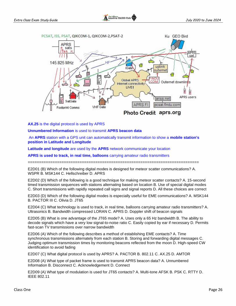
AX.25 is the digital protocol is used by APRS
Unnumbered Information is used to transmit APRS beacon data
An APRS station with a GPS unit can automatically transmit information to show a mobile station's position in Latitude and Longitude
Latitude and longitude are used by the APRS network communicate your location
APRS is used to track, in real time, balloons carrying amateur radio transmitters
============================================================================
E2D01 (B) Which of the following digital modes is designed for meteor scatter communications? A. WSPR B. MSK144 C. Hellschreiber D. APRS
E2D02 (D) Which of the following is a good technique for making meteor scatter contacts? A. 15-second timed transmission sequences with stations alternating based on location B. Use of special digital modes C. Short transmissions with rapidly repeated call signs and signal reports D. All these choices are correct
E2D03 (D) Which of the following digital modes is especially useful for EME communications? A. MSK144 B. PACTOR III C. Olivia D. JT65
E2D04 (C) What technology is used to track, in real time, balloons carrying amateur radio transmitters? A. Ultrasonics B. Bandwidth compressed LORAN C. APRS D. Doppler shift of beacon signals
E2D05 (B) What is one advantage of the JT65 mode? A. Uses only a 65 Hz bandwidth B. The ability to decode signals which have a very low signal-to-noise ratio C. Easily copied by ear if necessary D. Permits fast-scan TV transmissions over narrow bandwidth
E2D06 (A) Which of the following describes a method of establishing EME contacts? A. Time synchronous transmissions alternately from each station B. Storing and forwarding digital messages C. Judging optimum transmission times by monitoring beacons reflected from the moon D. High-speed CW identification to avoid fading
E2D07 (C) What digital protocol is used by APRS? A. PACTOR B. 802.11 C. AX.25 D. AMTOR
E2D08 (A) What type of packet frame is used to transmit APRS beacon data? A. Unnumbered Information B. Disconnect C. Acknowledgement D. Connect
E2D09 (A) What type of modulation is used for JT65 contacts? A. Multi-tone AFSK B. PSK C. RTTY D. IEEE 802.11

Extra Class Exam Study Guide July 2020 to June 2024
Class One Page 27
E2D10 (C) How can an APRS station be used to help support a public service communications activity? A. An APRS station with an emergency medical technician can automatically transmit medical data to the nearest hospital B. APRS stations with General Personnel Scanners can automatically relay the participant numbers and time as they pass the check points C. An APRS station with a Global Positioning System unit can automatically transmit information to show a mobile station's position during the event D. All these choices are correct
E2D11 (D) Which of the following data are used by the APRS network to communicate station location? A. Polar coordinates B. Time and frequency C. Radio direction finding spectrum analysis D. Latitude and longitude
============================================================================
E2E Operating methods
============================================================================
300 baud is the most common data rate used for HF packet
PACTOR can be used to transfer binary files
Editor’s note: Winlink is a radio messaging transfer system that uses amateur-band radio frequencies
Selective fading has occurred when one of the ellipses in an FSK crossed-ellipse display suddenly disappears
Direct FSK applies the data signal to the transmitter VFO
AFSK audio phone conversion of tones into a string of ones and zeros
Editor’s note: RTTY tuning display. Pattern A indicates that the signal has been tuned corrected. At B the receiver is slightly off frequency, while C indicates that the transmitting station is using a shift that differs from your processor or modem setting. Although hardly any RTTY operators use oscilloscope tuning today, modern tuning indicators still rely on the same principle. Below-Left properly tuned RTTY signal. Below-Right & Center loss of signal.

Extra Class Exam Study Guide July 2020 to June 2024
Class One Page 28
PSK31 uses a very narrow bandwidth (approximately 60 Hz at -26 dB) yet provides 50 word-per-
Forward Error Correction (FEC) is implemented in PSK31 by transmitting extra data that may be used to detect and correct transmission errors
PSK31 uses variable length coding of characters (Varicode)
Editor’s note: In PSK31 (1's) are represented by a tone with no phase shift compared to the previous bit and (0's) are tone with a 180-degree phase shift relative to the phase of the previous bit. The phase shift occurs during the zero-level modulation to minimize bandwidth. When the modulation level returns, the positions of the sine wave top and bottom are reversed from the previous bit. Thus, the phase changes by 180 degrees while the frequency remains constant. – AD7FO
To establish contact ALE stations constantly scans a list of frequencies, activating the radio when the designated call sign is received
FT4 contacts are organized as alternating transmissions at 7.5 second intervals
Which of the following is a possible reason that attempts to initiate contact with a digital station on a clear frequency are unsuccessful?
Your transmit frequency is incorrect The protocol version you are using is not the supported by the digital station Another station you are unable to hear is using the frequency All of these choices are correct

Extra Class Exam Study Guide July 2020 to June 2024
Class One Page 29
============================================================================
E2E01 (B) Which of the following types of modulation is common for data emissions below 30 MHz? A. DTMF tones modulating an FM signal B. FSK C. Pulse modulation D. Spread spectrum
E2E02 (A) What do the letters FEC mean as they relate to digital operation? A. Forward Error Correction B. First Error Correction C. Fatal Error Correction D. Final Error Correction
E2E03 (C) How is the timing of FT4 contacts organized? A. By exchanging ACK/NAK packets B. Stations take turns on alternate days C. Alternating transmissions at 7.5 second intervals D. It depends on the lunar phase
E2E04 (A) What is indicated when one of the ellipses in an FSK crossed-ellipse display suddenly disappears? A. Selective fading has occurred B. One of the signal filters is saturated C. The receiver has drifted 5 kHz from the desired receive frequency D. The mark and space signal have been inverted
E2E05 (A) Which of these digital modes does not support keyboard-to-keyboard operation? A. PACTOR B. RTTY C. PSK31 D. MFSK
E2E06 (C) What is the most common data rate used for HF packet? A. 48 baud B. 110 baud C. 300 baud D. 1200 baud
E2E07 (D) Which of the following is a possible reason that attempts to initiate contact with a digital station on a clear frequency are unsuccessful? A. Your transmit frequency is incorrect B. The protocol version you are using is not supported by the digital station C. Another station you are unable to hear is using the frequency D. All these choices are correct
E2E08 (B) Which of the following HF digital modes can be used to transfer binary files? A. Hellschreiber B. PACTOR C. RTTY D. AMTOR
E2E09 (D) Which of the following HF digital modes uses variable-length coding for bandwidth efficiency? A. RTTY B. PACTOR C. MT63 D. PSK31
E2E10 (C) Which of these digital modes has the narrowest bandwidth? A. MFSK16 B. 170 Hz shift, 45-baud RTTY C. PSK31 D. 300-baud packet
E2E11 (A) What is the difference between direct FSK and audio FSK? A. Direct FSK applies the data signal to the transmitter VFO, while AFSK transmits tones via phone B. Direct FSK occupies less bandwidth C. Direct FSK can transmit faster baud rates D. Only direct FSK can be decoded by computer
E2E12 (A) How do ALE stations establish contact? A. ALE constantly scans a list of frequencies, activating the radio when the designated call sign is received B. ALE radios monitor an internet site for the frequency they are being paged on C. ALE radios send a constant tone code to establish a frequency for future use D. ALE radios activate when they hear their signal echoed by back scatter
E2E13 (D) Which of these digital modes has the fastest data throughput under clear communication conditions? A. AMTOR B. 170 Hz shift, 45 baud RTTY C. PSK31 D. 300 baud packet
============================================================================

Extra Class Exam Study Guide July 2020 to June 2024
Class One Page 30
Class One Fundamentals and Substance
============================================================================
After completing each class be sure to use the Fundamentals and Substance subsection that was solely created as a tool for test preparation by helping you make connections between topics and serves as quality review material for after each class. Using these steps can be most useful when learning about new topics that include a lot of detail. The information is in the form of class notes with all of the important information you need to know. These notes are not a substitute for studying the class material in fact you will need to complete your class assignment in order to effectively use these notes. The notes are organized into easily digestible headings and bullet points to organize topics with the key words, main subpoints and summary are all written in one place.
============================================================================
HF Bands
Upper Sideband (USB) emissions will be 3 kHz above the carrier frequency
Lower Sideband (LSB) emissions will be 3 kHz below the carrier frequency
The mean power of any spurious emission must be at least - 43 dB below 30 MHZ
Dealers may sell non-certified linear amplifiers if they were purchased in used condition and resold to another amateur
630M – Max 5W EIRP 472 - 479 KHz
2200 M – Max 1W EIRP 135.7 – 137.8
60M - Max 100 watts ERP, half-wave dipole, CW center of channel, max bandwidth 2.8 kHz
Ships, Aircraft and International
Operation aboard a ship or aircraft must be approved by the master of the ship
An amateur license is required when operating on United States registered craft
European Conference of Postal and Telecommunications Administrations (CEPT) license
International Amateur Radio Permit (IARP)
International Telecommunication Union Reciprocal Permit is an agreement between the US and a country that does not participate in either CEPT or IARP agreements
Control Operator
The use of devices and procedures for control so that the control operator does not have to be present at a control point is automatic control of a station
3 minutes is the maximum permissible duration of a remotely controlled station’s transmissions if its control link malfunctions
If a message forwarding system inadvertently forwards a message that is in violation of FCC rules, the control operator of the originating station is primarily accountable for the rules violation
An automatically controlled station may NOT originate third party communications
RACES
Any FCC-licensed amateur station certified by the responsible civil defense organization for the area served may be operated in RACES
All amateur service frequencies authorized to the control operator are authorized to an amateur station participating in RACES

Extra Class Exam Study Guide July 2020 to June 2024
Class One Page 31
Specials Restrictions
An amateur station antenna near an airport requires FAA notification & FCC registration (Part 17)
An Environmental Assessment must be submitted to the FCC before placing an amateur station within a designated wilderness area or wildlife preserve, National Register of Historical Places
The National Radio Quiet Zone is an area surrounding the National Radio Astronomy Observatory
Within 1 mile an amateur station must protect an FCC monitoring facility from harmful interference
An amateur station could be required to avoid transmitting during certain hours on frequencies that cause the interference if its signal causes interference to domestic broadcast reception, assuming that the receiver(s) involved are of good engineering design
Special Temporary Authority can be granted for experimental amateur communications
PRB-1 require government zoning regulations to make reasonable accommodations
Canada
Canadian amateurs operating in the USA cannot exceed U.S. Amateur Extra Class privileges
LINE A is an area roughly parallel to of the US-Canadian border and about 75 miles south
North of Line A Amateur stations may not transmit on 420 - 430 MHz
Amateur space and Earth stations
Telemetry is one-way transmission of measurements at a distance from the measuring instrument
Call sign identification is required for balloon-borne telemetry station
A space station, beacon station, or telecommand station may transmit one-way communications
A telecommand station transmits to initiate, modify or terminate functions of a space station
A telecommand station may transmit special codes intended to obscure the meaning of messages
A telecommand station is designated by the space station licensee, subject to the privileges of the class of operator license held by the control operator
Space Station more than 50 kilometers above the surface of the Earth
Earth Station less than 50 kilometers above the surface of the Earth
1 Watt is the maximum transmitter power when operating a model craft by telecommand
40m, 20m, 17m, 15m, 12m and 10m bands have HF frequencies authorized to space stations
2M, 70 cm, 23 cm, 13 cm bands have frequencies authorized to space stations
Earth stations most post a copy of the station license and name, address, and phone of the station licensee and control operator (label your balloon)
An Earth station is any amateur station, subject to the privileges of the class of operator license held by the control operator

Extra Class Exam Study Guide July 2020 to June 2024
Class One Page 32
Not for Profit or Business
Communications incidental to the purpose of the amateur service and remarks of a personal
No compensation for communications directly or indirectly (Not for Hire or Trade)
No transmissions are permitted in which you or your employer have a pecuniary (monetary) interest
Spread Spectrum
Spread spectrum transmissions permitted on amateur frequencies above 222 MHz
A station transmitting SS emission must not cause harmful interference
The transmitting station must be in an area regulated by the FCC
The transmission code must not be used to obscure the meaning
Volunteer Examiner program
A Volunteer Examiner Coordinator (VEC) is an organization that has entered into an agreement with the FCC to coordinate amateur operator license examinations
The questions for all written US amateur license examinations are listed in a question pool maintained by all the VECs
Preparing, processing, administering and coordinating an examination for an amateur radio license are out-of-pocket expenses that may be reimbursed VEs and VECs
The Volunteer Examiner (VE) accreditation process is the procedure by which a VEC confirms that the VE applicant meets FCC requirements to serve as an examiner
Three is the minimum number of qualified VEs required to administer an license examination
A VE cannot administer an examination to relatives of the VE as listed in the FCC rules
The penalty for a VE who fraudulently administers or certifies an examination is revocation of the VE’s amateur station license grant and the suspension of the VE’s amateur operator license grant
A score of 74% is the minimum passing score on amateur operator license examinations
Immediately terminate the candidate’s examination if a candidate fails to comply with the examiner’s instructions during an amateur operator license examination
The VE team must return the application document to the examinee with the application form if the examinee DOES NOT PASS THE EXAM
Operating methods
“self-spotting” is the prohibited practice of posting one’s own call sign and frequency on a call sign spotting network
30 meters bands is amateur radio contesting generally excluded
During a VHF/UHF contest the weak signal segment of the band, with most of the activity near the calling frequency would have the highest level of activity
Extra Class Exam Study Guide July 2020 to June 2024
Class One Page 33
Send your full call sign once or twice when attempting to contact a DX station working a pileup or in a contest
Why might a DX station state that they are listening on another frequency? A. Because the DX station may be transmitting on a frequency that is prohibited to some responding stations B. To separate the calling stations from the DX station C. To reduce interference, thereby improving operating efficiency D. All of these choices are correct
The function of a DX QSL Manager is to handle the receiving and sending of confirmation cards for a DX station
Cabrillo format is a standard for submission of electronic contest logs
Ham radio mesh network uses frequencies shared with unlicensed wireless data services (WIFI)
A wireless router running custom firmware is used to implement an amateur radio mesh network
Discovery and link establishment protocols are used to form a mesh network
HF Digital Operating methods
MSK441 is especially designed for use for meteor scatter signals
Which of the following is a good technique for making meteor scatter contacts? A. 15-second timed transmission sequences with stations alternating based on location B. Use of special digital modes C. Short transmissions with rapidly repeated call signs and signal reports D. All these choices are correct
JT65 developed for weak-signal VHF/UHF such as EME
JT65 can decode signals with very low signal-to-noise ratio
Time synchronous transmissions alternately from each station is a method of establishing EME contacts
JT65 uses Multi-tone AFSK
AX.25 is the digital protocol is used by APRS
Unnumbered Information is used to transmit APRS beacon data
An APRS station with a GPS unit can automatically transmit information to show a mobile station's position in Latitude and Longitude
Latitude and longitude are used by the APRS network communicate your location
APRS is used to track, in real time, balloons carrying amateur radio transmitters
300 baud is the most common data rate used for HF packet
PACTOR can be used to transfer binary files
Selective fading has occurred when one of the ellipses in an FSK crossed-ellipse display suddenly disappears
Direct FSK applies the data signal to the transmitter VFO
AFSK audio phone conversion of tones into a string of ones and zeros
PSK31 uses a very narrow bandwidth (approximately 60 Hz at -26 dB) yet provides 50 word-per-
Forward Error Correction (FEC) is implemented in PSK31 by transmitting extra data that may be used to detect and correct transmission errors
PSK31 uses variable length coding of characters (Varicode)

Extra Class Exam Study Guide July 2020 to June 2024
Class One Page 34
To establish contact ALE stations constantly scans a list of frequencies, activating the radio when the designated call sign is received
FT4 contacts are organized as alternating transmissions at 7.5 second intervals
Which of the following is a possible reason that attempts to initiate contact with a digital station on a clear frequency are unsuccessful?
Your transmit frequency is incorrect The protocol version you are using is not the supported by the digital station Another station you are unable to hear is using the frequency All of these choices are correct

Extra Class Exam Study Guide July 2020 to June 2024
Class Two Page 35
CLASS 2 - RADIO COMPONENTS AND SUBSYSTEMS
============================================================================
E6A Semiconductor materials and devices
E6B Diodes
E6C Digital ICs
E7A Digital circuits: digital circuit principles and logic circuits
E6F Electro-optical technology: photoconductivity
E6D Toroidal and Solenoidal Inductors
E6E Analog ICs: MMICs, IC packaging characteristics
E7B Amplifiers
E7F DSP filtering and other operations
E7H Oscillators and signal sources
E7C Filters and matching networks
E7D Power supplies and voltage regulators
E7G Active filters and op-amp circuits
Class Two Fundamentals and Substance
============================================================================
E6A Semiconductor materials and devices
============================================================================
N-type semiconductor materials contains excess free electrons
Acceptor impurity is an impurity atom that adds holes to a semiconductor crystal structure
At microwave frequencies gallium arsenide is used as a semiconductor material in preference to germanium or silicon
PN-junction diode not conduct current when reverse biased because holes in P-type material and electrons in the N-type material are separated by the applied voltage, widening the depletion region

Extra Class Exam Study Guide July 2020 to June 2024
Class Two Page 36
============================================================================
E6A01 (C) In what application is gallium arsenide used as a semiconductor material? A. In high-current rectifier circuits B. In high-power audio circuits C. In microwave circuits D. In very low-frequency RF circuits
E6A02 (A) Which of the following semiconductor materials contains excess free electrons? A. N-type B. P-type C. Bipolar D. Insulated gate
E6A03 (C) Why does a PN-junction diode not conduct current when reverse biased? A. Only P-type semiconductor material can conduct current B. Only N-type semiconductor material can conduct current C. Holes in P-type material and electrons in the N-type material are separated by the applied voltage, widening the depletion region D. Excess holes in P-type material combine with the electrons in N-type material, converting the entire diode into an insulator
E6A04 (C) What is the name given to an impurity atom that adds holes to a semiconductor crystal structure? A. Insulator impurity B. N-type impurity C. Acceptor impurity D. Donor impurity
=============================================================================
A bipolar transistor has low input impedance
The change of collector current with respect to base current is the beta of a bipolar junction transistor
A silicon NPN transistor is biased on has a base-to-emitter voltage of approx. 0.6 to 0.7 volts
Alpha cutoff is the frequency at which the gain of a transistor has decreased to 0.7 of the gain obtainable at 1 kHz

Extra Class Exam Study Guide July 2020 to June 2024
Class Two Page 37
=============================================================================
E6A06 (B) What is the beta of a bipolar junction transistor? A. The frequency at which the current gain is reduced to 0.707 B. The change in collector current with respect to base current C. The breakdown voltage of the base to collector junction D. The switching speed
E6A07 (D) Which of the following indicates that a silicon NPN junction transistor is biased on? A. Base-to-emitter resistance of approximately 6 to 7 ohms B. Base-to-emitter resistance of approximately 0.6 to 0.7 ohms C. Base-to-emitter voltage of approximately 6 to 7 volts D. Base-to-emitter voltage of approximately 0.6 to 0.7 volts
E6A08 (D) What term indicates the frequency at which the grounded-base current gain of a transistor has decreased to 0.7 of the gain obtainable at 1 kHz? A. Corner frequency B. Alpha rejection frequency C. Beta cutoff frequency D. Alpha cutoff frequency
An FET has high input impedance
Depletion-mode is when a FET that has a current between source and drain but no gate voltage
MOSFET devices have internally connected Zener diodes on the gates to reduce the chance of static damage to the gate
=============================================================================
E6A05 (C) How does DC input impedance at the gate of a field-effect transistor compare with the DC input impedance of a bipolar transistor? A. They are both low impedance B. An FET has lower input impedance C. An FET has higher input impedance D. They are both high impedance
E6A09 (A) What is a depletion-mode FET? A. An FET that exhibits a current flow between source and drain when no gate voltage is applied B. An FET that has no current flow between source and drain when no gate voltage is applied C. Any FET without a channel D. Any FET for which holes are the majority carriers
E6A12 (D) Why do many MOSFET devices have internally connected Zener diodes on the gates? A. To provide a voltage reference for the correct amount of reverse-bias gate voltage B. To protect the substrate from excessive voltages C. To keep the gate voltage within specifications and prevent the device from overheating D. To reduce the chance of static damage to the gate

Extra Class Exam Study Guide July 2020 to June 2024
Class Two Page 38
=============================================================================
=============================================================================
E6A10 (B) In Figure E6-1, what is the schematic symbol for an N-channel dual-gate MOSFET? A. 2 B. 4 C. 5 D. 6
E6A11 (A) In Figure E6-1, what is the schematic symbol for a P-channel junction FET? A. 1 B. 2 C. 3 D. 6
============================================================================
E6B Diodes
============================================================================
A Zener diode maintains a constant voltage drop under conditions of varying current
A Schottky diode has less forward voltage drop silicon diode when used as a power supply rectifier
Schottky diode is a commonly used as a VHF/UHF mixer or detector
Metal-semiconductor junction describes a Schottky diode

Extra Class Exam Study Guide July 2020 to June 2024
Class Two Page 39
Excessive junction temperature is the failure mechanism when a junction diode fails due to excessive current
Forward bias is required for an LED to emit light
A Varactor diode is designed for use as a voltage-controlled capacitor
Low junction capacitance of a PIN diode makes it useful as an RF switch
An RF detector is a common use for point contact diodes
Forward DC bias current is used to control the attenuation of RF signals by a PIN diode
A Tunnel diode is capable of both amplification and oscillation

Extra Class Exam Study Guide July 2020 to June 2024
Class Two Page 40
============================================================================
E6B01 (B) What is the most useful characteristic of a Zener diode? A. A constant current drop under conditions of varying voltage B. A constant voltage drop under conditions of varying current C. A negative resistance region D. An internal capacitance that varies with the applied voltage
E6B02 (D) What is an important characteristic of a Schottky diode as compared to an ordinary silicon diode when used as a power supply rectifier? A. Much higher reverse voltage breakdown B. More constant reverse avalanche voltage C. Longer carrier retention time D. Less forward voltage drop
E6B03 (B) What type of bias is required for an LED to emit light? A. Reverse bias B. Forward bias C. Zero bias D. Inductive bias
E6B04 (A) What type of semiconductor device is designed for use as a voltage-controlled capacitor? A. Varactor diode B. Tunnel diode C. Silicon-controlled rectifier D. Zener diode
E6B05 (D) What characteristic of a PIN diode makes it useful as an RF switch? A. Extremely high reverse breakdown voltage B. Ability to dissipate large amounts of power C. Reverse bias controls its forward voltage drop D. Low junction capacitance
E6B06 (D) Which of the following is a common use of a Schottky diode? A. As a rectifier in high current power supplies B. As a variable capacitance in an automatic frequency control circuit C. As a constant voltage reference in a power supply D. As a VHF/UHF mixer or detector
E6B07 (B) What is the failure mechanism when a junction diode fails due to excessive current? A. Excessive inverse voltage B. Excessive junction temperature C. Insufficient forward voltage D. Charge carrier depletion
E6B08 (A) Which of the following is a Schottky barrier diode? A. Metal-semiconductor junction B. Electrolytic rectifier C. PIN junction D. Thermionic emission diode
E6B09 (C) What is a common use for point-contact diodes? A. As a constant current source B. As a constant voltage source C. As an RF detector D. As a high-voltage rectifier
E6B11 (A) What is used to control the attenuation of RF signals by a PIN diode? A. Forward DC bias current B. A sub-harmonic pump signal C. Reverse voltage larger than the RF signal D. Capacitance of an RF coupling capacitor
============================================================================
============================================================================
E6B10 (B) In Figure E6-2, what is the schematic symbol for a light-emitting diode? A. 1 B. 5 C. 6 D. 7
============================================================================
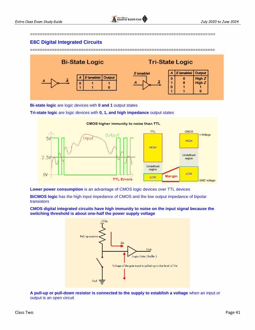
Extra Class Exam Study Guide July 2020 to June 2024
Class Two Page 41
============================================================================
E6C Digital Integrated Circuits
============================================================================
Bi-state logic are logic devices with 0 and 1 output states
Tri-state logic are logic devices with 0, 1, and high impedance output states
Lower power consumption is an advantage of CMOS logic devices over TTL devices
BiCMOS logic has the high input impedance of CMOS and the low output impedance of bipolar transistors
CMOS digital integrated circuits have high immunity to noise on the input signal because the switching threshold is about one-half the power supply voltage
A pull-up or pull-down resistor is connected to the supply to establish a voltage when an input or output is an open circuit

Extra Class Exam Study Guide July 2020 to June 2024
Class Two Page 42
============================================================================
E6C03 (A) What is tri-state logic? A. Logic devices with 0, 1, and high-impedance output states B. Logic devices that utilize ternary math C. Low-power logic devices designed to operate at 3 volts D. Proprietary logic devices manufactured by Tri-State Devices
E6C04 (C) Which of the following is an advantage of BiCMOS logic? A. Its simplicity results in much less expensive devices than standard CMOS B. It is immune to electrostatic damage C. It has the high input impedance of CMOS and the low output impedance of bipolar transistors D. All these choices are correct
E6C05 (D) What is an advantage of CMOS logic devices over TTL devices? A. Differential output capability B. Lower distortion C. Immune to damage from static discharge D. Lower power consumption
E6C06 (C) Why do CMOS digital integrated circuits have high immunity to noise on the input signal or power supply? A. Large bypass capacitance is inherent B. The input switching threshold is about two times the power supply voltage C. The input switching threshold is about one-half the power supply voltage D. Bandwidth is very limited
E6C07 (B) What best describes a pull-up or pull-down resistor? A. A resistor in a keying circuit used to reduce key clicks B. A resistor connected to the positive or negative supply line used to establish a voltage when an input or output is an open circuit C. A resistor that ensures that an oscillator frequency does not drift D. A resistor connected to an op-amp output that prevents signals from exceeding the power supply voltage
============================================================================
Hysteresis in a comparator prevents input noise from causing unstable output signals
When the level of a comparator's input signal crosses the threshold the output state changes
Editor’s note: Hysteresis can be added to a comparator circuit to improve its stability, especially when the input signal is noisy. The hysteresis of the circuit can be seen using an oscilloscope, time delayed output signal is slower to rise (and fall) but eventually reproduces the input signal. In the circuit above R1 adjusts the offset voltage of the OP Amp. R1 can change the output signal from a pulse to a square wave by changing the threshold.
============================================================================
E6C01 (A) What is the function of hysteresis in a comparator? A. To prevent input noise from causing unstable output signals B. To allow the comparator to be used with AC input signals C. To cause the output to change states continually D. To increase the sensitivity
E6C02 (B) What happens when the level of a comparator's input signal crosses the threshold? A. The IC input can be damaged B. The comparator changes its output state C. The comparator enters latch-up D. The feedback loop becomes unstable
============================================================================

Extra Class Exam Study Guide July 2020 to June 2024
Class Two Page 43
A programmable gates and circuits in a single integrated circuit is a programmable logic device
=============================================================================
E6C09 (B) What is a Programmable Logic Device (PLD)? A. A logic circuit that can be modified during use B. A programmable collection of logic gates and circuits in a single integrated circuit C. Programmable equipment used for testing digital logic integrated circuits D. A type of transistor whose gain can be changed by digital logic circuits
============================================================================
============================================================================
E6C08 (B) In Figure E6-3, what is the schematic symbol for a NAND gate? A. 1 B. 2 C. 3 D. 4
E6C10 (D) In Figure E6-3, what is the schematic symbol for a NOR gate? A. 1 B. 2 C. 3 D. 4
E6C11 (C) In Figure E6-3, what is the schematic symbol for the NOT operation (inverter)? A. 2 B. 4 C. 5 D. 6
============================================================================
Programmable Gate Array (PGA)
Editor’s note: A programmable logic device (PLD) is an
electronic component used to build reconfigurable digital
circuits. Unlike integrated circuits (IC) which consist of
logic gates and have a fixed function, a PLD has an
undefined function at the time of manufacture. There are
three fundamental types of standard PLDs: PROM, PAL,
and Field Programmable Gate Array (FPGA).

Extra Class Exam Study Guide July 2020 to June 2024
Class Two Page 44
E7A Digital circuits: digital circuit principles and logic circuits
============================================================================
Bi-state logic are logic devices with 0 and 1 output states
A TRUTH TABLE is a list of inputs and corresponding outputs for a digital device
NAND gate produces a logic "0" at its output only when all inputs are logic "1"
OR gate produces a logic "1" at its output if any or all inputs are logic "1"
NOR gate produces a logic "0" at its output if any single input is a logic “1”
Positive Logic is the name for logic which represents a logic "1" as a high voltage
Negative logic is the name for logic which represents a logic "0" as a high voltage
=============================================================================
E7A01 (C) Which circuit is bistable? A. An AND gate B. An OR gate C. A flip-flop D. A bipolar amplifier
E7A07 (D) What logical operation does a NAND gate perform? A. It produces logic 0 at its output only when all inputs are logic 0 B. It produces logic 1 at its output only when all inputs are logic 1 C. It produces logic 0 at its output if some but not all inputs are logic 1 D. It produces logic 0 at its output only when all inputs are logic 1
E7A08 (A) What logical operation does an OR gate perform? A. It produces logic 1 at its output if any or all inputs are logic 1 B. It produces logic 0 at its output if all inputs are logic 1 C. It only produces logic 0 at its output when all inputs are logic 1 D. It produces logic 1 at its output if all inputs are logic 0
E7A09 (C) What logical operation is performed by an exclusive NOR gate? A. It produces logic 0 at its output only if all inputs are logic 0 B. It produces logic 1 at its output only if all inputs are logic 1 C. It produces logic 0 at its output if only one input is logic 1 D. It produces logic 1 at its output if only one input is logic 1
E7A10 (C) What is a truth table? A. A table of logic symbols that indicate the high logic states of an op-amp B. A diagram showing logic states when the digital device output is true C. A list of inputs and corresponding outputs for a digital device D. A table of logic symbols that indicate the logic states of an op-amp
E7A11 (D) What type of logic defines "1" as a high voltage? A. Reverse Logic B. Assertive Logic C. Negative logic D. Positive Logic
=============================================================================

Extra Class Exam Study Guide July 2020 to June 2024
Class Two Page 45
Astable multivibrator is a circuit that continuously alternates between two states without an external clock
A monostable multivibrator switches momentarily to the opposite binary state and then returns, after a set time
A flip-flop can divide the frequency of a pulse train by 2
Two flip-flops are required to divide a signal frequency by 4
A decade counter produces one output pulse for every 10 input pulses
Editor’s note: JK flip-flop is similar to an RS except that it toggles when both J and K are high. A D flip-flop output takes on the state of the D input when the clock signal transitions from low to high
=============================================================================
E7A03 (B) Which of the following can divide the frequency of a pulse train by 2? A. An XOR gate B. A flip-flop C. An OR gate D. A multiplexer
E7A04 (B) How many flip-flops are required to divide a signal frequency by 4? A. 1 B. 2 C. 4 D. 8
E7A05 (D) Which of the following is a circuit that continuously alternates between two states without an external clock? A. Monostable multivibrator B. J-K flip-flop C. T flip-flop D. Astable multivibrator
E7A06 (A) What is a characteristic of a monostable multivibrator? A. It switches momentarily to the opposite binary state and then returns to its original state after a set time B. It produces a continuous square wave oscillating between 1 and 0 C. It stores one bit of data in either a 0 or 1 state D. It maintains a constant output voltage, regardless of variations in the input voltage
E7A02 (A) What is the function of a decade counter? A. It produces one output pulse for every 10 input pulses B. It decodes a decimal number for display on a seven-segment LED display C. It produces 10 output pulses for every input pulse D. It decodes a binary number for display on a seven-segment LED display
=============================================================================

Extra Class Exam Study Guide July 2020 to June 2024
Class Two Page 46
E6F Electro-optical technology: photoconductivity
============================================================================
Electrons absorb the energy from light falling on a photovoltaic cell
The conversion of LIGHT to ELECTRICAL energy is the photovoltaic effect
Silicon is the most common type of photovoltaic cell used for electrical power generation
The efficiency of a photovoltaic cell is the relative fraction of light that is converted to current
0.5 V is the approximate open-circuit voltage produced by a fully-illuminated silicon photovoltaic cell
============================================================================
E6F01 (C) What absorbs the energy from light falling on a photovoltaic cell? A. Protons B. Photons C. Electrons D. Holes
E6F04 (B) What is the photovoltaic effect? A. The conversion of voltage to current when exposed to light B. The conversion of light to electrical energy C. The conversion of electrical energy to mechanical energy D. The tendency of a battery to discharge when exposed to light
E6F09 (D) What is the efficiency of a photovoltaic cell? A. The output RF power divided by the input DC power B. Cost per kilowatt-hour generated C. The open-circuit voltage divided by the short-circuit current under full illumination D. The relative fraction of light that is converted to current
E6F10 (B) What is the most common type of photovoltaic cell used for electrical power generation? A. Selenium B. Silicon C. Cadmium Sulfide D. Copper oxide
E6F11 (B) What is the approximate open-circuit voltage produced by a fully illuminated silicon photovoltaic cell? A. 0.1 V B. 0.5 V C. 1.5 V D. 12 V
============================================================================
A crystalline semiconductor is affected the most by photoconductivity
The conductivity of a photoconductive material increases when light shines on it

Extra Class Exam Study Guide July 2020 to June 2024
Class Two Page 47
============================================================================
E6F02 (A) What happens to the conductivity of a photoconductive material when light shines on it? A. It increases B. It decreases C. It stays the same D. It becomes unstable
E6F06 (A) Which of these materials is most commonly used to create photoconductive devices? A. A crystalline semiconductor B. An ordinary metal C. A heavy metal D. A liquid semiconductor
============================================================================
opt isolators commonly are a combination of an LED and a phototransistor
An optical shaft encoder detects rotation of a control by interrupting a light source with a patterned wheel
============================================================================
E6F03 (D) What is the most common configuration of an optoisolator or optocoupler? A. A lens and a photomultiplier B. A frequency modulated helium-neon laser C. An amplitude modulated helium-neon laser D. An LED and a phototransistor
E6F05 (A) Which describes an optical shaft encoder? A. A device that detects rotation of a control by interrupting a light source with a patterned wheel B. A device that measures the strength of a beam of light using analog to digital conversion C. A digital encryption device often used to encrypt spacecraft control signals D. A device for generating RTTY signals by means of a rotating light source
=============================================================================
A solid-state relay uses semiconductors to implement the functions of an electromechanical relay
Optoisolators provide a very high degree of control circuit isolation when switching 120 VAC
=============================================================================
E6F07 (B) What is a solid-state relay? A. A relay using transistors to drive the relay coil B. A device that uses semiconductors to implement the functions of an electromechanical relay C. A mechanical relay that latches in the on or off state each time it is pulsed D. A semiconductor passive delay line
E6F08 (C) Why are optoisolators often used in conjunction with solid-state circuits when switching 120 VAC? A. Optoisolators provide a low impedance link between a control circuit and a power circuit B. Optoisolators provide impedance matching between the control circuit and power circuit C. Optoisolators provide a very high degree of electrical isolation between a control circuit and the circuit being switched D. Optoisolators eliminate the effects of reflected light in the control circuit
=============================================================================

Extra Class Exam Study Guide July 2020 to June 2024
Class Two Page 48
E6D Toroidal and Solenoidal Inductors
============================================================================
Ferrite and brass are commonly used as a core material in an inductor
Permeability of the core material determines the inductance of a toroidal inductor
Powdered-iron toroids maintain their characteristics at higher currents rather than ferrite toroids
Brass core material decreases inductance when inserted into a coil
Powdered-iron toroids require fewer turns for a given inductance value than ferrite toroids
Saturation is when flux density cannot increase the magnetization of the material further,
Saturation can cause signal distortion (intermods & harmonics) in amplifiers and matching circuits.
Editor’s note: A variable inductor having an adjustable ferrite core is known as slug tuned inductor. The value of inductance increases or decreases respectively, due to the movement of a core into or out of the coil winding. A ferrite slug increases inductance when inserted. A brass slug decreases inductance when inserted
.
=============================================================================
E6D04 (B) Which materials are commonly used as a core in an inductor? A. Polystyrene and polyethylene B. Ferrite and brass C. Teflon and Delrin D. Cobalt and aluminum
E6D06 (D) What core material property determines the inductance of an inductor? A. Thermal impedance B. Resistance C. Reactivity D. Permeability
E6D08 (B) What is one reason for using powdered-iron cores rather than ferrite cores in an inductor? A. Powdered-iron cores generally have greater initial permeability B. Powdered-iron cores generally maintain their characteristics at higher currents C. Powdered-iron cores generally require fewer turns to produce a given inductance D. Powdered-iron cores use smaller diameter wire for the same inductance
E6D11 (B) Which type of core material decreases inductance when inserted into a coil? A. Ceramic B. Brass C. Ferrite D. Powdered iron

Extra Class Exam Study Guide July 2020 to June 2024
Class Two Page 49
E6D05 (C) What is one reason for using ferrite cores rather than powdered iron in an inductor? A. Ferrite toroids generally have lower initial permeability B. Ferrite toroids generally have better temperature stability C. Ferrite toroids generally require fewer turns to produce a given inductance value D. Ferrite toroids are easier to use with surface mount technology
E6D01 (A) Why should core saturation of an impedance matching transformer be avoided? A. Harmonics and distortion could result B. Magnetic flux would increase with frequency C. RF susceptance would increase D. Temporary changes of the core permeability could result
E6D12 (C) What is inductor saturation? A. The inductor windings are over-coupled B. The inductor's voltage rating is exceeded causing a flashover C. The ability of the inductor's core to store magnetic energy has been exceeded D. Adjacent inductors become over-coupled
=============================================================================
Toroidal cores confine most of the magnetic field within the core material unlike a solenoidal
Inter-turn capacitance is the primary cause of inductor self-resonance
=============================================================================
E6D10 (A) What is a primary advantage of using a toroidal core instead of a solenoidal core in an inductor? A. Toroidal cores confine most of the magnetic field within the core material B. Toroidal cores make it easier to couple the magnetic energy into other components C. Toroidal cores exhibit greater hysteresis D. Toroidal cores have lower Q characteristics
E6D13 (A) What is the primary cause of inductor self-resonance? A. Inter-turn capacitance B. The skin effect C. Inductive kickback D. Non-linear core hysteresis
=============================================================================
Magnetizing current in the primary winding of a transformer is the current when no load is attached to the secondary
=============================================================================
E6D07 (A) What is current in the primary winding of a transformer called if no load is attached to the secondary? A. Magnetizing current B. Direct current C. Excitation current D. Stabilizing current
=============================================================================

Extra Class Exam Study Guide July 2020 to June 2024
Class Two Page 50
Ferrite beads are commonly used as VHF and UHF parasitic suppressors on amplifiers
=============================================================================
E6D09 (C) What devices are commonly used as VHF and UHF parasitic suppressors at the input and output terminals of a transistor HF amplifier? A. Electrolytic capacitors B. Butterworth filters C. Ferrite beads D. Steel-core toroids
=============================================================================
Physical deformation of a crystal by the application of a voltage is one aspect of the piezoelectric effect
A motional capacitance, motional inductance, and loss resistance in series, all in parallel with a shunt capacitor representing electrode and stray capacitance is the equivalent circuit of a quartz crystal.
=============================================================================
E6D02 (A) What is the equivalent circuit of a quartz crystal? A. Motional capacitance, motional inductance, and loss resistance in series, all in parallel with a shunt capacitor representing electrode and stray capacitance B. Motional capacitance, motional inductance, loss resistance, and a capacitor representing electrode and stray capacitance all in parallel C. Motional capacitance, motional inductance, loss resistance, and a capacitor representing electrode and stray capacitance all in series D. Motional inductance and loss resistance in series, paralleled with motional capacitance and a capacitor representing electrode and stray capacitance
E6D03 (A) Which of the following is an aspect of the piezoelectric effect? A. Mechanical deformation of material by the application of a voltage B. Mechanical deformation of material by the application of a magnetic field C. Generation of electrical energy in the presence of light D. Increased conductivity in the presence of light
=============================================================================

Extra Class Exam Study Guide July 2020 to June 2024
Class Two Page 51
E6E Analog ICs: MMICs, IC packaging characteristics
============================================================================
50 ohms is the most common input and output impedance of circuits that use MMICs
Controlled gain, low noise figure typical 2 dB, constant impedance makes the MMIC good for VHF to microwave circuits
The B+ supply is furnished through a resistor and/or RF choke connected to the MMIC output lead
Microstrip construction is typically used to construct a MMIC based microwave amplifier
At UHF & higher frequencies gallium arsenide is used as a semiconductor material
Gallium nitride is likely to provide the highest frequency of operation when used in MMICs

Extra Class Exam Study Guide July 2020 to June 2024
Class Two Page 52
============================================================================
E6E01 (B) Why is gallium arsenide (GaAs) useful for semiconductor devices operating at UHF and higher frequencies? A. Higher noise figures B. Higher electron mobility C. Lower junction voltage drop D. Lower transconductance
E6E03 (D) Which of the following materials is likely to provide the highest frequency of operation when used in MMICs? A. Silicon B. Silicon nitride C. Silicon dioxide D. Gallium nitride
E6E04 (A) Which is the most common input and output impedance of circuits that use MMICs? A. 50 ohms B. 300 ohms C. 450 ohms D. 10 ohms
E6E05 (A) Which of the following noise figure values is typical of a low-noise UHF preamplifier? A. 2 dB B. -10 dB C. 44 dBm D. -20 dBm
E6E06 (D) What characteristics of the MMIC make it a popular choice for VHF through microwave circuits? A. The ability to retrieve information from a single signal even in the presence of other strong signals B. Plate current that is controlled by a control grid C. Nearly infinite gain, very high input impedance, and very low output impedance D. Controlled gain, low noise figure, and constant input and output impedance over the specified frequency range
E6E07 (D) What type of transmission line is used for connections to MMICs? A. Miniature coax B. Circular waveguide C. Parallel wire D. Microstrip
E6E08 (A) How is power supplied to the most common type of MMIC? A. Through a resistor and/or RF choke connected to the amplifier output lead B. MMICs require no operating bias C. Through a capacitor and RF choke connected to the amplifier input lead D. Directly to the bias voltage (VCC IN) lead
============================================================================
DIP (Dual in-line packages) is a common print circuit board through-hole IC package.
DIPs have two parallel rows of pins extending perpendicularly out of the package
(Below-Left)
DIP through-hole package ICs not typically used at UHF and higher frequencies due to excessive lead length
Editor’s note: Surface-mount technology (SMT) devices are called a surface-mount device (SMD) are mounted or placed directly onto the surface of printed circuit boards. (Above-Center & Above-Left.).
Surface-Mount Devices are suitable for use at frequencies above the HF range
Surface-Mount Devices are leadless solving most parasitic effects, smaller circuit area and shorter circuit-board traces.
=============================================================================
E6E09 (D) Which of the following component package types would be most suitable for use at frequencies above the HF range? A. TO-220 B. Axial lead C. Radial lead D. Surface mount

Extra Class Exam Study Guide July 2020 to June 2024
Class Two Page 53
E6E02 (A) Which of the following device packages is a through-hole type? A. DIP B. PLCC C. Ball grid array D. SOT
E6E10 (D) What advantage does surface-mount technology offer at RF compared to using through-hole components? A. Smaller circuit area B. Shorter circuit-board traces C. Components have less parasitic inductance and capacitance D. All these choices are correct
E6E11 (D) What is a characteristic of DIP packaging used for integrated circuits? A. Package mounts in a direct inverted position B. Low leakage doubly insulated package C. Two chips in each package (Dual In Package) D. A total of two rows of connecting pins placed on opposite sides of the package (Dual In-line Package)
E6E12 (C) Why are DIP through-hole package ICs not typically used at UHF and higher frequencies? A. Too many pins B. Epoxy coating is conductive above 300 MHz C. Excessive lead length D. Unsuitable for combining analog and digital signals
============================================================================
E7B Amplifiers
============================================================================
A Class A common emitter amplifier would bias normally be set half-way between saturation and cutoff
A Class AB amplifier operates more than 180 degrees but less than 360 degrees
Class AB designs commonly use a Push-pull amplifier to eliminate even-order harmonics
A Class C amplifier has Bias is set well into the cutoff region, operates less than 180 degrees
Signal distortion and excessive bandwidth result when a Class C amplifier is used to amplify a SSB phone signal
A Class D amplifier that uses switching technology to achieve high efficiency
A class D amplifier uses low-pass output filter to remove switching signal components
Switching amplifiers more efficient than linear amplifiers because the power transistor is at saturation or cutoff most of the time
Editor’s note: Class AB Amplifier is a combination of Classes
A and B in that for small power outputs the amplifier operates
as a class A amplifier but changes to a class B amplifier for
larger current outputs. This action is achieved by pre-biasing
the two transistors in the amplifiers output stage.

Extra Class Exam Study Guide July 2020 to June 2024
Class Two Page 54
Editor’s note: Amplifier classes: Power amplifiers are classified primarily by the design of the output stage.
Classification is based on the amount of time the output device(s) operate during each cycle of the input signal.
Class A operation is where the tube conducts continuously for the entire cycle of the input signal, or a bias current flow in the output devices at all times. The key ingredient of class A operation is that the output is always on. Conversely the output device is never turned off. Because of this, class A amplifiers are single-ended designs. Class A is the most inefficient of all power amplifier designs, averaging only around 20%. Because of this, class A amplifiers are large, heavy and run very hot. On the positive side, class A designs are inherently the most linear, and have the least amount of distortion. When driving an A class amplifier care should be taken to ensure the peak to peak input voltage stays within the linear range of the amplifier. - AD7FO
Class B has conduction occurring for only for ½ of the input cycle. Class B amplifiers typically have dual output devices operating 180º out of phase with each other in a push / pull configuration to allow the full cycle of the input to be amplified. Both output devices are never allowed to be on at the same time, bias is set so that current flow in a specific output device is zero without an input signal. Current only flows in each of the push / pull amplifier output amplifiers for one half cycle. Thus, each output amplifier is only on for ½ of a complete sinusoidal signal cycle. Class B push pull designs show high efficiency but poor linearity around the 0 voltage crossover region. This is due to the time it takes to turn one device off and the other device on, which translates into extreme crossover distortion. Thus, restricting class B designs to power consumption critical applications, e.g., battery operated equipment. Class B push / pull transmitter power amplifiers reduce or prevent even order harmonics in the output signal. - AD7FO
Class AB operation allows both devices to be on at the same time (like in class A), but just barely. The output bias is set so that current flows in a specific output device appreciably more than a half cycle but less than the entire cycle. That is, only a small amount of current is allowed to flow through both devices, unlike the complete load current of class A designs, but enough to keep each device operating so they respond instantly to input voltage demands. Thus, the inherent non-linearity of class B designs is eliminated, without the gross inefficiencies of the class A design. It is this combination of good efficiency (around 50%) with excellent linearity that makes class AB the most popular audio amplifier design. - AD7FO
Class C operation allows current flows for less than one half cycle of the input signal. The class C operation is achieved by reverse biasing the amplifier to point below cutoff and allows only the portion of the input signal that overcomes the reverse bias to cause current flow. The class C operated amplifier is used as a radio-frequency amplifier in frequency modulated or CW transmitters. - AD7FO
Class-D amplifier or switching amplifier is an electronic amplifier in which the amplifying devices (transistors, usually MOSFETs) operate as electronic switches, and not as linear gain devices as in other amplifiers. They operate by rapidly switching back and forth between the supply rails, being fed by a modulator using pulse width, pulse density, or related techniques to encode the audio input into a pulse train. The audio escapes through a simple low-pass filter into the loudspeaker. The high-frequency pulses are blocked. Since the pairs of output transistors are never conducting at the same time, there is no other path for current flow apart from the low-pass filter/loudspeaker. For this reason, efficiency can exceed 90%. - wikipedia.org
Common Base Amplifier Input on Emitter, output on collector, Low impedance input, High impedance output. Primarily used as an impedance converter
Editor’s note: Ground Grid Amplifier Input on Cathode, output from plate, Low impedance input, High impedance output.
==============================================================================
E7B01 (A) For what portion of the signal cycle does each active element in a push-pull Class AB amplifier conduct? A. More than 180 degrees but less than 360 degrees B. Exactly 180 degrees C. The entire cycle D. Less than 180 degrees

Extra Class Exam Study Guide July 2020 to June 2024
Class Two Page 55
E7B02 (A) What is a Class D amplifier? A. A type of amplifier that uses switching technology to achieve high efficiency B. A low power amplifier that uses a differential amplifier for improved linearity C. An amplifier that uses drift-mode FETs for high efficiency D. A frequency doubling amplifier
E7B03 (A) Which of the following components form the output of a class D amplifier circuit? A. A low-pass filter to remove switching signal components B. A high-pass filter to compensate for low gain at low frequencies C. A matched load resistor to prevent damage by switching transients D. A temperature compensating load resistor to improve linearity
E7B04 (A) Where on the load line of a Class A common emitter amplifier would bias normally be set? A. Approximately halfway between saturation and cutoff B. Where the load line intersects the voltage axis C. At a point where the bias resistor equals the load resistor D. At a point where the load line intersects the zero bias current curve
E7B06 (B) Which of the following amplifier types reduces even-order harmonics? A. Push-push B. Push-pull C. Class C D. Class AB
E7B07 (D) Which of the following is a likely result when a Class C amplifier is used to amplify a single-sideband phone signal? A. Reduced intermodulation products B. Increased overall intelligibility C. Signal inversion D. Signal distortion and excessive bandwidth
E7B13 (D) Which of the following describes an emitter follower (or common collector) amplifier? A. A two-transistor amplifier with the emitters sharing a common bias resistor B. A differential amplifier with both inputs fed to the emitter of the input transistor C. An OR circuit with only one emitter used for output D. An amplifier with a low impedance output that follows the base input voltage
E7B14 (B) Why are switching amplifiers more efficient than linear amplifiers? A. Switching amplifiers operate at higher voltages B. The power transistor is at saturation or cutoff most of the time C. Linear amplifiers have high gain resulting in higher harmonic content D. Switching amplifiers use push-pull circuits
E7B18 (C) What is a characteristic of a grounded-grid amplifier? A. High power gain B. High filament voltage C. Low input impedance D. Low bandwidth
==============================================================================
RF power amplifier be neutralized by feeding a 180-degree out-of-phase portion of the output back to the input
Install parasitic suppressors and/or neutralize the stage prevent unwanted oscillations in an RF power amplifier
Use a resistor in series with the emitter to prevent thermal runaway in a bipolar transistor amplifier

Extra Class Exam Study Guide July 2020 to June 2024
Class Two Page 56
Intermodulation products in a linear power amplifier result in transmission of spurious signals
Third-order intermodulation products are relatively close in frequency to the desired signal
The typical HF vacuum tube RF amplifier has an VSWR mismatch between the final stage tube plate and the antenna requiring a Pi Network for matching. The tuning capacitor is adjusted for minimum plate current, and the loading capacitor is adjusted for maximum permissible plate current
============================================================================
E7B05 (C) What can be done to prevent unwanted oscillations in an RF power amplifier? A. Tune the stage for maximum SWR B. Tune both the input and output for maximum power C. Install parasitic suppressors and/or neutralize the stage D. Use a phase inverter in the output filter
E7B08 (C) How can an RF power amplifier be neutralized? A. By increasing the driving power B. By reducing the driving power C. By feeding a 180-degree out-of-phase portion of the output back to the input D. By feeding an in-phase component of the output back to the input
E7B15 (C) What is one way to prevent thermal runaway in a bipolar transistor amplifier? A. Neutralization B. Select transistors with high beta C. Use a resistor in series with the emitter D. All these choices are correct
E7B16 (A) What is the effect of intermodulation products in a linear power amplifier? A. Transmission of spurious signals B. Creation of parasitic oscillations C. Low efficiency D. All these choices are correct
E7B17 (A) Why are odd-order rather than even-order intermodulation distortion products of concern in linear power amplifiers? A. Because they are relatively close in frequency to the desired signal B. Because they are relatively far in frequency from the desired signal C. Because they invert the sidebands causing distortion D. Because they maintain the sidebands, thus causing multiple duplicate signals
E7B09 (D) Which of the following describes how the loading and tuning capacitors are to be adjusted when tuning a vacuum tube RF power amplifier that employs a Pi-network output circuit? A. The loading capacitor is set to maximum capacitance and the tuning capacitor is adjusted for minimum allowable plate current B. The tuning capacitor is set to maximum capacitance and the loading capacitor is adjusted for minimum plate permissible current C. The loading capacitor is adjusted to minimum plate current while alternately adjusting the tuning capacitor for maximum allowable plate current D. The tuning capacitor is adjusted for minimum plate current, and the loading capacitor is adjusted for maximum permissible plate current
============================================================================

Extra Class Exam Study Guide July 2020 to June 2024
Class Two Page 57
============================================================================
E7B10 (B) In Figure E7-1, what is the purpose of R1 and R2? A. Load resistors B. Voltage divider bias C. Self bias D. Feedback
E7B11 (D) In Figure E7-1, what is the purpose of R3? A. Fixed bias B. Emitter bypass C. Output load resistor D. Self bias
E7B12 (C) What type of amplifier circuit is shown in Figure E7-1? A. Common base B. Common collector C. Common emitter D. Emitter follower
============================================================================
E7F DSP filtering and other operations
============================================================================
Direct digital conversion of RF is digitized by an analog-to-digital converter without being mixed with a local oscillator signal
Editor’s note: I and Q represent In-phase and Quadrature The “in-phase” or reference signal is referred to
as “I,” and the signal that is shifted by 90 degrees (the signal in quadrature) is called “Q.”

Extra Class Exam Study Guide July 2020 to June 2024
Class Two Page 58
Fast Fourier Transform converts a signal from its time domain to frequency domain and vice versa
Direct digital conversion Sample Rate determines Bandwidth
Direct digital conversion bandwidth of a Direct Digital Conversion is 1/2 the Sample Rate.
Direct digital conversion sample rate must be at least twice the highest frequency of the signal
Editor’s note: The Nyquist theorem Example: ADC has a sample rate of 1MHz, therefore the input maximum bandwidth can be 0.5MHz. The sample rate can be higher than 2X but not lower.
Reference voltage level and sample bits determine the minimum detectable signal level for an SDR receiver.
1 volt at a resolution of 1 millivolt requires 1024 samples or 2^10 bits
==============================================================================
An anti-aliasing digital filter removes high-frequency signal components that would otherwise be reproduced as lower frequency components
Editor’s note: An anti-aliasing filter (AAF) is a filter used before a signal sampler to restrict the bandwidth of a signal, a low pass filter. An anti-aliasing filter will typically either permit some aliasing to occur or else attenuate some in-band frequencies close to the Nyquist limit. For this reason, many practical systems sample higher than would be theoretically required by a perfect AAF in order to ensure that all frequencies of interest can be reconstructed, a practice called oversampling.

Extra Class Exam Study Guide July 2020 to June 2024
Class Two Page 59
Editor’s note: Fourier analysis of a square wave pictured above shows a square wave is made up of a
sine wave plus all of its odd harmonics.
Decimation reducing the effective sample rate by removing samples
Editor’s note: Decimators can be used to reduce the sampling frequency, whereas interpolators can be used to increase it. ... Sampling rate conversion systems are used to change the sampling rate of a signal. The process of sampling rate decrease is called decimation, and the process of sampling rate increase is called interpolation. However, you can do interpolation prior to decimation to achieve an overall rational ...an example is 4/5 Resampling.
Editor’s note: Adding a small amount of noise by dithering noise to the input signal allows a more precise representation of a signal over time.
An adaptive filter DSP audio filter can be used to remove unwanted noise from a received SSB signal

Extra Class Exam Study Guide July 2020 to June 2024
Class Two Page 60
A direct form discrete-time Finite Impulse Response (FIR) filter of order N. The top part is an N-stage delay line with N + function of taps. Each unit delay is a z−1 operator in Z-transform notation.
More taps allow a digital signal processing filter to create a sharper filter response
A Hilbert-transform is a DSP filter might be used to generate an SSB signal
Editor’s note: the Hilbert transform is a particularly simple representation in the frequency domain: it imparts a phase shift of 90° to every Fourier component of a function. Implementing a Hilbert transform enables us to create an analytic signal based on some original real-valued signal. And in the comms world we can use the analytic signal to easily and accurately compute the instantaneous magnitude of the original real-valued signal.

Extra Class Exam Study Guide July 2020 to June 2024
Class Two Page 61
==============================================================================
E7F01 (C) What is meant by direct digital conversion as applied to software defined radios? A. Software is converted from source code to object code during operation of the receiver B. Incoming RF is converted to a control voltage for a voltage controlled oscillator C. Incoming RF is digitized by an analog-to-digital converter without being mixed with a local oscillator signal D. A switching mixer is used to generate I and Q signals directly from the RF input
E7F02 (A) What kind of digital signal processing audio filter is used to remove unwanted noise from a received SSB signal? A. An adaptive filter B. A crystal-lattice filter C. A Hilbert-transform filter D. A phase-inverting filter
E7F03 (C) What type of digital signal processing filter is used to generate an SSB signal? A. An adaptive filter B. A notch filter C. A Hilbert-transform filter D. An elliptical filter
E7F04 (D) What is a common method of generating an SSB signal using digital signal processing? A. Mixing products are converted to voltages and subtracted by adder circuits B. A frequency synthesizer removes the unwanted sidebands C. Varying quartz crystal characteristics emulated in digital form D. Signals are combined in quadrature phase relationship
E7F05 (B) How frequently must an analog signal be sampled by an analog-to-digital converter so that the signal can be accurately reproduced? A. At least half the rate of the highest frequency component of the signal B. At least twice the rate of the highest frequency component of the signal C. At the same rate as the highest frequency component of the signal D. At four times the rate of the highest frequency component of the signal
E7F06 (D) What is the minimum number of bits required for an analog-to-digital converter to sample a signal with a range of 1 volt at a resolution of 1 millivolt? A. 4 bits B. 6 bits C. 8 bits D. 10 bits
E7F07 (C) What function is performed by a Fast Fourier Transform? A. Converting analog signals to digital form B. Converting digital signals to analog form C. Converting digital signals from the time domain to the frequency domain D. Converting 8-bit data to 16-bit data
E7F08 (B) What is the function of decimation? A. Converting data to binary code decimal form B. Reducing the effective sample rate by removing samples C. Attenuating the signal D. Removing unnecessary significant digits
E7F09 (A) Why is an anti-aliasing digital filter required in a digital decimator? A. It removes high-frequency signal components that would otherwise be reproduced as lower frequency components B. It peaks the response of the decimator, improving bandwidth C. It removes low-frequency signal components to eliminate the need for DC restoration D. It notches out the sampling frequency to avoid sampling errors
E7F10 (A) What aspect of receiver analog-to-digital conversion determines the maximum receive bandwidth of a Direct Digital Conversion SDR? A. Sample rate B. Sample width in bits C. Sample clock phase noise D. Processor latency
E7F11 (B) What sets the minimum detectable signal level for a direct-sampling SDR receiver in the absence of atmospheric or thermal noise? A. Sample clock phase noise B. Reference voltage level and sample width in bits C. Data storage transfer rate D. Missing codes and jitter
E7F12 (A) Which of the following is an advantage of a Finite Impulse Response (FIR) filter vs an Infinite Impulse Response (IIR) digital filter? A. FIR filters can delay all frequency components of the signal by the same amount B. FIR filters are easier to implement for a given set of passband rolloff requirements C. FIR filters can respond faster to impulses D. All these choices are correct
E7F13 (D) What is the function of taps in a digital signal processing filter? A. To reduce excess signal pressure levels B. Provide access for debugging software C. Select the point at which baseband signals are generated D. Provide incremental signal delays for filter algorithms
E7F14 (B) Which of the following would allow a digital signal processing filter to create a sharper filter response? A. Higher data rate B. More taps C. Complex phasor representations D. Double-precision math routines
============================================================================
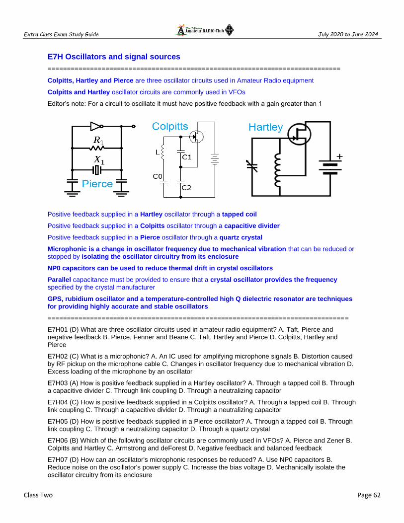
Extra Class Exam Study Guide July 2020 to June 2024
Class Two Page 62
E7H Oscillators and signal sources
============================================================================
Colpitts, Hartley and Pierce are three oscillator circuits used in Amateur Radio equipment
Colpitts and Hartley oscillator circuits are commonly used in VFOs
Editor’s note: For a circuit to oscillate it must have positive feedback with a gain greater than 1
Positive feedback supplied in a Hartley oscillator through a tapped coil
Positive feedback supplied in a Colpitts oscillator through a capacitive divider
Positive feedback supplied in a Pierce oscillator through a quartz crystal
Microphonic is a change in oscillator frequency due to mechanical vibration that can be reduced or stopped by isolating the oscillator circuitry from its enclosure
NP0 capacitors can be used to reduce thermal drift in crystal oscillators
Parallel capacitance must be provided to ensure that a crystal oscillator provides the frequency specified by the crystal manufacturer
GPS, rubidium oscillator and a temperature-controlled high Q dielectric resonator are techniques for providing highly accurate and stable oscillators
==============================================================================
E7H01 (D) What are three oscillator circuits used in amateur radio equipment? A. Taft, Pierce and negative feedback B. Pierce, Fenner and Beane C. Taft, Hartley and Pierce D. Colpitts, Hartley and Pierce
E7H02 (C) What is a microphonic? A. An IC used for amplifying microphone signals B. Distortion caused by RF pickup on the microphone cable C. Changes in oscillator frequency due to mechanical vibration D. Excess loading of the microphone by an oscillator
E7H03 (A) How is positive feedback supplied in a Hartley oscillator? A. Through a tapped coil B. Through a capacitive divider C. Through link coupling D. Through a neutralizing capacitor
E7H04 (C) How is positive feedback supplied in a Colpitts oscillator? A. Through a tapped coil B. Through link coupling C. Through a capacitive divider D. Through a neutralizing capacitor
E7H05 (D) How is positive feedback supplied in a Pierce oscillator? A. Through a tapped coil B. Through link coupling C. Through a neutralizing capacitor D. Through a quartz crystal
E7H06 (B) Which of the following oscillator circuits are commonly used in VFOs? A. Pierce and Zener B. Colpitts and Hartley C. Armstrong and deForest D. Negative feedback and balanced feedback
E7H07 (D) How can an oscillator's microphonic responses be reduced? A. Use NP0 capacitors B. Reduce noise on the oscillator's power supply C. Increase the bias voltage D. Mechanically isolate the oscillator circuitry from its enclosure

Extra Class Exam Study Guide July 2020 to June 2024
Class Two Page 63
E7H08 (A) Which of the following components can be used to reduce thermal drift in crystal oscillators? A. NP0 capacitors B. Toroidal inductors C. Wirewound resistors D. Non-inductive resistors
E7H12 (B) Which of the following must be done to ensure that a crystal oscillator provides the frequency specified by the crystal manufacturer? A. Provide the crystal with a specified parallel inductance B. Provide the crystal with a specified parallel capacitance C. Bias the crystal at a specified voltage D. Bias the crystal at a specified current
E7H13 (D) Which of the following is a technique for providing highly accurate and stable oscillators needed for microwave transmission and reception? A. Use a GPS signal reference B. Use a rubidium stabilized reference oscillator C. Use a temperature-controlled high Q dielectric resonator D. All these choices are correct
==============================================================================

Extra Class Exam Study Guide July 2020 to June 2024
Class Two Page 64
Phase accumulator is a principal component of a Direct Digital Synthesizer (DDS)
The amplitude values that represent a sine-wave output is contained in the lookup table of a DDS
Spurious signals at discrete frequencies are the major spectral impurity components of DDS
A Phase-Locked Loop (PPL) circuit an electronic servo loop consisting of a phase detector, a low-pass filter, a voltage-controlled oscillator, and a stable reference oscillator
Frequency synthesis and FM demodulation are functions can be performed by a PLL
Editor’s notes:
A Direct Digital Synthesizer (DDS) circuit uses a phase accumulator, lookup table, digital to analog converter and a low-pass anti-alias filter
A PLL is used as VFO because it has the same degree of frequency stability as a crystal oscillator
The frequency range over which the circuit can lock is the capture range of a PLL circuit
Why is the short-term stability of the reference oscillator important in because any phase variations in the reference oscillator signal will produce phase noise in the synthesizer output in a PLL
Phase noise is the major spectral impurity components of PLL
==============================================================================

Extra Class Exam Study Guide July 2020 to June 2024
Class Two Page 65
E7H09 (A) What type of frequency synthesizer circuit uses a phase accumulator, lookup table, digital to analog converter, and a low-pass anti-alias filter? A. A direct digital synthesizer B. A hybrid synthesizer C. A phase-locked loop synthesizer D. A diode-switching matrix synthesizer
E7H10 (B) What information is contained in the lookup table of a direct digital synthesizer (DDS)? A. The phase relationship between a reference oscillator and the output waveform B. Amplitude values that represent the desired waveform C. The phase relationship between a voltage-controlled oscillator and the output waveform D. Frequently used receiver and transmitter frequencies
E7H11 (C) What are the major spectral impurity components of direct digital synthesizers? A. Broadband noise B. Digital conversion noise C. Spurious signals at discrete frequencies D. Nyquist limit noise
E7H14 (C) What is a phase-locked loop circuit? A. An electronic servo loop consisting of a ratio detector, reactance modulator, and voltage-controlled oscillator B. An electronic circuit also known as a monostable multivibrator C. An electronic servo loop consisting of a phase detector, a low-pass filter, a voltage-controlled oscillator, and a stable reference oscillator D. An electronic circuit consisting of a precision push-pull amplifier with a differential input
E7H15 (D) Which of these functions can be performed by a phase-locked loop? A. Wide-band AF and RF power amplification B. Comparison of two digital input signals, digital pulse counter C. Photovoltaic conversion, optical coupling D. Frequency synthesis, FM demodulation
============================================================================
E7C Filters and matching networks
============================================================================
An elliptical filter has extremely sharp cutoff with one or more notches in the stop band
Chebyshev filter has ripple in the passband and a sharp cutoff.
Editor’s note: The Butterworth filter is a type of signal processing filter designed to have a frequency response as flat as possible in the passband. The desired signal will pass through the filter without attenuation.

Extra Class Exam Study Guide July 2020 to June 2024
Class Two Page 66
The Q of Pi-networks can be controlled is one advantage of a Pi-matching network over an L-matching network consisting of a single inductor and a single capacitor
The Q of Pi networks can be varied depending on the component values chosen
A low-pass filter Pi-network has a capacitor is connected between the input and ground, another capacitor is connected between the output and ground, and an inductor is connected between input and output
A Pi-L network with a series inductor on the output is used for matching a vacuum-tube final amp to 50-ohm output
An impedance-matching circuit transforms a complex impedance to a resistive impedance by cancelling the reactive part of the impedance and changes the resistive part to a desired value
A Pi-L-network has greater harmonic suppression over a Pi-network for impedance matching between the final amplifier of a vacuum-tube transmitter and an antenna
A T-network with series capacitors and a parallel shunt inductor is a high-pass filter

Extra Class Exam Study Guide July 2020 to June 2024
Class Two Page 67
Shape factor describes a receiving filter's ability to reject signals occupying an adjacent channel
A cavity filter would be the best choice for use in a 2M repeater duplexer
A crystal lattice filter is a filter with narrow bandwidth and steep skirts made using quartz crystals
The relative frequencies of each crystal determine the bandwidth and response shape of a crystal ladder filter
Extra Class Exam Study Guide July 2020 to June 2024
Class Two Page 68
==============================================================================
E7C01 (D) How are the capacitors and inductors of a low-pass filter Pi-network arranged between the network's input and output? A. Two inductors are in series between the input and output, and a capacitor is connected between the two inductors and ground B. Two capacitors are in series between the input and output, and an inductor is connected between the two capacitors and ground C. An inductor is connected between the input and ground, another inductor is connected between the output and ground, and a capacitor is connected between the input and output D. A capacitor is connected between the input and ground, another capacitor is connected between the output and ground, and an inductor is connected between input and output
E7C02 (C) Which of the following is a property of a T-network with series capacitors and a parallel shunt inductor? A. It is a low-pass filter B. It is a band-pass filter C. It is a high-pass filter D. It is a notch filter
E7C03 (A) What advantage does a series-L Pi-L-network have over a series-L Pi-network for impedance matching between the final amplifier of a vacuum-tube transmitter and an antenna? A. Greater harmonic suppression B. Higher efficiency C. Does not require a capacitor D. Greater transformation range
E7C04 (C) How does an impedance-matching circuit transform a complex impedance to a resistive impedance? A. It introduces negative resistance to cancel the resistive part of impedance B. It introduces transconductance to cancel the reactive part of impedance C. It cancels the reactive part of the impedance and changes the resistive part to a desired value D. Reactive currents are dissipated in matched resistances
E7C05 (D) Which filter type is described as having ripple in the passband and a sharp cutoff? A. A Butterworth filter B. An active LC filter C. A passive op-amp filter D. A Chebyshev filter
E7C06 (C) What are the distinguishing features of an elliptical filter? A. Gradual passband rolloff with minimal stop band ripple B. Extremely flat response over its pass band with gradually rounded stop band corners C. Extremely sharp cutoff with one or more notches in the stop band D. Gradual passband rolloff with extreme stop band ripple
E7C07 (B) Which describes a Pi-L-network used for matching a vacuum tube final amplifier to a 50-ohm unbalanced output? A. A Phase Inverter Load network B. A Pi-network with an additional series inductor on the output C. A network with only three discrete parts D. A matching network in which all components are isolated from ground
E7C08 (A) Which of the following factors has the greatest effect on the bandwidth and response shape of a crystal ladder filter? A. The relative frequencies of the individual crystals B. The DC voltage applied to the quartz crystal C. The gain of the RF stage preceding the filter D. The amplitude of the signals passing through the filter
E7C09 (D) What is a crystal lattice filter? A. A power supply filter made with interlaced quartz crystals B. An audio filter made with four quartz crystals that resonate at 1 kHz intervals C. A filter using lattice-shaped quartz crystals for high-Q performance D. A filter with narrow bandwidth and steep skirts made using quartz crystals
E7C10 (B) Which of the following filters would be the best choice for use in a 2 meter band repeater duplexer? A. A crystal filter B. A cavity filter C. A DSP filter D. An L-C filter
E7C11 (C) Which of the following describes a receiving filter's ability to reject signals occupying an adjacent channel? A. Passband ripple B. Phase response C. Shape factor D. Noise factor
E7C12 (A) What is one advantage of a Pi-matching network over an L-matching network consisting of a single inductor and a single capacitor? A. The Q of Pi-networks can be controlled B. L-networks cannot perform impedance transformation C. Pi-networks are more stable D. Pi-networks provide balanced input and output
============================================================================

Extra Class Exam Study Guide July 2020 to June 2024
Class Two Page 69
E7D Power supplies and voltage regulators
============================================================================
The conduction of a control element is varied to maintain a constant output voltage in a LINEAR voltage regulator.
The pass transistor maintains a constant output voltage in a linear voltage regulator circuit over a wide range of load current.
Minimum input-to-output voltage required to maintain regulation is the drop-out voltage.
Voltage difference from input to output multiplied by output current is the power dissipation.
A Zener diode is typically used as a stable reference voltage in a linear voltage regulator
Of the linear voltage regulators, a series regulator usually makes the most efficient use of the primary power source
A shunt regulator is a linear voltage regulator with a constant load on the unregulated voltage source
When several electrolytic filter capacitors are connected in series to increase the operating voltage of a power supply filter circuit, why should resistors be connected across each capacitor?
A. To equalize, as much as possible, the voltage drop across each capacitor B. To provide a safety bleeder to discharge the capacitors when the supply is off C. To provide a minimum load current to reduce voltage excursions at light loads D. All of these choices are correct

Extra Class Exam Study Guide July 2020 to June 2024
Class Two Page 70
The control device’s duty cycle is controlled to produce a constant average output voltage in a SWITCHING electronic voltage regulator
The high frequency inverter design uses much smaller transformers and filter components for an equivalent power output making it both less expensive and lighter in weight than a conventional power supply
A "step-start" circuit in a high-voltage power supply allows the filter capacitors to charge gradually
A solar power system uses a charge controller to prevention battery damage due to overcharge
==============================================================================
E7D01 (D) How does a linear electronic voltage regulator work? A. It has a ramp voltage as its output B. It eliminates the need for a pass transistor C. The control element duty cycle is proportional to the line or load conditions D. The conduction of a control element is varied to maintain a constant output voltage
E7D02 (C) What is a characteristic of a switching electronic voltage regulator? A. The resistance of a control element is varied in direct proportion to the line voltage or load current B. It is generally less efficient than a linear regulator C. The controlled device's duty cycle is changed to produce a constant average output voltage D. It gives a ramp voltage at its output
E7D03 (A) What device is typically used as a stable voltage reference in a linear voltage regulator? A. A Zener diode B. A tunnel diode C. An SCR D. A varactor diode
E7D04 (B) Which of the following types of linear voltage regulator usually make the most efficient use of the primary power source? A. A series current source B. A series regulator C. A shunt regulator D. A shunt current source
E7D05 (D) Which of the following types of linear voltage regulator places a constant load on the unregulated voltage source? A. A constant current source B. A series regulator C. A shunt current source D. A shunt regulator

Extra Class Exam Study Guide July 2020 to June 2024
Class Two Page 71
E7D09 (C) What is the main reason to use a charge controller with a solar power system? A. Prevention of battery undercharge B. Control of electrolyte levels during battery discharge C. Prevention of battery damage due to overcharge D. Matching of day and night charge rates
E7D10 (C) What is the primary reason that a high-frequency switching type high-voltage power supply can be both less expensive and lighter in weight than a conventional power supply? A. The inverter design does not require any output filtering B. It uses a diode bridge rectifier for increased output C. The high frequency inverter design uses much smaller transformers and filter components for an equivalent power output D. It uses a large power factor compensation capacitor to recover power from the unused portion of the AC cycle
E7D11 (D) What is the function of the pass transistor in a linear voltage regulator circuit? A. Permits a wide range of output voltage settings B. Provides a stable input impedance over a wide range of source voltage C. Maintains nearly constant output impedance over a wide range of load current D. Maintains nearly constant output voltage over a wide range of load current
E7D12 (C) What is the dropout voltage of an analog voltage regulator? A. Minimum input voltage for rated power dissipation B. Maximum output voltage drops when the input voltage is varied over its specified range C. Minimum input-to-output voltage required to maintain regulation D. Maximum that the output voltage may decrease at rated load
E7D13 (C) What is the equation for calculating power dissipated by a series linear voltage regulator? A. Input voltage multiplied by input current B. Input voltage divided by output current C. Voltage difference from input to output multiplied by output current D. Output voltage multiplied by output current
E7D14 (D) What is the purpose of connecting equal-value resistors across power supply filter capacitors connected in series? A. Equalize the voltage across each capacitor B. Discharge the capacitors when voltage is removed C. Provide a minimum load on the supply D. All these choices are correct
E7D15 (D) What is the purpose of a step-start circuit in a high-voltage power supply? A. To provide a dual-voltage output for reduced power applications B. To compensate for variations of the incoming line voltage C. To allow for remote control of the power supply D. To allow the filter capacitors to charge gradually
==============================================================================
E7D06 (C) What is the purpose of Q1 in the circuit shown in Figure E7-2? A. It provides negative feedback to improve regulation B. It provides a constant load for the voltage source C. It controls the current supplied to the load D. It provides D1 with current
E7D07 (A) What is the purpose of C2 in the circuit shown in Figure E7-2? A. It bypasses rectifier output ripple around D1 B. It is a brute force filter for the output C. To self-resonate at the hum frequency D. To provide fixed DC bias for Q1
E7D08 (C) What type of circuit is shown in Figure E7-2? A. Switching voltage regulator B. Grounded emitter amplifier C. Linear voltage regulator D. Monostable multivibrator
==============================================================================

Extra Class Exam Study Guide July 2020 to June 2024
Class Two Page 72
E7G Active filters and op-amp circuits
============================================================================
An integrated circuit operational amplifier is a high-gain, direct-coupled differential amplifier with very high input and very low output impedance
The typical input impedance of an integrated circuit op-amp is very high
The typical output impedance of an integrated circuit op-amp is very low
The gain of an ideal operational amplifier does not vary with frequency
The frequency at which the open-loop gain of the amplifier equals one is the gain-bandwidth of an operational amplifier
Restrict both gain & Q to prevent ringing and audio instability in a multi-section op-amp RC audio filter
Undesired oscillations added to the desired signal is the effect of ringing in a filter
Op-amp input-offset voltage is the differential input voltage needed to bring the open-loop output voltage to zero
============================================================================
E7G01 (A) What is the typical output impedance of an op-amp? A. Very low B. Very high C. 100 ohms D. 1000 ohms
E7G02 (D) What is ringing in a filter? A. An echo caused by a long time delay B. A reduction in high frequency response C. Partial cancellation of the signal over a range of frequencies D. Undesired oscillations added to the desired signal
E7G03 (D) What is the typical input impedance of an op-amp? A. 100 ohms B. 1000 ohms C. Very low D. Very high

Extra Class Exam Study Guide July 2020 to June 2024
Class Two Page 73
E7G04 (C) What is meant by the "op-amp input offset voltage"? A. The output voltage of the op-amp minus its input voltage B. The difference between the output voltage of the op-amp and the input voltage required in the immediately following stage C. The differential input voltage needed to bring the open loop output voltage to zero D. The potential between the amplifier input terminals of the op-amp in an open loop condition
E7G05 (A) How can unwanted ringing and audio instability be prevented in an op-amp RC audio filter circuit? A. Restrict both gain and Q B. Restrict gain but increase Q C. Restrict Q but increase gain D. Increase both gain and Q
E7G06 (B) What is the gain-bandwidth of an operational amplifier? A. The maximum frequency for a filter circuit using that type of amplifier B. The frequency at which the open-loop gain of the amplifier equals one C. The gain of the amplifier at a filter's cutoff frequency D. The frequency at which the amplifier's offset voltage is zero
E7G08 (D) How does the gain of an ideal operational amplifier vary with frequency? A. It increases linearly with increasing frequency B. It decreases linearly with increasing frequency C. It decreases logarithmically with increasing frequency D. It does not vary with frequency
E7G12 (A) What is an operational amplifier? A. A high-gain, direct-coupled differential amplifier with very high input impedance and very low output impedance B. A digital audio amplifier whose characteristics are determined by components external to the amplifier C. An amplifier used to increase the average output of frequency modulated amateur signals to the legal limit D. A RF amplifier used in the UHF and microwave regions
============================================================================
Editor’s note: An operational amplifier is one of the most useful linear devices that have been developed with integrated circuitry. While it is possible to build an op amp with discrete components, the symmetry of this circuit requires a close match of many components and is more effective, and much easier, to implement in integrated circuitry. The op amp approaches a perfect analog circuit building block. Ideally, an op amp has infinite input impedance (Zi), zero output impedance (Zo) and an open loop voltage gain (Av) of infinity. Obviously, practical op amps do not meet these specifications, but they do come closer than most other types of amplifiers. The gain of an op amp is the function of the input resistor and the feedback resistor. Gain in calculated by dividing the input resistor R1 value into the feedback resistor Rf. In figure E7-4 if the input resistor,R1, is 10,000 ohms and the feedback resistor ,Rf, 1s 1,000,000 ohms the gain would be 1,000,0000 / 10,000 or a gain of 100. The output is inverted in this configuration when the signal is feed into the negative pin of the op amp. This is the most commonly used configuration. Op amp can be configured in a non-inverting so the output signal is the same polarity as the input signal. – AD7FO

Extra Class Exam Study Guide July 2020 to June 2024
Class Two Page 74
E7G07 (C) What magnitude of voltage gain can be expected from the circuit in Figure E7 3 when R1 is 10 ohms and RF is 470 ohms? A. 0.21 B. 94 C. 47 D. 24
Gain = RF /R1
Gain = 470/10
Gain = 47
E7G10 (C) What absolute voltage gain can be expected from the circuit in Figure E7-3 when R1 is 1800 ohms and RF is 68 kilohms? A. 1 B. 0.03 C. 38 D. 76
Gain = -RF /R1
Gain = 68K/1800
Gain = 37.78
E7G11 (B) What absolute voltage gain can be expected from the circuit in Figure E7-3 when R1 is 3300 ohms and RF is 47 kilohms? A. 28 B. 14 C. 7 D. 0.07
Gain = RF /R1
Gain = 47K/3300
Gain = 14.24
E7G09 (D) What will be the output voltage of the circuit shown in Figure E7-3 if R1 is 1000 ohms, RF is 10,000 ohms, and 0.23 volts DC is applied to the input? A. 0.23 volts B. 2.3 volts C. -0.23 volts D. -2.3 volts
Gain = RF /R1
Gain = 10K/1K
Gain = 10
V Output = Input x Gain
Vop = 0.23 x -10
Vop = - 2.3 V
============================================================================

Extra Class Exam Study Guide July 2020 to June 2024
Class Two Page 75
Class Two Fundamentals and Substance
============================================================================
After completing each class be sure to use the Fundamentals and Substance subsection that was solely created as a tool for test preparation by helping you make connections between topics and serves as quality review material for after each class. Using these steps can be most useful when learning about new topics that include a lot of detail. The information is in the form of class notes with all of the important information you need to know. These notes are not a substitute for studying the class material in fact you will need to complete your class assignment in order to effectively use these notes. The notes are organized into easily digestible headings and bullet points to organize topics with the key words, main subpoints and summary are all written in one place.
============================================================================
Semiconductors
N-type semiconductor materials contains excess free electrons
Acceptor impurity is an impurity atom that adds holes to a semiconductor crystal structure
At microwave frequencies gallium arsenide is used as a semiconductor material in preference to germanium or silicon
PN-junction diode not conduct current when reverse biased because holes in P-type material and electrons in the N-type material are separated by the applied voltage, widening the depletion region
A bipolar transistor has low input impedance
The change of collector current with respect to base current is the beta of a bipolar junction transistor
A silicon NPN transistor is biased on has a base-to-emitter voltage of approx. 0.6 to 0.7 volts
Alpha cutoff is the frequency at which the gain of a transistor has decreased to 0.7 of the gain obtainable at 1 kHz
An FET has high input impedance
Depletion-mode is when a FET that has a current between source and drain but no gate voltage
MOSFET devices have internally connected Zener diodes on the gates to reduce the chance of static damage to the gate

Extra Class Exam Study Guide July 2020 to June 2024
Class Two Page 76
Diodes
A Zener diode maintains a constant voltage drop under conditions of varying current
A Schottky diode has less forward voltage drop silicon diode when used as a power supply rectifier
Schottky diode is a commonly used as a VHF/UHF mixer or detector
Metal-semiconductor junction describes a Schottky diode
Excessive junction temperature is the failure mechanism when a junction diode fails due to excessive current
Forward bias is required for an LED to emit light
A Varactor diode is designed for use as a voltage-controlled capacitor
Low junction capacitance of a PIN diode makes it useful as an RF switch
An RF detector is a common use for point contact diodes
Forward DC bias current is used to control the attenuation of RF signals by a PIN diode
A Tunnel diode is capable of both amplification and oscillation
Integrated Circuits
Bi-state logic are logic devices with 0 and 1 output states
Tri-state logic are logic devices with 0, 1, and high impedance output states
Lower power consumption is an advantage of CMOS logic devices over TTL devices
BiCMOS logic has the high input impedance of CMOS and the low output impedance of bipolar transistors
CMOS digital integrated circuits have high immunity to noise on the input signal because the switching threshold is about one-half the power supply voltage
A pull-up or pull-down resistor is connected to the supply to establish a voltage when an input or output is an open circuit
Hysteresis in a comparator prevents input noise from causing unstable output signals
When the level of a comparator's input signal crosses the threshold the output state changes
A programmable gates and circuits in a single integrated circuit is a programmable logic device

Extra Class Exam Study Guide July 2020 to June 2024
Class Two Page 77
Digital Logic
Bi-state logic are logic devices with 0 and 1 output states
A TRUTH TABLE is a list of inputs and corresponding outputs for a digital device
Positive Logic is the name for logic which represents a logic "1" as a high voltage
Negative logic is the name for logic which represents a logic "0" as a high voltage
NAND gate produces a logic "0" at its output only when all inputs are logic "1"
OR gate produces a logic "1" at its output if any or all inputs are logic "1"
NOR gate produces a logic "0" at its output if any single input is a logic “1”
Astable multivibrator is a circuit that continuously alternates between two states without an external clock
A monostable multivibrator switches momentarily to the opposite binary state and then returns, after a set time
A flip-flop can divide the frequency of a pulse train by 2
Two flip-flops are required to divide a signal frequency by 4
A decade counter produces one output pulse for every 10 input pulses
Electro-optical technology
Electrons absorb the energy from light falling on a photovoltaic cell
The conversion of LIGHT to ELECTRICAL energy is the photovoltaic effect
Silicon is the most common type of photovoltaic cell used for electrical power generation
The efficiency of a photovoltaic cell is the relative fraction of light that is converted to current
0.5 V is the approximate open-circuit voltage produced by a fully-illuminated silicon photovoltaic cell
A crystalline semiconductor is affected the most by photoconductivity
The conductivity of a photoconductive material increases when light shines on it
Optoisolators commonly are a combination of an LED and a phototransistor
An optical shaft encoder detects rotation of a control by interrupting a light source with a patterned wheel
A solid-state relay uses semiconductors to implement the functions of an electromechanical relay
Optoisolators provide a very high degree of control circuit isolation when switching 120 VAC

Extra Class Exam Study Guide July 2020 to June 2024
Class Two Page 78
Inductors
Ferrite and brass are commonly used as a core material in an inductor
Permeability of the core material determines the inductance of a toroidal inductor
Powdered-iron toroids maintain their characteristics at higher currents rather than ferrite toroids
Brass core material decreases inductance when inserted into a coil
Powdered-iron toroids require fewer turns for a given inductance value than ferrite toroids
Saturation is when flux density cannot increase the magnetization of the material further,
Saturation can cause signal distortion (intermods & harmonics) in amplifiers and matching circuits.
Toroidal cores confine most of the magnetic field within the core material unlike a solenoidal
Inter-turn capacitance is the primary cause of inductor self-resonance
Magnetizing current in the primary winding of a transformer is the current when no load is attached to the secondary
Ferrite beads are commonly used as VHF and UHF parasitic suppressors on amplifiers
Analog Integrated Circuits
50 ohms is the most common input and output impedance of circuits that use MMICs
Controlled gain, low noise figure typical 2 dB, constant impedance makes the MMIC good for VHF to microwave circuits
The B+ supply is furnished through a resistor and/or RF choke connected to the MMIC output lead
Microstrip construction is typically used to construct a MMIC based microwave amplifier
At UHF & higher frequencies gallium arsenide is used as a semiconductor material
Gallium nitride is likely to provide the highest frequency of operation when used in MMICs
DIP (Dual in-line packages) is a common print circuit board through-hole IC package.
DIPs have two parallel rows of pins extending perpendicularly out of the package
DIP through-hole package ICs not typically used at UHF and higher frequencies due to excessive lead length
Surface-Mount Devices are suitable for use at frequencies above the HF range
Surface-Mount Devices are leadless solving most parasitic effects, smaller circuit area and shorter circuit-board traces.
Amplifiers
A Class A common emitter amplifier would bias normally be set half-way between saturation and cutoff
A Class AB amplifier operates more than 180 degrees but less than 360 degrees
Class AB designs commonly use a Push-pull amplifier to eliminate even-order harmonics
A Class C amplifier has Bias is set well into the cutoff region, operates less than 180 degrees
Signal distortion and excessive bandwidth result when a Class C amplifier is used to amplify a SSB phone signal
A Class D amplifier that uses switching technology to achieve high efficiency
A class D amplifier uses low-pass output filter to remove switching signal components

Extra Class Exam Study Guide July 2020 to June 2024
Class Two Page 79
Switching amplifiers more efficient than linear amplifiers because the power transistor is at saturation or cutoff most of the time
Common Base Amplifier Input on Emitter, output on collector, Low impedance input, High impedance output. Primarily used as an impedance converter
RF power amplifier be neutralized by feeding a 180-degree out-of-phase portion of the output back to the input
Install parasitic suppressors and/or neutralize prevent unwanted oscillations in an RF amplifier
Use a resistor in series with the emitter to prevent thermal runaway in a bipolar transistor amplifier
Intermodulation products in a linear power amplifier result in transmission of spurious signals
Third-order intermodulation products are relatively close in frequency to the desired signal
The typical HF vacuum tube RF amplifier has an VSWR mismatch between the final stage tube plate and the antenna requiring a Pi Network for matching. The tuning capacitor is adjusted for minimum plate current, and the loading capacitor is adjusted for maximum permissible plate current
Digital Signal Processing
Direct digital conversion of RF is digitized by an analog-to-digital converter without being mixed with a local oscillator signal
Fast Fourier Transform converts a signal from its time domain to frequency domain and vice versa
Direct digital conversion Sample Rate determines Bandwidth
Direct digital conversion bandwidth of a Direct Digital Conversion is 1/2 the Sample Rate.
Direct digital conversion sample rate must be at least twice the highest frequency of the signal
Reference voltage level and sample bits determine the minimum detectable signal level for an SDR
1 volt at a resolution of 1 millivolt requires 1024 samples or 2^10 bits
An anti-aliasing digital filter removes high-frequency signal components that would otherwise be reproduced as lower frequency components
Decimation reducing the effective sample rate by removing samples
An adaptive filter DSP audio filter can be used to remove unwanted noise from a received SSB signal
A direct form discrete-time Finite Impulse Response (FIR) filter of order N. The top part is an N-stage delay line with N + function of taps. Each unit delay is a z−1 operator in Z-transform notation.
More taps allow a digital signal processing filter to create a sharper filter response
A Hilbert-transform is a DSP filter might be used to generate an SSB signal
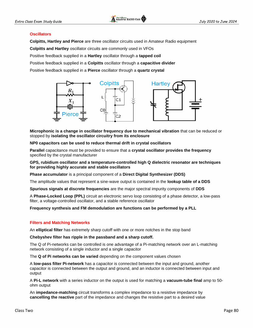
Extra Class Exam Study Guide July 2020 to June 2024
Class Two Page 80
Oscillators
Colpitts, Hartley and Pierce are three oscillator circuits used in Amateur Radio equipment
Colpitts and Hartley oscillator circuits are commonly used in VFOs
Positive feedback supplied in a Hartley oscillator through a tapped coil
Positive feedback supplied in a Colpitts oscillator through a capacitive divider
Positive feedback supplied in a Pierce oscillator through a quartz crystal
Microphonic is a change in oscillator frequency due to mechanical vibration that can be reduced or stopped by isolating the oscillator circuitry from its enclosure
NP0 capacitors can be used to reduce thermal drift in crystal oscillators
Parallel capacitance must be provided to ensure that a crystal oscillator provides the frequency specified by the crystal manufacturer
GPS, rubidium oscillator and a temperature-controlled high Q dielectric resonator are techniques for providing highly accurate and stable oscillators
Phase accumulator is a principal component of a Direct Digital Synthesizer (DDS)
The amplitude values that represent a sine-wave output is contained in the lookup table of a DDS
Spurious signals at discrete frequencies are the major spectral impurity components of DDS
A Phase-Locked Loop (PPL) circuit an electronic servo loop consisting of a phase detector, a low-pass filter, a voltage-controlled oscillator, and a stable reference oscillator
Frequency synthesis and FM demodulation are functions can be performed by a PLL
Filters and Matching Networks
An elliptical filter has extremely sharp cutoff with one or more notches in the stop band
Chebyshev filter has ripple in the passband and a sharp cutoff.
The Q of Pi-networks can be controlled is one advantage of a Pi-matching network over an L-matching network consisting of a single inductor and a single capacitor
The Q of Pi networks can be varied depending on the component values chosen
A low-pass filter Pi-network has a capacitor is connected between the input and ground, another capacitor is connected between the output and ground, and an inductor is connected between input and output
A Pi-L network with a series inductor on the output is used for matching a vacuum-tube final amp to 50-ohm output
An impedance-matching circuit transforms a complex impedance to a resistive impedance by cancelling the reactive part of the impedance and changes the resistive part to a desired value

Extra Class Exam Study Guide July 2020 to June 2024
Class Two Page 81
A Pi-L-network has greater harmonic suppression over a Pi-network for impedance matching between the final amplifier of a vacuum-tube transmitter and an antenna
A T-network with series capacitors and a parallel shunt inductor is a high-pass filter
Shape factor describes a receiving filter's ability to reject signals occupying an adjacent channel
A cavity filter would be the best choice for use in a 2M repeater duplexer
A crystal lattice filter is a filter with narrow bandwidth and steep skirts made using quartz crystals
The relative frequencies of each crystal determine the bandwidth and response shape of a crystal ladder filter
Physical deformation of a crystal by the application of a voltage is one aspect of the piezoelectric effect
A motional capacitance, motional inductance, and loss resistance in series, all in parallel with a shunt capacitor representing electrode and stray capacitance is the equivalent circuit of a quartz crystal.
Power Supplies
The conduction of a control element is varied to maintain a constant output voltage in a LINEAR voltage regulator.
The pass transistor maintains a constant output voltage in a linear voltage regulator circuit over a wide range of load current.
Minimum input-to-output voltage required to maintain regulation is the drop-out voltage.
Voltage difference from input to output multiplied by output current is the power dissipation.
A Zener diode is typically used as a stable reference voltage in a linear voltage regulator
Of the linear voltage regulators, a series regulator usually makes the most efficient use of the primary power source
A shunt regulator is a linear voltage regulator with a constant load on the unregulated voltage source
The control device’s duty cycle is controlled to produce a constant average output voltage in a SWITCHING electronic voltage regulator
The high frequency inverter design uses much smaller transformers and filter components for an equivalent power output making it both less expensive and lighter in weight than a conventional power supply
A "step-start" circuit in a high-voltage power supply allows the filter capacitors to charge gradually
A solar power system uses a charge controller to prevention battery damage due to overcharge
Operational Amplifiers
An integrated circuit operational amplifier is a high-gain, direct-coupled differential amplifier with very high input and very low output impedance
The typical input impedance of an integrated circuit op-amp is very high
The typical output impedance of an integrated circuit op-amp is very low
The gain of an ideal operational amplifier does not vary with frequency

Extra Class Exam Study Guide July 2020 to June 2024
Class Two Page 82
The frequency at which the open-loop gain of the amplifier equals one is the gain-bandwidth of an operational amplifier
Restrict both gain & Q to prevent ringing and audio instability in a multi-section op-amp RC audio filter
Undesired oscillations added to the desired signal is the effect of ringing in a filter
Op-amp input-offset voltage is the differential input voltage needed to bring the open-loop output voltage to zero

Extra Class Exam Study Guide July 2020 to June 2024
Class Three Page 83
CLASS 3 – WAVEFORMS, MODULATION, RECEIVERS,
OPERATING METHODS, SPACE AND TELEVISION
============================================================================
E8A AC Waveforms
E4A Test equipment
E4B Measurement technique and limitations
E7E Modulation and Demodulation
E8B Modulation and Demodulation
E8C Digital signals
E8D Keying defects and overmodulation of digital signals
E4C Receiver performance characteristics
E4D Receiver performance characteristics
E4E Noise suppression and interference
E2C, E2D, E2E Operating methods
E2A Amateur radio in space
E2B Television practices
Class Three Fundamentals and Substance
============================================================================
E8A AC Waveforms
============================================================================
256 different input levels can be encoded by an ADC with 8-bit resolution or 2^8 bits
A Square wave is made up of a sine wave plus all of its odd harmonics
A Saw Tooth wave is made up of a sine wave plus all of its harmonics
Editor’s note: Fourier analysis of the wave pictured above shows each wave is made up of a sine wave
plus a combination of harmonics.
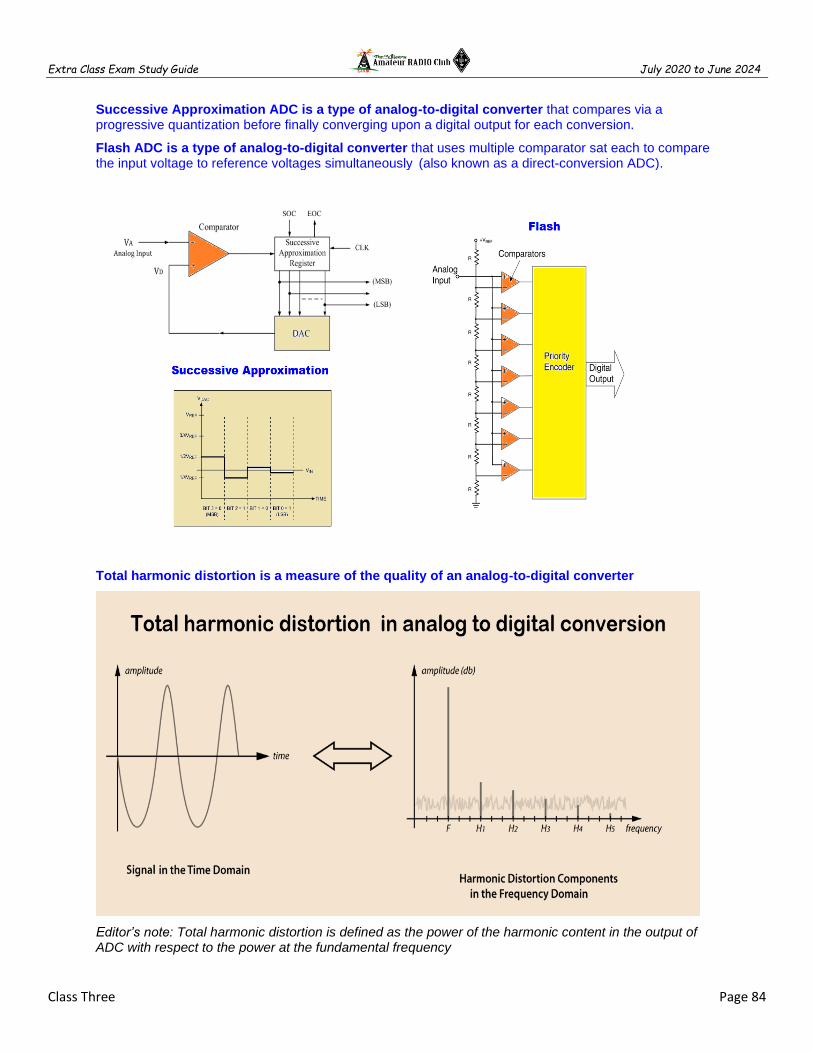
Extra Class Exam Study Guide July 2020 to June 2024
Class Three Page 84
Successive Approximation ADC is a type of analog-to-digital converter that compares via a progressive quantization before finally converging upon a digital output for each conversion.
Flash ADC is a type of analog-to-digital converter that uses multiple comparator sat each to compare the input voltage to reference voltages simultaneously (also known as a direct-conversion ADC).
Total harmonic distortion is a measure of the quality of an analog-to-digital converter
Editor’s note: Total harmonic distortion is defined as the power of the harmonic content in the output of ADC with respect to the power at the fundamental frequency

Extra Class Exam Study Guide July 2020 to June 2024
Class Three Page 85
A small amount of noise added to the input signal to allow more precise representation of a signal over time is "dither" with respect to analog-to-digital converters
Editor’s note: Adding a small amount of noise by dithering noise to the input signal allows a more precise representation of a signal over time. Example: Dithering is a process that uses digital noise to smooth out colors in digital graphics and sounds in digital audio. Digital Graphics. All digital photos are an approximation of the original subject, since computers cannot display an infinite amount of colors.
A low-pass filter used in conjunction with a digital-to-analog converter remove harmonics from the output caused by the discrete analog levels generated
2:1 ratio of PEP-to-average power in a typical SSB phone signal
Speech characteristics determines the PEP-to-average power ratio of a SSB phone signal
Editor’s note: Typical average power of a SSB voice transmission, for example, is 10-20% of PEP. The percentage of longer-term average power to PEP increases with processing, and commonly reaches ~50% with extreme speech processing.

Extra Class Exam Study Guide July 2020 to June 2024
Class Three Page 86
============================================================================
E8A01 (A) What is the name of the process that shows that a square wave is made up of a sine wave plus all its odd harmonics? A. Fourier analysis B. Vector analysis C. Numerical analysis D. Differential analysis
E8A02 (A) Which of the following is a type of analog-to-digital conversion? A. Successive approximation B. Harmonic regeneration C. Level shifting D. Phase reversal
E8A03 (A) What type of wave does a Fourier analysis show to be made up of sine waves of a given fundamental frequency plus all its harmonics? A. A sawtooth wave B. A square wave C. A sine wave D. A cosine wave
E8A04 (B) What is "dither" with respect to analog-to-digital converters? A. An abnormal condition where the converter cannot settle on a value to represent the signal B. A small amount of noise added to the input signal to allow more precise representation of a signal over time C. An error caused by irregular quantization step size D. A method of decimation by randomly skipping samples
E8A05 (D) What of the following instruments would be the most accurate for measuring the RMS voltage of a complex waveform? A. A grid dip meter B. A D'Arsonval meter C. An absorption wave meter D. A true-RMS calculating meter
E8A06 (A) What is the approximate ratio of PEP-to-average power in a typical single-sideband phone signal? A. 2.5 to 1 B. 25 to 1 C. 1 to 1 D. 100 to 1
E8A07 (B) What determines the PEP-to-average power ratio of a single-sideband phone signal? A. The frequency of the modulating signal B. Speech characteristics C. The degree of carrier suppression D. Amplifier gain
E8A08 (C) Why would a direct or flash conversion analog-to-digital converter be useful for a software defined radio? A. Very low power consumption decreases frequency drift B. Immunity to out-of-sequence coding reduces spurious responses C. Very high speed allows digitizing high frequencies D. All these choices are correct
E8A09 (D) How many different input levels can be encoded by an analog-to-digital converter with 8-bit resolution? A. 8 B. 8 multiplied by the gain of the input amplifier C. 256 divided by the gain of the input amplifier D. 256
E8A10 (C) What is the purpose of a low-pass filter used in conjunction with a digital-to-analog converter? A. Lower the input bandwidth to increase the effective resolution B. Improve accuracy by removing out-of-sequence codes from the input C. Remove harmonics from the output caused by the discrete analog levels generated D. All these choices are correct
E8A11 (A) Which of the following is a measure of the quality of an analog-to-digital converter? A. Total harmonic distortion B. Peak envelope power C. Reciprocal mixing D. Power factor
============================================================================

Extra Class Exam Study Guide July 2020 to June 2024
Class Three Page 87
E4A Test equipment
============================================================================
Sampling rate determines the bandwidth of a digital oscilloscope
Editor’s note: The The highest frequency that can be digitized without aliasing is one-half the sample rate
A spectrum analyzer displays frequency on the horizontal axis
A spectrum analyzer displays amplitude on the vertical axis
A spectrum analyzer is used to display intermodulation distortion products in an SSB transmission?
Editor’s note:
An oscilloscope displays signals in the time domain An Oscilloscope could be used for detailed analysis of digital signals A spectrum analyzer displays signals in the frequency domain A spectrum analyzer is used to display spurious signals from a radio transmitter
The compensation of an oscilloscope probe is adjusted until the horizontal portions of the displayed wave are as nearly flat as possible
The effect of aliasing in a digital or computer-based oscilloscope are false signals being displayed
Keep the oscilloscope probe ground connection of the probe as short as possible
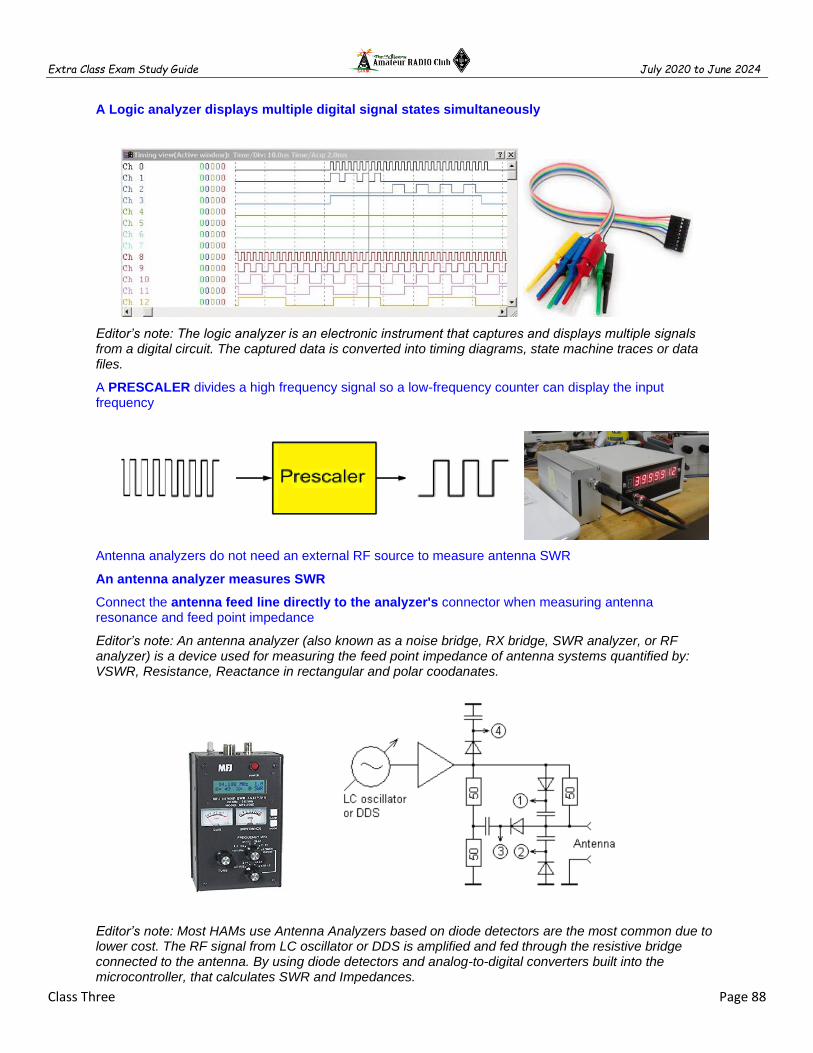
Extra Class Exam Study Guide July 2020 to June 2024
Class Three Page 88
A Logic analyzer displays multiple digital signal states simultaneously
Editor’s note: The logic analyzer is an electronic instrument that captures and displays multiple signals from a digital circuit. The captured data is converted into timing diagrams, state machine traces or data files.
A PRESCALER divides a high frequency signal so a low-frequency counter can display the input frequency
Antenna analyzers do not need an external RF source to measure antenna SWR
An antenna analyzer measures SWR
Connect the antenna feed line directly to the analyzer's connector when measuring antenna resonance and feed point impedance
Editor’s note: An antenna analyzer (also known as a noise bridge, RX bridge, SWR analyzer, or RF analyzer) is a device used for measuring the feed point impedance of antenna systems quantified by: VSWR, Resistance, Reactance in rectangular and polar coodanates.
Editor’s note: Most HAMs use Antenna Analyzers based on diode detectors are the most common due to lower cost. The RF signal from LC oscillator or DDS is amplified and fed through the resistive bridge connected to the antenna. By using diode detectors and analog-to-digital converters built into the microcontroller, that calculates SWR and Impedances.

Extra Class Exam Study Guide July 2020 to June 2024
Class Three Page 89
=============================================================================
E4A01 (A) Which of the following limits the highest frequency signal that can be accurately displayed on a digital oscilloscope? A. Sampling rate of the analog-to-digital converter B. Amount of memory C. Q of the circuit D. All these choices are correct
E4A02 (B) Which of the following parameters does a spectrum analyzer display on the vertical and horizontal axes? A. RF amplitude and time B. RF amplitude and frequency C. SWR and frequency D. SWR and time
E4A03 (B) Which of the following test instruments is used to display spurious signals and/or intermodulation distortion products generated by an SSB transmitter? A. A wattmeter B. A spectrum analyzer C. A logic analyzer D. A time-domain reflectometer
E4A04 (A) How is the compensation of an oscilloscope probe typically adjusted? A. A square wave is displayed and the probe is adjusted until the horizontal portions of the displayed wave are as nearly flat as possible B. A high frequency sine wave is displayed and the probe is adjusted for maximum amplitude C. A frequency standard is displayed and the probe is adjusted until the deflection time is accurate D. A DC voltage standard is displayed and the probe is adjusted until the displayed voltage is accurate
E4A05 (D) What is the purpose of the prescaler function on a frequency counter? A. It amplifies low-level signals for more accurate counting B. It multiplies a higher frequency signal so a low-frequency counter can display the operating frequency C. It prevents oscillation in a low-frequency counter circuit D. It divides a higher frequency signal so a low-frequency counter can display the input frequency
E4A06 (A) What is the effect of aliasing on a digital oscilloscope caused by setting the time base too slow? A. A false, jittery low-frequency version of the signal is displayed B. All signals will have a DC offset C. Calibration of the vertical scale is no longer valid D. Excessive blanking occurs, which prevents display of the signal
E4A07 (B) Which of the following is an advantage of using an antenna analyzer compared to an SWR bridge to measure antenna SWR? A. Antenna analyzers automatically tune your antenna for resonance B. Antenna analyzers do not need an external RF source C. Antenna analyzers display a time-varying representation of the modulation envelope D. All these choices are correct
E4A08 (D) Which of the following measures SWR? A. A spectrum analyzer B. A Q meter C. An ohmmeter D. An antenna analyzer
E4A09 (A) Which of the following is good practice when using an oscilloscope probe? A. Keep the signal ground connection of the probe as short as possible B. Never use a high-impedance probe to measure a low-impedance circuit C. Never use a DC-coupled probe to measure an AC circuit D. All these choices are correct
E4A10 (D) Which of the following displays multiple digital signal states simultaneously? A. Network analyzer B. Bit error rate tester C. Modulation monitor D. Logic analyzer
E4A11 (D) How should an antenna analyzer be connected when measuring antenna resonance and feed point impedance? A. Loosely couple the analyzer near the antenna base B. Connect the analyzer via a high-impedance transformer to the antenna C. Loosely couple the antenna and a dummy load to the analyzer D. Connect the antenna feed line directly to the analyzer's connector
============================================================================

Extra Class Exam Study Guide July 2020 to June 2024
Class Three Page 90
E4B Measurement technique and limitations
=============================================================================
Input impedance, Output impedance and Reflection coefficient can be measured with a Vector Network Analyzer (VNA)
The VNA ports at which measurements are made are represented by S parameters
VNA S21 is equivalent to forward gain
VNA S21 is equivalent to SWR (equivalent to return loss)
Short circuit, open circuit, and 50 ohms test loads are used to calibrate a VNA
Editor’s note: A vector network analyzer (VNA) is a test system that enables the RF performance of radio frequency and microwave devices to be characterized in terms of network scattering parameters, or S parameters. The VNA creates a signal and based on the received signal characterizes the device under test. S-parameters that describe transmission, such as S21, are analogous to other familiar terms including gain, insertion loss, or attenuation. S-parameters that describe reflection, such as S11, correspond to voltage standing wave ratio (VSWR), return loss, or reflection coefficient.
Intermodulation distortion (IMD) >> SSB TX non-harmonically two tones & observe RF on a spectrum analyzer
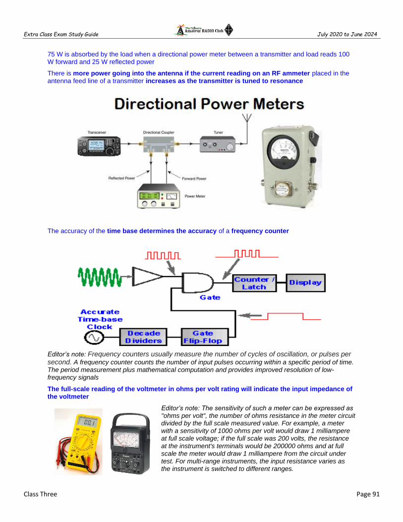
Extra Class Exam Study Guide July 2020 to June 2024
Class Three Page 91
75 W is absorbed by the load when a directional power meter between a transmitter and load reads 100 W forward and 25 W reflected power
There is more power going into the antenna if the current reading on an RF ammeter placed in the antenna feed line of a transmitter increases as the transmitter is tuned to resonance
The accuracy of the time base determines the accuracy of a frequency counter
Editor’s note: Frequency counters usually measure the number of cycles of oscillation, or pulses per second. A frequency counter counts the number of input pulses occurring within a specific period of time. The period measurement plus mathematical computation and provides improved resolution of low-frequency signals
The full-scale reading of the voltmeter in ohms per volt rating will indicate the input impedance of the voltmeter
Editor’s note: The sensitivity of such a meter can be expressed as "ohms per volt", the number of ohms resistance in the meter circuit divided by the full scale measured value. For example, a meter with a sensitivity of 1000 ohms per volt would draw 1 milliampere at full scale voltage; if the full scale was 200 volts, the resistance at the instrument's terminals would be 200000 ohms and at full scale the meter would draw 1 milliampere from the circuit under test. For multi-range instruments, the input resistance varies as the instrument is switched to different ranges.

Extra Class Exam Study Guide July 2020 to June 2024
Class Three Page 92
The bandwidth of the circuit's frequency response can be used to measure the Q of a series-tuned circuit
Editor’s note: The Q, or quality, factor of a resonant circuit is a measurement of the figure of merit corresponds to bandwidth in a series resonant circuit looks like a resistance at the resonant frequency. Since the definition of resonance is XL=XC, the reactive components cancel, leaving only the resistance to contribute to the impedance. The impedance is also at a minimum at resonance.
=============================================================================
E4B01 (B) Which of the following factors most affects the accuracy of a frequency counter? A. Input attenuator accuracy B. Time base accuracy C. Decade divider accuracy D. Temperature coefficient of the logic
E4B02 (A) What is the significance of voltmeter sensitivity expressed in ohms per volt? A. The full scale reading of the voltmeter multiplied by its ohms per volt rating will indicate the input impedance of the voltmeter B. When used as a galvanometer, the reading in volts multiplied by the ohms per volt rating will determine the power drawn by the device under test C. When used as an ohmmeter, the reading in ohms divided by the ohms per volt rating will determine the voltage applied to the circuit D. When used as an ammeter, the full scale reading in amps divided by ohms per volt rating will determine the size of shunt needed
E4B03 (C) Which S parameter is equivalent to forward gain? A. S11 B. S12 C. S21 D. S22
E4B04 (A) Which S parameter represents input port return loss or reflection coefficient (equivalent to VSWR)? A. S11 B. S12 C. S21 D. S22
E4B05 (B) What three test loads are used to calibrate an RF vector network analyzer? A. 50 ohms, 75 ohms, and 90 ohms B. Short circuit, open circuit, and 50 ohms C. Short circuit, open circuit, and resonant circuit D. 50 ohms through 1/8 wavelength, 1/4 wavelength, and 1/2 wavelength of coaxial cable
E4B06 (D) How much power is being absorbed by the load when a directional power meter connected between a transmitter and a terminating load reads 100 watts forward power and 25 watts reflected power? A. 100 watts B. 125 watts C. 25 watts D. 75 watts
E4B07 (A) What do the subscripts of S parameters represent? A. The port or ports at which measurements are made B. The relative time between measurements C. Relative quality of the data D. Frequency order of the measurements
E4B08 (C) Which of the following can be used to measure the Q of a series-tuned circuit? A. The inductance to capacitance ratio B. The frequency shift C. The bandwidth of the circuit's frequency response D. The resonant frequency of the circuit
E4B09 (D) What is indicated if the current reading on an RF ammeter placed in series with the antenna feed line of a transmitter increases as the transmitter is tuned to resonance? A. There is possibly a short to ground in the feed line B. The transmitter is not properly neutralized C. There is an impedance mismatch between the antenna and feed line D. There is more power going into the antenna

Extra Class Exam Study Guide July 2020 to June 2024
Class Three Page 93
E4B10 (B) Which of the following methods measures intermodulation distortion in an SSB transmitter? A. Modulate the transmitter using two RF signals having non-harmonically related frequencies and observe the RF output with a spectrum analyzer B. Modulate the transmitter using two AF signals having non-harmonically related frequencies and observe the RF output with a spectrum analyzer C. Modulate the transmitter using two AF signals having harmonically related frequencies and observe the RF output with a peak reading wattmeter D. Modulate the transmitter using two RF signals having harmonically related frequencies and observe the RF output with a logic analyzer
E4B11 (D) Which of the following can be measured with a vector network analyzer? A. Input impedance B. Output impedance C. Reflection coefficient D. All these choices are correct question text here
=============================================================================
E7E Modulation and Demodulation
=============================================================================
The frequency components present in the modulating signal is called BASEBAND
The two input frequencies along with their SUM AND DIFFERENCE FREQUENCIES appear at the output of a mixer circuit
SPURIOUS MIXER PRODUCTS are generated when an excessive signal energy reaches a mixer

Extra Class Exam Study Guide July 2020 to June 2024
Class Three Page 94
A diode detector functions by rectification and filtering of RF signals
A reactance modulator on the oscillator can be used to generate FM phone emissions
The function of a reactance modulator is to produce PM signals by using an electrically variable inductance or capacitance
Editor’s note: An analog phase modulator functions by varying the tuning of an amplifier tank circuit to produce PM signals
The frequency DISCRIMINATOR stage in a FM receiver is used for detecting FM signals
A pre-emphasis network circuit is added to an FM transmitter to boost the higher audio frequencies
De-emphasis commonly used in FM communications receivers for compatibility with transmitters using phase modulation
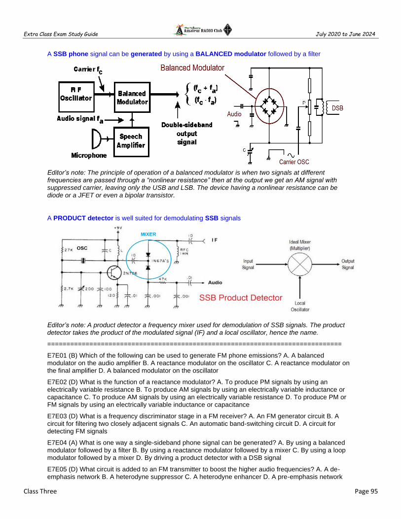
Extra Class Exam Study Guide July 2020 to June 2024
Class Three Page 95
A SSB phone signal can be generated by using a BALANCED modulator followed by a filter
Editor’s note: The principle of operation of a balanced modulator is when two signals at different frequencies are passed through a “nonlinear resistance” then at the output we get an AM signal with suppressed carrier, leaving only the USB and LSB. The device having a nonlinear resistance can be diode or a JFET or even a bipolar transistor.
A PRODUCT detector is well suited for demodulating SSB signals
Editor’s note: A product detector a frequency mixer used for demodulation of SSB signals. The product detector takes the product of the modulated signal (IF) and a local oscillator, hence the name.
=============================================================================
E7E01 (B) Which of the following can be used to generate FM phone emissions? A. A balanced modulator on the audio amplifier B. A reactance modulator on the oscillator C. A reactance modulator on the final amplifier D. A balanced modulator on the oscillator
E7E02 (D) What is the function of a reactance modulator? A. To produce PM signals by using an electrically variable resistance B. To produce AM signals by using an electrically variable inductance or capacitance C. To produce AM signals by using an electrically variable resistance D. To produce PM or FM signals by using an electrically variable inductance or capacitance
E7E03 (D) What is a frequency discriminator stage in a FM receiver? A. An FM generator circuit B. A circuit for filtering two closely adjacent signals C. An automatic band-switching circuit D. A circuit for detecting FM signals
E7E04 (A) What is one way a single-sideband phone signal can be generated? A. By using a balanced modulator followed by a filter B. By using a reactance modulator followed by a mixer C. By using a loop modulator followed by a mixer D. By driving a product detector with a DSB signal
E7E05 (D) What circuit is added to an FM transmitter to boost the higher audio frequencies? A. A de-emphasis network B. A heterodyne suppressor C. A heterodyne enhancer D. A pre-emphasis network

Extra Class Exam Study Guide July 2020 to June 2024
Class Three Page 96
E7E06 (A) Why is de-emphasis commonly used in FM communications receivers? A. For compatibility with transmitters using phase modulation B. To reduce impulse noise reception C. For higher efficiency D. To remove third-order distortion products
E7E07 (B) What is meant by the term "baseband" in radio communications? A. The lowest frequency band that the transmitter or receiver covers B. The frequency range occupied by a message signal prior to modulation C. The unmodulated bandwidth of the transmitted signal D. The basic oscillator frequency in an FM transmitter that is multiplied to increase the deviation and carrier frequency
E7E08 (C) What are the principal frequencies that appear at the output of a mixer circuit? A. Two and four times the original frequency B. The square root of the product of input frequencies C. The two input frequencies along with their sum and difference frequencies D. 1.414 and 0.707 times the input frequency
E7E09 (A) What occurs when an excessive amount of signal energy reaches a mixer circuit? A. Spurious mixer products are generated B. Mixer blanking occurs C. Automatic limiting occurs D. A beat frequency is generated
E7E10 (A) How does a diode envelope detector function? A. By rectification and filtering of RF signals B. By breakdown of the Zener voltage C. By mixing signals with noise in the transition region of the diode D. By sensing the change of reactance in the diode with respect to frequency
E7E11 (C) Which type of detector circuit is used for demodulating SSB signals? A. Discriminator B. Phase detector C. Product detector D. Phase comparator
=============================================================================
E8B Modulation and Demodulation
=============================================================================
The maximum carrier frequency deviation compared to the highest audio modulating frequency is the deviation ratio
Modulation index is the term for the ratio between the frequency deviation of an RF carrier wave, and the modulating frequency of its corresponding FM-phone signal
Editor’s note: The FM modulation index is equal to the ratio of the frequency deviation to the modulating frequency

Extra Class Exam Study Guide July 2020 to June 2024
Class Three Page 97
E8B03 (A) What is the modulation index of an FM-phone signal having a maximum frequency deviation of 3000 Hz either side of the carrier frequency when the modulating frequency is 1000 Hz? A. 3 B. 0.3 C. 3000 D. 1000
Modulation index = Max Carrier Dev / Max Modulation
Dev = 3000 / 1000
Dev = 3
8B04 (B) What is the modulation index of an FM-phone signal having a maximum carrier deviation of plus or minus 6 kHz when modulated with a 2 kHz modulating frequency? A. 6000 B. 3 C. 2000 D. 1/3
Modulation index = Max Carrier Dev / Max Modulation
Dev = 6000 / 2000
Dev = 3
E8B05 (D) What is the deviation ratio of an FM-phone signal having a maximum frequency swing of plus-or-minus 5 kHz when the maximum modulation frequency is 3 kHz? A. 60 B. 0.167 C. 0.6 D. 1.67
Modulation index = Max Carrier Dev / Max Modulation
Dev = 5000 / 3000
Dev = 1.67
E8B06 (A) What is the deviation ratio of an FM-phone signal having a maximum frequency swing of plus or minus 7.5 kHz when the maximum modulation frequency is 3.5 kHz? A. 2.14 B. 0.214 C. 0.47 D. 47
Modulation index = Max Carrier Dev / Max Modulation
Dev = 7500 / 3500
Dev = 2.14
FREQUENCY DIVISION MULTIPLEXING is two or more information streams are merged into a baseband, which then modulates the transmitter
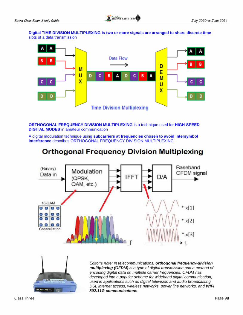
Extra Class Exam Study Guide July 2020 to June 2024
Class Three Page 98
Digital TIME DIVISION MULTIPLEXING is two or more signals are arranged to share discrete time slots of a data transmission
ORTHOGONAL FREQUENCY DIVISION MULTIPLEXING is a technique used for HIGH-SPEED DIGITAL MODES in amateur communication
A digital modulation technique using subcarriers at frequencies chosen to avoid intersymbol interference describes ORTHOGONAL FREQUENCY DIVISION MULTIPLEXING
Editor’s note: In telecommunications, orthogonal frequency-division multiplexing (OFDM) is a type of digital transmission and a method of encoding digital data on multiple carrier frequencies. OFDM has developed into a popular scheme for wideband digital communication, used in applications such as digital television and audio broadcasting, DSL internet access, wireless networks, power line networks, and WIFI 802.11G communications.

Extra Class Exam Study Guide July 2020 to June 2024
Class Three Page 99
=============================================================================
E8B01 (A) What is the modulation index of an FM signal? A. The ratio of frequency deviation to modulating signal frequency B. The ratio of modulating signal amplitude to frequency deviation C. The type of modulation used by the transmitter D. The bandwidth of the transmitted signal divided by the modulating signal frequency
E8B02 (D) How does the modulation index of a phase-modulated emission vary with RF carrier frequency? A. It increases as the RF carrier frequency increases B. It decreases as the RF carrier frequency increases C. It varies with the square root of the RF carrier frequency D. It does not depend on the RF carrier frequency
E8B03 (A) What is the modulation index of an FM-phone signal having a maximum frequency deviation of 3000 Hz either side of the carrier frequency when the modulating frequency is 1000 Hz? A. 3 B. 0.3 C. 3000 D. 1000
8B04 (B) What is the modulation index of an FM-phone signal having a maximum carrier deviation of plus or minus 6 kHz when modulated with a 2 kHz modulating frequency? A. 6000 B. 3 C. 2000 D. 1/3
E8B05 (D) What is the deviation ratio of an FM-phone signal having a maximum frequency swing of plus-or-minus 5 kHz when the maximum modulation frequency is 3 kHz? A. 60 B. 0.167 C. 0.6 D. 1.67
E8B06 (A) What is the deviation ratio of an FM-phone signal having a maximum frequency swing of plus or minus 7.5 kHz when the maximum modulation frequency is 3.5 kHz? A. 2.14 B. 0.214 C. 0.47 D. 47
E8B07 (A) Orthogonal Frequency Division Multiplexing is a technique used for which type of amateur communication? A. High-speed digital modes B. Extremely low-power contacts C. EME D. OFDM signals are not allowed on amateur bands
E8B08 (D) What describes Orthogonal Frequency Division Multiplexing? A. A frequency modulation technique that uses non-harmonically related frequencies B. A bandwidth compression technique using Fourier transforms C. A digital mode for narrow-band, slow-speed transmissions D. A digital modulation technique using subcarriers at frequencies chosen to avoid intersymbol interference
E8B09 (B) What is deviation ratio? A. The ratio of the audio modulating frequency to the center carrier frequency B. The ratio of the maximum carrier frequency deviation to the highest audio modulating frequency C. The ratio of the carrier center frequency to the audio modulating frequency D. The ratio of the highest audio modulating frequency to the average audio modulating frequency
E8B10 (B) What is frequency division multiplexing? A. The transmitted signal jumps from band to band at a predetermined rate B. Two or more information streams are merged into a baseband, which then modulates the transmitter C. The transmitted signal is divided into packets of information D. Two or more information streams are merged into a digital combiner, which then pulse position modulates the transmitter
E8B11 (B) What is digital time division multiplexing? A. Two or more data streams are assigned to discrete sub-carriers on an FM transmitter B. Two or more signals are arranged to share discrete time slots of a data transmission C. Two or more data streams share the same channel by transmitting time of transmission as the sub-carrier D. Two or more signals are quadrature modulated to increase bandwidth efficiency
=============================================================================

Extra Class Exam Study Guide July 2020 to June 2024
Class Three Page 100
E8C Digital signals
=============================================================================
The rate a waveform changes to convey information is the definition of symbol rate in a digital transmission
Using a more efficient digital code increases data rate be without increasing bandwidth
Symbol rate and baud are the same
0.5 KHz is the bandwidth of a 170-hertz shift, 300-baud ASCII transmission
BW = ( K x shift ) + B where K is 1.2 and B is baud
BW = ( 1.2 x 170 ) + 300
BW = 504 Hz
15.36 kHz is the bandwidth of a 4800-Hz frequency shift, 9600-baud ASCII FM transmission
BW = ( K x shift ) + B where K is 1.2 and B is baud
BW = ( 1.2 x 4800 ) + 9600
BW = 15,360 Hz
Editor’s Note: Narrow band two state or digital modulation requires a bandwidth (BW) = (Constant Factor multiplied by Frequency Shift) plus the Baud rate. The constant factor depends on how much signal distortion. The constant commonly used for audio rates and amateur HF digital communications is 1.2.
Editor’s Note: Common modulations for data emissions below 30 MHz
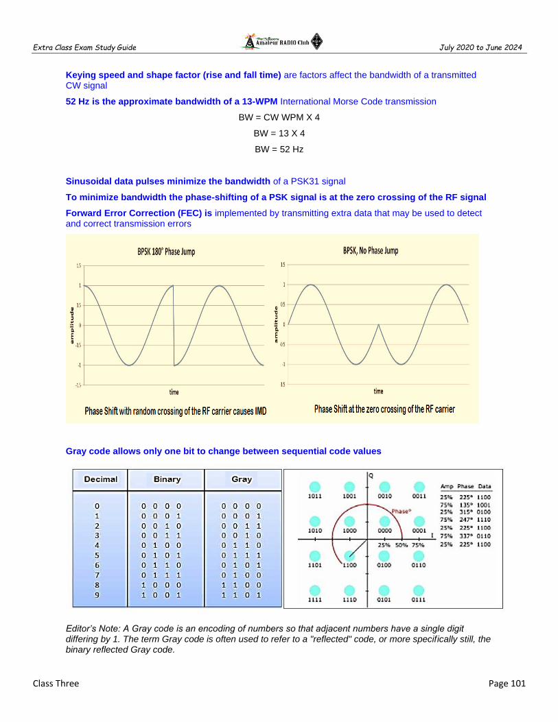
Extra Class Exam Study Guide July 2020 to June 2024
Class Three Page 101
Keying speed and shape factor (rise and fall time) are factors affect the bandwidth of a transmitted CW signal
52 Hz is the approximate bandwidth of a 13-WPM International Morse Code transmission
BW = CW WPM X 4
BW = 13 X 4
BW = 52 Hz
Sinusoidal data pulses minimize the bandwidth of a PSK31 signal
To minimize bandwidth the phase-shifting of a PSK signal is at the zero crossing of the RF signal
Forward Error Correction (FEC) is implemented by transmitting extra data that may be used to detect and correct transmission errors
Gray code allows only one bit to change between sequential code values
Editor’s Note: A Gray code is an encoding of numbers so that adjacent numbers have a single digit differing by 1. The term Gray code is often used to refer to a "reflected" code, or more specifically still, the binary reflected Gray code.
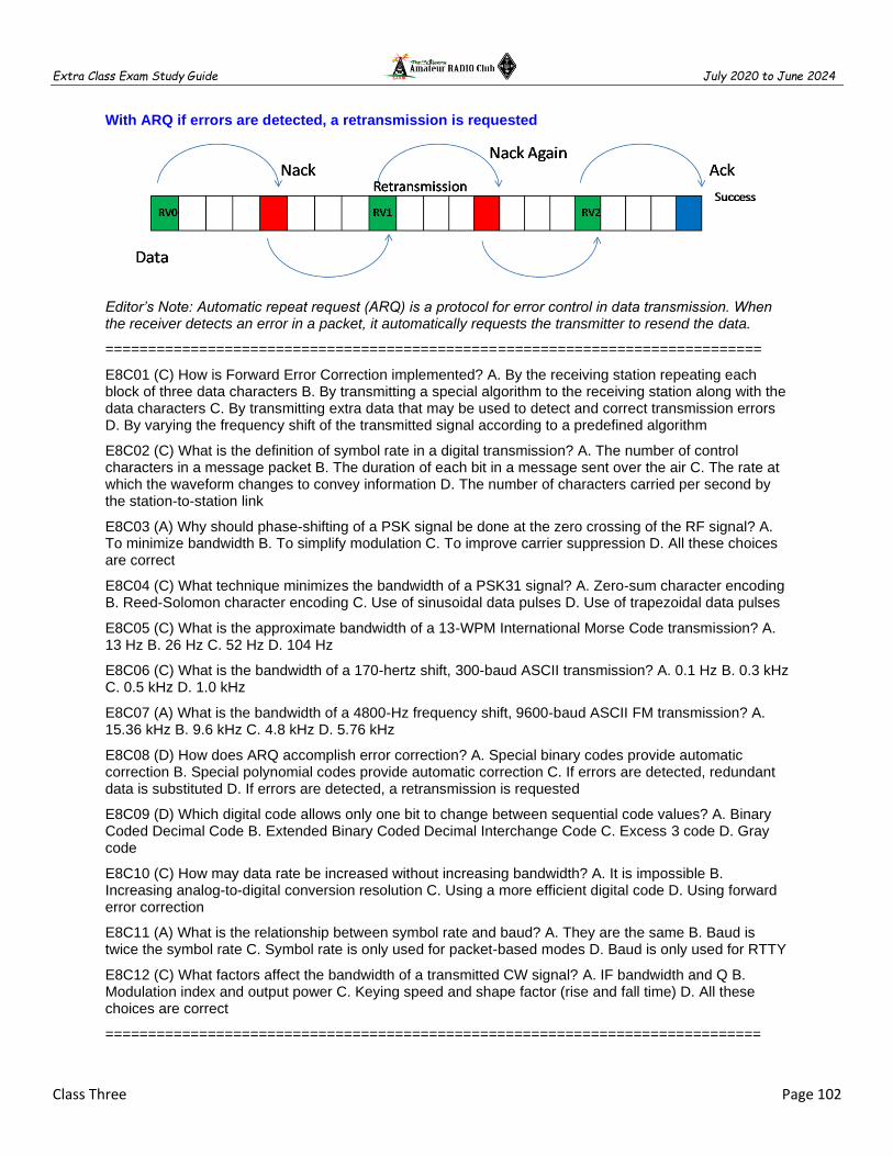
Extra Class Exam Study Guide July 2020 to June 2024
Class Three Page 102
With ARQ if errors are detected, a retransmission is requested
Editor’s Note: Automatic repeat request (ARQ) is a protocol for error control in data transmission. When the receiver detects an error in a packet, it automatically requests the transmitter to resend the data.
=============================================================================
E8C01 (C) How is Forward Error Correction implemented? A. By the receiving station repeating each block of three data characters B. By transmitting a special algorithm to the receiving station along with the data characters C. By transmitting extra data that may be used to detect and correct transmission errors D. By varying the frequency shift of the transmitted signal according to a predefined algorithm
E8C02 (C) What is the definition of symbol rate in a digital transmission? A. The number of control characters in a message packet B. The duration of each bit in a message sent over the air C. The rate at which the waveform changes to convey information D. The number of characters carried per second by the station-to-station link
E8C03 (A) Why should phase-shifting of a PSK signal be done at the zero crossing of the RF signal? A. To minimize bandwidth B. To simplify modulation C. To improve carrier suppression D. All these choices are correct
E8C04 (C) What technique minimizes the bandwidth of a PSK31 signal? A. Zero-sum character encoding B. Reed-Solomon character encoding C. Use of sinusoidal data pulses D. Use of trapezoidal data pulses
E8C05 (C) What is the approximate bandwidth of a 13-WPM International Morse Code transmission? A. 13 Hz B. 26 Hz C. 52 Hz D. 104 Hz
E8C06 (C) What is the bandwidth of a 170-hertz shift, 300-baud ASCII transmission? A. 0.1 Hz B. 0.3 kHz C. 0.5 kHz D. 1.0 kHz
E8C07 (A) What is the bandwidth of a 4800-Hz frequency shift, 9600-baud ASCII FM transmission? A. 15.36 kHz B. 9.6 kHz C. 4.8 kHz D. 5.76 kHz
E8C08 (D) How does ARQ accomplish error correction? A. Special binary codes provide automatic correction B. Special polynomial codes provide automatic correction C. If errors are detected, redundant data is substituted D. If errors are detected, a retransmission is requested
E8C09 (D) Which digital code allows only one bit to change between sequential code values? A. Binary Coded Decimal Code B. Extended Binary Coded Decimal Interchange Code C. Excess 3 code D. Gray code
E8C10 (C) How may data rate be increased without increasing bandwidth? A. It is impossible B. Increasing analog-to-digital conversion resolution C. Using a more efficient digital code D. Using forward error correction
E8C11 (A) What is the relationship between symbol rate and baud? A. They are the same B. Baud is twice the symbol rate C. Symbol rate is only used for packet-based modes D. Baud is only used for RTTY
E8C12 (C) What factors affect the bandwidth of a transmitted CW signal? A. IF bandwidth and Q B. Modulation index and output power C. Keying speed and shape factor (rise and fall time) D. All these choices are correct
=============================================================================

Extra Class Exam Study Guide July 2020 to June 2024
Class Three Page 103
E8D Keying defects and overmodulation of digital signals
=============================================================================
Signals not using the spread spectrum algorithm are suppressed in the receiver therefore resistant to interference
Direct sequence spread-spectrum (DSSS) communications technique uses a high-speed binary bit stream to shift the phase of an RF carrier
Frequency hopping spread-spectrum (FHSS) communications technique alters the center frequency of a conventional carrier many times per second in accordance with a pseudo-random list of channels
Editor’s Note: Frequency hopping spread-spectrum (FHSS) does not spread the signal, as a result, there is no processing gain. The processing gain is the increase in power density when the signal is de-spread and it will improve the received signal's Signal-to-noise ratio (SNR). In other words, the frequency hopper needs to put out more power in order to have the same SNR as a direct-sequence radio
ASCII code has both upper- and lower-case text
Some types of errors can be detected by including a parity bit with an ASCII character stream
ASCII uses seven or eight data bits per character and no shift code
Editor’s Note: American Standard Code for Information Interchange (ASCII) is a digital code with the letters, numbers, and punctuation characters are represented by a 7 bit number.
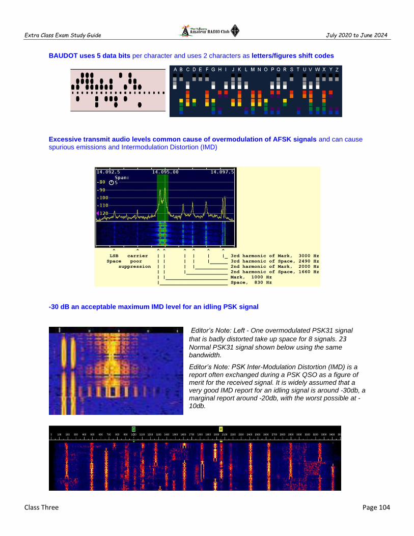
Extra Class Exam Study Guide July 2020 to June 2024
Class Three Page 104
BAUDOT uses 5 data bits per character and uses 2 characters as letters/figures shift codes
Excessive transmit audio levels common cause of overmodulation of AFSK signals and can cause spurious emissions and Intermodulation Distortion (IMD)
-30 dB an acceptable maximum IMD level for an idling PSK signal
Editor’s Note: Left - One overmodulated PSK31 signal
that is badly distorted take up space for 8 signals. 23 Normal PSK31 signal shown below using the same bandwidth.
Editor’s Note: PSK Inter-Modulation Distortion (IMD) is a report often exchanged during a PSK QSO as a figure of merit for the received signal. It is widely assumed that a very good IMD report for an idling signal is around -30db, a marginal report around -20db, with the worst possible at -10db.

Extra Class Exam Study Guide July 2020 to June 2024
Class Three Page 105
The generation of key clicks is the primary effect of extremely short rise or fall time on a CW signal
Increase keying waveform rise and fall times is the most common method of reducing key clicks
=============================================================================
E8D01 (A) Why are received spread spectrum signals resistant to interference? A. Signals not using the spread spectrum algorithm are suppressed in the receiver B. The high power used by a spread spectrum transmitter keeps its signal from being easily overpowered C. The receiver is always equipped with a digital blanker D. If interference is detected by the receiver it will signal the transmitter to change
E8D02 (B) What spread spectrum communications technique uses a high-speed binary bit stream to shift the phase of an RF carrier? A. Frequency hopping B. Direct sequence C. Binary phase-shift keying D. Phase compandored spread spectrum
E8D03 (D) How does the spread spectrum technique of frequency hopping work? A. If interference is detected by the receiver it will signal to change frequencies B. If interference is detected by the receiver it will signal the transmitter to wait until the frequency is clear C. A binary bit stream is used to shift the phase of an RF carrier very rapidly in a pseudorandom sequence D. The frequency of the transmitted signal is changed very rapidly according to a pseudorandom sequence also used by the receiving station
E8D04 (C) What is the primary effect of extremely short rise or fall time on a CW signal? A. More difficult to copy B. The generation of RF harmonics C. The generation of key clicks D. Limits data speed
E8D05 (A) What is the most common method of reducing key clicks? A. Increase keying waveform rise and fall times B. Low-pass filters at the transmitter output C. Reduce keying waveform rise and fall times D. High-pass filters at the transmitter output
E8D06 (D) What is the advantage of including parity bits in ASCII characters? A. Faster transmission rate B. The signal can overpower interfering signals C. Foreign language characters can be sent D. Some types of errors can be detected
E8D07 (D) What is a common cause of overmodulation of AFSK signals? A. Excessive numbers of retries B. Ground loops C. Bit errors in the modem D. Excessive transmit audio levels
E8D08 (D) What parameter evaluates distortion of an AFSK signal caused by excessive input audio levels? A. Signal-to-noise ratio B. Baud C. Repeat Request Rate D. Intermodulation Distortion (IMD)
E8D09 (D) What is considered an acceptable maximum IMD level for an idling PSK signal? A. +10 dB B. +15 dB C. -20 dB D. -30 dB
E8D10 (B) What are some of the differences between the Baudot digital code and ASCII? A. Baudot uses 4 data bits per character, ASCII uses 7 or 8; Baudot uses 1 character as a letters/figures shift code, ASCII has no letters/figures code B. Baudot uses 5 data bits per character, ASCII uses 7 or 8; Baudot uses 2 characters as letters/figures shift codes, ASCII has no letters/figures shift code C. Baudot uses 6 data bits per character, ASCII uses 7 or 8; Baudot has no letters/figures shift code, ASCII uses 2 letters/figures shift codes D. Baudot uses 7 data bits per character, ASCII uses 8; Baudot has no letters/figures shift code, ASCII uses 2 letters/figures shift codes
E8D11 (C) What is one advantage of using ASCII code for data communications? A. It includes built-in error correction features B. It contains fewer information bits per character than any other code C. It is possible to transmit both upper and lower case text D. It uses one character as a shift code to send numeric and special characters
=============================================================================

Extra Class Exam Study Guide July 2020 to June 2024
Class Three Page 106
E4C Receiver performance characteristics
=============================================================================
An attenuator be used to reduce receiver overload on the lower frequency HF bands with little or no impact on signal-to-noise ratio because atmospheric noise is generally greater than internally generated noise even after attenuation
A narrow-band roofing filter improves dynamic range by attenuating strong signals near the receive frequency
Editor’s note: A typical multiple-conversion superheterodyne receiver has several stages of filtering. Preselector filters reject out-of-band signals. Roofing filters at the input to each IF further restrict receiver bandwidth, attenuating strong in-band signals that might overload the IF amplifiers. In the final IF stage, single-signal filters are used to select just the desired signal.
A front-end filter or pre-selector can be effective in eliminating image signal interference Provides front end selectivity Reject strong near out of band signals Tunable input filter that passes the desired frequency. Increases rejection of out of band signals.

Extra Class Exam Study Guide July 2020 to June 2024
Class Three Page 107
Minimum discernible signal (MDS) represents the receiver minimum discernible signal
Editor’s note: The Minimum detectable signal (MDS) is the minimum power level that can be processed by a receiver to provide a relevant output. It is also known as the noise floor of the system. It can also be defined as the input signal power required to give a particular SNR.
The noise figure of a receiver >> ratio in dB of the noise generated by the receiver vs. theoretical minimum noise
The theoretical noise at the input of a perfect receiver at room temperature = -174 dBm/Hz
A CW receiver with the AGC off has an equivalent input noise power density of -174 dBm/Hz. What would be the level of an unmodulated carrier input to this receiver that would yield an audio output SNR of 0 dB in a 400 Hz noise bandwidth?
You are given the MDS for the receiver in Hz but you need to determine the MDS for 400 Hz
BW Ratio [400 vs 1 Hz] = 10 X log (400 / 1)
BW Ratio [400 vs 1 Hz] = 10 x 2.6 = 26 dB
- - - - - - - - - - - - - - - - - - - - - -
MDS for 400 Hz = (MDS @ 1 Hz) + ( BW Ratio [400 vs 1 Hz] )
MDS for 400 Hz = -174 + 26
MDS for 400 Hz = -148 dBm
Minimum Discernible Signal
MDS of a receiver is the strength of the
smallest discernible input signal.
Depends on noise figure and bandwidth.
MDS also called the receiver’s noise floor.
Signal that produces same audio level as
the receiver’s noise.
The lower the MDS the more sensitive the
receiver.

Extra Class Exam Study Guide July 2020 to June 2024
Class Three Page 108
Receiver oscillator phase noise causes nearby frequencies to interfere with reception of weak
Reciprocal mixing is the local oscillator mixing with adjacent strong signals to create interference to desired signals
What transmit frequency might generate an image response signal in a receiver tuned to 14.300 MHz and which uses a 455 kHz IF frequency?
IF of 455Khz and the signal on 14.300 MHz
BFO frequency = 14.3 + .455 = 14.755 MHz
IMAGE RESPONSE SIGNAL IN A RECEIVER
Image on 15.210 received because 15.210 – 14.755 MHz = 0.455 MHz (IF)
Editor’s note: When a local oscillator signal is mixed with an incoming signal in generates the sum and the difference of the two signals. If we assume High side mix (the LO is higher than the tuned frequency then the LO will be the tuned frequency + 455KHz. A signal 455 KHz above the LO would also generate a 455 KHz IF spurious or image signal. So taking the receive frequency of 14.300 MHz and 2 times the IF frequency of 0.455 MHz (14.300 – (2x.455) we get 15.210 MHz – AD7FO.
A higher frequency IF is EASIER design to eliminate image responses
Receive bandwidth selected to match the modulation bandwidth, maximizing signal-to-noise ratio and minimizing interference is an advantage of having a variety of receiver IF bandwidths
An SDR receiver is overloaded when input signals exceed the ADC reference voltage
Reference voltage level and sample bits determine the minimum detectable signal level for an SDR receiver.
Analog-to-digital converter sample width in bits has the largest effect on an SDR receiver's dynamic range
Capture effect is the term for the suppression in an FM receiver of one signal by another stronger signal on the same frequency
Overloading occurs when a strong
signal starts to saturate the ADC
because the dynamic range was not
high enough. Dynamic range is the
ability of an SDR to receive weak
signals when strong signals are nearby.
The need for high dynamic range can
be alleviated by using RF filtering.
Extra Class Exam Study Guide July 2020 to June 2024
Class Three Page 109
Editor’s note: FM capture effect, is a phenomenon associated with FM reception in which only the stronger of two signals at, or near, the same frequency or channel will be demodulated. ... Some types of radio receiver circuits have a stronger capture effect than others.
=============================================================================
E4C01 (D) What is an effect of excessive phase noise in a receiver's local oscillator? A. It limits the receiver's ability to receive strong signals B. It can affect the receiver's frequency calibration C. It decreases receiver third-order intercept point D. It can combine with strong signals on nearby frequencies to generate interference
E4C02 (A) Which of the following receiver circuits can be effective in eliminating interference from strong out-of-band signals? A. A front-end filter or pre-selector B. A narrow IF filter C. A notch filter D. A properly adjusted product detector
E4C03 (C) What is the term for the suppression in an FM receiver of one signal by another stronger signal on the same frequency? A. Desensitization B. Cross-modulation interference C. Capture effect D. Frequency discrimination
E4C04 (D) What is the noise figure of a receiver? A. The ratio of atmospheric noise to phase noise B. The ratio of the noise bandwidth in hertz to the theoretical bandwidth of a resistive network C. The ratio of thermal noise to atmospheric noise D. The ratio in dB of the noise generated by the receiver to the theoretical minimum noise
E4C05 (B) What does a receiver noise floor of -174 dBm represent? A. The minimum detectable signal as a function of receive frequency B. The theoretical noise in a 1 Hz bandwidth at the input of a perfect receiver at room temperature C. The noise figure of a 1 Hz bandwidth receiver D. The galactic noise contribution to minimum detectable signal
E4C06 (D) A CW receiver with the AGC off has an equivalent input noise power density of -174 dBm/Hz. What would be the level of an unmodulated carrier input to this receiver that would yield an audio output SNR of 0 dB in a 400 Hz noise bandwidth? A. -174 dBm B. -164 dBm C. -155 dBm D. -148 dBm
E4C07 (B) What does the MDS of a receiver represent? A. The meter display sensitivity B. The minimum discernible signal C. The multiplex distortion stability D. The maximum detectable spectrum
E4C08 (D) An SDR receiver is overloaded when input signals exceed what level? A. One-half the maximum sample rate B. One-half the maximum sampling buffer size C. The maximum count value of the analog-to-digital converter D. The reference voltage of the analog-to-digital converter
E4C09 (C) Which of the following choices is a good reason for selecting a high frequency for the design of the IF in a superheterodyne HF or VHF communications receiver? A. Fewer components in the receiver B. Reduced drift C. Easier for front-end circuitry to eliminate image responses D. Improved receiver noise figure
E4C10 (C) What is an advantage of having a variety of receiver IF bandwidths from which to select? A. The noise figure of the RF amplifier can be adjusted to match the modulation type, thus increasing receiver sensitivity B. Receiver power consumption can be reduced when wider bandwidth is not required C. Receive bandwidth can be set to match the modulation bandwidth, maximizing signal-to-noise ratio and minimizing interference D. Multiple frequencies can be received simultaneously if desired
E4C11 (D) Why can an attenuator be used to reduce receiver overload on the lower frequency HF bands with little or no impact on signal-to-noise ratio? A. The attenuator has a low-pass filter to increase the strength of lower frequency signals B. The attenuator has a noise filter to suppress interference C. Signals are attenuated separately from the noise D. Atmospheric noise is generally greater than internally generated noise even after attenuation
E4C12 (D) Which of the following has the largest effect on an SDR receiver's dynamic range? A. CPU register width in bits B. Anti-aliasing input filter bandwidth C. RAM speed used for data storage D. Analog-to-digital converter sample width in bits
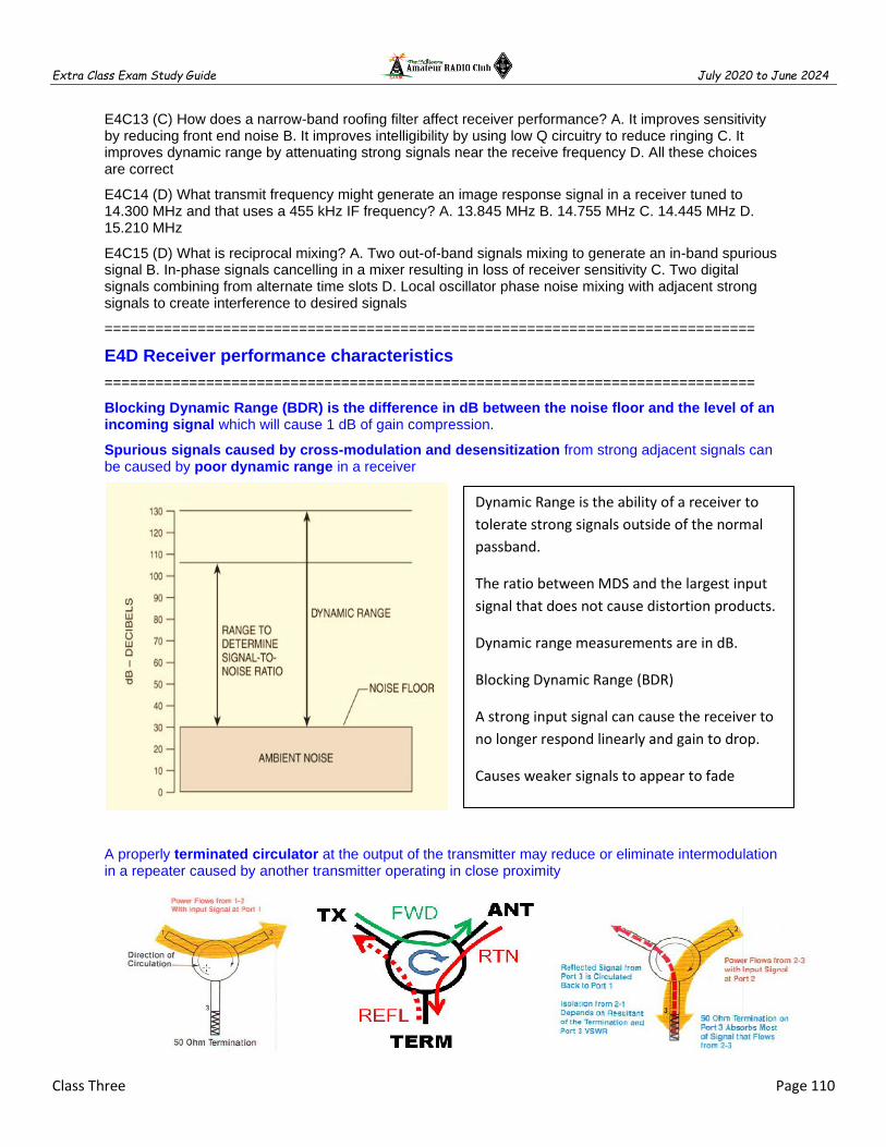
Extra Class Exam Study Guide July 2020 to June 2024
Class Three Page 110
E4C13 (C) How does a narrow-band roofing filter affect receiver performance? A. It improves sensitivity by reducing front end noise B. It improves intelligibility by using low Q circuitry to reduce ringing C. It improves dynamic range by attenuating strong signals near the receive frequency D. All these choices are correct
E4C14 (D) What transmit frequency might generate an image response signal in a receiver tuned to 14.300 MHz and that uses a 455 kHz IF frequency? A. 13.845 MHz B. 14.755 MHz C. 14.445 MHz D. 15.210 MHz
E4C15 (D) What is reciprocal mixing? A. Two out-of-band signals mixing to generate an in-band spurious signal B. In-phase signals cancelling in a mixer resulting in loss of receiver sensitivity C. Two digital signals combining from alternate time slots D. Local oscillator phase noise mixing with adjacent strong signals to create interference to desired signals
=============================================================================
E4D Receiver performance characteristics
=============================================================================
Blocking Dynamic Range (BDR) is the difference in dB between the noise floor and the level of an incoming signal which will cause 1 dB of gain compression.
Spurious signals caused by cross-modulation and desensitization from strong adjacent signals can be caused by poor dynamic range in a receiver
A properly terminated circulator at the output of the transmitter may reduce or eliminate intermodulation in a repeater caused by another transmitter operating in close proximity
Dynamic Range is the ability of a receiver to
tolerate strong signals outside of the normal
passband.
The ratio between MDS and the largest input
signal that does not cause distortion products.
Dynamic range measurements are in dB.
Blocking Dynamic Range (BDR)
A strong input signal can cause the receiver to
no longer respond linearly and gain to drop.
Causes weaker signals to appear to fade
Gain compression or blocking.

Extra Class Exam Study Guide July 2020 to June 2024
Class Three Page 111
Desensitization is the reduction in receiver sensitivity caused by a strong signal near the received frequency
Strong adjacent-channel signals can cause receiver desensitization
Decreasing the RF bandwidth of a receiver will reduce the likelihood of receiver desensitization
A PRESELECTOR increases the rejection of unwanted signals
Nonlinear circuits or devices causes intermodulation in an electronic circuit
Intermodulation is the term for spurious signals generated by the combination of two or more signals in a non-linear device or circuit.
Odd-order intermodulation products of two signals in the band of interest are likely to be in band
When the repeaters are in close proximity and the signals mix in the final amplifier of one or both transmitters intermodulation interference between two repeaters can occur
What transmitter frequencies would cause an intermodulation-product signal in a receiver tuned to 146.70 MHz when a nearby station transmits on 146.52 MHz? = A. 146.34 MHz and 146.61 MHz
There are many possible IMD solutions; You know 146.70 MHz = FIMD and you know transmitter A (TXa) = 146.52 MHz you are being asked to find transmitter B!
#1) 2nd FIMD = TXa + TXb > too high for the receiver
#2) 2nd FIMD = TXa - TXb > too low for the receiver
#3) 3rd FIMD = 2TXa + TXb > too high for the receiver
#4) 3rd FIMD = 2TXa - TXb > 146.70= (2 x 146.52) - TXb
TXb = (2 x 146.52) - 146.70
TXb = (293.04) - 146.70 = 146.34 MHz
#5) 3rd FIMD = 2TXb + TXa > too high for the receiver
#6) 3rd FIMD = 2TXb - TXa > 146.70 = (2 x TXb) - 146.52
TXb = (146.70 + 146.52) / 2
TXb = (293.22) / 2 = 146.61 MHZ

Extra Class Exam Study Guide July 2020 to June 2024
Class Three Page 112
Receiver third-order intercept level of 40 dBm means a pair of 40 dBm signals will theoretically generate a third-order intermodulation product with the same level as the input signals
Editor’s note: Third order intercept point is an ideal point as once the device reaches to 1 dB compression point the two curves will become parallel to each other and they will never cut. Which shows that the power for fundamental and third order component will not be same. but this parameter is very important in terms of characterizing a device.
Editor’s note: Receiver output power for a desired signal and for third-order distortion products varies with changes of input signal power. The input signal consists of two equal-power sine-wave signas. Higher Intercept points represent better receiver IMD performance. The input signal power at which the level of the distortion products equals the output level for the desired signal is the receiver’s intercept point. Example: A 40 dBm third-order intercept point means a pair of 40 dBm signals would produce and IMD product of same 40 dBm level.
Extra Class Exam Study Guide July 2020 to June 2024
Class Three Page 113
=============================================================================
E4D01 (A) What is meant by the blocking dynamic range of a receiver? A. The difference in dB between the noise floor and the level of an incoming signal that will cause 1 dB of gain compression B. The minimum difference in dB between the levels of two FM signals that will cause one signal to block the other C. The difference in dB between the noise floor and the third-order intercept point D. The minimum difference in dB between two signals which produce third-order intermodulation products greater than the noise floor
E4D02 (A) Which of the following describes problems caused by poor dynamic range in a receiver? A. Spurious signals caused by cross-modulation and desensitization from strong adjacent signals B. Oscillator instability requiring frequent retuning and loss of ability to recover the opposite sideband C. Cross-modulation of the desired signal and insufficient audio power to operate the speaker D. Oscillator instability and severe audio distortion of all but the strongest received signals
E4D03 (B) How can intermodulation interference between two repeaters occur? A. When the repeaters are in close proximity and the signals cause feedback in the final amplifier of one or both transmitters B. When the repeaters are in close proximity and the signals mix in the final amplifier of one or both transmitters C. When the signals from the transmitters are reflected out of phase from airplanes passing overhead D. When the signals from the transmitters are reflected in phase from airplanes passing overhead
E4D04 (B) Which of the following may reduce or eliminate intermodulation interference in a repeater caused by another transmitter operating in close proximity? A. A band-pass filter in the feed line between the transmitter and receiver B. A properly terminated circulator at the output of the repeater's transmitter C. Utilizing a Class C final amplifier D. Utilizing a Class D final amplifier
E4D05 (A) What transmitter frequencies would cause an intermodulation-product signal in a receiver tuned to 146.70 MHz when a nearby station transmits on 146.52 MHz? A. 146.34 MHz and 146.61 MHz B. 146.88 MHz and 146.34 MHz C. 146.10 MHz and 147.30 MHz D. 173.35 MHz and 139.40 MHz
E4D06 (D) What is the term for spurious signals generated by the combination of two or more signals in a non-linear device or circuit? A. Amplifier desensitization B. Neutralization C. Adjacent channel interference D. Intermodulation
E4D07 (A) Which of the following reduces the likelihood of receiver desensitization? A. Decrease the RF bandwidth of the receiver B. Raise the receiver IF frequency C. Increase the receiver front end gain D. Switch from fast AGC to slow AGC
E4D08 (C) What causes intermodulation in an electronic circuit? A. Too little gain B. Lack of neutralization C. Nonlinear circuits or devices D. Positive feedback
E4D09 (C) What is the purpose of the preselector in a communications receiver? A. To store often-used frequencies B. To provide a range of AGC time constants C. To increase rejection of signals outside the desired band D. To allow selection of the optimum RF amplifier device
E4D10 (C) What does a third-order intercept level of 40 dBm mean with respect to receiver performance? A. Signals less than 40 dBm will not generate audible third-order intermodulation products B. The receiver can tolerate signals up to 40 dB above the noise floor without producing third-order intermodulation products C. A pair of 40 dBm input signals will theoretically generate a third-order intermodulation product that has the same output amplitude as either of the input signals D. A pair of 1 mW input signals will produce a third-order intermodulation product that is 40 dB stronger than the input signal
E4D11 (A) Why are odd-order intermodulation products, created within a receiver, of particular interest compared to other products? A. Odd-order products of two signals in the band of interest are also likely to be within the band B. Odd-order products overload the IF filters C. Odd-order products are an indication of poor image rejection D. Odd-order intermodulation produces three products for every input signal within the band of interest
E4D12 (A) What is the term for the reduction in receiver sensitivity caused by a strong signal near the received frequency? A. Desensitization B. Quieting C. Cross-modulation interference D. Squelch gain rollback
=============================================================================

Extra Class Exam Study Guide July 2020 to June 2024
Class Three Page 114
=============================================================================
E4E Noise suppression and interference =============================================================================
Common-mode currents on the shield and conductors can cause shielded cables to radiate or receive interference
Common-mode current flows equally on all conductors of an unshielded multi-conductor cable
Broadband white noise, ignition noise & power line noise can often be reduced with a DSP noise filter
A noise blanker may remove signals which appear across a wide bandwidth
Electric motor noise may be suppressed by installing a brute-force AC-line filter in series with the motor leads
Alternator noise may be suppressed by connecting the radio's power leads directly to the battery and by installing coaxial capacitors in line with the alternator leads
Arcing thermostat contacts, defective doorbell transformer or a malfunctioning illuminated advertising display may cause a loud roaring or buzzing AC line interference that comes and goes at intervals

Extra Class Exam Study Guide July 2020 to June 2024
Class Three Page 115
An IF noise blanker makes nearby signals may appear to be excessively wide even if they meet emission standards
Editor’s note: This is because a peak of the signal is removed and the broader lower section is only received. The observed 3 dB bandwidth of the blanked signal would appear to be much wider than if referred to the original peak signal level. - AD7FO
Nearby corroded metal joints are mixing and re-radiating the broadcast signals cause if you are hearing combinations of local AM broadcast signals within one or more of the MF or HF ham bands?
One disadvantage of using some types of automatic DSP notch-filters when attempting to copy CW signals is the DSP filter can remove the desired signal at the same time as it removes interfering signals
The appearance of unstable modulated or unmodulated signals at specific frequencies might be caused by the operation of a nearby personal computer
Editor’s note: Corroded joints act like diodes and then function as a mixer generating sum and difference frequencies from nearby strong signals. - AD7FO

Extra Class Exam Study Guide July 2020 to June 2024
Class Three Page 116
==============================================================================
E4E01 (A) What problem can occur when using an automatic notch filter (ANF) to remove interfering carriers while receiving CW signals? A. Removal of the CW signal as well as the interfering carrier B. Any nearby signal passing through the DSP system will overwhelm the desired signal C. Received CW signals will appear to be modulated at the DSP clock frequency D. Ringing in the DSP filter will completely remove the spaces between the CW characters
E4E02 (D) Which of the following types of noise can often be reduced with a digital signal processing noise filter? A. Broadband white noise B. Ignition noise C. Power line noise D. All these choices are correct
E4E03 (B) Which of the following signals might a receiver noise blanker be able to remove from desired signals? A. Signals that are constant at all IF levels B. Signals that appear across a wide bandwidth C. Signals that appear at one IF but not another D. Signals that have a sharply peaked frequency distribution
E4E04 (D) How can conducted and radiated noise caused by an automobile alternator be suppressed? A. By installing filter capacitors in series with the DC power lead and a blocking capacitor in the field lead B. By installing a noise suppression resistor and a blocking capacitor in both leads C. By installing a high-pass filter in series with the radio's power lead and a low-pass filter in parallel with the field lead D. By connecting the radio's power leads directly to the battery and by installing coaxial capacitors in line with the alternator leads
E4E05 (B) How can radio frequency interference from an AC motor be suppressed? A. By installing a high-pass filter in series with the motor's power leads B. By installing a brute-force AC-line filter in series with the motor leads C. By installing a bypass capacitor in series with the motor leads D. By using a ground-fault current interrupter in the circuit used to power the motor
E4E06 (C) What is one type of electrical interference that might be caused by a nearby personal computer? A. A loud AC hum in the audio output of your station receiver B. A clicking noise at intervals of a few seconds C. The appearance of unstable modulated or unmodulated signals at specific frequencies D. A whining type noise that continually pulses off and on
E4E07 (B) Which of the following can cause shielded cables to radiate or receive interference? A. Low inductance ground connections at both ends of the shield B. Common-mode currents on the shield and conductors C. Use of braided shielding material D. Tying all ground connections to a common point resulting in differential-mode currents in the shield
E4E08 (B) What current flows equally on all conductors of an unshielded multi-conductor cable? A. Differential-mode current B. Common-mode current C. Reactive current only D. Return current
E4E09 (C) What undesirable effect can occur when using an IF noise blanker? A. Received audio in the speech range might have an echo effect B. The audio frequency bandwidth of the received signal might be compressed C. Nearby signals may appear to be excessively wide even if they meet emission standards D. FM signals can no longer be demodulated
E4E10 (D) What might be the cause of a loud roaring or buzzing AC line interference that comes and goes at intervals? A. Arcing contacts in a thermostatically controlled device B. A defective doorbell or doorbell transformer inside a nearby residence C. A malfunctioning illuminated advertising display D. All these choices are correct
E4E11 (B) What could cause local AM broadcast band signals to combine to generate spurious signals in the MF or HF bands? A. One or more of the broadcast stations is transmitting an over-modulated signal B. Nearby corroded metal joints are mixing and re-radiating the broadcast signals C. You are receiving skywave signals from a distant station D. Your station receiver IF amplifier stage is defective
=============================================================================
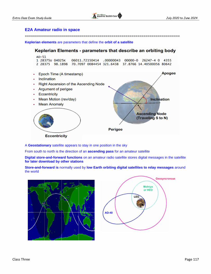
Extra Class Exam Study Guide July 2020 to June 2024
Class Three Page 117
E2A Amateur radio in space
=============================================================================
Keplerian elements are parameters that define the orbit of a satellite
A Geostationary satellite appears to stay in one position in the sky
From south to north is the direction of an ascending pass for an amateur satellite
Digital store-and-forward functions on an amateur radio satellite stores digital messages in the satellite for later download by other stations
Store-and-forward is normally used by low Earth orbiting digital satellites to relay messages around the world

Extra Class Exam Study Guide July 2020 to June 2024
Class Three Page 118
The letters in a satellite's MODE designator specify the uplink and downlink frequency ranges
L band is 23 cm and S band is 13 cm regarding satellite communications
The following types of signals can be relayed through a linear transponder; FM and CW SSB and SSTV PSK and Packet
The following occurs when a satellite is using an INVERTING LINEAR TRANSPONDER:
Doppler shift is reduced because the uplink and downlink shifts are in opposite directions Signal position in the band is reversed Upper sideband on the uplink becomes lower sideband on the downlink, and vice versa
The signal is passed through a mixer and the difference rather than the sum is transmitted in an inverting linear transponder
A circularly polarized antenna can be used to minimize the
effects of spin modulation and Faraday rotation
Editor’s note: If the signal from an amateur satellite exhibit a
rapidly repeating fading effect means the satellite is spinning

Extra Class Exam Study Guide July 2020 to June 2024
Class Three Page 119
Limit YOUR power to a satellite which uses a linear transponder to avoid reducing the downlink power to others
Editor’s Note: In a linear transponder the largest received signal sets the transponder output power. Signals less than the larger signal are attenuated and therefore are re-sent at a lower power than the larger signal. Using the minimum power needed to access the transponder will allow more users to have access to the transponder. – AD7FO
=============================================================================
E2A01 (C) What is the direction of an ascending pass for an amateur satellite? A. From west to east B. From east to west C. From south to north D. From north to south
E2A02 (D) Which of the following occurs when a satellite is using an inverting linear transponder? A. Doppler shift is reduced because the uplink and downlink shifts are in opposite directions B. Signal position in the band is reversed C. Upper sideband on the uplink becomes lower sideband on the downlink, and vice versa D. All these choices are correct
E2A03 (D) How is the signal inverted by an inverting linear transponder? A. The signal is detected and remodulated on the reverse sideband B. The signal is passed through a non-linear filter C. The signal is reduced to I and Q components and the Q component is filtered out D. The signal is passed through a mixer and the difference rather than the sum is transmitted
E2A04 (B) What is meant by the term mode? as applied to an amateur radio satellite? A. Whether the satellite is in a low earth or geostationary orbit B. The satellite's uplink and downlink frequency bands C. The satellite's orientation with respect to the Earth D. Whether the satellite is in a polar or equatorial orbit
E2A05 (D) What do the letters in a satellite's mode designator specify? A. Power limits for uplink and downlink transmissions B. The location of the ground control station C. The polarization of uplink and downlink signals D. The uplink and downlink frequency ranges
E2A06 (A) What are Keplerian elements? A. Parameters that define the orbit of a satellite B. Phase reversing elements in a Yagi antenna C. High-emission heater filaments used in magnetron tubes D. Encrypting codes used for spread spectrum modulation
E2A07 (D) Which of the following types of signals can be relayed through a linear transponder? A. FM and CW B. SSB and SSTV C. PSK and packet D. All these choices are correct
E2A08 (B) Why should effective radiated power to a satellite that uses a linear transponder be limited? A. To prevent creating errors in the satellite telemetry B. To avoid reducing the downlink power to all other users C. To prevent the satellite from emitting out-of-band signals D. To avoid interfering with terrestrial QSOs
E2A09 (A) What do the terms L band and S band specify regarding satellite communications? A. The 23 centimeter and 13 centimeter bands B. The 2 meter and 70 centimeter bands C. FM and Digital Store-and-Forward systems D. Which sideband to use

Extra Class Exam Study Guide July 2020 to June 2024
Class Three Page 120
E2A10 (B) What type of satellite appears to stay in one position in the sky? A. HEO B. Geostationary C. Geomagnetic D. LEO
E2A11 (B) What type of antenna can be used to minimize the effects of spin modulation and Faraday rotation? A. A linearly polarized antenna B. A circularly polarized antenna C. An isotropic antenna D. A log-periodic dipole array
E2A12 (C) What is the purpose of digital store-and-forward functions on an amateur radio satellite? A. To upload operational software for the transponder B. To delay download of telemetry between satellites C. To store digital messages in the satellite for later download by other stations D. To relay messages between satellites
E2A13 (B) Which of the following techniques is normally used by low Earth orbiting digital satellites to relay messages around the world? A. Digipeating B. Store-and-forward C. Multi-satellite relaying D. Node hopping
=============================================================================
E2B Television practices
=============================================================================
NTSC is the video standard used by North American Fast Scan ATV stations
30 frames per second are transmitted in a fast-scan (NTSC) television system
525 horizontal lines make up a fast-scan (NTSC) television frame
An interlaced scanning pattern generated by scanning odd numbered lines in one field and even numbered ones in the next in a fast-scan (NTSC) television system

Extra Class Exam Study Guide July 2020 to June 2024
Class Three Page 121
Chroma is the name of the signal component that carries color information in NTSC video
Vestigial sideband modulation is one complete sideband and a portion of the other sideband are transmitted
Vestigial sideband reduces bandwidth while allowing for simple video detector circuitry for standard fast- scan TV transmissions
Transmitting on channels shared with cable TV allows commercial analog TV receivers to be used for fast-scan TV operations on the 70 cm band
Tone frequency of an amateur slow-scan television signal encodes the brightness of the picture
Specific tone frequencies signal SSTV receiving equipment to begin a new picture line
The Vertical Interval Signaling (VIS) code transmitted as part of an SSTV transmission identifies the SSTV Mode
Digital Radio Mondiale (DRM) can be decoded using a receiver with SSB capability and a suitable computer
Color lines are sent sequentially in analog SSTV

Extra Class Exam Study Guide July 2020 to June 2024
Class Three Page 122
=============================================================================
E2B01 (A) How many times per second is a new frame transmitted in a fast-scan (NTSC) television system? A. 30 B. 60 C. 90 D. 120
E2B02 (C) How many horizontal lines make up a fast-scan (NTSC) television frame? A. 30 B. 60 C. 525 D. 1080
E2B03 (D) How is an interlaced scanning pattern generated in a fast-scan (NTSC) television system? A. By scanning two fields simultaneously B. By scanning each field from bottom to top C. By scanning lines from left to right in one field and right to left in the next D. By scanning odd numbered lines in one field and even numbered lines in the next
E2B04 (A) How is color information sent in analog SSTV? A. Color lines are sent sequentially B. Color information is sent on a 2.8 kHz subcarrier C. Color is sent in a color burst at the end of each line D. Color is amplitude modulated on the frequency modulated intensity signal
E2B05 (C) Which of the following describes the use of vestigial sideband in analog fast-scan TV transmissions? A. The vestigial sideband carries the audio information B. The vestigial sideband contains chroma information C. Vestigial sideband reduces bandwidth while allowing for simple video detector circuitry D. Vestigial sideband provides high frequency emphasis to sharpen the picture
E2B06 (A) What is vestigial sideband modulation? A. Amplitude modulation in which one complete sideband and a portion of the other are transmitted B. A type of modulation in which one sideband is inverted C. Narrow-band FM modulation achieved by filtering one sideband from the audio before frequency modulating the carrier D. Spread spectrum modulation achieved by applying FM modulation following single sideband amplitude modulation
E2B07 (B) What is the name of the signal component that carries color information in NTSC video? A. Luminance B. Chroma C. Hue D. Spectral intensity
E2B08 (A) What technique allows commercial analog TV receivers to be used for fast-scan TV operations on the 70 cm band? A. Transmitting on channels shared with cable TV B. Using converted satellite TV dishes C. Transmitting on the abandoned TV channel 2 D. Using USB and demodulating the signal with a computer sound card
E2B09 (D) What hardware, other than a receiver with SSB capability and a suitable computer, is needed to decode SSTV using Digital Radio Mondiale (DRM)? A. A special IF converter B. A special front end limiter C. A special notch filter to remove synchronization pulses D. No other hardware is needed
E2B10 (A) What aspect of an analog slow-scan television signal encodes the brightness of the picture? A. Tone frequency B. Tone amplitude C. Sync amplitude D. Sync frequency
E2B11 (B) What is the function of the Vertical Interval Signaling (VIS) code sent as part of an SSTV transmission? A. To lock the color burst oscillator in color SSTV images B. To identify the SSTV mode being used C. To provide vertical synchronization D. To identify the call sign of the station transmitting
E2B12 (A) What signals SSTV receiving software to begin a new picture line? A. Specific tone frequencies B. Elapsed time C. Specific tone amplitudes D. A two-tone signal
=============================================================================

Extra Class Exam Study Guide July 2020 to June 2024
Class Three Page 123
Class Three Fundamentals and Substance
============================================================================
After completing each class be sure to use the Fundamentals and Substance subsection that was solely created as a tool for test preparation by helping you make connections between topics and serves as quality review material for after each class. Using these steps can be most useful when learning about new topics that include a lot of detail. The information is in the form of class notes with all of the important information you need to know. These notes are not a substitute for studying the class material in fact you will need to complete your class assignment in order to effectively use these notes. The notes are organized into easily digestible headings and bullet points to organize topics with the key words, main subpoints and summary are all written in one place.
============================================================================
AC Waveforms
256 different input levels can be encoded by an ADC with 8-bit resolution or 2^8 bits
A Square wave is made up of a sine wave plus all of its odd harmonics
A Saw Tooth wave is made up of a sine wave plus all of its harmonics
Successive Approximation ADC is a type of analog-to-digital converter that compares via a progressive quantization before finally converging upon a digital output for each conversion.
Flash ADC is a type of analog-to-digital converter that uses multiple comparator sat each to compare the input voltage to reference voltages simultaneously (also known as a direct-conversion ADC).
Total harmonic distortion is a measure of the quality of an analog-to-digital converter
A small amount of noise added to the input signal to allow more precise representation of a signal over time is "dither" with respect to analog-to-digital converters
A low-pass filter used in conjunction with a digital-to-analog converter remove harmonics from the output caused by the discrete analog levels generated
2:1 ratio of PEP-to-average power in a typical SSB phone signal
Speech characteristics determines the PEP-to-average power ratio of a SSB phone signal
Test equipment
Sampling rate determines the bandwidth of a digital oscilloscope
A spectrum analyzer displays frequency on the horizontal axis
A spectrum analyzer displays amplitude on the vertical axis
A spectrum analyzer is used to display intermodulation distortion products in an SSB transmission?
The compensation of an oscilloscope probe is adjusted until the horizontal portions of the displayed wave are as nearly flat as possible
The effect of aliasing in a digital or computer-based oscilloscope are false signals being displayed
Keep the oscilloscope probe ground connection of the probe as short as possible
A Logic analyzer displays multiple digital signal states simultaneously
A PRESCALER divides a high frequency signal so a low-frequency counter can display the frequency
Antenna analyzers do not need an external RF source to measure antenna SWR
An antenna analyzer measures SWR
Connect the antenna feed line directly to the analyzer's connector when measuring antenna resonance and feed point impedance

Extra Class Exam Study Guide July 2020 to June 2024
Class Three Page 124
Measurements
Input impedance, Output impedance and Reflection coefficient can be measured with a Vector Network Analyzer (VNA)
The VNA ports at which measurements are made are represented by S parameters
VNA S21 is equivalent to forward gain
VNA S21 is equivalent to SWR (equivalent to return loss)
Short circuit, open circuit, and 50 ohms test loads are used to calibrate a VNA
Intermodulation distortion (IMD) >> SSB TX non-harmonically two tones & observe RF on a spectrum analyzer
75 W is absorbed by the load when a directional power meter between a transmitter and load reads 100 W forward and 25 W reflected power
There is more power going into the antenna if the current reading on an RF ammeter placed in the antenna feed line of a transmitter increases as the transmitter is tuned to resonance
The accuracy of the time base determines the accuracy of a frequency counter
The full-scale reading of the voltmeter in ohms per volt rating will indicate the input impedance of the voltmeter
The bandwidth of the circuit's frequency response can be used to measure the Q of a series-tuned circuit
Modulation
The frequency components present in the modulating signal is called BASEBAND
The two input frequencies along with their SUM AND DIFFERENCE FREQUENCIES appear at the output of a mixer circuit
SPURIOUS MIXER PRODUCTS are generated when an excessive signal energy reaches a mixer
A diode detector functions by rectification and filtering of RF signals
A reactance modulator on the oscillator can be used to generate FM phone emissions
The function of a reactance modulator is to produce PM signals by using an electrically variable inductance or capacitance
The frequency DISCRIMINATOR stage in a FM receiver is used for detecting FM signals
A pre-emphasis network circuit is added to an FM transmitter to boost the higher audio frequencies
De-emphasis commonly used in FM communications receivers for compatibility with transmitters using phase modulation
A SSB phone signal can be generated by using a BALANCED modulator followed by a filter
A PRODUCT detector is well suited for demodulating SSB signals
The maximum carrier frequency deviation compared to the highest audio modulating frequency is the deviation ratio
Modulation index is the term for the ratio between the frequency deviation of an RF carrier wave, and the modulating frequency of its corresponding FM-phone signal
Modulation index = Max Carrier Dev / Max Modulation
FREQUENCY DIVISION MULTIPLEXING is two or more information streams are merged into a baseband, which then modulates the transmitter

Extra Class Exam Study Guide July 2020 to June 2024
Class Three Page 125
Digital TIME DIVISION MULTIPLEXING is two or more signals are arranged to share discrete time slots of a data transmission
ORTHOGONAL FREQUENCY DIVISION MULTIPLEXING is a technique used for HIGH-SPEED DIGITAL MODES in amateur communication
A digital modulation technique using subcarriers at frequencies chosen to avoid intersymbol interference describes ORTHOGONAL FREQUENCY DIVISION MULTIPLEXING
Digital Comms
The rate a waveform changes to convey information is the definition of symbol rate in a digital transmission
Using a more efficient digital code increases data rate be without increasing bandwidth
Symbol rate and baud are the same
Keying speed and shape factor (rise and fall time) are factors affect the bandwidth of a transmitted CW signal
52 Hz is the approximate bandwidth of a 13-WPM International Morse Code transmission
Sinusoidal data pulses minimize the bandwidth of a PSK31 signal
To minimize bandwidth the phase-shifting of a PSK signal is at the zero crossing of the RF signal
Forward Error Correction (FEC) is implemented by transmitting extra data that may be used to detect and correct transmission errors
Gray code allows only one bit to change between sequential code values
With ARQ if errors are detected, a retransmission is requested
Signals not using the spread spectrum algorithm are suppressed in the receiver therefore resistant to interference
Direct sequence spread-spectrum (DSSS) communications technique uses a high-speed binary bit stream to shift the phase of an RF carrier
Frequency hopping spread-spectrum (FHSS) communications technique alters the center frequency of a conventional carrier many times per second in accordance with a pseudo-random list of channels
ASCII code has both upper- and lower-case text
Some types of errors can be detected by including a parity bit with an ASCII character stream
ASCII uses seven or eight data bits per character and no shift code
BAUDOT uses 5 data bits per character and uses 2 characters as letters/figures shift codes
Intermodulation and Spurious Signals
Excessive transmit audio levels common cause of overmodulation of AFSK signals and can cause spurious emissions and Intermodulation Distortion (IMD)
-30 dB an acceptable maximum IMD level for an idling PSK signal
The generation of key clicks is the primary effect of extremely short rise or fall time on a CW signal
Increase keying waveform rise and fall times is the most common method of reducing key clicks

Extra Class Exam Study Guide July 2020 to June 2024
Class Three Page 126
Receiver Performance
An attenuator be used to reduce receiver overload on the lower frequency HF bands with little or no impact on signal-to-noise ratio because atmospheric noise is generally greater than internally generated noise even after attenuation
A narrow-band roofing filter improves dynamic range by attenuating strong signals near the receive frequency
A front-end filter or pre-selector can be effective in eliminating image signal interference Minimum discernible signal (MDS) represents the receiver minimum discernible signal
The noise figure of a receiver >> ratio in dB of the noise generated by the receiver vs. theoretical minimum noise
The theoretical noise at the input of a perfect receiver at room temperature = -174 dBm/Hz
MDS for 400 Hz = -148 dBm
Receiver oscillator phase noise causes nearby frequencies to interfere with reception of weak
Reciprocal mixing is the local oscillator mixing with adjacent strong signals to create interference to desired signals
A higher frequency IF is EASIER design to eliminate image responses
Receive bandwidth selected to match the modulation bandwidth, maximizing signal-to-noise ratio and minimizing interference is an advantage of having a variety of receiver IF bandwidths
An SDR receiver is overloaded when input signals exceed the ADC reference voltage
Reference voltage level and sample bits determine the minimum detectable signal level for an SDR receiver.
Analog-to-digital converter sample width in bits has the largest effect on an SDR receiver's dynamic range
Capture effect is the term for the suppression in an FM receiver of one signal by another stronger signal on the same frequency
Blocking Dynamic Range (BDR) is the difference in dB between the noise floor and the level of an incoming signal which will cause 1 dB of gain compression.
Spurious signals caused by cross-modulation and desensitization from strong adjacent signals can be caused by poor dynamic range in a receiver
A properly terminated circulator at the output of the transmitter may reduce or eliminate intermodulation in a repeater caused by another transmitter operating in close proximity
Desensitization is the reduction in receiver sensitivity caused by a strong signal near the received frequency
Strong adjacent-channel signals can cause receiver desensitization
Decreasing the RF bandwidth of a receiver will reduce the likelihood of receiver desensitization
A PRESELECTOR increases the rejection of unwanted signals
Nonlinear circuits or devices causes intermodulation in an electronic circuit
Intermodulation is the term for spurious signals generated by the combination of two or more signals in a non-linear device or circuit.
Odd-order intermodulation products of two signals in the band of interest are likely to be in band
When the repeaters are in close proximity and the signals mix in the final amplifier of one or both transmitters intermodulation interference between two repeaters can occur
Receiver third-order intercept level of 40 dBm means a pair of 40 dBm signals will theoretically generate a third-order intermodulation product with the same level as the input signals

Extra Class Exam Study Guide July 2020 to June 2024
Class Three Page 127
Noise Suppression
Common-mode currents on the shield and conductors can cause shielded cables to radiate or receive interference
Common-mode current flows equally on all conductors of an unshielded multi-conductor cable
Broadband white noise, ignition noise & power line noise can often be reduced with a DSP noise filter
A noise blanker may remove signals which appear across a wide bandwidth
Electric motor noise may be suppressed by installing a brute-force AC-line filter in series with the motor leads
Alternator noise may be suppressed by connecting the radio's power leads directly to the battery and by installing coaxial capacitors in line with the alternator leads
Arcing thermostat contacts, defective doorbell transformer or a malfunctioning illuminated advertising display may cause a loud roaring or buzzing AC line interference that comes and goes at intervals
An IF noise blanker makes nearby signals may appear to be excessively wide even if they meet emission standards
Nearby corroded metal joints are mixing and re-radiating the broadcast signals cause if you are hearing combinations of local AM broadcast signals within one or more of the MF or HF ham bands?
One disadvantage of using some types of automatic DSP notch-filters when attempting to copy CW signals is the DSP filter can remove the desired signal at the same time as it removes interfering signals
The appearance of unstable modulated or unmodulated signals at specific frequencies might be caused by the operation of a nearby personal computer
Satellites
Keplerian elements are parameters that define the orbit of a satellite
A Geostationary satellite appears to stay in one position in the sky
From south to north is the direction of an ascending pass for an amateur satellite
Digital store-and-forward functions on an amateur radio satellite stores digital messages in the satellite for later download by other stations
Store-and-forward is used by low Earth orbiting digital satellites to relay messages around the world
The letters in a satellite's MODE designator specify the uplink and downlink frequency ranges
L band is 23 cm and S band is 13 cm regarding satellite communications
The following types of signals can be relayed through a linear transponder; FM and CW SSB and SSTV PSK and Packet
The following occurs when a satellite is using an INVERTING LINEAR TRANSPONDER:
Doppler shift is reduced because the uplink and downlink shifts are in opposite directions Signal position in the band is reversed Upper sideband on the uplink becomes lower sideband on the downlink, and vice versa
The signal is passed through a mixer and the difference rather than the sum is transmitted in an inverting linear transponder
A circularly polarized antenna can be used to minimize the effects of spin modulation
Limit YOUR power to a satellite which uses a linear transponder to avoid reducing the downlink power to others

Extra Class Exam Study Guide July 2020 to June 2024
Class Three Page 128
Television
NTSC is the video standard used by North American Fast Scan ATV stations
30 frames per second are transmitted in a fast-scan (NTSC) television system
525 horizontal lines make up a fast-scan (NTSC) television frame
An interlaced scanning pattern generated by scanning odd numbered lines in one field and even numbered ones in the next in a fast-scan (NTSC) television system
Chroma is the name of the signal component that carries color information in NTSC video
Vestigial sideband modulation is one complete sideband and a portion of the other sideband are transmitted
Vestigial sideband reduces bandwidth while allowing for simple video detector circuitry for standard fast- scan TV transmissions
Transmitting on channels shared with cable TV allows commercial analog TV receivers to be used for fast-scan TV operations on the 70 cm band
Tone frequency of an amateur slow-scan television signal encodes the brightness of the picture
Specific tone frequencies signal SSTV receiving equipment to begin a new picture line
The Vertical Interval Signaling (VIS) code transmitted as part of an SSTV transmission identifies the SSTV Mode
Digital Radio Mondiale (DRM) can be decoded using a receiver with SSB capability and a suitable computer
Color lines are sent sequentially in analog SSTV
Extra Class Exam Study Guide July 2020 to June 2024
Class Four Page 129
============================================================================
CLASS 4 - AC WAVEFORM TRANSMISSION
CHARACTERISTICS AND QUANTIFICATION
============================================================================
Learning the Language of Waveforms as a HAM
E5D AC and RF energy in real circuits
E5A Resonance and Q
E5B Time constants and phase relationships
E5C Coordinate systems and phasors in electronics
E9E Matching: matching antennas to feed lines
E9F Transmission lines
E9G The Smith chart
Class Four Fundamentals and Substance
============================================================================
Using the Language of Waveforms as a HAM
============================================================================
This section is not about the Extra Class License exam it is included solely to provide contextual meaning to the many ways science uses measurement systems with quantity to RF waveforms; VSWR, Reflection Coefficient, Return Loss, Forward Power, Reflected Power , Radiated Power, Rectangular Coordinates, Polar notation, Vectors, Smith Charts and Fast Fourier Transforms. AS a HAM understanding there are more ways to measure RF than frequency and SWR is good but the knowledge of where to find much more detailed RF yardsticks and their relationships will make you a better HAM.
Quantifying
Basic to the whole idea of weights and measures are the concepts of uniformity, units, and standards. Uniformity, the essence of any system of weights and measures, requires accurate, reliable standards of mass and length and agreed-on units. These quantities with physical dimensions to allow documenting, communicating and conversion between units; ratios, length, time, current, mass, temperature, luminance and substance. In radio we use units of; ratios, length, time, current, voltage and watts to express the invisible things that describe the magic that cannot be seen directly. Radio must have frequency, the rate at which something occurs is all about time and the number of waves that pass a fixed place in a given amount of time. Still each unit is the name of a quantity, such as meters or feet. Most of radio uses meters, seconds’ and ratios.
All about Wavelengths
The basic building block of radio communications is a radio wave. Like waves on a pond, a radio wave is a series of repeating peaks and valleys. The entire pattern of a wave, before it repeats itself, is called a cycle. The wavelength is the distance a wave takes to complete one cycle. Yes, you are a HAM and already know about wavelengths but take a moment to look at this key parameter that determine the behavior of all antennas and transmission lines. Look at the basic Vertical 1/4 Wavelength Monopole antenna as an example. As long as the antenna is not near any objects the free space impedance of the quarter-wave monopole is the same, 37.5+j21.25 ohms independent of frequency. Changing your view point from frequency to wavelengths is an advantage when dealing with both understanding and practical considerations. If you have ever worked on a 1950’s 40M tube radio with point to point wiring it would not
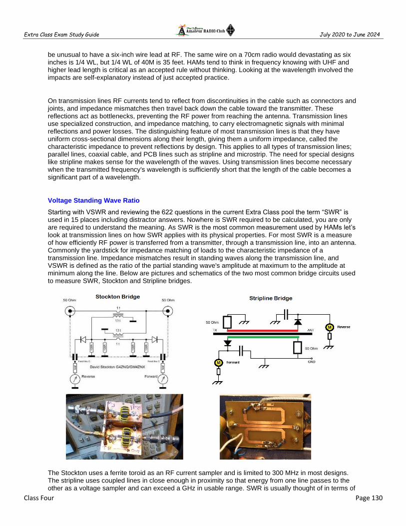
Extra Class Exam Study Guide July 2020 to June 2024
Class Four Page 130
be unusual to have a six-inch wire lead at RF. The same wire on a 70cm radio would devastating as six inches is 1/4 WL, but 1/4 WL of 40M is 35 feet. HAMs tend to think in frequency knowing with UHF and higher lead length is critical as an accepted rule without thinking. Looking at the wavelength involved the impacts are self-explanatory instead of just accepted practice.
On transmission lines RF currents tend to reflect from discontinuities in the cable such as connectors and joints, and impedance mismatches then travel back down the cable toward the transmitter. These reflections act as bottlenecks, preventing the RF power from reaching the antenna. Transmission lines use specialized construction, and impedance matching, to carry electromagnetic signals with minimal reflections and power losses. The distinguishing feature of most transmission lines is that they have uniform cross-sectional dimensions along their length, giving them a uniform impedance, called the characteristic impedance to prevent reflections by design. This applies to all types of transmission lines; parallel lines, coaxial cable, and PCB lines such as stripline and microstrip. The need for special designs like stripline makes sense for the wavelength of the waves. Using transmission lines become necessary when the transmitted frequency's wavelength is sufficiently short that the length of the cable becomes a significant part of a wavelength.
Voltage Standing Wave Ratio
Starting with VSWR and reviewing the 622 questions in the current Extra Class pool the term “SWR” is used in 15 places including distractor answers. Nowhere is SWR required to be calculated, you are only are required to understand the meaning. As SWR is the most common measurement used by HAMs let’s look at transmission lines on how SWR applies with its physical properties. For most SWR is a measure of how efficiently RF power is transferred from a transmitter, through a transmission line, into an antenna. Commonly the yardstick for impedance matching of loads to the characteristic impedance of a transmission line. Impedance mismatches result in standing waves along the transmission line, and VSWR is defined as the ratio of the partial standing wave's amplitude at maximum to the amplitude at minimum along the line. Below are pictures and schematics of the two most common bridge circuits used to measure SWR, Stockton and Stripline bridges.
The Stockton uses a ferrite toroid as an RF current sampler and is limited to 300 MHz in most designs. The stripline uses coupled lines in close enough in proximity so that energy from one line passes to the other as a voltage sampler and can exceed a GHz in usable range. SWR is usually thought of in terms of

Extra Class Exam Study Guide July 2020 to June 2024
Class Four Page 131
the maximum and minimum AC voltages along the transmission line, thus called the voltage standing wave ratio, however both circuits use reference loads, typically 50 Ohms, to become forward and reverse power meters.
The magic comes as a ratio SWR can be determined from voltage, power or impedances.
Coefficient of Reflection
The Reflection Coefficient (Γ) indicates is the ratio of the reflected wave to that of the incident wave by
an impedance discontinuity in the transmission medium. It is a ratio of the amplitude of the reflected wave to the forward wave. The reflection coefficient depends on the load impedance and the impedance of the transmission line. Although this is starting to sound like SWR the reflection coefficient is different than the VSWR. The reflection coefficient quantifies the level of the incident waveform that is reflected, whereas the standing wave ratio, be it a current standing wave ratio or a voltage standing wave ratio looks at the ratio of the peak and minimum voltage or current levels within the feeder arising from the forward and reflected power.
The Reflection Coefficient (Γ) is not SWR but does have a direct relationship if you look closely at he
formula below.

Extra Class Exam Study Guide July 2020 to June 2024
Class Four Page 132
At this point, you should begin to understand the importance of impedance matching: grossly mismatched impedances will lead to most of the power reflected away from the load. The tablebelow show the real-world relationships between; SWR, Reflection Coefficient, Return Loss, Forward Power, Reflected Power and Radiated Power.
Rectangular Coordinates
Sometimes SWR does not provide enough information you want to match or tune the antenna for maximum radiation. The maximum power theorem says that maximum power is transferred from source to load when the load resistance equals the source resistance and the load reactance equals the negative of the source reactance. It is necessary to have more details on the antenna impedance which is equivalent to a resistance in series with a reactance expressed as a complex number. The impedance caused by these two effects is collectively referred to as reactance and forms the imaginary part of complex impedance whereas resistance forms the real part. The complex number, with resistance is the ohms plus reactance in ohms. The reactance can be positive (Inductive) or negative (capacitive), written R + j.
In Rectangular Coordinates impedance is written R + j. In the example below 50 Ohms resistive with 80 Ohms inductive load would be R40 Ω + j80 Ω or common practice is R40+j80.

Extra Class Exam Study Guide July 2020 to June 2024
Class Four Page 133
What is meant by "happy transmitter" is the concept that an antenna tuner presents a resistive load of 50 ohms to a transmitter. An indoor antenna tuner, and your antenna is a 5:1 match for your frequency 7 MHz, and the tuner brings it down to 1.0:1, but you do not get the same transfer of power to the antenna as you would if the tuner was remote at the antenna. The indoor tuner will deliver about 40W to the antenna but a remote tuner would provide 98W to the antenna. Remote tuners or antenna matching networks are always significantly better matching techniques. Rectangular Coordinates impedance information is required to design an antenna feedpoint matching network.
Polar Coordinates
Another way of stating a complex load impedance is with the concept of magnitude and phase, unlike resistance, which has only magnitude. The previous example antenna impedance was R40 + j80 would be Z90 Ohms, 60 Degrees. When a circuit is driven with direct current (DC), there is no distinction between impedance and resistance; the latter can be thought of as impedance with zero phase angle. The notion of impedance is useful for performing AC analysis of electrical networks, because it allows relating sinusoidal voltages and currents by a simple linear law.
Magnitude of the complex impedance is the ratio of the voltage amplitude to the current amplitude
Phase of the complex impedance is the phase shift by which the current lags the voltage

Extra Class Exam Study Guide July 2020 to June 2024
Class Four Page 134
Smith Charts
The Smith chart, invented by Phillip H. Smith (1905–1987) in 1939 is a graphical calculator designed for electrical engineers specializing in RF design to assist in solving problems with transmission lines and matching circuits. A Smith chart can be used to perform an impedance match by bringing impedance to the center of the chart, which corresponds to a pure resistance of 50 Ω by adjusting the reactance values. This is achieved by designing a matching network, between the feed line and the antenna.
Consider that in 1939 computers as we know them today did not exists and only mechanical analog computers were the only alternative to pen and paper. The engineers did have the slide rule, an analog computer, as the desktop calculator until the 1970’s to perform multiplication and division, and also for functions such as exponents, roots, logarithms, and trigonometry, but typically not for addition or subtraction. The slide rule is no longer used but the Smith Chart is still popular likely because it provides a visualization of the complexity of transmission lines and matching solutions. Smith Chart displays are still used today as paper plots just like SWR vs frequency plots and displays screen in Vector Network Analyzers and finite element antenna modeling.
Smith Charts are very intimidating, as they appear to have lines going everywhere. All those lines in the Smith Chart presents in one picture the complex impedances, SWR, Reflection Coefficient, and Return Loss. The chart has the added advantage of being a graphical tool for determining matching solutions. Smith Charts have the advantage of all information about the circuit is visible at once and no math is required. You do everything graphically, plot vectors and read the solution from the chart. For example, the transmission line length, adding discrete capacitors or inductors and even stub matching graphically. Essentially, everything you might need to know about is always right in front of you
Smith Chart
Resistance axis (only R straight line)
Resistance Circles (from Rt to Lt)
Reactance Arcs
Wavelengths are on outer circle edge
Reactance Circle is outer edge of circle
SWR Circles (from center out)

Extra Class Exam Study Guide July 2020 to June 2024
Class Four Page 135
Below is a Smith Chart showing the previous example antenna impedance was R40 + j80 at the “1 PM” position and the transmitter at the center. The desire is matching the R40 + j80 to a RG58 / 50 Ohm resistive transmitter but using a Smith Chart.
Now we can look at designing a network to insert between them so that proper impedance matching occurs using the Smith Chart. Many solutions will do the job so it it better to pick a starting point based on practical considerations like as filter type structure, quality factor, and limited choice of components. The approach chosen to accomplish this calls for adding series and shunt elements on the Smith chart until the desired impedance is achieved. Graphically, it appears as finding a way to link the points on the Smith chart. Reactance components follow a simple set of rules on the chart;
Series components follow lines of resistance (right to left
increasing diameter circles)
Parallel components follow lines of reactance (left to right increasing diameter circles)
Length of the arc is equal to the component’s reactance at
frequency in Ohms
Inductive is upward capacitive is downward

Extra Class Exam Study Guide July 2020 to June 2024
Class Four Page 136
Again, we want to match the R40 + j80 to a RG58 / 50 Ohm resistive 7 MHz transmitter at the center of the chart. To illustrate the approach a series capacitor is selected because I can see a downward arc on the resistive circle will bring us close to center as shown below;
With the first the value of capacitance at 282pF the result impedance presented to the transmitter output is R40 + j0 for a SWR 1.25:1 From this point there are no series or parallel component additions that would result in a 50 Ohm match. The two simple options are a parallel capacitor or inductor, both require a different value for the series capacitor shown at 282 pF.
Choosing to use an inductor in parallel to replicate the more common antenna tuner configuration means a greater capacitive reactance value will be required as the inductor arc will be upward and counter-clockwise. The capacitor was 282 pF @ 7 MHz = 80 Ohms but more reactance requires the capacitance to decrease in a series circuit to 227 pF @ 7 MHz = 100 Ohms as shown below;

Extra Class Exam Study Guide July 2020 to June 2024
Class Four Page 137
The addition of an inductor in shunt means a to move in the counter-clockwise direction on the admittance Smith chart until the value is found return a solution at the pure resistance line of the chart. After drawing the arc the arc length can be read from the scale. The final step is converting form reactance in Ohm to microhenries for the 7 MHz operating frequency, 2.27 uH.
The use of Smith Charts allows the graphical solution to transmission line and match network problems without the algebra or trigonometry. If the drawing of arc’s and reading scales is still intimidating than the equations required for the same solutions are shown below.
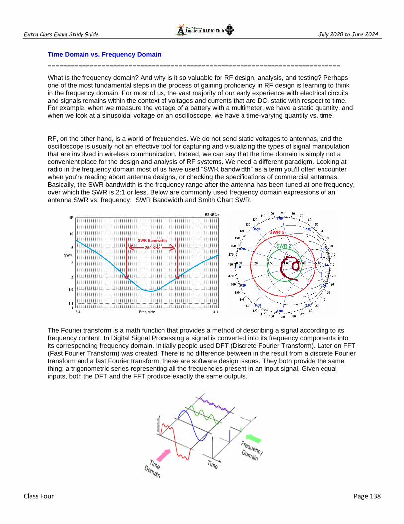
Extra Class Exam Study Guide July 2020 to June 2024
Class Four Page 138
Time Domain vs. Frequency Domain
============================================================================
What is the frequency domain? And why is it so valuable for RF design, analysis, and testing? Perhaps one of the most fundamental steps in the process of gaining proficiency in RF design is learning to think in the frequency domain. For most of us, the vast majority of our early experience with electrical circuits and signals remains within the context of voltages and currents that are DC, static with respect to time. For example, when we measure the voltage of a battery with a multimeter, we have a static quantity, and when we look at a sinusoidal voltage on an oscilloscope, we have a time-varying quantity vs. time.
RF, on the other hand, is a world of frequencies. We do not send static voltages to antennas, and the oscilloscope is usually not an effective tool for capturing and visualizing the types of signal manipulation that are involved in wireless communication. Indeed, we can say that the time domain is simply not a convenient place for the design and analysis of RF systems. We need a different paradigm. Looking at radio in the frequency domain most of us have used “SWR bandwidth” as a term you'll often encounter when you're reading about antenna designs, or checking the specifications of commercial antennas. Basically, the SWR bandwidth is the frequency range after the antenna has been tuned at one frequency, over which the SWR is 2:1 or less. Below are commonly used frequency domain expressions of an antenna SWR vs. frequency; SWR Bandwidth and Smith Chart SWR.
The Fourier transform is a math function that provides a method of describing a signal according to its frequency content. In Digital Signal Processing a signal is converted into its frequency components into its corresponding frequency domain. Initially people used DFT (Discrete Fourier Transform). Later on FFT (Fast Fourier Transform) was created. There is no difference between in the result from a discrete Fourier transform and a fast Fourier transform, these are software design issues. They both provide the same thing: a trigonometric series representing all the frequencies present in an input signal. Given equal inputs, both the DFT and the FFT produce exactly the same outputs.

Extra Class Exam Study Guide July 2020 to June 2024
Class Four Page 139
Editor’s note: Fourier analysis of the wave pictured above shows each wave is made up of a sine wave
plus a combination of harmonics. A Square wave is made up of a sine wave plus all of its odd harmonic A Saw Tooth wave is made up of a sine wave plus all of its harmonics and a Triangle wave is a more complex.
Digital signal processing is an analog-to-digital converter (ADC) converts the continuously variable analog signal into a discrete digital signal, the digital data is processed (changed in some useful way) and then a digital-to-analog converter (DAC) converts the digital signal back into an analog signal. Digital signal processing organizes signals into a frequency domain, the frequencies may be filtered in many different ways. For example, all frequencies above a desired cutoff value can be digitally eliminated (amplitude value set to zero), and all frequencies below a different cutoff value can be similarly eliminated, thereby leaving only a narrowed desired band of frequencies, as listed below;
Filter out RF noise Filter out undesirable IF mixing products from the IF passband Baseband notch filter, audio mixers, equalizers, compressors or expanders Voice Shaping or Voice Speech Processor Pantograph, Spectrum Analyzer, Waterfall Display (Frequency Domain Information)
DSP is used everywhere in all kinds of communications and the benefit of DSP is the data is transformed from RF to data without adding noise or errors from the conversion process. Independent of purpose numbers or demodulated bits; CW, AM, SSB, FM, FSK, PSK, MFSK (8, 16, 32, 64) Phase Modulator / Demodulators. Beyond to do to implement a digital signal processing system is come up with an equation that expresses the signal we'd like in terms of the signal we've got. DSP to do any of the following:
CW, SSTV, RTTY, PSK & QPSK (31, 63, 125) PACTOR, Hell, Oliva Data Encoder / Decoder Callsign Extraction, Beacon Monitor…and other unbounded possibilities.

Extra Class Exam Study Guide July 2020 to June 2024
Class Four Page 140
Vector Antenna Analyzer and Vector Network Analyzer (VNA) are a special form of DSP transceiver that measure both amplitude and phase of the fundamental and harmonics measurement systems. Network analyzers are used at RF frequencies operating frequencies can range from 5 Hz to 5 GHz. Using this fundamental signal information, microprocessors compute; VSWR, Reflection Coefficient, Return Loss, Forward Power, Reflected Power, Radiated Power, Rectangular Coordinates, Polar notation, Vectors, and Smith Charts.
A vector network analyzer (VNA) is a test system that enables the RF performance of radio frequency and microwave devices to be characterized in terms of network scattering parameters, or S parameters. The VNA creates a signal and based on the received signal characterizes the device under test. S-parameters that describe transmission, such as S21, are analogous to other familiar terms including gain, insertion loss, or attenuation. S-parameters that describe reflection, such as S11, correspond to voltage standing wave ratio (VSWR), return loss, or reflection coefficient.

Extra Class Exam Study Guide July 2020 to June 2024
Class Four Page 141
============================================================================
E5D AC and RF energy in real circuits
============================================================================
Wattless, nonproductive power is REACTIVE POWER
REACTIVE POWER in an AC circuit is exchanged between magnetic and electric fields, but is not dissipated
The true power be determined in an AC circuit where the voltage and current are out of phase by multiplying the apparent power by the power factor
POWER FACTOR = Real Power (Watts) / Total Power (V x A)
POWER FACTOR = COS of (Voltage to Current) Phase
Editor’s Note: "Real"a.k.a. True power is power that does actual work - e.g: creating heat, lifting loads, etc. "Reactive power" is power where the current is out of phase with the voltage, and the "Volts x amps" doesn't do any real work. Current that charges a capacitor, for example or current that creates the magnetic field around a coil for another. "Apparent power" is the mathematical combination of these two.
============================================================================
E5D05 (C) What is the power factor of an RL circuit having a 30-degree phase angle between the voltage and the current? A. 1.73 B. 0.5 C. 0.866 D. 0.577
PF = COS 30° = 0.866
Extra Class Exam Study Guide July 2020 to June 2024
Class Four Page 142
E5D07 (B) How many watts are consumed in a circuit having a power factor of 0.71 if the apparent power is 500VA? A. 704 W B. 355 W C. 252 W D. 1.42 mW
POWER FACTOR = Real Power (True Watts) / Total Power (V x A)
or
Real Power = PF x Total Power
Real Power = 0.71 x VA
Real Power = 0.71 x 500
Real Power = 355 W
E5D08 (D) How many watts are consumed in a circuit having a power factor of 0.6 if the input is 200VAC at 5 amperes? A. 200 watts B. 1000 watts C. 1600 watts D. 600 watts
POWER FACTOR = Real Power (True Watts) / Total Power (V x A)
or
Real Power = PF x Total Power
Real Power = 0.6 x VA
Real Power = 0.6 x (200V X 5A)
Real Power = 0.6 x 1000VA
Real Power = 600 W
E5D11 (C) What is the power factor of an RL circuit having a 60-degree phase angle between the voltage and the current? A. 1.414 B. 0.866 C. 0.5 D. 1.73
PF = COS 60° = 0.5
E5D12 (B) How many watts are consumed in a circuit having a power factor of 0.2 if the input is 100 VAC at 4 amperes? A. 400 watts B. 80 watts C. 2000 watts D. 50 watts
POWER FACTOR = Real Power (True Watts) / Total Power (V x A)
or
Real Power = PF x Total Power
Real Power = 0.2 x VA
Real Power = 0.2 x (100V X 4A)
Real Power = 0.2 x 400VA
Real Power = 80 W
E5D13 (B) How many watts are consumed in a circuit consisting of a 100-ohm resistor in series with a 100-ohm inductive reactance drawing 1 ampere? A. 70.7 watts B. 100 watts C. 141.4 watts D. 200 watts
Trick question Resistor only has Real Power
W = I2 R >> Ohms Law
W = 12 x 100
W = 100 W

Extra Class Exam Study Guide July 2020 to June 2024
Class Four Page 143
E5D15 (D) What is the power factor of an RL circuit having a 45-degree phase angle between the voltage and the current? A. 0.866 B. 1.0 C. 0.5 D. 0.707
PF = COS 45° = 0.707
============================================================================
SKIN EFFECT >> As frequency increases, RF current flows closer to the surface of the conductor
Editor’s Note: skin effect is why the resistance at RF currents is different at DC
Precision printed circuit conductors above a ground plane that provide constant impedance interconnects at microwave frequencies is a microstrip
Short connections used at microwave frequencies to reduce phase shift along the connection
To avoid unwanted inductive reactance, it is important to keep lead lengths short for components used in circuits for VHF and above
Editor’s Note: Microstrip construction is typically used to construct a MMIC based microwave amplifier
MAGNETIC FIELD is in a circle around a conductor

Extra Class Exam Study Guide July 2020 to June 2024
Class Four Page 144
============================================================================
E5D01 (A) What is the result of skin effect? A. As frequency increases, RF current flows in a thinner layer of the conductor, closer to the surface B. As frequency decreases, RF current flows in a thinner layer of the conductor, closer to the surface C. Thermal effects on the surface of the conductor increase the impedance D. Thermal effects on the surface of the conductor decrease the impedance
E5D02 (B) Why is it important to keep lead lengths short for components used in circuits for VHF and above? A. To increase the thermal time constant B. To avoid unwanted inductive reactance C. To maintain component lifetime D. All these choices are correct
E5D03 (D) What is microstrip? A. Lightweight transmission line made of common zip cord B. Miniature coax used for low power applications C. Short lengths of coax mounted on printed circuit boards to minimize time delay between microwave circuits D. Precision printed circuit conductors above a ground plane that provide constant impedance interconnects at microwave frequencies
E5D04 (B) Why are short connections used at microwave frequencies? A. To increase neutralizing resistance B. To reduce phase shift along the connection C. To increase compensating capacitance D. To reduce noise figure
E5D06 (D) In what direction is the magnetic field oriented about a conductor in relation to the direction of electron flow? A. In the same direction as the current B. In a direction opposite to the current C. In all directions; omni-directional D. In a circle around the conductor
E5D09 (B) What happens to reactive power in an AC circuit that has both ideal inductors and ideal capacitors? A. It is dissipated as heat in the circuit B. It is repeatedly exchanged between the associated magnetic and electric fields, but is not dissipated C. It is dissipated as kinetic energy in the circuit D. It is dissipated in the formation of inductive and capacitive fields
E5D10 (A) How can the true power be determined in an AC circuit where the voltage and current are out of phase? A. By multiplying the apparent power by the power factor B. By dividing the reactive power by the power factor C. By dividing the apparent power by the power factor D. By multiplying the reactive power by the power factor
E5D14 (A) What is reactive power? A. Wattless, nonproductive power B. Power consumed in wire resistance in an inductor C. Power lost because of capacitor leakage D. Power consumed in circuit Q
============================================================================

Extra Class Exam Study Guide July 2020 to June 2024
Class Four Page 145
E5A Resonance and Q
============================================================================
Resonance is the frequency at which the capacitive reactance equals the inductive reactance
Resonance can cause the voltage across reactances in series to be larger than the voltage applied to them
The magnitude of the impedance of a circuit with an RLC all in parallel, at resonance is equal to circuit resistance (looks like R)
The MAXIMUM CIRCULATING current of a parallel LC circuit occurs at resonance within the components
MINIMUM current is at the INPUT of a parallel RLC circuit as the frequency is resonance
The voltage and current are in phase across a series resonant circuit at resonance
The voltage and current are in phase across a parallel resonant circuit at resonance

Extra Class Exam Study Guide July 2020 to June 2024
Class Four Page 146
Increasing the Q of an impedance-matching circuit decreases the bandwidth
Increasing Q in a series resonant circuit increases the internal voltages
Lower losses increase Q for inductors and capacitors
RLC parallel resonant circuit Q = Resistance / Reactance = R / X
RLC series resonant circuit Q = / Reactance / Resistance = X / R
Half Power Bandwidth = Resonant Frequency / Q of the Circuit

Extra Class Exam Study Guide July 2020 to June 2024
Class Four Page 147
============================================================================
E5A01 (A) What can cause the voltage across reactances in a series RLC circuit to be higher than the voltage applied to the entire circuit? A. Resonance B. Capacitance C. Conductance D. Resistance
E5A02 (C) What is resonance in an LC or RLC circuit? A. The highest frequency that will pass current B. The lowest frequency that will pass current C. The frequency at which the capacitive reactance equals the inductive reactance D. The frequency at which the reactive impedance equals the resistive impedance
E5A03 (D) What is the magnitude of the impedance of a series RLC circuit at resonance? A. High, as compared to the circuit resistance B. Approximately equal to capacitive reactance C. Approximately equal to inductive reactance D. Approximately equal to circuit resistance
E5A04 (A) What is the magnitude of the impedance of a parallel RLC circuit at resonance? A. Approximately equal to circuit resistance B. Approximately equal to inductive reactance C. Low compared to the circuit resistance D. High compared to the circuit resistance
E5A05 (A) What is the result of increasing the Q of an impedance-matching circuit? A. Matching bandwidth is decreased B. Matching bandwidth is increased C. Matching range is increased D. It has no effect on impedance matching
E5A06 (B) What is the magnitude of the circulating current within the components of a parallel LC circuit at resonance? A. It is at a minimum B. It is at a maximum C. It equals 1 divided by the quantity 2 times pi, multiplied by the square root of inductance L multiplied by capacitance C D. It equals 2 multiplied by pi, multiplied by frequency, multiplied by inductance
E5A07 (A) What is the magnitude of the current at the input of a parallel RLC circuit at resonance? A. Minimum B. Maximum C. R/L D. L/R
E5A08 (C) What is the phase relationship between the current through and the voltage across a series resonant circuit at resonance? A. The voltage leads the current by 90 degrees B. The current leads the voltage by 90 degrees C. The voltage and current are in phase D. The voltage and current are 180 degrees out of phase
E5A09 (C) How is the Q of an RLC parallel resonant circuit calculated? A. Reactance of either the inductance or capacitance divided by the resistance B. Reactance of either the inductance or capacitance multiplied by the resistance C. Resistance divided by the reactance of either the inductance or capacitance D. Reactance of the inductance multiplied by the reactance of the capacitance
E5A10 (A) How is the Q of an RLC series resonant circuit calculated? A. Reactance of either the inductance or capacitance divided by the resistance B. Reactance of either the inductance or capacitance multiplied by the resistance C. Resistance divided by the reactance of either the inductance or capacitance D. Reactance of the inductance multiplied by the reactance of the capacitance
E5A13 (C) What is an effect of increasing Q in a series resonant circuit? A. Fewer components are needed for the same performance B. Parasitic effects are minimized C. Internal voltages increase D. Phase shift can become uncontrolled
E5A15 (A) Which of the following increases Q for inductors and capacitors? A. Lower losses B. Lower reactance C. Lower self-resonant frequency D. Higher self-resonant frequency
E5A11 (C) What is the half-power bandwidth of a resonant circuit that has a resonant frequency of 7.1 MHz and a Q of 150? A. 157.8 Hz B. 315.6 Hz C. 47.3 kHz D. 23.67 kHz
Half Power BW = Resonant Frequency / Q of the Circuit
F = Fr / Q
F = 7.1 MHz / 150
F = 7100 KHz / 150
F = 47.333 KHz
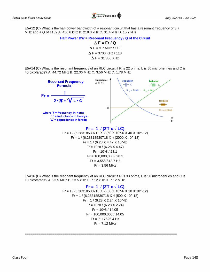
Extra Class Exam Study Guide July 2020 to June 2024
Class Four Page 148
E5A12 (C) What is the half-power bandwidth of a resonant circuit that has a resonant frequency of 3.7 MHz and a Q of 118? A. 436.6 kHz B. 218.3 kHz C. 31.4 kHz D. 15.7 kHz
Half Power BW = Resonant Frequency / Q of the Circuit
F = Fr / Q
F = 3.7 MHz / 118
F = 3700 KHz / 118
F = 31.356 KHz
E5A14 (C) What is the resonant frequency of an RLC circuit if R is 22 ohms, L is 50 microhenries and C is 40 picofarads? A. 44.72 MHz B. 22.36 MHz C. 3.56 MHz D. 1.78 MHz
Fr = 1 / (2 x √ LC) Fr = 1 / (6.28318530718 X √ (50 X 10^-6 X 40 X 10^-12)
Fr = 1 / (6.28318530718 X √ (2000 X 10^-18)
Fr = 1 / (6.28 X 4.47 X 10^-8)
Fr = 10^8 / (6.28 X 4.47)
Fr = 10^8 / 28.1
Fr = 100,000,000 / 28.1
Fr = 3,558,812.7 Hz
Fr = 3.56 MHz
E5A16 (D) What is the resonant frequency of an RLC circuit if R is 33 ohms, L is 50 microhenries and C is 10 picofarads? A. 23.5 MHz B. 23.5 kHz C. 7.12 kHz D. 7.12 MHz
Fr = 1 / (2 x √ LC) Fr = 1 / (6.28318530718 X √ (50 X 10^-6 X 10 X 10^-12)
Fr = 1 / (6.28318530718 X √ (500 X 10^-18)
Fr = 1 / (6.28 X 2.24 X 10^-8)
Fr = 10^8 / (6.28 X 2.24)
Fr = 10^8 / 14.05
Fr = 100,000,000 / 14.05
Fr = 7117625.4 Hz
Fr = 7.12 MHz
============================================================================

Extra Class Exam Study Guide July 2020 to June 2024
Class Four Page 149
E5B Time constants and phase relationships
============================================================================
Resistance & Conductance
Conductance is the reciprocal of Resistance: G = 1/R
Reactance & Susceptance
Susceptance is the reciprocal of Reactance: B = 1/X
Impedance & Admittance
Admittance is the reciprocal of Impedance: Y = 1/Z
Susceptance is the imaginary part of admittance
One time constant is the time required for the capacitor in an RC circuit to charge 63.2%
One time constant is the time required for a charged capacitor in an RC circuit to discharge to 36.8%
The capacitor in an RC circuit is discharged to 13.5% of the starting voltage after two-time constants
One time constant = TC (sec) = R (MΩ) x C (uF) Check your decimal point!
Editor’s note: When a voltage is applied to a capacitor through a resistance (all circuits have resistance) it takes time for the voltage across the capacitor to reach the applied voltage. At the instant the voltage is applied the current in the circuit is at a maximum limited only by the circuit resistance. As time passes the voltage across the capacitor rises and the current decreases until the capacitor charge reaches the applied voltage at which point the current goes to zero. - AD7FO
============================================================================
E5B01 (B) What is the term for the time required for the capacitor in an RC circuit to be charged to 63.2% of the applied voltage or to discharge to 36.8% of its initial voltage? A. An exponential rate of one B. One time constant C. One exponential period D. A time factor of one
E5B02 (D) What letter is commonly used to represent susceptance? A. G B. X C. Y D. B

Extra Class Exam Study Guide July 2020 to June 2024
Class Four Page 150
E5B04 (D) What is the time constant of a circuit having two 220-microfarad capacitors and two 1-megohm resistors, all in parallel? A. 55 seconds B. 110 seconds C. 440 seconds D. 220 seconds
One time constant = TC (sec) = R (MΩ) x C (uF) Check your decimal point!
TC (sec) = R (MΩ) x C (uF)
TC = 0.5 x 440
TC = 220 Sec
E5B05 (D) What happens to the magnitude of a pure reactance when it is converted to a susceptance? A. It is unchanged B. The sign is reversed C. It is shifted by 90 degrees D. It becomes the reciprocal
E5B06 (C) What is susceptance? A. The magnetic impedance of a circuit B. The ratio of magnetic field to electric field C. The imaginary part of admittance D. A measure of the efficiency of a transformer
E5B12 (A) What is admittance? A. The inverse of impedance B. The term for the gain of a field effect transistor C. The turns ratio of a transformer D. The inverse of Q factor
=============================================================================
Voltage same as Current phase angle in a Resistor
Voltage leads current by 90 deg through an inductor
Current leads voltage by 90 deg through a capacitor
“ELI the ICE man” Inductors – voltage (E) leads current (I)
Capacitors – current (I) leads voltage (E)

Extra Class Exam Study Guide July 2020 to June 2024
Class Four Page 151
=============================================================================
E5B09 (D) What is the relationship between the AC current through a capacitor and the voltage across a capacitor? A. Voltage and current are in phase B. Voltage and current are 180 degrees out of phase C. Voltage leads current by 90 degrees D. Current leads voltage by 90 degrees
E5B10 (A) What is the relationship between the AC current through an inductor and the voltage across an inductor? A. Voltage leads current by 90 degrees B. Current leads voltage by 90 degrees C. Voltage and current are 180 degrees out of phase D. Voltage and current are in phase
=============================================================================
Editor’s note: EYEBALL ESTIMATING The problems on the exam are traditionally solved using
trigonometry as shown above. An alternative method is to solve graphically. The first step in using a
graphical method is visually estimating angles. The diagrams below show the quadrants are each 90 .
Dividing the quadrant is 45. The center and right graphs show ~ 15 increments can be estimated by eye to select the correct exam answer.
Editor’s note: The second step is to determine the net reactance graphically. The inductance is shown as positive and capacitance is negative on the graph. Example XC = 500 Ohms combined with XL = 250 Ohms. 500 is down combined with 250 equals 250 down.

Extra Class Exam Study Guide July 2020 to June 2024
Class Four Page 152
Editor’s note: The third step is to determine the vector graphically. EYEBALL ESTIMATED
============================================================================
E5B07 (C) What is the phase angle between the voltage across and the current through a series RLC circuit if XC is 500 ohms, R is 1 kilohm, and XL is 250 ohms? A. 68.2 degrees with the voltage leading the current B. 14.0 degrees with the voltage leading the current C. 14.0 degrees with the voltage lagging the current D. 68.2 degrees with the voltage lagging the current
R = 1000 Ohms combined with XC = 250 Ohms. The resulting vector is negative (capacitive ICE)
and eyeball estimated at -15 vs. the math solution -14.
Current leads voltage by 90 deg through a capacitor
A. 68.2 V lead
B. 14.0 V lead
C. 14.0 V lag
D. 68.2 V lag

Extra Class Exam Study Guide July 2020 to June 2024
Class Four Page 153
E5B08 (A) What is the phase angle between the voltage across and the current through a series RLC circuit if XC is 100 ohms, R is 100 ohms, and XL is 75 ohms? A. 14 degrees with the voltage lagging the current B. 14 degrees with the voltage leading the current C. 76 degrees with the voltage leading the current D. 76 degrees with the voltage lagging the current
Θ = tan^-1 [(250-500)/1000]
Θ = tan^-1 [(-250)/1000]
Θ = tan^-1 (-0.25) = -14.036°
The vector is negative (capacitive ICE) and eyeball estimated at -15 vs. the math solution -14.
Current leads voltage by 90 deg through a capacitor
E5B09 (D) What is the relationship between the AC current through a capacitor and the voltage across a capacitor? A. Voltage and current are in phase B. Voltage and current are 180 degrees out of phase C. Voltage leads current by 90 degrees D. Current leads voltage by 90 degrees
Voltage same as Current phase angle in a Resistor
Voltage leads current by 90 deg through an inductor
Current leads voltage by 90 deg through a capacitor
E5B10 (A) What is the relationship between the AC current through an inductor and the voltage across an inductor? A. Voltage leads current by 90 degrees B. Current leads voltage by 90 degrees C. Voltage and current are 180 degrees out of phase D. Voltage and current are in phase
Voltage same as Current phase angle in a Resistor
Voltage leads current by 90 deg through an inductor
Current leads voltage by 90 deg through a capacitor

Extra Class Exam Study Guide July 2020 to June 2024
Class Four Page 154
E5B11 (B) What is the phase angle between the voltage across and the current through a series RLC circuit if XC is 25 ohms, R is 100 ohms, and XL is 50 ohms? A. 14 degrees with the voltage lagging the current B. 14 degrees with the voltage leading the current C. 76 degrees with the voltage lagging the current D. 76 degrees with the voltage leading the current
Θ = tan^-1 [(50-25)/100]
Θ = tan^-1 (+0.25)
Θ = +14.036°
The vector is Positive (inductive ELI) and eyeball estimated at +15 vs. the math solution +14.
Voltage leads current by 90 deg through an inductor
E5B03 (B) How is impedance in polar form converted to an equivalent admittance? A. Take the reciprocal of the angle and change the sign of the magnitude B. Take the reciprocal of the magnitude and change the sign of the angle C. Take the square root of the magnitude and add 180 degrees to the angle D. Square the magnitude and subtract 90 degrees from the angle
============================================================================
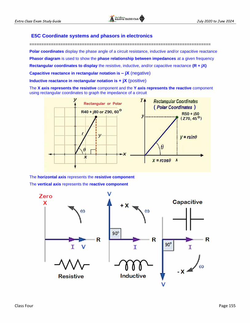
Extra Class Exam Study Guide July 2020 to June 2024
Class Four Page 155
E5C Coordinate systems and phasors in electronics
============================================================================
Polar coordinates display the phase angle of a circuit resistance, inductive and/or capacitive reactance
Phasor diagram is used to show the phase relationship between impedances at a given frequency
Rectangular coordinates to display the resistive, inductive, and/or capacitive reactance (R + jX)
Capacitive reactance in rectangular notation is – jX (negative)
Inductive reactance in rectangular notation is + jX (positive)
The X axis represents the resistive component and the Y axis represents the reactive component using rectangular coordinates to graph the impedance of a circuit
The horizontal axis represents the resistive component
The vertical axis represents the reactive component

Extra Class Exam Study Guide July 2020 to June 2024
Class Four Page 156
============================================================================
E5C01 (A) Which of the following represents capacitive reactance in rectangular notation? A. -jX B. +jX C. Delta D. Omega
E5C02 (C) How are impedances described in polar coordinates? A. By X and R values B. By real and imaginary parts C. By phase angle and magnitude D. By Y and G values
E5C03 (C) Which of the following represents an inductive reactance in polar coordinates? A. A positive magnitude B. A negative magnitude C. A positive phase angle D. A negative phase angle
E5C04 (D) What coordinate system is often used to display the resistive, inductive, and/or capacitive reactance components of impedance? A. Maidenhead grid B. Faraday grid C. Elliptical coordinates D. Rectangular coordinates
E5C05 (C) What is the name of the diagram used to show the phase relationship between impedances at a given frequency? A. Venn diagram B. Near field diagram C. Phasor diagram D. Far field diagram
E5C06 (B) What does the impedance 50-j25 represent? A. 50 ohms resistance in series with 25 ohms inductive reactance B. 50 ohms resistance in series with 25 ohms capacitive reactance C. 25 ohms resistance in series with 50 ohms inductive reactance D. 25 ohms resistance in series with 50 ohms capacitive reactance
E5C07 (D) Where is the impedance of a pure resistance plotted on rectangular coordinates? A. On the vertical axis B. On a line through the origin, slanted at 45 degrees C. On a horizontal line, offset vertically above the horizontal axis D. On the horizontal axis
E5C08 (D) What coordinate system is often used to display the phase angle of a circuit containing resistance, inductive and/or capacitive reactance? A. Maidenhead grid B. Faraday grid C. Elliptical coordinates D. Polar coordinates
E5C09 (A) When using rectangular coordinates to graph the impedance of a circuit, what do the axes represent? A. The X axis represents the resistive component and the Y axis represents the reactive component B. The X axis represents the reactive component and the Y axis represents the resistive component C. The X axis represents the phase angle and the Y axis represents the magnitude D. The X axis represents the magnitude and the Y axis represents the phase angle

Extra Class Exam Study Guide July 2020 to June 2024
Class Four Page 157
E5C10 (B) Which point on Figure E5-1 best represents the impedance of a series circuit consisting of a 400-ohm resistor and a 38-picofarad capacitor at 14 MHz? A. Point 2 B. Point 4 C. Point 5 D. Point 6
R = 400 & X
= 1/ (2 π FC) = X
= 1/ (2 x π x MHz x uF)
= 1/0.0033427
= -299.16 Ω
400 R – 300 j
Editor’s note: Solving the question graphically
requires the process of elimination. The R=400
has three possible point in Figure 5-1, points: 2,
4, 6. The reactance is given as a capacitance
and frequency. Point 4 is the answer as the only
negative (capacitive) point of the three points.
FYI only 1, 3 & 4 are correct answers in the test
pool questions.
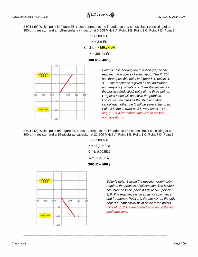
Extra Class Exam Study Guide July 2020 to June 2024
Class Four Page 158
E5C11 (B) Which point in Figure E5-1 best represents the impedance of a series circuit consisting of a 300-ohm resistor and an 18-microhenry inductor at 3.505 MHz? A. Point 1 B. Point 3 C. Point 7 D. Point 8
R = 300 & X
X = 2 π FL
X = 2 x π x MHz x uH
X = 396.41 Ω
300 R + 400 j
E5C12 (A) Which point on Figure E5-1 best represents the impedance of a series circuit consisting of a 300-ohm resistor and a 19-picofarad capacitor at 21.200 MHz? A. Point 1 B. Point 3 C. Point 7 D. Point 8
R = 300 & X
X = 1/ (2 π FC)
X = 1/ 0.002531
X = -395.12 Ω
300 R – 400 j
============================================================================
Editor’s note: Solving the question graphically
requires the process of elimination. The R=300
has three possible point in Figure 5-1, points: 1,
3, 8. The reactance is given as an inductance
and frequency. Points 3 or 8 are the answer as
the positive (inductive) point of the three points.
Graphics alone will not solve the problem.
Logical can be used as the MHz and Mico
cancel each other the X will be several hundred.
Point 3 is the answer as 8 is very small. FYI
only 1, 3 & 4 are correct answers in the test
pool questions.
Editor’s note: Solving the question graphically
requires the process of elimination. The R=300
has three possible point in Figure 5-1, points: 1,
3, 8. The reactance is given as a capacitance
and frequency. Point 1 is the answer as the only
negative (capacitive) point of the three points.
FYI only 1, 3 & 4 are correct answers in the test
pool questions.

Extra Class Exam Study Guide July 2020 to June 2024
Class Four Page 159
E9E Matching: matching antennas to feed lines
============================================================================
The DELTA MATCHING system matches a high-impedance transmission line to a lower impedance antenna by connecting the line to the driven element in two places spaced a fraction of a wavelength each side of element center
The gamma match that matches an unbalanced feed line to an antenna by feeding the driven element both at the center of the element and at a fraction of a wavelength to one side of center
A Gamma match is used to shunt-feed a grounded tower at its base
The series capacitor in a gamma matching network cancels the inductive reactance of the matching network
An antenna's driven element capacitive to be tuned to use a hairpin matching system
Editor’s note: Hairpin matching is adding an inductance directly across the feed point of the antenna. The inductance may be a simple U-shaped wire or rods. This U-shape is of course the reason for the name hairpin and many applications of this matching style use that form of inductance.

Extra Class Exam Study Guide July 2020 to June 2024
Class Four Page 160
The stub match uses a section of transmission line connected in parallel with the feed line at or near the feed point
Editor’s note: The universal stub matching technique is an effective way of matching a feed line to a VHF or UHF antenna when the impedances of both the antenna and feed line are unknown
A Wilkinson divider divides power equally among multiple loads while two 50-ohm loads while maintaining 50-ohm input impedance
Insert a 1/4-wavelength piece of 75-ohm coaxial cable transmission line in series between the antenna and the 50-ohm feed cable to match an antenna with 100-ohm feed point impedance to a 50-ohm coaxial cable feed line
The primary purpose of a phasing line when used with an antenna having multiple driven elements is to ensure that each driven element operates in concert with the others to create the desired antenna pattern
Editor’s note: 50-Ω transmission line is to be matched to a resistive load impedance with ZL = 100 Ω via a quarter-wave 75 Ω shown above is a quarter-wave transmission line transformer.
Reflection coefficient describes the interactions at the load end of a mismatched transmission line
Editor’s note: The reflection coefficient is also known as S11 or return loss. Voltage Standing Wave Ratio is a function of the reflection coefficient, which describes the power reflected from the antenna.

Extra Class Exam Study Guide July 2020 to June 2024
Class Four Page 161
============================================================================
E9E01 (B) What system matches a higher-impedance transmission line to a lower-impedance antenna by connecting the line to the driven element in two places spaced a fraction of a wavelength each side of element center? A. The gamma matching system B. The delta matching system C. The omega matching system D. The stub matching system
E9E02 (A) What is the name of an antenna matching system that matches an unbalanced feed line to an antenna by feeding the driven element both at the center of the element and at a fraction of a wavelength to one side of center? A. The gamma match B. The delta match C. The epsilon match D. The stub match
E9E03 (D) What is the name of the matching system that uses a section of transmission line connected in parallel with the feed line at or near the feed point? A. The gamma match B. The delta match C. The omega match D. The stub match
E9E04 (B) What is the purpose of the series capacitor in a gamma-type antenna matching network? A. To provide DC isolation between the feed line and the antenna B. To cancel the inductive reactance of the matching network C. To provide a rejection notch that prevents the radiation of harmonics D. To transform the antenna impedance to a higher value
E9E05 (A) How must an antenna's driven element be tuned to use a hairpin matching system? A. The driven element reactance must be capacitive B. The driven element reactance must be inductive C. The driven element resonance must be lower than the operating frequency D. The driven element radiation resistance must be higher than the characteristic impedance of the transmission line
E9E06 (C) Which of these feed line impedances would be suitable for constructing a quarter-wave Q-section for matching a 100-ohm loop to 50-ohm feed line? A. 50 ohms B. 62 ohms C. 75 ohms D. 450 ohms
E9E07 (B) What parameter describes the interactions at the load end of a mismatched transmission line? A. Characteristic impedance B. Reflection coefficient C. Velocity factor D. Dielectric constant
E9E08 (C) What is a use for a Wilkinson divider? A. It divides the operating frequency of a transmitter signal so it can be used on a lower frequency band B. It is used to feed high-impedance antennas from a low-impedance source C. It is used to divide power equally between two 50-ohm loads while maintaining 50-ohm input impedance D. It is used to feed low-impedance loads from a high-impedance source
E9E09 (C) Which of the following is used to shunt-feed a grounded tower at its base? A. Double-bazooka match B. Hairpin match C. Gamma match D. All these choices are correct
E9E10 (C) Which of these choices is an effective way to match an antenna with a 100-ohm feed point impedance to a 50-ohm coaxial cable feed line? A. Connect a 1/4-wavelength open stub of 300-ohm twinlead in parallel with the coaxial feed line where it connects to the antenna B. Insert a 1/2 wavelength piece of 300-ohm twinlead in series between the antenna terminals and the 50-ohm feed cable C. Insert a 1/4-wavelength piece of 75-ohm coaxial cable transmission line in series between the antenna terminals and the 50-ohm feed cable D. Connect a 1/2 wavelength shorted stub of 75-ohm cable in parallel with the 50-ohm cable where it attaches to the antenna
E9E11 (A) What is the primary purpose of phasing lines when used with an antenna having multiple driven elements? A. It ensures that each driven element operates in concert with the others to create the desired antenna pattern B. It prevents reflected power from traveling back down the feed line and causing harmonic radiation from the transmitter C. It allows single-band antennas to operate on other bands D. It creates a low-angle radiation pattern
============================================================================

Extra Class Exam Study Guide July 2020 to June 2024
Class Four Page 162
E9F Transmission lines
============================================================================
Velocity factor of a transmission line is the transmission line velocity divided by the velocity of light in a vacuum
Electrical signals move more slowly in a coaxial cable than in air
Dielectric has biggest effect on the Velocity Factor of a transmission line
The significant differences between foam-dielectric coaxial cable and solid-dielectric cable are; reduced safe operating voltage limits, reduced losses per unit of length and higher velocity factor
Coaxial cable with solid polyethylene dielectric 0.66 is the typical velocity factor
Ladder line has lower loss than coaxial cable
Ladder line has 1.0is the typical velocity factor
Cable Length = Velocity Factor X [ Speed of Light / Frequency ] X Wavelength of Cable
Editor’s note: The To determine the electrical length of a transmission line you need to multiply the velocity factor of the line (available from the supplier of the line) by the free space length. For the length in feet, this is (983.6 / frequency in MHz) velocity. For the length in meters, this is (299.8 / frequency in MHz) velocity.
Transmission line is any integer multiple of 1/2 wavelength, the impedance equals other end
Transmission line is an odd multiple of 1/4 wavelength, the impedance inverted the other end
Transmission line 1/8 wavelength long, is capacitive with the other end open
Transmission line 1/8 wavelength long, is inductive with the other end shorted
============================================================================
E9F01 (D) What is the velocity factor of a transmission line? A. The ratio of the characteristic impedance of the line to the terminating impedance B. The index of shielding for coaxial cable C. The velocity of the wave in the transmission line multiplied by the velocity of light in a vacuum D. The velocity of the wave in the transmission line divided by the velocity of light in a vacuum
E9F02 (C) Which of the following has the biggest effect on the velocity factor of a transmission line? A. The termination impedance B. The line length C. Dielectric materials used in the line D. The center conductor resistivity

Extra Class Exam Study Guide July 2020 to June 2024
Class Four Page 163
E9F03 (D) Why is the physical length of a coaxial cable transmission line shorter than its electrical length? A. Skin effect is less pronounced in the coaxial cable B. The characteristic impedance is higher in a parallel feed line C. The surge impedance is higher in a parallel feed line D. Electrical signals move more slowly in a coaxial cable than in air
E9F04 (B) What impedance does a 1/2-wavelength transmission line present to a generator when the line is shorted at the far end? A. Very high impedance B. Very low impedance C. The same as the characteristic impedance of the line D. The same as the output impedance of the generator
E9F05 (D) What is the approximate physical length of a solid polyethylene dielectric coaxial transmission line that is electrically 1/4 wavelength long at 14.1 MHz? A. 10.6 meters B. 5.3 meters C. 4.3 meters D. 3.5 meters
Cable Length = VF x WL/4 Cable Length = 0.66 x (300 / 14.1) / 4
Cable Length = 0.66 x (21.28 / 4) Cable Length = 0.66 x 5.319
Cable Length = 3.511 M
E9F06 (C) What is the approximate physical length of an air-insulated, parallel conductor transmission line that is electrically 1/2 wavelength long at 14.10 MHz? A. 7.0 meters B. 8.5 meters C. 10.6 meters D. 13.3 meters
Cable Length = VF x WL/4 Cable Length = 1.0 x (300 / 14.1) / 2
Cable Length = 1.0 x (21.28 / 2) Cable Length = 1.0 x 10.64 Cable Length = 10.64 M
Editor’s note: A transmission line is a pair of parallel conductors exhibiting certain characteristics. Velocity factor is a fractional value relating to a transmission line's propagation at the speed of light in a vacuum.
E9F07 (A) How does ladder line compare to small-diameter coaxial cable such as RG-58 at 50 MHz? A. Lower loss B. Higher SWR C. Smaller reflection coefficient D. Lower velocity factor
E9F08 (D) Which of the following is a significant difference between foam dielectric coaxial cable and solid dielectric cable, assuming all other parameters are the same? A. Foam dielectric has lower safe operating voltage limits B. Foam dielectric has lower loss per unit of length C. Foam dielectric has higher velocity factor D. All these choices are correct
E9F09 (B) What is the approximate physical length of a foam polyethylene dielectric coaxial transmission line that is electrically 1/4 wavelength long at 7.2 MHz? A. 10.4 meters B. 8.3 meters C. 6.9 meters D. 5.2
Cable Length = VF x WL/4 Cable Length = 0.66 x (300 / 7.2) / 4
Cable Length = 0.66 x (41.66 / 4) Cable Length = 0.66 x 10.417
Cable Length = 6.875 M
E9F10 (C) What impedance does a 1/8-wavelength transmission line present to a generator when the line is shorted at the far end? A. A capacitive reactance B. The same as the characteristic impedance of the line C. An inductive reactance D. Zero
E9F11 (C) What impedance does a 1/8-wavelength transmission line present to a generator when the line is open at the far end? A. The same as the characteristic impedance of the line B. An inductive reactance C. A capacitive reactance D. Infinite
E9F12 (D) What impedance does a 1/4-wavelength transmission line present to a generator when the line is open at the far end? A. The same as the characteristic impedance of the line B. The same as the input impedance to the generator C. Very high impedance D. Very low impedance
E9F13 (A) What impedance does a 1/4-wavelength transmission line present to a generator when the line is shorted at the far end? A. Very high impedance B. Very low impedance C. The same as the characteristic impedance of the transmission line D. The same as the generator output impedance

Extra Class Exam Study Guide July 2020 to June 2024
Class Four Page 164
============================================================================
E9G The Smith chart
============================================================================
Smith Chart Key Terms
Resistance axis (only R straight line)
Resistance Circles (from Rt to Lt)
Reactance Arcs
Reactance Circle is outer edge of circle
SWR Circles (from center out)
Wavelengths are transmission line lengths
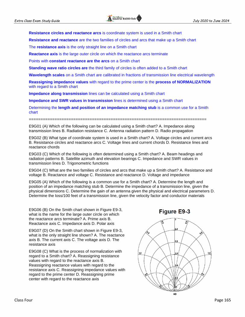
Extra Class Exam Study Guide July 2020 to June 2024
Class Four Page 165
Resistance circles and reactance arcs is coordinate system is used in a Smith chart
Resistance and reactance are the two families of circles and arcs that make up a Smith chart
The resistance axis is the only straight line on a Smith chart
Reactance axis is the large outer circle on which the reactance arcs terminate
Points with constant reactance are the arcs on a Smith chart
Standing wave ratio circles are the third family of circles is often added to a Smith chart
Wavelength scales on a Smith chart are calibrated in fractions of transmission line electrical wavelength
Reassigning impedance values with regard to the prime center is the process of NORMALIZATION with regard to a Smith chart
Impedance along transmission lines can be calculated using a Smith chart
Impedance and SWR values in transmission lines is determined using a Smith chart
Determining the length and position of an impedance matching stub is a common use for a Smith chart
============================================================================
E9G01 (A) Which of the following can be calculated using a Smith chart? A. Impedance along transmission lines B. Radiation resistance C. Antenna radiation pattern D. Radio propagation
E9G02 (B) What type of coordinate system is used in a Smith chart? A. Voltage circles and current arcs B. Resistance circles and reactance arcs C. Voltage lines and current chords D. Resistance lines and reactance chords
E9G03 (C) Which of the following is often determined using a Smith chart? A. Beam headings and radiation patterns B. Satellite azimuth and elevation bearings C. Impedance and SWR values in transmission lines D. Trigonometric functions
E9G04 (C) What are the two families of circles and arcs that make up a Smith chart? A. Resistance and voltage B. Reactance and voltage C. Resistance and reactance D. Voltage and impedance
E9G05 (A) Which of the following is a common use for a Smith chart? A. Determine the length and position of an impedance matching stub B. Determine the impedance of a transmission line, given the physical dimensions C. Determine the gain of an antenna given the physical and electrical parameters D. Determine the loss/100 feet of a transmission line, given the velocity factor and conductor materials
E9G06 (B) On the Smith chart shown in Figure E9-3, what is the name for the large outer circle on which the reactance arcs terminate? A. Prime axis B. Reactance axis C. Impedance axis D. Polar axis
E9G07 (D) On the Smith chart shown in Figure E9-3, what is the only straight line shown? A. The reactance axis B. The current axis C. The voltage axis D. The resistance axis
E9G08 (C) What is the process of normalization with regard to a Smith chart? A. Reassigning resistance values with regard to the reactance axis B. Reassigning reactance values with regard to the resistance axis C. Reassigning impedance values with regard to the prime center D. Reassigning prime center with regard to the reactance axis
Extra Class Exam Study Guide July 2020 to June 2024
Class Four Page 166
E9G09 (A) What third family of circles is often added to a Smith chart during the process of solving problems? A. Standing wave ratio circles B. Antenna-length circles C. Coaxial-length circles D. Radiation-pattern circles
E9G10 (D) What do the arcs on a Smith chart represent? A. Frequency B. SWR C. Points with constant resistance D. Points with constant reactance
E9G11 (B) How are the wavelength scales on a Smith chart calibrated? A. In fractions of transmission line electrical frequency B. In fractions of transmission line electrical wavelength C. In fractions of antenna electrical wavelength D. In fractions of antenna electrical frequency
============================================================================

Extra Class Exam Study Guide July 2020 to June 2024
Class Four Page 167
Class Four Fundamentals and Substance
============================================================================
After completing each class be sure to use the Fundamentals and Substance subsection that was solely created as a tool for test preparation by helping you make connections between topics and serves as quality review material for after each class. Using these steps can be most useful when learning about new topics that include a lot of detail. The information is in the form of class notes with all of the important information you need to know. These notes are not a substitute for studying the class material in fact you will need to complete your class assignment in order to effectively use these notes. The notes are organized into easily digestible headings and bullet points to organize topics with the key words, main subpoints and summary are all written in one place.
============================================================================
Power Factor
Wattless, nonproductive power is REACTIVE POWER
REACTIVE POWER in an AC circuit is exchanged between magnetic and electric fields, but is not dissipated
The true power be determined in an AC circuit where the voltage and current are out of phase by multiplying the apparent power by the power factor
Trick question Resistor only has Real Power
POWER FACTOR = Real Power (Watts) / Total Power (V x A)
POWER FACTOR = COS of (Voltage to Current) Phase
PF = COS 30° = 0.866
PF = COS 60° = 0.5
PF = COS 45° = 0.707
UHF and Microwave
SKIN EFFECT >> As frequency increases, RF current flows closer to the surface of the conductor
Precision printed circuit conductors above a ground plane that provide constant impedance interconnects at microwave frequencies is a microstrip
Short connections used at microwave frequencies to reduce phase shift along the connection
To avoid unwanted inductive reactance, it is important to keep lead lengths short for components used in circuits for VHF and above
MAGNETIC FIELD is in a circle around a conductor
G B Y
Susceptance is the reciprocal of Reactance: B = 1/X
Admittance is the reciprocal of Impedance: Y = 1/Z
Susceptance is the imaginary part of admittance

Extra Class Exam Study Guide July 2020 to June 2024
Class Four Page 168
Resonance and Q
Resonance is the frequency at which the capacitive reactance equals the inductive reactance
Resonance can cause the voltage across reactances in series to be larger than the voltage
The magnitude of the impedance of a circuit with an RLC all in parallel, at resonance is equal to circuit resistance (looks like R)
The MAXIMUM CIRCULATING current of a parallel LC circuit occurs at resonance within the components
MINIMUM current is at the INPUT of a parallel RLC circuit as the frequency is resonance
The voltage and current are in phase across a series resonant circuit at resonance
The voltage and current are in phase across a parallel resonant circuit at resonance
Increasing the Q of an impedance-matching circuit decreases the bandwidth
Increasing Q in a series resonant circuit increases the internal voltages
Lower losses increase Q for inductors and capacitors
RLC parallel resonant circuit Q = Resistance / Reactance = R / X
RLC series resonant circuit Q = / Reactance / Resistance = X / R
Half Power Bandwidth = Resonant Frequency / Q of the Circuit
Resonant frequency of an RLC circuit equals a formula or just remember 3.56 MHz or 7.12 MHz
Time Constants
One time constant is the time required for the capacitor in an RC circuit to charge 63.2%
One time constant is the time required for a charged capacitor in an RC to discharge to 36.8%
The capacitor in an RC circuit is discharged to 13.5% of the starting after two-time constants
One time constant = TC (sec) = R (MΩ) x C (uF) Check your decimal point!
Phase Relationships
Voltage same as Current phase angle in a Resistor
Voltage leads current by 90 deg through an inductor
Current leads voltage by 90 deg through a capacitor
“ELI the ICE man” Inductors – voltage (E) leads current (I)
Capacitors – current (I) leads voltage (E)

Extra Class Exam Study Guide July 2020 to June 2024
Class Four Page 169
Rectangular and Polar Plots
Polar coordinates display the phase angle of a circuit resistance, inductive and/or capacitive reactance
Phasor diagram is used to show the phase relationship between impedances at a given frequency
Rectangular coordinates display the resistive, inductive, and/or capacitive reactance (R + jX)
Capacitive reactance in rectangular notation is – jX (negative)
Inductive reactance in rectangular notation is + jX (positive)
The X axis represents the resistive component and the Y axis represents the reactive component using rectangular coordinates to graph the impedance of a circuit
The horizontal axis represents the resistive component
The vertical axis represents the reactive component
Matching Antennas to Feedlines
The DELTA MATCHING system matches a high-impedance transmission line to a lower impedance antenna by connecting the line to the driven element in two places spaced a fraction of a wavelength each side of element center
The gamma match that matches an unbalanced feed line to an antenna by feeding the driven element both at the center of the element and at a fraction of a wavelength to one side of center
A Gamma match is used to shunt-feed a grounded tower at its base
The series capacitor in a gamma matching network cancels the inductive reactance of the matching network
An antenna's driven element capacitive to be tuned to use a hairpin matching system
The stub match uses a section of transmission line connected in parallel with the feed line at or near the feed point
A Wilkinson divider divides power equally among multiple loads while two 50-ohm loads while maintaining 50-ohm input impedance
Insert a 1/4-wavelength piece of 75-ohm coaxial cable transmission line in series between the antenna and the 50-ohm feed cable to match an antenna with 100-ohm feed point impedance to a 50-ohm coaxial cable feed line
The primary purpose of a phasing line when used with an antenna having multiple driven elements is to ensure that each driven element operates in concert with the others to create the desired antenna pattern
Reflection coefficient is the interactions at the load end of a mismatched transmission line
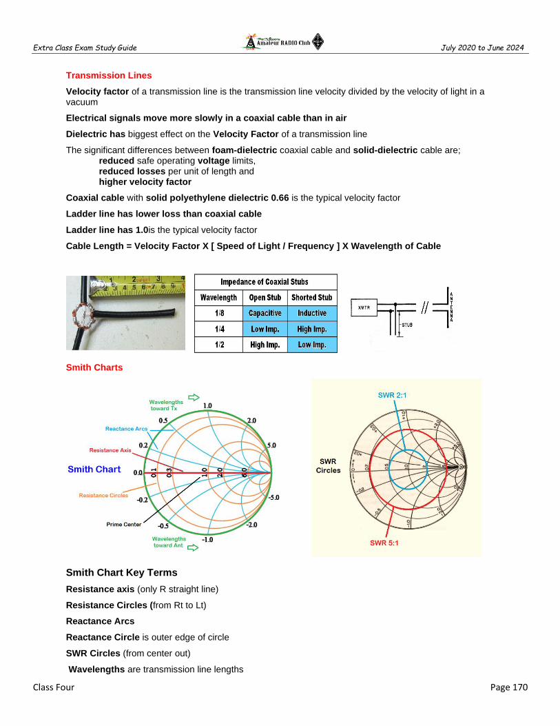
Extra Class Exam Study Guide July 2020 to June 2024
Class Four Page 170
Transmission Lines
Velocity factor of a transmission line is the transmission line velocity divided by the velocity of light in a vacuum
Electrical signals move more slowly in a coaxial cable than in air
Dielectric has biggest effect on the Velocity Factor of a transmission line
The significant differences between foam-dielectric coaxial cable and solid-dielectric cable are; reduced safe operating voltage limits, reduced losses per unit of length and higher velocity factor
Coaxial cable with solid polyethylene dielectric 0.66 is the typical velocity factor
Ladder line has lower loss than coaxial cable
Ladder line has 1.0is the typical velocity factor
Cable Length = Velocity Factor X [ Speed of Light / Frequency ] X Wavelength of Cable
Smith Charts
Smith Chart Key Terms
Resistance axis (only R straight line)
Resistance Circles (from Rt to Lt)
Reactance Arcs
Reactance Circle is outer edge of circle
SWR Circles (from center out)
Wavelengths are transmission line lengths

Extra Class Exam Study Guide July 2020 to June 2024
Class Five Page 171
CLASS 5 – ANTENNAS, PROPOGATION AND SAFETY
============================================================================
E9A Basic Antenna parameters
E3A Electromagnetic waves
E9B Antenna patterns and designs
E9C Practical wire antennas
E9D Yagi antennas
E9H Receiving Antennas
E3B Transequatorial propagation
E3C Radio horizon
E0A Safety
Class Five Fundamentals and Substance
============================================================================
E9A Basic Antenna parameters
============================================================================
Feed point impedance is affected by antenna height
Editor’s Note: Feed point impedance is the resistance and reactance seen at the antenna terminals
Antenna Bandwidth is the frequency range an antenna satisfies performance requirements, typically frequency range a feedpoint (Editor’s Note: aka VSWR is less than 2:1)
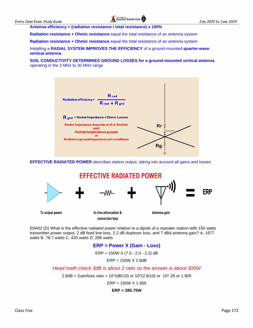
Extra Class Exam Study Guide July 2020 to June 2024
Class Five Page 172
Antenna efficiency = (radiation resistance / total resistance) x 100%
Radiation resistance + Ohmic resistance equal the total resistance of an antenna system
Radiation resistance + Ohmic resistance equal the total resistance of an antenna system
Installing a RADIAL SYSTEM IMPROVES THE EFFICIENCY of a ground-mounted quarter-wave vertical antenna
SOIL CONDUCTIVITY DETERMINES GROUND LOSSES for a ground-mounted vertical antenna operating in the 3 MHz to 30 MHz range
EFFECTIVE RADIATED POWER describes station output, taking into account all gains and losses
E9A02 (D) What is the effective radiated power relative to a dipole of a repeater station with 150 watts transmitter power output, 2 dB feed line loss, 2.2 dB duplexer loss, and 7 dBd antenna gain? A. 1977 watts B. 78.7 watts C. 420 watts D. 286 watts
ERP = Power X (Gain - Loss)
ERP = 150W X (7.0 - 2.0 - 2.2) dB
ERP = 150W X 2.8dB
Head math check 3dB is about 2 ratio so the answer is about 300W
2.8dB = Gain/loss ratio = 10^(dB/10) or 10^(2.8/10) or 10^.28 or 1.905
ERP = 150W X 1.905
ERP = 285.75W

Extra Class Exam Study Guide July 2020 to June 2024
Class Five Page 173
E9A06 (A) What is the effective radiated power relative to a dipole of a repeater station with 200 watts transmitter power output, 4 dB feed line loss, 3.2 dB duplexer loss, 0.8 dB circulator loss, and 10 dBd antenna gain? A. 317 watts B. 2000 watts C. 126 watts D. 300 watts
ERP = Power X (Gain - Loss)
ERP = 200W X (10.0 - 4.0 - 3.2 – 0.8) dB
ERP = 200W X 2.0dB
Head math check 2dB is about 1.5 ratio so the answer is about 300W
2.0dB = Gain/loss ratio = 10^(dB/10)or 10^(2.0/10) or 10^.20 or 1.584
ERP = 200W X 1.584
ERP = 316.80 W
E9A07 (B) What is the effective isotropic radiated power of a repeater station with 200 watts transmitter power output, 2 dB feed line loss, 2.8 dB duplexer loss, 1.2 dB circulator loss, and 7 dBi antenna gain? A. 159 watts B. 252 watts C. 632 watts D. 63.2 watts
ERP = Power X (Gain - Loss)
ERP = 200W X (7.0 - 2.0 - 2.8 – 1.2) dB
ERP = 200W X 1.0dB
Head math check 1dB is about 1.2 ratio so the answer is about 240W
1.0dB = Gain/loss ratio = 10^(dB/10)or 10^(1.0/10) or 10^.10 or 1.2589
ERP = 200W X 1.2589
ERP = 251.78 W
Editor’s note: There is another way to work these problems by converting the transmitter power to
dBW. Here is the same problem as above in all dB math. You will get the same answer.
ERP = Power X (Gain - Loss)
ERP = (200W) + 7.0 - 2.0 - 2.8 – 1.2
ERP = 23.0103 dBw + 7.0 - 2.0 - 2.8 – 1.2
ERP = 24.0103 dBW
24.0103 dBW = 10^(dB/10)or 10^(24.0103/10) or 10^2.40103 or 251.7851 Watts
ERP = 251.78 W
Editor’s note: This method is good for complex transmission paths just add and subtract dBs and
only convert at the TX end

Extra Class Exam Study Guide July 2020 to June 2024
Class Five Page 174
An ISOTROPIC antenna is a theoretical antenna used as a reference for antenna gain
An ISOTROPIC antenna has no gain in any direction
DIPOLE ANTENNA GAIN is 2.15 dB reference to an ISOTROPIC ANTENNA
E9A12 (A) How much gain does an antenna have compared to a 1/2-wavelength dipole when it has 6 dB gain over an isotropic antenna? A. 3.85 dB B. 6.0 dB C. 8.15 dB D. 2.79 dB
Unknown Antenna = 6 dBi
Generic Dipole Antenna = 2.15 dBi
dBi – 2.15dB = dBd (DP Gain)
6 dBi – 2.15 dBi = 3.85 dB
Unknown Antenna = 3.85 dB more than a Dipole Antenna
DIPOLE ANTENNA GAIN is 2.15 dB reference to an ISOTROPIC ANTENNA
Editor’s Note: Antenna gain tells us the power transmitted by an antenna in a specific direction as compared to an isotropic antenna. This specification describes how strong a signal an antenna can send out or receive in a specified direction. One antenna concentrates more energy in one direction but the total energy is the same for both antennas.

Extra Class Exam Study Guide July 2020 to June 2024
Class Five Page 175
============================================================================
E9A01 (C) What is an isotropic antenna? A. A grounded antenna used to measure Earth conductivity B. A horizontally polarized antenna used to compare Yagi antennas C. A theoretical, omnidirectional antenna used as a reference for antenna gain D. A spacecraft antenna used to direct signals toward Earth
E9A02 (D) see discussion in previous section
E9A03 (C) What is the radiation resistance of an antenna? A. The combined losses of the antenna elements and feed line B. The specific impedance of the antenna C. The value of a resistance that would dissipate the same amount of power as that radiated from an antenna D. The resistance in the atmosphere that an antenna must overcome to be able to radiate a signal
E9A04 (B) Which of the following factors affect the feed point impedance of an antenna? A. Transmission line length B. Antenna height C. The settings of an antenna tuner at the transmitter D. The input power level
E9A05 (D) What is included in the total resistance of an antenna system? A. Radiation resistance plus space impedance B. Radiation resistance plus transmission resistance C. Transmission-line resistance plus radiation resistance D. Radiation resistance plus loss resistance
E9A06 (A) see discussion in previous section
E9A07 (B) see discussion in previous section
E9A08 (B) What is antenna bandwidth? A. Antenna length divided by the number of elements B. The frequency range over which an antenna satisfies a performance requirement C. The angle between the half-power radiation points D. The angle formed between two imaginary lines drawn through the element ends
E9A09 (B) What is antenna efficiency? A. Radiation resistance divided by transmission resistance B. Radiation resistance divided by total resistance C. Total resistance divided by radiation resistance D. Effective radiated power divided by transmitter output
E9A10 (A) Which of the following improves the efficiency of a ground-mounted quarter-wave vertical antenna? A. Installing a radial system B. Isolating the coax shield from ground C. Shortening the radiating element D. All these choices are correct
E9A11 (C) Which of the following factors determines ground losses for a ground-mounted vertical antenna operating in the 3 MHz to 30 MHz range? A. The standing wave ratio B. Distance from the transmitter C. Soil conductivity D. Take-off angle
E9A12 (A) see discussion in previous section
E9A13 (C) What term describes station output, taking into account all gains and losses? A. Power factor B. Half-power bandwidth C. Effective radiated power D. Apparent power
============================================================================
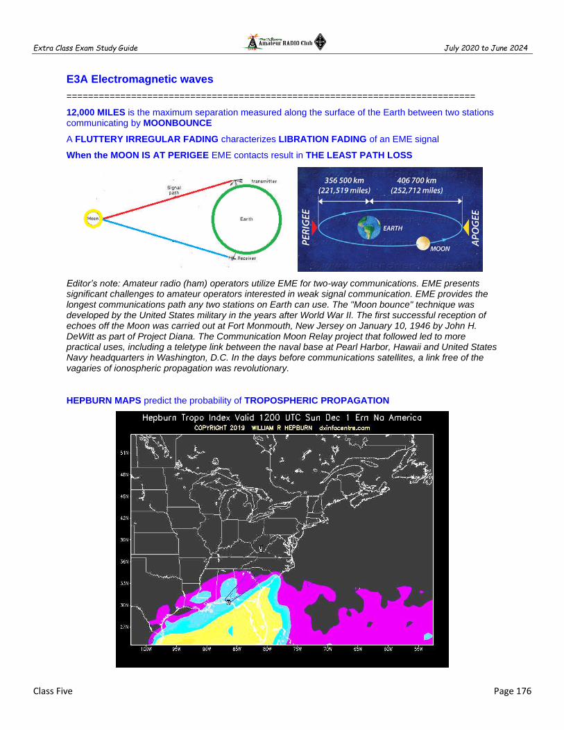
Extra Class Exam Study Guide July 2020 to June 2024
Class Five Page 176
E3A Electromagnetic waves
============================================================================
12,000 MILES is the maximum separation measured along the surface of the Earth between two stations communicating by MOONBOUNCE
A FLUTTERY IRREGULAR FADING characterizes LIBRATION FADING of an EME signal
When the MOON IS AT PERIGEE EME contacts result in THE LEAST PATH LOSS
Editor’s note: Amateur radio (ham) operators utilize EME for two-way communications. EME presents significant challenges to amateur operators interested in weak signal communication. EME provides the longest communications path any two stations on Earth can use. The "Moon bounce" technique was developed by the United States military in the years after World War II. The first successful reception of echoes off the Moon was carried out at Fort Monmouth, New Jersey on January 10, 1946 by John H. DeWitt as part of Project Diana. The Communication Moon Relay project that followed led to more practical uses, including a teletype link between the naval base at Pearl Harbor, Hawaii and United States Navy headquarters in Washington, D.C. In the days before communications satellites, a link free of the vagaries of ionospheric propagation was revolutionary.
HEPBURN MAPS predict the probability of TROPOSPHERIC PROPAGATION

Extra Class Exam Study Guide July 2020 to June 2024
Class Five Page 177
ATMOSPHERIC DUCTS capable of propagating microwave signals often form over BODIES OF WATER
TEMPERATURE INVERSION can create a PATH FOR MICROWAVE PROPAGATION
TROPOSPHERIC PROPAGATION of microwave signals occurs along WARM AND COLD FRONTS
Typical range for TROPOSPHERIC PROPAGATION of microwave signals is 100 MILES TO 300 MILES
Editor’s note: Tropospheric propagation called ducting or duct effect, occurs when there is a defined, horizontal boundary between air masses having different densities. When a cool air mass is overlain by a warm air mass, as is the case along and near warm fronts and cold fronts, radio waves at VHF and UHF are reflected at the boundary if they strike it at a near-grazing angle from beneath (within the cooler air mass). Because radio waves are also reflected from the earth's surface, the result can be efficient propagation for hundreds or, in some cases, upwards of 1,000 miles, as the waves alternately bounce off the frontal boundary and the surface.
The interaction in the E layer of CHARGED PARTICLES from the Sun with THE EARTH'S MAGNETIC FIELD is the cause of AURORAL ACTIVITY
CW IS BEST FOR AURORAL PROPAGATION
Editor’s note: Auroral borealis is caused by the collision of solar-wind particles with oxygen and nitrogen molecules in the upper atmosphere. These collisions partially ionize the molecules by knocking loose some of their outer electrons. VHF radio waves are reflected from the ionization created by an auroral curtain. VHF/UHF propagation up to 1,400 miles. Generally, auroral propagation is available only to stations in the northern states

Extra Class Exam Study Guide July 2020 to June 2024
Class Five Page 178
METEOR STRIKES THE E LAYER A CYLINDRICAL REGION OF FREE ELECTRONS is formed
28 MHz - 148 MHz is most suited for METEOR SCATTER communications
Editor’s note: Meteor Scatter communications can be reflected by the ionized trail of a meteor (level of the E-layer, 50-75 miles). The ability of a meteor trail to reflect radio signals depends on the electron density. The best frequency range is between 28 and 148 MHz Meteor-scatter communication is best between midnight and noon. Meteor Showers – are predictable (Perseids in August, Geminids in December). FSK441 part of the WSJT software suite, HSCW 800 to 2,000 WPM.
Switching to a lower frequency HF band might help to restore contact when DX signals become too weak to copy across an entire HF band a few hours after sunset
Editor’s note: Frequencies used by HF systems are generally higher during the day than they are at night because the disappearance of the sun effectively ends the ionization process. As a result of this, the D and E layers disappear while the F1 and F2 merge to form a single F layer.

Extra Class Exam Study Guide July 2020 to June 2024
Class Five Page 179
Waves with a ROTATING ELECTRIC FIELD are CIRCULARLY POLARIZED electromagnetic waves
============================================================================
E3A01 (D) What is the approximate maximum separation measured along the surface of the Earth between two stations communicating by EME? A. 500 miles, if the moon is at perigee B. 2000 miles, if the moon is at apogee C. 5000 miles, if the moon is at perigee D. 12,000 miles, if the moon is visible by both stations
E3A02 (B) What characterizes libration fading of an EME signal? A. A slow change in the pitch of the CW signal B. A fluttery irregular fading C. A gradual loss of signal as the sun rises D. The returning echo is several hertz lower in frequency than the transmitted signal
E3A03 (A) When scheduling EME contacts, which of these conditions will generally result in the least path loss? A. When the moon is at perigee B. When the moon is full C. When the moon is at apogee D. When the MUF is above 30 MHz
E3A04 (D) What do Hepburn maps predict? A. Sporadic E propagation B. Locations of auroral reflecting zones C. Likelihood of rain scatter along cold or warm fronts D. Probability of tropospheric propagation
E3A05 (C) Tropospheric propagation of microwave signals often occurs in association with what phenomenon? A. Grayline B. Lightning discharges C. Warm and cold fronts D. Sprites and jets
E3A06 (B) What might help to restore contact when DX signals become too weak to copy across an entire HF band a few hours after sunset? A. Switch to a higher frequency HF band B. Switch to a lower frequency HF band C. Wait 90 minutes or so for the signal degradation to pass D. Wait 24 hours before attempting another communication on the band
E3A07 (C) Atmospheric ducts capable of propagating microwave signals often form over what geographic feature? A. Mountain ranges B. Forests C. Bodies of water D. Urban areas
E3A08 (A) When a meteor strikes the Earth's atmosphere, a cylindrical region of free electrons is formed at what layer of the ionosphere? A. The E layer B. The F1 layer C. The F2 layer D. The D layer
E3A09 (C) Which of the following frequency ranges is most suited for meteor scatter communications? A. 1.8 MHz - 1.9 MHz B. 10 MHz - 14 MHz C. 28 MHz - 148 MHz D. 220 MHz - 450 MHz
E3A10 (B) Which type of atmospheric structure can create a path for microwave propagation? A. The jet stream B. Temperature inversion C. Wind shear D. Dust devil
E3A11 (B) What is a typical range for tropospheric propagation of microwave signals? A. 10 miles to 50 miles B. 100 miles to 300 miles C. 1200 miles D. 2500 miles
E3A12 (C) What is the cause of auroral activity? A. The interaction in the F2 layer between the solar wind and the Van Allen belt B. An extreme low-pressure area in the polar regions C. The interaction in the E layer of charged particles from the Sun with the Earth's magnetic field D. Meteor showers concentrated in the extreme northern and southern latitudes
E3A13 (A) Which of these emission modes is best for auroral propagation? A. CW B. SSB C. FM D. RTTY

Extra Class Exam Study Guide July 2020 to June 2024
Class Five Page 180
E3A14 (B) What is meant by circularly polarized electromagnetic waves? A. Waves with an electric field bent into a circular shape B. Waves with a rotating electric field C. Waves that circle the Earth D. Waves produced by a loop antenna
============================================================================
E9B Antenna patterns and designs
============================================================================
METHOD OF MOMENTS is a computer program technique used for MODELING ANTENNAS
The principle of a METHOD OF MOMENTS analysis is modeled as a series of segments, each having a uniform value of current
A disadvantage of decreasing the number of wire segments is the computed feed point impedance may be incorrect
The region where the SHAPE OF THE ANTENNA PATTERN IS INDEPENDENT OF DISTANCE IS THE FAR FIELD of an antenna
The TOTAL AMOUNT OF RADIATION emitted by a directional gain antenna compare with the total amount of radiation emitted from a theoretical isotropic antenna ARE THE SAME.
Editor’s note: The Numerical Electromagnetics Code, or NEC, is a popular antenna modeling system for wire and surface antennas. The code is based on the method of moments solution of the electric field integral equation (EFIE) for thin wires and the magnetic field integral equation (MFIE) for closed, conducting surfaces. It uses an iterative method to calculate the currents in a set of wires, and the fields that result.

Extra Class Exam Study Guide July 2020 to June 2024
Class Five Page 181
Figure E9-1, what is the Beamwidth? 50 degrees
Figure E9-1, what is the front-to-back ratio? 18 dB

Extra Class Exam Study Guide July 2020 to June 2024
Class Five Page 182
Figure E9-1, what is the front-to-side ratio? 14 dB
Figure E9-2, what is the front-to-back ratio? 28 dB
What pattern is shown in Figure E9-2? Elevation
ELEVATION ANGLE OF PEAK response in the pattern shown in Figure E9-2? 7.5 degrees

Extra Class Exam Study Guide July 2020 to June 2024
Class Five Page 183
============================================================================
E9B01 (B) In the antenna radiation pattern shown in Figure E9-1, what is the beamwidth? A. 75 degrees B. 50 degrees C. 25 degrees D. 30 degrees
E9B02 (B) In the antenna radiation pattern shown in Figure E9-1, what is the front-to-back ratio? A. 36 dB B. 18 dB C. 24 dB D. 14 dB
E9B03 (B) In the antenna radiation pattern shown in Figure E9-1, what is the front-to-side ratio? A. 12 dB B. 14 dB C. 18 dB D. 24 dB
E9B04 (B) What is the front-to-back ratio of the radiation pattern shown in Figure E9 2? A. 15 dB B. 28 dB C. 3 dB D. 38 dB
E9B05 (A) What type of antenna pattern is shown in Figure E9-2? A. Elevation B. Azimuth C. Radiation resistance D. Polarization
E9B06 (C) What is the elevation angle of peak response in the antenna radiation pattern shown in Figure E9-2? A. 45 degrees B. 75 degrees C. 7.5 degrees D. 25 degrees
E9B07 (C) How does the total amount of radiation emitted by a directional gain antenna compare with the total amount of radiation emitted from a theoretical isotropic antenna, assuming each is driven by the same amount of power? A. The total amount of radiation from the directional antenna is increased by the gain of the antenna B. The total amount of radiation from the directional antenna is stronger by its front-to-back ratio C. They are the same D. The radiation from the isotropic antenna is 2.15 dB stronger than that from the directional antenna
E9B08 (D) What is the far field of an antenna? A. The region of the ionosphere where radiated power is not refracted B. The region where radiated power dissipates over a specified time period C. The region where radiated field strengths are constant D. The region where the shape of the antenna pattern is independent of distance
E9B09 (B) What type of computer program technique is commonly used for modeling antennas? A. Graphical analysis B. Method of Moments C. Mutual impedance analysis D. Calculus differentiation with respect to physical properties
E9B10 (A) What is the principle of a Method of Moments analysis? A. A wire is modeled as a series of segments, each having a uniform value of current B. A wire is modeled as a single sine-wave current generator C. A wire is modeled as a single sine-wave voltage source D. A wire is modeled as a series of segments, each having a distinct value of voltage across it
E9B11 (C) What is a disadvantage of decreasing the number of wire segments in an antenna model below 10 segments per half-wavelength? A. Ground conductivity will not be accurately modeled B. The resulting design will favor radiation of harmonic energy C. The computed feed point impedance may be incorrect D. The antenna will become mechanically unstable
============================================================================

Extra Class Exam Study Guide July 2020 to June 2024
Class Five Page 184
E9C Practical wire antennas
============================================================================
Low-angle radiation from a vertically polarized antenna over SEAWATER WILL BE MUCH STRONGER
Editor’s note: Effects of Low conductivity soil losses reduce signal strength at low angles
Editor’s note: Effects of Low-angle radiation from a vertically polarized antenna over rocky soil will be much weaker
The radiation pattern OF TWO 1/4-WAVELENGTH VERTICAL ANTENNAS SPACED 1/2-WAVELENGTH apart and fed 180 DEGREES OUT OF PHASE IS A FIGURE-8 ORIENTED along the axis of the array
The radiation pattern OF TWO 1/4-WAVELENGTH VERTICAL ANTENNAS SPACED 1/4-WAVELENGTH apart and fed 90 DEGREES OUT OF PHASE IS A CARDIOID along the axis of the array

Extra Class Exam Study Guide July 2020 to June 2024
Class Five Page 185
The radiation pattern OF TWO 1/4-WAVELENGTH VERTICAL ANTENNAS SPACED 1/2-WAVELENGTH apart and fed IN PHASE IS A FIGURE-8 BROADSIDE TO along the axis of the array
The lobes align more in the direction of the wire long wire antenna as the wire length is increased
Editor’s note: Out of phase cancel (antenna radiation & ground reflections), signal strength will decrease
Editor’s note: In phase reinforce (antenna radiation & ground reflections), signal strength will increase

Extra Class Exam Study Guide July 2020 to June 2024
Class Five Page 186
The main lobe takeoff angle decreases in the downhill direction of a horizontally polarized antenna mounted on the side of a hill compare with the same antenna mounted on flat ground
Editor’s note: Effects of ground reflections and absorption on antenna systems efficiency is the losses in nearby ground, ground structures, or the antenna’s ground system. Radiation pattern over ground is affected by the electrical conductivity of the soil
The radiation pattern of a horizontally polarized 3-element beam antenna takeoff angle of the lowest elevation lobe decreases with increasing height above ground
Editor’s note: Raising the antenna lowers the vertical takeoff angle of the peak radiation
Editor’s note: Horizontal antennas have less ground losses
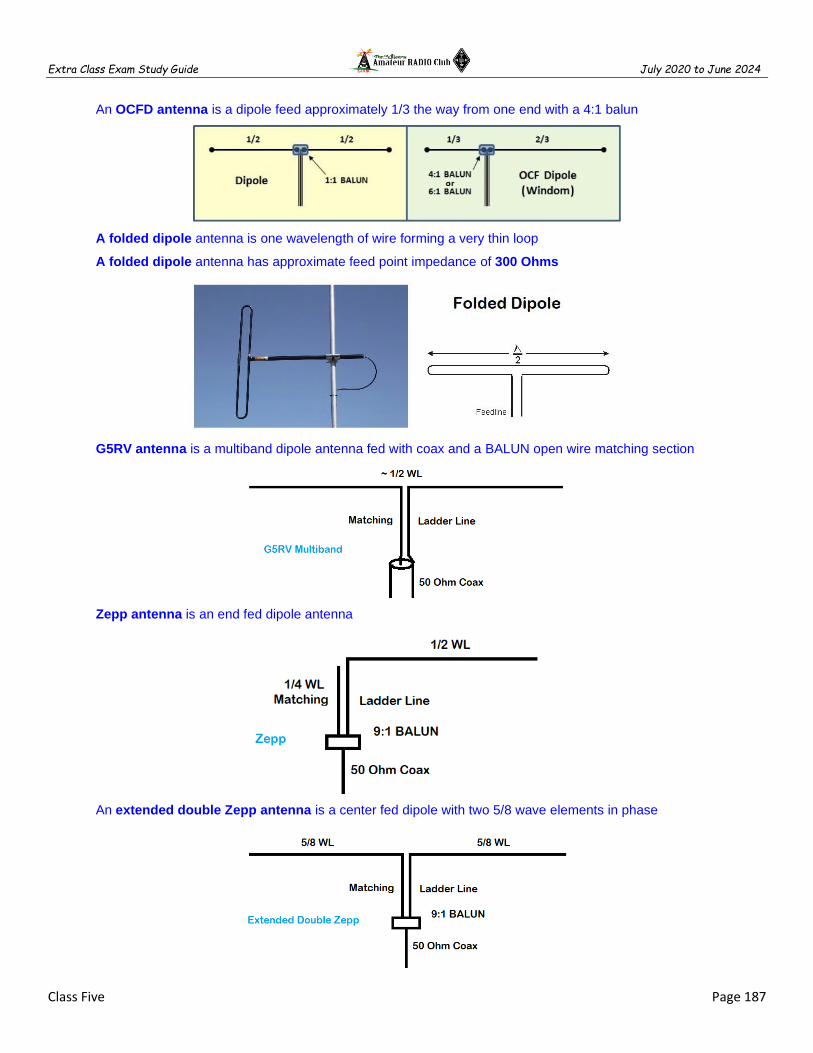
Extra Class Exam Study Guide July 2020 to June 2024
Class Five Page 187
An OCFD antenna is a dipole feed approximately 1/3 the way from one end with a 4:1 balun
A folded dipole antenna is one wavelength of wire forming a very thin loop
A folded dipole antenna has approximate feed point impedance of 300 Ohms
G5RV antenna is a multiband dipole antenna fed with coax and a BALUN open wire matching section
Zepp antenna is an end fed dipole antenna
An extended double Zepp antenna is a center fed dipole with two 5/8 wave elements in phase

Extra Class Exam Study Guide July 2020 to June 2024
Class Five Page 188
The terminating resistor on a rhombic antenna provides a unidirectional directional radiation pattern
Editor’s note: The open ended on a rhombic antenna provides a bidirectional radiation pattern
============================================================================
E9C01 (D) What is the radiation pattern of two 1/4-wavelength vertical antennas spaced 1/2-wavelength apart and fed 180 degrees out of phase? A. Cardioid B. Omni-directional C. A figure-8 broadside to the axis of the array D. A figure-8 oriented along the axis of the array
E9C02 (A) What is the radiation pattern of two 1/4-wavelength vertical antennas spaced 1/4-wavelength apart and fed 90 degrees out of phase? A. Cardioid B. A figure-8 end-fire along the axis of the array C. A figure-8 broadside to the axis of the array D. Omni-directional
E9C03 (C) What is the radiation pattern of two 1/4-wavelength vertical antennas spaced 1/2-wavelength apart and fed in phase? A. Omni-directional B. Cardioid C. A Figure-8 broadside to the axis of the array D. A Figure-8 end-fire along the axis of the array
E9C04 (B) What happens to the radiation pattern of an unterminated long wire antenna as the wire length is increased? A. The lobes become more perpendicular to the wire B. The lobes align more in the direction of the wire C. The vertical angle increases D. The front-to-back ratio decreases
E9C05 (A) Which of the following is a type of OCFD antenna? A. A dipole fed approximately 1/3 the way from one end with a 4:1 balun to provide multiband operation B. A remotely tunable dipole antenna using orthogonally controlled frequency diversity C. A folded dipole center-fed with 300-ohm transmission line D. A multiband dipole antenna using one-way circular polarization for frequency diversity
E9C06 (B) What is the effect of adding a terminating resistor to a rhombic antenna? A. It reflects the standing waves on the antenna elements back to the transmitter B. It changes the radiation pattern from bidirectional to unidirectional C. It changes the radiation pattern from horizontal to vertical polarization D. It decreases the ground loss
E9C07 (A) What is the approximate feed point impedance at the center of a two-wire folded dipole antenna? A. 300 ohms B. 72 ohms C. 50 ohms D. 450 ohms
E9C08 (C) What is a folded dipole antenna? A. A dipole one-quarter wavelength long B. A type of ground-plane antenna C. A half-wave dipole with an additional parallel wire connecting its two ends D. A dipole configured to provide forward gain

Extra Class Exam Study Guide July 2020 to June 2024
Class Five Page 189
E9C09 (A) Which of the following describes a G5RV antenna? A. A multi-band dipole antenna fed with coax and a balun through a selected length of open wire transmission line B. A multi-band trap antenna C. A phased array antenna consisting of multiple loops D. A wide band dipole using shorted coaxial cable for the radiating elements and fed with a 4:1 balun
E9C10 (B) Which of the following describes a Zepp antenna? A. A dipole constructed from zip cord B. An end-fed dipole antenna C. An omni-directional antenna commonly used for satellite communications D. A vertical array capable of quickly changing the direction of maximum radiation by changing phasing lines
E9C11 (D) How is the far-field elevation pattern of a vertically polarized antenna affected by being mounted over seawater versus soil? A. The low-angle radiation decreases B. Additional higher vertical angle lobes will appear C. Fewer vertical angle lobes will be present D. The low-angle radiation increases
E9C12 (C) Which of the following describes an Extended Double Zepp antenna? A. A wideband vertical antenna constructed from precisely tapered aluminum tubing B. A portable antenna erected using two push support poles C. A center-fed 1.25-wavelength antenna (two 5/8-wave elements in phase) D. An end-fed folded dipole antenna
E9C13 (B) How does the radiation pattern of a horizontally polarized 3-element beam antenna vary with increasing height above ground? A. The takeoff angle of the lowest elevation lobe increases B. The takeoff angle of the lowest elevation lobe decreases C. The horizontal beamwidth increases D. The horizontal beamwidth decreases
E9C14 (B) How does the performance of a horizontally polarized antenna mounted on the side of a hill compare with the same antenna mounted on flat ground? A. The main lobe takeoff angle increases in the downhill direction B. The main lobe takeoff angle decreases in the downhill direction C. The horizontal beamwidth decreases in the downhill direction D. The horizontal beamwidth increases in the uphill direction
============================================================================
E9D Yagi antennas
============================================================================
The gain of an ideal parabolic dish antenna increases by 6 dB when the frequency is doubled
Editor’s note: The gain of a parabolic antenna is proportional to the diameter2. The doubling of results in the antenna size doubling in wavelengths and the gain is four times greater.

Extra Class Exam Study Guide July 2020 to June 2024
Class Five Page 190
Two Linear Yagis perpendicular to each other with the driven elements at the same point on the boom and fed 90 degrees out of phase produce circular polarization
The front-to-back ratio decreases in a Yagi antenna is designed solely for max forward gain
Top loading in a shortened HF vertical antenna improves radiation efficiency

Extra Class Exam Study Guide July 2020 to June 2024
Class Five Page 191
Place a high-Q loading coil at center of the vertical radiator to minimize losses in a shortened antenna
The function of a loading coil on an HF mobile antenna is to cancel capacitive reactance
As the Q of an antenna increases the SWR bandwidth decreases
The radiation resistance decreases and the capacitive reactance increases when a fixed length HF mobile antenna is operated below its resonant frequency
A high Q loading coil be placed near the center of the vertical radiator to minimize losses in a shortened vertical antenna
The bandwidth decreases in an antenna shortened through the use of loading coils
Top loading in a shortened HF vertical antenna improves radiation efficiency
Best RF station ground is a short connection to 3 or 4 interconnected ground rods driven into the Earth
A wide flat copper strap is best for minimizing losses in a station's RF ground system

Extra Class Exam Study Guide July 2020 to June 2024
Class Five Page 192
============================================================================
E9D01 (D) How much does the gain of an ideal parabolic dish antenna change when the operating frequency is doubled? A. 2 dB B. 3 dB C. 4 dB D. 6 dB
E9D02 (C) How can linearly polarized Yagi antennas be used to produce circular polarization? A. Stack two Yagis fed 90 degrees out of phase to form an array with the respective elements in parallel planes B. Stack two Yagis fed in phase to form an array with the respective elements in parallel planes C. Arrange two Yagis perpendicular to each other with the driven elements at the same point on the boom fed 90 degrees out of phase D. Arrange two Yagis collinear to each other with the driven elements fed 180 degrees out of phase
E9D03 (A) Where should a high Q loading coil be placed to minimize losses in a shortened vertical antenna? A. Near the center of the vertical radiator B. As low as possible on the vertical radiator C. As close to the transmitter as possible D. At a voltage node
E9D04 (C) Why should an HF mobile antenna loading coil have a high ratio of reactance to resistance? A. To swamp out harmonics B. To lower the radiation angle C. To minimize losses D. To minimize the Q
E9D05 (B) What usually occurs if a Yagi antenna is designed solely for maximum forward gain? A. The front-to-back ratio increases B. The front-to-back ratio decreases C. The frequency response is widened over the whole frequency band D. The SWR is reduced
E9D06 (B) What happens to the SWR bandwidth when one or more loading coils are used to resonate an electrically short antenna? A. It is increased B. It is decreased C. It is unchanged if the loading coil is located at the feed point D. It is unchanged if the loading coil is located at a voltage maximum point
E9D07 (D) What is an advantage of using top loading in a shortened HF vertical antenna? A. Lower Q B. Greater structural strength C. Higher losses D. Improved radiation efficiency
E9D08 (B) What happens as the Q of an antenna increases? A. SWR bandwidth increases B. SWR bandwidth decreases C. Gain is reduced D. More common-mode current is present on the feed line
E9D09 (D) What is the function of a loading coil used as part of an HF mobile antenna? A. To increase the SWR bandwidth B. To lower the losses C. To lower the Q D. To cancel capacitive reactance
E9D10 (B) What happens to feed-point impedance at the base of a fixed length HF mobile antenna when operated below its resonant frequency? A. The radiation resistance decreases and the capacitive reactance decreases B. The radiation resistance decreases and the capacitive reactance increases C. The radiation resistance increases and the capacitive reactance decreases D. The radiation resistance increases and the capacitive reactance increases
E9D11 (B) Which of the following conductors would be best for minimizing losses in a station's RF ground system? A. Resistive wire, such as spark plug wire B. Wide flat copper strap C. Stranded wire D. Solid wire
E9D12 (C) Which of the following would provide the best RF ground for your station? A. A 50-ohm resistor connected to ground B. An electrically short connection to a metal water pipe C. An electrically short connection to 3 or 4 interconnected ground rods driven into the Earth D. An electrically short connection to 3 or 4 interconnected ground rods via a series RF choke
============================================================================

Extra Class Exam Study Guide July 2020 to June 2024
Class Five Page 193
E9H Receiving Antennas
============================================================================
A BEVERAGE antenna should be one or more wavelengths long
Atmospheric noise is so high that gain over a dipole is not important for low band (160M & 80M) receiving antennas
Editor’s note: The Beverage antenna or "wave antenna" is a long-wire receiving antenna mainly used in the low frequency and medium frequency radio bands, invented by Harold H. Beverage in 1921. It is used by amateur radio, shortwave listening, and longwave radio DXers and military applications.
RECEIVING LOOP ANTENNA >> One or more turns of wire wound in the shape of a large open coil
The output loop antenna be increased by adding turns in the loop or add area to the loop
Placing a grounded electrostatic shield around a small loop direction-finding antenna eliminates tracking errors caused by strong out-of-band signals
Editor’s note: Shielded loop antenna is electro-statically balanced against ground, giving better nulls
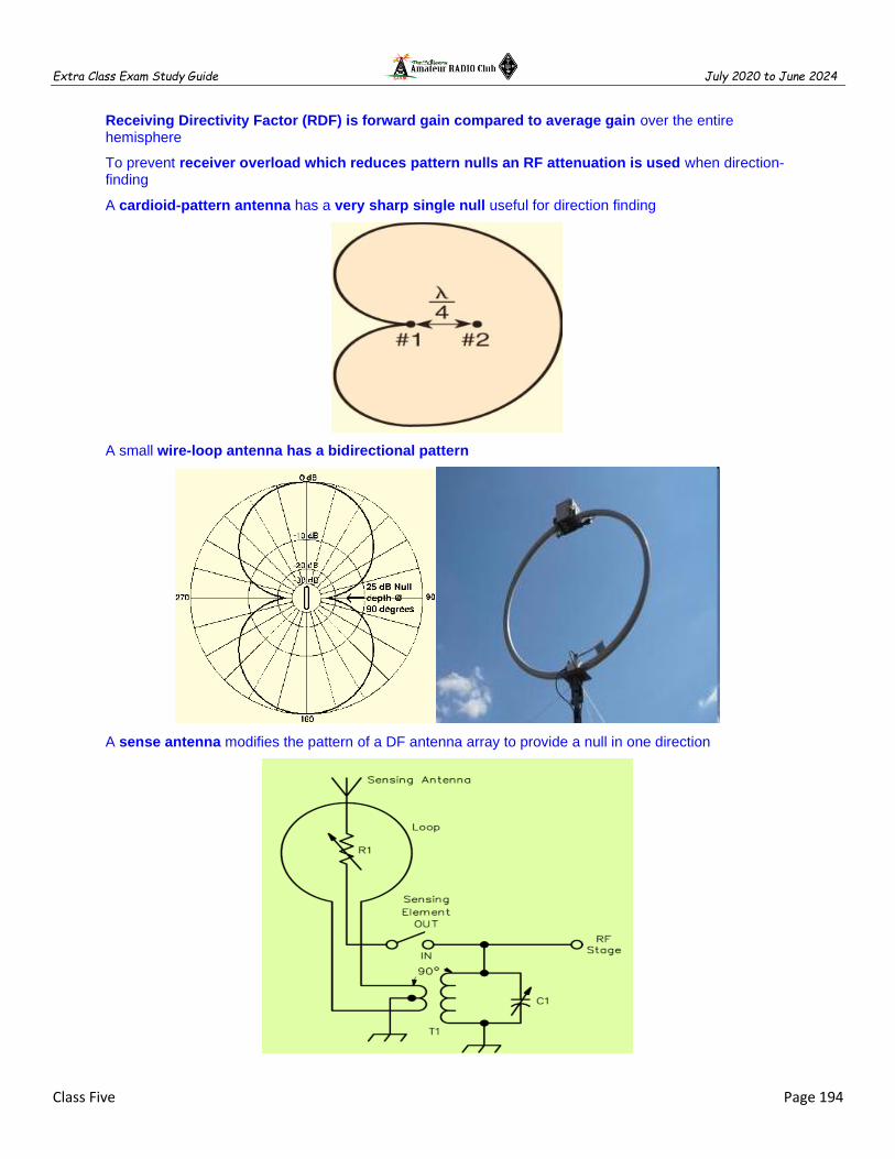
Extra Class Exam Study Guide July 2020 to June 2024
Class Five Page 194
Receiving Directivity Factor (RDF) is forward gain compared to average gain over the entire hemisphere
To prevent receiver overload which reduces pattern nulls an RF attenuation is used when direction-finding
A cardioid-pattern antenna has a very sharp single null useful for direction finding
A small wire-loop antenna has a bidirectional pattern
A sense antenna modifies the pattern of a DF antenna array to provide a null in one direction

Extra Class Exam Study Guide July 2020 to June 2024
Class Five Page 195
A Pennant antenna is a small, vertically oriented receiving antenna consisting of a triangular loop terminated in approximately 900 ohms
Editor’s note: A Pennant antenna is a single-turn loops terminated on the side opposite the feedpoint. The termination effects a null off the end where the terminator is located, thereby producing a cardioid (heart-shaped) directional pick-up pattern. The antenna is broadband rather than resonant. The pattern produced holds up well over a wide frequency range.
The triangulation method uses headings from several different receiving locations to locate a signal
============================================================================
E9H01 (D) When constructing a Beverage antenna, which of the following factors should be included in the design to achieve good performance at the desired frequency? A. Its overall length must not exceed 1/4 wavelength B. It must be mounted more than 1 wavelength above ground C. It should be configured as a four-sided loop D. It should be one or more wavelengths long
E9H02 (A) Which is generally true for low band (160 meter and 80 meter) receiving antennas? A. Atmospheric noise is so high that gain over a dipole is not important B. They must be erected at least 1/2 wavelength above the ground to attain good directivity C. Low loss coax transmission line is essential for good performance D. All these choices are correct
E9H03 (D) What is Receiving Directivity Factor (RDF)? A. Forward gain compared to the gain in the reverse direction B. Relative directivity compared to isotropic C. Relative directivity compared to a dipole D. Forward gain compared to average gain over the entire hemisphere
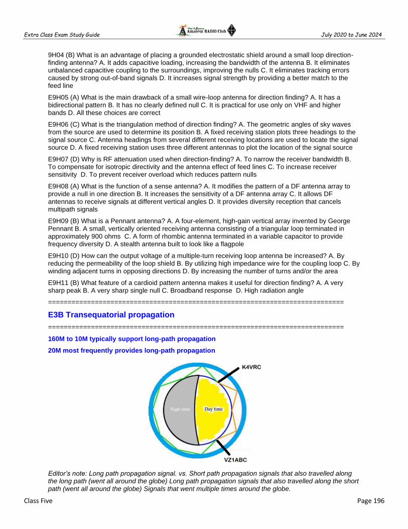
Extra Class Exam Study Guide July 2020 to June 2024
Class Five Page 196
9H04 (B) What is an advantage of placing a grounded electrostatic shield around a small loop direction-finding antenna? A. It adds capacitive loading, increasing the bandwidth of the antenna B. It eliminates unbalanced capacitive coupling to the surroundings, improving the nulls C. It eliminates tracking errors caused by strong out-of-band signals D. It increases signal strength by providing a better match to the feed line
E9H05 (A) What is the main drawback of a small wire-loop antenna for direction finding? A. It has a bidirectional pattern B. It has no clearly defined null C. It is practical for use only on VHF and higher bands D. All these choices are correct
E9H06 (C) What is the triangulation method of direction finding? A. The geometric angles of sky waves from the source are used to determine its position B. A fixed receiving station plots three headings to the signal source C. Antenna headings from several different receiving locations are used to locate the signal source D. A fixed receiving station uses three different antennas to plot the location of the signal source
E9H07 (D) Why is RF attenuation used when direction-finding? A. To narrow the receiver bandwidth B. To compensate for isotropic directivity and the antenna effect of feed lines C. To increase receiver sensitivity D. To prevent receiver overload which reduces pattern nulls
E9H08 (A) What is the function of a sense antenna? A. It modifies the pattern of a DF antenna array to provide a null in one direction B. It increases the sensitivity of a DF antenna array C. It allows DF antennas to receive signals at different vertical angles D. It provides diversity reception that cancels multipath signals
E9H09 (B) What is a Pennant antenna? A. A four-element, high-gain vertical array invented by George Pennant B. A small, vertically oriented receiving antenna consisting of a triangular loop terminated in approximately 900 ohms C. A form of rhombic antenna terminated in a variable capacitor to provide frequency diversity D. A stealth antenna built to look like a flagpole
E9H10 (D) How can the output voltage of a multiple-turn receiving loop antenna be increased? A. By reducing the permeability of the loop shield B. By utilizing high impedance wire for the coupling loop C. By winding adjacent turns in opposing directions D. By increasing the number of turns and/or the area
E9H11 (B) What feature of a cardioid pattern antenna makes it useful for direction finding? A. A very sharp peak B. A very sharp single null C. Broadband response D. High radiation angle
============================================================================
E3B Transequatorial propagation
============================================================================
160M to 10M typically support long-path propagation
20M most frequently provides long-path propagation
Editor’s note: Long path propagation signal. vs. Short path propagation signals that also travelled along the long path (went all around the globe) Long path propagation signals that also travelled along the short path (went all around the globe) Signals that went multiple times around the globe.

Extra Class Exam Study Guide July 2020 to June 2024
Class Five Page 197
Transequatorial propagation is between two mid-latitude points at approximately the same distance north and south of the magnetic equator
5000 miles is the maximum range for signals using transequatorial propagation
Afternoon or early evening to is the best time of day for trans equatorial propagation
Editor’s note: Trans equatorial Propagation (TE) is a form of F-layer ionospheric propagation. TE occurs between mid-latitude station approximately the same distance north and south of the Earth’s magnetic equator (2,500 north and south of the equator). TE occurs on 50 & 144 MHz and to some extent 432 MHz. The high-density-ionization regions from approximately between 10 and 15 degrees on either side of the Earth’s magnetic equator. Best time to look for them is March 21 & Sept 21.
Independent waves created in the ionosphere that are elliptically polarized are "extraordinary" and "ordinary" waves
Linearly polarized radio waves that split into ordinary and extraordinary waves in the ionosphere become elliptically polarized
Editor’s note: Near the critical frequency the waves are excessively retarded in the ionized layer, which accounts for the rise of the curve at the critical frequency. At the right of the curve appear two critical frequencies for the F2 layer. This is an indication of double refraction of the waves due to the earth's magnetic field, two components of different polarization being produced. One is called the "ordinary" wave and the other the "extraordinary" wave. The symbols o and x, respectively, are used for these components.

Extra Class Exam Study Guide July 2020 to June 2024
Class Five Page 198
SPORADIC E propagation is likely to occur around the solstices, especially the SUMMER SOLSTICE
Sporadic E propagation can occur any time of day
Editor’s note: Sporadic E propagation bounces signals off ionized atmospheric gas in the lower E region (located at altitudes of approx. 90 to 160 km). This occasionally allows for long-distance communication at VHF frequencies of 800–2200 km.
SUCCESSIVE IONOSPHERIC REFLECTIONS without an intermediate reflection from the ground is the primary characteristic of CHORDAL HOP PROPAGATION
CHORDAL HOP PROPAGATION EXPERIENCES LESS LOSS along the path than normal skip
Editor’s note: Chordal Hop is when a signal approaches the ionosphere at a steep angle the signal penetrates the ionosphere and may pass right through, or be 'reflected' back (green ray, right). It is actually refracted rather than reflected. However, when a signal approaches the ionosphere at a grazing angle, the likelihood of 'reflection' is higher than for vertically approaching signals. The penetration is less and the attenuation is less. This 'chordal hop' process is believed to be common at night when the F layer is stable. Because there is no ground reflection involved, and less penetration of the ionosphere, the attenuation is much less than with other propagation mechanisms, and as a result signals are stronger.
============================================================================
E3B01 (A) What is transequatorial propagation? A. Propagation between two mid-latitude points at approximately the same distance north and south of the magnetic equator B. Propagation between points located on the magnetic equator C. Propagation between a point on the equator and its antipodal point D. Propagation between points at the same latitude

Extra Class Exam Study Guide July 2020 to June 2024
Class Five Page 199
E3B02 (C) What is the approximate maximum range for signals using transequatorial propagation? A. 1000 miles B. 2500 miles C. 5000 miles D. 7500 miles
E3B03 (C) What is the best time of day for transequatorial propagation? A. Morning B. Noon C. Afternoon or early evening D. Late at night
E3B04 (B) What is meant by the terms "extraordinary" and "ordinary" waves? A. Extraordinary waves describe rare long-skip propagation compared to ordinary waves, which travel shorter distances B. Independent waves created in the ionosphere that are elliptically polarized C. Long-path and short-path waves D. Refracted rays and reflected waves
E3B05 (C) Which amateur bands typically support long-path propagation? A. Only 160 meters to 40 meters B. Only 30 meters to 10 meters C. 160 meters to 10 meters D. 6 meters to 2 meters
E3B06 (B) Which of the following amateur bands most frequently provides long-path propagation? A. 80 meters B. 20 meters C. 10 meters D. 6 meters
E3B07 (C) What happens to linearly polarized radio waves that split into ordinary and extraordinary waves in the ionosphere? A. They are bent toward the magnetic poles B. They become depolarized C. They become elliptically polarized D. They become phase locked
E3B08 (x) Deleted Question
E3B09 (A) At what time of year is sporadic E propagation most likely to occur? A. Around the solstices, especially the summer solstice B. Around the solstices, especially the winter solstice C. Around the equinoxes, especially the spring equinox D. Around the equinoxes, especially the fall equinox
E3B10 (A) Why is chordal hop propagation desirable? A. The signal experiences less loss compared to multi-hop using Earth as a reflector B. The MUF for chordal hop propagation is much lower than for normal skip propagation C. Atmospheric noise is lower in the direction of chordal hop propagation D. Signals travel faster along ionospheric chords
E3B11 (D) At what time of day can sporadic E propagation occur? A. Only around sunset B. Only around sunset and sunrise C. Only in hours of darkness D. Any time
E3B12 (B) What is the primary characteristic of chordal hop propagation? A. Propagation away from the great circle bearing between stations B. Successive ionospheric refractions without an intermediate reflection from the ground C. Propagation across the geomagnetic equator D. Signals reflected back toward the transmitting station
============================================================================
E3C Radio horizon
============================================================================
MODELING A RADIO WAVE'S PATH through the ionosphere is termed RAY TRACING in radio communications
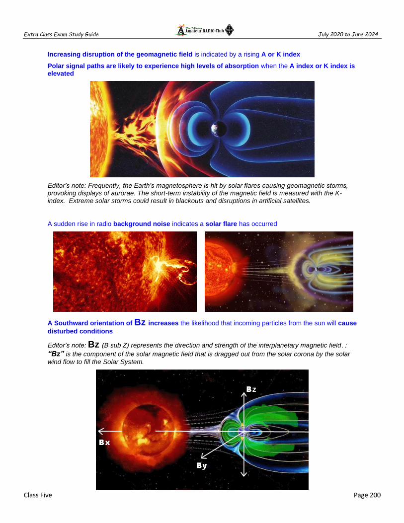
Extra Class Exam Study Guide July 2020 to June 2024
Class Five Page 200
Increasing disruption of the geomagnetic field is indicated by a rising A or K index
Polar signal paths are likely to experience high levels of absorption when the A index or K index is elevated
Editor’s note: Frequently, the Earth's magnetosphere is hit by solar flares causing geomagnetic storms, provoking displays of aurorae. The short-term instability of the magnetic field is measured with the K-index. Extreme solar storms could result in blackouts and disruptions in artificial satellites.
A sudden rise in radio background noise indicates a solar flare has occurred
A Southward orientation of Bz increases the likelihood that incoming particles from the sun will cause
disturbed conditions
Editor’s note: Bz (B sub Z) represents the direction and strength of the interplanetary magnetic field. :
“Bz” is the component of the solar magnetic field that is dragged out from the solar corona by the solar
wind flow to fill the Solar System.

Extra Class Exam Study Guide July 2020 to June 2024
Class Five Page 201
“X” indicates the greatest solar flare intensity
Editor’s note: Solar flares are classified according to their strength. The smallest ones are A-class, followed by B, C, M and X, the largest. Solar flares are giant explosions on the sun that send energy, light and high-speed particles into space. These flares are often associated with solar magnetic storms known as coronal mass ejections (CMEs).
The intensity of an X3 flare is 50% greater than an X2 flare
VOACAP software models HF propagation
Editor’s note: Voice of America Coverage Analysis Program (VOACAP) is a radio propagation model that uses empirical data to predict the point-to-point path loss and coverage of a given transceiver if given as inputs: two antennas (configuration and position), solar weather, and time/date.
Editor’s note: Flare strength within a class is
noted by a numerical suffix ranging from 1 to
9, which is also the factor for that event
within the class. Hence, an X2 flare is twice
the strength of an X1 flare, an X3 flare is
three times as powerful as an X1, and only
50% more powerful than an X2. An X2 is four
times more powerful than an M5 flare.

Extra Class Exam Study Guide July 2020 to June 2024
Class Five Page 202
The 304A solar parameter measures the UV emission at 304 angstroms, correlated to solar flux index
Editor’s note: The Sun generates electromagnetic radiation at various wavelengths, which ionize particular regions:
hard X-rays (1-10 Angstroms) ionizes the D region, soft X-rays (10-100 Angstroms) ionizes the E region, ultraviolet light (100-1000 Angstroms) ionizes the F region.
An extreme geomagnetic storm is termed a G5
Vertical polarization is best for ground-wave propagation
The maximum distance of ground-wave propagation decreases as the signal frequency is increased
Editor’s note: Vertical polarization is subject to considerably less attenuation than horizontally polarized signals. The difference can amount to several tens of decibels. It is for this reason that medium wave broadcast stations use vertical antennas,

Extra Class Exam Study Guide July 2020 to June 2024
Class Five Page 203
VHF/UHF radio horizon distance exceed the geometric horizon by 15% of the distance
The radio-path horizon distance exceeds the geometric horizon by downward bending due to density variations in the atmosphere
Editor’s note: Ground wave propagation can propagate a considerable distance over the earth's surface particularly below 4 MHz. Ground wave radio signal propagation is ideal for relatively short distance propagation on these frequencies during the daytime.
============================================================================
E3C01 (B) What does the radio communication term "ray tracing" describe? A. The process in which an electronic display presents a pattern B. Modeling a radio wave's path through the ionosphere C. Determining the radiation pattern from an array of antennas D. Evaluating high voltage sources for x-rays
E3C02 (A) What is indicated by a rising A or K index? A. Increasing disruption of the geomagnetic field B. Decreasing disruption of the geomagnetic field C. Higher levels of solar UV radiation D. An increase in the critical frequency
E3C03 (B) Which of the following signal paths is most likely to experience high levels of absorption when the A index or K index is elevated? A. Transequatorial B. Polar C. Sporadic E D. NVIS
E3C04 (C) What does the value of Bz (B sub Z) represent? A. Geomagnetic field stability B. Critical frequency for vertical transmissions C. Direction and strength of the interplanetary magnetic field D. Duration of long-delayed echoes
3C05 (A) What orientation of Bz (B sub z) increases the likelihood that incoming particles from the sun will cause disturbed conditions? A. Southward B. Northward C. Eastward D. Westward
E3C06 (A) By how much does the VHF/UHF radio horizon distance exceed the geometric horizon? A. By approximately 15 percent of the distance B. By approximately twice the distance C. By approximately 50 percent of the distance D. By approximately four times the distance
E3C07 (D) Which of the following descriptors indicates the greatest solar flare intensity? A. Class A B. Class B C. Class M D. Class X
E3C08 (A) What does the space weather term G5 mean? A. An extreme geomagnetic storm B. Very low solar activity C. Moderate solar wind D. Waning sunspot numbers
E3C09 (B) How does the intensity of an X3 flare compare to that of an X2 flare? A. 10 percent greater B. 50 percent greater C. Twice as great D. Four times as great
E3C10 (B) What does the 304A solar parameter measure? A. The ratio of x-ray flux to radio flux, correlated to sunspot number B. UV emissions at 304 angstroms, correlated to the solar flux index C. The solar wind velocity at 304 degrees from the solar equator, correlated to solar activity D. The solar emission at 304 GHz, correlated to x-ray flare levels
E3C11 (C) What does VOACAP software model? A. AC voltage and impedance B. VHF radio propagation C. HF propagation D. AC current and impedance
E3C12 (C) How does the maximum range of ground-wave propagation change when the signal frequency is increased? A. It stays the same B. It increases C. It decreases D. It peaks at roughly 14 MHz

Extra Class Exam Study Guide July 2020 to June 2024
Class Five Page 204
E3C13 (A) What type of polarization is best for ground-wave propagation? A. Vertical B. Horizontal C. Circular D. Elliptical
E3C14 (D) Why does the radio-path horizon distance exceed the geometric horizon? A. E-region skip B. D-region skip C. Due to the Doppler effect D. Downward bending due to density variations in the atmosphere
E3C15 (B) What might be indicated by a sudden rise in radio background noise across a large portion of the HF spectrum? A. A temperature inversion has occurred B. A solar flare has occurred C. Increased transequatorial propagation is likely D. Long-path propagation is likely
============================================================================
E0A Safety
============================================================================
Only with a carbon monoxide detector can detect CO from an emergency generator
Editor’s note: Carbon Monoxide – from generators or heating equipment during emergency operations
BERYLLIUM OXIDE is an insulating material commonly used as a thermal conductor for some types of electronic devices is extremely TOXIC if broken or crushed and the particles are accidentally inhaled
Editor’s note: Beryllium & Beryllium Oxide – used in copper alloys to stiffen it, Spring Contacts, duplexer fingers. The oxide powder is carcinogenic and may cause skin burns. In solid form, it is safe to handle if not subjected to machining that generates dust. Beryllium oxide ceramic is not a hazardous waste under federal law in the USA.

Extra Class Exam Study Guide July 2020 to June 2024
Class Five Page 205
Polychlorinated biphenyls (PCB) is a toxic material may be present in some electronic components such as high voltage capacitors and transformers
Editor’s note: Polychlorinated biphenyls (PCB) were once widely deployed as dielectric and coolant fluids in electrical apparatus, carbonless copy paper and in heat transfer fluids. Common Amateur Radio applications were dummy loads and large capacitors. Because of their longevity, PCBs are still found in used equipment, even though their manufacture has declined drastically since the 1960s, when problems were identified. With the discovery of PCBs' environmental toxicity, and classification as persistent organic pollutants, their production was banned by United States federal law in 1978.
Make sure signals from your station are less than the uncontrolled MPE limits when evaluating RF exposure levels from your station
Over 30 to 300 MHz frequencies are the FCC human body RF exposure limits most restrictive
When evaluating a site with multiple transmitters operating at the same time each transmitter that produces 5 percent or more of its MPE limit at accessible locations the operators and licensees of which transmitters are responsible for mitigating over-exposure situations

Extra Class Exam Study Guide July 2020 to June 2024
Class Five Page 206
High gain antennas commonly used can result in high exposure levels is one of the potential hazards of using microwaves in the amateur radio bands
SAR measures the rate at which RF energy is absorbed by the body
Localized heating of the body from RF exposure in excess of the MPE limits can result from using high-power UHF or microwave transmitter
The are there separate electric (E) and magnetic (H) field MPE limits because;
The body reacts to electromagnetic radiation from both the E and H fields
Ground reflections and scattering make the field impedance vary with location
E field and H field radiation intensity peaks can occur at different locations
Lightning protection is the primary function of an external earth connection or ground rod
============================================================================

Extra Class Exam Study Guide July 2020 to June 2024
Class Five Page 207
E0A01 (B) What is the primary function of an external earth connection or ground rod? A. Reduce received noise B. Lightning protection C. Reduce RF current flow between pieces of equipment D.
E0A02 (B) When evaluating RF exposure levels from your station at a neighbor's home, what must you do? A. Ensure signals from your station are less than the controlled Maximum Permitted Exposure (MPE) limits B. Ensure signals from your station are less than the uncontrolled Maximum Permitted Exposure (MPE) limits C. Ensure signals from your station are less than the controlled Maximum Permitted Emission (MPE) limits D. Ensure signals from your station are less than the uncontrolled Maximum Permitted Emission (MPE) limits
E0A03 (C) Over what range of frequencies are the FCC human body RF exposure limits most restrictive? A. 300 kHz to 3 MHz B. 3 to 30 MHz C. 30 to 300 MHz D. 300 to 3000 MHz
E0A04 (C) When evaluating a site with multiple transmitters operating at the same time, the operators and licensees of which transmitters are responsible for mitigating over-exposure situations? A. Only the most powerful transmitter B. Only commercial transmitters C. Each transmitter that produces 5 percent or more of its MPE limit in areas where the total MPE limit is exceeded. D. Each transmitter operating with a duty cycle greater than 50 percent
E0A05 (B) What is one of the potential hazards of operating in the amateur radio microwave bands? A. Microwaves are ionizing radiation B. The high gain antennas commonly used can result in high exposure levels C. Microwaves often travel long distances by ionospheric reflection D. The extremely high frequency energy can damage the joints of antenna structures
E0A06 (D) Why are there separate electric (E) and magnetic (H) field MPE limits? A. The body reacts to electromagnetic radiation from both the E and H fields B. Ground reflections and scattering make the field strength vary with location C. E field and H field radiation intensity peaks can occur at different locations D. All these choices are correct
E0A07 (B) How may dangerous levels of carbon monoxide from an emergency generator be detected? A. By the odor B. Only with a carbon monoxide detector C. Any ordinary smoke detector can be used D. By the yellowish appearance of the gas
E0A08 (C) What does SAR measure? A. Synthetic Aperture Ratio of the human body B. Signal Amplification Rating C. The rate at which RF energy is absorbed by the body D. The rate of RF energy reflected from stationary terrain
E0A09 (C) Which insulating material commonly used as a thermal conductor for some types of electronic devices is extremely toxic if broken or crushed and the particles are accidentally inhaled? A. Mica B. Zinc oxide C. Beryllium Oxide D. Uranium Hexafluoride
E0A10 (A) What toxic material may be present in some electronic components such as high voltage capacitors and transformers? A. Polychlorinated biphenyls B. Polyethylene C. Polytetrafluoroethylene D. Polymorphic silicon
E0A11 (C) Which of the following injuries can result from using high-power UHF or microwave transmitters? A. Hearing loss caused by high voltage corona discharge B. Blood clotting from the intense magnetic field C. Localized heating of the body from RF exposure in excess of the MPE limits D. Ingestion of ozone gas from the cooling system
============================================================================

Extra Class Exam Study Guide July 2020 to June 2024
Class Five Page 208
============================================================================
Class Five Fundamentals and Substance
============================================================================
Antenna parameters
Feed point impedance is affected by antenna height
Antenna Bandwidth is the frequency range an antenna satisfies performance requirements, typically frequency range a feedpoint (Editor’s Note: aka VSWR is less than 2:1)
Antenna efficiency = (radiation resistance / total resistance) x 100%
Radiation resistance + Ohmic resistance equal the total resistance of an antenna system
Radiation resistance + Ohmic resistance equal the total resistance of an antenna system
Installing a RADIAL SYSTEM IMPROVES THE EFFICIENCY of a ground-mounted quarter-wave vertical antenna
SOIL CONDUCTIVITY DETERMINES GROUND LOSSES for a ground-mounted vertical antenna operating in the 3 MHz to 30 MHz range
EFFECTIVE RADIATED POWER describes station output, taking into account all gains and losses
ERP = Power X (Gain - Loss)
An ISOTROPIC antenna is a theoretical antenna used as a reference for antenna gain
An ISOTROPIC antenna has no gain in any direction
DIPOLE ANTENNA GAIN is 2.15 dB reference to an ISOTROPIC ANTENNA
Electromagnetic waves
12,000 MILES is the maximum separation measured along the surface of the Earth between two stations communicating by MOONBOUNCE
A FLUTTERY IRREGULAR FADING characterizes LIBRATION FADING of an EME signal
When the MOON IS AT PERIGEE EME contacts result in THE LEAST PATH LOSS
HEPBURN MAPS predict the probability of TROPOSPHERIC PROPAGATION
ATMOSPHERIC DUCTS capable of propagating microwave signals often form over BODIES OF WATER
TEMPERATURE INVERSION can create a PATH FOR MICROWAVE PROPAGATION
TROPOSPHERIC PROPAGATION of microwave signals occurs along WARM AND COLD FRONTS
Typical range for TROPOSPHERIC PROPAGATION of microwave signals is 100 MILES TO 300 MILES
The interaction in the E layer of CHARGED PARTICLES from the Sun with THE EARTH'S MAGNETIC FIELD is the cause of AURORAL ACTIVITY
CW IS BEST FOR AURORAL PROPAGATION
METEOR STRIKES THE E LAYER A CYLINDRICAL REGION OF FREE ELECTRONS is formed
28 MHz - 148 MHz is most suited for METEOR SCATTER communications
Switching to a lower frequency HF band might help to restore contact when DX signals become too weak to copy across an entire HF band a few hours after sunset
Waves with a ROTATING ELECTRIC FIELD are CIRCULARLY POLARIZED electromagnetic waves

Extra Class Exam Study Guide July 2020 to June 2024
Class Five Page 209
Antenna patterns
METHOD OF MOMENTS is a computer program technique used for MODELING ANTENNAS
The principle of a METHOD OF MOMENTS analysis is modeled as a series of segments, each having a uniform value of current
A disadvantage of decreasing the number of wire segments is the computed feed point impedance may be incorrect
The region where the SHAPE OF THE ANTENNA PATTERN IS INDEPENDENT OF DISTANCE IS THE FAR FIELD of an antenna
The TOTAL AMOUNT OF RADIATION emitted by a directional gain antenna compare with the total amount of radiation emitted from a theoretical isotropic antenna ARE THE SAME.
Wire Antennas
============================================================================
Low-angle radiation from a vertically polarized antenna over SEAWATER WILL BE MUCH STRONGER
The radiation pattern OF TWO 1/4-WAVELENGTH VERTICAL ANTENNAS SPACED 1/2-WAVELENGTH apart and fed 180 DEGREES OUT OF PHASE IS A FIGURE-8 ORIENTED along the axis of the array
The radiation pattern OF TWO 1/4-WAVELENGTH VERTICAL ANTENNAS SPACED 1/4-WAVELENGTH apart and fed 90 DEGREES OUT OF PHASE IS A CARDIOID along the axis of the array
The radiation pattern OF TWO 1/4-WAVELENGTH VERTICAL ANTENNAS SPACED 1/2-WAVELENGTH apart and fed IN PHASE IS A FIGURE-8 BROADSIDE TO along the axis of the array
The main lobe takeoff angle decreases in the downhill direction of a horizontally polarized antenna mounted on the side of a hill compare with the same antenna mounted on flat ground
The radiation pattern of a horizontally polarized 3-element beam antenna takeoff angle of the lowest elevation lobe decreases with increasing height above ground
An OCFD antenna is a dipole feed approximately 1/3 the way from one end with a 4:1 balun
A folded dipole antenna is one wavelength of wire forming a very thin loop
A folded dipole antenna has approximate feed point impedance of 300 Ohms
G5RV antenna is a multiband dipole antenna fed with coax and a BALUN open wire matching section
Zepp antenna is an end fed dipole antenna
An extended double Zepp antenna is a center fed dipole with two 5/8 wave elements in phase
The terminating resistor on a rhombic antenna provides a unidirectional directional radiation pattern
Extra Class Exam Study Guide July 2020 to June 2024
Class Five Page 210
Gain Antennas
The gain of an ideal parabolic dish antenna increases by 6 dB when the frequency is doubled
Two Linear Yagis perpendicular to each other with the driven elements at the same point on the boom and fed 90 degrees out of phase produce circular polarization
The front-to-back ratio decreases in a Yagi antenna is designed solely for max forward gain
Top loading in a shortened HF vertical antenna improves radiation efficiency
Place a high-Q loading coil at center of the vertical radiator to minimize losses in a shortened antenna
The function of a loading coil on an HF mobile antenna is to cancel capacitive reactance
As the Q of an antenna increases the SWR bandwidth decreases
The radiation resistance decreases and the capacitive reactance increases when a fixed length HF mobile antenna is operated below its resonant frequency
A high Q loading coil be placed near the center of the vertical radiator to minimize losses in a shortened vertical antenna
The bandwidth decreases in an antenna shortened through the use of loading coils
Top loading in a shortened HF vertical antenna improves radiation efficiency
Best RF station ground is a short connection to 3 or 4 interconnected ground rods driven into the Earth
A wide flat copper strap is best for minimizing losses in a station's RF ground system
Receiving Antennas
A BEVERAGE antenna should be one or more wavelengths long
Atmospheric noise is so high that gain over a dipole is not important for low band (160M & 80M) receiving antennas
RECEIVING LOOP ANTENNA >> One or more turns of wire wound in the shape of a large open coil
The output loop antenna be increased by adding turns in the loop or add area to the loop
Placing a grounded electrostatic shield around a small loop direction-finding antenna eliminates tracking errors caused by strong out-of-band signals
Receiving Directivity Factor (RDF) is forward gain compared to average gain over the entire hemisphere
To prevent receiver overload which reduces pattern nulls an RF attenuation is used when direction-finding
A cardioid-pattern antenna has a very sharp single null useful for direction finding
A small wire-loop antenna has a bidirectional pattern
A sense antenna modifies the pattern of a DF antenna array to provide a null in one direction
A Pennant antenna is a small, vertically oriented receiving antenna consisting of a triangular loop terminated in approximately 900 ohms
The triangulation method uses headings from several different receiving locations to locate a signal

Extra Class Exam Study Guide July 2020 to June 2024
Class Five Page 211
Propagation
160M to 10M typically support long-path propagation
20M most frequently provides long-path propagation
Transequatorial propagation is between two mid-latitude points at approximately the same distance north and south of the magnetic equator
5000 miles is the maximum range for signals using transequatorial propagation
Afternoon or early evening to is the best time of day for trans equatorial propagation
Independent waves created in the ionosphere that are elliptically polarized are "extraordinary" and "ordinary" waves
Linearly polarized radio waves that split into ordinary and extraordinary waves in the ionosphere become elliptically polarized
SPORADIC E propagation is likely to occur around the solstices, especially the SUMMER SOLSTICE
Sporadic E propagation can occur any time of day
SUCCESSIVE IONOSPHERIC REFLECTIONS without an intermediate reflection from the ground is the primary characteristic of CHORDAL HOP PROPAGATION
CHORDAL HOP PROPAGATION EXPERIENCES LESS LOSS along the path than normal skip
Radio Horizon
MODELING A RADIO WAVE'S PATH through the ionosphere is termed RAY TRACING in radio communications
Increasing disruption of the geomagnetic field is indicated by a rising A or K index
Polar signal paths are likely to experience high levels of absorption when the A index or K index is elevated
A sudden rise in radio background noise indicates a solar flare has occurred
A Southward orientation of Bz increases the likelihood that incoming particles from the sun will cause
disturbed conditions
“X” indicates the greatest solar flare intensity
The intensity of an X3 flare is 50% greater than an X2 flare
VOACAP software models HF propagation
The 304A solar parameter measures the UV emission at 304 angstroms, correlated to solar flux index
An extreme geomagnetic storm is termed a G5
Vertical polarization is best for ground-wave propagation
The maximum distance of ground-wave propagation decreases as the signal frequency is increased
VHF/UHF radio horizon distance exceed the geometric horizon by 15% of the distance
The radio-path horizon distance exceeds the geometric horizon by downward bending due to density variations in the atmosphere
Extra Class Exam Study Guide July 2020 to June 2024
Class Five Page 212
Safety
Only with a carbon monoxide detector can detect CO from an emergency generator
BERYLLIUM OXIDE is an insulating material commonly used as a thermal conductor for some types of electronic devices is extremely TOXIC if broken or crushed and the particles are accidentally inhaled
Polychlorinated biphenyls (PCB) is a toxic material may be present in some electronic components such as high voltage capacitors and transformers
Make sure signals from your station are less than the uncontrolled MPE limits when evaluating RF exposure levels from your station
Over 30 to 300 MHz frequencies are the FCC human body RF exposure limits most restrictive
When evaluating a site with multiple transmitters operating at the same time each transmitter that produces 5 percent or more of its MPE limit at accessible locations the operators and licensees of which transmitters are responsible for mitigating over-exposure situations
High gain antennas commonly used can result in high exposure levels is one of the potential hazards of using microwaves in the amateur radio bands
SAR measures the rate at which RF energy is absorbed by the body
Localized heating of the body from RF exposure in excess of the MPE limits can result from using high-power UHF or microwave transmitter
The are there separate electric (E) and magnetic (H) field MPE limits because;
The body reacts to electromagnetic radiation from both the E and H fields
Ground reflections and scattering make the field impedance vary with location
E field and H field radiation intensity peaks can occur at different locations
Lightning protection is the primary function of an external earth connection or ground rod
============================================================================

Extra Class Exam Study Guide July 2020 to June 2024
Page 213
Math Equations for Extra Class
============================================================================
Operational Amplifier Gain = R rf / R input or remember the answers are 14, 38, 47 or -2V
FM Modulation index = Max Carrier Dev / Max Modulation or remember the answers range is 1.6 to 3
MDS conversion (dB vs BW) or just remember MDS for 400 Hz = -148 dBm
POWER FACTOR = Real Power (Watts) / Total Power (V x A) >>> PF = W / VA or remember the answers are 80W, 100W & 600W
POWER FACTOR = COS of (Voltage to Current) Phase
Only three possible answers PF = COS 30° = 0.866 PF = COS 60° = 0.5 PF = COS 45° = 0.707
RLC parallel resonant circuit Q = Resistance / Reactance = R / X need to know definition, no math
RLC series resonant circuit Q = / Reactance / Resistance = X / R need to know definition, no math
Half Power Bandwidth = Resonant Frequency / Q of the Circuit or remember 31 & 47 are answers
Resonant Frequency >>> Fr = 1 / (2 x √ LC) or remember 3.6 MHz & 7.1 MHz are only answers
One time constant = TC (sec) = R (MΩ) x C (uF) need to know definition One answer220 uSec
Rectangular and Polar Plots Triganometry or just use your eyeball
Cable Length = Velocity Factor X [ Speed of Light / Frequency ] X Wavelength of Cable or remember the answers are 3.5M, 6.9M & 10.6M
Antenna efficiency = (radiation resistance / total resistance) x 100% need to know definition, no math
Radiation resistance + Ohmic resistance equal the total resistance of an antenna system need to know definition, no math
ERP = Power X (Gain - Loss) or remember the answers are 252W, 286W & 317W
DIPOLE ANTENNA GAIN is 2.15 dB reference to an ISOTROPIC ANTENNA or remember the only answer is 3.85 dB
Extra Class Exam Study Guide July 2020 to June 2024
Page 214
A 304A SOLAR PARAMETER 202
3RD ORDER INTERCEPT LEVEL 112
60 M EMISSIONS 8
60 M PEP 8
A INDEX 200
ABSORPTION 200
ACCEPTOR IMPURITY 35
AC-LINE FILTER 114
ADAPTIVE FILTER 59
ADC 83
ADC SAMPLE 108
ADJACENT CHANNEL 67
ADJACENT-CHANNEL SIGNALS 111
ADMITTANCE 149
AFSK AUDIO PHONE 27
AFSK EMISSIONS 7
AFSK OVERMODULATION 104
AIRPORTS 11
ALE STATIONS 28
ALIASING 87
ALPHA CUTOFF 36
ALTERNATOR NOISE 114
AMATEUR SLOW-SCAN TV 121
AMPLIFIER 53
ANALOG TO DIGITAL CONVERTER 83
ANTENNA ANALYZERS 88
ANTENNA BANDWIDTH 171
ANTENNA EFFICIENCY 172
ANTENNA PATTERNS 180
ANTI-ALIASING 58
APPARENT POWER 141
APRS 26
ARCING 114
ARQ 102
ASCII CODE 103
ASCII TRANSMISSION 100
ASTABLE MULTIVIBRATOR 45
ATMOSPHERIC DUCTS 177
ATMOSPHERIC NOISE 193
ATTENUATOR 106
AURORAL ACTIVITY 177
AURORAL PROPAGATION 177
AUTOMATIC REPEAT REQUEST 102
AVERAGE POWER 85
AX.25 26
B B 149
BACKGROUND NOISE 200
BALANCED MODULATOR 95
BALUN 187
BAND EDGE 7
BASEBAND 93
BAUD 100
BAUD RATE 100
BAUDOT 104
BDR 110
BEAMWIDTH 181
BERYLLIUM OXIDE 204
BETA 36
BEVERAGE ANTENNA 193
BICMOS LOGIC 41
BIDIRECTIONAL PATTERN 194
BIPOLAR TRANSISTOR 36
BI-STATE LOGIC 41
BIT RATE 100
BLOCKING DYNAMIC RANGE 110
BUTTERWORTH FILTER 65
BZ 200
C CABRILLO FORMAT 24
CANADIAN AMATEURS 17
CAPACITIVE DIVIDER 62
CAPACITIVE REACTANCE 145
CAPTURE EFFECT 108
CARBON MONOXIDE DETECTOR 204
CARDIOID-PATTERN ANTENNA 194
CARRIER FREQUENCY DEVIATION 96
CAVITY FILTER 67
CC&R 13
CEPT 15
CHARGE CONTROLLER 70
CHEBYSHEV FILTER 65
CHORDAL HOP 198
CIRCULAR POLARIZATION 190
CIRCULARLY POLARIZED 118
CIRCULARLY POLARIZED 179
CIRCULATING CURRENT 145
CIRCULATOR 110
CLASS A AMPLIFIER 53
CLASS AB AMPLIFIER 53
CLASS B AMPLIFIER 53
CLASS C AMPLIFIER 53
CLASS D AMPLIFIER 53
CMOS LOGIC 41
COAXIAL CABLE 162
COAXIAL STUB 162
COLPITTS 62
COMMON BASE AMPLIFIER 54
COMMON-MODE 114
COMPARATOR 42
COMPENSATION 18
CONDUCTANCE 149
CONTROL LINK 14
CONTROL OPERATOR 14
CONTROLLED MPE LIMITS 205
COORDINATE SYSTEMS 155
CORE MATERIAL 48
CROSS-MODULATION 110
CRYSTAL 50
CRYSTAL LATTICE FILTER 67
CRYSTALLINE SEMICONDUCTOR 46
CURRENT LEADS VOLTAGE 150
CW 101
D DATA EMISSIONS 100
DDS 64
DECADE COUNTER 45
DECIMATION 59
DE-EMPHASIS 94
DELTA MATCHING 159
DEMODULATION 93
DEPLETION-MODE 37
DESENSITIZATION 110
DETECTING FM SIGNALS 94
DEVIATION RATIO 96
DIELECTRIC 162
DIFFERENCE 93
DIGITAL CODE 100
DIGITAL OSCILLOSCOPE 87
DIGITAL RADIO MONDIALE 121
DIGITAL STORE-AND-FORWARD 117
DIODE DETECTOR 94
DIP 52
DIPOLE ANTENNA GAIN 174
DIRECT DIGITAL CONVERSION 57
DIRECT DIGITAL SYNTHESIZER 64
DIRECT FSK 27
DIRECT SEQUENCE SPREAD-
SPECTRUM 103
DIRECTIONAL POWER METER 91
DISCRIMINATOR 94
DITHER 85
DOORBELL TRANSFORMER 114
DRM SSTV SSB 11
DROP-OUT VOLTAGE 69
DSP FILTERING 57
DSP NOTCH-FILTERS 115
DUAL IN-LINE PACKAGES 52
DUTY CYCLE 70
DX STATION 24
DYNAMIC RANGE 106
DYNAMIC RANGE 108
E EARTH STATION 19
EFFECTIVE RADIATED POWER 172
EFFICIENT DIGITAL CODE 100
ELECTRIC MOTOR NOISE 114
ELECTROLYTIC FILTER CAP 69
ELECTROMAGNETIC WAVES 176
ELECTRO-OPTICAL 46
ELECTROSTATIC SHIELD 193
ELEVATION ANGLE 182
ELI THE ICE MAN 150
ELLIPTICAL FILTER 65
ELLIPTICALLY POLARIZED 197
EME 25
EME 176
EMISSION BANDWIDTH 10
ERP 172
EXTENDED DOUBLE ZEPP 187
EXTRAORDINARY WAVES 197
F FAR FIELD 180
FAST FOURIER TRANSFORM 58
FAST SCAN ATV 120
FEED LINES 159
FEED POINT IMPEDANCE 88
FEED POINT IMPEDANCE 171
FERRITE BEADS 50
FET 37
FFT 58
FINITE IMPULSE RESPONSE 60
FIR 60
FLASH ADC 84
FLIP-FLOP 45
FLUX DENSITY 48
FM DEMODULATION 64
FOAM-DIELECTRIC 162
Extra Class Exam Study Guide July 2020 to June 2024
Page 215
F Continues FOLDED DIPOLE 187
FOREIGN COUNTRIES 15
FORWARD BIAS 39
FORWARD ERROR CORRECTION 28
FORWARD ERROR CORRECTION 101
FREQUENCY COUNTER 91
FREQ DIVISION MULTIPLEXING 97
FREQ HOP SPREAD-SPECTRUM 103
FREQUENCY RESPONSE 92
FREQUENCY SYNTHESIS 64
FRONT-TO-BACK RATIO 181
FRONT-TO-BACK RATIO 190
FRONT-TO-SIDE RATIO 182
FSK CROSSED-ELLIPSE 27
FT4 28
G G 149
G5RV ANTENNA 187
GALLIUM ARSENIDE 35
GALLIUM ARSENIDE 51
GALLIUM NITRIDE 51
GAMMA MATCH 159
GEO 117
GEOMAGNETIC FIELD 200
GEOMETRIC HORIZON 203
GEOSTATIONARY 117
GPS 62
GRAY CODE 101
GROUND REFLECTIONS 206
GROUND ROD 206
H HAIRPIN MATCHING 159
HALF POWER BANDWIDTH 146
HARMONICS 83
HARTLEY 62
HEIGHT ABOVE GROUND 186
HEPBURN MAPS 176
HF PACKET 27
HIGH FREQUENCY INVERTER 70
HIGH Q DIELECTRIC 62
HILBERT-TRANSFORM 60
HOA 13
HORIZONTALLY POLARIZED 186
HYSTERESIS 42
I IARP 15
IF BANDWIDTHS 108
IF NOISE BLANKER 115
IGNITION NOISE 114
IMAGE RESPONSE 108
IMAGE SIGNAL INTERFERENCE 106
IMD 90
IMD 111
IMPEDANCE 149
INDEPENDENT WAVES 197
INDUCTIVE REACTANCE 145
INDUCTOR 48
INDUCTOR SELF-RESONANCE 49
INTERLACED SCANNING 120
INTERMODULATION 111
INTERMODULATION DISTORTION 87
INTERMODULATION DISTORTION 90
INTERMODULATION PRODUCTS 56
INTERPLANETARY MAG FIELD 200
INTER-TURN CAPACITANCE 49
INVERTING LIN TRANSPONDER 118
ISOTROPIC ANTENNA 174
J JT65 25
K K INDEX 200
KEPLERIAN ELEMENTS 117
KEY CLICKS 105
KEYING SPEED 101
L L NETWORK 66
LADDER LINE 162
LAG 150
LEAD 150
LED 39
LEGAL CARRIER 7
LEO 117
LIBRATION FADING 176
LIGHTNING PROTECTION 206
LINE A 17
LINEAR TRANSPONDER 118
LINEAR VOLTAGE REGULATOR. 69
LINEARLY POLARIZED 197
LOADING COIL 191
LOGIC ANALYZER 88
LONG WIRE ANTENNA 185
LONG-PATH PROPAGATION 196
LOOKUP TABLE 64
LOW EARTH ORBITING 117
LOW-ANGLE RADIATION 184
LOW-PASS FILTER 66
LOW-PASS FILTER 85
M MAGNETIC FIELD 49
MAGNETIC FIELD 143
MAGNETIZING CURRENT 49
MATCHING ANTENNAS 159
MATH EQUATIONS 212
MDS 107
MEO 117
MESH NETWORK 24
MESSAGE FORWARDING 9
METEOR SCATTER 178
METHOD OF MOMENTS 180
MICROPHONIC 62
MICROSTRIP 51
MICROSTRIP 143
MINIMUM DISCERNIBLE SIGNAL 107
MINIMUM I/O VOLTAGE 69
MIXER 93
MMIC 51
MMIC 143
MODEL CRAFT 19
MODELING ANTENNAS 180
MODULATION 93
MODULATION INDEX 96
MOLNIYA EARTH ORBIT 117
MONOSTABLE MULTIVIBRATOR 45
MOONBOUNCE 176
MOSFET 37
MPE 205
MSK441 25
N NAND GATE 44
NEGATIVE LOGIC 44
NEUTRALIZED 55
NOISE BLANKER 114
NOISE FIGURE 107
NOISE POWER DENSITY 107
NON-CERTIFIED LINEAR 17
NONLINEAR CIRCUITS 111
NOR GATE 44
NORMALIZATION 165
NP0 CAPACITORS 62
NTSC VIDEO 120
N-TYPE SEMICONDUCTOR 35
NULL PATTERN 194
NEC 180
O OCFD 187
OFDM 98
OFF-CENTER-FEED DIPOLE 187
OFFSET VOLTAGE 72
OHMIC RESISTANCE 172
OHMS PER VOLT 91
OPEN-LOOP OUTPUT 72
OPERATIONAL AMPLIFIER 72
OPTICAL SHAFT ENCODER 47
OPTOISOLATORS 47
OR GATE 44
ORDINARY WAVES 197
ORIGINATING STATION 9
ORTHOGONAL FREQ DIV MULT 98
OSCILLATOR PHASE NOISE 108
OSCILLATORS 62
OVERCHARGE 70
P PACTOR 27
PARABOLIC DISH 189
PARASITIC SUPPRESSORS 55
PARITY BIT 103
PASS TRANSISTOR 69
PASSBAND RIPPLE 65
PCB 205
PECUNIARY 18
PENNANT ANTENNA 195
PEP 85
PEP-TO-AVERAGE POWER 85
PERIGEE 176
PERMEABILITY 48
PHASE ACCUMULATOR 64
PHASE MODULATION 94
PHASED ANTENNAS 184
PHASE-LOCKED LOOP 64
PHASING LINE 160
PHASOR DIAGRAM 155
PHASORS 155
PHOTOCONDUCTIVITY 46
PHOTOVOLTAIC EFFECT 46
PI NETWORK 56
PI NETWORKS 66
PIERCE 62
PIEZOELECTRIC EFFECT 50

Extra Class Exam Study Guide July 2020 to June 2024
Page 216
P Continues PIN DIODE 39
PLATE CURRENT 56
PLL 64
PN-JUNCTION DIODE 35
POINT CONTACT DIODES 39
POLAR COORDINATES 155
POLAR SIGNAL PATHS 200
POLYCHLORINATED BIPHENYLS 205
POLYETHYLENE DIELECTRIC 162
POSITIVE LOGIC 44
POWDERED-IRON TOROIDS 48
POWER DISSIPATION 69
POWER FACTOR 141
POWER LINE NOISE 114
PRE-EMPHASIS 94
PRESCALER 88
PRESELECTOR 111
PRE-SELECTOR 106
PROBE COMPENSATION 87
PRODUCT DETECTOR 95
PROGRAMMABLE GATE ARRAY 43
PSK IMD 104
PSK31 28
PSK31 101
PULL-DOWN RESISTOR 41
Q Q 66
Q 92
Q 145
Q OF AN ANTENNA 191
QUARTZ CRYSTAL 62
QUARTZ CRYSTALS 67
R R 149
RACES 13
RADIATION EFFICIENCY 172
RADIATION EFFICIENCY 190
RADIATION RESISTANCE 172
RADIATION RESISTANCE 191
RADIO HORIZON 199
RADIO HORIZON 203
RADIO QUIET ZONE 12
RAY TRACING 199
RDF 194
REACTANCE 149
REACTANCE ARCS 164
REACTANCE CIRCLE 164
REACTANCE MODULATOR 94
REACTIVE COMPONENT 155
REACTIVE POWER 141
REAL POWER 141
REASONANT FREQUENCY 146
RECEIVE BANDWIDTH 108
RECEIVER OVERLOAD 106
RECEIVING DIRECTIVITY FACT 194
RECEIVING LOOP ANTENNA 193
RECIPROCAL MIXING 108
RECTANGULAR COORDINATES 155
RECTANGULAR NOTATION 155
REFERENCE VOLTAGE 58
REFERENCE VOLTAGE 69
REFLECTION COEFFICIENT 160
REGULATOR. 69
REJECT SIGNALS 67
REPEATER DUPLEXER 67
RESISTANCE 149
RESISTANCE AXIS 164
RESISTANCE CIRCLES 164
RESISTIVE COMPONENT 155
RESONANCE 145
RESONANCE 145
RF AMMETER 91
RF DETECTOR 39
RF EXPOSURE LIMITS 205
RF GROUND SYSTEM 191
RHOMBIC ANTENNA 188
RINGING 72
RISE AND FALL TIME 101
RLC 145
RLC Q 146
ROOFING FILTER 106
RUBIDIUM OSCILLATOR 62
S S PARAMETERS 90
S11 90
S12 90
S21 90
S22 90
SAFETY 204
SAMPLE BITS 58
SAMPLE RATE. 58
SAMPLING RATE 87
SAR 206
SATELLITE MODE 118
SATURATION 48
SAW TOOTH WAVE 83
SCHOTTKY DIODE 38
SDR RECEIVER OVERLOAD 108
SDR REFERENCE VOLTAGE 108
SELF-RESONANCE 49
SELF-SPOTTING 24
SENSE ANTENNA 194
SERIES REGULATOR 69
SHAFT ENCODER 47
SHAPE FACTOR 101
SHAPE FACTOR 67
SHIP OR AIRCRAFT OPERATION 10
SHORTENED ANTENNA 190
SINE WAVE 83
SINUSOIDAL DATA PULSES 101
SKIN EFFECT 143
SMD 52
SMITH CHART 164
SNR 107
SOIL CONDUCTIVITY 172
SOLAR FLARE 200
SOLAR FLARE INTENSITY 201
SOLAR POWER 70
SOLID-DIELECTRIC 162
SOLID-STATE RELAY 47
SPACE STATION LICENSEE 19
SPECIAL TEMPORARY AUTHORITY 18
SPECIFIC ABSORPTION RATE 206
SPECTRUM ANALYZER 87
SPEECH PROCESSING 85
SPORADIC E PROPAGATION 198
SPREAD SPECTRUM 16
SPREAD SPECTRUM 103
SPURIOUS EMISSION 10
SPURIOUS EMISSION STANDARDS 17
SPURIOUS MIXER PRODUCTS 93
SPURIOUS SIGNALS 56
SPURIOUS SIGNALS 110
SPURIOUS SIGNALS 64
SQUARE WAVE 83
SSTV 121
STATION GROUND 191
STEP-START 70
STORE-AND-FORWARD 117
STUB MATCH 160
SUCCESSIVE APPROX ADC 84
SUM 93
SUMMER SOLSTICE 198
SURFACE-MOUNT DEVICES 52
SUSCEPTANCE 149
SWITCHING REGULATOR 70
SWR 88
SWR CIRCLES 164
SYMBOL RATE 100
T T NETWORK 66
TAKEOFF ANGLE 186
TAPPED COIL FEEDBACK 62
TAPS 60
TELECOMMAND STATION 19
TELEMETRY 21
TEMPERATURE INVERSION 177
TERMINATING RESISTOR 188
THEORETICAL NOISE 107
THERMAL RUNAWAY 55
THERMOSTAT CONTACTS 114
THIRD PARTY 14
3rd ORDER INTERMODULATION 56
TIME BASE 91
TIME CONSTANT 149
TIME DIVISION MULTIPLEXING 98
TOP LOADING 190
TOROIDS 48
TOTAL ANTENNA RESISTANCE 172
TOTAL HARMONIC DISTORTION 84
TOTAL RADIATION 180
TRANSEQUATORIAL PROP 197
TRANSISTOR BIAS 36
TRANSMISSION LINE LENGTHS 164
TRANSMISSION LINES 162
TRIANGULATION 195
TRI-STATE LOGIC 41
TROPOSPHERIC PROPAGATION 176
TRUE POWER 141
TRUTH TABLE 44
TUNING CAPACITOR 56
TUNNEL DIODE 39
TV CHROMA 121
TV FRAMES 120
TV LINES 120
U UNCONTROLLED MPE LIMITS 205

Extra Class Exam Study Guide July 2020 to June 2024
Page 217
V VARACTOR DIODE 39
VECTOR NETWORK ANALYZER 90
VELOCITY FACTOR 162
VERTICAL INTERVAL SIGNALING 121
VERTICALLY POLARIZED 186
VESTIGIAL SIDEBAND MODULATION 121
VIS 121
VOACAP SOFTWARE 201
VOLTAGE LEADS CURRENT 150
VOLTAGE REGULATOR 70
VOLTAGE REGULATOR. 69
VOLUNTEER EXAMINER 22
VEC 22
W X Y Z WHITE NOISE 114
WIFI 802.11G 98
WILDLIFE PRESERVE 11
WILKINSON DIVIDER 160
WPM 101
X 149
X SOLAR FLARE INTENSITY 201
Y 149
YAGI ANTENNAS 190
Z 149
ZENER DIODE 38
ZENER DIODE 69
ZEPP ANTENNA 187
ZERO CROSSING 101
Extra Class Exam Study Guide July 2020 to June 2024
Page 218
Glossary
AC Alternating Current - Electric current flowing in alternating directions. In the US the frequency is 60 Hz.
AGC Automatic Gain - This flattens the sound
AM Amplitude - Amplitude is changed to add the modulation known as voice.
Ammeter Measure’s amps or electric current and is connected in series with the circuit.
Amperes A measurement of the current. Current is measured in Amperes (or commonly referred to as amps).
Antenna The apparatus used to send and receive radio signals.
Antenna omnidirectional antenna. Many houses have a satellite TV dish installed which is a directional antenna.
Antenna Analyzer Tests the antenna to show what frequency it works best at and many other features.
APRS Automatic Packet - Real-time tactical digital communications using a map to show the locations of stations
AR Automatic Repeat - A digital scheme whereby the receiving station detects errors and sends a request to send again
ARES Amateur Radio Emergency Services
ARRL The Amateur Radio Relay League. Originally messages were routinely passed from one operator to the next (relayed) to get information sent great distances.
ATV Amateur Television - Hams using video cameras and TV's with their transceivers to have two-way video
Auxiliary Station A special repeater generally devoted to extending coverage for an individual station.
Band A segment of the radio wave spectrum, identified by the approximate wavelength. For example, a2 Meter Band signal is approximately 2 Meters long for one wavelength.
Band Plan A description or illustration of how parts of each band or wavelength segment is appropriately used.
Beacon An amateur radio propagation beacon is a radio beacon, whose purpose is the investigation of the propagation of radio signals. They continuously transmit signals to demonstrate how well the signals are traveling.
Beam Antenna See Directional Antenna.
CQ Calling Any Station
Call Sign The letters and number assigned by the FCC to a given license holder. All call signs are unique, meaning only one person or entity may hold a valid call sign. If a license has expired and the grace period has passed, that call sign may be issued to someone
Capacitor A component that can store energy in an electrical field.

Extra Class Exam Study Guide July 2020 to June 2024
Page 219
Carrier Signal This is like the foundation of a radio signal. This is the basis which is altered by the mixer to be the desired frequency and has modulation added upon it so communication works.
Check sum A method of error checking. The "check" is the number of words in the message.
Coax A feed line composed of a center wire which carries the RF signal surrounded by an insulating layer which is then surrounded by a braided wire mesh which is covered by a sturdy insulated covering. This is always round. Most Ham coax is 50 Ohm.
Code Generally, this refers to Morse Code. Someone "talking code" is using Morse Code to communicate. This could also be part of a telecommand. Passing coded messages to hide their meaning is prohibited.
Contesting A timed event where amateur radio operators try to contact as many other operators as they can within the time allotted.
Control Operator The FCC licensed Amateur Radio Operator that has control of the transceiver.
Control Point The point at which you control the transmitting on the radio. Usually the "PTT" or Push To Talk button.
CTCSS Continuous Tone - Repeater stations generally require sending a CTCSS as part of the transmission. This
Current A measurement of the flow of electrons in an electric circuit. A measurement of Amps shows the level of current.
CW Continuous Wave, meaning Morse Code
dB Decibel - A unit of measurement used to express the ratio of one value of a physical property to
DC Direct Current - Electric current flowing in one direction. All batteries use DC. If there is a + and a -
DCS Digital-Coded - Similar to CTCSS but this is digital where CTCSS is analog.
Diode An electrical component like a one-way gate. Current can only flow in one direction through diode.
Directional An antenna that focuses the signals in one direction.
DMR Digital Mobile Radio - A digital radio standard originally designed for commercial users
DMR Talk Group DMR is a digital method to communicate through a repeater which allows two conversations simultaneously occur. A talk group is similar to a chat room where multiple people take turns talking.
Doppler Shift An observed change in frequency. The frequency of sound changes as the fast moving by. The radio frequency changes as the satellite rushes by.
Double or Doubling When two stations transmit at the same time neither transmission works well. You know you were "doubled" when you stop talking only to hear someone else finishing their transmission.
DTMF Dual-Tone Multi- - This is the audible tones used to dial a telephone number and is call "Touch Tone."
Ducting VHF long distance path caused by temperature and humidity than the layers above and below it. This is similar to an "inversion" layer.
Dummy Load A non-inductive resistor and a heat sink to be used in place of an antenna. This is used when testing transmitters so no actual signal is transmitted out.
Duplex Receiving on one frequency and transmitting on a different one. This dual frequency use is called duplex, or duplexing. Repeaters use duplex.
Duty Cycle The percentage of time that a transmitter is transmitting vs receiving.
Extra Class Exam Study Guide July 2020 to June 2024
Page 220
EchoLink A service where repeaters can be accessed through the Internet most anywhere in the world.
Emergency, May Day, SOS
The terms Emergency, Priority, May Day, SOS, and usually Break are serious words. Anyone hearing these should immediately help anyone that used the term. Those using these terms need to have an actual emergency such as a life-threatening problem.
Farad A measurement of stored electrical energy.
FCC Federal Communications Commission - The US agency regulates and enforces the rules for Amateur Radio Service.
FCC Rules Always follow the FCC rules when transmitting. One rule is that all other rules can be ignored if violating those other rules will save human lives.
Feed Line The wire that connects a transceiver to the antenna. Hand-held transceivers have no visible feedline.
Ferrite Choke A passive electric component that suppresses high frequency noise in electronic circuits. These are often seen a cylindrical lump near the end of an electrical or signal cord.
FET Field Effect Transistor - A special transistor. The leads are the source, gate and drain
FM Frequency Modulation - Frequency is changed to add the modulation known as voice.
Frequency How often something occurs. In radio, it is how often a radio wave completes one cycle. This is measured in Hertz (Hz). Higher frequencies are Kilohertz (kHz), Megahertz (MHz), Gigahertz (GHz), Terahertz (THz), etc.
Frequency Coordinator
A volunteer group that recommends frequency use for local repeaters.
Fuse A device designed to stop the flow of energy if the flow exceeds the capacity of the fuse. Without a fuse, an electrical device could malfunction and burn or explode.
Gain The change in performance. A transistor has gain which means it can amplify the current. An antenna can have gain which means it can amplify or improve the transmission.
Gateway An amateur station allowing other stations to access the Internet through their station.
Gin pole An attachment used to erect tall antenna supports called towers. This is a tall movable brace with a pulley at the top allowing heavy sections to be lifted into place at the top of the tower.
Grid Locator A letter-number designator assigned to a geographic location. Class location is: EL88xu
Ground A connection from an electric item to a ground rod driven into the earth.
HAM Amateur Radio Operator - No one really knows where the term Ham came from or what it really means
Henry A measurement of stored magnetic energy.
Hertz The measurement of frequency and is defined as one cycle per second. Common household electricity operates at 60 Hz, or 60 cycles per second.
HF High Frequency - This is from 3 MHz to 30 MHz. This is generally from the 10 Meter band to the 160
Identify You identify yourself during transmissions by stating your FCC designation which is your call sign. The rules state it is done at the end of every ten minutes and at the end of the transmission.
Impendence An opposition to the flow of AC current. Impendence is measured in ohms.
Inductor A component that can store energy in a magnetic field.

Extra Class Exam Study Guide July 2020 to June 2024
Page 221
Ionosphere A layer of the atmosphere that can reflect HF signals back down to the earth. There are multiple layers within the Ionosphere.
IRLP Internet Radio - This uses Voice-Over-IP (VoIP) custom software and hardware. Coupled with the
ITU International - This the United Nations specialized agency for information and communication
Keplerian elements Data inputs for satellite tracking.
Ladder Line A special feed line composed of two wires separated by an insulator. This feed line looks like a rope ladder for an action figure toy.
LED Light Emitting Diode - A diode which emits light. See Diode.
LEO Low Earth Orbit - Most amateur radio satellites use low earth orbits.
Linked Repeaters Connecting two or more repeaters is linking them. This link may be with a radio connection or by using an Internet connection. The radio linking is limited by the range of the signal while the Internet linking is only limited by the connection to the Internet
Log Book This is your record of Amateur Radio communications. This should include the date, time, and frequency of the transmission, and the call sign of who you communicated with.
LSB Lower Side Band - See SSB
Memory Saving a frequency and other option within a transceiver.
Meter A display. This could be a needle flexing or a series of lights. Either version offers a visual indication of the item being measured. These include a speedometer, a voltmeter, an ohmmeter.
Mixer A component that changes the frequency generated by the oscillator. This allows one transceiver to access several frequencies.
Modulation The addition of the sound inputs changed into RF. This get added to the carrier signal and transmitted. This is your voice spoken into the microphone and changed into electrical impulses.
Morse Code A communications system where letters (or other characters) are represented by long sounds(dah) and short sounds (dit) transmitted over the air. For example, dah, dit dit, dah dah, dit would be the word "time."
MPE Maximum Permissible Exposure - The MPE limits are based on whole-body specific RF absorption rates.
MR Memory Recall - A setting to use the memorized frequencies.
NB Noise Blanker - Reduces certain noises
NCS Net Control Station - The station or operator directing the Ham radio net.
Net An organized communication involving a group of Hams. This would either be a directed net which includes the NCS or an informal net which would be like a chat room.
Noise Blanker A setting in the receiver to cut or reduce certain noise sources.
NPN or PNP Negative and Positive - This transistor has three leads; emitter, base and collector
NTSC National Television - The pre-1990 analog TV signal standard in the US.
Ohm A measurement of the opposition to the flow of electrical current. The measurement of ohm is in both AC (measured as impedance) and DC (measured as resistance) circuits.
Ohmmeter Measure’s ohms or resistance. This is a powered setting on the meter so be sure there is no power in the circuit.

Extra Class Exam Study Guide July 2020 to June 2024
Page 222
Omnidirectional A normal antenna which sends the radio signal out equally in all directions
Operator The person allowed to operate the radio.
Oscillator A component that generates a signal or sound. The oscillator makes the carrier signal which is the transmission.
Over-deviation An excessive level of modulation or voice input. A microphone should be held sideways to your mouth to avoid over-deviation. Think of a young child with a microphone; they often over-deviate by talking too close to the mic.
Parallel An electrical connection where the current flows through multiple paths. Some components may not have the current flow through since an alternate path is available. Usually, the components share the current flow.
PEP Peak Envelope Power - Peak envelope power is the maximum power at a given point in time
Phone Speaking, as in Phonetic, using your voice.
Phonetic Using words to represent letters. Like Alpha for A, Bravo for B, etc.
PNP or NPN Transistor - either one negative and two positive or vice versa.
Potentiometer A variable resistor. This has the ability to change the potential energy passing through.
Power Supply A device to convert AC 110 V power to the DC 13.8 V (12 V) power the transceiver requires.
Propagation The travel of a radio signal. Poor propagation means the signals are not traveling far. Good propagation means distant signals can be heard. Great propagation may include worldwide communication.
PS heavier and more expensive than a switching PS, but it is also more accurate and dependable.
PSK Phase Shift Keying - A popular computer-sound card-generated radioteletype mode.
QRM Manmade noise - This means "I am receiving noise" which is not from nature
QSY Switching to another frequency - This means "Follow me as I change to _____ frequency."
RACES Radio Amateur Civil Emergency Service - Government activated only during the emergency and during the immediate aftermath
Radio Horizon The point where a radio signal ends. Radio waves travel along the earth better than light waves, so radio signals can go slightly beyond the visible horizon.
Radio Wave An energy wave consisting of Electrical energy and Magnetic energy; therefore, it is Electromagnetic energy. This travels at the speed of light which is stated as 300,000,000 Meters per second.
Receiver Slightly adjusts the receive frequency up or down. This does not change the transmit frequency. Incremental Tuner
Rectifier A component composed of diodes aligned to alter the flow of current from alternating current to direct current.
Relay Retransmitting from one station to another. Generally, when distance prevents one station from hearing the other, a station within range of both can relay the messages back and forth.
Repeater Offset This is the difference between the frequency a repeater receives on vs. what it transmits on. For 2M it is generally plus or minus 600 kHz and for 70 CM is plus or minus 5 MHz
Repeater Station A transceiver that receives a signal and immediately retransmits that signal. These are generally on mountain tops so they can transmit greater distances. Often just called a repeater.

Extra Class Exam Study Guide July 2020 to June 2024
Page 223
Resistance An opposition to the flow of DC current. Resistance is measured in ohms.
RF Radio Frequency - The frequency of the Electromagnetic energy emission commonly called a radio wave.
RIT Receiver Incremental - Slightly adjusts the receive frequency up or down. This does not change the transmit
Schematic A drawing of symbols representing how electrical components are connected.
Secondary User There is a primary user (often the government) who has priority. As long as they are not using the frequency, a secondary user can transmit. But the secondary user cannot interfere with the primary user.
Selectivity The ability to choose. In a transceiver this chooses one signal over another.
Sensitivity The ability to detect. In a transceiver this pulls in the weak signal.
Series An electrical connection where the current flows through all components in order.
Simplex Receiving and transmitting on the same frequency. This is simple.
Space Station A repeater or Amateur Radio Station over 50 km above the earth, generally in orbit.
Spin Fading An observed change in signal strength as a satellite rotates during its orbit.
Squelch A setting where the receiver silences unwanted levels of sound. If the squelch is set too high, distant signals will not be heard. If it is not set high enough, steady static is heard.
SSB Single Side Band - An amplitude modulation that uses one sideband with a carrier
Stroke, Slant, Slash The separation between your call sign and a special designator like the slash in a date ("/").
Switch A device to connect or open an electrical circuit, often used to turn on a light or other electrical device.
Switching PS A small power supply that uses a rectifier to convert house current to DC.
SWR Standing Wave Ratio - A measurement of how much radio wave energy is reflected from the antenna back to the transmitter
Tactical Call Sign This is a term used to temporarily identify your station. You must still use your FCC call sign (see Identify) according to the rules.
Telecommand A radio signal transmitted with the intent to control a device. Such as initiating, modifying, or terminating the functions of a device. This could be a repeater, a space station, or your RC vehicle.
Traffic A specific organized message that is passed from one operator to the next intending to deliver the
Transceiver A radio that both transmits and receives.
Transformer This component changes or transforms AC power, usually from 120 V to a smaller value. These exchange the extra volts into heat which is why some transformers are hot when in use. The greater the energy difference, the hotter the transformer will be.
Transistor A component consisting of three layers of semiconductor material. Transistors can amplify a signal and they can direct the flow of current.
Transmit To send a radio signal.
Tropospheric A phenomenon where a radio signal bounces up and down within a layer of the atmosphere
UHF Ultra High Frequency - This is from 300 MHz to 3000 MHz

Extra Class Exam Study Guide July 2020 to June 2024
Page 224
Uplink or Downlink The radio transmission to or from a space station.
USB Upper Side Band - An amplitude modulation that uses one sideband with a carrier
Variable Some electrical components can be adjusted and have "variable" before their name. These include a variable resister (potentiometer) and a variable inductor.
VFO Variable Frequency - The ability to change to any frequency within the radio’s capability. Radios used to use
VHF Very High Frequency - This is from 30 MHz to 300 MHz. This is generally from the 2 M to the 6 M band
VoIP Voice over Internet Protocol - A methodology for the delivery of voice communications
Voltmeter Measure’s volts or electromotive force and is connected in parallel with the circuit.
Volts A measurement of the electromotive force.
Watts A measurement of electrical power. Power is measured in watts.
Wavelength The distance traveled by a radio wave during one cycle. This can be measured from the top (peak to peak), the bottom (trough to trough), or any other single point of the radio wave.
Window Line A special feed line composed of two insulated wires running parallel separated by 1" of flat insulation which has squares cut out looking like windows.
Related Documents