1

Welcome message from author
This document is posted to help you gain knowledge. Please leave a comment to let me know what you think about it! Share it to your friends and learn new things together.
Transcript
1
2
3
On the cover:
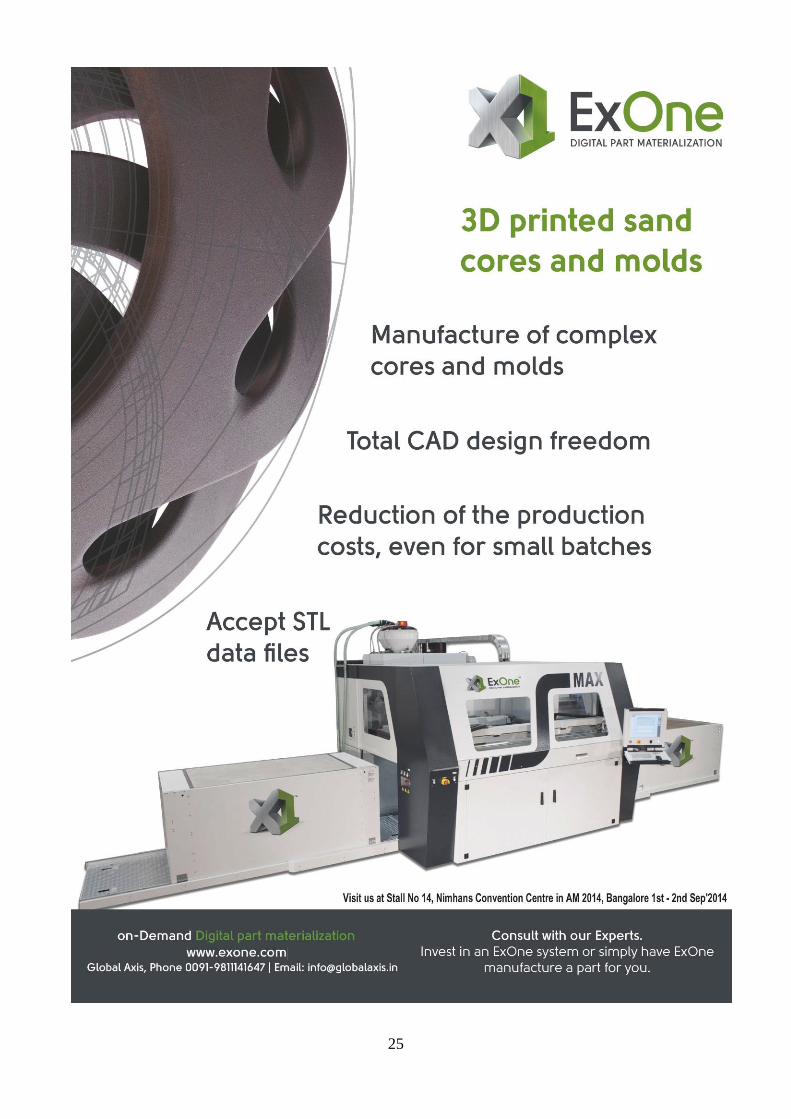
‘3D Printing Sand Moulds and Cores
by ExOne’
latest updates:
20. Press Release: RAPID.TECH
2014: EOS launches the EOS M 290 metal system to succeed the established EOSINT M 280 system
21. Press Release: SLM Solutions: New
order intake in H1 2014 underpins positive expectations
22. Press Release: Efesto and RPM
Innovations announce global strategic partnership in Metal 3D Printing, launch premium suite of Metal 3D Printing equipment, repair & free form fabrication services
A
regulars:
4.Editorial Insight
5. White Paper: New Mindset in Product Design 09. Case study: Direct Digital Manufacturing Takes Flight - Stratasys
11. Case Study: Boeing Sees Growing Value & Versatility in SLS
System and DuraForm Materials
13. ExOne – The New Standard for Pump Manufacturing
15. Case Study: Medical– US Regulator FDA Awards First Approval
for Customised 3D-Printed Polymeric Cranial Implants
17. Intake manifold: 3D Printing of sand Moulds: Voxeljet
18.The World’s Largest Argon Chamber Industrially Hardened LMD
System : Efesto LLC, USA
The
AM AM –14/15 Vol.05 Issue 27
Magazine Website: www.ammagazine.in
:
4
“3D printing--Shaping the future of Indian Foundry industry” The foundry industry in India has been growing steadily over the past
several years despite economic slowdown dented its demand from
the end user industry i.e. engineering and auto component sectors.
The Indian foundry industry is producing various grades of Castings
as per International standards.
The various types of castings which are produced are ferrous, non
ferrous, Aluminium Alloy, graded cast iron, ductile iron, Steel etc for
application in Automobiles, Railways, Pumps Compressors & Valves,
Diesel Engines, Cement/Electrical/Textile Machinery, Aero & Sanitary
pipes & Fittings etc & Castings for special applications.
To get a casting done in a foundry through conventional process we
go through various processes-- we develop cad part file, design
pattern and core box, manufacture a pattern and a core box,
produce and assemble cores, produce cope and drag mold, then we
assemble the mold package and finally produce the casting. This
conventional process is very cumbersome and time-taking.
As well, the first prototype is never the finished product and
prototypes need to be redesigned numerous times. The slow nature
and high cost of traditional prototype design do not allow
organizations to fully utilize their expertise and abilities. Also many
times we come across a better way to design our product, but due to
the costs and time involved to make these changes, we can't
implement the changes to our design.
To unfold and eliminate the monotonous and the cumbersome
conventional method, ExOne Gmbh, after spending a lot of time and
money in research and development, has successfully been able to
provide a paradigm shift from conventional manufacturing to 3D
printing. It has brought a new life to the foundry industry. Intricate parts
with undercuts, draft angles can be created in a matter of hours and
the design changes can be made numerous times giving designers
the flexibility to design a product.
ExOne‘s S-Max with a job box size of 1.8x1.0x.07m is playing a
promising role-- just design the CAD data and print the mold package
eliminating the need for patterns and tooling. Now dependency on the
tool and pattern makers is minimized. 3D is currently entering the
mainstream to great fanfare.
The technology is at its tipping point right now allowing companies to
build larger components and achieve greater precision and finer
resolution at higher speeds. This in turn transforms overall
manufacturing by slashing product-development cycle times,
eliminating tooling costs and simplifying production runs—which
makes creation of complex shapes & structures that weren‘t feasible
before. Moreover, it would help companies improve the productivity of
materials by eliminating waste that accrues in traditional
manufacturing.
India has not yet caught on the 3D printing wave like the US
and Europe have, but as competitive pressures in the market
increase, various technology patents lapse, vendors eager to fulfill
interest and demand, falling prices will make printers more affordable
for more consumers.
Expiring of 3D printing patents this year will likely to open new
avenues in 3D printing revolution which in turn can also bring down
the cost.
Others argue that the only thing holding 3D printing back is the
technology itself––printers are either too slow, too cumbersome or
incapable of printing objects that people actually want, partly due to
limitations in materials.
Despite these, it would be a positive move for the industry and may
translate into 3D printing taking off in a big way in India. Three-D
printing, no doubt will make the world a very different place-- and, with
the right strategies, a better one too.
- Global Axis (Partner to ExOne GmbH)
New Delhi, India
Editorial:
:
5
3D PRINTING CAN HELP BRING BETTER PRODUCTS TO MARKET FASTER
By Stratasys, Inc.
The terms ―3D printing‖ and ―additive manufacturing‖ refer to processes that automatically build objects layer by layer from computer data.
The technology is already well-used in many sectors including transportation, health care, military and education. Uses include building
concept models, functional prototypes, factory tooling (such as molds and robot-arm ends), and even finished goods (such as aircraft
internal components). The aerospace and medical industries in particular have developed advanced applications for 3D printing. 3D
printing is sometimes referred to as ―rapid prototyping,‖ but this term does not encompass all current uses for the technology. Materials
used in 3D printing include resins, plastics and, in some cases, metal.
The earliest method, stereolithography, has been around
since the late 1980s, but adoption was limited because of
the toxic chemicals it required and the fragility of its models.
Other technologies have evolved since then, including Fused
Deposition Modeling (FDM®). FDM, introduced in the early
1990s, lays down super-thin layers of production-grade
thermoplastic, yielding comparatively durable models.
Since 3D printing‘s inception, system reliability and model
quality have increased, resulting in diverse applications.
At the same time, prices have gone down to the point where
some systems are affordable even for small businesses.
In a 2011 report, Wohlers Associates predicted that worldwide annual sales of additive manufacturing systems will reach 15,000 units by
2015 — more than double the 2010 rate. Lower-priced professional systems will drive most of this growth.
In FDM TechnologyTM, printer software on the user‘s Windows network or workstation accepts computer-aided design (CAD) data in .stl
format. The software works like a paper printer‘s driver, sending data to the 3D printer as a job and telling the print head where to lay
down material.
Filaments of plastic modeling material and soluble support material are heated to a semi-liquid state, forced through an extrusion tip and
precisely deposited in extremely fine layers. (FDM layer thickness ranges from 0.005 inch [.127 mm] to 0.013 inch [.330 mm], depending
on the system.) The print head moves in X-Y coordinates, and the modeling base moves down the Z axis as the model and its support
material are built from the bottom up.
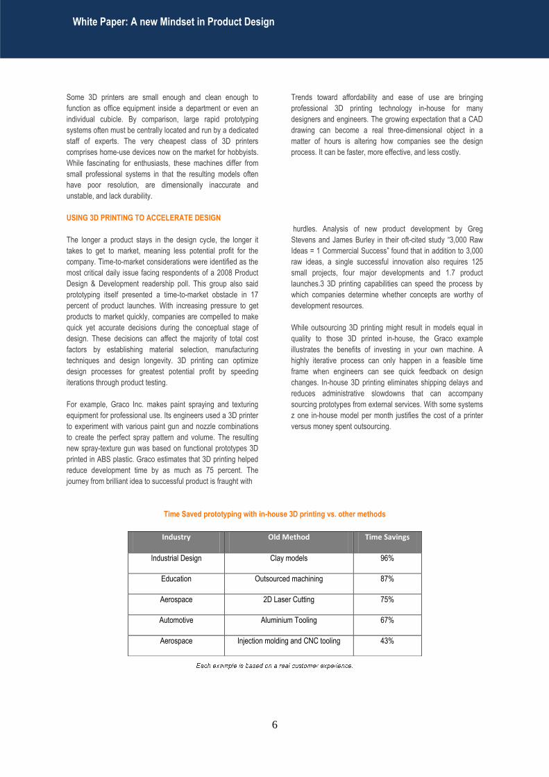
The soluble support material (brown in the example photo on this page) holds up overhanging portions while the model is being built, and
allows for complex models — even nested structures and multipart assemblies with moving parts — to be 3D printed. When the print job is
complete, the support material washes away and the model is ready to be used or, if desired, finished with paint or another process.
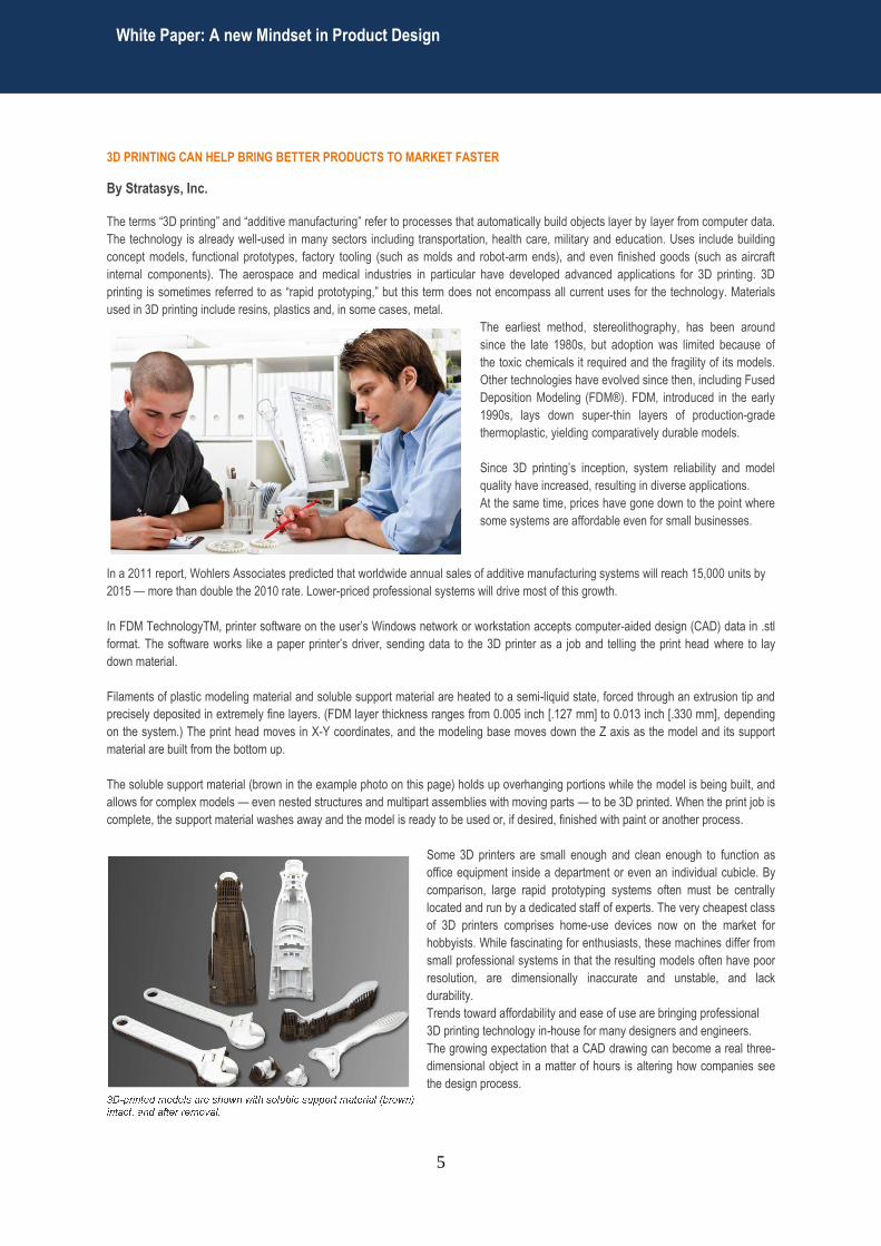
Some 3D printers are small enough and clean enough to function as
office equipment inside a department or even an individual cubicle. By
comparison, large rapid prototyping systems often must be centrally
located and run by a dedicated staff of experts. The very cheapest class
of 3D printers comprises home-use devices now on the market for
hobbyists. While fascinating for enthusiasts, these machines differ from
small professional systems in that the resulting models often have poor
resolution, are dimensionally inaccurate and unstable, and lack
durability.
Trends toward affordability and ease of use are bringing professional
3D printing technology in-house for many designers and engineers.
The growing expectation that a CAD drawing can become a real three-
dimensional object in a matter of hours is altering how companies see
the design process.
White Paper: A new Mindset in Product Design
:
6
Some 3D printers are small enough and clean enough to
function as office equipment inside a department or even an
individual cubicle. By comparison, large rapid prototyping
systems often must be centrally located and run by a dedicated
staff of experts. The very cheapest class of 3D printers
comprises home-use devices now on the market for hobbyists.
While fascinating for enthusiasts, these machines differ from
small professional systems in that the resulting models often
have poor resolution, are dimensionally inaccurate and
unstable, and lack durability.
Trends toward affordability and ease of use are bringing
professional 3D printing technology in-house for many
designers and engineers. The growing expectation that a CAD
drawing can become a real three-dimensional object in a
matter of hours is altering how companies see the design
process. It can be faster, more effective, and less costly.
USING 3D PRINTING TO ACCELERATE DESIGN
The longer a product stays in the design cycle, the longer it
takes to get to market, meaning less potential profit for the
company. Time-to-market considerations were identified as the
most critical daily issue facing respondents of a 2008 Product
Design & Development readership poll. This group also said
prototyping itself presented a time-to-market obstacle in 17
percent of product launches. With increasing pressure to get
products to market quickly, companies are compelled to make
quick yet accurate decisions during the conceptual stage of
design. These decisions can affect the majority of total cost
factors by establishing material selection, manufacturing
techniques and design longevity. 3D printing can optimize
design processes for greatest potential profit by speeding
iterations through product testing.
For example, Graco Inc. makes paint spraying and texturing
equipment for professional use. Its engineers used a 3D printer
to experiment with various paint gun and nozzle combinations
to create the perfect spray pattern and volume. The resulting
new spray-texture gun was based on functional prototypes 3D
printed in ABS plastic. Graco estimates that 3D printing helped
reduce development time by as much as 75 percent. The
journey from brilliant idea to successful product is fraught with
hurdles. Analysis of new product development by Greg
Stevens and James Burley in their oft-cited study ―3,000 Raw
Ideas = 1 Commercial Success‖ found that in addition to 3,000
raw ideas, a single successful innovation also requires 125
small projects, four major developments and 1.7 product
launches.3 3D printing capabilities can speed the process by
which companies determine whether concepts are worthy of
development resources.
While outsourcing 3D printing might result in models equal in
quality to those 3D printed in-house, the Graco example
illustrates the benefits of investing in your own machine. A
highly iterative process can only happen in a feasible time
frame when engineers can see quick feedback on design
changes. In-house 3D printing eliminates shipping delays and
reduces administrative slowdowns that can accompany
sourcing prototypes from external services. With some systems
z one in-house model per month justifies the cost of a printer
versus money spent outsourcing.
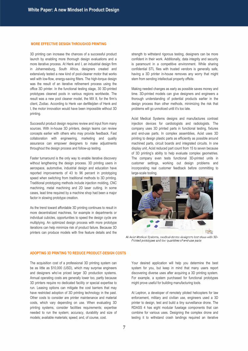
Time Saved prototyping with in-house 3D printing vs. other methods
Industry Old Method Time Savings
Industrial Design Clay models 96%
Education Outsourced machining 87%
Aerospace 2D Laser Cutting 75%
Automotive Aluminium Tooling 67%
Aerospace Injection molding and CNC tooling 43%
White Paper: A new Mindset in Product Design
:
7
MORE EFFECTIVE DESIGN THROUGH3D PRINTING
3D printing can increase the chances of a successful product
launch by enabling more thorough design evaluations and a
more iterative process. At Henk and I, an industrial design firm
in Johannesburg, South Africa, designers created and
extensively tested a new kind of pool-cleaner motor that works
well with low-flow, energy-saving filters. The high-torque design
was the result of an iterative refinement process using the
office 3D printer. In the functional testing stage, 30 3D-printed
prototypes cleaned pools in various regions worldwide. The
result was a new pool cleaner model, the MX 8, for the firm‘s
client, Zodiac. According to Henk van derMeijden of Henk and
I, the motor innovation would have been impossible without 3D
printing.
Successful product design requires review and input from many
sources. With in-house 3D printers, design teams can review
concepts earlier with others who may provide feedback. Fast
collaboration with engineering, marketing and quality
assurance can empower designers to make adjustments
throughout the design process and follow-up testing.
Faster turnaround is the only way to enable iterative discovery
without lengthening the design process. 3D printing users in
aerospace, automotive, industrial design and education have
reported improvements of 43 to 96 percent in prototyping
speed when switching from traditional methods to 3D printing.
Traditional prototyping methods include injection molding, CNC
machining, metal machining and 2D laser cutting. In some
cases, lead time required by a machine shop had been a major
factor in slowing prototype creation.
As the trend toward affordable 3D printing continues to result in
more decentralized machines, for example in departments or
individual cubicles, opportunities to speed the design cycle are
multiplying. An optimized design process with more prototype
iterations can help minimize risk of product failure. Because 3D
printers can produce models with fine feature details and the
strength to withstand rigorous testing, designers can be more
confident in their work. Additionally, data integrity and security
is paramount in a competitive environment. While sharing
confidential STL files with trusted vendors is generally safe,
having a 3D printer in-house removes any worry that might
stem from sending intellectual property offsite.
Making needed changes as early as possible saves money and
time. 3D-printed models can give designers and engineers a
thorough understanding of potential products earlier in the
design process than other methods, minimizing the risk that
problems will go unnoticed until it‘s too late.
Acist Medical Systems designs and manufactures contrast
injection devices for cardiologists and radiologists. The
company uses 3D printed parts in functional testing, fixtures
and end-use parts. In complex assemblies, Acist uses 3D
printing to design plastic parts as efficiently as possible around
machined parts, circuit boards and integrated circuits. In one
display unit, Acist reduced part count from 15 to seven because
of 3D printing‘s ability to help evaluate complex geometries.
The company even tests functional 3D-printed units in
customer settings, working out design problems and
incorporating real customer feedback before committing to
large-scale tooling.
ADOPTING 3D PRINTING TO REDUCE PRODUCT-DESIGN COSTS
The acquisition cost of a professional 3D printing system can
be as little as $10,000 (USD), which may surprise engineers
and designers who‘ve priced larger 3D production systems.
Annual operating costs are generally lower too, partly because
3D printers require no dedicated facility or special expertise to
run. Leasing options can mitigate the cost barriers that may
have restricted adoption of 3D printing technology in the past.
Other costs to consider are printer maintenance and material
costs, which vary depending on use. When evaluating 3D
printing systems, consider facilities requirements; expertise
needed to run the system; accuracy, durability and size of
models; available materials; speed; and, of course, cost.
Your desired application will help you determine the best
system for you, but keep in mind that many users report
discovering diverse uses after acquiring a 3D printing system.
For example, a system purchased for functional prototypes
might prove useful for building manufacturing tools.
At Leptron, a developer of remotely piloted helicopters for law
enforcement, military and civilian use, engineers used a 3D
printer to design, test and build a tiny surveillance drone. The
RDASS 4 has eight modular fuselage components that can
combine for various uses. Designing the complex drone and
testing it to withstand crash landings required an iterative
White Paper: A new Mindset in Product Design
:
White Paper: A new Mindset in Product Design
:

8
approach involving 200 design changes, including structural
reinforcements and aerodynamic improvements. In-house 3D
printing cut product development costs for the RDASS 4 by 60
percent over injection molding. Further, the project may not
have been commercially feasible without the 6-month head
start that 3D printing offered in getting the drone to market.
3D printing provides a highly cost-efficient means of producing
numerous design iterations and gaining immediate feedback
throughout the critical beginning stages of the development
process. The ability to refine form, fit and function quickly can
significantly improve production costs and time to market. This
can create a distinct competitive advantage for those
companies who include 3D printing as an integral part of their
design process.
Lower costs will continue to expand the 3D printing market,
especially in small to medium-sized businesses and schools.
The speed, consistency, accuracy and low cost of these
printers will help companies reduce time-to-market and
maintain a competitive edge.
White Paper: A new Mindset in Product Design
:
9
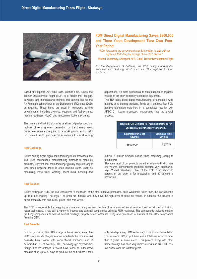
FDM Direct Digital Manufacturing Saves $800,000
and Three Years Development Time Over Four-
Year Period
“FDM has saved the government over $3.8 million to date with an expected 10-to-15-year savings of over $15 million. “
- Mitchell Weatherly, Sheppard AFB, Chief, Trainer Development Flight
For the Department of Defense, the TDF designs and builds “trainers” and “training aids” such as UAV replicas to train students.
Based at Sheppard Air Force Base, Wichita Falls, Texas, the
Trainer Development Flight (TDF) is a facility that designs,
develops, and manufactures trainers and training aids for the
Air Force and all branches of the Department of Defense (DoD)
as required. These items are used in numerous training
environments, including avionics, weapons and fuel systems,
medical readiness, HVAC, and telecommunications systems.
The trainers and training aids may be either original products or
replicas of existing ones, depending on the training need.
Some devices are not required to be working units, so it usually
isn‘t cost-efficient to purchase the actual item. For most training
applications, it‘s more economical to train students on replicas,
instead of the often extremely expensive equipment.
The TDF uses direct digital manufacturing to fabricate a wide
majority of its training products. To do so, it employs four FDM
additive fabrication machines in a centralized location with
AFSO 21 (Lean) processes incorporated into the overall
process.
Real Challenge
Before adding direct digital manufacturing to its processes, the
TDF used conventional manufacturing methods to make its
products. Conventional manufacturing typically requires longer
lead times because there is often multiple steps, such as
machining, lathe work, welding, sheet metal bending and
cutting. A similar difficulty occurs when producing tooling to
mold a part. ―Because most of our projects are either one-of-a-kind or very low volume, conventional methods become very expensive,‖ says Mitchell Weatherly, Chief of the TDF. ―Only about 10 percent of our work is for prototyping, and 90 percent is production.‖
Real Solution
Before settling on FDM, the TDF considered ―a multitude‖ of the other additive processes, says Weatherly. ―With FDM, the investment is
up front, not ongoing,‖ he says. ―The parts are durable, and they have the high level of detail we require. In addition, the process is
environmentally safe and 100% ‗green‘ with zero waste.‖
The TDF is responsible for designing and manufacturing an exact replica of an unmanned aerial vehicle (UAV) or ―drone‖ for training repair technicians. It has built a variety of internal and external components using its FDM machines. The components included most of the body components as well as several cowlings, propellers, and antennas. They also purchased a number of real UAV components from the OEM. Real Benefits
Just for producing the UAV‘s large antenna alone, using the
FDM machines did the job in about one-tenth the time it would
normally have taken with conventional methods, and it
delivered an ROI of over $12,000. The savings go beyond time,
though. For the antenna, it would have taken an outsourced
machine shop up to 20 days to produce the part, where it took
only two days using FDM — but only 15 to 20 minutes of labor.
For the entire UAV project there was a total time saved of more
than 3 years in some areas. This project, along with other
trainer savings has been very impressive with an $800,000 cost
avoidance over the last four years.
How Did FDM Compare to Traditional Methods for
Sheppard AFB over a four-year period?
Estimated Part Cost Savings
Estimated Time Savings
$800,000
3 years
Direct Digital Manufacturing Takes Flight - Stratasys
:
10
―Major advantages to the FDM system include its speed over
other processes or alternative build methods, the versatility of
FDM versus injection molding, and the ability to run multiple
parts simultaneously through the system,‖ says Weatherly.
Benefits include ease of maintenance, as well as the availability
to use multiple materials for a variety of purposes. ―Additional
capabilities include the ability to design based on function
needs instead of manufacturing constraints, and the ability to
implement design changes immediately and at minimal costs.
The versatility to manufacture any item coupled with zero
hazardous waste is one of the greatest advantages to the Air
Force,‖ says Weatherly. ―The FDM-based machines have been
used for a number of trainer projects which have tight budgets.
We have also utilized the FDM process for research and
development for our airmen and soldiers to be able to train like
we fight.‖
―For our first FDM machine purchase, we projected ROI in 4
years, but it took only 18 months,‖ Weatherly says. ―For our
second FDM machine purchase we saw ROI in only 9 months.
You will never get away from conventional methods and highly
skilled technicians, but you can give them the proper tools and
new technology that can make their job easier and competitive.
I believe FDM is one of the technologically advanced premier
manufacturing methods available. Since 2004, when we
purchased our first of four machines, the FDM process has
saved the government over $3.8 million to date with an
expected 10-to-15-year savings of over $15 million.‖
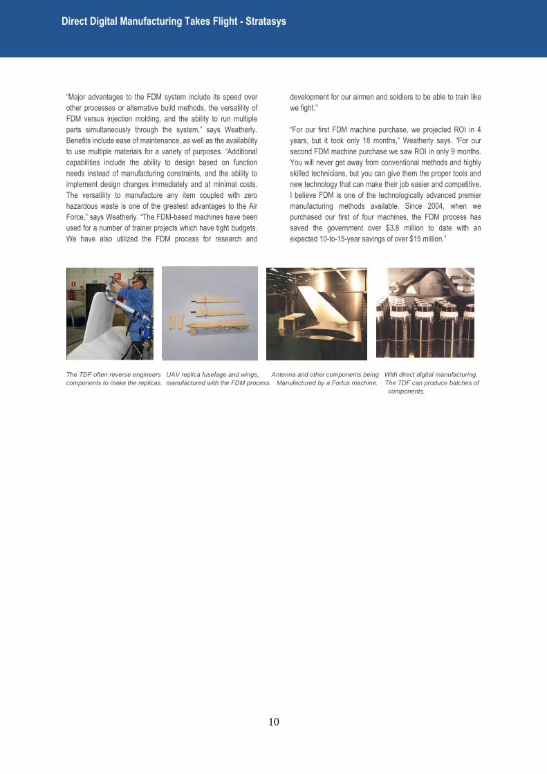
The TDF often reverse engineers UAV replica fuselage and wings, Antenna and other components being With direct digital manufacturing,
components to make the replicas. manufactured with the FDM process. Manufactured by a Fortus machine. The TDF can produce batches of
components.
Direct Digital Manufacturing Takes Flight - Stratasys
:
11
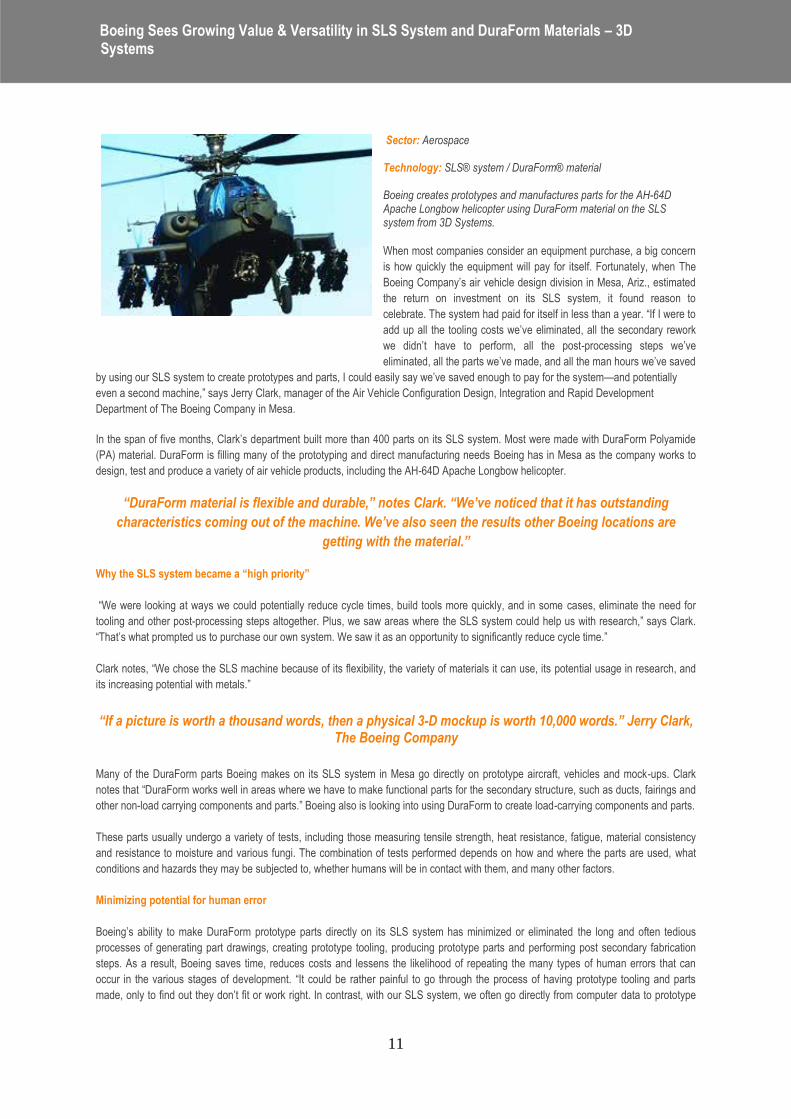
Sector: Aerospace
Technology: SLS® system / DuraForm® material Boeing creates prototypes and manufactures parts for the AH-64D Apache Longbow helicopter using DuraForm material on the SLS system from 3D Systems.
When most companies consider an equipment purchase, a big concern
is how quickly the equipment will pay for itself. Fortunately, when The
Boeing Company‘s air vehicle design division in Mesa, Ariz., estimated
the return on investment on its SLS system, it found reason to
celebrate. The system had paid for itself in less than a year. ―If I were to
add up all the tooling costs we‘ve eliminated, all the secondary rework
we didn‘t have to perform, all the post-processing steps we‘ve
eliminated, all the parts we‘ve made, and all the man hours we‘ve saved
by using our SLS system to create prototypes and parts, I could easily say we‘ve saved enough to pay for the system—and potentially
even a second machine,‖ says Jerry Clark, manager of the Air Vehicle Configuration Design, Integration and Rapid Development
Department of The Boeing Company in Mesa.
In the span of five months, Clark‘s department built more than 400 parts on its SLS system. Most were made with DuraForm Polyamide
(PA) material. DuraForm is filling many of the prototyping and direct manufacturing needs Boeing has in Mesa as the company works to
design, test and produce a variety of air vehicle products, including the AH-64D Apache Longbow helicopter.
“DuraForm material is flexible and durable,” notes Clark. “We’ve noticed that it has outstanding
characteristics coming out of the machine. We’ve also seen the results other Boeing locations are
getting with the material.” Why the SLS system became a “high priority”
―We were looking at ways we could potentially reduce cycle times, build tools more quickly, and in some cases, eliminate the need for
tooling and other post-processing steps altogether. Plus, we saw areas where the SLS system could help us with research,‖ says Clark.
―That‘s what prompted us to purchase our own system. We saw it as an opportunity to significantly reduce cycle time.‖
Clark notes, ―We chose the SLS machine because of its flexibility, the variety of materials it can use, its potential usage in research, and
its increasing potential with metals.‖
“If a picture is worth a thousand words, then a physical 3-D mockup is worth 10,000 words.” Jerry Clark, The Boeing Company
Many of the DuraForm parts Boeing makes on its SLS system in Mesa go directly on prototype aircraft, vehicles and mock-ups. Clark
notes that ―DuraForm works well in areas where we have to make functional parts for the secondary structure, such as ducts, fairings and
other non-load carrying components and parts.‖ Boeing also is looking into using DuraForm to create load-carrying components and parts.
These parts usually undergo a variety of tests, including those measuring tensile strength, heat resistance, fatigue, material consistency
and resistance to moisture and various fungi. The combination of tests performed depends on how and where the parts are used, what
conditions and hazards they may be subjected to, whether humans will be in contact with them, and many other factors.
Minimizing potential for human error
Boeing‘s ability to make DuraForm prototype parts directly on its SLS system has minimized or eliminated the long and often tedious
processes of generating part drawings, creating prototype tooling, producing prototype parts and performing post secondary fabrication
steps. As a result, Boeing saves time, reduces costs and lessens the likelihood of repeating the many types of human errors that can
occur in the various stages of development. ―It could be rather painful to go through the process of having prototype tooling and parts
made, only to find out they don‘t fit or work right. In contrast, with our SLS system, we often go directly from computer data to prototype
Boeing Sees Growing Value & Versatility in SLS System and DuraForm Materials – 3D Systems
:
12
part to installation on the aircraft. It‘s another type of paperless system. If a picture is worth a thousand words, then a physical 3-D mockup
is worth 10,000 words,‖ says Clark.
Digital manufacturing small quantities Boeing Mesa also is exploring the use of DuraForm parts to fill orders for limited-production part quantities. This solution has great
potential at Boeing.
Clark explains, ―Our primary customer is the U.S. Army, but we sell to foreign defense forces as well. Foreign customers may want the
same aircraft or vehicle that the U.S. military uses, but they may have special requirements and requests for customization or changes.‖
For example, customers may want to add their own avionics equipment onto the vehicle. ―Therefore, we may need a different cooling
system configuration and associated ducting arrangement,‖ says Clark.
―If our customers purchase 40 or 50 aircraft a year, and Boeing has to make only three or four cooling ducts per aircraft, it doesn‘t make
sense to spend the time or money producing expensive tooling and performing the multiple lay up steps,‖ says Clark. ―Here, we can
produce the DuraForm parts the customer needs directly on our SLS system. Later, if there is greater demand for more parts, we can go
forward with production tooling by building the tooling itself with our SLS system.‖
Clark adds, ―The key here is the ability to customize a baseline quickly and rapidly and produce the parts per the customer‘s needs
without adding in a lot of tooling time or costs to the process.‖
Clark notes that Boeing has used DuraForm parts and prototypes for a long and growing list of applications, including creating
visualization samples for suppliers; providing quotes; producing samples of existing parts that could not be produced any other way
except through dissection of a complex assembly; conducting internal design review and technical review sessions with upper
management; performance reviews (with customers‘ sample parts provided); and producing scale models for testing
―Another benefit we are seeing is improved communication with our suppliers and team members and also among colleagues.‖ ―This is particularly true when technical staff members are explaining a part to non-technical staff members,‖ says Clark. ―When you get people to understand each other and communicate, it definitely helps the projects run more smoothly.‖ ―Probably one of our greatest challenges here is getting our people to understand that our SLS system is not just a machine for making pretty models,‖ Clark says. ―Sure you can do that, but right now we are using it for actual parts, functional parts, rapid prototyping, rapid tool development and rapid manufacturing.‖
Clark adds, ―We want more people within the corporation to know this and to understand and see the potential applications and uses.‖
Boeing Sees Growing Value & Versatility in SLS System and DuraForm Materials – 3D Systems
:
13
For years, the pump industry has relied on traditional processes to create the molds for
pumps and parts, which, because of the necessary man-hours, often result in work
stoppages and slowdowns. But now the industry is in the midst of an overhaul as additive
manufacturing – think 3D printing for the industrial sector – led by ExOne offers the promise
of a fast and cost-effective way to build the sand molds for castings.
ExOne, a publicly traded leader in the additive manufacturing space, provides 3D printing machines, 3D printed products and related
services to industrial customers in several segments, including pumps, automotive, aerospace, medical and energy. The ExOne process
gives traditional manufacturers an opportunity to reduce costs, lower the risk of trial and error and create opportunities for design
innovation.
ExOne delivers functional parts – primarily in stainless steel and foundry silica sand – which can be used for both prototyping and real-
world production applications.
Manufacturers that use ExOne‘s additive manufacturing process see significant, strategic advantages over traditional methods. The ability
to expand creativity and flexibility with virtually unlimited design complexity, without the need for draft angles, enables product designs
previously unattainable. Additionally, the opportunity for rapid production of castings and prototypes in turn reduces lead times
significantly, and gets new products to the market faster.
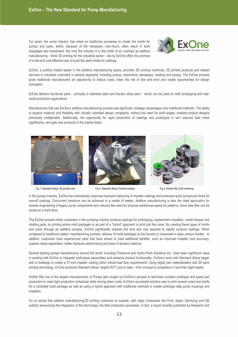
Fig 1: Standard Alloys‘ 3D printed core Fig 2: Standard Alloys‘ finished casting Fig 3: Andritz Ritz CAD rendering
In the pumps industry, ExOne has dramatically improved hydraulic balancing of impeller castings and produced quick turnaround times for
one-off castings. Concurrent iterations can be achieved in a matter of weeks. Additive manufacturing is also the ideal application for
reverse engineering of legacy pump components and reduces the need for physical warehouse space for patterns, since data files can be
stored on a hard drive.
The ExOne process helps customers in the pumping industry produce castings for prototyping, replacement impellers, volute shapes and
rotating parts, by printing entire mold packages or as part of a ―hybrid‖ approach to print just the cores. By creating these types of molds
and cores through an additive process, ExOne significantly reduces the time and cost required to rapidly produce castings. When
compared to traditional pattern manufacturing process, delivery of mold packages to the foundry is measured in days versus months. In
addition, customers have experienced parts that have shown to yield additional benefits, such as improved impeller core accuracy,
superior blade registration, better hydraulic performance and ease of dynamic balance.
Several leading pumps manufacturers around the world, including Flowserve and Hydro Parts Solutions Inc., have seen significant value
in working with ExOne to integrate multi-piece assemblies and enhance product functionality. ExOne‘s work with Standard Alloys began
with a challenge to create a 57-inch impeller casting within critical lead time requirements. Using digital part materialization and 3D sand
printing technology, ExOne produced Standard Alloys‘ largest RCT core to date – from concept to completion in less than eight weeks.
Andritz Ritz one of the largest manufacturers of Pumps also sought out ExOne‘s process to fast-track complex prototype and spare part
production to meet tight production schedules while driving down costs. ExOne‘s successful solution was to print several cores and shells
for a complete mold package as well as using a hybrid approach with traditional methods to create prototype step pump housings and
impellers.
It‘s no secret that additive manufacturing/3D printing continues to explode, with major companies like Ford, Apple, Samsung and GE
publicly announcing the integration of the technology into their production processes. In fact, a report recently published by Research and
ExOne – The New Standard for Pump Manufacturing
:

14
Markets claims the 3D printing/additive manufacturing industry will be worth $4 billion by 2025. To meet the unique needs of specific
customers, ExOne has made significant investments in its material qualification research and testing with the opening of a new material
characterization and testing facility in St. Clairsville, Ohio in April 2013.
ExOne has firmly positioned itself as the leader in the industrial market, and over the past year has made significant strides to further
solidify that position. The company continues to develop machines that increase print speeds and reduce lead time in an effort to
continually lower the cost curve for industrial customers. ExOne‘s S-Max 3Dsand printer creates complex sand casting cores and molds
directly from CAD data, in about 24 – 30 hours - without hard tooling, which significantly reduces lead time, increases design freedom, and
improves the entire casting process chain.
ExOne – The New Standard for Pump Manufacturing
:
15
Oxford Performance Materials (OPM) made medical history when they
received the first Food and Drug Administration (FDA) 510(k) clearance
for their polymer additive manufactured OsteoFab™ Patient Specific
Cranial Device (OPSCD). The customizable implant made of the plastic
material PEKK is designed to restore voids in the skull caused by trauma
or disease. Manufactured in a matter of hours with Additive
Manufacturing (AM) technology by EOS, the implant saw its first use just
a few days later when the device was successfully implanted in a patient
missing a significant portion of cranial bone.
Challenge
However, PEKK has a high melting point relative to other polymers. And the
EOSINT P 800 is the only industrial 3D-printing system in the world which can
process the high-temperature polymer via additive layer manufacturing. But it
wasn‘t just a matter of buying the system one day and making a product the
next. Scott DeFelice, President and CEO of OPM, explains the arduous path
to commercialization of patient specific implants: ―For starters, you need an
ISO 13485 compliant facility that has design controls and an appropriate clean
manufacturing environment. Furthermore you need to be compliant with CFR
21 cGMP (current Good Manufacturing Practices). Add to that a completely
validated process and ISO 10993 biocompatibility data on your finished parts.
In short, you need a lot of stuff in your bucket.‖
Solution
The high-temperature plastic has a number of mechanical and thermal
qualities that make it highly suitable for cranial reconstruction. It has a density
and stiffness similar to bone, it is lighter than traditional implant material such
as titanium and stainless steel, it hardly reacts with other substances and it is
radiolucent so as not to interfere with diagnostic imaging equipment.
Perhaps its most exciting attribute is bone‘s affinity to the material. ―Based on research studies, it is osteoconductive,‖ says DeFelice. In
some implants, the surrounding bone pulls away from the site over time and you have to rely on screws to hold everything in place
forever. ―Since PEKK has shown osteoconductive properties, long-term implant stability may be easier to achieve than with other
materials. And given the correct implant design, results are getting even better. You can obtain a multiplying effect by increasing surface
area and achieving intimate contact between the implant and native tissues,‖ explains DeFelice.
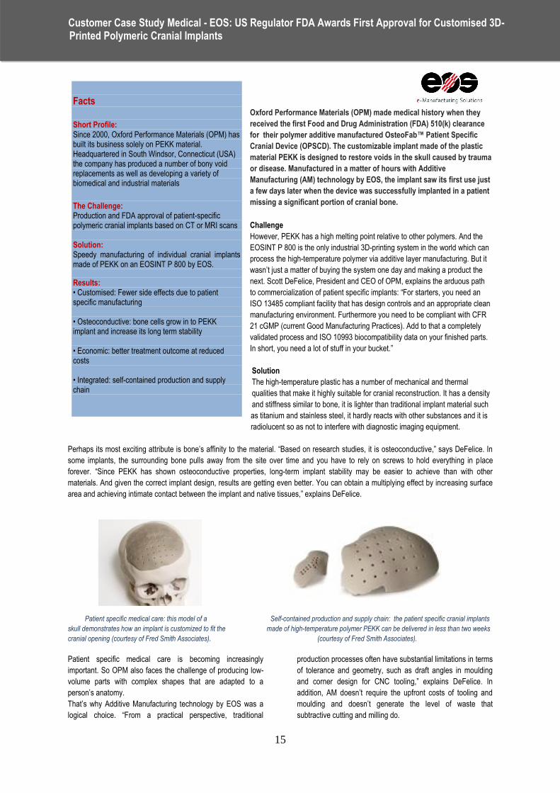
Patient specific medical care: this model of a Self-contained production and supply chain: the patient specific cranial implants
skull demonstrates how an implant is customized to fit the made of high-temperature polymer PEKK can be delivered in less than two weeks
cranial opening (courtesy of Fred Smith Associates). (courtesy of Fred Smith Associates).
Patient specific medical care is becoming increasingly
important. So OPM also faces the challenge of producing low-
volume parts with complex shapes that are adapted to a
person‘s anatomy.
That‘s why Additive Manufacturing technology by EOS was a
logical choice. ―From a practical perspective, traditional
production processes often have substantial limitations in terms
of tolerance and geometry, such as draft angles in moulding
and corner design for CNC tooling,‖ explains DeFelice. In
addition, AM doesn‘t require the upfront costs of tooling and
moulding and doesn‘t generate the level of waste that
subtractive cutting and milling do.
Facts
Short Profile: Since 2000, Oxford Performance Materials (OPM) has built its business solely on PEKK material. Headquartered in South Windsor, Connecticut (USA) the company has produced a number of bony void replacements as well as developing a variety of biomedical and industrial materials
The Challenge: Production and FDA approval of patient-specific polymeric cranial implants based on CT or MRI scans Solution: Speedy manufacturing of individual cranial implants made of PEKK on an EOSINT P 800 by EOS.
Results: • Customised: Fewer side effects due to patient specific manufacturing • Osteoconductive: bone cells grow in to PEKK implant and increase its long term stability • Economic: better treatment outcome at reduced costs • Integrated: self-contained production and supply chain
Customer Case Study Medical - EOS: US Regulator FDA Awards First Approval for Customised 3D- Printed Polymeric Cranial Implants
:
16
After an intense navigation of regulatory hurdles, it was
possible to start creating of a patient specific cranial implant.
DeFelice sets the scene: ―Based on a CT or MRI scan of the
injured area, a slice file is generated which divides the data into
cross-sectional layers. After review by a physician, it is sent to
OPM. Using 3D design software, a team of design engineers
create an implant based on the file to precisely fit that patient‘s
anatomy. Once you have that, you get approval of the implant
design from the surgeon, and then print the part.‖
The manufacturing is entirely automatic. The EOSINT P 800
lays down a thin layer of powder on its build platform. Guided
by the lowest slice of the implant design file, a high-
temperature laser melts a cross section of the implant design.
When that layer is done, the build platform lowers, the system
distributes a new powder layer on top of the old one, and the
laser melts the next cross section. The process is repeated
until the entire implant is built.
Once the implant has been removed from the powder cake, it‘s
ready for quality inspection. ―In addition to mechanical and
analytical testing, we use a structured light scanner run 100
percent line-of-sight metrology inspection to certify the
dimensional accuracy of the final product,‖ DeFelice says. The
implant is then shipped to the hospital. The total process takes
less than two weeks from the time the data is received to the
time the implant is shipped.
Results
This self-contained production and supply chain are good news
for the patient. The right implant shortens the duration of
surgery, the patient recovers more quickly and the risk of
infection is reduced.
Hospitals benefit and typical operating room rates run upwards
of $60 per minute, so pressure is high to manage the costs of
patient care. Scott DeFelice adds: ―The new medical paradigm
is about improving outcomes while reducing costs. That‘s what
AM technology helps us accomplish.‖
After having successfully created and obtained FDA approval
for their cranial implant, OPM is making plans to explore other
implant opportunities throughout the body. DeFelice states:
―EOS technology is capable of producing practically any shape
geometry to match the precise needs of an individual patient. It
lifts manufacturability restrictions. There is no region of the
human skeletal anatomy that won‘t be touched by this
technology. When the patient is on the operating table and the
part shows up and doesn‘t fit, you‘re putting someone‘s life at
risk. The first implant case was very large, measuring nearly six
inches across, and large areas of critical tissue had to be
exposed during surgery. So it was critical that the implant
should fit perfectly. Every second is critical in that situation,‖
explains Scott DeFelice. Medical engineering has very high
standards: it demands the right material, the right process, the
right quality system, and the right metrology. Together these
elements are life-savers.
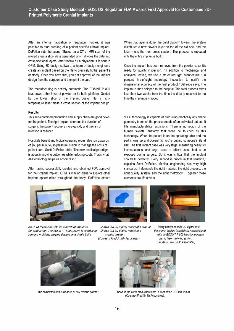
An OPM technician sets up a batch of implants Shown is a 3D digital model of a cranial Using patient-specific 3D digital data, for production. The EOSINT P 800 system is capable of Shown is a 3D digital model of a the cranial implant is additively manufactured running multiple, varying designs in a single build cranial implant with an EOSINT P 800 high-temperature (Courtesy Fred Smith Associates). plastic laser-sintering system (Courtesy Fred Smith Associates).
The completed part is cleaned of any residue powder Shown is the OPM production team in front of the EOSINT P 800 (Courtesy Fred Smith Associates).
Customer Case Study Medical - EOS: US Regulator FDA Awards First Approval for Customised 3D- Printed Polymeric Cranial Implants
:
17
Project description:
The manufacture of sand moulds for cast parts with such
thin layers (0.15 mm) presents a great challenge for the
construction of sand moulds. Even experts are surprised by
the fact that this process can be completed in a fully
automated manner and without the use of tools on the basis
of 3D CAD data.
With conventional methods, model and mould builders would
require several weeks to complete this process. The
aluminium clutch case is used for the prototype of a vehicle
clutch.
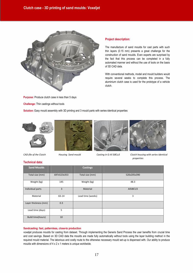
Purpose: Produce clutch case in less than 5 days Challenge: Thin castings without tools Solution: Easy mould assembly with 3D printing and 3 mould parts with series-identical properties
CAD-file of the Clutch Housing Sand mould Casting in G-Al Si8Cu3 Clutch housing with series-identical
properties
Technical data:
Sandcasting: fast, patternless, close-to production
voxeljet produces moulds for casting from dataset. Through implementing the Generis Sand Process the user benefits from crucial time
and cost savings. Based on 3D CAD data the moulds are made fully automatically without tools using the layer building method in the
required mould material. The laborious and costly route to the otherwise necessary mould set-up is dispensed with. Our ability to produce
moulds with dimensions of 4 x 2 x 1 meters is unique worldwide.
Sand Moulds Castings
Total size (mm) 697x523x353 Total size (mm) 520x205x390
Weight (kg) 145 Weight (kg) 48.3
Individual parts 3 Material AISI8CU3
Material GS-14 Lead time (weeks) 3
Layer thickness (mm) 0.3
Lead time (days) 5
Build time(hours) 10
Clutch case - 3D printing of sand moulds: Voxeljet
:
18
Efesto LLC, USA - The World’s Largest Argon Chamber Industrially Hardened LMD System
:

19
Efesto LLC, USA - The World’s Largest Argon Chamber Industrially Hardened LMD System
:
20
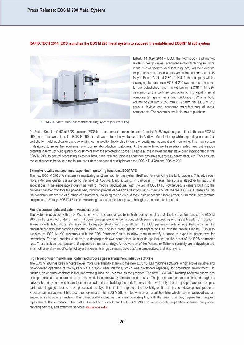
RAPID.TECH 2014: EOS launches the EOS M 290 metal system to succeed the established EOSINT M 280 system
Erfurt, 14 May 2014 – EOS, the technology and market
leader in design-driven, integrated e-manufacturing solutions
in the field of Additive Manufacturing (AM), will be exhibiting
its products at its stand at this year‗s Rapid.Tech, on 14-15
May in Erfurt. At stand 2-301 in Hall 2, the company will be
displaying its brand-new EOS M 290 system, the successor
to the established and market-leading EOSINT M 280,
designed for the tool-free production of high-quality serial
components, spare parts and prototypes. With a build
volume of 250 mm x 250 mm x 325 mm, the EOS M 290
permits flexible and economic manufacturing of metal
components. The system is available now to purchase.
EOS M 290 Metal Additive Manufacturing system (source: EOS)
Dr. Adrian Keppler, CMO at EOS stresses, ―EOS has incorporated proven elements from the M 280 system generation in the new EOS M
290, but at the same time, the EOS M 290 also allows us to set new standards in Additive Manufacturing while expanding our product
portfolio for metal applications and extending our innovation leadership in terms of quality management and monitoring. This new system
is designed to serve the requirements of our serial-production customers. At the same time, we have also created new optimisation
potential in terms of build quality for customers from the prototyping space.‖ Despite all the innovations that have been incorporated in the
EOS M 290, its central processing elements have been retained: process chamber, gas stream, process parameters, etc. This ensures
constant process behaviour and in turn consistent component quality beyond the EOSINT M 280 and EOS M 290.
Extensive quality management, expanded monitoring functions, EOSTATE
The new EOS M 290 offers extensive monitoring functions both for the system itself and for monitoring the build process. This adds even
more extensive quality assurance to the field of Additive Manufacturing. In particular, it makes the system attractive for industrial
applications in the aerospace industry as well for medical applications. With the aid of EOSTATE PowderBed, a camera built into the
process chamber monitors the powder bed, following powder deposition and exposure, by means of still images. EOSTATE Base ensures
the consistent monitoring of a range of parameters, including the position of the Z axis or scanner, laser power, air humidity, temperature
and pressure. Finally, EOSTATE Laser Monitoring measures the laser power throughout the entire build period.
Flexible components and extensive accessories
The system is equipped with a 400 Watt laser, which is characterised by its high radiation quality and stability of performance. The EOS M
290 can be operated under an inert (nitrogen) atmosphere or under argon, which permits processing of a great breadth of materials.
These include light alloys, stainless and tool-grade steels, and superalloys. The EOS parameter sets ensure that parts can be
manufactured with standardised property profiles, resulting in a broad spectrum of applications. As with the previous model, EOS also
supplies its EOS M 290 customers with the EOS ParameterEditor, to allow them to modify a range of exposure parameters for
themselves. The tool enables customers to develop their own parameters for specific applications on the basis of the EOS parameter
sets. These include laser power and exposure speed or strategy. A new version of the Parameter Editor is currently under development,
which will also allow modification of layer thickness, inert gas stream, build platform temperature, and skip layers.
High level of user friendliness, optimised process gas management, intuitive software
The EOS M 290 has been rendered even more user friendly thanks to the new EOSYSTEM machine software, which allows intuitive and
task-oriented operation of the system via a graphic user interface, which was developed especially for production environments. In
addition, an operator assistant is included which guides the user through the program. The new EOSPRINT Desktop Software allows jobs
to be prepared and computed directly at the workplace, separately from the build process. The job file can then be transferred through the
network to the system, which can then concentrate fully on building the part. Thanks to the availability of offline job preparation, complex
parts with large job files can be processed quickly. This in turn improves the flexibility of the application development process.
Process gas management has also been optimised. The EOS M 290 is fitted with an air circulation filter which itself is equipped with an
automatic self-cleaning function. This considerably increases the filters operating life, with the result that they require less frequent
replacement. It also reduces filter costs. The solution portfolio for the EOS M 290 also includes data preparation software, component
handling devices, and extensive services. www.eos.info.
Press Release: EOS M 290 Metal System
:
21
Luebeck, July 2, 2014 – SLM Solutions Group AG, a leading provider of metal-based additive manufacturing technology (also
referred to as “3D printing”), sees the positive trend in new order intake as of the end of the first half of the year as confirmation
of its optimistic expectation for the current 2014 financial year.
The uptrend in SLM Solutions' order book position continued during the first six months of 2014, as expected: New order intake was
boosted to a total of 19 machines – almost double last year's 10 machines. These orders include two orders for the SLM 500HL flagship
product, currently the most productive laser melting system on the market. This shift towards high-value systems boosts the total value of
the machines that have been ordered, the most important driver of corporate sales revenues.
Uwe Bögershausen, CFO of SLM Solutions Group AG, expressed his satisfaction: "Since the start of the year, we have observed a
positive trend in our new order intake, and consequently regard this as a confirmation of our expectation for the full year. Internationally
operating industrial companies are currently making a transition to deploying laser melting systems also for the direct component
manufacturing. This is affecting components as varied as hip implants and dental prostheses, complex tooling applications, and
aerospace components. The attractive market segment for metal-based 3D printing is about to pass the inflection point, and is now
experiencing a growth boom from which SLM Solutions, in particular, will benefit as one of the technology leaders."
About the company:
SLM Solutions Group AG, headquartered in Luebeck, Germany, is a leading provider of metal-based additive manufacturing technology
(also commonly referred to as ―3D printing‖). SLM Solutions focuses on the development, assembly and sales of machines and integrated
system solutions in the field of selective laser melting, vacuum and metal casting. SLM Solutions currently employs over 80 people in
Germany and the USA. The products are used worldwide by customers in particular from the aerospace, energy, healthcare and
automotive industries. SLM Solutions stands for technologically advanced, innovative and highly efficient integrated system solutions.
Contact:
Mark Appoh, cometis AG
Unter den Eichen 7, 65195 Wiesbaden
Telephone: +49 (611) 205855-21
Email: [email protected]
Press Release: SLM Solutions: New order intake in H1 2014 underpins positive expectations
:
22
EFESTO AND RPM INNOVATIONS ANNOUNCE GLOBAL STRATEGIC PARTNERSHIP IN METAL 3D PRINTING, LAUNCH
PREMIUM SUITE OF METAL 3D PRINTING EQUIPMENT, REPAIR & FREE-FORM FABRICATION SERVICES
Superior Township, MI – June 8, 2014. EFESTO and RPM Innovations, both rapidly growing and leading enterprises specializing
in Metal 3D Printing technology and applications, today announced a long term global strategic partnership to offer a comprehensive
range of professional grade, industrially hardened, and production proven Laser Metal Deposition (LMD) equipment and services
for Metal Additive Manufacturing. (LMD is also known as “Powder Fed”, “Blown Powder”, “Directed Energy Deposition”, “Laser
Deposition Technology”...).
This partnership brings immediate benefit to potential and existing users of Metal 3D Printing by making available a comprehensive line
of premium, robust and production proven LMD machines and the highest quality contract services, supported by more than 50,000 hours
of expertise in advanced LMD applications.
Ashok Varma, CEO of EFESTO, said: “We met hundreds of potential and existing industrial users, and identified a large global
opportunity to satisfy a glaring unmet need - the significant gap between demand and availability of truly industrial grade LMD systems
and the practical experience required to ensure good results and economic viability. Most currently installed systems are in laboratories or
light industrial applications, many idle or under-utilized, with few suppliers and users having the practical experience to optimally utilize this
technology and reduce “time to value”. Metal 3D Printing grew 75% in 2013 over 2012, twice the growth of overall 3D Printing. We
believe this trend will accelerate, further expanding the gap between supply and demand. Together with RPMI, we bring a holistic set of
solutions, experience, and capability to the global industrial marketplace. Our primary mission is to delight our customers, and to make a
profound, enduring and positive impact on this emerging industry.”
The companies together will offer the following solutions and services:
• Metal 3D Printing Equipment: Premium, Industrially hardened, production proven, Argon chamber, and standard laser build envelope
from (XYZ) 600mm x 600mm x 600mm to 1500mm x 1500mm x 2100mm.
• Metal 3D Printing Contract Services: Free form fabrication, repair and reclamation, hybrid manufacturing, small lot production, R&D,
process validation pilots, ―design for Additive‖ engineering support.
• Metal 3D Printing Service Bureaus: Turnkey, Joint Venture, and Build Operate Transfer (BOT) – business case, design engineering,
equipment, process development, training, support, management.
• Custom Engineering: Larger systems, work piece handling, inter-changeable laser heads for surface treatment, custom nozzles,
custom ―process recipes‖, advanced process monitoring and control …
• Global Turnkey Support: Delivery, Installation, Commissioning, Operator/Expert Training, Maintenance Contracts, Extended
Warranties, Tele-Service, Rapid Response, Certified Powders/Consumables.
Robert Mudge, CEO of RPM Innovations and RPM & Associates, said: ―We originally purchased our first LMD machine from an
outside manufacturer in 2004. By 2007 we realized this system was not large enough or robust enough for our growing operations. We
began investigating existing laser system integrators that could build us a larger premium system so we could meet our customer needs.
We were not able to “find” a suitable solution so we decided to design and built our own laser deposition system (RPMI557), which we
commissioned in 2009. To date, we have added a total of three additional RPMI 557 systems as we continue to serve our customers in
the defense, aerospace, energy, mining and heavy industries. Typically, we deposit more than 15,000 pounds of Titanium, Stainless
Steel, Cobalt and Nickel Based Super Alloys annually, and are experiencing exceptional growth in our core LMD services business.‖
EFESTO and RPMI have partnered to commercialize RPMI‘s 557 system for third party use, as well as a full range of smaller systems to
address less demanding requirements. All systems retain the core design principles of the industrially hardened 557 platform. The two
companies will continue to serve their existing respective markets and customers, and jointly provide application expertise and customer
support worldwide. Collectively, this partnership creates the leading specialized entity for revenues in metal 3D Printing with Laser
Metal Deposition, deploying more than 40 dedicated engineering, applications and business development specialists operating in the
Americas, Europe and Asia, and a rapidly growing sales pipeline already in excess of $ 50 million.
Press Release: Efesto and RPM Innovation announce global strategic partnership
:

23
Robert Mudge added: ―After several years of in-house development and thousands of hours of operation, we recently decided to offer our
systems for sale into the 3D printing market. Teaming with EFESTO and their global vision and sales network, we expect our synergy will
create exceptional value and opportunity for the 3D printing industry. RPMI will continue to service its existing customer base in North
America and parts of Europe while EFESTO will service other selected global markets. We are very pleased to be teamed
with EFESTO and anticipate exponential mutual growth as additive manufacturing matures.‖
Ashok Varma added: ―Partnering with RPMI was a straightforward and logical decision. RPMI has seen increasing customer requests to
purchase RPMI built LMD systems, and EFESTO required a comprehensive line of industrial grade and production proven systems to
satisfy its customer requirements. RPMI’s historical focus has primarily been in North America while EFESTO operates
globally. RPMI perfected the service bureau quality and business model, and EFESTO has several requirements to establish 3D Printing
service bureaus across the globe. This is going to be an intensely exciting time for both companies.‖
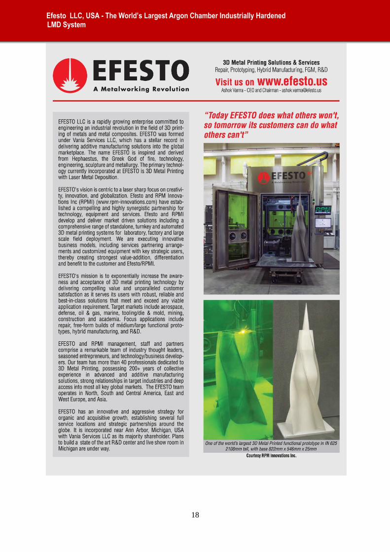
EFESTO LLC is a rapidly growing global enterprise committed to engineering an industrial revolution in the field of metal 3D
Printing.EFESTO has a hybrid business model, offering equipment, services, and establishing fully equipped service bureaus in strategic
locations around the world. EFESTO‘s vision and mission is to exponentially increase the awareness and acceptance of metal 3D
Printing. Target markets include aerospace, defense, energy, marine, tooling/die & mold, mining and construction. Focus applications
include repair, free-form fabrication, hybrid manufacturing and advanced R&D. EFESTO teams operate in the Americas, East and West
Europe, and Asia.
RPM Innovations, Inc. is the leading Laser Metal Deposition services provider in North America and possibly in the world, specializing
infreeform fabrication, hybrid manufacturing and repair applications for the aerospace, defense, oil & gas, power, mining and heavy
industries. RPMI has successfully manufactured some of the industry‘s largest metal 3D Printed components using Titanium and Nickel
Super Alloys in their own RPMI 557 laser systems. RPMI has manufactured its premium industrial grade RPMI 557 laser systems for in-
house use since 2009 and currently operates a total of 4 machines in continuous production. RPMI is now offering four sizes (222, 434,
535, 557) of their systems for sale to third party users. RPMI was the recipient of the Gold Boeing Performance Excellence Award in
2010 and Silver Boeing Performance Excellence Award in 2013.
EFESTO Media Contact: Albert Sellas
www.efesto.us
RPMI Media Contact: Nick Wald
www.RPM-innovations.com
Press Release: Efesto and RPM Innovation announce global strategic partnership
:
24
25
26
27
Related Documents


