Universidade do Minho Escola de Engenharia Aly Ahmed Upgrading BIM Processes in a Structural Design Office September 2021 UMinho | 2021 Aly Ahmed Upgrading BIM Processes in a Structural Design Office Co-funded by the Erasmus+ Programme of the European Union The European Master in Building Information Modelling is a joint initiative of:

Welcome message from author
This document is posted to help you gain knowledge. Please leave a comment to let me know what you think about it! Share it to your friends and learn new things together.
Transcript

Universidade do MinhoEscola de Engenharia
Aly Ahmed
Upgrading BIM Processesin a Structural Design Office
September 2021UM
inho
| 2
021
Aly
Ahm
edU
pgra
ding
BIM
Pro
cess
esin
a S
truc
tura
l Des
ign
Off
ice
Co-funded by the Erasmus+ Programme of the European Union
The European Master in Building Information Modelling is a joint initiative of:

Universidade do Minho
Escola de Engenharia
Aly Ahmed
Upgrading BIM Processes in a Structural
Design Office
Master Dissertation
European Master in Building Information Modelling
Work conducted under supervision of:
Miguel Azenha
Hélder S. Sousa
João Vieira (Tutor in Company)
September, 2021

Upgrading BIM Processes in a Structural Design Office
Erasmus Mundus Joint Master Degree Programme – ERASMUS+
European Master in Building Information Modelling BIM A+ ii
AUTHORSHIP RIGHTS AND CONDITIONS OF USE OF THE
WORK BY THIRD PARTIES
This is an academic work that can be used by third parties, as long as internationally accepted rules
and good practices are respected, particularly in what concerts to author rights and related matters.
Therefore, the present work may be used according to the terms of the license shown below.
If the user needs permission to make use if this work in conditions that are not part of the licensing
mentioned below, he/she should contact the author through the RepositóriUM platform of the
University of Minho.
License granted to the users of this work
Attribution
CC BY
https://creativecommons.org/licenses/by/4.0/

Upgrading BIM Processes in a Structural Design Office
Erasmus Mundus Joint Master Degree Programme – ERASMUS+
European Master in Building Information Modelling BIM A+ iii
ACKNOWLEDGEMENTS
First of all, I would like to express my gratitude to the European Commission, which supported me
during the whole BIM A+ Master Program with an Erasmus Mundus scholarship. Without it, this wok
would not be possible.
Thank you, Professor Miguel Azenha, for the availability, wise guidance, and all support dispended
during the whole development of this work. and for your rich knowledge expressed throughout the
development of this master’s thesis.
Thank you, Dr Hélder S. Sousa for the constructive and rich knowledge exchange during the whole
Master Program.
I wish to express my sincere thanks to Newton partner company for providing the opportunity of this
thesis collaboration. I am very grateful for the assistance given by the partners João Vieira and José
Carlos Lino, for sharing their knowledge, time, and support for the development of this research.
Thank you, Aline, and Tiago, for being wonderful and supportive friends, sharing me my ups and
downs. I am lucky to have friends like both of you.
Thank you, my sister Nada, and my parents, for your unconditional support and love.
Thank you, my BFF Eman, and Mekkawy, for being supportive, thank you for being in my life.

Upgrading BIM Processes in a Structural Design Office
Erasmus Mundus Joint Master Degree Programme – ERASMUS+
European Master in Building Information Modelling BIM A+ iv
STATEMENT OF INTEGRITY
I hereby declare having conducted this academic work with integrity. I confirm that I have not used
plagiarism or any form of undue use of information or falsification of results along the process leading
to its elaboration.
I further declare that I have fully acknowledged the Code of Ethical Conduct of the University of
Minho.

Upgrading BIM Processes in a Structural Design Office
Erasmus Mundus Joint Master Degree Programme – ERASMUS+
European Master in Building Information Modelling BIM A+ v
RESUMO
A metodologia BIM permite auxiliar os engenheiros estruturais no desenvolvimento integrado da
certificação de um projeto estrutural, reduzindo erros e aumentando a ligação entre as vertentes de
engenharia e arquitetura. De igual forma, BIM permite que engenheiros estruturais, desenhadores e
responsáveis pela execução melhorem a qualidade do projeto estrutural e a cooperação entre
profissões. Embora exista investigação teórica sobre a importância dos processos BIM na indústria de
engenharia estrutural, existe uma lacuna no que respeita à discussão sobre a implementação dos
processos BIM de forma prática.
Este trabalho pretende apresentar como atualizar de forma prática os processos de trabalho num
escritório de projeto para lidar com os novos desafios e inovações no campo de BIM com objetivo de
aumentar a produtividade interna do trabalho em diferentes usos de BIM na fase de projeto. Além
disso, é almejado definir novas estratégias reestruturado esses processos para serem mais integrados,
digitalizados e com maior controlo da qualidade da produção, permitindo assim aumentar a eficiência
do trabalho e reduzindo ao tempo despendido.
Dessa forma, esta dissertação forneceu uma estrutura para atualizar um processo BIM na fase de
projeto de forma os usos de BIM desejados, dentro do escritório de design Newton, através da revisão
do modelo interno de BIM, com biblioteca de objetos, e modificando esses objetos de forma a atender
às necessidades da fase de projeto. Além disso, foram revistos os processos de modelação e projeto
utilizados de forma a automatizar algumas tarefas repetitivas para que os projetistas disponham de
mais tempo produtivo.
Palavras-chave: Building Information Modeling (BIM), Dimensionamento estrutural, template BIM,
Biblioteca de objetos, Manual de modelação).

Upgrading BIM Processes in a Structural Design Office
Erasmus Mundus Joint Master Degree Programme – ERASMUS+
European Master in Building Information Modelling BIM A+ vi
ABSTRACT
BIM software supports structural engineers in developing integrative allocation of structural design
certification, reducing errors, and increasing the association between engineering and architecture
departments. BIM allows structural engineers, detailers, and fabricators to improve structural design
and association among professions. Even though much research discussed the importance of BIM
processes in the structural engineering industry theoretically, there was a lack of research that
discussed the implementation of BIM processes in practical aspects.
This work intends to provide practical upgrading for work processes in a Design office to deal with
new BIM challenges and implementation for new BIM innovations to increase the work productivity
for the desired BIM uses within a company in the Design stage. Also, define new strategies to re-
engineer these processes to be more integrated and digitalized with controlling the production quality,
increasing the work efficiency, and save more time.
Therefore, this dissertation has provided upgrading framework for the BIM process in the design stage
to achieve the desired BIM uses for Newton design office through revising the internal BIM template
with objects library and modify them to cover the design stage needs. Also, revise the used modelling
and design processes and automate some repetitive tasks so designers can use their productive time
more wisely.
.
Keywords: Building Information Modelling (BIM), Structural Design, BIM Template, Object
libraries, Modelling Manual.

Upgrading BIM Processes in a Structural Design Office
Erasmus Mundus Joint Master Degree Programme – ERASMUS+
European Master in Building Information Modelling BIM A+ vii
TABLE OF CONTENTS
1. INTRODUCTION ............................................................................................................. 13
1.1. GENERAL REMARKS AND SCOPE ................................................................................. 13
1.2. OBJECTIVES ....................................................................................................................... 14
1.3. PARTNERSHIP FOR THE DISSERTATION ..................................................................... 14
1.4. DISSERTATION STRUCTURE .......................................................................................... 14
2. LITERATURE REVIEW .................................................................................................. 17
2.1. BIM ....................................................................................................................................... 17
2.2. BIM IN STRUCTURAL DESIGN ....................................................................................... 17
2.3. STRUCTURAL DELIVERABLES IN PRE-BIM CONTEXT ............................................ 18
2.4. MODEL USES ...................................................................................................................... 18
2.5. NAMING CONVENTION ................................................................................................... 19
2.5.1. Spelling ......................................................................................................................... 19
2.5.2. Composition .................................................................................................................. 19
2.5.3. Abbreviations ................................................................................................................ 19
2.5.4. Naming fields ................................................................................................................ 19
2.6. CLASSIFICATION SYSTEMS............................................................................................ 19
2.6.1. Uniclass 2015 ................................................................................................................ 20
2.6.2. Omniclass ...................................................................................................................... 21
2.7. IFC – MODEL EXCHANGE................................................................................................ 23
2.8. REVIT SOFTWARE REVIEW ............................................................................................ 24
2.8.1. Revit template ............................................................................................................... 24
2.8.2. Object families .............................................................................................................. 25
2.8.3. Revit parameters ............................................................................................................ 25
3. UPGRADING NEWTON’S FRAMEWORK .................................................................. 27
3.1. DIAGNOSIS OF THE EXISTING TEMPLATE FRAMEWORK ...................................... 27
3.1.1. Diagnosis of existing Newton objects ........................................................................... 28
3.2. THE DEVELOPMENT OF NEWTON TEMPLATE FRAMEWORK ............................... 28
3.2.1. Implementation of naming convention .......................................................................... 29
3.2.2. General settings ............................................................................................................. 29
3.2.3. Views and Sheets .......................................................................................................... 32
3.2.4. Graphic standards .......................................................................................................... 34
3.2.5. View Templates ............................................................................................................. 36
3.2.6. Revit IFC Exporter settings ........................................................................................... 39
3.2.7. Objects library development ......................................................................................... 40
3.2.8. Materials library development....................................................................................... 44
3.3. DATABASE SYSTEM ......................................................................................................... 45
3.4. MODELLING TECHNICAL MANUAL ............................................................................. 47
3.4.1. Introduction ................................................................................................................... 47

Upgrading BIM Processes in a Structural Design Office
Erasmus Mundus Joint Master Degree Programme – ERASMUS+
European Master in Building Information Modelling BIM A+ viii
3.4.2. Modelling of Structural Elements .................................................................................. 47
3.4.3. Model Quality Assurance .............................................................................................. 49
4. AUTOMATING NEWTON TASKS ............................................................................... 51
4.1. INTRODUCTION ................................................................................................................. 51
4.2. FORMWORK ........................................................................................................................ 51
4.2.1. Concept and Methodology ............................................................................................. 51
4.2.2. Specific formwork template in Revit ............................................................................. 52
4.2.3. Dynamo script................................................................................................................ 54
4.2.4. The irregular elements 3D modelling ............................................................................ 59
4.3. FOOTING INSULATION .................................................................................................... 60
4.3.1. Concept and Methodology ............................................................................................. 60
4.3.2. Identifying Revit information ........................................................................................ 61
4.3.3. Dynamo script................................................................................................................ 61
4.4. SPLITTING VL ELEMENTS AT LEVELS ......................................................................... 65
4.4.1. Concept and Methodology ............................................................................................. 65
4.4.2. Dynamo script for splitting columns at levels ............................................................... 66
4.4.3. Dynamo script for splitting walls at levels .................................................................... 69
5. CONCLUSION ................................................................................................................ 73
5.1. GENERAL CONCLUSION .................................................................................................. 73
5.2. FUTURE DEVELOPMENT ................................................................................................. 74
REFERENCES......................................................................................................................... 76
LIST OF ACRONYMS AND ABBREVIATIONS ................................................................ 77
APPENDICES ......................................................................................................................... 78
APPENDIX 1: UPDATED NEWTON OBJECTS............................................................................ 78
APPENDIX 2: MODELLING OF STRUCTURAL ELEMENTS ................................................... 79
APPENDIX 2: MODELLING CHECK LIST ................................................................................. 121

Upgrading BIM Processes in a Structural Design Office
Erasmus Mundus Joint Master Degree Programme – ERASMUS+
European Master in Building Information Modelling BIM A+ ix
LIST OF FIGURES
Figure 1-Tables and their relationships used in Uniclass 2015. ............................................................ 20
Figure 2– Uniclass divisions ................................................................................................................. 21
Figure 3- Omniclass tables .................................................................................................................... 22
Figure 4- Project Information in Newton Template .............................................................................. 30
Figure 5– Newton Starting page ............................................................................................................ 32
Figure 6– ISO Standard title block1 ...................................................................................................... 33
Figure 7– ISO Standard title block 2 ..................................................................................................... 33
Figure 8– Newton title block ................................................................................................................. 33
Figure 9– Newton Line Types ............................................................................................................... 34
Figure 10– Line styles system category ................................................................................................ 35
Figure 11– New Newton Line Styles .................................................................................................... 35
Figure 12– Newton Patterns .................................................................................................................. 36
Figure 13– Newton View Templates .................................................................................................... 36
Figure 14– Newton Filters..................................................................................................................... 37
Figure 15– Newton Project Phases ........................................................................................................ 38
Figure 16– Newton Project Phases ........................................................................................................ 38
Figure 17– Newton Schedule for controlling phases feature ................................................................ 39
Figure 18– Export IFC setting ............................................................................................................... 39
Figure 19– Classification shared parameters......................................................................................... 41
Figure 20– Read only Classification parameters in Data group ............................................................ 41
Figure 21– Cast in situ element classification ....................................................................................... 42
Figure 22– The exposure class parameter ............................................................................................. 43
Figure 23– Newton IFC shared parameters ........................................................................................... 43
Figure 24– Newton IFC classification database .................................................................................... 44
Figure 25– The structural properties of the Revit materials .................................................................. 45
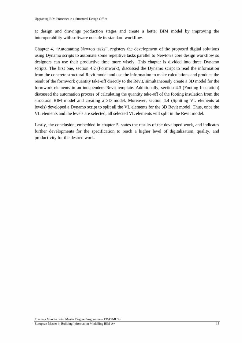
Figure 26– Families and types of Revit objects .................................................................................... 46
Figure 27– Naming and classification in Newton database .................................................................. 46
Figure 28– Columns modelling ............................................................................................................. 48
Figure 29– Wall modelling ................................................................................................................... 48
Figure 30– parapet wall modelling with piers ....................................................................................... 48
Figure 31– Dynamo script concept ....................................................................................................... 52
Figure 32– Creation of project parameters in Revit .............................................................................. 53
Figure 33– Creation of generic adaptive family for 4 nodes formwork ................................................ 53
Figure 34– Extracting the used elements and converting them to Dynamo geometries. ...................... 54
Figure 35– Selection of the formwork surfaces .................................................................................... 55
Figure 36– Removing the duplicated surface area. ............................................................................... 55
Figure 37– Extracting the formwork areas and linking it with Revit parameters. ................................ 56
Figure 38-Dynamo script for number of points warning check. ........................................................... 56
Figure 39 – Adding area parameters to formwork elements. ................................................................ 57
Figure 40 – Creating the 3D Revit model and add areas parameter to each element. ........................... 57

Upgrading BIM Processes in a Structural Design Office
Erasmus Mundus Joint Master Degree Programme – ERASMUS+
European Master in Building Information Modelling BIM A+ x
Figure 41 – Formwork 3D model Details .............................................................................................. 58
Figure 42 – Formwork Dynamo script for irregular shapes .................................................................. 59
Figure 43 – Formwork 3D model for irregular shapes & non-structural elements ............................... 59
Figure 44 – Dynamo script concept ....................................................................................................... 60
Figure 45 – Dynamo script for selecting elements from Revit .............................................................. 61
Figure 46 – Dynamo script creating insulation surfaces ....................................................................... 62
Figure 47 – Dynamo script for removing bottom surfaces of tie beams ............................................... 62
Figure 48 – Dynamo script for getting the insulation area .................................................................... 62
Figure 49 – Dynamo script for Creating the 3D model in Revit ........................................................... 63
Figure 50 – Dynamo Player interface for Insulation ............................................................................. 63
Figure 51 –Insulation 3D model details ................................................................................................ 64
Figure 52 –Concept and methodology of Splitting VL elements Dynamo script ................................. 66
Figure 53 –Dynamo script for selection of elements and levels ............................................................ 66
Figure 54 –Extracting column data ....................................................................................................... 67
Figure 55–Dynamo script for new levels list management ................................................................... 67
Figure 56 –Dynamo script for new columns creation ........................................................................... 68
Figure 57 –Dynamo script for remodel the original columns ................................................................ 68
Figure 58–Dynamo script for selection walls and levels ....................................................................... 69
Figure 59 –Dynamo script for extracting walls information ................................................................. 70
Figure 60–Dynamo script for sorting levels by elevations .................................................................... 70
Figure 61 –Dynamo script for new levels list management .................................................................. 71
Figure 62 –Dynamo script for remodel the original walls ..................................................................... 71

Upgrading BIM Processes in a Structural Design Office
Erasmus Mundus Joint Master Degree Programme – ERASMUS+
European Master in Building Information Modelling BIM A+ xi
LIST OF TABLES
Table 1– Diagnosis of the information of Newton Families ................................................................. 28
Table 2– Example of Newton families Naming Convention ................................................................ 29
Table 3–Diagnosis for families Naming Fields ..................................................................................... 29
Table 4- Newton created shared parameters ......................................................................................... 31
Table 5– The major categories of exposure classes .............................................................................. 42

Upgrading BIM Processes in a Structural Design Office
Erasmus Mundus Joint Master Degree Programme – ERASMUS+
European Master in Building Information Modelling BIM A+ xii
This page is intentionally left blank

Upgrading BIM Processes in a Structural Design Office
Erasmus Mundus Joint Master Degree Programme – ERASMUS+
European Master in Building Information Modelling BIM A+ 13
1. INTRODUCTION
1.1. General remarks and scope
Over the past decades, the introduction and implementation of Building Information Modelling (BIM)
into processes with the support of technological tools has developed and transformed the Architecture,
Engineering, and Construction (AEC) industry, introducing new approaches to the Design Stage. It
has, furthermore, established new types of collaboration among stakeholders, from the very first stages
of the project until the end of its lifecycle (Eastman, C.M, Teicholz, P.Sacks, R. and Liston, 2018) In
addition, it has been proven that BIM tools and BIM workflows significantly increase design
productivity, reduce construction waste, and improve connectivity in facility operations (B Succar et
al., 2016).
BIM has contributed to increasing the digitalization of the AEC processes addressing its low
productivity growth over time, seeking more efficiency and revenues for the industry (Mihindu and
Arayici, 2008). With BIM, all data has a direct or indirect relationship, creating a database
representing a digital project copy. Regardless, the design process and the insertion of information
with BIM tools are still broadly hand operated. The desire to respond to the clients effectively and
optimize the design and construction workflows has generated new data management tools.
The development of new BIM processes and implementation of BIM tools according to the desired
uses of companies is a feasible way to achieve custom automatization, increase work productivity.
Also, it has been a goal of researchers and companies for a more integrated design process. Therefore,
several graphical programming tools for design have arisen. Dynamo, the visual programming tool for
Autodesk Revit, has proven suitable for approaching BIM design workflow, reducing labour time,
increasing quality assurance, and supporting software interoperability. Especially inside structured
Companies, where BIM is already implemented in the day-to-day workflow, Dynamo effectively
automates repetitive tasks. Companies are always looking for possibilities to simplify, optimize and
improve their processes. They want to reduce, especially labour-intensive tasks. Visual programming
application into BIM tools like Revit gives new opportunities to create, manage, and check
geometrical and no-geometrical information in the digital model.
Moreover, BIM software enables architects, designers, engineers, modellers, Building Information
Modelling (BIM) coordinators, and BIM managers to create BIM models and analyse intelligent data
to improve design and construction. BIM has developed a transformation in the engineering industry.
Information is the core of any process that improves productivity, providing several benefits compared
to the traditional 2D CAD process. Productivity in modelling is directly connected to the BIM
Templates quality used in projects. Also, it can help to increase efficiency when working in software,
and the company will benefit from consistency across projects. The templates save much time by
having predefined standards.

Upgrading BIM Processes in a Structural Design Office
Erasmus Mundus Joint Master Degree Programme – ERASMUS+
European Master in Building Information Modelling BIM A+ 14
1.2. Objectives
This work intends to provide practical upgrading for work processes in a Design office to deal with
new BIM challenges and implementation for new BIM innovations to increase the work productivity
for the desired BIM uses within a company in the Design stage. Also, define new strategies to re-
engineer these processes to be more integrated and digitalized with controlling the production quality,
increasing the work efficiency, and save more time.
In order to accomplish the main objective, it is required to revise the internal BIM objects library and
the used Revit template and modify them to cover the design stage needs. Also, revise the used
modelling and design processes and automate some repetitive tasks so designers can use their
productive time more wisely using Dynamo scripts that allow user to achieve the desired BIM uses.
It is also intended to create procedures manual for the modelling tasks to support modellers in
increasing the production quality of structural models with high accuracy level. Also, facilitate
coordination and collaboration at design and drawings production stages and create a BIM model
suitable to be exported to other structural analysis software.
1.3. Partnership for the dissertation
This work was developed in close connection with Newton - Consultores De Engenharia Lda, an
international engineering company that has been using and improving its BIM methodology for over
10 years to provide structural design and project management services. Newton facilitated the
conditions to work side-by-side with the company to define the needs and identify the problems
related to this subject. The colleagues involved were a vital asset to criticize and validate this work,
improving its initial status.
1.4. Dissertation structure
Besides the introduction, the other four chapters structure this work. The second chapter comprehends
a literature review about the topics considered essential to support the development of the work,
mainly involving building information modelling in the structural design phase.
The following chapter, “Upgrading Newton Framework”, diagnosed the framework of the used BIM
template and discussed the improvement structure for all factors that affect the modelling workflow. In
addition, it clarifies the upgrading structure for Newton internal Revit families by implementing
Uniclass 2015 and Omniclass classification systems for efficient specification, scheduling, and cost
estimation. Additionally, it illustrates upgrading the used materials with their parameters to achieve
the desired BIM uses. Also, it discusses the procedure of applying a new naming convention for all
Revit families. it highlights the importance of applying a database system to store the information of
Revit families. Moreover, describes exporting the IFC model by mapping the Revit elements with IFC
shared parameters. This IFC development aims to increase the quality of the exported IFC model.
Additionally, (Modelling technical manual) discussed, improving the current a technical modelling
guide manual for Newton BIM uses. This manual discusses the procedures of modelling structural
elements (Foundations, slabs, beams, columns, and walls) to facilitate coordination and collaboration
Upgrading BIM Processes in a Structural Design Office
Erasmus Mundus Joint Master Degree Programme – ERASMUS+
European Master in Building Information Modelling BIM A+ 15
at design and drawings production stages and create a better BIM model by improving the
interoperability with software outside its standard workflow.
Chapter 4, “Automating Newton tasks”, registers the development of the proposed digital solutions
using Dynamo scripts to automate some repetitive tasks parallel to Newton's core design workflow so
designers can use their productive time more wisely. This chapter is divided into three Dynamo
scripts. The first one, section 4.2 (Formwork), discussed the Dynamo script to read the information
from the concrete structural Revit model and use the information to make calculations and produce the
result of the formwork quantity take-off directly to the Revit, simultaneously create a 3D model for the
formwork elements in an independent Revit template. Additionally, section 4.3 (Footing Insulation)
discussed the automation process of calculating the quantity take-off of the footing insulation from the
structural BIM model and creating a 3D model. Moreover, section 4.4 (Splitting VL elements at
levels) developed a Dynamo script to split all the VL elements for the 3D Revit model. Thus, once the
VL elements and the levels are selected, all selected VL elements will split in the Revit model.
Lastly, the conclusion, embedded in chapter 5, states the results of the developed work, and indicates
further developments for the specification to reach a higher level of digitalization, quality, and
productivity for the desired work.

Upgrading BIM Processes in a Structural Design Office
Erasmus Mundus Joint Master Degree Programme – ERASMUS+
European Master in Building Information Modelling BIM A+ 16
This page is intentionally left blank

Upgrading BIM Processes in a Structural Design Office
Erasmus Mundus Joint Master Degree Programme – ERASMUS+
European Master in Building Information Modelling BIM A+ 17
2. LITERATURE REVIEW
This chapter presents an in-depth view of the main subjects related to building information modelling
in the structural design phase. Initially, some aspects of BIM are discussed, such as BIM uses that can
serve the structural design. Then, works on information management are introduced, like standards,
commonly used BIM tools, methods, and issues are presented.
2.1. BIM
BIM is a process and platform used in the construction industry. Nowadays, BIM is used in many
projects and is a requirement on contracts. An ordinary meaning of BIM is "a digital representation of
physical and functional characteristics of a facility and a shared knowledge about a facility forming a
reliable basis for decisions during its life-cycle; defined as existing from earliest conception to
demolition" (BuildingSMART, 2017). There is a general cognizance that BIM is a 3D design.
Therefore, a BIM model has multi-dimensional information on itself. BIM is a system for initiating
and organizing all the knowledge on the building objects during the construction project phases,
including initiating, planning, construction, closure, facilities management, and demolition. The result
of this mechanism is the BIM model and the digital description of all conditions of the developed
resource. Many people assume BIM as a prominent design allocation and advance establishment
(Autodesk, 2017). After the handover, the real value can be figured out when the manager or the
person who owns the stocks gets all the correct knowledge. Above all, BIM integrates much
independent information on the model in which items are connected to associated knowledge like
manuals, specifications, and warranty details. This feature permits the owner or the facilitator to
organize the items effectively and correctly. BIM connects all the knowledge about various parts of
building design at the same point. Thus, BIM allows everyone to reach the information for any
purpose, e.g., to integrate various ways of design to be more effective, to collaborate for effective
building design. In this way, the risk associated with unknowns and missing data about the building is
reduced, and the cost of change is minimized.
2.2. BIM in Structural design
BIM software supports structural engineers in developing integrative allocation of structural design
certification, reducing errors, and increasing the association between engineering and architecture
departments. BIM allows structural engineers, detailers, and fabricators to improve structural design
and association among professions. The BIM model is a building prototype and ensures the designer
realizes failures and clashes before building the actual structural design (Autodesk, 2017). BIM can
also create integrated design projects and can act as a dominant material as a management tool.
Structural designers confront many advantages of BIM in various forms, as the model can be
consistently updated for achieving integrated design. BIM also changes the form of how one manages
and see the items. It increases the impact on building design, structural design, and engineering
analysis. BIM makes possible the reduction in design efforts, minimizes errors and changes, and

Upgrading BIM Processes in a Structural Design Office
Erasmus Mundus Joint Master Degree Programme – ERASMUS+
European Master in Building Information Modelling BIM A+ 18
develops cost-effective designs and increases production quality. It ensures better results both in
design and construction (AutodeskAEC, 2017).
2.3. Structural Deliverables in pre-BIM context
According to Portuguese law, as an example, the deliverables for structural design projects are
consist of
▪ Calculation notes and justifications according to applicable law.
▪ Drawings Plan views and cross-sections at adequate scales that represent:
• The position with dimensioning of the structural elements, such as (beams, columns,
slabs including openings, walls, etc.).
• The cross-sectional Information of all elements (before finishing application).
• The level of unfinished superior surfaces of beams, walls, slabs.
• Location and size of openings in structural elements (e.g., for plumbing).
• The development of columns through their height, with a clear indication of
lower/upper levels.
• Details of all elements of the structure that show their shape/constitution and allow
their construction without doubts or ambiguities at the scales 1:50, 1:20, 1:10 or
higher.
▪ Quantity take-off for materials and works to be conducted. Corresponding budgeting as well.
▪ Technical specifications for the conduction of all works (general and specific).
2.4. Model uses
The conceptual background of Model Uses has been covered by BIM Excellence (Bilal Succar, 2020).
Model Uses describe and verify the Information Requirements that need to be delivered as 3D digital
models. As a Knowledge Block, Model Uses form part of a more significant modular language that
connects information requirements with System Units, Defined Roles, and Competency Items.
The following BIM uses the most commonly used in Design offices to achieve the desired deliverable
of the 3D BIM model.
• Quantity Take-Off (QTO): A Model Use representing how 3D models are used to calculate the
number of used elements, objects, and building materials to generate Cost Estimates.
• Cost Estimation: A Model Use representing how 3D models are used to generate feasibility
studies and compare different budgetary options.
• Design Authoring: A Model Use represents developing Generative Models or Parametric
Models for design exploration, design communication and design iteration purposes. Design
authoring is a crucial BIM activity leading to model-based 2D Documentation, 3D Detailing
and other model-based deliverables.
• 2D Documentation: A Model Use representing how 2D Drawings are extracted from
information-rich 3D models. 2D Documentation typically includes 2D plans, 2D sections, 2D
elevations and 2D details.

Upgrading BIM Processes in a Structural Design Office
Erasmus Mundus Joint Master Degree Programme – ERASMUS+
European Master in Building Information Modelling BIM A+ 19
• 3D Detailing: A Model Use representing how three-dimensional details are extracted from
information-rich 3D models. 3D Detailing typically include hybrid 2D-3D annotated views
• Structural Analysis: A Model Use representing how 3D models are used to analyse the
behaviour of the structural system. Structural analysis typically includes studying the effects
of static/dynamic loads on buildings and how building design can be subsequently optimized.
2.5. Naming Convention
2.5.1. Spelling
According to NBS object standards, the BIM object has applied spellings that consider the approach
taken by the origin resource. For instance, NBS uses the Oxford English Dictionary (OED) as the
default spelling guide. It is essential to follow a consistent approach to spelling when it uniformly
comes to scheduling information.
2.5.2. Composition
BIM object Name shall consist of alphanumeric characters without text formatting (a-z, A-Z, 0-9).
Also, it is limited to a maximum of 75 characters. In addition, the naming fields shall use only the dash
character (-) within phrases and the underscore character (_) as a delimiter. Information within each
field is to be Pascal Case (capitalized first letters for words and no spaces). No spaces or other
punctuation shall be used. Naming conventions should be spontaneous so that information can be
found and recovered. For example, spaces and punctuation are not helpful in the digital age, and
special characters may mean different things and commands in different software packages. In this
way, it facilitates the ability to provide search functionally and interactions with other databases. The
BIM object and file name must be unique to avoid duplication of information and aid in exporting
information and its interpretation.
2.5.3. Abbreviations
The BIM object and file name must be unique to avoid duplication of information and aid in exporting
information and its interpretation.
2.5.4. Naming fields
The naming fields shall be consisting of BIM object the originator, source, material, and type. NBS
recommended to organize the naming fields as follow:
<Originator>_<Source>_<Material>_<Subtype>_<Differentiator>
2.6. Classification systems
Implementation of classification systems on the internal elements libraries is essential for efficient
specification, scheduling, and cost estimation. This classification system allows the used BIM objects
to be identified, described, and well organised within the BIM environment. In addition, the
classification system facilitates the searching, sorting, extracting, and analysing of the data. Using a

Upgrading BIM Processes in a Structural Design Office
Erasmus Mundus Joint Master Degree Programme – ERASMUS+
European Master in Building Information Modelling BIM A+ 20
unified classification system ensures consistency and reduces ambiguity. Also, it allows the user to
collect and compare data across several projects.
2.6.1. Uniclass 2015
Uniclass can categorize information for costing, briefing, CAD layering when preparing specifications
or other production documents. Also, it is open, accessible, and compliant with ISO 12006-2 ease
integrations with and translations to other classification schemes in the future.
Uniclass provides:
• a unified system to classify all elements relate to the construction industry.
• A flexible numbering system to adapt to future requirements for classification.
• A synonyms database that allows users by using standard terminology to find the required
classification.
The suite of Uniclass 2015 tables is generally hierarchical and permits a venture to be characterized
from the broadest see to the foremost nitty-gritty. The Complexes table portrays ventures in general
terms. Moreover, it can be thought of in terms of the arrangement of an Activity. Complexes
classifications can be broken down as groupings of Entities, Activities and Spaces/locations depending
on the specific utilize (Delany, 2019).
In Uniclass 2015, The locations / Spaces and Activities tables could be used to describe Entities. Also,
it can be described by systems tables as figured in Figure 1. Thus, the main starting point for detailed
design and construction is entities.
Elements are the primary Entity's architectural components, such as walls, structural columns, and
floors. Other requirements in entities like ventilation or heating are considered as functions. Also, the
Elements table consists of Functions, so it is named Elements/ functions, which are described in more
detail by Systems, which contain Products.
Figure 1-Tables and their relationships used in Uniclass 2015.
• Complexes can generally describe a project, such as a private house with a garden and garage,
rail networks and airports.

Upgrading BIM Processes in a Structural Design Office
Erasmus Mundus Joint Master Degree Programme – ERASMUS+
European Master in Building Information Modelling BIM A+ 21
• Entities are separate things in the project, such as buildings and bridges. However, they
present the places where the different activities occur.
• The Activities table describes what user activities are contained in the complex, entity, or
space. It also includes project management, surveys, operation and maintenance, and services.
• Spaces are provided in buildings for different activities to take place. In some cases, a space is
only proper for one activity. The term location is more relevant for linear entities such as
transport corridors than space for dividing the project into appropriate sections.
• Elements are the primary building components (floors, walls, and roofs) or the main structural
components like a bridge (foundations, piers, deck). While Functions are the provided and
managed building services.
• Systems are collections of products that could be one or more are collected to describe an
element or a function (Delany, 2019).
Uniclass codes consist of either four or five pairs of characters. The four following pairs represent
groups, sub-groups, sections, and objects. Each group of codes has Up to 99 items. The figure below
shows the Uniclass division into groups, sub-groups, sections, and objects.
Figure 2-Uniclass divisions
2.6.2. Omniclass
This study also classified using the Omniclass, the currently used classification system in the US
construction industry based on ISO 12006-2 (Organization of Information about building Works –
Framework for Classification). Also, OmniClass is supported by CSI (Construction Specifications
Institute) and CSC (Construction Specifications Canada).
OmniClass contains many features of legacy systems that it includes, while developing the subject
matter to support the BIM requirements and the AEC industry integrated processes. OmniClass has
become an essential demand within the developing field of product search and comparison. It supports
the requirement in BIM format for highly detailed product information. In addition, it can normalize

Upgrading BIM Processes in a Structural Design Office
Erasmus Mundus Joint Master Degree Programme – ERASMUS+
European Master in Building Information Modelling BIM A+ 22
and categorize detailed attributes/properties and processes developed and supported by the National
BIM Standard and Integrated Project Delivery.
Omniclass is developed to provide a standardized source for information classification throughout the
facility's entire life cycle from conception to demolition or reuse. It can be used for organizing,
sorting, and retrieving information and deriving relational computer applications.
The advantages of Omniclass:
• it incorporates other systems currently in use as the basis of many of its tables such as
MasterFormat for work result table, UniFormat for elements table and EPIC for structuring
products.
• its implementation in computer technology (primarily relational or object-oriented databases),
using that to relate information from variety of perspectives and to produce reports from all
perspectives.
OmniClass is a faceted classification that can classify from various perspectives. It has fifteen tables;
each table describes a different aspect of construction information as shown in the following figure.
Figure 3- Omniclass tables

Upgrading BIM Processes in a Structural Design Office
Erasmus Mundus Joint Master Degree Programme – ERASMUS+
European Master in Building Information Modelling BIM A+ 23
The most useful Omniclass codes for contractors to create a work breakdown structure (WBS) are:
Table 22- Work Results. This table defines the deliverables required under or by the contract
documents. This document is usually known as the Contractual Work Breakdown Structure and
describes what the contractor must deliver or create to have completed the project. While the WBS
defines WHAT needs to be done, the next level deeper is the cost and resource loaded CPM schedule.
This schedule tells us HOW (the sequence of activities or the workflow) and WHEN the work will be
done, established by the early and late start and finishes dates, calculated by the forward and
backwards pass.
Table 41- Materials. This table contains a list of bulk materials usually purchased by the truck, trailer,
tank, or rail car volumes. These will most likely be used if a contractor has set up their concrete batch
plant or asphalt plant rather than used for most construction sites.
Table 23- Products. This table contains almost 7,000 “products” used in the construction process.
Again, these can be broken down into a more refined set of codes.
2.7. IFC – Model Exchange
Interoperability is a crucial feature for exchanging and (re)data in new generation applications for
planning, construction, analysis, management, collaboration, and communication. Among such data,
an essential source of information about the built environment is Building Information Models
(BIMs). The effective interoperability of such data would bring significant advantages. These would
involve many scopes. First, the collaboration among different practitioners involved in building
design, construction, and management. Second, the exchange and reuse of the data among diverse
stakeholders and through time. Third, the integration with other data sets, including different formats,
for various use cases.
OpenBIM is a new general methodology for Designing, construction, and operating of buildings
according to open standards. Despite the used software, the openBIM approach supports open
cooperation, transparency for all project partners. IFC is considered the primary standard for
information exchange in openBIM (BIM Corner, 2021).
The "Industry Foundation Classes" or IFC is an open, standardized, digital, and interoperability
solution for coordination between different BIM software or hardware devices for all the built
environments. It is a generic, neutral data format. IFC presents descriptions for all object element
types used in the construction industry and stores those descriptions in a data file.
BuildingSMART International delivered the IFC schema specifications to achieve its goal by
promoting the openBIM. The IFC schema specification identifies the usage, construction, operation of
the facility or installation. Also, it can describe the physical elements of buildings, the manufacturing
way of the products. In addition, it can provide more structural and energy analysis models, work
schedules, and cost breakdowns.
The IFC file format facilitates information transmission from one party to another for a specific
business transaction, which reduces the information loss during this information exchange between

Upgrading BIM Processes in a Structural Design Office
Erasmus Mundus Joint Master Degree Programme – ERASMUS+
European Master in Building Information Modelling BIM A+ 24
software, increasing productivity and enhancing communication. Also, it can be used to archive
project information during different phases (the design, procurement, and construction) or archive for
long term purposes in the "as-built" phase (BuildingSMART website, 2021).
BuildignSMART regularly set the updates to develop the IFC definitions. The IFC schema is steadily
growing. The current version is IFC 4, issued in 2013 (the prior releases were marked as 1.0, 1.5, 1.51
and then 2x, 2×2, 2×3).
MVD (Model view definition) enables a specific information exchange requirements which given at
specific stage of the project that determines the usage of the IFC file. It is used to exchange specialized
models with their specific graphics and contents to fulfil planners needs. For instance, information
about the supporting building elements could be used for a specialized model for structural planning.
(Autodesk, 2018). BuildingSMART listed MVDs available in Revit as follows:
• IFC4, Model Reference View provides a specific IFC file for coordination and quantity
determination.
• IFC4, Design Transfer View provides an IFC model to import and edit in specific BIM
software.
• IFC2x3, COBie 2.4 Design Deliverable which the UK government requires for their level 2
BIM for collaboration on public sector work.
• IFC2x3 Coordination View provided the IFC model for the coordination exchange between
the building industry disciplines.
2.8. Revit software review
2.8.1. Revit template
Revit Template is essential at the beginning of any new project to ensure that this project is consistent
with other company projects. The template provides a reliable way to ensure that the project follows
the suitable collection of features, settings, and office standards.
The quality of the Revit template used in projects significantly affects the Revit productivity,
including industry and organization standards. Also, the template can increase Revit working
efficiency, which leads to more consistency across different company projects.
The main goal of templates is to save much time for the company. Revit users do not need to adapt the
project settings for each new project to be compatible with company standards with the predefined
templates.
Templates are different according to the design purposes, which could be personalized for a specified
type of project and will contain all the necessary standards and information used in this special task.
Therefore, many checklists were developed for different template purposes. The checklist is not a rigid
list of points that the BIM manager must include but a list of things that should be considered when
creating a template. Thus, a BIM manager should choose only those elements that will best fit the
purpose of a given Revit template.

Upgrading BIM Processes in a Structural Design Office
Erasmus Mundus Joint Master Degree Programme – ERASMUS+
European Master in Building Information Modelling BIM A+ 25
2.8.2. Object families
Revit Libraries are the Revit objects / families’ databases that include all the geometrical and non-
geometrical information of the objects. The Revit libraries consist of three types of libraries:
• The first library is the system Revit library, which is pre-made by Autodesk and has a
limitation in the library customization and can be saved inside the Revit template such as
“walls, floors”.
• The loadable Revit families, which can be created from scratch by the user, can be saved as
(.rft) independent files and can be inserted in the project directly from ready-made families
such as “Structural Columns, Structural Framing.”
• The in-place families can be created from scratch by the user like the loadable families, but
those families can be created only for specific projects and cannot be saved outside the project
file.
Revit software allows families creators to make realistic and accurate families and import existing
libraries from other creators, websites, and software. Revit families could be developed as parametric
families with geometrical and non-geometrical information, which allows the user to modify the given
libraries by updating predefined parameters such as length, thickness or number when using (array)
order.
By this method, the family parameters define the Revit library's geometry. Each combination of the
parameters can be saved as a family type, and each instance of a type can also contain other variations.
For example, a concrete rectangular column is a Family. It has types defining different dimensions,
and the actual building model has instances of the types placed in the building where parameters based
on instances can define each concrete rectangular column uniquely.
2.8.3. Revit parameters
Project parameter allows users to add a new information to a specific Revit category for a specific
project. This parameter is visible in schedules but cannot be used in tags. Also, it is not shared with
any external file. There are no limits to creating new project parameters in the project. However, it is
recommended to keep it to a minimum because it leads to a heavy Revit file due to increasing its size
and become more challenging to maintain the unnecessary data inside the model.
Shared parameters have the same uses as project parameters with some differences. The main
difference is that the shared parameter can be created for various Revit families. Also, it can be used in
schedules, tags, and exported as ODBC (Open Database Connectivity). In addition, shared parameters
can be stored in an external text file (.TXT file) to host the shared parameters information. Also, the
values of the shared parameters applied in a specific family or project are not automatically applied to
other families using the same shared parameter.
Global parameters can be created for multiple objects from different categories, not just a specific
category.

Upgrading BIM Processes in a Structural Design Office
Erasmus Mundus Joint Master Degree Programme – ERASMUS+
European Master in Building Information Modelling BIM A+ 26
This page is intentionally left blank

Upgrading BIM Processes in a Structural Design Office
Erasmus Mundus Joint Master Degree Programme – ERASMUS+
European Master in Building Information Modelling BIM A+ 27
3. UPGRADING NEWTON’S FRAMEWORK
This chapter focuses on an in-depth view of upgrading Newton framework through the customization
of the BIM template to serve Newton projects such as industrial facilities, houses, and multi-story
buildings. This study has been developed to update the Newton template to be compatible with the
desired BIM uses. In addition, saving more time working with BIM software and follow the company
standard, which serves the Portuguese and the European markets.
The focus of the development is this dissertation will be targeting procedures that will power Newton's
performance regarding to the following BIM uses:
• Setting up the model for structural analysis.
• Extracting quantity take-off.
• Drawing generation.
3.1. Diagnosis of the existing Template framework
The BIM uses related to structural designs as described before are part of the work scope of the study
firm, Newton - Consultores De Engenharia Lda. As a structural design office with a consistent
background in using BIM, Newton saw the possibility of adding value to its business model by
upgrading the used template with its object contents to be prepared for ever more demanding client’s
requirements.
The methodology applied to diagnose the existing workflow and discuss the dissertation development
was based on weekly meetings (in-person and video calls) with the company representative and the
dissertation supervisors. In addition, the Zoom platform was used to hold online meetings. In addition,
A communication channel on the WhatsApp platform was established at the very beginning of the
dissertation development, enabling information exchange through messages daily. Furthermore, a
Common Data Environment (CDE) was also set up on OneDrive, allowing data sharing between the
Newton team and the author of the dissertation. Finally, it is worth highlighting that the total
availability and commitment of the Newton team were crucial for this work achievement.
Newton customized its own template using Revit Autodesk software from many years. It has been
delivering the BIM uses very correctly in many ways, the quantity take-off, the drawing generation,
and the structural analysis. The goal is to upgrade the used template and its contents to be compatible
with different client's requirements without decreasing the productivity of a fully trained and
operational staff.
There is a general template for the Newton project start. However, even Newton has delivered several
projects with more information requirements and many parameters; as shown in table 1, the general
template is not yet prepared for comprehensive information requirements, which may be required
according to EIR. Therefore, this work intended to make the template easier for the designers to
achieve information requirements without having more work.

Upgrading BIM Processes in a Structural Design Office
Erasmus Mundus Joint Master Degree Programme – ERASMUS+
European Master in Building Information Modelling BIM A+ 28
3.1.1. Diagnosis of existing Newton objects
This study focuses on the structural elements (Structural column, Structural framings, Walls, Floors,
and Structural foundations) and diagnoses their parameters. The following table 1 diagnoses the
structural column and the structural framing families as an example according to multiple factors to
study the information needed to be developed.
Newton Families Dimensions Material IFC
Parameters
Naming
convention
Classification
Systems
Elements
Specifications
Structural Column x x N/A N/A N/A N/A
Structural Framing x x N/A N/A N/A N/A
Structural Foundations x x N/A N/A N/A N/A
Floors x x N/A N/A N/A N/A
Walls x x N/A N/A N/A N/A
Table 1– Diagnosis of the information of Newton Families
3.2. The development of Newton Template framework
This study agrees that the Newton office will develop its BIM template to automate some procedures,
which will improve quality and productivity, save time, and reduce errors and rework. Also, applying
naming convention for the template and its objects.
In addition, Newton will manage its BIM objects library and specification database in compliance with
the classification system Uniclass 2015, Omniclass, and the NBS object standards. Both classification
systems and standards are indispensable for the intended increase of automatization, allowing the link
between different sources of construction data and assuring its interoperability among different digital
tools. Moreover, creating new IFC parameters to better export the model in IFC format.
Revit Template is dynamic; it will be developed continuously with new improvements to adjust it for
updated workflows and standards. It is the BIM manager responsibility to create and update the
template and its contents. Autodesk releases a new Revit version every year. Therefore, the BIM
manager should check and run some tests for the template whenever there is a significant update for
the software or a new version.
In this workflow, Newton will be able to use any Revit version from Revit 2021. However, the Revit
2021 template will be upgraded to a specific version when a new project starts.
This study used the checklist of items to update on the Revit template which included to the datasets of
the book Increasing Autodesk Revit Productivity for BIM Projects (F Roberti, D Ferreira, 2021) to be
as a guide to upgrade the Newton template according to the latest Revit 2021 specifications. This
checklist has many features that suitable for structural design uses.

Upgrading BIM Processes in a Structural Design Office
Erasmus Mundus Joint Master Degree Programme – ERASMUS+
European Master in Building Information Modelling BIM A+ 29
3.2.1. Implementation of naming convention
This study has developed to apply the metadata requirements for Newton BIM objects, views, and
sheets according to NBS National BIM Library, including naming convention for objects, properties,
values, and materials. Before applying NBS standards on Newton Revit template and its contents, the
template contents were stored in the Portuguese language. Then, they were translated to the English
language to follow the NBS standards and be opened more on all the European markets.
Table 2 and Table 3 show as the example for families naming convention, the applied naming
convention for structural column objects library.
Families Updated Naming Families Old Naming
Nw_Column_RC_Circular NW-Pilares Circulares
Nw_Column_RC_Rectangular NW-Pilares em Betão Armado
Nw_Column_Steel_Circular CHS-Circular Hollow Section-Column
Nw_Column_Steel_HEB NW-Pilares Metálicos
Nw_Column_Steel_RectangularHollowSection RHS-Rectangular Hollow Section Column
Nw_Column_Steel_SquareHollowSection SHS-Square Hollow Section-Column
Table 2– Example of Newton families Naming Convention
NW Newton Office Originator
Column Object Type Source
RC Object Material Material
Rectangular Object Section Subtype
Table 3–Diagnosis for families Naming Fields
3.2.2. General settings
The template general settings discuss the fundamental configuration.
• Browser Organization
The Browser Organization tool is crucial to enhance the modelling productivity because of the ability
to optimize the way of views and sheets organization to be suitable for Newton's workflow. The
Browser Organization tool is classified into three divisions, as follows:
• Browser Organization – Views
• Browser Organization – Schedules
• Browser Organization – Sheets
In this section, the project browser did not have many changes. The existing Newton template was
suitable for the structural deliverable according to the Portuguese market and the desired BIM uses.
The browser organization depends on the company needs, the working team usage, and the project
base.

Upgrading BIM Processes in a Structural Design Office
Erasmus Mundus Joint Master Degree Programme – ERASMUS+
European Master in Building Information Modelling BIM A+ 30
The Views has been organized differently to serve Newton BIM uses, with translating all the
Portuguese expressions to the English language and applying new naming conventions according to
NBS standards.
Also, for schedules, sheets, and legends, no changes were applied. The existing Newton template
covered all the company requirements. Therefore, the changes were applied only for the naming
convention and translation for all schedules, legends, and sheets. In addition, some new schedules
were created to achieve better BIM uses and save more time.
The existing Newton template has many schedules that serve the QTO BIM use. The template
schedules have been created to calculate the quantities of the elements and show their information,
also calculate the materials take-off. In addition, the template has many sheets to serve the drawing
generation BIM use by creating sheets that able to extract the structural plans at different levels,
sections, elevations, and details for different structural elements.
• Snaps
Object snap is essential for adding or editing any element, as it will display the snap point symbol. The
settings of object snap could be changed according to a specific workflow. Also, it could allow the
user to change the condition of any specific snap order to fit a specific workflow. In addition, the
object snap shortcuts could help in increasing template productivity. Snaps decided to be as Revit
default without applying any changes.
• Project Information
Project information is helpful to specify any information about the project, such as (Organization
name, Organization description, building name, and Author). In addition, project Information can be
customized according to company requirements by creating a new project parameter or shared
parameters and adding them to the system family “Project Information”.
For the Newton Template, new project parameters shown in figure 4 were developed and added to the
project information to be accessible by just picking on the project information such as (Model name,
Model number, Designer, and Checker).
Figure 4- Project Information in Newton Template

Upgrading BIM Processes in a Structural Design Office
Erasmus Mundus Joint Master Degree Programme – ERASMUS+
European Master in Building Information Modelling BIM A+ 31
• Template parameters
The study kept the existing project parameters for Newton and created new parameters to fulfil the
company needs, such as the project information parameters discussed before. While it did not develop
any new global parameters and mostly depended on the shared parameters to achieve the desired
development.
In addition, four shared parameters groups shown in Table 4 were created to fulfil Newton
requirements. Each group contains different shared parameters which can be used in various projects.
All those shared parameters are stored in Newton template and in an external text file under the name
“NewtonSharedParameters”. The following table shows the created shared parameters with their
shared parameter groups, and the uses of each shared parameter will be illustrated in the further
sections. It’s BIM manager responsibility to add or modify the template parameters.
Parameter Group Classification
system
Dynamo
parameters
IFC Material
specifications
BIM Object Name x
NBS Description x
NBS Reference x
OmniClass Description x
OmniClass Number x
OmniClass Version x
Uniclass Version x
Uniclass EF Description x
Uniclass EF Number x
Uniclass Pr Description x
Uniclass Pr Number x
Uniclass Ss Description x
Uniclass Ss Number x
Formwork Area x
Insulation Area x
IFC Export As x
IFC Export Type x
Exposure Class x
Table 4- Newton created shared parameters
• Project Units
Project units can be defined by discipline, which can automatically adjust all the projects without any
need for any other input from the user. Newton Project units were developed according to the
International System of Units (SI) (ISO 80000-1:2009), to fulfil European market requirements.

Upgrading BIM Processes in a Structural Design Office
Erasmus Mundus Joint Master Degree Programme – ERASMUS+
European Master in Building Information Modelling BIM A+ 32
3.2.3. Views and Sheets
• Starting page – splash screen
The splash screen is the main page where the project's primary information should be included.
Newton starting page shown in Figure 5 is developed as a view template to include Newton logo,
Project photo and information about project and model which contains:
• The project’s name.
• Date of creation.
• The used Revit template.
• The used Revit version.
• The project code.
• The client name.
• The design stage.
• The Revision number.
• The model’s name.
• The modeler.
• The project manager.
• The BIM Coordinator.
• The project Team members
Figure 5– Newton Starting page
• Title Block
The title block has the same principles as the starting page which has relevant information about the
project and sheet. New title blocks were proposed to Newton representative to produce a new sheet
frame that follows ISO 7200 standards. However, we found after discussion that the current one is
better for Newton work, the clients' requirements, and the Portuguese market.
ISO 7200 has provided two samples for title block; the first one in Figure 6 is in compact form,
provides maximum space for factual content of document. Its dimension is 180 x 27 mm, contains five
optional data fields.

Upgrading BIM Processes in a Structural Design Office
Erasmus Mundus Joint Master Degree Programme – ERASMUS+
European Master in Building Information Modelling BIM A+ 33
Figure 6– ISO Standard title block1
The second in Figure 7 is a title block with person name fields on additional line, provides larger space
for legal owner field and free area in upper right-hand corner for classification, key words, etc. Its
dimension is 180 x 36 mm, contains six optional data fields.
Figure 7– ISO Standard title block 2
While the existing title block in the Newton template has its information in the Portuguese language
with a different arrangement for the data fields as shown in the following figure.
Figure 8– Newton title block

Upgrading BIM Processes in a Structural Design Office
Erasmus Mundus Joint Master Degree Programme – ERASMUS+
European Master in Building Information Modelling BIM A+ 34
3.2.4. Graphic standards
Graphic standards cover the primary settings that control the Revit graphics, which directly affects the
productivity and consistency across the discipline drawings.
• Line patterns
Line patterns combine just two characters (Dash – Dot) with specific dimensions and blank spaces.
According to Newton requirements and usage, this study is developed to create new line patterns
Figure 9 and store them in the Newton template according to ISO128-20. Also, a naming convention is
applied for each line style to identify its formation. For instance, line type “NW_Dash_1.0mm” refers
to a line type for Newton company consists of a Dash with length 1.00 mm, then a blank space, then
another Dash with length 1.00 mm and so on.
Figure 9– Newton Line Types
• Line Styles
Line styles consist of line patterns, line weights, and colours. Revit classifies the line styles to hard-
coded or system line styles category, which has <> and cannot be renamed or deleted, shown in Figure
10. The other line style category can be created, renamed, and deleted by the user. For both line style
categories, the user can modify the line weight, colour, and pattern.
This study modified some line patterns and line wights for some line style system categories in Figure
11. Also, created new line styles with their weight, colour and pattern for future uses to fulfil the
company requirements.

Upgrading BIM Processes in a Structural Design Office
Erasmus Mundus Joint Master Degree Programme – ERASMUS+
European Master in Building Information Modelling BIM A+ 35
Figure 10– Line styles system category
Figure 11– New Newton Line Styles
• Fill Patterns
Fill patterns control the appearance of the objects’ surfaces and the cut areas. Revit divided the parts
into two categories (Drafting and Model), where the user can create, edit, delete, and rename the
patterns. The main difference between the two categories is that the Drafting represents the cut areas
of the model elements without concerning the scale factor. On the other hand, the Model category
defines model elements and their surfaces, and it scales with the model, so if the view scale changes,
the pattern scale changes accordingly.
In addition, patterns could be imported from the AutoCAD pattern file or created directly in Revit.
This study reviewed the patterns from the existing template, filtered them according to Newton's uses,
added some new patterns according to ISO 128-50, and applied the naming convention as shown in
Figure 12.

Upgrading BIM Processes in a Structural Design Office
Erasmus Mundus Joint Master Degree Programme – ERASMUS+
European Master in Building Information Modelling BIM A+ 36
Figure 12– Newton Patterns
3.2.5. View Templates
View Templates are a combination of properties that can be managed and applied to specific views.
The assigned views will use the same view settings and keep consistency across construction
documentation sets by applying this specific view template.
After creating a view template, the user can modify the view template parameter to assign the desired
view template and apply its view properties. Figure 13 shows the created view templates in Newton
template.
Figure 13– Newton View Templates

Upgrading BIM Processes in a Structural Design Office
Erasmus Mundus Joint Master Degree Programme – ERASMUS+
European Master in Building Information Modelling BIM A+ 37
• Filters
Filters allow the Revit user to override the visibility and the graphical representation of elements by
selecting one or more categories in the filter and defining the filter rules.
This study is developed to create new filters with their rules to fulfil Newton's needs and increase the
Revit work productivity. For instance, the following filter showed in Figure 14 represents the column
filtration by selecting the structural columns category and applying the filtering rule to search for the
family name containing the word "column" in the structural column category. Also, at the same way of
column filtration, new filters were created by selecting the structural family category and applying the
filtering rule to search for the family name of (Beams, concrete walls, floors). In addition, new filters
were created to make a filtration for rebars by their diameters. The BIM manager can create different
filters by setting filters rules regarding the desired use of the filter for future developments.
Figure 14– Newton Filters
• Phases
Phases are used to fulfil the project's requirements that need to be represented on different stages, such
as refurbishment projects, which impact the deliverables and the coordination processes. The phases
feature allows the user to track the phase elements that are new, Demolished, Temporary, and
Existing, as well as to control the different views of the project.
Phases features allow the user to define different phases according to the project process in “Project
Phases” tab. This study defined four phases according to apply to Newton projects as shown in Figure
15:
• Existing: Elements were created in an earlier phase and continue to exist in the current phase.
• Demo: Elements were created in an earlier phase and demolished in the current phase.
• New Construction: elements were created in the current view.
• Final: Final delivery of the project.

Upgrading BIM Processes in a Structural Design Office
Erasmus Mundus Joint Master Degree Programme – ERASMUS+
European Master in Building Information Modelling BIM A+ 38
Figure 15– Newton Project Phases
In addition, Revit allows users to create different combinations to control phases visibility. Also, apply
colour coding to define how objects will be represented at the different four states as shown in Figure
16:
• Existing: Elements that exist in the view phase.
• New: Elements modelled in the view phase.
• Demolished: Existing elements already demolished in the particular phase.
• Temporary: New elements are demolished in the same phase.
Figure 16– Newton Project Phases
Moreover, a new schedule is created as shown in Figure 17 to allow the user to control the phases
feature by choosing from the dropdown list the desired level, phase, and phase filter. This Revit
schedule will facilitate the management of phases through the project creation lifetime, which will
increase the productivity of Revit.

Upgrading BIM Processes in a Structural Design Office
Erasmus Mundus Joint Master Degree Programme – ERASMUS+
European Master in Building Information Modelling BIM A+ 39
Figure 17– Newton Schedule for controlling phases feature
3.2.6. Revit IFC Exporter settings
While Newton used to use IFC 2x3 to export their IFC models, this study is developed using IFC 4
format for better representation of complex geometries. It is essential to map all Revit families to a
specific IFC class and IFC type before exporting the model to the IFC format. This mapping allows
the element type to be well-identified across different software.
In this section, the exporting settings of IFC are modified according to the desired MVD which is
essential to define the IFC's content and structure and should be coordinated and chosen according to
the BIM uses. In this study, "IFC 4 Design Transfer View" is the default MVD for the Newton
template as shown in Figure 18.
Design Transfer View aims to support the transfer of model data to be used for further design,
analysis, estimating and facility management tasks. While Reference View aims to support the
coordination of the planning disciplines; architecture, structural analysis and building services,
especially to support clash detection and resolution of issues resulting from geometry.
Figure 18– Export IFC setting

Upgrading BIM Processes in a Structural Design Office
Erasmus Mundus Joint Master Degree Programme – ERASMUS+
European Master in Building Information Modelling BIM A+ 40
3.2.7. Objects library development
• Classification improvement
This study has developed a BIM object library complying with NBS Object Standards and a
specification database for these objects. It classifies the objects using an internal classification based
on the Uniclass2015 system, having the same classification code/index in both object library and
specification database, which confers linking them. The choice for Uniclass relies on the coverage of
this classification system, comprising products, systems, activities, among other categories, and the
fact that it is developed by the leading BIM specification institution in the UK, one of the countries
with the highest levels of BIM adoption in the world (Kassem & Succar, 2017). Moreover, an internal
movement in Portugal to establish a national classification system based on Uniclass has directed the
firm to stick to NBS standards. The challenge is that intelligence is needed to recognize the data,
understand the semantically meaning, and then check the consistency of that information.
Besides classifying the internal BIM object library using Uniclass 2015 system, this study also
classified using the Omniclass. The Omniclass classification system's primary purpose is to add value
to the Newton office that its internal libraries are compatible with US projects requirements, allowing
Newton to fulfil clients' requirements outside Europe.
The study has developed to apply the Uniclass 2015 and Omniclass classification systems in Newton
internal library using Revit families. Firstly, with a collaboration with the Newton team, all the Revit
families for Newton projects have been collected, identified, and classified according to the element's
structural usage. Then, the work is implemented to the used elements, divided according to Revit
usage classification (Structural Columns, Structural Framing, Structural Foundations, Floors, and
Walls).
From NBS official website, all Uniclass classification tables and Omniclass tables were downloaded in
.xlsx format, and each element in each table has its number parameter and description parameter. The
Uniclass 2015 tables are:
• Uniclass Table EF for Elements / Functions.
• Uniclass Table Pr for Products.
• Uniclass Table Ss for Systems.
And the used Omniclass tables are:
• Table 21 for Elements (Included design elements).
• Table 23 for products.
This study collects all Newton families manually in one Excel sheet. It classifies each family
according to the used three Uniclass 2015 tables (EF, Pr, and Ss) and the used two Omniclass tables
(21&23). The Annexes attached in this dissertation contain the full table contains the modified
Newton families.

Upgrading BIM Processes in a Structural Design Office
Erasmus Mundus Joint Master Degree Programme – ERASMUS+
European Master in Building Information Modelling BIM A+ 41
In the Newton Revit template, new shared parameters as showed in Figure 19 are created for
classification and NBS specifications. Those shared parameters are stored in (.txt) external file, and
the user can browse the file's location to insert it in the Revit project.
Figure 19– Classification shared parameters
The classification shared parameters for each Newton Revit family were added as a “Type” parameter,
not an “Instance”, to apply the classifications to all family elements. Also, the following figure
describes that all parameters were added under the “Data” group with read only value not to be
modified by the user.
Figure 20– Read only Classification parameters in Data group
Some structural elements are products with unified specifications and dimensions, such as the steel
sections (IPE, HEB and angels) and the precast concrete elements, which have their specifications
from the producer and could be classified as a product according to the used classification system.

Upgrading BIM Processes in a Structural Design Office
Erasmus Mundus Joint Master Degree Programme – ERASMUS+
European Master in Building Information Modelling BIM A+ 42
While other elements are not considered products, such as cast in situ concrete elements, which are
cast in the site under a supervision without pre-ordering the structural elements from a producer.
Therefore, this study classified some structural elements as a product, and the others cannot be
classified as a product, so some elements have no classification value for the Uniclass product number
and description parameters as shown in Figure 21.
Figure 21– Cast in situ element classification
• Exposure class parameter
The European standard EN 206-1 categorized the concrete exposure classes according to various
degradation mechanisms (Kulkarni, 2009). Consequently, the European exposure classes are divided
into six major categories:
No risk of corrosion or attack. X0
Corrosion caused by
carbonation.
XC1-XC2-XC3-XC4
Corrosion caused by chlorides
other than from sea water.
XD1-XD2-XD3
Corrosion caused by chlorides
from sea water.
XS1-XS2-XS3
Freeze/thaw attack with or
without de-icing salts.
XF1-XF2-XF3-XF4
Chemical attack XA1-XA2-XA3
Table 5– The major categories of exposure classes
This study has developed to apply the exposure classes to all Newton reinforced concrete structural
families by adding a new shared parameter as an "Instance" parameter, not "Type" under the
"Materials and Finishes" group.
The main difference between "Instance" and "Type" parameters is that the "Instance" parameter
enables the user to modify the value of the parameter separately for every instance. In contrast, the

Upgrading BIM Processes in a Structural Design Office
Erasmus Mundus Joint Master Degree Programme – ERASMUS+
European Master in Building Information Modelling BIM A+ 43
"Type" parameter enables the user to modify the parameter value to all elements of the family type.
Furthermore, from a structural view, the "Instance" parameter is more accurate because the exposure
class depends on the element's location in the building, not on its type. For instance, the building has
two columns with the same family type, one of them located inside the building with no risk of
corrosion and the other one located at the facade of the building with any reason of corrosion which
affects the exposure class of the element.
The study is designed to allow the user to insert the exposure class parameter's value manually
according to the division and sub-division of the European exposure classes as shown in Figure 22
Figure 22– The exposure class parameter
• IFC mapping using parameters
This study is applied new shared parameters for IFC classification for all Newton used families as
shown in Figure 23. Those shared parameters are stored in (.txt) external file, and the user can browse
the file's location to insert it in the Revit project.
Figure 23– Newton IFC shared parameters
The IFC shared parameters for each Newton family were added as an “Instance” parameter, not a
“Type”, to allow the user to choose the desired functionality of subcategory for each instance
separately should be assigned. However, each shared parameter has a default value for the standard
classification, and the user could change it. Also, all parameters were added under the “IFC
parameters” group to be exported correctly to the IFC format.

Upgrading BIM Processes in a Structural Design Office
Erasmus Mundus Joint Master Degree Programme – ERASMUS+
European Master in Building Information Modelling BIM A+ 44
In addition, the used default values of each IFC shared parameter are stored in the excel spreadsheet of
the Newton database with a dropdown list for the possible options for each family to be exported with
the correct value expression of the IFC classes and types according to IFC 4.0 as shown in Figure 24.
The BIM manager must copy the desired value manually and paste it into the Revit IFC shared
parameters value.
Figure 24– Newton IFC classification database
3.2.8. Materials library development
The library of materials would serve as an input to the objects library as all Newton objects would be
created out of materials according to the structural usage. This section aims to clarify the content data
of materials by reviewing the properties that make up a Revit material and the different possible uses
beyond defining the appearance of elements.
The way materials are used may vary significantly from project to project, and therefore the level of
information need might vary. Thus, the user must be aware of the intended use of materials when
working on a model. Carefully filling in all the properties of materials might be a waste of time if
these will never be used. On the other hand, not paying attention to material properties that will be
needed down the road might pose a more significant problem when it needs to go through all the
materials and revise and complete the missing fields.
Most Newton projects follow the Eurocode for design of concrete structures (EN 1992) and Eurocode
for design of steel structures (EN 1993). Thus, the material properties must serve the requirements of
the Newton office to achieve its BIM uses. The Revit material library has materials that follow the
Eurocode with their naming convention and structural properties; thus, the Revit material library has
been used with applying some modification to serve Newton uses.
• Information aspect
In most cases, the material’s name is an important property, which will be used to identify the
composition of the model elements, such as the different layers that make up a wall or a slab. The
naming convention for the used materials in Newton office were developed to follow the same naming
convention of the Eurocode as shown in Figure 25.

Upgrading BIM Processes in a Structural Design Office
Erasmus Mundus Joint Master Degree Programme – ERASMUS+
European Master in Building Information Modelling BIM A+ 45
• Visualization aspect
This aspect relates to the way materials will be represented in drawings or other views. Thus, this is a
crucial element in almost every project. This study used the default values of Revit library materials in
visualization of materials, which will not affect the BIM uses of Newton 3D models.
• Analysis aspect
This aspect relates to the properties of materials required for analysis, such as structural calculations or
energy performance simulations. This study kept the Thermal properties of the materials with the
default values as it will not affect the desired BIM uses.
The physical properties shown in Figure 25 are the essential properties for the Revit material library. It
directly affects the structural analysis stage when the model is exported to another structural analysis
software (Robot software). The values of the physical properties were developed to follow the
Eurocodes to achieve Newton BIM uses in the structural design.
Figure 25– The structural properties of the Revit materials
3.3. Database system
Any fact should have an important aspect which is called information. People can use this information
to communicate and change data. The data that users use should be managed efficiently and stored in a
manageable database. Better stored data in a database system can result in accurate information. The
database is a crucial structure system to store information in an organised, logical way, leading to
efficient data management that can be stored, shared, and integrated.
This study developed a new database for all Newton used Revit families after applying the
classification systems and naming convention. This database has been saved in two different ways, the
first one in an Excel spreadsheet and the other in Newton Revit Template “.rte” file. The BIM
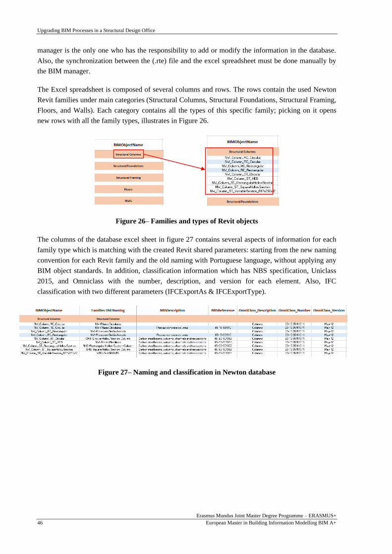
Upgrading BIM Processes in a Structural Design Office
Erasmus Mundus Joint Master Degree Programme – ERASMUS+
European Master in Building Information Modelling BIM A+ 46
manager is the only one who has the responsibility to add or modify the information in the database.
Also, the synchronization between the (.rte) file and the excel spreadsheet must be done manually by
the BIM manager.
The Excel spreadsheet is composed of several columns and rows. The rows contain the used Newton
Revit families under main categories (Structural Columns, Structural Foundations, Structural Framing,
Floors, and Walls). Each category contains all the types of this specific family; picking on it opens
new rows with all the family types, illustrates in Figure 26.
Figure 26– Families and types of Revit objects
The columns of the database excel sheet in figure 27 contains several aspects of information for each
family type which is matching with the created Revit shared parameters: starting from the new naming
convention for each Revit family and the old naming with Portuguese language, without applying any
BIM object standards. In addition, classification information which has NBS specification, Uniclass
2015, and Omniclass with the number, description, and version for each element. Also, IFC
classification with two different parameters (IFCExportAs & IFCExportType).
Figure 27– Naming and classification in Newton database

Upgrading BIM Processes in a Structural Design Office
Erasmus Mundus Joint Master Degree Programme – ERASMUS+
European Master in Building Information Modelling BIM A+ 47
3.4. Modelling Technical Manual
3.4.1. Introduction
This section covers structural BIM modelling and the required information content of the BIM models
produced by the structural designer in the Newton design office. BIM models aim to achieve
controlled decision-making and support the information flow within the design group, the owner, and
the contractor. This guideline covers the BIM model produced by the structural designer and will
hereafter be referred to as the structural model. The structural model develops and becomes more
specific as the design process progresses.
This document establishes a standard modelling approach to serve Newton BIM uses incorporating the
structural design concept. The BIM model can facilitate coordination and collaboration at design,
drawings production (including plans, sections, and elevations) and QTO stages. In addition, it is
considered as a guide for creating a BIM model suitable to be exported to other structural analysis
software when the data interlinking process becomes mature and practical.
This version of modelling involves reinforced concrete elements of superstructure only, and Autodesk
Revit has been the modelling tool throughout this document. Therefore, it is assumed that users shall
possess structural engineering knowledge and Revit modelling skill when using this guide.
The Annexes attached in this dissertation contain the full structural modelling guidelines to provide
users with a standard step-by-step guide for their modelling tasks.
3.4.2. Modelling of Structural Elements
The “Modelling of structural elements” section describes the standard modelling approach for major
structural elements of the BIM structural model in the right way to achieve Newton BIM Uses. This
section is divided according to the structural elements as follows:
1- Foundations
This section aims to model all the structural elements related to foundations step by step, such as
Foundation walls, Wall footing, Piers and Pilasters, Isolated footings and Piles, Foundation slab, and
Step footing.
2- Columns
The columns section contains the appropriate way to model columns, posts, and hangers by picking
the structural column family elements according to the sectional shape. All columns should be defined
between the levels “floor by floor,” as shown in Figure 28, where they support other elements. And
top of their supporting elements (like the top of the column/wall/beam and foundation below), with
required level offsets, even if the cross-section does not change across different floors. In this way, it
is possible to obtain automatic measurements of columns per floor and obtain nodes “points” in the
analytical model at the different floor levels. However, there may be exceptional situations in which

Upgrading BIM Processes in a Structural Design Office
Erasmus Mundus Joint Master Degree Programme – ERASMUS+
European Master in Building Information Modelling BIM A+ 48
this rule cannot be applied. The modeller must explain the situation to the BIM Coordinator and the
structural engineer responsible for the project.
Figure 28– Columns modelling
3- Walls
All walls “Shear, Core, Bearing, Hanger, Stub, and Parapets” should be modelled with appropriate
types from the Basic Wall category family with its Structural Usage property. All walls should be
defined with Top and Base Constraints between the levels “floor by floor” as columns that serve as
support for other elements and top of their supporting elements as shown in Figure 29. In addition, the
top-level walls should be extended to the top of slabs being supported instead of the bottom of slab
elements only.
Figure 29– Wall modelling
As shown in Figure 30, parapet walls and parapet walls with piers have a different way of conceptual
modelling from ordinary walls. The base level and the top level of the parapet wall should be assigned
with similar levels, and the top offset made equal to the required parapet height. Also, it should be
modelled as individual walls spanned between pier edges, and the pier should be modelled with a
structural column family element.
Figure 30– parapet wall modelling with piers

Upgrading BIM Processes in a Structural Design Office
Erasmus Mundus Joint Master Degree Programme – ERASMUS+
European Master in Building Information Modelling BIM A+ 49
For irregularly shaped wall modelling, the main issue is that the irregular part will be neglected from
the structural analysis due to modelling it as (Model in-place), which be neglected in the exported
analytical model to the structural analysis software.
4- Beams
All beams should be modelled with appropriate family types from “Structural Framing” or “Structural
Beam System” category families. Also, all continuous beams should be modelled “span by span”, and
all beams should be connected to their supports by one of the following methods (Secondary beam
rested on main beam, Beam rested on a column, and Beam rested on a structural wall).
5- Slabs
The modeller should choose appropriate types from the “Floor” family according to the structural
usage. All slab elements should be modelled “panel by panel”. Also, for all suspended slabs, “One-
way slabs & Two-way slabs” boundaries should be defined, while flat slabs floor system boundaries
should be located at the centres of the supporting columns.
6- Staircases
Structural staircases have difficulties in modelling as the elements modelled by the Stair family is
belonged to architectural model elements, not the structural ones. Thus, the modelling approach of
staircases is to model architecturally, then create an in-place model above the architectural one.
7- Precast elements
In this section, the study used the new tool in Revit 2021 for the “Precast” tab, which is used only for
the structural system elements “Walls & Floors”. This tool has many features, such as a split tool that
split elements into different segments with different dimensions according to design. Also, the
reinforcement tool allows the modeller to create the reinforcement in the precast elements by
controlling the rebars direction, distribution, and type. In addition, the shop drawing tool creates all
necessary shop drawings documentation for the elements “Rebar List Template & Details Sheet for
side, plan, elevation and section view”.
3.4.3. Model Quality Assurance
A Quality Assurance workflow should be part of the project to keep the model performance. This
section provides a checklist for the project team to check the compliance of the BIM structural models
to this guide. Modeller must carry out a self-audit according to this guide to ensure that the developed
models can comply with this guide before issuing the models for project collaboration. On the other
hand, the project team is advised to return the auditing result to the modellers for rectifying the models
when non-compliance and modelling errors are discovered.
The Annexes attached in this dissertation contain the full Quality check list for the Revit template and
for the structural model. Global parameters can be created for multiple objects from different
categories, not just a specific category.

Upgrading BIM Processes in a Structural Design Office
Erasmus Mundus Joint Master Degree Programme – ERASMUS+
European Master in Building Information Modelling BIM A+ 50
This page is intentionally left blank

Upgrading BIM Processes in a Structural Design Office
Erasmus Mundus Joint Master Degree Programme – ERASMUS+
European Master in Building Information Modelling BIM A+ 51
4. AUTOMATING NEWTON TASKS
4.1. Introduction
Visual programming enables users to create a script by changing graphical elements rather than text
programming, typical for developing a code. This research has developed some scripts by Dynamo,
open-source software that enables visual programming for Autodesk Revit. Dynamo is used to
automate some steps and can be widely adopted by users without textual programming skills. In
addition, Dynamo has proven to be a suitable tool to approach BIM design workflow, reduce labour
time, increase quality assurance, and support software interoperability. The use of Dynamo exhibits its
effectiveness to automate repetitive tasks. Companies are always looking for possibilities to simplify,
optimise and improve their processes. They want to reduce, especially labour-intensive tasks.
4.2. Formwork
The main issue of the formwork modelling is that it is a temporary mould used as a concrete form that
is usually not present in the Structural concrete BIM model because formwork is a temporary structure
used only in the construction phase (Olsen & Taylor, 2017). In addition, there is no specific tool to
model concrete formwork in the BIM software products (Monteiro & Martins, 2013). Users have to
calculate the formwork quantity take-off manually or to develop a formwork model by alternative
BIM elements to get the formwork quantity for the BIM model, which waste too much time and
decrease the accuracy level, especially in large complex projects.
4.2.1. Concept and Methodology
One of this thesis’s objectives is to develop a new method that automatically calculates the quantity
take-off from any concrete structural BIM model with creating 3D model for the formwork at the same
time. As shown in Figure 31 The relevant information needed to create the formwork model and
extract the quantity take-off is extracted from the BIM model via Revit software. Dynamo is used to
create the parametric modelling for the formwork depending on the Revit model for the concrete
structure in a separate Revit template and add the formwork quantity values in a specific parameter in
a specific formwork Revit template. Also, for the irregular concrete elements, the script can be run
from Dynamo (Dynamo player) and directly write and visualise the results in the BIM model (Revit
platform).
So, the parametric script which was created in Dynamo reads the information from the concrete
structural model and uses the information to make calculations and produce the result of the formwork
quantity take-off directly to the Revit list of shared parameters, simultaneously create a 3D model for
the formwork elements in an independent Revit template.
The surface area of the formwork represents its quantity (Royal Institution of Chartered Surveyors
(RISC), 2012). The surfaces of the reinforced concrete elements represent the surface area of the
concrete formwork applied. The proposed method imports concrete elements from the Revit model:

Upgrading BIM Processes in a Structural Design Office
Erasmus Mundus Joint Master Degree Programme – ERASMUS+
European Master in Building Information Modelling BIM A+ 52
columns, beams, slabs, walls, and foundations. Then, Dynamo will combine and deduct the
overlapping parts before extracting the desired surfaces, representing the concrete formworks, and
calculating their areas.
Figure 31– Dynamo script concept
4.2.2. Specific formwork template in Revit
Before running the Dynamo script, the user must open the Revit formwork template, which has the
features that the Dynamo script can link with it. The main goal of this template is to create a separate
Revit project file for the formwork model from the structural concrete Revit model. So, after running
the Dynamo script, the user will have a new model for formwork only with all required data.
Formwork Parameters
In this template, Custom parameters for formwork areas were created to read the surface area for the
structural concrete elements from Dynamo. Those parameters are stored in the system family “Project
Information” because they do not belong to specific elements as shown in Figure 32. The formwork
areas parameters were created as “Project parameters” under the “Construction” parameter group.
Also, the formwork parameters are divided into one parameter for all HZ elements “Formwork area

Upgrading BIM Processes in a Structural Design Office
Erasmus Mundus Joint Master Degree Programme – ERASMUS+
European Master in Building Information Modelling BIM A+ 53
for Beams & Slabs”, one parameter for VL elements “Formwork area for Columns & Walls”, the last
parameter for footing elements “Formwork area for Footings” and a parameter for the whole
formwork project area “Total Formwork area for the structure”.
Figure 32– Creation of project parameters in Revit
Creation of formwork adaptive components
As shown in Figure 33, to make a visualization of the 3D formwork model in the Revit template, it
needs to create a specific family to link with Dynamo data. So, new “Metric Generic Model Adaptive”
families were created with a different number of nodes to adopt with different formwork shapes. After
selection nodes numbers, the solid form was created with defining the thickness and the material of the
formwork elements to create the formwork 3D model in Revit by loading all those adaptive families to
the template. In this way, every formwork shape extracted from Dynamo is linked to the respective
adaptive formwork family from the template. Once this connection is identified, the Dynamo script
can be used to create the formwork 3D model in Revit.
Figure 33– Creation of generic adaptive family for 4 nodes formwork

Upgrading BIM Processes in a Structural Design Office
Erasmus Mundus Joint Master Degree Programme – ERASMUS+
European Master in Building Information Modelling BIM A+ 54
4.2.3. Dynamo script
Extracting information from the structural model
Before opening the Dynamo script, the user must import the Revit link for the concrete structural
model in the formwork project file to create the formwork 3D model in a separate file from the
structural model file to not mess with the structural project file itself. Also, if the 3D formwork model
is created in the same file of the structural project model, the two models will be created above each
other, and it will be difficult and time consuming to use. In addition, in this way, the user can control
the formwork model creation because the information in the formwork template is defined before.
From the formwork project file, the user can open the Dynamo and choose the Revit project link from
the dropdown list to start extracting the structural Revit model information.
The Dynamo script was used to extract the necessary geometrical information from the BIM model to
perform its calculations.
The main issue in the selection phase is that selecting the desired elements categories (Structural
Framing, Floors, Structural Columns, Walls, and Structural Foundations) from the Structural model
Revit link is picking the family types and the family elements together. So, the Dynamo script needs to
be filtered to select only the used family elements by removing the Revit element family types.
After extracting the Revit element, the Dynamo script converts the Revit elements into Dynamo
geometry to apply the algorithms on it by combining the HZ elements “Beams & slabs”, VL elements
“Columns & Walls” and the foundation elements and convert the Dynamo solid geometries into
surfaces as shown in figure 34.
Figure 34– Extracting the used elements and converting them to Dynamo geometries.
After converting the Dynamo solid geometry into geometries surfaces, the Dynamo script makes a
filtration for the formwork surface areas by removing the unused surfaces as shown in figure 35. For
HZ elements “Beams & Slabs”, the formwork elements consist of only side faces and bottom faces

Upgrading BIM Processes in a Structural Design Office
Erasmus Mundus Joint Master Degree Programme – ERASMUS+
European Master in Building Information Modelling BIM A+ 55
without the upper faces. For VL elements “Columns & Walls”, the formwork elements consist of only
the side faces without upper and bottom faces. For the foundation elements, the formwork elements
consist of the side surfaces without the upper and bottom surfaces. In addition, the Dynamo script
creates different colour coding for each type of element to facilitate the geometry visualization in
Dynamo.
Some previous references recommended making a solid union from the beginning to make the whole
structure as one solid, then explode the solid and extract the formwork surfaces. I did not follow this
strategy in the Dynamo script for many reasons:
• This Dynamo script strategy would allow the user to get only the total formwork area for the
whole structure at the end without getting the area of different elements separately.
• The script would not allow the user to make colour coding for the different geometries in
Dynamo.
• It will be very complicated to remove the upper or bottom surfaces of the VL elements
“Columns & Walls” if the user models the VL elements “Floor by Floor”. This Dynamo
strategy could work in a good way if the user models the VL elements as one element from
level 0 to the top level without dividing it by floor, which is not the correct way to model the
VL elements.
Figure 35– Selection of the formwork surfaces
After extracting the desired formwork surfaces for each element, there are duplicated surface areas
between the HZ elements and VL elements that need to be removed before calculating the surface area
of the elements and creating the formwork 3D model.
Figure 36– Removing the duplicated surface area.

Upgrading BIM Processes in a Structural Design Office
Erasmus Mundus Joint Master Degree Programme – ERASMUS+
European Master in Building Information Modelling BIM A+ 56
Linking the formwork areas with the created parameters
The Dynamo script in this phase extract the surface area for the VL elements “Columns & walls”, HZ
elements “Beams & Slabs”, footing elements and the total formwork area for the whole structure after
removing the overlapped areas between the elements, then link those areas with Revit parameters
which stored in the system family “Project Information” as mentioned before.
Figure 37– Extracting the formwork areas and linking it with Revit parameters.
Creating the Revit formwork 3D model
After creating metric generic model families with the points of Dynamo surfaces, defining material of
wood and the plates’ thickness, in this phase, the Dynamo script matches the geometry surfaces with
the adaptive component families in Revit by points. Dynamo should match the same formwork surface
points with the same points of the generic model families.
Several generic model families have been created that could be mainly used for all formwork faces,
from formwork plate contains 4 points to 24 points. If the number of points exceeded 24 points, the
user should define a new generic model family for it.
In addition, the Dynamo script has a warning check as shown in figure 38 for the number of points for
each surface to give the user a warning if the number of points exceeded 24 points.
Figure 38-Dynamo script for number of points warning check.

Upgrading BIM Processes in a Structural Design Office
Erasmus Mundus Joint Master Degree Programme – ERASMUS+
European Master in Building Information Modelling BIM A+ 57
After creating the 3D formwork model in Revit, the Dynamo script links each formwork surface to a
new area parameter as shown in figure 40 so that the user could get the surface area for each element
separately directly from Revit as shown in figure 39.
Figure 39 – Adding area parameters to formwork elements.
Figure 40 – Creating the 3D Revit model and add areas parameter to each element.

Upgrading BIM Processes in a Structural Design Office
Erasmus Mundus Joint Master Degree Programme – ERASMUS+
European Master in Building Information Modelling BIM A+ 58
Formwork Dynamo script application
This part of this thesis aimed to create a fully automated process for extracting the formwork data and
creating a 3D visualization model in order to eliminate the use of third-party tools and expertise, to
speed the process and include it in the cost estimation phase of the project, particularly since the early
decision-making phase.
This formwork Dynamo script shows good performance and results by creating the formwork 3D
model in a separate Revit project as shown in figure 41, extracting the surface area for each formwork
face and the accumulative surface area for VL elements HZ elements, footings, and the whole
building.
Another benefit of the automated formwork procedure integrated with the BIM environment would be
reducing human mistakes, which usually happen during the static and traditional method of
calculation, making the data more reliable and accurate.
The main issue of this Dynamo script is that it works only for the regular shapes and for the structural
elements only from Revit because of the linking between the Dynamo geometry surfaces and the Revit
generic adaptive families. So for the irregular elements, another Dynamo script has been developed to
solve this Dynamo script issue.
Figure 41 – Formwork 3D model Details

Upgrading BIM Processes in a Structural Design Office
Erasmus Mundus Joint Master Degree Programme – ERASMUS+
European Master in Building Information Modelling BIM A+ 59
4.2.4. The irregular elements 3D modelling
Dynamo script for the Irregular elements
The previous Dynamo script does not show promising results for the distinctive elements and non-
structural elements such as slanted columns, circular columns, curved walls, stairs, and ramps. So that,
a new Dynamo script has been developed specifically for this type of element.
The strategy in this script is to allow the user to pick the element surface directly from the Revit
structural project file, which needs to create formwork for it. Once picking the surface, the formwork
will be created with a custom parameter for the surface area.
The category used in Revit to make the formwork is “Casework”. After defining the Revit category,
the user must create a new shared parameter for the “Formwork Area” to link it to the Dynamo script
to the surface area of the formwork.
The Dynamo script has been developed to define the formwork thickness, material, and category to
model the formwork by selecting the desired surface. Also, it linked to the Revit to add the surface
area value to the “Formwork Area” created shared parameter in Revit.
Figure 42 – Formwork Dynamo script for irregular shapes
Figure 43 – Formwork 3D model for irregular shapes & non-structural elements

Upgrading BIM Processes in a Structural Design Office
Erasmus Mundus Joint Master Degree Programme – ERASMUS+
European Master in Building Information Modelling BIM A+ 60
4.3. Footing Insulation
4.3.1. Concept and Methodology
In this section, Dynamo script has been developed to automate the process of calculating the quantity
take-off of the footing insulation from the structural BIM model with creating a 3D model for it at the
same time after defining the insulation material and specific Revit parameters for footing insulation
area.
The strategy as shown in figure 44 is to allow the user to select all the elements that need to be
insulated directly from the Revit structural project file. Once make the elements selection, then run the
Dynamo player, the Dynamo player shows the total insulation area, also the insulation 3D model will
be created with a custom parameter for the insulation surface area.
The category used in Revit to make the insulation modelling is “Generic Models”. After defining the
Revit category, the user must create a new shared parameter for the “Insulation Area” and a new
Insulation material to link it to the Dynamo.
Figure 44 – Dynamo script concept

Upgrading BIM Processes in a Structural Design Office
Erasmus Mundus Joint Master Degree Programme – ERASMUS+
European Master in Building Information Modelling BIM A+ 61
4.3.2. Identifying Revit information
Insulation parameters
Custom parameters for the insulation area were created to read the surface area for all the sub-ground
elements which need to be insulated from Dynamo. This “Insulation Area” parameter is a shared
parameter created for instance element and specially for “Generic Models” category which is the Revit
family category would match with insulation elements. Once the user picks on any insulation face, the
Insulation Area parameter gets a value automatically.
Insulation material
Before running the Dynamo script, the user must define a new material specially for the insulation in
Revit from the material library, the new material for the insulation is “Damp-proofing” to link it to
Dynamo script and create the 3D model.
4.3.3. Dynamo script
Extracting information from the structural model
The essential process is selecting the desired elements that need to be insulated. In this study, the
chosen way to do the elements’ selection is the manual way. The user must filtrate for all the desired
elements. In this way, the desired element in Revit is linked to the Dynamo script. Once the
connection is identified, the Dynamo script can be used to calculate the insulation surface area and
create the 3D model.
The main issue of this strategy is that the Dynamo will not differentiate the foundation elements from
the superstructure elements. So, the selection needs to be done very responsibly and accurately to
obtain a realistic result.
After selecting the Revit elements, the Dynamo script is designed to convert the Revit elements into
Dynamo geometries, then union all the solid geometries to become one geometry and extract the
surfaces from the union solid. This strategy is followed to subtract the overlapping areas between the
Revit elements.
Figure 45 – Dynamo script for selecting elements from Revit

Upgrading BIM Processes in a Structural Design Office
Erasmus Mundus Joint Master Degree Programme – ERASMUS+
European Master in Building Information Modelling BIM A+ 62
Creating insulation surfaces
In this phase, the Dynamo script is designed to extract only the insulation surface as shown in figure
46 by removing the upper and the lower surfaces for all elements. This strategy is applied by
identifying a point at the middle of each surface and filter the surfaces according to vector z, then
removing the maximum and the minimum value of vector z.
Figure 46 – Dynamo script creating insulation surfaces
The main issue in this strategy is that the bottom surfaces of tie beams need to be removed which is
not considered as maximum or minimum surface according to the direction of vector Z after making a
union for all solid geometries. So, another strategy is applied in this study by filtering all tie beams
solids geometry according to family category “Structural Framing”, then making a line from all solids
centroids and identify the length and the direction of those lines to intersect the bottom surfaces of the
tie beams, then removing all the surfaces that intersect with any line as shown in figure 47.
Figure 47 – Dynamo script for removing bottom surfaces of tie beams
After extracting the insulation surfaces for all Revit elements, the Dynamo script is designed to get the
surface area for the insulation elements, accumulate the surfaces areas and get the total area as shown
in figure 48.
Figure 48 – Dynamo script for getting the insulation area

Upgrading BIM Processes in a Structural Design Office
Erasmus Mundus Joint Master Degree Programme – ERASMUS+
European Master in Building Information Modelling BIM A+ 63
Creating the 3D model
In this study, the Dynamo script is developed to create the 3D model in Revit by transforming
Dynamo solid geometry into Revit elements by defining some aspects to link Dynamo to Revit. The
Dynamo script used “Generic Models” category to create the insulation elements in Revit, and for the
insulation material, the Dynamo script defined the used material to be “Damp-proofing” which is
defined in the Revit project file. In addition, the Dynamo script is developed to extract the insulation
area for the surfaces and link it to Revit through a specific parameter “Insulation Area” which is
created before in Revit project file.
Figure 49 – Dynamo script for Creating the 3D model in Revit
Dynamo player
The Dynamo script is designed to allow the user to use the Dynamo player plugin to select the
elements need for insulation. Once the user run the Dynamo player, the total insulation area appears in
the Dynamo player tab as shown in figure 50. In addition, the 3D model of insulation is created above
the Structural model and by hiding the structural model, the user could receive only the 3D model of
insulation with area parameter for each element.
Figure 50 – Dynamo Player interface for Insulation
Insulation Dynamo script application
This part of this thesis aimed to create a fully automated process for extracting the footing insulation
data and creating a 3D visualization model as shown in figure 51 in order to eliminate the use of third-

Upgrading BIM Processes in a Structural Design Office
Erasmus Mundus Joint Master Degree Programme – ERASMUS+
European Master in Building Information Modelling BIM A+ 64
party tools and expertise, to speed the process and include it in the cost estimation phase of the project,
particularly since the early decision-making phase.
This Insulation Dynamo script shows good performance and results by creating the insulation 3D
model, extracting the surface area for each insulation face and the total insulation area for all the
elements from the Dynamo player tab.
Another benefit of the automated insulation procedure integrated with the BIM environment would be
reducing human mistakes, which usually happen during the static and traditional method of
calculation, making the data more reliable and accurate.
Figure 51 –Insulation 3D model details

Upgrading BIM Processes in a Structural Design Office
Erasmus Mundus Joint Master Degree Programme – ERASMUS+
European Master in Building Information Modelling BIM A+ 65
4.4. Splitting VL elements at levels
One of this thesis’s objectives is to develop new methods that automatically calculates the quantity
take-off from any concrete structural BIM model in the right way without affecting the other BIM uses
of the model in an accurate, efficient, and time-saving way.
For modelling VL elements “Columns & Walls” in Revit, some users used to model columns from
bottom to top level as one element. Others used to model VL elements level by level for other
purposes. For example, at the coordination phase in the project between the structural department and
the architectural department, the architect may ask the structural engineer for changes in the location,
orientation, type, and material of columns or walls for any architectural purposes. So, it will be more
efficient, time-saving, and accurate to model all columns or walls in different levels as one element
from the bottom level to the top level and make the changes one time for one element more than
applying changes by selecting all columns level by level. However, splitting VL elements level by
level is very important at the following phases after the coordination phase. At the quantity take-off
phase, it is essential to split columns or walls by level to get accurate quantity and cost estimating for
each level individually. In addition, the columns and walls must be modelled level by level for the
structural analysis phase, especially to link the Revit BIM model to Robot software to create the
correct analytical model for the structural analysis purpose.
4.4.1. Concept and Methodology
Users must split VL elements at levels manually or create different BIM models for the same project
with different modelling elements according to BIM uses, which waste too much time and decrease
the accuracy level, especially in large complex projects. Or using alternative BIM plugins to split VL
elements at levels and get the quantity of the VL elements for the BIM model, which could be money-
consuming or affect clashes in the BIM model.
In this study, the Dynamo script is used to split all the VL elements for the 3D Revit model using the
Dynamo player plugin. Once selection the VL elements and the levels, all selected VL elements will
split in the Revit model as shown in figure 52.
The main issue of the Dynamo is that it does not accept to split the elements at points; there is no
specific order to make it directly from the Dynamo. Therefore, the solution which has developed in
this study is to change the VL elements’ levels to start from bottom level to level 1 instead of top-
level. Then duplicate the VL elements each level to reach the top level with the same type, properties,
location, and orientation of the original VL elements.

Upgrading BIM Processes in a Structural Design Office
Erasmus Mundus Joint Master Degree Programme – ERASMUS+
European Master in Building Information Modelling BIM A+ 66
Figure 52 –Concept and methodology of Splitting VL elements Dynamo script
4.4.2. Dynamo script for splitting columns at levels
Extracting information from the structural model
The Dynamo script is developed to allow the user to select the elements and the levels as shown in
figure 53. Then, it automatically applies filtration to extract only the structural columns and levels
from the Revit model. The selected levels are the levels that the user wants to split the column on it, so
in the selection phase, the user must not choose the bottom and top levels.
Figure 53 –Dynamo script for selection of elements and levels

Upgrading BIM Processes in a Structural Design Office
Erasmus Mundus Joint Master Degree Programme – ERASMUS+
European Master in Building Information Modelling BIM A+ 67
In addition, the Dynamo script is designed to extract all the information for the selected columns as
shown in figure 54 “The top-level, the location, the orientation and the top offset” by extracting the
values of the Revit parameters to use it in the following Dynamo script. The insertion point determines
the location of the columns, and the X vector determines the orientation.
Figure 54 –Extracting column data
After extracting the required level to split columns, the Dynamo script is designed to reorder the levels
to be in order according to their elevations.
Creation of split column elements
The Dynamo script is developed to use the extracted information from the original column element,
modelled from the bottom to top-level. This information is used to create another column element
between levels with the same properties, location, and orientation by using the original columns family
type, location point, and the selected new levels. The main issue of this strategy is that the new level
list may not read the data from the column element due to problems in levels list management that it
does not match the level list with the number of original column elements. Therefore, to solve this
problem, the Dynamo script is designed to count the original column number and repeat the new level
list to be compatible with the same original columns number.
Figure 55–Dynamo script for new levels list management

Upgrading BIM Processes in a Structural Design Office
Erasmus Mundus Joint Master Degree Programme – ERASMUS+
European Master in Building Information Modelling BIM A+ 68
After creating new column elements at the selected levels, the Dynamo script is developed to change
the top offset parameter of the created columns at the last level to be compatible with the top offset of
the original columns.
Moreover, one of these Dynamo script issues is that after creating the new columns at levels, the
orientation of the columns follows the global direction of the X-axis, which could make conflicts with
the orientation of the original columns. Therefore, the Dynamo script is designed to change the
orientation of the newly created columns to be compatible with the orientation of the original column
elements. By making rotation for all new columns with the same angle between the local X direction
for original columns and the global X-axis.
Figure 56 –Dynamo script for new columns creation
After that, the Dynamo script is developed to change the parameters of the original columns to be
compatible with the other new columns. By changing the top-level parameter of the column to be the
first selected level by elevation and removing the original column's top offset as the offset is already
applied for the new columns at the last level. So, the original columns changed to be located between
the bottom and the first selected level without offsets instead of the bottom level and the top level with
top offsets.
The essential part of the Dynamo script is to make the changing parameters of the original columns
after creating the new columns level by level. Thus, it ensures that the Dynamo script will not occur
clashes between the top level of the original columns and the top level of the created new columns.
Figure 57 –Dynamo script for remodel the original columns
In summary, the Dynamo script strategy is to reorder the selected levels by elevations and create new
columns between them with the same type, orientation, location, and properties of the original
columns. For example, for the columns in the first level, the first level to be the bottom level, the
second level to be the top-level, and for the columns in the second level, the second level is the bottom
level, the third level is the top level, and so on. In addition, rearrange the original column levels
between the bottom level and the first selected level by elevation.

Upgrading BIM Processes in a Structural Design Office
Erasmus Mundus Joint Master Degree Programme – ERASMUS+
European Master in Building Information Modelling BIM A+ 69
Dynamo player
Dynamo player was used to run the scripts to simplify the procedure of splitting columns at levels.
However, the dynamo scripts often become heavy and complicated to run and very difficult to
understand by other users who are not the developer or do not have specific Dynamo knowledge.
The Dynamo script is designed to allow the user to select the desired Dynamo script in the Dynamo
player plugin, select the desired columns that need to split and select the levels to split columns on it.
Then, by clicking “Play”, The Dynamo player creates everything automatically without any need to
open the Dynamo script.
4.4.3. Dynamo script for splitting walls at levels
Extracting information from the structural model
The Dynamo script for splitting walls at levels is developed to allow the user to select the walls and
the levels like the splitting columns at levels Dynamo script. The main difference between column
script and wall script is that the columns elements are defined by point. In contrast, the wall's elements
are characterised by a curve which leads to some changes in the core but without changing the concept
and the methodology of the Dynamo script.
Figure 58–Dynamo script for selection walls and levels
In the selection phase, the walls Dynamo script is developed to allow the user to choose the elements
as the column Dynamo script and filtrate the walls and the levels only. In addition, extract all the
information for the selected walls with some differences from the column Dynamo script. For
example, there is no need to extract the location point of the walls like columns as walls are not
defined by points. Also, there is no need for all the Dynamo nodes to adapt the orientation of new
columns to the original columns because walls are drawn by curves, not by points. Also, Revit defined
the levels of wall elements by "Constraint" parameters, not "Levels", so the Dynamo script is designed
to extract to the top constraint of walls to get the top level.

Upgrading BIM Processes in a Structural Design Office
Erasmus Mundus Joint Master Degree Programme – ERASMUS+
European Master in Building Information Modelling BIM A+ 70
Figure 59 –Dynamo script for extracting walls information
After extracting the required level to split columns, the Dynamo script is designed to reorder the levels
to be in order according to their elevations.
Creation of split wall elements
The Dynamo script is developed to use the extracted information from the original wall elements,
modelled from the bottom to top-level. This information is used to create other wall elements between
levels with the same properties and location by using the original wall family type, location line, and
the selected new levels. The main difference in this phase between column Dynamo script and walls
Dynamo script is drawing the new wall elements. The used way for drawing walls is to define location
by curves, the start and the end level, and wall type instead of the way of drawing columns by defining
the column type, levels, and point.
One of the main issues in this strategy is that after creating the new walls in Dynamo, they may not
appear in the Revit views because they are not defined as structural walls in Revit. The main reason
for this problem is that the structural wall discipline parameter in Revit must be “Structural”
discipline. The “Structural” parameter is marked to allow Revit software to deal with the structural
walls, not architectural ones. Therefore, to solve this problem in Revit, the Dynamo script is modified
to extract the “Structural” parameter from the original wall elements and set it as a new parameter for
all new wall elements.
Figure 60–Dynamo script for sorting levels by elevations

Upgrading BIM Processes in a Structural Design Office
Erasmus Mundus Joint Master Degree Programme – ERASMUS+
European Master in Building Information Modelling BIM A+ 71
As for the column Dynamo script, the main issue of this strategy is that the new level list may not read
the data from the wall element due to problems in levels list management. As a result, it does not
match the level list with the number of original wall elements. Therefore, to solve this problem, the
Dynamo script is designed to count the original wall number and repeat the new level list to be
compatible with the same original walls number.
Figure 61 –Dynamo script for new levels list management
After creating new wall elements at the selected levels, the Dynamo script is developed to change the
top offset parameter of the created walls at the last level to be compatible with the top offset of the
original walls.
After that, the Dynamo script is developed to change the parameters of the original walls to be
compatible with the other new walls. By changing the top-constraint parameter of the walls to be the
first selected level by elevation and removing the original column's top offset as the offset is already
applied for the new walls at the last level. So, the original walls changed to be located between the
bottom and the first selected level without offsets instead of the bottom level and the top level with top
offsets.
The essential part of the Dynamo script is to make the changing parameters of the original walls after
creating the new columns level by level. Thus, it ensures that the Dynamo script will not occur clashes
between the top level of the original walls and the top level of the created new walls.
Figure 62 –Dynamo script for remodel the original walls
In summary, the Dynamo script strategy is to reorder the selected levels by elevations and create new
walls between them with the same type, discipline, location, and properties as the original walls. In
addition, rearrange the original wall levels between the bottom level and the first selected level by
elevation. Global parameters can be created for multiple objects from different categories, not just a
specific category.

Upgrading BIM Processes in a Structural Design Office
Erasmus Mundus Joint Master Degree Programme – ERASMUS+
European Master in Building Information Modelling BIM A+ 72
This page is intentionally left blank

Upgrading BIM Processes in a Structural Design Office
Erasmus Mundus Joint Master Degree Programme – ERASMUS+
European Master in Building Information Modelling BIM A+ 73
5. CONCLUSION
5.1. General conclusion
This study aimed to upgrade the Newton office work process to deal with the new BIM challenges.
During this dissertation work, four main outputs were developed and provided for BIM
implementation upgrading in Newton. The main output and corresponding conclusion of the creation
and implementation tools and processes are followed below:
1. The Newton Revit template was updated which significantly affect the BIM productivity.
Also, the template can increase BIM working efficiency, which leads to more consistency
across different company projects. The main goal of templates is to be compatible with the
desired BIM uses, save more time working with Revit, and follow the company standard,
which serves the Portuguese and the European markets.
2. The internal libraries of Newton objects were developed by implementing Uniclass 2015
and Omniclass classification systems for efficient specification, scheduling, and cost
estimation. The classification systems allow the used Revit families to be identified,
described, and well organised within the BIM environment. In addition, the classification
system facilitates the searching, sorting, extracting, and analysing of the data. Using a unified
classification system ensures consistency and reduces ambiguity. Also, it allows the user to
collect and compare data across several projects. In addition, a new database is developed for
all Newton used families. This database has been saved in two different ways, the first one in
an Excel spreadsheet and the other in Newton Revit Template “. rte.” file. This database is a
crucial structure system to store information of Revit families in an organised, logical way,
leading to efficient data management that can be stored, shared, and integrated.
3. New Dynamo scripts were developed to increase the efficiency of Revit software and Newton
work productivity. Also, automate some repetitive design tasks so designers can use their
productive time more wisely. This study developed a parametric script which was created in
Dynamo to read the information from the concrete structural Revit model and use the
information to make calculations and produce the result of the formwork quantity take-off
directly to the Revit list of shared parameters, simultaneously create a 3D model for the
formwork elements in an independent Revit template. Also, for the irregular concrete
elements, the script can be run from (Dynamo player) and directly write and visualise the
results in the BIM model (Revit platform). In addition, another Dynamo script has been
developed to automate the process of calculating the quantity take-off of the footing insulation
from the structural BIM model with creating a 3D model for it at the same time after defining
the insulation material and specific Revit parameters for footing insulation area. Moreover,
this study developed a new Dynamo script to split all the VL elements for the 3D Revit model
using the Dynamo player plugin. Once selection the VL elements and the levels, all selected
VL elements will split in the Revit model.

Upgrading BIM Processes in a Structural Design Office
Erasmus Mundus Joint Master Degree Programme – ERASMUS+
European Master in Building Information Modelling BIM A+ 74
4. A technical modelling guide manual was developed for Newton BIM uses. This manual
aims to be a standard for modelling procedures for the Newton team to achieve controlled
BIM structural model. In addition, it aims to facilitate coordination and collaboration at design
and drawings production stages and create a BIM model suitable to be exported to other
structural analysis software.
5.2. Future Development
Even though the dissertation, comprising its conceptual and practical work accomplished their goals,
some issues are still not contemplated due to the time limitation and some improvements that would
enhance the work were identified.
As a further development, Automation of extracting the QTO and linking it with elements
specifications would bring a higher level of digitalization for Newton. Besides, linking the Newton’s
template with the external database would empower the proposed framework to deal with other BIM
uses. In addition, automation of modelling quality by creating scripts or external digital tool to check
the elements modelling procedure and give warnings if the way of modelling is not correct with
extracting excel report for the modelling quality check.

Upgrading BIM Processes in a Structural Design Office
Erasmus Mundus Joint Master Degree Programme – ERASMUS+
European Master in Building Information Modelling BIM A+ 75
This page is intentionally left blank

Upgrading BIM Processes in a Structural Design Office
Erasmus Mundus Joint Master Degree Programme – ERASMUS+
European Master in Building Information Modelling BIM A+ 76
REFERENCES
Autodesk. (2018). Revit IFC manual - Detailed instructions for handling IFC files. 1–52.
Delany, S. (2019). Standards, codifications, and Classifiactions for a General Contractor.
Classification.
Eastman, C.M, Teicholz, P.Sacks, R. and Liston, K. 2011. (2018). A Guide to Building Information
Modelling for Owners, Managers, Designers, Engineers and Contractors. In Wiley and Sons.
Kassem, M., & Succar, B. (2017). Automation in Construction Macro BIM adoption : Comparative
market analysis. 81(September 2016), 286–299. https://doi.org/10.1016/j.autcon.2017.04.005
Kulkarni, V. R. (2009). Exposure classes for designing durable concrete. Indian Concrete Journal,
83(3), 23–43.
Monteiro, A., & Martins, J. P. (2013). A survey on modeling guidelines for quantity takeoff- oriented
BIM-based design. November. https://doi.org/10.1016/j.autcon.2013.05.005
Olsen, D., & Taylor, J. M. (2017). Quantity Take-Off Using Building Information Modeling ( BIM ),
and Its Limiting Factors. 196(June), 1098–1100. https://doi.org/10.1016/j.proeng.2017.08.067
Royal Institution of Chartered Surveyors (RISC). (2012). RICS new rules of measurement.
Succar, B, Saleeb, N., & Sher, W. (2016). Model Uses: Foundations for a Modular Requirements
Clarification Language. May.
Succar, Bilal. (2020). 211in Model Uses Table. Zenodo, 1.26, 7.
https://doi.org/10.5281/zenodo.3563403%0Ahttps://bimexcellence.org/wp-
content/uploads/201in-Competency-Table.pdf
Autodesk, (March 25, 2017). http://www.autodesk.com/solutions/bim/overview.
AutodeskAEC, (March 25, 2017). www.autodesk.com/collections/architecture-engineering-
construction/overview.
BuildingSMART, (March20, 2017). http://www.buildingsmart-tech.org/specifications/bcf-releases.
NBS (2014) ‘BIM Object Standard’, Nbs, (March, 2019)
NBS (2017) ‘Specification Report 2017 NBS’, Specification Report 2017. Available at:
https://www.thenbs.com/knowledge/nbs-specification-report-2017.
F. Roberti, & D. Ferreira, Increasing Autodesk Revit Productivity for BIM Projects, 2021.
BIM Corner, (2019). https://bimcorner.com/everything-worth-knowing-about-the-ifc-format/
Aksomitas, D. (2020) BIM and Classification, BIMAXON. http://www.bimaxon.com/what-is-
bim/bim-classification/ (Accessed: 19 June 2020).
Al-ashmori, Y. Y. et al. (2020) ‘Civil Engineering BIM benefits and its influence on the BIM
implementation in Malaysia’. doi: 10.1016/j.asej.2020.02.002.
Autodesk (2017) ‘Classification Systems and Their Use in Autodesk Revit ® Managing the “I” in
BIM’, https://www.biminteroperabilitytools.com/classificationmanager/downloads/Autodesk
Whitepaper - Classification Systems.pdf.
BIM Dictionary (2019) “Building Information Modelling (BIM)”.
https://bimdictionary.com/en/building-information-modelling/1.

Upgrading BIM Processes in a Structural Design Office
Erasmus Mundus Joint Master Degree Programme – ERASMUS+
European Master in Building Information Modelling BIM A+ 77
LIST OF ACRONYMS AND ABBREVIATIONS
BIM
NBS
API
AEC
CSI
CSC
QTO
ODBC
MVD
Building Information Modelling
National Building Specification
Application Programming Interface
Architectural, Engineering and Construction
Construction Specifications Institute
Construction Specifications Canada
Quantity Take-off
Open Database Connectivity
Model View Definition

Upgrading BIM Processes in a Structural Design Office
Erasmus Mundus Joint Master Degree Programme – ERASMUS+
European Master in Building Information Modelling BIM A+ 78
APPENDICES
APPENDIX 1: UPDATED NEWTON OBJECTS
BIMObjectName Families Old Naming NBSDescription NBSReference OmniClass_Description OmniClass_Number OmniClass_Version Uniclass2015Version Uniclass_EF_DescriptionUniclass_EF_NumberUniclass_Pr_DescriptionUniclass_Pr_NumberUniclass_Ss_Descript
ionUniclass_Ss_Number IFCExportAs IfcExportType
Structural Columns Structural Columns
Nw_Column_RC_Circular NW-Pilares Circulares Floor Structural Frame 21-02 10 10 10 May-12 July 2019 v1.6 Superstructure EF_20_10 Concrete columns Pr_20_85_16_15 Concrete column systems Ss_20_30_75_15 IfcColumnType.COLUMN COLUMN
Nw_Column_RC_Rectangular NW-Pilares em Betão Armado Floor Structural Frame 21-02 10 10 10 May-12 July 2019 v1.6 Superstructure EF_20_10 Concrete columns Pr_20_85_16_15 Concrete column systems Ss_20_30_75_15 IfcColumnType.COLUMN COLUMN
Nw_Column_Steel_Circular CHS-Circular Hollow Section-Column Floor Structural Frame 21-02 10 10 10 May-12 July 2019 v1.6 Superstructure EF_20_10 Carbon steel columns Pr_20_85_16_11 Steel column systems Ss_20_30_75_80 IfcColumnType.COLUMN COLUMN
Nw_Column_Steel_HEB NW-Pilares Metálicos Floor Structural Frame 21-02 10 10 10 May-12 July 2019 v1.6 Superstructure EF_20_10 Carbon steel columns Pr_20_85_16_11 Steel column systems Ss_20_30_75_80 IfcColumnType.COLUMN COLUMN
Nw_Column_Steel_RectangularHollowSection RHS-Rectangular Hollow Section-Column Floor Structural Frame 21-02 10 10 10 May-12 July 2019 v1.6 Superstructure EF_20_10 Carbon steel columns Pr_20_85_16_11 Steel column systems Ss_20_30_75_80 IfcColumnType.COLUMN COLUMN
Nw_Column_Steel_SquareHollowSection SHS-Square Hollow Section-Column Floor Structural Frame 21-02 10 10 10 May-12 July 2019 v1.6 Superstructure EF_20_10 Carbon steel columns Pr_20_85_16_11 Steel column systems Ss_20_30_75_80 IfcColumnType.COLUMN COLUMN
Nw_Column_Steel_VariableSection_667x250x12 WTC-S-VARIAVEL Floor Structural Frame 21-02 10 10 10 May-12 July 2019 v1.6 Superstructure EF_20_10 Carbon steel columns Pr_20_85_16_11 Steel column systems Ss_20_30_75_80 IfcColumnType.COLUMN COLUMN
Structural Foundations Structural Foundations
Nw_Pile_RC_Boared Estaca de Betão Armado In situ concrete bored piling system 15-05-65/120 Bored Piles 21-01 10 20 15 May-12 July 2019 v1.6 Substructure EF_20_05 Concrete piles Pr_20_85_62_18In situ concrete bored piling
systemsSs_20_05_65_41 IfcPileType.BORED BORED_PILE
Nw_Pile_RC_Driven Estaca de Betão Armado Precast concrete piles 45-15-60/310 Driven Piles 21-01 10 20 10 May-12 July 2019 v1.6 Substructure EF_20_05 Concrete piles Pr_20_85_62_18Driven precast or prestressed
concrete piling systemsSs_20_05_65_24 IfcPileType.DRIVEN DRIVEN_PILE
Nw_FoundationSlab_RC_LT1_0.30 LT1 In situ reinforced concrete raft foundation system 15-05-15/130 Raft Foundations 21-01 10 20 60 May-12 July 2019 v1.6 Substructure EF_20_05Reinforced concrete raft
foundation systemsSs_20_05_15_72 IfcSlabType.BASESLAB FOUNDATION_SLAB
Nw_FoundationSlab_RC_M1_0.90 M1 In situ reinforced concrete raft foundation system 15-05-15/130 Raft Foundations 21-01 10 20 60 May-12 July 2019 v1.6 Substructure EF_20_05Reinforced concrete raft
foundation systemsSs_20_05_15_72 IfcSlabType.BASESLAB FOUNDATION_SLAB
Nw_FoundationSlab_RC_P1_2.00 P1 In situ reinforced concrete raft foundation system 15-05-15/130 Raft Foundations 21-01 10 20 60 May-12 July 2019 v1.6 Substructure EF_20_05Reinforced concrete raft
foundation systemsSs_20_05_15_72 IfcSlabType.BASESLAB FOUNDATION_SLAB
Nw_FoundationSlab_RC_Plinto_0.50 Plinto In situ reinforced concrete raft foundation system 15-05-15/130 Raft Foundations 21-01 10 20 60 May-12 July 2019 v1.6 Substructure EF_20_05Reinforced concrete raft
foundation systemsSs_20_05_15_72 IfcSlabType.BASESLAB FOUNDATION_SLAB
Nw_FoundationSlab_RC_Plinto2_1.00 Plinto 2 In situ reinforced concrete raft foundation system 15-05-15/130 Raft Foundations 21-01 10 20 60 May-12 July 2019 v1.6 Substructure EF_20_05Reinforced concrete raft
foundation systemsSs_20_05_15_72 IfcSlabType.BASESLAB FOUNDATION_SLAB
Nw_FoundationSlab_RC_S1_0.30 S1 (h=0.30) In situ reinforced concrete raft foundation system 15-05-15/130 Raft Foundations 21-01 10 20 60 May-12 July 2019 v1.6 Substructure EF_20_05Reinforced concrete raft
foundation systemsSs_20_05_15_72 IfcSlabType.BASESLAB FOUNDATION_SLAB
Nw_FoundationSlab_RC_S1_0.60 S1 (h=0.60) In situ reinforced concrete raft foundation system 15-05-15/130 Raft Foundations 21-01 10 20 60 May-12 July 2019 v1.6 Substructure EF_20_05Reinforced concrete raft
foundation systemsSs_20_05_15_72 IfcSlabType.BASESLAB FOUNDATION_SLAB
Nw_FoundationSlab_RC_S2_0.30 S2 (h=0.30) In situ reinforced concrete raft foundation system 15-05-15/130 Raft Foundations 21-01 10 20 60 May-12 July 2019 v1.6 Substructure EF_20_05Reinforced concrete raft
foundation systemsSs_20_05_15_72 IfcSlabType.BASESLAB FOUNDATION_SLAB
Nw_FoundationSlab_RC_S2_0.50 S2 (h=0.50) In situ reinforced concrete raft foundation system 15-05-15/130 Raft Foundations 21-01 10 20 60 May-12 July 2019 v1.6 Substructure EF_20_05Reinforced concrete raft
foundation systemsSs_20_05_15_72 IfcSlabType.BASESLAB FOUNDATION_SLAB
Nw_FoundationSlab_RC_S3_0.30 S3 (h=0.30) In situ reinforced concrete raft foundation system 15-05-15/130 Raft Foundations 21-01 10 20 60 May-12 July 2019 v1.6 Substructure EF_20_05Reinforced concrete raft
foundation systemsSs_20_05_15_72 IfcSlabType.BASESLAB FOUNDATION_SLAB
Nw_FoundationSlab_RC_S3_0.70 S3 (h=0.70) In situ reinforced concrete raft foundation system 15-05-15/130 Raft Foundations 21-01 10 20 60 May-12 July 2019 v1.6 Substructure EF_20_05Reinforced concrete raft
foundation systemsSs_20_05_15_72 IfcSlabType.BASESLAB FOUNDATION_SLAB
Nw_FoundationSlab_RC_S4_0.30 S4 (h=0.30) In situ reinforced concrete raft foundation system 15-05-15/130 Raft Foundations 21-01 10 20 60 May-12 July 2019 v1.6 Substructure EF_20_05Reinforced concrete raft
foundation systemsSs_20_05_15_72 IfcSlabType.BASESLAB FOUNDATION_SLAB
Nw_FoundationSlab_RC_S5_0.30 S5 (h=0.30) In situ reinforced concrete raft foundation system 15-05-15/130 Raft Foundations 21-01 10 20 60 May-12 July 2019 v1.6 Substructure EF_20_05Reinforced concrete raft
foundation systemsSs_20_05_15_72 IfcSlabType.BASESLAB FOUNDATION_SLAB
Nw_FoundationSlab_RC_S5_0.45 S5 (h=0.45) In situ reinforced concrete raft foundation system 15-05-15/130 Raft Foundations 21-01 10 20 60 May-12 July 2019 v1.6 Substructure EF_20_05Reinforced concrete raft
foundation systemsSs_20_05_15_72 IfcSlabType.BASESLAB FOUNDATION_SLAB
Nw_FoundationSlab_RC_S6_0.30 S6 (h=0.30) In situ reinforced concrete raft foundation system 15-05-15/130 Raft Foundations 21-01 10 20 60 May-12 July 2019 v1.6 Substructure EF_20_05Reinforced concrete raft
foundation systemsSs_20_05_15_72 IfcSlabType.BASESLAB FOUNDATION_SLAB
Nw_FoundationSlab_RC_S7_0.30 S7 (h=0.30) In situ reinforced concrete raft foundation system 15-05-15/130 Raft Foundations 21-01 10 20 60 May-12 July 2019 v1.6 Substructure EF_20_05Reinforced concrete raft
foundation systemsSs_20_05_15_72 IfcSlabType.BASESLAB FOUNDATION_SLAB
Nw_FoundationSlab_RC_S8_0.40 S8 (h=0.40) In situ reinforced concrete raft foundation system 15-05-15/130 Raft Foundations 21-01 10 20 60 May-12 July 2019 v1.6 Substructure EF_20_05Reinforced concrete raft
foundation systemsSs_20_05_15_72 IfcSlabType.BASESLAB FOUNDATION_SLAB
Nw_FoundationSlab_RC_SMS2_0.40 SMS2 (h=0.40) In situ reinforced concrete raft foundation system 15-05-15/130 Raft Foundations 21-01 10 20 60 May-12 July 2019 v1.6 Substructure EF_20_05Reinforced concrete raft
foundation systemsSs_20_05_15_72 IfcSlabType.BASESLAB FOUNDATION_SLAB
Nw_FoundationWall_RC_0.50 Spar1 (h=0.50m) In situ reinforced concrete retaining wall system 10-35-40/140 Wall Foundations 21-01 10 10 10 May-12 July 2019 v1.6 Substructure EF_20_05Reinforced concrete retaining
wall systemsSs_20_60_35_70 IfcFootingType.USERDEFINED USERDEFINED
Structural Framing Structural Framing
Nw_Beam_RC_Rectangular M_Concrete-Rectangular Beam Floor Structural Frame 21-02 10 10 10 May-12 July 2019 v1.6 Superstructure EF_20_10 Concrete beams Pr_20_85_08_15 Concrete beam systems Ss_20_20_75_15 IfcBeamType.BEAM BEAM
Nw_Beam_Steel_Angle_L L-Angles Floor Structural Frame 21-02 10 10 10 May-12 July 2019 v1.6 Superstructure EF_20_10 Carbon steel beams Pr_20_85_08_11 Steel beam systems Ss_20_20_75_80 IfcMemberType.USERDEFINED USERDEFINED
Nw_Beam_Steel_CircularHollowSection Circular Hollow Sections Floor Structural Frame 21-02 10 10 10 May-12 July 2019 v1.6 Superstructure EF_20_10 Carbon steel beams Pr_20_85_08_11 Steel beam systems Ss_20_20_75_80 IfcBeamType.BEAM BEAM
Nw_Beam_Steel_HEB H-Wide Flange Beams Floor Structural Frame 21-02 10 10 10 May-12 July 2019 v1.6 Superstructure EF_20_10 Carbon steel beams Pr_20_85_08_11 Steel beam systems Ss_20_20_75_80 IfcBeamType.BEAM BEAM
Nw_Beam_Steel_IPE IPE-Beams Floor Structural Frame 21-02 10 10 10 May-12 July 2019 v1.6 Superstructure EF_20_10 Carbon steel beams Pr_20_85_08_11 Steel beam systems Ss_20_20_75_80 IfcBeamType.BEAM BEAM
Nw_Beam_Steel_IPN IPN-Beams Floor Structural Frame 21-02 10 10 10 May-12 July 2019 v1.6 Superstructure EF_20_10 Carbon steel beams Pr_20_85_08_11 Steel beam systems Ss_20_20_75_80 IfcBeamType.BEAM BEAM
Nw_Beam_Steel_RectangularHollowSection RHS-Rectangular Hollow Section Floor Structural Frame 21-02 10 10 10 May-12 July 2019 v1.6 Superstructure EF_20_10 Carbon steel beams Pr_20_85_08_11 Steel beam systems Ss_20_20_75_80 IfcBeamType.BEAM BEAM
Nw_Beam_Steel_SquareHollowSection SHS-Square Hollow Section Floor Structural Frame 21-02 10 10 10 May-12 July 2019 v1.6 Superstructure EF_20_10 Carbon steel beams Pr_20_85_08_11 Steel beam systems Ss_20_20_75_80 IfcBeamType.BEAM BEAM
Nw_Beam_Steel_UPN U-Channels Floor Structural Frame 21-02 10 10 10 May-12 July 2019 v1.6 Superstructure EF_20_10 Carbon steel beams Pr_20_85_08_11 Steel beam systems Ss_20_20_75_80 IfcMemberType.USERDEFINED USERDEFINED
Nw_Frame_Steel_Trapezoidal TELHA trapezoidal Solid steel slab 20-20-10/105 Floor Decks, Slabs, and Toppings 21-02 10 10 20 May-12 July 2019 v1.6 Superstructure EF_20_10 Solid steel slab systems Ss_30_16_10_80 IfcSlabType.USERDEFINED USERDEFINED
Floors Floors
Nw_Deck_STR_0.03 Deck-Estrutura 3mm Decking systems 20-15-25/125 Floor Decks, Slabs, and Toppings 21-02 10 10 20 May-12 July 2019 v1.6 Floors EF_30_20 Decking systems Ss_30_20_30_25 IfcSlabType.FLOOR FLOOR
Nw_Floor_BeamAndBlock_0.20 Viga e bloco de 200 mmFloor Decks, Slabs, and Toppings 21-02 10 10 20 May-12 July 2019 v1.6 Floors EF_30_20 Beam and block floor systems Ss_30_12_05 IfcSlabType.FLOOR FLOOR
Nw_Floor_LightWeightRC_0.22 Betão Leve In situ reinforced concrete floor, roof deck or balcony system 20-05-80/145 Floor Decks, Slabs, and Toppings 21-02 10 10 20 May-12 July 2019 v1.6 Floors EF_30_20 Concrete solid slabs Pr_20_85_14_16 Concrete slab deck systems Ss_30_16_10_16 IfcSlabType.FLOOR FLOOR
Nw_Floor_RC_LA_0.12 LA (e=0.12) In situ reinforced concrete floor, roof deck or balcony system 20-05-80/145 Floor Decks, Slabs, and Toppings 21-02 10 10 20 May-12 July 2019 v1.6 Floors EF_30_20 Concrete solid slabs Pr_20_85_14_16 Concrete slab deck systems Ss_30_16_10_16 IfcSlabType.FLOOR FLOOR
Nw_Floor_RC_LAP1_0.05 LAP1 35+5 In situ reinforced concrete floor, roof deck or balcony system 20-05-80/145 Floor Decks, Slabs, and Toppings 21-02 10 10 20 May-12 July 2019 v1.6 Floors EF_30_20 Concrete solid slabs Pr_20_85_14_16 Concrete slab deck systems Ss_30_16_10_16 IfcSlabType.FLOOR FLOOR
Nw_Floor_RC_LAT_0.45 LAT (e=0.15) In situ reinforced concrete floor, roof deck or balcony system 20-05-80/145 Floor Decks, Slabs, and Toppings 21-02 10 10 20 May-12 July 2019 v1.6 Floors EF_30_20 Concrete solid slabs Pr_20_85_14_16 Concrete slab deck systems Ss_30_16_10_16 IfcSlabType.FLOOR FLOOR
Nw_Floor_RC_LAT_EX_0.35 LAT-Ex (e=0.15) In situ reinforced concrete floor, roof deck or balcony system 20-05-80/145 Floor Decks, Slabs, and Toppings 21-02 10 10 20 May-12 July 2019 v1.6 Floors EF_30_20 Concrete solid slabs Pr_20_85_14_16 Concrete slab deck systems Ss_30_16_10_16 IfcSlabType.FLOOR FLOOR
Nw_Floor_RC_LAV_0.06 LAV (e=0.18) In situ reinforced concrete floor, roof deck or balcony system 20-05-80/145 Floor Decks, Slabs, and Toppings 21-02 10 10 20 May-12 July 2019 v1.6 Floors EF_30_20 Concrete solid slabs Pr_20_85_14_16 Concrete slab deck systems Ss_30_16_10_16 IfcSlabType.FLOOR FLOOR
Nw_Floor_RC_LCC1_0.12 LCC 1 (e=0.12m) In situ reinforced concrete floor, roof deck or balcony system 20-05-80/145 Floor Decks, Slabs, and Toppings 21-02 10 10 20 May-12 July 2019 v1.6 Floors EF_30_20 Concrete solid slabs Pr_20_85_14_16 Concrete slab deck systems Ss_30_16_10_16 IfcSlabType.FLOOR FLOOR
Nw_Floor_RC_LCC2_0.18 LCC 2 (e=0.18m) In situ reinforced concrete floor, roof deck or balcony system 20-05-80/145 Floor Decks, Slabs, and Toppings 21-02 10 10 20 May-12 July 2019 v1.6 Floors EF_30_20 Concrete solid slabs Pr_20_85_14_16 Concrete slab deck systems Ss_30_16_10_16 IfcSlabType.FLOOR FLOOR
Nw_Floor_RC_LE2_0.18 LE2 (e=0.18m) In situ reinforced concrete floor, roof deck or balcony system 20-05-80/145 Floor Decks, Slabs, and Toppings 21-02 10 10 20 May-12 July 2019 v1.6 Floors EF_30_20 Concrete solid slabs Pr_20_85_14_16 Concrete slab deck systems Ss_30_16_10_16 IfcSlabType.FLOOR FLOOR
Nw_Floor_RC_LFA1_0.38 LFA1 (e=0.38) In situ reinforced concrete floor, roof deck or balcony system 20-05-80/145 Floor Decks, Slabs, and Toppings 21-02 10 10 20 May-12 July 2019 v1.6 Floors EF_30_20 Concrete solid slabs Pr_20_85_14_16 Concrete slab deck systems Ss_30_16_10_16 IfcSlabType.FLOOR FLOOR
Nw_Floor_RC_LFA2_0.50 LFA2 (e=0.50) In situ reinforced concrete floor, roof deck or balcony system 20-05-80/145 Floor Decks, Slabs, and Toppings 21-02 10 10 20 May-12 July 2019 v1.6 Floors EF_30_20 Concrete solid slabs Pr_20_85_14_16 Concrete slab deck systems Ss_30_16_10_16 IfcSlabType.FLOOR FLOOR
Nw_Floor_RC_LM1_0.20 LM1 (e=0.20) In situ reinforced concrete floor, roof deck or balcony system 20-05-80/145 Floor Decks, Slabs, and Toppings 21-02 10 10 20 May-12 July 2019 v1.6 Floors EF_30_20 Concrete solid slabs Pr_20_85_14_16 Concrete slab deck systems Ss_30_16_10_16 IfcSlabType.FLOOR FLOOR
Nw_Floor_RC_LM1_0.23 LM1 (e=0.23) In situ reinforced concrete floor, roof deck or balcony system 20-05-80/145 Floor Decks, Slabs, and Toppings 21-02 10 10 20 May-12 July 2019 v1.6 Floors EF_30_20 Concrete solid slabs Pr_20_85_14_16 Concrete slab deck systems Ss_30_16_10_16 IfcSlabType.FLOOR FLOOR
Nw_Floor_RC_LM2_0.20 LM2 (e=0.20) In situ reinforced concrete floor, roof deck or balcony system 20-05-80/145 Floor Decks, Slabs, and Toppings 21-02 10 10 20 May-12 July 2019 v1.6 Floors EF_30_20 Concrete solid slabs Pr_20_85_14_16 Concrete slab deck systems Ss_30_16_10_16 IfcSlabType.FLOOR FLOOR
Nw_Floor_RC_LM2_0.23 LM2 (e=0.23) In situ reinforced concrete floor, roof deck or balcony system 20-05-80/145 Floor Decks, Slabs, and Toppings 21-02 10 10 20 May-12 July 2019 v1.6 Floors EF_30_20 Concrete solid slabs Pr_20_85_14_16 Concrete slab deck systems Ss_30_16_10_16 IfcSlabType.FLOOR FLOOR
Nw_Floor_RC_LM3_0.25 LM3 (e=0.25) In situ reinforced concrete floor, roof deck or balcony system 20-05-80/145 Floor Decks, Slabs, and Toppings 21-02 10 10 20 May-12 July 2019 v1.6 Floors EF_30_20 Concrete solid slabs Pr_20_85_14_16 Concrete slab deck systems Ss_30_16_10_16 IfcSlabType.FLOOR FLOOR
Nw_Floor_RC_LM4_0.20 LM4 (e=0.20) In situ reinforced concrete floor, roof deck or balcony system 20-05-80/145 Floor Decks, Slabs, and Toppings 21-02 10 10 20 May-12 July 2019 v1.6 Floors EF_30_20 Concrete solid slabs Pr_20_85_14_16 Concrete slab deck systems Ss_30_16_10_16 IfcSlabType.FLOOR FLOOR
Nw_Floor_RC_LM4_0.50 LM4 (e=0.50) In situ reinforced concrete floor, roof deck or balcony system 20-05-80/145 Floor Decks, Slabs, and Toppings 21-02 10 10 20 May-12 July 2019 v1.6 Floors EF_30_20 Concrete solid slabs Pr_20_85_14_16 Concrete slab deck systems Ss_30_16_10_16 IfcSlabType.FLOOR FLOOR
Nw_Floor_RC_LMPool_0.30 LMPiscinaSwimming pool floor tiling system 30-70-75/175 Pools 21-06 10 50 10 May-12 July 2019 v1.6 Floors EF_30_20
Swimming pool floor tiling
systemsSs_37_40_85_83 IfcSlabType.FLOOR FLOOR
Nw_Ramp_RC_0.25 RampaInternal ramp system 30-05-40/140 Ramps 21-02 10 10 50 May-12 July 2019 v1.6 Ramps EF_35_20
Concrete stair or ramp
systemsSs_35_10_85_15 IfcSlabType.FLOOR FLOOR
Nw_Ramp_RC_0.35 Rampa TérreaInternal ramp system 30-05-40/140 Ramps 21-02 10 10 50 May-12 July 2019 v1.6 Ramps EF_35_20
Concrete stair or ramp
systemsSs_35_10_85_15 IfcSlabType.FLOOR FLOOR
Nw_Ramp_RC_LM_0.25 LM_Rampa (e=0.25)Internal ramp system 30-05-40/140 Ramps 21-02 10 10 50 May-12 July 2019 v1.6 Ramps EF_35_20
Concrete stair or ramp
systemsSs_35_10_85_15 IfcSlabType.FLOOR FLOOR
Nw_Slab_RC_ExistingToMaintain_0.35 Laje Existente a Manter In situ reinforced concrete floor, roof deck or balcony system 20-05-80/145 Floor Decks, Slabs, and Toppings 21-02 10 10 20 May-12 July 2019 v1.6 Floors EF_30_20 Concrete solid slabs Pr_20_85_14_16 Concrete slab deck systems Ss_30_16_10_16 IfcSlabType.FLOOR FLOOR
Walls Walls
Nw_Wall_Glass_Int_0.05 Cristalera In situ glass block wall system 25-10-40/140 Interior Glazed Partitions 21-03 10 10 20 May-12 July 2019 v1.6 Walls EF_25_10 Glass block wall systems Ss_25_13_33_33 IfcWallType.PARTITIONING
Nw_Wall_Glass_Int_0.10 Cristalera 2 In situ glass block wall system 25-10-40/140 Interior Glazed Partitions 21-03 10 10 20 May-12 July 2019 v1.6 Walls EF_25_10 Glass block wall systems Ss_25_13_33_33 IfcWallType.PARTITIONING
Nw_Wall_ConcreteMasonry_Ext_50_100p_0.264 CW 102-50-100p In situ reinforced concrete wall structure system 25-15-35/140 Exterior Wall Construction 21-02 20 10 20May-12 July 2019 v1.6 Walls EF_25_10
Reinforced concrete wall
structure systems Ss_25_11_16_70 IfcWallType.SOLIDWALL
Nw_Wall_ConcreteMasonry_Ext_50_140p_0.304 CW 102-50-140p In situ reinforced concrete wall structure system 25-15-35/140 Exterior Wall Construction 21-02 20 10 20May-12 July 2019 v1.6 Walls EF_25_10
Reinforced concrete wall
structure systems Ss_25_11_16_70 IfcWallType.SOLIDWALL
Nw_Wall_ConcreteMasonry_Ext_50_215p_0.379 CW 102-50-215p In situ reinforced concrete wall structure system 25-15-35/140 Exterior Wall Construction 21-02 20 10 20May-12 July 2019 v1.6 Walls EF_25_10
Reinforced concrete wall
structure systems Ss_25_11_16_70 IfcWallType.SOLIDWALL
Nw_Wall_ConcreteMasonry_Ext_85_100p_0.299 CW 102-85-100p In situ reinforced concrete wall structure system 25-15-35/140 Exterior Wall Construction 21-02 20 10 20May-12 July 2019 v1.6 Walls EF_25_10
Reinforced concrete wall
structure systems Ss_25_11_16_70 IfcWallType.SOLIDWALL
Nw_Wall_ConcreteMasonry_Ext_85_140p_0.339 CW 102-85-140p In situ reinforced concrete wall structure system 25-15-35/140 Exterior Wall Construction 21-02 20 10 20May-12 July 2019 v1.6 Walls EF_25_10
Reinforced concrete wall
structure systems Ss_25_11_16_70 IfcWallType.SOLIDWALL
Nw_Wall_ConcreteMasonry_Ext_85_215p_0.414 CW 102-85-215p In situ reinforced concrete wall structure system 25-15-35/140 Exterior Wall Construction 21-02 20 10 20May-12 July 2019 v1.6 Walls EF_25_10
Reinforced concrete wall
structure systems Ss_25_11_16_70 IfcWallType.SOLIDWALL
Nw_Wall_RC_Ext_0.20 CxE1 In situ reinforced concrete wall structure system 25-15-35/140 Exterior Wall Construction 21-02 20 10 20May-12 July 2019 v1.6 Walls EF_25_10
Reinforced concrete wall
structure systems Ss_25_11_16_70 IfcWallType.SOLIDWALL
Nw_Wall_RC_Ext_0.225 Exterior - 225mm Concrete In situ reinforced concrete wall structure system 25-15-35/140 Exterior Wall Construction 21-02 20 10 20May-12 July 2019 v1.6 Walls EF_25_10
Reinforced concrete wall
structure systems Ss_25_11_16_70 IfcWallType.SOLIDWALL
Nw_Wall_RC_Ext_0.30 Exterior - 300mm Concrete In situ reinforced concrete wall structure system 25-15-35/140 Exterior Wall Construction 21-02 20 10 20May-12 July 2019 v1.6 Walls EF_25_10
Reinforced concrete wall
structure systems Ss_25_11_16_70 IfcWallType.SOLIDWALL
Nw_Wall_MetalStudLayer_Ext_0.46 Exterior - Block on Mtl. Stud Exterior Wall Construction 21-02 20 10 20May-12 July 2019 v1.6 Walls EF_25_10
Prefabricated metal wall
systems Ss_25_12_85_60 IfcWallType.SOLIDWALL
Nw_Wall_MetalStudLayer_Ext_0.35 Exterior - Brick on Mtl. Stud Exterior Wall Construction 21-02 20 10 20May-12 July 2019 v1.6 Walls EF_25_10
Prefabricated metal wall
systems Ss_25_12_85_60 IfcWallType.SOLIDWALL
Nw_Wall_Concreteblocks_Ext_0.429 Exterior - Enlucido en ladrillo en bloque In situ reinforced concrete wall structure system 25-15-35/140 Exterior Wall Construction 21-02 20 10 20May-12 July 2019 v1.6 Walls EF_25_10
Reinforced concrete wall
structure systems Ss_25_11_16_70 IfcWallType.SOLIDWALL
Nw_Wall_MetalLayer_Ext_0.35 Exterior - Ladrillo en entramado metálico Exterior Wall Construction 21-02 20 10 20May-12 July 2019 v1.6 Walls EF_25_10
Prefabricated metal wall
systems Ss_25_12_85_60 IfcWallType.SOLIDWALL
Nw_Wall_BrickPlaster_Ext_0.429 Exterior - Reboco em tijolo no bloco In situ reinforced concrete wall structure system 25-15-35/140 Exterior Wall Construction 21-02 20 10 20May-12 July 2019 v1.6 Walls EF_25_10
Reinforced concrete wall
structure systems Ss_25_11_16_70 IfcWallType.SOLIDWALL
Nw_Wall_ConcreteMasonry_Ext_0.429 Exterior - Render on Brick on Block In situ reinforced concrete wall structure system 25-15-35/140 Exterior Wall Construction 21-02 20 10 20May-12 July 2019 v1.6 Walls EF_25_10
Reinforced concrete wall
structure systems Ss_25_11_16_70 IfcWallType.SOLIDWALL
Nw_Wall_MetalBrick_Ext_0.35 Exterior - Tijolo em montante metálico Exterior Wall Construction 21-02 20 10 20May-12 July 2019 v1.6 Walls EF_25_10
Prefabricated metal wall
systems Ss_25_12_85_60 IfcWallType.SOLIDWALL
Nw_Wall_RC_Foundation_0.30 Foundation - 300mm ConcreteIn situ reinforced concrete retaining wall system 10-35-40/140 Wall Foundations 21-01 10 10 10 May-12 July 2019 v1.6 Substructure EF_20_05
Reinforced concrete retaining
wall systemsSs_20_60_35_70 IfcFootingType.USERDEFINED USERDEFINED
Nw_Wall_RC_Foundation_0.90 Foundation - 900mm FootingIn situ reinforced concrete retaining wall system 10-35-40/140 Wall Foundations 21-01 10 10 10 May-12 July 2019 v1.6 Substructure EF_20_05
Reinforced concrete retaining
wall systemsSs_20_60_35_70 IfcFootingType.USERDEFINED USERDEFINED
Nw_Wall_ConcreteMasonry_Ext_0.140 Generic - 140mm Masonry In situ reinforced concrete wall structure system 25-15-35/140 Exterior Wall Construction 21-02 20 10 20May-12 July 2019 v1.6 Walls EF_25_10
Reinforced concrete wall
structure systems Ss_25_11_16_70 IfcWallType.SOLIDWALL
Nw_Wall_Brick_Ext_0.20 Generic - 200mm Exterior Wall Construction 21-02 20 10 20 May-12 July 2019 v1.6 Walls EF_25_10 Lead brick wall systems Ss_25_13_45 IfcWallType.SOLIDWALL
Nw_Wall_ConcreteMasonry_Ext_0.225 Generic - 225mm Masonry In situ reinforced concrete wall structure system 25-15-35/140 Exterior Wall Construction 21-02 20 10 20May-12 July 2019 v1.6 Walls EF_25_10
Reinforced concrete wall
structure systems Ss_25_11_16_70 IfcWallType.SOLIDWALL
Nw_Wall_MetalStudLayer_InteriorPartition_0.079 Interior - 79mm Partition (1-hr) Interior Fixed Partitions 21-03 10 10 10May-12 July 2019 v1.6 Walls EF_25_10
Prefabricated metal wall
systems Ss_25_12_85_60 IfcWallType.PARTITIONING
Nw_Wall_MetalStudLayer_InteriorPartition_0.1355 Interior - 135mm Partition (2-hr) Interior Fixed Partitions 21-03 10 10 10May-12 July 2019 v1.6 Walls EF_25_10
Prefabricated metal wall
systems Ss_25_12_85_60 IfcWallType.PARTITIONING
Nw_Wall_MetalStudLayer_InteriorPartition_0.1385 Interior - 138mm Partition (1-hr) Interior Fixed Partitions 21-03 10 10 10May-12 July 2019 v1.6 Walls EF_25_10
Prefabricated metal wall
systems Ss_25_12_85_60 IfcWallType.PARTITIONING
Nw_Wall_ConcreteMasonry_Int_100_0.124 Interior - Blockwork 100 Masonry internal partition system 25-10-55/165 Interior Fixed Partitions 21-03 10 10 10May-12 July 2019 v1.6 Walls EF_25_10
Masonry internal partition
systems Ss_25_13_50_56 IfcWallType.PARTITIONING
Nw_Wall_ConcreteMasonry_Int_140_0.164 Interior - Blockwork 140 Masonry internal partition system 25-10-55/165 Interior Fixed Partitions 21-03 10 10 10May-12 July 2019 v1.6 Walls EF_25_10
Masonry internal partition
systems Ss_25_13_50_56 IfcWallType.PARTITIONING
Nw_Wall_ConcreteMasonry_Int_190_0.214 Interior - Blockwork 190 Masonry internal partition system 25-10-55/165 Interior Fixed Partitions 21-03 10 10 10May-12 July 2019 v1.6 Walls EF_25_10
Masonry internal partition
systems Ss_25_13_50_56 IfcWallType.PARTITIONING
Nw_Wall_RC_Ext_MS_0.25 MS1 (e=0.25) In situ reinforced concrete wall structure system 25-15-35/140 Exterior Wall Construction 21-02 20 10 20May-12 July 2019 v1.6 Walls EF_25_10
Reinforced concrete wall
structure systems Ss_25_11_16_70 IfcWallType.SOLIDWALL
Nw_Wall_RC_Ext_MS_0.30 MS1 (e=0.30) In situ reinforced concrete wall structure system 25-15-35/140 Exterior Wall Construction 21-02 20 10 20May-12 July 2019 v1.6 Walls EF_25_10
Reinforced concrete wall
structure systems Ss_25_11_16_70 IfcWallType.SOLIDWALL
Nw_Wall_RC_Ext_MS_0.35 MS1 (e=0.35) In situ reinforced concrete wall structure system 25-15-35/140 Exterior Wall Construction 21-02 20 10 20May-12 July 2019 v1.6 Walls EF_25_10
Reinforced concrete wall
structure systems Ss_25_11_16_70 IfcWallType.SOLIDWALL
Nw_Wall_RC_Ext_MS_0.20 MS2 (e=0.20) In situ reinforced concrete wall structure system 25-15-35/140 Exterior Wall Construction 21-02 20 10 20May-12 July 2019 v1.6 Walls EF_25_10
Reinforced concrete wall
structure systems Ss_25_11_16_70 IfcWallType.SOLIDWALL

Upgrading BIM Processes in a Structural Design Office
Erasmus Mundus Joint Master Degree Programme – ERASMUS+
European Master in Building Information Modelling BIM A+ 79
APPENDIX 2: MODELLING OF STRUCTURAL ELEMENTS
The “Modelling of structural elements” section describes the standard modelling approach for major
structural elements of the BIM structural model.
1.1 Foundations:
1) Foundation walls
1- The setting up of the foundation wall starts from thickness, then adding it to the base of the model underneath the exterior architectural walls.
2- From the “Structure” tab choose “Wall” type select the required Foundation wall family.
3- The modeler should ensure that the “Base Constraint” plan is the foundation plan.
4- To create a new type of foundation wall, from “Properties” box pick “Edit Type” pick
“Duplicate” pick “Edit” to change the “Structure” parameter. 5- The modeler should ensure that the function of the wall is “Foundation”.

Upgrading BIM Processes in a Structural Design Office
Erasmus Mundus Joint Master Degree Programme – ERASMUS+
European Master in Building Information Modelling BIM A+ 80
6- To create a new thickness change the “Thickness” of the “Structure” function.
7- To change the material pick “By Category” and choose the required material from
“Material Browser.”

Upgrading BIM Processes in a Structural Design Office
Erasmus Mundus Joint Master Degree Programme – ERASMUS+
European Master in Building Information Modelling BIM A+ 81
8- From “Modify I Place Structural Wall” modify the “Level” and the “Location line”. And
from “Draw” panel, choose “Pick Lines” and select center lines of the perimeter of the
architectural model.
9- And from “Draw” panel, choose “Pick Lines” and select center lines of the perimeter of the
architectural model.
2) Wall footings “Strip footing”
1- Wall footing is a strip footing that is hosted to foundation wall.
2- To add a wall footing, from “Project Browser” box select the foundation level plan
from “Structure” tab choose “Wall” command from “Foundation” panel or type
“F+T”.
3- Choose the required foundation wall family pick “Edit Type” “Duplicate” to add new
type with new dimensions and a new structural material.
4- The modeler should ensure that the structural usage is “Bearing”.
5- Select the foundation wall and it is going to place a footing underneath all the walls that are
joined.

Upgrading BIM Processes in a Structural Design Office
Erasmus Mundus Joint Master Degree Programme – ERASMUS+
European Master in Building Information Modelling BIM A+ 82
3) Piers and Pilasters
1- Piers and pilasters are considered columns in Revit, so we will use existing concrete column
and modify it to become a pier.
2- Starting from “Project Browser” select the foundation level plan from “Structure” tab,
choose “Column” choose the required concrete column family pick “Edit Type”
pick “Duplicate” to add new type with new dimensions and a new structural material.
3- Then from “Modify I Place Structural Column” choose “Height” and the column to reach
“Level 1”.
4- Pick the location of the piers and pilasters as the setting of the ordinary columns and the
modeler should ensure that the material of the foundation wall, strip footings, piers and
pilasters are the same.
4) Isolated footing & Piles
1- Piers and pilasters need something to bear on as well, this is way Revit has isolated
footings. Like the strip footing, isolated footing is a bearing element for other foundation
systems.
2- Starting from “Project Browser”, under structural plans select the foundation level
plan from “Structure” tab choose “Isolated” command in “Foundation” panel
choose the required footing family pick “Edit Type” pick “Duplicate” to add new
type with new dimensions and a new structural material.

Upgrading BIM Processes in a Structural Design Office
Erasmus Mundus Joint Master Degree Programme – ERASMUS+
European Master in Building Information Modelling BIM A+ 83
3- The modeler should ensure that it has the same other foundation elements material.
4- After editing the type, choose from “Modify” tab “At Column” command and select the
desired columns to have the isolated footing or piles.
5) Foundation Slab
1- Starting from “Project Browser”, under structural plans select the foundation level
plan from “Structure” tab choose “Slab” command in “Foundation” panel
choose the required footing family pick “Edit Type” pick “Duplicate” to add new
type with new dimensions and a new structural material.
2- Then set the boundary lines through picking walls or picking lines.

Upgrading BIM Processes in a Structural Design Office
Erasmus Mundus Joint Master Degree Programme – ERASMUS+
European Master in Building Information Modelling BIM A+ 84
6) Step footings
1- After modelling the foundation wall, we can create step footing foundation through
editing the profile of foundation wall.
2- Starting from “Project Browser” select the elevation view contains the foundation
wall need to be stepped. To add the foundation wall select it.
3- From “Mode” tab choose “Edit Profile” edit it by the required step footing profile.

Upgrading BIM Processes in a Structural Design Office
Erasmus Mundus Joint Master Degree Programme – ERASMUS+
European Master in Building Information Modelling BIM A+ 85
4- Then modify the base offset of piers to get the bottom of the piers attach with the
bottom of foundation.
5- Fill the chunk of concrete that is needed in the corners. From the “Structure” tab
choose “Model In-Place” from “Component” command.
6- Choose “Structural Foundation” edit the step footing.
7- Click “Extrusion” command choose “Pick a plane” in “Work plan” box pick the
plan draw the element.

Upgrading BIM Processes in a Structural Design Office
Erasmus Mundus Joint Master Degree Programme – ERASMUS+
European Master in Building Information Modelling BIM A+ 86
8- Change the properties of the extrusion, by modifying the “Extrusion End” to be the same
width of footing define its Material to be the same as the step footing After
finishing the model, select “Join” from “Modify” tab to join the extrusion with the
existing step footing.
1.2 Columns
1) Modelling approach
1- With a structural grid in place, adding columns is a snap. Also, when we add a column, we must specify the height of the columns as we are adding them.
2- All columns / post / hanger should be modeled with appropriate Structural Column category family elements selected according to their sectional shape.
3- From “Structure” tab choose “Column” command or type “C+L” to insert a structural column to the model.
4- To load a specific structural column family, choose “Load Family” command from “Insert” tab
choose the required structural column from Newton Library.

Upgrading BIM Processes in a Structural Design Office
Erasmus Mundus Joint Master Degree Programme – ERASMUS+
European Master in Building Information Modelling BIM A+ 87
`
5- Or you can just drag and drop the required structural column type from the “Families” list in the “Project Browser”.
6- To insert columns, change the command “Depth” to be “Height” and this height goes up to
the desired level pick on the required location of column “the intersection of HZ & VL grids” or use the command “At Grids” and select all the grids you want to insert columns on their intersections.
7- For those elements not to be included into the building structure analytical model
modeler should uncheck the element instance property “Enable Analytical Model” check box.

Upgrading BIM Processes in a Structural Design Office
Erasmus Mundus Joint Master Degree Programme – ERASMUS+
European Master in Building Information Modelling BIM A+ 88
8- All columns should be defined between the levels “floor by floor” where they serve as support for other elements and top of their supporting elements (like top of the column / wall / beam and foundation below), with required level offsets, even if the cross section does not change across different floors. by this way, it is possible to obtain an automatic measurements of columns per floor, as well as to obtain nodes “points” in the analytical model at the different floor levels. However, there may be exceptional situations in which this rule cannot be applied. In this case, the modeler must explain the situation with the BIM Coordinator and the structural engineer responsible for the project.
9- To model the concrete column across different levels, use the command “Copy to Clipboard”
in “Modify” tab, which allows you to copy the element use “Paste” command on
the same tab with “Aligned to Selected Levels” choose the floors you want to repeat the columns.

Upgrading BIM Processes in a Structural Design Office
Erasmus Mundus Joint Master Degree Programme – ERASMUS+
European Master in Building Information Modelling BIM A+ 89
10- A descriptive Comments like “Hanger post” and “Post” is advised to be added to the Comment properties for those elements which are not used as normal columns.
2) Structural Column Family Customization
1- For those element types not to be included in the column family types, the modeler should create a new column family type according to required design dimensions by “double
clicking” on the column type to open the “Type properties” pick on “Duplicate”
to add the new type change the naming of the new type to follow the naming
convention of the column types change the column dimensions values to the new column dimensions “b & h”.

Upgrading BIM Processes in a Structural Design Office
Erasmus Mundus Joint Master Degree Programme – ERASMUS+
European Master in Building Information Modelling BIM A+ 90
2- For each column instance, it is the modeler responsibility to change the Exposure Class of the column according to design.
1.3 Walls
1) Modelling approach:
1- From “Structure” tab, choose “Wall” command to create a structural wall to the model
Wall dropdown list Structural Wall Choose from “Properties” the wall type that you need.

Upgrading BIM Processes in a Structural Design Office
Erasmus Mundus Joint Master Degree Programme – ERASMUS+
European Master in Building Information Modelling BIM A+ 91
2- From “Modify I Place Structural Wall” Choose line or any draw tools from the “Draw” panel.
3- To insert wall, change the command “Depth” to be “Height” and this height goes up to the desired level. Or select “Depth” and the base level of the wall.
4- From the Option bar define the appropriate “Location Line” of the wall “Core Face: Exterior”
or “Core Face: Interior. Also, check “Chain” to create a series of walls set “Offset” to 0.0 and leave “Radius” unchecked as appropriate.
5- All walls “Shear / Core / Bearing / Hanger / Stub and Parapets” should be modeled with appropriate types from Basic Wall category family with its Structural Usage property.

Upgrading BIM Processes in a Structural Design Office
Erasmus Mundus Joint Master Degree Programme – ERASMUS+
European Master in Building Information Modelling BIM A+ 92
6- For those elements not to be included in analytical model, modeler should uncheck the element property “Structural” check box and the Structural Usage will be “Non-bearing” by default.
7- All walls should be defined with Top and Base Constraints between the levels “floor by floor”
where they serve as support for other elements and top of their supporting elements. The top-level of walls should be extended to the top of slabs being supported instead of to the bottom of slab elements only.
8- Description comments like “Hanger wall” and “Bearing wall” are required to be added to the Comment properties of wall such that their structural usage can be identified.
2) Parapet Walls:
1- the base Level and the top Level should be assigned with identical level together with the Top Offset made equal to the required parapet height.
2- Parapet wall should be included into the story model in which the parapet wall is attached.

Upgrading BIM Processes in a Structural Design Office
Erasmus Mundus Joint Master Degree Programme – ERASMUS+
European Master in Building Information Modelling BIM A+ 93
3) Parapet walls with piers:
1- the parapet walls should be modeled as individual walls spanned between pier edges and the pier should be modeled with structural column family element.
2- Like the parapet wall, both top level and base level of piers should be assigned with identical level with the Top which equals to the required parapet height.
3- The “Enable Analytical Model” property box should be unchecked. 4- The description “Parapet Pier” to be written the comments property.

Upgrading BIM Processes in a Structural Design Office
Erasmus Mundus Joint Master Degree Programme – ERASMUS+
European Master in Building Information Modelling BIM A+ 94
4) Irregular Shaped wall Modelling Approach:
1- The main issue of modelling an irregular-shaped structural wall is that the irregular part will be neglected from the structural analysis.
2- The basic wall element, without the irregular part, will be modeled by the ordinary way as
mentioned before in sub-section 1. 3- To model the irregular part, the modeler should create In-Place Model.
4- From the “Structure” tab choose “Component” dropdown list “Model In-Place”
.

Upgrading BIM Processes in a Structural Design Office
Erasmus Mundus Joint Master Degree Programme – ERASMUS+
European Master in Building Information Modelling BIM A+ 95
5- From Family Category and Parameters dialog select Walls for Family Category Click OK
From Name dialog, type the name for “in-place mode”, preferably same as the
basic wall Click OK.
6- The modeler could use reference lines and dimensions to help in the sketching of the shape
of the irregular part of the wall. From “Datum” panel choose “Reference Line”
choose the suite tool under “Modify I Place Reference Lines” tag Draw panel to sketch the reference line.
7- To Create the outline of the irregular part of the wall, from “Forms panel” choose
“Extrusion” Choose appropriate draw tool to sketch the profile for the irregular
part of the wall from “Modify I Create Extrusion” tag “Draw” panel.

Upgrading BIM Processes in a Structural Design Office
Erasmus Mundus Joint Master Degree Programme – ERASMUS+
European Master in Building Information Modelling BIM A+ 96
8- In the Properties box, select the required “Material” to be the same of the material of the basic wall.
9- Ensure that the Work Plane “the bottom level of the wall” shown in the Properties box is at
the level decided and the “Extrusion End” to be the same height of the wall.
10- Otherwise reset it using the tool in “Modify I create Extrusion tag” “Work Plane panel”
choose “Set” pick on the desired bottom level of the irregular wall.
11- Click “Modify I Create Extrusion” tag Mode panel “Finish Edit Mode” to finish.
12- To align the top edge of the extrusion to the upper floor level, click “Modify I Walls” tag
“Modify panel” “Align” . 13- To create a constraint between the top edge and the aligned level, click the lock shown
above the floor level line.

Upgrading BIM Processes in a Structural Design Office
Erasmus Mundus Joint Master Degree Programme – ERASMUS+
European Master in Building Information Modelling BIM A+ 97
14- To join the Extrusion with the Basic wall, click “Modify” tag “Geometry panel” “Join
” dropdown list “Join Geometry ”.
5) Structural Wall Family Customization:
1- The Structural Wall is a system family which means that the family file cannot be created for wall, but it could be defined as a new wall type for individual models.
2- Some commonly used wall types have already defined in the Newton model template. For those wall types are not included in the walls system family, the modeler should create a new wall type according to required design aspects.
3- To create a new wall type, pick on “Edit Type” from “Properties” box choose the Type
that you want to edit pick “Duplicate” to create a new wall type Change the new wall type name according to Newton naming convention.
4- Click “Edit” for “Structure “property.
5- Change the “Material” of “Structure” and the “Thickness” to required value in the Edit
Assembly dialog click “OK”.

Upgrading BIM Processes in a Structural Design Office
Erasmus Mundus Joint Master Degree Programme – ERASMUS+
European Master in Building Information Modelling BIM A+ 98
1.4 Beams
1) Modelling approach:
1- All beams should be modeled with appropriate family type from “Structural Framing” or “Structural Beam System” category families.
2- All continuous beams should be modeled “span by span”. 3- All beams should be connected to their supports by one of the following methods:
a. Secondary beam rested on Main beam:
The handle of the beam should be connected to the reference plane of its supporting beams. Normally, it is defined along the center of a Structural Framing family.
b. Beam rested on Column:
Beam supported on column should model with its end handle attached to any one of the reference planes of the column. Normally, they are along the major and minor axes of the column section.

Upgrading BIM Processes in a Structural Design Office
Erasmus Mundus Joint Master Degree Programme – ERASMUS+
European Master in Building Information Modelling BIM A+ 99
c. Wall
In general, the handle of the beam should connect to the centerline of its wall support except lintel beam which can be joined to the end of the wall. In the latter case, the beam handle can attach to edge of the wall end.
4- To model a regular Beam, from “Structure” tab choose “Beam” command to insert a
structural beam to the model Choose from “Properties” the wall type that you need.
5- From “Modify I Place Beam” Choose line or any draw tools from the “Draw” panel.
6- On the “Modify I Place Beam” Option bar choose the desired level to create the beam by
“Placement Plane” dropdown list and the “Structural Usage” of the beam.

Upgrading BIM Processes in a Structural Design Office
Erasmus Mundus Joint Master Degree Programme – ERASMUS+
European Master in Building Information Modelling BIM A+ 100
7- Sketch the beam by clicking the start point and endpoint in the drawing area.
8- To align the side of the beam to the side of its supporter, click “Modify I Place Beam” tab
“Modify panel” “Align” .
9- To model the beams across different levels, Select the desired beams use “Modify” tab
the command “Copy to Clipboard ”, which allows you to copy the element
use “Paste” dropdown list on the same tab with “Aligned to Selected Levels ”
choose the floors you want to repeat the beams “OK”.
10- To Modify the beam parameters, Select the desired beam change the parameters from “Properties” box:
(a) Change the “Structural Material” pick the “ ” Choose the desired
material according to the design from “Material Browser” box “OK”.
Start Point End
Point
Beam Creation

Upgrading BIM Processes in a Structural Design Office
Erasmus Mundus Joint Master Degree Programme – ERASMUS+
European Master in Building Information Modelling BIM A+ 101
(b) To model special beams like cantilever, tie beam and ground beam, the modeler
should from the “Structural Usage” dropdown list select “Other” specify the structural usage of the beam in the “Comments” which can facilitate other model user to sort out the elements according to their structural usage within a model.
(c) The modeler should ensure that the “z Justification” value is “Top” which allows top surface of the beam to be aligned with its supporter.
(d) To model inverted beam including lintel beam, from “z Justification” modeler should select “Bottom” instead of “Top” to align the beam with its supporter from the bottom surface.

Upgrading BIM Processes in a Structural Design Office
Erasmus Mundus Joint Master Degree Programme – ERASMUS+
European Master in Building Information Modelling BIM A+ 102
2) Structural Framing Family Customization:
1- For those element types not to be included in the column family types, the modeler should create a new structural framing family type according to required design dimensions by “double clicking” on the structural framing type in “Project Browser” box to open
the “Type properties” box pick on “Duplicate” to add the new type change the naming of the new type to follow the naming convention of the structural
framing types change the new structural framing dimensions values to the new desired dimensions “b & h”.
2- For each structural framing instance, it is the modeler responsibility to change the Exposure Class of the structural framing according to design.
1.5 Slabs
1) Modelling approach:
1- The modeler should choose appropriate types from “Floor” family according to the structural usage.
2- To model a slab, from “Structure” panel choose “Floor” dropdown list “Floor: Structural”.

Upgrading BIM Processes in a Structural Design Office
Erasmus Mundus Joint Master Degree Programme – ERASMUS+
European Master in Building Information Modelling BIM A+ 103
3- For the structural elements which included into the building analytical model, the modeler should check the “Structural” check box and “Enable Analytical Model” check box.
4- For those elements not to be included into the building structure analytical model, the element property “Structural” check box and “Enable Analytical Model” check box should be unchecked.
5- From “Modify I Create Floor Boundary” Choose the “Boundary line” by any draw tools from the “Draw” panel.
6- All slab elements should be modeled “panel by panel”. 7- For all Suspended slabs “One-way slabs & Two-way slabs” boundaries should be defined as
follow: (a) The boundaries of the slab to be aligned with the center lines of the supporting
elements “Walls & Beams”. (b) The boundaries of the slab to be aligned with the edge of the supporting slab.

Upgrading BIM Processes in a Structural Design Office
Erasmus Mundus Joint Master Degree Programme – ERASMUS+
European Master in Building Information Modelling BIM A+ 104
8- For flat slabs floor system boundaries should be located at the centers of the supporting columns.
9- The modeler should use from “Modify I Floors” “Geometry” panel “Join” to eliminate
the solid lines between the slab’s panels. 10- The modeler should ensure the correct “Span Direction” for one-way slabs, from “Modify I
Edit Boundary” “Span Direction” Pick the direction of the one-way slab.
11- The modeler should specify the slab elements according to their usage to facilitate the QTO process under the “Comments” property.

Upgrading BIM Processes in a Structural Design Office
Erasmus Mundus Joint Master Degree Programme – ERASMUS+
European Master in Building Information Modelling BIM A+ 105
2) Structural Floor family customization:
1- The Structural Floor is a system family which means that the family file cannot be created for Floor, but it could be defined as a new floor type for individual models.
2- Some commonly used floor types have already defined in the Newton model template. For those floor types are not included in the floors system family, the modeler should create a new floor type according to required design aspects.
3- To create a new floor type, pick on “Edit Type” from “Properties” box choose the Type
that you want to edit pick “Duplicate” to create a new wall type Change the new wall type name according to Newton naming convention.
4- Click “Edit” for “Structure “property.
5- Change the “Material” of “Structure” and the “Thickness” to required value in the Edit
Assembly dialog click “OK”.

Upgrading BIM Processes in a Structural Design Office
Erasmus Mundus Joint Master Degree Programme – ERASMUS+
European Master in Building Information Modelling BIM A+ 106
1.6 Staircases:
1) Modelling approach
1- The elements modeled by Stair family is belonged to architectural model elements not the structural one. 2- All staircases are to be modeled as a composition of landings and stair flights.
3- From “Architecture” tap choose “Stair” choose the desired stairs type from
“Properties” box Edit type Duplicate from “Type Properties” box to create a new type with the desired dimensions according to the Newton naming convention.
4- From the “Type Properties” box change the “Calculation Rules” parameters to be matched with the staircase design.
5- From the “Type Properties” box change the “Construction” parameters for “Run Type” and “Landing Type” by clicking on “ ”.

Upgrading BIM Processes in a Structural Design Office
Erasmus Mundus Joint Master Degree Programme – ERASMUS+
European Master in Building Information Modelling BIM A+ 107
6- For “Run Type” parameter, open the “Type properties” box choose “Duplicate” to create
a new “Run Type” Change the “Structural Depth” parameter and the “Monolithic Material”
“OK”.
7- The modeler should ensure that the “Nosing Length” parameter value is 0.00.
8- For “Landing Type” parameter, open the “Type Properties” box choose “Duplicate” to
create a new “Landing Type” Change the “Monolithic Thickness” parameter and the “Monolithic
Material” “OK”.

Upgrading BIM Processes in a Structural Design Office
Erasmus Mundus Joint Master Degree Programme – ERASMUS+
European Master in Building Information Modelling BIM A+ 108
9- For the “Run” , from the “Properties” box change the “Constrains” parameters and the “Dimension” parameters.
10- From “Modify I Create Stair” change the “Location Line” and the “Actual Run Width”.
11- Start to model the staircase While modeling it, it appears the number of risers created
and the number of remaining risers, and the landing is created automatically Pick on “Finish Edit
Model” .

Upgrading BIM Processes in a Structural Design Office
Erasmus Mundus Joint Master Degree Programme – ERASMUS+
European Master in Building Information Modelling BIM A+ 109
12- If the stair does not appear in the View, change it from the “Visibility/Graphic Overrides” box
or type from keyboard “VV” “Model Categories” tab pick on “Stairs” checkbox.
13- From “Structural” tab choose “Component” dropdown list “Model in place”
from “Family Category and Parameters” box, choose “Floors” change the name of the “In
place model” “OK”.

Upgrading BIM Processes in a Structural Design Office
Erasmus Mundus Joint Master Degree Programme – ERASMUS+
European Master in Building Information Modelling BIM A+ 110
14- Pick on “Set” to identify the “Work Plan” from “Work Plan” box choose “Pick a
plan” choose the side view plan of the stairs.
15- From “Forms” panel Pick on “Extrusion” from “Draw” panel choose the drawing tool to create the stairs cross section.

Upgrading BIM Processes in a Structural Design Office
Erasmus Mundus Joint Master Degree Programme – ERASMUS+
European Master in Building Information Modelling BIM A+ 111
By the drawing tool “Pick Line” pick on the outer perimeter of the stair cross
section Pick on “Finish Edit Model” Attach the created extrusion model to
the other side of the stairs to be at the same width of the architecture stairs
“Finish the Model” .
16- The modeler should use from “Modify I Extrusion” “Geometry” panel “Join” to eliminate the solid lines between the stair’s panels.
17- From the created stairs model “Properties” box change the material “OK”

Upgrading BIM Processes in a Structural Design Office
Erasmus Mundus Joint Master Degree Programme – ERASMUS+
European Master in Building Information Modelling BIM A+ 112
18- The modeler should select the stairs use “Filter” command uncheck the “Floors”
Delete the other categories “OK”.
1.7 Precast tap:
1- Precast tab is a new standard tab in Revit 2021. The precast tools are only used to the structural system elements “Walls & Floors”.
2- The modeler should model all semi or fully precast slabs as suspended slab with appropriate material specified for that kind of construction.
3- The modeler can only use precast tools and apply changes to structural system elements “Structural walls & Structural floors”.
1) Split Tool :
1- By picking on “Split Tool”, it is going to synchronize some families to the project, so the modeler should wait for that.

Upgrading BIM Processes in a Structural Design Office
Erasmus Mundus Joint Master Degree Programme – ERASMUS+
European Master in Building Information Modelling BIM A+ 113
2) The modeler should check “Multiple” checkboxes to select more than one element Select
the elements “Finish”.
3) After selecting the elements, the modeler should choose the “Floor Type” from “Slab Properties” box.
4) The selected elements have been split into different segments.
5) The modeler should take into consideration that when Revit divides the elements “Walls & Floors” into precast elements, now it is using parts of the original elements. So, the modeler can select individual part of the original element or can select the whole original element by change the selection using “tab” key from keyboard.
6) From “Properties” box, the modeler could change the “Parts Visibility” property “Apply”.
7) The “Show Parts” value allows the modeler to preview the details of the precast parts “the holes between the walls – the connections.

Upgrading BIM Processes in a Structural Design Office
Erasmus Mundus Joint Master Degree Programme – ERASMUS+
European Master in Building Information Modelling BIM A+ 114
8) For the “Structural Plan”, the modeler should “Edit” the “View Range” property change the
“Top & Bottom & Level” to be “Unlimited” to show all the element parts in the view “OK”.
9) For Hollow core slab:
(a) “Precast” tab select the slab “Split” choose the “Floor Type” to be
“Hollow core slab” from “Slab Properties” box “OK”.
(b) If Revit gives an error warning with invalid slab thickness, the modeler should create a new floor type with a new thickness that could match with the hollow core slab requirements.
10) For Hollow Wall & Double Wall: (a) To create a hollow wall which could modeled out of two layers and in between of
them could insert sort of thermal insulation or air, the modeler should create a
new wall type use “Insert” to add two “Structure” layers and “Thermal/Air
Layer” between them change the “Material” and the “Thickness” with the desired material and thickness of all layers. “Check Walls family customization subsection”.

Upgrading BIM Processes in a Structural Design Office
Erasmus Mundus Joint Master Degree Programme – ERASMUS+
European Master in Building Information Modelling BIM A+ 115
(b) The modeler cannot split the hollow walls by the height but can split it by levels
identification. So, the modeler should change the constrains parameters from “Properties” box.
(c) From “Precast” tab “Split” select the desired wall
2) Reinforcement Tool :
1) The modeler should pick the “Reinforcement” tool select the elements “finish”. 2) Revit is going to ask about the “Area Reinforcement Type” and “Edge Reinforcement Type”
The modeler should choose the desired from the dropdown list “OK”. 3) The modeler could change the rebars direction, distribution, and type & The edge configuration from “Edit” or from “Configuration” tool.

Upgrading BIM Processes in a Structural Design Office
Erasmus Mundus Joint Master Degree Programme – ERASMUS+
European Master in Building Information Modelling BIM A+ 116
4) If the modeler wants to enhance the viewing of rebars select “Graphic Display Options”
from “Visual Style” icon turn on the transparency the rebars appears like simple line work.

Upgrading BIM Processes in a Structural Design Office
Erasmus Mundus Joint Master Degree Programme – ERASMUS+
European Master in Building Information Modelling BIM A+ 117
5) After that, the modeler makes selection for the desired element from
“Filter” command select only “Structural Rebar” “OK”.
6) From “Properties” box, the modeler could change the “View Visibility States” “Edit”
check the checkbox of “View as solid” for the “3D View” “OK” change the level of detail to be “Fine”.

Upgrading BIM Processes in a Structural Design Office
Erasmus Mundus Joint Master Degree Programme – ERASMUS+
European Master in Building Information Modelling BIM A+ 118
3) Configuration Tool :
1) The configuration panel controls all the settings related to the other tools and the rules of splitting the element into segments. 2) The configuration panel contains a “Precast” list divided into “Wall” list, “Slab” list and “Built in parts” list. 3) The modeler could control the dimension of the created segments from “Segmentation” sub-list for both “walls and slabs” according to the precast design.

Upgrading BIM Processes in a Structural Design Office
Erasmus Mundus Joint Master Degree Programme – ERASMUS+
European Master in Building Information Modelling BIM A+ 119
4) If the modeler wants to change the span direction of the segments of a particular floor,
Select the floor before splitting “Edit Boundary” from “Modify I Floors” tab choose “Span
Direction” pick on the other floor direction “Finish”.
5) From “Reinforcement” sub-list, the modeler could edit the “Reinforcement” direction, distribution, and type & The edge configuration as I mentioned in “Reinforcement Tool” subsection. 6) From “Shop Drawing” sub-list, the modeler could change “The Template & Center of Gravity & Dimension Type.
4) Shop Drawings Tool :
1) The modeler should pick the “Shop Drawing” tool select the elements “finish” Revit will create all necessary shop drawings documentation for the elements “Rebar List Template & Details Sheet for side, plan, elevation and section view”, Also, the modeler could edit each view individually.

Upgrading BIM Processes in a Structural Design Office
Erasmus Mundus Joint Master Degree Programme – ERASMUS+
European Master in Building Information Modelling BIM A+ 120

Upgrading BIM Processes in a Structural Design Office
Erasmus Mundus Joint Master Degree Programme – ERASMUS+
European Master in Building Information Modelling BIM A+ 121
APPENDIX 2: MODELLING CHECK LIST
Items Description Yes No N/A Remarks22.1
2.1.1each str. column has been defined between appropriate
levels “floor by floor”.
2.1.2Top level of the str. columns have been extended to top
level of slab being supported.
2.1.3Irregular shape columns have been modeled as
per design assumption.
2.1.4 Structural usage loaded in Structural columns.
2.1.5
For the elements not to be included into the building
structure analytical model, property “Enable Analytical
Model” should be unchecked
2.1.6
For the elements to be included into the building structure
analytical model, property “Enable Analytical Model” should
be checked
2.1.7
A descriptive comments have been added to
Comments property where necessary for those elements
which are not used as normal columns.
2.1.8For each column instance, change the Exposure Class of the
column according to design.
2.1.9check that the used material is the desired one according to
the design.
2.1.10Do you create a new column type ? If yes, check for every
new type:if No, skip to 2.2
2.1.10.aChange the name of the new type to follow Newton naming
convention.
2.1.10.bChange the dimensions of the new type to follow the design
dimensions.
2.1.10.c To add a new coulmn family, return to the BIM Manager.
Modelling of Structural ElementsColumns

Upgrading BIM Processes in a Structural Design Office
Erasmus Mundus Joint Master Degree Programme – ERASMUS+
European Master in Building Information Modelling BIM A+ 122
2.2
2.2.1each str. wall has been defined between appropriate levels
“floor by floor”.
2.2.2Top level of the str. walls have been extended to top level of
slab being supported.
2.2.3 Structural usage property has been choosen for each wall .
2.2.4 Walls connections have been checked.
2.2.5 Proper Interior/exterior position of walls have been checked.
2.2.6For the elements not to be included in analytical model,
uncheck the element property “Structural” checkbox.
2.2.7For the elements to be included in analytical model, check
the element property “Structural” checkbox.
2.2.8A descriptive comments have been added to
Comments property where necessary for all walls.
2.2.9 Parapets have been placed at correct level.
2.2.10Parapet walls have been modeled as individual
wall spanned between piers edge.
2.2.11
For parapet walls and piers, the base Level and the top Level
should be assigned with identical level together with the Top
Offset made equal to the required parapet height.
2.2.12piers have been modeled with structural column family
element.
2.2.13for parapet walls, The “Enable Analytical Model” property
box has been unchecked
2.2.14
the irregular walls divided into basic wall which modeled by
the ordinary way, and irregular part which modeled by
"Model In Place".
2.2.15Do you create a new wall type ? If yes, check for every new
type:if No, skip to 2.3
2.2.15.aChange the name of the new type to follow Newton naming
convention.
2.2.15.bChange the material and the thickness of the "Structure"
layer property.
Walls
2.32.3.1 All continuous beams have been modeled span by span.
2.3.2All beams have been connected to their supports with proper
method.
2.3.3 Structural usage property has been choosen for each beam .
2.3.4Beams should be Joined with connected slab and wall
elements.
2.3.5For Special beams like cantilever, tie beam and ground beam,
the structural usage has been chooses as "Other".
2.3.6For Special beams like cantilever, tie beam and ground beam
have been specified in Comments property
2.3.7 For ordinary beams, “z Justification” value is “Top”.
2.3.8For inverted & Lintel beams, “z Justification” value is
“bottom”.
2.3.9For each beam instance, change the Exposure Class of the
beam according to design.
2.3.10check that the used material is the desired one according to
the design.
2.3.11Do you create a new beam type ? If yes, check for every new
type:if No, skip to 2.4
2.3.11.aChange the name of the new type to follow Newton naming
convention.
2.3.12.bChange the dimensions of the new type to follow the design
dimensions.
2.3.13.c To add a new beam family, return to the BIM Manager.
Beams

Upgrading BIM Processes in a Structural Design Office
Erasmus Mundus Joint Master Degree Programme – ERASMUS+
European Master in Building Information Modelling BIM A+ 123
2.42.4.1 All slab elements have been modeled panel by panel.
2.4.2 Wall attached to the top level of slabs being supported.
2.4.3 Slabs joined with all neighbor slabs
2.4.4
For the structural elements which included into the building
analytical model, the “Structural” and “Enable Analytical
Model” checkboxs have been checked.
2.4.5
For the elements not to be included into the building
structure analytical model, “Structural” and “Enable
Analytical Model” checkboxs have been unchecked.
2.4.6All Suspended slabs boundaries have been aligned with the
center lines of the suppoting "Beams & Walls".
2.4.7All Suspended slabs boundaries have been aligned with the
edge of the suppoting "slabs".
2.4.8All flat slabs boundaries have been located at the centers of
the supporting columns.
2.4.9the correct “Span Direction” for one-way slabs has been
checked
2.4.10A proper description has been applied to the Comments
property of the floor elements which have specific usage.
2.4.11Do you create a new floor type ? If yes, check for every new
type:if No, skip to 2.5
2.4.11.aChange the name of the new type to follow Newton naming
convention.
2.4.11.bChange the material and the thickness of the "Structure"
layer property.
Slabs
2.5
2.5.1
From configuration tool, the rules of splitting segments,
distribution of reinforcment and shop drawings properties
have been controled.
2.5.2Precast slabs have been modeled as suspended slabs with
appropriate material.
2.5.3the correct floor type has been choosen after selecting the
precast slabs.
2.5.4For the "Structural plans", the view range properites have
been changed into "Unlimited".
2.5.5Revit warning for creating hollow core slabs have been
checked.
2.5.6For hollow wall, it is modeled as two "structure" layers and
"Thermal/Air Layer" between them.
2.5.7the correct thicknesses and matrials have been choosen for
all types of precast slabs and walls.
2.5.8The correct "Area Reinforcment Type"and "Edge
Reinforcment Type" have been choosen.
Precast tab
Related Documents


![aLy [&] fRaN](https://static.cupdf.com/doc/110x72/55a30da51a28abf1308b456a/aly-fran.jpg)


