✓ When used correctly, hydraulic power is one of the safest methods of applying force to your work. To that end we offer some DO’s and DON’Ts, simple common sense points which apply to practically all Larzep hydraulic products. The illustrations and application photos of Larzep products throughout this catalogue are used to portray how some of our customers have used hydraulics in industry. In designing similar systems, care must be taken to select the proper components that provide safe operation and fit your needs. Check to see if all safety measures have been adopted to avoid the risk of injury and property damage from your application or system. Larzep cannot be held responsible for damage or injury caused by unsafe use, maintenance or application of its products. Please contact the Larzep office or a representative for guidance when you are in doubt as to the proper safety precautions to be taken in designing and setting up your particular system. In addition to these tips, every Larzep product comes with specific safety information and instructions. Please read them carefully. A Provide a leveled and solid support for the entire jack base area. JACKS SAFETY INSTRUCTIONS The entire jack saddle must be in contact with the load. Movement of the load must be in the same direction as jack plunger. JACKS Provide a solid support for the entire cylinder base area. Use cylinder base attachment for more stability. CYLINDERS The entire cylinder saddle must be in contact with the load. Movement of the cylinder must be parallel with the movement of the load. CYLINDERS Do not use cylinder without saddle. This will cause plunger to “mushroom”. Saddles distribute load evenly on the plunger. CYLINDERS Never place any part of your body under the load. Load must be on cribbing before venturing under. CYLINDERS Always protect cylinder threads for use with attachments. CYLINDERS Keep hydraulic equipment away from open fire and temperatures above 65 °C. CYLINDERS Close release valve hand tight. Using tools will ruin the valve. PUMPS Fill pump only to recommended level. Fill only when connected cylinder is fully retracted. PUMPS Always use genuine Larzep hydraulic oil. PUMPS Don’t use handle extenders. Hand pumps should be easy to operate when used correctly. PUMPS Performance under Pressure 180

Welcome message from author
This document is posted to help you gain knowledge. Please leave a comment to let me know what you think about it! Share it to your friends and learn new things together.
Transcript
�
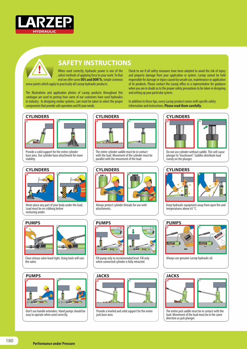
When used correctly, hydraulic power is one of the safest methods of applying force to your work. To that end we offer some DO’s and DON’Ts, simple common
sense points which apply to practically all Larzep hydraulic products.
The illustrations and application photos of Larzep products throughout this catalogue are used to portray how some of our customers have used hydraulics in industry. In designing similar systems, care must be taken to select the proper components that provide safe operation and fit your needs.
Check to see if all safety measures have been adopted to avoid the risk of injury and property damage from your application or system. Larzep cannot be held responsible for damage or injury caused by unsafe use, maintenance or application of its products. Please contact the Larzep office or a representative for guidance when you are in doubt as to the proper safety precautions to be taken in designing and setting up your particular system.
In addition to these tips, every Larzep product comes with specific safety information and instructions. Please read them carefully.
Always read the safety instructions.
Provide a leveled and solid support for the entire jack base area.
JACKS
SAFETY INSTRUCTIONS
The entire jack saddle must be in contact with theload. Movement of the load must be in the samedirection as jack plunger.
JACKS
Provide a solid support for the entire cylinder base area. Use cylinder base attachment for more stability.
CYLINDERS
The entire cylinder saddle must be in contact with the load. Movement of the cylinder must be parallel with the movement of the load.
CYLINDERS
Do not use cylinder without saddle. This will cause plunger to “mushroom”. Saddles distribute load evenly on the plunger.
CYLINDERS
Never place any part of your body under the load. Load must be on cribbing beforeventuring under.
CYLINDERS
Always protect cylinder threads for use with attachments.
CYLINDERS
Keep hydraulic equipment away from open fire andtemperatures above 65 °C.
CYLINDERS
Close release valve hand tight. Using tools will ruinthe valve.
PUMPS
Fill pump only to recommended level. Fill only when connected cylinder is fully retracted.
PUMPS
Always use genuine Larzep hydraulic oil.
PUMPS
Don’t use handle extenders. Hand pumps should be easy to operate when used correctly.
PUMPS
Performance under Pressure180
Always read the safety instructions.
Never place any part of your body under the load.Ensure the load is on a solid support beforeventuring under.
JACKS
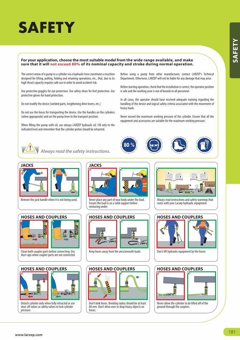
The correct union of a pump to a cylinder via a hydraulic hose constitutes a machine designed for lifting, pulling, folding and retaining operations, etc., that, due to its high thrust capacity requires safe use in order to avoid accident risk.
Use protective goggles for eye protection. Use safety shoes for feet protection. Use protective gloves for hand protection.
Do not modify the device (welded parts, lengthening drive levers, etc.).
Do not use the hoses for transporting the device. Use the handles on the cylinders (when appropriate) and set the pump lever to the transport position.
When filling the pump with oil, use always LARZEP hydraulic oil. Fill only to the indicated level and remember that the cylinder piston should be retracted.
Before using a pump from other manufacturer, contact LARZEP’s Technical Department. Otherwise, LARZEP will not be liable for any damage that may arise.
Before starting operation, check that the installation is correct, the operator position is safe and the working zone is out of bounds to all personnel.
In all cases, the operator should have received adequate training regarding the handling of the device and logical safety criteria associated with the movement of heavy loads.
Never exceed the maximum working pressure of the cylinder. Ensure that all the equipment and accessories are suitable for the maximum working pressure.
For your application, choose the most suitable model from the wide range available, and make sure that it will not exceed 80% of its nominal capacity and stroke during normal operation.
Remove the jack handle when it is not being used.
JACKS
Clean both coupler parts before connecting. Use dust caps when coupler parts are not connected.
HOSES AND COUPLERS
Keep hoses away from the area beneath loads.
HOSES AND COUPLERS
Don’t lift hydraulic equipment by the hoses.
HOSES AND COUPLERS
Detach cylinder only when fully retracted or useshut-off valves or safety valves to lock cylinderpressure.
HOSES AND COUPLERS
Don’t kink hoses. Bending radius should be at least 80 mm. Don’t drive over or drop heavy objects onhoses.
HOSES AND COUPLERS
Never allow the cylinder to be lifted off of the ground through the couplers.
HOSES AND COUPLERS
Always read instructions and safety warnings that come with your Larzep hydraulic equipment.
www.larzep.com181
SAFETY
SAFE
TY
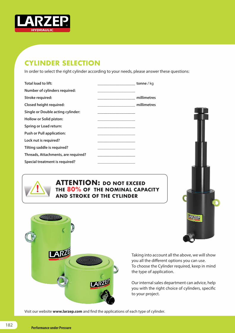
CYLINDER SELECTIONIn order to select the right cylinder according to your needs, please answer these questions:
Total load to lift: ___________________ tonne / kg
Number of cylinders required: ___________________
Stroke required: ___________________ millimetres
Closed height required: ___________________ millimetres
Single or Double acting cylinder: ___________________
Hollow or Solid piston: ___________________
Spring or Load return: ___________________
Push or Pull application: ___________________
Lock nut is required? ___________________
Tilting saddle is required? ___________________
Threads, Attachments, are required? ___________________
Special treatment is required? ___________________
ATTENTION: DO NOT EXCEED THE 80% OF THE NOMINAL CAPACITY AND STROKE OF THE CYLINDER
Taking into account all the above, we will show you all the different options you can use.To choose the Cylinder required, keep in mind the type of application.
Our internal sales department can advice, help you with the right choice of cylinders, specific to your project.
Always read the safety instructions.
Visit our website www.larzep.com and find the applications of each type of cylinder.
Performance under Pressure182
Visit our website www.larzep.com for the online Cylinder or Pump Selection application.
In order to select the right pump according to your needs, please answer these questions:
HAND PUMPSSingle or Double acting: ___________________Number of cylinders required: ___________________Cylinder capacity: ___________________ tonneCylinder stroke: ___________________ millimetresTotal hose length: ___________________ metres
POWERPACKSSingle or Double acting: ___________________Number of cylinders required: ___________________Cylinder capacity: ___________________ tonneCylinder stroke: ___________________ millimetresTotal hose length: ___________________ metresManual or Solenoid valve: ___________________Load holding is required? ___________________Single or Three phase: ___________________Voltage: ___________________ VFrequency: ___________________ HzRemote pendant (for HBM) is required? ___________________Roll bar, Wheel kit, Heat exchanger, Pedal or Pressure gauge are required? ___________________
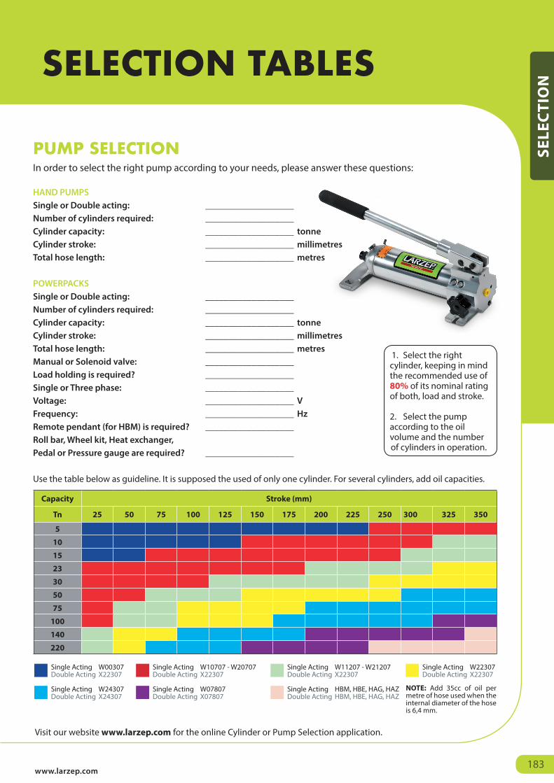
Use the table below as guideline. It is supposed the used of only one cylinder. For several cylinders, add oil capacities.
PUMP SELECTION
Capacity Stroke (mm)
Tn 25 50 75 100 125 150 175 200 225 250 300 325 350
5
10
15
23
30
50
75
100
140
220
Single Acting W00307Double Acting X22307
Single Acting W10707 - W20707Double Acting X22307
Single Acting W11207 - W21207Double Acting X22307
Single Acting W22307Double Acting X22307
Single Acting W24307Double Acting X24307
Single Acting W07807Double Acting X07807
Single Acting HBM, HBE, HAG, HAZDouble Acting HBM, HBE, HAG, HAZ
1. Select the right cylinder, keeping in mind the recommended use of 80% of its nominal rating of both, load and stroke.
2. Select the pump according to the oil volume and the number of cylinders in operation.
NOTE: Add 35cc of oil per metre of hose used when the internal diameter of the hose is 6,4 mm.
www.larzep.com183
SELECTION TABLES
SELE
CTI
ON
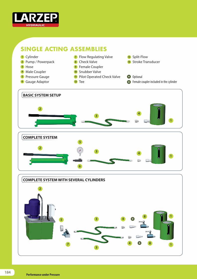
SINGLE ACTING ASSEMBLIES
BASIC SYSTEM SETUP
COMPLETE SYSTEM
COMPLETE SYSTEM WITH SEVERAL CYLINDERS
Cylinder Pump / Powerpack Hose Male Coupler Pressure Gauge Gauge Adaptor
Flow Regulating Valve Check Valve Female Coupler Snubber Valve Pilot Operated Check Valve Tee
Split-Flow Stroke Transducer
Optional Female coupler included in the cylinder
1
2
3
4
5
6
7
8
9
10
11
12
13
14
1
2
3
4
5
6
7
8
9
10
11
12
13
14
1
2
3
4
5
6
7
8
9
10
11
12
13
14
1
2
3
4
5
6
7
8
9
10
11
12
13
14
1
2
3
4
5
6
7
8
9
10
11
12
13
14
1
2
3
4
5
6
7
8
9
10
11
12
13
14
1
2
3
4
5
6
7
8
9
10
11
12
13
14
1
2
3
4
5
6
7
8
9
10
11
12
13
14
1
2
3
4
5
6
7
8
9
10
11
12
13
14
1
2
3
4
5
6
7
8
9
10
11
12
13
14
1
2
3
4
5
6
7
8
9
10
11
12
13
14
1
2
3
4
5
6
7
8
9
10
11
12
13
14
1
2
3
4
5
6
7
8
9
10
11
12
13
14
1
2
3
4
5
6
7
8
9
10
11
12
13
14
1
2
3
4
5
6
7
8
9
10
11
12
13
14
1
2
3
4
5
6
7
8
9
10
11
12
13
14
1
2
3
4
5
6
7
8
9
10
11
12
13
14
1
2
3
4
5
6
7
8
9
10
11
12
13
14
1
2
3
4
5
6
7
8
9
10
11
12
13
14
1
2
3
4
5
6
7
8
9
10
11
12
13
14
1
2
3
4
5
6
7
8
9
10
11
12
13
14
1
2
3
4
5
6
7
8
9
10
11
12
13
14
1
2
3
4
5
6
7
8
9
10
11
12
13
14
1
2
3
4
5
6
7
8
9
10
11
12
13
14
Performance under Pressure184
LIFTING SYSTEM AND SPLIT-FLOW
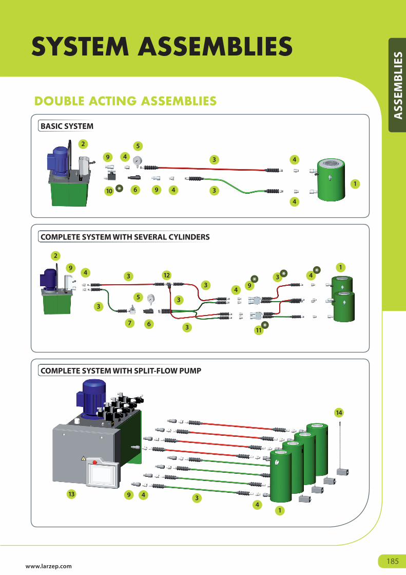
COMPLETE SYSTEM WITH SEVERAL CYLINDERS
BASIC SYSTEM
DOUBLE ACTING ASSEMBLIES
COMPLETE SYSTEM WITH SPLIT-FLOW PUMP
1
2
3
4
5
6
7
8
9
10
11
12
13
14
1
2
3
4
5
6
7
8
9
10
11
12
13
14
1
2
3
4
5
6
7
8
9
10
11
12
13
14
1
2
3
4
5
6
7
8
9
10
11
12
13
14
1
2
3
4
5
6
7
8
9
10
11
12
13
14
1
2
3
4
5
6
7
8
9
10
11
12
13
14
1
2
3
4
5
6
7
8
9
10
11
12
13
14
1
2
3
4
5
6
7
8
9
10
11
12
13
14
1
2
3
4
5
6
7
8
9
10
11
12
13
14
1
2
3
4
5
6
7
8
9
10
11
12
13
14
1
2
3
4
5
6
7
8
9
10
11
12
13
14
1
2
3
4
5
6
7
8
9
10
11
12
13
14
1
2
3
4
5
6
7
8
9
10
11
12
13
14
1
2
3
4
5
6
7
8
9
10
11
12
13
14
1
2
3
4
5
6
7
8
9
10
11
12
13
14
1
2
3
4
5
6
7
8
9
10
11
12
13
14
1
2
3
4
5
6
7
8
9
10
11
12
13
14
1
2
3
4
5
6
7
8
9
10
11
12
13
14
1
2
3
4
5
6
7
8
9
10
11
12
13
14
1
2
3
4
5
6
7
8
9
10
11
12
13
14
1
2
3
4
5
6
7
8
9
10
11
12
13
14
1
2
3
4
5
6
7
8
9
10
11
12
13
14
1
2
3
4
5
6
7
8
9
10
11
12
13
14
1
2
3
4
5
6
7
8
9
10
11
12
13
14
1
2
3
4
5
6
7
8
9
10
11
12
13
14
1
2
3
4
5
6
7
8
9
10
11
12
13
14
1
2
3
4
5
6
7
8
9
10
11
12
13
14
1
2
3
4
5
6
7
8
9
10
11
12
13
14
1
2
3
4
5
6
7
8
9
10
11
12
13
14
1
2
3
4
5
6
7
8
9
10
11
12
13
14
1
2
3
4
5
6
7
8
9
10
11
12
13
14
1
2
3
4
5
6
7
8
9
10
11
12
13
14
1
2
3
4
5
6
7
8
9
10
11
12
13
14
1
2
3
4
5
6
7
8
9
10
11
12
13
14
1
2
3
4
5
6
7
8
9
10
11
12
13
14
1
2
3
4
5
6
7
8
9
10
11
12
13
14
1
2
3
4
5
6
7
8
9
10
11
12
13
14
1
2
3
4
5
6
7
8
9
10
11
12
13
14
www.larzep.com185
SYSTEM ASSEMBLIES
ASS
EMB
LIES
VALVE INFORMATION
Performance under Pressure186
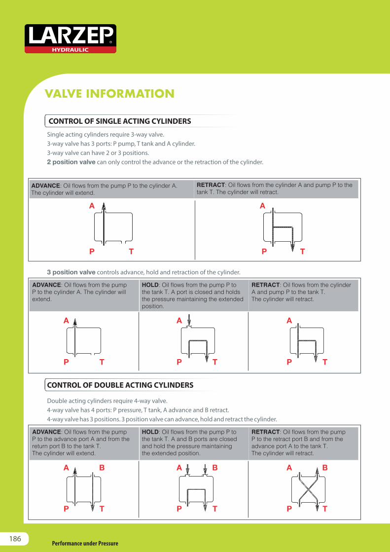
Single acting cylinders require 3-way valve.3-way valve has 3 ports: P pump, T tank and A cylinder.3-way valve can have 2 or 3 positions. 2 position valve can only control the advance or the retraction of the cylinder.
3 position valve controls advance, hold and retraction of the cylinder.
Double acting cylinders require 4-way valve.4-way valve has 4 ports: P pressure, T tank, A advance and B retract.4-way valve has 3 positions. 3 position valve can advance, hold and retract the cylinder.
ADVANCE: Oil flows from the pump P to the cylinder A. The cylinder will extend.
RETRACT: Oil flows from the cylinder A and pump P to the tank T. The cylinder will retract.
A A
P PT T
ADVANCE: Oil flows from the pump P to the cylinder A. The cylinder will extend.
HOLD: Oil flows from the pump P to the tank T. A port is closed and holds the pressure maintaining the extended position.
RETRACT: Oil flows from the cylinder A and pump P to the tank T. The cylinder will retract.
A A A
P P PT T T
ADVANCE: Oil flows from the pump P to the advance port A and from the return port B to the tank T.The cylinder will extend.
HOLD: Oil flows from the pump P to the tank T. A and B ports are closed and hold the pressure maintaining the extended position.
RETRACT: Oil flows from the pump P to the retract port B and from the advance port A to the tank T. The cylinder will retract.
A A AB B B
P P PT T T
CONTROL OF SINGLE ACTING CYLINDERS
CONTROL OF DOUBLE ACTING CYLINDERS
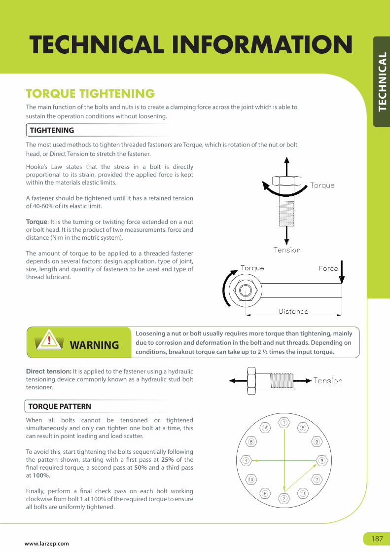
Loosening a nut or bolt usually requires more torque than tightening, mainly due to corrosion and deformation in the bolt and nut threads. Depending on conditions, breakout torque can take up to 2 ½ times the input torque.
Always read the safety instructions.WARNING
www.larzep.com187
TORQUE TIGHTENING
Hooke’s Law states that the stress in a bolt is directly proportional to its strain, provided the applied force is kept within the materials elastic limits.
A fastener should be tightened until it has a retained tension of 40-60% of its elastic limit.
Torque: It is the turning or twisting force extended on a nut or bolt head. It is the product of two measurements: force and distance (N·m in the metric system).
The amount of torque to be applied to a threaded fastener depends on several factors: design application, type of joint, size, length and quantity of fasteners to be used and type of thread lubricant.
Direct tension: It is applied to the fastener using a hydraulic tensioning device commonly known as a hydraulic stud bolt tensioner.
When all bolts cannot be tensioned or tightened simultaneously and only can tighten one bolt at a time, this can result in point loading and load scatter.
To avoid this, start tightening the bolts sequentially following the pattern shown, starting with a first pass at 25% of the final required torque, a second pass at 50% and a third pass at 100%.
Finally, perform a final check pass on each bolt working clockwise from bolt 1 at 100% of the required torque to ensure all bolts are uniformly tightened.
The main function of the bolts and nuts is to create a clamping force across the joint which is able to sustain the operation conditions without loosening.
The most used methods to tighten threaded fasteners are Torque, which is rotation of the nut or bolt head, or Direct Tension to stretch the fastener.
TECHNICAL INFORMATION
TEC
HN
ICA
L
TIGHTENING
TORQUE PATTERN
Stroke (S)
Load (F) (Force)
Oil Capacity (V)Stroke (S)
Pressure (P)
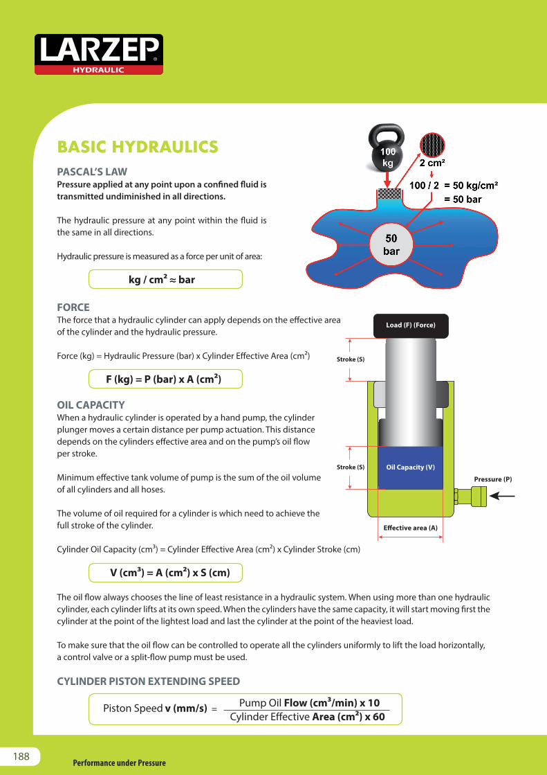
FORCE The force that a hydraulic cylinder can apply depends on the effective area of the cylinder and the hydraulic pressure.
Force (kg) = Hydraulic Pressure (bar) x Cylinder Effective Area (cm²)
F (kg) = P (bar) x A (cm²)
OIL CAPACITYWhen a hydraulic cylinder is operated by a hand pump, the cylinder plunger moves a certain distance per pump actuation. This distancedepends on the cylinders effective area and on the pump’s oil flowper stroke.
Minimum effective tank volume of pump is the sum of the oil volumeof all cylinders and all hoses.
The volume of oil required for a cylinder is which need to achieve thefull stroke of the cylinder.
Cylinder Oil Capacity (cm³) = Cylinder Effective Area (cm²) x Cylinder Stroke (cm)
V (cm³) = A (cm²) x S (cm)
The oil flow always chooses the line of least resistance in a hydraulic system. When using more than one hydraulic cylinder, each cylinder lifts at its own speed. When the cylinders have the same capacity, it will start moving first the cylinder at the point of the lightest load and last the cylinder at the point of the heaviest load.
To make sure that the oil flow can be controlled to operate all the cylinders uniformly to lift the load horizontally, a control valve or a split-flow pump must be used.
CYLINDER PISTON EXTENDING SPEED
PASCAL’S LAW Pressure applied at any point upon a confined fluid is transmitted undiminished in all directions.
The hydraulic pressure at any point within the fluid is the same in all directions.
Hydraulic pressure is measured as a force per unit of area:
kg / cm² ≈ bar
BASIC HYDRAULICS
Piston Speed v (mm/s) = Pump Oil Flow (cm3/min) x 10 Cylinder Effective Area (cm2) x 60
Performance under Pressure188
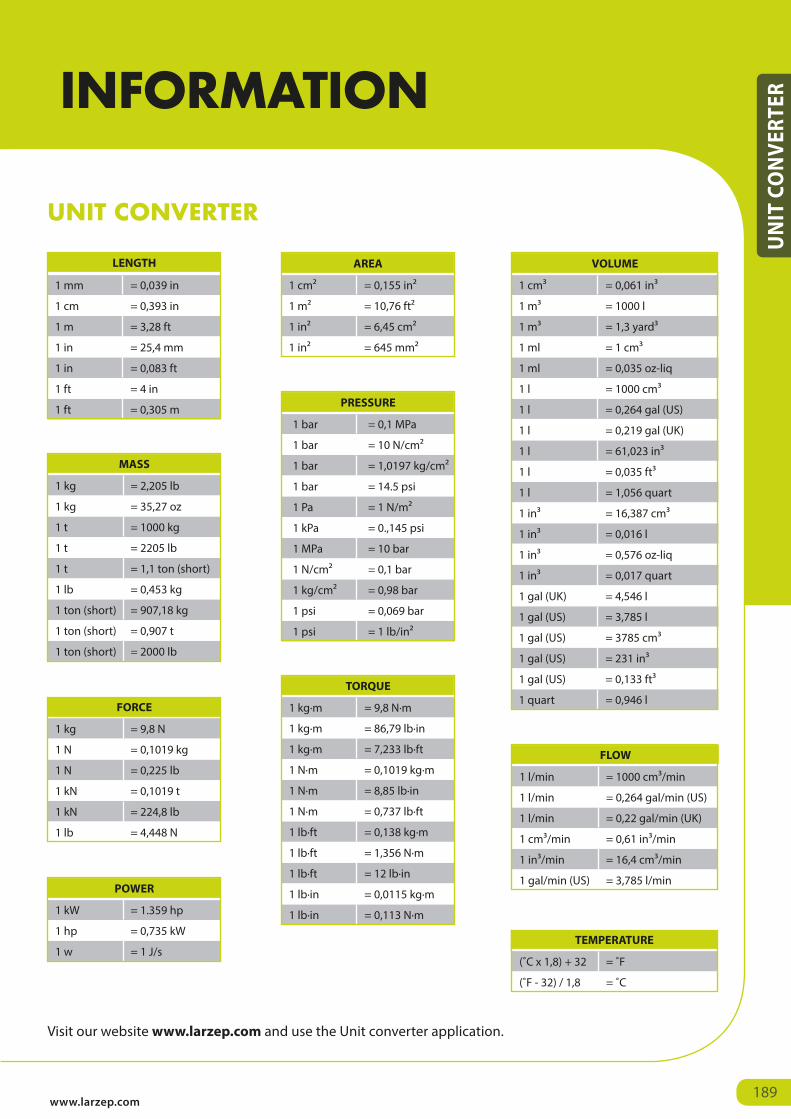
1 mm = 0,039 in
1 cm = 0,393 in
1 m = 3,28 ft
1 in = 25,4 mm
1 in = 0,083 ft
1 ft = 4 in
1 ft = 0,305 m
LENGTH
1 cm² = 0,155 in²
1 m² = 10,76 ft²
1 in² = 6,45 cm²
1 in² = 645 mm²
AREA
1 cm³ = 0,061 in³
1 m³ = 1000 l
1 m³ = 1,3 yard³
1 ml = 1 cm³
1 ml = 0,035 oz-liq
1 l = 1000 cm³
1 l = 0,264 gal (US)
1 l = 0,219 gal (UK)
1 l = 61,023 in³
1 l = 0,035 ft³
1 l = 1,056 quart
1 in³ = 16,387 cm³
1 in³ = 0,016 l
1 in³ = 0,576 oz-liq
1 in³ = 0,017 quart
1 gal (UK) = 4,546 l
1 gal (US) = 3,785 l
1 gal (US) = 3785 cm³
1 gal (US) = 231 in³
1 gal (US) = 0,133 ft³
1 quart = 0,946 l
VOLUME
1 kg = 2,205 lb
1 kg = 35,27 oz
1 t = 1000 kg
1 t = 2205 lb
1 t = 1,1 ton (short)
1 lb = 0,453 kg
1 ton (short) = 907,18 kg
1 ton (short) = 0,907 t
1 ton (short) = 2000 lb
MASS
1 bar = 0,1 MPa
1 bar = 10 N/cm²
1 bar = 1,0197 kg/cm²
1 bar = 14.5 psi
1 Pa = 1 N/m²
1 kPa = 0.,145 psi
1 MPa = 10 bar
1 N/cm² = 0,1 bar
1 kg/cm² = 0,98 bar
1 psi = 0,069 bar
1 psi = 1 lb/in²
PRESSURE
1 kg = 9,8 N
1 N = 0,1019 kg
1 N = 0,225 lb
1 kN = 0,1019 t
1 kN = 224,8 lb
1 lb = 4,448 N
FORCE
1 kW = 1.359 hp
1 hp = 0,735 kW
1 w = 1 J/s
POWER
1 kg·m = 9,8 N·m
1 kg·m = 86,79 lb·in
1 kg·m = 7,233 lb·ft
1 N·m = 0,1019 kg·m
1 N·m = 8,85 lb·in
1 N·m = 0,737 lb·ft
1 lb·ft = 0,138 kg·m
1 lb·ft = 1,356 N·m
1 lb·ft = 12 lb·in
1 lb·in = 0,0115 kg·m
1 lb·in = 0,113 N·m
TORQUE
1 l/min = 1000 cm³/min
1 l/min = 0,264 gal/min (US)
1 l/min = 0,22 gal/min (UK)
1 cm³/min = 0,61 in³/min
1 in³/min = 16,4 cm³/min
1 gal/min (US) = 3,785 l/min
FLOW
(˚C x 1,8) + 32 = ˚F
(˚F - 32) / 1,8 = ˚C
TEMPERATURE
UNIT CONVERTER
Visit our website www.larzep.com and use the Unit converter application.
www.larzep.com189
UN
IT C
ON
VERT
ERINFORMATION
Related Documents


