Welcome message from author
This document is posted to help you gain knowledge. Please leave a comment to let me know what you think about it! Share it to your friends and learn new things together.
Transcript


Reinforcing back-ribs to minimize valve operating problems such as distortion, skidding andexfoliation of rubber liners caused by line pressure load and friction with metal discs.
XJ Series
Aluminum Butterfly Valves KITZ XJ Series aluminum butterfly valves : Featured with unique style of
the neck designs(U.S.P. No.6676109), for accommodation of various piping designs, piping positions and installation environments.
Two neck designs for your choice :Long neck type, short neck type are available for versatile applications.
Easy valve-to-flange centering :Light weight of die-cast aluminum valve body (which is only one-thirds of KITZ's conventional cast iron butterfly valves) eases valve-to-flange centering work on mounting valves on pipelines.
Wide range of service applications :Austenitic stainless steel discs and EPDM rubber seats can handle many different kinds of line fluid without concern of corrosion.
Stabilized operating torque :A pair of stem bearing assembled around the top and bottom stems prevents stem galling, and stabilizes valve operating torque for smooth and trouble-free disc rotation.
On-the-spot actuator assembly :The actuator mounting pads of all necks are designed in conformity with ISO 5211 requirements for direct on-site mounting of actuators which are provided with ISO 5211 valve mounting flanges.
Prevention of dew condensation (Long neck type) :A long stainless steel neck blocks transfer of the fluid heat to a valve operating device, which thus needs no insulation on the operating device. Dew condensation is minimized also in case of gear operated valves on cold water service.
Rust prevention :Main parts such as stems, discs, necks, neck connectors and endplates, and small parts such as stopper plates, washers and boltings are all made of stainless steel for highly graded rust prevention.
S-shape spherical disc for high sealing performance (patented) :KITZ's original cross-sectionally S-shaped valve discs with spherical surface evenly make tight contact with rubber liners for excellent sealing performance with reduced operating torque. Thorough 360 s゚hut-off mechanism helps extend service life of rubber liners. (Size 2inch and over.)
Long Neck
Short NeckShort Neck
1 2
Short neck
40
3 4 5 6 8 10 12
50 65 80 100 125 150 200 250 300
10XJME
G-10XJME
FA-10XJME
FAS-10XJME
EXS-10XJME
10XJMEA
G-10XJMEA
FA-10XJMEA
FAS-10XJMEA
EXS-10XJMEA
PN16XJME
G-PN16XJME
10XJSME
G-10XJSME
FA-10XJSME
FAS-10XJSME
EXS-10XJSME
Lever
Gear
Pneumatic actuator(Double action)
Pneumatic actuator(Spring return)
Electric actuator
Lever
Gear
Pneumatic actuator(Double action)
Pneumatic actuator(Spring return)
Electric actuator
Lever
Gear
Lever
Gear
Pneumatic actuator (Double action)
Pneumatic actuator (Spring return)
Electric actuator
2 2/
○
○
○
○
○
●
●
○
○
○
○
○
○
○
○
○
○
●
●
○
○
○
●
●
●
●
○
○
○
○
○
○
○
○
●
●
○
○
○
●
●
●
●
○
○
○
○
○
○
○
○
●
●
○
○
○
●
●
●
●
○
○
○
○
○
○
○
○
●
●
○
○
○
●
●
●
●
○
○
○
○
○
○
○
○
●
●
○
○
○
●
●
●
●
○
○
○
○
○
○
○
○
●
●
○
○
○
●
●
●
●
○
○
○
○
○
○
○
●
●
○
○
○
●
●
○
○
○
○
○
○
●
○
○
○
○
○
●
○
○
○
○
○
2//1//2
1
6
6
8
8
10
6
6
8
8
10
6
6
7
7
9
9
10
● ● ● ● ● ●
●●● ●●● ●●● ●●● ●●● ●●●
●
●
●
●
●
●
●
●
●
●
●
●
● ● ● ● ● ● ●
●●●
●
●
●
■Product Coding
■Product Range
Valve operation
None
G
FA
FAS
EXS
Lever
Gear
Pneumatic actuator(Double action)
Pneumatic actuator(Spring return action)
Electric actuator(Please consult KITZfor availability of power supply)
Design
None
S
Disc material
M
P
Seat material
E
Long neck
Short neck
316 stainless steel
PPS*
EPDM
・・・・・・・・・・・・
・・・・・・・・・・・・・
・・・・・・・・・・・・・・
・・・・・・・・・・・・・
・・・・・・・・・・・・・
・・・・・・・・・・・・・・
・・・・・・・・・・・・・・・・・・・
・・・・・・・・・・・・・・・・・・
・・・・・・・・・・・・・・・・・・
・・・・・・・・・・・・・・・・・・
Long neck
JIS 10K
JIS 10K/ASME
Class 150
EN1092PN16
JIS 10K
Size
Product code
mm
inchPageOperatorClassDesign
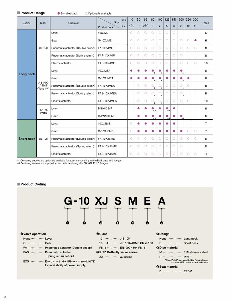
1/21 Maximum service pressure
Service temperature range*1
Continuous service temperature range*2
Face-to-face dimension
Coupling flanges
Class
-20°C~+120°C
0°C~+100°C
API609, BS5155(Short pattern)ISO 5752-20, JIS B 2002 46 series
1MPa 1MPa1.6MPa(16bar)
■Technical Specification ■P-T Rating
■Pressure Loss(for handling static clean water)
1
3
4
5
6
Class
10
10 A
PN16
KITZ Butterfly valve series
XJ
JIS 10K
JIS 10K/ASME Class 150
EN1092 4504 PN16
XJ series
・・・・・・・・・・・・・・
・・・・・・・・・
・・・・・・・・・・・
・・・・・・・・・・・・・・
2
11.1
0.7
-20 0 90Temperature(℃)
Pressure
Pressure drop
MPa
120
0.5
1.6
0 10 20 30
100
90
80
70
60
50
40
30
20
10
40 50
Valve opening(%)
Flow rate(%)
Close Open
60 70 80 90 100
1.0 2.0 5.0 10 50
Flow volume(m3/h)100
222222″″″
3333″″″444444″″555″″
6666″″″888″″1001″100″″″
12222122″″″
500 100020000.098
0.49
0.98
9.8
4.9
(kPa)
*1 Condition : Fluid is not frozen.*2 Refer to P-T rating chart.*3 With centering sleeves.
Refer to the product range chart in page 3 and precaution in page 14 for details.
Parts
Body
Neck
Stem
Disc
O-ring
Rubber seat
Bottom stem
Bearing
Material
Aluminum Die-cast / Equivalent ASTM B85-84-383.0
A351 Gr. CF8
(Equivalent ASTM A276 Type 410)
A351 Gr. CF8M
EPDM
EPDM
(Equivalent ASTM A276 Type 410)
Metal Backed PTFE(Size 10″and 12″)Polyphenylenesulfide(10XJMEA : Size ″to 8″)Bronze : CAC401C(PN16XJME : Size 2″to 8″)
■Material
Valve size Valve opening
40
50
65
80
100
125
150
200
250
300
76
99
205
372
723
1100
1820
2780
4350
6860
1/
2
2/
3
4
5
6
8
10
12
■Cv Value
■Flow Characteristics
mm inch 90°
2//1//
2//1//
3 4
Note:Contact KITZ corporation for technical advice when service conditions may exceed the P-T rating range limited here.
* * *
*
*
*
*
* *
* *
* *
* *
**
**
**
** **
**Centering sleeves are optionally available for accurate centering with ASME class 150 flanges.**Centering sleeves are supplied for accurate centering with EN1092 PN16 flanges.
JIS 10K Class 150 PN16
JIS B 2220/ 2239 10K
ASME Class 150JIS B 2220/ 2239 10K
*3
EN1092 PN16*3
10K / Class 150
PN16
●Standardized. ○○Optionally available.
11/1 2//
*Disc: Poly Phenylene Sulfide Resin pleasecontact KITZ corporation for detailes.
Short neck
40
3 4 5 6 8 10 12
50 65 80 100 125 150 200 250 300
10XJME
G-10XJME
FA-10XJME
FAS-10XJME
EXS-10XJME
10XJMEA
G-10XJMEA
FA-10XJMEA
FAS-10XJMEA
EXS-10XJMEA
PN16XJME
G-PN16XJME
10XJSME
G-10XJSME
FA-10XJSME
FAS-10XJSME
EXS-10XJSME
Lever
Gear
Pneumatic actuator(Double action)
Pneumatic actuator(Spring return)
Electric actuator
Lever
Gear
Pneumatic actuator(Double action)
Pneumatic actuator(Spring return)
Electric actuator
Lever
Gear
Lever
Gear
Pneumatic actuator (Double action)
Pneumatic actuator (Spring return)
Electric actuator
2 2/
○
○
○
○
○
●
●
○
○
○
○
○
○
○
○
○
○
●
●
○
○
○
●
●
●
●
○
○
○
○
○
○
○
○
●
●
○
○
○
●
●
●
●
○
○
○
○
○
○
○
○
●
●
○
○
○
●
●
●
●
○
○
○
○
○
○
○
○
●
●
○
○
○
●
●
●
●
○
○
○
○
○
○
○
○
●
●
○
○
○
●
●
●
●
○
○
○
○
○
○
○
○
●
●
○
○
○
●
●
●
●
○
○
○
○
○
○
○
●
●
○
○
○
●
●
○
○
○
○
○
○
●
○
○
○
○
○
●
○
○
○
○
○
2//1//2
1
6
6
8
8
10
6
6
8
8
10
6
6
7
7
9
9
10
● ● ● ● ● ●
●●● ●●● ●●● ●●● ●●● ●●●
●
●
●
●
●
●
●
●
●
●
●
●
● ● ● ● ● ● ●
●●●
●
●
●
■Product Coding
■Product Range
Valve operation
None
G
FA
FAS
EXS
Lever
Gear
Pneumatic actuator(Double action)
Pneumatic actuator(Spring return action)
Electric actuator(Please consult KITZfor availability of power supply)
Design
None
S
Disc material
M
P
Seat material
E
Long neck
Short neck
316 stainless steel
PPS*
EPDM
・・・・・・・・・・・・
・・・・・・・・・・・・・
・・・・・・・・・・・・・・
・・・・・・・・・・・・・
・・・・・・・・・・・・・
・・・・・・・・・・・・・・
・・・・・・・・・・・・・・・・・・・
・・・・・・・・・・・・・・・・・・
・・・・・・・・・・・・・・・・・・
・・・・・・・・・・・・・・・・・・
Long neck
JIS 10K
JIS 10K/ASME
Class 150
EN1092PN16
JIS 10K
Size
Product code
mm
inchPageOperatorClassDesign
1/21 Maximum service pressure
Service temperature range*1
Continuous service temperature range*2
Face-to-face dimension
Coupling flanges
Class
-20°C~+120°C
0°C~+100°C
API609, BS5155(Short pattern)ISO 5752-20, JIS B 2002 46 series
1MPa 1MPa1.6MPa(16bar)
■Technical Specification ■P-T Rating
■Pressure Loss(for handling static clean water)
1
3
4
5
6
Class
10
10 A
PN16
KITZ Butterfly valve series
XJ
JIS 10K
JIS 10K/ASME Class 150
EN1092 4504 PN16
XJ series
・・・・・・・・・・・・・・
・・・・・・・・・
・・・・・・・・・・・
・・・・・・・・・・・・・・
2
11.1
0.7
-20 0 90Temperature(℃)
Pressure
Pressure drop
MPa
120
0.5
1.6
0 10 20 30
100
90
80
70
60
50
40
30
20
10
40 50
Valve opening(%)
Flow rate(%)
Close Open
60 70 80 90 100
1.0 2.0 5.0 10 50
Flow volume(m3/h)100
222222″″″
3333″″″444444″″555″″
6666″″″888″″1001″100″″″
12222122″″″
500 100020000.098
0.49
0.98
9.8
4.9
(kPa)
*1 Condition : Fluid is not frozen.*2 Refer to P-T rating chart.*3 With centering sleeves.
Refer to the product range chart in page 3 and precaution in page 14 for details.
Parts
Body
Neck
Stem
Disc
O-ring
Rubber seat
Bottom stem
Bearing
Material
Aluminum Die-cast / Equivalent ASTM B85-84-383.0
A351 Gr. CF8
(Equivalent ASTM A276 Type 410)
A351 Gr. CF8M
EPDM
EPDM
(Equivalent ASTM A276 Type 410)
Metal Backed PTFE(Size 10″and 12″)Polyphenylenesulfide(10XJMEA : Size ″to 8″)Bronze : CAC401C(PN16XJME : Size 2″to 8″)
■Material
Valve size Valve opening
40
50
65
80
100
125
150
200
250
300
76
99
205
372
723
1100
1820
2780
4350
6860
1/
2
2/
3
4
5
6
8
10
12
■Cv Value
■Flow Characteristics
mm inch 90°
2//1//
2//1//
3 4
Note:Contact KITZ corporation for technical advice when service conditions may exceed the P-T rating range limited here.
* * *
*
*
*
*
* *
* *
* *
* *
**
**
**
** **
**Centering sleeves are optionally available for accurate centering with ASME class 150 flanges.**Centering sleeves are supplied for accurate centering with EN1092 PN16 flanges.
JIS 10K Class 150 PN16
JIS B 2220/ 2239 10K
ASME Class 150JIS B 2220/ 2239 10K
*3
EN1092 PN16*3
10K / Class 150
PN16
●Standardized. ○○Optionally available.
11/1 2//
*Disc: Poly Phenylene Sulfide Resin pleasecontact KITZ corporation for detailes.

5 6
10XJME (Size: "11/2// " to "6")10XJMEA (Size: "11/2// " to "8")PN16XJME (Size: "2" to "6")
SSS
OO
NO.1
H
HH1
H3H3
H2H2
Dd
L
C
L1
E
F
D1
■Dimensions
40506580100125150200
unit:mm
40506580100125150196
d
4066748394122135161
H2
3343464652565660
L
8093118129149184214258
D
105120140150175210240290
C
180180180180180230230350
D1mm
1/22/34568
//1//
////
inch98.5120.5139.5152.5190.5216 241.5298.5
Class 150-125145160180210240-
PN1610K172176185193204249261281
H
128132141149160195207234
H1
No.0No.0No.0No.0No.1No.1No.1No.2No.2No.2
40506580100125150196245295
d
175179188196223258270311405430
H
128132141149160195207234328353
H1
140166174183194122135161*1238263
H2
19191919242424323232
H3
33434646525656606878
L
8093118129149184214258 316367
D
105120140150175210240290355400
98.5 120.5139.5152.5190.5216241.5298.5362-
-125145160180210240295--
C
80808080110110110170170170
D1
122122122122135150150180180180
L1
29292929363636515151
E
28282828404040636363
F
40506580100125150200250300
mm inch1/22/345681012
2//1//
2//1//
PN16Class15010K
Long Neck Type Lever Operated
Long Neck Type Gear Operated
Size
■Dimensions unit:mm
Size Gear type
G-10XJME (Size: "11/2// " to "12")G-10XJMEA (Size: "11/2// " to "10")G-PN16XJME (Size: "2" to "8")
H
HH1
H2H2
Dd
L
C
D1
■Dew Condensation Test ■Corrosion Resistance Level
■Valve Insulation
Atmospheric Humidity(%)
G–10XJMEA Estimated Dew Condensation Boundary
Positive dewcondensation area
Atmospheric Temperature(℃)
Negative dewcondensation area
Boundary area
70
75
80
85
90
95
100
20 25 30 35 40
Long Neck Type(G-10XJMEA)
FluidMaterials
*Chlorine-free
Disc materialCF8M
= Excellent= Good= Less recommended= Not recommended
Seat materialEPDM
This table indicates general corrosion resistance level of the materi-als of discs and rubber liners used for KITZ XJ Series butterflyvalves against typical line fluids. The data is based on the laboratorytest finding on material test specimens (not valve component testspecimens) under constantly controlled test conditions, and thuseach data may be subject to variation, depending on actual valveservice conditions in the field. Please contact KITZ Corporation fortechnical advice, if service conditions are extra-ordinarily severe, oryou have any doubt about corrosion resistance level of valves on-site. Also please contact KITZ Corporation when valves are used forhot water service.
Areas in blue are recommended to insulate
Acetic acid(10%)
Air
Ammonia(anhydrous liquid)
Ammonium sulfate
Animal fat
Calcium chloride
Carbonic acid
Chlorinated water
Ethane
Ethyl alcohol
Freon 12
Gasoline(refined / unleaded)
Hydrochloric acid 37%(cold)
Hydrogen gas(cold)
Lubricating oil(petroleum base)
Methyl alcohol
Mineral oil
Heavy oil
Natural gas
Oxygen(cold)
Petroleum oil(refined)
Propane gas
Sea water
Soybean oil
Sulfuric acid(7%)
Sulfuric acid(20%)
Sulfuric acid(50≧%)
Sulfurous
Steam(100℃)
Vegetable oil
Water(fresh)*
*1 G-PN16XJME H2=183

7 8
S
O
NO.1
H
E
F
L
H1
H3
H2
Dd
L1
C
D1
H
H1
H2
Dd
L
C
D1
10XJSME
G-10XJSME
Short Neck Type Lever Operated
Short Neck Type Gear Operated
■Dimensions
40 50 65 80 100 125 150
unit:mm
40 50 65 80 100 125 150
d
40 66 74 83 94 122 135
H2
33 43 46 46 52 56 56
L
80 93 118 129 149 184 214
D
105 120 140 150 175 210 240
C
180 180 180 180 180 230 230
D1mm
1/ 2 2/ 3 4 5 6
21
21
inch137 139 147 156 167 205 217
H
93 95 103 112 123 151 163
H1Size
No.0 No.0 No.0 No.0 No.1 No.1 No.1 No.2 No.2 No.2
40 50 65 80 100 125 150 196 245 295
d
140 142 150 159 186 214 226 267 317 342
H
93 95 103 112 123 151 163 190 239 264
H1
40 66 74 83 94 122 135 161 238 263
H2
19 19 19 19 24 24 24 32 32 32
H3
33 43 46 46 52 56 56 60 68 78
L
80 93 118 129 149 184 214 258 316 367
D
105 120 140 150 175 210 240 290 355 400
C
80 80 80 80 110 110 110 170 170 170
D1
122 122 122 122 135 150 150 180 180 180
L1
29 29 29 29 36 36 36 51 51 51
E
28 28 28 28 40 40 40 63 63 63
F
40 50 65 80 100 125 150 200 250 300
mm inch1/ 2 2/ 3 4 5 6 8 10 12
21
21
■Dimensions unit:mm
Size Gear type
■Dimensions unit:mm
■Dimensions unit:mm
mm inch
Long Neck Type Pneumatically Operated -Double Action Actuator
Long Neck Type Pneumatically Operated -Spring Return Action Actuator
Size
mm inchSize
Actuator
FA-1 FA-1 FA-2 FA-2 FA-2 FA-3 FA-3 FA-4 FA-5 FA-6
40 50 65 80 100 125 150 196 245 295
d
251 255 287 295 306 357 369 435 573 627
H
128 132 141 149 160 195 207 234 328 353
H1
140 166 174 183 194 122 135 161 238 263
H2
181 185 207 215 226 271 283 327 441 475
H3
33 43 46 46 52 56 56 60 68 78
L
80 93 118 129 149 184 214 258 316 367
D
87 87 107 107 107 128 128 160 208 268
E187 87 107 107 107 128 128 160 208 268
E250 50 54 54 54 57 57 68 78 101
W154 54 70 70 70 87 87 111 135 178
W2 PRc/ Rc/ Rc/ Rc/ Rc/ Rc/ Rc/ Rc/ Rc/ Rc/
41
41
41
41
41
41
41
41
41
41
C
40 50 65 80 100 125 150 200 250 300
1/ 2 2/ 3 4 5 6 8 10 12
21
21
98.5 120.5 139.5 152.5 190.5 216 241.5 298.5 362 -
Class150
105 120 140 150 175 210 240 290 355 400
10K Type
ActuatorTypeFAS-2 FAS-2 FAS-3 FAS-3 FAS-4 FAS-4 FAS-5 FAS-6
274 278 303 311 364 396 452 511
H
128 132 141 149 160 195 207 234
H1
40 66 74 83 94 122 135 161
H2
194 198 217 225 256 288 320 359
H3
33 43 46 46 52 56 56 60
L
80 93 118 129 149 184 214 258
DC
166 166 203 203 290 290 363 483
E1107 107 128 128 160 160 208 268
E254 54 57 57 68 68 78 101
W170 70 87 87 111 111 135 178
W2 P1 P2
Rc/ Rc/ Rc/ Rc/ Rc/ Rc/ Rc/ Rc/
41
41
41
41
41
41
41
41
Rc/ Rc/ Rc/ Rc/ Rc/ Rc/ Rc/ Rc/
81
81
81
81
81
81
81
81
d
40 50 65 80 100 125 150 196
40 50 65 80 100 125 150 200
1/ 2 2/ 3 4 5 6 8
21
21
98.5 120.5 139.5 152.5 190.5 216 241.5 298.5
Class150
105 120 140 150 175 210 240 290
10K
Please contact KITZ corporation for actuator specifications.
Please contact KITZ corporation for actuator specifications.
●Size 10" to 12"●Size 1/" to 8"21
*1 JIS 10K and ASME Class 150. Refer to Page 3 for details.
*1 JIS 10K and ASME Class 150. Refer to Page 3 for details.
FA-10XJMEFA-10XJMEA
FAS-10XJMEFAS-10XJMEA
H
H3
W1
W2
P2 EXH P1
H1
H2
Dd
L
L
H
H3
H1
H2
Dd
E1 E2
W2
W1
2-P
C
E2E1
C
H
2-P
H3
E1 E2
W2
W1
H1
d D
H2
L
C

Short Neck Type Pneumatically Operated - Spring Return Action Actuator
Please contact KITZ corporation for actuator specifications.
Please contact KITZ corporation for actuator specifications.
●Size 1/" to 8"21 ●Size 10" to 12"
■Dimensions unit:mm
■Dimensions unit:mm
mm inchSize
mm inchSize
Actuator
FA-1 FA-1 FA-2 FA-2 FA-2 FA-3 FA-3 FA-4 FA-5 FA-6
40 50 65 80 100 125 150 196 245 295
d
216 218 249 258 269 313 325 391 483 537
H
93 95 103 112 123 151 163 190 238 263
H1
140 166 174 183 194 122 135 161 238 263
H2
146 148 169 178 189 227 239 283 351 385
H3
33 43 46 46 52 56 56 60 68 78
L
80 93 118 129 149 184 214 258 316 367
D
87 87 107 107 107 128 128 160 208 268
E187 87 107 107 107 128 128 160 208 268
E250 50 54 54 54 57 57 68 78 101
W154 54 70 70 70 87 87 111 135 178
W2 PRc/ Rc/ Rc/ Rc/ Rc/ Rc/ Rc/ Rc/ Rc/ Rc/
41
41
41
41
41
41
41
41
41
41
C
40 50 65 80 100 125 150 200 250 300
1/ 2 2/ 3 4 5 6 8 10 12
21
21
105 120 140 150 175 210 240 290 355 400
Type
ActuatorType
FAS-2 FAS-2 FAS-3 FAS-3 FAS-4 FAS-4 FAS-5 FAS-6
239 241 265 274 327 352 408 467
H
93 95 103 112 123 151 163 190
H1
40 66 74 83 94 122 135 161
H2
159 161 179 188 219 244 276 315
H3
33 43 46 46 52 56 56 60
L
80 93 118 129 149 184 214 258
D C
166 166 203 203 290 290 363 483
E1107 107 128 128 160 160 208 268
E254 54 57 57 68 68 78 101
W170 70 87 87 111 111 135 178
W2 P1
41
41
41
41
Rc/ Rc/ Rc/ Rc/ Rc/ Rc/ Rc/ Rc/
41
41
41
41
P2
81
81
81
81
Rc/ Rc/ Rc/ Rc/ Rc/ Rc/ Rc/ Rc/
81
81
81
81
d
40 50 65 80 100 125 150 196
40 50 65 80 100 125 150 200
1/ 2 2/ 3 4 5 6 8
21
21
105 120 140 150 175 210 240 290
9 10
Short Neck Type Pneumatically Operated -Double Action Actuator
FA-10XJSME
FAS-10XJSME
H
2-P
H3
W1 W1
W2
H
H3
H1
H2
Dd
W2
H2
Dd
H1
E1 E2E2E1
P2 EXH P1
C
C
C
LL
2-P
E2E1
W1
W2
H3
H1
H2
Dd
H
L
Short Neck Type
Long Neck Type Electrically Operated
EXS-10XJSME
Electrically Operated
Please contact KITZ corporation for actuator specifications.
■Dimensions unit:mm
mm inchSize Actuator
EXS-2 EXS-2 EXS-2 EXS-2 EXS-2 EXS-3 EXS-3 EXS-3 EXS-4 EXS-4
40 50 65 80 100 125 150 196 245 295
d
309 313 322 330 341 401 413.5 440 604 629
H
128 132 141 149 160 194.5 207 233.5 328 353
H1
140 166 174 183 194 122 135 161 238 263
H2
33 43 46 46 52 56 56 60 68 78
L
80 93 118 129 149 184 214 258 316 367
D
198 198 198 198 198 121.5 121.5 121.5 137 137
E206.5 206.5 206.5 206.5 206.5 230 230 230 245.5 245.5
E154 54 54 54 54 69 69 69 73 73
E2131 131 131 131 131 158 158 158 188 188
W1132 132 132 132 132 132 132 132 132 132
W2107.5 107.5 107.5 107.5 107.5 117.5 117.5 117.5 153 153
H3C
40 50 65 80 100 125 150 200 250 300
1/ 2 2/ 3 4 5 6 8 10 12
21
21
- 120.5 139.5 152.5 190.5 216 241.5 298.5 362 -
Class150
105 120 140 150 175 210 240 290 355 400
10K Type
■Dimensions unit:mm
mm inchSize Actuator
EXS-2 EXS-2 EXS-2 EXS-2 EXS-2 EXS-3 EXS-3 EXS-3 EXS-4 EXS-4
40 50 65 80 100 125 150 196 245 295
d
274 276 284 293 304 357.5 369.5 396.5 514 539
H
193 195 103 112 123 151 163 190 238 263
H1
140 166 174 183 194 122 135 161 238 263
H2
33 43 46 46 52 56 56 60 68 78
L
80 93 118 129 149 184 214 258 316 367
D
198 198 198 198 198 121.5 121.5 121.5 137 137
E206.5 206.5 206.5 206.5 206.5 230 230 230 245.5 245.5
E154 54 54 54 54 69 69 69 73 73
E2131 131 131 131 131 158 158 158 188 188
W1132 132 132 132 132 132 132 132 132 132
W2107.5 107.5 107.5 107.5 107.5 117.5 117.5 117.5 153 153
H3C
40 50 65 80 100 125 150 200 250 300
1/ 2 2/ 3 4 5 6 8 10 12
21
21
105 120 140 150 175 210 240 290 355 400
Type
*1 JIS 10K and ASME Class 150. Refer to Page 3 for details.
EXS-10XJMEEXS-10XJMEA
EXS-10XJME
Space for opering cover unit Space for opering cover unit
E2
G1/2×2
W1W2
AE1
A
H
H1
H2
Dd
H3E2
E
L
E
E1
C
G1/2×2Conduit port
G1/2×2Conduit port
E2
W1
H3
H
H1
H2
Dd
W2
A
E
E1
L
C
C
A
E2
E
E2H3
H
H1
H2
Dd
L
C
G1/2×2
H3
H
H1
H2
Dd
L
Space for opering cover unit Space for opering cover unit
Conduit port
Conduit port
Please contact KITZ corporation for actuator specifications.

Pipes Recommended for Use of Butterfly Valves
Boltings Recommended for Use of Butterfly Valves
■Sizes of Lined Steel Pipes
■Hexagonal bolt ■Double bolt
(Boltings used for other than cast iron flanges)
11
★Please contact KITZ Corporation when cast iron flanges are used.
40
50
65
80
100
125
150
200
250
300
Flange
mm inch Size Pcs.
85
95
105
105
110
120
125
130
150
160
M16
M16
M16
M16
M16
M20
M20
M20
M22
M22
JIS 10K
L
4
4
4
8
8
8
8
12
12
16
Size Pcs.
-
105
110
110
115
120
125
130
-
-
-
M16
M16
M16
M16
M16
M20
M20
-
-
EN1092 PN 16
L
-
14
14
18
18
18
18
12
-
-
Size Pcs.
-
100
105
110
125
130
135
145
160
-
ASME class 150
L
-
4
4
4
8
8
8
8
12
-
21
21
1/
2
2/
3
4
5
6
8
10
12
-
/-11
/-11
/-11
/-11
/-10
/-10
/-10
/-9
-
85
85
85
85
43
43
43
87
40
50
65
80
100
125
150
200
250
300
Flange
mm inch Size Pcs.
105
115
120
120
130
145
150
155
170
180
M16
M16
M16
M16
M16
M20
M20
M20
M22
M22
JIS 10K
L
4
4
4
8
8
8
8
12
12
16
Size Pcs.
-
125
130
130
135
140
145
155
-
-
-
M16
M16
M16
M16
M16
M20
M20
-
-
EN1092 PN 16
L
-
14
14
18
18
18
18
12
-
-
Size Pcs.
-
120
130
130
145
160
160
170
190
-
ASME Class 150
L
-
14
14
14
18
18
18
18
12
-
21
21
1/
2
2/
3
4
5
6
8
10
12
-
/-11
/-11
/-11
/-11
/-10
/-10
/-10
/-9
-
85
85
85
85
43
43
43
87
28
30
50
70
90
116
144
194
244
292
40
50
65
80
100
125
150
200
250
300
1/
2
2/
3
4
5
6
8
10
12
21
21
Pipe type Double welding
Schedule
Single welding
ScheduleSGP SGP
TSmm inch
20 40 20 40
Minimum Diam of pipe
●
●
●
●
●
●
●
●
●
●
--
●
●
●
●
●
●
●
●
●
●
●
●
●
●
●
●
●
●
●
●
●
●
●
●
●
●
●
●
●
--
●
●
●
●
●
●
●
●
●
●
●
●
●
●
●
●
●
●
●
●
●
●
●
●
●
×
×
●
●
12
Welded flange
Disk
(L=mm) (L=mm)
Double welding
Singlewelding
TSflange
When butterfly valves are being opened, move of discs may be in-terrupted by pipe internals. Where butterfly valves are connected with welded pipe flanges shown in the right illustration, use of pipes given in the right table is recommended. Valve-to-flange centering work must be always accurately done on valve mounting on pipe-lines.
In case of vinyl chloride lined steel pipes, sizes of flanges must be larger than the minimum inside diameters given in the right table. In case of pulverulent polyethlene of the pipes lined steel pipes, no special care is needed.

Mount valves taking consideration of the effects which discs are given by fluid velocity or pressure chages in the pipings. Refer to the illustrations. (Fig.4)Contact KITZ Corporation or its local distributors for the details.
Valves equipped with manual operators such as levers, handles and gears must be ONLY MANUALLY operated. Application of an excessive external force to operate valves may result in malfunction of valves and their operators.
Ensure to fully open valves before a loop test of the piping system is carried out with line pressure higher than the nominal pressure of tested valves. Never use closed valves in place of blind flanges.
When valves need to be dismantled from pipes for maintenance or any other cause, ensure to thoroughly releave the line pressure beforehand. Loosening piping bolts under line pressure causes a danger. Any residual fluid left inside the pipeline must be completely drained.
Users should contact KITZ Corporation or its local distrib-utors for technical advice, when valves should be continu-ously pressurized while left open by 30° or less.
Don't use position indicators to operate valves, or overload position indicators. This may cause damage to indicators.
Ensure to use blind flanges when butterfly valves are mounted at the end of pipelines.
Standard actuators are referenced in this catalog for actuated valve operation. Contact KITZ Corporation or its local distributors for mounting optional actuators.
Contact KITZ Corporation for service at hopper or pump outlets.
Avoid touching gear operators and actuator stopper bolts accidentally.
It is recommended to perform periodical inspection for・Making sure of valve opening degree・Checking loosened bolts and leakage at each
connection・Checking vibration and noise
Refer to instruction manual for other precautions. Also refer to actuator catalogs and instruction manuals for actuated valves.
Valve Operation1
2
3
4
5
6
7
8
9
14
10
11
Fig.4
Fig.5
●Mounting to bent pipe ●Mounting to pump outlet
Pumpshaft Centrifugal pump
(Vertical shaft)
Pumpshaft
Pumpshaft
Centrifugal pump(Horizontal shaft)
Axial flow pump
Flange
Bolt
CenteringSleeve
Note:Centering with centering sleeves is required for the valves coupled with them for accurate centering (Fig.5)Refer to page 3 for applicable sizes.
CenteringSleeve
WARNINGDon't disassemble necks while the valve is pressurized to prevent stem blow-out. Also don't dismantle valve op-erating devices, since it may cause valve discs rotate and result valve malfunction.
GOOD GOOD
GOODDo not use
Do not use GOOD
10D
10D
10D
Valves must be stored in dry, clean and corrosion-free en-vironment with no direct exposure to the sun, leaving valves open by 10°for prevention of permanent distortion of resilient seats. Refrain from overloading valves and their actuators, such as storing them in piles or placing other objects on them.
Storage and Handling
Valves must be mounted on flanges only after flanges have been welded to pipes and cooled down to the at-mospherical temperature. Otherwise, welding heat may affect the quality of resilient seats.
Edges of welded flanges must be machined for smooth surface finish so that they may not damage resilient seats during valve mounting. Flange faces must be free from damage or deformation, and be cleaned to remove rust or any other foreign objects so that there will be no concern of external leakage through valve and flange connections. Gaskets are not required for mounting KITZ XJ series but-terfly valves.
Clean flanges and pipe bores to thoroughly remove weld-ing spatters, scales and other foreign objects which may have been left inside.
Accurate centering of each couple of upstream and down-stream pipes is essential for trouble-free operation of valves mounted between them. Incorrect centering shown in Fig.1 must be by all means avoided.
For valve mounting, set jack bolts under the pipes for flat support at the same height, and adjust the flange-to-flange distance so that some 6mm to 10mm room may be allowed beside the both sides of the valve body. Remem-ber that valves here must be left open only by 10 from the fully closed position. (Fig.2)
Set two bolts into the lower mounting guides of a valve and mount it carefully so that flange faces may not dam-age resilient seats.
Then set another two bolts into the upper mounting guides of a valve, ensuring the correct centering between pipes and the valve.
Trially open the valve to check to see if there is no dis-turbing contact between the valve disc and the flanges.
Remove the jack bolts, set all bolts around the valve body and tighten them alternately and diagonally. Till the flan-ges contact the valve body (Fig.3 ).Refer to the table shown below for recommended torque values.
Mounting on Pipelines
Precautions for Trouble-free Operationof KITZ Butterfly Valves
1
1
Ensure to select a valve with design specifications which meet the fluid type and the pressure and temperature conditions required.
Lubricants are applied to discs and rubber seats as standard to protect their surfaces.Oil-free treated types are available as option. Contact KITZ Corporation or its local distributors for the details.
Contact KITZ Corporation or its local distributors for service with pulverulent bodies.
Valve Selection1
2
3
2
3
4
6
5
7
8
9
Fig.1
(a)
(b)
For mounting actuated valves, provide valve supports to prevent bending of valve necks and reduce valve and pipe vibration.
Don't step on valve necks or valve hand-wheels.
Don‘t mount butterfly valves directly to check valves or pumps, which may cause damage to them by the disc contacts.
Don‘t mount valves to downstream sides of elbows, redu-cers or regulating valves where fluid velocity changes. It is re-commended to install valves approximately 10 times of the valve nominal sizes away from them for such cases.
10
11
12
13
Fig.2
Fig.3
40
50
65
80
100
125
150
200
250
300
49(5)
88(9)
118(12)
N・m(kgf・m)DN
Recommended torque values
13 14

1104①ITP
E-232=10
Related Documents