The Schneider Electric Altivar™ 660 Drive Systems provides a robust, packaged, adjustable-speed solution for commercial, industrial, and municipal applications. All ratings are UL 508A listed, with selectable control and power configurations. These drives combine the reliability and ease-of-use of the Altivar drives family with proven, validated, and tested drive system designs. Altivar ™ 660 Drive Systems • Pre-engineered, ready to use solutions in highly efficient designs • Modular and compact to maximize space utilization • Flexibility for application requirements • UL Type 1, 12 and 3R rated enclosures • 1 – 125 hp utilizing the ATV630 • Built in pump curves • Embedded ethernet and web server • Dynamic QR codes • Real time clock 1 st Wave of Launch 1-125hp

Welcome message from author
This document is posted to help you gain knowledge. Please leave a comment to let me know what you think about it! Share it to your friends and learn new things together.
Transcript
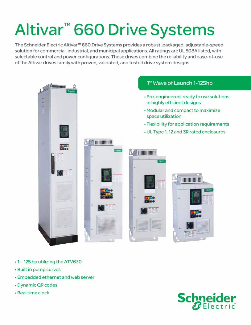
The Schneider Electric Altivar™ 660 Drive Systems provides a robust, packaged, adjustable-speed solution for commercial, industrial, and municipal applications. All ratings are UL 508A listed, with selectable control and power configurations. These drives combine the reliability and ease-of-use of the Altivar drives family with proven, validated, and tested drive system designs.
Altivar™ 660 Drive Systems
• Pre-engineered, ready to use solutions in highly efficient designs
• Modular and compact to maximize space utilization
• Flexibility for application requirements• UL Type 1, 12 and 3R rated enclosures
• 1 – 125 hp utilizing the ATV630• Built in pump curves• Embedded ethernet and web server• Dynamic QR codes• Real time clock
1st Wave of Launch 1-125hp
2
ATV660 Drive Systems
3
ATV660 Drive Systems Content
ATV660 Drive Systems
■ Applications .....................................................4
■ 1-125 hp ............................................................6
■ Configured to Order ........................................8
■ Engineered to Order ......................................10
■ Make the Switch ............................................14
■ Specifications ................................................15
4
ATV660 Drive Systems Applications
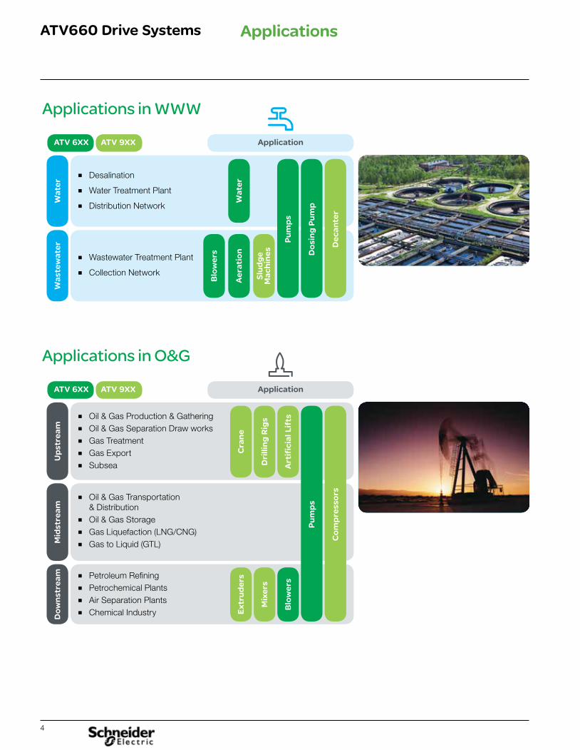
Applications in WWW
ATV 6XX ATV 9XX
Wat
er
Wat
er
Blo
wer
s
Aer
atio
n
Slu
dg
e M
ach
ines
Pu
mp
s
Do
sin
g P
um
p
Dec
ante
r
Was
tew
ater
■ Desalination
■ Water Treatment Plant
■ Distribution Network
■ Wastewater Treatment Plant
■ Collection Network
Application
Applications in O&G
ATV 6XX ATV 9XX
Up
stre
amM
idst
ream
Do
wn
stre
am
Ext
rud
ers
Cra
ne
Mix
ers
Dri
llin
g R
igs
Blo
wer
sA
rtif
icia
l Lif
ts
Pu
mp
s
Co
mp
ress
ors
■ Oil & Gas Production & Gathering■ Oil & Gas Separation Draw works■ Gas Treatment■ Gas Export■ Subsea
■ Oil & Gas Transportation & Distribution
■ Oil & Gas Storage■ Gas Liquefaction (LNG/CNG)■ Gas to Liquid (GTL)
■ Petroleum Refining■ Petrochemical Plants■ Air Separation Plants■ Chemical Industry
Application
5
ATV660 Drive Systems Applications
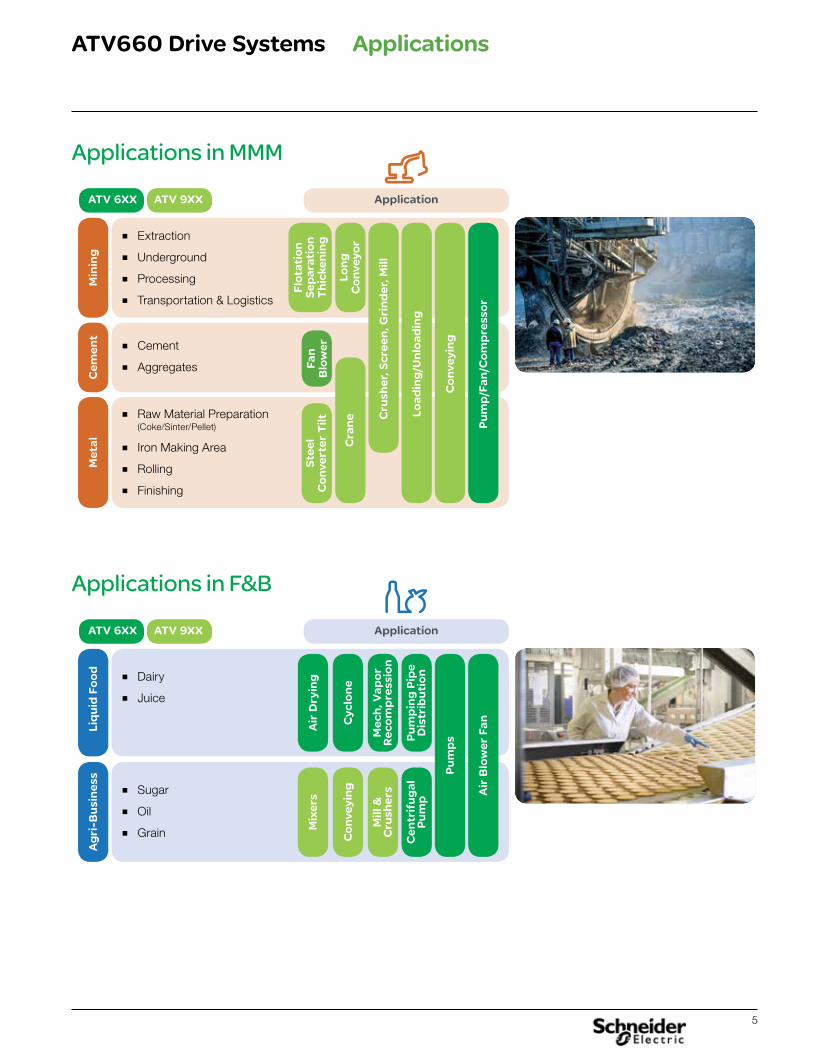
Applications in MMM
ATV 6XX ATV 9XX
Min
ing
Met
al
Load
ing
/Un
load
ing
Cru
sher
, Scr
een
, Gri
nd
er, M
ill
Co
nve
yin
g
Pu
mp
/Fan
/Co
mp
ress
or
Cem
ent
■ Extraction
■ Underground
■ Processing
■ Transportation & Logistics
■ Raw Material Preparation (Coke/Sinter/Pellet)
■ Iron Making Area
■ Rolling
■ Finishing
■ Cement
■ Aggregates
Application
Applications in F&B
ATV 6XX ATV 9XX
Liq
uid
Fo
od
Mix
ers
Co
nve
yin
g
Mill
&
Cru
sher
s
Cen
trif
ug
al
Pu
mp
Air
Dry
ing
Cyc
lon
e
Mec
h, V
apo
r R
eco
mp
ress
ion
Pu
mp
ing
Pip
e D
istr
ibu
tio
n
Pu
mp
s
Air
Blo
wer
Fan
Ag
ri-B
usi
nes
s
■ Dairy
■ Juice
■ Sugar
■ Oil
■ Grain
Application
Flo
tati
on
S
epar
atio
n
Th
icke
nin
g
Lon
g
Co
nve
yor
Cra
ne
Ste
el
Co
nve
rter
Tilt
Fan
B
low
er
6
ATV660 Drive Systems
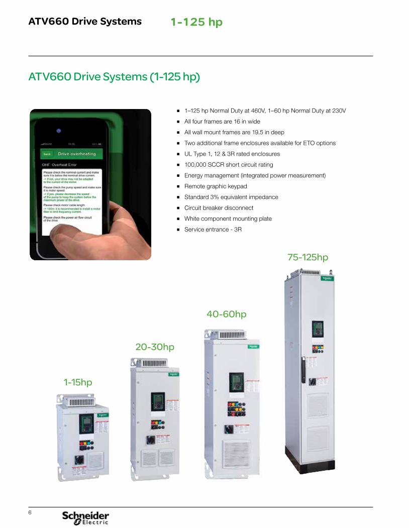
ATV660 Drive Systems (1-125 hp)
■ 1–125 hp Normal Duty at 460V, 1–60 hp Normal Duty at 230V
■ All four frames are 16 in wide
■ All wall mount frames are 19.5 in deep
■ Two additional frame enclosures available for ETO options
■ UL Type 1, 12 & 3R rated enclosures
■ 100,000 SCCR short circuit rating
■ Energy management (integrated power measurement)
■ Remote graphic keypad
■ Standard 3% equivalent impedance
■ Circuit breaker disconnect
■ White component mounting plate
■ Service entrance - 3R
75-125hp
40-60hp
20-30hp
1-15hp
1-125 hp
7
ATV660 Drive Systems
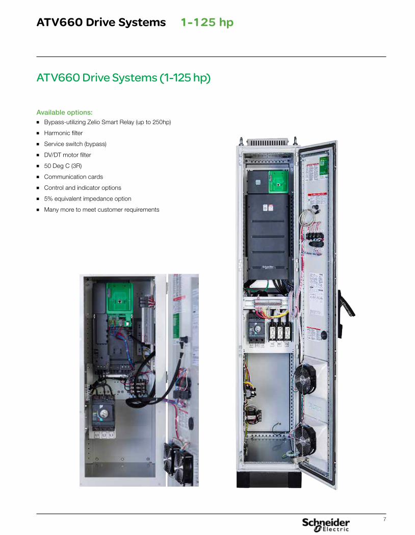
ATV660 Drive Systems (1-125 hp)
Available options:■ Bypass-utilizing Zelio Smart Relay (up to 250hp)
■ Harmonic filter
■ Service switch (bypass)
■ DV/DT motor filter
■ 50 Deg C (3R)
■ Communication cards
■ Control and indicator options
■ 5% equivalent impedance option
■ Many more to meet customer requirements
1-125 hp
8
ATV660 Drive Systems
Configuration To Order
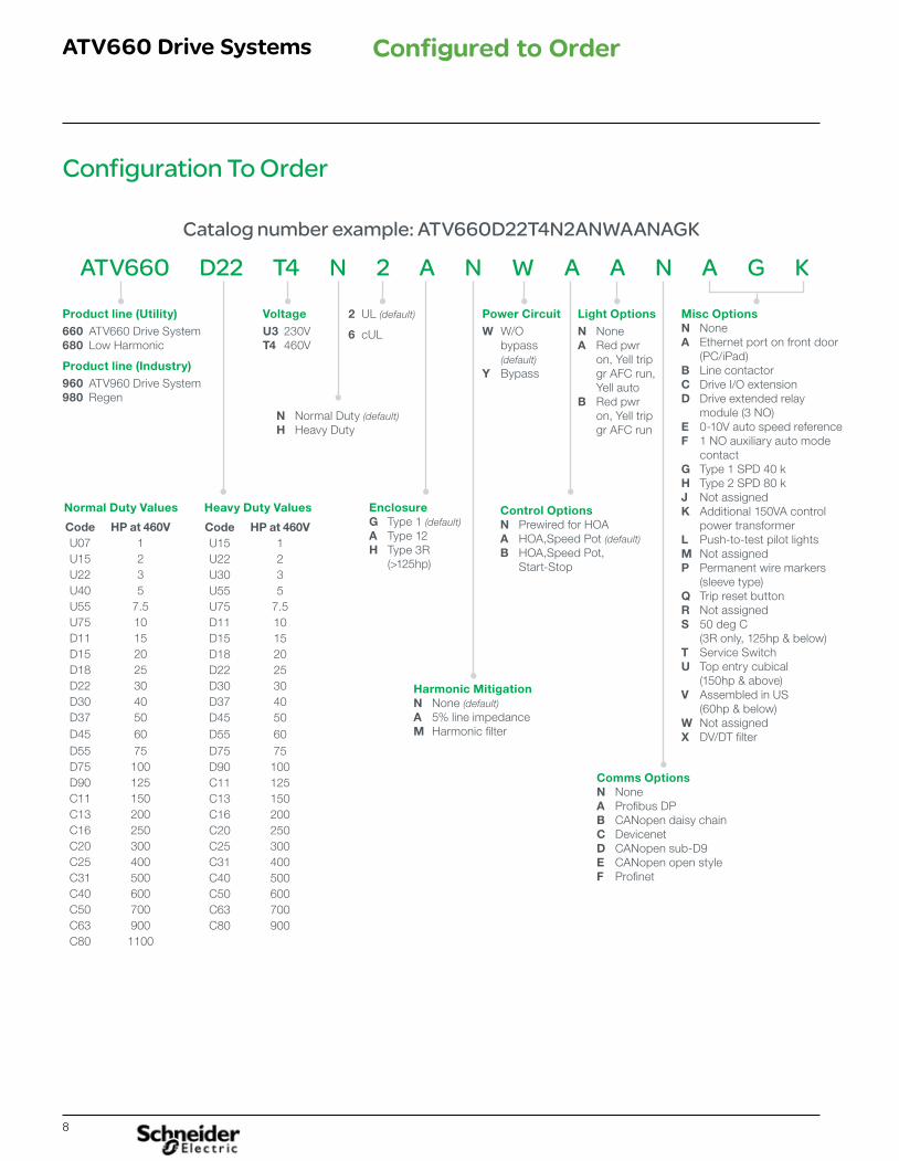
Catalog number example: ATV660D22T4N2ANWAANAGK
ATV660 D22 T4 N 2 A N W A A N A G K
Product line (Utility) 660 ATV660 Drive System680 Low Harmonic
Product line (Industry) 960 ATV960 Drive System980 Regen
Enclosure G Type 1 (default) A Type 12H Type 3R (>125hp)
Harmonic Mitigation N None (default) A 5% line impedanceM Harmonic filter
Comms OptionsN NoneA Profibus DPB CANopen daisy chainC DevicenetD CANopen sub-D9E CANopen open styleF Profinet
Misc OptionsN NoneA Ethernet port on front door
(PC/iPad)B Line contactor C Drive I/O extensionD Drive extended relay
module (3 NO)E 0-10V auto speed referenceF 1 NO auxiliary auto mode
contactG Type 1 SPD 40 kH Type 2 SPD 80 kJ Not assignedK Additional 150VA control
power transformerL Push-to-test pilot lightsM Not assignedP Permanent wire markers
(sleeve type)Q Trip reset buttonR Not assignedS 50 deg C
(3R only, 125hp & below)T Service SwitchU Top entry cubical
(150hp & above)V Assembled in US
(60hp & below)W Not assignedX DV/DT filter
VoltageU3 230VT4 460V
Power CircuitW W/O bypass (default) Y Bypass
Light OptionsN NoneA Red pwr on, Yell trip gr AFC run, Yell autoB Red pwr on, Yell trip gr AFC run
2 UL (default)
6 cUL
N Normal Duty (default)H Heavy Duty
Control OptionsN Prewired for HOAA HOA,Speed Pot (default)B HOA,Speed Pot, Start-Stop
Configured to Order
Normal Duty Values Heavy Duty Values
Code HP at 460VU07 1U15 2U22 3U40 5U55 7.5U75 10D11 15D15 20D18 25D22 30D30 40D37 50D45 60D55 75D75 100D90 125C11 150C13 200C16 250C20 300C25 400C31 500C40 600C50 700C63 900C80 1100
Code HP at 460VU15 1U22 2U30 3U55 5U75 7.5D11 10D15 15D18 20D22 25D30 30D37 40D45 50D55 60D75 75D90 100C11 125C13 150C16 200C20 250C25 300C31 400C40 500C50 600C63 700C80 900
9
ATV660 Drive Systems
Catalog Number Example: (Configuration To Order)
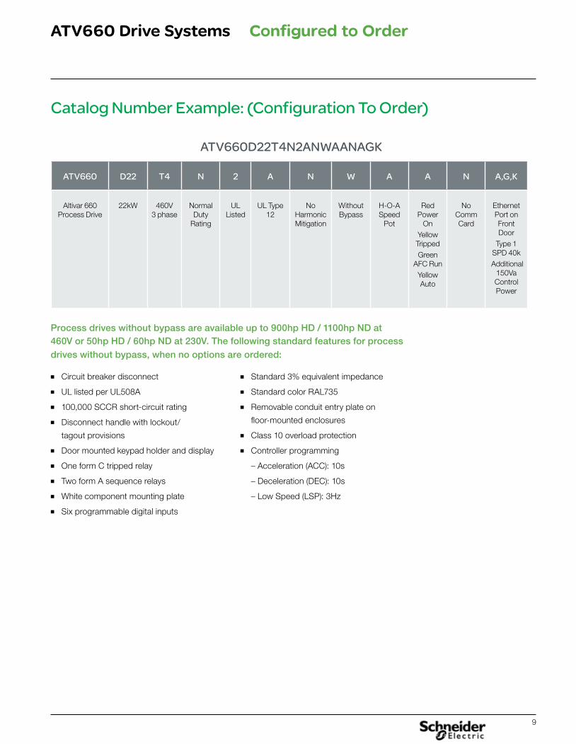
ATV660D22T4N2ANWAANAGK
ATV660 D22 T4 N 2 A N W A A N A,G,K
Altivar 660 Process Drive
22kW 460V 3 phase
Normal Duty
Rating
UL Listed
UL Type 12
No Harmonic Mitigation
Without Bypass
H-O-A Speed
Pot
Red Power
OnYellow TrippedGreen
AFC RunYellow Auto
No Comm Card
Ethernet Port on Front Door
Type 1 SPD 40k
Additional 150Va Control Power
Process drives without bypass are available up to 900hp HD / 1100hp ND at 460V or 50hp HD / 60hp ND at 230V. The following standard features for process drives without bypass, when no options are ordered:
■ Circuit breaker disconnect
■ UL listed per UL508A
■ 100,000 SCCR short-circuit rating
■ Disconnect handle with lockout/
tagout provisions
■ Door mounted keypad holder and display
■ One form C tripped relay
■ Two form A sequence relays
■ White component mounting plate
■ Six programmable digital inputs
■ Standard 3% equivalent impedance
■ Standard color RAL735
■ Removable conduit entry plate on
floor-mounted enclosures
■ Class 10 overload protection
■ Controller programming
– Acceleration (ACC): 10s
– Deceleration (DEC): 10s
– Low Speed (LSP): 3Hz
Configured to Order
10
ATV660 Drive Systems
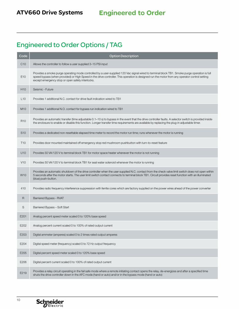
Engineered to Order Options / TAGCode Option Description
C10 Allows the controller to follow a user supplied 3–15 PSI input
E10Provides a smoke purge operating mode controlled by a user-supplied 120 Vac signal wired to terminal block TB1. Smoke purge operation is full speed bypass (when provided) or High Speed in the drive controller. This operation is designed run the motor from any operator control setting except emergency stop or open safety interlocks.
H10 Seismic - Future
L10 Provides 1 additional N.C. contact for drive fault indication wired to TB1
M10 Provides 1 additional N.O. contact for bypass run indication wired to TB1
R10Provides an automatic transfer (time adjustable 0.1–10 s) to bypass in the event that the drive controller faults. A selector switch is provided inside the enclosure to enable or disable this function. Longer transfer time requirements are available by replacing the plug-in adjustable timer.
S10 Provides a dedicated non-resettable elapsed time meter to record the motor run time; runs whenever the motor is running
T10 Provides door mounted maintained off emergency stop red mushroom pushbutton with turn-to-reset feature
U10 Provides 50 VA/120 V to terminal block TB1 for motor space heater whenever the motor is not running
V10 Provides 50 VA/120 V to terminal block TB1 for seal water solenoid whenever the motor is running
W10Provides an automatic shutdown of the drive controller when the user supplied N.C. contact from the check valve limit switch does not open within 5 seconds after the motor starts. The user limit switch contact connects to terminal block TB1. Circuit provides reset function with an illuminated (blue) push-button.
410 Provides radio frequency interference suppression with ferrite cores which are factory supplied on the power wires ahead of the power converter
R Barriered Bypass - RVAT
S Barriered Bypass – Soft Start
E201 Analog percent speed meter scaled 0 to 120% base speed
E202 Analog percent current scaled 0 to 100% of rated output current
E203 Digital ammeter (amperes) scaled 0 to 2 times rated output amperes
E204 Digital speed meter (frequency) scaled 0 to 72 Hz output frequency
E205 Digital percent speed meter scaled 0 to 120% base speed
E206 Digital percent current scaled 0 to 100% of rated output current
E219Provides a relay circuit operating in the fail safe mode where a remote initiating contact opens the relay, de-energizes and after a specified time shuts the drive controller down in the AFC mode (hand or auto) and/or in the bypass mode (hand or auto)
Engineered to Order
11
ATV660 Drive Systems
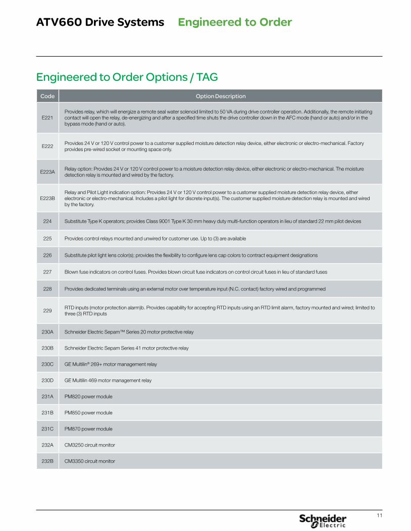
Engineered to Order Options / TAGCode Option Description
E221Provides relay, which will energize a remote seal water solenoid limited to 50 VA during drive controller operation. Additionally, the remote initiating contact will open the relay, de-energizing and after a specified time shuts the drive controller down in the AFC mode (hand or auto) and/or in the bypass mode (hand or auto).
E222Provides 24 V or 120 V control power to a customer supplied moisture detection relay device, either electronic or electro-mechanical. Factory provides pre-wired socket or mounting space only.
E223ARelay option: Provides 24 V or 120 V control power to a moisture detection relay device, either electronic or electro-mechanical. The moisture detection relay is mounted and wired by the factory.
E223BRelay and Pilot Light indication option: Provides 24 V or 120 V control power to a customer supplied moisture detection relay device, either electronic or electro-mechanical. Includes a pilot light for discrete input(s). The customer supplied moisture detection relay is mounted and wired by the factory.
224 Substitute Type K operators; provides Class 9001 Type K 30 mm heavy duty multi-function operators in lieu of standard 22 mm pilot devices
225 Provides control relays mounted and unwired for customer use. Up to (3) are available
226 Substitute pilot light lens color(s); provides the flexibility to configure lens cap colors to contract equipment designations
227 Blown fuse indicators on control fuses. Provides blown circuit fuse indicators on control circuit fuses in lieu of standard fuses
228 Provides dedicated terminals using an external motor over temperature input (N.C. contact) factory wired and programmed
229RTD inputs (motor protection alarm)b. Provides capability for accepting RTD inputs using an RTD limit alarm, factory mounted and wired; limited to three (3) RTD inputs
230A Schneider Electric Sepam™ Series 20 motor protective relay
230B Schneider Electric Sepam Series 41 motor protective relay
230C GE Multilin® 269+ motor management relay
230D GE Multilin 469 motor management relay
231A PM820 power module
231B PM850 power module
231C PM870 power module
232A CM3250 circuit monitor
232B CM3350 circuit monitor
Engineered to Order
12
ATV660 Drive Systems
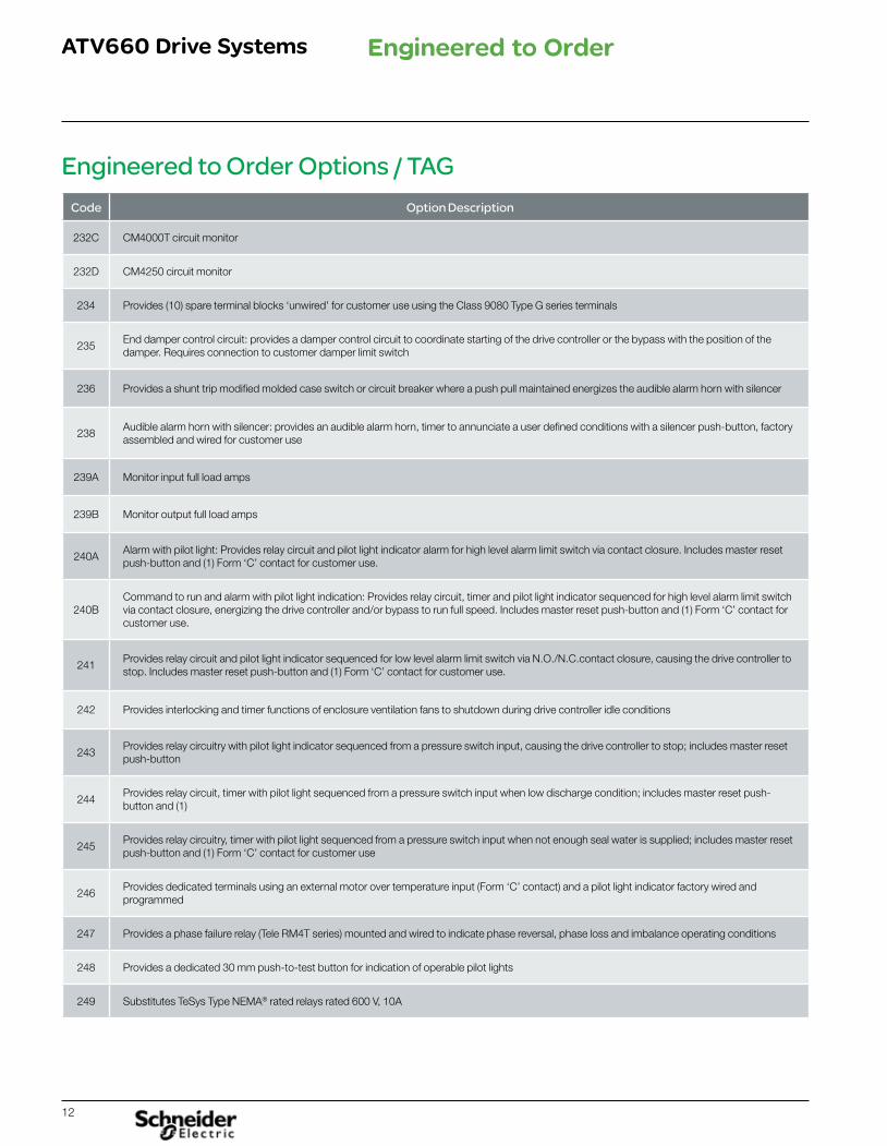
Engineered to Order Options / TAGCode Option Description
232C CM4000T circuit monitor
232D CM4250 circuit monitor
234 Provides (10) spare terminal blocks ‘unwired’ for customer use using the Class 9080 Type G series terminals
235End damper control circuit: provides a damper control circuit to coordinate starting of the drive controller or the bypass with the position of the damper. Requires connection to customer damper limit switch
236 Provides a shunt trip modified molded case switch or circuit breaker where a push pull maintained energizes the audible alarm horn with silencer
238Audible alarm horn with silencer: provides an audible alarm horn, timer to annunciate a user defined conditions with a silencer push-button, factory assembled and wired for customer use
239A Monitor input full load amps
239B Monitor output full load amps
240AAlarm with pilot light: Provides relay circuit and pilot light indicator alarm for high level alarm limit switch via contact closure. Includes master reset push-button and (1) Form ‘C’ contact for customer use.
240BCommand to run and alarm with pilot light indication: Provides relay circuit, timer and pilot light indicator sequenced for high level alarm limit switch via contact closure, energizing the drive controller and/or bypass to run full speed. Includes master reset push-button and (1) Form ‘C’ contact for customer use.
241Provides relay circuit and pilot light indicator sequenced for low level alarm limit switch via N.O./N.C.contact closure, causing the drive controller to stop. Includes master reset push-button and (1) Form ‘C’ contact for customer use.
242 Provides interlocking and timer functions of enclosure ventilation fans to shutdown during drive controller idle conditions
243Provides relay circuitry with pilot light indicator sequenced from a pressure switch input, causing the drive controller to stop; includes master reset push-button
244Provides relay circuit, timer with pilot light sequenced from a pressure switch input when low discharge condition; includes master reset push-button and (1)
245Provides relay circuitry, timer with pilot light sequenced from a pressure switch input when not enough seal water is supplied; includes master reset push-button and (1) Form ‘C’ contact for customer use
246Provides dedicated terminals using an external motor over temperature input (Form ‘C’ contact) and a pilot light indicator factory wired and programmed
247 Provides a phase failure relay (Tele RM4T series) mounted and wired to indicate phase reversal, phase loss and imbalance operating conditions
248 Provides a dedicated 30 mm push-to-test button for indication of operable pilot lights
249 Substitutes TeSys Type NEMA® rated relays rated 600 V, 10A
Engineered to Order
13
ATV660 Drive Systems
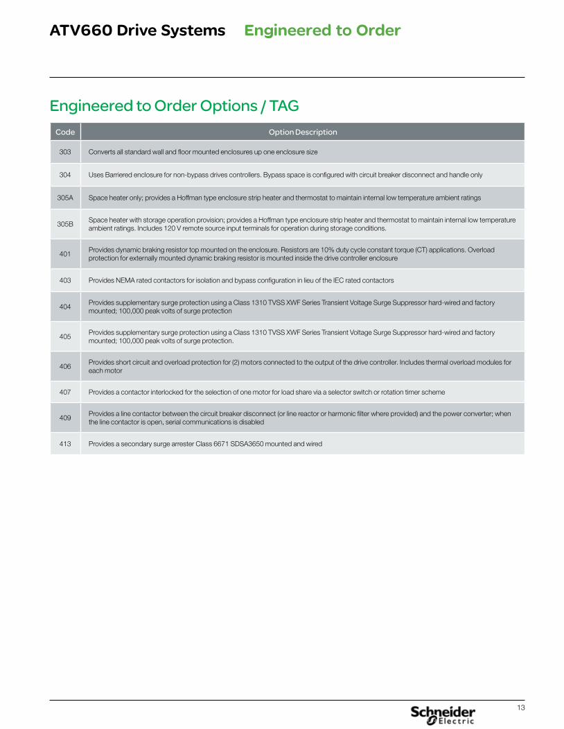
Engineered to Order Options / TAGCode Option Description
303 Converts all standard wall and floor mounted enclosures up one enclosure size
304 Uses Barriered enclosure for non-bypass drives controllers. Bypass space is configured with circuit breaker disconnect and handle only
305A Space heater only; provides a Hoffman type enclosure strip heater and thermostat to maintain internal low temperature ambient ratings
305BSpace heater with storage operation provision; provides a Hoffman type enclosure strip heater and thermostat to maintain internal low temperature ambient ratings. Includes 120 V remote source input terminals for operation during storage conditions.
401Provides dynamic braking resistor top mounted on the enclosure. Resistors are 10% duty cycle constant torque (CT) applications. Overload protection for externally mounted dynamic braking resistor is mounted inside the drive controller enclosure
403 Provides NEMA rated contactors for isolation and bypass configuration in lieu of the IEC rated contactors
404Provides supplementary surge protection using a Class 1310 TVSS XWF Series Transient Voltage Surge Suppressor hard-wired and factory mounted; 100,000 peak volts of surge protection
405Provides supplementary surge protection using a Class 1310 TVSS XWF Series Transient Voltage Surge Suppressor hard-wired and factory mounted; 100,000 peak volts of surge protection.
406Provides short circuit and overload protection for (2) motors connected to the output of the drive controller. Includes thermal overload modules for each motor
407 Provides a contactor interlocked for the selection of one motor for load share via a selector switch or rotation timer scheme
409Provides a line contactor between the circuit breaker disconnect (or line reactor or harmonic filter where provided) and the power converter; when the line contactor is open, serial communications is disabled
413 Provides a secondary surge arrester Class 6671 SDSA3650 mounted and wired
Engineered to Order
14
ATV660 Drive Systems
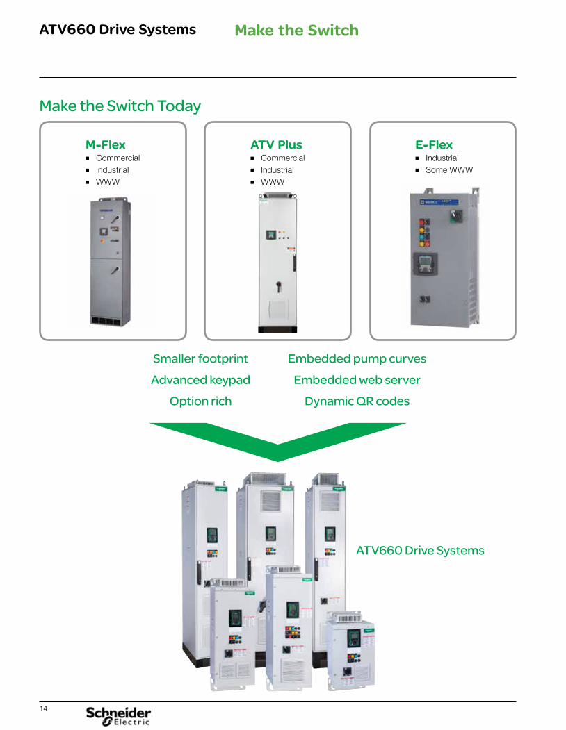
Make the Switch Today
M-Flex ■ Commercial■ Industrial■ WWW
ATV Plus ■ Commercial■ Industrial■ WWW
ATV660 Drive Systems
Smaller footprint Advanced keypad
Option rich
Embedded pump curves Embedded web server
Dynamic QR codes
E-Flex ■ Industrial■ Some WWW
Make the Switch
15
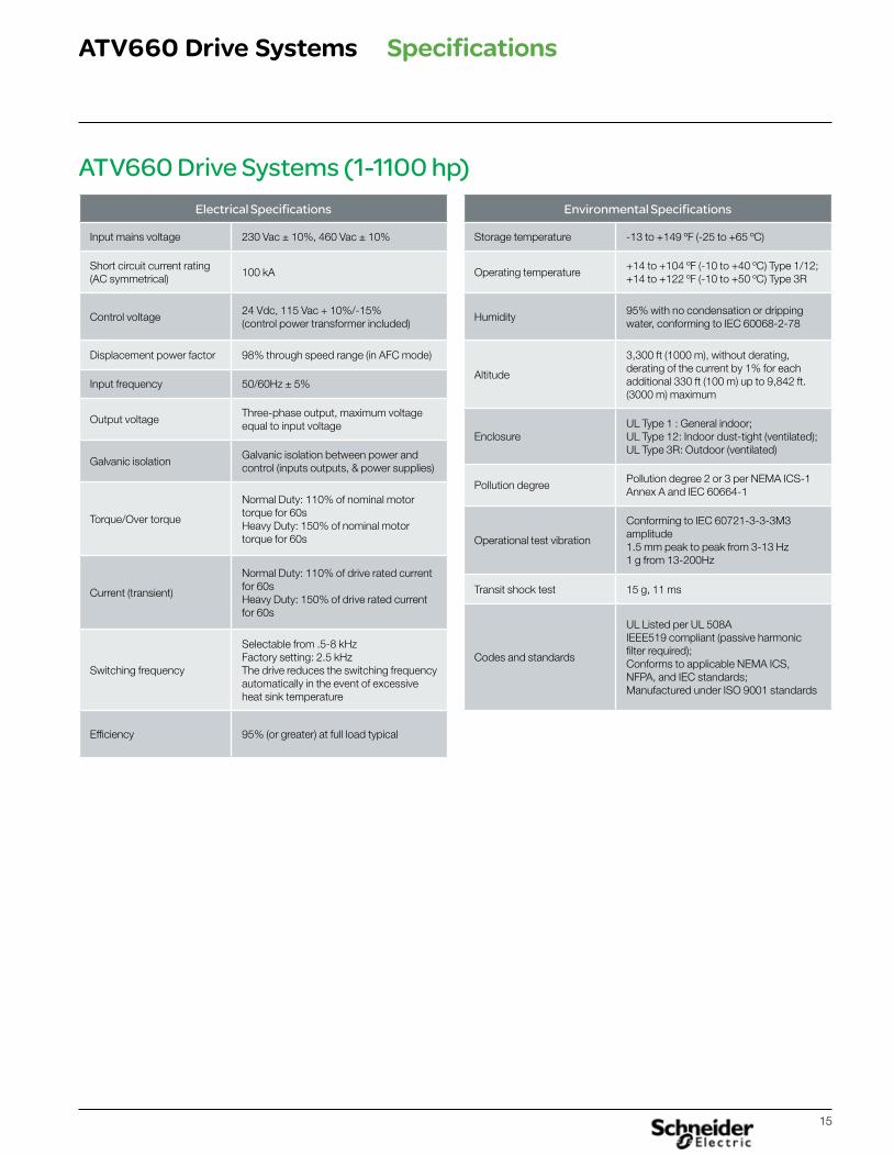
ATV660 Drive Systems
Electrical Specifications
Input mains voltage 230 Vac ± 10%, 460 Vac ± 10%
Short circuit current rating(AC symmetrical)
100 kA
Control voltage24 Vdc, 115 Vac + 10%/-15%(control power transformer included)
Displacement power factor 98% through speed range (in AFC mode)
Input frequency 50/60Hz ± 5%
Output voltageThree-phase output, maximum voltage equal to input voltage
Galvanic isolationGalvanic isolation between power and control (inputs outputs, & power supplies)
Torque/Over torque
Normal Duty: 110% of nominal motor torque for 60sHeavy Duty: 150% of nominal motor torque for 60s
Current (transient)
Normal Duty: 110% of drive rated current for 60sHeavy Duty: 150% of drive rated current for 60s
Switching frequency
Selectable from .5-8 kHzFactory setting: 2.5 kHzThe drive reduces the switching frequency automatically in the event of excessive heat sink temperature
Efficiency 95% (or greater) at full load typical
Environmental Specifications
Storage temperature -13 to +149 ºF (-25 to +65 ºC)
Operating temperature+14 to +104 ºF (-10 to +40 ºC) Type 1/12;+14 to +122 ºF (-10 to +50 ºC) Type 3R
Humidity95% with no condensation or dripping water, conforming to IEC 60068-2-78
Altitude
3,300 ft (1000 m), without derating,derating of the current by 1% for eachadditional 330 ft (100 m) up to 9,842 ft.(3000 m) maximum
EnclosureUL Type 1 : General indoor;UL Type 12: Indoor dust-tight (ventilated);UL Type 3R: Outdoor (ventilated)
Pollution degreePollution degree 2 or 3 per NEMA ICS-1Annex A and IEC 60664-1
Operational test vibration
Conforming to IEC 60721-3-3-3M3 amplitude1.5 mm peak to peak from 3-13 Hz1 g from 13-200Hz
Transit shock test 15 g, 11 ms
Codes and standards
UL Listed per UL 508AIEEE519 compliant (passive harmonic filter required);Conforms to applicable NEMA ICS, NFPA, and IEC standards;Manufactured under ISO 9001 standards
ATV660 Drive Systems (1-1100 hp)
Specifications
16
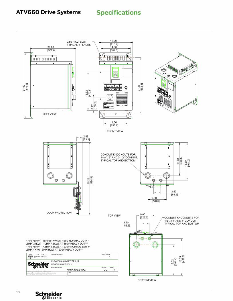
ATV660 Drive Systems Specifications
17
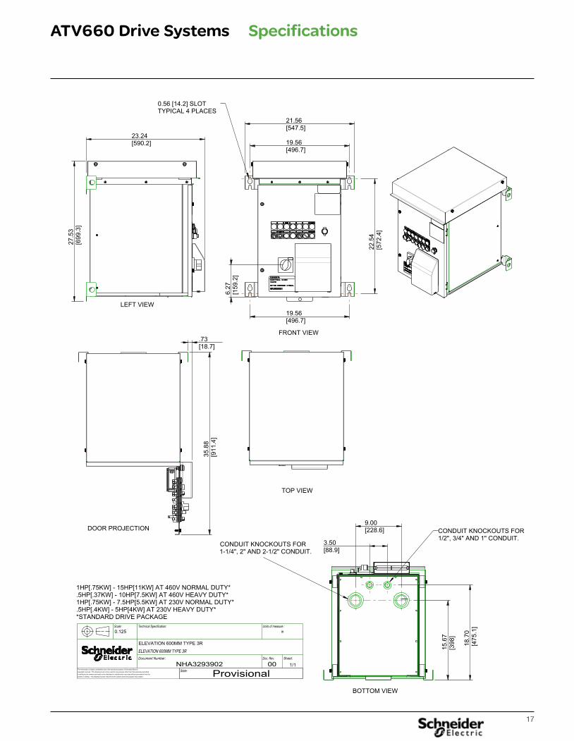
ATV660 Drive Systems Specifications
18
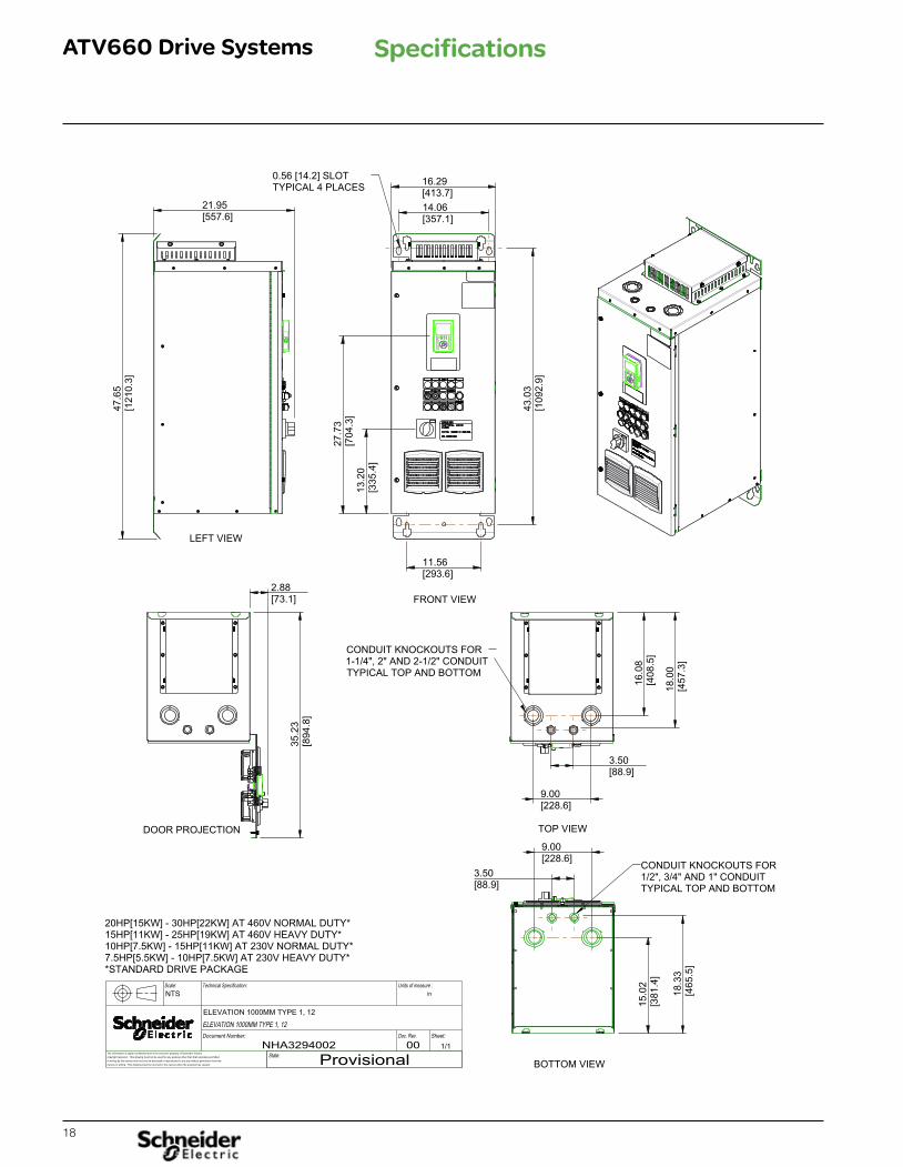
ATV660 Drive Systems Specifications
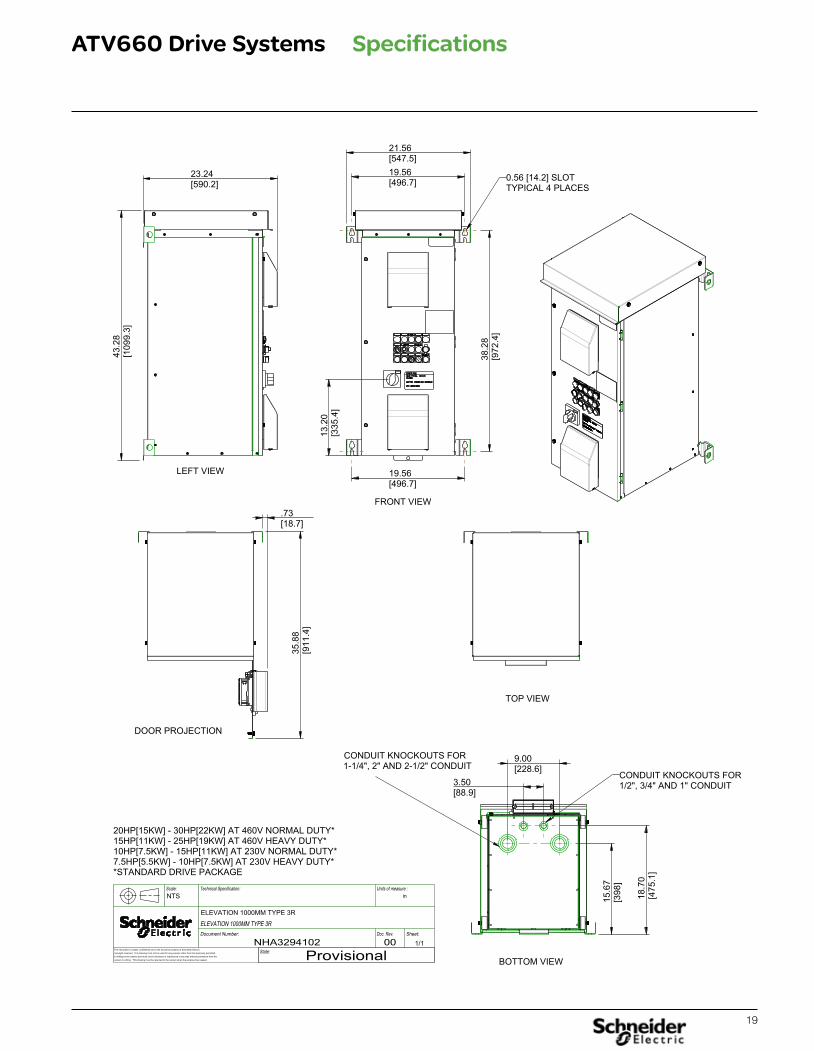
19
ATV660 Drive Systems Specifications
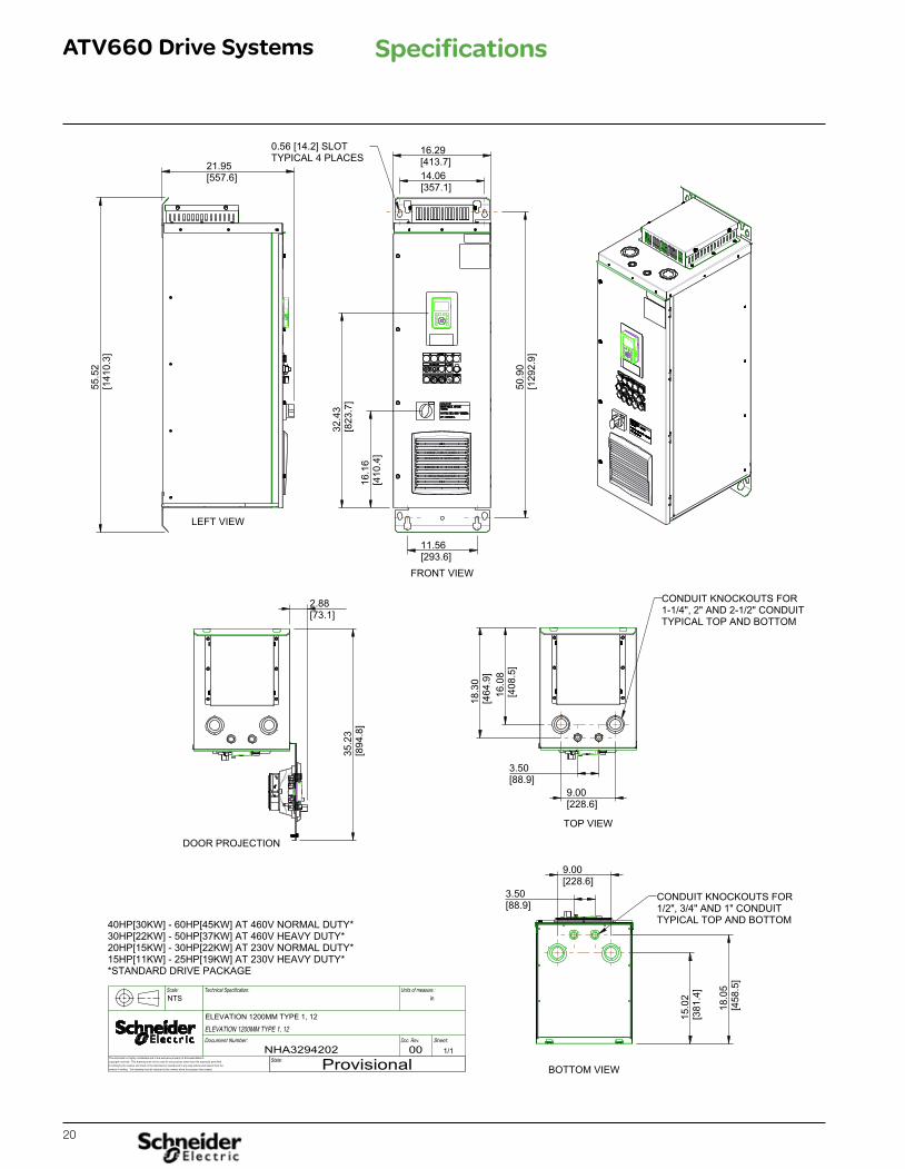
20
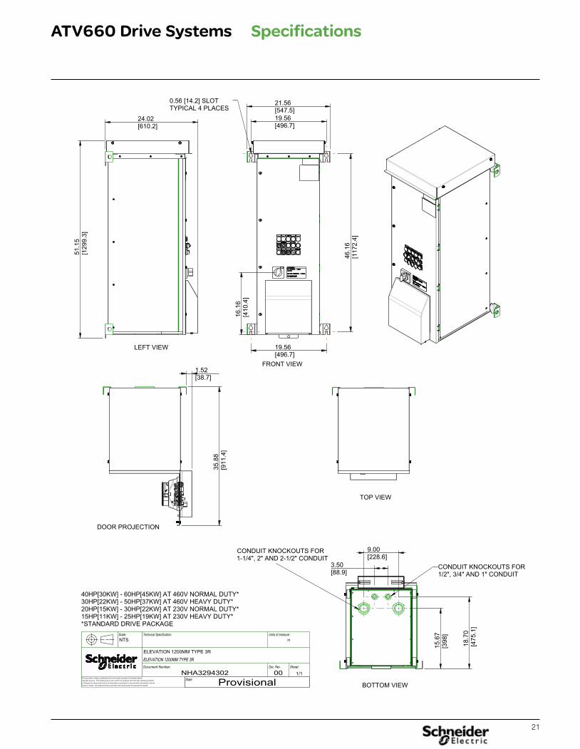
ATV660 Drive Systems Specifications
21
ATV660 Drive Systems Specifications
22
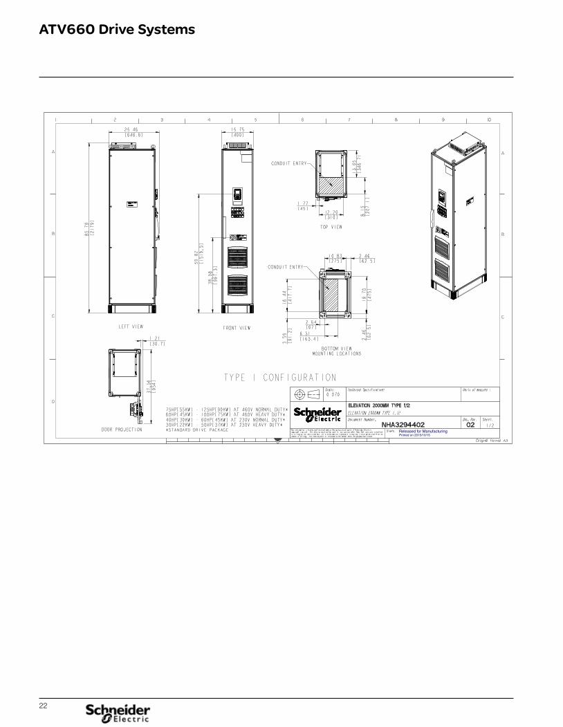
ATV660 Drive Systems
Released for ManufacturingPrinted on 2015/10/15
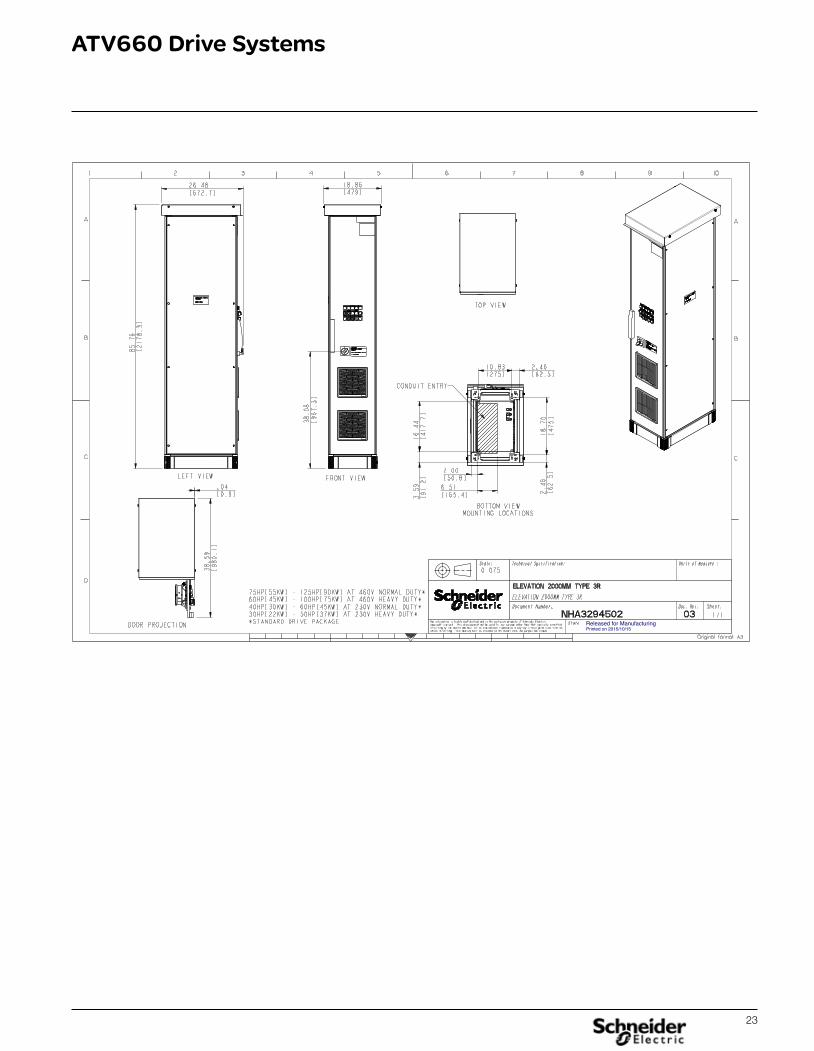
23
ATV660 Drive Systems
Released for ManufacturingPrinted on 2015/10/15
24
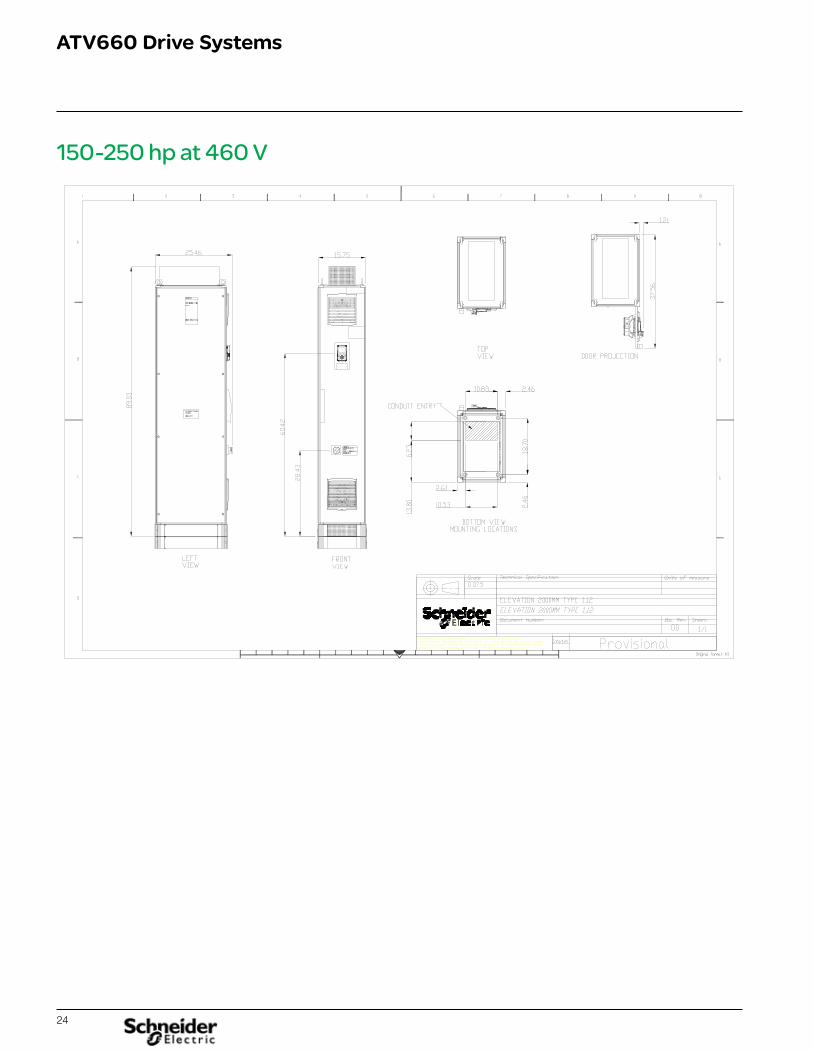
ATV660 Drive Systems
150-250 hp at 460 V
25
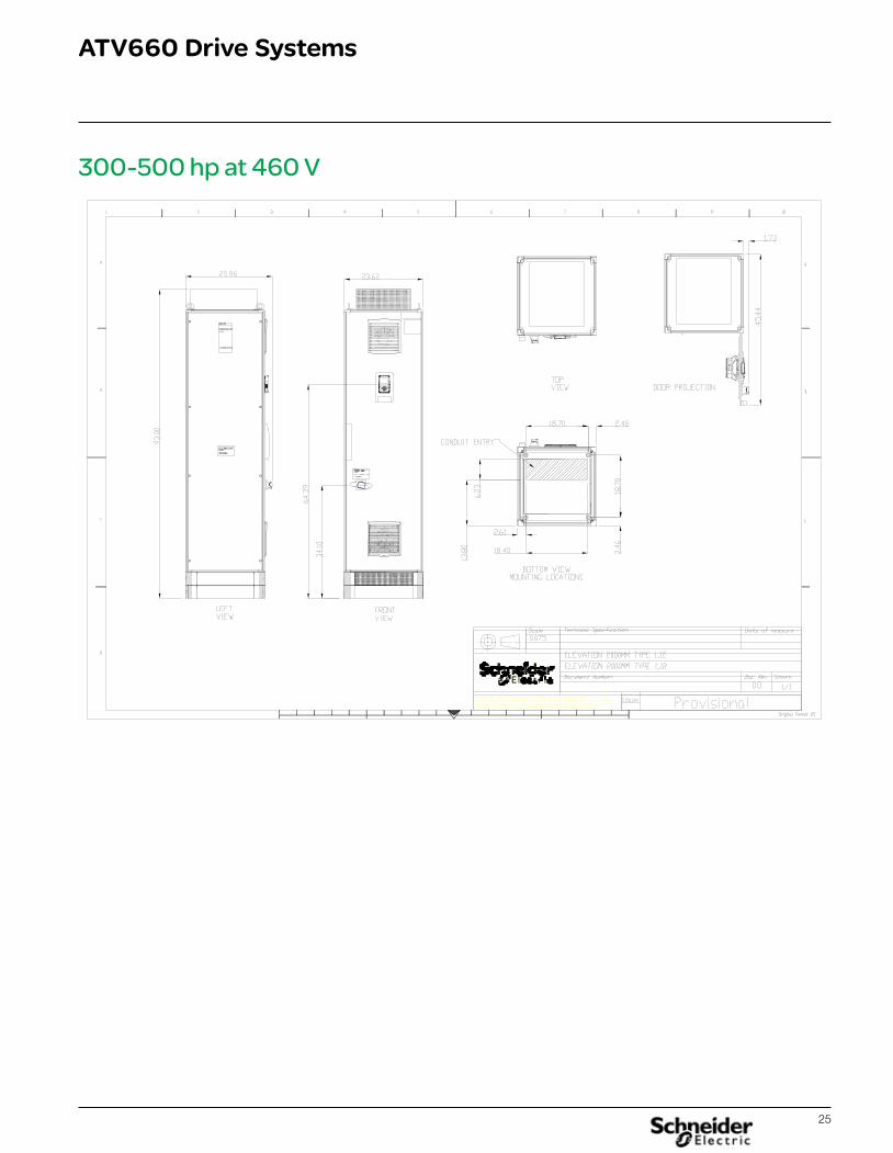
ATV660 Drive Systems
300-500 hp at 460 V

26
ATV660 Drive Systems
27
ATV660 Drive Systems
ATV600MV variable speed drive
8800BR1601February 2016 - V1.0
Schneider Electric USA, Inc.8001 Knightdale Blvd. Knightdale, NC 27545
USA Customer Care CenterTel: 888-778-2733
schneider-electric.us/drives
Schneider Electric USA, Inc. The information provided in this documentation contains general descriptions and/or technical characteristics of the performance of the products contained herein. This documentation is not intended as a substitute for and is not to be used for determining suitability or reliability of these products for specific user applications. It is the duty of any such user or integrator to perform the appropriate and complete risk analysis, evaluation and testing of the products with respect to the relevant specific application or use thereof. Neither Schneider Electric nor any of its affiliates or subsidiaries shall be responsible or liable for misuse of the information contained herein.
© 2016 Schneider Electric. All rights Reserved. Schneider Electric, Altistart, Altivar, Magelis, Make the most of your energy, Modbus and The Global Specialist in Energy Management are trademarks and the property of Schneider Electric SE, its subsidiaries and affiliated companies. All other trademarks are the property of their respective owners.Design: Schneider ElectricPhotos: Schneider Electric
For additional information contact:Gerald DixonProduct Manager Drive [email protected]
Drive Quotation [email protected]
Related Documents