Alternative Energy Wind Generator Nuevas Esperanzas, Honduras 8 March 2012 – 16 March 2012 Engineering Service-Learning College of Engineering The Ohio State University 17 March 2014 Students: Lianna Brown Nathan Lamba Mary Lenk Connor Locke Emily Reed Trip Resident Directors: Dr. Edgar Casale (Fundamental of Engineering Professor) Carlos Montoya Rodriguez (Graduate Teaching Assistant)

Welcome message from author
This document is posted to help you gain knowledge. Please leave a comment to let me know what you think about it! Share it to your friends and learn new things together.
Transcript

Alternative Energy Wind Generator
Nuevas Esperanzas, Honduras
8 March 2012 – 16 March 2012
Engineering Service-Learning
College of Engineering
The Ohio State University
17 March 2014
Students:
Lianna Brown
Nathan Lamba
Mary Lenk
Connor Locke
Emily Reed
Trip Resident Directors:
Dr. Edgar Casale (Fundamental of Engineering Professor)
Carlos Montoya Rodriguez (Graduate Teaching Assistant)

2
Table of Contents
Table of Contents .......................................................................................................................................... 2
Introduction ................................................................................................................................................... 3
Background Information ........................................................................................................................... 3
Trip Details – Participants ........................................................................................................................ 3
Project Details ............................................................................................................................................... 3
Project background ................................................................................................................................... 3
Objectives ................................................................................................................................................. 4
Design Ideas .................................................................................................................................................. 4
Research Performed .................................................................................................................................. 4
Electrical System ...................................................................................................................................... 4
Mechanical System ................................................................................................................................... 8
Sustainability and Maintainability ............................................................................................................ 9
Pre-Trip Progress Summary .......................................................................................................................... 9
Schedule – Prior to Departure ................................................................................................................. 10
Schedule – Expected In-Country ............................................................................................................ 10
Pree-Trip Testing .................................................................................................................................... 10
Materials, Tools and Costs ...................................................................................................................... 10
In-Country Implementation ........................................................................................................................ 16
Mechanical/Structural System ................................................................................................................ 16
Electrical System .................................................................................................................................... 18
Post-Trip Summary ..................................................................................................................................... 23
Post-Trip Modifications and Recommendations ..................................................................................... 23
Schedule—In Country ............................................................................................................................ 23
Materials, Tools, and Costs ..................................................................................................................... 24
Acknowledgements ................................................................................................................................. 24
Appendix ..................................................................................................................................................... 25
References ............................................................................................................................................... 26

3
Introduction
Background Information
The team traveled to the orphanage, Montana de Luz (MdL), in Honduras Saturday, March 8, 2014
through Sunday, March 16, 2014 to complete a humanitarian engineering service project as part of an
engineering service-learning course at The Ohio State University. Montana de Luz is an orphanage for
children who have HIV/AIDS. The orphanage expressed an interest in outdoor lighting for security
reasons. It was recommended that an alternative energy source be used to power the lights since the
electricity is very expensive and unreliable at Montana de Luz. The wind turbine would be an investment
that would eventually pay for itself. Since wind energy is free, the only cost is the initial installment of the
turbine. The team spent nine weeks designing and planning the logistics of the turbine prior to departure.
The goal was to implement a turbine that would power three outdoor lights and generate curiosity for
renewable energy. The turbine serves as a tool to educate local Hondurans about wind energy and provide
a base for a future large scale wind turbine project.
Trip Details – Participants
The turbine team consisted of five undergraduate students and two trip advisors. The trip advisors were
both fluent in Spanish, and one was born and raised in Honduras. The three of the five team members
were moderate at Spanish, and could provide brief translations and listening skills. Below is the list of the
members, roles, and majors:
• Undergraduate Students
o Lianna Brown, Electrical Engineering — Project Leader
o Emily Reed, Industrial and Systems Engineering — Historian
o Nathan Lamba, Biomedical Engineering — Research Leader
o Connor Locke, Mechanical Engineering — Mechanical Leader
o Mary Lenk, Electrical Engineering — Electricity Expert
• Trip Directors
o Dr. Edgar Casale, Professor
o Carlos Montoya Rodriguez, Graduate Teaching Assistant
Project Details
Project Background
Energy is an issue for the people in Honduras as it is expensive and unreliable. A solution to this problem
is sustainable energy. This project focuses on wind energy as a solution. Installing a wind turbine will
provide free electricity after the initial capital cost of installment. The team decided to implement a small-
scale wind turbine as a pilot project.

4
Objectives
Problem Definition:
The team was presented with the task of supplying a wind generator that would explore the possibilities
of sustainable energy while also educating the people about utilizing resources such as alternative energy
to improve living conditions. The wind turbine was to power three CFLs and have a mechanism to switch
back to the grid in case of low wind speeds.
Scope of Work:
The team decided to implement a small scale wind generator as a pilot program because of the
uncertainties of the project. The team was presented with wind data from the previous year that indicated
low wind speeds that averaged between 1.1 and 1.8 m/s. These wind speeds are not sufficient to utilize a
wind turbine. The team was skeptical of this data because of the location of the wind collection data. The
device was located near a tree and large water barrels that could have been blocking the wind. The
solution to this was to implement a small wind generator that could function at low wind speeds and also
to increase the height of the turbine.
List of Deliverables:
The team intended to provide a small wind generator that would power three 20 W compact fluorescent
lights (CFLs). This totals to 60 W of power that the generator would need to provide. This is a small load
that would test the success of the wind generator without risking the potential of failure that could hinder
the orphanage. In addition to the 450 Watt wind generator itself, the team supplied a device box
containing a charge controller, and 1000 Watt 12 volt DC to 120 volt AC inverter, a 12 volt deep-cycle
battery, and a photocell, manual brake, a new breaker box with manual transfer switch, and 8 gauge and
14 gauge wiring from the turbine to the load. The 14 foot mounting pole and tool kit was included.
Design Ideas
Research Performed
Initially, the team referred to the documentation from the Ohio State group that went to Choluteca in
2012. The team learned several important things from the document, including the kind of generator that
would be needed, the calculations that would be necessary for the project, the components of the system,
and tips from the mistakes and problems the previous team ran into. The team learned that a permanent
magnet DC generator with a low RPM rating preferably below 1000 RPMs. A 12 volt deep cycle battery
would also be needed that would be charged by the wind turbine.
The 2013 MdL team, from the previous year, installed a wind data collector on top of the water tower on
the side closest to the MdL complex and was four feet from the base of the tower. The data from the
previous year was collected and e-mailed by Laura Manship, a long-term volunteer at Montana de Luz.
The team analyzed the data using Matlab to find the average wind speed produced over the course of 6
months, June 2013 through February 2014. The average wind speed was found to be 1.5 m/s. Like the

5
group that went to Choluteca, the MdL team wanted to build the wind turbine from scratch. The team
began trying to find a generator that would spin at the low wind speed found by the data collector in
Honduras. The team researched several generators online on Ebay, Menards, Lowe’s, and several other
sites. The team sought out advice from Miriam Cater, a graduate student at The Ohio State University,
who has conducted research on wind energy in developing countries. She told the team to search for a
generator with very low RPM rating, around 200-350 RPMs since the average wind speed was only 3.5
mph. She also told the team that the size of the blades and the cross sectional area of the sweep of the
blades would determine how much power the turbine could generate. She also directed the team to the
2012 documentation and EEIC course website that had all the calculations and equations that would be
necessary to find the correct size of the blade lengths. Finally, she suggested that the generator have a
rating of at least 10 amps. She recommended that the team get one that has a hub already attached, or the
team would have to get a pulley or some kind of a keyed-plate to attach the blades to. She reassured the
team that 3.5 mph would be a good amount of wind to keep the turbine spinning, but the problem would
be to get the turbine started spinning, which requires around 9-10 mph. She suggested the team analyze
the maximum wind speed too to be sure the wind would be strong enough to start the turbine spinning.
She advised the team to avoid blades that were too long or heavy.
The team continued to research generators that had both low RPM ratings and 10amps; however, the team
was unable to find a generator that would provide both of these requirements and remain within the
budget of $1000. The team also was unsure if there would be enough time to build an entire turbine from
scratch before the departure date. The team had spent a great deal of time searching for a generator with
little progress. It was unclear if after building a turbine from scratch, if the project would be feasible. The
team that travelled to Choluteca in 2012 had started earlier and had more experience, but was still unable
to produce a functioning turbine. Purchasing a manufactured wind turbine kit would reduce the risk of
creating a product that did not function properly. The team also reasoned that buying each component
separately would be less cost efficient than purchasing a turbine kit. Because of all these reasons, the team
determined that it would be best to buy a 600 Watt Coleman turbine kit from Menard’s, which cost
$489.00. The kit came with an AC generator, which had the capability of mounting to a pole and spin in
all directions, the blades, manual switch, charge controller, 8 gauge wire, and the instruction manual in
both English and Spanish. Even though the team purchased the turbine, there was still a great deal of
work that had to be completed before the departure date, including designing the mounting system, testing
the turbine, creating the electrical system, buying all necessary electrical components, and fixing the data
collector software.
Electrical System
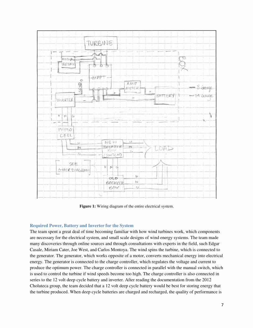
System Schematic
The electrical system is described in greater detail in Section 5. The overall system uses several important
components. The components situated on top of the water tower are the AC turbine, 12 volt deep cycle
battery, 1000 Watt inverter, solar cell, 14 gauge wiring, 8 gauge wiring, charge controller, amp meter, and
manual brake. The other main components including, the breaker box, and the double pull double throw
switch, are located inside the dining hall and are connected by 150 feet of 14 gauge wire. The turbine
supplies the energy for the system. It collects wind energy when it spins and the generator transforms the

6
mechanical energy from the blades into AC electrical energy, which runs through the wires to the manual
brake. The black wire on the turbine connected to the black wire on the 8 gauge wire, the red wire on the
turbine connected to the white wire on the 8 gauge, and the blue wire on the 8 gauge connected to the
wire that did not have any insulation over top of it. The blue wire was the ground wire. The manual brake
is a switch that can be turned on when the wind speeds get to be too high for the system. This will stop
the turbine from spinning and turning to face the wind. The manual switch will prevent any current from
flowing into the system. The manual brake is connected to the charge controller using three wires, black,
red, and blue. A charge controller compares the output of the generator to the voltage of the battery. It
uses an algorithm to calculate the absolute best power that the wind turbine can output. The charge
controller then allows for the best possible voltage so the maximum amount of current can flow into the
battery. The charge controller converts from AC to DC. The charge controller has several features, such
as maximum power point tracking technology, voltage detection system, temperature compensation,
electronic protection, including reverse polarity, over-current, short-circuit, over temperature, and high
efficiency. The amp meter is connected to one side of the charge controller. The amp meter measures how
much current is flowing in the system. The amp meter is connected to the positive terminal of the 12 volt
deep cycle battery. The battery stores the electrical energy and can be discharged when the three CFL
lights are turned on. The inverter is also connected to the charge controller. The inverter converts 12 volts
DC to 120 volts AC. The inverter also prevents charge from flowing in the wrong direction. The inverter
is connected to the photocell, which is a sensor that detects when it is daylight and sunny and when it is
nighttime and dark. The photocell prevents charge from flowing out of the battery when the photocell
detects light. The photocell allows current to flow when it is dark. The components are connected using
splicers and two types of tape, including electrical tape and water proof and heat protection tape. The
turbine was wired to the charge controller using 8 gauge wire, which wired to the amp meter, battery, and
inverter. The inverter was connected to the photocell. Connected to the other end of the photocell was 14
gauge wire, which ran to the dining hall and connected to the new breaker box and existing electrical
system. Figure 1, on the top of the next page, shows an outline of a wiring diagram of the entire electrical
system.
7
Figure 1: Wiring diagram of the entire electrical system.
Required Power, Battery and Inverter for the System
The team spent a great deal of time becoming familiar with how wind turbines work, which components
are necessary for the electrical system, and small scale designs of wind energy systems. The team made
many discoveries through online sources and through consultations with experts in the field, such Edgar
Casale, Miriam Cater, Joe West, and Carlos Montoya. The wind spins the turbine, which is connected to
the generator. The generator, which works opposite of a motor, converts mechanical energy into electrical
energy. The generator is connected to the charge controller, which regulates the voltage and current to
produce the optimum power. The charge controller is connected in parallel with the manual switch, which
is used to control the turbine if wind speeds become too high. The charge controller is also connected in
series to the 12 volt deep cycle battery and inverter. After reading the documentation from the 2012
Choluteca group, the team decided that a 12 volt deep cycle battery would be best for storing energy that
the turbine produced. When deep cycle batteries are charged and recharged, the quality of performance is

8
not reduced. Therefore a deep cycle battery was preferred over a lead acid battery, which does not
function properly after being discharged too many times. This deep cycle battery had to be purchased in
Honduras since the deep cycle battery the team purchased at Wal-Mart was not allowed on the flight.
From several experts, the team learned that an inverter, which converts from DC current to AC current,
would be necessary since the charge controller converts the AC current produced by the wind turbine to
the DC current to charge the battery. Originally, the team thought that the wind generator produced DC
current, but while in Honduras, the team discovered that the wind generator was an AC current producer
and the charge controller converted the current to DC. Nonetheless, the inverter was a necessary
component to convert the positive, negative and ground to hot, neutral, and ground. The 800 Watt Pro
Power Inverter by Whistler was purchased from Wal-Mart for $36.01. The team took a lot of time to
research several inverters. This inverter was chosen because it had a rating of 800 Watts, which was well
above the turbine’s 600 Watt maximum. This inverter also advertised that it provides continuous power
and will automatically shut off if the rated power is exceeded or if the inverter overheats. However, the
team did not realize that this inverter would have to be manually reset every time the charge on the
battery drops below the minimum level of 10.5 volts. The team solved this problem, and the
documentation is noted later on in the paper.
Breaker Box System
The team implemented a new breaker box for the wind turbine next to the existing breaker box in order
for users to easily distinguish between grid power and turbine power. The new breaker box the team
installed was an Eaton 4-Circuit 2-Space 70-Amp Main Lug Load Center. This new breaker box housed
the breaker for the turbine along with a double pole double throw switch to alternate between grid power
and turbine power. The newly installed breaker box is connected directly to the old breaker box, three
20W light bulbs, and the inverter in the black device box on the water tower.
Mechanical System
Diagrams of Structural Components
Figure 1, shown at the top of the next page, is a diagram of the wind turbine system; Table 1 identifies
each component
Figure 2: Diagram of the structural components of the wind turbine

9
Table 1: Identification of the structural components of the wind turbine.
Letter Concept Item
A Turbine Tail
B Turbine Blade
C Rotational/Pivot Support
D Turbine Pole
E U-Bolts
F Water Tower Structure
G Device Box
Sustainability and Maintainability
The wind turbine system will be able to produce a maximum of 450 Watts, and it currently powers three
20 Watt CFL light bulbs outside the dining hall complex of MdL. The system is able to use free energy
provided by the wind as long as there is enough wind to sustain it. The battery will continuously charge as
the wind blows and will store energy during the day. The photocell will prevent charge from flowing
when the photocell detects light, so that energy is not wasted when the lights are not needed. The turbine
is mounted high above any trees or brush so as to capture the most amount of wind. The turbine is
designed to spin atop the mounting system and face in the direction of the wind.
The MdL staff were educated about the system during two group meetings, in which the team described
and explained the entire system in both Spanish and English and answered questions. The documentation,
instructional manuals, and a troubleshooting guide will be composed and sent to MdL. Group members
and MdL staff will remain in contact to ensure the project’s future sustainability and success. The wind
data collector was remounted next to the wind turbine to compare the wind turbine’s performance to the
data collected. The group members have required that the wind data be emailed to the Program Director,
Dr. Edgar Casale, every month to ensure adequate wind is being produced onsite to power the wind
turbine.
With one 12 volt battery, the system is able to provide 450 Watts. Currently, the system is supplying
power for less than 100 Watts with only three CFL light bulbs. This system has great potential to expand.
More light bulbs could be added to the system. It is recommended that an outlet in the wall be installed to
expand the system. This would allow small devices, such as cell phones, laptops, or i-pods to charge
when the power fails. An addition of another 12 volt battery, would increase the maximum power to 600
Watts. This 24 volt system could allow for more devices to be added to the wind turbine system.

10
Pre-Trip Progress Summary
Schedule – Prior to Departure
The following is a breakdown of the week to week activities for the project:
• Jan. 9th - Mar. 6th:
� Background research
� Bought materials
� Tested system
• Mar. 18th - Apr. 22nd
� Post trip documentation
� Write and translate instruction manuals
Schedule – Expected In-Country
The following is a breakdown of the day to day activities for the project while in-country.
• Mar. 8th - 16th
o Day 1:
� Set up turbine
� Mount turbine pole
o Day 2:
� Wire the device box with the 8 gauge wire
o Day 3
� Wire the 14 gauge wire from the device box to the lights
o Day 4
� Hang up the new breaker box
� Wire the new breaker box
o Day 5
� Test the system
Pre-Trip Testing
The first steps were to establish that the turbine in fact worked and learn the necessary components of the
turbine. With help from Joe West in the Scott Lab, the team learned how to connect the turbine to the
charge controller using a wire stripper and several wire clamps. The team then connected the turbine and
charge controller to the battery using battery connectors. The battery was then hooked up to the
oscilloscope, which displayed the voltage supplied by the battery. Initially the 12 volt battery had a
potential difference of 11 volts. A drill was used to rotate the shaft of the turbine. With the shaft rotating,
the team was able to determine the voltage the battery was able to supply and determine if the battery was
charging by the green indication LED on the charge controller. In the beginning, the team had the brake
turned on, so the battery would not charge, but with the proper set-up, the battery was able to charge and
the turbine was proved to work. The pictures of the proper connection and set-up of the charge controller,
turbine, battery, and oscilloscope are shown at the top of the next pages in Figures 3, 4, 5, and 6.

11
Figure 3: Turbine connection to charge controller
Figure 4: Charge controller configuration, including connection to battery
Figure 5: Charge controller configuration, including connection to turbine

12
Figure 6: Battery connection to oscilloscope
Next, the team verified the low startup wind speed for the turbine. The turbine was connected to the
charge controller, which was connected to the battery and that was connected to an oscilloscope. There
was also a light sensor wired to the oscilloscope and placed facing the spinning shaft of the motor as
pictured on the next page. The test set up is pictured below in Figures 7 and 8.
Figure 7: Wiring Diagram of test set-up
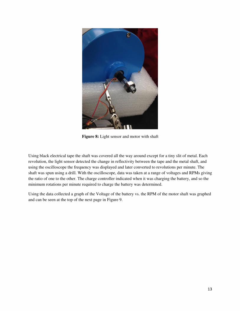
13
Figure 8: Light sensor and motor with shaft
Using black electrical tape the shaft was covered all the way around except for a tiny slit of metal. Each
revolution, the light sensor detected the change in reflectivity between the tape and the metal shaft, and
using the oscilloscope the frequency was displayed and later converted to revolutions per minute. The
shaft was spun using a drill. With the oscilloscope, data was taken at a range of voltages and RPMs giving
the ratio of one to the other. The charge controller indicated when it was charging the battery, and so the
minimum rotations per minute required to charge the battery was determined.
Using the data collected a graph of the Voltage of the battery vs. the RPM of the motor shaft was graphed
and can be seen at the top of the next page in Figure 9.

14
Figure 9: Graph of the Volts vs. RPM
According to the graph the minimal RPM needed to charge the battery is about 340, corresponding to a
voltage of about 12.65.

15
Materials, Tools and Costs
A outline of the cost expenses outputted in this project is outlined below in Figure 10.
Figure 10: Pre-Trip budget of the turbine project
Items Brought in the United States
• Wind Generator
• 1000 W Inverter
• 800W Inverter
• Breaker
• Breaker Switch
• Breaker Box
• Photocell
• Black Box
• Test Mounting Pole
• 8 Gauge Wire
• 14 Gauge Wire
• U-Clamps
• C-Clamps
• Inverter Plug
Wind Generator 489 U-Clamps 12.82 Tool Kit 28.97
800W Inverter 36 C-Clamps 4.96 Screwdrivers 9.48
Breaker 4.18 Inverter Plug 4.34 Wire Stripper 14.99
Breaker Switch 8.99 Blue Spades 4.27 Drill Bit Kit 6.99
Breaker Box 19.97 Copper Spades 12.45 Drill Bit 4.21
Photocell 7.89 Splicing Tape 3.98 Wrench 6.99
Black Box 19.99 Electrical Tape 9.33 Tarp 19.97
Test Mounting Pole 13.14 Aluminum Splice 9.98
8 Gauge Wire 27.6 Battery Terminal 5.58
14 Gauge Wire 83 Sticky Mounts 10.97
Zip Ties 2.48
AA Batteries 1
Screws 3.62
TOTAL $709.76 $85.78 $91.60
TOTAL 887.14$
Major Components Additional Parts Tools
Wind Turbine Budget

16
• Blue Spades
• Copper Spades
• Splicing Tape
• Electrical Tape
• Aluminum Splice
• Battery Terminal
• Sticky Mounts
• Zip Ties
• AA Batteries
• Screws
• Tool Kit
• Screwdrivers
• Wire Stripper
• Drill Bit Kit
• Drill Bit
• Wrench
• Tarp
Items Obtained and Tools Used in Honduras
• 3 Padlocks/Keys
• Red/Black Cables
• Silicon Sealant
• Angle Bracket
• Mounting Pole
• Deep Cycle Battery
• Welding
• Power drill
In-Country Implementation
Mechanical/Structural System
Wind Turbine Assembly and Mounting
Once on sight at Montana de Luz, the team searched for a mounting pole. Originally the team tried to find
a pole that MdL already had, but these poles did not have the correct diameter for the turbine. Therefore, a
14 foot pole was purchased for mounting the turbine. In order to mount the turbine, the team decided to
first assemble the turbine itself on top of the water tower, next bring the pole up on to the height of the
water tower, then attach the turbine to the pole on top of the water tower, and finally mount the turbine
and pole to the frame of the tower.

17
To strengthen the pole, a two inch by two inch angled bracket measuring 12 feet was welded to the 1.75
inch diameter pole measuring 14 feet, thereby leaving 2 feet of breathing room for the turbine to be
mounted on top. The pole also had a square notch cut from the bottom of the pole to allow for the 8 gauge
wiring to feed through as depicted below. Lastly the pole was painted red to show Ohio State University
spirit and can be seen below in Figure 11.
Figure 11: Mounting pole with holes and wires.
The Coleman 450 Watt turbine was carried up the ladder in multiple pieces. The pieces were laid on a
large tarp on the top of the water tower and assembled using the fastenings and tools supplied in the
turbine kit. Next, two members of the team, who were situated on the ground, lifted the pole up to two
members of the team, who were on top of the water tower. The team found that the U-bolts that had been
purchased for attaching the pole to the frame of the water tower were not long enough to secure the pole.
To solve this problem, the frame of the water tower was cut at 45 degree angle so the angled bracket,
which was welded to the pole, would fit snuggly against the frame. The 8 gauge wire, which was attached
to the turbine, was fed through the length of the pole and out the other side. The base of the pole was
placed against the back corner of the base of the water tower frame and held diagonally so that the turbine
could be mounted atop it. The adhesive strip supplied in the kit was then attached to the top of the pole
and the turbine was fitted over it and tightened using two screws and bolts that came with the kit. The
pole, with the turbine now attached on top, was lifted to the vertical position against the corner of the
frame with the angled bracket resting flush against the frame of the water tower. The 4 U-bolts secured
the pole to the gate of the water tower at evenly spaced intervals along the frame, as pictured in Figure 12
on the top of the next page.
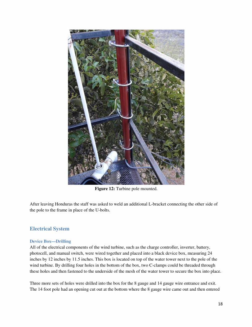
18
Figure 12: Turbine pole mounted.
After leaving Honduras the staff was asked to weld an additional L-bracket connecting the other side of
the pole to the frame in place of the U-bolts.
Electrical System
Device Box—Drilling
All of the electrical components of the wind turbine, such as the charge controller, inverter, battery,
photocell, and manual switch, were wired together and placed into a black device box, measuring 24
inches by 12 inches by 11.5 inches. This box is located on top of the water tower next to the pole of the
wind turbine. By drilling four holes in the bottom of the box, two C-clamps could be threaded through
these holes and then fastened to the underside of the mesh of the water tower to secure the box into place.
Three more sets of holes were drilled into the box for the 8 gauge and 14 gauge wire entrance and exit.
The 14 foot pole had an opening cut out at the bottom where the 8 gauge wire came out and then entered

19
the black device box to connect to the charge controller. This hole was drilled along the side of the device
box facing the wind turbine, and was placed about 2.5 inches from the bottom of the device box, and two
inches from the left side of the box.
The next hole that was made was used so that the photocell could be fastened to the box. The hole was
position on the side of the box that was closest to the MdL complex and on the left side of wind turbine
and was drilled in the center about 3 inches from the top of the box.
Several more holes were drilled on the bottom of the box to provide ventilation for the inverter. These
holes were located in the center of the bottom of the box in a rectangular region that measured 2 inches by
4 inches. These holes were drilled in 0.25 inch by 0.25 inch square pattern that repeated itself.
Several unwanted holes were drilled in the box in hopes of mounting the charge controller to the side of
the device box; however, it was found that the charge controller could not be mounted and had to lay flat
to work properly. These holes and the wiring holes were sealed with silicon sealant after drilling was
complete. This seal prevents water and unwanted varmints from entering the box. The ventilation holes
were not sealed because they were on the bottom of the box and provided air flow for the inverter.
Device Box
Eight gauge wire was connected to the generator of the turbine. The 8 gauge wire was led through the
pole and out a small hole in the pole at the bottom. The 8 gauge wire was then led through a hole in the
black device box. The 8 gauge wire was then connected to the charge controller. The manual brake was
attached to the same side of the charge controller. In case of an emergency, the manual brake can be
utilized to prevent damage to the turbine or any of the components. The other side of the charge controller
is connected to the battery and the inverter. The current flows through the charge controller and into the
battery. An amp meter is attached in series between the charge controller and the positive terminal of the
battery to check the current levels. Because the positive terminal of the battery is now attached to the
turbine, the battery can charge when current is sent through the system. The negative terminal of the
battery is attached to the charge controller so the battery can discharge when the lights need electricity.
The current then flows into the grounded inverter, where it is transferred from 12 volts DC to 120 volts
AC. Because there is now 120 volts, less current is needed to maintain a constant current based on the
equation P = I*V, where P equals power in Watts, I equals current in Amps, and V equals voltage in
volts. Because there is less current, a 14 gauge wire was used to connect the inverter to the newly
installed breaker box. The photocell is connected in series with the inverter and the breaker box. When
the photocell detects that the sun has gone down, it sends a signal so the lights turn on automatically. This
prevents someone having to turn the lights on every night. The completed device box with all components
mentioned above can be seen on the top of the next page in Figure 13 and outlined in Table 3.

20
Figure 13: Labeled Components of the device box.
Table 2: Description of each component of the device box.
Letter Concept Item
A Manual Switch
B Charge Controller
C Inverter
D Amp Meter
E Battery
F Solar Cell
Wiring
The 14 gauge wire from the inverter exited through another small hole in the box. Approximately 200 feet
of wire was then used to connect to the new breaker box. To secure the wire to the water tower and the
sides of the building, zip ties and adhesive squares were applied. An example of the wiring process can be
seen at the top of the next page in Figure 14.

21
Figure 14: This shows the 14 gauge wire on the side of the building, and it is secured using the sticky
attachments and zip ties.
The 14 gauge wire terminated at the newly installed breaker box, located inside the dining hall. The wire
was led through a previously existing small hole at the top of the wall of the dining hall and down the
inside wall of the building into the breaker box.
Breaker Box
The breaker box was designed so that both the electricity provided by the turbine and the electricity
provided by the grid could be used when needed. A double pole, double throw switch was installed into
the new breaker box. A hole was drilled into the breaker box so that the electrical components of the
switch were inside the box and the physical switch was mounted on the outside the box. The switch
included 6 terminals—2 for turbine, 2 for grid, and 2 for neutral. The two terminals for each system
included a hot and neutral terminal. A picture of the switch can be seen below in Figure 15.
Figure 15: Double pole double pole switch

22
The hot wire from the turbine first went through the new breaker and into the appropriate terminal. To use
the electricity from the grid, the new breaker box had to be connected to the old breaker box. The team
discovered that the breaker box 2, which was supposed to contain the breaker for the three outdoor lights
was incorrect and did not have the breaker installed in it. The breaker box 1 that did have the correct
breaker was located approximately 30 feet further down the building wall. The team did not have enough
14 gauge wire to connect to this breaker box 1 so a new breaker had to be installed in the breaker box 2
originally thought to contain the breaker. Hot and neutral wires from the new breaker box were connected
to the old breaker box 2 in order to have the possibility of using grid electricity. The hot and neutral wires
from the lights were attached to the two neutral terminals on the switch. A new light switch was installed
on the outside of the building to turn the lights on and off. A picture of the new breaker box and the
previous breaker box can be seen below in Figures 16 and 17.
Figure 16: Previous breaker box with correct breaker.
Figure 17: The Breaker box that had the new switch installed and connected to the new breaker box.

23
Post-Trip Summary
Post-Trip Modifications and Recommendations
Modifications that were made after the trip included replacing the inverter that was originally purchased.
The original 800 Watt Whistler inverter did not provide an Auto On/Off Low Voltage Management
feature. All inverters have the feature, called Low Voltage Alarm and Under Voltage Protection, to
protect the battery once the voltage from the battery depletes to 10.5 +/- 0.5 V. When the batter is below
10.0 V the alarm sounds, and then the inverter shuts down when the voltage is at 10.0 +/- 0.5 V. The
problem with the original 800 Watt Whistler inverter was once it shut down, it would not automatically
start up on its own when the voltage of the battery returned to 10.5 V. To solve this problem, a new
inverter was purchased. Many inverters were researched to find one that had the Auto On/Off Low
Voltage Management. The inverter that was found with this capability was the Cobra CPI-1000 Power
Inverter. This inverter was purchased and sent to Montana de Luz with explicit instructions on how to
disconnect the old inverter and wire in the new one.
Status of Project at End of Semester
The project was left in Honduras as not working or generating any power due to the inactive inverter. The
settings of the turbine are configured so that the wind turbine is spinning and charging the battery, but the
inverter is turned off and the breaker box is switched so that the lights are being powered by the grid. The
date that the new inverter is installed and the lights are being powered by the wind turbine grid is
estimated to be April 18th 2014 at the latest.
Schedule—In Country
The following is a breakdown of the day to day activities for the project while in-country.
• Mar. 8th - 16th
o Day 1:
� Assessed location
� Prepared materials
� Began connection of electronics inside the device box
o Day 2:
� Installed 14 gauge wire
� Drilled holes in the device box
� Bought/adjusted the pole's design
o Day 3
� Bought battery
� Breaker box mounted/some connections made
� Wind turbine assembled
o Day 4
� Installed pole and turbine
� Completed breaker box connections
� Completed device box connections
o Day 5

24
� Sealed t he device box
� Installed data collector
� Tested the lights
� Slept on top of the water tower to make sure the turbine performed correctly
Materials and Costs
The final cost of the entire project was $1,141.00 after the in-country materials were purchased, and replacements of materials were done. A outline of the cost expenses outputted in this project is outlined below in Figure 18.
Figure 18: Budget of the turbine project post-trip.
Acknowledgements
• Dr. Edgar Casale and Carlos Montoya
• Erika Shell Castro, staff, and children
• Jorge
• Dr. Miriam Cater
• Joe West
• Dr. Merrill
Wind Generator 489 U-Clamps 12.82 Tool Kit 28.97
Deep Cycle Battery 150 C-Clamps 4.96 Screwdrivers 9.48
800W Inverter 36 Inverter Plug 4.34 Wire Stripper 14.99
Inverter #2 78.86 Blue Spades 4.27 Drill Bit Kit 6.99
Breaker 4.18 Copper Spades 12.45 Drill Bit 4.21
Breaker Switch 8.99 Splicing Tape 3.98 Wrench 6.99
Breaker Box 19.97 Electrical Tape 9.33 Tarp 19.97
Photocell 7.89 Aluminum Splice 9.98 Paint 8.00
Black Box 19.99 Battery Terminal 5.58
Test Mounting Pole 13.14 Silicon Sealant 2
Mounting Pole … Sticky Mounts 10.97
Angle Bracket … Zip Ties 2.48
8 Gauge Wire 27.6 AA Batteries 1
14 Gauge Wire 83 3 Padlocks/Keys 6
Red/Black Cables 9
Screws 3.62
TOTAL $938.62 $102.78 $99.60
TOTAL 1,141.00$
Major Components Additional Parts Tools
Wind Turbine Budget

25
Appendix

26
References
[1] Simon, Miriam. "Wind Generator Information." Thesis Defense. The Ohio State University, Columbus. 13 FEBJAN 2012. Lecture.
[2] Alternative Energy Wind Generator Documentation—Cuoluteca 2012
[3] Joe West, Scott Laboratory
Related Documents