INSTRUCTION MANUAL ALR-AEC-8 ALERO 8-CHANNEL MICROPHONE MIXER

Welcome message from author
This document is posted to help you gain knowledge. Please leave a comment to let me know what you think about it! Share it to your friends and learn new things together.
Transcript
INSTRUCTION MANUAL
ALR-AEC-8 ALERO8-CHANNEL MICROPHONE MIXER
ii Alero 8-Channel Microphone Mixer Instruction Manual
AMX Limited Warranty and DisclaimerThis Limited Warranty and Disclaimer extends only to products purchased directly from AMX or an AMX Authorized Partner which include AMX Dealers, Distributors, VIP’s or other AMX authorized entity.
AMX warrants its products to be free of defects in material and workmanship under normal use for three (3) years from the date of purchase, with the fol-lowing exceptions:
• Electroluminescent and LCD Control Panels are warranted for three (3) years, except for the display and touch overlay components are warranted for a period of one (1) year.
• Disk drive mechanisms, pan/tilt heads, power supplies, and MX Series products are warranted for a period of one (1) year.
• AMX lighting products are guaranteed to switch on and off any load that is properly connected to our lighting products, as long as the AMX lighting products are under warranty. AMX also guarantees the control of dimmable loads that are properly connected to our lighting products. The dimming performance or quality there of is not guaranteed, impart due to the random combinations of dimmers, lamps and ballasts or transformers.
• AMX software is warranted for a period of ninety (90) days.
• Batteries and incandescent lamps are not covered under the warranty.
• AMX AutoPatch Epica, Modula, Modula Series4, Modula CatPro Series and 8Y-3000 product models will be free of defects in materials and manu-facture at the time of sale and will remain in good working order for a period of three (3) years following the date of the original sales invoice from AMX. The three-year warranty period will be extended to the life of the product (Limited Lifetime Warranty) if the warranty card is filled out by the dealer and/or end user and returned to AMX so that AMX receives it within thirty (30) days of the installation of equipment but no later than six (6) months from original AMX sales invoice date. The life of the product extends until five (5) years after AMX ceases manufacturing the product model. The Limited Lifetime Warranty applies to products in their original installation only. If a product is moved to a different installation, the Limited Lifetime Warranty will no longer apply, and the product warranty will instead be the three (3) year Limited Warranty.
All products returned to AMX require a Return Material Authorization (RMA) number. The RMA number is obtained from the AMX RMA Department. The RMA number must be clearly marked on the outside of each box. The RMA is valid for a 30-day period. After the 30-day period the RMA will be canceled. Any shipments received not consistent with the RMA, or after the RMA is canceled, will be refused. AMX is not responsible for products returned without a valid RMA number.
AMX is not liable for any damages caused by its products or for the failure of its products to perform. This includes any lost profits, lost savings, incidental damages, or consequential damages. AMX is not liable for any claim made by a third party or by an AMX Authorized Partner for a third party.
This Limited Warranty does not apply to (a) any AMX product that has been modified, altered or repaired by an unauthorized agent or improperly trans-ported, stored, installed, used, or maintained; (b) damage caused by acts of nature, including flood, erosion, or earthquake; (c) damage caused by a sus-tained low or high voltage situation or by a low or high voltage disturbance, including brownouts, sags, spikes, or power outages; or (d) damage caused by war, vandalism, theft, depletion, or obsolescence.
This limitation of liability applies whether damages are sought, or a claim is made, under this warranty or as a tort claim (including negligence and strict product liability), a contract claim, or any other claim. This limitation of liability cannot be waived or amended by any person. This limitation of liability will be effective even if AMX or an authorized representative of AMX has been advised of the possibility of any such damages. This limitation of liability, how-ever, will not apply to claims for personal injury.
Some states do not allow a limitation of how long an implied warranty last. Some states do not allow the limitation or exclusion of incidental or consequen-tial damages for consumer products. In such states, the limitation or exclusion of the Limited Warranty may not apply. This Limited Warranty gives the owner specific legal rights. The owner may also have other rights that vary from state to state. The owner is advised to consult applicable state laws for full determination of rights.
EXCEPT AS EXPRESSLY SET FORTH IN THIS WARRANTY, AMX MAKES NO OTHER WARRANTIES, EXPRESSED OR IMPLIED, INCLUDING ANY IMPLIED WARRANTIES OF MERCHANTABILITY OR FITNESS FOR A PARTICULAR PURPOSE. AMX EXPRESSLY DISCLAIMS ALL WARRANTIES NOT STATED IN THIS LIMITED WARRANTY. ANY IMPLIED WARRANTIES THAT MAY BE IMPOSED BY LAW ARE LIMITED TO THE TERMS OF THIS LIMITED WARRANTY. EXCEPT AS OTHERWISE LIMITED BY APPLICABLE LAW, AMX RESERVES THE RIGHT TO MODIFY OR DISCONTINUE DESIGNS, SPECIFICATIONS, WARRANTIES, PRICES, AND POLICIES WITHOUT NOTICE.
lug hasconsult
s.
ing the
plug is, or has
ons in
the
man
IMPORTANT SAFETY INSTRUCTIONS
ESD WARNINGTo avoid ESD (Electrostatic Discharge) damage to sensitive components, make sure you are properly grounded beforetouching any internal materials.When working with any equipment manufactured with electronic devices, proper ESD grounding procedures must befollowed to make sure people, products, and tools are as free of static charges as possible. Grounding straps, conductivesmocks, and conductive work mats are specifically designed for this purpose. These items should not be manufacturedlocally, since they are generally composed of highly resistive conductive materials to safely drain static discharges,without increasing an electrocution risk in the event of an accident
Anyone performing field maintenance on AMX equipment should use an appropriate ESD field service kit complete with atleast a dissipative work mat with a ground cord and a UL listed adjustable wrist strap with another ground cord.
1) READ these instructions.
2) KEEP these instructions.
3) HEED all warnings.
4) FOLLOW all instructions.
5) DO NOT use this apparatus near water.
6) CLEAN ONLY with dry cloth.
7) DO NOT block any ventilation openings. Install in accordance with the manufacturer's instructions.
8) DO NOT install near any heat sources such as radiators, heat registers, stoves, or other apparatus (including amplifiers) that produce heat.9) DO NOT defeat the safety purpose of the polarized or grounding type plug. A polarized plug has two blades with one wider than the other. A grounding type p
two blades and a third grounding prong. The wider blade or the third prong are provided for your safety. If the provided plug does not fit into your outlet, an electrician for replacement of the obsolete outlet.
10) PROTECT the power cord from being walked on or pinched, particularly at plugs, convenience receptacles, and the point where they exit from the apparatu
11) ONLY USE attachments/accessories specified by the manufacturer.
12) USE ONLY with a cart, stand, tripod, bracket, or table specif ied by the manufacturer, or sold with the apparatus. When a cart is used, use caution when movcart/apparatus combination to avoid injury from tip-over.
13) UNPLUG this apparatus during lightning storms or when unused for long periods of time.14) REFER all servicing to qualified service personnel. Servicing is required when the apparatus has been damaged in any way, such as power-supply cord or
damaged, liquid has been spilled or objects have fallen into the apparatus, the apparatus has been exposed to rain or moisture, does not operate normallybeen dropped.
15) DO NOT expose this apparatus to dripping or splashing and ensure that no objects filled with liquids, such as vases, are placed on the apparatus.
16) To completely disconnect this apparatus from the AC Mains, disconnect the power supply cord plug from the AC receptacle.
17) Where the mains plug or an appliance coupler is used as the disconnect device, the disconnect device shall remain readily operable.
18) DO NOT overload wall outlets or extension cords beyond their rated capacity as this can cause electric shock or fire.
19) Place the equipment near a main power supply outlet and make sure that you can easily access the power breaker switch.
The exclamation point, within an equilateral triangle, is intended to alert the user to the presence of important operating and maintenance (servicing) instructithe literature accompanying the product.
The lightning flash with arrowhead symbol within an equilateral triangle is intended to alert the user to the presence of uninsulated "dangerous voltage" withinproduct's enclosure that may be of sufficient magnitude to constitute a risk of electrical shock to persons.
ESD Warning: The icon to the left indicates text regarding potential danger associated with the discharge of static electricity from an outside source (such as huhands) into an integrated circuit, often resulting in damage to the circuit.
WARNING: To reduce the risk of fire or electrical shock, do not expose this apparatus to rain or moisture.
WARNING: No naked flame sources - such as candles - should be placed on the product.
WARNING: Equipment shall be connected to a MAINS socket outlet with a protective earthing connection.
i Alero 8-Channel Microphone Mixer Instruction Manual

FCC AND CANADA EMC COMPLIANCE INFORMATION:This device complies with part 15 of the FCC Rules. Operation is subject to the following two conditions:
(1) This device may not cause harmful interference, and (2) this device must accept any interference received, including interference that maycause undesired operation.NOTE: This equipment has been tested and found to comply with the limits for a Class B digital device, pursuant to part 15 of the FCC Rules. These limits are designed to provide reasonable protection against harmful interference in a residential installation. This equipment generates, uses and can radiate radio frequency energy and, if not installed and used in accordance with the instructions, may cause harmful interference to radio communications. However, there is no guarantee that interference will not occur in a particular installation. If this equipment does cause harmful interference to radio or television reception, which can be determined by turning the equipment off and on, the user is encouraged to try to correct the interference by one or more of the following measures:Reorient or relocate the receiving antenna.Increase the separation between the equipment and receiver.Connect the equipment into an outlet on a circuit different from that to which the receiver is connected.Consult the dealer or an experienced radio/TV technician for help.
Approved under the verification provision of FCC Part 15 as a Class B Digital Device.
CAN ICES-3 (B)/NMB-3(B)
EU COMPLIANCE INFORMATION:Eligible to bear the CE mark; Conforms to European Union Low Voltage Directive 2006/95/EC; European Union EMC Directive 2004/108/EC; European Union Restriction of Hazardous Substances Recast (RoHS2) Directive 2011/65/EU; European Union WEEE (recast) Directive 2012/19/EU;
You may obtain a free copy of the Declaration of Conformity by visiting http://www.amx.com/techcenter/certifications.asp
WEEE NOTICE
WARNING: Do Not Open! Risk of Electrical Shock. Voltages in this equipment are hazardous to life. No user-serviceable parts inside. Refer all servicing to qualified service personnel.
WARNING: To reduce the risk of fire or electrical shock, do not expose this apparatus to rain or moisture.
WARNING: No naked flame sources - such as candles - should be placed on the product.
WARNING: Equipment shall be connected to a MAINS socket outlet with a protective earthing connection.
WARNING: This product is intended to be operated ONLY from the voltages listed on the back panel or the recommended, or included, power supply of the product. Operation from other voltages other than those indicated may cause irreversible damage to the product and void the products warranty. The use of AC Plug Adapters is cautioned because it can allow the product to be plugged into voltages in which the product was not designed to operate. If the product is equipped with a detachable power cord, use only the type provided with your product or by your local distributor and/or retailer. If you are unsure of the correct operational voltage, please contact your local distributor and/or retailer.
CAUTION: Changes or modifications not expressly approved by the manufacturer could void the user's authority to operate this device.
This appliance is labeled in accordance with European Directive 2012/19/EU concerning waste of electrical and electronic equipment (WEEE). This label indicates that this product should not be disposed of with household waste. It should be deposited at an appropriate facility to enable recovery and recycling.
ii Alero 8-Channel Microphone Mixer Instruction Manual
Table of Contents
Table of Contents
Introduction ......................................................................................................1Audio ................................................................................................................................ 1Power Supply..................................................................................................................... 2
Hardware Description .......................................................................................3Front Panel ........................................................................................................................ 3Rear Panel ......................................................................................................................... 3Connector Definitions....................................................................................................... 4
VC - Video Conferencing......................................................................................................................... 4Line In/Line Out ...................................................................................................................................... 4PA Speaker Output.................................................................................................................................. 5Microphone Inputs ................................................................................................................................. 5Mute Group ............................................................................................................................................. 5USB Port.................................................................................................................................................. 6RJ-45 Connector ..................................................................................................................................... 6Power Connector .................................................................................................................................... 6
Installation ........................................................................................................7List of Supplies ................................................................................................................. 7Placement......................................................................................................................... 7Connections...................................................................................................................... 7
Connect to the Network.......................................................................................................................... 7Connect Power........................................................................................................................................ 8Connect Audio Conference Equipment .................................................................................................. 8Connect Video Conference Equipment................................................................................................... 8Microphone Connections........................................................................................................................ 9Detect IP address ................................................................................................................................... 9Configure Microphone Inputs ................................................................................................................ 9Configure Input/Output Channels. ........................................................................................................ 9
Configuration ..................................................................................................10Reset Button ................................................................................................................... 10HTTPS for Secure Communication ................................................................................. 10Login ............................................................................................................................... 10Network Configuration ................................................................................................... 11Levels.............................................................................................................................. 12
Signal Levels ......................................................................................................................................... 12Microphone Volume.............................................................................................................................. 12Channel Volume.................................................................................................................................... 13
Signal Mixing .................................................................................................................. 13Signal Levels ......................................................................................................................................... 13
iii Alero 8-Channel Microphone Mixer Instruction Manual
Table of Contents
Selection of Mixing Microphones (AMM).............................................................................................. 13Signal Mixing......................................................................................................................................... 14Active Mute Groups .............................................................................................................................. 15
Microphone Settings ...................................................................................................... 16Basic Configuration .........................................................................................17
Upgrade Device .............................................................................................................. 17Manage Settings............................................................................................................. 17
Save Configuration Settings ................................................................................................................. 17Restore Configuration Settings ............................................................................................................ 17Export Configuration Settings .............................................................................................................. 17Import Configuration Settings ............................................................................................................. 18
Factory Reset.................................................................................................................. 18Authentication................................................................................................................ 18
Authentication Required....................................................................................................................... 18Username.............................................................................................................................................. 18Password .............................................................................................................................................. 18Apply Settings....................................................................................................................................... 18
ivAlero 8-Channel Microphone Mixer Instruction Manual

Introduction
IntroductionThe Alero (FG1140-08) is an 8 channel microphone mixer with built in acoustic echo canceller. Alero acts as a USB audio device with a capability to connect 3 analog input and 3 analog output channels. Alero also supports 2 channel mono line level speaker signal outputs:
Line In 1 and 2 are stereoLine Level to speaker is stereo
AudioThe product contains audio signal processing software with the following signal processing blocks:
Alero supplies full duplex communication without disturbing background noise in a telecommunication system. The microphone input channels are automatically mixed with the AMM. The loudspeaker echo is removed from the microphone signals by the modules AEC and RES. Noise reduction, equalization filters are applied to further improve audio quality. Comfort noise is added to microphone channels to avoid a pumping noise level when the RES is working. A flowwebpage of the signal processing modules for the microphone input is shown in FIG. 1.
Processor DescriptionAutomatic Microphone Mixing (AMM)
The microphone input channels are automatically combined into one output channel. The microphone mixing performs a selection of which channel to open, reducing overall noise level and improving speech clarity compared with just adding all microphone channels.
Acoustic Echo Cancellation(AEC)
Models the acoustic environment and removes the loudspeaker echo via adaptive filtering.
Residual Echo Suppression (RES)
Additional suppression of acoustic echo while still maintaining full duplex performance.
Comfort Noise (CN) Noise with similar level and characteristics as the background noise is added to microphone channels to avoid a pumping noise level when the RES applies damping to reduce echoes.
Noise Reduction (NR) Models the characteristics and level of the background noise and reduces the noise level on the microphone channels.
Channel Equalization (EQ) Equalization filtering is applied for enhancing speech clarity and to compensate for characteristics on connected devices.
Signal Mixer The processed microphone signal is added to the output channels in combination with the input channels. It is possible to select the routing of input channels to output channels.
Volume Adjustment (VOL) Volume adjustment and mute functionality for all input and output channels without sudden transitions. There are no artifacts such as clicks and pops when muting/unmuting a channel. Signal amplification is performed without introducing amplitude clipping.
FIG. 1 Microphone Signal Processing Flowwebpage
1 Alero 8-Channel Microphone Mixer Instruction Manual
Introduction
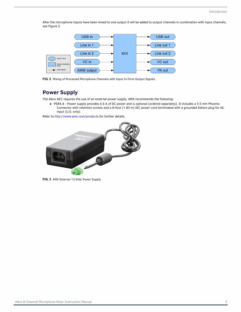
After the microphone inputs have been mixed to one output it will be added to output channels in combination with input channels, see Figure 2.
Power SupplyThe Alero AEC requires the use of an external power supply. AMX recommends the following:
PSR4.4 - Power supply provides 4.5 A of DC power and is optional (ordered separately). It includes a 3.5 mm Phoenix Connector with retention screws and a 6-foot (1.83 m) IEC power cord terminated with a grounded Edison plug for AC input (U.S. only).
Refer to http://www.amx.com/products for further details.
FIG. 2 Mixing of Processed Microphone Channels with Input to Form Output Signals
FIG. 3 AMX External 13.5Vdc Power Supply
2 Alero 8-Channel Microphone Mixer Instruction Manual

Hardware Description
Hardware DescriptionAlero has a metallic enclosure with visual user interfaces located on the front panel and connectivity interfaces on the rear panel.
Front PanelThe Alero front panel is the only side that should be visible in a typical setup. Here, the user can monitor the most essential statuses in three groups of LEDs as shown in FIG. 4.
The table below provides descriptions of the front panel LEDs used to determine the state of the unit and operation of the microphones.
Rear PanelThe rear panel is intended to be used by a system installer. FIG. 5 shows all connector inputs and output audio channels as well as USB, network, and power supply. Also displayed are the factory reset button and a mute control connector.
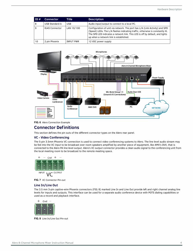
The following table provides a brief description of the rear panel components with a visual shown in FIG. 6.
FIG. 4 Front Panel LEDs.
Group Description Usage1 POWER One continuously lit green LED Indicates that the unit is powered on.
2 MICROPHONES – SIGNAL A continuously lit green LED will flicker indicating an active signal on the corresponding eight microphone channels.
3 MICROPHONES – CLIP Eight red LEDs indicate risk of amplitude clipping on corresponding channel due to a strong signal. LED is only active for a short time after a strong signal is detected. Reduce gain on the channel if LED is active.
FIG. 5 Rear Panel Connectors
ID # Connector Title Description1 5-pin Phoenix VC Video Conference audio channel input and output. Line level
2 3-pin Phoenix LINE IN 2 analog line level inputs
3 3-pin Phoenix LINE OUT 2 analog line level outputs
4 5-pin Phoenix PA OUT 2 mono line level outputs for connection to local sound reinforcement (PA) system.
5 3-pin Phoenix MICROPHONES 8 microphone inputs. Phantom power configurable.
6 6-pin Phoenix MUTE Muting of certain microphone groups by applying contact closure or mic switch. Up to 5 mute groups may be created. Refer to Active Mute Groups on page 15 for more details.
7 1 Push Button RESET Reset to factory settings by pressing button while powering on unit, also used to Switch between static IP and DHCP
Continued
3 Alero 8-Channel Microphone Mixer Instruction Manual
Hardware Description
Connector Def initionsThis section defines the pin outs of the different connector types on the Alero rear panel.
VC - Video ConferencingThe 5-pin 3.5mm Phoenix VC connection is used to connect video conferencing systems to Alero. The line level audio stream may be fed into the VC input to be broadcast over room speakers amplified by another piece of equipment, like AMX’s DVX, that is connected to the Alero PA line level output. Alero’s VC output connector provides a clean audio signal to the conferencing unit from the local meeting room to be broadcast to the remote meeting space.
Line In/Line OutThe 3.5 mm 3-pin captive-wire Phoenix connectors (FIG. 8) marked Line In and Line Out provide left and right channel analog line levels for inputs and outputs. This interface can be used for a separate audio conference device with POTS dialing capabilities or used as a record and playback interface.
8 USB Standard-b USB Audio input/output to connect to a local PC.
9 RJ45 Connector LAN 10/100 Configuration of unit via network. The port has L/A (Link Activity) and SPD (Speed) LEDs. The L/A flashes indicating traffic, otherwise is constantly lit. The SPD LED indicates a network link. This LED is off by default, and lights up when a network link is established.
10 2 pin Phoenix INPUT PWR 12 VDC power supply
FIG. 6 Alero Connection Example
FIG. 7 VC Connector Pin-out
FIG. 8 Line In/Line Out Pin-out
ID # Connector Title Description
4 Alero 8-Channel Microphone Mixer Instruction Manual
Hardware Description
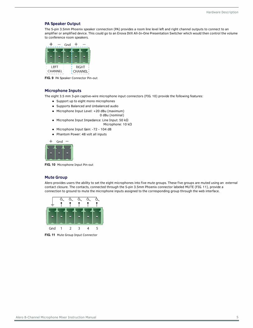
PA Speaker OutputThe 5-pin 3.5mm Phoenix speaker connection (PA) provides a room line level left and right channel outputs to connect to an amplifier or amplified device. This could go to an Enova DVX All-In-One Presentation Switcher which would then control the volume to conference room speakers.
Microphone InputsThe eight 3.5 mm 3-pin captive-wire microphone input connectors (FIG. 10) provide the following features:
Support up to eight mono microphonesSupports Balanced and Unbalanced audio Microphone Input Level: +20 dBu (maximum)
0 dBu (nominal)Microphone Input Impedance: Line Input: 50 kΩ
Microphone: 10 kΩ
Microphone Input Gain: -72 - 104 dBPhantom Power: 48 volt all inputs
Mute GroupAlero provides users the ability to set the eight microphones into five mute groups. These five groups are muted using an external contact closure. The contacts, connected through the 5-pin 3.5mm Phoenix connector labeled MUTE (FIG. 11), provide a connection to ground to mute the microphone inputs assigned to the corresponding group through the web interface.
FIG. 9 PA Speaker Connector Pin-out
FIG. 10 Microphone Input Pin-out
FIG. 11 Mute Group Input Connector
5 Alero 8-Channel Microphone Mixer Instruction Manual
Hardware Description
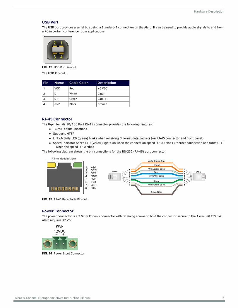
USB PortThe USB port provides a serial bus using a Standard-B connection on the Alero. It can be used to provide audio signals to and from a PC in certain conference room applications.
The USB Pin-out:
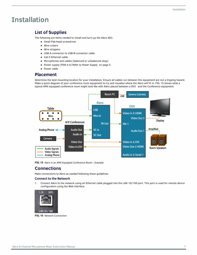
RJ-45 ConnectorThe 8-pin female 10/100 Port RJ-45 connector provides the following features:
TCP/IP communicationsSupports HTTPLink/Activity LED (green) blinks when receiving Ethernet data packets (on RJ-45 connector and front panel)Speed Indicator Speed LED (yellow) lights On when the connection speed is 100 Mbps Ethernet connection and turns OFF
when the speed is 10 MbpsThe following diagram shows the pin connections for the RS-232 (RJ-45) port connector.
Power ConnectorThe power connector is a 3.5mm Phoenix connector with retaining screws to hold the connector secure to the Alero unit FIG. 14. Alero requires 12 Vdc.
FIG. 12 USB Port Pin-out
Pin Name Cable Color Description1 VCC Red +5 VDC
2 D- White Data -
3 D+ Green Data +
4 GND Black Ground
FIG. 13 RJ-45 Receptacle Pin-out
FIG. 14 Power Input Connector
6 Alero 8-Channel Microphone Mixer Instruction Manual
Installation
InstallationList of SuppliesThe following are items needed to install and turn-up the Alero AEC:
Small Flat-head screwdriverWire cuttersWire strippersUSB A-connector to USB B-connector cableCat-5 Ethernet cableMicrophones and cables (balanced or unbalanced okay)Power supply (PSN 4.4) Refer to Power Supply on page 5.Power cable
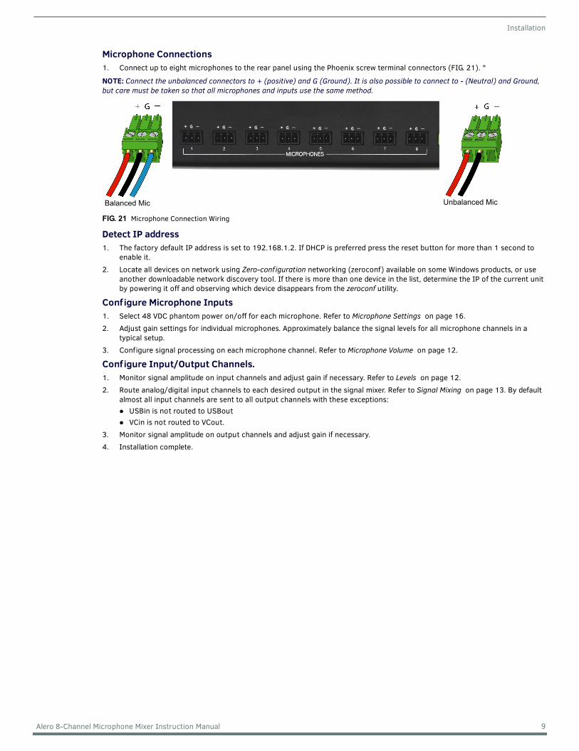
PlacementDetermine the best mounting location for your installation. Ensure all cables run between the equipment are not a tripping hazard. Make a quick diagram of your conference room equipment to try and visualize where the Alero will f it in. FIG. 15 shows what a typical AMX equipped conference room might look like with Alero placed between a DVX and the Conference equipment.
ConnectionsMake connections to Alero as needed following these guidelines.
Connect to the Network1. Connect Alero to the network using an Ethernet cable plugged into the LAN 10/100 port. This port is used for remote device
configuration using the Web interface.
FIG. 15 Alero in an AMX Equipped Conference Room - Example
FIG. 16 Network Connection
7 Alero 8-Channel Microphone Mixer Instruction Manual

Installation
Connect Power1. Connect the power supply using the male two-pin Phoenix screw down plug. Refer to Power Supply on page 5 for details on
the recommended AMX power supply.2. Secure the plug terminals to the receptacle on the Alero backplate. 3. Plug the power supply into the wall outlet using the cord included with the power supply. Alero will power on automatically.
Connect Audio Conference Equipment Prepare wire ends by cutting 1/4" of the insulation off of the end of the wires. Insert the stripped ends into the Phoenix style secure screw terminals (FIG. 18). Refer to the wire guide on the Alero rear panel for each connector type.
+ = PositiveG = Ground- = Neutral
1. If using an audio conference device, connect the input and output channels to the Alero rear panel Line In and Line Out.
2. The Alero USB port is used to pass audio to local equipment used to make conference calls (i.e., a local room PC being used to make Skype calls). If using the USB port for Audio output, connect the cable to the USB port (FIG. 19).
Connect Video Conference Equipment1. If using a video conference device, connect the audio inputs/outputs to the Alero VC connection IN/OUT while passing the
Video signal to the Enova DVX All-In-One Presentation Switcher or other switching equipment. The audio signal will then pass to the conference room switcher (i.e., DVX) for volume control.
FIG. 17 12-Volt Power Connection
FIG. 18 Audio Conference Device Connections
FIG. 19 Serial Audio Conference Device Connections
FIG. 20 Video Conference Device Connections
Insert Stripped Wire Ends
Screw downterminals Back Panel Wire Guide
Insert Phoenix style male connector into back panel connections
8 Alero 8-Channel Microphone Mixer Instruction Manual
Installation
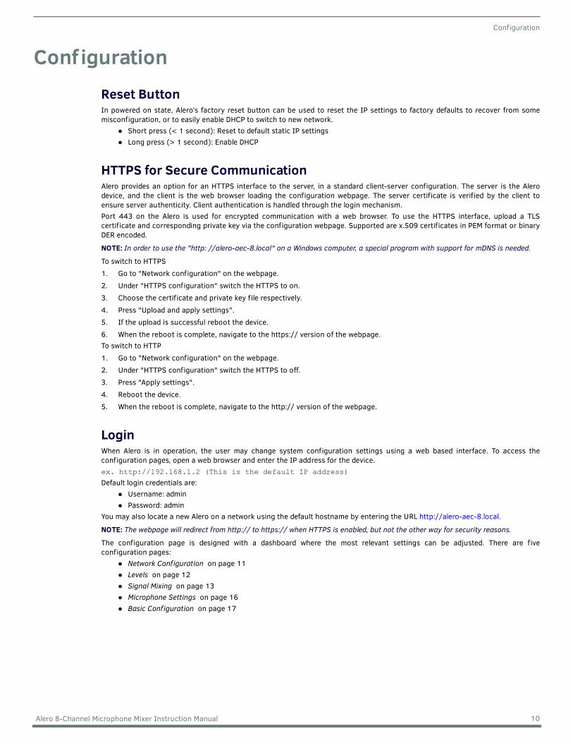
Microphone Connections1. Connect up to eight microphones to the rear panel using the Phoenix screw terminal connectors (FIG. 21). "
NOTE: Connect the unbalanced connectors to + (positive) and G (Ground). It is also possible to connect to - (Neutral) and Ground, but care must be taken so that all microphones and inputs use the same method.
Detect IP address 1. The factory default IP address is set to 192.168.1.2. If DHCP is preferred press the reset button for more than 1 second to
enable it. 2. Locate all devices on network using Zero-conf iguration networking (zeroconf) available on some Windows products, or use
another downloadable network discovery tool. If there is more than one device in the list, determine the IP of the current unit by powering it off and observing which device disappears from the zeroconf utility.
Conf igure Microphone Inputs1. Select 48 VDC phantom power on/off for each microphone. Refer to Microphone Settings on page 16.2. Adjust gain settings for individual microphones. Approximately balance the signal levels for all microphone channels in a
typical setup.3. Configure signal processing on each microphone channel. Refer to Microphone Volume on page 12.
Conf igure Input/Output Channels.1. Monitor signal amplitude on input channels and adjust gain if necessary. Refer to Levels on page 12.2. Route analog/digital input channels to each desired output in the signal mixer. Refer to Signal Mixing on page 13. By default
almost all input channels are sent to all output channels with these exceptions:USBin is not routed to USBoutVCin is not routed to VCout.
3. Monitor signal amplitude on output channels and adjust gain if necessary.4. Installation complete.
FIG. 21 Microphone Connection Wiring
Balanced Mic Unbalanced Mic
9 Alero 8-Channel Microphone Mixer Instruction Manual
Configuration
Conf igurationReset ButtonIn powered on state, Alero’s factory reset button can be used to reset the IP settings to factory defaults to recover from somemisconfiguration, or to easily enable DHCP to switch to new network.
Short press (< 1 second): Reset to default static IP settingsLong press (> 1 second): Enable DHCP
HTTPS for Secure CommunicationAlero provides an option for an HTTPS interface to the server, in a standard client-server configuration. The server is the Alerodevice, and the client is the web browser loading the configuration webpage. The server certificate is verified by the client toensure server authenticity. Client authentication is handled through the login mechanism.Port 443 on the Alero is used for encrypted communication with a web browser. To use the HTTPS interface, upload a TLScertificate and corresponding private key via the configuration webpage. Supported are x.509 certificates in PEM format or binaryDER encoded.
NOTE: In order to use the "http: //alero-aec-8.local" on a Windows computer, a special program with support for mDNS is needed.
To switch to HTTPS1. Go to "Network configuration" on the webpage.2. Under "HTTPS configuration" switch the HTTPS to on.3. Choose the certificate and private key file respectively.4. Press "Upload and apply settings".5. If the upload is successful reboot the device.6. When the reboot is complete, navigate to the https:// version of the webpage.To switch to HTTP1. Go to "Network configuration" on the webpage.2. Under "HTTPS configuration" switch the HTTPS to off.3. Press "Apply settings".4. Reboot the device.5. When the reboot is complete, navigate to the http:// version of the webpage.
LoginWhen Alero is in operation, the user may change system configuration settings using a web based interface. To access theconfiguration pages, open a web browser and enter the IP address for the device.ex. http://192.168.1.2 (This is the default IP address)
Default login credentials are:Username: adminPassword: admin
You may also locate a new Alero on a network using the default hostname by entering the URL http://alero-aec-8.local.
NOTE: The webpage will redirect from http:// to https:// when HTTPS is enabled, but not the other way for security reasons.
The configuration page is designed with a dashboard where the most relevant settings can be adjusted. There are fiveconfiguration pages:
Network Conf iguration on page 11Levels on page 12Signal Mixing on page 13Microphone Settings on page 16Basic Conf iguration on page 17
10 Alero 8-Channel Microphone Mixer Instruction Manual

Configuration
Network Conf igurationThe default Alero IP and other network settings can be configured on the Network Conf iguration page (FIG. 22). On this page usersmay also enable DHCP to have an IP address assigned by the network automatically.
NOTE: If the manual settings are bad, the device will not be accessible via a conf iguration page since the network connection will not work. If this happens, follow the procedure Factory Reset on page 18.
Address Type Conf igured AddressIP Address 192.168.1.2
Gateway 192.168.1.1
Netmask 255.255.255.0
FIG. 22 Network Configuration Page
11 Alero 8-Channel Microphone Mixer Instruction Manual
Configuration
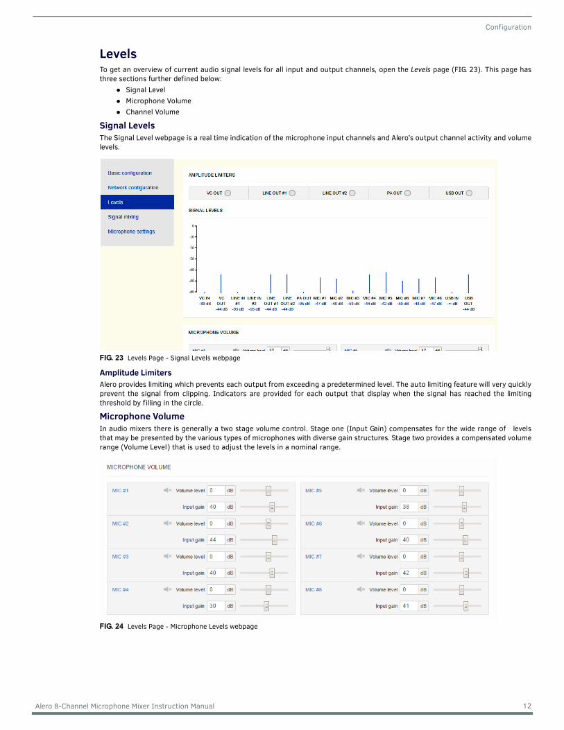
LevelsTo get an overview of current audio signal levels for all input and output channels, open the Levels page (FIG. 23). This page hasthree sections further defined below:
Signal LevelMicrophone VolumeChannel Volume
Signal LevelsThe Signal Level webpage is a real time indication of the microphone input channels and Alero’s output channel activity and volumelevels.
Amplitude LimitersAlero provides limiting which prevents each output from exceeding a predetermined level. The auto limiting feature will very quicklyprevent the signal from clipping. Indicators are provided for each output that display when the signal has reached the limitingthreshold by filling in the circle.
Microphone VolumeIn audio mixers there is generally a two stage volume control. Stage one (Input Gain) compensates for the wide range of levelsthat may be presented by the various types of microphones with diverse gain structures. Stage two provides a compensated volumerange (Volume Level) that is used to adjust the levels in a nominal range.
FIG. 23 Levels Page - Signal Levels webpage
FIG. 24 Levels Page - Microphone Levels webpage
12 Alero 8-Channel Microphone Mixer Instruction Manual
Configuration
Input GainThe Input Gain adjustment is the first stage and sets the input mic gain. With the Volume Level set to 0 dB, set the Input Gain miclevel as high as possible without any audible distortion, with some margin (approximately around 55 dB).
Volume LevelThe Volume Level adjustment controls the nominal level and provides for uniform level adjustments in real time. If the analog levelis driven to distortion, no adjustment of the this level will compensate for this distortion. If the Input Gain level is too low, theVolume Level will not be able to raise it enough to compensate.The AGC (Automatic Gain Control) works in the Volume Level and attempts to regulate the volume output based on the mic inputreceiving the strongest signal.
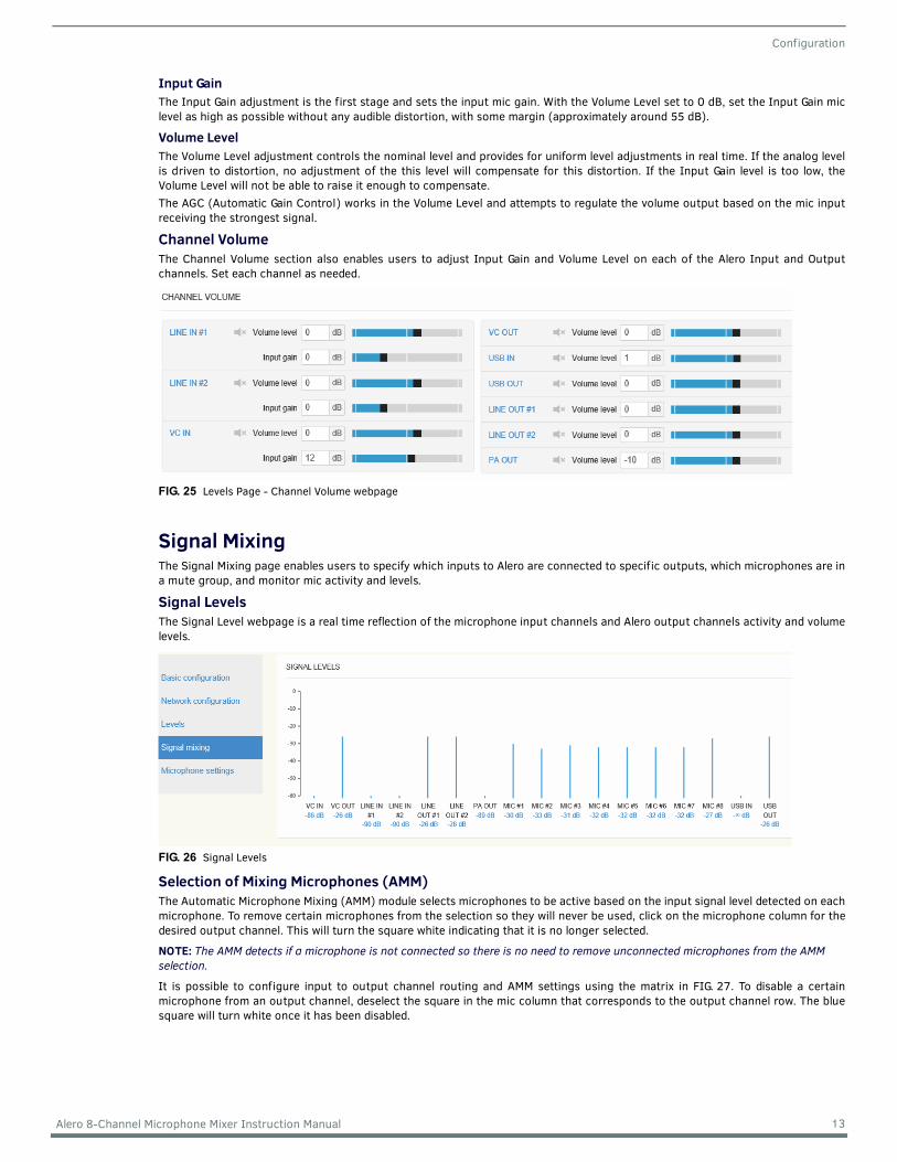
Channel VolumeThe Channel Volume section also enables users to adjust Input Gain and Volume Level on each of the Alero Input and Outputchannels. Set each channel as needed.
Signal MixingThe Signal Mixing page enables users to specify which inputs to Alero are connected to specific outputs, which microphones are ina mute group, and monitor mic activity and levels.
Signal LevelsThe Signal Level webpage is a real time reflection of the microphone input channels and Alero output channels activity and volumelevels.
Selection of Mixing Microphones (AMM)The Automatic Microphone Mixing (AMM) module selects microphones to be active based on the input signal level detected on eachmicrophone. To remove certain microphones from the selection so they will never be used, click on the microphone column for thedesired output channel. This will turn the square white indicating that it is no longer selected.
NOTE: The AMM detects if a microphone is not connected so there is no need to remove unconnected microphones from the AMM selection.
It is possible to configure input to output channel routing and AMM settings using the matrix in FIG. 27. To disable a certainmicrophone from an output channel, deselect the square in the mic column that corresponds to the output channel row. The bluesquare will turn white once it has been disabled.
FIG. 25 Levels Page - Channel Volume webpage
FIG. 26 Signal Levels
13 Alero 8-Channel Microphone Mixer Instruction Manual

Configuration
Active microphones are displayed by an "ACTIVE" indicator (FIG. 27). It is possible to disable AMM for individual output channels bypressing the gray AMM symbol under the output channel shown in the matrix below. This causes all the AMM symbol to turn whiteand the microphone signals in that row to be consistently in an ACTIVE state and added to that output channel.
Signal MixingThe Signal Mixing matrix (FIG. 28) shows the default input to output channel mixing settings. All input channels are routed to alloutput channels except the following:
the USB Input is not routed to the USB Outputthe VC Input is not routed to the VC Output
To remove an input channel from an output channel, click on the corresponding row/column to turn the square white.
FIG. 27 AMM Settings and Mic Input to Output Channel Signal Routing.
FIG. 28 Input to Output Signal Routing.
14 Alero 8-Channel Microphone Mixer Instruction Manual
Configuration
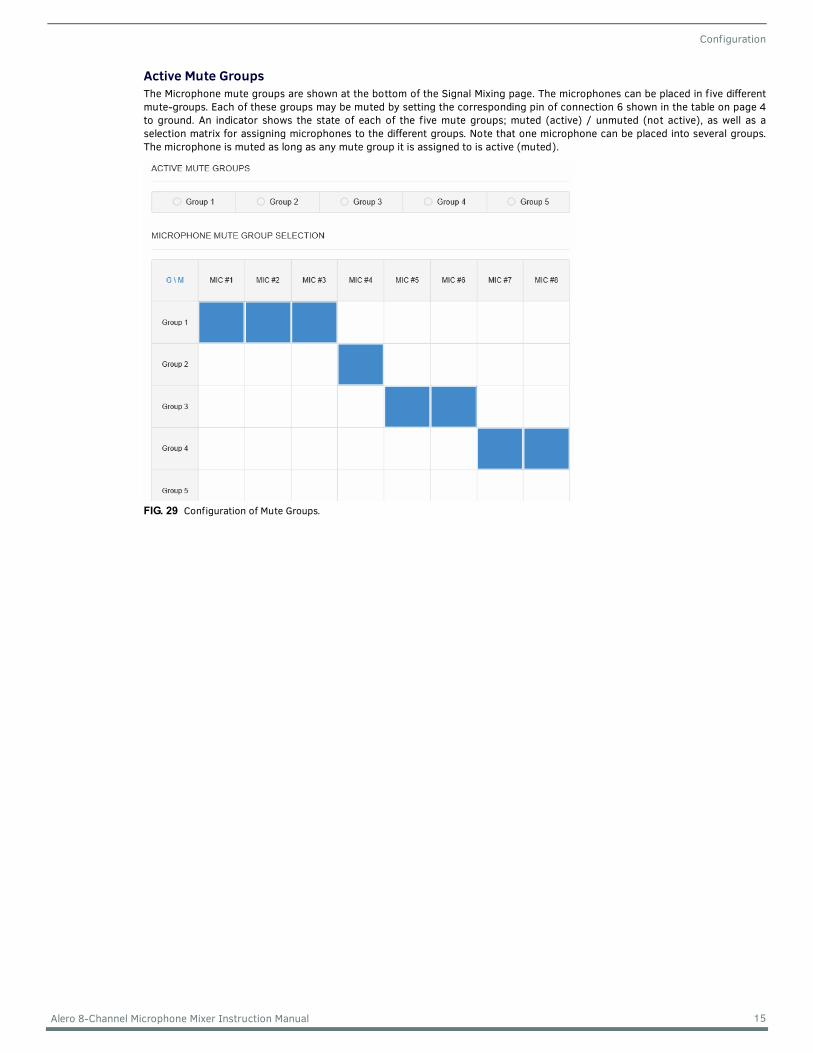
Active Mute GroupsThe Microphone mute groups are shown at the bottom of the Signal Mixing page. The microphones can be placed in five differentmute-groups. Each of these groups may be muted by setting the corresponding pin of connection 6 shown in the table on page 4to ground. An indicator shows the state of each of the five mute groups; muted (active) / unmuted (not active), as well as aselection matrix for assigning microphones to the different groups. Note that one microphone can be placed into several groups.The microphone is muted as long as any mute group it is assigned to is active (muted).
FIG. 29 Configuration of Mute Groups.
15 Alero 8-Channel Microphone Mixer Instruction Manual
Configuration
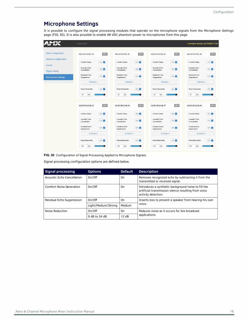
Microphone SettingsIt is possible to configure the signal processing modules that operate on the microphone signals from the Microphone Settingspage (FIG. 30). It is also possible to enable 48 VDC phantom power to microphones from this page.
Signal processing configuration options are defined below.
FIG. 30 Configuration of Signal Processing Applied to Microphone Signals.
Signal processing Options Default DescriptionAcoustic Echo Cancellation On/Off On Removes recognized echo by subtracting it from the
transmitted or received signal.
Comfort Noise Generation On/Off On Introduces a synthetic background noise to fill the artificial transmission silence resulting from voice activity detection.
Residual Echo Suppression On/Off On Inserts loss to prevent a speaker from hearing his own voice.Light/Medium/Strong Medium
Noise Reduction On/Off On Reduces noise as it occurs for live broadcast applications.0 dB to 24 dB 12 dB
16 Alero 8-Channel Microphone Mixer Instruction Manual

Basic Configuration
Basic Conf igurationMost maintenance tasks are performed in the Basic Conf iguration page (FIG. 31) where users can perform firmware upgrades, store and load settings and change login credentials.
Upgrade DeviceFirmware upgrades can be performed using the Basic conf iguration page (FIG. 31). 1. Click Choose f ile to select a new firmware file from the local computer. The naming convention of new firmware releases is: "SW1140-08_ALR-AEC-8_vx_x.bin (x = release and version number)
2. When the new firmware is selected, press the upload button to start the firmware upgrade. Alero will update the firmware and restart. Settings will be stored and used with the new firmware.
NOTE: The upgrade process will take up to 5 minutes. Please do not remove the power during this process.
Manage SettingsThe Manage Settings section enables administrators to save or export the current device configuration settings, import a new settings file, or restore to the last saved settings.
Save Conf iguration SettingsTo save the current settings for network and audio, press Save Settings in the Basic conf iguration page (FIG. 31). The saved settings will also be used after a reboot.
Restore Conf iguration SettingsTo retrieve the last saved settings press Restore Saved Settings.
Export Conf iguration Settings 1. To export an Alero’s configuration to file (format .bin), press Export Settings.2. Your computer will prompt to open or save the file. Press Save to download and save the file on your local system
The copy format of the configuration export includes:Volume Settings - All Inputs and OutputsSignal Mixing - A ll Inputs and OutputsMicrophone Settings - All Inputs and Outputs
FIG. 31 Basic Configuration Page
17 Alero 8-Channel Microphone Mixer Instruction Manual
Basic Configuration
Import Conf iguration SettingsThe Web UI enables selecting files to import. To install a previously exported configuration file:1. Press Import Conf iguration. Select a f ile from the list. 2. Press Upload to import the selected file.
Factory ResetIf somehow the product has ended up in a bad state, there is an option to reset the device to factory settings. Follow these steps for performing a factory reset.1. Remove power from Alero.2. Press the Reset button on the rear panel for approximately 5 seconds while reapplying power to Alero.3. Wait for Alero to start.
NOTE: All settings and f irmware upgrades will be lost when performing a factory reset.
AuthenticationThe Authentication section enables administrators to change the default system user and password used to make changes to the performance when needed.
Authentication RequiredSelecting this disabled authentication so anyone may access the system to make changes.
UsernameEnter a username desired to secure the system from the default admin username.
PasswordEnter a password desired to secure the system from the default admin password.
Apply SettingsSelect Apply Settings to make the changes.
18 Alero 8-Channel Microphone Mixer Instruction Manual

© 2015 Harman. All rights reserved. Alero, AMX, AV FOR AN IT WORLD, HARMAN, and their respective logos are registered trademarks of HARMAN. Oracle, Java and any other company or brand name referenced may be trademarks/registered trademarks of their respective companies.AMX does not assume responsibility for errors or omissions. AMX also reserves the right to alter specifications without prior notice at any time.The AMX Warranty and Return Policy and related documents can be viewed/downloaded at www.amx.com.
3000 RESEARCH DRIVE, RICHARDSON, TX 75082 AMX.com | 800.222.0193 | 469.624.8000 | +1.469.624.7400 | fax 469.624.7153
Last Revised:12/09/2015
Related Documents


