ALPHACAM 2020.1 MATERIAL AND TOOLING CREATION

Welcome message from author
This document is posted to help you gain knowledge. Please leave a comment to let me know what you think about it! Share it to your friends and learn new things together.
Transcript

ALPHACAM 2020.1 MATERIAL AND TOOLING CREATION

Copyright Copyright © 2019 Hexagon AB and/or its subsidiaries and affiliates. All rights reserved. Any copyright or other intellectual property right of whatever nature which subsists or may subsist in the presentation and/or content of the programs (including without limitation its look, feel, visual or other non-literal elements) remains the property of Hexagon AB and/or its subsidiaries and affiliates or its licensor(s) absolutely. No part of this publication may be reproduced, transmitted, transcribed, stored in a retrieval system or translated into any language, in any form or by any means, electronic, mechanical, optical, chemical, manual or otherwise, without the express written permission of Hexagon AB and/or its subsidiaries and affiliates. Unauthorised reproduction or distribution of these programs or any part thereof is unlawful and may result in civil or criminal penalties. Windows is a trademark of Microsoft Corporation. All product names mentioned in this publication, and not listed above, are acknowledged as the trademarks of the respective manufacturers and producers of such products. Hexagon AB and/or its subsidiaries and affiliates makes no representations or warranties with respect to the contents hereof and specifically disclaim any implied warranties of satisfactory quality or fitness for any particular purpose. Further, Hexagon AB and/or its subsidiaries and affiliates reserves the right to revise this publication and to make changes in the contents hereof without obligation to notify any person of such changes or revisions. The information contained within this document is subject to change without notice and does not represent a commitment on the part of the vendor. The software described in this document is furnished under a licence agreement and may be used or copied only in accordance with the terms of the agreement. .
ALPHACAM 2020.1 Material and Tooling Creation
i
Contents Copyright ..................................................................................................................................... i
Conventions used in this manual ............................................................................................... v
Recommended Operating Systems and Hardware for ALPHACAM ...................................... vi Supported Operating Systems .................................................................................................. vi ALPHACAM Minimum Specifications ........................................................................................ vi
Hexagon Customer Portal ......................................................................................................... vii
ALPHACAM esupport ............................................................................................................... viii
MATERIAL FILE ............................................................................................................................ 1
General Overview ....................................................................................................................... 1
Modifying Material File ................................................................................................................ 2
Using the Material File ................................................................................................................ 2
Speeds and Feeds calculation ................................................................................................... 3
ROTATING TOOLS ....................................................................................................................... 4
Standard Tools ........................................................................................................................... 4
User Defined Tools ..................................................................................................................... 4
Tool Definition .............................................................................................................................. 5
Starting Tool Definition ............................................................................................................... 5
Define Tool Dialogues ................................................................................................................ 6
Tooling parameters ................................................................................................................. 8
Define Tool Dialogue Options..................................................................................................... 9
Tool Number ........................................................................................................................... 9
Offset Number ......................................................................................................................... 9
Length ..................................................................................................................................... 9
Diameter .................................................................................................................................. 9
Corner Radius ......................................................................................................................... 9
Cone Angle ............................................................................................................................. 9
Special .................................................................................................................................. 10
Depth of cut ........................................................................................................................... 10
Maximum depth ..................................................................................................................... 10
ALPHACAM 2020.1 Material and Tooling Creation
ii
Feeds and Speeds ................................................................................................................... 11
Calculated ............................................................................................................................. 11
Fixed ..................................................................................................................................... 11
Simulation ............................................................................................................................. 12
Important notes for tool holder graphical options .................................................................. 16
Tool Notes ............................................................................................................................. 17
Units ...................................................................................................................................... 17
Spindle Rotation .................................................................................................................... 17
Coolant .................................................................................................................................. 17
Saving the tool ...................................................................................................................... 17
Example of tool naming convention: ..................................................................................... 18
Tool Definition Tutorials ............................................................................................................ 19
Training Tool Definitions ........................................................................................................... 19
Flat 16mm ............................................................................................................................. 19
User Defined Tool Definition..................................................................................................... 21
2mm Corner Radius Tool Drawing ........................................................................................ 22
2mm Corner Radius Tool Definition ...................................................................................... 23
Chamfer Tool Drawing .......................................................................................................... 24
Basic Tool holder ...................................................................................................................... 26
Basic Aggregate / Angled Tool holder ...................................................................................... 32
Programmable C Axis Aggregate / Angled Tool holder............................................................ 36
Multi Drilling Head (Router Module Only) ................................................................................. 37
2D Graphics only ................................................................................................................... 38
Reference Point using wireframe .......................................................................................... 44
Solid Model method .............................................................................................................. 46
Reference Point using solids ................................................................................................ 51
Populating Multi Drill Units ........................................................................................................ 53
ALPHACAM 2020.1 Material and Tooling Creation
iii
Table of Images FIGURE 1 - CUSTOMER SUPPORT PORTAL VII FIGURE 2 - ESUPPORT PAGE VIII FIGURE 3 - OPENING A MATERIAL FILE IN ALPHAEDIT 2 FIGURE 4 - MATERIAL SELECTION ICON WHEN SELECTING A TOOL IN ALPHACAM 2 FIGURE 5 - MILL / ROUTER TOOL CREATION TYPE 5 FIGURE 6 - STONE TOOL CREATION TYPE 5 FIGURE 7 - MAIN TOOL CREATION DIALOGUE 6 FIGURE 8 - SPECIALS DROP DOWN 6 FIGURE 9 - SIMULATION OPTIONS FOR TOOL HOLDERS 7 FIGURE 10 - TOOL NOTES DIALOGUE 7 FIGURE 11 - REQUIRED OPTIONS WHEN CREATING A NEW TOOL 8 FIGURE 12 - SPECIAL OPTION ON FLAT TOOL, TAPER 10 FIGURE 13 - SPECIAL OPTION ON BALL END, LOLLIPOP 10 FIGURE 14 - SPECIAL OPTION ON BULLNOSE, LOLLIPOP 10 FIGURE 15 - SIMPLE TOOL DEFINITION FOR SIMULATION 12 FIGURE 16 - ADVANCED TOOL DEFINITION FOR SIMULATION 12 FIGURE 17 - NO HOLDER REQUIRED FOR SIMULATION 13 FIGURE 18 - SIMPLE HOLDER FOR SIMULATION 13 FIGURE 19 - 2D GEOMETRY PROFILE FOR SIMULATION 14 FIGURE 20 - SOLID MODELS FOR SIMULATION 14 FIGURE 21 - LIBRARY SELECTION FOR SIMULATION 15 FIGURE 22 - CURRENT DEFAULT HOLDER FOR SIMULATION 15 FIGURE 23 - TOOLING OPTIONS USING FIXED FEEDS AND SPEED 19 FIGURE 24 - TOOLING OPTIONS USING CALCULATED FEEDS AND SPEED 19 FIGURE 25 - TOOL HOLDER OPTIONS FOR SIMULATION 19 FIGURE 26 - USER DEFINED TOOLING EXAMPLES 21 FIGURE 27 - SAMPLE FORM TOOL FOR USER DEFINED TOOL CREATION 22 FIGURE 28 - WARNING NOTICE WHEN CREATING USER-DEFINED TOOLING 23 FIGURE 29 - SAMPLE CHAMFER TOOL FOR USER DEFINED TOOL CREATION 24 FIGURE 30 - WARNING NOTICE WHEN CREATING USER-DEFINED TOOLING 25 FIGURE 31 - TOOL HOLDER SELECTION OPTIONS FOR DEFINING NEW HOLDER IN MILL / STONE 26 FIGURE 32 - TOOL HOLDER SELECTION OPTIONS FOR DEFINING NEW HOLDER IN ROUTER ONLY 27 FIGURE 33 - GEOMETRY FOR HOLDER PROFILE 28 FIGURE 34 - TOOL HOLDER GRAPHICS DEFINITION DIALOGUE 28 FIGURE 35 - SELECTING THE AXIS OF REVOLUTION 29 FIGURE 36 - LOCATION POINT ON ACTIVE DRAWING FOR THE TOP OF THE TOOL 30 FIGURE 37 - LOCATION POINT DIALOGUE FOR THE MACHINE GAUGE LINE REFERENCE POINT 31 FIGURE 38 - GAUGE LINE REFERENCE LOCATION POINT 31 FIGURE 39 - SAMPLE ANGLED HEAD UNIT 32 FIGURE 40 - TOOL LOCATION CIRCLE 32 FIGURE 41 - TOOL HOLDER SELECTION OPTIONS FOR DEFINING NEW HOLDER IN MILL / STONE 33 FIGURE 42 - TOOL HOLDER SELECTION OPTIONS FOR DEFINING NEW HOLDER IN ROUTER ONLY 33 FIGURE 43 - SELECTING THE REFERENCE CIRCLE FOR TOOLING LOCATION 34 FIGURE 44 - SELECTING THE GAUGE LINE REFERENCE POINT 35 FIGURE 45 - TOOL HOLDER SELECTION OPTIONS FOR DEFINING NEW HOLDER IN MILL / STONE 36 FIGURE 46 - TOOL HOLDER SELECTION OPTIONS FOR DEFINING NEW HOLDER IN ROUTER ONLY 36 FIGURE 47 - EXAMPLE MULTI DRILL GEOMETRY INCLUDING SOLID MODELS 37 FIGURE 48 - EXAMPLE MULTI DRILL UNIT USING 2D GEOMETRIES ONLY 38 FIGURE 49 - TOOL HOLDER SELECTION OPTIONS FOR DEFINING NEW HOLDER IN ROUTER ONLY 39 FIGURE 50 - GEOMETRY SELECTION PROMPT BAR 39 FIGURE 51 - GRAPHICS SELECTOR DIALOGUE OPTIONS 40
ALPHACAM 2020.1 Material and Tooling Creation
iv
FIGURE 52 - TOOL REFERENCE CIRCLE PROMPT 41 FIGURE 53 - OPTIONAL REFERENCE INFORMATION DIALOGUE 41 FIGURE 54 - MAIN BODY SELECTION PROMPT 42 FIGURE 55 - MAIN BODY REFERENCE DIALOGUE 42 FIGURE 56 - GAUGE LINE REFERENCE PROMPT 43 FIGURE 57 - ADDING THE MULTIDRILL UNIT 44 FIGURE 58 - SETTING THE UNIT REFERENCE POINT 44 FIGURE 59 - EXAMPLE REFERENCE POINT 44 FIGURE 60 - UNIT LOCATION PROMPT FOR X & Y 45 FIGURE 61 - UNIT LOCATION PROMPT FOR Z 45 FIGURE 62 - EXAMPLE MULTI DRILL GEOMETRY INCLUDING SOLID MODELS 46 FIGURE 63 - TOOL HOLDER SELECTION OPTIONS FOR DEFINING NEW HOLDER IN ROUTER ONLY 47 FIGURE 64 - GEOMETRY SELECTION PROMPT BAR 47 FIGURE 65 - TOOL LOCATION PROMPT 48 FIGURE 66 - SELECT THE CORRECT TOOL LOCATION CIRCLE 48 FIGURE 67 - OPTIONAL REFERENCE INFORMATION DIALOGUE 48 FIGURE 68 - MAIN BODY SELECTION PROMPT 49 FIGURE 69 - MAIN BODY REFERENCE DIALOGUE 49 FIGURE 70 - GAUGE LINE REFERENCE PROMPT 50 FIGURE 71 - ADDING THE MULTIDRILL UNIT 51 FIGURE 72 - SETTING THE UNIT REFERENCE POINT 51 FIGURE 73 - EXAMPLE REFERENCE POINT 51 FIGURE 74 - UNIT LOCATION PROMPT FOR X & Y 52 FIGURE 75 - UNIT LOCATION PROMPT FOR Z 52 FIGURE 76 - MULTI DRILL PROJECT MANAGER PAGE 53 FIGURE 77 - <RCLICK> MENU FOR MULTI DRILL MAIN UNIT 53 FIGURE 78 - <RCLICK> MENU FOR DRILL LOCATIONS 54 FIGURE 79 - FULLY LOADED MULTI DRILL UNIT PROJECT MANAGER PAGE 54 FIGURE 80 - FULLY LOADED MULTI DRILL UNIT 55
ALPHACAM 2020.1 Material and Tooling Creation
v
Conventions used in this manual To enable you to use the information in this guide effectively, you need to understand the conventions used in the guide to represent differing types of information.
• Buttons on the screen are represented as the button text in square brackets. For example: Click on [OK].
• Keys on the keyboard are represented as bold lettering in between < > characters. For example: Press <Enter>.
• Ribbon Tab options are represented as a path with the Ribbon Tab in UPPER case with sub menus Capitalised and separated with an arrow For example: Select FILE > Open.
• Field names are represented as bold text. And the value to be entered will be represented by Bold Text. For example: Enter the value 50 in the Offset field. Or When prompted for the X & Y values type 100,50 <Enter>
Denotes a <LClick> or Primary Mouse Button Click.
Denotes a <RClick> or Secondary Mouse Button Click.
This is a note. It contains useful or additional information.
This is a reference. It directs you to another part of the user guide.
This is a thought box. It is generally used in exercises and contains a question for you to consider.
This is a highlighted note to emphasise information
This is a warning; it contains information that you must not ignore.
This is a tip. It is generally used in exercises and offers further advice.
1. This is the first line of a number list item
2. This is the second item of the numbered instructions, which you must
3. Follow in sequence.
• This is a list
• of items, in which
• The order is not important.
ALPHACAM 2020.1 Material and Tooling Creation
vi
Recommended Operating Systems and Hardware for ALPHACAM
Supported Operating Systems • Operating System
• 64bit operating systems of the following list are supported,
• Windows 7 (Professional, Enterprise or Ultimate) SP1 required,
• Windows 8.1 Professional and Enterprise,
• Windows 10 Professional and Enterprise.
• Alphacam will install and run on the 'Home' editions of the above operating systems. However, this is not recommended, and we cannot guarantee to fix any Alphacam issues specifically related to these operating systems.
• Nvidia or ATI Open GL Graphics Card with 1Gb dedicated memory
We recommend you keep up to date with the with the latest Software Updates for the supported operating systems and drivers for your hardware base.
Any Windows Operating system (OS) prior to and including Vista, is not a supported operating system.
ALPHACAM Minimum Specifications
The latest minimum specification can be found at http://www.alphacam.com/systemrequirements
This minimum specification is to run any ALPHACAM Essential module, you will need to considerably increase the specification if you are working with solid models and producing the NC code for 3D machining and 3, 4, or 5 axis simultaneous machining strategies. Your minimum specifications should be the fastest processor with the most memory and the highest specification video card that your budget will allow.
If using Autodesk Inventor Files, please check the current Inventor View requirements at autodesk inventor view
ALPHACAM 2020.1 Material and Tooling Creation
vii
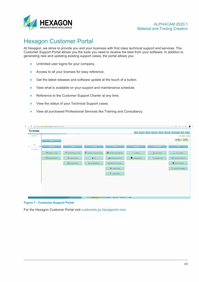
Hexagon Customer Portal At Hexagon, we strive to provide you and your business with first class technical support and services. The Customer Support Portal allows you the tools you need to receive the best from your software. In addition to generating new and updating existing support cases, the portal allows you:
• Unlimited user logins for your company.
• Access to all your licenses for easy reference.
• Get the latest releases and software update at the touch of a button.
• View what is available on your support and maintenance schedule.
• Reference to the Customer Support Charter at any time.
• View the status of your Technical Support cases.
• View all purchased Professional Services like Training and Consultancy.
Figure 1 - Customer Support Portal
For the Hexagon Customer Portal visit customers.ps.hexagonmi.com
ALPHACAM 2020.1 Material and Tooling Creation
viii
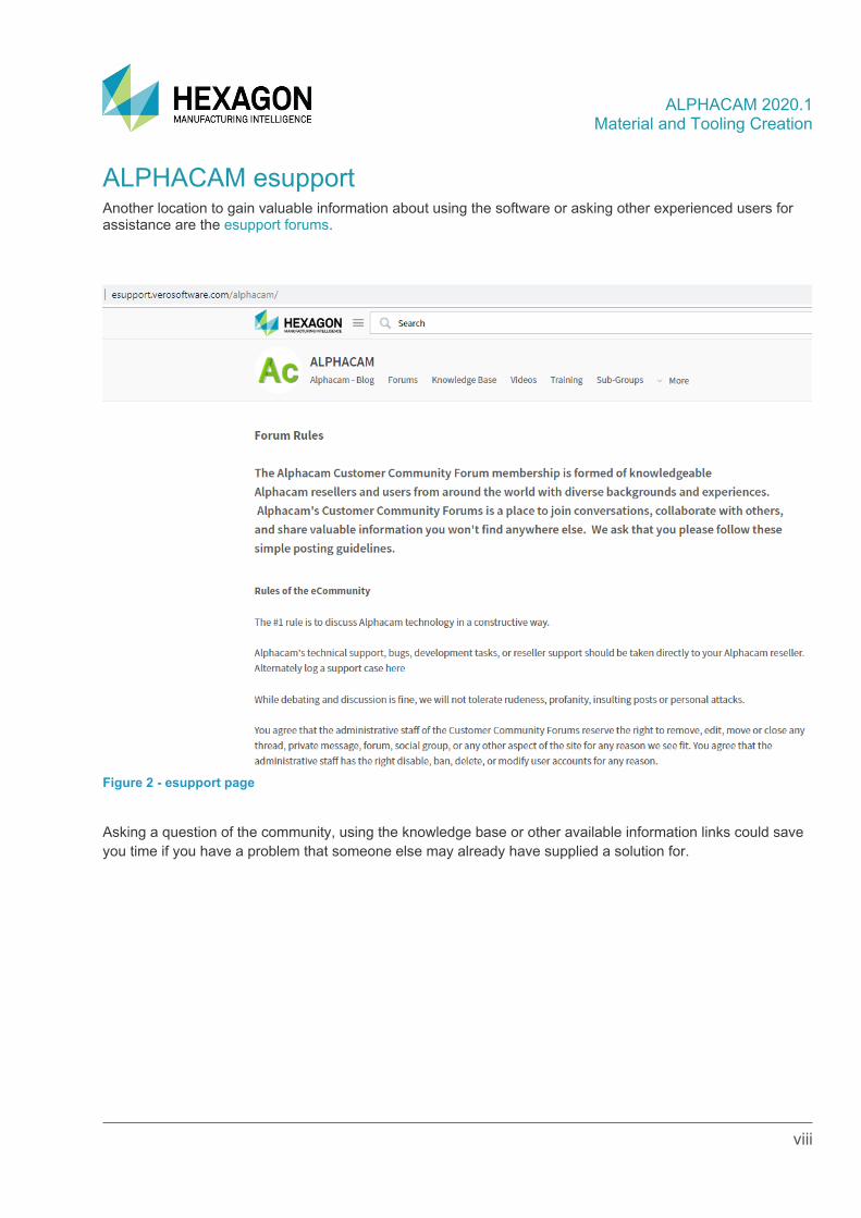
ALPHACAM esupport Another location to gain valuable information about using the software or asking other experienced users for assistance are the esupport forums.
Figure 2 - esupport page
Asking a question of the community, using the knowledge base or other available information links could save you time if you have a problem that someone else may already have supplied a solution for.
ALPHACAM 2020.1 Material and Tooling Creation
Material and Tooling Creation 1
MATERIAL FILE
General Overview The material file is used to store the surface cutting speed for any given cutting condition. Each module has a related Material File and these are in the LICOMDAT folder. The different material files are:
• Module File Name Cutting Speed Type
• Milling Mmat.dat Rotational Surface Speed of Tool
• Router Rmat.dat Rotational Surface Speed of Tool
• Lathe Tmat.dat Rotational Surface Speed of Part
• Wire Wmat.dat Linear Feed Rate Value
• Profile Lmat.dat Linear Feed Rate Value
• Stone Smat.dat Rotational Surface Speed of Tool
They are all basically the same format and each material definition consists of a minimum of 2 lines.
1. $ Unique Reference
2. Cutting Speed and Units
The first line is the unique reference which is displayed in the select a material dialogue. The reference line needs to start with $ and can be up to 60 characters long, only the first 48 characters are displayed, and must be unique to the file. It should be descriptive and include those items that influence a change in cutting speed, E.G. Part Material - Tool Material - Work Holding - Cutting Type etc. In the MMAT, RMAT & SMAT.dat files the cutting speed is the constant surface speed of the cutter expressed in either Ft/Min or M/Min. In the LMAT.dat file the cutting speed is the constant surface speed of the Part expressed in either Ft/Min or M/Min. In the LMAT and WMAT.dat files the cutting speed is the value of the linear feed rate, the units are not specified as the units are as in the job where it is being applied. Time spent on your CNC Machining Centre adjusting speeds and feeds will be minimised if you spend time correcting the m/min values. If you are hesitant about what values to use, then speak to your tooling representative, they will be able give you advice.
ALPHACAM 2020.1 Material and Tooling Creation
Material and Tooling Creation 2
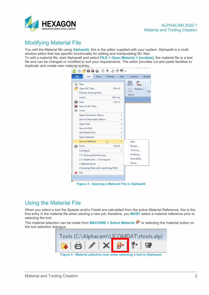
Modifying Material File You edit the Material file using Alphaedit, this is the editor supplied with your system. Alphaedit is a multi-window editor that has specific functionality for editing and manipulating NC files. To edit a material file, start Alphaedit and select FILE > Open Material > [module], the material file is a text file and can be changed or modified to suit your requirements. The editor provides cut and paste facilities to duplicate and create new material entries.
Figure 3 - Opening a Material File in Alphaedit
Using the Material File When you select a tool the Speeds and/or Feeds are calculated from the active Material Reference, this is the first entry in the material file when starting a new job; therefore, you MUST select a material reference prior to selecting the tool. The material selection can be made from MACHINE > Select Material or selecting the material button on the tool selection dialogue.
Figure 4 - Material selection icon when selecting a tool in Alphacam
ALPHACAM 2020.1 Material and Tooling Creation
Material and Tooling Creation 3
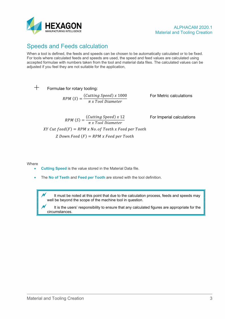
Speeds and Feeds calculation When a tool is defined, the feeds and speeds can be chosen to be automatically calculated or to be fixed. For tools where calculated feeds and speeds are used, the speed and feed values are calculated using accepted formulae with numbers taken from the tool and material data files. The calculated values can be adjusted if you feel they are not suitable for the application,
Formulae for rotary tooling:
𝑅𝑅𝑅𝑅𝑅𝑅 (𝑆𝑆) =(𝐶𝐶𝐶𝐶𝐶𝐶𝐶𝐶𝐶𝐶𝐶𝐶𝐶𝐶 𝑆𝑆𝑆𝑆𝑆𝑆𝑆𝑆𝑆𝑆) 𝑥𝑥 1000𝜋𝜋 𝑥𝑥 𝑇𝑇𝑇𝑇𝑇𝑇𝑇𝑇 𝐷𝐷𝐶𝐶𝐷𝐷𝐷𝐷𝑆𝑆𝐶𝐶𝑆𝑆𝐷𝐷
For Metric calculations
𝑅𝑅𝑅𝑅𝑅𝑅 (𝑆𝑆) =(𝐶𝐶𝐶𝐶𝐶𝐶𝐶𝐶𝐶𝐶𝐶𝐶𝐶𝐶 𝑆𝑆𝑆𝑆𝑆𝑆𝑆𝑆𝑆𝑆) 𝑥𝑥 12𝜋𝜋 𝑥𝑥 𝑇𝑇𝑇𝑇𝑇𝑇𝑇𝑇 𝐷𝐷𝐶𝐶𝐷𝐷𝐷𝐷𝑆𝑆𝐶𝐶𝑆𝑆𝐷𝐷
For Imperial calculations
𝑋𝑋𝑋𝑋 𝐶𝐶𝐶𝐶𝐶𝐶 𝑓𝑓𝑆𝑆𝑆𝑆𝑆𝑆(𝐹𝐹) = 𝑅𝑅𝑅𝑅𝑅𝑅 𝑥𝑥 𝑁𝑁𝑇𝑇. 𝑇𝑇𝑓𝑓 𝑇𝑇𝑆𝑆𝑆𝑆𝐶𝐶ℎ 𝑥𝑥 𝐹𝐹𝑆𝑆𝑆𝑆𝑆𝑆 𝑆𝑆𝑆𝑆𝐷𝐷 𝑇𝑇𝑇𝑇𝑇𝑇𝐶𝐶ℎ
𝑍𝑍 𝐷𝐷𝑇𝑇𝐷𝐷𝐶𝐶 𝐹𝐹𝑆𝑆𝑆𝑆𝑆𝑆 (𝐹𝐹) = 𝑅𝑅𝑅𝑅𝑅𝑅 𝑥𝑥 𝐹𝐹𝑆𝑆𝑆𝑆𝑆𝑆 𝑆𝑆𝑆𝑆𝐷𝐷 𝑇𝑇𝑇𝑇𝑇𝑇𝐶𝐶ℎ
Where
• Cutting Speed is the value stored in the Material Data file.
• The No of Teeth and Feed per Tooth are stored with the tool definition.
It must be noted at this point that due to the calculation process, feeds and speeds may well be beyond the scope of the machine tool in question.
It is the users’ responsibility to ensure that any calculated figures are appropriate for the circumstances.
ALPHACAM 2020.1 Material and Tooling Creation
Material and Tooling Creation 4
ROTATING TOOLS There are two categories of rotating tools;
Standard Tools These are tools that can be defined within the tool creation dialogue by completing the required form.
• Flat End cutters Straight or Tapered.
• Bull Nose cutters Straight, Tapered or Under Cut
• Ball End cutters Straight, Tapered or Lollipop
• Drills Twist, Lip & Spur or Core
• Taps.
• Saws/Disc.
User Defined Tools A user defined tool is any tool that does not conform to the above standard definitions. You must have a complete closed profile of the cross section of the tool visible in the drawing area of Alphacam prior to creating this form of tooling.
If you use differing types of User Defined tooling, it may prove easier to download the tooling cross section from the suppliers’ web site rather than draw complex gang or stack tooling yourself.
ALPHACAM 2020.1 Material and Tooling Creation
Material and Tooling Creation 5
Tool Definition The only difference in the definition between standard tools and user defined tools is that for User Defined tools you must select the tool cross section geometry on screen prior to the tool dialogue starting. If tool holder geometry is to be attached to the tool, it is necessary to have the holder geometry on screen and in the correct orientation prior to starting the tool definition as you will be required to select it as part of the tool definition process. Using Solid representations for the tool holder, these need to be on screen and in the correct orientation prior to the tool definition process commencing.
Not all modules of ALPHACAM support the different tool holder creation options.
Starting Tool Definition
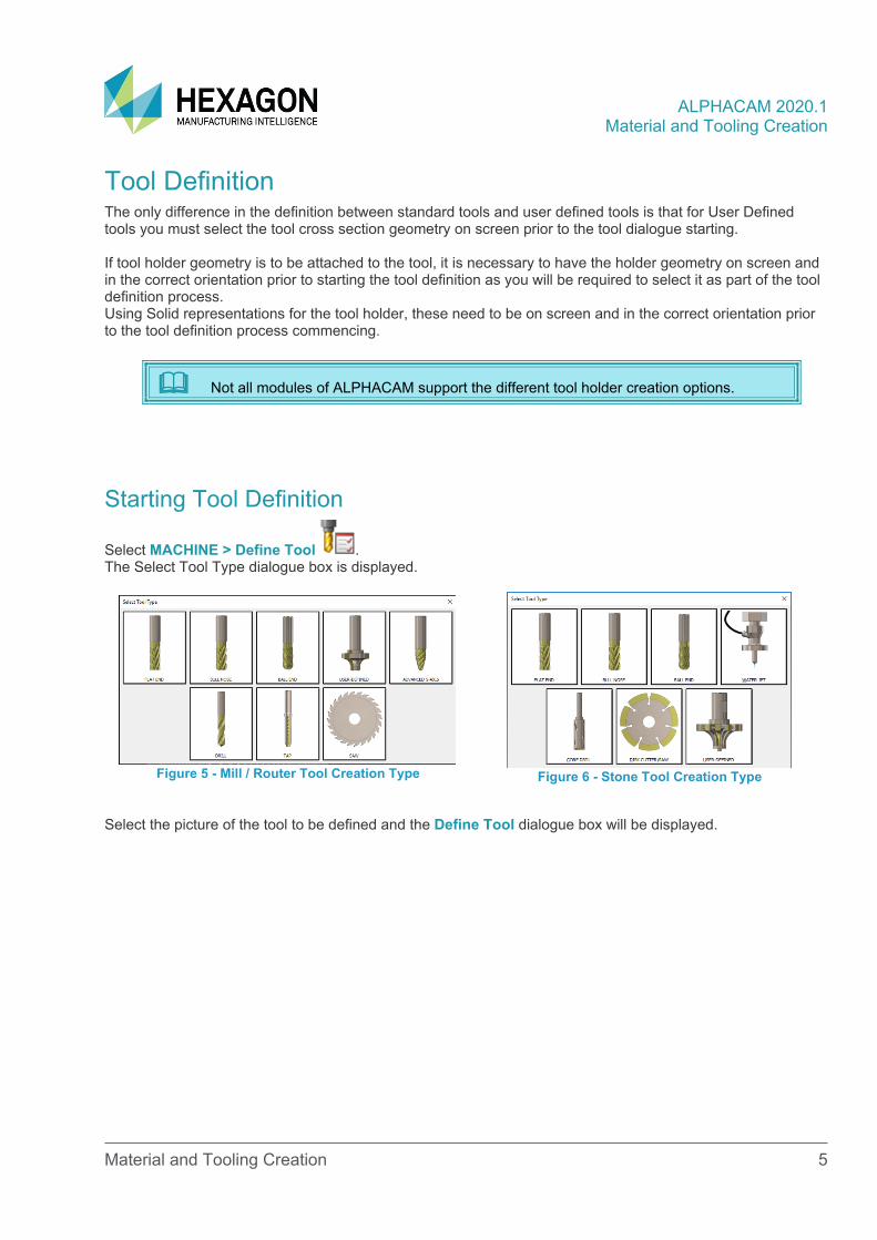
Select MACHINE > Define Tool . The Select Tool Type dialogue box is displayed.
Figure 5 - Mill / Router Tool Creation Type
Figure 6 - Stone Tool Creation Type
Select the picture of the tool to be defined and the Define Tool dialogue box will be displayed.
ALPHACAM 2020.1 Material and Tooling Creation
Material and Tooling Creation 6
Define Tool Dialogues
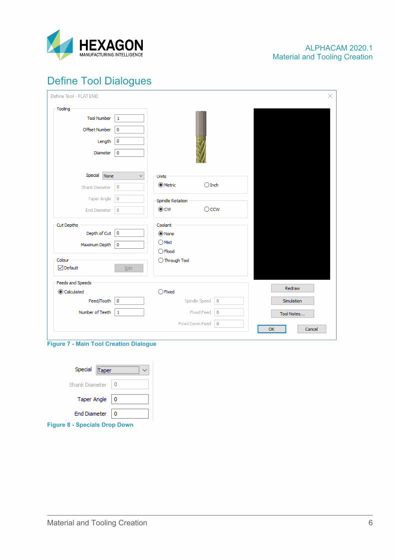
Figure 7 - Main Tool Creation Dialogue
Figure 8 - Specials Drop Down
ALPHACAM 2020.1 Material and Tooling Creation
Material and Tooling Creation 7
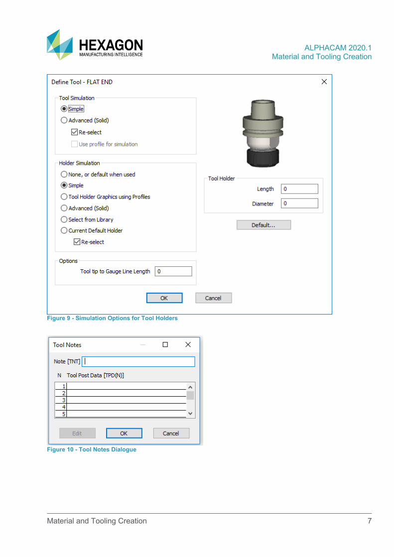
Figure 9 - Simulation Options for Tool Holders
Figure 10 - Tool Notes Dialogue
ALPHACAM 2020.1 Material and Tooling Creation
Material and Tooling Creation 8
Tooling parameters
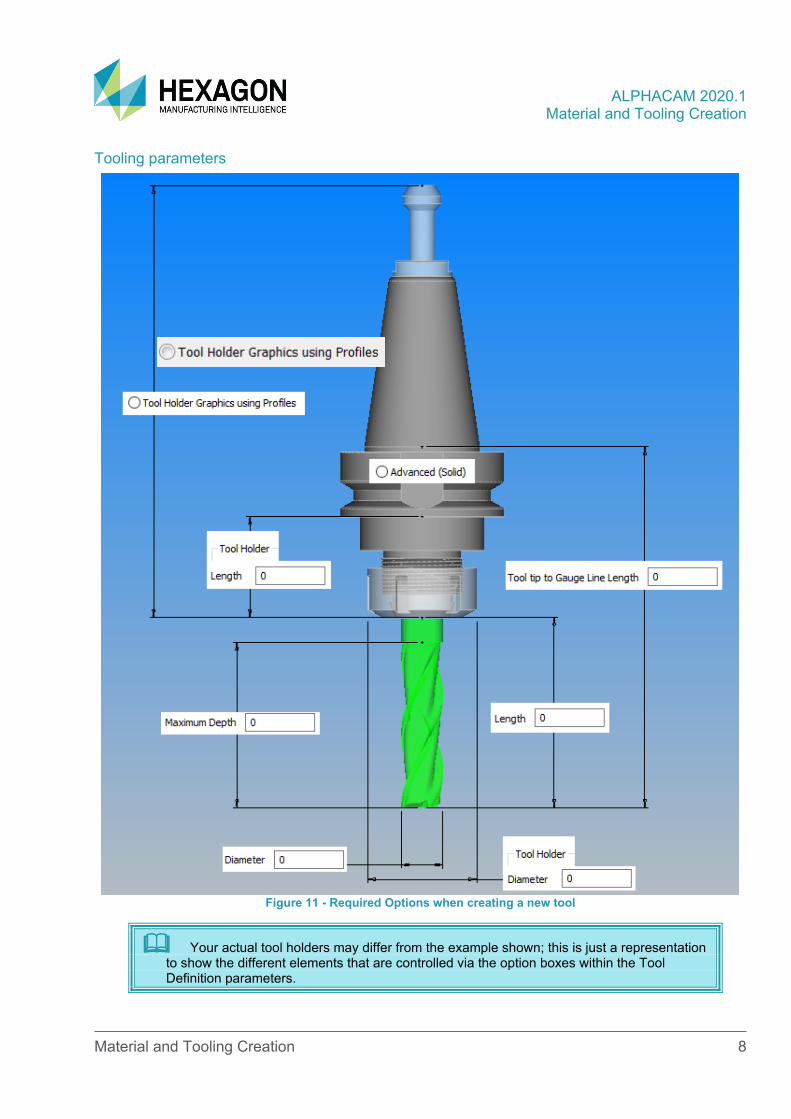
Figure 11 - Required Options when creating a new tool
Your actual tool holders may differ from the example shown; this is just a representation to show the different elements that are controlled via the option boxes within the Tool Definition parameters.
ALPHACAM 2020.1 Material and Tooling Creation
Material and Tooling Creation 9
Define Tool Dialogue Options
Tool Number This is the T number that will be output in the program. If you use standard tooling set-ups where tools have set positions in a carousel, then use the tools’ normal position number. If the tool position is not standard then a number greater than that allowed on the machine should be used, as it will require changing when the operation is processed. This also ensures that an incorrect tool is not selected if you forget to set the correct tool number.
In the case of SCM machines, this must match the tool number as defined in the machine tool table. i.e. T1 will be T101.
In the case of many Biesse machines, the tool number may not be used on router bits, it is the tool name. Usually the tool name is taken from the Tool Note value [TNT]; this should match that set on the machine.
Offset Number This is the number of the offset register assigned to the tool. If this field is left at 0 then the default will be the tool number (this is normal).
Length This option specifies the length of the tool that extends below the tool holder. The tool length is NOT used in any automatic checking it is used for visual checking during simulation.
Diameter This is the nominal cutting diameter of the tool.
Corner Radius This is the corner radius on the Bull Nose tools.
Cone Angle The Cone Angle is the included angle at the tip of a Drill. Ie.118° or 120°, for twist drills, 180° for Lip & Spur, Flat ended Drills (C/Bores) and 60° for glass drills.
ALPHACAM 2020.1 Material and Tooling Creation
Material and Tooling Creation 10
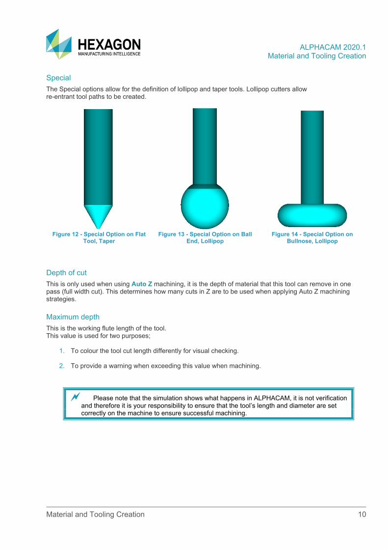
Special The Special options allow for the definition of lollipop and taper tools. Lollipop cutters allow re-entrant tool paths to be created.
Figure 12 - Special Option on Flat
Tool, Taper Figure 13 - Special Option on Ball
End, Lollipop Figure 14 - Special Option on
Bullnose, Lollipop
Depth of cut This is only used when using Auto Z machining, it is the depth of material that this tool can remove in one pass (full width cut). This determines how many cuts in Z are to be used when applying Auto Z machining strategies.
Maximum depth This is the working flute length of the tool. This value is used for two purposes;
1. To colour the tool cut length differently for visual checking.
2. To provide a warning when exceeding this value when machining.
Please note that the simulation shows what happens in ALPHACAM, it is not verification and therefore it is your responsibility to ensure that the tool’s length and diameter are set correctly on the machine to ensure successful machining.
ALPHACAM 2020.1 Material and Tooling Creation
Material and Tooling Creation 11
Feeds and Speeds This section allows you to control the feeds and speed values that are output in the program, there are two options Calculated and Fixed.
Calculated This calculates the spindle RPM using the cutting rate from the current material setting and tool diameter.
• Feed/Tooth - This is the amount of material removed by each tooth per revolution of the cutter.
• Number of Teeth - This specifies the number of cutting edges for XY motion it is assumed that there is only one cutting edge in Z (the one that crosses the centre line).
These values are used with the spindle speed to calculate the linear feed rate.
Fixed These values are directly output on the NC-code
• Spindle Speed - is the RPM to be used.
• Fixed Feed - is the linear feed rate used when the tool is cutting the material expressed in mm per min.
• Fixed Down Feed - is the linear feed rate used when the tool is feeding into the material in Z expressed in mm per min.
If the machine uses Meters per min the post will adjust the values to suit.
ALPHACAM 2020.1 Material and Tooling Creation
Material and Tooling Creation 12
Simulation This option allows the choice between two differing Tool simulation options and six different tool holder options which will give a graphical representation of the tool and holder during any simulation run.
For Tooling options;
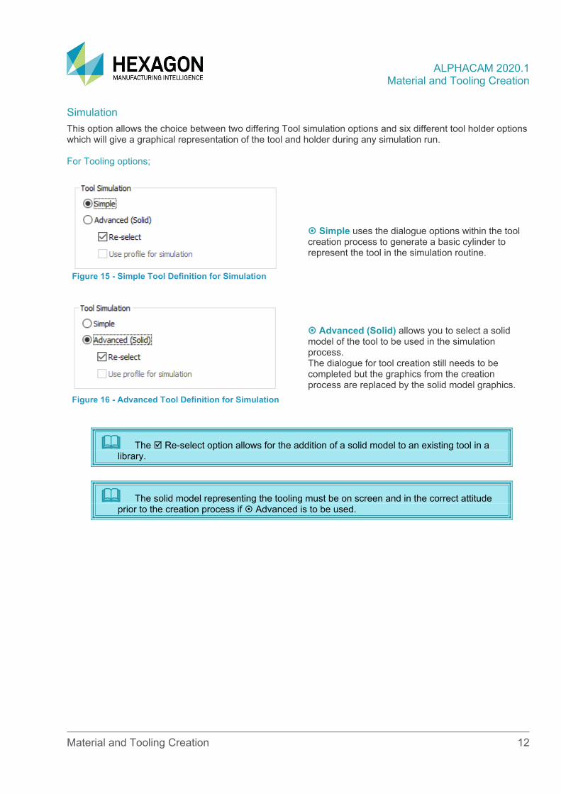
Figure 15 - Simple Tool Definition for Simulation
Simple uses the dialogue options within the tool creation process to generate a basic cylinder to represent the tool in the simulation routine.
Figure 16 - Advanced Tool Definition for Simulation
Advanced (Solid) allows you to select a solid model of the tool to be used in the simulation process. The dialogue for tool creation still needs to be completed but the graphics from the creation process are replaced by the solid model graphics.
The Re-select option allows for the addition of a solid model to an existing tool in a library.
The solid model representing the tooling must be on screen and in the correct attitude prior to the creation process if Advanced is to be used.
ALPHACAM 2020.1 Material and Tooling Creation
Material and Tooling Creation 13
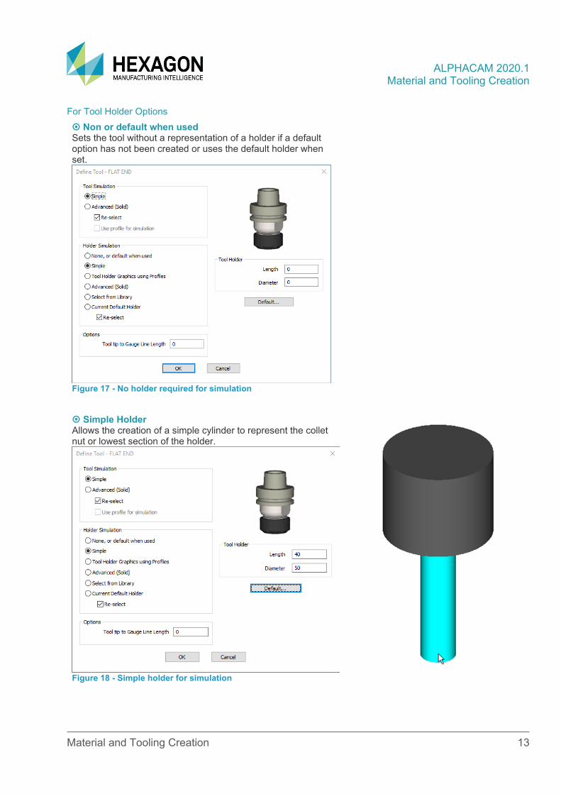
For Tool Holder Options Non or default when used Sets the tool without a representation of a holder if a default option has not been created or uses the default holder when set.
Figure 17 - No holder required for simulation
Simple Holder
Allows the creation of a simple cylinder to represent the collet nut or lowest section of the holder.
Figure 18 - Simple holder for simulation
ALPHACAM 2020.1 Material and Tooling Creation
Material and Tooling Creation 14
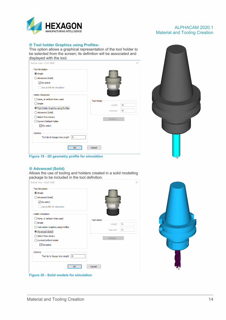
Tool holder Graphics using Profiles-
This option allows a graphical representation of the tool holder to be selected from the screen; its definition will be associated and displayed with the tool.
Figure 19 - 2D geometry profile for simulation
Advanced (Solid) Allows the use of tooling and holders created in a solid modelling package to be included in the tool definition.
Figure 20 - Solid models for simulation
ALPHACAM 2020.1 Material and Tooling Creation
Material and Tooling Creation 15
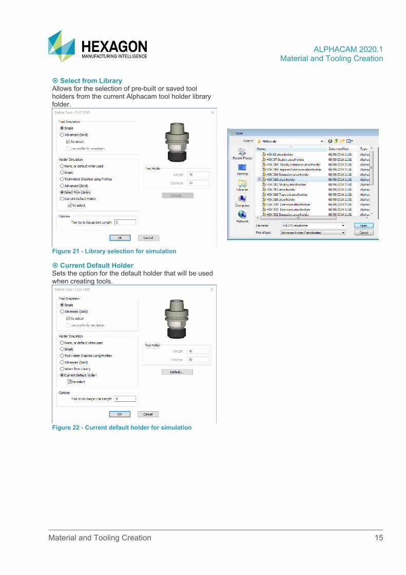
Select from Library
Allows for the selection of pre-built or saved tool holders from the current Alphacam tool holder library folder.
Figure 21 - Library selection for simulation
Current Default Holder Sets the option for the default holder that will be used when creating tools.
Figure 22 - Current default holder for simulation
ALPHACAM 2020.1 Material and Tooling Creation
Material and Tooling Creation 16
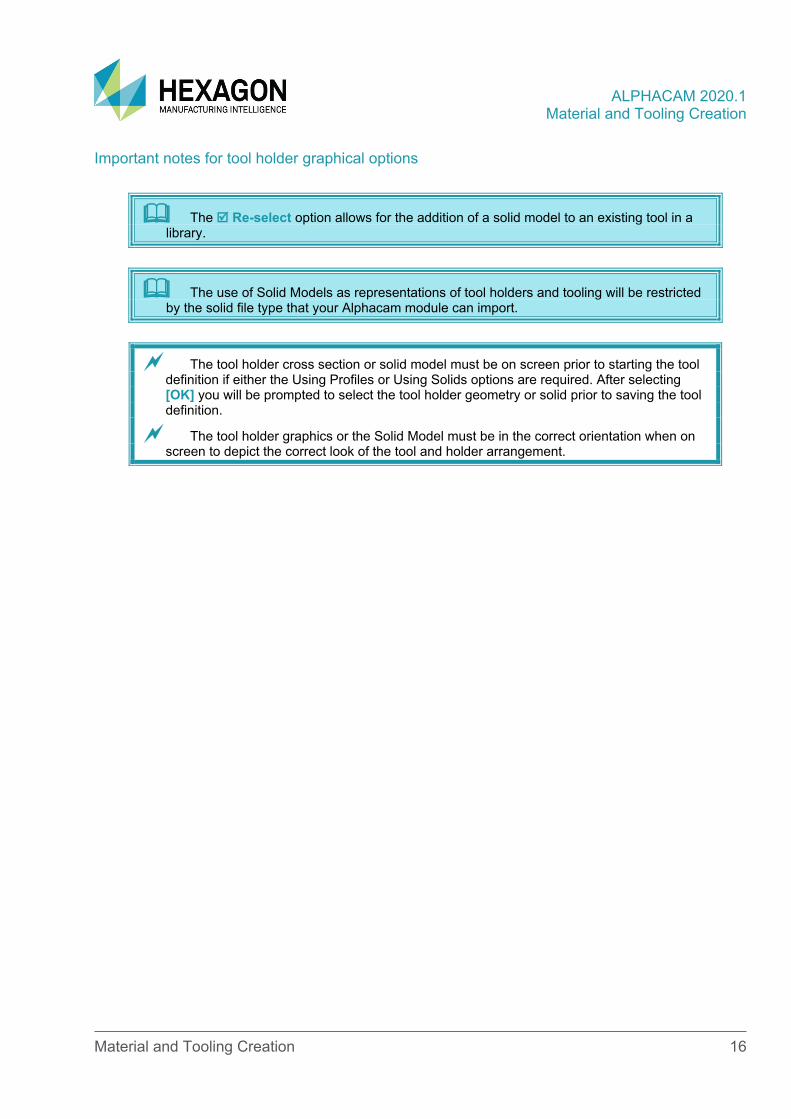
Important notes for tool holder graphical options
The Re-select option allows for the addition of a solid model to an existing tool in a library.
The use of Solid Models as representations of tool holders and tooling will be restricted by the solid file type that your Alphacam module can import.
The tool holder cross section or solid model must be on screen prior to starting the tool definition if either the Using Profiles or Using Solids options are required. After selecting [OK] you will be prompted to select the tool holder geometry or solid prior to saving the tool definition.
The tool holder graphics or the Solid Model must be in the correct orientation when on screen to depict the correct look of the tool and holder arrangement.
ALPHACAM 2020.1 Material and Tooling Creation
Material and Tooling Creation 17
Tool Notes This button activates the tool notes dialogue box.
• Note [TNT] - This is a note that is output in the operations list and as a comment where the tool is loaded in the program. This can be left blank if required.
Some machine post processors require the tool note name in the tool call command for the program, so it may be a requirement to have a value entered in some instances.
• N Tool Post Data [TPD(N)] - This is data array of 100 variables that can be utilised by the post processor to access specific tooling related variables that are not normally available. Your engineer will inform you if the use of TPD is required and what variables are required.
Units This specifies the units of the values used in the tool definition.
Metric Drawing, Metric Tooling definition together with a Metric Post Processor = Metric output code.
Imperial Drawing, Imperial Tooling definition together with an Imperial Post Processor = Imperial output code.
Spindle Rotation This specifies the cutting rotation for the tool. Normal tools cut with the spindle running in a Clockwise direction. Left-handed tools cut with the spindle running in a counter clockwise direct.
The spindle rotation direction is set so that the tool will spin in the correct cutting direction to allow it to function. For example, if an aggregate or angled head is being used, the spindle rotation may be in reverse so that the actual tool rotates correctly.
Coolant This section allows you to pre-set the coolant to be used with this tool. The option can be altered at the point of use if required.
Saving the tool When the [OK] button is selected, the system will prompt you to select the tool holder geometry if this option has been selected, the Save dialogue box will be displayed. The save dialogue allows you to save the tool definition file using a filename of your choice, a tool naming and library convention should be established to make the tool selection as simple as possible.
ALPHACAM 2020.1 Material and Tooling Creation
Material and Tooling Creation 18
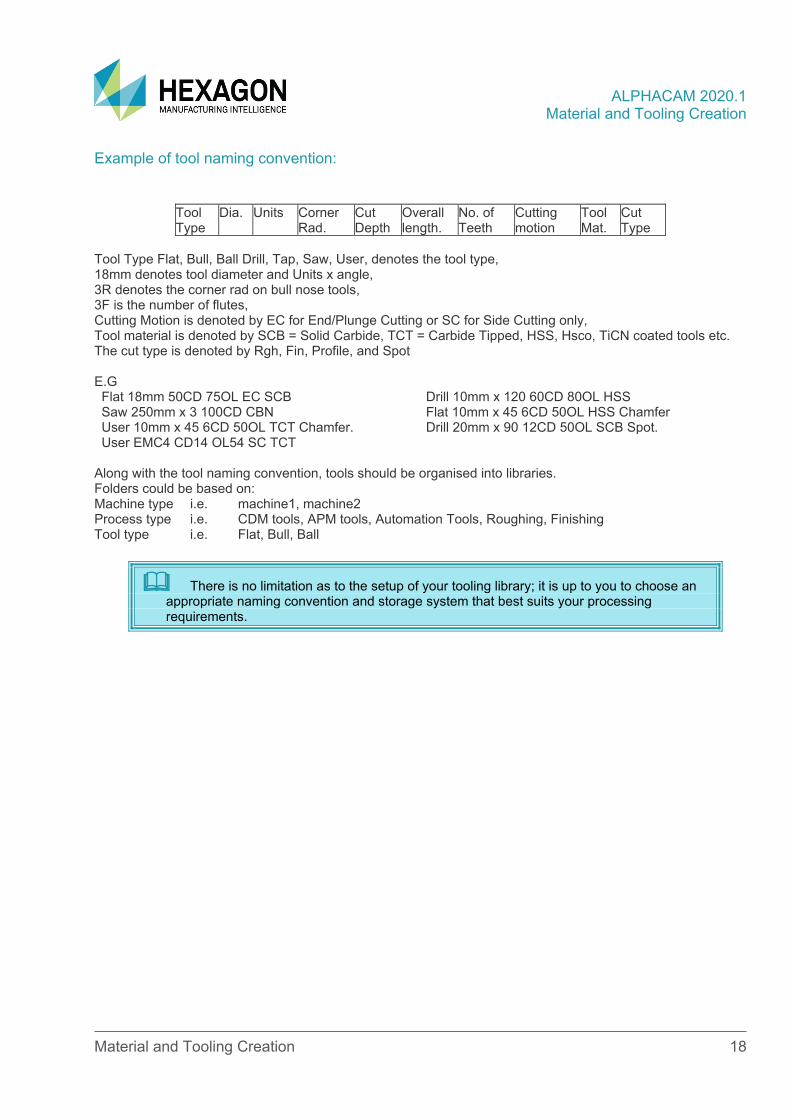
Example of tool naming convention:
Tool Type
Dia. Units Corner Rad.
Cut Depth
Overall length.
No. of Teeth
Cutting motion
Tool Mat.
Cut Type
Tool Type Flat, Bull, Ball Drill, Tap, Saw, User, denotes the tool type, 18mm denotes tool diameter and Units x angle, 3R denotes the corner rad on bull nose tools, 3F is the number of flutes, Cutting Motion is denoted by EC for End/Plunge Cutting or SC for Side Cutting only, Tool material is denoted by SCB = Solid Carbide, TCT = Carbide Tipped, HSS, Hsco, TiCN coated tools etc. The cut type is denoted by Rgh, Fin, Profile, and Spot E.G Flat 18mm 50CD 75OL EC SCB Drill 10mm x 120 60CD 80OL HSS Saw 250mm x 3 100CD CBN Flat 10mm x 45 6CD 50OL HSS Chamfer User 10mm x 45 6CD 50OL TCT Chamfer. Drill 20mm x 90 12CD 50OL SCB Spot. User EMC4 CD14 OL54 SC TCT
Along with the tool naming convention, tools should be organised into libraries. Folders could be based on: Machine type i.e. machine1, machine2 Process type i.e. CDM tools, APM tools, Automation Tools, Roughing, Finishing Tool type i.e. Flat, Bull, Ball
There is no limitation as to the setup of your tooling library; it is up to you to choose an appropriate naming convention and storage system that best suits your processing requirements.
ALPHACAM 2020.1 Material and Tooling Creation
Material and Tooling Creation 19
Tool Definition Tutorials
Training Tool Definitions
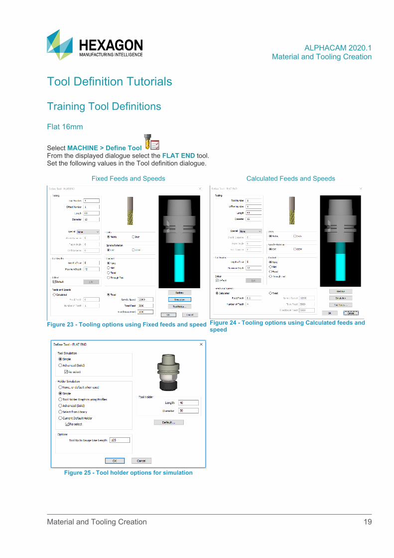
Flat 16mm
Select MACHINE > Define Tool From the displayed dialogue select the FLAT END tool. Set the following values in the Tool definition dialogue.
Fixed Feeds and Speeds Calculated Feeds and Speeds
Figure 23 - Tooling options using Fixed feeds and speed
Figure 24 - Tooling options using Calculated feeds and speed
Figure 25 - Tool holder options for simulation
ALPHACAM 2020.1 Material and Tooling Creation
Material and Tooling Creation 20
Select [OK] from the Tool holder dialogue, then [OK] from the Tool Definition dialogue. Navigate to the training tool library, and save the tool under a suitable name E.g. 16mm Flat Also, create the following tools using depths, feeds and speed, and coolant options that are appropriate for your working environment. Name them with suitable options that will allow you to easily identify them when required.
• 8mm Flat.
• 6mm Twist Drill.
• 15mm x 120° Chamfer Drill.
• 8mm twist Drill.
• 12mm x 30° engraver.
• 10mm x 45° chamfer cutter.
• R2 corner rounding.
ALPHACAM 2020.1 Material and Tooling Creation
Material and Tooling Creation 21
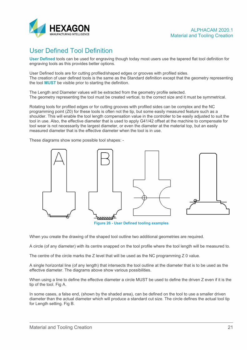
User Defined Tool Definition User Defined tools can be used for engraving though today most users use the tapered flat tool definition for engraving tools as this provides better options. User Defined tools are for cutting profiled/shaped edges or grooves with profiled sides. The creation of user defined tools is the same as the Standard definition except that the geometry representing the tool MUST be visible prior to starting the definition. The Length and Diameter values will be extracted from the geometry profile selected. The geometry representing the tool must be created vertical, to the correct size and it must be symmetrical. Rotating tools for profiled edges or for cutting grooves with profiled sides can be complex and the NC programming point (Z0) for these tools is often not the tip, but some easily measured feature such as a shoulder. This will enable the tool length compensation value in the controller to be easily adjusted to suit the tool in use. Also, the effective diameter that is used to apply G41/42 offset at the machine to compensate for tool wear is not necessarily the largest diameter, or even the diameter at the material top, but an easily measured diameter that is the effective diameter when the tool is in use. These diagrams show some possible tool shapes: -
Figure 26 - User Defined tooling examples
When you create the drawing of the shaped tool outline two additional geometries are required. A circle (of any diameter) with its centre snapped on the tool profile where the tool length will be measured to. The centre of the circle marks the Z level that will be used as the NC programming Z 0 value. A single horizontal line (of any length) that intersects the tool outline at the diameter that is to be used as the effective diameter. The diagrams above show various possibilities. When using a line to define the effective diameter a circle MUST be used to define the driven Z even if it is the tip of the tool. Fig A. In some cases, a false end, (shown by the shaded area), can be defined on the tool to use a smaller driven diameter than the actual diameter which will produce a standard cut size. The circle defines the actual tool tip for Length setting. Fig B.
ALPHACAM 2020.1 Material and Tooling Creation
Material and Tooling Creation 22
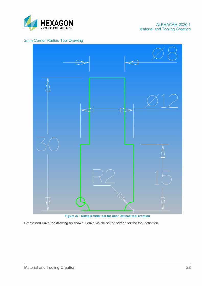
2mm Corner Radius Tool Drawing
Figure 27 - Sample form tool for User Defined tool creation
Create and Save the drawing as shown. Leave visible on the screen for the tool definition.
ALPHACAM 2020.1 Material and Tooling Creation
Material and Tooling Creation 23
2mm Corner Radius Tool Definition
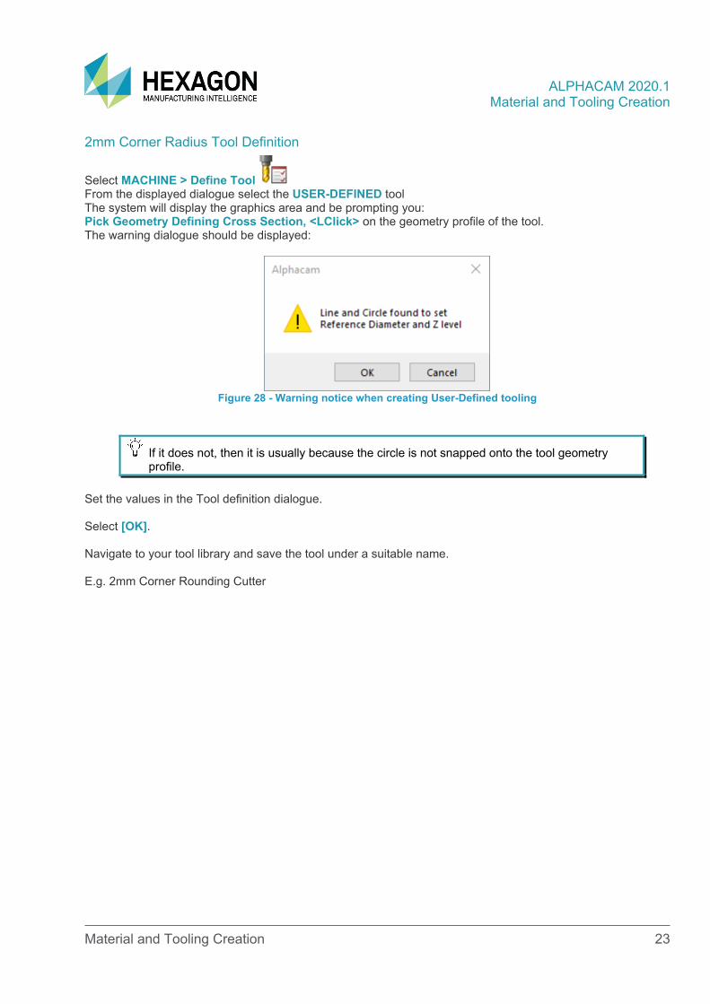
Select MACHINE > Define Tool From the displayed dialogue select the USER-DEFINED tool The system will display the graphics area and be prompting you: Pick Geometry Defining Cross Section, <LClick> on the geometry profile of the tool. The warning dialogue should be displayed:
Figure 28 - Warning notice when creating User-Defined tooling
If it does not, then it is usually because the circle is not snapped onto the tool geometry profile.
Set the values in the Tool definition dialogue. Select [OK]. Navigate to your tool library and save the tool under a suitable name. E.g. 2mm Corner Rounding Cutter
ALPHACAM 2020.1 Material and Tooling Creation
Material and Tooling Creation 24
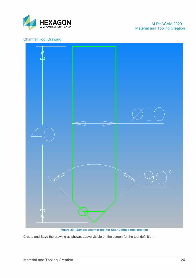
Chamfer Tool Drawing
Figure 29 - Sample chamfer tool for User Defined tool creation
Create and Save the drawing as shown. Leave visible on the screen for the tool definition.
ALPHACAM 2020.1 Material and Tooling Creation
Material and Tooling Creation 25
Chamfer Tool Definition
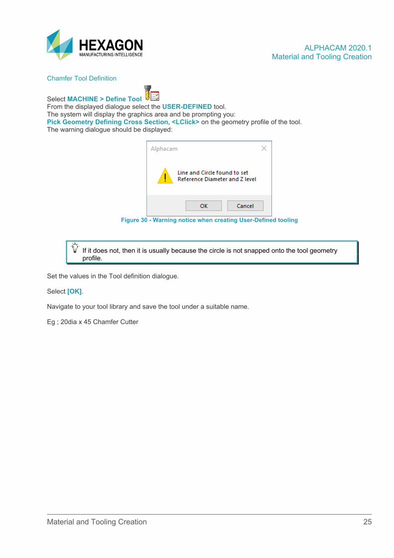
Select MACHINE > Define Tool From the displayed dialogue select the USER-DEFINED tool. The system will display the graphics area and be prompting you: Pick Geometry Defining Cross Section, <LClick> on the geometry profile of the tool. The warning dialogue should be displayed:
Figure 30 - Warning notice when creating User-Defined tooling
If it does not, then it is usually because the circle is not snapped onto the tool geometry profile.
Set the values in the Tool definition dialogue. Select [OK]. Navigate to your tool library and save the tool under a suitable name. Eg ; 20dia x 45 Chamfer Cutter
ALPHACAM 2020.1 Material and Tooling Creation
Material and Tooling Creation 26
Tool Holder Tutorials The process for creating a tool holder for the simulation is almost identical to the requirements for creating representations of the tools themselves. There needs to be either of the following items on screen prior to commencing the dialogue;
• A 2D geometric profile of the tool holder, in the correct attitude as it would appear on the actual machine.
• A 3D solid model representation of the tool holder, in the correct attitude as it would appear on the actual machine.
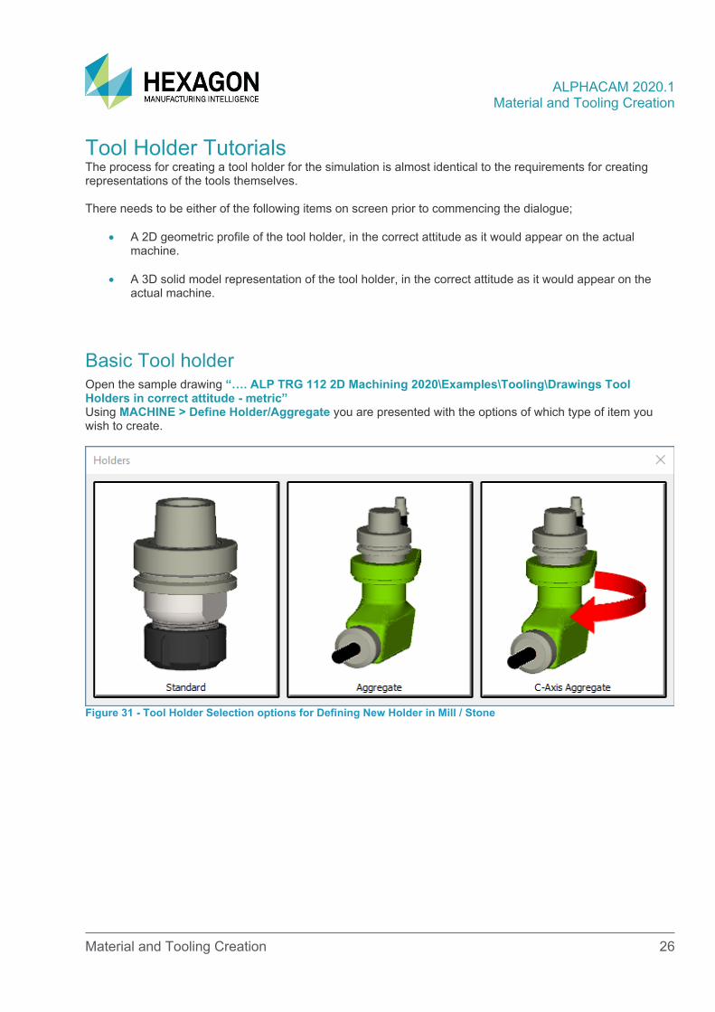
Basic Tool holder Open the sample drawing “…. ALP TRG 112 2D Machining 2020\Examples\Tooling\Drawings Tool Holders in correct attitude - metric” Using MACHINE > Define Holder/Aggregate you are presented with the options of which type of item you wish to create.
Figure 31 - Tool Holder Selection options for Defining New Holder in Mill / Stone
ALPHACAM 2020.1 Material and Tooling Creation
Material and Tooling Creation 27
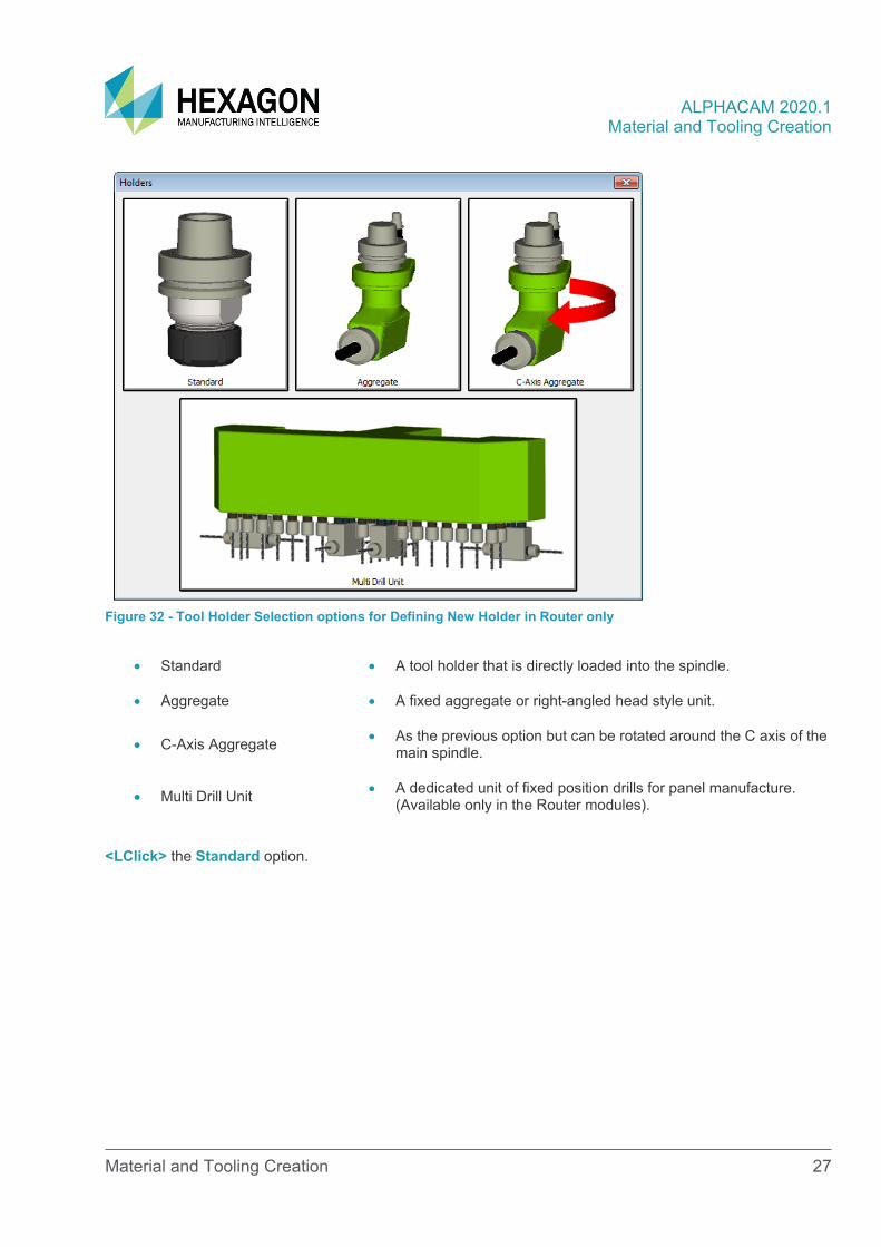
Figure 32 - Tool Holder Selection options for Defining New Holder in Router only
• Standard • A tool holder that is directly loaded into the spindle.
• Aggregate • A fixed aggregate or right-angled head style unit.
• C-Axis Aggregate • As the previous option but can be rotated around the C axis of the main spindle.
• Multi Drill Unit • A dedicated unit of fixed position drills for panel manufacture. (Available only in the Router modules).
<LClick> the Standard option.
ALPHACAM 2020.1 Material and Tooling Creation
Material and Tooling Creation 28
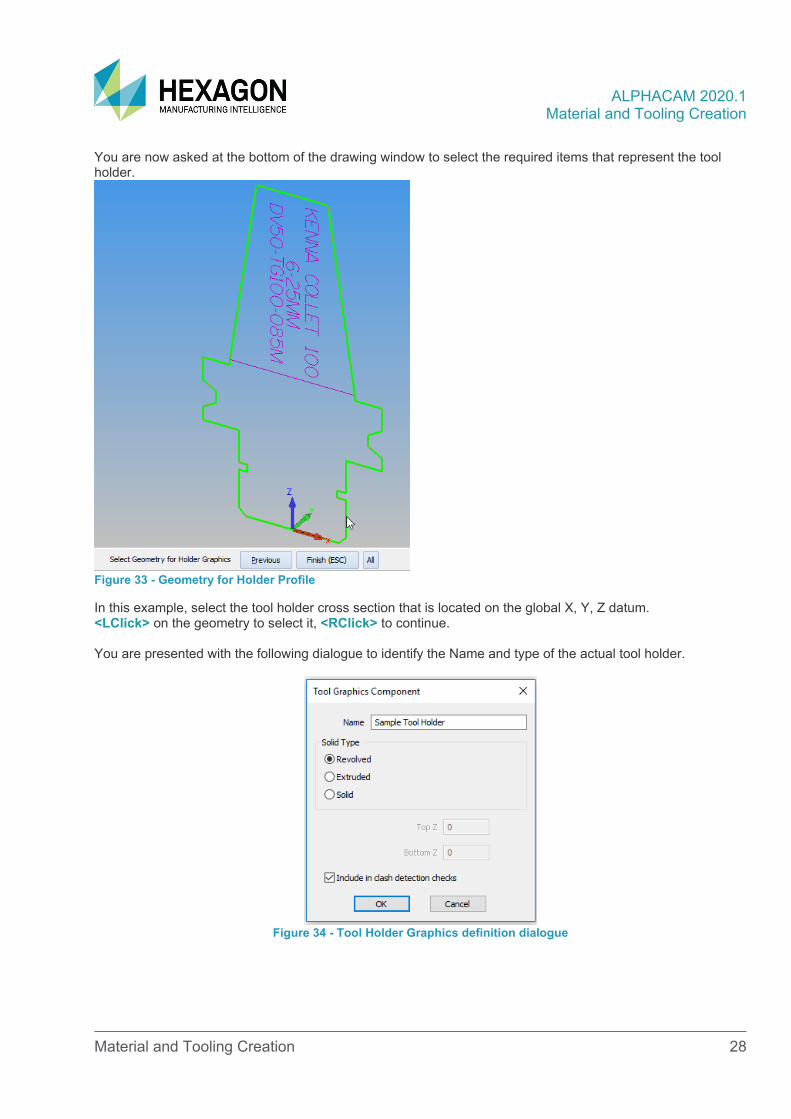
You are now asked at the bottom of the drawing window to select the required items that represent the tool holder.
Figure 33 - Geometry for Holder Profile
In this example, select the tool holder cross section that is located on the global X, Y, Z datum. <LClick> on the geometry to select it, <RClick> to continue. You are presented with the following dialogue to identify the Name and type of the actual tool holder.
Figure 34 - Tool Holder Graphics definition dialogue
ALPHACAM 2020.1 Material and Tooling Creation
Material and Tooling Creation 29
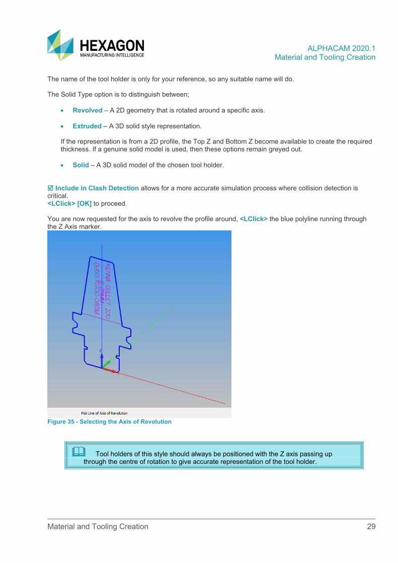
The name of the tool holder is only for your reference, so any suitable name will do. The Solid Type option is to distinguish between;
• Revolved – A 2D geometry that is rotated around a specific axis.
• Extruded – A 3D solid style representation.
If the representation is from a 2D profile, the Top Z and Bottom Z become available to create the required thickness. If a genuine solid model is used, then these options remain greyed out.
• Solid – A 3D solid model of the chosen tool holder.
Include in Clash Detection allows for a more accurate simulation process where collision detection is critical. <LClick> [OK] to proceed. You are now requested for the axis to revolve the profile around, <LClick> the blue polyline running through the Z Axis marker.
Figure 35 - Selecting the Axis of Revolution
Tool holders of this style should always be positioned with the Z axis passing up through the centre of rotation to give accurate representation of the tool holder.
ALPHACAM 2020.1 Material and Tooling Creation
Material and Tooling Creation 30
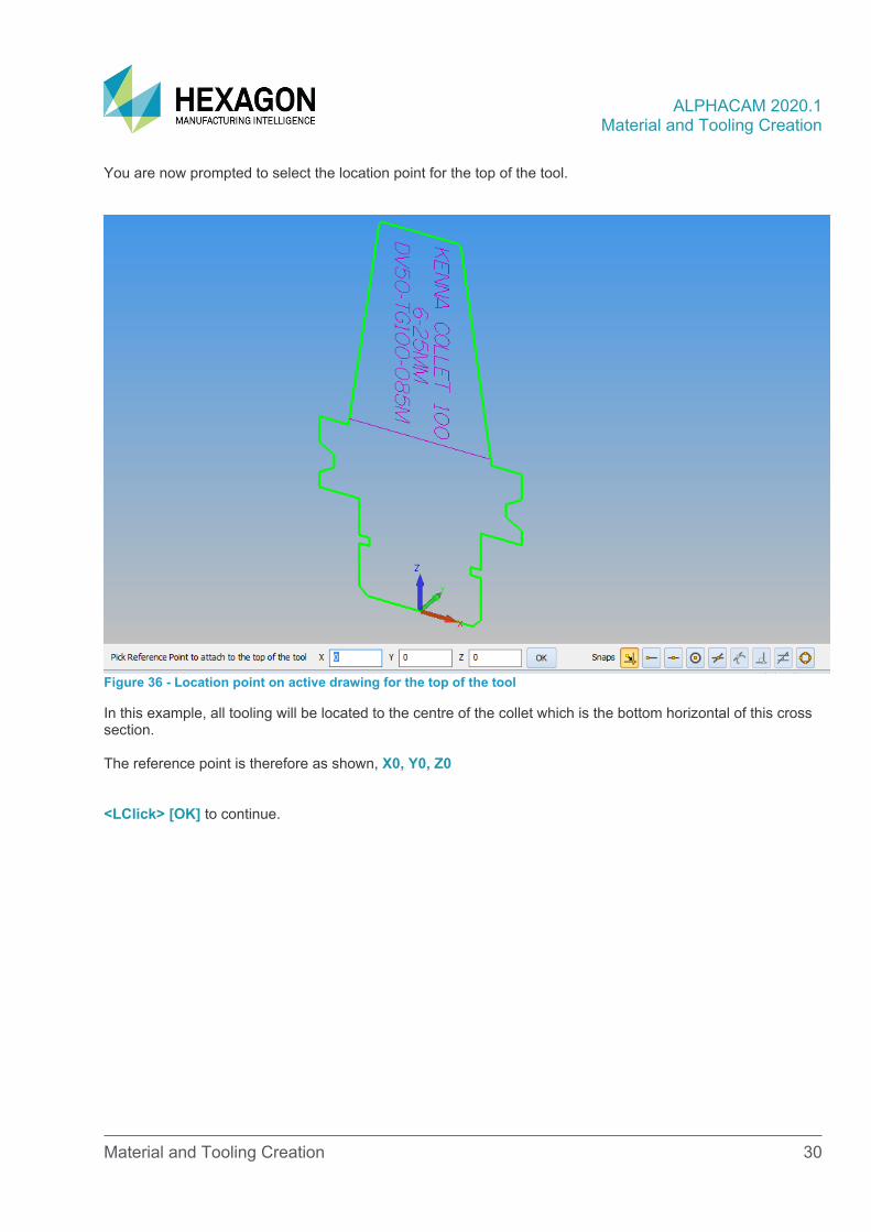
You are now prompted to select the location point for the top of the tool.
Figure 36 - Location point on active drawing for the top of the tool
In this example, all tooling will be located to the centre of the collet which is the bottom horizontal of this cross section.
The reference point is therefore as shown, X0, Y0, Z0
<LClick> [OK] to continue.
ALPHACAM 2020.1 Material and Tooling Creation
Material and Tooling Creation 31
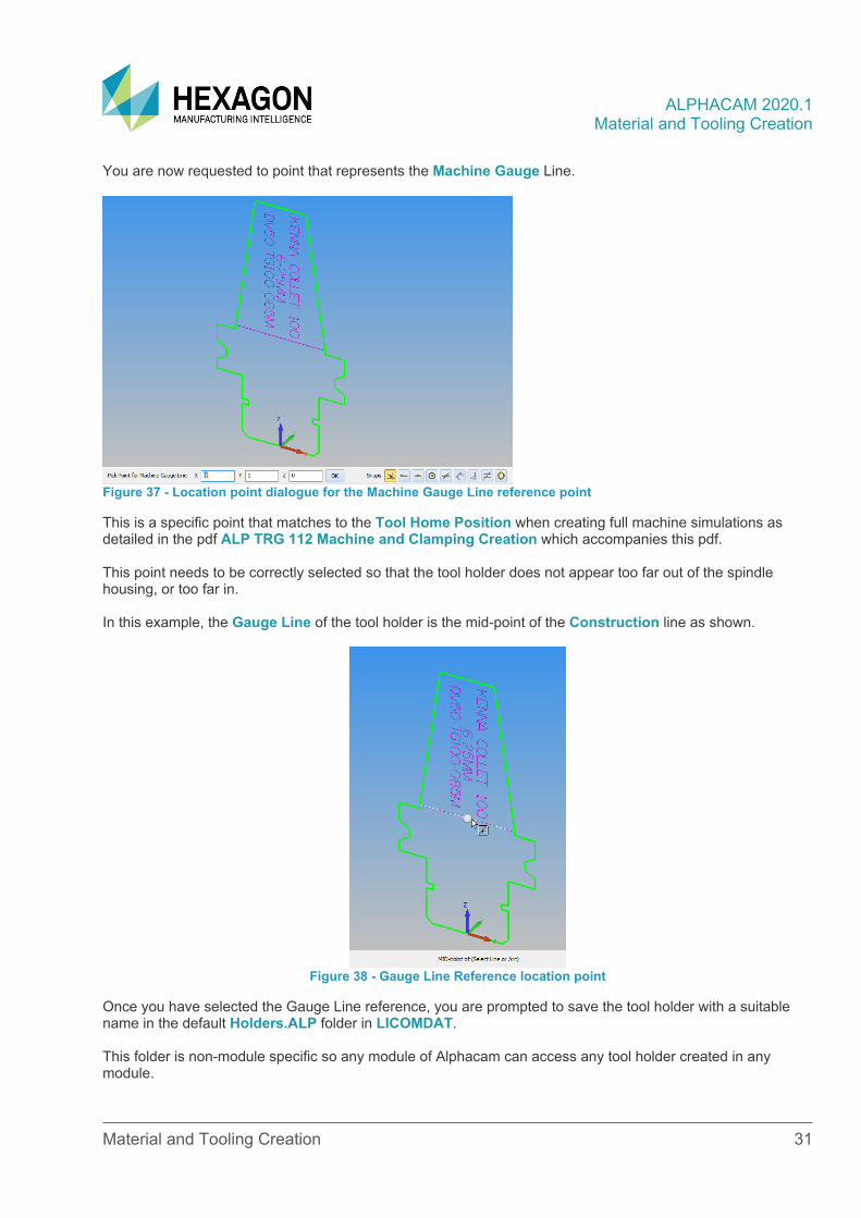
You are now requested to point that represents the Machine Gauge Line.
Figure 37 - Location point dialogue for the Machine Gauge Line reference point
This is a specific point that matches to the Tool Home Position when creating full machine simulations as detailed in the pdf ALP TRG 112 Machine and Clamping Creation which accompanies this pdf.
This point needs to be correctly selected so that the tool holder does not appear too far out of the spindle housing, or too far in.
In this example, the Gauge Line of the tool holder is the mid-point of the Construction line as shown.
Figure 38 - Gauge Line Reference location point
Once you have selected the Gauge Line reference, you are prompted to save the tool holder with a suitable name in the default Holders.ALP folder in LICOMDAT.
This folder is non-module specific so any module of Alphacam can access any tool holder created in any module.
ALPHACAM 2020.1 Material and Tooling Creation
Material and Tooling Creation 32
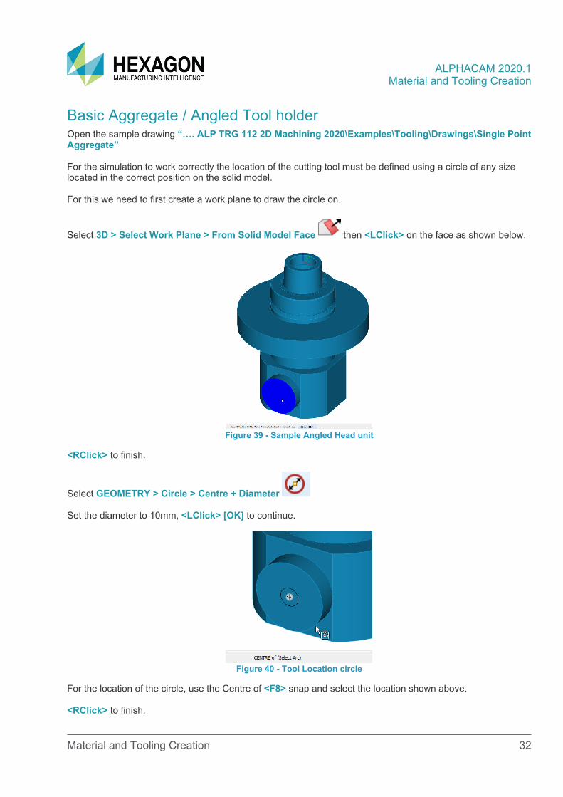
Basic Aggregate / Angled Tool holder Open the sample drawing “…. ALP TRG 112 2D Machining 2020\Examples\Tooling\Drawings\Single Point Aggregate”
For the simulation to work correctly the location of the cutting tool must be defined using a circle of any size located in the correct position on the solid model.
For this we need to first create a work plane to draw the circle on.
Select 3D > Select Work Plane > From Solid Model Face then <LClick> on the face as shown below.
Figure 39 - Sample Angled Head unit
<RClick> to finish.
Select GEOMETRY > Circle > Centre + Diameter
Set the diameter to 10mm, <LClick> [OK] to continue.
Figure 40 - Tool Location circle
For the location of the circle, use the Centre of <F8> snap and select the location shown above.
<RClick> to finish.
ALPHACAM 2020.1 Material and Tooling Creation
Material and Tooling Creation 33
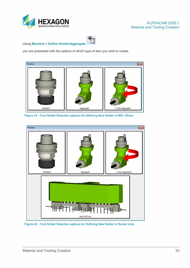
Using Machine > Define Holder/Aggregate
you are presented with the options of which type of item you wish to create.
Figure 41 - Tool Holder Selection options for Defining New Holder in Mill / Stone
Figure 42 - Tool Holder Selection options for Defining New Holder in Router only
ALPHACAM 2020.1 Material and Tooling Creation
Material and Tooling Creation 34
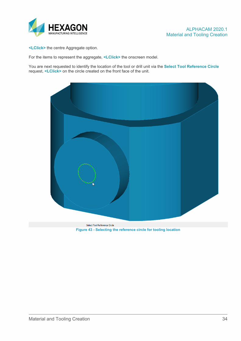
<LClick> the centre Aggregate option.
For the items to represent the aggregate, <LClick> the onscreen model.
You are next requested to identify the location of the tool or drill unit via the Select Tool Reference Circle request, <LClick> on the circle created on the front face of the unit.
Figure 43 - Selecting the reference circle for tooling location
ALPHACAM 2020.1 Material and Tooling Creation
Material and Tooling Creation 35
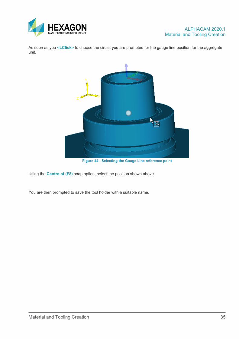
As soon as you <LClick> to choose the circle, you are prompted for the gauge line position for the aggregate unit.
Figure 44 - Selecting the Gauge Line reference point
Using the Centre of (F8) snap option, select the position shown above.
You are then prompted to save the tool holder with a suitable name.
ALPHACAM 2020.1 Material and Tooling Creation
Material and Tooling Creation 36
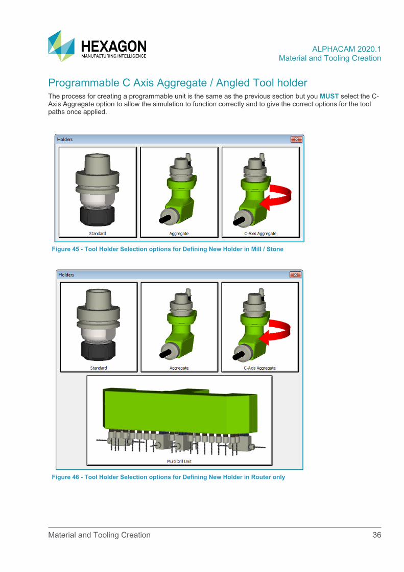
Programmable C Axis Aggregate / Angled Tool holder The process for creating a programmable unit is the same as the previous section but you MUST select the C-Axis Aggregate option to allow the simulation to function correctly and to give the correct options for the tool paths once applied.
Figure 45 - Tool Holder Selection options for Defining New Holder in Mill / Stone
Figure 46 - Tool Holder Selection options for Defining New Holder in Router only
ALPHACAM 2020.1 Material and Tooling Creation
Material and Tooling Creation 37
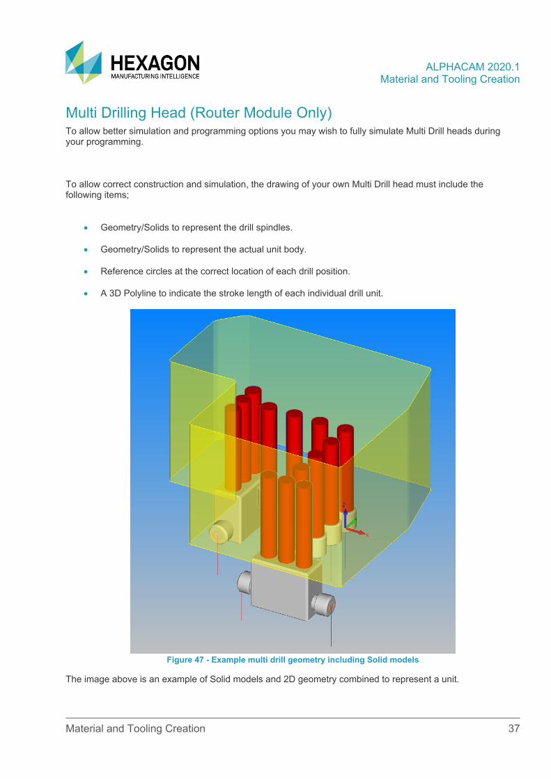
Multi Drilling Head (Router Module Only) To allow better simulation and programming options you may wish to fully simulate Multi Drill heads during your programming.
To allow correct construction and simulation, the drawing of your own Multi Drill head must include the following items;
• Geometry/Solids to represent the drill spindles.
• Geometry/Solids to represent the actual unit body.
• Reference circles at the correct location of each drill position.
• A 3D Polyline to indicate the stroke length of each individual drill unit.
Figure 47 - Example multi drill geometry including Solid models
The image above is an example of Solid models and 2D geometry combined to represent a unit.
ALPHACAM 2020.1 Material and Tooling Creation
Material and Tooling Creation 38
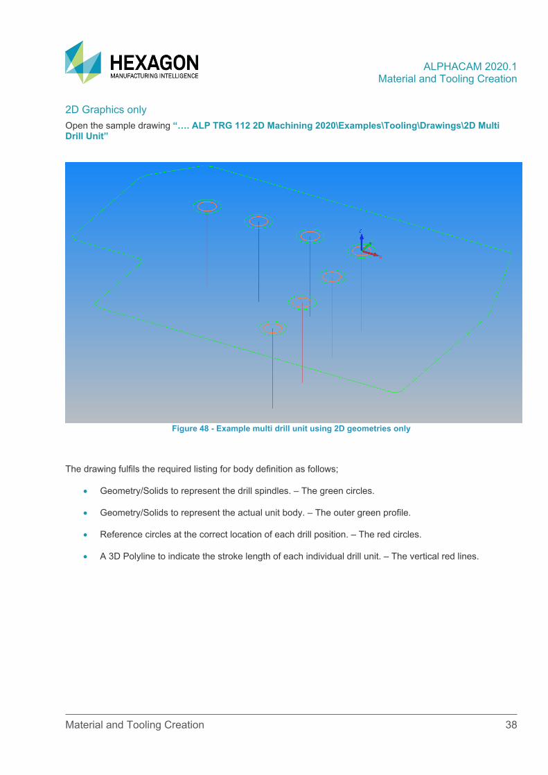
2D Graphics only Open the sample drawing “…. ALP TRG 112 2D Machining 2020\Examples\Tooling\Drawings\2D Multi Drill Unit”
Figure 48 - Example multi drill unit using 2D geometries only
The drawing fulfils the required listing for body definition as follows;
• Geometry/Solids to represent the drill spindles. – The green circles.
• Geometry/Solids to represent the actual unit body. – The outer green profile.
• Reference circles at the correct location of each drill position. – The red circles.
• A 3D Polyline to indicate the stroke length of each individual drill unit. – The vertical red lines.
ALPHACAM 2020.1 Material and Tooling Creation
Material and Tooling Creation 39
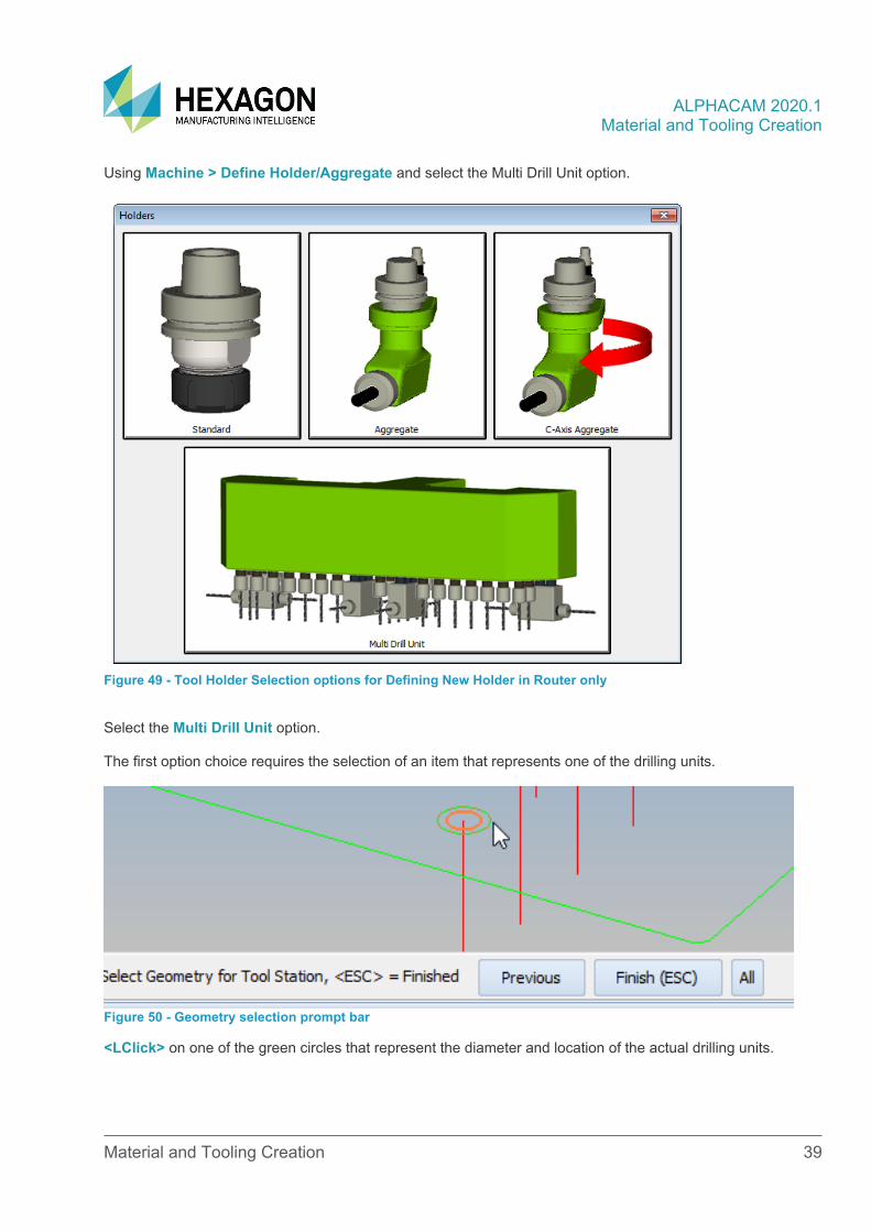
Using Machine > Define Holder/Aggregate and select the Multi Drill Unit option.
Figure 49 - Tool Holder Selection options for Defining New Holder in Router only
Select the Multi Drill Unit option. The first option choice requires the selection of an item that represents one of the drilling units.
Figure 50 - Geometry selection prompt bar
<LClick> on one of the green circles that represent the diameter and location of the actual drilling units.
ALPHACAM 2020.1 Material and Tooling Creation
Material and Tooling Creation 40
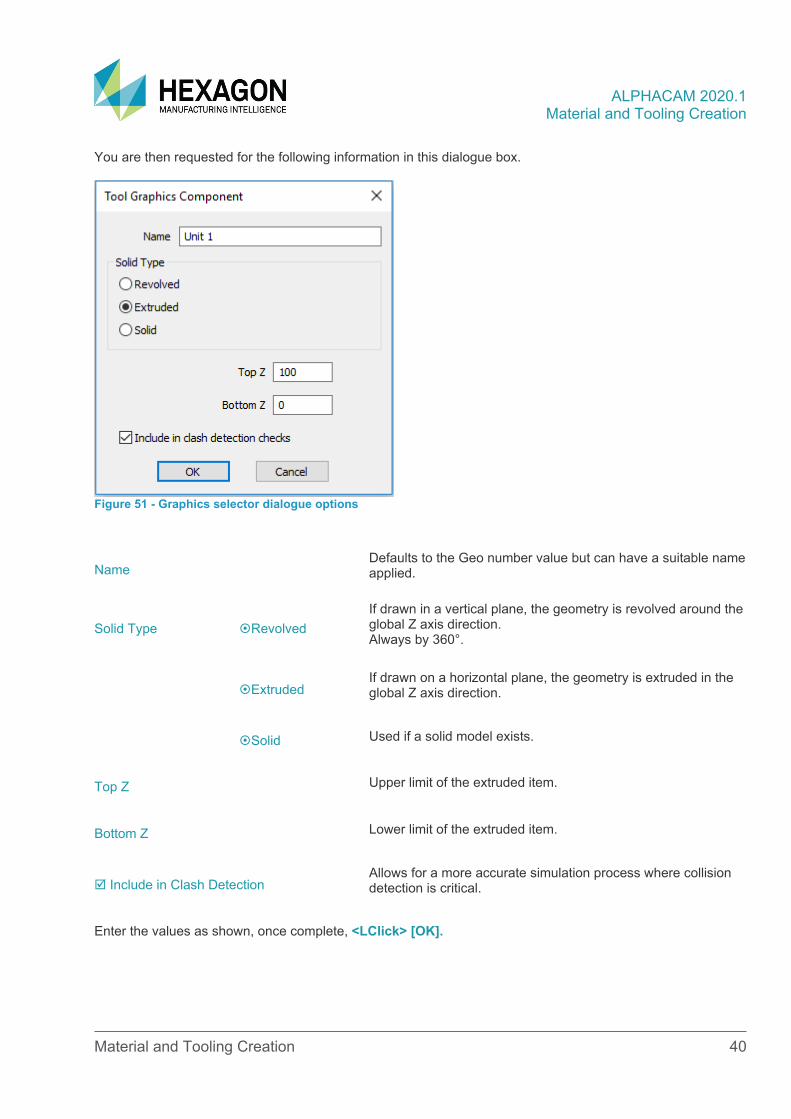
You are then requested for the following information in this dialogue box.
Figure 51 - Graphics selector dialogue options
Name Defaults to the Geo number value but can have a suitable name applied.
Solid Type Revolved If drawn in a vertical plane, the geometry is revolved around the global Z axis direction. Always by 360°.
Extruded If drawn on a horizontal plane, the geometry is extruded in the global Z axis direction.
Solid Used if a solid model exists.
Top Z Upper limit of the extruded item.
Bottom Z Lower limit of the extruded item.
Include in Clash Detection Allows for a more accurate simulation process where collision detection is critical.
Enter the values as shown, once complete, <LClick> [OK].
ALPHACAM 2020.1 Material and Tooling Creation
Material and Tooling Creation 41
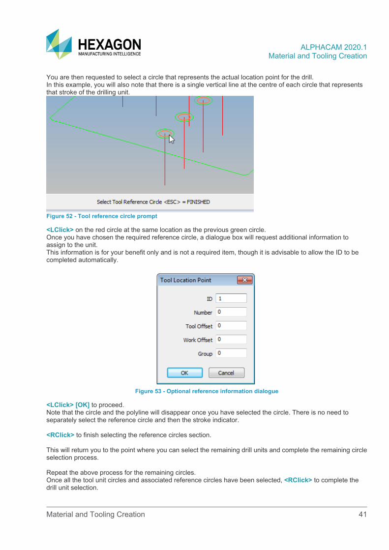
You are then requested to select a circle that represents the actual location point for the drill. In this example, you will also note that there is a single vertical line at the centre of each circle that represents that stroke of the drilling unit.
Figure 52 - Tool reference circle prompt
<LClick> on the red circle at the same location as the previous green circle. Once you have chosen the required reference circle, a dialogue box will request additional information to assign to the unit. This information is for your benefit only and is not a required item, though it is advisable to allow the ID to be completed automatically.
Figure 53 - Optional reference information dialogue
<LClick> [OK] to proceed. Note that the circle and the polyline will disappear once you have selected the circle. There is no need to separately select the reference circle and then the stroke indicator. <RClick> to finish selecting the reference circles section. This will return you to the point where you can select the remaining drill units and complete the remaining circle selection process. Repeat the above process for the remaining circles. Once all the tool unit circles and associated reference circles have been selected, <RClick> to complete the drill unit selection.
ALPHACAM 2020.1 Material and Tooling Creation
Material and Tooling Creation 42
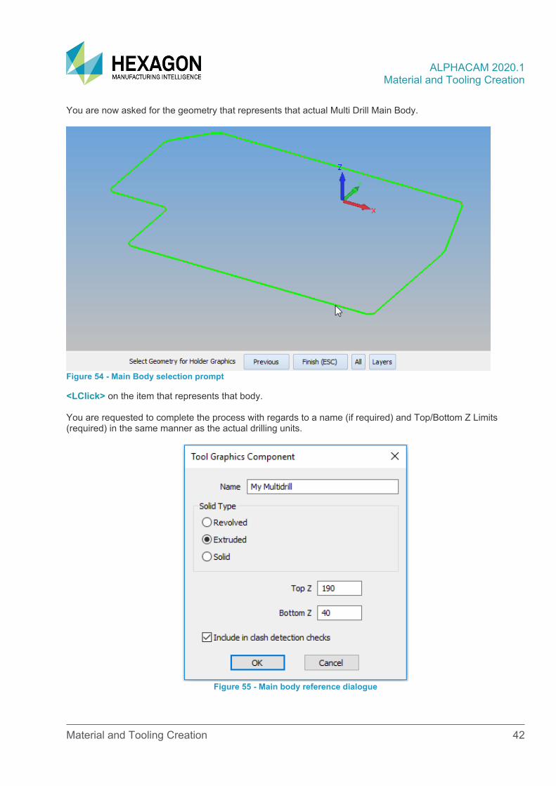
You are now asked for the geometry that represents that actual Multi Drill Main Body.
Figure 54 - Main Body selection prompt
<LClick> on the item that represents that body. You are requested to complete the process with regards to a name (if required) and Top/Bottom Z Limits (required) in the same manner as the actual drilling units.
Figure 55 - Main body reference dialogue
ALPHACAM 2020.1 Material and Tooling Creation
Material and Tooling Creation 43
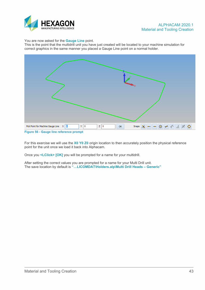
You are now asked for the Gauge Line point. This is the point that the multidrill unit you have just created will be located to your machine simulation for correct graphics in the same manner you placed a Gauge Line point on a normal holder.
Figure 56 - Gauge line reference prompt
For this exercise we will use the X0 Y0 Z0 origin location to then accurately position the physical reference point for the unit once we load it back into Alphacam. Once you <LClick> [OK] you will be prompted for a name for your multidrill. After setting the correct values you are prompted for a name for your Multi Drill unit. The save location by default is “…LICOMDAT\Holders.alp\Multi Drill Heads – Generic”
ALPHACAM 2020.1 Material and Tooling Creation
Material and Tooling Creation 44
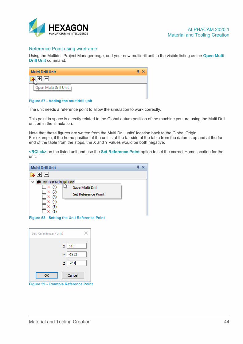
Reference Point using wireframe Using the Multidrill Project Manager page, add your new multidrill unit to the visible listing us the Open Multi Drill Unit command.
Figure 57 - Adding the multidrill unit
The unit needs a reference point to allow the simulation to work correctly. This point in space is directly related to the Global datum position of the machine you are using the Multi Drill unit on in the simulation. Note that these figures are written from the Multi Drill units’ location back to the Global Origin. For example, if the home position of the unit is at the far side of the table from the datum stop and at the far end of the table from the stops, the X and Y values would be both negative. <RClick> on the listed unit and use the Set Reference Point option to set the correct Home location for the unit.
Figure 58 - Setting the Unit Reference Point
Figure 59 - Example Reference Point

ALPHACAM 2020.1 Material and Tooling Creation
Material and Tooling Creation 45
Figure 60 - Unit location prompt for X & Y
Figure 61 - Unit location prompt for Z
ALPHACAM 2020.1 Material and Tooling Creation
Material and Tooling Creation 46
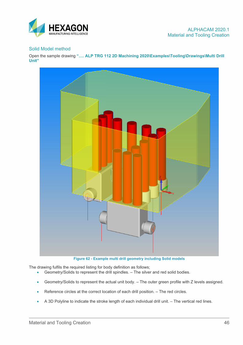
Solid Model method Open the sample drawing “…. ALP TRG 112 2D Machining 2020\Examples\Tooling\Drawings\Multi Drill Unit”
Figure 62 - Example multi drill geometry including Solid models
The drawing fulfils the required listing for body definition as follows; • Geometry/Solids to represent the drill spindles. – The silver and red solid bodies.
• Geometry/Solids to represent the actual unit body. – The outer green profile with Z levels assigned.
• Reference circles at the correct location of each drill position. – The red circles.
• A 3D Polyline to indicate the stroke length of each individual drill unit. – The vertical red lines.
ALPHACAM 2020.1 Material and Tooling Creation
Material and Tooling Creation 47
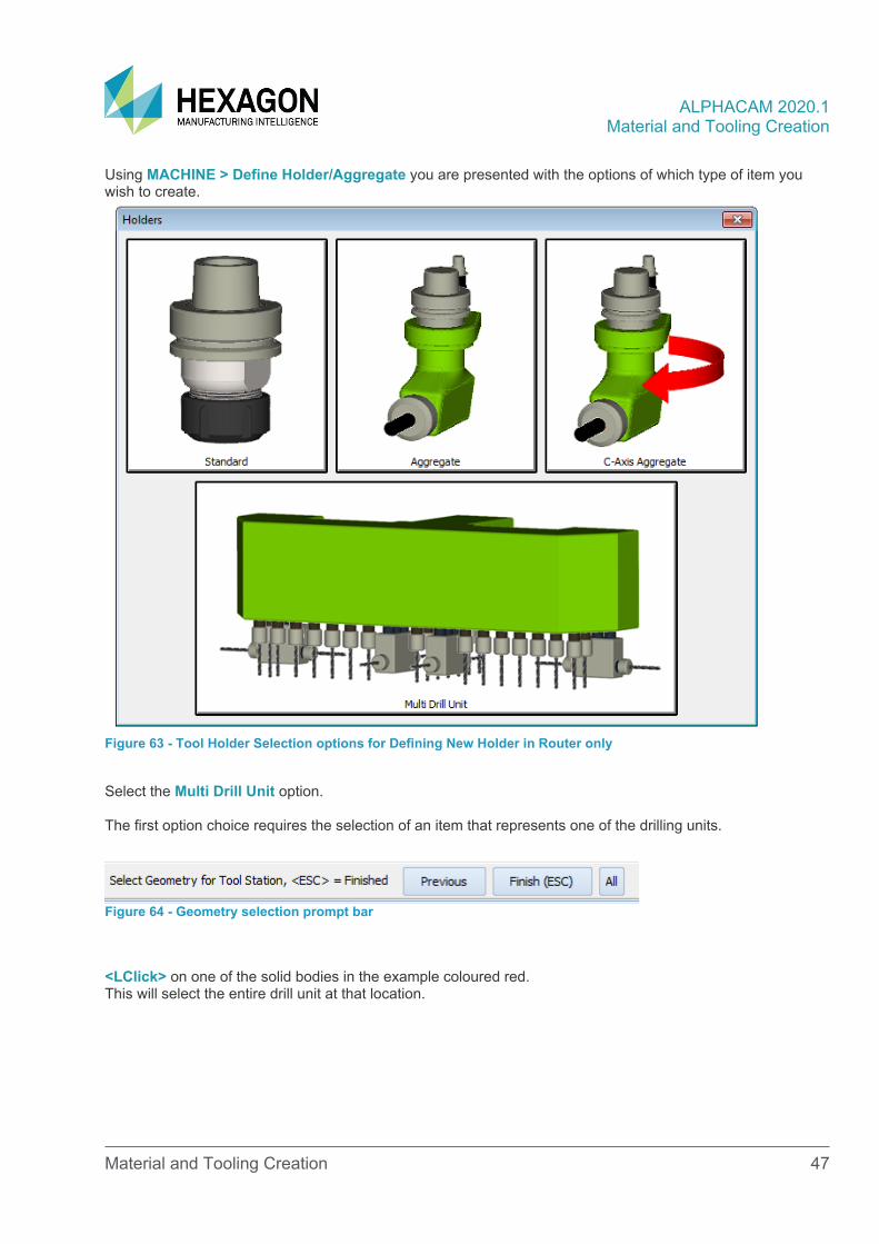
Using MACHINE > Define Holder/Aggregate you are presented with the options of which type of item you wish to create.
Figure 63 - Tool Holder Selection options for Defining New Holder in Router only
Select the Multi Drill Unit option. The first option choice requires the selection of an item that represents one of the drilling units.
Figure 64 - Geometry selection prompt bar
<LClick> on one of the solid bodies in the example coloured red. This will select the entire drill unit at that location.
ALPHACAM 2020.1 Material and Tooling Creation
Material and Tooling Creation 48
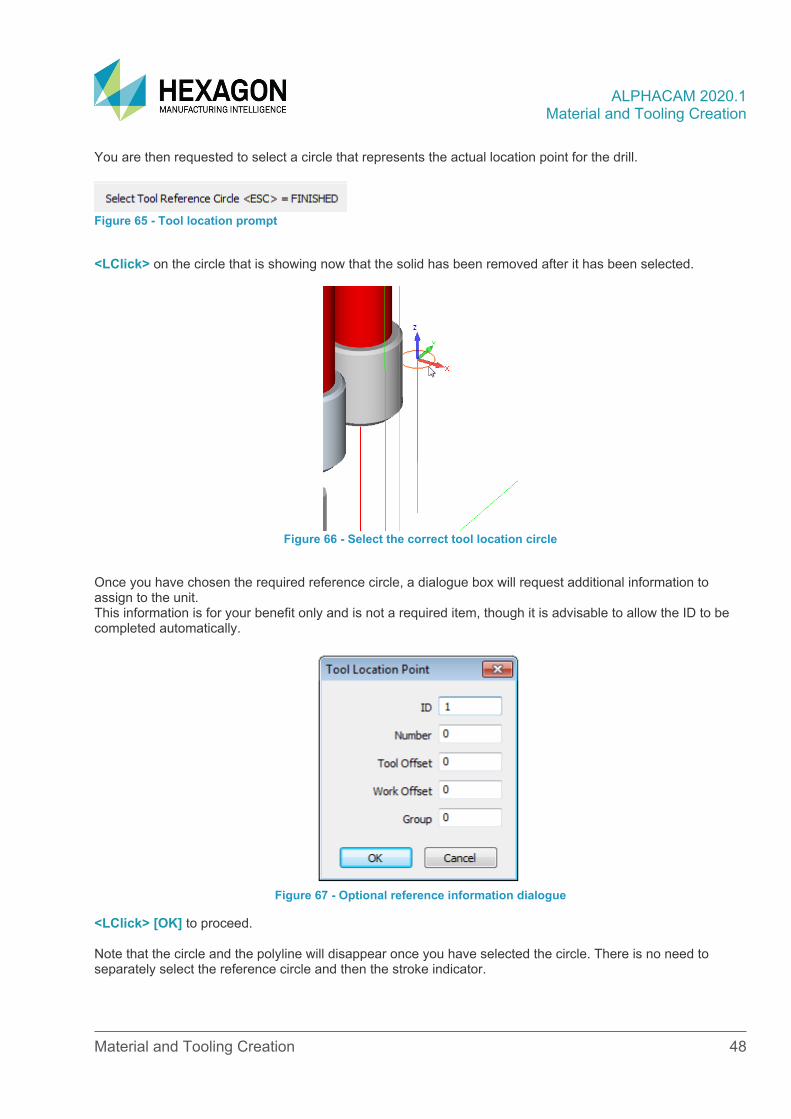
You are then requested to select a circle that represents the actual location point for the drill.
Figure 65 - Tool location prompt
<LClick> on the circle that is showing now that the solid has been removed after it has been selected.
Figure 66 - Select the correct tool location circle
Once you have chosen the required reference circle, a dialogue box will request additional information to assign to the unit. This information is for your benefit only and is not a required item, though it is advisable to allow the ID to be completed automatically.
Figure 67 - Optional reference information dialogue
<LClick> [OK] to proceed. Note that the circle and the polyline will disappear once you have selected the circle. There is no need to separately select the reference circle and then the stroke indicator.
ALPHACAM 2020.1 Material and Tooling Creation
Material and Tooling Creation 49
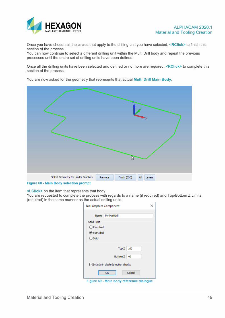
Once you have chosen all the circles that apply to the drilling unit you have selected, <RClick> to finish this section of the process. You can now continue to select a different drilling unit within the Multi Drill body and repeat the previous processes until the entire set of drilling units have been defined. Once all the drilling units have been selected and defined or no more are required, <RClick> to complete this section of the process. You are now asked for the geometry that represents that actual Multi Drill Main Body.
Figure 68 - Main Body selection prompt
<LClick> on the item that represents that body. You are requested to complete the process with regards to a name (if required) and Top/Bottom Z Limits (required) in the same manner as the actual drilling units.
Figure 69 - Main body reference dialogue

ALPHACAM 2020.1 Material and Tooling Creation
Material and Tooling Creation 50
You are now asked for the Gauge Line point. This is the point that the multidrill unit you have just created will be located to your machine simulation for correct graphics in the same manner you placed a Gauge Line point on a normal holder.
Figure 70 - Gauge line reference prompt
For this exercise we will use the X0 Y0 Z0 origin location to then accurately position the physical reference point for the unit once we load it back into Alphacam. Once you <LClick> [OK] you will be prompted for a name for your multidrill. After setting the correct values you are prompted for a name for your Multi Drill unit. The save location by default is “…LICOMDAT\Holders.alp\Multi Drill Heads – Generic”

ALPHACAM 2020.1 Material and Tooling Creation
Material and Tooling Creation 51
Reference Point using solids Using the Multidrill Project Manager page, add your new multidrill unit to the visible listing us the Open Multi Drill Unit command.
Figure 71 - Adding the multidrill unit
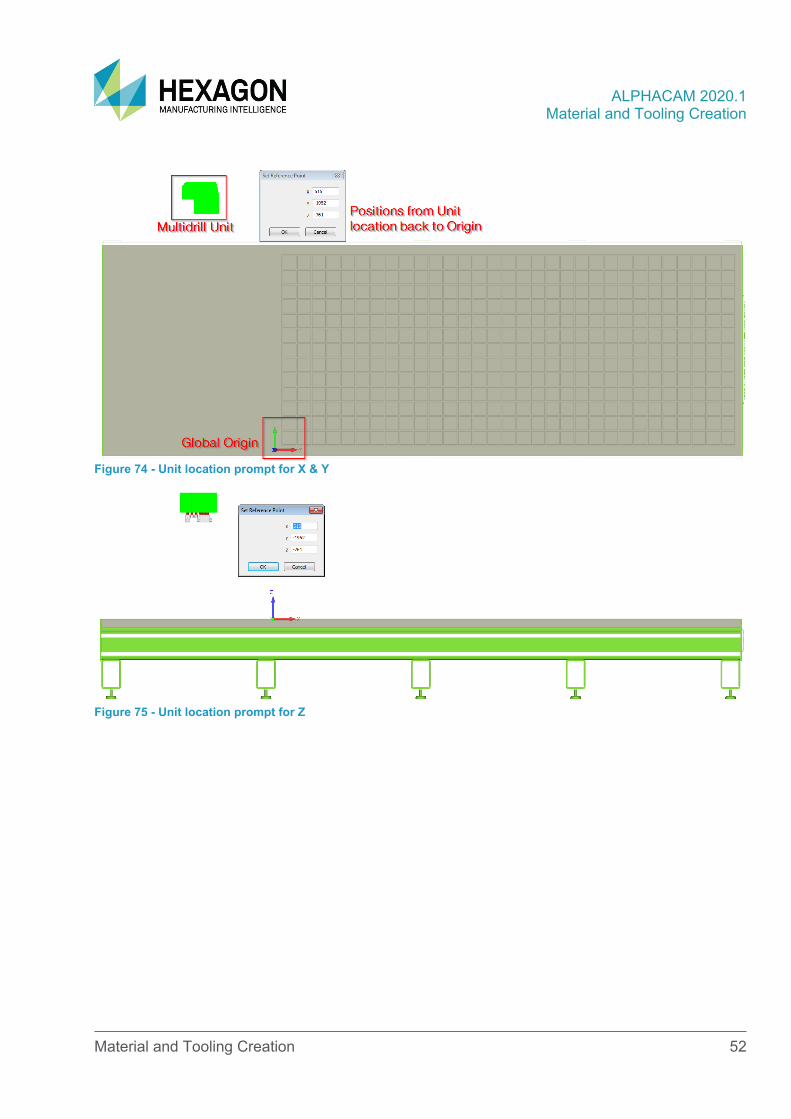
The unit needs a reference point to allow the simulation to work correctly. This point in space is directly related to the Global datum position of the machine you are using the Multi Drill unit on in the simulation. Note that these figures are written from the Multi Drill units’ location back to the Global Origin. For example, if the home position of the unit is at the far side of the table from the datum stop and at the far end of the table from the stops, the X and Y values would be both negative. <RClick> on the listed unit and use the Set Reference Point option to set the correct Home location for the unit.
Figure 72 - Setting the Unit Reference Point
Figure 73 - Example Reference Point
ALPHACAM 2020.1 Material and Tooling Creation
Material and Tooling Creation 52
Figure 74 - Unit location prompt for X & Y
Figure 75 - Unit location prompt for Z
ALPHACAM 2020.1 Material and Tooling Creation
Material and Tooling Creation 53
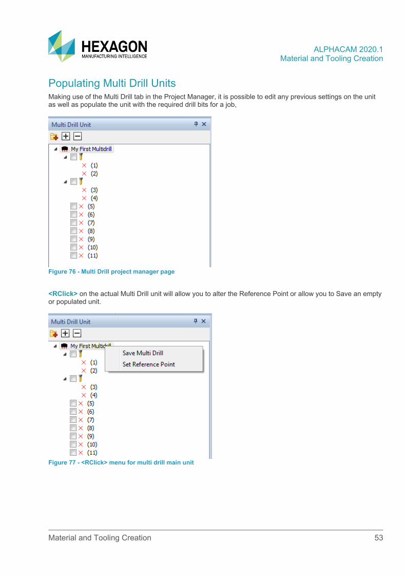
Populating Multi Drill Units Making use of the Multi Drill tab in the Project Manager, it is possible to edit any previous settings on the unit as well as populate the unit with the required drill bits for a job,
Figure 76 - Multi Drill project manager page
<RClick> on the actual Multi Drill unit will allow you to alter the Reference Point or allow you to Save an empty or populated unit.
Figure 77 - <RClick> menu for multi drill main unit
ALPHACAM 2020.1 Material and Tooling Creation
Material and Tooling Creation 54
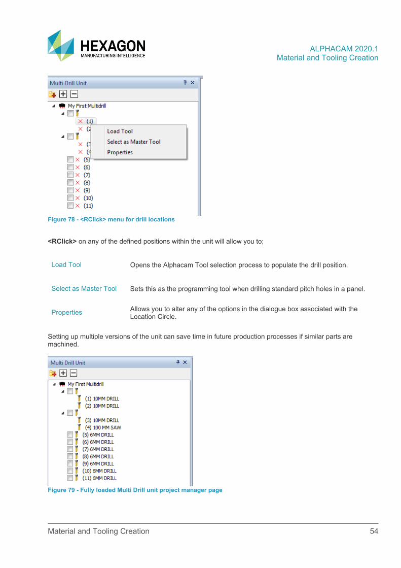
Figure 78 - <RClick> menu for drill locations
<RClick> on any of the defined positions within the unit will allow you to;
Load Tool Opens the Alphacam Tool selection process to populate the drill position.
Select as Master Tool Sets this as the programming tool when drilling standard pitch holes in a panel.
Properties Allows you to alter any of the options in the dialogue box associated with the Location Circle.
Setting up multiple versions of the unit can save time in future production processes if similar parts are machined.
Figure 79 - Fully loaded Multi Drill unit project manager page
ALPHACAM 2020.1 Material and Tooling Creation
Material and Tooling Creation 55
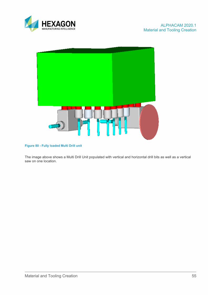
Figure 80 - Fully loaded Multi Drill unit
The image above shows a Multi Drill Unit populated with vertical and horizontal drill bits as well as a vertical saw on one location.

ALPHACAM 2020.1 Material and Tooling Creation
Version amendments
V Amendment Description A Software Version Amended Date 12 Minor text formatting alterations 1 2020.1 05/11/2019 12 Template altered to Hexagon branding 0 2020.0 15/03/2019
ALPHACAM 2020.1 Material and Tooling Creation
ALPHACAM Floor Two Tel.+44 (0) 1189 226677 No. One, Waterside Drive Email. [email protected] Arlington Business Park Web. www.alphacam.com Theale Reading Support. [email protected] Berkshire Portal. customers.ps.hexagonmi.com RG7 4SA United Kingdom
Related Documents