Data Sheet Broadcom AV02-4540EN September 22, 2020 Description The Broadcom ® ALMD-xx3E LED series has the same or just slightly less luminous intensity than conventional high brightness, through-hole LEDs. The LED lamps can be assembled using common SMT assembly processes and are compatible with industrial reflow soldering processes. The LEDs are made with an advanced optical grade epoxy for superior performance in outdoor sign applications. For easy pick and place assembly, the LEDs are shipped in tape and reel. Every reel is shipped from a single intensity and color bin—except the red color—for better uniformity. Features Compact form factor High brightness material Available in Red, Amber, Green, and Blue colors – Red AlInGaP 626 nm – Amber AlInGaP 590 nm – Green InGaN 525 nm – Blue InGaN 470 nm JEDEC MSL 2A Compatible with reflow soldering process Typical viewing angle: 30° Tinted lens Applications Full color signs Mono color signs CAUTION! InGaN devices are Class 1C HBM ESD sensitive, AlInGaP devices are Class 1B ESD sensitive per JEDEC Standard. Oobserve appropriate precautions during handling and processing. Refer to Application Note AN-1142 for additional details. CAUTION! Keep the LED in the moisture barrier bag (MBB) with <5% RH when not in use because prolonged exposure to environment might cause the silver-plated leads to tarnish or rust, which might cause difficulties in soldering. ALMD-EL3E, ALMD-EG3E, ALMD-CM3E, ALMD-CB3E High Brightness SMT Round Amber, Red, Green, and Blue LED Lamps

Welcome message from author
This document is posted to help you gain knowledge. Please leave a comment to let me know what you think about it! Share it to your friends and learn new things together.
Transcript
Data Sheet
ALMD-EL3E, ALMD-EG3E, ALMD-CM3E, ALMD-CB3EHigh Brightness SMT Round Amber, Red, Green, and Blue LED Lamps
Description
The Broadcom® ALMD-xx3E LED series has the same or just slightly less luminous intensity than conventional high brightness, through-hole LEDs.
The LED lamps can be assembled using common SMT assembly processes and are compatible with industrial reflow soldering processes.
The LEDs are made with an advanced optical grade epoxy for superior performance in outdoor sign applications.
For easy pick and place assembly, the LEDs are shipped in tape and reel. Every reel is shipped from a single intensity and color bin—except the red color—for better uniformity.
Features
Compact form factor
High brightness material
Available in Red, Amber, Green, and Blue colors
– Red AlInGaP 626 nm
– Amber AlInGaP 590 nm
– Green InGaN 525 nm
– Blue InGaN 470 nm
JEDEC MSL 2A
Compatible with reflow soldering process
Typical viewing angle: 30°
Tinted lens
Applications
Full color signs
Mono color signs
CAUTION! InGaN devices are Class 1C HBM ESD sensitive, AlInGaP devices are Class 1B ESD sensitive per JEDEC Standard. Oobserve appropriate precautions during handling and processing. Refer to Application Note AN-1142 for additional details.
CAUTION! Keep the LED in the moisture barrier bag (MBB) with <5% RH when not in use because prolonged exposure to environment might cause the silver-plated leads to tarnish or rust, which might cause difficulties in soldering.
Broadcom AV02-4540ENSeptember 22, 2020

ALMD-EL3E, ALMD-EG3E, ALMD-CM3E, ALMD-CB3E Data Sheet High Brightness SMT Round Amber, Red, Green, and Blue LED Lamps
Figure 1: Package Dimensions
NOTE:
1. All dimensions are in millimeters.
2. Tolerance is ± 0.20 mm, unless other specified.
3. Mildsteel lead frame.
Device Selection Guide
Part Number
Color and Dominant
Wavelength d (nm) Typa
a. Dominant wavelength, d, is derived from the CIE Chromaticity Diagram and represents the color of the lamp.
Luminous Intensity Iv (mcd)b,c,d
b. The luminous intensity is measured on the mechanical axis of the lamp package and it is tested with pulsing condition.
c. The optical axis is closely aligned with the package mechanical axis.
d. Tolerance for each bin limit is ± 15%.
Viewing Angle Typ (°) e
e. ½ is the off-axis angle where the luminous intensity is half the on-axis intensity.
Min Max
ALMD-EG3E-WY002 Red 626 5500 12000 30
ALMD-EG3E-XY002 Red 626 7200 12000
ALMD-EL3E-WY002 Amber 590 5500 12000
ALMD-EL3E-XYK02 Amber 590 7200 12000
ALMD-CM3E-Y1002 Green 525 9300 21000
ALMD-CB3E-SU002 Blue 470 1900 4200
A
1.60 ± 0.50
2.50
3.40 ± 0.50
6.50 ± 0.50
C1.4 (4×)
1.00
Package Marking
CC
A A
4.20
4.20
4.75 ± 0.50
A: Anode
C: Cathode
Broadcom AV02-4540EN2

ALMD-EL3E, ALMD-EG3E, ALMD-CM3E, ALMD-CB3E Data Sheet High Brightness SMT Round Amber, Red, Green, and Blue LED Lamps
Part Numbering System
Intensity Bin Limit Table (1.3:1 lv Bin Ratio)
Tolerance for each bin limit is ± 15%.
VF Bin Table (V at 20 mA) for Red and Amber Only
Tolerance for each bin limit is ± 0.05 V.
Red Color Range
Tolerance for each bin limit is ± 0.5 nm.
A L M D - x1 x2 x3 x4 - x5 x6 x7 x8 x9
Code Description Option
x1 Package type E
C
Round AlInGaP
Round InGaN
x2 Color B
G
L
M
Blue
Red
Amber
Green
x3 Viewing angle 3 30°
x4 Product specification designation E
x5 Minimum intensity bin Refer to device selection guide
x6 Maximum intensity bin Refer to device selection guide
x7 Color bin selection 0 Full distribution
K Color bins 2 and 4
x8 x9 Packaging option 02 Tested 20 mA, 13-in. carrier tape
Bin
Intensity (mcd) at 20 mA
Min. Max.
S 1900 2500
T 2500 3200
U 3200 4200
V 4200 5500
W 5500 7200
X 7200 9300
Y 9300 12000
Z 12000 16000
1 16000 21000
Bin ID Min. Max.
VD 1.8 2.0
VA 2.0 2.2
VB 2.2 2.4
Min. Dom.
Max. Dom. X Min. Y Min. X Max. Y Max.
618.0 630.0 0.6872 0.3126 0.6890 0.2943
0.6690 0.3149 0.7080 0.2920
Broadcom AV02-4540EN3

ALMD-EL3E, ALMD-EG3E, ALMD-CM3E, ALMD-CB3E Data Sheet High Brightness SMT Round Amber, Red, Green, and Blue LED Lamps
Amber Color Range
Tolerance for each bin limit is ± 0.5 nm.
Green Color Range
Tolerance for each bin limit is ± 0.5 nm.
Blue Color Range
Tolerance for each bin limit is ± 0.5 nm.
Absolute Maximum Rating, TJ = 25 °C
BinMin. Dom.
Max. Dom. X Min. Y Min. X Max. Y Max.
1 584.5 587.0 0.5420 0.4580 0.5530 0.4400
0.5370 0.4550 0.5570 0.4420
2 587.0 589.5 0.5570 0.4420 0.5670 0.4250
0.5530 0.4400 0.5720 0.4270
4 589.5 592.0 0.5720 0.4270 0.5820 0.4110
0.5670 0.4250 0.5870 0.4130
6 592.0 594.5 0.5870 0.4130 0.5950 0.3980
0.5820 0.4110 0.6000 0.3990
BinMin. Dom.
Max. Dom. X Min. Y Min. X Max. Y Max.
1 519.0 523.0 0.0667 0.8323 0.1450 0.7319
0.1200 0.7375 0.0979 0.8316
2 523.0 527.0 0.0979 0.8316 0.1711 0.7218
0.1450 0.7319 0.1305 0.8189
3 527.0 531.0 0.1305 0.8189 0.1967 0.7077
0.1711 0.7218 0.1625 0.8012
4 531.0 535.0 0.1625 0.8012 0.2210 0.6920
0.1967 0.7077 0.1929 0.7816
5 535.0 539.0 0.1929 0.7816 0.2445 0.6747
0.2210 0.6920 0.2233 0.7600
BinMin. Dom.
Max. Dom. X Min. Y Min. X Max. Y Max.
1 460.0 464.0 0.1440 0.0297 0.1766 0.0966
0.1818 0.0904 0.1374 0.0374
2 464.0 468.0 0.1374 0.0374 0.1699 0.1062
0.1766 0.0966 0.1291 0.0495
3 468.0 472.0 0.1291 0.0495 0.1616 0.1209
0.1699 0.1062 0.1187 0.0671
4 472.0 476.0 0.1187 0.0671 0.1517 0.1423
0.1616 0.1209 0.1063 0.0945
5 476.0 480.0 0.1063 0.0945 0.1397 0.1728
0.1517 0.1423 0.0913 0.1327
Parameter Red and Amber Green Blue Units
DC Forward Current a 50 30 20 mA
Peak Forward Current 100b 100c 100c mA
Power Dissipation 120 114 76 mW
LED Junction Temperature 110 °C
Operating Temperature Range –40 to +85 °C
Storage Temperature Range –40 to +100 °C
a. Derate linearly as shown in Figure 5 and Figure 10.
b. Duty factor 30%, frequency 1 kHz.
c. Duty factor 10%, frequency 1 kHz.
Broadcom AV02-4540EN4

ALMD-EL3E, ALMD-EG3E, ALMD-CM3E, ALMD-CB3E Data Sheet High Brightness SMT Round Amber, Red, Green, and Blue LED Lamps
Electrical/Optical Characteristics, TJ = 25 °C
Parameter Symbol Min. Typ. Max. Units Test Conditions
Forward VoltageRedAmberGreenBlue
VF1.81.82.82.8
2.12.13.23.2
2.42.43.83.8
V IF = 20 mA
Reverse Voltagea
Red and AmberGreen and Blue
a. Indicates product final testing condition. Long-term reverse bias is not recommended.
VR55
VIR = 100 µA
IR = 10 µA
Dominant Wavelengthb
RedAmberGreenBlue
b. The dominant wavelength is derived from the Chromaticity Diagram and represents the color of the lamp.
d618.0584.5519.0460.0
626.0590.0525.0470.0
630.0594.5539.0480.0
nm IF = 20 mA
Peak WavelengthRedAmberGreenBlue
PEAK634594516464
nm Peak of Wavelength of Spectral Distribution at IF = 20 mA
Thermal ResistanceRedAmberGreenBlue
RJ-PIN270270270480
°C/W LED Junction-to-Pin
Luminous Efficacyc
RedAmberGreenBlue
c. The radiant intensity, Ie in watts per steradian, may be found from the equation Ie = IV/V where IV is the luminous intensity in candelas and V is the luminous efficacy in lumens/watt.
V20049053065
lm/W Emitted Luminous Power/Emitted Radiant Power
Thermal coefficient of d
RedAmberGreenBlue
0.0590.1030.0280.024
nm/°C IF = 20 mA; +25°C ≤ TJ ≤ +100°C
Broadcom AV02-4540EN5

ALMD-EL3E, ALMD-EG3E, ALMD-CM3E, ALMD-CB3E Data Sheet High Brightness SMT Round Amber, Red, Green, and Blue LED Lamps
AlInGaP
Figure 2: Relative Intensity vs. Wavelength Figure 3: Forward Current vs. Forward Voltage
0.0
0.2
0.4
0.6
0.8
1.0
500 550 600 650
Amber Red
WAVELENGTH - nm
REL
ATI
VE
INTE
NSI
TY
0
10
20
30
40
50
60
0 0.5 1 1.5 2 2.5 3
FORWARD VOLTAGE - V
FOR
WA
RD
CU
RR
ENT
- mA
Figure 4: Relative Intensity vs. Forward Current Figure 5: Maximum Forward Current vs. Ambient Temperature
0.0
0.5
1.0
1.5
2.0
2.5
3.0
0 10 20 30 40 50 60
Red
Amber
FORWARD CURRENT - mA
REL
ATI
VE
LUM
INO
US
INTE
NSI
TY
(NO
RM
ALI
ZED
AT
20 m
A)
0
10
20
30
40
50
60
0 20 40 60 80 100
RJA = 460 ° C/W
R JA = 660 ° C/W
TA - AMBIENT TEMPERATURE - °C
MA
XIM
UM
FO
RW
AR
D C
UR
REN
T - m
A
Figure 6: Relative Dominant Wavelength Shift vs. Forward Current
-0.8
-0.6
-0.4
-0.2
0
0.2
0.4
0.6
0.8
1
1.2
0 10 20 30 40 50 60
Red
Amber
FORWARD CURRENT - mA
REL
ATI
VE
DO
MIN
AN
T W
AV
ELEN
GTH
SH
IFT
- nm
Broadcom AV02-4540EN6
ALMD-EL3E, ALMD-EG3E, ALMD-CM3E, ALMD-CB3E Data Sheet High Brightness SMT Round Amber, Red, Green, and Blue LED Lamps
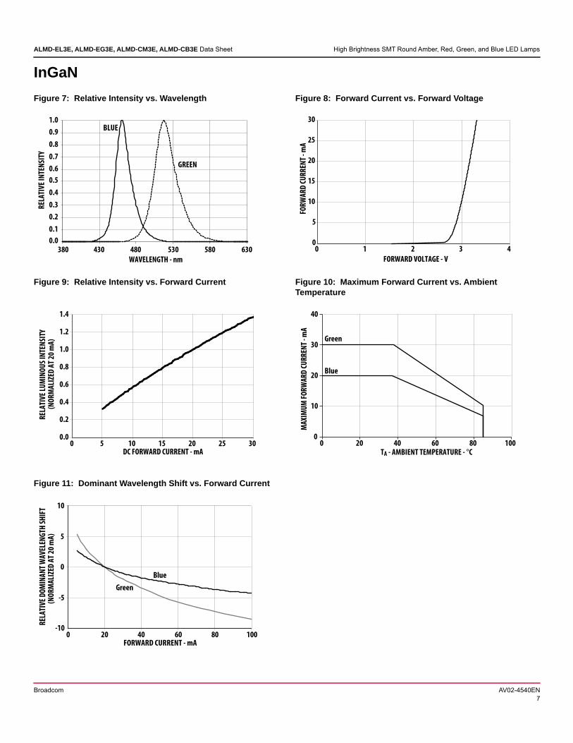
InGaN
Figure 7: Relative Intensity vs. Wavelength Figure 8: Forward Current vs. Forward Voltage
0.0
0.1
0.2
0.3
0.4
0.5
0.6
0.7
0.8
0.9
1.0
380 430 480 530 580 630
WAVELENGTH - nm
REL
ATI
VE
INTE
NSI
TY
GREEN
BLUE
0
5
10
15
20
25
30
0 1 2 3 4
FORWARD VOLTAGE - V
FOR
WA
RD
CU
RR
ENT
- mA
Figure 9: Relative Intensity vs. Forward Current Figure 10: Maximum Forward Current vs. Ambient Temperature
0.0
0.2
0.4
0.6
0.8
1.0
1.2
1.4
0 5 10 15 20 25 30DC FORWARD CURRENT - mA
REL
ATI
VE
LUM
INO
US
INTE
NSI
TY(N
OR
MA
LIZE
D A
T 20
mA
)
0
10
20
30
40
0 20 40 60 80 100TA - AMBIENT TEMPERATURE - °C
MA
XIM
UM
FO
RW
AR
D C
UR
REN
T - m
A
Blue
Green
Figure 11: Dominant Wavelength Shift vs. Forward Current
-10
-5
0
5
10
0 20 40 60 80 100
Green
Blue
FORWARD CURRENT - mA
REL
ATIV
E D
OM
INAN
T W
AVEL
ENG
TH S
HIF
T
(NO
RM
ALI
ZED
AT
20 m
A)
Broadcom AV02-4540EN7

ALMD-EL3E, ALMD-EG3E, ALMD-CM3E, ALMD-CB3E Data Sheet High Brightness SMT Round Amber, Red, Green, and Blue LED Lamps
Figure 12: Radiation Pattern for X-Axis Figure 13: Component Axis for Radiation Pattern
0
0.2
0.4
0.6
0.8
1
-90 -60 -30 0 30 60 90
ANGULAR DISPLACEMENT-DEGREE
NO
RM
ALI
ZED
INTE
NSI
TY
CC
A A
X X
Package Marking
Figure 14: Relative Intensity Shift vs. Junction Temperature Figure 15: Forward Voltage Shift vs. Junction Temperature
0.1
1
10
-40 -20 0 20 40 60 80 100 120
NO
RM
ALZ
IED
INTE
NSI
TY (P
HO
TO)
TJ - JUNCTION TEMPERATURE (°C)
GreenBlueRedAmber
-0.4
-0.3
-0.2
-0.1
0
0.1
0.2
0.3
0.4
-40 -20 0 20 40 60 80 100 120
FOR
WA
RD
VO
LTA
GE
SHIF
T - V
TJ - JUNCTION TEMPERATURE (°C)
GreenBlue
Red
Amber
Figure 16: Recommended Soldering Land Pattern
NOTE: Recommended stencil thickness is 0.1524 mm (6 mils) minimum and above.
5.2
2.1
4.0
0.7
Broadcom AV02-4540EN8

ALMD-EL3E, ALMD-EG3E, ALMD-CM3E, ALMD-CB3E Data Sheet High Brightness SMT Round Amber, Red, Green, and Blue LED Lamps
Figure 17: Carrier Tape Dimensions
NOTE: All dimensions are in mm.
Figure 18: Reel Dimension
NOTE: All dimensions are in mm.
4.50±0.20
2.20±0.20
2.00±0.204.00±0.20
8.00±0.20
16.00±0.30
7.50±0.20
1.75±0.20
7.10±0.205.30±0.20
0.50±0.10
1.80±0.20
5.20±0.20
1.55±0.20
1.60±0.20
O 1
00 ±
0.5
0
O 3
30 M
AX.
16.40 ± 0.20
13.00 ± 0.20
Broadcom AV02-4540EN9
ALMD-EL3E, ALMD-EG3E, ALMD-CM3E, ALMD-CB3E Data Sheet High Brightness SMT Round Amber, Red, Green, and Blue LED Lamps
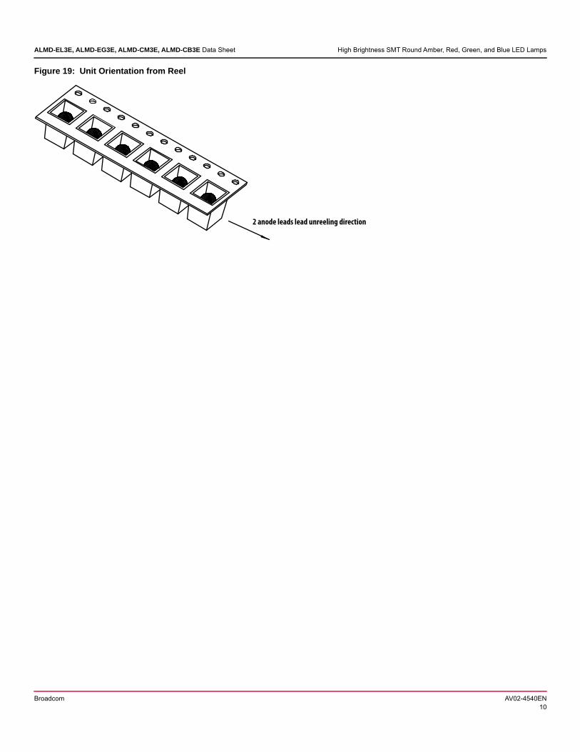
Figure 19: Unit Orientation from Reel
2 anode leads lead unreeling direction
Broadcom AV02-4540EN10

ALMD-EL3E, ALMD-EG3E, ALMD-CM3E, ALMD-CB3E Data Sheet High Brightness SMT Round Amber, Red, Green, and Blue LED Lamps
Soldering
Recommended reflow soldering conditions:
(i) Leaded reflow soldering
(ii) Lead-free reflow soldering
Reflow soldering must not be done more than twice. Take the necessary precautions for handling a moisture-sensitive device, as stated in the following section.
The recommended board reflow direction follows.
Do not apply any pressure or force on the LED during reflow and after reflow when the LED is still hot.
Use reflow soldering to solder the LED. Use hand soldering only for rework if unavoidable but must be strictly controlled to the following conditions:
– Soldering iron tip temperature = 320°C maximum
– Soldering duration = 3 seconds maximum
– Number of cycles = 1 only
– Power of soldering iron = 50 W maximum
Do not touch the LED body with a hot soldering iron except the soldering terminals because this may damage the LED.
For de-soldering, use a double-flat tip.
Confirm beforehand whether the functionality and performance of the LED is affected by hand soldering.
Precautionary Notes
Handling Precautions
For automated pick-and-place, Broadcom has tested the following nozzle size made with urethane material to be work well with this LED. However, due to the possibility of variations in other parameters such as pick-and-place machine maker/model and other settings of the machine, verify the selected nozzle.
NOTE:
1. The nozzle tip should touch the LED flange during pick and place.
2. The outer dimensions of the nozzle should fit into the carrier tape pocket.
240°C MAX.
20 SEC. MAX.
3°C/SEC.
MAX.
120 SEC. MAX.
TIME
TEM
PER
ATU
RE
183°C100-150°C
-6°C/SEC.
MAX.
60-150 SEC.
3°C/SEC. MAX.
217 °C200 °C
60 - 120 SEC.
6 °C/SEC. MAX.
3 °C/SEC. MAX.
3 °C/SEC. MAX.
150 °C
255 - 260 °C
100 SEC. MAX.
10 to 30 SEC.
TIME
TEM
PER
ATU
RE
4.8mm
4.4mm Φ3.9mm
Pick & Place nozzle
LED flange
>3.5mm
Broadcom AV02-4540EN11

ALMD-EL3E, ALMD-EG3E, ALMD-CM3E, ALMD-CB3E Data Sheet High Brightness SMT Round Amber, Red, Green, and Blue LED Lamps
Handling of Moisture-Sensitive Devices
This product has a Moisture Sensitive Level 2a rating per JEDEC J-STD-020. Refer to Broadcom Application Note AN5305, Handling of Moisture Sensitive Surface Mount Devices, for additional details and a review of proper handling procedures.
Before use
Store an unopened moisture barrier bag (MBB) at <40°C/90% RH for 12 months. If the actual shelf life has exceeded 12 months and the humidity indicator card (HIC) indicates that baking is not required, it is safe to reflow the LEDs per the original MSL rating.
Do not open the MBB prior to assembly (for example, for IQC).
Control after opening the MBB
Read the HIC immediately upon opening of the MBB.
Keep the LEDs at <30°C/60%RH at all times, and complete all high-temperature-related processes, including soldering, curing, or rework, within 672 hours.
Control for unfinished reel
Store unused LEDs in a sealed MBB with desiccant or desiccator at <5% RH.
Control of assembled boards
If the PCB soldered with the LEDs is to be subjected to other high-temperature processes, store the PCB in a sealed MBB with desiccant or desiccator at <5% RH to ensure that all LEDs have not exceeded their floor life of 672 hours.
Baking is required if the following conditions exist
The HIC indicator is not BROWN at 10% and is AZURE at 5%.
The LEDs are exposed to conditions of >30°C/60% RH at any time.
The LEDs’ floor life exceeded 672 hrs.
The recommended baking condition is 60°C ± 5°C for 20 hours. Baking should only be done once.
Storage
The soldering terminals of these LEDs are silver plated. If the LEDs are exposed in an ambient environment for too long, the silver plating might be oxidized, which affects its solderability performance. As such, keep unused LEDs in sealed a MBB with desiccant or in desiccator at <5% RH.
Application Precautions The drive current of the LED must not exceed the
maximum allowable limit across temperature as stated in the data sheet. Use constant current driving to ensure consistent performance.
LEDs exhibit slightly different characteristics at different drive currents that might result in larger performance variations (such as, intensity, wavelength, and forward voltage). Set the application current as close as possible to the test current to minimize these variations.
The LED is not intended for reverse bias. Use other appropriate components for such purposes. When driving the LED in matrix form, ensure that the reverse bias voltage does not exceed the allowable limit of the LED.
Avoid rapid change in ambient temperatures, especially in high humidity environments, because these will cause condensation on the LED.
If the LED is intended to be used in an outdoor or a harsh environment, protect the LED leads with suitable potting material against damages caused by rain water, oil, corrosive gases, and so on. Use a louver or a shade to reduce direct sunlight on the LEDs.
Eye Safety Precautions
LEDs may pose optical hazards when in operation. Do not look directly at operating LEDs because it may be harmful to the eyes. For safety reasons, use appropriate shielding or personal protective equipment.
Broadcom AV02-4540EN12

Disclaimer
Broadcom’s products and software are not specifically designed, manufactured, or authorized for sale as parts, components, or assemblies for the planning, construction, maintenance, or direct operation of a nuclear facility or for use in medical devices or applications. The customer is solely responsible, and waives all rights to make claims against Broadcom or its suppliers, for all loss, damage, expense, or liability in connection with such use.
Broadcom, the pulse logo, Connecting everything, Avago Technologies, Avago, and the A logo are among the trademarks of Broadcom and/or its affiliates in the United States, certain other countries, and/or the EU.
Copyright © 2016–2020 Broadcom. All Rights Reserved.
The term “Broadcom” refers to Broadcom Inc. and/or its subsidiaries. For more information, please visit www.broadcom.com.
Broadcom reserves the right to make changes without further notice to any products or data herein to improve reliability, function, or design. Information furnished by Broadcom is believed to be accurate and reliable. However, Broadcom does not assume any liability arising out of the application or use of this information, nor the application or use of any product or circuit described herein, neither does it convey any license under its patent rights nor the rights of others.
Related Documents


