CASTING AND ANODISING OF AL ALLOYS-ALLOY DESIGN, MANUFACTURING PROCESS AND MATERIAL PROPERTIES THESIS FOR THE DEGREE OF DOCTOR OF PHILOSOPHY Casting and Anodising of Al Alloys- Alloy Design, Manufacturing Process and Material Properties Baiwei Zhu Department of Materials and Manufacturing Jönköping, Sweden 2019

Welcome message from author
This document is posted to help you gain knowledge. Please leave a comment to let me know what you think about it! Share it to your friends and learn new things together.
Transcript

CASTING AND ANODISING OF AL ALLOYS-ALLOY DESIGN, MANUFACTURING PROCESS AND MATERIAL PROPERTIES
THESIS FOR THE DEGREE OF DOCTOR OF PHILOSOPHY
Casting and Anodising of Al Alloys-
Alloy Design, Manufacturing Process
and Material Properties
Baiwei Zhu
Department of Materials and Manufacturing
Jönköping, Sweden 2019

Doctoral Thesis
Casting and Anodising of Al Alloys- Alloy Design, Manufacturing
Process and Material Properties
Baiwei Zhu
Department of Mechanical and Manufacturing
School of Engineering, Jönköping University
SE-551 11 Jönköping, Sweden
Copyright © Baiwei Zhu
Research Series from the School of Engineering, Jönköping University
Department of Mechanical and Manufacturing
Dissertation Series No. 41, 2019
ISBN: 978-91-87289-43-9
Published and Distributed by
School of Engineering, Jönköping University
Department of Mechanical and Manufacturing
SE-551 11 Jönköping, Sweden
Printed in Sweden by
Ineko AB
Göteborg, 2018
CASTING AND ANODISING OF AL ALLOYS-ALLOY DESIGN, MANUFACTURING PROCESS AND MATERIAL PROPERTIES
i
ABSTRACT
Casting and semi-solid metal (SSM) casting are widely used to manufacture near-net-shape components of Al-Si alloys in the automotive and electronic industries. In such applications, casting components need to meet the combined requirements of good mechanical properties and corrosion and wear resistance. Hence, a good understanding of the relevant aspects such as material design, manufacturing and surface treatments have a significant impact on the final performance of the component. The objective of this thesis is to understand the interaction among manufacturing and surface treatments and how their combination impacts the microstructure and final properties. The results will accordingly highlight the potential for improving the mechanical and anodising properties of rheocast components.
The influence of the most relevant alloying elements has been investigated in this study. It is found that Si and Fe have a significant influence on anodising. During anodising, Si particles are oxidised at a much lower rate than Al phase and embedded in the oxide layer. Due to the presence of Si particles and their morphology, residual metallic Al phase and cracks are introduced in the oxide layer. A reduced number of residual metallic Al phase, as well as defects, can be obtained by changing the Si particle morphology to disconnected fibrous by Sr modification. On the contrary, Fe-rich intermetallics could be partly dissolved during anodising, leaving vacancies or voids as defects in the oxide layer. So, it was proved that by modifying Si particles and removing Fe-rich intermetallics from the surface, the defects in the oxide layer are reduced, and better corrosion protection is achieved.
The SSM process increases the microstructural inhomogeneity such as transverse macrosegregation and longitudinal macrosegregation in the cast component. The results show that the presence of surface liquid segregation (SLS) layer by transverse macrosegregation does not have a significant impact on the corrosion resistance and hardness of the oxide layer of as-cast surfaces compared to liquid casting. The longitudinal macrosegregation influences the corrosion protection provided by the anodised layer but does not affect the hardness of the rheocast component before or after anodising. In this study, it is also found that, during the casting of Al-Si alloys, the surface of the component can be enriched in Fe-rich intermetallics due to the SLS or interaction with the die material. Despite this affects only the very superficial thickness, it has a big impact on the corrosion resistance and hardness of the oxide layer.
This study has revealed that the high value of the oxide layer thickness, as well as the hydrothermal sealing, is not a guarantee for improving the corrosion resistance of the oxide layer. An increase of the oxide layer thickness by increasing applied voltage or anodising time decreases both the corrosion resistance and hardness of the oxide layer. Moreover, the hydrothermal sealing after anodising significantly decreases the corrosion protection provided by the anodised layer in Al-Si alloys due to cracks formation.

ii
This study has observed that the casting defects such as oxide film, cold shots and the solute-rich layer which are related to the casting process dominate the fatigue behaviours of the SSM cast components. The fractographic examination indicates that the oxide film, cold shots and solute-rich layer act as crack initiation points during fatigue testing. Therefore, it was found that, in these conditions, the anodising does not have an evident impact on fatigue properties, despite the anodising process adds a brittle anodised layer on the surface.
Keywords: Cast aluminium, Semi-solid casting, Anodising
.
CASTING AND ANODISING OF AL ALLOYS-ALLOY DESIGN, MANUFACTURING PROCESS AND MATERIAL PROPERTIES
iii
SAMMANFATTNING
Det blir allt vanligare att använda semi-solid metallgjutning (SSM) för att tillverka komponenter av Al-Si-legeringar för fordons- och telekomindustrin med minimalt behov av mekanisk efterbearbetning. I dessa applikationer måste de gjutna komponenterna leva upp till en kombination av krav på mekaniska egenskaper, samt även korrosions- och nötningsbeständighet. Det är därför viktig att ha förståelse för hur relevanta aspekter som materialdesign, tillverkning och ytbehandling påverkar komponentens slutgiltiga egenskaper. Syftet med denna avhandling är att presentera nya lösningar som kombinerar de kostnadseffektiva processerna gjutning och anodisering genom att anpassa val av legering med processkontroll för både gjutning och anodisering. Resultatet visar att det är möjligt att förbättra både mekaniska och ytegenskaper hos Rheo-gjutna komponenter.
Denna studie har undersökt inverkan av legeringselement som Si och Fe på anodisering. Resultatet visar att både Si och Fe har signifikant påverkan på anodiseringen. Under anodisering oxideras Si-partiklar mycket långsammare än den omgivande Al-fasen och blir därmed inneslutet i oxidskiktet. Som ett resultat av Si-partiklarnas existens och deras morfologi bildas isolerade kvarvarande rester av metallisk Al-fas samt sprickor i oxidskiktet. Genom att ändra Si-partiklarnas morfologi till osammanhängande fibrer med hjälp av Sr-modifiering är det möjligt att minska mängden av metallisk Al-fas samt defekter i oxidskiktet. I motsättning till Si-partiklar lösas Fe-rika intermetaller delvist upp under anodiseringen och lämnar defekter i form av hålrum i oxidskiktet. Studien visar att en betydande förbättring av korrosionsbeständigheten av anodiserade komponenter kan uppnås genom att ändra Si-partiklarnas morfologi till fibrer och minska innehållet av Fe-rika intermetaller.
SSM-processen ökar den mikrostrukturella inhomogeniteten i gjutna komponenter på grund av tvär- och längsgående makrosegregering. Det har visats att uppkomsten av ytsegregering som följd av tvärgående makrosegregering inte inverkar på korrosionsbeständighet och hårdhet av anodiseringsskiktet på obearbetade komponenter vid jämnföring med konventionell smältgjutning som också bildar gjuthud. Däremot påverkar den längsgående makrosegregeringen oxidskiktets korrosionsskyddande effekt, men inte hårdheten. Studien visar också att det sker en uppkoncentrering av Fe-rika intermetaller i ytan på Rheogjutna Al-Si-legering. Detta kan bero på ytsegregering eller växelverkan med gjutformen. Även om detta bara påverkar det yttersta skiktet av ytan på komponenten, kan det ha stor inverkan på korrosionsbeständighet och hårdheten av oxidskiktet.
Det har avslöjats att varken ett tjockt oxidskikt eller hydrotermisk försegling är någon garanti för att förbättra oxidskiktets korrosionsegenskaper. Att växa ett tjockare oxidskikt genom att använda högre elektrisk spänning eller anodisera i längre tid minskar i bägge tillfällen både oxidskiktets korrosionsbeständighet och hårdhet. Ytterligare har det visats att också hydrotermisk försegling av anodiserade Al-Si-legeringar ger sämre korrosionsskydd.

iv
Studien visar också att gjutdefekter som oxidfilmer från smältan, kallflytningar och invers segregering, som alla härstammar från gjutprocess dominerar utmattningsegenskaperna för SSM-gjutna komponenter. Fraktografi visar att defekterna fungerar som sprickinitierare under utmattninglast. Slutligen har det visats att anodisering, i sig själv inte påverkar utmattningsegenskaperna trots att processen skapar ett sprött ytskikt på komponenten.
Nyckelord: Gjutning av aluminium, semi-solid gjutning, anodisering, komponent, gjutlegering, kisel, järn
.

CASTING AND ANODISING OF AL ALLOYS-ALLOY DESIGN, MANUFACTURING PROCESS AND MATERIAL PROPERTIES
v
ACKNOWLEDGEMENTS
I like to express my sincere gratitude to:
My supervisor, Associate Prof. Caterina Zanella, for her continuous support and guidance of my research and study for her immense knowledge, patience and motivation.
Prof. Salem Seifeddine and Prof. Peter Leisner, my cosupervisors, for valuable comments and advice and for giving me the opportunity to have a fun journey.
Prof. Anders E.W. Jarfors for helpful discussion and useful comments.
Mr Jorge Santos for helping me with experimental works and helpful discussion and useful comments.
Associate Prof. Per O.Å. Persson, Assistant Prof. Nils-Eric Andersson, Dr Michele Fedel and Prof. Flavio Deflorian, for helpful and useful comments.
Dr Fengxiang Lin and Dr Ehsan Ghassemali for helping me with the microscopy analysis.
Jörgen Bloom, Toni Bogdanoff, Esbjörn Ollas, Peter Gunnarsson and Lars Johansson, for helping with the experimental works.
The KK-stiftelsen (The Knowledge Foundation) for financial support.
The industrial partners COMPtech AB and Ahlins I Habo AB for good collaboration.
All my colleagues and friends in the Department of Materials and Manufacturing, Jönköping University, for creating an excellent working environment and for all fun we have had in these five years.
Finally, I would like to gratefully and sincerely thank my family, especially my lovely fiancée, for providing me with support, patience and love.
Baiwei Zhu
朱柏崴
Jönköping, 2019

vi
CASTING AND ANODISING OF AL ALLOYS-ALLOY DESIGN, MANUFACTURING PROCESS AND MATERIAL PROPERTIES
vii
SUPPLEMENTS
The following supplements constitute the basis of this thesis.
Supplement I B. Zhu, P. Leisner, S. Seifeddine, A.E.W. Jarfors; Influence of
Si and cooling rate on microstructure and mechanical properties
of Al-Si-Mg cast alloys, Surface and Interface Analysis, 2016,
48: pp. 861-869.
This work was firstly presented at ASST 2015, Madeira, Portugal, 17th-21st, May 2015, and
then it was published in the journal “Surface and Interface Analysis”.
B. Zhu is the main author. P. Leisner, S. Seifeddine, A.E.W. Jarfors contributed with advice
regarding the work.
Supplement II B. Zhu, S. Seifeddine, P.O.Å. Persson, A.E.W. Jarfors, P.
Leisner, C. Zanella; A study of formation and growth of the
anodised surface layer on cast Al-Si based on different
analytical techniques, Materials and Design, 2016, 101: pp.
254-262.
A previous version of this work was firstly presented at eastForum 2015, Lund, Sweden,
25th-26th, June 2015 This work was then upgraded and published in the journal of
“Materials and Design”.
B. Zhu is the main author. P.O.Å Persson assisted with transmission electron microscopy
work. S. Seifeddine, P. Leisner, A.E.W. Jarfors and C. Zanella contributed with advice
regarding the work. B. Zhu and C. Zanella wrote the final manuscript.
Supplement III B. Zhu, M. Fedel, N-E. Andersson, P. Leisner, F. Deflorian, C.
Zanella; Effect of Si content and morphology on corrosion
resistance of anodized cast Al-Si alloys, Journal of The
Electrochemical Society, 2017, 164(7): C435-C441.
This work was published in the journal “Journal of The Electrochemical Society”.
B. Zhu is the main author. M. Fedel assisted with electrochemical impedance spectroscopy
work. N-E. Andersson assisted with focused ion beam-scanning electron microscopy work.
P. Leisner and F. Deflorian contributed with advice regarding the work. C. Zanella
contributed with results analysis, advice regarding the work and the manuscript.

viii
Supplement IV B. Zhu, M. Fedel, N-E. Andersson, P. Leisner, F. Deflorian, C.
Zanella; Influence of the Sr modification and post-treatment on
corrosion resistance of oxide layer of cast Al-(low)Si alloys.
This work was presented at EUROCORR 2017 and 20th International Corrosion Congress
and Process Safety Congress 2017; Prague, Czech Republic, 3rd-7th September 2017.
B. Zhu is the main author. M. Fedel assisted with electrochemical impedance spectroscopy
work. N-E. Andersson assisted with focused ion beam-scanning electron microscopy work.
P. Leisner and F. Deflorian contributed with advice regarding the work. C. Zanella
contributed with results analysis, advice regarding the work and the manuscript.
Supplement V B. Zhu, S. Seifeddine, A.E.W. Jarfors, P. Leisner, C. Zanella; A
study of anodising behaviour of Al-Si components produced by
rheocasting, Solid State Phenomena, 2019, 285: pp 39-44.
This work was firstly presented at 15th International Conference on Semi-Solid Processing
of Alloys and Composites, Shenzhen, China, 22nd—24th October 2018, and then it was
published in the journal of “Solid State Phenomena”.
B. Zhu is the main author. S. Seifeddine, A.E.W. Jarfors and P. Leisner contributed with
advice regarding the work. C. Zanella contributed with results analysis, advice regarding
the work and the manuscript.
Supplement VI B. Zhu, C. Zanella; Hardness and corrosion behaviour of
anodised Al-Si produced by rheocasting, Materials and Design,
2019, 173.
This work has been accepted by the journal “Materials and Design”
B. Zhu is the main author and performed the experiments. C. Zanella contributed with
results analysis, advice regarding the work and the manuscript.
Supplement VII Influence of Fe-rich intermetallics and their segregation on
anodising properties of Al-Si-Mg rheocast alloys
B. Zhu is the main author and performed the experiments. C. Zanella contributed with
results analysis, advice regarding the work and the manuscript. This work was submitted to
the journal of “ Journal of Materials Processing Technology”.
Supplement VIII Influence of Mg content on the fatigue behaviour of Al-Si-Mg
alloys by rheocasting process

CASTING AND ANODISING OF AL ALLOYS-ALLOY DESIGN, MANUFACTURING PROCESS AND MATERIAL PROPERTIES
ix
The manuscript is under preparation. B. Zhu is the main author and performed the
experiments with J. Santos. J. Santos, A.E.W. Jarfors and C. Zanella contributed with,
results analysis, advice regarding the work and the manuscript. This work will be submitted
to the journal of “Material Science and Engineering: A”.

x

CASTING AND ANODISING OF AL ALLOYS-ALLOY DESIGN, MANUFACTURING PROCESS AND MATERIAL PROPERTIES
xi
TABLE OF CONTENTS
CHAPTER 1INTRODUCTION ........................................................................................................... 1 1.1 BACKGROUND .................................................................................................................................................................................. 1 1.2 AL-SI ALLOYS .................................................................................................................................................................................... 2
1.2.1 Alloy elements ................................................................................................................................................ 2 1.2.2 Microstructure of Al-Si alloys ...................................................................................................................... 2
1.3 SEMI-SOLID METAL CASTING .................................................................................................................................................. 3 1.3.1 The RheoMetal™ process ........................................................................................................................... 4 1.3.2 Microstructure ................................................................................................................................................ 4 1.3.3 Segregation ...................................................................................................................................................... 5 1.3.4 Mechanical properties ................................................................................................................................... 5
1.4 ANODISING.......................................................................................................................................................................................... 6 1.4.1 Anodising of aluminium ............................................................................................................................... 6 1.4.2 Formation and growth of the oxide layer.................................................................................................. 6
1.5 ANODIISNG IN CAST ALUMINIUM ALLOYS ............................................................................................................................... 8 1.5.1 Influence of alloying elements on anodising ............................................................................................ 8 1.5.2 Influence of casting process on anodising ................................................................................................ 9 1.5.3 Corrosion resistance and hardness of anodised layer in cast Al alloys................................................. 9 1.5.4 Influence of anodising on fatigue properties .......................................................................................... 10
1.6 GAP BETWEEN PREVIOUS RESEARCHES AND PRESENT STUDY ...................................................................................10
CHAPTER 2RESEARCH APPROACH ......................................................................................... 11 2.1 PURPOSE AND AIM .......................................................................................................................................................................11 2.2 RESEARCH METHODOLOGY .........................................................................................................................................................11 2.3 RESEARCH DESIGN .......................................................................................................................................................................11 2.4 RESEARCH QUESTIONS ..................................................................................................................................................................13 2.5 MATERIAL AND EXPERIMENTAL PROCEDURE ....................................................................................................................14
2.5.1 Materials ........................................................................................................................................................ 14 2.5.2 Casting: .......................................................................................................................................................... 15 2.5.3 Anodising ...................................................................................................................................................... 17 2.5.4 Characterisation and testing ....................................................................................................................... 17 2.5.5 Mechanical (tensile and fatigue) testing ................................................................................................... 18 2.5.6 Corrosion testing ......................................................................................................................................... 18 2.5.7 Hardness ........................................................................................................................................................ 18
CHAPTER 3SUMMARY OF RESULTS AND DISCUSSION ................................................... 19 3.1 ALLOY DESIGN FOR ANODISING AND MECHANICAL PROPERTIES (SUPPLEMENT I, II, III, VII &
VIII) 19 3.1.1 Microstructural characterisation of the bulk materials .......................................................................... 19 3.1.2 Influence of alloying element on mechanical properties ...................................................................... 21 3.1.3 Influence of the alloying element on anodising properties .................................................................. 23
3.2 INFLUENCE OF CASTING METHODS AND PROCESS ON MECHANICAL AND ANODISINGPROPERTIES (SUPPLEMENT V VI & VIII) ............................................................................................................................................................33 3.2.1 Microstructural evaluation of the bulk materials.................................................................................... 33 3.2.2 Influence of casting defects on mechanical properties ......................................................................... 34 3.2.3 Influence of casting on anodising properties.......................................................................................... 36
3.3 OPTIMISATION OF ANODISING PROCESS FOR MECHANICAL AND ANODISING PROPERTIES...........................40 3.3.1 Influence of anodised layer on fatigue properties of Al-Si alloys ....................................................... 40 3.3.2 Influence of anodising process on corrosion resistance and hardness of the oxide layer .............. 41
CHAPTER 4CONCLUDING REMARKS ........................................................................................... 45
CHAPTER 5 FUTURE WORK ........................................................................................................... 47
REFERENCES .................................................................................................................................... 49
APPENDED PAPERS.......................................................................................................................... 53

xii

CASTING AND ANODISING OF AL ALLOYS-ALLOY DESIGN, MANUFACTURING PROCESS AND MATERIAL PROPERTIES
1
CHAPTER 1
INTRODUCTION
1.1 BACKGROUND
To meet requirements of fuel efficiency and environmental concerns, cast Al alloys such as Al-Si-Mg alloys have been widely used in automotive industries, owing to their low density, good mechanical performance and being recyclable. With the growing demand for high reliability, the fatigue life of the component is more important and obtained more interests, since the use of the component in automotive industries is commonly under repeated and cyclic loading. However, for Al castings, the solidification defects mainly pore, and oxide films have a significantly detrimental effect on the fatigue life, as they behave as crack initiation [1-3].
Recently, semi-solid metal (SSM) casting was developed as an alternative for conventional castings such as high pressure die casting (HPDC) to manufacture complex geometry components. In SSM casting, instead of liquid melt, a so-called slurry which is a combination of liquid and solid phases was injected into the die cavity [4, 5]. Due to the pre-solidification step before casting, SSM casting was believed to reduce the shrinkage and gas porosity and have the possibility to perform T6 heat treatment in comparison to HPDC. Therefore, the SSM castings present better mechanical properties especially elongation comparing with the conventional castings [6].
Besides good mechanical properties and weight minimisation, Al casting components in automotive or electronics industries very often need to have good corrosion and wear resistance, due to their working environment. To meet such requirements, surface treatment is commonly applied to such components. Anodising is an electrochemical treatment and commonly used on Al alloys to provide good corrosion protection and wear resistance, by generating an aluminium oxide layer on the surface. However, the application of anodising in cast Al alloys meets problems which mainly concerns the relatively high alloying elements especially Si, second phase particles and surface quality due to the manufacturing method. The development of SSM casting method offers an opportunity to cast Al-Si alloys with relatively lower Si content and a complex geometry [7]. However, due to the separation of the solid parts and liquid parts during filling, the liquid part which has higher alloying elements will segregate to the surface, creating a surface liquid segregation (SLS) layer containing high eutectic fraction [7-9]. The presence of the SLS layer that is rich in alloying elements is expected to have an influence on anodising behaviour.

2
1.2 AL-SI ALLOYS
1.2.1 Alloying elements
As the major and most important alloying element, Si alloyed in aluminium alloys mainly contributes to improve the castability, i.e. to improve the fluidity and to decrease the shrinkage during solidification. Depending on the concentration of Si, Al-Si alloys can be classified into hypoeutectic alloy (Si<12.6 wt-%), eutectic alloy (12.6 wt-% Si) and hypereutectic (Si>12.6 wt-%). Moreover, as a hard phase, introducing Si also improves the mechanical properties such as elastic modulus, yield strength, ultimate tensile strength (UTS) and wear resistance for Al alloys [10-12]. Si has also been believed to improve the resistance for pitting corrosion in Al-Si alloys, as the incorporation of Si atom in passive film render it more stable[13, 14]. However, the increase of Si content would decrease ductility and thermal conductivity.
The addition of Mg to Al-Si alloys is used for improving strength and hardness after heat treatment. The strength and hardness improvement are attributed to the precipitation of Mg2Si particles in the matrix after heat treatment. The hardening Mg2Si particles display a solubility limit corresponding to approximately 0.7 wt-% Mg, beyond which no further strengthening occurs and the ductility decreases [15]. Moreover, the high Mg content leads to a short fatigue life [16].
Fe is commonly found in Al-Si alloys because of the recycling process and casting process. The presence of Fe helps to prevent die soldering in HPDC process. However, Fe is commonly believed as an undesired element, as it forms Fe-rich intermetallics such as plate-like β-Al5FeSi particles resulting in a reduction of ductility and corrosion resistance [17-20]. To minimise the detrimental effect of Fe on ductility, Mn is added to form α-Al15(Fe,Mn)3Si2 phases so-called “Chinese script” which have less harmful morphologies from the mechanical properties [17, 21, 22].
1.2.2 Microstructure of Al-Si alloys
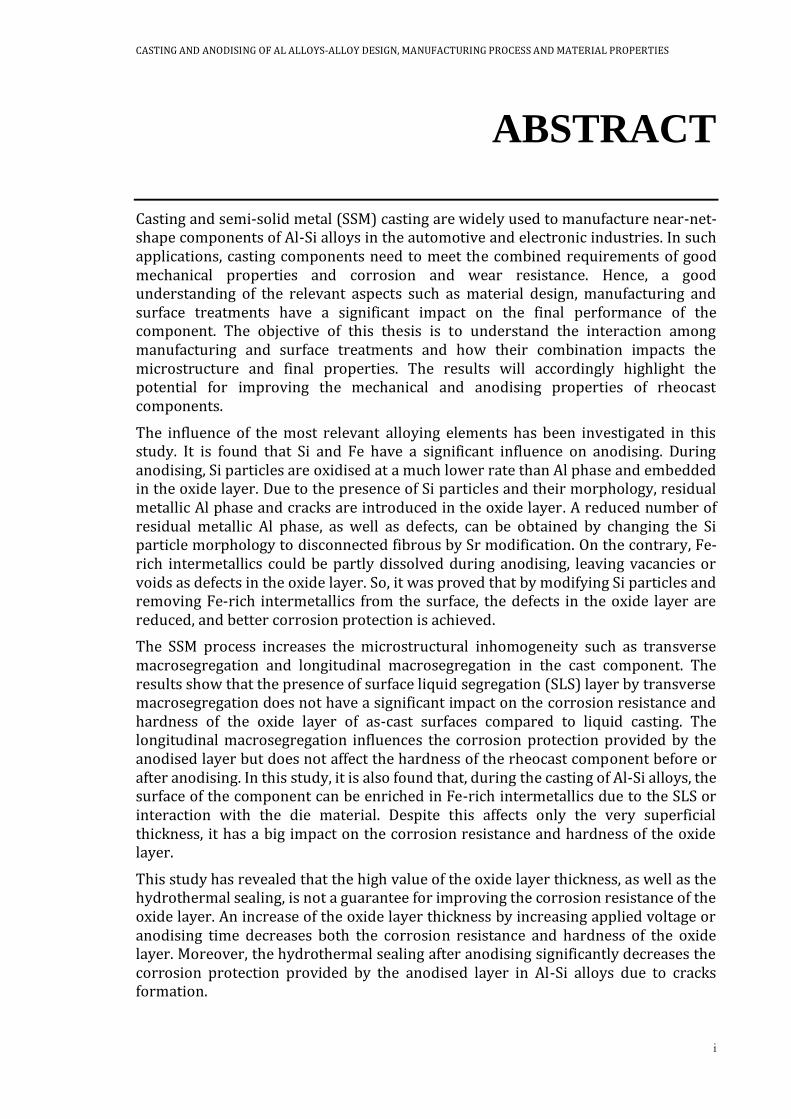
A typical microstructure of Al-Si alloys presents a combination of primary Al phases and eutectic regions if the Si content is less than 12.6 wt-%. Figure 1 demonstrates the Al-Si phase diagram. In hypoeutectic alloys (Si<12.6 wt-%), during solidification, the primary Al phases will solidify first in the form of dendrites surrounded by liquid melts when the temperature goes below liquidus temperature. When the temperature is below eutectic temperature, the eutectic reaction will be processed, and eutectic region, which consists of Al phase and most of Si particles in Al-Si binary system, will solidify between primary Al phases.
CASTING AND ANODISING OF AL ALLOYS-ALLOY DESIGN, MANUFACTURING PROCESS AND MATERIAL PROPERTIES
3
Figure 1: Al-Si phase diagram adapted from [23].
Si commonly forms a three-dimensional network of interconnected Si flakes in the eutectic region. The size of Si platelets is influenced by the cooling rate during solidification based on the surface energy of the Al-Si solid interface [24]. A high cooling rate contributes to fine Si flakes with a finer microstructure of eutectic region. However, the interconnected network of Si flakes in three dimensions will not change by varying cooling rate [25]. Chemical modification by adding a modifier such as Sr, Na, Sb, Ba, Ca, etc. can change the interconnected Si flakes to disconnected Si fibres, which can contribute to an improvement of ductility [26-28]. As one common modifier, a small amount of strontium (Sr) can realise the modification of Si particle from interconnected flakes to disconnected fibres. The mechanisms of modification normally can be classified into nucleation theories [25, 29, 30] and growth theories [31-33]. In nucleation theories, the modification of Si particle morphology is attributed to the increased growth velocity of the eutectic, as the modifier poisons the potent nuclei resulting in a decrease of nucleation density of eutectic grains [25, 30]. In growth theories, the impurity atom (modifier) such as Sr absorbed at monolayer poisons the Si growth by disturbing the alternative stacking sequence during faceted growth of the Si particle and promote multiple twinning in a zigzag growth [31-33]. However, if the addition of Sr in Al-Si alloys is significant, the modification could lose its positive effect so-called “over-modification”. In over-modification condition, coarse Si particles, Al2Si2Sr, will be formed, which can degrade the ductility of Al-Si alloys [34].
In Al-Si alloys, intermetallics such as Fe-containing intermetallics are obtained in the eutectic region. In Al-Si-Mg alloys, in addition to β-Al5FeSi phases, the peritectic reaction forms π-Al8FeMg3Si6 phases, In alloys with Mn, α-Al15(Fe,Mn)3Si2 phases, so-called “Chinese scripts” will be observed in the microstructure.
1.3 SEMI-SOLID METAL CASTING
In SSM casting, instead of liquid melt, the die-cavity is filled by a slurry which is a mixture of solid and liquid phases. Based on the slurry preparation methods, the SSM casting process can be classified into two groups, thixocasting and rheocasting. In thixocasting, the solid billet is heated up to the semi-solid condition as a slurry and then filled in the die cavity. While, in rheocasting, the slurry is produced by shearing
4
while cooling the liquid melt. Subsequently, the slurry which contains a certain fraction of solid globules is injected into the die cavity. Comparing with thixocasting, the rheocasting process takes advantages of lower primary investment cost and being able to recycle the scrap in-house [35]. In the rheocasting process, based on the slurry making methods, there are various technologies such as Semi-Solid Rheocasting™ (SSR), the Gas-Induced Sem-Solid (GISS), Swirled Enthalpy Exchange Device (SEED) and the RheoMetal™ process.
1.3.1 The RheoMetal™ process
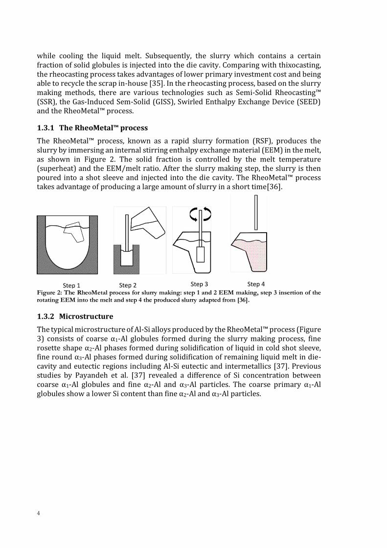
The RheoMetal™ process, known as a rapid slurry formation (RSF), produces the slurry by immersing an internal stirring enthalpy exchange material (EEM) in the melt, as shown in Figure 2. The solid fraction is controlled by the melt temperature (superheat) and the EEM/melt ratio. After the slurry making step, the slurry is then poured into a shot sleeve and injected into the die cavity. The RheoMetal™ process takes advantage of producing a large amount of slurry in a short time[36].
Figure 2: The RheoMetal process for slurry making: step 1 and 2 EEM making, step 3 insertion of the rotating EEM into the melt and step 4 the produced slurry adapted from [36].
1.3.2 Microstructure
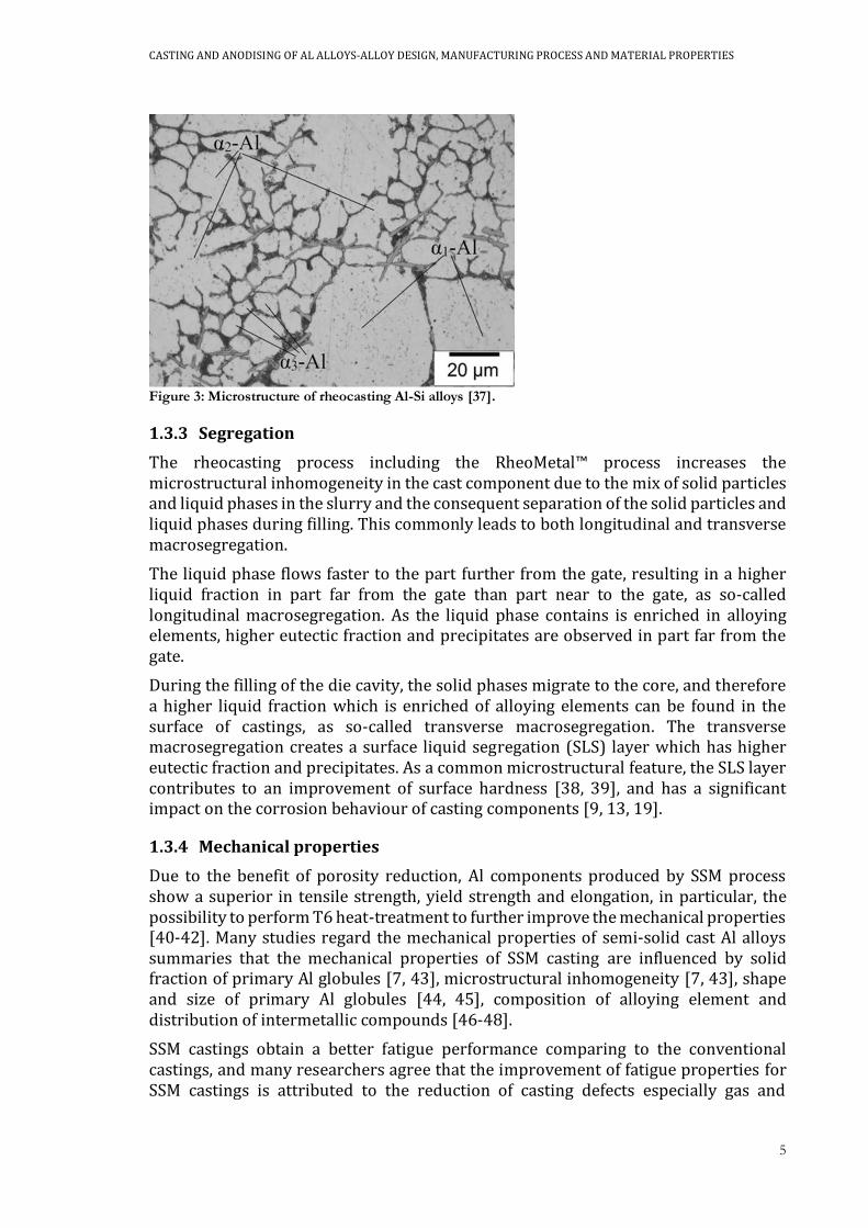
The typical microstructure of Al-Si alloys produced by the RheoMetal™ process (Figure 3) consists of coarse α1-Al globules formed during the slurry making process, fine rosette shape α2-Al phases formed during solidification of liquid in cold shot sleeve, fine round α3-Al phases formed during solidification of remaining liquid melt in die-cavity and eutectic regions including Al-Si eutectic and intermetallics [37]. Previous studies by Payandeh et al. [37] revealed a difference of Si concentration between coarse α1-Al globules and fine α2-Al and α3-Al particles. The coarse primary α1-Al globules show a lower Si content than fine α2-Al and α3-Al particles.
CASTING AND ANODISING OF AL ALLOYS-ALLOY DESIGN, MANUFACTURING PROCESS AND MATERIAL PROPERTIES
5
Figure 3: Microstructure of rheocasting Al-Si alloys [37].
1.3.3 Segregation
The rheocasting process including the RheoMetal™ process increases the microstructural inhomogeneity in the cast component due to the mix of solid particles and liquid phases in the slurry and the consequent separation of the solid particles and liquid phases during filling. This commonly leads to both longitudinal and transverse macrosegregation.
The liquid phase flows faster to the part further from the gate, resulting in a higher liquid fraction in part far from the gate than part near to the gate, as so-called longitudinal macrosegregation. As the liquid phase contains is enriched in alloying elements, higher eutectic fraction and precipitates are observed in part far from the gate.
During the filling of the die cavity, the solid phases migrate to the core, and therefore a higher liquid fraction which is enriched of alloying elements can be found in the surface of castings, as so-called transverse macrosegregation. The transverse macrosegregation creates a surface liquid segregation (SLS) layer which has higher eutectic fraction and precipitates. As a common microstructural feature, the SLS layer contributes to an improvement of surface hardness [38, 39], and has a significant impact on the corrosion behaviour of casting components [9, 13, 19].
1.3.4 Mechanical properties
Due to the benefit of porosity reduction, Al components produced by SSM process show a superior in tensile strength, yield strength and elongation, in particular, the possibility to perform T6 heat-treatment to further improve the mechanical properties [40-42]. Many studies regard the mechanical properties of semi-solid cast Al alloys summaries that the mechanical properties of SSM casting are influenced by solid fraction of primary Al globules [7, 43], microstructural inhomogeneity [7, 43], shape and size of primary Al globules [44, 45], composition of alloying element and distribution of intermetallic compounds [46-48].
SSM castings obtain a better fatigue performance comparing to the conventional castings, and many researchers agree that the improvement of fatigue properties for SSM castings is attributed to the reduction of casting defects especially gas and
6
shrinkage porosities [6, 40, 49-51]. It is well known that the casting defects such as porosity and inclusions significantly influence the fatigue life of the cast components, as they usually act as the initiation point for fatigue crack and shorten the crack propagation period [12, 52]. In defects-free SSM castings, the microstructural characteristics play important role in fatigue crack initiation and propagation. A high fraction of primary Al globules [6, 53], small size and uniform distribution of Al globules [6, 53, 54] and less platelet-like Fe-rich intermetallics [55] could improve the fatigue properties of SSM castings.
1.4 ANODISING
1.4.1 Anodising of aluminium
Anodising process is an electrochemical process that generates aluminium oxide on the surface, shown in the following equation:
Anodic reaction:
2𝐴𝑙 + 3𝐻2𝑂 → 𝐴𝑙2𝑂3 + 6𝐻+ + 6𝑒− (1.1)
The anodising process can be performed in many different chemical solutions. Normally, the acid solution such as sulfuric acid is used for surface treatments (anodising) of aluminium. Anodising process for Al alloys very often consists of six steps, as they are alkaline degreasing, alkaline etching, desmutting in nitric acid, anodising, colouring and sealing.
Before anodising, the Al alloys are typically degreased in alkaline for removing oil, grease and other contaminants from the fabrication process. Alkaline etching and desmutting in nitric acid follow in order to remove the natural oxide layer and the introduced smut during etching. As the anodising forms a nanoporous structure of the oxide, the oxide layer can be coloured in a variety of colours based on the requirements. The sealing step is performed to enhance the corrosion resistance of the oxide layer and to make the surface easier to maintain, by filling or plugging the micropores of the oxide layer. Sealing step is typically performed in hot water at a temperature between 98-100 oC, which is also named as hydrothermal sealing (HTS). At the temperature between 98-100 oC, the aluminium oxide will form AlOOH which will close the nanopores due to the volume increase. When superior corrosion resistance and/or wear resistance are required, chemical or physical impregnation can be applied to deposit sealing components into pores by means of electrochemical reaction or electromigration of corrosion-inhibiting species.
1.4.2 Formation and growth of the oxide layer
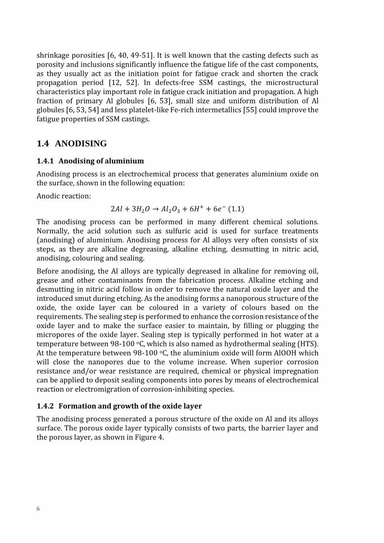
The anodising process generated a porous structure of the oxide on Al and its alloys surface. The porous oxide layer typically consists of two parts, the barrier layer and the porous layer, as shown in Figure 4.
CASTING AND ANODISING OF AL ALLOYS-ALLOY DESIGN, MANUFACTURING PROCESS AND MATERIAL PROPERTIES
7
Figure 4: Hexagonal cell structure of the porous oxide layer in cross-section and top view [56, 57].
Many efforts have been made to understand the mechanism of formation of the porous structure. One of the common accepted mechanism to explain the pore formation is field-assisted dissolution which is first proposed by Hoar and Mott [58]. In the field-assisted dissolution model, the formation of the porous oxide layer consists of two main reactions (1.1) and (1.2), as shown below
𝐴𝑙2𝑂3 + 6𝐻+ → 2𝐴𝑙3+ + 3𝐻2𝑂 (1.2)
The new oxide film is formed only at the metal/oxide interface by the reaction (1.1), the Al3+ cations by the dissolution of aluminium oxide reaction (1.2) at the oxide/electrolyte interface migrate outwards to the electrolyte.
Generally, the anodising of Al and its alloys can be performed galvanostatically (constant current) or potentiostatically (constant voltage), as shown in Figure 5b-c. The formation and growth of the porous oxide layer take places in several steps (Figure 5a). For an example of anodising at the constant voltage in this thesis, in step I, there is uniform oxidation and formation of the first oxide layer. In potentiostatic regimes, the current in step I will be relatively high in the very early beginning due to the metallic Al or its alloys. When the oxide layer generates and covers the full surface, the current will decrease as the increased thickness of the oxide layer, since the oxide layer (alumina) is a good insulator. In step II, the tendency of the current curve turns upwards owing to the formation of fine-featured imperfections in the outer regions of the oxide. The imperfections are formed by the concentration of the electrical field in areas with thinner oxide than on the rest of the surface, thereby increasing both formation and dissolution of aluminium oxide. These imperfections then grow as nanotubes almost through the oxide layer with further anodising (Step III), due to an accelerating dissolution of the oxide under a high electric field at the pore base. At step III, the regular nanopores with a hexagonal structure are formed as shown in Figure 4. When the dissolution and formation of aluminium oxide reach a steady state, the current reaches a constant level in step IV.

8
Figure 5: Sketch of formation and growth (a) of the porous oxide layer in (b) galvanostat and (c) potentiostat adapted from [59].
1.5 ANODIISNG IN CAST ALUMINIUM ALLOYS
Besides the fact that anodising is one of the common surface treatments for Al alloys, the application of anodising in cast Al alloys meets the obstacles related to high alloying elements and the quality of the casting surface.
1.5.1 Influence of alloying elements on anodising
Si, as the major element in cast Al alloys, is a disturbing element for anodising, since Si is precipitated as Si particles in eutectic regions which cannot be fully anodised or dissolved during anodising. The undissolved Si particles in the oxide layer lead to the cloudiness of the anodised surface, and a grey or dark anodised surface will be presented if Si content exceeds than 5 wt-% [60]. A high Si content in Al alloys will decrease the thickness of the oxide layer and cause a non-uniform oxide layer thickness [61]. The presence of Si particles would introduce defects in the oxide layer. Fratila-Apachitei et al. [62] studied the anodised layer with embedded Si particle on Al-10wt% Si alloy by using transmission electron microscopy (TEM). It is found that the Si particle will be anodised at a significantly reduced rate with a formation of a barrier type SiO2 film with a cavity above them. Similar results have also been reported by Mohedona et al. [63]. The quality of the oxide layer is influenced by the morphology of Si particle. The refinement of Si particle by adding modifier [64] or performing T6 heat treatment [65] is favourable for forming the anodised layer with less defects and even distribution of thickness.
As a common alloying element in Al alloys especially cast Al alloys, Fe is believed to diminishes the specular brightness of the anodised samples even when it is found in
(a)
(b) (c)

CASTING AND ANODISING OF AL ALLOYS-ALLOY DESIGN, MANUFACTURING PROCESS AND MATERIAL PROPERTIES
9
small amounts [60]. Fe in Al alloys is commonly precipitated as Fe-rich intermetallics in the microstructure. Different research groups studied the behaviour of Fe-rich intermetallic particles during anodising by using different techniques, and results demonstrated that Fe-rich intermetallics can be partly dissolved during anodising, resulting in a defective oxide layer [66-68]. Moreover, in work by Jariyaboon et al. [66], it was reported that the dissolution of Fe-rich intermetallics is also dependant on their chemical composition.
Studies of anodising in wrought aluminium alloys indicated that the Mg alloying influence the anodised layer by the precipitation of Mg2Si. It is agreed that, due to the relatively high activity of Mg, the Mg in Mg2Si will be anodised during anodising. During anodising, at an applied voltage above 12 V, the Mg2Si will be oxidised to MgO and SiO2 [69]. While at a low applied voltage, the Mg2Si will be preferentially oxidised through selective oxidation of Mg, resulting in an incorporation of Si in the porous anodic film [68, 69].
1.5.2 Influence of casting process on anodising
Different casting processes change the microstructure of Al-Si alloys, and therefore the final properties of the anodised component varied. Riddar et al. [70] compared the anodised Al surface from three fabrication methods, permanent mould casting, sand casting and HPDC on AlSi7Mg, AlSi7Mg and AlSi9Cu3, respectively. The results show non-uniform oxide layers on three cast alloys, and the sample produced by HPDC has the thinnest oxide layer than others. Although the HPDC casting has higher Si content, the thinner and uneven oxide layer on HPDC casting is associated with the higher solidification which could influence the distribution of Si particles in the microstructure. Moreover, the hardness of the oxide layer on HPDC sample exhibits the lowest mean value and largest scattering, comparing with others.
As mentioned previously, being different from other casting methods, the SSM process increases the microstructural inhomogeneity in the cast component and creates an SLS layer which has a higher eutectic fraction and precipitates on the surface. The enrichment of the eutectic region and precipitates were expected to affect the anodising properties. However, very few researches considered the SLS layer on the component during anodising and reported that the presence of the SLS layer results in a thin and porous layer with worse corrosion resistance [71, 72].
1.5.3 Corrosion resistance and hardness of anodised layer in cast Al alloys
Most of the studies regarding to the corrosion behaviour of the anodised layer were focused to investigate the influence of alloy composition [67, 68, 73, 74] and anodising process such as electrolyte [75, 76], type of anodising [63, 77, 78], applied voltage or current [68]and post-treatment [79-82] on it. Moreover, due to the relatively high demands of wrought Al alloys in aerospace industries, most of the studies were performed in wrought Al alloys.
In cast Al alloys, despite the application of anodising aims to improve the corrosion resistance and hardness of the component, however, a limited number of studies have studied the corrosion behaviour and hardness of anodised layer on cast Al components. Chaukea et al. [72] study the corrosion behaviour of the anodised layer on A356 alloys by Rheo-HPDC. They indicated that the electrochemical potential
10
difference between Al and Si leads to preferential corrosion attack at the interface between eutectic and Al matrix interface. And the presence of SLS layer in SSM castings degrade the corrosion resistance of the anodised layer, but the anodised layer can still provide sufficient corrosion protection.
1.5.4 Influence of anodising on fatigue properties
Since the anodising process changes the surface condition by adding a brittle layer on the component surface, the fatigue properties are therefore expected to be decreased. Some researchers studied the influence of anodising on fatigue properties of wrought Al alloys [83-88]. And results commonly show that the presence of the anodised layer on component surface degrades the fatigue life due to the brittle nature of the anodised layer and irregularities beneath the coating [83, 84, 86]. Moreover, the fatigue strength is reduced with increasing the thickness of the oxide layer [83].
1.6 GAP BETWEEN PREVIOUS RESEARCHES AND PRESENT STUDY
A limited number of studies have briefly investigated how the alloying element such as Si, Mg and Fe and fabrication methods influence the application of anodising in cast Al alloys. Few researches have provided proper theories which can explain the formation and growth of the oxide layer in cast Al alloys and how the oxide layer growth is related to the microstructure of Al-Si alloys. This thesis will enhance knowledge on the formation and growth of the oxide layer in Al-Si alloys by presenting proper mechanisms and correlating the bulk microstructure to the oxide layer formation in Al-Si alloys. Moreover, a special focus of this study will be put on semi-solid Al castings.
The idea of applying anodising in cast Al alloys is to improve the corrosion resistance of the component. However, most of the previous studies were focused on the thickness and the quality of the oxide layer, few researches have tested and investigated the corrosion protection of anodised layer on Al-Si alloys and identify the influence of alloying elements, microstructural characteristics and anodising process parameter on it. In this thesis, the corrosion behaviour and hardness of the anodised layer on Al-Si alloys will be evaluated. And the influence of alloying element, microstructures and anodising process parameters on corrosion resistance and hardness of the anodised layer will be identified.
Due to the application of the structural component in automotive industries, the fatigue life of such cast component is more important owing to the use of such component under repeated and cyclic loading. Many studies studied the fatigue properties of the cast component without considering the surface treatment. However, besides good mechanical properties, such cast components very often need to meet the requirements of good corrosion and wear resistance. Very few limited researches have been performed to investigate the influence of anodising on fatigue properties of the cast component. This thesis will investigate the influence of anodising on fatigue properties of the SSM castings.
Moreover, since most studies are performed on the sample with an ideal quality of the surface, this thesis will focus on as-cast surfaces which is closer to the practical application.
CASTING AND ANODISING OF AL ALLOYS-ALLOY DESIGN, MANUFACTURING PROCESS AND MATERIAL PROPERTIES
11
CHAPTER 2
RESEARCH APPROACH
2.1 PURPOSE AND AIM
In the application of Al-Si-Mg alloys in the automotive and electronics industries, Al-Si-Mg castings need to meet the requirements of a combination of excellent mechanical properties and corrosion and wear resistance. Being a multidisciplinary thesis, this work involved a study that spans from alloy design, the casting process, surface treatment (anodising) to the final mechanical and anodising properties.
This thesis aims to understand the mechanism of formation and growth of the anodised layer on cast Al alloys. Moreover, fundamental aspects of mechanical and surface properties of cast Al alloys that govern the influence of alloying elements, microstructural features, casting process and anodising process parameter will be investigated and understood in this thesis.
The knowledge of this thesis will be transferred to industrial designers and manufacturers and contribute a combination of technical and economic benefits by merging casting and anodising to design and produce Al component with good mechanical properties and corrosion protection.
2.2 RESEARCH METHODOLOGY
The research topic is firstly defined by considering the industrial needs and research gaps in the scientific community. Based on the topic of interest, a literature survey is followed to gather the relevant knowledge, pinpointed the research issues and define the variables and hypothesis. Design of experiment is performed when research variables have been defined, to establish cause and effect between variables. In this study, the reliability of the research is ensured by using proper experimental tools and measuring instruments, as well as by considering the repeatability of the experimental results. In this thesis, the repeatability of the sample’s performance (such as mechanical properties and the corrosion resistance) is ensured by reliable analytical methods performed on different samples to ensure the reliability of the collected data. Moreover, a big quantity of collected data ensures the quality of the research.
2.3 RESEARCH DESIGN
Based on the purpose and goals of this thesis, a series of investigation of main aspects
involved in material selection/alloy design, casting process, anodising process parameter and their influence on mechanical properties and anodise results was
12
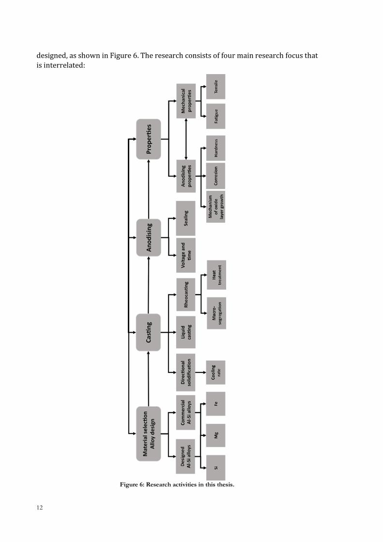
designed, as shown in Figure 6. The research consists of four main research focus that
is interrelated:
Figure 6: Research activities in this thesis.

CASTING AND ANODISING OF AL ALLOYS-ALLOY DESIGN, MANUFACTURING PROCESS AND MATERIAL PROPERTIES
13
Material selection/Alloy design is a critical aspect regarding both the mechanical
properties of the bulk materials and the achievement of anodising in Al alloys. In the present thesis, two groups of Al-Si alloys named designed alloys and commercial Al
alloys are used for benchmarking. As a primary element in cast Al alloys, Si is as one factor that influences the anodise results, e.g. quality of oxide layer and corrosion
resistance. In this thesis, designed Al-Si alloys with relatively low Si concentration and relatively low level of other alloying elements are applied for investigating the
influence of Si such as Si content and particle morphology on anodising properties. In cast Al-Si alloys, Mg is added to improve the mechanical properties. In this thesis, three
commercial Al alloys with different Mg contents were used for identifying the influence of Mg contents on tensile and fatigue properties of rheocast Al-Si alloys.
Moreover, the influence of Fe-rich intermetallics and their segregation on anodising properties was also conducted in commercial Al alloys. In this study, the relatively
lower Fe content on the sample surface was achieved by performing a mechanically
cleaning as a pre-treatment before anodising.
Casting process influences the microstructure and the performance of the oxide layer. In the present thesis, the directional solidification technology and a rheocasting
method, the RheoMetal™ process integrated with vertical pressure die casting (VPDC) were performed to study the influence of cooling rate and microstructural
macrosegregation on mechanical and anodising properties.
Anodising process and its parameter in terms of anodising voltage and anodising time
influence the thickness and performance of the oxide layer. As one of the most important steps in anodising, the influence of the sealing step on the corrosion
resistance of the oxide layer in cast Al alloys was investigated.
Material properties characterisation aims to characterise the performance of the
materials in tensile and fatigue testing of bulk materials and in-service conditions by hardness, corrosion testing (by electrochemical impedance spectroscopy, EIS) and
fatigue testing after anodising. Additionally, the mechanisms of the oxide layer growth
will be investigated in this thesis.
2.4 RESEARCH QUESTIONS
In order to understand the influence of each aspect on final properties, several
questions had to be answered:
How can the Al-Si alloys be modified in order to obtain a cast component with
better anodising and mechanical properties? (Supplement I, II, III, VII & VIII)
• As the major alloying element, the influence of Si content and morphology on anodising properties is addressed in this question. (Supplement I, II & III)
• Fe-rich intermetallics are commonly presented in Al-Si alloy. The effect of Fe-rich intermetallics on anodising properties is investigated in this question
(Supplement VII)

14
• In cast Al-Si alloys, Mg is commonly added to improve the mechanical
properties. However, few studies are conducted in the effect of Mg content on
fatigue properties in SSM casting. (Supplement VIII)
What is the influence of casting methods on the anodising and mechanical
properties of cast Al-Si alloys? (Supplement V, VI, VII & VIII)
• Compared with traditional liquid casting, the SSM process introduces macrosegregation in the cast component. The influence of the microstructural
inhomogeneity such as longitudinal and transverse macrosegregation on anodising properties is studied in this question. (Supplement V, VI & VII)
• Casting defects are commonly found in cast components. The types of casting defects in SSM casting and the influence of them on mechanical properties are
addressed in this question (Supplement VIII).
How can the anodising process be optimised in order to obtain a cast Al component
with better anodising and mechanical properties? (Supplement IV, V, VI, VII & VIII)
• The changes of anodising process parameters such as applied voltage and
anodising time will vary the thickness of the oxide layer. The influence of the oxide layer thickness on anodising properties of cast Al alloys by rheocasting is
addressed in this question. (Supplement V, VI & VII) • After anodising, the sealing step is typically performed to improve the
corrosion resistance of the anodised layer. The influence of post-treatment such as sealing on the corrosion resistance of the oxide layer in cast Al-Si alloys
is addressed in this question. (Supplement IV) • The anodising process by adding a brittle anodised layer on the sample is
expected to influence the fatigue properties. The influence of the anodised layer on fatigue properties of SSM cast samples will be investigated in this study.
(Supplement VIII)
2.5 MATERIAL AND EXPERIMENTAL PROCEDURE
2.5.1 Material
In this thesis, three designed Al-Si alloys with low Si level (Alloy A to C) and two commercial Al-Si alloys (EN AC 42000 and TX630, who are typically used in industries
to produce component by rheocasting) were produced for benchmarking. The chemical composition is shown in Table 1 and Table 2. The main reason to design new
alloys was to study the influence of Si, and the other alloying elements like Mg, Cu and Fe were kept at a similar level. However, the Fe content in Alloy C/CM was slightly
higher than in alloy A/AM and alloy B/BM. In this thesis, in both designed Al-Si alloys and commercial Al-Si alloys, Sr is chosen and added as Si particle morphology
modifier. And the amount of Sr modifier used in this thesis was set between 150 to 300 ppm, based on the previous literature results [89]. To investigate the influence of Mg
content on material properties, TX630 alloys with three Mg content were tested (Table
2).

CASTING AND ANODISING OF AL ALLOYS-ALLOY DESIGN, MANUFACTURING PROCESS AND MATERIAL PROPERTIES
15
Table 1: Chemical composition of designed alloys. Alloy Si Mg Fe Mn Cu Sr Al
Alloy A/AM*
2.43 0.23 0.20 0.05 0.23 0.00/0.02 bal.
Alloy B/BM*
3.53 0.26 0.24 0.09 0.23 0.00/0.02 bal.
Alloy C/CM*
5.45 0.29 0.36 0.14 0.23 0.00/0.02 bal.
*M indicates the addition of Sr as modifier
Table 2: Chemical composition of commercial Al-Si alloys. Alloy Si Mg Fe Mn Cu Sr Al EN AC 42000
7.00 0.38 0.40 0.26 0.07 0.02 bal.
TX630-1 7.40 0.41 0.12
0.02 0.05 0.03 bal.
TX630-2 7.20 0.47 0.12 0.02 0.02 0.03 bal. TX630-3 7.20 0.59 0.12 0.02 0.01 0.03 bal.
2.5.2 Casting:
2.5.2.1 Directional solidification technique
Designed alloy samples (Table 1) were firstly cast in a Cu die coated with graphite as
cylindrical rods and then remelted and solidified with the directional solidification technology (Figure 7). The initial rods were put into graphite coated steel tubes and
then inserted into the furnace at 720 oC for 30 minutes. Then the furnace was raised at a set speed and the steel tubes with samples inside were withdraw from the furnace
and cooled by water cooling. The speed of the furnace determined the cooling rate. In this thesis, two different cooling rates referring to the furnace speed of 3 mm/s and
0.3 mm/s, have been used to produce samples with two microstructures comparable to HPDC and die casting. Finally, the samples were machined and polished to remove
impurities from the surface and the head part of rods was removed. Typically, samples produced using the directional solidification technique have a homogenous
microstructure throughout the entire sample.

16
Figure 7: Directional solidification equipment for designed Al-Si alloys.
2.5.2.2 Liquid and semi-solid casting
In this thesis, the RheoMetal™ process (Figure 2) was applied to produce the slurry
from the Al-Si alloys in Table 2. The slurry was prepared with the stirring speed around 1000 rpm and 35 oC of superheat (melt temperature before slurry making at
650 oC for both EN AC 42000 and TX630). The solid fraction (primary α-Al phases) in the slurry was controlled by the amount of enthalpy exchange material (EEM) to shot
ratio was fixed to 7 wt-% in this thesis thus obtaining constant solid fraction [90]. The slurry was then poured into the shot sleeve of a vertical pressure die casting (VPDC)
machine to cast in 10 mm thick samples with geometry shown in Figure 8b. Machine parameter such as die temperature, plunger advance speed and intensification
pressure, were kept constant at 175 oC, 0.3 m/s and 160 bar, respectively.
Figure 8: Sketch of (a) the casting process, and (b) the cast sample.
In this thesis, liquid casting was also performed in the same VPDC machine with same
machine parameter. Prior to liquid and semi-solid casting, servral liquid shots were performed to heat the machine and maintain the thermal condition in the shot sleeve
and die cavity.
T5 heat treatment was performed on TX630 alloys (TX630-1 to TX630-3) by using an air circulation furnace within a period of 24 hours after casting for artificial ageing step. The artificial ageing was performed at the temperature of 175 oC with 4.5 hours as holding time, based on the previous study of heat treatment optimisation [91]. After the completion of the artificial ageing, samples were allowed to cool in still air.
(a) (b)
CASTING AND ANODISING OF AL ALLOYS-ALLOY DESIGN, MANUFACTURING PROCESS AND MATERIAL PROPERTIES
17
2.5.3 Anodising
The anodising process in this thesis was performed in a bath of 1.0 M H2SO4 at room temperature. The applied voltage and anodising time vary from 15 to 25 V and 15 to
120 mins, respectively, in order to study the influence of anodising voltage and duration on the thickness, corrosion resistance and hardness of the oxide layer in cast
Al alloys.
Differently from previous studies, the as-cast surface was focused and studied. Prior
to anodising, samples were only ultrasonically cleaned in ethanol for at least 5 mins. After anodising, samples were ultrasonically rinsed in distilled water for at least 3
mins and then oven dried at 50 oC for 30 mins.
Although the as-cast surface of cast samples was focused, for investigating the
mechanisms of oxide layer growth in Al-Si alloys and the influence of Si on anodising properties, selected samples of designed Al-Si alloys were ground and polished to
mirror finish (< 1 µm) and cleaned using the same procedure as as-cast surface. The hydrothermal sealing (HTS) step was performed in selective samples of designed Al-
Si alloys in boiled demineralised water for 40 mins. After the HTS step, samples were
dried in the oven for 50 mins at 50 oC.
2.5.4 Characterisation and testing
2.5.4.1 Microstructure evaluation
The microstructures of the bulk materials and anodised layer were studied by optical microscopy (OM, Olympus GX71F), scanning electron microscopy (SEM, JEOL JSM-
7001F), low vacuum SEM (LVSEM, JOEL IT300LV) and focused ion beam-SEM (FIB-SEM, Tescan Lyra 3). The thickness of the oxide layer was measured by optical
microscopy on the cross-section of the samples, and at least 30 measurements were
performed on each sample.
Scanning transmission electron microscopy (STEM)
In this thesis, a scanning transmission electron microscopy (STEM, Titan3™-60-300)
was applied to exam the detailed microstructural features of an anodised layer on Alloy C and alloy CM with a mirror finished surface before anodising. A disc-shaped
section (about 1 mm) of the sample was cut from cross-section and used for sample preparation for STEM. The STEM sample was produced by conventional cutting,
glueing and polishing method. For thinning to electron transparency, Argon ion milling at 5 kV using a Gatan Ion Polishing System was applied. Electron microscopy was
performed using a double corrected STEM equipped with a monochromated high brashness electron source, large solid angle energy-dispersive X-ray spectroscopy
(EDXS) detector (Super-X), as well as a high-speed, Dual EELS Gatan Quantum ERS imaging filter, employed for electron energy loss spectroscopy (EELS) spectrum
imaging in the low loss region, to investigate the resulting structures.

18
2.5.5 Mechanical (tensile and fatigue) testing
In this thesis, samples produced by directional solidification were tensile-tested according to the ASTM B557 standard, while the tensile testing of samples by
rheocasting were conducted based on SS-EN ISO 6892-1:2016. The tensile testing was using a Zwick/Roell Z 100 machine equipped with a length extensometer to measure
the elongation. In tensile testing, minimum four samples were tested for each
condition.
Fatigue testing was performed under four-point bending at a stress ration of -1 (R=σmin/σmax=-1) with a sinusoidal loading with a frequency of 10 Hz using an MTS
machine at room temperature. In order to ensure the reliability of the collected, a big range of results was achieved by performing different loads or testing more than one
sample in the same stress condition.
2.5.6 Corrosion testing
Corrosion testing was conducted by the electrochemical impedance spectroscopy
(EIS) with a three-electrode configuration on an AUTOLAB 302N and an Ivium Vertex potentiostat. Samples were immersion in 3 wt-% NaCl at room temperature, while a
platinum ring and an Ag/AgCl electrode (3 M KCl) used as the counter and reference electrodes, respectively. The frequency ranged from 100 kHz to 10mHz with 36 points,
with the amplitude of the sinusoidal potential being 10 mV around the open-circuit potential (OCP). Repeatability was ensured by measuring three specimens of the same
material. The spectra were collected the immersion time of at least 12 hours at the room temperature. After collecting the spectra, the ZSimpWin software program was
used to analyse and fit the impedance spectra.
2.5.7 Hardness
The hardness of the anodised layer on selected samples was determined by using Micro Materials NanoTest Vantage equipped with Vickers and Berkovich indenters.
The load for hardness testing was set based on the thickness of the oxide layer so that
the diagonal of the indentation was on third of the local oxide layer thickness or below.

CASTING AND ANODISING OF AL ALLOYS-ALLOY DESIGN, MANUFACTURING PROCESS AND MATERIAL PROPERTIES
19
CHAPTER 3
SUMMARY OF RESULTS AND
DISCUSSION
3.1 ALLOY DESIGN FOR ANODISING AND MECHANICAL PROPERTIES
(SUPPLEMENT I, II, III, VII & VIII)
3.1.1 Microstructural characterisation of the bulk materials
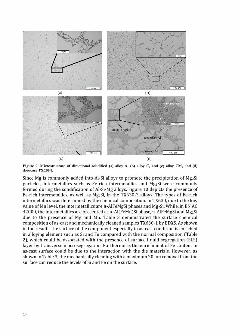
As the main alloying element in cast Al alloys, the Si content influences the microstructure of the Al-Si alloys. Figure 9 demonstrated the microstructural changes of bulk materials by changing the Si concentration and the Si particle morphology by addition of Sr. As shown in Figure 9, by increasing Si concentration in Al-Si alloys, the Al phase is slightly refined visually, and an increase of the fraction of the eutectic region is evident. Morphological changes of Si particles in bulk materials were obtained by the addition of Sr in Al-Si alloys. A shown in Figure 9a-b, in the Al-Si alloys without Sr, Si particles are displayed as polygonal flakes, and a continuous branched network of Si flakes was evident. By introducing 200-300 ppm Sr in Al-Si alloys (Figure 9c-d), Si particles are displayed as disconnected fibres, although the Si content and casting methods are different.
20
Figure 9: Microstructure of directional solidified (a) alloy A, (b) alloy C, and (c) alloy CM, and (d) rheocast TX630-1.
Since Mg is commonly added into Al-Si alloys to promote the precipitation of Mg2Si particles, intermetallics such as Fe-rich intermetallics and Mg2Si were commonly formed during the solidification of Al-Si-Mg alloys. Figure 10 depicts the presence of Fe-rich intermetallics, as well as Mg2Si, in the TX630-3 alloys. The types of Fe-rich intermetallics was determined by the chemical composition. In TX630, due to the low value of Mn level, the intermetallics are π-AlFeMgSi phases and Mg2Si. While, in EN AC 42000, the intermetallics are presented as α-Al(FeMn)Si phase, π-AlFeMgSi and Mg2Si due to the presence of Mg and Mn. Table 3 demonstrated the surface chemical composition of as-cast and mechanically cleaned samples TX630-1 by EDXS. As shown in the results, the surface of the component especially in as-cast condition is enriched in alloying element such as Si and Fe compared with the normal composition (Table 2), which could be associated with the presence of surface liquid segregation (SLS) layer by transverse macrosegregation. Furthermore, the enrichment of Fe content in as-cast surface could be due to the interaction with the die materials. However, as shown in Table 3, the mechanically cleaning with a maximum 20 µm removal from the surface can reduce the levels of Si and Fe on the surface.
(a) (b)
(c) (d)

CASTING AND ANODISING OF AL ALLOYS-ALLOY DESIGN, MANUFACTURING PROCESS AND MATERIAL PROPERTIES
21
Figure 10: SEM micrographs and EDXS mapping of Fe-rich intermetallics and Mg2Si on TX630-3.
Table 3: Surface chemical composition of as-cast and mechanically cleaned samples of TX630-1 by EDXS in top view.
Surface preparation
Si Mg Fe Mn Cu Al
As-cast 16.13 ±0.62
2.58 ±0.13
0.68 ±0.08
0.09 ±0.04
0.15 ±0.07
bal.
Mechanically cleaned
13.06 ±1.03
2.00 ±0.11
0.21 ±0.03
0.09 ±0.03
0.19 ±0.04
bal.
3.1.2 Influence of alloying element on mechanical properties
3.1.2.1 Tensile behaviour
Tensile properties of Al-Si alloys, including ultimate tensile strength (UTS), yield strength (YS) and elongation were presented as a function of Si concentration and modification in Figure 11a, and as a function of Mg content after T5 treatment in Figure 11b.
Figure 11: Tensile test results of (a) directional solidified samples, (b) rheocast samples of TX630.
Comparing the tensile test results as a function of Si level, it appears that by increasing the Si content in Al-Si alloys, the UTS and YS increases, while the elongation decreases. An increase of Si content in the materials increases the fraction of hard and brittle eutectic regions resulting in an improvement of mechanical properties such as UTS
(a) (b)

22
and YS. However, the reduce of elongation in alloy C/CM could also be associated with a higher Fe content. Sr modification by changing Si particle morphology from flake-like to fibrous aims to improve the elongation of the material. However, comparing the tensile results with different Si particle morphologies, the contribution of modification in the improvement of elongation is not evident (inside the standard deviation). In the current study, it seems that, because of the relatively low Si content, the morphology of the Si particle will not dominate the mechanical properties. Furthermore, the Fe-rich intermetallics randomness in size, distribution and orientation play a major role in the mechanical properties.
The tensile test results (Figure 11b) indicated that the Mg content has a significant influence on mechanical properties. A comparison of tensile test results of Al-Si-Mg with different Mg contents shows that the increase of Mg content increases the YS values and decreases the elongation. However, no significant difference in UTS values for three alloys was evident. An increase of general Mg concentration in Al-Si alloys contributes to an increase of Mg composition in primary Al phases after T5 treatment [92]. Judging from this the increase of Mg content could increase the amount available Mg for precipitation hardening, and therefore the yield strength increases.
3.1.2.2 Fatigue behaviour
Figure 12 shows the S-N curves obtained by four-point bending fatigue testing. The applied stress was defined according to the yield stress of the Al-Si alloys. The highest applied stress was slightly above the yield stress, and the stress was continuously decreased around 10 MPa. In this thesis, fatigue tests were performed at four different stress level in each material. It can be seen from Figure 12 that the number of cycles of rheocast samples increases with a decrease in maximum stress applied. Comparing the fatigue test results of rheocast samples with different Mg content in the T5 condition, it appears that the fatigue life was increased with the increase of Mg content from 0.4 wt-% to 0.47 wt-%. However, the TX630 alloy with 0.6 wt-% Mg shows the lowest fatigue life among the tested samples in T5 condition. Similar results were also reported by Wang et al. [52]. For better understanding, the relations between fatigue behaviour and tensile, maximum stress was normalised to the yield strength in each alloy. As shown in Figure 12b, the TX630 alloy with lower Mg content has a higher fatigue life when the maximum stress is around its yield strength.
Figure 12: (a) S-N curve of TX630 alloys, (b) normalisation of maximum stress by yield strength.
(a) (b)
CASTING AND ANODISING OF AL ALLOYS-ALLOY DESIGN, MANUFACTURING PROCESS AND MATERIAL PROPERTIES
23
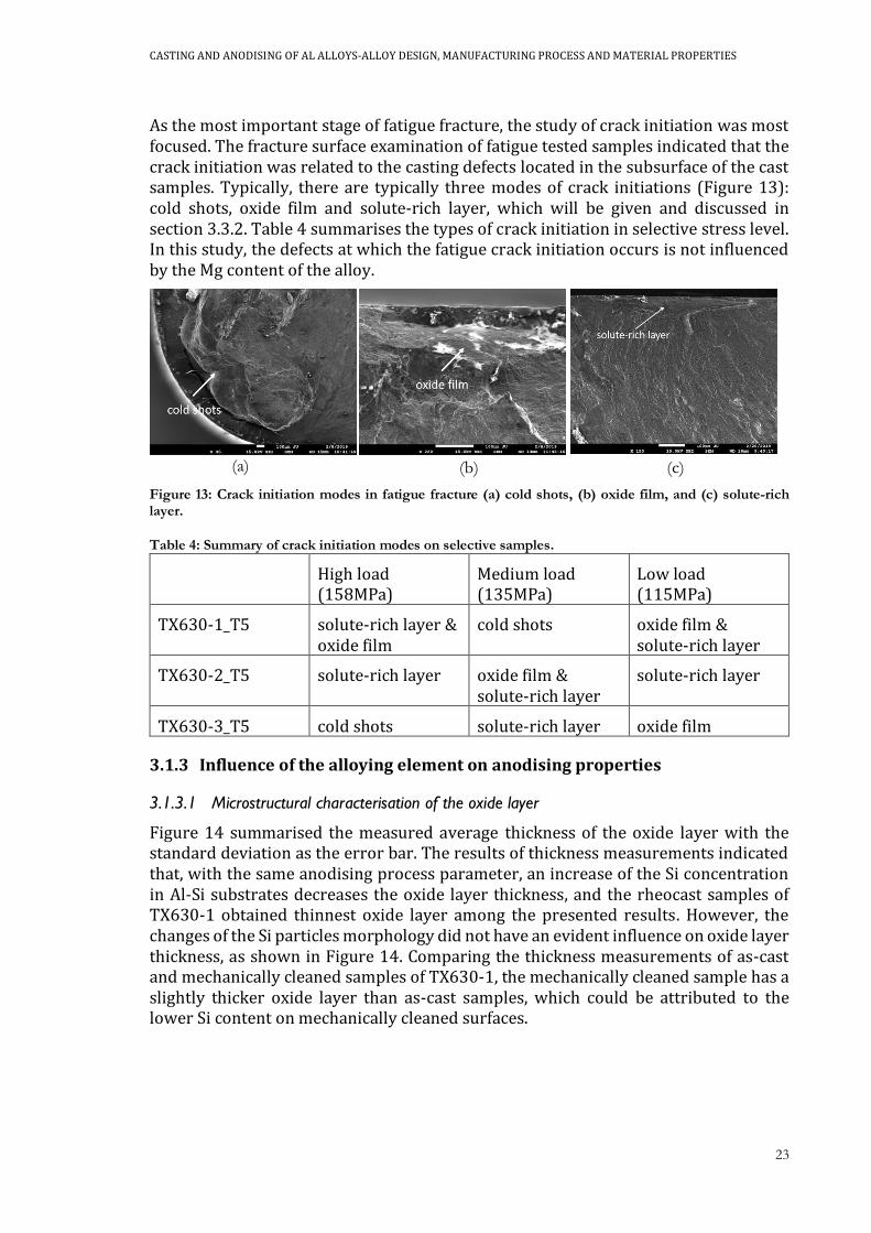
As the most important stage of fatigue fracture, the study of crack initiation was most focused. The fracture surface examination of fatigue tested samples indicated that the crack initiation was related to the casting defects located in the subsurface of the cast samples. Typically, there are typically three modes of crack initiations (Figure 13): cold shots, oxide film and solute-rich layer, which will be given and discussed in section 3.3.2. Table 4 summarises the types of crack initiation in selective stress level. In this study, the defects at which the fatigue crack initiation occurs is not influenced by the Mg content of the alloy.
Figure 13: Crack initiation modes in fatigue fracture (a) cold shots, (b) oxide film, and (c) solute-rich layer.
Table 4: Summary of crack initiation modes on selective samples.
High load (158MPa)
Medium load (135MPa)
Low load (115MPa)
TX630-1_T5 solute-rich layer & oxide film
cold shots oxide film & solute-rich layer
TX630-2_T5 solute-rich layer oxide film & solute-rich layer
solute-rich layer
TX630-3_T5 cold shots solute-rich layer oxide film
3.1.3 Influence of the alloying element on anodising properties
3.1.3.1 Microstructural characterisation of the oxide layer
Figure 14 summarised the measured average thickness of the oxide layer with the standard deviation as the error bar. The results of thickness measurements indicated that, with the same anodising process parameter, an increase of the Si concentration in Al-Si substrates decreases the oxide layer thickness, and the rheocast samples of TX630-1 obtained thinnest oxide layer among the presented results. However, the changes of the Si particles morphology did not have an evident influence on oxide layer thickness, as shown in Figure 14. Comparing the thickness measurements of as-cast and mechanically cleaned samples of TX630-1, the mechanically cleaned sample has a slightly thicker oxide layer than as-cast samples, which could be attributed to the lower Si content on mechanically cleaned surfaces.
(c) (a) (b)

24
Figure 14: The thickness of the oxide layer for designed Al-Si alloys and TX630-1 anodising at 20 V for 30 mins.
The changes of the microstructure of the Al-Si substrates by changing Si concentration, Si particle morphology and the Fe content change the microstructure of the oxide layer. Figure 15 and Figure 16 compared the cross-section microstructure of the oxide layer on directional solidified alloy A and C, as well as rheocast TX630-1 sample with different levels of Fe, respectively.
Figure 15: OM micrographs of (a) alloy A, (b) alloy C, and (c) alloy CM.
Figure 16: In-beam backscattered SEM micrographs of the oxide layer on (a) TX630-1, as-cast surface, (b) TX630-1, mechanically cleaned surface in cross-section.
(c) (a) (b)
(a) (b)

CASTING AND ANODISING OF AL ALLOYS-ALLOY DESIGN, MANUFACTURING PROCESS AND MATERIAL PROPERTIES
25
As shown in Figure 15 and Figure 16, since the Si particle cannot be dissolved during anodising, Si particles were embedded in the oxide layer, resulting in an uneven distribution of the oxide layer thickness. By increasing the Si concentration, more fraction of Si particles in the oxide layer is evident. Comparing the microstructure of the oxide layer in alloy C and CM in Figure 15, during anodising, the oxide layer grows through the Al phase between Si particles and engulf them no matter the morphology of Si particles. The microstructural characterisation of substrates revealed the presence of Fe-rich intermetallics and Mg2Si. However, no Fe-rich intermetallics was revealed in the oxide layer. Instead of Fe-rich intermetallics, voids which have a similar geometry and layout of Fe-rich intermetallics were evident. And comparing the SEM micrographs of the oxide layer on surfaces with different Fe level, it was found that, after anodising, fewer vacancies or voids were evident in the mechanical cleaned surface with lower Fe level. It seems that Fe-rich intermetallics could be partly dissolved during anodising.
3.1.3.2 Study of Si behaviour during anodising by STEM
To obtain more detailed information about the microstructure difference of the oxide layer in unmodified and modified conditions, closer microstructure characterisation of the oxide layer in alloy C and CM was conducted by applying STEM. Figure 17a depicts the embedded flake-like Si particles in the oxide layer regards of unmodified alloy C. As shown in Figure 17a, crack and voids above or through Si particles are evident. The EDXS mapping indicated the presence of Al-rich phases which were located either beneath or between Si particles. And the EELS mapping proves that Al-rich observed in EDXS map is actually metallic Al which remains unanodised after anodising. Moreover, the EELS mapping reveals the presence of the oxidised silicon layer, represented by a more yellow colour, on the top of Si. In the modified condition, Si particles are displayed as small isolated fibres due to the modification process, and only a few cracks and voids are observed in this condition, as shown in Figure 17b. Comparing with the oxide layer on unmodified alloy C, no residual metallic Al phases was evident in this magnification. In Figure 17b, a silicon oxide (Si-O, yellow response) with more than 100 nm in thickness is observed on the top of pure Si (green response) in the EELS mapping. The EELS results proved that a relatively large fraction of the Si fibre is anodised. Furthermore, a small area (nano-scale) of metallic Al phase beneath a particle was observed in EELS map. However, comparing with the unmodified alloy, a lower fraction of residual metallic Al phase was evident in the modified alloy.
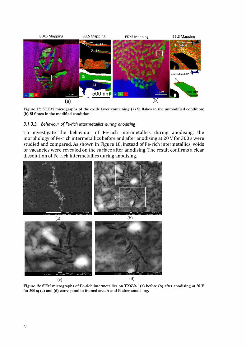
26
Figure 17: STEM micrographs of the oxide layer containing (a) Si flakes in the unmodified condition; (b) Si fibres in the modified condition.
3.1.3.3 Behaviour of Fe-rich intermetallics during anodising
To investigate the behaviour of Fe-rich intermetallics during anodising, the morphology of Fe-rich intermetallics before and after anodising at 20 V for 300 s were studied and compared. As shown in Figure 18, instead of Fe-rich intermetallics, voids or vacancies were revealed on the surface after anodising. The result confirms a clear dissolution of Fe-rich intermetallics during anodising.
Figure 18: SEM micrographs of Fe-rich intermetallics on TX630-1 (a) before (b) after anodising at 20 V for 300 s; (c) and (d) correspond to framed area A and B after anodising.
(a) (b)
(a) (b)
(c) (d)

CASTING AND ANODISING OF AL ALLOYS-ALLOY DESIGN, MANUFACTURING PROCESS AND MATERIAL PROPERTIES
27
3.1.3.4 Mechanism of the oxide layer formation and growth in cast Al alloys
The formation and growth of the oxide layer in Al-Si alloys are presented by some mechanisms that can describe the behaviour of Si particle, eutectic region and Fe-rich intermetallics during anodising. During anodising, the oxide layer grows homogenously in the Al phase perpendicular to the surface. When oxide front meets the Si particles, Si reacts to form Si-O at a much slower rate than Al oxidation. Therefore, the oxide front circumvents the Si particle. When the oxide front passes the Si particle, the Si particle becomes embedded in the oxide layer and insulated from the bulk material and the oxidation stops, leaving a partly anodised Si particle in the oxide layer. Moreover, Si particle can act as shields for the Al phase that cannot be directly reached by the oxide front before becoming insulated. Therefore, the metallic Al phase that remains unanodised is commonly observed in the oxide layer beneath or between Si particles (Figure 19). Furthermore, cracks and voids observed in the oxide layer could be associated with the presence of Si particles. The cracks and voids may be a result of localised intrinsic stress due to the volume expansion around the Si particles. As stress release, a crack or void may have formed during anodising. In this thesis, the increase of Si content or the enrichment of eutectic Si by segregation increase the probability of the oxide layer growing through the eutectic phase, and therefore more Si particles were embedded in the oxide layer with a thinner oxide layer.
Figure 19: Behaviour of Si particle during anodising.
The Si particle morphology has a significant influence on the growth and formation of the oxide layer. In unmodified condition (Figure 20a), due to the interconnected and relatively larger Si flakes, the space between the flakes for the oxide layer growth becomes narrow. More Al phases become shielded from oxidation, resulting in larger and more numerous residual metallic Al inclusions remaining in the oxide. In the modified condition (Figure 20b), the disconnected structure of Si fibres promotes a more homogenous growth of the oxide layer through Al phase between them, resulting in a decrease of the residual metallic Al areas in the oxide layer. Meanwhile, the modification of Si particle morphology to fibrous promotes a large fraction of Si-O in Si particles and few cracks and voids in the oxide layer.
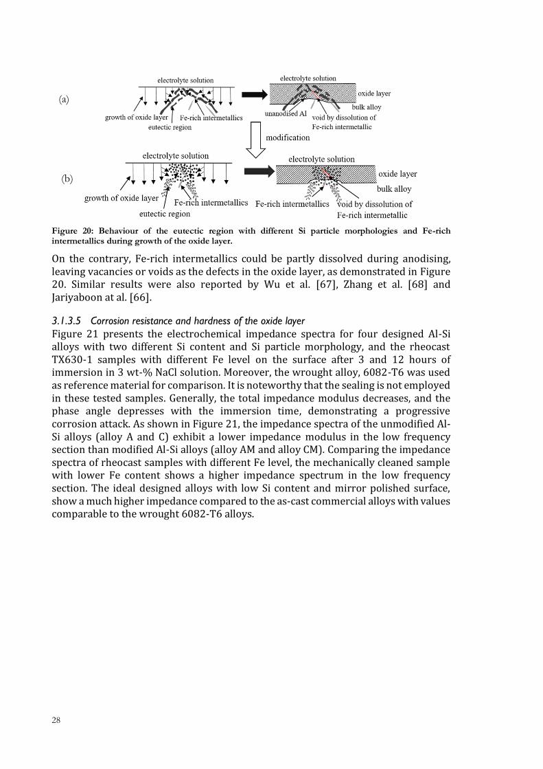
28
Figure 20: Behaviour of the eutectic region with different Si particle morphologies and Fe-rich intermetallics during growth of the oxide layer.
On the contrary, Fe-rich intermetallics could be partly dissolved during anodising, leaving vacancies or voids as the defects in the oxide layer, as demonstrated in Figure 20. Similar results were also reported by Wu et al. [67], Zhang et al. [68] and Jariyaboon at al. [66].
3.1.3.5 Corrosion resistance and hardness of the oxide layer
Figure 21 presents the electrochemical impedance spectra for four designed Al-Si alloys with two different Si content and Si particle morphology, and the rheocast TX630-1 samples with different Fe level on the surface after 3 and 12 hours of immersion in 3 wt-% NaCl solution. Moreover, the wrought alloy, 6082-T6 was used as reference material for comparison. It is noteworthy that the sealing is not employed in these tested samples. Generally, the total impedance modulus decreases, and the phase angle depresses with the immersion time, demonstrating a progressive corrosion attack. As shown in Figure 21, the impedance spectra of the unmodified Al-Si alloys (alloy A and C) exhibit a lower impedance modulus in the low frequency section than modified Al-Si alloys (alloy AM and alloy CM). Comparing the impedance spectra of rheocast samples with different Fe level, the mechanically cleaned sample with lower Fe content shows a higher impedance spectrum in the low frequency section. The ideal designed alloys with low Si content and mirror polished surface, show a much higher impedance compared to the as-cast commercial alloys with values comparable to the wrought 6082-T6 alloys.
(b)
(a)

CASTING AND ANODISING OF AL ALLOYS-ALLOY DESIGN, MANUFACTURING PROCESS AND MATERIAL PROPERTIES
29
Figure 21: Bode plot of EIS spectra of 6082-T6, alloy A, alloy AM, alloy C, alloy CM, rheocast TX630-2 samples with as-cast surface and mechanically cleaned surface at (a) 3 hours, (b) 12 hours.
To obtain quantitative information of the resistance and capacitance of the anodised
layer, the equivalent circuit, Rel(CPEoxRox)(CPEinRpo) as demonstrated in Figure 22a was used to fit the impedance spectra for shorter immersion time. In the current
circuit, Rel stands for the resistance of the electrolyte, Rox indicates the resistance of the oxide layer and Rpo is the polarisation resistance at the interface. The capacitive
behaviour is simulated by two constant phase elements (CPE), CPEox and CPEin, for the oxide layer and interface (electrical double layer and barrier layer), respectively. In
this thesis, another equivalent circuit, Rel(CPEox(Rox(CPEinRpo))), as shown in Figure 22b, was used to fit the impedance spectra for longer immersion time, after the
appearance of corrosion attack in the defects. Figure 21 shows the measured (points) and fitted (gray lines) spectra obtained after 3 and 12 hours of immersion, and the
fitting results match well to the measured spectra.
(a)
(b)
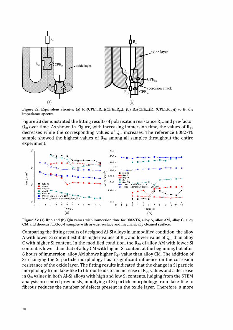
30
Figure 22: Equivalent circuits: (a) Rel(CPEoxRox)(CPEinRpo); (b) Rel(CPEox(Rox(CPEinRpo))) to fit the impedance spectra.
Figure 23 demonstrated the fitting results of polarisation resistance Rpo and pre-factor Qin over time. As shown in Figure, with increasing immersion time, the values of Rpo decreases while the corresponding values of Qin increases. The reference 6082-T6 sample showed the highest values of Rpo among all samples throughout the entire experiment.
Figure 23: (a) Rpo and (b) Qin values with immersion time for 6082-T6, alloy A, alloy AM, alloy C, alloy CM and rheocast TX630-1 samples with as-cast surface and mechanically cleaned surface.
Comparing the fitting results of designed Al-Si alloys in unmodified condition, the alloy A with lower Si content exhibits higher values of Rpo and lower value of Qin than alloy C with higher Si content. In the modified condition, the Rpo of alloy AM with lower Si content is lower than that of alloy CM with higher Si content at the beginning, but after 6 hours of immersion, alloy AM shows higher Rpo value than alloy CM. The addition of Sr changing the Si particle morphology has a significant influence on the corrosion resistance of the oxide layer. The fitting results indicated that the change in Si particle morphology from flake-like to fibrous leads to an increase of Rpo values and a decrease in Qin values in both Al-Si alloys with high and low Si contents. Judging from the STEM analysis presented previously, modifying of Si particle morphology from flake-like to fibrous reduces the number of defects present in the oxide layer. Therefore, a more
(a) (b)
(a) (b)
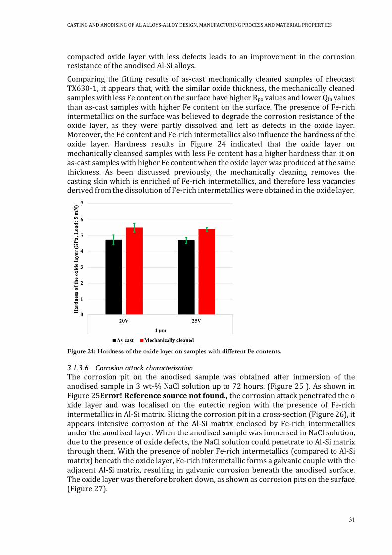
CASTING AND ANODISING OF AL ALLOYS-ALLOY DESIGN, MANUFACTURING PROCESS AND MATERIAL PROPERTIES
31
compacted oxide layer with less defects leads to an improvement in the corrosion resistance of the anodised Al-Si alloys.
Comparing the fitting results of as-cast mechanically cleaned samples of rheocast TX630-1, it appears that, with the similar oxide thickness, the mechanically cleaned samples with less Fe content on the surface have higher Rpo values and lower Qin values than as-cast samples with higher Fe content on the surface. The presence of Fe-rich intermetallics on the surface was believed to degrade the corrosion resistance of the oxide layer, as they were partly dissolved and left as defects in the oxide layer. Moreover, the Fe content and Fe-rich intermetallics also influence the hardness of the oxide layer. Hardness results in Figure 24 indicated that the oxide layer on mechanically cleansed samples with less Fe content has a higher hardness than it on as-cast samples with higher Fe content when the oxide layer was produced at the same thickness. As been discussed previously, the mechanically cleaning removes the casting skin which is enriched of Fe-rich intermetallics, and therefore less vacancies derived from the dissolution of Fe-rich intermetallics were obtained in the oxide layer.
Figure 24: Hardness of the oxide layer on samples with different Fe contents.
3.1.3.6 Corrosion attack characterisation
The corrosion pit on the anodised sample was obtained after immersion of the anodised sample in 3 wt-% NaCl solution up to 72 hours. (Figure 25 ). As shown in Figure 25Error! Reference source not found., the corrosion attack penetrated the oxide layer and was localised on the eutectic region with the presence of Fe-rich intermetallics in Al-Si matrix. Slicing the corrosion pit in a cross-section (Figure 26), it appears intensive corrosion of the Al-Si matrix enclosed by Fe-rich intermetallics under the anodised layer. When the anodised sample was immersed in NaCl solution, due to the presence of oxide defects, the NaCl solution could penetrate to Al-Si matrix through them. With the presence of nobler Fe-rich intermetallics (compared to Al-Si matrix) beneath the oxide layer, Fe-rich intermetallic forms a galvanic couple with the adjacent Al-Si matrix, resulting in galvanic corrosion beneath the anodised surface. The oxide layer was therefore broken down, as shown as corrosion pits on the surface (Figure 27).
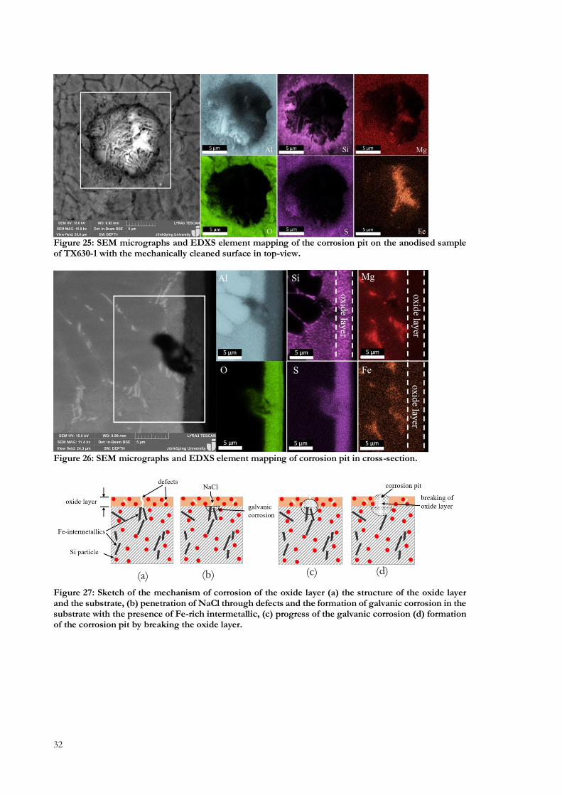
32
Figure 25: SEM micrographs and EDXS element mapping of the corrosion pit on the anodised sample of TX630-1 with the mechanically cleaned surface in top-view.
Figure 26: SEM micrographs and EDXS element mapping of corrosion pit in cross-section.
Figure 27: Sketch of the mechanism of corrosion of the oxide layer (a) the structure of the oxide layer and the substrate, (b) penetration of NaCl through defects and the formation of galvanic corrosion in the substrate with the presence of Fe-rich intermetallic, (c) progress of the galvanic corrosion (d) formation of the corrosion pit by breaking the oxide layer.
(a) (b) (c) (d)

CASTING AND ANODISING OF AL ALLOYS-ALLOY DESIGN, MANUFACTURING PROCESS AND MATERIAL PROPERTIES
33
3.2 INFLUENCE OF CASTING METHODS AND PROCESS ON
MECHANICAL AND ANODISINGPROPERTIES (SUPPLEMENT V VI &
VIII)
3.2.1 Microstructural evaluation of the bulk materials
In this thesis, microstructural characterisation of rheocasting sample was assessed and compared with a traditional liquid casting which was evaluated as a reference in this study. The microstructure of typical rheocast Al alloys is mainly composed of coarse primary α1- Al phase formed during the slurry making step, fine secondary α2-Al phase formed during solidification of remaining liquid phase of slurry in die cavity and eutectic region including Al-Si phases and intermetallics, as shown in Figure 28a-c. While, on the contrary, the liquid cast Al-Si alloy (Figure 28d) has the typical dendritic microstructure.
Figure 28: OM micrographs of rheocast ENAC 42000 (a) typical microstructure, (b) the SLS layer in part near to the gate, (c) SLS layer in part near to the vent, (d) liquid casting with the presence of skin effect.
Figure 28b-c demonstrates the presence of the SLS layer by transverse macrosegregation which contains a high fraction of Al-Si eutectic regions and intermetallics on the surface both in near-to-gate (Figure 28b) and near-to-vent (Figure 28c) parts. In rheocasting, due to the separation of the liquid phases from solid phases, the solid phase trends to migrate to the core of the component, while the liquid phase which contains higher alloying elements flows to the surface of the component, leading to a transvers macrosegregation with a higher fraction of eutectic regions and intermetallics on the component surface [4, 5]. Furthermore, the solute-rich liquid
(a) (b)
(c) (d)
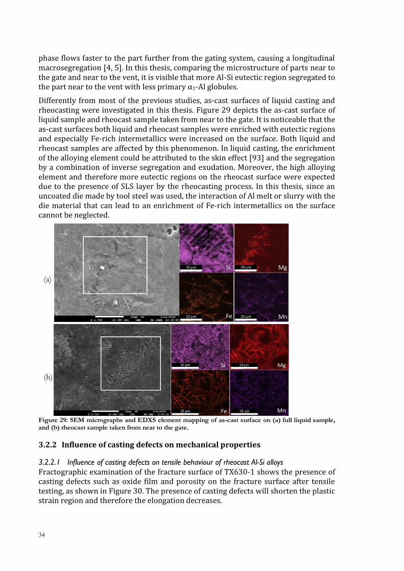
34
phase flows faster to the part further from the gating system, causing a longitudinal macrosegregation [4, 5]. In this thesis, comparing the microstructure of parts near to the gate and near to the vent, it is visible that more Al-Si eutectic region segregated to the part near to the vent with less primary α1-Al globules.
Differently from most of the previous studies, as-cast surfaces of liquid casting and rheocasting were investigated in this thesis. Figure 29 depicts the as-cast surface of liquid sample and rheocast sample taken from near to the gate. It is noticeable that the as-cast surfaces both liquid and rheocast samples were enriched with eutectic regions and especially Fe-rich intermetallics were increased on the surface. Both liquid and rheocast samples are affected by this phenomenon. In liquid casting, the enrichment of the alloying element could be attributed to the skin effect [93] and the segregation by a combination of inverse segregation and exudation. Moreover, the high alloying element and therefore more eutectic regions on the rheocast surface were expected due to the presence of SLS layer by the rheocasting process. In this thesis, since an uncoated die made by tool steel was used, the interaction of Al melt or slurry with the die material that can lead to an enrichment of Fe-rich intermetallics on the surface cannot be neglected.
Figure 29: SEM micrographs and EDXS element mapping of as-cast surface on (a) full liquid sample, and (b) rheocast sample taken from near to the gate.
3.2.2 Influence of casting defects on mechanical properties
3.2.2.1 Influence of casting defects on tensile behaviour of rheocast Al-Si alloys
Fractographic examination of the fracture surface of TX630-1 shows the presence of casting defects such as oxide film and porosity on the fracture surface after tensile testing, as shown in Figure 30. The presence of casting defects will shorten the plastic strain region and therefore the elongation decreases.
(a)
(b)
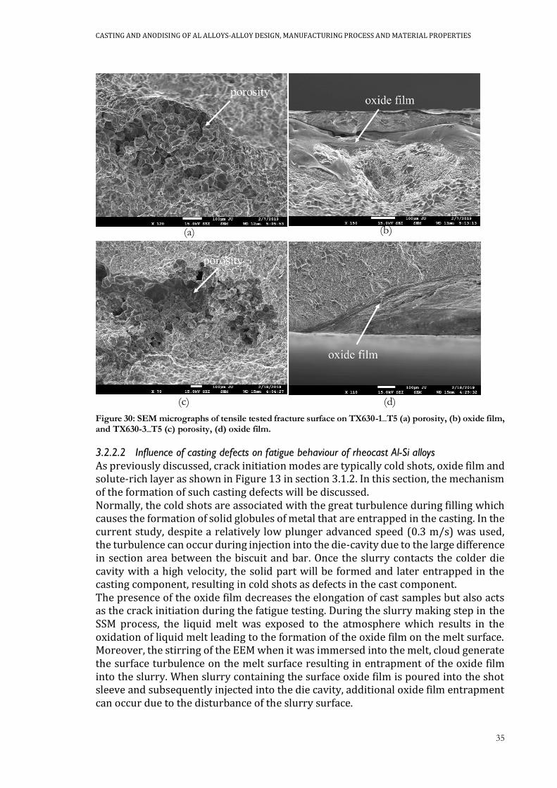
CASTING AND ANODISING OF AL ALLOYS-ALLOY DESIGN, MANUFACTURING PROCESS AND MATERIAL PROPERTIES
35
Figure 30: SEM micrographs of tensile tested fracture surface on TX630-1_T5 (a) porosity, (b) oxide film, and TX630-3_T5 (c) porosity, (d) oxide film.
3.2.2.2 Influence of casting defects on fatigue behaviour of rheocast Al-Si alloys
As previously discussed, crack initiation modes are typically cold shots, oxide film and solute-rich layer as shown in Figure 13 in section 3.1.2. In this section, the mechanism of the formation of such casting defects will be discussed. Normally, the cold shots are associated with the great turbulence during filling which causes the formation of solid globules of metal that are entrapped in the casting. In the current study, despite a relatively low plunger advanced speed (0.3 m/s) was used, the turbulence can occur during injection into the die-cavity due to the large difference in section area between the biscuit and bar. Once the slurry contacts the colder die cavity with a high velocity, the solid part will be formed and later entrapped in the casting component, resulting in cold shots as defects in the cast component. The presence of the oxide film decreases the elongation of cast samples but also acts as the crack initiation during the fatigue testing. During the slurry making step in the SSM process, the liquid melt was exposed to the atmosphere which results in the oxidation of liquid melt leading to the formation of the oxide film on the melt surface. Moreover, the stirring of the EEM when it was immersed into the melt, cloud generate the surface turbulence on the melt surface resulting in entrapment of the oxide film into the slurry. When slurry containing the surface oxide film is poured into the shot sleeve and subsequently injected into the die cavity, additional oxide film entrapment can occur due to the disturbance of the slurry surface.
(a) (b)
(c) (d)

36
In this thesis, fatigue fracture examination commonly found that the crack was initiated beneath a layer with a thickness in a range of 100-200 µm, and a gap between the layer and its surroundings could be observed. EDXS analysis indicated that the layer commonly has a higher concentration of alloying elements especially Si compared to the surroundings (Figure 31). Many studies have revealed the presence of surface segregation on cast Al and Mg components, and they reported that the surface segregation could be a result of inverse segregation and/or exudation[55, 94-98]. In the current study, as the solidification starts from the surface, the solidification shrinkage leads the flow of solute-rich liquid to feed the shrinkage through the interdendritic channels. Moreover, due to the presence of intensification pressure, a pressure-driven exudation would occur, as the solute-rich liquid flowed to the air gap between the partly solidified part and the mould. However, the mechanism of formation of the layer needs to be understood in the future study.
Figure 31: EDXS analysis of solute-rich layer in a fatigue fracture surface of TX630-2 alloy.
3.2.3 Influence of casting process on anodising properties
3.2.3.1 Microstructural evaluation of the oxide layer
Figure 32 compares the microstructure of the oxide layer in liquid cast samples and rheocast samples. Being difficult to be dissolved during anodising, Si particles were embedded in the oxide layer, and a higher fraction of eutectic Si particles was evident in rheocast samples due to the presence of SLS layer on rheocast samples. The measured average thickness of the oxide layer of the liquid cast and rheocast samples were summarised in Figure 33a. As shown in Figure 33a, the liquid cast samples trends to have a thicker average thickness of the oxide layer, however, no significant difference was evident between liquid cast and rheocast samples by considering the standard deviation as the error bar.

CASTING AND ANODISING OF AL ALLOYS-ALLOY DESIGN, MANUFACTURING PROCESS AND MATERIAL PROPERTIES
37
Figure 32: Micrographs of the oxide layer (anodising at 25 V for 60 mins) on EN AC 42000 (a) liquid cast sample, (b) as-cast rheocast sample, near to gate.
Figure 33: Thickness of the oxide layer on EN AC 42000 in both liquid cast and rheocast condition; the “G” stands for the parts taken from near to the gate, and the “V” means the parts taken from near to the vent.
3.2.3.2 Corrosion resistance of the oxide layer
The Bode plots of EIS spectra of samples obtained after 1 and 12 hours of immersion in 3 wt-% NaCl solution were reported in Figure 34. It is noteworthy that the sealing is not employed in these tested samples. Generally, Figure 34 shows relative low impedance spectra in the low frequency range, indicating the presence of some defects in the oxide layer. As previously discussed, due to the segregation or interaction of Al melt with die materials during casting, as-cast surfaces on both liquid and rheocast samples are enriched with Fe-rich intermetallics which could decrease the corrosion resistance of the oxide layer as they were partly dissolved during anodising.
(a) (b)
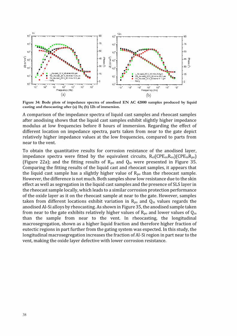
38
Figure 34: Bode plots of impedance spectra of anodised EN AC 42000 samples produced by liquid casting and rheocasting after (a) 1h; (b) 12h of immersion.
A comparison of the impedance spectra of liquid cast samples and rheocast samples after anodising shows that the liquid cast samples exhibit slightly higher impedance modulus at low frequencies before 8 hours of immersion. Regarding the effect of different location on impedance spectra, parts taken from near to the gate depict relatively higher impedance values at the low frequencies, compared to parts from near to the vent.
To obtain the quantitative results for corrosion resistance of the anodised layer, impedance spectra were fitted by the equivalent circuits, Rel(CPEoxRox)(CPEinRpo) (Figure 22a); and the fitting results of Rpo and Qin were presented in Figure 35. Comparing the fitting results of the liquid cast and rheocast samples, it appears that the liquid cast sample has a slightly higher value of Rpo than the rheocast sample. However, the difference is not much. Both samples show low resistance due to the skin effect as well as segregation in the liquid cast samples and the presence of SLS layer in the rheocast sample locally, which leads to a similar corrosion protection performance of the oxide layer as it on the rheocast sample at near to the gate. However, samples taken from different locations exhibit variation in Rpo and Qin values regards the anodised Al-Si alloys by rheocasting. As shown in Figure 35, the anodised sample taken from near to the gate exhibits relatively higher values of Rpo and lower values of Qin than the sample from near to the vent. In rheocasting, the longitudinal macrosegregation, shown as a higher liquid fraction and therefore higher fraction of eutectic regions in part further from the gating system was expected. In this study, the longitudinal macrosegregation increases the fraction of Al-Si region in part near to the vent, making the oxide layer defective with lower corrosion resistance.
(a) (b)
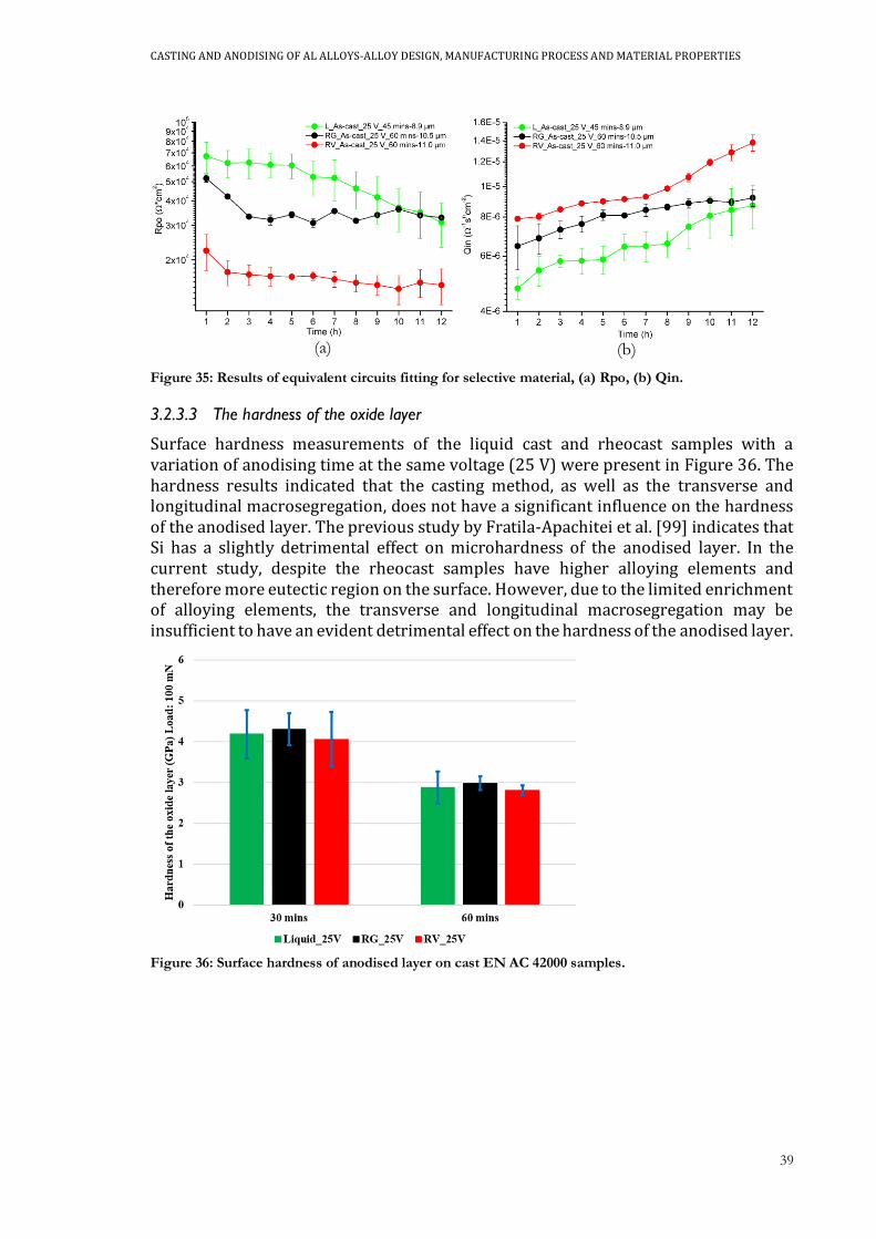
CASTING AND ANODISING OF AL ALLOYS-ALLOY DESIGN, MANUFACTURING PROCESS AND MATERIAL PROPERTIES
39
Figure 35: Results of equivalent circuits fitting for selective material, (a) Rpo, (b) Qin.
3.2.3.3 The hardness of the oxide layer
Surface hardness measurements of the liquid cast and rheocast samples with a variation of anodising time at the same voltage (25 V) were present in Figure 36. The hardness results indicated that the casting method, as well as the transverse and longitudinal macrosegregation, does not have a significant influence on the hardness of the anodised layer. The previous study by Fratila-Apachitei et al. [99] indicates that Si has a slightly detrimental effect on microhardness of the anodised layer. In the current study, despite the rheocast samples have higher alloying elements and therefore more eutectic region on the surface. However, due to the limited enrichment of alloying elements, the transverse and longitudinal macrosegregation may be insufficient to have an evident detrimental effect on the hardness of the anodised layer.
Figure 36: Surface hardness of anodised layer on cast EN AC 42000 samples.
(a) (b)

40
3.3 OPTIMISATION OF ANODISING PROCESS FOR MECHANICAL AND
ANODISING PROPERTIES
3.3.1 Influence of anodised layer on fatigue properties of Al-Si alloys
Figure 37 demonstrated the fatigue test results of rheocast samples of TX630-1 with an anodised layer in the thickness of 3 µm. As shown in Figure 37, despite the anodising process adds a brittle anodised layer on cast samples, the fatigue life or fatigue strength was not affected by the presence of the anodised layer. Fractographic examination of fracture surface shows that the presence of the oxide layer does not change the types of crack initiation, as the types of crack initiation are mainly casting defects such as oxide film and solute-rich layer. Previous studies [83-86] indicated that due to the presence of the brittle anodised layer on the sample surface, the anodised layer would act as the initiation point of the fatigue crack. In the current study, it seems that the casting defects dominate the crack nucleation compared with the brittle anodised layer.
Figure 37: Fatigue results of TX630-1 with and without the anodised layer.
Figure 38: Crack initiation on anodised samples after fatigue testing, (a) the oxide film, (b) the solute-rich layer.
(a) (b)
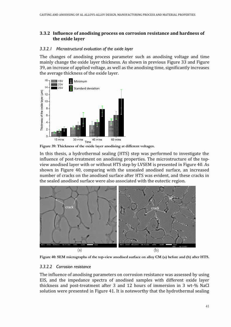
CASTING AND ANODISING OF AL ALLOYS-ALLOY DESIGN, MANUFACTURING PROCESS AND MATERIAL PROPERTIES
41
3.3.2 Influence of anodising process on corrosion resistance and hardness of the oxide layer
3.3.2.1 Microstructural evaluation of the oxide layer
The changes of anodising process parameter such as anodising voltage and time mainly change the oxide layer thickness. As shown in previous Figure 33 and Figure 39, an increase of applied voltage, as well as the anodising time, significantly increases the average thickness of the oxide layer.
Figure 39: Thickness of the oxide layer anodising at different voltages.
In this thesis, a hydrothermal sealing (HTS) step was performed to investigate the influence of post-treatment on anodising properties. The microstructure of the top-view anodised layer with or without HTS step by LVSEM is presented in Figure 40. As shown in Figure 40, comparing with the unsealed anodised surface, an increased number of cracks on the anodised surface after HTS was evident, and these cracks in the sealed anodised surface were also associated with the eutectic region.
Figure 40: SEM micrographs of the top-view anodised surface on alloy CM (a) before and (b) after HTS.
3.3.2.2 Corrosion resistance
The influence of anodising parameters on corrosion resistance was assessed by using EIS, and the impedance spectra of anodised samples with different oxide layer thickness and post-treatment after 3 and 12 hours of immersion in 3 wt-% NaCl solution were presented in Figure 41. It is noteworthy that the hydrothermal sealing
(a) (b)

42
is only employed in alloy CM. Impedance spectra revealed that the oxide layer thickness and the HTS process have a significant influence on corrosion resistance. Comparing the impedance spectra of the anodised layer with two different thickness, it was found that the anodised samples associated with a thinner oxide layer obtain higher impedance modulus at low frequencies than samples with a thicker oxide layer. However, when anodised layers formed with a similar oxide layer, the similar impedance modulus were obtained despite the applied voltages were different. A comparison of impedance spectra of unsealed and sealed samples shows that the sealed sample shows much lower impedance spectra than the unsealed samples.
Figure 41: Bode plots of impedance spectra of anodised samples with different anodising parameter after (a) 3 hours and (b) 12 hours of immersion.
To obtain quantitative information of the resistance and capacitance of the anodised layer, the equivalent circuit, Rel(CPEoxRox)(CPEinRpo) as demonstrated in Figure 22a was used to fit the impedance spectra for shorter immersion time. Figure 42 depicts the fitting results of Rpo and Qin. As shown in Figure 42, the fitting results show that the oxide layer thickness, as well as the HTS step, plays an important role in the corrosion protection of the anodised layer.
(a)
(b)
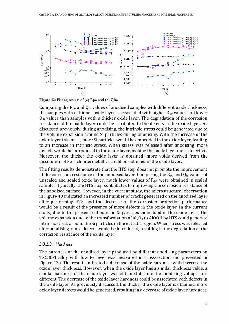
CASTING AND ANODISING OF AL ALLOYS-ALLOY DESIGN, MANUFACTURING PROCESS AND MATERIAL PROPERTIES
43
Figure 42: Fitting results of (a) Rpo and (b) Qin.
Comparing the Rpo and Qin values of anodised samples with different oxide thickness, the samples with a thinner oxide layer is associated with higher Rpo values and lower Qin values than samples with a thicker oxide layer. The degradation of the corrosion resistance of the oxide layer could be attributed to the defects in the oxide layer. As discussed previously, during anodising, the intrinsic stress could be generated due to the volume expansion around Si particles during anodising. With the increase of the oxide layer thickness, more Si particles would be embedded in the oxide layer, leading to an increase in intrinsic stress. When stress was released after anodising, more defects would be introduced in the oxide layer, making the oxide layer more defective. Moreover, the thicker the oxide layer is obtained, more voids derived from the dissolution of Fe-rich intermetallics could be obtained in the oxide layer.
The fitting results demonstrate that the HTS step does not promote the improvement of the corrosion resistance of the anodised layer. Comparing the Rpo and Qin values of unsealed and sealed oxide layer, much lower values of Rpo were obtained in sealed samples. Typically, the HTS step contributes to improving the corrosion resistance of the anodised surface. However, in the current study, the microstructural observation in Figure 40 indicated an increased number of cracks generated on the anodised layer after performing HTS, and the decrease of the corrosion protection performance would be a result of the presence of more defects in the oxide layer. In the current study, due to the presence of eutectic Si particles embedded in the oxide layer, the volume expansion due to the transformation of Al2O3 to AlOOH by HTS could generate intrinsic stress around the Si particles in the eutectic region. When stress was released after anodising, more defects would be introduced, resulting in the degradation of the corrosion resistance of the oxide layer
3.3.2.3 Hardness
The hardness of the anodised layer produced by different anodising parameters on TX630-1 alloy with low Fe level was measured in cross-section and presented in Figure 43a. The results indicated a decrease of the oxide hardness with increase the oxide layer thickness. However, when the oxide layer has a similar thickness value, a similar hardness of the oxide layer was obtained despite the anodising voltages are different. The decrease of the oxide layer hardness could be associated with defects in the oxide layer. As previously discussed, the thicker the oxide layer is obtained, more oxide layer defects would be generated, resulting in a decrease of oxide layer hardness.
(a) (b)

44
Moreover, the decrease of the oxide layer hardness could also be related to the local heating effect during anodising. Figure 43b reported the nanohardness profile along the corrosion section of the oxide layer as the function of distance to the surface. The local hardness of the oxide layer shows a continuous decrease from the interface to the surface. The previous study by Aerts et al. [100] indicated a more porous oxide structure with a relative large pore diameter near the surface. And they reported that it was affected by the thermal enhanced oxide dissolution on the oxide surface with increasing electrolyte temperature and time of exposure to the electrolyte [100]. In the current study, the aluminium oxide close to the surface forming earlier than the aluminium oxide near the interface, is longer affected by the local heating effect and might result in an anodised layer with a larger nanopore diameter and therefore slightly lower hardness. At the same voltage, the thicker the oxide layer is obtained, the longer the oxide is exposed to the heating effect, leading to the decrease of the oxide layer hardness. The similar results were also shown in EN AC 42000 (Figure 36).
Figure 43: (a) Hardness of the oxide layer with different oxide layer thickness, (b) nanohardness profile as a function of the distance from the surface.
(a) (b)

CASTING AND ANODISING OF AL ALLOYS-ALLOY DESIGN, MANUFACTURING PROCESS AND MATERIAL PROPERTIES
45
CHAPTER 4
CONCLUDING REMARKS
This PhD thesis tries to promote a better application of the anodising process in casting Al components with certain demands on corrosion resistance and mechanical properties, by focusing on the influence of alloying elements, casting methods and anodising process parameter on mechanical and anodising properties of cast Al-Si alloys. To reach this point, a wide range of aspects and variables have been considered to obtain more knowledge related to the oxide layer formation and growth, corrosion protection, surface hardness and mechanical properties. The following conclusions are highlighted from work:
Alloy design for mechanical and anodising properties of Al-Si alloys: • As the main alloying element in Al-Si alloys, Si content and particle morphology
dominate the anodised layer protection. Si particles are partly anodised at a much lower rate than the Al phases and remain embedded in the oxide. Depending on the geometry and morphology of Si particles, Si particles can shield Al and prevent them from anodising, resulting in the presence of residual metallic Al phase in the oxide layer and the formation of defects at the interface among oxide and Si particle.
• The Si particle morphology has a significant influence on the oxide layer growth during anodising. By changing the Si particle morphology from flake-like to interconnected fibrous, the amount of residual metallic Al phases and oxide defects reduces. Therefore, the change of Si particle from flakes to fibres can substantially improve the corrosion protection of the oxide layer even in Al-Si alloys with high Si content.
• Fe-rich intermetallics could be partly dissolved during anodising, leaving vacancies or voids as the defects in the oxide layer. By decreasing the number of Fe-rich intermetallics on the sample surface, both corrosion resistance and hardness of the oxide layer can be improved.
• The presence of Fe-rich intermetallics makes the oxide layer defective, facilitating the propagation of the corrosion attack into the Al-Si matrix, as well as the corrosion of the Al-Si matrix when Fe-rich intermetallics displayed under the interface of the oxide layer and Al-Si matrix.
• The increase of Mg content in Al-Si alloys is not a guarantee for improving the fatigue properties after T5 treatment.
Influence of casting methods on mechanical and anodising properties • Compared to the liquid casting, the presence of SLS layer by transverse
macrosegregation in rheocasting does not have a significant impact on
46
corrosion resistance and hardness of the oxide layer, despite the enrichment of eutectic fraction and therefore of Si content on the surface.
• The longitudinal macrosegregation in rheocasting samples results in an inhomogeneity in corrosion protection performance of the oxide layer after anodising.
• During rheocasting of Al-Si alloys, the surface of the component can be enriched in Fe-rich intermetallics due to the combination of the SLS layer by transverse macrosegregation and the interaction with die material. And it significantly affects the final properties of the oxide layer.
• The casting defects such as porosity, the oxide film, cold shots and solute-rich layer dominate both tensile and fatigue properties of the rheocast components, therefore the anodising does not affect the fatigue life.
Optimisation of anodising process on mechanical and anodising properties • In the anodising of cast Al alloys, the oxide layer thickness varies by changing
the anodising voltage and time. An increase of the oxide layer thickness decreases both the corrosion resistance and hardness of the oxide layer, which is related to the oxide defects.
• In this thesis, the hydrothermal sealing is not a guarantee for improving the corrosion resistance provided by the oxide layer. The hydrothermal sealing could introduce cracks, resulting in the degradation of the corrosion protection performance of the oxide layer.
CASTING AND ANODISING OF AL ALLOYS-ALLOY DESIGN, MANUFACTURING PROCESS AND MATERIAL PROPERTIES
47
CHAPTER 5
FUTURE WORK
As a part of project “CompCAST+”, the future work will focus on the fatigue properties of cast Al alloys by considering the surface treatment and corrosion. Moreover, other aspects should also be considered and investigated in future work.
Residual intrinsic stress
As been widely discussed in this thesis, the intrinsic stress is believed to be generated around Si particles during anodising and hydrothermal sealing. The future work needs to develop a method to reveal and measure the intrinsic stress in the amorphous anodised oxide.
Alloy development
In this study, due to the presence of Mg, the study of Fe-rich intermetallic behaviour during anodising was mostly focused on π-AlFeMgSi phases. However, besides the π-AlFeMgSi phase, other Fe-rich intermetallics such as β-AlFeSi and α-AlFeMnSi are commonly obtained in cast aluminium alloys. The future work needs to investigate the behaviour of different types of Fe-rich intermetallics during anodising.
Casting
In this thesis, casting defects such as oxide film, cold shots and solute-rich layer were believed to dominate the fatigue behaviour, and it is believed that most of the casting defects are related to the casting process. The future work needs to understand the mechanism of the formation of casting defects especially the solute-rich layer. Moreover, in this thesis, it was also found that Fe-rich intermetallics are enriched in the casting surface. An understanding of the mechanism of enrichments of Fe-rich intermetallics on the surface will help to eliminate the presence of enrichment of Fe-rich intermetallics which has been provided to decrease the corrosion protection provided by the anodised layer.
Anodising
In this thesis, the oxide defects due to the presence of intrinsic stress and Fe-rich intermetallic dissolution are believed as the main reason for the reduced corrosion protection by the oxide layer. The future work needs to focus on a pre-treatment to minimise the defects in order to improve the corrosion resistance of the oxide layer of the as-cast surface.

48

CASTING AND ANODISING OF AL ALLOYS-ALLOY DESIGN, MANUFACTURING PROCESS AND MATERIAL PROPERTIES
49
REFERENCES
[1] H. Jiang, P. Bowen, J.F. Knott, J. Mater. Sci., 34 (1999). [2] Q.G. Wang, D. Apelian, D.A. Lados, J. Light. Met, 1 (2001). [3] Q.G. Wang, C.J. Davidson, J.R. Griffiths, P.N. Crepeau, Metall. Mater. Trans. B, 37(6) (2006). [4] H. Kaufmann, W. Franger, U. Galovsky, P.J. Uggowitzer, Fluctuations of alloy composition and their influence on sponge effect and fluidity of A356-NRC, in: H. Kaufmann (Ed.) 2nd International Light Metals Technology Conference, LKR-Verlag, St. Wolfgang, Austria, 2005, pp. 169-177. [5] H.I. Laukli, C.M. Gourlay, A.K. Dahle, Metall. Mater. Trans. A, 36(3) (2005). [6] M. Brochu, Y. Verreman, F. Ajersch, L. Bucher, Solid State Phenom., 141-143 (2008). [7] M. Payandeh, A.E.W. Jarfors, M. Wessén, Solid State Phenom., 217-218 (2015). [8] A.A. Alain, M. Brochu, H. Möller, Solid State Phenom., 217-218 (2014). [9] H. Möller, E.P. Masuku, The Open Corrosion Journal, 2 (2009). [10] D.K. Dwivedi, R. Sharma, A. Kumar, International Journal of Cast Metals Research, 19(5) (2006). [11] H. Elzanaty, Impact: International Journal of Research in Engineering & Technology, 2(7) (2014). [12] Y. Wang, H. Liao, Y. Wu, J. Yang, Mater. Des., 53 (2014). [13] M. Eslami, F. Deflorian, M. Payandeh, A.E.W. Jarfors, C. Zanella, Investigation of corrosion behaviour of SSM-HPDC aluminium-silicon alloys, EUROCORR 2016, Montpellier, France, 2016. [14] M.A. Pech-Canul, M.I. Pech-Canul, P. Bartolo-Pérez, M. Echeverria, Electrochim. Acta, 140(10) (2014). [15] J.G. Kaufmann, E.L. Rooy, Aluminum alloy castings: properties, process and application, ASM International2004. [16] M. Wu, J. Zhang, Y. Zhang, H. Wang, J. Mater. Eng. Perform., 27(11) (2018). [17] L. Ceschini, I. Boromei, A. Morri, S. Seifeddine, I.L. Svensson, Mater. Des., 36 (2012). [18] C.M. Dinnis, J.A. Taylor, A.K. Dahle, Scripta Mater., 53(8) (2005). [19] M. Eslami, M. Payandeh, F. Deflorian, A.E.W. Jarfors, C. Zanella, Metals, 8(4) (2018). [20] B. Mingo, R. Arrabal, A. Pardo, E. Matykina, P. Skeldon, Mater. Charact., 112 (2016). [21] L. Ceschini, I. Boromei, A. Morri, S. Seifeddine, I.L. Svensson, J. Mater. Process Technol., 209(15-16) (2009). [22] S. Seifeddine, S. Johansson, I.L. Svensson, Mater. Sci. Eng., A, 490(1-2) (2008). [23] T.B. Massalski, H. Okamoto, P.R. Subramanian, L. Kacprzak, Binary Alloy Phase Diagrams, ASM International, Ohio, USA, 1992. [24] M.M. Makhlouf, H.V. Guthy, J. Light Met., 1(4) (2001). [25] S.D. McDonald, K. Nogita, A.K. Dahle, Acta Mater., 52(14) (2004). [26] H. Liao, Y. Sun, G. Sun, Mater. Sci. Eng., A, 335 (2002).
50
[27] M. Zamani, S. Seifeddine, M. Aziziderouei, Light Metals, (2014). [28] M. Zamani, S. Seifeddine, A.E.W. Jarfors, Light Metals, (2013). [29] S.C. Flood, J.D. Hunt, Metal Sci., 15(7) (2013). [30] S.D. McDonald, A.K. Dahle, J.A. Taylor, D.H. StJohan, Metall. Mater. Trans. A, 35(6) (2004). [31] D.C. Jenkinson, L.M. Hogan, J. Cryst. Growth, 28(2) (1975). [32] S.Z. Lu, A. Hellawell, Metall. Mater. Trans. A, 18(10) (1987). [33] M. Timpel, N. Wanderka, R. Schlesiger, T. Tamamoto, N. Lazarev, D. Isheim, G. Schmitz, S. Matsumura, J. Banhart, Acta Mater., 60 (2012). [34] M. Zamani, S. Seifeddine, Int. J. Metalcast, 10(4) (2016). [35] Z. Fan, Int. Mater. Rev., 47(2) (2002). [36] M. Wessén, H. Cao, J. Metallur. Sci. Technol., 25(2) (2007). [37] M. Payandeh, A.E.W. Jarfors, M. Wessén, Metall. Mater. Trans. A, 47(3) (2015). [38] G. Govender, H. Möller, Solid State Phenom., 141-143 (2008). [39] H. Möller, U.A. Caurle, E.P. Masuku, Trans. Nonferrous Met. Soc. China, 20 (2010). [40] S.C. Bergsma, X. Li, M.E. Kassner, Mater. Sci. Eng., A, 297 (2001). [41] E. Cerri, M. Cabibbo, P. Cavaliere, E. Evangelista, Mater. Sci. Forum, 331 (2000). [42] Q. Zhu, S.P. Midson, Trans. Noferr. Met. Soc. China, 20 (2010). [43] M. Payandeh, E. Sjölander, A.E.W. Jarfors, M. Wessén, Mechanical and thermal properties of rheocast telecom component using low silicon aluminium alloy in as-cast and heat-treated conditions, TMS 2015 144th Annual Meeting & Exhibition, 2015, pp. 209-214. [44] R. Burapa, S. Janudom, T. Chucheep, R. Canyook, J. Wannasin, Trans. Noferr. Met. Soc. China, 20 (2010). [45] T. Haga, P. Kapranos, J. Mater. Process Technol., 130-131 (2002). [46] S. Wu, G. Zhong, L. Wan, P. An, Y. Mao, Trans. Noferr. Met. Soc. China, 20 (2010). [47] Z.-K. Zheng, Y.-J. Ji, W.-M. Mao, R. Yue, Z.-Y. Liu, Trans. Noferr. Met. Soc. China, 27 (2017). [48] S.G. Shabestari, E. Parshizfard, J. Alloys Compd., 509 (2011). [49] M. Blad, B. Johannesson, P. Nordberg, J. Winklhofer, Solid State Phenom., 256 (2016). [50] Y.X. Gan, R.A. Overfelt, J. Mater. Sci., 41(22) (2006). [51] Y.B. Yu, S. Kim, Y. Lee, J. Lee, Metall. Mater. Trans. A, 33 (2002). [52] Q.G. Wang, D. Apelian, D.A. Lados, J. Light. Met, 1 (2001). [53] C. Park, S. Kim, Y. Kwon, Y. Lee, J. Lee, Metall. Mater. Trans. A, 35(3) (2004). [54] N. Hayat, H. Toda, T. Kobayashi, N. Wade, Mater. Sci. Forum, 396-402 (2002). [55] M. Bouazara, A. Bouaicha, A. Ragab, A. Allaoui, J. Mater. Eng. Perform., 2015(24) (2015) 3084-3092. [56] A.D. Juhl, The structure and properties of the oxide layer formed by different pulse anodizing, Aluminum 2000, Cyprus, 1997. [57] A.D. Juhl, Pulse anodizing of extruded and cast aluminum alloys, Technical University of Denmark, Copenhagen, 1999. [58] T.P. Hoar, N.F. Mott, J. Phys. Chem. Solids, 9(2) (1959). [59] V.P. Parkhutik, V.I. Shershulsky, J. Phys. D: Appl. Phys., 25(8) (1992). [60] S. Wernick, R. Pinner, P.G. Sheasby, The surface treatment and finishing of aluminum and its alloys, 5 ed., Finishing Publications LTD, Teddington, Middlesex, England, 1987.

CASTING AND ANODISING OF AL ALLOYS-ALLOY DESIGN, MANUFACTURING PROCESS AND MATERIAL PROPERTIES
51
[61] K. Labisz, L.A. Dobrzański, J. Konieczny, Arch Foundary Eng, 8(Special issue) (2008). [62] L.E. Fratila-Apachitei, F.D. Tichelaar, G.E. Thompson, H. Terryn, P. Skeldon, J. Duszczyk, L. Katgerman, Electrochim. Acta, 49(19) (2004) 3169. [63] M. Mohedano, E. Matykina, R. Arrabal, B. Mingo, A. Pardo, Appl. Surf. Sci., 346 (2015). [64] L.E. Fratila-Apachitei, H. Terryn, P. Skeldon, G.E. Thompson, J. Duszczyk, L. Katgerman, Electrochim. Acta, 49 (2004). [65] A. Forn, J.A. Picas, M.T. Baile, A. Martin, V.G. Garcia, Surf. Coat. Tech., 202 (2007). [66] M. Jariyaboon, P. Møller, R.E. Dunin-Borkowski, R. Ambat, Anti-Corros. Method. M, 58(4) (2011). [67] H. Wu, Y. Ma, W. Huang, X. Zhou, K. Li, Y. Liao, Z. Wang, Z. Liang, L. Liu, J. Electrochem. Soc., 165(9) (2018). [68] F. Zhang, J.-O. Nilsson, J. Pan, J. Electrochem. Soc., 163(9) (2016). [69] Y. Ma, X. Zhou, J. Wang, G.E. Thompson, W. Huang, J.-O. Nilsson, M. Gustavsson, A. Crispin, J. Electrochem. Soc., 161(6) (2014). [70] F. Riddar, S. Hogmark, Å. Kassman Rudolphi, J. Mater. Process. Tech., 212 (2012). [71] K. Chauke, H. Möller, U.A. Curle, G. Govender, Mater. Sci. Forum., 765 (2013). [72] K. Chauke, K. Mutombo, G. Govender, Adv. Mat. Res., 1019 (2014). [73] Q. Meng, G.S. Frankel, J. Electrochem. Soc., 151(5) (2004). [74] M. García-Rubio, P. Ocón, M. Curioni, G.E. Thompson, P. Skeldon, A. Lavía, I. García, Corros. Sci., 52 (2010). [75] L. Domingues, J.C.S. Fernades, M.D. Cunha Belo, M.G.S. Ferreira, L. Guerra-Rosa, Corros. Sci., 45 (2003). [76] M. García-Rubio, P. Ocón, A. Climent-Font, R.W. Smith, M. Curioni, G.E. Thompson, P. Skeldon, A. Lavía, I. García, Corros. Sci., 51 (2009). [77] Y. Mori, A. Koshi, J. Liao, Corros. Sci., 104 (2016). [78] L. Bouchama, N. Azzouz, N. Boukmouche, J.P. Chopart, A.L. Daltin, Y. Bouznit, Surf. Coat. Tech., 235 (2013). [79] A. Bautista, J.A. González, V. López, Surf. Coat. Tech., 154 (2002). [80] M. Whelan, K. Barton, J. Cassidy, J. Colreavy, B. Duffy, Surf. Coat. Tech., 227 (2013). [81] M. García-Rubio, M.P. de Lara, P. Ocón, S. Diekhoff, M. Beneke, A. Lavía, I. García, Electrochim. Acta, 54(21) (2009). [82] A. Carangelo, M. Curioni, A. Acquesta, T. Monetta, F. Bellucci, J. Electrochem. Soc., 163(10) (2016). [83] E. Cirik, K. Genel, Surf Coat Tech, 202 (2008). [84] K. Hockauf, L. Köhler, M. Händel, T. Halle, D. Nickel, G. Alisch, T. Lampke, Mat.-wiss. u. Werkstofftech, 42(7) (2011). [85] T.-S. Shih, H.-S. Yong, W.-N. Hsu, Metals, 6(3) (2015). [86] K. Shiozawa, H. Kobayashi, M. Terada, A. Matsui, Trans. Jpn. Soc. Mech. Eng. A., 67(662) (2001). [87] A. Inoue, T. Tagawa, T. Ishikawa, J. Jpn Inst. Metals, 76(6) (2012). [88] M. Shahzad, M. Chaussumier, R. Chieragatti, C. Mabru, F. Rezai-Aria, Procedia, Eng., 2 (2010). [89] M. Zamani, S. Seifeddine, Light Metals 2015, (2015). [90] J. Santos, A.E.W. Jarfors, A.K. Dahle, Solid State Phenom., 256 (2016).
52
[91] E. Sjölander, S. Seifeddine, Mater. Sci. Eng. A, 528(24) (2011). [92] J. Santos, A.E.W. Jarfors, A.K. Dahle, The effect of magnesimum on the intermetallic phases and heat treatment response of cast Al-7Si-Mg, Jönköping University, Jönköping, 2018. [93] Z.W. Chen, Mater. Sci. Eng., A, 348(1-2) (2002). [94] C.M. Gourlay, H.I. Laukli, A.K. Dahle, Metall. Mater. Trans. A, 38 (2007). [95] E. Haug, A. Mo, H.J. Thevik, Int. J. Heat Mass Transfer, 38(9) (1995). [96] S.G. Lee, G.R. Patel, A.M. Gokhale, Mater. Charact., 55 (2005). [97] S.G. Lee, G.R. Patel, A.M. Gokhale, Scr. Mater., 52 (2005). [98] T. Motegi, A. Ohno, J. Japan Inst. Metals, 46(3) (1982). [99] L.E. Fratila-Apachitei, J. Duszczyk, L. Katgerman, Surf. Coat. Technol., 165 (2003) 309. [100] T. Aerts, T. Dimogerontalis, I. De Graeve, J. Fransaer, H. Terryn, Surf. Coat. Technol., 201(7310-7317) (2007).

CASTING AND ANODISING OF AL ALLOYS-ALLOY DESIGN, MANUFACTURING PROCESS AND MATERIAL PROPERTIES
53
APPENDED PAPERS
Supplement I B. Zhu, P. Leisner, S. Seifeddine, A.E.W. Jarfors; Influence of Si and cooling rate on microstructure and mechanical properties of Al-Si-Mg cast alloys, Surface and Interface Analysis, 2016, 48: pp. 861-869.
Supplement II B. Zhu, S. Seifeddine, P.O.Å. Persson, A.E.W. Jarfors, P. Leisner, C. Zanella; A study of formation and growth of the anodised surface layer on cast Al-Si based on different analytical techniques, Materials and Design, 2016, 101: pp. 254-262.
Supplement III B. Zhu, M. Fedel, N-E. Andersson, P. Leisner, F. Deflorian, C. Zanella; Effect of Si content and morphology on corrosion resistance of anodized cast Al-Si alloys, Journal of The Electrochemical Society, 2017, 164(7): C435-C441.
Supplement IV B. Zhu, M. Fedel, N-E. Andersson, P. Leisner, F. Deflorian, C. Zanella; Influence of the Sr modification and post-treatment on corrosion resistance of oxide layer of cast Al-(low)Si alloys.
Supplement V B. Zhu, S. Seifeddine, A.E.W. Jarfors, P. Leisner, C. Zanella; A study of anodising behaviour of Al-Si components produced by rheocasting, Solid State Phenomena, 2019, 285: pp 39-44.
Supplement VI B. Zhu, C. Zanella; Hardness and corrosion behaviour of anodised Al-Si produced by rheocasting, Materials and Design, 2019, 173.
Supplement VII Influence of Fe-rich intermetallics and their segregation on anodising properties of Al-Si-Mg rheocast alloys
Submitted to “Journal of Materials Processing Technology”.
Supplement VIII Influence of Mg content on the fatigue behaviour of Al-Si-Mg alloys by rheocasting process
Manuscript is under preparation.

54
Related Documents


