www.alfra.de DEBURRING CUTTING PUNCHING DRILLING LIFTING

Welcome message from author
This document is posted to help you gain knowledge. Please leave a comment to let me know what you think about it! Share it to your friends and learn new things together.
Transcript
w w w . a l f r a . d e
DEBURRINGCUTTINGPUNCHING DRILLING HEBENHEBENLIFTING
A /
20
16
EN
A/20
16 EN
2
We started producing our own hole punches for control cabinet and switch gear construction in Germany more than 40 years ago.By this stage we had already gathered a lot of experience in the sales of such tools.Thanks to our closeness to our customers, we have been able to continuously integrate their requirements and suggested improvements into further developments.
This resulted in the production of additional, new products:hydraulic manual punches for energy-saving actuation of hole punches, cutting devices for mounting rails, machines and tools for busbar production, stationery punching machines for efficient control cabinet and housing production, and much more. The starting shot for top quality "Made in Germany" products was actually fired many years ago. Now, many customers worldwide are profiting from the company's history.An ALFRA Type TriCut™ hole punch has three cutters which means that the possibility of canting during punch breakthrough can be completely ruled out. The materials and finish have been carefully selected to provide users with the quality and durability that they have come to expect. Our joint screws are completely new! The bearing is packed into an aluminium cage in an elaborate production process. The unit is completely protected against dust, dirt and external mechanical influences. The benefits are a minimum of force application and long-wearing tools for optimum cost/usage affect.
The articles named above have been continuously developed over many decades. You will be able to find them in our new catalogue - in a completely up-to-date improved version.The articles are produced at our production facilities in Hockenheim and Stahnsdorf near Berlin. This is a practical expression of company philosophy, it protects jobs and protects you from defective goods. We don’t want to supply you with anything less.
We use this process to set quality standards by which you as a welcome and much appreciated customer can judge us at any time. ALFRA offers you decades of accumulated know-how in the technology of hole punches, screw holes, hole crackers etc. Our range of equipment for "hole making" is extremely varied and unique.
MonoCut™, TwinCut™, TriCut™ and TriCut+™ in addition to FormCut™ and FormCut+™, associated with more than 100 years of company history, speak for themselves.
The story behind the title image

3
Only if you manufacture in-house, can you control and shape the entire manufacturing process.
We have consistenly implemented a resource-saving approach to our environment into daily practice in recent years and developed a heightened awareness of "what comes from where" and how to effectively make use of these valuable resources.With the use of alternative energy, i.e. photovoltaics, we have achieved almost climate-neutral production process in recent years.
And lest we forget: we are, of course, certified according to ISO Standards since 1997!
This means that you can feel good about our tools – not just because they are so technically advanced and are so durable.
But also because the entire production cycle has been carefully designed to ensure that our tools won't leave any traces which could pollute the environment or leave problems for the generations that will follow us.
Over the last 4 years we have reduced our CO2 emissions by almost 400 tonnes!We have produced 600 megawatt-hours of power for our own use!
Energy awareness by ALFRA

4
Contents
Tools and machines for control engineering
Hole punches MonoCut™ / setsPages 8 - 9
Split hole punches TriCut™ / setsPages 10 - 11
Split hole punches TriCut+™ / setsPages 12 - 13
Split hole punches TwinCut™ / setsPages 14 - 15
Split hole punches FormCut™Pages 16 - 17
Split hole punches FormCut™Pages 18 - 19
Hole punches SanitaryPage 20
Hole punchesSub-Min-DPage 21
Hole punches special forms/custom-made productsPages 22 - 23
Manual hydraulic punches / sets
Pages 24 - 33
Akku-Compact Flex™Akku-Compact
Pages 30 / 33
Hydraulic pumps
Pages 34 - 37
5
Contents
Accessories
Pages 38 - 40
Notched groove tongs
Page 41
Cutting device for Profile rails
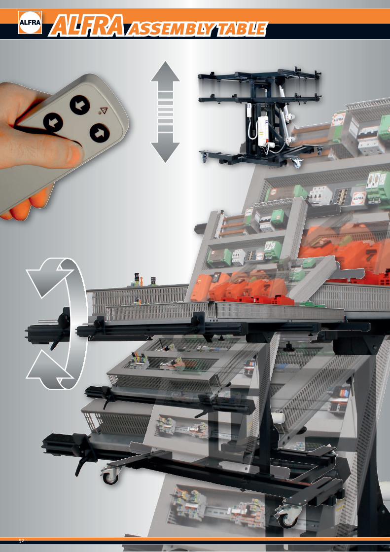
Pages 42 - 49
Wiring duct cutting devicePages 50 - 51
Assembly tables AMT 150, AMTE 200/250 Pages 52 - 55
Busbar finishing Pages 56 - 66
Crimping devices
Pages 67 - 68
Cable cutters
Page 69
ALFRA PRESS
Pages 70 - 93
6
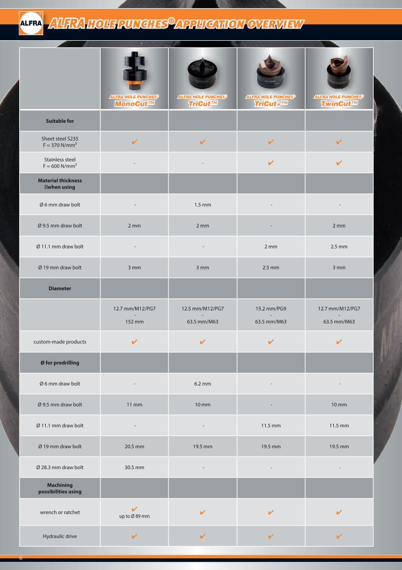
ALFRA hole punches® application overview
ALFRA HOLE PUNCHES®
MonoCut™ALFRA HOLE PUNCHES®
TriCut™ALFRA HOLE PUNCHES®
TriCut+™ALFRA HOLE PUNCHES®
TwinCut™
Suitable for
Sheet steel S235F ≈ 370 N/mm² ✔ ✔ ✔ ✔
Stainless steelF ≈ 600 N/mm² - - ✔ ✔
Material thickness ♠when using
Ø 6 mm draw bolt - 1.5 mm - -
Ø 9.5 mm draw bolt 2 mm 2 mm - 2 mm
Ø 11.1 mm draw bolt - - 2 mm 2.5 mm
Ø 19 mm draw bolt 3 mm 3 mm 2.5 mm 3 mm
Diameter
12.7 mm/M12/PG7 -
152 mm
12.5 mm/M12/PG7-
63.5 mm/M63
15.2 mm/PG9-
63.5 mm/M63
12.7 mm/M12/PG7-
63.5 mm/M63
custom-made products ✔ ✔ ✔ ✔
Ø for predrilling
Ø 6 mm draw bolt - 6.2 mm - -
Ø 9.5 mm draw bolt 11 mm 10 mm - 10 mm
Ø 11.1 mm draw bolt - - 11.5 mm 11.5 mm
Ø 19 mm draw bolt 20.5 mm 19.5 mm 19.5 mm 19.5 mm
Ø 28.3 mm draw bolt 30.5 mm - - -
Machiningpossibilities using
wrench or ratchet ✔ up to Ø 89 mm ✔ ✔ ✔
Hydraulic drive ✔ ✔ ✔ ✔

7
Ball bearing screw
2
12
3
4
1
2
3
4
High-tensile bolts for the toughest operating conditions
Protrusion of ball bearing outside protective ring ensures perfect force transmission to wrench or punching tool
Ball bearings encapsulated in aluminium rings Extremely long-life and perfectly protected against soiling
UNF fine thread
8
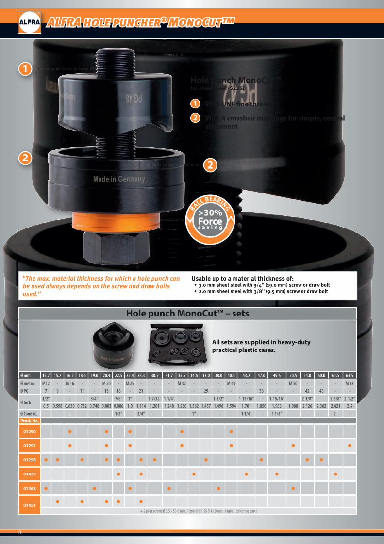
ALFRA hole puncher® MonoCut™
Hole punch MonoCut™ – sets
All sets are supplied in heavy-duty practical plastic cases.
Ø mm 12.7 15.2 16.2 18.6 19.0 20.4 22.5 25.4 28.3 30.5 31.7 32.5 34.6 37.0 38.0 40.5 43.2 47.0 49.6 50.5 54.0 60.0 61.5 63.5
Ø metric M12 - M 16 - - M 20 - M 25 - - - M 32 - - - M 40 - - - M 50 - - - M 63
Ø PG 7 9 - 11 - 13 16 - 21 - - - - 29 - - - 36 - - 42 48 - -
Ø Inch1/2" - - - 3/4" - 7/8" 1" - 1-7/32" 1-1/4" - - - 1-1/2" - 1-11/16" - 1-15/16" - 2-1/8" - 2-3/8" 2-1/2"0.5 0,598 0,638 0,732 0,748 0,803 0,886 1.0 1,114 1,201 1,248 1,280 1,362 1,457 1,496 1,594 1,701 1,850 1,953 1,988 2,126 2,362 2,421 2.5
Ø Conduit - - - - - - 1/2" - 3/4" - - - 1" - - - 1 1/4" - 1 1/2" - - - 2" -Prod.-No.
01290 ● ● ● ● ●
01291 ● ● ● ● ● ● ●
01298 ● ● ● ● ● ● ● ● ● ● ●
01459 ● ● ● ● ● ●
01463 ● ● ● ● ● ●
01451● ● ● ● ●
+ 2 joint screws Ø 9.5 x 50.0 mm, 1 pre-drill HSS Ø 11.0 mm, 1 tube lubricating paste
22
1
1
2
With UNF fine thread
With 4 crosshair markings for simple, central alignment
Hole punch MonoCut™for sheet steel (S235)
"The max. material thickness for which a hole punch can be used always depends on the screw and draw bolts used."
Usable up to a material thickness of:• 3.0 mm sheet steel with 3/4" (19.0 mm) screw or draw bolt• 2.0 mm sheet steel with 3/8" (9.5 mm) screw or draw bolt
>30%Forces a v i n g
BALL BEARING
9
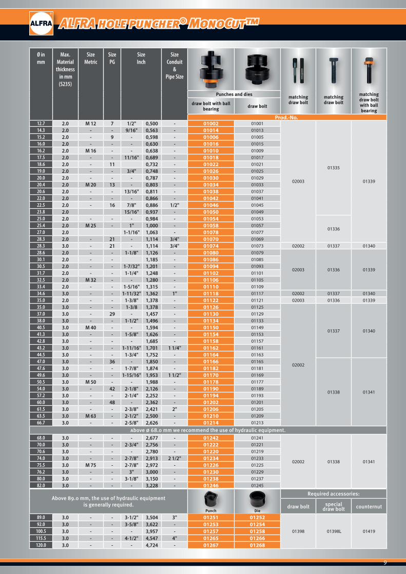
ALFRA hole puncher® MonoCut™
Ø in mm
Max. Material thickness
in mm(S235)
SizeMetric
Size PG
Size Inch
SizeConduit
& Pipe Size
Punches and dies matching draw bolt
matching draw bolt
matchingdraw boltwith ball bearing
draw bolt with ball bearing draw bolt
Prod.-No.12.7 2.0 M 12 7 1/2" 0,500 - 01002 01001
02003
01335
01339
14.3 2.0 - - 9/16" 0,563 - 01014 0101315.2 2.0 - 9 - 0,598 - 01006 0100516.0 2.0 - - - 0,630 - 01016 0101516.2 2.0 M 16 - - 0,638 - 01010 0100917.5 2.0 - - 11/16" 0,689 - 01018 0101718.6 2.0 - 11 0,732 - 01022 0102119.0 2.0 - - 3/4" 0,748 - 01026 0102520.0 2.0 - - - 0,787 - 01030 0102920.4 2.0 M 20 13 - 0,803 - 01034 0103320.6 2.0 - - 13/16" 0,811 - 01038 0103722.0 2.0 - - - 0,866 - 01042 0104122.5 2.0 - 16 7/8" 0,886 1/2" 01046 0104523.8 2.0 15/16" 0,937 - 01050 0104925.0 2.0 - - - 0,984 - 01054 01053
0133625.4 2.0 M 25 - 1" 1,000 - 01058 0105727.0 2.0 1-1/16" 1,063 - 01078 0107728.3 2.0 - 21 - 1,114 3/4" 01070 0106928.3 3.0 - 21 - 1,114 3/4" 01074 01073 02002 01337 0134028.6 2.0 - - 1-1/8" 1,126 - 01080 01079
02003 01336 01339
30.1 2.0 - - 1,185 - 01086 0108530.5 2.0 - - 1-7/32" 1,201 - 01094 0109331.7 2.0 - - 1-1/4" 1,248 - 01102 0110132.5 2.0 M 32 - - 1,280 - 01106 0110533.4 2.0 - - 1-5/16" 1,315 - 01110 0110934.6 3.0 - - 1-11/32" 1,362 1" 01118 01117 02002 01337 0134035.0 2.0 - - 1-3/8" 1,378 - 01122 01121 02003 01336 0133935.0 3.0 - - 1-3/8 1,378 - 01126 01125
02002
01337 01340
37.0 3.0 - 29 - 1,457 - 01130 0112938.0 3.0 - - 1-1/2" 1,496 - 01134 0113340.5 3.0 M 40 - - 1,594 - 01150 0114941.3 3.0 - - 1-5/8" 1,626 - 01154 0115342.8 3.0 - - - 1,685 - 01158 0115743.2 3.0 - - 1-11/16" 1,701 1 1/4" 01162 0116144.5 3.0 - - 1-3/4" 1,752 - 01164 0116347.0 3.0 - 36 - 1,850 - 01166 01165
01338 01341
47.6 3.0 - - 1-7/8" 1,874 - 01182 0118149.6 3.0 - - 1-15/16" 1,953 1 1/2" 01170 0116950.5 3.0 M 50 - - 1,988 - 01178 0117754.0 3.0 - 42 2-1/8" 2,126 - 01190 0118957.2 3.0 - - 2-1/4" 2,252 - 01194 0119360.0 3.0 - 48 - 2,362 - 01202 0120161.5 3.0 - - 2-3/8" 2,421 2" 01206 0120563.5 3.0 M 63 - 2-1/2" 2,500 - 01210 0120966.7 3.0 - - 2-5/8" 2,626 - 01214 01213
Above Ø 68.0 mm we recommend the use of hydraulic equipment.68.0 3.0 - - - 2,677 - 01242 01241
02002 01338 01341
70.0 3.0 - - 2-3/4" 2,756 - 01222 0122170.6 3.0 - - - 2,780 - 01220 0121974.0 3.0 - - 2-7/8" 2,913 2 1/2" 01234 0123375.5 3.0 M 75 - 2-7/8" 2,972 - 01226 0122576.2 3.0 - - 3" 3,000 - 01230 0122980.0 3.0 - - 3-1/8" 3,150 - 01238 0123782.0 3.0 - - - 3,228 - 01246 01245
Above 89.0 mm, the use of hydraulic equipmentis generally required.
Punch Die
Required accessories:
draw bolt specialdraw bolt counternut
89.0 3.0 - - 3-1/2" 3,504 3" 01251 01252
01398 01398L 0141992.0 3.0 - - 3-5/8" 3,622 - 01253 01254
100.5 3.0 - - - 3,957 - 01257 01258115.5 3.0 - - 4-1/2" 4,547 4" 01265 01266120.0 3.0 - - - 4,724 - 01267 01268
10
Split hole punch TriCut™
Split hole punch TriCut™ - sets
All sets are supplied in heavy-duty practical plastic cases.
Ø mm 12.5 15.2 16.2 18.6 19.0 20.4 22.5 25.4 28.3 30.5 31.7 32.5 34.6 37.0 38.0 40.5 43.2 47.0 49.6 50.5 54.0 60.0 61.5 63.5Ø metric M12 - M 16 - - M 20 - M 25 - - - M 32 - - - M 40 - - - M 50 - - - M 63Ø PG 7 9 - 11 - 13 16 - 21 - - - - 29 - - - 36 - - 42 48 - -
Ø Inch1/2" - - - 3/4" - 7/8" 1" - 1-7/32" 1-1/4" - - - 1-1/2" - 1-11/16" - 1-15/16" - 2-1/8" - 2-3/8" 2-1/2"0.5 0,598 0,638 0,732 0,748 0,803 0,886 1.0 1,114 1,201 1,248 1,280 1,362 1,457 1,496 1,594 1,701 1,850 1,953 1,988 2,126 2,362 2,421 2.5
Ø Conduit - - - - - - 1/2" - 3/4" - - - 1" - - - 1 1/4" - 1 1/2" - - - 2" -Prod.-No.
01762 ● ● ● ● ●
01757 ● ● ● ● ● ● ●
01760 ● ● ● ● ● ●
01761 ● ● ● ● ● ●
01754● ● ● ● ● ●
+ 1 ball bearing screw Ø 6.0 x 40.0 mm, 1 ball bearing screw Ø 9.5 x 50.0 mm, 1 ball bearing screw Ø 19.0 x 55.0 mm, 1 pre-drill HSS Ø 10.0 mm, 1 can lubricating paste
01755● ● ● ● ● ● ●
+ 2 ball bearing screws Ø 9.5 x 50.0 mm, 1 ball bearing screw Ø 19.0 x 55.0 mm, 1 ball bearing screw Ø 19.0 x 75.0 mm, 1 pre-drill HSS Ø 10.0 mm, 1 can lubricating paste
01750● ● ● ● ● ●
+2 ball bearing screws Ø 9.5 x 50.0 mm, 1 pre-drill HSS Ø 10.0 mm, 1 tube lubricating paste
01751● ● ● ● ● ● ● ● ● ●
+ 2 ball bearing screws Ø 9.5 x 50.0 mm, 1 ball bearing screw Ø 19.0 x 55.0 mm, 1 ball bearing screw Ø 19.0 x 75.0 mm, 1 pre-drill HSS Ø 10.0 mm, 1 can lubricating paste
3 3
2
1
1
2
3
With 3-fold split
With UNF fine thread
With 4 crosshair markings for simple, central alignment
Split hole punch TriCut™for sheet steel (S235)
>30%Forces a v i n g
BALL BEARING
"The max. material thickness for which a hole punch can be used always depends on the screw and draw bolts used."
Usable up to a material thickness of:• 3.0 mm sheet steel with 3/4" (19.0 mm) screw or draw bolt• 2.0 mm sheet steel with 3/8" (9.5 mm) screw or draw bolt• 1.5 mm steel sheet with M6 (6.0 mm) screw or draw bolt

11
Split hole punch TriCut™
Ø in mm
Max. Material thickness
in mm(S235)
SizeMetric
Size PG
Size Inch
SizeConduit
& Pipe Size
Punches and dies, draw bolt with ball bearing
Punches and dies matching draw bolt
matchingdraw bolt
with ball bearingProd.-No.
12.5 1.5 M 12 7 1/2" 0,500 - 01674 01770 02022 01334
15.2 2.0 - 9 - 0,598 - 01680 01771
02003 01339
16.2 2.0 M 16 - - 0,638 - 01683 01772
18.6 2.0 - 11 - 0,732 - 01686 01773
20.4 2.0 M 20 13 - 0,803 - 01689 01774
22.5 2.0 - 16 7/8" 0,886 1/2" 01692 01775
25.4 2.0 M 25 - 1" 1,000 - 01695 01776
28.3 2.0 - 21 - 1,114 3/4" 01698 01777
28.3 3.0 - 21 - 1,114 3/4" 01701 01778 02002 01340
30.5 2.0 - - 1-7/32" 1,201 - 01703 01779 02003 01339
32.5 3.0 M 32 - - 1,280 - 01708 01780
02002
0134034.6 3.0 - - 1-11/32" 1,362 1" 01711 01788
37.0 3.0 - 29 - 1,457 - 01713 01781
40.5 3.0 M 40 - - 1,594 - 01715 01782
01341
43.2 3.0 - - 1-11/16" 1,701 1 1/4" 01718 01789
47.0 3.0 - 36 - 1,850 - 01720 01783
49.6 3.0 - - 1-15/16" 1,953 1 1/2" 01723 01790
50.5 3.0 M 50 - - 1,988 - 01736 01784
54.0 3.0 - 42 2-1/8" 2,126 - 01727 01785
60.0 3.0 - 48 - 2,362 - 01729 01786
61.5 3.0 - - 2-3/8" 2,421 2" 01732 01791
63.5 3.0 M 63 - 2-1/2" 2,500 - 01739 01787

12
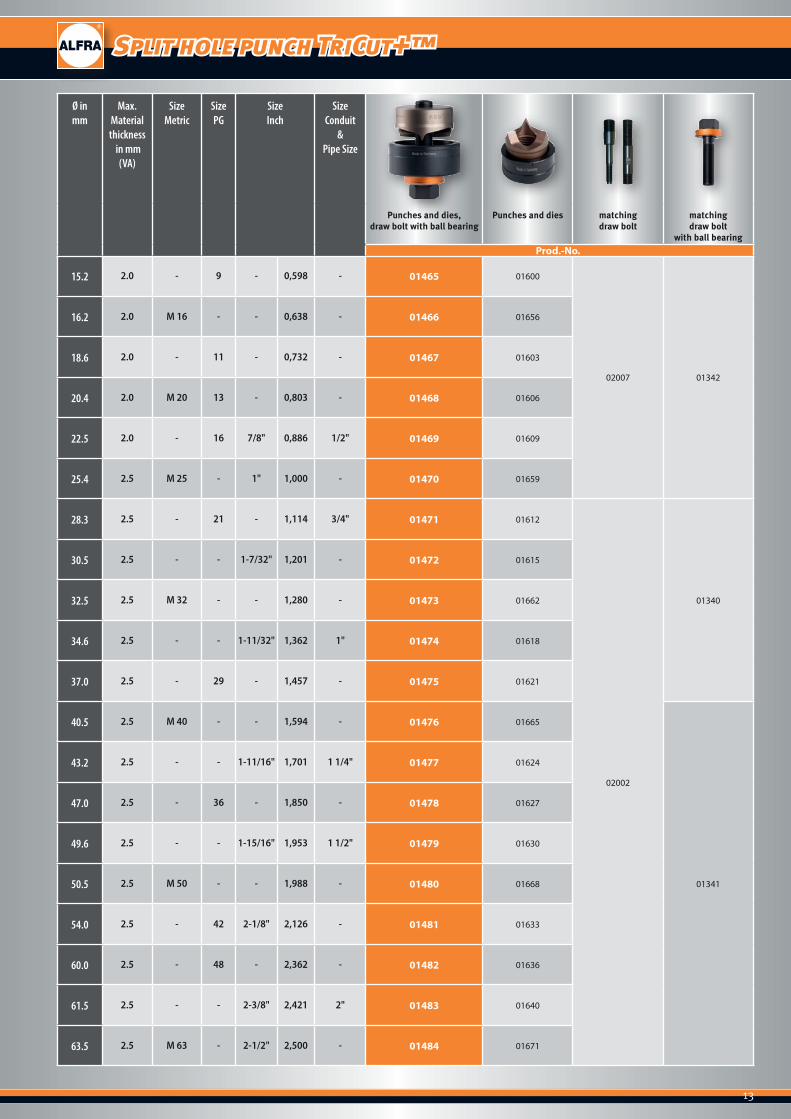
Split hole punch TriCut+™
Split hole punch TriCut+™ - sets
All sets are supplied in heavy-duty practical plastic cases.
Ø mm 15.2 16.2 18.6 19.0 20.4 22.5 25.4 28.3 30.5 31.7 32.5 34.6 37.0 38.0 40.5 43.2 47.0 49.6 50.5 54.0 60.0 61.5 63.5Ø metric - M 16 - - M 20 - M 25 - - - M 32 - - - M 40 - - - M 50 - - - M 63Ø PG 9 - 11 - 13 16 - 21 - - - - 29 - - - 36 - - 42 48 - -
Ø Inch- - - 3/4" - 7/8" 1" - 1-7/32" 1-1/4" - - - 1-1/2" - 1-11/16" - 1-15/16" - 2-1/8" - 2-3/8" 2-1/2"
0,598 0,638 0,732 0,748 0,803 0,886 1.0 1,114 1,201 1,248 1,280 1,362 1,457 1,496 1,594 1,701 1,850 1,953 1,988 2,126 2,362 2,421 2.5Ø Conduit - - - - - 1/2" - 3/4" - - - 1" - - - 1 1/4" - 1 1/2" - - - 2" -Prod.-No.
01652 ● ● ● ● ●
01653 ● ● ● ● ● ● ●
01645 ● ● ● ● ● ●
01646 ● ● ● ● ●
2
1
1
2
3
With 3-fold split
With UNF fine thread
With 4 crosshair markings for simple, central alignment
Split hole punch TriCut+™for sheet steel (S235) and stainless steel
3
>30%Forces a v i n g
BALL BEARING
"The max. material thickness for which a hole punch can be used always depends on the screw and draw bolts used."
Usable up to a material thickness of:• 2.5 mm steel sheet with 3/4" (19.0 mm) screw or draw bolt• 2.0 mm steel sheet with 7/16" (11.1 mm) screw or draw bolt
3
13
Split hole punch TriCut+™
Ø in mm
Max. Material thickness
in mm(VA)
SizeMetric
Size PG
Size Inch
SizeConduit
& Pipe Size
Punches and dies, draw bolt with ball bearing
Punches and dies matching draw bolt
matchingdraw bolt
with ball bearingProd.-No.
15.2 2.0 - 9 - 0,598 - 01465 01600
02007 01342
16.2 2.0 M 16 - - 0,638 - 01466 01656
18.6 2.0 - 11 - 0,732 - 01467 01603
20.4 2.0 M 20 13 - 0,803 - 01468 01606
22.5 2.0 - 16 7/8" 0,886 1/2" 01469 01609
25.4 2.5 M 25 - 1" 1,000 - 01470 01659
28.3 2.5 - 21 - 1,114 3/4" 01471 01612
02002
01340
30.5 2.5 - - 1-7/32" 1,201 - 01472 01615
32.5 2.5 M 32 - - 1,280 - 01473 01662
34.6 2.5 - - 1-11/32" 1,362 1" 01474 01618
37.0 2.5 - 29 - 1,457 - 01475 01621
40.5 2.5 M 40 - - 1,594 - 01476 01665
01341
43.2 2.5 - - 1-11/16" 1,701 1 1/4" 01477 01624
47.0 2.5 - 36 - 1,850 - 01478 01627
49.6 2.5 - - 1-15/16" 1,953 1 1/2" 01479 01630
50.5 2.5 M 50 - - 1,988 - 01480 01668
54.0 2.5 - 42 2-1/8" 2,126 - 01481 01633
60.0 2.5 - 48 - 2,362 - 01482 01636
61.5 2.5 - - 2-3/8" 2,421 2" 01483 01640
63.5 2.5 M 63 - 2-1/2" 2,500 - 01484 01671
14
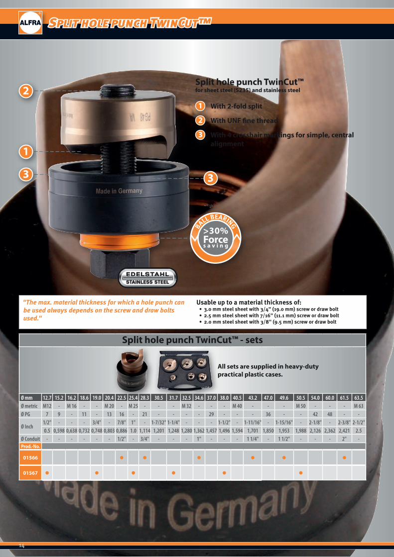
Split hole punch TwinCut™
Split hole punch TwinCut™ - sets
All sets are supplied in heavy-duty practical plastic cases.
Ø mm 12.7 15.2 16.2 18.6 19.0 20.4 22.5 25.4 28.3 30.5 31.7 32.5 34.6 37.0 38.0 40.5 43.2 47.0 49.6 50.5 54.0 60.0 61.5 63.5Ø metric M12 - M 16 - - M 20 - M 25 - - - M 32 - - - M 40 - - - M 50 - - - M 63Ø PG 7 9 - 11 - 13 16 - 21 - - - - 29 - - - 36 - - 42 48 - -
Ø Inch1/2" - - - 3/4" - 7/8" 1" - 1-7/32" 1-1/4" - - - 1-1/2" - 1-11/16" - 1-15/16" - 2-1/8" - 2-3/8" 2-1/2"0.5 0,598 0,638 0,732 0,748 0,803 0,886 1.0 1,114 1,201 1,248 1,280 1,362 1,457 1,496 1,594 1,701 1,850 1,953 1,988 2,126 2,362 2,421 2.5
Ø Conduit - - - - - - 1/2" - 3/4" - - - 1" - - - 1 1/4" - 1 1/2" - - - 2" -Prod.-No.
01566 ● ● ● ● ● ●
01567 ● ● ● ● ● ●
"The max. material thickness for which a hole punch can be used always depends on the screw and draw bolts used."
Usable up to a material thickness of:• 3.0 mm steel sheet with 3/4" (19.0 mm) screw or draw bolt• 2.5 mm steel sheet with 7/16" (11.1 mm) screw or draw bolt• 2.0 mm steel sheet with 3/8" (9.5 mm) screw or draw bolt
2
1
1
2
3
With 2-fold split
With UNF fine thread
With 4 crosshair markings for simple, central alignment
Split hole punch TwinCut™for sheet steel (S235) and stainless steel
3
>30%Forces a v i n g
BALL BEARING
3
15
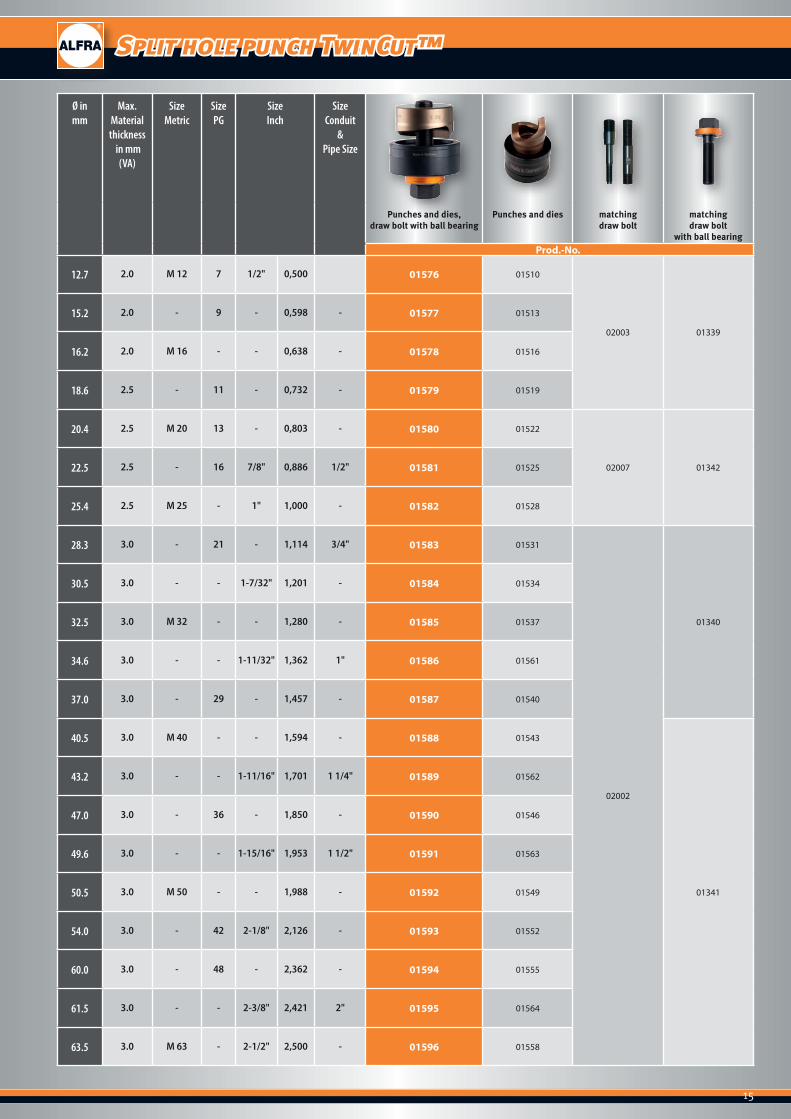
Split hole punch TwinCut™
Ø in mm
Max. Material thickness
in mm(VA)
SizeMetric
Size PG
Size Inch
SizeConduit
& Pipe Size
Punches and dies, draw bolt with ball bearing
Punches and dies matching draw bolt
matchingdraw bolt
with ball bearingProd.-No.
12.7 2.0 M 12 7 1/2" 0,500 01576 01510
02003 01339
15.2 2.0 - 9 - 0,598 - 01577 01513
16.2 2.0 M 16 - - 0,638 - 01578 01516
18.6 2.5 - 11 - 0,732 - 01579 01519
20.4 2.5 M 20 13 - 0,803 - 01580 01522
02007 0134222.5 2.5 - 16 7/8" 0,886 1/2" 01581 01525
25.4 2.5 M 25 - 1" 1,000 - 01582 01528
28.3 3.0 - 21 - 1,114 3/4" 01583 01531
02002
01340
30.5 3.0 - - 1-7/32" 1,201 - 01584 01534
32.5 3.0 M 32 - - 1,280 - 01585 01537
34.6 3.0 - - 1-11/32" 1,362 1" 01586 01561
37.0 3.0 - 29 - 1,457 - 01587 01540
40.5 3.0 M 40 - - 1,594 - 01588 01543
01341
43.2 3.0 - - 1-11/16" 1,701 1 1/4" 01589 01562
47.0 3.0 - 36 - 1,850 - 01590 01546
49.6 3.0 - - 1-15/16" 1,953 1 1/2" 01591 01563
50.5 3.0 M 50 - - 1,988 - 01592 01549
54.0 3.0 - 42 2-1/8" 2,126 - 01593 01552
60.0 3.0 - 48 - 2,362 - 01594 01555
61.5 3.0 - - 2-3/8" 2,421 2" 01595 01564
63.5 3.0 M 63 - 2-1/2" 2,500 - 01596 01558
16
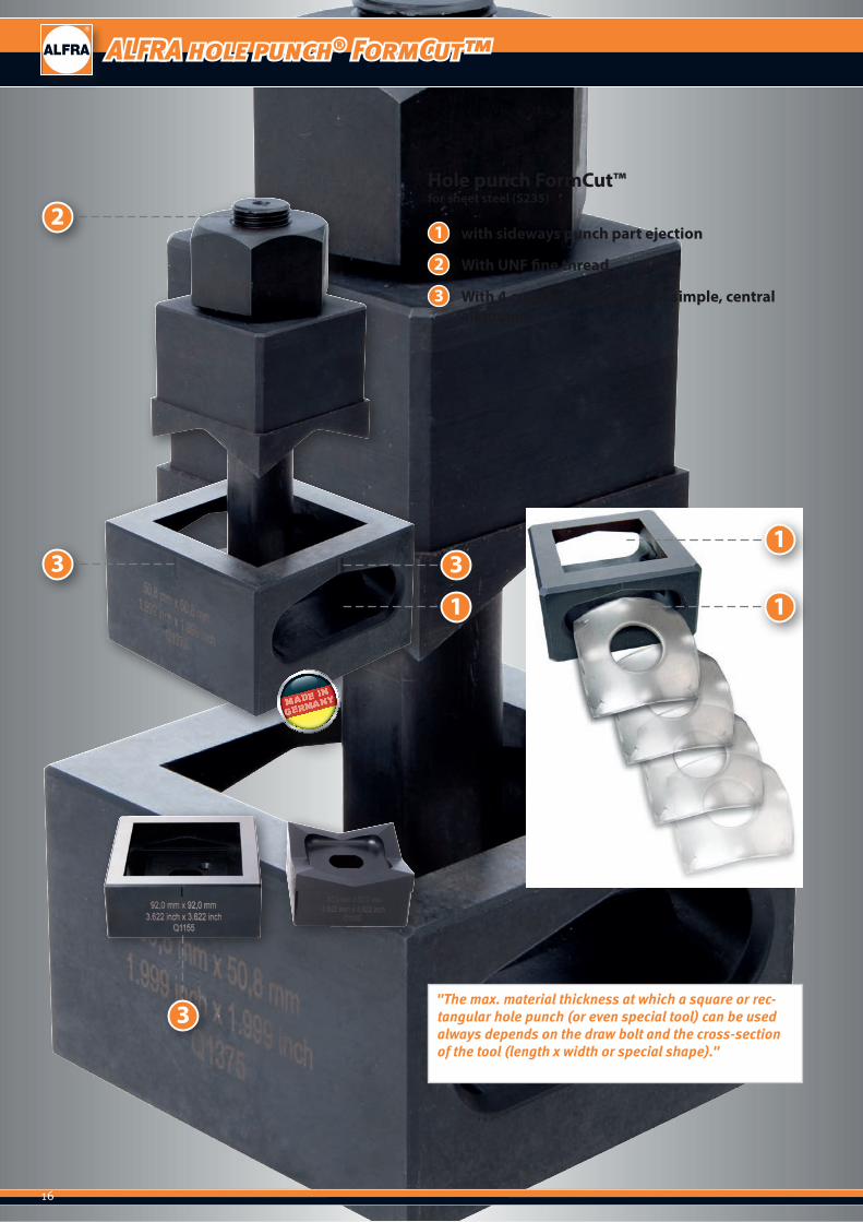
ALFRA hole punch® FormCut™
3
1
2
3
with sideways punch part ejection
With UNF fine thread
With 4 crosshair markings for simple, central alignment
Hole punch FormCut™for sheet steel (S235)
"The max. material thickness at which a square or rec-tangular hole punch (or even special tool) can be used always depends on the draw bolt and the cross-section of the tool (length x width or special shape)."
2
3 3
1
1
1

17
ALFRA hole punch® FormCut™
Size in
mm
Max. Material thickness
in mm(S235)
For use in pre-drillingin mm
incl. -1 4 draw bolt counternut Ball bearingpressure nut
Adapter for hydraulic
Hole punch FormCut™ - square - for sheet steel (S235)Prod.-No.
12.7 x 12.7 1.75 ● ● 10 0130001348 01355
01352 01353
15.8 x 15.8 1.75 ● ● 10 01301
19.0 x 19.0 2.0 ● ● 14 01302
01347 0135122.2 x 22.2 2.0 ● ● 14 01303
24.0 x 24.0 2.0 ● ● 14 01331
25.4 x 25.4 2.0 ● ● 17 01304 01360 01354 01359 01361
45.5 x 45.5 3.0 ● 20 0131301345
0135046.0 x 46.0 3.0 ● 20 01305
50.8 x 50.8 3.0 ● 24 0130601344
68.0 x 68.0 3.0 ● 24 0130801349
92.0 x 92.0 3.0 ● 30 01309
01343125.0 x 125.0 3.0 ● 30 0143101356
138.0 x 138.0 3.0 ● 30 01311
Size in
mm
Max. Material thickness
in mm(S235)
Number of poles
For use in pre-drillingin mm
incl. -1 4 draw bolt counternutor bridge
Ball bearingpressure nut
Adapter for hydraulic
Hole punch FormCut™ - rectangular - for sheet steel (S235)Prod.-No.
17.0 x 19.0 2.0 ● ● 14 01317 01347
01351
01352 01353
21.8 x 25.8 2.0 ● ● 17 01318
01360 01359 0136122.0 x 30.0 2.0 ● ● 17 01319
22.0 x 42.0 2.0 ● ● 17 01320
25.0 x 50.0 2.0 ● ● 17 01332 01418
45.0 x 92.0 2.0 ● 24 0131401344 01349
46.0 x 92.0 2.0 ● 24 01329
68.0 x 138.0 3.0 ● 30 01330 01344 01358
Hole punch FormCut™ - rectangular - for heavy plug connectors (S235) - for sheet steel (S235)
36.0 x 52.0 2.0 6-pole ● 24 01325
013440135036.0 x 65.0 2.0 10-pole ● 24 01326
36.0 x 86.0 2.0 16-pole ● 24 01327
36.0 x 91.0 2.0 ● 24 01323 01349
36.0 x 112.0 2.0 24-pole ● 24 01328 01343 01357
46.0 x 86.0 2.0 ● 24 01322 0134401349
46.0 x 112.0 2.0 ● 30 01324 01343
1 2 3 4
1 2 3 4

18
ALFRA hole punch® FormCut+™
3
1
2
3
with sideways punch part ejection
With UNF fine thread
With 4 crosshair markings for simple, central alignment
Hole punch FormCut+™for sheet steel (S235) and stainless steel
"The max. material thickness at which a square or rec-tangular hole punch (or even special tool) can be used always depends on the draw bolt and the cross-section of the tool (length x width or special shape)."
2
3 3
1
1
1

19
ALFRA hole punch® FormCut+™
Size in mm
Max. Material thickness
in mm(VA)
For use in pre-drilling in mm
incl. -1 4 draw bolt counternut Ball bearingpressure nut
Adapter for hydraulic
Hole punch FormCut+™ - square - for stainless steel (VA)Prod.-No.
12.7 x 12.7 1.25 ● ● 10 01300101348 01355
01352 01353
15.8 x 15.8 1.25 ● ● 10 013011
19.0 x 19.0 1.5 ● ● 14 013021
01347 0135122.2 x 22.2 1.5 ● ● 14 013031
24.0 x 24.0 1.5 ● ● 14 013311
25.4 x 25.4 1.5 ● ● 17 013041 01360 01354 01359 01361
45.5 x 45.5 2.0 ● 20 01313101345
0135046.0 x 46.0 2.0 ● 20 013051
50.8 x 50.8 2.0 ● 24 01306101344
68.0 x 68.0 2.0 ● 24 01308101349
92.0 x 92.0 2.0 ● 30 013091
01343125.0 x 125.0 2.0 ● 30 014311 01356
138.0 x 138.0 2.0 ● 30 013111 01356
Size in mm
Max. Material thickness
in mm(VA)
Number of poles
For use in pre-drilling in mm
incl. -1 4 draw bolt counternutor bridge
Ball bearingpressure nut
Adapter for hydraulic
Hole punch FormCut+™ - rectangular - for stainless steel (VA)Prod.-No.
17.0 x 19.0 1.5 ● ● 14 013171 01347
01351
01352 01353
21.8 x 25.8 1.5 ● ● 17 013181
01360 01359 0136122.0 x 30.0 1.5 ● ● 17 013191
22.0 x 42.0 1.5 ● ● 17 013201
25.0 x 50.0 1.5 ● ● 17 013321 01418
45.0 x 92.0 2.0 ● 24 01314101344 01349
46.0 x 92.0 2.0 ● 24 013241
68.0 x 138.0 2.0 ● 30 013301 01343 01358
Hole punch FormCut+™ - rectangular - for heavy plug connectors - for stainless steel (VA)
36.0 x 52.0 2.0 6-pole ● 24 013251
013440135036.0 x 65.0 2.0 10-pole ● 24 013261
36.0 x 86.0 2.0 16-pole ● 24 013271
36.0 x 91.0 2.0 ● 24 013231 01349
36.0 x 112.0 2.0 24-pole ● 24 013281 01343 01357
46.0 x 86.0 2.0 ● 24 013221 0134401349
46.0 x 112.0 2.0 ● 30 013241 01343
1 2 3 4
1 2 3 4
20
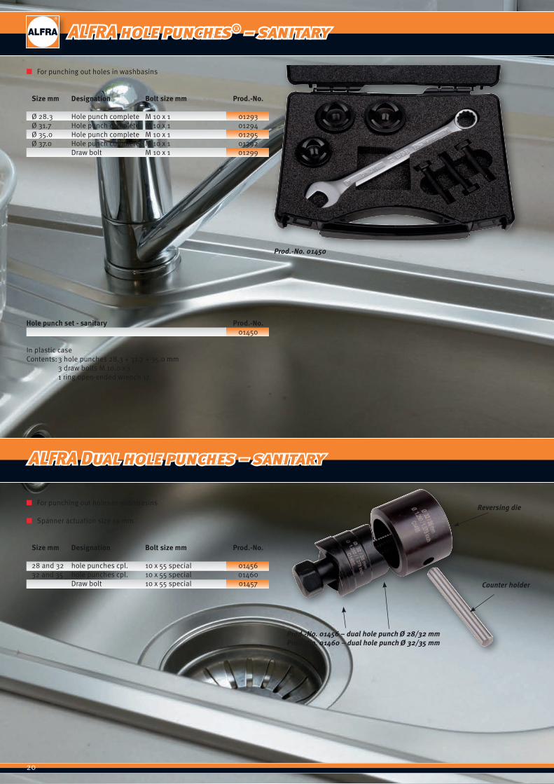
ALFRA hole punches® – sanitary
Prod.-No. 01450
Prod.-No. 01456 – dual hole punch Ø 28/32 mmProd.-No. 01460 – dual hole punch Ø 32/35 mm
Counter holder
Reversing die
■ For punching out holes in washbasins
Size mm Designation Bolt size mm Prod.-No.
Ø 28.3 Hole punch complete M 10 x 1 01293Ø 31.7 Hole punch complete M 10 x 1 01294Ø 35.0 Hole punch complete M 10 x 1 01295Ø 37.0 Hole punch complete M 10 x 1 01292 Draw bolt M 10 x 1 01299
Hole punch set - sanitary Prod.-No. 01450
In plastic caseContents: 3 hole punches 28.3 + 31.7 + 35.0 mm 3 draw bolts M 10.0 x 1 1 ring open-ended wrench 17
■ For punching out holes in washbasins
■ Spanner actuation size 19 mm
Size mm Designation Bolt size mm Prod.-No.
28 and 32 hole punches cpl. 10 x 55 special 01456 32 and 35 hole punches cpl. 10 x 55 special 01460 Draw bolt 10 x 55 special 01457
ALFRA Dual hole punches – sanitary
21
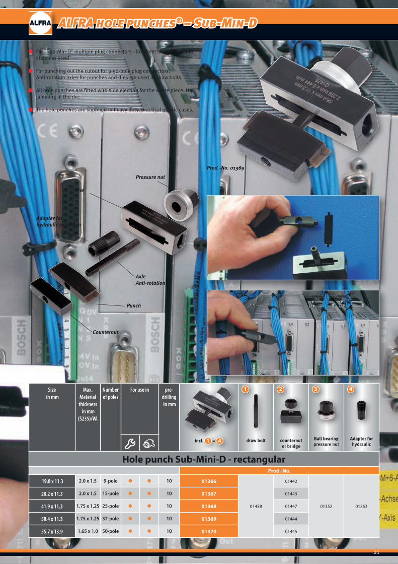
ALFRA hole punches® – Sub-Min-D
■ For "Sub-Min-D" multiple plug connectors - for sheet steel (S235) and stainless steel
■ For punching out the cutout for 9-50-pole plug connectors. Anti-rotation axles for punches and dies are used as draw bolts.
■ All hole punches are fitted with side ejection for the waste piece. No jamming in the die.
■ The hole punches are supplied in heavy duty, practical plastic cases.
Prod.-No. 01369
Pressure nut
Die
Adapter forhydraulic actuation
Counternut
Punch
AxleAnti-rotation
Size in mm
Max. Material thickness
in mm(S235)/VA
Number of poles
For use in pre-drilling in mm
incl. -1 4 draw bolt counternutor bridge
Ball bearingpressure nut
Adapter for hydraulic
Hole punch Sub-Mini-D - rectangularProd.-No.
19.8 x 11.3 2.0 x 1.5 9-pole ● ● 10 01366
01438
01442
01352 01353
28.2 x 11.3 2.0 x 1.5 15-pole ● ● 10 01367 01443
41.9 x 11.3 1.75 x 1.25 25-pole ● ● 10 01368 01447
58.4 x 11.3 1.75 x 1.25 37-pole ● ● 10 01369 01444
55.7 x 13.9 1.65 x 1.0 50-pole ● ● 10 01370 01445
1 2 3 4
22
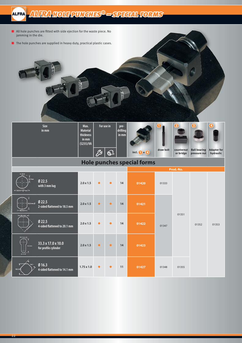
ALFRA hole punches® – special forms
■ All hole punches are fitted with side ejection for the waste piece. No jamming in the die.
■ The hole punches are supplied in heavy duty, practical plastic cases.
Prod.-No. 01423
Size in mm
Max. Material thickness
in mm(S235)/VA
For use in pre-drilling in mm
incl. -1 4draw bolt counternut
or bridgeBall bearingpressure nut
Adapter for hydraulic
Hole punches special formsProd.-No.
Ø 22.5 with 3 mm lug
2.0 x 1.5 ● ● 14 01420 01333
01351
01352 01353
Ø 22.5 2-sided flattened to 18.5 mm
2.0 x 1.5 ● ● 14 01421
01347Ø 22.5 4-sided flattened to 20.1 mm
2.0 x 1.5 ● ● 14 01422
33.3 x 17.0 x 10.0 for profile cylinder
2.0 x 1.5 ● ● 14 01423
Ø 16.3 4-sided flattened to 14.1 mm
1.75 x 1.0 ● ● 11 01427 01348 01355
1 2 3 4

23
■ We can make any form of circular, square, rectangular hole punch to your drawings at short notice.
■ Please state whether your enquiry is for manual or hydraulic actuation in addition to the sheet thickness and material number.
■ Ask for our technical support.
Hole punch custom-made products
Circular
Ø diameter d Material thickness Material type
mm mmSheet steel (S235) ¨
Stainless steel (VA) ¨
Circularwith lugs
Ø diameter d Number of lugs Lug width Material thickness Material type
mm mm mm
Sheet steel (S235) ¨
Stainless steel (VA) ¨
a Square
Edge length a Material thickness Material type
mm mmSheet steel (S235) ¨
Stainless steel (VA) ¨
h
b
Rectangle
Width b Height h Material thickness Material type
mm mm mmSheet steel (S235) ¨Stainless steel (VA) ¨
Circularflattened on one side
Ø diameter d Flattened to Material thickness Material type
mm mm mmSheet steel (S235) ¨
Stainless steel (VA) ¨
Circularflattened on two sides
Ø diameter d Flattened to Material thickness Material type
mm mm mmSheet steel (S235) ¨Stainless steel (VA) ¨
a
Squarewith 4 flattened corners
Edge length a Corners flattened to Material thickness Material type
mm mm mm
Sheet steel (S235) ¨
Stainless steel (VA) ¨
ALFRA hole punch® custom-made products
24
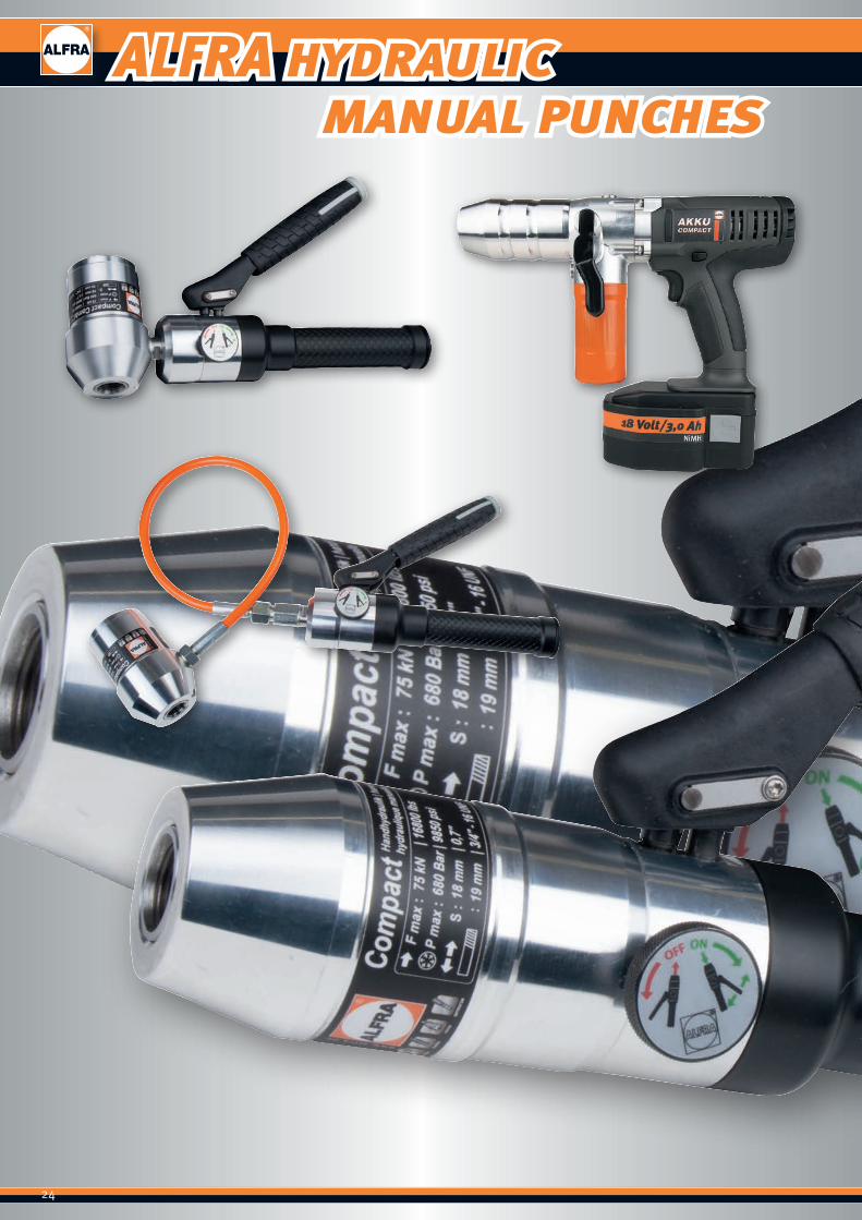
ALFRA hydraulic manual punches
25
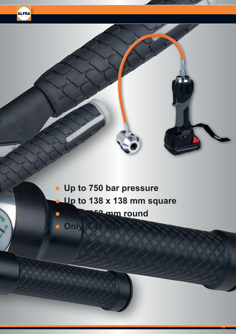
ALFRA hydraulic manual punches
● Up to 750 bar pressure ● Up to 138 x 138 mm square ● Up to 152 mm round ● Only 1.45 kg
26
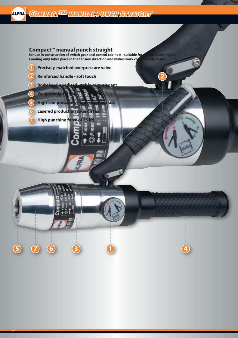
Compact™ manual punch straight
36 475 1
21
2
3
4
5
6
7
Precisely-matched overpressure valve
Reinforced handle - soft touch
Body hard-anodised, stable grip, elegant
Weighs only 1.45 kg
High-compression cylinder bore surface
Lasered production code on rear
High punching force of 75 kN
Compact™ manual punch straightfor use in construction of switch gear and control cabinets - suitable for all hole punch typesLoading only takes place in the tension direction and makes work considerably easier
27
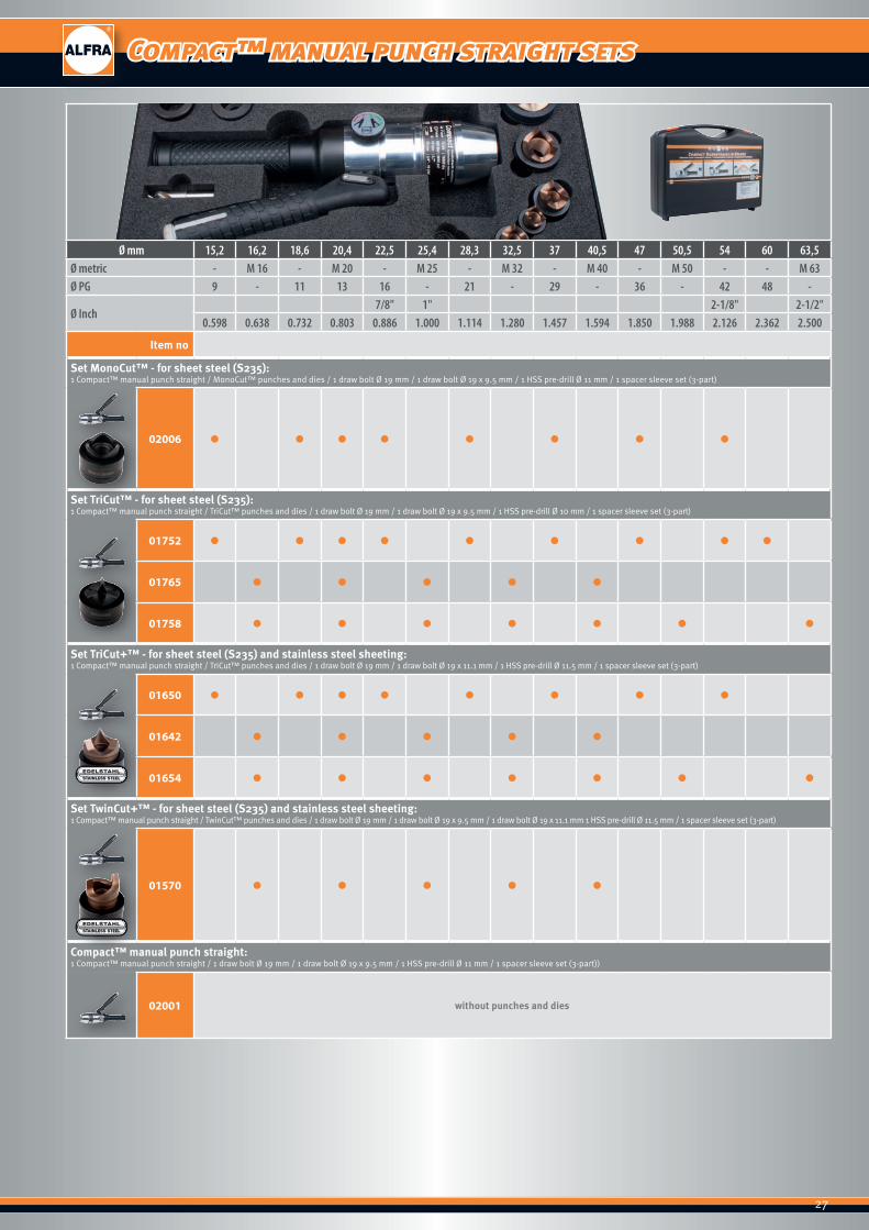
Compact™ manual punch straight sets
Ø mm 15,2 16,2 18,6 20,4 22,5 25,4 28,3 32,5 37 40,5 47 50,5 54 60 63,5Ø metric - M 16 - M 20 - M 25 - M 32 - M 40 - M 50 - - M 63Ø PG 9 - 11 13 16 - 21 - 29 - 36 - 42 48 -
Ø Inch7/8" 1" 2-1/8" 2-1/2"
0.598 0.638 0.732 0.803 0.886 1.000 1.114 1.280 1.457 1.594 1.850 1.988 2.126 2.362 2.500
Item no
Set MonoCut™ - for sheet steel (S235): 1 Compact™ manual punch straight / MonoCut™ punches and dies / 1 draw bolt Ø 19 mm / 1 draw bolt Ø 19 x 9.5 mm / 1 HSS pre-drill Ø 11 mm / 1 spacer sleeve set (3-part)
02006 ● ● ● ● ● ● ● ●
Set TriCut™ - for sheet steel (S235):1 Compact™ manual punch straight / TriCut™ punches and dies / 1 draw bolt Ø 19 mm / 1 draw bolt Ø 19 x 9.5 mm / 1 HSS pre-drill Ø 10 mm / 1 spacer sleeve set (3-part)
01752 ● ● ● ● ● ● ● ● ●
01765 ● ● ● ● ●
01758 ● ● ● ● ● ● ●
Set TriCut+™ - for sheet steel (S235) and stainless steel sheeting:1 Compact™ manual punch straight / TriCut™ punches and dies / 1 draw bolt Ø 19 mm / 1 draw bolt Ø 19 x 11.1 mm / 1 HSS pre-drill Ø 11.5 mm / 1 spacer sleeve set (3-part)
01650 ● ● ● ● ● ● ● ●
01642 ● ● ● ● ●
01654 ● ● ● ● ● ● ●
Set TwinCut+™ - for sheet steel (S235) and stainless steel sheeting:1 Compact™ manual punch straight / TwinCut™ punches and dies / 1 draw bolt Ø 19 mm / 1 draw bolt Ø 19 x 9.5 mm / 1 draw bolt Ø 19 x 11.1 mm 1 HSS pre-drill Ø 11.5 mm / 1 spacer sleeve set (3-part)
01570 ● ● ● ● ●
Compact™ manual punch straight:1 Compact™ manual punch straight / 1 draw bolt Ø 19 mm / 1 draw bolt Ø 19 x 9.5 mm / 1 HSS pre-drill Ø 11 mm / 1 spacer sleeve set (3-part))
02001 without punches and dies
28
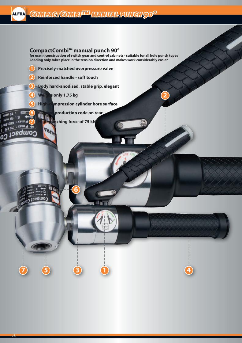
CompactCombi™ manual punch 90°
1
2
3
4
5
6
7
Precisely-matched overpressure valve
Reinforced handle - soft touch
Body hard-anodised, stable grip, elegant
Weighs only 1.75 kg
High-compression cylinder bore surface
Lasered production code on rear
High punching force of 75 kN
3
6
47 5 1
2
CompactCombi™ manual punch 90°for use in construction of switch gear and control cabinets - suitable for all hole punch typesLoading only takes place in the tension direction and makes work considerably easier
29
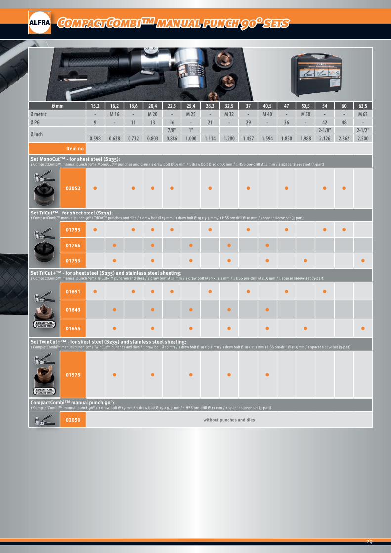
CompactCombi™ manual punch 90° sets
Ø mm 15,2 16,2 18,6 20,4 22,5 25,4 28,3 32,5 37 40,5 47 50,5 54 60 63,5Ø metric - M 16 - M 20 - M 25 - M 32 - M 40 - M 50 - - M 63Ø PG 9 - 11 13 16 - 21 - 29 - 36 - 42 48 -
Ø Inch7/8" 1" 2-1/8" 2-1/2"
0.598 0.638 0.732 0.803 0.886 1.000 1.114 1.280 1.457 1.594 1.850 1.988 2.126 2.362 2.500
Item no
Set MonoCut™ - for sheet steel (S235):1 CompactComb™ manual punch 90° / MonoCut™ punches and dies / 1 draw bolt Ø 19 mm / 1 draw bolt Ø 19 x 9.5 mm / 1 HSS pre-drill Ø 11 mm / 1 spacer sleeve set (3-part)
02052 ● ● ● ● ● ● ● ● ●
Set TriCut™ - for sheet steel (S235):1 CompactComb™ manual punch 90° / TriCut™ punches and dies / 1 draw bolt Ø 19 mm / 1 draw bolt Ø 19 x 9.5 mm / 1 HSS pre-drill Ø 10 mm / 1 spacer sleeve set (3-part)
01753 ● ● ● ● ● ● ● ● ●
01766 ● ● ● ● ●
01759 ● ● ● ● ● ● ●
Set TriCut+™ - for sheet steel (S235) and stainless steel sheeting:1 CompactComb™ manual punch 90° / TriCut+™ punches and dies / 1 draw bolt Ø 19 mm / 1 draw bolt Ø 19 x 11.1 mm / 1 HSS pre-drill Ø 11.5 mm / 1 spacer sleeve set (3-part)
01651 ● ● ● ● ● ● ● ●
01643 ● ● ● ● ●
01655 ● ● ● ● ● ● ●
Set TwinCut+™ - for sheet steel (S235) and stainless steel sheeting:1 CompactCombi™ manual punch 90° / TwinCut™ punches and dies / 1 draw bolt Ø 19 mm / 1 draw bolt Ø 19 x 9.5 mm / 1 draw bolt Ø 19 x 11.1 mm 1 HSS pre-drill Ø 11.5 mm / 1 spacer sleeve set (3-part)
01575 ● ● ● ● ●
CompactCombi™ manual punch 90°:1 CompactCombi™ manual punch 90° / 1 draw bolt Ø 19 mm / 1 draw bolt Ø 19 x 9.5 mm / 1 HSS pre-drill Ø 11 mm / 1 spacer sleeve set (3-part)
02050 without punches and dies

30
Akku-Compact Flex™
1
2
3
4
Handle inset soft touch
High-pressure hose - flexible, elastic
USB interface for readable pressure values, service intervals etc.…
Pressure sensor - automatic detection of punch breakthrough. Once the material has been punched through, the punch can not damage the die.
4
1
3
2
Akku-Compact Flex™for use in construction of switch gear and control cabinets - suitable for all hole punch typesLoading only takes place in the tension direction and makes work considerably easier

31
Akku-Compact Flex™
Prod.-No. 02072 Prod.-No. 02071
Prod.-No. 02082
Practical manual hydraulics with 18 V LiON battery for punching circular, square and rectangular cutouts in control cabinet and switch gear construc-tion.Extremely easy to handle and light thanks to high-tensile aluminium head.
■ Light and easy to handle, only 2.5 kg including battery
Technical data:Punching Circular holes: up to 82 mm Ø 3.0 mm sheet steel (S235) 2.0 mm stainless steel (F = 600 N/mm2) 89 - 152 mm Ø only with special traction bolt* and spacer* 2.0 mm sheet steel (S235) 1.5 mm stainless steel (F = 600 N/mm2)Shaped holes: 68 x 68 mm 3.0 mm sheet steel (S235),
2.0 mm stainless steel (F = 600 N/mm2) 92 x 92 mm only with special traction bolt* and spacer* 2.0 mm sheet steel (S235) 1.5 mm stainless steel (F = 600 N/mm2)DriveMax. punching force: 75 kNMax. hydraulic pressure: 680 bar
Battery 18 V Li-Ion / 1.5 AhCharging time: 30 mins. after full dischargeUse: - 10° - + 40° C
Battery chargerCharges all batteries 18 - 28 V, compatible for NiCD, NiMH and Li-Ion batter-ies. Automatic temperature monitoring. Battery cell overcharging is prevented by switchover from rapid charging to trickle charging.The charging state is shown by the LED display.The PCB is completely enclosed.
Punching capacity with 1.5 Ah battery 195 x Ø 22.5 mm MonoCut™ to 2.5 mm S235 165 x Ø 22.5 mm TriCut™ to 2.5 mm S235
105 x Ø 63.5 mm MonoCut™ to 2.5 mm S235 65 x Ø 63.5 mm TriCut™ to 2.5 mm S235
170 x Ø 22.5 mm TwinCut™ to 1.5 mm V2A 95 x Ø 63.5 mm TwinCut™ to 1.5 mm V2A
Weight2.5 kg including battery
Scope of delivery: Prod.-No.ALFRA Akku-Compact Flex™ manual hydraulics 02082with 1 battery 18 V, charger 18 - 28 VDraw bolts – 9.5 x 19 mm – Prod.-No. 02003Draw bolts – 19 x 120 mm – Prod.-No. 02002Spacer sleeve set 3-part – Prod.-No. 02004Pre-drill 11 mm Ø – Prod.-No. 08023in heavy duty, practical plastic case
Spare parts: Prod.-No.Replacement battery 02082-01Battery charger 220 V - 240 V 02082-03* Special draw bolt for square holes 92 x 92 mm 01395* Special draw bolt for round holes 89 x 152 mm 01398L* Special spacer sleeve 01396
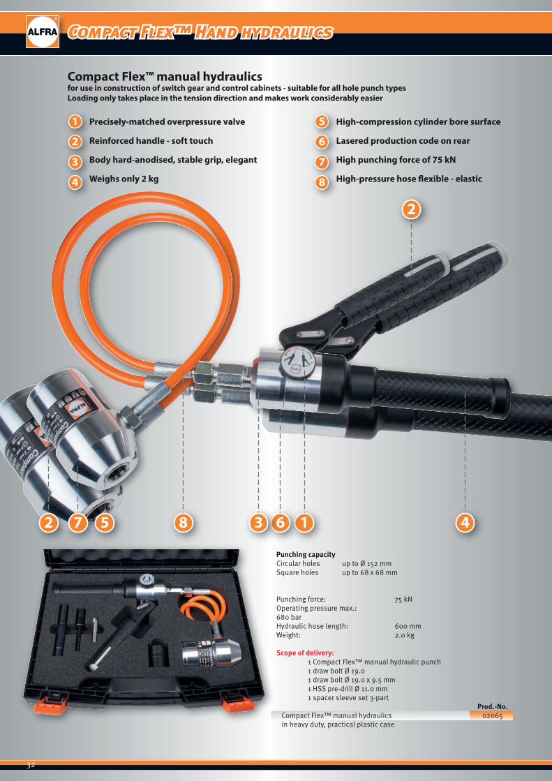
32
Punching capacity Circular holes up to Ø 152 mmSquare holes up to 68 x 68 mm
Punching force: 75 kNOperating pressure max.: 680 barHydraulic hose length: 600 mmWeight: 2.0 kg
Scope of delivery: 1 Compact Flex™ manual hydraulic punch 1 draw bolt Ø 19.0 1 draw bolt Ø 19.0 x 9.5 mm 1 HSS pre-drill Ø 11.0 mm 1 spacer sleeve set 3-part
Prod.-No.Compact Flex™ manual hydraulics 02065in heavy duty, practical plastic case
57 1 4682
2
51
2
3
4
6
7
8
Precisely-matched overpressure valve
Reinforced handle - soft touch
Body hard-anodised, stable grip, elegant
Weighs only 2 kg
High-compression cylinder bore surface
Lasered production code on rear
High punching force of 75 kN
High-pressure hose flexible - elastic
Compact Flex™ manual hydraulicsfor use in construction of switch gear and control cabinets - suitable for all hole punch typesLoading only takes place in the tension direction and makes work considerably easier
3
Compact Flex™ Hand hydraulics
33
Prod.-No. 02072 Prod.-No. 02071
Prod.-No. 02070
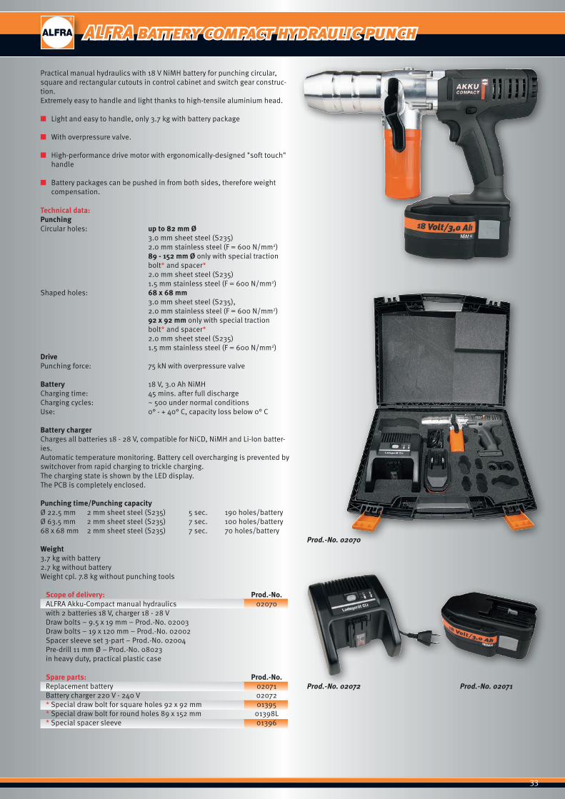
ALFRA battery compact hydraulic punch
Practical manual hydraulics with 18 V NiMH battery for punching circular, square and rectangular cutouts in control cabinet and switch gear construc-tion.Extremely easy to handle and light thanks to high-tensile aluminium head.
■ Light and easy to handle, only 3.7 kg with battery package
■ With overpressure valve.
■ High-performance drive motor with ergonomically-designed "soft touch" handle
■ Battery packages can be pushed in from both sides, therefore weight compensation.
Technical data:Punching Circular holes: up to 82 mm Ø 3.0 mm sheet steel (S235) 2.0 mm stainless steel (F = 600 N/mm2) 89 - 152 mm Ø only with special traction bolt* and spacer* 2.0 mm sheet steel (S235) 1.5 mm stainless steel (F = 600 N/mm2)Shaped holes: 68 x 68 mm 3.0 mm sheet steel (S235),
2.0 mm stainless steel (F = 600 N/mm2) 92 x 92 mm only with special traction bolt* and spacer* 2.0 mm sheet steel (S235) 1.5 mm stainless steel (F = 600 N/mm2)DrivePunching force: 75 kN with overpressure valve
Battery 18 V, 3.0 Ah NiMHCharging time: 45 mins. after full dischargeCharging cycles: ~ 500 under normal conditionsUse: 0° - + 40° C, capacity loss below 0° C
Battery chargerCharges all batteries 18 - 28 V, compatible for NiCD, NiMH and Li-Ion batter-ies. Automatic temperature monitoring. Battery cell overcharging is prevented by switchover from rapid charging to trickle charging.The charging state is shown by the LED display.The PCB is completely enclosed.
Punching time/Punching capacityØ 22.5 mm 2 mm sheet steel (S235) 5 sec. 190 holes/batteryØ 63.5 mm 2 mm sheet steel (S235) 7 sec. 100 holes/battery68 x 68 mm 2 mm sheet steel (S235) 7 sec. 70 holes/battery
Weight3.7 kg with battery2.7 kg without batteryWeight cpl. 7.8 kg without punching tools
Scope of delivery: Prod.-No.ALFRA Akku-Compact manual hydraulics 02070with 2 batteries 18 V, charger 18 - 28 VDraw bolts – 9.5 x 19 mm – Prod.-No. 02003Draw bolts – 19 x 120 mm – Prod.-No. 02002Spacer sleeve set 3-part – Prod.-No. 02004Pre-drill 11 mm Ø – Prod.-No. 08023in heavy duty, practical plastic case
Spare parts: Prod.-No.Replacement battery 02071Battery charger 220 V - 240 V 02072* Special draw bolt for square holes 92 x 92 mm 01395* Special draw bolt for round holes 89 x 152 mm 01398L* Special spacer sleeve 01396
34
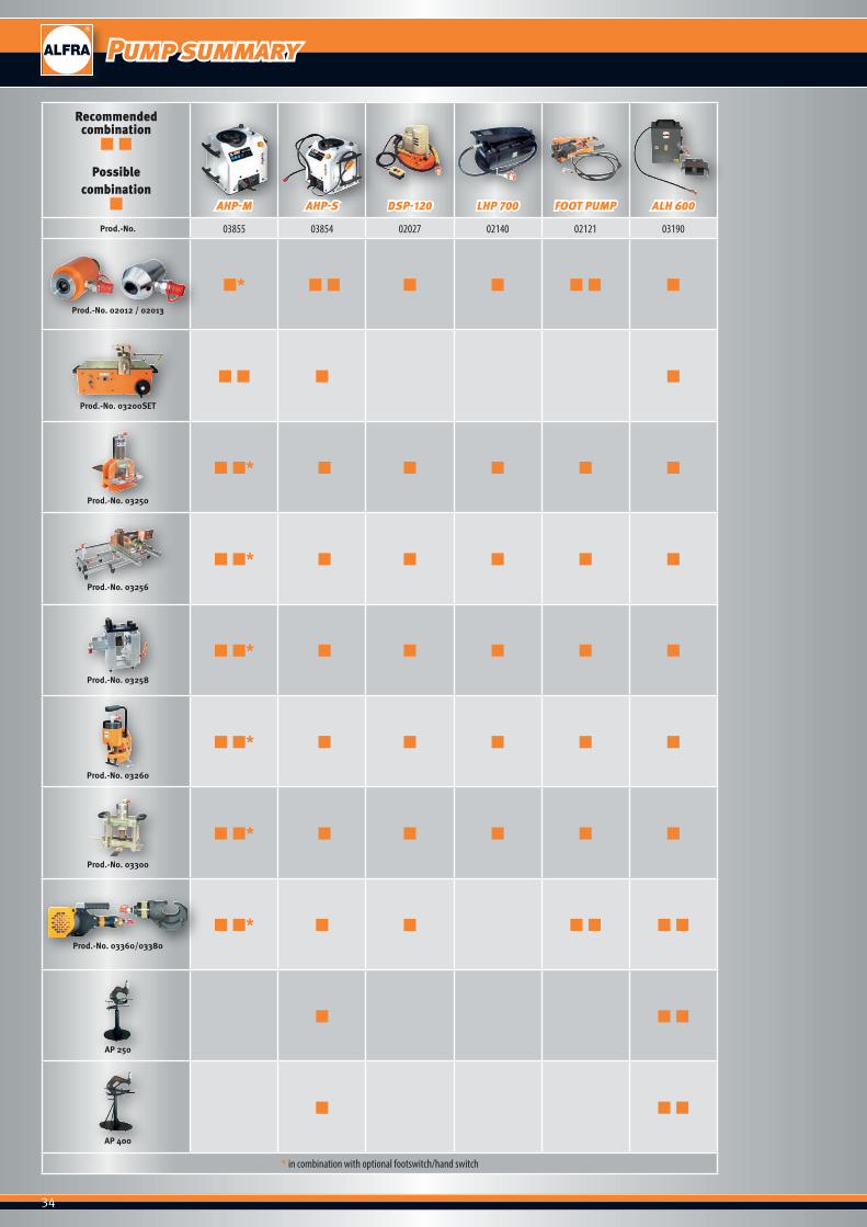
Recommended combination
■ ■
Possible combination
■ AHP-M AHP-S DSP-120 LHP 700 FOOT PUMP ALH 600
Prod.-No. 03855 03854 02027 02140 02121 03190
Prod.-No. 02012 / 02013
■* ■ ■ ■ ■ ■ ■ ■
Prod.-No. 03200SET
■ ■ ■ ■
Prod.-No. 03250
■ ■* ■ ■ ■ ■ ■
Prod.-No. 03256
■ ■* ■ ■ ■ ■ ■
Prod.-No. 03258
■ ■* ■ ■ ■ ■ ■
Prod.-No. 03260
■ ■* ■ ■ ■ ■ ■
Prod.-No. 03300
■ ■* ■ ■ ■ ■ ■
Prod.-No. 03360/03380
■ ■* ■ ■ ■ ■ ■ ■
AP 250
■ ■ ■
AP 400
■ ■ ■
* in combination with optional footswitch/hand switch
Pump summary
35
Prod.-No. 03859 optional
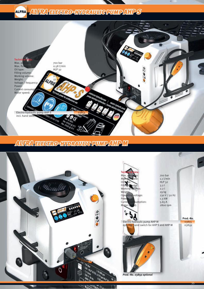
Technical data:Max. pressure: 700 barMax. flow rate: 1.1 l/minOil type: HLP 32Filling volume: 3.2 lWorking volume: 2.2 lWeight: 29 kgOperating voltage: 230 V / 50 HzPower: 1.3 kWCurrent consumption: 5.65 AMotor speed: 2800 rpm
Prod.-No.Electro-hydraulic pump AHP M 03855optional hand switch for AHP S and AHP M 03859
Technical data:Max. pressure: 700 barMax. flow rate: 0.58 l/minOil type: HLP 32Filling volume: 3.2 lWorking volume: 2.2 lWeight: 27 kgVoltage / frequency: 230 V / 50 HzPower: 0.75 kWCurrent consumption: 3.26 AMotor speed: 2800 rpm
Prod.-No.Electro-hydraulic pump AHP S 03854incl. hand switch
ALFRA electro-hydraulic pump AHP S
ALFRA electro-hydraulic pump AHP M

36
Prod.-No. 02120
■ Max. operating pressure 700 bar ■ Fitted pressure limiting valve. ■ For all circular, square, rectangular and special shape hole punches. ■ The foot pump leaves both hands free for precise positioning and
punching on the control cabinet. The foot pump carrying frame is splayed. This guarantees steady working with no risk of tipping.
Tank volume: 270 cm3
Usable oil volume: 210 cm3
Delivery volume: 1.7 cm3 per piston stroke
Contents: 1 hydraulic cylinder with quick coupling 1 hydraulic hose 2.8 m 1 draw bolt Ø 19.0 and 19.0 x 9.5 mm 1 spacer sleeve set 5-part 1 pre-drill Ø 11.0 mm
Prod.-No.Set foot pump with hydraulic cylinder and accessories 02120
Foot pump only, with 2.8 m hydraulic hose 02121
ALFRA foot pump
37
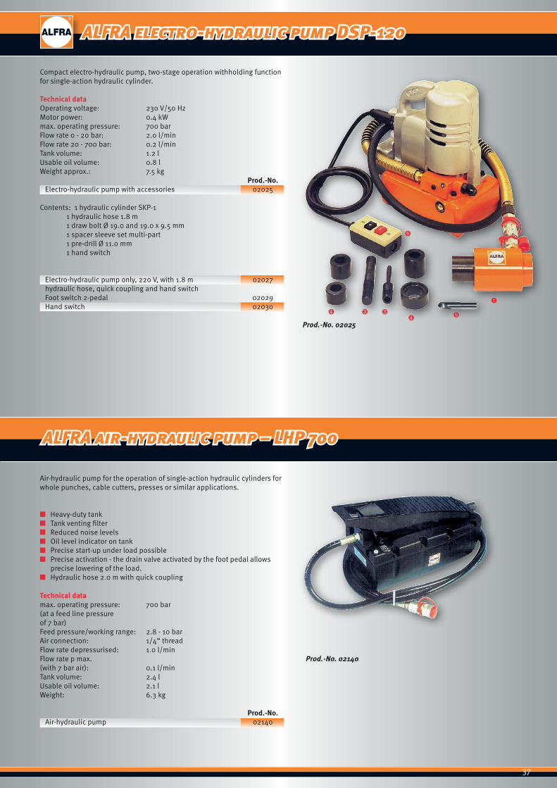
ALFRA electro-hydraulic pump DSP-120
Prod.-No. 02025
❹ ❸ ❸❹
➊
➏
➎
Prod.-No. 02140
ALFRA air-hydraulic pump – LHP 700
Compact electro-hydraulic pump, two-stage operation withholding function for single-action hydraulic cylinder.
Technical dataOperating voltage: 230 V/50 HzMotor power: 0.4 kWmax. operating pressure: 700 barFlow rate 0 - 20 bar: 2.0 l/minFlow rate 20 - 700 bar: 0.2 l/minTank volume: 1.2 lUsable oil volume: 0.8 lWeight approx.: 7.5 kg
Prod.-No.Electro-hydraulic pump with accessories 02025
Contents: 1 hydraulic cylinder SKP-1 1 hydraulic hose 1.8 m 1 draw bolt Ø 19.0 and 19.0 x 9.5 mm 1 spacer sleeve set multi-part 1 pre-drill Ø 11.0 mm 1 hand switch
Electro-hydraulic pump only, 220 V, with 1.8 m 02027hydraulic hose, quick coupling and hand switchFoot switch 2-pedal 02029Hand switch 02030
Air-hydraulic pump for the operation of single-action hydraulic cylinders for whole punches, cable cutters, presses or similar applications.
■ Heavy-duty tank ■ Tank venting filter ■ Reduced noise levels ■ Oil level indicator on tank ■ Precise start-up under load possible ■ Precise activation - the drain valve activated by the foot pedal allows
precise lowering of the load. ■ Hydraulic hose 2.0 m with quick coupling
Technical datamax. operating pressure: 700 bar(at a feed line pressureof 7 bar)Feed pressure/working range: 2.8 - 10 barAir connection: 1/4“ threadFlow rate depressurised: 1.0 l/minFlow rate p max.(with 7 bar air): 0.1 l/minTank volume: 2.4 lUsable oil volume: 2.1 lWeight: 6.3 kg
Prod.-No.Air-hydraulic pump 02140
38
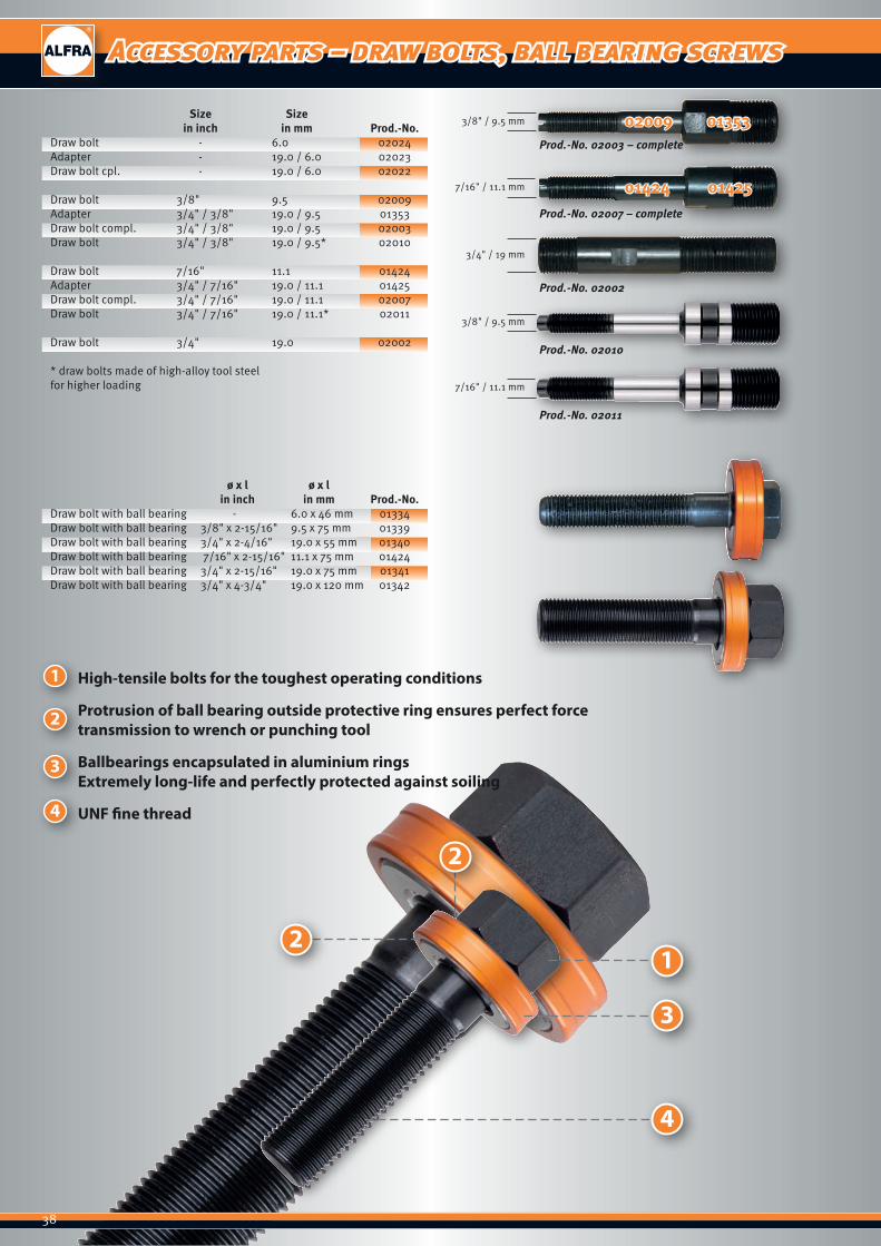
Accessory parts – draw bolts, ball bearing screws
3/4" / 19 mm
02009 013533/8" / 9.5 mm
3/8" / 9.5 mm
7/16" / 11.1 mm
7/16" / 11.1 mm
01424 01425
Prod.-No. 02003 – complete
Prod.-No. 02007 – complete
Prod.-No. 02002
Prod.-No. 02011
Prod.-No. 02010
Size Size in inch in mm Prod.-No.Draw bolt - 6.0 02024Adapter - 19.0 / 6.0 02023Draw bolt cpl. - 19.0 / 6.0 02022
Draw bolt 3/8" 9.5 02009Adapter 3/4" / 3/8" 19.0 / 9.5 01353Draw bolt compl. 3/4" / 3/8" 19.0 / 9.5 02003Draw bolt 3/4" / 3/8" 19.0 / 9.5* 02010
Draw bolt 7/16" 11.1 01424Adapter 3/4" / 7/16" 19.0 / 11.1 01425Draw bolt compl. 3/4" / 7/16" 19.0 / 11.1 02007Draw bolt 3/4" / 7/16" 19.0 / 11.1* 02011
Draw bolt 3/4" 19.0 02002
* draw bolts made of high-alloy tool steelfor higher loading
ø x l ø x l in inch in mm Prod.-No.Draw bolt with ball bearing - 6.0 x 46 mm 01334Draw bolt with ball bearing 3/8" x 2-15/16" 9.5 x 75 mm 01339Draw bolt with ball bearing 3/4" x 2-4/16" 19.0 x 55 mm 01340Draw bolt with ball bearing 7/16" x 2-15/16" 11.1 x 75 mm 01424Draw bolt with ball bearing 3/4" x 2-15/16" 19.0 x 75 mm 01341Draw bolt with ball bearing 3/4" x 4-3/4" 19.0 x 120 mm 01342
2
12
3
4
1
2
3
4
High-tensile bolts for the toughest operating conditions
Protrusion of ball bearing outside protective ring ensures perfect force transmission to wrench or punching tool
Ballbearings encapsulated in aluminium rings Extremely long-life and perfectly protected against soiling
UNF fine thread
39
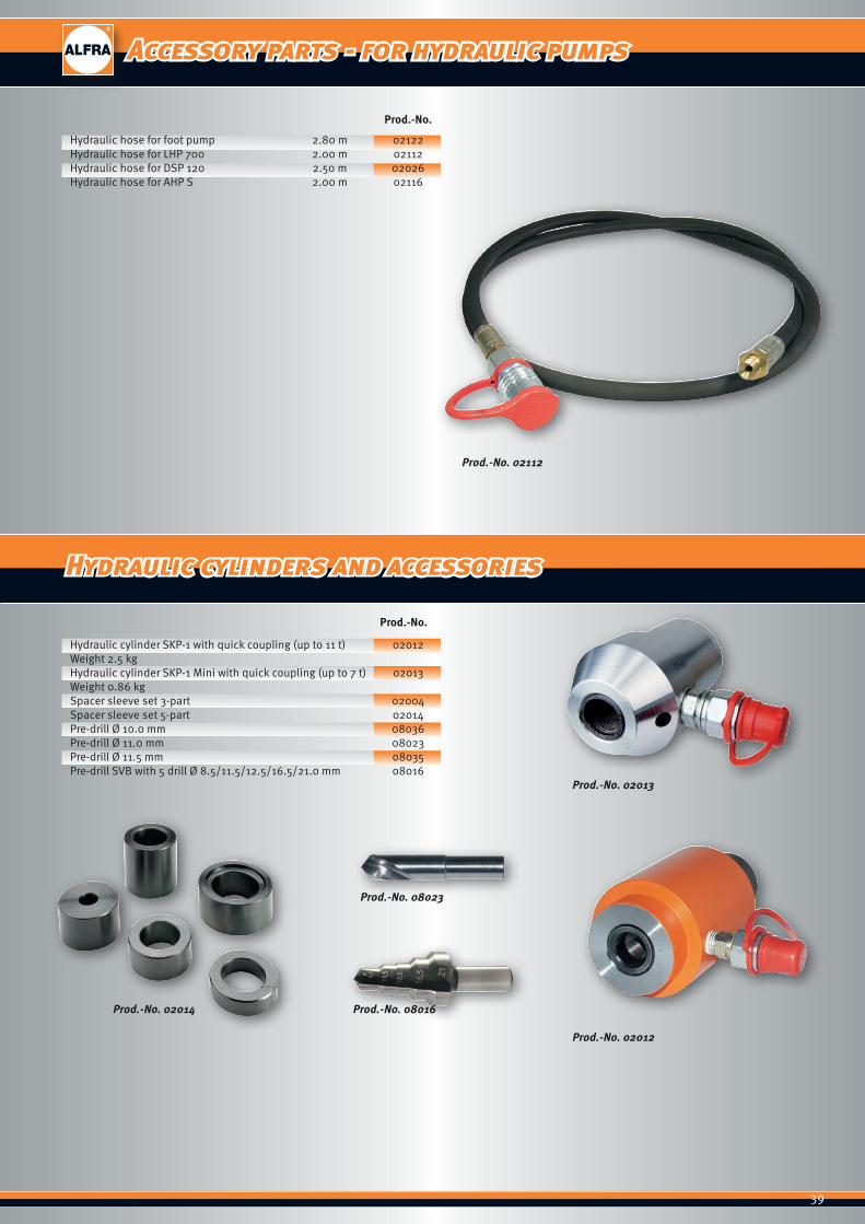
Accessory parts - for hydraulic pumps
Prod.-No. 02112
Prod.-No. 02012
Prod.-No. 02014
Prod.-No. 08023
Prod.-No. 08016
Prod.-No. 02013
Prod.-No.
Hydraulic hose for foot pump 2.80 m 02122Hydraulic hose for LHP 700 2.00 m 02112Hydraulic hose for DSP 120 2.50 m 02026Hydraulic hose for AHP S 2.00 m 02116
Prod.-No.
Hydraulic cylinder SKP-1 with quick coupling (up to 11 t) 02012Weight 2.5 kgHydraulic cylinder SKP-1 Mini with quick coupling (up to 7 t) 02013Weight 0.86 kgSpacer sleeve set 3-part 02004Spacer sleeve set 5-part 02014Pre-drill Ø 10.0 mm 08036Pre-drill Ø 11.0 mm 08023Pre-drill Ø 11.5 mm 08035Pre-drill SVB with 5 drill Ø 8.5/11.5/12.5/16.5/21.0 mm 08016
Hydraulic cylinders and accessories
40
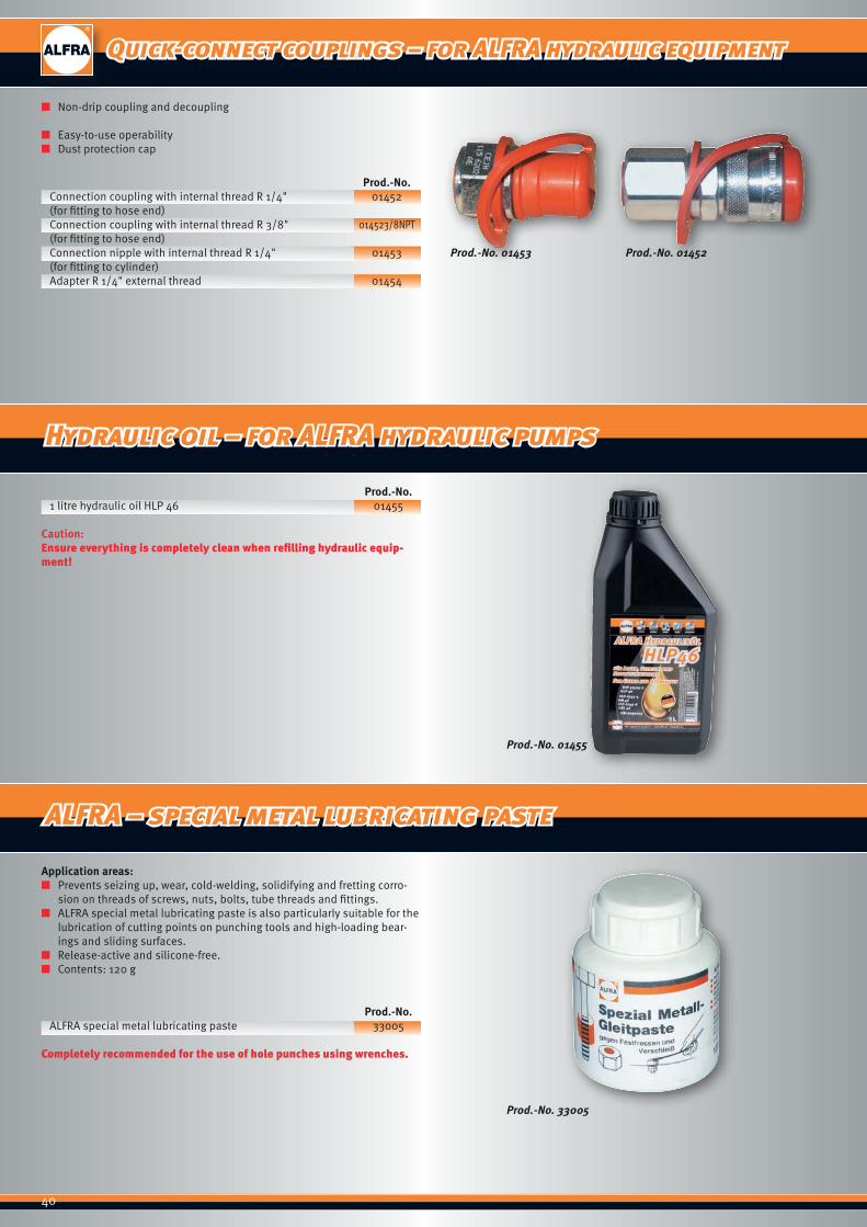
Quick-connect couplings – for ALFRA hydraulic equipment
Prod.-No. 01453 Prod.-No. 01452
Prod.-No. 01455
Prod.-No. 33005
■ Non-drip coupling and decoupling
■ Easy-to-use operability ■ Dust protection cap
Prod.-No.Connection coupling with internal thread R 1/4" 01452(for fitting to hose end)Connection coupling with internal thread R 3/8" 014523/8NPT(for fitting to hose end)Connection nipple with internal thread R 1/4" 01453(for fitting to cylinder)Adapter R 1/4" external thread 01454
Application areas: ■ Prevents seizing up, wear, cold-welding, solidifying and fretting corro-
sion on threads of screws, nuts, bolts, tube threads and fittings. ■ ALFRA special metal lubricating paste is also particularly suitable for the
lubrication of cutting points on punching tools and high-loading bear-ings and sliding surfaces.
■ Release-active and silicone-free. ■ Contents: 120 g
Prod.-No.ALFRA special metal lubricating paste 33005
Completely recommended for the use of hole punches using wrenches.
Prod.-No.1 litre hydraulic oil HLP 46 01455
Caution:Ensure everything is completely clean when refilling hydraulic equip-ment!
Hydraulic oil – for ALFRA hydraulic pumps
ALFRA – special metal lubricating paste
41
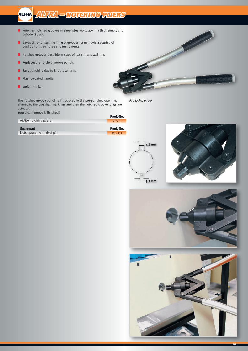
ALFRA – notching pliers
Prod.-No. 03015
■ Punches notched grooves in sheet steel up to 2.0 mm thick simply and quickly (S235).
■ Saves time-consuming filing of grooves for non-twist securing of pushbuttons, switches and instruments.
■ Notched grooves possible in sizes of 3.2 mm and 4.8 mm.
■ Replaceable notched groove punch.
■ Easy punching due to large lever arm.
■ Plastic-coated handle.
■ Weight 1.3 kg.
The notched groove punch is introduced to the pre-punched opening, aligned to the crosshair markings and then the notched groove tongs are actuated.Your clean groove is finished!
Prod.-No.ALFRA notching pliers 03015
Spare part Prod.-No.Notch punch with rivet pin 030151

42
ALFRA cutting devices
43
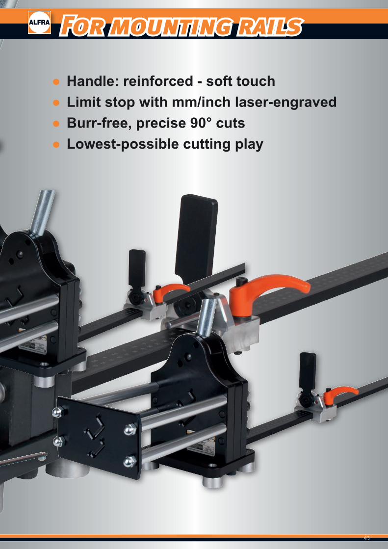
For mounting rails
● Handle: reinforced - soft touch ● Limit stop with mm/inch laser-engraved ● Burr-free, precise 90° cuts ● Lowest-possible cutting play

44
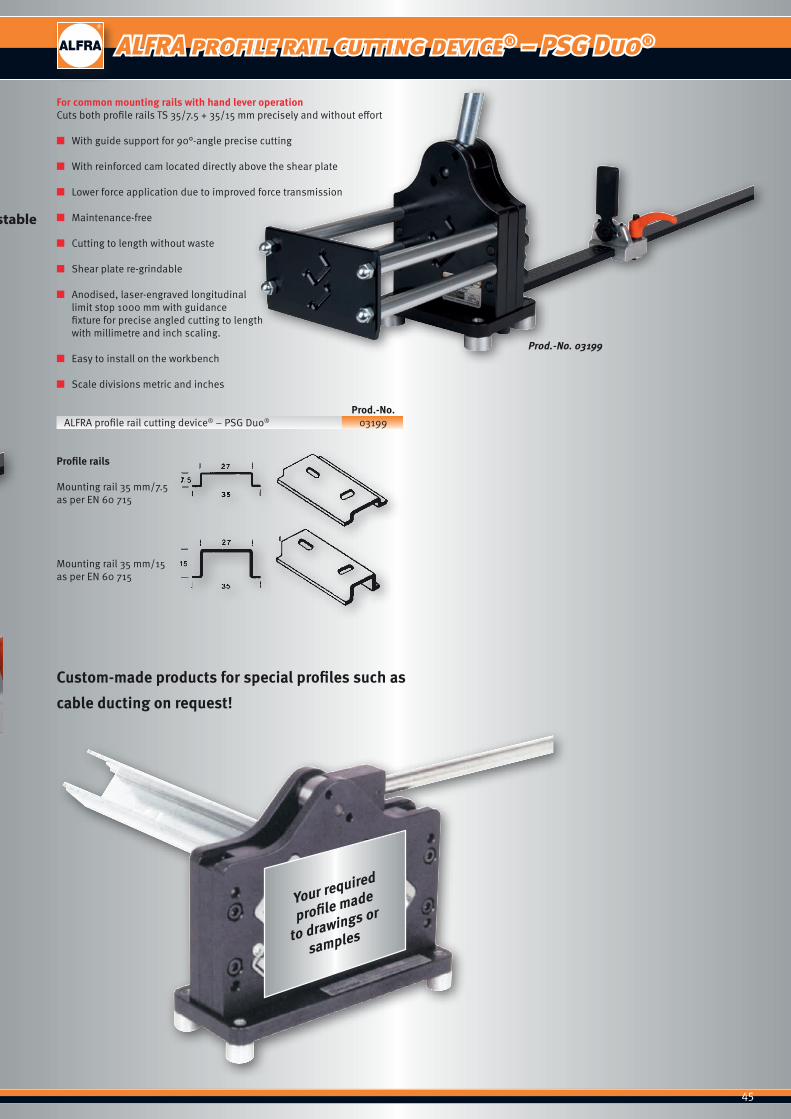
ALFRA profile rail cutting device® – PSG Duo®
1
2
3
4
Handle: reinforced - soft touch
Limit stop with mm/inch laser-engraved
2 separate profiles for burr-free precise 90° cuts - stable profile guiding
Profile throughput is optimised for lowest-possible cutting play
12
4
3
Prod.-No. 03199
45
ALFRA profile rail cutting device® – PSG Duo®
For common mounting rails with hand lever operationCuts both profile rails TS 35/7.5 + 35/15 mm precisely and without effort
■ With guide support for 90°-angle precise cutting
■ With reinforced cam located directly above the shear plate
■ Lower force application due to improved force transmission
■ Maintenance-free
■ Cutting to length without waste
■ Shear plate re-grindable
■ Anodised, laser-engraved longitudinal limit stop 1000 mm with guidance fixture for precise angled cutting to length with millimetre and inch scaling.
■ Easy to install on the workbench
■ Scale divisions metric and inches Prod.-No.ALFRA profile rail cutting device® – PSG Duo® 03199
Profile rails
Mounting rail 35 mm/7.5as per EN 60 715
Mounting rail 35 mm/15as per EN 60 715
Prod.-No. 03199
Custom-made products for special profiles such as
cable ducting on request!
Your required
profile made
to drawings or
samples
Handle: reinforced - soft touch
Limit stop with mm/inch laser-engraved
2 separate profiles for burr-free precise 90° cuts - stable profile guiding
Profile throughput is optimised for lowest-possible cutting play
46
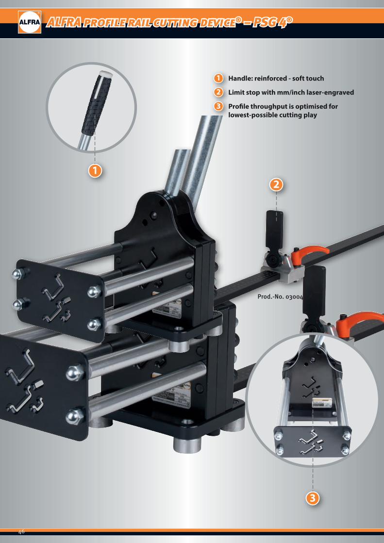
ALFRA profile rail cutting device® – PSG 4®
1
2
3
Handle: reinforced - soft touch
Limit stop with mm/inch laser-engraved
Profile throughput is optimised for lowest-possible cutting play
12
3
Prod.-No. 03004

47
ALFRA profile rail cutting device® – PSG 4®
Prod.-No. 03004
Guidance fixturefor 90° angle-precise cutting
For hand-operated mounting railsCuts profile and ground rails precisely and without effort. Standard version for TS 35/7.5 - 35/15 - 15/5.5 - Cu 10.0 x 3.0 mm
■ With reinforced cam located directly above the shear plate ■ Lower force application due to improved force transmission ■ Burr-free cutting to length without waste ■ Maintenance-free ■ Anodised, laser-engraved length limit stop 1000 mm with guiding
device for precise angled cutting to length, with millimetre and inch scaling.
■ Shear plate re-grindable ■ Guidance fixture for 90° angle-precise cutting ■ Easy to install on the workbench ■ Custom-made products are also possible (please send us a sample rail
of about 1000 mm length). Prod.-No.ALFRA profile rail cutting device® – PSG 4® 03004
Standard version
Mounting rail 35 mm/7.5as per EN 60 715
Mounting rail 35 mm/15as per EN 60 715
Mounting rail 15 mm/5.5as per EN 60 715
Copper ground rails10 mm x 3 mm

48
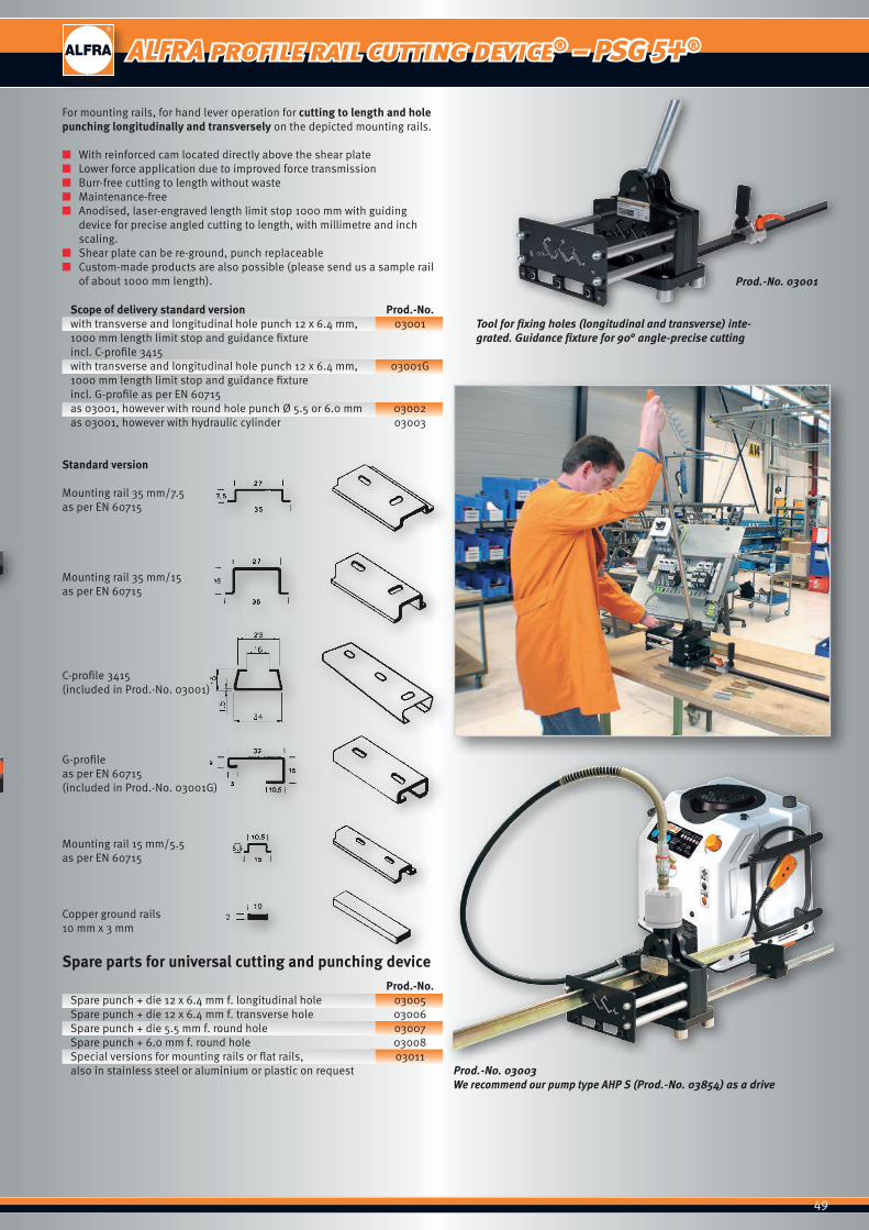
ALFRA profile rail cutting device® – PSG 5+®
1
2
3
Handle: reinforced - soft touch
Limit stop with mm/inch laser-engraved compatible with PSG series
Profile throughput is optimised for lowest-possible cutting play
1
2
3
Prod.-No. 03001
49
ALFRA profile rail cutting device® – PSG 5+®
Prod.-No. 03001
Tool for fixing holes (longitudinal and transverse) inte-grated. Guidance fixture for 90° angle-precise cutting
Prod.-No. 03003 We recommend our pump type AHP S (Prod.-No. 03854) as a drive
For mounting rails, for hand lever operation for cutting to length and hole punching longitudinally and transversely on the depicted mounting rails.
■ With reinforced cam located directly above the shear plate ■ Lower force application due to improved force transmission ■ Burr-free cutting to length without waste ■ Maintenance-free ■ Anodised, laser-engraved length limit stop 1000 mm with guiding
device for precise angled cutting to length, with millimetre and inch scaling.
■ Shear plate can be re-ground, punch replaceable ■ Custom-made products are also possible (please send us a sample rail
of about 1000 mm length).
Scope of delivery standard version Prod.-No.with transverse and longitudinal hole punch 12 x 6.4 mm, 030011000 mm length limit stop and guidance fixtureincl. C-profile 3415with transverse and longitudinal hole punch 12 x 6.4 mm, 03001G1000 mm length limit stop and guidance fixtureincl. G-profile as per EN 60715 as 03001, however with round hole punch Ø 5.5 or 6.0 mm 03002as 03001, however with hydraulic cylinder 03003
Standard version
Mounting rail 35 mm/7.5as per EN 60715
Mounting rail 35 mm/15as per EN 60715
C-profile 3415(included in Prod.-No. 03001)
G-profileas per EN 60715(included in Prod.-No. 03001G)
Mounting rail 15 mm/5.5as per EN 60715
Copper ground rails10 mm x 3 mm
Spare parts for universal cutting and punching device Prod.-No.Spare punch + die 12 x 6.4 mm f. longitudinal hole 03005Spare punch + die 12 x 6.4 mm f. transverse hole 03006Spare punch + die 5.5 mm f. round hole 03007Spare punch + 6.0 mm f. round hole 03008Special versions for mounting rails or flat rails, 03011also in stainless steel or aluminium or plastic on request
Handle: reinforced - soft touch
Limit stop with mm/inch laser-engraved compatible with PSG series
Profile throughput is optimised for lowest-possible cutting play
50
ALFRA cable ducting cutting device – VKS 125
1
2
3
4
5
31
4
2
5
Enlarged opening height (also suitable for ducting with special webs)
Full-surface supporting table (no sagging ducts)
Length stop laser-engraved in metric/inch
Ergonomic hand lever for optimum force transmission
Foldable, sprung cutter protector
51
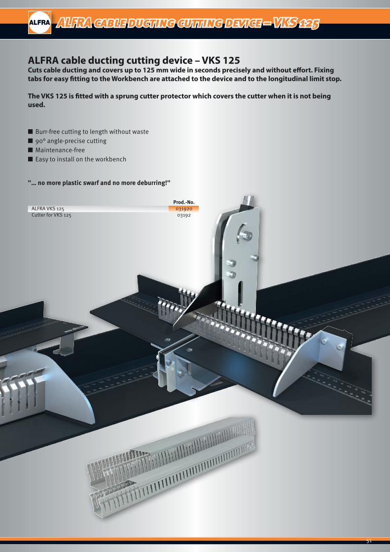
ALFRA cable ducting cutting device – VKS 125
■ Burr-free cutting to length without waste ■ 90° angle-precise cutting ■ Maintenance-free ■ Easy to install on the workbench
"… no more plastic swarf and no more deburring!"
Prod.-No.ALFRA VKS 125 031920Cutter for VKS 125 03192
ALFRA cable ducting cutting device – VKS 125Cuts cable ducting and covers up to 125 mm wide in seconds precisely and without effort. Fixing tabs for easy fitting to the Workbench are attached to the device and to the longitudinal limit stop.
The VKS 125 is fitted with a sprung cutter protector which covers the cutter when it is not being used.
52
ALFRA assembly table
53
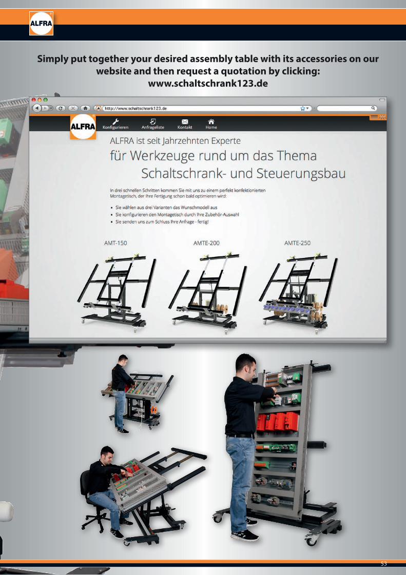
Simply put together your desired assembly table with its accessories on our website and then request a quotation by clicking:
www.schaltschrank123.de
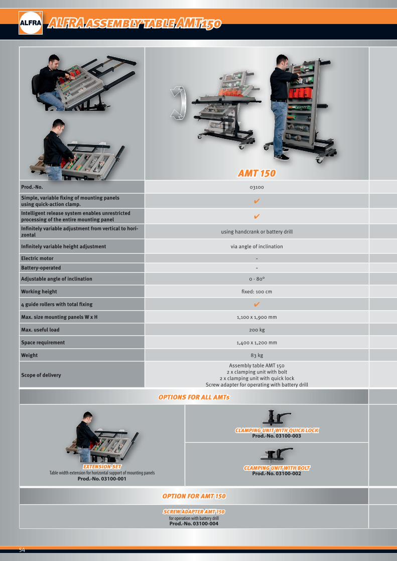
54
AMT 150 AMTE 200 AMTE 250Prod.-No. 03100 031002 031001
Simple, variable fixing of mounting panels using quick-action clamp. ✔ ✔ ✔
Intelligent release system enables unrestricted processing of the entire mounting panel ✔ ✔ ✔
Infinitely variable adjustment from vertical to hori-zontal using handcrank or battery drill using battery-operated electric motors using battery-operated electric motors
Infinitely variable height adjustment via angle of inclination by angle of inclination using battery-operated electric motors using battery-operated electric motors
Electric motor - ✔ ✔
Battery-operated - ✔ ✔
Adjustable angle of inclination 0 - 80° 0 - 80° 0 - 80°
Working height fixed: 100 cm fixed: 90 cm variable: 80 - 110 cm
4 guide rollers with total fixing ✔ ✔ ✔
Max. size mounting panels W x H 1,100 x 1,900 mm 1,100 x 1,900 mm 1,100 x 1,900 mm
Max. useful load 200 kg 200 kg 300 kg
Space requirement 1,400 x 1,200 mm 1,400 x 1,200 mm 1,400 x 1,200 mm
Weight 83 kg 93 kg 140 kg
Scope of delivery
Assembly table AMT 1502 x clamping unit with bolt
2 x clamping unit with quick lockScrew adapter for operating with battery drill
Electric assembly table AMTE 200 2 x clamping unit with bolt
2 x clamping unit with quick lockexternal charging station for the battery
Electric assembly table AMTE 250 2 x clamping unit with bolt
2 x clamping unit with quick lockexternal charging station for the battery
OPTIONS FOR ALL AMTs OPTIONS FOR ALL AMTs OPTIONS FOR AMTE 200 / 250 OPTION FOR AMTE 250
EXTENSION SETTable width extension for horizontal support of mounting panels
Prod.-No. 03100-001
CLAMPING UNIT WITH QUICK LOCKProd.-No. 03100-003
CLAMPING UNIT WITH BOLTProd.-No. 03100-002 CONTROL CABINET SET
Prod.-No. 03100-005
CABLE GUIDANCEProd.-No. 031001-003
ROLLER CONVEYORfor sideways insertion of the mounting panel
into the control cabinetProd.-No. 031001-004
CABLE ROLL HOLDERProd.-No. 031001-002
OPTION FOR AMT 150 OPTIONS FOR AMTE 200 / 250
SCREW ADAPTER AMT 150for operation with battery drillProd.-No. 03100-004
SPARE BATTERYProd.-No. 031001-001
CHARGING PLUG for 110 V 60 Hz
Prod.-No. 031001-0011
ALFRA assembly table AMT150

55
AMT 150 AMTE 200 AMTE 250Prod.-No. 03100 031002 031001
Simple, variable fixing of mounting panels using quick-action clamp. ✔ ✔ ✔
Intelligent release system enables unrestricted processing of the entire mounting panel ✔ ✔ ✔
Infinitely variable adjustment from vertical to hori-zontal using handcrank or battery drill using battery-operated electric motors using battery-operated electric motors
Infinitely variable height adjustment via angle of inclination by angle of inclination using battery-operated electric motors using battery-operated electric motors
Electric motor - ✔ ✔
Battery-operated - ✔ ✔
Adjustable angle of inclination 0 - 80° 0 - 80° 0 - 80°
Working height fixed: 100 cm fixed: 90 cm variable: 80 - 110 cm
4 guide rollers with total fixing ✔ ✔ ✔
Max. size mounting panels W x H 1,100 x 1,900 mm 1,100 x 1,900 mm 1,100 x 1,900 mm
Max. useful load 200 kg 200 kg 300 kg
Space requirement 1,400 x 1,200 mm 1,400 x 1,200 mm 1,400 x 1,200 mm
Weight 83 kg 93 kg 140 kg
Scope of delivery
Assembly table AMT 1502 x clamping unit with bolt
2 x clamping unit with quick lockScrew adapter for operating with battery drill
Electric assembly table AMTE 200 2 x clamping unit with bolt
2 x clamping unit with quick lockexternal charging station for the battery
Electric assembly table AMTE 250 2 x clamping unit with bolt
2 x clamping unit with quick lockexternal charging station for the battery
OPTIONS FOR ALL AMTs OPTIONS FOR ALL AMTs OPTIONS FOR AMTE 200 / 250 OPTION FOR AMTE 250
EXTENSION SETTable width extension for horizontal support of mounting panels
Prod.-No. 03100-001
CLAMPING UNIT WITH QUICK LOCKProd.-No. 03100-003
CLAMPING UNIT WITH BOLTProd.-No. 03100-002 CONTROL CABINET SET
Prod.-No. 03100-005
CABLE GUIDANCEProd.-No. 031001-003
ROLLER CONVEYORfor sideways insertion of the mounting panel
into the control cabinetProd.-No. 031001-004
CABLE ROLL HOLDERProd.-No. 031001-002
OPTION FOR AMT 150 OPTIONS FOR AMTE 200 / 250
SCREW ADAPTER AMT 150for operation with battery drillProd.-No. 03100-004
SPARE BATTERYProd.-No. 031001-001
CHARGING PLUG for 110 V 60 Hz
Prod.-No. 031001-0011
ALFRA electric assembly table AMTE 200 / AMTE 250
56
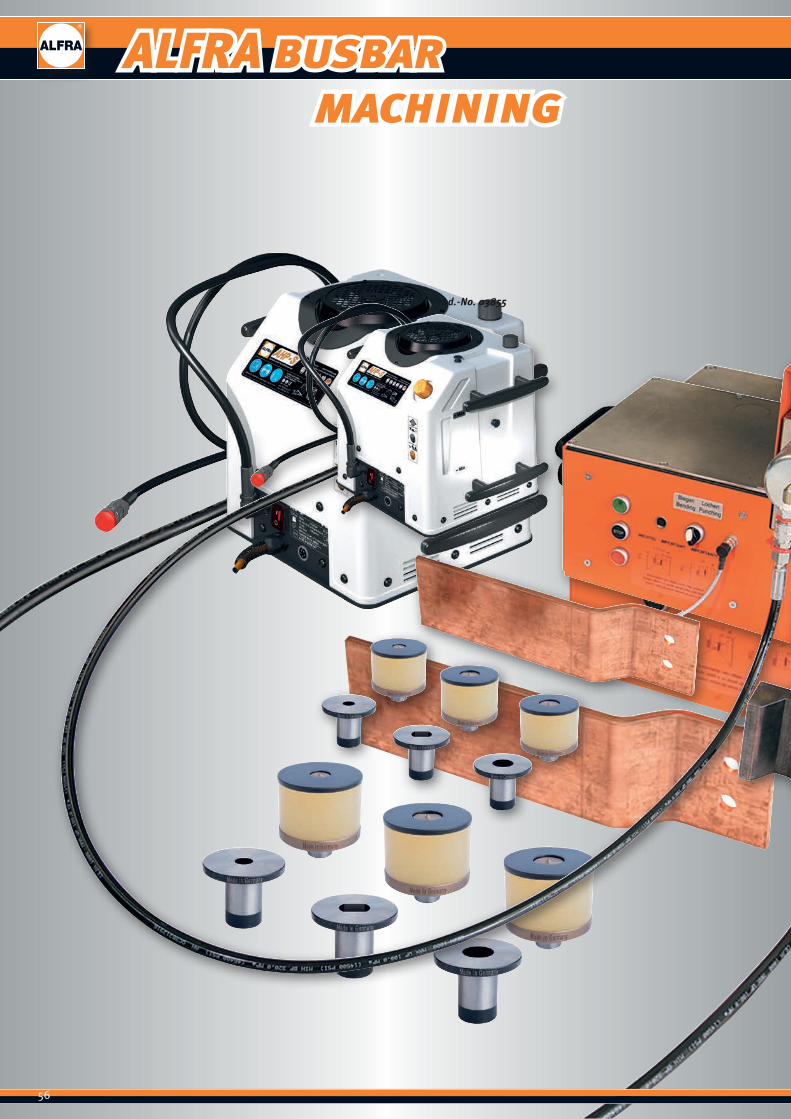
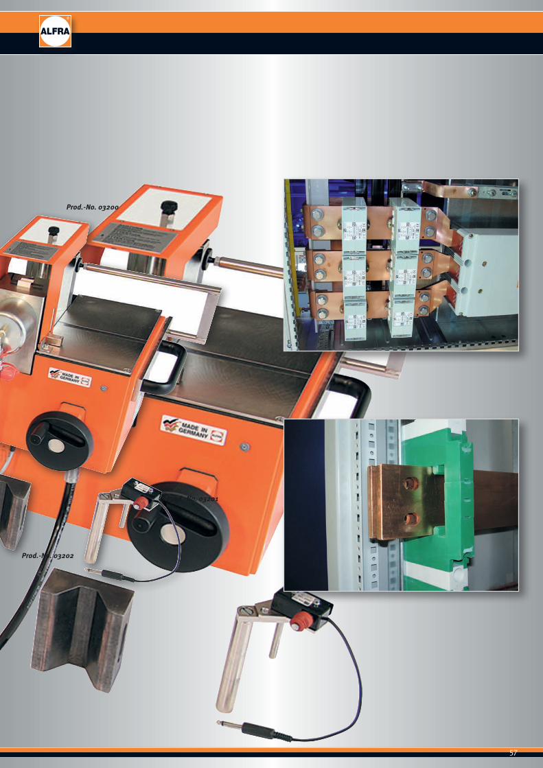
ALFRA busbar machining
Prod.-No. 03855
57
ALFRA busbar machining
Prod.-No. 03200
Prod.-No. 03201
Prod.-No. 03202

58
Busbars at 120 x 12 mm (160 x 10 mm on request) can easily be bent using a universal working cylinder, and holes of Ø 6.6 up to 21.5 mm including longitudinal holes can be punched through the simple insertion of hole punches
Bending busbars
Turn switch to "bend".To bend busbars, the bending die is inserted in the hydraulic piston and the electric angle measurer is placed in the round guidance crew on the counter block. The contact cable is connected to the electric motor.The required angle is fixed on the angle scale using an adjusting screw. Since copper springs back, we recommend making a setting 1° - 3° above the required angle depending on the material thickness.You should check the first bending angle. This bending angle can be reproduced as often as required since the bending process is automatically interrupted on achieving the angle by the electrical contact switch.
Perforating busbars
Switch setting to "perforate".The punch with the neoprene scraper and the matching die are placed in the locating hole.The punch is fixed sideways using a grub screw. Depending on the busbar width and the required hole arrangement, the processing block can be infinitely variably raised or lowered hydraulically using the handwheel. A counter attached to the handwheel shows the height of the hole centre in millimetres.We recommend centre-punching the busbar and then aligning the punch centring point above the centre punch to guarantee a precise hole location.
The neoprene scraper and a fitted electronic sensor ensure automatic punch retraction.
Technical data:BendingBending Cu max: 120 x 12 mmBending up to: more than 90°smallest leg length: 50 mmsmallest U-bend: 100 mmsmallest Z-bend: 72 mm (depending on material thickness)The values stated are based on copper rails 120 x 10 mm
PunchingPunching Cu: 6.6 - 21.5 mm also longitudinal hole up to max. L = 21
mmMaterial thickness Cu max: 12 mmMaterial width up to: 110 mm centralExternal dimensions L x W x H: 700 x 410 x 410 mmWeight: 60 kg
Special version for processing of busbars up to 160 x 10 mm available on request.
ALFRA busbar bending and hole punching device
59
Prod.-No. 03200SET
Prod.-No. 03229
Freely-programmable digital angle measurerCan be used for devices Prod.-No. 03200 and 03980
R10Prod.-No. 03201
Prod.-No. 03228 Prod.-No. 03202
ALFRA busbar bending and hole punching device
Prod.-No.ALFRA busbar bending and hole punching device 03200SETwith electrical angle measurer R10, bending die R10and length limit stop
Electrical angle measurer R10 03201Bending die R10 03202
Length limit stop 03203
Bending die with movable jaws (120 x 10 mm Cu) 03228Digital angle measurer 03229Stage bending tool 03246with 2 pairs of pressure plates for 5 and 10 mm stages (max. range: 100 x 5 mm / 60 x 10 mm Cu)
Electro-hydraulic pump AHP M
Technical data:Max. pressure: 700 barMax. flow rate: 1.1 l/minOil type: HLP 32Filling volume: 3.2 lWorking volume: 2.2 lWeight: 29 kgOperating voltage 230 V / 50 HzPower: 1.3 kWCurrent consumption: 5.65 AMotor speed: 2800 rpm
Prod.-No.Electro-hydraulic pump AHP M 03855optional hand switch for AHP S and AHP M 03859
Electro-hydraulic pump AHP S
Technical data:Max. pressure: 700 barMax. flow rate: 0.58 l/minOil type: HLP 32Filling volume: 3.2 lWorking volume: 2.2 lWeight: 27 kgVoltage / frequency: 230 V / 50 HzPower: 0.75 kWCurrent consumption: 3.26 AMotor speed: 2800 rpm
Prod.-No.Electro-hydraulic pump AHP S 03854incl. hand switch
Prod.-No. 03855
Prod.-No. 03854

60
ALFRA busbar bending and hole punching device
Prod.-No. 03911
Prod.-No. 03921
Round punches and dies
longitudinal hole punches and dies
Prod.-No.ALFRA busbar set 1: 03911
■ Prod.-No. 03200SET ALFRA busbar bending and hole punching device with electrical angle measurer R10, bending die R10 and length limit stop
■ Prod.-No. 03855 electro-hydraulic pump AHP M
Prod.-No.ALFRA busbar set 2: 03921
■ Prod.-No. 03200SET ALFRA busbar bending and hole punching device with electrical angle measurer R10, bending die R10 and length limit stop
■ Prod.-No. 03854 electro-hydraulic pump AHP S
AccessoriesAvailable punches and dies
Punch Ø Metric Max. in mm Screw connection Material thickness in mm Prod.-No. 6.6 6.0 5.0 03204 9.0 8.0 6.0 03205 9.5 8.0 6.0 03206 11.0 10.0 12.0 03207 11.5 10.0 12.0 03208 13.5 12.0 12.0 03209 14.0 12.0 12.0 03210 17.5 16.0 12.0 03211 18.0 16.0 12.0 03212 21.0 20.0 12.0 03213 21.5 20.0 12.0 03214
Die Ø Max. in mm Material thickness in mm Prod.-No.
6.6 5.0 03230 9.0 6.0 03231 9.5 6.0 03232 11.0 12.0 03233 11.5 12.0 03234 13.5 12.0 03235 14.0 12.0 03236 17.5 12.0 03237 18.0 12.0 03238 21.0 12.0 03239 21.5 12.0 03240
Punches and dies for longitudinal holes up to max. L x W = 21 x 18 mm Prod.-No. 03241
61
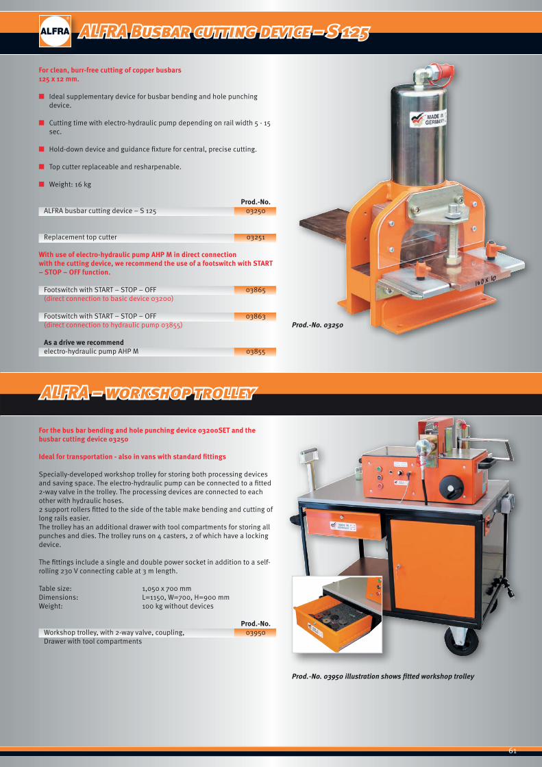
ALFRA Busbar cutting device – S 125
Prod.-No. 03250
Prod.-No. 03950 illustration shows fitted workshop trolley
For clean, burr-free cutting of copper busbars 125 x 12 mm.
■ Ideal supplementary device for busbar bending and hole punching device.
■ Cutting time with electro-hydraulic pump depending on rail width 5 - 15 sec.
■ Hold-down device and guidance fixture for central, precise cutting.
■ Top cutter replaceable and resharpenable.
■ Weight: 16 kg
Prod.-No.ALFRA busbar cutting device – S 125 03250
Replacement top cutter 03251
With use of electro-hydraulic pump AHP M in direct connectionwith the cutting device, we recommend the use of a footswitch with START – STOP – OFF function.
Footswitch with START – STOP – OFF 03865(direct connection to basic device 03200)
Footswitch with START – STOP – OFF 03863(direct connection to hydraulic pump 03855)
As a drive we recommendelectro-hydraulic pump AHP M 03855
For the bus bar bending and hole punching device 03200SET and the busbar cutting device 03250
Ideal for transportation - also in vans with standard fittings
Specially-developed workshop trolley for storing both processing devices and saving space. The electro-hydraulic pump can be connected to a fitted 2-way valve in the trolley. The processing devices are connected to each other with hydraulic hoses. 2 support rollers fitted to the side of the table make bending and cutting of long rails easier. The trolley has an additional drawer with tool compartments for storing all punches and dies. The trolley runs on 4 casters, 2 of which have a locking device.
The fittings include a single and double power socket in addition to a self-rolling 230 V connecting cable at 3 m length.
Table size: 1,050 x 700 mmDimensions: L=1150, W=700, H=900 mmWeight: 100 kg without devices
Prod.-No.Workshop trolley, with 2-way valve, coupling, 03950Drawer with tool compartments
ALFRA – workshop trolley
62
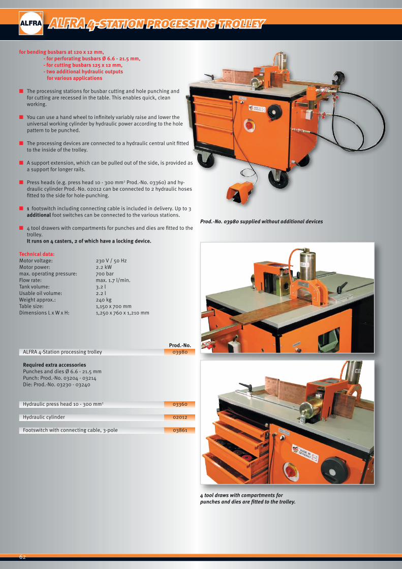
Prod.-No. 03980 supplied without additional devices
4 tool draws with compartments for punches and dies are fitted to the trolley.
for bending busbars at 120 x 12 mm, - for perforating busbars Ø 6.6 - 21.5 mm, - for cutting busbars 125 x 12 mm, - two additional hydraulic outputs for various applications
■ The processing stations for busbar cutting and hole punching and for cutting are recessed in the table. This enables quick, clean working.
■ You can use a hand wheel to infinitely variably raise and lower the universal working cylinder by hydraulic power according to the hole pattern to be punched.
■ The processing devices are connected to a hydraulic central unit fitted to the inside of the trolley.
■ A support extension, which can be pulled out of the side, is provided as a support for longer rails.
■ Press heads (e.g. press head 10 - 300 mm2 Prod.-No. 03360) and hy-draulic cylinder Prod.-No. 02012 can be connected to 2 hydraulic hoses fitted to the side for hole-punching.
■ 1 footswitch including connecting cable is included in delivery. Up to 3 additional foot switches can be connected to the various stations.
■ 4 tool drawers with compartments for punches and dies are fitted to the trolley. It runs on 4 casters, 2 of which have a locking device.
Technical data:Motor voltage: 230 V / 50 HzMotor power: 2.2 kWmax. operating pressure: 700 barFlow rate: max. 1.7 l/min.Tank volume: 3.2 lUsable oil volume: 2.2 lWeight approx.: 240 kgTable size: 1,150 x 700 mmDimensions L x W x H: 1,250 x 760 x 1,210 mm
Prod.-No.ALFRA 4-Station processing trolley 03980
Required extra accessoriesPunches and dies Ø 6.6 - 21.5 mmPunch: Prod.-No. 03204 - 03214Die: Prod.-No. 03230 - 03240
Hydraulic press head 10 - 300 mm2 03360
Hydraulic cylinder 02012
Footswitch with connecting cable, 3-pole 03861
ALFRA 4-station processing trolley
63
We recommend our electro-hydraulic pump AHP S Prod.-No. 03854 as a drive
Prod.-No. 03256 scope of delivery without punches and dies
Round punches and dies
longitudinal hole punches and dies
Bending busbars up to 120 x 12 mmPerforating busbars Ø 6.6 up to 21.5 mm
The device consists of a base frame made of torsion-free aluminium profile with a mounting for the base bodies for bending and perforating. A length limit stop makes adjustment of the hole arrangement easier during punch-ing. To make working with longer copper rails easier, the insert frame with support frame can be extended to up to around 700 mm. All limit stops and support frames are quick and easy to fix using clamping levers.
Technical data:Bending:Bending Cu max: 120 x 12 mmBending up to: more than 90°smallest leg length: 50 mmsmallest U-bend: 100 mmsmallest Z-bend: 72 mmThe values stated are based on copper rails 120 x 10 mm
Punching:Punching Cu: Ø 6.6 - 21.5 mm also longitudinal hole up to max. L = 21
mmMaterial thickness Cu max: 12 mmMaterial width up to: 110 mm centralDimensions L x W x H: 615 x 370 x 315 mmWeight: 44 kg
Prod.-No.ALFRA busbar bending and hole punching device – LPV 03256
AccessoriesAvailable punches and dies
Punch Ø Metric Max. in mm Screw connection Material thickness in mm Prod.-No. 6.6 6.0 5.0 03204 9.0 8.0 6.0 03205 9.5 8.0 6.0 03206 11.0 10.0 12.0 03207 11.5 10.0 12.0 03208 13.5 12.0 12.0 03209 14.0 12.0 12.0 03210 17.5 16.0 12.0 03211 18.0 16.0 12.0 03212 21.0 20.0 12.0 03213 21.5 20.0 12.0 03214
Die Ø Max. in mm Material thickness in mm Prod.-No.
6.6 5.0 03230 9.0 6.0 03231 9.5 6.0 03232 11.0 12.0 03233 11.5 12.0 03234 13.5 12.0 03235 14.0 12.0 03236 17.5 12.0 03237 18.0 12.0 03238 21.0 12.0 03239 21.5 12.0 03240
Punches and dies for longitudinal holes up to max. L x W = 21 x 18 mm Prod.-No. 03241
ALFRA busbar bending and hole punching device – LPV
64
ALFRA busbar bending and hole punching device – LPV 160
Prod.-No. 03258"Perforate" setting
Bending busbars up to 160 x 12 mm
Perforating busbars Ø 6.6 - 21.5 mm
Prod.-No. 03258"Bend" setting
Prod.-No. 03258Complete (without punches and dies)
■ The device consists of a base frame made of special aluminium and a hydraulic cylinder up to 600 bar.
■ Using bending dies R=11 mm and R=5 mm and height adjustment, all busbars of up to max. 160 mm width can be bent to various angles.
■ The angle measurement is engraved on the top section. ■ Changing over to bending and hole-punching is easy and simple.
Technical data:BendingBending Cu max.: 160 x 12 mmBending angle up to: 92°smallest leg length: 50 mm internal dimensionsmallest U-bend: 160 mm internal dimensionsmallest Z-bend: 55 mm (material-dependent) internal
dimensionPunching/perforatingPunching Cu max.: Ø 6.6 - 21.5 mm also longitudinal hole up to max. L = 21
mmMaterial thickness Cu max.: 12 mmMaterial width up to: 160 mm centralDimensions L x W x H: 390 x 150 x 330 mmWeight: 20 kg
Recommended drive typeElectro-hydraulic pump AHP S Prod.-No. 03854Air-hydraulic pump LHP 700 Prod.-No. 02140Foot pump Prod.-No. 02121
Prod.-No.ALFRA BS 160 with bending die 03258and bending punch R=11 mm for busbars 9-12 mm
AccessoriesBending punch R=5 mm for busbars 3-8 mm 03259
Available punches and dies
Punch Ø Metric Max. in mm Screw connection Material thickness in mm Prod.-No. 6.6 6.0 5.0 03204 9.0 8.0 6.0 03205 9.5 8.0 6.0 03206 11.0 10.0 12.0 03207 11.5 10.0 12.0 03208 13.5 12.0 12.0 03209 14.0 12.0 12.0 03210 17.5 16.0 12.0 03211 18.0 16.0 12.0 03212 21.0 20.0 12.0 03213 21.5 20.0 12.0 03214
Die Ø Max. in mm Material thickness in mm Prod.-No.
6.6 5.0 03230 9.0 6.0 03231 9.5 6.0 03232 11.0 12.0 03233 11.5 12.0 03234 13.5 12.0 03235 14.0 12.0 03236 17.5 12.0 03237 18.0 12.0 03238 21.0 12.0 03239 21.5 12.0 03240
Punches and dies for longitudinal holes up to max. L x W = 21 x 18 mm Prod.-No. 03241
65
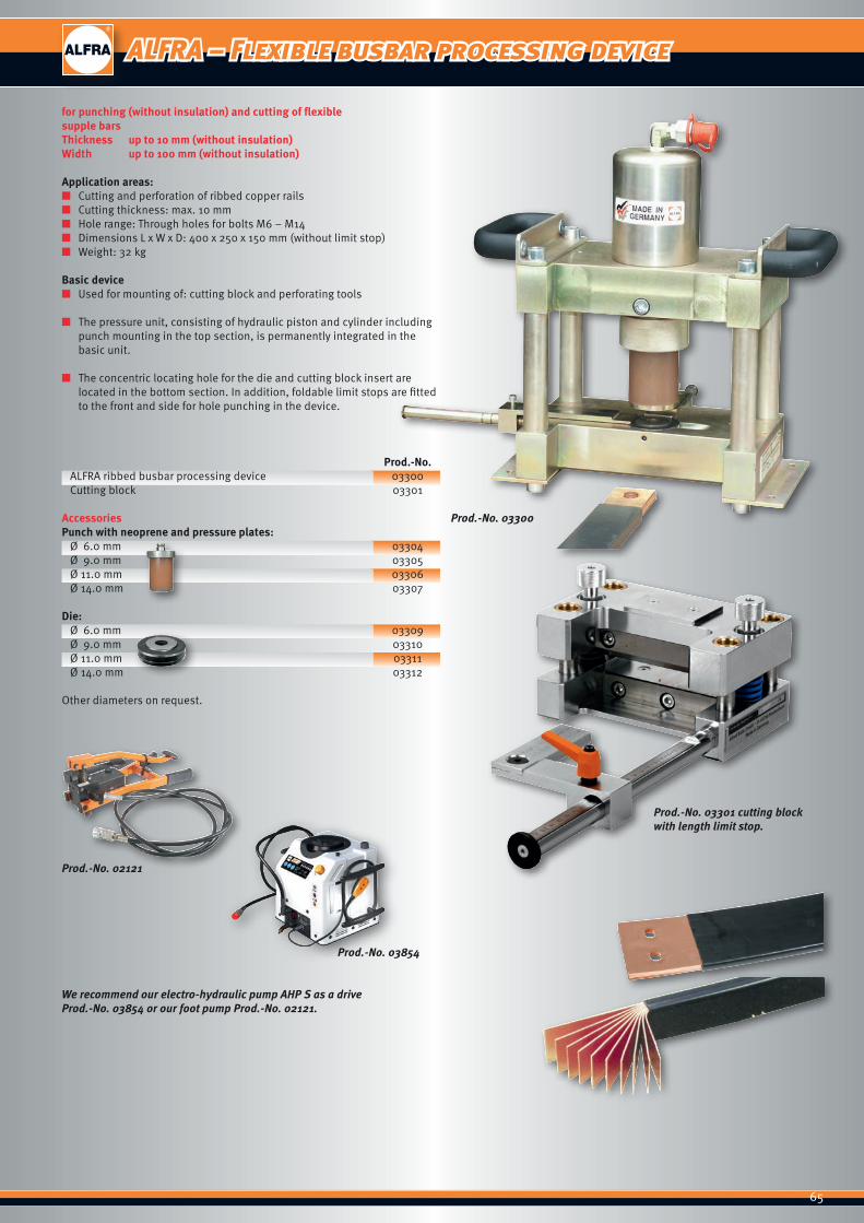
Prod.-No. 03300
Prod.-No. 03301 cutting blockwith length limit stop.
We recommend our electro-hydraulic pump AHP S as a driveProd.-No. 03854 or our foot pump Prod.-No. 02121.
Prod.-No. 03854
Prod.-No. 02121
ALFRA – Flexible busbar processing device
for punching (without insulation) and cutting of flexible supple barsThickness up to 10 mm (without insulation)Width up to 100 mm (without insulation)
Application areas: ■ Cutting and perforation of ribbed copper rails ■ Cutting thickness: max. 10 mm ■ Hole range: Through holes for bolts M6 – M14 ■ Dimensions L x W x D: 400 x 250 x 150 mm (without limit stop) ■ Weight: 32 kg
Basic device ■ Used for mounting of: cutting block and perforating tools
■ The pressure unit, consisting of hydraulic piston and cylinder including punch mounting in the top section, is permanently integrated in the basic unit.
■ The concentric locating hole for the die and cutting block insert are located in the bottom section. In addition, foldable limit stops are fitted to the front and side for hole punching in the device.
Prod.-No.ALFRA ribbed busbar processing device 03300Cutting block 03301
AccessoriesPunch with neoprene and pressure plates:
Ø 6.0 mm 03304Ø 9.0 mm 03305Ø 11.0 mm 03306Ø 14.0 mm 03307
Die:Ø 6.0 mm 03309Ø 9.0 mm 03310Ø 11.0 mm 03311Ø 14.0 mm 03312
Other diameters on request.
66
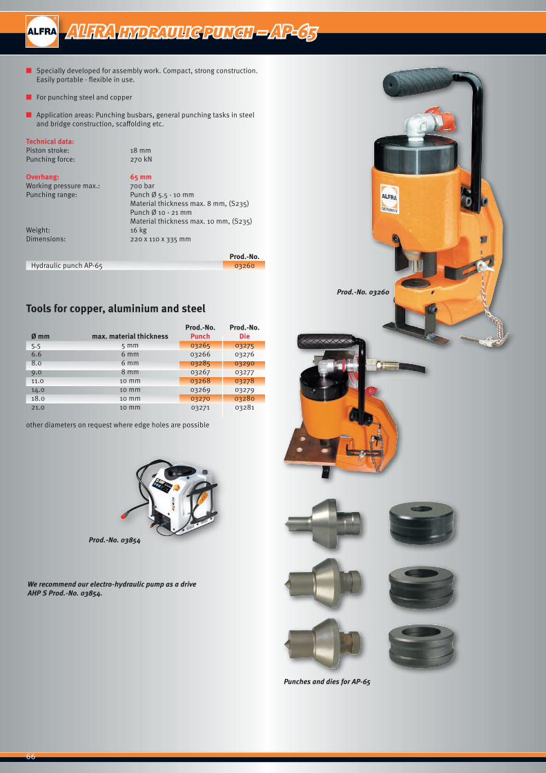
Prod.-No. 03260
Punches and dies for AP-65
We recommend our electro-hydraulic pump as a drive AHP S Prod.-No. 03854.
Prod.-No. 03854
ALFRA hydraulic punch – AP-65
■ Specially developed for assembly work. Compact, strong construction. Easily portable - flexible in use.
■ For punching steel and copper
■ Application areas: Punching busbars, general punching tasks in steel and bridge construction, scaffolding etc.
Technical data:Piston stroke: 18 mmPunching force: 270 kN
Overhang: 65 mmWorking pressure max.: 700 barPunching range: Punch Ø 5.5 - 10 mm Material thickness max. 8 mm, (S235) Punch Ø 10 - 21 mm Material thickness max. 10 mm, (S235)Weight: 16 kgDimensions: 220 x 110 x 335 mm
Prod.-No.Hydraulic punch AP-65 03260
Tools for copper, aluminium and steel
Prod.-No. Prod.-No.Ø mm max. material thickness Punch Die5.5 5 mm 03265 032756.6 6 mm 03266 032768.0 6 mm 03285 032909.0 8 mm 03267 0327711.0 10 mm 03268 0327814.0 10 mm 03269 0327918.0 10 mm 03270 0328021.0 10 mm 03271 03281
other diameters on request where edge holes are possible
67
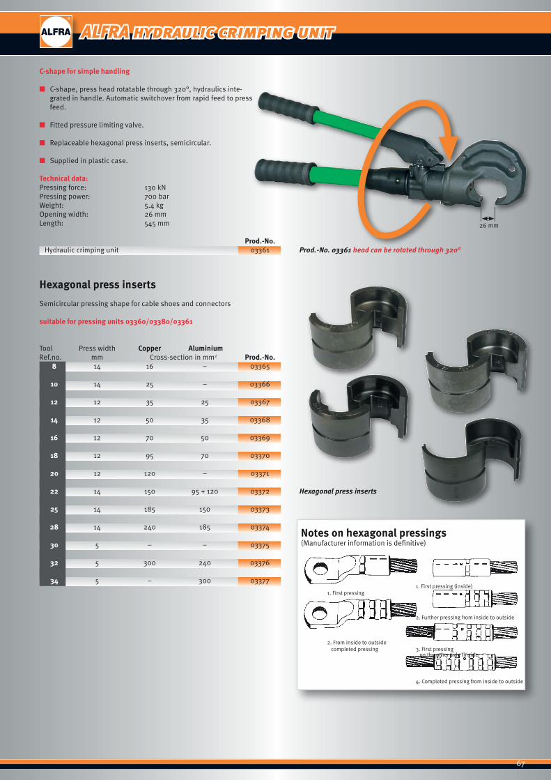
Prod.-No. 03361 head can be rotated through 320°
Hexagonal press inserts
Notes on hexagonal pressings(Manufacturer information is definitive)
1. First pressing (inside) 1. First pressing
2. Further pressing from inside to outside
2. From inside to outside completed pressing 3. First pressing on the other side (inside
4. Completed pressing from inside to outside
26 mm
ALFRA hydraulic crimping unit
C-shape for simple handling
■ C-shape, press head rotatable through 320°, hydraulics inte-grated in handle. Automatic switchover from rapid feed to press feed.
■ Fitted pressure limiting valve.
■ Replaceable hexagonal press inserts, semicircular.
■ Supplied in plastic case.
Technical data:Pressing force: 130 kNPressing power: 700 barWeight: 5.4 kgOpening width: 26 mmLength: 545 mm
Prod.-No.Hydraulic crimping unit 03361
Hexagonal press inserts
Semicircular pressing shape for cable shoes and connectors
suitable for pressing units 03360/03380/03361
Tool Press width Copper AluminiumRef.no. mm Cross-section in mm2 Prod.-No.
8 14 16 – 03365
10 14 25 – 03366
12 12 35 25 03367
14 12 50 35 03368
16 12 70 50 03369
18 12 95 70 03370
20 12 120 – 03371
22 14 150 95 + 120 03372
25 14 185 150 03373
28 14 240 185 03374
30 5 – – 03375
32 5 300 240 03376
34 5 – 300 03377
68
Hexagonal press inserts
Prod.-No. 03360
26 mm
Prod.-No. 03380
38 mm
C-shape for simple handling
■ pressing cable shoes and connectors made of copper and aluminium of between 10 – 300 mm2.
■ Hexagonal press inserts semicircular.
■ Supplied in sheet steel transport boxes.
■ Electro-hydraulic pump Prod.-No. 03854 or foot pump 02121 can be used to operate both press heads.
Technical data:Pressing force: 130 kNPressing power: 700 barWeight: 3.9 kgOpening width: 26 mmLength: 245 mm
Prod.-No.Hydraulic press head 03360
Technical data:Pressing force: 130 kNPressing power: 700 barWeight: 4.6 kgOpening width: 38 mmLength: 275 mm
Prod.-No.Hydraulic press head 03380
Hexagonal press inserts
Semicircular pressing shape for cable shoes and connectors
suitable for pressing units 03360/03380/03361
Tool Press width Copper AluminiumRef.no. mm Cross-section in mm2 Prod.-No.
8 14 16 – 03365
10 14 25 – 03366
12 12 35 25 03367
14 12 50 35 03368
16 12 70 50 03369
18 12 95 70 03370
20 12 120 – 03371
22 14 150 95 + 120 03372
25 14 185 150 03373
28 14 240 185 03374
30 5 – – 03375
32 5 300 240 03376
34 5 – 300 03377
ALFRA hydraulic press heads

69
85 mm
Prod.-No. 04015 head can be rotated through 320°
Prod.-No. 04002
85 mm
Ideal for cutting cables up to Ø 85 mm
Advantages ■ Guided cutter blade. ■ Independent, can be used in any location. ■ Clean cuts at minimal deformation.
Application areas:Power supply companies, power distribution construction, telecommunica-tions, municipal utilities and their providers, crane construction, mining, shipbuilding, maintenance or repair etc.
Technical data:Cutting force: 55 kNCutting pressure: 700 barWeight: 6.3 kgLength: 450 mm
Cutting performance:telephone cable: up to Ø 85 mmelectric cable with armouring: up to Ø 85 mminsulated aluminium cable: 3 x 240 mm2
(earthing cable)insulated aluminium cable: 630 mm2
(single-core)aluminium wire: up to Ø 46 mmcopper wire: up to Ø 28 mm
Prod.-No.hydraulic cable cutter AKS 85 04002supplied in sailcloth bag
With built-in manual hydraulics for cutting cables up to Ø 85 mm
The most ergonomic working position can be selected thanks to the inte-grated hydraulics in the rotating handle.The cable cutter can be used on scaffolds, on high tension pylons or in manholes etc. independently of hydraulic pumps.
Application areas:Power supply companies, power distribution construction, telecommunica-tions, municipal utilities and their providers, crane construction, mining, shipbuilding, maintenance or repair etc.
Technical data:Cutting force: 55 kNCutting pressure: 700 barWeight: 6.6 kgLength: 740 mm
The cutting performance is equivalent to Type AKS 85.
Prod.-No.Hydraulic manual cable cutter HKS 85 04015supplied in sailcloth bag
ALFRA hydraulic manual cable cutter - HKS 85
ALFRA hydraulic cable cutter – AKS 85
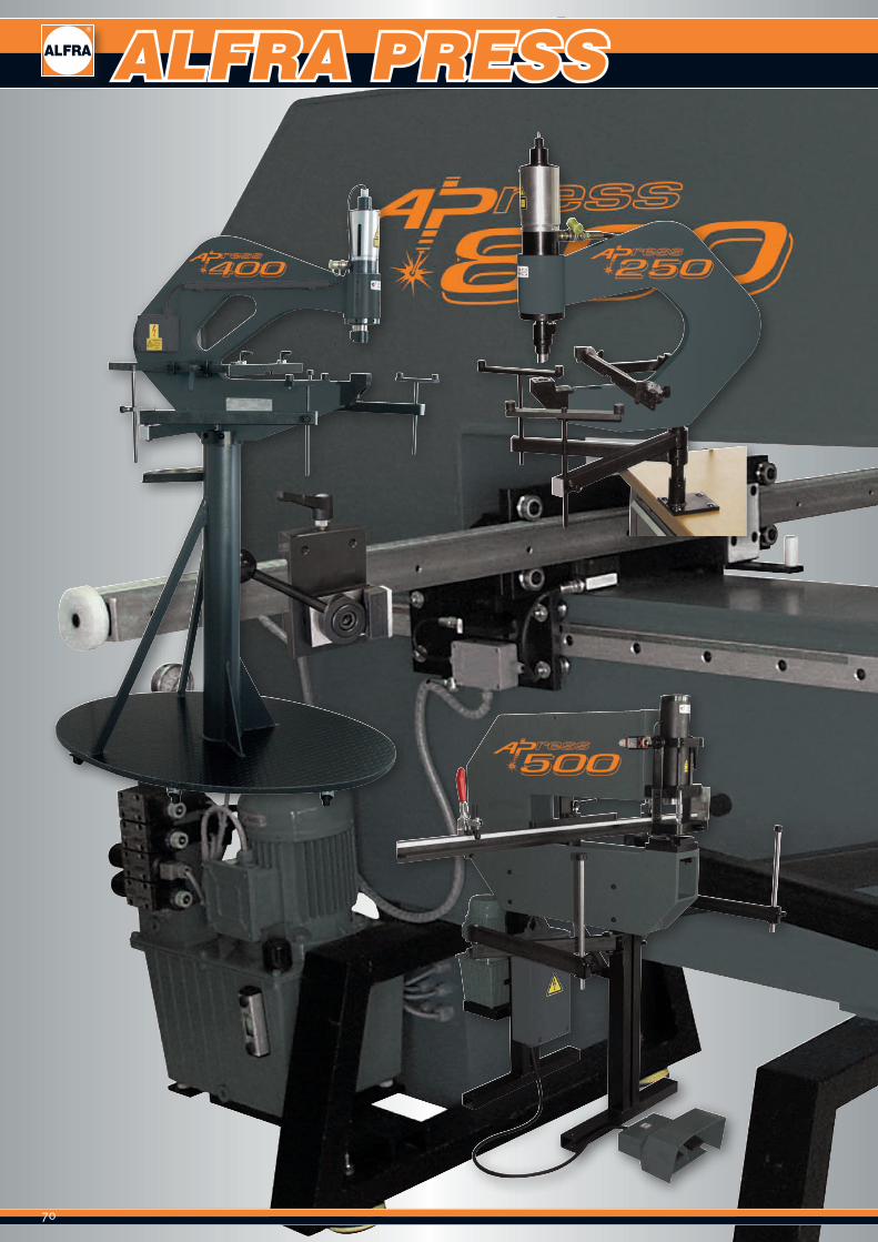
70
ALFRA PRESS
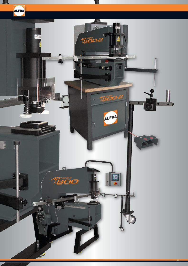
71
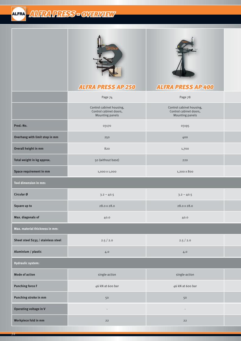
72
ALFRA PRESS AP 250 ALFRA PRESS AP 400 ALFRA PRESS AP 500 ALFRA PRESS AP 600-2 ALFRA PRESS AP 800Page 74 Page 78 Page 82 Page 86 Page 90
Control cabinet housing,Control cabinet doors,
Mounting panels
Control cabinet housing,Control cabinet doors,
Mounting panels
Control cabinet doors, Mounting panels,
various control cabinet housings
Control cabinet doors, Mounting panels
Control cabinet doors, Mounting panels
Prod.-No. 03170 03195 03093 03090 03400
Overhang with limit stop in mm 250 400 500 600 800
Overall height in mm 820 1,700 1,500 1,600 1,700
Total weight in kg approx. 50 (without base) 220 200 360 850
Space requirement in mm 1,000 x 1,000 1,200 x 800 1,500 x 1,500 mm 2,000 x 3,000 2,360 x 4,440
Tool dimension in mm:
Circular Ø 3.2 – 40.5 3.2 – 40.5 3.2 – 63.5 3.2 – 70.0 3.2 – 120.0
Square up to 28.0 x 28.0 28.0 x 28.0 46.0 x 46.0 68.0 x 68.0 110.0 x 110.0
Max. diagonals of 40.0 40.0 60.0 90.0 140.0
Max. material thickness in mm:
Sheet steel S235 / stainless steel 2.5 / 2.0 2.5 / 2.0 3.0 / 2.0 3.0 / 2.0 3.0 / 2.0
Aluminium / plastic 4.0 4.0 4.0 4.0 4.0
Hydraulic system:
Mode of action single-action single-action double-action double-action double-action
Punching force F 46 kN at 600 bar 46 kN at 600 bar 48 kN at 130 bar 60 kN at 165 bar 135 kN at 190 bar
Punching stroke in mm 50 50 66 66 72
Operating voltage in V - - 220 400 400
Workpiece fold in mm 22 22 30 30 40
ALFRA PRESS - overview
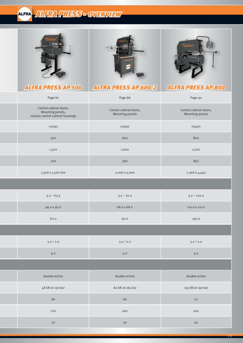
73
ALFRA PRESS AP 250 ALFRA PRESS AP 400 ALFRA PRESS AP 500 ALFRA PRESS AP 600-2 ALFRA PRESS AP 800Page 74 Page 78 Page 82 Page 86 Page 90
Control cabinet housing,Control cabinet doors,
Mounting panels
Control cabinet housing,Control cabinet doors,
Mounting panels
Control cabinet doors, Mounting panels,
various control cabinet housings
Control cabinet doors, Mounting panels
Control cabinet doors, Mounting panels
Prod.-No. 03170 03195 03093 03090 03400
Overhang with limit stop in mm 250 400 500 600 800
Overall height in mm 820 1,700 1,500 1,600 1,700
Total weight in kg approx. 50 (without base) 220 200 360 850
Space requirement in mm 1,000 x 1,000 1,200 x 800 1,500 x 1,500 mm 2,000 x 3,000 2,360 x 4,440
Tool dimension in mm:
Circular Ø 3.2 – 40.5 3.2 – 40.5 3.2 – 63.5 3.2 – 70.0 3.2 – 120.0
Square up to 28.0 x 28.0 28.0 x 28.0 46.0 x 46.0 68.0 x 68.0 110.0 x 110.0
Max. diagonals of 40.0 40.0 60.0 90.0 140.0
Max. material thickness in mm:
Sheet steel S235 / stainless steel 2.5 / 2.0 2.5 / 2.0 3.0 / 2.0 3.0 / 2.0 3.0 / 2.0
Aluminium / plastic 4.0 4.0 4.0 4.0 4.0
Hydraulic system:
Mode of action single-action single-action double-action double-action double-action
Punching force F 46 kN at 600 bar 46 kN at 600 bar 48 kN at 130 bar 60 kN at 165 bar 135 kN at 190 bar
Punching stroke in mm 50 50 66 66 72
Operating voltage in V - - 220 400 400
Workpiece fold in mm 22 22 30 30 40
ALFRA PRESS - overview
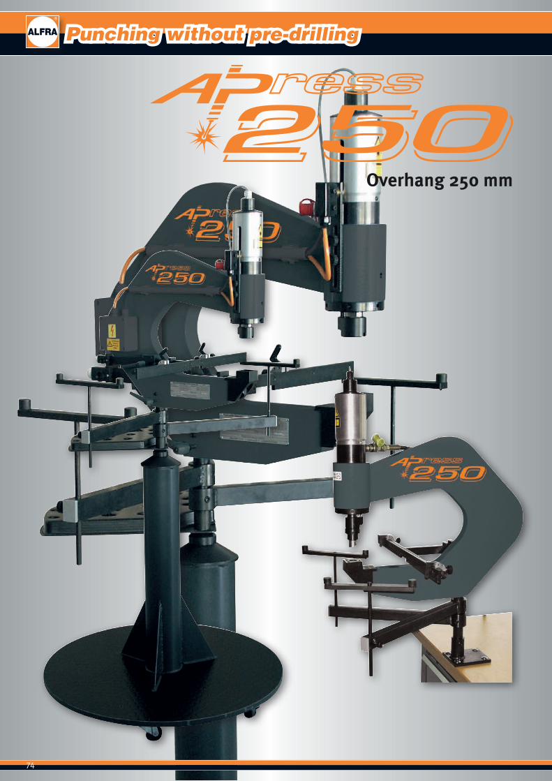
74
Mobile working platform optionally available.
Overhang 250 mm
Punching without pre-drilling
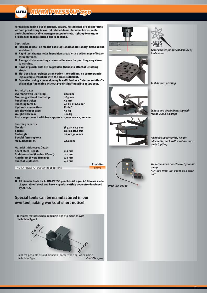
75
Laser pointer for optical display of tool centre
Tool drawer, pivoting
Length and depth limit stop with foldable add-on stops
Pivoting support arms, height adjustable, each with 2 rubber sup-ports (option)
We recommend our electro-hydraulic pump ALH-600 Prod.-No. 03190 as a drive unit.
Prod.-No. 03190
Prod.-No. 03174
For rapid punching-out of circular, square, rectangular or special forms without pre-drilling in control cabinet doors, terminal boxes, cable ducts, housings, cable management panels etc. right up to margins. Simple tool change carried out in seconds.
Description: ■ Flexible in use - on mobile base (optional) or stationary, fitted on the
workbench. ■ Rapid tool change helps in problem areas with a wide range of break-
through types. ■ A range of die mountings is available, even for punching very close
to margins. ■ Rows of punch-outs are no problem thanks to attachable folding
stops. ■ Tip: Use a laser pointer as an option - no scribing, no centre punch-
ing, a simple crosshair with the pin is sufficient. ■ Operation using a manual pump is sufficient as a "starter solution" -
this makes "punching without pre-drilling" possible at low cost.
Technical data:Overhang with limit stop: 250 mmOverhang without limit stop: 265 mmPunching stroke: 50 mmPunching force F: 46 kN at 600 barHydraulic connection: R 1/4"Weight without base: 50 kgWeight with base: 120 kgSpace requirement with base approx.: 1,000 mm x 1,000 mm
Punching capacity:Circular: Ø 3.2 - 40.5 mmSquare: 28.0 x 28.0 mmRectangle: 22.0 x 30.0 mmSpecial forms up to amax. diagonal of: 40.0 mm
Material thicknesses (max): Sheet steel (S235): 2.5 mmStainless steel (F = 600 N/mm2): 2.0 mmAluminium (F = 22 N/mm2 ): 4.0 mmPunchable plastics: 4.0 mm Prod.-No.
ALFRA PRESS AP 250 (without options) 03170
Note: ■ All circular tools for ALFRA PRESS punches AP 250 - AP 800 are made
of special tool steel and have a special cutting geometry developed by ALFRA.
Special tools can be manufactured in our own toolmaking works at short notice!
Technical features when punching close to margins with die holder Type I
Smallest-possible axial dimension (border spacing) when using die holder Type I
ALFRA PRESS AP 250

76
Punching without pre-drilling
Stationary hole punch - AP 250
Type Designation Prod.-No.
Machine Punching yoke ALFRA PRESS 250 with hydraulic cylinder and quick coupling, cylinder piston withnon-twist device for insertion of all punch sockets
03170
Pump Electro-hydraulic pump ALH 600 03190
Special fitting
Laser pointer with power unit for electro-hydraulic pump ALH 600 03181
Laser pointer, cpl. with power unit and connector plug for separate mains cable 230V/50Hz 03182
Combined length and depth limit stops with 2 adjustable limit stops per axis. The limit stops in the X direction are foldable and are suitable as an add-on limit stop for rows of punch-outs.
03177
Pivoting support arms (pairs) height adjustable, each with 2 rubber supports 03179
Limit switch for stroke limitation (only in combination with hydraulic pump ALH-600) 03183
Mobile base 03189
Punch socket
with scraper and centring pinØ 3.2 - 30.5 mm with mounting shaft for AP 250 - 400
03171
with scraper and centring pin for round punch Ø 32.5 - 40.5 mm with 19 mm Female thread for AP 250 - 400
03172
Die holder
Type I Dies Ø 3.2 - 22.5 mm for punching right up to margins for AP 250 - 400 03174
Type II Dies Ø 3.2 - 30.5 mm and moulding tool up to 21 x 21 mm (30.5 mm max. diagonals) for AP 250 - 400
03175
Type IV Dies Ø 30.6 - 40.5 mm and moulding tool up to 28 x 28 mm (40.0 mm max. diagonals) AP 250 - 400
03176
Square and rectangular hole punches - AP 250 (with mounting shaft and centring point, including die)
Type Designation Prod.-No. AP 250 AP 400 AP 500 AP 600 AP 800
Square holes21.0 x 21.0 mm for AP 250 - 400 03087 ● ●
25.4 x 25.4 mm for AP 250 - 400 03088 ● ●
Rectangular holes 22.0 x 30.0 mm for AP 250 - 400 03089 ● ●
Special holes Ø 22.5 mm with 4 lugs for AP 250 - 400 03086 ● ●
Spare neoprene scraper
for punch socket (03171) Ø 3.2 - 30.5 mm 03185 ● ●
for punch socket (03172) Ø 30.6 - 40.5 mm 03186 ● ●
Overhang 250 mm
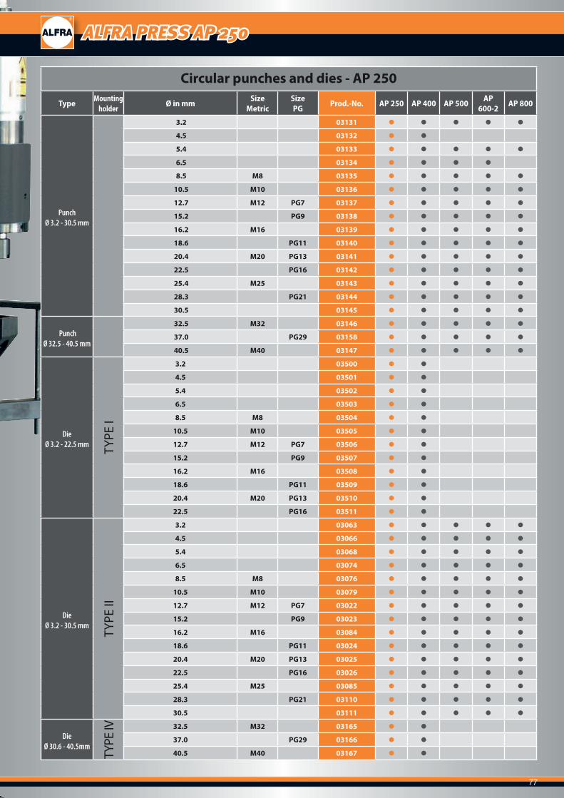
77
ALFRA PRESS AP 250
Circular punches and dies - AP 250
Type Mounting holder Ø in mm Size
MetricSizePG Prod.-No. AP 250 AP 400 AP 500 AP
600-2 AP 800
Punch Ø 3.2 - 30.5 mm
3.2 03131 ● ● ● ● ●
4.5 03132 ● ●
5.4 03133 ● ● ● ● ●
6.5 03134 ● ● ● ●
8.5 M8 03135 ● ● ● ● ●
10.5 M10 03136 ● ● ● ● ●
12.7 M12 PG7 03137 ● ● ● ● ●
15.2 PG9 03138 ● ● ● ● ●
16.2 M16 03139 ● ● ● ● ●
18.6 PG11 03140 ● ● ● ● ●
20.4 M20 PG13 03141 ● ● ● ● ●
22.5 PG16 03142 ● ● ● ● ●
25.4 M25 03143 ● ● ● ● ●
28.3 PG21 03144 ● ● ● ● ●
30.5 03145 ● ● ● ● ●
PunchØ 32.5 - 40.5 mm
32.5 M32 03146 ● ● ● ● ●
37.0 PG29 03158 ● ● ● ● ●
40.5 M40 03147 ● ● ● ● ●
Die Ø 3.2 - 22.5 mm TY
PE I
3.2 03500 ● ●
4.5 03501 ● ●
5.4 03502 ● ●
6.5 03503 ● ●
8.5 M8 03504 ● ●
10.5 M10 03505 ● ●
12.7 M12 PG7 03506 ● ●
15.2 PG9 03507 ● ●
16.2 M16 03508 ● ●
18.6 PG11 03509 ● ●
20.4 M20 PG13 03510 ● ●
22.5 PG16 03511 ● ●
Die Ø 3.2 - 30.5 mm
TYPE
II
3.2 03063 ● ● ● ● ●
4.5 03066 ● ● ● ● ●
5.4 03068 ● ● ● ● ●
6.5 03074 ● ● ● ● ●
8.5 M8 03076 ● ● ● ● ●
10.5 M10 03079 ● ● ● ● ●
12.7 M12 PG7 03022 ● ● ● ● ●
15.2 PG9 03023 ● ● ● ● ●
16.2 M16 03084 ● ● ● ● ●
18.6 PG11 03024 ● ● ● ● ●
20.4 M20 PG13 03025 ● ● ● ● ●
22.5 PG16 03026 ● ● ● ● ●
25.4 M25 03085 ● ● ● ● ●
28.3 PG21 03110 ● ● ● ● ●
30.5 03111 ● ● ● ● ●
Die Ø 30.6 - 40.5mm
TYPE
IV 32.5 M32 03165 ● ●
37.0 PG29 03166 ● ●
40.5 M40 03167 ● ●

78
Stable, mobile base as standard
Punching without pre-drilling
Overhang 400 mm

79
Laser pointer for optical display of tool centre
Die holder Type ll
Tool drawer, pivoting
Length and depth limit stop with foldable add-on stops(Option)
Pivoting support arms, height adjustable, each with 3 rubber sup-ports (option)
Prod.-No. 03174
We recommend our electro-hydraulic pump ALH-600 Prod.-No. 03190 as a drive unit.
Prod.-No. 03190
For rapid punching-out in circular, square, rectangular or special forms without pre-drilling in control cabinet doors, terminal boxes, cable ducts, housings, cable management panels etc. right up to margins. Simple tool change carried out in seconds.
Description: ■ Flexible in use - on mobile base. ■ Rapid tool change helps in problem areas with a wide range of break-
through types. ■ A range of die mountings is available, even for punching very close
to margins. ■ Rows of punch-outs are no problem thanks to attachable folding
stops. ■ Tip: Use a laser pointer as an option - no scribing, no centre punch-
ing, a simple crosshair with the pin is sufficient. ■ Operation using a manual pump is sufficient as a "starter solution" -
this makes "punching without pre-drilling" possible at low cost.
Technical data:Overhang with limit stop: 400 mmOverhang without limit stop: 430 mmPunching stroke: 50 mmPunching force F: 46 kN at 600 barHydraulic connection: R 1/4“Weight: 220 kgSpace requirement with base approx.: 1,200 x 800 mm
Punching capacity:Circular from: Ø 3.2 - 40.5 mmSquare up to: 28.0 x 28.0 mmRectangular up to: 22.0 x 30.0 mmSpecial forms up to amax. diagonal of: 40.0 mm
Material thicknesses (max): Sheet steel (S235): 2.5 mmStainless steel (F = 600 N/mm2): 2.0 mmAluminium (F = 22 N/mm2 ): 4.0 mmPunchable plastics: 4.0 mm Prod.-No.
ALFRA PRESS AP 400 (without options) 03195
Note: ■ All circular tools for ALFRA PRESS punches AP 250 - AP 800 are made
of special tool steel and have a special cutting geometry developed by ALFRA.
Special tools can be manufactured in our own toolmaking works at short notice!
Technical features when punching close to margins with die holder Type I
Smallest-possible axial dimension (border spacing) when using die holder Type I
ALFRA PRESS AP 400
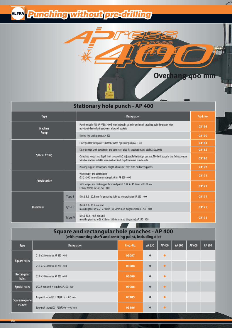
80
Punching without pre-drilling
Stationary hole punch - AP 400
Type Designation Prod.-No.
MachinePump
Punching yoke ALFRA PRESS 400 E with hydraulic cylinder and quick coupling, cylinder piston withnon-twist device for insertion of all punch sockets
03195
Electro-hydraulic pump ALH 600 03190
Special fitting
Laser pointer with power unit for electro-hydraulic pump ALH 600 03181
Laser pointer, with power unit and connector plug for separate mains cable 230V/50Hz 03182
Combined length and depth limit stops with 2 adjustable limit stops per axis. The limit stops in the X direction are foldable and are suitable as an add-on limit stop for rows of punch-outs.
03196
Pivoting support arms (pairs) height adjustable, each with 2 rubber supports 03197
Punch socket
with scraper and centring pinØ 3.2 - 30.5 mm with mounting shaft for AP 250 - 400
03171
with scraper and centring pin for round punch Ø 32.5 - 40.5 mm with 19 mm Female thread for AP 250 - 400
03172
Die holder
Type I Dies Ø 3.2 - 22.5 mm for punching right up to margins for AP 250 - 400 03174
Type II Dies Ø 3.2 - 30.5 mm and moulding tool up to 21 x 21 mm (30.5 mm max. diagonals) for AP 250 - 400
03175
Type IV Dies Ø 30.6 - 40.5 mm and moulding tool up to 28 x 28 mm (40.0 mm max. diagonals) AP 250 - 400
03176
Square and rectangular hole punches - AP 400 (with mounting shaft and centring point, including die)
Type Designation Prod.-No. AP 250 AP 400 AP 500 AP 600 AP 800
Square holes
21.0 x 21.0 mm for AP 250 - 400 03087 ● ●
25.4 x 25.4 mm for AP 250 - 400 03088 ● ●
Rectangular holes
22.0 x 30.0 mm for AP 250 - 400 03089 ● ●
Special holes Ø 22.5 mm with 4 lugs for AP 250 - 400 03086 ● ●
Spare neoprene scraper
for punch socket (03171) Ø 3.2 - 30.5 mm 03185 ● ●
for punch socket (03172) Ø 30.6 - 40.5 mm 03186 ● ●
Overhang 400 mm

81
ALFRA PRESS AP 400
Circular punches and dies - AP 400
Type Mounting holder Ø in mm Size
MetricSizePG Prod.-No. AP 250 AP 400 AP 500 AP
600-2 AP 800
Punch Ø 3.2 - 30.5 mm
3.2 03131 ● ● ● ● ●
4.5 03132 ● ●
5.4 03133 ● ● ● ● ●
6.5 03134 ● ● ● ●
8.5 M8 03135 ● ● ● ● ●
10.5 M10 03136 ● ● ● ● ●
12.7 M12 PG7 03137 ● ● ● ● ●
15.2 PG9 03138 ● ● ● ● ●
16.2 M16 03139 ● ● ● ● ●
18.6 PG11 03140 ● ● ● ● ●
20.4 M20 PG13 03141 ● ● ● ● ●
22.5 PG16 03142 ● ● ● ● ●
25.4 M25 03143 ● ● ● ● ●
28.3 PG21 03144 ● ● ● ● ●
30.5 03145 ● ● ● ● ●
PunchØ 32.5 - 40.5 mm
32.5 M32 03146 ● ● ● ● ●
37.0 PG29 03158 ● ● ● ● ●
40.5 M40 03147 ● ● ● ● ●
Die Ø 3.2 - 22.5 mm TY
PE I
3.2 03500 ● ●
4.5 03501 ● ●
5.4 03502 ● ●
6.5 03503 ● ●
8.5 M8 03504 ● ●
10.5 M10 03505 ● ●
12.7 M12 PG7 03506 ● ●
15.2 PG9 03507 ● ●
16.2 M16 03508 ● ●
18.6 PG11 03509 ● ●
20.4 M20 PG13 03510 ● ●
22.5 PG16 03511 ● ●
Die Ø 3.2 - 30.5 mm
TYPE
II
3.2 03063 ● ● ● ● ●
4.5 03066 ● ● ● ● ●
5.4 03068 ● ● ● ● ●
6.5 03074 ● ● ● ● ●
8.5 M8 03076 ● ● ● ● ●
10.5 M10 03079 ● ● ● ● ●
12.7 M12 PG7 03022 ● ● ● ● ●
15.2 PG9 03023 ● ● ● ● ●
16.2 M16 03084 ● ● ● ● ●
18.6 PG11 03024 ● ● ● ● ●
20.4 M20 PG13 03025 ● ● ● ● ●
22.5 PG16 03026 ● ● ● ● ●
25.4 M25 03085 ● ● ● ● ●
28.3 PG21 03110 ● ● ● ● ●
30.5 03111 ● ● ● ● ●
Die Ø 30.6 - 40.5mm
TYPE
IV 32.5 M32 03165 ● ●
37.0 PG29 03166 ● ●
40.5 M40 03167 ● ●
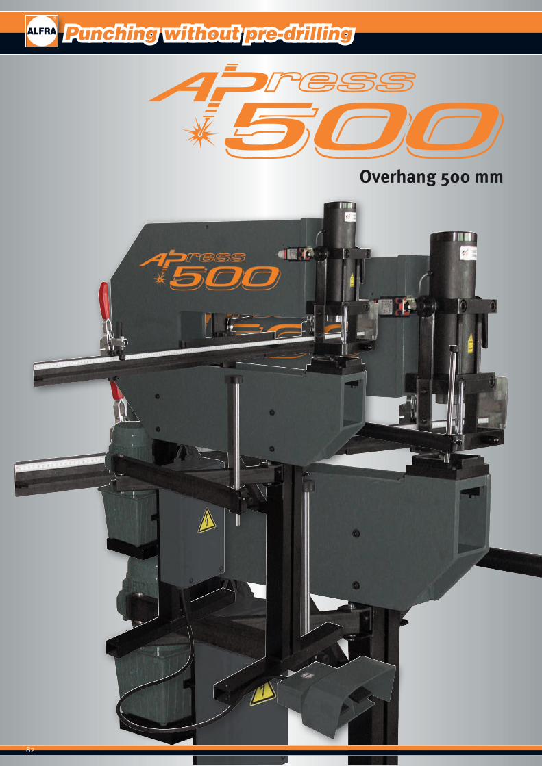
82
Punching without pre-drilling
Overhang 500 mm
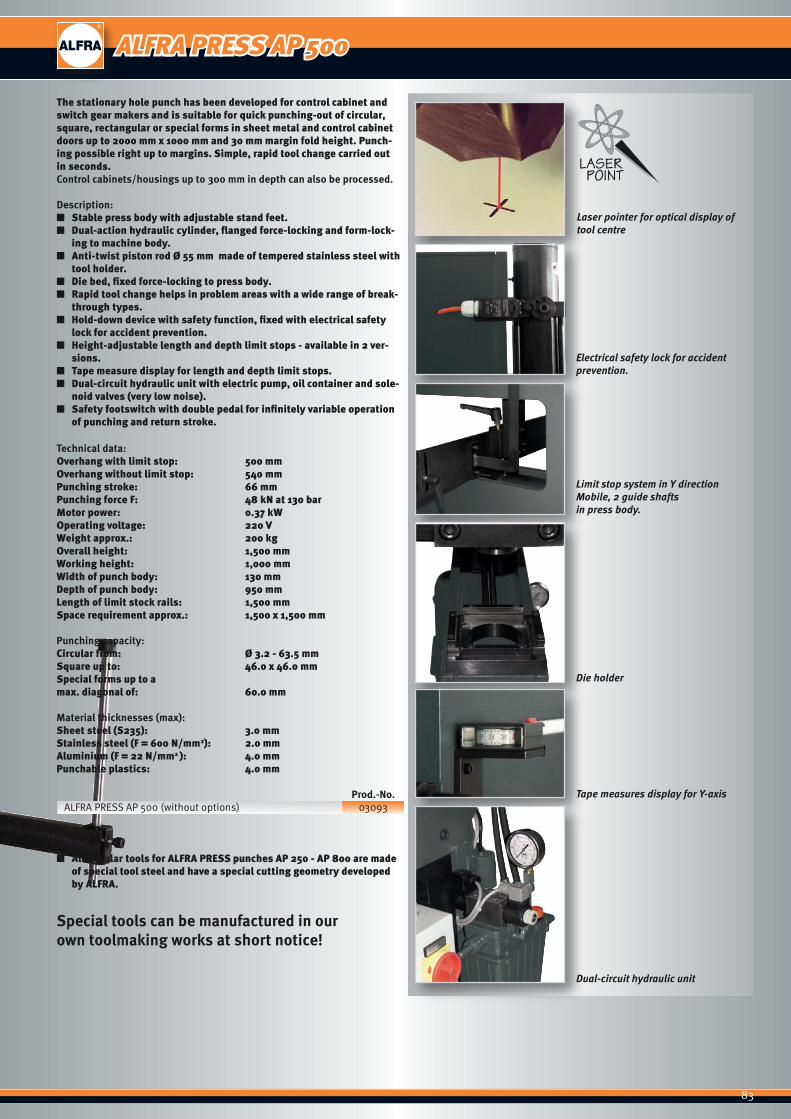
83
Laser pointer for optical display of tool centre
Electrical safety lock for accident prevention.
Limit stop system in Y direction Mobile, 2 guide shafts in press body.
Die holder
Tape measures display for Y-axis
Dual-circuit hydraulic unit
The stationary hole punch has been developed for control cabinet and switch gear makers and is suitable for quick punching-out of circular, square, rectangular or special forms in sheet metal and control cabinet doors up to 2000 mm x 1000 mm and 30 mm margin fold height. Punch-ing possible right up to margins. Simple, rapid tool change carried out in seconds.Control cabinets/housings up to 300 mm in depth can also be processed.
Description: ■ Stable press body with adjustable stand feet. ■ Dual-action hydraulic cylinder, flanged force-locking and form-lock-
ing to machine body. ■ Anti-twist piston rod Ø 55 mm made of tempered stainless steel with
tool holder. ■ Die bed, fixed force-locking to press body. ■ Rapid tool change helps in problem areas with a wide range of break-
through types. ■ Hold-down device with safety function, fixed with electrical safety
lock for accident prevention. ■ Height-adjustable length and depth limit stops - available in 2 ver-
sions. ■ Tape measure display for length and depth limit stops. ■ Dual-circuit hydraulic unit with electric pump, oil container and sole-
noid valves (very low noise). ■ Safety footswitch with double pedal for infinitely variable operation
of punching and return stroke.
Technical data:Overhang with limit stop: 500 mmOverhang without limit stop: 540 mmPunching stroke: 66 mmPunching force F: 48 kN at 130 barMotor power: 0.37 kWOperating voltage: 220 VWeight approx.: 200 kgOverall height: 1,500 mmWorking height: 1,000 mmWidth of punch body: 130 mmDepth of punch body: 950 mmLength of limit stock rails: 1,500 mmSpace requirement approx.: 1,500 x 1,500 mm
Punching capacity:Circular from: Ø 3.2 - 63.5 mmSquare up to: 46.0 x 46.0 mmSpecial forms up to amax. diagonal of: 60.0 mm
Material thicknesses (max): Sheet steel (S235): 3.0 mmStainless steel (F = 600 N/mm2): 2.0 mmAluminium (F = 22 N/mm2 ): 4.0 mmPunchable plastics: 4.0 mm
Prod.-No.ALFRA PRESS AP 500 (without options) 03093
Note: ■ All circular tools for ALFRA PRESS punches AP 250 - AP 800 are made
of special tool steel and have a special cutting geometry developed by ALFRA.
Special tools can be manufactured in our own toolmaking works at short notice!
ALFRA PRESS AP 500

84
Punching without pre-drilling
Stationary hole punch - AP 500
Type Designation Prod.-No.
Machine Stationary hole punch ALFRA PRESS 500 LPV with hydraulic cylinder, dual-actionHydraulic unit, adjustable stand feet, safety footswitch
03093
Special fitting
Laser pointer for optical display of tool centre 03021
Length and depth limit stops movable in Y direction 03094
Length and depth limit stops movable in X and Y direction 03095
Pivoting double joint arm for supporting workpiece (individual) 03078
Punch socket
with scraper and centring pin for round punch with mounting shaft AP 500 - 600 Ø 3.2 - 30.5 mm
03036
AP 500 - 600 Ø 32.5 - 40.5 mm 03035
Die holder
Type A Circular die Type A Ø 3.2 - 25.4 mm 03040
Type B Circular die Type A Ø 28.3 - 40.5 mm 03041
Type C Circular die Type A Ø 40.6 - 63.5 mm 03077
Square and rectangular hole punches - AP 500 (with mounting shaft and centring point, including die)
Type Designation Prod.-No. AP 250 AP 400 AP 500 AP 600 AP 800
Square holes
12.7 x 12.7 mm for AP 500 - 600 03042 ● ●
19.0 x 19.0 mm for AP 500 - 600 03044 ● ●
22.2 x 22.2 mm for AP 500 - 600 03045 ● ●
25.4 x 25.4 mm for AP 500 - 600 03046 ● ●
46.0 x 46.0 mm for AP 500 - 600 03047 ● ●
68.0 x 68.0 mm for AP 600 03050 ●
Rectangular holes
22.0 x 30.0 mm for AP 500 - 600 03048 ● ●
22.0 x 42.0 mm for AP 500 - 600 03049 ● ●
Special holes
Ø 22.5 mm 1 lug 3.2 mm for AP 500 - 600 03051 ● ●
Ø 22.5 mm with 2 lugs 3.2 mm for AP 500 - 600 03052 ● ●
Ø 22.5 mm, flattened on 4 sides to 20.1 mm for AP 500 - 600 03055 ● ●
Overhang 500 mm
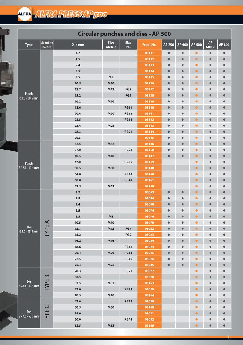
85
ALFRA PRESS AP 500
Circular punches and dies - AP 500
Type Mounting holder Ø in mm Size
MetricSizePG Prod.-No. AP 250 AP 400 AP 500 AP
600-2 AP 800
Punch Ø 3.2 - 30.5 mm
3.2 03131 ● ● ● ● ●
4.5 03132 ● ● ● ● ●
5.4 03133 ● ● ● ● ●
6.5 03134 ● ● ● ● ●
8.5 M8 03135 ● ● ● ● ●
10.5 M10 03136 ● ● ● ● ●
12.7 M12 PG7 03137 ● ● ● ● ●
15.2 PG9 03138 ● ● ● ● ●
16.2 M16 03139 ● ● ● ● ●
18.6 PG11 03140 ● ● ● ● ●
20.4 M20 PG13 03141 ● ● ● ● ●
22.5 PG16 03142 ● ● ● ● ●
25.4 M25 03143 ● ● ● ● ●
28.3 PG21 03144 ● ● ● ● ●
30.5 03145 ● ● ● ● ●
Punch Ø 32.5 - 40.5 mm
32.5 M32 03146 ● ● ● ● ●
37.0 PG29 03158 ● ● ● ● ●
40.5 M40 03147 ● ● ● ● ●
47.0 PG36 03159 ● ● ●
50.5 M50 03148 ● ● ●
54.0 PG42 03160 ● ● ●
60.0 PG48 03161 ● ● ●
63.5 M63 03149 ● ● ●
Die Ø 3.2 - 25.4 mm
TYPE
A
3.2 03063 ● ● ● ● ●
4.5 03066 ● ● ● ● ●
5.4 03068 ● ● ● ● ●
6.5 03074 ● ● ● ● ●
8.5 M8 03076 ● ● ● ● ●
10.5 M10 03079 ● ● ● ● ●
12.7 M12 PG7 03022 ● ● ● ● ●
15.2 PG9 03023 ● ● ● ● ●
16.2 M16 03084 ● ● ● ● ●
18.6 PG11 03024 ● ● ● ● ●
20.4 M20 PG13 03025 ● ● ● ● ●
22.5 PG16 03026 ● ● ● ● ●
25.4 M25 03085 ● ● ● ● ●
Die Ø 28.3 - 40.5 mm
TYPE
B
28.3 PG21 03027 ● ● ●
30.5 03028 ● ● ●
32.5 M32 03163 ● ● ●
37.0 PG29 03029 ● ● ●
40.5 M40 03164 ● ● ●
DieØ 47.0 - 63.5 mm
TYPE
C
47.0 PG36 03030 ● ● ●
50.5 M50 03168 ● ● ●
54.0 03031 ● ● ●
60.0 PG48 03032 ● ● ●
63.5 M63 03169 ● ● ●
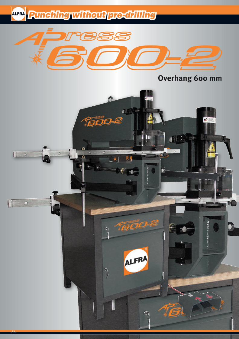
86
Punching without pre-drilling
Overhang 600 mm
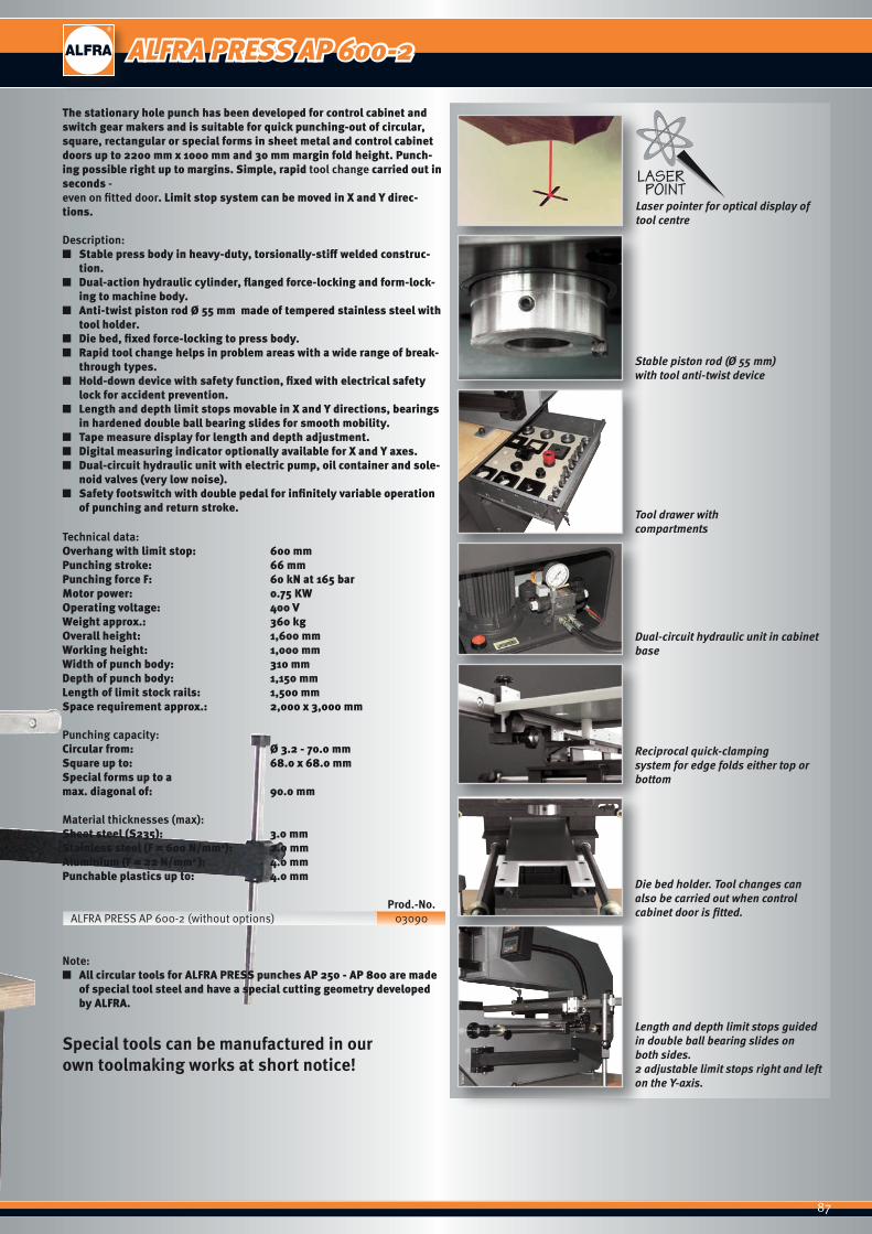
87
Laser pointer for optical display of tool centre
Stable piston rod (Ø 55 mm)with tool anti-twist device
Tool drawer with compartments
Dual-circuit hydraulic unit in cabinet base
Reciprocal quick-clampingsystem for edge folds either top or bottom
Die bed holder. Tool changes can also be carried out when control cabinet door is fitted.
Length and depth limit stops guidedin double ball bearing slides on both sides.2 adjustable limit stops right and left on the Y-axis.
The stationary hole punch has been developed for control cabinet and switch gear makers and is suitable for quick punching-out of circular, square, rectangular or special forms in sheet metal and control cabinet doors up to 2200 mm x 1000 mm and 30 mm margin fold height. Punch-ing possible right up to margins. Simple, rapid tool change carried out in seconds - even on fitted door. Limit stop system can be moved in X and Y direc-tions.
Description: ■ Stable press body in heavy-duty, torsionally-stiff welded construc-
tion. ■ Dual-action hydraulic cylinder, flanged force-locking and form-lock-
ing to machine body. ■ Anti-twist piston rod Ø 55 mm made of tempered stainless steel with
tool holder. ■ Die bed, fixed force-locking to press body. ■ Rapid tool change helps in problem areas with a wide range of break-
through types. ■ Hold-down device with safety function, fixed with electrical safety
lock for accident prevention. ■ Length and depth limit stops movable in X and Y directions, bearings
in hardened double ball bearing slides for smooth mobility. ■ Tape measure display for length and depth adjustment. ■ Digital measuring indicator optionally available for X and Y axes. ■ Dual-circuit hydraulic unit with electric pump, oil container and sole-
noid valves (very low noise). ■ Safety footswitch with double pedal for infinitely variable operation
of punching and return stroke.
Technical data:Overhang with limit stop: 600 mmPunching stroke: 66 mmPunching force F: 60 kN at 165 barMotor power: 0.75 KWOperating voltage: 400 VWeight approx.: 360 kgOverall height: 1,600 mmWorking height: 1,000 mmWidth of punch body: 310 mmDepth of punch body: 1,150 mmLength of limit stock rails: 1,500 mmSpace requirement approx.: 2,000 x 3,000 mm
Punching capacity:Circular from: Ø 3.2 - 70.0 mmSquare up to: 68.0 x 68.0 mmSpecial forms up to amax. diagonal of: 90.0 mm
Material thicknesses (max): Sheet steel (S235): 3.0 mmStainless steel (F = 600 N/mm2): 2.0 mmAluminium (F = 22 N/mm2 ): 4.0 mmPunchable plastics up to: 4.0 mm
Prod.-No.ALFRA PRESS AP 600-2 (without options) 03090
Note: ■ All circular tools for ALFRA PRESS punches AP 250 - AP 800 are made
of special tool steel and have a special cutting geometry developed by ALFRA.
Special tools can be manufactured in our own toolmaking works at short notice!
ALFRA PRESS AP 600-2

88
Punching without pre-drilling
Stationary hole punch - AP 600-2
Type Designation Prod.-No.
MachineStationary hole punch ALFRA PRESS 600-2 with hydraulic cylinder, cabinet base, length anddepth limit stops movable in X and Y directions, cylinder pistons with anti-twist device for use withall punch sockets, dual-action hydraulic unit, safety footswitch.
03090
Special fitting
Laser pointer for optical display of tool centre 03021
Digital measuring indicator Y-axis 03091
Digital measuring indicator X-axis 03092
Pivoting double joint arm for supporting workpiece (individual) 03078
Punch socket
with scraper and centring pinfor round punch with mounting shaft for AP 500 - 600 Ø 3.2 - 30.5 mm
03036
with scraper and centring pinfor round punch with 19 mm female thread for AP 500 - 600 Ø 32.5 - 40.5 mm
03035
Die holder
Type A Circular die Type A Ø 3.2 - 25.4 mm 03040
Type B Circular die Type A Ø 28.3 - 40.5 mm 03041
Type C Circular die Type A Ø 40.5 - 63.5 mm 03077
Square and rectangular hole punches - AP 600-2 (with mounting shaft and centring point, including die)
Type Designation Prod.-No. AP 250 AP 400 AP 500 AP 600 AP 800
Square holes
12.7 x 12.7 mm for AP 500 - 600 03042 ● ●
19.0 x 19.0 mm for AP 500 - 600 03044 ● ●
22.2 x 22.2 mm for AP 500 - 600 03045 ● ●
25.4 x 25.4 mm for AP 500 - 600 03046 ● ●
46.0 x 46.0 mm for AP 500 - 600 03047 ● ●
68.0 x 68.0 mm for AP 600 03050 ●
Rectangular holes
22.0 x 30.0 mm for AP 500 - 600 03048 ● ●
22.0 x 42.0 mm for AP 500 - 600 03049 ● ●
Special holes
Ø 22.5 mm 1 lug 3.2 mm for AP 500 - 600 03051 ● ●
Ø 22.5 mm with 2 lugs 3.2 mm for AP 500 - 600 03052 ● ●
Ø 22.5 mm, flattened on 4 sides to 20.1 mm for AP 500 - 600 03055 ● ●
Overhang 600 mm

89
ALFRA PRESS AP 600-2
Circular punches and dies - AP 600-2
Type Mounting holder Ø in mm Size
MetricSizePG Prod.-No. AP 250 AP 400 AP 500 AP
600-2 AP 800
Punch Ø 3.2 - 30.5 mm
3.2 03131 ● ● ● ● ●
4.5 03132 ● ● ● ● ●
5.4 03133 ● ● ● ● ●
6.5 03134 ● ● ● ● ●
8.5 M8 03135 ● ● ● ● ●
10.5 M10 03136 ● ● ● ● ●
12.7 M12 PG7 03137 ● ● ● ● ●
15.2 PG9 03138 ● ● ● ● ●
16.2 M16 03139 ● ● ● ● ●
18.6 PG11 03140 ● ● ● ● ●
20.4 M20 PG13 03141 ● ● ● ● ●
22.5 PG16 03142 ● ● ● ● ●
25.4 M25 03143 ● ● ● ● ●
28.3 PG21 03144 ● ● ● ● ●
30.5 03145 ● ● ● ● ●
Punch Ø 32.5-40.5 mm
32.5 M32 03146 ● ● ● ● ●
37.0 PG29 03158 ● ● ● ● ●
40.5 M40 03147 ● ● ● ● ●
47.0 PG36 03159 ● ● ●
50.5 M50 03148 ● ● ●
54.0 PG42 03160 ● ● ●
60.0 PG48 03161 ● ● ●
63.5 M63 03149 ● ● ●
Die Ø 3.2 - 25.4 mm
TYPE
A
3.2 03063 ● ● ● ● ●
4.5 03066 ● ● ● ● ●
5.4 03068 ● ● ● ● ●
6.5 03074 ● ● ● ● ●
8.5 M8 03076 ● ● ● ● ●
10.5 M10 03079 ● ● ● ● ●
12.7 M12 PG7 03022 ● ● ● ● ●
15.2 PG9 03023 ● ● ● ● ●
16.2 M16 03084 ● ● ● ● ●
18.6 PG11 03024 ● ● ● ● ●
20.4 M20 PG13 03025 ● ● ● ● ●
22.5 PG16 03026 ● ● ● ● ●
25.4 M25 03085 ● ● ● ● ●
Die Ø 28.3 - 40.5 mm
TYPE
B
28.3 PG21 03027 ● ● ●
30.5 03028 ● ● ●
32.5 M32 03163 ● ● ●
37.0 PG29 03029 ● ● ●
40.5 M40 03164 ● ● ●
DieØ 47.0 - 63.5 mm
TYPE
C
47.0 PG36 03030 ● ● ●
50.5 M50 03168 ● ● ●
54.0 03031 ● ● ●
60.0 PG48 03032 ● ● ●
63.5 M63 03169 ● ● ●
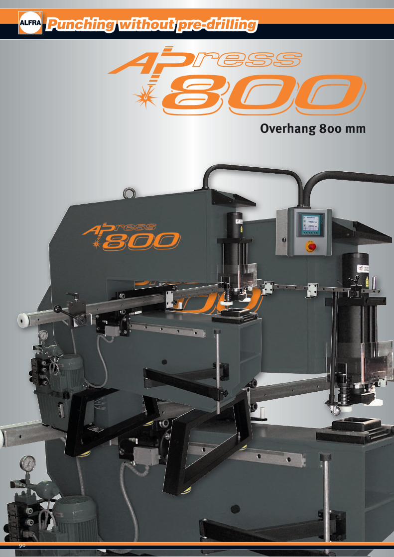
90
Punching without pre-drilling
Overhang 800 mm

91
Pivoting control panel with two-hand operation
Form and force-locking workpiece mounting with quick-action clamp-ing system
Tool holder, anti-twist in piston rod, hold-down device / scraper combination
Die holder, tool change also possible with fitted control cabinet door
Path measurement of X and Y travel
Dual-circuit hydraulic unit
Hold-down device/scraper combination
The stationary hole punch has been developed for control cabinet and switch gear makers and is suitable for quick punching-out of circular, square, rectangular or special forms in sheet metal and control cabinet doors up to 2200 mm x 1000 mm and 40 mm margin fold height. Punch-ing possible right up to margins. Simple, rapid tool change carried out in seconds - even on fitted door. Limit stop system can be moved in X and Y direc-tions.
Description: ■ Stable press body in heavy-duty, torsionally-stiff welded construc-
tion, fitted on stands with rubber-bonded metal feet. ■ Pivoting control panel with digital display, emergency stop button,
electrical operating buttons and two-hand operation. ■ Dual-action hydraulic cylinder, flanged force-locking and form-lock-
ing to machine body. ■ Anti-twist piston rod Ø 63 mm made of tempered stainless steel with
tool holder. ■ Die bed, fixed force-locking to press body. ■ Time relay for piston return saves working time. ■ Hold-down device/scraper combination with figure protection. ■ X – Y limit stop system, easily movable in heavy-duty, precise profile
roller guides. ■ Form and force-fitting workpiece mounting and clamping device. ■ Pivoting workpiece mounting left of press body for easy raising of
workpiece. ■ Locking of limit stop system using electrically-operated hydraulic
brakes. ■ Digital path measurement and display of X and Y travel with a display
accuracy of 0.1 mm and a measuring accuracy of 1%. ■ Rapid tool change helps in problem areas with a wide range of break-
through types. ■ Dual-circuit hydraulic unit with electric pump, oil container and sole-
noid valves (very low noise).
Technical data:Overhang with limit stop: 800 mmPunching stroke: 72 mmPunching force F: 135 kN at 190 barMotor power: 1.5 kWOperating voltage: 400 VWeight approx.: 850 kgOverall height: 1,700 mmWorking height: 1,000 mmWidth of punch body: 280 mmDepth of punch body: 1,700 mmSpace requirement approx.: 2,360 x 4,440 mm
Punching capacity:Circular from: Ø 3.2 - 120.0 mmSquare up to: 110.0 x 110.0 mmSpecial forms up to amax. diagonal of: 140.0 mm
Material thicknesses (max): Sheet steel (S235): 3.0 mmStainless steel (F = 600 N/mm2): 2.0 mmAluminium (F = 22 N/mm2 ): 4.0 mmPunchable plastics up to: 4.0 mm
Prod.-No.ALFRA PRESS AP 800 (without options) 03400
Special tools can be manufactured in our own toolmaking works at short notice!
ALFRA PRESS AP 800
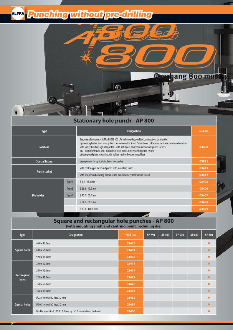
92
Stationary hole punch - AP 800
Type Designation Prod.-No.
Machine
Stationary hole punch ALFRA PRESS 800 LPV in heavy duty welded construction, dual-actionhydraulic cylinder, limit stop system can be moved in X and Y directions, hold-down device/scraper combinationwith safety function, cylinder pistons with anti-twist device for use with all punch sockets,dual-circuit hydraulic unit, movable control panel, time relay for piston return,pivoting workpiece mounting, die holder, rubber-bonded metal feet.
03400
Special fitting Laser pointer for optical display of tool centre 03021
Punch socketwith centring pin for round punch with mounting shaft 03413
with scraper and centring pin for round punch with 19 mm female thread 03411
Die holder
Type A Ø 3.2 - 25.4 mm 03405
Type B Ø 28.3 - 40.5 mm 03406
Type C Ø 40.6 - 63.5 mm 03407
Ø 64.0 - 80.0 mm 03408
Ø 80.1 - 100.0 mm 03409
Square and rectangular hole punches - AP 800 (with mounting shaft and centring point, including die)
Type Designation Prod.-No. AP 250 AP 400 AP 500 AP 600 AP 800
Square holes
46.0 x 46.0 mm 03425 ●
68.0 x 68.0 mm 03491 ●
92.0 x 92.0 mm 03435 ●
Rectangular holes
22.0 x 30.0 mm 03417 ●
24.0 x 36.0 mm 03419 ●
22.0 x 42.0 mm 03421 ●
35.0 x 65.0 mm 03428 ●
46.0 x 92.0 mm 03433 ●
Special holes
Ø 22.5 mm with 2 lugs 3.2 mm 03452 ●
Ø 30.5 mm with 2 lugs 3.2 mm 03454 ●
Double louvre tool 100.0 x 8.0 mm up to 2.0 mm material thickness 03456 ●
Punching without pre-drilling
Overhang 800 mm
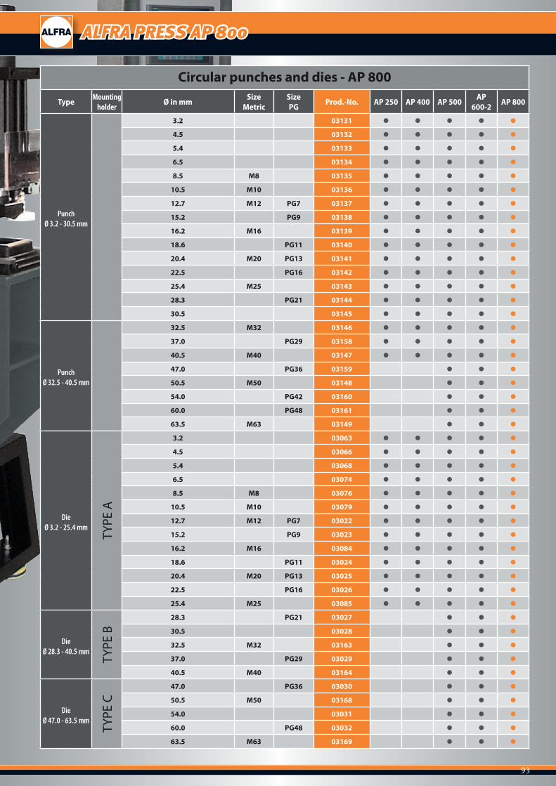
93
ALFRA PRESS AP 800
Circular punches and dies - AP 800
Type Mounting holder Ø in mm Size
MetricSizePG Prod.-No. AP 250 AP 400 AP 500 AP
600-2 AP 800
Punch Ø 3.2 - 30.5 mm
3.2 03131 ● ● ● ● ●
4.5 03132 ● ● ● ● ●
5.4 03133 ● ● ● ● ●
6.5 03134 ● ● ● ● ●
8.5 M8 03135 ● ● ● ● ●
10.5 M10 03136 ● ● ● ● ●
12.7 M12 PG7 03137 ● ● ● ● ●
15.2 PG9 03138 ● ● ● ● ●
16.2 M16 03139 ● ● ● ● ●
18.6 PG11 03140 ● ● ● ● ●
20.4 M20 PG13 03141 ● ● ● ● ●
22.5 PG16 03142 ● ● ● ● ●
25.4 M25 03143 ● ● ● ● ●
28.3 PG21 03144 ● ● ● ● ●
30.5 03145 ● ● ● ● ●
Punch Ø 32.5 - 40.5 mm
32.5 M32 03146 ● ● ● ● ●
37.0 PG29 03158 ● ● ● ● ●
40.5 M40 03147 ● ● ● ● ●
47.0 PG36 03159 ● ● ●
50.5 M50 03148 ● ● ●
54.0 PG42 03160 ● ● ●
60.0 PG48 03161 ● ● ●
63.5 M63 03149 ● ● ●
Die Ø 3.2 - 25.4 mm
TYPE
A
3.2 03063 ● ● ● ● ●
4.5 03066 ● ● ● ● ●
5.4 03068 ● ● ● ● ●
6.5 03074 ● ● ● ● ●
8.5 M8 03076 ● ● ● ● ●
10.5 M10 03079 ● ● ● ● ●
12.7 M12 PG7 03022 ● ● ● ● ●
15.2 PG9 03023 ● ● ● ● ●
16.2 M16 03084 ● ● ● ● ●
18.6 PG11 03024 ● ● ● ● ●
20.4 M20 PG13 03025 ● ● ● ● ●
22.5 PG16 03026 ● ● ● ● ●
25.4 M25 03085 ● ● ● ● ●
Die Ø 28.3 - 40.5 mm
TYPE
B
28.3 PG21 03027 ● ● ●
30.5 03028 ● ● ●
32.5 M32 03163 ● ● ●
37.0 PG29 03029 ● ● ●
40.5 M40 03164 ● ● ●
DieØ 47.0 - 63.5 mm
TYPE
C
47.0 PG36 03030 ● ● ●
50.5 M50 03168 ● ● ●
54.0 03031 ● ● ●
60.0 PG48 03032 ● ● ●
63.5 M63 03169 ● ● ●

94

95
Copyright by Alfred Raith GmbH2016
All technical specifications, descriptions and illustrations in this catalogue are non-binding. We reserve the right to make changes due to the ongoing development of our products.
We accept no liability for any printing errors.
Publication of this catalogue makes all previous catalogues invalid.
As of April 2016
All rights reserved.
This catalogue was created with the greatest possible care. All technical data and information was verified before printing.For reasons of continuous improvement and development of the ALFRA pro-duction program, we reserve the right to modify or even remove products in this catalogue from our delivery program. For this reason technical data and products which are contained in this catalogue may vary without prior notification.
Complete or partial utilisation and reproduction of this catalogue (draw-ings, images, text, logos) is prohibited without written approval.
96
Your notes
97
Your notes

98
Your notes

99
Your notes
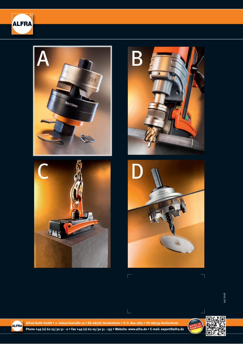
A B
DC
A /
20
16
EN
04/2
016
Alfred Raith GmbH • 2. Industriestraße 10 • DE-68766 Hockenheim • P. O. Box 1667 • DE-68759 Hockenheim
Phone +49 (0) 62 05/30 51 - 0 • Fax +49 (0) 62 05/30 51 - 135 • Website: www.alfra.de • E-mail: [email protected]
Related Documents