©Alex Doboli 2006 Analog to Digital Converters Alex Doboli, Ph.D. Department of Electrical and Computer Engineering State University of New York at Stony Brook Email: [email protected]

©Alex Doboli 2006 Analog to Digital Converters Alex Doboli, Ph.D. Department of Electrical and Computer Engineering State University of New York at.
Dec 17, 2015
Welcome message from author
This document is posted to help you gain knowledge. Please leave a comment to let me know what you think about it! Share it to your friends and learn new things together.
Transcript

©Alex Doboli 2006
Analog to Digital Converters
Alex Doboli, Ph.D.
Department of Electrical and Computer Engineering
State University of New York at Stony Brook
Email: [email protected]

©Alex Doboli 2006
ADC
The chapter introduces the following aspects:
• Basic concepts of ADC & 1sr and 2nd order ADCs
• ADC are main subsystems in any embedded system
ADC offer high resolution through two mechanisms:– Oversampling: reduces in-band quantization noise– Noiseshaping: eliminates in-band quantization noise
• PSoC implementation of ADC: modulator, decimator, API
©Alex Doboli 2006
Nyquist ADCs
Embedded system front end:
©Alex Doboli 2006
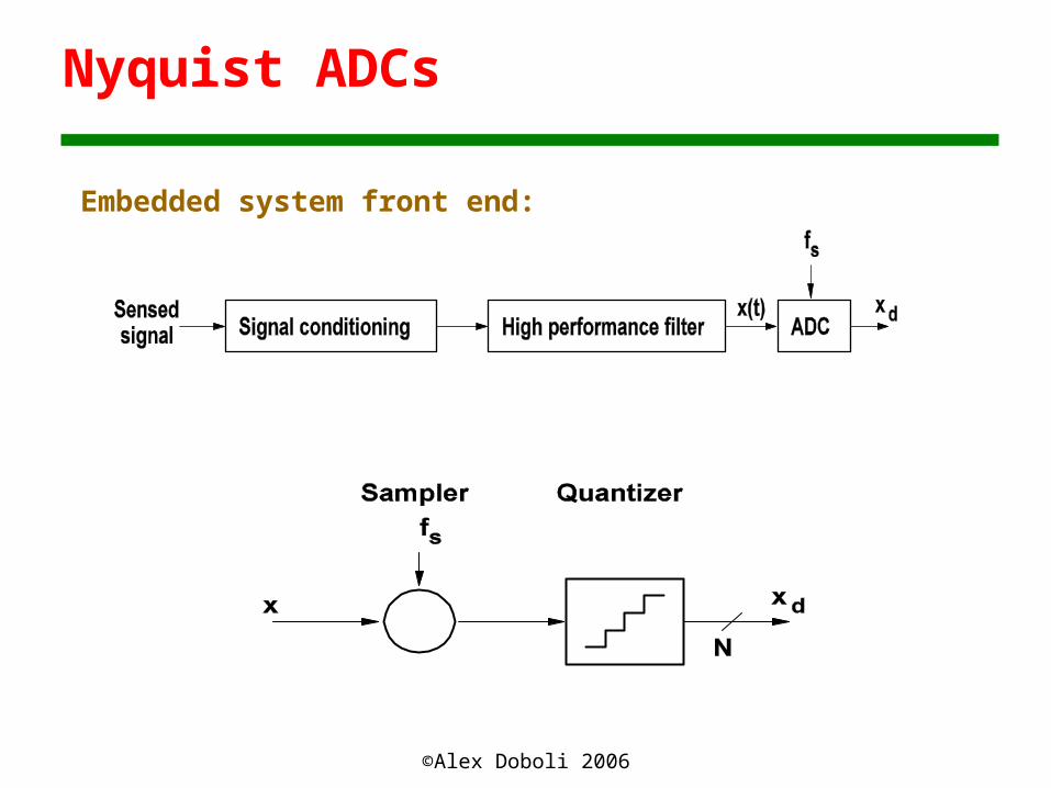
Sampling
• Collect sufficient data for correctly representing a continuous-time signal

©Alex Doboli 2006
Nyquist Sampling Theorem
• A bandlimited signal can be exactly reconstructed if the samplingFrequency is greater than twice the signal bandwidth
• Nyquist frequency is twice the signal bandwidth

©Alex Doboli 2006
Sampling
aliasing
Xs(f) = X(f) + X(f+/-fs) + X(f+/-2fs) + X(f+/-3fs) + X(f+/-4fs) + …

©Alex Doboli 2006
Quantization
• Quantization is the process of converting the sampled continuous-Valued signals into discrete-valued data

©Alex Doboli 2006
Quantization
• Discretization range: = 2 / (2B - 1)
• Quantization error:er ε (-/2, /2)
White noise
xd = xs + er

©Alex Doboli 2006
Quantization Error
• Bennett’s conditions:• Input does not overload quantizer• B is large• is small• Joint probability density function of the input at
various sampling moments is smooth
• Quantization error is white noise & is uncorrelated to the input

©Alex Doboli 2006
Quantization Error
• Quantization noise power
• Power spectral density
2e = 2 / 12
©Alex Doboli 2006
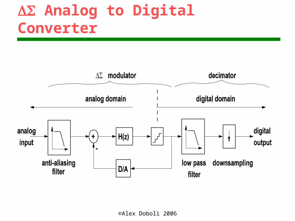
Analog to Digital Converter
©Alex Doboli 2006
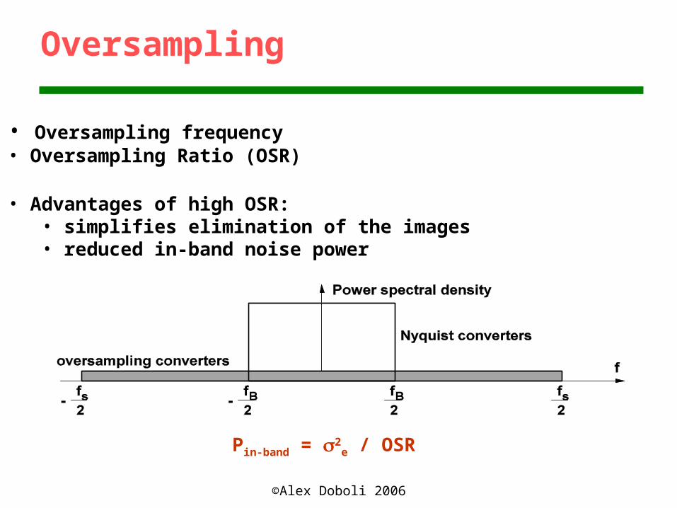
Oversampling
• Oversampling frequency• Oversampling Ratio (OSR)
• Advantages of high OSR:• simplifies elimination of the images• reduced in-band noise power
Pin-band = 2e / OSR

©Alex Doboli 2006
Noiseshaping
Y(z) = H(z) / (1 + H(z)) X(z) + 1 / (1 + H(z)) E(z)
STF NTF
©Alex Doboli 2006
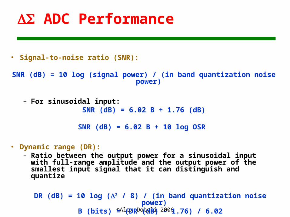
ADC Performance
• Signal-to-noise ratio (SNR):
SNR (dB) = 10 log (signal power) / (in band quantization noise power)
– For sinusoidal input:SNR (dB) = 6.02 B + 1.76 (dB)
SNR (dB) = 6.02 B + 10 log OSR
• Dynamic range (DR):– Ratio between the output power for a sinusoidal input with full-
range amplitude and the output power of the smallest input signal that it can distinguish and quantize
DR (dB) = 10 log (2 / 8) / (in band quantization noise power)B (bits) = (DR (dB) – 1.76) / 6.02

©Alex Doboli 2006
First-order Modulator
yd(t) = z-1 x(t) + (1 – z-1) e(t)
STF = z-1
NTF = 1 – z-1
©Alex Doboli 2006
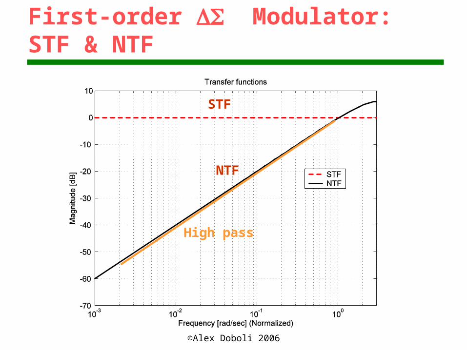
First-order Modulator: STF & NTF
STF
NTF
High pass
©Alex Doboli 2006
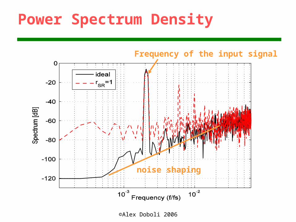
Power Spectrum Density
Frequency of the input signal
noise shaping

©Alex Doboli 2006
Modulator Performance
• Signal to noise ratio for sinusoidal input:
• In-band quantization noise power:
Pin-band = 2 / (9 OSR3)
SNR = 10 log (9 A2 OSR3) / (2 2)

©Alex Doboli 2006
Dynamic Range
34 dB (5 bits)

©Alex Doboli 2006
Dynamic Range vs. OSR
DR=34db (OSR=32)DR=38dB (OSR=64)
DR=42dB (OSR=128)DR=50dB (OSR=256)
(8 bits)

©Alex Doboli 2006
PSoC Implementation
Vin (-Vref, Vref)Vref {VDD/2, 1.6 Vbandgap, Vexternal}OSR = 64Vin = (n – 128) / 128 Vref
©Alex Doboli 2006
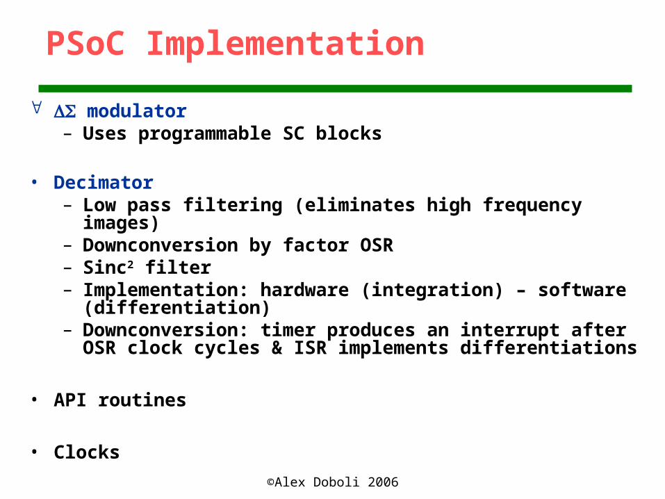
PSoC Implementation
modulator– Uses programmable SC blocks
• Decimator– Low pass filtering (eliminates high frequency images)– Downconversion by factor OSR– Sinc2 filter– Implementation: hardware (integration) – software
(differentiation)– Downconversion: timer produces an interrupt after OSR clock
cycles & ISR implements differentiations
• API routines
• Clocks
©Alex Doboli 2006
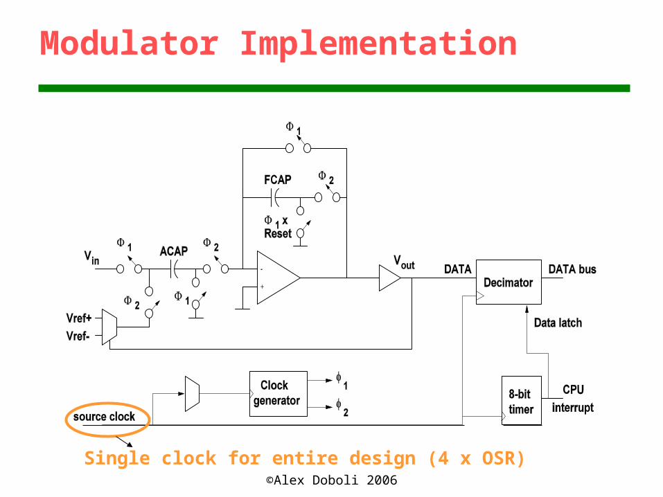
Modulator Implementation
Single clock for entire design (4 x OSR)
©Alex Doboli 2006
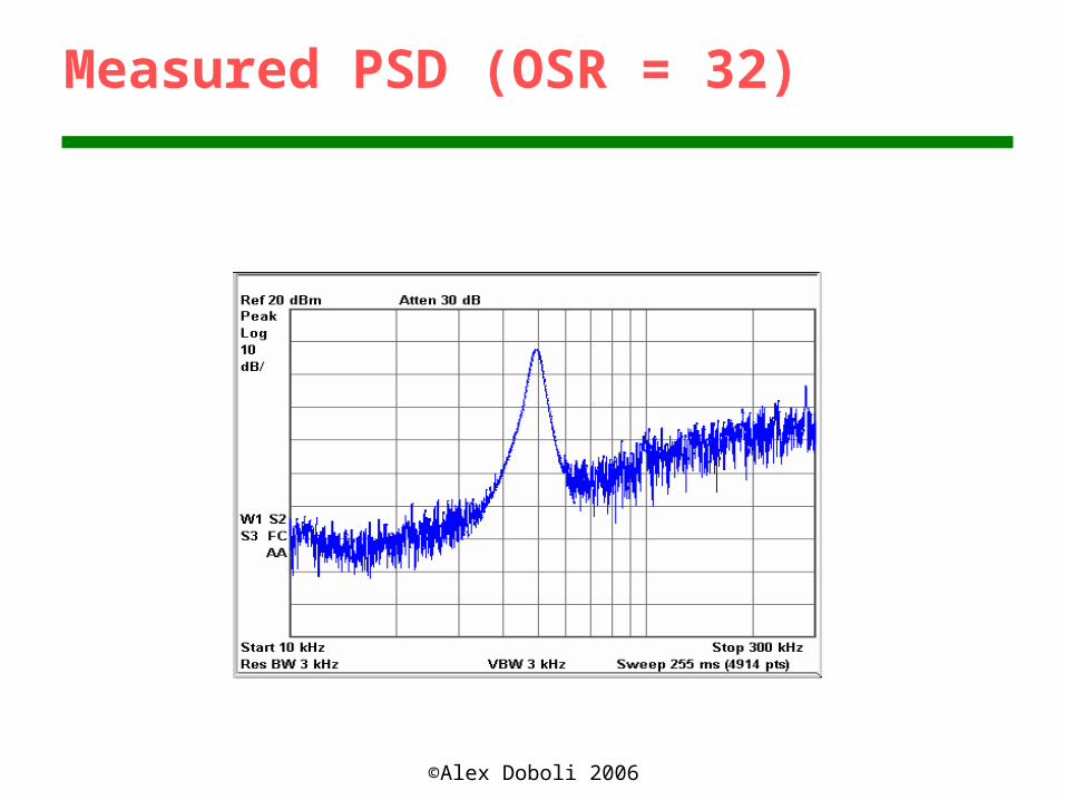
Measured PSD (OSR = 32)

©Alex Doboli 2006
Measured PSD (OSR = 64)
©Alex Doboli 2006
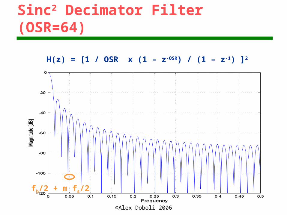
Sinc2 Decimator Filter (OSR=64)
H(z) = [1 / OSR x (1 – z-OSR) / (1 – z-1) ]2
fb/2 + m fs/2
©Alex Doboli 2006
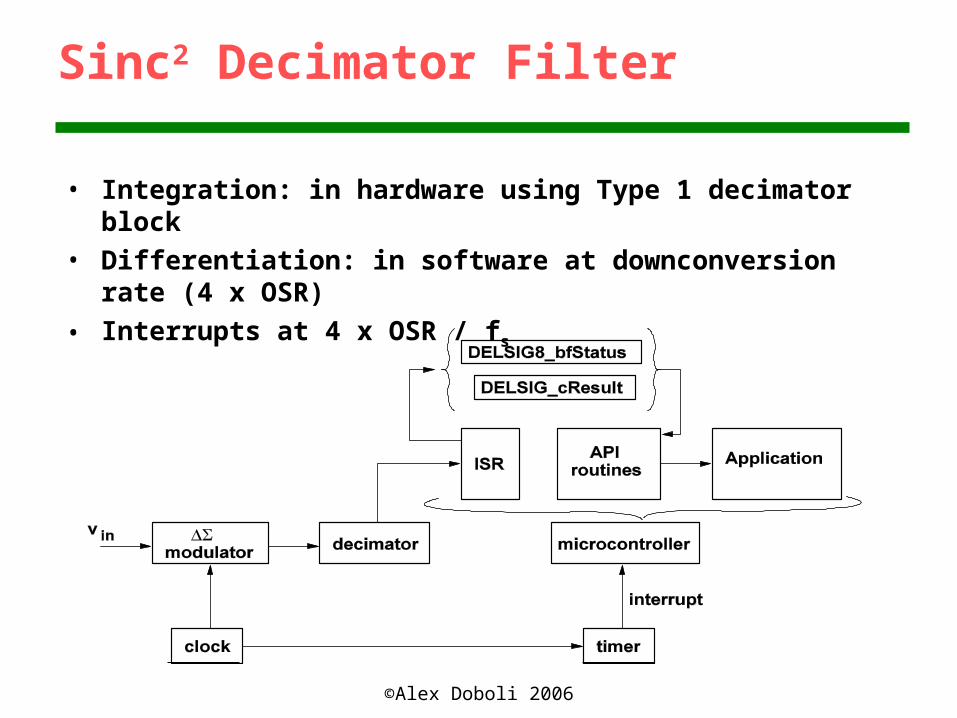
Sinc2 Decimator Filter
• Integration: in hardware using Type 1 decimator block• Differentiation: in software at downconversion rate (4 x
OSR)
• Interrupts at 4 x OSR / fs

©Alex Doboli 2006
Timer ISR
©Alex Doboli 2006
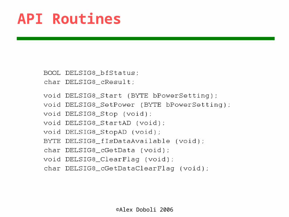
API Routines
©Alex Doboli 2006
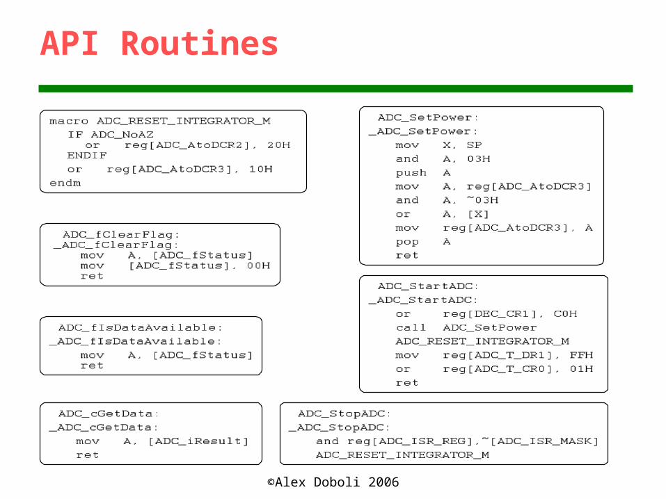
API Routines
©Alex Doboli 2006
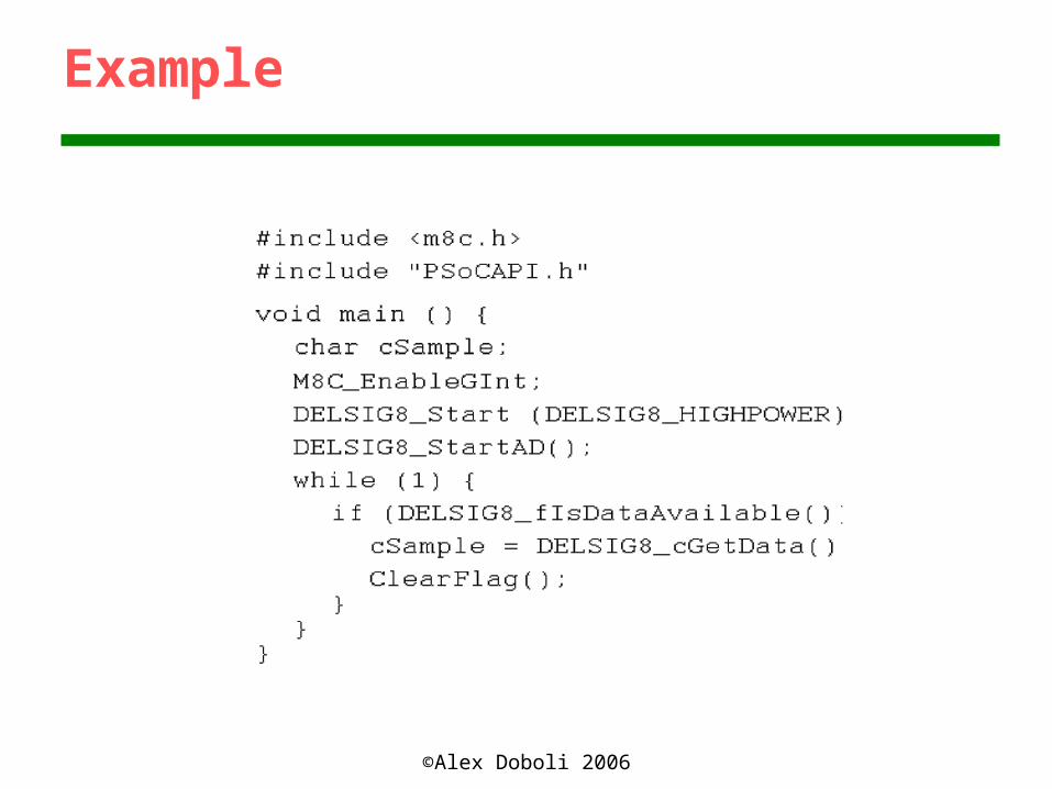
Example
©Alex Doboli 2006
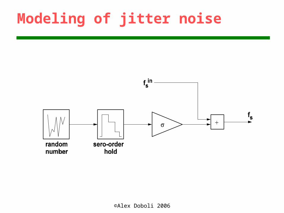
Modeling of jitter noise

©Alex Doboli 2006
Switch Thermal Noise

©Alex Doboli 2006
Switch Thermal Noise

©Alex Doboli 2006
Switch Thermal Noise

©Alex Doboli 2006
OpAmp Noise

©Alex Doboli 2006
Modeling of Slew Rate & Saturation
©Alex Doboli 2006
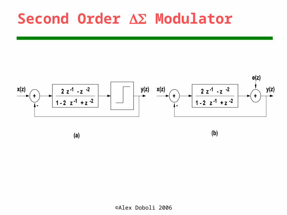
Second Order Modulator

©Alex Doboli 2006
Second-order Modulator

©Alex Doboli 2006
PSoC Implementation
Related Documents