18-1 Shape Optimization Of Instrument Panel Components For Crashworthiness Using Distributed Computing Alex Akkerman*, Mike Burger ‡ , Bob Kuhn † , Hrabri Rajic † , Nielen Stander ‡ , Ravi Thyagarajan* * Ford Motor Company † Kuck & Associates, Inc. ‡ Livermore Software Technology Corp. Contact: Robert Kuhn Kuck & Associates, Inc. 1906 Fox Drive Champaign, IL 61820 +1 217-356-2288 [email protected] Abbreviations: D LK ,D RK -- Displacement of the Left and Right Knee D LBT ,D LBF ,D LBB -- Depth of Left Bracket: Top, Front, and Bottom EA – Energy Absorption F LK ,F RK – Force on Left and Right Knee G RB ,G LB ,G KB -- Gauge of Left and Right Bracket and Knee Bolster IP – Instrument Panel KE initial , KE final – Total Kinetic Energy, initial and final R Y ,R RB --Cross-section Radius of Steering Yoke,Radius Right EA Hole W RB ,W LB, W LBF -- Width Right and Left Bracket and Left Bracket Flange Keywords: Crashworthiness, Design Optimization, Distributed Computing, Energy Management, Knee Bolster, Parametric Preprocessing, Shape Optimization.

Welcome message from author
This document is posted to help you gain knowledge. Please leave a comment to let me know what you think about it! Share it to your friends and learn new things together.
Transcript

18-1
Shape Optimization Of Instrument Panel Components ForCrashworthiness Using Distributed Computing
Alex Akkerman*, Mike Burger ‡, Bob Kuhn†,Hrabri Rajic †, Nielen Stander‡, Ravi Thyagarajan*
* Ford Motor Company† Kuck & Associates, Inc.
‡ Livermore SoftwareTechnology Corp.
Contact:Robert KuhnKuck & Associates, Inc.1906 Fox DriveChampaign, IL 61820+1 [email protected]
Abbreviations:DLK, DRK -- Displacement of the Left and Right KneeDLBT, DLBF , DLBB -- Depth of Left Bracket: Top, Front, and BottomEA – Energy AbsorptionFLK, FRK – Force on Left and Right KneeGRB, GLB, GKB -- Gauge of Left and Right Bracket and Knee BolsterIP – Instrument PanelKEinitial, KEfinal – Total Kinetic Energy, initial and finalRY, RRB --Cross-section Radius of Steering Yoke,Radius Right EA HoleWRB, WLB,WLBF -- Width Right and Left Bracket and Left Bracket Flange
Keywords:Crashworthiness, Design Optimization, Distributed Computing, EnergyManagement, Knee Bolster, Parametric Preprocessing, Shape Optimization.

18-2
ABSTRACT
The ability to quickly design new vehicles with optimal crashworthiness is a goal ofautomotive manufacturers. This paper takes steps towards that goal by automating manualdesign iterations. The crashworthiness of an instrument panel was enhanced using LS-OPTand LS-DYNA. It is shown that:
•= LS-OPT can modify the shape of non-styled parts in the instrument panel in order toenhance its crashworthiness by using a parametric preprocessor, e.g. TrueGrid.
•= The design was generated several times faster than with manual methods. LS-OPTgenerated and executed LS-DYNA runs without need for manual result analysis.
•= The dramatic increase in the size of the design space caused by shape optimizationwas managed efficiently by LS-OPT.
•= The cost of obtaining these designs can be reduced by using distributed computing toexplore the design space on workstations which would otherwise be underutilized.
INTRODUCTION
The automotive instrument panel (IP) has evolved over time to become one of the mostcomplex subsystems in today's automobile (Jira, 1996), both from an appearance andfunctionality viewpoint. Not only does it lend a distinctive character to the interior of anautomobile from an aesthetic point of view, it must also house beneath the styled surfaceseveral components required for functional reasons. Some examples of these are cross-vehiclestructure, steering column supports, climate control system, electronic modules and wiring,airbags, and a knee bolster system. Of particular significance to this paper is the knee bolsterportion of an IP, which is designed to perform several functions (Kulkarni, 1998). Mostnotably it provides the first contact surface for the knees in a frontal impact situation. Also, itparticipates in cushioning and directing the knees and in energy management of the lowertorso of the occupant.
Design variables for problems of this type can create a very large design space that theengineer must explore. Typical parameters are:
•= Gauge and modulus of the material in the energy absorption (EA) brackets,•= Gauge and modulus of the knee bolster material,•= Steering column isolator cross-section radius, and•= Lightening holes and flange depth in the EA brackets.
In the previous European LS-DYNA Users Group Meeting a paper was presented using LS-OPT to optimize the gauges and materials of these components, the first two types ofparameters. (Akkerman, 1999). Since the design problem was small, second order responsesurfaces could be used to construct a trade-off diagram of maximum knee force versusintrusion.
In the present paper the search of a much larger design space, covering all four parametertypes, was automated. Although the response variables and objective function remainbasically the same, the number of design variables increased from 3 to 11. This dramaticallyenlarged the design space precluding the use of complex design surfaces.
Because of the additional design complexity two major features are introduced:
TrueGrid is a registered trademark ofXYZ Scientific Applications, Inc.,http://www.truegrid.com.

18-3
•= A parametric preprocessor, TrueGrid, to allow geometric modeling.•= A successive linear approximation procedure to reduce the number of simulations.
Although the latter method is linear versus the quadratic method used previously, it is shownthat only three or four iterations are required for convergence. This can be achieved byreducing the size of the region of interest in the design space. (Stander, 2000)
Computationally, it was demonstrated that the workstation cluster environment was just aseasy to use as the compute server when running LS-OPT. Given the cost and availability ofunused computer cycles, the distributed LS-OPT version is a significant step forward.
General Problem Statement
Figure 1 shows the finite element model of a typical automotive IP. For model simplificationand reduced per-iteration computational times, only the driver's side of the IP is used in theanalysis as shown, and consists of around 25,000 shell elements with 60 PIDs and 11materials. Symmetry boundary conditions are assumed at the centerline, and to simulate abench component "Bendix" test, body attachments are assumed fixed in all 6 directions. Alsoshown in Figure 1 are simplified knee forms which move in a direction as determined fromprior physical tests. The mass (17.5 kg each) and initial velocity (6.62 m/sec) of the knees aretuned to reflect a predetermined lower torso energy (770 J) that is typically managed by anIP, most of which is borne by the knee bolster system shown in Figure 2. As shown in thefigure, this system is composed of a knee bolster (steel, plastic or both) that also serves assteering column cover whose surface is styled and should not be changed, two EA brackets(usually steel) attached to the cross vehicle IP structure that absorb a significant portion of thelower torso energy of the occupant by deforming appropriately, as shown in Figure 3.Sometimes, a steering column isolator (also known as a yoke) may be used as part of the knee
Figure 1. Typical instrument panel prepared for a “Bendix” component test.
Simplifiedknee forms
A non-visible,optimizable part
A styledsurface, non-optimizable
18-4
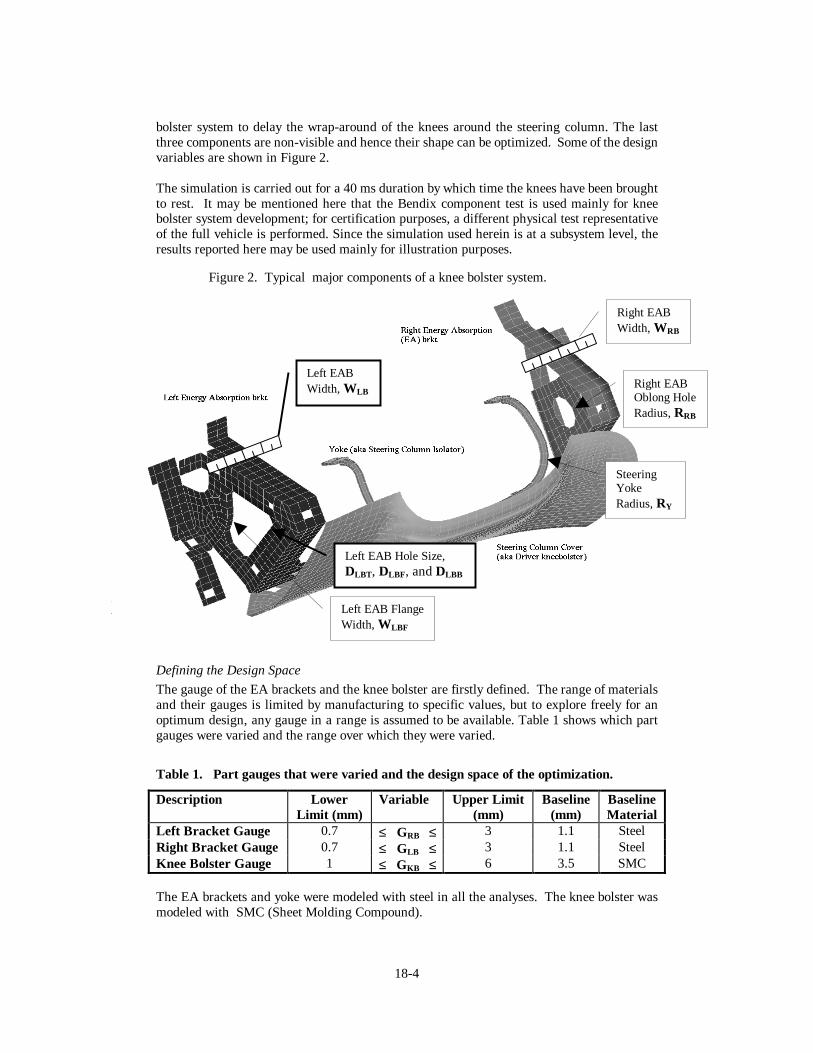
bolster system to delay the wrap-around of the knees around the steering column. The lastthree components are non-visible and hence their shape can be optimized. Some of the designvariables are shown in Figure 2.
The simulation is carried out for a 40 ms duration by which time the knees have been broughtto rest. It may be mentioned here that the Bendix component test is used mainly for kneebolster system development; for certification purposes, a different physical test representativeof the full vehicle is performed. Since the simulation used herein is at a subsystem level, theresults reported here may be used mainly for illustration purposes.
Defining the Design Space
The gauge of the EA brackets and the knee bolster are firstly defined. The range of materialsand their gauges is limited by manufacturing to specific values, but to explore freely for anoptimum design, any gauge in a range is assumed to be available. Table 1 shows which partgauges were varied and the range over which they were varied.
Table 1. Part gauges that were varied and the design space of the optimization.
Description LowerLimit (mm)
Variable Upper Limit(mm)
Baseline(mm)
BaselineMaterial
Left Bracket Gauge 0.7 ≤ GRB ≤ 3 1.1 SteelRight Bracket Gauge 0.7 ≤ GLB ≤ 3 1.1 SteelKnee Bolster Gauge 1 ≤ GKB ≤ 6 3.5 SMC
The EA brackets and yoke were modeled with steel in all the analyses. The knee bolster wasmodeled with SMC (Sheet Molding Compound).
Figure 2. Typical major components of a knee bolster system.
SteeringYokeRadius,RY
Right EABOblong HoleRadius,RRB
Left EAB FlangeWidth, WLBF
Right EABWidth, WRB
Left EABWidth, WLB
Left EAB Hole Size,DLBT , DLBF, andDLBB

18-5
To specify a shape optimization problem, we start with a baseline design and specify how itsgeometry may be varied. The complexity of doing this depends on the part being optimized.Figure 2 shows the parameterization of the three parts to be optimized in this design. Theyoke is simplest to describe. One design variable, the cross-section radius of the yoke,RY,may be varied. It is clear how to specify it as a constraint:
Table 2. Yoke shape design space.
Description Lower Limit(mm)
Variable Upper Limit(mm)
Baseline(mm)
BaselineMaterial
Yoke Radius 4 ≤ RY ≤ 10 7 Steel
Now, consider the right EA bracket. The shape optimization will restrict itself to two areas:•= Right EA Hole Radius -- The hole in the right EA bracket has been modeled as an
oblong hole. The radius of the hole is one design variable,RRB. The out-of-rounddimension of the hole was arbitrarily fixed and is not considered a design variable.
•= Right EA Flange Width -- Around the outside of the bracket the metal has beenfolded at 90 degrees to make a mounting surface and to provide flange stiffness. Thewidth of the flange isWRB.
For the left EA bracket, the shape optimization will restrict itself to three areas:•= Size and shape of the hole-- There are three design variables,DLBT , DLBF, DLBB.
These correspond to the flange depths in the bracket plane for 3 of the 4 primaryedges of the left EA bracket, the top, the front, and the bottom, as seen from thedriver’s position. The depth of the back of bracket is currently fixed.
•= Inner Flange Width -- The hole in the left EA bracket has been folded inward toform a metal rim which acts to stiffen the bracket. The width of the flange is adesign variable,WFLB.
•= Width of the bracket -- As with the right AE bracket, the outside of the bracket hasbeen folded at 90 degrees. The width of the flange isWLB.
Fillets to round the four sides of the hole have not been used because they are not likely tohave global effects.
The shape variables are summarized in the following table:
Table 3. Left and right energy absorption bracket shape design space.
Description Lower Limit(mm)
Variable Upper Limit(mm)
Baseline(mm)
Right EA Hole Radius 10 ≤ RRB ≤ 25 15Right EA Width 20 ≤ WRB ≤ 40 32Left EA Depth Top 20 ≤ DLBT ≤ 40 28.3Left EA Depth Front 20 ≤ DLBF ≤ 40 27.5Left EA Depth Bottom 20 ≤ DLBB ≤ 40 22.3Left EA Inner FlangeWidth
5 ≤ WLBF ≤ 15 7
Left EA Width 20 ≤ WLB ≤ 40 32

18-6
OPTIMIZATION PROBLEM CONSTRAINTS
For optimal occupant kinematics, it is essential that knee intrusion into the IP be limited todesired values. Upper bounds of the left and right knee displacements,DLK andDRK, are usedto limit knee intrusions. In this case the variables were constrained to beless than 115 mm.
Optimization Problem Objective
In general, the primary object of knee bolster crashworthiness engineering is to minimize theforces on the occupant to specific program targets within the limits of the design envelope.Therefore, the primary optimization criterion is to minimize the force on the occupant’s leftand right knees,FLK and FRK. The selection of a low force constraint value forced theoptimization strategy to be minimize the maximum knee force subject to the constraintsabove.
Objective Function: min ( max ( FLK , FRK ) )
The maximization considers both the knee forces over time. The knee forces have beenfiltered, SAE 60 Hz, to improve the approximation accuracy.
Design Summary Table
Table 4 lists the design variable values and responses for: the baseline design, Figures 2 and3; the shape optimized design, Tables 1 through 3; and the gauge-only optimization, Table 1.Because there were some design changes in the structure, the baseline design responses aredifferent from those reported in the previous paper (Akkerman, 1999).
Table 4. Baseline design characteristics.
Parameter Baseline ShapeOptimized
Gauge OnlyOptimized
Left Bracket Gauge, GRB 1.1 0.84 0.99Right Bracket Gauge, GLB 1.1 0.7 0.86
Figure 3. Knee bolster system after deformation.

18-7
Knee Bolster Gauge, GKB 3.5 6 5.63Yoke Cross-Section Radius, RY 7 4 7Right EA Hole Radius, RRB 15 13.14 15Right EA Width, W RB 32 34.39 32Left EA Depth Top, DLBT 28.3 26.23 28.3Left EA Depth Front, D LBF 27.5 31.5 27.5Left EA Depth Bottom, DLBB 22.3 34.02 22.3Left EA Inner Flange Width, W LBF 7 14.25 7Left EA Width, W LB 32 27.87 32Maximum Left Knee Force 7625 N 6602 N 7821 NMaximum Right Knee Force 9458 N 6293 N 7850 NMaximum Left Knee Displacement 92 mm 97.3 mm 92.7 mmMaximum Right Knee Displacement 88 mm 95.41 mm 80.7 mm
Figure 4. Views of the smallest and largest shapes in the design space.
(a) Smallest left bracket. (b) Smallest right bracket.
(a) Largest left bracket. (b) Largest right bracket.
18-8
Specifying Shape Optimization Input Files with TrueGrid
LS-OPT will call a user-selected preprocessor before each LS-DYNA run. Before calling thepreprocessor, it substitutes the design variable values for their symbolic parameters in thepreprocessor input file. This causes the preprocessor to customize the design for the selecteddesign point. We chose to use TrueGrid for preprocessing the design for three reasons:
•= It has more parametric capability than other parametric modeling programs. WithTrueGrid any piece of data can be parameterized to be an LS-OPT design variable.
•= The meshing can be parameterized to adapt to shape changes.•= TrueGrid specializes in hexahedral meshing which is important for high quality elements.
The original LS-DYNA input file for the IP was modified to prepare it for shape optimizationin several steps:
1) TrueGrid was used to produce surface geometry from the original LS-DYNA input.This was a critical step that separated the geometry from the other LS-DYNA inputparameters. In the extracted pure geometry it was necessary to preserve the fixedparts of the baseline design:•= The Bendix occupant impact model,•= The knee bolster and IP which are styled surfaces,•= The attachment points between the parts, and•= The mounting of the IP system which is considered clamped in the Bendix test.
2) From the new surface geometry TrueGrid created the components to be shapeoptimized with parameterized variables. This included the 11 parameters that arevaried in this optimization problem. LS-OPT automatically appended the fixed partof the model to the TrueGrid output before simulation.
Preparing the parameterized input file for the IP according to the parameters above took about8 hours for a skilled user of TrueGrid. Figure 4 illustrates the range of designs in the designspace in terms of the geometry of the smallest and largest brackets.
Computational Environment
LS-OPT generated 19 LS-DYNA design points for each iteration. This number is based onthe number of design variables with a provision for over-sampling the design space (Roux,1999). Three iterations were needed for convergence of this problem, so the total number ofsimulations including a final check run was 58.
Runs were made on two computational environments: a server and a workstation network:
1. HP V-class running 10 processors simultaneously. Each LS-DYNA run took about3.5 hours on one processor.
2. The workstation cluster consisted of a network of 4 dual-processor Intel systemsrunning Windows-NT for LS-DYNA runs and an SGI O200 as follows:
2 processors on a 550MHz dual PIII Xeon / NT (Blaze)1 processor on a 500MHz dual PIII Xeon / NT (Rum)2 processors on a 450MHz dual PII Xeon / NT (Tropical)2 processors on a 450MHz dual PII Xeon / NT (Zpro)2 processors on an O200 / IRIX (Gemini)
Each LS-DYNA job took between 3.5 and 4.5 hours. LS-OPT ran on the O200.

18-9
The Application Distributor software in LS-OPT managed sending out LS-DYNA runs acrossthe cluster to these systems and bringing back the relevant data. Executing LS-OPT softwarewas identical in both environments with the exception of requiring workstations in thenetwork environment to be identified as available for executing LS-DYNA jobs.
DISCUSSION OF RESULTS
Figure 5 depicts the optimization history of the knee forces when normalized to 6500N andTable 4 summarizes the optimized design. Despite the large design space, it is shown that inbasically two iterations the maximum force was reduced to its minimum value. Theoptimization brought the maximum simulated knee force down from 9457 to 6602, animprovement of 30% in a simulation of the Bendix test. However, it must be mentioned thatbecause this analysis is based on a single size occupant, a defined vehicle environment, and asingle test mode, more simulations would be necessary to determine the overall effectivenessof this design. (In the future, the multi-case feature of LS-OPT may be used to incorporate
Figure 5. Maximum knee forces on each iteration.
Figure 6. Trade-off between maximum knee force and displacement.

18-10
multiple simulation cases in the same design.) The server computational environment and thecluster of workstations environment produced knee forces that were less than 1% different onthe optimized design although the values of the design variables for the optimized designswere different. This suggests that, due to the many design variables in this problem, there aremultiple mechanisms which result in the same minimal knee forces.
Figure 6 shows the approximate trade-off between normalized maximum knee force and kneedisplacement normalized to 115mm. It is shown that the force increases with a constraineddisplacement. As expected, no design points occur inside the predicted tradeoff curve,confirming relative accuracy of the design problem. A further investigation into the accuracyof the first design approximation (Figure 7) also confirms this aspect. In this over-sampled
Figure 7. Predicted versus computed force and displacement for the left knee.
Figure 8. Size of key design variables during shape optimization.

18-11
approximation, all of the design points are close to their predicted value over a wide range ofvariation.
Figure 8 illustrates the value of shape optimization. Several dimensions were changedsignificantly from the baseline design:
•= The internal flange on the left EA bracket increased to the maximum allowed size.•= The dimensions of the hole in left EA bracket grew in some dimensions and shrunk
in other dimensions.•= The yoke cross-section radius was made smaller. And,•= The right EA bracket hole size changed very little.
To quantify the effect of shape optimization, the baseline design was optimized with only thegauge design variables active. The maximum simulated knee forces converged at 7852. Thusshape optimization in the configuration we tested appeared to have contribute 19% to theresults described above.
Final checks confirm the success of the process:•= The final kinetic energy for the optimum design was determined to be 7% of the
initial energy, indicating that the design did absorb most of the impact energy.•= Figure 9 shows the filtered (60Hz) and unfiltered knee forces of the final design.
Note that the peaks, which become active in the design process, occur at differenttimes.
•= It was also observed that the yoke deformations were quite similar in the baselineand optimized designs leading to the conclusion that column isolation performancewas also comparable in the two designs.
Figure 9. Left and right knee forces in the optimized design over simulation time.

18-12
Distributed ComputationEach LS-OPT iteration of this optimization consisted of 19 LS-DYNA jobs. LS-OPT has thecapability to execute independent jobs on an SMP server or to distribute jobs across theinternet to available workstations or servers. Both programs run the same way to the user.Figure 10 illustrates what happens behind the scenes to allow an LS-OPT user to use anetwork of different types of systems transparently. The Application Distributor softwarelibrary creates proxy processes on the distributor computer running LS-OPT. Theycommunicate with Task Proxies on each available task server. Both the LS-OPT and theLocal Task think they are communicating to each other on the same system.
LS-OPT parallel processing performance was comparable on the server and on theworkstations. The granularity of LS-OPT parallelism is extremely coarse -- each task is a fewhour LS-DYNA run. Data communication is relatively low -- files were copied to and fromlocal working directories just as on LS-OPT server.
LS-OPT running in distributed mode provides greater flexibility, better productivity, andmore consistent results:
•= Greater Flexibility – Any configuration of workstation and servers withavailable time can be used while the optimization is being run.
•= Better Productivity – LS-OPT’s optimization method can search and evaluatemore designs faster than an engineer can.
•= Consistent Results – Creating many single-processor LS-DYNA jobs to useavailable systems reduces numerical differences that are inevitable in parallelLS-DYNA runs. Thus, one source of “noise” in simulations is eliminated.
Monitoring runs in the distributed computational environment is more interesting than in theserver case. On the server, LS-OPT periodically shows the status of the LS-DYNA jobsbeing run. This is important for the person running LS-OPT and it is preserved in thedistributed environment. In addition, for the distributed environment, the users of theworkstations and servers contributing to the run want to monitor and control how much oftheir systems are being utilized by LS-OPT. In distributed mode, users can control the LS-OPT computational environment with an interactive monitor and control program. Being asuper user or a system manager is not necessary.
Figure 10. Distributed execution environment.
Distributor Computer
Internet
Task Server
Local Task
TrueGrid
LS-DYNA
Proxy1
Proxym
LS-OPT
Task Executor
Task Proxy
Application Distributor
. . .

18-13
CONCLUSIONS
LS-OPT can be used to modify part gauges and shapes in the instrument panel in order toenhance its crashworthiness. LS-OPT was relatively easy to use for the optimizationsperformed.
•= LS-OPT is a useful tool for finding an optimum solution to an IP crashworthinesssimulation.
•= The optimization can be performed concurrently for many simultaneously varying gaugeand shape parameters.
•= The predicted LS-OPT results were all well within the acceptable levels of correlationwith the actual LS-DYNA runs for the same design parameters.
It was seen that using design optimization tools can leverage the creativity of the engineer byallowing him to explore new design options while using computer time to thoroughly analyzethe well known design space.
Computationally, LS-OPT on workstations enables more automotive engineers to use thisproductivity tool. In addition, it offers computer users a very effective means to useworkstation idle cycles.
ACKNOWLEDGEMENTS
We would like to send our greatest thanks and appreciation to Kumar Kulkarni of Ford MotorCompany who built the finite element model used in this study.
REFERENCES
A. AKKERMAN, B. KUHN, H. RAJIC, N. STANDER, R. THYAGARAJAN, “Optimizationof Instrument Panel Crashworthiness”, 2nd European LS-DYNA Users Group Meeting, May,1999.JIRA, J., KULKARNI, K., and THYAGARAJAN, R., "Deformation Control in AutomotiveInstrument Panels Exposed to High Sunload Temperatures With the Use of Unique CowltopAttachments", International Body Engineering Conference,1996, Interior and Safety Systems,Detroit, MI, Oct 1996.KULKARNI, K., and THYAGARAJAN, R., "A Brief Look at Instrument Panel Knee BolsterDesigns and Materials", 1998 Regional Technical Conference of Society of PlasticsEngineers, Detroit, MI, May 1998.ROUX, W.J., STANDER, N., and HAFTKA, R., “Response Surface Approximations forStructural Optimizations”, International Journal for Numerical Methods in Engineering, Vol.42, pp. 517-534, 1999.STANDER, N., “Crashworthiness Design Optimization Using LS-OPT and Full-Model LS-DYNA Analyses”, LS-DYNA Users Conference, Japan, 1998.STANDER, N., REICHERT, R, and FRANK, T. “Optimization of Nonlinear DynamicalProblems Using Successive Linear Approximations in LS-OPT”, 6th International LS-DYNAUsers Conference, Dearborn, MI, April 9-11, 2000.STANDER, N., ROUX, W., PATTABIRAMAN, S., and DHULIPUDI, R., “The Applicationof LS-OPT to Design Optimization Problems in Nonlinear Dynamics Using LS-DYNA”, 5 th
International LS-DYNA Users Conference, Detroit, MI, September 1998.

18-14
Related Documents