ALCOHOL DETECTOR ALCOHOL DETECTOR ABSTRACT The main aim of this embedded application is to detect the alcohol drunken people. We are developing an embedded kit which will be placed in a vehicle. Now, the vehicle will be under the control of the kit .If any drunken person enter in to the vehicle it gives a buzzer sound immediately , and now the car will be under the control of the hardware used. We run the vehicle by using wireless communication i.e. from Control section (acts as transmitter) we are ejecting the control signals, then the vehicle receives (acts as receiver) the signals, according to the signals it will give a alarm or buzzer. It aims at designing and executing the vehicle controlling using RF. By using the RF communication, whenever alcohol is detected using the alcohol detector, the micro controller sends the information to the encoder and the encoder encodes the values and is received by the RF Transmitter. RF Receiver receives the information from the RF Transmitter and decoder decodes the serial input and sends the output to the micro controller and according to the information received by the micro controller the robot will MINI PROJECT Page 1

Welcome message from author
This document is posted to help you gain knowledge. Please leave a comment to let me know what you think about it! Share it to your friends and learn new things together.
Transcript

ALCOHOL DETECTOR
ALCOHOL DETECTOR
ABSTRACT
The main aim of this embedded application is to detect the alcohol
drunken people. We are developing an embedded kit which will be placed in a
vehicle. Now, the vehicle will be under the control of the kit .If any drunken
person enter in to the vehicle it gives a buzzer sound immediately , and now the
car will be under the control of the hardware used.
We run the vehicle by using wireless communication i.e. from Control
section (acts as transmitter) we are ejecting the control signals, then the vehicle
receives (acts as receiver) the signals, according to the signals it will give a alarm
or buzzer.
It aims at designing and executing the vehicle controlling using RF.
By using the RF communication, whenever alcohol is detected using the alcohol
detector, the micro controller sends the information to the encoder and the encoder
encodes the values and is received by the RF Transmitter. RF Receiver receives the
information from the RF Transmitter and decoder decodes the serial input and sends
the output to the micro controller and according to the information received by the
micro controller the robot will move in that particular direction. The robot movement
is driven with the help of L293D as driver IC.
The programming language used for developing the software to the
microcontroller is Embedded/Assembly. The KEIL cross compiler is used to edit,
compile and debug this program. Micro Flash programmer is used for burning the
developed code on Keil in to the microcontroller Chip. Here in our application we are
using AT89C51 microcontroller which is Flash Programmable IC. AT represents the
Atmel Corporation represents CMOS technology is used for designing the IC.
MINI PROJECT Page 1

ALCOHOL DETECTOR
INDEX
1. INTRODUCTION
OBJECTIVE OF THE PROJECT
BLOCK DIAGRAM
1. DESCRIPTION OF THE PROJECT
DESCRIPTION
SCHEMATIC
2. HARDWARE DESCRIPTION
RF
HT12E
HT12D
RLP-434
TLP-434
MICRO CONTROLLER
L293D
DC MOTOR
ALCOHOL DETECTOR
POWER SUPPLY
BUZZER
3. SOFTWARE DESCRIPTION
KEILC
CODE
4. CONCLUSION
6. BIBLIOGRAPHY
MINI PROJECT Page 2

ALCOHOL DETECTOR
CHAPTER 1
INTRODUCTION:
Objective: The main aim of this embedded application is to design a alcohol
detector using RF Communication and AT89c51 Programmable controller.
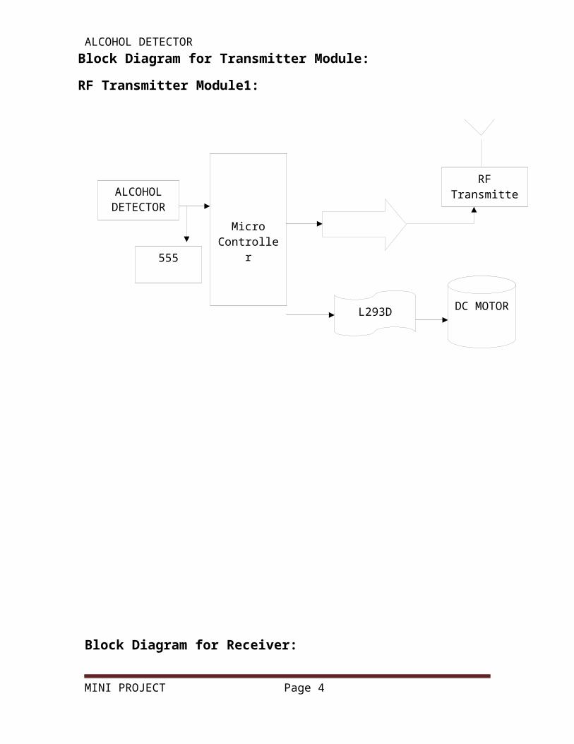
Block Diagram for Transmitter Module:
RF Transmitter Module1:
MINI PROJECT Page 3
MicroController Encoder
RF Transmitter
L293D DC MOTOR
ALCOHOL DETECTOR
555
ALCOHOL DETECTORBlock Diagram for Receiver:
RF Receiver Module:
MINI PROJECT Page 4
RF Receiver
Decoder
BUZZER

ALCOHOL DETECTOR
CHAPTER 2
DESCRIPTION OF THE PROJECT
This application is in the area of embedded systems.
An embedded system is some combination of computer hardware and
software, either fixed in capability or programmable, that is specifically designed
for a particular function
Since the embedded system is dedicated to specific tasks, design
engineers can optimize it reducing the size and cost of the product and
increasing the reliability and performance. Embedded systems are controlled by
one or more main processing cores that are typically either a microcontroller or a
digital signal processor (DSP). Embedded systems control many devices in
common use today.
The Keil C51 C Compiler for the 8051 microcontroller is the most popular
8051 C compiler in the world. It provides more features than any other 8051 C
compiler available today. The C51 Compiler allows you to write 8051
microcontroller applications in C that, once compiled, have the efficiency and
speed of assembly language. Language extensions in the C51 Compiler give you
full access to all resources of the 8051.
The C51 Compiler translates C source files into reloadable object modules
which contain full symbolic information for debugging with the µVision Debugger
or an in-circuit emulator. In addition to the object file, the compiler generates a
listing file which may optionally include symbol table and cross reference
information.
MINI PROJECT Page 5

ALCOHOL DETECTOR
Embedded C is an extension for the programming language C to support
embedded processors, enabling portable and efficient application programming
for embedded systems
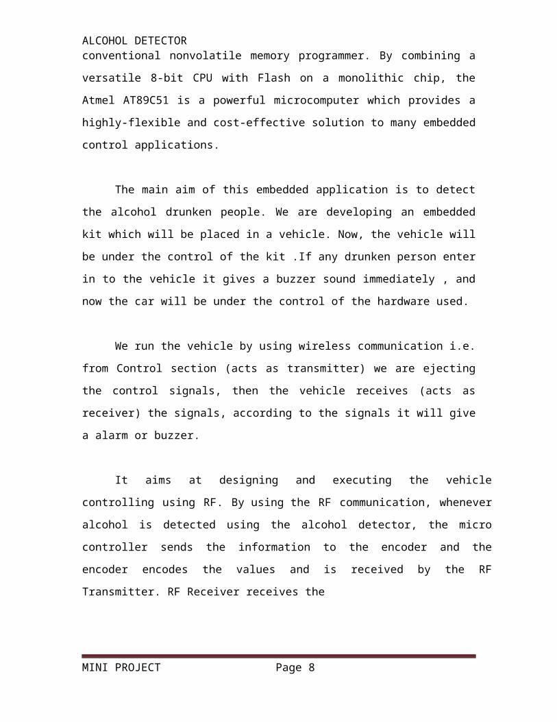
The AT89C51 is a low-power, high-performance CMOS 8-bit
microcomputer with 4K bytes of Flash programmable and erasable read only
memory (EPROM). The device is manufactured using Atmel’s high-density
nonvolatile memory technology and is compatible with the industry-standard
MCS-51 instruction set and pin out. The on-chip Flash allows the program
memory to be reprogrammed in-system or by a conventional nonvolatile memory
programmer. By combining a versatile 8-bit CPU with Flash on a monolithic chip,
the Atmel AT89C51 is a powerful microcomputer which provides a highly-flexible
and cost-effective solution to many embedded control applications.
The main aim of this embedded application is to detect the alcohol
drunken people. We are developing an embedded kit which will be placed in a
vehicle. Now, the vehicle will be under the control of the kit .If any drunken
person enter in to the vehicle it gives a buzzer sound immediately , and now the
car will be under the control of the hardware used.
We run the vehicle by using wireless communication i.e. from Control
section (acts as transmitter) we are ejecting the control signals, then the vehicle
receives (acts as receiver) the signals, according to the signals it will give a alarm
or buzzer.
It aims at designing and executing the vehicle controlling using RF.
By using the RF communication, whenever alcohol is detected using the alcohol
detector, the micro controller sends the information to the encoder and the encoder
encodes the values and is received by the RF Transmitter. RF Receiver receives the
MINI PROJECT Page 6

ALCOHOL DETECTORinformation from the RF Transmitter and decoder decodes the serial input and
sends the output to the micro controller and according to the information received by
the micro controller the robot will move in that particular direction. The robot
movement is driven with the help of L293D as driver IC.
2.1 SCHEMATIC:
TRANSMITTER:
MINI PROJECT Page 7
ALCOHOL DETECTOR
RECEIVER:
MINI PROJECT Page 8

ALCOHOL DETECTOR
2.2 HT12E:
Features:
_ Operating voltage
_ 2.4V~5V for the HT12A
_ 2.4V~12V for the HT12E
_ Low power and high noise immunity CMOS technology
_ Low standby current: 0.1_A (typ.) at VDD=5V
_ HT12A with a 38kHz carrier for infrared transmission medium
_ Minimum transmission word
_ Four words for the HT12E
_ One word for the HT12A
_ Built-in oscillator needs only 5% resistor
_ Data code has positive polarity
_ Minimal external components
_ Pair with Holtek_s 212 series of decoders
_ 18-pin DIP, 20-pin SOP package
Applications
_ Burglar alarm system
_ Smoke and fire alarm system
_ Garage door controllers
_ Car door controllers
_ Car alarm system
_ Security system
_ Cordless telephones
_ Other remote control systems
MINI PROJECT Page 9

ALCOHOL DETECTOR
CHAPTER 3
HARDWARE DESCRIPTION
The 212 encoders are a series of CMOS LSIs for remote control system
applications. They are capable of encoding information which consists of N
address bits and 12_N data bits. Each address/data input can be set to one of
the two logic states. The programmed addresses/ data are transmitted together
with the header bits via an RF or an infrared transmission medium upon receipt
of a trigger signal. The capability to select a TE trigger on the HT12E or a DATA
trigger on the HT12A further enhances the application flexibility of the 212 series
of encoders. The HT12A additionally provides a 38kHz carrier for infrared
systems.
Selection Table:
MINI PROJECT Page 10

ALCOHOL DETECTOR
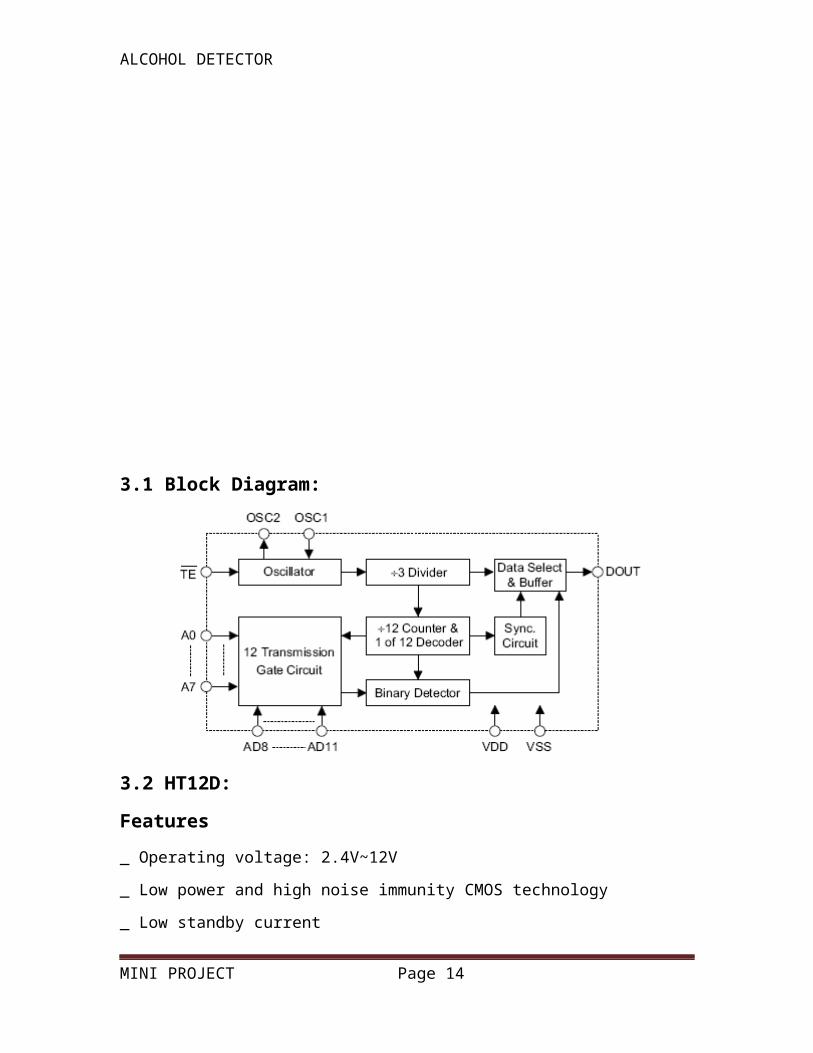
3.1 Block Diagram:
3.2 HT12D:
Features
_ Operating voltage: 2.4V~12V
_ Low power and high noise immunity CMOS technology
_ Low standby current
_ Capable of decoding 12 bits of information
_ Pair with Holtek_s 212 series of encoders
_ Binary address setting
_ Received codes are checked 3 times
_ Address/Data number combination
_ HT12D: 8 address bits and 4 data bits
_ HT12F: 12 address bits only
_ Built-in oscillator needs only 5% resistor
_ Valid transmission indicator
_ Easy interface with an RF or an infrared transmission medium
_ Minimal external components
MINI PROJECT Page 11

ALCOHOL DETECTORApplications:
_ Burglar alarm system
_ Smoke and fire alarm system
_ Garage door controllers
_ Car door controllers
_ Car alarm system
_ Security system
_ Cordless telephones
_ Other remote control systems
3.3 Description:
The 212 decoders are a series of CMOS LSIs for remote control system
applications. They are paired with Holtek_s 212 series of encoders (refer to the
encoder/decoder cross reference table). For proper operation, a pair of
encoder/decoder with the same number of addresses and data format should be
chosen. The decoders receive serial addresses and data from a programmed 212
series of encoders that are transmitted by a carrier using an RF or an IR
transmission medium. They compare the serial input data three times
continuously with their local addresses. If no error or unmatched codes are
found, the input data codes are decoded and then transferred to the output pins.
The VT pin also goes high to indicate a valid transmission. The 212 series of
decoders are capable of decoding informations that consist of N bits of address
and 12_N bits of data. Of this series, the HT12D is arranged to provide 8 address
bits and 4 data bits, and HT12F is used to decode 12 bits of address information.
Selection Table
Notes: Data type: L stands for latch type data output.
MINI PROJECT Page 12

ALCOHOL DETECTORVT can be used as a momentary data output.
Block Diagram:
3.4 BLOCK DIAGRAM:
MINI PROJECT Page 13
ALCOHOL DETECTOR
Fig Block Diagram of AT89C51 Microcontroller
Dallas Semiconductor’s DC87C550 provides increased performance over
Intel’s 8051 while maintaining instruction set compatibility. Many instructions that
execute in 12 CPU clock cycles in an 8051, will execute in only 4 clocks
for the DC87C550 therefore resulting in increased execution speeds of up to
three times. Additionally, the DC87C550 has a power management mode that
MINI PROJECT Page 14

ALCOHOL DETECTORallows slowing of the processor in order to reduce power consumption. This
mode can be utilized in battery operated or otherwise low power applications.
The architecture of the instruction set varies greatly from one micro controller to
another. The choices made in designing the instruction set impact program
memory space usage, code execution speed, and ease of programming.
3.5 FEATURES OF 8051 MICRO CONTROLLER
The features of the micro controller are as follows:
• Compatible with MCS-51 ™ Products
• 4K Bytes of In-System Reprogrammable Flash Memory
– Endurance: 1,000 Write/Erase Cycles
• Fully Static Operation: 0 Hz to 24 MHz
• Three-level Program Memory Lock
• 128 x 8-bit Internal RAM
• 32 Programmable I/O Lines
• Two 16-bit Timer/Counters
• Six Interrupt Sources
• Programmable Serial Channel
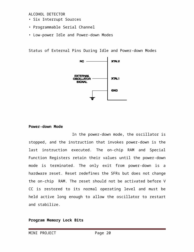
• Low-power Idle and Power-down Modes
Status of External Pins During Idle and Power-down Modes
MINI PROJECT Page 15

ALCOHOL DETECTORPower-down Mode
In the power-down mode, the oscillator is stopped, and the
instruction that invokes power-down is the last instruction executed. The on-chip
RAM and Special Function Registers retain their values until the power-down
mode is terminated. The only exit from power-down is a hardware reset. Reset
redefines the SFRs but does not change the on-chip RAM. The reset should not
be activated before V CC is restored to its normal operating level and must be
held active long enough to allow the oscillator to restart and stabilize.
Program Memory Lock Bits
On the chip are three lock bits that can be left unprogrammed (U) or
can be programmed (P) to obtain the additional features listed in the table below.
When lock bit 1 is programmed, the logic level at the EA pin is sampled and
latched during reset. If the device is powered up without a reset, the latch
initializes to a random value, and holds that value until reset is activated. It is
necessary that the latched value of EA be in agreement with the current logic
level at that pin in order for the device to function properly.
3.6 INTERRUPT PROGRAMMING WITH 8051:
An interrupt is an external or internal event that interrupts the micro
controller to inform it that a device needs its service. In the interrupt method,
whenever any device needs its service, the device notifies the micro controller by
sending it an interrupt signal. Upon receiving an interrupt signal, the micro
controller interrupts whatever it is doing and serves the device. For every
interrupt, there must be an service routine called as interrupt service routine
(ISR) or interrupt handler. There is a fixed location in memory that holds the
address of its ISR. The group of memory locations set aside to hold the
addresses of ISRs is called the vector table.
Steps in executing an interrupt
MINI PROJECT Page 16

ALCOHOL DETECTOR Upon activation of an interrupt in a micro controller, it follows the
following steps:
It finishes the instruction it is executing and saves the address of the next
instruction on the stack.
It also saves the current status of all interrupts internally.
It jumps to a fixed location in memory called vector table that holds the address
of the interrupt service routine.
The micro controller gets the address of the ISR from the interrupt vector table
and jumps to it. It starts to execute the interrupt service subroutine until it reaches
the last instruction of the subroutine, which is RETI (Return from Interrupt).Upon
executing the RETI instruction, the micro controller returns to the place where it
was interrupted. First, it gets the program counter (PC) address from the stack by
popping the top two bytes of the stack into the PC. Then it starts execute from
that address.
3.7 SIX INTERRUPTS IN 8051:
There are really five interrupts available to the user in the 8051 but
many manufacturer’s data sheets state that there are six interrupts since they
include RESET.
RESET: When the reset pin is activated, the 8051 jumps to address location
0000. This is the power-up reset.
Two interrupts are set aside for the timers: one for timer0 and one for timer1.
Memory locations 000BH and 001BH in the interrupt vector table belong to
timer0 and timer1, respectively.
Two interrupts are set aside for hardware external hardware interrupts. Pin
numbers 12 (P3.2) and 13 (P3.3) in port34 are for the external hardware
interrupts INT0 and INT1, respectively. Memory locations 0003H and 0013H in
the interrupt vector table are assigned to INT0 and INT1, respectively.
MINI PROJECT Page 17

ALCOHOL DETECTORSerial communication has a single interrupt that belongs to both receive and
transfer. The interrupt vector table location 0023H belongs to this interrupt.
Table 1: Interrupt Vector Table for the 8051
INTERRUPT ROM Locatio (Hex) Pin
Reset 0000 9
interrupt 0 (INT0) 0003 P3.2 (12)
Timer 0 000B
interrupt 1 (INT1) 0013 P3.3 (13)
Timer 1 001B
SerialCOMinterrupt 0023
Enabling and disabling an interrupt
Upon rest, all interrupts are disabled (masked), meaning that none
will be responded to by the micro controller if they are activated. The interrupts
must be enabled by software in order for the micro controller to respond to them.
There is a register called INTERRUPT ENABLE (IE) that is responsible for
enabling and disabling the interrupts.
3.8 DC Motor:
DC motors are configured in many types and sizes, including brush less,
servo, and gear motor types. A motor consists of a rotor and a permanent
magnetic field stator. The magnetic field is maintained using either permanent
magnets or electromagnetic windings. DC motors are most commonly used in
variable speed and torque.
MINI PROJECT Page 18

ALCOHOL DETECTORMotion and controls cover a wide range of components that in some way
are used to generate and/or control motion. Areas within this category include
bearings and bushings, clutches and brakes, controls and drives, drive
components, encoders and resolves, Integrated motion control, limit switches,
linear actuators, linear and rotary motion components, linear position
sensing, motors (both AC and DC motors), orientation position sensing,
pneumatics and pneumatic components, positioning stages, slides and guides,
power transmission (mechanical), seals, slip rings, solenoids, springs.
Motors are the devices that provide the actual speed and torque in a drive
system. This family includes AC motor types (single and multiphase motors,
universal, servo motors, induction, synchronous, and gear motor) and DC motors
(brush less, servo motor, and gear motor) as well as linear, stepper and air
motors, and motor contactors and starters.
In any electric motor, operation is based on simple electromagnetism. A
current-carrying conductor generates a magnetic field; when this is then placed in
an external magnetic field, it will experience a force proportional to the current in
the conductor, and to the strength of the external magnetic field. As you are well
aware of from playing with magnets as a kid, opposite (North and South)
polarities attract, while like polarities (North and North, South and South) repel.
The internal configuration of a DC motor is designed to harness the magnetic
interaction between a current-carrying conductor and an external magnetic field
to generate rotational motion.
MINI PROJECT Page 19
ALCOHOL DETECTORLet's start by looking at a simple 2-pole DC electric motor (here red represents a
magnet or winding with a "North" polarization, while green represents a magnet
or winding with a "South" polarization).
Every DC motor has six basic parts -- axle, rotor (a.k.a., armature), stator,
commutator, field magnet(s), and brushes. In most common DC motors (and all
that Beamers will see), the external magnetic field is produced by high-strength
permanent magnets1. The stator is the stationary part of the motor -- this includes
the motor casing, as well as two or more permanent magnet pole pieces. The
rotor (together with the axle and attached commutator) rotates with respect to the
stator. The rotor consists of windings (generally on a core), the windings being
electrically connected to the commutator. The above diagram shows a common
motor layout -- with the rotor inside the stator (field) magnets.
The geometry of the brushes, commutator contacts, and rotor windings
are such that when power is applied, the polarities of the energized winding and
the stator magnet(s) are misaligned, and the rotor will rotate until it is almost
aligned with the stator's field magnets. As the rotor reaches alignment, the
brushes move to the next commutator contacts, and energize the next winding.
Given our example two-pole motor, the rotation reverses the direction of current
through the rotor winding, leading to a "flip" of the rotor's magnetic field, and
driving it to continue rotating.
MINI PROJECT Page 20

ALCOHOL DETECTORIn real life, though, DC motors will always have more than two poles (three is a
very common number). In particular, this avoids "dead spots" in the commutator.
You can imagine how with our example two-pole motor, if the rotor is exactly at
the middle of its rotation (perfectly aligned with the field magnets), it will get
"stuck" there. Meanwhile, with a two-pole motor, there is a moment where the
commutator shorts out the power supply (i.e., both brushes touch both
commutator contacts simultaneously). This would be bad for the power supply,
waste energy, and damage motor components as well. Yet another disadvantage
of such a simple motor is that it would exhibit a high amount of torque” ripple"
(the amount of torque it could produce is cyclic with the position of the rotor).
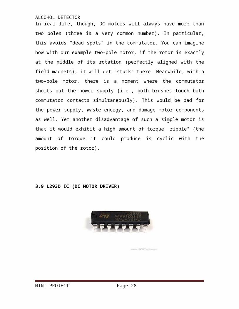
3.9 L293D IC (DC MOTOR DRIVER)
MINI PROJECT Page 21

ALCOHOL DETECTOR
FIGURE: L293 & L293D Driver ICs
The L293 and L293D are quadruple high-current half-H drivers. The L293 is
designed to provide bidirectional drive currents of up to 1 A at voltages from 4.5
V to 36 V. The L293D is designed to provide bidirectional drive currents of up to
600-mA at voltages from 4.5 V to 36 V. Both devices are designed to drive
inductive loads such as relays, solenoids, dc and bipolar stepping motors, as well
as other high-current/high-voltage loads in positive-supply applications. All inputs
are TTL compatible. Each output is a complete totem-pole drive circuit, with a
Darlington transistor sink and a pseudo-Darlington source. Drivers are enabled in
pairs, with drivers 1 and 2 enabled by 1,2EN and drivers 3 and 4 enabled by
3,4EN.
MINI PROJECT Page 22

ALCOHOL DETECTOR
When an enable input is high, the associated drivers are enabled and their
outputs are active and in phase with their inputs. When the enable input is low,
those drivers are disabled and their outputs are off and in the high-impedance
state. With the proper data inputs, each pair of drivers forms a full-H (or bridge)
reversible drive suitable for solenoid or motor applications. On the L293, external
high-speed output clamp diodes should be used for inductive transient
suppression. A VCC1 terminal, separate from VCC2, is provided for the logic
inputs to minimize device power dissipation. The L293and L293D are
characterized
MINI PROJECT Page 23

ALCOHOL DETECTOR
0°C .
3.10 555:
General Description:
The LM555 is a highly stable device for generating accurate time delays or
oscillation. Additional terminals are provided for triggering or resetting if desired.
In the time delay mode of operation, the time is precisely controlled by one
external resistor and capacitor. For astable operation as an oscillator, the free
running frequency and duty cycle are accurately controlled with two external
resistors and one capacitor. The circuit may be triggered and reset on falling
waveforms, and the output circuit can source or sink up to 200mA or drive TTL
circuits.
MINI PROJECT Page 24

ALCOHOL DETECTOR
Features Direct replacement for SE555/NE555
Timing from microseconds through hours
Operates in both astable and monostable modes
Adjustable duty cycle
Output can source or sink 200 mA
Output and supply TTL compatible
Temperature stability better than 0.005% per °C
Normally on and normally off output
Available in 8-pin MSOP package
Applications
Precision timing
Pulse generation
Sequential timing
Time delay generation
Pulse width modulation
Pulse position modulation
Linear ramp generator
3.11 Battery:
An electrical battery is a combination of one or more electrochemical
cells, used to convert stored chemical energy into electrical energy. Since the
invention of the first Voltaic pile in 1800 by Alessandro Volta, the battery has
become a common power source for many household and industrial applications.
According to a 2005 estimate, the worldwide battery industry generates US$48
billion in sales each year, with 6% annual growth.
Batteries may be used once and discarded, or recharged for years as in
standby power applications. Miniature cells are used to power devices such as
MINI PROJECT Page 25

ALCOHOL DETECTORhearing aids and wristwatches; larger batteries provide standby power for
telephone exchanges or computer data centers.
The name "battery" was coined by Benjamin Franklin for an arrangement
of multiple Leyden jars (an early type of capacitor) after a battery of cannons.
Strictly, a battery is a collection of two or more cells, but in popular usage battery
often refers to a single electrical cell.
An early form of electrochemical battery called the Baghdad Battery may
have been used in antiquity. However, the modern development of batteries
3.12 LM7812 AND LM7805:
Features
• Output Current of 1.5A
• Output Voltage Tolerance of 5%
• Internal thermal overload protection
• Internal Short-Circuit Limited
• No External Component
• Output Voltage 5.0V, 6V, 8V, 9V, 10V,
12V, 15V, 18V, 24V
MINI PROJECT Page 26

ALCOHOL DETECTOR3.13 Description:
The Bay Linear LM78XX is integrated linear positive regulator with three
terminals. The LM78XX offer several fixed output voltages making them useful in
wide range of applications. When used as a zener diode/resistor combination
replacement, the LM78XX usually results in an effective output impedance
improvement of two orders of magnitude, lower quiescent current.
The LM78XX is available in the TO-252, TO-220 & TO-263 Packages
Applications:
• Post regulator for switching DC/DC converter
• Bias supply for analog circuits
MINI PROJECT Page 27
ALCOHOL DETECTOR
CHAPTER 4
SOFTWARE DESCRIPTION
CODE:
#include<reg51.h>
sbit alc =P3^0;
sbit motp=P1^1;
sbit motn=P1^0;
void main()
{
unsigned int i;
alc=0; motp=motn=0;
while(1)
{
motp=1;motn=0;
if(alc==1)
{
motp=motn=0; for(i=0;i<65535;i++);motp=1;motn=0;
}
}//while
}//main
CHAPTER 5
MINI PROJECT Page 28

ALCOHOL DETECTOR
CONCLUSION
The project “ALCOHOL DETECTOR” has been successfully designed
and tested. It has been developed by integrating features of all the hardware
components used. Presence of every module has been reasoned out and placed
carefully thus contributing to the best working of the unit.
Secondly, using highly advanced IC’s and with the help of growing
technology the project has been successfully implemented.
Wireless communication industry is blossoming at a great pace. As
wireless communication systems evolve, service quality and capacity are of
primary importance. To ensure reliable communication over a mobile radio
channel, a system must overcome multi path fading, polarization mismatch, and
interference. The trend towards low power hand held transceivers increases all of
these challenges. Keeping all the above parameters in view we have designed a
low cost integrated system for monitoring the different types of parameters
between two systems.
Finally we conclude that EMBEDDED SYSTEM is an emerging field and
there is a huge scope for research and development.
MINI PROJECT Page 29
ALCOHOL DETECTOR
FUTURE ENHANCEMENT
Wireless is the buzz of communication industry today. The field of
wireless communication is growing leaps and bounds day by day. There have
been many advancements taking place in the semiconductor industry leading to
more and more advancements in wireless technology.
In this project the main in this application is to provide house cleaning
robot using RF. There is a huge scope for improvement in wireless
communication technology. One of the highly hyped advancement is in Wireless
LANS. For example the data can be transmitted between different LANS by
using simple coding technique and that too very efficiently.
MINI PROJECT Page 30

ALCOHOL DETECTOR
CHAPTER 6
BIBLIOGRAPHY
The 8051 Micro controller and Embedded
Systems
-Muhammad Ali Mazidi
Janice Gillispie Mazidi
The 8051 Micro controller Architecture,
Programming & Applications
-Kenneth J.Ayala
Fundamentals Of Micro processors and
Micro computers
-B.Ram
Micro processor Architecture, Programming
& Applications
-Ramesh S.Gaonkar
Electronic Components
-D.V.Prasad
Wireless Communications
- Theodore S. Rappaport
MINI PROJECT Page 31
Related Documents