VISVESWARAYA TECHNOLOGICAL UNIVERSITY, BELAGAVI A PROJECT REPORT on “ALCOHOL DETECTION AND CAR IGNITION LOCKING SYSTEM” Submitted in Partial fulfillment as a requirement for the award of degree of BACHELOR OF ENGINEERING IN ELECTRONICS AND COMMUNICATION ENGINEERING For the Academic Year: 2018-2019 SUBMITTED BY, S. SUHAS 1NH15EC084 NAMRATHA B.R 1NH15EC133 SANJEEV JAYASURYA. S 1NH15EC092 UNDER THE GUIDANCE of DR. PRIYAMVADA Associate Professor Department of Electronics and Communication Engineering NEW HORIZON COLLEGE OF ENGINEERING, BENGALURU

Welcome message from author
This document is posted to help you gain knowledge. Please leave a comment to let me know what you think about it! Share it to your friends and learn new things together.
Transcript

VISVESWARAYA TECHNOLOGICAL UNIVERSITY, BELAGAVI
A PROJECT REPORT
on
“ALCOHOL DETECTION AND CAR
IGNITION LOCKING SYSTEM”
Submitted in Partial fulfillment as a requirement for the award of degree of
BACHELOR OF ENGINEERING
IN ELECTRONICS AND COMMUNICATION ENGINEERING
For the Academic Year: 2018-2019
SUBMITTED BY,
S. SUHAS 1NH15EC084
NAMRATHA B.R 1NH15EC133
SANJEEV JAYASURYA. S 1NH15EC092
UNDER THE GUIDANCE
of
DR. PRIYAMVADA
Associate Professor
Department of Electronics and Communication Engineering
NEW HORIZON COLLEGE OF ENGINEERING,
BENGALURU


VISVESWARAYA TECHNOLOGICAL UNIVERSITY, BELAGAVI
DEPARTMENT OF ELECTRONICS AND COMMUNICATION
ENGINEERING
CERTIFICATE
Certified that the project work entitled “ALCOHOL DETECTION AND CAR
IGNITION LOCKING SYSTEM” carried out by S SUHAS (1NH15EC084),
NAMRATHA B R (1NH15EC133), SANJEEV JAYASURYA S
(1NH15EC092),bonafide students of NEW HORIZON COLLEGE OF
ENGINEERING, BENGALURU in partial fulfillment for the award of Bachelor of
Engineering in VIII Semester of the Visveswaraiah Technological University, Belgaum
during the year 2018-2019. It is certified that all corrections/suggestions indicated for
Internal Assessment have been incorporatedin the Report deposited in the department
library.
The project report has been approved as it satisfies the academic requirements in respect
of Project work prescribed for the Degree.
GUIDE
HOD
PRINCIPAL
Dr. Priyamvada Dr. Sanjeev Sharma
Dr. Manjunatha
External Viva
NAME OF THE EXAMINER SIGN WITH DATE
1.
2.


ACKNOWLEDGEMENT
We wish to express our profound gratitude to our respected Chairman Dr. Mohan
Maghnani, for providing all the facilities in the college and respected Principal, Dr.
Manjunatha for his constant support. We would like to express our sincere thanks to
Dr. Sanjeev Sharma, Head of the department of Electronics and Communication
Engineering for his continuous support and encouragement. We feel deeply indebted
to our esteemed Project Coordinator, Mrs. Reema Sharma and our Guide Dr.
Priyamvada for their guidance, right from the conception and visualization to the
very presentation of the project. They have been our guiding light throughout. We
are greatly indebted to our faculties, both teaching and supporting staff, Department
of Electronics and Communication Engineering, who took great interest in our project
work. They motivated and guided us throughout the accomplishment of this goal. We
express our profound thanks for their meticulous guidance. Finally, we would like to
express our heartfelt thanks to our beloved parents for their blessings, our friends for
their help and wishes for the successful completion of this project work.
S. Suhas Namratha B.R Sanjeev Jayasurya. S
(1NH15EC084) (1NH15EC133) (1NH15EC092)

DECLARATION
We, S Suhas, Namratha B R, Sanjeev Jayasurya S, students of B.E in Electronics and
Communication Engineering at New Horizon College of Engineering, Bangalore,
hereby declare that this project work entitled “Alcohol Detection and Car Ignition
Locking System”, is an original and bonafide work carried out by us during the
academic year 2018-19.
We also declare that, to the best of our knowledge, the work reported here is not
from any other thesis or dissertation on the basis of which the degree or award was
conferred on an earlier occasion by any student.
ABSTRACT
This system is aimed at making vehicle driving safer than before. The main purpose behind this
project is “Drunken driving detection”. Now days, many accidents are happening because of the
alcohol consumption of the driver or the person who is driving the vehicle. Thus, drunk driving is a
major reason of accidents in almost all countries all over the world. We have proposed the
detection of alcohol using alcohol detector connected to ARM such that when the level of alcohol
crosses a permissible limit, the vehicle ignition system will turn off. Alcohol Detector in Car project is
designed for the safety of the people seating inside the car. Alcohol breath analyzer project should
be fitted / installed inside the vehicle. And there is auto theft detection of the system is also added
which will detect whether the system is present or not in the car. If any of these conditions match
then the concerned person will get a msg through GSM along with GPS coordinates.

TABLE OF CONTENTS
Title Page
1.INTRODUCTION
1.1 Objective 1
1.2 Problem Statement 5
1.3 Objective 5
1.4 Proposed system 6
1.5 Literature Survey 6
2. SYSTEM DESCRIPTION, CONSTRUCTION
AND OPERATION
2.1 System Overview 7
2.2 Component Specification 7
2.2.1 ARM-7 Micro Controller 8
2.2.1.1 About ARM 8
2.2.1.2 Features of LPC214x Series Controllers 11
2.2.2 DC Motor 12
2.2.2.1 DC Motor Principle 12
2.2.2.2 Working of DC Motor 13
2.2.3 Global System for Mobile (GSM) 14
2.2.3.1 GSM Transmission Structure 15
2.2.3.2 GSM System Architecture 16
2.2.4 Liquid Crystal Display (LCD) 18
2.2.4.1 Pin Diagram 18
2.2.4.2 Pin Description 19
2.2.4.3 Block Diagram of LCD Display 19
2.2.4.4 Control and Display Commands 20
2.2.4.5 Address Counter (AC) 22
2.2.4.6 8-Bit Mode 29
2.2.4.7 4-Bit Mode 30
2.2.4.8 LCD Display Interfacing – Flowchart 30

2.2.5 GPS (Global Positioning System) 31
2.2.5.1 Segments of GPS 32
2.2.5.2 Applications of GPS 33
2.2.6 Relay 34
2.2.6.1 Port Description 35
2.2.6.2 Working of Relay 36
2.2.6.3 Types of Relay 36
2.2.7 Alcohol Sensor (MQ-3 Sensor) 38
2.2.7.1 Block Diagram 39
2.2.7.2 Basic Pin Configuration 39
2.2.7.3 Working Principle 40
2.2.7.4 Features 40
2.3 Flow-Chart 41
3. SOFTWARE SPECIFICATIONS
3.1 About Keil Uvision 42
3.2 ARM-7 Highlights 43
3.3 ARM-7 Development Tool Support 43
4. RESULTS
4.1 Alcohol Detection Output 44
4.2 Switch Output 45
5. Conclusion and Future Scope
5.1 Conclusion 46
5.2 Future Scope 46
References 47
Appendix 48


DEPARTMENT OF ELECTRONICS AND COMMUNICATION 1
CHAPTER 1
INTRODUCTION
1.1 Brief Overview
Driving under the influence of alcohol continues to be one of the nation’s most
serious problem faced by the general public. It is a known fact that under the
influence of alcohol the driving skills is impaired and the risk of involvement in
accidents increases exponentially.
One study estimates that eliminating alcohol would reduce traffic fatalities by 47
percent (± 4%), equivalent to a reduction of between 20,000 and 24,000 fatalities
annually. There is no doubt that a reduction in alcohol-impaired driving would result
in a substantial savings of human lives and resources, worldwide.
India had earned the questionable qualification of having a greater number of
fatalities because of street mishaps on the society. Street wellbeing is rising as a
noteworthy social worry far and wide, particularly in India. Drinking and driving is as
of now a genuine general medical issue, which is probably going to rise as a standout
amongst the most critical issues sooner rather than later. The primary reason behind
this task is "Drunk driving detection". Since numerous mishaps are increasing due to
the liquor utilization of the driver or the individual who is driving the vehicle.
Subsequently Drunk driving is a noteworthy reason of mischances in all nations
everywhere throughout the world. Thus, the framework diminishes the quantum of
street mischances and fatalities because of drunk driving in future.
Drunk driving is the purpose for the vast majority of the deaths, Since the Drunk
Driving Detection and Car Ignition Locking Using Arduino intends to change that with
mechanized, straightforward, noninvasive liquor wellbeing check in vehicles. Alcohol
sensor is implanted on the steering of the car, to such an extent that when the level
of liquor crosses an admissible breaking point, where the start of vehicle will
stopignition and the motor will stop. The Arduino processor always uses the liquor

DEPARTMENT OF ELECTRONICS AND COMMUNICATION 2
sensor information to check drunk driving and works a bolt on the vehicle. In 2009
alone, more than 10,000 activity fatalities were connected directly to drivers who
had more blood alcohol level as permitted. Numerous accidents occur because of
the carelessness with respect to driver. Numerous drivers drink and drive which is a
criminal offense. Such drivers are a danger to society and ought to be captured
rapidly. Despite the fact that the nation has laws to check drunken driving yet its
viable usage is still to be worked upon and at times even questionable. For such
reason we are outlining a framework to decide if he/she is fit to drive or not.
This framework is fundamentally an Embedded System which is mix of both
programming and equipment which can play out some particular capacities. There
are developing worry about the quantity of mischance caused by a man who driving
vehicles particularly during drunken. Statistic demonstrate the accident caused by
drunken drivers expanded every year. As indicated by the Insurance Information
Institute, 16,068 individuals were killed in 2000 in liquor related engine vehicle
crashes, a 1.8 percent expansion more than 1999, and alcohol keeps on being a
factor in 38 percent of all traffic fatalities. Everything hasbeen identified with level of
alcohol in the blood after they drunk. Blood Alcohol Content (BAC) is typically
communicated as a level of alcohol in the blood.
High BAC of the drunken driver will influence their practices likes obviousness,
passionate swings, and outrage or bitterness. There is the exploration about Blood
Alcohol Concentration and with 0.2mg/l or more, (estimated in mg of 1 liquor for
each 100ml of blood, or mg/l) the judgment, coordination and tangible discernment
are impeded, response time moderates, execution in scholarly tests falls, and vision
is debilitated. So, there is a requirement for an effective framework to check
drunken drivers and this drunk driving detection using car ignition locking task can
be one of the strategies to decrease this issue or more particular to keepawaythe
drunken driver itself to driving the vehicles.
Consistently, 40 individuals which underneath the age of 25 die due to highway
accidents. What's more, as per the world fitness association, car crashes caused an

DEPARTMENT OF ELECTRONICS AND COMMUNICATION 3
around 1.24 million deaths within the year 2010, somewhat down from 1.26 million
in 2000. That is one individual is passed on for at regular intervals. Just 28 global
areas, speaking to 449 million individuals (7% of the total population), have
allaroundlegitimate rules that adapt to each of the five threat components. The five
perils components for street mischances are pace, drink–utilizing, protective caps,
safety belts andtyke restraints. Over a third piece of road site visitors dying are
inlow-and center income nations are among walkers and cyclists.
However, under 35% of low and focus profit countries have directions in zone to
monitor those street clients. The vital point of this gadget is to avoid the charge
mischances which can be generally happened because of drunkenness of driving
power. This gadget discovers the drunkenness of driving power and spare the
passengersfrom riding, so this attempt to give one type of security or insurance to
driving power and spare remain. The principle expectation of this framework is to
maintain a strategic distance from the rate of accidents which are ordinarily
occurred duetodrunkenness of driver.This framework identifies the drunkenness of
driver and keep them from driving, so this framework will try to give one kind of
security or wellbeing system to driver and spare lives.
Alcohol influences the focal sensory system of a man. Indeed, even 0.05% BAC
understands judgment disabled and the capacity to control directing is influenced. In
this paper we havecomposed a programmed alcohol detector which is coordinated
with the steering wheel. This workidentifies with mechanical assembly to prevent a
motorcar from being driven by a drunk driver. At the point when the sensor
distinguishes nearness of alcohol in the breath of the driver, car is bolted
automatically. "Drinking is not just damaging to drunken driver it likewise influences
the encompassing zone and individuals."
Nowadays street accidents are real issue everywhere throughout the world. As
report by WHO (World Health Organization) in its first Global status report (2014)
80,000 of Indian individuals are died on streets due to finished speeding, drunk
driving and different reasons. Drunk driving is a central point for ascent of deaths on

DEPARTMENT OF ELECTRONICS AND COMMUNICATION 4
streets. Drink and drive not just convey street dangers to others, yet in addition
influences the wellbeing of his own life. The greater part of the mischances is
happening outside the urban areas because of the drunk driving. In India consistently
auto collision is causedby drunkdriving. Around3 thousand deathsand more than 6
thousand are wounded in a year and its expanding quickly.
Other Wide zones of drunk fatalities are suicides, unmanned railroad crossing,
fundamental city activity. The greater part of nowadays, we hear lot of accidents
because of drunken driving. Drunken drivers won't be in stable condition thus the
rash driving is the burden for other road users and furthermore question of life and
death for the drunken driver and for others. The principle reason behind this project
is "Drunk driving detection". Presently, numerous accidents are occurring a direct
result of the liquor utilization of the driver or the individual who is driving the
vehicle. In this way Drunk driving is a noteworthy reason of mishaps in all nations
everywhere throughout the world.
Alcohol Detector in Car is intended for the safety of the general population seating
inside the car. This project ought to be fitted/introduced inside the vehicle.Alcohol
sensor will be appended withArduino. While liquor isnoticed by the sensor, sensor
sends the input voltage to Arduino. On the off chance that there are any hints of
Alcohol over as far as possible, at that point the framework will lock the Engine in
the meantime will automatically give a buzzer, we can reducethe accidents by
checking the driving individuals on the roads. Drunk driving is one of the intense
national and worldwide street security issue.
Despite the fact that driving under the drunken condition is illegal and punishable in
relatively every nation, and still, at the end of the day numerous people/youths,
break the guidelines and feel eager to drink and drive. The fundamental thought
spins around the idea -Why not make the vehicle sufficiently keen to check the drunk
condition of the driver and take alarming and preventive activities previously any
incident on street? This paper examines the plan, improvement and in-vehicle
testing of the proposed drunk driver detection and modifying system.The work is
DEPARTMENT OF ELECTRONICS AND COMMUNICATION 5
finished with the intend to expand the wellbeing component of smart vehicles by
installing a dependable drink and drive circumstance detection gadget in the steering
wheel of the vehicle that consequently recognizes the alcohol content in the exhaled
breath of the driver and shows the alarming drunk condition of the driver.
1.2 Problem Statement
Drunken driving is the major cause of road accidents worldwide becausedriving
under the influence of alcohol reduces the driver’s perception and vehicle control.
Manual checking of alcohol using breath analyzer is done by the police in order to
reduce the problem. But, this method has very less effect as it is not possible to
check if every driver is driving under the influence of alcohol.
1.3 Objective
The target of this projectis to give an ideaand inventive method for avoiding drunken
driving of a Motorcar by locking the car. Likewise, to permita man who is not
alcoholic to drive a same Motorcar. To broaden this thought with more innovative
headways and make it accessible in a financially effective way. We need to plan a sort
of framework which can recognize the alcohol content in the cars to prevent the
conduct of alcoholic driving.
The sensor will be fixed close to the driver's seat. The driver should breath to the
system before the individual begins the car. On the off chance that the alcohol level
identified is underneath the permissible standard, the car can be started regularly. In
the event that the alcohol level is over the suitable standard, the framework will send
caution to the driver through LCD display. The framework ought to be protected,
delicate, exact, advantageous and cheap. This sort of framework can be fixed on each
car to guarantee the driver's driving security.

DEPARTMENT OF ELECTRONICS AND COMMUNICATION 6
1.4 Proposed System
The system uses ARM-7 (LPC2148) micro controller as the heart of the system. An
Alcohol sensor (MQ-3) is made use, which on sensing high Blood Alcohol Content
(BAC) locks the Car Ignition, thus making the driver unable to start the engine under
the influence of alcohol. An LCD is used to indicate the detection of alcohol. A GSM
Module is used to send an alert message along with the co-ordinates obtained from
the GPS module to the concerned authorities as well as friends and family. A switch is
also installed along with the system in order to ensure the system is not removed
from the car by the user. In the case of any tampering with the switch, an alert
message along with co-ordinates will be sent to the concerned authorities and strict
action can be taken. This is done to ensure maximum safety of the driver.
1.5 Literature Survey
[1] Z. Xiaoronget proposed a model for automatic alcohol detection based on using
alcohol sensor MQ-3 and IOT. He used STC12C516A microcontroller and MQ3 sensor
as primary components for detection.
[2] Another method was relied on MQ-135 gas sensor for alcohol detection and
stopping vehicle ignition.
[3] Special Sensors were used in a research to detect the physiological behavior such
as changes in heart rate, change in the eye blinking pattern, drowsiness using Facial
Detection and Eye Recognition Cameras.
[4] In a research, the GPS location was given in terms of latitude and longitude. The
vehicle would stop after alcohol detection.

DEPARTMENT OF ELECTRONICS AND COMMUNICATION 7
CHAPTER 2
SYSTEM DESCRIPTION, CONSTRUCTION AND
OPERATION
2.1 System Overview
Fig. 2.1 Block Diagram of the System
Theblock diagram explains the concept of alcohol detection and ignition locking
system. Here lpc2148 is used as the heart of the project. MQ3 sensor is used for
detection of alcohol. If the concerned person is drunk then the ignition system will
not be activated. Another feature of this system is the auto theft detection if any one
tries to steal /deactivate the system then a message is sent to the concerned person
with GPS. The vehicle is shown in the form of a DC motor.
2.2 Component Specification
Standard off the shelf components have been used in this SLDS project. This section
describes each component used in detail.
Switch
DEPARTMENT OF ELECTRONICS AND COMMUNICATION 8
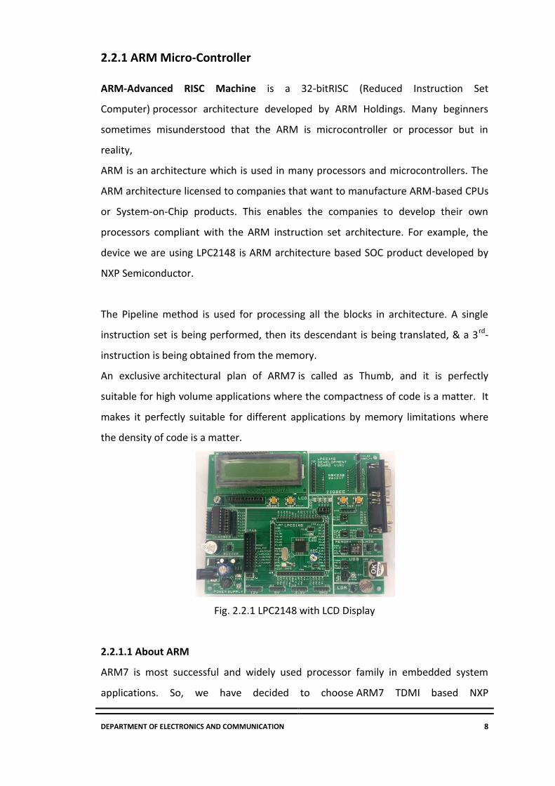
2.2.1 ARM Micro-Controller
ARM-Advanced RISC Machine is a 32-bitRISC (Reduced Instruction Set
Computer) processor architecture developed by ARM Holdings. Many beginners
sometimes misunderstood that the ARM is microcontroller or processor but in
reality,
ARM is an architecture which is used in many processors and microcontrollers. The
ARM architecture licensed to companies that want to manufacture ARM-based CPUs
or System-on-Chip products. This enables the companies to develop their own
processors compliant with the ARM instruction set architecture. For example, the
device we are using LPC2148 is ARM architecture based SOC product developed by
NXP Semiconductor.
The Pipeline method is used for processing all the blocks in architecture. A single
instruction set is being performed, then its descendant is being translated, & a 3rd-
instruction is being obtained from the memory.
An exclusive architectural plan of ARM7 is called as Thumb, and it is perfectly
suitable for high volume applications where the compactness of code is a matter. It
makes it perfectly suitable for different applications by memory limitations where
the density of code is a matter.
Fig. 2.2.1 LPC2148 with LCD Display
2.2.1.1 About ARM
ARM7 is most successful and widely used processor family in embedded system
applications. So, we have decided to choose ARM7 TDMI based NXP

DEPARTMENT OF ELECTRONICS AND COMMUNICATION 9
controllerLPC2148. Also, ARM7 is a balance between classic and new Cortex series.
ARM7 is excellent to get start with in terms of resources available on internet and
quality documentation provided by NXP. It suits perfectly for beginners to get in-
depth idea about hardware and software implementation.
LPC2148 is manufactured by NXP Semiconductor (Phillips) and it is preloaded with
many in-built features and peripherals. This makes it more efficient and reliable
choice for a high-end application developer. Now let’s have a look at pin diagram of
LPC2148. (Fig 2.1.1.1)
Fig 2.2.1.1LPC2148 Pin Diagram

DEPARTMENT OF ELECTRONICS AND COMMUNICATION 10
MEMORY
LPC2148 has 32kB on chip SRAM and 512kB on chip FLASH memory. This chip has
built in support up to 2kB end point USB RAM. This memory is more than enough for
almost all applications. Let’s understand the function of this huge memory space in
LPC2148.
FLASH Memory System: The LPC2148 has 512kB flash memory. This memory
maybeused for both code and data storage. The flash memory can be programmed
by various ways
Using serial built in JTAG Interface
Using In-System Programming (ISP)
By means of In-Application Programming (IAP) capabilities
The application program, using IAP functions may also erase and/or program the
FLASH while the application is running. When the LPC2148 on chip bootloader is
used, 500kB of flash memory is available for user code.
RAM Memory System: LPC2148 provides 32kB of static RAM which may be used for
code and/or data storage. It may be accessed as 8-bit, 16-bit and 32-bits.
GPIO- General Purpose Input/output
GPIO registers control the device pins which are not linked to a particular peripheral
function. The device pins can be arranged as i/p[s or o/ps. Individual registers allow
for clearing any number of o/p’s concurrently. The output register value can be read
back, & the present condition of the port pins. These microcontrollers begin an
accelerated function over LPC200 devices.General purpose input/output registers
are moved to the processor bus used for the best probable I/O time.
These registers are addressable by bytes.
The total value of a port can be
The complete value of the port can be written in the only instruction

DEPARTMENT OF ELECTRONICS AND COMMUNICATION 11
2.2.1.2 Features of LPC214x series controllers:
• 8 to 40 kB of on-chip static RAM and 32 to 512 kB of on-chip flash program
memory.128-bit wide interface/accelerator enables high speed 60 MHz operation.
• In-System/In-Application Programming (ISP/IAP) via on-chip boot-loader software.
Single flash sector or full chip erase in 400ms and programming of 256 bytes in 1ms.
• Embedded ICE RT and Embedded Trace interfaces offer real-time debugging with
theon-chip Real Monitor software and high-speed tracing of instruction execution.
• USB 2.0 Full Speed compliant Device Controller with 2 kB of endpoint RAM. In
addition, the LPC2146/8 provides 8 kB of on-chip RAM accessible to USB by DMA.
• One or two (LPC2141/2 vs. LPC2144/6/8) 10-bit A/D converters provide a total of
6/14analog inputs, with conversion times as low as 2.44 us per channel.
• Single 10-bit D/A converter provides variable analog output.
• Two 32-bit timers/external event counters (with four capture and four compare
channels each), PWM unit (six outputs) and watchdog.
• Low power real-time clock with independent power and dedicated 32 kHz clock
input.
• Multiple serial interfaces including two UARTs (16C550), two Fast I2C-bus (400
kbit/s), SPI and SSP with buffering and variable data length capabilities.
• Vectored interrupt controller with configurable priorities and vector addresses.
• Up to 45 of 5 V tolerant fast general purpose I/O pins in a tiny LQFP64 package.
• Up to nine edge or level sensitive external interrupt pins available.
• On-chip integrated oscillator operates with an external crystal in range from 1 MHz
to30 MHz and with an external oscillator up to 50 MHz
• Power saving modes include Idle and Power-down.
• Individual enable/disable of peripheral functions as well as peripheral clock scaling
for additional power optimization.
• Processor wake-up from Power-down mode via external interrupt, USB, Brown-Out
Detect (BOD) or Real-Time Clock (RTC).
• Single power supply chip with Power-On Reset (POR) and BOD circuits:
CPU operating voltage range of 3.0 V to 3.6 V (3.3 V ± 10 %) with 5 V tolerant I/O
pads.
DEPARTMENT OF ELECTRONICS AND COMMUNICATION 12
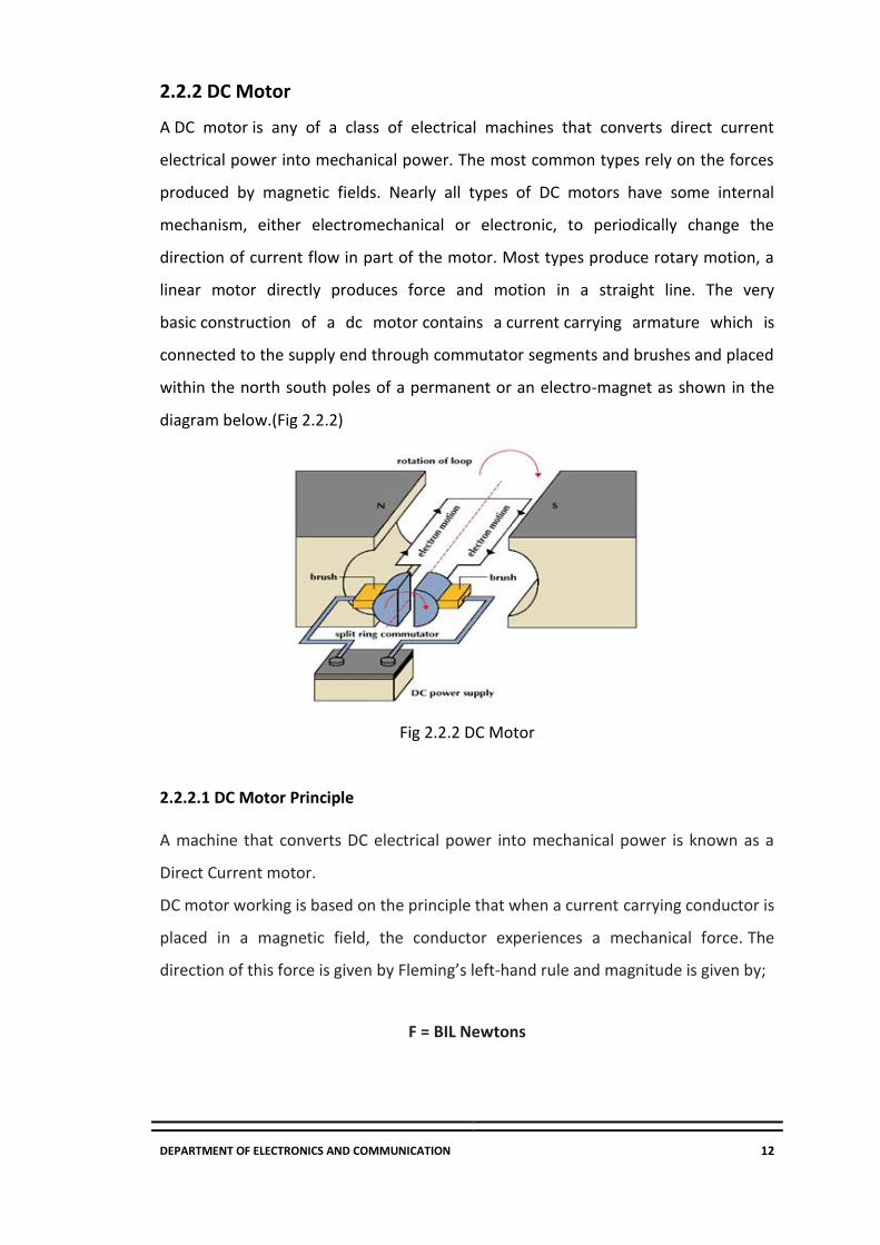
2.2.2 DC Motor
A DC motor is any of a class of electrical machines that converts direct current
electrical power into mechanical power. The most common types rely on the forces
produced by magnetic fields. Nearly all types of DC motors have some internal
mechanism, either electromechanical or electronic, to periodically change the
direction of current flow in part of the motor. Most types produce rotary motion, a
linear motor directly produces force and motion in a straight line. The very
basic construction of a dc motor contains a current carrying armature which is
connected to the supply end through commutator segments and brushes and placed
within the north south poles of a permanent or an electro-magnet as shown in the
diagram below.(Fig 2.2.2)
Fig 2.2.2 DC Motor
2.2.2.1 DC Motor Principle
A machine that converts DC electrical power into mechanical power is known as a
Direct Current motor.
DC motor working is based on the principle that when a current carrying conductor is
placed in a magnetic field, the conductor experiences a mechanical force. The
direction of this force is given by Fleming’s left-hand rule and magnitude is given by;
F = BIL Newtons

DEPARTMENT OF ELECTRONICS AND COMMUNICATION 13
According to Flemings left-hand rule when electric current passes through a coil in a
magnetic field, the magnetic force produces a torque which turns the DC motor.The
direction of this force is perpendicular to both the wire and the magnetic field.
2.2.2.2 Working of DC Motor
When the terminals of the motor are connected to an external source of DC
supply:the field magnets are excited developing alternate North and South poles and
the armature conductors carry currents.All conductors under North-pole carry
currents in one direction while all the conductors under South-pole carry currents in
the opposite direction. The armature conductors under N-pole carry currents into
the plane of the paper and the conductors under S-pole carry currents out of the
plane of paper. On applying Fleming’s left-hand rule, it is clear that force on each
conductor is tending to rotate the armature in the anticlockwise direction. All these
forces add together to produce a driving torque which sets the armature rotates.
When the conductor moves from one side of a brush to the other, the current in that
conductor is reversed. At the same time, it comes under the influence of the next
pole which is of opposite polarity. Also, the function of a commutator in the motor is
the same as in a generator.
Fig.2.2.2.2 Cross-section of DC Machine

DEPARTMENT OF ELECTRONICS AND COMMUNICATION 14
2.2.3 Global System for Mobile (GSM)
GSM stands for Global System for Mobile Communications. It is a standard
set developed by the European Telecommunications Standards Institute
(ETSI) to describe protocols for second generation (2G) digital cellular
networks used by mobile phones. A Modem is a device which modulates and
demodulates signals as required to meet the communication requirements. It
modulates an analog carrier signal to encode digital information, and also
demodulates such a carrier signal to decode the transmitted information.
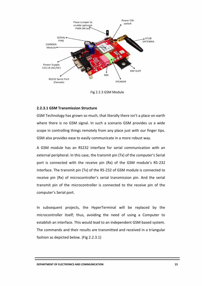
A GSM Modem is a device that modulates and demodulates the GSM signals
and in this particular case 2G signals. The modem we are using is SIMCOM
SIM900. It is a Tri-band GSM/GPRS Modem as it can detect and operate at
three frequencies (EGSM 900 MHz, DCS 1800 MHz and PCS1900 MHz).
Default operating frequencies are EGSM 900MHz and DCS 1800MHz.
Sim900 is widely used in many projects and hence many variants of
development boards for this have been developed. These development boards
are equipped with various features to make it easy to communicate with the
SIM900 module. Some boards provide only TTL interface while some boards
include an RS232 interface and some others include an USB interface. If your PC
has a serial port (DB9) you can buy a GSM Modem that has both TTL and RS232
interfacings in economy.
Sim900 GSM module used here, consists of a TTL interface and an RS232
interface. The TTL interface allows us to directly interface with a
microcontroller while the RS232 interface includes a MAX232 IC to enable
communication with the PC. It also consists of a buzzer, antenna and SIM
slot. Sim900 in this application is used as a DCE (Data Circuit-terminating
Equipment) and PC as a DTE (Data Terminal Equipment).
DEPARTMENT OF ELECTRONICS AND COMMUNICATION 15
Fig 2.2.3 GSM Module
2.2.3.1 GSM Transmission Structure
GSM Technology has grown so much, that literally there isn’t a place on earth
where there is no GSM signal. In such a scenario GSM provides us a wide
scope in controlling things remotely from any place just with our finger tips.
GSM also provides ease to easily communicate in a more robust way.
A GSM module has an RS232 interface for serial communication with an
external peripheral. In this case, the transmit pin (Tx) of the computer’s Serial
port is connected with the receive pin (Rx) of the GSM module’s RS-232
interface. The transmit pin (Tx) of the RS-232 of GSM module is connected to
receive pin (Rx) of microcontroller’s serial transmission pin. And the serial
transmit pin of the microcontroller is connected to the receive pin of the
computer’s Serial port.
In subsequent projects, the HyperTerminal will be replaced by the
microcontroller itself; thus, avoiding the need of using a Computer to
establish an interface. This would lead to an independent GSM based system.
The commands and their results are transmitted and received in a triangular
fashion as depicted below. (Fig 2.2.3.1)

DEPARTMENT OF ELECTRONICS AND COMMUNICATION 16
Fig.2.2.3.1GSM transmission structure
The microcontroller is programmed to receive and transmit data at a baud rate of
9600. For more details on setting the baud rate of microcontroller, refer serial.
The controller can receive data signals either by polling or by making use of
serial interrupt (ES). Serial interrupt has been explained in interrupt. In
polling, the controller continuously scans serial port for incoming data from
the GSM module.
2.2.3.2 GSM System Architecture
In GSM system the mobile handset is called Mobile Station (MS). A cell is
formed by the coverage area of a Base Transceiver Station (BTS) which serves
the MS in its coverage area. Several BTS together are controlled by one Base
Station Controller (BSC). The BTS and BSC together form Base Station
Subsystem (BSS). The combined traffic of the mobile stations in their
respective cells is routed through a switch called Mobile Switching Center
(MSC). Connection originating or terminating from external telephone (PSTN)
are handled by a dedicated gateway Gate way Mobile Switching Center
(GMSC). The architecture of a GSM system is shown in the figure below.
In addition to the above entities several databases are used for the purpose
of call control and network management. These databases are Home
Location Register (HLR), Visitor Location Register (VLR), the Authentication
Center (AUC), and Equipment Identity Register (EIR). Home Location Register
(HLR) stores the permanent (such as user profile) as well as temporary (such

DEPARTMENT OF ELECTRONICS AND COMMUNICATION 17
as current location) information about all the users registered with the
network.
A VLR stores the data about the users who are being serviced currently. It
includes the data stored in HLR for faster access as well as the temporary
data like location of the user. The AUC stores the authentication information
of the user such as the keys for encryption. The EIR stores data about the
equipment’s and can be used to prevent calls from a stolen equipment’s.
Fig 2.2.3.2GSM architecture
All the mobile equipment’s in GSM system are assigned unique id called IMSI
(International Mobile Equipment Identity) and is allocated by equipment
manufacturer and registered by the service provider. This number is stored in
the EIR. The users are identified by the IMSI (International Module Subscriber
Identity) which is stored in the Subscriber Identity Module (SIM) of the user. A
mobile station can be used only if a valid SIM is inserted into equipment with
valid IMSI. The “real” telephone number is different from the above ids and is
stored in SIM.

DEPARTMENT OF ELECTRONICS AND COMMUNICATION 18
2.2.4 Liquid Crystal Display (LCD)
LCD (Liquid Crystal Display) screen is an electronic display module and find a
wide range of applications. A 16x2 LCD display is very basic module and is
very commonly used in various devices and circuits. These modules are
preferred over seven segments and other multi-segmentLEDs.
The reasons being: LCDs are economical; easily programmable; have no
limitation of displaying special &even custom(unlike in seven
segments),animations and so on. A 16x2 LCD means it can display 16
characters per line and there are 2 such lines. In this LCD each character is
displayed in 5x7 pixel matrix. This LCD has two registers, namely, Command
and Data.
The command register stores the command instructions given to the LCD. A
command is an instruction given to LCD to do a predefined task like
initializing it, clearing its screen, setting the cursor position, controlling
display etc. The data register stores the data to be displayed on the LCD. The
data is the ASCII value of the character to be displayed on the LCD. Click to
learn more about internal structure of aLCD.
2.2.4.1 Pin Diagram
Fig.2.2.4.1PIN Diagram of LCD
DEPARTMENT OF ELECTRONICS AND COMMUNICATION 19
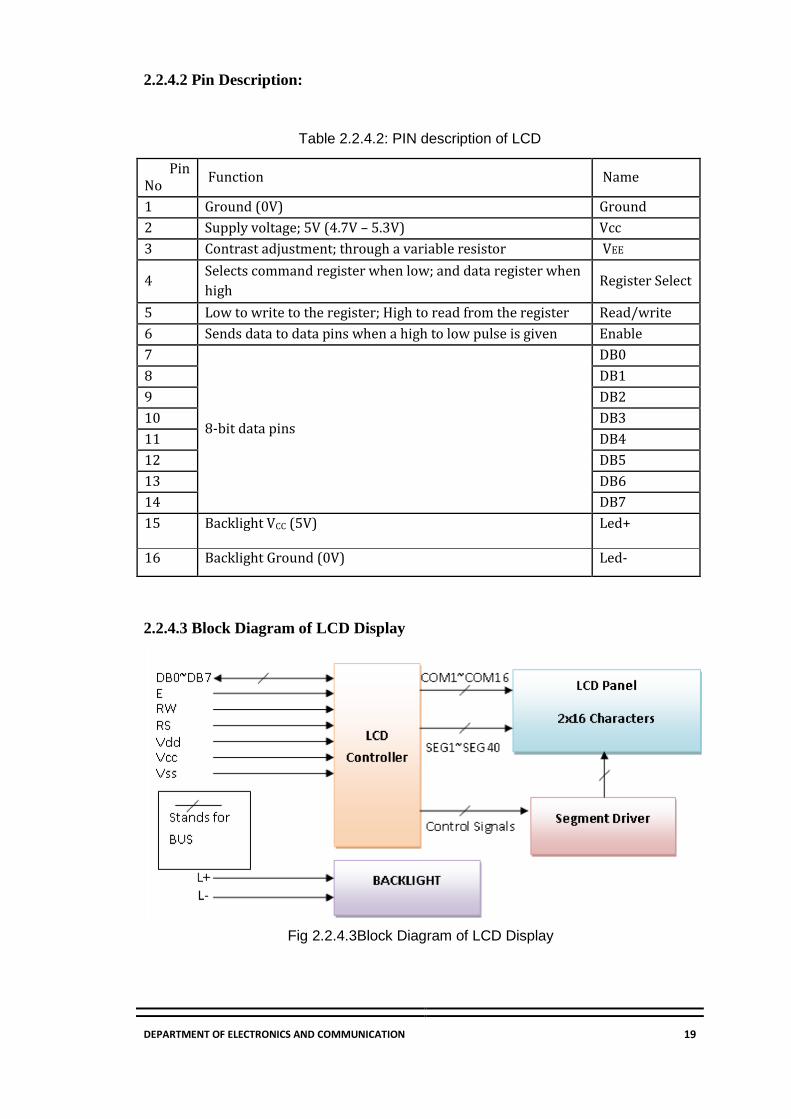
2.2.4.2 Pin Description:
Table 2.2.4.2: PIN description of LCD
Pin No
Function Name
1 Ground (0V) Ground
2 Supply voltage; 5V (4.7V – 5.3V) Vcc
3 Contrast adjustment; through a variable resistor VEE
4 Selects command register when low; and data register when
high Register Select
5 Low to write to the register; High to read from the register Read/write
6 Sends data to data pins when a high to low pulse is given Enable
7
8-bit data pins
DB0
8 DB1
9 DB2
10 DB3
11 DB4
12 DB5
13 DB6
14 DB7
15 Backlight VCC (5V) Led+
16 Backlight Ground (0V) Led-
2.2.4.3 Block Diagram of LCD Display
Fig 2.2.4.3Block Diagram of LCD Display

DEPARTMENT OF ELECTRONICS AND COMMUNICATION 20
2.2.4.4 Control and Display Commands
Table2.2.4.4: Control and Display Commands
Instruction Instruction Code InstructionCode
Description
Execution
time
RS R/W DB7 DB6 DB5 DB4 DB3 DB2 DB1 DB0
Read
Data
From
RAM
1 1 D7 D6 D5 D4 D3 D2 D1 D0 Readdata from
internal RAM
1.531.64m
s
Write data
to
RAM
1 0 D7 D6 D5 D4 D3 D2 D1 D0 Write data into
internal RAM
(DDRAM/CGRAM)
1.531.64m
s
Busy flag
&Addr
ess
0 1 BF AC6 AC5 AC4 AC3 AC2 AC1 AC0 Busy flag (BF: 1→
LCD Busy) and
contents of
address counter
in bits AC6AC0.
39 µs
Set
DDR
0 0 1 AC6 AC5 AC4 AC3 AC2 AC1 AC0 Set DDRAM
address in
address counter.
39 µs

DEPARTMENT OF ELECTRONICS AND COMMUNICATION 21

DEPARTMENT OF ELECTRONICS AND COMMUNICATION 22
2.2.4.5 Address Counter (AC)
Outline
Now the instruction can be divided mainly in four kinds
1) Function set instructions
2) Address set instructions
3) Data transfer instructions with internal RAM
4) Others
Details of the Instructions:
1) Read Data from RAM
Table 1: Read data from RAM
Read 8bit binary data from DDRAM/CGRAM
The selection of RAM is set by the previous address set instruction. If the
address set instruction of RAM is not performed before this instruction, the
data that is read first is invalid, because the direction of AC is not
determined. If the RAM data is read several times without RAM address set
instruction before read operation, the correct RAM data from the second,
but the first data would be incorrect, as there is no time to transfer RAM
data. In case of DDRAM read operation, cursor shift instruction plays the
same role as DDRAM address set instruction; it also transfers RAM data to
the output data registers.

DEPARTMENT OF ELECTRONICS AND COMMUNICATION 23
After read operation, the data address counter is automatically increased or
decreased by 1 according to the entry mode. After CGRAM read operation,
display shift may not be executed properly.
*In case of RAM write operation, AC is increased or decreased by 1 like that
of the read operation. In this time AC indicates the next address position, but
the previous data can only by the read instruction.
2) Write data to RAM
Table 2: Write data to RAM
Write binary 8-bit data to DDRAM. The selection of DRAM or CGRAM is set by
the previous address set instruction; DDRAM address set, CGRAM address
set. RAM set instruction can also determine the AC direction to RAM. After
write operation, the address is automatically increasedor decreased by 1
according to the entry mode.
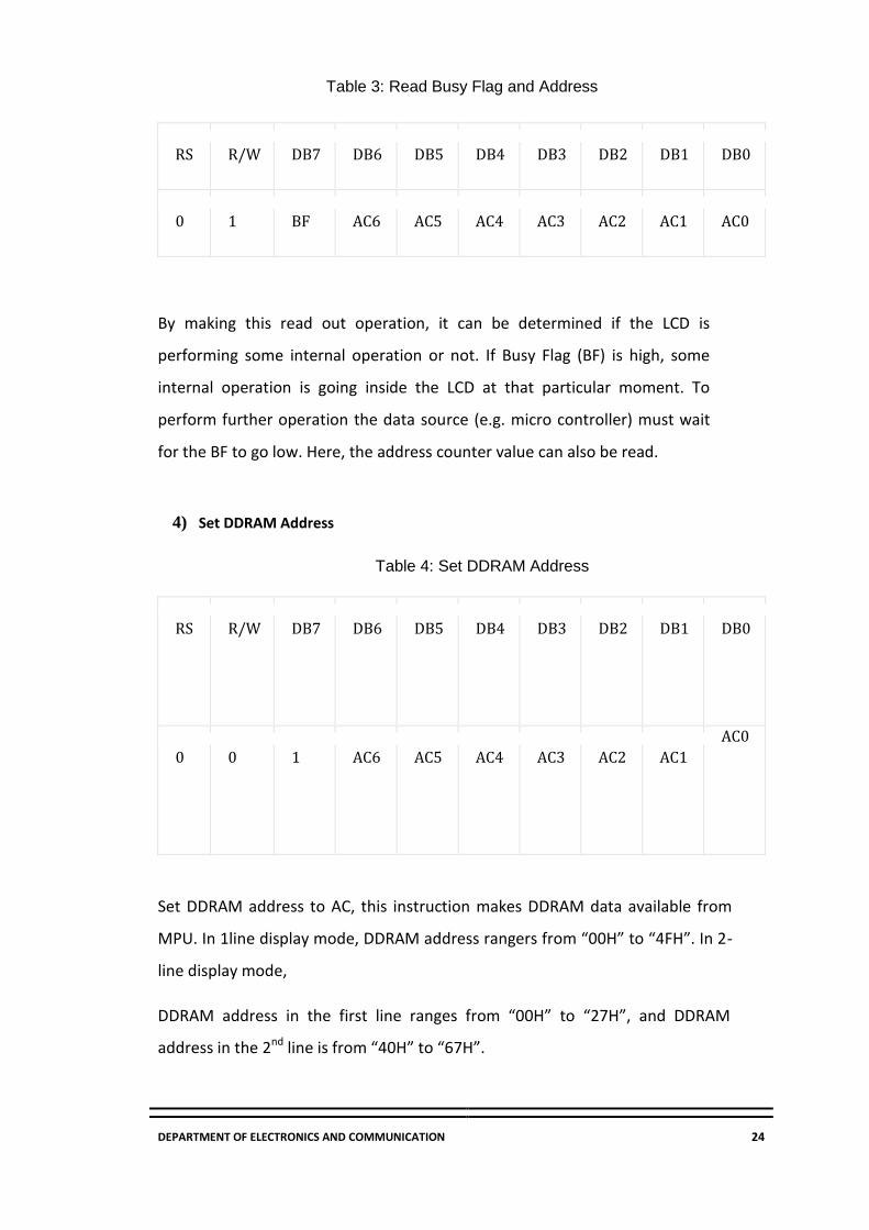
3) Read Busy Flag and Address
By making this read out operation, it can be determined if the LCD is
performing some internal operation or not. If Busy Flag (BF) is high, some
internal operation is going inside the LCD at that particular moment. To
perform further operation the data source (e.g. micro controller) must wait
for the BF to go low. Here, the address counter value can also be read.
DEPARTMENT OF ELECTRONICS AND COMMUNICATION 24
Table 3: Read Busy Flag and Address
RS
R/W
DB7
DB6
DB5
DB4
DB3
DB2
DB1
DB0
0
1
BF
AC6
AC5
AC4
AC3
AC2
AC1
AC0
By making this read out operation, it can be determined if the LCD is
performing some internal operation or not. If Busy Flag (BF) is high, some
internal operation is going inside the LCD at that particular moment. To
perform further operation the data source (e.g. micro controller) must wait
for the BF to go low. Here, the address counter value can also be read.
4) Set DDRAM Address
Table 4: Set DDRAM Address
RS
R/W
DB7
DB6
DB5
DB4
DB3
DB2
DB1
DB0
0
0
1
AC6
AC5
AC4
AC3
AC2
AC1
AC0
Set DDRAM address to AC, this instruction makes DDRAM data available from
MPU. In 1line display mode, DDRAM address rangers from “00H” to “4FH”. In 2-
line display mode,
DDRAM address in the first line ranges from “00H” to “27H”, and DDRAM
address in the 2nd line is from “40H” to “67H”.

DEPARTMENT OF ELECTRONICS AND COMMUNICATION 25
5) Set CGRAM address
Table 5: Set CGRAM address
6) Function Set
Table 6: Function Set
DL: Interface data length control bit
DL=’1’ means 8bit mode of data transfer.
DL=’0’ means 4bit mode of data transfer
When 4-bit mode is activated, the data needs to be transferred in two parts, first
higher 4bits, and then lower 4 bits.
N: display line number control bit
N=’1’ will allows to characters to display in 2-lines
N=’0’ will allows to characters to display in the first line only
F: display font control bit
F=’0’ will use 5×8 dots format display mode
DEPARTMENT OF ELECTRONICS AND COMMUNICATION 26
F=’1’ will use 5×11 dots format displaymode
7) Cursor or display Shift
Table 7: Cursor or Display shift
RS
R/W
DB7
DB6
DB5
DB4
DB3
DB2
DB1
DB0
0
0
0
0
0
1
S/C
R/L
X
X
Without writing or reading the display data, shifting right/left cursor position or
display. This instruction is made to correct or search or display data. During 2-line
display mode, cursor moves to the 2nd line after the 40th digit of the 1st line.
When displayed data is shifted repeatedly, each line shifts individually.
When display shift is performed, the contents of the address counter are not
changed.
8) Display On/Off Control
Table 8: Display Control
This instruction controls Display, Cursor and cursor blink.

DEPARTMENT OF ELECTRONICS AND COMMUNICATION 27
D: Display On/Off control bit
D=’1’ means entire display is turned on
D=’0’ means entire display is turned off. But Display data remains in DDRAM.
C: Cursor On/Off control bit
C=’1’ turns on the cursor
C=’0’ turns off the cursor. But I/D register retains the data
B: Cursor blink On/Off control bit
B=’1’ makes cursor blink periodically.
B=’0’ stops the cursor to blink and cursor looks steady if the Cursor is turned on.
9) Entry Mode Set
This instruction sets the moving direction of cursor and display.
When I/D= ’1’ cursor moves to the right and DDRAM address is increased by 1.
When I/D= ’0’ cursor moves to the left and DDRAM address is decreased
by 1. CGRAM operates in the same way in this setting.
Table 9: Entry Mode set
RS
R/W
DB7
DB6
DB5
DB4
DB3
DB2
DB1
DB0
0
0
0
0
0
0
0
1
I/D
SH
This instruction sets the moving direction of cursor and display.
When I/D= ’1’ cursor moves to the right and DDRAM address is increased by 1.
DEPARTMENT OF ELECTRONICS AND COMMUNICATION 28
When I/D= ’0’ cursor moves to the left and DDRAM address is decreased
by 1. CGRAM operates in the same way in this setting.
10) Return Home
Table10: Return Home
This instruction sets the address counter to 00H and returns the cursor to the first
column of first line. And if display is shifted previously, this instruction shifts this too.
The DDRAM contents don’t change in this instruction.
11) Clear display
Table12: Clear Display
Clear all the display using 20H to all DDRAM and set value DDRAM address
counter (AC) to “00H”. It returns the cursor to the first column of first line and
sets the entry mode to increment mode (I/D=’1’).

DEPARTMENT OF ELECTRONICS AND COMMUNICATION 29
2.2.4.68-Bit Mode
Now the question is how to display data in the LCD or give command to it. There are
two modes of data transfer are supported by LCD displays. One is 4bit mode, another
is 8- bit mode. To transfer data in 8- bit mode, first put your data in the 8bit bus,
then put command in the command bus and then pulse the enable signal.
There is lot of stuff that can be done with the LCDs, to start with we will simple
display a couple of strings on the 2 lines of the LCD as shown in the image.
Fig 2.2.4.68-Bit mode Schematic
Schematic description:
• Data Lines: In this mode, all of the 8 data lines DB0 to DB7 are connected from
the microcontroller to a LCD module as shown the schematic.
• Control Lines:' The RS, RW and E are control lines, as discussed earlier.
• Power & contrast: Apart from that the LCD should be powered with 5V
between PIN 2(VCC) and PIN 1(GND). PIN 3 is the contrast pin and is output of
center terminal of potentiometer (voltage divider) which varies voltage
between 0 to 5v to vary the contrast.
• Back-light: The PIN 15 and 16 are used as backlight. The led backlight can be
powered through a simple current limiting resistor as we do with normal LED’s.

DEPARTMENT OF ELECTRONICS AND COMMUNICATION 30
2.2.4.7 4-Bit Mode
To send data in 4bit mode; first put upper 4bit in the 4 -bit data bus connected
to 4MSB pins of LCD display, then put control signals in the control bus, then
pulse the E pin once. Next put the lower 4- bit in the data bus and pulse the E
pin again. Here is a flowchart simply describing it.
There are following differences in 4-bit mode.
• Only data lines D4 to D7 are used as shown in the schematic below.
• In code, we need to send the command to select 4 -bit mode as shown in the
instruction set above.
2.2.4.8 LCD Display Interfacing – Flowchart
Fig 2.2.4.8Flow chart of interfacing LCD display

DEPARTMENT OF ELECTRONICS AND COMMUNICATION 31
2.2.5 GPS (Global Positioning System)
Using the Global Positioning System (GPS, all process used to establish all position at
any point on the globe) the following two values can be determined anywhere on
Earth. GPS receivers are used for positioning, locating, navigating, surveying and
determining the time and are employed both by private individuals (e.g. for leisure
activities, such as trekking, balloon flights and cross-country skiing etc.) and
companies (surveying, determining the time, navigation, vehicle monitoring etc.)
GPS (the full description is: Navigation System with Timing and Ranging Global
Positioning System, NAVSTAR-GPS) was developed by the U.S. Department of
Defense (DoD) and can be used both by civilians and military personnel. The civil
signal SPS (standard positioning service) can be used freely by the general public,
whilst the military signal PPS (Precise positioning service) can only be used by
authorized government agencies. The first satellite was placed in orbit on 22nd
February 1978, and there are currently 28 operational satellites orbiting the earth at
a height of 20,180km on 6 different orbital planes. Their orbits are inclined at
55degree to the equator, ensuring that at least 4 satellites are in radio
communication with any point on the planet. Each satellite orbits the earth in
approximately 12 hours and has four atomic clocks on board.
Fig.2.2.5 GPS Satellite
DEPARTMENT OF ELECTRONICS AND COMMUNICATION 32
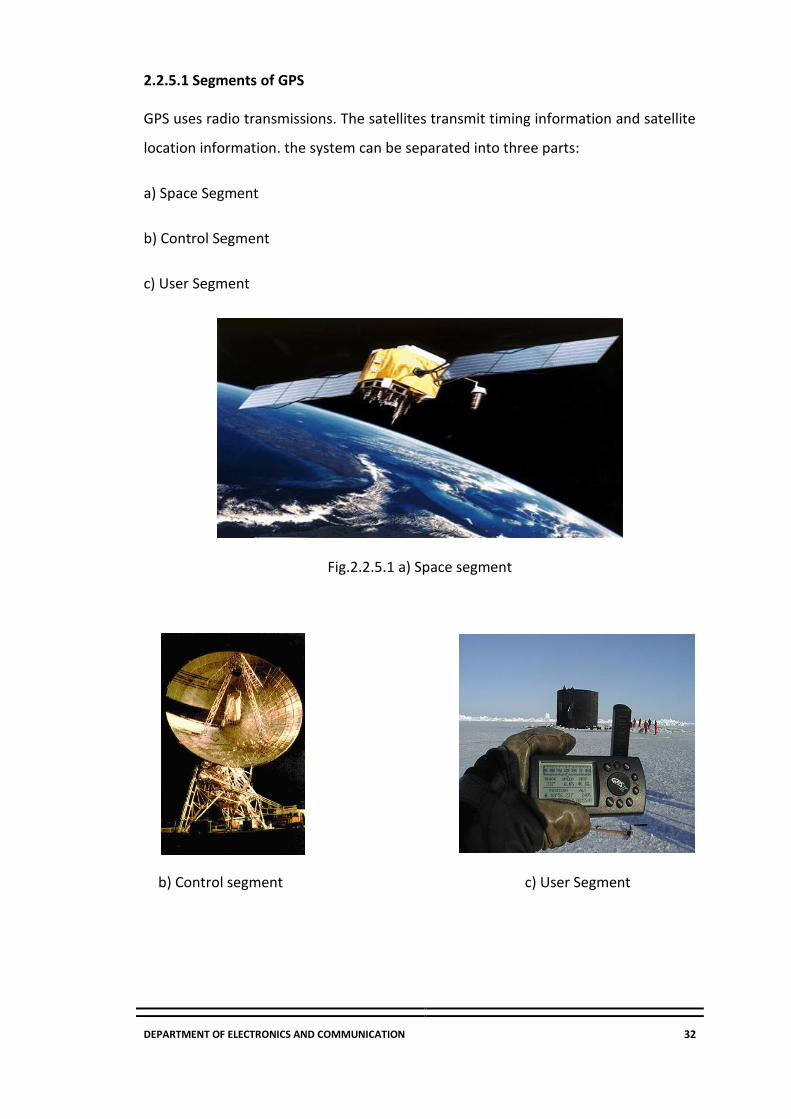
2.2.5.1 Segments of GPS
GPS uses radio transmissions. The satellites transmit timing information and satellite
location information. the system can be separated into three parts:
a) Space Segment
b) Control Segment
c) User Segment
Fig.2.2.5.1 a) Space segment
b) Control segment c) User Segment

DEPARTMENT OF ELECTRONICS AND COMMUNICATION 33
Space segment
• The space segment consists of the satellites themselves.
• According to the United states Naval observatory there are currently 27
operational GPS satellites about 11,000 miles up in space.
• This constellation provides between five and eight GPS satellites visible from
any point on the earth.
Control segment
• The control segment is a group of ground stations that monitor and operate
the GPS satellites. There are monitoring stations spaced around the globe
and one Master Control Station located in Colorado Springs
User segment
• The user requires a GPS receiver in order to receive the transmissions from
the satellites. The GPS receiver calculates the location based on signals from
the satellites
• The users consist of both the military and civilians.
2.2.5.2 Applications of GPS
Car navigation
Dynamic vehicle routing
Tracking rental cars
Monitoring high risk auto loans

DEPARTMENT OF ELECTRONICS AND COMMUNICATION 34
2.2.6 RELAY
The main usage of the Relay was seen in the history of transmitting and receiving the
information, that was called as Morse code where the input signals used to be either
1 or 0, these change in signals were mechanically noted in terms of ON and OFF of a
light bulb or a beep sound, it means those pulses of 1s and 0s are converted as
mechanical ON and OFF using electromagnets.
A Relay is generally used when it is required to control a circuit by a separate low-
power signal, or when several circuits must be controlled by one signal. They are
classified into many types, a standard and generally used relay is made up of
electromagnets which in general used as a switch.
Fig 2.2.6 Relay module
The signal received from one side of the device controls the switching
operation on the other side. So, relay is a switch which controls (open and
close) circuits electro-mechanically.
The main operation of this device is to make or break contact with the help of
a signal without any human involvement in order to switch it ON or OFF. When the switch is open no current passes through the relay, the circuit is
open, and the load that is connected to the relay receives no power.
When a relay is closed, the circuit is completed and current passes through
the relay and delivers power to the load. To open and close a relay
electromagnet is used.
DEPARTMENT OF ELECTRONICS AND COMMUNICATION 35
When the coil controlling the electromagnet is given a voltage, the
electromagnet causes the contacts in the relay to connect and transfer
current through the relay.
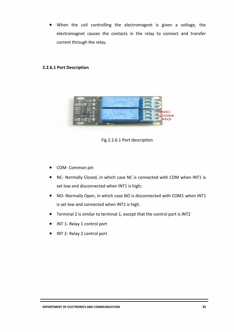
2.2.6.1 Port Description
Fig 2.2.6.1 Port description
COM- Common pin
NC- Normally Closed, in which case NC is connected with COM when INT1 is
set low and disconnected when INT1 is high;
NO- Normally Open, in which case NO is disconnected with COM1 when INT1
is set low and connected when INT1 is high.
Terminal 2 is similar to terminal 1, except that the control port is INT2
INT 1- Relay 1 control port
INT 2- Relay 2 control port

DEPARTMENT OF ELECTRONICS AND COMMUNICATION 36
2.2.6.2 Working of a Relay Circuit
Fig.2.2.6.2Relay Switch Circuit
In the above circuit, 5V relay is powered by a 9V battery. An ON/OFF switch is added
for the switching purpose of the relay. At the initial condition when switch is open,
no current flow through coil, hence Common Port of relay is connected to NO
(Normally Open) Pin, so the LAMP remain off.
When the switch is closed, current start flowing through the coil, and by the concept
of electromagnetic induction, magnetic field is generated in the coil which attracts
the movable armature and the Com Port get connected with NC (Normally Close) pin
of the relay. Hence, the LAMP turns ON.
2.2.6.3 Types of Relays
1. Electromagnetic Relays
2. Solid State Relays
3. Hybrid Relays
DEPARTMENT OF ELECTRONICS AND COMMUNICATION 37
1. Electromagnetic Relays
These relays are constructed with electrical, mechanical and magnetic components,
and have operating coil and mechanical contacts. Therefore, when the coil gets
activated by a supply system, these mechanical contacts gets opened or closed. The
type of supply can be AC or DC.
There are 3 types under Electromagnetic Relays namely:
a)Attraction type Relays- These relays can work with both AC and DC supply and
attract a metal bar or a piece of metal when power is supplied to the coil. These
relays don’t have any time delays so these are used for instantaneous operation.
b)Induction type Relays - These are used as protective relays in AC systems alone
and are usable with DC systems. The actuating force for contacts movement is
developed by a moving conductor that may be a disc or a cup, through the
interaction of electromagnetic fluxes due to fault currents. mostly used as directional
relays in power-system protection and also for high-speed switching operation
applications.
c)Magnetic Latching Relays - These relays use permanent magnet or parts with a
high remittance to remain the armature at the same point as the coil is electrified
when the coil power source is taken away.
2. Solid State Relays
Solid State uses solid state components to perform the switching operation without
moving any parts. Since the control energy required is much lower compared with
the output power to be controlled by this relay that results the power gain higher
when compared to the electromagnetic relays.
3. Hybrid Relays
These relays are composed of electromagnetic relays and electronic components.
Usually, the input part contains the electronic circuitry that
performs rectification and the other control functions, and the output part include
electromagnetic relay.

DEPARTMENT OF ELECTRONICS AND COMMUNICATION 38
2.2.7 Alcohol Sensor (MQ-3 Sensor)
It is a low-cost semiconductor sensor which can detect alcoholat concentrations
from 0.05 mg/L to 10 mg/L. The sensitive material used for this sensor is SnO2,
whose conductivity is lower in clean air. The conductivity increases with increase in
concentration of alcohol gases. It is highly sensitive to alcohol and has a good
resistance to disturbances due to smoke and gasoline. It provides both digital and
analog outputs. MQ3 alcohol sensor module can be easily interfaced with
Microcontrollers, Raspberry Pi etc.
This alcohol sensor is suitable for detecting alcohol concentration on your breath. It
has high sensitivity and fast response time. Sensor provides an analog resistive
output based on alcohol concentration. The drive circuit is very simple as it requires
only one resistor. A simple interface could be a 0-3.3V ADC.
Fig 2.2.7 MQ-3 Sensor

DEPARTMENT OF ELECTRONICS AND COMMUNICATION 39
2.2.7.1 Block Diagram
Fig 2.2.7.1 Block Diagram of MQ-3 Sensor
VCC – Input Power Supply
GND – Supply Ground
DO – Digital Output
AO – Analog Output
2.2.7.2 Basic Pin Configuration
The MQ-3 alcohol gas sensor consists of total 6-pins including A, H, B and the other
three pins are A, H, B out of the total 6-pins we use only 4 pins. The two pins A, H
are used for the heating purpose and the other two pins are used for the ground and
power. There is a heating system inside the sensor, which is made up of aluminum
oxide, tin dioxide. It has heat coils that is used as a heat sensor.
Fig.2.2.7.2 Pin Configuration of Alcohol Sensor

DEPARTMENT OF ELECTRONICS AND COMMUNICATION 40
2.2.7.3 Working Principle
The MQ-3 alcohol sensor consists of a tin dioxide (SnO2), a perspective layer inside
aluminum oxide micro tubes (measuring electrodes) and a heating element inside a
tubular casing. The end face of the sensor is enclosed by a stainless-steel net and the
back side holds the connection terminals. Ethyl alcohol present in the breath is
oxidized into acetic acid passing through the heat element. With the ethyl alcohol
cascade on the tin dioxide sensing layer, the resistance decreases. By using the
external load resistance, the resistance variation is converted into a suitable voltage
variation.
Fig.2.2.7.3 MQ-3 Circuit Diagram
2.2.7.4 Features
5V operation
LEDs for output and power
Output sensitivity adjustable
Analog/Digital output 0V to 5V
Good Sensitivity to Alcohol Gas
Both Digital and Analog Outputs
On-board LED Indicator

DEPARTMENT OF ELECTRONICS AND COMMUNICATION 41
2.3 Flow-Chart
Fig.2.3 Flowchart of Alcohol Detection and Ignition Locking System

DEPARTMENT OF ELECTRONICS AND COMMUNICATION 42
CHAPTER 3
SOFTWARE SPECIFICATIONS
3.1 About Keil Uvision
Keil development tools for the ARM Microcontroller Architecture support every level
of software developer.Keil provides a broad range of development tools
like ANSI C compiler, macro assemblers, debuggers andsimulators, linkers, IDE,
library managers, real-time operating systems and evaluation boards for Intel
8051, Intel MCS-251&ARM.The industry-standard Keil C Compilers, Macro
Assemblers, Debuggers, Real-time Kernels, Single-board Computers, and Emulators
support all ARM derivatives.
Tools developed by Keil endorse the most popular microcontrollers and are
distributed in several packages and configurations, dependent on the architecture.
MDK-ARM is the Microcontroller Development Kit, for several ARM7, ARM9, and
Cortex-Mx based devices.
The Keil Uvision Development Kit supports 32-bit (ARM7 and ARM9 based) devices
support complex applications, which require greater processing power. These cores
provide high-speed 32- bit arithmetic within a 4GB address space. The RISC
instruction set has been extended with a Thumb mode for high code density.
Using a program called Flash Magic, the Uvision code can be dumped into the ARM-
7 micro-controller.
Fig.3.1 Keil Logo
DEPARTMENT OF ELECTRONICS AND COMMUNICATION 43
3.2 ARM-7 Highlights
Standard (IRQ) and Fast (FIQ) interrupt. Banked microcontroller registers
on FIQ reduce register save/restore overhead.
Linear 4 GB memory space that includes peripherals and eliminates the
need for specific memory types Load-store architecture with efficient
pointer addressing. Fast task context switch times are achieved with
multiple register load/store.
Vectored Interrupt Controller (available in most microcontrollers)
optimizes multiple interrupt handling
Compact 16-bit Instruction Set (Thumb). Compared to ARM mode,
Thumb mode code is about 65% of the code size and 160% faster when
executing from a 16-bit memory system.
ARM7 and ARM9 devices provide indirect memory access instructions
only. However, there are no bit operations.
Processor modes with separate interrupt stacks for predictable stack
requirements.
3.3 ARM-7 Development Tool Support
The ARM compilation tools support all ARM-specific features and provide:
FunctionIn-lining eliminates call/return overhead and optimizes
parameter passing.
Inline assembly supports special ARM/Thumb instructions in C/C++
programs.
RAM functions enable high-speed interrupt code and In-System Flash
programming.
ARM/Thumb interworking provides outstanding code density and
microcontroller performance.
Task function and RTOS support are built into the C/C++ compiler.
DEPARTMENT OF ELECTRONICS AND COMMUNICATION 44
CHAPTER 4
RESULTS
a) The MQ3 Alcohol Sensor and the 16x2 LCD Display is interfaced with ARM-7
(LPC2148) Microcontroller.
b) MQ3 Sensor senses alcohol and indication of high Alcohol content is through the
external LED Light present on the sensor board.
c) The LCD display is used to display the results given by the MQ3 Sensor.
d) The Switch is used to ensure the driver does not tamper with the system.
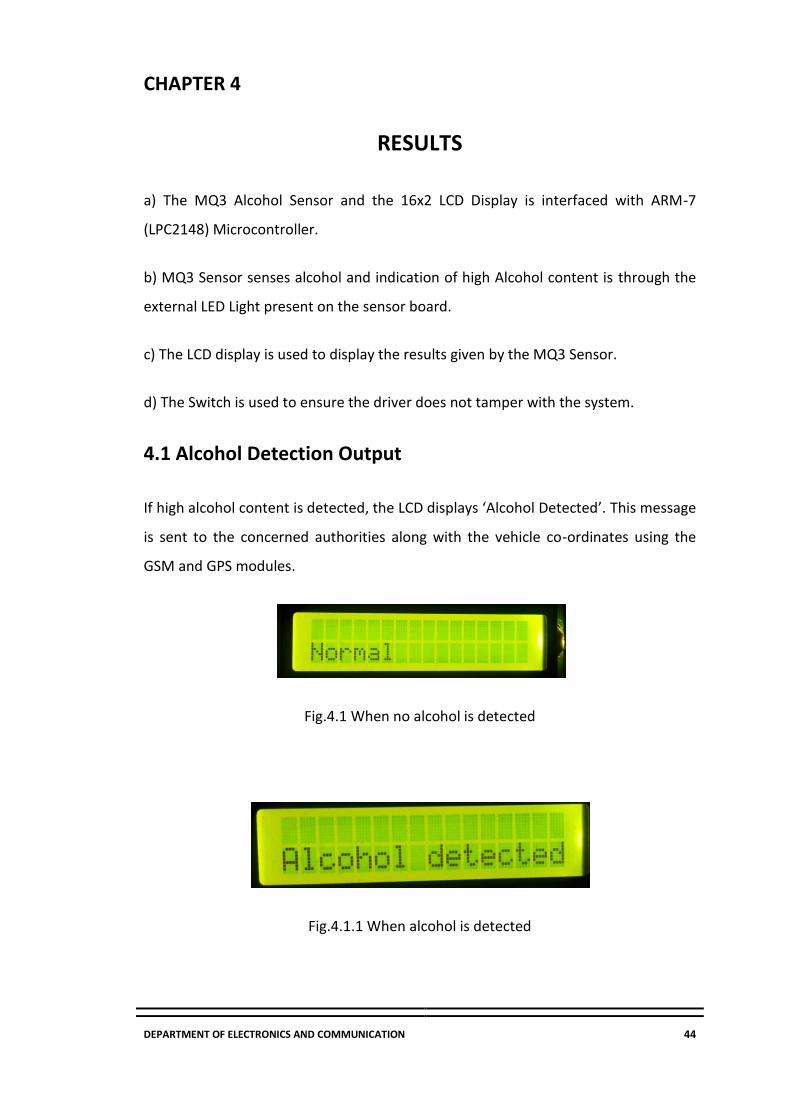
4.1 Alcohol Detection Output
If high alcohol content is detected, the LCD displays ‘Alcohol Detected’. This message
is sent to the concerned authorities along with the vehicle co-ordinates using the
GSM and GPS modules.
Fig.4.1 When no alcohol is detected
Fig.4.1.1 When alcohol is detected

DEPARTMENT OF ELECTRONICS AND COMMUNICATION 45
Fig.4.1.2 Detection Message received from GSM Module
Fig.4.1.3 Co-ordinates shown in Flash magic terminal
4.2 Switch Output
The Switch is pressed during installation and should be kept pressed at all times. Any
tampering which causes the switch to be released displays an “Alert” message on the
LCD Display.
A message, “Someone is trying to remove the system”, is sent to the concerned
authorities along with the vehicle co-ordinates using the GSM and GPS modules.
Fig.4.2 Alert message shown when switch is released
Fig.4.2.1 Alert Message received from GSM Module

DEPARTMENT OF ELECTRONICS AND COMMUNICATION 46
CHAPTER 5
CONCLUSION AND FUTURE SCOPE
5.1 Conclusion
In this project we have built up areal time model that can automatically lock the
motor engine when a drunken driver tries to drive a car. These days, car collisions
are mostly observed. By fitting this alcohol sensor into the car, we can save the life
of the driver and furthermore the rest of the travelers. The life time of the task is
high. It has low or zero support cost and obviously low power utilization. This is a
developed system to check drunken driving. By executing this outline a safe car
travel is possible decreasing the mishap rate because of drinking. By executing this
outline, drunken drivers can be controlled so are the mishaps because of drunken
driving.
5.2 Future Works
Government must authorize laws to introduce such circuit in each car and must
manage all car organizations to preinstall such systems while manufacturing the car
itself. If it is achieved, the death rate because of drunken drivers can be brought to
least level. In this kind of system, securely landing of car aside without disturbing
other vehicles can also be added as a future extension.

DEPARTMENT OF ELECTRONICS AND COMMUNICATION 47
REFERENCES
[1] Z. Xiaoronget , “The Drunk Driving Automatic Detection System Based on
Internet of Things”, International Journal of Control and Automation, Vol. 9,
No. 2, 2016, pp. 297-306 -
https://www.sparkfun.com/datasheets/Sensors/MQ-3.pdf
[2] J. Dai, J. Teng, X. Bai, Z. Shen, and D. Xuan. "Mobile phone based drunk driving
detection." In 2010 4th International Conference on Pervasive Computing
Technologies for Healthcare, pp. 1-8. IEEE, 2010
[3] A. R. Varma, S. V. Arote, C. Bharti, and K. Singh. "Accident prevention using
eye blinking and head movement." IJCA Proceedings on Emerging Trends in
Computer Science and Information Technology-2012 (ETCSIT2012) etcsit1001
4 (2012): 31-35.
[4] V. Savania, H. Agravata and D. Patela, “Alcohol Detection and Accident
Prevention of Vehicle”, International Journal of Innovative and Emerging
Research in Engineering, Volume 2, Issue 3, 2015, pp 55-59
[5] Articles base directory [online] 2011 Feb. 16 Available
fromURL:http://www.dwworld.de/dw/article/0,,5519345,00.html.
[6] S.P. Bhumkar, V.V. Deotare, R.V. Babar, “Accident avoidance and detection on
highways”.
[7] Abhi R. Varma, Seema V. Arote, Chetna Bharti, Kuldeep Singh, "Accident
Prevention Using Eye Blinking and Head Movement"IJCA Proceedings on
Emerging Trends in Computer Science andInformation Technology -
2012(ETCSIT2012) etcsit1001 ETCSIT(4):31-35, April 2012.
DEPARTMENT OF ELECTRONICS AND COMMUNICATION 48
APPENDIX
Uvision Code:
#include <lpc214x.h>
#include <stdint.h>
#include <stdio.h>
#include <stdlib.h>
#include <stdbool.h>
#include <string.h>
#include "LCD.h"
#define NUMBER "7349460276"
void ser_init(void);
void tx(unsigned char c);
unsigned char rx(void);
void tx_str(unsigned char *s);
void sms(unsigned char *num1,unsigned char *msg);
void gsm_delay(void);
unsigned int dell;
char Latitude_Buffer[15],Longitude_Buffer[15],Time_Buffer[15],
Altitude_Buffer[8];
char iir_val[10];
char GGA_String[150];
uint8_t GGA_Comma_Pointers[20];
char GGA[3];
volatile uint16_t GGA_Index, CommaCounter;
bool IsItGGAString = false;
__irq void UART0_Interrupt(void);
void delay_ms(uint16_t j)
{
uint16_t x,i;

DEPARTMENT OF ELECTRONICS AND COMMUNICATION 49
for(i=0;i<j;i++)
{
for(x=0; x<6000; x++); /* loop to generate 1 milisecond
delay with Cclk = 60MHz */
}
}
void UART0_init(void)
{
PINSEL0 = PINSEL0 | 0x00000005; /* Enable UART0 Rx0 and
Tx0 pins of UART0 */
U0LCR = 0x83; /* DLAB = 1, 1 stop bit, 8-bit character
length */
U0DLM = 0x00; /* For baud rate of 9600 with Pclk =
15MHz */
U0DLL = 0x61; /* We get these values of U0DLL and U0DLM
from formula */
U0LCR = 0x03; /* DLAB = 0 */
U0IER = 0x00000001; /* Enable RDA interrupts */
}
void UART0_TxChar(char ch) /* A function to send a byte on
UART0 */
{
U0IER = 0x00000000; /* Disable RDA interrupts */
U0THR = ch;
while( (U0LSR & 0x40) == 0 ); /* Wait till THRE bit
becomes 1 which tells that transmission is completed */
U0IER = 0x00000001; /* Enable RDA interrupts */

DEPARTMENT OF ELECTRONICS AND COMMUNICATION 50
}
void UART0_SendString(char* str) /* A function to send string
on UART0 */
{
U0IER = 0x00000000; /* Disable RDA interrupts */
uint8_t i = 0;
while( str[i] != '\0' )
{
UART0_TxChar(str[i]);
i++;
}
U0IER = 0x00000001; /* Enable RDA interrupts */
}
__irq void UART0_Interrupt(void)
{
int iir_value;
char received_char;
iir_value = U0IIR;
received_char = U0RBR;
if( received_char == '$' )
{
GGA_Index = 0;
CommaCounter = 0;
IsItGGAString = false;
}
else if( IsItGGAString == true ) /* If $GPGGA string */
{
if ( received_char == ',' )
{
GGA_Comma_Pointers[CommaCounter++] =
GGA_Index; /* Store locations of commas in the string in a
buffer */
}
GGA_String[GGA_Index++] = received_char;

DEPARTMENT OF ELECTRONICS AND COMMUNICATION 51
/* Store the $GPGGA string in a buffer */
}
else if( ( GGA[0] == 'G' ) && ( GGA[1] == 'G' )
&& ( GGA[2] == 'A' ) ) /* If GGA string received */
{
IsItGGAString = true;
GGA[0] = GGA[1] = GGA[2] = 0;
}
else /* Store received character */
{
GGA[0] = GGA[1];
GGA[1] = GGA[2];
GGA[2] = received_char;
}
VICVectAddr = 0x00;
}
void get_Time(void)
{
U0IER = 0x00000000; /* Disable RDA interrupts */
uint8_t time_index=0;
uint8_t index;
uint16_t hour, min, sec;
uint32_t Time_value;
/* parse Time in GGA string stored in buffer */
for(index = 0; GGA_String[index]!=','; index++)
{
Time_Buffer[time_index] = GGA_String[index];
time_index++;
}
Time_value = atol(Time_Buffer); /* convert
string to integer */
hour = (Time_value / 10000); /* extract
hour from integer */
min = (Time_value % 10000) / 100; /* extract
minute from integer */

DEPARTMENT OF ELECTRONICS AND COMMUNICATION 52
sec = (Time_value % 10000) % 100; /* extract
second from integer*/
sprintf(Time_Buffer, "%d:%d:%d", hour,min,sec);
U0IER = 0x00000001; /* Enable RDA interrupts */
}
void get_Latitude(uint16_t Latitude_Pointer)
{
U0IER = 0x00000000; /* Disable RDA interrupts */
uint8_t lat_index = 0;
uint8_t index = (Latitude_Pointer+1);
/* parse Latitude in GGA string stored in buffer */
for(;GGA_String[index]!=',';index++)
{
Latitude_Buffer[lat_index]=GGA_String[index];
lat_index++;
}
float lat_decimal_value, lat_degrees_value;
int32_t lat_degrees;
lat_decimal_value = atof(Latitude_Buffer); /* Latitude in
ddmm.mmmm */
/* convert raw latitude into degree format */
lat_decimal_value = (lat_decimal_value/100); /*
Latitude in dd.mmmmmm */
lat_degrees = (int)(lat_decimal_value); /* dd of
latitude */
lat_decimal_value = (lat_decimal_value -
lat_degrees)/0.6; /* .mmmm/0.6 (Converting minutes to
eequivalent degrees) */
lat_degrees_value = (float)(lat_degrees +
lat_decimal_value); /* Latitude in dd.dddd format */

DEPARTMENT OF ELECTRONICS AND COMMUNICATION 53
sprintf(Latitude_Buffer, "%f", lat_degrees_value);
U0IER = 0x00000001; /* Enable RDA interrupts */
}
void get_Longitude(uint16_t Longitude_Pointer)
{
U0IER = 0x00000000; /* Disable RDA interrupts */
uint8_t long_index = 0;
uint8_t index = (Longitude_Pointer+1);
/* parse Longitude in GGA string stored in buffer */
for(;GGA_String[index]!=',';index++)
{
Longitude_Buffer[long_index]=GGA_String[index];
long_index++;
}
float long_decimal_value, long_degrees_value;
int32_t long_degrees;
long_decimal_value = atof(Longitude_Buffer); /*
Longitude in dddmm.mmmm */
/* convert raw longitude into degree format */
long_decimal_value = (long_decimal_value/100); /* Longitude
in ddd.mmmmmm */
long_degrees = (int)(long_decimal_value); /* ddd of
Longitude */
long_decimal_value = (long_decimal_value -
long_degrees)/0.6; /* .mmmmmm/0.6 (Converting minutes to
eequivalent degrees) */
long_degrees_value = (float)(long_degrees +
long_decimal_value); /* Longitude in dd.dddd format */

DEPARTMENT OF ELECTRONICS AND COMMUNICATION 54
sprintf(Longitude_Buffer, "%f", long_degrees_value);
U0IER = 0x00000001; /* Enable RDA interrupts */
}
void get_Altitude(uint16_t Altitude_Pointer)
{
U0IER = 0x00000000; /* Disable RDA interrupts */
uint8_t alt_index = 0;
uint8_t index = (Altitude_Pointer+1);
/* parse Altitude in GGA string stored in buffer */
for(;GGA_String[index]!=',';index++)
{
Altitude_Buffer[alt_index]=GGA_String[index];
alt_index++;
}
U0IER = 0x00000001; /* Enable RDA interrupts */
}
int main(void)
{
IO0DIR&= ~(1<<2);
IO0DIR |=(1<<5);
IO0DIR&= ~(1<<3);
// ser_init();
char a[15],b[15];
IO1DIR=0xffffffff;
// IO0DIR=0x00000C00;
PINSEL0=0x0300
lcd_init();

DEPARTMENT OF ELECTRONICS AND COMMUNICATION 55
show("Welcome");
delay_ms(1000);
GGA_Index = 0;
memset(GGA_String, 0 , 150);
memset(Latitude_Buffer, 0 , 15);
memset(Longitude_Buffer, 0 , 15);
memset(Time_Buffer, 0 , 15);
memset(Altitude_Buffer, 0 , 8);
VICVectAddr0 = (unsigned) UART0_Interrupt; /* UART0 ISR
Address */
VICVectCntl0 = 0x00000026; /* Enable UART0 IRQ slot */
VICIntEnable = 0x00000040; /* Enable UART0 interrupt */
VICIntSelect = 0x00000000; /* UART0 configured as IRQ */
UART0_init();
while(1)
{
cmd(0x80);
if(!(IO0PIN & (1<<3)))
{
// show("alert");
}
else
{
show("Alert!");
delay_ms(1000);
sms(NUMBER, "Someone is trying to remove the
system at 12.933436N, 77.691362E");
cmd(0x01);
//sms(NUMBER, "12);
//sms(NUMBER, Longitude_Buffer);
}
if(!(IO0PIN & (1<<2)))
{
IO0CLR |=(1<<5);
cmd(0x8b);
cmd(0xc0);
show("Alcohol detected");
DEPARTMENT OF ELECTRONICS AND COMMUNICATION 56
sms(NUMBER,"Alcohol detected at 12.933436N, 77.691362E");
delay_ms(1000);
cmd(0x01);
}
else{
IO0SET |=(1<<5);
cmd(0x8b);
cmd(0xC0);
show("Normal");
delay_ms(1000);
//tx_str(Latitude_Buffer);
// sms(NUMBER, Latitude_Buffer);
// sms(NUMBER, Longitude_Buffer);
cmd(0x01);
IO0SET|=(1<<5);
}
delay_ms(1000);
UART0_SendString(GGA_String);
UART0_SendString("\r\n");
// UART0_SendString("UTC Time : ");
get_Time();
// UART0_SendString(Time_Buffer);
// UART0_SendString("\r\n");
UART0_SendString("Latitude : ");
get_Latitude(GGA_Comma_Pointers[0]);
UART0_SendString(Latitude_Buffer);
UART0_SendString("\r\n");
UART0_SendString("Longitude : ");
get_Longitude(GGA_Comma_Pointers[2]);
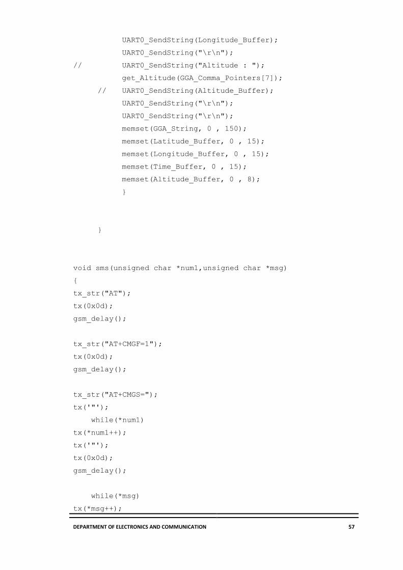
DEPARTMENT OF ELECTRONICS AND COMMUNICATION 57
UART0_SendString(Longitude_Buffer);
UART0_SendString("\r\n");
// UART0_SendString("Altitude : ");
get_Altitude(GGA_Comma_Pointers[7]);
// UART0_SendString(Altitude_Buffer);
UART0_SendString("\r\n");
UART0_SendString("\r\n");
memset(GGA_String, 0 , 150);
memset(Latitude_Buffer, 0 , 15);
memset(Longitude_Buffer, 0 , 15);
memset(Time_Buffer, 0 , 15);
memset(Altitude_Buffer, 0 , 8);
}
}
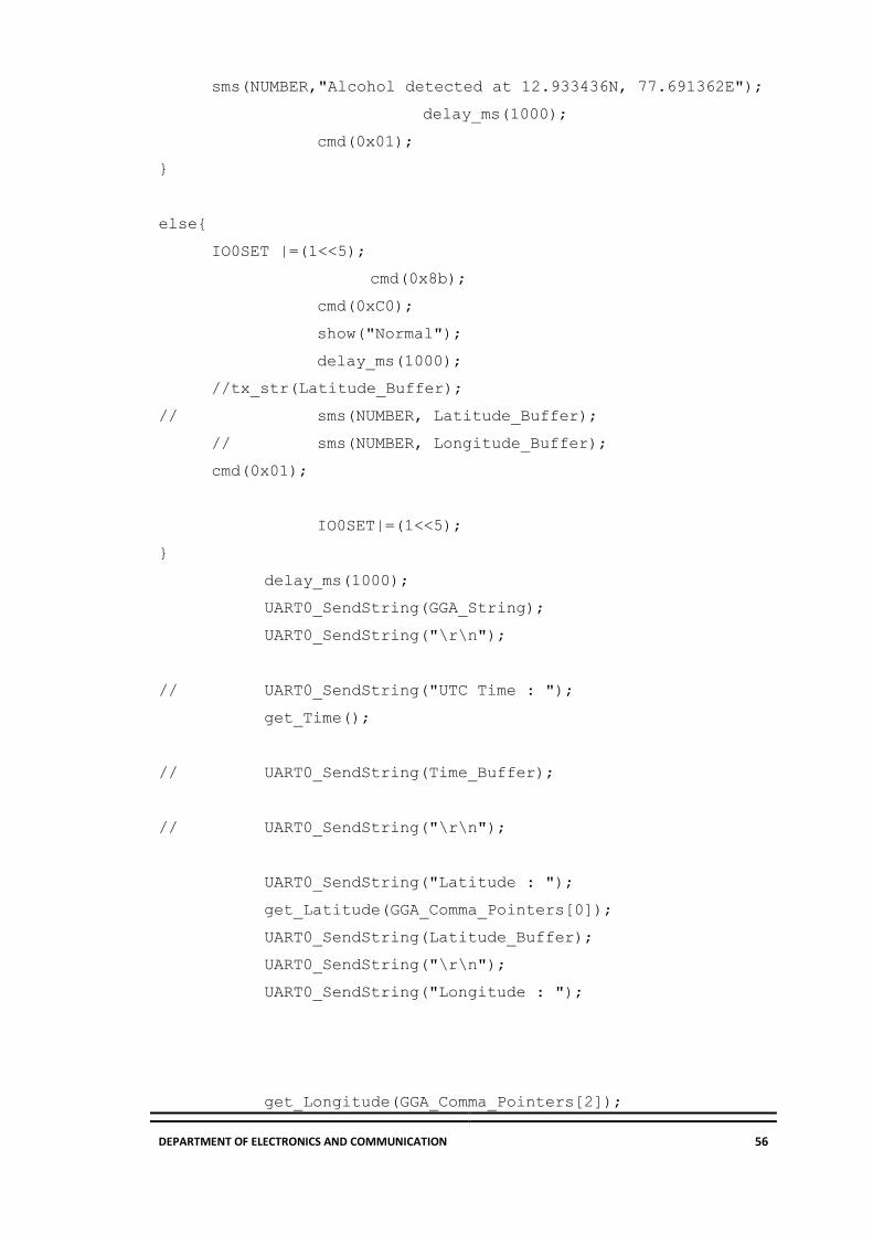
void sms(unsigned char *num1,unsigned char *msg)
{
tx_str("AT");
tx(0x0d);
gsm_delay();
tx_str("AT+CMGF=1");
tx(0x0d);
gsm_delay();
tx_str("AT+CMGS=");
tx('"');
while(*num1)
tx(*num1++);
tx('"');
tx(0x0d);
gsm_delay();
while(*msg)
tx(*msg++);

DEPARTMENT OF ELECTRONICS AND COMMUNICATION 58
tx(0x1a);
gsm_delay();
}
void gsm_delay()
{
unsigned long int gsm_del,ff;
for(gsm_del=0;gsm_del<=500000;gsm_del++)
for(ff=0;ff<25;ff++);
}
void ser_init()
{
VPBDIV=0x02; //PCLK = 30MHz
PINSEL0=0x5;
U0LCR=0x83;
U0DLL=195;
U0DLM=0;
U0LCR=0x03;
U0TER=(1<<7);
}
void tx(unsigned char c)
{
U0THR=c;
while((U0LSR&(1<<5))==0);
}
void tx_str(unsigned char *s)
{
while(*s) {
tx(*s++);
}
}
unsigned char rx()
{

DEPARTMENT OF ELECTRONICS AND COMMUNICATION 59
while((U0LSR&(1<<0))==0);
return U0RBR;
}
LCD Code:
#define bit(x) (1<<x)
void lcd_init(void);
void cmd(unsigned char a);
void dat(unsigned char b);
void show(unsigned char *s);
void lcd_delay(void);
void lcd_init()
{
cmd(0x38);
cmd(0x0e);
cmd(0x01);
cmd(0x06);
cmd(0x0c);
cmd(0x80);
}
void cmd(unsigned char a)
{
IO1CLR=0xFF070000;
IO1SET=(a<<24);
IO1CLR=bit(16); //rs=0
IO1CLR=bit(17); //rw=0
IO1SET=bit(18); //en=1
lcd_delay();
IO1CLR=bit(18); //en=0
}
void dat(unsigned char b)
{
IO1CLR=0xFF070000;
IO1SET=(b<<24);
IO1SET=bit(16); //rs=1
IO1CLR=bit(17); //rw=0
IO1SET=bit(18); //en=1
lcd_delay();
IO1CLR=bit(18); //en=0
}
void show(unsigned char *s)
{
while(*s) {
dat(*s++);

DEPARTMENT OF ELECTRONICS AND COMMUNICATION 60
}
}
void lcd_delay()
{
unsigned int i;
for(i=0;i<=6000;i++);
}
Related Documents