UMTS Link Budget Methodology Sylvestre Demonget Wireless BG / W-CDMA BD / Post-Sales Support & Technology Introduction / W-CDMA Network Engineering April 2 nd , 2007

Alcatel-Lucent UMTS Link Budget Methodology v1.0
Oct 21, 2015
UMTS
WCDMA
3G
ALCATEL
WCDMA
3G
ALCATEL
Welcome message from author
This document is posted to help you gain knowledge. Please leave a comment to let me know what you think about it! Share it to your friends and learn new things together.
Transcript
UMTS Link Budget Methodology
Sylvestre Demonget
Wireless BG / W-CDMA BD /
Post-Sales Support & Technology Introduction / W-CDMA Network Engineering
April 2nd, 2007
2 | HSUPA Link Budget | February 28th, 2007 All Rights Reserved © Alcatel-Lucent 2006
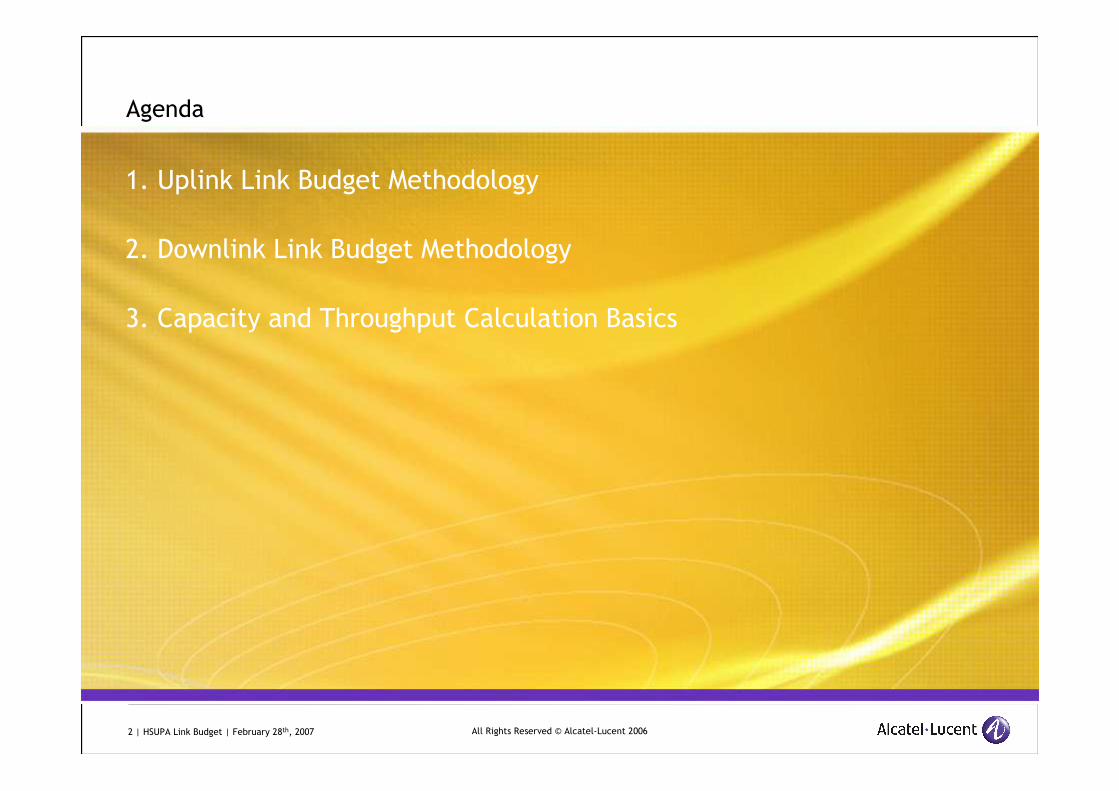
Agenda
1. Uplink Link Budget Methodology
2. Downlink Link Budget Methodology
3. Capacity and Throughput Calculation Basics
3 | HSUPA Link Budget | February 28th, 2007 All Rights Reserved © Alcatel-Lucent 2006
Introduction
UMTS Link Budget methodology:
� Uplink: Cell Range derivation based on a specific UL dimensioning service
� Downlink:
� Calculation for each DL service of transmit power necessary to reach cell edge
� Comparison with maximum allowed power for this DL service
Aspects covered in this presentation:
� Link budget methodology (UL and DL) applicable to both Release 99 and HSPA
� Cell Range comparisons for multiple:
� R’99 UL services
� HSUPA user throughput targets
� UL and DL Capacity calculation using analytic formulas
� HSPA Throughput computation using static simulation:
� Throughput map
� Throughput Vs. Distance from Site
4 | HSUPA Link Budget | February 28th, 2007 All Rights Reserved © Alcatel-Lucent 2006
Agenda
1. Uplink Link Budget Methodology
2. Downlink Link Budget Methodology
3. Capacity and Throughput Calculation Basics
5 | HSUPA Link Budget | February 28th, 2007 All Rights Reserved © Alcatel-Lucent 2006
1UMTS Uplink Link Budget
Methodology, Cell Range Comparisons
6 | HSUPA Link Budget | February 28th, 2007 All Rights Reserved © Alcatel-Lucent 2006
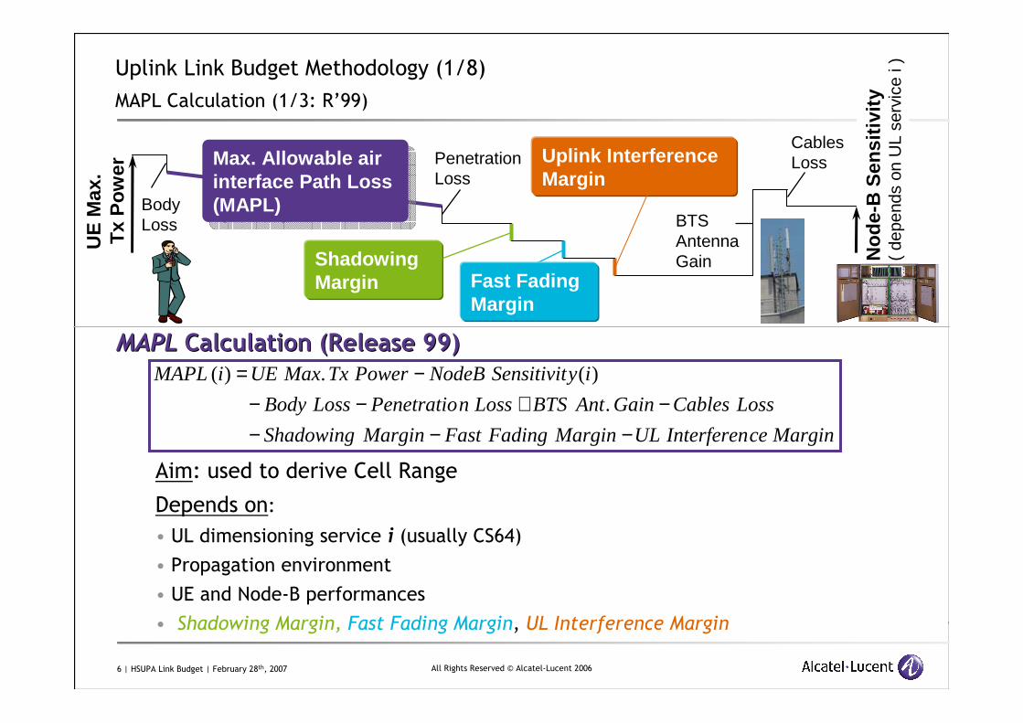
Uplink Link Budget Methodology (1/8)
MAPL Calculation (1/3: R’99)
MAPLMAPL Calculation (Release 99)Calculation (Release 99)
Aim: used to derive Cell Range
Depends on:
• UL dimensioning service i (usually CS64)
• Propagation environment
• UE and Node-B performances
• Shadowing Margin, Fast Fading Margin, UL Interference Margin
MarginceInterferenULMarginFadingFastMarginShadowing
LossCablesGainAntBTSLossnPenetratioLossBody
iySensitivitNodeBPowerTxMaxUEiMAPL
−−−−+−−
−=.
)(.)(
UE
Max
.T
xP
ow
er
BodyLoss BTS
AntennaGain
PenetrationLoss
No
de-
B S
ensi
tivi
ty(
depe
nds
on U
L se
rvic
e i )
Max. Allowable air interface Path Loss (MAPL)
Max. Allowable air interface Path Loss (MAPL)
Shadowing Margin
Uplink Interference Margin
Cables Loss
Fast Fading Margin
7 | HSUPA Link Budget | February 28th, 2007 All Rights Reserved © Alcatel-Lucent 2006
Uplink Link Budget Methodology (2/8)
MAPL Calculation (2/3: Impact of HSDPA)
MAPLMAPL Calculation (Impact of HSDPA)Calculation (Impact of HSDPA)
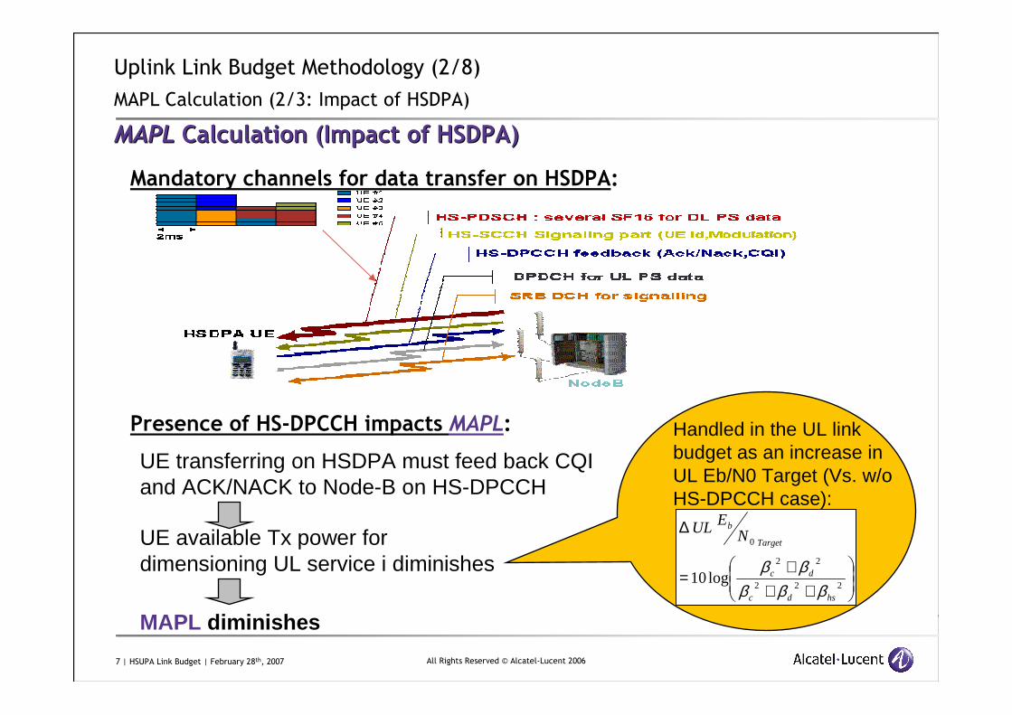
Mandatory channels for data transfer on HSDPA:
Presence of HS-DPCCH impacts MAPL:
UE transferring on HSDPA must feed back CQI and ACK/NACK to Node-B on HS-DPCCH
UE available Tx power fordimensioning UL service i diminishes
MAPL diminishes
+++
=
∆
222
22
0
log10hsdc
dc
Target
bN
EUL
βββββ
Handled in the UL link budget as an increase in UL Eb/N0 Target (Vs. w/o HS-DPCCH case):
8 | HSUPA Link Budget | February 28th, 2007 All Rights Reserved © Alcatel-Lucent 2006
Uplink Link Budget Methodology (2/8)
MAPL Calculation (3/3: HSUPA)
MAPLMAPL Calculation (HSUPA)Calculation (HSUPA)
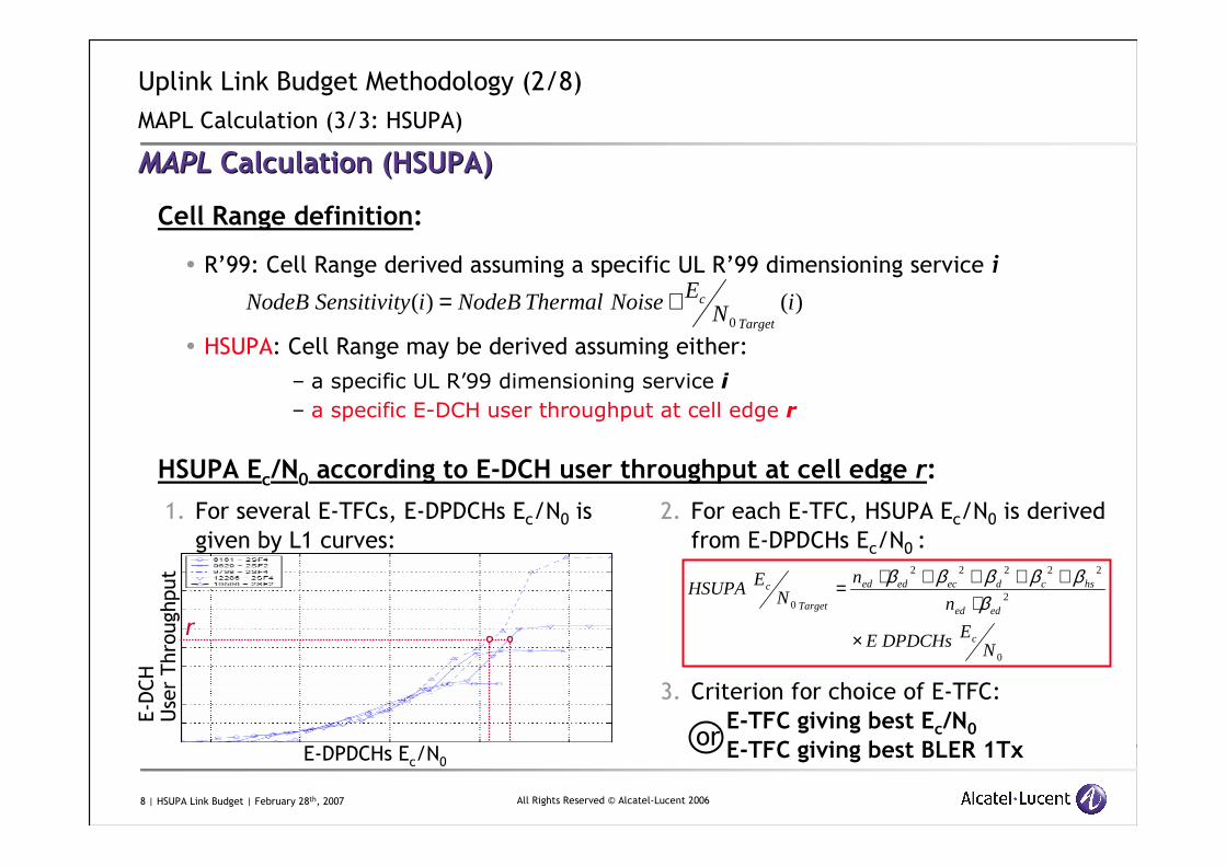
Cell Range definition:
� R’99: Cell Range derived assuming a specific UL R’99 dimensioning service i
� HSUPA: Cell Range may be derived assuming either:
– a specific UL R’99 dimensioning service i
– a specific E-DCH user throughput at cell edge r
HSUPA Ec/N0 according to E-DCH user throughput at cell edge r:
)()(0
iNENoiseThermalNodeBiySensitivitNodeB
Target
c+=
1. For several E-TFCs, E-DPDCHs Ec/N0 is
given by L1 curves:
E-DPDCHs Ec/N0
E-DCH
User Throughput
2. For each E-TFC, HSUPA Ec/N0 is derived
from E-DPDCHs Ec/N0 :
3. Criterion for choice of E-TFC:
E-TFC giving best Ec/N0
E-TFC giving best BLER 1Tx
0
2
22222
0
NEDPDCHsE
n
nN
EHSUPA
c
eded
hscdeceded
Target
c
×
⋅++++⋅=
ββββββ
r
or
9 | HSUPA Link Budget | February 28th, 2007 All Rights Reserved © Alcatel-Lucent 2006
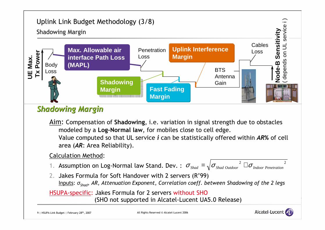
Uplink Link Budget Methodology (3/8)
Shadowing Margin
Shadowing MarginShadowing Margin
Aim: Compensation of Shadowing, i.e. variation in signal strength due to obstacles
modeled by a Log-Normal law, for mobiles close to cell edge.
Value computed so that UL service i can be statistically offered within AR% of cell
area (AR: Area Reliability).
Calculation Method:
1. Assumption on Log-Normal law Stand. Dev. :
2. Jakes Formula for Soft Handover with 2 servers (R’99)Inputs: σShad, AR, Attenuation Exponent, Correlation coeff. between Shadowing of the 2 legs
HSUPA-specific: Jakes Formula for 2 servers without SHO(SHO not supported in Alcatel-Lucent UA5.0 Release)
22nPenetratioIndoorOutdoorShadShad σσσ +=
UE
Max
.T
xP
ow
er
BodyLoss BTS
AntennaGain
PenetrationLoss
No
de-
B S
ensi
tivi
ty(
depe
nds
on U
L se
rvic
e i )
Max. Allowable air interface Path Loss (MAPL)
Shadowing Margin
Shadowing Margin
Uplink Interference Margin
Cables Loss
Fast Fading Margin
10 | HSUPA Link Budget | February 28th, 2007 All Rights Reserved © Alcatel-Lucent 2006
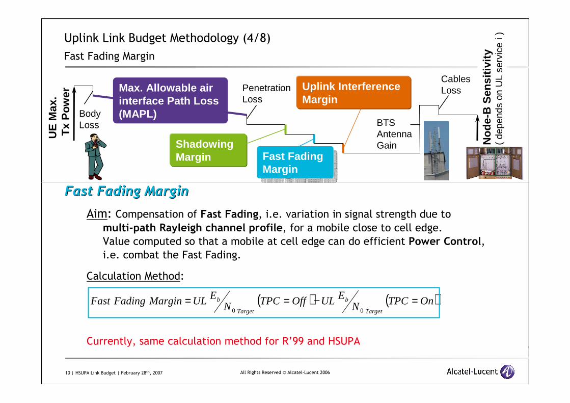
Uplink Link Budget Methodology (4/8)
Fast Fading Margin
Fast Fading MarginFast Fading Margin
Aim: Compensation of Fast Fading, i.e. variation in signal strength due to
multi-path Rayleigh channel profile, for a mobile close to cell edge.
Value computed so that a mobile at cell edge can do efficient Power Control,
i.e. combat the Fast Fading.
Calculation Method:
Currently, same calculation method for R’99 and HSUPA
UE
Max
.T
xP
ow
er
BodyLoss BTS
AntennaGain
PenetrationLoss
No
de-
B S
ensi
tivi
ty(
depe
nds
on U
L se
rvic
e i )
Max. Allowable air interface Path Loss (MAPL)
Shadowing Margin
Uplink Interference Margin
Cables Loss
Fast Fading Margin
Fast Fading Margin
( ) ( )OnTPCNEULOffTPCN
EULMarginFadingFastTarget
b
Target
b =−==00
11 | HSUPA Link Budget | February 28th, 2007 All Rights Reserved © Alcatel-Lucent 2006
Uplink Link Budget Methodology (5/8)
Uplink Interference Margin (1/2)
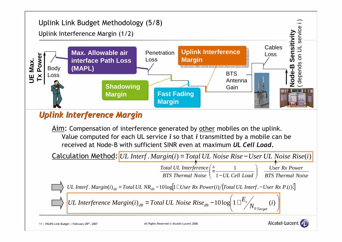
Uplink Interference MarginUplink Interference Margin
Aim: Compensation of interference generated by other mobiles on the uplink.
Value computed for each UL service i so that i transmitted by a mobile can be
received at Node-B with sufficient SINR even at maximum UL Cell Load.
Calculation Method: )()(. iRiseNoiseULUserRiseNoiseULTotaliMarginInterfUL −=
−=∆
LoadCellULNoiseThermalBTS
ceInterferenULTotal
1
1
NoiseThermalBTS
PowerRxUser
( )[ ]).(.)(1log10)(. iPRxUserInterfULTotaliPowerRxUserNRULTotaliMarginInterfUL dBdB −+−=
+−= )(1log10)(0
iNERiseNoiseULTotaliMarginceInterferenUL
Target
cdBdB
UE
Max
.T
xP
ow
er
BodyLoss BTS
AntennaGain
PenetrationLoss
No
de-
B S
ensi
tivi
ty(
depe
nds
on U
L se
rvic
e i )
Max. Allowable air interface Path Loss (MAPL)
Shadowing Margin
Uplink Interference Margin
Uplink Interference Margin
Cables Loss
Fast Fading Margin
12 | HSUPA Link Budget | February 28th, 2007 All Rights Reserved © Alcatel-Lucent 2006
Uplink Link Budget Methodology (6/8)
Uplink Interference Margin (2/2)
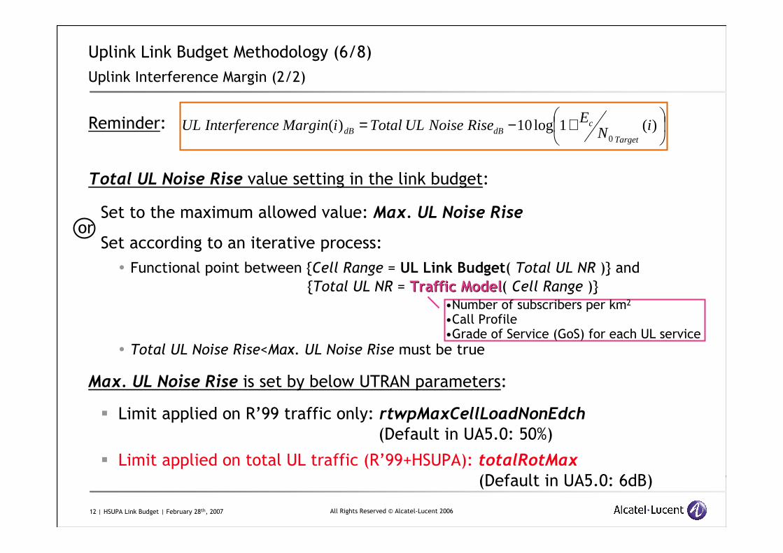
Reminder:
Total UL Noise Rise value setting in the link budget:
Set to the maximum allowed value: Max. UL Noise Rise
Set according to an iterative process:
� Functional point between {Cell Range = UL Link Budget( Total UL NR )} and
{Total UL NR = Traffic ModelTraffic Model( Cell Range )}
� Total UL Noise Rise<Max. UL Noise Rise must be true
Max. UL Noise Rise is set by below UTRAN parameters:
� Limit applied on R’99 traffic only: rtwpMaxCellLoadNonEdch
(Default in UA5.0: 50%)
� Limit applied on total UL traffic (R’99+HSUPA): totalRotMax
(Default in UA5.0: 6dB)
•Number of subscribers per km2
•Call Profile•Grade of Service (GoS) for each UL service
+−= )(1log10)(0
iNERiseNoiseULTotaliMarginceInterferenUL
Target
cdBdB
or
13 | HSUPA Link Budget | February 28th, 2007 All Rights Reserved © Alcatel-Lucent 2006
Uplink Link Budget Methodology (7/8)
Cell Range Calculation
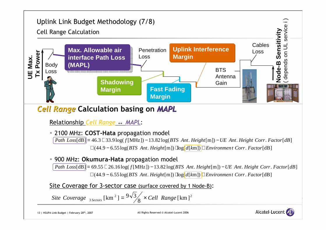
Cell RangeCell Range Calculation basing onCalculation basing on MAPLMAPL
Relationship Cell Range ↔ MAPL:
� 2100 MHz: COST-Hata propagation model
� 900 MHz: Okumura-Hata propagation model
Site Coverage for 3-sector case (surface covered by 1 Node-B):
]dB[.])m[log(])m[.log(55.69.44(
][..])m[.log(82.13])MHz[log(9.333.46]dB[
FactorCorrtEnvironmenkdHeightAntBTS
dBFactorCorrHeightAntUEHeightAntBTSfLossPath
+⋅−+−−+=
]dB[.])m[log(])m[.log(55.69.44(
][..])m[.log(82.13])MHz[log(16.2655.69]dB[
FactorCorrtEnvironmenkdHeightAntBTS
dBFactorCorrHeightAntUEHeightAntBTSfLossPath
+⋅−+−−+=
UE
Max
.T
xP
ow
er
BodyLoss BTS
AntennaGain
PenetrationLoss
No
de-
B S
ensi
tivi
ty(
depe
nds
on U
L se
rvic
e i )
Max. Allowable air interface Path Loss (MAPL)
Max. Allowable air interface Path Loss (MAPL)
Shadowing Margin
Uplink Interference Margin
Cables Loss
Fast Fading Margin
223 ]km[8
39]km[ RangeCellCoverageSite Sectors ×=
14 | HSUPA Link Budget | February 28th, 2007 All Rights Reserved © Alcatel-Lucent 2006
Uplink Link Budget Methodology (8/8)
Tower Mounted Amplifier (TMA) Benefits and Drawbacks
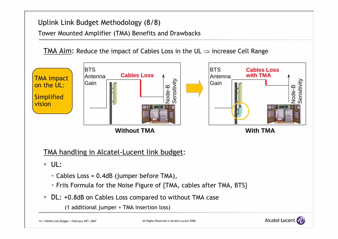
TMA Aim: Reduce the impact of Cables Loss in the UL ⇒ increase Cell Range
TMA handling in Alcatel-Lucent link budget:
� UL:
� Cables Loss = 0.4dB (jumper before TMA),
� Friis Formula for the Noise Figure of {TMA, cables after TMA, BTS}
� DL: +0.8dB on Cables Loss compared to without TMA case
(1 additional jumper + TMA insertion loss)
BTS Antenna Gain
Cables Loss
Without TMA
Nod
e-B
S
ensi
tivity
BTS Antenna Gain
Cables Loss with TMA
With TMA
Nod
e-B
S
ensi
tivity
TMA impact on the UL:
Simplifiedvision
15 | HSUPA Link Budget | February 28th, 2007 All Rights Reserved © Alcatel-Lucent 2006
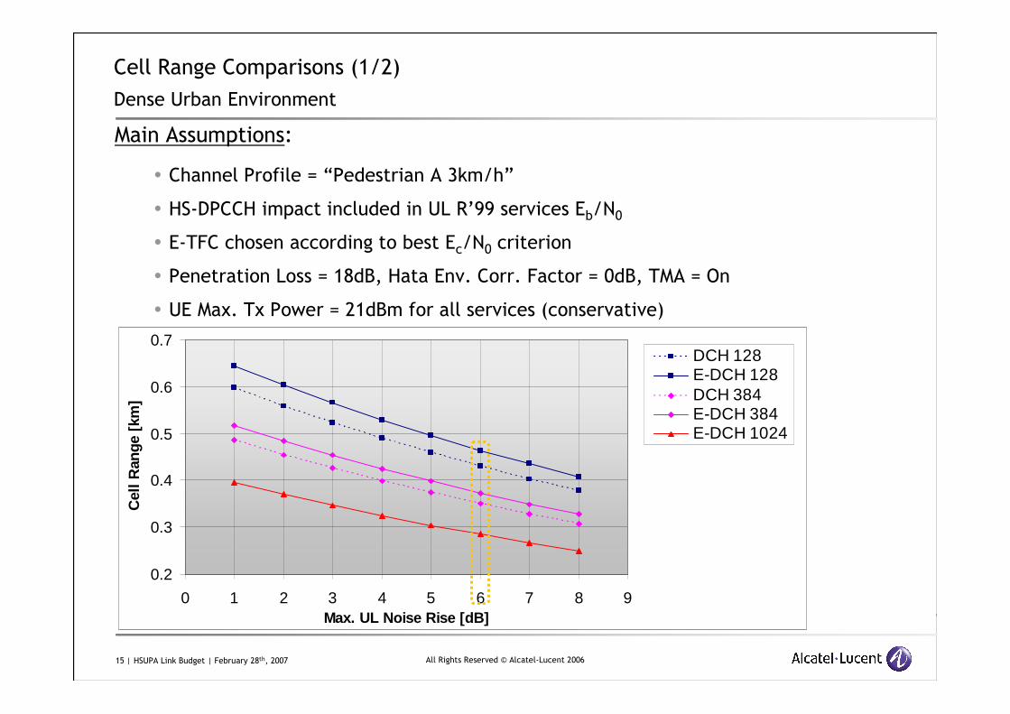
Cell Range Comparisons (1/2)
Dense Urban Environment
Main Assumptions:
� Channel Profile = “Pedestrian A 3km/h”
� HS-DPCCH impact included in UL R’99 services Eb/N0
� E-TFC chosen according to best Ec/N0 criterion
� Penetration Loss = 18dB, Hata Env. Corr. Factor = 0dB, TMA = On
� UE Max. Tx Power = 21dBm for all services (conservative)
0.2
0.3
0.4
0.5
0.6
0.7
0 1 2 3 4 5 6 7 8 9Max. UL Noise Rise [dB]
Cel
l Ran
ge [
km]
DCH 128E-DCH 128DCH 384E-DCH 384E-DCH 1024
16 | HSUPA Link Budget | February 28th, 2007 All Rights Reserved © Alcatel-Lucent 2006
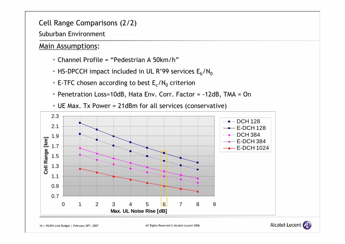
Cell Range Comparisons (2/2)
Suburban Environment
Main Assumptions:
� Channel Profile = “Pedestrian A 50km/h”
� HS-DPCCH impact included in UL R’99 services Eb/N0
� E-TFC chosen according to best Ec/N0 criterion
� Penetration Loss=10dB, Hata Env. Corr. Factor = -12dB, TMA = On
� UE Max. Tx Power = 21dBm for all services (conservative)
0.7
0.9
1.1
1.3
1.5
1.7
1.9
2.1
2.3
0 1 2 3 4 5 6 7 8 9Max. UL Noise Rise [dB]
Cel
l Ran
ge [
km]
DCH 128E-DCH 128DCH 384E-DCH 384E-DCH 1024
17 | HSUPA Link Budget | February 28th, 2007 All Rights Reserved © Alcatel-Lucent 2006
Agenda
1. Uplink Link Budget Methodology
2. Downlink Link Budget Methodology
3. Capacity and Throughput Calculation Basics
18 | HSUPA Link Budget | February 28th, 2007 All Rights Reserved © Alcatel-Lucent 2006
2UMTS Downlink Link Budget
Methodology, Impact of HSUPA DL channels
19 | HSUPA Link Budget | February 28th, 2007 All Rights Reserved © Alcatel-Lucent 2006
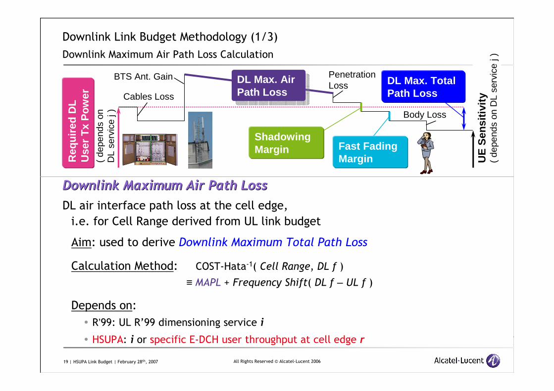
Downlink Link Budget Methodology (1/3)
Downlink Maximum Air Path Loss Calculation
Downlink Maximum Air Path LossDownlink Maximum Air Path Loss
DL air interface path loss at the cell edge,
i.e. for Cell Range derived from UL link budget
Aim: used to derive Downlink Maximum Total Path Loss
Calculation Method: COST-Hata-1( Cell Range, DL f )
≡ MAPL + Frequency Shift( DL f – UL f )
Depends on:
� R’99: UL R’99 dimensioning service i
� HSUPA: i or specific E-DCH user throughput at cell edge r
BTS Ant. Gain DL Max. Total Path LossCables Loss
DL Max. Air Path Loss
DL Max. Air Path Loss
PenetrationLoss
Shadowing Margin Fast Fading
MarginReq
uir
ed D
L
Use
r T
xP
ow
er(
depe
nds
on
DL
serv
ice
j ) Body Loss
UE
Sen
siti
vity
( de
pend
s on
DL
serv
ice
j )
20 | HSUPA Link Budget | February 28th, 2007 All Rights Reserved © Alcatel-Lucent 2006
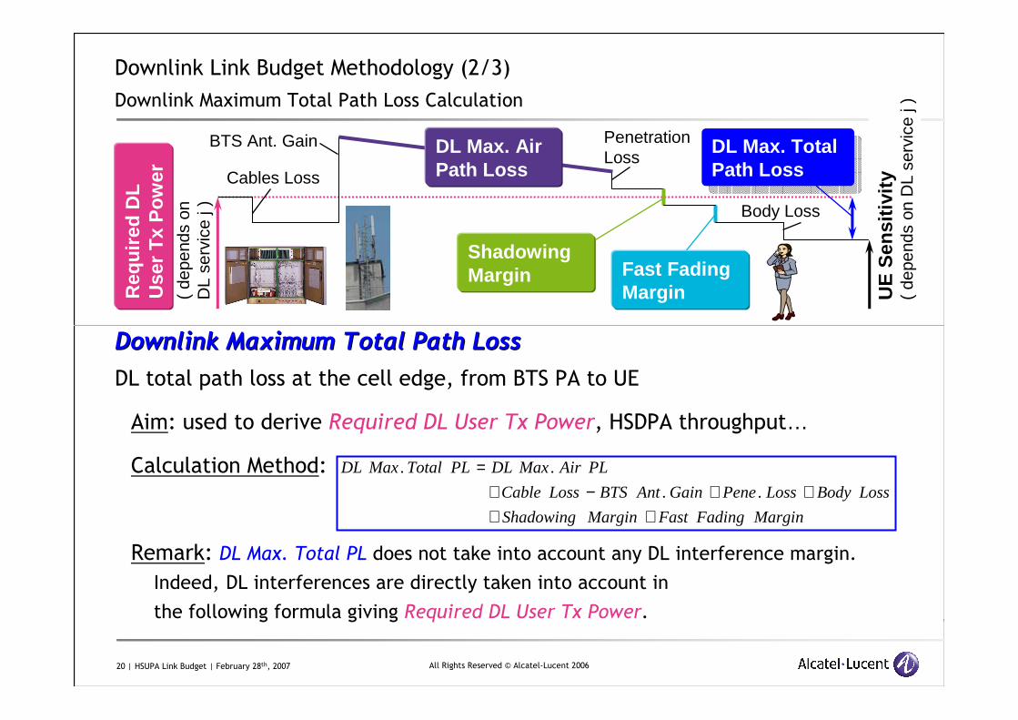
Downlink Link Budget Methodology (2/3)
Downlink Maximum Total Path Loss Calculation
Downlink Maximum Total Path LossDownlink Maximum Total Path Loss
DL total path loss at the cell edge, from BTS PA to UE
Aim: used to derive Required DL User Tx Power, HSDPA throughput…
Calculation Method:
Remark: DL Max. Total PL does not take into account any DL interference margin.
Indeed, DL interferences are directly taken into account in
the following formula giving Required DL User Tx Power.
BTS Ant. GainDL Max. Total Path Loss
DL Max. Total Path LossCables Loss
DL Max. Air Path Loss
PenetrationLoss
Shadowing Margin Fast Fading
MarginReq
uir
ed D
L
Use
r T
xP
ow
er(
depe
nds
on
DL
serv
ice
j ) Body Loss
UE
Sen
siti
vity
( de
pend
s on
DL
serv
ice
j )
MarginFadingFastMarginShadowing
LossBodyLossPeneGainAntBTSLossCable
PLAirMaxDLPLTotalMaxDL
++++−+
=..
..
21 | HSUPA Link Budget | February 28th, 2007 All Rights Reserved © Alcatel-Lucent 2006
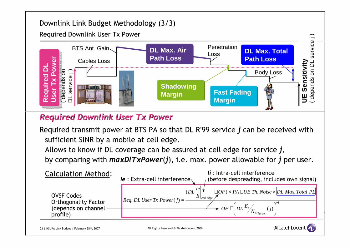
Downlink Link Budget Methodology (3/3)
Required Downlink User Tx Power
Required Downlink User Required Downlink User TxTx PowerPower
Required transmit power at BTS PA so that DL R’99 service j can be received with sufficient SINR by a mobile at cell edge.
Allows to know if DL coverage can be assured at cell edge for service j,
by comparing with maxDlTxPower(j), i.e. max. power allowable for j per user.
Calculation Method:
BTS Ant. Gain DL Max. Total Path LossCables Loss
DL Max. Air Path Loss
PenetrationLoss
Shadowing Margin Fast Fading
MarginReq
uir
ed D
L
Use
r T
xP
ow
er
Req
uir
ed D
L
Use
r T
xP
ow
er(
depe
nds
on
DL
serv
ice
j ) Body Loss
UE
Sen
siti
vity
( de
pend
s on
DL
serv
ice
j )
1
0)(
..)(
)(. −
+
×+×+=
jNEDLOF
PLTotalMaxDLNoiseThUEPAOFIi
IeDL
jPowerTxUserDLReq
Target
c
edgecell
Ii : Intra-cell interference(before despreading, includes own signal)
OVSF Codes Orthogonality Factor(depends on channel profile)
Ie : Extra-cell interference
22 | HSUPA Link Budget | February 28th, 2007 All Rights Reserved © Alcatel-Lucent 2006
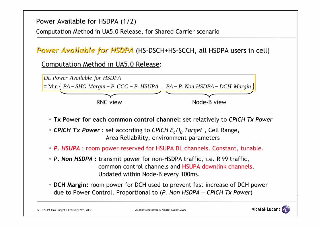
Power Available for HSDPA (1/2)
Computation Method in UA5.0 Release, for Shared Carrier scenario
Power Available for HSDPAPower Available for HSDPA (HS-DSCH+HS-SCCH, all HSDPA users in cell)
Computation Method in UA5.0 Release:
� Tx Power for each common control channel: set relatively to CPICH Tx Power
� CPICH Tx Power : set according to CPICH Ec/I0 Target , Cell Range,
Area Reliability, environment parameters
� P. HSUPA : room power reserved for HSUPA DL channels. Constant, tunable.
� P. Non HSDPA : transmit power for non-HSDPA traffic, i.e. R’99 traffic, common control channels and HSUPA downlink channels.
Updated within Node-B every 100ms.
� DCH Margin: room power for DCH used to prevent fast increase of DCH power
due to Power Control. Proportional to (P. Non HSDPA – CPICH Tx Power)
{ }MarginDCHHSDPANonPPAHSUPAPCCCPMarginSHOPA
HSDPAforAvailablePowerDL
−−−−−= .,..Min
RNC view Node-B view
23 | HSUPA Link Budget | February 28th, 2007 All Rights Reserved © Alcatel-Lucent 2006
Power Available for HSDPA (2/2)
Impact of HSUPA Downlink Channels
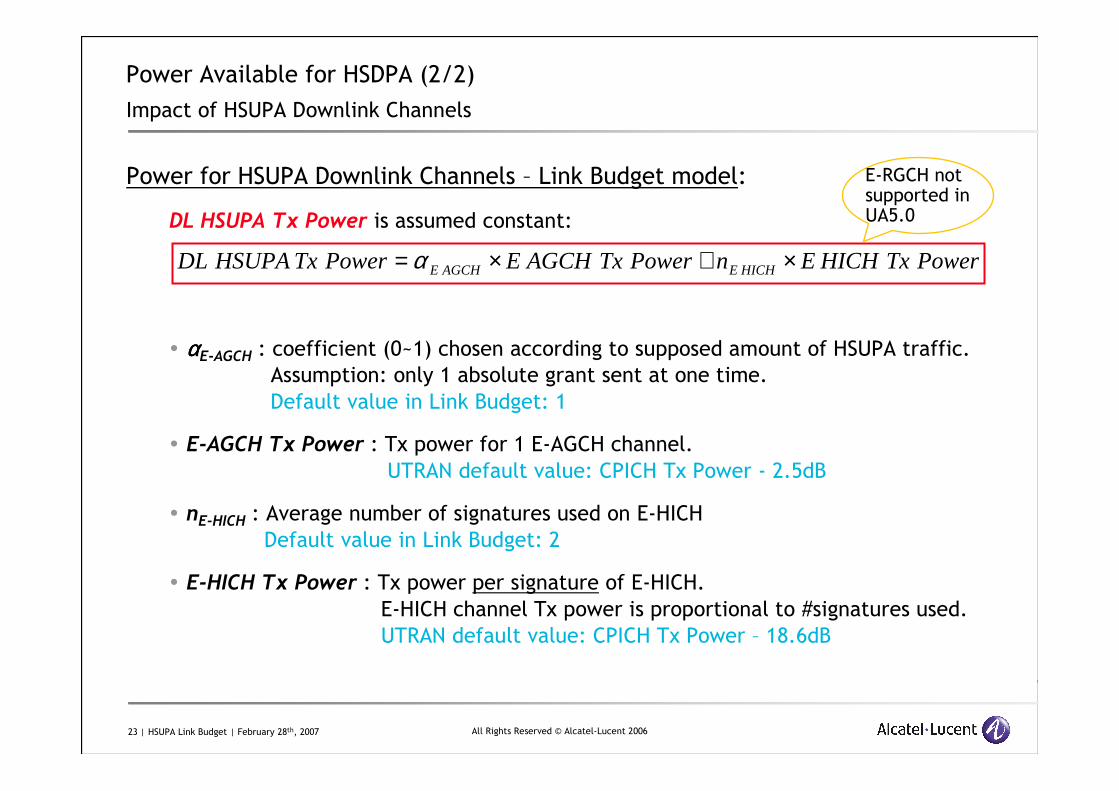
Power for HSUPA Downlink Channels – Link Budget model:
DL HSUPA Tx Power is assumed constant:
� ααααE-AGCH : coefficient (0~1) chosen according to supposed amount of HSUPA traffic.
Assumption: only 1 absolute grant sent at one time.
Default value in Link Budget: 1
� E-AGCH Tx Power : Tx power for 1 E-AGCH channel.
UTRAN default value: CPICH Tx Power - 2.5dB
� nE-HICH : Average number of signatures used on E-HICH
Default value in Link Budget: 2
� E-HICH Tx Power : Tx power per signature of E-HICH.
E-HICH channel Tx power is proportional to #signatures used.
UTRAN default value: CPICH Tx Power – 18.6dB
PowerTxHICHEnPowerTxAGCHEPowerTxHSUPADL HICHEAGCHE ×+×= α
E-RGCH not supported in UA5.0
24 | HSUPA Link Budget | February 28th, 2007 All Rights Reserved © Alcatel-Lucent 2006
Agenda
1. Uplink Link Budget Methodology
2. Downlink Link Budget Methodology
3. Capacity and Throughput Calculation Basics
25 | HSUPA Link Budget | February 28th, 2007 All Rights Reserved © Alcatel-Lucent 2006
3Capacity and Throughput Calculation Basics
Method presented: calculation via formulas/static simulation
26 | HSUPA Link Budget | February 28th, 2007 All Rights Reserved © Alcatel-Lucent 2006
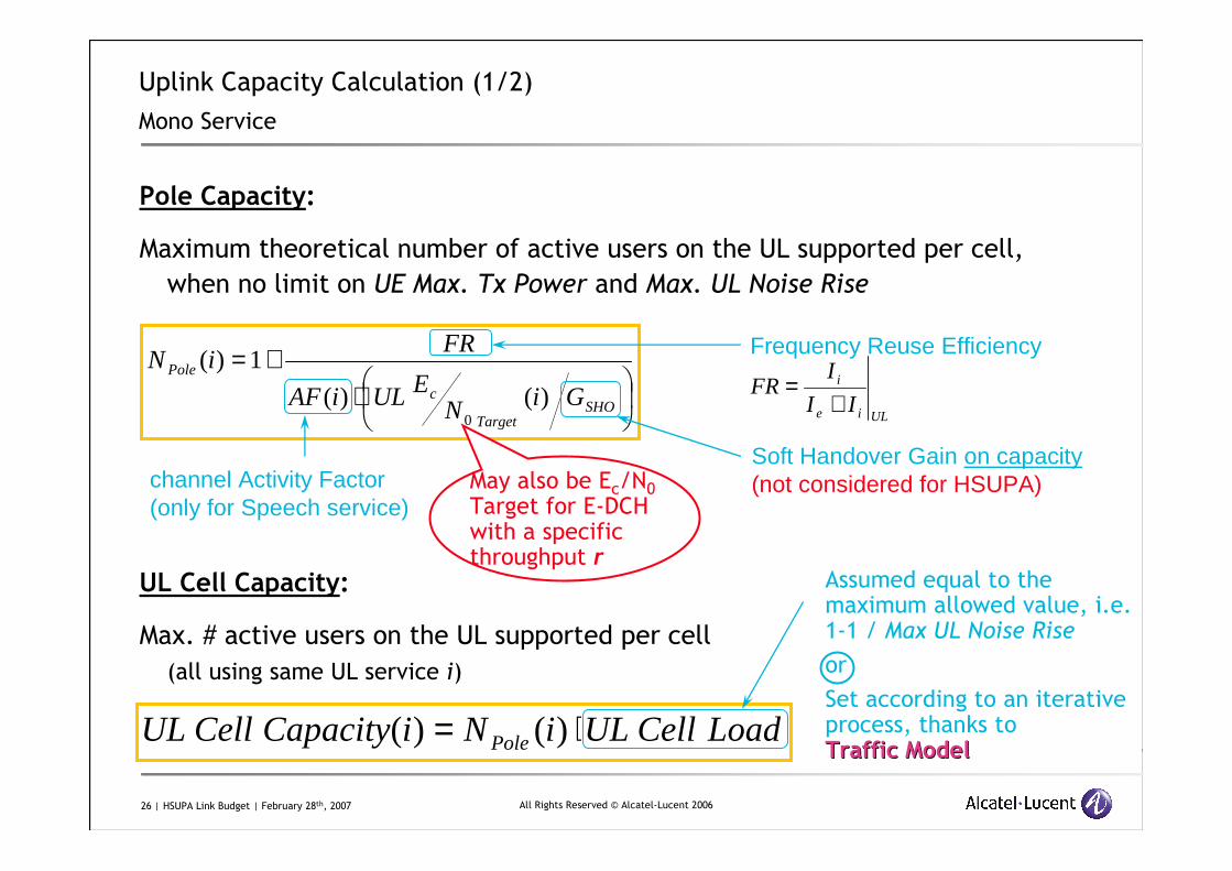
Pole Capacity:
Maximum theoretical number of active users on the UL supported per cell,
when no limit on UE Max. Tx Power and Max. UL Noise Rise
UL Cell Capacity:
Max. # active users on the UL supported per cell
(all using same UL service i)
Uplink Capacity Calculation (1/2)
Mono Service
ULie
i
II
IFR
+=
⋅+=
SHOTarget
c
Pole
GiNEULiAF
FRiN
)()(
1)(
0
LoadCellULiNiCapacityCellUL Pole ⋅= )()(
Frequency Reuse Efficiency
Soft Handover Gain on capacity(not considered for HSUPA)channel Activity Factor
(only for Speech service)
Assumed equal to the maximum allowed value, i.e. 1-1 / Max UL Noise Rise
or
Set according to an iterative process, thanks toTraffic ModelTraffic Model
May also be Ec/N0
Target for E-DCH with a specificthroughput r
27 | HSUPA Link Budget | February 28th, 2007 All Rights Reserved © Alcatel-Lucent 2006
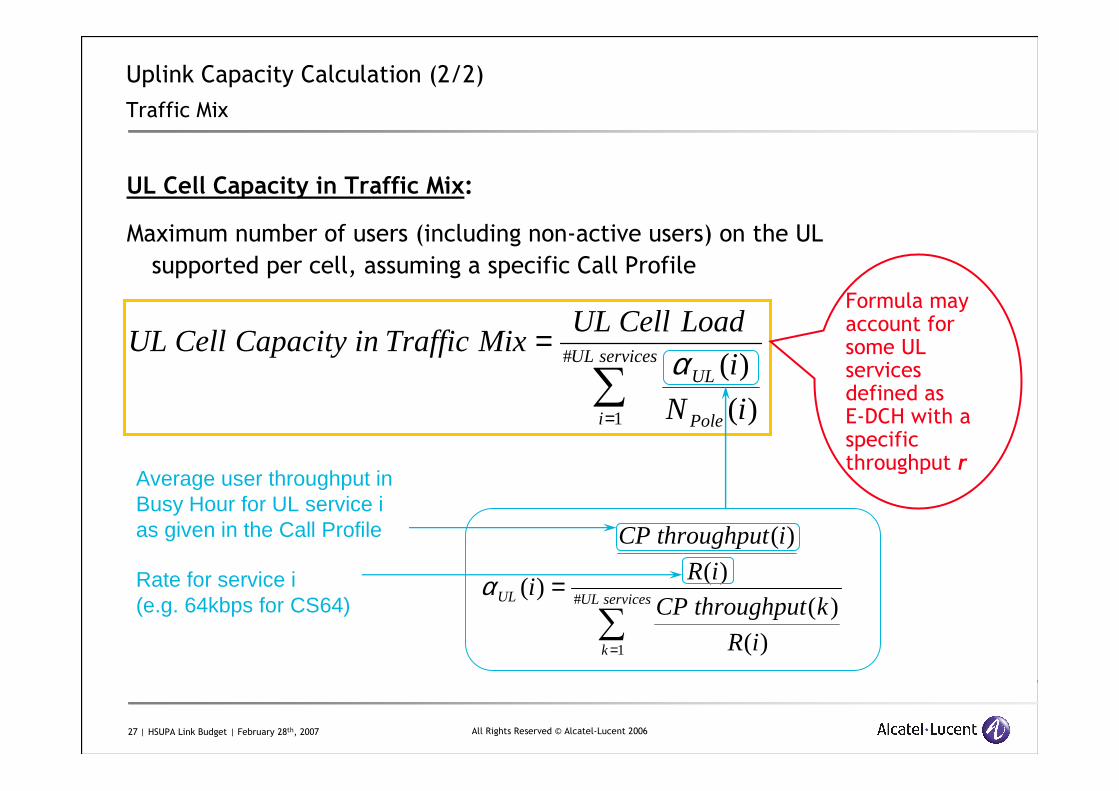
UL Cell Capacity in Traffic Mix:
Maximum number of users (including non-active users) on the UL
supported per cell, assuming a specific Call Profile
Uplink Capacity Calculation (2/2)
Traffic Mix
∑=
=servicesUL
i Pole
UL
iN
i
LoadCellULMixTrafficinCapacityCellUL
#
1 )(
)(α
Average user throughput in Busy Hour for UL service ias given in the Call Profile
∑=
=servicesUL
k
UL
iR
kthroughputCP
iR
ithroughputCP
i#
1 )(
)(
)(
)(
)(αRate for service i(e.g. 64kbps for CS64)
Formula mayaccount for some UL services defined asE-DCH with a specificthroughput r
28 | HSUPA Link Budget | February 28th, 2007 All Rights Reserved © Alcatel-Lucent 2006
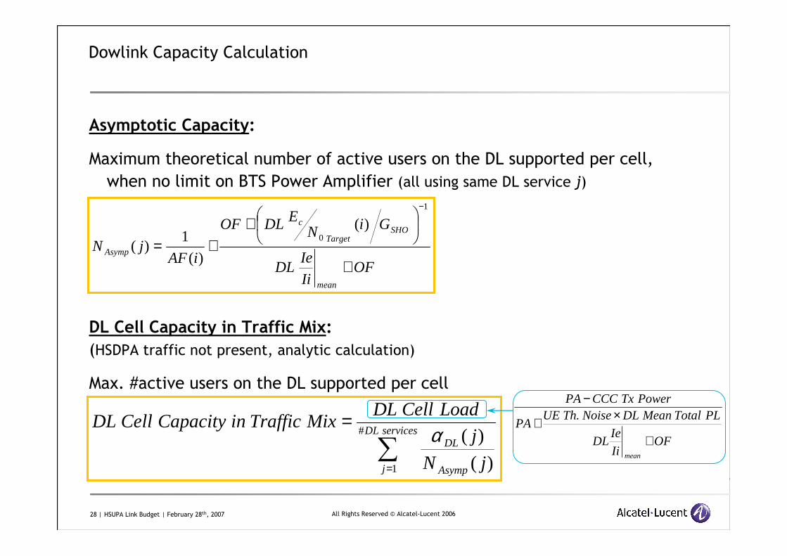
Asymptotic Capacity:
Maximum theoretical number of active users on the DL supported per cell,
when no limit on BTS Power Amplifier (all using same DL service j)
DL Cell Capacity in Traffic Mix:
(HSDPA traffic not present, analytic calculation)
Max. #active users on the DL supported per cell
Dowlink Capacity Calculation
OFIi
IeDL
GiNEDLOF
iAFjN
mean
SHOTarget
c
Asymp
+
++=
−1
0)(
)(
1)(
OFIi
IeDL
PLTotalMeanDLNoiseThUEPA
PowerTxCCCPA
mean
+
×+
−.
∑=
=servicesDL
j Asymp
DL
jN
j
LoadCellDLMixTrafficinCapacityCellDL
#
1 )(
)(α
29 | HSUPA Link Budget | February 28th, 2007 All Rights Reserved © Alcatel-Lucent 2006
Power Available for HS-DSCH
HS-DSCH Rx Ec/N0
DistanceServing Node-B↔↔↔↔UE
HSDPA UE Category
HSDPA User Throughput
CQI reported
HSDPA Throughput Computation via Static Simulation (1/2)
UE SpeedChannel Profile
DL Total Path Loss
Shadowing at UE
BTS Ant. Diagram
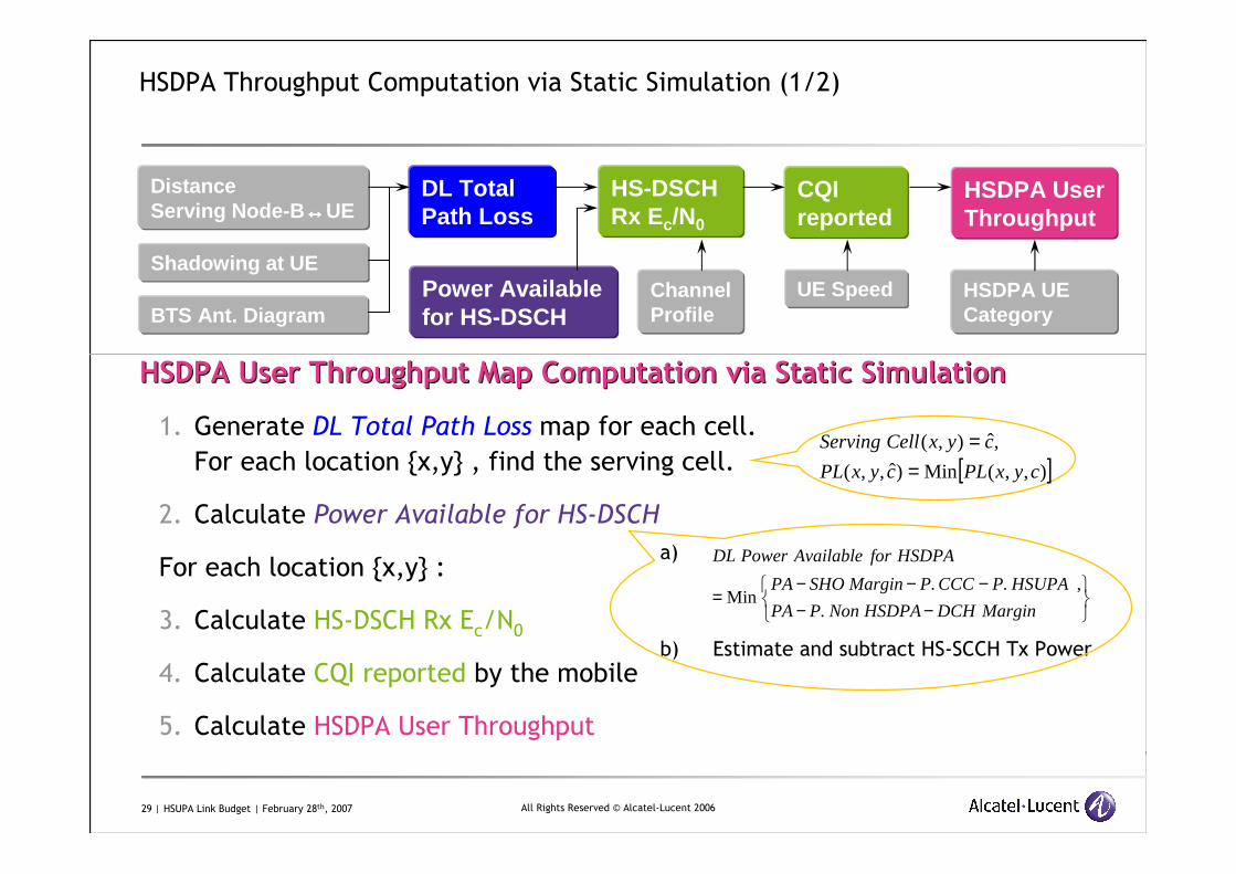
HSDPA User ThroughputHSDPA User Throughput Map Computation via Static SimulationMap Computation via Static Simulation
1. Generate DL Total Path Loss map for each cell.
For each location {x,y} , find the serving cell.
2. Calculate Power Available for HS-DSCH
For each location {x,y} :
3. Calculate HS-DSCH Rx Ec/N0
4. Calculate CQI reported by the mobile
5. Calculate HSDPA User Throughput
[ ]),,(Min)ˆ,,(
,ˆ),(
cyxPLcyxPL
cyxCellServing
==
a)
b) Estimate and subtract HS-SCCH Tx Power
−−−−−
=MarginDCHHSDPANonPPA
HSUPAPCCCPMarginSHOPA
HSDPAforAvailablePowerDL
.
,..Min
30 | HSUPA Link Budget | February 28th, 2007 All Rights Reserved © Alcatel-Lucent 2006
Power Available for HS-DSCH
HS-DSCH Rx Ec/N0
DistanceServing Node-B↔↔↔↔UE
HSDPA UE Category
HSDPA User Throughput
HSDPA User Throughput
CQI reported
CQI reported
HSDPA Throughput Computation via Static Simulation (2/2)
UE SpeedChannel Profile
DL Total Path Loss
Shadowing at UE
BTS Ant. Diagram
HSDPA User ThroughputHSDPA User Throughput Map Computation via Static SimulationMap Computation via Static Simulation
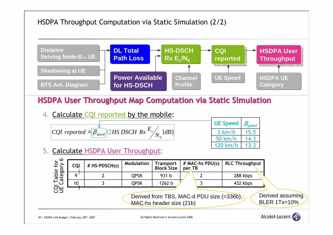
4. Calculate CQI reported by the mobile:
5. Calculate HSDPA User Throughput:
[dB]0N
ERxDSCHHSreportedCQI cspeed += β
13.3120 km/h
14.350 km/h
15.53 km/h
ββββspeedUE Speed
3
2
# HS-PDSCH(s)
QPSK
QPSK
Modulation
432 kbps31262 b10
288 kbps2931 b9
RLC Throughput# MAC-hs PDU(s)per TB
TransportBlock Size
CQI
CQI Table for
UE Category 6
……
Derived from TBS, MAC-d PDU size (=336b),MAC-hs header size (21b)
Derived assuming BLER 1Tx=10%
31 | HSUPA Link Budget | February 28th, 2007 All Rights Reserved © Alcatel-Lucent 2006
UL Noise Rise Available for user
E-DCHRx Ec/N0
DistanceServing Node-B↔↔↔↔UE
HSDPA UE Category
E-DCH User Throughput
E-TFC
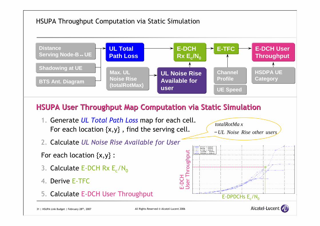
HSUPA Throughput Computation via Static Simulation
UE Speed
Max. ULNoise Rise(totalRotMax)
UL Total Path Loss
Shadowing at UE
BTS Ant. Diagram
HSUPA User ThroughputHSUPA User Throughput Map Computation via Static SimulationMap Computation via Static Simulation
1. Generate UL Total Path Loss map for each cell.
For each location {x,y} , find the serving cell.
2. Calculate UL Noise Rise Available for User
For each location {x,y} :
3. Calculate E-DCH Rx Ec/N0
4. Derive E-TFC
5. Calculate E-DCH User Throughput
Channel Profile
usersotherRiseNoiseUL
xtotalRotMa
−
E-DPDCHs Ec/N0
E-DCH
User Throughput
32 | HSUPA Link Budget | February 28th, 2007 All Rights Reserved © Alcatel-Lucent 2006
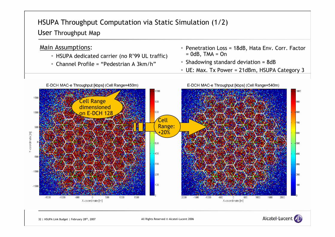
HSUPA Throughput Computation via Static Simulation (1/2)
User Throughput Map
Main Assumptions:
� HSUPA dedicated carrier (no R’99 UL traffic)
� Channel Profile = “Pedestrian A 3km/h”
� Penetration Loss = 18dB, Hata Env. Corr. Factor = 0dB, TMA = On
� Shadowing standard deviation = 8dB
� UE: Max. Tx Power = 21dBm, HSUPA Category 3
CellRange: +20%
Cell Range dimensionedon E-DCH 128
33 | HSUPA Link Budget | February 28th, 2007 All Rights Reserved © Alcatel-Lucent 2006
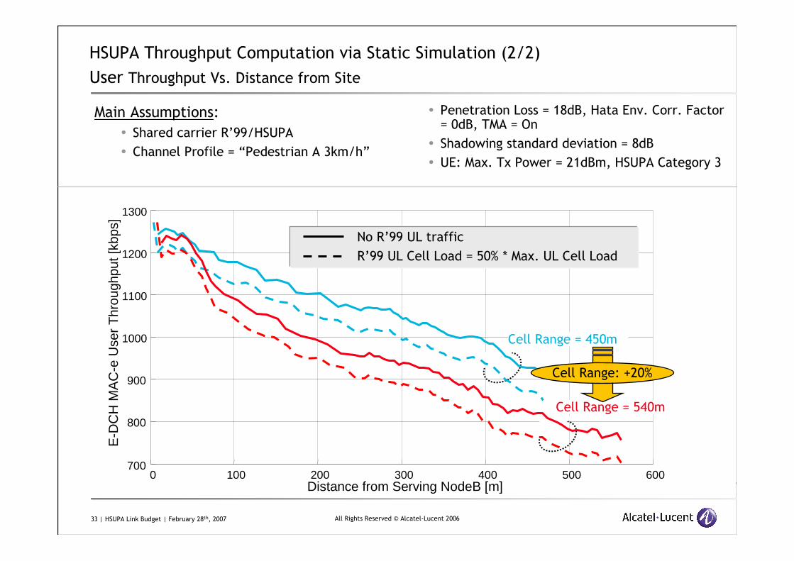
HSUPA Throughput Computation via Static Simulation (2/2)
User Throughput Vs. Distance from Site
Main Assumptions:
� Shared carrier R’99/HSUPA
� Channel Profile = “Pedestrian A 3km/h”
� Penetration Loss = 18dB, Hata Env. Corr. Factor = 0dB, TMA = On
� Shadowing standard deviation = 8dB
� UE: Max. Tx Power = 21dBm, HSUPA Category 3
•0 •100 •200 •300 •400 •500 •600•700
•800
•900
•1000
•1100
•1200
•1300
•Distance from Serving NodeB [m]
•E-D
CH
MA
C-e
Use
r T
hrou
ghpu
t[kb
ps]
•
R’99 UL Cell Load = 50% * Max. UL Cell Load
No R’99 UL traffic
Cell Range = 450m
Cell Range = 540m
Cell Range: +20%
34 | HSUPA Link Budget | February 28th, 2007 All Rights Reserved © Alcatel-Lucent 2006
Presentation Summary
UMTS Link Budget methodology:
� Uplink: Cell Range derivation based on specific UL dimensioning service
� Downlink:
� Calculation for each DL service of required power necessary to reach cell edge
� Comparison with maximum allowed power for this DL service
UMTS Link Budget tool usage:
� Main objective: derive Cell Range assuming a dimensioning UL service
� Other features: UL and DL Capacity calculation via formulas
Gives an idea of capacity without running any simulation
� Gives inputs for Radio Dimensioning and Cell Planning
� Used to study impact of features on RF aspects

35 | HSUPA Link Budget | February 28th, 2007 All Rights Reserved © Alcatel-Lucent 2006
www.alcatel-lucent.com
Related Documents