Alcatel-Lucent 1359ISN | Release 5.1D Administration Guide 3AL 88259 AAAA October 2008 Issue 6

Welcome message from author
This document is posted to help you gain knowledge. Please leave a comment to let me know what you think about it! Share it to your friends and learn new things together.
Transcript

Alcatel-Lucent
1359ISN | Release 5.1D
Administration Guide
3AL 88259 AAAA October 2008
Issue 6

RELEASED 3AL 88259 AAAA Edition 06 2/160
REVISION HISTORY
ED DATE APPRAISAL AUTHORITY ORIGINATOR
06 29/10/2008 CUIKAI CHEN DEBING
RELEASED 3AL 88259 AAAA Edition 06 3/160
Tables of contents
1 PRELIMINARY .................................................................................................................................... 11
1.1 General Information .......................................................................................................................... 11
1.2 Handbook Applicability ..................................................................................................................... 11
1.3 Product–Release Handbooks ........................................................................................................... 11 1.3.1 Handbooks related to the specific software application .............................................................. 11 1.3.2 Related Handbooks .................................................................................................................... 11 1.3.3 Documentation on CD-ROM ....................................................................................................... 12 1.3.4 Handbooks related to the product’s hardware ............................................................................ 12
1.4 Conventions ....................................................................................................................................... 12
1.5 Purpose of the Document ................................................................................................................. 13
1.6 Target Audience................................................................................................................................. 13
1.7 Document Description ...................................................................................................................... 14
1.8 Terminology ....................................................................................................................................... 15
1.9 Glossary ............................................................................................................................................. 17
2 GENERALITIES .................................................................................................................................. 26
2.1 OS-Kernel environment for NMS architecture ................................................................................ 26
2.2 Interface Service Network (ISN) ....................................................................................................... 27
2.3 Network Management Subsystem activation ................................................................................. 28
2.4 Role of the Administrator ................................................................................................................. 29
3 RELEASE IDENTIFICATION .............................................................................................................. 30
4 CONFIGURATIONS ............................................................................................................................ 32
4.1 Preparing NMC Configuration .......................................................................................................... 32 4.1.1 Component Customization.......................................................................................................... 32 4.1.2 System Customization ................................................................................................................ 32
4.2 NMC Configuration ............................................................................................................................ 34 4.2.1 System tuning ............................................................................................................................. 34 4.2.2 Configure specific NMAs ............................................................................................................. 36
4.3 Process Monitoring ........................................................................................................................... 39 4.3.1 Groups of Processes .................................................................................................................. 41 4.3.2 Run Levels .................................................................................................................................. 41
5 USER MANAGEMENT ....................................................................................................................... 43

RELEASED 3AL 88259 AAAA Edition 06 4/160
5.1 ISN Managers/Client Configuration ................................................................................................. 43
5.2 NML configuration ............................................................................................................................. 43 5.2.1 NAD Configuration - 1354RM ..................................................................................................... 43 5.2.2 NAD Configuration – 1354BM .................................................................................................... 45 5.2.3 NML Operator ............................................................................................................................. 45 5.2.4 Network Resources Assignment ................................................................................................. 46
5.3 ISN Agent configuration for each Agent ......................................................................................... 46 5.3.1 NML Operator Mapping .............................................................................................................. 46 5.3.2 NRI NPA or ET reports ............................................................................................................... 46
5.4 ISN Dispatcher Configuration .......................................................................................................... 47 5.4.1 Managers configuration .............................................................................................................. 47 5.4.2 NRI NPA or ET reports ............................................................................................................... 47 5.4.3 Agent Host Declarer .................................................................................................................... 47 5.4.4 Enabling the environment configuration ..................................................................................... 48 5.4.5 Checking the FTP configuration ................................................................................................. 49
5.5 Customizing User Profiles ................................................................................................................ 50
5.6 ISN operator - 1354RM user mapping (1354RM Users.ac configuration file) .............................. 55
6 APPLICATION VARIABLES AND CONFIGURATION FILES ........................................................... 57
6.1 Application Variables ........................................................................................................................ 57 6.1.1 Common Variables ..................................................................................................................... 57 6.1.2 ISN Agent Variables .................................................................................................................... 60 6.1.3 ISN Dispatcher Variables ............................................................................................................ 63
6.2 Name Server File................................................................................................................................ 68 6.2.1 ISN Agent .................................................................................................................................... 68 6.2.2 ISN Dispatcher ............................................................................................................................ 69
6.3 Trace Configuration File ................................................................................................................... 70 6.3.1 Trace Config File for Dispathcer and Agent ................................................................................ 70 6.3.2 Trace Config File for TAO ........................................................................................................... 70
6.4 ISN Agents File .................................................................................................................................. 72
6.5 ISN Managers File .............................................................................................................................. 73
6.6 ISN Managers Map File ..................................................................................................................... 75 6.6.1 For System_Instance_Name = 1354RM: ................................................................................... 75 6.6.2 For System_Instance_Name = 1354BM: .................................................................................... 76
6.7 ISN Configuration Check .................................................................................................................. 78
6.8 ISN Operator - 1354RM user mapping (1354RM User.ac configuration file) ............................... 79
7 BACKUP/RESTORE FEATURE ......................................................................................................... 81
7.1 Backup/Restore Data Types ............................................................................................................. 81 7.1.1 Dispatcher ................................................................................................................................... 81 7.1.2 Agent ........................................................................................................................................... 82
RELEASED 3AL 88259 AAAA Edition 06 5/160
7.2 Resiliance Data Types ....................................................................................................................... 82 7.2.1 Dispatcher ................................................................................................................................... 82 7.2.2 Agent ........................................................................................................................................... 83
7.3 Backup/Restore and Resiliance Run Levels ................................................................................... 83
8 SYSTEM LOG MANAGEMENT .......................................................................................................... 85
8.1 Access Log Management Files ........................................................................................................ 85
8.2 Event and Fault Log Management Files .......................................................................................... 86
8.3 Trace Management ............................................................................................................................ 86 8.3.1 Dispatcher Trace Management Files .......................................................................................... 86 8.3.2 Agent Trace Management Files .................................................................................................. 87
9 ISN CONFIGURATION TOOL ............................................................................................................ 89
9.1 Managers ............................................................................................................................................ 89 9.1.1 New Manager Definition .............................................................................................................. 91 9.1.2 Modify an existing Manager ........................................................................................................ 92
9.2 Manager Password Management ..................................................................................................... 92
9.3 Profiles ................................................................................................................................................ 93
9.4 Agent(s) Configuration ..................................................................................................................... 95 9.4.1 Agents (Dispatcher Configuration) .............................................................................................. 95 9.4.2 Agent Configuration .................................................................................................................... 96
9.5 Dispatcher Parameters ..................................................................................................................... 99
9.6 Agents Parameters .......................................................................................................................... 100
10 ISN CONFIGURATIONS ................................................................................................................... 102
10.1 Single Agent ..................................................................................................................................... 102
10.2 Multi Agent ....................................................................................................................................... 103 10.2.1 Multi Agent Isn configuration..................................................................................................... 103 10.2.2 Isn Multi Agent Configuration files ............................................................................................ 105
10.3 Multi Dispatcher ............................................................................................................................... 106
11 PM DATA FILE PRODUCTION (1354RM) ....................................................................................... 108
12 NRI CUSTOMIZATION FOR EACH MANAGER .............................................................................. 110
12.1 Changing the NR63compatible ...................................................................................................... 111
12.2 Backward compatibility manage .................................................................................................... 112
13 MAINTENANCE ................................................................................................................................ 113

RELEASED 3AL 88259 AAAA Edition 06 6/160
13.1 Generalities ...................................................................................................................................... 113
13.2 Preventive Maintenance .................................................................................................................. 113
13.3 Corrective Maintenance .................................................................................................................. 113
13.4 Maintenance Operations ................................................................................................................. 113
14 TROUBLESHOOTING ...................................................................................................................... 115
14.1 Retrieve Data Actions ..................................................................................................................... 115
14.2 FTP .................................................................................................................................................... 115 14.2.1 FTP Configuration ..................................................................................................................... 115 14.2.2 FTP Setup ................................................................................................................................. 116 14.2.3 FTP Access ............................................................................................................................... 117 14.2.4 FTP Customization ................................................................................................................... 117 14.2.5 FTP login setup ......................................................................................................................... 118 14.2.6 FTP login password change ..................................................................................................... 118 14.2.7 Repository directory creation .................................................................................................... 118
14.3 PM data file production (1354RM) .................................................................................................. 119 14.3.1 PM Counter Definition ............................................................................................................... 120 14.3.2 PM Measure Definition .............................................................................................................. 121 14.3.3 PM Measure - Report Correlation ............................................................................................. 121 14.3.4 Connectivity - PM Measure Correlation .................................................................................... 122 14.3.5 PM Measure Activation ............................................................................................................. 122 14.3.6 PM Frequency changing ........................................................................................................... 122
14.4 Customized Isn Configuration ....................................................................................................... 123
15 PROCEDURES ................................................................................................................................. 125
15.1 Failure Management ........................................................................................................................ 125
15.2 Upload Failures ................................................................................................................................ 125
15.3 Advanced Network Management ................................................................................................... 125
16 MIGRATION PROCEDURE .............................................................................................................. 127
16.1 Migration into NR7 environment .................................................................................................... 127 16.1.1 Data Export from ISN R2.1B (on source machine) ................................................................... 127 16.1.2 Data Import into Isn 2.2 (on destination machine) .................................................................... 128
16.2 Migration into ISN 5.1B ................................................................................................................... 129 16.2.1 Data Export from ISN R2.2 ....................................................................................................... 129 16.2.2 Data Import into Isn 5.1B (on destination machine) ................................................................. 130
APPENDIX A ISN INSTALLATION GUIDELINES ................................................................................. 131
A.1 ASCII ISN - ONE 1354RM - ONE EXTERNAL OS (WITHOUT 1355VPNs) .................................... 131 A.1.1 Installation of the ISN Delivery Package ................................................................................... 131 A.1.2 ISN Agent Customization .......................................................................................................... 131 A.1.3 ISN Dispatcher Customization .................................................................................................. 132

RELEASED 3AL 88259 AAAA Edition 06 7/160
A.1.4 Adding a ISN Agent under control ............................................................................................ 132 A.1.5 Opening the ISN Interface to an External OS ........................................................................... 133 A.1.6 Checking the ISN Configuration ............................................................................................... 134 A.1.7 Checking the FTP Configuration ............................................................................................... 134
A.2 ASCII ISN - ONE 1354RM - ONE EXTERNAL OS (WITH 1355VPNs) ........................................... 135 A.2.1 Installing and customizing the ISN Interface............................................................................. 135 A.2.2 Opening the ISN Interface to an External OS ........................................................................... 136
APPENDIX B INTERFACE MASTER PROFILE .................................................................................... 139
B.1 Supported Functions ...................................................................................................................... 139
B.2 CSM SUPPORTED RESOURCE ATTRIBUTES .............................................................................. 142 B.2.1 sConn Attributes ....................................................................................................................... 142 B.2.2 sTP Attributes ........................................................................................................................... 143 B.2.3 sTopology Attributes ................................................................................................................. 143 B.2.4 Call Attribute ............................................................................................................................. 144 B.2.5 sConn Alarm Fields ................................................................................................................... 144 B.2.6 sConn Constr Fields ................................................................................................................. 144 B.2.7 sConn PM Fields ....................................................................................................................... 145 B.2.8 Scheduled Job Fields ................................................................................................................ 145
B.3 SPECIFIC ACTIONS CONSTRAINTS .............................................................................................. 145 B.3.1 Isn BATCH ................................................................................................................................ 145 B.3.2 NM BATCH Command .............................................................................................................. 145 B.3.3 change sConn serviceState ...................................................................................................... 146 B.3.4 define sConn Constraint ........................................................................................................... 146 B.3.5 define sConn ............................................................................................................................. 148 B.3.6 LoopBack on TTP ..................................................................................................................... 148 B.3.7 modify sConn ............................................................................................................................ 148 B.3.8 AddIdleTrail – ActIdleTrail – DeactTrail - RemIdleTrail ............................................................ 149
B.4 SPECIFIC NOTIFICATIONS CONSTRAINTS .................................................................................. 150 B.4.1 Isn BATCH ................................................................................................................................ 150 B.4.2 NE Change ............................................................................................................................... 150 B.4.3 Sconn Alarm ............................................................................................................................. 150
B.5 FILTERS AND TYPE OF REPLY FOR RETRIEVE DATA............................................................... 150
B.6 MESSAGE PARAMETER SPECIFICATION .................................................................................... 150 B.6.1 Completion Code Values .......................................................................................................... 150 B.6.2 Interger Parameters Mapping ................................................................................................... 155
B.7 MANAGEMENT OF DATA FILES .................................................................................................... 158 B.7.1 General description ................................................................................................................... 158 B.7.2 Data Files Directories and addressing ...................................................................................... 158 B.7.3 FTP Session ............................................................................................................................. 158 B.7.4 File Compression ...................................................................................................................... 159 B.7.5 Data Files collection .................................................................................................................. 159 B.7.6 Data Files purge mechanism .................................................................................................... 160
B.8 REDUNDANT ENVIRONMENT ........................................................................................................ 160
B.9 MECHANISM TO DISTINGUISH THE EXTERNAL MANAGER RESOURCES .............................. 160 B.9.1 Resources managed by 1354RM ............................................................................................. 160

RELEASED 3AL 88259 AAAA Edition 06 8/160
LIST OF FIGURES AND TABLES
Figures Figure 1 Alcatel CDE Front Panel .................................................................................................................... 28
Figure 2 TMN OS application ........................................................................................................................... 28
Figure 3 Custom Window ................................................................................................................................. 33
Figure 4 Selecting System Configuration from TMNOS ................................................................................... 35
Figure 5 System Configuration window ............................................................................................................ 35
Figure 6 ISN Agent Configuration window for 1354RM .................................................................................... 36
Figure 7 ISN Dispatcher Configuration ............................................................................................................. 38
Figure 8 Process Monitoring Control Main Window (ISN not working) ............................................................ 39
Figure 9 Process Monitor Control (ISN working) .............................................................................................. 40
Figure 10 Managers Folder .............................................................................................................................. 91
Figure 11 Isn Configuration Tool: Manager Password Folder .......................................................................... 93
Figure 12 Profiles Folder .................................................................................................................................. 94
Figure 13 Agents Folder ................................................................................................................................... 96
Figure 14 Agents Configuration ........................................................................................................................ 97
Figure 15 Dispatcher Parameters ..................................................................................................................... 99
Figure 16 - 1354RM Agent Parameters......................................................................................................... 100
Figure 17 Isn Single Agent Configuration ....................................................................................................... 102
Figure 18 Isn Multi Agent Configuration ......................................................................................................... 103
Figure 19 Isn Multi Dispatcher Configuration ................................................................................................. 106
Tables Table 1 Generic Completion Codes ............................................................................................................... 150
Table 2 Specific Completion Codes ............................................................................................................... 151
Table 3 Specific Completion Codes for BM .................................................................................................... 153
Table 4 Availability Level ................................................................................................................................ 155
Table 5: Quality Level ..................................................................................................................................... 156
Table 6: Elementary Alarm Probable Causes (1254RM) ............................................................................... 156
Table 7: Path Alarm probable causes (1354RM) ........................................................................................... 156
Table 8: Alarm Probable Causes (not supported) .......................................................................................... 157
Table 9: Alarm Probable Causes (1354NP) ................................................................................................... 157
Table 10: Parameters for FTP session ........................................................................................................... 159

RELEASED 3AL 88259 AAAA Edition 06 9/160
HISTORY
ED DATE DESCRIPTION
01 Apr. 2007 First External Edition of the Customer Administration Guide.
02 Apr. 2008 Second External Edition of the Customer Administration Guide.
03 Apr. 2008 Third External Edition of the Customer Administration Guide.
04 June. 2008 Fourth External Edition of the Customer Administration Guide.
05 Aug . 2008 Fifth External Edition of the Customer Administration Guide.
06 Oct. 2008 Cheng Lijuan: align to official code: 3AL 88259 AAAA
10 March 4,2009 Lv Lei:param description for BCC increment route info. Chapter 6.1.2.3

RELEASED 3AL 88259 AAAA Edition 06 10/160

RELEASED 3AL 88259 AAAA Edition 06 11/160
1 PRELIMINARY
1.1 General Information
WARNING
ALCATEL makes no warranty of any kind with regards to this manual, and specifically disclaims the
implied warranties of merchantability and fitness for a particular purpose. ALCATEL will not be liable for
errors contained herein or for damages, whether direct, indirect, consequential, incidental, or special, in
connection with the furnishing, performance, or use of this material.
NOTICE
The product specification and/or performance levels contained in this document are for information
purposes only and are subject to change without notice. They do not represent any obligation on the
part of ALCATEL.
COPYRIGHT NOTIFICATION
The technical information of this manual is the property of ALCATEL and must not be copied,
reproduced or disclosed to a third party without written consent.
1.2 Handbook Applicability
This handbook applies to the following product–releases:
PRODUCT ANV P/N
1359ISN 3AL 88201 AAAA
PRODUCT RELEASE VERSION ANV P/N
1359ISN 5.1D 5.1D 3AL 88245 ABAA
1.3 Product–Release Handbooks
The list of handbooks given here below is valid on the issue date of this Handbook and can
be changed without any obligation for ALCATEL to update it in this Handbook.
Some of the handbooks listed here below may not be available on the issue date of this
Handbook.
The standard Customer Documentation in the English language for the equipment whose product–release–version is stated in para.1.2 on page 7 consists of the following handbooks:
1.3.1 Handbooks related to the specific software application
REF HANDBOOK ANV Part No. THIS
HANDBOOK
[1] 1359ISN R5.1D
Administration Guide 3AL 88259 AAAA
1.3.2 Related Handbooks
REF HANDBOOK ANV Part No. THIS
HANDBOOK
or note

RELEASED 3AL 88259 AAAA Edition 06 12/160
[2] 1350 Rel.8.1 Installation Guide
8DG 80028 BAAA
Note 1
[3] 1350 Rel.7.1 System Management Operator’s
Handbook 3AL 88893 AAAA
[4] 1354 RM 74 Operator’s Handbook – 3AL 61112 AAAA
Note: Most general arguments concerning Network Management Subsystems and some common operations
to be performed on NM Subsystems.
1.3.3 Documentation on CD-ROM
This product have also documentation on CD-ROM/DVD.
1.3.4 Handbooks related to the product’s hardware
Refer to WS supplier handbooks.
In particular refer to such handbooks to obtain the following information (where applicable): ♦ COMPLIANCE WITH EUROPEAN NORMS ♦ SAFETY RULES
- General rules
- Harmful optical signals
- Risk of explosion
- Moving mechanical parts
- Heat-radiating Mechanical Parts ♦ ELECTROMAGNETIC COMPATIBILITY ♦ ELECTROSTATIC DISCHARGERS (ESD) ♦ EQUIPMENT LABELS
1.4 Conventions
The following conventions are used in this manual:
[Enter] A key name is shown between square brackets to indicate that you press a named
key on the keyboard.
courier Courier type is uses to indicate the output produced by the system or data that you
can find.
bold italic Bold italic letters indicate information that you must enter from the keyboard.
<data> Data shown between angle brackets means that these data depending by the particular instance of the system. It must be substituted with the correct data.
..,sys,root> Actions must be performed as root.
..,$ Actions must be performed as normal user (not as root).

RELEASED 3AL 88259 AAAA Edition 06 13/160
1.5 Purpose of the Document
This document is to describe all the post installation steps the 1359ISN requires.
1.6 Target Audience
This document is destined to the SDH Manager product installer/administrator.
The document that should be read before starting this document is:
- “Isn Development Installation Guide” document, see [1].
It is advisable that the installer knows the basic Unix-commands and the vi editor.
It is recommended to have some knowledge of NM underlying principles.

RELEASED 3AL 88259 AAAA Edition 06 14/160
1.7 Document Description
This document is divided into two parts:
Part 1: Services provided to the operator to manage the correct behavior of the customized subsystem.
- Chapter 2: Generalities. The 1353NM processes are briefly described and management services offered to the system administrator are listed here.
� Role of the administrator
� System Management Notions
� Defense Management
� Document Conventions.
- Chapter 3: Release Identification. The information about the releases of components and applications are described here.
- Chapter 4: Configuration. The operations requested for configuring, launching and stopping 1359ISN product are described here.
� NMC Configuration
� Process Monitoring
- Chapter 5: User Management. All facilities available for the system users management are described here.
���� ISN Managers/Client Configuration
���� NML configuration
���� ISN Agent configuration
���� ISN Dispatcher configuration
���� Customizing User Profiles
- Chapter 6: Configuration Files. Configuration Files for ISN are described here.
� ISN Agent files
� ISN Manager files
- Chapter 7: Backup/Restore. Here is described how to manage periodic actions.
� Backup Data Types
� Backup Run Levels
- Chapter 8: System Log Management. Tools to control logs, to track failure and to control traces are described.
���� SMF/Command/Event Logs Management
���� Failure Management
���� Trace Management
- Chapter 9: ISN Configuration Tool

RELEASED 3AL 88259 AAAA Edition 06 15/160
- Chapter 10: ISN Configurations.
- Chapter 11: PM Data file production.
- .Chapter 12: NRI Customization for each Manager.
Part 2: Maintenance.
- Chapter 13: Troubleshooting.
- Chapter 14: Procedures.
� Migration procedure
- Appendix A: ISN Installation Guide
- Appendix B: INTERFACE MASTER PROFILE
1.8 Terminology
A definition of some widely used terms is given below to better glance through this document.
• Administrator : A user who has access rights to all the management domains of the product. He has access to the whole network and to all the management functionality.
• Alarm : A warning of a system malfunction, which may have an immediate or potentially negative impact on the operation of equipment or the OS.
• Alarm Status : Identifies the type and severity of an alarm.
• Craft Terminal (CT) : Workstation or Personal computer (PC) from which the local access to an NE is possible. It can be used to configure or perform monitoring tasks on the NE.
• EML Application : This application is responsible for the configuration and management of NEs.
• Information Manager (IM) : A software unit representing the functional core of an application (or a part of it), handling the application data processing and its persistency. An IM opposes itself and provides services to an USM (User Service Manager) in charge of the dialog with the operator.
• Management Information Base (MIB) : Describes all the managed objects controlled by the system. The OS MIB and the NE MIB are typical examples in this system.
• Network Element (NE) : Either a single telecommunications equipment or part of a Telecommunications Network, it has characteristics compliant with CCITT recommendations.
• Network Services Access Point (NSAP) : This refers to the access point in layer 3 (network layer) of the OSI stack, which provides services to the transport layer (layer 4). This access point is identified by a unique NSAP address, which is constructed according to international standards. On PNM an NSAP address must be provided to uniquely identify the NE to be supervised.
• Notification : Spontaneous data received by the system concerning an NE.

RELEASED 3AL 88259 AAAA Edition 06 16/160
• Operation System (OS) : A system dedicated to the supervision of NEs in a standard way, using protocols and interfaces. It offers to the operator a set of functions necessary to supervise the NEs.
• Operator : The end-user of the product. He supervises a part of the network that is dependant on his user profile.
• Severity : Linked to the alarms, the severity indicates the magnitude of a failure.
• Telecommunication Management Network (TMN) : Defines the concept of interoperable management of TNs. They provide an organized network structure to achieve the interconnection of the different components of the TN and the services to process the information.
• Telecommunication Network (TN) : Describes the network to be managed. Provides the transmission, the transport and the switching support for the interconnected network elements.
• User Service Manager (USM) : These are presentation processes used by PNM to manage the user interface and facilitate the interaction with the product.
RELEASED 3AL 88259 AAAA Edition 06 17/160
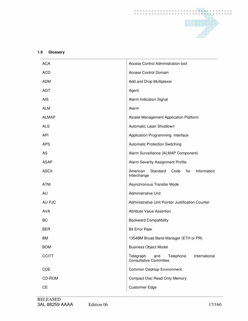
1.9 Glossary
ACA Access Control Administration tool
ACD Access Control Domain
ADM Add and Drop Multiplexer
AGT Agent
AIS Alarm Indication Signal
ALM Alarm
ALMAP Alcatel Management Application Platform
ALS Automatic Laser Shutdown
API Application Programming Interface
APS Automatic Protection Switching
AS Alarm Surveillance (ALMAP Component)
ASAP Alarm Severity Assignment Profile
ASCII American Standard Code for Information Interchange
ATM Asynchronous Transfer Mode
AU Administrative Unit
AU PJC Administrative Unit Pointer Justification Counter
AVA Attribute Value Assertion
BC Backward Compatibility
BER Bit Error Rate
BM 1354BM Broad Band Manager (ETH or PR)
BOM Business Object Model
CCITT Telegraph and Telephone International Consultative Committee
CDE Common Desktop Environment.
CD-ROM Compact Disc Read Only Memory
CE Custormer Edge

RELEASED 3AL 88259 AAAA Edition 06 18/160
CLNP Connectionless Network Protocol
CLNS Connectionless Network Service
CM 1352CM Compact Manager
CMIP Common Management Information Protocol
CMIS Common Management Information Service
COMET C++ Object Management Extended Tool chain
CPA Customer Protocol Adaptor
CR Change Request
CSM Common Service Management
CSV Command Separated Value
CT Craft Terminal
DB Data Base
DBD Data Base Driver
DBI Data Base Interface
DCC Data Communication Channel
DCN Data Communications Network
DNI Delivery to NI
DR1 Decision Review One
DR2 Decision Review Two
DR4 Decision Review Four
DS Degraded Signal
DWDM Dense Wavelength Division Multiplexing
E2E End-To-End
ECC Embedded Communication Channels
EFD Event Forwarding Discriminator
EML Element Management Layer
EMS Event Management Service or Equipment Management System
EOA External OSS Application

RELEASED 3AL 88259 AAAA Edition 06 19/160
EOS External-OS
EPIM Event Processing Information Manager
EPS Equipment Protection Switching
ES Ethernet Segment
ETB ETHernet Bridge
ETH ETHernet
ETS ETHernet Switch
EU Exchange Unit
EVC Ethernet Virtual Connection
FAD Functional Access Domain
FCC Full Code Complete
FDN Fully Distinguished Name
FERF Far End Received Failure
FLS Frame Loss Second
FTP File Transfert Protocol
FWK Frame Work
Gbit/s Gigabits per second
GDBM GNU DataBase Manager
GDMO Guidelines for Definition of Managed Objects
GEM Generic EML
GENOS Generic OS-OS Interfaces
GNE Gateway Network Element
GUI Graphical User Interface
HMI Human Machine Interface
HO Matrix High Order Matrix
HOA High Order Assembler
HP Hewlett Packard
HPA High Order Path Adaptation
RELEASED 3AL 88259 AAAA Edition 06 20/160
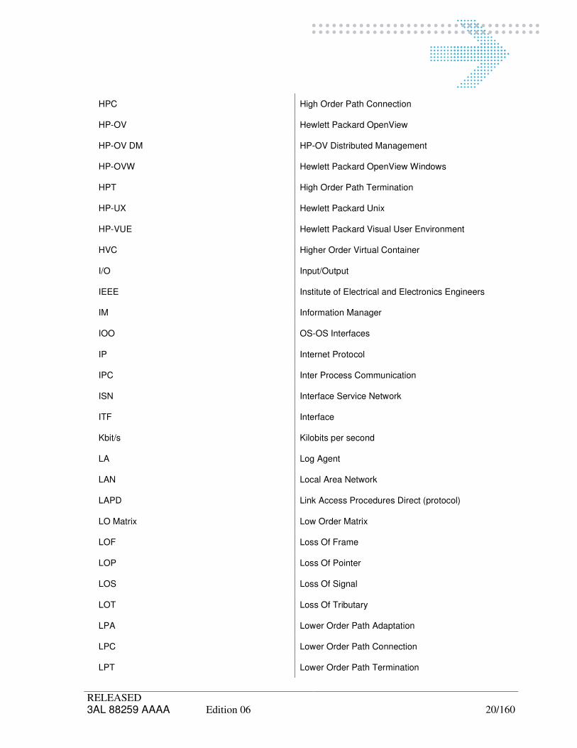
HPC High Order Path Connection
HP-OV Hewlett Packard OpenView
HP-OV DM HP-OV Distributed Management
HP-OVW Hewlett Packard OpenView Windows
HPT High Order Path Termination
HP-UX Hewlett Packard Unix
HP-VUE Hewlett Packard Visual User Environment
HVC Higher Order Virtual Container
I/O Input/Output
IEEE Institute of Electrical and Electronics Engineers
IM Information Manager
IOO OS-OS Interfaces
IP Internet Protocol
IPC Inter Process Communication
ISN Interface Service Network
ITF Interface
Kbit/s Kilobits per second
LA Log Agent
LAN Local Area Network
LAPD Link Access Procedures Direct (protocol)
LO Matrix Low Order Matrix
LOF Loss Of Frame
LOP Loss Of Pointer
LOS Loss Of Signal
LOT Loss Of Tributary
LPA Lower Order Path Adaptation
LPC Lower Order Path Connection
LPT Lower Order Path Termination

RELEASED 3AL 88259 AAAA Edition 06 21/160
LRF Local Registration File
LVC Lower Order Virtual Container
MAC Media Access Control
Mbit/s Megabits per seconds
ME Managed Element
MEF Metro Ethernet Forum
MGR Manager
MIB Management Information Base
MLSN Multi Layer SubNetwork
MO Managed Object
MOC Managed Object Class
MOI Managed Object Instance
MS Multiplex Section
MSP Multiplex Section Protection
MST Multiplex Section Termination
MTMN Multi-Technology Network Management
MTOSI Multi-Technology Operation System Inteface
NAD Network Access Domain
NAP Network Access Point
NBI North Bound Interface
NCDR Network Connectivity Data Retrieval (old name of NRI)
NE Network Element
NED NE Directory
NI Network Integration
NM Network Management
NMA Network Management Application
NMC Network Management Component
NML Network Management Layer

RELEASED 3AL 88259 AAAA Edition 06 22/160
NMS Network Management Subsystem
NNI Network to Network Interface
NR Network Release
NRI Network Resource Inventory
NSAP Network Service Access Point
NTP Network Time Protocol
OAD Object Access Domain
OC Object Creation
OD Object Deletion
OFS Out of Frame Seconds
OID Object Identifier
OMSG Optical Multiservices Gate
OMSN Optical Multiservices Node
OND Optical Network Division
OS Operation System
OSC OS-Conf
OSI Open System Interconnection
OSK OS-Kernel
PBS Product BreakDown Structure
PDH Plesiochronous Digital Hierarchy
PDR Preliminary Design Review
PI Physical Interface
PM Performance Monitoring
PMC Process Monitoring Control
PMD PM Data
PMDM PM Data Management
PMDS Performance Monitoring Data System
PNM Physical Network Manager

RELEASED 3AL 88259 AAAA Edition 06 23/160
PPI PDH Physical Interface
PTM Path Trace Mismatch
PTP Physical Termination Point
QoS Quality of Service
RFC Request For Comment
RI Remote Inventory
RID RI Data
RM 1354RM Regional Manager
RS Regenerator Section
RST Regenerator Section Termination
SA Section Adaptation
SADK Sub Agent Development Kit
SAP Service Access Point
SCM Software Configuration Management
SCSI Small Computer Serial Interface
SDH Synchronous Digital Hierarchy
SDK Software Development Kit
SEN-IM Simple EML/NL Info Model
SF Signal Failure
SH 1353SH (old name 1353NM)
SIT-S Start of InTegration teSts
SNMP Simple Network Management Protocol
SONET Synchronous Optical Network
SPI SDH Physical Interface
SQL Structured Query Language
STM-N Synchronous Transport Module level N (N is an integer = 1,4 or 16)
SVT Start Validation Test
SW SoftWare

RELEASED 3AL 88259 AAAA Edition 06 24/160
SWB SW Building Block
SWC SW Component
SY 1354SY Synchronization Manager
TBD To Be Defined
TC Traffic Descriptor
TCP Transport Control Protocol
TD Traffic Classifier
TF Transmit Fail
TFS Technical Functional Specification
TL Topology Link
TMN Telecommunications Management Network
TN Telecommunications Network
TND Terrestrial Network Division (old name of OND)
TP Termination Point
TU Tributary Unit
TU PJC Tributary Unit Pointer Justification Counter
UML Unified Modeling Language
UNI User Network Interface
USM User Service Manager
VC Virtual Container
VLAN Virtual LAN
VPN Virtual Private Network or 1355VPN Alcatel VPN Manager
VPNP VPN Network Provisioning
WBS Work Breakdown Structure
WDM Wavelength Division Multiplexing
WIN Windows Operating System
XC Cross-Connect

RELEASED 3AL 88259 AAAA Edition 06 25/160
XML eXstend Manipulation Language
RELEASED 3AL 88259 AAAA Edition 06 26/160
2 GENERALITIES
2.1 OS-Kernel environment for NMS architecture
Network Release 8.1 PL2 is a version that signs a turning point in the system architecture. A common platform for NM Subsystems has been identified that collects common components and applications. OS-Kernel, this is the name of the common platform, idea derives from the observation that so far each NM Product needs to be installed on a dedicated physical machine. This constraint brings to a waste of disk space and machine resources and may result in an uncomfortable working environment for operators that have to operate on different NM Subsystems at the same time. Another incentive to the development of the OS-Kernel comes from observing the growing size of the servers and workstations. The machines become very big and consequently expensive, so it is necessary to optimize their utilization in order to obtain a good ratio between the hardware bought and the systems installed. The aim of the OS-Kernel is to provide a common building block of the Network Management architecture. On the other side the NM Products (1353NM, 1354RM, 1353SN, 1354BM-ATM, 1354BM-ETH, ...) will be split in components and applications, so the final result is that a product is a collection of components and applications. On this common block the NM Products will be assembled fitting the applications and components needed on the OS-Kernel platform. Up till now difficulties must be faced when installing different product instances (typically NM OS) on the same workstation (co-hosting). Common resources used by OS applications are duplicated; conflicts may rise due to different requirements for the application customization, etc. The modularity offered by OS-Kernel permits to install on a hardware platform a single product or several different products, as well as different instances of the same product.
OS-Kernel offers a set of functionalities about:
� Process Management
� Subsystem Configuration
� Installation/Integration & Customization
� System Management Function

RELEASED 3AL 88259 AAAA Edition 06 27/160
2.2 Interface Service Network (ISN)
The ISN is an open interface that allows one or more External OS to exchange management messages with the Alcatel OS Manager products (1354RM, 1354BM, 1354NP*, 1354SY*). The ISN interface is available with one protocol option:
- ASCII interface, based on TCP-IP protocol stack with ASCII application messages. 1359ISN is composed of two different modules:
- The Isn Dispatcher is the module that receives all the requests from the Isn interface and must dispatch each request to the right Isn Agent module.
- The Isn Agent is a mib-less and distributed system. In order to discover where the network resource involved in the current operation is placed, the Isn Dispatcher must send a "broadcast" retrieve request to all the known Isn Agent modules, each one located into a different nwH or snH system (discovery algorithm).
The goal of Isn Agent is to provide to the Service Layer (external OS) a unique interface (Isn) for trasport and data network path provisioning and inventory, independently from the distribution and the complexity of the Network Layer Management Systems. The Isn Agent is a subsystem of both 1354BM and 1354RM products: it’s designed in order to be installed on the mentioned environments. We speak about ISN as a component in this document, we refer it as NMC. The component is installed within a Network Management Subsystem (NMS).
(*): Supported only by design.

RELEASED 3AL 88259 AAAA Edition 06 28/160
2.3 Network Management Subsystem activation
TMN OS is the graphical interface of OS-Kernel application dedicated to manage the different Subsystem Instances built on the same hardware machine. TMN OS application is the box containing and managing all the NM Subsystems customized on a single physical machine.
TMN OS Icon
Figure 1 Alcatel CDE Front Panel
Select TMN OS icon as shown in the previous figure to start TMN OS application. The TMN-OS Management Window will be shown in a few seconds, you have to select the 1353NM instance you want to manage.
Figure 2 TMN OS application

RELEASED 3AL 88259 AAAA Edition 06 29/160
2.4 Role of the Administrator
The role of the administrator can be summarized in:
- manage the system and keep the OS up and running:
� process monitoring and configuration,
� logs management,
� trace management,
� backup/restore operations,
� NE maintenance (software download, save TPs),
� reconfigurations (stack, processes).
- perform preventive maintenance operations:
� to minimize the failures consequences and to be able to start up the system as quickly as possible in case of power supply failure for example,
� to avoid file system full occurrence or hardware failures.
- perform corrective maintenance operations in case of:
� power supply failure,
� file system full,
� hardware failures (disk crash, SCSI errors),
� software failures (Panic UNIX, application bug).

RELEASED 3AL 88259 AAAA Edition 06 30/160
3 RELEASE IDENTIFICATION
As described by 6.1.1.2, SWVERSION contains the version of the interface, in particular the
version of the Isn component (e.g. “V5.1”).
If in addition it is necessary to know the specific package and or fix currently installed on the
machine, the following script executed from shell:
,sys,root> /alcatel/Kernel/bin/Info.pl -sys 1354RM -inst <System_Instance_Id>
Provides all information about 1354RM system identified by <System_Instance_Id>, including
ones related to its Isn component.

RELEASED 3AL 88259 AAAA Edition 06 31/160

RELEASED 3AL 88259 AAAA Edition 06 32/160
4 CONFIGURATIONS
4.1 Preparing NMC Configuration
Before executing this step check the value of the $DISPLAY environment variable (the script will start a graphical window).
Two types of custom procedures are available:
- Global System Custom
- Component Customization. The first time you customize, you have always to use the global customization. The other times you deliver Isn and a new customization is needed please execute the Isn components customization. A new customization is always needed in case of a package; it is optionally needed in case of a fix and this information will be written in the delivery email and into the Release Notes document. To do these operations you have to be logged as “root” user.
4.1.1 Component Customization
Use following commands:
,sys,root> /alcatel/Kernel/script/updateInstance.pl -sys 1354RM -inst
<System_Instance_Id> -type NMC -comp ISN_AGENT
and press [Enter]
,sys,root> /alcatel/Kernel/script/updateInstance.pl -sys 1354RM -inst
<System_Instance_Id> -type NMC -comp ISN_DISP and press [Enter] Note that in all cases there is a partial Isn configuration (i.e. either Dispatcher or Agent does not need), the command corresponding to the not existing component is skipped.
4.1.2 System Customization
In all cases not all Isn components need to be installed (e.g. in Isn Agent stand-alone installation,
only Agent has to be installed), before starting this step you have to edit the file (by root user):
/alcatel/NMS/1354RM/7.4/conf/Kernel/Composition.cfg
It is necessary to comment the row related to the component you have not installed and
consequently you don’t need to configure (e.g. in agent stand alone installation, please comment
dispatcher row).
System configuration application will not process the subsystem, which has the row commented (e.g.
continuing the example before, you are going to configure Isn Agent subsystem only).
Then please execute following command:
,sys,root> /alcatel/Kernel/script/Custom and press [Enter]
The customization window will appear. The main parameters to set in the Custom window (see the figure below) are:

RELEASED 3AL 88259 AAAA Edition 06 33/160
- System_Version <Name of NMS and version installed>
- System_Instance <Instance to be created>
- System_Instance_Role <role of the System Instance. Default value:Master>
- System_Instance_Name <System Instance logical Name>
- Master_HostName <HostName of the System Instance >
- Master_kernel_type <Os-Kernel>
- Drive_Version <Version Kernel Instance driver> The following Graphical Interface is displayed in order to collect the user input:
Figure 3 Custom Window
At the end select “Actions > Apply & Exit".

RELEASED 3AL 88259 AAAA Edition 06 34/160
N.B. If the System Instance has been already configured once before, the Custom execution will automatically run also the Update Process Configuration.
4.2 NMC Configuration
The installation can be stand-alone, with two different options : - Agent stand-alone means without dispatcher, for instance in a multi-agent configuration; - Dispatcher stand-alone means that no agents are installed on the same machine.
4.2.1 System tuning
In case of a stand-alone installation, before starting configuration you have to edit the file (by root
user):
/usr/Systems/<System_Instance_Name>_<System_Instance_Id>/Kernel/conf/Composition.cfg
It is necessary to comment the row related to the component you have not installed and
consequently you don’t need to configure (e.g. in a agent stand alone installation, when you are
going to start agent configuration, please comment dispatcher row).
System configuration application will not process the subsystem, which has the row commented
(e.g. continuing the example before, you are going to configure Isn Agent subsystem only).
Now login as "alcatel" user and launch TMNOS application. This operation is available selecting
the icon.

RELEASED 3AL 88259 AAAA Edition 06 35/160
Figure 4 Selecting System Configuration from TMNOS
The following System Configuration window will appear:
Figure 5 System Configuration window
Depending on the existing components, according to the Isn components specified in the
“Composition.cfg” file, it is possible to configure either:
• 1359ISN agent component only (see ISN Agent Configuration). This is the case if you
have previously installed only the Isn Agent on the machine; or
• 1359ISN Dispatcher only (see ISN Dispatcher Configuration). This is the case dispatcher
was installed stand alone; or
• both agent and dispatcher applying in sequence the two steps.

RELEASED 3AL 88259 AAAA Edition 06 36/160
The configuration of the ISN NMC is done executing following steps as explained in details in following paragraphs:
• Select and configure the components in the SubSystem List frame area;
• Launch the System Configuration pressing the “Update config” item in the Main menu.
4.2.2 Configure specific NMAs
4.2.2.1 ISN Agent Configuration
Select the ISNAGENT_SubSystem in the Subsystems List.
The following 1359ISN Agent Configuration window will then appear (in case of NMS: 1354RM):
Figure 6 ISN Agent Configuration window for 1354RM

RELEASED 3AL 88259 AAAA Edition 06 37/160
Press the Action/Apply and Exit on the ISN Agent Configuration window. The chosen values will be checked and stored. The ISN Agent configuration procedure terminates and the window disappears.

RELEASED 3AL 88259 AAAA Edition 06 38/160
4.2.2.2 ISN Dispatcher Configuration
If Dispatcher has to be configured, select the ISNDISP SubSystem from the Subsystems List.
The following window containing the ISN Dispatcher configuration variables appears:
Figure 7 ISN Dispatcher Configuration
Press Action/Apply and Exit from the ISN Dispatcher Configuration window. The values are checked and stored. The ISN Dispatcher configuration procedure terminates and the window disappears. Please remember that in case the ISN Dispatcher has been installed in a different System (NMS) than at least one Agent, you have to manually edit “isnagents.cfg” and “nserverfile” on dispatcher in order to specify the agents it has to connect to and for each of them the host where they are installed. This operation should be done for example in case of multi-agent or in case of dispatcher

RELEASED 3AL 88259 AAAA Edition 06 39/160
and agents are stand alone on different machines. Please refer the 6.2.2 and 6.3.2 paragraphs for more details.
4.3 Process Monitoring
Figure 8 Process Monitoring Control Main Window (ISN not working)
From TMNOS management menu:
• Select Process monitoring
The Process Monitoring Control panel will be displayed. Select on the Process Monitor window:

RELEASED 3AL 88259 AAAA Edition 06 40/160
• IsnAgent Process
• IsnDispatcher Process The start operation can be performed for the entire component or for a single process
•••• Select Action - Selected Item
Figure 9 Process Monitor Control (ISN working)

RELEASED 3AL 88259 AAAA Edition 06 41/160
4.3.1 Groups of Processes
The below table summarize the group of processes defined for the described NMC; for each group the list of processes with a brief description is shown in the table.
Process Group Process Description
IsnAgent Isn_Agent Unique interface for external OS
IsnDispatcher Isn_Dispatcher Module that receives all the requests from the Isn Interface and must dispatch each request to the right Isn Agent module.
4.3.2 Run Levels
NMS Run Level is a Unix Run-Level similar concept, that lets consider the system to be in a run level at any given time. A run level can be viewed as a software configuration of the subsystem, where each configuration allows only a selected group of processes to exist.
Run Level Number
Name Description
0 FullFunctionality Subsystem runs with all configured functionalities
1 BackupMode Subsystem runs to allow a backup job running without conflicting problems. Only processes configured for this run level should run.
2 RestoreMode Subsystem runs to allow a restore job running without conflicting problems. Only processes configured for this run level should run.
3 DB_only

RELEASED 3AL 88259 AAAA Edition 06 42/160

RELEASED 3AL 88259 AAAA Edition 06 43/160
5 USER MANAGEMENT
5.1 ISN Managers/Client Configuration
When the ISN Dispatcher and the ISN Agents have been installed and configured, it's possible to
enable one or more ISN Managers/Clients (External Oss) to have access to the managed network
through the ISN interface.
In order to have a completed ISN Managers/Clients configuration following steps are suggested:
1. NML configuration: NAD and OPERATOR (see par 5.2) 2. Isn Agent configuration for each Agents (see par 5.3)
- NML operator mapping (/usr/System/<System_Instance_Name>/ISN_AGENT/data/isnmgrmap.cfg)
3. ISN Dispatcher configuration (see par 5.4)
- Managers configuration (/usr/System/<System_Instance_Name>/ISN_DISP/data/isnmanagers.cfg)
- Enabling the environment configuration (/usr/System/<System_Instance_Name>/ISN_DISP/ etc/mgrftpconfig script)
5.2 NML configuration
5.2.1 NAD Configuration - 1354RM
If the ISN Agent is installed on a 1354RM system you must perform following steps:
Login as user with Administration privileges (alcatel).
Through the SMF user interface you must create (if a new one is needed) one or more NAD (one for
each VPN) to be associated to the ISN Manager under configuration:
Activate the SMF user interface from TMNOS selecting Actions Select the "Operators Administration" function; Select the "Initiators Management" function; For each NAD (Initiator) to be created fill the following fields and then push the "Add"
button:
� RM Initiator: unique number to be associated to the NAD
� Initiator Name: unique label to be associated to the NAD (e.g. Mgr_Key or VPN_Key)
� Rule: type of access to the network resources; select the rule AC_R_PMVPN and one of the following rules: AC_R_SNML, AC_R_VPN, AC_R_EVPN, AC_R_RVPN, AC_R_VPNPOOL, AC_R_EVPNPOOL.
Push the "Close" button and save the changes to complete the operation.
Rules Initiator Name Description
AC_R_SNML RM Administrator Operator This rule is mapped by

RELEASED 3AL 88259 AAAA Edition 06 44/160
default on the “RM Administrator” initiator. It can be used when the manager needs to retrieve resources related to whole network
AC_R_VPN Virtual Private Network Operator
As RVPN except that the routing can be done also on free LCs (Security Label=0).
It can be used only for VPN Initiat
AC_R_EVPN Enhanced Virtual Private Network Operator
As VPN except that also free NAPs can be used for path set-up.
It can be used only for VPN Initiators.
AC_R_RVPN (Restricted Virtual Private Network Operator free POOL)
It is able to create, view, modify paths only using resources (NAPs & LCs) assigned to his NAD or to free pool.
It can be assigned only to VPN Initiator
AC_R_VPNPOOL Virtual Private Network Operator free POOL
As RVPN except that the routing can be done also on free LCs (Security Label=0).
It can be used only for VPN Initiato
AC_R_EVPNPOOL Enhanced Virtual Private Network Operator free POOL.
As VPN except that also free NAPs can be used for path set-up.
It can be used only for VPN Initiators.

RELEASED 3AL 88259 AAAA Edition 06 45/160
5.2.2 NAD Configuration – 1354BM
For more details and specification see the paragraph 6.6“ISN Managers Map File” into section BM.
5.2.3 NML Operator
5.2.3.1 RM System
Through the SMF user interface you must create one NML Operator for each created NAD
performing the following steps:
Login as user with Administration privileges (alcatel).
Activate the SMF user interface from TMNOS selecting Actions; Select the "Operation Administration" function; Select the "Add Operator" function; For each Operator to be created fill the following fields and then push the "Add" button:
� Username: unique name to be associated to the Operator (e.g. it can be the same as VPN_Key)
� Password: Operator's password
� Confirm Password: Operator's password
� Real Name: description of the Operator (ISN Manager)
� Profiles: select the "Constructor" profile;
� Initiator: select the related NAD created on the previous step;
Push the "Close" button to complete the operation.
5.2.3.2 BM-PR System
To the username and password can be created using the BMPR System, following this step: 1. From the "System menu of BMPR Client select "Management" option. A user definition
panel will appear. 2. On thelest part of the frame right-click on "Users" and select "New". Now an empty user
set-up appears on the right side of the frame. 3. Enter the Name, Password, Confirm Password. 4. And the most important part: when defining the "Group Information", choose
"Administrator" in the first combo and "NBI" in the second. 5. Now press "New" button and you'll see your new username appears under the "Users"
sub-tree on the left side of frame. 6. Now you can use the created username and password to open an NBI session. Than it’s mandatory, on directory /usr/Systems/<System_Instance_Name>/ISN_AGENT/data, you must edit the “param.cfg”, put in the correct side the NBISESSIONUSERID and NBISESSIONUSERPSW defined in the previous step (for more details see 6.1.2.2 were is present default param).

RELEASED 3AL 88259 AAAA Edition 06 46/160
5.2.4 Network Resources Assignment
If the ISN Agent is installed on a 1354RM you can assign the network resources (NAPs,
Paths, Link Connections) to the ISN Manager through the "NAD Change" action of the
1354RM Browser application (the details are out of the scope of this document).
5.3 ISN Agent configuration for each Agent
5.3.1 NML Operator Mapping
The last step consists in configuring the ISN Agent in order to map the ISN Manager to the
created NML Operator/NAD. You must edit the "ISN Managers Map File"
"usr/System/<System_Instance_Name>/ISN_AGENT/data/isnmgrmap.cfg ", specified by
the application variable AGTDATAFILE of the ISN Agent, inserting in each line the ISN
Manager Key, the VPN Key (optional) and the related NML Operator name.
<mgr_key>:<vpn_key>:<operator>:<degr_prot>:<FREQ_15>:<FREQ_24>
(See the paragraph 6.6 “ISN Managers Map File” for more details).
5.3.2 NRI NPA or ET reports
NR63compatible variable has to be configured in order to set if the Agent supports either NPA report (new report) or ET report (old report).
NR63compatible equal to 1 means the agent supports the old ET report.
NR63compatible equal to 0 means Agent behaves according new behavior. This is the default behavior.
The environment variable is present into:
usr/System/<System_Instance_Name>/ISN_AGENT/etc/env_def_isn
It means NR63compatible is applied to all the VPNs (and the managers) managed by such Agent.
Note that the value sets into all the “env_def_isn” files must be the same. Anyway system does not perform any check.

RELEASED 3AL 88259 AAAA Edition 06 47/160
5.4 ISN Dispatcher Configuration
5.4.1 Managers configuration
First of all you must insert managers names in the file "ISN Managers File"
("/usr/System/<System_Instance_Name>/ISN_DISP/data/isnmanagers.cfg"), inserting in
each line the information for each ISN Manager (see “ISN Managers File” paragraph). In
this way you enable the manager to connect to the ISN Dispatcher in order to access the
network through the ISN Interface.
<Mgr_key>:<Mgr_root>:<int_type>:<ip_addr>:<vpn_type>:<compress>:<multi_notif>:<profile>: <isn_version>:<log_type>:<log_size>:<PM_FILE_FORMAT>
(see the paragraph 6.5“ISN Managers File” for more details).
5.4.2 NRI NPA or ET reports
NR63compatible variable has to be configured in order to set if NPA report (new report) or ET report (old report) is supported.
NR63compatible equal to 1 means old ET report is supported.
NR63compatible equal to 0 means new behavior is enabled. This is the default behavior.
The environment variable is present into:
usr/System/<System_Instance_Name>/ISN_AGENT/etc/env_def_isn
Note that the value sets into “env_def_isn” file on dispatcher must be equal to the values set into the “env_def_isn” files on agents. Anyway system does not perform any check.
Chapter 12 describes the NRI customization procedure in case a new manager is created or NR63compatible variable changes but at least a manager already exists.
5.4.3 Agent Host Declarer
In case of multi-agent Isn configuration (see 10.2), i.e. at least one agent is not co hosted to dispatcher, kernel has to know where remote agents are present. This has to be done before any configuration activity starts that need dispatcher to access remotely to agent hosts (e.g. enabling the environment configuration by mgrftpconfig).
Please login as “root” and execute for each agent not co hosted to dispatcher:
…sys,root> /alcatel/Kernel/etc/HostDeclarer.pl -add <agent host name>, and press [Enter]

RELEASED 3AL 88259 AAAA Edition 06 48/160
5.4.4 Enabling the environment configuration
Now you can run the script mgrftpconfig (once for each manager). The script receives three parameters (the user name, the user id and the Manager's Key) and creates the Sub-login, all the directories that the user will need and also prompts for password setting.
Login as "root " user and execute:
..,sys,root> /usr/System/<System_Instance_Name>/ISN_DISP/etc/mgrftpconfig
<user-name> <user-id> <Mgr_Key> , and press [Enter]
Where:
<user-name> is the anonymous FTP sub-login username (note: generally it is set equal to Mgr_Key and
must be different from the NLMOperator created in paragraph "NML Operator
Configuration"
NOTE : the sub-login username can't exceed 8 characters;
<user-id> is a unique user-id (number) associated to the sub-login;
<Mgr_Key> is the unique label associated to the ISN Manager.
In order to define a unique <user-id> it is necessary to check the already assigned
numbers in the file /etc/passwd and to choose an unused one. The <user-id> is the third
field of the record, e.g.
oracle2:9uJEkE9T0Lvrg:2223 :200:,,,:/home/oracle72:/usr/bin/ksh
This script creates configuration directories also for all the agents under the dispatcher
control.
N.B.: In case of Resiliance, this operation is to be done on spare machine, too. This is
need to configure FTP login in the same way of main, since file /etc/passwd is not
replicated.

RELEASED 3AL 88259 AAAA Edition 06 49/160
5.4.5 Checking the FTP configuration
You can check the FTP configuration for each ISN Manager executing the following FTP
session:
..,sys,root> ftp <hostname> , and press [Enter] Connected to <hostname>. 220 <hostname> FTP server (Version 1.7.212.2 Tue Apr 21 12:14:46 GMT 1998) ready.
ftp> user <username> <password> 331 Password required for qsntest1. 230 User qsntest1 logged in.
ftp> pwd 257 "/Isn/repository/<Mgr_Key>" is current directory.
ftp> ls 200 PORT command successful. 150 Opening ASCII mode data connection for /usr/bin/ls. total 0 226 Transfer complete. ftp> quit 221 Goodbye.
Where:
<hostname> is the name of the host where the ISN Dispatcher is installed;
<username> is the sub-login username associated to the ISN Manager;
<password> is the password assigned to the sub-login associated to the ISN Manager;
<Mgr_Key> is the unique label associated to the ISN Manager.
Note: In case of problems, see 13.

RELEASED 3AL 88259 AAAA Edition 06 50/160
5.5 Customizing User Profiles
The Profiles Files:
"/usr/Systems/<System_Instance_Name>/ISN_DISP/data/profiles.cfg" and
"usr/Systems/<System_Instance_Name>/ISN_DISP/data/profiles_custom.cfg"
specified by the application variables PROFILESFILE and PROFILESCUSTOMFILE of the ISN Dispatcher, contain the ISN interface profiles definition.
The basic profiles (PROFILESFILE) shouldn’t be modified; new custom profiles must be added to the custom profiles file (PROFILESCUSTOMFILE).
Each Profile is a list of Functions available for the ISN Managers with that profile; is also possible to define a profile as a combination of other profiles.
Each line of the file contains the definition of a profile with the following syntax:
<Profile_name>:<Func>:<Func>:<Prof>:<Prof>
Where:
<Profile_name> must be set to a unique label identifying the profile;
<Func> is the label identifying an available Function;
<Prof> is the label identifying a profile defined in a previous line.
Functions listed in table below are currently available through the ISN interface side RM:
Actions
RetrieveTopol Topology data retrieval
RetrieveSTP Service TP data retrieval
RetrieveSConn Service Connectivity data retrieval
RetrieveReport Network Configuration data retrieval
BatchNMSAction Allow the execution of a NM commands list
BatchAction Allow the execution of a Batch File
DefineSConn Service Connectivity definition
RemoveSConn Service Connectivity deletion
ChangeSConnServSt
Change the Service State of a Connectivity
ModifySConnAvailLevel
Change the Availability Level of a Connectivity
ModifySConnComment1
Change the Comment1 of a Connectivity
ModifySConnComment2
Change the Comment2 of a Connectivity

RELEASED 3AL 88259 AAAA Edition 06 51/160
RetrieveAlarm Used to retrieve current sConn alarm
DefinePathConstr Used to define a constraint on a defined sConn
ModifyPMFields Change PM fields
RetrievePM Retrieve the PM data details.
ConcatenateCtp Concatenate AU4 CTPs of a SDH Port
RetrieveConstr Retrieve the constraints list over a specified sConn
RetrieveError Retrieve the sConn data related to the allocation failures
RetrieveRoute Retrieve the routing of a given sConn
DefineLoopBack LoopBack management on TTP for path testing
ModifyTrailNumber Modifies the number of a trail on a path
ManageTrailsActiv Mange the idle trails on a path
ModifyLcasControl Modifies LCAS Protocol
ModifySrvTrailsRouting
Used to define allocation criteria for server trails
Spontaneous Notifications
DefineSConnNotif Service Connectivity definition notification
RemoveSConnNotif Service Connectivity deletion notification
UpdateSConnNotif Service Connectivity update notification
NLHStartNotif Network Handler start notification
NEChangeNotif NE change notification
UpdateSTPNotif Service TP update notification
AssignResChangeNotif
Resource assignment change notification
CreateSTPNotif Service TP definition notification
RemoveSTPNotif Service TP deletion notification
LabelUpdateNotif User label update notification
PhysicalPortAlNotif Physical SDH port alarm notification
FaultUpdateNotif Connectivity fault update notification
SconnAlNotif Sconn alarm notification

RELEASED 3AL 88259 AAAA Edition 06 52/160
Functions listed in table below are currently available through the ISN interface side BM:
Actions
RetrieveSubnetwork Sub Network Retrieval
RetrieveTopologicalLink
Topological Link Retrieval
RetrieveManagedElement
Retrieve of Mes and Service locations
RetrieveTpPool Termination Point Pool Retrieval
RetrieveCall Call Retrieval
RetrieveCallAlarm Call Retrieval Alarm
DefineCall Call Creation
RemoveCall Delete Call
ModifyCall Call Modification
ModifyFlow To modify one or many flows belonging to a Call
ActivateCall Call Activation
Spontaneous Notifications
CallAlmNotif Call Alarm notification
ChangeMeStNotif Me change status notification
DefineSubNotif SubNetwork definition notification
DefineMeNotif Me definition notification
DefineTlNotif TL definition notification
DefineTppNotif TpPool definition notification
RemoveSubNotif SubNetwork deletion notification
RemoveMeNotif Me deletion notification
RemoveTlNotif TL deletion notification
RemoveTppNotif TpPool deletion notification
RemoveCallNotif Call deletion notification

RELEASED 3AL 88259 AAAA Edition 06 53/160
DefineCallNotif Call definition notification
UpdateSubNotif SubNetwork Update notification
UpdateMeNotif Me Update notification
UpdateTopLinkNotif TL Update notification
UpdateTpPoolNotif TpPool Update notification
CallUpdateNotif Call Update notification
UpdateFlowNotif Flow Update notification
DefineFlowNotif Flow definition notification
RemoveFlowNotif Flow deletion notification
ChangecallStNotif Call change status notification

RELEASED 3AL 88259 AAAA Edition 06 54/160
The following pre-defined profiles are currently available through the ISN interface:
RETRIEVE RetrieveTopol + RetrieveSTP + RetrieveSConn + RetrieveReport + BatchNMSAction + RetrieveSubnetwork + RetrieveTopologicalLink + RetrieveManagedElement + RetrieveTpPool + RetrieveCall + RetrieveCallAlarm
PATHBUILD DefineSConn + RemoveSConn + ChangeSConnServSt + ModifySConnAvailLevel + ModifySConnComment1 + ModifySConnComment2 + RetrieveAlarm + DefinePathConstrain + ModifyPMFiels + RetrieveAlarm + RetrievePM + ConcatenateCtp + RetrieveConstrain + RetrieveError + RetrieveRoute + DefineLoopBack + ModifyTrailNumber + ManageTrailsActiv + ModifyLcasControl + ModifySrvTrailsRouting
PATHSPONTNOTIF DefineSConnNotif + RemoveSConnNotif + UpdateSConnNotif
SPONTNOTIF NLHStartNotif + NEChangeNotif + UpdateSTPNotif + AssignResChangeNotif + CreateSTPNotif + RemoveSTPNotif + LabelUpdateNotif + CallAlmNotif + ChangeMeStNotif + DefineSubNotif + DefineMeNotif + DefineTlNotif + DefineTppNotif + RemoveSubNotif + RemoveMeNotif + RemoveTlNotif + RemoveTppNotif + RemoveCallNotif + DefineCallNotif + UpdateSubNotif + UpdateMeNotif + UpdateTopLinkNotif + UpdateTpPoolNotif + CallUpdateNotif + UpdateFlowNotif + DefineFlowNotif + RemoveFlowNotif + ChangecallStNotif
ALARMS PhysicalPortAlNotif + FaultUpdateNotif + SconnAlNotif
SCONNALARMS FaultUpdateNotif + SconnAlNotif
CALLBUILD DefineCall + ModifyCall + ModifyFlow + RemoveCall + ActivateCall
BATCHACTION BatchAction
READONLY RETRIEVE + PATHSPONTNOTIF + SPONTNOTIF + ALARMS
1355VPN PATHBUILD + RETRIEVE + PATHSPONTNOTIF + SPONTNOTIF + SCONNALARMS
ALL READONLY + PATHBUILD + BATCHACTION + CALLBUILD
It is possible to create new profiles (or change the pre-defined profiles) just editing the custom profile file according to the above syntax.

RELEASED 3AL 88259 AAAA Edition 06 55/160
5.6 ISN operator - 1354RM user mapping (1354RM Users.ac configuration file)
User.ac file is a user configuration file of 1354RM that maps a Isn operator to NAD and to the 1354RM WS machine. It is composed by a set of rows like: <UserName>:<GroupName>:<ApplicationName>:<RmId>:<ListOfWs> Note that <UserName> is the Isn operator, <RmId> is the NAD of 1354RM and <ListOfWs> is the list of machine where such user is defined. Consider following remark : in case 1354RM is configured with a Master and a Presentation machine, any Isn operator has to be associated ONLY to the Master machine.

RELEASED 3AL 88259 AAAA Edition 06 56/160

RELEASED 3AL 88259 AAAA Edition 06 57/160
6 APPLICATION VARIABLES AND CONFIGURATION FILES
6.1 Application Variables
It is possible to customize each ISN component by a configuration file. It contains all the
application variables with fixed values, installation depending values or customizable
values.
N.B. The application variables are stored only inside the related configuration files and
cannot be accessed as UNIX shell environment variables.
Warning: The application variables on the configuration files shouldn't be changed by
hand; only few variables (shown inside gray boxes) can be customized through the
installation procedure or the customization procedure.
N.B. All the file names specified in this paragraph are relative to the ISN installation
directory.
The configuration file names are the following:
ISN Agent: /usr/Systems/<System_Instance_Name>/ISN_AGENT/data/param.cfg
ISN Dispatcher: /usr/Systems/<System_Instance_Name>/ISN_DISP/data/param.cfg
6.1.1 Common Variables
Following application variables are valid both for ISN Agent and ISN Dispatcher
configuration.
6.1.1.1 Tracing service
Following variables define the use of the tracing and logging (see “Trace ConfigurationFile”
paragraph) and shouldn't be modified:
TraceConfiguration It specifies the pathname of the trace configuration file. Fixed for the ISN Agent to: "usr/System/<System_Instance_Name>/ISN_AGENT/data/trace.cfg". Fixed for the ISN Dispatcher to: "usr/System/<System_Instance_Name>/ISN_DISP/data/trace.cfg"
MaxTrace It specifies the maximum size (in bytes) of each tracing file. Fixed to: 0 (unlimited size, managed by SMF)
DO_PRETTY_PRINT It specifies how to trace the QSN-IM object identifiers. Default: True (symbolic names); False = dot notation
CO_ALLOW_EFD_WILDCAR (required by the platform) Fixed to: False

RELEASED 3AL 88259 AAAA Edition 06 58/160
DING

RELEASED 3AL 88259 AAAA Edition 06 59/160
6.1.1.2 Protocols and QSN Info Model
Following parameters are related to the protocols to be used and to the Qsn Info Model.
QSNAGTMODE It specifies the protocol stack used at the QSN agent side.
Fixed to: XMP&TCP
Permitted values:
XMP: OSI stack (full or RFC1006, see OV Object Registration Service)
TCP: CMIP over TCP/IP socket
XMP&TCP: both the above modes are supported
QSNMGRMODE Meaningful for ISN Dispatcher only.
It specifies the protocol stack used at the QSN manager side:
Fixed to: TCP
Permitted values:
XMP: OSI stack (full or RFC1006, see OV Object Registration Service)
TCP: CMIP over TCP/IP socket
Following parameters customize the Qsn Info Model. OSTITLE “1354RM” or “1354BM”
for ISN Agent "1359ISN" for ISN Dispatcher
It specifies the OS title
DOMAINLABEL "systemId=" It specifies the nlHDomain label. VENDORNAME "Alcatel" It specifies the label of the nlHDomain
vendor. SWVERSION "V5.1B" It specifies the software version of the
related ISN component. QSNVERSION "Ed1" It specifies the version of the supported
Qsn Info Model. SCHEDNAME "Scheduler" it specifies the name of the Manager
recognized as the Scheduler. BATCHNAME "Batch" it specifies the name of the Manager
recognized as the Batch module. NETWORKRELEASE
"NETWORK_RELEASE"
It specifies the network release of the related ISN component.

RELEASED 3AL 88259 AAAA Edition 06 60/160
6.1.2 ISN Agent Variables
Following variables are specific of the ISN Agent component.
In particular, the used variables depends by NMS type ISN Agent component is installed on.
PathInfo belongs to ISN Agent ,so varaiables of PathInfo are also in the ISN Agent configuration file
6.1.2.1 ISN Agent Variables for 1354RM
Note that the document describes only the ones really impacting the Agent behavior.
Variable Value Description
QSNROOT Default: 1 It's an integer value that specifies the root of the QSN containment tree. Each ISN Agent must have a different QSNROOT value
ISNASCIIAGTPORT
Default: 10001 It specifies the socket port number for the QSN TCP-stack interface. It must be set to an integer value (> 2000) not already used by other application on the same system. N.B. this value is stored into the ISN Agent Name Server File.
PATH_CACHE_SIZE
Default: 100 It specifies the number of connectivity that are maintained in Agent cache memory.
CO_BASIC_VIRTUAL_HOSTNAME
Default: None, it must be specified.
It specifies the Full Domain Name of the host on which the Agent is installed
FTIMEOUT Default: 60 (1 hour)
It specifies the waiting timeout (in minutes) for each F interface request.
IDLETIMER Default: 60 (1 hour)
It specifies the waiting timeout (in minutes) for each ISN operation. N.B. For a large number of ISN network resources (TPs and Paths), the global retrieval operation could be longer than one hour; in that case the timeout must be set to a bigger value.
AGTPOLLINGTIMER
Default: 5 It specifies the polling period (in minutes) for the NML system. The ISN Agent checks periodically the connection with the hosting NML system (1354RM) in order to notify the ISN Dispatcher about the status of that SDH Manager (working or degraded).
SCONNALARM Default: "ALL" It specifies which connectivity alarm must be forwarded to Isn Dispatcher. The ISN Agent can be enabled to forward ALL, QOS (TCA alarms), COM (communication alarms) or NONE
PORTALARM Default: "SDH" It specifies which port alarm must be forwarded to Isn Dispatcher. The ISN Agent can be enabled to forward ALL, SDH, PDH
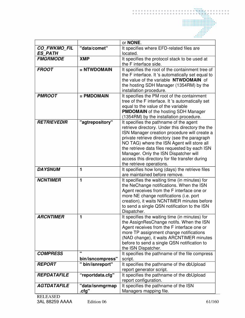
RELEASED 3AL 88259 AAAA Edition 06 61/160
or NONE.
CO_FWKMO_FILES_PATH
"data/comet" It specifies where EFD-related files are located.
FMGRMODE XMP It specifies the protocol stack to be used at the F interface side.
FROOT = NTWDOMAIN It specifies the root of the containment tree of the F interface. It 's automatically set equal to the value of the variable NTWDOMAIN of the hosting SDH Manager (1354RM) by the installation procedure.
PMROOT = PMDOMAIN It specifies the PM root of the containment tree of the F interface. It 's automatically set equal to the value of the variable PMDOMAIN of the hosting SDH Manager (1354RM) by the installation procedure.
RETRIEVEDIR "agtrepository" It specifies the pathname of the agent retrieve directory. Under this directory the the ISN Manager creation procedure will create a private retrieve directory (see the paragraph NO TAG) where the ISN Agent will store all the retrieve data files requested by each ISN Manager. Only the ISN Dispatcher will access this directory for file transfer during the retrieve operations.
DAYSNUM 1 It specifies how long (days) the retrieve files are maintained before remove.
NCNTIMER 1 It specifies the waiting time (in minutes) for the NeChange notifications. When the ISN Agent receives from the F interface one or more NE change notifications (i.e. port creation), it waits NCNTIMER minutes before to send a single QSN notification to the ISN Dispatcher.
ARCNTIMER 1 It specifies the waiting time (in minutes) for the AssignResChange notifs. When the ISN Agent receives from the F interface one or more TP assignment change notifications (NAD change), it waits ARCNTIMER minutes before to send a single QSN notification to the ISN Dispatcher.
COMPRESS " bin/isncompress"
It specifies the pathname of the file compress script.
REPORT " bin/isnreport" It specifies the pathname of the dbUpload report generator script.
REPDATAFILE “reportdata.cfg" It specifies the pathname of the dbUpload report configuration.
AGTDATAFILE "data/isnmgrmap.cfg"
It specifies the pathname of the ISN Managers mapping file.

RELEASED 3AL 88259 AAAA Edition 06 62/160
INITIATORSFILE “data/initiators.ac"
It specifies the pathname of the NAD initiator file.
USERSFILE " data/users.ac" It specifies the pathname of the operator-NAD mapping file.
QSNAGT_PRDLINK
“/usr/Systems/1354RM_1-8.1/ISN_AGENT”
Agent home directory
BACKCOMPILA Default: False ILA Backward Compatibility Management: False value means no backward compatibility is set. True value means backward compatibility is set.
6.1.2.2 ISN Agent Variables for 1354BM
Note that the document describes only the ones really impacting the Agent behavior.
Variable Value Description
QSNROOT Default: 1 It's an integer value that specifies the root of the QSN containment tree. Each ISN Agent must have a different QSNROOT value
ISNASCIIAGTPORT
Default: 10001 It specifies the socket port number for the QSN TCP-stack interface. It must be set to an integer value (> 2000) not already used by other application on the same system. N.B. this value is stored into the ISN Agent Name Server File.
ISN_CO_BASIC_VIRTUAL_HOSTNAME
Default: None, it must be specified.
It specifies the Full Domain Name of the host on which the Agent is installed
IDLETIME Default: 60 (1 hour)
It specifies the waiting timeout (in minutes) for each ISN operation. N.B. For a large number of ISN network resources (TPs and Paths), the global retrieval operation could be longer than one hour; in that case the timeout must be set to a bigger value.
RETRIEVEDIR "agtrepository" It specifies the pathname of the agent retrieve directory. Under this directory the the ISN Manager creation procedure will create a private retrieve directory (see the paragraph NO TAG) where the ISN Agent will store all the retrieve data files requested by each ISN Manager. Only the ISN Dispatcher will access this directory for file transfer during the retrieve operations.
DAYSNUM 1 It specifies how long (days) the retrieve files are maintained before remove.
COMPRESS " bin/isncompress"
It specifies the pathname of the file compress script.
REPORT " bin/isnreportBM"
It specifies the pathname of the dbUpload report generator script.

RELEASED 3AL 88259 AAAA Edition 06 63/160
REPDATAFILE “reportdata.cfg" It specifies the pathname of the dbUpload report configuration.
AGTDATAFILE "data/isnmgrmap.cfg"
It specifies the pathname of the ISN Managers mapping file.
NUMCHARPERLINE
Default: 2000 It specifies the number of characters per line (including separator char) for report file. Max. value is 2000.
QSNAGT_PRDLINK
“/usr/Systems/ <System_Instance_Name>/ISN_AGENT”
Agent home directory
NBISESSIONUSERID
Default: “bmml” NBI Session UserId (For BM-PR see par 5.2.3.2)
NBISESSIONUSERPSW
Default: Empty NBI Session Password (For BM-ETH the psw is “system1”, for BM-PR see 5.2.3.2)
IORFILENAME “/usr/Systems/<System_Instance_Name>/web/html/NbiSessionFactory.ref”
NBI Session IOR File
HOW_MANY 100000 Number of elements returned in a single request
SINCTPPOOL Default: true It specifies if RETDATATPPOOL must be execute in synchronous mode
6.1.2.3 PathInfo Varaibles
Note that the document describes only the ones really impacting the PathInfo behaviour.
Variable Value Description
MAX_PARALLEL_REQUEST
Default: 60 It's an integer value that specifies the number of paths, which are contained by one group. PathInfo queries the route information as groups.
PATH_DUMP_INTERVAL
Default: 5 It specifies the waiting timeout (in second) for each query of the path group about routes. Both MAX_PARALLEL_REQUEST and PATH_DUMP_INTERVAL decide the efficiency of PathInfo.
NUM_PER_FILE Default: 1000 It specifies the number of paths in each Trail_RouteInfo and SDH_RouteInfo
TRACE_LEVEL Default: 1 It specifies the trace level .1 is the lowest while 7 is the highest.
6.1.3 ISN Dispatcher Variables
Note that the document describes only the ones really impacting the Dispatcher behaviour.

RELEASED 3AL 88259 AAAA Edition 06 64/160
Variable Value Description
ISNASCIIPORT Default: 10000 It specifies the socket port number for the ISN ASCII interface. It must be set to an integer value (> 2000) not already used by other applications on the same system.
IDLETIMER Default: 60 (1 hour) It specifies the waiting timeout (in minutes) for each ISN operation. N.B. For a large number of ISN network resources (TPs and Paths), the global retrieval operation could be longer than one hour; in that case the timeout must be set to a bigger value.
PMPOLLINGTIMER Default: 30 It specifies the polling period (in minutes) for the PM data files. The ISN Dispatcher checks periodically on all the Isn Agents the available PM data files and transfer them to the manager's repository.
AGTPOLLINGTIMER Default: 5 It specifies the polling period (in minutes) for the ISN Agents. The ISN Dispatcher checks periodically the connection with the ISN Clients in order to notify the ISN Managers about the status of the whole management system (working or degraded).
DAYSNUM Default: 7 It specifies how long (days) the retrieve files are present into the repository directory. After this period, they will be removed.
SCHEDPERIOD Default: 1 It specifies the polling timeout (in minutes) for the scheduled operations. The ISN Scheduler module checks every SCHEDPERIOD minutes if there is one or more scheduled operation to be executed.
SCHEDIDLETIMER Default: 10 It specifies the waiting timeout (in minutes) for each scheduled op. When a scheduled operation is requested, the ISN Scheduler module waits the acknowledge from the ISN Dispatcher for a maximum of SCHEDIDLETIMER minutes.
ACCESSLOGMAXSIZE
Default: 100000 It specifies the Maximum size for the file(s) that log all the external accesses to ISN Dispatcher. Its value

RELEASED 3AL 88259 AAAA Edition 06 65/160
is expressed in bytes. When a Manager tries to connect to the Dispatcher or disconnects, the log file is appended with an entry that specifies the details of the operation. The log files are located in directory log
ACCESSLOGNRFILES
Default: 5 It specifies the Maximum Number of Access Log Files. Access Log is split into a number N=ACCESSLOGNRFILES of files in order to avoid losing all past information when the log is full. N files are present at most and each of them has a max size of ACCESSLOGMAXSIZE/ N. When one of the Access Log files reaches the max size, a new one is created and new data is put in this new file. When N log files reach the maximum allowed size, the oldest one is deleted and a new one is created to log new data. In this way, only a fraction of the logged data is lost namely the oldest. The log files are located in directory log
RETRIEVEDIR "repository/" It specifies the pathname of the retrieve directory. Under this directory the installation procedure will create a directory named Scheduler (see the below variable SCHEDDIR), where all the scheduled ISN operations will be stored. Further, the ISN Manager creation procedure will create a private retrieve directory (see the paragraph 5.9.6) accessible in exclusive mode (via FTP) by the owner ISN Manager; in that directory the ISN Dispatcher will store all the retrieve data files requested by that ISN Manager.
RENAME "bin/isnrename" It specifies the pathname of the file rename script.
FTRANSFER "bin/isnftransfer" It specifies the pathname of the file transfer script.

RELEASED 3AL 88259 AAAA Edition 06 66/160
PMFTRANSFER "bin/isnpmftransfer" It specifies the pathname of the PM data file transfer script.
NODECACHENUM Default: 100 It specifies the NE cache size of the ISN Dispatcher. It specifies the maximum number of Network Elements that will by kept into the ISN Dispatcher memory cache.
SCONNCACHENUM Default: 100 It specifies the SConn cache size of the ISN Dispatcher. It specifies the maximum number of Service Connectivities (paths) that will by maintained into the ISN Dispatcher memory cache.
AGENTSFILE " data/isnagents.cfg" It specifies the pathname of the ISN Agents configuration file.
MANAGERSFILE " data/isnmangers.cfg" It specifies the pathname of the ISN Managers configuration file.
PROFILESFILE " data/profiles.cfg" It specifies the pathname of the ISN Managers basic profiles file.
PROFILESCUSTOMFILE
" data/profiles_custom.cfg"
It specifies the pathname of the ISN Managers custom profiles file.
SCHEDDIR "repository/Scheduler/"
It specifies the working directory for the scheduled operations.
PMREPOSITORYDIR "pmrepository" It specifies the pathname of the remote directory where the PM data files are moved by the Isn Agent.
WORKDIR "tmp" It specifies the working directory of the Isn Dispatcher.
SIMULMODE "False" It specifies whether the Dispatcher works in Simulated mode (True) or in normal mode (False)
SIMULFTRANSFER "bin/isnsimulftransfer" It specifies the location of the script that deals with transferring data files for simulated mode of the Dispatcher. Only effective if SIMULMODE set to True.
SIMTPFILE "data/simTPFile.gz" It specifies the pathname of the file that contains simulated data for Termination Points. Only effective if SIMULMODE set to True.
SIMTOPOLFILE "data/simTopolFile.gz" It specifies the pathname of the file that contains simulated data for Topology data. Only effective if SIMULMODE set to True
SIMSCONNFILE "data/simSconnFile.gz"
It specifies the pathname of the file that contains simulated data for

RELEASED 3AL 88259 AAAA Edition 06 67/160
Service Connectivities data. Only effective if SIMULMODE set to True.
SIMREPORTFILE "data/simReportFile.gz"
It specifies the pathname of the file that contains simulated data for Reports. Only effective if SIMULMODE set to True.
NUM_ARCH_REP Number of stored NRI reports
KEEP_NCDR_OLD_NAMES
It describes if the attribute name mapping is required. Apply backward compatibility to NCDR/NRI report. The mapping between new and old attribute names is stored in "data/keepoldnames.cfg".
BATCHTIMER Default: 10 It specifies the maximum period (in minutes) for a batch op. When a batch operation is requested, the ISN Batch module supervises it for a maximum of BATCHTIMER minutes and then terminates its execution sending a negative completion to the ISN Dispatcher.
PRDLINK “/usr/Systems/<System_Instance_Name>/ISN_DISP”
Dispatcher home directory
PASSWORDSFILE “data/isnmanagerspasswords.cfg”
Pathname for ISN Managers configuration file
ACCESSLOGFILE “log/AccessLog” Access log file
DELTA_NCDR_SCRIPT
“bin/DeltaFileMng” NCDR/NRI Delta Script
OLDNAMES_NCDR_SCRIPT
“bin/keepOldNames” NCDR/NRI script to Keep Old names

RELEASED 3AL 88259 AAAA Edition 06 68/160
6.2 Name Server File
The Name Server File (specified by the application variable NSERVERFILE) contains the routing information for both ISN Dispatcher and ISN Agent (1354RM).
6.2.1 ISN Agent
The name server file of the ISN Agent
"/usr/Systems/<System_Instance_Name>/ISN_AGENT/data/nserverfile"
is automatically created during configuration and doesn't need to be changed. It contains the two following
lines:
DN 2.9.3.2.7.4=<qroot> : SYSTEM 2.9.3.2.7.4=ISNAgt<qroot> : HOST=LOCAL : PORT=<port>;
If the ISN Agent is installed on 1354RM the file contains the following line:
DN 1.3.6.1.4.1.12.2.2.159=<froot> : SYSTEM 2.9.3.2.7.4=<host> : HOST=LOCAL : PORT=0;
Where:
<qroot> is be set equal to the value of QSNROOT variable of the Isn Agent;
<port> is be set equal to the value of ISNAGTPORT variable of the ISN Agent;
<froot> is be set equal to the value of FROOT variable of the Isn Agent.

RELEASED 3AL 88259 AAAA Edition 06 69/160
6.2.2 ISN Dispatcher
The name server file of the ISN Dispatcher
"/usr/Systems/<System_Instance_Name>/ISN_DISP/data/isndispt/nserverfile"
is automatically created during the customization process, but if the dispatcher communicates with more than one agent or it is stand alone, it must be changed manually. Otherwise it does not need to be changed.
The file must contain the following line for each agent connected with the dispatcher:
DN 2.9.3.2.7.4=<qroot> : SYSTEM 2.9.3.2.7.4=ISNAgt<qroot> : HOST=<host> : PORT=<port>;
Where:
<qroot> must be set equal to the value of QSNROOT variable of the Isn Agent;
<host> must be set equal to the hostname of the system where the Isn Agent is installed or simply localhost (default);
<port> must be set equal to the value of ISNAGTPORT variable of the ISN Agent;
N.B. T he hostname of all the ISN Agent systems must be properly configured (providing the IP address) on the hosts file (/etc/hosts) of the machine where the ISN Dispatcher is installed; see the HP-UX Administration Guide to obtain details about the syntax of the hosts file.
“Customization_Guide_OSKernel_7.0.4_ed3” document (delivered by OS Kernel team) describes the configuration procedure of the /etc/hosts file in order to perform remote connections between two hosts through Kernel scripts.

RELEASED 3AL 88259 AAAA Edition 06 70/160
6.3 Trace Configuration File
6.3.1 Trace Config File for Dispathcer and Agent
The Trace Configuration File (specified by the application variable traceConfiguration) contains the trace devices and the enabled trace levels (TRACE_FILTERS section):
SYSTEMLOG_OUTPUT { ALL STDERR } TRACE_OUTPUT { ALL STDERR } DATAFLOW_OUTPUT { ALL STDERR } TRACE_FILTERS { ALL { ALL 1 7 10 } }
If you want to change the enabled trace levels you must just edit this file; the meaning of the trace level numbers are the following:
1 - System errors (always enabled)
2 - Raw events
3 - CORBA (not used)
4 - Function calls
5 - Platform calls
6 - Debugging
7 - Isn errors
8 - ASCII-ISN data flow
9 - Isn events
10 - Isn main events
6.3.2 Trace Config File for TAO
If you want to enable trace TAO cobra channel buffer you must edit this file: “/usr/Syetem/<System_Instance_Name>/ISN_AGENT/data/traceTAO.cfg”
and assign to the variable TAO_DEBUG the value 1

RELEASED 3AL 88259 AAAA Edition 06 71/160
e.g. export TAO_DEBUG = 1

RELEASED 3AL 88259 AAAA Edition 06 72/160
6.4 ISN Agents File
The ISN Agents File
"/usr/Systems/<System_Instance_Name>/ISN_DISP/data/isnagents.cfg"
specified by the application variable AGENTSFILE of the ISN Dispatcher contains the configuration of all the ISN Agents. It is generated automatically by customize procedure but if there are more than one agent communicating with the dispatcher or it is stand alone, it must be changed manually. Otherwise it does not need to be changed.
The file must contain one line for each ISN Agent:
<qroot>:<hosting_prd>:<host>:<login>:<resilienceRole>:<spareRoot>
Where:
<qroot> must be set equal to the value of QSNROOT variable of the Isn Agent;
<hosting_prd> must be set equal to <System_Instance_Name> (i.e. the same value as the directory name). Typically it is composed by the hosting product name where Isn Agent is installed (i.e. 1354RM, 1354NP, 1354BM), the instance identifier and the ‘_’ character between them (i.e. 1354RM_1).
<host> must be set equal to the hostname of the system where the Isn Agent is installed or simply localhost (default);
<login> must be set to the login name for file transfer access; if hosting_prd = 1354RM the set login = snml; if hosting_prd = 1354BMETH the set login = bmml; if hosting_prd = 1354BMPR the set login = bmpradm; if hosting_prd = 1355VPN the set login = vpnadmin
<resilienceRole
>
must be the role of the agent in case of resilience: None if the agent is not resilied Active if the agent is the main agent in a couple of resilied agents StandBy if the agent is the spare agent in a couple of resilied agents;
<spareRoot> must be set to the QSNROOT of the other agent in case of resilience, otherwise it is empty.
Example: we consider a situation where the ISNDispatcher communicate with a RM agent lying on the localhost. The isnagents.cfg file will contain following line:
1:1354RM:localhost:None:None:1
Example: we consider a situation where the ISNDispatcher communicate with two RM agents: one is resilied and the other not. The resilied agent lies on the xxx machine and its pal on the yyy machine. The agent, which is not resilied, lies on the localhost. The isnagents.cfg file will contain following lines:
1:1354RM:xxx:snml:Active:2 2:1354RM:yyy:snml:StandBy:1 3:1354RM:localhost:None:
In this case the data/nameserverfile will contain three rows: one for each agent in isnagents.cfg:
DN 2.9.3.2.7.4 = 1 : SYSTEM 2.9.3.2.7.4 = ISNAgt1 : HOST = xxx : PORT = 10001; DN 2.9.3.2.7.4 = 2 : SYSTEM 2.9.3.2.7.4 = ISNAgt2 : HOST = yyy : PORT = 10001; DN 2.9.3.2.7.4 = 3 : SYSTEM 2.9.3.2.7.4 = ISNAgt3 : HOST = localhost : PORT = 10001;

RELEASED 3AL 88259 AAAA Edition 06 73/160
NOTE: as the syntax of isnagents file has changed from ISN2.1.5 (resilienceRole and spareRoot fields have been inserted); when upgrading an old ISN (i.e. 1.3) to a new one please check that the file is up to date with the new syntax before starting ISNAgent processes.
6.5 ISN Managers File
The ISN Managers File
/usr/Systems/<System_Instance_Name>/ISN_DISP/data/isnmanagers.cfg,
specified by the application variable MANAGERSFILE of the ISN Dispatcher) contains the configuration of all the ISN Managers or Clients; the file must contain one line for each ISN Manager:
<Mgr_key>:<Mgr_root>:<int_type>:<ip_addr>:<vpn_type>:<compress>:<multi_notif>:<profile>: <isn_version>:<log_type>:<log_size>:<PM_FILE_FORMAT>
Where:
<Mgr_key> Is a label identifying the manager through the ISN Interface must be set to the unique key associated to the ISN Manager;
<Mgr_root> Is a number identifying the manager through the ISN Interface. It's used for routing purposes and must be different from the QSNROOT parameter of the ISN Agents. Must be set to the unique QSN root associated to the ISN Manager;
<int_type> must be set to the protocol type used by the ISN Manager (ASCII);
<ip_addr> OPTIONAL: must be set equal to the IP address of the Client host if ASCII-ISN is used;
<vpn_type> It identifies the type of VPN; must be set equal to the vpn type associated to the ISN Manager. Only for event purposes.
VPN = the associated Customer can use only its own end points to set-up the paths and both the own and the "free-pool" connectivity resources;
EVPN = Enhanced VPN, the associated Customer can use its own and "free-pool" end points, and both the own and the "free-pool" connectivity resources;
RVPN = Restricted VPN, the manager can use only its own end points and the assigned connectivity resources (CTPs, link connections).
VPNPOOL = Standard VPN Dedicated, the associated Customer can use only its own end points to set-up the paths and both the own and the "dedicated-free-pool" connectivity resources;
EVPNPOOL = Enhanced VPN Dedicated, on adding the manager can also use the “dedicated-free-pool" end points
EVPNALLPOOL = Enhanced VPN ALL POOL, the manager can use both the “free-pool” and the “dedicated free-pool” end points and the connectivity resources

RELEASED 3AL 88259 AAAA Edition 06 74/160
VPN TYPE END POINTS CONN RESOURCES
VPN Own 0 / Own
EVPN 0 / Own 0 / Own
RVPN Own Own
VPNPOOL Own 999 / Own
EVPNPOOL 999 / Own 999 / Own
EVPNALLPOOL 999 / 0 / Own 999 / 0 / Own
Note:
- 999 means “dedicated free-pool” and 0 mean “free-pool”.
- “Dedicated free-pool” implies that NAD 999 exists on 1354RM; if not yet, it is mandatory to
create it.
<compress> indicates if the file compression is required for the ISN Manager (False, True).
For VPN manager this parameter has to be set to False. <multi_notif> indicates if the ISN Manager must receive one notification for each file (False,
True) <profile> must be set to the profile label associated to the ISN Manager.
<isn_version> indicates the Isn version supported by the ISN Manager. (V51 for managers compliant to Isn 5.1A (NR81); V51 for the last interface version this document is referring (i.e. Isn 5.1A (NR81))). This value determinates the syntax and the behavior the interface will use communicating to the manager. Syntax, Behavior and limitations (if any) are provided by the ASCII-CSM, ASCII services & common definition and Master Profile documents. So please reference the Isn documentation according to the version you declared here.
<log_type> meaningful only for ASCII-ISN interface; indicates the logger type for the ISN Manager:
NONE - the logger feature is disabled;
FULL - all the notifications to be sent to the manager are logged;
LOST - only the notifications not sent to the disconnected manager are logged.
<log_size> meaningful only for ASCII-ISN interface; indicates the maximum size (in bytes) of the logger ( by default is set to ACCESSLOGMAXSIZE = 100000).
<PM_FILE_FORMAT> It describes the format of PM report files Dispatcher has to generate and provide to manager.
Supported values are represented in following table:
PM_GRAN_ISNDATE Dispatcher gets from RM the csv PM data files, renames them and moves them in the specific manager directory. This is the behaviour provides till now.
PM_GRAN_ISNDATE_TAR Dispatcher locally produces files according to PM_GRAN_ISNDATE format but additionally groups them in tar files. It produces a tar file

RELEASED 3AL 88259 AAAA Edition 06 75/160
every 1000 elementary files.
PM_ISNDATE_TAR Dispatcher retrieves all the csv PM data files in one shot; it produces an isn tar file every 1000 collected RM csv files. The approach is to manage at Isn level less PM files than those produced by RM.
PM_COUNTERPERIOD Dispatcher gets available PM files from RM. Then locally Dispatcher creates new PM files, each one referring a specific collection period of time (it is called “counter period” and is fixed to 2 hours for 15min granularity and one day for 24H granularity), and redistributes the collected counters from the collected files into the new ones according to the following criteria: counters belonging to the granularity period part of a counter period will be written into the new file referring such counter period. A new file contains data collected using the same granularity and related to paths of the same operator. Files can be compressed or not.
PM_COUNTERPERIODTAR
Dispatcher locally produces files according to PM_COUNTERPERIOD format but additionally groups them in tar files. It produces a tar file every 1000 counter period elementary files. Note that the tar groups files belonging to different operators and different granularity periods.
PM_COUNTERDAY Dispatcher gets available PM files from RM. Then locally Dispatcher creates new PM files, each one referring a specific collection day. The PM counters are moved from the collected files into this file if the granularity period belongs to the day the file refers to. A new file contains data collected using the same granularity and related to paths of the same operator. Files can be compressed or not.
PM_COUNTERDAYTAR Dispatcher locally produces files according to PM_COUNTERDAY format but additionally groups them in tar files. It produces a tar file every 1000 counter day starting files. Note that the tar groups files belonging to different operators and different granularity periods.
Default value is: PM_GRAN_ISNDATE
N.B. ISN Manager names have to be unique (one different character is enough).
6.6 ISN Managers Map File
The ISN Managers Map File
"/usr/System/<System_Instance_Name>/ISN_AGENT/data/isnmgrmap.cfg",
specified by the application variable AGTDATAFILE of the ISN Agent, contains the mapping between ISN Manager key, VPN key and local operator name; the file must contain one line for each ISN Manager or one line for each VPN associated to one ISN Manager:
6.6.1 For System_Instance_Name = 1354RM:
<mgr_key>:<vpn_key>:<operator>:<degr_prot>:<FREQ_15>:<FREQ_24>

RELEASED 3AL 88259 AAAA Edition 06 76/160
Where:
<Mgr_key> must be set to the unique key associated to the ISN Manager;
<vpn_key> OPTIONAL: must be set to the VPN key associated to the ISN Manager;
<operator> must be set equal to the operator username associated to the ISN Manager / VPN;
<degr_prot> degraded protection, describes whether “degraded protection” alarms are enabled or not (true means enabled)
<FREQ_15> it represents, for 15 minutes granularity, the frequency the RM uses to produce PM report files. The possible values are: 1Hour, 2Hours, 1Day. The default is 1Hour. From NR71 on the default is 2Hours.
<FREQ_24> it represents, for 24 hours granularity, the frequency the RM uses to produce PM report files. The possible values are: 1Day, 1Week, 1Month. The default is 1Day.
Note that:
The mapping between <vpn_key> and <operator> must be unique.
The mapping between Vpns (<vpn_key>) and more managers (<Mgr_key>) are instead supported.
It contains also a standard manager used by ISNDispatcher to communicate with ISNAgent that must not be removed:
ISNDispatcher::
Example: consider we have a manager that access to user1's resources and user2's resources for VPN1 and VPN2; and a manager that uses resources of a third user for an other vpn. Then the file will contain three rows:
Mgr1:Vpn1:user1:True:2Hours:1Day Mgr1:Vpn2:user2:True:2Hours:1Day Mgr2:Vpn3:user3:True:2Hours:1Day
6.6.2 For System_Instance_Name = 1354BM:
<mgr_key>:<vpn_key>:<vpn_type>:<nad>:<FreeBoundaryRes>:<FreeInterBandRes>
Where:
<mgr_key> must be set to the unique key associated to the ISN Manager works on <nad> partition (e.g. Mgr1);
<vpn_key> it is the key (label) of the partition associated to the ISN Manager (e.g. vpn1); <vpn_type> it is the type of the partition. Possible value is one of the set of fives represented by
figure below (e.g. Enhanced):
Standard = the associated ISN Manager can use only its own edge ports to set-up the call and both the own and the "free-pool" internal resources for call routing;

RELEASED 3AL 88259 AAAA Edition 06 77/160
Enhanced = Enhanced VPN, the associated ISN Manager can use its own and "free-pool" edge ports to set-up the call, and both the own and the "free-pool" internal resources for call routing;
Restricted = Restricted VPN, the ISN Manager can use only its own edge ports to set-up the call and the assigned internal resources for call routing;
DedStandard = Standard VPN Dedicated, the associated Customer can use only its own edge ports to set-up the paths and both the own and the "dedicated-free-pool" internal resources for call routing;
DedEnhanced = Enhanced VPN Dedicated, on adding the manager can also use the “dedicated-free-pool" edge ports to set-up the paths;
Note:
- 999 means “dedicated free-pool” and 0 means “free-pool”. - “Dedicated free-pool” implies that NAD 999 exists on 1354BM; if not yet, it is mandatory to create it. <nad> it is the NAD in string format. Resources dedicated to such partition are correlated
inside BM to this NAD (e.g.501). It means that a port assigned to NAD=501 is not visible by other partitions;
<FreeBoundaryRes> it is the NAD of the pool edge ports that this partition can manage
additionally to the dedicated ones. Possible values: 0 for enhanced, 999 for dedicated enhanced; empty in all other cases;
<FreeInterBandRes> it is the NAD of the pool internal resources that this partition can use
additionally to the dedicated ones for Call routing. Possible values: 0 for enhanced and standard, 999 for dedicated enhanced and dedicated standard; empty in all other cases.
For exemple (i.e. complete VPN Service and NAD management is available), file will contain for each supported manager a row with manager label and the other fields according to the type of VPN, like for instance:
… Mgr1:vpn1:Standard:1::0
VPN TYPE FreeBoundaryRes FreeInterBandRes
Standard Own Own + pool 0
Enhanced Own + pool 0 Own + pool 0
Restricted Own Own
DedStandard Own Own + pool 999
DedEnhanced Own + pool 999 Own + pool 999

RELEASED 3AL 88259 AAAA Edition 06 78/160
Mgr2:vpn1:Enhanced:1:0:0 Mgr3:vpn2:Restricted:2:: Mgr4:vpn3:DedStandard:3::999 Mgr5:vpn1:DedEnhanced:1:999:999 …
6.7 ISN Configuration Check
After the global configuration, it is advisable to execute a check to verify the ISN configuration. This script checks managers/agents configuration file, FTP configuration and verifies the directories, permissions and ownership for all managers.
sys,root> cd /usr/Systems/<System_Instance_Name>/ISN_DISP/ Execute the Isn check configuration script sys,root> bin/checkIsnConfig If you are logged as “root” user also a check on FTP process is done. This will check the Dispatcher and all the configured agents. It is also possible to check each single Agent configuration connecting to the agent WS (or locally) and executing: sys,root> cd /usr/Systems/<System_Instance_Name>/ISN_AGENT/
sys,root> bin/checkIsnConfigAgt

RELEASED 3AL 88259 AAAA Edition 06 79/160
6.8 ISN Operator - 1354RM user mapping (1354RM User.ac configuration file)
User.ac file is a user configuration file of 1354RM that maps each supported Isn operator to NAD and to the 1354RM WS machine. It is composed by a set of rows like:
<UserName>:<GroupName>:<ApplicationName>:<RmId>:<ListOfWs> Note that <UserName> is the Isn operator, <RmId> is the NAD of 1354RM and <ListOfWs> is the list of machines where such user is defined. The following remark has to be considered: in case 1354RM is configured with a Master and a Presentation machine, any Isn operator has to be associated ONLY to the Master machine.

RELEASED 3AL 88259 AAAA Edition 06 80/160

RELEASED 3AL 88259 AAAA Edition 06 81/160
7 BACKUP/RESTORE FEATURE
Backup and Restore is normally done using SMF. From TMNOS window, selects the 1354RM instance (e.g. 1354RM_1), apply action->SMF->Backup or Restore and then choose the Isn domain to apply the operation (i.e. Isn is composed by two domains, one for Agent and one for Dispatcher; it could happen that a 1354RM instance has either Agent or Dispatcher only and in such case it will be possible to backup or restore the only existing component).
7.1 Backup/Restore Data Types
Each Isn component (i.e. Agent, Dispatcher) has a specific “DataGroup.cfg” file containing the group of data and for each of them the files involved in backup and restore operation.
7.1.1 Dispatcher
File Location File Name Description /usr/System/<System_instance_name>/ISN_DISP/Kernel/conf
DataGroup.cfg
Backup/Restore data groups:
• ISN_DISP_Domain The involved files are:
• ISN_DISP/data/KeepOldNames.cfg
• ISN_DISP/data/isnagents.cfg
• ISN_DISP/data/isnmanagers.cfg
• ISN_DISP/data/isnmanagerspasswords.cfg
• ISN_DISP/data/profiles_custom.cfg
• ISN_DISP/data/reportdata
• ISN_DISP/data/trace.cfg
• ISN_DISP/data/nserverfile
• ISN_DISP/data/param.cfg
• ISN_DISP/etc/env_def_isn
• ISN_DISP/disprepository
• ISN_DISP/Scheduler
• ISN_DISP/batchrepository
• /home/ftp/Isn/repository

RELEASED 3AL 88259 AAAA Edition 06 82/160
7.1.2 Agent
File Location File Name Description /usr/System/<System_instance_name>/ISN_AGENT/Kernel/conf
DataGroup.cfg
Backup/Restore data groups:
• ISN_AGENT_Domain The involved files are:
• ISN_AGENT/data/isnmgrmap.cfg
• ISN_AGENT/data/reportdata
• ISN_AGENT/data/trace.cfg
• ISN_AGENT/data/param.cfg –s
• ISN_AGENT/data/nserverfile.cfg –s
• ISN_AGENT/etc/env_def_isn
• ISN_AGENT/agtrepository
• ISN_AGENT/pmrepository
• ISN_AGENT/pm
7.2 Resiliance Data Types
Each Isn component (i.e. Agent, Dispatcher) has a specific “DataGroup.cfg” file containing the group of data and for each of them the files involved in backup and restore operation.
7.2.1 Dispatcher
File Location File Name Description /usr/System/<System_instance_name>/ISN_DISP/Kernel/conf
DataGroup.cfg
Resiliance data groups:
• ISN_DISP_DomainResiliance The involved files are:
• ISN_DISP/data/KeepOldNames.cfg
• ISN_DISP/data/isnagents.cfg
• ISN_DISP/data/isnmanagers.cfg
• ISN_DISP/data/isnmanagerspasswords.cfg
• ISN_DISP/data/profiles_custom.cfg
• ISN_DISP/data/reportdata
• ISN_DISP/data/trace.cfg
• ISN_DISP/etc/env_def_isn
• ISN_DISP/disprepository
• ISN_DISP/Scheduler
• ISN_DISP/batchrepository

RELEASED 3AL 88259 AAAA Edition 06 83/160
• /home/ftp/Isn/repository See note in Par 5.4.4 .
7.2.2 Agent
File Location File Name Description /usr/System/<System_instance_name>/ISN_AGENT/Kernel/conf
DataGroup.cfg
Backup/Restore data groups:
• ISN_AGENT_DomainResiliance The involved files are:
• ISN_AGENT/data/isnmgrmap.cfg
• ISN_AGENT/data/reportdata
• ISN_AGENT/data/trace.cfg
• ISN_AGENT/etc/env_def_isn
• ISN_AGENT/agtrepository
• ISN_AGENT/pmrepository
• ISN_AGENT/pm
7.3 Backup/Restore and Resiliance Run Levels
Backup can be applied also if ISN is running; Restore is preferred when Isn is not running. The specific run levels are one belonging to 1354RM or 1354BM, since ISN is component of 1354RM or 1354BM system.

RELEASED 3AL 88259 AAAA Edition 06 84/160

RELEASED 3AL 88259 AAAA Edition 06 85/160
8 SYSTEM LOG MANAGEMENT
Log is managed at Isn Dispatcher level. Three types of logs are supported:
Access Log: it traces all the access to the system; access log management is on Isn base;
Event Log: it traces the events. It is managed on Isn Manager base (i.e. there is one event log for
each supported manager);
Fault Log: it traces the fault events. It is managed on Isn Manager base (i.e. there is one event log
for each supported manager).
8.1 Access Log Management Files
6.1.2.2 describes ACCESSLOGMAXSIZE and ACCESSLOGNRFILES environment variables.
They provide a default behavior of access log; in particular the max size of each available access
log file and how many file will be present.
Access log files are available into the following dispatcher directory:
/usr/Systems/<System_Instance_Name>/ISN_DISP/log
The file name is “AccessLog” with the extension providing the progressive number of the
available files (i.e. from “001” to ACCESSLOGNRFILES).
Each time the current log file reaches the defined ACCESSLOGMAXSIZE, Isn creates a new
file with the extension increased by one. When there are already ACCESSLOGNRFILES access
log files, Isn creates a new file with extension equal to “001” and the content of the previous file
with such extension is lost.
The following table resumes the available access log files:
File Location File Name Description /usr/Systems/<System_Instance_Name>/ISN_DISP/log
AccessLog.001
“ AccessLog.002
“ …
“ AccessLog.N
Where N is less or equal to value contained by ACCESSLOGNRFILES.

RELEASED 3AL 88259 AAAA Edition 06 86/160
8.2 Event and Fault Log Management Files
These logs are managed on Manager base. It means that:
Each time a new manager is configured, it is possible to define its specific log policy. As described
in paragraph 6.5, <log_type> defines the type of log enabled for this specific manager (e.g. LOST,
so only the events/alarms not received by manager will be stored into log) and <log_size> the real
size of each event/fault log file (if not specified, the default value contained by
ACCESSLOGMAXSIZE is assumed).
Each manager can get via FTP its log files accessing to the proper dedicated directory:
/home/ftp/Isn/repository/<Mgr_Key>
The following table resumes the available event/fault log files:
File Location File Name Description /home/ftp/Isn/repository/<Mgr_Key> EventLog.001
“ EventLog.002
“ …
“ EventLog.N
“ FaultLog.001
“ FaultLog.002
“ FaultLog.N
Where N is less or equal to value contained by ACCESSLOGNRFILES.
8.3 Trace Management
Tracing is available both on Dispatcher and on Agents.
8.3.1 Dispatcher Trace Management Files
“trace.cfg” file present into the following directory:
/usr/Systems/<System_Instance_Name>/ISN_DISP/data
defines the trace properties (i.e. devices and trace levels. Please see details at 6.3).
Paragraph 6.1.1.1 describes furthermore tracing service properties, like trace configuration
directory, max size of trace files and so on.
The following trace files are available:
File Location File Name Description /usr/Systems/<System_Instance_Name>/ISN_DISP/ Isndisp.trc

RELEASED 3AL 88259 AAAA Edition 06 87/160
trace
“ Isnsched.trc Traces on sched. op.
“ Isnbatch.trc Traces on batch op.
8.3.2 Agent Trace Management Files
“trace.cfg” file present into the following directory:
/usr/Systems/<System_Instance_Name>/ISN_AGENT/data
defines the trace properties (i.e. devices and trace levels. Please see details at 6.3).
Paragraph 6.1.1.1 describes furthermore tracing service properties, like trace configuration
directory, max size of trace files and so on.
The following trace files are available:
File Location File Name Description /usr/Systems/<System_Instance_Name>/ISN_AGENT/trace
Isnagt.trc

RELEASED 3AL 88259 AAAA Edition 06 88/160

RELEASED 3AL 88259 AAAA Edition 06 89/160
9 ISN CONFIGURATION TOOL
Isn provides a new tool that supports administrator to apply post installation configuration steps. It provides a GUI that keeps configuration process easier: operator works graphically while the tool updates automatically Isn environment (i.e. modifies the proper files). Configuration tool provides a set of customization folders, one for each of the following topics: Managers: new manager definition, manager modification, manager deletion; Manager Password: modify a password to an already defined manager; Profiles: definition, modification, deletion of customer profiles i.e. a set of elementary
operation types and/or system pre-defined profiles); Agents: this activity impacts both Dispatcher and Agent(s). On dispatcher side it is possible to
define new agents dispatcher has to communicate with. On agent side (i.e. it means the machine where agent runs) sets all parameters allowing agent and dispatcher communicate each other;
Dispatcher parameters: it allows setting parameter values that influence dispatcher behavior; Agent parameters: it allows setting parameter values that influence dispatcher behavior. Please note Isn allows Administrator executing configuration steps already existing in previous versions both manually (old way) and graphically by configuration tool. Administrator can choose to perform such steps in the way he likes (i.e. either manually (old way) or by the new tool). The advantage using configuration tool is that he works graphically without directly manage files. Vice versa new configuration operations (e.g. like password management, present starting from Isn 4.0 Step2) can be done by configuration tool only. Configuration Tool is launched executing the following command, once connected as alcatel user: /usr/Systems/<System_Instance_Name>/ISN_DISP/bin/runConfTool
The window provides on top a Pull Down menu containing the following options: Save All: it is a global save. It saves all the changes the operator confirmed without save them into
each folder. It saves them into files located on dispatcher (location: “/usr/Isn/data/isndisp/” till NR63; usr/Systems/1354RM<instance>/ISN_DISP/data/starting from NR81) and on each updated Agent (location: “/usr/Isn/data/isnagt/” till NR63; “usr/Systems/ISN_AGENT/data/ starting from NR81)
Load All: deletes data in RAM; copies the contents of configuration files residing in Dispatcher (i.e. “isnmanagers.cfg”, “isnagents.cfg” and “profiles_custom.cfg”) into RAM; deletes the agent configuration files that have been copied on Dispatcher via FTP. In other words all the changes not yet saved will be lost.
Exit: closes configuration tool application; if operator did some changes and didn’t save them, a warning message appears requesting a confirmation. The operator can save or confirm the exit. In the first case the behavior is the same as “Save All”; in the second case the all the changes stored in RAM are lost.
9.1 Managers
This panel allows new manager definition, modification of an existing one, deletion of a no more useful one. Selecting the Manager folder on top tabbed panel menu, the folder provides information as shown in the next figure:
RELEASED 3AL 88259 AAAA Edition 06 90/160
“Defined Managers” J Panel on the top left of the folder. It provides in table format all the current defined Managers; the data displayed are currently stored in RAM; when the tool is launched, the content of “isnmanagers.cfg” is copied into RAM. There is one manager for each row and as many columns as the attributes foreseen to univocally define a Manager. The manager attributes are: Manager Key, Qsn Root, IP Address, VPN Type, Compress, Multi Notif, Profiles, Isn Version, Log Type, Log Size.
“Manager Parameters” J Panel on the top right of the folder. It provides as many boxes as the manager parameters. It is used both to define a new Manager and to modify an existing one. The following parameters have a default:
� Compress: True
� Multi Notification: False
� Isn Version: the version of the running interface
� Log Type: None
� Log Size: 10000
� PM Format : PM_GRAN_ISNDATE
Profile Combo box correlates the manager to the profile. The profile is one defined in “profiles.cfg” or “profiles_custom.cfg”.The tooltip allows restoring at any time the default value simply double clicking into the box.
“>> Copy” button between the two J Panels above described. The attributes of the row currently selected into “Managers” J Panel are copied into the “Manager Properties” J Panel in the corresponding boxes.
“Add <<” button: to add a new Manager into the “Managers” J Panel. A new row will appear and the values of attributes are copied from “Manager Properties” J Panel into the proper columns.
“Modify <<” button: to modify an existing Manager. The values of attributes are copied from “Manager Properties” J Panel into the proper columns of the row corresponding to the Manager to modify. This button is enabled only if the “Manager Properties” J Panel has been filled using the “>> Copy” button.

RELEASED 3AL 88259 AAAA Edition 06 91/160
Figure 10 Managers Folder
The folder provides also following buttons on the bottom:
Load: allows deleting the RAM; copies the contents of “isnmanagers.cfg” file into RAM. In other words it is a partial restore (only for data managed by the current folder).
Save: the Managers currently present in RAM and displayed on the folder are saved into the “isnmanagers.cfg” file. The previous file content is lost. It is a partial save, i.e. only relative to data managed by the current folder.
Delete: the Manager currently selected on “Managers” J Panel will be deleted; a warning message will request to confirm the deletion. After confirmation the manager will be deleted on RAM;
Exit: it closes configuration tool application; if operator did some changes and he didn’t save them, a warning message appears requesting a confirmation. The operator can save or confirm the exit. In the first case the behavior is the same as “Save All”; in the second case all the changes stored in RAM are lost.
9.1.1 New Manager Definition
The operator inserts new manager parameter values into “Manager Properties” J Panel. If some values coincide with an already existing manager, the operator can select the existing manager row into the “Managers” J Panel and then click the “>>” button. The values of the selected manager will

RELEASED 3AL 88259 AAAA Edition 06 92/160
appear into the proper boxes in the “Manager Properties” J Panel. The operator can do all the changes he likes. When all the values are correctly inserted for the new manager, the “Add” button will check that the values are acceptable (e.g. the Manager Key is unique). If the check succeeds, the new manager is stored in RAM and a new row will appear in the defined “Managers” J Panel.
9.1.2 Modify an existing Manager
“Modify” button is active only if the operator selects a manager row to be modified into the “Managers” J Panel and fills the “Manager Properties” J Panel pressing the “>>” button. The procedure is equal to new manager definition, except that the operator at the end has to click the “Modify” button. If the checks succeed, the row of the selected manager into the “Managers” J Panel will be updated with the new values. It allows definition, modification and deletion of “Customer Profiles”.
9.2 Manager Password Management
Manager can have optionally a password. However Managers with a null or empty password are allowed: this is the case of managers working according to a previous Isn version or V40 managers that do not use this security feature. Isn configuration tool has the “Mgr Passwd” Tab Folder dedicated to password management. It allows modifying password value for an existing manager. A manager can be just defined (i.e. created in the current session and for instance saved only in RAM) or defined time ago and for instance already having a password value. As soon as Administrator selects the “Mgr Passwd” Tab Folder on top Tabbed Panel menu, the folder provides on the left the list of defined managers (note: all managers, including ones behave according to an old Isn version and so not managing a password). Please refer the next figure. Administrator can modify a password applying the following steps: Select the manager from the manager list present on the left side (e.g. Mgr1); Click on the “Copy” button. The Manager name will appear into “Isn Manager” box on the
top right of the folder. The “Password” box will remain always empty for security reason, also if the selected manager already has a meaningful password value;
Administrator can digit the new desired value into “Password” box. It will appear clearly into the box;
Click on the “Modify” button. The new password value is confirmed and saved into current data session on ram;
Click on the “Save” button to persistently confirm the new password value. Please take into account that:
Administrator can define a password value also to managers behaving to an old Isn version. However such value will be never considered at connection time;
Remember that the “Save” button stores all changes done in current configuration session (i.e. all changes done from the last save till now) and not only the defined password value.

RELEASED 3AL 88259 AAAA Edition 06 93/160
Figure 11 Isn Configuration Tool: Manager Password Folder
9.3 Profiles
A Customer Profile is composed by a variable number of “Properties”. A Property is either an elementary “Operation Type” or a “System Profile”. System Profiles are pre-defined profiles (i.e. RETRIEVE, PATH BUILD, CALLBUILD, PATHSPONTNOTIF, SPONTNOTIF, ALARMS, SCONNALARMS, BATCHACTION, READONLY, 1355VPN, ALL) that can be used alone or referenced by one or more customer profiles. They can be neither modified nor deleted. A customer profile cannot reference another customer profile. Selecting the Profiles folder on top tabbed panel menu, the folder provides as shown in the next figure:
� “Defined Profiles list ” J Panel on the top left of the folder. It provides in table format all profiles defined by the operator; the data displayed are the ones currently stored in RAM; at the beginning when the tool is launched, the content of “profiles_custom.cfg” is copied into RAM. There is one profile for each row and two columns: the first describes the profile name, while the second the properties separated one another by “:”. Under this panel there is
� “Custom Profile” J Panel on the top right of the folder used for creating or modifying custom profiles. It contains the following three J Panels:
• Name: it manages the custom profile name;

RELEASED 3AL 88259 AAAA Edition 06 94/160
• System Profiles: it contains a Check-N object with as many option buttons as the pre-defined profiles;
• Operation Types: it contains a Check-N object with as many option buttons as the supported elementary options.
The operator can fill the panel starting from either a custom or a system one. He selects the profile into the proper J panel and then clicks the “>> Copy” button. The option buttons of the referenced operations and system profiles will appear selected. The operator can now execute all the changes he needs (add new operation types and system profiles, remove some already referenced). Once He has finished, he can click either:
� “Add <<” button: a new custom profile is added into the custom profile J button. Some consistency checks are applied (i.e. the profile name must be unique).
� “Modify <<” button: this button is enabled only if the operator copied a custom profile into the J panel using the “>> Copy” button. Some consistency checks are applied (i.e. the profile name must be unique). The system updates the row of the existing customer profile into the “Custom Profiles” J Panel according to the selected operations and system profiles.
Figure 12 Profiles Folder

9.4 Agent(s) Configuration
This folder configures Dispatcher (i.e. defining the Agents it has to communicate with) and the supported Isn Agents.
9.4.1 Agents (Dispatcher Configuration)
Following actions can be performed on this panel :
� define a new Agent the Dispatcher has to communicate with;
� modify some parameters of an already defined agent;
� delete a no more useful agent.
The “isnagents.cfg” file contains all the current supported agents. When the tool starts, it copies the supported agents into RAM and display them into this folder. The parameters required to define an agent are: Agent Id (i.e. Qsn Root), Hosting Prd, Host name, User Name (i.e. the administrator user name on the NMS), Resilience Role, Spare Agent Id (i.e. Spare Root).
Note: on dispatcher the “nserverfile” contains additionally the port identifier used for the connection, but the port is managed into Agent parameter folder. Selecting the Agents folder on top tabbed panel menu, the folder provides as shown in the next figure:
� “Defined Agents list ” J Panel on the top left of the folder. It provides in table format all agents defined by the operator; the data displayed are the ones currently stored in RAM; at the beginning when the tool is launched, the content of “isnagents.cfg” is copied into RAM. There is one agent for each row.
� “Agents Parameter” J Panel on the top right of the folder used for creating or modifying agents.
The operator can fill the panel starting from either a custom or a system one. He selects the agent into the proper J panel and then clicks the “>> Copy” button. The operator can now execute all the changes he needs. Once He has finished, he can click either:
• “Add <<” button: a new agent is added in the left table. Some consistency checks are applied.
• “Modify <<” button: this button is enabled only if the operator copied an agent into the J panel using the “>> Copy” button. Some consistency checks are applied. The system updates the row of the existing agent into the “Defined Agents list” J Panel.

RELEASED 3AL 88259 AAAA Edition 06 96/160
Figure 13 Agents Folder
9.4.2 Agent Configuration
This function allows setting the necessary VPN parameters on the machine where the agents run necessary for the communication with the proper Isn Managers through Dispatcher. The tool copies for each involved agent the current configuration files locally to set the required parameters (i.e. “isnmgrmap.cfg”, “users.ac” and “initiators.ac”). The tool needs that the files “users.ac” and “initiator.ac” are updated on all the involved NMSs when this activity starts; in other words all the NADs and NMS users and their mapping must be known in advance before start configuring Isn. The tool allows defining the Agents managed on Dispatcher. Then selecting one of this agents, Configuration tool reaches the selected agent via FTP, gets the current configuration files, copies the current values in RAM and displays all the currently defined VPNs (VPN name or key, correlation to the Isn Manager and to the NML operator) on screen. The operator can define a new VPN, modify or delete an existing one. All the changes are temporary stored in RAM. The global save stores the new dispatcher configuration into “isnagents.cfg” on Dispatcher, if any, and the Isn agent configuration into “isnmgrmap.cfg” via ftp on the machine where the Agent runs. The operator can modify many Agents in parallel.

RELEASED 3AL 88259 AAAA Edition 06 97/160
Figure 14 Agents Configuration
As shown in the above figure, the Agents folder is composed by:
� “Defined Agents list (Dispatcher Properties)” J Panel on the top left of the folder. It provides in table format all the agents currently defined on dispatcher side; the data displayed are the ones currently stored in RAM; at the beginning when the tool is launched, the content of “isnagents.cfg” is copied into RAM. There is one agent for each row and as many columns as the attributes foreseen to univocally define it. Note that User Name is fixed related to the Host product (e.g. “snml” in case host product is “1354RM”). Under this panel there is
� “Agent Parameters (on NMS)” J Panel. It provides the configuration of the agent currently selected in the “Current Managed Agents (Dispatcher Properties)” J Panel above. If you select a different row in the “Current Managed Agents (Dispatcher Properties)” J Panel, this panel will be automatically refreshed with the configuration of the new selected agent. The table merges together the contents of the “isnmgrmap.cfg”, “users.ac” and “initiators.ac” files in order to provide the complete attributes for each manager defined on such agent. So the “NML Operator” attribute value is used to get the row into the “users.ac” and “RmId” for the row into “initiators.ac”. Furthermore it distinguishes the attributes that can be changed by the operator (i.e. Mgr Key, VPN Key, NML Operator, Degraded Protection) and the ones that are read only (i.e. Group Name, Application Name, RmId, List Of WS, Rm Name, Rules). These values depend by the NML Operator attribute value. In particular:
• Mgr Key is one of the manager currently defined into the Manager folder (i.e. the ones displayed if operator opens the manager folder);

RELEASED 3AL 88259 AAAA Edition 06 98/160
• NML Operator is one of the user names currently present in the retrieved “users.ac” file. Once the operator chooses one of the values present in the files, all the attributes of this user are displayed on the J Panel.
• RmId is the relationship between the referenced user into “user.ac” file and the corresponding rules into “initiators.ac” file.
There are the usual “>> Copy”, “Add <<” and “Modify <<” buttons for “Current Managed Agents (Dispatcher Properties)” J Panel and “Selected Agent Configuration (on NMS)” J Panel. The behavior for each of them is the same as already described for the previous folders.

RELEASED 3AL 88259 AAAA Edition 06 99/160
9.5 Dispatcher Parameters
This panel is used to modify Dispatcher Parameters. It provides four different sub-panels that subdivide the parameters :
� CommonParam : to define trace and Ascii Port parameters;
� DispParam : to define parameters for the display, polling data and log;
� BatchParam : to define the batch timer;
� SchedParam: to define scheduling job parameters (max number of jobs, time period, …).
Figure 15 Dispatcher Parameters

RELEASED 3AL 88259 AAAA Edition 06 100/160
9.6 Agents Parameters
This panel allows modifying agent parameters. It provides a combo-box to select the Agent (one defined in the Agents folder). It provides two different sub-panels that subdivide the parameters :
� CommonParam : to define trace and Ascii Port parameters;
� AgentParam : to define parameters for the display, polling data and log;
Figure 16 - 1354RM Agent Parameters

RELEASED 3AL 88259 AAAA Edition 06 101/160

RELEASED 3AL 88259 AAAA Edition 06 102/160
10 ISN CONFIGURATIONS
This chapter describes typical Isn Configurations (Multi Agent and Multi Dispatcher). This chapter provides rules to configure Isn and behaviors. In all these possible configurations, it is assumed a Multi Manager scenario. It means that an Isn Dispatcher interacts with two or more Managers, each one involved on one or more VPNs.
10.1 Single Agent
The simpler Isn configuration foresees one Dispatcher and only one Isn Agent. It is applicable for small networks that can be managed by one NMS only. Above Dispatcher, one or more Isn Managers support one or more VPNs each. The following figure resumes such configuration.
Figure 17 Isn Single Agent Configuration
In this case Dispatcher and the unique Isn Agents will manage all the VPNs and all the requests sent by the Isn Managers.
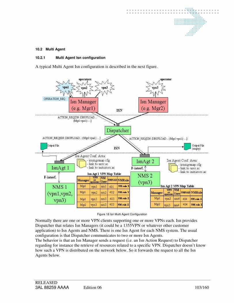
RELEASED 3AL 88259 AAAA Edition 06 103/160
10.2 Multi Agent
10.2.1 Multi Agent Isn configuration
A typical Multi Agent Isn configuration is described in the next figure.
Figure 18 Isn Multi Agent Configuration
Normally there are one or more VPN clients supporting one or more VPNs each. Isn provides Dispatcher that relates Isn Managers (it could be a 1355VPN or whatever other customer application) to Isn Agents and NMS. There is one Isn Agent for each NMS system. The usual configuration is that Dispatcher communicates to two or more Isn Agents. The behavior is that an Isn Manager sends a request (i.e. an Isn Action Request) to Dispatcher regarding for instance the retrieve of resources related to a specific VPN. Dispatcher doesn’t know how such a VPN is distributed on the network below. So it forwards the request to all the Isn Agents below.

The Isn Agents that really manage such a VPN will answer with an Action success reply and then will provide a file containing the requested resources; as particular case if no resources are supported for that VPN, the file will be empty. If an Isn Agent does not know the VPN, it will return an empty file as well. It is important to take into account that Isn does not support on Isn Agent the following VPN and NM User combinations: One VPN related to two or more NM Users: Isn Agent will manage Action requests only for
the first NM User (i.e. for the NM User present in the first row inside the isnmgrmap.cfg file containing the exact VPN - NM User combination), while spontaneous notifications (i.e. events coming from F interface due to changes executed directly by NMS) will be sent for all;
Two or more VPNs related to the same NM User: Isn Agent will manage Action requests for all, while spontaneous notifications are supported only for the first row inside the isnmgrmap.cfg file containing the NM User that executed the operation on NMS.

RELEASED 3AL 88259 AAAA Edition 06 105/160
10.2.2 Isn Multi Agent Configuration files
In order to realize the Isn Multi Agent Configuration the following steps are necessary:
- Define a new agent running on localhost to be managed by the localhost Dispatcher.
- For each Agent different socket Port and QSNROOT parameters must be configured. This can be done during the ISN_AGENT Subsystem configuration.
- For Isn Dispatcher the “data/isnagents.cfg” and “data/nserverfile” will be automatically updated in order to specify the agents it has to connect to and for each of them the host where it is installed.
- Running the script: /alcatel/Kernel/etc/HostDeclarer.pl -add <agent host name> [Enter] (see par. 5.4.3)
These are the files above mentioned after ISN ConfTool automatic settings:
- The Isnagents.cfg file will contain (for example) the following lines:
� 1:<System_Instance_Name>:<host>:<login>:<resilianceRole>:<spareRoot> for Isnagt1;
� 2:<System_Instance_Name>:<host>:<login>:<resilianceRole>:<spareRoot> for Isnagt2;
- The nserverfile will contain (for example) the following lines:
� DN 2.9.3.2.7.4 = 1:SYSTEM 2.9.3.2.7.4=ISNAgt1:HOST=<host>:PORT = 10004;
� DN 2.9.3.2.7.4 = 2:SYSTEM 2.9.3.2.7.4=ISNAgt2:HOST=<host>:PORT = 10001;

RELEASED 3AL 88259 AAAA Edition 06 106/160
10.3 Multi Dispatcher
A typical Multi Dispatcher Isn configuration is described in the next figure.
Figure 19 Isn Multi Dispatcher Configuration
Each Dispatcher supports one or more Isn Managers each one working on one or more VPNs. To correctly manage spontaneous notifications, Isn Managers must be identified into the system by a univocal label (e.g. Mgr1 and Mgr2). The figure describes the scenario in case a spontaneous event occurs. The NMS sends a
spontaneous event to its Isn Agent via F interface. The Isn Agent consults the isnmgrmap.cfg file and identifies the involved Isn Manager, starting from the VPN, which the resources belong to. Then it sends the Isn spontaneous notification to all Dispatchers. Each Dispatcher knows the Managers that are connected. So when it receives an event it can forward the event itself to the proper manager or filter out the event if it refers a not connected manager. The Configuration can be dynamically upgraded. It means that is possible to add a new Dispatcher and new Managers above without restart the system. The system periodically checks if there are changes in the configuration files and if any automatically upgrades the system. So for instance, referring the figure above, Mgr2 and Dispatcher 2 could be added into the system in a second step without stopping the system.

RELEASED 3AL 88259 AAAA Edition 06 107/160

RELEASED 3AL 88259 AAAA Edition 06 108/160
11 PM DATA FILE PRODUCTION (1354RM)
ISN provides start/stop PM: Modifying an already existing path: in this case all the necessary steps requested by 1354RM
are automatically applied by Isn Agent; At path creation time (“Automatic Monitoring”): in this case all the necessary steps requested by 1354RM are automatically applied by Isn Agent, except that NML operator has to manually create the report (if it does not already exist) and correlate it to the proper created measure. For these two operations please follows 14.3.1 and 14.3.3 respectively. One restriction about this function(ISN provides start/stop PM):
1. Create a path in 1354RM,then can successfully start/stop PM. 2. Remove the path. 3. Create a path in 1354RM with the same command(including the same attributes),then can
not do the start/stop PM.The start/stop PM will not be successful. The reason: RM will add a record which map the path in table named about "Measure" when user start PM(step 1), but RM will not delete this record when user end PM(step 2), and the Measure state of the record will be "Terminate".So,we can do start/end PM success on the first time , but failed when we do it again(step 3). The resolve:After remove the path in RM,remove the record in “Measure” which in RM database manually.

RELEASED 3AL 88259 AAAA Edition 06 109/160

RELEASED 3AL 88259 AAAA Edition 06 110/160
12 NRI CUSTOMIZATION FOR EACH MANAGER
During the Isn Manager configuration phase, the default NRI reports index is distributed on appropriate areas.
The procedure to follow is the same for any Isn configuration: Agent and Dispatcher on the same machine or one Agent stand alone on a machine.
When Administrator executes:
- /usr/Systems/<System_Instance_Name>/ISN_DISP/etc/mgrftpconfig
the script copies, for the manager name specified as parameter, the file into the manager specific configuration area:
/usr/Systems/<System_Instance_Name>/ISN_DISP/data/ reportdata/$Mgr/reportdata.help
Note that the script evaluates the value of the NR63compatible variable and takes the proper file (i.e. the one supporting ET report if value is equal to 1; the file supporting NPA report if equal to 0).
- usr/Systems/<System_Instance_Name>/ISN_DISP/etc/DistributeReportCfg
It copies the NRI report index file (reportdata.cfg) from Dispatcher to all the involved Isn Agents:
/usr/Systems/<System_Instance_Name>/ISN_AGENT/data/reportdata/$Mgr/reportdata.cfg.
Agents don’t need to be restarted in order to take into account the new downloaded reportdata.cfg file. As soon as the new file is distributed, the Agents read it.
In a second step, if necessary, the System Administrator can customize the NRI reports index file according to the specific NRI behavior requested by such Isn Manager. In order to do this, it's necessary to modify the file:
/usr/Systems/<System_Instance_Name>/ISN_DISP/data/reportdata/$Mgr/reportdata.help.
Each Manager can customize its reports: the header shows the help describing the used syntax and the rules to follow in order to modify the customization.
The "Y" field on attributes can be modified (from Y to N or vice versa) indicating if it will be retrieved (Y) or not (N).
E.g:
# : Y : = attributes retrieved
# : N : = attributes not retrieved
#

RELEASED 3AL 88259 AAAA Edition 06 111/160
For only BM-ETH reports, the second “Y”/”N” field (filterable Attr Info) exists, too. The filterable Attr Info indicates whether an attribute can (Y) or cannot (N) be used as filter. This info is provided by BM-ETH and should not be changed by administrator.
It is possible to customize also (i.e. insert, delete or modify) the default filter condition. It means that when such a report is requested, this filter will be always applied (by default). If additionally requestor will specify a filter into action request, the two filters will be joint by a “AND” logical operator.
If default or customized filter condition contains “OR” logical operators (like report number 3), manager cannot specify any filter condition into action request.
# FILTER : N : = no filter applied
# FILTER : Y : <filter> = filter condition (default or customized).
To download this NRI report profile, Administrator will manually execute the
"DistributeReportCfg" command providing the specific Manager as parameter.
Agents do not need a restart, in order to take into account the new downloaded reportdata.cfg file. As soon as the new file is distributed, Agents will read it. When Isn manager will request a NRI report, Isn Agent will filter and select data according to the
currently present "reportdata.cfg" file.
12.1 Changing the NR63compatible
In case at least a manager has been created and the operator needs to change NR63compatible variable, please follow the next procedure:
• Set properly the NR63compatible variables into the “env_def_isn” files (one for each Agent) and the “env_def_isn” file for Dispatcher;
• Execute the following command by “snml” user:
/usr/Systems/<System_Instance_Name>/ISN_DISP/etc/ChangeNRCompatibleTo <PARAM>
<PARAM> has to be equal to NEW if NR63compatible has been set to 0; must be equal to OLD if NR63compatible has been set to 1.
According the variables value, the script gets the reportdata.cfg Alcatel default file, copies it into all manager directories and distributes it to all agents.
• In case NR63compatible is set to 1, please check that on Dispatcher KEEP_NCDR_OLD_NAMES present into param.cfg file is True;
• Restart Isn (i.e. all Isn Agent and Dispatcher as well);
• If the operator needs to customize the NRI reports for a single manager only, please modify the
reportdata.help file into the corresponding manager directory and apply then the distribute command.

RELEASED 3AL 88259 AAAA Edition 06 112/160
12.2 Backward compatibility manage
When the ISN version is a compatible one,then doing system configuration, two new parameters applied to new function:
• BACKCOMPDBUPLOAD: To disable/enable backward compatibility function. Acceptable parameters are
o True
o False
• BACKCOMPISNVERSION: is the version which 51D compatible. Current acceptable parameter is
o V51C When fill value of two new parameters be careful about character case of uppercase and lowercase.

RELEASED 3AL 88259 AAAA Edition 06 113/160
13 MAINTENANCE
13.1 Generalities
None
13.2 Preventive Maintenance
None
13.3 Corrective Maintenance
None
13.4 Maintenance Operations
None

RELEASED 3AL 88259 AAAA Edition 06 114/160

RELEASED 3AL 88259 AAAA Edition 06 115/160
14 TROUBLESHOOTING
This section aims to give solutions to the most frequent problems that occur during the ISN installation and configuration procedures.
14.1 Retrieve Data Actions
During the execution of the Retrieve actions, the error code 13 (degraded agent) can be generated.
The problem is due to a wrong number of retrievable objects in
/usr/snml/conf/conf_nlMong.
RM has a parameter, which indicates the maximum number of data that can be retrieved at once.
If the TPs to be retrieved are more, RM sends an error to ISN, which fails the retrieve operation.
In order to solve the problem, it is necessary to change in the file
/usr/snml/conf/conf_nlMong the actual number in each line with a larger one (i.e: 1000000) and to restart the nlMon_g RMAgent.
N.B. Please, run the checkIsnConfigAgt script (see par 5.5.7 ISN Configuration Check) after each Manager Configuration
14.2 FTP
14.2.1 FTP Configuration
The FTP is properly configured on the ISN Dispatcher machine in order to give a public and
restricted access through FTP to all the ISN Managers.
The FTP configuration takes place automatically during customization process. All the FTP-Area
directories, anonymous FTP user, and user group are created; should any of the items already exist,
its automatic creation is skipped.

RELEASED 3AL 88259 AAAA Edition 06 116/160
14.2.2 FTP Setup
The guest FTP must be set-up on the ISN Dispatcher machine in order to give a restricted access through FTP to the ISN Managers.
Following steps should be done :
Login as " root " user.
Check for ftponly group and if not already present, define the "ftponly" group, adding the following line to the /etc/group system file:
ftponly : : 30 :
N.B. The group id (30) could be already used on your system; in that case you can use any other available group id.
Check for FTP home directory, if not present, create it and change the permission to the FTP home directory:
..,sys,root> mkdir -p /home/ftp , and press [Enter]
..,sys,root> chmod 555 /home/ftp , and press [Enter]
Check for the usr directories and if not present create and change the permission to the usr directories under the anonymous FTP home directory (if not already performed):
..,sys,root> mkdir -p /home/ftp/bin , and press [Enter]
..,sys,root> chmod -R 555 /home/ftp/ , and press [Enter]
Check for the links and if not already performed, create some hard links to the required system files:
..,sys,root> cp -f /sbin/ls /home/ftp/bin , and press [Enter]
Modify the file /etc/inetd.conf adding the switch -a to the ftpd daemon:
ftp stream tcp nowait root /usr/lbin/ftpd ftpd -l -a

RELEASED 3AL 88259 AAAA Edition 06 117/160
14.2.3 FTP Access
The /etc/shells and /etc/ftpd/ftpaccess files should be automatically updated by /usr/Isn/etc/mgrftpconfig script.
The /etc/shells should contain the following lines:
/sbin/sh
/usr/bin/sh
/usr/bin/rsh
/usr/bin/ksh
/usr/bin/rksh
/usr/bin/csh
/usr/bin/keysh
/usr/bin/false
If for any reason the file does not exist or it contains something different, please create or modify it manually.
The /etc/ftpd/ftpaccess file should contain after the following comment line:
# all the following default to “yes” for everybody
following row (it is more or less at line number 30 into the file):
delete no anonymous # delete permission?
If the line is not present or the content is different (e.g. it could be),:
delete no guest,anonymous # delete permission?
please update the file manually.
14.2.4 FTP Customization
Create and change the permission to the Isn/repository directory under the FTP home directory:
..,sys,root> mkdir -p /home/ftp/Isn/repository , and press [Enter]
..,sys,root> chmod -R 555 /home/ftp/Isn , and press [Enter]

RELEASED 3AL 88259 AAAA Edition 06 118/160
14.2.5 FTP login setup
For each ISN Manager to be enabled to access the ISN file repository through FTP, you must create a guest ftp login:
Login as " root " user.
For each Isn Manager you must define a guest ftp login, adding the following line to the /etc/passwd file:
<user-name>::<user-id>:<ftponly_grpid>::/home/ftp/./Isn/repository/<Mgr_Key>:/usr/bin/false
Where:
<user-name> is the anonymous FTP sub-login username;
<user-id> is a unique user-id associated to the sub-login;
<ftponly_grpid> is the group-id (e.g. 30) of the ftponly group in the system file /etc/group;
<Mgr_Key> is the unique label associated to the ISN Manager.
14.2.6 FTP login password change
In order to setup or change the FTP guest login password you must execute the following command:
..,sys,root> passwd <user-name> , and press [Enter]
Where <user-name> is the FTP guest login username associated to the ISN Manager.
14.2.7 Repository directory creation
For each ISN Manager you must create a dedicated repository directory to store its retrieve files, giving the right permissions:
..,sys,root> mkdir /home/ftp/Isn/repository/<Mgr_Key> , and press [Enter]
..,sys,root> chmod 770 /home/ftp/Isn/repository/<Mgr_Key> , and press [Enter]
..,sys,root> chown <user-name>:dba /home/ftp/Isn/repository/<Mgr_Key> , and press [Enter]
Where:
<Mgr_Key> is the unique label associated to the ISN Manager.
<user-id> is a unique user-id associated to the sub-login.
Moreover, for each ISN Manager repository directory, you must create a sub-directory (named LINK_PM directory) where ISN will store links to PM files (which are located in the repository directory). This is needed in order to improve performances when an ISN Manager retrieves a great quantity of PM files.
..,sys,root> mkdir /home/ftp/Isn/repository/<Mgr_Key>/LINK_PM , and press [Enter]

RELEASED 3AL 88259 AAAA Edition 06 119/160
..,sys,root> chmod 770/home/ftp/Isn/repository/<Mgr_Key>/LINK_PM , and press [Enter]
..,sys,root> chown <user-name>:dba /home/ftp/Isn/repository/<Mgr_Key>/LINK_PM , and
press [Enter]
Where:
<Mgr_Key> is the unique label associated to the ISN Manager.
<user-id> is a unique user-id associated to the sub-login.
14.3 PM data file production (1354RM)
In Isn 4.1 is not mandatory that the operator applies all the steps below described manually. In fact
Isn Agent executes them automatically when it has to activate a connection monitoring.
However the operator can decide at any time to continue using the manual approach.
Log into 1354RM as the NML Operator defined to support the given External OS; remember that
the Operator must have a NAD enabled with the rule AC_R_PMVPN. If the External OS manages
more VPNs (more NADs and more SNML Operators) following operations must be performed for
each VPN.
Start the 1354RM Browser application and select "PM Tools" on the toolbar.
Note: You have to follow different steps if you are using connectivity with "automatic monitoring",
or not.
If the connectivity has been created with "Automatic Monitoring", the 1354RM system will create a
new measure (24 hours granularity) already correlated to the connectivity; in this case you need
only to correlate that measure to a report. So please, follow step 14.3.1 to create the report and step
14.3.3 to correlate report and measure.

RELEASED 3AL 88259 AAAA Edition 06 120/160
14.3.1 PM Counter Definition
On the 1354RM Browser select the "Performance Monitoring Domain" object and select the
"Create -> Counter Report " action on the PM Domain menu.
On the "CREATE : Performance Monitoring Counter Report " window you must specify the
following parameters:
- User label: the measure user label must be set as follows:
<Mgr_Key>_<granularity> or
<Mgr_Key>_<granularity>_<VPN_Key>
where:
<Mgr_Key> is the Isn Manager label associated to the External OS;
<VPN_Key> is the VPN label (optional, if you want to create one report for each VPN)
<granularity> is a number indicating the PM data granularity (15 or 24) you should create one PM
Report for each granularity.
- Type: select File.
- Destination: must be set to /usr/Isn/pm/userlabel (i.e. /usr/Isn/pm/1355VPN_24_VPN1)
- Frequency: defines the frequency of the report generation
- ReportFormat: Csv (available only on 1354RM 5.2.0 or later)
Press the [Create] button.

RELEASED 3AL 88259 AAAA Edition 06 121/160
14.3.2 PM Measure Definition
On the 1354RM Browser select the "Performance Monitoring Domain" object and click on the
"Create a new measure " button on the toolbar (or select the menu Create -> Measure).
On the "CREATE : Measure " window you must specify the following parameters:
- User label: to avoid any confusion, the measure user label should be defined equal to
the PM Counter report user label (see above), but that is not strictly
required.
- Granularity: select 24 Hours or 15 Minutes.
- Counters provided: set to True
Don't change the other parameter values (defaults).
Press the [Create] button on the toolbar.
In order to activate the new measure it is necessary to correlate one connection (path) to the
measure itself (see below).
Note: it’s task of the NML operator to choose the criteria to follow for the path to measure
correlation (i.e. one path for each measure or a measure can monitor a set of paths). In the second
case, the number of paths to correlate to one measure depends on 1354RM capability.
14.3.3 PM Measure - Report Correlation
Now you must correlate the new measure to the PM Report: open the "Measures List " from the
"Performance Monitoring Domain" object; then select the new measure and select from the Action
menu: Action -> Correlate/Merge -> Correlate reports.
Then open the "PM Reports List " from the "Performance Monitoring Domain" object, drag and
drop the report on the Correlate window; at last click on the "Start correlating all the specified
objects " on the toolbar.

RELEASED 3AL 88259 AAAA Edition 06 122/160
14.3.4 Connectivity - PM Measure Correlation
To generate PM data counters of a given connectivity on the related PM counter report, the
connectivity must be correlated to the related PM measure (24 hours, 15 minutes or both).
After this operation the PM counters for the selected connectivities will be stored on the defined PM
counter reports with the given frequency; the Isn Agent will transfer all the PM files to the External
OS repository directory (accessible via FTP).
If the connectivity has not been created with "Automatic Monitoring" you must correlate the
connectivity to the defined measure.
In order to correlate the connectivity to the measure you must do following actions:
open the "Measures List " from the "Performance Monitoring Domain" object;
select the new measure and select from the Action menu: Action -> Correlate/Merge ->
Correlate paths/trails;
open the "Path list", drag and drop the path to correlate on the "Correlate" window and click
on "Start correlating all the specified objects" button on the toolbar.
14.3.5 PM Measure Activation
In order to activate a new measure, you must open the "Measures List" from the "Performance Monitoring Domain" object; select the new measure and select from the Action menu: Action -> Start/Consistency/Stop -> Start.
14.3.6 PM Frequency changing
It’s not possible change PM Frequency when measure is active/running on system. This scenario is not also supported on RM, where is not possible change the frequency of report correlated a measurement observation. The parameter related to PM frequency present in isnmgrmap.cfg is used only when a new PM report is created. So, to change the PM Frequency, for exiting PM reports, is not enough changing just the ISN_AGENT/data/isnmgrmap.cfg file. However, two workarounds exist to change PM Frequency when measure is active/running on system.
- Procedure 1: Complex but ISN and RM configuration are lined up each other.
From ISN: stop PM related to all VPN associated Paths.
From RM: Uncorrelate report/measure; Remove report; Remove measure;

RELEASED 3AL 88259 AAAA Edition 06 123/160
From ISN: modify ISN_AGENT/data/isnmgrmap.cfg; start PM for all VPN associated Paths (the report
will be created with new specified frequency).
- Procedure 2: Slim but ISN and RM configuration are not lined up each other.
From ISN: stop PM related to all VPN associated Paths.
From RM: Modify the PM Frequency;
From ISN: Start PM for all VPN associated.
14.4 Customized Isn Configuration
During ISN system configuration or ‘custom’ procedure the ISN configuration files are overwritten.
So, if a customer configuration exists it will be lost.
In such case, if the operator is going to perform a ‘custom’ or ‘system Configuration’, without
having a new installed ISN, to avoid to re-customize ISN configuration, the Backup/Restore
procedure has to be used.
This procedure is valid also to hold a customized NRI.

RELEASED 3AL 88259 AAAA Edition 06 124/160

RELEASED 3AL 88259 AAAA Edition 06 125/160
15 PROCEDURES
15.1 Failure Management
None
15.2 Upload Failures
None
15.3 Advanced Network Management
None.

RELEASED 3AL 88259 AAAA Edition 06 126/160

RELEASED 3AL 88259 AAAA Edition 06 127/160
16 MIGRATION PROCEDURE
The ISN migration has to be done by migration of 1354RM system. However the migration from any starting 1359ISN (i.e. typically 1359ISN 2.1B) to 1359ISN 5.0 needs the following two steps:
• Migration into NR7 environment: this allows migrating the starting ISN into the first version using OS Kernel environment, that is ISN 2.2;
• Migration into ISN5.1B: it starts from ISN 2.2, got at the end of the previous step and converts it into ISN 5.1B environment.
16.1 Migration into NR7 environment
The procedure assumes that there is a 1355VPN instance working in NR5/6 environment on “source machine”. The goal is to migrate it on a “destination machine” in NR7 environment. The procedure executes first a data export on the source machine and then a data import on the destination machine.
16.1.1 Data Export from ISN R2.1B (on source machine)
• Install the migration scripts:
o cd /tmp
o Retrieve the migration package:
ftp <machine address> (ftp/any)
cd <migration tool directory>
bin
get migration_tools_R1.5.tar
o Extract the migration tool:
tar xvf migration_tools_R1.5.tar
o Execute the following command:
migration_tools/move_exe
• Predispose of NR5/6 environment for export:
o predispose 1355RM > /tmp/predispose.log 2>&1
• Export file generation:
o ExpMigData <root_dir> <RM_instance_name> ISN_AGENT_Domain ISN_DISP_Domain
(e.g. ExpMigData /alcatel 1354RM_1 ISN_AGENT_Domain ISN_DISP_Domain) <root_dir> is the complete path name where data are copied; <RM_instance_name> is the name identifier of the 1354RM instance the ISN components belong to.
As result, <root_dir> will contain the file <RM_instance_name>_migr_data.tar.gz
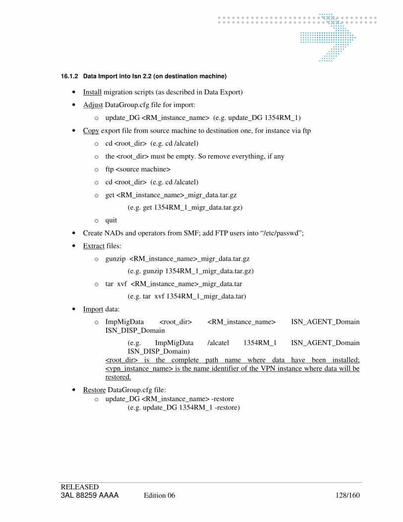
RELEASED 3AL 88259 AAAA Edition 06 128/160
16.1.2 Data Import into Isn 2.2 (on destination machine)
• Install migration scripts (as described in Data Export)
• Adjust DataGroup.cfg file for import:
o update_DG <RM_instance_name> (e.g. update_DG 1354RM_1)
• Copy export file from source machine to destination one, for instance via ftp
o cd <root_dir> (e.g. cd /alcatel)
o the <root_dir> must be empty. So remove everything, if any
o ftp <source machine>
o cd <root_dir> (e.g. cd /alcatel)
o get <RM_instance_name>_migr_data.tar.gz
(e.g. get 1354RM_1_migr_data.tar.gz)
o quit
• Create NADs and operators from SMF; add FTP users into “/etc/passwd”;
• Extract files:
o gunzip <RM_instance_name>_migr_data.tar.gz
(e.g. gunzip 1354RM_1_migr_data.tar.gz)
o tar xvf <RM_instance_name>_migr_data.tar
(e.g. tar xvf 1354RM_1_migr_data.tar)
• Import data:
o ImpMigData <root_dir> <RM_instance_name> ISN_AGENT_Domain ISN_DISP_Domain
(e.g. ImpMigData /alcatel 1354RM_1 ISN_AGENT_Domain ISN_DISP_Domain)
<root_dir> is the complete path name where data have been installed; <vpn_instance_name> is the name identifier of the VPN instance where data will be restored.
• Restore DataGroup.cfg file:
o update_DG <RM_instance_name> -restore (e.g. update_DG 1354RM_1 -restore)

RELEASED 3AL 88259 AAAA Edition 06 129/160
16.2 Migration into ISN 5.1B
16.2.1 Data Export from ISN R2.2
• Install the migration scripts:
o cd /alcatel/DEPOT
o Retrieve the migration package:
ftp <machine address> (ftp/any)
cd <migration tool directory>
bin
get migration_tools_R2.0.tar
quit
o Extract migration tool:
cd /tmp
tar xvf /alcatel/DEPOT/migration_tools_R2.0.tar
o Execute the following command:
migration_tools/move_exe
• Export file generation:
o ExpMigData <root_dir> <RM_instance_name> ISN_AGENT_Domain ISN_DISP_Domain
(e.g. ExpMigData /alcatel 1354RM_1 ISN_AGENT_Domain ISN_DISP_Domain) As result, <root_dir> will contain the file <RM_instance_name>_migr_data.tar.gz

RELEASED 3AL 88259 AAAA Edition 06 130/160
16.2.2 Data Import into Isn 5.1B (on destination machine)
• Copy export file from source machine to destination one, for instance via ftp
o cd <root_dir> (e.g. cd /alcatel)
o the <root_dir> must be empty. So remove everything, if any
o ftp <source machine>
o cd <root_dir> (e.g. cd /alcatel)
o get <RM_instance_name>_migr_data.tar.gz
(e.g. get 1354RM_1_migr_data.tar.gz)
o quit
• Create NADs and operators from SMF; add FTP users into “/etc/passwd”;
• Extract files:
o gunzip <RM_instance_name>_migr_data.tar.gz
(e.g. gunzip 1354RM_1_migr_data.tar.gz)
o tar xvf <RM_instance_name>_migr_data.tar
(e.g. tar xvf 1354RM_1_migr_data.tar)
• Import data:
o ImpMigData <root_dir> <RM_instance_name> ISN_AGENT_Domain ISN_DISP_Domain
(e.g. ImpMigData /alcatel 1354RM_1 ISN_AGENT_Domain ISN_DISP_Domain)
• Execute SystemConfig

RELEASED 3AL 88259 AAAA Edition 06 131/160
APPENDIX A ISN INSTALLATION GUIDELINES
A.1 ASCII ISN - ONE 1354RM - ONE EXTERNAL OS (WITHOUT 1355VPNs)
The following example shows how to configure the ISN Interface on a single 1354RM, enabling the ASCII interface for an External OS (ISN Manager) not using VPNs (the network resources assigned to the External OS are not splitted in more domains).
System data
1354RM host name myhost
Isn Installation directory /alcatel/
Isn Agent data
ISN socket port (ISNASCIIPORT) 10000
Isn Agent socket port (ISNAGTPORT) 10001
Isn Agent Identifier (QSNROOT) 1
BACKCOMPDBUPLOAD True
BACKCOMPISNVERSION V51C
Isn Manager (External OS) data
ISN Manager IP Address (Ip_Addr) 10.10.10.1
ISN Manager Key (Mgr_Key) isnmgr1
ISN Manager Identifier (Mgr_Root) 1001 (must be different from the Isn Agent Identifier)
ISN Interface Type (Interface_Type) ASCII
ISN Interface Profile (Interface_Profile) ALL
VPN Type (VPN_Type) EVPN (enabled to use the free-pool resources)
A.1.1 Installation of the ISN Delivery Package
Log-in as root .
Choose the following values for the installation variables:
HOST_TYPE IMM
HOSTING_PRD 1354RM
NETWORK_RELEASE NR 8.1 PL2
A.1.2 ISN Agent Customization
Choose the following values for the application variables:
QSNROOT 1
ISNAGTPORT 10001

RELEASED 3AL 88259 AAAA Edition 06 132/160
Timeouts and other variables Default values
BACKCOMPDBUPLOAD True/False
BACKCOMPISNVERSION V51C
A.1.3 ISN Dispatcher Customization
Choose the following values for the application variables:
ISNASCIIPORT 10000
Timeouts and other variables Default values
A.1.4 Adding a ISN Agent under control
Log-in as alcatel.
Add (if not automatically done) the following line to the ISN Dispatcher Name Server File
/usr/Systems/<System_Instance_Name>/ISN_DISP/data/nserverfile
DN 2.9.3.2.7.4=1 : SYSTEM 2.9.3.2.7.4=ISNAgt1 : HOST=myhost : PORT=10001;
Add the following line to the ISN Agents File
/usr/Systems/<System_Instance_Name>/ISN_DISP/data/isnagents.cfg
1:1354RM:myhost:snml:None:0

RELEASED 3AL 88259 AAAA Edition 06 133/160
A.1.5 Opening the ISN Interface to an External OS
STEP-1: NAD Configuration
Create a NAD with the following parameters:
RM Initiator 1001
Initiator Name isnusr1_IN
Rule AC_R_EVPN
STEP-2: NML Operator Configuration
Create an Operator with the following parameters:
Username isnusr1
Profiles Constructor
Initiator isnusr1_IN
STEP-3: Network Resources Assignment
Assign to the NAD isnusr1_IN the network resources to made reserved for the External OS.
STEP-4: Repository directory creation
Create the following directory:
/usr/Systems/<System_Instance_Name>/ISN_AGENT/agtrepository/isnmgr1
STEP-5: NML Operator Mapping
Add the following line to the ISN managers Map File
/usr/Systems/<System_Instance_Name>/ISN_AGENT/data/isnmgrmap.cfg
isnmgr1::isnuser1:True::
STEP-6: FTP sub-login setup
Log-in as root and execute the folowing command:
/usr/Isn/etc/mgrftpconfig isnusr1 200 isnmgr1
STEP-7: ISN Manager Configuration
Log-in as alcatel .
Add the following line to the ISN Managers File
/usr/Systems/<System_Instance_Name>/ISN_DISP/data/isnmanagers.cfg
isnmgr1:1001:ASCII:10.10.10.1:EVPN:False:True:ALL:V51:FULL:1000000:

RELEASED 3AL 88259 AAAA Edition 06 134/160
A.1.6 Checking the ISN Configuration
Activate (if not already done) the Isn Agent from the 1354RM Process Monitor.
Execute the following TELNET session (in italic bold the commands to enter):
telnet myhost 10000 Trying... Connected to myhost. Escape character is '^]'.
CON_REQ[ISN::::isnmgr1] CON_RESP[::CON_CNF:]
<CNTRL>+] telnet> quit Connection closed.
A.1.7 Checking the FTP Configuration
Execute the following FTP session (in italic bold the commands to enter):
ftp myhost Connected to myhost. 220 myhost FTP server (Version 1...) ready.
Name (root) : ftp 331 Guest login ok, send ident as password.
Password: isnmgr1 230 Guest login ok, access restrictions apply. Remote system type is UNIX. Using binary mode to transfer files.
ftp> user isnmgr1 <password> 331 Password required for isnmgr1. 230 User isnmgr1 logged in.
ftp> pwd 257 "/Isn/repository/isnmgr1" is current directory.
ftp> ls 200 PORT command successful. 150 Opening ASCII mode data connection for /usr/bin/ls. total 0 226 Transfer complete.
ftp> quit 221 Goodbye.

RELEASED 3AL 88259 AAAA Edition 06 135/160
A.2 ASCII ISN - ONE 1354RM - ONE EXTERNAL OS (WITH 1355VPNs)
The following example shows how to configure the ISN Interface on a single 1354RM, enabling the ASCII interface for an External OS (e.g. 1355VPN) using VPNs (the network resources assigned to the External OS are splitted in more domains).
System data
1354RM host name myhost
Isn Installation directory /alcatel/
Isn Agent data
ISN socket port (ISNASCIIPORT) 10000
Isn Agent socket port (ISNAGTPORT) 10001
Isn Agent Identifier (QSNROOT) 1
BACKCOMPDBUPLOAD True
BACKCOMPISNVERSION V51C
Isn Manager (External OS) data
ISN Manager IP Address (Ip_Addr) 10.10.10.1
ISN Manager Key (Mgr_Key) 1355VPN
ISN Manager Identifier (Mgr_Root) 1001 (must be different from the Isn Agent Identifier)
ISN Interface Type (Interface_Type) ASCII
ISN Interface Profile (Interface_Profile) 1355VPN
VPN Type (VPN_Type) VPN (not enabled to use the free-pool TPs)
VPN data (2 VPNs)
VPN Key (VPN_Key) isnvpn1, isnvpn2
VPN Type (VPN_Type) VPN
A.2.1 Installing and customizing the ISN Interface
Follow the steps as indicated into the paragraphs from A.1.1 to A.1.4

RELEASED 3AL 88259 AAAA Edition 06 136/160
A.2.2 Opening the ISN Interface to an External OS
STEP-1: NAD Configuration
Create 2 NADs with the following parameters:
RM Initiator 1001
Initiator Name isnvpn1
Rule AC_R_VPN
RM Initiator 1002
Initiator Name isnvpn2
Rule AC_R_VPN
STEP-2: NML Operator Configuration
Create 2 Operators with the following parameters:
Username isnvpn1
Profiles Constructor
Initiator isnvpn1
Username isnvpn2
Profiles Constructor
Initiator isnvpn2
STEP-3: Network Resources Assignment
Assign to the NAD isnvpn1 the network resources to made reserved for the first VPN.
Assign to the NAD isnvpn2 the network resources to made reserved for the second VPN.
STEP-4: Repository directory creation
Create the following directory:
/usr/Systems/<System_Instance_Name>/ISN_AGENT/agtrepository/1355VPN
STEP-5: NML Operator Mapping
Add the following lines to the ISN managers Map File
/usr/Systems/<System_Instance_Name>/ISN_AGENT/data/isnmgrmap.cfg
1355VPN:isnvpn1:isnvpn1:True: 1355VPN:isnvpn2:isnvpn2:True:
STEP-6: FTP sub-login setup
Log-in as root and execute the folowing command:
/usr/Systems/<System_Instance_Name>/ISN_DISP/etc/mgrftpconfig 1355VPN 1001 1355VPN

RELEASED 3AL 88259 AAAA Edition 06 137/160
STEP-7: ISN Manager Configuration
Log-in as alcatel .
Add the following line to the ISN Managers File
/usr/Systems/<System_Instance_Name>/ISN_DISP/data/isnmanagers.cfg
1355VPN:1001:ASCII:10.10.10.1:VPN:False:True:1355VPN:V51:FULL:1000000:
STEP-8: FTP login setup
Log-in as alcatel /usr/Isn/etc/mgrftpconfig isnvpn1 1001 1355VPN

RELEASED 3AL 88259 AAAA Edition 06 138/160

RELEASED 3AL 88259 AAAA Edition 06 139/160
APPENDIX B INTERFACE MASTER PROFILE
This appendix describes the profile of the Isn interface only for CSM functionality.
The profile for NRI functionality is contained in NRI interface document.
Completion Code values contained in Table 1 Generic Completion Codes and Table 2 Specific Completion Codes are valid also for NRI functionality.
B.1 Supported Functions
The table below lists the functions of the 1359ISN in relation with the subsystem that supports the action
“All” means all subsystem : 1354RM, 1354BM.
Each item is described in line with the following column titles: item, profile support, subsystem that supports the request/notification, constraint / comment.
Item Supp SubSystem Constraints/Comments
Interface types
ASCII–based via TCP/IP socket Y All
Main Functions
ACTIONS
ACTIDLETRAIL Y 1354RM
ADDIDLETRAIL Y 1354RM
BATCHNMS Y 1354RM
CHSCSS Y 1354RM
DEACTTRAIL Y 1354RM
DEFCONSTR Y 1354RM
DEFSC Y 1354RM
DELACTJOB Y 1354RM
LOOPBACK Y 1354RM
MODSC Y 1354RM
REMIDLETRAIL Y 1354RM
REMSC Y 1354RM
RETRACTJOB Y 1354RM see ASCII CSM documentation
RETDATASC Y 1354RM see ASCII CSM documentation
RETDATATOP Y 1354RM see ASCII CSM documentation
RETDATATP Y 1354RM see ASCII CSM documentation
Retrieve data: nlHDomain data Y All (i.e.NRI). For more details see NRI
documentation.
RETSCONNALR Y 1354RM see ASCII CSM documentation
RETSCONNCONSTR Y 1354RM
RETSCONNERROR Y 1354RM

RELEASED 3AL 88259 AAAA Edition 06 140/160
Item Supp SubSystem Constraints/Comments
RETSCONNPM Y 1354RM see ASCII CSM documentation
RETSCONNROUTE Y 1354RM It’s permitted only to choice the
detailLevel (Full or Partial)
RETDATASUB Y 1354BM
RETDATATL Y 1354BM
RETDATAME Y 1354BM
RETDATATPP Y 1354BM
RETDATACALL Y 1354BM
RETCALLALM Y 1354BM
DEFCALL Y 1354BM
REMCALL Y 1354BM
MODCALL Y 1354BM
MODFLOW Y 1354BM
ACTCALL Y 1354BM
NOTIFICATIONS after executed
operations
ACTIDLETRAIL Y
ADDIDLETRAIL Y
BATCH Y 1354RM
BATCHNMS Y 1354RM
DEACTTRAIL Y 1354RM
DEFCONSTR Y 1354RM
DELACTJOB Y 1354RM
DEFSC Y 1354RM
LOOPBACK Y 1354RM
REMIDLETRAIL Y 1354RM
REMSC Y 1354RM
RETRACTJOB Y 1354RM
RETDATASC Y 1354RM
RETDATATOP Y 1354RM
RETDATATP Y 1354RM
RETSCONNALR Y 1354RM
RETSCONNCONSTR Y 1354RM
RETSCONNERROR Y 1354RM
RETSCONNPM Y 1354RM
RETSCONNROUTE Y 1354RM
UPDSC Y 1354RM
RETDATASUB 1354BM
RETDATATL 1354BM
RETDATAME 1354BM
RETDATATPP 1354BM
RETDATACALL 1354BM
RETCALLALM 1354BM
DEFCALL 1354BM
REMCALL 1354BM
MODCALL 1354BM
MODFLOW 1354BM

RELEASED 3AL 88259 AAAA Edition 06 141/160
Item Supp SubSystem Constraints/Comments
CHCALLST 1354BM
Spontaneous NOTIFICATIONS
ADDJOB
DEFSC Y 1354RM
DEFSTP Y 1354RM
DISCON_IND N
LOOPBACK Y 1354RM
MODSCATTR Y 1354RM
NECH Y 1354RM
NLHSTART Y All
PHPORTAL Y 1354RM
REMSC Y 1354RM
REMSTP Y 1354RM
SCONNAL Y 1354RM
SCHEDSTATUS 1354RM
UPDFAULT Y 1354RM
UPDLBL N 1354RM
UPDSC Y 1354RM
UPDSTP Y 1354RM
CALLALM 1354BM
CHMEST 1354BM
CHCALLST 1354BM
UPDSUB 1354BM
UPDME 1354BM
UPDTL 1354BM
UPDTPP 1354BM
UPDCALL 1354BM
UPDFLOW 1354BM
DEFSUB 1354BM
DEFME 1354BM
DEFTL 1354BM
DEFTPP 1354BM
DEFCALL 1354BM
DEFFLOW 1354BM
REMSUB 1354BM
REMME 1354BM
REMTL 1354BM
REMTPP 1354BM
REMCALL 1354BM
REMFLOW 1354BM
ASCII-based specific functions
connect request Y
connect response (confirm / reject) Y
disconnect indication N
heartbeat request Y

RELEASED 3AL 88259 AAAA Edition 06 142/160
Item Supp SubSystem Constraints/Comments
heartbeat response Y
Functions not using Isn messages
Transfer of “retrieve data reply” files Y All uses FTP
Transfer of PM data files Y 1354RM uses FTP
Transfer of State Transition data files N uses FTP
B.2 CSM SUPPORTED RESOURCE ATTRIBUTES
B.2.1 sConn Attributes
Attribute Supp Constraints/Comments Filter
sTrailLbl Y Y
signalRate Y Y
aEndsTP Y Y
zEndsTP Y Y
OwnerId Y Y
faultReport N and so fault reporting is enabled for all sConns N
routingRules N N
useAlarmed
Resources Y Y
customerLabel Y Y
availLev Y Y
qualLev N N
repairPriority N N
servState Y Y
workState Y
PV: working, not working (internal/external).
Degraded (internal/external) not supported,
because alarmStatus is used instead.
Y
directionality Y Y
pMDataCollect Y Y
alarmStatus Y Y
comment1 Y supported by 1354RM N
comment2 Y supported by 1354RM N
transportRate Y supported by 1354RM Y
configurationRate Y supported by 1354RM Y
serviceType Y supported by 1354RM Y
transpTechnology Y Supported by 1354RM Y
virtConcatLevel Y Supported by 1354RM Y
pathPtr Y Supported by 1354RM Y
loopBack Y Supported by 1354RM Y
activeConcLevel Y Supported by 1354RM Y

RELEASED 3AL 88259 AAAA Edition 06 143/160
concMemberSt Y Supported by 1354RM Y
concLevelMode Y Supported by 1354RM Y
ethMapping Y Supported by 1354RM
value not allowed : ‘notDefined’ Y
Notes PV means “permitted value(s)”.
B.2.2 sTP Attributes
Attribute Supp Constraints/Comments Filter
sTPGlobalName Y Y
signalRate Y Y
sTPType Y Y
sTPDirection Y Y
busyState Y Y
assignPolicy Y PV “dedicated”, “all”
Value “some” is for future releases Y
pdhPayloadType Y Y
supportedAu4Conc Y Supported only over 1354NP N
transportRate Y Supported only by 1354RM Y
transpTechnology Y Supported only by 1354RM Y
loopBackStatus Y Supported by 1354RM Y
au4maxSupportedConclevel Y Supported by 1354RM Y
tu3maxSupportedConclevel Y Supported by 1354RM Y
tu12maxSupportedConclevel Y Supported by 1354RM Y
ethMapping Y Supported by 1354RM Y
gfpProtocol Y Supported by 1354RM Y
B.2.3 sTopology Attributes
Attribute Supp Constraints/Comments Filter
siteLabel Y Y
nELabel Y Y
nELongLabel N N
sdhPortLabel Y Y
sdhPortAlarms Y Y
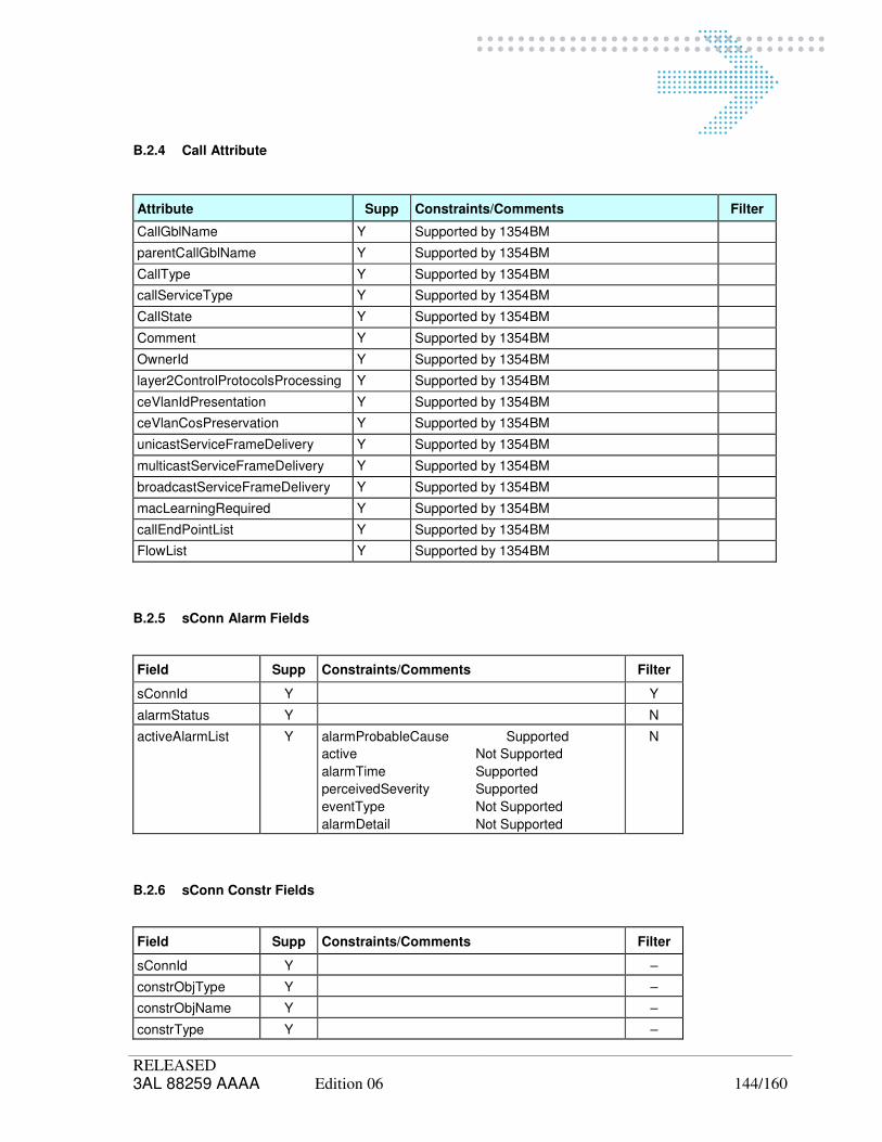
RELEASED 3AL 88259 AAAA Edition 06 144/160
B.2.4 Call Attribute
Attribute Supp Constraints/Comments Filter
CallGblName Y Supported by 1354BM
parentCallGblName Y Supported by 1354BM
CallType Y Supported by 1354BM
callServiceType Y Supported by 1354BM
CallState Y Supported by 1354BM
Comment Y Supported by 1354BM
OwnerId Y Supported by 1354BM
layer2ControlProtocolsProcessing Y Supported by 1354BM
ceVlanIdPresentation Y Supported by 1354BM
ceVlanCosPreservation Y Supported by 1354BM
unicastServiceFrameDelivery Y Supported by 1354BM
multicastServiceFrameDelivery Y Supported by 1354BM
broadcastServiceFrameDelivery Y Supported by 1354BM
macLearningRequired Y Supported by 1354BM
callEndPointList Y Supported by 1354BM
FlowList Y Supported by 1354BM
B.2.5 sConn Alarm Fields
Field Supp Constraints/Comments Filter
sConnId Y Y
alarmStatus Y N
activeAlarmList Y alarmProbableCause Supported
active Not Supported
alarmTime Supported
perceivedSeverity Supported
eventType Not Supported
alarmDetail Not Supported
N
B.2.6 sConn Constr Fields
Field Supp Constraints/Comments Filter
sConnId Y –
constrObjType Y –
constrObjName Y –
constrType Y –
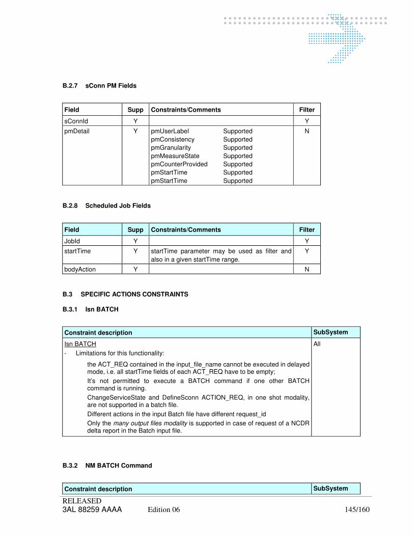
RELEASED 3AL 88259 AAAA Edition 06 145/160
B.2.7 sConn PM Fields
Field Supp Constraints/Comments Filter
sConnId Y Y
pmDetail Y pmUserLabel Supported
pmConsistency Supported
pmGranularity Supported
pmMeasureState Supported
pmCounterProvided Supported
pmStartTime Supported
pmStartTime Supported
N
B.2.8 Scheduled Job Fields
Field Supp Constraints/Comments Filter
JobId Y Y
startTime Y startTime parameter may be used as filter and
also in a given startTime range.
Y
bodyAction Y N
B.3 SPECIFIC ACTIONS CONSTRAINTS
B.3.1 Isn BATCH
Constraint description SubSystem
Isn BATCH
- Limitations for this functionality:
the ACT_REQ contained in the input_file_name cannot be executed in delayed mode, i.e. all startTime fields of each ACT_REQ have to be empty;
It’s not permitted to execute a BATCH command if one other BATCH command is running.
ChangeServiceState and DefineSconn ACTION_REQ, in one shot modality, are not supported in a batch file.
Different actions in the input Batch file have different request_id
Only the many output files modality is supported in case of request of a NCDR delta report in the Batch input file.
All
B.3.2 NM BATCH Command
Constraint description SubSystem

RELEASED 3AL 88259 AAAA Edition 06 146/160
Constraint description SubSystem
BATCHNMS Command
- Limitations for this functionality:
The default profile contains only the following commands:
CREATEtrail
DELETEtrail
ALLOCtrail
DEALLOCtrail
IMPLtrail
DEIMPLtrail
CONFIGtrail
CONSTRtrail
PROTECTtail
1354RM
B.3.3 change sConn serviceState
Constraint description SubSystem
change serviceState of sConn point to point
- The following input parameters are not supported:
mainInterv;
suplTextInfo
1354RM
change serviceState of a single HO Trail
Not Supported
1354RM
B.3.4 define sConn Constraint
Constraint description SubSystem
define sConn constraint
- <constrObjType> contains either “CTP, PATH” or “TRAIL”;
- <constrType> value depends on <constrObjType>. The following table
describes, for each constrType value, the allowed constrObjType objects:
1354RM
<constrType> <constrObjType> Notes
1354RM
1354NP

RELEASED 3AL 88259 AAAA Edition 06 147/160
Constraint description SubSystem
useMain CTP, TRAIL LO-Path uses an HO-Trail, HO-Path a MS-Trail
useSpare CTP, TRAIL LO-Path uses an HO-Trail, HO-Path a MS-Trail
notUseMain - For RL, PhyConn and Node
notUseSpare - For RL, PhyConn and Node
useMainSpare CTP, TRAIL LO-Path uses an HO-Trail, HO-Path a MS-Trail
notUse - For RL, PhyConn and Node
useService CTP, TRAIL LO-Path uses an HO-Trail, HO-Path a MS-Trail
notUseService - For RL, PhyConn and Node
overlapped PATH Paths must have same nodes, rate, protType;
they use the same server trails
disjoined PATH, TRAIL not use the same physical connections
overlappedRL PATH The two paths use the same RL (i.e. routing link)
useMainA CTP
useMainZ CTP
useSpareA CTP
useSpareZ CTP
useMainSpareA CTP
useMainSpareZ CTP
useServiceAZ CTP
useServiceZA CTP
1354NP
<constrType> <constrObjType> Notes
useMain CTP
useSpare CTP protection must be 1+1
notUseMain CTP
notUseSpare CTP protection must be 1+1
useMainSpare -
notUse -
useService -
notUseService -
overlapped PATH
Not applicable if protection is 1+1;
only one constraint is allowed disjoined
overlappedRL -
useMainA -
useMainZ -
useSpareA -
useSpareZ -

RELEASED 3AL 88259 AAAA Edition 06 148/160
Constraint description SubSystem
useMainSpareA -
useMainSpareZ -
useServiceAZ -
useServiceZA -
B.3.5 define sConn
Constraint description SubSystem
define sConn point to point
- The following input parameters are not supported:
- availLevMatch; default value is: False (BestEffort);
- qualLev;
- qualLevMatch; default value is: False (BestEffort);
- repairPriority;
- faultReport; default value is: true;
- routingRoules;
- useAlarmedResources; default value is: true;
- pMDataCollect; Supported by 1354RM, 1354NP and its value may be only
{True:False};
1354RM
B.3.6 LoopBack on TTP
Constraint description SubSystem
The LoopBack action is allowed only on TTP
1354RM
B.3.7 modify sConn
Constraint description SubSystem

RELEASED 3AL 88259 AAAA Edition 06 149/160
Constraint description SubSystem
Modify sConn supports only to change one attribute at a time
Modify sConn point to point
- The following input parameters are not supported:
availLev ; supported by 1354RM, but its value may be changed only if
servState=defined. The value: availLev =4 can not be changed.
availLevMatch;
repairPriority;
pMDataCollect;
faulReport;
pMFields; Supported for 1354RM, but pmReport24 and pmReport15 may be
only true.
1354RM
The availLev = 1 (protection “IN Rings” on 1354RM) and availLev = 4 (MS protection profile = “Protection Preferred” on 1354RM) can be assigned only at definition time of the connectivity.
availability level 1354RM Prot. Allow. changes
0 (Full) SNCP 2, 3, 6, 7
1 (Partial) In Rings -
2 (Enhanced) D&C SNCP 0
3 (None) None 0, 6, 7
4 (LowPriority) MS Prot. Profile = Prot.Pref. -
5 (Undefined) - -
6 (Full/InoAlarmPref) SNCP 0, 2, 3
7 (FullNotIntrusiveAlarmPref) SNCP 0, 2, 3
1354RM
B.3.8 AddIdleTrail – ActIdleTrail – DeactTrail - RemIdleTrail
Constraint description SubSystem
Actions allowed only for trails on Fast or Gigabit Ethernet path
1354RM

RELEASED 3AL 88259 AAAA Edition 06 150/160
B.4 SPECIFIC NOTIFICATIONS CONSTRAINTS
B.4.1 Isn BATCH
Constraint description SubSystem
Limitations for the <stop_at_op> attribute:
it’s managed as an Integer instead of a sequence of integer
it’s notified in case of error, only if the beh_first_error is set equal to STOP1KO;
i if beh_first_error is set equal to CONTINUE and one or more errors occur, it’s not notified.
1354RM
B.4.2 NE Change
Constraint description SubSystem
NE change
- only for NE creation or deletion; the notification is not sent to the manager for a
AVC like change label of site, NE, port etc.
1354RM
B.4.3 Sconn Alarm
Constraint description SubSystem
The <eventTypeid > field may be set only :
QoS Alarm
CommunicationAlarm
Processing Alarm (only for 1354NP)
1354RM
B.5 FILTERS AND TYPE OF REPLY FOR RETRIEVE DATA
For the detailed description of the filters see ISN ASCII NRI document.
B.6 MESSAGE PARAMETER SPECIFICATION
B.6.1 Completion Code Values
When a notification is consequence of an action request, it carries a field named Completion code
used to inform the manager if the action was correctly performed or if some sort of error occurred. The tables hereafter show the meaning of notification completion codes.
Table 1 Generic Completion Codes
Code Value Meaning
0 Success

RELEASED 3AL 88259 AAAA Edition 06 151/160
Code Value Meaning
1 Idle (software module not yet initialised)
2 To be Implemented (feature not yet implemented)
3 Configuration error
4 Memory error
5 Internal error (possible software bug)
6 Communication problem
7 Protocol error
8 Not supported request
9 Generic error (not better specified error)
10 Object busy (another action currently running on the selected object)
11 Agent busy (too many operations running on the agent at the same time)
12 Disabled agent (the involved agent is not connected)
13 Degraded agent (an agent doesn’t answer properly)
14 Not allowed (the requestor does’nt have the permissions to perform the action)
15 Timeout expired
16 Unknown operation
17 Data not available
18 Error received data
19 Operation not performed due to inconsistent state of the object
20 Disabled Scheduler
21 Time In The Past
22 Disabled Batch
23 Other Batch Act Pending
24 Not Existing Agent
25 RM internal Error
26 Not foreseen error
27 RM internal warning
Table 2 Specific Completion Codes
Code Value Meaning
1000 File error (generic error in file operations)
1001 No data found (the requested network resources are not found)
1002 Node data not available for retrieve operation
1003 Problems in packed-data retrieve data actions on sConn
1004 Lack of ownership (the given network resources doesn’t belong to the requestor)
1005 Compress file error – can’t find the destination directory
1006 No action (the requested action cannot be performed)
1007 Compress file error – can’t rename the compressed file
1008 Aend (sTP/node) for Sconn not available
1009 Zend (sTP/node) for Sconn not available
1010 Zend (sTP/Node) for Sconn not specified
1011 Unable to choose sTP by the specified Node
1012 Sconn definition type not supported
1013 Aend and Zend sTPs belong to different owners (NADs)
1014 Aend and Zend sTPs both belong to the free pool (not enough data to create
path)

RELEASED 3AL 88259 AAAA Edition 06 152/160
Code Value Meaning
1015 The requested sTP is already busy in a sConn
1016 1354NN Agent is not available (for actions that require its presence)
1017 File transfer error
1018 Error while compressing file
1019 Error while uncompressing file
1020 Report generator – problem in report production
1021 Different signal rate between Aend and Zend sTPs
1022 The owner was not specified
1023 No Aend sTP
1024 Specified sTP does not belong to the sConn
1025 No more sTP available for sConn creation
1026 Specified sConn is not unidirectional
1027 Specified sTP cannot be used as Aend
1028 Not Fully Connected (in case of change service state on a path not connected)
1029 Report generator – initialisation error
1030 Report generator – wrong input parameters
1031 Report generator – can’t open report file
1032 Report generator – unknown report required
1033 Report generator – wrong attribute list required
1034 Report generator – data base access error
1035 Problem while activate LcRetrieve from a Ctp Boundary
1036 Problem while activate CtpRetrieve From a LinkConnection
1037 Define Path Constrain Error
1038 Error during Create Path
1039 Wrong Filter in the NRI report
1040 Inconsistent Loop back Status
1041 Path is Assigned To NN
1042 Ho Trail is Still LO Configured
1043 Error in Trail Associated To Path
1044 Inconsistent Trail Layer
1045 Inconsistent Alarm Propagation Activity
1046 Report generator – NR63Compatible (ET report) not applicable
1047 Report generator – repBackComp not applicable
1050 Error in number of Sink (Too Many)
1052 Protection required on wrong object
1055 Wrong Hops Number
1056 No DC In Topology
1070 NPA Filter Error
1100 Action Interrupted by RM
1170 Retrieve Alarm data over a path not alarmed
1180 No scheduled job found
1190 Change Service State with priority permitted only in Allocation action
1200 Job Scheduling Request Reject
1210 Signal Rate not compatible with transport Rate
1211 Missing Signal Rate
1220 Batch request rejected
1230 Failure during execution of Batch action
1240 Scheduled actions not supported in input file

RELEASED 3AL 88259 AAAA Edition 06 153/160
Code Value Meaning
1250 Empty input file
1251 Wrong input file format
1252 Wrong input parameter
1260 No error on path
1270 Batch NMS file error
1271 Batch NMS error
1272 Batch NMS not permitted command
1273 Batch NMS wrong commands range
1280 Delta NRI file error
1291 Loop back Not Allowed On CTP
1300 Concatenation Level on the path is Not Modifiable
1301 Wrong number of requested Trails
1302 Wrong Service State
1303 In case of alarmed trail the Action requires confirmation (Forced value)
1304 Path Not Virtual Concatenated
1305 Path is Commissioned
1306 Deactivate action Not Allowed
1307 Remove All action Not Allowed
1308 Deletion Trail Failed
1309 Deimplement action Failed
1310 Wrong Constraint Rate
1311 Deallocate action Failed
1312 Trail to be deactivated
1313 Naps to be deactivated
1314 Inconsistent Rules
1315 Trails Request Not Allowed
1316 Allocation Failed
1317 Implementation Failed
1318 Failed To Configurate Nap
1319 Some Constraints Exist
1320 Error in Setting Sncp Type
1330 Error during create PM Report
1331 Error during create PMeasure
1332 Error during Correlation Pmeasure To Path Or Trail
1333 Error during Correlation Pmeasure To Report
1334 Error during delete PMeasure
1335 Error during activate PM measure
1336 No PM measure to stop
1337 Error to stop PMeasure
1338 Error to correlate Default TCA to PmTp
1400 modifyLcasControlError
1401 modifyLcasError_activeTrail
1402 modifyLcasNotAvailable
1410 modifySrvTrailsRoutingError
Table 3 Specific Completion Codes for BM
Value Meaning Reason
5000 BM Internal Error Raised when a generical internal error is thrown
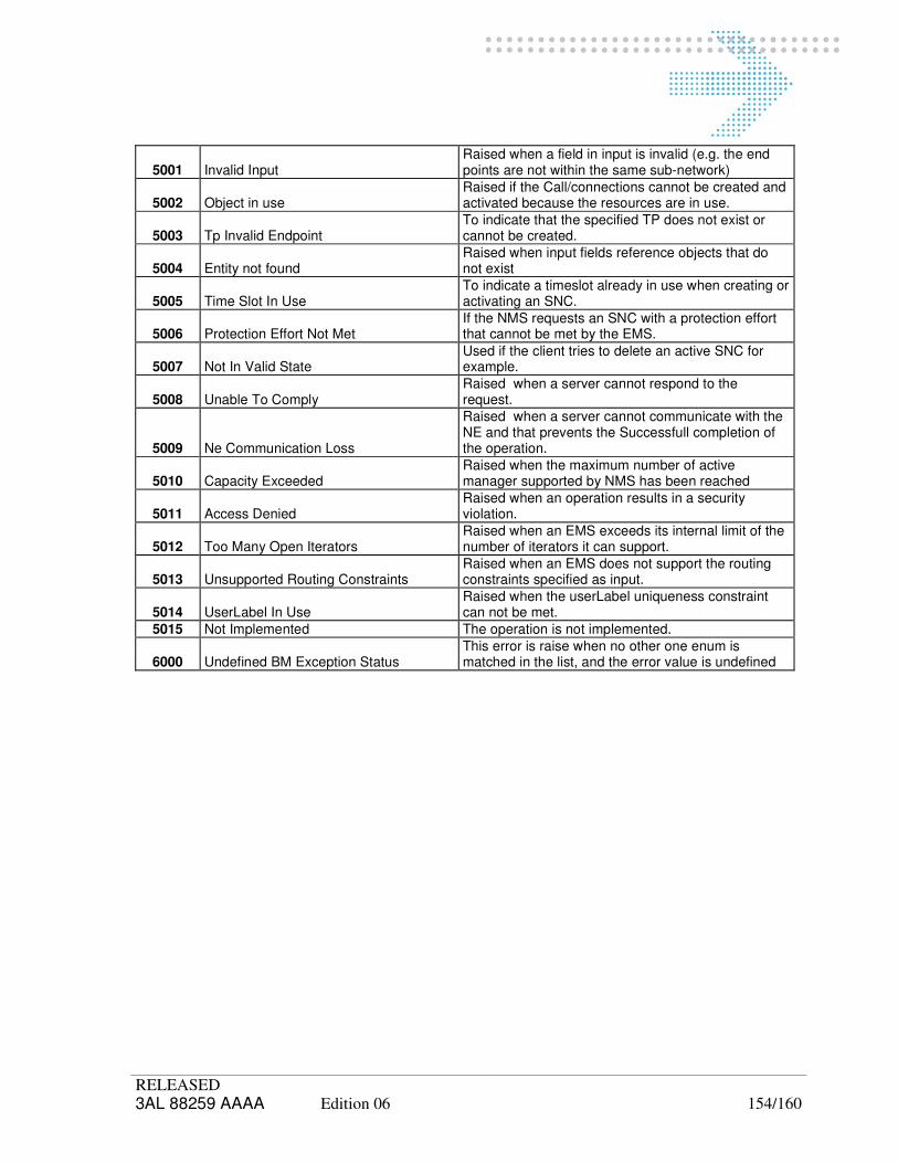
RELEASED 3AL 88259 AAAA Edition 06 154/160
5001 Invalid Input Raised when a field in input is invalid (e.g. the end points are not within the same sub-network)
5002 Object in use Raised if the Call/connections cannot be created and activated because the resources are in use.
5003 Tp Invalid Endpoint To indicate that the specified TP does not exist or cannot be created.
5004 Entity not found Raised when input fields reference objects that do not exist
5005 Time Slot In Use To indicate a timeslot already in use when creating or activating an SNC.
5006 Protection Effort Not Met If the NMS requests an SNC with a protection effort that cannot be met by the EMS.
5007 Not In Valid State Used if the client tries to delete an active SNC for example.
5008 Unable To Comply Raised when a server cannot respond to the request.
5009 Ne Communication Loss
Raised when a server cannot communicate with the NE and that prevents the Successfull completion of the operation.
5010 Capacity Exceeded Raised when the maximum number of active manager supported by NMS has been reached
5011 Access Denied Raised when an operation results in a security violation.
5012 Too Many Open Iterators Raised when an EMS exceeds its internal limit of the number of iterators it can support.
5013 Unsupported Routing Constraints Raised when an EMS does not support the routing constraints specified as input.
5014 UserLabel In Use Raised when the userLabel uniqueness constraint can not be met.
5015 Not Implemented The operation is not implemented.
6000 Undefined BM Exception Status This error is raise when no other one enum is matched in the list, and the error value is undefined

RELEASED 3AL 88259 AAAA Edition 06 155/160
B.6.2 Interger Parameters Mapping
This Appendix gives the mapping on the supported NML systems of the Isn parameters defined as generic Integer.
Table 4 Availability Level
Value 1354RM 1354NN 1354NP
ProtType MsProtProf SncpType
0
Full
SNCP
sncplprefAir Protection type = end
to end
QoS protection = no
protection
Path protection
Manual SNCP
1
Partial
In Rings
Protection type =
none
QoS protection = full
protection
Path protection
Automatic
2
Enhanced D&C
Protection type = end
to end
QoS protection = full
protection
Path protection
Automatic SNCP
3
None
Path
protection
None
Protection type =
none
QoS protection = no
protection
Path protection
Manual (no
protection)
4
LowPriority
Protection
Preferred
not supported not supported
5
Undefined
not supported not supported
6
Full/I
NoAlarm
Pref.
sncplprefNoAir
not supported not supported
7
Full Not Intr
Alarm Pref
sncpNpref
not supported not supported
The meaning of the values introduced at RM level, for the SNCP protection are:
- sncpIprefNoAlr : SNCP/I (Inherent) without degraded Alarm
This protection type indicates that no alarms are received when the protection is degraded (Main or
Spare fails with or without path switch). This protection is used also in previous releases.
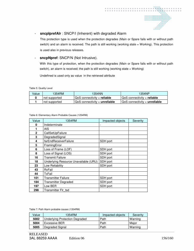
RELEASED 3AL 88259 AAAA Edition 06 156/160
- sncpIprefAlr : SNCP/I (Inherent) with degraded Alarm
This protection type is used when the protection degrades (Main or Spare fails with or without path
switch) and an alarm is received. The path is still working (working state = Working). This protection
is used also in previous releases.
- sncpNpref: SNCP/N (Not Intrusive).
With this type of protection, when the protection degrades (Main or Spare fails with or without path
switch), an alarm is received; the path is still working (working state = Working)
Undefined is used only as value in the retrieved attribute
Table 5: Quality Level
Value 1354RM 1354NN 1354NP
0 not supported QoS connectivity = reliable QoS connectivity = reliable
1 not supported QoS connectivity = unreliable QoS connectivity = unreliable
Table 6: Elementary Alarm Probable Causes (1254RM)
Value 1354RM Impacted objects Severity
0 Indeterminate -
1 AIS
2 CallSetUpFailure
3 DegradedSignal
4 farEndReceiverFailure SDH port
5 FramingError
6 Loss of Frame (LOF) SDH port
8 Loss of Signal (LOS) SDH port
16 Transmit Failure SDH port
18 Underlying Resource Unavailable (URU) SDH port
23 Low Reliability SDH port
43 RxFail
44 TxFail
101 Transmitter Failure SDH port
184 Transmitter Degraded SDH port
197 Low BER SDH port
298 Transmitter Flr_tsd
Table 7: Path Alarm probable causes (1354RM)
Value 1354RM Impacted objects Severity
5002 Underlying Protection Degraded Path Warning
5004 Excessive BER Path Major
5005 Degraded Signal Path Warning

RELEASED 3AL 88259 AAAA Edition 06 157/160
5007 Transport Failure Path Major
5008 Client Failure Path Warning
5009 Quality Threshold Crossed 15m Path Minor
5010 Quality Threshold Crossed 24h Path Minor
5012 Remote SDH failure Path -
5014 ConnectivityProblem Path Major
5017 HDSLfailure Path Warning
5018 Transport Outgoing Failure Path Major
5019 Transport Incoming Failure Path Major
5020 Tandem Connection Failure Path Minor
5021 Incoming TC Failure Path Minor
5022 Outgoing TC Failure Path Minor
5023 TC_DegradedSignal Path Warning
5024 TC_Thresholdcrossed15m Path Minor
5025 TC_Thresholdcrossed24h Path Minor
5028 Degraded Protection Path Warning
5029 Bandwidth Reduced Path Minor
5030 SNC Failure Path -
5031 Lcas ProtocolError Path Major
5032 Lcas ExceedDiffDelay Path Major
Table 8: Alarm Probable Causes (not supported)
Value 1354RM Reason
5001 Media or Equipment Failure Physical Connection
5003 Rsfailure MS Trail
5006 Configuration Mismatch Processing Error Alarm
5011 MS Configuration Mismatch Processing Error Alarm
5013 EquipmentFailure Physical Connection
5015 OSCfailure OCH Trail
5016 ThresholdCorrectedErrors OCH Trail
5026 Remote Power Supply failure Physical Connection
5027 Server Media failure Physical Connection
Table 9: Alarm Probable Causes (1354NP)
Value Probable Cause Perceived severity Event type
6000 SimpleSnConnNullAlarm
6001 SimpleSnConnInsideFailure
6002 SimpleSnConnOutsideFailure
6003 SimpleSnConnPathTraceMismatch CRITICAL Processing Alarm
6004 SimpleSnConnDestinationLost MAJOR Communication Alarm
6005 SimpleSnConnLocalDropfailure CRITICAL Communication Alarm
6006 SimpleSnConnfault CRITICAL Communication Alarm

RELEASED 3AL 88259 AAAA Edition 06 158/160
6008 SimpleSnConnProtectionFault CRITICAL Communication Alarm
6008 SimpleSnConnProtectionDegraded MINOR QoS Alarm
6009 SimpleSnConnDegraded MAJOR QoS Alarm
6010 SimpleSnConnQualityDegraded MINOR QoS Alarm
6011 SimpleSnConnfaultProgramming CRITICAL Communication Alarm
6012 SimpleSnConnUnmapped CRITICAL Communication Alarm
6013 SimpleSnConnProtected WARNING Communication Alarm
6014 DoubleSnConnPathsNoDisjoint MINOR Communication Alarm
B.7 MANAGEMENT OF DATA FILES
Isn Manager can request data retrieval (i.e. topology, sConn, sTP, DB data), start / stop the measurements on specific sConn using Isn messages. Viceversa, for PM and when the result involves several network resources, data are returned by means of ascii files (i.e. retrieval data files and PM data files, see [4]).
The following chapter describes:
- the rules that ISN Agents have to follow providing data files;
- the collection mechanism used by ISN Manager to get data files.
So the concepts here below described have to be considered as integral part of the interface.Completion Code Values
B.7.1 General description
Retrieval data files are produced on demand and a set of files are produced to satisfy one specific request.
Performance Monitoring Data Files are periodically created after the monitoring is activated on sConns. Only 24 hours granularity is managed at ISN. A PM Data File contains data related to one sConn. It means that one file contains the hystorical PM data of the monitored nTP objects of a sConn. A PM Data File can refer to either one granularity period only or to more granularity periods according to ISN Agent internal behaviour.
PM data files contain all the available counters.
B.7.2 Data Files Directories and addressing
When a ISN Agent generates a new Data File, one of the following behaviours happen:
- an event is sent every time a new retrieval data file is available to be collected. The notification contains the filename, the directory, if it is the last file to completely satisfy the request, the number of files ready to be collected and the total files produced.
- in case of PM file, the ISN Agent simply generates the new file(s) without to produce any notification.
In both cases, ISN Agents should make available data files to ISN Manager only when they are ready to be retrieved.
ISN Agent provides a “rigid” file system organization. It means that ISN Manager can easily recover the files knowing in advance how to reach them.
B.7.3 FTP Session
In order to retrieve the owned ISN files, ISN Manager must perform an FTP session.
The Isn Manager knows in advance the hostname of the FTP server machine that holds the file and a private

RELEASED 3AL 88259 AAAA Edition 06 159/160
username-password pair. The user must connect to the FTP server via anonymous login, then specifies his username and password and can perform the transfer as below indicated (in bold-Italics: user typed parts):
ftp ISNHOST
Name: ftp
Password: any
Then, in order to get its rights the external OS must open a protected FTP session as follows:
ftp> user ISNFTPNAME ISNFTPPASSWD
The user it set to the owned FTP repository (directory) and is not able to access to the un-authorized directories; the ISN files can be retrieved with the normal FTP get commands.
Both types of available files are present in the same directory on ISN Agent.
The following table describes the meaningful parameters for FTP activity:
Table 10: Parameters for FTP session
ISN PARAMETER DEFAULT VALUE DESCRIPTION
ISNHOST n.a. host name of the ISN Dispatcher machine
ISNFTPNAME ISNMGRNAME unique FTP login name associated to each
external OS
ISNFTPPASSWD n.a. password of the FTP login name
Note that ISNFTPNAME and ISNFTPPASSWD parameters are associated to each external OS.
B.7.4 File Compression
Generated files can be compressed for transfer efficiency, if explicitly requested by ISN Manager. The used compression tool is:
GNU Zip (gzip) Rel. 1.2.4.
B.7.5 Data Files collection
ISN Manager is responsible for collecting the Data Files as soon as ISN Agent makes them available.
The ISN Manager behaviour depends if it is notified or not. In particular:
- every time a Retrieve Data Reply notification is received, it can get the file(s) from ISN Agent;
- if ISN Agent doesn’t send (i.e. in case of PM files) or ISN Manager does not receive events for a defined period, the ISN Manager can collect files using a polling mechanism.
For the polling mechanism, the frequency of collection has to be defined. The mechanism can be more efficient if both ISN Manager and ISN Agent are synchronized one each other. It is possible to define a global system frequency for this purpose (note that the frequency value used by the snH and nwH to generate files has to be considered because it has an influence on the actual frequency with which the ISN Agent will be able to provide files to ISN Manager ).
In particular the system frequency is fixed to one day. In any case it could be set a frequency value smaller than one day in order to balance some delays that could happen.File Compression

RELEASED 3AL 88259 AAAA Edition 06 160/160
B.7.6 Data Files purge mechanism
ISN Agent keeps a file available for a period of time; afterwards it will be removed. ISN Manager is
responsible for collecting the Data Files before it will be removed. The period of time is initially fixed to one
week, but it is possible to set a different value if necessary.
B.8 REDUNDANT ENVIRONMENT
In case of ISN installed on a redundant environment (OS Resilience), the external OS must know the names (or IP addresses in case of ASCII interface) of the two host where the ISN Dispatcher is installed.
At any time is un-predictable to know which is the active and the stand-by system, but is guarantee that only one of the systems answer to the ISN session requests.
The OS Resilience guarantees the persistence of the ISN data files after a switch (active system down and stand-by system up); the ISN files are mantained aligned on the stand-by system with a fixed replication period (i.e. 5 minutes).
B.9 MECHANISM TO DISTINGUISH THE EXTERNAL MANAGER RESOURCES
This section is not of interest to the ExtMgr in that the ExtMgr assumes internally there are mechanisms to identify his resources but does not need to know how such “internal” mechanisms work.
B.9.1 Resources managed by 1354RM
A NAD is defined at 1354RM level for the specific ExtMgr-X and the 1354RM Isn Agent uses a mapping between Isn ownerId (e.g. ExtMgr-X) and NAD-X to distinguish the sConn and sTP resources and related messages for this specific ExtMgr from those of other customers in the network.
END OF DOCUMENT
Related Documents