Alberta Reliability Standards Updated: December 1, 2019

Welcome message from author
This document is posted to help you gain knowledge. Please leave a comment to let me know what you think about it! Share it to your friends and learn new things together.
Transcript
Alberta Reliability Standards
Updated: December 1, 2019

Alberta Reliability Standards Contents
Effective: 2019-12-01
BAL Resource and Demand Balancing BAL-001-AB-2 Real Power Balancing Control Performance
BAL-002-AB-3 Contingency Reserve for Recovery from a Balancing Contingency Event
BAL-002-WECC-AB1-2 Contingency Reserve
BAL-003-AB1-1.1 Frequency Response and Frequency Bias
Setting
BAL-004-WECC-AB-2 Automatic Time Error Correction
BAL-005-AB-1 Balancing Authority Control
CIP Critical Infrastructure Protection CIP-SUPP-001-AB1 Cyber Security – Supplemental CIP Alberta Reliability Standard
CIP-SUPP-002-AB Cyber Security – Supplemental CIP Alberta Reliability Standard Technical Feasibility Exceptions
CIP-002-AB-5.1 Cyber Security – BES Cyber System Categorization
CIP-003-AB-5 Cyber Security – Security Measurement Controls
CIP-004-AB-5.1 Cyber Security – Personnel & Training
CIP-005-AB-5 Cyber Security – Electronic Security Perimeter(s)
CIP-006-AB-5 Cyber Security – Physical Security of BES Cyber Systems
CIP-007-AB-5 Cyber Security – System Security Management
CIP-008-AB-5 Cyber Security – Incident Reporting and Response
CIP-009-AB-5 Cyber Security – Recovery Plans for BES Cyber Systems
CIP-010-AB-1 Cyber Security – Configuration Change Management and Vulnerability Assessments
CIP-011-AB-1 Cyber Security – Information Protection
CIP-PLAN-AB-1 Cyber Security – Implementation Plan for Version 5 CIP Security Standards
COM Communications COM-001-AB1-1.1 Telecommunications
COM-002-AB1-2a Communications and Coordination
EOP Emergency Preparedness and Operations EOP-001-AB1-2.1b Emergency Operations Planning
EOP-002-AB1-2 Capacity and Energy Emergencies
EOP-003-AB1-1 Load Shedding Plans
EOP-004-AB-2 Event Reporting

Alberta Reliability Standards Contents
Effective: 2019-12-01
EOP-005-AB-2 System Restoration from Blackstart Resources
EOP-006-AB-2 System Restoration Coordination
EOP-008-AB-1 Loss of Control Centre Functionality
FAC Facilities Design, Connections and Maintenance FAC-001-AB-0 Facility Connection Requirements
FAC-002-AB-0 Coordination of Plans for New Facilities
FAC-003-AB1-1 Transmission Vegetation Management Program
FAC-008-AB-3 Facility Ratings
FAC-010-AB1-2.1 System Operating Limits Methodology for the Planning Horizon
FAC-011-AB-2 System Operating Limits Methodology for the Operations Horizon
FAC-014-AB1-2 Establish and Communicate System Operating Limits
FAC-501-WECC-AB2-1 Transmission Maintenance
INT Interchange Scheduling and Coordination INT-006-AB-2 Response to Interchange Authority
INT-009-AB-2.1 Implementation of Interchange
INT-010-AB-2.1 Interchange Initiation and Modification for Reliability
IRO Interconnection Reliability Operations and Coordination IRO-002-AB-5 Reliability Coordination Monitoring and Analysis
IRO-003-AB-2 Reliability Coordination Wide Area View
IRO-005-AB1-3.1a Reliability Coordination Current Day Operations
IRO-006-AB-5 Reliability Coordination Transmission Loading Relief
IRO-006-WECC-AB-2 Qualified Transfer Path Unscheduled Flow Relief
IRO-008-AB-2 Reliability Coordinator Operational Analyses and Real Time
IRO-009-AB-2 Reliability Coordinator Actions to Operate within IROLs
IRO-010-AB-2 Reliability Coordinator Data Specification and Collection
IRO-014-AB-3 Coordination Among Reliability Coordinators
IRO-017-AB-1 Outage Coordination
IRO-018-AB-1(i) Reliability Coordinator Real Time Reliability Monitoring and Analysis Capabilities
MOD Modeling, Data and Analysis MOD-010&012-AB-0 Steady-State and Dynamic Data for Transmission System
Modeling and Simulation
Alberta Reliability Standards Contents
Effective: 2019-12-01
MOD-031-AB-2 Demand and Energy Data
PER Personnel Performance, Training, and Qualifications PER-003-AB-1 Operations Personnel Credentials
PER-004-AB-2 Reliability Coordination – Staffing
PER-005-AB-2 Operations Personnel Training
PRC Protection and Control PRC-001-AB3-1.1(ii) Protection System Coordination
PRC-002-AB- 2 Disturbance Monitoring and Reporting Requirements
PRC-004-AB2-1 Analysis and Mitigation of Transmission and Generation Protection System Misoperation
PRC-004-WECC-AB1-1 Protection System and Remedial Action Scheme Misoperation
PRC-005-AB1-6 Protection System, Automatic Reclosing and Sudden Pressure Relaying Maintenance
PRC-009-AB-0 Underfrequency Load Shedding Performance Following an Underfrequency Event
PRC-010-AB-0 Assessment of the Design and Effectiveness of Under Voltage Load Shed Program
PRC-018-AB-1 Disturbance Monitoring Equipment Installation and Data Reporting
PRC-021-AB1-1 Under Voltage Load Shed Program Data
PRC-022-AB-1 Under Voltage Load Shedding Program Performance
PRC-023-AB-2 Transmission Relay Loadability
TPL Transmission Planning TPL-001-AB-0 System Performance Under Normal Conditions
TPL-002-AB1-0 System Performance Following Loss of a Single BES Element
TPL-003-AB-0 System Performance Following Loss of Two or More Bulk Electric System Elements
TPL-004-AB-0 System Performance Following Extreme Bulk Electric System Events
VAR Voltage and Reactive VAR-001-AB-4 Voltage and Reactive Control
VAR-002-AB-3 Generator Operation for Maintaining Network Voltages
VAR-002-WECC-AB-1 Automatic Voltage Regulators and Voltage Regulating Systems
VAR-501-WECC-AB-1 Power System Stabilizer
Alberta Reliability Standard Real Power Balancing Control Performance BAL-001-AB-2
Effective: 2019-07-01 Page 1 of 4 Public
1. Purpose
The purpose of this reliability standard is to control Interconnection frequency within defined limits.
2. Applicability
This reliability standard applies to:
(a) the ISO except when:
(i) the ISO is receiving overlap regulation service;
(ii) the ISO is a member of a regulation reserve sharing group and remains in active status under the applicable agreement or the governing rules for the regulation reserve sharing group; or
(iii) the interconnected electric system is not synchronously connected to the Interconnection.
3. Requirements
R1 The ISO must operate such that the control performance standard 1, calculated in accordance with Appendix 1, is greater than or equal to 100% for each preceding 12 consecutive month period, evaluated monthly.
R2 The ISO must operate such that its clock-minute average of reporting area control error does not exceed the clock-minute area control error limit of the balancing authority for more than 30 consecutive clock-minutes, calculated in accordance with Appendix 2.
4. Measures
The following measures correspond to the requirements identified in section 3 of this reliability standard. For example, MR1 is the measure for requirement R1.
MR1 Evidence of operating such that the control performance standard 1 is greater than or equal to 100% as required in requirement R1 exists. Evidence may include dated calculation output from spreadsheets, system logs, or other equivalent evidence.
MR2 Evidence of operating such that the clock-minute average of reporting area control error does not exceed the clock-minute area control error limit of the balancing authority for more than 30 consecutive clock-minutes as required in requirement R2 exists. Evidence may include dated calculation output from spreadsheets, system logs, or other equivalent evidence.
5. Appendices
Appendix 1 - Equations Supporting Requirement R1 and Measure M1
Appendix 2 - Equations Supporting Requirement R2 and Measure M2
Revision History
Date Description
2019-07-01 Initial release.

Alberta Reliability Standard Real Power Balancing Control Performance BAL-001-AB-2
Effective: 2019-07-01 Page 2 of 4 Public
Appendix 1 – Equations Supporting Requirement R1 and Measure M1
The control performance standard 1 (CPS1) is calculated as follows:
The frequency-related compliance factor ( ), is a ratio of the accumulating clock-minute compliance parameters for the most recent preceding 12 consecutive months, divided by the square of the target frequency bound:
where is the constant derived from a targeted frequency bound for the western interconnection or as revised by the NERC.
The rating index is derived from the most recent preceding 12 consecutive months of data. The accumulating clock-minute compliance parameters are derived from the one-minute averages of reporting area control error, frequency error, and frequency bias settings. A clock-minute average is the average of the reporting balancing authority’s valid measured variable (i.e., for reporting area control error ( ) and for frequency error) for each sampling cycle during a given clock-minute.
And,
The balancing authority’s clock-minute compliance factor ( ) calculation is:
Normally, 60 clock-minute averages of the reporting area control error and frequency error will be used to compute the hourly average compliance factor ( ).

Alberta Reliability Standard Real Power Balancing Control Performance BAL-001-AB-2
Effective: 2019-07-01 Page 3 of 4 Public
The reporting balancing authority must be able to recalculate and store each of the respective clock-hour averages ( ) and the data samples for each 24-hour period (one for each clock-hour; i.e., hour ending (HE) 0100, HE 0200, ..., HE 2400). To calculate the monthly compliance factor ( ):
To calculate the 12-month compliance factor ( ):
To ensure that the average reporting area control error and frequency error calculated for any one-minute interval is representative of that time interval, it is necessary that at least 50% of both the reporting area control error and frequency error sample data during the one-minute interval is valid. If the recording of reporting area control error or frequency error is interrupted such that less than 50% of the one-minute sample period data is available or valid, then that one-minute interval is excluded from the CPS1 calculation.
A balancing authority providing overlap regulation service to another balancing authority calculates its CPS1 performance after combining its reporting area control error and frequency bias settings with the reporting area control error and frequency bias settings of the balancing authority receiving the regulation service.

Alberta Reliability Standard Real Power Balancing Control Performance BAL-001-AB-2
Effective: 2019-07-01 Page 4 of 4 Public
Appendix 2 - Equations Supporting Requirement R2 and Measure M2
When actual frequency is equal to scheduled frequency, and do not apply.
When actual frequency is less than scheduled frequency, does not apply, and is calculated as:
When actual frequency is greater than scheduled frequency, does not apply and the is calculated as:
Where:
is the low area control error limit of the balancing authority (MW)
is the high area control error limit of the balancing authority (MW)
is a constant to convert the frequency bias setting from MW/0.1 Hz to MW/Hz
is the frequency bias setting for a balancing authority (expressed as MW/0.1 Hz)
is the measured frequency in Hz.
is the scheduled frequency in Hz.
is the low frequency trigger limit (calculated as )
is the high frequency trigger limit (calculated as )
Where is the constant derived from a targeted frequency bound for the western interconnection or as revised by the NERC.
To ensure that the average actual frequency calculated for any one-minute interval is representative of that time interval, it is necessary that at least 50% of the actual frequency sample data during that one-minute interval is valid. If the recording of actual frequency is interrupted such that less than 50% of the one-minute sample period data is available or valid, then that one-minute interval is excluded from the area control error limit of the balancing authority calculation and the 30-minute clock would be reset to zero.
A balancing authority providing overlap regulation service to another balancing authority calculates its area control error limit of the balancing authority performance after combining its frequency bias setting with the frequency bias setting of the balancing authority receiving overlap regulation service.
Alberta Reliability Standard Contingency Reserve for Recovery from a Balancing Contingency Event BAL-002-AB-3
Effective: 2019-07-01 Page 1 of 2 Public
1. Purpose
The purpose of this reliability standard is to ensure the ISO balances resources and demand and returns the area control error to defined values, subject to applicable limits, following a reportable balancing contingency event.
2. Applicability
This reliability standard applies to:
(a) the ISO, only in periods during which the ISO is not in active status under a reserve sharing group agreement or governing rules for a reserve sharing group.
3. Requirements
R1 The ISO, when it is experiencing a reportable balancing contingency event must:
R1.1 within the contingency event recovery period, demonstrate recovery by returning its reporting area control error to at least the recovery value of:
(a) zero (if its pre-reporting contingency event area control error value was positive or equal to zero); or
(b) its pre-reporting contingency event area control error value (if its pre-reporting contingency event area control error value was negative);
however, any balancing contingency event that occurs during the contingency event recovery period must reduce the required recovery: (i) beginning at the time of, and (ii) by the magnitude of, such individual balancing contingency event;
R1.2. document all reportable balancing contingency events using the form the NERC designates; and
R1.3. deploy contingency reserve, within system constraints, to respond to all reportable balancing contingency events; however, the ISO is not subject to compliance with requirement R1.1 if the ISO:
R1.3.1 (a) is experiencing an ISO declared energy emergency alert level;
(b) is using its contingency reserve to mitigate an operating emergency in accordance with its emergency operating plan;
(c) has depleted its contingency reserve to a level below its most severe single contingency; and
(d) intentionally left blank; or
R1.3.2 (a) experiences multiple contingencies where the combined MW loss exceeds its most severe single contingency and that are defined as a single balancing contingency event; or
(b) experiences multiple balancing contingency events within the sum of the time periods defined by the contingency event recovery period and contingency reserve restoration period whose combined magnitude exceeds the ISO's most severe single contingency.
Alberta Reliability Standard Contingency Reserve for Recovery from a Balancing Contingency Event BAL-002-AB-3
Effective: 2019-07-01 Page 2 of 2 Public
R2 The ISO must develop, review, and maintain annually, and implement an operating process as part of its operating plan to determine its most severe single contingency and make preparations to have contingency reserve equal to, or greater than the ISO’s most severe single contingency available for maintaining system reliability.
R3 The ISO, following a reportable balancing contingency event, must restore its contingency reserve to at least its most severe single contingency, before the end of the contingency reserve restoration period, but any balancing contingency event that occurs before the end of a contingency reserve restoration period resets the beginning of the contingency event recovery period.
4. Measures
The following measures correspond to the requirements identified in section 3 of this reliability standard. For example, MR1 is the measure for requirement R1.
MR1.1 Evidence of demonstrating the recovery of the reporting area control error as required in requirement R1.1 exists. Evidence may include documented reportable balancing contingency events using the designated form, or other equivalent evidence.
MR1.2 Evidence of documenting all reportable balancing contingency events as required by requirement R1.2 exists. Evidence may include documented reportable balancing contingency events using the designated NERC form, or other equivalent evidence.
MR1.3 Evidence of deploying contingency reserve, within system constraints, to respond to all reportable balancing contingency events, as required in requirement R1.3 exists. Evidence may include directive logs, phone calls, designated forms, or other equivalent evidence.
MR2 Evidence of developing, reviewing, maintaining and implementing an operating process to determine the most severe single contingency and to have contingency reserves as required in requirement R2 exists. Evidence may include a dated operating process with a revision history, or other equivalent evidence.
MR3 Evidence of restoring contingency reserve as required in requirement R3 exists. Evidence may include historical data, computer logs, operator logs, or other equivalent evidence.
Revision History
Date Description
2019-07-01 Initial release.
Alberta Reliability Standard Contingency Reserve BAL-002-WECC-AB1-2
Effective: 2015-07-26 Page 1 of 3
1. Purpose
The purpose of this reliability standard is to specify the quantity and types of contingency reserve required to ensure reliability under normal and abnormal conditions.
2. Applicability
This reliability standard applies to:
(a) the ISO, which may meet the requirements of this reliability standard through participation in a reserve sharing group that the ISO has designated as its agent.
This reliability standard does not apply in the case of contingencies that result in the interconnected electric system losing synchronism with the western interconnection.
3. Requirements
R1 The ISO must have held, at a minimum, an average amount of contingency reserve that is:
R1.1 the greater of either:
(a) an amount equal to the loss of the most severe single contingency; or
(b) an amount equal to the sum of:
three percent (3%) of the hourly integrated amount of load, being the hourly integrated amount of net generation the ISO determines is delivered to the grid minus net actual interchange;
plus
three percent (3%) of the hourly integrated amount of net generation the ISO determines is delivered to the grid;
where “net generation the ISO determines is delivered to the grid” is equal to the sum of:
(i) generation from a generating unit or aggregated generating facility but not including unit service and station service loads;
plus
(ii) generation from an industrial complex or facility that has on-site generation but not including generation serving on-site load;
plus
(iii) generation delivered to the grid by the City of Medicine Hat;
R1.2 comprised of any combination of the operating reserve types specified below:
(a) spinning reserve;
(b) supplemental reserve;

Alberta Reliability Standard Contingency Reserve BAL-002-WECC-AB1-2
Effective: 2015-07-26 Page 2 of 3
(c) interchange transactions sourced within Alberta that the ISO designates as supplemental reserve;
(d) interchange transactions sourced external to Alberta that the ISO designates as spinning reserve or supplemental reserve and that, by agreement, is deliverable to Alberta on firm transmission service;
(e) a resource, other than a generating unit, an aggregated generating facility or load, that can provide energy or reduce energy consumption;
(f) load, including demand response resources, demand-side management resources, direct control load management, interruptible load or interruptible demand, or any other load made available for curtailment by the ISO via contract or agreement; and
(g) during capacity and energy emergencies, load that can be interrupted; and
R1.3 an amount of capacity from a resource that is capable of fully responding within ten (10) minutes;
except within the first sixty (60) minutes following a disturbance resulting from a loss of supply and requiring the activation of contingency reserve or except following the deployment of contingency reserve during implementation of the ISO’s capacity and energy emergency plan.
R2 The ISO must maintain at least fifty percent (50%) of its minimum amount of contingency reserve required in requirement R1 as spinning reserve that is immediately and automatically responsive to frequency deviations through the action of a governor or other control system.
R3 The ISO must, when operating as a sink balancing authority, maintain an amount of operating reserve, in addition to the minimum contingency reserve required in requirement R1, equal to the amount of supplemental reserve for any interchange transaction designated as part of the supplemental reserve of the source balancing authority or source reserve sharing group, except within the first sixty (60) minutes following an event requiring the activation of contingency reserve or except following the deployment of contingency reserve during implementation of the ISO’s capacity and energy emergency plan.
R4 The ISO must, when operating as a source balancing authority, maintain an amount of operating reserve, in addition to the minimum contingency reserve amounts required in requirement R1, equal to the amount and type of operating reserve for any operating reserve transactions for which it is the source balancing authority.
4. Measures
The following measures correspond to the requirements identified in section 3 of this reliability standard. For example, MR1 is the measure for requirement R1.
MR1 Evidence of having held contingency reserve as required in requirement R1 exists. Evidence may include:
(a) a reserve sharing group agreement including an agent appointment agreement, documentation of the methodology of the contingency reserve calculation, or ancillary services contracts; or

Alberta Reliability Standard Contingency Reserve BAL-002-WECC-AB1-2
Effective: 2015-07-26 Page 3 of 3
(b) records of disturbances or implementation of the ISO’s capacity and emergency plan as required in requirement R1.
MR1.1 Evidence of calculating the amount of contingency reserve as required in requirement R1.1 exists. Evidence may include records of the required and available contingency reserve.
MR1.2 Evidence of having contingency reserve that is comprised of the operating reserve types as required in requirement R1.2 exists. Evidence may include a reserve sharing group agreement including an agent appointment agreement or ancillary services contracts.
MR1.3 Evidence of having access to contingency reserve that is capable of fully responding in ten (10) minutes as required in requirement R1.3 exists. Evidence may include a reserve sharing group agreement including an agent appointment agreement or technical requirements for contingency reserve.
MR2 Evidence of maintaining at least fifty percent (50%) of the ISO’s minimum amount of contingency reserve as spinning reserve that is immediately responsive to frequency deviations as required in requirement R2 exists. Evidence may include a reserve sharing group agreement including an agent appointment agreement or records of dispatches of ancillary services.
MR3 Evidence of maintaining an amount of operating reserve as required in requirement R3 exists. Evidence may include a sworn affidavit from an appropriate ISO representative, authoritative documents that restrict or permit the transactions set out in requirement R3, documents that demonstrate the ISO was in a capacity and energy emergency, or a reserve sharing group agreement including an agent appointment agreement.
MR4 Evidence of maintaining an amount of operating reserve as required in requirement R4 exists. Evidence may include a sworn affidavit from an appropriate ISO representative or a reserve sharing group agreement including an agent appointment agreement.
Revision History
Effective Date Description
2015-07-26 Revised Applicability section to include exclusion for contingencies that result in the interconnected electric system losing synchronism with the western interconnection
2014-10-01 Initial release.

Alberta Reliability Standard Frequency Response and Frequency Bias Setting BAL-003-AB1-1.1
Effective: 2019-08-01 Page 1 of 7 Public
1. Purpose
The purpose of this reliability standard is to:
(a) require sufficient frequency response from the ISO to maintain Interconnection frequency within predefined bounds by arresting frequency deviations and supporting frequency until the frequency is restored to its scheduled value; and
(b) provide consistent methods for measuring frequency response and determining the frequency bias setting.
2. Applicability
This reliability standard applies to:
(a) the ISO, unless the interconnected electric system is not synchronously connected to the Interconnection.
3. Requirements
R1 The ISO must:
(a) achieve an annual frequency response measure (as calculated in accordance with Appendix A) that is equal to or more negative than its frequency response obligation; and
(b) report, in accordance with Appendix A, the annual frequency response measure calculated pursuant to requirement R1(a),
which obligations the ISO may meet through participation in a frequencyresponse sharing group which the ISO has designated as its agent.
R2 The ISO must, if it is not receiving overlap regulation service and uses a fixed frequency bias setting:
R2.1 implement the frequency bias setting determined in accordance with Appendix A, as validated by the Electric Reliability Organization, into its area control error calculation during the implementation period specified by the Electric Reliability Organization; and
R2.2 use this frequency bias setting until directed to change by the Electric Reliability Organization.
R3 The ISO must, if it is not receiving overlap regulation service and is utilizing a variable frequency bias setting, maintain a frequency bias setting that is:
R3.1 less than zero at all times; and
R3.2 equal to or more negative than its frequency response obligation when frequency varies from 60 Hz by more than +/- 0.036 Hz.
R4 The ISO must, if it is performing overlap regulation service, modify its frequency bias setting in its area control error calculation, in order to represent the frequency bias setting for the combined balancing authority area, to be equivalent to either:
R4.1 the sum of the frequency bias settings, as shown on the NERC FRS Form 1 and FRS Form 2 for the participating balancing authorities and as validated by the Electric Reliability Organization, or

Alberta Reliability Standard Frequency Response and Frequency Bias Setting BAL-003-AB1-1.1
Effective: 2019-08-01 Page 2 of 7 Public
R4.2 the frequency bias setting shown on the NERC FRS Form 1 and FRS Form 2 for the entirety of the participating balancing authority areas.
4. Measures
The following measures correspond to the requirements identified in section 3 of this reliability standard. For example, MR1 is the measure for requirement R1.
MR1 Evidence of achieving an annual frequency response measure as required in requirement R1, and of reporting the annual frequency response measure as required in requirement R1 exists. Evidence may include dated data plus documented formula in either hardcopy or electronic format that shows an annual frequency response measure was achieved that is equal to or more negative than the frequency response obligation, a dated document in hard copy or electronic format showing submission of a completed report, or other equivalent evidence.
MR2 Evidence of implementing the frequency bias setting as validated by the Electric Reliability Organization into the area control error calculation as required in requirement R2 exists. Evidence may include a dated document in hard copy or electronic format showing the frequency bias setting as validated by the Electric Reliability Organization was implemented into the area control error calculation within the implementation period specified, or other equivalent evidence.
MR3 Evidence of maintaining a frequency bias setting as required in requirement R3 exists. Evidence may include a dated report in hard copy or electronic format showing the average clock-minute average frequency bias setting was less than zero and, during periods when the clock-minute average frequency was outside of the range 59.964 Hz to 60.036 Hz, was equal to or more negative than the frequency response obligation, or other equivalent evidence.
MR4 Evidence of modifying the frequency bias setting in the area control error calculation as required in requirement R4 exists. Evidence may include a dated operating log, database or list, in hard copy or electronic format, showing that when overlap regulation service was performed the frequency bias setting was modified in the area control error calculation, or other equivalent evidence.
5. Appendices
Appendix A - BAL-003-AB-1.1 Frequency Response & Frequency Bias Setting Standard Supporting Document
Revision History
Date Description
2019-08-01
Amended R1 as follows;
replaced “reserve” with “response”, bolded frequency and unbolded ‘sharing group’.
2019-07-01 Initial release.

Alberta Reliability Standard Frequency Response and Frequency Bias Setting BAL-003-AB1-1.1
Effective: 2019-08-01 Page 3 of 7 Public
Appendix A
BAL-003-AB-1.1 Frequency Response & Frequency Bias Setting Standard Supporting Document
Interconnection Frequency Response Obligation
The Electric Reliability Organization, in consultation with regional representatives, has established a target contingency protection criterion for each frequency response obligation of the Interconnection. The default frequency response obligation of the Interconnection listed in Table 1 is based on the resource contingency criteria, which is the largest category C (N-2) event identified. A maximum delta frequency is calculated by adjusting a starting frequency for each Interconnection by the following:
• Prevailing underfrequency load shedding first step;
• CCAdj which is the adjustment for the differences between 1-second and sub-second Point C observations for frequency events. A positive value indicates that the sub-second C data is lower than the 1-second data;
• CBR which is the statistically determined ratio of the Point C to Value B; and
• BC’Adj which is the statistically determined adjustment for the event nadir being below the Value B (Eastern Interconnection only) during primary frequency response withdrawal.
The frequency response obligation for each Interconnection in Table 1 is then calculated by dividing the resource contingency criteria MWs by 10 times the maximum delta frequency. In the Eastern Interconnection there is an additional adjustment (BC’ Adj) for the event nadir being below the Value B due to primary frequency response withdrawal. This frequency response obligation for the Interconnection includes uncertainty adjustments at a 95% confidence level. Detailed descriptions of the calculations used in Table 1 below are defined in the Procedure for ERO Support of Frequency Response and Frequency Bias Setting Standard.
Table 1
Interconnection Eastern Western ERCOT HQ Units
Starting Frequency (Fstart) 59.974 59.976 59.963 59.972 Hz
Prevailing UFLS First Step 59.5* 59.5 59.3 58.5 Hz
Base Delta Frequency (DFBase)
0.474 0.476 0.663 1.472 Hz
CCADJ 0.007 0.004 0.012 N/A Hz
Delta Frequency (DFCC) 0.467 0.472 0.651 1.472 Hz
CBR 1.000 1.625 1.377 1.550
Delta Frequency (DFCBR) 0.467 0.291 0.473 0.949 Hz
BC’ADJ 0.018 N/A N/A N/A Hz
Max. Delta Frequency 0.449 0.291 0.473 0.949
Resource Contingency Criteria
4,500 2740 2,750 1700 MW

Alberta Reliability Standard Frequency Response and Frequency Bias Setting BAL-003-AB1-1.1
Effective: 2019-08-01 Page 4 of 7 Public
Interconnection Eastern Western ERCOT HQ Units
Credit for Load Resources (CLR)
300 1400** MW
IFRO -1002 -840 -286 -179 MW/0.1 Hz
*The Eastern Interconnection underfrequency load setting set point listed is a compromise value set midway between the stable frequency minimum established in the NERC standard PRC-006-1, Automatic Underfrequency Load Shedding (59.3 Hz) and the local protection underfrequency load setting setting of 59.7 Hz used in Florida and Manitoba.
**In the base obligation measure for ERCOT, 1400 MW (load resources triggered by under frequency relays at 59.70 Hz) was reduced from its resource contingency criteria level of 2750 MW to get 239 MW/0.1 Hz. This was reduced to accurately account for designed response from load resources within 30 cycles.
An Interconnection may propose alternate frequency response obligation protection criteria for that Interconnection to the Electric Reliability Organization by submitting a Standard Authorization Request with supporting technical documentation.
Balancing Authority Frequency Response Obligation and Frequency Bias Setting
The Electric Reliability Organization will manage the administrative procedure for annually assigning a frequency response obligation and implementation of the frequency bias setting for each balancing authority. The annual timeline for all activities described in this section are shown below.
For an Interconnection with multiple balancing authorities, the frequency response obligation shown in Table 1 is allocated based on the balancing authority annual load and annual generation. The frequency response obligation allocation will be based on the following method:
FROBA = IFRO × Annual GenBA + Annual LoadBA
Annual GenInt + Annual LoadInt
Where:
• Annual GenBA is the total annual “Output of Generating Plants” within the balancing authority area, on FERC Form 714, column c of Part II - Schedule 3.
• Annual LoadBA is total annual load within the balancing authority area, on FERC Form 714, column e of Part II - Schedule 3.
• Annual GenInt is the sum of all annual genBA values reported in that Interconnection.
• Annual LoadInt is the sum of all annual loadBA values reported in that Interconnection.
The data used for this calculation is from the most recently filed Form 714. As an example, a report to the NERC in January 2013 would use the Form 714 data filed in 2012, which utilized data from 2011.

Alberta Reliability Standard Frequency Response and Frequency Bias Setting BAL-003-AB1-1.1
Effective: 2019-08-01 Page 5 of 7 Public
Balancing authorities that are not FERC-jurisdictional should use the Form 714 Instructions to assemble and submit equivalent data to the Electric Reliability Organization for use in the frequency response obligation allocation process.
Balancing authorities that elect to form a frequency response sharing group will calculate a frequency response sharing group frequency response obligation by adding together the individual frequency response obligations of the balancing authority.
Balancing authorities that elect to form a frequency response sharing group as a means to jointly meet the frequency response obligation will calculate their frequency response measure performance in one of two ways:
• Calculate a group net actual interchange and measure the group response to all events in the reporting year on a single FRS Form 1, or
• Jointly submit the individual balancing authorities’ FRS Form 1s, with a summary spreadsheet that contains the sum of each participant’s individual event performance.
Balancing authorities that merge or that transfer load or generation are encouraged to notify the Electric Reliability Organization of the change in footprint and corresponding changes in allocation such that the net obligation to the Interconnection remains the same and so that control performance standard limits can be adjusted.
Each balancing authority reports its previous year’s frequency response measure, frequency bias setting and frequency bias type (fixed or variable) to the Electric Reliability Organization each year to allow the Electric Reliability Organization to validate the revised frequency bias settings on FRS Form 1. If the Electric Reliability Organization posts the official list of events after the date specified in the timeline below, balancing authorities will be given 30 days from the date the Electric Reliability Organization posts the official list of events to submit their FRS Form 1.
Once the Electric Reliability Organization reviews the data submitted in FRS Form 1 and FRS Form 2 for all balancing authorities, the Electric Reliability Organization will use FRS Form 1 data to post the following information for each balancing authority for the upcoming year:
• frequency bias setting; and
• frequency response obligation.
Once the data listed above is fully posted, the Electric Reliability Organization will announce the three-day implementation period for changing the frequency bias setting if it differs from that shown in the timeline below.
A balancing authority using a fixed frequency bias setting sets its frequency bias setting to the greater of (in absolute value):
• Any number the balancing authority chooses between 100% and 125% of its frequency response measure as calculated on FRS Form 1; or
• The Interconnection minimum as determined by the Electric Reliability Organization.
For purposes of calculating the minimum frequency bias setting, a balancing authority participating in a frequency response sharing group will need to calculate its stand-alone frequency response measure using FRS Form 1 and FRS Form 2 to determine its minimum frequency bias setting.

Alberta Reliability Standard Frequency Response and Frequency Bias Setting BAL-003-AB1-1.1
Effective: 2019-08-01 Page 6 of 7 Public
A balancing authority providing overlap regulation will report the historic peak demand and generation of its combined balancing authority areas on FRS Form 1 as described in requirement R4.
There are occasions when changes are needed to frequency bias settings outside of the normal schedule. Examples are footprint changes between balancing authorities and major changes in load or generation or the formation of new balancing authorities. In such cases, the changing balancing authorities will work with their regions, the NERC, and the Resources Subcommittee to confirm appropriate changes to frequency bias settings, frequency response obligation, control performance standard limits and inadvertent interchange balances.
If there is no net change to the Interconnection total frequency bias, the balancing authorities involved will agree on a date to implement their respective change in frequency bias settings. The balancing authorities and Electric Reliability Organization will also agree to the allocation of frequency response obligation such that the sum remains the same.
If there is a net change to the Interconnection total frequency bias, this will cause a change in CPS2 limits and frequency response obligation for other balancing authorities in the Interconnection. In this case, the Electric Reliability Organization will notify the impacted balancing authorities of their respective changes and provide an implementation window for making the frequency bias setting changes.
Frequency Response Measure
The balancing authority will calculate its frequency response measure from single event frequency response data, defined as: “the data from an individual event from a balancing authority that is used to calculate its frequency response, expressed in MW/0.1Hz” as calculated on FRS Form 2 for each event shown on FRS Form 1. The events in FRS Form 1 are selected by the Electric Reliability Organization using the Procedure for ERO Support of Frequency Response and Frequency Bias Setting Standard. The frequency response measure for a typical balancing authority in an Interconnection with more than one balancing authority is basically the change in its net actual interchange on its intertie with its adjacent balancing authorities divided by the change in Interconnection frequency. (Some balancing authorities may choose to apply corrections to their net actual interchange values to account for factors such as nonconforming loads.) FRS Form 1 and FRS Form 2 show the types of adjustments that are allowed. Note that with the exception of the contingent balancing authority column, any adjustments made must be made for all events in an evaluation year. As an example, if an entity has non-conforming loads and makes an adjustment for one event, all events must show the nonconforming load, even if the non-conforming load does not impact the calculation. This ensures that the reports are not utilizing the adjustments only when they are favorable to the balancing authority. The Electric Reliability Organization will use a standardized sampling interval of approximately 16 seconds before the event up to the time of the event for the pre-event net actual interchange, and frequency (A values) and approximately 20 to 52 seconds after the event for the post-event net actual interchange (B values) in the computation of frequency response measure values, dependent on the data scan rate of the balancing authority’s Energy Management System.
All events listed on FRS Form 1 need to be included in the annual submission of FRS Form 1 and FRS Form 2. The only time a balancing authority should exclude an event is if its intertie data or its frequency data is corrupt or its Energy Management System was unavailable. FRS Form 2 has instructions on how to correct the balancing authority’s data if the given event is internal to the balancing authority or if other authorized adjustments are used.
Alberta Reliability Standard Frequency Response and Frequency Bias Setting BAL-003-AB1-1.1
Effective: 2019-08-01 Page 7 of 7 Public
Assuming data entry is correct, FRS Form 1 will automatically calculate the frequency response measure of the balancing authority for the past 12 months as the median of the frequency response measure values. A balancing authority electing to report as an frequency response sharing group or a provider of overlap regulation service will provide an FRS Form 1 for the aggregate of its participants.
To allow a balancing authority to plan its operations, events with a “Point C” that cause the Interconnection frequency to be lower than that shown in Table 1 above or higher than an equal change in frequency going above 60 Hz may be included in the list of events for that Interconnection. However, the calculation of the balancing authority response to such an event will be adjusted to show a frequency change only to the target minimum frequency shown in Table 1 above or a high frequency amount of an equal quantity. Should such an event happen, the Electric Reliability Organization will provide additional guidance.
Alberta Reliability Standard Automatic Time Error Correction BAL-004-WECC-AB-2
Effective Date: 2016-12-19 Page 1 of 2 Public
1. Purpose
The purpose of this reliability standard is to maintain the frequency of the western interconnection and to ensure that time error corrections and primary inadvertent interchange payback are effectively conducted in a manner that does not adversely affect the reliability of the western interconnection.
2. Applicability
This reliability standard applies to:
(a) the ISO.
3. Requirements
R1 Following the conclusion of each month, the ISO must verify that the absolute value of its accumulated primary inadvertent interchange for both the monthly on peak period and the monthly off peak period are each individually less than or equal to 150% of the previous calendar year’s peak demand, where peak demand is the highest hourly integrated net energy for load.
R2 The ISO must, within ninety (90) days of discovery of an error in the calculation of hourly primary inadvertent interchange, recalculate the value of hourly primary inadvertent interchange and adjust the accumulated primary inadvertent interchange from the time of the error.
R3 The ISO must, while synchronously connected to the western interconnection, keep its automatic time error correction in service, with an allowable exception period of less than or equal to an accumulated twenty-four (24) hours per calendar quarter for automatic time error correction to be out of service.
R3.1 Notwithstanding requirement R3, the ISO may disable automatic time error correction if there is a reliability concern on the interconnected electric system while executing an automatic time error correction, and this time will not be included as part of the allowable exception period.
R4 The ISO must compute the following by fifty (50) minutes after each hour:
R4.1 the hourly primary inadvertent interchange;
R4.2 the accumulated primary inadvertent interchange; and
R4.3 the automatic time error correction term.
R5 The ISO must be able to change its automatic generation control operating mode between flat frequency, flat tie line, tie line bias, and tie line bias plus time error control, to correspond to current operating conditions.
R6 The ISO must recalculate the hourly primary inadvertent interchange and accumulated primary inadvertent interchange for the on peak and off peak periods whenever adjustments are made to hourly inadvertent interchange or the hourly change in system time error, as distributed by the Interconnection time monitor.
R7 The ISO must make the same adjustment to the accumulated primary inadvertent interchange as it did for any month-end meter reading adjustments to inadvertent interchange.
R8 The ISO must payback inadvertent interchange using automatic time error correction rather than bilateral and unilateral payback.

Alberta Reliability Standard Automatic Time Error Correction BAL-004-WECC-AB-2
Effective Date: 2016-12-19 Page 2 of 2 Public
4. Measures
The following measures correspond to the requirements identified in section 3 of this reliability standard. For example, MR1 is the measure for requirement R1.
MR1 Evidence of verifying the absolute value of the ISO’s accumulated primary inadvertent interchange as required in requirement R1 exists. Evidence may include, but is not limited to, data, screen shots from the WECC Interchange Tool, production of data from any other databases, spreadsheets, displays, or other equivalent evidence.
MR2 Evidence of recalculating the value of hourly primary inadvertent interchange and adjusting the accumulated primary inadvertent interchange from the time of the error as required in requirement R2 exists. Evidence may include, but is not limited to, data, screen shots from the WECC Interchange Tool, production data from any other databases, spreadsheets, displays, or other equivalent evidence.
MR3 Evidence of keeping the automatic time error correction in service as required in requirement R3 exists. Evidence may include, but is not limited to, dated archived files, historical data, or other equivalent evidence.
MR4 Evidence of computing the hourly primary inadvertent interchange, accumulated primary inadvertent interchange and automatic time error correction as required in requirement R4 exists. Evidence may include, but is not limited to, data, screen shots from the WECC Interchange Tool, data from any other databases, spreadsheets, displays, or other equivalent evidence.
MR5 Evidence of having the ability to change the automatic generation control operating mode as required in requirement R5 exists. Evidence may include, but is not limited to, snapshots of the operating interface provided in the energy management system for changing its automatic generation control operating mode, or other equivalent evidence.
MR6 Evidence of recalculating hourly primary inadvertent interchange and accumulated primary inadvertent interchange as required in requirement R6 exists. Evidence may include, but is not limited to, data, screen shots from the WECC Interchange Tool, data from any other databases, spreadsheets, displays, or other equivalent evidence.
MR7 Evidence of making the adjustments to accumulated primary inadvertent interchange as required in requirement R7 exists. Evidence may include, but is not limited to, data, screen shots of the WECC Interchange Tool, data from any other databases, spreadsheets, displays, or other equivalent evidence.
MR8 Evidence of paying back the inadvertent interchange as required in requirement R8 exists. Evidence may include, but is not limited to, historical inadvertent interchange data, data from the WECC Interchange Tool, or other equivalent evidence.
Revision History
Date Description
2016-12-19 Initial release.

Alberta Reliability Standard Balancing Authority Control BAL-005-AB-1
Effective: 2019-07-01 Page 1 of 2 Public
1. Purpose
The purpose of this reliability standard is to establish requirements for acquiring data necessary to calculate reporting area control error and specify a minimum periodicity, accuracy, and availability requirement for acquisition of the data.
2. Applicability
This reliability standard applies to:
(a) the ISO.
3. Requirements
R1 The ISO must use a design scan rate of no more than 9 seconds in acquiring data necessary to calculate reporting area control error.
R2 Intentionally left blank.
R3 The ISO must use frequency metering equipment for the calculation of reporting area control error:
R3.1 that is available a minimum of 99.95% for each calendar year; and
R3.2 with a minimum accuracy of 0.001 Hz.
R4 The ISO must make available to its operating personnel information associated with reporting area control error including quality flags indicating missing or invalid data.
R5 The ISO must ensure the system it uses to calculate reporting area control error is available a minimum of 99.5% of each calendar year.
R6 The ISO must implement an operating process to identify and mitigate errors affecting the accuracy of scan rate data used in the calculation of reporting area control error for its balancing authority area.
R7 The ISO must ensure that each interconnection, pseudo-tie, and dynamic schedule with an adjacent balancing authority is equipped with:
R7.1 a common source to provide information to both the ISO and the adjacent balancing authority for the scan rate values used in the calculation of reporting area control error; and,
R7.2 a time synchronized common source to determine hourly MWh values agreed-upon to aid in the identification and mitigation of errors.
4. Measures
The following measures correspond to the requirements identified in section 3 of this reliability standard. For example, MR1 is the measure for requirement R1.
MR1 Evidence of using a design scan rate as required in requirement R1 exists. Evidence may include data files, database, spreadsheets, system logs, display information, other data, or other equivalent evidence.
MR2 Intentionally left blank.

Alberta Reliability Standard Balancing Authority Control BAL-005-AB-1
Effective: 2019-07-01 Page 2 of 2 Public
MR3 Evidence of using frequency metering equipment for the calculation of reporting area control error as required in requirement R3 exists. Evidence may include dated documents, data files, database, system logs, other data, or other equivalent evidence.
MR4 Evidence of making available information associated with reporting area control error as required in requirement R4 exists. Evidence may include graphical display or dated alarm log that provides indication of data validity for the real-time reporting area control error based on both the calculated result and all of the associated inputs, or other equivalent evidence.
MR5 Evidence of ensuring the system used to calculate reporting area control error was available as required in requirement R5 exists. Evidence may include data files, database, system logs, other data, or other equivalent evidence.
MR6 Evidence of implementing an operating process as required in requirement R6 exists. Evidence may include evidence that shows the operating process was implemented, such as dated communications, incorporation in operator task verification, or other equivalent evidence.
MR7 Evidence of ensuring that each interconnection, pseudo-tie and dynamic schedule with an adjacent balancing authority is equipped with a common source as required in requirement R7 exists. Evidence may include technical documentation, electronic communications, or other equivalent evidence.
Revision History
Date Description
2019-07-01 Initial release.

Alberta Reliability Standard Cyber Security – Supplemental CIP Alberta Reliability Standard CIP-SUPP-001-AB1
Effective: 2017-03-21 Page 1 of 2 Public
A. Introduction
1. Title: Cyber Security – Supplemental CIP Alberta Reliability Standard
2. Number: CIP-SUPP-001-AB1
3. Purpose: The purpose of this reliability standard is to allow the ISO to approve variances to the requirements of a CIP Cyber Security reliability standard, other than technical feasibility exceptions.
4. Applicability:
This reliability standard applies to those Responsible Entities listed in CIP-002-AB-5.1, Cyber Security – BES Cyber System Categorization, section 4, Applicability.
B. Requirements and Measures
R1 A Responsible Entity, other than the ISO, must, where it seeks a variance to the requirements of a CIP Cyber Security reliability standard, make a request in writing to the ISO outlining (i) the requirements of the particular CIP Cyber Security reliability standard in respect of which the variance is sought; (ii) the grounds in support of the requested variance, which grounds must not be frivolous or of little merit; and (iii) the requested effective dates of the variance.
M1 Evidence of a request for a variance being made in writing as required in requirement R1 exists. Evidence may include, but is not limited to, a hard copy or electronic copy of the request.
R2 The ISO and the Responsible Entity must treat a request for a variance under requirement R1, all records related to such a request, and a variance approved under requirement R3, as confidential in accordance with the provisions of section 103.1 of the ISO rules, Confidentiality, provided however that where the request for a variance is made by a Responsible Entity whose rights and obligations are the subject of a power purchase arrangement that Responsible Entity may disclose to its counterparties such information in respect of the variance as and if required under the terms of the power purchase arrangement.
R2.1 Where the ISO determines that the disclosure of a request for a variance under requirement R1, all records related to such a request, or a variance approved under requirement R3:
(a) would have no material impact on the reliability of the interconnected electric system; and
(b) does not contain information which, in the opinion of the ISO, is commercially sensitive,
requirement R2 of this standard does not apply and the ISO may publicly disclose the request and all records related to the request in accordance with subsection 2(6)(b)(i) of section 103.1 of the ISO rules.
M2 Evidence of treating the request as confidential as described in requirement R2 exists, unless requirement R2.1 applies.

Alberta Reliability Standard Cyber Security – Supplemental CIP Alberta Reliability Standard CIP-SUPP-001-AB1
Effective: 2017-03-21 Page 2 of 2 Public
R3 The ISO must, where it approves a variance requested under requirement R1:
(a) indicate the effective dates of the variance;
(b) identify the Responsible Entity to which the variance applies;
(c) maintain a copy of the variance, in writing; and
(d) provide a copy of the variance, in writing, to the Responsible Entity that has requested the variance.
M3 Evidence of taking the steps required in requirement R3 exists. Evidence may include, but is not limited to, a written copy of the variance including its effective dates, correspondence to the Responsible Entity enclosing a copy of the variance or other equivalent evidence.
R4 The ISO must not, in any event, approve a variance requested under requirement R1 unless the ISO determines, by its own assessment, that the variance has merit and will not have a material impact on the reliability of the interconnected electric system.
M4 Evidence of performing an assessment in accordance with requirement R4 exists. Evidence may include, but is not limited to, a copy of the ISO’s business practices relating to variances of a CIP Cyber Security reliability standard.
R5 The ISO must, where it does not approve a variance requested under requirement R1, provide a copy of its decision, including reasons, in writing, to the Responsible Entity that has requested the variance.
M5 Evidence of issuing a decision denying the variance requested exists. Evidence may include, but is not limited to, a hard copy or electronic copy of a letter from the ISO denying the variance requested.
R6 Notwithstanding any of the requirements of this reliability standard, a Responsible Entity must make a request for a technical feasibility exception in accordance with the provisions of CIP-SUPP-002-AB, Technical Feasibility Exceptions.
M6 Evidence of requesting a technical feasibility exception as required in requirement R6 exists. Evidence may include, but is not limited to, a hard copy or electronic copy of the request, or other equivalent evidence.
Revision History
Date Description
2017-03-21 Addition of requirement R6 and associated measure. Revision to purpose statement.
2015-06-05 Initial release.

Alberta Reliability Standard Cyber Security – Supplemental CIP Alberta Reliability Standard Technical Feasibility Exceptions CIP-SUPP-002-AB
Effective: 2017-03-21 Page 1 of 2 Public
A. Introduction
1. Title: Cyber Security – Supplemental CIP Alberta Reliability Standard Technical Feasibility Exceptions
2. Number: CIP-SUPP-002-AB
3. Purpose: The purpose of this reliability standard is to allow the ISO to approve technical feasibility exceptions to the requirements of a CIP Cyber Security reliability standard.
4. Applicability:
This reliability standard applies to those Responsible Entities listed in CIP-002-AB-5.1, Cyber Security – BES Cyber System Categorization, section 4, Applicability.
B. Requirements and Measures
R1 A Responsible Entity other than the ISO must, where:
(a) a requirement in the CIP Cyber Security reliability standards uses the phrase “where technically feasible”; and
(b) the Responsible Entity seeks a variance from the requirement referenced in sub-requirement R1(a) on the grounds of technical feasibility,
request that the ISO approve a technical feasibility exception.
MR1 Evidence of a request for a technical feasibility exception as required in requirement R1 exists. Evidence may include, but is not limited to, a hard copy or electronic copy of the request, or other equivalent evidence.
R2 A Responsible Entity must make a request under requirement R1 in writing in the form specified by the ISO.
MR2 Evidence of making a request in writing as described in requirement R1 exists. Evidence may include, but is not limited to, a hard copy or electronic copy of the request, or other equivalent evidence.
R3 At the ISO’s request, a Responsible Entity must provide:
(a) any additional information relating to a request for a technical feasibility exception; or
(b) the reasons why the additional information will not be provided.
MR3 Evidence of providing additional information or reasons in accordance with requirement R3 exists. Evidence may include, but is not limited to, a hard copy or electronic copy of the request and the response, or other equivalent evidence.
R4 The ISO and the Responsible Entity must treat a request for a technical feasibility exception under requirement R1, and all records related to such a request, as confidential in accordance with the provisions of section 103.1 of the ISO rules, Confidentiality, provided however that where the request for a technical feasibility exception is made by a Responsible Entity whose rights and obligations are the subject of a power purchase arrangement, that Responsible Entity may disclose to its counterparties such information in respect of the technical feasibility exception as and if required under the terms of the power purchase arrangement.
MR4 Evidence of treating the request as confidential as described in requirement R4 exists.

Alberta Reliability Standard Cyber Security – Supplemental CIP Alberta Reliability Standard Technical Feasibility Exceptions CIP-SUPP-002-AB
Effective: 2017-03-21 Page 2 of 2 Public
R5 The ISO must post the criteria that it considers when determining whether to approve or disapprove a request for a technical feasibility exception on the AESO website, and must notify Responsible Entities at least thirty (30) days in advance of any amendments to the criteria.
MR5 Evidence of posting the criteria and notifying Responsible Entities as described in requirement R5 exists. Evidence may include, but is not limited to, a dated copy of the AESO website posting and a dated posting in the AESO stakeholder newsletter.
R6 The ISO must, upon reviewing a Responsible Entity’s request submitted under requirement R1 and any additional information provided to the ISO, approve the request in whole or in part, or disapprove the request.
R6.1 The ISO must, where the request submitted under requirement R1 is approved, provide a copy of its decision, in writing, to the Responsible Entity that has requested the technical feasibility exception and set out:
(a) any terms and conditions of the approval; and
(b) the expiration date of the approval.
R6.2 The ISO must, where the request submitted under requirement R1 is disapproved, provide a copy of its decision, including reasons, in writing, to the Responsible Entity that has requested the technical feasibility exception.
MR6 Evidence of an approval or disapproval of the request as described in requirement R6 exists. Evidence may include but is not limited to a dated copy of the approval or disapproval.
R7 A Responsible Entity must, where there is a material change in the facts underlying the request for or approval of a technical feasibility exception, submit a revised request to the ISO under requirement R2 within sixty (60) days of becoming aware of the material change.
MR7 Evidence of submitting a revised request to the ISO in accordance with requirement R7 exists. Evidence may include, but is not limited to, a dated record of becoming aware of a material change in facts and a dated hard copy or electronic copy of the revised request, or other equivalent evidence.
R8 The ISO may, after providing written notice to the Responsible Entity, amend or terminate a technical feasibility exception prior to the expiration date of the technical feasibility exception where:
(a) a Responsible Entity does not fulfill the terms and conditions of the approval;
(b) there is a material change in the facts underlying the approval; or
(c) the Responsible Entity advises the ISO, in writing, that the technical feasibility exception is no longer required.
MR8 Evidence of amending or terminating a technical feasibility exception and providing notice prior to the expiration date of the approval as described in requirement R8 exists. Evidence may include, but is not limited to, a dated hard copy or electronic copy of the amended or terminated technical feasibility exception provided to the Responsible Entity.
Revision History
Date Description
2017-03-21 Initial release.

Alberta Reliability Standard Cyber Security – BES Cyber System Categorization CIP-002-AB-5.1
Effective: 2017-10-01
Page 1 of 8
A. Introduction
1. Title: Cyber Security – BES Cyber System Categorization
2. Number: CIP-002-AB-5.1
3. Purpose: To identify and categorize BES cyber systems and their associated BES cyber assets for the application of cyber security requirements commensurate with the adverse impact that loss, compromise, or misuse of those BES cyber systems could have on the reliable operation of the bulk electric system. Identification and categorization of BES cyber systems support appropriate protection against compromises that could lead to misoperation or instability in the bulk electric system.
4. Applicability:
4.1. For the purpose of the requirements contained herein, the following list of entities will be collectively referred to as “Responsible Entities”. For requirements in this reliability standard where a specific entity or subset of entities are the applicable entity or entities, the entity or entities are specified explicitly.
4.1.1. [Intentionally left blank.]
4.1.2. a legal owner of an electric distribution system that owns one or more of the following facilities, systems, and equipment for the protection or restoration of the bulk electric system:
4.1.2.1. each underfrequency load shedding or under voltage load shed system that:
4.1.2.1.1. is part of a load shedding program that is subject to one or more requirements in a reliability standard; and
4.1.2.1.2. performs automatic load shedding under a common control system owned by the entity in subsection 4.1.2., without human operator initiation, of 300 MW or more;
4.1.2.2. each remedial action scheme where the remedial action scheme is subject to one or more requirements in a reliability standard;
4.1.2.3. each protection system (excluding underfrequency load shedding and under voltage load shed) that applies to transmission where the protection system is subject to one or more requirements in a reliability standard; and
4.1.2.4. each cranking path and group of elements meeting the initial switching requirements from a contracted blackstart resource up to and including the first point of supply and/or point of delivery of the next generating unit or aggregated generating facility to be started;
4.1.3. the operator of a generating unit and the operator of an aggregated generating facility;
4.1.4. the legal owner of a generating unit and the legal owner of an aggregated generating facility;
4.1.5. [Intentionally left blank.]

Alberta Reliability Standard Cyber Security – BES Cyber System Categorization CIP-002-AB-5.1
Effective: 2017-10-01
Page 2 of 8
4.1.6. [Intentionally left blank.]
4.1.7. the operator of a transmission facility;
4.1.8. the legal owner of a transmission facility; and
4.1.9. the ISO.
4.2. For the purpose of the requirements contained herein, the following facilities, systems, and equipment owned by each Responsible Entity in subsection 4.1 above are those to which these requirements are applicable. For requirements in this reliability standard where a specific type of facilities, system, or equipment or subset of facilities, systems, and equipment are applicable, these are specified explicitly.
4.2.1. One or more of the following facilities, systems and equipment that operate at, or control elements that operate at, a nominal voltage of 25 kV or less and are owned by a legal owner of an electric distribution system or a legal owner of a transmission facility for the protection or restoration of the bulk electric system:
4.2.1.1. each underfrequency load shedding or under voltage load shed system that:
4.2.1.1.1. is part of a load shedding program that is subject to one or more requirements in a reliability standard; and
4.2.1.1.2. performs automatic load shedding under a common control system owned by one or more of the entities in subsection 4.2.1, without human operator initiation, of 300 MW or more;
4.2.1.2. each remedial action scheme where the remedial action scheme is subject to one or more requirements in a reliability standard;
4.2.1.3. each protection system (excluding underfrequency load shedding and under voltage load shed) that applies to transmission where the protection system is subject to one or more requirements in a reliability standard; and
4.2.1.4. each cranking path and group of elements meeting the initial switching requirements from a contracted blackstart resource up to and including the first point of supply and/or point of delivery of the next generating unit or aggregated generating facility to be started;
4.2.2. Responsible Entities listed in subsection 4.1 other than a legal owner of an electric distribution system are responsible for:
4.2.2.1. each transmission facility that is part of the bulk electric system except each transmission facility that:
4.2.2.1.1. is a transformer with fewer than 2 windings at 100 kV or higher and does not connect a contracted blackstart resource;
4.2.2.1.2. radially connects only to load;
4.2.2.1.3. radially connects only to one or more generating units or aggregated generating facilities with a combined maximum authorized real power of less than or equal to 67.5 MW and does not connect a contracted blackstart resource; or

Alberta Reliability Standard Cyber Security – BES Cyber System Categorization CIP-002-AB-5.1
Effective: 2017-10-01
Page 3 of 8
4.2.2.1.4. radially connects to load and one or more generating units or aggregated generating facilities that have a combined maximum authorized real power of less than or equal to 67.5 MW and does not connect a contracted blackstart resource;
4.2.2.2. a reactive power resource that is dedicated to supplying or absorbing reactive power that is connected at 100 kV or higher, or through a dedicated transformer with a high-side voltage of 100 kV or higher, except those reactive power resources operated by an end-use customer for its own use;
4.2.2.3. a generating unit that is:
4.2.2.3.1. directly connected to the bulk electric system and has a maximum authorized real power rating greater than 18 MW unless the generating unit is part of an industrial complex;
4.2.2.3.2. within a power plant which:
4.2.2.3.2.1. is not part of an aggregated generating facility;
4.2.2.3.2.2. is directly connected to the bulk electric system; and
4.2.2.3.2.3. has a combined maximum authorized real power rating greater than 67.5 MW unless the power plant is part of an industrial complex;
4.2.2.3.3. within an industrial complex with supply transmission service greater than 67.5 MW; or
4.2.2.3.4. a contracted blackstart resource;
4.2.2.4. an aggregated generating facility that is:
4.2.2.4.1. directly connected to the bulk electric system and has a maximum authorized real power rating greater than 67.5 MW unless the aggregated generating facility is part of an industrial complex;
4.2.2.4.2. within an industrial complex with supply transmission service greater than 67.5 MW; or
4.2.2.4.3. a contracted blackstart resource;
and
4.2.2.5. control centres and backup control centres.
4.2.3. The following are exempt from this reliability standard:
4.2.3.1. [Intentionally left blank.]
4.2.3.2. cyber assets associated with communication networks and data communication links between discrete electronic security perimeters.
4.2.3.3. [Intentionally left blank.]
4.2.3.4. for the legal owner of an electric distribution system, the systems and equipment that are not included in subsection 4.2.1 above.

Alberta Reliability Standard Cyber Security – BES Cyber System Categorization CIP-002-AB-5.1
Effective: 2017-10-01
Page 4 of 8
5. [Intentionally left blank.]
6. [Intentionally left blank.]
B. Requirements and Measures
R1. Each Responsible Entity shall implement a process that considers each of the following assets for purposes of parts 1.1 through 1.3:
(i) control centres and backup control centres;
(ii) transmission stations and substations;
(iii) generating units and aggregated generating facilities;
(iv) systems and facilities critical to system restoration, including contracted blackstart resources and cranking paths and initial switching requirements;
(v) remedial action schemes that support the reliable operation of the bulk electric system; and
(vi) for the legal owner of an electric distribution system or legal owner of a transmission facility, protection systems specified in Applicability subsection 4.2.1 above.
1.1. Identify each of the high impact BES cyber systems according to Attachment 1, Section 1, if any, at each asset;
1.2. Identify each of the medium impact BES cyber systems according to Attachment 1, Section 2, if any, at each asset; and
1.3. Identify each asset that contains a low impact BES cyber system according to Attachment 1, Section 3, if any (a discrete list of low impact BES cyber systems is not required).
M1. Acceptable evidence includes, but is not limited to, dated electronic or physical lists required by requirement R1, and Parts 1.1 and 1.2.
R2. The Responsible Entity shall:
2.1. review the identifications in requirement R1 and its parts (and update them if there are changes identified) at least once every 15 months, even if it has no identified items in requirement R1, and
2.2. have its CIP senior manager or delegate approve the identifications required by requirement R1 at least once every 15 months, even if it has no identified items in requirement R1.
M2. Acceptable evidence includes, but is not limited to, electronic or physical dated records to demonstrate that the Responsible Entity has reviewed and updated, where necessary, the identifications required in requirement R1 and its parts, and has had its CIP senior manager or delegate approve the identifications required in requirement R1 and its parts at least once every 15 months, even if it has none identified in requirement R1 and its parts, as required by requirement R2.

Alberta Reliability Standard Cyber Security – BES Cyber System Categorization CIP-002-AB-5.1
Effective: 2017-10-01
Page 5 of 8
Attachments
Attachment 1 – Impact Rating Criteria
Revision History
Date Description
2017-10-01 Initial release.

Alberta Reliability Standard Cyber Security – BES Cyber System Categorization CIP-002-AB-5.1
Effective: 2017-10-01
Page 6 of 8
CIP-002-AB-5.1 Attachment 1
Impact Rating Criteria
The criteria defined in Attachment 1 do not constitute stand-alone compliance requirements, but are criteria characterizing the level of impact and are referenced by requirements.
1. High Impact Rating (H)
Each BES cyber system used by and located at any of the following:
1.1. the ISO’s control centre and backup control centre;
1.2. [Intentionally left blank.]
1.3. each control centre or backup control centre used to perform the functional obligations of an operator of a transmission facility for one or more of the assets that meet criterion 2.2, 2.4, 2.5, 2.8, 2.9, or 2.10; and
1.4. each control centre or backup control centre used to perform the functional obligations of the operator of a generating unit or the operator of an aggregated generating facility for one or more of the assets that meet criterion 2.1, 2.3, 2.6, 2.8, or 2.9.
2. Medium Impact Rating (M)
Each BES cyber system, not included in Section 1 above, associated with any of the following:
2.1. commissioned generation, by each group of generating units or aggregated generating facilities at a single plant location, with an aggregate maximum authorized real power rating of each of the generating units minus the station service load equal to or exceeding 1500 MW in a single Interconnection. For each group of generating units or aggregated generating facilities, the only BES cyber systems that meet this criterion are those shared BES cyber systems that could, within 15 minutes, adversely impact the reliable operation of any combination of generating units and/or aggregated generating facilities that in aggregate equal or exceed 1500 MW in a single Interconnection;
2.2. each bulk electric system reactive resource or group of resources at a single location (excluding generating units and aggregated generating facilities) with an aggregate maximum reactive power nameplate rating of 1000 MVAR or greater(excluding those at generating units or aggregated generating facilities). The only BES cyber systems that meet this criterion are those shared BES cyber systems that could, within 15 minutes, adversely impact the reliable operation of any combination of resources that in aggregate equal or exceed 1000 MVAR;
2.3. each generating unit and aggregated generating facility that the ISO designates, and informs the legal owner of the generating unit or legal owner of the aggregated generating facility, as necessary to avoid an adverse reliability impact in the planning horizon of more than one year;
2.4. transmission facilities operated at 500 kV or higher;

Alberta Reliability Standard Cyber Security – BES Cyber System Categorization CIP-002-AB-5.1
Effective: 2017-10-01
Page 7 of 8
2.5. transmission facilities that are operating between 200 kV and 499 kV at a single station or substation, where the station or substation is connected at 200 kV or higher voltages to three or more other transmission stations or substations and has an "aggregate weighted value" exceeding 3000 according to the table below. The "aggregate weighted value" for a single station or substation is determined by summing the "weight value per line" shown in the table below for each incoming and each outgoing bulk electric system transmission line that is connected to another transmission station or substation;
Voltage Value of a Line Weight Value per Line
Less than 200 kV (not applicable) (not applicable)
200 kV to 299 kV 700
300 kV to 499 kV 1300
500 kV and above 0
2.6. generating units at a single plant location, aggregated generating facilities or transmission facilities at a single station or substation location that are identified by the ISO as critical to the derivation of interconnection reliability operating limits and their associated contingencies;
2.7. [Intentionally left blank.]
2.8. transmission facilities and switchyards associated with generating units or aggregated generating facilities that connect the generator output to the transmission system that, if destroyed, degraded, misused, or otherwise rendered unavailable, would result in the loss of a generating unit or an aggregated generating facility identified by any legal owner of a generating unit or any legal owner of an aggregated generating facility as a result of its application of Attachment 1, criterion 2.1 or 2.3;
2.9. each remedial action scheme, or automated switching system that operates system element(s) of the bulk electric system, that, if destroyed, degraded, misused or otherwise rendered unavailable, would cause one or more interconnection reliability operating limits (IROLs) violations for failure to operate as designed or cause a reduction in one or more IROLs if destroyed, degraded, misused, or otherwise rendered unavailable;
2.10. each system or group of element(s) that performs automatic load shedding under a common control system, without human operator initiation, of 300 MW or more implementing under voltage load shed or underfrequency load shedding under a load shedding program that is subject to one or more requirements in a reliability standard;
2.11. each control centre or backup control centre, not already included in High Impact Rating (H) above, used to perform the functional obligations of the operator of a generating unit or the operator of an aggregated generating facility for an aggregate highest rated net real power capability of the preceding 12 months equal to or exceeding 1500 MW; and
2.12. each control centre or backup control centre used to perform the functional obligations of the operator of a transmission facility not included in High Impact Rating (H), above, with

Alberta Reliability Standard Cyber Security – BES Cyber System Categorization CIP-002-AB-5.1
Effective: 2017-10-01
Page 8 of 8
the exception of the operator of a transmission facility whose only transmission facility is a radial connection from either a generating unit, aggregated generating facility or industrial complex to either the transmission system or to transmission facilities within the City of Medicine Hat.
2.13. [Intentionally left blank.]
3. Low Impact Rating (L) BES cyber systems not included in sections 1 or 2 above that are associated with any of the following assets and that meet the applicability qualifications in subsection 4.2 of this reliability standard:
3.1. control centres and backup control centres;
3.2. transmission stations and substations;
3.3. generating units and aggregated generating facilities;
3.4. systems and facilities critical to system restoration, including contracted blackstart resources and cranking paths and initial switching requirements;
3.5 remedial action schemes that support the reliable operation of the bulk electric system; and
3.6. for a legal owner of an electric distribution system or legal owner of a transmission facility, protection systems specified in subsection 4.2.1 of this reliability standard.

Alberta Reliability Standard Cyber Security – Security Management Controls CIP-003-AB-5
Effective: 2017-10-01, except R2 Effective: 2018-10-01
Page 1 of 5
A. Introduction
1. Title: Cyber Security – Security Management Controls
2. Number: CIP-003-AB-5
3. Purpose: To specify consistent and sustainable security management controls that establish responsibility and accountability to protect BES cyber systems against compromise that could lead to misoperation or instability in the bulk electric system.
4. Applicability:
4.1. For the purpose of the requirements contained herein, the following list of entities will be collectively referred to as “Responsible Entities”. For requirements in this reliability standard where a specific entity or subset of entities are the applicable entity or entities, the entity or entities are specified explicitly.
4.1.1. [Intentionally left blank.]
4.1.2. a legal owner of an electric distribution system that owns one or more of the following facilities, systems, and equipment for the protection or restoration of the bulk electric system:
4.1.2.1. each underfrequency load shedding or under voltage load shed system that:
4.1.2.1.1. is part of a load shedding program that is subject to one or more requirements in a reliability standard; and
4.1.2.1.2. performs automatic load shedding under a common control system owned by the entity in subsection 4.1.2., without human operator initiation, of 300 MW or more;
4.1.2.2. each remedial action scheme where the remedial action scheme is subject to one or more requirements in a reliability standard;
4.1.2.3. each protection system (excluding underfrequency load shedding and under voltage load shed) that applies to transmission where the protection system is subject to one or more requirements in a reliability standard; and
4.1.2.4. each cranking path and group of elements meeting the initial switching requirements from a contracted blackstart resource up to and including the first point of supply and/or point of delivery of the next generating unit or aggregated generating facility to be started;
4.1.3. the operator of a generating unit and the operator of an aggregated generating facility;
4.1.4. the legal owner of a generating unit and the legal owner of an aggregated generating facility;
4.1.5. [Intentionally left blank.]
4.1.6. [Intentionally left blank.]
4.1.7. the operator of a transmission facility;

Alberta Reliability Standard Cyber Security – Security Management Controls CIP-003-AB-5
Effective: 2017-10-01, except R2 Effective: 2018-10-01
Page 2 of 5
4.1.8. the legal owner of a transmission facility; and
4.1.9. the ISO.
4.2. For the purpose of the requirements contained herein, the following facilities, systems, and equipment owned by each Responsible Entity in subsection 4.1 above are those to which these requirements are applicable. For requirements in this reliability standard where a specific type of facilities, system, or equipment or subset of facilities, systems, and equipment are applicable, these are specified explicitly.
4.2.1. One or more of the following facilities, systems and equipment that operate at, or control elements that operate at, a nominal voltage of 25 kV or less and are owned by a legal owner of an electric distribution system or a legal owner of a transmission facility for the protection or restoration of the bulk electric system:
4.2.1.1. each underfrequency load shedding or under voltage load shed system that:
4.2.1.1.1. is part of a load shedding program that is subject to one or more requirements in a reliability standard; and
4.2.1.1.2. performs automatic load shedding under a common control system owned by one or more of the entities in subsection 4.2.1, without human operator initiation, of 300 MW or more;
4.2.1.2. each remedial action scheme where the remedial action scheme is subject to one or more requirements in a reliability standard;
4.2.1.3. each protection system (excluding underfrequency load shedding and under voltage load shed) that applies to transmission where the protection system is subject to one or more requirements in a reliability standard; and
4.2.1.4. each cranking path and group of elements meeting the initial switching requirements from a contracted blackstart resource up to and including the first point of supply and/or point of delivery of the next generating unit or aggregated generating facility to be started;
4.2.2. Responsible Entities listed in subsection 4.1 other than a legal owner of an electric distribution system are responsible for:
4.2.2.1. each transmission facility that is part of the bulk electric system except each transmission facility that:
4.2.2.1.1. is a transformer with fewer than 2 windings at 100 kV or higher and does not connect a contracted blackstart resource;
4.2.2.1.2. radially connects only to load;
4.2.2.1.3. radially connects only to one or more generating units or aggregated generating facilities with a combined maximum authorized real power of less than or equal to 67.5 MW and does not connect a contracted blackstart resource; or
4.2.2.1.4. radially connects to load and one or more generating units or aggregated generating facilities that have a combined maximum authorized real power
Alberta Reliability Standard Cyber Security – Security Management Controls CIP-003-AB-5
Effective: 2017-10-01, except R2 Effective: 2018-10-01
Page 3 of 5
of less than or equal to 67.5 MW and does not connect a contracted blackstart resource;
4.2.2.2. a reactive power resource that is dedicated to supplying or absorbing reactive power that is connected at 100 kV or higher, or through a dedicated transformer with a high-side voltage of 100 kV or higher, except those reactive power resources operated by an end-use customer for its own use;
4.2.2.3. a generating unit that is:
4.2.2.3.1. directly connected to the bulk electric system and has a maximum authorized real power rating greater than 18 MW unless the generating unit is part of an industrial complex;
4.2.2.3.2. within a power plant which:
4.2.2.3.2.1. is not part of an aggregated generating facility;
4.2.2.3.2.2. is directly connected to the bulk electric system; and
4.2.2.3.2.3. has a combined maximum authorized real power rating greater than 67.5 MW unless the power plant is part of an industrial complex;
4.2.2.3.3. within an industrial complex with supply transmission service greater than 67.5 MW; or
4.2.2.3.4. a contracted blackstart resource;
4.2.2.4. an aggregated generating facility that is:
4.2.2.4.1. directly connected to the bulk electric system and has a maximum authorized real power rating greater than 67.5 MW unless the aggregated generating facility is part of an industrial complex;
4.2.2.4.2. within an industrial complex with supply transmission service greater than 67.5 MW; or
4.2.2.4.3. a contracted blackstart resource;
and
4.2.2.5. control centres and backup control centres.
4.2.3. The following are exempt from this reliability standard:
4.2.3.1. [Intentionally left blank.]
4.2.3.2. cyber assets associated with communication networks and data communication links between discrete electronic security perimeters.
4.2.3.3. [Intentionally left blank.]
4.2.3.4. for the legal owner of an electric distribution system, the systems and equipment that are not included in subsection 4.2.1 above.
5. [Intentionally left blank.]
6. [Intentionally left blank.]
Alberta Reliability Standard Cyber Security – Security Management Controls CIP-003-AB-5
Effective: 2017-10-01, except R2 Effective: 2018-10-01
Page 4 of 5
B. Requirements and Measures
R1. Each Responsible Entity, for its High Impact and Medium Impact BES cyber systems, shall review and obtain CIP senior manager approval at least once every 15 months for one or more documented cyber security policies that collectively address the following topics:
1.1 Personnel & training (CIP-004-AB-5.1);
1.2 Electronic security perimeters (CIP-005-AB-5) including interactive remote access;
1.3 Physical security of BES cyber systems (CIP-006-AB-5);
1.4 System security management (CIP-007-AB-5);
1.5 Incident reporting and response planning (CIP-008-AB-5);
1.6 Recovery plans for BES cyber systems (CIP-009-AB-5);
1.7 Configuration change management and vulnerability assessments (CIP-010-AB-1);
1.8 Information protection (CIP-011-AB-1); and
1.9 Declaring and responding to CIP exceptional circumstances.
M1. Examples of evidence may include, but are not limited to, policy documents; revision history, records of review, or workflow evidence from a document management system that indicate review of each cyber security policy at least once every 15 months; and documented approval by the CIP senior manager for each cyber security policy.
R2. Each Responsible Entity for its assets identified in CIP-002-AB-5.1, requirement R1, part 1.3, shall implement, in a manner that identifies, assesses, and corrects deficiencies, one or more documented cyber security policies that collectively address the following topics, and review and obtain CIP senior manager approval for those policies at least once every 15 months:
2.1 Cyber security awareness;
2.2 Physical security controls;
2.3 Electronic access controls for external routable protocol connections and dial-up connectivity; and
2.4 Incident response to a cyber security incident.
An inventory, list, or discrete identification of Low Impact BES cyber systems or their BES cyber assets is not required.
M2. Examples of evidence may include, but are not limited to, one or more documented cyber security policies and evidence of processes, procedures, or plans that demonstrate the implementation of the required topics; revision history, records of review, or workflow evidence from a document management system that indicate review of each cyber security policy at least once every 15 months; and documented approval by the CIP senior manager for each cyber security policy.
R3. Each Responsible Entity shall identify a CIP senior manager by name and document any change within 30 days of the change.

Alberta Reliability Standard Cyber Security – Security Management Controls CIP-003-AB-5
Effective: 2017-10-01, except R2 Effective: 2018-10-01
Page 5 of 5
M3. An example of evidence may include, but is not limited to, a dated and approved document from a high level official designating the name of the individual identified as the CIP senior manager.
R4. The Responsible Entity shall implement, in a manner that identifies, assesses, and corrects deficiencies, a documented process to delegate authority, unless no delegations are used. Where allowed by the CIP reliability standards, the CIP senior manager may delegate authority for specific actions to a delegate or delegates. These delegations shall be documented, including the name or title of the delegate, the specific actions delegated, and the date of the delegation; approved by the CIP senior manager; and updated within 30 days of any change to the delegation. Delegation changes do not need to be reinstated with a change to the delegator.
M4. An example of evidence may include, but is not limited to, a dated document, approved by the CIP senior manager, listing individuals (by name or title) who are delegated the authority to approve or authorize specifically identified items.
Revision History
Date Description
2017-10-01 Initial release.
Alberta Reliability Standard Cyber Security – Personnel & Training CIP-004-AB-5.1
Effective: 2017-10-01
Page 1 of 14
A. Introduction
1. Title: Cyber Security – Personnel & Training
2. Number: CIP-004-AB-5.1
3. Purpose: To minimize the risk against compromise that could lead to misoperation or instability in the bulk electric system from individuals accessing BES cyber systems by requiring an appropriate level of personnel risk assessment, training, and security awareness in support of protecting BES cyber systems.
4. Applicability:
4.1. For the purpose of the requirements contained herein, the following list of entities will be collectively referred to as “Responsible Entities”. For requirements in this reliability standard where a specific entity or subset of entities are the applicable entity or entities, the entity or entities are specified explicitly.
4.1.1. [Intentionally left blank.]
4.1.2. a legal owner of an electric distribution system that owns one or more of the following facilities, systems, and equipment for the protection or restoration of the bulk electric system:
4.1.2.1. each underfrequency load shedding or under voltage load shed system that:
4.1.2.1.1. is part of a load shedding program that is subject to one or more requirements in a reliability standard; and
4.1.2.1.2. performs automatic load shedding under a common control system owned by the entity in subsection 4.1.2., without human operator initiation, of 300 MW or more;
4.1.2.2. each remedial action scheme where the remedial action scheme is subject to one or more requirements in a reliability standard;
4.1.2.3. each protection system (excluding underfrequency load shedding and under voltage load shed) that applies to transmission where the protection system is subject to one or more requirements in a reliability standard; and
4.1.2.4. each cranking path and group of elements meeting the initial switching requirements from a contracted blackstart resource up to and including the first point of supply and/or point of delivery of the next generating unit or aggregated generating facility to be started;
4.1.3. the operator of a generating unit and the operator of an aggregated generating facility;
4.1.4. the legal owner of a generating unit and the legal owner of an aggregated generating facility;
4.1.5. [Intentionally left blank.]
4.1.6. [Intentionally left blank.]
Alberta Reliability Standard Cyber Security – Personnel & Training CIP-004-AB-5.1
Effective: 2017-10-01
Page 2 of 14
4.1.7. the operator of a transmission facility;
4.1.8. the legal owner of a transmission facility; and
4.1.9. the ISO.
4.2. For the purpose of the requirements contained herein, the following facilities, systems, and equipment owned by each Responsible Entity in subsection 4.1 above are those to which these requirements are applicable. For requirements in this reliability standard where a specific type of facilities, system, or equipment or subset of facilities, systems, and equipment are applicable, these are specified explicitly.
4.2.1. One or more of the following facilities, systems and equipment that operate at, or control elements that operate at, a nominal voltage of 25 kV or less and are owned by a legal owner of an electric distribution system or a legal owner of a transmission facility for the protection or restoration of the bulk electric system:
4.2.1.1. each underfrequency load shedding or under voltage load shed system that:
4.2.1.1.1. is part of a load shedding program that is subject to one or more requirements in a reliability standard; and
4.2.1.1.2. performs automatic load shedding under a common control system owned by one or more of the entities in subsection 4.2.1, without human operator initiation, of 300 MW or more;
4.2.1.2. each remedial action scheme where the remedial action scheme is subject to one or more requirements in a reliability standard;
4.2.1.3. each protection system (excluding underfrequency load shedding and under voltage load shed) that applies to transmission where the protection system is subject to one or more requirements in a reliability standard; and
4.2.1.4. each cranking path and group of elements meeting the initial switching requirements from a contracted blackstart resource up to and including the first point of supply and/or point of delivery of the next generating unit or aggregated generating facility to be started;
4.2.2. Responsible Entities listed in subsection 4.1 other than a legal owner of an electric distribution system are responsible for:
4.2.2.1. each transmission facility that is part of the bulk electric system except each transmission facility that:
4.2.2.1.1. is a transformer with fewer than 2 windings at 100 kV or higher and does not connect a contracted blackstart resource;
4.2.2.1.2. radially connects only to load;
4.2.2.1.3. radially connects only to one or more generating units or aggregated generating facilities with a combined maximum authorized real power of less than or equal to 67.5 MW and does not connect a contracted blackstart resource; or
4.2.2.1.4. radially connects to load and one or more generating units or aggregated

Alberta Reliability Standard Cyber Security – Personnel & Training CIP-004-AB-5.1
Effective: 2017-10-01
Page 3 of 14
generating facilities that have a combined maximum authorized real power of less than or equal to 67.5 MW and does not connect a contracted blackstart resource;
4.2.2.2. a reactive power resource that is dedicated to supplying or absorbing reactive power that is connected at 100 kV or higher, or through a dedicated transformer with a high-side voltage of 100 kV or higher, except those reactive power resources operated by an end-use customer for its own use;
4.2.2.3. a generating unit that is:
4.2.2.3.1. directly connected to the bulk electric system and has a maximum authorized real power rating greater than 18 MW unless the generating unit is part of an industrial complex;
4.2.2.3.2. within a power plant which:
4.2.2.3.2.1. is not part of an aggregated generating facility;
4.2.2.3.2.2. is directly connected to the bulk electric system; and
4.2.2.3.2.3. has a combined maximum authorized real power rating greater than 67.5 MW unless the power plant is part of an industrial complex;
4.2.2.3.3. within an industrial complex with supply transmission service greater than 67.5 MW; or
4.2.2.3.4. a contracted blackstart resource;
4.2.2.4. an aggregated generating facility that is:
4.2.2.4.1. directly connected to the bulk electric system and has a maximum authorized real power rating greater than 67.5 MW unless the aggregated generating facility is part of an industrial complex;
4.2.2.4.2. within an industrial complex with supply transmission service greater than 67.5 MW; or
4.2.2.4.3. a contracted blackstart resource;
and
4.2.2.5. control centres and backup control centres.
4.2.3. The following are exempt from this reliability standard:
4.2.3.1. [Intentionally left blank.]
4.2.3.2. cyber assets associated with communication networks and data communication links between discrete electronic security perimeters.
4.2.3.3. [Intentionally left blank.]
4.2.3.4. for the legal owner of an electric distribution system, the systems and equipment that are not included in subsection 4.2.1 above.
4.2.3.5. Responsible Entities that identify that they have no BES cyber systems categorized

Alberta Reliability Standard Cyber Security – Personnel & Training CIP-004-AB-5.1
Effective: 2017-10-01
Page 4 of 14
as High Impact or Medium Impact according to the CIP‐002-AB‐5.1 identification and categorization processes.
5. [Intentionally left blank.]
6. [Intentionally left blank.]
B. Requirements and Measures
R1. Each Responsible Entity shall implement one or more documented processes that collectively include each of the applicable requirement parts in CIP‐004-AB‐5.1 Table R1 – Security Awareness Program.
M1. Evidence must include each of the applicable documented processes that collectively include
each of the applicable requirement parts in CIP‐004-AB‐5.1 Table R1 – Security Awareness Program and additional evidence to demonstrate implementation as described in the Measures column of the table.
CIP-004-AB-5.1 Table R1 – Security Awareness Program
Part Applicable Systems Requirements Measures
1.1 High Impact BES cyber systems
Medium Impact BES cyber systems
Security awareness that, at least once each calendar quarter, reinforces cyber security practices (which may include associated physical security practices) for the Responsible Entity’s personnel who have authorized electronic or authorized unescorted physical access to BES cyber systems.
An example of evidence may include, but is not limited to, documentation that the quarterly reinforcement has been provided. Examples of evidence of reinforcement may include, but are not limited to, dated copies of information used to reinforce security awareness, as well as evidence of distribution, such as:
direct communications (for example, e‐mails, memos,
computer‐based training); or
indirect communications (for example, posters, intranet, or brochures); or
management support and reinforcement (for example, presentations or meetings).
R2. Each Responsible Entity shall implement, in a manner that identifies, assesses, and corrects deficiencies, a cyber security training program(s) appropriate to individual roles, functions, or responsibilities that collectively includes each of the applicable requirement parts in CIP‐004-AB‐
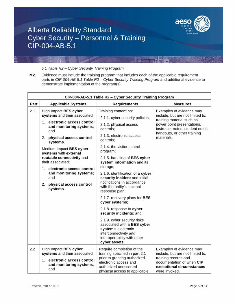
Alberta Reliability Standard Cyber Security – Personnel & Training CIP-004-AB-5.1
Effective: 2017-10-01
Page 5 of 14
5.1 Table R2 – Cyber Security Training Program.
M2. Evidence must include the training program that includes each of the applicable requirement
parts in CIP‐004-AB‐5.1 Table R2 – Cyber Security Training Program and additional evidence to demonstrate implementation of the program(s).
CIP-004-AB-5.1 Table R2 – Cyber Security Training Program
Part Applicable Systems Requirements Measures
2.1 High Impact BES cyber systems and their associated:
1. electronic access control and monitoring systems; and
2. physical access control systems.
Medium Impact BES cyber systems with external routable connectivity and their associated:
1. electronic access control and monitoring systems; and
2. physical access control systems.
Training content on:
2.1.1. cyber security policies;
2.1.2. physical access controls;
2.1.3. electronic access controls;
2.1.4. the visitor control program;
2.1.5. handling of BES cyber system information and its storage;
2.1.6. identification of a cyber security incident and initial notifications in accordance with the entity’s incident response plan;
2.1.7. recovery plans for BES cyber systems;
2.1.8. response to cyber security incidents; and
2.1.9. cyber security risks associated with a BES cyber system’s electronic interconnectivity and interoperability with other cyber assets.
Examples of evidence may include, but are not limited to, training material such as power point presentations, instructor notes, student notes, handouts, or other training materials.
2.2 High Impact BES cyber systems and their associated:
1. electronic access control and monitoring systems; and
Require completion of the training specified in part 2.1 prior to granting authorized electronic access and authorized unescorted physical access to applicable
Examples of evidence may include, but are not limited to, training records and documentation of when CIP exceptional circumstances were invoked.

Alberta Reliability Standard Cyber Security – Personnel & Training CIP-004-AB-5.1
Effective: 2017-10-01
Page 6 of 14
CIP-004-AB-5.1 Table R2 – Cyber Security Training Program
Part Applicable Systems Requirements Measures
2. physical access control systems.
Medium Impact BES cyber systems with external routable connectivity and their associated:
1. electronic access control and monitoring systems; and
2. physical access control systems.
cyber assets, except during CIP exceptional circumstances.
2.3 High Impact BES cyber systems and their associated:
1. electronic access control and monitoring systems; and
2. physical access control systems.
Medium Impact BES cyber systems with external routable connectivity and their associated:
1. electronic access control and monitoring systems; and
2. physical access control systems.
Require completion of the training specified in part 2.1 at least once every 15 months.
Examples of evidence may include, but are not limited to, dated individual training records.
R3. Each Responsible Entity shall implement, in a manner that identifies, assesses, and corrects deficiencies, one or more documented personnel risk assessment programs to attain and retain authorized electronic or authorized unescorted physical access to BES Cyber Systems that
collectively include each of the applicable requirement parts in CIP‐004-AB‐5.1 Table R3 – Personnel Risk Assessment Program.
M3. Evidence must include the documented personnel risk assessment programs that collectively
include each of the applicable requirement parts in CIP‐004-AB‐5.1 Table R3 – Personnel Risk Assessment Program and additional evidence to demonstrate implementation of the program(s).

Alberta Reliability Standard Cyber Security – Personnel & Training CIP-004-AB-5.1
Effective: 2017-10-01
Page 7 of 14
CIP-004-AB-5.1 Table R3 – Personnel Risk Assessment Program
Part Applicable Systems Requirements Measures
3.1 High Impact BES cyber systems and their associated:
1. electronic access control and monitoring systems; and
2. physical access control systems.
Medium Impact BES cyber systems with external routable connectivity and their associated:
1. electronic access control and monitoring systems; and
2. physical access control systems.
Process to confirm identity. An example of evidence may include, but is not limited to, documentation of the Responsible Entity’s process to confirm identity.
3.2 High Impact BES cyber systems and their associated:
1. electronic access control and monitoring systems; and
2. physical access control systems.
Medium Impact BES cyber systems with external routable connectivity and their associated:
1. electronic access control and monitoring systems; and
2. physical access control systems.
Process to perform a seven year criminal history records check as part of each personnel risk assessment that includes:
3.2.1. current residence, regardless of duration; and
3.2.2. other locations where, during the seven years immediately prior to the date of the criminal history records check, the subject has resided for six consecutive months or more.
If it is not possible to perform a full seven year criminal history records check, conduct as much of the seven year criminal history records check as possible and document the reason the full seven year criminal history records check could not be performed.
An example of evidence may include, but is not limited to, documentation of the Responsible Entity’s process to perform a seven year criminal history records check.

Alberta Reliability Standard Cyber Security – Personnel & Training CIP-004-AB-5.1
Effective: 2017-10-01
Page 8 of 14
CIP-004-AB-5.1 Table R3 – Personnel Risk Assessment Program
Part Applicable Systems Requirements Measures
3.3 High Impact BES cyber systems and their associated:
1. electronic access control and monitoring systems; and
2. physical access control systems.
Medium Impact BES cyber systems with external routable connectivity and their associated:
1. electronic access control and monitoring systems; and
2. physical access control systems.
Criteria or process to evaluate criminal history records checks for authorizing access.
An example of evidence may include, but is not limited to, documentation of the Responsible Entity’s process to evaluate criminal history records checks.
3.4 High Impact BES cyber systems and their associated:
1. electronic access control and monitoring systems; and
2. physical access control systems.
Medium Impact BES cyber systems with external routable connectivity and their associated:
1. electronic access control and monitoring systems; and
2. physical access control systems.
Criteria or process for verifying that personnel risk assessments performed for contractors or service vendors are conducted according to parts 3.1 through 3.3.
An example of evidence may include, but is not limited to, documentation of the Responsible Entity’s criteria or process for verifying contractors or service vendors personnel risk assessments.
3.5 High Impact BES cyber systems and their associated:
1. electronic access control and monitoring systems; and
Process to ensure that individuals with authorized electronic or authorized unescorted physical access have had a personnel risk
An example of evidence may include, but is not limited to, documentation of the Responsible Entity’s process for ensuring that individuals

Alberta Reliability Standard Cyber Security – Personnel & Training CIP-004-AB-5.1
Effective: 2017-10-01
Page 9 of 14
CIP-004-AB-5.1 Table R3 – Personnel Risk Assessment Program
Part Applicable Systems Requirements Measures
2. physical access control systems.
Medium Impact BES cyber systems with external routable connectivity and their associated:
1. electronic access control and monitoring systems; and
2. physical access control systems.
assessment completed according to parts 3.1 to 3.4 within the last seven years.
with authorized electronic or authorized unescorted physical access have had a personnel risk assessment completed within the last seven years.
R4. Each Responsible Entity shall implement, in a manner that identifies, assesses, and corrects deficiencies, one or more documented access management programs that collectively include each of the applicable requirement parts in CIP‐004-AB-5.1 Table R4 – Access Management Program.
M4. Evidence must include the documented processes that collectively include each of the applicable
requirement parts in CIP‐004-AB‐5.1 Table R4 – Access Management Program and additional evidence to demonstrate that the access management program was implemented as described in the Measures column of the table.
CIP-004-AB-5.1 Table R4 – Access Management Program
Part Applicable Systems Requirements Measures
4.1 High Impact BES cyber systems and their associated:
1. electronic access control and monitoring systems; and
2. physical access control systems.
Medium Impact BES cyber systems with external routable connectivity and their associated:
1. electronic access control and monitoring systems; and
Process to authorize based on need, as determined by the Responsible Entity, except for CIP exceptional circumstances:
4.1.1. electronic access;
4.1.2. unescorted physical access into a physical security perimeter; and
4.1.3. access to designated storage locations, whether physical or electronic, for BES cyber system information.
An example of evidence may include, but is not limited to, dated documentation of the process to authorize electronic access, unescorted physical access in a physical security perimeter, and access to designated storage locations, whether physical or electronic, for BES cyber system information.
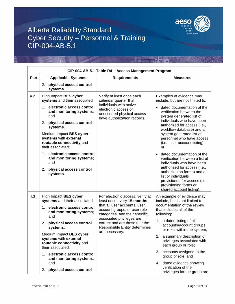
Alberta Reliability Standard Cyber Security – Personnel & Training CIP-004-AB-5.1
Effective: 2017-10-01
Page 10 of 14
CIP-004-AB-5.1 Table R4 – Access Management Program
Part Applicable Systems Requirements Measures
2. physical access control systems.
4.2 High Impact BES cyber systems and their associated:
1. electronic access control and monitoring systems; and
2. physical access control systems.
Medium Impact BES cyber systems with external routable connectivity and their associated:
1. electronic access control and monitoring systems; and
2. physical access control systems.
Verify at least once each calendar quarter that individuals with active electronic access or unescorted physical access have authorization records.
Examples of evidence may include, but are not limited to:
dated documentation of the verification between the system generated list of individuals who have been authorized for access (i.e., workflow database) and a system generated list of personnel who have access (i.e., user account listing), or
dated documentation of the verification between a list of individuals who have been authorized for access (i.e., authorization forms) and a list of individuals provisioned for access (i.e., provisioning forms or shared account listing).
4.3 High Impact BES cyber systems and their associated:
1. electronic access control and monitoring systems; and
2. physical access control systems.
Medium Impact BES cyber systems with external routable connectivity and their associated:
1. electronic access control and monitoring systems; and
2. physical access control
For electronic access, verify at least once every 15 months that all user accounts, user account groups, or user role categories, and their specific, associated privileges are correct and are those that the Responsible Entity determines are necessary.
An example of evidence may include, but is not limited to, documentation of the review that includes all of the following:
1. a dated listing of all accounts/account groups or roles within the system;
2. a summary description of privileges associated with each group or role;
3. accounts assigned to the group or role; and
4. dated evidence showing verification of the privileges for the group are

Alberta Reliability Standard Cyber Security – Personnel & Training CIP-004-AB-5.1
Effective: 2017-10-01
Page 11 of 14
CIP-004-AB-5.1 Table R4 – Access Management Program
Part Applicable Systems Requirements Measures
systems. authorized and appropriate to the work function performed by people assigned to each account.
4.4 High Impact BES cyber systems and their associated:
1. electronic access control and monitoring systems; and
2. physical access control systems.
Medium Impact BES cyber systems with external routable connectivity and their associated:
1. electronic access control and monitoring systems; and
2. physical access control systems.
Verify at least once every 15 months that access to the designated storage locations for BES cyber system information, whether physical or electronic, are correct and are those that the Responsible Entity determines are necessary for performing assigned work functions.
An example of evidence may include, but is not limited to, the documentation of the review that includes all of the following:
1. a dated listing of authorizations for BES cyber system information;
2. any privileges associated with the authorizations; and
3. dated evidence showing a verification of the authorizations and any privileges were confirmed correct and the minimum necessary for performing assigned work functions.
R5. Each Responsible Entity shall implement, in a manner that identifies, assesses, and corrects deficiencies, one or more documented access revocation programs that collectively include each of the applicable requirement parts in CIP‐004-AB‐5.1 Table R5 – Access Revocation.
M5. Evidence must include each of the applicable documented programs that collectively include
each of the applicable requirement parts in CIP‐004-AB‐5.1 Table R5 – Access Revocation and additional evidence to demonstrate implementation as described in the Measures column of the table.
CIP-004-AB-5.1 Table R5 – Access Revocation
Part Applicable Systems Requirements Measures
5.1 High Impact BES cyber systems and their associated:
1. electronic access control and monitoring systems; and
A process to initiate removal of an individual’s ability for unescorted physical access and interactive remote access upon a termination action, and complete the
An example of evidence may include, but is not limited to, documentation of all of the following:
1. dated workflow or sign‐off
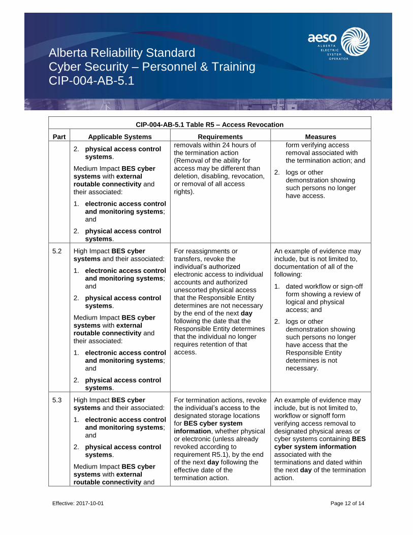
Alberta Reliability Standard Cyber Security – Personnel & Training CIP-004-AB-5.1
Effective: 2017-10-01
Page 12 of 14
CIP-004-AB-5.1 Table R5 – Access Revocation
Part Applicable Systems Requirements Measures
2. physical access control systems.
Medium Impact BES cyber systems with external routable connectivity and their associated:
1. electronic access control and monitoring systems; and
2. physical access control systems.
removals within 24 hours of the termination action (Removal of the ability for access may be different than deletion, disabling, revocation, or removal of all access rights).
form verifying access removal associated with the termination action; and
2. logs or other demonstration showing such persons no longer have access.
5.2 High Impact BES cyber systems and their associated:
1. electronic access control and monitoring systems; and
2. physical access control systems.
Medium Impact BES cyber systems with external routable connectivity and their associated:
1. electronic access control and monitoring systems; and
2. physical access control systems.
For reassignments or transfers, revoke the individual’s authorized electronic access to individual accounts and authorized unescorted physical access that the Responsible Entity determines are not necessary by the end of the next day following the date that the Responsible Entity determines that the individual no longer requires retention of that access.
An example of evidence may include, but is not limited to, documentation of all of the following:
1. dated workflow or sign‐off form showing a review of logical and physical access; and
2. logs or other demonstration showing such persons no longer have access that the Responsible Entity determines is not necessary.
5.3 High Impact BES cyber systems and their associated:
1. electronic access control and monitoring systems; and
2. physical access control systems.
Medium Impact BES cyber systems with external routable connectivity and
For termination actions, revoke the individual’s access to the designated storage locations for BES cyber system information, whether physical or electronic (unless already revoked according to requirement R5.1), by the end of the next day following the effective date of the termination action.
An example of evidence may include, but is not limited to, workflow or signoff form verifying access removal to designated physical areas or cyber systems containing BES cyber system information associated with the terminations and dated within the next day of the termination action.
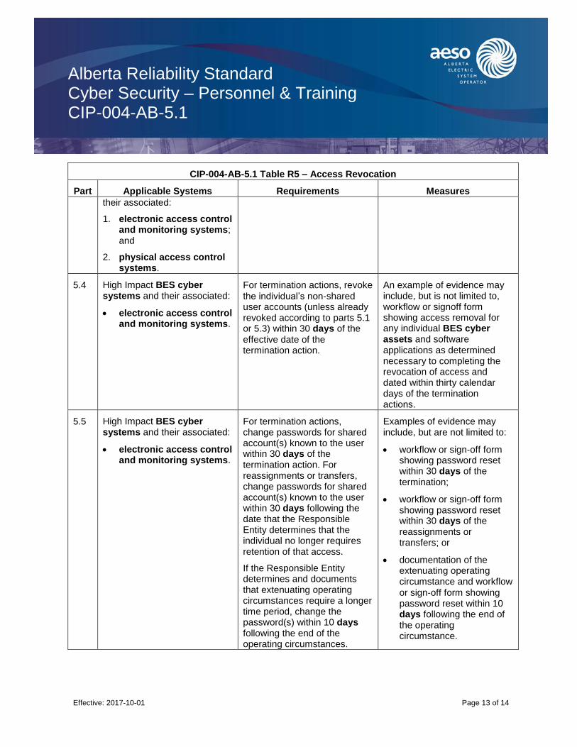
Alberta Reliability Standard Cyber Security – Personnel & Training CIP-004-AB-5.1
Effective: 2017-10-01
Page 13 of 14
CIP-004-AB-5.1 Table R5 – Access Revocation
Part Applicable Systems Requirements Measures
their associated:
1. electronic access control and monitoring systems; and
2. physical access control systems.
5.4 High Impact BES cyber systems and their associated:
electronic access control and monitoring systems.
For termination actions, revoke
the individual’s non‐shared user accounts (unless already revoked according to parts 5.1 or 5.3) within 30 days of the effective date of the termination action.
An example of evidence may include, but is not limited to, workflow or signoff form showing access removal for any individual BES cyber assets and software applications as determined necessary to completing the revocation of access and dated within thirty calendar days of the termination actions.
5.5 High Impact BES cyber systems and their associated:
electronic access control and monitoring systems.
For termination actions, change passwords for shared account(s) known to the user within 30 days of the termination action. For reassignments or transfers, change passwords for shared account(s) known to the user within 30 days following the date that the Responsible Entity determines that the individual no longer requires retention of that access.
If the Responsible Entity determines and documents that extenuating operating circumstances require a longer time period, change the password(s) within 10 days following the end of the operating circumstances.
Examples of evidence may include, but are not limited to:
workflow or sign‐off form showing password reset within 30 days of the termination;
workflow or sign‐off form showing password reset within 30 days of the reassignments or transfers; or
documentation of the extenuating operating circumstance and workflow
or sign‐off form showing password reset within 10 days following the end of the operating circumstance.
Alberta Reliability Standard Cyber Security – Personnel & Training CIP-004-AB-5.1
Effective: 2017-10-01
Page 14 of 14
Revision History
Date Description
2017-10-01 Initial release.

Alberta Reliability Standard Cyber Security – Electronic Security Perimeter(s) CIP-005-AB-5
Effective: 2017-10-01
Page 1 of 7
A. Introduction
1. Title: Cyber Security – Electronic Security Perimeter(s)
2. Number: CIP-005-AB-5
3. Purpose: To manage electronic access to BES cyber systems by specifying a controlled electronic security perimeter in support of protecting BES cyber systems against compromise that could lead to misoperation or instability in the bulk electric system.
4. Applicability:
4.1. For the purpose of the requirements contained herein, the following list of entities will be collectively referred to as “Responsible Entities”. For requirements in this reliability standard where a specific entity or subset of entities are the applicable entity or entities, the entity or entities are specified explicitly.
4.1.1. [Intentionally left blank.]
4.1.2. a legal owner of an electric distribution system that owns one or more of the following facilities, systems, and equipment for the protection or restoration of the bulk electric system:
4.1.2.1. each underfrequency load shedding or under voltage load shed system that:
4.1.2.1.1. is part of a load shedding program that is subject to one or more requirements in a reliability standard; and
4.1.2.1.2. performs automatic load shedding under a common control system owned by the entity in subsection 4.1.2., without human operator initiation, of 300 MW or more;
4.1.2.2. each remedial action scheme where the remedial action scheme is subject to one or more requirements in a reliability standard;
4.1.2.3. each protection system (excluding underfrequency load shedding and under voltage load shed) that applies to transmission where the protection system is subject to one or more requirements in a reliability standard; and
4.1.2.4. each cranking path and group of elements meeting the initial switching requirements from a contracted blackstart resource up to and including the first point of supply and/or point of delivery of the next generating unit or aggregated generating facility to be started;
4.1.3. the operator of a generating unit and the operator of an aggregated generating facility;
4.1.4. the legal owner of a generating unit and the legal owner of an aggregated generating facility;
4.1.5. [Intentionally left blank.]
4.1.6. [Intentionally left blank.]
4.1.7. the operator of a transmission facility;

Alberta Reliability Standard Cyber Security – Electronic Security Perimeter(s) CIP-005-AB-5
Effective: 2017-10-01
Page 2 of 7
4.1.8. the legal owner of a transmission facility; and
4.1.9. the ISO.
4.2. For the purpose of the requirements contained herein, the following facilities, systems, and equipment owned by each Responsible Entity in subsection 4.1 above are those to which these requirements are applicable. For requirements in this reliability standard where a specific type of facilities, system, or equipment or subset of facilities, systems, and equipment are applicable, these are specified explicitly.
4.2.1. One or more of the following facilities, systems and equipment that operate at, or control elements that operate at, a nominal voltage of 25 kV or less and are owned by a legal owner of an electric distribution system or a legal owner of a transmission facility for the protection or restoration of the bulk electric system:
4.2.1.1. each underfrequency load shedding or under voltage load shed system that:
4.2.1.1.1. is part of a load shedding program that is subject to one or more requirements in a reliability standard; and
4.2.1.1.2. performs automatic load shedding under a common control system owned by one or more of the entities in subsection 4.2.1, without human operator initiation, of 300 MW or more;
4.2.1.2. each remedial action scheme where the remedial action scheme is subject to one or more requirements in a reliability standard;
4.2.1.3. each protection system (excluding underfrequency load shedding and under voltage load shed) that applies to transmission where the protection system is subject to one or more requirements in a reliability standard; and
4.2.1.4. each cranking path and group of elements meeting the initial switching requirements from a contracted blackstart resource up to and including the first point of supply and/or point of delivery of the next generating unit or aggregated generating facility to be started;
4.2.2. Responsible Entities listed in subsection 4.1 other than a legal owner of an electric distribution system are responsible for:
4.2.2.1. each transmission facility that is part of the bulk electric system except each transmission facility that:
4.2.2.1.1. is a transformer with fewer than 2 windings at 100 kV or higher and does not connect a contracted blackstart resource;
4.2.2.1.2. radially connects only to load;
4.2.2.1.3. radially connects only to one or more generating units or aggregated generating facilities with a combined maximum authorized real power of less than or equal to 67.5 MW and does not connect a contracted blackstart resource; or
4.2.2.1.4. radially connects to load and one or more generating units or aggregated generating facilities that have a combined maximum authorized real power

Alberta Reliability Standard Cyber Security – Electronic Security Perimeter(s) CIP-005-AB-5
Effective: 2017-10-01
Page 3 of 7
of less than or equal to 67.5 MW and does not connect a contracted blackstart resource;
4.2.2.2. a reactive power resource that is dedicated to supplying or absorbing reactive power that is connected at 100 kV or higher, or through a dedicated transformer with a high-side voltage of 100 kV or higher, except those reactive power resources operated by an end-use customer for its own use;
4.2.2.3. a generating unit that is:
4.2.2.3.1. directly connected to the bulk electric system and has a maximum authorized real power rating greater than 18 MW unless the generating unit is part of an industrial complex;
4.2.2.3.2. within a power plant which:
4.2.2.3.2.1. is not part of an aggregated generating facility;
4.2.2.3.2.2. is directly connected to the bulk electric system; and
4.2.2.3.2.3. has a combined maximum authorized real power rating greater than 67.5 MW unless the power plant is part of an industrial complex;
4.2.2.3.3. within an industrial complex with supply transmission service greater than 67.5 MW; or
4.2.2.3.4. a contracted blackstart resource;
4.2.2.4. an aggregated generating facility that is:
4.2.2.4.1. directly connected to the bulk electric system and has a maximum authorized real power rating greater than 67.5 MW unless the aggregated generating facility is part of an industrial complex;
4.2.2.4.2. within an industrial complex with supply transmission service greater than 67.5 MW; or
4.2.2.4.3. a contracted blackstart resource;
and
4.2.2.5. control centres and backup control centres.
4.2.3. The following are exempt from this reliability standard:
4.2.3.1. [Intentionally left blank.]
4.2.3.2. cyber assets associated with communication networks and data communication links between discrete electronic security perimeters.
4.2.3.3. [Intentionally left blank.]
4.2.3.4. for the legal owner of an electric distribution system, the systems and equipment that are not included in subsection 4.2.1 above.
4.2.3.5. Responsible Entities that identify that they have no BES cyber systems categorized
as High Impact or Medium Impact according to the CIP‐002-AB‐5.1 identification and
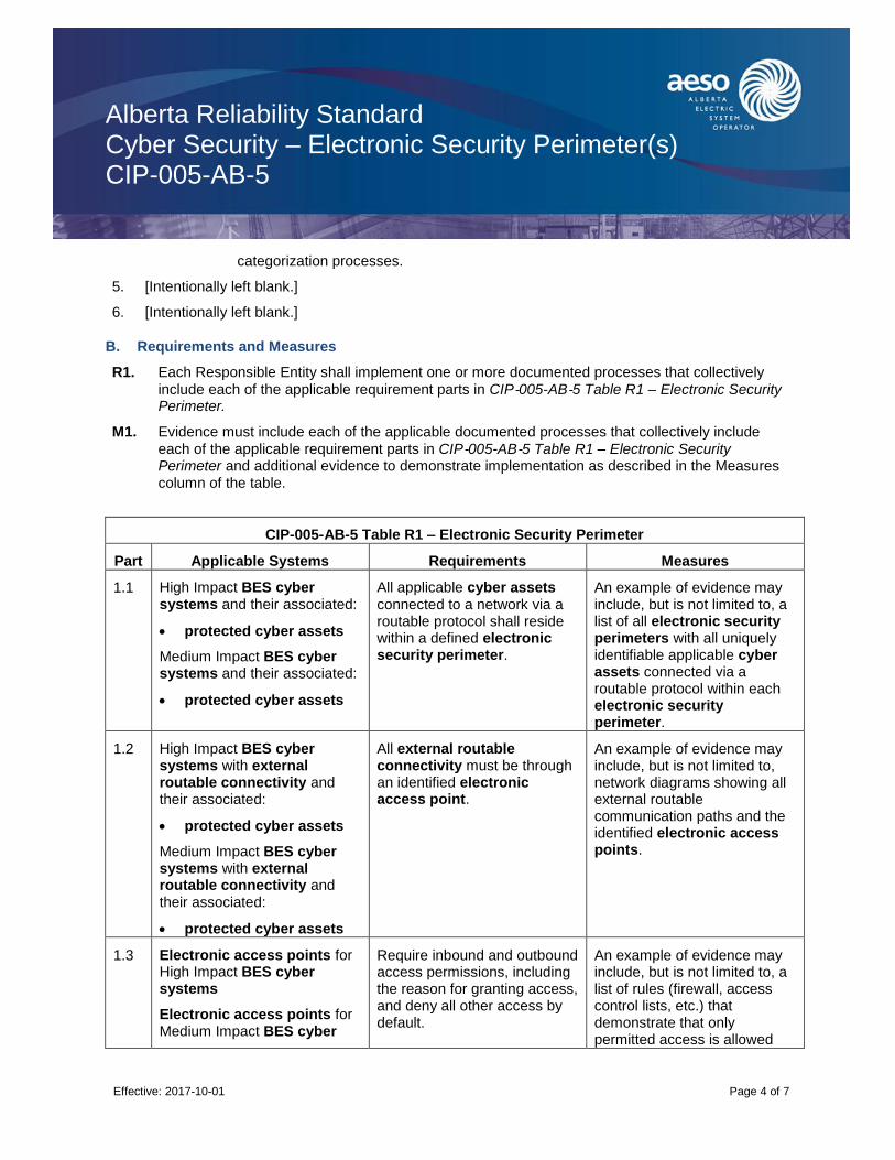
Alberta Reliability Standard Cyber Security – Electronic Security Perimeter(s) CIP-005-AB-5
Effective: 2017-10-01
Page 4 of 7
categorization processes.
5. [Intentionally left blank.]
6. [Intentionally left blank.]
B. Requirements and Measures
R1. Each Responsible Entity shall implement one or more documented processes that collectively
include each of the applicable requirement parts in CIP‐005-AB‐5 Table R1 – Electronic Security Perimeter.
M1. Evidence must include each of the applicable documented processes that collectively include
each of the applicable requirement parts in CIP‐005-AB‐5 Table R1 – Electronic Security Perimeter and additional evidence to demonstrate implementation as described in the Measures column of the table.
CIP-005-AB-5 Table R1 – Electronic Security Perimeter
Part Applicable Systems Requirements Measures
1.1 High Impact BES cyber systems and their associated:
protected cyber assets
Medium Impact BES cyber systems and their associated:
protected cyber assets
All applicable cyber assets connected to a network via a routable protocol shall reside within a defined electronic security perimeter.
An example of evidence may include, but is not limited to, a list of all electronic security perimeters with all uniquely identifiable applicable cyber assets connected via a routable protocol within each electronic security perimeter.
1.2 High Impact BES cyber systems with external routable connectivity and their associated:
protected cyber assets
Medium Impact BES cyber systems with external routable connectivity and their associated:
protected cyber assets
All external routable connectivity must be through an identified electronic access point.
An example of evidence may include, but is not limited to, network diagrams showing all external routable communication paths and the identified electronic access points.
1.3 Electronic access points for High Impact BES cyber systems
Electronic access points for Medium Impact BES cyber
Require inbound and outbound access permissions, including the reason for granting access, and deny all other access by default.
An example of evidence may include, but is not limited to, a list of rules (firewall, access control lists, etc.) that demonstrate that only permitted access is allowed
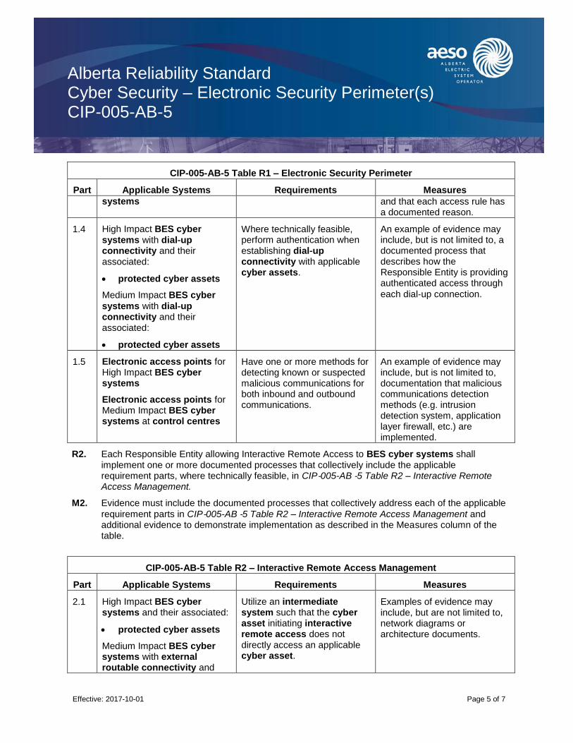
Alberta Reliability Standard Cyber Security – Electronic Security Perimeter(s) CIP-005-AB-5
Effective: 2017-10-01
Page 5 of 7
CIP-005-AB-5 Table R1 – Electronic Security Perimeter
Part Applicable Systems Requirements Measures
systems and that each access rule has a documented reason.
1.4 High Impact BES cyber systems with dial‐up connectivity and their associated:
protected cyber assets
Medium Impact BES cyber
systems with dial‐up connectivity and their associated:
protected cyber assets
Where technically feasible, perform authentication when establishing dial‐up connectivity with applicable cyber assets.
An example of evidence may include, but is not limited to, a documented process that describes how the Responsible Entity is providing authenticated access through
each dial‐up connection.
1.5 Electronic access points for High Impact BES cyber systems
Electronic access points for Medium Impact BES cyber systems at control centres
Have one or more methods for detecting known or suspected malicious communications for both inbound and outbound communications.
An example of evidence may include, but is not limited to, documentation that malicious communications detection methods (e.g. intrusion detection system, application layer firewall, etc.) are implemented.
R2. Each Responsible Entity allowing Interactive Remote Access to BES cyber systems shall implement one or more documented processes that collectively include the applicable requirement parts, where technically feasible, in CIP‐005-AB ‐5 Table R2 – Interactive Remote Access Management.
M2. Evidence must include the documented processes that collectively address each of the applicable
requirement parts in CIP‐005-AB ‐5 Table R2 – Interactive Remote Access Management and additional evidence to demonstrate implementation as described in the Measures column of the table.
CIP-005-AB-5 Table R2 – Interactive Remote Access Management
Part Applicable Systems Requirements Measures
2.1 High Impact BES cyber systems and their associated:
protected cyber assets
Medium Impact BES cyber systems with external routable connectivity and
Utilize an intermediate system such that the cyber asset initiating interactive remote access does not directly access an applicable cyber asset.
Examples of evidence may include, but are not limited to, network diagrams or architecture documents.

Alberta Reliability Standard Cyber Security – Electronic Security Perimeter(s) CIP-005-AB-5
Effective: 2017-10-01
Page 6 of 7
CIP-005-AB-5 Table R2 – Interactive Remote Access Management
Part Applicable Systems Requirements Measures
their associated:
protected cyber assets
2.2 High Impact BES cyber systems and their associated:
protected cyber assets
Medium Impact BES cyber systems with external routable connectivity and their associated:
protected cyber assets
For all interactive remote access sessions, utilize encryption that terminates at an intermediate system.
An example of evidence may include, but is not limited to, architecture documents detailing where encryption initiates and terminates.
2.3 High Impact BES cyber systems and their associated:
protected cyber assets
Medium Impact BES cyber systems with external routable connectivity and their associated:
protected cyber assets
Require multi‐factor authentication for all interactive remote access sessions.
An example of evidence may include, but is not limited to, architecture documents detailing the authentication factors used.
Examples of authenticators may include, but are not limited to,
something the individual knows such as passwords or PINs. This does not include User ID;
something the individual has such as tokens, digital certificates, or smart cards; or
something the individual is such as fingerprints, iris scans, or other biometric characteristics.
Revision History

Alberta Reliability Standard Cyber Security – Electronic Security Perimeter(s) CIP-005-AB-5
Effective: 2017-10-01
Page 7 of 7
Date Description
2017-10-01 Initial release.

Alberta Reliability Standard Cyber Security – Physical Security of BES Cyber Systems CIP-006-AB-5
Effective: 2017-10-01
Page 1 of 10
A. Introduction
1. Title: Cyber Security – Physical Security of BES Cyber Systems
2. Number: CIP-006-AB-5
3. Purpose: To manage physical access to BES cyber systems by specifying a physical security plan in support of protecting BES cyber systems against compromise that could lead to misoperation or instability in the bulk electric system.
4. Applicability:
4.1. For the purpose of the requirements contained herein, the following list of entities will be collectively referred to as “Responsible Entities.” For requirements in this reliability standard where a specific entity or subset of entities are the applicable entity or entities, the entity or entities are specified explicitly.
4.1.1. [Intentionally left blank.]
4.1.2. a legal owner of an electric distribution system that owns one or more of the following facilities, systems, and equipment for the protection or restoration of the bulk electric system:
4.1.2.1. each underfrequency load shedding or under voltage load shed system that:
4.1.2.1.1. is part of a load shedding program that is subject to one or more requirements in a reliability standard; and
4.1.2.1.2. performs automatic load shedding under a common control system owned by the entity in subsection 4.1.2., without human operator initiation, of 300 MW or more;
4.1.2.2. each remedial action scheme where the remedial action scheme is subject to one or more requirements in a reliability standard;
4.1.2.3. each protection system (excluding underfrequency load shedding and under voltage load shed) that applies to transmission where the protection system is subject to one or more requirements in a reliability standard; and
4.1.2.4. each cranking path and group of elements meeting the initial switching requirements from a contracted blackstart resource up to and including the first point of supply and/or point of delivery of the next generating unit or aggregated generating facility to be started;
4.1.3. the operator of a generating unit and the operator of an aggregated generating facility;
4.1.4. the legal owner of a generating unit and the legal owner of an aggregated generating facility;
4.1.5. [Intentionally left blank.]
4.1.6. [Intentionally left blank.]
4.1.7. the operator of a transmission facility;

Alberta Reliability Standard Cyber Security – Physical Security of BES Cyber Systems CIP-006-AB-5
Effective: 2017-10-01
Page 2 of 10
4.1.8. the legal owner of a transmission facility; and
4.1.9. the ISO.
4.2. For the purpose of the requirements contained herein, the following facilities, systems, and equipment owned by each Responsible Entity in subsection 4.1 above are those to which these requirements are applicable. For requirements in this reliability standard where a specific type of facilities, system, or equipment or subset of facilities, systems, and equipment are applicable, these are specified explicitly.
4.2.1. One or more of the following facilities, systems and equipment that operate at, or control elements that operate at, a nominal voltage of 25 kV or less and are owned by a legal owner of an electric distribution system or a legal owner of a transmission facility for the protection or restoration of the bulk electric system:
4.2.1.1. each underfrequency load shedding or under voltage load shed system that:
4.2.1.1.1. is part of a load shedding program that is subject to one or more requirements in a reliability standard; and
4.2.1.1.2. performs automatic load shedding under a common control system owned by one or more of the entities in subsection 4.2.1, without human operator initiation, of 300 MW or more;
4.2.1.2. each remedial action scheme where the remedial action scheme is subject to one or more requirements in a reliability standard;
4.2.1.3. each protection system (excluding underfrequency load shedding and under voltage load shed) that applies to transmission where the protection system is subject to one or more requirements in a reliability standard; and
4.2.1.4. each cranking path and group of elements meeting the initial switching requirements from a contracted blackstart resource up to and including the first point of supply and/or point of delivery of the next generating unit or aggregated generating facility to be started;
4.2.2. Responsible Entities listed in subsection 4.1 other than a legal owner of an electric distribution system are responsible for:
4.2.2.1. each transmission facility that is part of the bulk electric system except each transmission facility that:
4.2.2.1.1. is a transformer with fewer than 2 windings at 100 kV or higher and does not connect a contracted blackstart resource;
4.2.2.1.2. radially connects only to load;
4.2.2.1.3. radially connects only to one or more generating units or aggregated generating facilities with a combined maximum authorized real power of less than or equal to 67.5 MW and does not connect a contracted blackstart resource; or
4.2.2.1.4. radially connects to load and one or more generating units or aggregated generating facilities that have a combined maximum authorized real power
Alberta Reliability Standard Cyber Security – Physical Security of BES Cyber Systems CIP-006-AB-5
Effective: 2017-10-01
Page 3 of 10
of less than or equal to 67.5 MW and does not connect a contracted blackstart resource;
4.2.2.2. a reactive power resource that is dedicated to supplying or absorbing reactive power that is connected at 100 kV or higher, or through a dedicated transformer with a high-side voltage of 100 kV or higher, except those reactive power resources operated by an end-use customer for its own use;
4.2.2.3. a generating unit that is:
4.2.2.3.1. directly connected to the bulk electric system and has a maximum authorized real power rating greater than 18 MW unless the generating unit is part of an industrial complex;
4.2.2.3.2. within a power plant which:
4.2.2.3.2.1. is not part of an aggregated generating facility;
4.2.2.3.2.2. is directly connected to the bulk electric system; and
4.2.2.3.2.3. has a combined maximum authorized real power rating greater than 67.5 MW unless the power plant is part of an industrial complex;
4.2.2.3.3. within an industrial complex with supply transmission service greater than 67.5 MW; or
4.2.2.3.4. a contracted blackstart resource;
4.2.2.4. an aggregated generating facility that is:
4.2.2.4.1. directly connected to the bulk electric system and has a maximum authorized real power rating greater than 67.5 MW unless the aggregated generating facility is part of an industrial complex;
4.2.2.4.2. within an industrial complex with supply transmission service greater than 67.5 MW; or
4.2.2.4.3. a contracted blackstart resource;
and
4.2.2.5. control centres and backup control centres.
4.2.3. The following are exempt from this reliability standard:
4.2.3.1. [Intentionally left blank.]
4.2.3.2. cyber assets associated with communication networks and data communication links between discrete electronic security perimeters.
4.2.3.3. [Intentionally left blank.]
4.2.3.4. for the legal owner of an electric distribution system, the systems and equipment that are not included in subsection 4.2.1 above.
4.2.3.5. Responsible Entities that identify that they have no BES cyber systems categorized
as High Impact or Medium Impact according to the CIP‐002-AB‐5.1 identification and

Alberta Reliability Standard Cyber Security – Physical Security of BES Cyber Systems CIP-006-AB-5
Effective: 2017-10-01
Page 4 of 10
categorization processes.
5. [Intentionally left blank.]
6. [Intentionally left blank.]
B. Requirements and Measures
R1. Each Responsible Entity shall implement, in a manner that identifies, assesses, and corrects deficiencies, one or more documented physical security plans that collectively include all of the applicable requirement parts in CIP‐006-AB‐5 Table R1 – Physical Security Plan.
M1. Evidence must include each of the documented physical security plans that collectively include all
of the applicable requirement parts in CIP‐006-AB‐5 Table R1 – Physical Security Plan and additional evidence to demonstrate implementation of the plan or plans as described in the Measures column of the table.
CIP-006-AB-5 Table R1 – Physical Security Plan
Part Applicable Systems Requirements Measures
1.1 Medium Impact BES cyber systems without external routable connectivity
Physical access control systems associated with:
High Impact BES cyber systems, or
Medium Impact BES cyber systems with external routable connectivity
Define operational or procedural controls to restrict physical access.
An example of evidence may include, but is not limited to, documentation that operational or procedural controls exist.
1.2 Medium Impact BES cyber systems with external routable connectivity and their associated:
1. electronic access control or monitoring systems; and
2. protected cyber assets
Utilize at least one physical access control to allow unescorted physical access into each applicable physical security perimeter to only those individuals who have authorized unescorted physical access.
An example of evidence may include, but is not limited to, language in the physical security plan that describes each physical security perimeter and how unescorted physical access is controlled by one or more different methods and proof that unescorted physical access is restricted to only authorized individuals, such as a list of authorized individuals accompanied by access logs.
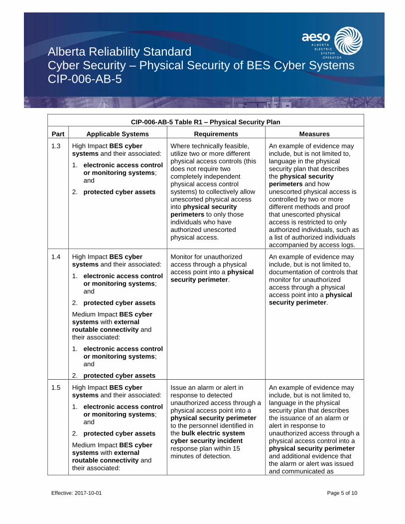
Alberta Reliability Standard Cyber Security – Physical Security of BES Cyber Systems CIP-006-AB-5
Effective: 2017-10-01
Page 5 of 10
CIP-006-AB-5 Table R1 – Physical Security Plan
Part Applicable Systems Requirements Measures
1.3 High Impact BES cyber systems and their associated:
1. electronic access control or monitoring systems; and
2. protected cyber assets
Where technically feasible, utilize two or more different physical access controls (this does not require two completely independent physical access control systems) to collectively allow unescorted physical access into physical security perimeters to only those individuals who have authorized unescorted physical access.
An example of evidence may include, but is not limited to, language in the physical security plan that describes the physical security perimeters and how unescorted physical access is controlled by two or more different methods and proof that unescorted physical access is restricted to only authorized individuals, such as a list of authorized individuals accompanied by access logs.
1.4 High Impact BES cyber systems and their associated:
1. electronic access control or monitoring systems; and
2. protected cyber assets
Medium Impact BES cyber systems with external routable connectivity and their associated:
1. electronic access control or monitoring systems; and
2. protected cyber assets
Monitor for unauthorized access through a physical access point into a physical security perimeter.
An example of evidence may include, but is not limited to, documentation of controls that monitor for unauthorized access through a physical access point into a physical security perimeter.
1.5 High Impact BES cyber systems and their associated:
1. electronic access control or monitoring systems; and
2. protected cyber assets
Medium Impact BES cyber systems with external routable connectivity and their associated:
Issue an alarm or alert in response to detected unauthorized access through a physical access point into a physical security perimeter to the personnel identified in the bulk electric system cyber security incident response plan within 15 minutes of detection.
An example of evidence may include, but is not limited to, language in the physical security plan that describes the issuance of an alarm or alert in response to unauthorized access through a physical access control into a physical security perimeter and additional evidence that the alarm or alert was issued and communicated as
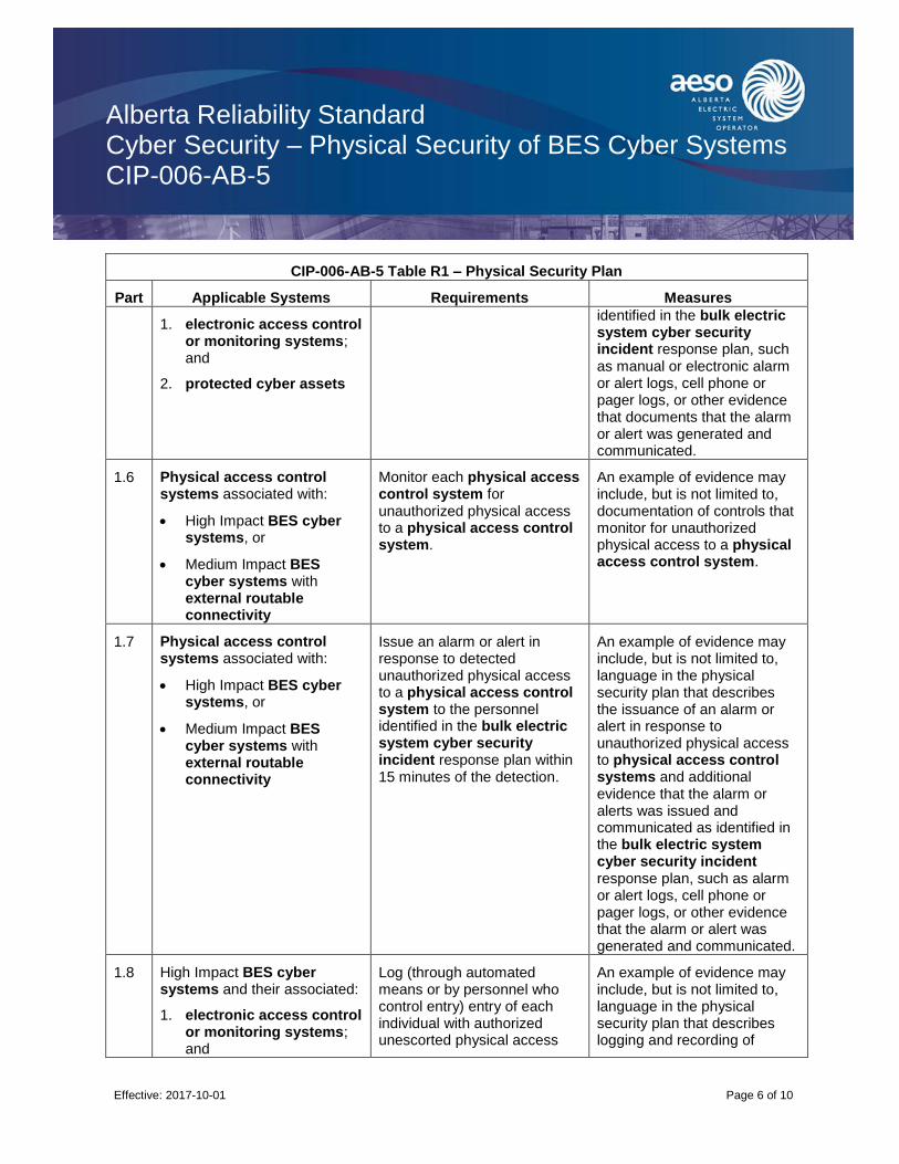
Alberta Reliability Standard Cyber Security – Physical Security of BES Cyber Systems CIP-006-AB-5
Effective: 2017-10-01
Page 6 of 10
CIP-006-AB-5 Table R1 – Physical Security Plan
Part Applicable Systems Requirements Measures
1. electronic access control or monitoring systems; and
2. protected cyber assets
identified in the bulk electric system cyber security incident response plan, such as manual or electronic alarm or alert logs, cell phone or pager logs, or other evidence that documents that the alarm or alert was generated and communicated.
1.6 Physical access control systems associated with:
High Impact BES cyber systems, or
Medium Impact BES cyber systems with external routable connectivity
Monitor each physical access control system for unauthorized physical access to a physical access control system.
An example of evidence may include, but is not limited to, documentation of controls that monitor for unauthorized physical access to a physical access control system.
1.7 Physical access control systems associated with:
High Impact BES cyber systems, or
Medium Impact BES cyber systems with external routable connectivity
Issue an alarm or alert in response to detected unauthorized physical access to a physical access control system to the personnel identified in the bulk electric system cyber security incident response plan within 15 minutes of the detection.
An example of evidence may include, but is not limited to, language in the physical security plan that describes the issuance of an alarm or alert in response to unauthorized physical access to physical access control systems and additional evidence that the alarm or alerts was issued and communicated as identified in the bulk electric system cyber security incident response plan, such as alarm or alert logs, cell phone or pager logs, or other evidence that the alarm or alert was generated and communicated.
1.8 High Impact BES cyber systems and their associated:
1. electronic access control or monitoring systems; and
Log (through automated means or by personnel who control entry) entry of each individual with authorized unescorted physical access
An example of evidence may include, but is not limited to, language in the physical security plan that describes logging and recording of
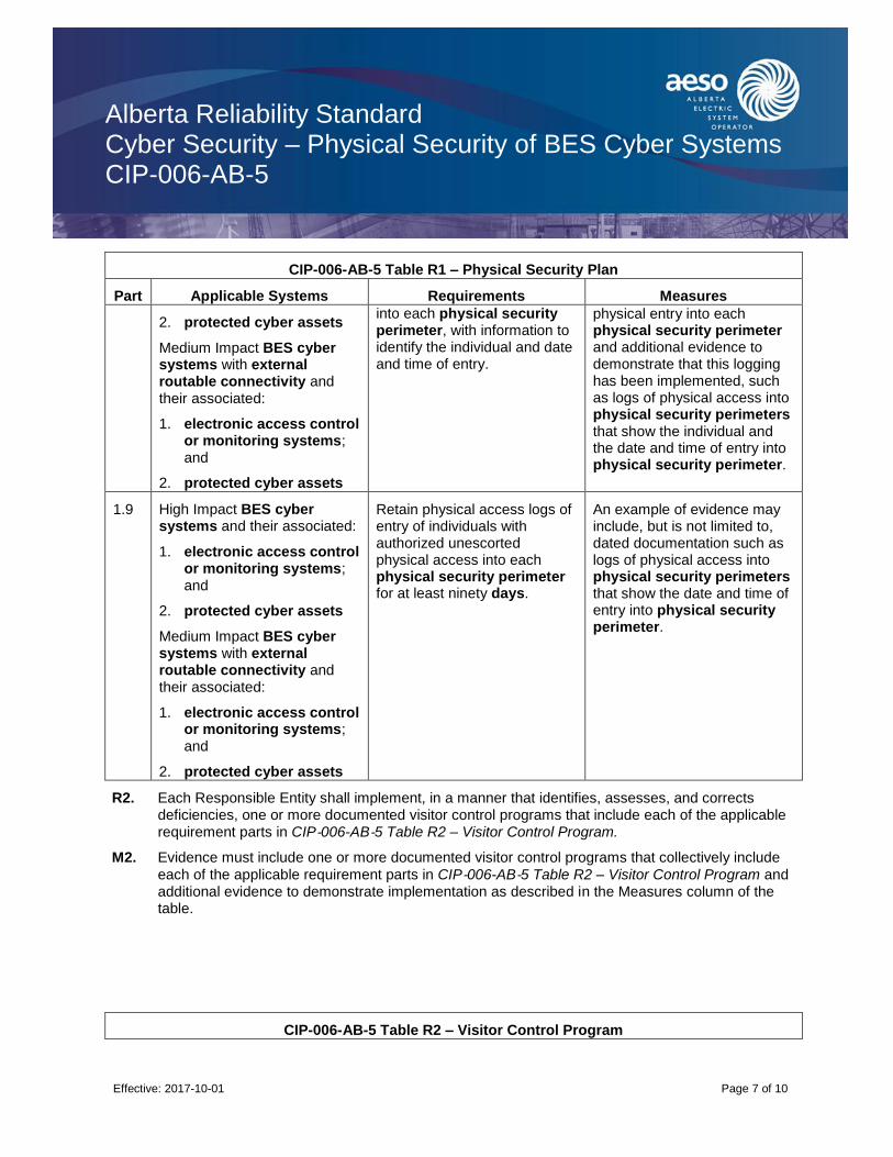
Alberta Reliability Standard Cyber Security – Physical Security of BES Cyber Systems CIP-006-AB-5
Effective: 2017-10-01
Page 7 of 10
CIP-006-AB-5 Table R1 – Physical Security Plan
Part Applicable Systems Requirements Measures
2. protected cyber assets
Medium Impact BES cyber systems with external routable connectivity and their associated:
1. electronic access control or monitoring systems; and
2. protected cyber assets
into each physical security perimeter, with information to identify the individual and date and time of entry.
physical entry into each physical security perimeter and additional evidence to demonstrate that this logging has been implemented, such as logs of physical access into physical security perimeters that show the individual and the date and time of entry into physical security perimeter.
1.9 High Impact BES cyber systems and their associated:
1. electronic access control or monitoring systems; and
2. protected cyber assets
Medium Impact BES cyber systems with external routable connectivity and their associated:
1. electronic access control or monitoring systems; and
2. protected cyber assets
Retain physical access logs of entry of individuals with authorized unescorted physical access into each physical security perimeter for at least ninety days.
An example of evidence may include, but is not limited to, dated documentation such as logs of physical access into physical security perimeters that show the date and time of entry into physical security perimeter.
R2. Each Responsible Entity shall implement, in a manner that identifies, assesses, and corrects deficiencies, one or more documented visitor control programs that include each of the applicable requirement parts in CIP‐006-AB‐5 Table R2 – Visitor Control Program.
M2. Evidence must include one or more documented visitor control programs that collectively include
each of the applicable requirement parts in CIP‐006-AB‐5 Table R2 – Visitor Control Program and additional evidence to demonstrate implementation as described in the Measures column of the table.
CIP-006-AB-5 Table R2 – Visitor Control Program

Alberta Reliability Standard Cyber Security – Physical Security of BES Cyber Systems CIP-006-AB-5
Effective: 2017-10-01
Page 8 of 10
Part Applicable Systems Requirements Measures
2.1 High Impact BES cyber systems and their associated:
1. electronic access control or monitoring systems; and
2. protected cyber assets
Medium Impact BES cyber systems with external routable connectivity and their associated:
1. electronic access control or monitoring systems; and
2. protected cyber assets
Require continuous escorted access of visitors (individuals who are provided access but are not authorized for unescorted physical access) within each physical security perimeter, except during CIP exceptional circumstances.
An example of evidence may include, but is not limited to, language in a visitor control program that requires continuous escorted access of visitors within physical security perimeters and additional evidence to demonstrate that the process was implemented, such as visitor logs.
2.2 High Impact BES cyber systems and their associated:
1. electronic access control or monitoring systems; and
2. protected cyber assets
Medium Impact BES cyber systems with external routable connectivity and their associated:
1. electronic access control or monitoring systems; and
2. protected cyber assets
Require manual or automated logging of visitor entry into and exit from the physical security perimeter that includes date and time of the initial entry and last exit, the visitor’s name, and the name of an individual point of contact responsible for the visitor, except during CIP exceptional circumstances.
An example of evidence may include, but is not limited to, language in a visitor control program that requires continuous escorted access of visitors within physical security perimeters and additional evidence to demonstrate that the process was implemented, such as dated visitor logs that include the required information.
2.3 High Impact BES cyber systems and their associated:
1. electronic access control or monitoring systems; and
2. protected cyber assets
Medium Impact BES cyber systems with external routable connectivity and
Retain visitor logs for at least ninety days.
An example of evidence may include, but is not limited to, documentation showing logs have been retained for at least ninety days.
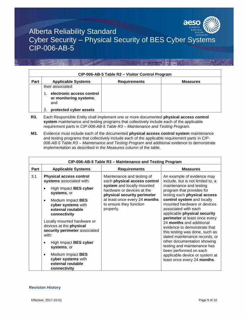
Alberta Reliability Standard Cyber Security – Physical Security of BES Cyber Systems CIP-006-AB-5
Effective: 2017-10-01
Page 9 of 10
CIP-006-AB-5 Table R2 – Visitor Control Program
Part Applicable Systems Requirements Measures
their associated:
1. electronic access control or monitoring systems; and
2. protected cyber assets
R3. Each Responsible Entity shall implement one or more documented physical access control system maintenance and testing programs that collectively include each of the applicable
requirement parts in CIP‐006-AB‐5 Table R3 – Maintenance and Testing Program.
M3. Evidence must include each of the documented physical access control system maintenance
and testing programs that collectively include each of the applicable requirement parts in CIP‐006-AB‐5 Table R3 – Maintenance and Testing Program and additional evidence to demonstrate implementation as described in the Measures column of the table.
CIP-006-AB-5 Table R3 – Maintenance and Testing Program
Part Applicable Systems Requirements Measures
3.1 Physical access control systems associated with:
High Impact BES cyber systems, or
Medium Impact BES cyber systems with external routable connectivity
Locally mounted hardware or devices at the physical security perimeter associated with:
High Impact BES cyber systems, or
Medium Impact BES cyber systems with external routable connectivity
Maintenance and testing of each physical access control system and locally mounted hardware or devices at the physical security perimeter at least once every 24 months to ensure they function properly.
An example of evidence may include, but is not limited to, a maintenance and testing program that provides for testing each physical access control system and locally mounted hardware or devices associated with each applicable physical security perimeter at least once every 24 months and additional evidence to demonstrate that this testing was done, such as dated maintenance records, or other documentation showing testing and maintenance has been performed on each applicable device or system at least once every 24 months.
Revision History

Alberta Reliability Standard Cyber Security – Physical Security of BES Cyber Systems CIP-006-AB-5
Effective: 2017-10-01
Page 10 of 10
Date Description
2017-10-01 Initial release.
Alberta Reliability Standard Cyber Security – System Security Management CIP-007-AB-5
Effective: 2017-10-01
Page 1 of 14
A. Introduction
1. Title: Cyber Security – System Security Management
2. Number: CIP-007-AB-5
3. Purpose: To manage system security by specifying select technical, operational, and procedural requirements in support of protecting BES cyber systems against compromise that could lead to misoperation or instability in the bulk electric system.
4. Applicability:
4.1. For the purpose of the requirements contained herein, the following list of entities will be collectively referred to as “Responsible Entities”. For requirements in this reliability standard where a specific entity or subset of entities are the applicable entity or entities, the entity or entities are specified explicitly.
4.1.1. [Intentionally left blank.]
4.1.2. a legal owner of an electric distribution system that owns one or more of the following facilities, systems, and equipment for the protection or restoration of the bulk electric system:
4.1.2.1. each underfrequency load shedding or under voltage load shed system that:
4.1.2.1.1. is part of a load shedding program that is subject to one or more requirements in a reliability standard; and
4.1.2.1.2. performs automatic load shedding under a common control system owned by the entity in subsection 4.1.2., without human operator initiation, of 300 MW or more;
4.1.2.2. each remedial action scheme where the remedial action scheme is subject to one or more requirements in a reliability standard;
4.1.2.3. each protection system (excluding underfrequency load shedding and under voltage load shed) that applies to transmission where the protection system is subject to one or more requirements in a reliability standard; and
4.1.2.4. each cranking path and group of elements meeting the initial switching requirements from a contracted blackstart resource up to and including the first point of supply and/or point of delivery of the next generating unit or aggregated generating facility to be started;
4.1.3. the operator of a generating unit and the operator of an aggregated generating facility;
4.1.4. the legal owner of a generating unit and the legal owner of an aggregated generating facility;
4.1.5. [Intentionally left blank.]
4.1.6. [Intentionally left blank.]
4.1.7. the operator of a transmission facility;

Alberta Reliability Standard Cyber Security – System Security Management CIP-007-AB-5
Effective: 2017-10-01
Page 2 of 14
4.1.8. the legal owner of a transmission facility; and
4.1.9. the ISO.
4.2. For the purpose of the requirements contained herein, the following facilities, systems, and equipment owned by each Responsible Entity in subsection 4.1 above are those to which these requirements are applicable. For requirements in this reliability standard where a specific type of facilities, system, or equipment or subset of facilities, systems, and equipment are applicable, these are specified explicitly.
4.2.1. One or more of the following facilities, systems and equipment that operate at, or control elements that operate at, a nominal voltage of 25 kV or less and are owned by a legal owner of an electric distribution system or a legal owner of a transmission facility for the protection or restoration of the bulk electric system:
4.2.1.1. each underfrequency load shedding or under voltage load shed system that:
4.2.1.1.1. is part of a load shedding program that is subject to one or more requirements in a reliability standard; and
4.2.1.1.2. performs automatic load shedding under a common control system owned by one or more of the entities in subsection 4.2.1, without human operator initiation, of 300 MW or more;
4.2.1.2. each remedial action scheme where the remedial action scheme is subject to one or more requirements in a reliability standard;
4.2.1.3. each protection system (excluding underfrequency load shedding and under voltage load shed) that applies to transmission where the protection system is subject to one or more requirements in a reliability standard; and
4.2.1.4. each cranking path and group of elements meeting the initial switching requirements from a contracted blackstart resource up to and including the first point of supply and/or point of delivery of the next generating unit or aggregated generating facility to be started;
4.2.2. Responsible Entities listed in subsection 4.1 other than a legal owner of an electric distribution system are responsible for:
4.2.2.1. each transmission facility that is part of the bulk electric system except each transmission facility that:
4.2.2.1.1. is a transformer with fewer than 2 windings at 100 kV or higher and does not connect a contracted blackstart resource;
4.2.2.1.2. radially connects only to load;
4.2.2.1.3. radially connects only to one or more generating units or aggregated generating facilities with a combined maximum authorized real power of less than or equal to 67.5 MW and does not connect a contracted blackstart resource; or
4.2.2.1.4. radially connects to load and one or more generating units or aggregated generating facilities that have a combined maximum authorized real power
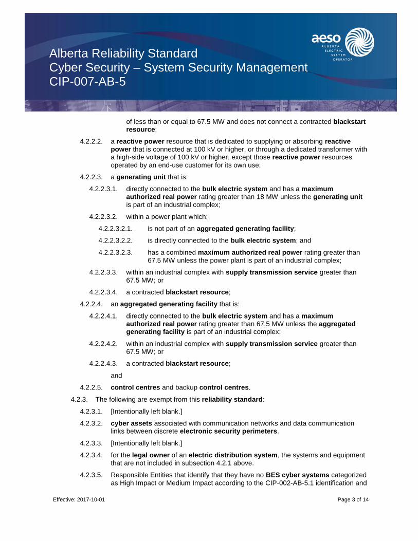
Alberta Reliability Standard Cyber Security – System Security Management CIP-007-AB-5
Effective: 2017-10-01
Page 3 of 14
of less than or equal to 67.5 MW and does not connect a contracted blackstart resource;
4.2.2.2. a reactive power resource that is dedicated to supplying or absorbing reactive power that is connected at 100 kV or higher, or through a dedicated transformer with a high-side voltage of 100 kV or higher, except those reactive power resources operated by an end-use customer for its own use;
4.2.2.3. a generating unit that is:
4.2.2.3.1. directly connected to the bulk electric system and has a maximum authorized real power rating greater than 18 MW unless the generating unit is part of an industrial complex;
4.2.2.3.2. within a power plant which:
4.2.2.3.2.1. is not part of an aggregated generating facility;
4.2.2.3.2.2. is directly connected to the bulk electric system; and
4.2.2.3.2.3. has a combined maximum authorized real power rating greater than 67.5 MW unless the power plant is part of an industrial complex;
4.2.2.3.3. within an industrial complex with supply transmission service greater than 67.5 MW; or
4.2.2.3.4. a contracted blackstart resource;
4.2.2.4. an aggregated generating facility that is:
4.2.2.4.1. directly connected to the bulk electric system and has a maximum authorized real power rating greater than 67.5 MW unless the aggregated generating facility is part of an industrial complex;
4.2.2.4.2. within an industrial complex with supply transmission service greater than 67.5 MW; or
4.2.2.4.3. a contracted blackstart resource;
and
4.2.2.5. control centres and backup control centres.
4.2.3. The following are exempt from this reliability standard:
4.2.3.1. [Intentionally left blank.]
4.2.3.2. cyber assets associated with communication networks and data communication links between discrete electronic security perimeters.
4.2.3.3. [Intentionally left blank.]
4.2.3.4. for the legal owner of an electric distribution system, the systems and equipment that are not included in subsection 4.2.1 above.
4.2.3.5. Responsible Entities that identify that they have no BES cyber systems categorized
as High Impact or Medium Impact according to the CIP‐002-AB‐5.1 identification and

Alberta Reliability Standard Cyber Security – System Security Management CIP-007-AB-5
Effective: 2017-10-01
Page 4 of 14
categorization processes.
5. [Intentionally left blank.]
6. [Intentionally left blank.]
B. Requirements and Measures
R1. Each Responsible Entity shall implement, in a manner that identifies, assesses, and corrects deficiencies, one or more documented processes that collectively include each of the applicable requirement parts in CIP‐007-AB‐5 Table R1 – Ports and Services.
M1. Evidence must include the documented processes that collectively include each of the applicable
requirement parts in CIP‐007-AB‐5 Table R1 – Ports and Services and additional evidence to demonstrate implementation as described in the Measures column of the table.
CIP-007-AB-5 Table R1 – Ports and Services
Part Applicable Systems Requirements Measures
1.1 High Impact BES cyber systems and their associated:
1. electronic access control or monitoring systems;
2. physical access control systems; and
3. protected cyber assets
Medium Impact BES cyber systems with external routable connectivity and their associated:
1. electronic access control or monitoring systems;
2. physical access control systems; and
3. protected cyber assets
Where technically feasible, enable only logical network accessible ports that have been determined to be needed by the Responsible Entity, including port ranges or services where needed to handle dynamic ports. If a device has no provision for disabling or restricting logical ports on the device then those ports that are open are deemed needed.
Examples of evidence may include, but are not limited to:
documentation of the need for all enabled ports on all applicable cyber assets and electronic access points, individually or by group.
listings of the listening ports on the cyber assets, individually or by group, from either the device configuration files, command output (such as netstat), or network scans of open ports; or
configuration files of host-based firewalls or other device level mechanisms that only allow needed ports and deny all others.
1.2 High Impact BES cyber systems
Medium Impact BES cyber systems at control centres
Protect against the use of unnecessary physical input/output ports used for network connectivity, console commands, or removable
An example of evidence may include, but is not limited to, documentation showing types of protection of physical input/output ports, either
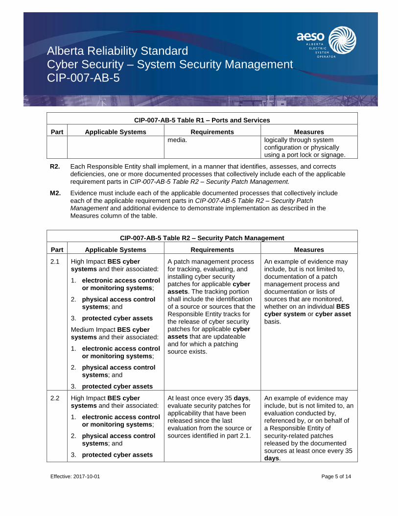
Alberta Reliability Standard Cyber Security – System Security Management CIP-007-AB-5
Effective: 2017-10-01
Page 5 of 14
CIP-007-AB-5 Table R1 – Ports and Services
Part Applicable Systems Requirements Measures
media. logically through system configuration or physically using a port lock or signage.
R2. Each Responsible Entity shall implement, in a manner that identifies, assesses, and corrects deficiencies, one or more documented processes that collectively include each of the applicable requirement parts in CIP‐007-AB‐5 Table R2 – Security Patch Management.
M2. Evidence must include each of the applicable documented processes that collectively include
each of the applicable requirement parts in CIP‐007-AB‐5 Table R2 – Security Patch Management and additional evidence to demonstrate implementation as described in the Measures column of the table.
CIP-007-AB-5 Table R2 – Security Patch Management
Part Applicable Systems Requirements Measures
2.1 High Impact BES cyber systems and their associated:
1. electronic access control or monitoring systems;
2. physical access control systems; and
3. protected cyber assets
Medium Impact BES cyber systems and their associated:
1. electronic access control or monitoring systems;
2. physical access control systems; and
3. protected cyber assets
A patch management process for tracking, evaluating, and installing cyber security patches for applicable cyber assets. The tracking portion shall include the identification of a source or sources that the Responsible Entity tracks for the release of cyber security patches for applicable cyber assets that are updateable and for which a patching source exists.
An example of evidence may include, but is not limited to, documentation of a patch management process and documentation or lists of sources that are monitored, whether on an individual BES cyber system or cyber asset basis.
2.2 High Impact BES cyber systems and their associated:
1. electronic access control or monitoring systems;
2. physical access control systems; and
3. protected cyber assets
At least once every 35 days, evaluate security patches for applicability that have been released since the last evaluation from the source or sources identified in part 2.1.
An example of evidence may include, but is not limited to, an evaluation conducted by, referenced by, or on behalf of a Responsible Entity of
security‐related patches released by the documented sources at least once every 35 days.

Alberta Reliability Standard Cyber Security – System Security Management CIP-007-AB-5
Effective: 2017-10-01
Page 6 of 14
CIP-007-AB-5 Table R2 – Security Patch Management
Part Applicable Systems Requirements Measures
Medium Impact BES cyber systems and their associated:
1. electronic access control or monitoring systems;
2. physical access control systems; and
3. protected cyber assets
2.3 High Impact BES cyber systems and their associated:
1. electronic access control or monitoring systems;
2. physical access control systems; and
3. protected cyber assets
Medium Impact BES cyber systems and their associated:
1. electronic access control or monitoring systems;
2. physical access control systems; and
3. protected cyber assets
For applicable patches identified in part 2.2, within 35 days of the evaluation completion, take one of the following actions:
apply the applicable patches; or
create a dated mitigation plan; or
revise an existing mitigation plan.
Mitigation plans shall include the Responsible Entity’s planned actions to mitigate the vulnerabilities addressed by each security patch and a timeframe to complete these mitigations.
Examples of evidence may include, but are not limited to:
records of the installation of the patch (e.g., exports from automated patch management tools that provide installation date, verification of BES cyber system component software revision, or registry exports that show software has been installed); or
a dated plan showing when and how the vulnerability will be addressed, to include documentation of the actions to be taken by the Responsible Entity to mitigate the vulnerabilities addressed by the security patch and a timeframe for the completion of these mitigations.
2.4 High Impact BES cyber systems and their associated:
1. electronic access control or monitoring systems;
2. physical access control systems; and
For each mitigation plan created or revised in part 2.3, implement the plan within the timeframe specified in the plan, unless a revision to the plan or an extension to the timeframe specified in part 2.3 is approved by the CIP senior
An example of evidence may include, but is not limited to, records of implementation of mitigations.

Alberta Reliability Standard Cyber Security – System Security Management CIP-007-AB-5
Effective: 2017-10-01
Page 7 of 14
CIP-007-AB-5 Table R2 – Security Patch Management
Part Applicable Systems Requirements Measures
3. protected cyber assets
Medium Impact BES cyber systems and their associated:
1. electronic access control or monitoring systems;
2. physical access control systems; and
3. protected cyber assets
manager or delegate.
R3. Each Responsible Entity shall implement, in a manner that identifies, assesses, and corrects deficiencies, one or more documented processes that collectively include each of the applicable requirement parts in CIP‐007-AB‐5 Table R3 – Malicious Code Prevention.
M3. Evidence must include each of the documented processes that collectively include each of the
applicable requirement parts in CIP‐007-AB‐5 Table R3 – Malicious Code Prevention and additional evidence to demonstrate implementation as described in the Measures column of the table.
CIP-007-AB-5 Table R3 – Malicious Code Prevention
Part Applicable Systems Requirements Measures
3.1 High Impact BES cyber systems and their associated:
1. electronic access control or monitoring systems;
2. physical access control systems; and
3. protected cyber assets
Medium Impact BES cyber systems and their associated:
1. electronic access control or monitoring systems;
2. physical access control systems; and
3. protected cyber assets
Deploy method(s) to deter, detect, or prevent malicious code.
An example of evidence may include, but is not limited to, records of the Responsible Entity’s performance of these processes (e.g., through traditional antivirus, system hardening, policies, etc.).
3.2 High Impact BES cyber systems and their associated:
Mitigate the threat of detected malicious code.
Examples of evidence may include, but are not limited to:
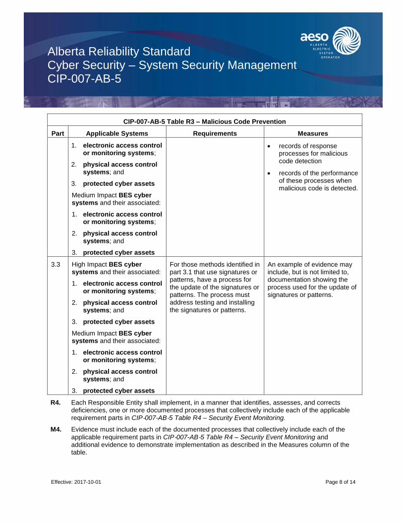
Alberta Reliability Standard Cyber Security – System Security Management CIP-007-AB-5
Effective: 2017-10-01
Page 8 of 14
CIP-007-AB-5 Table R3 – Malicious Code Prevention
Part Applicable Systems Requirements Measures
1. electronic access control or monitoring systems;
2. physical access control systems; and
3. protected cyber assets
Medium Impact BES cyber systems and their associated:
1. electronic access control or monitoring systems;
2. physical access control systems; and
3. protected cyber assets
records of response processes for malicious code detection
records of the performance of these processes when malicious code is detected.
3.3 High Impact BES cyber systems and their associated:
1. electronic access control or monitoring systems;
2. physical access control systems; and
3. protected cyber assets
Medium Impact BES cyber systems and their associated:
1. electronic access control or monitoring systems;
2. physical access control systems; and
3. protected cyber assets
For those methods identified in part 3.1 that use signatures or patterns, have a process for the update of the signatures or patterns. The process must address testing and installing the signatures or patterns.
An example of evidence may include, but is not limited to, documentation showing the process used for the update of signatures or patterns.
R4. Each Responsible Entity shall implement, in a manner that identifies, assesses, and corrects deficiencies, one or more documented processes that collectively include each of the applicable requirement parts in CIP‐007-AB‐5 Table R4 – Security Event Monitoring.
M4. Evidence must include each of the documented processes that collectively include each of the
applicable requirement parts in CIP‐007-AB‐5 Table R4 – Security Event Monitoring and additional evidence to demonstrate implementation as described in the Measures column of the table.

Alberta Reliability Standard Cyber Security – System Security Management CIP-007-AB-5
Effective: 2017-10-01
Page 9 of 14
CIP-007-AB-5 Table R4 – Security Event Monitoring
Part Applicable Systems Requirements Measures
4.1 High Impact BES cyber systems and their associated:
1. electronic access control or monitoring systems;
2. physical access control systems; and
3. protected cyber assets
Medium Impact BES cyber systems and their associated:
1. electronic access control or monitoring systems;
2. physical access control systems; and
3. protected cyber assets
Log events at the BES cyber system level (per BES cyber system capability) or at the cyber asset level (per cyber asset capability) for
identification of, and after‐the‐fact investigations of, cyber security incidents that includes, as a minimum, each of the following types of events:
4.1.1. detected successful login attempts;
4.1.2. detected failed access attempts and failed login attempts;
4.1.3. detected malicious code.
Examples of evidence may include, but are not limited to, a paper or system generated listing of event types for which the BES cyber system is capable of detecting and, for generated events, is configured to log. This listing must include the required types of events.
4.2 High Impact BES cyber systems and their associated:
1. electronic access control or monitoring systems;
2. physical access control systems; and
3. protected cyber assets
Medium Impact BES cyber systems with external routable connectivity and their associated:
1. electronic access control or monitoring systems;
2. physical access control systems; and
3. protected cyber assets
Generate alerts for security events that the Responsible Entity determines necessitates an alert, that includes, as a minimum, each of the following types of events (per cyber asset or BES cyber system capability):
4.2.1. detected malicious code from part 4.1; and
4.2.2. detected failure of part 4.1 event logging.
Examples of evidence may include, but are not limited to, paper or system generated listing of security events that the Responsible Entity determined necessitate alerts, including paper or system generated list showing how alerts are configured.
4.3 High Impact BES cyber systems and their associated:
Where technically feasible, retain applicable event logs identified in part 4.1 for at least
Examples of evidence may include, but are not limited to, documentation of the event log

Alberta Reliability Standard Cyber Security – System Security Management CIP-007-AB-5
Effective: 2017-10-01
Page 10 of 14
CIP-007-AB-5 Table R4 – Security Event Monitoring
Part Applicable Systems Requirements Measures
1. electronic access control or monitoring systems;
2. physical access control systems; and
3. protected cyber assets
Medium Impact BES cyber systems at control centres and their associated:
1. electronic access control or monitoring systems;
2. physical access control systems; and
3. protected cyber assets
the last 90 consecutive days except under CIP exceptional circumstances.
retention process and paper or system generated reports showing log retention configuration set at 90 days or greater.
4.4 High Impact BES cyber systems and their associated:
1. electronic access control or monitoring systems; and
2. protected cyber assets
Review a summarization or sampling of logged events as determined by the Responsible Entity at intervals no greater than 15 days to identify undetected cyber security incidents.
Examples of evidence may include, but are not limited to, documentation describing the review, any findings from the review (if any), and dated documentation showing the review occurred.
R5. Each Responsible Entity shall implement, in a manner that identifies, assesses, and corrects deficiencies, one or more documented processes that collectively include each of the applicable requirement parts in CIP‐007-AB‐5 Table R5 – System Access Controls.
M5. Evidence must include each of the applicable documented processes that collectively include
each of the applicable requirement parts in CIP‐007-AB‐5 Table 5 – System Access Controls and additional evidence to demonstrate implementation as described in the Measures column of the table.
CIP-007-AB-5 Table R5 – System Access Controls
Part Applicable Systems Requirements Measures
5.1 High Impact BES cyber systems and their associated:
1. electronic access control or monitoring systems;
2. physical access control
Have a method(s) to enforce authentication of interactive user access, where technically feasible.
An example of evidence may include, but is not limited to, documentation describing how access is authenticated.

Alberta Reliability Standard Cyber Security – System Security Management CIP-007-AB-5
Effective: 2017-10-01
Page 11 of 14
CIP-007-AB-5 Table R5 – System Access Controls
Part Applicable Systems Requirements Measures
systems; and
3. protected cyber assets
Medium Impact BES cyber systems at control centres and their associated:
1. electronic access control or monitoring systems;
2. physical access control systems; and
3. protected cyber assets
Medium Impact BES cyber systems with external routable connectivity and their associated:
1. electronic access control or monitoring systems;
2. physical access control systems; and
3. protected cyber assets
5.2 High Impact BES cyber systems and their associated:
1. electronic access control or monitoring systems;
2. physical access control systems; and
3. protected cyber assets
Medium Impact BES cyber systems and their associated:
1. electronic access control or monitoring systems;
2. physical access control systems; and
3. protected cyber assets
Identify and inventory all known enabled default or other generic account types, either by system, by groups of systems, by location, or by system type(s).
An example of evidence may include, but is not limited to, a listing of accounts by account types showing the enabled or generic account types in use for the BES cyber system.
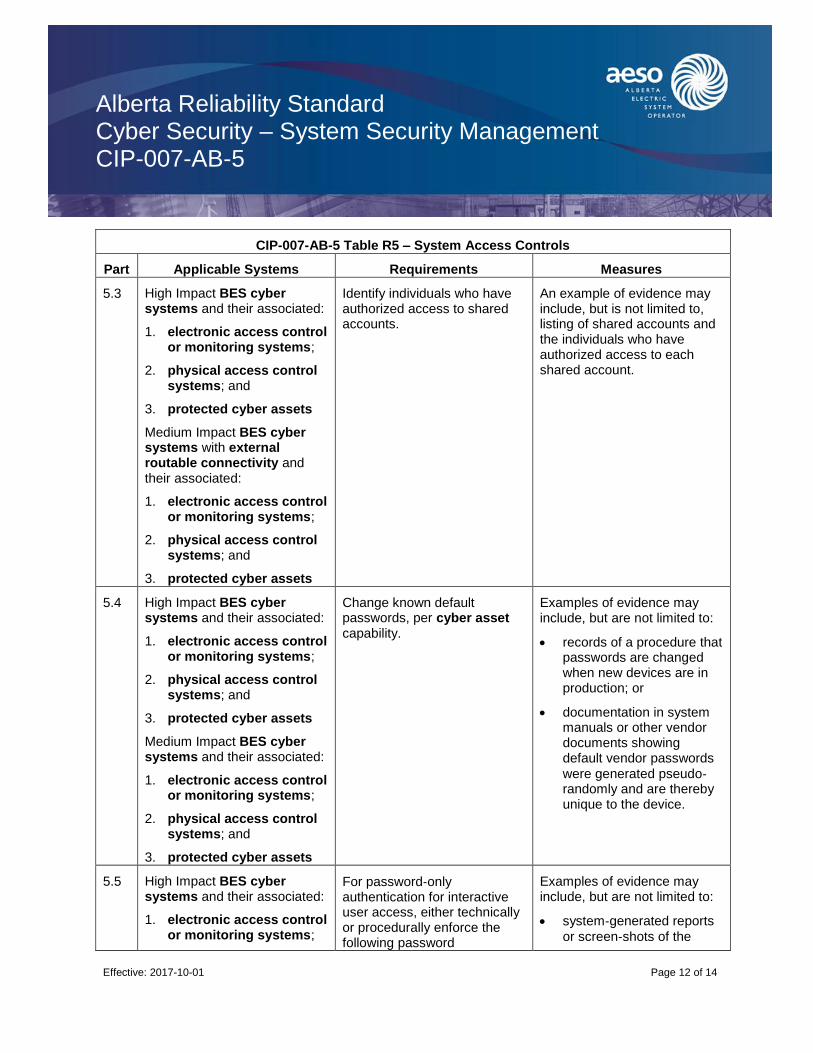
Alberta Reliability Standard Cyber Security – System Security Management CIP-007-AB-5
Effective: 2017-10-01
Page 12 of 14
CIP-007-AB-5 Table R5 – System Access Controls
Part Applicable Systems Requirements Measures
5.3 High Impact BES cyber systems and their associated:
1. electronic access control or monitoring systems;
2. physical access control systems; and
3. protected cyber assets
Medium Impact BES cyber systems with external routable connectivity and their associated:
1. electronic access control or monitoring systems;
2. physical access control systems; and
3. protected cyber assets
Identify individuals who have authorized access to shared accounts.
An example of evidence may include, but is not limited to, listing of shared accounts and the individuals who have authorized access to each shared account.
5.4 High Impact BES cyber systems and their associated:
1. electronic access control or monitoring systems;
2. physical access control systems; and
3. protected cyber assets
Medium Impact BES cyber systems and their associated:
1. electronic access control or monitoring systems;
2. physical access control systems; and
3. protected cyber assets
Change known default passwords, per cyber asset capability.
Examples of evidence may include, but are not limited to:
records of a procedure that passwords are changed when new devices are in production; or
documentation in system manuals or other vendor documents showing default vendor passwords
were generated pseudo‐randomly and are thereby unique to the device.
5.5 High Impact BES cyber systems and their associated:
1. electronic access control or monitoring systems;
For password‐only authentication for interactive user access, either technically or procedurally enforce the following password
Examples of evidence may include, but are not limited to:
system‐generated reports
or screen‐shots of the
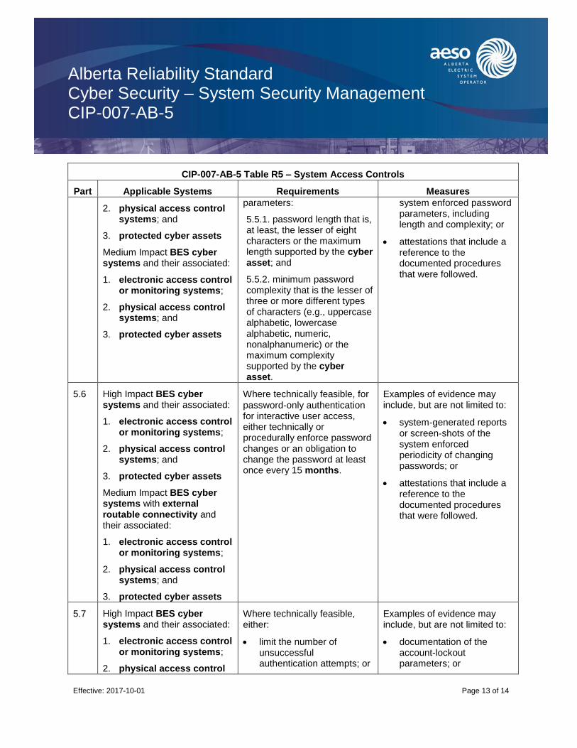
Alberta Reliability Standard Cyber Security – System Security Management CIP-007-AB-5
Effective: 2017-10-01
Page 13 of 14
CIP-007-AB-5 Table R5 – System Access Controls
Part Applicable Systems Requirements Measures
2. physical access control systems; and
3. protected cyber assets
Medium Impact BES cyber systems and their associated:
1. electronic access control or monitoring systems;
2. physical access control systems; and
3. protected cyber assets
parameters:
5.5.1. password length that is, at least, the lesser of eight characters or the maximum length supported by the cyber asset; and
5.5.2. minimum password complexity that is the lesser of three or more different types of characters (e.g., uppercase alphabetic, lowercase alphabetic, numeric, nonalphanumeric) or the maximum complexity supported by the cyber asset.
system enforced password parameters, including length and complexity; or
attestations that include a reference to the documented procedures that were followed.
5.6 High Impact BES cyber systems and their associated:
1. electronic access control or monitoring systems;
2. physical access control systems; and
3. protected cyber assets
Medium Impact BES cyber systems with external routable connectivity and their associated:
1. electronic access control or monitoring systems;
2. physical access control systems; and
3. protected cyber assets
Where technically feasible, for
password‐only authentication for interactive user access, either technically or procedurally enforce password changes or an obligation to change the password at least once every 15 months.
Examples of evidence may include, but are not limited to:
system‐generated reports or screen‐shots of the system enforced periodicity of changing passwords; or
attestations that include a reference to the documented procedures that were followed.
5.7 High Impact BES cyber systems and their associated:
1. electronic access control or monitoring systems;
2. physical access control
Where technically feasible, either:
limit the number of unsuccessful authentication attempts; or
Examples of evidence may include, but are not limited to:
documentation of the account-lockout parameters; or

Alberta Reliability Standard Cyber Security – System Security Management CIP-007-AB-5
Effective: 2017-10-01
Page 14 of 14
CIP-007-AB-5 Table R5 – System Access Controls
Part Applicable Systems Requirements Measures
systems; and
3. protected cyber assets
Medium Impact BES cyber systems at control centres and their associated:
1. electronic access control or monitoring systems;
2. physical access control systems; and
3. protected cyber assets
generate alerts after a threshold of unsuccessful authentication attempts.
rules in the alerting configuration showing how the system notified individuals after a determined number of unsuccessful login attempts.
Revision History
Date Description
2017-10-01 Initial release.
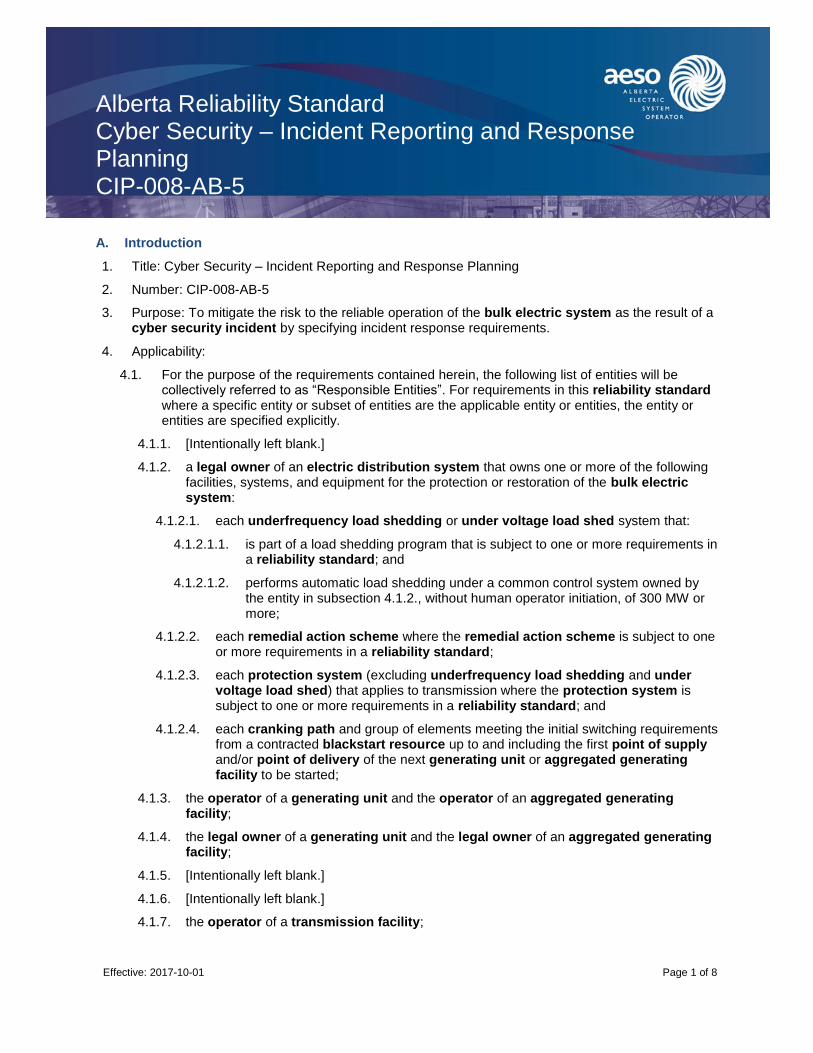
Alberta Reliability Standard Cyber Security – Incident Reporting and Response Planning CIP-008-AB-5
Effective: 2017-10-01
Page 1 of 8
A. Introduction
1. Title: Cyber Security – Incident Reporting and Response Planning
2. Number: CIP-008-AB-5
3. Purpose: To mitigate the risk to the reliable operation of the bulk electric system as the result of a cyber security incident by specifying incident response requirements.
4. Applicability:
4.1. For the purpose of the requirements contained herein, the following list of entities will be collectively referred to as “Responsible Entities”. For requirements in this reliability standard where a specific entity or subset of entities are the applicable entity or entities, the entity or entities are specified explicitly.
4.1.1. [Intentionally left blank.]
4.1.2. a legal owner of an electric distribution system that owns one or more of the following facilities, systems, and equipment for the protection or restoration of the bulk electric system:
4.1.2.1. each underfrequency load shedding or under voltage load shed system that:
4.1.2.1.1. is part of a load shedding program that is subject to one or more requirements in a reliability standard; and
4.1.2.1.2. performs automatic load shedding under a common control system owned by the entity in subsection 4.1.2., without human operator initiation, of 300 MW or more;
4.1.2.2. each remedial action scheme where the remedial action scheme is subject to one or more requirements in a reliability standard;
4.1.2.3. each protection system (excluding underfrequency load shedding and under voltage load shed) that applies to transmission where the protection system is subject to one or more requirements in a reliability standard; and
4.1.2.4. each cranking path and group of elements meeting the initial switching requirements from a contracted blackstart resource up to and including the first point of supply and/or point of delivery of the next generating unit or aggregated generating facility to be started;
4.1.3. the operator of a generating unit and the operator of an aggregated generating facility;
4.1.4. the legal owner of a generating unit and the legal owner of an aggregated generating facility;
4.1.5. [Intentionally left blank.]
4.1.6. [Intentionally left blank.]
4.1.7. the operator of a transmission facility;

Alberta Reliability Standard Cyber Security – Incident Reporting and Response Planning CIP-008-AB-5
Effective: 2017-10-01
Page 2 of 8
4.1.8. the legal owner of a transmission facility; and
4.1.9. the ISO.
4.2. For the purpose of the requirements contained herein, the following facilities, systems, and equipment owned by each Responsible Entity in subsection 4.1 above are those to which these requirements are applicable. For requirements in this reliability standard where a specific type of facilities, system, or equipment or subset of facilities, systems, and equipment are applicable, these are specified explicitly.
4.2.1. One or more of the following facilities, systems and equipment that operate at, or control elements that operate at, a nominal voltage of 25 kV or less and are owned by a legal owner of an electric distribution system or a legal owner of a transmission facility for the protection or restoration of the bulk electric system:
4.2.1.1. each underfrequency load shedding or under voltage load shed system that:
4.2.1.1.1. is part of a load shedding program that is subject to one or more requirements in a reliability standard; and
4.2.1.1.2. performs automatic load shedding under a common control system owned by one or more of the entities in subsection 4.2.1, without human operator initiation, of 300 MW or more;
4.2.1.2. each remedial action scheme where the remedial action scheme is subject to one or more requirements in a reliability standard;
4.2.1.3. each protection system (excluding underfrequency load shedding and under voltage load shed) that applies to transmission where the protection system is subject to one or more requirements in a reliability standard; and
4.2.1.4. each cranking path and group of elements meeting the initial switching requirements from a contracted blackstart resource up to and including the first point of supply and/or point of delivery of the next generating unit or aggregated generating facility to be started;
4.2.2. Responsible Entities listed in subsection 4.1 other than a legal owner of an electric distribution system are responsible for:
4.2.2.1. each transmission facility that is part of the bulk electric system except each transmission facility that:
4.2.2.1.1. is a transformer with fewer than 2 windings at 100 kV or higher and does not connect a contracted blackstart resource;
4.2.2.1.2. radially connects only to load;
4.2.2.1.3. radially connects only to one or more generating units or aggregated generating facilities with a combined maximum authorized real power of less than or equal to 67.5 MW and does not connect a contracted blackstart resource; or
4.2.2.1.4. radially connects to load and one or more generating units or aggregated generating facilities that have a combined maximum authorized real power

Alberta Reliability Standard Cyber Security – Incident Reporting and Response Planning CIP-008-AB-5
Effective: 2017-10-01
Page 3 of 8
of less than or equal to 67.5 MW and does not connect a contracted blackstart resource;
4.2.2.2. a reactive power resource that is dedicated to supplying or absorbing reactive power that is connected at 100 kV or higher, or through a dedicated transformer with a high-side voltage of 100 kV or higher, except those reactive power resources operated by an end-use customer for its own use;
4.2.2.3. a generating unit that is:
4.2.2.3.1. directly connected to the bulk electric system and has a maximum authorized real power rating greater than 18 MW unless the generating unit is part of an industrial complex;
4.2.2.3.2. within a power plant which:
4.2.2.3.2.1. is not part of an aggregated generating facility;
4.2.2.3.2.2. is directly connected to the bulk electric system; and
4.2.2.3.2.3. has a combined maximum authorized real power rating greater than 67.5 MW unless the power plant is part of an industrial complex;
4.2.2.3.3. within an industrial complex with supply transmission service greater than 67.5 MW; or
4.2.2.3.4. a contracted blackstart resource;
4.2.2.4. an aggregated generating facility that is:
4.2.2.4.1. directly connected to the bulk electric system and has a maximum authorized real power rating greater than 67.5 MW unless the aggregated generating facility is part of an industrial complex;
4.2.2.4.2. within an industrial complex with supply transmission service greater than 67.5 MW; or
4.2.2.4.3. a contracted blackstart resource;
and
4.2.2.5. control centres and backup control centres.
4.2.3. The following are exempt from this reliability standard:
4.2.3.1. [Intentionally left blank.]
4.2.3.2. cyber assets associated with communication networks and data communication links between discrete electronic security perimeters.
4.2.3.3. [Intentionally left blank.]
4.2.3.4. for the legal owner of an electric distribution system, the systems and equipment that are not included in subsection 4.2.1 above.
4.2.3.5. Responsible Entities that identify that they have no BES cyber systems categorized
as High Impact or Medium Impact according to the CIP‐002-AB‐5.1 identification and
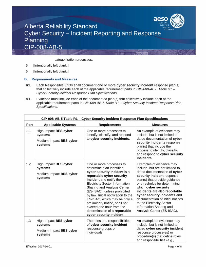
Alberta Reliability Standard Cyber Security – Incident Reporting and Response Planning CIP-008-AB-5
Effective: 2017-10-01
Page 4 of 8
categorization processes.
5. [Intentionally left blank.]
6. [Intentionally left blank.]
B. Requirements and Measures
R1. Each Responsible Entity shall document one or more cyber security incident response plan(s)
that collectively include each of the applicable requirement parts in CIP‐008-AB‐5 Table R1 – Cyber Security Incident Response Plan Specifications.
M1. Evidence must include each of the documented plan(s) that collectively include each of the applicable requirement parts in CIP‐008-AB‐5 Table R1 – Cyber Security Incident Response Plan Specifications.
CIP-008-AB-5 Table R1 – Cyber Security Incident Response Plan Specifications
Part Applicable Systems Requirements Measures
1.1 High Impact BES cyber systems
Medium Impact BES cyber systems
One or more processes to identify, classify, and respond to cyber security incidents.
An example of evidence may include, but is not limited to, dated documentation of cyber security incidents response plan(s) that include the process to identify, classify, and respond to cyber security incidents.
1.2 High Impact BES cyber systems
Medium Impact BES cyber systems
One or more processes to determine if an identified cyber security incident is a reportable cyber security incident and notify the Electricity Sector Information Sharing and Analysis Center (ES‐ISAC), unless prohibited by law. Initial notification to the
ES‐ISAC, which may be only a preliminary notice, shall not exceed one hour from the determination of a reportable cyber security incident.
Examples of evidence may include, but are not limited to, dated documentation of cyber security incident response plan(s) that provide guidance or thresholds for determining which cyber security incidents are also reportable cyber security incidents and documentation of initial notices to the Electricity Sector Information Sharing and
Analysis Center (ES‐ISAC).
1.3 High Impact BES cyber systems
Medium Impact BES cyber systems
The roles and responsibilities of cyber security incident response groups or individuals.
An example of evidence may include, but is not limited to, dated cyber security incident response process(es) or procedure(s) that define roles and responsibilities (e.g.,

Alberta Reliability Standard Cyber Security – Incident Reporting and Response Planning CIP-008-AB-5
Effective: 2017-10-01
Page 5 of 8
CIP-008-AB-5 Table R1 – Cyber Security Incident Response Plan Specifications
Part Applicable Systems Requirements Measures
monitoring, reporting, initiating, documenting, etc.) of cyber security incident response groups or individuals.
1.4 High Impact BES cyber systems
Medium Impact BES cyber systems
Incident handling procedures for cyber security incidents.
An example of evidence may include, but is not limited to, dated for cyber security incident response process(es) or procedure(s) that address incident handling (e.g., containment, eradication, recovery/incident resolution).
R2. Each Responsible Entity shall implement each of its documented cyber security incident
response plans to collectively include each of the applicable requirement parts in CIP‐008-AB‐5 Table R2 – Cyber Security Incident Response Plan Implementation and Testing.
M2. Evidence must include, but is not limited to, documentation that collectively demonstrates implementation of each of the applicable requirement parts in CIP‐008-AB‐5 Table R2 – Cyber Security Incident Response Plan Implementation and Testing.
CIP-008-AB-5 Table R2 – Cyber Security Incident Response Plan Implementation and Testing
Part Applicable Systems Requirements Measures
2.1 High Impact BES cyber systems
Medium Impact BES cyber systems
Test each cyber security incident response plan(s) at least once every 15 months:
by responding to an actual reportable cyber security incident;
with a paper drill or tabletop exercise of a reportable cyber security incident; or
with an operational exercise of a reportable cyber security incident.
Examples of evidence may include, but are not limited to,
dated evidence of a lessons‐learned report that includes a summary of the test or a compilation of notes, logs, and communication resulting from the test. Types of exercises may include discussion or operations based exercises.
2.2 High Impact BES cyber systems
Medium Impact BES cyber
Use the cyber security incident response plan(s) under Requirement R1 when responding to a reportable
Examples of evidence may include, but are not limited to, incident reports, logs, and notes that were kept during the

Alberta Reliability Standard Cyber Security – Incident Reporting and Response Planning CIP-008-AB-5
Effective: 2017-10-01
Page 6 of 8
CIP-008-AB-5 Table R2 – Cyber Security Incident Response Plan Implementation and Testing
Part Applicable Systems Requirements Measures
systems cyber security incident or performing an exercise of a reportable cyber security incident. Document deviations from the plan(s) taken during the response to the incident or exercise.
incident response process,
and follow‐up documentation that describes deviations taken from the plan during the incident or exercise.
2.3 High Impact BES cyber systems
Medium Impact BES cyber systems
Retain records related to reportable cyber security incident.
An example of evidence may include, but is not limited to, dated documentation, such as security logs, police reports, emails, response forms or checklists, forensic analysis results, restoration records,
and post‐incident review notes related to reportable cyber security incidents.
R3. Each Responsible Entity shall maintain each of its cyber security incident response plans
according to each of the applicable requirement parts in CIP‐008-AB‐5 Table R3 – Cyber Security Incident Response Plan Review, Update, and Communication.
M3. Evidence must include, but is not limited to, documentation that collectively demonstrates maintenance of each cyber security incident response plan according to the applicable
requirement parts in CIP‐008-AB‐5 Table R3 – Cyber Security Incident Response Plan Review, Update, and Communication.
CIP-008-AB-5 Table R3 – Cyber Security Incident Response Plan Review, Update, and Communication
Part Applicable Systems Requirements Measures
3.1 High Impact BES cyber systems
Medium Impact BES cyber systems
No later than 90 days after completion of a cyber security incident response plan(s) test or actual reportable cyber security incident response:
3.1.1. document any lessons learned or document the absence of any lessons learned;
3.1.2. update the cyber
An example of evidence may include, but is not limited to, all of the following:
1. dated documentation of post incident(s) review
meeting notes or follow‐up report showing lessons learned associated with the cyber security incident response plan(s) test or actual reportable cyber security incident

Alberta Reliability Standard Cyber Security – Incident Reporting and Response Planning CIP-008-AB-5
Effective: 2017-10-01
Page 7 of 8
CIP-008-AB-5 Table R3 – Cyber Security Incident Response Plan Review, Update, and Communication
Part Applicable Systems Requirements Measures
security incident response plan based on any documented lessons learned associated with the plan; and
3.1.3. notify each person or group with a defined role in the cyber security incident response plan of the updates to the cyber security incident response plan based on any documented lessons learned.
response or dated documentation stating there were no lessons learned;
2. dated and revised cyber security incident response plan showing any changes based on the lessons learned; and
3. evidence of plan update distribution including, but not limited to:
emails;
USPS or other mail service;
electronic distribution system; or
training sign‐in sheets.
3.2 High Impact BES cyber systems
Medium Impact BES cyber systems
No later than 60 days after a change to the roles or responsibilities, cyber security incident response groups or individuals, or technology that the Responsible Entity determines would impact the ability to execute the plan:
3.2.1. update the cyber security incident response plan(s); and
3.2.2. notify each person or group with a defined role in the cyber security incident response plan of the updates.
An example of evidence may include, but is not limited to:
1. dated and revised cyber security incident response plan with changes to the roles or responsibilities, responders or technology; and
2. evidence of plan update distribution including, but not limited to:
emails;
USPS or other mail service;
electronic distribution system; or
training sign‐in sheets.

Alberta Reliability Standard Cyber Security – Incident Reporting and Response Planning CIP-008-AB-5
Effective: 2017-10-01
Page 8 of 8
Revision History
Date Description
2017-10-01 Initial release.

Alberta Reliability Standard Cyber Security – Recovery Plans for BES Cyber Systems CIP-009-AB-5
Effective: 2017-10-01
Page 1 of 9
A. Introduction
1. Title: Cyber Security – Recovery Plans for BES Cyber Systems
2. Number: CIP-009-AB-5
3. Purpose: To recover reliability functions performed by BES cyber systems by specifying recovery plan requirements in support of the continued stability, operability, and reliability of the bulk electric system.
4. Applicability:
4.1. For the purpose of the requirements contained herein, the following list of entities will be collectively referred to as “Responsible Entities”. For requirements in this reliability standard where a specific entity or subset of entities are the applicable entity or entities, the entity or entities are specified explicitly.
4.1.1. [Intentionally left blank.]
4.1.2. a legal owner of an electric distribution system that owns one or more of the following facilities, systems, and equipment for the protection or restoration of the bulk electric system:
4.1.2.1. each underfrequency load shedding or under voltage load shed system that:
4.1.2.1.1. is part of a load shedding program that is subject to one or more requirements in a reliability standard; and
4.1.2.1.2. performs automatic load shedding under a common control system owned by the entity in subsection 4.1.2., without human operator initiation, of 300 MW or more;
4.1.2.2. each remedial action scheme where the remedial action scheme is subject to one or more requirements in a reliability standard;
4.1.2.3. each protection system (excluding underfrequency load shedding and under voltage load shed) that applies to transmission where the protection system is subject to one or more requirements in a reliability standard; and
4.1.2.4. each cranking path and group of elements meeting the initial switching requirements from a contracted blackstart resource up to and including the first point of supply and/or point of delivery of the next generating unit or aggregated generating facility to be started;
4.1.3. the operator of a generating unit and the operator of an aggregated generating facility;
4.1.4. the legal owner of a generating unit and the legal owner of an aggregated generating facility;
4.1.5. [Intentionally left blank.]
4.1.6. [Intentionally left blank.]
4.1.7. the operator of a transmission facility;

Alberta Reliability Standard Cyber Security – Recovery Plans for BES Cyber Systems CIP-009-AB-5
Effective: 2017-10-01
Page 2 of 9
4.1.8. the legal owner of a transmission facility; and
4.1.9. the ISO.
4.2. For the purpose of the requirements contained herein, the following facilities, systems, and equipment owned by each Responsible Entity in subsection 4.1 above are those to which these requirements are applicable. For requirements in this reliability standard where a specific type of facilities, system, or equipment or subset of facilities, systems, and equipment are applicable, these are specified explicitly.
4.2.1. One or more of the following facilities, systems and equipment that operate at, or control elements that operate at, a nominal voltage of 25 kV or less and are owned by a legal owner of an electric distribution system or a legal owner of a transmission facility for the protection or restoration of the bulk electric system:
4.2.1.1. each underfrequency load shedding or under voltage load shed system that:
4.2.1.1.1. is part of a load shedding program that is subject to one or more requirements in a reliability standard; and
4.2.1.1.2. performs automatic load shedding under a common control system owned by one or more of the entities in subsection 4.2.1, without human operator initiation, of 300 MW or more;
4.2.1.2. each remedial action scheme where the remedial action scheme is subject to one or more requirements in a reliability standard;
4.2.1.3. each protection system (excluding underfrequency load shedding and under voltage load shed) that applies to transmission where the protection system is subject to one or more requirements in a reliability standard;
4.2.1.4. each cranking path and group of elements meeting the initial switching requirements from a contracted blackstart resource up to and including the first point of supply and/or point of delivery of the next generating unit or aggregated generating facility to be started;
4.2.2. Responsible Entities listed in subsection 4.1 other than a legal owner of an electric distribution system are responsible for:
4.2.2.1. each transmission facility that is part of the bulk electric system except each transmission facility that:
4.2.2.1.1. is a transformer with fewer than 2 windings at 100 kV or higher and does not connect a contracted blackstart resource;
4.2.2.1.2. radially connects only to load;
4.2.2.1.3. radially connects only to one or more generating units or aggregated generating facilities with a combined maximum authorized real power of less than or equal to 67.5 MW and does not connect a contracted blackstart resource; or
4.2.2.1.4. radially connects to load and one or more generating units or aggregated generating facilities that have a combined maximum authorized real power of less than or equal to 67.5 MW and does not connect a contracted blackstart

Alberta Reliability Standard Cyber Security – Recovery Plans for BES Cyber Systems CIP-009-AB-5
Effective: 2017-10-01
Page 3 of 9
resource;
4.2.2.2. a reactive power resource that is dedicated to supplying or absorbing reactive power that is connected at 100 kV or higher, or through a dedicated transformer with a high-side voltage of 100 kV or higher, except those reactive power resources operated by an end-use customer for its own use;
4.2.2.3. a generating unit that is:
4.2.2.3.1. directly connected to the bulk electric system and has a maximum authorized real power rating greater than 18 MW unless the generating unit is part of an industrial complex;
4.2.2.3.2. within a power plant which:
4.2.2.3.2.1. is not part of an aggregated generating facility;
4.2.2.3.2.2. is directly connected to the bulk electric system; and
4.2.2.3.2.3. has a combined maximum authorized real power rating greater than 67.5 MW unless the power plant is part of an industrial complex;
4.2.2.3.3. within an industrial complex with supply transmission service greater than 67.5 MW; or
4.2.2.3.4. a contracted blackstart resource;
4.2.2.4. an aggregated generating facility that is:
4.2.2.4.1. directly connected to the bulk electric system and has a maximum authorized real power rating greater than 67.5 MW unless the aggregated generating facility is part of an industrial complex;
4.2.2.4.2. within an industrial complex with supply transmission service greater than 67.5 MW; or
4.2.2.4.3. a contracted blackstart resource;
and
4.2.2.5. control centres and backup control centres.
4.2.3. The following are exempt from this reliability standard:
4.2.3.1. [Intentionally left blank.]
4.2.3.2. cyber assets associated with communication networks and data communication links between discrete electronic security perimeters.
4.2.3.3. [Intentionally left blank.]
4.2.3.4. for the legal owner of an electric distribution system, the systems and equipment that are not included in subsection 4.2.1 above.
4.2.3.5. Responsible Entities that identify that they have no BES cyber systems categorized
as High Impact or Medium Impact according to the CIP‐002-AB‐5.1 identification and categorization processes.

Alberta Reliability Standard Cyber Security – Recovery Plans for BES Cyber Systems CIP-009-AB-5
Effective: 2017-10-01
Page 4 of 9
5. [Intentionally left blank.]
6. [Intentionally left blank.]
B. Requirements and Measures
R1. Each Responsible Entity shall have one or more documented recovery plans that collectively include
each of the applicable requirement parts in CIP‐009-AB‐5 Table R1 – Recovery Plan Specifications.
M1. Evidence must include the documented recovery plan(s) that collectively include the applicable
requirement parts in CIP‐009-AB‐5 Table R1 – Recovery Plan Specifications.
CIP-009-AB-5 Table R1 – Recovery Plan Specifications
Part Applicable Systems Requirements Measures
1.1 High Impact BES cyber systems and their associated:
1. electronic access control or monitoring systems; and
2. physical access control systems
Medium Impact BES cyber systems and their associated:
1. electronic access control or monitoring systems; and
2. physical access control systems
Conditions for activation of the recovery plan(s).
An example of evidence may include, but is not limited to, one or more plans that include language identifying conditions for activation of the recovery plan(s).
1.2 High Impact BES cyber systems and their associated:
1. electronic access control or monitoring systems; and
2. physical access control systems
Medium Impact BES cyber systems and their associated:
1. electronic access control or monitoring systems; and
2. physical access control
Roles and responsibilities of responders.
An example of evidence may include, but is not limited to, one or more recovery plans that include language identifying the roles and responsibilities of responders.

Alberta Reliability Standard Cyber Security – Recovery Plans for BES Cyber Systems CIP-009-AB-5
Effective: 2017-10-01
Page 5 of 9
CIP-009-AB-5 Table R1 – Recovery Plan Specifications
Part Applicable Systems Requirements Measures
systems
1.3 High Impact BES cyber systems and their associated:
1. electronic access control or monitoring systems; and
2. physical access control systems
Medium Impact BES cyber systems and their associated:
1. electronic access control or monitoring systems; and
2. physical access control systems
One or more processes for the backup and storage of information required to recover BES cyber system functionality.
An example of evidence may include, but is not limited to, documentation of specific processes for the backup and storage of information required to recover BES cyber system functionality.
1.4 High Impact BES cyber systems and their associated:
1. electronic access control or monitoring systems; and
2. physical access control systems
Medium Impact BES cyber systems at control centres and their associated:
1. electronic access control or monitoring systems; and
2. physical access control systems
One or more processes to verify the successful completion of the backup processes in Part 1.3 and to address any backup failures.
An example of evidence may include, but is not limited to, logs, workflow or other documentation confirming that the backup process completed successfully and backup failures, if any, were addressed.
1.5 High Impact BES cyber systems and their associated:
1. electronic access control or monitoring systems; and
2. physical access control systems
One or more processes to preserve data, per cyber asset capability, for determining the cause of a cyber security incident that triggers activation of the recovery plan(s). Data preservation should not
An example of evidence may include, but is not limited to, procedures to preserve data, such as preserving a corrupted drive or making a data mirror of the system before proceeding with recovery.
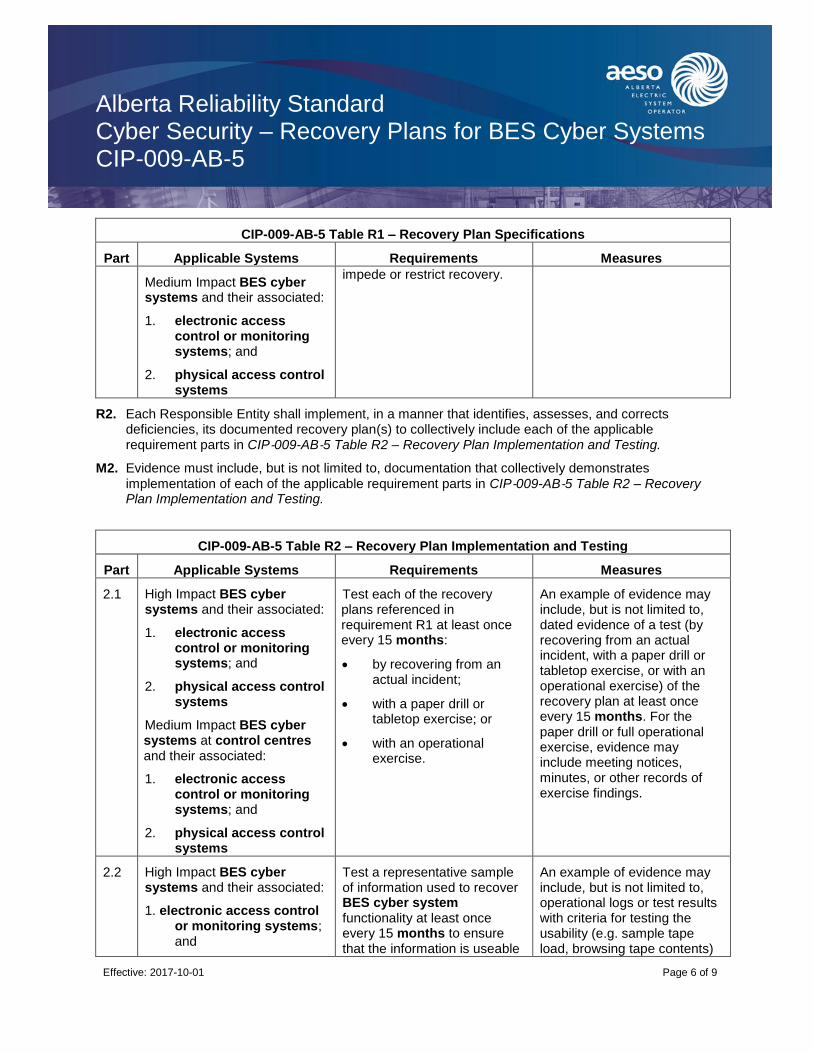
Alberta Reliability Standard Cyber Security – Recovery Plans for BES Cyber Systems CIP-009-AB-5
Effective: 2017-10-01
Page 6 of 9
CIP-009-AB-5 Table R1 – Recovery Plan Specifications
Part Applicable Systems Requirements Measures
Medium Impact BES cyber systems and their associated:
1. electronic access control or monitoring systems; and
2. physical access control systems
impede or restrict recovery.
R2. Each Responsible Entity shall implement, in a manner that identifies, assesses, and corrects deficiencies, its documented recovery plan(s) to collectively include each of the applicable requirement parts in CIP‐009-AB‐5 Table R2 – Recovery Plan Implementation and Testing.
M2. Evidence must include, but is not limited to, documentation that collectively demonstrates
implementation of each of the applicable requirement parts in CIP‐009-AB‐5 Table R2 – Recovery Plan Implementation and Testing.
CIP-009-AB-5 Table R2 – Recovery Plan Implementation and Testing
Part Applicable Systems Requirements Measures
2.1 High Impact BES cyber systems and their associated:
1. electronic access control or monitoring systems; and
2. physical access control systems
Medium Impact BES cyber systems at control centres and their associated:
1. electronic access control or monitoring systems; and
2. physical access control systems
Test each of the recovery plans referenced in requirement R1 at least once every 15 months:
by recovering from an actual incident;
with a paper drill or tabletop exercise; or
with an operational exercise.
An example of evidence may include, but is not limited to, dated evidence of a test (by recovering from an actual incident, with a paper drill or tabletop exercise, or with an operational exercise) of the recovery plan at least once every 15 months. For the paper drill or full operational exercise, evidence may include meeting notices, minutes, or other records of exercise findings.
2.2 High Impact BES cyber systems and their associated:
1. electronic access control or monitoring systems; and
Test a representative sample of information used to recover BES cyber system functionality at least once every 15 months to ensure that the information is useable
An example of evidence may include, but is not limited to, operational logs or test results with criteria for testing the usability (e.g. sample tape load, browsing tape contents)
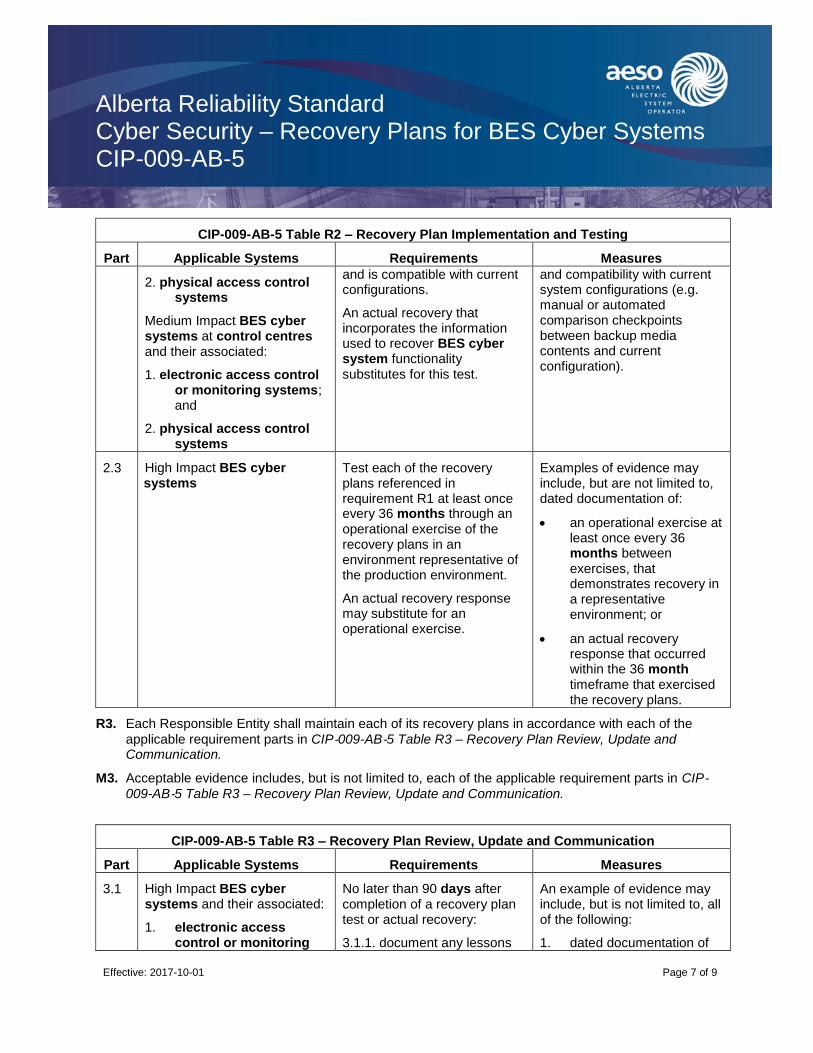
Alberta Reliability Standard Cyber Security – Recovery Plans for BES Cyber Systems CIP-009-AB-5
Effective: 2017-10-01
Page 7 of 9
CIP-009-AB-5 Table R2 – Recovery Plan Implementation and Testing
Part Applicable Systems Requirements Measures
2. physical access control systems
Medium Impact BES cyber systems at control centres and their associated:
1. electronic access control or monitoring systems; and
2. physical access control systems
and is compatible with current configurations.
An actual recovery that incorporates the information used to recover BES cyber system functionality substitutes for this test.
and compatibility with current system configurations (e.g. manual or automated comparison checkpoints between backup media contents and current configuration).
2.3 High Impact BES cyber systems
Test each of the recovery plans referenced in requirement R1 at least once every 36 months through an operational exercise of the recovery plans in an environment representative of the production environment.
An actual recovery response may substitute for an operational exercise.
Examples of evidence may include, but are not limited to, dated documentation of:
an operational exercise at least once every 36 months between exercises, that demonstrates recovery in a representative environment; or
an actual recovery response that occurred within the 36 month timeframe that exercised the recovery plans.
R3. Each Responsible Entity shall maintain each of its recovery plans in accordance with each of the
applicable requirement parts in CIP‐009-AB‐5 Table R3 – Recovery Plan Review, Update and Communication.
M3. Acceptable evidence includes, but is not limited to, each of the applicable requirement parts in CIP‐009-AB‐5 Table R3 – Recovery Plan Review, Update and Communication.
CIP-009-AB-5 Table R3 – Recovery Plan Review, Update and Communication
Part Applicable Systems Requirements Measures
3.1 High Impact BES cyber systems and their associated:
1. electronic access control or monitoring
No later than 90 days after completion of a recovery plan test or actual recovery:
3.1.1. document any lessons
An example of evidence may include, but is not limited to, all of the following:
1. dated documentation of
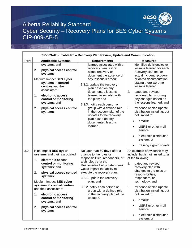
Alberta Reliability Standard Cyber Security – Recovery Plans for BES Cyber Systems CIP-009-AB-5
Effective: 2017-10-01
Page 8 of 9
CIP-009-AB-5 Table R3 – Recovery Plan Review, Update and Communication
Part Applicable Systems Requirements Measures
systems; and
2. physical access control systems
Medium Impact BES cyber systems at control centres and their associated:
1. electronic access control or monitoring systems; and
2. physical access control systems
learned associated with a recovery plan test or actual recovery or document the absence of any lessons learned;
3.1.2. update the recovery plan based on any documented lessons learned associated with the plan; and
3.1.3. notify each person or group with a defined role in the recovery plan of the updates to the recovery plan based on any documented lessons learned.
identified deficiencies or lessons learned for each recovery plan test or actual incident recovery or dated documentation stating there were no lessons learned;
2. dated and revised recovery plan showing any changes based on the lessons learned; and
3. evidence of plan update distribution including, but not limited to:
emails;
USPS or other mail service;
electronic distribution system; or
training sign-in sheets.
3.2 High Impact BES cyber systems and their associated:
1. electronic access control or monitoring systems; and
2. physical access control systems
Medium Impact BES cyber systems at control centres and their associated:
1. electronic access control or monitoring systems; and
2. physical access control systems
No later than 60 days after a change to the roles or responsibilities, responders, or technology that the Responsible Entity determines would impact the ability to execute the recovery plan:
3.2.1. update the recovery plan; and
3.2.2. notify each person or group with a defined role in the recovery plan of the updates.
An example of evidence may include, but is not limited to, all of the following:
1. dated and revised recovery plan with changes to the roles or responsibilities, responders, or technology; and
2. evidence of plan update distribution including, but not limited to:
emails;
USPS or other mail service;
electronic distribution system; or
Alberta Reliability Standard Cyber Security – Recovery Plans for BES Cyber Systems CIP-009-AB-5
Effective: 2017-10-01
Page 9 of 9
CIP-009-AB-5 Table R3 – Recovery Plan Review, Update and Communication
Part Applicable Systems Requirements Measures
training sign-in sheets.
Revision History
Date Description
2017-10-01 Initial release.

Alberta Reliability Standard Cyber Security – Configuration Change Management and Vulnerability Assessments CIP-010-AB-1
Effective: 2017-10-01
Page 1 of 9
A. Introduction
1. Title: Cyber Security – Configuration Change Management and Vulnerability Assessments
2. Number: CIP-010-AB-1
3. Purpose: To prevent and detect unauthorized changes to BES cyber systems by specifying configuration change management and vulnerability assessment requirements in support of protecting BES cyber systems from compromise that could lead to misoperation or instability in the bulk electric system.
4. Applicability:
4.1. For the purpose of the requirements contained herein, the following list of entities will be collectively referred to as “Responsible Entities”. For requirements in this reliability standard where a specific entity or subset of entities are the applicable entity or entities, the entity or entities are specified explicitly.
4.1.1. [Intentionally left blank.]
4.1.2. a legal owner of an electric distribution system that owns one or more of the following facilities, systems, and equipment for the protection or restoration of the bulk electric system:
4.1.2.1. each underfrequency load shedding or under voltage load shed system that:
4.1.2.1.1. is part of a load shedding program that is subject to one or more requirements in a reliability standard; and
4.1.2.1.2. performs automatic load shedding under a common control system owned by the entity in subsection 4.1.2., without human operator initiation, of 300 MW or more;
4.1.2.2. each remedial action scheme where the remedial action scheme is subject to one or more requirements in a reliability standard;
4.1.2.3. each protection system (excluding underfrequency load shedding and under voltage load shed) that applies to transmission where the protection system is subject to one or more requirements in a reliability standard; and
4.1.2.4. each cranking path and group of elements meeting the initial switching requirements from a contracted blackstart resource up to and including the first point of supply and/or point of delivery of the next generating unit or aggregated generating facility to be started;
4.1.3. the operator of a generating unit and the operator of an aggregated generating facility;
4.1.4. the legal owner of a generating unit and the legal owner of an aggregated generating facility;
4.1.5. [Intentionally left blank.]
4.1.6. [Intentionally left blank.]
4.1.7. the operator of a transmission facility;

Alberta Reliability Standard Cyber Security – Configuration Change Management and Vulnerability Assessments CIP-010-AB-1
Effective: 2017-10-01
Page 2 of 9
4.1.8. the legal owner of a transmission facility; and
4.1.9. the ISO.
4.2. For the purpose of the requirements contained herein, the following facilities, systems, and equipment owned by each Responsible Entity in subsection 4.1 above are those to which these requirements are applicable. For requirements in this reliability standard where a specific type of facilities, system, or equipment or subset of facilities, systems, and equipment are applicable, these are specified explicitly.
4.2.1. One or more of the following facilities, systems and equipment that operate at, or control elements that operate at, a nominal voltage of 25 kV or less and are owned by a legal owner of an electric distribution system or a legal owner of a transmission facility for the protection or restoration of the bulk electric system:
4.2.1.1. each underfrequency load shedding or under voltage load shed system that:
4.2.1.1.1. is part of a load shedding program that is subject to one or more requirements in a reliability standard; and
4.2.1.1.2. performs automatic load shedding under a common control system owned by one or more of the entities in subsection 4.2.1, without human operator initiation, of 300 MW or more;
4.2.1.2. each remedial action scheme where the remedial action scheme is subject to one or more requirements in a reliability standard;
4.2.1.3. each protection system (excluding underfrequency load shedding and under voltage load shed) that applies to transmission where the protection system is subject to one or more requirements in a reliability standard; and
4.2.1.4. each cranking path and group of elements meeting the initial switching requirements from a contracted blackstart resource up to and including the first point of supply and/or point of delivery of the next generating unit or aggregated generating facility to be started;
4.2.2. Responsible Entities listed in subsection 4.1 other than a legal owner of an electric distribution system are responsible for:
4.2.2.1. each transmission facility that is part of the bulk electric system except each transmission facility that:
4.2.2.1.1. is a transformer with fewer than 2 windings at 100 kV or higher and does not connect a contracted blackstart resource;
4.2.2.1.2. radially connects only to load;
4.2.2.1.3. radially connects only to one or more generating units or aggregated generating facilities with a combined maximum authorized real power of less than or equal to 67.5 MW and does not connect a contracted blackstart resource; or
4.2.2.1.4. radially connects to load and one or more generating units or aggregated generating facilities that have a combined maximum authorized real power of less than or equal to 67.5 MW and does not connect a contracted blackstart

Alberta Reliability Standard Cyber Security – Configuration Change Management and Vulnerability Assessments CIP-010-AB-1
Effective: 2017-10-01
Page 3 of 9
resource;
4.2.2.2. a reactive power resource that is dedicated to supplying or absorbing reactive power that is connected at 100 kV or higher, or through a dedicated transformer with a high-side voltage of 100 kV or higher, except those reactive power resources operated by an end-use customer for its own use;
4.2.2.3. a generating unit that is:
4.2.2.3.1. directly connected to the bulk electric system and has a maximum authorized real power rating greater than 18 MW unless the generating unit is part of an industrial complex;
4.2.2.3.2. within a power plant which:
4.2.2.3.2.1. is not part of an aggregated generating facility;
4.2.2.3.2.2. is directly connected to the bulk electric system; and
4.2.2.3.2.3. has a combined maximum authorized real power rating greater than 67.5 MW unless the power plant is part of an industrial complex;
4.2.2.3.3. within an industrial complex with supply transmission service greater than 67.5 MW; or
4.2.2.3.4. a contracted blackstart resource;
4.2.2.4. an aggregated generating facility that is:
4.2.2.4.1. directly connected to the bulk electric system and has a maximum authorized real power rating greater than 67.5 MW unless the aggregated generating facility is part of an industrial complex;
4.2.2.4.2. within an industrial complex with supply transmission service greater than 67.5 MW; or
4.2.2.4.3. a contracted blackstart resource;
and
4.2.2.5. control centres and backup control centres.
4.2.3. The following are exempt from this reliability standard:
4.2.3.1. [Intentionally left blank.]
4.2.3.2. cyber assets associated with communication networks and data communication links between discrete electronic security perimeters.
4.2.3.3. [Intentionally left blank.]
4.2.3.4. for the legal owner of an electric distribution system, the systems and equipment that are not included in subsection 4.2.1 above.
4.2.3.5. Responsible Entities that identify that they have no BES cyber systems categorized
as High Impact or Medium Impact according to the CIP‐002-AB‐5.1 identification and categorization processes.
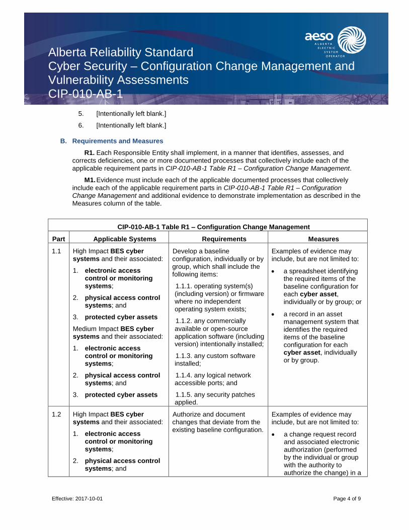
Alberta Reliability Standard Cyber Security – Configuration Change Management and Vulnerability Assessments CIP-010-AB-1
Effective: 2017-10-01
Page 4 of 9
5. [Intentionally left blank.]
6. [Intentionally left blank.]
B. Requirements and Measures
R1. Each Responsible Entity shall implement, in a manner that identifies, assesses, and corrects deficiencies, one or more documented processes that collectively include each of the applicable requirement parts in CIP‐010-AB‐1 Table R1 – Configuration Change Management.
M1. Evidence must include each of the applicable documented processes that collectively
include each of the applicable requirement parts in CIP‐010-AB‐1 Table R1 – Configuration Change Management and additional evidence to demonstrate implementation as described in the Measures column of the table.
CIP-010-AB-1 Table R1 – Configuration Change Management
Part Applicable Systems Requirements Measures
1.1 High Impact BES cyber systems and their associated:
1. electronic access control or monitoring systems;
2. physical access control systems; and
3. protected cyber assets
Medium Impact BES cyber systems and their associated:
1. electronic access control or monitoring systems;
2. physical access control systems; and
3. protected cyber assets
Develop a baseline configuration, individually or by group, which shall include the following items:
1.1.1. operating system(s) (including version) or firmware where no independent operating system exists;
1.1.2. any commercially
available or open‐source application software (including version) intentionally installed;
1.1.3. any custom software installed;
1.1.4. any logical network accessible ports; and
1.1.5. any security patches applied.
Examples of evidence may include, but are not limited to:
a spreadsheet identifying the required items of the baseline configuration for each cyber asset, individually or by group; or
a record in an asset management system that identifies the required items of the baseline configuration for each cyber asset, individually or by group.
1.2 High Impact BES cyber systems and their associated:
1. electronic access control or monitoring systems;
2. physical access control systems; and
Authorize and document changes that deviate from the existing baseline configuration.
Examples of evidence may include, but are not limited to:
a change request record and associated electronic authorization (performed by the individual or group with the authority to authorize the change) in a

Alberta Reliability Standard Cyber Security – Configuration Change Management and Vulnerability Assessments CIP-010-AB-1
Effective: 2017-10-01
Page 5 of 9
CIP-010-AB-1 Table R1 – Configuration Change Management
Part Applicable Systems Requirements Measures
3. protected cyber assets
Medium Impact BES cyber systems and their associated:
1. electronic access control or monitoring systems;
2. physical access control systems; and
3. protected cyber assets
change management system for each change; or
documentation that the change was performed in accordance with the requirement.
1.3 High Impact BES cyber systems and their associated:
1. electronic access control or monitoring systems;
2. physical access control systems; and
3. protected cyber assets
Medium Impact BES cyber systems and their associated:
1. electronic access control or monitoring systems;
2. physical access control systems; and
3. protected cyber assets
For a change that deviates from the existing baseline configuration, update the baseline configuration as necessary within 30 days of completing the change.
An example of evidence may include, but is not limited to, updated baseline documentation with a date that is within 30 days of the date of the completion of the change.
1.4 High Impact BES cyber systems and their associated:
1. electronic access control or monitoring systems;
2. physical access control systems; and
3. protected cyber assets
Medium Impact BES cyber systems and their associated:
For a change that deviates from the existing baseline configuration:
1.4.1. prior to the change, determine required cyber
security controls in CIP‐005 and CIP‐007 that could be impacted by the change;
1.4.2. following the change, verify that required cyber security controls determined
An example of evidence may include, but is not limited to, a list of cyber security controls verified or tested along with the dated test results.

Alberta Reliability Standard Cyber Security – Configuration Change Management and Vulnerability Assessments CIP-010-AB-1
Effective: 2017-10-01
Page 6 of 9
CIP-010-AB-1 Table R1 – Configuration Change Management
Part Applicable Systems Requirements Measures
1. electronic access control or monitoring systems;
2. physical access control systems; and
3. protected cyber assets
in 1.4.1 are not adversely affected; and
1.4.3. document the results of the verification.
1.5 High Impact BES cyber systems
Where technically feasible, for each change that deviates from the existing baseline configuration:
1.5.1. prior to implementing any change in the production environment, test the changes in a test environment or test the changes in a production environment where the test is performed in a manner that minimizes adverse effects, that models the baseline configuration to ensure that required cyber security
controls in CIP‐005 and CIP‐007 are not adversely affected; and
1.5.2. document the results of the testing and, if a test environment was used, the differences between the test environment and the production environment, including a description of the measures used to account for any differences in operation between the test and production environments.
An example of evidence may include, but is not limited to, a list of cyber security controls tested along with successful test results and a list of differences between the production and test environments with descriptions of how any differences were accounted for, including the date of the test.
R2. Each Responsible Entity shall implement, in a manner that identifies, assesses, and corrects deficiencies, one or more documented processes that collectively include each of the applicable requirement parts in CIP‐010-AB‐1 Table R2 – Configuration Monitoring.
M2. Evidence must include each of the applicable documented processes that collectively
include each of the applicable requirement parts in CIP‐010-AB‐1 Table R2 – Configuration
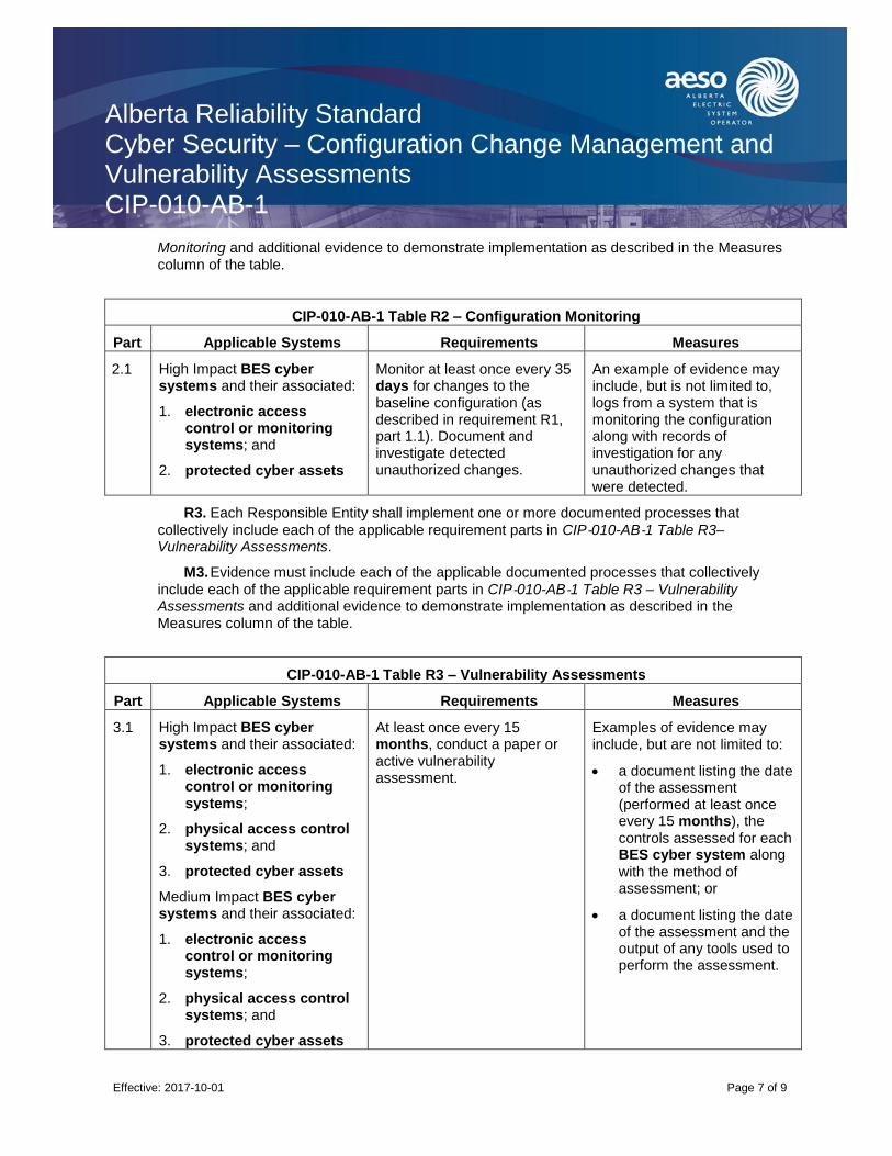
Alberta Reliability Standard Cyber Security – Configuration Change Management and Vulnerability Assessments CIP-010-AB-1
Effective: 2017-10-01
Page 7 of 9
Monitoring and additional evidence to demonstrate implementation as described in the Measures column of the table.
CIP-010-AB-1 Table R2 – Configuration Monitoring
Part Applicable Systems Requirements Measures
2.1 High Impact BES cyber systems and their associated:
1. electronic access control or monitoring systems; and
2. protected cyber assets
Monitor at least once every 35 days for changes to the baseline configuration (as described in requirement R1, part 1.1). Document and investigate detected unauthorized changes.
An example of evidence may include, but is not limited to, logs from a system that is monitoring the configuration along with records of investigation for any unauthorized changes that were detected.
R3. Each Responsible Entity shall implement one or more documented processes that
collectively include each of the applicable requirement parts in CIP‐010-AB‐1 Table R3– Vulnerability Assessments.
M3. Evidence must include each of the applicable documented processes that collectively
include each of the applicable requirement parts in CIP‐010-AB‐1 Table R3 – Vulnerability Assessments and additional evidence to demonstrate implementation as described in the Measures column of the table.
CIP-010-AB-1 Table R3 – Vulnerability Assessments
Part Applicable Systems Requirements Measures
3.1 High Impact BES cyber systems and their associated:
1. electronic access control or monitoring systems;
2. physical access control systems; and
3. protected cyber assets
Medium Impact BES cyber systems and their associated:
1. electronic access control or monitoring systems;
2. physical access control systems; and
3. protected cyber assets
At least once every 15 months, conduct a paper or active vulnerability assessment.
Examples of evidence may include, but are not limited to:
a document listing the date of the assessment (performed at least once every 15 months), the controls assessed for each BES cyber system along with the method of assessment; or
a document listing the date of the assessment and the output of any tools used to perform the assessment.
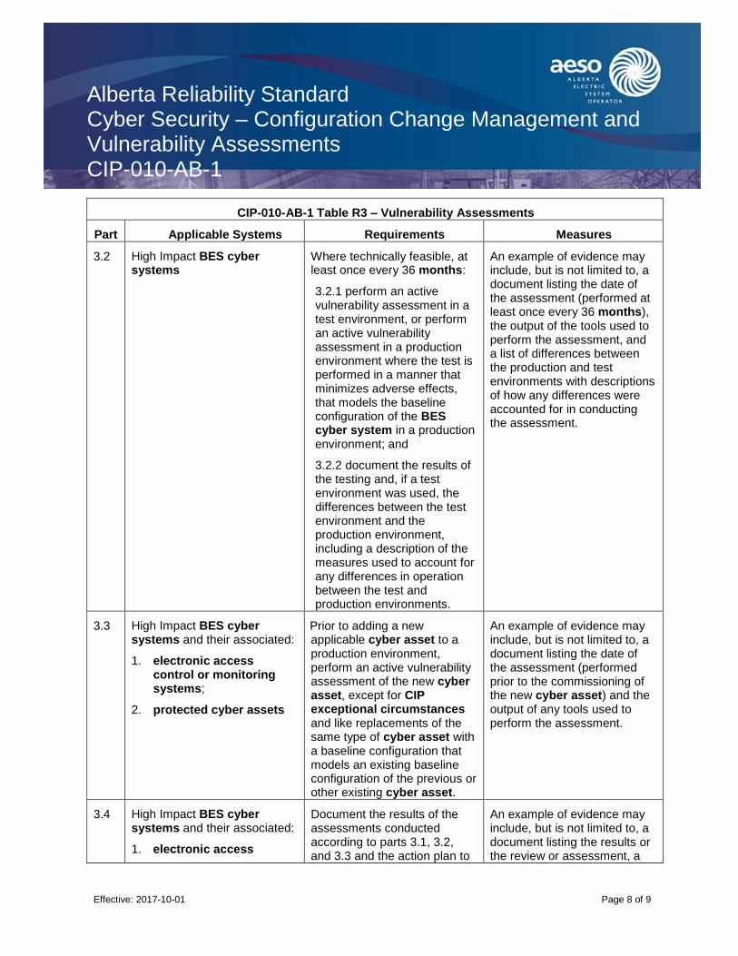
Alberta Reliability Standard Cyber Security – Configuration Change Management and Vulnerability Assessments CIP-010-AB-1
Effective: 2017-10-01
Page 8 of 9
CIP-010-AB-1 Table R3 – Vulnerability Assessments
Part Applicable Systems Requirements Measures
3.2 High Impact BES cyber systems
Where technically feasible, at least once every 36 months:
3.2.1 perform an active vulnerability assessment in a test environment, or perform an active vulnerability assessment in a production environment where the test is performed in a manner that minimizes adverse effects, that models the baseline configuration of the BES cyber system in a production environment; and
3.2.2 document the results of the testing and, if a test environment was used, the differences between the test environment and the production environment, including a description of the measures used to account for any differences in operation between the test and production environments.
An example of evidence may include, but is not limited to, a document listing the date of the assessment (performed at least once every 36 months), the output of the tools used to perform the assessment, and a list of differences between the production and test environments with descriptions of how any differences were accounted for in conducting the assessment.
3.3 High Impact BES cyber systems and their associated:
1. electronic access control or monitoring systems;
2. protected cyber assets
Prior to adding a new applicable cyber asset to a production environment, perform an active vulnerability assessment of the new cyber asset, except for CIP exceptional circumstances and like replacements of the same type of cyber asset with a baseline configuration that models an existing baseline configuration of the previous or other existing cyber asset.
An example of evidence may include, but is not limited to, a document listing the date of the assessment (performed prior to the commissioning of the new cyber asset) and the output of any tools used to perform the assessment.
3.4 High Impact BES cyber systems and their associated:
1. electronic access
Document the results of the assessments conducted according to parts 3.1, 3.2, and 3.3 and the action plan to
An example of evidence may include, but is not limited to, a document listing the results or the review or assessment, a
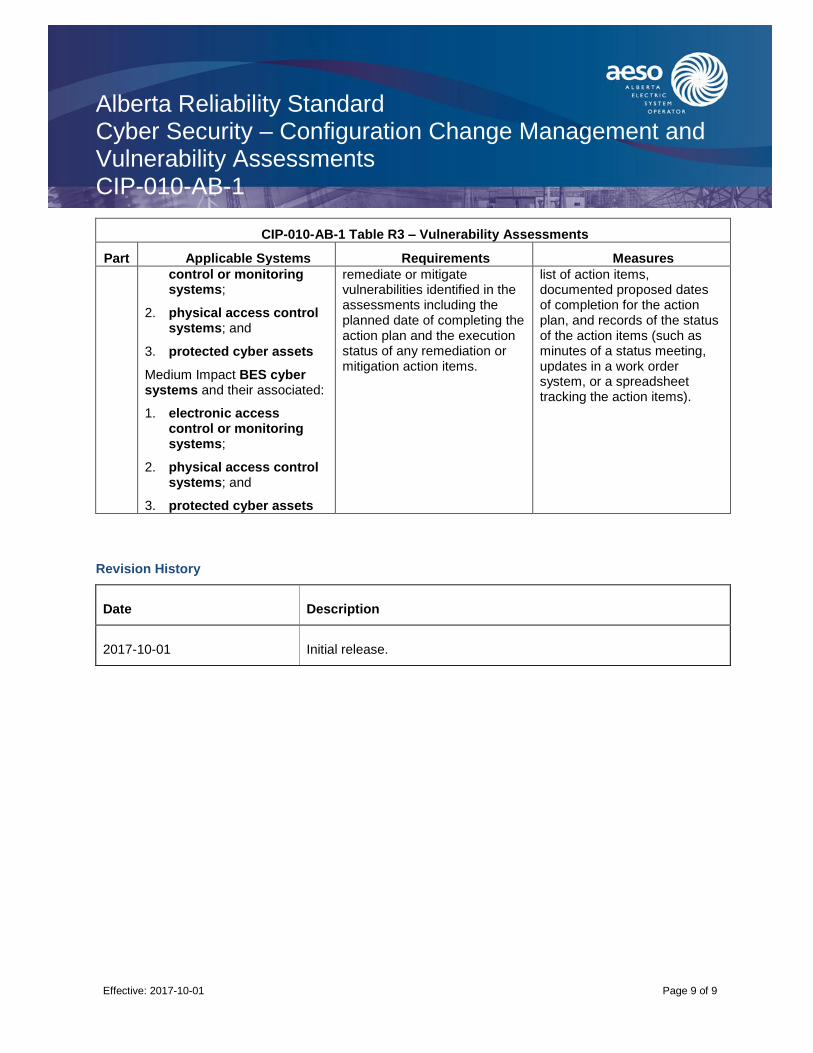
Alberta Reliability Standard Cyber Security – Configuration Change Management and Vulnerability Assessments CIP-010-AB-1
Effective: 2017-10-01
Page 9 of 9
CIP-010-AB-1 Table R3 – Vulnerability Assessments
Part Applicable Systems Requirements Measures
control or monitoring systems;
2. physical access control systems; and
3. protected cyber assets
Medium Impact BES cyber systems and their associated:
1. electronic access control or monitoring systems;
2. physical access control systems; and
3. protected cyber assets
remediate or mitigate vulnerabilities identified in the assessments including the planned date of completing the action plan and the execution status of any remediation or mitigation action items.
list of action items, documented proposed dates of completion for the action plan, and records of the status of the action items (such as minutes of a status meeting, updates in a work order system, or a spreadsheet tracking the action items).
Revision History
Date Description
2017-10-01 Initial release.

Alberta Reliability Standard Cyber Security – Information Protection CIP-011-AB-1
Effective: 2017-10-01
Page 1 of 6
A. Introduction
1. Title: Cyber Security – Information Protection
2. Number: CIP-011-AB-1
3. Purpose: To prevent unauthorized access to BES cyber system information by specifying information protection requirements in support of protecting BES cyber systems against compromise that could lead to misoperation or instability in the bulk electric system.
4. Applicability:
4.1. For the purpose of the requirements contained herein, the following list of entities will be collectively referred to as “Responsible Entities”. For requirements in this reliability standard where a specific entity or subset of entities are the applicable entity or entities, the entity or entities are specified explicitly.
4.1.1. [Intentionally left blank.]
4.1.2. a legal owner of an electric distribution system that owns one or more of the following facilities, systems, and equipment for the protection or restoration of the bulk electric system:
4.1.2.1. each underfrequency load shedding or under voltage load shed system that:
4.1.2.1.1. is part of a load shedding program that is subject to one or more requirements in a reliability standard; and
4.1.2.1.2. performs automatic load shedding under a common control system owned by the entity in subsection 4.1.2., without human operator initiation, of 300 MW or more;
4.1.2.2. each remedial action scheme where the remedial action scheme is subject to one or more requirements in a reliability standard;
4.1.2.3. each protection system (excluding underfrequency load shedding and under voltage load shed) that applies to transmission where the protection system is subject to one or more requirements in a reliability standard; and
4.1.2.4. each cranking path and group of elements meeting the initial switching requirements from a contracted blackstart resource up to and including the first point of supply and/or point of delivery of the next generating unit or aggregated generating facility to be started;
4.1.3. the operator of a generating unit and the operator of an aggregated generating facility;
4.1.4. the legal owner of a generating unit and the legal owner of an aggregated generating facility;
4.1.5. [Intentionally left blank.]
4.1.6. [Intentionally left blank.]
4.1.7. the operator of a transmission facility;
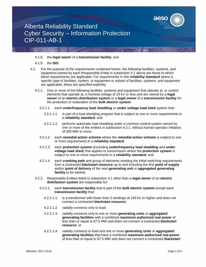
Alberta Reliability Standard Cyber Security – Information Protection CIP-011-AB-1
Effective: 2017-10-01
Page 2 of 6
4.1.8. the legal owner of a transmission facility; and
4.1.9. the ISO.
4.2. For the purpose of the requirements contained herein, the following facilities, systems, and equipment owned by each Responsible Entity in subsection 4.1 above are those to which these requirements are applicable. For requirements in this reliability standard where a specific type of facilities, system, or equipment or subset of facilities, systems, and equipment are applicable, these are specified explicitly.
4.2.1. One or more of the following facilities, systems and equipment that operate at, or control elements that operate at, a nominal voltage of 25 kV or less and are owned by a legal owner of an electric distribution system or a legal owner of a transmission facility for the protection or restoration of the bulk electric system:
4.2.1.1. each underfrequency load shedding or under voltage load shed system that:
4.2.1.1.1. is part of a load shedding program that is subject to one or more requirements in a reliability standard; and
4.2.1.1.2. performs automatic load shedding under a common control system owned by one or more of the entities in subsection 4.2.1, without human operator initiation, of 300 MW or more;
4.2.1.2. each remedial action scheme where the remedial action scheme is subject to one or more requirements in a reliability standard;
4.2.1.3. each protection system (excluding underfrequency load shedding and under voltage load shed) that applies to transmission where the protection system is subject to one or more requirements in a reliability standard; and
4.2.1.4. each cranking path and group of elements meeting the initial switching requirements from a contracted blackstart resource up to and including the first point of supply and/or point of delivery of the next generating unit or aggregated generating facility to be started;
4.2.2. Responsible Entities listed in subsection 4.1 other than a legal owner of an electric distribution system are responsible for:
4.2.2.1. each transmission facility that is part of the bulk electric system except each transmission facility that:
4.2.2.1.1. is a transformer with fewer than 2 windings at 100 kV or higher and does not connect a contracted blackstart resource;
4.2.2.1.2. radially connects only to load;
4.2.2.1.3. radially connects only to one or more generating units or aggregated generating facilities with a combined maximum authorized real power of less than or equal to 67.5 MW and does not connect a contracted blackstart resource; or
4.2.2.1.4. radially connects to load and one or more generating units or aggregated generating facilities that have a combined maximum authorized real power of less than or equal to 67.5 MW and does not connect a contracted blackstart
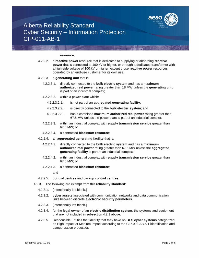
Alberta Reliability Standard Cyber Security – Information Protection CIP-011-AB-1
Effective: 2017-10-01
Page 3 of 6
resource;
4.2.2.2. a reactive power resource that is dedicated to supplying or absorbing reactive power that is connected at 100 kV or higher, or through a dedicated transformer with a high-side voltage of 100 kV or higher, except those reactive power resources operated by an end-use customer for its own use;
4.2.2.3. a generating unit that is:
4.2.2.3.1. directly connected to the bulk electric system and has a maximum authorized real power rating greater than 18 MW unless the generating unit is part of an industrial complex;
4.2.2.3.2. within a power plant which:
4.2.2.3.2.1. is not part of an aggregated generating facility;
4.2.2.3.2.2. is directly connected to the bulk electric system; and
4.2.2.3.2.3. has a combined maximum authorized real power rating greater than 67.5 MW unless the power plant is part of an industrial complex;
4.2.2.3.3. within an industrial complex with supply transmission service greater than 67.5 MW; or
4.2.2.3.4. a contracted blackstart resource;
4.2.2.4. an aggregated generating facility that is:
4.2.2.4.1. directly connected to the bulk electric system and has a maximum authorized real power rating greater than 67.5 MW unless the aggregated generating facility is part of an industrial complex;
4.2.2.4.2. within an industrial complex with supply transmission service greater than 67.5 MW; or
4.2.2.4.3. a contracted blackstart resource;
and
4.2.2.5. control centres and backup control centres.
4.2.3. The following are exempt from this reliability standard:
4.2.3.1. [Intentionally left blank.]
4.2.3.2. cyber assets associated with communication networks and data communication links between discrete electronic security perimeters.
4.2.3.3. [Intentionally left blank.]
4.2.3.4. for the legal owner of an electric distribution system, the systems and equipment that are not included in subsection 4.2.1 above.
4.2.3.5. Responsible Entities that identify that they have no BES cyber systems categorized
as High Impact or Medium Impact according to the CIP‐002-AB‐5.1 identification and categorization processes.

Alberta Reliability Standard Cyber Security – Information Protection CIP-011-AB-1
Effective: 2017-10-01
Page 4 of 6
5. [Intentionally left blank.]
6. [Intentionally left blank.]
B. Requirements and Measures
R1. Each Responsible Entity shall implement, in a manner that identifies, assesses, and corrects deficiencies, one or more documented information protection program(s) that collectively includes each of the applicable requirement parts in CIP‐011-AB‐1 Table R1 – Information Protection.
M1. Evidence for the information protection program must include the applicable requirement parts in
CIP‐011-AB‐1 Table R1 – Information Protection and additional evidence to demonstrate implementation as described in the Measures column of the table.
CIP-011-AB-1 Table R1 – Information Protection
Part Applicable Systems Requirements Measures
1.1 High Impact BES cyber systems and their associated:
1. electronic access control or monitoring systems; and
2. physical access control systems
Medium Impact BES cyber systems and their associated:
1. electronic access control or monitoring systems; and
2. physical access control systems
Method(s) to identify information that meets the definition of BES cyber system information.
Examples of acceptable evidence include, but are not limited to:
documented method to identify BES cyber system information from entity’s information protection program; or
indications on information (e.g., labels or classification) that identify BES cyber system information as designated in the entity’s information protection program; or
training materials that provide personnel with sufficient knowledge to recognize BES cyber system information; or
repository or electronic and physical location designated for housing BES cyber system information in the entity’s information protection program.
1.2 High Impact BES cyber Procedure(s) for protecting Examples of acceptable
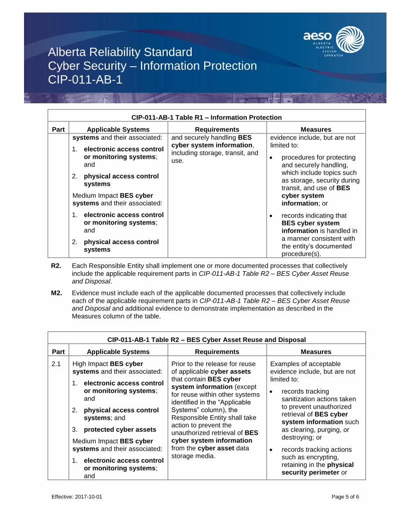
Alberta Reliability Standard Cyber Security – Information Protection CIP-011-AB-1
Effective: 2017-10-01
Page 5 of 6
CIP-011-AB-1 Table R1 – Information Protection
Part Applicable Systems Requirements Measures
systems and their associated:
1. electronic access control or monitoring systems; and
2. physical access control systems
Medium Impact BES cyber systems and their associated:
1. electronic access control or monitoring systems; and
2. physical access control systems
and securely handling BES cyber system information, including storage, transit, and use.
evidence include, but are not limited to:
procedures for protecting and securely handling, which include topics such as storage, security during transit, and use of BES cyber system information; or
records indicating that BES cyber system information is handled in a manner consistent with the entity’s documented procedure(s).
R2. Each Responsible Entity shall implement one or more documented processes that collectively
include the applicable requirement parts in CIP‐011-AB‐1 Table R2 – BES Cyber Asset Reuse and Disposal.
M2. Evidence must include each of the applicable documented processes that collectively include
each of the applicable requirement parts in CIP‐011-AB‐1 Table R2 – BES Cyber Asset Reuse and Disposal and additional evidence to demonstrate implementation as described in the Measures column of the table.
CIP-011-AB-1 Table R2 – BES Cyber Asset Reuse and Disposal
Part Applicable Systems Requirements Measures
2.1 High Impact BES cyber systems and their associated:
1. electronic access control or monitoring systems; and
2. physical access control systems; and
3. protected cyber assets
Medium Impact BES cyber systems and their associated:
1. electronic access control or monitoring systems; and
Prior to the release for reuse of applicable cyber assets that contain BES cyber system information (except for reuse within other systems identified in the “Applicable Systems” column), the Responsible Entity shall take action to prevent the unauthorized retrieval of BES cyber system information from the cyber asset data storage media.
Examples of acceptable evidence include, but are not limited to:
records tracking sanitization actions taken to prevent unauthorized retrieval of BES cyber system information such as clearing, purging, or destroying; or
records tracking actions such as encrypting, retaining in the physical security perimeter or

Alberta Reliability Standard Cyber Security – Information Protection CIP-011-AB-1
Effective: 2017-10-01
Page 6 of 6
CIP-011-AB-1 Table R2 – BES Cyber Asset Reuse and Disposal
Part Applicable Systems Requirements Measures
2. physical access control systems; and
3. protected cyber assets
other methods used to prevent unauthorized retrieval of BES cyber system information.
2.2 High Impact BES cyber systems and their associated:
1. electronic access control or monitoring systems; and
2. physical access control systems; and
3. protected cyber assets
Medium Impact BES cyber systems and their associated:
1. electronic access control or monitoring systems; and
2. physical access control systems; and
3. protected cyber assets
Prior to the disposal of applicable cyber assets that contain BES cyber system information, the Responsible Entity shall take action to prevent the unauthorized retrieval of BES cyber system information from the cyber asset or destroy the data storage media.
Examples of acceptable evidence include, but are not limited to:
records that indicate that data storage media was destroyed prior to the disposal of an applicable cyber asset; or
records of actions taken to prevent unauthorized retrieval of BES cyber system information prior to the disposal of an applicable cyber asset.
Revision History
Date Description
2017-10-01 Initial release.
Alberta Reliability Standard Cyber Security – Implementation Plan for Version 5 CIP Security Standards CIP-PLAN-AB-1
Effective: 2017-10-01
Page 1 of 3
1. Purpose
The purpose of this reliability standard is to set the effective dates for the Version 5 CIP Cyber Security reliability standards and describe compliance timelines for planned and unplanned changes that result in a higher categorization for a BES cyber system.
2. Applicable Reliability Standards
This reliability standard applies to the Version 5 CIP Cyber Security reliability standards, which are:
CIP–002–AB-5.1, Cyber Security — BES Cyber System Categorization;
CIP–003–AB-5, Cyber Security — Security Management Controls;
CIP–004–AB-5.1, Cyber Security — Personnel and Training;
CIP–005–AB-5, Cyber Security — Electronic Security Perimeter(s);
CIP–006–AB-5, Cyber Security — Physical Security of BES Cyber Systems;
CIP–007–AB-5, Cyber Security — Systems Security Management;
CIP–008–AB-5, Cyber Security — Incident Reporting and Response Planning;
CIP–009–AB-5, Cyber Security — Recovery Plans for BES Cyber Systems;
CIP–010–AB-1, Cyber Security — Configuration Change Management and Vulnerability Assessments; and
CIP–011–AB-1, Cyber Security — Information Protection.
3. Compliance with Reliability Standards
Once the Version 5 CIP Cyber Security reliability standards become effective, the “Responsible Entities” identified in the applicability section of each Version 5 CIP Cyber Security reliability standard must comply with the requirements of those reliability standards.
4. Proposed Effective Date
The Version 5 Cyber Security reliability standards, except for requirement R2 of CIP-003-AB-5, become effective on the first day of the calendar quarter (January 1, April 1, July 1 or October 1) that follows eight (8) full calendar quarters after approval by the Commission. Requirement R2 of CIP-003-AB-5 becomes effective on the first day of the calendar quarter (January 1, April 1, July 1 or October 1) that follows twelve (12) full calendar quarters after approval by the Commission.
5. Initial Performance of Certain Periodic Requirements
Specific Version 5 CIP Cyber Security reliability standards have periodic requirements that contain time parameters for subsequent and recurring iterations of the requirement, such as, but not limited to, “. . . at least once every fifteen (15) months . . .”, and “Responsible Entities” must comply initially with those periodic requirements as follows:
1. on or before the effective date of the Version 5 CIP Cyber Security reliability standards for the following requirements:
Alberta Reliability Standard Cyber Security – Implementation Plan for Version 5 CIP Security Standards CIP-PLAN-AB-1
Effective: 2017-10-01
Page 2 of 3
• CIP-002-5, requirement R2; and
• CIP-003-5, requirement R1;
2. on or before the Effective Date of CIP-003-5, Requirement R2 for the following requirement:
• CIP-003-5, requirement R2;
3. within fourteen (14) days after the effective date of the Version 5 CIP Cyber Security reliability standards for the following requirement:
• CIP-007-5, requirement R4, Part 4.4;
4. within thirty-five (35) days after the effective date of the Version 5 CIP Cyber Security reliability standards for the following requirements:
• CIP-010-1, requirement R2, Part 2.1;
5. within three (3) months after the effective date of the Version 5 CIP Cyber Security reliability standards for the following requirement:
• CIP-004-5, requirement R4, Part 4.2;
6. within twelve (12) months after the effective date of the Version 5 CIP Cyber Security reliability standards for the following requirements:
• CIP-004-5, requirement R2, Part 2.3;
• CIP-004-5, requirement R4, Parts 4.3 and 4.4;
• CIP-006-5, requirement R3, Part 3.1;
• CIP-008-5, requirement R2, Part 2.1;
• CIP-009-5, requirement R2, Parts 2.1 and 2.2; and
• CIP-010-1, requirement R3, Part 3.1; and
7. within twenty-four (24) months after the effective date of the Version 5 CIP Cyber Security reliability standards for the following requirements:
• CIP-009-5, requirement R2, Part 2.3; and
• CIP-010-1, requirement R3, Part 3.2.
6. Planned or Unplanned Changes Resulting in a Higher Categorization
Planned changes refer to any changes of the electric system or BES cyber system as identified through the annual assessment under CIP-002-AB-5.1, requirement R2, which were planned and implemented by the “Responsible Entity” identified in the applicability section of each Version 5 CIP Cyber Security reliability standard.
In contrast, unplanned changes refer to any changes of the electric system or BES cyber system, as identified through the annual assessment under CIP-002-AB-5.1, Requirement R2, which were not planned by the “Responsible Entity” identified in the applicability section of each Version 5 CIP Cyber Security reliability standard.

Alberta Reliability Standard Cyber Security – Implementation Plan for Version 5 CIP Security Standards CIP-PLAN-AB-1
Effective: 2017-10-01
Page 3 of 3
For planned changes resulting in a higher categorization, the “Responsible Entity” identified in the applicability section of each Version 5 CIP Cyber Security reliability standard shall comply with all applicable requirements in the Version 5 CIP Cyber Security reliability standards on the update of the identification and categorization of the affected BES cyber system and any applicable and associated physical access control systems, electronic access control or monitoring systems and protected cyber assets, with additional time to comply for requirements in the same manner as those timelines specified in the section Initial Performance of Certain Periodic Requirements above.
For unplanned changes resulting in a higher categorization, the “Responsible Entity” identified in the applicability section of each Version 5 CIP Cyber Security reliability standard shall comply with all applicable requirements in the Version 5 CIP Cyber Security reliability standards, according to the following timelines, following the identification and categorization of the affected BES cyber system and any applicable and associated physical access control systems, electronic access control or monitoring systems and protected cyber assets, with additional time to comply for requirements in the same manner as those timelines specified in the section Initial Performance of Certain Periodic Requirements above.
Scenario of Unplanned Changes After the Effective Date for Each Version 5 CIP Cyber Security Reliability Standard
Compliance Implementation
New High Impact BES cyber system twelve (12) months
New Medium Impact BES cyber system twelve (12) months
Newly categorized High Impact BES cyber system from Medium Impact BES cyber system
twelve (12) months for requirements not applicable to Medium Impact BES Cyber Systems
Newly categorized Medium Impact BES cyber system twelve (12) months
The “Responsible Entity” identified in the applicability section of each Version 5 CIP Cyber Security reliability standard identifies first Medium Impact or High Impact BES cyber system (i.e., the “Responsible Entity” identified in the applicability section of each Version 5 CIP Cyber Security reliability standard previously had no BES cyber systems categorized as High Impact or Medium Impact according to the CIP-002-AB-5.1 identification and categorization processes)
twenty-four (24) months
Revision History
Date Description
2017-10-01 Initial release.

Alberta Reliability Standard Telecommunications COM-001-AB1-1.1
Alberta Reliability Standards Effective: 2015-05-01
Page 1 of 4
1. Purpose
The purpose of this reliability standard is to ensure the ISO and each operator of a transmission facility have adequate and reliable voice and message telecommunication facilities internally and with others for the exchange of interconnection and operating information necessary to maintain reliability.
2. Applicability
This reliability standard applies to the following:
(a) the operator of a transmission facility that is:
(i) part of the bulk electric system; or
(ii) not part of the bulk electric system but which the ISO:
(A) determines is necessary for the reliable operation of either the interconnected electric system or the City of Medicine Hat electric system; and
(B) publishes on the AESO website and may amend from time to time in accordance with the process set out in Appendix 1; and
(b) the ISO.
3. Requirements
R1 The ISO must, as necessary to maintain reliability, provide adequate, reliable, and, where applicable, diverse and redundant voice and message telecommunication facilities for the exchange of interconnection and internal Alberta operating information with the following:
(a) each operator of a transmission facility;
(b) each adjacent interconnected transmission operator directly connected to Alberta;
(c) each adjacent balancing authority directly connected to Alberta; and
(d) the adjacent reliability coordinators.
R2 Each operator of a transmission facility must, as necessary to maintain reliability, provide adequate, reliable, and, where applicable, diversely routed and redundant voice and message telecommunication facilities for the exchange of interconnection and Alberta operating information with the following:
(a) each adjacent operator of a transmission facility;
(b) each adjacent interconnected transmission operator that is directly connected to Alberta; and
(c) the ISO.
R3 The ISO and each operator of a transmission facility must manage and test its alternate voice and message telecommunication facilities.
R4 The ISO must provide a means to coordinate voice and message telecommunications with each operator of a transmission facility, adjacent interconnected transmission operator, adjacent
Alberta Reliability Standard Telecommunications COM-001-AB1-1.1
Alberta Reliability Standards Effective: 2015-05-01
Page 2 of 4
balancing authority and adjacent reliability coordinators, which coordination must include the ability to investigate and recommend solutions to voice and message telecommunications problems within Alberta.
R5 Each operator of a transmission facility must provide a means to coordinate voice and message telecommunications with the ISO and adjacent interconnected transmission operators, which coordination must include the ability to investigate and recommend solutions to voice and message telecommunications problems within Alberta.
R6 The ISO and each operator of a transmission facility must use the English language for all communications between their respective operating personnel responsible for the real-time generation control and operation of the interconnected electric system.
R7 The ISO and each operator of a transmission facility must have written operating instructions and procedures to enable continued operation of the interconnected electric system during the loss of voice and message telecommunications facilities.
4. Measures
The following measures correspond to the requirements identified in section 3 of this reliability standard. For example, MR1 is the measure for R1.
MR1 Evidence of providing voice and message telecommunication facilities as required in requirement R1 exists. Evidence may include:
(a) a list identifying each telecommunication facility for the exchange of interconnection and Alberta operating information; and
(b) documentation demonstrating the implementation of diverse routing and redundancy capability.
MR2 Evidence of providing voice and message telecommunication facilities as required in requirement R2 exists. Evidence may include:
(a) a list identifying each telecommunication facility for the exchange of interconnection and Alberta operating information; and
(b) documentation demonstrating the implementation of diverse routing and redundancy capability, if applicable.
MR3 Evidence of managing and testing its alternate voice and message telecommunication facilities as required in requirement R3 exists. Evidence may include:
(a) a list identifying each telecommunication facility as determined to be alternate;
(b) documented procedures describing how to manage and test its alternate telecommunication facilities; and
(c) records of testing.
MR4 Evidence of providing a means to coordinate voice and message telecommunications as required in requirement R4 exists. Evidence may include a documented procedure in place which identifies a process for coordinating telecommunications and a process for investigating and recommending solutions to telecommunications problems.
MR5 Evidence of providing a means to coordinate voice and message telecommunications as required in requirement R5 exists. Evidence may include a documented procedure in place which identifies a
Alberta Reliability Standard Telecommunications COM-001-AB1-1.1
Alberta Reliability Standards Effective: 2015-05-01
Page 3 of 4
process for coordinating telecommunications and a process for investigating and recommending solutions to telecommunications problems.
MR6 Evidence of using the English language as required in requirement R6 exists. Evidence may include operator logs, voice recordings, electronic communications or e-tag records.
MR7 Evidence of having written operating instructions and procedures as required in requirement R7 exists. Evidence may include electronic or hard copy of the operating instructions and procedures.
5. Appendices
Appendix 1 – Amending Process for List of Facilities
Revision History
Effective Description
2013-10-01 Initial Release
2015-05-01 Revised for ISO assumption of RC functionality for the Alberta footprint
Alberta Reliability Standard Telecommunications COM-001-AB1-1.1
Alberta Reliability Standards Effective: 2015-05-01
Page 4 of 4
Appendix 1 Amending Process for List of Facilities
In order to amend the list referenced in subsections (a)(ii)(B) of section 2, Applicability, the ISO must:
(a) upon determining that a transmission facility is to be added, notify the operator in writing and determine an effective date, which must be no less than thirty (30) days after the date of notice, for the operator to meet the applicable requirements;
(b) upon determining that a transmission facility is to be deleted, notify the operator in writing and determine an effective date for the operator to no longer be required to meet the applicable requirements; and
(c) publish the amended list with effective dates on the AESO website.

Alberta Reliability Standards Communications and Coordination
COM-002-AB1-2a Communications and Coordination
Effective: 2014-01-01 Page 1 of 2
1. Purpose
The purpose of this reliability standard is to ensure the ISO and entities subject to this reliability standard have adequate communications and that these communications capabilities are staffed and available for addressing a real-time emergency condition, and to ensure communications by operating personnel are effective.
2. Applicability
This reliability standard applies to:
(a) the operator of a generating unit that is:
(i) directly connected to the transmission system or to transmission facilities within the City of Medicine Hat; and
(ii) not part of an aggregated generating facility;
(b) the operator of an aggregated generating facility that is directly connected to the transmission system or to transmission facilities within the City of Medicine Hat;
(c) the operator of a transmission facility; and
(d) the ISO.
3. Requirements
R1 The ISO must have voice and data communication facilities with:
(a) each operator of a transmission facility;
(b) each adjacent interconnected transmission operator directly connected to Alberta; and
(c) each adjacent balancing authority directly connected to Alberta;
R2 The operator of a transmission facility must have voice and data communication facilities with:
(a) each adjacent operator of a transmission facility;
(b) each adjacent interconnected transmission operator directly connected to Alberta; and
(c) the ISO.
R3 Each operator of a generating unit and each operator of an aggregated generating facility must have voice and data communication facilities with:
(a) each operator of a transmission facility to which it is directly connected; and
(b) the ISO.
R4 The ISO, each operator of a transmission facility, each operator of an aggregated generating facility and each operator of a generating unit must have personnel available for all hours of the day, seven (7) days a week, to receive and respond to any voice or data communication regarding a real-time system emergency condition via the communication facilities as identified in requirements R1 through R3.
R5 The ISO must notify all potentially affected adjacent interconnected transmission operators and adjacent balancing authorities through predetermined communication paths:
(a) of any threat to the reliability of the interconnected electric system; or

COM-002-AB1-2a Communications and Coordination
Effective: 2014-01-01 Page 2 of 2
(b) if the ISO anticipates shedding firm load.
R6 The ISO must, when issuing a verbal directive, do so in a clear, concise and definitive manner, identify the instruction as a directive, and:
(a) if the recipient of the directive does not respond by repeating the information in the directive, then the ISO must request the recipient to repeat the information in the directive;
(b) if the information in the response is not correct, the ISO must repeat the directive to resolve any misunderstandings; and
(c) if the information is repeated correctly, the ISO must acknowledge this to the recipient.
4. Measures
The following measures correspond to the requirements identified in section 3 of this reliability standard. For example, MR1 is the measure for R1.
MR1 Evidence of having voice and data communication facilities as required in requirement R1 exists. Evidence may include a list of communication facilities or other equivalent evidence that confirms that the communications have been provided.
MR2 Evidence of having voice and data communications as required in requirement R2 exists. Evidence may include a list of communication facilities or other equivalent evidence that confirms that the communications have been provided.
MR3 Evidence of having voice and data communications as required in requirement R3 exists. Evidence may include a list of communication facilities or other equivalent evidence that confirms that the communications have been provided.
MR4 Evidence of having personnel available as required in requirement R4 exists. Evidence may include operator logs, timesheets, on-call lists or shift schedules.
MR5 Evidence of notifying entities as required in requirement R5 exists. Evidence may include operator logs or voice recordings.
MR6 Evidence of issuing verbal directives as required in requirement R6 exists. Evidence may include voice recordings or operator logs.
Revision History
Effective Description
2013-10-01 Initial release
2014-01-01 Administrative update to standardize formatting, definitions and drafting style.
Removed references to the WECC Reliability Coordinator.
Alberta Reliability Standard
Emergency Operations Planning
EOP-001-AB1-2.1b
Alberta Reliability Standards In Effect: 2015-05-01
Page 1 of 4
1. Purpose
The purpose of this reliability standard is to define requirements for the development, maintenance, implementation and coordination of plans to mitigate operating emergencies.
2. Applicability
This reliability standard applies to:
(a) the operator of a transmission facility that is part of the bulk electric system; and (b) the ISO.
This reliability standard does not apply to the operator of a transmission facility whose transmission facility is a radial connection from a generating unit or an aggregated generating facility to either the transmission system or to transmission facilities within the city of Medicine Hat.
3. Requirements
R1 The ISO must, as appropriate, have operating agreements with adjacent balancing authorities that contain provisions for emergency assistance.
R2 The ISO must develop, maintain and implement a capacity and energy emergency plan to mitigate insufficient generating capacity.
R3 Each of the ISO and the operator of a transmission facility must develop, maintain and implement plans to mitigate operating emergencies on the transmission system.
R4 Each of the ISO and the operator of a transmission facility must develop, maintain and implement plans for load shedding.
R5 Each of the ISO and the operator of a transmission facility must include, at a minimum, when developing emergency plans as identified in requirements R2, R3 and R4, the following:
(a) communication protocols to be used during operating emergencies;
(b) a list of controlling actions to resolve the operating emergency within NERC established timelines, including, where appropriate, a controlling action to reduce load;
(c) the tasks to be coordinated with and among any affected operator of a transmission facility, adjacent interconnected transmission operator and adjacent balancing authority, as appropriate; and
(d) a procedure for adjusting staffing levels for the emergency, where appropriate.
Alberta Reliability Standard
Emergency Operations Planning
EOP-001-AB1-2.1b
Alberta Reliability Standards in Effect: 2015-05-01
Page 2 of 4
R6 The ISO must consider the elements in Appendix 1 when developing a capacity and energy emergency plan in accordance with requirement R2.
R7 The ISO must review its capacity and energy emergency plan, plans to mitigate operating emergencies on the transmission system and plans for load shedding once every calendar year and update as required.
R8 Each operator of a transmission facility must review its plans for load shedding once every calendar year and update as required.
R9 The ISO must provide a copy of its updated capacity and energy emergency plan, plans for load shedding and plans to mitigate operating emergencies on the transmission system to any affected:
(a) operator of a transmission facility;
(b) adjacent interconnected transmission operator; and
(c) adjacent balancing authority.
R10 Each operator of a transmission facility must provide a copy of its updated plans to mitigate operating emergencies on the transmission system and plans for load shedding to any affected adjacent operator of a transmission facility and the ISO.
4 Measures
The following measures correspond to the requirements identified in Section 3 of this reliability standard. For example, MR1 is the measure for R1.
MR1 Evidence of having at least one (1) operating agreement with an adjacent balancing authority as required in requirement R1 exists.
MR2 Evidence of developing, maintaining and implementing a capacity and energy emergency plan as required in requirement R2 exists. Evidence may include a dated, current capacity and energy emergency plan and communications or training to the operating personnel.
MR3 Evidence of developing, maintaining and implementing plans to mitigate operating emergencies on the transmission system as required in requirement R3 exists. Evidence may include dated, current plans to mitigate operating emergencies on the transmission system and communications or training to the operating personnel.
MR4 Evidence of developing, maintaining and implementing load shedding plans as required in requirement R4 exists. Evidence may include dated, current plans for load shedding and communications or training to the operating personnel.
MR5 Evidence of including the items in emergency plans as required in requirement R5 exists. Evidence may include emergency plans that contain items listed in requirement R5.
Alberta Reliability Standard
Emergency Operations Planning
EOP-001-AB1-2.1b
Alberta Reliability Standards in Effect: 2015-05-01
Page 3 of 4
MR6 Evidence of considering the elements in Appendix 1 as required in requirement R6 exists. Evidence may include documentation indicating which elements from Appendix 1 were not included in the capacity and emergency plan and the rationale why they were not included.
MR7 Evidence of reviewing and updating each plan as required in requirement R7 exists. Evidence may include documentation confirming each plan was reviewed once every calendar year and updated as required.
MR8 Evidence of reviewing and updating plans as required in requirement R8 exists. Evidence may include documentation confirming each plan was reviewed once every calendar year and updated as required.
MR9 Evidence of providing each updated plan as required in requirement R9 exists. Evidence may include email or mail to appropriate recipients that identifies contents submitted.
MR10 Evidence of providing updated plans as required in requirement R10 exists. Evidence may include email or mail to appropriate recipients that identifies contents submitted.
5. Appendix 1
Elements for Consideration in Development of Capacity and Energy Emergency Plan
1. Bulk electric system energy use — The reduction of the bulk electric system’s own energy use to a minimum.
2. Public appeals — Appeals to the public through all media for voluntary load reductions and energy conservation including educational messages on how to accomplish such load reduction and conservation.
3. Load management — Implementation of load management and voltage reductions, if appropriate.
4. Interruptible and curtailable loads — Use of interruptible and curtailable load to reduce capacity requirements or to conserve the fuel in short supply.
5. Maximizing generating unit output and availability — The operation of all generating sources to maximize output and availability. This should include plans to winterize generating units and aggregated generating facilities during extreme cold weather.
6. Notifying independent power producers (IPP) — Notification of cogeneration and independent power producers to maximize output and availability.
7. Requests of government — Requests to appropriate government agencies to implement programs to achieve necessary energy reductions.

Alberta Reliability Standard
Emergency Operations Planning
EOP-001-AB1-2.1b
Alberta Reliability Standards in Effect: 2015-05-01
Page 4 of 4
8. Load curtailment — A mandatory load curtailment plan to use as a last resort. This plan should address the needs of critical loads essential to the health, safety and welfare of the community. Address firm load curtailment.
9. Notification of government agencies — Notification of appropriate government agencies as the various steps of the operating emergency plan are implemented.
10. Notifications to operating entities — Notifications to other operating entities as steps in the operating emergency plan are implemented.
Revision History
Effective Description
2015-05-01 Revised for ISO assumption of RC functionality for the Alberta footprint
2014-01-01 Initial Release

Alberta Reliability Standard
Capacity and Energy Emergencies EOP-002-AB1-2
Effective: 2014-01-01 Page 1 of 5
EOP–002–AB1–2 Capacity and Energy Emergencies
1. Purpose
The purpose of this reliability standard is to ensure the ISO is prepared for a supply shortfall event.
2. Applicability
This reliability standard applies to:
ISO
3. Definitions
Italicized terms used in this reliability standard have the meanings as set out in the Alberta Reliability Standards Glossary of Terms and Part 1 of the ISO Rules.
4. Requirements
R1 The ISO must exercise its authority to alleviate a supply shortfall event in the AIES.
R2 The ISO must implement its capacity and energy emergency plan by following ISO rules.
R3 The ISO must communicate its current and its forecast of future system conditions to adjacent balancing authorities during a supply shortfall event.
R4 The ISO must follow plans in ISO rules when it anticipates a supply shortfall event may occur. The ISO plans must include any one of or combination of the following:
Issuing directives as necessary, including bringing on all available generation;
Postponing equipment maintenance;
Posting interconnection TTC to maximum reliability based capacity and being prepared to reduce firm load.
R5 The ISO must, during a supply shortfall event:
Only use the assistance provided by the Interconnection’s frequency bias for the time needed to manage the event.
Not direct generating units in an attempt to return the Interconnection frequency to normal beyond that supplied through frequency bias action and interchange schedule changes.
R6 The ISO must comply with the control performance and disturbance control standards during a supply shortfall event. If necessary to do so, the ISO must implement remedies including without limitation, any one of or combination of the following:
Loading all available generating capacity.
Deploying all available operating reserves.

EOP–002–AB1–2 Capacity and Energy Emergencies
Effective: 2014-01-01 Page 2 of 5
Interrupting interruptible load and exports.
Requesting emergency assistance from other balancing authorities.
Declaring , in accordance with ISO rules,an Energy Emergency Alert(s); and
Reducing load, through procedures such as public appeals, voltage reductions, and curtailing interruptible loads.
R7 The ISO must comply with the control performance and disturbance control reliability standards during a supply shortfall event. The ISO must perform the following if all the remedies listed in requirement R6 have been implemented and the control performance and disturbance control standards are not being met:
R7.1 Issue directives for the manual shedding of firm load without delay to return its ACE to zero; and
R7.2 In accordance with the ISO rules, declare an Energy Emergency Alert.
R8 The ISO must notify each affected adjacent balancing authority in the WECC that a supply shortfall event exists before revising system operating limits.
R9 The ISO must complete an “Energy Emergency Alert 3 Report”, using the template in Appendix 1, within two business days of downgrading or termination of an Energy Emergency Alert 3.
5. Processes and Procedures
No procedures have been defined for this reliability standard.
6. Measures
The following measures correspond to the requirements identified in Section 4 of this reliability standard. For example, MR1 is the measure for R1.
MR1 The following must exist:
An authorization letter signed by an officer of the ISO stating that the persons in the position of system controller have the authority to carry out actions and exercise the authority in the requirement.
Job descriptions for system controllers identify the responsibilities of the system controller to operate to ISO rules and reliability standards.
MR2 Procedures to manage a supply shortfall event exist in ISO rules.
Disturbance reports, operator logs, voice recordings and/or other data exist that demonstrate the ISO managed a supply shortfall event in accordance with its procedures.
MR3 Evidence of communicating current and forecast system conditions as described in requirement R3 exists. Evidence may include operator logs, voice recordings, electronic communications and/or other data.
MR4 ISO rules must include the planning as identified in R3. Operator logs, voice recordings, electronic communications exist to show that procedures in planning for such an event were met.
MR5 Operator logs, voice recordings, electronic communications and/or other data exist to show that the requirement was met.

EOP–002–AB1–2 Capacity and Energy Emergencies
Effective: 2014-01-01 Page 3 of 5
MR6 ISO rules include the remedies identified in the requirement. Operator logs, voice recordings, electronic communications and/or other data exist to show that the requirement was met.
MR7 Operator logs, voice recordings, electronic communications exist to show that requirement was met.
MR8 Evidence of notifying affected adjacent balancing authorities as described in requirement R8 exists. Evidence may include operator logs, voice recordings, electronic communications, electronic data or other equivalent evidence.
MR9 An “Energy Emergency Alert 3 Report” exists for each event where an Energy Emergency Alert 3 was declared.
7. Appendices
Appendix 1 - Energy Emergency Alert 3 Report (see below)
8. Guidelines
No guidelines have been defined for this reliability standard.
Revision History
Effective Description
2014-01-01 Removed references to the VRC.
2009-10-03 New Issue
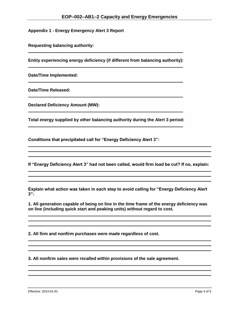
EOP–002–AB1–2 Capacity and Energy Emergencies
Effective: 2014-01-01 Page 4 of 5
Appendix 1 - Energy Emergency Alert 3 Report Requesting balancing authority: Entity experiencing energy deficiency (if different from balancing authority): Date/Time Implemented: Date/Time Released: Declared Deficiency Amount (MW): Total energy supplied by other balancing authority during the Alert 3 period: Conditions that precipitated call for “Energy Deficiency Alert 3”: If “Energy Deficiency Alert 3” had not been called, would firm load be cut? If no, explain: Explain what action was taken in each step to avoid calling for “Energy Deficiency Alert 3”: 1. All generation capable of being on line in the time frame of the energy deficiency was on line (including quick start and peaking units) without regard to cost. 2. All firm and nonfirm purchases were made regardless of cost. 3. All nonfirm sales were recalled within provisions of the sale agreement.
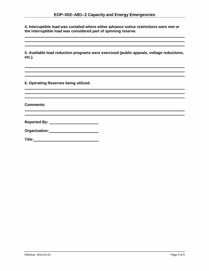
EOP–002–AB1–2 Capacity and Energy Emergencies
Effective: 2014-01-01 Page 5 of 5
4. Interruptible load was curtailed where either advance notice restrictions were met or the interruptible load was considered part of spinning reserve. 5. Available load reduction programs were exercised (public appeals, voltage reductions, etc.). 6. Operating Reserves being utilized. Comments: Reported By: Organization: Title:

Alberta Reliability Standard Load Shedding Plans
EOP-003-AB1-1
Effective: 2012-12-17 Page 1 of 3
EOP–003–AB1–1 Load Shedding Plans
1. Purpose
The purpose of this reliability standard is to ensure plans are in place and plans are implemented to shed load when there is insufficient generation or transmission capacity, to mitigate the risk of an uncontrolled failure of the Interconnection.
2. Applicability
This reliability standard applies to the entities listed below:
(a) the operator of a transmission facility that is part of the bulk electric system;
(b) a market participant receiving service under Rate DTS of the ISO tariff, unless such service is used solely for supplying station service to a generating unit or an aggregated generating facility;
(c) the operator of an electric distribution system who is a counterparty to an agreement with a market participant receiving service under Rate DTS of the ISO tariff, for the provision of load shedding services; and
(d) the ISO.
This reliability standard does not apply to the operator of a transmission facility whose transmission facility is a radial connection from a generating unit or an aggregated generating facility to either the transmission system or to transmission facilities within the city of Medicine Hat.
3. Definitions
Italicized terms used in this reliability standard have the meanings as set out in the Consolidated Authoritative Document Glossary.
4. Requirements
R1 When the AIES is operating with insufficient generation or transmission capacity and after considering all remedial steps, the ISO must issue directives to shed load.
R1.1 Each market participant and operator of an electric distribution system must shed load or reduce MW inflow as directed by the ISO.
R1.2 When coordination with the ISO is not possible or practicable, and after considering all remedial steps, the operator of a transmission facility, when operating with insufficient generation or transmission capacity, must shed load rather than risk an uncontrolled failure of components or cascading of the Interconnection.
R2 The ISO must establish plans for automatic load shedding for underfrequency or under voltage conditions.

EOP– 003– AB–1 Load Shedding Plans
Effective: 2012-12-17 Page 2 of 3
R3 The ISO must submit UFLS plans to WECC for coordination of UFLS plans among other interconnected transmission operators and balancing authorities.
R4 The ISO must coordinate UVLS plans among other interconnected transmission operators and balancing authorities external to Alberta.
R5 The ISO must consider one or more of these factors in designing an automatic load shedding scheme: frequency, rate of frequency decay, voltage level, rate of voltage decay, or power flow levels.
R6 The ISO must implement automatic load shedding in MW blocks established to minimize the risk of further uncontrolled separation, loss of generation, or system shutdown.
R7 After the AIES separates from the Interconnection, if there is insufficient generating capacity to restore frequency following automatic underfrequency load shedding, the ISO must issue directives to shed additional load.
R8 The ISO must coordinate automatic load shedding throughout Alberta with underfrequency isolation of generating units, tripping of shunt capacitors, and other automatic actions that will occur under abnormal frequency, voltage, or power flow conditions.
R9 The ISO must have procedures for directing operator controlled manual load shedding to respond to real-time emergencies.
R10 The ISO must be capable of directing manual load shedding in a time frame adequate for responding to the emergency.
R11 Each market participant and operator of an electric distribution system must be capable of implementing manual load shedding in a time frame adequate for responding to the emergency.
5. Processes and Procedures
No procedures have been defined for this reliability standard.
6. Measures
The following measures correspond to the requirements identified in Section 4 of this reliability standard. For example, MR1 is the measure for R1.
These measures will be used by the ISO in carrying out its compliance monitoring duties in accordance with ISO rule 12. The ISO may consider other data and information, including any provided by a market participant.
MR1 Voice recordings and logs exist to confirm the ISO issued directives to shed load.
MR1.1 Electronic logs, metering or electronic data exists to confirm the market participant or operator of an electric distribution system shed load.
MR1.2 Electronic logs and/or electronic data exist to confirm the operator of a transmission facility shed load.
MR2 Automatic load shedding plans exist. Plans meet the defined need of load shedding situations.
MR3 Written confirmation from WECC that the ISO submitted UFLS plans.

EOP– 003– AB–1 Load Shedding Plans
Effective: 2012-12-17 Page 3 of 3
MR4 Written confirmation from interconnected transmission operators and balancing authorities external to Alberta indicating that the ISO coordinated UVLS plans.
MR5 One or more of these factors were considered in the design of the load shed scheme.
MR6 One or more MW blocks exist in load shed plans or schemes.
MR7 Voice recordings and logs exist to confirm the ISO issued directives to shed additional load.
MR8 ISO rules, interconnection standards or studies exist to show coordination with automatic actions.
MR9 Procedures exist for directing operator controlled manual load shedding.
MR10 Electronic logs, and/or voice recordings exist to confirm the ISO directed manual load shedding. Manual load shedding is performed in a time frame adequate to respond to the emergency as defined in operating procedures or equipment ratings.
MR11 Electronic logs, metering or electronic data exists to confirm the manual load shedding. Manual load shedding is performed in a time frame adequate to respond to the emergency as defined in operating procedures or equipment ratings.
7. Appendices
No appendices have been defined for this reliability standard.
8. Guidelines
No guidelines have been defined for this reliability standard.
Revision History
Effective Description
2012-12-17
Administrative update – “TFO”, “demand customer” and “WSP” replaced with “operator of a transmission facility”, “market participant receiving service under Rate DTS of the ISO tariff” and “operator of an electric distribution system”; and other cleanup items.
2009-06-17 New Issue

Alberta Reliability Standard Event Reporting EOP-004-AB-2
Effective: 2016-08-30 Page 1 of 2 Public
1. Purpose
The purpose of this reliability standard is to improve the reliability of the bulk electric system by requiring the reporting of events by the ISO.
2. Applicability
This reliability standard applies to:
(a) the ISO.
3. Requirements
R1 The ISO must have an event reporting operating plan to report the events identified in Appendix 1 to the NERC and other organizations, as appropriate.
R2 The ISO must, upon recognition of a reportable event identified in Appendix 1, report the event in accordance with its event reporting operating plan as soon as practicable, but no more than five (5) business days following such recognition.
R3 The ISO must validate all contact information contained in its event reporting operating plan each calendar year.
4. Measures
The following measures correspond to the requirements identified in section 3 of this reliability standard. For example, MR1 is the measure for requirement R1.
MR1 Evidence of having an event reporting operating plan as required in requirement R1 exists. Evidence may include, but is not limited to, an event reporting operating plan for the events identified in Appendix 1.
MR2 Evidence of reporting events as required in requirement R2 exists. Evidence may include, but is not limited to, a copy of the completed report, operator logs, voice recordings, electronic communications, or other equivalent evidence.
MR3 Evidence of validating all contact information contained in the event reporting operating plan as required in requirement R3 exists. Evidence may include, but is not limited to, dated records showing contact information, electronic communications or other equivalent evidence.
5. Appendices
Appendix 1 – Reportable Events
Revision History
Date Description
2016-08-30 Initial release.

Alberta Reliability Standard Event Reporting EOP-004-AB-2
Effective: 2016-08-30 Page 2 of 2 Public
Appendix 1
Reportable Events
The following are the reportable events to be contained in the ISO’s event reporting operating plan, as described in requirement R1:
1. a physical threat to a control centre of the ISO, excluding a weather or natural disaster related threat, which has the potential to degrade the normal operation of a control centre of the ISO;
2. a suspicious device or activity at a control centre of the ISO;
3. a situation on the bulk electric system requiring a public appeal for load reduction;
4. a situation on the bulk electric system requiring a system-wide voltage reduction greater than or equal to 3%;
5. a situation on the bulk electric system requiring manual firm load shedding greater than or equal to 100 MW;
6. exceeding an interconnection reliability operating limit within the interconnected electric system for an amount of time that is greater than interconnection reliability operating limit Tv, or exceeding a system operating limit for a major transmission path identified in the table “Major WECC Transfer Paths in the Bulk Electric System”, as provided by the WECC, for more than thirty (30) minutes;
7. a loss of firm load greater than or equal to 300 MW for fifteen (15) minutes or more;
8. an unintended transmission system separation within the interconnected electric system that results in an island of greater than or equal to 100 MW, excluding an island created by the loss of:
a) a transmission system radial connection; b) non-transmission system facilities (distribution level); or c) the interconnection;
9. total generation loss, within one (1) minute, of greater than or equal to 2000 MW;
10. an unplanned evacuation of the control centre of the ISO for thirty (30) continuous minutes or more;
11. a complete loss, for thirty (30) continuous minutes or more, of voice communication systems for the control centre of the ISO; or
12. a complete loss of monitoring capability affecting the control centre of the ISO for thirty (30) continuous minutes or more that renders analysis capability, such as state estimator or contingency analysis, inoperable.

Alberta Reliability Standard System Restoration from Blackstart Resources EOP-005-AB-2
-
Effective: 2019-12-01 Page 1 of 9 Public
1. Purpose
The purpose of this reliability standard is to ensure plans, facilities, and personnel are prepared to enable restoration of the interconnected electric system starting from blackstart resources, to ensure reliability is maintained during restoration, and priority is placed on restoring the interconnected electric system and the interconnection in accordance with the ISO’s restoration plan.
2. Applicability
This reliability standard applies to:
(a) the ISO;
(b) the operator of a transmission facility that the ISO includes in its restoration plan and in a list published on the AESO website that the ISO may amend from time to time in accordance with the process set out in Appendix 1;
(c) the operator of a generating unit that:
(i) is not part of an aggregated generating facility;
(ii) has a maximum authorized real power rating greater than 18 MW; and
(iii) is directly connected to either the transmission system or to transmission facilities within the City of Medicine Hat; and
(d) the operator of an electric distribution system that is identified in the restoration plan of an operator of a transmission facility.
3. Requirements
R1 Each operator of a transmission facility must have a restoration plan approved by the ISO that allows for the restoration of the transmission facilities that it operates to a state whereby the choice of the next load to be restored is not driven by the need to control frequency or voltage, regardless of where the blackstart resource is located, following a disturbance in which:
(a) one or more areas of the interconnected electric system shuts down; and
(b) the use of blackstart resources is required to restore the shut-down area(s) to service.
The restoration plan must include:
R1.1 Strategies for system restoration that are coordinated with the ISO’s restoration plan.
R1.2 Intentionally left blank.
R1.3 Procedures for restoring:
(a) connections with other operators of transmission facilities; and
(b) interconnections with any adjacent interconnected transmission operators under the direction of the ISO.
R1.4 The characteristics of each blackstart resource that is connected to the transmission facilities of the operator of a transmission facility, including but not limited to the:
(a) name;
(b) location;
(c) megawatt and megavar capacity; and

Alberta Reliability Standard System Restoration from Blackstart Resources EOP-005-AB-2
Effective: 2019-12-01 Page 2 of 9 Public
(d) type of generating unit.
R1.5 The identification of the initial switching requirements for any facilities, operated by the operator of a transmission facility, that are a part of the cranking paths identified in the ISO’s restoration plan.
R1.6 Acceptable operating voltage and frequency limits during restoration.
R1.7 Operating processes to reestablish connections between the transmission facilities of the operator of a transmission facility for areas that have been restored and are prepared for reconnection.
R1.8 Operating processes to restore loads required to restore the interconnected electric system, such as:
(a) station service for substations;
(b) generating units to be restarted or stabilized; and
(c) load needed to stabilize generation and frequency, and to provide voltage control.
R1.9 Operating processes for accepting authority from and transferring authority back to the ISO in accordance with the ISO’s restoration plan.
R2 In the event of changes to the roles and specific tasks of entities identified in a restoration plan:
(a) the ISO must provide the affected entities identified in its restoration plan with a description of any changes to their roles and specific tasks prior to the effective date of the plan; and
(b) each operator of a transmission facility must provide the affected entities identified in its approved restoration plan with a description of their roles and any changes to their roles and specific tasks prior to the effective date of the plan.
R3 Each operator of a transmission facility must within sixty (60) days, or another time period agreed to by the ISO, after receiving an updated copy of the ISO’s restoration plan:
(a) review its restoration plan;
(b) align its restoration plan, as necessary, with the ISO’s restoration plan; and
(c) submit its plan to the ISO for approval.
R3.1 The operator of a transmission facility must, where the ISO disapproves a restoration plan submitted pursuant to requirement R3(c), resolve the issues described in the reasons provided by the ISO within a timeframe agreed to by the ISO.
R4 Each operator of a transmission facility must update and submit its revised restoration plan to the ISO for approval:
(a) within ninety (90) days after identifying an unplanned permanent interconnected electric system modification; and
(b) no less than ninety (90) days prior to implementing a planned interconnected electric system modification
that would change the implementation of its restoration plan.

Alberta Reliability Standard System Restoration from Blackstart Resources EOP-005-AB-2
Effective: 2019-12-01 Page 3 of 9 Public
R4.1 The operator of a transmission facility must, where the ISO disapproves a revised restoration plan submitted pursuant to requirement R4, resolve the issues described in the reasons provided by the ISO within a timeframe agreed to by the ISO.
R5 Each operator of a transmission facility must have a copy of its current ISO approved restoration plan within its primary and backup control rooms for the purpose of ensuring it is available to its real time operating personnel.
R5.1 Each operator of a transmission facility must provide a copy of its current ISO approved restoration plan to each operator of an electric distribution system identified in that plan.
R6 The ISO must verify through analysis of actual events, steady state and dynamic simulations, or testing that its restoration plan accomplishes its intended function. This must be completed every five (5) years at a minimum. Such analysis, simulations or testing must verify:
R6.1 the capability of blackstart resources to meet the real power and reactive power requirements of the cranking paths and the dynamic capability to supply initial loads;
R6.2 the location and magnitude of loads required to control voltages and frequency within acceptable operating limits; and
R6.3 the capability of generating units required to control voltages and frequency within acceptable operating limits.
R7 Each affected operator of a transmission facility must, following a disturbance in which one or more areas of the interconnected electric system shuts down and the use of blackstart resources is required to restore the shut-down area to service, implement its restoration plan. If the restoration plan cannot be executed as expected, the operator of a transmission facility must use the strategies for system restoration referred to in requirement R1.1 to facilitate restoration.
R8 Each affected operator of a transmission facility must, following a disturbance in which one or more areas of the interconnected electric system shuts down and the use of blackstart resources is required to restore the shut-down area to service, resynchronize these areas with each applicable:
(a) neighbouring operator of a transmission facility’s area; and
(b) interconnected transmission operator’s area,
but only with the prior authorization of the ISO and in accordance with the procedures included in the ISO’s restoration plan.
R9 The ISO must have blackstart resource testing requirements to verify that each blackstart resource is capable of meeting the requirements of the ISO’s restoration plan. These blackstart resource testing requirements must include:
R9.1 The frequency of testing such that each blackstart resource is tested at least once every three (3) calendar years.
R9.2 A list of required tests including:
(a) a test to verify the ability of the blackstart resource to:
(i) start the generating unit(s) associated with the blackstart resource when isolated with no support from the interconnected electric system; or
(ii) remain energized without connection to the remainder of the interconnected electric system, if designed to do so; and

Alberta Reliability Standard System Restoration from Blackstart Resources EOP-005-AB-2
Effective: 2019-12-01 Page 4 of 9 Public
(b) upon completion of (a), a test to verify the ability of the generating unit(s) associated with the blackstart resource to energize a bus. If it is not possible to energize a bus during the test, the testing entity must otherwise demonstrate that the generating unit(s) associated with the blackstart resource has the capability to energize a bus.
R9.3 The minimum duration of each of the required tests.
R10 Each operator of a transmission facility must include system restoration training for its operating personnel once each calendar year in its operations training program. This training program must include training on the following:
(a) the operator of a transmission facility’s restoration plan including coordination with the ISO and each operator of a generating unit and operator of an aggregated generating facility included in its restoration plan;
(b) restoration priorities;
(c) the building of cranking paths as included in its restoration plan; and
(d) synchronizing re-energized sections of the interconnected electric system.
R11 Each operator of a transmission facility and operator of an electric distribution system must provide a minimum of two (2) hours of system restoration training every two (2) calendar years to its field switching personnel identified as performing unique tasks associated with the operator of a transmission facility’s restoration plan that are outside of their normal tasks.
R12 Each operator of a transmission facility must participate in the ISO’s restoration drills, exercises, or simulations if requested by the ISO.
R13 The ISO must have written blackstart resource agreements or mutually agreed upon procedures or protocols with each operator of a generating unit with a blackstart resource, specifying the terms and conditions of their arrangement. Such agreements must include references to the blackstart resource testing requirements, including those specified in requirement R9.
R14 Each operator of a generating unit with a blackstart resource must have documented procedures for starting each blackstart resource and energizing a bus.
R15 Each operator of a generating unit with a blackstart resource must notify the ISO of any known changes to the capabilities of that blackstart resource affecting the ability of the operator of a generating unit to fulfill the requirements of the ISO’s restoration plan within twenty-four (24) hours of becoming aware of such change.
R16 Each operator of a generating unit with a blackstart resource must perform blackstart resource tests, and maintain records of such testing, in accordance with the testing requirements set by the ISO as referenced in the blackstart resource agreements or mutually agreed upon procedures or protocols.
R16.1 Testing records must include at a minimum:
(a) name of the blackstart resource;
(b) generating unit tested;
(c) date of the test;
(d) duration of the test;
(e) time required to start the generating unit; and

Alberta Reliability Standard System Restoration from Blackstart Resources EOP-005-AB-2
Effective: 2019-12-01 Page 5 of 9 Public
(f) an indication of any testing requirements not met under requirement R9.
R16.2 Each operator of a generating unit with a blackstart resource must provide the blackstart resource test results within thirty (30) days after receiving a request from the ISO.
R17 Each operator of a generating unit with a blackstart resource must provide a minimum of two (2) hours of training every two (2) calendar years to each of its operating personnel responsible for:
(a) the startup of its blackstart resource; and
(b) energizing a bus.
R17.1 The training program must include training on the following:
(a) those elements of the ISO’s restoration plan that are applicable to the blackstart resource, including coordination with the ISO and the adjacent operator of a transmission facility; and
(b) the procedures documented in requirement R14.
R18 Each operator of a generating unit must participate in the ISO’s restoration drills, exercises, or simulations if requested by the ISO.
4. Measures
The following measures correspond to the requirements identified in section 3 of this reliability standard. For example, MR1 is the measure for requirement R1.
MR1 Evidence of having a restoration plan that is approved by the ISO and includes the elements as required in requirement R1 exists. Evidence may include, but is not limited to:
(a) email, mail or other equivalent evidence demonstrating approval of the restoration plan by the ISO; and
(b) a documented restoration plan including the elements identified in requirement R1.
MR2 Evidence of providing a description of any changes to the roles and specific tasks of affected entities identified in the restoration plan as required in requirement R2 exists. Evidence may include, but is not limited to, a documented restoration plan showing the effective date and dated emails with receipts or registered mail with receipts, including a description of any changes to roles and specific tasks, or other equivalent evidence.
MR3 Evidence of reviewing, aligning and submitting the restoration plan as required in requirement R3 exists. Evidence may include, but is not limited to, a documented restoration plan, including a review or revision history, and emails with receipts or registered mail with receipts, or other equivalent evidence.
MR3.1 Evidence of resolving the issues described in the reasons provided by the ISO within a timeframe agreed to by the ISO as required in requirement R3.1 exists. Evidence may include, but is not limited to, emails with receipts or registered mail with receipts, or other equivalent evidence.
MR4 Evidence of updating and submitting the revised restoration plan as required in requirement R4 exists. Evidence may include, but is not limited to:
(a) for the date of identifying any unplanned permanent modifications: logs, a dated report, emails, or other equivalent evidence;

Alberta Reliability Standard System Restoration from Blackstart Resources EOP-005-AB-2
Effective: 2019-12-01 Page 6 of 9 Public
(b) for the date of implementing planned modifications: logs, a dated report, emails, or other equivalent evidence;
(c) for updating the restoration plan: a dated documented restoration plan and revision histories, or other equivalent evidence; and
(d) for submitting the revised restoration plan: emails with receipts or registered mail receipts including submission date, or other equivalent evidence.
MR4.1 Evidence of resolving the issues described in the reasons provided by the ISO within a timeframe agreed to by the ISO as required in requirement R4.1 exists. Evidence may include, but is not limited to, emails with receipts or registered mail with receipts, or other equivalent evidence.
MR5 Evidence of having a copy of the current ISO approved restoration plan within the primary and backup control rooms as required in requirement R5 exists. Evidence may include but is not limited to dated records to show that the latest ISO approved copy of the restoration plan is available in the primary and backup control rooms and to the real time operating personnel in accordance with requirement R5, or other equivalent evidence.
MR5.1 Evidence of providing a copy of the current ISO approved restoration plan to each operator of an electric distribution system as required in requirement R5.1 exists. Evidence may include dated emails with receipts or registered mail receipts, or other equivalent evidence.
MR6 Evidence of verifying every five (5) years that the restoration plan accomplishes its intended function as required in requirement R6 exists. Evidence may include, but is not limited to, dated event analysis assessments, dated study results, or other equivalent evidence.
MR7 Evidence of executing the restoration plan or using the restoration strategies as required in requirement R7 exists. Evidence may include, but is not limited to, sequence of events records, data files, operator logs, voice recordings, electronic communications, or other equivalent evidence.
MR8 Evidence of resynchronizing shut down area(s) with the ISO’s prior authorization and in accordance with the procedures included in the ISO’s restoration plan as required in requirement R8 exists. Evidence may include, but is not limited to, a dated copy of the ISO’s restoration plan and a combination of the following evidence as appropriate:
(a) sequence of events records;
(b) data files;
(c) operator logs;
(d) voice recordings;
(e) electronic communications,
or other equivalent evidence.
MR9 Evidence of having blackstart resource testing requirements as required in requirement R9 exists. Evidence may include, but is not limited to, blackstart resource testing requirement documentation, or other equivalent evidence.
MR10 Evidence of including system restoration training within the operations training program as required in requirement R10 exists. Evidence may include, but is not limited to, a documented

Alberta Reliability Standard System Restoration from Blackstart Resources EOP-005-AB-2
Effective: 2019-12-01 Page 7 of 9 Public
operations training program including system restoration training for operating personnel, or other equivalent evidence.
MR11 Evidence of providing a minimum of two (2) hours of system restoration training every two (2) calendar years as required in requirement R11 exists. Evidence may include, but is not limited to, training records, training documentation including dates and duration, or other equivalent evidence.
MR12 Evidence of participating in the ISO’s restoration drills, exercises, or simulations as required in requirement R12 exists. Evidence may include, but is not limited to:
(1) documentation of the ISO’s request; and
(2) training records, participation records, training documentation, or other equivalent evidence.
MR13 Evidence of having written blackstart resource agreements or mutually agreed upon procedures or protocols as required in requirement R13 exists. Evidence may include, but is not limited to, executed agreements, procedures or protocols, or other equivalent evidence.
MR14 Evidence of having documented procedures for starting each blackstart resource and energizing a bus as required in requirement R14 exists. Evidence may include, but is not limited to, documented procedures, or other equivalent evidence.
MR15 Evidence of notifying the ISO of any known changes to the capabilities of the blackstart resource as required in requirement R15 exists. Evidence may include, but is not limited to, emails with receipts, registered mail receipts, time stamped voice record(ing)s or operator logs, showing when the operator of a generating unit with a blackstart resource became aware of changes to the blackstart resource capabilities and that it notified the ISO within twenty-four (24) hours of becoming aware of such changes as required in requirement R15, or other equivalent evidence.
MR16 Evidence of performing blackstart resource tests, maintaining records of such testing, and providing the blackstart resource test results as required in requirement R16 exists. Evidence may include, but is not limited to, test records, test results, and emails with receipts or registered mail receipts that show that it provided these records to the ISO when requested, or other equivalent evidence.
MR17 Evidence of providing a minimum of two (2) hours of training every two (2) calendar years as required in requirement R17 exists. Evidence may include, but is not limited to, training records, training dates, durations and training materials provided, or other equivalent evidence.
MR18 Evidence of participating in the ISO’s restoration drills, exercises, or simulations as required in requirement R18 exists. Evidence may include, but is not limited to:
(1) documentation of the ISO’s request; and
(2) training records, participation records, training documentation, or other equivalent evidence.
5. Appendices
Appendix 1 – Amending Process for List of Operators of Transmission Facilities Included in the AESO Restoration Plan
Alberta Reliability Standard System Restoration from Blackstart Resources EOP-005-AB-2
Effective: 2019-12-01 Page 8 of 9 Public
Revision History
Date Description
2019-12-01 Unbolded “real time”
2018-07-01 Initial release.
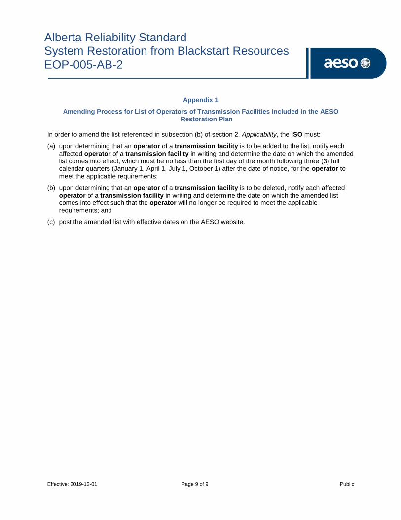
Alberta Reliability Standard System Restoration from Blackstart Resources EOP-005-AB-2
Effective: 2019-12-01 Page 9 of 9 Public
Appendix 1
Amending Process for List of Operators of Transmission Facilities included in the AESO Restoration Plan
In order to amend the list referenced in subsection (b) of section 2, Applicability, the ISO must:
(a) upon determining that an operator of a transmission facility is to be added to the list, notify each affected operator of a transmission facility in writing and determine the date on which the amended list comes into effect, which must be no less than the first day of the month following three (3) full calendar quarters (January 1, April 1, July 1, October 1) after the date of notice, for the operator to meet the applicable requirements;
(b) upon determining that an operator of a transmission facility is to be deleted, notify each affected operator of a transmission facility in writing and determine the date on which the amended list comes into effect such that the operator will no longer be required to meet the applicable requirements; and
(c) post the amended list with effective dates on the AESO website.

Alberta Reliability Standard
System Restoration Coordination
EOP-006-AB-2
Effective: 2015-09-01 Page 1 of 4
1. Purpose
Ensure plans are established and personnel are prepared to enable effective coordination of the system restoration process to ensure reliability is maintained during restoration of the interconnected electric system in the event of a complete or partial blackout.
2. Applicability
This reliability standard applies to:
(a) the ISO.
3. Requirements
R.1. The ISO must have a restoration plan for its area. The scope of the ISO’s restoration plan starts
when contracted blackstart resources are utilized to re-energize a shut down area of the bulk
electric system. The scope of the ISO’s restoration plan ends when each operator of a
transmission facility is interconnected and the ISO’s area is connected to all of its neighbouring
reliability coordinator areas, provided facilities are available to be returned to service. The
restoration plan shall include:
R1.1. a strategy to be employed during restoration events for restoring the interconnected electric system including minimum criteria for meeting the objectives of the ISO’s restoration plan;
R1.2. operating processes for restoring the interconnected electric system;
R1.3. the elements of coordination between the ISO and each operator of a transmission facility in accordance with the ISO’s system restoration plan;
R1.4. descriptions of the elements of coordination of restoration plans with neighbouring
reliability coordinators; R1.5. criteria and conditions for reestablishing connections between each operator of a
transmission facility within its area, with transmission operators in other reliability coordinator areas, and with other reliability coordinators;
R1.6. reporting requirements for the entities within the ISO’s area during a restoration event; R1.7. criteria for sharing information regarding restoration with neighbouring reliability
coordinators and with operators of transmission facilities within the ISO’s area; and R1.8. identification of the ISO as the primary contact for disseminating information regarding
restoration to neighbouring reliability coordinators, and to operators of transmission facilities within its area. R1.9. Intentionally left blank.

Alberta Reliability Standard
System Restoration Coordination
EOP-006-AB-2
Effective: 2015-09-01 Page 2 of 4
R2. The ISO must distribute its most recent restoration plan to each operator of a transmission facility, as referenced in the ISO’s restoration plan, and to neighbouring reliability coordinators within thirty (30) days of creation or revision.
R3. The ISO must review its restoration plan within thirteen (13) months of the last review.
R4. The ISO must review its neighbouring reliability coordinator’s restoration plans.
R4.1. If the ISO finds conflicts between its restoration plans and any of its neighbours, the conflicts must be resolved in thirty (30) days.
R5. The ISO must review the restoration plans or procedures of operators of transmission facilities
within its area that are required to be submitted to the ISO under any ISO rules or reliability
standards.
R5.1. The ISO must determine whether each of the restoration plans or procedures referenced in requirement R5 is coordinated and compatible with the ISO’s restoration plan and each of the other restoration plans or procedures referenced in requirement R5. The ISO must approve or disapprove, with stated reasons, the restoration plan or procedure submitted by an operator of a transmission facility within thirty (30) days following the receipt of the restoration plan or procedure.
R6. The ISO must have, within its primary and backup control rooms, so that it is available to all of its operating personnel, a copy of its latest restoration plan and copies of the latest restoration plans or procedures of each operator of a transmission facility in the ISO’s area that is required to have an
approved plan or procedure in accordance with any ISO rule or reliability standard.
R7. The ISO must work with each affected operator of a generating unit, operator of an aggregated generating facility, and operator of a transmission facility as well as neighbouring reliability coordinators to monitor restoration progress, coordinate restoration, and take actions to restore the bulk electric system frequency within acceptable operating limits. If the restoration plan cannot be completed as expected, the ISO must utilize its restoration plan strategies to facilitate restoration of the interconnected electric system.
R8. The ISO must coordinate or authorize resynchronizing islanded areas that bridge boundaries between each operator of a transmission facility or a boundary between the ISO’s area and a reliability coordinator area. If the resynchronization cannot be completed as expected the ISO must utilize its restoration plan strategies to facilitate resynchronization.
R9. The ISO must include within its operations training program, annual interconnected electric
system restoration training for its operating personnel to assure the proper execution of its
restoration plan. This training program must address the following
R9.1. the coordination role of the ISO; and
R9.2. reestablishing WECC Paths 1 and 83.
R10. The ISO must conduct two (2) scheduled instances of a system restoration drill, exercise, or
simulation per calendar year, which must provide an opportunity for each operator of a
transmission facility, operator of a generating unit and operator of an aggregated generating
Alberta Reliability Standard
System Restoration Coordination
EOP-006-AB-2
Effective: 2015-09-01 Page 3 of 4
facility to attend as dictated by the particular scope of the drill, exercise, or simulation that is being
conducted.
R10.1. The ISO must request each operator of a transmission facility, operator of a generating unit and operator of an aggregated generating facility, as identified in the ISO’s restoration plan, to participate in a drill, exercise, or simulation at least once every two calendar years
4. Measures
The following measures correspond to the requirements identified in section 3 of this reliability standard. For example, MR1 is the measure for requirement R1.
MR1 Evidence of having a restoration plan as required in requirement R1 exists. Evidence may include, but is not limited to, a dated copy of the restoration plan.
MR2 Evidence of distributing the restoration plan as required in requirement R2 exists. Evidence may include, but is not limited to, e-mails with receipts or other equivalent evidence.
MR3. Evidence of reviewing the restoration plan as required in requirement R3 exists. Evidence may include, but is not limited to, a review signature sheet, or revision histories, or other equivalent evidence.
MR4. Evidence of reviewing neighboring reliability coordinator’s restoration plans and resolving any conflicts within thirty (30) days as required in requirement R4 exists.
MR5. Evidence of reviewing, approving or disapproving, and notifying each operator of a transmission facility as required in requirement R5 exists. Evidence may include, but is not limited to, a review
signature sheet or emails, or other equivalent evidence.
MR6. Evidence of having copies of restoration plans as required in requirement R6 exists. Evidence may include, but is not limited to, e-mails, restoration plans or procedures documentation, or other equivalent evidence.
MR7. Evidence of monitoring and coordinating restoration progress as required in requirement R7 exists. Evidence may include, but is not limited to, voice recordings, e-mail, dated computer printouts, operator logs or other equivalent evidence.
MR8. If there has been a resynchronizing of an islanded area, the ISO and each reliability coordinator involved may have evidence that it coordinated or authorized resynchronizing in accordance with requirement R8. Evidence may include, but is not limited to, voice recordings, e-mails, operator logs or other equivalent evidence.
MR9. The ISO may have an electronic or hard copy of its training records available showing that it has provided training in accordance with requirement R9.
MR10. The ISO may have evidence that it conducted two scheduled instances of a system restoration drill, exercise, or simulation per calendar year and that operators of a transmission facility and operators of a generating unit and operators of an aggregated generating facility as identified in the ISO’s restoration plan were invited in accordance with requirement R10. Evidence may
include, but is not limited to, e-mails or other equivalent evidence.
Alberta Reliability Standard
System Restoration Coordination
EOP-006-AB-2
Effective: 2015-09-01 Page 4 of 4
Revision History
Effective Date Description
2015-09-01 Initial release.

Alberta Reliability Standard Loss of Control Centre Functionality EOP-008-AB-1
Effective: 2019-07-01 Page 1 of 4
1. Purpose
The purpose of this reliability standard is to ensure continued reliable operations of the bulk electric system in the event that a control centre becomes inoperable.
2. Applicability
This reliability standard applies to:
(a) the ISO; and
(b) the operator of a transmission facility who operates a control centre that controls transmission facilities that are part of the bulk electric system.
This reliability standard does not apply to the operator of a transmission facility whose transmission facilities are only:
(a) radial transmission facilities connecting to:
load;
one or more generating units; and / or
one or more aggregated generating facilities; or
(b) either part of an industrial complex or connected to an industrial complex and cannot interrupt power flow on the interconnected electric system, other than power flow on its own transmission facilities.
3. Requirements
R1 The ISO and each operator of a transmission facility must have a current operating plan describing the manner in which it continues to meet its functional obligations with regard to the reliable operations of the bulk electric system in the event that its primary control centre functionality is lost.
This operating plan for backup functionality must include the following, at a minimum:
(a) the location and method of implementation for providing backup functionality;
(b) a summary description of the items required to support the backup functionality. These items must include, at a minimum:
(i) tools and applications to ensure that system operators have situational awareness of the bulk electric system;
(ii) data communications;
(iii) voice communications;
(iv) power source(s); and
(v) physical and cyber security;
(c) an operating process for keeping the backup functionality consistent with the primary control centre;
(d) operating procedures, including decision authority, for use in determining when to implement the operating plan for backup functionality;

Alberta Reliability Standard Loss of Control Centre Functionality EOP-008-AB-1
Effective: 2019-07-01 Page 2 of 4
(e) a transition period between the decision to transfer functionality to the back up control centre following the loss of primary control centre functionality and the time to fully implement the backup functionality that is less than or equal to two (2) hours; and
(f) an operating process describing the actions to be taken during the transition period between the loss of primary control centre functionality and the time to fully implement the backup functionality items identified in requirement R1, part (b). The operating process must include at a minimum:
(i) a list of all entities to notify when there is a change in operating locations;
(ii) actions to manage the risk to the bulk electric system during the transition from primary to backup functionality, as well as during outages of the primary or backup functionality; and
(iii) identification of the roles for personnel involved during the initiation and implementation of the operating plan for backup functionality.
R2 The ISO and each operator of a transmission facility must have a copy of its current operating plan for backup functionality available at its primary control centre and at the location providing backup functionality.
R3 The ISO must have a backup control centre facility (provided through its own dedicated backup facility or at another entity’s control centre staffed with NERC certified “reliability coordinator operators” when control has been transferred to the backup facility) that provides the functionality required for maintaining compliance with all reliability standards that depend on primary control centre functionality. To avoid requiring a tertiary facility, a backup facility is not required during:
(a) planned outages of the primary or backup facilities of two (2) weeks or less; or
(b) unplanned outages of the primary or backup facilities.
R4 Each operator of a transmission facility must, when control has been transferred to the backup functionality location, have backup functionality provided either through:
(a) a facility staffed by operators that are certified in accordance with any applicable reliability standards; or
(b) contracted services staffed by operators that are certified in accordance with any applicable reliability standards
that includes monitoring, control, logging, and alarming sufficient for maintaining compliance with all reliability standards that depend on the operator of a transmission facility’s primary control centre functionality.
To avoid requiring tertiary functionality, backup functionality is not required during:
(i) planned outages of the primary or backup functionality of two (2) weeks or less; or
(ii) unplanned outages of the primary or backup functionality.
R5 The ISO and each operator of a transmission facility must annually review and approve its operating plan for backup functionality.
R5.1 An update and approval of the operating plan for backup functionality must take place within sixty (60) days of identifying any necessary changes to any part of the operating plan described in requirement R1.

Alberta Reliability Standard Loss of Control Centre Functionality EOP-008-AB-1
Effective: 2019-07-01 Page 3 of 4
R6 The ISO and each operator of a transmission facility must have primary and backup functionality that do not depend on each other for the control centre functionality required to maintain compliance with reliability standards.
R7 The ISO and each operator of a transmission facility must conduct and document results of an annual test of its operating plan that demonstrates:
R7.1 The transition time between the decision to transfer functionality to the backup control centre following the simulated loss of primary control centre functionality and the time to fully implement the backup functionality; and
R7.2 The backup functionality for a minimum of two (2) continuous hours.
R8 The following requirements apply in the event of a loss of primary or backup functionality that is anticipated to last for more than six (6) months:
R8.1 Where the operator of a transmission facility loses primary or backup functionality as described in requirement R8, it must provide a plan to the ISO within six (6) months of the date when the functionality is lost, showing how it will re-establish primary or backup functionality; and
R8.2 Where the ISO loses primary or backup functionality as described in requirement R8, it must provide a plan to the WECC within six (6) months of the date when the functionality is lost, showing how it will re-establish primary or backup functionality.
4. Measures
The following measures correspond to the requirements identified in section 3 of this reliability standard. For example, MR1 is the measure for requirement R1.
MR1 Evidence of having a current operating plan for backup functionality as required in requirement R1 exists. Evidence may include, but is not limited to, a dated, current operating plan with specified elements or other equivalent evidence.
MR2 Evidence of having an electronic or paper copy of the current operating plan for backup functionality available at its primary control centre and at the location providing backup functionality as required in requirement R2 exists.
Evidence may include, but is not limited to, a current electronic or paper copy of the operating plan, operator log identifying when the plan was put into the control centre, or other equivalent evidence.
MR3 Evidence of having a backup control centre facility that provides the functionality and is staffed as required in requirement R3 exists. Evidence may include, but is not limited to, documentation identifying that the backup control centre facility is staffed with NERC certified “reliability coordinator operators” and provides the same functionality to maintain compliance with all reliability standards as the primary control centre, or other equivalent evidence.
MR4 Evidence of having backup functionality provided either through a facility or contracted services staffed as required in requirement R4 exists. Evidence may include, but is not limited to, documentation identifying that the backup functionality includes monitoring, control, logging, and alarming sufficient for maintaining compliance with all reliability standards that depend on the primary control centre functionality, or other equivalent evidence.
MR5 Evidence of reviewing and approving annually the operating plan for backup functionality as required in requirement R5 exists. Evidence may include, but is not limited to, a dated, current,

Alberta Reliability Standard Loss of Control Centre Functionality EOP-008-AB-1
Effective: 2019-07-01 Page 4 of 4
operating plan for backup functionality, including a revision and approval history, or other equivalent evidence.
MR5.1 Evidence of updating and approving the operating plan for backup functionality as required in requirement R5.1 exits. Evidence may include, but is not limited to, an updated and approved operating plan for backup functionality within sixty (60) days of any changes to any part of the operating plan described in requirement R1, or other equivalent evidence.
MR6 Evidence of having primary and backup functionality that do not depend on each other for the control centre functionality required to maintain compliance with reliability standards as required in requirement R6 exists. Evidence may include, but is not limited to, documentation or drawings that show the independence of the two (2) control centres, or other equivalent evidence.
MR7 Evidence of conducting an annual test for backup functionality and documenting the results of the operating plan as required in requirement R7 exists. Evidence may include, but is not limited to, testing documentation or other equivalent evidence.
MR8 Evidence for requirement R8 is included in the following measures:
MR8.1 Evidence of providing a plan to the ISO as required in requirement R8.1 exists. Evidence may include, but is not limited to, a dated email or letter providing the plan to the ISO, or other equivalent evidence.
MR8.2 Evidence of providing a plan to the WECC as required in requirement R8.2 exists. Evidence may include, but is not limited to, a dated email or letter to the WECC, or other equivalent evidence.
Revision History
Date Description
2019-07-01 Initial release.
Alberta Reliability Standard
Facility Connection Requirements FAC-001-AB-0
Effective: 2010-09-24 Page 1 of 2
FAC–001–AB–0 Facility Connection Requirements
1. Purpose
The purpose of this reliability standard is to establish connection and performance requirements for facilities connecting to the AIES.
2. Applicability
This reliability standard applies to:
ISO
3. Definitions
Italicized terms used in this reliability standard have the meanings as set out in the Alberta Reliability Standards Glossary of Terms and Part 1 of the ISO Rules.
4. Requirements
R1 The ISO must document transmission interconnection requirements to comply with all reliability standards. The ISO’s transmission interconnection requirements must address connection requirements for:
R1.1 Generating units
R1.2 Transmission facilities
R1.3 Transmission connected end-use customer’s facilities
R2 The ISO’s transmission interconnection requirements or project functional specification must address, but is not limited to, the following items:
R2.1 Voltage level and MW and MVAR capacity or demand at point of connection
R2.2 Breaker duty and surge protection
R2.3 System protection and coordination
R2.4 Metering and telecommunications
R2.5 Grounding and safety issues
R2.6 Insulation and insulation coordination
R2.7 Voltage, reactive power, and power factor control
R2.8 Power quality impacts
R2.9 Equipment ratings
R2.10 Synchronizing of facilities
R2.11 Maintenance coordination
R2.12 Operational issues (abnormal frequency and voltages)

FAC–001–AB–0 Facility Connection Requirements
Effective: 2010-09-24 Page 2 of 2
R2.13 Inspection requirements for existing or new facilities
R2.14 Communications and procedures during normal and emergency operating conditions
R3 The ISO must assess the long term implications to the AIES of any facility to be connected to it.
R4 The ISO must maintain and update as required and post on its website its transmission interconnection requirements.
5. Processes and Procedures
No procedures have been defined for this reliability standard.
6. Measures
The following measures correspond to the requirements identified in Section 4 of this reliability standard. For example, MR1 is the measure for R1.
MR1 The ISO transmission interconnection requirements include requirements for generating units, transmission facilities and transmission connected end use customer facilities.
The ISO transmission interconnection requirements include content that is compliant and consistent with all reliability standards.
MR2 The ISO transmission interconnection requirements or project functional specifications contain information addressing each item identified in R2.
MR3 The assessment made in R3 is included in either the transmission interconnection requirements or project functional specification.
MR4 The ISO transmission interconnection requirements are posted on its website.
A revision history for the ISO transmission interconnection requirements shows that updates were made for each change to reliability standards, as appropriate.
Changes to the ISO transmission interconnection requirements are completed within 12 months of the Commission approving a change in the reliability standards.
7. Appendices
No appendices have been defined for this reliability standard.
8. Guidelines
No guidelines have been defined for this reliability standard.
Revision History
Effective Description
2010-09-24 New Issue
Alberta Reliability Standard
Coordination of Plans for New Facilities FAC-002-AB-0
Effective: 2010-03-22 Page 1 of 2
FAC–002–AB–0 Coordination of Plans for New Facilities
1. Purpose
The purpose of this reliability standard is to demonstrate that proper evaluation of potential reliability impacts of new transmission facilities to be connected to the AIES has occurred.
2. Applicability
This reliability standard applies to:
ISO
3. Definitions
Italicized terms used in this reliability standard have the meanings as set out in the Alberta Reliability Standards Glossary of Terms and Part 1 of the ISO Rules.
4. Requirements
R1 The ISO must retain the documentation of its evaluation of the potential reliability impact of the new transmission facilities and their connections on the AIES for three years after energization.
R2 The ISO must provide the documentation referred to in requirement R1 to the WECC within 30 calendar days of its request, provided such request is made with the three year period referred to in requirement R1.
5. Processes and Procedures
No procedures have been defined for this reliability standard.
6. Measures
The following measures correspond to the requirements identified in Section 4 of this reliability standard. For example, MR1 is the measure for R1.
MR1 Documentation exists for the past three years and is made available when requested per R1.
MR2 Confirmation exists that documentation was received if requested.
7. Appendices
No appendices have been defined for this reliability standard.
8. Guidelines
No guidelines have been defined for this reliability standard.

FAC–001–AB–0 Coordination of Plans for New Facilities
Effective: 2010-03-22 Page 2 of 2
Revision History
Effective Description
2010-03-22 New Issue

Alberta Reliability Standards Facilities Design, Connections and Maintenance
FAC-003-AB1-1
Effective: 2012-12-17 Page 1 of 6
FAC-003-AB1-1 Transmission Vegetation Management Program
1. Purpose
The purpose of this reliability standard is to improve the reliability of electric transmission systems by preventing outages from vegetation located on a right-of-way, corridor or other route (collectively “ROW”) and minimizing outages from vegetation located adjacent to a ROW, maintaining clearances between transmission facilities and vegetation on and along a ROW, and reporting vegetation related outages of electric transmission systems to the ISO and WECC.
2. Applicability
This reliability standard applies to:
(a) the legal owner of a transmission facility with transmission facilities operated at 200 kV and above and any lower voltage transmission facilities designated by the ISO as critical to the reliability of the AIES as identified in Appendix A; provided that transmission facilities on ROWs that are assessed and identified on an annual basis not to have vegetation capable of growing higher than 2 meters are excluded; and
(b) the ISO.
3. Definitions
Italicized terms used in this reliability standard have the meanings as set out in the Consolidated Authoritative Document Glossary.
4. Requirements
R1 Each legal owner of a transmission facility must prepare a TVMP. This program is to be updated at least annually. The TVMP must include the objectives, practices, approved procedures, and work specifications 1 of the legal owner of a transmission facility.
R1.1 The TVMP must define a schedule for and the type (aerial or ground) of ROW vegetation inspections. This schedule must be flexible enough to adjust for changing conditions. The inspection schedule must be based on the anticipated growth of vegetation and any other environmental or operational factors that could impact the relationship of vegetation to the transmission facilities of the legal owner of a transmission facility. The legal owner of a transmission facility must perform vegetation inspections as identified in the schedule.
1 ANSI A300, Tree Care Operations – Tree, Shrub, and Other Woody Plant Maintenance – Standard Practices, while
not a requirement of this reliability standard, is considered by NERC to be an industry best practice.

FAC-003-AB1-1 Transmission Vegetation Management Program
Effective: 2012-12-17 Page 2 of 6
R1.2 The TVMP must identify and document clearances between vegetation and any overhead ungrounded supply conductors, taking into consideration transmission line voltage, the effects of ambient temperature on conductor sag under maximum design loading, and the effects of wind velocities on conductor sway. Specifically, the legal owner of a transmission facility must establish clearances to be achieved at the time of vegetation management work identified herein as Clearance 1, and must also establish and maintain a set of clearance requirements identified herein as Clearance 2 to prevent flashover between vegetation and overhead ungrounded supply conductors.
R1.2.1 Clearance 1 — Each legal owner of a transmission facility must determine and document appropriate clearance distances to be achieved at the time of vegetation management work based upon local conditions and the expected time frame in which the legal owner of a transmission facility plans to return for future vegetation management work. Local conditions may include, but are not limited to: operating voltage, appropriate vegetation management techniques, fire risk, reasonably anticipated tree and conductor movement, species types and growth rates, species failure characteristics, local climate and rainfall patterns, line terrain and elevation, location of the vegetation within the span, and worker approach distance requirements. Clearance 1 distances must be greater than those defined in Clearance 2.
R1.2.2 Clearance 2 — Each legal owner of a transmission facility must determine and document specific minimum radial clearance distances to be maintained between vegetation and conductors under all rated electrical operating conditions. These minimum radial clearance distances are necessary to prevent flashover between vegetation and conductors and will vary due to such factors as altitude and operating voltage. Subject to R1.2.2.1 and R1.2.2.2, the documented specific minimum radial clearance distances must be no less than those set forth in the Institute of Electrical and Electronics Engineers (IEEE) Standard 516-2003 (Guide for Maintenance Methods on Energized Power Lines) and as specified in its Section 4.2.2.3, Minimum Air Insulation Distances without Tools in the Air Gap.
R1.2.2.1 Where transmission system transient overvoltage factors are not known, clearances must be derived from Table 5, IEEE 516-2003, phase-to-ground distances, with appropriate altitude correction factors applied.
R1.2.2.2 Where transmission system transient overvoltage factors are known, clearances must be derived from Table 7, IEEE 516-2003, phase-to-phase voltages, with appropriate altitude correction factors applied.
R1.3 All personnel directly involved in the design and implementation of the TVMP must hold appropriate qualifications and must have taken appropriate training, as defined by the legal owner of a transmission facility, to perform their duties.
R1.4 Each legal owner of a transmission facility must develop mitigation measures to achieve sufficient clearances for the protection of its transmission facilities
FAC-003-AB1-1 Transmission Vegetation Management Program
Effective: 2012-12-17 Page 3 of 6
when it identifies locations on the ROW where it is restricted from attaining Clearance 1 distances.
R1.5 Each legal owner of a transmission facility must establish and document a process for the immediate communication of vegetation conditions that present an imminent threat of a transmission line outage.
This is so that action (temporary reduction in line rating, switching line out of service, etc.) may be taken until the threat is relieved.
R2 The legal owner of a transmission facility must create and implement an annual plan for vegetation management work to ensure the reliability of its transmission facilities. The plan must describe the methods used, such as manual clearing, mechanical clearing, herbicide treatment, or other actions. The plan must be flexible enough to adjust to changing conditions, taking into consideration anticipated growth of vegetation and all other environmental factors that may have an impact on the reliability of the AIES. Adjustments to the plan must be documented as they occur. The plan must include the time required to obtain permissions or permits from landowners or regulatory authorities. Each legal owner of a transmission facility must have systems and procedures for documenting and tracking the planned vegetation management work and ensuring that the vegetation management work was completed according to its work specifications.
R3 Each legal owner of a transmission facility must report quarterly to the ISO, sustained outages to its transmission lines determined by the legal owner of a transmission facility to have been caused by vegetation.
R3.1 Multiple sustained outages on an individual transmission line, if caused by the same vegetation, must be reported as one outage regardless of the actual number of outages within a 24-hour period.
R3.2 The legal owner of a transmission facility is not required to report to the ISO, sustained outages to its transmission lines caused by either:
vegetation falling onto a transmission line from outside the ROW caused by a natural disasters are not considered reportable (examples of disasters include, but are not limited to, earthquakes, fires, tornados, hurricanes, landslides, wind shear, ice storms, floods, major storms as defined either by the legal owner of a transmission facility or an applicable regulatory body); or
vegetation falling onto a transmission line caused by human or animal activity are not considered reportable (examples of human or animal activity include, but are not limited to, logging, animal severing tree, vehicle contact with tree, arboricultural, horticultural or agricultural activities, or removal/digging of vegetation).
R3.3 The outage information provided by the legal owner of a transmission facility to the ISO must include at a minimum:
number or name of the transmission line(s) forced out of service;
date and time;
duration of the outage;
FAC-003-AB1-1 Transmission Vegetation Management Program
Effective: 2012-12-17 Page 4 of 6
description of the cause of the outage;
other pertinent comments; and
remedial action taken by the legal owner of a transmission facility.
R3.4 An outage must be categorized by the legal owner of a transmission facility as one of the following:
R3.4.1 Category 1 — Grow-ins: Outages caused by vegetation growing into transmission lines from vegetation inside and/or outside of the ROW;
R3.4.2 Category 2 — Fall-ins: Outages caused by vegetation falling into transmission lines from inside the ROW; or
R3.4.3 Category 3 — Fall-ins: Outages caused by vegetation falling into transmission lines from outside the ROW.
R4 The ISO must report quarterly to WECC, sustained outages to transmission lines determined by the legal owner of a transmission facility to have been caused by vegetation.
R4.1 Multiple sustained outages within a 24-hour period on an individual transmission line, if caused by the same vegetation, must be reported as one outage regardless of the actual number of outages.
R4.2 The ISO is not required to report to WECC, sustained outages to transmission lines caused by either:
outages from vegetation falling onto transmission lines from outside the ROW caused by natural disasters are not reportable (examples of disasters include, but are not limited to, earthquakes, fires, tornados, hurricanes, landslides, wind shear, ice storms, floods, major storms as defined either by the legal owner of a transmission facility, or an applicable regulatory body); or
outages from vegetation caused by human or animal activity are not considered reportable (examples of human or animal activity include, but are not limited to, logging, animal severing tree, vehicle contact with tree, arboricultural, horticultural or agricultural activities, or removal/digging of vegetation).
R4.3 The outage information provided by the ISO to WECC must include at a minimum:
number or name of the transmission line(s) forced out of service;
date and time;
duration of the outage;
description of the cause of the outage;
other pertinent comments; and
remedial action taken by the legal owner of a transmission facility.
R4.4 An outage must be categorized by the legal owner of a transmission facility as one of the following:

FAC-003-AB1-1 Transmission Vegetation Management Program
Effective: 2012-12-17 Page 5 of 6
R4.4.1 Category 1 — Grow-ins: Outages caused by vegetation growing into transmission lines from vegetation inside and/or outside of the ROW;
R4.4.2 Category 2 — Fall-ins: Outages caused by vegetation falling into transmission lines from inside the ROW; or
R4.4.3 Category 3 — Fall-ins: Outages caused by vegetation falling into transmission lines from outside the ROW.
5. Procedures
No procedures have been defined for this reliability standard.
6. Measures
The following measures correspond to the requirements identified in Section 4 of this reliability standard. For example, MR1 is the measure for R1.
These measures will be used by the ISO in carrying out its compliance monitoring duties in accordance with ISO rule 12. The ISO may consider other data and information, including any provided by a market participant.
MR1 A revision history of the TVMP is provided annually to the ISO. A TVMP exists and is provided in the format specified in the ISO TVMP template. The TVMP is provided within 30 days of request. The TVMP is complete and includes the required component sections specified in the template.
MR1.1 A vegetation inspection schedule exists in the TVMP. The schedule is completed in accordance with the ISO TVMP template. The schedule includes all applicable transmission lines. Documentation exists to show that the vegetation inspections have been performed.
MR1.2 Clearance 1 and Clearance 2 values exist in the TVMP
MR1.2.1 Clearance 1 values exist for every transmission line. Clearance 1 values specified are greater than those of Clearance 2.
MR1.2.2 Clearance 2 values exist for every transmission line. Clearance 2 values specified are greater than the minimum clearances set in IEEE standards for the applicable scenarios.
MR1.3 Requirements, training, and qualifications for positions responsible for preparing and implementing the TVMP exist. Documentation exists to confirm that personnel meet the requirements, training, and qualifications of the position. Acceptable documentation includes training records, licenses, certificates, and resumes.
MR1.4 A list exists and specifies locations on the ROW where Clearance 1 is not attainable. Mitigation measures exist where there are restrictions. Mitigating measures are appropriate and meet the intent of this reliability standard.
MR1.5 A documented process or procedure for communication exists. The process is appropriate and of sufficient detail to meet the intent of the requirement.
MR2 A work plan exists in the form of the ISO vegetation management work plan template. The work plan is complete. The work plan is submitted annually and within 30 days of being requested.

FAC-003-AB1-1 Transmission Vegetation Management Program
Effective: 2012-12-17 Page 6 of 6
Evidence exists to show that the work plan is implemented. Evidence may include status and inspection reports, work orders, and/or contracts. The work plan is being followed in accordance to the schedule. The work is completed in accordance with the work plan. Revision documentation exists where the plan has been revised. Evidence is provided to the ISO within 30 days of a request.
MR3 to 3.4.3 Quarterly reports are submitted to the ISO by the dates specified by the ISO. Quarterly reports contain all sustained outages caused by vegetation for that reporting period. Quarterly reports contain the specific information in the requirement.
MR4 to 4.4.3 Quarterly reports are submitted to the WECC by dates specified by WECC. Quarterly reports contain all sustained outages caused by vegetation received by the ISO for that reporting period. Quarterly reports contain the specific information in the requirement.
7. Appendices
Appendix A - Transmission Facilities Designated as Critical to the AIES
The following facilities have been identified as critical to the AIES and require the application of this reliability standard:
887L (Pocaterra T48S - Alberta / BC border);
777L (Pocaterra T48S - Seebe T245S);
786L (Coleman T799S - Alberta / BC border); and
170L (Coleman T799S - Pincher Creek T396S).
8. Guidelines
No guidelines have been defined for this reliability standard.
Revision History
Date Description
2012-12-17 Administrative update – “TFO” replaced with the “legal owner of a transmission facility”; and other minor cleanup items.
2010-01-26 R1 and R2
2013-10-01 New Issue
Alberta Reliability Standard Facility Ratings FAC-008-AB-3
Effective: 2019-01-01 for new facilities; 2019-12-01 for remove bold “real-time” 2020-01-01 for existing facilities
Page 1 of 6 Public
1. Purpose
The purpose of this reliability standard is to ensure that the facility ratings used in the reliable planning and operation of the transmission system are determined based on technically sound principles. A facility rating is an essential component in the determination of system operating limits.
2. Applicability
This reliability standard applies to:
(a) the legal owner of a transmission facility:
(i) that is part of the bulk electric system, except for transformers that do not have a primary terminal and at least one (1) secondary terminal engerized at 100 kV or higher;
(ii) that the ISO:
(A) determines is necessary for the reliable operation of either the interconnected electric system or the City of Medicine Hat electric system; and
(B) publishes on the AESO website and may amend from time to time on notice to market participants in accordance with the process set out in Appendix 1;
(iii) who owns a generating unit step-up transformer for those generating units listed in subsection (b); or
(iv) who owns a transformer connected to a blackstart resource;
(b) the legal owner of a generating unit that is:
(i) directly connected to the bulk electric system and has a maximum authorized real power rating greater than 18 MW, unless the generating unit is part of an industrial complex;
(ii) within a power plant that:
(A) is not part of an aggregated generating facility;
(B) is directly connected to the bulk electric system; and
(C) has a combined maximum authorized real power rating greater than 67.5 MW,
unless the power plant is part of an industrial complex;
(iii) a blackstart resource;
(iv) directly connected to the bulk electric system and within an industrial complex with supply transmission service greater than 67.5 MW; or
(v) material to this reliability standard and to the reliability of the bulk electric system, regardless of maximum authorized real power rating, as the ISO determines and publishes on the AESO website and may amend from time to time in accordance with the process set out in Appendix 1; and
(c) the legal owner of an aggregated generating facility that is:
(i) directly connected to the bulk electric system and has a maximum authorized real power rating greater than 67.5 MW, unless the aggregated generating facility is part of an industrial complex;
(ii) a blackstart resource;

Alberta Reliability Standard Facility Ratings FAC-008-AB-3
Effective: 2019-01-01 for new facilities; 2019-12-01 for remove bold “real-time” 2020-01-01 for existing facilities
Page 2 of 6 Public
(iii) directly connected to the bulk electric system and within an industrial complex with supply transmission service greater than 67.5 MW; or
(iv) regardless of maximum authorized real power rating, material to this reliability standard and to the reliability of the bulk electric system as the ISO determines and publishes on the AESO website and may amend from time to time in accordance with the process set out in Appendix 1.
3. Requirements
R1 Each legal owner of a generating unit and legal owner of an aggregated generating facility must have documentation for determining the facility ratings of its facilities:
(a) up to the low side terminals of the step-up transformer if the legal owner of the generating unit or legal owner of the aggregated generating facility does not own the step-up transformer; or
(b) including the step-up transformer and associated terminal equipment (as applicable based on ownership) if the legal owner of the generating unit or legal owner of the aggregated generating facility owns the step-up transformer.
R1.1 The documentation must contain assumptions used to rate the facilities and at least one (1) of the following:
(a) design or construction information such as design criteria, ratings provided by equipment manufacturers, equipment drawings and/or specifications, engineering analyses, method(s) consistent with industry standards (e.g. the American National Standards Institute and the Institute of Electrical and Electronic Engineers (“IEEE”)), or an established engineering practice that has been verified by testing or engineering analysis; or
(b) operational information such as commissioning test results, performance testing or historical performance records, any of which may be supplemented by engineering analyses.
R1.2 The documentation must be consistent with the principle that the facility ratings do not exceed the most limiting applicable equipment rating of the individual equipment that comprises that facility.
R2 Each legal owner of a generating unit and legal owner of an aggregated generating facility must have a documented methodology for determining the facility ratings of its facilities connected between the location specified in requirement R1 and the interface with a transmission facility (based on equipment ownership) that contains all of the following:
R2.1 the method used to establish the equipment ratings of the equipment that comprises the facility must be consistent with at least one (1) of the following:
(a) ratings provided by equipment manufacturers or obtained from equipment manufacturer specifications, such as the nameplate rating;
(b) one (1) or more industry standards developed through an open process such as the IEEE or the International Council on Large Electric Systems (“CIGRE”); or
(c) a practice that has been verified by testing, performance history or engineering analysis;
R2.2 the underlying assumptions, design criteria, and methods used to determine the equipment ratings identified in requirement R2.1, including identification of how each of the following were considered:
(a) equipment rating standard(s) used in development of this method;
Alberta Reliability Standard Facility Ratings FAC-008-AB-3
Effective: 2019-01-01 for new facilities; 2019-12-01 for remove bold “real-time” 2020-01-01 for existing facilities
Page 3 of 6 Public
(b) ratings provided by equipment manufacturers or obtained from equipment manufacturer specifications;
(c) ambient conditions (for particular or average conditions or as they vary in real time);
(d) operating limitations; and
(e) both summer and winter season operations, where summer is defined as May 1st at
12:01 AM Mountain Time to October 31st at 12:00 midnight Mountain Time and winter is
defined as November 1st at 12:01 AM Mountain Time to April 30
th at 12:00 midnight
Mountain Time;
R2.3 a statement that a facility rating must not exceed the most limiting applicable equipment rating of the individual equipment that comprises that facility;
R2.4 the process by which the equipment ratings of the equipment that comprises a facility are determined, where:
R2.4.1 the scope of equipment that comprises the facility, addressed in accordance with requirement R2.4 must include (based on equipment ownership), but not be limited to, conductors, transformers, relay protective devices, terminal equipment, and series and shunt compensation devices; and
R2.4.2 the scope of equipment ratings addressed in accordance with requirement R2.4 must include, as a minimum, both normal ratings and emergency ratings, such that:
R2.4.2.1 the emergency ratings for equipment comprising power transformers must be specified for a 30 minute duration and the next 3.5 hour duration; and
R2.4.2.2 the emergency ratings for transmission lines must be specified for a ten (10) minute duration.
R3 Each legal owner of a transmission facility must have a documented methodology for determining the facility ratings of its facilities (except for those facilities associated with a generating unit or aggregated generating facility addressed in requirements R1 and R2) that contains all of the following:
R3.1 the method used to establish the equipment ratings of the equipment that comprises the facility must be consistent with at least one (1) of the following:
(a) ratings provided by equipment manufacturers or obtained from equipment manufacturer specifications, such as the nameplate rating;
(b) one (1) or more industry standards developed through an open process such as the IEEE or CIGRE; or
(c) a practice that has been verified by testing, performance history or engineering analysis;
R3.2 the underlying assumptions, design criteria, and methods used to determine the equipment ratings identified in requirement R3.1, including identification of how each of the following were considered:
(a) equipment rating standard(s) used in development of this method;
(b) ratings provided by equipment manufacturers or obtained from equipment manufacturer specifications;
(c) ambient conditions (for particular or average conditions or as they vary in);
(d) operating limitations; and
Alberta Reliability Standard Facility Ratings FAC-008-AB-3
Effective: 2019-01-01 for new facilities; 2019-12-01 for remove bold “real-time” 2020-01-01 for existing facilities
Page 4 of 6 Public
(e) both summer and winter season operations, where summer is defined as May 1st
at 12:01 AM Mountain Time to October 31
st at 12:00 midnight Mountain Time and winter is
defined as November 1st at 12:01 AM Mountain Time to April 30
th at 12:00 midnight
Mountain Time;
R3.3 a statement that a facility rating must not exceed the most limiting applicable equipment rating of the individual equipment that comprises that facility; and
R3.4 the process by which the equipment ratings of the equipment that comprises a facility are determined, where:
R3.4.1 the scope of equipment that comprises the facility, addressed in accordance with requirement R3.4, must include, but not be limited to, conductors, transformers, relay protective devices, terminal equipment, and series and shunt compensation devices; and
R3.4.2 the scope of equipment ratings addressed in accordance with requirement R3.4 must include, at a minimum, both normal ratings and emergency ratings, such that:
R3.4.2.1 the emergency ratings for equipment comprising power transformers must be specified for a 30 minute duration and the next 3.5 hour duration; and
R3.4.2.2 the emergency ratings for transmission lines must be specified for a ten (10) minute duration.
R4 Intentionally left blank.
R5 Intentionally left blank.
R6 Each legal owner of a transmission facility, legal owner of a generating unit and legal owner of an aggregated generating facility must have facility ratings for its facilities that are consistent with:
(a) the facility ratings methodology in accordance with requirements R2 or R3, for a transmission facility, a generating unit and an aggregated generating facility; and
(b) the documentation in accordance with requirement R1, for a generating unit and an aggregated generating facility.
R7 Intentionally left blank.
R8 Intentionally left blank.
4. Measures
The following measures correspond to the requirements identified in section 3 of this reliability standard. For example, MR1 is the measure for requirement R1.
MR1 Evidence of having documentation for determining the facility ratings as required in requirements R1, R1.1 and R1.2 exists.
MR2 Evidence of having a documented facility ratings methodology as described in requirement R2 exists.
MR3 Evidence of having a documented facility ratings methodology as described in requirement R3 exists.
MR4 Intentionally left blank.
MR5 Intentionally left blank.
Alberta Reliability Standard Facility Ratings FAC-008-AB-3
Effective: 2019-01-01 for new facilities; 2019-12-01 for remove bold “real-time” 2020-01-01 for existing facilities
Page 5 of 6 Public
MR6 Evidence of having facility ratings that are consistent with the facility ratings methodology in accordance with requirements R2 and R3, and the documentation in accordance with requirement R1 exists.
MR7 Intentionally left blank.
MR8 Intentionally left blank.
5. Appendices
Appendix1 – Amending Process for List of Facilities
Revision History
Date Description
2019-12-01 Unbolded “real time”
2019-01-01 Initial release

Alberta Reliability Standard Facility Ratings FAC-008-AB-3
Effective: 2019-01-01 for new facilities; 2019-12-01 for remove bold “real-time” 2020-01-01 for existing facilities
Page 6 of 6 Public
Appendix 1
Amending Process for List of Facilities
In order to amend a list referenced in subsections (a)(ii), (b)(iv) and (c)(iii) of section 2, Applicability, the ISO must:
(a) upon determining that a transmission facility, generating unit or aggregated generating facility is to be added, notify the legal owner and operator in writing and determine an effective date, which must be no less than:
(i) eight (8) full calendar quarters after the date of notice, where the transmission facility, generating unit or aggregated generating facility is commissioned prior to the date of notice; and
(ii) no less than four (4) full calendar quarters after the date of notice, where the transmission facility, generating unit or aggregated generating facility is commissioned on or after the date of notice;
(b) upon determining that a transmission facility, generating unit or aggregated generating facility is to be deleted, notify the legal owner and operator in writing and determine an effective date on which the legal owner and operator will no longer be required to meet the applicable requirements; and
(c) publish the amended list with effective dates on the AESO website.

Alberta Reliability Standard System Operating Limits Methodology for the Planning Horizon FAC-010-AB1-2.1
Effective: 2016-08-30
Page 1 of 5
1. Purpose
The purpose of this reliability standard is to ensure that system operating limits used in the reliable planning of the bulk electric system are determined based on an established methodology or methodologies.
2. Applicability
This reliability standard applies to:
(a) the ISO.
3. Requirements
R1 The ISO must have a documented system operating limit methodology for use in developing system operating limits that:
(a) is applicable for developing system operating limits used in the ISO’s planning horizon;
(b) states that system operating limits must not exceed any associated facility rating; and
(c) includes a description of how to identify the subset of system operating limits that qualify as interconnected reliability operating limits.
R2 The system operating limit methodology of the ISO must include a requirement:
R2.1 That system operating limits developed in the pre-contingency state, and with all facilities in service:
(a) result in:
i. bulk electric system performance that demonstrates transient, dynamic and voltage stability;
ii. all facilities operating within their facility ratings; and
iii. system conditions within thermal, voltage and stability limits;
and
(b) reflect expected system conditions and changes to bulk electric system topology.
R2.2 That system operating limits developed starting with all facilities in service and following any single contingency including:
(a) single line to ground fault or three-phase fault, whichever is most severe, with normal clearing, on any generating unit, line, transformer or shunt device;
(b) loss of any generating unit, line, transformer or shunt device without a fault; or
(c) single pole block, with normal clearing, in a monopolar or bipolar high voltage direct current system;
result in bulk electric system performance that:
(d) demonstrates transient, dynamic and voltage stability;

Alberta Reliability Standard System Operating Limits Methodology for the Planning Horizon FAC-010-AB1-2.1
Effective: 2016-08-30
Page 2 of 5
(e) has all facilities operating within their facility ratings;
(f) is within voltage and stability limits; and
(g) has no cascading or uncontrolled separation,
with either or both of the following responses to the single contingency being acceptable:
(h) planned or controlled interruption of electric supply to radial customers or some local network customers connected to or supplied by the facility on which the fault occurred or by the affected area; or
(i) bulk electric system reconfiguration through manual or automatic control or protection actions.
R2.3 Intentionally left blank.
R2.4 That following a single contingency, in preparation for the next contingency when developing system operating limits, the ISO may make system adjustments, including changes to generation, uses of the transmission system, and the transmission system topology.
R2.5 That system operating limits developed starting with all facilities in service and following any of the multiple contingencies identified in reliability standard TPL-003-AB, result in bulk electric system performance that:
(a) demonstrates transient, dynamic and voltage stability;
(b) has all facilities operating within their facility ratings;
(c) is within voltage and stability limits; and
(d) has no cascading or uncontrolled separation,
with any of the following responses to such multiple contingencies being acceptable:
(e) planned or controlled interruption of electric supply to radial customers or some local network customers connected to or supplied by the facility on which the fault occurred or by the affected area;
(f) bulk electric system reconfiguration through manual or automatic control or protection actions; or
(g) planned or controlled interruption of demand to demand customers, the planned removal of a generating unit, or the curtailment of firm, non-recallable power transfers.
R2.6 Intentionally left blank.
R3 In addition to requirements R1 through R2, the ISO must include within the system operating limit methodology a description of the:
(a) study model, which must include at least the Alberta system as well as the critical modeling details from other interconnected jurisdictions that would impact any facility under study;

Alberta Reliability Standard System Operating Limits Methodology for the Planning Horizon FAC-010-AB1-2.1
Effective: 2016-08-30
Page 3 of 5
(b) selection of applicable contingencies;
(c) level of system detail included in the study model used to determine system operating limits;
(d) allowed uses of remedial action schemes;
(e) anticipated transmission system configuration, generation dispatch and load level;
(f) criteria for determining when violating a system operating limit qualifies as an interconnection reliability operating limit and criteria for developing any associated interconnection reliability operating limit Tv; and
(g) any reliability margins applied.
R4 The ISO must provide its system operating limit methodology, and any update to that methodology, to all of the following prior to implementation of the methodology or any update to the methodology:
(a) each adjacent planning authority; and
(b) each planning authority that indicated it has a reliability-related need for the methodology.
R5 Intentionally left blank.
R6 The system operating limit methodology of the ISO must include a requirement that:
R6.1 for interconnections with other systems within the WECC, starting with all facilities in service and following any of the multiple contingencies identified in reliability standard TPL-003-AB or any of the following multiple contingencies:
(a) simultaneous permanent phase to ground faults of each of two (2) adjacent transmission circuits on a multiple circuit tower with normal clearing. If multiple circuit towers are used only for station entrance and exit purposes, and if they do not exceed five (5) towers at each station, this condition is an acceptable risk and therefore can be excluded;
(b) a permanent phase to ground fault on any generating unit, transmission circuit, transformer, or collector bus section with delayed fault clearing except for collector bus sectionalizing breakers or collector bus tie breakers as specified in requirement R6.2;
(c) simultaneous permanent loss of both poles of a direct current bipolar facility without an alternating current fault;
(d) the failure of a circuit breaker associated with a remedial action scheme to operate when required following the loss of any system element without a fault, or a permanent phase to ground fault, with normal clearing, on any transmission circuit, transformer or collector bus section; or
(e) a single-line-to-ground fault with normal clearing on common mode contingency of two (2) adjacent circuits on separate towers unless the ISO determines the event frequency is less than one (1) in thirty (30) years,

Alberta Reliability Standard System Operating Limits Methodology for the Planning Horizon FAC-010-AB1-2.1
Effective: 2016-08-30
Page 4 of 5
the system operating limits result in bulk electric system performance that:
(f) demonstrates transient, dynamic and voltage stability;
(g) has all facilities operating within their facility ratings;
(h) is within voltage and stability limits; and
(i) has no cascading or uncontrolled separation,
with any of the following responses to such multiple contingencies being acceptable:
(j) planned or controlled interruption of electric supply to radial customers or some local network customers connected to or supplied by the facility on which the fault occurred or by the affected area;
(k) bulk electric system reconfiguration through manual or automatic control or protection actions; or
(l) planned or controlled interruption of demand to demand customers, the planned removal of a generating unit, or the curtailment of firm, non-recallable power transfers.
R6.2 for interconnections with other systems within the WECC, starting with all facilities in service and following either of these multiple contingencies:
(a) a common mode outage of two (2) generating units connected to the same switchyard not otherwise addressed by reliability standard FAC-010-AB; or
(b) the loss of multiple collector bus sections as a result of failure or delayed clearing of a collector bus tie or collector bus sectionalizing breaker to clear a permanent phase to ground fault, the system operating limits result in bulk electric system performance such that cascading does not occur on other systems in other jurisdictions within the WECC.
R6.3 where the ISO makes changes to any contingencies and required responses identified in requirements R6.1 and R6 .2 for specific facilities on interconnections to other systems within the WECC in accordance with the WECC performance category adjustment process based upon system performance and robust design, the system operating limits result in bulk electric system performance that satisfies the performance requirements in requirements R2.4.
4. Measures
The following measures correspond to the requirements identified in Section 3 of this reliability standard. For example, MR1 is the measure for R1.
MR1 Evidence of having a documented system operating limit methodology as required in requirement R1 exists.
MR2 Evidence of the system operating limit methodology including requirements as required in sub requirements R2.1, R2.2, R2.4 and R2.5 exists.
MR3 Evidence of the system operating limit methodology including the description(s) as required in requirement R3 exists.
Alberta Reliability Standard System Operating Limits Methodology for the Planning Horizon FAC-010-AB1-2.1
Effective: 2016-08-30
Page 5 of 5
MR4 Evidence of providing the system operating limit methodology as required in requirement R4 exists. Evidence may include, but is not limited to, email or mail to an appropriate recipient that identifies contents submitted.
MR5 Intentionally left blank.
MR6 Evidence of the system operating limit methodology including requirements as required in sub requirements R6.1 through R6.3 exists.
Revision History
Effective Description
2012-07-01 Initial Release
2015-09-01 Revised for ISO assumption of RC functionality for the Alberta footprint
2016-08-30 Inclusion of the defined term system element.

Alberta Reliability Standard System Operating Limits Methodology for the Operations Horizon FAC-011-AB-2
Effective: 2019-12-01 Page 1 Public
1. Purpose
To ensure that system operating limits used in the reliable operation of the bulk electric system are
determined based on an established methodology or methodologies.
2. Applicability
This reliability standard applies to:
(a) the ISO.
3. Requirements
R1 The ISO must have a documented methodology for use in developing system operating limits (system operating limit methodology) within its area. This system operating limit methodology must:
R1.1 be applicable for developing system operating limits used in the operations horizon;
R1.2 state that system operating limits must not exceed associated facility ratings; and
R1.3 include a description of how to identify the subset of system operating limits that qualify as interconnection reliability operating limits.
R2 The system operating limit methodology of the ISO must include a requirement that system operating limits provide bulk electric system performance consistent with the following:
R2.1 in the pre-contingency state, the bulk electric system must demonstrate transient, dynamic and voltage stability; all facilities must be within their facility ratings and within their thermal, voltage and stability limits. In the determination of system operating limits, the bulk electric system condition used must reflect current or expected system conditions and must reflect changes to system topology such as facility outages;
R2.2 following the single contingencies1 identified in requirement 2.2.1 through requirement 2.2.3,
the system must demonstrate transient, dynamic and voltage stability; all facilities must be operating within their facility ratings and within their thermal, voltage and stability limits; and cascading or uncontrolled separation must not occur:
R2.2.1 single line to ground or three (3) -phase fault (whichever is more severe), with normal clearing, on any generating unit, aggregated generating facility, line, transformer, or shunt device that is faulted;
R2.2.2 loss of any generating unit, aggregated generating facility, line, transformer, or shunt device without a fault; and
R2.2.3 single pole block, with normal clearing, in a monopolar or bipolar high voltage direct current system;
R2.3 in determining the system’s response to a single contingency, the following will be acceptable:
R2.3.1 planned or controlled interruption of electric supply to radial customers or some local network customers connected to or supplied by the faulted facility or by the affected area;
1 The contingencies identified in FAC-011-AB-2 requirement R2.2.1 through requirement R2.2.3 are the minimum
contingencies that must be studied but are not necessarily the only contingencies that are studied.

Alberta Reliability Standard System Operating Limits Methodology for the Operations Horizon FAC-011-AB-2
Effective: 2019-12-01 Page 2 Public
R2.3.2 interruption of other network customers, (a) only if the system has already been adjusted, or is being adjusted, following at least one prior outage, or (b) if the real-time operating conditions are more adverse than anticipated in the corresponding studies; and
R2.3.3 system reconfiguration through manual or automatic control or protection actions; and
R2.4 to prepare for the next contingency, system adjustments may be made, including changes to generation, uses of the transmission system, and the transmission system topology.
R3 The ISO’s methodology for determining system operating limits, must include, as a minimum, a description of the following, along with any reliability margins applied for each:
R3.1 study model (must include at least the entire ISO area as well as the critical modeling details from other reliability coordinator areas that would impact the facility or facilities under study);
R3.2 selection of applicable contingencies;
R3.3 a process for determining which of the stability limits associated with the list of multiple contingencies (as determined by the ISO in accordance with FAC-014 requirement R6) are applicable for use in the operating horizon given the actual or expected system conditions;
R3.3.1 this process must address the need to modify these limits, to modify the list of limits, and to modify the list of associated multiple contingencies;
R3.4 level of detail of system models used to determine system operating limits;
R3.5 allowed uses of remedial action schemes or remedial action plans;
R3.6 anticipated transmission system configuration, generation dispatch and load level; and
R3.7 criteria for determining when violating a system operating limit qualifies as an interconnection reliability operating limit and criteria for developing any associated interconnection reliability operating limit Tv.
R4 The ISO must issue its system operating limit methodology and any changes to that methodology, prior to the effective date of the methodology or of a change to the methodology, to all of the following:
R4.1 each adjacent reliability coordinator and each reliability coordinator that indicated it has a reliability-related need for the methodology.
R4.2 each planning authority and transmission planner that models any portion of the ISO’s area.
R4.3 each operator of a transmission facility that operates in the ISO’s area.
R5 Intentionally left blank.
4. Measures
The following measures correspond to the requirements identified in section 3 of this reliability standard.
For example, MR1 is the measure for requirement R1.
MR1 The system operating limit methodology of the ISO may address all of the items listed in requirement R1.1 through requirement R1.3. Evidence may include, but is not limited to, a documented system operating limit methodology, or other equivalent evidence as required in requirement R1.

Alberta Reliability Standard System Operating Limits Methodology for the Operations Horizon FAC-011-AB-2
Effective: 2019-12-01 Page 3 Public
MR2 Evidence of including requirements in the system operating limit methodology as set out in requirement R2. Evidence may include, but is not limited to, a documented system operating limit methodology, or other equivalent evidence as set out in requirement R2.
MR3 Evidence of including all of the items as required in requirement R3.1 through R3.7 in the system operating limit methodology. Evidence may include, but is not limited to, a documented system operating limit methodology, documented processes or other equivalent evidence as required in requirement R2.
MR4 The ISO may have evidence of issuing the system operating limit methodology, and any changes to that methodology, including the date they were issued, as required in requirement R4. Evidence may include, but is not limited to, emails, or other equivalent evidence.
MR5 Intentionally left blank.
Revision History
Date Description
2019-12-01 Unbolded “real-time”
2015-09-01 Initial release.

Alberta Reliability Standard Establish and Communicate System Operating Limits FAC-014-AB1-2
Effective: 2016-08-30
Page 1 of 2
1. Purpose
The purpose of this reliability standard is to establish and communicate system operating limits to be used in the reliable planning and operation of the bulk electric system.
2. Applicability
This reliability standard applies to:
(a) the ISO.
3. Requirements
R1 The ISO must ensure that system operating limits, including interconnection reliability operating limits, for its area are established and that the system operating limits (including interconnection reliability operating limits) are consistent with its system operating limit methodology.
R2 Intentionally left blank.
R3 Intentionally left blank.
R4 Intentionally left blank.
R5 The ISO must provide its system operating limits and interconnection reliability operating limits in the operating horizon to:
(a) each adjacent reliability coordinator;
(b) each operator of a transmission facility within its area that has a reliability-related need for those limits; and
(c) each entity that has a reliability-related need for those limits and provides a written request for delivery of those limits.
R5.1 For each interconnection reliability operating limit, the ISO must provide the following supporting information:
R5.1.1 identification and status of the associated system element (or group of system elements) that is (are) critical to the derivation of the interconnection reliability operating limit;
R5.1.2 the value of the interconnection reliability operating limit and its associated Tv;
R5.1.3 the associated contingency(ies); and
R5.1.4 the type of limitation represented by the interconnection reliability operating limit (e.g., voltage collapse, angular stability).
R5.2 Intentionally left blank.
R5.3 The ISO must provide its system operating limits (including the subset of system operating limits that are interconnection reliability operating limits) in the planning horizon to adjacent planning authorities.
R5.4 Intentionally left blank.
Alberta Reliability Standard Establish and Communicate System Operating Limits FAC-014-AB1-2
Effective: 2016-08-30
Page 2 of 2
R6 The ISO must identify and develop a list of the subset of multiple contingencies from reliability standard TPL-003-AB, which result in stability limits as determined if any that exist in its planning horizon.
1
R6.1 Intentionally left blank.
R6.2 Intentionally left blank.
4 Measures
The following measures correspond to the requirements identified in Section 3 of this reliability standard. For example, MR1 is the measure for R1.
MR1 Evidence that the ISO’s system operating limits, including interconnection reliability operating limits, for its area are established and consistent with its system operating limit methodology. Evidence may include, but is not limited to, dated reports, voice recordings, business practices or other equivalent evidence.
MR2 Intentionally left blank.
MR3 Intentionally left blank.
MR4 Intentionally left blank.
MR5 Evidence to confirm the ISO provided its system operating limits and interconnection reliability operating limits and supporting information as required in requirement R5 exists. Evidence may include, but is not limited to, records of email communication to appropriate recipients that identify contents submitted, or other equivalent evidence.
MR6 Evidence that the ISO identified and listed the subset of multiple contingencies as required in requirement R6 exists. Evidence may include, but is not limited to, dated reports, letters, or other documentation containing the list of multiple contingencies.
MR6.1 Intentionally left blank.
MR6.2 Intentionally left blank.
5. Appendices
No appendices have been defined for this reliability standard.
Revision History
Date Description
2016-08-30 Inclusion of the defined term system element.
2015-09-01 Revised for ISO assumption of RC functionality for the Alberta footprint
2012-10-01 Initial Release
1 Requirement R6 is referenced in requirement R3.3 of FAC-011-AB
Alberta Reliability Standard
Transmission Maintenance
FAC-501-WECC-AB2-1
Effective: 2015-07-01 Page 1 of 3
1. Purpose
The purpose of this reliability standard is to ensure the legal owner of a transmission facility of a major transmission path, including any associated transmission facility, has a Transmission Maintenance and Inspection Plan such that a reliable path is available.
2. Applicability
This reliability standard applies to the legal owner of a transmission facility that is, or is part of, a major transmission path identified in the table “Major WECC Transfer Paths in the Bulk Electric System” as provided by the WECC.
3. Requirements
R1 The Transmission Maintenance and Inspection Plan of the legal owner of a transmission facility must detail its inspection and maintenance requirements and must apply to each transmission facility that is associated with each of the transmission paths identified by the ISO.
R1.1 The legal owner of a transmission facility must review its Transmission Maintenance and Inspection Plan annually and update it as required.
R1.2 The legal owner of a transmission facility must annually submit its Transmission Maintenance and Inspection Plan and any updates to the ISO.
R2 The Transmission Maintenance and Inspection Plan of the legal owner of a transmission facility must include without limitation the following maintenance categories:
R2.1 Transmission line maintenance details:
R.2.1.1 patrol/inspection;
R.2.1.2 contamination control; and
R.2.1.3 tower and wood pole structure management;
R2.2 Station maintenance details:
R.2.2.1 inspections;
R.2.2.2 contamination control; and
R.2.2.3 equipment maintenance for the following:
(a) circuit breakers;
(b) power transformers (including phase-shifting transformers);
(c) regulators; and

Alberta Reliability Standard
Transmission Maintenance
FAC-501-WECC-AB2-1
Effective: 2015-07-01 Page 2 of 3
(d) reactive power devices (including, but not limited to, shunt capacitors, series capacitors, static VAR compensators, synchronous condensers, shunt reactors, and tertiary reactors).
R3 The maintenance practices of the legal owner of a transmission facility in the Transmission Maintenance and Inspection Plan must be either performance-based, time-based, or condition-based, or a combination of all three (3).
The Tranmsision Maintenance and Inspection Plan of the legal owner of a transmission facility must include scheduled intervals for any time-based maintenance activities and/or a description supporting condition or performance-based maintenance practices including a description of the condition or performance based trigger.
R4 The legal owner of a transmission facility must implement its Transmission Maintenance and Inspection Plan and retain records that demonstrate such implementation including without limitation the following:
R4.1 The names of individual or crew members responsible for performing the work or inspection;
R4.2 The date(s) the work or inspection was performed;
R4.3 The transmission facility on which the work or inspection was performed; and
R4.4 A description of the inspection or maintenance performed.
4. Measures
The following measures correspond to the requirements identified in section 3 of this reliability standard. For example, MR1 is the measure for requirement R1.
MR1 A documented Transmission Maintenance and Inspection Plan as identified in requirement R1 exists and covers each transmission facility as identified by the ISO.
MR1.1 Evidence exists that shows the legal owner of a transmission facility reviewed their Transmission Maintenance and Inspection Plan annually and updated it as needed.
MR1.2 The Transmission Maintenance and Inspection Plan and updates, if any, are received by the ISO annually.
MR2 The Transmission Maintenance and Inspection Plan addresses the required maintenance details of requirement R2.
MR3 The Transmission Maintenance and Inspection Plan addresses the items in requirement R3.

Alberta Reliability Standard
Transmission Maintenance
FAC-501-WECC-AB2-1
Effective: 2015-07-01 Page 3 of 3
MR4 Records exist that show the legal owner of a transmission facility implemented and followed itsTransmission Maintenance and Inspection Plan .
Revision History
Effective Description
2015-07-01
Transmission paths identified by the AESO for the purposes of requirement R1 updated to include new Bennett 520S equipment and 632 Russell equipment and moved from the Appendix to another document. Administrative update to standardize formatting, definitions and drafting style.
2012-12-17 Administrative update – “TFO” replaced with “legal owner of a transmission facility”; and other minor clean up items.
2010-09-10 Initial Release

Alberta Reliability Standard Evaluation of Interchange Transactions INT-006-AB-4
Effective: 2018-10-01 Page 1 of 4 Public
1. Purpose
The purpose of this reliability standard is to ensure that responsible entities conduct a reliability assessment of each arranged interchange before it is implemented.
2. Applicability
This reliability standard applies to:
(a) the ISO.
3. Requirements
R1 The ISO must approve or deny each on-time arranged interchange or emergency arranged interchange that it receives and must do so prior to the expiration of the time period defined in Appendix 1, column B.
R1.1 The ISO must, when it is either the source balancing authority or sink balancing authority deny the arranged interchange or curtail confirmed interchange if it does not expect to be capable of supporting the magnitude of the interchange, including ramping, throughout the duration of the arranged interchange.
R1.2 The ISO must deny the arranged interchange or curtail confirmed interchange if the scheduling path (proper connectivity of adjacent balancing authorities) between it and its adjacent balancing authorities is invalid.
R2 The ISO must approve or deny each on-time arranged interchange or emergency arranged interchange that it receives and must do so prior to the expiration of the time period defined in Appendix 1, column B.
R2.1 The ISO must deny the arranged interchange or curtail confirmed interchange if the transmission path (proper connectivity of adjacent transmission service providers) between it and its adjacent transmission service providers is invalid.
R3 The ISO must, when it receives a reliability adjustment arranged interchange, approve or deny it prior to the expiration of the time period defined in Appendix 1, column B.
R4 The ISO must when it is a sink balancing authority confirm that none of the following conditions exist prior to transitioning an arranged interchange to confirmed interchange:
(a) it is a reliability adjustment arranged interchange, the time period specified in Appendix 1, column B has elapsed, and the ISO or the source balancing authority associated with the arranged interchange has not communicated its approval of the transition;
(b) it is not a reliability adjustment arranged interchange, the time period specified in Appendix 1, column B, has elapsed, and not all balancing authorities and transmission service providers associated with the arranged interchange have communicated their approval of the transition; or
(c) it is not a reliability adjustment arranged interchange, the time period specified in Appendix 1, column B, has elapsed, and any entity associated with the arranged interchange has communicated its denial of the transition.
Alberta Reliability Standard Evaluation of Interchange Transactions INT-006-AB-4
Effective: 2018-10-01 Page 2 of 4 Public
R5 For each arranged interchange that is transitioned to confirmed interchange, the ISO must, when it is the sink balancing authority, notify the following entities of the on-time confirmed interchange such that the notification is delivered in time to be incorporated into scheduling systems prior to ramp start as specified in Appendix 1, column D:
R5.1 the source balancing authority;
R5.2 each intermediate balancing authority;
R5.3 each reliability coordinator associated with each balancing authority included in the arranged interchange;
R5.4 each transmission service provider included in the arranged interchange; and
R5.5 each purchasing selling entity included in the arranged interchange.
4. Measures
The following measures correspond to the requirements identified in section 3 of this reliability standard. For example, MR1 is the measure for requirement R1.
MR1 Evidence of either approving or denying arranged interchange as required in requirement R1 exists. Evidence may include, but is not limited to, dated and time stamped electronic logs or other equivalent evidence.
MR2 Evidence of either approving or denying arranged interchange as required in requirement R2 exists. Evidence may include, but is not limited to, dated and time stamped electronic logs or other equivalent evidence.
MR3 Evidence of either approving or denying reliability adjustment arranged interchange as required in requirement R3 exists. Evidence may include, but is not limited to, dated and time stamped electronic logs, studies or other equivalent evidence.
MR4 Evidence of confirming none of the conditions exist prior to transitioning an arranged interchange to confirmed interchange as required in requirement R4 exists. Evidence may include, but is not limited to, an interchange transaction without an implemented e-tag, or other equivalent evidence.
MR5 Evidence of notifying entities of the on-time confirmed interchange as required in requirement R5 exists. Evidence may include, but is not limited to, dated and time stamped electronic logs, voice recordings or other equivalent evidence.
5. Appendices
Appendix 1 – Timing Tables
Revision History
Date Description
2018-10-01 Initial release.
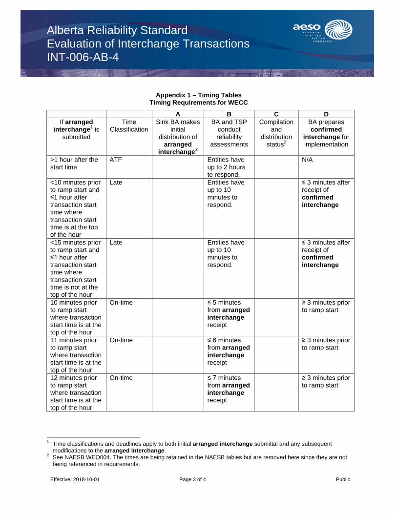
Alberta Reliability Standard Evaluation of Interchange Transactions INT-006-AB-4
Effective: 2018-10-01 Page 3 of 4 Public
Appendix 1 – Timing Tables Timing Requirements for WECC
A B C D If arranged
interchange1 is submitted
Time Classification
Sink BA makes initial
distribution of arranged
interchange2
BA and TSP conduct reliability
assessments
Compilation and
distribution status2
BA prepares confirmed
interchange for implementation
>1 hour after the start time
ATF Entities have up to 2 hours to respond.
N/A
<10 minutes prior to ramp start and ≤1 hour after transaction start time where transaction start time is at the top of the hour
Late Entities have up to 10 minutes to respond.
≤ 3 minutes after receipt of confirmed interchange
<15 minutes prior to ramp start and ≤1 hour after transaction start time where transaction start time is not at the top of the hour
Late Entities have up to 10 minutes to respond.
≤ 3 minutes after receipt of confirmed interchange
10 minutes prior to ramp start where transaction start time is at the top of the hour
On-time ≤ 5 minutes from arranged interchange receipt
≥ 3 minutes prior to ramp start
11 minutes prior to ramp start where transaction start time is at the top of the hour
On-time ≤ 6 minutes from arranged interchange receipt
≥ 3 minutes prior to ramp start
12 minutes prior to ramp start where transaction start time is at the top of the hour
On-time ≤ 7 minutes from arranged interchange receipt
≥ 3 minutes prior to ramp start
1 Time classifications and deadlines apply to both initial arranged interchange submittal and any subsequent
modifications to the arranged interchange. 2 See NAESB WEQ004. The times are being retained in the NAESB tables but are removed here since they are not
being referenced in requirements.

Alberta Reliability Standard Evaluation of Interchange Transactions INT-006-AB-4
Effective: 2018-10-01 Page 4 of 4 Public
A B C D If arranged
interchange1 is submitted
Time Classification
Sink BA makes initial
distribution of arranged
interchange2
BA and TSP conduct reliability
assessments
Compilation and
distribution status2
BA prepares confirmed
interchange for implementation
13 minutes prior to ramp start where transaction start time is at the top of the hour
On-time ≤ 8 minutes from arranged interchange receipt
≥ 3 minutes prior to ramp start
14 minutes prior to ramp start where transaction start time is at the top of the hour
On-time ≤ 9 minutes from arranged interchange receipt
≥ 3 minutes prior to ramp start
< 1 hour and ≥ 15 minutes prior to ramp start
On-time ≤ 10 minutes from arranged interchange receipt
≥ 3 minutes prior to ramp start
≥ 1 hour and < 4 hours prior to ramp start
On-time < 20 minutes from arranged interchange receipt
≥ 39 minutes prior to ramp start
≥ 4 hours prior to ramp start
On-time ≤ 2 hours from arranged interchange receipt
≥ 1 hour 58 minutes prior to ramp start
Submitted before 10:00 PPT with start time ≥ 00:00 PPT of following day
On-time By 12:00 PPT of day the arranged interchange was recieved
≥ 1 hour 58 minutes prior to ramp start
Alberta Reliability Standard Implementation of Interchange INT-009-AB-2.1
Effective: 2018-10-01 Page 1 of 1 Public
1. Purpose
The purpose of this reliability standard is to ensure that balancing authorities implement the interchange as agreed upon in the interchange confirmation process.
2. Applicability
This reliability standard applies to:
(a) the ISO.
3. Requirements
R1 The ISO must agree with each of its adjacent balancing authorities that its composite confirmed interchange with that adjacent balancing authority, at mutually agreed upon time intervals, excluding dynamic schedules and pseudo-ties and including any interchange per INT-010-AB not yet captured in the composite confirmed interchange, is:
R1.1 identical in magnitude to that of the adjacent balancing authority; and
R1.2 opposite in sign or direction to that of the adjacent balancing authority.
R2 The ISO when it is either the attaining balancing authority or the native balancing authority must use a dynamic value emanating from a common source that is agreed upon with the other balancing authority to account for the pseudo-tie in the net actual interchange term of its control area control error or alternate control process.
R3 The ISO must, if it is the balancing authority in whose area the high-voltage direct current intertie is controlled, coordinate the confirmed interchange prior to its implementation with the operator of the high-voltage direct current intertie.
4. Measures
The following measures correspond to the requirements identified in section 3 of this reliability standard. For example, MR1 is the measure for requirement R1.
MR1 Evidence of agreeing on composite confirmed interchange with adjacent balancing authorities as required in requirement R1 exists. Evidence may include, but is not limited to dated logs, voice recordings, electronic records or other equivalent evidence.
MR2 Evidence of using a dynamic value emanating from an agreed upon common source as required in requirement R2 exists. Evidence may include, but is not limited to dated logs, voice recordings, electronic records, written agreement or other equivalent evidence.
MR3 Evidence of coordinating the confirmed interchange prior to its implementation with the operator of the high-voltage direct current intertie as required in requirement R3 exists. Evidence may include, but is not limited to dated logs, electronic records or other equivalent evidence.
Revision History
Date Description
2018-10-01 Initial release.
Alberta Reliability Standard Interchange Initiation and Modification for Reliability INT-010-AB-2.1
Effective: 2018-10-01 Page 1 of 1 Public
1. Purpose
The purpose of this reliability standard is to provide guidance for required actions on confirmed interchange or implemented interchange to address reliability.
2. Applicability
This reliability standard applies to:
(a) the ISO.
3. Requirements
R1 The ISO must, if it experiences a loss of resources covered by an energy sharing agreement or other reliability needs covered by an energy sharing agreement, ensure that a request for interchange is submitted with a start time no more than sixty (60) minutes beyond the resource loss or reliability need. If the use of the energy sharing agreement does not exceed sixty (60) minutes from the time of the resource loss or reliability need, no request for interchange is required.
R2 The ISO must, when it is the sink balancing authority, after modifying a confirmed interchange or implemented interchange for actual or anticipated reliability-related reasons, ensure that a reliability adjustment arranged interchange reflecting the modification is submitted within sixty (60) minutes of the start of the modification.
R3 The ISO must, when it is a sink balancing authority, after scheduling interchange for actual or anticipated reliability-related reasons, ensure that a request for interchange is submitted reflecting that interchange schedule within sixty (60) minutes of the start of the scheduled interchange.
4. Measures
The following measures correspond to the requirements identified in section 3 of this reliability standard. For example, MR1 is the measure for requirement R1.
MR1 Evidence of ensuring that a request for interchange is submitted as required in requirement R1 exists. Evidence may include, but is not limited to, dated and time-stamped request for interchange, electronic logs or other equivalent evidence.
MR2 Evidence of ensuring that a reliability adjustment arranged interchange is submitted as required in requirement R2 exists. Evidence may include, but is not limited to, dated and time-stamped reliability adjustment arranged interchange, electronic logs or other equivalent evidence.
MR3 Evidence of ensuring that a reliability adjustment arranged interchange is submitted as required in requirement R2 exists. Evidence may include, but is not limited to, dated and time-stamped reliability adjustment arranged interchange, electronic logs or other equivalent evidence.
Revision History
Date Description
2018-10-01 Initial release.

Alberta Reliability Standard Reliability Coordinator Monitoring and Analysis IRO-002-AB-5
Effective: 2019-12-01 Page 1 Public
1. Purpose
The purpose of this reliability standard is to provide the ISO with the capabilities necessary to monitor and analyze data needed to perform their reliability functions.
2. Applicability
This reliability standard applies to:
(a) the ISO.
3. Requirements
R1 The ISO must have data exchange capabilities with entities, that the ISO deems necessary, for it to perform operational planning analysis.
R2 The ISO must have data exchange capabilities, with redundant and diversely routed data exchange infrastructure within the ISO’s primary control centre, for the exchange of real time data with entities it deems necessary, for performing its real time monitoring and real time assessments.
R3A The ISO must test its primary control centre data exchange capabilities specified in requirement R2 for redundant functionality at least once every 90 days.
R3B The ISO must, if the test conducted pursuant to requirement R3A is unsuccessful, initiate action within 2 hours to restore redundant functionality.
R4 The ISO must provide its real time operating personnel with the authority to approve planned outages and maintenance of its telecommunication, monitoring, and analysis capabilities.
R5 The ISO must, as necessary, monitor:
(a) system elements that are part of the bulk electric system; (b) the status of remedial action schemes; and (c) system elements that are not part of the bulk electric system,
within Alberta and neighbouring reliability coordinator areas, to identify any system operating limit exceedances and to determine any interconnection reliability operating limit exceedances within Alberta.
R6 The ISO must have monitoring systems that provide information utilized by the ISO’s operating personnel, giving particular emphasis to alarm management and awareness systems, automated data transfers, and synchronized information systems, over a redundant infrastructure.
4. Measures
The following measures correspond to the requirements identified in section 3 of this reliability standard. For example, MR1 is the measure for requirement R1.
MR1 Evidence of having data exchange capabilities as required in requirement R1 exists. Evidence may include a document that lists the ISO’s data exchange capabilities with entities, that the ISO deems necessary, for it to perform operational planning analysis, or other equivalent evidence.
MR2 Evidence of having data exchange capabilities as required in requirement R2 exists. Evidence may include system specifications, system diagrams, other documentation that lists the ISO’s data exchange capabilities, or other equivalent evidence.
MR3A Evidence of testing the ISO’s primary control centre data exchange capabilities for redundant functionality as required in requirement R3A exists. Evidence may include dated and time-stamped test records, operator logs, voice recordings, electronic communications, or other equivalent evidence.

Alberta Reliability Standard Reliability Coordinator Monitoring and Analysis IRO-002-AB-5
Effective: 2019-12-01 Page 2 Public
MR3B Evidence of initiating action within 2 hours to restore redundant functionality of the ISO’s primary control centre data exchange capabilities as required in requirement R3B exists. Evidence may include dated and time-stamped test records, operator logs, voice recordings, electronic communications, or other equivalent evidence.
MR4 Evidence of providing the ISO’s real time operating personnel with the authority as required in requirement R4 exists. Evidence may include a documented procedure, or other equivalent evidence.
MR5 Evidence of monitoring system elements and remedial action schemes as required in requirement R5 exists. Evidence may include energy management system description documents, computer printouts, SCADA data collection, or other equivalent evidence.
MR6 Evidence of having monitoring systems as required in requirement R6 exists. Evidence may include energy management system description documents, computer printouts, SCADA data collection, or other equivalent evidence.
Revision History
Date Description
2019-12-01 Initial release.

Alberta Reliability Standard Reliability Coordination Current Day Operations IRO-005-AB1-3.1a
Effective: 2019-12-01
Page 1 of 2
1. Purpose
The ISO must be continuously aware of conditions within its area and include this information in its reliability assessments. The ISO must monitor bulk electric system parameters that may have significant impacts upon its area and neighbouring reliability coordinator areas.
2. Applicability
This reliability standard applies to:
(a) the ISO.
3. Requirements
R1 Intentionally left blank.
R1.1 Intentionally left blank.
R1.2 Intentionally left blank.
R1.3 Intentionally left blank.
R1.4 Intentionally left blank.
R1.5 Intentionally left blank.
R1.6 Intentionally left blank.
R1.7 Intentionally left blank.
R1.8 Intentionally left blank.
R1.9 Intentionally left blank.
R1.10 Intentionally left blank.
R2 Intentionally left blank.
R3 The ISO must ensure that it is aware of geomagnetic disturbance forecast information and develop any required response plans.
R4 Intentionally left blank.
R5 Intentionally left blank.
R6 Intentionally left blank.
R7 Intentionally left blank.
R8 Intentionally left blank.
R9 Intentionally left blank.
R10 Intentionally left blank.
R11 Intentionally left blank.
R12 Intentionally left blank.
4. Measures
The following measures correspond to the requirements identified in section 3 of this reliability standard. For example, MR1 is the measure for requirement R1.
MR1 Intentionally left blank.
Alberta Reliability Standard Monitoring and Analysis IRO-005-AB1-3.1a
Effective: 2019-12-01
Page 2 of 2
MR2 Intentionally left blank.
MR3 The ISO may have evidence that could include, but is not limited to, operator logs, voice recordings or transcripts of voice recordings, electronic communications or equivalent evidence to demonstrate that it was aware of geomagnetic disturbance (GMD) forecast information and evidence of the development of any required response plans.
MR4 Intentionally left blank.
MR5 Intentionally left blank.T
MR6 Intentionally left blank.
MR7 Intentionally left blank.
MR8 Intentionally left blank.
MR9 Intentionally left blank.
MR10 Intentionally left blank.
MR11 Intentionally left blank.
MR12 Intentionally left blank.
Revision History
Effective Date Description
2019-12-01 Removed all requirements that have been retired at NERC. requirement R3 will be retained until NERC EOP-010-1 is adopted for application in Alberta.
2016-08-30 Inclusion of the defined term system element.
2015-04-01 Initial release.

Alberta Reliability Standard
Reliability Coordination – Transmission Loading Relief
IRO-006-AB-5
Effective: 2015-04-01 Page 1 of 1
1. Purpose
To ensure coordinated action between Interconnections when implementing Interconnection-wide transmission loading relief procedures to prevent or manage potential or actual system operating limit and interconnection reliability operating limit exceedances to maintain reliability of the bulk electric system.
2. Applicability
This reliability standard applies to:
(a) the ISO.
3. Requirements
R1 When the ISO receives a request pursuant to an Interconnection-wide transmission loading relief procedure (such as Eastern Interconnection Transmission Loading Relief, WECC Unscheduled Flow Mitigation, or congestion management procedures from the ERCOT Protocols) from any reliability coordinator, balancing authority, or transmission operator in another Interconnection to curtail an interchange transaction that crosses an Interconnection boundary, the ISO must comply with the request, unless it provides a reliability reason to the requestor why it cannot comply with the request.
4. Measures
The following measures correspond to the requirements identified in section 3 of this reliability standard. For example, MR1 is the measure for requirement R1.
MR1 The ISO may have evidence (such as dated logs, voice recordings, e-tag histories, and studies, in electronic or hard copy format) that, when a request to curtail an interchange transaction crossing an Interconnection boundary pursuant to an Interconnection-wide transmission loading relief procedure was made from another reliability coordinator, balancing authority, or transmission operator in that other Interconnection, the ISO complied with the request or provided a reliability reason why it could not comply with the request.
Revision History
Effective Date Description
2015-04-01 Initial release.

Alberta Reliability Standard Reliability Coordinator Operational Analyses and Real-time Assessments IRO-008-AB-2
Effective: 2019-12-01 Page 1 Public
1. Purpose
The purpose of this reliability standard is to perform analyses and assessments to prevent instability, uncontrolled separation, and cascading.
2. Applicability
This reliability standard applies to:
(a) the ISO.
3. Requirements
R1 The ISO must perform an operational planning analysis that will allow it to assess whether the planned operations for the next day will exceed system operating limits and interconnection reliability operating limits within its wide-area.
R2 The ISO must have an operating plan for next-day operations to address potential system operating limit and interconnection reliability operating limit exceedances identified as a result of its operational planning analysis as performed in requirement R1.
R3 Intentionally left blank.
R4 The ISO must perform a real time assessment at least once every 30 minutes.
R5 Intentionally left blank.
R6 Intentionally left blank.
4. Measures
The following measures correspond to the requirements identified in section 3 of this reliability standard. For example, MR1 is the measure for requirement R1.
MR1 Evidence of performing an operational planning analysis as required in requirement R1 exists. Evidence may include a completed operational planning analysis, dated power flow study results, or other equivalent evidence.
MR2 Evidence of having an operating plan as required in requirement R2 exists. Evidence may include plans for precluding operating in excess of each system operating limit and interconnected reliability operating limit that were identified as a result of the operational planning analysis, or other equivalent evidence.
MR3 Intentionally left blank.
MR4 Evidence of performing a real time assessment at least once every 30 minutes as required in requirement R4 exists. Evidence may include dated computer logs showing times of assessment as conducted, dated checklists, or other equivalent evidence.
MR5 Intentionally left blank.
MR6 Intentionally left blank.
Revision History
Date Description
2019-12-01 Initial release.
Alberta Reliability Standard Reliability Coordinator Actions to Operate within IROLs IRO-009-AB-2
Effective: 2019-12-01 Page 1 Public
1. Purpose
The purpose of this reliability standard is to prevent instability, uncontrolled separation, or cascading outages that adversely impact the reliability of the Interconnection by ensuring prompt action to prevent or mitigate instances of exceeding interconnection reliability operating limits.
2. Applicability
This reliability standard applies to:
(a) the ISO.
3. Requirements
R1 The ISO must, for each interconnection reliability operating limit that the ISO identifies one or more days prior to the current day, have one or more operating processes, procedures, or plans that identify actions to take, or actions to direct others to take, up to and including load shedding, that:
R1.1 can be implemented in time to prevent the identified interconnection reliability operating limit exceedance; and
R1.2 mitigate the magnitude and duration of an interconnection reliability operating limit exceedance such that the interconnection reliability operating limit exceedance is relieved within the interconnection reliability operating limit Tv.
R2 The ISO must initiate one or more operating processes, procedures, or plans that are intended to
prevent an interconnection reliability operating limit exceedance, as identified in the ISO’s real time monitoring or real time assessment.
R3 The ISO must act or direct others to act so that the magnitude and duration of an interconnection reliability operating limit exceedance is mitigated within the interconnection reliability operating limit Tv, as identified in the ISO’s real time monitoring or real time assessment.
R4 The ISO must operate to the most limiting interconnection reliability operating limit or interconnection reliability operating limit Tv in instances where there is a difference in an interconnection reliability operating limit or its interconnection reliability operating limit Tv and that of another reliability coordinator where both entities are responsible for that facility or group of facilities.
4. Measures
The following measures correspond to the requirements identified in section 3 of this reliability standard. For example, MR1 is the measure for requirement R1.
MR1 Evidence of having one or more operating processes, procedures, or plans to address both preventing and mitigating the magnitude and duration of interconnection reliability operating limit exceedances as required in requirement R1 exists. Evidence may include a list of any interconnection reliability operating limit (and each associated interconnection reliability operating limit Tv) identified in advance, along with one or more dated operating processes, procedures, or plans that will be used, or other equivalent evidence.
MR2 Evidence of initiating one or more operating processes, procedures, or plans to prevent an interconnection reliability operating limit exceedance as required in requirement R2 exists. Evidence may include operating processes, procedures, or plans from requirement R1, dated operating logs, dated voice recordings, dated transcripts of voice recordings, or other equivalent evidence.

Alberta Reliability Standard Reliability Coordinator Actions to Operate within IROLs IRO-009-AB-2
Effective Date: 2019-12-01 Page 2 Public
MR3 Evidence of acting or requesting others to act so that the magnitude and duration of an interconnection reliability operating limit exceedance is mitigated as required in requirement R3 exists. Evidence may include operating processes, procedures, or plans, dated operating logs, dated voice recordings, dated transcripts of voice recordings, or other equivalent evidence.
MR4 Evidence of operating to the most limiting interconnection reliability operating limit or interconnection reliability operating limit Tv in instances where there was a difference as required in requirement R4 exists. Evidence may include dated computer printouts, dated operator logs, dated voice recordings, dated transcripts of voice recordings, or other equivalent evidence.
Revision History
Date Description
2019-12-01 Initial release.

Alberta Reliability Standard Reliability Coordinator Data Specification and Collection IRO-010-AB-2
Effective: 2019-12-01 Page 1 Public
1. Purpose
The purpose of this reliability standard is to prevent instability, uncontrolled separation, or cascading outages that adversely impact reliability, by ensuring the ISO has the data it needs to monitor and assess the operation of the area for which it has reliability coordination responsibility.
2. Applicability
This reliability standard applies to:
(a) the ISO.
3. Requirements
R1 Intentionally left blank.
R2 Intentionally left blank.
R3 The ISO must provide data and information, as requested and agreed upon to each reliability coordinator with which it has a reliability relationship using:
R3.1 a mutually agreeable format;
R3.2 a mutually agreeable process for resolving data conflicts; and
R3.3 a mutually agreeable security protocol.
4. Measures
The following measures correspond to the requirements identified in section 3 of this reliability standard. For example, MR1 is the measure for requirement R1.
MR1 Intentionally left blank.
MR2 Intentionally left blank.
MR3 Evidence of providing data and information as required in requirement R3 exists. Evidence may include electronic or hard copies of data transmittals, or other equivalent evidence.
Revision History
Date Description
2019-12-01 Initial release.
Alberta Reliability Standard Coordination Among Reliability Coordinators IRO-014-AB-3
Effective: 2019-12-01 Page 1 Public
1. Purpose
The purpose of this reliability standard is to ensure that the ISO’s operations are coordinated such that they will not adversely impact other reliability coordinator areas and to preserve the reliability benefits of interconnected operations.
2. Applicability
This reliability standard applies to:
(a) the ISO.
3. Requirements
R1 The ISO must have and implement operating procedures, operating processes, or operating plans, for activities that require notification or coordination of actions that may impact adjacent reliability coordinator areas, to support the reliability of the Interconnection. These operating procedures, operating processes, or operating plans must include the following:
R1.1 criteria and processes for notifications;
R1.2 energy and capacity shortages;
R1.3 control of voltage, including the coordination of reactive resources;
R1.4 exchange of information including planned and unplanned outage information to support its operational planning analysis and real time assessments; and
R1.5 provisions for periodic communications to support reliable operations.
R2 The ISO must maintain its operating procedures, operating processes, and operating plans identified in requirement R1 as follows:
R2.1 review and update annually with no more than 15 months between reviews;
R2.2 obtain written agreement from all of the reliability coordinators required to take the indicated actions for each update; and
R2.3 distribute to all reliability coordinators that are required to take the indicated actions within 30 days of an update.
R3 The ISO, upon identification of an expected or actual emergency in Alberta, must notify other impacted reliability coordinators.
R4 The ISO must operate as though the emergency exists during each instance where the ISO and another reliability coordinator disagree on the existence of an emergency.
R5 The ISO must, when it identifies an emergency in Alberta, develop an action plan to resolve the emergency during those instances where another impacted reliability coordinator disagrees on the existence of an emergency.
R6 The ISO must, when impacted, implement the action plan developed by another reliability coordinator that identifies an emergency during those instances where the ISO and the other reliability coordinator disagree on the existence of an emergency, unless such actions would violate safety, equipment, regulatory, or statutory requirements.
R7 The ISO must, when requested and able, assist another reliability coordinator if the requesting reliability coordinator has implemented its emergency procedures, unless such actions cannot be physically implemented or would violate safety, equipment, regulatory, or statutory requirements.

Alberta Reliability Standard Coordination Among Reliability Coordinators IRO-014-AB-3
Effective: 2019-12-01 Page 2 Public
Measures
The following measures correspond to the requirements identified in section 3 of this reliability standard. For example, MR1 is the measure for requirement R1.
MR1 Evidence of having and implementing operating procedures, operating processes, or operating plans as required in requirement R1 exists. Evidence may include dated, current in effect documentation with the specified elements, notes from periodic communications, or other equivalent evidence.
MR2 Evidence of maintaining its operating procedures, operating processes, and operating plans as required in requirement R2 exists. Evidence may include dated documentation with confirmation of receipt, dated notice of acceptance or agreement to take specified actions, dated electronic communications with confirmation of receipt and acceptance or agreement to take specified actions, or other equivalent evidence.
MR3 Evidence of notifying impacted reliability coordinators as required in requirement R3 exists. Evidence may include voice recordings or transcripts of voice recordings, electronic communications, or other equivalent evidence.
MR4 Evidence of operating as though an emergency existed as required in requirement R4 exists. Evidence may include dated operator logs, voice recordings or transcripts of voice recordings, electronic communication, or other equivalent evidence.
MR5 Evidence of developing an action plan to resolve the emergency as required in requirement R5 exists. Evidence may include dated operator logs, voice recordings or transcripts of voice recordings, electronic communications, or other equivalent evidence.
MR6 Evidence of implementing the action plan as required in requirement R6 exists. Evidence may include dated operator logs, voice recordings or transcripts of voice recordings, electronic communications, or dated documentation, or other equivalent evidence.
MR7 Evidence of assisting reliability coordinators as required in requirement R7 exists. Evidence may include dated operator logs, voice recordings or transcripts of voice recordings, electronic communications, or other equivalent evidence.
Revision History
Date Description
2019-12-01 Initial release.
Alberta Reliability Standard Outage Coordination IRO-017-AB-1
Effective: 2019-12-01 Page 1 Public
1. Purpose
The purpose of this reliability standard is to ensure that outages are properly coordinated in the operations planning time horizon and near-term transmission planning horizon.
2. Applicability
This reliability standard applies to:
(a) the ISO.
3. Requirements
R1 Intentionally left blank.
R2 Intentionally left blank.
R3 The ISO must provide its planning assessment to impacted reliability coordinators.
R4 Intentionally left blank.
Measures
The following measures correspond to the requirements identified in section 3 of this reliability standard. For example, MR1 is the measure for requirement R1.
MR1 Intentionally left blank.
MR2 Intentionally left blank.
MR3 Evidence of providing the ISO’s planning assessment to impacted reliability coordinators as required in requirement R3 exists. Evidence may include web postings with an electronic notice of the posting, e-mail records, or other equivalent evidence.
MR4 Intentionally left blank.
Revision History
Date Description
2019-12-01 Initial release.
Alberta Reliability Standard Reliability Coordination Real Time Reliability Monitoring and Analysis Capabilities IRO-018-AB-1(i)
Effective: 2019-12-01 Page 1 Public
1. Purpose
The purpose of this reliability standard is to establish requirements for real time monitoring and analysis capabilities to support reliable system operations.
2. Applicability
This reliability standard applies to:
(a) the ISO.
3. Requirements
R1 The ISO must implement an operating process or operating procedure, to address the quality of the real time data necessary to perform its real time monitoring and real time assessments, which must include:
R1.1 criteria for evaluating the quality of real time data;
R1.2 provisions to indicate the quality of real time data to the system operator; and
R1.3 actions to address real time data quality issues with each entity responsible for providing the data when data quality affects real time assessments.
R2 The ISO must implement an operating process or operating procedure to address the quality of analysis used in its real time assessments which must include:
R2.1 criteria for evaluating the quality of analysis used in its real time assessments;
R2.2 provisions to indicate the quality of analysis used in its real time assessments; and
R2.3 actions to address analysis quality issues affecting its real time assessments.
R3 The ISO must have an alarm process monitor that provides notification to its real time operating personnel when a failure of its real time monitoring alarm processor has occurred.
4. Measures
The following measures correspond to the requirements identified in section 3 of this reliability standard. For example, MR1 is the measure for requirement R1.
MR1 Evidence of implementing an operating process or operating procedure as required in requirement R1 exists. Evidence may include an operating process or operating procedure in electronic or hard copy format meeting all provisions of requirement R1 and evidence that the ISO implemented the operating process or operating procedure as called for in the operating process or operating procedure, such as dated operator or supporting logs, dated checklists, voice recordings, voice transcripts, or other equivalent evidence.
MR2 Evidence of implementing an operating process or operating procedure as required in requirement R2 exists. Evidence may include an operating process or operating procedure in electronic or hard copy format meeting all provisions of requirement R2 and evidence the ISO implemented the operating process or operating procedure as called for in the operating process or operating procedure, such as dated operator logs, dated checklists, voice recordings, voice transcripts, or other equivalent evidence.
MR3 Evidence of having an alarm process monitor that provides notification to the ISO’s real time operating personnel as required in requirement R3 exists. Evidence may include operator logs, computer printouts, system specifications, or other equivalent evidence.

Alberta Reliability Standard Reliability Coordination Real Time Reliability Monitoring and Analysis Capabilities IRO-018-AB-1(i)
Effective: 2019-12-01 Page 2 Public
Revision History
Date Description
2019-12-01 Initial release.

Alberta Reliability Standard
Qualified Transfer Path Unscheduled Flow Relief
IRO-006-WECC-AB-2
Effective: 2015-04-01 Page 1 of 1
1. Purpose
The purpose of this reliability standard is to mitigate transmission overloads due to unscheduled flow on qualified transfer paths.
2. Applicability
This reliability standard applies to:
(a) the ISO.
3. Requirements
R1 The ISO must approve schedule curtailment requests submitted to mitigate transmission overloads on qualified transfer paths, implement alternative actions, or a combination thereof that collectively meets the relief requirement.
4. Measures
The following measures correspond to the requirements identified in section 3 of this reliability standard. For example, MR1 is the measure for requirement R1.
MR1 E-tags, voice recordings or operator logs exist and are provided on request. E-tags, voice recordings or operator logs contain content confirming requirement R1 is met.
Revision History
Date Description
2015-04-01 Initial release.
Alberta Reliability Standard Steady-State and Dynamic Data for Transmission System Modeling and Simulation MOD-010&012-AB-0
Effective: 2014-01-01 Page 1 of 2
1 Purpose
The purpose of this reliability standard is to provide for the delivery of data and information necessary to establish consistent power flow and dynamic models to be used in the analysis of the reliability of the Interconnection.
2 Applicability
This reliability standard applies to:
(a) the legal owner of a generating unit that is:
(i) directly connected to the transmission system or to transmission facilities within the City of Medicine Hat; and
(ii) not part of an aggregated generating facility;
(b) the legal owner of an aggregated generating facility that is directly connected to the transmission system or to transmission facilities within the City of Medicine Hat;
(c) the legal owner of a transmission facility; and
(d) the ISO.
3 Requirements
R1 Each legal owner of a generating unit, legal owner of an aggregated generating facility and legal owner of a transmission facility must provide, within thirty (30) days of the ISO’s written request, equipment characteristics and system data that the ISO requires to meet requirements R2 and R3.
R2 Subject to requirement R3, the ISO must provide equipment characteristics and system data, including dynamics system modeling, simulation data and interchange schedules, to the WECC in compliance with the appropriate Interconnection-wide WECC steady-state and dynamics system modeling and simulation data requirements and reporting procedures.
R3 The ISO must provide the equipment characteristics and system data, including modeling data and information specified in requirement R2, according to the data bank compilation schedule the WECC publishes but if no such schedule has been published, then the ISO must provide such equipment characteristics and system data no later than:
(a) thirty (30) days from the date the WECC requests it if the ISO has received the requested information prior to the date that WECC requested it; or
(b) sixty (60) days from the date the WECC requests it if the ISO has not received the information prior to the date that WECC requested it.
4 Measures
The following measures correspond to the requirements identified in section 3 of this reliability standard. For example, MR1 is the measure for R1.
MR1 Evidence of providing equipment characteristics and system data as required in requirement R1. Evidence may include data files, email or mail.

Alberta Reliability Standard Steady-State and Dynamic Data for Transmission System Modeling and Simulation MOD-010&012-AB-0
Effective: 2014-01-01 Page 2 of 2
MR2 Evidence of providing equipment characteristics and system data as required in requirement R2. Evidence may include data files, email or mail.
MR3 Evidence of providing equipment characteristics and system data within the timelines specified in requirement R3. Evidence may include email or mail.
Revision History
Effective Description
2014-01-01 Initial Release – The first day of the calendar quarter that follows three full calendar quarters after approval by the Commission

Alberta Reliability Standard Demand and Energy Data MOD-031-AB-2
Effective: 2018-08-01 Page 1 of 2 Public
1. Purpose
The purpose of this reliability standard is to identify the requirements for the ISO to provide to the WECC, demand, energy and related data to support reliability studies and assessments.
2. Applicability
This reliability standard applies to:
(a) the ISO.
3. Requirements
R1 Intentionally left blank.
R2 Intentionally left blank.
R3 The ISO must provide the data listed below, for the Alberta balancing authority area, to the WECC within 75 days of receiving a request for such data, unless the WECC and the ISO agree otherwise:
R3.1 any or all of the following actual data:
R3.1.1 integrated hourly demands in MWs for the prior calendar year;
R3.1.2 monthly and annual integrated peak hour demands in MWs for the prior calendar year;
R3.1.2.1 if the annual peak hour actual demand varies due to weather related conditions (e.g., temperature, humidity or wind speed), the ISO must also provide the weather normalized annual peak hour actual demand for the prior calendar year;
R3.1.3 monthly and annual net energy for load in GWhs for the prior calendar year; and
R3.1.4 monthly and annual peak hour controllable and dispatchable demand side management under the control or supervision of the ISO in MWs for the prior calendar year including, reporting for each hour: 1) the committed MWs (the amount under control or supervision); 2) the MWs issued in a dispatch (the amount, if any, activated for use by the system operator); and 3) the realized MWs (the amount of actual demand reduction);
R3.2 any or all of the following forecast data:
R3.2.1 monthly peak hour forecast total internal demands in MWs for the next 2 calendar years;
R3.2.2 monthly forecast net energy for load in GWhs for the next 2 calendar years;
R3.2.3 peak hour forecast total internal demands (summer and winter) in MWs for 10 calendar years into the future;
R3.2.4 annual forecast net energy for load in GWhs for 10 calendar years into the future; and
R3.2.5 total and available peak hour forecast of controllable and dispatchable demand side management (summer and winter), in MWs, under the control or supervision of the system operator for 10 calendar years into the future;

Alberta Reliability Standard Demand and Energy Data MOD-031-AB-2
Effective: 2018-08-01 Page 2 of 2 Public
R3.3 any or all of the following summary explanations:
R3.3.1 the assumptions and methods used in the development of aggregated peak demand and net energy for load forecasts;
R3.3.2 the demand and energy effects of controllable and dispatchable demand side management under the control or supervision of the system operator;
R3.3.3 how demand side management is addressed in the forecasts of its peak demand and annual net energy for load;
R3.3.4 how the controllable and dispatchable demand side management forecast compares to actual controllable and dispatchable demand side management for the prior calendar year and, if applicable, how the assumptions and methods for future forecasts were adjusted; and
R3.3.5 how the peak demand forecast compares to actual demand for the prior calendar year with due regard to any relevant weather-related variations (e.g., temperature, humidity, or wind speed) and, if applicable, how the assumptions and methods for future forecasts were adjusted.
R4 Intentionally left blank.
4. Measures
The following measures correspond to the requirements identified in section 3 of this reliability standard. For example, MR1 is the measure for requirement R1.
MR1 Intentionally left blank.
MR2 Intentionally left blank.
MR3 Evidence of providing the data as required in requirement R3 exists. Evidence may include dated emails or dated transmittal letters, or other equivalent evidence.
MR4 Intentionally left blank.
Revision History
Date Description
2018-08-01 Initial release.

Alberta Reliability Standard Operations Personnel Credentials PER-003-AB-1
Effective: 2019-12-01 Page 1 of 2 Public
1. Purpose
The purpose of this reliability standard is to ensure that operating personnel performing the reliability-related tasks of an operator of a transmission facility are certified through the NERC System Operator Certification Program when filling a real time operating position responsible for control of the bulk electric system.
2. Applicability
This reliability standard applies to:
(a) an operator of a transmission facility that is part of the bulk electric system.
This reliability standard does not apply to the operator of a transmission facility who only operates transmission facilities that are:
(a) radial transmission facilities connected to:
(i) load;
(ii) one or more generating unit; and/or
(iii) one or more aggregated generating facility;
(b) connected to an industrial complex, or part of an industrial complex, and the removal of any or all of these transmission facilities cannot interrupt power flow on the interconnected electric system, other than power flow on its own transmission facilities when all transmission facilities in the rest of the interconnected electric system are in service; or
(c) transmission facilities where the operation of all these facilities is covered by an operating agreement with a NERC-certified operator whereby the NERC-certified operator has the operating authority for these facilities.
3. Requirements
R1 Intentionally left blank.
R2 An operator of a transmission facility must staff each of its real time operating positions performing reliability-related tasks with operating personnel who have obtained and maintained one of the following NERC certificates:
(a) Reliability Operator;
(b) Balancing, Interchange and Transmission Operator; or
(c) Transmission Operator.
R3 Intentionally left blank.
4. Measures
The following measures correspond to the requirements identified in section 3 of this reliability standard. For example, MR1 is the measure for requirement R1.
MR1 Intentionally left blank.
MR2 Evidence of staffing its real time operating positions performing reliability-related tasks with operating personnel certified in accordance with the requirement R2 exists. This evidence may

Alberta Reliability Standard Operations Personnel Credentials PER-003-AB-1
Effective: 2019-12-01 Page 2 of 2 Public
include, but it is not limited to:
(a) the list of real time operating positions performing reliability-related tasks;
(b) the list of operating personnel assigned to the real time operating positions performing reliability-related tasks;
(c) a copy of each of its operating personnel’s NERC certificate; and
(d) work schedules, logs, or other equivalent evidence showing which operating personnel were assigned to work in real time operating positions performing reliability-related tasks.
MR3 Intentionally left blank.
Revision History
Date Description
2019-12-01 Unbolded “real time”
2019-01-01 Initial release.
Alberta Reliability Standard
Reliability Coordination - Staffing
PER-004-AB-2
Alberta Reliability Standards Effective Date: 2015-05-01
Page 1 of 1
1. Purpose
The ISO must have sufficient, competent staff to perform the functions of the ISO.
2. Applicability
This reliability standard applies to:
(a) the ISO.
3. Requirements
R1 The ISO must be staffed with adequately trained operating personnel, each possessing a valid NERC Reliability Operator certificate, 24 hours per day, seven days per week.
R2 The ISO must ensure that ISO operating personnel have adequate information regarding system operating limits, interconnection reliability operating limits and intertie facility limits available.
4. Measures
The following measures correspond to the requirements identified in section 3 of this reliability standard. For example, MR1 is the measure for requirement R1.
MR1 Evidence may include, but is not limited to, NERC certificate / certification records, shift schedules or other equivalent evidence that will be used to confirm that the ISO is staffed with operating personnel possessing a valid NERC Reliability Operator certificate 24 hours per day, seven days per week.
MR2 Evidence may include but is not limited to, EMS screenshots, methodology documentation or other equivalent documentation that will be used to confirm that ISO operating personnel have adequate information regarding system operating limits and interconnection reliability operating limits and intertie facility limits.
Revision History
Effective Date Description
2015-05-01 Initial release.

Alberta Reliability Standard Operations Personnel Training PER-005-AB-2
Effective: 2019-12-01 Page 1 Public
1. Purpose
The purpose of this reliability standard is to ensure that personnel performing or supporting real time operations on the bulk electric system are trained using a systematic approach.
2. Applicability
This reliability standard applies to:
(a) the ISO;
(b) the operator of a transmission facility that has personnel who can act independently to operate in real time, or to direct the real time operation of, those transmission facilities that are part of the bulk electric system from a control centre. This does not include field switching personnel.
This reliability standard does not apply to the operator of a transmission facility whose only transmission facilities are:
(i) radial transmission facilities connecting to:
(a) load;
(b) one or more generating units; and / or
(c) one or more aggregated generating facilities; or
(ii) either part of an industrial complex or connected to an industrial complex and cannot interrupt power flow on the interconnected electric system, other than power flow on its own transmission facilities.
3. Requirements
R1 The ISO and each operator of a transmission facility must use a systematic approach to develop and implement a training program for its real time operating personnel, as follows:
R1.1 The ISO and each operator of a transmission facility must:
(a) create a definition of a company-specific real time reliability-related task;
(b) develop a documented methodology for determining company-specific real time reliability-related tasks; and
(c) create a list of bulk electric system company-specific real time reliability-related tasks based on that methodology.
R1.1.1 The ISO and each operator of a transmission facility must review, and update if necessary, its list of bulk electric system company-specific real time reliability-related tasks identified in R1.1 each calendar year.
R1.2 The ISO and each operator of a transmission facility must design and develop training materials according to its training program, based on the bulk electric system company-specific real time reliability-related task list created in R1.1.
R1.3 The ISO and each operator of a transmission facility must deliver training to its real time operating personnel according to its training program.
R1.4 The ISO and each operator of a transmission facility must conduct an evaluation each calendar year of the training program established in requirement R1 to identify any needed changes to the training program, and must implement the changes identified.
R2 Intentionally left blank.

Alberta Reliability Standard Operations Personnel Training PER-005-AB-2
Effective: 2019-12-01 Page 2 Public
R3 The ISO and each operator of a transmission facility must verify, at least once, the capabilities of its real time operating personnel, identified in requirement R1, assigned to perform each of the bulk electric system company-specific real time reliability-related tasks identified under requirement R1.1.
R3.1 Within six (6) months of a modification or addition of a bulk electric system company-specific real time reliability-related task, the ISO and each operator of a transmission facility must verify the capabilities of each of its real time operating personnel identified in requirement R1 to perform the new or modified bulk electric system company-specific real time reliability-related tasks identified in requirement R1.1.
R4 The ISO must provide its real time operating personnel identified in requirement R1 with emergency operations training using simulation technology such as a simulator, virtual technology, or other technology that replicates the operational behavior of the bulk electric system if the ISO:
(1) has operational authority or control over facilities with established interconnection reliability operating limits, or
(2) has established protection systems or operating guides to mitigate interconnection reliability operating limit violations,
R4.1 The ISO must comply with requirement R4 within twelve (12) months of meeting either of the criteria identified in requirements R4(1) or R4(2).
R5 The ISO and each operator of a transmission facility must use a systematic approach to develop and implement training for its identified operations support personnel on how their job function(s) impact those bulk electric system company-specific real time reliability-related tasks that it has identified pursuant to requirement R1.1.
R5.1 The ISO and each operator of a transmission facility must conduct an evaluation each calendar year of the training established in requirement R5 to identify and implement changes to the training.
R6 Intentionally left blank.
4. Measures
The following measures correspond to the requirements identified in section 3 of this reliability
standard. For example, MR1 is the measure for requirement R1.
MR1 Evidence of using a systematic approach to develop and implement a training program for its real time operating personnel as required in requirement R1 exists. Evidence may include, but is not limited to, training program descriptions, meeting minutes, design notes, or other equivalent evidence.
MR1.1 Evidence of having a definition, methodology and bulk electric system company-specific real time reliability-related task list and review history, as required in requirement R1.1 exists. Evidence may include, but is not limited to, a definition for real time reliability-related tasks, a documented methodology for determining company-specific real time reliability-related tasks, a list of real time reliability related tasks, a documented revision history or other equivalent evidence.
Alberta Reliability Standard Operations Personnel Training PER-005-AB-2
Effective: 2019-12-01 Page 3 Public
MR1.2 Evidence of designing and developing training materials as required in requirement R1.2 exists. Evidence may include, but is not limited to, course design documents and examples of training materials or other equivalent evidence.
MR1.3 Evidence of delivering real time operating personnel training, as required in requirement R 1.3 exists. Evidence may include, but is not limited to, training records showing the names of the attendees, the title of the training delivered, and the dates of delivery or other equivalent evidence.
MR1.4 Evidence of conducting an evaluation of the training program each calendar year and implementing the identified changes, as required in requirement R1.4 exists. Evidence may include, but is not limited to, instructor observations, trainee feedback, course evaluations, meeting minutes, training program document revision history, or other equivalent evidence.
MR2 Intentionally left blank.
MR3 Evidence of verifying, at least once, the capabilities of the real time operating personnel, as required in requirement R3 exists.
Evidence may include, but is not limited to, documented records to show that it verified the capability of each of its real time personnel on company-specific real time reliability-related tasks with the date of verification, employee name, supervisor signature and check sheets for each company-specific real time reliability-related task completed, the results of learning assessments, or other equivalent evidence.
MR3.1 Evidence of verifying the capabilities of real time operating personnel within six (6) months of a modification or addition of a bulk electric system company-specific real time reliability-related task, as required in requirement R3.1 exists. Evidence may include, but is not limited to, documented records to show that it verified the capability of each of its personnel on company-specific real time reliability-related tasks with the date of verification, employee name, supervisor signature and check sheets for each company-specific real time reliability-related task completed, the results of learning assessments, or other equivalent evidence.
MR4 Evidence of providing emergency operations training as required in requirement R4 exists. Evidence may include, but is not limited to, dated training records or other equivalent evidence.
MR4.1 Evidence of complying with requirement R4 as required in requirement R4.1 exists. Evidence may include, but is not limited to, dated training records or other equivalent evidence.
MR5 Evidence of using a systematic approach to develop and implement training for identified operations support personnel as required in requirement R5 exists. Evidence may include, but is not limited to, training records showing employee name, date of training and completion of training, or other equivalent evidence.
MR5.1 Evidence of conducting an evaluation each calendar year of the training established in requirement R5 and that any identified changes were implemented as required in requirement R5.1 exists. Evidence may include, but is not limited to, instructor observations, trainee feedback, course evaluations, meeting minutes, training program document revision history or other equivalent evidence.
MR6 Intentionally left blank.

Alberta Reliability Standard Operations Personnel Training PER-005-AB-2
Effective: 2019-12-01 Page 4 Public
Revision History
Date Description
2019-12-01 Unbolded “real time”
2018-04-01 Initial release.

Alberta Reliability Standard Protection System Coordination PRC-001-AB3-1.1(ii)
Effective: 2017-10-01 Page 1 of 7 Public
1. Purpose
The purpose of this reliability standard is to ensure protection systems are coordinated among operating entities.
2. Applicability
This reliability standard applies to:
(a) the legal owner of a transmission facility that is:
(i) part of the bulk electric system; or
(ii) not part of the bulk electric system and which the ISO:
(A) determines is necessary for the reliable operation of either the interconnected electric system or the City of Medicine Hat electric system; and
(B) publishes on the AESO website and may amend from time to time in accordance with the process set out in Appendix 1;
(b) the legal owner of a generating unit that is:
(i) directly connected to the bulk electric system and has a maximum authorized real power rating greater than 18 MW;
(ii) within a power plant which:
(A) is not part of an aggregated generating facility;
(B) is directly connected to the bulk electric system; and
(C) has a combined maximum authorized real power rating greater 67.5 MW;
(iii) a blackstart resource; or
(iv) material to this reliability standard and to the reliability of the bulk electric system, regardless of its maximum authorized real power rating, as the ISO determines and publishes on the AESO website and may amend from time to time in accordance with the process set out in Appendix 1;
(c) the legal owner of an aggregated generating facility that is:
(i) directly connected to the bulk electric system and has a maximum authorized real power rating greater than 67.5 MW;
(ii) within a power plant or industrial complex which:
(A) is directly connected to the bulk electric system; and
(B) has a combined maximum authorized real power rating greater than 67.5 MW;
(iii) a blackstart resource; or
(iv) material to this reliability standard and to the reliability of the bulk electric system, regardless of its maximum authorized real power rating, as the ISO determines and publishes on the AESO website and may amend from time to time in accordance with the process set out in Appendix 1;

Alberta Reliability Standard Protection System Coordination PRC-001-AB3-1.1(ii)
Effective: 2017-10-01 Page 2 of 7 Public
(d) the operator of a transmission facility that is:
(i) part of the bulk electric system; or
(ii) not part of the bulk electric system and which the ISO:
(A) determines is necessary for the reliable operation of either the interconnected electric system or the City of Medicine Hat electric system; and
(B) publishes on the AESO website and may amend from time to time in accordance with the process set out in Appendix 1;
(e) the operator of a generating unit that is:
(i) directly connected to the bulk electric system and has a maximum authorized real power rating greater than 18 MW;
(ii) within a power plant which:
(A) is not part of an aggregated generating facility;
(B) is directly connected to the bulk electric system; and
(C) has a combined maximum authorized real power rating greater than 67.5 MW;
(iii) a blackstart resource; or
(iv) material to this reliability standard and to the reliability of the bulk electric system, regardless of its maximum authorized real power rating, as the ISO determines and publishes on the AESO website and may amend from time to time in accordance with the process set out in Appendix 1; and
(f) the operator of an aggregated generating facility that is:
(i) directly connected to the bulk electric system and has a maximum authorized real power rating greater than 67.5 MW;
(ii) within a power plant or industrial complex which:
(A) is directly connected to the bulk electric system; and
(B) has a combined maximum authorized real power rating greater than 67.5 MW;
(iii) a blackstart resource; or
(iv) material to this reliability standard and to the reliability of the bulk electric system, regardless of its maximum authorized real power rating, as the ISO determines and publishes on the AESO website and may amend from time to time in accordance with the process set out in Appendix 1.
3. Requirements
R1 Each operator of a generating unit and operator of an aggregated generating facility must, upon failure of any component of a protection system of a generating unit or an aggregated generating facility which it operates, take the actions listed in requirement R1.1 and R1.2.
R1.1 Notify the operator of a transmission facility to which the generating unit or aggregated generating facility is connected as soon as possible, but no longer than twenty-four (24) hours after becoming aware of such a failure, and provide the following information, regardless of whether or not the generating unit or aggregated generating facility remains on-line:

Alberta Reliability Standard Protection System Coordination PRC-001-AB3-1.1(ii)
Effective: 2017-10-01 Page 3 of 7 Public
(a) identify the protection system that failed; and
(b) identify whether or not a functionally equivalent protection system remains in service.
R1.2 Correct the failure as soon as possible.
R2 Each operator of a transmission facility, operator of a generating unit and operator of an aggregated generating facility must take the actions listed in requirements R2.1 through R2.3 after becoming aware of the failure of any of the following protection systems or teleprotection communication channels under its authority:
(a) a protection system, other than a related teleprotection communication channel referred to in requirement R2(c) or R2(d), that protects a transmission facility operated at a nominal voltage greater than 200 kV, whether or not a functionally equivalent protection system remains in service;
(b) a protection system, other than a related teleprotection communication channel referred to in requirement R2(c) or R2(d), that protects a transmission facility that is part of the bulk electric system where a functionally equivalent protection system is not available;
(c) a teleprotection communication channel, that is part of a protection system for a transmission facility operated at a nominal voltage greater than 200 kV, where there is an equivalent backup teleprotection communication channel, and where the failure lasts for more than twenty-four (24) continuous hours; or
(d) a teleprotection communication channel, where there is no equivalent backup teleprotection communication channel, and where the failure lasts for more than ten (10) consecutive minutes.
R2.1 Provide notification to the ISO, and to each directly affected operator of a transmission facility, directly affected operator of a generating unit, directly affected operator of an aggregated generating facility and directly affected interconnected transmission operator as soon as possible, but no longer than twenty-four (24) hours after becoming aware of a failure identified in requirements R2(a), R2(b) and R2(d), and no longer than forty-eight (48) hours after becoming aware of a failure identified in requirement R2(c), regardless of whether or not the transmission facility is removed from service following the awareness of such failure, that includes the following information:
(a) the identification of the protection system or teleprotection communication channel(s) that failed;
(b) when the protection system or teleprotection communication channel(s) failed or when such failure was first discovered; and
(c) an estimate of the date when the protection system or teleprotection communication channel(s) will be returned to service.
R2.2 Where the protection system or teleprotection communication channel(s) are not returned to service by the estimated return to service date identified in requirement R2.1, provide a new estimate of the return to service date up to five (5) days after the previous estimated return to service date to the entities that received the notification in accordance with requirement R2.1.
R2.3 Correct the failure as soon as possible.

Alberta Reliability Standard Protection System Coordination PRC-001-AB3-1.1(ii)
Effective: 2017-10-01 Page 4 of 7 Public
R3 Each legal owner of a generating unit and legal owner of an aggregated generating facility must coordinate all new protection systems and all protection system changes with each affected interconnecting legal owner of a transmission facility and notify the ISO that such coordination has occurred.
R4 Each legal owner of a transmission facility must coordinate all new protection systems and all protection system changes with:
(a) each affected adjacent legal owner of a transmission facility;
(b) each affected legal owner of a generating unit;
(c) each affected legal owner of an aggregated generating facility;
(d) each affected interconnected transmission operator; and
(e) the ISO, as affected,
and must notify the ISO that such coordination has occurred.
R5 Each operator of a generating unit, operator of an aggregated generating facility and operator of a transmission facility must identify, notify and coordinate planned changes that may require changes in the protection systems of others as described in requirements R5.1 and R5.2.
R5.1 Each operator of a generating unit and operator of an aggregated generating facility must identify planned changes to its generation, load, or operating conditions that may require changes to the protection systems of others, and must notify the ISO and coordinate with each affected operator of a transmission facility in advance of making such changes.
R5.2 Each operator of a transmission facility must identify planned changes to its transmission, load or operating conditions that may require changes to the protection systems of others, and must notify the ISO and coordinate with each affected:
(a) operator of a transmission facility;
(b) adjacent interconnected transmission operator;
(c) operator of a generating unit; and
(d) operator of an aggregated generating facility,
in advance of making such changes.
R6 Each operator of a transmission facility must monitor the status (on/off) of each remedial action scheme in its area, and must notify the ISO and each affected:
(a) operator of a transmission facility;
(b) adjacent interconnected transmission operator;
(c) operator of a generating unit; and
(d) operator of an aggregated generating facility,
of each change in status.
Alberta Reliability Standard Protection System Coordination PRC-001-AB3-1.1(ii)
Effective: 2017-10-01 Page 5 of 7 Public
4. Measures
The following measures correspond to the requirements identified in section 3 of this reliability standard. For example, MR1 is the measure for requirement R1.
MR1 Evidence of notifying, providing information and correcting failures of any component of a protection system as required in requirement R1 exists. Evidence may include, but is not limited to:
MR1.1 voice recordings, operator logs, electronic notifications (emails) or other equivalent evidence; and
MR1.2 work orders, setting change files, electronic records or other equivalent evidence.
MR2 Evidence of providing notification, providing an estimate and correcting failures of any of the protection systems or teleprotection communication channel(s) as required in requirement R2 exists. Evidence may include, but is not limited to:
MR2.1 voice recordings, operator logs, electronic notifications (emails) or other equivalent evidence; MR2.2 voice recordings, operator logs, electronic notifications (emails) or other equivalent evidence;
and
MR2.3 work orders, setting change files, electronic records or other equivalent evidence.
MR3 Evidence of coordinating protection systems and notifying the ISO as required in requirement R3 exists.
Evidence of coordinating protection systems may include, but is not limited to, a fault analysis study, letters of agreement on settings, notifications of changes or other equivalent evidence.
Evidence of notifying the ISO may include, but is not limited to, electronic notifications (emails), hard copy notifications, or other equivalent evidence.
MR4 Evidence of coordinating protection systems and notifying the ISO as required in requirement R4 exists.
Evidence of coordinating protection systems may include, but is not limited to, a fault analysis study, letters of agreement on settings, notifications of changes or other equivalent evidence.
Evidence of notifying the ISO may include, but is not limited to, electronic notifications (emails), hard copy notifications or other equivalent evidence.
MR5 Measures for this requirement are identified in the subsections below:
MR5.1 Evidence of identifying, notifying and coordinating planned changes that may require changes to the protection systems of others as required in requirement R5.1 exists.
Evidence may include, but is not limited to, voice recordings, operator logs, electronic notifications (emails) or other equivalent evidence.
MR5.2 Evidence of identifying, notifying and coordinating planned changes that may require changes to the protection systems of others as required in requirement R5.2 exists.
Evidence may include, but is not limited to, voice recordings, operator logs, electronic notifications (emails) or other equivalent evidence.
Alberta Reliability Standard Protection System Coordination PRC-001-AB3-1.1(ii)
Effective: 2017-10-01 Page 6 of 7 Public
MR6 Evidence of monitoring the status of each remedial action scheme in its area and notifying entities of each change in status as required in requirement R6 exists.
Evidence of monitoring the status of each remedial action scheme may include, but is not limited to, SCADA data, wiring diagrams or other equivalent evidence.
Evidence of notifying entities may include, but is not limited to, SCADA data, voice recordings, operator logs, electronic notifications (emails) or other equivalent evidence.
Revision History
Date Description
2017-10-01 Alberta specific revisions made to improve clarity.
2015-05-01 Revised for ISO assumption of RC functionality for the Alberta footprint
2013-01-02
Administrative update – “TFO” and “GFO” replaced with “legal owner of a transmission facility”, “operator of a transmission facility”, “legal owner of a generating unit”, “operator of a generating unit”, “legal owner of an aggregated generating facility”, and “operator of an aggregated generating facility”; applied standard at the bulk electric system level; added Appendix 1; and other minor cleanup items.
2011-01-13 R1
2010-01-22 New Issue

Alberta Reliability Standard Protection System Coordination PRC-001-AB3-1.1(ii)
Effective: 2017-10-01 Page 7 of 7 Public
Appendix 1 Amending Process for List of Facilities
In order to amend any list referenced in subsections (a)(ii)(B), (b)(iv), (c)(iv), (d)(ii)(B), (e)(iv) and (f)(iv) of section 2, Applicability, the ISO must:
(a) upon determining that a transmission facility, generating unit or aggregated generating facility is to be added, notify the legal owner and operator in writing and determine an effective date, which must be no less than thirty (30) days after the date of notice, by which the transmission facility, generating unit or aggregated generating facility is to meet the applicable requirements;
(b) upon determining that a transmission facility, generating unit or aggregated generating facility is to be deleted, notify the legal owner and operator in writing and determine an effective date on which the transmission facility, generating unit or aggregated generating facility will no longer be required to meet the applicable requirements; and
(c) publish the amended list with effective dates on the AESO website.
Alberta Reliability Standard Disturbance Monitoring and Reporting Requirements PRC-002-AB-2
Effective: 2019-10-01 Page 1 of 10 Public
1. Purpose
The purpose of this reliability standard is to ensure that adequate data is available to facilitate analysis of disturbances on the bulk electric system.
2. Applicability
This reliability standard applies to the following:
(a) the legal owner of a transmission facility that is part of the bulk electric system;
(b) the legal owner of a generating unit that is part of the bulk electric system;
(c) the legal owner of an aggregated generating facility that is part of the bulk electric system; and
(d) the ISO.
3. Requirements
R1 Each legal owner of a transmission facility must:
R1.1 identify bulk electric system buses for which sequence of events recording and fault recording data is required by using the methodology in Appendix 1;
R1.2 notify other legal owners of system elements on the bulk electric system connected to those bulk electric system buses, if any, within 90 days of completion of requirement R1.1, that those system elements require either one or both of sequence of events recording data and fault recording data; and
R1.3 re-evaluate all bulk electric system buses at least once every 5 calendar years in accordance with requirement R1.1 and notify other legal owners, if any, in accordance with requirement R1.2, and implement the re-evaluated list of bulk electric system buses as per the Implementation Plan in Appendix 2.
R2 Each legal owner of a transmission facility, legal owner of a generating unit, and legal owner of an aggregated generating facility must have sequence of events recording data for circuit breaker position, open or close, for each circuit breaker it owns connected directly to the bulk electric system buses identified in requirement R1 and associated with the system elements on the bulk electric system at those bulk electric system buses.
R3 Each legal owner of a transmission facility, legal owner of a generating unit, and legal owner of an aggregated generating facility must have fault recording data to determine the following electrical quantities for each triggered fault recording for the system elements on the bulk electric system it owns connected to the bulk electric system buses identified in requirement R1:
R3.1 phase-to-neutral voltage for each phase of each specified bulk electric system bus; and
R3.2 each phase current and the residual or neutral current for the following system elements on the bulk electric system:
R3.2.1 transformers that have a low-side operating voltage of 100 kV or above; and
R3.2.2 transmission lines.

Alberta Reliability Standard Disturbance Monitoring and Reporting Requirements PRC-002-AB-2
Effective: 2019-10-01 Page 2 of 10 Public
R4 Each legal owner of a transmission facility, legal owner of a generating unit, and legal owner of an aggregated generating facility must have fault recording data as specified in requirement R3 that meets the following:
R4.1 a single record or multiple records that include:
(a) a pre-trigger record length of at least 2 cycles and a total record length of at least 30 cycles for the same trigger point, or
(b) at least 2 cycles of the pre-trigger data, the first 3 cycles of the post-trigger data, and the final cycle of the fault as seen by the fault recorder;
R4.2 a minimum recording rate of 16 samples per cycle; and
R4.3 trigger settings for at least the following:
R4.3.1 neutral (residual) overcurrent; and
R4.3.2 phase under voltage or overcurrent.
R5 The ISO must:
R5.1 identify system elements on the bulk electric system for which dynamic disturbance recording data is required, including the following:
R5.1.1 generating resources with:
R5.1.1.1 an individual generating unit with a maximum authorized real power rating greater than or equal to 450 MW; and
R5.1.1.2 an individual generating unit with a maximum authorized real power rating greater than or equal to 270 MW where the plant/facility aggregate maximum authorized real power rating is greater than or equal to 900 MW;
R5.1.2 any one system element on the bulk electric system that is part of an angular stability or voltage stability related system operating limit;
R5.1.3 each terminal of a high voltage direct current circuit with a nameplate rating greater than or equal to 270 MW, on the alternating current portion of the converter;
R5.1.4 one or more system elements on the bulk electric system that are part of an interconnection reliability operating limit; and
R5.1.5 any one system element on the bulk electric system within a major voltage sensitive area as defined by an area with an in-service under voltage load shed program;
R5.2 identify a minimum dynamic disturbance recording coverage, inclusive of those system elements on the bulk electric system identified in requirement R5.1, of at least:
R5.2.1 one system element on the bulk electric system; and
R5.2.2 one system element on the bulk electric system per 3,000 MW of the ISO’s historical simultaneous peak demand of the interconnected electric system;
R5.3 notify all legal owners of identified system elements on the bulk electric system, within 90 days of completion of requirement R5.1, that their respective system elements on the bulk electric system require dynamic disturbance recording data when requested; and
R5.4 re-evaluate all system elements on the bulk electric system at least once every 5 calendar years in accordance with requirements R5.1 and R5.2, and notify legal owners in accordance

Alberta Reliability Standard Disturbance Monitoring and Reporting Requirements PRC-002-AB-2
Effective: 2019-10-01 Page 3 of 10 Public
with requirement R5.3 to implement the re-evaluated list of system elements on the bulk electric system as per the implementation plan in Appendix 2.
R6 Each legal owner of a transmission facility must have dynamic disturbance recording data to determine the following electrical quantities for each system element on the bulk electric system it owns for which it received notification as identified in requirement R5:
R6.1 one phase-to-neutral or positive sequence voltage;
R6.2 the phase current for the same phase at the same voltage corresponding to the voltage in requirement R6.1, or the positive sequence current;
R6.3 real power and reactive power flows expressed on a 3-phase basis corresponding to all circuits where current measurements are required; and
R6.4 frequency of any one of the voltages in requirement R6.1.
R7 Each legal owner of a generating unit and legal owner of an aggregated generating facility must have dynamic disturbance recording data to determine the following electrical quantities for each system element on the bulk electric system it owns for which it received notification as identified in requirement R5:
R7.1 one phase-to-neutral, phase-to-phase, or positive sequence voltage at either the generator step-up transformer high-side or low-side voltage level;
R7.2 the phase current for the same phase at the same voltage corresponding to the voltage in requirement R7.1, phase currents for any phase-to-phase voltages, or positive sequence current;
R7.3 real power and reactive power flows expressed on a 3-phase basis corresponding to all circuits where current measurements are required; and
R7.4 frequency of at least one of the voltages in requirement R7.1.
R8 Each legal owner of a transmission facility, legal owner of a generating unit, and legal owner of an aggregated generating facility responsible for dynamic disturbance recording data for the system elements on the bulk electric system for which it received notification as identified in requirement R5 must, unless it complies with subsection 7(1) of Section 502.9 of the ISO rules, Synchrophasor Measurement Unit Technical Requirements, have continuous data recording and storage, unless the equipment was installed prior to the effective date of this reliability standard and is not capable of continuous recording, in which case, triggered records must meet the following:
R8.1 triggered record lengths of at least 3 minutes; or
R8.2 at least one of the following 3 triggers:
(a) off nominal low frequency trigger set at < 59.55 Hz and off nominal high frequency trigger set at > 61.0 Hz;
(b) rate of change of frequency trigger set at < -0.05625 Hz/sec and > 0.125 Hz/sec; or
(c) undervoltage trigger set no lower than 85% of normal operating voltage for a duration of 5 seconds.
Alberta Reliability Standard Disturbance Monitoring and Reporting Requirements PRC-002-AB-2
Effective: 2019-10-01 Page 4 of 10 Public
R9 Each legal owner of a transmission facility, legal owner of a generating unit, and legal owner of an aggregated generating facility responsible for dynamic disturbance recording data for the system elements on the bulk electric system identified in requirement R5 must have dynamic disturbance recording data that meet the following:
R9.1 input sampling rate of at least 960 samples per second; and
R9.2 output recording rate of electrical quantities of at least 30 times per second.
R10 Each legal owner of a transmission facility, legal owner of a generating unit, and legal owner of an aggregated generating facility must time synchronize all sequence of events recording and fault recording data for the bulk electric system buses identified in requirement R1 and dynamic disturbance recording data for the system elements on the bulk electric system identified in requirement R5 to meet the following:
R10.1 synchronization to Coordinated Universal Time with or without a local time offset; and
R10.2 synchronized device clock accuracy within ± 2 milliseconds of Coordinated Universal Time.
R11 Each legal owner of a transmission facility, legal owner of a generating unit, and legal owner of an aggregated generating facility must provide to the ISO, upon written request, all sequence of events recording and fault recording data for the bulk electric system buses identified in requirement R1 and dynamic disturbance recording data for the system elements on the bulk electric system identified in requirement R5, in accordance with the following:
R11.1 data is retrievable for the period of 10 days, inclusive of the day the data was recorded;
R11.2 data subject to requirement R11.1 is provided within 30 days of a request unless an extension is granted by the ISO;
R11.3 sequence of events recording data are provided in ASCII Comma Separated Value format following Appendix 3;
R11.4 fault recording and dynamic disturbance recording data are provided in electronic files that are formatted in conformance with C37.111, IEEE Standard for Common Format for Transient Data Exchange (COMTRADE), revision C37.111-1999 or later; and
R11.5 data files will be named in conformance with C37.232, IEEE Standard for Common Format for Naming Time Sequence Data Files (COMNAME), revision C37.232-2011 or later.
R11-A The ISO must provide to the WECC or the NERC upon written request, all sequence of events recording and fault recording data that the ISO subsequently receives, through making the same request of responsible entities in Alberta, in accordance with requirement R11, within 60 days of a request unless an extension is granted by the either the WECC or the NERC.
R12 Each legal owner of a transmission facility, legal owner of a generating unit, and legal owner of an aggregated generating facility must, within 90 days of the discovery of a failure of the recording capability for the sequence of events recording, fault recording or dynamic disturbance recording data, either:
(a) restore the recording capability, or
(b) submit a corrective action plan to the ISO and implement it.
R12.1 the ISO must submit a corrective action plan to the WECC within 15 days of receiving a corrective action plan from any of a legal owner of a transmission facility, legal owner of a generating unit, or legal owner of an aggregated generating facility.
Alberta Reliability Standard Disturbance Monitoring and Reporting Requirements PRC-002-AB-2
Effective: 2019-10-01 Page 5 of 10 Public
4. Measures
The following measures correspond to the requirements identified in section 3 of this reliability standard. For example, MR1 is the measure for requirement R1.
MR1 Evidence of identifying bulk electric system buses, notifying legal owners, re-evaluating all bulk electric system buses, and implementing the re-evaluated list as required in requirement R1 exists. Evidence may include lists, dated correspondence, or other equivalent evidence.
MR2 Evidence of having sequence of events recording data for circuit breaker positions as required in requirement R2 exists. Evidence may include documents describing the device interconnections and configurations which may include a single design standard as representative for common installations, station drawings, and data recordings, or other equivalent evidence.
MR3 Evidence of having fault recording data as required in requirement R3 exists. Evidence may include documents describing the device specifications and configurations which may include a single design standard as representative for common installations, station drawings, and data recordings, or other equivalent evidence.
MR4 Evidence of having fault recording data as required in requirement R4 exists. Evidence may include data recordings, technical specification sheets, settings documentation, or other equivalent evidence.
MR5 Evidence of identifying system elements on the bulk electric system, identifying a minimum dynamic disturbance recording coverage, and notifying all legal owners of identified system elements on the bulk electric system as required in requirement R5 exists. Evidence may include lists and related documentation, dated correspondence, or other equivalent evidence.
MR6 Evidence of having dynamic disturbance recording data as required in requirement R6 exists. Evidence may include data records, documents describing the device specifications and configurations, which may include a single design standard as representative for common installations, station drawings, or other equivalent evidence.
MR7 Evidence of having dynamic disturbance recording data as required in requirement R7 exists. Evidence may include data records, documents describing the device specifications and configurations, which may include a single design standard as representative for common installations, station drawings, or other equivalent evidence.
MR8 Evidence of having continuous data recording and storage, or of having triggered records that meet the criteria required in requirement R8 exists. Evidence may include data recordings, technical specification sheets, settings documentation, or other equivalent evidence.
MR9 Evidence of having dynamic disturbance recording data as required in requirement R9 exists. Evidence may include data recordings, technical specification sheets, settings documentation or other equivalent evidence.
MR10 Evidence of time synchronizing all sequence of events recording and fault recording data, and dynamic disturbance recording data as required in requirement R10 exists. Evidence may include technical specification sheets, settings documentation, or other equivalent evidence.
MR11 Evidence of providing all sequence of events recording and fault recording data as required in requirement R11 exists. Evidence may include dated correspondence, documents describing data storage capability, device specification, configuration or settings, data records, or other equivalent evidence.

Alberta Reliability Standard Disturbance Monitoring and Reporting Requirements PRC-002-AB-2
Effective: 2019-10-01 Page 6 of 10 Public
MR11-A Evidence of providing all sequence of events recording and fault recording data as required in requirement R11-A exists. Evidence may include dated correspondence, or other equivalent evidence.
MR12 Evidence of either restoring the recording capability or submitting a corrective action plan and implementing it as required in requirement R12 exists. Evidence may include dated reports of discovery of a failure, documentation noting the date the data recording was restored, SCADA records, work orders, dated correspondence, a corrective action plan, or other equivalent evidence.
MR12.1 Evidence of submitting a corrective action plan to the WECC as required in requirement R12.1 exists. Evidence may include dated correspondence, or other equivalent evidence.
5. Appendices
Appendix 1 - Methodology for Selecting Bulk Electric System Buses for Capturing Sequence of Events Recording and Fault Recording Data
Appendix 2 - Implementation Plan
Appendix 3 - Sequence of Events Recording Data Format
Revision History
Date Description
2019-10-01 Initial release.

Alberta Reliability Standard Disturbance Monitoring and Reporting Requirements PRC-002-AB-2
Effective: 2019-10-01 Page 7 of 10 Public
Appendix 1
Methodology for Selecting Bulk Electric System Buses for Capturing Sequence of Events Recording and Fault Recording Data
(Requirement R1)
To identify monitored bulk electric system buses for sequence of events recording and fault recording data required by requirement R1, each legal owner of a transmission facility must follow sequentially, unless otherwise noted, the steps listed below:
Step 1 Determine a complete list of bulk electric system buses that it owns.
For the purposes of this reliability standard, a single bulk electric system bus includes physical buses with breakers connected at the same voltage level within the same physical location sharing a common ground grid. These buses may be modeled or represented by a single node in fault studies. For example, ring bus or breaker-and-a-half bus configurations are considered to be a single bus.
Step 2 Reduce the list to those bulk electric system buses that have a maximum available calculated 3-phase short circuit MVA of 1,500 MVA or greater. If there are no buses on the resulting list, proceed to Step 7.
Step 3 Determine the 11 bulk electric system buses on the list with the highest maximum available calculated 3-phase short circuit MVA level. If the list has 11 or fewer bulk electric system buses, proceed to Step 7.
Step 4 Calculate the median MVA level of the 11 bulk electric system buses determined in Step 3.
Step 5 Multiply the median MVA level determined in Step 4 by 20%.
Step 6 Reduce the bulk electric system buses on the list to only those that have a maximum available calculated 3-phase short circuit MVA higher than the greater of:
(a) 1,500 MVA; or
(b) 20% of median MVA level determined in Step 5.
Step 7 If there are no bulk electric system buses on the list: the procedure is complete and no fault recording and sequence of events recording data is required. Proceed to Step 9.
If the list has one or more, but less than or equal to 11 bulk electric system buses: fault recording and sequence of events recording data is required at the bulk electric system bus with the highest maximum available calculated 3-phase short circuit MVA as determined in Step 3. Proceed to Step 9.
If the list has more than 11 bulk electric system buses: sequence of events recording and fault recording data is required on at least the 10% of the bulk electric system buses determined in Step 6 with the highest maximum available calculated 3-phase short circuit MVA. Proceed to Step 8.
Step 8 Sequence of events recording and fault recording data is required at additional bulk electric system buses on the list determined in Step 6. The aggregate of the number of bulk electric system buses determined in Step 7 and in this Step 8 are at least 20% of the bulk electric system buses determined in Step 6. The additional bulk electric system buses are selected, at the discretion of the legal owner of a transmission facility, to provide maximum wide-area coverage for sequence of events recording and fault recording data. The following bulk electric system bus locations are recommended:

Alberta Reliability Standard Disturbance Monitoring and Reporting Requirements PRC-002-AB-2
Effective: 2019-10-01 Page 8 of 10 Public
(a) electrically distant bulk electric system buses or electrically distant from other disturbance monitoring equipment devices;
(b) voltage sensitive areas;
(c) cohesive load and generation zones;
(d) bulk electric system buses with a relatively high number of incident transmission circuits
(e) bulk electric system buses with reactive power devices; and
(f) major facilities interconnecting outside the area of the legal owner of a transmission facility.
Step 9 The list of monitored bulk electric system buses for sequence of events recording and fault recording data for requirement R1 is the aggregate of the bulk electric system buses determined in Steps 7 and 8.
Alberta Reliability Standard Disturbance Monitoring and Reporting Requirements PRC-002-AB-2
Effective: 2019-10-01 Page 9 of 10 Public
Appendix 2
Implementation Plan
Effective Date
This reliability standard is effective on the first day 3 full calendar quarters after the date that it is approved by the Commission.
Implementation Plan for PRC-002-AB-2 Requirements R1 and R5:
Entities must be 100% compliant on the first day following 3 full calendar quarters after the date that the reliability standard is approved by the Commission.
Implementation Plan for PRC-002-AB-2 Requirements R2, R3, R4, R6, R7, R8, R9, R10,and R11:
Entities must be at least 50% compliant within 4 calendar years of the effective date of PRC-002-AB-2 and 100% compliant within 6 calendar years of the effective date.
Entities that own only one identified bulk electric system bus, system element on the bulk electric system, or generating unit must be 100% compliant within 6 calendar years of the effective date.
Entities must be 100% compliant with a re-evaluated list from requirements R1 or R5 within 3 calendar years following the notification by the ISO or the legal owner of a transmission facility that re-evaluated the list.
Standards for Retirement
PRC-018-AB-1
Each legal owner of a transmission facility, legal owner of a generating unit, and legal owner of an aggregated generating facility must maintain documentation to demonstrate compliance with PRC-018-AB-1 until that entity meets the requirements of PRC-002-AB-2 in accordance with this Implementation Plan. Reliability standard PRC-018-AB-1 remains effective throughout the phased implementation period of PRC-002-AB-2 and is applicable to an entity’s disturbance monitoring and reporting activities not yet transitioned to PRC-002-AB-2. PRC-018-AB-1 will be retired following full implementation of PRC-002-AB-2 as noted below.
PRC-018-AB-1 Midnight of the day immediately prior to 6 years after the effective date of PRC-002-AB-2.

Alberta Reliability Standard Disturbance Monitoring and Reporting Requirements PRC-002-AB-2
Effective: 2019-10-01 Page 10 of 10 Public
Appendix 3
Sequence of Events Recording Data Format
(Requirement R11, R11.3)
Date, Time, Local Time Code, Substation, Device, State1
08/27/13, 23:58:57.110, -5, Sub 1, Breaker 1, Close
08/27/13, 23:58:57.082, -5, Sub 2, Breaker 2, Close
08/27/13, 23:58:47.217, -5, Sub 1, Breaker 1, Open
08/27/13, 23:58:47.214, -5, Sub 2, Breaker 2, Open
1 “OPEN” and “CLOSE” are used as examples. Other terminology such as TRIP, TRIP TO LOCKOUT, RECLOSE, etc. is also acceptable.
Alberta Reliability Standard Analysis and Mitigation of Transmission and Generation Protection System Misoperation PRC-004-AB2-1
Effective: 2019-04-01 Page 1 of 2 Public
1. Purpose
The purpose of this reliability standard is to ensure all misoperations of transmission and generation protection systems affecting the reliability of the bulk electric system are analyzed and mitigated.
2. Applicability
This reliability standard applies to:
(a) the legal owner of a transmission facility;
(b) the legal owner of a generating unit that:
(i) is not part of an aggregated generating facility;
(ii) has a maximum authorized real power rating greater than 4.5 MW;
(iii) is directly connected to the transmission system or to transmission facilities within the City of Medicine Hat; and
(iv) has protection systems that directly affect the reliability of the bulk electric system;
(c) the legal owner of an aggregated generating facility that:
(i) is directly connected to the transmission system or to transmission facilities within the City of Medicine Hat;
(ii) has a maximum authorized real power rating greater than 4.5 MW; and
(iii) has protection systems that directly affect the reliability of the bulk electric system; and
(d) the ISO.
3. Requirements
R1 Each legal owner of a transmission facility, legal owner of a generating unit and legal owner of an aggregated generating facility must analyze misoperations of its protection systems affecting the reliability of the bulk electric system, and develop and implement a corrective action plan to avoid future misoperations of a similar nature.
R2 Each legal owner of a transmission facility, legal owner of a generating unit and legal owner of an aggregated generating facility must provide to the ISO documentation of its misoperations analyses and corrective action plans upon request by the ISO.
R3 The ISO must provide to the WECC documentation of the misoperations analyses and corrective action plans upon request by the WECC.
4. Measures
The following measures correspond to the requirements identified in section 3 of this reliability standard. For example, MR1 is the measure for requirement R1.
MR1 Evidence of analyzing misoperations, and developing and implementing a corrective action plan as required in requirement R1 exists. Evidence may include reports that include analysis and corrective action plans, emails, work orders, or other equivalent evidence.
MR2 Evidence of providing to the ISO documentation of misoperations analyses and corrective action
Alberta Reliability Standard Analysis and Mitigation of Transmission and Generation Protection System Misoperation PRC-004-AB2-1
Effective: 2019-04-01 Page 2 of 2 Public
plans as required in requirement R2 exists. Evidence may include emails, dated correspondence, or other equivalent evidence.
MR3 Evidence of providing to the WECC documentation of the misoperations analyses and corrective action plans as required in requirement R3 exists. Evidence may include emails, dated correspondence, or other equivalent evidence
Revision History
Date Description
2019-04-01
Clarification to ensure the protections system misoperations that must be analyzed are those affecting the reliability of the bulk electric system. Administrative update: existing PRC-004-AB1-1 is being renamed PRC-004-AB2-1; and amendments to ensure consistent use of defined terms as included in the AESO’s Consolidated Authoritative Document Glossary (“CADG”); formatting and grammatical corrections; the deletion of the following sections: (a) “Definitions”; (b) “Processes and Procedures”, (c) “Appendices”; and (d) “Guidelines”
2013-01-02 Administrative update – “TFO” and “GFO” replaced with “legal owner of a transmission facility”, “legal owner of a generating unit” and “legal owner of an aggregated generating facility”; and other minor clean up items.
2010-02-11 Initial release.

Alberta Reliability Standard Protection System and Remedial Action Scheme Misoperation PRC-004-WECC-AB1-1
Effective: 2016-08-30
Page 1 of 7
1. Purpose
The purpose of this reliability standard is to ensure all misoperations of transmission and generation protection systems and RASs on transmission paths are analyzed and mitigated.
2. Applicability
This reliability standard applies to:
(a) the legal owner of a transmission facility that is the legal owner of a WECC major transmission path facility or RAS listed in the tables titled “Major WECC Transfer Paths in the Bulk Electric System” and “Major WECC Remedial Action Schemes (RAS)” as provided by the WECC;
(b) the operator of a transmission facility that operates a WECC major transmission path facility or RAS listed in the tables titled “Major WECC Transfer Paths in the Bulk Electric System” and “Major WECC Remedial Action Schemes (RAS)” as provided by the WECC;
(c) the legal owner of a generating unit that owns components of RASs listed in the table titled “Major WECC Remedial Action Schemes (RAS)” as provided by the WECC;
(d) the legal owner of an aggregated generating facility that owns components of RASs listed in the table titled “Major WECC Remedial Action Schemes (RAS)” as provided by the WECC;
(e) the operator of a generating unit that operates RASs listed in the table titled “Major WECC Remedial Action Schemes (RAS)” as provided by the WECC;
(f) the operator of an aggregated generating facility that operates RASs listed in the table titled “Major WECC Remedial Action Schemes (RAS)” as provided by the WECC; and
(g) the ISO.
3. Definitions
Bold terms used in this reliability standard have the meanings as set out in the Consolidated
Authoritative Document Glossary.
4. Requirements
R1 Each legal owner of a transmission facility, legal owner of a generating unit, legal owner of an aggregated generating facility, operator of a transmission facility, operator of a generating unit and operator of an aggregated generating facility must ensure that its system operators and protection personnel analyze all protection system and RAS operations as follows:
R1.1 Each operator of a transmission facility, operator of a generating unit and operator of an aggregated generating facility must review all tripping of transmission system elements and RAS operations to identify apparent misoperations within 24 hours.
R1.2 Protection personnel of the legal owner of a transmission facility, the legal owner of a generating unit and the legal owner of an aggregated generating facility must analyze all operations of protection systems and RAS within 20 business days of the
Alberta Reliability Standard Protection System and Remedial Action Scheme Misoperation PRC-004-WECC-AB1-1
Effective: 2016-08-30
Page 2 of 7
operation of either such system or RAS to determine whether a misoperation has occurred.
R2 Each legal owner of a transmission facility, legal owner of a generating unit and legal owner of an aggregated generating facility must perform the actions listed in requirements R2.1 to R2.4 inclusive for each misoperation of the protection system or RAS, subject to the following:
Requirements R2.1 to R2.4 inclusive do not apply to protection system and/or RAS operations that appear to have operated correctly at the time of occurrence. If the legal owner of a transmission facility, legal owner of a generating unit or legal owner of an aggregated generating facility later finds through system protection personnel analysis that the protection system or RAS misoperated, the requirements of R2.1 to R2.4 inclusive become applicable at the time the legal owner of a transmission facility, legal owner of a generating unit or legal owner of an aggregated generating facility identifies the misoperation.
Table 1 is provided as a simplified summary of the requirements in R2.1 to R2.4 inclusive.
2.1 If the protection system or RAS has a security-based misoperation and two or more FEPS or FERAS remain in service to ensure BES reliability, the legal owner of a transmission facility, legal owner of a generating unit or legal owner of an aggregated generating facility must remove from service the protection system or RAS that misoperated, within 22 hours following the identification of the misoperation.
Repair or replacement of the failed protection system or RAS is at the discretion of the legal owner of a transmission facility, legal owner of a generating unit or legal owner of an aggregated generating facility.
R2.2 If the protection system or RAS has a security-based misoperation and only one FEPS or FERAS remains in service to ensure BES reliability, the legal owner of a transmission facility, legal owner of a generating unit or legal owner of an aggregated generating facility responsible for the protection system or RAS, as the case may be, must perform the following:
R2.2.1 Remove from service, within 22 hours for repair or modification, the protection system or RAS that misoperated.
R2.2.2 Repair or replace any protection system or RAS that misoperated with a FEPS
or FERAS within 20 business days of the date of removal.
R2.2.3 Remove the system element from service or disable the RAS if repair or replacement is not completed within 20 business days.
R2.3 If the protection system or RAS has a security-based or dependability-based misoperation and a FEPS or FERAS is not in service to ensure BES reliability, the legal owner of a transmission facility, legal owner of a generating unit or legal owner of an aggregated generating facility responsible for the protection system or RAS, as the case may be, must repair and place back in service within 22 hours the protection system or RAS that misoperated.
If this cannot be done, the responsible legal owner of a transmission facility, legal owner of a generating unit or legal owner of an aggregated generating facility must perform the following:
R2.3.1 When a FEPS is not available, remove the associated system element from service.

Alberta Reliability Standard Protection System and Remedial Action Scheme Misoperation PRC-004-WECC-AB1-1
Effective: 2016-08-30
Page 3 of 7
R2.3.2 When FERAS is not available, meet one of the following requirements:
R2.3.2.1 If the responsible entity is a legal owner of a generating unit or legal owner of an aggregated generating facility, it must advise the ISO, and the operator of a generating unit or operator of an aggregated generating facility must adjust generation to a reliable operating level as directed by the ISO.
R2.3.2.2 If the responsible entity is a legal owner of a transmission facility, it must advise the ISO, and the operator of a transmission facility must operate the facilities within the adjusted SOL as determined and directed by the ISO.
R2.4 If the protection system or RAS has a dependability-based misoperation, but has one or more FEPS or FERAS that operated correctly, the associated system element or transmission path may remain in service without removing from service the protection system or RAS that failed, provided one of the following is performed
R2.4.1 The legal owner of a transmission facility, legal owner of a generating unit or legal owner of an aggregated generating facility must repair or replace any protection system or RAS that misoperated with FEPS and FERAS within 20 business days of the date of the misoperation identification, or
R2.4.2 The legal owner of a transmission facility, legal owner of a generating unit or legal owner of an aggregated generating facility must remove from service the
associated system element or RAS.
R3 The legal owner of a transmission facility, legal owner of a generating unit or legal owner of an aggregated generating facility must submit a misoperation incident report to the ISO within six business days of identifying the misoperation for the following:
R3.1 Identification of a misoperation of a protection system and/or RAS
R3.2 Completion of repairs or the replacement of the protection system and/or RAS that misoperated.
R4 The ISO must submit misoperation incident reports to WECC within 10 business days
of identifying the misoperation.
5. Processes and Procedures
No procedures have been defined for this reliability standard.
6. Measures
The following measures correspond to the requirements identified in Section 4 of this reliability
standard. For example, MR1 is the measure for R1.
MR1 Measures for this requirement are identified in the subsections below.
MR1.1 Documentation exists that confirms a review was completed within the timelines as specified in requirement R1.1.
MR1.2 Documentation exists that confirms an analysis was completed and in the timelines as specified in requirement R1.2.

Alberta Reliability Standard Protection System and Remedial Action Scheme Misoperation PRC-004-WECC-AB1-1
Effective: 2016-08-30
Page 4 of 7
MR2 Measures for this requirement are identified in the subsections below.
MR2.1 Evidence exists and shows that required actions were taken in the timelines as specified in requirement R2.1.
MR2.2 Measures for this requirement are identified in the subsections below.
MR2.2.1 Evidence exists and shows that required actions were taken in the timelines as specified in requirement R2.2.1.
MR2.2.2 Evidence exists and shows that required actions were taken in the timelines as specified in requirement R2.2.2.
MR2.2.3 Evidence exists and shows that required actions were taken in the timelines as specified in requirement R2.2.3.
MR2.3 Evidence exists and shows that required actions were taken in the timelines as specified in requirement R2.3.
MR2.3.1 Evidence exists and shows that required actions were taken in the
timelines as specified in requirement R2.3.1.
MR2.3.2 Measures for this requirement are identified in the subsections below.
MR2.3.2.1 Evidence exists and shows that required actions were taken in the timelines as specified in requirement R2.3.2.1.
MR2.3.2.2 Evidence exists and shows that required actions were taken in the timelines as specified in requirement R2.3.2.2.
MR2.4 Measures for this requirement are identified in the subsections below
MR2.4.1 Evidence exists and shows that required actions were taken in the
timelines as specified in requirement R2.4.1.
MR2.4.2 Evidence exists and shows that required actions were taken in the
timelines as specified in requirement R2.4.2.
MR3 Misoperation incident report is submitted within timelines as specified in requirement R3.
MR3.1 Misoperation incident report contains content as specified in requirement R3.1.
MR3.2 Misoperation incident report contains content as specified in requirements R3.2.
MR4 Confirmation exists that incident reports as specified in requirement R4 were received within the timelines specified, or evidence that requests for confirmation were made for the incident reports provided as specified in requirement R4.
7. Appendices
Appendix 1 – Requirement R2: Table of Required Actions for Protection System or RAS Misoperation (see below)

Alberta Reliability Standard Protection System and Remedial Action Scheme Misoperation PRC-004-WECC-AB1-1
Effective: 2016-08-30
Page 5 of 7
8. Guidelines
No guidelines have been defined for this reliability standard.
Revision History
Date Description
2016-08-30 Inclusion of the defined term system element.
2013-01-02 Administrative update – “TFO and GFO” replaced with “legal owner of a transmission facility” “legal owner of a generating unit” and “legal owner of an aggregated generating facility”; and other minor cleanup items.
2010-02-11 New Issue

Alberta Reliability Standard Protection System and Remedial Action Scheme Misoperation PRC-004-WECC-AB1-1
Effective: 2016-08-30
Page 6 of 7
Appendix 1 – Requirement R2: Table of Required Actions for Protection System or RAS Misoperation
PRC-004-WECC-1 Requirement R2 - Table of Required Actions for Protection System or RAS Misoperation
Protective System/RAS Situation Required Mitigating Actions
Protection Basis:
Number of FEPS or RAS in place after misoperation
Misoperating protection system is:
Protection System/RAS
Removal Requirement
Protection System/RAS
Repair or Replacement Requirement
System Element Removal Requirement
Security
2 or more PS Remove within 22h.
At owners discretion.
1 PS Remove within 22h.
Repair within 20 days.
Remove system element from service.
0 PS None. Repair within 22 hours.
If not repaired in 22 hours then remove system element from service.
2 or more RAS Remove within 22h.
At owners discretion.
1 RAS Remove within 22h.
Repair within 20 days.
If not repaired in 20 days then disable RAS or
remove system element from service.
0 RAS None. Repair within 22 hours.
Either the legal owner of a transmission facility,
legal owner of a generating unit or legal owner of an aggregated generating facility must advise the ISO, and the
operator of a generating unit or operator of an
aggregated generating facility must adjust
generating operating levels to a reliable operating level as directed by the ISO or
the ISO will adjust the SOL and the operator of a
transmission facility will operate the facilities within
established limits.

Alberta Reliability Standard Protection System and Remedial Action Scheme Misoperation PRC-004-WECC-AB1-1
Effective: 2016-08-30
Page 7 of 7
Depe
nda
bility
1 or more that operated correctly
PS Can leave in service.
Repair in 20 days or remove
system element from service.
0 PS None. Repair within 22 hours.
If not repaired in 22 hours then remove system element from service.
1 or more that operated correctly
PS Can leave in service.
Repair in 20 days or remove RAS or system element
from service.
0 RAS None. Repair within 22 hours.
Either the legal owner of a transmission facility,
legal owner of a generating unit or legal owner of an aggregated generating facility must advise the ISO, and the
operator of a generating unit or operator of an
aggregated generating facility must adjust
generating operating levels to a reliable operating level as directed by the ISO or
the ISO will adjust the SOL and the operator of a
transmission facility will operate the facilities within
established limits.

Alberta Reliability Standard Protection System, Automatic Reclosing and Sudden Pressure Relaying Maintenance PRC-005-AB1-6
Effective: 2019-10-01 Page 1 of 41 Public
1. Purpose
The purpose of this reliability standard is to document and implement programs for the maintenance of all protection systems, automatic reclosing, and sudden pressure relaying affecting the reliability of the transmission system so that they are kept in working order.
2. Applicability
The entities identified in subsection 2.1 must apply the requirements of this reliability standard to the devices listed in subsection 2.2 unless exempted under subsection 2.3.
2.1 This reliability standard applies to:
(a) the legal owner of a transmission facility that:
(i) is part of the bulk electric system, excluding any transformer with less than 2 terminals energized at 100 kV or higher;
(ii) is not part of the bulk electric system, and owns any of the following:
(A) the protection systems used for the ISO’s underfrequency load shedding program;
(B) the protection systems used for undervoltage load shed systems installed to prevent system voltage collapse or voltage instability for the reliability of the interconnected electric system;
(C) protection systems installed as a remedial action scheme, including automatic reclosing applied as an integral part of a remedial action scheme, for the reliability of the interconnected electric system; or
(iii) is material to this reliability standard and to the reliability of either the interconnected electric system or the City of Medicine Hat electric system, as the ISO determines and includes on a list published on the AESO website, which the ISO may amend from time to time in accordance with the process set out in Appendix 3.
(b) the legal owner of a generating unit that:
(i) has a maximum authorized real power rating greater than 18 MW and is either:
(A) directly connected to the transmission system,
(B) directly connected to transmission facilities within the City of Medicine Hat, or
(C) part of an industrial complex that is directly connected to the transmission system or to transmission facilities within the City of Medicine Hat;
(ii) is within a power plant that:
(A) is not part of an aggregated generating facility;
(B) is directly connected to the transmission system or to transmission facilities within the City of Medicine Hat; and
(C) has a combined maximum authorized real power rating greater than 67.5 MW;
(iii) is a black start resource; or
(iv) is material to this reliability standard and to the reliability of either the interconnected electric system or the City of Medicine Hat electric system, regardless of the maximum authorized real power rating of the generating unit, as the ISO determines and

Alberta Reliability Standard Protection System, Automatic Reclosing and Sudden Pressure Relaying Maintenance PRC-005-AB1-6
Effective: 2019-10-01 Page 2 of 41 Public
includes on a list published on the AESO website, which the ISO may amend from time to time in accordance with the process set out in Appendix 3;
(c) the legal owner of an aggregated generating facility that:
(i) has a maximum authorized real power rating greater than 67.5 MW and is either:
(A) directly connected to the transmission system;
(B) directly connected to transmission facilities within the City of Medicine Hat; or
(C) part of an industrial complex that is directly connected to the transmission system or to transmission facilities within the City of Medicine Hat;
(ii) is a black start resource; or
(iii) is material to this reliability standard and to the reliability of either the interconnected electric system or the City of Medicine Hat electric system, regardless of the maximum authorized real power rating of the aggregated generating facility, as the ISO determines and includes on a list published on the AESO website, which the ISO may amend from time to time in accordance with the process set out in Appendix 3.
2.2 This reliability standard applies to the following devices:
(a) protection systems and sudden pressure relaying that are installed for the purpose of detecting faults on system elements as identified in section 2.1;
(b) protection systems used for the ISO’s underfrequency load shedding program;
(c) protection systems used for undervoltage load shed systems installed to prevent system voltage collapse or voltage instability for the reliability of the interconnected electric system;
(d) protection systems installed as a remedial action scheme for the reliability of the interconnected electric system;
(e) protection systems and sudden pressure relaying for generating units, including:
(i) protection systems that act to trip the generating unit either directly or via lockout or auxiliary tripping relays;
(ii) protection systems and sudden pressure relaying for generating unit step-up transformers; and
(iii) protection systems and sudden pressure relaying for station service or excitation transformers connected to the generating unit bus, that act to trip the generating unit either directly or via lockout or tripping auxiliary relays;
(f) protection systems and sudden pressure relaying for aggregated generating facilities from and including the collector bus to a common point of connection at 100 kV or above;
(g) automatic reclosing, including:
(i) automatic reclosing applied on all transmission lines connected to a bus operated at a voltage level of 100 kV or higher located at generating plant substations where the combined maximum authorized real power is greater than 500 MW;
(ii) automatic reclosing applied on all transmission line terminals operated at a voltage level of 100 kV or higher at substations one bus away from generating plants specified in Section 2.2 (g)(i) when the substation is less than 10 circuit-miles from the generating plant substation; and
Alberta Reliability Standard Protection System, Automatic Reclosing and Sudden Pressure Relaying Maintenance PRC-005-AB1-6
Effective: 2019-10-01 Page 3 of 41 Public
(iii) automatic reclosing applied as an integral part of a remedial action scheme specified in subsection (d) above.
2.3 Automatic reclosing addressed in subsections 2.2(g)(i) and 2.2(g)(ii) may be excluded if the equipment owner can demonstrate to the ISO that a close-in three-phase fault present for twice the normal clearing time (capturing a minimum trip-close-trip time delay) does not result in a total loss of gross generation in either the interconnected electric system or the City of Medicine Hat electric system exceeding the gross capacity of the largest generating unit where the automatic reclosing is applied.
3. Requirements
R1 Each legal owner of a transmission facility, legal owner of a generating unit, and legal owner of an aggregated generating facility must establish a protection system maintenance program for its protection systems, automatic reclosing, and sudden pressure relaying.
The protection system maintenance program must:
R1.1 identify which maintenance method (a time-based method, the performance-based method per Appendix 2, or a combination of these maintenance methods) is used to address each protection system, automatic reclosing, and sudden pressure relaying component type (as identified in Appendix 1). All batteries associated with the station dc supply component type of a protection system must be included in a time-based program as described in Table 1-4 and Table 3 of Appendix 1.
R1.2 include the applicable monitored component attributes applied to each protection system, automatic reclosing, and sudden pressure relaying component type consistent with the maintenance intervals specified in Tables 1-1 through 1-5, Table 2, Table 3, Tables 4-1 through 4-3, and Table 5 of Appendix 1, where monitoring is used to extend the maintenance intervals beyond those specified for unmonitored protection system, automatic reclosing, and sudden pressure relaying components.
R2 Each legal owner of a transmission facility, legal owner of a generating unit, and legal owner of an aggregated generating facility that uses performance-based maintenance intervals in its protection system maintenance program must follow the procedure established in Appendix 2 to establish and maintain its performance-based intervals.
R3 Each legal owner of a transmission facility, legal owner of a generating unit, and legal owner of an aggregated generating facility that uses time-based maintenance program(s) must maintain its protection system, automatic reclosing, and sudden pressure relaying components that are included within the time-based maintenance program in accordance with the minimum maintenance activities and maximum maintenance intervals prescribed within Tables 1-1 through 1-5, Table 2, Table 3, Tables 4-1 through 4-3, and Table 5 of Appendix 1.
R4 Each legal owner of a transmission facility, legal owner of a generating unit, and legal owner of an aggregated generating facility that uses performance-based maintenance program(s) in accordance with requirement R2 must implement and follow its protection system maintenance program for its protection system, automatic reclosing, and sudden pressure relaying components that are included within the performance-based program(s).
R5 Each legal owner of a transmission facility, legal owner of a generating unit, and legal owner of an aggregated generating facility must demonstrate efforts to correct identified unresolved maintenance issues.
4. Measures

Alberta Reliability Standard Protection System, Automatic Reclosing and Sudden Pressure Relaying Maintenance PRC-005-AB1-6
Effective: 2019-10-01 Page 4 of 41 Public
The following measures correspond to the requirements identified in section 3 of this reliability standard. For example, MR1 is the measure for requirement R1.
MR1 Evidence of having a documented protection system maintenance program in accordance with requirement R1 exists. Evidence may include, but is not limited to a documented protection system maintenance program that may include supporting information such as manufacturer’s specifications or engineering drawings or other equivalent evidence.
MR2 Evidence of following the procedure for performance-based maintenance intervals as required in requirement R2 exists. Evidence may include, but is not limited to, component lists, dated maintenance records and dated analysis records and results or other equivalent evidence.
MR3 Evidence of maintaining protection system, automatic reclosing, and sudden pressure relaying components in accordance with the minimum maintenance activities and maximum maintenance intervals as required in requirement R3 exists. Evidence may include, but is not limited to, dated maintenance records, dated maintenance summaries, dated check-off lists, dated inspection records, or dated work orders or other equivalent evidence.
MR4 Evidence of following the protection system maintenance program for performance-based maintenance program(s) as required in requirement R4 exists. Evidence may include, but is not limited to, dated maintenance records, dated maintenance summaries, dated check-off lists, dated inspection records, or dated work orders or other equivalent evidence.
MR5 Evidence of demonstrating efforts to correct identified unresolved maintenance issues as required in requirement R5 exists. Evidence may include, but is not limited to, work orders, replacement component orders, invoices, project schedules with completed milestones, return material authorizations or purchase orders or other equivalent evidence.
5. Implementation Plan
Each legal owner of a transmission facility, legal owner of a generating unit, and legal owner of an aggregated generating facility must implement requirements R1 through R5 in accordance with the implementation plan in Appendix 5.
6. Appendices
Appendix 1 – Tables describing protection system, automatic reclosing, and sudden pressure relaying component types, maintenance activities and intervals:
Table 1-1 Maintenance Activities and Intervals for Protection Systems for Protective Relay Excluding distributed UFLS and distributed UVLS
Table 1-2 Maintenance Activities and Intervals for Protection Systems for Communications Systems Excluding distributed UFLS and distributed UVLS
Table 1-3 Maintenance Activities and Intervals for Protection Systems for Voltage and Current Sensing Devices Providing Inputs to Protective Relays Excluding distributed UFLS and distributed UVLS
Table 1-4(a) Maintenance Activities and Intervals for Protection Systems for Protection System Station dc Supply Using Vented Lead-Acid (VLA) Batteries Excluding distributed UFLS and distributed UVLS
Table 1-4(b) Maintenance Activities and Intervals for Protection Systems for Protection System Station dc Supply Using Valve-Regulated Lead-Acid (VRLA) Batteries Excluding distributed UFLS and distributed UVLS
Alberta Reliability Standard Protection System, Automatic Reclosing and Sudden Pressure Relaying Maintenance PRC-005-AB1-6
Effective: 2019-10-01 Page 5 of 41 Public
Table 1-4(c) Maintenance Activities and Intervals for Protection Systems for Protection System Station dc Supply Using Nickel-Cadmium (NiCad) Batteries Excluding distributed UFLS and distributed UVLS
Table 1-4(d) Maintenance Activities and Intervals for Protection Systems for Protection System Station dc Supply Using Non Battery Based Energy Storage Excluding distributed UFLS and distributed UVLS
Table 1-4(e) Maintenance Activities and Intervals for Protection Systems for Protection System Station dc Supply for non-bulk electric system Interrupting Devices for RAS, non-distributed UFLS, and non-distributed UVLS systems
Table 1-4(f) Exclusions for Protection System Station dc Supply Monitoring Devices and Systems
Table 1-5 Maintenance Activities and Intervals for Protection Systems for Control Circuitry Associated With Protective Functions Excluding distributed UFLS and distributed UVLS, Automatic Reclosing, and Sudden Pressure Relaying
Table 2 Alarming Paths and Monitoring
Table 3 Maintenance Activities and Intervals for distributed UFLS and distributed UVLS Systems
Table 4-1 Maintenance Activities and Intervals for Automatic Reclosing Components for Reclosing and Supervisory Relay
Table 4-2(a) Maintenance Activities and Intervals for Automatic Reclosing Components for Control Circuitry Associated with Reclosing and Supervisory Relays that are NOT an Integral Part of RAS
Table 4-2(b) Maintenance Activities and Intervals for Automatic Reclosing Components for Control Circuitry Associated with Reclosing and Supervisory Relays that are an Integral Part of RAS
Table 4-3 Maintenance Activities and Intervals for Automatic Reclosing Components for Voltage Sensing Devices Associated with Supervisory Relays
Table 5-1 Maintenance Activities and Intervals for Sudden Pressure Relaying for Fault Pressure Relay
Table 5-2 Maintenance Activities and Intervals for Sudden Pressure Relaying for Control Circuitry Associated with a Fault Pressure Relay
Appendix 2 – Performance-Based Protection System Maintenance Program;
Appendix 3 – Amending Process for List of Facilities;
Appendix 4 – Amending Process for List of Devices; and
Appendix 5 – Implementation Plan

Alberta Reliability Standard Protection System, Automatic Reclosing and Sudden Pressure Relaying Maintenance PRC-005-AB1-6
Effective: 2019-10-01 Page 6 of 41 Public
Revision History
Date Description
2019-10-01
Revised: - the Applicability section to clearly apply the reliability standard to
protection systems associated with underfrequency load shedding, under voltage load shedding, and remedial action schemes that are not part of the bulk electric system, add clarity regarding the reference to the bulk electric system and the exclusion of certain types of transformers, and to add a provision enabling the ISO to add transmission facilities it determines are material to this reliability standard;
- the Implementation Plan to add references to Tables 4 and 5 in subsection 5.5 in Appendix 5; and
- reliability standard to correct various typos, update references, and replace the descriptions of compliance dates in Appendix 5 with the actual calendar dates.
2019-10-01 Initial release.
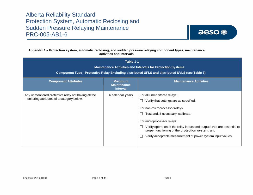
Alberta Reliability Standard Protection System, Automatic Reclosing and Sudden Pressure Relaying Maintenance PRC-005-AB1-6
Effective: 2019-10-01 Page 7 of 41 Public
Appendix 1 – Protection system, automatic reclosing, and sudden pressure relaying component types, maintenance activities and intervals
Table 1-1
Maintenance Activities and Intervals for Protection Systems
Component Type - Protective Relay Excluding distributed UFLS and distributed UVLS (see Table 3)
Component Attributes Maximum Maintenance
Interval
Maintenance Activities
Any unmonitored protective relay not having all the monitoring attributes of a category below.
6 calendar years For all unmonitored relays:
Verify that settings are as specified.
For non-microprocessor relays:
Test and, if necessary, calibrate.
For microprocessor relays:
Verify operation of the relay inputs and outputs that are essential to proper functioning of the protection system; and
Verify acceptable measurement of power system input values.

Alberta Reliability Standard Protection System, Automatic Reclosing and Sudden Pressure Relaying Maintenance PRC-005-AB1-6
Effective: 2019-10-01 Page 8 of 41 Public
Table 1-1
Maintenance Activities and Intervals for Protection Systems
Component Type - Protective Relay Excluding distributed UFLS and distributed UVLS (see Table 3)
Component Attributes Maximum Maintenance
Interval
Maintenance Activities
Monitored microprocessor protective relay with the following:
Internal self-diagnosis and alarming (see Table 2);
Voltage and/or current waveform sampling three or more times per power cycle, and conversion of samples to numeric values for measurement calculations by microprocessor electronics; and
Alarming for power supply failure (see Table 2).
12 calendar years Verify:
Settings are as specified;
Operation of the relay inputs and outputs that are essential to proper functioning of the protection system; and
Acceptable measurement of power system input values.
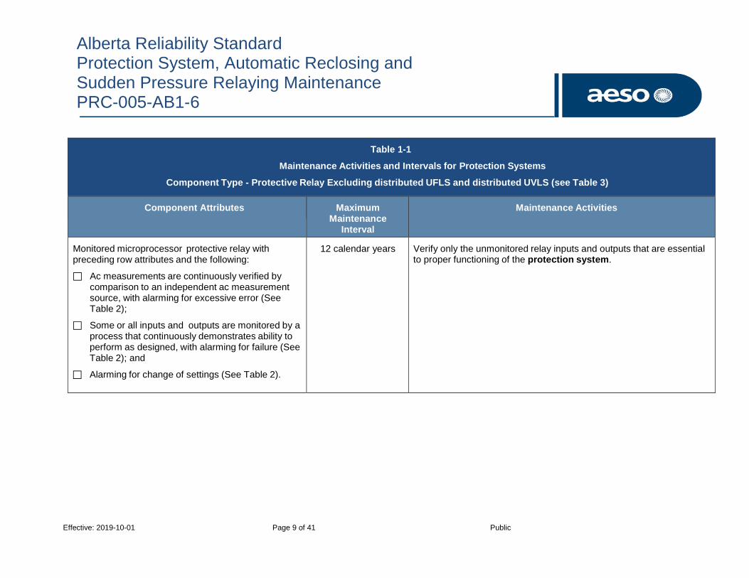
Alberta Reliability Standard Protection System, Automatic Reclosing and Sudden Pressure Relaying Maintenance PRC-005-AB1-6
Effective: 2019-10-01 Page 9 of 41 Public
Table 1-1
Maintenance Activities and Intervals for Protection Systems
Component Type - Protective Relay Excluding distributed UFLS and distributed UVLS (see Table 3)
Component Attributes Maximum Maintenance
Interval
Maintenance Activities
Monitored microprocessor protective relay with preceding row attributes and the following:
Ac measurements are continuously verified by comparison to an independent ac measurement source, with alarming for excessive error (See Table 2);
Some or all inputs and outputs are monitored by a process that continuously demonstrates ability to perform as designed, with alarming for failure (See Table 2); and
Alarming for change of settings (See Table 2).
12 calendar years Verify only the unmonitored relay inputs and outputs that are essential to proper functioning of the protection system.
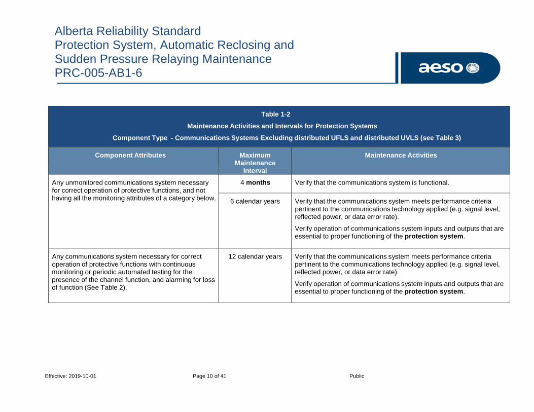
Alberta Reliability Standard Protection System, Automatic Reclosing and Sudden Pressure Relaying Maintenance PRC-005-AB1-6
Effective: 2019-10-01 Page 10 of 41 Public
Table 1-2
Maintenance Activities and Intervals for Protection Systems
Component Type - Communications Systems Excluding distributed UFLS and distributed UVLS (see Table 3)
Component Attributes Maximum Maintenance
Interval
Maintenance Activities
Any unmonitored communications system necessary for correct operation of protective functions, and not having all the monitoring attributes of a category below.
4 months Verify that the communications system is functional.
6 calendar years Verify that the communications system meets performance criteria pertinent to the communications technology applied (e.g. signal level, reflected power, or data error rate).
Verify operation of communications system inputs and outputs that are essential to proper functioning of the protection system.
Any communications system necessary for correct operation of protective functions with continuous monitoring or periodic automated testing for the presence of the channel function, and alarming for loss of function (See Table 2).
12 calendar years Verify that the communications system meets performance criteria pertinent to the communications technology applied (e.g. signal level, reflected power, or data error rate).
Verify operation of communications system inputs and outputs that are essential to proper functioning of the protection system.

Alberta Reliability Standard Protection System, Automatic Reclosing and Sudden Pressure Relaying Maintenance PRC-005-AB1-6
Effective: 2019-10-01 Page 11 of 41 Public
Table 1-2
Maintenance Activities and Intervals for Protection Systems
Component Type - Communications Systems Excluding distributed UFLS and distributed UVLS (see Table 3)
Component Attributes Maximum Maintenance
Interval
Maintenance Activities
Any communications system with all of the following:
Continuous monitoring or periodic automated testing for the performance of the channel using criteria pertinent to the communications technology applied (e.g. signal level, reflected power, or data error rate, and alarming for excessive performance degradation); (See Table 2); and
Some or all inputs and outputs are monitored by a process that continuously demonstrates ability to perform as designed, with alarming for failure (See Table 2).
12 calendar years Verify only the unmonitored communications system inputs and outputs that are essential to proper functioning of the protection system
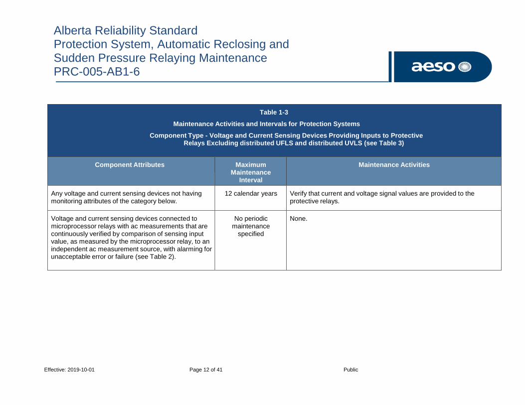
Alberta Reliability Standard Protection System, Automatic Reclosing and Sudden Pressure Relaying Maintenance PRC-005-AB1-6
Effective: 2019-10-01 Page 12 of 41 Public
Table 1-3
Maintenance Activities and Intervals for Protection Systems
Component Type - Voltage and Current Sensing Devices Providing Inputs to Protective Relays Excluding distributed UFLS and distributed UVLS (see Table 3)
Component Attributes Maximum Maintenance
Interval
Maintenance Activities
Any voltage and current sensing devices not having monitoring attributes of the category below.
12 calendar years Verify that current and voltage signal values are provided to the protective relays.
Voltage and current sensing devices connected to microprocessor relays with ac measurements that are continuously verified by comparison of sensing input value, as measured by the microprocessor relay, to an independent ac measurement source, with alarming for unacceptable error or failure (see Table 2).
No periodic maintenance
specified
None.

Alberta Reliability Standard Protection System, Automatic Reclosing and Sudden Pressure Relaying Maintenance PRC-005-AB1-6
Effective: 2019-10-01 Page 13 of 41 Public
Table 1-4(a)
Maintenance Activities and Intervals for Protection Systems
Component Type – Protection System Station dc Supply Using Vented Lead-Acid (VLA) Batteries Excluding distributed UFLS and distributed UVLS (see Table 3)
Protection System Station dc supply used only for non-bulk electric system interrupting devices for RAS, non-distributed UFLS systems, or non-distributed UVLS systems is excluded (see Table 1-4(e)).
Component Attributes Maximum Maintenance
Interval
Maintenance Activities
Protection system station dc supply using Vented Lead-Acid (VLA) batteries not having monitoring attributes of Table 1-4(f).
4 months unless a variance is
granted by the AESO
Verify:
Station dc supply voltage
Inspect:
Electrolyte level; and
For unintentional grounds
18 months Verify:
Float voltage of battery charger
Battery continuity
Battery terminal connection resistance
Battery intercell or unit-to-unit connection resistance
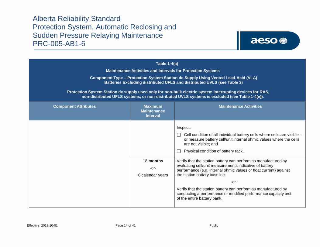
Alberta Reliability Standard Protection System, Automatic Reclosing and Sudden Pressure Relaying Maintenance PRC-005-AB1-6
Effective: 2019-10-01 Page 14 of 41 Public
Table 1-4(a)
Maintenance Activities and Intervals for Protection Systems
Component Type – Protection System Station dc Supply Using Vented Lead-Acid (VLA) Batteries Excluding distributed UFLS and distributed UVLS (see Table 3)
Protection System Station dc supply used only for non-bulk electric system interrupting devices for RAS, non-distributed UFLS systems, or non-distributed UVLS systems is excluded (see Table 1-4(e)).
Component Attributes Maximum Maintenance
Interval
Maintenance Activities
Inspect:
Cell condition of all individual battery cells where cells are visible – or measure battery cell/unit internal ohmic values where the cells are not visible; and
Physical condition of battery rack.
18 months
-or-
6 calendar years
Verify that the station battery can perform as manufactured by evaluating cell/unit measurements indicative of battery performance (e.g. internal ohmic values or float current) against the station battery baseline.
-or-
Verify that the station battery can perform as manufactured by conducting a performance or modified performance capacity test of the entire battery bank.

Alberta Reliability Standard Protection System, Automatic Reclosing and Sudden Pressure Relaying Maintenance PRC-005-AB1-6
Effective: 2019-10-01 Page 15 of 41 Public
Table 1-4(b)
Maintenance Activities and Intervals for Protection Systems
Component Type – Protection System Station dc Supply Using Valve-Regulated Lead-Acid (VRLA) Batteries Excluding distributed UFLS and distributed UVLS (see Table 3)
Protection System Station dc supply used only for non-bulk electric system interrupting devices for RAS, non-distributed UFLS systems, or non-distributed UVLS systems is excluded (see Table 1-4(e)).
Component Attributes Maximum Maintenance
Interval
Maintenance Activities
Protection system station dc supply with Valve Regulated Lead-Acid (VRLA) batteries not having monitoring attributes of Table 1-4(f).
4 months unless a variance is
granted by the AESO
Verify:
Station dc supply voltage
Inspect:
For unintentional grounds
6 months Inspect:
Condition of all individual units by measuring battery cell/unit internal ohmic values.
18 months Verify:
Float voltage of battery charger;
Battery continuity;

Alberta Reliability Standard Protection System, Automatic Reclosing and Sudden Pressure Relaying Maintenance PRC-005-AB1-6
Effective: 2019-10-01 Page 16 of 41 Public
Table 1-4(b)
Maintenance Activities and Intervals for Protection Systems
Component Type – Protection System Station dc Supply Using Valve-Regulated Lead-Acid (VRLA) Batteries Excluding distributed UFLS and distributed UVLS (see Table 3)
Protection System Station dc supply used only for non-bulk electric system interrupting devices for RAS, non-distributed UFLS systems, or non-distributed UVLS systems is excluded (see Table 1-4(e)).
Component Attributes Maximum Maintenance
Interval
Maintenance Activities
Battery terminal connection resistance; and
Battery intercell or unit-to-unit connection resistance.
Inspect:
Physical condition of battery rack.
6 months
-or-
3 calendar years
Verify that the station battery can perform as manufactured by evaluating cell/unit measurements indicative of battery performance (e.g. internal ohmic values or float current) against the station battery baseline.
-or-
Verify that the station battery can perform as manufactured by conducting a performance or modified performance capacity test of the entire battery bank.

Alberta Reliability Standard Protection System, Automatic Reclosing and Sudden Pressure Relaying Maintenance PRC-005-AB1-6
Effective: 2019-10-01 Page 17 of 41 Public
Table 1-4(c)
Maintenance Activities and Intervals for Protection Systems
Component Type – Protection System Station dc Supply Using Nickel-Cadmium (NiCad) Batteries Excluding distributed UFLS and distributed UVLS (see Table 3)
Protection System Station dc supply used only for non-bulk electric system interrupting devices for RAS, non-distributed UFLS system, or non-distributed UVLS systems is excluded (see Table 1-4(e)).
Component Attributes Maximum Maintenance
Interval
Maintenance Activities
Protection system station dc supply Nickel-Cadmium (NiCad) batteries not having monitoring attributes of Table 1-4(f).
4 months unless a variance is
granted by the AESO
Verify:
Station dc supply voltage.
Inspect:
Electrolyte level; and
For unintentional grounds.
18 months Verify:
Float voltage of battery charger;
Battery continuity;
Battery terminal connection resistance; and
Battery intercell or unit-to-unit connection resistance.

Alberta Reliability Standard Protection System, Automatic Reclosing and Sudden Pressure Relaying Maintenance PRC-005-AB1-6
Effective: 2019-10-01 Page 18 of 41 Public
Table 1-4(c)
Maintenance Activities and Intervals for Protection Systems
Component Type – Protection System Station dc Supply Using Nickel-Cadmium (NiCad) Batteries Excluding distributed UFLS and distributed UVLS (see Table 3)
Protection System Station dc supply used only for non-bulk electric system interrupting devices for RAS, non-distributed UFLS system, or non-distributed UVLS systems is excluded (see Table 1-4(e)).
Component Attributes Maximum Maintenance
Interval
Maintenance Activities
Inspect:
Cell condition of all individual battery cells; and
Physical condition of battery rack.
6 calendar years Verify that the station battery can perform as manufactured by conducting a performance or modified performance capacity test of the entire battery bank.

Alberta Reliability Standard Protection System, Automatic Reclosing and Sudden Pressure Relaying Maintenance PRC-005-AB1-6
Effective: 2019-10-01 Page 19 of 41 Public
Table 1-4(d)
Maintenance Activities and Intervals for Protection Systems
Component Type – Protection System Station dc Supply Using Non Battery Based Energy Storage Excluding distributed UFLS and distributed UVLS (see Table 3)
Protection System Station dc supply used only for non-bulk electric system interrupting devices for RAS, non-distributed UFLS system, or non-distributed UVLS systems is excluded (see Table 1-4(e)).
Component Attributes Maximum Maintenance
Interval
Maintenance Activities
Any protection system station dc supply not using a battery and not having monitoring attributes of Table 1-4(f).
4 months Verify:
Station dc supply voltage
Inspect:
For unintentional grounds
18 months Inspect:
Condition of non-battery based dc supply
6 calendar years Verify that the dc supply can perform as manufactured when ac power is not present.

Alberta Reliability Standard Protection System, Automatic Reclosing and Sudden Pressure Relaying Maintenance PRC-005-AB1-6
Effective: 2019-10-01 Page 20 of 41 Public
Table 1-4(e)
Maintenance Activities and Intervals for Protection Systems
Component Type – Protection System Station dc Supply for non-bulk electric system Interrupting Devices for RAS, non-distributed UFLS, and non-distributed UVLS systems
Component Attributes Maximum Maintenance
Interval
Maintenance Activities
Any protection system dc supply used for tripping only non- bulk electric system interrupting devices as part of a remedial action scheme, non-distributed UFLS, or non-distributed UVLS system and not having monitoring attributes of Table 1-4(f).
When control circuits are verified
(See Table 1-5)
Verify station dc supply voltage.

Alberta Reliability Standard Protection System, Automatic Reclosing and Sudden Pressure Relaying Maintenance PRC-005-AB1-6
Effective: 2019-10-01 Page 21 of 41 Public
Table 1-4(f)
Exclusions for Protection System Station dc Supply Monitoring Devices and Systems
Component Attributes Maximum Maintenance
Interval
Maintenance Activities
Any station dc supply with high and low voltage monitoring and alarming of the battery charger voltage to detect charger overvoltage and charger failure (See Table 2).
No periodic maintenance
specified
No periodic verification of station dc supply voltage is required.
Any battery based station dc supply with electrolyte level monitoring and alarming in every cell (See Table 2).
No periodic inspection of the electrolyte level for each cell is required.
Any station dc supply with unintentional dc ground monitoring and alarming (See Table 2).
No periodic inspection of unintentional dc grounds is required.
Any station dc supply with charger float voltage monitoring and alarming to ensure correct float voltage is being applied on the station dc supply (See Table 2).
No periodic verification of float voltage of battery charger is required.
Any battery based station dc supply with monitoring and alarming of battery string continuity (See Table 2).
No periodic verification of the battery continuity is required.

Alberta Reliability Standard Protection System, Automatic Reclosing and Sudden Pressure Relaying Maintenance PRC-005-AB1-6
Effective: 2019-10-01 Page 22 of 41 Public
Table 1-4(f)
Exclusions for Protection System Station dc Supply Monitoring Devices and Systems
Component Attributes Maximum Maintenance
Interval
Maintenance Activities
Any battery based station dc supply with monitoring and alarming of the intercell and/or terminal connection detail resistance of the entire battery (See Table 2).
No periodic verification of the intercell and terminal connection resistance is required.
Any Valve Regulated Lead-Acid (VRLA) or Vented Lead-Acid (VLA) station battery with internal ohmic value or float current monitoring and alarming, and evaluating present values relative to baseline internal ohmic values for every cell/unit (See Table 2).
No periodic evaluation relative to baseline of battery cell/unit measurements indicative of battery performance is required to verify the station battery can perform as manufactured.
Any Valve Regulated Lead-Acid (VRLA) or Vented Lead-Acid (VLA) station battery with monitoring and alarming of each cell/unit internal ohmic value (See Table 2).
No periodic inspection of the condition of all individual units by measuring battery cell/unit internal ohmic values of a station VRLA or Vented Lead-Acid (VLA) battery is required.

Alberta Reliability Standard Protection System, Automatic Reclosing and Sudden Pressure Relaying Maintenance PRC-005-AB1-6
Effective: 2019-10-01 Page 23 of 41 Public
Table 1-5
Maintenance Activities and Intervals for Protection Systems
Component Type - Control Circuitry Associated With Protective Functions Excluding distributed UFLS and distributed UVLS (see Table 3), Automatic Reclosing (see Table 4), and Sudden Pressure Relaying (see Table 5)
Note: Table requirements apply to all Control Circuitry Components of Protection Systems, and RAS except as noted.
Component Attributes Maximum Maintenance
Interval
Maintenance Activities
Trip coils or actuators of circuit breakers, interrupting devices, or mitigating devices (regardless of any monitoring of the control circuitry). As long as there is monitoring on the mitigating devices for high-voltage direct current/ flexible alternating current transmission system (HVDC/FACTS) devices no maintenance is required.
6 calendar years Verify that each trip coil is able to operate the circuit breaker, interrupting device, or mitigating device.
Electromechanical lockout devices which are directly in a trip path from the protective relay to the interrupting device trip coil (regardless of any monitoring of the control circuitry).
6 calendar years Verify electrical operation of electromechanical lockout devices.
Unmonitored control circuitry associated with RAS. (See Table 4-2(b) for RAS which include automatic reclosing.)
12 calendar years Verify all paths of the control circuits essential for proper operation of the RAS.

Alberta Reliability Standard Protection System, Automatic Reclosing and Sudden Pressure Relaying Maintenance PRC-005-AB1-6
Effective: 2019-10-01 Page 24 of 41 Public
Unmonitored control circuitry associated with protective functions inclusive of all auxiliary relays.
12 calendar years Verify all paths of the trip circuits inclusive of all auxiliary relays through the trip coil(s) of the circuit breakers or other interrupting devices.
Control circuitry associated with protective functions and/or RAS whose integrity is monitored and alarmed (See Table 2).
No periodic maintenance
specified
None.
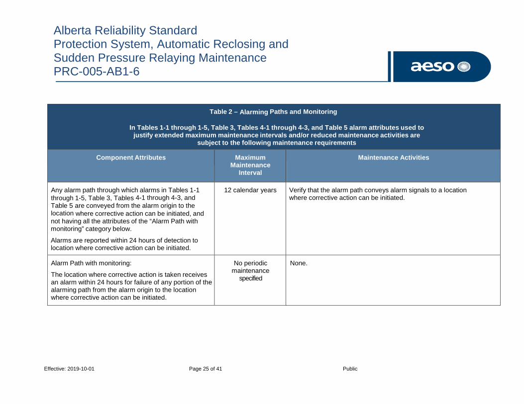
Alberta Reliability Standard Protection System, Automatic Reclosing and Sudden Pressure Relaying Maintenance PRC-005-AB1-6
Effective: 2019-10-01 Page 25 of 41 Public
Table 2 – Alarming Paths and Monitoring
In Tables 1-1 through 1-5, Table 3, Tables 4-1 through 4-3, and Table 5 alarm attributes used to justify extended maximum maintenance intervals and/or reduced maintenance activities are
subject to the following maintenance requirements
Component Attributes Maximum Maintenance
Interval
Maintenance Activities
Any alarm path through which alarms in Tables 1-1 through 1-5, Table 3, Tables 4-1 through 4-3, and Table 5 are conveyed from the alarm origin to the location where corrective action can be initiated, and not having all the attributes of the “Alarm Path with monitoring” category below.
Alarms are reported within 24 hours of detection to location where corrective action can be initiated.
12 calendar years Verify that the alarm path conveys alarm signals to a location where corrective action can be initiated.
Alarm Path with monitoring:
The location where corrective action is taken receives an alarm within 24 hours for failure of any portion of the alarming path from the alarm origin to the location where corrective action can be initiated.
No periodic maintenance
specified
None.

Alberta Reliability Standard Protection System, Automatic Reclosing and Sudden Pressure Relaying Maintenance PRC-005-AB1-6
Effective: 2019-10-01 Page 26 of 41 Public
Table 3
Maintenance Activities and Intervals for distributed UFLS and distributed UVLS Systems
Component Attributes Maximum Maintenance
Interval
Maintenance Activities
Any unmonitored protective relay not having all the monitoring attributes of a category below.
6 calendar years Verify that settings are as specified.
For non-microprocessor relays:
Test and, if necessary calibrate.
For microprocessor relays:
Verify operation of the relay inputs and outputs that are essential to proper functioning of the protection system; and
Verify acceptable measurement of power system input values.
Monitored microprocessor protective relay with the following:
Internal self-diagnosis and alarming (See Table 2); and
Voltage and/or current waveform sampling three or more times per power cycle, and conversion of samples to numeric values for measurement calculations by microprocessor electronics.
Alarming for power supply failure (See Table 2).
12 calendar years Verify:
Settings are as specified;
Operation of the relay inputs and outputs that are essential to proper functioning of the protection system; and
Acceptable measurement of power system input values.

Alberta Reliability Standard Protection System, Automatic Reclosing and Sudden Pressure Relaying Maintenance PRC-005-AB1-6
Effective: 2019-10-01 Page 27 of 41 Public
Table 3
Maintenance Activities and Intervals for distributed UFLS and distributed UVLS Systems
Component Attributes Maximum Maintenance
Interval
Maintenance Activities
Monitored microprocessor protective relay with preceding row attributes and the following:
Ac measurements are continuously verified by comparison to an independent ac measurement source, with alarming for excessive error (See Table 2); and
Some or all inputs and outputs are monitored by a process that continuously demonstrates ability to perform as designed, with alarming for failure (See Table 2).
Alarming for change of settings (See Table 2).
12 calendar years Verify only the unmonitored relay inputs and outputs that are essential to proper functioning of the protection system.
Voltage and/or current sensing devices associated with UFLS or UVLS systems.
12 calendar years Verify that current and/or voltage signal values are provided to the protective relays.
Protection system dc supply for tripping non-bulk electric system interrupting devices used only for a UFLS or UVLS system.
12 calendar years Verify protection system dc supply voltage.

Alberta Reliability Standard Protection System, Automatic Reclosing and Sudden Pressure Relaying Maintenance PRC-005-AB1-6
Effective: 2019-10-01 Page 28 of 41 Public
Table 3
Maintenance Activities and Intervals for distributed UFLS and distributed UVLS Systems
Component Attributes Maximum Maintenance
Interval
Maintenance Activities
Control circuitry between the UFLS or UVLS relays and electromechanical lockout and/or tripping auxiliary devices (excludes non-bulk electric system interrupting device trip coils).
12 calendar years Verify the path from the relay to the lockout and/or tripping auxiliary relay (including essential supervisory logic).
Electromechanical lockout and/or tripping auxiliary devices associated only with UFLS or UVLS systems (excludes non-bulk electric system interrupting device trip coils).
12 calendar years Verify electrical operation of electromechanical lockout and/or tripping auxiliary devices.
Control circuitry between the electromechanical lockout and/or tripping auxiliary devices and the non-bulk electric system interrupting devices in UFLS or UVLS systems, or between UFLS or UVLS relays (with no interposing electromechanical lockout or auxiliary device) and the non-bulk electric system interrupting devices (excludes non-bulk electric system interrupting device trip coils).
No periodic maintenance
specified
None.
Trip coils of non-bulk electric system interrupting devices in UFLS or UVLS systems.
No periodic maintenance
specified
None.

Alberta Reliability Standard Protection System, Automatic Reclosing and Sudden Pressure Relaying Maintenance PRC-005-AB1-6
Effective: 2019-10-01 Page 29 of 41 Public
Table 4-1
Maintenance Activities and Intervals for Automatic Reclosing Components Component Type – Reclosing and Supervisory Relay
Note: In cases where Components of Automatic Reclosing are common to Components listed in Table 1-1 through
1-5, the Components only need to be tested once during a distinct maintenance interval.
Component Attributes Maximum Maintenance
Interval
Maintenance Activities
Any unmonitored reclosing relay or supervisory relay not having all the monitoring attributes of a category below.
6 calendar years Verify that settings are as specified.
For non-microprocessor reclosing or supervisory relays:
Test and, if necessary calibrate
For microprocessor reclosing or supervisory relays:
Verify operation of the relay inputs and outputs that are essential to proper functioning of the Automatic Reclosing.
For microprocessor supervisory relays:
Verify acceptable measurement of power system input values.

Alberta Reliability Standard Protection System, Automatic Reclosing and Sudden Pressure Relaying Maintenance PRC-005-AB1-6
Effective: 2019-10-01 Page 30 of 41 Public
Table 4-1
Maintenance Activities and Intervals for Automatic Reclosing Components Component Type – Reclosing and Supervisory Relay
Note: In cases where Components of Automatic Reclosing are common to Components listed in Table 1-1 through
1-5, the Components only need to be tested once during a distinct maintenance interval.
Component Attributes Maximum Maintenance
Interval
Maintenance Activities
Monitored microprocessor reclosing relay or supervisory relay with the following: Internal self-diagnosis and alarming (See Table 2).
Alarming for power supply failure (See Table 2).
For supervisory relay:
Voltage waveform sampling three or more times per power cycle, and conversion of samples to numeric values for measurement calculations by microprocessor electronics.
12 calendar years Verify:
Settings are as specified.
Operation of the relay inputs and outputs that are essential to proper functioning of the Automatic Reclosing.
For supervisory relays:
Verify acceptable measurement of power system input values.
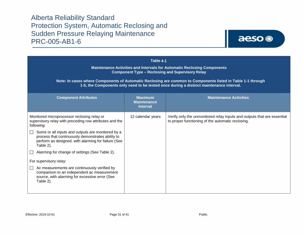
Alberta Reliability Standard Protection System, Automatic Reclosing and Sudden Pressure Relaying Maintenance PRC-005-AB1-6
Effective: 2019-10-01 Page 31 of 41 Public
Table 4-1
Maintenance Activities and Intervals for Automatic Reclosing Components Component Type – Reclosing and Supervisory Relay
Note: In cases where Components of Automatic Reclosing are common to Components listed in Table 1-1 through
1-5, the Components only need to be tested once during a distinct maintenance interval.
Component Attributes Maximum Maintenance
Interval
Maintenance Activities
Monitored microprocessor reclosing relay or supervisory relay with preceding row attributes and the following:
Some or all inputs and outputs are monitored by a process that continuously demonstrates ability to perform as designed, with alarming for failure (See Table 2).
Alarming for change of settings (See Table 2).
For supervisory relay:
Ac measurements are continuously verified by comparison to an independent ac measurement source, with alarming for excessive error (See Table 2).
12 calendar years Verify only the unmonitored relay inputs and outputs that are essential to proper functioning of the automatic reclosing.

Alberta Reliability Standard Protection System, Automatic Reclosing and Sudden Pressure Relaying Maintenance PRC-005-AB1-6
Effective: 2019-10-01 Page 32 of 41 Public
Table 4-2(a)
Maintenance Activities and Intervals for Automatic Reclosing Components
Component Type – Control Circuitry Associated with Reclosing and Supervisory Relays that are NOT an Integral Part of RAS
Note: In cases where Components of Automatic Reclosing are common to Components listed in Table 1-5, the Components only need to be tested once during a distinct maintenance interval.
Component Attributes Maximum Maintenance
Interval
Maintenance Activities
Unmonitored control circuitry associated with automatic reclosing that is not an integral part of an RAS.
12 calendar years Verify that automatic reclosing, upon initiation, does not issue a premature closing command to the close circuitry.
Control circuitry associated with automatic reclosing that is not part of an RAS and is monitored and alarmed for conditions that would result in a premature closing command. (See Table 2)
No periodic maintenance
specified
None.

Alberta Reliability Standard Protection System, Automatic Reclosing and Sudden Pressure Relaying Maintenance PRC-005-AB1-6
Effective: 2019-10-01 Page 33 of 41 Public
Table 4-2(b)
Maintenance Activities and Intervals for Automatic Reclosing Components
Component Type – Control Circuitry Associated with Reclosing and Supervisory Relays that are an Integral Part of RAS
Note: In cases where Components of Automatic Reclosing are common to Components listed in Table 1-5, the Components only need to be tested once during a distinct maintenance interval.
Component Attributes Maximum Maintenance
Interval
Maintenance Activities
Close coils or actuators of circuit breakers or similar devices that are used in conjunction with automatic reclosing as part of an RAS (regardless of any monitoring of the control circuitry).
6 calendar years Verify that each close coil or actuator is able to operate the circuit breaker or mitigating device.
Unmonitored close control circuitry associated with automatic reclosing used as an integral part of an RAS.
12 calendar years Verify all paths of the control circuits associated with automatic reclosing that are essential for proper operation of the RAS.
Control circuitry associated with automatic reclosing that is an integral part of an RAS whose integrity is monitored and alarmed (See Table 2).
No periodic maintenance
specified
None.

Alberta Reliability Standard Protection System, Automatic Reclosing and Sudden Pressure Relaying Maintenance PRC-005-AB1-6
Effective: 2019-10-01 Page 34 of 41 Public
Table 4-3
Maintenance Activities and Intervals for Automatic Reclosing Components
Component Type – Voltage Sensing Devices Associated with Supervisory Relays
Note: In cases where Components of Automatic Reclosing are common to Components listed in Table 1-3, the Components only need to be tested once during a distinct maintenance interval.
Component Attributes Maximum Maintenance
Interval
Maintenance Activities
Any voltage sensing devices not having monitoring attributes of the category below.
12 calendar years Verify that voltage signal values are provided to the supervisory relays.
Voltage sensing devices that are connected to microprocessor supervisory relays with ac measurements that are continuously verified by comparison of sensing input value, as measured by the microprocessor relay, to an independent ac measurement source, with alarming for unacceptable error or failure. (See Table 2)
No periodic maintenance
specified
None.
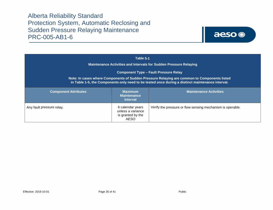
Alberta Reliability Standard Protection System, Automatic Reclosing and Sudden Pressure Relaying Maintenance PRC-005-AB1-6
Effective: 2019-10-01 Page 35 of 41 Public
Table 5-1
Maintenance Activities and Intervals for Sudden Pressure Relaying
Component Type – Fault Pressure Relay
Note: In cases where Components of Sudden Pressure Relaying are common to Components listed in Table 1-5, the Components only need to be tested once during a distinct maintenance interval.
Component Attributes Maximum Maintenance
Interval
Maintenance Activities
Any fault pressure relay. 6 calendar years unless a variance is granted by the
AESO
Verify the pressure or flow sensing mechanism is operable.
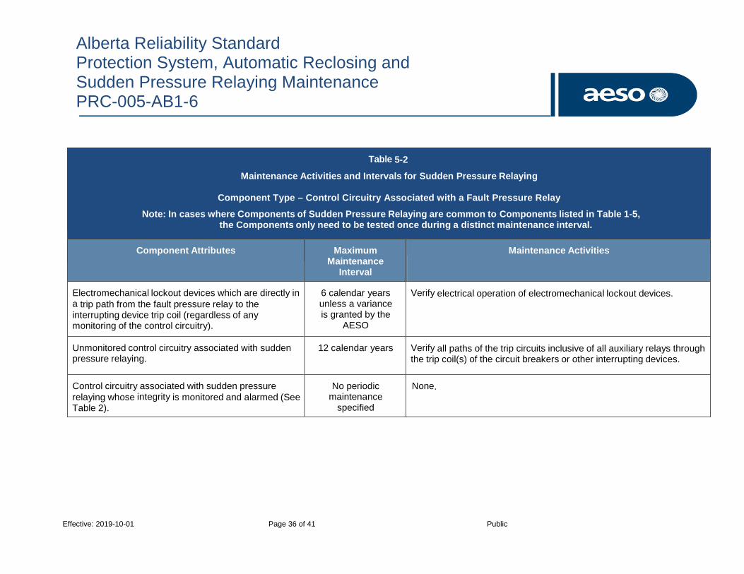
Alberta Reliability Standard Protection System, Automatic Reclosing and Sudden Pressure Relaying Maintenance PRC-005-AB1-6
Effective: 2019-10-01 Page 36 of 41 Public
Table 5-2
Maintenance Activities and Intervals for Sudden Pressure Relaying
Component Type – Control Circuitry Associated with a Fault Pressure Relay
Note: In cases where Components of Sudden Pressure Relaying are common to Components listed in Table 1-5, the Components only need to be tested once during a distinct maintenance interval.
Component Attributes Maximum Maintenance
Interval
Maintenance Activities
Electromechanical lockout devices which are directly in a trip path from the fault pressure relay to the interrupting device trip coil (regardless of any monitoring of the control circuitry).
6 calendar years unless a variance is granted by the
AESO
Verify electrical operation of electromechanical lockout devices.
Unmonitored control circuitry associated with sudden pressure relaying.
12 calendar years Verify all paths of the trip circuits inclusive of all auxiliary relays through the trip coil(s) of the circuit breakers or other interrupting devices.
Control circuitry associated with sudden pressure relaying whose integrity is monitored and alarmed (See Table 2).
No periodic maintenance
specified
None.
Alberta Reliability Standard Protection System, Automatic Reclosing and Sudden Pressure Relaying Maintenance PRC-005-AB1-6
Effective: 2019-10-01 Page 37 of 41 Public
Appendix 2 – Performance-Based Protection System Maintenance Program Purpose:
1. To establish a technical basis for initial and continued use of a performance-based protection system maintenance program.
2. To establish the technical justification for the initial use of a performance-based protection system maintenance program:
a. Develop a list with a description of components included in each designated segment, with a minimum segment population of 60 components;
b. Maintain the components in each segment according to the time-based maximum allowable intervals established in Tables 1-1 through 1-5, Table 3, Tables 4-1 through 4-2, and Table 5 until results of maintenance activities for the segment are available for a minimum of 30 individual components of the segment;
c. Document the maintenance program activities and results for each segment, including maintenance dates and countable events for each included component;
d. Analyze the maintenance program activities and results for each segment to determine the overall performance of the segment and develop maintenance intervals; and
e. Determine the maximum allowable maintenance interval for each segment such that the segment experiences countable events on no more than 4% of the components within the segment, for the greater of either the last 30 components maintained or all components maintained in the previous year.
3. To maintain the technical justification for the ongoing use of a performance-based protection system maintenance program:
a. At least annually, update the list of components and segments, and/or description if any changes occur within the segment;
b. Perform maintenance on the greater of 5% of the components (addressed in the performance based protection system maintenance program) in each segment or 3 individual components within the segment in each year;
c. For the prior year, analyze the maintenance program activities and results for each segment to determine the overall performance of the segment; and
d. Using the prior year’s data, determine the maximum allowable maintenance interval for each segment such that the segment experiences countable events on no more than 4% of the components within the segment, for the greater of either the last 30 components maintained or all components maintained in the previous year.
If the components in a segment maintained through a performance-based protection system maintenance program experience 4% or more countable events, develop, document and implement an action plan to reduce the countable events to less than 4% of the segment population within 3 years.
Alberta Reliability Standard Protection System, Automatic Reclosing and Sudden Pressure Relaying Maintenance PRC-005-AB1-6
Effective: 2019-10-01 Page 38 of 41 Public
Appendix 3 – Amending Process for List of Facilities
In order to amend any list referenced in subsections 2.1(a)(iii), 2.1(b)(iv) and 2.1(c)(iii), of section 2, Applicability of this reliability standard, the ISO must:
(a) upon determining that a transmission facility, generating unit or aggregated generating facility is to be added, notify the legal owner in writing and determine when the legal owner is to be compliant with the requirements of this reliability standard, which from the date of notice must be at a minimum the maximum maintenance interval identified in Tables 1 to 5 plus six (6) full months;
(b) upon determining that a transmission facility, generating unit or aggregated generating facility is to be deleted, notify the legal owner in writing and determine an effective date for the legal owner to no longer be required to meet the applicable requirements; and
(c) publish the amended list with effective dates on the AESO website.
Alberta Reliability Standard Protection System, Automatic Reclosing and Sudden Pressure Relaying Maintenance PRC-005-AB1-6
Effective: 2019-10-01 Page 39 of 41 Public
Appendix 4 – Amending Process for List of Devices
If devices are added or removed as described in subsections 2.2(b), 2.2(c) and 2.2(d) of section 2, Applicability of this reliability standard the ISO must:
(a) upon determining that a protection system that is to be used for underfrequency load shedding, under voltage load shed or that is to be installed as a remedial action scheme is to be added, notify the legal owner in writing and determine when the legal owner is to be compliant with the requirements of this reliability standard, which from the date of notice must be at a minimum the maximum maintenance interval identified in Tables 1 to 5 plus 6 full months;
(b) upon determining that a protection system that is used for underfrequency load shedding, under voltage load shed or that is installed as a remedial action scheme is to be removed, notify the legal owner in writing and determine an effective date for the legal owner to no longer be required to meet the applicable requirements.

Alberta Reliability Standard Protection System, Automatic Reclosing and Sudden Pressure Relaying Maintenance PRC-005-AB1-6
Effective: 2019-10-01 Page 40 of 41 Public
Appendix 5 – Implementation Plan
1. Purpose
The purpose of this appendix is to set the effective dates and the implementation timelines for Alberta reliability standard PRC-005-AB1-6, Protection System, Automatic Reclosing and Sudden Pressure Relaying Maintenance (“PRC-005-AB1-6”).
2. Compliance with Reliability Standards
The entities identified in section 2 of this reliability standard must comply with the requirements of PRC-005-AB1-6 in accordance with the implementation schedule.
3. Effective Date
PRC-005-AB1-6 will become effective on October 1, 2019. Entities must follow the phased implementation plan set out in sections 4 and 5 below.
4. Implementation Plan for Requirements R1, R2 and R5
Entities must be compliant with requirements R1, R2 and R5 of PRC-005-AB1-6 on October 1, 2019.
5. Implementation Plan for Requirements R3 and R4
1. For protection system, automatic reclosing, and sudden pressure relaying component maintenance activities with maximum allowable intervals of less than 1 calendar year, as established in Tables 1-1 through 1-5, the entity must be compliant with PRC-005-AB1-6 by April 1, 2020.
2. For protection system, automatic reclosing, and sudden pressure relaying component maintenance activities with maximum allowable intervals 1 calendar year or more, but 2 calendar years or less, as established in Tables 1-1 through 1-5, the entity must be compliant with PRC-005-AB1-6 by October 1, 2021.
3. For protection system, automatic reclosing, and sudden pressure relaying component maintenance activities with maximum allowable intervals of 3 calendar years, as established in Tables 1-1 through 1-5, maintenance must be completed in accordance with the following:
• The entity must complete maintenance on 30% of identified components in accordance with their protection system maintenance program by October 1, 2020 or, for generating plants with scheduled outage intervals exceeding 2 years, at the conclusion of the first succeeding maintenance outage;
• The entity must complete maintenance on 60% of the identified components in accordance with their protection system maintenance program by October 1, 2021.
• The entity must complete maintenance on 100% of the identified components in accordance with their protection system maintenance program by October 1, 2022.
4. For protection system, automatic reclosing, and sudden pressure relaying component maintenance activities with maximum allowable intervals of 6 calendar years, as established in Tables 1-1 through 1-5, Table 3, Table 4-1, Table 4-2b, Table 5-1, and Table 5-2 maintenance must be completed in accordance with the following:
• The entity must complete maintenance on 30% of the identified components in accordance with their protection system maintenance program by October 1, 2021 or,
Alberta Reliability Standard Protection System, Automatic Reclosing and Sudden Pressure Relaying Maintenance PRC-005-AB1-6
Effective: 2019-10-01 Page 41 of 41 Public
for generating plants with scheduled outage intervals exceeding 3 years, at the conclusion of the first succeeding maintenance outage.
• The entity must complete maintenance on 60% of the identified components in accordance with their protection system maintenance program by October 1, 2023.
• The entity must complete maintenance on 100% of the identified components in accordance with their protection system maintenance program by October 1, 2025.
5. For protection system, automatic reclosing, and sudden pressure relaying component maintenance activities with maximum allowable intervals of 12 calendar years, as established in Tables 1-1 through 1-5, Table 2, Table 3, Tables 4-1 through 4-3, and Table 5-2 maintenance must be completed in accordance with the following:
• The entity must complete maintenance on 30% of the identified components in accordance with their protection system maintenance program by October 1, 2023.
• The entity must complete maintenance on 60% of the identified components in accordance with their protection system maintenance program by October 1, 2027.
• The entity must complete maintenance on 100% of the identified components in accordance with their protection system maintenance program by October 1, 2031.

Alberta Reliability Standard UFLS Performance Following
an Underfrequency Event PRC-009-AB-0
Effective: 2009-10-03 Page 1 of 2
PRC–009–AB–0 UFLS Performance Following an Undefrequency Event
1. Purpose
The purpose of this reliability standard is to ensure effectiveness of the UFLS program performance.
2. Applicability
This reliability standard applies to:
ISO
3. Definitions
Italicized terms used in this reliability standard have the meanings as set out in the Alberta Reliability Standards Glossary of Terms and Part 1 of the ISO Rules.
4. Requirements
R1 The ISO must analyze and document its UFLS program performance in accordance with WECC’s UFLS program. The analysis must address the performance of UFLS equipment and program effectiveness following system events resulting in system frequency excursions below the initializing set points of the UFLS program. The analysis must include, without limitation the following:
A description of the system event including initiating conditions.
A review of the UFLS set points and tripping times.
A simulation of the system event.
A summary of the findings.
R2 The ISO must provide documentation of the analysis of the UFLS program performance to WECC on request and within the timeframe agreed to by the ISO and WECC.
5. Processes and Procedures
No procedures have been defined for this reliability standard.
6. Measures
The following measures correspond to the requirements identified in Section 4 of this reliability standard. For example, MR1 is the measure for R1.
MR1 Disturbance document(s) exist for each UFLS event. The disturbance document(s) contain analysis of the event.
MR2 Written confirmation from WECC that documentation was received.

PRC–009–AB–0 UFLS Performance Following an Undefrequency Event
Effective: 2009-10-03 Page 2 of 2
7. Appendices
No appendices have been defined for this reliability standard.
8. Guidelines
No guidelines have been defined for this reliability standard.
Revision History
Date Description
2009-10-03 New Issue

Alberta Reliability Standard Assessment of the Design and Effectiveness of UVLS Program
PRC-010-AB-0
Effective: 2009-10-03 Page 1 of 2
PRC–010–AB–0 Assessment of the Design and Effectiveness of Under Voltage Load Shedding Program
1. Purpose
The purpose of this reliability standard is to ensure the effectiveness of each UVLS program.
2. Applicability
This reliability standard applies to:
ISO
3. Definitions
Italicized terms used in this reliability standard have the meanings as set out in the Alberta Reliability Standards Glossary of Terms and Part 1 of the ISO Rules.
4. Requirements
R1 The ISO must conduct and document an assessment of the effectiveness of each UVLS program every five years. In the event the AESO determines that conditions affecting the UVLS operation have occurred, it may conduct and document an assessment within such five year period as it deems appropriate.
R2 The assessment of the effectiveness of each UVLS program must include without limitation, the following:
Coordination of the UVLS programs with other protection and control systems in the WECC as appropriate.
Simulations that demonstrate that the performance of each UVLS program is consistent with reliability standards TPL-001-AB-0, TPL-002-AB-0, TPL-003-AB-0 and TPL-004-AB-0.
A review of the voltage set points and timing
R3 The ISO must provide documentation of its most recent assessment of UVLS programs to WECC on request and within the timeframe agreed to by the ISO and WECC.
5. Processes and Procedures
No procedures have been defined for this reliability standard.
6. Measures
The following measures correspond to the requirements identified in Section 4 of this reliability standard. For example, MR1 is the measure for R1.
MR1 Documentation of the most recent assessment of the effectiveness of each UVLS program exists and was carried out within the last five years.

PRC-010-AB-0 Assessment of the Design and Effectiveness of UVLS Program
Effective: 2009-10-03 Page 2 of 2
MR2 Documentation of the most recent assessment includes the elements of R2.
MR3 Written confirmation from WECC that the documentation requested by it pursuant to R3 has been received.
7. Appendices
No appendices have been defined for this reliability standard.
8. Guidelines
No guidelines have been defined for this reliability standard.
Revision History
Date Description
2009-10-03 New Issue

Alberta Reliability Standard Disturbance Monitoring Equipment Installation and Data Reporting PRC-018-AB-1
Effective: 2016-08-30
Page 1 of 3
1. Purpose
The purpose of this reliability standard is to ensure that disturbance monitoring equipment is installed and that disturbance data is reported in accordance with regional requirements to facilitate analyses of events.
2. Applicability
This reliability standard applies to:
(a) the legal owner of a transmission facility that owns disturbance monitoring equipment as identified in the list of Disturbance Monitoring Equipment Locations as required in requirement R1, as published by the ISO on the AESO website and as amended from time to time by the ISO on notice to market participants;
(b) the legal owner of a generating unit that owns disturbance monitoring equipment as identified in the list of Disturbance Monitoring Equipment Locations as required in requirement R1, as published by the ISO on the AESO website and as amended from time to time by the ISO on notice to market participants;
(c) the legal owner of an aggregated generating facility that owns disturbance monitoring equipment as identified in the list of Disturbance Monitoring Equipment Locations as required in requirement R1, as published by the ISO on the AESO website and as amended from time to time by the ISO on notice to market participants; and
(d) the ISO.
3. Requirements
R1 The ISO must maintain and publish a list of all disturbance monitoring equipment that this reliability standard applies to which includes all disturbance monitoring equipment the WECC requires to be installed in Alberta.
R2 Each legal owner of a transmission facility, legal owner of a generating unit and legal owner of an aggregated generating facility that the ISO directs to install disturbance monitoring equipment must install such disturbance monitoring equipment with internal clocks synchronized to within two (2) milliseconds or less of the Universal Coordinated Time scale.
R3 The ISO must have recorded disturbance data available for retrieval for at least ten (10) days.
R4 Each legal owner of a transmission facility, legal owner of a generating unit and legal owner of an aggregated generating facility must install disturbance monitoring equipment as directed by the ISO.
R5 Each legal owner of a transmission facility, legal owner of a generating unit and legal owner of an aggregated generating facility must report, within thirty (30) days of the ISO’s request, the following information on the disturbance monitoring equipment:
R5.1 type of disturbance monitoring equipment;
R5.2 make and model of disturbance monitoring equipment;

Alberta Reliability Standard Disturbance Monitoring Equipment Installation and Data Reporting PRC-018-AB-1
Effective: 2016-08-30
Page 2 of 3
R5.3 installation location;
R5.4 operational status;
R5.5 date last tested;
R5.6 monitored system elements which may include transmission circuit and bus section;
R5.7 monitored devices which may include circuit breaker, disconnect status and alarms; and
R5.8 monitored electrical quantities, which may include voltage and current.
R6 The ISO must provide the information received from the legal owner of a transmission facility, legal owner of a generating unit and legal owner of an aggregated generating facility in requirement R5 to the WECC within forty-five (45) days of the WECC’s written request.
R7 If the ISO is unable to directly access disturbance data, then each legal owner of a transmission facility, legal owner of a generating unit and legal owner of an aggregated generating facility must provide all available disturbance data recorded by disturbance monitoring equipment to the ISO within forty-five (45) days of the ISO’s written request.
R8 The ISO must provide all available disturbance data recorded by the disturbance monitoring equipment of a legal owner of a transmission facility, legal owner of a generating unit and legal owner of an aggregated generating facility to the WECC within sixty (60) days of the WECC’s written request.
R9 The ISO must archive all data recorded by disturbance monitoring equipment for all WECC or ISO identified events for at least three (3) years.
R10 Each legal owner of a transmission facility, legal owner of a generating unit and legal owner of an aggregated generating facility that the ISO directs to have disturbance monitoring equipment must develop, implement and maintain a maintenance and testing program for disturbance monitoring equipment that includes:
R10.1 maintenance and testing intervals and their basis; and
R10.2 a summary of maintenance and testing procedures.
4 Measures
The following measures correspond to the requirements identified in Section 4 of this reliability standard. For example, MR1 is the measure for R1.
MR1 Evidence of maintaining and publishing a list as required in requirement R1 exists. Evidence may include a list published on the AESO’s website that identifies the effective date and revision history.
MR2 Evidence of having internal clocks in the installed disturbance monitoring equipment synchronized as required in requirement R2 exists. Evidence may include: the manufacturer’s equipment specification, commissioning documents or GPS clock records that demonstrate each installed disturbance monitoring equipment’s internal clock is synchronized in accordance with R2.

Alberta Reliability Standard Disturbance Monitoring Equipment Installation and Data Reporting PRC-018-AB-1
Effective: 2016-08-30
Page 3 of 3
MR3 Evidence of having recorded disturbance data available for retrieval as required in requirement R3 exists. Evidence may include disturbance records.
MR4 Evidence of installing disturbance monitoring equipment as required in requirement R4 exists. Evidence may include documentation of the installation of the disturbance monitoring equipment.
MR5 Evidence of reporting information as required in requirement R5 exists. Evidence may include email or mail to the appropriate ISO recipient that identifies information submitted.
MR6 Evidence of providing data as required in requirement R6 exists. Evidence may include email or mail to the appropriate WECC recipient that identifies data submitted.
MR7 Evidence of providing data as required in requirement R7 exists. Evidence may include email or mail to the appropriate ISO recipient that identifies data submitted.
MR8 Evidence of providing data as required in requirement R8 exists. Evidence may include email or mail to appropriate WECC recipient that identifies data submitted.
MR9 Evidence of archiving data as required in requirement R9 exists. Evidence may include dated archived data files.
MR10 Evidence of developing, implementing and maintaining a maintenance and testing program as required in requirement R10 exists. Evidence may include a documented maintenance and testing program, maintenance and testing records showing the test date, type of test, what was tested and test results.
MR10.1 Evidence of developing, implementing and maintaining a maintenance and testing program as required in requirement R10.1 exists. Evidence may include a documented maintenance and testing program that includes the provision as required in requirement R10.1.
MR10.2 Evidence of developing, implementing and maintaining a maintenance and testing program as required in requirement R10.2 exists. Evidence may include a documented maintenance and testing program that includes the provision as required in requirement R10.2.
5. Appendices
No appendices have been defined for this reliability standard.
Revision History
Effective Description
2013-01-01 Initial Release
2016-08-30 Inclusion of the defined term system element.

Alberta Reliability Standard Under Voltage Load Shedding Program Data
PRC-021-AB1-1
Effective: 2013-01-02 Page 1 of 2
PRC–021–AB1–1 Under Voltage Load Shedding Program Data
1. Purpose
The purpose of this reliability standard is to ensure data is provided to support the WECC database maintained for UVLS programs.
2. Applicability
This reliability standard applies to:
(a) the legal owner of a transmission facility that owns an under voltage load shed system;
(b) a market participant receiving service under Rate DTS of the ISO tariff that owns an under voltage load shed system; and
(c) the ISO.
3. Definitions
Italicized terms used in this reliability standard have the meanings as set out in the Consolidated Authoritative Document Glossary.
4. Requirements
R1 The ISO must update its UVLS data annually to support the WECC UVLS database.
R2 The ISO must provide the following data to the WECC for each installed UVLS system in Alberta that is in the WECC UVLS database:
Size and location of load, or percent of connected load, to be interrupted;
Corresponding voltage set points and overall scheme clearing times;
Time delay from initiation to trip signal;
Breaker operating times; and
Any other schemes that are part of or impact the UVLS programs, including without limitation related generation protection, islanding schemes, automatic load restoration schemes, UFLS and RAS (identified as special protection systems by WECC).
R3 Each legal owner of a transmission facility and market participant must, upon request by the ISO, provide UVLS data to the ISO. The legal owner of a transmission facility or market participant may meet this requirement R3 by providing UVLS data in accordance with ISO rules.
R4 The ISO must provide its UVLS data to the WECC within 30 calendar days of a written request to do so from WECC.
5. Processes and Procedures
No procedures have been defined for this reliability standard.

PRC–021–AB1–1 Under Voltage Load Shedding Program Data
Effective: 2013-01-02 Page 2 of 2
6. Measures
The following measures correspond to the requirements identified in Section 4 of this reliability standard. For example, MR1 is the measure for R1.
MR1 Evidence that the UVLS data update process was completed within 12 months of the previous update.
MR2 Written confirmation from WECC that UVLS data was received.
MR3 Written confirmation from the ISO that UVLS data was received.
MR4 Written confirmation from WECC that data was received within 30 calendar days of a request.
7. Appendices
No appendices have been defined for this reliability standard.
8. Guidelines
No guidelines have been defined for this reliability standard.
Revision History
Date Description
2013-01-02 Administrative update – “TFO” and “demand customers” replaced with “legal owner of a transmission facility” and “market participant receiving service under Rate DTS of the ISO tariff”; and other minor cleanup items.
2009-09-19 New Issue

Alberta Reliability Standard Under Voltage Load Shedding Program Performance
PRC-022-AB-1
Effective: 2009-10-03 Page 1 of 2
PRC–022–AB–1 Under Voltage Load Shedding Program Performance
1. Purpose
The purpose of this reliability standard is to ensure that UVLS programs perform as intended to mitigate the risk of voltage collapse or voltage instability in the AIES.
2. Applicability
This reliability standard applies to:
ISO
3. Definitions
Italicized terms used in this reliability standard have the meanings as set out in the Alberta Reliability Standards Glossary of Terms and Part 1 of the ISO Rules.
4. Requirements
R1 The ISO must analyze and document UVLS operations and misoperations in accordance with ISO rules.
R2 The ISO’s analysis of UVLS operations and misoperations must include without limitation, the following:
A description of the UVLS event including initiating conditions.
A review of the UVLS set points and tripping times.
An analysis of the sequence of events.
A summary of the findings.
For any misoperation, a corrective action.
R3 The ISO must simulate the UVLS event, within the timeframe agreed to by the ISO, if WECC makes a written request for a simulation.
R4 The ISO must provide documentation of its analysis of a UVLS program performance to the WECC within 90 calendar days of a request from WECC.
5. Processes and Procedures
No procedures have been defined for this reliability standard.
6. Measures
The following measures correspond to the requirements identified in Section 4 of this reliability standard. For example, MR1 is the measure for R1.
MR1 Event reports exist for UVLS events that require a report in accordance with ISO rules.
MR2 Documentation of the analysis includes the items listed in R2.
PRC–022–AB–1 Under Voltage Load Shedding Program Performance
Effective: 2009-10-03 Page 2 of 2
MR3 Results of the simulation exists.
MR4 Written confirmation from the WECC that documentation was received within 90 calendar days.
7. Appendices
No appendices have been defined for this reliability standard.
8. Guidelines
No guidelines have been defined for this reliability standard.
Revision History
Date Description
2009-10-03 New Issue

Alberta Reliability Standard Transmission Relay Loadability PRC-023-AB-2
Effective: R6: 2014-04-01, R1-R5: 2015-04-01, 2016-04-01
Page 1 of 8
1. Purpose
The purpose of this reliability standard is to ensure the protective relay settings do not limit transmission loadability, do not interfere with an operator’s ability to take remedial action to protect the reliability of the system, and are set to reliably detect all fault conditions and protect the electrical network from these faults.
2. Applicability
This reliability standard applies to:
(a) a legal owner of a transmission facility with load-responsive phase protection systems, as described in Appendix 1 applied to any one (1) or more of the following facilities:
(i) transmission lines operated at two hundred (200) kV and above;
(ii) transmission lines operated below two hundred (200) kV which the ISO identifies as essential to the reliability of the bulk electric system as required in requirement R6.2;
(iii) transformers with low voltage terminals connected at two hundred (200) kV and above; or
(iv) transformers with low voltage terminals connected below two hundred (200) kV which the ISO identifies in accordance with requirement R6.2;
(b) a legal owner of a generating unit, that also owns the associated switch yard, with load-responsive phase protection systems, as described in Appendix 1 applied to any one (1) or more of the following facilities:
(i) transmission lines operated at two hundred (200) kV and above;
(ii) transmission lines operated below two hundred (200) kV which the ISO identifies as essential to the reliability of the bulk electric system as required in requirement R6.2;
(iii) transformers with low voltage terminals connected at two hundred (200) kV and above; or
(iv) transformers with low voltage terminals connected below two hundred (200) kV which the ISO identifies in accordance with requirement R6.2;
(c) a legal owner of an aggregated generating facility, that also owns the associated switch yard, with load-responsive phase protection systems, as described in Appendix 1 applied to any one (1) or more of the following facilities:
(i) transmission lines operated at two hundred (200) kV and above;
(ii) transmission lines operated below two hundred (200) kV which the ISO identifies as essential to the reliability of the bulk electric system as required in requirement R6.2;
(iii) transformers with low voltage terminals connected at two hundred (200) kV and above; or
(iv) transformers with low voltage terminals connected below two hundred (200) kV which the ISO identifies in accordance with requirement R6.2; and
(d) the ISO.

Alberta Reliability Standard Transmission Relay Loadability PRC-023-AB-2
Effective: R6: 2014-04-01, R1-R5: 2015-04-01, 2016-04-01
Page 2 of 8
3. Requirements
R1 Each legal owner of a transmission facility, legal owner of a generating unit and legal owner of an aggregated generating facility must use one of the criteria set out in requirements R1.1 through R1.14, inclusive, for each specific circuit terminal to prevent its phase protective relay settings from limiting transmission system loadability while maintaining reliable protection of the bulk electric system for all fault conditions and evaluate the phase protective relay’s loadability at zero point eight five (0.85) per unit voltage and a power factor angle of thirty (30) degrees.
R1.1 Set transmission line relays so they do not operate at or below one hundred and fifty (150 %) percent of the highest seasonal facility rating of a circuit for the available defined loading duration nearest to four (4) hours, expressed in amperes;
R1.2 Set transmission line relays so they do not operate at or below one hundred and fifteen (115 %) percent of the highest seasonal 15-minute facility rating of a circuit, expressed in amperes;
R1.3 Set transmission line relays so they do not operate at or below one hundred and fifteen (115%) percent of the maximum theoretical power transfer capability, using a ninety (90) degree angle between the sending-end and receiving-end voltages and either reactance or complex impedance of the circuit, expressed in amperes, using one of the following to perform the power transfer calculation:
R1.3.1 an infinite source, i.e. zero source impedance, with a one point zero zero (1.00) per unit bus voltage at each end of the transmission line; or
R1.3.2 an impedance at each end of the transmission line, which reflects the actual system source impedance with a one point zero five (1.05) per unit voltage behind each source impedance;
R1.4 Set transmission line relays on series compensated transmission lines so they do not operate at or below the maximum power transfer capability of the transmission line, determined as the greater of:
(a) one hundred and fifteen (115 %) percent of the highest emergency rating of the series capacitor, or
(b) one hundred and fifteen (115%) percent of the maximum power transfer capability of the circuit, expressed in amperes, calculated in accordance with requirement R1.3, using the full transmission line inductive reactance;
R1.5 Set transmission line relays on weak source systems so they do not operate at or below one hundred and seventy (170%) percent of the maximum end-of-line three-phase fault magnitude, expressed in amperes;
R1.6 Set transmission line relays applied on transmission lines connected to a generating unit or aggregated generating facility remote to load so they do not operate at or below two hundred and thirty (230%) percent of the total nameplate capability of all the generating units at the facility;
R1.7 Set transmission line relays applied at the load center terminal, remote from a generating unit or aggregated generating facility, so they do not operate at or below one hundred and fifteen (115%) percent of the maximum current flow from the load to the generation source under any system configuration;
R1.8 Set transmission line relays applied on the system-end of transmission lines that serve load remote to the system so they do not operate at or below one hundred and fifteen (115%) percent of

Alberta Reliability Standard Transmission Relay Loadability PRC-023-AB-2
Effective: R6: 2014-04-01, R1-R5: 2015-04-01, 2016-04-01
Page 3 of 8
the maximum current flow from the system to the load under any system configuration;
R1.9 Set transmission line relays applied on the load-end of transmission lines that serve load remote to the system so they do not operate at or below one hundred and fifteen (115%) of the maximum current flow from the load to the system under any system configuration;
R1.10 Set transformer fault protection relays and transmission line relays on transmission lines terminated only with a transformer so that they do not operate at or below the greater of:
(a) one hundred and fifty (150%) percent of the applicable maximum transformer nameplate rating, expressed in amperes, including the forced cooled ratings corresponding to all installed supplemental cooling equipment; or
(b) one hundred and fifteen (115%) percent of the highest established emergency transformer rating;
R1.11 Set load responsive transformer fault protection relays, if used, such that the protection settings do not expose the transformer to a fault level and duration that exceeds the transformer’s mechanical withstand capability;
R1.12 For transformer overload protection relays that do not comply with requirement R1.10:
(a) set the relays to allow the transformer to be operated at an overload level of at least one hundred and fifty (150%) percent of the maximum applicable nameplate rating, or one hundred and fifteen (115%) percent of the highest emergency transformer rating, whichever is greater;
(b) the protection relay must allow overload in subsection 1.12(a) for at least fifteen (15) minutes to allow the ISO to take controlled action to relieve the overload;
(c) install supervision for the relays using either a top oil or simulated winding hot spot temperature element; and
(d) the relay setting should be no less than one hundred (100°C) degrees Celsius for the top oil or one hundred and forty (140°C) degrees Celsius for the winding hot spot temperature;
R1.13 When the desired transmission line capability is limited by the requirement to adequately protect the transmission line, set the transmission line distance relays to a maximum of one hundred and twenty five (125%) percent of the apparent impedance, at the impedance angle of the transmission line, subject to the following constraints:
R1.13.1 Set the maximum torque angle to ninety (90) degrees or the highest setting supported by the manufacturer;
R1.13.2 Evaluate the relay loadability in amperes at the relay trip point at zero point eight five (0.85) per unit voltage and a power factor angle of thirty (30) degrees; and
R1.13.3 Include a relay setting component of eighty seven (87%) percent of the current calculated in requirement R1.13.2 in the facility rating determination for the circuit; and
R1.14 Where other situations present practical limitations on circuit capability, set the phase protection relays so they do not operate at or below one hundred and fifteen (115%) percent of such limitations.
R2 Each legal owner of a transmission facility, legal owner of a generating unit and legal owner of an aggregated generating facility must set its out-of-step blocking elements to allow tripping of phase protective relays for faults that occur during the loading conditions used to verify transmission line relay
Alberta Reliability Standard Transmission Relay Loadability PRC-023-AB-2
Effective: R6: 2014-04-01, R1-R5: 2015-04-01, 2016-04-01
Page 4 of 8
loadability per requirement R1.
R3 Any legal owner of a transmission facility, legal owner of a generating unit or legal owner of an aggregated generating facility that uses a circuit capability with the practical limitations described in requirements R1.6, R1.7, R1.8, R1.9, R1.13, or R1.14 must use the calculated circuit capability as the facility rating of the circuit and must obtain the agreement of the ISO to use the calculated circuit capability.
R4 Any legal owner of a transmission facility, legal owner of a generating unit or legal owner of an aggregated generating facility that uses requirement R1.2 as the basis for verifying transmission line relay loadability must provide the ISO with an updated list of circuits associated with those transmission line relays at least once each calendar year, with no more than fifteen (15) months between reports.
R5 Any legal owner of a transmission facility, legal owner of a generating unit or legal owner of an aggregated generating facility that uses requirement R1.13 as the basis for verifying transmission line relay loadability must provide the ISO with an updated list of circuits associated with those transmission line relays at least once each calendar year, with no more than fifteen (15) months between reports.
R6 The ISO must conduct an assessment at least once each calendar year, with no more than fifteen (15) months between assessments, by applying the criteria in Appendix 2 to identify the circuits in its Planning Coordinator area for which the legal owner of a transmission facility, legal owner of a generating unit and legal owner of an aggregated generating facility must comply with requirements R1 through R5. The ISO must:
R6.1 Maintain a list of circuits per the application of Appendix 2, including an effective date that is no earlier than twenty-four (24) months from identification of the circuits; and
R6.2 Provide the list of circuits to the legal owner of a transmission facility, legal owner of a generating unit and legal owner of an aggregated generating facility within its Planning Coordinator area within thirty (30) days of the establishment of the initial list and within thirty (30) days of any changes to that list.
4. Measures
The following measures correspond to the requirements identified in section 3 of this reliability standard. For example, MR1 is the measure for R1.
MR1 Evidence of using one of the criteria set out in requirements R1.1 through R1.14 as required in requirement R1 exists. Evidence may include:
(a) spreadsheets or summaries of calculations to show that each of its transmission relays is set in accordance with one of the criteria set out in requirements R1.1 through R1.14; and
(b) coordination curves or summaries of calculations that show that relays set per criterion set out in requirement R1.11 do not expose the transformer to fault levels and durations beyond those indicated in the reliability standard.
MR2 Evidence of setting its out-of-step blocking elements as required in requirement R2 exists. Evidence may include spreadsheets or summaries of calculations.
MR3 Evidence of using, and obtaining the agreement to use, the calculated circuit capability as required in requirement R3 exists. Evidence may include:
(a) facility rating spreadsheets or facility rating database to show that the calculated circuit

Alberta Reliability Standard Transmission Relay Loadability PRC-023-AB-2
Effective: R6: 2014-04-01, R1-R5: 2015-04-01, 2016-04-01
Page 5 of 8
capability was used as the facility rating of the circuit; and
(b) dated correspondence to show that the ISO agreed to the calculated circuit capability.
MR4 Evidence of providing the ISO with an updated list of circuits as required in requirement R4 exists. Evidence may include email or mail to the appropriate ISO recipient with the updated list which may either be a full list, a list of incremental changes to the previous list, or a statement that there are no changes to the previous list.
MR5 Evidence of providing the ISO with an updated list of circuits as required in requirement R5 exists. Evidence may include email or mail to the appropriate ISO recipient with the updated list which may either be a full list, a list of incremental changes to the previous list, or a statement that there are no changes to the previous list.
MR6 Evidence of conducting an assessment as required in requirement R6 exists. Evidence may include power flow results, calculation summaries or study reports that the ISO used the criteria established within Appendix 2 to identify the circuits in its Planning Coordinator area.
MR6.1 Evidence of maintaining the list of circuits as required in requirement R6.1 exists. Evidence may include a documented list of circuits with the effective date and the revision history captured.
MR6.2 Evidence of providing the list of circuits as required in requirement R6.2 exists. Evidence may include email or mail to the applicable entities.
5. Appendices
Appendix 1 – Associated Switch Yard with Load-Responsive Phase Protection Systems
Appendix 2 – Criteria for Identifying Circuits and Establishing a List
Revision History
Effective Description
April 1, 2015
for requirements R1, R2, R3, R4 and R5 for:
(a) transmission lines operated at two hundred (200) kV and above; and
(b) transformers with low voltage terminals connected at two hundred (200) kV and above.
April 1, 2014
for requirement R6
April 1, 2016
for requirements R1, R2, R3, R4 and R5 for:
(a) transmission lines operated below two hundred (200) kV which the ISO identifies as essential to the reliability of the bulk electric system; and
(b) transformers with low voltage terminals connected below two hundred (200) kV the ISO identifies as essential to the reliability of the bulk electric system.

Alberta Reliability Standard Transmission Relay Loadability PRC-023-AB-2
Effective: R6: 2014-04-01, R1-R5: 2015-04-01, 2016-04-01
Page 6 of 8
Appendix 1 – Associated Switch Yard with Load-Responsive Phase Protection Systems
1. This reliability standard includes any protective functions which could trip with or without time delay, on load current, including:
(a) phase distance;
(b) out-of-step tripping;
(c) switch-on-to-fault;
(d) overcurrent relays;
(e) communications aided protection schemes including:
(i) permissive overreach transfer trip;
(ii) permissive under-reach transfer trip;
(iii) directional comparison blocking; and
(iv) directional comparison unblocking; and
(f) phase overcurrent supervisory elements (i.e. phase fault detectors) associated with current-based, communication-assisted schemes (i.e. pilot wire, phase comparison, and line current differential) where the scheme is capable of tripping for loss of communications.
2. The following protection systems are excluded from the requirements of this reliability standard:
(a) relay elements that are only enabled when other relays or associated systems fail, including:
(i) overcurrent elements that are only enabled during loss of potential conditions; and
(ii) elements that are only enabled during a loss of communications except as noted in subsection 1(f) above;
(b) protection systems intended for the detection of ground fault conditions;
(c) protection systems intended for protection during stable power swings;
(d) generator protection relays that are susceptible to load;
(e) relay elements used only for remedial action scheme purposes;
(f) protection systems that are designed only to respond in time periods which allow fifteen (15) minutes or greater to respond to overload conditions;
(g) thermal emulation relays which are used in conjunction with dynamic facility ratings; and
(h) relay elements associated with direct current lines.

Alberta Reliability Standard Transmission Relay Loadability PRC-023-AB-2
Effective: R6: 2014-04-01, R1-R5: 2015-04-01, 2016-04-01
Page 7 of 8
Appendix 2 – Criteria for Identifying Circuits and Establishing a List
The ISO must evaluate the following circuits:
(a) transmission lines operated at one hundred (100) kV to two hundred (200) kV and transformers with low voltage terminals connected at one hundred (100) kV to two hundred (200) kV; and
(b) transmission lines operated below one hundred (100) kV and transformers with low voltage terminals connected below one hundred (100) kV that are essential to the reliability of the bulk electric system.
Criteria
If any of the following criteria apply to a circuit, the ISO must identify the circuit as required in requirement R6.
1 A major transfer path within the Western Interconnection as defined by the Regional Entity.
2 The circuit is a monitored facility of an interconnection reliability operating limit, where the interconnection reliability operating limit was determined in the planning horizon pursuant to reliability standard FAC-010-AB-2.1, System Operation Limits Methodology for the Planning Horizon.
3 The circuit is identified through the following sequence of power flow analyses:
(a) simulate double contingency combinations selected by engineering judgment, without manual system adjustments in between the two (2) contingencies (reflects a situation where a system operator may not have time between the two (2) contingencies to make appropriate system adjustments), performed by the ISO for the one-to-five-year planning horizon;
(b) for circuits operated between one hundred (100) kV and two hundred (200) kV, evaluate the post-contingency loading, in consultation with the legal owner, against a threshold based on the facility rating assigned for that circuit and used in the power flow case by the ISO;
(c) when more than one (1) facility rating for that circuit is available in the power flow case, the ISO must base the threshold for selection on the facility rating for the loading duration nearest four (4) hours;
(d) the threshold for selection of the circuit will vary based on the loading duration assumed in the development of the facility rating:
(i) if the facility rating is based on a loading duration of up to and including four (4) hours, the circuit must comply with the standard if the loading exceeds one hundred and fifteen percent (115%) of the facility rating;
(ii) if the facility rating is based on a loading duration greater than four (4) and up to and including eight (8) hours, the circuit must comply with the standard if the loading exceeds one hundred and twenty percent (120%) of the facility rating; or
(iii) if the facility rating is based on a loading duration of greater than eight (8) hours, the circuit must comply with the standard if the loading exceeds one hundred and thirty percent (130%) of the facility rating; and
(e) radially operated circuits serving only load are excluded.

Alberta Reliability Standard Transmission Relay Loadability PRC-023-AB-2
Effective: R6: 2014-04-01, R1-R5: 2015-04-01, 2016-04-01
Page 8 of 8
4 The ISO must select the circuit based on technical studies or assessments, other than those specified in criteria 1 through 3, in consultation with the legal owner.
5 The ISO and the legal owner must mutually agree upon the circuit for inclusion.
Alberta Reliability Standard System Performance Under Normal Conditions TPL-001-AB-0
Effective: 2016-08-30
Page 1 of 6
1. Purpose
The purpose of this reliability standard is to ensure that a reliable transmission system is planned that meets specified performance requirements, with sufficient lead time. The transmission system must continue to be modified or upgraded as required to meet present and future system specified performance requirements as identified by periodically performed system simulations and associated planning assessments.
2. Applicability
This reliability standard applies to:
(a) ISO
3. Definitions
Bold terms used in this reliability standard have the meanings as set out in the Consolidated Authoritative Document Glossary and Part 1 of the ISO Rules.
4. Requirements
R1 The ISO must demonstrate through a planning assessment that a transmission system is planned such that, with all transmission facilities in service and with pre-contingency operating procedures in effect, the transmission system can be operated to accommodate forecasted customer demands, supply and forecasted firm (non- recallable reserved) transmission services at all demand levels over the range of forecast system demands, under the conditions defined in Category A of Appendix 1.
The ISO planning assessment must:
R1.1 Be carried out annually.
R1.2 Be conducted for years one through five and years six through ten planning horizons.
R1.3 Be supported by a study and/or system simulation testing, conducted within the last five years, that addresses each of the requirements in requirement R1.3.1 to R1.3.9, showing system
performance for the conditions defined in Category A of Appendix 1.
R1.3.1 Cover critical system conditions and study years as determined necessary by the ISO.
R1.3.2 Be conducted annually unless the ISO determines that changes to system conditions do not warrant such analyses.
R1.3.3 Be conducted beyond the five year planning horizon only as needed to address identified marginal conditions that may have longer lead time solutions.
R1.3.4 Have pre-contingency operating procedures established and in place.
R1.3.5 Have all projected firm transfers modeled, if any.
R1.3.6 Be performed for selected demand levels over the range of forecast system demands as considered necessary by the ISO.
R1.3.7 Demonstrate that system performance meets the conditions defined in Category A of Appendix 1.

Alberta Reliability Standard System Performance Under Normal Conditions TPL-001-AB-0
Effective: 2016-08-30
Page 2 of 6
R1.3.8 Include existing and planned facilities as considered necessary by the ISO.
R1.3.9 Include reactive power resources to ensure that adequate reactive resources are available to meet system performance.
R1.4 Address any planned upgrades needed to meet the performance requirements for the conditions defined in Category A of Appendix 1.
R2 When system simulations indicate an inability of the systems to respond as set out in R1.3.7 in this reliability standard, the ISO must:
R2.1 Develop corrective plans to achieve the required system performance as described above throughout the planning horizon.
R2.1.1 Including a schedule for implementation.
R2.1.2 Including a discussion of expected required in-service dates of facilities.
R2.1.3 Consider lead times necessary to implement corrective plans.
R2.2 Review in subsequent annual assessments, where sufficient lead time exists, the continuing need for identified system facilities. Detailed implementation plans are not needed.
R3 The ISO must provide the planning assessment to WECC on an annual basis.
5. Processes and Procedures
No procedures have been defined for this reliability standard.
6. Measures
The following measures correspond to the requirements identified in Section 4 of this reliability standard. For example, MR1 is the measure for R1.
MR1 The planning assessment will be valid and meet requirement in R1 through the following measures:
(a) The scope of the planning assessment identifies where area studies have been conducted in the past year. It also identifies area studies that have been conducted in previous years and are still valid. Where area studies have not been conducted, a plan and schedule to conduct one is included in the planning assessment.
(b) The planning assessment includes time horizons as specified in R1.2.
(c) The planning assessment has been prepared within the last year.
(d) A certification that the planning assessment complies with each of the R1 technical requirements is provided and states that the planning assessment meets all requirements, identifies requirements not met, and states reasons where the requirement was not met.
(e) A summary list of supporting area studies and needs identification documents is provided. The summary list includes the title and date of the study. The area studies and needs identification documents are provided if requested.
MR2 The area studies and needs identification documents contain recommendations and projects for corrective plans where an inability of the systems to respond to requirements specified in R1 has been identified. The area studies and needs identification documents are provided on request. The
Alberta Reliability Standard System Performance Under Normal Conditions TPL-001-AB-0
Effective: 2016-08-30
Page 3 of 6
area studies and needs identification documents contain the technical components as specified in R2 and its subsections.
MR3 A written or email confirmation from WECC that it has received the planning assessment from the ISO. The confirmation includes the date of when the planning assessment was received and source identification information.
7. Appendices
Appendix 1 - Transmission System Standards – Normal and Emergency Conditions (see below)
8. Guidelines
No guidelines have been defined for this reliability standard.
Revision History
Date Description
2010-09-24 New Issue
2016-08-30 Inclusion of the defined term system element.

Alberta Reliability Standard System Performance Under Normal Conditions TPL-001-AB-0
Effective: 2016-08-30
Page 4 of 6
Appendix 1 - Transmission System Standards – Normal and Emergency Conditions
Category
Contingencies System Limits or Impacts
Initiating Event(s) and Contingency System Element(s)
System Stable and Both Thermal and Voltage Limits Within Applicable
Ratinga
Loss of Demand or Curtailed Firm Transmission Service Transfers
Cascading
A
No contingencies All facilities in service Yes No No
B
Event resulting in the loss of a single system element
Single Line Ground (SLG) or 3-Phase (3Ø) fault, with normal clearing:
Yes Nob No
1. Generator Yes Nob No
2. Transmission circuit Yes Nob No
3. Transformer Yes Nob No
C
Event(s) resulting in the loss of two or more (multiple) system elements
SLG fault, with normal clearinge:
1. Bus section Yes Planned/ Controlledc
No
2. Breaker (failure or internal fault) Yes Planned/ Controlledc No
SLG or 3Ø fault, with normal clearing
e, manual system
adjustments, followed by another SLG or 3Ø fault, with normal clearing
e
3. Category B (B1, B2, B3, or B4) contingency, manual system adjustments, followed by another Category B (B1, B2, B3, or B4) contingency
Yes Planned/ Controlledc No
Bipolar block, with normal clearinge:
4. Bipolar (dc) line fault (non 3Ø), with normal clearing
e:
Yes Planned/ Controlledc No
5. Any two circuits of a multiple circuit towerline
t Yes Planned/ Controlled
c No
SLG fault, with delayed clearinge
(stuck breaker or protection system failure)
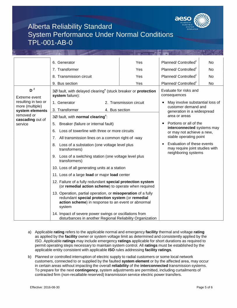
Alberta Reliability Standard System Performance Under Normal Conditions TPL-001-AB-0
Effective: 2016-08-30
Page 5 of 6
6. Generator Yes Planned/ Controlledc No
7. Transformer Yes Planned/ Controlledc No
8. Transmission circuit Yes Planned/ Controlledc No
9. Bus section Yes Planned/ Controlledc No
D d
Extreme event resulting in two or more (multiple) system elements removed or cascading out of service
3Ø fault, with delayed clearinge
(stuck breaker or protection system failure):
Evaluate for risks and consequences
May involve substantial loss of customer demand and generation in a widespread area or areas
Portions or all of the interconnected systems may or may not achieve a new, stable operating point
Evaluation of these events may require joint studies with neighboring systems
1. Generator 2. Transmission circuit
3. Transformer 4. Bus section
3Ø fault, with normal clearinge:
5. Breaker (failure or internal fault)
6. Loss of towerline with three or more circuits
7. All transmission lines on a common right-of -way
8. Loss of a substation (one voltage level plus transformers)
9. Loss of a switching station (one voltage level plus transformers)
10. Loss of all generating units at a station
11. Loss of a large load or major load center
12. Failure of a fully redundant special protection system (or remedial action scheme) to operate when required
13. Operation, partial operation, or misoperation of a fully redundant special protection system (or remedial action scheme) in response to an event or abnormal system
14. Impact of severe power swings or oscillations from disturbances in another Regional Reliability Organization
a) Applicable rating refers to the applicable normal and emergency facility thermal and voltage rating as applied by the facility owner or system voltage limit as determined and consistently applied by the ISO. Applicable ratings may include emergency ratings applicable for short durations as required to permit operating steps necessary to maintain system control. All ratings must be established by the applicable entity consistent with applicable ISO rules addressing facility ratings.
b) Planned or controlled interruption of electric supply to radial customers or some local network customers, connected to or supplied by the faulted system element or by the affected area, may occur in certain areas without impacting the overall reliability of the interconnected transmission systems. To prepare for the next contingency, system adjustments are permitted, including curtailments of contracted firm (non-recallable reserved) transmission service electric power transfers.
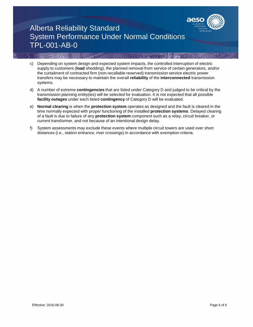
Alberta Reliability Standard System Performance Under Normal Conditions TPL-001-AB-0
Effective: 2016-08-30
Page 6 of 6
c) Depending on system design and expected system impacts, the controlled interruption of electric supply to customers (load shedding), the planned removal from service of certain generators, and/or the curtailment of contracted firm (non-recallable reserved) transmission service electric power transfers may be necessary to maintain the overall reliability of the interconnected transmission systems.
d) A number of extreme contingencies that are listed under Category D and judged to be critical by the transmission planning entity(ies) will be selected for evaluation. It is not expected that all possible facility outages under each listed contingency of Category D will be evaluated.
e) Normal clearing is when the protection system operates as designed and the fault is cleared in the time normally expected with proper functioning of the installed protection systems. Delayed clearing of a fault is due to failure of any protection system component such as a relay, circuit breaker, or current transformer, and not because of an intentional design delay.
f) System assessments may exclude these events where multiple circuit towers are used over short distances (i.e., station entrance, river crossings) in accordance with exemption criteria.

Alberta Reliability Standard System Performance Following Loss of a Single BES Element TPL-002-AB1-0
Effective: 2017-10-30 Page 1 of 6 Public
1. Purpose
The purpose of this reliability standard is to ensure that a reliable transmission system is planned that meets specified performance requirements with sufficient lead time. The transmission system must continue to be modified or upgraded as required to meet present and future system specified performance requirements as identified by periodically performed system simulations and associated planning assessments.
2. Applicability
This reliability standard applies to:
(a) ISO
3. Definitions
Bold terms used in this reliability standard have the meanings as set out in the Consolidated Authoritative Document Glossary and Part 1 of the ISO Rules.
4. Requirements
R1 The ISO must demonstrate for transmission facilities rated 69 kV and above, through a planning assessment, that a transmission system is planned such that the transmission system can be operated to accommodate forecasted customer demands and forecasted firm (non-recallable reserved) transmission services, at all demand levels over the range of forecast system demands, under the contingency conditions as defined in Category B of Appendix 1.
The ISO planning assessments must:
R1.1 Be carried out annually.
R1.2 Be conducted for near term (year one through five) and longer term (year six through ten) planning horizons.
R1.3 Be supported by a study and/or system simulation testing, conducted within the last five years that addresses each of the requirements in requirement R1.3.1 to R1.3.12, showing system
performance for the conditions defined in Category B of Appendix 1.
R1.3.1 Be performed and evaluated only for those Category B contingencies that the ISO has determined would produce the more severe system results or impacts. The rationale for the contingencies selected for evaluation and an explanation of why the remaining simulations would produce less severe system results must be included in the study.
R1.3.2 Cover critical system conditions and study years as determined necessary by the ISO.
R1.3.3 Be conducted annually unless the ISO determines that changes to system conditions
do not warrant such analyses.
R1.3.4 Be conducted beyond the five year horizon only as needed to address identified marginal conditions that may have longer lead time solutions.
R1.3.5 Have all projected firm transfers modeled, if any.

Alberta Reliability Standard System Performance Following Loss of a Single BES Element TPL-002-AB1-0
Effective: 2017-10-30 Page 2 of 6 Public
R1.3.6 Be performed and evaluated for selected demand levels over the range of forecast
system demands as considered necessary by the ISO.
R1.3.7 Demonstrate that system performance meets the conditions defined in Category B of Appendix 1.
R1.3.8 Include existing and planned facilities as considered necessary by the ISO.
R1.3.9 Include reactive power resources to ensure that adequate reactive resources are available to meet system performance.
R1.3.10 Include the effects of existing and planned protection systems, including any backup or redundant systems.
R1.3.11 Include the effects of existing and planned control devices.
R1.3.12 Include the planned outage and maintenance of any bulk electric equipment (including protection systems or their components) at those demand levels for which planned (including maintenance) outages are performed. For stations supplied by two lines, if one line is out for maintenance, then those stations are considered to be supplied by a radial line.
R1.4 Address any planned upgrades needed to meet the performance requirements for the conditions defined in Category B of Appendix 1.
R1.5 Consider all contingencies applicable to Category B of Appendix 1.
R2 When system simulations indicate an inability of the systems to respond as set out in R1.3.7 of this reliability standard the ISO must:
R2.1 Provide corrective plans to achieve the required system performance as described above throughout the planning horizon:
R2.1.1 Including a schedule for implementation.
R2.1.2 Including a discussion of expected required in-service dates of facilities.
R2.1.3 Consider lead times necessary to implement corrective plans.
R2.2 Review, in subsequent annual assessments, where sufficient lead time exists, the continuing need for identified system facilities. Detailed implementation plans are not needed.
R3 The ISO must provide the planning assessment to WECC on an annual basis.
5. Processes and Procedures
No procedures have been defined for this reliability standard.
6. Measures
The following measures correspond to the requirements identified in Section 4 of this reliability standard. For example, MR1 is the measure for R1.
MR1 The planning assessment will be valid and meet requirements in R1 through the following measures:
(a) The scope of the planning assessment identifies where area studies have been conducted in the past year. It also identifies area studies that have been conducted in previous years and
Alberta Reliability Standard System Performance Following Loss of a Single BES Element TPL-002-AB1-0
Effective: 2017-10-30 Page 3 of 6 Public
are still valid. Where area studies have not been conducted, a plan and schedule to conduct one is included in the planning assessment.
(b) The planning assessment includes time horizons as specified in R1.2.
(c) The planning assessment has been prepared within the last year.
(d) A certification that the planning assessment complies with each of the R1 technical requirements is provided and states that the planning assessment meets all requirements, identifies requirements not met, and states reasons where the requirement was not met.
(e) A summary list of supporting area studies and needs identification documents is provided. The summary list includes the title and date of the study. The area studies and needs identification documents are provided if requested.
MR2 The area studies and needs identification documents contain recommendations and projects for the corrective plans where an inability of the systems to respond to requirements specified in R1 has been identified. The area studies and needs identification documents must be provided on request.
MR3 A written or email confirmation from WECC that it has received the planning assessment from the ISO. The confirmation includes the date of when the planning assessment was received and source identification information.
7. Appendices
Appendix 1 - Transmission System Standards – Normal and Emergency Conditions (see below)
8. Guidelines
No guidelines have been defined for this reliability standard.
Revision History
Date Description
2017-10-30 Initial release.

Alberta Reliability Standard System Performance Following Loss of a Single BES Element TPL-002-AB1-0
Effective: 2017-10-30 Page 4 of 6 Public
Appendix 1 - Transmission System Standards – Normal and Emergency Conditions
Category
Contingencies System Limits or Impacts
Initiating Event(s) and Contingency System Element(s)
System Stable and Both Thermal and Voltage Limits Within Applicable
Ratinga
Loss of Demand or Curtailed Firm Transmission Service Transfers
Cascading
A
No contingencies All facilities in service Yes No No
B
Event resulting in the loss of a single system element
Single Line Ground (SLG) or 3-Phase (3Ø) fault, with normal clearing:
Yes Nob No
1. Generator Yes Nob No
2. Transmission circuit Yes Nob No
3. Transformer Yes Nob No
C
Event(s) resulting in the loss of two or more (multiple) system elements
SLG fault, with normal clearinge:
1. Bus section Yes Planned/ Controlledc
No
2. Breaker (failure or internal fault) Yes Planned/ Controlledc No
SLG or 3Ø fault, with normal clearing
e, manual system
adjustments, followed by another SLG or 3Ø fault, with normal clearing
e
3. Category B (B1, B2, B3, or B4) contingency, manual system adjustments, followed by another Category B (B1, B2, B3, or B4) contingency
Yes Planned/ Controlledc No
Bipolar block, with normal clearinge:
4. Bipolar (dc) line fault (non 3Ø), with normal clearing
e:
Yes Planned/ Controlledc No
5. Any two circuits of a multiple circuit towerline
t Yes Planned/ Controlled
c No
SLG fault, with delayed clearinge
(stuck breaker or protection system failure)
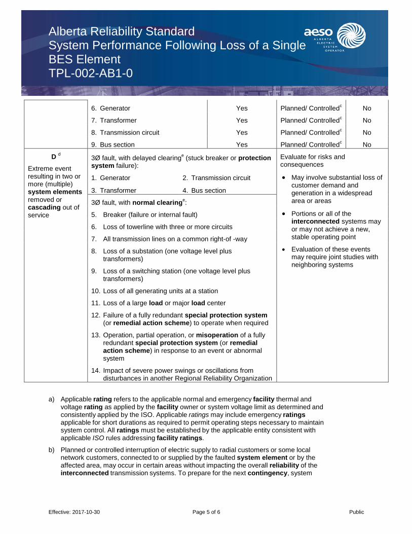
Alberta Reliability Standard System Performance Following Loss of a Single BES Element TPL-002-AB1-0
Effective: 2017-10-30 Page 5 of 6 Public
6. Generator Yes Planned/ Controlledc No
7. Transformer Yes Planned/ Controlledc No
8. Transmission circuit Yes Planned/ Controlledc No
9. Bus section Yes Planned/ Controlledc No
D d
Extreme event resulting in two or more (multiple) system elements removed or cascading out of service
3Ø fault, with delayed clearinge
(stuck breaker or protection system failure):
Evaluate for risks and consequences
May involve substantial loss of customer demand and generation in a widespread area or areas
Portions or all of the interconnected systems may or may not achieve a new, stable operating point
Evaluation of these events may require joint studies with neighboring systems
1. Generator 2. Transmission circuit
3. Transformer 4. Bus section
3Ø fault, with normal clearinge:
5. Breaker (failure or internal fault)
6. Loss of towerline with three or more circuits
7. All transmission lines on a common right-of -way
8. Loss of a substation (one voltage level plus transformers)
9. Loss of a switching station (one voltage level plus transformers)
10. Loss of all generating units at a station
11. Loss of a large load or major load center
12. Failure of a fully redundant special protection system (or remedial action scheme) to operate when required
13. Operation, partial operation, or misoperation of a fully redundant special protection system (or remedial action scheme) in response to an event or abnormal system
14. Impact of severe power swings or oscillations from disturbances in another Regional Reliability Organization
a) Applicable rating refers to the applicable normal and emergency facility thermal and voltage rating as applied by the facility owner or system voltage limit as determined and consistently applied by the ISO. Applicable ratings may include emergency ratings applicable for short durations as required to permit operating steps necessary to maintain system control. All ratings must be established by the applicable entity consistent with applicable ISO rules addressing facility ratings.
b) Planned or controlled interruption of electric supply to radial customers or some local network customers, connected to or supplied by the faulted system element or by the affected area, may occur in certain areas without impacting the overall reliability of the interconnected transmission systems. To prepare for the next contingency, system

Alberta Reliability Standard System Performance Following Loss of a Single BES Element TPL-002-AB1-0
Effective: 2017-10-30 Page 6 of 6 Public
adjustments are permitted, including curtailments of contracted firm (non-recallable reserved) transmission service electric power transfers.
c) Depending on system design and expected system impacts, the controlled interruption of electric supply to customers (load shedding), the planned removal from service of certain generators, and/or the curtailment of contracted firm (non-recallable reserved) transmission service electric power transfers may be necessary to maintain the overall reliability of the interconnected transmission systems.
d) A number of extreme contingencies that are listed under Category D and judged to be critical by the transmission planning entity(ies) will be selected for evaluation. It is not expected that all possible facility outages under each listed contingency of Category D will be evaluated.
e) Normal clearing is when the protection system operates as designed and the fault is cleared in the time normally expected with proper functioning of the installed protection systems. Delayed clearing of a fault is due to failure of any protection system component such as a relay, circuit breaker, or current transformer, and not because of an intentional design delay.
f) System assessments may exclude these events where multiple circuit towers are used over short distances (i.e., station entrance, river crossings) in accordance with exemption criteria.

Alberta Reliability Standard System Performance Following Loss of Two or more BES Elements TPL-003-AB-0
Effective: 2016-08-30
Page 1 of 6
1. Purpose
The purpose of this reliability standard is to ensure that a reliable transmission system is planned that meets specified performance requirements, with sufficient lead time. The transmission system must continue to be modified or upgraded as required to meet present and future system specified performance requirements as identified by periodically performed system simulations and associated planning assessments.
2. Applicability
This reliability standard applies to:
(a) ISO
3. Definitions
Bold terms used in this reliability standard have the meanings as set out in the Consolidated Authoritative Document Glossary and Part 1 of the ISO Rules.
4. Requirements
R1 The ISO must demonstrate for transmission facilities rated 100 kV and above, through a planning assessment that the AIES is planned such that the AIES can be operatedto accommodate forecasted customer demands, supply and forecasted firm (non- recallable reserved) transmission services, at all demand levels over the range of forecast system demands, under the contingency conditions as defined in Category C of Appendix 1. The controlled interruption of demand to demand customers, the planned removal of generating units, or the curtailment of firm (non-recallable reserved) power transfers may be necessary to meet this reliability standard.
The ISO planning assessments must:
R1.1 Be carried out annually.
R1.2 Be conducted for near term (year one through five) and longer term (year six through ten) planning horizons.
R1.3 Be supported by a study and/or system simulation testing, conducted within the last five years that addresses each of the requirements in requirement R1.3.1 to R1.3.1, showing system performance for the conditions defined in Category C of Appendix 1.
R1.3.1 Be performed and evaluated only for those Category C contingencies that the ISO
determines would produce the more severe system results or impacts. The rationale for the contingencies selected for evaluation and an explanation of why the remaining simulations would produce less severe system results must be included in the study.
R1.3.2 Cover critical system conditions and study years as determined necessary by the ISO.
R1.3.3 Be conducted annually unless the ISO determines that changes to system conditions do not warrant such analyses.
R1.3.4 Be conducted beyond the five year planning horizon only as needed to address identified marginal conditions that may have longer lead- time solutions.
R1.3.5 Have all projected firm transfers modeled, if any.
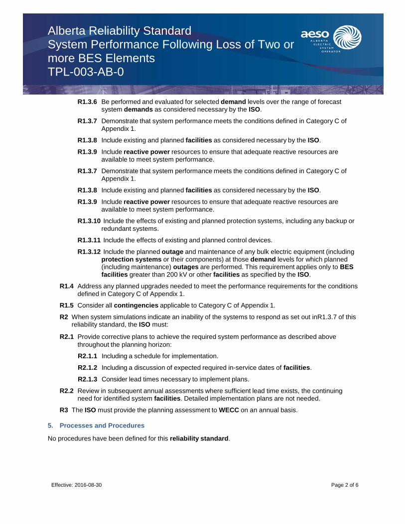
Alberta Reliability Standard System Performance Following Loss of Two or more BES Elements TPL-003-AB-0
Effective: 2016-08-30
Page 2 of 6
R1.3.6 Be performed and evaluated for selected demand levels over the range of forecast system demands as considered necessary by the ISO.
R1.3.7 Demonstrate that system performance meets the conditions defined in Category C of Appendix 1.
R1.3.8 Include existing and planned facilities as considered necessary by the ISO.
R1.3.9 Include reactive power resources to ensure that adequate reactive resources are available to meet system performance.
R1.3.10 Include the effects of existing and planned protection systems, including any backup or redundant systems.
R1.3.11 Include the effects of existing and planned control devices.
R1.3.12 Include the planned outage and maintenance of any bulk electric equipment (including protection systems or their components) at those demand levels for which planned (including maintenance) outages are performed. This requirement applies only to BES facilities greater than 200 kV or other facilities as specified by the ISO.
R1.4 Address any planned upgrades needed to meet the performance requirements for the conditions defined in Category C of Appendix 1.
R1.5 Consider all contingencies applicable to Category C of Appendix 1.
R2 When system simulations indicate an inability of the systems to respond as set out inR1.3.7 of this reliability standard, the ISO must:
R2.1 Provide corrective plans to achieve the required system performance as described above
throughout the planning horizon:
R2.1.1 Including a schedule for implementation.
R2.1.2 Including a discussion of expected required in-service dates of facilities.
R2.1.3 Consider lead times necessary to implement plans.
R2.2 Review in subsequent annual assessments where sufficient lead time exists, the continuing need for identified system facilities. Detailed implementation plans are not needed.
R3 The ISO must provide the planning assessment to WECC on an annual basis.
5. Processes and Procedures
No procedures have been defined for this reliability standard.
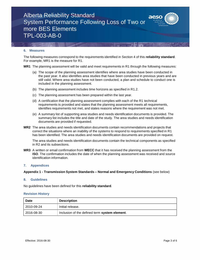
Alberta Reliability Standard System Performance Following Loss of Two or more BES Elements TPL-003-AB-0
Effective: 2016-08-30
Page 3 of 6
6. Measures
The following measures correspond to the requirements identified in Section 4 of this reliability standard. For example, MR1 is the measure for R1.
MR1 The planning assessment will be valid and meet requirements in R1 through the following measures:
(a) The scope of the planning assessment identifies where area studies have been conducted in the past year. It also identifies area studies that have been conducted in previous years and are still valid. Where area studies have not been conducted, a plan and schedule to conduct one is included in the planning assessment.
(b) The planning assessment includes time horizons as specified in R1.2.
(c) The planning assessment has been prepared within the last year.
(d) A certification that the planning assessment complies with each of the R1 technical requirements is provided and states that the planning assessment meets all requirements, identifies requirements not met, and states reasons where the requirement was not met.
(e) A summary list of supporting area studies and needs identification documents is provided. The summary list includes the title and date of the study. The area studies and needs identification documents are provided if requested.
MR2 The area studies and needs identification documents contain recommendations and projects that correct the situations where an inability of the systems to respond to requirements specified in R1 has been identified. The area studies and needs identification documents are provided on request.
The area studies and needs identification documents contain the technical components as specified in R2 and its subsections.
MR3 A written or email confirmation from WECC that it has received the planning assessment from the ISO. The confirmation includes the date of when the planning assessment was received and source identification information.
7. Appendices
Appendix 1 - Transmission System Standards – Normal and Emergency Conditions (see below)
8. Guidelines
No guidelines have been defined for this reliability standard.
Revision History
Date Description
2010-09-24 Initial release.
2016-08-30 Inclusion of the defined term system element.

Alberta Reliability Standard System Performance Following Loss of Two or more BES Elements TPL-003-AB-0
Effective: 2016-08-30
Page 4 of 6
Appendix 1 - Transmission System Standards – Normal and Emergency Conditions
Category
Contingencies System Limits or Impacts
Initiating Event(s) and Contingency System Element(s)
System Stable and Both Thermal and Voltage Limits Within Applicable
Ratinga
Loss of Demand or Curtailed Firm Transmission Service Transfers
Cascading
A
No contingencies All facilities in service Yes No No
B
Event resulting in the loss of a single system element
Single Line Ground (SLG) or 3-Phase (3Ø) fault, with normal clearing:
Yes Nob No
1. Generator Yes Nob No
2. Transmission circuit Yes Nob No
3. Transformer Yes Nob No
C
Event(s) resulting in the loss of two or more (multiple) system elements
SLG fault, with normal clearinge:
1. Bus section Yes Planned/ Controlledc
No
2. Breaker (failure or internal fault) Yes Planned/ Controlledc No
SLG or 3Ø fault, with normal clearing
e, manual system
adjustments, followed by another SLG or 3Ø fault, with normal clearing
e
3. Category B (B1, B2, B3, or B4) contingency, manual system adjustments, followed by another Category B (B1, B2, B3, or B4) contingency
Yes Planned/ Controlledc No
Bipolar block, with normal clearinge:
4. Bipolar (dc) line fault (non 3Ø), with normal clearing
e:
Yes Planned/ Controlledc No
5. Any two circuits of a multiple circuit towerline
t Yes Planned/ Controlled
c No
SLG fault, with delayed clearinge
(stuck breaker or protection system failure)
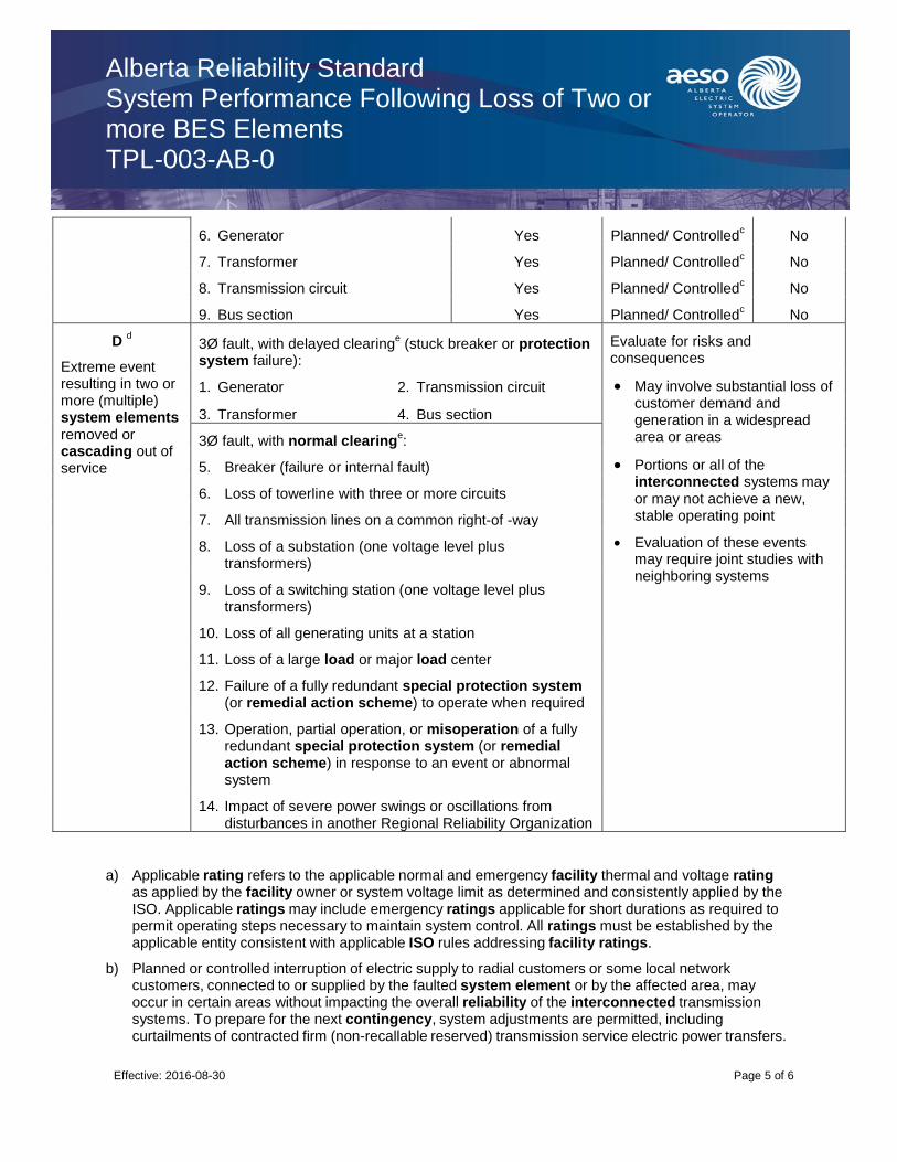
Alberta Reliability Standard System Performance Following Loss of Two or more BES Elements TPL-003-AB-0
Effective: 2016-08-30
Page 5 of 6
6. Generator Yes Planned/ Controlledc No
7. Transformer Yes Planned/ Controlledc No
8. Transmission circuit Yes Planned/ Controlledc No
9. Bus section Yes Planned/ Controlledc No
D d
Extreme event resulting in two or more (multiple) system elements removed or cascading out of service
3Ø fault, with delayed clearinge
(stuck breaker or protection system failure):
Evaluate for risks and consequences
May involve substantial loss of customer demand and generation in a widespread area or areas
Portions or all of the interconnected systems may or may not achieve a new, stable operating point
Evaluation of these events may require joint studies with neighboring systems
1. Generator 2. Transmission circuit
3. Transformer 4. Bus section
3Ø fault, with normal clearinge:
5. Breaker (failure or internal fault)
6. Loss of towerline with three or more circuits
7. All transmission lines on a common right-of -way
8. Loss of a substation (one voltage level plus transformers)
9. Loss of a switching station (one voltage level plus transformers)
10. Loss of all generating units at a station
11. Loss of a large load or major load center
12. Failure of a fully redundant special protection system (or remedial action scheme) to operate when required
13. Operation, partial operation, or misoperation of a fully redundant special protection system (or remedial action scheme) in response to an event or abnormal system
14. Impact of severe power swings or oscillations from disturbances in another Regional Reliability Organization
a) Applicable rating refers to the applicable normal and emergency facility thermal and voltage rating as applied by the facility owner or system voltage limit as determined and consistently applied by the ISO. Applicable ratings may include emergency ratings applicable for short durations as required to permit operating steps necessary to maintain system control. All ratings must be established by the applicable entity consistent with applicable ISO rules addressing facility ratings.
b) Planned or controlled interruption of electric supply to radial customers or some local network customers, connected to or supplied by the faulted system element or by the affected area, may occur in certain areas without impacting the overall reliability of the interconnected transmission systems. To prepare for the next contingency, system adjustments are permitted, including curtailments of contracted firm (non-recallable reserved) transmission service electric power transfers.

Alberta Reliability Standard System Performance Following Loss of Two or more BES Elements TPL-003-AB-0
Effective: 2016-08-30
Page 6 of 6
c) Depending on system design and expected system impacts, the controlled interruption of electric supply to customers (load shedding), the planned removal from service of certain generators, and/or the curtailment of contracted firm (non-recallable reserved) transmission service electric power transfers may be necessary to maintain the overall reliability of the interconnected transmission systems.
d) A number of extreme contingencies that are listed under Category D and judged to be critical by the transmission planning entity(ies) will be selected for evaluation. It is not expected that all possible facility outages under each listed contingency of Category D will be evaluated.
e) Normal clearing is when the protection system operates as designed and the fault is cleared in the time normally expected with proper functioning of the installed protection systems. Delayed clearing of a fault is due to failure of any protection system component such as a relay, circuit breaker, or current transformer, and not because of an intentional design delay.
f) System assessments may exclude these events where multiple circuit towers are used over short distances (i.e., station entrance, river crossings) in accordance with exemption criteria.

Alberta Reliability Standard System Performance Following Extreme BES Events TPL-004-AB-0
Effective: 2016-08-30
Page 1 of 6
1. Purpose
The purpose of this reliability standard is to ensure that a reliable transmission system is planned that meets specified performance requirements with sufficient lead time. The transmission system must continue to be modified or upgraded as required to meet present and future system specified performance requirements as identified by periodically performed system simulations and associated planning assessments.
2. Applicability
This reliability standard applies to:
(a) ISO
3. Definitions
Bold terms used in this reliability standard have the meanings as set out in the Consolidated Authoritative Document Glossary and Part 1 of the ISO Rules.
4. Requirements
R1 The ISO must demonstrate for transmission facilities rated 100 kV and above, through a planning assessment that a transmission system is planned such that it has been evaluated for the risks and consequences of a number of each of the extreme contingencies that are listed under Category D of Appendix 1.
The ISO planning assessments must:
R1.1 Be carried out annually.
R1.2 Be conducted for near term (year one through five).
R1.3 Be supported by a study and/or system simulation that addresses each of the following categories, showing system performance following Category D contingencies of Appendix 1.
R1.3.1 Be performed and evaluated only for those Category D contingencies that ISO determines would produce the more severe system results or impacts. The rationale for the contingencies selected for evaluation and an explanation of why the remaining simulations would produce less severe system results must be included in the study.
R1.3.2 Cover critical system conditions and study years as considered necessary by the ISO.
R1.3.3 Be conducted annually unless the ISO determines that changes to system conditions do not warrant such analyses.
R1.3.4 Have all projected firm transfers modeled, if any.
R1.3.5 Include existing and planned facilities as considered necessary by the ISO.
R1.3.6 Include reactive power resources to ensure that adequate reactive resources are available to meet system performance.
Alberta Reliability Standard System Performance Following Extreme BES Events TPL-004-AB-0
Effective: 2016-08-30
Page 2 of 6
R1.3.7 Include the effects of existing and planned protection systems, including any backup or redundant systems.
R1.3.8 Include the effects of existing and planned control devices.
R1.3.9 Include the planned outage and maintenance of any bulk electric equipment (including protection systems or their components) at those demand levels for which planned (including maintenance) outages are performed. This requirement applies only to BES facilities greater than 200 kV or other facilities as specified by the ISO.
R1.4 Consider all contingencies applicable to Category D of Appendix 1.
R2 The ISO must provide the planning assessment to WECC on an annual basis.
5. Processes and Procedures
No procedures have been defined for this reliability standard.
6. Measures
The following measures correspond to the requirements identified in Section 4 of this reliability standard. For example, MR1 is the measure for R1.
MR1 The planning assessment will be valid and meet requirement in R1 and associated sub-sections through the following measures:
(a) The scope of the planning assessment identifies where area studies have been conducted in the past year. It also identifies area studies that have been conducted in previous years and are still valid. Where area studies have not been conducted, a plan and schedule to conduct one is included in the planning assessment.
(b) The planning assessment includes time horizons as specified in R1.2.
(c) The planning assessment has been prepared within the last year.
(d) A certification that the planning assessment complies with each of the R1 technical requirements is provided and states that the planning assessment meets all requirements, identifies requirements not met, and states reasons where the requirement was not met.
(e) A summary list of supporting area studies and needs identification documents is provided. The summary list includes the title and date of the study. The area studies and needs identification documents are provided if requested.
MR2 A written or email confirmation from WECC that it has received the planning assessment from the ISO. The confirmation includes the date of when the planning assessment was received and source identification information.
7. Appendices
Appendix 1 - Transmission System Standards – Normal and Emergency Conditions (see below)
Alberta Reliability Standard System Performance Following Extreme BES Events TPL-004-AB-0
Effective: 2016-08-30
Page 3 of 6
8. Guidelines
No guidelines have been defined for this reliability standard.
Revision History
Date Description
2010-09-24 Initial release.
2016-08-30 Inclusion of the defined term system element.
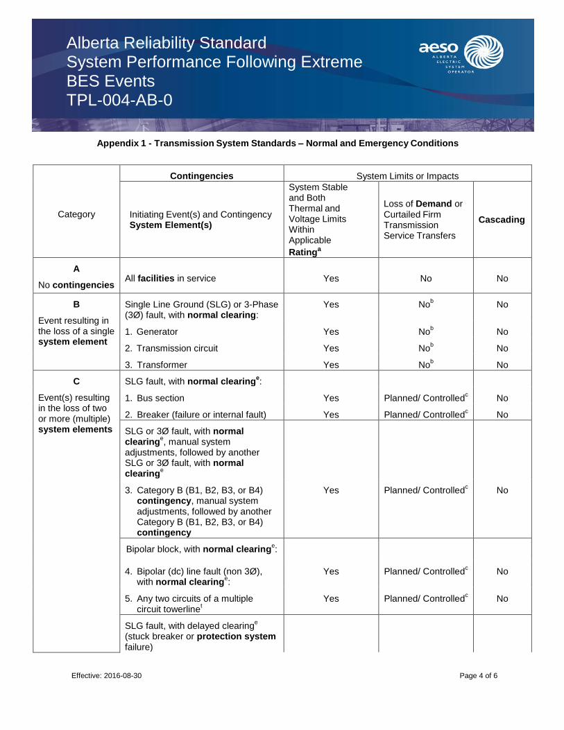
Alberta Reliability Standard System Performance Following Extreme BES Events TPL-004-AB-0
Effective: 2016-08-30
Page 4 of 6
Appendix 1 - Transmission System Standards – Normal and Emergency Conditions
Category
Contingencies System Limits or Impacts
Initiating Event(s) and Contingency System Element(s)
System Stable and Both Thermal and Voltage Limits Within Applicable
Ratinga
Loss of Demand or Curtailed Firm Transmission Service Transfers
Cascading
A
No contingencies All facilities in service Yes No No
B
Event resulting in the loss of a single system element
Single Line Ground (SLG) or 3-Phase (3Ø) fault, with normal clearing:
Yes Nob No
1. Generator Yes Nob No
2. Transmission circuit Yes Nob No
3. Transformer Yes Nob No
C
Event(s) resulting in the loss of two or more (multiple) system elements
SLG fault, with normal clearinge:
1. Bus section Yes Planned/ Controlledc
No
2. Breaker (failure or internal fault) Yes Planned/ Controlledc No
SLG or 3Ø fault, with normal clearing
e, manual system
adjustments, followed by another SLG or 3Ø fault, with normal clearing
e
3. Category B (B1, B2, B3, or B4) contingency, manual system adjustments, followed by another Category B (B1, B2, B3, or B4) contingency
Yes Planned/ Controlledc No
Bipolar block, with normal clearinge:
4. Bipolar (dc) line fault (non 3Ø), with normal clearing
e:
Yes Planned/ Controlledc No
5. Any two circuits of a multiple circuit towerline
t Yes Planned/ Controlled
c No
SLG fault, with delayed clearinge
(stuck breaker or protection system failure)
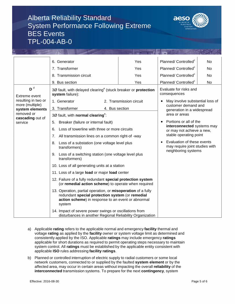
Alberta Reliability Standard System Performance Following Extreme BES Events TPL-004-AB-0
Effective: 2016-08-30
Page 5 of 6
6. Generator Yes Planned/ Controlledc No
7. Transformer Yes Planned/ Controlledc No
8. Transmission circuit Yes Planned/ Controlledc No
9. Bus section Yes Planned/ Controlledc No
D d
Extreme event resulting in two or more (multiple) system elements removed or cascading out of service
3Ø fault, with delayed clearinge
(stuck breaker or protection system failure):
Evaluate for risks and consequences
May involve substantial loss of customer demand and generation in a widespread area or areas
Portions or all of the interconnected systems may or may not achieve a new, stable operating point
Evaluation of these events may require joint studies with neighboring systems
1. Generator 2. Transmission circuit
3. Transformer 4. Bus section
3Ø fault, with normal clearinge:
5. Breaker (failure or internal fault)
6. Loss of towerline with three or more circuits
7. All transmission lines on a common right-of -way
8. Loss of a substation (one voltage level plus transformers)
9. Loss of a switching station (one voltage level plus transformers)
10. Loss of all generating units at a station
11. Loss of a large load or major load center
12. Failure of a fully redundant special protection system (or remedial action scheme) to operate when required
13. Operation, partial operation, or misoperation of a fully redundant special protection system (or remedial action scheme) in response to an event or abnormal system
14. Impact of severe power swings or oscillations from disturbances in another Regional Reliability Organization
a) Applicable rating refers to the applicable normal and emergency facility thermal and voltage rating as applied by the facility owner or system voltage limit as determined and consistently applied by the ISO. Applicable ratings may include emergency ratings applicable for short durations as required to permit operating steps necessary to maintain system control. All ratings must be established by the applicable entity consistent with applicable ISO rules addressing facility ratings.
b) Planned or controlled interruption of electric supply to radial customers or some local network customers, connected to or supplied by the faulted system element or by the affected area, may occur in certain areas without impacting the overall reliability of the interconnected transmission systems. To prepare for the next contingency, system

Alberta Reliability Standard System Performance Following Extreme BES Events TPL-004-AB-0
Effective: 2016-08-30
Page 6 of 6
adjustments are permitted, including curtailments of contracted firm (non-recallable reserved) transmission service electric power transfers.
c) Depending on system design and expected system impacts, the controlled interruption of electric supply to customers (load shedding), the planned removal from service of certain generators, and/or the curtailment of contracted firm (non-recallable reserved) transmission service electric power transfers may be necessary to maintain the overall reliability of the interconnected transmission systems.
d) A number of extreme contingencies that are listed under Category D and judged to be critical by the transmission planning entity(ies) will be selected for evaluation. It is not expected that all possible facility outages under each listed contingency of Category D will be evaluated.
e) Normal clearing is when the protection system operates as designed and the fault is cleared in the time normally expected with proper functioning of the installed protection systems. Delayed clearing of a fault is due to failure of any protection system component such as a relay, circuit breaker, or current transformer, and not because of an intentional design delay.
f) System assessments may exclude these events where multiple circuit towers are used over short distances (i.e., station entrance, river crossings) in accordance with exemption criteria.
Alberta Reliability Standard Voltage and Reactive Control VAR-001-AB-4
Forwarded to the Commission: 2019-06-27 Page 1 Public
1. Purpose
To ensure that voltage levels, reactive flows, and reactive resources are monitored, controlled, and maintained within limits in real-time to protect equipment and the reliable operation of the Interconnection.
2. Applicability
This reliability standard applies to:
(a) the ISO.
3. Requirements R1 The ISO must specify a system voltage range with an associated tolerance band, as part of its plan to operate within system operating limits and interconnection reliability operating limits.
R1.1 The ISO must provide a copy of the system voltage range with an associated tolerance band to an interconnected transmission operator within thirty (30) days of a request.
R2 The ISO must operate with sufficient reactive power resources available within Alberta to protect the voltage levels of the transmission system under normal and contingency conditions. R3 The ISO must be able to regulate transmission voltage and reactive power flow by issuing directives or instructions to operate the devices necessary to do so. R4 The ISO must specify the criteria that will exempt a generating unit or an aggregated generating facility from:
a) following a voltage or reactive power instruction or directive;
b) having its automatic voltage regulator or voltage regulating system in service or being in voltage control mode; or
c) making any associated notifications.
R4.1 If the ISO determines that a generating unit or an aggregated generating facility has satisfied
the exemption criteria, the ISO must notify the associated operator of a generating unit or operator
of an aggregated generating facility.
R5 The ISO, when issuing directives or instructions for voltage level or reactive power, to the
operator of a generating unit or the operator of an aggregated generating facility, must specify the
following:
a) the voltage level at the point of connection between the transmission system and a
generating unit or an aggregated generating facility, including those in a power plant or an industrial complex; or
b) the reactive power to be achieved by the generating unit, aggregated generating facility, power plant or industrial complex.
R6 The ISO must, after a review with the legal owner of a generating unit or the legal owner of an aggregated generating facility regarding necessary off-load tap changes for the step-up transformer that connects to the transmission system, provide documentation to the legal owner of a generating
Alberta Reliability Standard Voltage and Reactive Control VAR-001-AB-4
Effective: 2019-12-01 Page 2 Public
unit or the legal owner of an aggregated generating facility specifying the required tap changes, a timeframe for making the changes, and technical justification for these changes.
4. Measures
The following measures correspond to the requirements identified in section 3 of this reliability standard.
For example, MR1 is the measure for R1.
MR1. Evidence of specifying a system voltage range with an associated tolerance band as required in
requirement R1 exists.
MR1.1 Evidence of providing a copy of the system voltage range with an associated tolerance band as
required in requirement R1.1 exists. Evidence may include, but is not limited to, emails, website postings,
or any other equivalent evidence.
MR2 Evidence of operating with sufficient reactive power resources as required in requirement R2
exists. Evidence may include, but is not limited to, data files or any other equivalent evidence.
MR3 Evidence of being able to regulate transmission voltage and reactive power flow as required in
requirement R3 exists. Evidence may include, but is not limited to, relevant ISO authoritative documents.
MR4 Evidence of specifying the criteria that will exempt a generating unit or an aggregated generating facility as specified in requirement R4 exists.
MR4.1 Evidence of notifying the associated operator of a generating unit or operator of an aggregated generating facility if the ISO determines that the exemption criteria were satisfied. Evidence may include, but is not limited to, emails, data files or other equivalent evidence.
MR5 Evidence of issuing directives or instructions to the operator of a generating unit or the operator of an aggregated generating facility as required in requirement R5 exists. Evidence may include, but is not limited to, voice recordings or other equivalent evidence.
MR6 Evidence of providing documentation as required in requirement R6 exists. Evidence may include,
but is not limited to, dated study results or email to appropriate recipients that identifies contents submitted or other equivalent evidence.
5. Appendices
Appendix 1 - Exemptions Revision History
Date Description
2019-12-01 Unbolded “real time”
2016-04-01 Revised to align with NERC version 4.
2012-10-01 Initial release

Alberta Reliability Standard Voltage and Reactive Control VAR-001-AB-4
Effective: 2019-12-01 Page 3 Public
Appendix 1 - Exemptions
1. Exemption Criteria
A generating unit or aggregated generating facility must, in order to meet the exemption criteria referred to in requirement R4 of this reliability standard:
(a) be a wind aggregated generating facility;
(b) not be equipped with a voltage regulating system; and
(c) be the subject of an executed Construction Commitment Agreement and have completed the ISO’s approval process for connection to the transmission system under the Technical Requirements for connecting generators (1999).
Alberta Reliability Standard Generator Operation for Maintaining Network Voltages VAR-002-AB-3
Effective: 2016-04-01 Page 1 of 4
1. Purpose
To ensure generating units and aggregated generating facilities provide reactive support and voltage control, within generating facility capabilities, in order to protect equipment and maintain reliable operation of the Interconnection.
2. Applicability
This reliability standard applies to:
(a) the legal owner of a generating unit, including a generating unit that operates as a synchronous condenser, that:
(i) is not part of an aggregated generating facility;
(ii) has a maximum authorized real power rating greater than 4.5 MW; and
(iii) is directly connected to either the transmission system or to transmission facilities within the City of Medicine Hat;
(b) the operator of a generating unit, including a generating unit that operates as a synchronous condenser, that:
(i) is not part of an aggregated generating facility;
(ii) has a maximum authorized real power rating greater than 4.5 MW; and
(iii) is directly connected to either the transmission system or to transmission facilities within the City of Medicine Hat;
(c) the legal owner of an aggregated generating facility that:
(i) has a maximum authorized real power rating greater than 4.5 MW; and
(ii) is directly connected to either the transmission system or to transmission facilities within the City of Medicine Hat; and
(d) the operator of an aggregated generating facility that:
(i) has a maximum authorized real power rating greater than 4.5 MW; and
(ii) is directly connected to either the transmission system or to transmission facilities within the City of Medicine Hat.
Notwithstanding subsections (c) and (d) above, this reliability standard does not apply to the legal owner of an aggregated generating facility or the operator of an aggregated generating facility that meets the criteria listed in Appendix 1 of VAR-001-AB.
Requirements
R1 The operator of a generating unit and the operator of an aggregated generating facility must, while a generating unit or aggregated generating facility is electrically connected to the transmission
Alberta Reliability Standard Generator Operation for Maintaining Network Voltages VAR-002-AB-3
Effective: 2016-04-01 Page 2 of 4
system, operate the generating unit or aggregated generating facility with its automatic voltage regulator or voltage regulating system in service and in voltage control mode unless:
a) exempted by the ISO;
b) the operator of the generating unit or operator of the aggregated generating facility provides voice notification to the ISO of its intention to operate the generating unit or aggregated generating facility otherwise;
c) the generating unit or aggregated generating facility is being operated in start-up or shut-
down mode in accordance with the procedure of the operator of a generating unit or operator of an aggregated generating facility; or
d) the operator of a generating unit or the operator of an aggregated generating facility has
previously obtained approval from the ISO allowing the generating unit or aggregated generating facility to be in a testing mode.
R2 Unless exempted by the ISO, each operator of a generating unit and each operator of an aggregated generating facility must, upon receiving an instruction from the ISO regarding voltage levels or reactive power, comply with that instruction.
R2.1 Each operator of a generating unit and each operator of an aggregated generating facility must, when:
a) the automatic voltage regulator of a generating unit or the voltage regulating system of an aggregated generating facility is out of service; or (b) the generating unit does not have an automatic voltage regulator, or the aggregated generating facility does not have a voltage regulating system,
use an alternative method to control the generator reactive output to comply with an instruction from the ISO regarding voltage levels or reactive power.
R2.2 Notwithstanding requirement R2, where the operator of a generating unit or the operator of an aggregated generating facility cannot comply with an instruction to modify voltage, the operator of a generating unit or the operator of an aggregated generating facility must provide an explanation for why the instruction cannot be met.
R2.3 Each operator of a generating unit and operator of an aggregated generating facility that does not monitor the voltage or reactive power at the location specified in an instruction from the ISO, or at the location specified in a directive issued by the ISO in accordance with section 301.2 of the ISO rules, ISO Directives, must have a methodology for converting the voltage or reactive power at the location specified by the ISO.
R3 Each operator of a generating unit and operator of an aggregated generating facility must notify the ISO within thirty (30) minutes after a status change of the automatic voltage regulator, voltage regulating system or alternative voltage controlling device and power system stabilizer, as applicable, on any generating unit or aggregated generating facility.

Alberta Reliability Standard Generator Operation for Maintaining Network Voltages VAR-002-AB-3
Effective: 2016-04-01 Page 3 of 4
R3.1 If the status has been restored within thirty (30) minutes of such change, then the operator of a generating unit or operator of an aggregated generating facility is not required to notify the ISO of the status change.
R3.2 If a generating unit or an aggregated generating facility is in testing, start-up, shut-down or offline mode, requirement R3 does not apply.
R4 Each operator of a generating unit and operator of an aggregated generating facility must notify the ISO within thirty (30) minutes after becoming aware of a change in reactive capability due to factors other than a status change described in requirement R3.
R4.1 If the capability has been restored within thirty (30) minutes of the operator of a generating unit or operator of an aggregated generating facility becoming aware of such change, then the operator is not required to notify the ISO of the change in reactive capability.
R4.2 If a generating unit or an aggregated generating facility is in testing, start-up, shut-down or offline mode, requirement R4 does not apply.
R5 Each legal owner of a generating unit and each legal owner of an aggregated generating facility whose step-up transformer for connecting to the transmission system or auxiliary transformer has primary voltages equal to or greater than the generating unit terminal voltage must provide any one (1) or more of the following to the ISO within thirty (30) days of a request:
a) tap settings; b) available fixed tap ranges; and c) impedance data.
R6 Each legal owner of a generating unit and each legal owner of an aggregated generating facility that has a step-up transformer, with off-load taps for connecting to the transmission system must, change the tap positions according to the specifications the ISO provides.
R6.1 Each legal owner of a generating unit and each legal owner of an aggregated generating facility that cannot comply with requirement R6 must notify the ISO within thirty (30) days of the ISO providing the specifications, and must include the technical justification along with the notice.
4. Measures
The following measures correspond to the requirements identified in section 3 of this reliability standard. For example, MR1 is the measure for R1.
MR1 Evidence of operating the generating unit or aggregated generating facility in automatic voltage control mode as required in requirement R1 exists. Evidence may include, but is not limited to, exemption letters, data files, start-up or shut-down procedures, operator logs, voice recordings, e-mail, or other equivalent evidence.

Alberta Reliability Standard Generator Operation for Maintaining Network Voltages VAR-002-AB-3
Effective: 2016-04-01 Page 4 of 4
MR2 Evidence of complying with an instruction as required in requirement R2 exists. Evidence may include, but is not limited to, data files or operator logs.
MR 2.1 Evidence of using an alternative method to control generator reactive power output as required in requirement R2.1 exists. Evidence may include, but is not limited to, data files, operator logs or voice recordings.
MR 2.2 Evidence of providing an explanation to the ISO, as required in requirement R2.2 exists. Evidence may include, but is not limited to, voice recordings or operator logs.
MR 2.3 Evidence of having a methodology as required in requirement R2.3 exists. Evidence may include, but is not limited to, a documented methodology or other equivalent evidence.
MR3 Evidence of notifying the ISO within thirty (30) minutes of any status change as required in requirement R3 exists. Evidence may include, but is not limited to, data logs, SCADA logs, voice recordings or operator logs.
MR4 Evidence of notifying the ISO within thirty (30) minutes of becoming aware of a change in capability as required in requirement R4 exists. If the capability has been restored within the first thirty (30) minutes of the operator of a generating unit or operator of an aggregated generating facility becoming aware of such change, no evidence of notification is necessary. Evidence may include, but is not limited to, voice recordings or operator logs.
MR5 Evidence of providing the ISO with information on its step-up transformer or auxiliary transformer, as required in requirement R5 exists. Evidence may include, but is not limited to, dated written or electronic records. MR6 Evidence of changing step-up transformer taps in accordance with the ISO’s specifications as required in requirement R6 exists. Evidence may include, but is not limited to, written or electronic records.
MR6.1 Evidence of notifying the ISO as required in requirement R6.1 exists. Evidence may include, but is not limited to, written or electronic notifications.
Revision History
Date Description
2013-10-01 Initial release
2016-04-01 Revised to align with NERC version 3.

Alberta Reliability Standard Automatic Voltage Regulators and Voltage Regulating Systems VAR-002-WECC-AB-1
Effective: 2013-10-01 Page 1 of 3
1. Purpose
The purpose of this reliability standard is to ensure that:
(a) automatic voltage regulators on generating units and synchronous condensers are in service and controlling voltage; and
(b) voltage regulating systems at aggregated generating facilities are in service and controlling voltage.
2. Applicability
This reliability standard applies to:
(a) the operator of a generating unit, including those that operate as a synchronous condenser, that:
(i) is not part of an aggregated generating facility;
(ii) has a maximum authorized real power rating greater than four point five (4.5) MW; and
(iii) is directly connected to either the transmission system or to transmission facilities within the City of Medicine Hat;
(b) the operator of an aggregated generating facility that:
(i) has a maximum authorized real power rating greater than four point five (4.5) MW; and
(ii) is directly connected to either the transmission system or to transmission facilities within the City of Medicine Hat; and
(c) the operator of a transmission facility that operates a synchronous condenser.
3. Requirements
R1 Each operator of a generating unit, operator of an aggregated generating facility and operator of a transmission facility that operates a synchronous condenser, must have the automatic voltage regulator or voltage regulating system in service and in automatic voltage control mode for ninety-eight percent (98%) of all operating hours except that the operating hours determined in accordance with requirements R1.1 through R1.12 inclusive may be extended to achieve the ninety-eight percent (98%) requirement.
R1.1 The operating hours during which the generating unit, aggregated generating facility or synchronous condenser operates for less than five percent (5%) of all hours during any calendar quarter;
R1.2 The operating hours during which maintenance or testing on any of the foregoing was performed, up to a maximum of seven (7) calendar days per calendar quarter;
R1.3 The operating hours during which the automatic voltage regulator or voltage regulating system exhibits instability due to an abnormal system configuration;

Alberta Reliability Standard Automatic Voltage Regulators and Voltage Regulating Systems VAR-002-WECC-AB-1
Effective: 2013-10-01 Page 2 of 3
R1.4 The operating hours, up to a maximum of sixty (60) consecutive days per incident, during which the automatic voltage regulator or voltage regulating system is out of service for repair due to component failure;
R1.5 The operating hours, up to a maximum of twelve (12) consecutive months, during which the automatic voltage regulator or voltage regulating system had a component failure, provided the operator of a generating unit, operator of an aggregated generating facility or operator of a transmission facility submitted documentation to the ISO identifying the need for time to obtain replacement parts and, if required, to schedule an outage;
R1.6 The operating hours, up to a maximum of twenty-four (24) consecutive months during which the automatic voltage regulator or voltage regulating system had a component failure, provided the operator of a generating unit, operator of an aggregated generating facility or operator of a transmission facility submitted documentation to the ISO identifying the need for time for replacement of the excitation system including replacing the automatic voltage regulator or voltage regulating system, limiters, and controls but not necessarily the power source and power bridge, and to schedule an outage;
R1.7 The operating hours during which the synchronous generating unit, aggregated generating facility or synchronous condenser is not in commercial operation;
R1.8 The operating hours for which the ISO has issued a directive to the operator of a generating unit to operate the generating unit when the automatic voltage regulator is unavailable for service;
R1.9 The operating hours for which the ISO has issued a directive to the operator of an aggregated generating facility to operate the aggregated generating facility when the voltage regulating system is unavailable for service;
R1.10 The operating hours for which the ISO has issued a directive to an operator of a transmission facility to operate a synchronous condenser when the automatic voltage regulator is unavailable for service;
R1.11 The operating hours during which an automatic voltage regulator exhibits instability due to operation of an on-load tap changer transformer in the area when the ISO has authorized the operator of a generating unit or operator of a transmission facility to operate the excitation system in modes other than automatic voltage control until the transmission system configuration changes; and
R1.12 The operating hours during which a voltage regulating system exhibits instability due to operation of an on-load tap changer transformer in the area when the ISO has authorized the operator of an aggregated generating facility to operate the voltage regulating system in modes other than automatic voltage control until the transmission system configuration changes.
R2 Each operator of a generating unit, operator of an aggregated generating facility and operator of a transmission facility must have documentation supporting the identification of the number of operating hours excluded for each requirement in requirements R1.1 through R1.12 inclusive.
Alberta Reliability Standard Automatic Voltage Regulators and Voltage Regulating Systems VAR-002-WECC-AB-1
Effective: 2013-10-01 Page 3 of 3
4. Measures
MR1 Evidence of having the automatic voltage regulator or voltage regulating system in service and in automatic voltage control mode as required in requirement R1 exists. Evidence may include documentation that summarizes for each calendar quarter:
(a) the number of hours the automatic voltage regulator or voltage regulating system was in service and in automatic voltage control mode while the generating unit, the aggregated generating facility or synchronous condenser was operating;
(b) the number of hours the automatic voltage regulator or voltage regulating system was out of service while the generating unit, the aggregated generating facility or synchronous condenser was operating;
(c) the number of operating hours excluded in accordance with requirements R1.1 through R1.12; and
(d) the percentage of operating hours that the automatic voltage regulator or voltage regulating system was in service, excluding the number of operating hours determined in accordance with requirements R1.1 through R1.12.
MR2 Evidence of having documentation as required in requirement R2 exists. Evidence may include a document identifying the subject of each applicable exclusion, the date and the period of time that the exclusion refers to, reasons, the supporting data and the supporting logs.
Revision History
Effective Description
2013-10-01

Alberta Reliability Standard Power System Stabilizer VAR-501-WECC-AB-1
Effective: 2013-10-01 Page 1 of 4
1. Purpose
The purpose of this reliability standard is to ensure that power system stabilizers on generating units are kept in service.
2. Applicability
This reliability standard applies to:
(a) the operator of a generating unit equipped with a power system stabilizer that is either:
(i) directly connected to the bulk electric system or part of an industrial complex that is directly connected to the bulk electric system, and has a maximum authorized real power rating greater than eighteen (18) MW; or
(ii) within a power plant which:
(A) is not part of an aggregated generating facility;
(B) is directly connected to the bulk electric system; and
(C) has a combined maximum authorized real power rating greater than sixty-seven point five (67.5) MW;
(iii) a black start resource; or
(iv) regardless of maximum authorized real power rating, material to this reliability standard and to the reliability of the bulk electric system as the ISO determines and publishes on the AESO website and may amend from time to time in accordance with the process set out in Appendix 1.
3. Requirements
R1 Each operator of a generating unit equipped with a power system stabilizer must have the power system stabilizer in service ninety-eight (98%) of all operating hours except that the operating hours determined in accordance with requirements R 1.1 through 1.12 inclusive may be excluded to achieve the ninety-eight percent (98%) requirement.
R1.1 The operating hours during which the generating unit operates for less than five percent (5%) of all hours during any calendar quarter.
R1.2 The operating hours during which maintenance or testing on the power system stabilizer was performed, up to a maximum of seven (7) days per calendar quarter.
R1.3 The operating hours during which the power system stabilizer exhibits instability due to abnormal system configuration.
R1.4 The operating hours during which the generating unit is operating in the synchronous condenser mode and the generating unit is very near or at a zero (0) real power level.
R1.5 The operating hours during which the generating unit is generating less real power than its design limit for effective power system stabilizer operation.
R1.6 The operating hours during which the generating unit is passing through a range of output that is a known “rough zone” being a range in which a generating unit is experiencing excessive

Alberta Reliability Standard Power System Stabilizer VAR-501-WECC-AB-1
Effective: 2013-10-01 Page 2 of 4
vibration.
R1.7 The operating hours during which the automatic voltage regulator of the generating unit is not in service.
R1.8 The operating hours, up to a maximum of sixty (60) consecutive days per incident, during which the power system stabilizer is out of service for repair due to a component failure.
R1.9 The operating hours, up to a maximum of twelve (12) consecutive months, during which the power system stabilizer had a component failure, but only if the operator of a generating unit submitted documentation to the ISO identifying the need for time to obtain replacement parts and identifying a scheduled outage, if required.
R1.10 The operating hours, up to a maximum of twenty-four (24) consecutive months, during which the power system stabilizer had a component failure, but only if the operator of a generating unit submitted documentation to the ISO identifying the need for time to replace the power system stabilizer and to schedule an outage.
R1.11 The operating hours during which the generating unit is not in commercial operation.
R1.12 The operating hours for which the ISO has issued a directive to the operator of a generating unit to operate the generating unit when the power system stabilizer is unavailable for service
R2 Each operator of a generating unit must have documentation supporting the identification of the number of operating hours excluded for each requirement in requirements R1.1 through R1.12 inclusive.
4. Measures
The following measures correspond to the requirements identified in section 3 of this reliability standard. For example, MR1 is the measure for R1.
MR1 Evidence of having the power system stabilizer in service as required in requirement R1 exists. Evidence may include documentation that summarizes for each calendar quarter:
(a) the number of hours the power system stabilizer was in service while the generating unit was operating;
(b) the number of hours the power system stabilizer was out of service while the generating unit was operating;
(c) the number of operating hours excluded in accordance with requirements R1.1 through R1.12; and
(d) the percentage of operating hours that the power system stabilizer was in service excluding the number of operating hours determined in accordance with requirements R1.1 through R1.12
MR2 Evidence of having documentation as required in requirement R2 exists. Evidence may include a document identifying the subject of each exclusion, the date and the period of time that the exclusion refers to, reasons, the supporting data and the supporting logs.

Alberta Reliability Standard Power System Stabilizer VAR-501-WECC-AB-1
Effective: 2013-10-01 Page 3 of 4
5. Appendices
Appendix 1 – Amending Process for List of Generating Units
Revision History
Effective Description
2013-10-01

Alberta Reliability Standard Power System Stabilizer VAR-501-WECC-AB-1
Effective: 2013-10-01 Page 4 of 4
Appendix 1
Amending Process for List of Generating Units
In order to amend the list referenced in subsection (a)(iv) of section 2, Applicability, the ISO must:
(a) upon determining that a generating unit is to be added, notify each affected operator of a generating unit in writing and determine an effective date, which must be no less than thirty (30) days after the date of notice, for the operator to meet the applicable requirements;
(b) upon determining that a generating unit is to be deleted, notify each affected operator of a generating unit in writing and determine an effective date for the operator to no longer be required to meet the applicable requirements; and
(c) post the amended list with effective dates on the AESO website.
Related Documents