Alaska Department of Transportation and Public Facilities Alaska Test Methods Manual Revised March 31, 2005

Welcome message from author
This document is posted to help you gain knowledge. Please leave a comment to let me know what you think about it! Share it to your friends and learn new things together.
Transcript

Alaska Department of Transportation and Public Facilities
Alaska Test Methods Manual Revised March 31, 2005
Acknowledgement Design and Engineering Services, Statewide Materials is indebted to the following organizations for use of, or reference to, portions of their publications.
The American Association of State Highway and Transportation Officials The American Society for Testing and Materials
Appreciation is also extended to Laboratory and Construction personnel from each Region for their dedication and patience in seeing this task to completion.
Third Edition Printing, April 15, 2005

Contents TOC - i Alaska Test Methods Manual Revised 3/15/05
Contents
Section 200 Earthwork Title Description SectionATM 201 Sticks and Roots 201
WAQTC FOP for AASHTO T 255/T 265 Moisture Content of Aggregate and Soils 202
ATM 203 Organic Content of Soils by Ignition 203
WAQTC FOP for AASHTO T 89 Liquid Limit of Soils 204
WAQTC FOP for AASHTO T 90 Plastic Limit and Plasticity Index of Soils 205
ATM 206 pH of Topsoil 206
WAQTC FOP for AASHTO T 99/ T 180 Moisture-Density Relations of Soils* 207
ATM 212 Standard Density of Coarse Granular Materials using the Vibratory Compactor 212
WAQTC FOP for AASHTO T 310 In-Place Density and Moisture Content of Soil and Soil-Aggregate by Nuclear Methods* 213
WAQTC FOP for AASHTO T 224 Correction for Coarse Particles in the Soil Compaction Test 214
Section 300 Bases and Aggregates Title Description SectionWAQTC FOP for AASHTO T 2 Sampling Aggregates* 301
WAQTC FOP for AASHTO T 248 Reducing Samples of Aggregate to Test Size 303
WAQTC FOP for AASHTO T 27/T 11 Sieve Analysis of Aggregates & Soils* 304
WAQTC FOP for AASHTO TP 61 Percentage of Fracture in Coarse Aggregate 305
ATM 306 Flat and Elongated 306
WAQTC FOP for AASHTO T 176 Sand Equivalent 307
WAQTC FOP for AASHTO T 85 Specific Gravity and Absorption of Coarse Aggregate 308
ATM 312 Nordic Abrasion Value of Aggregate 312
ATM 313 Degradation Value of Aggregate 313
ATM 314 Expansive Breakdown of Stone on Soaking in Ethylene Glycol 314
*This Test Method has an Addendum attached which has specific instructions for the use of the noted test method by the State of Alaska DOT&PF.

Alaska Test Methods Manual TOC - ii Contents 3/15/05
Section 400 Asphalt Title Description Section WAQTC FOP for AASHTO T 40 Sampling Bituminous Materials* 401
WAQTC FOP for AASHTO T 168 Sampling Bituminous Mixes* 402
ATM 403 Sampling Hot Mix Asphalt 403
WAQTC TM 5 Reducing Samples of Bituminous Mixes to Testing Size* 404
ATM 405 Asphalt Cement Content of Hot Mix Asphalt by the Nuclear Method 405
WAQTC FOP for AASHTO T 308
Asphalt Binder Content of Bituminous Mixes by Ignition Method* 406
WAQTC TM 6 Moisture Content of Bituminous Mixes by Oven Drying 407
WAQTC FOP for AASHTO T 30 Mechanical Analysis of Extracted Aggregate* 408
WAQTC FOP for AASHTO T 209 Maximum Specific Gravity of Bituminous Mixes* 409
WAQTC FOP for AASHTO T 166/T 275
Bulk Specific Gravity and Percent Compaction of Bituminous Mixes* 410
WAQTC TM 8 In-Place Density of Bituminous Mixes using the Nuclear Moisture-Density Gauge* 411
ATM 412 Standard Density by the Control Strip Method 412
ATM 414 Anti-Strip Requirements of Hot Mix Asphalt 414
ATM 417 Hot Mix Asphalt Design by the Marshall Method 417
ATM 419 Rutting Susceptibility using an Asphalt Pavement Analyzer 419
Section 500 Concrete Title Description Section WAQTC TM 2 Sampling Freshly Mixed Concrete 501
WAQTC FOP for AASHTO T 309 Temperature of Freshly Mixed Concrete 502
WAQTC FOP for AASHTO T 119 Slump of Freshly Mixed Concrete 503
WAQTC FOP for AASHTO T 121
Unit Weight, Cement Factor & Water/Cement Ratio of Freshly Mixed Concrete* 504
WAQTC FOP for AASHTO T 152 Air Content of Freshly Mixed Concrete by the Pressure Method* 505
WAQTC FOP for AASHTO T 23 Making & Curing Concrete Test Specimens in the Field* 506
ATM 507 Making & Curing Grout Test Specimens in the Field 507
ATM 520 Resistance of Grout to Freeze-Thaw Action 520
Contents TOC - iii Alaska Test Methods Manual Revised 3/15/05
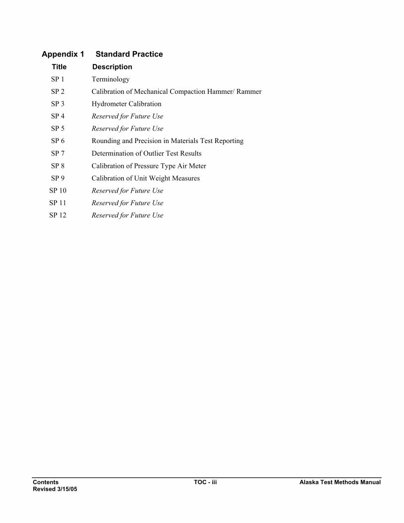
Appendix 1 Standard Practice Title Description SP 1 Terminology
SP 2 Calibration of Mechanical Compaction Hammer/ Rammer
SP 3 Hydrometer Calibration
SP 4 Reserved for Future Use
SP 5 Reserved for Future Use
SP 6 Rounding and Precision in Materials Test Reporting
SP 7 Determination of Outlier Test Results
SP 8 Calibration of Pressure Type Air Meter
SP 9 Calibration of Unit Weight Measures
SP 10 Reserved for Future Use
SP 11 Reserved for Future Use
SP 12 Reserved for Future Use

Sticks and Roots Content 201-1 Alaska Test Methods Manual Of Aggregate and Soil Revised 12/31/03
Sticks & Roots Content of Aggregate and Soil, ATM 201 1. Scope This method describes the procedure for determining the percent of sticks & roots by wet mass of the total aggregate or soil sample.
2. Significance This test would be used to quantify the organic content of soils for particles that are too large to test in accordance with ATM 203, Organic Content of Soils by Ignition.
3. Apparatus
• Balance or scale: Capacity sufficient for the field sample mass, readable to 0.1 percent or 0.1 g and meeting the requirements of AASHTO M 231.
• 2.00 mm (No. 10) sieve conforming to AASHTO M 92.
• Miscellaneous equipment including pans, gloves, etc.
4. Sampling and Sample Preparation Obtain the sample in accordance with WAQTC FOP for AASHTO T 2. The test will be performed on the complete as-received sample before drying.
5. Procedure 5.1. Determine the mass of the as-received sample to 0.1 percent or 0.1 g. Record this as the Total Sample
Mass.
5.2. Separate the sample on a 2.00 mm (No. 10) sieve to ease identification of sticks & roots.
5.3. Separate the sticks & roots from the plus 2.00 mm (No. 10) material and place in a separate pan.
5.4. Determine the mass of the sticks & roots to 0.1 percent or 0.1 g. Record this as the Sticks & Roots Mass.
6. Calculations Calculate the percentage of Sticks & Roots by: Sticks & Roots, percent =
100 x Mass Sample Wet TotalMass Wet Roots&Sticks
⎟⎟⎠
⎞⎜⎜⎝
⎛
7. Report Report the Stick and Root Content on Department forms to the nearest 1 percent.

Alaska Test Methods Manual 201-2 Sticks and Roots Content Of Aggregate and Soil Revised 12/31/03
This page left intentionally blank.
Moisture Content of 202-1 Alaska Test Methods Manual Soils and Aggregate October 2004
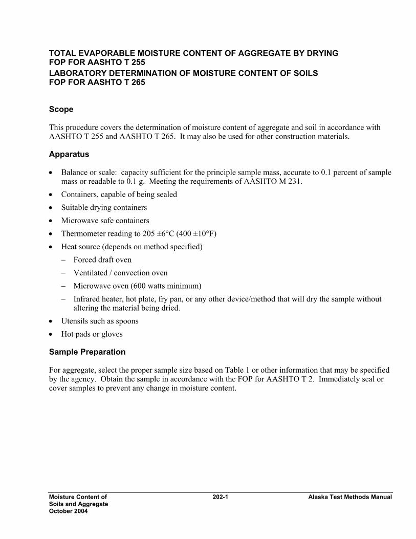
TOTAL EVAPORABLE MOISTURE CONTENT OF AGGREGATE BY DRYING FOP FOR AASHTO T 255 LABORATORY DETERMINATION OF MOISTURE CONTENT OF SOILS FOP FOR AASHTO T 265 Scope This procedure covers the determination of moisture content of aggregate and soil in accordance with AASHTO T 255 and AASHTO T 265. It may also be used for other construction materials. Apparatus • Balance or scale: capacity sufficient for the principle sample mass, accurate to 0.1 percent of sample
mass or readable to 0.1 g. Meeting the requirements of AASHTO M 231. • Containers, capable of being sealed • Suitable drying containers • Microwave safe containers • Thermometer reading to 205 ±6°C (400 ±10°F) • Heat source (depends on method specified)
− Forced draft oven − Ventilated / convection oven − Microwave oven (600 watts minimum) − Infrared heater, hot plate, fry pan, or any other device/method that will dry the sample without
altering the material being dried. • Utensils such as spoons • Hot pads or gloves Sample Preparation For aggregate, select the proper sample size based on Table 1 or other information that may be specified by the agency. Obtain the sample in accordance with the FOP for AASHTO T 2. Immediately seal or cover samples to prevent any change in moisture content.
Alaska Test Methods Manual 202-2 Moisture Content of Soils and Aggregate October 2003
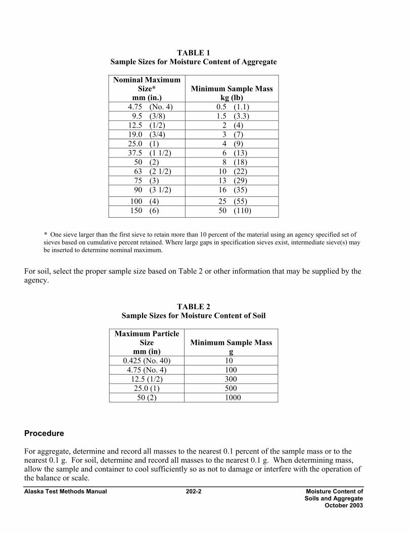
TABLE 1 Sample Sizes for Moisture Content of Aggregate
Nominal Maximum
Size* mm (in.)
Minimum Sample Mass
kg (lb) 4.75 (No. 4) 0.5 (1.1) 9.5 (3/8) 1.5 (3.3)
12.5 (1/2) 2 (4) 19.0 (3/4) 3 (7) 25.0 (1) 4 (9) 37.5 (1 1/2) 6 (13)
50 (2) 8 (18) 63 (2 1/2) 10 (22) 75 (3) 13 (29) 90 (3 1/2) 16 (35)
100 (4) 25 (55) 150 (6) 50 (110)
* One sieve larger than the first sieve to retain more than 10 percent of the material using an agency specified set of sieves based on cumulative percent retained. Where large gaps in specification sieves exist, intermediate sieve(s) may be inserted to determine nominal maximum.
For soil, select the proper sample size based on Table 2 or other information that may be supplied by the agency.
TABLE 2 Sample Sizes for Moisture Content of Soil
Maximum Particle
Size mm (in)
Minimum Sample Mass
g 0.425 (No. 40) 10 4.75 (No. 4) 100 12.5 (1/2) 300 25.0 (1) 500 50 (2) 1000
Procedure For aggregate, determine and record all masses to the nearest 0.1 percent of the sample mass or to the nearest 0.1 g. For soil, determine and record all masses to the nearest 0.1 g. When determining mass, allow the sample and container to cool sufficiently so as not to damage or interfere with the operation of the balance or scale.
Moisture Content of 202-3 Alaska Test Methods Manual Soils and Aggregate October 2004
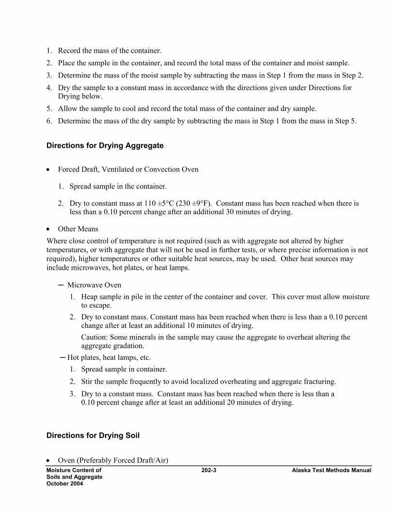
1. Record the mass of the container. 2. Place the sample in the container, and record the total mass of the container and moist sample. 3. Determine the mass of the moist sample by subtracting the mass in Step 1 from the mass in Step 2. 4. Dry the sample to a constant mass in accordance with the directions given under Directions for
Drying below. 5. Allow the sample to cool and record the total mass of the container and dry sample. 6. Determine the mass of the dry sample by subtracting the mass in Step 1 from the mass in Step 5. Directions for Drying Aggregate
• Forced Draft, Ventilated or Convection Oven
1. Spread sample in the container. 2. Dry to constant mass at 110 ±5°C (230 ±9°F). Constant mass has been reached when there is
less than a 0.10 percent change after an additional 30 minutes of drying.
• Other Means Where close control of temperature is not required (such as with aggregate not altered by higher temperatures, or with aggregate that will not be used in further tests, or where precise information is not required), higher temperatures or other suitable heat sources, may be used. Other heat sources may include microwaves, hot plates, or heat lamps.
─ Microwave Oven 1. Heap sample in pile in the center of the container and cover. This cover must allow moisture
to escape. 2. Dry to constant mass. Constant mass has been reached when there is less than a 0.10 percent
change after at least an additional 10 minutes of drying. Caution: Some minerals in the sample may cause the aggregate to overheat altering the aggregate gradation.
─ Hot plates, heat lamps, etc. 1. Spread sample in container. 2. Stir the sample frequently to avoid localized overheating and aggregate fracturing. 3. Dry to a constant mass. Constant mass has been reached when there is less than a
0.10 percent change after at least an additional 20 minutes of drying.
Directions for Drying Soil • Oven (Preferably Forced Draft/Air)

Alaska Test Methods Manual 202-4 Moisture Content of Soils and Aggregate October 2003
1. Place sample in container. 2. Dry to constant mass at 110 ±5°C (230 ±9°F). Constant mass has been reached when there is no
change after an additional 1 hour of drying. A sample dried overnight (15 to 16 hours) is sufficient in most cases.
Note 1: Soils containing gypsum or significant amounts of organic material require special drying. For reliable moisture contents dry these soils at 60°C (140°F). For more information see AASHTO T 265, Note 2.
Calculation Constant Mass for Aggregates:
Calculate constant mass using the following formula:
100% xChange MpMnMp−=
Where: Mp = previous mass measurement Mn = new mass measurement
Example: Mass of container: 1232.1 g Mass of container& sample after first drying cycle: 2637.2 g Mass, Mp, of possibly dry sample: 2637.2 g - 1232.1 g = 1405.1 g Mass of container and dry sample after second drying cycle: 2634.1 g
Mass, Mn, of dry sample: 2634.1 g - 1232.1 g = 1402.0 g
100%22.0 1.14050.14021.1405 x−=
0.22% is not less than 0.10% so continue to dry it
Mass of container and dry sample after third drying cycle: 2633.0 g Mass, Mn, of dry sample: 2633.0 g - 1232.1 g = 1400.9 g
100%08.0 0.14029.14000.1402 x−=
0.08% is less than 0.10% so it is dry for an aggregate, but continue drying for soil. This mass becomes the Dry mass for calculating the moisture content. Moisture Content Aggregate and Soils:
Calculate the moisture content, as a percent, using the following formula:

Moisture Content of 202-5 Alaska Test Methods Manual Soils and Aggregate October 2004
Where:
w = moisture content, percent MW = moist mass MD = dry mass Example: Mass of container: 1232.1 g Mass of container and moist sample: 2764.7 g Mass, MW, of moist sample: 2764.7 g - 1232.1 g = 1532.6 g Mass of container and dry sample: 2633.0 g Mass, MD, of dry sample: 2633.0 g - 1232.1 g = 1400.9 g
Report Results shall be reported on standard forms approved for use by the agency. Include:
• MW, moist mass • MD, dry mass • w, moisture content to nearest 0.1 percent
100M
MMwD
DW ×−
=
9.4%torounded9.401%100g1400.9g131.7100
g1400.9g1400.9g1532.6w =×=×
−=

Alaska Test Methods Manual 202-6 Moisture Content of Soils and Aggregate October 2003

Organic Content 203-1 Alaska Test Method Manual Revised 12/31/03
Organic Content of Soils ATM 203 1. Scope This method describes the procedure for determining organic content of soils by loss on ignition as adopted from AASHTO T 267.
This standard involves hazardous materials, operations and equipment. This standard does not purport to address all of the safety problems associated with its use. It is the responsibility of the agency to establish appropriate safety and health practices and to train the user of this standard prior to use. It is the responsibility of the user to consult the appropriate agency authority for and to practice and maintain the appropriate safety and health practices.
2. Apparatus
• 2.00 mm (No. 10) sieve and pan, plus whatever additional larger size sieves are necessary to prevent overloading the No. 10 sieve. Sieves will conform to AASHTO M 92.
• Pulverizing apparatus suitable for breaking up aggregations of soil particles without reducing the size of individual grains.
•. Balance or scale: Capacity sufficient for the principle sample mass, readable to 0.1%, or better, of the total sample mass and meeting the requirements of AASHTO M 231.
For this test, this would require a scale with a capacity of at least 100 g and readable to 0.01 g. • Muffle Furnace, thermostatically controlled, capable of maintaining a temperature of 445 ± 10°C (830
±15°F). The combustion chamber will be capable of accommodating the designated container(s) and sample(s). The furnace shall be equipped with a pyrometer recorder that will indicate chamber temperature while in use.
• Crucible, with covers, having a minimum volume of 100 ml and capable of withstanding repeated exposure to temperatures of 500ºC (950°F).
• Non-asbestos, heat-resistant, gauntlet-type gloves capable of withstanding temperatures of 500ºC (950°F).
• Desiccator of sufficient size containing an effective desiccant.
• Miscellaneous equipment including tongs, spatulas, wire brushes, etc.
3. Sampling and Sample Preparation 1. Obtain the sample in accordance with WAQTC FOP for AASHTO T 2.
2. Dry the sample to constant mass in accordance with the soil procedure of WAQTC FOP for AASHTO T 255/T 265.
3. Sieve the dry sample through the 2.00 mm (No. 10) sieve.
If the material contains lumps of organics or aggregations of soil, they will be broken up by such means that will not reduce the size of the plus 2.00 mm (No. 10) aggregate particles.
For Topsoil samples: Any large particles of organics that cannot be broken up will be removed and discarded.
Note 1: Organic content for topsoil is the organics that are readily available for use by the root system of the plantings (grass, trees, etc.).

Alaska Test Method Manual 203-2 Organic Content Revised 12/31/03
For other types of samples: Any large particles of organics that cannot be broken up will be removed by hand and reported as Sticks and Roots (see ATM 201).
4. Reduce the sample to a mass of approximately 100 g in accordance with WAQTC FOP for AASHTO T 248.
4. Procedure 1. Determine the mass of a crucible to the nearest 0.01 g and record as Tare.
2. Select a sample with a mass between 10-40 g, place into the crucible, determine the mass to the nearest 0.01 g and record as Mass Before Ignition + Tare.
Note 2: Sample masses for lightweight materials such as peat may be less than 10 g but should be of sufficient amount to fill the crucible to at least 3/4 depth. A cover may initially be required over the crucible during the initial phase of ignition to decrease the possibility of the sample being "blown out" from container.
3. Place the crucible into a pre-heated muffle furnace at a temperature of 445ºC (835°F) for a minimum of six hours until all organic matter is combusted. If a cover has been used, it shall be removed after approximately 2 hours of combustion.
4. Remove the test sample from the muffle furnace and cool it to room temperature in a desiccator.
5. Determine the mass to the nearest 0.01 grams and record as Mass After Ignition + Tare.
5. Calculations
1. Calculate the percent organic content by the following formula:
100 x C -A B -A Content Organic ⎟⎠⎞
⎜⎝⎛=
Where: A = Mass Before Ignition + Tare, B = Mass After Ignition + Tare, C = Tare.
6. Report Report the organic content on Department forms to the nearest 0.1 percent.
Liquid Limit of Soils 204-1 Alaska Test Methods Manual October 2003
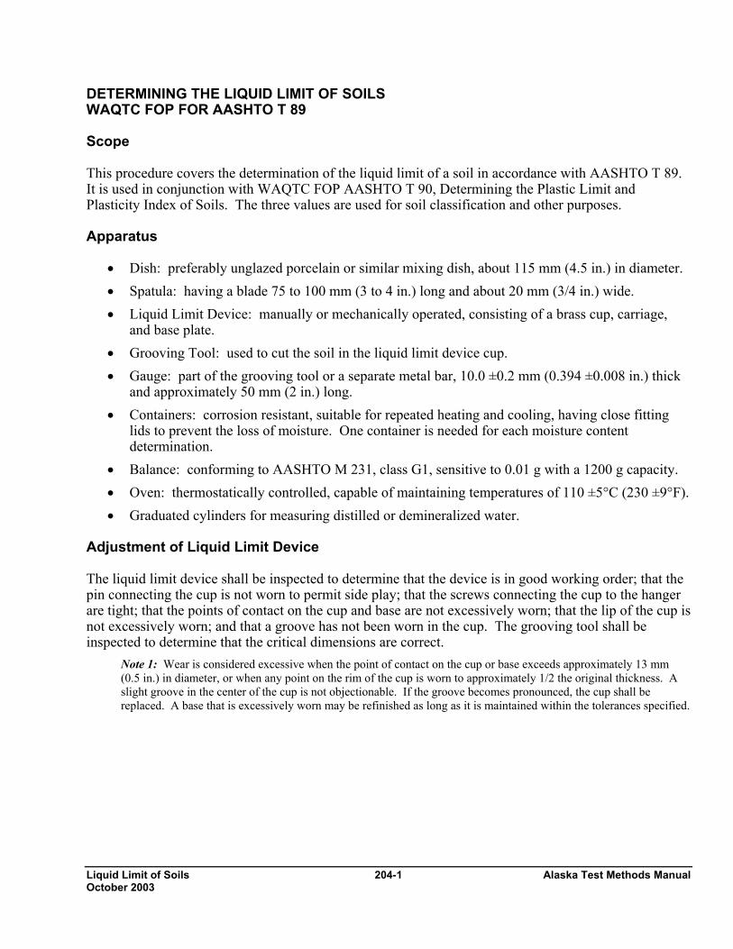
DETERMINING THE LIQUID LIMIT OF SOILS WAQTC FOP FOR AASHTO T 89 Scope This procedure covers the determination of the liquid limit of a soil in accordance with AASHTO T 89. It is used in conjunction with WAQTC FOP AASHTO T 90, Determining the Plastic Limit and Plasticity Index of Soils. The three values are used for soil classification and other purposes. Apparatus
• Dish: preferably unglazed porcelain or similar mixing dish, about 115 mm (4.5 in.) in diameter. • Spatula: having a blade 75 to 100 mm (3 to 4 in.) long and about 20 mm (3/4 in.) wide. • Liquid Limit Device: manually or mechanically operated, consisting of a brass cup, carriage,
and base plate. • Grooving Tool: used to cut the soil in the liquid limit device cup. • Gauge: part of the grooving tool or a separate metal bar, 10.0 ±0.2 mm (0.394 ±0.008 in.) thick
and approximately 50 mm (2 in.) long. • Containers: corrosion resistant, suitable for repeated heating and cooling, having close fitting
lids to prevent the loss of moisture. One container is needed for each moisture content determination.
• Balance: conforming to AASHTO M 231, class G1, sensitive to 0.01 g with a 1200 g capacity. • Oven: thermostatically controlled, capable of maintaining temperatures of 110 ±5°C (230 ±9°F). • Graduated cylinders for measuring distilled or demineralized water.
Adjustment of Liquid Limit Device The liquid limit device shall be inspected to determine that the device is in good working order; that the pin connecting the cup is not worn to permit side play; that the screws connecting the cup to the hanger are tight; that the points of contact on the cup and base are not excessively worn; that the lip of the cup is not excessively worn; and that a groove has not been worn in the cup. The grooving tool shall be inspected to determine that the critical dimensions are correct.
Note 1: Wear is considered excessive when the point of contact on the cup or base exceeds approximately 13 mm (0.5 in.) in diameter, or when any point on the rim of the cup is worn to approximately 1/2 the original thickness. A slight groove in the center of the cup is not objectionable. If the groove becomes pronounced, the cup shall be replaced. A base that is excessively worn may be refinished as long as it is maintained within the tolerances specified.
Alaska Test Methods Manual 204-2 Liquid Limit of Soils October 2003
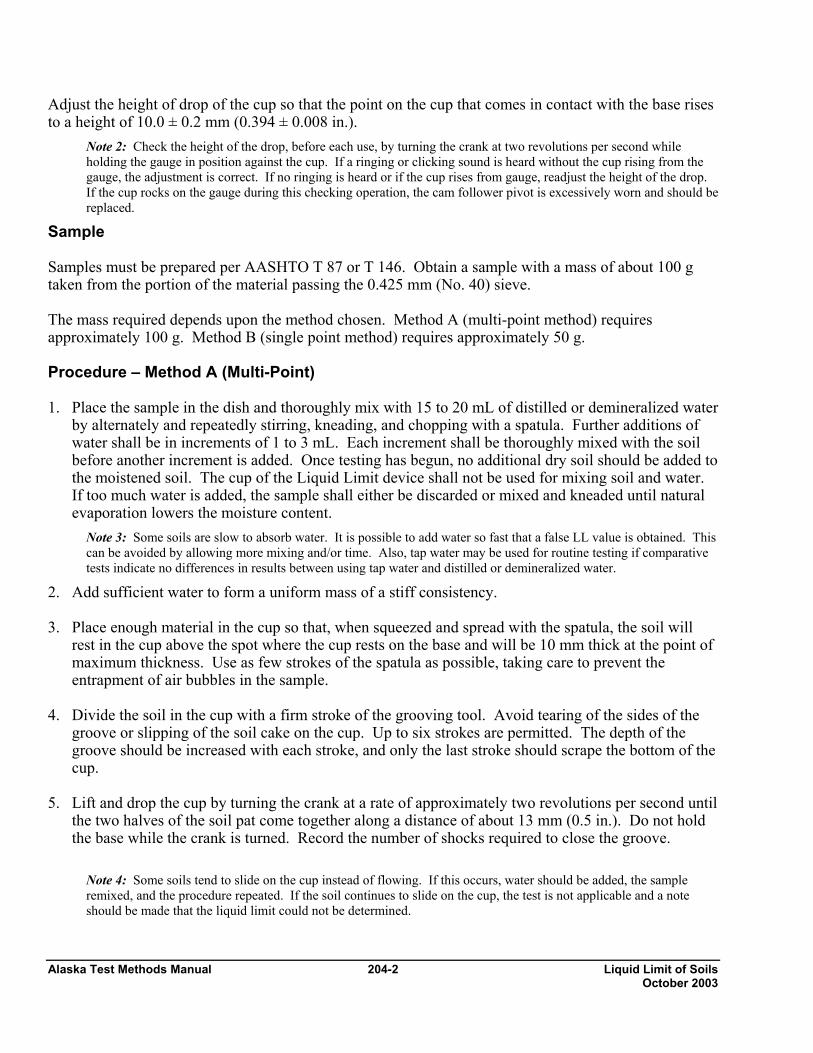
Adjust the height of drop of the cup so that the point on the cup that comes in contact with the base rises to a height of 10.0 ± 0.2 mm (0.394 ± 0.008 in.).
Note 2: Check the height of the drop, before each use, by turning the crank at two revolutions per second while holding the gauge in position against the cup. If a ringing or clicking sound is heard without the cup rising from the gauge, the adjustment is correct. If no ringing is heard or if the cup rises from gauge, readjust the height of the drop. If the cup rocks on the gauge during this checking operation, the cam follower pivot is excessively worn and should be replaced.
Sample Samples must be prepared per AASHTO T 87 or T 146. Obtain a sample with a mass of about 100 g taken from the portion of the material passing the 0.425 mm (No. 40) sieve. The mass required depends upon the method chosen. Method A (multi-point method) requires approximately 100 g. Method B (single point method) requires approximately 50 g. Procedure – Method A (Multi-Point) 1. Place the sample in the dish and thoroughly mix with 15 to 20 mL of distilled or demineralized water
by alternately and repeatedly stirring, kneading, and chopping with a spatula. Further additions of water shall be in increments of 1 to 3 mL. Each increment shall be thoroughly mixed with the soil before another increment is added. Once testing has begun, no additional dry soil should be added to the moistened soil. The cup of the Liquid Limit device shall not be used for mixing soil and water. If too much water is added, the sample shall either be discarded or mixed and kneaded until natural evaporation lowers the moisture content.
Note 3: Some soils are slow to absorb water. It is possible to add water so fast that a false LL value is obtained. This can be avoided by allowing more mixing and/or time. Also, tap water may be used for routine testing if comparative tests indicate no differences in results between using tap water and distilled or demineralized water.
2. Add sufficient water to form a uniform mass of a stiff consistency. 3. Place enough material in the cup so that, when squeezed and spread with the spatula, the soil will
rest in the cup above the spot where the cup rests on the base and will be 10 mm thick at the point of maximum thickness. Use as few strokes of the spatula as possible, taking care to prevent the entrapment of air bubbles in the sample.
4. Divide the soil in the cup with a firm stroke of the grooving tool. Avoid tearing of the sides of the
groove or slipping of the soil cake on the cup. Up to six strokes are permitted. The depth of the groove should be increased with each stroke, and only the last stroke should scrape the bottom of the cup.
5. Lift and drop the cup by turning the crank at a rate of approximately two revolutions per second until
the two halves of the soil pat come together along a distance of about 13 mm (0.5 in.). Do not hold the base while the crank is turned. Record the number of shocks required to close the groove.
Note 4: Some soils tend to slide on the cup instead of flowing. If this occurs, water should be added, the sample remixed, and the procedure repeated. If the soil continues to slide on the cup, the test is not applicable and a note should be made that the liquid limit could not be determined.

Liquid Limit of Soils 204-3 Alaska Test Methods Manual October 2003
6. Obtain a moisture content sample by slicing through the soil pat perpendicularly with the spatula and through the center of the groove. Place it into a suitable container for subsequent moisture determination.
7. Determine the moisture content of the moisture content sample in accordance with the FOP for
AASHTO T 255/T 265. Determine and record all masses to 0.01g. 8. Place the soil remaining in the cup back in the mixing dish and add 1 to 3 mL of water, or use
previously prepared portions to which sufficient water has been added to result in a more fluid condition.
9. Repeat Steps 3 through 8, a minimum of two times. The object is to have a determination in all three
shock ranges 25-35, 20-30, & 15-25. Flow Curve – Method A Prepare a flow curve on a semi-logarithmic graph with moisture content on the arithmetic vertical axis and the number of shocks on the logarithmic horizontal axis. The flow curve is a straight line drawn as closely as possible through three or more plotted points. Liquid Limit – Method A Determine the liquid limit. The moisture content at the intersection of the flow curve and the 25 shock line is the liquid limit. Procedure – Method B (Single-Point) 1. Place the sample in the dish and thoroughly mix with 8 to 10 mL of distilled or demineralized water,
and following the mixing procedure in Method A, Step 1. 2. Follow the procedure in Method A except that the soil pat should be prepared with water to produce
a consistency that will close the two halves of the soil pat at least 13 mm (0.5 in.) within 22 to 28 shocks of the cup.
Note: Groove closures occurring between 15 and 40 blows may be accepted if variations of ±5 percent of the true liquid limit are tolerable.
3. Return the soil remaining in the cup to the mixing dish and, without adding any additional water, repeat Step 2. If the closure again occurs within the acceptable range, obtain a moisture content specimen.

Alaska Test Methods Manual 204-4 Liquid Limit of Soils October 2003
4. Determine the moisture content of the moisture content sample in accordance with the FOP for AASHTO T 255/T 265.
Liquid Limit – Method B Calculate the liquid limit as follows:
LL = (wN)(N/25) 0.121
where LL = liquid limit wN = moisture content of sample at N blows N = number of blows Example: wN = 16.0 % and N = 23 LL = (16.0)(23/25) 0.121 = 15.8, say 16%
Report Results shall be reported on standard forms approved by the agency. Report LL to the nearest whole percent.
N (N/25) 0.121 N (N/25) 0.121 22 0.985 26 1.005 23 0.990 27 1.009 24 0.995 28 1.014 25 1.000
LL = (wN)(N/25) 0.121

Plastic Limit and 205-1 Alaska Test Methods Manual Plasticity Index of Soils October 2003
DETERMINING THE PLASTIC LIMIT AND PLASTICITY INDEX OF SOILS WAQTC FOP FOR AASHTO T 90 Scope This procedure covers the determination of the plastic limit and plasticity index of soil in accordance with AASHTO T 90. It is used in conjunction with AASHTO T 89, Determining the Liquid Limit of Soils. The three values are used for soil classification and other purposes. This FOP will cover the hand rolling method only. If the plastic limit device method is approved by the agency see AASHTO T 90 for that procedure. Apparatus
• Dish: preferably unglazed porcelain or similar mixing dish, about 115 mm (4.5 in.) in diameter. • Spatula: having a blade 75 to 100 mm (3 to 4 in.) long and about 20 mm (3/4 in.) wide. • Rolling Surface: a ground glass plate or piece of smooth, unglazed paper. • Containers: corrosion resistant, suitable for repeated heating and cooling, having close fitting
lids to prevent the loss of moisture. One container is needed for each moisture content determination.
• Balance: conforming to AASHTO M 231, class G1, sensitive to 0.01 g with a 1200 g capacity. • Oven: thermostatically controlled, capable of maintaining temperatures of 110 ±5°C (230 ±9°F)
Sample The plastic limit procedure is often run in conjunction with the liquid limit procedure. If this is the case, the plastic limit sample should be obtained from the soil prepared for the liquid limit test at any point in the process at which the soil is plastic enough to be easily shaped into a ball without sticking to the fingers excessively when squeezed. Obtain approximately 8 g of soil to run the plastic limit test. If the plastic limit only is to be determined, the sample must be prepared per AASHTO T 87 or T 146. Obtain about 20 g of material passing the 0.425 mm (No. 40) sieve. Mix the soil with distilled or demineralized water until the mass becomes plastic enough to be easily shaped into a ball. Obtain approximately 8 g of soil to run the plastic limit test.
Note 1: Tap water may be used for routine testing if comparative tests indicate no differences in results between using tap water and distilled or demineralized water.
Procedure (Hand Rolling Method) 1. From the sample pull a 1.5 to 2 g mass. 2. Squeeze and form the test sample into an ellipsoidal-shape mass. 3. Roll this mass between the fingers or palm and the rolling surface with just sufficient pressure to roll
the mass into a thread of uniform diameter along its length. Roll out between 80 and 90 strokes per minute, counting a stroke as one back and forth motion. The sample must be rolled into the 3 mm (1/8 in.) thread in no longer than 2 minutes.

Alaska Test Methods Manual 205-2 Plastic Limit and Plasticity Index of Soils October 2003
4. Break the thread into six or eight pieces when the diameter of the thread reaches 3 mm (1/8 in.). 5. Squeeze the pieces together between the thumbs and fingers of both hands into an ellipsoidal-shape
mass and reroll. 6. Continue this process of alternately rolling to a thread 3 mm (1/8 in.) in diameter, cutting into pieces,
gathering together, kneading and rerolling until the thread crumbles under the pressure required for rolling and the soil can no longer be rolled into a thread.
Note 2: Crumbling may occur when the thread has a diameter greater than 3 mm (1/8 in.). This shall be considered a satisfactory end point, provided the soil has been previously rolled into a thread 3 mm (1/8 in.) in diameter. The crumbling will manifest itself differently with various types of soil. Some soils fall apart in many pieces; others form an outside tubular layer that splits at both ends; splitting progresses toward the middle, and the thread falls apart in small platy particles. Heavy clay requires much pressure to deform the thread, particularly as it approaches the plastic limit, and the thread breaks into a series of barrel-shaped segments each 6 to 9 mm (1/4 to 3/8 in.) long. At no time shall the tester attempt to produce failure at exactly 3 mm (1/8 in.) diameter. It is permissible, however, to reduce the total amount of deformation for feebly plastic soils by making the initial diameter of the ellipsoidal-shaped mass nearer to the required 3 mm (1/8 in.) final diameter.
7. Gather the portions of the crumbled soil together and place in a suitable, tared container & cover. 8. Repeat steps one through seven until 8 g of sample have been tested and placed in the covered
container. 9. Determine the moisture content of the sample in accordance with the FOP for T 255/T 265.
Determine and record all masses to 0.01g. Plastic Limit The moisture content, as determined in Step 9 above, is the Plastic Limit. It is advisable to run several trials on the same material to ensure a proper determination of the Plastic Limit of the soil.

Plastic Limit and 205-3 Alaska Test Methods Manual Plasticity Index of Soils October 2003
Plasticity Index The Plasticity Index (PI) of the soil is equal to the difference between the Liquid Limit (LL) and the Plastic Limit (PL). PI = LL – PL Examples: #1 #2
LL = 34 and PL = 17 LL = 16 and PL = 10 PI = 34 – 17 = 17 PI = 16 – 10 = 6
Example Calculation
Container
Container
Mass, g
Container and Wet Soil
Mass, g
Wet Soil Mass, g
Container and Dry Soil
Mass, g
Dry Soil Mass, g
1 14.44 22.65 8.21 21.45 7.01 2 14.18 23.69 9.51 22.81 8.63
Water Mass, g Moisture Content Plastic Limit 1.20 17.1 17 0.88 10.2 10
Report Results shall be reported on standard forms approved by the agency. Report the PL and PI to the nearest whole number.

Alaska Test Methods Manual 205-4 Plastic Limit and Plasticity Index of Soils October 2003
This page intentionally left blank.

pH of Soils 206-1 Alaska Test Methods Manual Revised 12/31/03
pH of Topsoil ATM 206 1. Scope This method describes the procedure for determining the pH of topsoil.
2. Apparatus
• A soil test kit capable of determining the pH of soils. These are available from commercial greenhouses. Verify Reagent expiration dates and replace as needed.
• pH Meter—Calibrate according to manufacturers recommendations.
• 2.00 mm (No. 10) sieve conforming to AASHTO M 92.
3. Sampling and Sample Preparation 3.1. Obtain the sample in accordance with WAQTC FOP for AASHTO T 2.
3.2. Prepare the soil sample in accordance with the manufacturer's instructions for the soils kit.
4. Procedure 4.1. Separate sample on a 2.00 mm (No. 10) sieve. Discard the plus 2.00 mm (No. 10) material unless required
for other testing.
4.2. Determine the pH of the minus 2.00 mm (No. 10) material in accordance with the manufacturer's instructions.
5. Report Report the pH value to the nearest 0.5.

Alaska Test Methods Manual 206-2 pH of Soils Revised 12/31/03
This Page Intentionally Left Blank

Moisture-Density 207-1 Alaska Test Methods Manual Relations of Soil October 2004
MOISTURE-DENSITY RELATIONS OF SOILS: USING A 2.5-kg (5.5-lb) RAMMER AND A 305 mm (12-in.) DROP FOP FOR AASHTO T 99 (See Addendum for AKDOT&PF Guidelines) USING A 4.54-kg (10-lb) RAMMER AND A 457 mm (18-in.) DROP FOP FOR AASHTO T 180 (See Addendum for AKDOT&PF Guidelines) Scope This procedure covers the determination of the moisture-density relations of soils and soil-aggregate mixtures in accordance with two similar test methods:
• AASHTO T 99 methods A, B, C & D • AASHTO T 180 methods A, B, C & D
This test method applies to soil mixtures having 40% or less retained on the 4.75 mm (No 4) sieve for methods A or B, or, 30 % or less retained on the 19mm (¾”) with methods C or D. The retained material is defined as oversize (coarse) material. If no minimum percentage is specified 5% will be used. Samples that contain oversize (coarse) that meet percent retained criteria should be corrected by using the FOP for AASHTO T 224. Samples of soil or soil-aggregate mixture are prepared at several moisture contents and compacted into molds of specified size using manual or mechanical rammers delivering a specified quantity of compactive energy. The moist masses of the compacted samples are divided by the volume of the mold to determine moist density values. Moisture contents of the compacted samples are determined and used to obtain the dry density values of the same samples. Maximum dry density and optimum moisture content for the soil or soil-aggregate mixture is determined by plotting the relationship between dry density and moisture content. Apparatus
• Mold – Cylindrical, made of metal and having the dimensions shown in Table 1 or Table 2. It shall include a detachable collar and a base plate to which the mold can be fastened. If permitted by the agency, the mold may be of the “split” type, consisting of two half-round sections, which can be securely locked in place to form a cylinder.
• Rammer –Manually or mechanically operated rammers as detailed in Table 1 or Table 2. A manually operated rammer shall be equipped with a guide-sleeve to control the path and height of drop. The guide-sleeve shall have at least four vent holes no smaller then 9.5 mm (3/8 in.) diameter, spaced approximately 90 degrees apart and approximately 19 mm (3/4 in.) from each end. A mechanically operated rammer will uniformly distribute blows over the sample and will be calibrated with several soil types, and be adjusted, if necessary, to give the same moisture-density results as with the manually operated rammer. For additional information concerning calibration, see AASHTO T 99 and T 180.
• Sample Extruder – A jack, lever frame, or other device for extruding compacted specimens from the mold quickly and with little disturbance.
• Balance(s) or scale(s) of the capacity and sensitivity required for the procedure used by the agency. A balance or scale with a capacity of 20 kg (45 lb) and a sensitivity of 5 g, (0.01 lb) for obtaining the sample. Meeting the requirements of AASHTO M 231.

Alaska Test Methods Manual 207-2 Moisture-Density Relations of Soil October 2004
A balance or scale with a capacity of 2 kg and a sensitivity of 0.1 g, is used for moisture content determinations done under both procedures. Meeting the requirements of AASHTO M 231.
• Drying Apparatus – A thermostatically controlled drying oven capable of maintaining a temperature of 110 ±5°C (230 ±9°F) for drying moisture content samples in accordance with the FOP for AASHTO T 255/T 265.
• Straightedge – A steel straightedge at least 250 mm (10 in.) long, having one beveled edge and at least one surface, used for final trimming, plane within 0.1 percent of its length.
• Sieve(s) – 4.75 mm (No. 4) and/or 19.0 mm (3/4 in.) conforming to AASHTO M 92. • Mixing Tools – Miscellaneous tools such as a mixing pan, spoon, trowel, spatula, etc., or a
suitable mechanical device, for mixing the sample with water. • Containers with close-fitting lids to prevent gain or loss of moisture in the sample.
Table 1
Comparison of Apparatus, Sample, and Procedure – Metric
T 99 T 180 Methods A, C: 0.000943 Methods A, C: 0.000943 Mold Volume, m3 Methods B, D: 0.002124 Methods B, D: 0.002124 Methods A, C: 101.6 Methods A, C: 101.6 Mold Diameter, mm Methods B, D: 152.4 Methods B, D: 152.4
Mold Height, mm 116.43 116.43 Detachable Collar Height, mm 51 51 Rammer Diameter, mm 50.80 50.80 Rammer Mass, kg 2.495 4.536 Rammer Drop, mm 305 457 Layers 3 5
Methods A, C: 25 Methods A, C: 25 Blows per Layer Methods B, D: 56 Methods B, D: 56 Methods A, B: 4.75 minus Methods A, B: 4.75 minus Material Size, mm Methods C, D: 19.0 minus Methods C, D: 19.0 minus
Test Sample Size, kg Method A: 3 Method B: 7 Method C: 5 (1) Method D: 11(1)
Energy, kN-m/m3 592 2,693
(1)This may not be a large enough sample depending on your nominal maximum size for moisture content samples.
Moisture-Density 207-3 Alaska Test Methods Manual Relations of Soil October 2004
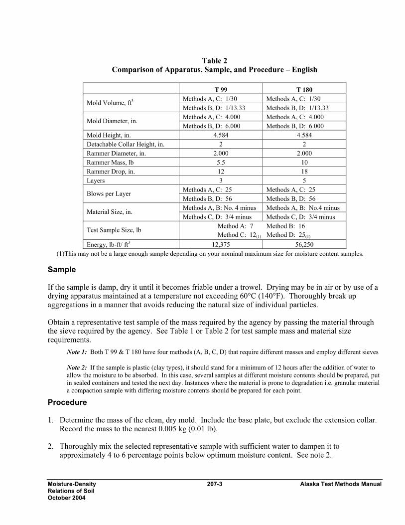
Table 2
Comparison of Apparatus, Sample, and Procedure – English
T 99 T 180 Methods A, C: 1/30 Methods A, C: 1/30 Mold Volume, ft3 Methods B, D: 1/13.33 Methods B, D: 1/13.33 Methods A, C: 4.000 Methods A, C: 4.000 Mold Diameter, in. Methods B, D: 6.000 Methods B, D: 6.000
Mold Height, in. 4.584 4.584 Detachable Collar Height, in. 2 2 Rammer Diameter, in. 2.000 2.000 Rammer Mass, lb 5.5 10 Rammer Drop, in. 12 18 Layers 3 5
Methods A, C: 25 Methods A, C: 25 Blows per Layer Methods B, D: 56 Methods B, D: 56 Methods A, B: No. 4 minus Methods A, B: No.4 minus Material Size, in. Methods C, D: 3/4 minus Methods C, D: 3/4 minus
Test Sample Size, lb Method A: 7 Method B: 16 Method C: 12(1) Method D: 25(1)
Energy, lb-ft/ ft3 12,375 56,250 (1)This may not be a large enough sample depending on your nominal maximum size for moisture content samples.
Sample If the sample is damp, dry it until it becomes friable under a trowel. Drying may be in air or by use of a drying apparatus maintained at a temperature not exceeding 60°C (140°F). Thoroughly break up aggregations in a manner that avoids reducing the natural size of individual particles. Obtain a representative test sample of the mass required by the agency by passing the material through the sieve required by the agency. See Table 1 or Table 2 for test sample mass and material size requirements.
Note 1: Both T 99 & T 180 have four methods (A, B, C, D) that require different masses and employ different sieves
Note 2: If the sample is plastic (clay types), it should stand for a minimum of 12 hours after the addition of water to allow the moisture to be absorbed. In this case, several samples at different moisture contents should be prepared, put in sealed containers and tested the next day. Instances where the material is prone to degradation i.e. granular material a compaction sample with differing moisture contents should be prepared for each point.
Procedure 1. Determine the mass of the clean, dry mold. Include the base plate, but exclude the extension collar.
Record the mass to the nearest 0.005 kg (0.01 lb). 2. Thoroughly mix the selected representative sample with sufficient water to dampen it to
approximately 4 to 6 percentage points below optimum moisture content. See note 2.
Alaska Test Methods Manual 207-4 Moisture-Density Relations of Soil October 2004
3. Form a specimen by compacting the prepared soil in the mold (with collar attached) in approximately equal layers. For each layer, spread the loose material uniformly in the mold. Lightly tamp the fluffy material with the manual rammer or other similar device. This establishes a firm surface on which to hold the rammer sleeve. Compact each layer with uniformly distributed blows from the rammer. See Table 1 for mold size, number of layers, number of blows, and rammer specification for the various test methods. Use the method specified by the agency. If material that has not been compacted remains adjacent to the walls of the mold and extends above the compacted surface, trim it down.
Note 3: During compaction, the mold shall rest firmly on a dense, uniform, rigid, and stable foundation or base. This base shall remain stationary during the compaction process.
4. Remove the extension collar. Avoid shearing off the sample below the top of the mold. A rule of thumb is that the material compacted in the mold should not be over 6 mm (¼ in) above the top of the mold once the collar has been removed.
5. Trim the compacted soil even with the top of the mold with the beveled edge of the straightedge. 6. Determine the mass of the mold and wet soil in kg to the nearest 0.005 kg (0.01 lb) or better. 7. Determine the wet mass of the sample by subtracting the mass in Step 1 from the mass in Step 6. 8. Calculate the wet density as indicated below under “Calculations.” 9. Extrude the material from the mold. For soils and soil aggregate mixtures slice vertically through the
center and take a representative moisture content sample from one of the cut faces insuring that all layers are represented. For granular materials a vertical face will not exist. Take a representative sample. This sample must meet the sample size requirements of the test method to be used to determine moisture content.
Note 4: When developing a curve for free-draining soils, such as uniform sands and gravels, where seepage occurs at the bottom of the mold and base plate, taking a representative moisture content from the mixing bowl may be preferred in order to determine the amount of moisture available for compaction.
10. Determine the moisture content of the sample in accordance with the FOP for AASHTO T 255/T 265.
11. Thoroughly break up the remaining portion of the molded specimen until it will again pass through
the sieve, as judged by eye, and add to the remaining portion of the sample being tested. See note 2. 12. Add sufficient water to increase the moisture content of the remaining soil by approximately 1 to 2
percentage points and repeat the above procedure. 13. Continue determinations until there is either a decrease or no change in the wet density. A minimum
of five determinations is usually necessary. Calculations 1. Calculate the wet density, in kg/m3 (lb/ft3), by multiplying the wet mass from Step 7 by the
appropriate factor chosen from the two below.

Moisture-Density 207-5 Alaska TeRelations of Soil October 2004
Method A & C molds: 1060 (30) Method B & D molds: 471 (13.33)
Note 5: The moist mass is in kg (lb). The factors are the inverses of the mold volumes in m3 (ft3) shown in Table 1. If the moist mass is in grams use 1.060 or 0.471 for factors when computing kg/m3.
1/0.000943 = 1060 [1/(1/30) = 30] 1/0.002124 = 471 [1/(1/13.33) = 13.33]
Example – Method A or C mold:
Wet mass = 1.916 kg (4.22 lb) (1.916)(1060) = 2031 kg/m3 Wet Density [(4.22)(30) = 126.6 lb/ft3 Wet Density
2. Calculate the dry density as follows.
or
Where: ρd = Dry density, kg/m3 (lb/ft3) ρw = Wet density, kg/m3 (lb/ft3) w = Moisture content, as a percentage
Example: ρw = 2030 kg/m3 (126.6 lb/ft3) and w = 14.7%
or Moisture-Density Curve Development When dry density is plotted on the vertical axis versus moisture content on the horizontapoints are connected, a moisture-density curve is developed. The peak of the curve has,the maximum dry density, or just “maximum density,” and the “optimum moisture conte Example:
100100ww
d ×⎟⎟⎠
⎞⎜⎜⎝
⎛+ρ
=ρ
33
d kg/m177010010014.7
kg/m2030=×⎟⎟
⎠
⎞⎜⎜⎝
⎛+
=ρ
⎟⎟⎟⎟
⎠
⎞
⎜⎜⎜⎜
⎝
⎛
+
ρ=ρ
1100w
wd
33
d kg/m17701100)/(14.7
kg/m2030=⎟⎟
⎠
⎞⎜⎜⎝
⎛+
=ρ
3
d 4.11010010014.7/ft126.6 lblb
=×⎟⎟⎠
⎞⎜⎜⎝
⎛+
=ρ
3
d /110.41100)/(14.7
b/ft6.126 lbl=⎟⎟
⎠
⎞⎜⎜⎝
⎛+
=ρ
30
]
32
st Methods Manual
l axis, and the as coordinates, nt” of the soil.
3/ft
3ft
Alaska Test Methods Manual 207-6 Moisture-Density Relations of Soil October 2004
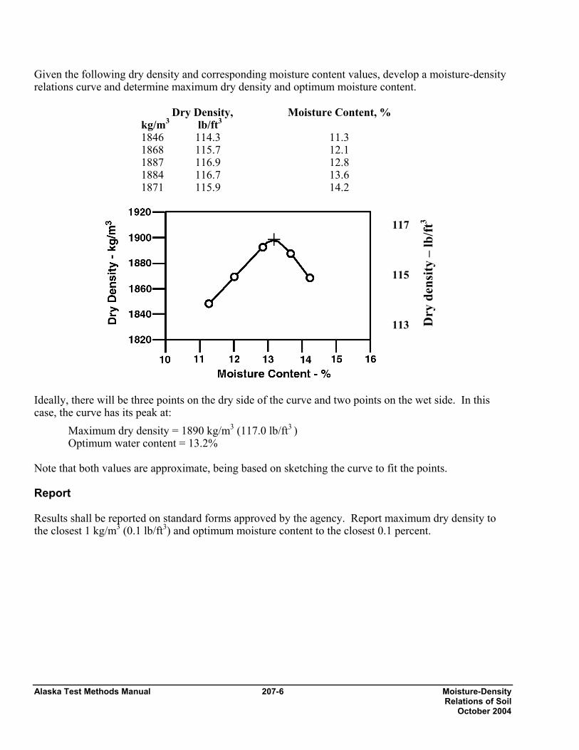
Given the following dry density and corresponding moisture content values, develop a moisture-density relations curve and determine maximum dry density and optimum moisture content.
Dry Density, kg/m3 lb/ft3
Moisture Content, %
1846 114.3 11.3 1868 115.7 12.1 1887 116.9 12.8 1884 116.7 13.6 1871 115.9 14.2
117 115 113 Ideally, there will be three points on the dry side of the curve and two points on the wet side. In this case, the curve has its peak at:
Maximum dry density = 1890 kg/m3 (117.0 lb/ft3 ) Optimum water content = 13.2%
Note that both values are approximate, being based on sketching the curve to fit the points. Report Results shall be reported on standard forms approved by the agency. Report maximum dry density to the closest 1 kg/m3 (0.1 lb/ft3) and optimum moisture content to the closest 0.1 percent.
Dry
den
sity
– lb
/ft3
Moisture-Density 207-7 Alaska Test Methods Manual Relations of Soil October 2004
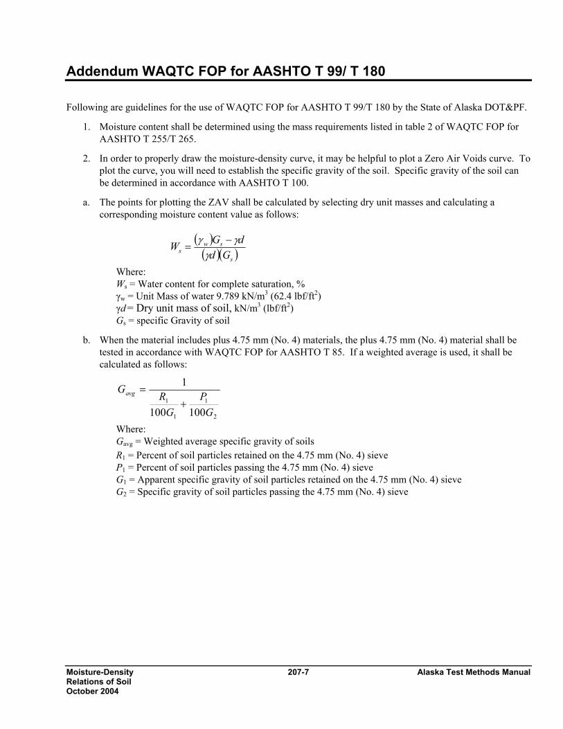
Addendum WAQTC FOP for AASHTO T 99/ T 180 Following are guidelines for the use of WAQTC FOP for AASHTO T 99/T 180 by the State of Alaska DOT&PF.
1. Moisture content shall be determined using the mass requirements listed in table 2 of WAQTC FOP for AASHTO T 255/T 265.
2. In order to properly draw the moisture-density curve, it may be helpful to plot a Zero Air Voids curve. To plot the curve, you will need to establish the specific gravity of the soil. Specific gravity of the soil can be determined in accordance with AASHTO T 100.
a. The points for plotting the ZAV shall be calculated by selecting dry unit masses and calculating a corresponding moisture content value as follows:
( )
( )( )s
sws Gd
dGWγ
γγ −=
Where: Ws = Water content for complete saturation, % γw = Unit Mass of water 9.789 kN/m3 (62.4 lbf/ft2) γd = Dry unit mass of soil, kN/m3 (lbf/ft2) Gs = specific Gravity of soil
b. When the material includes plus 4.75 mm (No. 4) materials, the plus 4.75 mm (No. 4) material shall be tested in accordance with WAQTC FOP for AASHTO T 85. If a weighted average is used, it shall be calculated as follows:
2
1
1
1
100100
1
GP
GR
Gavg
+=
Where: Gavg = Weighted average specific gravity of soils R1 = Percent of soil particles retained on the 4.75 mm (No. 4) sieve P1 = Percent of soil particles passing the 4.75 mm (No. 4) sieve G1 = Apparent specific gravity of soil particles retained on the 4.75 mm (No. 4) sieve G2 = Specific gravity of soil particles passing the 4.75 mm (No. 4) sieve

Alaska Test Methods Manual 207-8 Moisture-Density Relations of Soil October 2004
This page intentionally left blank.

Determining the Standard Density 212-1 Alaska Test Methods Manual of Coarse Granular Materials… Revised 12/31/03
Determining the Standard Density of Coarse Granular Materials Using the Vibratory Compactor ATM 212
1. Scope This method determines the maximum density values of granular materials for a standard compaction energy. The method accounts for variations in the maximum attainable density of a given material due to fluctuations in gradation.
With the specific gravity and the compacted density of the plus 4.75 mm (no. 4) and the minus 4.75 mm (No. 4) fractions, a chart and/or curve of standard density values versus percent passing the No. 4 sieve can be plotted.
This test method is applicable to granular materials with the gradation of the minus 75 mm (3 in) portion of the sample having 10-80 percent passing the 4.75 mm (No. 4) sieve and with the minus 4.75 mm (No. 4) portion of the sample having 10 percent or less passing the 75 µm (No. 200) sieve.
Note 1: The Vibratory Compaction Test was developed for sandy gravels whose fine fraction is non-plastic and highly permeable or free draining. When the fine fraction is primarily a soil with some plasticity and low permeability or not free draining, WAQTC FOP for AASHTO T 99/T 180 will be used. With borderline materials, both tests shall be applied, and the one yielding the highest unit weight value will be used.
2. Apparatus
• A vibratory spring-loaded compactor essentially conforming to specifications that can be obtained from the State Materials Engineer.
• Standard C.B.R. Mold with a non-perforated base and a piston to fit inside the mold with a maximum 1.5 mm (1/16") clearance between piston and mold.
• A 0.014 m3 (1/2 ft3) mold with a piston to fit inside mold having a maximum 1.5 mm (1/16 in) clearance between piston and mold.
Note 2: The molds and pistons will be constructed of metal of such dimensions as to remain rigid and inflexible under test conditions.
• Spacer blocks of varying heights compatible with the compactor and pistons.
• Measuring device, accurate and readable to 0.1 mm (0.01 in) with a minimum 300 mm (6 in) length.
• A 75 mm (3 in) and a 4.75 mm (No. 4) sieve conforming to AASHTO M 92 requirements.
• Balance or scale: Capacity sufficient for the principle sample mass, readable to 0.1 percent or 0.1 g and meeting the requirements of AASHTO M 231.
Note 3: For the fine aggregate compaction test, this would require a scale with a capacity of at least 20 kg (45 lb) and readable to 5 g (0.01 lb) or better.
Note 4: For the fine aggregate moisture content, this would require a scale with a capacity of at least 1000 g and readable to 0.1 g or better.
Note 5: For the coarse aggregate compaction test, this would require a scale with a capacity of at least 20 kg (45 lb) and readable to 5 g (0.01 lb) or better.
• A 2.5 kg (5.5 lb) metal rammer conforming to the requirements of WAQTC FOP for AASHTO T 99.

Alaska Test Methods Manual 212-2 Determining the Standard Density of Coarse Granular Materials… Revised 12/31/03
• Tamping rod of straight steel, 16 mm (5/8 in) in diameter and approximately 400 mm (24 in) long having at least one end rounded to a hemispherical tip.
• Graduated cylinder, 1000 ml capacity, readable to 5 ml.
• A stopwatch or timer accurate to 1 second.
• Miscellaneous tools including pans, spoon, trowel, mechanical mixer (optional), etc.
3. Equipment Calibration Calibration data will be updated annually or more frequently if justified by use. Calibration information will be recorded and accessible for every test.
Calibration of the Standard C.B.R. Mold (Small):
1. Measure the top and bottom diameter of the mold to the nearest 0.1 mm (0.01 in) and average the results to obtain the mean diameter of the mold. Calculate the area of the average diameter by the formula:
( )25.0 d××=Α π
Where: A = Area of mean diameter, in2 or mm2,
π = 3.1416, d = mean diameter, in or mm.
2. Assemble the mold, measure the overall height of the mold to the nearest 0.1 mm (0.01 in) at least 4 different places around the circumference of the mold and average the measurements. Record this as Height of Mold.
3. Calculate the Mold Conversion Factor by:
C = A
0001,000,000, or A
1728 USC
Where: C = Mold Conversion Factor, (1,000,000,000 = mm3/m3 and 1728 = in3/ft3), A = Area of mean diameter.
4. Record the result as the Small Mold Conversion Factor to the nearest whole number.
5. Calibration of the 0.014 m3 Mold (Large): Calibrate this mold using the same procedure as described for the small mold above and record the result to the nearest whole number as the Large Mold Conversion Factor.
4. Sample Preparation 1. Sample the material in accordance with WAQTC FOP for AASHTO T 2. Prepare the field sample by
splitting out a representative portion in accordance with WAQTC FOP for AASHTO T 248, Method A, to provide sufficient material for the following tests.
• Sieve Analysis in accordance with WAQTC FOP for AASHTO T 27/T 11.
• Coarse Aggregate Apparent Specific Gravity in accordance with WAQTC FOP for AASHTO T 85.
• Fine Aggregate Apparent Specific Gravity in accordance with AASHTO T 84 or AASHTO T100.
• Compaction sample to provide sufficient material for the compaction specimens detailed below.
2. Dry the compaction sample to constant mass in accordance with WAQTC FOP for AASHTO T 255.

Alaska Test Methods Manual 212-3 Determining the Standard Density of Coarse Granular Materials… Revised 12/31/03
3. Scalp the plus 75 mm (3 in) material from the compaction sample and discard, if not needed for any other tests. Separate the remainder of the compaction sample into coarse [minus 75 mm (3 in) to 4.75 mm (No. 4)] and fine [minus 4.75 mm (No. 4)] aggregate portions.
4. The quantity of material necessary to complete tests on both fractions is:
a. Fine aggregate, minimum of 3 portions approximately 6 kg (13 lb) each.
b. Coarse aggregate:
1) For material containing 5 percent or less of 19.0 mm (3/4 in) material, a portion of the minus 19.0 mm (3/4 in) aggregate of approximately 6 kg (13 lb).
2) For material containing more than 5 percent plus 19.0 mm (3/4 in) aggregate a portion of 18 to 20 kg (40 to 45 lb ).
5. Procedure
1. Compaction Test of the Fine Fraction
a. Assemble the C.B.R. Mold and determine its mass, along with the Piston, to the nearest 5 g (0.01 lb). Record this as the Mass of Mold Assembly.
b. Using one of the fine aggregate portions, add an amount of water estimated to produce a saturated sample when compacted and mix thoroughly.
1) When the material is at its saturation point, free water (a drop or two) will show at the base of the mold at about the. 227 kg (500 lb) load of the first compression run. The ideal saturation point would be a bead of water around the base of the mold at the end of the 10-minute compaction run. Most materials will yield the highest density at that moisture content. Some materials may continue to gain density at higher moisture contents; however, this is due to the washing out of fines, which will alter the character of the sample. Therefore, if severe washing-out or pumping of fines occurs (as evidenced by dirty water flooding off of the base or pumped on top of the piston), the sample is beyond the saturation point, will be discarded and a lower moisture content tried for the saturation point.
2) Moisture contents beyond the saturation point need not be tested.
c. Set the piston aside and place the sample in the mold in three approximately equal layers. Consolidate each lift by 25 strokes of the tamping rod followed by 25 blows of the manual rammer. If severe displacement of the material occurs, adjust the blow strength by limiting the height of each blow to produce the maximum compaction and minimum displacement. The surface of the top lift should be finished as level as possible.
d. Place the piston on top of the sample and mount the mold on the jack platform in the compactor. Spacers between the load spring and piston must be used to adjust the elevation of the mold so the hammers strike the mold in the center of the lift area. Elevate the mold until the loading head seats on top of the piston. Apply an initial seating load of approximately 45 kg (100 lbs) on the sample.
e. Start the vibratory hammers and, by elevating the jack, begin the loading rate procedure.

Alaska Test Methods Manual 212-4 Determining the Standard Density of Coarse Granular Materials… Revised 12/31/03
The load application rate to 2000 lbs. is applied as follows: Load Elapsed Time
0 to 225 kg (500 lb) 1 minute
225 kg to 450 kg (1000 lb) 1-1/2 minutes
450 kg to 900 kg (2000 lb) 2 minutes
f. Upon reaching the 900 kg (2000 lb) load at the end of the 2-minute cycle, stop the hammers, release the load on the jack, and return to zero pressure.
g. Repeat Steps 5 and 6 four additional times. After the last run remove the mold from the compactor.
h. Measure the height of the compacted sample, to the top of the piston, to the nearest 0.1 mm (0.01 in) by measuring from the top of the mold to the surface of the sample at a minimum of 4 different places evenly spaced around the circumference of the mold. Record and average these measurements. Subtract this average from the overall height of the mold and record as the Height of Sample.
i. Determine the mass of the specimen in the mold to the nearest 5 g (0.01 lb). Record this as Mass of Mold Assembly + Aggregate.
j. Remove the specimen from the mold and determine the moisture content in accordance with WAQTC FOP for AASHTO T 255, recording the data on the Vibratory Compaction Worksheet.
k. Repeat Steps 3-11 at lower or higher moisture content increments of approximately 1 percent intervals to determine the maximum density value for the material. Three tests are usually sufficient.
2. Compaction Test of the Coarse Fraction:
a. For minus 19 mm (3/4 in) aggregates:
1) Determine the mass of the coarse aggregate to the nearest 5 g (0.01 lb). Record this mass as Net Mass of Coarse Aggregate.
2) Add 2.5 percent moisture to the sample, mix thoroughly and place in the Standard C.B.R. mold in approximately three equal lifts. Compact each lift with 25 blows of the tamping rod (omit hammering). Avoid the loss of any material during this operation, or the net mass of coarse aggregate must be determined again, after determining the height of the sample and drying the material to constant mass.
3) Follow the procedures outlined in steps 1d. through 1g.
b. For plus 19 mm (3/4 in) aggregates:
1) Determine the mass of the coarse aggregate to the nearest 5 g (0.01 lb) or better. Record this mass the Net Mass of Coarse Aggregate.
2) Divide the sample into three representative and approximately equal portions.
3) Place one of the portions into the 0.014 m3 (1/2 ft3) mold. Level the surface by hand and consolidate the layer with 25 strokes of the tamping rod, using the rounded end. Distribute the strokes evenly over the entire cross section of the material rodding full depth, if possible, without hitting the bottom too hard.
Alaska Test Methods Manual 212-5 Determining the Standard Density of Coarse Granular Materials… Revised 12/31/03
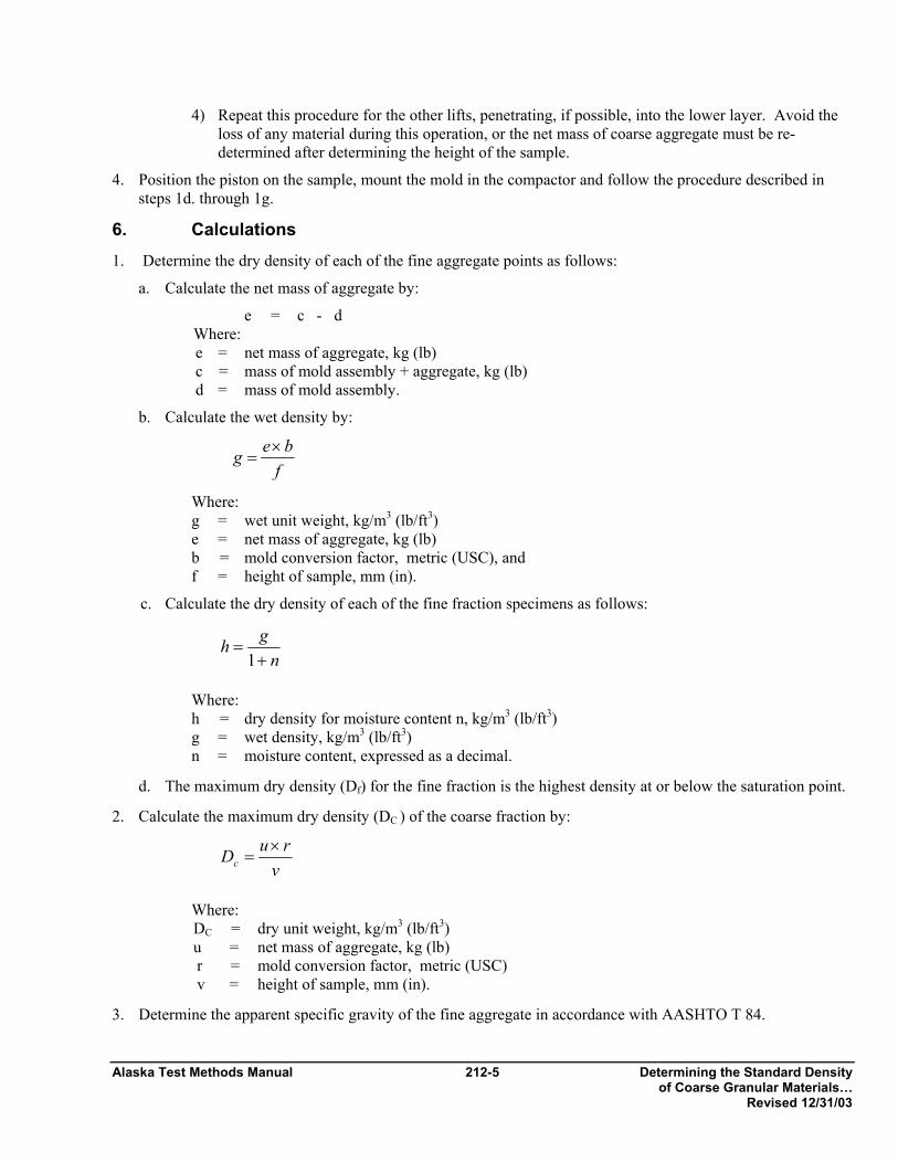
4) Repeat this procedure for the other lifts, penetrating, if possible, into the lower layer. Avoid the loss of any material during this operation, or the net mass of coarse aggregate must be re-determined after determining the height of the sample.
4. Position the piston on the sample, mount the mold in the compactor and follow the procedure described in steps 1d. through 1g.
6. Calculations 1. Determine the dry density of each of the fine aggregate points as follows:
a. Calculate the net mass of aggregate by:
e = c - d Where:
e = net mass of aggregate, kg (lb) c = mass of mold assembly + aggregate, kg (lb)
d = mass of mold assembly.
b. Calculate the wet density by:
f
beg ×=
Where: g = wet unit weight, kg/m3 (lb/ft3)
e = net mass of aggregate, kg (lb) b = mold conversion factor, metric (USC), and
f = height of sample, mm (in).
c. Calculate the dry density of each of the fine fraction specimens as follows:
n
gh+
=1
Where: h = dry density for moisture content n, kg/m3 (lb/ft3) g = wet density, kg/m3 (lb/ft3) n = moisture content, expressed as a decimal.
d. The maximum dry density (Df) for the fine fraction is the highest density at or below the saturation point.
2. Calculate the maximum dry density (DC ) of the coarse fraction by:
vruDc
×=
Where: DC = dry unit weight, kg/m3 (lb/ft3) u = net mass of aggregate, kg (lb)
r = mold conversion factor, metric (USC) v = height of sample, mm (in).
3. Determine the apparent specific gravity of the fine aggregate in accordance with AASHTO T 84.
Alaska Test Methods Manual 212-6 Determining the Standard Density of Coarse Granular Materials… Revised 12/31/03
4. Determine the apparent specific gravity of the coarse aggregate in accordance with WAQTC FOP for AASHTO T 85.
5. Plotting the "Maximum Dry Density vs. the Percent Passing 4.75 mm (No. 4) Sieve" curve is based on complex theoretical formulae. Programs for solution of these formulae, which produce curve data points and charts, have been developed for spreadsheets. These programs are available from the Statewide/ Regional laboratories.
7. Report The results shall be reported on Department forms. In addition to the standard conformance tests for the material, in chart form the Maximum Dry Density shall be reported to the nearest 1 kg/m3 (0.1 lb/ft3) vs. the Percent Passing 4.75 mm (No. 4) in whole percentages from 0 to 100 percent. The data may be displayed graphically in addition to the chart.
In-Place Density and Moisture 213-1 Alaska Test Methods Manual Of Soils by Nuclear Method October 2003
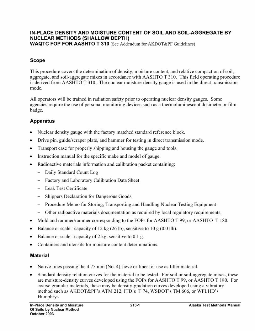
IN-PLACE DENSITY AND MOISTURE CONTENT OF SOIL AND SOIL-AGGREGATE BY NUCLEAR METHODS (SHALLOW DEPTH) WAQTC FOP FOR AASHTO T 310 (See Addendum for AKDOT&PF Guidelines) Scope This procedure covers the determination of density, moisture content, and relative compaction of soil, aggregate, and soil-aggregate mixes in accordance with AASHTO T 310. This field operating procedure is derived from AASHTO T 310. The nuclear moisture-density gauge is used in the direct transmission mode. All operators will be trained in radiation safety prior to operating nuclear density gauges. Some agencies require the use of personal monitoring devices such as a thermoluminescent dosimeter or film badge. Apparatus • Nuclear density gauge with the factory matched standard reference block. • Drive pin, guide/scraper plate, and hammer for testing in direct transmission mode. • Transport case for properly shipping and housing the gauge and tools. • Instruction manual for the specific make and model of gauge. • Radioactive materials information and calibration packet containing:
− Daily Standard Count Log − Factory and Laboratory Calibration Data Sheet − Leak Test Certificate − Shippers Declaration for Dangerous Goods − Procedure Memo for Storing, Transporting and Handling Nuclear Testing Equipment − Other radioactive materials documentation as required by local regulatory requirements.
• Mold and rammer/rammer corresponding to the FOPs for AASHTO T 99, or AASHTO T 180. • Balance or scale: capacity of 12 kg (26 lb), sensitive to 10 g (0.01lb). • Balance or scale: capacity of 2 kg, sensitive to 0.1 g. • Containers and utensils for moisture content determinations. Material • Native fines passing the 4.75 mm (No. 4) sieve or finer for use as filler material. • Standard density relation curves for the material to be tested. For soil or soil-aggregate mixes, these
are moisture-density curves developed using the FOPs for AASHTO T 99, or AASHTO T 180. For coarse granular materials, these may be density-gradation curves developed using a vibratory method such as AKDOT&PF’s ATM 212, ITD’s T 74, WSDOT’s TM 606, or WFLHD’s Humphrys.

Alaska Test Methods Manual 213-2 In-Place Density and Moisture Of Soils by Nuclear Method October 2003
Calibration Calibrate the nuclear gauge as required by the agency. This calibration may be performed by the
agency using manufacturer’s recommended procedures or by other facilities approved by the agency. Verify or re-establish calibration curves, tables, or equivalent coefficients every 12 months.
Standardization Turn the gauge on and allow it to stabilize for 10 to 20 minutes prior to standardization. Standardize
the nuclear gauge at the construction site at the start of each day’s work and as often as deemed necessary by the operator or agency. Record the standard count for both density and moisture in the Daily Standard Count Log. The exact procedure for standard count is listed in the manufacturer’s Operators Manual.
Note 1: Daily variations in standard count shall not exceed the daily variations established by the manufacturer of the gauge. If the daily variations are exceeded after repeating the standardization procedure, the gauge should be repaired and or recalibrated.
Note 2: New standard counts may be necessary more than once a day. See agency requirements.
Procedure - General There are two methods – A and B. Method A involves testing in a single direction. Method B requires testing in two directions. 1. Select a test location at least 10 m (30 ft) away from other sources of radioactivity and at least 3 m
(10 ft) away from large objects. The test site should be at least 150 mm (6 in.) away from any vertical projection, unless the gauge is corrected for trench wall effect.
2. Remove all loose and disturbed material, and remove additional material as necessary to expose the
top of the material to be tested. 3. Prepare a flat area sufficient in size to accommodate the gauge. Plane the area to a smooth condition
so as to obtain maximum contact between gauge and the material being tested. For Method B, the flat area must be sufficient to permit rotating the gauge 90 or 180 degrees about the source rod.
4. Fill in surface voids beneath the gauge with native fines. Smooth the surface with the guide plate or
other suitable tool. The depth of the native fines filler should not exceed approximately 3 mm (1/8 in.).
5. Make a hole perpendicular to the prepared surface using the guide plate and drive pin. The hole
shall be at least 50 mm (2 in.) deeper than the desired probe depth, and shall be aligned such that insertion of the probe will not cause the gauge to tilt from the plane of the prepared area. Remove the drive pin by pulling straight up and twisting the extraction tool.
6. Place the gauge on the prepared surface so the source rod can enter the hole without disturbing loose
material.

In-Place Density and Moisture 213-3 Alaska Test Methods Manual Of Soils by Nuclear Method October 2003
7. Insert the probe in the hole and lower the source rod to the desired test depth using the handle and trigger mechanism.
8. Seat the gauge firmly by partially rotating it back and forth about the source rod. Ensure the gauge
is seated flush against the surface by pressing down on the gauge corners, and making sure that the gauge does not rock.
9. Pull gently on the gauge to bring the side of the source rod nearest to the scaler/detector firmly
against the side of the hole. Procedure - Method A, Single Direction 10A. Take a test consisting of the average of two, one minute readings, and record both density and
moisture data. The two wet density readings should be within 32 kg/m3 (2 lb/ft3) of each other. The average of the two wet densities and moisture contents will be used to compute dry density.
11A. Obtain a representative sample of the material, 4 kg (9 lb) minimum, from directly beneath the
gauge. This sample will be used to verify moisture content and / or identify the correct density standard. Immediately seal the material to prevent loss of moisture. The material tested by direct transmission can be approximated by a cylinder of soil approximately 300 mm (12 in.) in diameter directly beneath the centerline of the radioactive source and detector. The height of the cylinder will be approximately the depth of measurement. When organic material or oversized aggregate is removed during this operation, disregard the test information and move to a new test site. Note 3: Some agencies do not require a sample be taken on crushed materials.
Procedure - Method B, Two Directions 10B. At a minimum take a one-minute reading and record both density and moisture data. Rotate the
gauge 90 degrees or 180, pivoting it around the source rod. Reseat the gauge pulling gently on the gauge to bring the side of the source rod nearest to the scaler/detector firmly against the side of the hole and take one-minute reading. (In trench locations, rotate the gauge 180 degrees for the second test.) Analyze the density and moisture data. A valid test consists of wet density readings in both gauge positions that are within 50 kg/m3 (3 lb/ft3). If the tests do not agree within this limit, move to a new location. The average of the wet density and moisture contents will be used to compute dry density.
11B. Obtain a representative sample of the material, 4 kg (9 lb) minimum, from directly beneath each
gauge position. This sample will be used to verify moisture content and / or identify the correct density standard. Immediately seal the material to prevent loss of moisture. The material tested by direct transmission can be approximated by a cylinder of soil approximately 300 to 400 mm (12 to 16 in.) diameter directly beneath the centerline of the radioactive source and detector. The height of the cylinder will be approximately the depth of measurement. Note 3: Some agencies do not require a sample be taken on crushed products.
Procedure - General (continued) 12. Determine the moisture content with a representative portion of the material using the FOP for
AASHTO T 255/T 265 or AASHTO T 217. Retain the remainder of the sample at its original
Alaska Test Methods Manual
moisture content for a one-point compaction test under the FOP for AASHTO T 272, or for gradation, if required.
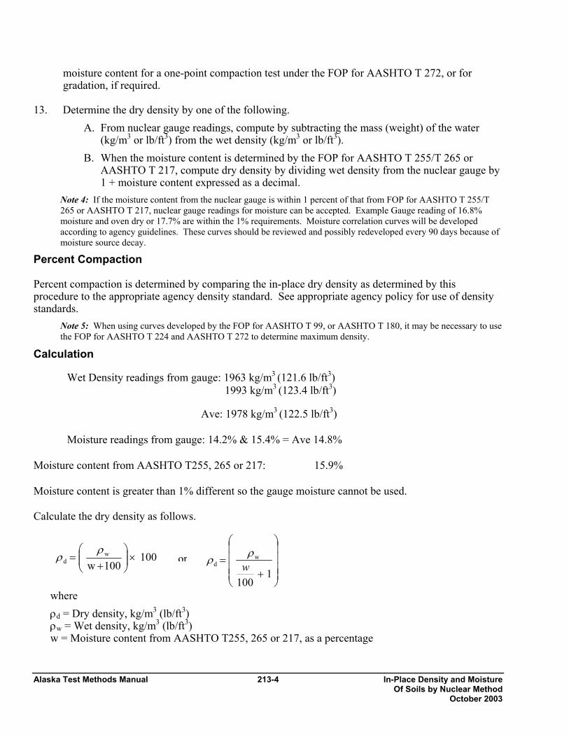
13. Determine the dry density by one of the following.
A. From nuclear gauge readings, compute by subtracting the mass (weight) of the water (kg/m3 or lb/ft3) from the wet density (kg/m3 or lb/ft3).
B. When the moisture content is determined by the FOP for AASHTO T 255/T 265 or AASHTO T 217, compute dry density by dividing wet density from the nuclear gauge by 1 + moisture content expressed as a decimal.
Note 4: If the moisture content from the nuclear gauge is within 1 percent of that from FOP for AASHTO T 255/T 265 or AASHTO T 217, nuclear gauge readings for moisture can be accepted. Example Gauge reading of 16.8% moisture and oven dry or 17.7% are within the 1% requirements. Moisture correlation curves will be developed according to agency guidelines. These curves should be reviewed and possibly redeveloped every 90 days because of moisture source decay.
Percent Compaction Percent compaction is determined by comparing the in-place dry density as determined by this procedure to the appropriate agency density standard. See appropriate agency policy for use of density standards.
Note 5: When using curves developed by the FOP for AASHTO T 99, or AASHTO T 180, it may be necessary to use the FOP for AASHTO T 224 and AASHTO T 272 to determine maximum density.
Calculation
Wet Density readings from gauge: 1963 kg/m3 (121.6 lb/ft3) 1993 kg/m3 (123.4 lb/ft3) Ave: 1978 kg/m3 (122.5 lb/ft3) Moisture readings from gauge: 14.2% & 15.4% = Ave 14.8% Moisture content from AASHTO T255, 265 or 217: 15.9% Moisture content is greater than 1% different so the gauge moisture cannot be used. Calculate the dry density as follows.
where ρd = Dry density, kg/m3 (lb/ρw = Wet density, kg/m3 (lbw = Moisture content from
100100ww
d ×⎟⎟⎠
⎞⎜⎜⎝
⎛+
=ρ
ρ ⎟⎟⎞
⎜⎜⎛
= wd
ρρ
or213-4 In-Place Density and Moisture Of Soils by Nuclear Method October 2003
ft3) /ft3) AASHTO T255, 265 or 217, as a percentage
⎟⎟⎠
⎜⎜⎝
+ 1100w

In-Place Density and Moisture 213-5 Alaska Test Methods Manual Of Soils by Nuclear Method October 2003
Corrected for moisture Dry Density: 1707 kg/m3 (105.7 lb/ft3)
Report Results shall be reported on standard forms approved by the agency. Include the following information: • Location of test, elevation of surface, and thickness of layer tested • Visual description of material tested • Make, model and serial number of the nuclear moisture-density gauge • Wet density • Moisture content as a percent, by mass, of dry soil mass • Dry density • Standard density • Percent compaction • Name and signature of operator
⎟⎟⎟⎟
⎠
⎞
⎜⎜⎜⎜
⎝
⎛
+=
1100
9.15/5.122/1978 33
dftlbormkgρ100
10015.9/5.122/1978 33
d ×⎟⎟⎠
⎞⎜⎜⎝
⎛+
=ftlbormkgρ
Alaska Test Methods Manual 213-6 In-Place Density and Moisture Of Soils by Nuclear Method October 2003
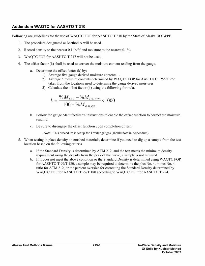
Addendum WAQTC for AASHTO T 310 Following are guidelines for the use of WAQTC FOP for AASHTO T 310 by the State of Alaska DOT&PF.
1. The procedure designated as Method A will be used.
2. Record density to the nearest 0.1 lb/ft2 and moisture to the nearest 0.1%.
3. WAQTC FOP for AASHTO T 217 will not be used.
4. The offset factor (k) shall be used to correct the moisture content reading from the gauge.
a. Determine the offset factor (k) by: 1) Average five gauge derived moisture contents. . 2) Average 5 moisture contents determined by WAQTC FOP for AASHTO T 255/T 265
taken from the locations used to determine the gauge derived moistures. 3) Calculate the offset factor (k) using the following formula.
1000%100
%%×
+−
=GAUGE
GAUGELAB
MMMk
b. Follow the gauge Manufacturer’s instructions to enable the offset function to correct the moisture
reading.
c. Be sure to disengage the offset function upon completion of test.
Note: This procedure is set up for Troxler gauges (should note in Addendum)
5. When testing in place density on crushed materials, determine if you need to dig up a sample from the test location based on the following criteria.
a. If the Standard Density is determined by ATM 212, and the test meets the minimum density requirement using the density from the peak of the curve, a sample is not required.
b. If it does not meet the above condition or the Standard Density is determined using WAQTC FOP for AASHTO T 99/T 180, a sample may be required to determine the plus No. 4, minus No. 4 ratio for ATM 212, or the percent oversize for correcting the Standard Density determined by WAQTC FOP for AASHTO T 99/T 180 according to WAQTC FOP for AASHTO T 224.
Correction for Coarse Particles in 214-1 Alaska Test Methods Manual The Soil Compaction Test October 2003
CORRECTION FOR COARSE PARTICLES IN THE SOIL COMPACTION TEST WAQTC FOP FOR AASHTO T 224 Scope This procedure covers the adjustment of the maximum dry density determined by WAQTC FOP for AASHTO T 99/ T 180 to compensate for coarse particles retained on the 4.75 mm (No. 4) or 19.0 mm (3/4-in.) sieve. For Methods A and B of WAQTC FOP for AASHTO T 99/T 180, the adjustment is based on the percent, by mass, of material retained on the 4.75 mm (No. 4) sieve and the bulk specific gravity Gsb of the material retained on the 4.75 mm (No. 4) sieve. A maximum of 40% of the material can be retained on the 4.75 mm (No.4) sieve for this method to be used. For Methods C and D of WAQTC FOP for AASHTO T 99/T 180, the adjustment is based on the percent, by mass, of material retained on the 19.0 mm (3/4 in.) sieve and the bulk specific gravity Gsb of the material retained on the 19.0 mm (3/4 in.) sieve. A maximum of 30% of the material can be retained on the 19.0 mm (3/4 in.) sieve for this method to be used. Whether the split is on the 4.75 mm (No.4) or the 19.0 mm (3/4 in.) sieve all material retained on that sieve is defined as oversized material. This method applies to soils with percentages up to the maximums listed above for oversize particles. A correction may not be practical for soils with only a small percentage of oversize material. Agency shall specify a minimum percentage below which the method is not needed. If not specified, this method applies when more than 5 percent by weight of oversize particles is present. Adjustment Equation Moisture Along with density, the moisture content can be corrected. The moisture content can be determined by the WAQTC FOP for AASHTO T 255/ T 265, T 217 or the Nuclear density gauge moisture content reading from the WAQTC FOP for AASHTO T 310. If the nuclear gauge moisture reading is used or when the moisture content is determined on the entire sample (both fine and oversized particles) the use of the adjustment equation is not needed. Combined moisture contents with material having an appreciable amount of silt or clay should be performed using WAQTC FOP for AASHTO T 255/T 265. Moisture contents used from WAQTC FOP for AASHTO T 310 must meet the criteria for that method. When samples are split for moisture content (oversized and fine materials) the following adjustment equations must be followed. 1. Split the sample into oversized material and fine material. 2. Dry the oversized material following the FOP for T 255. Dry the fine material using the FOP for T
255 or 217 if the material is sandy in nature. If the fine material has any appreciable amount of clay dry by the FOP for T 265.
3. Calculate the dry mass of the oversize and fine material as follows.
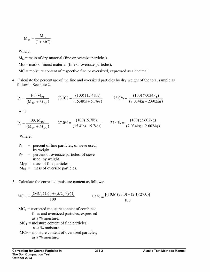
Correction for Coarse Particles in 214-2 Alaska Test Methods Manual The Soil Compaction Test October 2003
Where: MD = mass of dry material (fine or oversize particles). MM = mass of moist material (fine or oversize particles). MC = moisture content of respective fine or oversized, expressed as a decimal.
4. Calculate the percentage of the fine and oversized particles by dry weight of the total sample as
follows: See note 2.
And
Where: Pf = percent of fine particles, of sieve used, by weight. PC = percent of oversize particles, of sieve used, by weight. MDF = mass of fine particles. MDC = mass of oversize particles. 5. Calculate the corrected moisture content as follows:
MCT = corrected moisture content of combined fines and oversized particles, expressed as a % moisture. MCF = moisture content of fine particles, as a % moisture. MCC = moisture content of oversized particles, as a % moisture.
)(1M
M mD MC+
=
) (MM 100
DFf
DCM+=
) (MM 100
DCc
DCM+=
100)])(()(P )[(MC
MC fFT
cc PMC+=
100)]0.27)(1.2()(73.0 [(10.6)8.3% +
=
)7.5 (15.4lbslbs) (15.4 (100)73.0%lbs+
=
)7.5 (15.4lbs(5.7lbs) (100)27.0%
lbs+=
)602.2 (7.034kg(2.602kg) (100)27.0%
kg+=
)602.2 (7.034kg(7.034kg) (100)73.0%
kg+=

Correction for Coarse Particles in The Soil Compaction Test October 2003
Note 1: Moisture content of oversize material can be assumed to be two (2) percent for most construction applications. Note 2: In some field applications agencies will allow the percentages of oversize and fine materials to be determined with the materials in the wet state.
Adjustment Equation Density 6. Calculate the corrected dry density of the total sample (combined fine and oversized particles) as
follows: Where: Dd = corrected total dry density (combi fine and oversized particles) kg/m (lb/ft 3). Df = dry density of the fine particles kg (lb/ft3), determined in the lab. PC = percent of oversize particles, of sie used, by weight. Pf = percent of fine particles, of sieve u by weight. k = Metric:
1,000 * Bulk Specific Gravity (Gsb)(oven dry basis) of coarse particles
Or
English: 62.4 * Bulk Specific Gravity (Gsb) (oven dry basis) of coarse particles (lb/ft3). Note 3: If the specific gravity is known, then this valspecific gravity for aggregate may be assumed to be 2
Calculation Sample Calculations: • Metric:
Maximum laboratory dry density (Df
Percent coarse particles (PC): Percent fine particles (Pf): Bulk specific gravity of coarse partic
)])(()P )([(DD 100D
cf
fd
fPkk
+= or D = 100
d
214-3 Alaska Test Methods Manual
ned 3
/m3
ve
sed,
(kg/m3).
ue will be used in the calculation. For most construction activities the .600.
): 2329 kg/m3 27%
73% les (k): (2.697) (1000) = 2697 kg/m3
kP
DP c
f
f+

Correction for Coarse Particles in 214-4 Alaska Test Methods Manual The Soil Compaction Test October 2003
Dd = 2418.1 say 2418 kg/m3
• English:
Maximum laboratory dry density (DF): 140.4 lb/ft3 Percent coarse particles (PC): 27% Percent fine particles (Pf): 73% Bulk specific gravity of coarse particles (k): (2.697) (62.4) = 168.3 lb/ft3
Dd = 146.98 say 147.0 lb/ft 3
Report Results shall be reported on standard forms approved by the agency. Report adjusted maximum dry density to the closest 1 kg/m3 (0.1 lb/ft3).
)]73)(/2697((27) )[(2329kg/m))(2697kg/m(2329kg/m (100)D 33
33
d mkg+=
]881,196[62,883.00.300,131,628Dd +
=
259,764.00.0628,131,30Dd =
)]73)(/3.168((27) )lb/ft [(140.4)lb/ft )(168.3lb/ft (140.4 (100)D 33
33
d ftlb+=
]9.12285[3790.80.932,362,2Dd +
=
16,076.702,362,932.Dd =
Sampling of Aggregates 301-1 Alaska Test Methods Manual October 2004
SAMPLING OF AGGREGATES (See Addendum for AKDOT&PF Guidelines) FOP FOR AASHTO T 2 Scope This procedure covers sampling of fine and coarse aggregates (FA and CA) in accordance with AASHTO T 2. Sampling from conveyor belts, transport units, roadways, and stockpiles is covered. The specifications for some materials may require the contractor to provide a mechanical sampling system at crushers, screening operations, and mixing plants. This system is normally a permanently attached device that allows a sample container to pass perpendicularly through the entire stream of material or diverts the entire stream of material into the container. The sample container is normally larger at the bottom than the top (triangular shaped), with the slotted opening in the top based on the size of aggregate being sampled. Operation may be hydraulic, pneumatic, or manual, and shall allow the sample container to pass through the stream at least twice, once in each direction, without overfilling. With manually operated systems, a consistent operating speed is difficult to maintain and may result in variably sized, non-representative samples. For this reason, some agency specifications require that the sampling device be automatic or semi-automatic. Apparatus
• Shovels, scoops, sampling tubes of acceptable dimensions. • Custom built sampling devices suitable for varied sampling scenarios, and sampling containers.
Procedure - General Sampling is as important as testing, and the technician shall use every precaution to obtain samples that will show the true nature and condition of the materials the sample represents. 1. Wherever samples are taken, obtain at least three approximately equal increments, except that a
single pass or cycle (a pass through the aggregate stream and back) with a sampling device may be sufficient.
2. Mix the increments thoroughly to form a field sample that meets or exceeds the minimum mass
recommended in Table 1. Note 2: Based upon the tests required, the sample size may be four times that shown in Table 1 of the FOP for AASHTO T 27/T 11, if that mass is more appropriate. As a general rule the field sample size should be such that, when split twice will provide a testing sample of proper size.
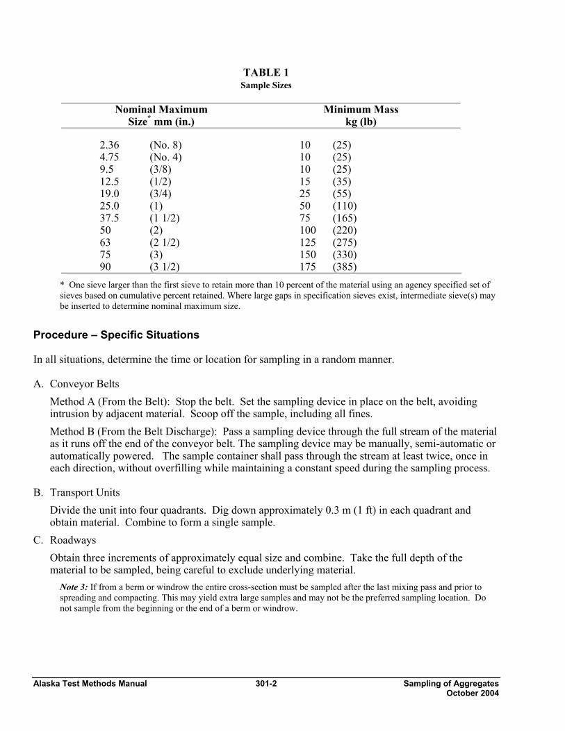
Alaska Test Methods Manual 301-2 Sampling of Aggregates October 2004
TABLE 1 Sample Sizes
Nominal Maximum
Size* mm (in.) Minimum Mass
kg (lb)
2.36 (No. 8) 10 (25) 4.75 (No. 4) 10 (25) 9.5 (3/8) 10 (25) 12.5 (1/2) 15 (35) 19.0 (3/4) 25 (55) 25.0 (1) 50 (110) 37.5 (1 1/2) 75 (165) 50 (2) 100 (220) 63 (2 1/2) 125 (275) 75 (3) 150 (330) 90 (3 1/2) 175 (385)
* One sieve larger than the first sieve to retain more than 10 percent of the material using an agency specified set of sieves based on cumulative percent retained. Where large gaps in specification sieves exist, intermediate sieve(s) may be inserted to determine nominal maximum size.
Procedure – Specific Situations In all situations, determine the time or location for sampling in a random manner. A. Conveyor Belts
Method A (From the Belt): Stop the belt. Set the sampling device in place on the belt, avoiding intrusion by adjacent material. Scoop off the sample, including all fines. Method B (From the Belt Discharge): Pass a sampling device through the full stream of the material as it runs off the end of the conveyor belt. The sampling device may be manually, semi-automatic or automatically powered. The sample container shall pass through the stream at least twice, once in each direction, without overfilling while maintaining a constant speed during the sampling process.
B. Transport Units
Divide the unit into four quadrants. Dig down approximately 0.3 m (1 ft) in each quadrant and obtain material. Combine to form a single sample.
C. Roadways Obtain three increments of approximately equal size and combine. Take the full depth of the material to be sampled, being careful to exclude underlying material.
Note 3: If from a berm or windrow the entire cross-section must be sampled after the last mixing pass and prior to spreading and compacting. This may yield extra large samples and may not be the preferred sampling location. Do not sample from the beginning or the end of a berm or windrow.
Sampling of Aggregates 301-3 Alaska Test Methods Manual October 2004
D. Stockpiles Note 4: Sampling at stockpiles should be avoided whenever possible due to problems involved in obtaining a representative gradation of material 1. Create, with a loader if one is available, vertical faces in the top, middle, and bottom third of the
stockpile. When no equipment is available a shovel may be used to create vertical faces. 2. Prevent sloughing by shoving a flat board in against the vertical face. Sample from the
horizontal surface at the intersection of the horizontal and vertical faces. Take at least one increment from each of the top, middle, and bottom thirds of the pile – and combine.
3. When sampling sand, remove the outer layer that may have become segregated. Using a sampling tube, obtain material from five random locations on the pile and mix thoroughly to form one sample.
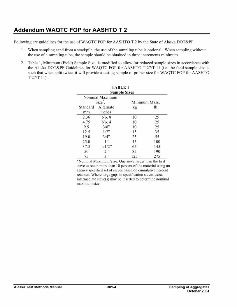
Alaska Test Methods Manual 301-4 Sampling of Aggregates October 2004
Addendum WAQTC FOP for AASHTO T 2 Following are guidelines for the use of WAQTC FOP for AASHTO T 2 by the State of Alaska DOT&PF.
1. When sampling sand from a stockpile, the use of the sampling tube is optional. When sampling without the use of a sampling tube, the sample should be obtained in three increments minimum.
2. Table 1, Minimum (Field) Sample Size, is modified to allow for reduced sample sizes in accordance with the Alaska DOT&PF Guidelines for WAQTC FOP for AASHTO T 27/T 11 (i.e. the field sample size is such that when split twice, it will provide a testing sample of proper size for WAQTC FOP for AASHTO T 27/T 11).
TABLE 1
Sample Sizes Nominal Maximum
Size*, Standard Alternate mm inches
Minimum Mass, kg lb
2.36 No. 8 10 25 4.75 No. 4 10 25 9.5 3/8” 10 25
12.5 1/2” 15 35 19.0 3/4” 25 55 25.0 1” 45 100 37.5 1/1/2” 65 145 50 2” 85 190 75 3” 125 275
*Nominal Maximum Size: One sieve larger than the first sieve to retain more than 10 percent of the material using an agency specified set of sieves based on cumulative percent retained. Where large gaps in specification sieves exist, intermediate sieve(s) may be inserted to determine nominal maximum size.

Reducing Samples of Aggregate 303-1 Alaska Test Methods Manual To Testing Size October 2004
REDUCING SAMPLES OF AGGREGATES TO TESTING SIZE FOP FOR AASHTO T 248 Scope This procedure covers the reduction of samples to the appropriate size for testing in accordance with AASHTO T 248. Techniques are used that minimize variations in characteristics between test samples and field samples. This procedure applies to fine aggregate (FA), coarse aggregate (CA), and mixes of the two, and may also be used on soils. Samples of fine aggregates that are drier than the saturated surface dry (SSD) condition shall be reduced by a mechanical splitter according to Method A. Samples of FA that are wetter than SSD shall be reduced by Method B, or the entire sample may be dried to the SSD condition, using temperatures that do not exceed those specified for any of the tests contemplated, and then reduced to test sample size using Method A. Samples of CA or mixtures of FA and CA may be reduced by either method. As a quick determination, if the fine aggregate will retain its shape when molded with the hand it is wetter that SSD. Apparatus Method A – Mechanical Splitter Sample splitter shall have an even number of equal width chutes, but not fewer than 8 for coarse aggregate or 12 for FA, which discharge alternately to each side of the splitter. The minimum width of individual chutes shall be approximately 50 percent larger than the largest particles in the sample to be split. For dry fine aggregate where the total sample passes the 9.5 mm (3/8 in.) sieve, the maximum chute width shall be 19 mm (3/4 in.). The splitter shall be equipped with two receptacles to hold the two halves of the sample following splitting. It shall also be equipped with a hopper or straightedge pan that has a width equal to or slightly less than the overall width of the assembly of chutes, by which the sample may be fed at a controlled rate to the chutes. The splitter and accessory equipment shall be so designed that the sample will flow smoothly without restriction or loss of material. Method B – Quartering
• Straightedge scoop, shovel, or trowel • Broom or brush • Canvas or plastic sheet, approximately 2 m by 3m (6 by 9 ft)
Sample Preparation If the FA sample is wetter than the SSD condition and Method A – Mechanical Splitter is to be used, dry the material using temperatures not exceeding those specified for any of the tests contemplated for the sample. Note 1: It may be undesirable to split some FA / CA mixtures that are over SSD condition using Method A.

Alaska Test Methods Manual 303-2 Reducing Samples of Aggregate To Testing Size October 2004
Procedure Method A – Mechanical Splitter Place the sample in the hopper or pan and uniformly distribute it from edge to edge so that approximately equal amounts flow through each chute. The rate at which the sample is introduced shall be such as to allow free flowing through the chutes into the hoppers below. Split the sample from one of the two hoppers as many times as necessary to reduce the sample to the size specified for the intended test. The portion of the material collected in the other receptacle may be reserved for reduction in size for other tests. As a check for effective splitting determine the mass of each part of the split. If the ratio of the two masses differs by more than 5 percent, corrective action must be taken. Calculation Splitter check: 5127 total sample mass Splitter pan #1: 2583 Splitter pan #2: 2544
25832544 X100 = 98.5 100-98.5 = 1.5%
Method B – Quartering Use either of the following two procedures or a combination of both. Quartering on a clean, hard, level surface: 1. Place the sample on a hard, clean, level surface where there will be neither loss of material nor the
accidental addition of foreign material. 2. Mix the material thoroughly by turning the entire sample over a minimum of three times. With the
last turning, shovel the entire sample into a conical pile by depositing each shovelful on top of the preceding one.
3. Flatten the conical pile to a uniform thickness and diameter by pressing down with a shovel. The
diameter should be four to eight times the thickness. 4. Divide the flattened pile into four approximately equal quarters with a shovel or trowel. 5. Remove two diagonally opposite quarters, including all fine material, and brush the cleared spaces
clean. 6. Successively mix and quarter the remaining material until the sample is reduced to the desired size. 7. The final test sample consists of two diagonally opposite quarters.
Reducing Samples of Aggregate 303-3 Alaska Test Methods Manual To Testing Size October 2004
Quartering on a canvas or plastic sheet: 1. Place the sample on the sheet. 2. Mix the material thoroughly by turning the entire sample over a minimum of three times. With the
last turning, shovel the entire sample into a conical pile by depositing each shovelful on top of the preceding one. Alternately lift each corner of the sheet and pulling it over the sample toward the diagonally opposite corner, causing the material to be rolled.
3. Flatten the conical pile to a uniform thickness and diameter by pressing down with a shovel. The
diameter should be four to eight times the thickness. 4. Divide the flattened pile into four approximately equal quarters with a shovel or trowel, or, insert a
stick or pipe beneath the sheet and under the center of the pile, then lift both ends of the stick, dividing the sample into two roughly equal parts. Remove the stick leaving a fold of the sheet between the divided portions. Insert the stick under the center of the pile at right angles to the first division and again lift both ends of the stick, dividing the sample into four roughly equal quarters.
5. Remove two diagonally opposite quarters, being careful to clean the fines from the sheet. 6. Successively mix and quarter the remaining material until the sample size is reduced to the desired
size. 7. The final test sample consists of two diagonally opposite quarters.

Alaska Test Methods Manual 303-4 Reducing Samples of Aggregate To Testing Size October 2004

Sieve Analysis of 304-1 Alaska Test Methods Manual Fine and Coarse Aggregates October 2004
SIEVE ANALYSIS OF FINE AND COARSE AGGREGATES FOP FOR AASHTO T 27 (See Addendum for AKDOT&PF Guidelines) MATERIALS FINER THAN 75 µm (No. 200) SIEVE IN MINERAL AGGREGATE BY WASHING (See Addendum for AKDOT&PF Guidelines) FOP FOR AASHTO T 11 Scope Sieve analyses determine the gradation or distribution of aggregate particles within a given sample in order to determine compliance with design and production standards. Accurate determination of material smaller than 75 µm (No. 200) cannot be made with AASHTO T 27 alone. If quantifying this material is required, it is recommended that AASHTO T 27 be used in conjunction with AASHTO T 11. Following the procedure in AASHTO T 11, the sample is washed through a 75 µm (No. 200) sieve. The amount of material passing this sieve is determined by comparing dry sample masses before and after the washing process. This procedure covers sieve analysis in accordance with AASHTO T 27 and materials finer than 75 µm (No. 200) in accordance with AASHTO T 11 performed in conjunction with AASHTO T 27. The procedure includes three method choices, A, B and C. Apparatus
• Balance or scale: Capacity sufficient for the masses shown in Table 1, accurate to 0.1 percent of the sample mass or readable to 0.1 g. Meeting the requirements of AASHTO M 231.
• Sieves – Meeting the requirements of AASHTO M 92. • Mechanical sieve shaker – Meeting the requirements of AASHTO T 27. • Suitable drying equipment (see FOP for AASHTO T 255). • Containers and utensils: A pan or vessel of a size sufficient to contain the sample covered with
water and to permit vigorous agitation without loss of any part of the sample or water. Sample Preparation Obtain samples in accordance with the FOP for AASHTO T 2 and reduce to the size shown in Table 1 in accordance with the FOP for AASHTO T 248. These sample sizes are standard for aggregate testing but, due to equipment restraints, samples may need to be partitioned into several “subsamples.” For example, a gradation that requires 100 kg (220 lbs) of material would not fit into a large tray shaker in one batch. Some agencies permit reduced sample sizes if it is proven that doing so is not detrimental to the test results. Some agencies require larger sample sizes. Check agency guidelines for required or permitted test sample sizes.
TABLE 1
Sample Sizes for Aggregate Gradation Test
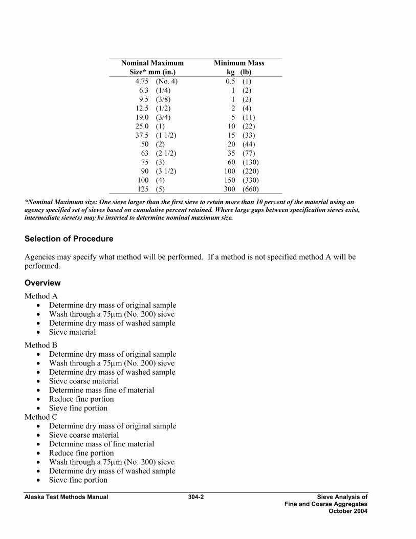
Alaska Test Methods Manual 304-2 Sieve Analysis of Fine and Coarse Aggregates October 2004
Nominal Maximum
Size* mm (in.) Minimum Mass
kg (lb) 4.75 (No. 4) 0.5 (1)
6.3 (1/4) 1 (2) 9.5 (3/8) 1 (2)
12.5 (1/2) 2 (4) 19.0 (3/4) 5 (11) 25.0 (1) 10 (22) 37.5 (1 1/2) 15 (33)
50 (2) 20 (44) 63 (2 1/2) 35 (77) 75 (3) 60 (130) 90 (3 1/2) 100 (220)
100 (4) 150 (330) 125 (5) 300 (660)
*Nominal Maximum size: One sieve larger than the first sieve to retain more than 10 percent of the material using an agency specified set of sieves based on cumulative percent retained. Where large gaps between specification sieves exist, intermediate sieve(s) may be inserted to determine nominal maximum size.
Selection of Procedure Agencies may specify what method will be performed. If a method is not specified method A will be performed.
Overview Method A
• Determine dry mass of original sample • Wash through a 75µm (No. 200) sieve • Determine dry mass of washed sample • Sieve material
Method B • Determine dry mass of original sample • Wash through a 75µm (No. 200) sieve • Determine dry mass of washed sample • Sieve coarse material • Determine mass fine of material • Reduce fine portion • Sieve fine portion
Method C • Determine dry mass of original sample • Sieve coarse material • Determine mass of fine material • Reduce fine portion • Wash through a 75µm (No. 200) sieve • Determine dry mass of washed sample • Sieve fine portion
Sieve Analysis of 304-3 Alaska Test Methods Manual Fine and Coarse Aggregates October 2004
Sample Sieving In all procedures it is required to shake the sample over nested sieves. Sieves are selected to furnish information required by specification. The sieves are nested in order of decreasing size from the top to the bottom and the sample, or a portion of the sample, is placed on the top sieve. Additional sieves may be necessary to provide other information, such as fineness modulus, or to keep from overloading the specified sieves. The sample may also be sieved in increments. Sieves are shaken in a mechanical shaker for 10 approximately minutes, or the minimum time determined to provide complete separation for the sieve shaker being used. The minimum time requirement should be evaluated for each shaker at least annually, by the following method: Continue shaking for a sufficient period and in such a manner that, after completion, not more than 0.5 percent by mass of the total sample passes any sieve during one minute of continuous hand sieving. Provide a snug-fitting pan and cover, and hold in a slightly inclined position in one hand. Strike the side of the sieve sharply and with an upward motion against the heel of the other hand at the rate of about 150 times per minute, turning the sieve about one sixth of a revolution at intervals of about 25 strokes. In determining sufficiency of sieving for sizes larger than 4.75 mm (No. 4), limit the material on the sieve to a single layer of particles. For sieves with openings smaller than 4.75 mm (No. 4), the mass retained on any sieve shall not exceed 7 kg/m2 (4g/in2) of sieving surface. For sieves with openings 4.75 mm (No. 4) and larger, the mass, in kg shall not exceed the product of 2.5 x (sieve opening in mm) x (effective sieving area). See Table 2.
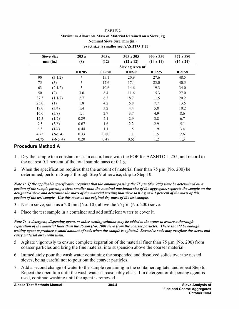
Alaska Test Methods Manual 304-4 Sieve Analysis of Fine and Coarse Aggregates October 2004
TABLE 2 Maximum Allowable Mass of Material Retained on a Sieve, kg
Nominal Sieve Size, mm (in.) exact size is smaller see AASHTO T 27
Procedure Method A 1. Dry the sample to a constant mass in accordance with the FOP for AASHTO T 255, and record to
the nearest 0.1 percent of the total sample mass or 0.1 g. 2. When the specification requires that the amount of material finer than 75 µm (No. 200) be
determined, perform Step 3 through Step 9 otherwise, skip to Step 10.
Note 1: If the applicable specification requires that the amount passing the 75 µm (No. 200) sieve be determined on a portion of the sample passing a sieve smaller than the nominal maximum size of the aggregate, separate the sample on the designated sieve and determine the mass of the material passing that sieve to 0.1 g or 0.1 percent of the mass of this portion of the test sample. Use this mass as the original dry mass of the test sample.
3. Nest a sieve, such as a 2.0 mm (No. 10), above the 75 µm (No. 200) sieve. 4. Place the test sample in a container and add sufficient water to cover it.
Note 2: A detergent, dispersing agent, or other wetting solution may be added to the water to assure a thorough separation of the material finer than the 75 µm (No. 200) sieve from the coarser particles. There should be enough wetting agent to produce a small amount of suds when the sample is agitated. Excessive suds may overflow the sieves and carry material away with them.
5. Agitate vigorously to ensure complete separation of the material finer than 75 µm (No. 200) from coarser particles and bring the fine material into suspension above the coarser material.
6. Immediately pour the wash water containing the suspended and dissolved solids over the nested sieves, being careful not to pour out the coarser particles.
7. Add a second change of water to the sample remaining in the container, agitate, and repeat Step 6. Repeat the operation until the wash water is reasonably clear. If a detergent or dispersing agent is used, continue washing until the agent is removed.
Sieve Size mm (in.)
203 φ (8)
305 φ (12)
305 x 305 (12 x 12)
350 x 350 (14 x 14)
372 x 580 (16 x 24)
Sieving Area m2 0.0285 0.0670 0.0929 0.1225 0.2158
90 (3 1/2) * 15.1 20.9 27.6 48.5 75 (3) * 12.6 17.4 23.0 40.5 63 (2 1/2) * 10.6 14.6 19.3 34.0 50 (2) 3.6 8.4 11.6 15.3 27.0
37.5 (1 1/2) 2.7 6.3 8.7 11.5 20.2 25.0 (1) 1.8 4.2 5.8 7.7 13.5 19.0 (3/4) 1.4 3.2 4.4 5.8 10.2 16.0 (5/8) 1.1 2.7 3.7 4.9 8.6 12.5 (1/2) 0.89 2.1 2.9 3.8 6.7 9.5 (3/8) 0.67 1.6 2.2 2.9 5.1 6.3 (1/4) 0.44 1.1 1.5 1.9 3.4
4.75 (No. 4) 0.33 0.80 1.1 1.5 2.6 -4.75 (-No. 4) 0.20 0.47 0.65 1.2 1.3
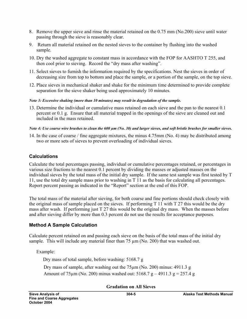
Sieve Analysis of 304-5 Alaska Test Methods Manual Fine and Coarse Aggregates October 2004
8. Remove the upper sieve and rinse the material retained on the 0.75 mm (No.200) sieve until water passing through the sieve is reasonably clear.
9. Return all material retained on the nested sieves to the container by flushing into the washed sample.
10. Dry the washed aggregate to constant mass in accordance with the FOP for AASHTO T 255, and then cool prior to sieving. Record the “dry mass after washing”.
11. Select sieves to furnish the information required by the specifications. Nest the sieves in order of decreasing size from top to bottom and place the sample, or a portion of the sample, on the top sieve.
12. Place sieves in mechanical shaker and shake for the minimum time determined to provide complete separation for the sieve shaker being used approximately 10 minutes.
Note 3: Excessive shaking (more than 10 minutes) may result in degradation of the sample.
13. Determine the individual or cumulative mass retained on each sieve and the pan to the nearest 0.1 percent or 0.1 g. Ensure that all material trapped in the openings of the sieve are cleaned out and included in the mass retained.
Note 4: Use coarse wire brushes to clean the 600 µm (No. 30) and larger sieves, and soft bristle brushes for smaller sieves.
14. In the case of coarse / fine aggregate mixtures, the minus 4.75mm (No. 4) may be distributed among two or more sets of sieves to prevent overloading of individual sieves.
Calculations Calculate the total percentages passing, individual or cumulative percentages retained, or percentages in various size fractions to the nearest 0.1 percent by dividing the masses or adjusted masses on the individual sieves by the total mass of the initial dry sample. If the same test sample was first tested by T 11, use the total dry sample mass prior to washing in T 11 as the basis for calculating all percentages. Report percent passing as indicated in the “Report” section at the end of this FOP. The total mass of the material after sieving, for both coarse and fine portions should check closely with the original mass of sample placed on the sieves. If performing T 11 with T 27 this would be the dry mass after wash. If performing just T 27 this would be the original dry mass. When the masses before and after sieving differ by more than 0.3 percent do not use the results for acceptance purposes. Method A Sample Calculation Calculate percent retained on and passing each sieve on the basis of the total mass of the initial dry sample. This will include any material finer than 75 µm (No. 200) that was washed out.
Example:
Dry mass of total sample, before washing: 5168.7 g Dry mass of sample, after washing out the 75µm (No. 200) minus: 4911.3 g Amount of 75µm (No. 200) minus washed out: 5168.7 g – 4911.3 g = 257.4 g
Gradation on All Sieves

Alaska Test Methods Manual 304-6 Sieve Analysis of Fine and Coarse Aggregates October 2004
Sieve Size mm (in.)
Mass Retained
g
Percent
Retained
Cumulative
Mass Retained
g
Cum.
Percent Retained
Calc’d Percent Passing
ReportedPercent Passing*
19.0 (3/4) 0 0 0 0.0 100.0 100 12.5 (1/2) 724.7 14.0 724.7 14.0 86.0 86 9.5 (3/8) 619.2 12.0 1343.9 26.0 74.0 74 4.75 (No. 4) 1189.8 23.0 2533.7 49.0 51.0 51 2.36 (No. 8) 877.6 17.0 3411.3 66.0 34.0 34 1.18 (No. 16) 574.8 11.1 3986.1 77.1 22.9 23 0.600 (No. 30) 329.8 6.4 4315.9 83.5 16.5 16 0.300 (No. 50) 228.5 4.4 4544.4 87.9 12.1 12 0.150 (No. 100) 205.7 4.0 4750.1 91.9 8.1 8 0.075 (No. 200) 135.4 2.6 4885.5 94.5 5.5 5.5 Pan 20.4 4905.9
*Report 75 µm (No. 200) sieve to 0.1 percent. Report all others to 1 percent.
Check sum: [(4911.3 -4905.9) / 4911.3] X 100 = 0.11 % is within the 0.3 percent requirement. Procedure Method B 1. Perform steps 1 thru 10 from the “Procedure Method A” then continue as follows: 2. Select sieves to furnish information required by the specifications. Nest the sieves in order of
decreasing size from top to bottom through the 4.75 mm (No.4) with a pan at the bottom to retain the minus 4.75 mm (No. 4).
3. Place the sample, or a portion of the sample, on the top sieve. Sieves may already be in the mechanical shaker or place the sieves in the mechanical shaker and shake for the minimum time determined to provide complete separation for the sieve shaker being used approximately 10 minutes.
Note 3: Excessive shaking (more than 10 minutes) may result in degradation of the sample.
4. Determine the individual or cumulative mass retained on each sieve to the nearest 0.1 percent or 0.1 g. Ensure that all material trapped in the openings of the sieve are cleaned out and included in the mass retained.
Note 4: Use coarse wire brushes to clean the 600 µm (No. 30) and larger sieves, and soft hair bristle for smaller sieves.
5. Determine the mass of the pan [minus 4.75 mm (No. 4)] (M1). 6. Reduce the minus 4.75 mm (No. 4) using a mechanical splitter in accordance with the FOP for
AASHTO T 248 to produce a sample with a mass of 500 g minimum. Determine and record the mass of the minus 7.75 mm (No. 4) split (M2).
7. Select sieves to furnish information required by the specifications. Nest the sieves in order of decreasing size from top to bottom through the 75 µm (No. 200) with a pan at the bottom to retain the minus 75µm (No. 200).
8. Repeat steps 3 and 4, Method B, with the minus 4.75 mm (No. 4) including determining the mass of

Sieve Analysis of 304-7 Alaska Test Methods Manual Fine and Coarse Aggregates October 2004
the material in the pan. 9a. Compute the “Adjusted Individual Mass Retained” of the size increment of the original sample as
follows when determining “Individual Mass Retained”.
where: A = Adjusted individual mass retained of the size increment on a total sample basis M1 = mass of minus 4.75mm (No. 4) sieve in total sample M2 = mass of minus 4.75mm (No. 4) sieve actually sieved B = individual mass of the size increment in the reduced portion sieved.
9b. Compute the “Adjusted Cumulative Mass Retained” of the size increment of the original sample as follows when determining “Cumulative Mass Retained”:
where: C = Total cumulative mass retained of the size increment based on a total sample M1 = mass of minus 4.75mm (No. 4) sieve in total sample M2 = mass of minus 4.75mm (No. 4) sieve actually sieved B = cumulative mass of the size increment in the reduced portion sieved. D = cumulative mass of plus 4.75mm (No. 4) portion of sample.
Method B Sample Calculation Sample calculation for percent retained and percent passing each sieve in accordance with Method B when the previously washed 4.75mm (No. 4) minus material is split:
Example: Dry mass of total sample, before washing: 3214.0 g Dry mass of sample, after washing out the 75 µm (No. 200) minus: 3085.1 g Amount of 75 µm (No. 200) minus washed out: 3214.0 g – 3085.1 g = 128.9 g
Gradation on Coarse Sieves Sieve Size
mm (in.)
Individual Mass
Retained, g
IndividualPercent
Retained
Cumulative Mass
Retained, g
Cumulative Percent
Retained
Calculated
Percent
B x MM =A
2
1
DMM
= C2
1 +⎟⎟⎠
⎞⎜⎜⎝
⎛× B
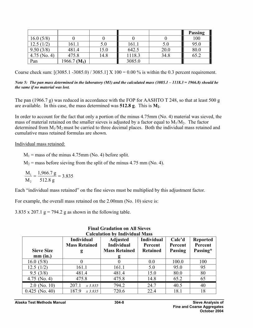
Alaska Test Methods Manual 304-8 Sieve Analysis of Fine and Coarse Aggregates October 2004
Passing 16.0 (5/8) 0 0 0 0 100 12.5 (1/2) 161.1 5.0 161.1 5.0 95.0 9.50 (3/8) 481.4 15.0 642.5 20.0 80.0 4.75 (No. 4) 475.8 14.8 1118.3 34.8 65.2 Pan 1966.7 (M1) 3085.0
Coarse check sum: [(3085.1 -3085.0) / 3085.1] X 100 = 0.00 % is within the 0.3 percent requirement.
Note 5: The pan mass determined in the laboratory (M1) and the calculated mass (3085.1 – 1118.3 = 1966.8) should be the same if no material was lost.
The pan (1966.7 g) was reduced in accordance with the FOP for AASHTO T 248, so that at least 500 g are available. In this case, the mass determined was 512.8 g. This is M2.
In order to account for the fact that only a portion of the minus 4.75mm (No. 4) material was sieved, the mass of material retained on the smaller sieves is adjusted by a factor equal to M1/M2. The factor determined from M1/M2 must be carried to three decimal places. Both the individual mass retained and cumulative mass retained formulas are shown.
Individual mass retained:
M1 = mass of the minus 4.75mm (No. 4) before split. M2 = mass before sieving from the split of the minus 4.75 mm (No. 4).
Each “individual mass retained” on the fine sieves must be multiplied by this adjustment factor. For example, the overall mass retained on the 2.00mm (No. 10) sieve is: 3.835 x 207.1 g = 794.2 g as shown in the following table.
Final Gradation on All Sieves Calculation by Individual Mass
Sieve Size mm (in.)
Individual Mass Retained
g
Adjusted Individual
Mass Retained g
Individual Percent
Retained
Calc’d Percent Passing
Reported Percent Passing*
16.0 (5/8) 0 0 0.0 100.0 100 12.5 (1/2) 161.1 161.1 5.0 95.0 95 9.5 (3/8) 481.4 481.4 15.0 80.0 80 4.75 (No. 4) 475.8 475.8 14.8 65.2 65 2.0 (No. 10) 207.1 x 3.835 794.2 24.7 40.5 40 0.425 (No. 40) 187.9 x 3.835 720.6 22.4 18.1 18
3.835
g 512.8 g 1,966.7
M M
2 1 = =
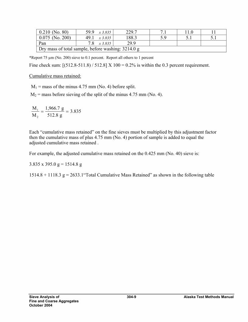
Sieve Analysis of 304-9 Alaska Test Methods Manual Fine and Coarse Aggregates October 2004
0.210 (No. 80) 59.9 x 3.835 229.7 7.1 11.0 11 0.075 (No. 200) 49.1 x 3.835 188.3 5.9 5.1 5.1 Pan 7.8 x 3.835 29.9 Dry mass of total sample, before washing: 3214.0 g
*Report 75 µm (No. 200) sieve to 0.1 percent. Report all others to 1 percent
Fine check sum: [(512.8-511.8) / 512.8] X 100 = 0.2% is within the 0.3 percent requirement. Cumulative mass retained: M1 = mass of the minus 4.75 mm (No. 4) before split.
M2 = mass before sieving of the split of the minus 4.75 mm (No. 4). Each “cumulative mass retained” on the fine sieves must be multiplied by this adjustment factor then the cumulative mass of plus 4.75 mm (No. 4) portion of sample is added to equal the adjusted cumulative mass retained . For example, the adjusted cumulative mass retained on the 0.425 mm (No. 40) sieve is: 3.835 x 395.0 g = 1514.8 g 1514.8 + 1118.3 g = 2633.1“Total Cumulative Mass Retained” as shown in the following table
3.835g512.8g1,966.7
MM
2
1 ==
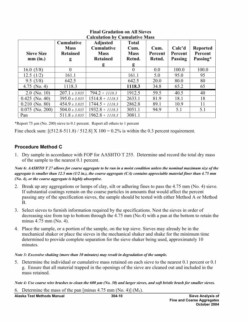
Alaska Test Methods Manual 304-10 Sieve Analysis of Fine and Coarse Aggregates October 2004
Final Gradation on All Sieves Calculation by Cumulative Mass
Sieve Size mm (in.)
Cumulative Mass
Retained g
Adjusted Cumulative
Mass Retained
g
Total Cum. Mass
Retnd. g
Cum.
Percent Retnd.
Calc’d Percent Passing
Reported Percent Passing*
16.0 (5/8) 0 0 0.0 100.0 100.0 12.5 (1/2) 161.1 161.1 5.0 95.0 95 9.5 (3/8) 642.5 642.5 20.0 80.0 80 4.75 (No. 4) 1118.3 1118.3 34.8 65.2 65 2.0 (No. 10) 207.1 x 3.835 794.2 + 1118.3 1912.5 59.5 40.5 40 0.425 (No. 40) 395.0 x 3.835 1514.8 + 1118.3 2633.1 81.9 18.1 18 0.210 (No. 80) 454.9 x 3.835 1744.5 + 1118.3 2862.8 89.1 10.9 11 0.075 (No. 200) 504.0 x 3.835 1932.8 + 1118.3 3051.1 94.9 5.1 5.1 Pan 511.8 x 3.835 1962.8 + 1118.3 3081.1
*Report 75 µm (No. 200) sieve to 0.1 percent. Report all others to 1 percent
Fine check sum: [(512.8-511.8) / 512.8] X 100 = 0.2% is within the 0.3 percent requirement. Procedure Method C 1. Dry sample in accordance with FOP for AASHTO T 255. Determine and record the total dry mass
of the sample to the nearest 0.1 percent. Note 6: AASHTO T 27 allows for coarse aggregate to be run in a moist condition unless the nominal maximum size of the aggregate is smaller than 12.5 mm (1/2 in.), the coarse aggregate (CA) contains appreciable material finer than 4.75 mm (No. 4), or the coarse aggregate is highly absorptive. 2. Break up any aggregations or lumps of clay, silt or adhering fines to pass the 4.75 mm (No. 4) sieve.
If substantial coatings remain on the coarse particles in amounts that would affect the percent passing any of the specification sieves, the sample should be tested with either Method A or Method B.
3. Select sieves to furnish information required by the specifications. Nest the sieves in order of decreasing size from top to bottom through the 4.75 mm (No.4) with a pan at the bottom to retain the minus 4.75 mm (No. 4).
4. Place the sample, or a portion of the sample, on the top sieve. Sieves may already be in the mechanical shaker or place the sieves in the mechanical shaker and shake for the minimum time determined to provide complete separation for the sieve shaker being used, approximately 10 minutes.
Note 3: Excessive shaking (more than 10 minutes) may result in degradation of the sample.
5. Determine the individual or cumulative mass retained on each sieve to the nearest 0.1 percent or 0.1 g. Ensure that all material trapped in the openings of the sieve are cleaned out and included in the mass retained.
Note 4: Use coarse wire brushes to clean the 600 µm (No. 30) and larger sieves, and soft bristle brush for smaller sieves.
6. Determine the mass of the pan [minus 4.75 mm (No. 4)] (M1).

Sieve Analysis of 304-11 Alaska Test Methods Manual Fine and Coarse Aggregates October 2004
7. Reduce the minus 4.75mm (No. 4) using a mechanical splitter in accordance with the FOP for AASHTO T 248 to produce a sample with a mass of 500 g minimum.
8. Determine and record the mass of the minus 4.75mm (No. 4) split (M3). 9. Perform steps 3 thru 10 of Method A (Wash) on the minus 4.75mm (No. 4) split. 10. Select sieves to furnish information required by the specifications. Nest the sieves in order of
decreasing size from top to bottom through the 75µm (No. 200) with a pan at the bottom to retain the minus 75 µm (No. 200).
11. Repeat steps 4 and 5, Method C, with the minus 4.75mm (No. 4) including determining the mass of the pan.
12a.Compute the “Adjusted Individual Mass Retained” of the size increment of the original sample as follows when determining “Individual Mass Retained”:
where:
A = Adjusted individual mass of the size increment on a total sample basis M1 = mass of the minus 4.75mm (No. 4) sieve in total sample M3 = mass of reduced portion of the minus 4.75mm (No. 4) before washing B = mass of the size increment in the reduced portion sieved.
12b.Compute the “Adjusted Cumulative Mass Retained” of the size increment of the original sample as
follows when determining “Cumulative Mass Retained”:
where: C = Total cumulative mass of the size increment based on a total sample M1 = mass of fraction finer than 4.75mm (No. 4) sieve in total sample M3 = mass of reduced portion of material finer than 4.75mm (No. 4) before washing B = cumulative mass of the size increment in the reduced portion sieved. D = cumulative mass of plus 4.75mm (No. 4) portion of sample.
Method C Sample Calculation
DMM
= C3
1 +⎟⎟⎠
⎞⎜⎜⎝
⎛× B
B x MM =A
3
1

Alaska Test Methods Manual 304-12 Sieve Analysis of Fine and Coarse Aggregates October 2004
Sample calculation for percent retained and percent passing each sieve in accordance with Method C when the 4.75mm (No. 4) minus material is split and then washed: Dry Mass of total sample: 3304.5 g Dry Mass of minus 4.75mm (No. 4) split before wash: 527.6 Dry Mass of minus 4.75mm (No. 4) split after wash: 495.3
Gradation on Coarse Sieves Sieve Size
mm (in.)
Individual Mass
Retained, g
IndividualPercent
Retained
Cumulative Mass
Retained, g
Cumulative Percent
Retained
Cal’d
Percent Passing
16.0 (5/8) 0 0 0 0 100.0 12.5 (1/2) 125.9 3.8 125.9 3.8 96.2 9.50 (3/8) 478.2 14.5 604.1 18.3 81.7 4.75 (No. 4) 691.5 20.9 1295.6 39.2 60.8 Pan 2008.9 (M1) 3304.5 Total Dry Mass = 3304.5
Coarse check sum: [(3304.5 -3304.5) / 3304.5] X 100 = 0.0 % is within the 0.3 percent requirement Note 5: The pan mass determined in the laboratory (M1) and the calculated mass (3304.5 – 1295.6 = 2008.9) should be the same if no material was lost.
The pan (2008.9 g) was reduced in accordance with the FOP for AASHTO T 248, so that at least 500 g are available. In this case, the mass determined was 527.6 g. This is M3.
In order to account for the fact that only a portion of the minus 4.75 mm (No. 4) material was washed and sieved, the mass of material retained on the smaller sieves is adjusted by a factor equal to M1/M3. The factor determined from M1/M3 must be carried to three decimal places. Both individual mass retained and cumulative mass retained formulas are shown.
Individual mass retained: M1 = mass of the minus 4.75mm (No. 4) before split. M3 = mass before washing of the split of the minus 4.75mm (No. 4).
Each “individual mass retained” on the fine sieves must be multiplied by this adjustment factor. For example, the overall mass retained on the 2.00 mm (No. 10) sieve is: 3.808 x 194.3 = 739.9 as shown in the following table
Final Gradation on All Sieves Calculation by Individual Mass
Individual Adjusted Individual Calculated Reported
3.808g527.6g2008.9
MM
3
1 ==
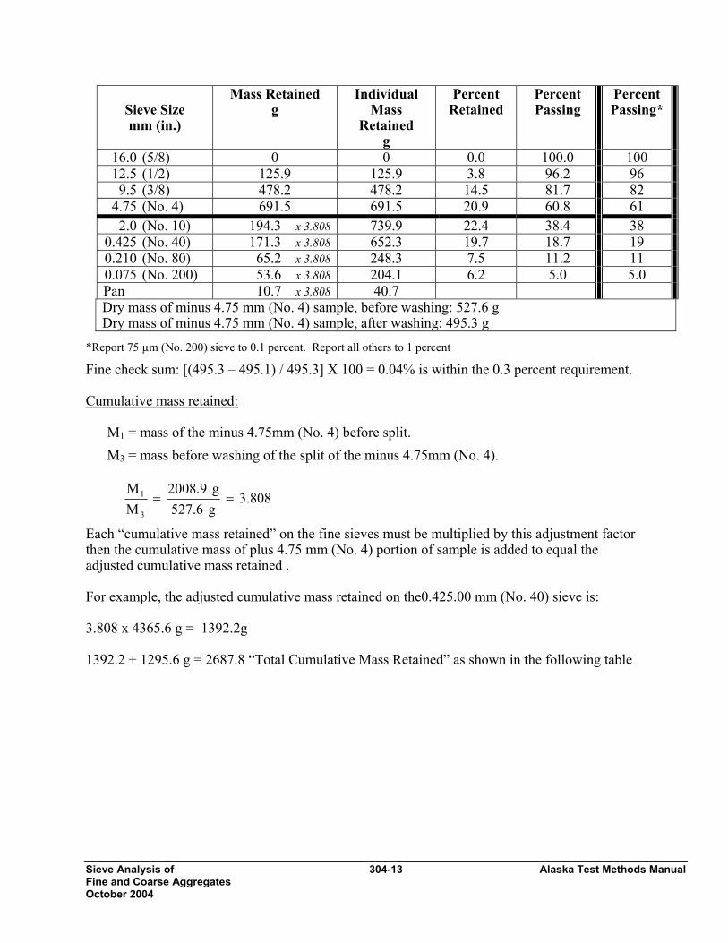
Sieve Analysis of 304-13 Alaska Test Methods Manual Fine and Coarse Aggregates October 2004
Sieve Size mm (in.)
Mass Retained g
Individual Mass
Retained g
Percent Retained
Percent Passing
Percent Passing*
16.0 (5/8) 0 0 0.0 100.0 100 12.5 (1/2) 125.9 125.9 3.8 96.2 96 9.5 (3/8) 478.2 478.2 14.5 81.7 82 4.75 (No. 4) 691.5 691.5 20.9 60.8 61 2.0 (No. 10) 194.3 x 3.808 739.9 22.4 38.4 38 0.425 (No. 40) 171.3 x 3.808 652.3 19.7 18.7 19 0.210 (No. 80) 65.2 x 3.808 248.3 7.5 11.2 11 0.075 (No. 200) 53.6 x 3.808 204.1 6.2 5.0 5.0 Pan 10.7 x 3.808 40.7 Dry mass of minus 4.75 mm (No. 4) sample, before washing: 527.6 g Dry mass of minus 4.75 mm (No. 4) sample, after washing: 495.3 g
*Report 75 µm (No. 200) sieve to 0.1 percent. Report all others to 1 percent Fine check sum: [(495.3 – 495.1) / 495.3] X 100 = 0.04% is within the 0.3 percent requirement. Cumulative mass retained:
M1 = mass of the minus 4.75mm (No. 4) before split. M3 = mass before washing of the split of the minus 4.75mm (No. 4).
Each “cumulative mass retained” on the fine sieves must be multiplied by this adjustment factor then the cumulative mass of plus 4.75 mm (No. 4) portion of sample is added to equal the adjusted cumulative mass retained . For example, the adjusted cumulative mass retained on the0.425.00 mm (No. 40) sieve is: 3.808 x 4365.6 g = 1392.2g 1392.2 + 1295.6 g = 2687.8 “Total Cumulative Mass Retained” as shown in the following table
3.808g527.6g2008.9
MM
3
1 ==
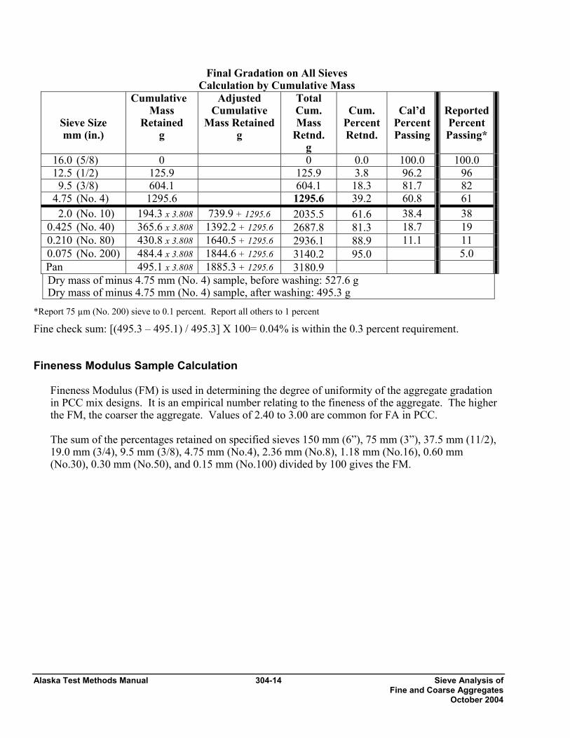
Alaska Test Methods Manual 304-14 Sieve Analysis of Fine and Coarse Aggregates October 2004
Final Gradation on All Sieves Calculation by Cumulative Mass
Sieve Size mm (in.)
Cumulative Mass
Retained g
Adjusted Cumulative
Mass Retained g
Total Cum. Mass
Retnd. g
Cum.
Percent Retnd.
Cal’d
Percent Passing
ReportedPercent Passing*
16.0 (5/8) 0 0 0.0 100.0 100.0 12.5 (1/2) 125.9 125.9 3.8 96.2 96 9.5 (3/8) 604.1 604.1 18.3 81.7 82 4.75 (No. 4) 1295.6 1295.6 39.2 60.8 61 2.0 (No. 10) 194.3 x 3.808 739.9 + 1295.6 2035.5 61.6 38.4 38 0.425 (No. 40) 365.6 x 3.808 1392.2 + 1295.6 2687.8 81.3 18.7 19 0.210 (No. 80) 430.8 x 3.808 1640.5 + 1295.6 2936.1 88.9 11.1 11 0.075 (No. 200) 484.4 x 3.808 1844.6 + 1295.6 3140.2 95.0 5.0 Pan 495.1 x 3.808 1885.3 + 1295.6 3180.9 Dry mass of minus 4.75 mm (No. 4) sample, before washing: 527.6 g Dry mass of minus 4.75 mm (No. 4) sample, after washing: 495.3 g
*Report 75 µm (No. 200) sieve to 0.1 percent. Report all others to 1 percent
Fine check sum: [(495.3 – 495.1) / 495.3] X 100= 0.04% is within the 0.3 percent requirement. Fineness Modulus Sample Calculation
Fineness Modulus (FM) is used in determining the degree of uniformity of the aggregate gradation in PCC mix designs. It is an empirical number relating to the fineness of the aggregate. The higher the FM, the coarser the aggregate. Values of 2.40 to 3.00 are common for FA in PCC. The sum of the percentages retained on specified sieves 150 mm (6”), 75 mm (3”), 37.5 mm (11/2), 19.0 mm (3/4), 9.5 mm (3/8), 4.75 mm (No.4), 2.36 mm (No.8), 1.18 mm (No.16), 0.60 mm (No.30), 0.30 mm (No.50), and 0.15 mm (No.100) divided by 100 gives the FM.
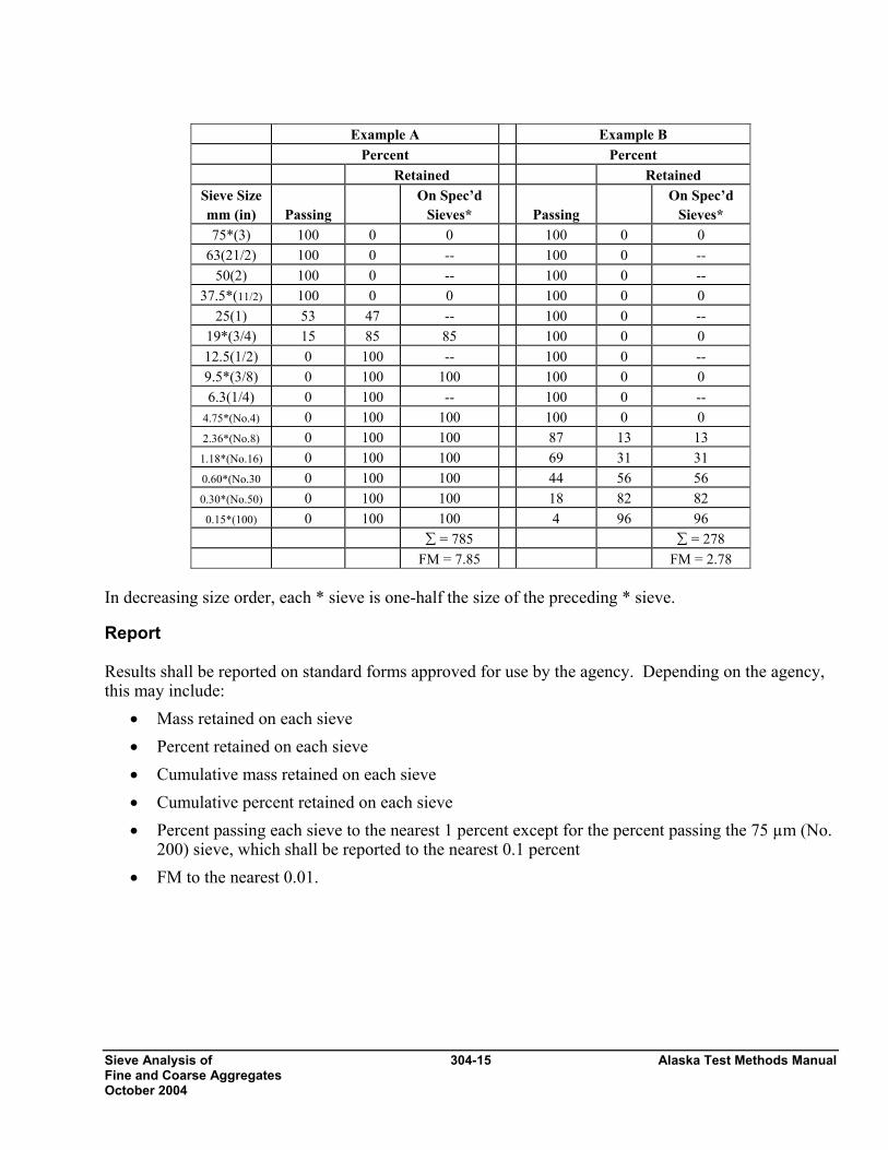
Sieve Analysis of 304-15 Alaska Test Methods Manual Fine and Coarse Aggregates October 2004
Example A Example B Percent Percent Retained Retained
Sieve Size mm (in)
Passing
On Spec’d Sieves*
Passing
On Spec’d Sieves*
75*(3) 100 0 0 100 0 0 63(21/2) 100 0 -- 100 0 --
50(2) 100 0 -- 100 0 -- 37.5*(11/2) 100 0 0 100 0 0
25(1) 53 47 -- 100 0 -- 19*(3/4) 15 85 85 100 0 0 12.5(1/2) 0 100 -- 100 0 -- 9.5*(3/8) 0 100 100 100 0 0 6.3(1/4) 0 100 -- 100 0 --
4.75*(No.4) 0 100 100 100 0 0 2.36*(No.8) 0 100 100 87 13 13 1.18*(No.16) 0 100 100 69 31 31 0.60*(No.30 0 100 100 44 56 56 0.30*(No.50) 0 100 100 18 82 82 0.15*(100) 0 100 100 4 96 96
∑ = 785 ∑ = 278 FM = 7.85 FM = 2.78
In decreasing size order, each * sieve is one-half the size of the preceding * sieve. Report Results shall be reported on standard forms approved for use by the agency. Depending on the agency, this may include:
• Mass retained on each sieve • Percent retained on each sieve • Cumulative mass retained on each sieve • Cumulative percent retained on each sieve • Percent passing each sieve to the nearest 1 percent except for the percent passing the 75 µm (No.
200) sieve, which shall be reported to the nearest 0.1 percent • FM to the nearest 0.01.
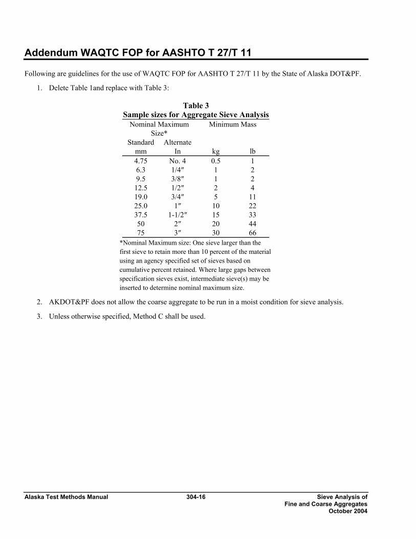
Alaska Test Methods Manual 304-16 Sieve Analysis of Fine and Coarse Aggregates October 2004
Addendum WAQTC FOP for AASHTO T 27/T 11 Following are guidelines for the use of WAQTC FOP for AASHTO T 27/T 11 by the State of Alaska DOT&PF.
1. Delete Table 1and replace with Table 3:
Table 3 Sample sizes for Aggregate Sieve Analysis
Nominal Maximum Size*
Minimum Mass
Standard Alternate mm In kg lb 4.75 No. 4 0.5 1 6.3 1/4″ 1 2 9.5 3/8″ 1 2
12.5 1/2″ 2 4 19.0 3/4″ 5 11 25.0 1″ 10 22 37.5 1-1/2″ 15 33 50 2″ 20 44 75 3″ 30 66
*Nominal Maximum size: One sieve larger than the first sieve to retain more than 10 percent of the material using an agency specified set of sieves based on cumulative percent retained. Where large gaps between specification sieves exist, intermediate sieve(s) may be inserted to determine nominal maximum size.
2. AKDOT&PF does not allow the coarse aggregate to be run in a moist condition for sieve analysis.
3. Unless otherwise specified, Method C shall be used.

Determining the Percentage of 305-1 Alaska Test Methods Manual Fracture in Coarse Aggregate October 2004
DETERMINING THE PERCENTAGE OF FRACTURE IN COARSE AGGREGATE FOP FOR AASHTO TP 61 Scope This procedure covers the determination of the percentage, by mass, of a coarse aggregate (CA) sample that consists of fractured particles meeting specified requirements in accordance with AASHTO TP 61. In this procedure, a sample of aggregate is screened on the sieve separating CA and fine aggregate (FA). This sieve will be identified in the agency’s specifications, but might be the 4.75 mm (No. 4) sieve. CA particles are visually evaluated to determine conformance to the specified fracture. The percentage of conforming particles, by mass, is calculated for comparison to the specifications. Apparatus • Balance or scale: Capacity sufficient for the principle sample mass, accurate to 0.1 percent of the
sample mass or readable to 0.1 g. Meets the requirements of AASHTO M231 • Sieves, meeting requirements of AASHTO M 92. • Splitter, meeting the requirements of FOP for AASHTO T 248. Terminology 1. Fractured Face – An angular, rough, or broken surface of an aggregate particle created by crushing
or by other means. A face is considered a “Fractured Face” whenever one-half or more of the projected area, when viewed normal to that face, is fractured with sharp and well defined edges. This excludes small nicks.
2. Fractured particle – A particle of aggregate having at least the minimum number of fractured faces
specified. (This is usually one or two.) Sampling and Sample Preparation 1. Sample and reduce the aggregate in accordance with the FOP’s for AASHTO T 2 and T 248. 2. When the specifications list only a total fracture percentage, the sample shall be prepared in
accordance with Method 1. When the specifications require that the fracture be counted and reported on each sieve, the sample shall be prepared in accordance with Method 2.
3. Method 1 - Combined Fracture Determination
a. Dry the sample sufficiently to obtain a clean separation of FA and CA material in the sieving operation.

Alaska Test Methods Manual 305-2 Determining the Percentage of Fracture in Coarse Aggregate October 2004
b. Sieve the sample in accordance with AASHTO T 27/ T 11 over the 4.75 mm (No. 4) sieve, or the appropriate sieve listed in the agency’s specifications for this material.
Note 1: Where necessary wash the sample over the sieve or sieves designated for the determination of fractured particles to remove any remaining fine material, and dry to a constant mass in accordance with AASHTO T 255.
c. Reduce the sample using Method A, Mechanical Splitter, in accordance with AASHTO T248 to
the appropriate test size. This test size should be slightly larger than shown in Table 1, to account for loss of fines through washing, if necessary.
TABLE 1
Sample Size Method 1 (Combined Sieve Fracture)
Nominal Maximum Size*
mm (in.)
Minimum Sample Mass Retained on 4.75 mm
(No. 4) Sieve g (lb)
37.5 (1 1/2) 2500 (6) 25.0 (1) 1500 (3.5 19.0 (3/4) 1000 (2.5) 12.5 (1/2) 700 (1.5) 9.5 (3/8) 400 (0.9)
4.75 (No. 4) 200 (0.4) * One sieve larger than the first sieve to retain more than 10 percent of the material using an agency specified set of sieves based on cumulative percent retained. Where large gaps in specification sieves exist, intermediate sieve(s) may be inserted to determine nominal maximum size. 4. Method 2 – Individual Sieve Fracture Determination
a. Dry the sample sufficiently to obtain a clean separation of FA and CA material in the sieving operation. A washed sample from the gradation determination (T27/11) may be used.
b. If not, sieve the sample in accordance with AASHTO T 27 over the sieves listed in the
specifications for this material. Note 2: If overload (buffer) sieves are used the material from that sieve must be added to the next specification sieve.
c. Select a representative portion from each sieve by splitting or quartering in accordance with
AASHTO T 248. The size of test sample for each sieve should be at least as large as shown in Table 2.
Note 1: Where necessary wash the sample over the sieve or sieves designated for the determination of fractured particles to remove any remaining fine material, and dry to a constant mass in accordance with AASHTO T 255.
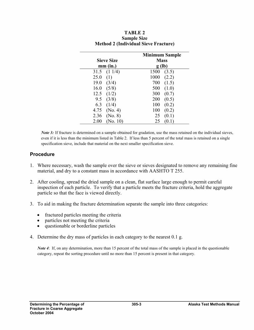
Determining the Percentage of 305-3 Alaska Test Methods Manual Fracture in Coarse Aggregate October 2004
TABLE 2 Sample Size
Method 2 (Individual Sieve Fracture)
Sieve Size mm (in.)
Minimum Sample Mass g (lb)
31.5 (1 1/4) 1500 (3.5) 25.0 (1) 1000 (2.2) 19.0 (3/4) 700 (1.5) 16.0 (5/8) 500 (1.0) 12.5 (1/2) 300 (0.7) 9.5 (3/8) 200 (0.5) 6.3 (1/4) 100 (0.2)
4.75 (No. 4) 100 (0.2) 2.36 (No. 8) 25 (0.1) 2.00 (No. 10) 25 (0.1)
Note 3: If fracture is determined on a sample obtained for gradation, use the mass retained on the individual sieves, even if it is less than the minimum listed in Table 2. If less than 5 percent of the total mass is retained on a single specification sieve, include that material on the next smaller specification sieve.
Procedure 1. Where necessary, wash the sample over the sieve or sieves designated to remove any remaining fine
material, and dry to a constant mass in accordance with AASHTO T 255. 2. After cooling, spread the dried sample on a clean, flat surface large enough to permit careful
inspection of each particle. To verify that a particle meets the fracture criteria, hold the aggregate particle so that the face is viewed directly.
3. To aid in making the fracture determination separate the sample into three categories:
• fractured particles meeting the criteria • particles not meeting the criteria • questionable or borderline particles
4. Determine the dry mass of particles in each category to the nearest 0.1 g.
Note 4: If, on any determination, more than 15 percent of the total mass of the sample is placed in the questionable category, repeat the sorting procedure until no more than 15 percent is present in that category.

Alaska Test Methods Manual 305-4 Determining the Percentage of Fracture in Coarse Aggregate October 2004
Calculation Calculate the mass percentage of fractured faces to the nearest 1 percent using the following formula:
P = ( ) 1002×
++
⎟⎠⎞
⎜⎝⎛ +
NQF
FQ
where: P = Percent of fracture F = Mass of fractured particles Q = Mass of questionable or borderline particles. N = Mass of unfractured particles Example: F = 632.6 g, Q = 97.6 g, N = 352.6 g P =
( ) 9.621006.3526.976.632
6.6322
6.97
=×++
⎟⎠⎞
⎜⎝⎛ +
P= 63%
Report Results shall be reported on standard forms approved for use by the agency. Report fracture to the nearest 1 percent.
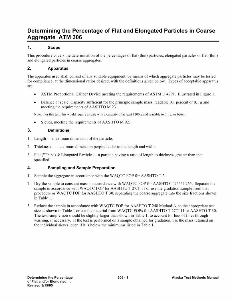
Determining the Percentage 306 - 1 Alaska Test Methods Manual of Flat and/or Elongated … Revised 3/15/05
Determining the Percentage of Flat and Elongated Particles in Coarse Aggregate ATM 306 1. Scope
This procedure covers the determination of the percentages of flat (thin) particles, elongated particles or flat (thin) and elongated particles in coarse aggregates.
2. Apparatus
The apparatus used shall consist of any suitable equipment, by means of which aggregate particles may be tested for compliance, at the dimensional ratios desired, with the definitions given below. Types of acceptable apparatus are:
• ASTM Proportional Caliper Device meeting the requirements of ASTM D 4791. Illustrated in Figure 1.
• Balance or scale: Capacity sufficient for the principle sample mass, readable 0.1 percent or 0.1 g and meeting the requirements of AASHTO M 231.
Note: For this test, this would require a scale with a capacity of at least 1200 g and readable to 0.1 g, or better.
• Sieves, meeting the requirements of AASHTO M 92.
3. Definitions
1. Length ⎯ maximum dimension of the particle.
2. Thickness ⎯ maximum dimension perpindicular to the length and width.
3. Flat ("Thin") & Elongated Particle ⎯ a particle having a ratio of length to thickness greater than that specified.
4. Sampling and Sample Preparation
1. Sample the aggregate in accordance with the WAQTC FOP for AASHTO T 2.
2. Dry the sample to constant mass in accordance with WAQTC FOP for AASHTO T 255/T 265. Separate the sample in accordance with WAQTC FOP for AASHTO T 27/T 11 or use the gradation sample from that procedure or WAQTC FOP for AASHTO T 30, separating the coarse aggregate into the size fractions shown in Table 1.
3. Reduce the sample in accordance with WAQTC FOP for AASHTO T 248 Method A, to the appropriate test size as shown in Table 1 or use the material from WAQTC FOPs for AASHTO T 27/T 11 or AASHTO T 30. The test sample size should be slightly larger than shown in Table 1, to account for loss of fines through washing, if necessary. If the test is performed on a sample obtained for gradation, use the mass retained on the individual sieves, even if it is below the minimums listed in Table 1.
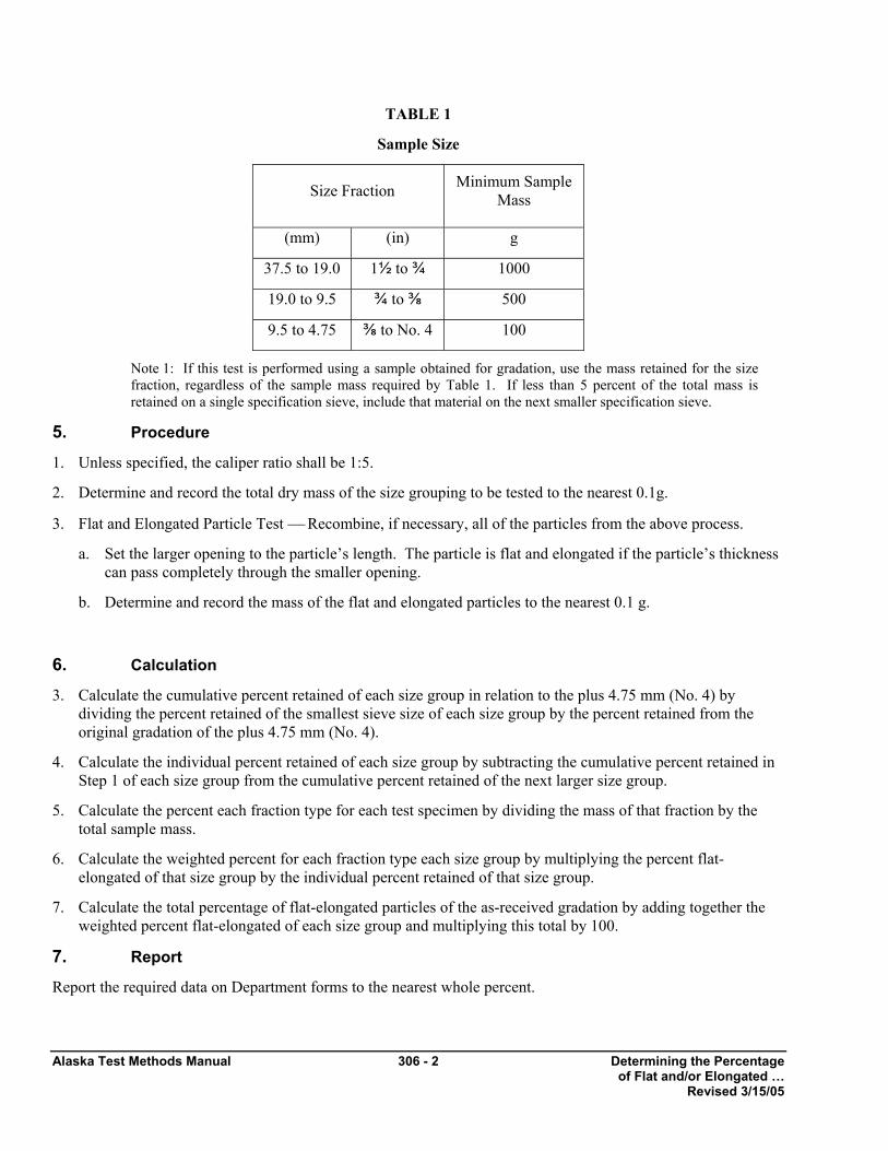
Alaska Test Methods Manual 306 - 2 Determining the Percentage of Flat and/or Elongated … Revised 3/15/05
TABLE 1
Sample Size
Size Fraction Minimum Sample Mass
(mm) (in) g
37.5 to 19.0 1½ to ¾ 1000
19.0 to 9.5 ¾ to ⅜ 500
9.5 to 4.75 ⅜ to No. 4 100
Note 1: If this test is performed using a sample obtained for gradation, use the mass retained for the size fraction, regardless of the sample mass required by Table 1. If less than 5 percent of the total mass is retained on a single specification sieve, include that material on the next smaller specification sieve.
5. Procedure
1. Unless specified, the caliper ratio shall be 1:5.
2. Determine and record the total dry mass of the size grouping to be tested to the nearest 0.1g.
3. Flat and Elongated Particle Test ⎯ Recombine, if necessary, all of the particles from the above process.
a. Set the larger opening to the particle’s length. The particle is flat and elongated if the particle’s thickness can pass completely through the smaller opening.
b. Determine and record the mass of the flat and elongated particles to the nearest 0.1 g.
6. Calculation
3. Calculate the cumulative percent retained of each size group in relation to the plus 4.75 mm (No. 4) by dividing the percent retained of the smallest sieve size of each size group by the percent retained from the original gradation of the plus 4.75 mm (No. 4).
4. Calculate the individual percent retained of each size group by subtracting the cumulative percent retained in Step 1 of each size group from the cumulative percent retained of the next larger size group.
5. Calculate the percent each fraction type for each test specimen by dividing the mass of that fraction by the total sample mass.
6. Calculate the weighted percent for each fraction type each size group by multiplying the percent flat-elongated of that size group by the individual percent retained of that size group.
7. Calculate the total percentage of flat-elongated particles of the as-received gradation by adding together the weighted percent flat-elongated of each size group and multiplying this total by 100.
7. Report
Report the required data on Department forms to the nearest whole percent.
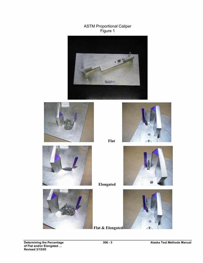
Determining the Percentage 306 - 3 Alaska Test Methods Manual of Flat and/or Elongated … Revised 3/15/05
ASTM Proportional Caliper Figure 1
Flat
Elongated
Flat & Elongated

Alaska Test Methods Manual 306 - 4 Determining the Percentage of Flat and/or Elongated … Revised 3/15/05
This page intentionally left blank.

Plastic Fines in Graded 307-1 Alaska Test Methods Manual Aggregates and Soils… October 2003
PLASTIC FINES IN GRADED AGGREGATES AND SOILS BY THE USE OF THE SAND EQUIVALENT TEST WAQTC FOP FOR AASHTO T 176 Scope This procedure covers the determination of plastic fines in accordance with AASHTO T 176. It serves as a rapid test to show the relative proportion of fine dust or clay-like materials in fine aggregates (FA) and soils. Apparatus See AASHTO T 176 for a detailed listing of sand equivalent apparatus. Note that the siphon tube and blow tube may be glass or stainless steel as well as copper. • Graduated plastic cylinder. • Rubber stopper. • Irrigator tube. • Weighted foot assembly: There are two models of the weighted foot assembly. The older model has
a guide cap that fits over the upper end of the graduated cylinder and centers the rod in the cylinder. It is read using a slot in the centering screws. The newer model has a sand reading indicator 254 mm (10 in.) above this point and is preferred for testing clay-like materials.
• Siphon assembly: The siphon assembly will be fitted to a 4-L (1 gal) bottle of working calcium chloride solution placed on a shelf 915 ±25 mm (36 ±1 in.) above the work surface.
• Weighted foot assembly having a mass of 1000 ± 5 g. • Measuring can having a capacity of 85 ±5 ml (3 oz.). • Funnel with a wide-mouth for transferring sample into graduated cylinder. • Quartering cloth – 600 mm (2 ft) square nonabsorbent cloth, such as plastic or oil cloth. • Mechanical splitter – see FOP for AASHTO T 248. • Strike off bar – A straight edge or spatula. • Clock or watch reading in minutes and seconds. • Manually operated sand equivalent shaker capable of producing an oscillating motion at a rate of
100 complete cycles in 45 ±5 seconds, with a hand assisted half stroke length of 127 ±5 mm (5 ±2 in.). It may be held stable by hand during the shaking operation. It is recommended that this shaker be fastened securely to a firm and level mount, by bolts or clamps, if a large number of determinations are to be made.
• Mechanical shaker – See AASHTO T 176 for equipment and procedure. • Oven capable of maintaining a temperature of 110 ±5°C (230 ±9°F). • Thermometer – Calibrated liquid-in-glass or electronic digital type designed for total immersion and
accurate to 0.1°C (0.2°F).

Alaska Test Methods Manual 307-2 Plastic Fines in Graded Aggregates and Soils… October 2003
Materials • Stock calcium chloride solution: Obtain commercially prepared calcium chloride stock solution
meeting AASHTO requirements. • Working calcium chloride solution: Dilute one 3 oz measuring can (85 ±5 mL) of stock calcium
chloride solution to 3.8 L (1 gal) with distilled or demineralized water. (The graduated cylinder filled to 111.8 mm [4.4 in.] contains 88 mL.)
Note 1: Mix the working solution thoroughly. Add 85ml (3oz) of stock solution to a clean, empty 3.8L (1qt) jug, add approximately one 1L (1qt) and agitate vigorously for 2 or 3 minutes. Add the remainder of the water in approximately 1L (1qt) increments repeating the agitation process.
Note 2: Tap water may be used if it is proven not to be detrimental to the test and if it is allowed by the agency.
Note 3: The shelf life of the working solution is approximately 30 days. Working solutions more than 30 days old shall be discarded.
Control The temperature of the working solution should be maintained at 22 ±3°C (72 ±5°F) during the performance of the test. If field conditions preclude the maintenance of the temperature range, reference samples should be submitted to the Central/Regional Laboratory, as required by the agency, where proper temperature control is possible. Samples that meet the minimum sand equivalent requirement at a working solution temperature outside of the temperature range need not be subject to reference testing. Sample Preparation 1. Obtain the sample in accordance with FOP for AASHTO T 2 and reduce in accordance with FOP
for AASHTO T 248. 2. Prepare sand equivalent test samples from the material passing the 4.75 mm (No. 4) sieve. If the
material is in clods, break it up and rescreen it over a 4.75 mm (No. 4) sieve. All fines shall be cleaned from particles retained on the 4.75 mm (No. 4) sieve and included with the material passing that sieve.
3. Split or quarter 1000 to 1500 g of material from the portion passing the 4.75 mm (No. 4) sieve. Use extreme care to obtain a truly representative portion of the original sample.
Note 4: Experiments show that, as the amount of material being reduced by splitting or quartering is decreased, the accuracy of providing representative portions is reduced. It is imperative that the sample be split or quartered carefully. When it appears necessary, dampen the material before splitting or quartering to avoid segregation or loss of fines.
Note 5: All tests including Reference Tests will be performed utilizing Alternative Method No. 2 as described in AASHTO T 176 unless specifications call for oven dry samples.
Plastic Fines in Graded 307-3 Alaska Test Methods Manual Aggregates and Soils… October 2003
4. The sample must have the proper moisture content to achieve reliable results. This condition is determined by tightly squeezing a small portion of the thoroughly mixed sample in the palm of the hand. If the cast that is formed permits careful handling without breaking, the correct moisture content has been obtained. If the material is too dry, the cast will crumble and it will be necessary to add water and remix and retest until the material forms a cast.
Note 6: Clean sands having little 75 µm(No.200) such as sand for Portland Cement Concrete (PCC) may not form a cast.
If the material shows any free water, it is too wet to test and must be drained and air dried, and mixed frequently to ensure uniformity. This drying process should continue until squeezing provides the required cast. If the moisture content is altered to provide the required cast, the altered sample should be placed in a pan, covered with a lid or with a damp cloth that does not touch the material, and allowed to stand for a minimum of 15 minutes. Samples that have been sieved without being air dried and still retain enough natural moisture are exempted from this requirement.
5. Place the sample on the quartering cloth and mix by alternately lifting each corner of the cloth and
pulling it over the sample toward the diagonally opposite corner, being careful to keep the top of the cloth parallel to the bottom, thus causing the material to be rolled. When the material appears homogeneous, finish the mixing with the sample in a pile near the center of the cloth.
6. Fill the measuring can by pushing it through the base of the pile while exerting pressure with the
hand against the pile on the side opposite the measuring can. As the can is moved through the pile, hold enough pressure with the hand to cause the material to fill the tin to overflowing. Press firmly with the palm of the hand, compacting the material and placing the maximum amount in the can. Strike off the can level full with the straight edge or spatula.
7. When required, repeat steps (5) and (6) to obtain additional samples. Procedure 1. Start the siphon by forcing air into the top of the solution bottle through the tube while the pinch
clamp is open.
2. Siphon 101.6 ±2.5 mm (4 ±0.1 in.) of working calcium chloride solution into the plastic cylinder. Pour the prepared test sample from the measuring can into the plastic cylinder using the funnel to avoid spilling. Tap the bottom of the cylinder sharply on the heel of the hand several times to release air bubbles and to promote thorough wetting of the sample.
3. Allow the wetted sample to stand undisturbed for 10 ±1 minutes. At the end of the 10-minute period, stopper the cylinder and loosen the material from the bottom by simultaneously partially inverting and shaking the cylinder.
4. After loosening the material from the bottom of the cylinder, shake the cylinder and contents by any
one of the following methods: a. Mechanical Method – Place the stoppered cylinder in the mechanical shaker, set the timer, and
allow the machine to shake the cylinder and contents for 45 ±1 seconds. Note 7: The next two methods – manually-operated shaker method and hand method – require that the
operator meet certain qualifications. See AASHTO T 176 for a full description.
Alaska Test Methods Manual 307-4 Plastic Fines in Graded Aggregates and Soils… October 2003
b. Manually-operated Shaker Method – Secure the stoppered cylinder in the three spring clamps
on the carriage of the manually-operated sand equivalent shaker and set the stroke counter to zero. Stand directly in front of the shaker and force the pointer to the stroke limit marker painted on the backboard by applying an abrupt horizontal thrust to the upper portion of the right hand spring strap. Remove the hand from the strap and allow the spring action of the straps to move the carriage and cylinder in the opposite direction without assistance or hindrance. Apply enough force to the right hand spring steel strap during the thrust portion of each stroke to move the pointer to the stroke limit marker by pushing against the strap with the ends of the fingers to maintain a smooth oscillating motion. The center of the stroke limit marker is positioned to provide the proper stroke length and its width provides the maximum allowable limits of variation. Proper shaking action is accomplished when the tip of the pointer reverses direction within the marker limits. Proper shaking action can best be maintained by using only the forearm and wrist action to propel the shaker. Continue shaking for 100 strokes.
c. Hand Method – Hold the cylinder in a horizontal position and shake it vigorously in a horizontal
linear motion from end to end. Shake the cylinder 90 cycles in approximately 30 seconds using a throw of 229 mm ±25 mm (9 ±1 in.). A cycle is defined as a complete back and forth motion. To properly shake the cylinder at this speed, it will be necessary for the operator to shake with the forearms only, relaxing the body and shoulders.
5. Set the cylinder upright on the work table and remove the stopper.
6. Insert the irrigator tube in the cylinder and rinse material from the cylinder walls as the irrigator is lowered. Force the irrigator through the material to the bottom of the cylinder by applying a gentle stabbing and twisting action while the working solution flows from the irrigator tip. Work the irrigator tube to the bottom of the cylinder as quickly as possible, since it becomes more difficult to do this as the washing proceeds. This flushes the fine material into suspension above the coarser sand particles. Continue to apply a stabbing and twisting action while flushing the fines upward until the cylinder is filled to the 381 mm (15 in.) mark. Then raise the irrigator slowly without shutting off the flow so that the liquid level is maintained at about 381 mm (15 in.) while the irrigator is being withdrawn. Regulate the flow just before the irrigator is entirely withdrawn and adjust the final level to 381 mm (15 in.).
Note 8: Occasionally the holes in the tip of the irrigator tube may become clogged by a particle of sand. If the obstruction cannot be freed by any other method, use a pin or other sharp object to force it out, using extreme care not to enlarge the size of the opening. Also, keep the tip sharp as an aid to penetrating the sample.
7. Allow the cylinder and contents to stand undisturbed for 20 minutes ±15 seconds. Start timing immediately after withdrawing the irrigator tube.
Note 9: Any vibration or movement of the cylinder during this time will interfere with the normal settling rate of the suspended clay and will cause an erroneous result.
8. Clay and Sand Readings a. At the end of the 20-minute sedimentation period, read and record the level of the top of the clay
suspension. This is referred to as the clay reading.

Plastic Fines in Graded 307-5 Alaska Test Methods Manual Aggregates and Soils… October 2003
Note 10: If no clear line of demarcation has formed at the end of the 20-minute sedimentation period, allow the sample to stand undisturbed until a clay reading can be obtained, then immediately read and record the level of the top of the clay suspension and the total sedimentation time. If the total sedimentation time exceeds 30 minutes, rerun the test using three individual samples of the same material. Read and record the clay column height of the sample requiring the shortest sedimentation period only. Once a sedimentation time has been established, subsequent tests will be run using that time. The time will be recorded along with the test results on all reports.
b. After the clay reading has been taken, place the weighted foot assembly over the cylinder and gently lower the assembly until it comes to rest on the sand. Do not allow the indicator to hit the mouth of the cylinder as the assembly is being lowered. Subtract 254 mm (10 in.) from the level indicated by the extreme top edge of the indicator and record this value as the sand reading.
c. If clay or sand readings fall between 2.5 mm (0.1 in.) graduations, record the level of the higher graduation as the reading. For example, a clay reading of 7.95 would be recorded as 8.0, a sand reading of 3.22 would be recorded as 3.3.
d. If two Sand Equivalent (SE) samples are run on the same material and the second varies by more than ±4 points, based on the first cylinder reading, additional tests shall be run.
e. If three or more Sand Equivalent (SE) samples are run on the same material, average the readings. If an individual reading varies by more than ±4 points, based on the average cylinder reading, additional tests shall be run.
Calculations 1. Calculate the SE to the nearest 0.1 using the following formula: SE =
For Example: Sand Reading = 3.3 and Clay Reading = 8.0
SE =
Note 11: This example reflects the use of equipment made with English units. At this time, equipment made with metric units is not available.
341.or41.251008.03.3
=×
100ReadingClayReadingSand
×

Alaska Test Methods Manual 307-6 Plastic Fines in Graded Aggregates and Soils… October 2003
2. Report the SE as the next higher whole number. In the example above, the 41.3 would be reported as 42. An SE of 41.0 would be reported as 41.
3. In determining the average of the two samples, raise each calculated SE value to the next higher
whole number before averaging. For example, calculated values of 41.3 and 42.8 would be reported as 42 and 43, respectively. Then average the two values:
If the average value is not a whole number, raise it to the next higher whole number – in this case: 43.
Report
Results shall be reported on standard forms approved for use by the agency.
Report results to the whole number.
42.52
4342=
+
Specific Gravity and Absorption of 308-1 Alaska Test Methods Manual Coarse Aggregate October 2003
SPECIFIC GRAVITY AND ABSORPTION OF COARSE AGGREGATE WAQTC FOP FOR AASHTO T 85 Scope This procedure covers the determination of specific gravity and absorption of coarse aggregate in accordance with AASHTO T 85. Specific gravity may be expressed as bulk specific gravity (Gsb), bulk specific gravity, saturated surface dry (Gsb SSD), or apparent specific gravity (Gsa). Gsb and absorption are based on aggregate after 15 hours soaking in water. This procedure is not intended to be used with lightweight aggregates. Terminology Absorption – the increase in the mass of aggregate due to water being absorbed into the pores of the material, but not including water adhering to the outside surface of the particles, expressed as a percentage of the dry mass. The aggregate is considered “dry” when it has been maintained at a temperature of 110 ±5°C (230 ±9°F) for sufficient time to remove all uncombined water. Specific Gravity – the ratio of the mass, in air, of a volume of a material to the mass of the same volume of gas-free distilled water at a stated temperature. Apparent Specific Gravity – the ratio of the mass, in air, of a volume of the impermeable portion of aggregate to the mass of an equal volume of gas-free distilled water at a stated temperature. Bulk Specific Gravity – the ratio of the mass, in air, of a volume of aggregate (including the permeable and impermeable voids in the particles, but not including the voids between particles) to the mass of an equal volume of gas-free distilled water at a stated temperature. Bulk Specific Gravity (SSD) – the ratio of the mass, in air, of a volume of aggregate, including the mass of water within the voids filled to the extent achieved by submerging in water for approximately 15 hours (but not including the voids between particles), to the mass of an equal volume of gas-free distilled water at a stated temperature. Apparatus
• Balance or scale with a capacity of 5 kg, sensitive to 1 g. Meeting the requirements of AASHTO M 231.
• Sample container, wire basket of 3.35 mm (No. 6) or smaller mesh, with a capacity of 4 to 7 L (1 to 2 gal) to contain aggregate with a nominal maximum size of 37.5 mm (1 1/2 in.) or smaller; larger basket for larger aggregates.
• Water tank, watertight and large enough to completely immerse aggregate and basket, equipped with an overflow valve to keep water level constant.
• Suspension apparatus: wire used to suspend apparatus shall be of smallest practical diameter. • Sieves, 4.75 mm (No. 4), or other sizes as needed, conforming to AASHTO M 92.
Sample Preparation 1. Obtain the sample in accordance with the FOP for AASHTO T 2 (see Note 1).
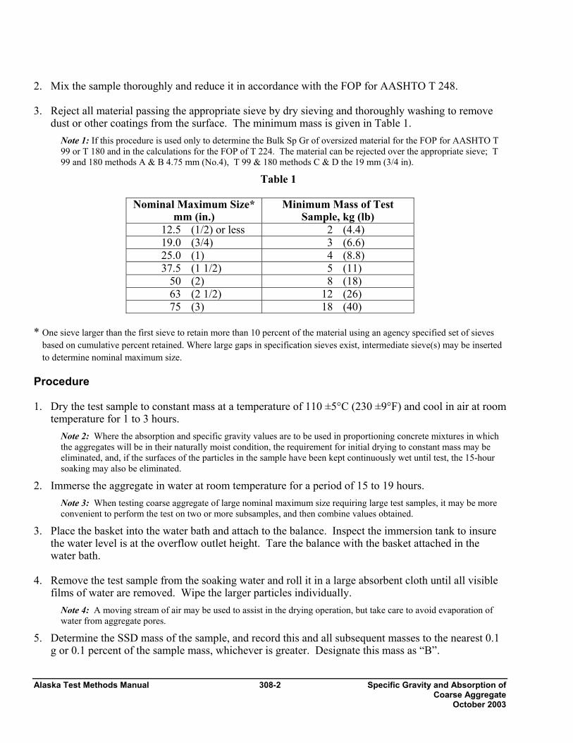
Alaska Test Methods Manual 308-2 Specific Gravity and Absorption of Coarse Aggregate October 2003
2. Mix the sample thoroughly and reduce it in accordance with the FOP for AASHTO T 248. 3. Reject all material passing the appropriate sieve by dry sieving and thoroughly washing to remove
dust or other coatings from the surface. The minimum mass is given in Table 1. Note 1: If this procedure is used only to determine the Bulk Sp Gr of oversized material for the FOP for AASHTO T 99 or T 180 and in the calculations for the FOP of T 224. The material can be rejected over the appropriate sieve; T 99 and 180 methods A & B 4.75 mm (No.4), T 99 & 180 methods C & D the 19 mm (3/4 in).
Table 1
Nominal Maximum Size* mm (in.)
Minimum Mass of Test Sample, kg (lb)
12.5 (1/2) or less 2 (4.4) 19.0 (3/4) 3 (6.6) 25.0 (1) 4 (8.8) 37.5 (1 1/2) 5 (11)
50 (2) 8 (18) 63 (2 1/2) 12 (26) 75 (3) 18 (40)
* One sieve larger than the first sieve to retain more than 10 percent of the material using an agency specified set of sieves
based on cumulative percent retained. Where large gaps in specification sieves exist, intermediate sieve(s) may be inserted to determine nominal maximum size.
Procedure 1. Dry the test sample to constant mass at a temperature of 110 ±5°C (230 ±9°F) and cool in air at room
temperature for 1 to 3 hours. Note 2: Where the absorption and specific gravity values are to be used in proportioning concrete mixtures in which the aggregates will be in their naturally moist condition, the requirement for initial drying to constant mass may be eliminated, and, if the surfaces of the particles in the sample have been kept continuously wet until test, the 15-hour soaking may also be eliminated.
2. Immerse the aggregate in water at room temperature for a period of 15 to 19 hours. Note 3: When testing coarse aggregate of large nominal maximum size requiring large test samples, it may be more convenient to perform the test on two or more subsamples, and then combine values obtained.
3. Place the basket into the water bath and attach to the balance. Inspect the immersion tank to insure the water level is at the overflow outlet height. Tare the balance with the basket attached in the water bath.
4. Remove the test sample from the soaking water and roll it in a large absorbent cloth until all visible
films of water are removed. Wipe the larger particles individually. Note 4: A moving stream of air may be used to assist in the drying operation, but take care to avoid evaporation of water from aggregate pores.
5. Determine the SSD mass of the sample, and record this and all subsequent masses to the nearest 0.1 g or 0.1 percent of the sample mass, whichever is greater. Designate this mass as “B”.
Specific Gravity and Absorption of 308-3 Alaska Test Methods Manual Coarse Aggregate October 2003
6. Re-inspect the immersion tank to insure the water level is at the overflow outlet height and tare the balance. Immediately place the SSD test sample in the sample container and weigh it in water maintained at 23.0 ±1.7°C (73.4 ±3°F). Shake the container to release entrapped air before recording the weight. Designate this submerged weight as “C”.
Note 5: The container should be immersed to a depth sufficient to cover it and the test sample during mass determination. Wire suspending the container should be of the smallest practical size to minimize any possible effects of a variable immersed length.
7. Dry the test sample to constant mass at a temperature of 110 ±5°C (230 ±9°F) and cool in air at room temperature for 1 to 3 hours. Designate this mass as “A”.
Calculations Perform calculations and determine values using the appropriate formula below. In these formulas, A = oven dry mass, B = SSD mass, and C = weight in water.
Bulk specific gravity (Gsb) Gsb = A / (B-C)
Bulk specific gravity, SSD (Gsb SSD)
Gsb SSD = B / (B - C)
Apparent specific gravity (Gsa) Gsa = A / (A - C)
Absorption
Absorption = [(B - A) / A] x 100
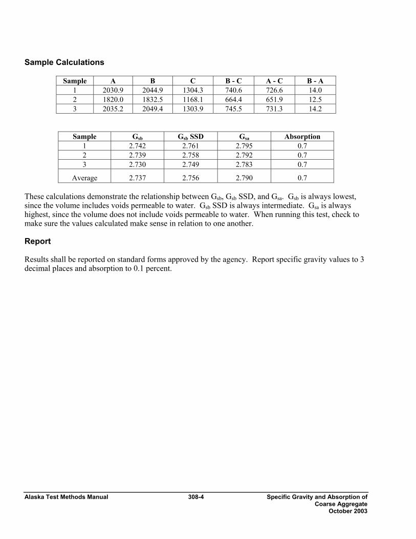
Alaska Test Methods Manual 308-4 Specific Gravity and Absorption of Coarse Aggregate October 2003
Sample Calculations
Sample A B C B - C A - C B - A 1 2030.9 2044.9 1304.3 740.6 726.6 14.0 2 1820.0 1832.5 1168.1 664.4 651.9 12.5 3 2035.2 2049.4 1303.9 745.5 731.3 14.2
Sample Gsb Gsb SSD Gsa Absorption 1 2.742 2.761 2.795 0.7 2 2.739 2.758 2.792 0.7 3 2.730 2.749 2.783 0.7
Average 2.737 2.756 2.790 0.7 These calculations demonstrate the relationship between Gsb, Gsb SSD, and Gsa. Gsb is always lowest, since the volume includes voids permeable to water. Gsb SSD is always intermediate. Gsa is always highest, since the volume does not include voids permeable to water. When running this test, check to make sure the values calculated make sense in relation to one another. Report Results shall be reported on standard forms approved by the agency. Report specific gravity values to 3 decimal places and absorption to 0.1 percent.

Nordic Abrasion 312 - 1 Alaska Test Methods Manual Revised 12/31/03
Nordic Abrasion Value of Coarse Aggregate ATM 312 1. Scope
This method describes the test procedure for the simulation of the abrasive action of traffic on coarse aggregates used in a surface layer to determine the ability of the aggregate to resist wear by abrasion from studded tires.
The test shall be performed on aggregates with a size fraction of 11.2 to 16.0 mm (7/16" to 5/8")
Note 1: Variations from this size range will not give consistent results.
The test is applicable to crushed and uncrushed natural and artificial aggregates.
This test method involves potentially hazardous materials, operations and equipment. This method does not purport to address all of the safety problems associated with it use.
2. Principle
A sample of a single-sized aggregate group, 11.2 to 16.0 mm (7/16" to 5/8"), is rotated together with steel balls and water in a steel drum. Three ribs, which are mounted on the interior of the drum, add to the abrading action of the aggregate particles and the steel balls. The contents roll within the drum with an abrading action. After the specified number of revolutions, the contents are removed from the drum and the aggregate portion is sieved on a 2.00 mm (No. 10) sieve to measure the wear as a percentage loss.
3. Apparatus
• Testing machine conforming to the design shown in Figure 1.
• The cylinder shall have an inside diameter of 206.5 ± 2 mm and an inside length of 335 ± 1 mm. Three ribs, each with a length of 333 ± 1 mm, shall be equally spaced around the internal circumference of the cylinder. The test drum shall be water-tight and made of a seamless steel tube conforming to according to grade TS 5 of ISO 2604-2, of outside diameter 219.1 and wall thickness of 6.3 mm. The cylinder shall rotate centrically with the axis in a horizontal position at a rate of 90 ± 3 rpm. A revolution counter shall automatically stop the rotation after 5400 revolutions.
• The three ribs shall be removable and made from spring steel as specified in ISO 683-14 and designed in accordance with figure 1. The ribs, prior to their use in the test, shall be preground in the drum for 25 h using a hard aggregate, together with the normal proportions of steel balls and water.
• During the test the ribs will wear and their action will change. Each rib shall be replaced, when its loss in original mass exceeds 15 g.
• Ball bearings, 14.99-15.05 mm diameter, of a hardness between 62 and 65 HRC, as specified in ISO

Alaska Test Methods Manual 312 - 2 Nordic Abrasion Revised 12/31/03
3290.
Figure 1
• Gauge to control minimum ball size, e.g. two parallel bars 14.5 mm apart.
• Magnet (optional) for removal of the charge from the aggregate test sample after abrasion. Note 3: Do not use too strong a magnet as the balls may become magnetized.
Nordic Abrasion 312 - 3 Alaska Test Methods Manual Revised 12/31/03
• Oven capable of maintaining a uniform temperature of 110 ± 5 °C (230 ± 9°F).
• Balance or scale: Capacity sufficient for the principle sample mass, readable to 0.1 percent or 0.1 g, of the total sample mass and meeting the requirements of AASHTO M 231.
• Sieves of the following sizes: 2.00 mm, 11.2 mm, and 16.0 mm (No. 10, 7/16" and 5/8").
• Bucket.
• Washing device.
4. Sampling
Obtain the sample in accordance with WAQTC FOP for AASHTO T 2.
5. Preparation Of Test Sample
Unprocessed Aggregate
1. Separate the sample on the 19 mm (3/4") sieve by hand or mechanical shaker, sieving the material for 5 minutes. Discard the minus 19 mm (3/4") material unless required for other testing.
2. Crush the plus 19 mm (3/4") aggregate, or a representative portion obtained in accordance with WAQTC FOP for AASHTO T 248, to pass the 19 mm (3/4") sieve.
3. Separate the material into the required test size, using 16 mm (5/8") sieve and 11.2 mm (7/16") sieves, in accordance with WAQTC FOP for AASHTO T 27/T 11. Discard all particles retained on the 16 mm (5/8") sieve and all the particles passing the 11.2 mm (7/16") sieve, unless required for other testing.
4. Proceed to Step 2 below.
Processed (already crushed) Aggregate
1. Separate the material into the required test size, using 16 mm (5/8") and 11.2 mm (7/16") sieves, in accordance with WAQTC FOP for AASHTO T 27/T 11. Discard all particles retained on the 5/8" (16 mm) sieve and all the particles passing the 11.2 mm (7/16") sieve, unless required for other testing.
2. Reduce the sample to test size (minimum of 3500 g) in accordance with WAQTC FOP for AASHTO T 248.
3. Wash the sample and dry to a constant mass in accordance with WAQTC FOP for AASHTO T 255/T 265.
4 Determine the apparent specific gravity of the sample, or a portion thereof, in accordance with WAQTC FOP for AASHTO T 85.
5. Determine the test sample mass by:
100066.2
×= ii
Pm
Where mi = mass of the test sample
pi = apparent specific gravity of test sample.
6. Batch 3 test specimens at the calculated weight ± 5 g.
6. Procedure
1. Place the ball charge (7000 ± 10 g) and the test sample in the drum and add (2000 ± 10) ml. of water.
2. Rotate the drum at a speed of 90 ± 3 rpm for 5400 ± 10 revolutions.

Alaska Test Methods Manual 312 - 4 Nordic Abrasion Revised 12/31/03
3. After the specified number of revolutions, discharge the contents (sample and ball charge) from the drum into a bucket.
4. Wash the sample including the ball charge on a 2.00 mm (No. 10) sieve. Remove the steel balls from the sample with a magnet.
Note 4: To avoid overloading the sieve, it may be necessary to divide the sample into smaller portions.
5. Dry the aggregate fraction retained on the 2.00 mm (No. 10) sieve, to a constant mass in accordance with WAQTC FOP for AASHTO T 255 and weigh to the nearest 0.1 g.
7. Calculation and Expression of Results
1. Calculate the individual Nordic Abrasion Values (AN) to the nearest 0.1 percent as follows:
AN = 100 x m
m -m
i
2i⎟⎟⎠
⎞⎜⎜⎝
⎛
Where mi = Initial dry mass of the test sample.
m2 = Dry mass of the aggregate after the test.
2. Compute and record the average of the individual Nordic Abrasion Values to the nearest 0.1 percent.
8. Precision
For Nordic abrasion values (AN) from 5 to 32 the single-operator precision is calculated as follows:
r = 0.7 + 0.08 AN
R = 0.7 + 0.7 = 0.10 AN
Multi-laboratory precision will be double the above values.
Note 5: The repeatability (r) and reproducibility (R) have been determined on the basis of limited interlaboratory studies in Sweden. Interpretation of the test results has been made in accordance with ISO 5725.
9. Report
The individual and average Nordic Abrasion values shall be reported on Department forms to the nearest 0.1 percent.

Degradation Values of Aggregate 313-1 Alaska Test Methods Manual Revised 3/15/05
Degradation Value of Aggregates ATM 313 1. Scope This test method describes the procedure for determining the durability of an aggregate. The durability of an aggregate as measured by the Degradation Value indicates the relative resistance of an aggregate to produce detrimental clay-like fines when subjected to a prescribed abrasion process in the presence of distilled or demineralized water.
2. Apparatus
• Jaw crusher with 150 mm (6") capacity.
• Sieves of the following sizes: 12.5 mm (½"), 6.3 mm (¼"), 2.00 mm (No. 10) and 75 µm (No. 200). Sieves shall conform to AASHTO M 92.
• Balance or scale: Capacity sufficient for the principle sample mass, readable to 0.1 percent or 0.1 g of the total sample mass and meeting the requirements of AASHTO M 231.
• 200 mm (8") sieve shaker with 45 mm (1¾") throw on cam at 285 ± 10 oscillations per minute.
• General Laboratory Interval Timer to control On-Off operation of sieve shaker. Timer will have a minimum 20 minute range accurate to ± 5 seconds.
• Plastic canister 190 mm (7 ½") in diameter and 150 mm (6") high, having a flat bottom.
• Distilled or demineralized water maintained at 22 ±3ºC (72 ± 5°F).
• Sample Washing Apparatus, consisting of a ring stand and ring capable of mounting a 230 mm mouth funnel with a 2.00 mm (No. 10) and 75 µm (No. 200) sieve setting on top of the funnel and a graduated cylinder calibrated at 500 ml with a rubber stopper.
• Graduated cylinder or pipette with 10 ml capacity graduated in 1 ml increments.
• Stock Sand Equivalent Solution prepared in accordance with WAQTC FOP for AASHTO T 176, using distilled water only. This solution should be stored in dark or opaque containers and protected from direct sunlight and heat. Solutions that have turned cloudy or formed precipitates will be discarded.
• Standard Sand Equivalent Cylinder with rubber stopper as described in WAQTC FOP for AASHTO T 176.
• Timer or Stopwatch, preferably with an alarm to indicate end of timed interval.
• Miscellaneous equipment including 500 ml wash bottle with a fine spray nozzle, pans, scoops, etc.
3. Degradation Test Area The degradation test area must be free of vibration and direct sunlight, and maintained at a temperature of 22 ±3ºC (72 ± 5°F).
4. Sample Preparation 1. Unprocessed Aggregate
a. Separate the aggregate on the 12.5 mm (½") sieve by hand or by mechanical shaker, sieving the material for 5 minutes. Discard the minus 12.5 mm (½") material unless required for other testing.
Alaska Test Methods Manual 313-2 Degradation Values of Aggregate Revised 3/15/05
b. Crush the plus 12.5 mm (½") aggregate, or a representative portion obtained in accordance with WAQTC FOP for AASHTO T 248, to pass the 12.5 mm (½") sieve.
c. Proceed to Step 4 below.
2. Processed (already crushed) Aggregate
a. Separate the material by hand sieving or by mechanical shaker, sieving the material for 5 minutes, into 2 size groups: minus 12.5 mm (½") to plus 6.3 mm (¼") and minus 6.3 mm (¼") to plus 2.00 mm (No. 10).
b. Reduce each size grouping to a representative sample in accordance with WAQTC FOP for AASHTO T 248, Method A, such that there will be a minimum of 500 grams after washing.
c. Wash each size grouping over a 2.00 mm (No. 10) sieve and dry to a constant mass in accordance with WAQTC FOP for AASHTO T 255/T 265.
d. Weigh out a 500 ±1 g portion of each size grouping.
5. Procedure 1. Combine both sample portions in the plastic canister, add 200 ml of distilled or demineralized water and
cover tightly. Do not allow the sample to soak more than 5 minutes before testing.
2. Place the canister in the degradation sieve shaker and run for 20 minutes ±5 seconds. Do not allow the sample to set for more than 5 minutes after agitation is completed.
3. Remove the canister and wash the material through nested 2.00 mm (No. 10) and 75 µm (No. 200) sieves. Continue washing until the wash water is clear and has reached the 500-ml mark on the graduated cylinder.
4. In instances where highly degradable materials are encountered and the sample cannot be washed clean with 500-ml. of water:
a. Continue washing using water sparingly, until the wash water is clear. If a change in receiver cylinders is required, be very careful not to lose any of the wash water.
b. To achieve the required 500 ml. volume, allow the wash water to settle until clear, then siphon or pipette off the excess water, being careful not to remove any of the settled material.
c. Use of a centrifuge to settle the material is allowed but extreme care must be taken to preclude any loss of material in transferring from the cylinders to the centrifuge bottles and then back to a single cylinder. The solution must be brought to a volume of 500 ml before proceeding to Step 5. Removal of extra water by oven-dried evaporation is not allowed.
5. Place the Sand Equivalent Cylinder upright in a vibration free area out of direct sunlight. Measure and pour 7 ml of the Stock Sand Equivalent Solution into the cylinder.
6. Bring all of the solids in the 500 ml of wash water into suspension by capping the graduated cylinder with the palm of the hand or a rubber stopper, then turning the graduated cylinder upside down and right side up 10 times or until material is in suspension, allowing the bubble to traverse from one end to the other and back again, as rapidly as possible (approximately 35 seconds).
7. Immediately pour the solution into the Sand Equivalent Cylinder, fill to the 15 mark, and plug with a rubber stopper.
8. Mix the contents of the Sand Equivalent Cylinder by turning the cylinder upside down and right side up allowing the bubble to traverse from one end to the other and back again. This is one cycle. Repeat this cycle 20 times as rapidly as possible (approximately 35 seconds).

Alaska Test Methods Manual 313-3 Degradation Values of Aggregate Revised 12/31/03
9. Place the cylinder on a vibration free platform out of direct sunlight, remove stopper and immediately start the timer or stopwatch that is pre-set for 20 minutes.
10. After 20 minutes, immediately read and record the height of the sediment to the nearest 0.1 graduation.
6. Calculations Determine the Degradation Value by Table I, next page, which is derived from the following formula.
100 x H75.115
H - 15 D ⎟⎠⎞
⎜⎝⎛
+=
Where: D = Degradation value.
H = Height of sediment in cylinder.
Values may range from 0 to 100 with high values representing more suitable material. The formula and chart place doubtful materials at about the midrange (30-70) of the scale, with poor ones below and good ones above that range.
7. Report Report degradation values to the nearest whole number.

Alaska Test Methods Manual 313-4 Degradation Values of Aggregate Revised 3/15/05
Table 1
Degradation Value, "D" H D H D H D H D H D 0.1 98 3.1 58 6.1 35 9.1 19 12.1 8 0.2 96 3.2 57 6.2 34 9.2 19 12.2 8 0.3 95 3.3 56 6.3 33 9.3 18 12.3 7 0.4 93 3.4 55 6.4 33 9.4 18 12.4 7 0.5 91 3.5 54 6.5 32 9.5 17 12.5 7
0.6 90 3.6 54 6.6 32 9.6 17 12.6 6 0.7 88 6.7 53 6.7 31 9.7 17 12.7 6 0.8 87 3.8 52 6.8 30 9.8 16 12.8 6 0.9 85 3.9 51 6.9 30 9.9 16 12.9 6 1.0 84 4.0 50 7 29 10.0 15 13.0 5
1.1 82 4.1 49 7.1 29 10.1 15 13.1 5 1.2 81 4.2 48 7.2 28 10.2 15 13.2 5 1.3 79 4.3 48 7.3 28 10.3 14 13.3 4 1.4 78 4.4 47 7.4 27 10.4 14 13.4 4 1.5 77 4.5 46 7.5 27 10.5 13 13.5 4
1.6 75 4.6 45 7.6 26 10.6 13 13.6 4 1.7 74 4.7 44 7.7 26 10.7 13 13.7 3 1.8 73 4.8 44 7.8 25 10.8 12 13.8 3 1.9 71 4.9 43 7.9 25 10.9 12 13.9 3 2.0 70 5.0 42 8 24 11.0 12 14.0 3
2.1 69 5.1 41 8.1 24 11.1 11 14.1 2 2.2 68 5.2 41 8.2 23 11.2 11 14.2 2 2.3 67 5.3 40 8.3 23 11.3 11 14.3 2 2.4 66 5.4 39 8.4 22 11.4 10 14.4 1 2.5 65 5.5 39 8.5 22 11.5 10 14.5 1
2.6 63 5.6 38 8.6 21 11.6 10 14.6 1 2.7 62 5.7 37 8.7 21 11.7 9 14.7 1 2.8 61 5.8 37 8.8 20 11.8 9 14.8 0 2.9 60 5.9 36 8.9 20 11.9 9 14.9 0 3.0 59 6.0 35 9.0 20 12.0 8 15.0 0
Expansive Breakdown of 314-1 Alaska Test Methods Manual Stone on Soaking… Revised 12/31/03
Expansive Breakdown of Stone on Soaking in Ethylene Glycol ATM 314 1. Scope
This method covers a procedure for subjecting samples of stone to immersion in ethylene glycol and observation of the effects of such immersion in accordance with CRD-D 148-69.
2. Principle of Method
Ethylene glycol is one of the materials that reacts with swelling clays of the montmorillonite group to form an organo-clay complex having a larger basal spacing than that of the clay mineral itself. Hence a sample of stone containing swelling clay of the montmorillonite group will be expected to undergo expansive breakdown upon soaking in ethylene glycol, if the amount, distribution, state of expansion, and ability to take up glycol is such as to cause such breakdown to occur. If such breakdown does occur, it may be expected that similar breakdown may occur if similar rock samples are exposed, for longer times, to wetting and drying or freezing and thawing in a water soaked condition in service. 3. Reagent
Ethylene Glycol – The regent used in this method shall be ethylene glycol meeting the requirements of ASTM D 2693.
4. Apparatus
• Jaw crusher with 150 mm (6") capacity. • Sieves of the following sizes: 75 mm (3") and 19.0 mm (¾") and conforming to AASHTO M 92. • Balance or scale: Capacity sufficient for the principle sample mass, readable to 0.1 percent or 0.1 g of the
total sample mass and meeting the requirements of AASHTO M 231. • Container shall be of suitable plastic, non-reactive with the reagent and of sufficient size to hold the test
sample and sufficient reagent to cover all particles of the sample to a depth of not less that 10 mm (1/2") capped with a tight-fitting cover.
5. Sampling and Sample Preparation
1. Obtain representative samples of the stone in accordance with WAQTC FOP for AASHTO T 2.
2. Crush the rock to pass a 75 mm (3") sieve.
3. Separate the material into the required test size, using 75 mm (3") and 19 mm (¾") sieves, in accordance with WAQTC FOP for AASHTO T 27/T 11. Discard all particles retained on the 75 mm (3") sieve and all particles passing the 19 mm (¾") sieve, unless required for other testing.
4. Reduce the sample to a test size of 5 ± 2 kg (11 ± 1 lb) in accordance with WAQTC FOP for AASHTO T 248, Method A.
5. When a sample of the stipulated mass and particle size has been prepared, it shall be washed to remove dust, loosely adherent coatings, and chips. After being washed, dry to a constant mass in accordance with WAQTC FOP for AASHTO T 255/T 265 except that constant mass shall be regarded as having been attained when the loss in weight between successive weighing at intervals of not less than 4 hours does not exceed 0.1 percent. Determine the number of particles and the mass before immersion to the nearest 0.1 percent of the total sample mass.
Alaska Test Methods Manual 314-2 Expansive Breakdown of Stone on Soaking… Revised 12/31/03
6. Procedure
1. The sample shall be placed in the container and immersed in the reagent so that all particles are covered to a depth of at least 12.5 mm (½").
2. At intervals not to exceed 3 days, examine the sample and note significant changes. The normal duration of the test shall be 15 days.
Note 3: Further information of value may be obtained in certain cases by continuing the treatment beyond 15 days: in other cases expansive breakdown may have been too extensive at earlier periods that no information of value will be obtained by continuing the treatment for the full 15 days.
3. When the exposure has been terminated, the sample shall be thoroughly washed and sieved by hand over a 19 mm (¾") sieve to remove the reagent from the surfaces of the particles and to remove fragments that will pass a 19 mm (¾") sieve. The material remaining on the sieve shall be dried to constant weight as described in Step 4 of the Sampling and Sample Preparation, and the total mass after immersion determined to the nearest 0.1 percent of the total sample mass.
7. Calculations
Calculate the total percent loss by:
100 x M
M -
B
A
⎟⎟⎠
⎞⎜⎜⎝
⎛ BM
where: MB = Mass before immersion, and
MA = Mass after immersion. 8. Report
Report the percent loss to the nearest 1 percent on department forms.
Sampling Bituminous Materials 401-1 Alaska Test Methods Manual October 2003
SAMPLING BITUMINOUS MATERIALS (See Addendum for AKDOT&PF Guidelines) WAQTC FOP FOR AASHTO T 40 Scope The procedure covers obtaining samples of liquid bituminous materials in accordance with AASHTO T 40. Sampling of solid and semi-solid bituminous materials – included in AASHTO T 40 – is not covered here. Procedure 1. Coordinate sampling with contractor or supplier. 2. Use appropriate safety equipment and precautions. 3. Allow a minimum of 4 L (1 gal) to flow before obtaining samples. 4. Obtain samples as indicated below.
• Hot Mix Asphalt (HMA) Plants: Obtain the samples from the line between the storage tank and the mixing plant while the plant is in operation, or from the delivery truck.
• Distributors: Obtain the sample directly from the spray bar or application device if the
bituminous liquid has not been diluted; otherwise, sample at delivery or prior to dilution. Material may also be sampled from the delivery truck before it is pumped into the distributor.
Containers Sample containers must be new, and the inside may not be washed or rinsed. The outside may be wiped with a clean, dry cloth. All samples shall be put in 1 L (1 qt) containers and properly identified on the outside of the container with contract number, date sampled, data sheet number, brand and grade of material, and sample number. Include lot and sublot numbers when appropriate. • Emulsified asphalt: Use wide-mouth plastic jars with screw caps. Protect the samples from freezing
since water is a part of the emulsion. The sample container should be completely filled to minimize a skin formation on the sample.
• All other bituminous liquids: Use metal cans. Note: The filled sample container shall not be submerged in solvent, nor shall it be wiped with a solvent saturated cloth. If cleaning is necessary, use a clean dry cloth.

Alaska Test Methods Manual 401-2 Sampling Bituminous Materials October 2003
Addendum WAQTC FOP for AASHTO T 40
The following guidelines for the use of WAQTC FOP for AASHTO T 40 by the State of Alaska DOT&PF.
1. When obtaining samples from HMA plants, sample only from the line between the storage tank and the mixing plant while the plant is in operation.
2. Sample containers for elastomer modified asphaltic cements must be new, and the inside may not be washed or rinsed. The outside may be wiped with a clean, dry cloth. All samples shall be put in 1 L (1 qt) wide mouth metal containers and properly identified on the outside of the container with contract number; date and time sampled, supplier, batch number and grade of material; and sample number. Include lot and sub-lot numbers when appropriate.
3. When sampling emulsified asphalt, use 1 gallon wide mouth plastic containers.
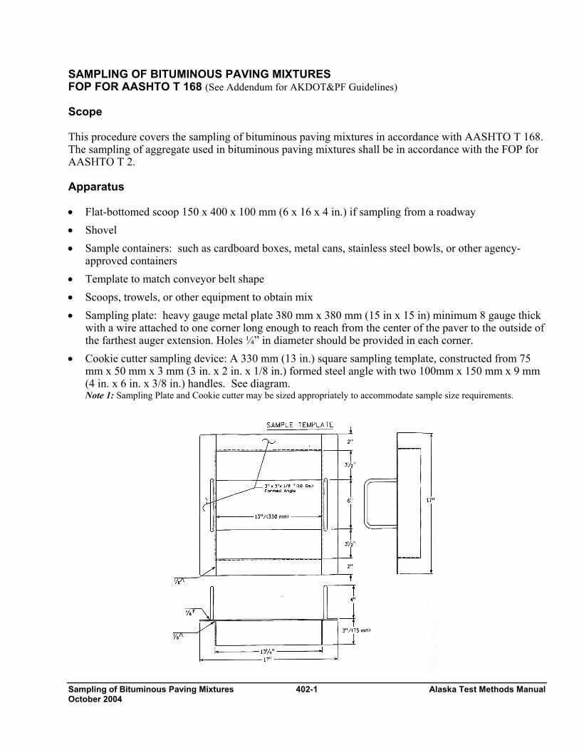
Sampling of Bituminous Paving Mixtures 402-1 Alaska Test Methods Manual October 2004
SAMPLING OF BITUMINOUS PAVING MIXTURES FOP FOR AASHTO T 168 (See Addendum for AKDOT&PF Guidelines) Scope This procedure covers the sampling of bituminous paving mixtures in accordance with AASHTO T 168. The sampling of aggregate used in bituminous paving mixtures shall be in accordance with the FOP for AASHTO T 2. Apparatus • Flat-bottomed scoop 150 x 400 x 100 mm (6 x 16 x 4 in.) if sampling from a roadway • Shovel • Sample containers: such as cardboard boxes, metal cans, stainless steel bowls, or other agency-
approved containers • Template to match conveyor belt shape • Scoops, trowels, or other equipment to obtain mix • Sampling plate: heavy gauge metal plate 380 mm x 380 mm (15 in x 15 in) minimum 8 gauge thick
with a wire attached to one corner long enough to reach from the center of the paver to the outside of the farthest auger extension. Holes ¼” in diameter should be provided in each corner.
• Cookie cutter sampling device: A 330 mm (13 in.) square sampling template, constructed from 75 mm x 50 mm x 3 mm (3 in. x 2 in. x 1/8 in.) formed steel angle with two 100mm x 150 mm x 9 mm (4 in. x 6 in. x 3/8 in.) handles. See diagram. Note 1: Sampling Plate and Cookie cutter may be sized appropriately to accommodate sample size requirements.

Alaska Test Methods Manual 402-2 Sampling of Bituminous Paving Mixtures October 2004
General Comments 1. Sampling is as important as testing, and every precaution must be taken to obtain a truly
representative sample. 2. Care shall be taken to prevent contamination of bituminous mixes by dust or other foreign matter,
and to avoid segregation of aggregate and bituminous materials. 3. Samples of mix upon which acceptance or rejection is based shall be selected at random, and may be
obtained by, or under the observation of, the purchaser or authorized representative. 4. Some agencies require mechanical sampling devices for hot mix asphalt (HMA) and cold feed
aggregate on some projects. These are normally permanently attached devices that allow a sample container to pass perpendicularly through the entire stream of material or divert the entire stream of material into the container. Operation may be hydraulic, pneumatic, or manual and allows the sample container to pass through the stream twice, once in each direction, without overfilling. Special caution is necessary with manually operated systems since a consistent speed is difficult to maintain and non-representative samples may result. Check agency requirements for the specifics of required sampling systems.
Sample Size Sample size depends on the test methods specified by the agency for acceptance. Check agency requirement for the size required. Sampling • General
1. The material shall be inspected to determine variations. The seller shall provide equipment for safe and appropriate sampling including sampling devices on plants, when required.
2. Place dense graded mixture samples in cardboard boxes, stainless steel bowls or other agency approved containers. Place open graded mixture samples in stainless steel bowls. Do not put open graded mixture samples in boxes until they have cooled to the point that bituminous material will not migrate from the aggregate.
• Sampling from a Conveyor Belt
1. Stop the conveyor belt. 2. Select at least three areas of approximately equal size on the belt for sampling. 3. Insert templates, the shape of which conforms to the shape of the belt, in each of the locations to
be sampled. 4. Obtain three approximately equal increments of material that will form a sample of the required
size when combined. 5. Scoop all material between templates into a suitable container.
• Attached Sampling Devices 1. When using an attached sampling device, pass the container twice through the material
perpendicularly without overfilling the container.

Sampling of Bituminous Paving Mixtures 402-3 Alaska Test Methods Manual October 2004
2. Repeat until proper sample size has been obtained.
• Sampling from Truck Transports 1. Obtain samples in four approximately equal increments from haul units. 2. Obtain each increment from approximately 300 mm (12 in.) below the surface, in each of the
four quadrants of load.
3. Combine the increments to form a sample of the required size. • Sampling from a Roadway Prior to Compaction (Scoop Method)
1. Obtain samples in approximately equal increments, after placement and prior to rolling, using the scoop.
2. Make a vertical face with the shovel about 750 mm (30 in.) parallel with centerline. 3. Pull the material back approximately 450 mm (18 in.).
Alaska Test Methods Manual 402-4 Sampling of Bituminous Paving Mixtures October 2004
4. Place the scoop on the pavement or base as flat as possible at one side of the vertical face and fill the scoop. Make sure that sufficient pressure is exerted on the scoop to remove all of the material to its full depth.
5. Close the lid and remove the scoop when it is full. 6. Repeat Steps 2 through 5 to obtain the required sample size.
• Sampling from Roadway Prior to Compaction (Plate Method)
Plate Method using the “ cookie cutter” sampling device.
There are two conditions that will be encountered when sampling Hot Mix Asphalt (HMA) from the roadway prior to Compaction. The two conditions are:
1. Laying HMA on grade, or untreated base material.
2. Laying HMA on existing asphalt or laying a second lift of HMA.
Method 1 will require the use of a Plate placed on the existing surface in front of the paving machine and sampling using the “cookie cutter” sampling device.
Method 2 requires only the use of the “cookie cutter” sampling device.
SAFETY:
Method 1 requires a plate to be placed in the roadway in front of the paving operation and therefore there is always concern with moving, operating equipment. It is safest to stop the paving train while a plate is installed in front of the paver. When this is not possible the following safety rules must be followed.
1. The plate placing operation must be at least 3 m (10 ft) in front of the paver or pickup device. The technician placing the plate must have eye contact and communication with the paving machine operator. If eye contact cannot be maintained at all time, a third person must be present to provide communication between the operator and the technician.
2. No technician is to be between the asphalt supply trucks and the paving machine. The exception to this rule is if the supply truck is moving forward creating a windrow, in which case the technician must be at least 3m (10 ft) behind the truck.
3. At any time the Engineer feels that the sampling technique is creating an unsafe condition, the operation is to be halted until it is made safe or the paving operation will be stopped while the plate is being placed.
Method 2 is performed behind the paving machine and in front of the breakdown roller. For safety, the roller must remain at least 3 m (10 ft) behind the sampling operation until the sample has been taken and the hole filled with loose HMA.
Method 1 - Obtaining a Sample on Untreated Base:
1. Following the safety rules detailed above, the technician is to
• smooth out a location in front of the paver at least 0.5 m (2 ft) inside the edge of the mat,
• lay the plate down diagonally with the direction of travel, keeping it flat and tight to the base,
• with the lead corner facing the paving machine.

Sampling of Bituminous Paving Mixtures 402-5 Alaska Test Methods Manual October 2004
2. Secure the plate in place by driving a 20-penny nail through the hole in the lead corner of the plate.
3. Pull the wire, attached to the outside corner of the plate, taut past the edge of the HMA mat and secure with a 16-penny nail.
4. Let the paving operation proceed over the plate and wire. Immediately proceed with the sampling.
5. Using the exposed end of the wire, pull the wire up through the fresh HMA to locate the corner of the plate. Place the “cookie cutter” sample device, just inside the end of the wire, align the cutter over the plate. Press “cookie cutter” device down through the HMA to the plate.
6. Using a small square tipped shovel and/or scoop, carefully remove all the HMA from inside of the cutter and place in a sample container.
7. Remove the sample cutter and the plate from the roadway. The hole made from the sampling must be filled with loose HMA.
Method 2 - Obtaining a Sample on Asphalt Surface:
1. After the paving machine has pasted the sampling point, immediately place the “cookie cutter” sampling device on the location to be sampled. Push the cutter down through the HMA until it is flat against the underlying asphalt mat.
2. Using a small square tipped shovel and/or scoop, carefully remove all the HMA from inside of the cutter and place in a sample container. The hole made from sampling must filled with loose HMA.
Note 2: It is recommended that the contractor replace the material in hole left from sampling Identification and Shipping 1. Identify sample containers as required by the agency. 2. Ship samples in containers that will prevent loss, contamination, or damage.

Alaska Test Methods Manual 402-6 Sampling of Bituminous Paving Mixtures October 2004
Addendum WAQTC FOP for AASHTO T 168 Following are guidelines for the use of WAQTC FOP for AASHTO T 168 by the State of Alaska DOT&PF.
1. When allowed by specification, sampling methods found in ATM 403 may be used.
Sampling HMA 403 - 1 Alaska Test Methods Manual 4/1/05
Sampling Hot Mix Asphalt ATM 403 1. Scope
This method describes the procedures used for sampling Hot Mix Asphalt (HMA).
2. Significance and Use This method provides procedures for sampling HMA in the field.
2.1. Sampling is equally as important as the testing, and the sampler shall use every precaution to obtain samples that will yield an acceptable estimate of the nature and conditions of the materials for which they represent.
2.2. Care shall be taken in sampling to avoid segregation of the material being sampled, and to prevent contamination by dust or other foreign matter.
3. Equipment 3.1 Flat scoop with vertical sides or a square point shovel
3.2 Plate with small lip (approximately ½”) and of sufficient size and rigidity to accommodate required sample. Plate to have wire(s) attached to allow the plate to be located and removed from the mat after paver travels past it.
3.3 Approved sample containers including new cardboard boxes, clean metal buckets, cans or bowls.
3.4 Miscellaneous tools, scrapper, scoop, gloves, etc.
4. Sampling from the Auger 4.1 Obtain samples from the accessible portion of the auger, using a square point shovel.
4.2 Place the shovel in front of the auger, with the blade flat upon the surface to be paved.
4.3 Allow the front face of the HMA coming off the auger to cover the shovel. Remove the shovel before the auger reaches the shovel by lifting it upward as vertically as possible being careful not to lose material.
4.4 Repeat the procedure at least three times, but as many times as necessary to obtain a sample of the required size.
4.5 Place the sample in an approved container for transport to Lab.
5. Lipped Plate Sampling 5.1 When using a pickup machine;
5.1.1 Stop the paver and pickup machine.
5.1.2 Place plate(s) underneath the pickup machine, midway between and just behind the rear tires and right in front of the paver.
5.2 When using dump trucks:
5.2.1 Stop the paver after the truck is attached to the paver.
5.2.2 Place plate(s) at the midpoint of the axis of the paver and behind the truck tires.
5.2.3 Stop the paver after the truck is attached to the paver.
Note: when placing plate(s), avoid influence from truck tires, pickup machine tires, and paver tracks or tires.
Alaska Test Methods Manual 403 - 2 Sampling HMA 4/1/05
5.3. Run an attached wire perpendicular to the direction of the paver, beyond the farthest auger extension and/or the ski.
5.4. Hold the wire to the ground with your foot.
5.5. Allow the paving operation to resume.
5.6. When the paver has passed over the plate position, pull up on the wire to locate the plate. Remove the plate(s) laden with mix from the HMA mat by lifting vertically being careful not to disturb the mix at the edge of the plate.
5.7. Place the sample in an approved container for transport to the Lab.
Note: make sure to hold the wire down on the ground so the ski will not snag it.
6. Windrow Sampling 6.1 When HMA is dumped in a windrow, sample in three locations equidistantly spaced longitudinally along
the top of the middle third of the windrow.
6.2 Obtain sample increments by removing and discarding the top 12 inches of the windrow. Remove a portion by digging vertically down with a square point shovel. Repeat for each increment.
6.3 Combine the three increments to form the composite sample.
6.4 Place the sample in an approved container for transport to the Lab.

Reducing Samples of Hot 404-1 Alaska Test Methods Manual Mix Asphalt to Testing Size October 2004
REDUCING SAMPLES OF HOT MIX ASPHALT TO TESTING SIZE FOP FOR WAQTC TM 5 (See Addendum for AKDOT&PF Guidelines) Significance Samples of bituminous paving mixes taken in accordance with AASHTO T 168 are composites and are large to increase the likelihood that they are representative of the product being tested. Materials sampled in the field need to be reduced to appropriate sizes for testing. As a general rule, field samples should be of a size that splitting once will result in the required test sample size. It is extremely important that the procedure used to reduce the field sample not modify the material properties. Scope This method covers the procedure reducing samples of Hot Mixed Asphalt (HMA). The samples are to be acquired in accordance with AASHTO T 168 and the increments placed in an agency approved suitable container. The sample is to be representative of the average of the HMA being produced. The field sample when reduced once should yield a sample of sufficient mass that combined opposite quarters of the field sample will meet the testing needs. The initial reduction of the field sample should be accomplished as close as possible to the point of sampling, this to avoid excessive cooling of the sample. The further reduction to test size may be done at this time or at another time and location as necessary. Apparatus
• Flat-bottom scoop, • Broom or brush, • Non-stick splitting surface such as metal, paper, canvas, or heat-resistant plastic, • Large spatulas, trowels, metal straightedge or 12 in. dry wall taping knife, sheet metal quartering
device, • Thermostatically controlled oven capable of maintaining a temperature of at least 110°C (230°F)
or high enough to heat the material to a pliable condition for splitting, • Miscellaneous equipment including trowel(s), spatula(s), hot plate, non-asbestos heat-resistant
gloves or mittens, pans, buckets, and cans. Sample Preparation The sample must be warm enough to separate. If not, warm in an oven until it is sufficiently soft to mix and separate easily. Procedure • Initial Reduction of Large Field Samples (over 35 kg (75 lb) 1. Heat the trowel(s), spatula(s), and splitting apparatus to approximately 110°C (230°F). 2. Place the sample on a surface where there will be neither loss of material nor the accidental addition
of foreign material. The surface may be covered with a canvas, heavy paper or other suitable
Alaska Test Methods Manual 404-2 Reducing Samples of Hot Mix Asphalt to Testing Size October 2004
material. Remove the sample from the agency approved container by dumping into a conical pile. 3. Mix the material thoroughly by turning the entire sample over a minimum of four times. With the
last turning, form the entire sample into a conical pile. Note 1: Mixing may be accomplished by turning the pile with a heated spatula or by rolling the material over with paper or
other material used for the rolling surface. To minimize segregation with lean mixes or mixes with aggregate larger than 19mm (3/4in), re-mixing the sample is not recommended.
4. Flatten the conical pile to a uniform thickness and diameter by pressing down with a hot spatula or
trowel. The diameter should be four to eight times the thickness. 5. Divide the flattened pile into four approximately equal quarters with a heated spatula, trowel, flat
metal plate, or sheet metal quartering splitter.
6. With the quartering device in place remove each quarter of the material and place in agency approved containers for testing, storage or shipment. Mark containers per the Sample Identification section.
7. Pay particular attention that excessive amounts of materials are not left on the splitting surface or splitting equipment.
8. When further reduction of the HMA is to be done at this time, reduce by using methods A, B, and C.
A combination of the reduction methods may be used if allowed by the agency.
• Reducing To Test Size – Method A
1. Place the sample on a surface where there will be neither loss of material nor the accidental addition of foreign material. The surface may be covered with a canvas, heavy paper, or other suitable material. Remove the sample from the agency approved containers by dumping into a conical pile.
2. Mix the sample thoroughly by turning the entire sample over a minimum of four times. Alternately lift each corner of the canvas or paper and pull it over the sample diagonally toward the opposite corner causing the material to be rolled. With the last turning, lift both opposite corners to form a conical pile.
3. Grasp the canvas or paper, roll the material into a loaf and flatten the top.
4. Pull the canvas or paper so at least ¼ of the length of the loaf is off the edge of the counter. Allow this material to drop into a container to be saved. As an alternate, using a straight edge, slice off approximately ¼ of the length of the loaf and place in a container to be saved.
5. Pull additional material (loaf) off the edge of the counter and drop the appropriate size sample into a sample pan or container. As an alternate, using a straight edge, slice off an appropriate size sample from the length of the loaf and place in a sample pan or container.
6. Repeat step 5 until the proper size sample has been acquired. Step 5 is to be repeated until all the samples for testing have been obtained.
Note 2 - When reducing the sample to test size it is advisable to take several small increments determining the mass each time until the proper minimum size is achieved. Unless the sample size is grossly in excess of the minimum or exceeds the maximum test size use the sample as reduced for the test.
Reducing Samples of Hot 404-3 Alaska Test Methods Manual Mix Asphalt to Testing Size October 2004
• Reducing to Test Size—Method B 1. Place the sample on a surface where there will be neither loss of material nor the accidental addition
of foreign material. The surface may be covered with a canvas, heavy paper, or other suitable material. Remove the sample from the containers by dumping into a conical pile.
2. Mix the sample thoroughly by turning the entire sample over a minimum of four times. Alternately lift each corner of the canvas or paper and pull it over the sample diagonally toward the opposite corner causing the material to be rolled. With the last turning, lift both opposite corners to form a conical pile.
3. Flatten the conical pile to a uniform thickness and diameter by pressing down with a hot spatula or trowel. The diameter should be four to eight times the thickness.
4. Quarter the conical pile using a quartering device or straightedge.
5. With the quartering device in place using a straightedge (taping knife) slice through the quarter of the HMA from the apex of the quarter to the outer edge. Pull or drag the material from the quarter holding one edge of the straightedge (taping knife) in contact with the quartering device. Two straight edges may be used in lieu of the quartering device.
6. Slide or scoop the material into a sample pan. Repeat step 5 removing a similar amount of material from the opposite quarter. Step 5 is to be repeated until all the samples for testing have been obtained.
Note 3- When reducing the sample to test size it is advisable to take several small increments determining the mass each time until the proper minimum size is achieved. Unless the sample size is grossly in excess of the minimum or exceeds the maximum test size use the sample as reduced for the test. • Reducing to Test Size—Method C
1. Place the sample on a surface where there will be neither loss of material nor the accidental addition of foreign material. The surface may be covered with a canvas, heavy paper, or other suitable material. Remove the sample from the containers by dumping into a conical pile.
2. Mix the sample thoroughly by turning the entire sample over a minimum of four times. Alternately lift each corner of the canvas or paper and pull it over the sample diagonally toward the opposite corner causing the material to be rolled. With the last turning, lift both opposite corners to form a conical pile.
3. Flatten the conical pile to a uniform thickness and diameter by pressing down with a hot spatula or trowel. The diameter should be four to eight times the thickness.
4. Quarter the conical pile using a quartering device or straightedge.
5. Remove the opposite quarters saving the material for future use.
6. Repeat step 2 through 5 until the proper size sample has been achieved.
7. When additional test specimens are required, dump the removed material into a conical pile as in step 1 and repeat steps 2 through 6. This process may be repeated until sample has been reduced to testing size for all tests.
Sample Identification

Alaska Test Methods Manual 404-4 Reducing Samples of Hot Mix Asphalt to Testing Size October 2004
1. Identify the sample as required by the agency.
2. Samples shall be submitted in agency approved containers and secured to prevent contamination and spillage.
3. The exact disposition of each quarter of the original field sample shall be determined by the agency.

Reducing Samples of Hot 404-5 Alaska Test Methods Manual Mix Asphalt to Testing Size October 2004
Addendum WAQTC TM 5 Following are guidelines for the use of WAQTC TM 5 by the State of Alaska DOT&PF.
1. A combination of the presented methods may be used in reducing an HMA sample to testing size.

Alaska Test Methods Manual 404-6 Reducing Samples of Hot Mix Asphalt to Testing Size October 2004
The page intentionally left blank.
Asphalt Cement Content of 405-1 Alaska Test Methods Manual Hot Mix Asphalt… Revised 3/15/05
Asphalt Cement Content of Hot Mix Asphalt by the Nuclear Method ATM 405
1. Scope This method covers the quantitative determination of the asphalt cement content of Hot Mix Asphalt by testing a sample with a device that utilizes neutron thermalization techniques. This is an adaptation of AASHTO T 287. Job mix formula (JMF) calibration, cross calibration of master and field gauges and calibration transfer are included. 2. Referenced Documents
• WAQTC Standards:
o FOP for AASHTO T 2, Sampling of Aggregates o FOP for AASHTO T 168, Sampling Bituminous Paving Mixtures o TM 5, Reducing Samples of Hot Mix Asphalt to Testing Size o TM 6, Moisture Content of Bituminous Mixes by Oven
• Other Documents:
o Manufacturer’s instruction manual. 3. Significance and Use This method can be used for rapidly determining the asphalt content of HMA. Testing can be completed in a matter of minutes so that adjustments, if necessary, can be made in the asphalt metering system with a limited amount of mix production. The procedure is useful in the determination of asphalt content only, as it does not provide extracted aggregate for the gradation analysis.
4. Apparatus
• Nuclear asphalt content gauge system consisting of:
o Neutron source: an encapsulated and sealed radioactive source o Thermal neutron detectors o Read-out instrument displaying, at a minimum, percent asphalt cement o Two or more stainless steel sample pans conforming to gauge requirements
• Sample containers with lids or other methods of closing to prevent contamination and of sufficient size to hold the entire sample. The containers should be able to withstand the reheating the mix to mixing temperature.
• Sample quartering apparatus conforming to requirements of the WAQTC TM 5. • Balance or scale: capable of determining mass to 15 kg, readable to 0.1 g and conforming to AASHTO
M 231 • Drying oven, of either of the following types, capable of handling the volume and sample size expected
for the project: o Forced air, ventilated or convection oven capable of maintaining a temperature of 177 ±3°C (350
±5°F) • Leveling plate: Flat, rigid plate of metal with a minimum thickness of 10 mm (⅜ in) and slightly larger
than the sample pans • Thermometer with a temperature range of 10-300°C (50-500°F)
Alaska Test Methods Manual 405-2 Asphalt Cement Content of Hot Mix Asphalt… Revised 3/15/05
• Assorted pans, spoons, spatulas, and mixing bowls • Radioactive materials information and calibration packet containing:
o Daily Background Count Log o Leak Test Certificate o Shippers Declaration for Dangerous Goods o Procedure Memo for Storing, Transporting and Handling Nuclear Testing Equipment o Other radioactive materials documentation as required by local regulatory requirements
5. Precautions
1. The equipment shall be so constructed as to be licensable in accordance with applicable health and safety regulations.
2. Equipment operators shall wear an approved form of radiation dosimetry (i.e., film badges, thermo luminescent dosimeter, etc) capable of monitoring the occupational radiation exposure.
3. Since nuclear equipment measures the total amount of hydrogen in the sample, this procedure is sensitive to changes in moisture content. It must be remembered that both asphalt cement and water contain hydrogen.
4. Keep any other source of neutron radiation at least 10 m (30 ft) from the equipment. Do not place the equipment where large amounts of hydrogenous material may be moved during the calibration or testing procedures (for example, water or plastic materials).
5. All personnel shall be kept at least 1 m (3 ft) away from the gauge during testing.
6. Standardization
1. Obtain and record a 16 minute background count, in accordance with manufacturer’s procedure, each day prior to taking test measurements or whenever the gauge has been moved or the conditions within 1 m (3 ft) of the gauge have changed. The measurement time for the background count is the same as that used for test measurements.
2. If the background count has not changed by more than 2 percent from the previous background count, then the apparatus shall be considered stable and acceptable for use. If the gauge has been moved or if the surrounding conditions have changed, additional background counts must be obtained until the 2 percent standard is met.
7. Calibration
1. This method is sensitive to the type of aggregate, percentage and source of asphalt cement, and to the aggregate gradation. Accordingly, a calibration curve must be developed for each mix type. When changes occur, a new calibration should be run. The curve shall be established with 3 points. (See Appendix A)
2. Prior to the start of each test, verify that the activated calibration is correct.
8. Procedure 1. Determine the mass of a clean gauge sample pan, and tare the pan on the scale.
2. Using a hot asphalt concrete mixture sample having a temperature of 121° to 149°C (250° to 300°F) obtained in accordance with WAQTC FOP for AASHTO T 168, and reduced in accordance with WAQTC TM 5, fill the sample pan one-half full, evenly distributing the sample in the pan. Level the asphalt concrete mixture with a preheated trowel or spatula, spading as necessary to compact, being careful to avoid segregating the mix or driving the fines into the bottom.

Asphalt Cement Content of 405-3 Alaska Test Methods Manual Hot Mix Asphalt… Revised 3/15/05
3. Fill the remainder of the pan until the mass of the asphalt concrete mixture in the pan is within ± 5 g of the mass of mix used for the calibration samples. Level the top of the asphalt concrete mixture using a spatula or trowel and spade as necessary to compact, avoiding segregation of the mix. Compact the sample into the pan, until it is level with the top of the pan, by standing on the metal plate and rocking/twisting back-and-forth.
4. Recheck the mass of mix verifying that it is ± 5 g of the calibration mass. Record the mass of the asphalt concrete mixture in the pan.
5. If the gauge does not have temperature compensation capability, measure and record the temperature of the compacted specimen. This temperature must be within ± 5°C (± 9°F) of the calibration test specimen temperature.
6. Place the pan into the gauge. Perform a 16 minute count and record the asphalt cement content.
7. Determine the uncorrected asphalt cement content to the nearest 0.01 percent by direct readout from the gauge, from the calibration graph, or by the formula supplied by the manufacturer.
8. Using a representative portion of the original sample or a portion of the material removed from the gauge pan, determine the moisture in the mixture in accordance with the WAQTC TM 6 and record to the nearest 0.01 percent.
9. Calculation
1. Subtract the moisture content from the uncorrected asphalt cement content. Record this as the corrected asphalt cement content.
10. Report Results shall be reported on standard forms approved by the agency. Report the following information.
• Make, model, and serial number of the nuclear asphalt content gauge. • Date and source of calibration. • Date of test. • Name and signature of operator. • Background count for the day of the test. • Mix identification. • Aggregate type and source(s); Asphalt cement source, type and grade. • Calibration sample mass and temperature. • Test sample mass and temperature, if gauge does not have temperature compensation capability. • Gauge reading, including print-out from gauge. • Asphalt cement content value to the nearest 0.1 %. • Attach the Nuclear Gauge print out to the report (if available).

Alaska Test Methods Manual 405-4 Asphalt Cement Content of Hot Mix Asphalt… Revised 3/15/05
Appendix A ATM 405 1. Gauge Calibration 1. Obtain samples of aggregate in accordance with WAQTC FOP for AASHTO T 2. Approximately 50 kg (110
lb) total will be required for calibration specimens. Dry the aggregates in accordance with WAQTC FOP for AASHTO T 255/T 265, separate into sieve sizes determined by the JMF.
2. Blend the aggregate together at the proper proportion to match the job mix formula following steps 3 and 4.
3. Calculate the required cumulative mass for each specified sieve using the following formula:
where: X = Required cumulative batch mass for each specified sieve P = Percent passing for each specified sieve according to the job mix formula T = Initial total aggregate mass
4. Correct for aggregate dust as follows.
a. Prepare a wash gradation sample from the mass calculated in Step 4. b. Perform a washed gradation following WAQTC FOP for AASHTO T 27/T 11. c. Compute the corrected batch mass for each specified sieve for the calibration points using the following
formula:
where: Zn = Adjusted cumulative batch mass for sieve size n. X = Pre-wash cumulative batch mass for each specified sieve. Y = Post-wash cumulative batch mass for each specified sieve.
5. Obtain samples of bituminous materials in accordance with WAQTC FOP for AASHTO T 40. Approximately 4 L (1 gal) will be required.
6. Calculate the mass of asphalt cement for each calibration point as follows:
B = E x Pbm
where: B = mass of asphalt cement to the nearest 0.1 g E = mass of mix Pbm = percent asphalt cement content by total mass of mixture, expressed as a decimal.
7. Use the three following asphalt cement contents:
• Specified minus 1.0 percent • Specified (mix design value) • Specified plus 1.0 percent
T100
P)(100X ×−
=
YXZ
2
n =

Asphalt Cement Content of 405-5 Alaska Test Methods Manual Hot Mix Asphalt… Revised 3/15/05
8. Calculate the mass of aggregate required for each calibration point as follows:
A = E – B
where:
A = mass of aggregate to the nearest 0.1 g B = mass of asphalt cement to the nearest 0.1 g E = mass of mix
2. Preparation of Calibration Specimens
1. Heat the prepared aggregate specimens to the mixing temperature range midpoint for the asphalt cement ± 5°C (± 9°F) and hold at that temperature for three hours or to constant mass.
2. Heat the asphalt cement to the mid-point of the mixing temperature range ± 5°C (± 9°F) in a covered container(s). It is best to use the asphalt cement as soon as it reaches mixing temperature. If this is not possible, maintain the asphalt cement at this temperature, rather than cool and reheat it, but do not hold the sample at this temperature for more than 4 hours.
3. All bowls, sample pans, and tools should be heated to the mid-point of the mixing temperature range ± 5°C (± 9°F). An initial or “butter” mix is required to condition the mixing equipment. Mix a minimum of three asphalt concrete specimens to cover the approximate range of the design asphalt content. Mix one at the design asphalt content, one 1.0 percent above, and one 1.0 percent below, use the same grade and type of asphalt as will be used in the asphalt concrete mixture to be tested. Mix 100g over the target calibration mass for each specimen.
4. Fill the sample pan one-half full, evenly distributing the sample in the pan. Level the asphalt concrete mixture with a spatula or trowel and spade as necessary to compact, avoiding segregation of the mix. Fill the remainder of the pan until the weight of the asphalt concrete mixture in the pan equals the dry aggregate weight. If the pan is not full, fill the pan to the point that the asphalt concrete mixture is mounded slightly above the top of the pan. Record the weight of the asphalt concrete mixture in the pan. This is the weight that is to be used for all calibration and test samples using this calibration. Level the top of the asphalt concrete mixture using a spatula or trowel and spade as necessary to compact, avoiding segregation of the mix. Use the metal plate to consolidate the asphalt concrete mixture until it is level with the top edge of the pan. All specimens should be compacted at the mid-point of the mixing temperature range ± 5°C (± 9°F) to ensure that the mix will compact properly.
5. Place each calibration pan into the gauge and proceed in accordance with the manufacturer’s instructions for operation of the equipment and the sequence of operations. Count each calibration sample for 16 minutes.
Note: Do not forget to perform and record a background count as per the manufactures instructions. 6. For gauges that generate the calibration internally, print out or otherwise record the formula coefficients (“A”
Values), the coefficient of fit and the calculated percent difference for each calibration point. The coefficient of fit must be between 0.998 and 1.000 for dense graded mix or 0.995 and 1.000 for open graded mix. Calibration points must have a calculated percent difference of less than 0.09 percent. If either requirement is not met, the calibration must be redone.
7. Store the acceptable calibration in the gauge’s memory, using the job mix formula and the Contract number or an easily recognizable calibration number, according to the manufacturer’s instructions.
8. For gauges other than the Troxler, prepare a calibration curve by plotting the calibration sample gauge readings versus asphalt cement content on linear graph paper, choosing convenient scale factors for gauge readings and asphalt cement content.

Alaska Test Methods Manual 405-6 Asphalt Cement Content of Hot Mix Asphalt… Revised 3/15/05
9. Calculate the correlation factor for gauges without internal calculations according the following formula:
∑
∑
⎟⎟⎠
⎞⎜⎜⎝
⎛−
⎟⎠⎞
⎜⎝⎛ −
−=
∧
i ii
i ii
YY
YYnFactorCorrelatio 2
2
1
where:
iY = actual percent asphalt values for each sample ∧
iY = calculated percent asphalt values from curve
iY = mean value of the actual percentages asphalt, and i = number of calibration samples.

Asphalt Cement Content of 405-7 Alaska Test Methods Manual Hot Mix Asphalt… Revised 3/15/05
Appendix B ATM 405 1. Cross Calibration (Troxler 3241)
1. Cross calibrating creates a relationship between the field gauge and a master gauge. This allows testing of production mix with a field gauge without the need to perform physical calibrations. When several gauges are cross calibrated, the mix calibrations may be transferred to each. The master gauge is normally located at where the calibration sample pans are fabricated.
2. The central lab shall prepare the cross calibration samples. Prepare six calibration samples, using a locally available specification aggregate, with binder contents between 3 and 8 percent at 1 percent increments or per the gauge manufacturer’s instructions. Mix the samples so that each pan of mix equals the base mass ± 5 g. Run each sample in the master gauge using a 16 minute count in the normal calibration mode. After all samples are run, the gauge will automatically calculate a coefficient of fit. The coefficient of fit must be at least 0.999.
3. Seal each pan to prevent change in hydrogen content and repeat steps 1 and 2. Sealed pans must meet same criteria.
4. Run each of the six sealed calibration samples in the field gauge while in cross calibration mode utilizing a 16 minute count. For each calibration sample, input the information from the master gauge into the field gauge. When the six cross calibration samples have been counted, print out the cross calibration data. The coefficient of fit must be .999 or 1.000. If this requirement is met, the master gauge and the field gauge are cross calibrated.
2. Calibration Transfer
When the field gauge has been cross calibrated with the master gauge a calibration transfer can be performed. JMF calibrations can now be transferred to the field gauge, using input data only. This transfer would be in lieu of calibrating the field gauge with a JMF calibration. Follow the manufacturer’s instructions to perform this transfer.

Alaska Test Methods Manual 405-8 Asphalt Cement Content of Hot Mix Asphalt… Revised 3/15/05
This page intentionally left blank.
Determining the Asphalt Binder Content 406-1 Alaska Test Methods Manual Of HMA by the Ignition Method October 2004
DETERMINING THE ASPHALT BINDER CONTENT OF HOT MIX ASPHALT (HMA) BY THE IGNITION METHOD (See Addendum for AKDOT&PF Guidelines) WAQTC FOP FOR AASHTO T 308 Scope This procedure covers the determination of asphalt cement binder content of hot mix asphalt (HMA) by ignition of the binder at 538°C (1000°F) or less in a furnace; samples may be heated by convection or direct infrared irradiation. The aggregate remaining after burning can be used for sieve analysis using the FOP for AASHTO T 30. Two methods – A and B – are presented. Some agencies allow the use of recycled HMA. When using recycled HMA, check with the agency for specific correction procedures. Background on Test Method Binder in the HMA is ignited in a furnace. Binder content is calculated as the difference between the initial mass of the HMA and the mass of the residual aggregate, correction factor, and moisture content. The binder content is expressed as percent of moisture-free mix mass. Sampling
Note 1: When only binder content of the HMA is to be determined, skip steps 1 and 2.
1. Obtain samples of aggregate in accordance with the FOP for AASHTO T 2. 2. Obtain samples of binder in accordance with the FOP for AASHTO T 40. 3. Obtain samples of HMA in accordance with the FOP for AASHTO T 168. 4. Reduce HMA samples in accordance with the FOP for WAQTC TM 5. 5. If the mixture is not sufficiently soft to separate with a spatula or trowel, place it in a large flat pan in
an oven at 125 ±5°C (257 ±9°F) until soft enough. 6. Test sample size shall be governed by nominal maximum aggregate size and shall conform to the
mass requirement shown in Table 1. When the mass of the test specimen exceeds the capacity of the equipment used, the test specimen may be divided into suitable increments, tested, and the results appropriately combined through a weighted average for calculation of the binder content. Note 2: Large samples of fine mixes tend to result in incomplete ignition of asphalt.
Table 1

Alaska Test Methods Manual 406-2 Determining the Asphalt Binder Content Of HMA by the Ignition Method October 2004
Nominal Maximum Aggregate Size*
mm (in.)
Minimum Mass Specimen
g
Maximum Mass Specimen
g 37.5 (1 ½) 4000 4500 25.0 (1) 3000 3500
19.0 (3/4) 2000 2500 12.5 (1/2) 1500 2000 9.5 (3/8) 1200 1700
4.75 (No. 4) 1200 1700
* One sieve larger than the first sieve to retain more than 10 percent of the material using an agency specified set of sieves based on cumulative percent retained. Where large gaps in specification sieves exist, intermediate sieve(s) may be inserted to determine nominal maximum size.
Apparatus Note 3: The apparatus must be calibrated for the specific mix design. See “Correction Factors” at the end of this FOP.
There are two methods – A and B. The apparatus for the two methods are the same except that the furnace for Method A has an internal balance. • Forced air ignition furnace, capable of maintaining the temperature at 578°C (1072°F).
For Method A, the furnace will be quipped with an internal scale thermally isolated from the furnace chamber and accurate to 0.1 g. The scale shall be capable of determining the mass of a 3500 g sample in addition to the sample baskets. A data collection system will be included so that mass can be automatically determined and displayed during the test. The furnace shall have a built-in computer program to calculate change in mass of the sample baskets and provide for the input of a correction factor for aggregate loss. The furnace shall provide a printed ticket with the initial specimen mass, specimen mass loss, temperature compensation, correction factor, corrected binder content, test time, and test temperature. The furnace shall provide an audible alarm and indicator light when the sample mass loss does not exceed 0.01 % of the total sample mass for three consecutive minutes. Note 4: The furnace shall be designed to permit the operator to change the ending mass loss percentage from 0.01 percent to 0.02 percent.
For both Method A and Method B, the furnace chamber dimensions shall be adequate to accommodate a 3500 g sample. The furnace door shall be equipped so that it cannot be opened during the ignition test. A method for reducing furnace emissions shall be provided and the furnace shall be vented so that no emissions escape into the laboratory. The furnace shall have a fan to pull air through the furnace to expedite the test and to eliminate the escape of smoke into the laboratory.
• Sample Basket Assembly: consisting of sample basket(s), catch pan, and basket guards. Sample basket(s) will be of appropriate size allowing samples to be thinly spread and allowing air to flow through and around the sample particles. Sets of two or more baskets shall be nested. A catch pan: of sufficient size to hold the sample basket(s) so that aggregate particles and melting binder falling through the screen mesh are caught. Basket guards will completely enclose the basket and be made of screen mesh, perforated stainless steel plate, or other suitable material.

Determining the Asphalt Binder Content 406-3 Alaska Test Methods Manual Of HMA by the Ignition Method October 2004
Note 5: Screen mesh or other suitable material with maximum and minimum opening of 2.36 mm (No. 8) and 600 µm (No. 30) respectively has been found to perform well.
• Thermometer, or other temperature measuring device, with a temperature range of 10 -260°C (50-500°F).
• Oven capable of maintaining 125 ±5°C (257 ±9°F). • Balance or scale: capacity sufficient for the sample mass and conforming to the requirements of M
231, Class G2. • Safety equipment: Safety glasses or face shield, high temperature gloves, long sleeve jacket, a heat
resistant surface capable of withstanding 650°C (1202°F), and a protective cage capable of surrounding the sample baskets during the cooling period. Particle mask for use during removal of the sample from the basket assembly.
• Miscellaneous equipment: A pan larger than the sample basket(s) for transferring sample after
ignition, spatulas, bowls, and wire brushes. Procedure – Method A (Internal Balance) 1. Preheat the ignition furnace to 538°C (1000°F) or to the temperature determined in the Correction
Factor section, step 8 of this method. Manually record the furnace temperature (set point) prior to the initiation of the test if the furnace does not record automatically.
2. Obtain an HMA sample in accordance with steps 3 through 6 of “Sampling”. 3. Oven dry the sample to a constant mass at a temperature of 105 ±5°C (221 ±9°F) or determine the
moisture content of the samples in accordance with WAQTC TM 6. Note 6: It is important that the moisture content sample be obtained, and its mass determined, when the initial mass of the HMA sample is determined. This will result in a more representative moisture sample.
4. Determine and record the mass to the nearest 0.1 g of the sample basket assembly. 5. Evenly distribute the sample in the sample basket assembly, taking care to keep the material away
from the edges of the basket. Use a spatula or trowel to level the sample. 6. Determine and record the total mass to the nearest 0.1 g, the sample & sample basket assembly.
Calculate and record the initial mass of the sample (total mass minus the mass of the sample basket assembly) to the nearest 0.1 g. Designate this mass as (Mi).
7. Record or enter the correction factor for the specific HMA.
8. Input the initial mass of the sample (Mi) into the ignition furnace controller. Verify that the correct
mass has been entered. CAUTION: Operator should wear safety equipment – high temperature gloves, face shield, fire-retardant shop coat – when opening the door to load or unload the sample.
Alaska Test Methods Manual 406-4 Determining the Asphalt Binder Content Of HMA by the Ignition Method October 2004
9. Open the chamber door and place the sample baskets in the furnace. Close the chamber door and verify that the sample mass displayed on the furnace scale equals the total mass of the sample and sample basket assembly recorded in Step 6 within ±5 g. Note 7: Furnace temperature will drop below the set point when the door is opened, but will recover when the door is closed and ignition begins. Sample ignition typically increases the temperature well above the set point – relative to sample size and binder content.
Initiate the test by pressing the start button. This will lock the sample chamber and start the combustion blower. Safety note: Do not attempt to open the furnace door until the binder has been completely burned off.
10. Allow the test to continue until the stable light and audible stable indicator indicate that the change in mass does not exceed 0.01 % for three consecutive minutes. Press the stop button. This will unlock the sample chamber and cause the printer to print out the test results.
Note 8: An ending mass loss percentage of 0.02 may be used, if allowed by the agency, when aggregate that exhibits an excessive amount of loss during ignition testing is used.
11. Open the chamber door, remove the sample basket(s), and place on the cooling plate or block. Place the protective cage over the sample and allow it to cool to room temperature (approximately 30 minutes).
12. Determine and record the total after ignition mass to the nearest 0.1 g. Calculate and record the
mass of the sample, after ignition (total after ignition mass minus the mass of the basket assembly) to the nearest 0.1 g. Designate this mass as Mf.
13. Use the binder content percentage from the printed ticket. If the sample was not oven dried and a
moisture content percentage has been determined, subtract the moisture content from the printed ticket binder content and report the difference as the corrected binder content.
Pb = BC – M –Cf (if not entered in the oven) where: Pb = the corrected binder content as a percent by mass of the HMA BC = binder content shown on printed ticket M = percent moisture content as determined by the FOP for WAQTC TM 6 Cf = correction factor as a percent by mass of the HMA sample
14. Binder content percentage can also be calculated using the formula from step 17 of Method B.
Procedure – Method B (External Balance) 1. Preheat the ignition furnace to 538°C (1000°F) or to the temperature determined in Step 8 of
“Correction Factor.” Manually record the furnace temperature (set point) prior to the initiation of the test if the furnace does not record automatically.
2. Obtain an HMA sample in accordance with steps 3 through 6 of “Sampling”. 3. Oven dry the sample to a constant mass at a temperature of 105 ±5°C (221 ±9°F) or determine the
moisture content of the samples in accordance with WAQTC TM 6.

Determining the Asphalt Binder Content 406-5 Alaska Test Methods Manual Of HMA by the Ignition Method October 2004
Note 9: It is important that the moisture content sample be obtained, and it’s mass determined, when the initial mass of the HMA sample is determined. This will result in a more representative moisture sample.
4. Determine and record the mass to the nearest 0.1 g of the sample basket assembly. 5. Place the sample basket(s) in the catch pan. Evenly distribute the sample in the sample basket(s),
taking care to keep the material away from the edges of the basket. Use a spatula or trowel to level the sample.
6. Determine and record the total mass to the nearest 0.1 g, the sample &sample basket assembly.
Calculate and record the initial mass of the sample (total mass minus the mass of the sample basket assembly) to the nearest 0.1 g. Designate this mass as (Mi ).
7. Record the correction factor for the specific HMA. 8. Open the chamber door and place the sample baskets in the furnace. Carefully position the baskets
so they are not in contact with the furnace wall. Burn the HMA sample in the furnace for 45 minutes or the length of time determined in “Correction Factor.”
9. Open the chamber door, remove the sample basket(s), and place on the cooling plate or block. Place
the protective cage over the sample and allow it to cool to room temperature, approximately 30 min. 10. Determine and record the total after ignition mass to the nearest 0.1 g. Calculate and record the
mass of the sample, after ignition (total after ignition mass minus the mass of the sample basket assembly) to the nearest 0.1 g.
11. Place the sample back into the furnace. 12. Burn the sample for at least 15 minutes after the furnace reaches the set temperature. 13. Open the chamber door, remove the sample basket(s), and place on the cooling plate or block.
Place the protective cage over the sample and allow it to cool to room temperature, approximately 30 min..
14. Determine and record the total after ignition mass to the nearest 0.1 g. Calculate and record the
mass of the sample, after ignition (total after ignition mass minus the mass of the sample basket assembly) to the nearest 0.1 g.
15. Repeat Steps 11 through 14 until the change in measured mass, of the sample after ignition, does
not exceed 0.01 percent of the previous sample mass, after ignition.
Note 10: An ending mass loss percentage of 0.02 may be used, if allowed by the agency, when aggregate that exhibits an excessive amount of loss during ignition testing is used.
16. Record the final value obtained as Mf, the final mass of the sample after ignition. 17. Calculate the binder content of the sample as follows: M−−×⎥
⎦
⎤⎢⎣
⎡ −= f
i
fib C100
MMM
P

Alaska Test Methods Manual 406-6 Determining the Asphalt Binder Content Of HMA by the Ignition Method October 2004
where: Pb = the corrected binder content as a percent by mass of the HMA sample Mf = the final mass of aggregate remaining after ignition Mi = the initial mass of the HMA sample prior to ignition Cf = correction factor as a percent by mass of the HMA sample M= percent moisture content as determined by the FOP for WAQTC for TM6.
Example Initial Mass of sample and Basket = 5292.7 Mass of Basket Assembly = 2931.5
Mi = 2361.2
Total Mass after First ignition + basket = 5154.4
Sample Mass after First ignition = 2222.9
Sample Mass after additional 15 min ignition = 2222.7
009.01009.2222
)7.22229.2222(=×
−
not greater than 0.01% so, Mf = 2222.7
%41.504.042.01002.2361
)7.22222.2361(=−−×
−
Pb= 5.41%
Gradation 1. Empty contents of the basket into a flat pan, being careful to capture all material. Use a small wire
brush to ensure all residual fines are removed from the baskets. Note 11: Particle masks are a recommended safety precaution.
2. Perform the gradation analysis in accordance with the FOP for AASHTO T 30. Report Results shall be reported on standard forms approved by the agency. Include:
• Method of test (A or B) • Corrected binder content, Pb • Correction factor, Cf
Determining the Asphalt Binder Content 406-7 Alaska Test Methods Manual Of HMA by the Ignition Method October 2004
• Temperature compensation factor (if applicable) • Total percent loss • Sample mass • Moisture content • Test temperature.
Attach the original printed ticket with all intermediate values (continuous tape) to the report for furnaces with internal balances. Correction Factors This procedure may be affected by the type of aggregate in the mixture and by the ignition furnace. A correction factor must, therefore, be established by testing a set of correction samples for each Job Mix Formula (JMF) mix design. This procedure must be performed before any acceptance testing is completed, and repeated each time there is a change in the mix ingredients or design and ignition furnace. Certain aggregate types may result in unusually high correction factors (> 1.0%) due to aggregate breakdown. Such mixes should be corrected and tested at a lower temperature as described below. All correction samples will be prepared by a central / regional laboratory unless otherwise directed. 1. Prepare an initial, or “butter,” mix at the design binder content. Mix and discard the butter mix prior
to mixing any of the correction specimens to ensure accurate asphalt content. 2. Prepare two correction samples at the JMF design binder content. Aggregate used for correction
specimens shall be sampled from material designated for use on the project. Any method may be used to combine aggregate; however, an additional “blank” specimen shall be batched and tested for aggregate gradation in accordance with the FOP for AASHTO T 30. The washed gradation shall fall within the mix design tolerances.
3. Place the freshly mixed specimens directly in the sample baskets. If freshly mixed specimens are
allowed to cool prior to placement in the baskets, the sample must be preheated in a 125°C (257 °F) oven for 25 minutes. Do not preheat the sample baskets.
4. Test the specimens in accordance with Method A or Method B of the procedure. 5. Perform a gradation analysis on the residual aggregate in accordance with the FOP for AASHTO T
30 if required. The results will be utilized in developing an “Aggregate Correction Factor” according to steps 9 through 11 and should be calculated and reported to 0.1%.
6. Once both of the correction specimens have been burned, determine the binder content for each
sample by calculation or from the printed oven tickets, if available. 7. If the difference between the binder contents of the two samples exceeds 0.15 %, repeat with two
more samples and, from the four results, discard the high and low result. Determine the correction factor from the two original or remaining results, as appropriate. Calculate the difference between the actual and measured binder contents for each sample. The correction factor, Cf, is the average of the differences expressed as a percent by mass of HMA.
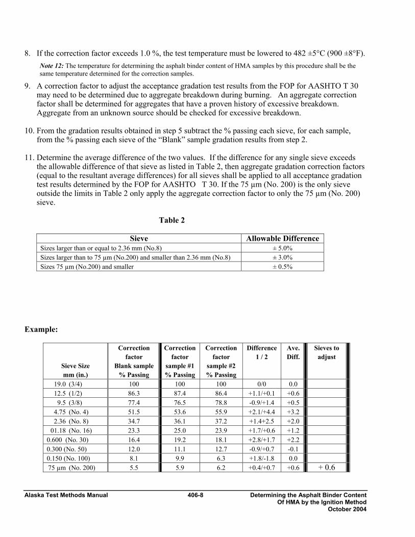
Alaska Test Methods Manual 406-8 Determining the Asphalt Binder Content Of HMA by the Ignition Method October 2004
8. If the correction factor exceeds 1.0 %, the test temperature must be lowered to 482 ±5°C (900 ±8°F). Note 12: The temperature for determining the asphalt binder content of HMA samples by this procedure shall be the same temperature determined for the correction samples.
9. A correction factor to adjust the acceptance gradation test results from the FOP for AASHTO T 30 may need to be determined due to aggregate breakdown during burning. An aggregate correction factor shall be determined for aggregates that have a proven history of excessive breakdown. Aggregate from an unknown source should be checked for excessive breakdown.
10. From the gradation results obtained in step 5 subtract the % passing each sieve, for each sample,
from the % passing each sieve of the “Blank” sample gradation results from step 2. 11. Determine the average difference of the two values. If the difference for any single sieve exceeds
the allowable difference of that sieve as listed in Table 2, then aggregate gradation correction factors (equal to the resultant average differences) for all sieves shall be applied to all acceptance gradation test results determined by the FOP for AASHTO T 30. If the 75 µm (No. 200) is the only sieve outside the limits in Table 2 only apply the aggregate correction factor to only the 75 µm (No. 200) sieve.
Table 2
Sieve Allowable Difference Sizes larger than or equal to 2.36 mm (No.8) ± 5.0% Sizes larger than to 75 µm (No.200) and smaller than 2.36 mm (No.8) ± 3.0% Sizes 75 µm (No.200) and smaller ± 0.5%
Example:
Sieve Size mm (in.)
Correction factor
Blank sample % Passing
Correction factor
sample #1 % Passing
Correction factor
sample #2 % Passing
Difference 1 / 2
Ave. Diff.
Sieves to adjust
19.0 (3/4) 100 100 100 0/0 0.0 12.5 (1/2) 86.3 87.4 86.4 +1.1/+0.1 +0.6 9.5 (3/8) 77.4 76.5 78.8 -0.9/+1.4 +0.5 4.75 (No. 4) 51.5 53.6 55.9 +2.1/+4.4 +3.2 2.36 (No. 8) 34.7 36.1 37.2 +1.4+2.5 +2.0 01.18 (No. 16) 23.3 25.0 23.9 +1.7/+0.6 +1.2 0.600 (No. 30) 16.4 19.2 18.1 +2.8/+1.7 +2.2 0.300 (No. 50) 12.0 11.1 12.7 -0.9/+0.7 -0.1 0.150 (No. 100) 8.1 9.9 6.3 +1.8/-1.8 0.0 75 µm (No. 200) 5.5 5.9 6.2 +0.4/+0.7 +0.6 + 0.6

Determining the Asphalt Binder Content 406-9 Alaska Test Methods Manual Of HMA by the Ignition Method October 2004
In this example all acceptance gradation test results (FOP for AASHTO T 30) performed on the residual aggregate would have an “Aggregate Correction Factor”. This factor would be + 0.6% on the 75 µm (No.200) sieve and would be subtracted from the % passing 75 µm (No.200) sieve.

Alaska Test Methods Manual 406-10 Determining the Asphalt Binder Content Of HMA by the Ignition Method October 2004
Addendum WAQTC FOP for AASHTO T 308 Following are guidelines for the use of WAQTC FOP for AASHTO T 308 by the State of Alaska DOT&PF.
1. Delete Step 8 in Calibration.
Moisture Content of Asphalt 407-1 Alaska Test Methods Manual Mixes by Oven Method October 2003
MOISTURE CONTENT OF BITUMINOUS MIXES BY OVEN WAQTC TM 6 Scope This procedure covers the determination of moisture content of bituminous mixes in accordance with WAQTC TM 6. Background on Test Method A test sample of bituminous mix is dried in an oven. The moisture content is calculated by one of two methods depending upon agency standards. • When binder content is reported as a percent of the initial mass of bituminous mix, moisture content
is reported as a percent of the initial, moist mass of mix. • When binder content is reported as a percent of the mass of aggregate, moisture content is reported
as a percent of the final, dry mass of mix. Apparatus • Balance or scale: 2 kg capacity, readable to 0.1 g conforming to AASHTO M 231 • Forced Draft, Ventilated, or Convection Oven: Capable of maintaining the temperature surrounding
the sample at 163 ±14°C (325 ±25°F) • Sample Container: Clean, dry, not affected by heat and of sufficient size to contain a test sample
without danger of spilling • Thermometer with a temperature range of 10-260°C (50-500°F) Sample The test sample shall be obtained in accordance with WAQTC FOP for AASHTO T 168, and reduced in accordance with WAQTC TM 5. The size of the test sample shall be a minimum of 1000 g. Procedure 1. Set the oven to a minimum of 105°C (221°F). In no case should the Job Mix Formula (JMF) mixing
temperature be exceeded. 2. Determine and record the mass of the sample container to the nearest 0.1 g. 3. Place the test sample in the sample container, and record the temperature of the test sample. 4. Remove the thermometer from the sample. Determine and record the total mass of the sample
container and test sample to the nearest 0.1 g. 5. Calculate the initial, moist mass of the test sample by subtracting the mass of the sample container
determined in Step 2 from total mass of the sample container and the test sample determined in Step 4.
Alaska Test Methods Manual 407-2 Moisture Content of Asphalt Mixes by Oven Method October 2003
6. Dry the test sample to a constant mass in the sample container. Note 1: Constant mass shall be defined as the mass at which further drying does not alter the mass by more than 0.05 percent. The sample shall be initially dried 90 minutes, and its mass determined at that time and at 30-minute intervals after that until a constant mass is reached.
7. Cool the sample container and test sample to approximately the same temperature as determined in Step 3.
8. Determine and record the total mass of the sample container and test sample to the nearest 0.1 g.
Note 2: Do not attempt to remove the test sample from the sample container for the purposes of determining mass.
9. Calculate the final, dry mass of the test sample by subtracting the mass of the sample container determined in Step 2 from the total mass of the sample container and the test sample determined in Step 8.
Note 3: Moisture content and the number of samples in the oven will affect the rate of drying at any given time. Placing wet samples in the oven with nearly dry samples could affect the drying process.
Calculations Constant Mass:
Calculate constant mass using the following formula:
100% xChange MpMnMp−=
Where: Mp = previous mass measurement Mn = new mass measurement
Example: Mass of container: 232.6 g Mass of container after first drying cycle: 1361.8 g Mass, Mp, of possibly dry sample: 1361.8 g – 232.6 g = 1129.2 g Mass of container and dry sample after second drying cycle: 1360.4 g
Mass, Mn, of dry sample: 1360.4 g – 232.6 g = 1127.8 g
100%12.0 2.11298.11272.1129 x−=
0.12% is not less than 0.05% so it must continue to be dried
Mass of container and dry sample after third drying cycle: 1359.9 g Mass, Mn, of dry sample: 1359.9g – 232.6g = 1127.3g
100%04.0 8.11273.11278.1127 x−=
0.04% is less than 0.05% so it is dry This mass becomes the Dry mass for calculating the moisture content.

Moisture Content of Asphalt 407-3 Alaska Test Methods Manual Mixes by Oven Method October 2003
Moisture Content: Calculate the moisture content, as a percent, using one of the following two formulas. Percent of Initial, Moist Mass:
where Mi = initial, moist mass Mf = final, dry mass
Example: Mi = 1134.9 g Mf = 1127.3 g
Percent of Final, Dry Mass:
where Mi = initial, moist mass Mf = final, dry mass
Example: Mi = 1134.9 g Mf = 1127.3 g
Report Results shall be reported on standard forms approved for use by the agency. Report the moisture content to 0.01 percent.
010M
MMContentMoisturef
fi×
−=
%67.0,674.0100g3.1127
g.31127g1134.9ContentMoisture say=×−
=
010M
MMContentMoisturei
fi×
−=
%67.0,670.0100g9.1134
g3.1127g1134.9ContentMoisture say=×−
=

Alaska Test Methods Manual 407-4 Moisture Content of Asphalt Mixes by Oven Method October 2003
This page intentionally left blank.
Mechanical Analysis of 408-1 Alaska Test Methods Manual Extracted Aggregate October 2004
MECHANICAL ANALYSIS OF EXTRACTED AGGREGATE FOP FOR AASHTO T 30 (See Addendum for AKDOT&PF Guidelines) Scope This procedure covers mechanical analysis of aggregate recovered from bituminous mix samples in accordance with AASHTO T 30. It is a specialized version of the standard wash sieve procedure in AASHTO T 11, and utilizes the aggregate recovered from the ignition oven used in AASHTO T 308. AASHTO T 30 was developed for analysis of extracted aggregate and, thus, includes references to extracted bitumen and filter element, which do not apply in this FOP. Sieve analyses determine the gradation or distribution of aggregate particles within a given sample in order to determine compliance with design and production standards. Apparatus • Balance or scale: capacity sufficient for the sample mass, accurate to 0.1 percent of the sample mass
or readable to 0.1 g • Sieves • Mechanical sieve shaker • Suitable drying equipment (see FOP for AASHTO T 255) • Containers and utensils – a pan or vessel of a size sufficient to contain the sample covered with
water and to permit vigorous agitation without loss of any part of the sample or water Sample Sieving 1. In this procedure it is required to shake the sample over nested sieves. The sieves are selected to
furnish information required by specification. Sieves are nested in order of decreasing size from the top to the bottom and the sample, or a portion of the sample, is placed on the top sieve. Additional sieves may be necessary to keep from overloading the specified sieves. The sample may also be sieved in increments.
2. Sieves are shaken in a mechanical shaker for approximately 10 minutes, or the minimum time determined to provide complete separation for the sieve shaker being used. The minimum time requirement should be evaluated for each shaker at least annually, by the following method: Continue shaking for a sufficient period and in such a manner that, after completion, not more than 0.5 percent by mass of the total sample passes any sieve during one minute of continuous hand sieving. Provide a snug-fitting pan and cover, and hold in a slightly inclined position in one hand. Strike the side of the sieve sharply and with an upward motion against the heel of the other hand at the rate of about 150 times per minute, turning the sieve about one sixth of a revolution at intervals of about 25 strokes. In determining sufficiency of sieving for sizes larger than 4.75mm (No. 4), limit the material on the sieve to a single layer of particles.
3. For sieves with openings smaller than 4.75mm (No. 4), the mass retained on any sieve shall not
exceed 7 kg/m2 (4 g/in2) of sieving surface. For sieves with openings 4.75mm (No. 4) and larger, the mass, in kg shall not exceed the product of 2.5 x (sieve opening in mm) x (effective sieving area). See Table 1.
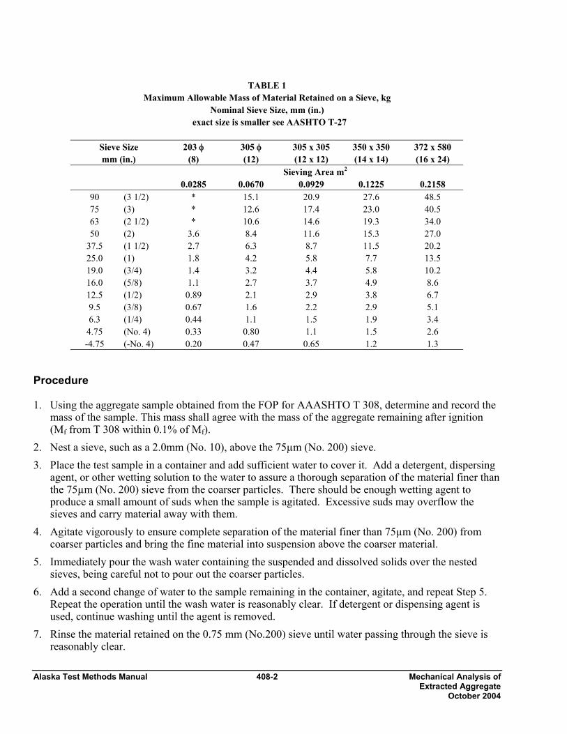
Alaska Test Methods Manual 408-2 Mechanical Analysis of Extracted Aggregate October 2004
TABLE 1
Maximum Allowable Mass of Material Retained on a Sieve, kg Nominal Sieve Size, mm (in.)
exact size is smaller see AASHTO T-27
Sieve Size mm (in.)
203 φ (8)
305 φ (12)
305 x 305 (12 x 12)
350 x 350 (14 x 14)
372 x 580 (16 x 24)
Sieving Area m2 0.0285 0.0670 0.0929 0.1225 0.2158
90 (3 1/2) * 15.1 20.9 27.6 48.5 75 (3) * 12.6 17.4 23.0 40.5 63 (2 1/2) * 10.6 14.6 19.3 34.0 50 (2) 3.6 8.4 11.6 15.3 27.0
37.5 (1 1/2) 2.7 6.3 8.7 11.5 20.2 25.0 (1) 1.8 4.2 5.8 7.7 13.5 19.0 (3/4) 1.4 3.2 4.4 5.8 10.2 16.0 (5/8) 1.1 2.7 3.7 4.9 8.6 12.5 (1/2) 0.89 2.1 2.9 3.8 6.7 9.5 (3/8) 0.67 1.6 2.2 2.9 5.1 6.3 (1/4) 0.44 1.1 1.5 1.9 3.4
4.75 (No. 4) 0.33 0.80 1.1 1.5 2.6 -4.75 (-No. 4) 0.20 0.47 0.65 1.2 1.3
Procedure 1. Using the aggregate sample obtained from the FOP for AAASHTO T 308, determine and record the
mass of the sample. This mass shall agree with the mass of the aggregate remaining after ignition (Mf from T 308 within 0.1% of Mf).
2. Nest a sieve, such as a 2.0mm (No. 10), above the 75µm (No. 200) sieve. 3. Place the test sample in a container and add sufficient water to cover it. Add a detergent, dispersing
agent, or other wetting solution to the water to assure a thorough separation of the material finer than the 75µm (No. 200) sieve from the coarser particles. There should be enough wetting agent to produce a small amount of suds when the sample is agitated. Excessive suds may overflow the sieves and carry material away with them.
4. Agitate vigorously to ensure complete separation of the material finer than 75µm (No. 200) from coarser particles and bring the fine material into suspension above the coarser material.
5. Immediately pour the wash water containing the suspended and dissolved solids over the nested sieves, being careful not to pour out the coarser particles.
6. Add a second change of water to the sample remaining in the container, agitate, and repeat Step 5. Repeat the operation until the wash water is reasonably clear. If detergent or dispensing agent is used, continue washing until the agent is removed.
7. Rinse the material retained on the 0.75 mm (No.200) sieve until water passing through the sieve is reasonably clear.
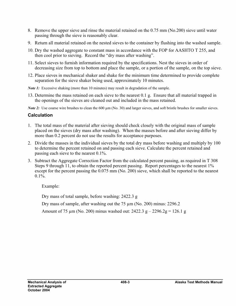
Mechanical Analysis of 408-3 Alaska Test Methods Manual Extracted Aggregate October 2004
8. Remove the upper sieve and rinse the material retained on the 0.75 mm (No.200) sieve until water passing through the sieve is reasonably clear.
9. Return all material retained on the nested sieves to the container by flushing into the washed sample. 10. Dry the washed aggregate to constant mass in accordance with the FOP for AASHTO T 255, and
then cool prior to sieving. Record the “dry mass after washing”. 11. Select sieves to furnish information required by the specifications. Nest the sieves in order of
decreasing size from top to bottom and place the sample, or a portion of the sample, on the top sieve. 12. Place sieves in mechanical shaker and shake for the minimum time determined to provide complete
separation for the sieve shaker being used, approximately 10 minutes. Note 1: Excessive shaking (more than 10 minutes) may result in degradation of the sample. 13. Determine the mass retained on each sieve to the nearest 0.1 g. Ensure that all material trapped in
the openings of the sieves are cleaned out and included in the mass retained. Note 2: Use coarse wire brushes to clean the 600 µm (No. 30) and larger sieves, and soft bristle brushes for smaller sieves. Calculation 1. The total mass of the material after sieving should check closely with the original mass of sample
placed on the sieves (dry mass after washing). When the masses before and after sieving differ by more than 0.2 percent do not use the results for acceptance purposes.
2. Divide the masses in the individual sieves by the total dry mass before washing and multiply by 100 to determine the percent retained on and passing each sieve. Calculate the percent retained and passing each sieve to the nearest 0.1%.
3. Subtract the Aggregate Correction Factor from the calculated percent passing, as required in T 308 Steps 9 through 11, to obtain the reported percent passing. Report percentages to the nearest 1% except for the percent passing the 0.075 mm (No. 200) sieve, which shall be reported to the nearest 0.1%.
Example:
Dry mass of total sample, before washing: 2422.3 g Dry mass of sample, after washing out the 75 µm (No. 200) minus: 2296.2 Amount of 75 µm (No. 200) minus washed out: 2422.3 g – 2296.2g = 126.1 g
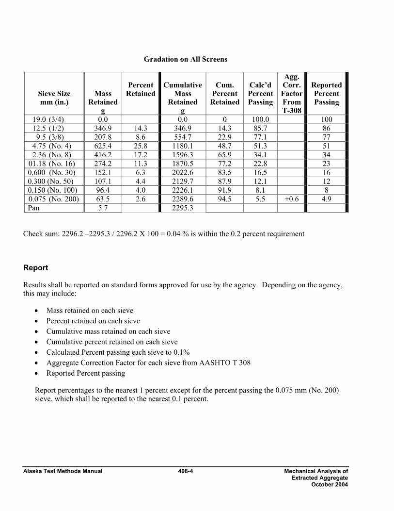
Alaska Test Methods Manual 408-4 Mechanical Analysis of Extracted Aggregate October 2004
Gradation on All Screens
Sieve Size mm (in.)
Mass Retained
g
Percent
Retained
Cumulative
Mass Retained
g
Cum.
Percent Retained
Calc’d PercentPassing
Agg. Corr. Factor From T-308
ReportedPercent Passing
19.0 (3/4) 0.0 0.0 0 100.0 100 12.5 (1/2) 346.9 14.3 346.9 14.3 85.7 86 9.5 (3/8) 207.8 8.6 554.7 22.9 77.1 77 4.75 (No. 4) 625.4 25.8 1180.1 48.7 51.3 51 2.36 (No. 8) 416.2 17.2 1596.3 65.9 34.1 34 01.18 (No. 16) 274.2 11.3 1870.5 77.2 22.8 23 0.600 (No. 30) 152.1 6.3 2022.6 83.5 16.5 16 0.300 (No. 50) 107.1 4.4 2129.7 87.9 12.1 12 0.150 (No. 100) 96.4 4.0 2226.1 91.9 8.1 8 0.075 (No. 200) 63.5 2.6 2289.6 94.5 5.5 +0.6 4.9 Pan 5.7 2295.3
Check sum: 2296.2 –2295.3 / 2296.2 X 100 = 0.04 % is within the 0.2 percent requirement Report Results shall be reported on standard forms approved for use by the agency. Depending on the agency, this may include:
• Mass retained on each sieve • Percent retained on each sieve • Cumulative mass retained on each sieve • Cumulative percent retained on each sieve • Calculated Percent passing each sieve to 0.1% • Aggregate Correction Factor for each sieve from AASHTO T 308 • Reported Percent passing
Report percentages to the nearest 1 percent except for the percent passing the 0.075 mm (No. 200) sieve, which shall be reported to the nearest 0.1 percent.

Mechanical Analysis of 408-5 Alaska Test Methods Manual Extracted Aggregate October 2004
Addendum WAQTC FOP for AASHTO T 30 Following are guidelines for the use of WAQTC FOP for AASHTO T 30 by the State of Alaska DOT&PF.
1. Calculate the minus 0.075 mm (No. 200) by dividing the sum of the loss from washing plus the mass of the material in the pan by the initial sample weight.

Alaska Test Methods Manual 408-6 Mechanical Analysis of Extracted Aggregate October 2004
This page intentionally left blank.

Theoretical Maximum Specific Gravity 409-1 Alaska Test Methods Manual Of Bituminous Paving Mixtures October 2004
THEORETICAL MAXIMUM SPECIFIC GRAVITY AND DENSITY OF BITUMINOUS PAVING MIXTURES (See Addendum for AKDOT&PF Guidelines) FOP FOR AASHTO T 209 Scope This procedure covers the determination of the maximum specific gravity of uncompacted bituminous paving mixtures in accordance with AASHTO T 209. Two methods using two different containers – bowl and flask – are covered. Apparatus • Balance or scale: 10 kg capacity, readable to 0.1 g. • Container: A glass, metal, or plastic bowl or volumetric flask capable of holding a 2 kg sample and
withstanding a partial vacuum. • Container cover: A glass plate or a metal or plastic cover with a vented opening. • Vacuum Lid: A metal or glass lid with a suitable vacuum connection. The vacuum opening to be
covered with a fine wire mesh. • Vacuum pump or water aspirator: Capable of evacuating air from the container to a residual
pressure of 4.0 kPa (30 mm Hg). • Manometer or Vacuum gauge: Traceable to NIST and capable of measuring residual pressure down
to 4.0 kPa (30 mm Hg) or less. • Water bath: A constant-temperature water bath (optional). • Thermometers: Calibrated liquid-in-glass, or electronic digital total immersion type, accurate to
0.5°C (0.9°F). • Bleeder valve to adjust vacuum. • Timer. Calibration of Flask Use a volumetric flask that is calibrated to accurately determine the mass of water, at 25 ±0.5°C (77 ±0.9°F), in the flask. The volumetric flask shall be calibrated periodically in conformance with procedures established by the agency. Test Sample Preparation 1. Obtain samples in accordance with the FOP for AASHTO T 168. 2. Test sample size shall conform to the requirements of Table 1. Samples larger than the capacity of
the container may be tested in two or more increments. Results will be combined and averaged. If the increments have a specific gravity difference greater than 0.018 for the bowl method and 0.011 for the flask method the test must be re-run.
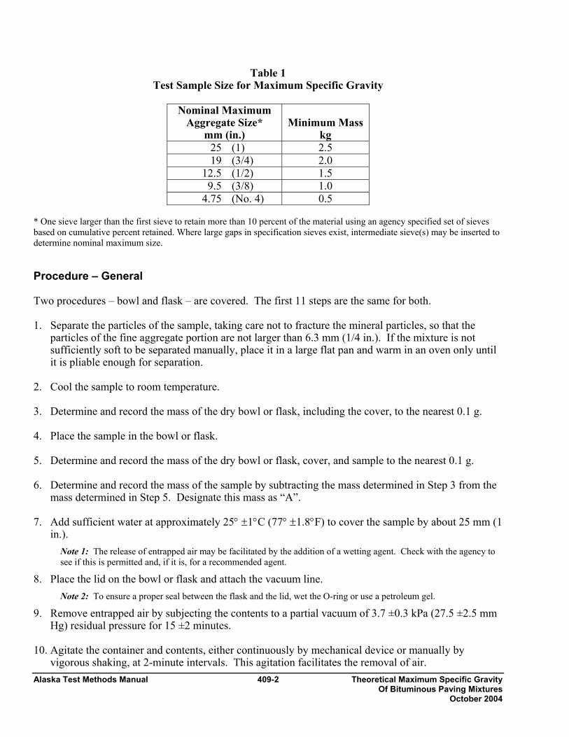
Alaska Test Methods Manual 409-2 Theoretical Maximum Specific Gravity Of Bituminous Paving Mixtures October 2004
Table 1 Test Sample Size for Maximum Specific Gravity
Nominal Maximum
Aggregate Size* mm (in.)
Minimum Mass
kg 25 (1) 2.5 19 (3/4) 2.0
12.5 (1/2) 1.5 9.5 (3/8) 1.0
4.75 (No. 4) 0.5 * One sieve larger than the first sieve to retain more than 10 percent of the material using an agency specified set of sieves based on cumulative percent retained. Where large gaps in specification sieves exist, intermediate sieve(s) may be inserted to determine nominal maximum size.
Procedure – General Two procedures – bowl and flask – are covered. The first 11 steps are the same for both. 1. Separate the particles of the sample, taking care not to fracture the mineral particles, so that the
particles of the fine aggregate portion are not larger than 6.3 mm (1/4 in.). If the mixture is not sufficiently soft to be separated manually, place it in a large flat pan and warm in an oven only until it is pliable enough for separation.
2. Cool the sample to room temperature. 3. Determine and record the mass of the dry bowl or flask, including the cover, to the nearest 0.1 g. 4. Place the sample in the bowl or flask. 5. Determine and record the mass of the dry bowl or flask, cover, and sample to the nearest 0.1 g. 6. Determine and record the mass of the sample by subtracting the mass determined in Step 3 from the
mass determined in Step 5. Designate this mass as “A”. 7. Add sufficient water at approximately 25° ±1°C (77° ±1.8°F) to cover the sample by about 25 mm (1
in.). Note 1: The release of entrapped air may be facilitated by the addition of a wetting agent. Check with the agency to see if this is permitted and, if it is, for a recommended agent.
8. Place the lid on the bowl or flask and attach the vacuum line. Note 2: To ensure a proper seal between the flask and the lid, wet the O-ring or use a petroleum gel.
9. Remove entrapped air by subjecting the contents to a partial vacuum of 3.7 ±0.3 kPa (27.5 ±2.5 mm Hg) residual pressure for 15 ±2 minutes.
10. Agitate the container and contents, either continuously by mechanical device or manually by
vigorous shaking, at 2-minute intervals. This agitation facilitates the removal of air.

Theoretical Maximum Specific Gravity 409-3 Alaska Test Methods Manual Of Bituminous Paving Mixtures October 2004
11. Slowly open the release valve, turn off the vacuum pump and remove the lid. Procedure – Bowl 12A. Suspend and immerse the bowl and contents in water at 25 ±1.0°C (77 ±1.8°F) for 10 ±1 minutes.
The holder shall be immersed sufficiently to cover it and the bowl. 13A. Determine and record the submerged weight of the bowl and contents to the nearest 0.1 g. 14A. Empty bowl and re-submerge following step 12A to determine the submerged weight of the bowl
to the nearest 0.1 g. 15A. Determine and record the submerged weight of the sample the nearest 0.1 g by subtracting the
submerged weight of the bowl from the submerged weight determined in Step 13A. Designate this submerged weight as “C”.
Procedure – Flask 12B. Fill the flask with water, place in a 25 ±1°C (77 ±1.8°F) water bath and allow to stand for 10 ±1
minutes. Note 3: In lieu of placing the flask in the water bath, after 10 minutes determine the temperature of the water in the flask and make the appropriate density correction using Table 2.
13B. Finish filling the flask, place the cover or a glass plate on the flask, and eliminate all air from the flask. Note 4: When using the metal flask and cover, place the cover on the flask and push down slowly, forcing excess water out of the hole in the center of the cover. Use care when filling flask to avoid reintroducing air into the water.
14B. Wipe off excess water from the flask and cover. 15B. Determine and record the mass of the flask, cover, de-aired water, and sample to the nearest 0.1 g.
Designate this mass as “E”. 16B Follow steps 12B through 15B with just water. Designate this mass as “D”. Many agencies
determine this mass ahead of time. Procedure – Mixtures Containing Uncoated Porous Aggregate If the pores of the aggregates are not thoroughly sealed by a bituminous film, they may become saturated with water during the vacuuming procedure, resulting in an error in maximum density. To determine if this has occurred, complete the general procedure and then: 1. Drain water from sample through a towel held over top of container to prevent loss of material. 2. Spread sample before an electric fan to remove surface moisture. 3. Determine the mass of the sample when the surface moisture appears to be gone.

Alaska Test Methods Manual 409-4 Theoretical Maximum Specific Gravity Of Bituminous Paving Mixtures October 2004
4. Continue drying and determine the mass of the sample at 15-minute intervals until less than a 0.5 g loss is found between determinations.
5. Record the mass as the saturated surface-dry mass to the nearest 0.1 g. Designate this mass as
“ASSD”. 6. Calculate, as indicated below, maximum specific gravity using “A” and “ASSD”, and compare the
two values. Calculation Calculate the maximum specific gravity to three decimal places as follows. Bowl Procedure
where: A = mass of dry sample in air, g C = submerged weight of sample in water, g Example: A = 1432.7 g C = 848.6 g
Flask Procedure or
where: A = Mass of dry sample in air, g ASSD = Mass of saturated surface-dry sample in air, g D = Mass of flask filled with water at 25°C (77°F), g E = Mass of flask filled with water and the test sample at test temperature, g
REDA
AGravitySpecificMaximum ×−+
=
C-AAGravitySpecificMaximum =
453.2g6.848g7.1432
g1432.7GravitySpecificMaximum =−
=
Maximum Specific Gravity
(for mixtures containing uncoated aggregate materials)
=+ −
×A
A D ER
SSD
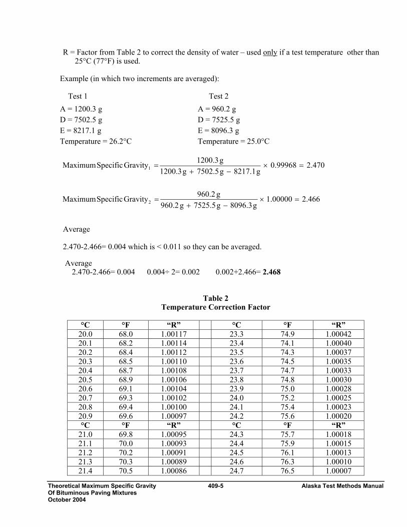
Theoretical Maximum Specific Gravity 409-5 Alaska Test Methods Manual Of Bituminous Paving Mixtures October 2004
R = Factor from Table 2 to correct the density of water – used only if a test temperature other than 25°C (77°F) is used.
Example (in which two increments are averaged): Test 1 Test 2 A = 1200.3 g A = 960.2 g D = 7502.5 g D = 7525.5 g E = 8217.1 g E = 8096.3 g Temperature = 26.2°C Temperature = 25.0°C
Average
2.470-2.466= 0.004 which is < 0.011 so they can be averaged.
Average 2.470-2.466= 0.004 0.004÷ 2= 0.002 0.002+2.466= 2.468
Table 2 Temperature Correction Factor
°C °F “R” °C °F “R”
20.0 68.0 1.00117 23.3 74.9 1.00042 20.1 68.2 1.00114 23.4 74.1 1.00040 20.2 68.4 1.00112 23.5 74.3 1.00037 20.3 68.5 1.00110 23.6 74.5 1.00035 20.4 68.7 1.00108 23.7 74.7 1.00033 20.5 68.9 1.00106 23.8 74.8 1.00030 20.6 69.1 1.00104 23.9 75.0 1.00028 20.7 69.3 1.00102 24.0 75.2 1.00025 20.8 69.4 1.00100 24.1 75.4 1.00023 20.9 69.6 1.00097 24.2 75.6 1.00020 °C °F “R” °C °F “R”
21.0 69.8 1.00095 24.3 75.7 1.00018 21.1 70.0 1.00093 24.4 75.9 1.00015 21.2 70.2 1.00091 24.5 76.1 1.00013 21.3 70.3 1.00089 24.6 76.3 1.00010 21.4 70.5 1.00086 24.7 76.5 1.00007
470.20.99968g8217.1g7502.5g1200.3
g1200.3GravitySpecificMaximum 1 =×−+
=
466.200000.1g3.0968g5.5257g2.609
g2.609GravitySpecificMaximum 2 =×−+
=

Alaska Test Methods Manual 409-6 Theoretical Maximum Specific Gravity Of Bituminous Paving Mixtures October 2004
21.5 70.7 1.00084 24.8 76.6 1.00005 21.6 70.9 1.00082 24.9 76.8 1.00002 21.7 71.1 1.00080 25.0 77.0 1.00000 21.8 71.2 1.00077 25.1 77.2 0.99997 21.9 71.4 1.00075 25.2 77.4 0.99995 22.0 71.6 1.00073 25.3 77.5 0.99992 22.1 71.8 1.00030 25.4 77.7 0.99989 22.2 72.0 1.00068 25.5 77.9 0.99987 22.3 72.1 1.00066 25.6 78.1 0.99984 22.4 72.3 1.00064 25.7 78.3 0.99981 22.5 72.5 1.00061 25.8 78.4 0.99979 22.6 72.7 1.00059 25.9 78.6 0.99976 22.7 72.9 1.00057 26.0 78.8 0.99973 22.8 73.0 1.00054 26.1 79.0 0.99971 22.9 73.2 1.00052 26.2 79.2 0.99968 23.0 73.4 1.00050 26.3 79.3 0.99965 23.1 73.6 1.00047 26.4 79.5 0.99963 23.2 73.8 1.00045 26.5 79.7 0.99960
Theoretical Maximum Density To calculate the theoretical maximum density at 25°C (77°F) use one of the following formulas. The density of water at 25°C (77°F) = 997.1 in Metric units or 62.245 in English units. Theoretical maximum density kg/m3 = maximum specific gravity X 997.1 kg/ m3 2.468 X 997.1 kg/ m3 = 2461 kg/ m3 or Theoretical maximum density lb/ft3 = maximum specific gravity X 62.245 lb/ft3 2.468 X 62.245 lb/ft3 = 153.6 lb/ft3 Report Results shall be reported on standard forms approved for use by the agency. Report maximum specific gravity to three decimal places. Report the theoretical maximum density to agency standard.

Theoretical Maximum Specific Gravity 409-7 Alaska Test Methods Manual Of Bituminous Paving Mixtures October 2004
Addendum WAQTC FOP for AASHTO T 209 Following are guidelines for the use of WAQTC FOP for AASHTO T 209 by the State of Alaska DOT&PF.
1. The flask method is to be used in all Theoretical Maximum Specific Gravity determinations.
2. Report the Theoretical Maximum Specific Gravity to the nearest 0.001.

Alaska Test Methods Manual 409-8 Theoretical Maximum Specific Gravity Of Bituminous Paving Mixtures October 2004
This page intentionally left blank.
Bulk Specific Gravity of 410-1 Alaska Test Methods Manual Compacted Bituminous Mixtures October 2004
BULK SPECIFIC GRAVITY OF COMPACTED BITUMINOUS MIXTURES USING SATURATED SURFACE-DRY SPECIMENS (See Addendum for AKDOT&PF Guidelines) FOP FOR AASHTO T 166 BULK SPECIFIC GRAVITY OF COMPACTED BITUMINOUS MIXTURES USING PARAFFIN-COATED SPECIMENS FOP FOR AASHTO T 275 Scope This procedure covers the determination of bulk specific gravity of compacted bituminous mixtures using three methods – A, B, and C – in accordance with AASHTO T 166. These three methods are for use on specimens not having open or inter-connecting voids and/or absorbing more than 2 percent water by volume. A fourth and fifth method – D & E – in accordance with AASHTO T 275 and covering specimens having open or interconnecting voids and/or absorbing more than 2 percent water by volume is also included. Apparatus – Method A (Suspension) • Balance or scale: 5 kg capacity, readable to 0.1 g, fitted with a suitable suspension apparatus and
holder to permit weighing the specimen while suspended in water and conforming to AASHTO M 231.
• Suspension apparatus: Wire of the smallest practical size and constructed to permit the container to be fully immersed.
• Water bath: For immersing the specimen in water while suspended under the balance or scale, and equipped with an overflow outlet for maintaining a constant water level.
• Towel: Damp towel used for surface drying specimens. • Oven: Capable of maintaining a temperature of 110 ±5°C (230 ±9°F) for drying the specimens to a
constant mass.
Note 1: AASHTO T 166 defines constant mass as the mass that further drying at 52 ±3°C (125 ±5°F) does not alter the mass by more than 0.05 percent. It also states that samples shall initially be dried overnight and that mass determinations shall be made at 2-hour drying intervals. AASHTO T 166 also states that recently molded laboratory samples that have not been exposed to moisture do not need drying.
• Pan: Pan or other suitable container of known mass, large enough to hold a sample for drying in oven.
• Thermometer: Having a range of 19 to27° C(66 to 80°F), graduated in 0.1° C(0.2°F) subdivisions. Procedure - Method A (Suspension) 1. Dry the specimen to constant mass. See note #1. 2. Cool the specimen in air at 25 ±5°C (77±9°F), and determine and record the dry mass to the nearest
0.1 g. Designate this mass as “A”. Note 2: water level must be at overflow level before and during the test.
3. Immerse the specimen in water at 25 ±1°C (77 ±1.8°F) for 3 to 5 minutes.
Alaska Test Methods Manual 410-2 Bulk Specific Gravity of Compacted Bituminous Mixtures October 2004
4. Determine and record the submerged weight to the nearest 0.1 g. Designate this submerged weight as “C”.
5. Remove the sample from the water and quickly surface dry with a damp towel. 6. Determine and record the mass of the SSD specimen to nearest 0.1 g. Designate this mass as “B”.
Any water that seeps from the specimen during the mass determination is considered part of the saturated specimen.
Note 3: To expedite the procedure, the immersed weight, C, can be determined first, followed by the SSD mass, B, and finally the dry mass of the specimen, A. To further expedite the process see Method C.
Calculations - Method A (Suspension) where: A = Mass of dry specimen in air, g B = Mass of SSD specimen in air, g C = Weight of specimen in water at 25 ±1°C (77 ±1.8°F), g Apparatus – Method B (Volumeter) • Balance or scale: 5 kg capacity, readable to 0.1 g and conforming to AASHTO M 231. • Water bath: thermostatically controlled to 25 ±0.5°C (77±0.9°F). • Thermometer: Range of 19 to 27°C (66 to 80°F), and graduated in 0.1°C (0.2°F) subdivisions. • Volumeter: Calibrated to 1200 mL or appropriate capacity for test sample and having a tapered lid
with a capillary bore. • Oven: Capable of maintaining a temperature of 110 ±5°C (230 ±9°F) for drying the specimens to a
constant mass. • Pan: Pan or other suitable container of known mass, large enough to hold a sample for drying in
oven. • Towel: Damp towel used for surface drying specimens. Procedure - Method B (Volumeter) 1. Dry the specimen to constant mass. See note 1. 2. Cool the specimen in air at 25 ±5°C (77±9°F), and determine and record the dry mass to the nearest
0.1 g. Designate this mass as “A”. 3. Immerse the specimen in the water bath for at least 10 minutes.
CBAGravitySpecificBulk−
=
100CBABvolume)(byAbsorbedWaterPercent ×
−−
=

Bulk Specific Gravity of 410-3 Alaska Test Methods Manual Compacted Bituminous Mixtures October 2004
4. Fill the volumeter with distilled water at 25 ±1°C (77 ±1.8°F) making sure some water escapes through the capillary bore of the tapered lid. Wipe the volumeter dry. Determine the mass of the volumeter to the nearest 0.1 g. Designate this mass as “D”.
5. Remove the specimen from the water bath and quickly surface dry with a damp towel. 6. Determine and record the mass of the SSD specimen to the nearest 0.1 g. Designate this mass as
“B”. Any water that seeps from the specimen during the mass determination is considered part of the saturated specimen.
7. Place the specimen in the volumeter and let stand 60 seconds. 8. Bring the temperature of the water to 25 ±1°C (77 ±1.8°F), and cover the volumeter making sure
some water escapes through the capillary bore of the tapered lid. 9. Wipe the volumeter dry. 10. Determine and record the mass of the volumeter and specimen to the nearest 0.1 g. Designate this
mass as “E”.
Note 4: To expedite the procedure, the SSD mass, B, can be determined first, followed by the mass of the volumeter and specimen, E, and finally the dry mass of the specimen, A. See Method C.
Note 5: Method B is not acceptable for use with specimens that have more than 6 % air voids.
Calculations - Method B (Volumeter) where: A = Mass of dry specimen in air, g B = Mass of SSD specimen in air, g D = Mass of volumeter filled with water at 25 ±1°C (77 ±1.8°F), g E = Mass of volumeter filled with specimen and water, g Apparatus - Method C (Rapid Test for Method A or B) See Methods A or B. Note 6: This procedure can be used for specimens not required to be saved and containing substantial amounts of moisture. Cores can be tested the same day as obtained by this method.
EDBAGravitySpecificBulk
−+=
100EDB
A-Bvolume)(byAbsorbedWaterPercent ×−+
=
Alaska Test Methods Manual 410-4 Bulk Specific Gravity of Compacted Bituminous Mixtures October 2004
Procedure – Method C (Rapid Test for Method A or B) 1. Determine which method to perform, A or B. Proceed with Method A or B, except that the dry mass,
A, is determined last. In method A and B, start on step 3, complete that procedure then continue as follows to determine mass “A”.
2. Place the specimen on a large, flat bottom pan of known mass. 3. Heat at a minimum of 105°C (221°F), until the specimen can be easily separated to the point where
the fine aggregate particles are not larger than 6.4 mm (1/4 in.). In no case should the Job mix formula mixing temperature be exceeded.
4. Dry to constant mass. Constant mass is defined as the mass at which further drying at the
temperature in step 3 does not change by more than 0.05% after an additional 2 hour drying time. 5. Cool to room temperature at 25 ±5°C (77 ±9°F). 6. Determine and record the mass of the pan and specimen to the nearest 0.1 g. 7. Determine and record the mass of the dry specimen to the nearest 0.1 g by subtracting the mass of
the pan from the mass determined in Step 6. Designate this mass as “A”. Calculations – Method C (Rapid Test for Method A or B) Complete the calculations as outlined in Methods A or B, as appropriate. Materials – Method D Suspension (Coated Specimens/AASHTO T 275) • Paraffin or parafilm: Used to coat test specimens. Apparatus – Method D Suspension (Coated Specimens/AASHTO T 275) • Balance or scale: 5 kg capacity, readable to 0.1 g, fitted with a suitable suspension apparatus and
holder to permit weighing the specimen while suspended in water and conforming to AASHTO M 231.
• Suspension apparatus: Wire of the smallest practical size and constructed to permit the container to be fully immersed.
• Water bath: For immersing the specimen in water while suspended under the balance or scale, and equipped with an overflow outlet for maintaining a constant water level.
• Oven: Capable of maintaining a temperature of 110 ±5°C (230 ±9°F) for drying the specimens to a constant mass.
• Pan: Pan or other suitable container of known mass, large enough to hold a sample for drying in oven.
Procedure - Method D Suspension (Coated Specimens/AASHTO T 275)

Bulk Specific Gravity of 410-5 Alaska Test Methods Manual Compacted Bituminous Mixtures October 2004
1. Dry the specimen to constant mass. See note 1. 2. Cool the specimen in air at 25 ±5°C (77±9°F), and determine and record the dry mass to the nearest
0.1 g. Designate this mass as “A”. 3. Coat specimen on all surfaces with melted paraffin, or parafilm coating, sufficiently thick to seal all
voids. 4. Allow coating to cool in air at 25 ±5°C (77±9°F) for 30 minutes. 5. Determine and record the mass of the coated specimen to the nearest 0.1 g. Designate this mass as
“D”. 6. Immerse the specimen in water at 25 ±1°C (77 ±1.8°F) for three to five minutes. 7. Determine and record the submerged weight to the nearest 0.1 g. Designate this submerged weight
as “E”. 8. Determine the specific gravity of paraffin or parafilm at 25 ±1°C (77 ±1.8°F) from the
manufacturer’s literature or other suitable source. Designate this specific gravity as “F”. Calculations - Method D Suspension (Coated Specimens/AASHTO T 275) where: A = Mass of dry specimen in air, g D = Mass of specimen with paraffin coating in air, g E = Weight of specimen with paraffin coating in water, g F = Specific gravity of paraffin or parafilm at 25 ±1°C (77 ±1.8°F) Apparatus – Method E Volumeter (Coated Specimens/AASHTO T 275) • Balance or scale: 5 kg capacity, readable to 0.1 g and conforming to AASHTO M 231. • Water bath: thermostatically controlled to 25 ±0.5°C (77±0.9°F). • Thermometer: Range of 19 to 27°C (66 to 80°F), and graduated in 0.1°C (0.2°F) subdivisions. • Volumeter: Calibrated to 1200 mL or appropriate capacity for test sample and having a tapered lid
with a capillary bore. • Oven: Capable of maintaining a temperature of 110 ±5°C (230 ±9°F) for drying the specimens to a
constant mass. • Pan: Pan or other suitable container of known mass, large enough to hold a sample for drying in
oven.
⎥⎦⎤
⎢⎣⎡ −
−−=
FADED
AGravitySpecificBulk

Alaska Test Methods Manual 410-6 Bulk Specific Gravity of Compacted Bituminous Mixtures October 2004
• Towel: Damp towel used for surface drying specimens. Procedure - Method E Volumeter (Coated Specimens/AASHTO T 275) 1. Dry the specimen to constant mass. See note 1. 2. Cool the specimen in air at 25 ±5°C (77±9°F), and determine and record the dry mass to
the nearest 0.1 g. Designate this mass as “A”. 3. Coat the specimen all surfaces with paraffin, or parafilm coating, sufficiently thick to seal
all voids. 4. Allow coating to cool in air at 25 ±5°C (77 ±9°F) for 30 minutes. 5. Determine and record the mass of the coated specimen to the nearest 0.1g. Designate this
mass as “C”. 6. Fill the volumeter with distilled water at 25 ±1°C (77 ±1.8°F) and place the coated
specimen in the volumeter. 7. Bring the temperature of the water to 25 ±1°C (77 ±1.8°F), and cover the volumeter
making sure some water escapes through the capillary bore of the tapered lid. 8. Wipe the volumeter dry. 9. Determine and record the mass of the volumeter and specimen to the nearest 0.1 g.
Designate this mass as “E”.
Calculations - Method E Volumeter (Coated Specimens/AASHTO T 275) where: A = Mass of dry specimen in air, g C = Mass of specimen with paraffin coating in air, g D = Mass of volumeter filled water at 25 ±1°C (77 ±1.8°F), g E = Mass of volumeter filled with specimen with paraffin coating and in water25 ±1°C (77 ±1.8°F), g F = Specific gravity of paraffin or parafilm at 25 ±1°C (77 ±1.8°F) Report Results shall be reported on standard forms approved for use by the agency. Report the bulk specific gravity and absorption to 3 decimal places. Report the method performed.
⎥⎦⎤
⎢⎣⎡ −
+−−=
)F
AC(D
AGravitySpecificBulkCE

Bulk Specific Gravity of 410-7 Alaska Test Methods Manual Compacted Bituminous Mixtures October 2004
Addendum WAQTC FOP for AASHTO T 166/T 275 Following are guidelines for the use of WAQTC FOP for AASHTO T 166/T 275 by the State of Alaska DOT&PF.
1. Report compaction to the 1%. Calculate as follows:
100×⎟⎠⎞
⎜⎝⎛=
BCA
Where: A = Percent Compaction B = Theoretical Maximum Specific Gravity C = Bulk Specific Gravity
2. Method C is the accepted method for AKDOT&PF projects. 3. Report absorption to 0.1%.

Alaska Test Methods Manual 410-8 Bulk Specific Gravity of Compacted Bituminous Mixtures October 2004
This page intentionally left blank.

In-Place Density of Bituminous Mixes … 411-1 Alaska Test Methods Manual October 2004
IN-PLACE DENSITY OF BITUMINOUS MIXES USING THE NUCLEAR MOISTURE-DENSITY GAUGE (See Addendum for AKDOT&PF Guidelines) FOP FOR WAQTC TM 8 Scope This test method describes a test procedure for determining the density of bituminous concrete by means of a nuclear gauge employing either direct transmission or backscatter methods. Correlation with densities determined under the FOP for AASHTO T 166 is required by some agencies. This test method involves potentially hazardous materials, operations and equipment. This method does not purport to address all of the safety problems associated with its use. It is the responsibility of the user of this standard to establish appropriate safety and health practices and determine the applicability of regulatory limitations prior to use. See Hazards. All operators will be trained in radiation safety prior to operating nuclear density gauges. Some agencies require the use of personal monitoring devices such as a thermoluminescent dosimeter or film badge. Apparatus • Nuclear density gauge with the factory matched standard reference block. • Drive pin, guide, scraper plate, and hammer for testing in direct transmission mode. • Transport case for properly shipping and housing the gauge and tools. • Instruction manual for the specific make and model of gauge. • Radioactive materials information and calibration packet containing:
− Daily Standard Count Log. − Factory and Laboratory Calibration Data Sheet. − Leak Test Certificate. − Shippers Declaration for Dangerous Goods. − Procedure Memo for Storing, Transporting and Handling Nuclear Testing Equipment. − Other radioactive materials documentation as required by local regulatory requirements.
Material • Filler material: Fine graded sand from the source used to produce the asphalt pavement or other
agency approved materials. Hazards
The gauge utilizes radioactive materials that may be hazardous to the health of the user unless proper precautions are taken. Users of this gauge must become familiar with the applicable safety procedures and governmental regulations. Effective instructions together with routine safety procedures such as source leak tests, recording and evaluation of personal monitoring device data, etc., are a recommended part of the operation and storage of this gauge.
Alaska Test Methods Manual 411-2 In-Place Density of Bituminous Mixes … October 2004
Calibration and Standardization 1. Calibrate the nuclear gauge as required by the agency. This calibration may be performed by the
agency using manufacturer’s recommended procedures or by other facilities approved by the agency. 2. Turn the gauge on and allow it to stabilize (approximately 10 to 20 minutes) prior to standardization.
Standardize the nuclear gauge at the construction site at the start of each day’s work and as often as deemed necessary by the operator or agency. Record the standard count for both density and moisture in the Daily Standard Count Log. The exact procedure for standard count is listed in the manufacturer’s Operators Manual.
Note 1: Daily variations in standard count shall not exceed the daily variations established by the manufacturer of the gauge. If the daily variations are exceeded after repeating the standardization procedure, the gauge should be repaired and or recalibrated.
Procedure 1. Turn the gauge on and allow it to stabilize per manufactures recommendations (approximately 10 to
20 minutes).. Leave the power on during the day’s testing. 2. Standardize the gauge by performing standard counts as covered in Step 2 above under Calibration
and Standardization. Note 2: New standard counts may be necessary more than once a day. See agency requirements.
3. Select a test location(s) in accordance with the project specifications. Test sites should be relatively smooth and flat. The test location should be at least 10 m (30 ft) away from other sources of radioactivity and at least 3 m (10 ft) away from large objects. If the gauge will be closer than 600 mm (24 in.) to any vertical mass, or less than 300 mm (12 in.) from a vertical pavement edge, use the gauge manufacturer’s correction procedure.
4. Direct Transmission Mode
a. Maximum contact between the base of the gauge and the surface of the material under test is critical. This mode can not be used where the depth of the Hot Mix Asphalt (HMA) is less than 33 mm (0.11’).
b. Use the guide and scraper plate as a template and drill a hole to a depth of at least 7 mm (1/4 in.)
deeper than the measurement depth required for the gauge. c. Place the gauge on the prepared surface so that the probe can enter the hole. Lower the probe to
the desired a test depth not to exceed the thickness of the lift of pavement being measured. Position the gauge by pulling it towards the scaler / detector so that the probe is firmly against the side of the hole.
d. Take a one-minute test and record the wet density reading. Rotate the gauge 90 degrees. Reseat the gauge by gently moving it side to side while pulling it towards the scaler / detector so that the probe is firmly against the side of the hole. Take another one-minute test and record the wet density reading.
e. The difference between the two one minute tests shall be less than 50 kg/m3 (3 lb/ft3). If not, then
rotate the gauge another 90 degrees. Reseat the gauge by gently moving it side to side while

In-Place Density of Bituminous Mixes … 411-3 Alaska Test Methods Manual October 2004
pulling it towards the scaler / detector so that the probe is firmly against the side of the hole. Then take another one-minute test and record the wet density reading. Again compare the readings. If difference between the second and third one minute tests is not less than 50 kg/m3 (3 lb/ft3) move to another test location.
5. Backscatter Mode
a. Maintain maximum contact between the base of the gauge and the surface of the material under test. Use filler material to fill surface voids. Spread a small amount of filler material over the test site surface and distribute it evenly. Strike off the surface with a straight edge guide or scraper plate, and remove excess material.
b. Place the gauge on the test site. Using a crayon, (not spray paint) mark the outline or footprint of
the gauge. Extend the probe to the backscatter position.
c. Take a one-minute test and record the wet density reading. Rotate the gauge 90 degrees about the probe. Mark the outline or footprint of the gauge. Take another one-minute test and record the wet density reading.
d. If the difference between the two one minute tests is greater than 40 kg/m3 (2.5 lb/ft3), retest in both directions.
.
Calculation of Results The density reported for each test site shall be the average of the two individual one-minute tests. Percent compaction is determined by comparing the in-place wet density as determined by this method to the appropriate agency density standard. See appropriate agency policy for use of density standards. Correlation with Cores Note 3: When density correlation with test method AASHTO T 166 is required, correlation of the nuclear gauge with
pavement cores shall be made on the first day’s paving (within 24 hours) or from a test strip constructed prior to the start of paving. Cores must be taken before traffic is allowed on the pavement.
1. Determine the number of cores required for correlation from the agency’s specifications. Cores shall be located on the first day’s paving or on the test strip. Locate the test sites in accordance with the agency’s specifications. Follow the “Procedure” section above to establish test sites and obtain densities using the nuclear gauge.
2. Obtain a pavement core from each of the test sites. The core should be taken from the center of the
nuclear gauge footprint. If direct transmission was used, locate the core at least 25 mm (1 in.) away from the edge of the drive pin hole.
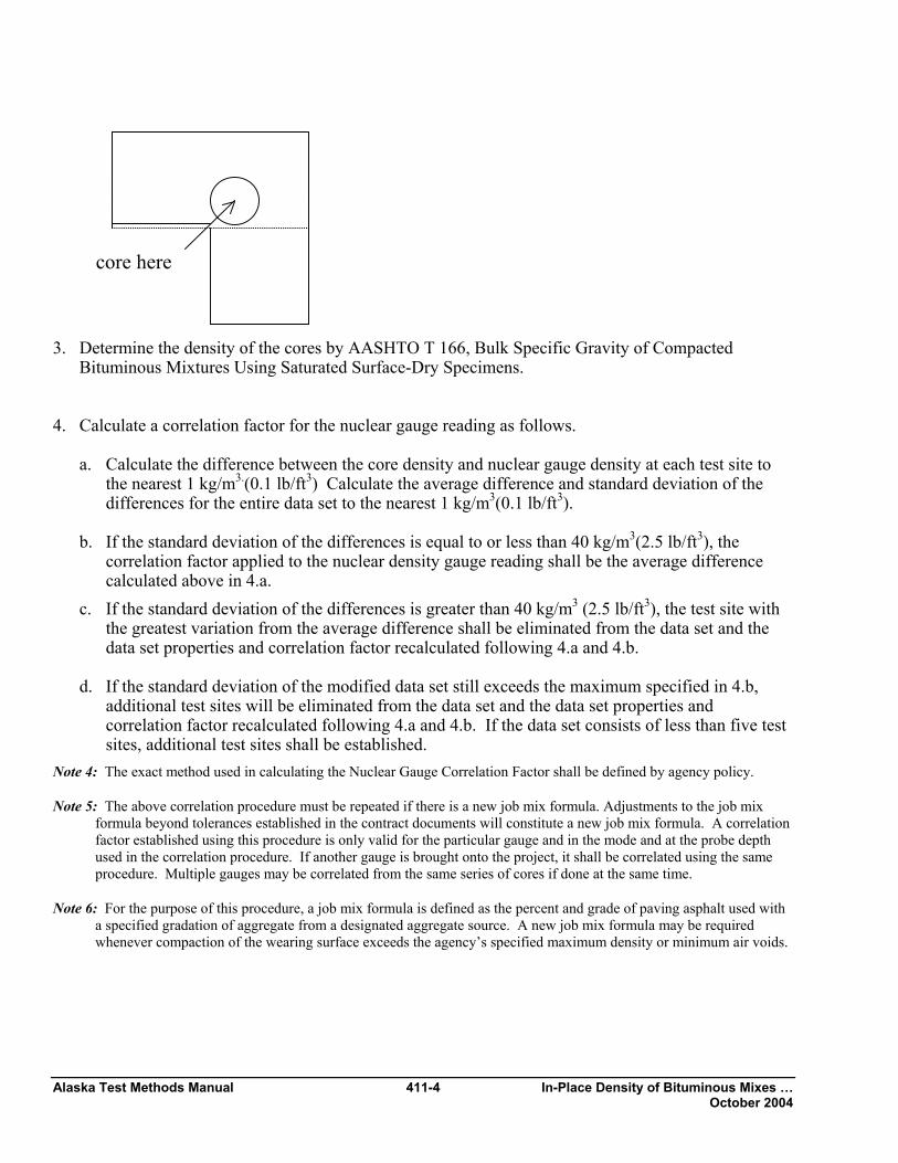
Alaska Test Methods Manual 411-4 In-Place Density of Bituminous Mixes … October 2004
3. Determine the density of the cores by AASHTO T 166, Bulk Specific Gravity of Compacted
Bituminous Mixtures Using Saturated Surface-Dry Specimens. 4. Calculate a correlation factor for the nuclear gauge reading as follows.
a. Calculate the difference between the core density and nuclear gauge density at each test site to the nearest 1 kg/m3.(0.1 lb/ft3) Calculate the average difference and standard deviation of the differences for the entire data set to the nearest 1 kg/m3(0.1 lb/ft3).
b. If the standard deviation of the differences is equal to or less than 40 kg/m3(2.5 lb/ft3), the
correlation factor applied to the nuclear density gauge reading shall be the average difference calculated above in 4.a.
c. If the standard deviation of the differences is greater than 40 kg/m3 (2.5 lb/ft3), the test site with the greatest variation from the average difference shall be eliminated from the data set and the data set properties and correlation factor recalculated following 4.a and 4.b.
d. If the standard deviation of the modified data set still exceeds the maximum specified in 4.b,
additional test sites will be eliminated from the data set and the data set properties and correlation factor recalculated following 4.a and 4.b. If the data set consists of less than five test sites, additional test sites shall be established.
Note 4: The exact method used in calculating the Nuclear Gauge Correlation Factor shall be defined by agency policy.
Note 5: The above correlation procedure must be repeated if there is a new job mix formula. Adjustments to the job mix formula beyond tolerances established in the contract documents will constitute a new job mix formula. A correlation factor established using this procedure is only valid for the particular gauge and in the mode and at the probe depth used in the correlation procedure. If another gauge is brought onto the project, it shall be correlated using the same procedure. Multiple gauges may be correlated from the same series of cores if done at the same time.
Note 6: For the purpose of this procedure, a job mix formula is defined as the percent and grade of paving asphalt used with a specified gradation of aggregate from a designated aggregate source. A new job mix formula may be required whenever compaction of the wearing surface exceeds the agency’s specified maximum density or minimum air voids.
core here
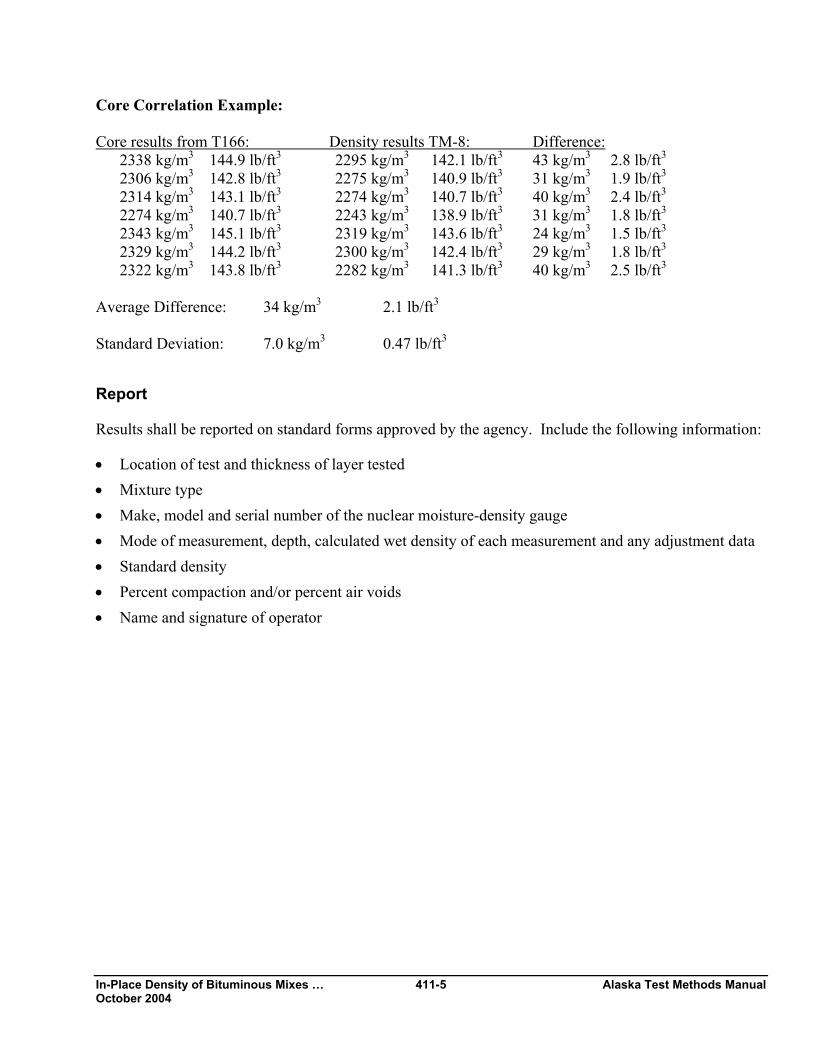
In-Place Density of Bituminous Mixes … 411-5 Alaska Test Methods Manual October 2004
Core Correlation Example: Core results from T166: Density results TM-8: Difference: 2338 kg/m3 144.9 lb/ft3 2295 kg/m3 142.1 lb/ft3 43 kg/m3 2.8 lb/ft3 2306 kg/m3 142.8 lb/ft3 2275 kg/m3 140.9 lb/ft3 31 kg/m3 1.9 lb/ft3 2314 kg/m3 143.1 lb/ft3 2274 kg/m3 140.7 lb/ft3 40 kg/m3 2.4 lb/ft3 2274 kg/m3 140.7 lb/ft3 2243 kg/m3 138.9 lb/ft3 31 kg/m3 1.8 lb/ft3 2343 kg/m3 145.1 lb/ft3 2319 kg/m3 143.6 lb/ft3 24 kg/m3 1.5 lb/ft3 2329 kg/m3 144.2 lb/ft3 2300 kg/m3 142.4 lb/ft3 29 kg/m3 1.8 lb/ft3 2322 kg/m3 143.8 lb/ft3 2282 kg/m3 141.3 lb/ft3 40 kg/m3 2.5 lb/ft3 Average Difference: 34 kg/m3 2.1 lb/ft3 Standard Deviation: 7.0 kg/m3 0.47 lb/ft3 Report Results shall be reported on standard forms approved by the agency. Include the following information: • Location of test and thickness of layer tested • Mixture type • Make, model and serial number of the nuclear moisture-density gauge • Mode of measurement, depth, calculated wet density of each measurement and any adjustment data • Standard density • Percent compaction and/or percent air voids • Name and signature of operator

Alaska Test Methods Manual 411-6 In-Place Density of Bituminous Mixes … October 2004
Addendum WAQTC TM 8 Following are guidelines for the use of WAQTC TM 8 by the State of Alaska DOT&PF.
1. All density testing on HMA done under this method shall be done in Backscatter only.

Standard Density by the… 412 - 1 Alaska Test Methods Manual Revised 1/12/04
Relative Standard Density by the Control Strip Method ATM 412 1. Scope This method describes a procedure for determining the relative standard density of a material by the control strip testing method. This is applicable to Hot Mix Asphalt (HMA), asphalt treated base courses (ATB), recycled asphalt pavement (RAP) or recycled asphalt materials (RAM).
2. Significance and Use In testing some HMA’s, ATB, RAP or RAM, determining the standard density may be difficult with conventional test methods used in the laboratory. When these problems occur a method that allows the determination of a relative standard density in the field can facilitate the verification of compaction efforts. This method describes a procedure to determine the relative standard density to be used in these circumstances.
3. Apparatus
• Nuclear Moisture/Density Gauge
• Compaction equipment that meets the requirements of the contract and of sufficient size and compaction energy to compact the material.
4. Site Preparation 1. The Engineer will designate the location and the size of the control strip, as well as minimum compaction
equipment to be used.
2. The subgrade will be compacted to a minimum density equal to that required for the material being tested. When the compaction is complete, the Engineer will approve the surface.
3. A representative lift of the material being evaluated will be placed and prepared for compaction.
5. Procedure 1. Attention should be paid to the requirements of the product being placed so that temperature and/or moisture
requirements are maintained in an acceptable range.
2. A minimum of 3 test locations will be selected with-in the control strip. The locations will be in the middle 1/3 of the control strip and at least 600 mm (12 in) from the edge of the control strip. The Engineer will select test locations.
3. The locations will be marked in such a way as not to be lost during the compaction of the control strip. This can be accomplished by marking the side of the strip with stakes or surveyors tape, or by marking with paint beside the location on the control strip.
4. Tests will be taken according to WAQTC FOP for AASHTO T 310 or WAQTC TM 8. A test will consist of the average of two 15 seconds (fast mode) wet density determinations in the same direction at each location unless otherwise stated in the project specifications.
5. Care should be taken when preparing the test location so that it is flat and the surface voids filled. If necessary, use a small quantity of dry sand for HMA or fines for other products to fill the voids. This layer will in no case be more than 3 mm (1/8 in) in depth.
6. After the first pass with the compaction equipment, an initial density test is taken and recorded.
Note 1: One pass of the roller will be defined as one roll over the location.
7. After each subsequent pass, a test is taken at each location and recorded.
Alaska Test Methods Manual 412 - 2 Standard Density by the… Revised 1/12/04
8. Continue the compaction and testing cycle until either of these conditions are met.
a. There is less than 16 kg/m3 (1 lb/ft3) increase in the wet density of the averaged density tests for each location on two consecutive passes.
b. There is less than 16 kg/m3 (1 lb/ft3) increase in the wet density of the average of all three locations for two consecutive passes.
9. Select ten random locations on the completed control strip and test according to the specified test method (either WAQTC FOP for AASHTO T 310 or WAQTC TM 8) using two one minute counts. Average the results from the ten locations and this value will be the relative standard density for this material.
Note 2: It may be necessary to repeat the procedure for additional roller types depending on the material to be tested and the requirements of sequencing for the finished surface.
Note 3: It may be useful to record the moisture readings from the gauge for comparison with the acceptance tests.
10. The compaction criteria will be 98% of the relative standard density determined in step 9.
11. Additional control strips may be required if there are changes in the material or lift thickness.
6. Calculations 1. The Relative Standard Density value will be calculated as follows:
( )10
10987654321 AAAAAAAAAADS+++++++++
=
Where: DS = Relative Standard Density for the material. An = Average Density for random test location n.
7. Report
• Report the average density for each pass • Report the standard density to the nearest 1 kg/m3 (0.1 lb/ft3)
Anti-Strip Requirements of 414-1 Alaska Test Methods Manual Bitumen-Aggregate Mixtures Revised 12/31/03
Anti-Strip Requirements of Hot Mix Asphalt ATM 414 1. Scope This method, an adaptation of AASHTO T 182, describes a procedure for determining the retention of a bituminous film by aggregate in the presence of water. It is applicable to asphalt cements, cutback asphalts and emulsified asphalts.
2. Apparatus
• Balance or scale: Capacity sufficient for the principle sample mass, readable to 0.1 percent of the total sample mass and meeting the requirements of AASHTO M 231.
• Thermostatically controlled oven capable of maintaining any required constant temperature between 49-150 ± 1ºC (120-300 ± 1°F).
• A 9.5 mm (⅜") and a 4.75 mm (No. 4) mm sieve conforming to AASHTO M 92. • 600 ml beakers, low form glass or plastic type. • Thermostatically controlled water bath capable of maintaining a temperature of 49º ± 1ºC (120° ± 2°F). • Miscellaneous equipment including a steel spatula with stiff blade (approximately ½" wide x 4" long (25
mm x 100 mm), glass or plastic containers for mixing samples, and air-tight containers of suitable size for storing bitumen and anti-strip mixtures.
3. Sample Preparation 1. Aggregate:
a. The test aggregate shall be processed in the same manner as that which would be used during the construction process.
b. Dry the aggregate to a constant weight in accordance with WAQTC FOP for AASHTO T 255.
c. Separate the aggregate by sieving to obtain the minus 9.5 mm (⅜") plus (No.4) material. Reduce this material, in accordance with WAQTC FOP for AASHTO T 248, Method A, to obtain approximately 1200 g.
2. Anti-stripping additive used in testing will be the same brand and type proposed for use on the project. 3. Bitumen and/or emulsified asphalts will be the same type and grade proposed for use in mix design.
4. Procedure 1. For asphalt cement and/or cutback asphalt samples:
a. Thoroughly mix the bitumen samples with the anti-strip additive in the proportions of 0.25 percent, 0.50 percent, and 0.75 percent or as required. If necessary to store this mixture, use airtight containers.
Note 1: After the additive is added to the bitumen standards they shall not be reheated in excess of preheat temperatures as outlined in (1) and (2) below.
b. Make up 1 or more aggregate specimens per additive content by placing 100 ± 1 gram of the aggregate to be tested into individual mixing containers.
c. Preheat aggregate specimens to the temperature of the respective bitumen below: (1) Asphalt cements: Preheat in oven at a temperature within the binders mixing temperature range
for no longer than 30 minutes.
(2) Cut-back asphalts:
Alaska Test Methods Manual 414-2 Anti-Strip Requirements of Bitumen-Aggregate Mixtures Revised 12/31/03
Grades 30 to 250. No preheat required. Grades 800 to 3000: Preheat at 60-90ºC (140-195 °F) for no longer than 30 minutes.
d. Preheat the bitumen at the respective temperatures above until it can be poured.
e. Add 5.5 ± 0.5 g of bitumen-additive mixture to the aggregate specimen(s).
f. Mix the bitumen and aggregate thoroughly until uniformly coated.
g. The bitumen-aggregate specimen(s) shall be oven-cured at a temperature 60 ± 1ºC (140 ± 2°F) for a minimum of 18 hours but no more than 24 hours.
h. Remove the sample(s) from the oven and re-mix to obtain a uniform coating. Allow the specimen(s) to cool to a temperature of 49ºC (120°F) or less.
i. Place 50 ± 1 g of each of the coated aggregates into individual 600 ml. beakers.
j. Add 400 ml distilled water, cover and place in an oven or water bath maintained at 49º ± 1ºC (120 ± 2°F) for 24 hours. If a water bath is used, the container(s) shall not be submerged so as to allow bath water into the beakers.
2. For emulsified asphalts (anionic/cationic):
IMPORTANT: ANTI-STRIPPING ADDITIVE WILL NOT BE USED WITH EMULSIFIED ASPHALTS.
a. Preheat the emulsified asphalt to 38 ± 1°C (100 ± 2°F). Mix the asphalt thoroughly.
b. Make up 3 aggregate samples by placing 100 ± 1 g of the aggregate into individual containers.
c. Preheat aggregate specimens to the emulsified asphalt preheat temperature listed in Step 1.c (2).
d. Add 8.0 ± 0.5 g of each emulsion to the 100 g samples of aggregate and mix until the stones are uniformly coated.
e. The emulsion-coated aggregate shall be cured at 132º ± 3ºC (270 ± 5°F) for a minimum of 18 hours but no more than 24 hours.
f. Follow Steps 1.h thru 1.j.
5. Observations 1. Without disturbing or agitating the coated aggregate, remove any film floating on the water surface.
2. By observation through the water from above, estimate to the nearest 10 percent of the total visible surface area the aggregate coated with bitumen. Any thin brownish translucent areas are to be considered fully coated.
3. Average the results if more than one specimen was prepared for each additive content. 6. Report Report the results on Department forms. The results will include the following:
• The visible bitumen/emulsion-covered area estimated to the nearest 10 percent for each additive content tested.
• The lowest percentage of additive required to obtain a 70 percent bitumen coating on the aggregate. • Type and grade of bitumen/emulsion used. • Brand of anti-stripping agent use.
Hot Mix Asphalt Design by 417-1 Alaska Test Methods Manual Marshal Method Revised 3/15/05
Hot Mix Asphalt Design by the Marshall Method ATM 417 1. Scope This method describes the Marshall Mix Design procedure for determining the optimum asphalt content, stability, flow and void properties of hot bituminous mixtures containing aggregates with maximum sizes of (1") or less. As recommended by AASHTO R 12, this method is adapted from the Asphalt Institute "Mix Design Methods for Asphalt Concrete and Other Hot Mix Types", Manual Series No. 2 (MS-2). It also includes information and procedures from AASHTO T 245 and AASHTO R 30.
2. Apparatus
• Ovens and hot plates thermostatically controlled to maintain the various required temperatures within ± 3°C (5°F).
• Temperature measuring devices:
For asphalt binder and mixes: having a range of 10-200°C (50-400°F) and sensitive to 3°C (5°F).
For the water bath: readable and sensitive to ± 0.2°C (0.5°F) at 60°C (140°F).
• Balance or scale: Capacity sufficient for the principal sample mass, readable to 0.1 percent or 0.1 g of the total sample mass and meeting the requirements of AASHTO M 231.
• Sieve shaker meeting the requirements of WAQTC FOP for AASHTO T27.
• Mechanical mixer with a wire whip mixing blade capable of producing a well-coated, homogeneous mixture and mixing bowls. Means of maintaining the mixture at mixing temperature, such as a heat lamp mounted below the mixer.
Note 1: The Hobart Kitchen Aid Model K-5A with wire whip Model K5A-WW has been found satisfactory.
• The mold assemblies, compaction pedestal, mold holder, extruder, breaking head and flow meter or stress-strain recorder shall conform to AASHTO T 245.
• Mechanical compaction device conforming to AASHTO T 245. The device shall be equipped with a counter that will automatically shut off the machine at the required number of blows. The device will be calibrated annually in accordance with ASTM D 2168.
• Paper discs of heavy weight non-absorbent paper stock, 100 mm (4") diameter.
Note 2: The Humboldt H-1341P paper disc has been found satisfactory.
• The water bath shall be at least 150 mm (6") deep and shall be thermostatically controlled so as to maintain a temperature of 60 ± 1oC (140 ± 1.8°F). The bath shall be equipped with an agitator to keep the water in constant circulation. It shall have a perforated false bottom or shelf for supporting the specimens a minimum of 2" (50 mm) above the bottom of the bath. The bath shall have a flat surface area large enough to allow the specimens to set singly with water flowing freely around each specimen. Stacking specimens is prohibited.
• Loading jack consisting of either a motor-driven screw jack, a hydraulic or other mechanical loading device which shall produce a uniform loading-head movement rate of 50 mm (2") per minute, independent of the load being applied. The loading frame shall have a minimum load capacity of 25 KN (5000 lb).
• Load-measuring device of 25 KN (5000 lb) minimum capacity, sensitive to 50 N (10 lb) or less, and capable of measuring displacement to 0.0025 mm (0.0001"). This device may be a load-cell or a ring

Alaska Test Methods Manual 417-2 Hot Mix Asphalt Design by Marshal Method Revised 3/15/05
dynamometer assembly.
• Flowmeter—The flowmeter shall consist of a guide sleeve and a gage. The activation pin of the gage shall slide inside the guide sleeve with a slight amount of frictional resistance. The guide sleeve shall slide freely over the guide rod of the breaking head. The flowmeter gage shall be adjusted to zero when placed in position on the breaking head when each individual test specimen is inserted between the breaking head segments. Graduations of the flowmeter gauge shall be in 0.25 mm (0.01") divisions.
• Data measuring/recording/display devices capable of the capacity and sensitivity of the load-measuring device and or flowmeter.
• Miscellaneous equipment including scale or caliper readable to 0.25 mm (0.01"), sample containers (metal pans, bowls or beakers), spatulas, spoons, marking crayons, heat-resistant gloves, straight-edge, etc.
• Bituminous Mix Design Worksheet, Bituminous Mix Design Report, and 0.45 Gradation Chart paper.
3. Synopsis Aggregate properties important to bituminous mixes shall be determined as required. For Asphalt Concrete Pavement (ACP) mixes this will include: gradation of each submitted aggregate and, after combining according to the proposed Job Mix Formula (JMF), the plasticity index, fracture, flat & elongated, and bulk specific gravity of the coarse & fine aggregate. For Stone Mastic Asphalt (SMA) mixes, in addition to the tests listed for ACP mixes, the unit mass of the combined coarse aggregate and the apparent specific gravity of the mineral filler will be required.
A minimum of four (4) sets of three (3) specimens each, shall be prepared, mixed and compacted at different asphalt contents. These asphalt contents shall be by mass of total mix and will be at 0.5 percent increments. These specimens will be tested for Unit Mass, Marshall Stability & Flow, Percent Air Voids in Total Mix (VTM), Percent Voids in Mineral Aggregate (VMA), Percent Voids Filled with Asphalt (VF), and (for SMA mixes) Voids in Coarse Aggregate (VCA). The final results will define the VTM over that parameters specification range and should define the maximum values of the Stability and Unit Mass of the mix and the minimum value for VMA.
Three (3) specimens shall be prepared, mixed and tested to determine the maximum specific gravity in accordance with WAQTC FOP for AASHTO T 209.
Calibration specimens will be prepared as required by the Acceptance testing program for the project. The calibrations may include any of the following:
• JMF Calibration Points for the Nuclear Asphalt Content Gauge for ATM 405. • Ignition Furnace Calibration Points for each Ignition Furnace System for WAQTC FOP for AASHTO T
308.
4. Determination of Asphalt Cement Properties If not provided by the supplier, determine the following:
4.1 Verify compliance of the asphalt cement plus additives to specifications; in addition, determine the specific gravity at 25°C (77°F) of the asphalt binder in accordance with AASHTO T 228/ASTM D 70.
4.2. Establish the temperature-viscosity properties of the binder in accordance with ASTM D 2493 with the viscosities determined in accordance with the following as required by the project specifications:

Hot Mix Asphalt Design by 417-3 Alaska Test Methods Manual Marshal Method Revised 3/15/05
Unmodified Binders Modified Binders
AASHTO T 201 & T 202 AASHTO T 316
ASTM D 2170 & D 2171 ASTM D 4402
4.3 Select the mixing and compaction temperatures using the temperature-viscosity data. Determine, unless otherwise specified, the mixing temperature at 170 ± 20 centistokes and the compaction temperature at 280 ± 30 centistokes.
Note 3: Modified asphalts may not adhere to the equiviscosity requirements noted; the manufacturer's recommendations should be requested and used to determine mixing and compaction temperatures. Practically the mixing temperature should not exceed 165°C (330°F) and the compaction temperature should not be lower than 115°C (240°F).
5. Preparation of Aggregate The aggregates used for the mix design will represent the aggregates in the contractor's stockpiles. The laboratory will use the aggregate as presented by the contractor and prepare the aggregate in the same manner as it will be handled during production. In no event will the aggregate be washed in the preparation of any test specimens other than the dust correction procedure.
5.1 Obtain samples from each individual aggregate in accordance with WAQTC FOP for AASHTO T 248 for the determination of the:
• Gradation in accordance with WAQTC FOP for AASHTO T 27/T 11 • Plastic Index in accordance with WAQTC FOP for AASHTO T 89 and WAQTC FOP for
AASHTO T 90 • Sand Equivalent in accordance with WAQTC FOP for AASHTO T 176, if required.
5.2 Mix the aggregates from the individual stockpiles at the blend ratio specified by the contractor.
Separate the combined aggregates by dry sieving into individual specification sieve sizes including the minus 75 µm (No. 200) material. As the material is being dry sieved, separation will not be as efficient as when using washed samples. Therefore sieving time must be increased to separate as efficiently as possible. Sieving times should be increased to 15 minutes for coarse aggregate separation and 15-20 minutes for fine aggregate. The increased sieving time may be determined in accordance with WAQTC FOP for AASHTO T 27 (see Note 5).
Separate sufficient aggregate to perform all required tests (i.e. Marshall Stability, Calibration Points for Nuclear Content Gauge, Ignition Furnace, and aggregate Quality as required).
5.3 Using the contractor-proposed gradation, calculate the initial cumulative masses for each specification sieve size by the following:
E 100
)P(100X iN ×
−=
where: X = Cumulative aggregate batch masses for sieve size N, PN = Percent passing from proposed gradation for sieve size N, and Ei = Initial total aggregate mass for a Marshall specimen.
Note 4: The initial aggregate mass may be chosen based on experience or a mass such as 1200 g may be assumed at this point. If a mass is assumed, a trial specimen to determine if height adjustment in accordance with the methodology of Preparation of Test Specimens, Step 1 a thru c will be required.
Alaska Test Methods Manual 417-4 Hot Mix Asphalt Design by Marshal Method Revised 3/15/05
5.4 Aggregate Batching Correction:
As the JMF gradation was determined in accordance with WAQTC FOP for AASHTO T 27/T 11, which washed the sample in some manner, and the material for the mix design has been separated by dry sieving which will not completely separate the aggregate, a correction must be made to the material separated for the mix design to ensure that the proper amount of aggregate but especially the minus 75 µm (No. 200) material is included in the test specimens. If this is not done, batching material in accordance with the methodology outlined in this method will result in the mix design having a higher percentage of aggregate, fine sand and/or silt than the contractor's JMF proposes.
a. Prepare a wash gradation sample.
Calculate the initial batch masses for the wash gradation. b. Perform a wash gradation in accordance with WAQTC FOP for AASHTO T 27/T 11.
c. Compute the adjusted cumulative batch masses for each of the sieve sizes by the following formula:
Y
X Z2
Ni =
where: ZNi = corrected cumulative batch mass for sieve size N, X = pre-wash cumulative batch mass for sieve size N, Y = post-wash cumulative batch mass for sieve size N.
Note 5: In some cases, the adjusted cumulative batch masses will result in decreasing batch masses instead of increasing batch masses. This indicates that the dry sieving operation did not efficiently separate the fine aggregate, leaving too much 75 µm (No. 200) and minus 75 µm (No. 200) material in the larger aggregate sizes. If this occurs, resieve the sizes showing the decreasing batch masses, combining the separated material with the material already separated and perform Step 4 a thru c again.
d. Tabulate the overall adjusted cumulative batch.
6. Estimate Projected Optimum Asphalt Content 6.1 Estimate the projected optimum asphalt content. This value can be based on any or all of these sources:
a. Experience. This is the most important method of estimating projected optimum asphalt content. The projected optimum asphalt content will be estimated to the nearest 0.5 percent with four (4) sets of three (3) specimens prepared to bracket the projected optimum at 0.5 percent intervals.
The following methods may be used where no experience exists for the proposed material and/or JMF target values.
b. Computational formula:
P = 0.035a + 0.045b +Kc + F
where: P = projected optimum asphalt content of mix, percent by mass of mix,
a = percent retained on the 2.36 mm (No. 8) sieve, expressed as a whole number b = percent passing the 2.36 mm (No. 8) sieve and retained on the 75 µm (No. 200) sieve,
expressed as a whole number c = percent passing the 75 µm (No. 200) sieve, expressed to the 0.1 percent K = 0.15 for 11 to 15 percent passing the 75 µm (No. 200) sieve, or 0.18 for 6 to 10 percent passing the 75 µm (No. 200) sieve, or

Hot Mix Asphalt Design by 417-5 Alaska Test Methods Manual Marshal Method Revised 3/15/05
0.20 for 5 percent or less passing the 75 µm (No. 200) sieve, and F = asphalt absorption. In the absence of other data, use 0.7 percent.
The projected optimum asphalt content will be rounded to the nearest 0.5 percent with specimens prepared as indicated under step 1.a.
c. Dust-Asphalt Ratio: Since the Dust-Asphalt Ratio specification is typically 0.6 to 1.2, using the larger of the D/A limits will give the projected minimum effective asphalt content for the JMF p200 target. Solving the Dust-Asphalt ratio formula for the projected minimum asphalt content percent (effective asphalt content plus absorbed asphalt):
Max. ⎟⎠⎞
⎜⎝⎛=
Pp200 D/A
for P results in ⎟⎠⎞
⎜⎝⎛=
ADMaxP
/.p200
where: P = projected minimum effective asphalt content of mix, percent by mass of mix, p200 = percent passing the 75 µm (No. 200) sieve, and
Max. D/A = dust-to-asphalt ratio.
The total projected asphalt content may be estimated by:
Pm = P + F
where: Pm = projected minimum asphalt content, percent P = projected minimum effective asphalt content of mix, percent F = asphalt absorption, percent. In the absence of other data use 0.7 percent.
This projected minimum asphalt content will be rounded to the nearest 0.5 percent with specimens prepared for at this projected minimum value and at least three (3) more above this value at 0.5 percent intervals.
7. Preparation of Test Specimens 7.1 Marshall Stability and Flow: Batch a minimum of four (4) sets of three (3) aggregate specimens each.
However, if the initial total aggregate mass for the Marshall specimen was estimated without prior experience, a single Marshall specimen will be batched, mixed at the projected optimum asphalt content, compacted and the thickness of the compacted specimen measured to determine if the aggregate mass must be adjusted.
a. Thickness Adjustment
1) The height of the compacted specimen must be within the specimen thickness limitations of 62-65 mm (2.45-2.55"). If it is not, adjust the total mass of the aggregate as shown below and recalculate the individual sieve masses to bring the specimens within this range.
2) Prepare an aggregate batch to the masses calculated above and calculate the mass of asphalt required for the estimated optimum asphalt content as shown below. Mix and compact the trial specimen in accordance with the requirements of sections 9 and 11.
3) If thickness adjustment is necessary, adjust Ei, the initial total aggregate mass, by the following:
(SI) H
E 63.5or (USC) H
E 2.5 E iia
××=
where:
Alaska Test Methods Manual 417-6 Hot Mix Asphalt Design by Marshal Method Revised 3/15/05
Ea = adjusted total aggregate mass, Ei = initial total aggregate mass, and
H = specimen thickness 0.1 mm (0.01") actually obtained.
4) If necessary, adjust each ZNi from Step 4c by:
Z EZ Ni
aNa ×=
iE
where: ZNa = adjusted cumulative batch mass for sieve size N, Ea = adjusted total aggregate mass, Ei = initial total aggregate mass, ZNi = corrected cumulative batch mass for sieve size N.
5) Using either the corrected cumulative sieve masses (ZNi) determined in Preparation of Aggregate, Step 4c or the adjusted cumulative sieve masses (ZNa) determined in Step 1a, above, prepare three (3) aggregate specimens for each asphalt content. The aggregate for each specimen will be batched and placed in a container and dry-mixed thoroughly.
b. Calculate the mass of the asphalt cement for each set of specimens by:
bN
bNai
P -100P )E(or E AW ×
=
where: AW = mass of asphalt cement, to the nearest 0.1 g, Ei (or Ea) = initial (or adjusted, see below) aggregate mass, and PbN = asphalt content for set N, to the nearest 0.1 percent.
7.2 Maximum Specific Gravity of Mixture.
a. For each sieve size, calculate the cumulative masses for a maximum specific gravity test specimen by the following formula:
Nii
N Z EQ R ×=
where: RN = cumulative batch mass for the maximum specific gravity specimen for sieve size N,
Ei = initial total aggregate mass, ZNi = adjusted cumulative batch mass for sieve size N, and Q = minimum sample mass required by WAQTC FOP for AASHTO T 209.
b. Prepare three (3) test specimens to these masses for performance of WAQTC FOP for AASHTO T 209.
7.3 Coarse Aggregate Properties.
a. For each coarse aggregate sieve size, calculate the cumulative masses for the required test specimens of coarse aggregate for the required test procedures by the following formula:
Nii
N Z E 4 No.
Q C ×=
where: CN = cumulative batch mass for the maximum specific gravity specimen for sieve size N, for
Hot Mix Asphalt Design by 417-7 Alaska Test Methods Manual Marshal Method Revised 3/15/05
the 4.75 mm (No. 4) and larger sieves only, Q = minimum sample mass required for the required tests.
No. 4 Zi = initial total aggregate mass of 4.75 mm (No. 4), and ZNi = adjusted cumulative batch mass for sieve size N.
b. Prepare the required number of test specimens to the minimum sample size required by the test procedure for the performance of the following or other specified tests as required:
Test Procedure
Designation Title Number of Specimens
WAQTC FOP for AASHTO T 85 Specific Gravity 1
WAQTC FOP for AASHTO TP 61 Fracture 1
ATM 306 Flat-Elongated 1
AASHTO T 19 (SMA only) Bulk Density 3
7.4 Fine Aggregate Properties.
a. For each fine aggregate sieve size, calculate the cumulative masses for the specific fine aggregate property test by the following formula:
( )4iNi4ii
N Z- Z x Z- E
Q F⎟⎟⎟⎟
⎠
⎞
⎜⎜⎜⎜
⎝
⎛
=
where: FN = cumulative batch mass for the fine aggregate specific gravity specimen for sieve size N, for the
minus 4.75 mm (No. 4) sieves only, Q = sample mass required for the specified test, Ei = initial total aggregate mass, ZNi = initial cumulative batch mass for sieve size N, and Z4i = initial cumulative batch mass for the 4.75 mm (No. 4) sieve. b. Prepare the required number
of test specimens to the minimum sample size required by the test procedure for the performance of the following or other specified tests as required:
Test Procedure
Designation Title Number of Specimens
AASHTO T 84 Specific Gravity 3
WAQTC FOP for AASHTO T 176 Sand Equivalent 1

Alaska Test Methods Manual 417-8 Hot Mix Asphalt Design by Marshal Method Revised 3/15/05
7.5 Mineral Filler Specific Gravity.
If the JMF p200 is greater than 6 percent, the minus 75 µm (No. 200) material will be treated as mineral filler and the apparent specific gravity of this material will be determined in accordance with AASHTO T 100.
8. Preparation of Asphalt Cement Heat a minimum of 1 L (1 qt) of asphalt cement to the mid-point of the mixing temperature range.
It is best to use the asphalt cement as soon as it reaches mixing temperature. If this is not possible, maintain the asphalt cement at this temperature in a covered container rather than reheat it.
9. Preparation of Mixtures and Mixture Conditioning 9.1 Place the aggregate specimens for Marshall Stability & Flow and Maximum Specific Gravity in the oven and heat to
the mid-point of the asphalt cement mixing temperature range. 9.2 "Butter" the mixing bowl with an asphalt and fine aggregate mixture that will coat the mixing area of the bowl.
Remove any excess material. 9.3 Place the heated specimen into the mixing bowl. 9.4 Form a crater in the dry blended aggregate large enough to hold the asphalt cement, place the mixing bowl on the
scale and weigh into the aggregate crater, to the nearest 0.1 g, the required amount of pre-heated asphalt cement. 9.5 Mechanically mix the aggregate and asphalt cement rapidly until thoroughly coating the aggregate and return to the
oven. 9.6 After mixing, spread the mixture in a pan to an even thickness of 25-50 mm (1-2 inches). Place the mixture and pan
in a forced-draft oven at the midpoint of the compaction temperature range for 120 ± 5 minutes. Stir the mixture after 60 ± 5 minutes to maintain uniform conditioning. Highly absorptive aggregates may require a longer conditioning time.
10. Equipment Preparation 10.1 Thoroughly clean the mold assemblies (molds, bases and collars) and heat in an oven to the mid-point of
the asphalt cements compaction temperature range.
10.2 Thoroughly clean the face of the compaction hammer and heat on a hot plate to a temperature within the asphalt cements compaction temperature range.
11. Compaction of Specimens 11.1 Place the pre-heated mold assembly into the mold holder on the compaction pedestal. Place a paper disc
in the bottom of the mold.
11.2 Stir the specimen thoroughly and place in the mold. Spade the mixture vigorously with a heated spatula 15 times around the perimeter and 10 times over the interior, remove the collar and smooth the surface of the mix to a slightly rounded shape.
11.3 Place a paper disc on top of the specimen, position the compaction hammer, and apply the required number of blows with the compaction hammer.
11.4 Remove the base plate and collar, invert and re-assemble the mold, and apply the same number of blows to the face of the inverted specimen.
11.5 Remove the collar, base plate and paper discs, mark each biscuit for individual identification, and allow them to cool until the specimen can be extruded without damage or distortion.
11.6 Extrude the specimen from the mold; transfer to a smooth, flat surface; allow it to stand and cool to room temperature.
Hot Mix Asphalt Design by 417-9 Alaska Test Methods Manual Marshal Method Revised 3/15/05
12. Mix Sample Test Procedures 12.1 Measure and record the thickness of each compacted specimen and record to the nearest 0.25 mm (0.01").
Use either a device that will measure the average height or measure the height with a caliper at three (3) locations spaced evenly around the circumference of the specimen and average these results.
12.2 Determine the bulk specific gravity of each compacted specimen in accordance with WAQTC FOP for AASHTO T 166.
12.3 Stability and Flow.
a. Bring the specimens to the specified temperature of 60 ± 1°C (140 ± 1.8°F) by immersing in the water bath for 30 to 40 minutes. Stacking specimens on top of each other is prohibited.
b. Thoroughly clean and lubricate the guide rods, and clean the inside surfaces of the breaking heads before performing the stability and flow tests. Maintain the breaking head at a temperature of 21 to 38°C (70 to 100 °F).
c. Remove the specimens one at a time from the water bath and place in the lower segment of the breaking head.
d. Place the upper segment of the breaking head on the specimen, firmly seat the head on the specimen, and place the complete assembly in position on the loading jack.
The elapsed time for the test from the removal of the test specimen from the water bath to the maximum load determination shall not exceed 30 seconds.
e. For machines using proving ring & flow meter:
1) Place the flow meter over one of the guide rods and adjust the flow meter to zero; hold the sleeve firmly against the upper segment of the breaking head while the test load is applied.
2) When the load to the specimen at a constant rate of 50.8 mm (2") per minute until the maximum load is reached. The maximum load is indicated when the proving ring dial value decreases.
3) Simultaneously read the proving ring dial to the nearest 0.0025 mm (0.0001") and the flow meter to the nearest 0.25 mm (0.01"). Record the readings as whole numbers (no decimal points) from the proving ring dial flow meter.
f. For machines using load cell and chart recorder/display:
1) Turn on the recorder, adjust the pen to the zero position according to the manufacture's instructions, turn the range selector to the appropriate range (use the smallest range possible) and set the chart speed at 10" per minute (250 mm per minute).
2) Apply the load to the specimen by means of the constant rate movement of the loading jack at 50 mm per minute (2" per minute) until the maximum is reached and the load, as indicated by the chart recorder, decreases.
4. Maximum Specific Gravity.
Determine the maximum specific gravity of the prepared specimens at or near the optimum asphalt content in accordance with WAQTC FOP for AASHTO T 209 as follows:
a. Choose a projected optimum asphalt content as described in Estimate Projected Optimum Asphalt Content.
b. Mix and condition the specimens in accordance with the provisions of Preparation of Mixtures and Mixture Conditioning.
Alaska Test Methods Manual 417-10 Hot Mix Asphalt Design by Marshal Method Revised 3/15/05
c. Determine the maximum specific gravity in accordance with WAQTC FOP for AASHTO T 209 on the prepared specimens at the projected optimum asphalt content.
d. If the projected optimum asphalt content differs from the final optimum asphalt content, determined below in Determination of Optimum Asphalt Content, Selection of Final Optimum Asphalt Content, by 1 percent or more, prepare and determine a new maximum specific gravity at the final optimum asphalt content and recalculate the maximum specific gravities at the other asphalt contents, the voids total mix and the optimum asphalt content.
13. Calculations 13.1 Calculate the bulk specific gravity of each compacted specimen in accordance with WAQTC FOP for
AASHTO T 166. Average the bulk specific gravities (Gmb) of all compacted specimens for each asphalt cement content.
Record the result to the nearest 0.001.
13.2 Calculate the unit mass for each asphalt content by:
WN = GmbN x 997.1 kg/m3 (62.245 lb/ft3)
where: WN = unit mass of set N,
GmbN = average bulk specific gravity of set N, and 997.1 kg/m3 (62.245 lb/ft3=density of water at 25°C (77°F).
Record the result to the nearest 1 kg/m3 (0.1 lb/ft3).
13.3 Calculate the maximum specific gravity of the mix at the selected asphalt content in accordance with WAQTC FOP for AASHTO T 209. Average the results and record the average to the nearest 0.001.
13.4 Calculate the maximum specific gravity for each asphalt content as follows:
a. Calculate the effective specific gravity of the aggregate by:
b
b
mm
bse
GP
G
PG−
−=
100100
where: Gse = effective specific gravity of the aggregate, Pb = asphalt content at which Gmm was determined, Gmm= maximum specific gravity at Pb, Gb = specific gravity of the asphalt at 25 °C (77°F).
Record the result to the nearest 0.001.
b. Calculate the maximum specific gravity for each asphalt content by:
b
bN
se
bNmm
GP
GP
G+
−=
100100
where: Gmm = maximum specific gravity for asphalt content PbN, Gse = effective specific gravity of the aggregate, PbN = percent asphalt for set N, and
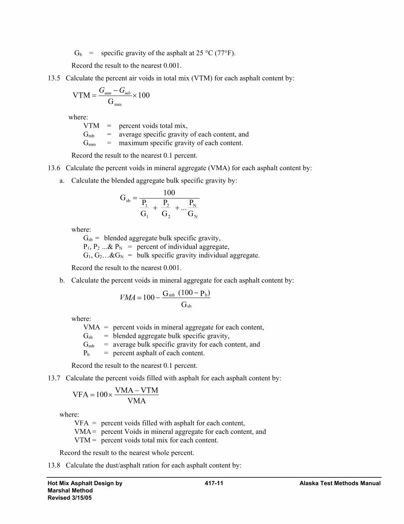
Hot Mix Asphalt Design by 417-11 Alaska Test Methods Manual Marshal Method Revised 3/15/05
Gb = specific gravity of the asphalt at 25 °C (77°F).
Record the result to the nearest 0.001.
13.5 Calculate the percent air voids in total mix (VTM) for each asphalt content by:
100 G
VTMmm
×−
= mbmm GG
where: VTM = percent voids total mix,
Gmb = average specific gravity of each content, and Gmm = maximum specific gravity of each content.
Record the result to the nearest 0.1 percent.
13.6 Calculate the percent voids in mineral aggregate (VMA) for each asphalt content by:
a. Calculate the blended aggregate bulk specific gravity by:
N
N
2
2
1
1sb
GP...
GP
GP
100G++
=
where: Gsb = blended aggregate bulk specific gravity,
P1, P2 ...& PN = percent of individual aggregate, G1, G2…&GN = bulk specific gravity individual aggregate.
Record the result to the nearest 0.001.
b. Calculate the percent voids in mineral aggregate for each asphalt content by:
G
)P(100 G100sb
bmb −−=VMA
where: VMA = percent voids in mineral aggregate for each content,
Gsb = blended aggregate bulk specific gravity, Gmb = average bulk specific gravity for each content, and Pb = percent asphalt of each content.
Record the result to the nearest 0.1 percent.
13.7 Calculate the percent voids filled with asphalt for each asphalt content by:
VMA
VTMVMA 100VFA −×=
where: VFA = percent voids filled with asphalt for each content, VMA = percent Voids in mineral aggregate for each content, and VTM = percent voids total mix for each content.
Record the result to the nearest whole percent.
13.8 Calculate the dust/asphalt ration for each asphalt content by:
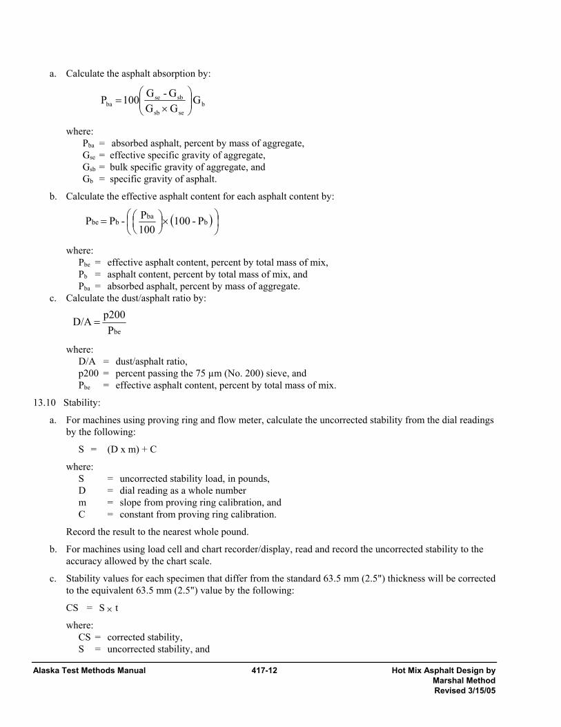
Alaska Test Methods Manual 417-12 Hot Mix Asphalt Design by Marshal Method Revised 3/15/05
a. Calculate the asphalt absorption by:
bsesb
sbseba G
G GG - G100 P ⎟⎟
⎠
⎞⎜⎜⎝
⎛×
=
where: Pba = absorbed asphalt, percent by mass of aggregate, Gse = effective specific gravity of aggregate, Gsb = bulk specific gravity of aggregate, and Gb = specific gravity of asphalt.
b. Calculate the effective asphalt content for each asphalt content by:
( )⎟⎠⎞
⎜⎝⎛ ×⎟
⎠⎞
⎜⎝⎛= b
babbe P - 100
100P - P P
where: Pbe = effective asphalt content, percent by total mass of mix, Pb = asphalt content, percent by total mass of mix, and Pba = absorbed asphalt, percent by mass of aggregate.
c. Calculate the dust/asphalt ratio by:
beP
p200 D/A =
where: D/A = dust/asphalt ratio, p200 = percent passing the 75 µm (No. 200) sieve, and Pbe = effective asphalt content, percent by total mass of mix.
13.10 Stability:
a. For machines using proving ring and flow meter, calculate the uncorrected stability from the dial readings by the following:
S = (D x m) + C
where: S = uncorrected stability load, in pounds, D = dial reading as a whole number m = slope from proving ring calibration, and C = constant from proving ring calibration.
Record the result to the nearest whole pound.
b. For machines using load cell and chart recorder/display, read and record the uncorrected stability to the accuracy allowed by the chart scale.
c. Stability values for each specimen that differ from the standard 63.5 mm (2.5") thickness will be corrected to the equivalent 63.5 mm (2.5") value by the following:
CS = S × t
where: CS = corrected stability,
S = uncorrected stability, and

Hot Mix Asphalt Design by 417-13 Alaska Test Methods Manual Marshal Method Revised 3/15/05
t = thickness correction factor = 4.2992 ( x -1.5901) for USC units or 531 (x-1.5118) for SI units. TABLE I
Thickness Correction Factors USC SI
Thickness, 0.1 mm t Thickness, 0.1 mm t Thickness, 0.01" t 62.0 1.036 63.5 0.999 2.45 1.034 62.1 1.033 63.6 0.997 2.46 1.027 62.2 1.031 63.7 0.994 2.47 1.021 62.3 1.028 63.8 0.992 2.48 1.014 62.4 1.026 63.9 0.990 2.49 1.008 62.5 1.023 64.0 0.987 2.50 1.000 62.6 1.021 64.1 0.985 2.51 0.995 62.7 1.019 64.2 0.983 2.52 0.989 62.8 1.016 64.3 0.980 2.53 0.983 62.9 1.014 64.4 0.978 2.54 0.973 63.0 1.011 64.5 0.976 2.55 0.970 63.1 1.009 64.6 0.974 63.2 1.006 64.7 0.971 63.3 1.004 64.8 0.969 63.4 1.002 64.9 0967 65.0 0.965
d. Corrected stability values for each asphalt content averaged and recorded to the nearest 50 N (10 lb) 10. Flow:
a. For machines using the proving ring and flow meter, average the flow values for each asphalt content and record as a whole number (e.g. flow reading of 0.12 will be recorded as 12).
b. For machines using load cell and chart recorder:
1) Extend the constant rate slope line to intersect the horizontal axis.
2) Determine the maximum load point and draw a line perpendicular to the horizontal axis through this point to intersect the horizontal axis.
3) From the point determined in (1) to the point determined in (2), read and record the flow as a whole number in 0.01" increments.
4) Average the flow values for each asphalt content set and record to the nearest whole number.
14. Determination of Optimum Asphalt Content
A mix that will satisfy a specific project. There are some considerations for adjustment that should be evaluated prior to 1. Graphical Presentation:
Prepare a graphical plot of Asphalt Content vs. Unit Mass, Stability, Flow, Percent Voids Total Mix, Percent Voids in Mineral Aggregate, and Percent Voids Filled with a smooth curve that represents a best-fit for all values.
14.1 Determination of Optimum Asphalt Content:
a. Determination of Preliminary Optimum Asphalt Content: Choose the preliminary optimum asphalt content at the median of the Voids in Total Mix specification. All of the calculated and measured mix properties should then be evaluated by comparing them to the project mix design specifications. If all of the specifications are met, then this is the preliminary optimum asphalt content. If all of the specifications
Alaska Test Methods Manual 417-14 Hot Mix Asphalt Design by Marshal Method Revised 3/15/05
are not met, then some adjustment or compromise is necessary or the mix may need to be redesigned. Even if all of the specifications are met, a number of considerations should be weighed before choosing the final optimum asphalt content.
b. Selection of Final Mix Optimum Asphalt Content: The final optimum asphalt content should be a compromise selected to balance all of the mix properties. Normally, the mix design specifications will produce a narrow range of acceptable asphalt contents that will pass all specifications. The asphalt content selection can be adjusted within this narrow range to achieve establishing the final optimum asphalt content. These are covered in detail in Asphalt Institute Manual MS-2, 6th Edition, Mix Design Methods, Chapter 5, Marshall Mix Design Method, Section D-5.15, Selection of Final Mix Design, pages 69 thru 77.
If this evaluation reveals no asphalt content which meets all project specifications or such a narrow range of asphalt contents meeting all project specifications as to be unfeasible and/or uneconomical to produce, the Materials Engineer may reject the proposed job mix design and require a new proposal from the contractor.
15. Report The report shall include the following:
• Project identification, Source/Supplier of mix and General Contractor Name.
• Aggregate quality identification(s), target gradation, blend ratio of individual stockpiles, blended bulk specific and effective specific gravities. Other properties that may be specified in the Contract such as: fineness modulus of the blended fine aggregate; percent fracture; percent flat and elongated; and the plasticity index of the blended fine aggregate.
• Asphalt binder quality identification, specific gravity at 77°F, the maximum mixing temperature, and the compaction temperature range.
• Anti-strip additive brand/type and the minimum percent required.
• Asphalt content at the median of the percent voids in total mix specification and the approved optimum asphalt content.
• The following properties at the optimum asphalt content: maximum specific gravity, percent voids in total mix, percent voids in mineral aggregate, percent voids filled, stability, flow, unit mass and the dust-asphalt ratio.
• Graphical representation on a 0.45 power graph of the target gradation with the LSL-USL.
• Graphical representation of asphalt content versus the following properties: unit mass, stability, flow, percent voids in total mix, percent voids in mineral aggregate and voids filled.
• Identification and address of the laboratory that performed the mix design, that laboratories mix design identification number and the signature/title of the professional engineer who reviewed and approved/disapproved the mix design.
Appendix ATM 417 1. Example Calculations
(See Example Worksheets.)
Contractor Proposed JMF for a Type IIA ACP Mix Design

Hot Mix Asphalt Design by 417-15 Alaska Test Methods Manual Marshal Method Revised 3/15/05
Sieve Percent Pass. 3/4" 100 1/2" 83 Note: Nominal Maximum Size of this material is 3/4 inch. 3/8" 69 #4 50 #8 36 #16 26 #30 18 #50 11 #100 7 #200 4.7
2. Preparation of Aggregate 2.1 Initial total aggregate mass: Ei = 1175.0 g
Calculate cumulative aggregate batch mass by:
g 1119.8 1175.0 x 100
4.7 - 100 200 No.for
g 752.0 1175.0 x 100
36 - 100 8 No.for Ei 100
PASSPercent 100 x
g 587.5 1175.0 x 100
50 - 100 4 No.for
==
==×−
=
==
Repeat for the other required sieve sizes.
2.2. Aggregate Dust Correction
a. Determine the masses for the dust correction gradation by subtracting the initial cumulative mass for the No. 4 sieve from each of the minus No. 4 sieve sizes initial cumulative mass.
XN Initial Cumulative Mass - No. 4 Initial Cumulative Mass
= XN Dust Correction Gradation Initial Cumulative Mass
For No. 8: 752.0 - 587.5 = 164.5 g
For No. 200: 1119.8 -587.5 = 532.3 g
Repeat for the other required sieve sizes.
c. Compute the adjusted cumulative batch masses for each of the fine aggregate sieves by:
Pre-wash cumulative batch mass, g Post-wash cumulative batch mass, g
No. 8 164.5 160.6
No. 200 532.3 521.9
Adjusted cumulative batch masses of each of the fine aggregate sieve calculations:

Alaska Test Methods Manual 417-16 Hot Mix Asphalt Design by Marshal Method Revised 3/15/05
4M 2
+=Y
XZ ni or
g 1130.4 5.5879.521
532.3 Z
g 756.0 587.5 6.1605.164
Z
2200i
2
i8
=+=
=+=
Repeat for the other required sieve sizes.
3. Estimate Projected Optimum Asphalt Content 3.1 Assuming that no experience with the current sources or contractor is available, the projected optimum
and minimum asphalt content will be estimated by both the computational formula and dust/asphalt methods.
b. Computational Formula
P = 0.035a + 0.045b +Kc + F
= 0.035 (100 - 36) + 0.045 (36 - 5) + (0.20 x 4.7) + 0.7
= 5.3, round to 5.5%
Test specimens will be prepared and tested at 4.5 to 6.5 percent binder contents.
c. Dust/Asphalt Ratio
⎟⎟⎠
⎞⎜⎜⎝
⎛=
A/D .maxp200
P = 4.7 / 1.2 = 3.9, round to 4.0 percent
Test specimens will be prepared and tested at 4.0 to 6.0 percent binder contents.
Since the two methods give slightly different ranges, specimens should be prepared and tested at 4.0 to 6.5 percent binder contents. 4. Preparation of Test Specimens 4.1 Thickness Adjustment
The thickness of the trial specimen is 2.48 inches, thus requiring adjustment of the initial aggregate mass by:
g 1184.5 2.48
1175 x 2.5 H
E 2.5 E ia ==×=
4.2 Adjust the final batch mass for each sieve by:
g 762.1 756.0 x 1175.01184.5 8 No.For
Z EZ
g 592.2 587.5 x 1175.01184.5 4 No.For
Nia
Na
==
×=
==
iE
Repeat for the other required sieve sizes.
4.3 Calculate the mass of the asphalt cement for each set of specimens by:
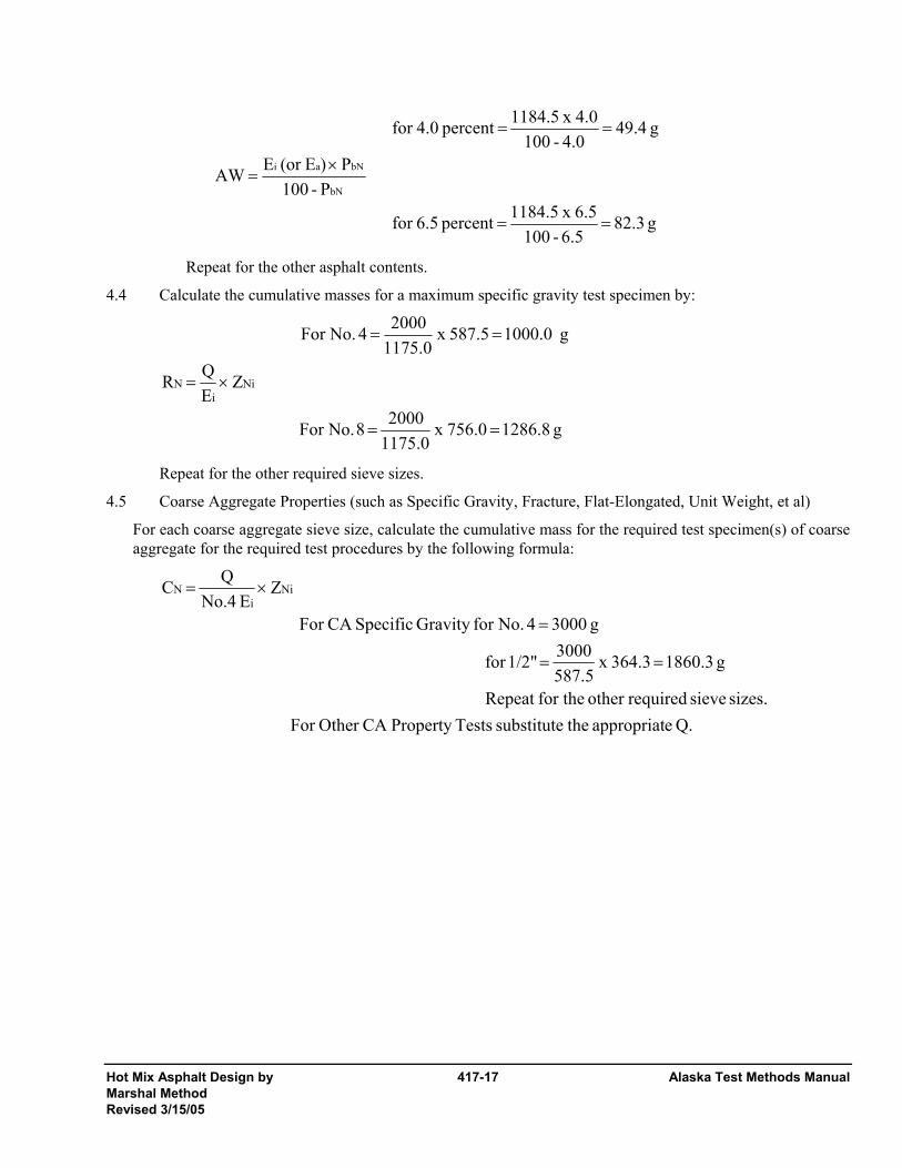
Hot Mix Asphalt Design by 417-17 Alaska Test Methods Manual Marshal Method Revised 3/15/05
g 82.3 6.5-100
6.5 x 1184.5 percent 6.5for
P -100P )E(or E AW
g 49.4 4.0 - 100
4.0 x 1184.5 percent 4.0for
bN
bNai
==
×=
==
Repeat for the other asphalt contents.
4.4 Calculate the cumulative masses for a maximum specific gravity test specimen by:
g 1286.8 756.0 x 1175.02000 8 No.For
Z EQ R
g 1000.0 587.5 x 1175.02000 4 No.For
Nii
N
==
×=
==
Repeat for the other required sieve sizes.
4.5 Coarse Aggregate Properties (such as Specific Gravity, Fracture, Flat-Elongated, Unit Weight, et al)
For each coarse aggregate sieve size, calculate the cumulative mass for the required test specimen(s) of coarse aggregate for the required test procedures by the following formula:
Q. eappropriat thesubstitute TestsProperty CA Other For sizes. sieve requiredother for theRepeat
g 1860.3 364.3 x 587.53000 1/2"for
g 3000 4 No.for Gravity SpecificCA For
Z E No.4
Q C Nii
N
==
=
×=

Alaska Test Methods Manual 417-18 Hot Mix Asphalt Design by Marshal Method Revised 3/15/05
4.6 Fine Aggregate Properties (such as Specific Gravity, Sand Equivalent, et al)
For each fine aggregate sieve size, calculate the cumulative masses for the required specimens of fine aggregate specific gravity by the following formula:
( )
( )
( )
Q. eappropriat thesubstitute TestsProperty FA Other For
sizes. sieve requiredother for theRepeat
g 924.1 587.5 - 1130.4 x 587.5- 1175.0
1000 200 No.
forGravity SpecificFA For
g 286.8 587.5 - 756.0 x 587.5- 1175.0
1000 8 No.
Z- Z x Z- E
Q F
4iNi4ii
N
=⎟⎠⎞
⎜⎝⎛=
=⎟⎠⎞
⎜⎝⎛=
=⎟⎟⎟
⎠
⎞
⎜⎜⎜
⎝
⎛
5. Calculations 5.1 Calculate the maximum specific gravity for each asphalt content as follows:
a. Calculate the effective specific gravity of the aggregate by:
2.745
1.0095.0
2.528100
5.0 - 100
GP
G100
P100G
b
b
mm
bse =
−=
−
−=
b. Calculate the maximum specific gravity for each asphalt content by:
contents.asphalt other for Repeat
2.568
009.10.4
745.24.0 100100 4.0%For
GP
GP 100100G
b
bN
se
bNmm =
+−
=+
−=
5.2 Calculate the percent air voids in total mix (VTM) for each asphalt content by:
6.4 x1002.568
2.403 2.568 4.0%For x100
GGGVTM
mm
mbmm =−
=−
=
5.3 Calculate the percent voids in mineral aggregate (VMA) for each asphalt content by:
a. Calculate the blended aggregate bulk specific gravity by:
2.689
2.65350
2.72750
100
GP...
GP
GP
100G
N
N
2
2
1
1sb =
+=
++=
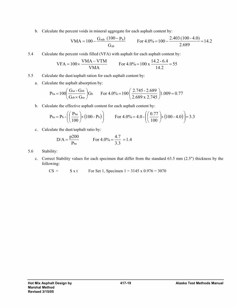
Hot Mix Asphalt Design by 417-19 Alaska Test Methods Manual Marshal Method Revised 3/15/05
b. Calculate the percent voids in mineral aggregate for each asphalt content by:
14.2 2.689
4.0) - (100 2.403100 4.0%For G
)P(100 G100VMAsb
bmb =−=−
−=
5.4 Calculate the percent voids filled (VFA) with asphalt for each asphalt content by:
55 14.2
6.4 - 14.2 x 100 4.0%For VMA
VTMVMA 100VFA ==−
×=
5.5 Calculate the dust/asphalt ration for each asphalt content by:
a. Calculate the asphalt absorption by:
0.77 1.009 2.745 x 2.6892.689 - 2.745 100 4.0%For G
G GG - G100 P b
sesb
sbseba =⎟
⎠⎞
⎜⎝⎛=⎟
⎠⎞
⎜⎝⎛
×=
b. Calculate the effective asphalt content for each asphalt content by:
( ) ( ) 3.3 4.0 - 100 1000.77 - 4.0 4.0%For P - 100
100P - P P b
babbe =⎟⎟
⎠
⎞⎜⎜⎝
⎛×⎟
⎠⎞
⎜⎝⎛=⎟⎟
⎠
⎞⎜⎜⎝
⎛×⎟
⎠⎞
⎜⎝⎛=
c. Calculate the dust/asphalt ratio by:
1.4 3.34.7 4.0%For
Pp200 D/A
be===
5.6 Stability:
c. Correct Stability values for each specimen that differ from the standard 63.5 mm (2.5") thickness by the following:
CS = S x t For Set 1, Specimen 1 = 3145 x 0.976 = 3070

Alaska Test Methods Manual 417-20 Hot Mix Asphalt Design by Marshal Method Revised 3/15/05
This page intentionally left blank.
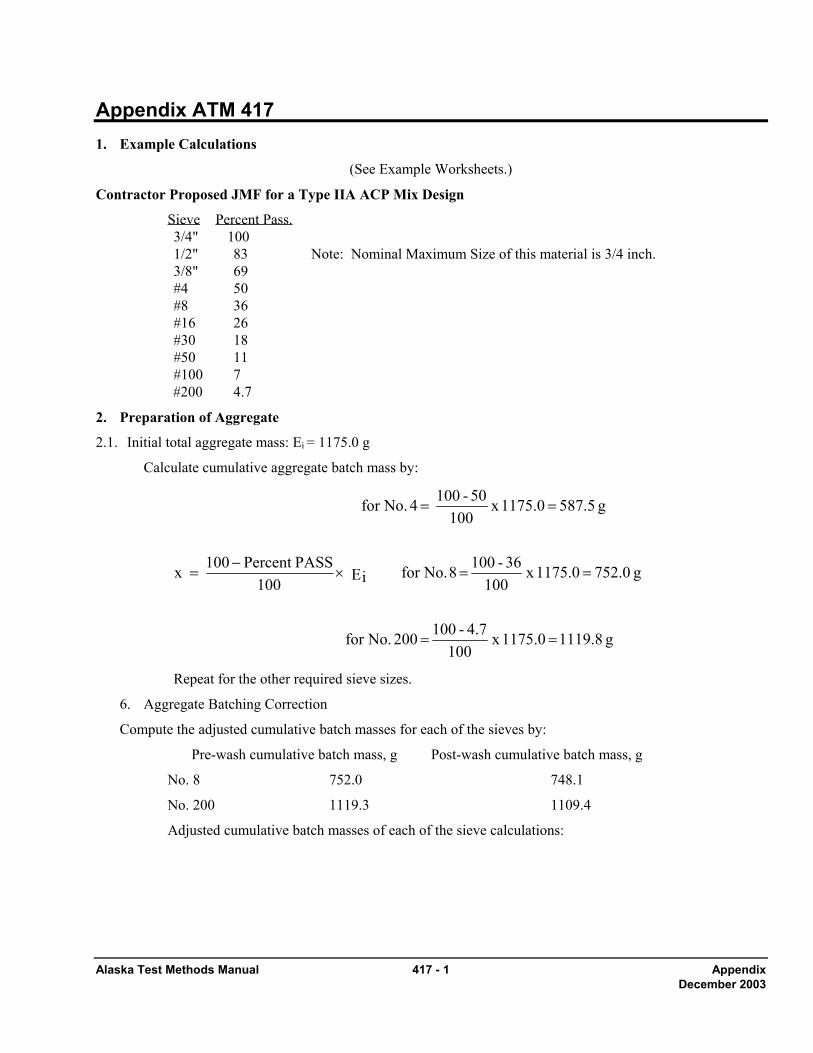
Alaska Test Methods Manual 417 - 1 Appendix December 2003
Appendix ATM 417 1. Example Calculations
(See Example Worksheets.)
Contractor Proposed JMF for a Type IIA ACP Mix Design
Sieve Percent Pass. 3/4" 100 1/2" 83 Note: Nominal Maximum Size of this material is 3/4 inch. 3/8" 69 #4 50 #8 36 #16 26 #30 18 #50 11 #100 7 #200 4.7
2. Preparation of Aggregate
2.1. Initial total aggregate mass: Ei = 1175.0 g
Calculate cumulative aggregate batch mass by:
g 1119.8 1175.0 x 100
4.7 - 100 200 No.for
g 752.0 1175.0 x 100
36 - 100 8 No.for Ei 100
PASSPercent 100 x
g 587.5 1175.0 x 100
50 - 100 4 No.for
==
==×−
=
==
Repeat for the other required sieve sizes.
6. Aggregate Batching Correction
Compute the adjusted cumulative batch masses for each of the sieves by:
Pre-wash cumulative batch mass, g Post-wash cumulative batch mass, g
No. 8 752.0 748.1
No. 200 1119.3 1109.4
Adjusted cumulative batch masses of each of the sieve calculations:
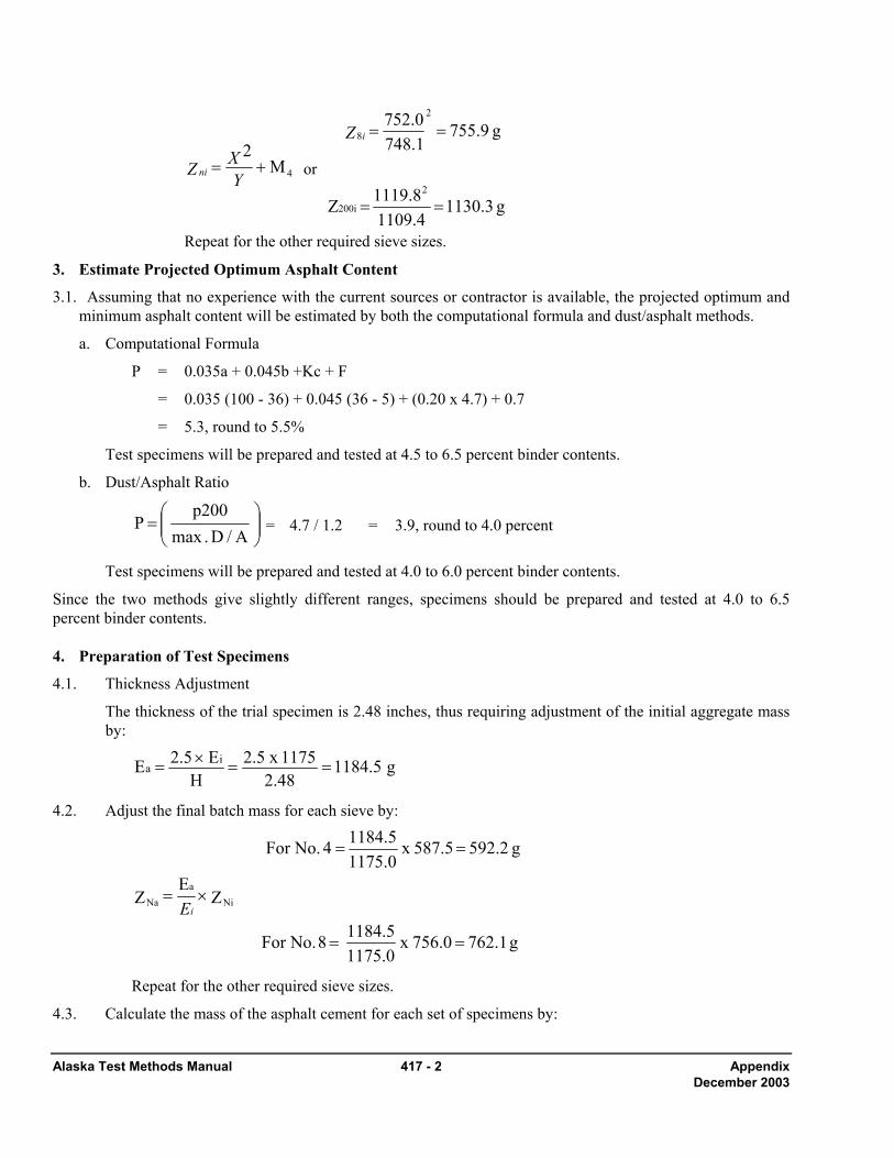
Alaska Test Methods Manual 417 - 2 Appendix December 2003
4M 2+=
YXZ ni or
g 1130.3 4.11098.1191 Z
g 755.9 1.7480.752
2
200i
2
8
==
==Z i
Repeat for the other required sieve sizes.
3. Estimate Projected Optimum Asphalt Content
3.1. Assuming that no experience with the current sources or contractor is available, the projected optimum and minimum asphalt content will be estimated by both the computational formula and dust/asphalt methods.
a. Computational Formula
P = 0.035a + 0.045b +Kc + F
= 0.035 (100 - 36) + 0.045 (36 - 5) + (0.20 x 4.7) + 0.7
= 5.3, round to 5.5%
Test specimens will be prepared and tested at 4.5 to 6.5 percent binder contents.
b. Dust/Asphalt Ratio
⎟⎟⎠
⎞⎜⎜⎝
⎛=
A/D .maxp200
P = 4.7 / 1.2 = 3.9, round to 4.0 percent
Test specimens will be prepared and tested at 4.0 to 6.0 percent binder contents.
Since the two methods give slightly different ranges, specimens should be prepared and tested at 4.0 to 6.5 percent binder contents. 4. Preparation of Test Specimens
4.1. Thickness Adjustment
The thickness of the trial specimen is 2.48 inches, thus requiring adjustment of the initial aggregate mass by:
g 1184.5 2.48
1175 x 2.5 H
E 2.5 E ia ==×=
4.2. Adjust the final batch mass for each sieve by:
g 762.1 756.0 x 1175.01184.5 8 No.For
Z EZ
g 592.2 587.5 x 1175.01184.5 4 No.For
Nia
Na
==
×=
==
iE
Repeat for the other required sieve sizes.
4.3. Calculate the mass of the asphalt cement for each set of specimens by:

Alaska Test Methods Manual 417 - 3 Appendix December 2003
g 82.3 6.5-100
6.5 x 1184.5 percent 6.5for
P -100P )E(or E AW
g 49.4 4.0 - 100
4.0 x 1184.5 percent 4.0for
bN
bNai
==
×=
==
Repeat for the other asphalt contents.
4 .4 Calculate the cumulative masses for a maximum specific gravity test specimen by:
g 1286.8 756.0 x 1175.02000 8 No.For
Z EQ R
g 1000.0 587.5 x 1175.02000 4 No.For
Nii
N
==
×=
==
Repeat for the other required sieve sizes.
4.5 Coarse Aggregate Properties (such as Specific Gravity, Fracture, Flat-Elongated, Unit Weight, et al)
For each coarse aggregate sieve size, calculate the cumulative mass for the required test specimen(s) of coarse aggregate for the required test procedures by the following formula:
Q. eappropriat thesubstitute TestsProperty CA Other For sizes. sieve requiredother for theRepeat
g 1860.3 364.3 x 587.53000 1/2"for
g 3000 4 No.for Gravity SpecificCA For
Z E No.4
Q C Nii
N
==
=
×=

Alaska Test Methods Manual 417 - 4 Appendix December 2003
4. Fine Aggregate Properties (such as Specific Gravity, Sand Equivalent, et al)
For each fine aggregate sieve size, calculate the cumulative masses for the required specimens of fine aggregate specific gravity by the following formula:
( )
( )
( )
Q. eappropriat thesubstitute TestsProperty FA Other For
sizes. sieve requiredother for theRepeat
g 924.1 587.5 - 1130.4 x 587.5- 1175.0
1000 200 No.
forGravity SpecificFA For
g 286.8 587.5 - 756.0 x 587.5- 1175.0
1000 8 No.
Z- Z x Z- E
Q F
4iNi4ii
N
=⎟⎠⎞
⎜⎝⎛=
=⎟⎠⎞
⎜⎝⎛=
=⎟⎟⎟
⎠
⎞
⎜⎜⎜
⎝
⎛
Calculations
4. Calculate the maximum specific gravity for each asphalt content as follows:
a. Calculate the effective specific gravity of the aggregate by:
2.745
1.0095.0
2.528100
5.0 - 100
GP
G100
P100G
b
b
mm
bse =
−=
−
−=
b. Calculate the maximum specific gravity for each asphalt content by:
contents.asphalt other for Repeat
2.568
009.10.4
745.24.0 100100 4.0%For
GP
GP 100100G
b
bN
se
bNmm =
+−
=+
−=
5. Calculate the percent air voids in total mix (VTM) for each asphalt content by:
6.4 x1002.568
2.403 2.568 4.0%For x100
GGGVTM
mm
mbmm =−
=−
=
6. Calculate the percent voids in mineral aggregate (VMA) for each asphalt content by:
a. Calculate the blended aggregate bulk specific gravity by:
2.689
2.65350
2.72750
100
GP...
GP
GP
100G
N
N
2
2
1
1sb =
+=
++=

Alaska Test Methods Manual 417 - 5 Appendix December 2003
b. Calculate the percent voids in mineral aggregate for each asphalt content by:
14.2 2.689
4.0) - (100 2.403100 4.0%For G
)P(100 G100VMAsb
bmb =−=−
−=
7. Calculate the percent voids filled (VFA) with asphalt for each asphalt content by:
55 14.2
6.4 - 14.2 x 100 4.0%For VMA
VTMVMA 100VFA ==−
×=
8. Calculate the dust/asphalt ration for each asphalt content by:
a. Calculate the asphalt absorption by:
0.77 1.009 2.745 x 2.6892.689 - 2.745 100 4.0%For G
G GG - G100 P b
sesb
sbseba =⎟
⎠⎞
⎜⎝⎛=⎟
⎠⎞
⎜⎝⎛
×=
b. Calculate the effective asphalt content for each asphalt content by:
( ) ( ) 3.3 4.0 - 100 1000.77 - 4.0 4.0%For P - 100
100P - P P b
babbe =⎟⎟
⎠
⎞⎜⎜⎝
⎛×⎟⎠⎞
⎜⎝⎛=⎟⎟
⎠
⎞⎜⎜⎝
⎛×⎟⎠⎞
⎜⎝⎛=
c. Calculate the dust/asphalt ratio by:
1.4 3.34.7 4.0%For
Pp200 D/A
be===
9. Stability:
c. Correct Stability values for each specimen that differ from the standard 63.5 mm (2.5") thickness by the following:
CS = S x t For Set 1, Specimen 1 = 3145 x 0.976 = 3070

Alaska Test Methods Manual 417 - 6 Appendix December 2003

Rut Susceptibility using the 419-1 Alaska Test Methods Manual Asphalt Pavement Analyzer Revised 3/15/05
Rutting Susceptibility using an Asphalt Pavement Analyzer ATM 419 1. Scope This method describes a procedure for determining the rut susceptibility of hot mix asphalt using an Asphalt Pavement Analyzer (APA).
2. Apparatus • Asphalt Pavement Analyzer (APA) – A thermostatically controlled device designed to test the rutting
susceptibility of hot mix asphalt by applying repetitive linear loads to compacted test specimens through pressurized hoses.
o The APA shall be thermostatically controlled to maintain the test temperature and conditioning chamber at any set point between 30-60 ± 1°C (85-140 ± 1°F).
o The APA shall be capable of independently applying loads up to 450 N (100 lbf) to the three wheels. The loads shall be calibrated to the desired test load by a suitable device such as an external force transducer or proving ring.
o The pressure in the test hoses shall be adjustable and capable of maintaining pressure up to 830 kPa (120 psi).
o The APA shall be capable of testing six cylindrical specimens simultaneously.
o The APA shall have a programmable master cycle counter that can be preset to the desired number of cycles for a test. The APA shall be capable to automatically stopping the test at the completion of the programmed number of cycles.
• Balance or scale: Capacity sufficient for the principle sample mass, readable to 0.1 percent or 0.1 g of the total sample mass and meeting the requirements of AASHTO M 231.
• Mixing utensils (bowls, spoon, spatula)
• Ovens and hot plates thermostatically controlled to maintain the various required temperatures within ± 3°C (5°F).
• Compaction device and molds
3. Test Specimens Number of test specimens – A sample will consist of six 150 mm diameter x 75 mm (6" diameter x 3") cylindrical specimens.
Production Mix
Samples of plant-produced mixtures shall be obtained in accordance with WAQTC FOP for AASHTO T 168. Samples shall be reduced to the appropriate test size in accordance with WAQTC TM 5 and compacted while the mixture is still hot. Reheating of loose plant mixture should be avoided.
Laboratory Prepared Mixtures
Mixture proportions will be batched in accordance to the desired Job Mix Formula. The required batch sizes are determined in accordance to ATM 417, Preparation of Aggregate and Preparation of Asphalt. The voids in total mix (VTM) target for the compacted specimens shall be 6.0 + 1.0 percent unless otherwise directed.
The temperature to which the asphalt binder must be heated to achieve a viscosity of 170 ± 20 cSt (0.170 + 0.020 Pa·s) or the mix design mixing temperature shall be the mixing temperature.

Alaska Test Methods Manual 419-2 Rut Susceptibility using the Asphalt Pavement Analyzer Revised 3/15/05
Prepare the mixture in accordance with ATM T 417, Preparation of Mixtures and Mixture conditioning. The temperature to which the asphalt binder must be heated to achieve a viscosity of 290 ± 30 cSt (0.290 + 0.030 Pa·s) or the mix design compaction temperature shall be the compaction temperature.
Roadway Core Specimens
Roadway core specimens shall be 150 mm (6") outside diameter with all surfaces of the perimeter perpendicular to the surface of the core within 5 mm (3/16"). Cores shall be trimmed with a wet masonry saw to a height of 75 ± 3 mm (3 ± 1/8"). Final adjustment of the core to the top of the testing molds shall be done with Plaster of Paris.
4. Compaction of Specimens 1 Superpave Gyratory Compaction
• Apparatus (see AASHTO T 312).
a. Compaction of the cylindrical specimens with the Superpave Gyratory Compactor will be performed in such a manner so that the target air void content of 6.0 ± 1.0% is obtained at the specified height of 75 ± 3 mm.
b. Remove the mold and base plate from the oven set at the compaction temperature. Place a paper disc in the bottom of the mold assembly.
c. Transfer the mixture to the mold with care to avoid segregation of the mixture.
d. Place the mold and mixture in the Superpave Gyratory Compactor and begin compaction as described in the compactor’s operation manual.
e. When the compaction procedure is completed, remove the mold and compacted specimen from the compactor. Extrude the specimen from the mold with care to avoid distorting the specimen until it is cooled.
f. Compacted specimens should be left at room temperature (about 25°C or 77°F) and allowed to cool overnight.
5. Determining the Voids Total Mix 1. Determine the bulk specific gravity of the test specimens in accordance with WAQTC FOP for AASHTO T
166, Method A. 2. Determine the maximum specific gravity of the test mixture in accordance with WAQTC FOP for AASHTO
T 209. 3. Determine the air void contents of the test specimens in accordance with AASHTO T 269.
6. Test Temperature The test temperature shall be 105°F unless otherwise directed.
7. Initial Measurements 2 Place the rut depth measurement template over the specimen. Take initial measurements on three locations of
each specimen. Record the measurement for each location to the nearest 0.01 mm.
8. Specimen Conditioning 1. Stabilize the testing chamber temperature at 105°F or as directed.
2. Place the test specimens into the testing molds and secure in the APA.
3 Push the sample holding tray in and secure. Close chamber doors.
4 Allow specimens to condition at the test temperature for 90 minutes.
Rut Susceptibility using the 419-3 Alaska Test Methods Manual Asphalt Pavement Analyzer Revised 3/15/05
5 Set PRESET COUNTER to 8000 cycles.
6 Start the testing. A complete test will take approximately 3.5 hours. At the end of the test cycle, the APA will stop.
7 Open the chamber doors, unlock and pull out the sample holding tray.
8 Remove specimens from the testing molds and take rut-depth measurements in the same manner as the Initial Measurements.
9. Calculations The rut depth at each location is determined by subtracting the final measurement from the initial measurement.
Determine the average rut depth for each specimen, use the average of all measurements to calculate the average rut depth.
The APA rut depth for the mixture is the average of six cylindrical specimens unless otherwise directed.
10. Report The test report shall include the following information:
• The laboratory name and date of test.
• The mixture type and description.
• The average rut depth to the nearest 0.1 mm.

Alaska Test Methods Manual 419-4 Rut Susceptibility using the Asphalt Pavement Analyzer Revised 3/15/05
This page intentionally left blank.
Sampling Freshly Mixed Concrete 501-1 Alaska Test Methods Manual October 2004
SAMPLING FRESHLY MIXED CONCRETE WAQTC TM 2 Scope This method covers procedures for obtaining representative samples of fresh concrete delivered to the project site and on which tests are to be performed to determine compliance with quality requirements of the specifications under which concrete is furnished. The method includes sampling from stationary, paving and truck mixers, and from agitating and non-agitating equipment used to transport central mixed concrete. Sampling concrete may involve hazardous materials, operations, and equipment. This standard does not purport to address all of the safety problems associated with its use. It is the responsibility of the user of this standard to establish appropriate safety and health practices. This method also covers the procedure for preparing a sample of concrete for further testing where it is necessary to remove aggregate larger than the designated size for the test method being performed. The removal of large aggregate particles is accomplished by wet sieving. Apparatus • Wheelbarrow • Cover for wheelbarrow (plastic, canvas, or burlap) • Buckets • Shovel • Cleaning equipment: including scrub brush, rubber gloves, water • Apparatus for wet sieving including a sieve or sieves conforming to AASHTO M92 of suitable size
and conveniently arranged and supported so that the sieve can be shaken rapidly by hand. Procedure 1. Use every precaution in order to obtain samples representative of the true nature and condition of the
concrete being placed being careful not to obtain samples from the very first or very last portions of the batch. The size of the sample will be 1.5 times the volume of concrete required for the specified testing, but not less than 0.03 m3 (1 ft3).
Note 1: Sampling should normally be performed as the concrete is delivered from the mixer to the conveying vehicle used to transport the concrete to the forms; however, specifications may require other points of sampling, such as at the discharge of a concrete pump.
• Sampling from stationary mixers, except paving mixers
Sample the concrete after a minimum of 1/2 m3 (1/2 yd3) of concrete has been discharged. Perform sampling by passing a receptacle completely through the discharge stream, or by completely diverting the discharge into a sample container. Take care not to restrict the flow of concrete from the mixer, container, or transportation unit so as to cause segregation. These requirements apply to both tilting and nontilting mixers.
• Sampling from paving mixers
Alaska Test Methods Manual 501-2 Sampling Freshly Mixed Concrete October 2004
Sample after the contents of the paving mixer have been discharged. Obtain material from at least five different locations in the pile and combine into one test sample. Avoid contamination with subgrade material or prolonged contact with absorptive subgrade. To preclude contamination or absorption by the subgrade, the concrete may be sampled by placing a shallow container on the subgrade and discharging the concrete across the container.
• Sampling from revolving drum truck mixers or agitators Sample the concrete after a minimum of 1/2 m3 (1/2 yd3) of concrete has been discharged. Do not obtain samples until after all of the water has been added to the mixer. Do not obtain samples from the very first or last portions of the batch discharge. Sample by repeatedly passing a receptacle through the entire discharge stream or by completely diverting the discharge into a sample container. Regulate the rate of discharge of the batch by the rate of revolution of the drum and not by the size of the gate opening.
• Sampling from open-top truck mixers, agitators, non-agitating equipment or other types of open-top containers Sample by whichever of the procedures described above is most applicable under the given conditions.
• Sampling from pump or conveyor placement systems
Sample after a minimum of 1/2 m3 (1/2 yd3) of concrete has been discharged. Do not obtain samples until after all of the pump slurry has been eliminated. Sample by repeatedly passing a receptacle through the entire discharge system or by completely diverting the discharge into a sample container. Do not lower the pump arm from the placement position to ground level for ease of sampling, as it may modify the air content of the concrete being sampled. Do not obtain samples from the very first or last portions of the batch discharge.
2. Transport samples to the place where fresh concrete tests are to be performed and specimens are to be molded. They shall then be combined and remixed with a shovel the minimum amount necessary to ensure uniformity. Protect the sample from direct sunlight, wind, rain, and sources of contamination.
3. Complete test for temperature and start tests for slump and air content within 5 minutes of obtaining the sample. Complete tests as expeditiously as possible. Start molding specimens for strength tests within 15 minutes of obtaining the sample.
Wet Sieving When required for slump testing, air content testing or molding test specimens the concrete sample shall be wet-sieved, after transporting but prior to remixing, by the following.
1. Place the sieve designated by the test procedure over dampened sample container.
2. Pass the concrete over the designated sieve. Do not overload the sieve (one particle thick).
3. Shake or vibrate the sieve until no more material passes the sieve. A horizontal back and forth motion is preferred.
4. Discard oversize material including all adherent mortar.

Sampling Freshly Mixed Concrete 501-3 Alaska Test Methods Manual October 2004
5. Repeat until sample of sufficient size is obtained. Mortar adhering to the wet-sieving equipment shall be included with the sample.
6. Remix the sample with a shovel the minimum amount necessary to ensure uniformity.
Note 2: Wet-sieving is not allowed for samples being utilized for density determinations according to the FOP for AASHTO T 121.

Alaska Test Methods Manual 501-4 Sampling Freshly Mixed Concrete October 2004
Temperature of Freshly… 502-1 Alaska Test Methods Manual October 2004
TEMPERATURE OF FRESHLY MIXED PORTLAND CEMENT CONCRETE WAQTC FOP FOR AASHTO T 309 Scope This procedure covers the determination of the temperature of freshly mixed portland cement concrete in accordance with AASHTO T 309. Apparatus • Container — The container shall be made of nonabsorptive material and large enough to provide at
least 75 mm (3 in.) of concrete in all directions around the sensor; concrete cover must also be a least three times the nominal maximum size of the coarse aggregate.
• Temperature Measuring Device — The temperature measuring device shall be calibrated and capable of measuring the temperature of the freshly mixed concrete to ±0.5°C (±1°F) throughout the temperature range likely to be encountered. Partial immersion liquid-in-glass thermometers (and possibly other types) shall have a permanent mark to which the device must be immersed without applying a correction factor.
• Reference Temperature Measuring Device — The reference temperature measuring device shall be a liquid-in-glass thermometer readable to 0.2°C (0.5°F) that has been verified and calibrated. The calibration certificate or report indicating conformance to the requirements of ASTM E 77 shall be available for inspection.
Calibration of Temperature Measuring Device Each thermometer shall be verified for accuracy annually and whenever there is a question of accuracy. Calibration shall be performed by comparing readings on the temperature measuring device with another calibrated instrument at two temperatures at least 15°C or 27°F apart. Sample Locations and Times The temperature of freshly mixed concrete may be measured in the transporting equipment, in forms, or in sample containers, provided the sensor of the temperature measuring device has at least 75 mm (3 in.) of concrete cover in all direction around it. Complete the temperature measurement of the freshly mixed concrete within 5 minutes of obtaining the sample. Concrete containing aggregate of a nominal maximum size greater than 75 mm (3 in.) may require up to 20 minutes for the transfer of heat from the aggregate to the mortar after batching. Procedure 1. Dampen the sample container. 2. Obtain the sample in accordance with the FOP for WAQTC TM 2.

Alaska Test Methods Manual 502-2 Temperature of Freshly… October 2004
3. Place sensor of the temperature measuring device in the freshly mixed concrete so that it has at least 75 mm (3 in.) of concrete cover in all directions around it.
4. Gently press the concrete in around the sensor of the temperature measuring device at the surface of
the concrete so that air cannot reach the sensor. 5. Leave the sensor of the temperature measuring device in the freshly mixed concrete for a minimum
of two minutes, or until the temperature reading stabilizes. 6. Complete the temperature measurement of the freshly mixed concrete within 5 minutes of obtaining
the sample. 7. Read and record the temperature to the nearest 0.5°C (1°F). Report Results shall be reported on standard forms approved for use by the agency. Record the measured temperature of the freshly mixed concrete to the nearest 0.5°C (1°F).
Slump of Hydraulic… 503-1 Alaska Test Methods Manual October 2004
SLUMP OF HYDRAULIC CEMENT CONCRETE WAQTC FOP FOR AASHTO T 119 Scope This procedure provides instructions for determining the slump of hydraulic cement concrete in accordance with AASHTO T 119. It is not applicable to non-plastic and non-cohesive concrete. With concrete using 37.5mm (1½ in.) or larger aggregate, the +37.5mm (1½ in.) aggregate must be removed in accordance with the FOP for WAQTC TM 2. Apparatus • Mold: The metal mold shall be provided with foot pieces and handles. The mold must be
constructed without a seam. The interior of the mold shall be relatively smooth and free from projections such as protruding rivets. The mold shall be free from dents. A mold that clamps to a rigid nonabsorbent base plate is acceptable provided the clamping arrangement is such that it can be fully released without movement of the mold.
• Mold: Other than metal must conform to AASHTO T 119 Sections 5.1.1.1 & 5.1.1.2. • Tamping rod: 16 mm (5/8 in.) diameter and approximately 600 mm (24 in.) long, having a
hemispherical tip. (Hemispherical means “half a sphere”; the tip is rounded like half of a ball.) • Scoop • Tape measure or ruler with at least 5 mm or 1/8 in. graduations • Base: Flat, rigid, non-absorbent moistened surface on which to set the slump cone Procedure 1. Obtain the sample in accordance with FOP for WAQTC TM 2. If any aggregate 37.5mm (1½ in.) or
larger aggregate is present, aggregate must be removed in accordance with the Wet Sieving portion of the FOP for WAQTC TM 2.
Note 1: Testing shall begin within five minutes of obtaining the sample.
2. Dampen the inside of the cone and place it on a dampened, rigid, nonabsorbent surface that is level
and firm. 3. Stand on both foot pieces in order to hold the mold firmly in place. 4. Fill the cone 1/3 full by volume, to a depth of approximately 67 mm (2 5/8 in.) by depth. 5. Consolidate the layer with 25 strokes of the tamping rod, using the rounded end. Distribute the
strokes evenly over the entire cross section of the concrete. For this bottom layer, incline the rod slightly and make approximately half the strokes near the perimeter, and then progress with vertical strokes, spiraling toward the center.
6. Fill the cone 2/3 full by volume, to a depth of approximately 155 mm (6 1/8 in.) by depth.

Alaska Test Methods Manual 503-2 Slump of Hydraulic… October 2004
7. Consolidate this layer with 25 strokes of the tamping rod, just penetrating into the bottom layer. Distribute the strokes evenly.
8. Fill the cone to overflowing. 9. Consolidate this layer with 25 strokes of the tamping rod, just penetrating into the second layer.
Distribute the strokes evenly. If the concrete falls below the top of the cone, stop, add more concrete, and continue rodding for a total of 25 strokes. Keep an excess of concrete above the top of the mold at all times. Distribute strokes evenly as before.
10. Strike off the top surface of concrete with a screeding and rolling motion of the tamping rod. 11. Clean overflow concrete away from the base of the mold. 12. Remove the mold from the concrete by raising it carefully in a vertical direction. Raise the mold
300 mm (12 in.) in 5 ±2 seconds by a steady upward lift with no lateral or torsional motion being imparted to the concrete.
The entire operation from the start of the filling through removal of the mold shall be carried out without interruption and shall be completed within an elapsed time of 2 1/2 minutes.
13. Invert the slump cone and set it next to the specimen. 14. Lay the tamping rod across the mold so that it is over the test specimen. 15. Measure the distance between the bottom of the rod and the displaced original center of the top of
the specimen to the nearest 5 mm (1/4 in.). Note 2: If a decided falling away or shearing off of concrete from one side or portion of the mass occurs, disregard the test and make a new test on another portion of the sample. If two consecutive tests on a sample of concrete show a falling away or shearing off of a portion of the concrete from the mass of the specimen, the concrete probably lacks the plasticity and cohesiveness necessary for the slump test to be applicable.
Report Results shall be reported on standard forms approved for use by the agency. Record the slump to the nearest 5 mm (1/4 in.).
Mass per Cubic Meter (Cubic Foot)… 504-1 Alaska Test Methods Manual October 2004
MASS PER CUBIC METER (CUBIC FOOT), YIELD, AND AIR CONTENT (GRAVIMETRIC) OF CONCRETE (See Addendum for AKDOT&PF Guidelines) WAQTC FOP FOR AASHTO T 121 Scope This procedure covers the determination of density, or unit mass, of freshly mixed concrete in accordance with AASHTO T 121. It also provides formulas for calculating the volume of concrete produced from a mixture of known quantities of component materials, and provides a method for calculating cement content& cementitous material content – the mass of cement or cementitous material per unit volume of concrete. A procedure for calculating water/cement ratio is also covered. Apparatus • Measure: May be the bowl portion of the air meter used for determining air content under the FOP
for AASHTO T 152. Otherwise, it shall be a metal cylindrical container meeting the requirements of AASHTO T 121. The capacity and dimensions of the measure shall conform to those specified in Table 1.
• Balance or scale: Accurate to 0.3 percent of the test load at any point within the range of use. • Tamping Rod: 16 mm (5/8 in.) diameter and approximately 600 mm (24 in.) long, having a
hemispherical tip. (Hemispherical means “half a sphere”; the tip is rounded like half of a ball.) • Vibrator: 7000 vibrations per minute, 19 to 38 mm (3/4 to 1 1/2 in.) in diameter, and the length of
the shaft shall be at least 610 mm (24in). • Scoop • Strike-off Plate: A flat rectangular metal plate at least 6 mm (1/4 in.) thick or a glass or acrylic plate
at least 12 mm (1/2 in.) thick, with a length and width at least 50 mm (2 in.) greater than the diameter of the measure with which it is to be used. The edges of the plate shall be straight and smooth within tolerance of 1.5 mm (1/16 in.).
• Mallet: With a rubber or rawhide head having a mass of 0.57 ±0.23 kg (1.25 ±0.5 lb) for use with measures of 0.014 m3 (1/2 ft3 ) or less, or having a mass of 1.02 ±0.23 kg (2.25 ±0.5 lb) for use with measures of 0.028 m3 (1 ft3).

Alaska Test Methods Manual 504-2 Mass per Cubic Meter (Cubic Foot)… October 2004
Table 1 Dimensions of Measures
Capacity
Inside
Diameter
Inside Height
Minimum Thicknesses
mm(in.)
Nominal Maximum Size of Coarse Aggregate**
m3 (ft3) mm (in.) mm (in.) Bottom Wall mm (in.) 0.0071 (1/4)*
203 ±2.54 (8.0 ±0.1)
213 ±2.54 (8.4 ±0.1)
5.1 (0.20)
3.0 (0.12)
25 (1)
0.0142 (1/2)
254 ±2.54 (10.0 ±0.1)
279 ±2.54 (11.0 ±0.1)
5.1 (0.20)
3.0 (0.12)
50 (2)
0.0283 (1)
356 ±2.54 (14.0 ±0.1)
284 ±2.54 (11.2 ±0.1)
5.1 (0.20)
3.0 (0.12)
76 (3)
* Note: Measure may be the base of the air meter used in the FOP for AASHTO T 152. ** Nominal Maximum size: One sieve larger than the first sieve to retain more than 10 percent of the material using an agency specified set of sieves based on cumulative percent retained. Where large gaps in specification sieves exist, intermediate sieve(s) may be inserted to determine nominal maximum size. Calibration of Measure 1. Determine the mass of the dry measure and strike-off plate. 2. Fill the measure with water at a temperature between 16°C and 29°C (60°F and 85°F) and cover
with the strike-off plate in such a way as to eliminate bubbles and excess water. 3. Wipe the outside of the measure and cover plate dry, being careful not to lose any water from the
measure. 4. Determine the mass of the measure, strike-off plate, and water in the measure. 5. Determine the mass of the water in the measure by subtracting the mass in Step 1 from the mass in
Step 4. 6. Measure the temperature of the water and determine its density from Table 2, interpolating as
necessary. 7. Calculate the volume of the measure, Vm, by dividing the mass of the water in the measure by the
density of the water at the measured temperature, from Table 2.
Example: at 23°C (73.4°F)
33m m0.007079
kg/m997.54kg7.062V ==
33m 0.2494
/ft62.27415.53V ft
lblb
==

Mass per Cubic Meter (Cubic Foot)… 504-3 Alaska Test Methods Manual October 2004
Table 2 Unit Mass of Water
15°C to 30°C
°C (°F) kg/m3 (lb/ft3) °C (°F) kg/m3 (lb/ft3) 15 (59.0) 999.10 (62.372) 23 (73.4) 997.54 (62.274)
15.6 (60.0) 999.01 (62.366) 23.9 (75.0) 997.32 (62.261) 16 (60.8) 998.94 (62.361) 24 (75.2) 997.29 (62.259) 17 (62.6) 998.77 (62.350) 25 (77.0) 997.03 (62.243) 18 (64.4) 998.60 (62.340) 26 (78.8) 996.77 (62.227)
18.3 (65.0) 998.54 (62.336) 26.7 (80.0) 996.59 (62.216) 19 (66.2) 998.40 (62.328) 27 (80.6) 996.50 (62.209) 20 (68.0) 998.20 (62.315) 28 (82.4) 996.23 (62.192) 21 (69.8) 997.99 (62.302) 29 (84.2) 995.95 (62.175)
21.1 (70.0) 997.97 (62.301) 29.4 (85.0) 995.83 (62.166) 22 (71.6) 997.77 (62.288) 30 (86.0) 995.65 (62.156)
Procedure - General
Note 1: There are two methods of consolidating the concrete – rodding and vibration. If the slump is greater than 75 mm (3 in.), consolidation is by rodding. When the slump is 25 to 75 mm (1 to 3 in.), internal vibration or rodding can be used to consolidate the sample, but the method used must be that required by the agency in order to obtain consistent, comparable results. For slumps less than 25 mm (1 in.), consolidate the sample by internal vibration. The internal vibration procedure follows this general procedure.
1. Obtain the sample in accordance with the FOP for WAQTC TM 2. Testing may be performed in conjunction with the FOP for AASHTO T 152. When doing so, this FOP should be performed prior to the FOP for AASHTO T 152.
Note 2: If the two tests are being performed using the same sample, this test shall begin within five minutes of obtaining the sample.
2. Determine the mass of the dry empty measure. 3. Dampen the inside of the measure. 4. Fill the measure approximately 1/3 full with concrete. 5. Consolidate the layer with 25 strokes of the tamping rod, using the rounded end. Distribute the
strokes evenly over the entire cross section of the concrete. Rod throughout its depth without hitting the bottom too hard.
6. Tap the sides of the measure smartly 10 to 15 times with the mallet to close voids and release
trapped air. 7. Add the second layer, filling the measure about 2/3 full.
Alaska Test Methods Manual 504-4 Mass per Cubic Meter (Cubic Foot)… October 2004
8. Consolidate this layer with 25 strokes of the tamping rod, penetrating about 25 mm (1 in.) into the bottom layer.
9. Tap the sides of the measure smartly 10 to 15 times with the mallet. 10. Add the final layer, slightly overfilling the measure. 11. Consolidate this layer with 25 strokes of the tamping rod, penetrating about 25 mm (1 in.) into the
second layer. 12. Tap the sides of the measure smartly 10 to 15 times with the mallet.
Note 3: The measure should be slightly over full, about 3 mm (1/8 in.) above the rim. If there is a great excess of concrete, remove a portion with the scoop. If the measure is under full, add a small quantity. This adjustment may be done only after consolidating the final layer and before striking off the surface of the concrete.
13. Strike off by pressing the strike-off plate flat against the top surface covering approximately 2/3 of the measure. Withdraw the strike-off plate with a sawing motion to finish the 2/3 originally covered. Cover the original 2/3 again with the plate; finishing the remaining 1/3 with a sawing motion (do not lift the plate, continue the sawing motion until the plate has cleared the surface of the measure). Final finishing may be accomplished with several strokes with the inclined edge of the strike-off plate. The surface should be smooth and free of voids.
14. Clean off all excess concrete from the exterior of the measure including the rim. 15. Determine and record the mass of the measure and the concrete to the nearest 0.3%. 16. If the air content of the concrete is to be determined, proceed to Step 14 of the FOP for AASHTO T
152. Procedure - Internal Vibration 1. Perform Steps 1 and 2 of the general procedure. 2. Fill the measure approximately half full. 3. Insert the vibrator at four different points in each layer when a 0.0283 m3 (1 ft3) measure is used, and
three different points in each layer when a 0.0142 m3 (1/2 ft3), or smaller, measure is used. Do not let the vibrator touch the bottom or sides of the measure.
Note 4: Remove the vibrator slowly, so that no air pockets are left in the material.
Note 5: Continue vibration only long enough to achieve proper consolidation of the concrete. Over vibration may cause segregation and loss of appreciable quantities of intentionally entrained air.
4. Fill the measure a bit over full. 5. Insert the vibrator as in Step 3. Do not let the vibrator touch the sides of the measure, but do
penetrate the first layer approximately 25 mm (1 in.). 6. Return to Step 13 of the general procedure and continue. Calculations

Mass per Cubic Meter (Cubic Foot)… 504-5 Alaska Test Methods Manual October 2004
• Density – Calculate the net mass, Mm, of the concrete in the measure by subtracting the mass of the
measure from the gross mass of the measure plus the concrete. Calculate the density, W, by dividing the net mass, Mm, by the volume, Vm, of the measure as shown below. Example:
• Yield – Calculate the yield, Y, or volume of concrete produced per batch, by dividing the total mass
of the batch, W1, by the density , W, of the concrete as shown below. Example:
Note 6: The total mass, W1, includes the masses of the cement, water, and aggregates in the concrete.
• Cement Content – Calculate the actual cement content, N, by dividing the mass of the cement, Nt,
by the yield, Y, as shown below. Note 7: Specifications may require Portland cement content and cementitous materials content Example: • Water Content – Calculate the mass of water in a batch of concrete by summing the:
– water added at batch plant – water added in transit – water added at jobsite – free water on coarse aggregate – free water on fine aggregate – liquid admixtures (if the agency requires this to be included).
This information is obtained from concrete batch tickets collected from the driver. Use the following conversion factors.
m
m
VM
=W 33 kg/m2390
m0.007079kg16.920
==W
W1WY = 3
3 m1.02kg/m2390
kg2436Y ==
YNΝ t
= 33 kg/m256
m1.02kg261
N ==
33 /ft6.144
0.249436.06 lb
ftlbW ==
33 1.02)lb/ft(27)(144.6
3978Y yd
lb==
33 /yd590
yd1.02602
N lblb
==

Alaska Test Methods Manual 504-6 Mass per Cubic Meter (Cubic Foot)… October 2004
To Convert From To Multiply By
Liters, L Kilograms, kg 1.0 Gallons, gal Kilograms, kg 3.785 Gallons, gal Pounds, lb 8.34
Milliliters, mL Kilograms, kg 0.001 Ounces, oz Milliliters, mL 28.4 Ounces, oz Kilograms, kg 0.0284 Ounces, oz Pounds, lb 0.0625 Pounds, lb Kilograms, kg 0.4536
Calculate the mass of free water on aggregate as follows. Example:
Total Aggregate Mass = 3540 kg(7804 lb) Free Water Percentage = 1.7∗ ∗ To determine Free Water percentage Total moisture content of the aggregates – absorbed moisture = Free Water
Example for actual water content:
Water added at batch plant = 300 L 79 gal Water added in transit = 0 L Water added at jobsite = 40 L 11 gal 340 L = 340 kg 90 gal = 751 lbs
Coarse aggregate: 3540 kg (7804 lbs) @ 1.7% free water Fine aggregate: 2490 kg (5489 lb) @ 5.9% free water
CA free water = 59 kg 130 lbs
FA free water = 139 kg 306 lbs
Mass of water in batch = 538 kg 1187 lbs
)100/PercentageWaterFree(1MassAggregateTotalMassAggregateTotalMassWaterFree
+−=
kg59)100/7.1(1
kg3540kg3540MassWaterFree =
+−=
=+
−)100/7.1(1
kg3540kg3540
=+
−)100/9.5(1
kg2490kg2490
lblblb 130)100/7.1(1
78047804 =+
−
=+
−)100/7.1(1
78047804 lblb
=+
−)100/9.5(1
54895489 lblb
Mass per Cubic Meter (Cubic Foot)… 504-7 Alaska Test Methods Manual October 2004
• Water/Cement Ratio – Calculate the water/cement ratio by dividing the mass of water in a batch of concrete by the mass of cementitous material in the batch. The masses of the cementitous materials are obtained from concrete batch tickets collected from the driver.
Example: Cement: 950 kg 2094 lb Fly Ash: 180 kg 397 lb Water: 538 kg (from previous example) 1187 lb
Report Results shall be reported on standard forms approved for use by the agency.
0.48say0.476,kg)180(950
kg538W/C =+
= 0.48)397(2094
1187W/C =
+=
lblb

Alaska Test Methods Manual 504-8 Mass per Cubic Meter (Cubic Foot)… October 2004
Addendum WAQTC FOP for AASHTO T 121 Following are guidelines for the use of WAQTC FOP for AASHTO T 121 by the State of Alaska DOT&PF.
1. Calibration shall be done in accordance with Standard Practice 9.
2. Under the Heading of Procedure – General, reverse steps 2 and 3.
3. Report each item to the following:
a. Volume of Measure– 0.000001 m3 (0.0001 ft3) b. Density— Nearest 10 kg/m3 (0.1 lb/ft3) c. Yield— 0. 001 m3 (0.001 yd3) d. Cement Content— Nearest 1 kg/m3 (nearest 1 lb/ft3) e. Water Content— Nearest 1 kg/m3 (nearest 1 lb/ft3) f. Water Cement Ratio— nearest 0.01

Air Content of Freshly Mixed Concrete… 505-1 Alaska Test Methods Manual October 2004
AIR CONTENT OF FRESHLY MIXED CONCRETE BY THE PRESSURE METHOD WAQTC FOP FOR AASHTO T 152 (See Addendum for AKDOT&PF Guidelines) Scope This procedure covers determination of the air content in freshly mixed Portland Cement Concrete containing dense aggregates in accordance with AASHTO T 152,Type B meter. It is not for use with lightweight or highly porous aggregates. This procedure includes calibration of the Type B air meter gauge, and two methods for calibrating the gauge are presented. Concrete containing aggregate that would be retained on the 50 mm (2 in) sieve must be wet sieved. Sieve a sufficient amount of the sample over the 37.5 mm (1 ½”) sieve per the wet sieving portion of the FOP for WAQTC TM 2. Apparatus • Air meter: Type B, as described in AASHTO T 152. • Balance or scale: Accurate to 0.3 percent of the test load at any point within the range of use (for
Method 1 calibration only). • Tamping rod: 16 mm (5/8 in.) diameter and approximately 600 mm (24 in.) long, having a
hemispherical tip. (Hemispherical means “half a sphere”; the tip is rounded like half of a ball). • Vibrator: 7000 vibrations per minute, 19 to 38 mm (0.75 to 1.50 in.) in diameter, at least 75 mm (3
in.) longer than the section being vibrated for use with low slump concrete. • Scoop • Container for water: rubber syringe (may also be a squeeze bottle) • Strike-off bar: Approximately 300 mm x 22 mm x 3 mm (12 in. x 3/4 in. x 1/8 in.). • Strike-off Plate: A flat rectangular metal plate at least 6 mm (1/4 in.) thick or a glass or acrylic plate
at least 12 mm (1/2 in.) thick, with a length and width at least 50 mm (2 in.) greater than the diameter of the measure with which it is to be used. The edges of the plate shall be straight and smooth within tolerance of 1.5 mm (1/16 in.).
Note 1: Use either the strike-off bar or strike-off plate; both are not required.
• Mallet: With a rubber or rawhide head having a mass of 0.57 ±0.23 kg (1.25 ±0.5 lb). Calibration of Air Meter Gauge
Note 2: There are two methods for calibrating the air meter, mass or volume.
1. Screw the short piece of straight tubing into the threaded petcock hole on the underside of the cover. Determine the mass of the dry, empty air meter bowl and cover assembly (Mass Method only).
2. Fill the bowl nearly full with water. 3. Clamp the cover on the bowl with the tube extending down into the water. Mark the petcock with
the tube attached for future reference. 4. Add water through the petcock having the pipe extension below until all air is forced out the other
petcock. Rock the meter slightly until all air is expelled through the petcock.

Alaska Test Methods Manual 505-2 Air Content of Freshly Mixed Concrete… October 2004
5. Wipe off the air meter bowl and cover assembly, and determine the mass of the filled unit (Mass Method only).
6. Pump up the air pressure to a little beyond the predetermined initial pressure indicated on the gauge.
Wait a few seconds for the compressed air to cool, and then stabilize the gauge hand at the proper initial pressure by pumping up or relieving pressure, as needed.
7. Close both petcocks and immediately open the main air valve exhausting air into the bowl. Wait a
few seconds until the meter needle stabilizes. The gauge should now read 0 percent. If two or more tests show a consistent variation from 0 percent in the result, change the initial pressure line to compensate for the variation, and use the newly established initial pressure line for subsequent tests.
8. Determine which petcock has the straight tube attached to it. Attach the curved tube to external
portion of the same petcock. 9. Pump air into the air chamber. Open the petcock with the curved tube attached to it. Open the main
air valve for short periods of time until 5 percent of water by mass or volume has been removed from the air meter. Remember to open both petcocks to release the pressure in the bowl and drain the water in the curved tube back into the bowl. To determine the mass of the water to be removed, subtract the mass found in Step 1 from the mass found in Step 5. Multiply this value by 0.05. This is the mass of the water that must be removed. To remove 5 percent by volume, remove water until the external calibrating vessel is level full.
Note3: Many air meters are supplied with a calibration vessel(s) of known volume that are used for this purpose. Calibration vessel(s) should be brass, not plastic, and must be protected from crushing or denting. If an external calibration vessel is used, confirm what percentage volume it represents for the air meter being used. Vessels commonly represent 5 percent volume, but they are for specific size meters. This should be confirmed by mass.
10. Remove the curved tube. Pump up the air pressure to a little beyond the predetermined initial
pressure indicated on the gauge. Wait a few seconds for the compressed air to cool, and then stabilize the gauge hand at the proper initial pressure by pumping up or relieving pressure, as needed.
11. Close both petcocks and immediately open the main air valve exhausting air into the bowl. Wait a
few seconds until the meter needle is stabilized. The gauge should now read 5.0 ±0.1 percent. If the gauge is outside that range, the meter needs adjustment. The adjustment could involve adjusting the starting point so that the gauge reads 5.0 ±0.1 percent when this calibration is run, or could involve moving the gauge needle to read 5.0 percent. Any adjustment should comply with the manufacturer’s recommendations. Note 4: Calibration shall be performed at the frequency required by the agency. Record the date of the calibration, the
calibration results, and the name of the technician performing the calibration in the log book kept with each air meter.
12. When the gauge hand reads correctly at 5.0 percent, additional water may be withdrawn in the same manner to check the results at other values such as 10 percent or 15 percent.
13. If an internal calibration vessel is used follow steps 1 thru 8 to set initial reading.

Air Content of Freshly Mixed Concrete… 505-3 Alaska Test Methods Manual October 2004
14. Release pressure from the bowl and remove cover. Place the internal calibration vessel into the bowl. This will displace 5 percent of the water in the bowl. (see AASHTO 152 for more information on internal calibration vessels)
15. Place the cover back on the bowl and add water through the petcock until all the air has been
expelled. 16. Pump up the air pressure chamber to the initial pressure. Wait a few seconds for the compressed air
to cool, and then stabilize the gauge hand at the proper initial pressure by pumping up or relieving pressure, as needed.
17. Close both petcocks and immediately open the main air valve exhausting air into the bowl. Wait a
few seconds until the meter needle stabilizes. The gauge should now read 5 percent.
Note 5: Remove the extension tubing from threaded petcock hole in the underside of the cover before starting the test procedure.
Procedure - General
Note 6: There are two methods of consolidating the concrete – rodding and internal vibration. If the slump is greater than 75 mm (3 in.), consolidation is by rodding. When the slump is 25 to 75 mm (1 to 3 in.), internal vibration or rodding can be used to consolidate the sample, but the method used must be that required by the agency in order to obtain consistent, comparable results. For slumps less than 25 mm (1 in.), consolidate the sample by internal vibration. The internal vibration procedure follows this general procedure.
1. Obtain the sample in accordance with the FOP for WAQTC TM 2. If any aggregate 37.5mm (1½ in.) or larger aggregate is present aggregate must be removed in accordance with the Wet Sieving portion of the FOP for WAQTC TM 2. Note 7: Testing shall begin within five minutes of obtaining the sample.
2. Dampen the inside of the air meter bowl and place on a firm level surface. 3. Fill the bowl approximately 1/3 full with concrete. 4. Consolidate the layer with 25 strokes of the tamping rod, using the rounded end. Distribute the
strokes evenly over the entire cross section of the concrete. Rod throughout its depth without hitting the bottom too hard.
5. Tap the sides of the bowl smartly 10 to 15 times with the mallet to close voids and release trapped
air. 6. Add the second layer, filling the bowl about 2/3 full. 7. Consolidate this layer with 25 strokes of the tamping rod, penetrating about 25 mm (1 in.) into the
bottom layer. 8. Tap the sides of the bowl 10 to 15 times with the mallet. 9. Add the final layer, slightly overfilling the bowl.
Alaska Test Methods Manual 505-4 Air Content of Freshly Mixed Concrete… October 2004
10. Consolidate this layer with 25 strokes of the tamping rod, penetrating about 25 mm (1 in.) into the second layer.
11. Tap the sides of the bowl smartly 10 to 15 times with the mallet.
Note 8: The bowl should be slightly over full, about 3 mm (1/8 in.) above the rim. If there is a great excess of concrete, remove a portion with the trowel or scoop. If the bowl is under full, add a small quantity. This adjustment may be done only after consolidating the final layer and before striking off the surface of the concrete.
12. Strike off the surface of the concrete and finish it smoothly with a sawing action of the strike-off bar or plate, using great care to leave the bowl just full. The surface should be smooth and free of voids.
13. Clean the top flange of the bowl to ensure a proper seal. 14. Moisten the inside of the cover and check to see that both petcocks are open and the main air valve is
closed. 15. Clamp the cover on the bowl. 16. Inject water through a petcock on the cover until water emerges from the petcock on the other side. 17. Jar and or rock the air meter gently until no air bubbles appear to be coming out of the second
petcock. 18. Close the air bleeder valve and pump air into the air chamber until the needle goes past the initial
pressure determined for the gauge. Allow a few seconds for the compressed air to cool. 19. Tap the gauge gently with one hand while slowly opening the air bleeder valve until the needle rests
on the initial pressure . Close the air bleeder valve. 20. Close both petcocks. 21. Open the main air valve. 22. Tap the sides of the bowl smartly with the mallet. 23. Lightly tap the gauge to settle the needle, and then read the air content to the nearest 0.1 percent. 24. Close the main air valve. 25. Open both petcocks to release pressure, remove the concrete, and thoroughly clean the cover and
bowl with clean water. 26. Open the main air valve to relieve the pressure in the air chamber. Procedure - Internal Vibration 1. Obtain the sample in accordance with the FOP for WAQTC TM 2. If any aggregate 37.5mm (1½
in.) or larger aggregate is present aggregate must be removed in accordance with the Wet Sieving portion of the FOP for WAQTC TM 2.
2. Dampen the inside of the air meter bowl and place on a firm level surface.
Air Content of Freshly Mixed Concrete… 505-5 Alaska Test Methods Manual October 2004
3. Fill the bowl approximately half full. 4. Insert the vibrator at three different points. Do not let the vibrator touch the bottom or sides of the
bowl.
Note 9: Remove the vibrator slowly, so that no air pockets are left in the material.
Note 10: Continue vibration only long enough to achieve proper consolidation of the concrete. Over vibration may cause segregation and loss of appreciable quantities of intentionally entrained air.
5. Fill the bowl a bit over full. 6. Insert the vibrator as in Step 3. Do not let the vibrator touch the sides of the bowl, and penetrate the
first layer approximately 25 mm (1 in.). 7. Return to Step 12 of the general procedure and continue. Report • Results shall be reported on standard forms approved for use by the agency. • Record the percent of air to the nearest 0.1 percent. • Some agencies require an aggregate correction factor in order to determine total % entrained air. Total % entrained air = Gauge reading – aggregate correction factor from mix design (See AASHTO T 152 for more information)

Alaska Test Methods Manual 505-6 Air Content of Freshly Mixed Concrete… October 2004
Addendum WAQTC FOP for AASHTO T 152 Following are guidelines for the use of WAQTC FOP for AASHTO T 152 by the State of Alaska DOT&PF.
1. Calibration shall be done in accordance with Standard Practice 8.
2. Correction Factors should be checked for each aggregate source. When the aggregate source indicates a Correction Factor at or above 0.4%, the correction factor for each mix design from that source shall be established and applied when it is at or above 0.4%.
3. In accordance to Note 6, this agency requires if the slump is less than 1”, vibrators will be used, if the slump is at or above 1”, the concrete shall be rodded.

Making and Curing Concrete… 506-1 Alaska Test Methods Manual October 2004
METHOD OF MAKING AND CURING CONCRETE TEST SPECIMENS IN THE FIELD WAQTC FOP FOR AASHTO T 23 (See Addendum for AKDOT&PF Guidelines) Scope This procedure covers the method for making, initially curing, and transporting concrete test specimens in the field in accordance with AASHTO T 23. Apparatus and Test Specimens • Concrete cylinder molds: Conforming to AASHTO M 205 with a length equal to twice the
diameter. Standard specimens shall be 150 mm (6 in.) by 300 mm (12 in.) cylinders. Mold diameter must be at least three times maximum aggregate size unless wet sieving is conducted according to the FOP for WAQTC TM 2. Agency specifications may allow cylinder molds of 100 mm (4 in.) by 200 mm (8 in.) size when the nominal maximum aggregate size does not exceed 25 mm (1 in.).
• Beam molds: Rectangular in shape with ends and sides at right angles to each other. Must be sufficiently rigid to resist warpage. Surfaces must be smooth. Molds shall produce length no more than 1.6 mm (1/16”) shorter than that required (greater length is allowed). Maximum variation from nominal cross section shall not exceed 3.2 mm (1/8 in.). Ratio of width to depth may not exceed 1.5; the smaller dimension must be at least 3 times maximum aggregate size. Unless otherwise noted in specifications, beam molds for casting specimens in the field shall result in specimens having width and depth of not less than 150 mm (6 inches). Specimens shall be cast and hardened with the long axes horizontal.
• Standard tamping rod: 16 mm (5/8 in.) diameter and approximately 600 mm (24 in.) long, having a hemispherical tip for preparing 150mm (6 in.) x 300 mm (12 in.) cylinders.
• Small tamping rod: 10 mm (3/8 in.) diameter and approximately 305 mm (12 in.) long, having a hemispherical tip for preparing 100 mm (4 in.) x 200 mm (8 in.) cylinders.
• Vibrator: At least 7000 vibrations per minute, diameter no more than ¼ the diameter or width of the mold and at least 75 mm (3 in.) longer than the section being vibrated for use with low slump concrete.
• Scoop • Trowel or Float • Mallet: With a rubber or rawhide head having a mass of 0.57 ± 0.23 kg (1.25 ±0.5 lb.). • Rigid base plates and cover plates: metal, glass, or plywood. • Initial Curing Facilities: Temperature controlled curing box or enclosure capable of maintaining the
required range of 16 to 27° C (60 to 80°F) during the entire initial curing period (for concrete with compressive strength of 40 Mpa (6000 psi) or more, the temperature shall be 20 to 26°C (68 to 78oF). As an alternative, sand or earth for initial cylinder protection may be used provided that the required temperature range is maintained and the specimens are not damaged.
• Thermometer: Capable of registering both maximum and minimum temperatures during the initial cure.
Procedure – Making Specimens – General
Alaska Test Methods Manual 506-2 Making and Curing Concrete… October 2004
1. Obtain the sample according with the FOP for WAQTC TM 2. Wet Sieving per the FOP for WAQTC TM 2 is required when concrete contains aggregate with a nominal maximum size greater than 50 mm (2 in.) for specimen’s with a 150 mm (6 in.) diameter, or greater than 25 mm (1 in.) for specimen’s with a 100 mm (4 in.) diameter.
2. Remix the sample after transporting to testing location. 3. Begin making specimens within 15 minutes of obtaining the sample. 4. Set molds upright on a level rigid base in a location free from vibration and relatively close to where
they will be stored.
5. Fill molds in the required number of layers attempting to exactly fill the mold on the final layer. Add or remove concrete prior to completion of consolidation to avoid a deficiency or excess of concrete.
6. There are two methods of consolidating the concrete – rodding and internal vibration. If the slump is greater than 25 mm (1 in.), consolidation may be by rodding or vibration. When the slump is 25 mm (1 in.) or less, consolidate the sample by internal vibration. Agency specifications may dictate when rodding or vibration will be used.
Procedure – Making Cylinders – Rodding 1. For the standard 150 mm (6 in.) by 300 mm (12 in.) specimen, fill each mold in three approximately
equal layers, moving the scoop or trowel around the perimeter of the mold to evenly distribute the concrete. For the 100 mm (4 in.) by 200 mm (8 in.) specimen, fill the mold in two layers. When filling the final layer, slightly overfill the mold.
2. Consolidate each layer with 25 strokes of the appropriate tamping rod, using the rounded end. Distribute strokes evenly over the cross section of the concrete. Rod the first layer throughout its depth without forcibly hitting the bottom. For subsequent layers, rod the layer throughout its depth penetrating approximately 25 mm (1 in.) into the underlying layer.
3. After rodding each layer, tap the sides of each mold 10 to 15 times with the mallet (reusable steel molds) or lightly with the open hand (single-use light-gauge molds).
4. Strike off the surface of the molds with tamping rod, or straightedge and begin initial curing. Note 1: Floating or troweling is permitted instead of striking off with rod or straightedge
Procedure – Making Cylinders – Internal Vibration 1. Fill the mold in two layers. 2. Insert the vibrator at the required number of different points for each layer (two points for 150 mm
(6 in.) diameter cylinders; one point for 100 mm (4 in.) diameter cylinders). When vibrating the bottom layer, do not let the vibrator touch the bottom or sides of the mold. When vibrating the top layer, the vibrator shall penetrate into the underlying layer approximately 25 mm (1 in.)
3. Remove the vibrator slowly, so that no air pockets are left in the material. Note 2: Continue vibration only long enough to achieve proper consolidation of the concrete. Over vibration may cause
segregation and loss of appreciable quantities of intentionally entrained air.
4. Strike off the surface of the molds with tamping rod, or straightedge and begin initial curing. Procedure – Making Flexural Beams – Rodding
Making and Curing Concrete… 506-3 Alaska Test Methods Manual October 2004
1. Fill the mold in two approximately equal layers with the second layer slightly overfilling the mold.
2. Consolidate each layer with the tamping rod once for every 1300 mm2 (2 in2) using the rounded end. Rod each layer throughout its depth taking care to not forcibly strike the bottom of the mold when compacting the first layer. Rod the second layer throughout its depth, penetrating approximately 25 mm (1”) into the lower layer.
3. After rodding each layer, strike the mold 10 to 15 times with the mallet and spade along the sides and end using a trowel.
4. Strike off to a flat surface using a float or trowel and begin initial curing. Procedure – Making Flexural Beams – Vibration 1. Fill the mold to overflowing in one layer.
2. Consolidate the concrete by inserting the vibrator vertically along the centerline at intervals not exceeding 150 mm (6 in.). Take care to not over vibrate, and withdraw the vibrator slowly to avoid large voids. Do not contact the bottom or sides of the mold with the vibrator.
3. After vibrating, strike the mold 10 to 15 times with the mallet.
4. Strike off to a flat surface using a float or trowel and begin initial curing. Procedure – Initial Curing • For initial curing of cylinders, there are two methods, use of which depends on the agency. In both
methods, the curing place must be firm, within ¼ in. of a level surface, and free from vibrations or other disturbances.
• Maintain initial curing temperature of 16 to 27° C (60 to 80°F) or 20 to 26°C (68 to 78°F) for concrete with strength of 40 Mpa (6000 psi) or more.
• Prevent loss of moisture. Method 1 – Initial cure in a temperature controlled chest-type curing box 1. Finish the cylinder using the tamping rod, straightedge, float or trowel. The finished surface shall be
flat with no projections or depressions greater than 6.3 mm (1/8 in.). 2. Place the mold in the curing box. When lifting light-gauge molds be careful to avoid distortion
(support the bottom, avoid squeezing the sides). 3. Place the lid on the mold to prevent moisture loss. 4. Mark the necessary identification data on the cylinder mold and lid. Method 2 – Initial cure by burying in earth or by using a curing box over the cylinder Note 3: This procedure may not be the preferred method of initial curing due to problems in maintaining the required range
of temperature.
1. Move the cylinder with excess concrete to the initial curing location.
Alaska Test Methods Manual 506-4 Making and Curing Concrete… October 2004
2. Mark the necessary identification data on the cylinder mold and lid. 3. Place the cylinder on level sand or earth, or on a board, and pile sand or earth around the cylinder to
within 50 mm (2 in.) of the top. 4. Finish the cylinder using the tamping rod, straightedge, float or trowel. Use a sawing motion across
the top of the mold. The finished surface shall be flat with no projections or depressions greater than 6.3 mm (1/8 in.).
5. If required by the agency, place a cover plate on top of the cylinder and leave it in place for the duration of the curing period or place the lid on the mold to prevent moisture loss.
Procedure – Transporting Specimens • After 24 to 48 hours of initial curing, the specimens will be transported to the laboratory for storing
under standard conditions. Specimen identity will be noted along with the date / time the specimen was made and the maximum and minimum temperatures registered during the initial cure.
Note 4: If a specimen does not attain initial set within 48 hours, it is to remain in place until initial set is reached. Concrete producer shall determine initial set according to AASHTO T 197. • While in transport, specimens shall be protected from jarring, extreme changes in temperature,
freezing, or moisture loss. • Cylinders shall be secured so that the axis is vertical.
• Transportation time shall not exceed 4 hours. Final Curing • For all specimens (cylinders or beams) final curing must be started within 30 minutes of mold
removal. Temperature shall be maintained at 23° ± 2° C (73 ±3° F) Free moisture must be present on the surfaces of the specimens during the entire curing period. Curing may be accomplished in a moist room or water tank conforming to M 201.
• For cylinders, during the final 3 hours prior to testing the temperature requirement may be waived, but free moisture must be maintained on specimen surfaces at all times until tested.
• Final curing of beams must include immersing in lime-saturated water for at least 20 hours prior to testing.
Report • Report on standard agency forms.
• Pertinent placement information for identification of project, element(s) represented, etc.
• Date and Time molded.
• Test ages.
• Slump, Air Content, & Density
• Temperature (concrete, initial cure max. & min., and ambient).
• Method of initial curing.

Making and Curing Concrete… 506-5 Alaska Test Methods Manual October 2004
• Other information as required by agency such as concrete supplier, truck number, invoice number, water added, etc.

Alaska Test Methods Manual 506-6 Making and Curing Concrete… October 2004
Addendum WAQTC FOP for AASHTO T 23 Following are guidelines for the use of WAQTC FOP for AASHTO T 23 by the State of Alaska DOT&PF.
1. If the slump is below 1” consolidate by vibrator. If the slump is 1” or above, consolidate by rodding.
2. When cylinders must be transported, transportation time shall not exceed 8 hours. If this transportation time requirement cannot be met, the transportation time must be approved by the Engineer in writing prior to transporting.
3. 150 mm by 300 mm (6 in by 12 in) will be used for all acceptance testing.
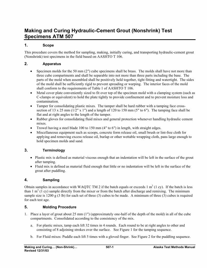
Making and Curing… (Non-Shrink)… 507-1 Alaska Test Methods Manual Revised 12/31/03
Making and Curing Hydraulic-Cement Grout (Nonshrink) Test Specimens ATM 507 1. Scope
This procedure covers the method for sampling, making, initially curing, and transporting hydraulic-cement grout (Nonshrink) test specimens in the field based on AASHTO T 106.
2. Apparatus
• Specimen molds for the 50 mm (2″) cube specimens shall be brass. The molds shall have not more than three cube compartments and shall be separable into not more than three parts including the base. The parts of the mold when assembled shall be positively held together, tight fitting and watertight. The sides of the mold shall be sufficiently rigid to prevent spreading or warping. The interior faces of the mold shall conform to the requirements of Table 1 of AASHTO T 106.
• Metal cover plate conveniently sized to fit over top of the specimen mold with a clamping system (such as C-clamps or equivalent) to hold the plate tightly to provide confinement and to prevent moisture loss and contamination.
• Tamper for consolidating plastic mixes. The tamper shall be hard rubber with a tamping face cross-section of 13 x 25 mm (1/2″ x 1″) and a length of 120 to 150 mm (5″ to 6″). The tamping face shall be flat and at right angles to the length of the tamper.
• Rubber gloves for consolidating fluid mixes and general protection whenever handling hydraulic cement mixes.
• Trowel having a steel blade 100 to 150 mm (4″ to 6″) in length, with straight edges. • Miscellaneous equipment such as scoops, concrete form release oil, small brush or lint-free cloth for
applying and removing excess release oil, burlap or other wettable wrapping cloth, pans large enough to hold specimen molds and sand.
3. Terminology
• Plastic mix is defined as material viscous enough that an indentation will be left in the surface of the grout after tamping.
• Fluid mix is defined as material fluid enough that little or no indentation will be left in the surface of the grout after puddling.
4. Sampling
Obtain samples in accordance with WAQTC TM 2 if the batch equals or exceeds 1 m3 (1 cy). If the batch is less than 1 m3 (1 cy) sample directly from the mixer or from the batch after discharge and remixing. The minimum sample size is 1200 g (3 lb) for each set of three (3) cubes to be made. A minimum of three (3) cubes is required for each test age.
5. Molding Procedure
1. Place a layer of grout about 25 mm (1″) (approximately one-half of the depth of the mold) in all of the cube compartments. Consolidated according to the consistency of the mix.
a. For plastic mixes, tamp each lift 32 times in 4 rounds. Each round to be at right angles to other and consisting of 8 adjoining strokes over the surface. See Figure 1 for the tamping sequence.
b. For Fluid mixes: Puddle each lift 5 times with a gloved finger. See Figure 2 for the puddling sequence.

Alaska Test Methods Manual 507-2 Making and Curing… (Non-Shrink)… Revised 12/31/03
Figure 1 Tamping Sequence
First & Third Round Second & Fourth Round
1 8 1 2 3 4 2 7 3 6 4 5 8 7 6 5
Figure 2 Puddling Sequence
1 4
5
3 2
3. When the tamping or puddling of the first lift in all of the compartments is completed, place the
second lift in each of the compartments, slightly over-filling each compartment.
4. Consolidate the grout in each compartment as described in 2a or 2b with the additional requirement that during consolidation of the second lift any grout forced out onto the top of the mold after each round will be pushed back onto the compartment by means of the tamper and/or gloved fingers before the next consolidation round. When consolidation of the grout is completed, material should extend slightly above the top of the mold. Push any grout forced out onto the top of the mold after the last round back onto the compartment with the trowel.
5. Smooth off the cubes by a single stroke of the flat side of the trowel (with the leading edge slightly raised) across the top of each cube once at right angles to the length of the mold and once along the length of the mold.
6. Finish the grout to a plane finish by drawing the straightedge of the trowel (held nearly perpendicular to the mold) with a sawing motion over the length of the mold.
7. Immediately after finishing the tops, place and secure the cover plate over the top of the mold.
6. Curing
1. Place the covered molds in a secure location as close as possible to the structure for initial curing. These shall remain undisturbed and protected from freezing or overheating for a period of 24 ± 4 hours.
2. At the end of the initial curing period, disassemble the mold and carefully remove the cube specimens. Using a permanent marker, identify the specimens with the field number.
3. Handling the cubes very carefully, wrap them in wet burlap or towels and place them into a watertight container to prevent moisture loss.
Making and Curing… (Non-Shrink)… 507-3 Alaska Test Methods Manual Revised 12/31/03
7. Transporting and Identifying Specimens
Immediately after the initial curing period, transport the specimens to the laboratory for final curing and/or compressive strength testing under standard conditions in accordance with AASHTO T 106, Section 10.5 or 10.6.
A grout compressive strength submittal/worksheet form will be filled out with the required data and accompany the cylinders or beams to the testing laboratory.
While in transport, specimens shall be protected from jarring, freezing or moisture loss.

Alaska Test Methods Manual 507-4 Making and Curing… (Non-Shrink)… Revised 12/31/03
This page intentionally left blank.
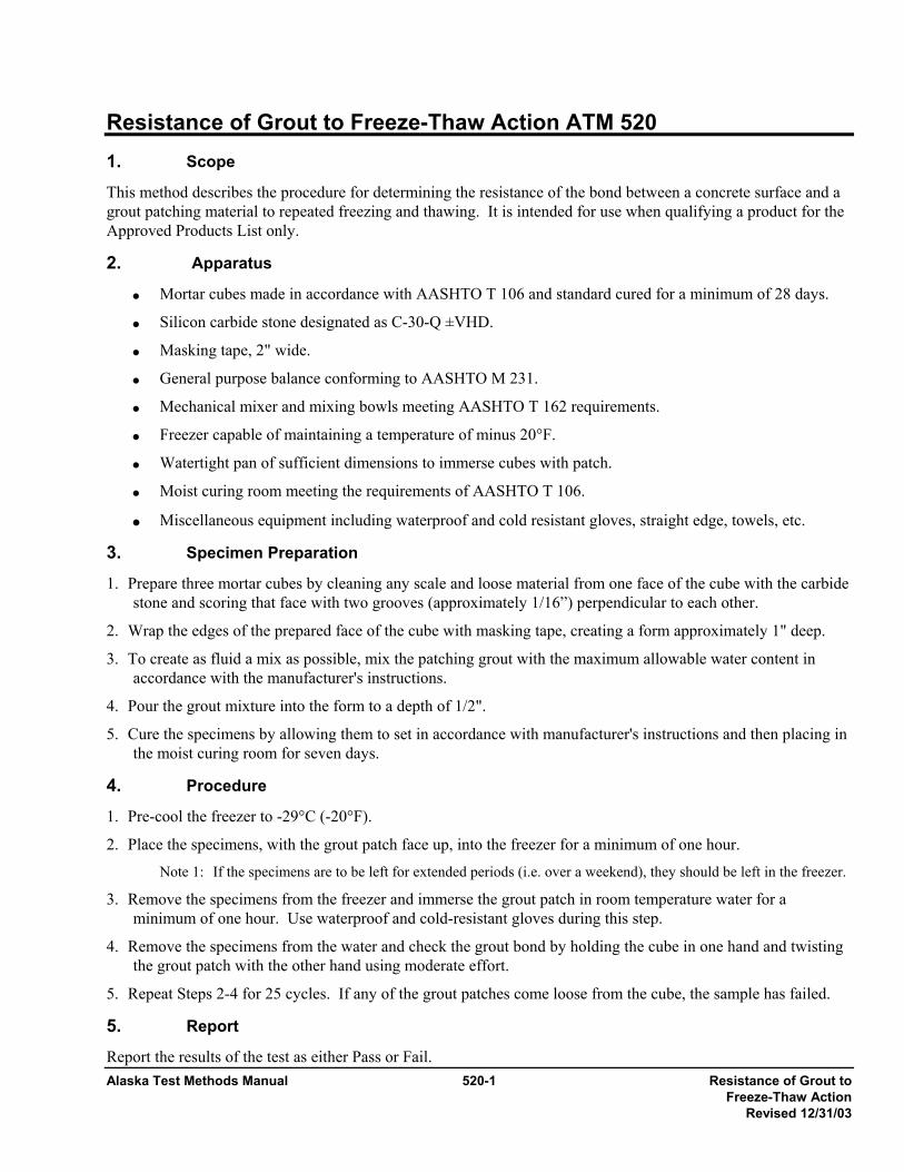
Alaska Test Methods Manual 520-1 Resistance of Grout to Freeze-Thaw Action Revised 12/31/03
Resistance of Grout to Freeze-Thaw Action ATM 520
1. Scope
This method describes the procedure for determining the resistance of the bond between a concrete surface and a grout patching material to repeated freezing and thawing. It is intended for use when qualifying a product for the Approved Products List only.
2. Apparatus
• Mortar cubes made in accordance with AASHTO T 106 and standard cured for a minimum of 28 days.
• Silicon carbide stone designated as C-30-Q ±VHD.
• Masking tape, 2" wide.
• General purpose balance conforming to AASHTO M 231.
• Mechanical mixer and mixing bowls meeting AASHTO T 162 requirements.
• Freezer capable of maintaining a temperature of minus 20°F.
• Watertight pan of sufficient dimensions to immerse cubes with patch.
• Moist curing room meeting the requirements of AASHTO T 106.
• Miscellaneous equipment including waterproof and cold resistant gloves, straight edge, towels, etc.
3. Specimen Preparation
1. Prepare three mortar cubes by cleaning any scale and loose material from one face of the cube with the carbide stone and scoring that face with two grooves (approximately 1/16”) perpendicular to each other.
2. Wrap the edges of the prepared face of the cube with masking tape, creating a form approximately 1" deep.
3. To create as fluid a mix as possible, mix the patching grout with the maximum allowable water content in accordance with the manufacturer's instructions.
4. Pour the grout mixture into the form to a depth of 1/2".
5. Cure the specimens by allowing them to set in accordance with manufacturer's instructions and then placing in the moist curing room for seven days.
4. Procedure
1. Pre-cool the freezer to -29°C (-20°F).
2. Place the specimens, with the grout patch face up, into the freezer for a minimum of one hour.
Note 1: If the specimens are to be left for extended periods (i.e. over a weekend), they should be left in the freezer.
3. Remove the specimens from the freezer and immerse the grout patch in room temperature water for a minimum of one hour. Use waterproof and cold-resistant gloves during this step.
4. Remove the specimens from the water and check the grout bond by holding the cube in one hand and twisting the grout patch with the other hand using moderate effort.
5. Repeat Steps 2-4 for 25 cycles. If any of the grout patches come loose from the cube, the sample has failed.
5. Report
Report the results of the test as either Pass or Fail.

Alaska Test Methods Manual 520-2 Resistance of Grout to Freeze-Thaw Action Revised 12/31/03
This page intentionally left blank.

Terminology SP 1-1 Alaska Test Methods Manual Revised 2/3/04
Terminology SP 1 1. Scope
This standard practice provides terminology as interpreted and defined by the State of Alaska. The definitions of the American Association of State Highway and Transportation Officials (AASHTO) are the ones most commonly followed by this Agency.
Absorption – The increase in the mass of aggregate due to water being absorbed into the pores of the material, but not including water adhering to the outside surface of the particles, expressed as a percentage of the dry mass.
Acceptance sampling and testing– sampling, testing, and the assessment of test results done to determine whether or not the quality of produced material or construction is acceptable in terms of the contract specifications.S
Admixture – Material other than water, cement, and aggregates in portland cement concrete (PCC).
Aggregate – Hard granular material of mineral composition, including sand, gravel, slag or crushed stone, used in roadway base and in Portland Cement Concrete (PCC) and Asphalt concrete pavement.
• Coarse aggregate – Aggregate retained on or above the 4.75 mm (No. 4) sieve.
• Coarse-graded aggregate – Aggregate having a predominance of coarse sizes.
• Dense-graded aggregate – Aggregate having a particle size distribution such that voids occupy a relatively small percentage of the total volume.
• Fine aggregate – Aggregate passing the 4.75 mm (No. 4) sieve.
• Fine-graded aggregate – Aggregate having a predominance of fine sizes.
• Mineral filler – A fine mineral product at least 70 percent of which passes a 75 µm (No. 200) sieve.
• Open-graded gap-graded aggregate – Aggregate having a particle size distribution such that voids occupy a relatively large percentage of the total volume.
• Well-Graded Aggregate – Aggregate having an even distribution of particle sizes.
Aggregate storage bins – Bins that store aggregate for feeding material to the dryer in an asphalt concrete pavement plant in substantially the same proportion as required in the finished mix.
Agitation – Provision of gentle motion in Portland Cement Concrete (PCC) sufficient to prevent segregation and loss of plasticity.
Air voids – Total volume of the small air pockets between coated aggregate particles in asphalt concrete pavement; expressed as a percentage of the bulk volume of the compacted paving mixture.
Ambient temperature – Temperature of the surrounding air.
Angular aggregate – Aggregate possessing well-defined edges at the intersection of roughly planar faces.
Apparent specific gravity – The ratio of the mass, in air, of a volume of the impermeable portion of aggregate to the mass of an equal volume of water.
Asphalt – A dark brown to black cementitious material in which the predominate constituents are bitumens occurring in nature or obtained through petroleum processing. Asphalt is a constituent of most crude petroleum.

Alaska Test Methods Manual SP 1-2 Terminology December 31, 2003
Asphalt cement – Asphalt specially prepared in quality and consistency for use in the manufacture of asphalt concrete pavement.
Asphalt concrete batch plant – A manufacturing facility for producing asphalt concrete that proportions aggregate by weight and asphalt by weight or volume.
Asphalt concrete continuous mix plant – A manufacturing facility for producing asphalt concrete that proportions aggregate and asphalt by a continuous volumetric proportioning system without specific batch intervals.
Automatic cycling control – A control system in which the opening and closing of the weigh hopper discharge gate, the bituminous discharge valve, and the pug mill discharge gate are actuated by means of automatic mechanical or electronic devices without manual control. The system includes preset timing of dry and wet mixing cycles.
Automatic dryer control – A control system that automatically maintains the temperature of aggregates discharged from the dryer.
Automatic proportioning control – A control system in which proportions of the aggregate and asphalt fractions are controlled by means of gates or valves that are opened and closed by means of automatic mechanical or electronic devices without manual control.
Bag (of cement) – 94 lb of portland cement. (Approximately 1 ftP
3P of bulk cement.)
Base – A layer of selected material constructed on top of subgrade or subbase and below the paving on a roadway.
Bias – The offset or skewing of data or information away from its true or accurate position as the result of systematic error.
Binder – Asphalt cement or modified asphalt cement that binds the aggregate particles into a dense mass.
Boulders – Rock fragment, often rounded, with an average dimension larger than 300 mm (12 in.).
Bulk Density – The mass per volume of a material, including any voids that may occur within the volume.
Bulk specific gravity – The ratio of the mass, in air, of a volume of aggregate or compacted asphalt concrete mix (including the permeable and impermeable voids in the particles, but not including the voids between particles) to the mass of an equal volume of water.
Bulk specific gravity (SSD) – The ratio of the mass, in air, of a volume of aggregate or compacted asphalt concrete mix, including the mass of water within the voids (but not including the voids between particles), to the mass of an equal volume of water. (See saturated surface dry.)
Clay – Fine-grained soil that exhibits plasticity over a range of water contents, and that exhibits considerable strength when dry. Also, that portion of the soil finer than 2 µm.
Cobble – Rock fragment, often rounded, with an average dimension between 75 and 300 mm (3 and 12 in.).
Cohesionless soil – Soil with little or no strength when dry and unconfined or when submerged, such as sand.
Cohesive soil – Soil with considerable strength when dry and that has significant cohesion when unconfined or submerged.
Compaction – Densification of a soil or asphalt concrete pavement by mechanical means.

Terminology SP 1-3 Alaska Test Methods Manual Revised 2/3/04
Compaction curve (Proctor curve or moisture-density curve) – The curve showing the relationship between the dry unit weight or density and the water content of a soil for a given compactive effort.
Compaction test (moisture-density test) – Laboratory compaction procedure in which a soil of known water content is placed in a specified manner into a mold of given dimensions, subjected to a compactive effort of controlled magnitude, and the resulting density determined.
Compressibility – Property of a soil or rock relating to susceptibility to decrease in volume when subject to load.
Consolidation – In the placement of portland cement concrete (PCC) it is the removal of entrapped air by either tamping or vibrating the material.
Constructor – The builder of a project. The individual or entity responsible for performing and completing the construction of a project required by the contract documents. Often called a contractor, since this individual or entity contracts with the owner.
Crusher-run – The total unscreened product of a stone crusher.
Delivery tolerances – Permissible variations from the desired proportions of aggregate and asphalt cement delivered to the pug mill.
Density – The ratio of mass to volume of a substance. Usually expressed in kg/mP
3P (lb/ftP
3P).
Design professional – The designer of a project. This individual or entity may provide services relating to the planning, design, and construction of a project, possibly including materials testing and construction inspection. Sometimes called a “contractor”, since this individual or entity contracts with the owner.
Dryer – An apparatus that dries aggregate and heats it to specified temperatures.
Dry mix time – The time interval between introduction of aggregate into the pug mill and the addition of asphalt cement.
Durability – The property of concrete that describes its ability to resist disintegration by weathering and traffic. Included under weathering are changes in the pavement and aggregate due to the action of water, including freezing and thawing.
Effective diameter (effective size) – DB10B, particle diameter corresponding to 10 percent finer or passing.
Embankment – Controlled, compacted material between the subgrade and subbase or base in a roadway.
Field Operating Procedure (FOP) – Procedure used in field testing on a construction site or in a field laboratory. (Based on AASHTO, ASTM or WAQTC test methods.)
Fineness modulus – A factor equal to the sum of the cumulative percentages of aggregate retained on certain sieves divided by 100; the sieves are 150 mm (6”), 75 mm (3”), 37.5 mm (1 ½”), 19.0 mm (3/4”), 9.5 mm (3/8”), 4.75 mm (No. 4), 2.36 mm (No. 8), 1.18 mm (No. 16), 0.60 mm (No. 30), 0.30 mm (No. 50), and 0.15 mm mm (No. 100). Used in the design of concrete mixes. The lower the fineness modulus, the more water/cement paste that is needed to coat the aggregate.
Fines – Portion of a soil or aggregate finer than a 75 µm (No. 200) sieve. Also silts and clays.
Free water – Water on aggregate available for reaction with hydraulic cement. Mathematically, the difference between total moisture content and absorbed moisture content.
Glacial till – Material deposited by glaciation, usually composed of a wide range of particle sizes, which has not been subjected to the sorting action of water.
Alaska Test Methods Manual SP 1-4 Terminology December 31, 2003
Gradation (grain-size or particle-size distribution) – The proportions by mass of a soil or fragmented rock distributed by particle size.
Gradation analysis (grain size analysis, particle-size or sieve analysis) – The process of determining grain-size distribution by separation of sieves with different size openings.
Hot aggregate storage bins – Bins that store heated and separated aggregate prior to final proportioning into the mixer.
Hot mix asphalt (HMA) – High quality, thoroughly controlled hot mixture of asphalt cement and well-graded, high quality aggregate.
Hydraulic cement – Cement that sets and hardens by chemical reaction with water.
Independent assurance – A management tool not directly responsible for process control or acceptance, to provide an independent assessment of the product and/or the reliability of test results obtained from the process control and acceptance testing.
In situ – Rock or soil in its natural formation or deposit.
Liquid limit – Water content corresponding to the boundary between the liquid and plastic states.
Loam – A mixture of sand, silt and/or clay with organic matter.
Lot – A quantity of material to be controlled. It may represent a specified mass, a specified number of truckloads, a linear quantity, or a specified time period during production.
Manual proportioning control – A control system in which proportions of the aggregate and asphalt fractions are controlled by means of gates or valves that are opened and closed by manual means. The system may or may not include power assisted devices in the actuation of gate and valve opening and closing.
Materials and methods specifications – Also called prescriptive specifications. Specifications that direct the Constructor (Contractor) to use specified materials in definite proportions and specific types of equipment and methods to place the material.
Maximum size – One sieve larger than nominal maximum size.
Maximum particle size –First sieve to retain any material.
Mesh – The square opening of a sieve.
Moisture content (Soils and Aggregate)– The ratio, expressed as a percentage, of the mass of water in a material to the dry mass of the material.
Moisture content (Asphalt)– The ratio, expressed as a percentage, of the mass of water in a material to the wet mass of the material.
Nominal maximum size – One sieve larger than the first sieve to retain more than 10 percent of the material using an agency specified set of sieves based on cumulative percent retained. Where large gaps between specification sieves exist, intermediate sieve(s) may be inserted to determine nominal maximum size.
Nuclear gauge – Instruments used to measure in-place density, moisture content, or asphalt content through the measurement of nuclear emissions.
Optimum moisture content (optimum water content) – The water content at which a soil can be compacted to a maximum dry density by a given compactive effort.
Terminology SP 1-5 Alaska Test Methods Manual Revised 2/3/04
Organic soil – Soil with a high organic content.
Paste – Mix of water and hydraulic cement that binds aggregate in portland cement concrete (PCC).
Penetration – The consistency of a bituminous material, expressed as the distance in tenths of a millimeter (0.1 mm) that a standard needle vertically penetrates a sample of the material under specified conditions of loading, time, and temperature.
Percent compaction – The ratio of density of a soil, aggregate, or asphalt concrete mix in the field to maximum density determined by a standard compaction test, expressed as a percentage.
Plant screens – Screens located between the dryer and hot aggregate storage bins that separate the heated aggregates by size.
Plastic limit – Water content corresponding to the boundary between the plastic and the semisolid states.
Plasticity – Property of a material to continue to deform indefinitely while sustaining a constant stress.
Plasticity index – Numerical difference between the liquid limit and the plastic limit and, thus, the range of water content over which the soil is plastic.
Portland cement – Hydraulic cement produced by pulverizing portland cement clinker.
Portland cement concrete (PCC) – A controlled mix of aggregate, portland cement, and water, and possibly other admixtures.
PCC batch plant – A manufacturing facility for producing portland cement concrete.
Proficiency samples – Homogeneous samples that are distributed and tested by two or more laboratories. The test results are compared to assure that the laboratories are obtaining the same results.
Pugmill – A shaft mixer designed to mix aggregate and cement.
Quality assurance (QA)– Planned and systematic actions necessary to provide confidence that a product or service will satisfy given requirements for quality. QA is the overall system for providing quality in a constructed project, including Quality Control (QC), Acceptance, and Independent Assurance (IA).
Quality assurance specifications – Also called QC/QA specifications. A combination of end-result (performance) specifications and materials and methods (prescriptive) specifications. The Constructor (Contractor) is responsible for quality control, and the Owner is responsible for acceptance of the product.
Quality control (QC) – Also called process control—those quality assurance actions and considerations necessary to assess production and construction processes so as to control the level of quality being produced in the end product. This concept of quality control includes sampling and testing to monitor the process but usually does not include acceptance sampling and testing.
Random sampling – Procedure for obtaining non-biased, representative samples.
Sand – Particles of rock passing the 4.75 mm (No. 4) sieve and retained on the 75 µm (No. 200) sieve.
Saturated surface dry (SSD) – Condition of an aggregate particle, asphalt concrete pavement or portland cement concrete (PCC) core, or other porous solid when the permeable voids are filled with water, but no water is present on exposed surfaces. (See bulk specific gravity.)
Segregation – The separation of aggregate by size resulting in a non-uniform material.
Alaska Test Methods Manual SP 1-6 Terminology December 31, 2003
SHRP – The Strategic Highway Research Program (SHRP) established in 1987 as a five-year research program to improve the performance and durability of roads and to make those roads safe for both motorists and highway workers. SHRP research funds were partly used for the development of performance-based specifications to directly relate laboratory analysis with field performance.
Sieve – Laboratory apparatus consisting of wire mesh with square openings, usually in circular or rectangular frames.
Silt – Material passing the 75 µm (No. 200) sieve that is non-plastic or very slightly plastic, and that exhibits little or no strength when dry and unconfined. Also, that portion of the soil finer than 75 µm and coarser than 2 µm.
Slump – Measurement related to the workability of concrete.
Soil – Natural occurring sediments or unconsolidated accumulations of solid particles produced by the physical and chemical disintegration or rocks, and which may or may not contain organic matter.
Specific gravity – The ratio of the mass, in air, of a volume of a material to the mass of an equal volume of water.
Stability – The ability of an asphalt concrete to resist deformation from imposed loads. Stability is dependent upon internal friction, cohesion, temperature, and rate of loading.
Stratified random sampling – Procedure for obtaining non-biased, representative samples in which the established lot size is divided into equally-sized sublots.
Subbase – A layer of selected material constructed between the subgrade and the base coarse in a flexible asphalt concrete pavement roadway, or between the subgrade and Portland Cement Concrete (PCC) pavement in a rigid PCC roadway.
Subgrade – Natural soil prepared and compacted to support a structure or roadway pavement.
Sublot – A segment of a lot chosen to represent the total lot.
Superpave™ – Superpave™ (Superior Performing Asphalt Pavement) is a trademark of the Strategic Highway Research Program (SHRP). Superpave™ is a product of the SHRP asphalt research. The Superpave™ system incorporates performance-based asphalt materials characterization with design environmental conditions to improve performance by controlling rutting, low temperature cracking and fatigue cracking. The three major components of Superpave™ are the asphalt binder specification, the mix design and analysis system, and a computer software system.
Theoretical maximum specific gravity – The ratio of the mass of a given volume of asphalt concrete with no air voids to the mass of an equal volume of water, both at a stated temperature commonly referred to as the “Rice” value.
Topsoil – Surface soil, usually containing organic matter.
Uniformity coefficient – CBu B, a value employed to quantify how uniform or well-graded an aggregate is: CBu B = DB60B/DB10B. 60 percent of the aggregate, by mass, has a diameter smaller than DB60B and 10 percent of the aggregate, by mass, has a diameter smaller than DB10B.
Unit weight – The ratio of weight to volume of a substance. The term “density” is more commonly used.
µm – Micro millimeter (micron) Used as measurement for sieve size.

Terminology SP 1-7 Alaska Test Methods Manual Revised 2/3/04
Viscosity – A measure of the resistance to flow; one method of measuring the consistency of asphalt.
• Absolute viscosity – A method of measuring viscosity using the “poise” as the basic measurement unit. This method is used at a temperature of 60°C, typical of hot pavement.
• Kinematic viscosity – A method of measuring viscosity using the stoke as the basic measurement unit. This method is used at a temperature of 135°C, typical of hot asphalt at a plant.
Void in the mineral aggregate (VMA) – The volume of inter-granular void space between aggregate particles of compacted asphalt concrete pavement that includes air and asphalt; expressed as a percentage of the bulk volume of the compacted paving mixture.
Voids filled with asphalt – The portion of the void in the mineral aggregate (VMA) that contains asphalt; expressed as a percentage of the bulk volume of mix or the VMA.
Wet mixing period – The time interval between the beginning of application of asphalt material and the opening of the mixer gate.
Zero air voids curve (saturation curve) – Curve showing the zero air voids density as a function of water content. Points that define the curve are calculated in accordance with the addendum of WAQTC FOP for AASHTO T 99/ T 180.

Alaska Test Methods Manual SP 1-8 Terminology December 31, 2003
This page intentionally left blank.
Calibration of Mechanical SP 2-1 Alaska Test Methods Manual Compaction Hammer Revised 12/31/03
Calibration of Mechanical Compaction Hammer/Rammer SP 2 1. Scope
This practice sets forth the apparatus, procedures, and materials necessary to calibrate a mechanical compaction hammer used in ATM 417, WAQTC FOP for AASHTO T 99/T 180, AASHTO T 245; and ASTM D 698/D 1557 in accordance with ASTM E 2168.
This test method involves potentially hazardous materials, operations and equipment. This method does not purport to address all of the safety problems associated with it use.
2. Apparatus
• Hand-operated compaction hammer and compaction pedestal conforming to the requirements of WAQTC FOP for AASHTO T 99/T 180, AASHTO T 245; and ASTM D 698/D 1557.
• Mechanical compaction hammer and pedestal conforming to the requirements of ATM 417, WAQTC FOP for AASHTO T 99/T 180, AASHTO T 245, and ASTM D 698/D 1557.
• Marshall and Proctor compaction molds, bases, collars and rubber plugs (roughly 50 mm (2”) thick and cut to fit bottom of mold).
• Caliper capable of measuring 25 mm to an accuracy of 0.01 mm.
• Lead deformation apparatus, consisting of an anvil, guide collar and striking pin.
• Lead test cylinders having a maximum weight spread of 0.06 grams between the heaviest and the lightest cylinder, a length of 17.2 ± 0.1 mm and a diameter of 7.87 ± 0.05 mm. A minimum of ten test cylinders are required for the calibration of one compaction hammer (However as many as 100 test cylinders may be required.)
Note 1: Calibration Kit CN-4242 and Lead Cylinders CN-4245 available from Soil Test have been found satisfactory.
3. Procedure--General 1. Inspect and adjust the mechanical and hand-operated compaction hammers to conform to the requirements of
ATM T 17, AASHTO T 99, T 180 & T 245; and ASTM D 698 & D 1557.
2. Select a set of lead cylinders from the same lot or shipment. Remove any burrs from the ends of the cylinders using a fine grade of emery cloth.
Note 2: Deformation of the test cylinders is affected by changes in temperature. Take precautions to maintain the temperature of the test cylinders within 3ºC of the temperature of the mechanical and hand-operated compaction hammers during the calibration procedure. All testing may be done at room temperature.
3. Measure and record, to the nearest 0.01 mm, the original length of the test cylinders. 4. Procedure—Hand Operated Manual Hammer
1. Place the compaction mold base plate on the compaction pedestal.
2. Assemble the deformation apparatus and place on the base plate.
3. Gently place a compaction mold with collar on the base plate.
Alaska Test Methods Manual SP 2-2 Calibration of Mechanical Compaction Hammer Revised 12/31/03
4. Gently place the hand-operated hammer on top of the striking pin and, with the guide shaft held vertical; apply one drop of the hammer.
5. Measure and record, to the nearest 0.01 mm, the final length of the test cylinder.
6. Using new test cylinders each time, repeat steps 2 through 5 until five (5) deformation values are obtained that do not vary by more than ± 2.0 percent from the average value of all values within this range.
5. Procedure—Mechanically Operated Hammer 1. Assemble a compaction base, mold and collar. Place a rubber plug in the mold assembly and operate the
compaction hammer for a minimum of 25 drops to allow friction in the parts to become constant. Remove the rubber plug.
2. Place the compaction mold base plate on the compaction pedestal.
3. Assemble the deformation apparatus and place on the base plate.
4. Gently place a compaction mold with collar on the base plate.
5. Gently place the mechanical hammer on top of the striking pin and, with the guide shaft held vertical; apply one drop of the hammer.
6. The mechanical compaction hammer shall operate automatically using the same technique that would be used in the actual test method. Raising and releasing the hammer manually or by any other procedure is not allowed.
7. Measure and record, to the nearest 0.01 mm, the final length of the test cylinder.
8. Using new test cylinders each time, repeat steps 3 through 7 until five (5) deformation values are obtained that do not vary by more than ± 2.0 percent from the average value of all values within this range.
6. Calibration Comparison and Adjustment
1. Calculate the percentage difference between the average deformation values of the mechanical and hand-operated compaction hammers. If the difference is less than or equal to 2.0 percent the mechanical compaction hammer is ready for use.
2. If the difference is greater than 2.0 percent, adjust the weight of the mechanical hammer and repeat steps 3 through 7 of the Mechanically Operated Hammer Procedure, until the mean value of 3 sets of data is equal to, or less than 2.0 percent.
7. Report
1. All compaction hammers shall be calibrated every 12 months or prior to use if the existing calibration is more than one (1) year old.
2. The original calibration certificate and test data shall be filed at the calibrating laboratory.
3. A copy of the calibration certificate shall be kept with the Compaction Hammer.

Calibration of Mechanical SP 2-3 Alaska Test Methods Manual Compaction Hammer Revised 12/31/03
Figure 1. LEAD DEFORMATION APPARATUS

Alaska Test Methods Manual SP 2-4 Calibration of Mechanical Compaction Hammer Revised 12/31/03
This page intentionally left blank.
Hydrometer Calibration SP 3-1 Alaska Test Methods Manual Revised 12/31/03
Hydrometer Calibration SP 3 1. Scope This practice provides for determining the composite correction which accounts for the dispersing agent used, temperature of the suspension, and height of the meniscus on the hydrometer stem in accordance with AASHTO T 88 and ASTM D 422.
This test method involves potentially hazardous materials, operations and equipment. This method does not purport to address all of the safety problems associated with it use.
2. Apparatus
• Sedimentation cylinder meeting the requirements of AASHTO T 88 and ASTM D 422. • Stock dispersing agent meeting the requirements of AASHTO T 88 and ASTM D 422. • Hydrometer 152H conforming to ASTM E 100. • Water bath or constant temperature room conforming to the requirements of AASHTO T 88 and ASTM D
422.
3. Procedure 3.1 Measurement of the composite correction will be made at two temperatures spanning the range of expected
test temperatures. Corrections for calculating intermediate temperatures assumes a straight-line relationship between the two observed values.
3.2 Place 125 ml of the dispersing agent into a sedimentation cylinder and fill with water to the 1000 ml. mark. Thoroughly mix the contents as described in AASHTO T 88 and ASTM D 422. Place the cylinder in the constant temperature bath/room, set for one of the two temperatures to be used.
3.3 Allow the temperature of the liquid to stabilize, insert the hydrometer, and, after a short interval to allow the hydrometer to stabilize, read the top of the meniscus formed on the hydrometer stem.
3.4 For hydrometer 152H the composite correction is the difference between the reading and zero (0).
3.5 Repeat steps 3 and 4 at the other temperature or hydrometer to be used.
3.6 The data may be represented in graphical (see Figure 1), tabular or formula form, whichever is more convenient.
Note 1: To conform with standard practices, make Temperature = x and Hydrometer Readings = y in both graphical and formula representations.
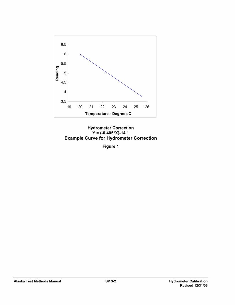
Alaska Test Methods Manual SP 3-2 Hydrometer Calibration Revised 12/31/03
Hydrometer Correction
Y = (-0.405*X)-14.1 Example Curve for Hydrometer Correction
Figure 1
3.5
4
4.5
5
5.5
6
6.5
19 20 21 22 23 24 25 26
Temperature - Degrees C
Rea
ding
Rounding and Precision… SP 6-1 Alaska Test Methods Manual Revised 12/31/03
Rounding and Precision in Materials Test Reporting SP 6 1. Scope
This standard practice provides a procedure for rounding off numbers generated during the process of calculating materials testing results when a specific test method does not specify rounding procedures.
2. Calculation Procedures
2.1 All test results should be reported to a significant, practical, and accurate value. This can be achieved using the following procedures:
2.2 If the first digit to the right of the place to which the calculation is to be reported ends in 0, 1, 2, 3, or 4, the value of that place is not changed. If the rounded number ends in 0, the 0 should be written down. For example, if the result of a calculation is to be rounded to the tenth then 5.6489 rounds to 5.6.
2.3 If the first digit to the right of the place to which the calculation is to be reported ends in 5, 6, 7, 8, or 9, the value of that place is increased by one. For example, if the result of a calculation is to be rounded to the tenth, then 5.6543 rounds to 5.7; 7.9722 rounds to 8.0; 0.054 rounds to 0.1.
2.4 Intermediate calculations are carried out to one more decimal place than that required in the final result. For example, where the final answer is to be reported to the whole percent, intermediate calculations will be carried out to the tenth of a percent (0.1%).
2.5 Most calculators carry 8 digits internally regardless of how many digits are shown in the display. When it is directed to round to a certain level of precision, this means round that value immediately. If the calculator shows a result as 7.45, it may be carrying 7.44537901. If the directions call for this intermediate result to be given to the hundredth, the calculator must be cleared and 7.45 entered. This rounded value must be entered in the calculator in order to remove unusable figures. As another example, if the value 3.4675489 results from a calculation and the directions are to round that result to the tenth, then the calculator must be cleared and the value 3.5 entered.

Alaska Test Methods Manual SP 6-2 Rounding and Precision… Revised 12/31/03
This page intentionally left blank.

Determination of Outlier SP 7-1 Alaska Test Methods Manual Test Results Revised 12/31/03
Determination of Outlier Test Results SP 7 1. Scope
This standard practice provides a mechanism for rejecting individual test values that may misrepresent the physical properties of a material lot. The method statistically identifies a non-representative "outlier" and justifies its removal from the remaining test data for the lot.
2. General
1. When a test result is clearly a result of a gross deviation from prescribed sampling or testing procedure, the test result should be discarded, without further analysis. When no direct evidence of sampling and/or testing errors exists, the lot data will be statistically evaluated for the presence of an outlier.
2. An outlying test result will be assumed to be non-characteristic of the overall quality of the material tested. Outlying test results will be excluded from the price adjustment calculation, by either documental evidence or through statistical analysis.
3. Basis of Statistical Criteria For Outliers
All test results in a lot are included in the calculation of the numerical value of a sample criterion (or statistic), which is then compared with a critical value based on the theory of random sampling from a normal distribution to determine whether the doubtful test result is to be retained or rejected. The critical value is that value of the sample criterion that would be exceeded by chance with 5% total probability. This 5% probability is the risk of erroneously rejecting a good observation and is the Department's defined outlier threshold limit.
4. Procedure
4.1 Calculate the arithmetic mean [ x ] of all test results for the lot using the following formula:
x = nX∑
Where: ∑ = summation of
X = individual test value to xn n = total number of test values
And where: x is rounded to the nearest 0.1 percent for density and all sieve sizes except the 0.075 mm (No. 200) sieve.
x is rounded to the nearest 0.01 percent for asphalt content and the 0.075 mm (No. 200) sieve.
4.2 Calculate sample standard deviation (s) of all test results for the lot using the following formula:
( ) ( )( )1
22
−
−= ∑ ∑
nnxxn
s
Where: s = standard deviation of the lot
∑(x2) = summation of the squares of individual test values.
Alaska Test Methods Manual SP 7-2 Determination of Outlier Test Results Revised 12/31/03
(∑x)2 = square of the summation of the individual test values.
n = total number of test values
4.3 The lot standard deviation (s) is rounded to the nearest 0.01 for density and all sieve sizes except the 0.075 mm (No. 200) sieve. The lot standard deviation(s) is rounded to the nearest 0.001 for asphalt content and the 0.075 mm (No. 200) sieve.
NOTE 1: This is the sample standard deviation and not the population (sigma) standard deviation. Many computer spreadsheet programs have formulas for population standard deviation and not sample standard deviation.
4.4 Calculate the difference between the arithmetic mean )(_x and the lowest test result (XL); and between the
highest test result (XH) and the arithmetic mean x
4.5 Calculate test criterion, TL or TH, of the test result with the greatest difference from the arithmetic mean
)(_x .
4.6 If the lowest test result (XL) has the greatest difference from the arithmetic mean x , then TL is calculated as follows:
s
xXT LL
_)( −
=
4.1 If the highest test result (XH) has the greatest difference from the arithmetic mean )(_x , then TH is
calculated as follows:
s
xXT HH
_)( −
=
Determine critical T value from Table 1.
4.2 If TL or TH, whichever is larger, exceeds the critical T value from Table 1, then that test result is an outlier
and will be excluded from the price adjustment calculations. If one or more additional test result(s) has the same value as the outlier, then none of the test results will be outliers and all test results will be included in the price adjustment calculations. If TL and TH are equal, then neither test result will be an outlier and all test results will be included in the price adjustment calculations.
NOTE 2: This test method will not be reapplied to identify additional "outliers" based on the new arithmetic mean and sample standard deviations calculated after the "outliers" have been excluded.

Determination of Outlier SP 7-3 Alaska Test Methods Manual Test Results Revised 12/31/03
TABLE 1
Critical T Values for a Sample Standard Deviation
Number Of Samples, n Critical T 3 1.155 4 1.481 5 1.715 6 1.887 7 2.020 8 2.126 9 2.215 10 2.290 11 2.355 12 2.412 13 2.462 14 2.507 15 2.549 16 2.585 17 2.620
5. Example 1 1. Consider the following test results on percent asphalt content:
5.3, 5.6, 5.8, 5.8, 5.9, 5.9, 5.9, 6.0, 6.0 and 6.0
2. Calculate the arithmetic mean )(_x :
)(_x = 5.3+5.6+5.8+5.8+5.9+5.9+5.9+6.0+6.0+6.0
10
)(_x = 5.82%
3. Calculate the sample standard deviation:
( ) ( )( )1
22
−
−= ∑ ∑
nnxxn
s
Where ∑(x)2 = 339.16
(∑x)2 = 3,387.24 n = 10 s = 0.220
4. The difference between the arithmetic mean )(_x and the lowest test result is:
(5.82% - 5.3%) = 0.52%
5. The difference between the highest test result and the arithmetic mean )(_x is:

Alaska Test Methods Manual SP 7-4 Determination of Outlier Test Results Revised 12/31/03
(6.0% - 5.82%) = .18%
6. Calculate TL or TH. Since the lowest test result (5.3%) had the greatest difference from the arithmetic mean
)(_x it is evaluated to determine if it is an outlier. TL is calculated as follows:
TL = (5.82% - 5.3%) ÷ 0.220 TL = 2.364
7. Determine Critical T. From Table 1, the critical T for 10 samples is 2.290. Since TL = 2.364 is greater than 2.290, the test result of 5.3% is an outlier and is excluded from the price adjustment calculations.
6. Example 2 1. Consider the following test result on percent asphalt content:
5.3, 5.8, 5.8, 5.8, 5.9, 5.9, 6.0, 6.0, 6.0 and 6.5
2. Calculate arithmetic mean )(_x :
x = 5.3+5.8+5.8+5.8+5.9+5.9+6.0+6.0+6.0+6.5 10 x = 5.90%
3. Calculate sample standard deviation:
( ) ( )( )1
22
−
−= ∑ ∑
nnxxn
s
Where: ∑(x)2 = 348.88
(∑x)2 = 3,481.00 n = 10 s = 0.294
4. The difference between the arithmetic mean x and the lowest test result is:
(5.90% - 5.3%) = 0.6%
5. The difference between the highest test result and the arithmetic mean )(_x is:
(6.5% - 5.90%) = 0.6%
6. Calculate TL or TH. Since the lowest test result (5.3%) and the highest test result (6.5%) have the same
difference from the arithmetic mean )(_x , both TL and TH are calculated.
TL = (5.90% - 5.3%) ÷ 0.294 TH = (6.5% - 5.90%) ÷ 0.294 TL = TH = 2.041
6.1.6 Since TL and TH are equal, neither test result is considered to be an outlier and all test results are included in the price adjustment calculation.
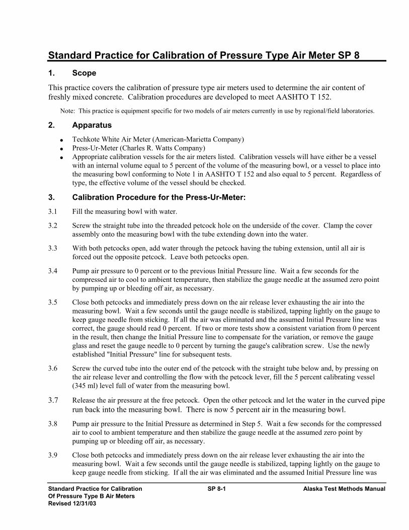
Standard Practice for Calibration SP 8-1 Alaska Test Methods Manual Of Pressure Type B Air Meters Revised 12/31/03
Standard Practice for Calibration of Pressure Type Air Meter SP 8 1. Scope
This practice covers the calibration of pressure type air meters used to determine the air content of freshly mixed concrete. Calibration procedures are developed to meet AASHTO T 152.
Note: This practice is equipment specific for two models of air meters currently in use by regional/field laboratories.
2. Apparatus
• Techkote White Air Meter (American-Marietta Company) • Press-Ur-Meter (Charles R. Watts Company) • Appropriate calibration vessels for the air meters listed. Calibration vessels will have either be a vessel
with an internal volume equal to 5 percent of the volume of the measuring bowl, or a vessel to place into the measuring bowl conforming to Note 1 in AASHTO T 152 and also equal to 5 percent. Regardless of type, the effective volume of the vessel should be checked.
3. Calibration Procedure for the Press-Ur-Meter: 3.1 Fill the measuring bowl with water.
3.2 Screw the straight tube into the threaded petcock hole on the underside of the cover. Clamp the cover assembly onto the measuring bowl with the tube extending down into the water.
3.3 With both petcocks open, add water through the petcock having the tubing extension, until all air is forced out the opposite petcock. Leave both petcocks open.
3.4 Pump air pressure to 0 percent or to the previous Initial Pressure line. Wait a few seconds for the compressed air to cool to ambient temperature, then stabilize the gauge needle at the assumed zero point by pumping up or bleeding off air, as necessary.
3.5 Close both petcocks and immediately press down on the air release lever exhausting the air into the measuring bowl. Wait a few seconds until the gauge needle is stabilized, tapping lightly on the gauge to keep gauge needle from sticking. If all the air was eliminated and the assumed Initial Pressure line was correct, the gauge should read 0 percent. If two or more tests show a consistent variation from 0 percent in the result, then change the Initial Pressure line to compensate for the variation, or remove the gauge glass and reset the gauge needle to 0 percent by turning the gauge's calibration screw. Use the newly established "Initial Pressure" line for subsequent tests.
3.6 Screw the curved tube into the outer end of the petcock with the straight tube below and, by pressing on the air release lever and controlling the flow with the petcock lever, fill the 5 percent calibrating vessel (345 ml) level full of water from the measuring bowl.
3.7 Release the air pressure at the free petcock. Open the other petcock and let the water in the curved pipe run back into the measuring bowl. There is now 5 percent air in the measuring bowl.
3.8 Pump air pressure to the Initial Pressure as determined in Step 5. Wait a few seconds for the compressed air to cool to ambient temperature and then stabilize the gauge needle at the assumed zero point by pumping up or bleeding off air, as necessary.
3.9 Close both petcocks and immediately press down on the air release lever exhausting the air into the measuring bowl. Wait a few seconds until the gauge needle is stabilized, tapping lightly on the gauge to keep gauge needle from sticking. If all the air was eliminated and the assumed Initial Pressure line was

Alaska Test Methods Manual SP 8-2 Standard Practice for Calibration Of Pressure Type B Air Meters Revised 12/31/03
correct, the gauge should read 5 percent.
3.10 If two or more consistent tests show that the gauge at 5 percent air reads incorrectly in excess of 0.2 percent, then remove the gauge glass and reset the gauge needle to 5 percent by adjusting the gauge's calibration screw.
3.11 When the gauge reads correctly at 5 percent, additional water may be withdrawn in the same manner to check results at 10 percent.
4. Calibration Procedure for White Meter 4.1 Fill material container with water. Be sure meter is in level position. Remove standpipe screwed into
petcock and screw it finger-tight into funnel petcock on underside of lid.
4.2 Wipe lip of container clean and dry.
4.3 Close main air valve (colored red) on top of air receiver. Open both petcocks on top of lid.
4.4 Place lid on measuring bowl and close the four toggle clamps.
4.5 Pour water into the funnel until the water comes out the petcock in the center of lid. Tap the meter gently until no air bubbles come out through the center petcock. Close both petcocks.
4.6 Close air bleeder valve in end of air receiver and gently pump air into receiver until gage hand comes to the vicinity of the red line. A little to one side or the other will make no difference as long as the hand has gone past the initial starting point.
4.7 Tap gauge gently with one hand and at the same time, crack bleeder valve in the end of air receiver until gage hand rests exactly on the initial starting point. Then quickly close bleeder valve.
4.8 Remove all water from funnel with syringe.
4.9 Open petcock under funnel and crack main air valve (red) to material container.
4.10 When water has risen exactly to line inside funnel, close petcock under funnel.
4.11 Open main air valve (red) to material container about 1/2 turn and tap gauge until hand comes to rest.
4.12 If meter is in perfect working order, gage hand will come to rest on 1 percent.
4.13 If gage hand does not come to rest on 1 percent, the starting point arrow should be readjusted.
4.14 After test, return standpipe to its place in center petcock.
5. Calibration Using Internal Calibration Vessel 5.1 Fill the measuring bowl with water.
5.2 Clamp the cover assembly onto the measuring bowl.
5.3 With both petcocks open, add water through one petcock, until all air is forced out the opposite petcock. Leave both petcocks open.
5.4 Pump air pressure to 0 percent or to the previous Initial Pressure Line. Wait a few seconds for the compressed air to cool to ambient temperature, then stabilize the gauge needle at the assumed zero point by pumping up or bleeding off air, as necessary.
5.5 Close both petcocks and immediately press down on the air release lever exhausting the air into the

Standard Practice for Calibration SP 8-3 Alaska Test Methods Manual Of Pressure Type B Air Meters Revised 12/31/03
measuring bowl. Wait a few seconds until the gauge needle is stabilized, tapping lightly on the gauge to keep gauge needle from sticking. If all the air was eliminated and the assumed Initial Pressure line was correct, the gauge should read 0 percent. If two or more tests show a consistent variation from 0 percent in the result, then change the Initial Pressure line to compensate for the variation, or remove the gauge glass and reset the gauge needle to 0 percent by turning the gauge's calibration screw. Use the newly established "Initial Pressure" line for subsequent tests.
5.6 Release the pressure and remove the cover assembly.
5.7 Place the Internal Calibration Vessel into the measuring bowl, replace the cover assembly and refill as in step 3.
5.8 Pump the air pressure to the Initial Pressure Line allowing a few seconds for the gauge needle to stabilize.
5.9 Verify there is water standing in both petcocks and then close them.
5.10 Release to air into the measuring bowl by pressing down on the air release lever. Tap the gauge lightly and when stable, the meter should read 5 percent. If two or more consistent tests show that the gauge at 5 percent air reads incorrectly in excess of 0.2 percent, then remove the gauge glass and reset the gauge needle to 5 percent by adjusting the gauge's calibration screw and check again
6. Report 6.1 Report the results of the calibration as well as noting any adjustments or repairs made.
6.2 Label the meter with a sticker noting the month and year of the calibration.
This page intentionally left blank.

Alaska Test Methods Manual SP 8-4 Standard Practice for Calibration Of Pressure Type B Air Meters Revised 12/31/03
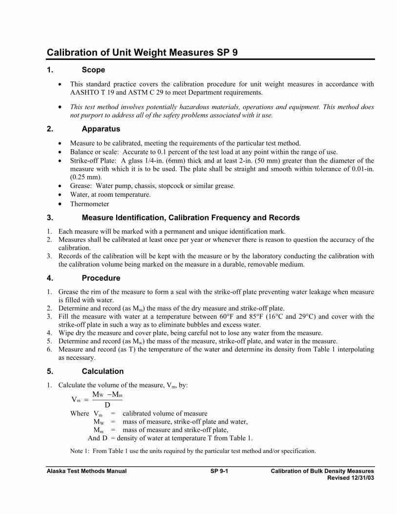
Alaska Test Methods Manual SP 9-1 Calibration of Bulk Density Measures Revised 12/31/03
Calibration of Unit Weight Measures SP 9 1. Scope
• This standard practice covers the calibration procedure for unit weight measures in accordance with AASHTO T 19 and ASTM C 29 to meet Department requirements.
• This test method involves potentially hazardous materials, operations and equipment. This method does not purport to address all of the safety problems associated with it use.
2. Apparatus
• Measure to be calibrated, meeting the requirements of the particular test method. • Balance or scale: Accurate to 0.1 percent of the test load at any point within the range of use. • Strike-off Plate: A glass 1/4-in. (6mm) thick and at least 2-in. (50 mm) greater than the diameter of the
measure with which it is to be used. The plate shall be straight and smooth within tolerance of 0.01-in. (0.25 mm).
• Grease: Water pump, chassis, stopcock or similar grease. • Water, at room temperature. • Thermometer
3. Measure Identification, Calibration Frequency and Records 1. Each measure will be marked with a permanent and unique identification mark. 2. Measures shall be calibrated at least once per year or whenever there is reason to question the accuracy of the
calibration. 3. Records of the calibration will be kept with the measure or by the laboratory conducting the calibration with
the calibration volume being marked on the measure in a durable, removable medium.
4. Procedure 1. Grease the rim of the measure to form a seal with the strike-off plate preventing water leakage when measure
is filled with water. 2. Determine and record (as Mm) the mass of the dry measure and strike-off plate. 3. Fill the measure with water at a temperature between 60°F and 85°F (16°C and 29°C) and cover with the
strike-off plate in such a way as to eliminate bubbles and excess water. 4. Wipe dry the measure and cover plate, being careful not to lose any water from the measure. 5. Determine and record (as Mw) the mass of the measure, strike-off plate, and water in the measure. 6. Measure and record (as T) the temperature of the water and determine its density from Table 1 interpolating
as necessary.
5. Calculation 1. Calculate the volume of the measure, Vm, by:
D
MMV
mWm
−=
Where Vm = calibrated volume of measure MW = mass of measure, strike-off plate and water, Mm = mass of measure and strike-off plate, And D = density of water at temperature T from Table 1. Note 1: From Table 1 use the units required by the particular test method and/or specification.

Alaska Test Methods Manual SP 9-2 Calibration of Bulk Density Measures Revised 12/31/03
6. Report Report the calibrated volume to the nearest 0.0001 cubic foot.
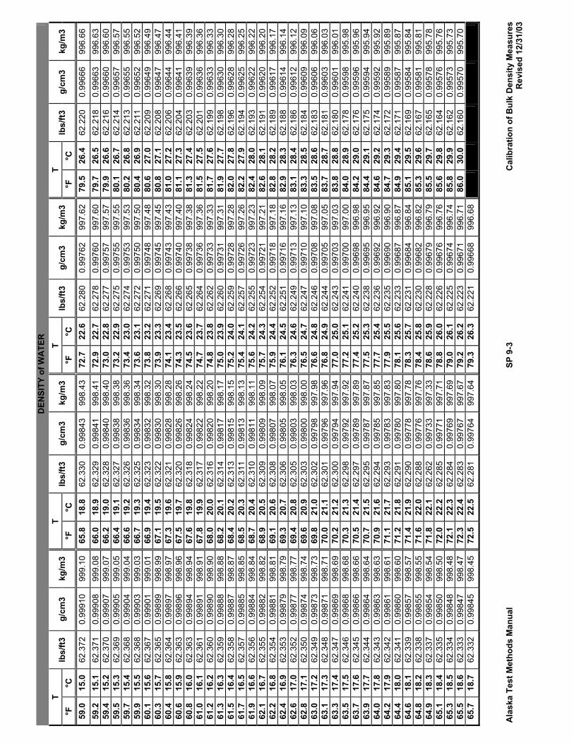
Ala
ska
Test
Met
hods
Man
ual
SP 9
-3
Cal
ibra
tion
of B
ulk
Den
sity
Mea
sure
s
R
evis
ed 1
2/31
/03
DEN
SITY
of W
ATE
R
T T
T T
°F
°C
lbs/
ft3
g/cm
3 kg
/m3
°F
°C
lbs/
ft3
g/cm
3 kg
/m3
°F
°C
lbs/
ft3
g/cm
3 kg
/m3
°F
°C
lbs/
ft3
g/cm
3 kg
/m3
59.0
15
.0
62.3
72
0.99
910
999.
10
65.8
18
.8
62.3
30
0.99
843
998.
43
72.7
22
.6
62.2
80
0.99
762
997.
62
79.5
26
.4
62.2
20
0.99
666
996.
66
59.2
15
.1
62.3
71
0.99
908
999.
08
66.0
18
.9
62.3
29
0.99
841
998.
41
72.9
22
.7
62.2
78
0.99
760
997.
60
79.7
26
.5
62.2
18
0.99
663
996.
63
59.4
15
.2
62.3
70
0.99
907
999.
07
66.2
19
.0
62.3
28
0.99
840
998.
40
73.0
22
.8
62.2
77
0.99
757
997.
57
79.9
26
.6
62.2
16
0.99
660
996.
60
59.5
15
.3
62.3
69
0.99
905
999.
05
66.4
19
.1
62.3
27
0.99
838
998.
38
73.2
22
.9
62.2
75
0.99
755
997.
55
80.1
26
.7
62.2
14
0.99
657
996.
57
59.7
15
.4
62.3
68
0.99
904
999.
04
66.6
19
.2
62.3
26
0.99
836
998.
36
73.4
23
.0
62.2
74
0.99
753
997.
53
80.2
26
.8
62.2
13
0.99
655
996.
55
59.9
15
.5
62.3
68
0.99
903
999.
03
66.7
19
.3
62.3
25
0.99
834
998.
34
73.6
23
.1
62.2
72
0.99
750
997.
50
80.4
26
.9
62.2
11
0.99
652
996.
52
60.1
15
.6
62.3
67
0.99
901
999.
01
66.9
19
.4
62.3
23
0.99
832
998.
32
73.8
23
.2
62.2
71
0.99
748
997.
48
80.6
27
.0
62.2
09
0.99
649
996.
49
60.3
15
.7
62.3
65
0.99
899
998.
99
67.1
19
.5
62.3
22
0.99
830
998.
30
73.9
23
.3
62.2
69
0.99
745
997.
45
80.8
27
.1
62.2
08
0.99
647
996.
47
60.4
15
.8
62.3
64
0.99
897
998.
97
67.3
19
.6
62.3
21
0.99
828
998.
28
74.1
23
.4
62.2
68
0.99
743
997.
43
81.0
27
.2
62.2
06
0.99
644
996.
44
60.6
15
.9
62.3
63
0.99
896
998.
96
67.5
19
.7
62.3
20
0.99
826
998.
26
74.3
23
.5
62.2
66
0.99
740
997.
40
81.1
27
.3
62.2
04
0.99
641
996.
41
60.8
16
.0
62.3
63
0.99
894
998.
94
67.6
19
.8
62.3
18
0.99
824
998.
24
74.5
23
.6
62.2
65
0.99
738
997.
38
81.3
27
.4
62.2
03
0.99
639
996.
39
61.0
16
.1
62.3
61
0.99
891
998.
91
67.8
19
.9
62.3
17
0.99
822
998.
22
74.7
23
.7
62.2
64
0.99
736
997.
36
81.5
27
.5
62.2
01
0.99
636
996.
36
61.2
16
.2
62.3
60
0.99
890
998.
90
68.0
20
.0
62.3
16
0.99
820
998.
20
74.8
23
.8
62.2
62
0.99
733
997.
33
81.7
27
.6
62.1
99
0.99
633
996.
33
61.3
16
.3
62.3
59
0.99
888
998.
88
68.2
20
.1
62.3
14
0.99
817
998.
17
75.0
23
.9
62.2
60
0.99
731
997.
31
81.9
27
.7
62.1
98
0.99
630
996.
30
61.5
16
.4
62.3
58
0.99
887
998.
87
68.4
20
.2
62.3
13
0.99
815
998.
15
75.2
24
.0
62.2
59
0.99
728
997.
28
82.0
27
.8
62.1
96
0.99
628
996.
28
61.7
16
.5
62.3
57
0.99
885
998.
85
68.5
20
.3
62.3
11
0.99
813
998.
13
75.4
24
.1
62.2
57
0.99
726
997.
26
82.2
27
.9
62.1
94
0.99
625
996.
25
61.9
16
.6
62.3
56
0.99
884
998.
84
68.7
20
.4
62.3
10
0.99
811
998.
11
75.6
24
.2
62.2
55
0.99
723
997.
23
82.4
28
.0
62.1
93
0.99
622
996.
22
62.1
16
.7
62.3
55
0.99
882
998.
82
68.9
20
.5
62.3
09
0.99
809
998.
09
75.7
24
.3
62.2
54
0.99
721
997.
21
82.6
28
.1
62.1
91
0.99
620
996.
20
62.2
16
.8
62.3
54
0.99
881
998.
81
69.1
20
.6
62.3
08
0.99
807
998.
07
75.9
24
.4
62.2
52
0.99
718
997.
18
82.8
28
.2
62.1
89
0.99
617
996.
17
62.4
16
.9
62.3
53
0.99
879
998.
79
69.3
20
.7
62.3
06
0.99
805
998.
05
76.1
24
.5
62.2
51
0.99
716
997.
16
82.9
28
.3
62.1
88
0.99
614
996.
14
62.6
17
.0
62.3
52
0.99
877
998.
77
69.4
20
.8
62.3
05
0.99
803
998.
03
76.3
24
.6
62.2
49
0.99
713
997.
13
83.1
28
.4
62.1
86
0.99
612
996.
12
62.8
17
.1
62.3
50
0.99
874
998.
74
69.6
20
.9
62.3
03
0.99
800
998.
00
76.5
24
.7
62.2
47
0.99
710
997.
10
83.3
28
.5
62.1
84
0.99
609
996.
09
63.0
17
.2
62.3
49
0.99
873
998.
73
69.8
21
.0
62.3
02
0.99
798
997.
98
76.6
24
.8
62.2
46
0.99
708
997.
08
83.5
28
.6
62.1
83
0.99
606
996.
06
63.1
17
.3
62.3
48
0.99
871
998.
71
70.0
21
.1
62.3
01
0.99
796
997.
96
76.8
24
.9
62.2
44
0.99
705
997.
05
83.7
28
.7
62.1
81
0.99
603
996.
03
63.3
17
.4
62.3
47
0.99
869
998.
69
70.2
21
.2
62.3
00
0.99
794
997.
94
77.0
25
.0
62.2
43
0.99
703
997.
03
83.8
28
.8
62.1
80
0.99
601
996.
01
63.5
17
.5
62.3
46
0.99
868
998.
68
70.3
21
.3
62.2
98
0.99
792
997.
92
77.2
25
.1
62.2
41
0.99
700
997.
00
84.0
28
.9
62.1
78
0.99
598
995.
98
63.7
17
.6
62.3
45
0.99
866
998.
66
70.5
21
.4
62.2
97
0.99
789
997.
89
77.4
25
.2
62.2
40
0.99
698
996.
98
84.2
29
.0
62.1
76
0.99
596
995.
96
63.9
17
.7
62.3
44
0.99
864
998.
64
70.7
21
.5
62.2
95
0.99
787
997.
87
77.5
25
.3
62.2
38
0.99
695
996.
95
84.4
29
.1
62.1
75
0.99
594
995.
94
64.0
17
.8
62.3
43
0.99
863
998.
63
70.9
21
.6
62.2
94
0.99
785
997.
85
77.7
25
.4
62.2
36
0.99
692
996.
92
84.6
29
.2
62.1
74
0.99
592
995.
92
64.2
17
.9
62.3
42
0.99
861
998.
61
71.1
21
.7
62.2
93
0.99
783
997.
83
77.9
25
.5
62.2
35
0.99
690
996.
90
84.7
29
.3
62.1
72
0.99
589
995.
89
64.4
18
.0
62.3
41
0.99
860
998.
60
71.2
21
.8
62.2
91
0.99
780
997.
80
78.1
25
.6
62.2
33
0.99
687
996.
87
84.9
29
.4
62.1
71
0.99
587
995.
87
64.6
18
.1
62.3
39
0.99
857
998.
57
71.4
21
.9
62.2
90
0.99
778
997.
78
78.3
25
.7
62.2
31
0.99
684
996.
84
85.1
29
.5
62.1
69
0.99
584
995.
84
64.8
18
.2
62.3
38
0.99
855
998.
55
71.6
22
.0
62.2
88
0.99
776
997.
76
78.4
25
.8
62.2
30
0.99
682
996.
82
85.3
29
.6
62.1
67
0.99
581
995.
81
64.9
18
.3
62.3
37
0.99
854
998.
54
71.8
22
.1
62.2
62
0.99
733
997.
33
78.6
25
.9
62.2
28
0.99
679
996.
79
85.5
29
.7
62.1
65
0.99
578
995.
78
65.1
18
.4
62.3
35
0.99
850
998.
50
72.0
22
.2
62.2
85
0.99
771
997.
71
78.8
26
.0
62.2
26
0.99
676
996.
76
85.6
29
.8
62.1
64
0.99
576
995.
76
65.3
18
.5
62.3
34
0.99
848
998.
48
72.1
22
.3
62.2
84
0.99
769
997.
69
79.0
26
.1
62.2
25
0.99
674
996.
74
85.8
29
.9
62.1
62
0.99
573
995.
73
65.5
18
.6
62.3
33
0.99
847
998.
47
72.3
22
.4
62.2
83
0.99
767
997.
67
79.2
26
.2
62.2
23
0.99
671
996.
71
86.0
30
.0
62.1
60
0.99
570
995.
70
65.7
18
.7
62.3
32
0.99
845
998.
45
72.5
22
.5
62.2
81
0.99
764
997.
64
79.3
26
.3
62.2
21
0.99
668
996.
68

Alaska Test Methods Manual SP 9-4 Calibration of Bulk Density Measures Revised 12/31/03
This page intentionally left blank.
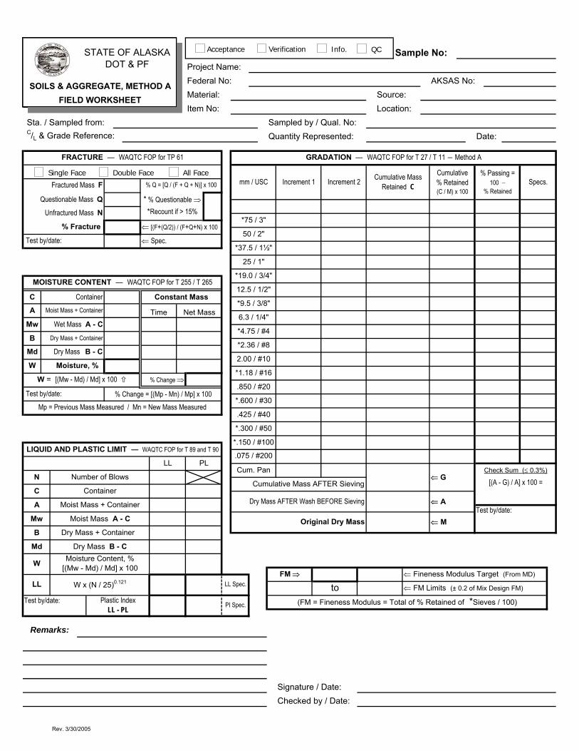
STATE OF ALASKA DOT & PF
Sample No: Project Name:Federal No: AKSAS No:SOILS & AGGREGATE, METHOD AMaterial: Source:FIELD WORKSHEETItem No: Location:
Sta. / Sampled from: Sampled by / Qual. No: C/L & Grade Reference: Quantity Represented: Date:
FRACTURE ― WAQTC FOP for TP 61 GRADATION ― WAQTC FOP for T 27 / T 11 ― Method A
mm / USC Increment 1 Increment 2 Cumulative Mass Retained C
Cumulative % Retained (C / M) x 100
% Passing = 100 −
% RetainedSpecs. Fractured Mass F % Q = [Q / (F + Q + N)] x 100
Questionable Mass Q * % Questionable ⇒Unfractured Mass N *Recount if > 15%
*75 / 3"% Fracture ⇐ [(F+(Q/2)) / (F+Q+N) x 100
50 / 2" Test by/date: ⇐ Spec.
*37.5 / 1½"
25 / 1"
*19.0 / 3/4"MOISTURE CONTENT ― WAQTC FOP for T 255 / T 265
12.5 / 1/2"C Container Constant Mass
*9.5 / 3/8"A Moist Mass + Container Time Net Mass 6.3 / 1/4"
Mw Wet Mass A - C*4.75 / #4
B Dry Mass + Container*2.36 / #8
Md Dry Mass B - C2.00 / #10
W Moisture, % *1.18 / #16
W = [(Mw - Md) / Md] x 100 % Change ⇒.850 / #20
Test by/date: % Change = [(Mp - Mn) / Mp] x 100*.600 / #30
Mp = Previous Mass Measured / Mn = New Mass Measured.425 / #40
*.300 / #50
*.150 / #100LIQUID AND PLASTIC LIMIT ― WAQTC FOP for T 89 and T 90
.075 / #200LL PL
Cum. Pan⇐ G
Check Sum (≤ 0.3%)N Number of Blows
Cumulative Mass AFTER Sieving [(A - G) / A] x 100 =C Container
Dry Mass AFTER Wash BEFORE Sieving ⇐ AA Moist Mass + Container Test by/date:
Mw Moist Mass A - C Original Dry Mass ⇐ MB Dry Mass + Container
Md Dry Mass B - C
W Moisture Content, % [(Mw - Md) / Md] x 100
FM ⇒ ⇐ Fineness Modulus Target (From MD)LL W x (N / 25)0.121 LL Spec. to ⇐ FM Limits (± 0.2 of Mix Design FM)
Test by/date: Plastic Index LL - PL PI Spec. (FM = Fineness Modulus = Total of % Retained of *Sieves / 100)
Remarks:
Signature / Date:Checked by / Date:
Single Face Double Face All Face
Acceptance Verification Info. QC
Rev. 3/30/2005
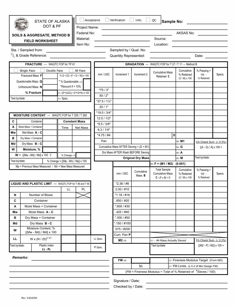
STATE OF ALASKA DOT & PF
Sample No: Project Name:Federal No: AKSAS No:SOILS & AGGREGATE, METHOD BMaterial: Source:FIELD WORKSHEETItem No: Location:
Sta. / Sampled from: Sampled by / Qual. No: C/L & Grade Reference: Quantity Represented: Date:
FRACTURE ― WAQTC FOP for TP 61 GRADATION ― WAQTC FOP for T 27 / T 11 ― Method B
mm / USC Increment 1 Increment 2 Cumulative Mass Retained C
Cumulative % Retained (C / M) x 100
% Passing = 100 −
% Retained Specs.Fractured Mass F % Q = [Q / (F + Q + N)] x 100
Questionable Mass Q * % Questionable ⇒Unfractured Mass N *Recount if > 15%
*75 / 3"% Fracture ⇐ [(F+(Q/2)) / (F+Q+N) x 100
50 / 2" Test by/date: ⇐ Spec.
*37.5 / 1½"
25 / 1"
*19.0 / 3/4"MOISTURE CONTENT ― WAQTC FOP for T 255 / T 265
12.5 / 1/2"C Container Constant Mass
*9.5 / 3/8"A Moist Mass + Container Time Net Mass 6.3 / 1/4"
Mw Wet Mass A - C*4.75 / #4 D
B Dry Mass + ContainerPan ⇐ M1 CA Check Sum (≤ 0.3%)Md Dry Mass B - C
Cumulative Mass AFTER Sieving = (D + M1) ⇐ G [(A - G) / A] x 100 =W Moisture, %
Dry Mass AFTER Wash BEFORE Sieving ⇐ AW = [(Mw - Md) / Md] x 100 % Change ⇒
Original Dry Mass ⇐ M Test by/date: Test by/date: % Change = [(Mp - Mn) / Mp] x 100
⇐ F = (M1 / M2) (0.001)Mp = Previous Mass Measured / Mn = New Mass Measured
mm / USC Cumulative Mass B
Total Sample Cumulative Mass
C = [F x B] + D
Cumulative % Retained (C / M) x 100
% Passing = 100 −
% Retained Specs.
LIQUID AND PLASTIC LIMIT ― WAQTC FOP for T 89 and T 90 *2.36 / #8
LL PL 2.00 / #10
N Number of Blows *1.18 / #16
C Container .850 / #20
A Moist Mass + Container *.600 / #30
Mw Moist Mass A - C .425 / #40
B Dry Mass + Container *.300 / #50
Md Dry Mass B - C *.150 / #100
W Moisture Content, % [(Mw - Md) / Md] x 100
.075 / #200
Cum. Pan PLL W x (N / 25)0.121 LL Spec. M2 ⇒ ⇐ − #4 Mass Actually Sieved FA Check Sum (≤ 0.3%)
Test by/date: Plastic Index LL - PL PI Spec. Test by/date: [(M2 - P) / M2] x 100 =
Remarks:FM ⇒ ⇐ Fineness Modulus Target (From MD)
to ⇐ FM Limits (± 0.2 of Mix Design FM)
(FM = Fineness Modulus = Total of % Retained of *Sieves / 100)
Signature / Date:Checked by / Date:
Single Face Double Face All Face
Acceptance Verification Info. QC
Rev. 3/30/2005
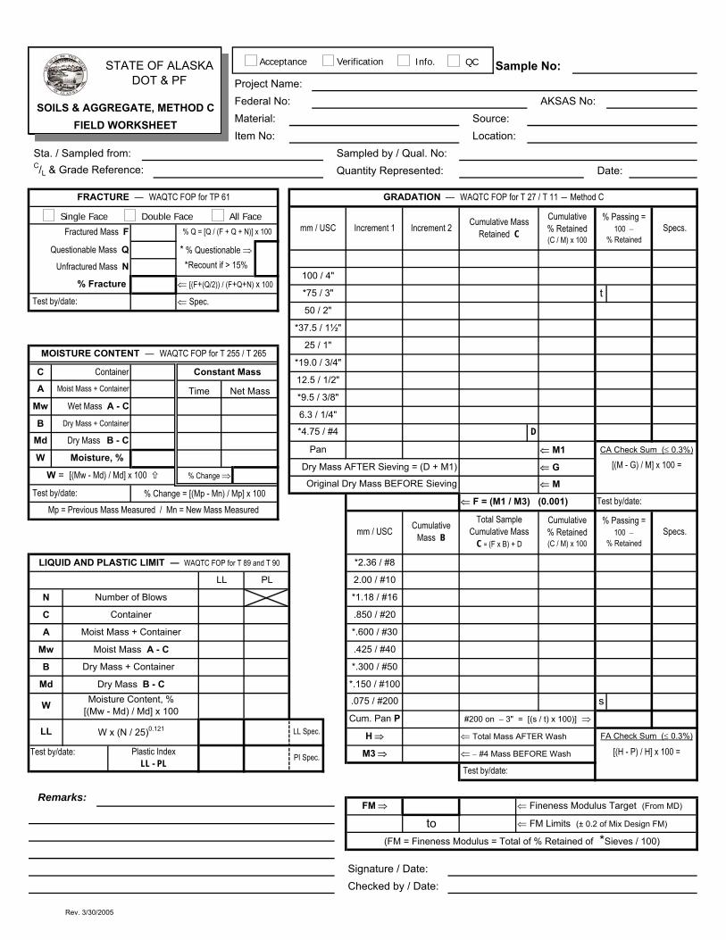
STATE OF ALASKA DOT & PF
Sample No: Project Name:Federal No: AKSAS No:SOILS & AGGREGATE, METHOD CMaterial: Source:FIELD WORKSHEETItem No: Location:
Sta. / Sampled from: Sampled by / Qual. No: C/L & Grade Reference: Quantity Represented: Date:
FRACTURE ― WAQTC FOP for TP 61 GRADATION ― WAQTC FOP for T 27 / T 11 ― Method C
mm / USC Increment 1 Increment 2 Cumulative Mass Retained C
Cumulative % Retained (C / M) x 100
% Passing = 100 −
% RetainedSpecs. Fractured Mass F % Q = [Q / (F + Q + N)] x 100
Questionable Mass Q * % Questionable ⇒Unfractured Mass N *Recount if > 15%
100 / 4"% Fracture ⇐ [(F+(Q/2)) / (F+Q+N) x 100
*75 / 3" t Test by/date: ⇐ Spec.
50 / 2"
*37.5 / 1½"
25 / 1"MOISTURE CONTENT ― WAQTC FOP for T 255 / T 265
*19.0 / 3/4"C Container Constant Mass
12.5 / 1/2"A Moist Mass + Container Time Net Mass *9.5 / 3/8"
Mw Wet Mass A - C6.3 / 1/4"
B Dry Mass + Container*4.75 / #4 D
Md Dry Mass B - CPan ⇐ M1 CA Check Sum (≤ 0.3%)
W Moisture, % Dry Mass AFTER Sieving = (D + M1) ⇐ G [(M - G) / M] x 100 =
W = [(Mw - Md) / Md] x 100 % Change ⇒Original Dry Mass BEFORE Sieving ⇐ M
Test by/date: % Change = [(Mp - Mn) / Mp] x 100⇐ F = (M1 / M3) (0.001) Test by/date:
Mp = Previous Mass Measured / Mn = New Mass Measured
mm / USC Cumulative Mass B
Total Sample Cumulative Mass
C = (F x B) + D
Cumulative % Retained (C / M) x 100
% Passing = 100 −
% RetainedSpecs.
LIQUID AND PLASTIC LIMIT ― WAQTC FOP for T 89 and T 90 *2.36 / #8
LL PL 2.00 / #10
N Number of Blows *1.18 / #16
C Container .850 / #20
A Moist Mass + Container *.600 / #30
Mw Moist Mass A - C .425 / #40
B Dry Mass + Container *.300 / #50
Md Dry Mass B - C *.150 / #100
W Moisture Content, % [(Mw - Md) / Md] x 100
.075 / #200 sCum. Pan P #200 on − 3" = [(s / t) x 100)] ⇒
LL W x (N / 25)0.121 LL Spec. H ⇒ ⇐ Total Mass AFTER Wash FA Check Sum (≤ 0.3%)
Test by/date: Plastic Index LL - PL PI Spec. M3 ⇒ ⇐ − #4 Mass BEFORE Wash [(H - P) / H] x 100 =
Test by/date:
Remarks:FM ⇒ ⇐ Fineness Modulus Target (From MD)
to ⇐ FM Limits (± 0.2 of Mix Design FM)
(FM = Fineness Modulus = Total of % Retained of *Sieves / 100)
Signature / Date:Checked by / Date:
Single Face Double Face All Face
Acceptance Verification Info. QC
Rev. 3/30/2005

STATE OF ALASKA DOT & PF
Sample No: Project Name:Federal No: AKSAS No:HMA Extracted Aggregate GradationMaterial: Source:FOP for T 30 - FIELD WORKSHEETItem No: Location:
Sta. / Sampled from: Sampled by / Qual. No: C/L & Grade Reference: Quantity Represented: Date:
FRACTURE ― WAQTC FOP for TP 61 HMA AGGREGATE GRADATION ― WAQTC FOP for T 30
mm / USC Increment 1 Increment 2 Cumulative Mass Retained C
Cumulative % Retained (C / Mf) x 100
% Passing = 100 −
% Retained
Specs.Fractured Mass F % Q = [Q / (F + Q + N)] x 100
Questionable Mass Q * % Questionable ⇒50 / 2"
Unfractured Mass N *Recount if > 15%*37.5 / 1½"
% Fracture ⇐ [(F+(Q/2)) / (F+Q+N) x 10025 / 1"
Test by/date: ⇐ Spec.*19.0 / 3/4"
12.5 / 1/2"
*9.5 / 3/8"MOISTURE CONTENT ― WAQTC FOP for T 255 / T 265
6.3 / 1/4"C Container Constant Mass
4.75 / #4A Moist Mass + Container Time Net Mass *2.36 / #8
Mw Wet Mass A - C2.00 / #10
B Dry Mass + Container1.18 / #16
Md Dry Mass B - C.850 / #20
W Moisture, % *.600 / #30
W = [(Mw - Md) / Md] x 100 % Change ⇒.425 / #40
Test by/date: % Change = [(Mp - Mn) / Mp] x 100*.300 / #50
Mp = Previous Mass Measured / Mn = New Mass Measured*.150 / #100
.075 / #200 *Pan (only) P * #200 = {[(Mf - A) + P] / Mf} x 100
LIQUID AND PLASTIC LIMIT ― WAQTC FOP for T 89 and T 90Cumulative Mass AFTER Sieving ⇐ G Test by/date:
LL PLDry Mass AFTER Wash BEFORE Sieving ⇐ A
N Number of BlowsDry Sample Mass after Ignition ⇐ Mf (from WAQTC FOP for T 308)
C ContainerCheck Sum (≤ 0.2%)
A Moist Mass + Container [(A - G) / A] x 100 =
Mw Moist Mass A - C
B Dry Mass + Container
Md Dry Mass B - C
W Moisture Content, % [(Mw - Md) / Md] x 100
LL W x (N / 25)0.121 LL Spec. FM ⇒ ⇐ Fineness Modulus Target (From MD)
to ⇐ FM Limits (± 0.2 of Mix Design FM)Test by/date: Plastic Index LL - PL PI Spec. (FM = Fineness Modulus = Total of % Retained of *Sieves / 100)
Remarks:
Signature / Date:Checked by / Date:
Wetting Agent Used
Single Face Double Face All Face
Acceptance Verification Info. IA QC
Rev. 3/31/2005
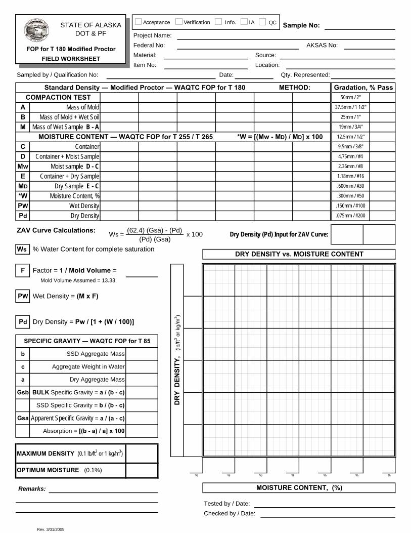
Pd
%% % %
SPECIFIC GRAVITY ― WAQTC FOP for T 85
Dry Density = Pw / [1 + (W / 100)]
x 100
METHOD:
ZAV Curve Calculations:
Ws
Wet Density
MOISTURE CONTENT ― WAQTC FOP for T 255 / T 265 *W = [(Mw - MD) / MD] x 100
b
c
SSD Aggregate Mass
Aggregate Weight in Water
a
Gsb
Gsa
SSD Specific Gravity = b / (b - c)
Dry Aggregate Mass
Gradation, % Pass
*W Moisture Content, %
Standard Density ― Modified Proctor ― WAQTC FOP for T 180
.150mm / #100
.075mm / #200
Ws =
MwContainer + Dry Sample
Container
Moist sample D - C
F
Pd
(62.4) (Gsa) - (Pd)
% Water Content for complete saturation
PW
Dry Sample E - CMD
Mold Volume Assumed = 13.33
PW
Factor = 1 / Mold Volume =
(Pd) (Gsa)Dry Density (Pd) Input for ZAV Curve:
DRY DENSITY vs. MOISTURE CONTENT
Dry Density
CContainer + Moist SampleD
1.18mm / #16E.600mm / #30
9.5mm / 3/8"
.300mm / #50
2.36mm / #8
25mm / 1"
19mm / 3/4"
4.75mm / #4
12.5mm / 1/2"
50mm / 2"
37.5mm / 1 1/2"
STATE OF ALASKA DOT & PF
Source:Location:
Sample No:
Material:
Project Name:Federal No: AKSAS No:FOP for T 180 Modified Proctor
FIELD WORKSHEETItem No:
Apparent Specific Gravity = a / (a - c)
Mass of Mold + Wet Soil
COMPACTION TESTMass of Mold
Sampled by / Qualification No:
Checked by / Date:
M
AB
Mass of Wet Sample B - A
DR
Y D
ENSI
TY,
(lb/
ft3 or k
g/m
3 )
Absorption = [(b - a) / a] x 100
BULK Specific Gravity = a / (b - c)
Wet Density = (M x F)
MAXIMUM DENSITY (0.1 lb/ft3 or 1 kg/m3)
OPTIMUM MOISTURE (0.1%)%
Tested by / Date:
MOISTURE CONTENT, (%)
% %
Remarks:
Date: Qty. Represented:
Acceptance Verification Info. IA QC
Rev. 3/31/2005

STATE OF ALASKA DOT & PF Project Name:
Federal No: AKSAS No:WAQTC FOP for T 310 (METHOD A)Material: Source:FIELD DENSITY WORKSHEETItem No: Spec. Gauge S/N:
FIELD DENSITY TEST NUMBERSTATIONC/ REFERENCEGRADE REFERENCE
L
QUANTITY REPRESENTEDDATE TESTED
STANDARD DENSITY WAQTC FOP for T 180:
Standard Density Lab NumberA Standard Density (Maximum Lab)
Optimum MoistureB Bulk Specific Gravity
DENSITY DETERMINATIONProbe Depth
Reading #1 Reading #2 Reading #1 Reading #2 Reading #1 Reading #2 Reading #1 Reading #2
Wet Density, (lb/ft3 or kg/m3) Gauge
C Average Wet Density
DDry Density (gauge) C / [1 + (E / 100)]
Dry Density (actual) C / [1 + (W / 100)]
MOISTURE CONTENT WAQTC FOP for T 255/T 265 or use gauge moisture if it is within 1% of actual moisture.% Moisture
GaugeE Average % MoistureF Wet Mass + ContainerG Dry Mass + ContainerJ ContainerW % Moisture (actual) [(F - G) / (G - J)] x 100
GRADATION / OVERSIZE CORRECTION *Note: If % Oversize (Pc) is less than or equal to 5%, no correction is required.
ATM 212 or *WAQTC FOP for T 224 P Wet Mass + TareQ TareR Wet Mass P - Q
S Dry Mass (actual) or R / [1 + (E / 100)]
T Oversize Mass + TareV Tare
Mc Oversize Mass T - V
Pc % Oversize (Mc / S) x 100
Pf % Passing 100 - Pc
Corrected Std. Density (chart or Dd formula)
% Compaction (D / Corr. Std. Den.) x 100
Dd = (100 * A * k ) / [(A * Pc) + (k * Pf)] ⇒ k = (62.4 lb/ft3 * B) or (1000 kg/m3 * B)
Signature / Qualification No. / Date: Checked by / Date:REMARKS:
A B C D / ATM 212
3/4" #4 3/4" #4 3/4" #4 3/4" #4
Acceptance Verification Info. IA QC
Rev. 3/31/2005
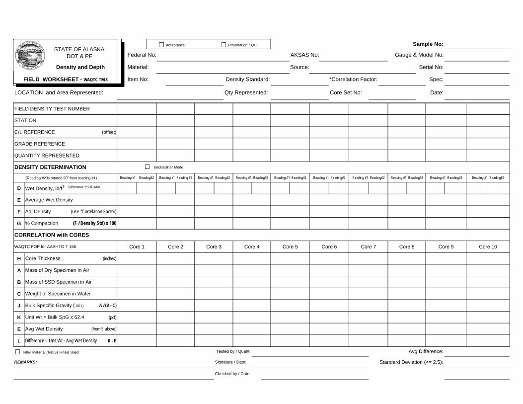
Sample No:STATE OF ALASKA
DOT & PF Federal No: AKSAS No: Gauge & Model No:
Density and Depth Material: Source: Serial No:
FIELD WORKSHEET - WAQTC TM 8 Item No: Density Standard: *Correlation Factor: Spec:
LOCATION and Area Represented: Qty Represented: Core Set No: Date:
FIELD DENSITY TEST NUMBER
STATION
C/L REFERENCE (offset)
GRADE REFERENCE
QUANTITY REPRESENTED
DENSITY DETERMINATION
(Reading #2 is rotated 90o from reading #1) Reading #1 Reading#2 Reading #1 Reading #2 Reading #1 Reading#2 Reading #1 Reading#2 Reading #1 Reading#2 Reading #1 Reading#2 Reading #1 Reading#2 Reading #1 Reading#2 Reading #1 Reading#2 Reading #1 Reading#2
D Wet Density, lb/f3 (Difference <=2.5 lb/f3)
E Average Wet Density
F Adj Density (use *Correlation Factor)
G % Compaction (F / Density Std) x 100
CORRELATION with CORES
WAQTC FOP for AASHTO T 166 Core 1 Core 2 Core 3 Core 4 Core 5 Core 6 Core 7 Core 8 Core 9 Core 10
H Core Thickness (inches)
A Mass of Dry Specimen in Air
B Mass of SSD Specimen in Air
C Weight of Specimen in Water
J Bulk Specific Gravity (.001) A / (B - C)
K Unit Wt = Bulk SpG x 62.4 (pcf)
E Avg Wet Density (from E above)
L Difference = Unit Wt - Avg Wet Density K - E
Tested by / Qual#: Avg Difference:
REMARKS: Signature / Date: Standard Deviation (<= 2.5):
Checked by / Date:
Filler Material (Native Fines) Used
Backscatter Mode
Acceptance Information / QC
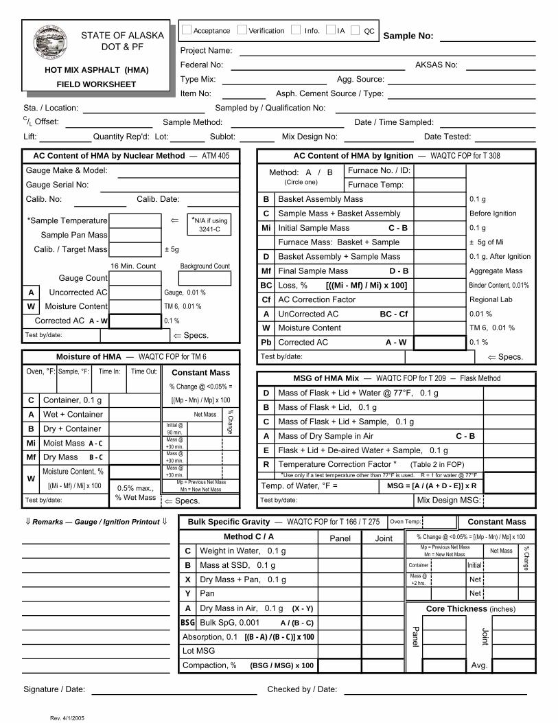
STATE OF ALASKA DOT & PF
Sample No: Project Name:
Federal No: AKSAS No:HOT MIX ASPHALT (HMA)Type Mix: Agg. Source:FIELD WORKSHEETItem No: Asph. Cement Source / Type:
Sta. / Location: Sampled by / Qualification No:C/L Offset: Sample Method: Date / Time Sampled:
Lift: Quantity Rep'd: Lot: Sublot: Mix Design No: Date Tested:
AC Content of HMA by Nuclear Method ― ATM 405 AC Content of HMA by Ignition ― WAQTC FOP for T 308
Gauge Make & Model: Method: A / B Furnace No. / ID:
Gauge Serial No: (Circle one) Furnace Temp:
Calib. No: Calib. Date: B Basket Assembly Mass 0.1 g
C Sample Mass + Basket Assembly Before Ignition*Sample Temperature ⇐ *N/A if using
3241-C Mi Initial Sample Mass C - B 0.1 gSample Pan Mass
Furnace Mass: Basket + Sample ± 5g of MiCalib. / Target Mass ± 5g
D Basket Assembly + Sample Mass 0.1 g, After Ignition16 Min. Count Background Count Mf Final Sample Mass D - B Aggregate Mass
Gauge CountBC Loss, % [((Mi - Mf) / Mi) x 100] Binder Content, 0.01%
A Uncorrected AC Gauge, 0.01 %Cf AC Correction Factor Regional Lab
W Moisture Content TM 6, 0.01 %A UnCorrected AC BC - Cf 0.01 %
Corrected AC A - W 0.1 %W Moisture Content TM 6, 0.01 %
Test by/date: ⇐ Specs.Pb Corrected AC A - W 0.1 %
Moisture of HMA ― WAQTC FOP for TM 6 Test by/date: ⇐ Specs.
Oven, °F: Sample, °F: Time In: Time Out: Constant Mass MSG of HMA Mix ― WAQTC FOP for T 209 ― Flask Method% Change @ <0.05% =
D Mass of Flask + Lid + Water @ 77°F, 0.1 gC Container, 0.1 g [(Mp - Mn) / Mp] x 100
B Mass of Flask + Lid, 0.1 gA Wet + Container Net Mass
% Change
C Mass of Flask + Lid + Sample, 0.1 gB Dry + Container Initial @
90 min.
A Mass of Dry Sample in Air C - BMi Moist Mass A - C Mass @
+30 min. E Flask + Lid + De-aired Water + Sample, 0.1 gMf Dry Mass B - C Mass @
+30 min. R Temperature Correction Factor * (Table 2 in FOP)
W Moisture Content, % Mass @
+30 min. *Use only if a test temperature other than 77°F is used. R = 1 for water @ 77°F
[(Mi - Mf) / Mi] x 100 0.5% max., % Wet Mass
Mp = Previous Net Mass Mn = New Net Mass Temp. of Water, °F = MSG = [A / (A + D - E)] x R
Test by/date: ⇐ Specs. Test by/date: Mix Design MSG:
⇓ Remarks ― Gauge / Ignition Printout ⇓ Bulk Specific Gravity ― WAQTC FOP for T 166 / T 275 Oven Temp: Constant Mass
Method C / A Panel Joint % Change @ <0.05% = [(Mp - Mn) / Mp] x 100
C Weight in Water, 0.1 g Mp = Previous Net Mass Mn = New Net Mass Net Mass
% ChangeB Mass at SSD, 0.1 g Container Initial
X Dry Mass + Pan, 0.1 g Mass @ +2 hrs. Net
Y Pan Net
A Dry Mass in Air, 0.1 g (X - Y) Core Thickness (inches)
BSG Bulk SpG, 0.001 A / (B - C) Panel
Joint Absorption, 0.1 [(B - A) / (B - C)] x 100 Lot MSG
Compaction, % (BSG / MSG) x 100 Avg.
Signature / Date: Checked by / Date:
Acceptance Verification Info. IA QC
Rev. 4/1/2005

STATE OF ALASKA DOT & PF
Pour No:Project Name:
Federal No: AKSAS No: Date:CONCRETE PLACEMENT REPORTStructure / Bridge: Item No:FIELD WORKSHEETStations / Area Rep'd: Truck No:
Supplier: Class: Ticket No:
Aggregate Source: Cement/Type: Mix Design No:
BATCH MASS (from Scale) Lbs. Pour Time: Start _________ Finish _________
Nt Cementitious Material (Nc + Nf + Nm) Mix Time: Mix Revs: Time of Discharge:
Port. Cement (Nc)____________ Fly Ash (Nf)____________M-silica (Nm)____________
A Fine Aggregate or Sand (FA) Spec.= 1½ hrs. with +1 minute per degree < 70°F, not to exceed 2 hrs.
B Intermediate Aggregate (IA) Time Between Batches: < 30 Minutes
C Coarse Aggregate (CA)TEMPERATURE ― WAQTC FOP for T 309
D Water Added at Plant gal. x 8.34 lbs. Concrete Temperature Weather Conditions
D1 Water Added on Site gal. x 8.34 lbs. Air Temperature
W1 Total Mass of Batch (Nt + A + B + C + D + D1)Water Temperature
AGGREGATE SSD WEIGHTSWAQTC FOP for: Specs:
FAa Free Moisture, % __________ ― __________ = %
T 119 Slump, in.b SSD Weight [A / (1 + (a / 100))] (% Moisture)* (absorption)**
T 152 Air, %
IAc Free Moisture, % __________ ― __________ = % a Mass of Bucket + Conc. lb.
d SSD Weight [B / (1 + (c / 100))] (% Moisture)* (absorption)** b Mass of Bucket lb.
Mm Mass of Conc. (a - b) lb.
CAe Free Moisture, % __________ ― __________ = %
Vm Bucket Volume ft3f SSD Weight [C / (1 + (e / 100))] (% Moisture)* (absorption)**
W T 121 Density (Mm/Vm) lb / ft3* Moisture From Batch Ticket
Test by/date:** Absorption From Mix Design, use 0.0% if Batch Ticket reports free moisture
MASS OF WATER IN BATCH Lbs. CYLINDER DATA ― WAQTC FOP for T 23E Free Water in FA (A - b) Time Made Cylinder IDF Free Water in IA (B - d)
G Free Water in CA (C - f)
H Total Water Mass (D + D1 + E + F + G) Test by/date:
Yd3 Batch Design BATCH DATA Actual yd3
Batch DataSpecifications Allowable Range*
VB Design Batch Volume, 0.01yd3
Actual yd3 / Batch = W1 / (27 x W), 0.01 yd3 YB * excludes 608, 609, 615, & Aviation items
Yield per yd3 Batch = Y / V , 0.01 yd3 Y .98 – 1.02W
B B
Water Cement Ratio (lb / lb) = H / Nt, nearest 0.01 W
Mix
Des
ign
Prop
ortio
ns
/ C Cementitious Content (lb / yd3) = Nt / YB, nearest lb.
/ CN ± 1% Batch Design –
3 Sacks / yd = N / 94, 0.1 sack3 ± 1% Batch Design –
3
Portland Cement Content (lb / yd ) = Nc / YB, nearest lb.
± 5% Batch Design – Microsilica Content (lb / yd3) = Nm / Y , nearest lb.
Fly Ash Content (lb / yd ) = Nf / YB, nearest lb.
± 10% Batch Design – Fine Aggregate = b / YB, nearest lb.
B
± 2%* Batch Design – Intermediate Aggregate = d / YB, nearest lb. ± 2%* Batch Design – Coarse Aggregate = f / YB, nearest lb. ± 2%* Batch Design –
Remarks: Signature / Date:Checked by / Date:
Acceptance Verification Info. IA QC
Rev. 3/31/2005
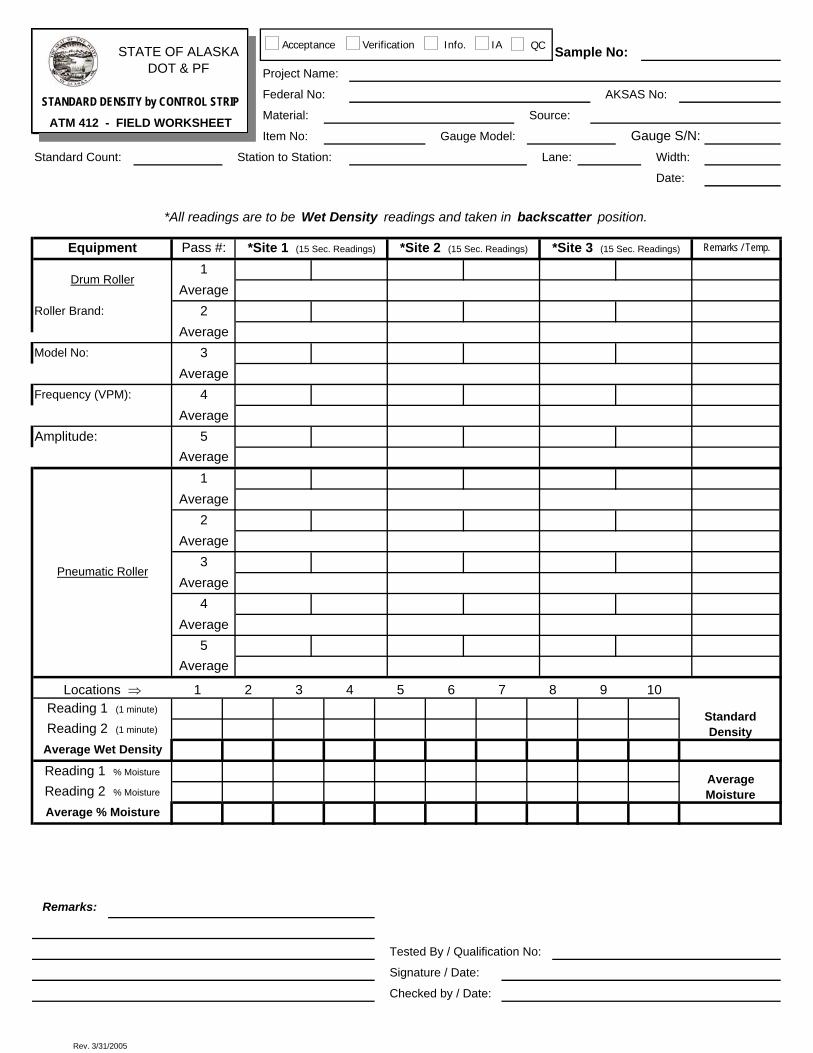
STATE OF ALASKA DOT & PF
Sample No: Project Name:
Federal No: AKSAS No:STANDARD DENSITY by CONTROL STRIPMaterial: Source:ATM 412 - FIELD WORKSHEETItem No: Gauge Model: Gauge S/N:
Standard Count: Station to Station: Lane: Width:
Date:
*All readings are to be Wet Density readings and taken in backscatter position.
Equipment Pass #: *Site 1 (15 Sec. Readings) *Site 2 (15 Sec. Readings) *Site 3 (15 Sec. Readings) Remarks / Temp.
Drum Roller1
AverageRoller Brand: 2
AverageModel No: 3
AverageFrequency (VPM): 4
AverageAmplitude: 5
Average
Pneumatic Roller
1Average
2Average
3Average
4Average
5Average
Locations ⇒ 1 2 3 4 5 6 7 8 9 10
Standard Density
Reading 1 (1 minute)
Reading 2 (1 minute)
Average Wet Density
Reading 1 % Moisture Average MoistureReading 2 % Moisture
Average % Moisture
Remarks:
Tested By / Qualification No:
Signature / Date:
Checked by / Date:
Acceptance Verification Info. IA QC
Rev. 3/31/2005

STATE OF ALASKA DOT & PF
Sample No: Project Name:Federal No: AKSAS No: AGGREGATE, Sand EquivalentMaterial: Source:FIELD WORKSHEETItem No: Location:
Sta. / Sampled from: Sampled by: C/L & Grade Reference: Qualification No: Date Sampled:
Sand Equivalent WAQTC FOP T 176
Sedimentation Time
Trial No. 1 2 3Sand Reading SR
Clay Reading CR
Sand Equivalent SE
Sedimentation Time
SE = (SR / CR) * 100
Test by/date: Average
Flat and Elongated ATM 306
Ratio:
Size Fraction mm― in
Group % Retained (A)
Dry Mass F & E Mass % F
& E (B) Weighted %
F&E (C)
37.5 to 19.0 1½ to ¾
19.0 to 9.5 ¾ to ⅜
9.5 to 4.75 ⅜ to No. 4(A) Group Retained is based on plus No. 4 only Total Weighted %
(B) % F & E = [(F & E Mass) / ( Dry Mass)] * 100
(C) Weighted % F & E = Group % Retained / % F & E Test by/date:
Remarks:
Signature / Date:Checked by / Date:
Acceptance Information / QC
1:2 1:3 1:5
Rev. 4/2/2005
Related Documents