ALADIN User’s Manual Olivier Bienaym´ e 1 , Daniel Egret 1,2 , Mark Allen 1 , Franc ¸ois Bonnarel 1 , Pierre Fernique 1 , Thomas Boch 1 1 CDS, UMR 7550, Observatoire de Strasbourg, 11 rue de l’Universit´ e, 67000 Strasbourg, France 2 present address: Observatoire de Paris Email: [email protected] April 28, 2005– Aladin Manual 3nd release – describing Aladin version 3. Abstract. ALADIN is an interactive sky atlas developed and maintained by the Centre de Donn´ ees astronomiques de Strasbourg (CDS) for the identification of astronomical sources through visual analysis of reference sky images. Contents 1 Introduction 3 1.1 The ALADIN interactive sky atlas ....... 3 1.2 The CDS .................... 3 2 The user interfaces 3 2.1 Aladin previewer ................ 3 2.2 Aladin applet .................. 3 2.3 Aladin Standalone ................ 4 3 Using Aladin 4 3.1 Access ...................... 4 3.2 Getting started .................. 4 3.3 The ALADIN view panels ............ 5 3.4 The plane stack ................. 5 3.5 Server selector ................. 6 3.5.1 Image servers .............. 6 3.5.2 Simbad ................. 6 3.5.3 VizieR ................. 6 3.5.4 NED .................. 6 3.5.5 Mission logs and Image Archives ... 6 3.5.6 Instrument Field of View ........ 6 3.5.7 My Data ................ 7 3.6 Learning more about the astronomical objects . 7 3.6.1 Selecting objects ............ 7 3.6.2 The Measurement window ....... 7 3.7 The tool bar ................... 7 3.7.1 Draw .................. 7 3.7.2 Text, Tags ................ 8 3.7.3 Distance (Dist) and Cut graph ..... 8 3.7.4 Filter .................. 8 3.7.5 RGB colour composition ........ 8 3.7.6 Blink .................. 8 3.7.7 Resampling ............... 8 3.7.8 Contour plots .............. 8 3.7.9 Zoom and image manipulation ..... 9 3.7.10 Colour map (Histog.) .......... 9 3.7.11 Properties ................ 9 3.7.12 Remove planes and views (del.) .... 10 3.7.13 Scale and coordinate grid ........ 10 3.8 The Save... and Print... menus ......... 10 3.9 The Tools... menu ................ 11 3.9.1 Aladin script console and note-pad .. 11 3.9.2 VOPlot ................. 11 3.9.3 Region Of Interest extractor ...... 11 3.9.4 Catalogue cross match tool ....... 12 3.9.5 Simbad Finger ............. 12 3.10 Help ....................... 12 4 More Detailed Features 12 4.1 Multiview mode ................. 12 4.2 Manipulating the plane stack .......... 13 4.3 Interacting with the VizieR database ...... 13

Welcome message from author
This document is posted to help you gain knowledge. Please leave a comment to let me know what you think about it! Share it to your friends and learn new things together.
Transcript

ALADIN User’s Manual
Olivier Bienayme1, Daniel Egret1,2, Mark Allen1, Francois Bonnarel1, Pierre Fernique1, Thomas Boch1
1 CDS, UMR 7550, Observatoire de Strasbourg, 11 rue de l’Universite, 67000 Strasbourg, France2 present address: Observatoire de Paris
Email: [email protected]
April 28, 2005–Aladin Manual 3nd release – describing Aladin version 3.
Abstract. ALADIN is an interactive sky atlas developed and maintained by the Centre de Donnees astronomiques de Strasbourg(CDS) for the identification of astronomical sources through visual analysis of reference sky images.
Contents
1 Introduction 31.1 The ALADIN interactive sky atlas . . . . . . . 31.2 The CDS . . . . . . . . . . . . . . . . . . . . 3
2 The user interfaces 32.1 Aladin previewer . . . . . . . . . . . . . . . . 32.2 Aladin applet . . . . . . . . . . . . . . . . . . 32.3 Aladin Standalone . . . . . . . . . . . . . . . . 4
3 Using Aladin 43.1 Access . . . . . . . . . . . . . . . . . . . . . . 43.2 Getting started . . . . . . . . . . . . . . . . . . 43.3 The ALADIN view panels . . . . . . . . . . . . 53.4 The plane stack . . . . . . . . . . . . . . . . . 53.5 Server selector . . . . . . . . . . . . . . . . . 6
3.5.1 Image servers . . . . . . . . . . . . . . 63.5.2 Simbad . . . . . . . . . . . . . . . . . 63.5.3 VizieR . . . . . . . . . . . . . . . . . 63.5.4 NED . . . . . . . . . . . . . . . . . . 63.5.5 Mission logs and Image Archives . . . 63.5.6 Instrument Field of View . . . . . . . . 63.5.7 My Data . . . . . . . . . . . . . . . . 7
3.6 Learning more about the astronomical objects .73.6.1 Selecting objects . . . . . . . . . . . . 73.6.2 The Measurement window . . . . . . . 7
3.7 The tool bar . . . . . . . . . . . . . . . . . . . 73.7.1 Draw . . . . . . . . . . . . . . . . . . 73.7.2 Text, Tags . . . . . . . . . . . . . . . . 83.7.3 Distance (Dist) and Cut graph . . . . .83.7.4 Filter . . . . . . . . . . . . . . . . . . 83.7.5 RGB colour composition . . . . . . . . 83.7.6 Blink . . . . . . . . . . . . . . . . . . 83.7.7 Resampling . . . . . . . . . . . . . . . 83.7.8 Contour plots . . . . . . . . . . . . . . 83.7.9 Zoom and image manipulation . . . . .93.7.10 Colour map (Histog.) . . . . . . . . . . 93.7.11 Properties . . . . . . . . . . . . . . . . 93.7.12 Remove planes and views (del.) . . . .103.7.13 Scale and coordinate grid . . . . . . . .10
3.8 The Save... and Print... menus . . . . . . . . .103.9 The Tools... menu . . . . . . . . . . . . . . . .11
3.9.1 Aladin script consoleand note-pad . . 113.9.2 VOPlot . . . . . . . . . . . . . . . . . 113.9.3 Region Of Interest extractor . . . . . .113.9.4 Catalogue cross match tool . . . . . . .123.9.5 Simbad Finger . . . . . . . . . . . . .12
3.10 Help . . . . . . . . . . . . . . . . . . . . . . .12
4 More Detailed Features 124.1 Multiview mode . . . . . . . . . . . . . . . . . 124.2 Manipulating the plane stack . . . . . . . . . .134.3 Interacting with the VizieR database . . . . . .13

2 Olivier Bienayme, Daniel Egret, Mark Allen, Francois Bonnarel, Pierre Fernique, Thomas Boch: ALADIN User’s Manual
4.4 History . . . . . . . . . . . . . . . . . . . . . 144.5 Loading personal files . . . . . . . . . . . . . .14
4.5.1 Local images . . . . . . . . . . . . . .144.5.2 Calibrating Images . . . . . . . . . . .144.5.3 Local Tables . . . . . . . . . . . . . .15
4.6 Script console and script mode . . . . . . . . .154.7 Coordinate manipulation . . . . . . . . . . . .174.8 Using theSHIFT key for hidden features . . . .17
5 The image databases 175.1 Database summary . . . . . . . . . . . . . . .175.2 DSS Images . . . . . . . . . . . . . . . . . . .185.3 MAMA/CAI Images . . . . . . . . . . . . . . 185.4 2MASS near-infrared survey . . . . . . . . . .185.5 IRAS-IRIS survey . . . . . . . . . . . . . . . .185.6 DENIS, ROSAT, SDSS . . . . . . . . . . . . .185.7 Image astrometry . . . . . . . . . . . . . . . .185.8 Image compression . . . . . . . . . . . . . . .19
6 The catalogue and survey server 196.1 VizieR . . . . . . . . . . . . . . . . . . . . . . 196.2 Archive previews . . . . . . . . . . . . . . . .19
7 Specific features of the Stand-alone version 197.1 Starting the Stand-alone version . . . . . . . .19
7.1.1 The Java Virtual Machine . . . . . . .207.1.2 The AladinJava Stand-alone package .20
7.2 Defining additional servers . . . . . . . . . . .20
8 Filters in Aladin 208.1 Introduction . . . . . . . . . . . . . . . . . . .208.2 Syntax . . . . . . . . . . . . . . . . . . . . . .21
8.2.1 Invocating columns . . . . . . . . . . .218.2.2 Comments . . . . . . . . . . . . . . .228.2.3 Arithmetic expressions using
UCDs/columns . . . . . . . . . . . . . 228.2.4 Conditions . . . . . . . . . . . . . . .228.2.5 Constraints . . . . . . . . . . . . . . .228.2.6 Actions . . . . . . . . . . . . . . . . . 228.2.7 Defining a color . . . . . . . . . . . . .238.2.8 Symbol shape . . . . . . . . . . . . . .23
8.3 Usage in Aladin . . . . . . . . . . . . . . . . .238.3.1 Creating a filter . . . . . . . . . . . . .238.3.2 Modifying a filter . . . . . . . . . . . . 248.3.3 Syntax errors . . . . . . . . . . . . . .248.3.4 Activate/Deactivate a filter . . . . . . .248.3.5 Scope of a filter . . . . . . . . . . . . .248.3.6 Applying multiple filters . . . . . . . . 248.3.7 Creating a filter in script mode . . . . .248.3.8 Miscellaneous . . . . . . . . . . . . .24
9 User feedback 25
10 Contribution / Acknowledgements 25
A Backus Naur Form of filter syntax 26
B Aladin Script Commands 27

Olivier Bienayme, Daniel Egret, Mark Allen, Francois Bonnarel, Pierre Fernique, Thomas Boch: ALADIN User’s Manual 3
1. Introduction
1.1. The ALADIN interactive sky atlas
ALADIN is an interactive sky atlas developed and maintainedby the Centre de Donnees astronomiques de Strasbourg (CDS)for the identification of astronomical sources through visualanalysis of reference sky images (Bonnarel et al. 2000).
ALADIN fully benefits from the environment of CDSdatabases and services (SIMBAD reference database, VizieRcatalogue service, etc.), and is designed as a multi-purpose ser-vice for use by the professional astronomical community.
ALADIN allows the user to visualize digitized images ofany part of the sky, to superimpose entries from the CDS as-tronomical catalogues and tables, and to interactively accessrelated data and information from SIMBAD , NED, VizieR, orother archives for all known objects in the field.
ALADIN is particularly useful for multi-spectral cross-identifications of astronomical sources, observation prepara-tion and quality control of new data sets (by comparison withstandard catalogues covering the same region of sky).
Fig. 1.Home page of ALADIN at the CDS Web site.
1.2. The CDS
The Centre de Donnees astronomiques de Strasbourg (CDS)defines, develops, and maintains services to help astronomersfind the information they need from the very rapidly increasingwealth of astronomical information.
A detailed description of the CDS on-line services can befound, e.g., in Genova et al. (2000), or at the CDS web site:http://cdsweb.u-strasbg.fr/.
2. The user interfaces
ALADIN is currently available in three main modes: ALADIN
previewer, a simple astronomical image provider; ALADIN java
applet and ALADIN java stand-alone version are graphic in-terfaces for image manipulations. ALADIN can also be con-trolled via in-line commands, executing script files or openingthe ALADIN script console. ALADIN is publicly accessible onthe World-Wide Web at the address: http://aladin.u-strasbg.fr/.
2.1. Aladin previewer
The ALADIN previewer is a simple web page application thatdisplays sky images centred on a given sky coordinate positionor object name (resolved to a coordinate by SIMBAD ). The de-fault action is to return14.1′ × 14.1′ DSS-I images, as theseimages are available for the whole sky. The other options are toreturn the larger6◦ × 6◦ DSS “Plate view” images, or to con-struct an RGB image from the DSS images (Fig. 2). The resultof a request also includes a list of direct links to all the otherimages available at that position in the ALADIN image server(in FITS or JPEG format).
Fig. 2. Result page of ALADIN previewer for the galaxy M51.The default image is from DSS-I.
2.2. Aladin applet
The Aladin Java applet is the primary public interface, sup-porting queries to the Aladin image server, overlays from anycatalogue or table available at CDS, or from SIMBAD and NEDdatabases, and access to a number of remote archives.
It allows the user to interactively make queries for images,catalogues, and data. Images may be manipulated with a set offunctions including zooming, changing colour-maps and pixel-resampling. Catalogues may be displayed with various coloursand symbols, and can be manipulated with filters. Other graph-ical functions such as contours, drawings, and distance vectorsare also available.
4 Olivier Bienayme, Daniel Egret, Mark Allen, Francois Bonnarel, Pierre Fernique, Thomas Boch: ALADIN User’s Manual
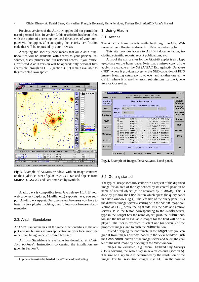
Previous versions of the ALADIN applet did not permit theuse of personal files. In version 3 this restriction has been liftedwith the option of accessing the local directories of your com-puter via the applet, after accepting the security certificationcode that will be requested by your browser.
Accepting the security code means that all Aladin func-tionalities will be available with access to your personal re-sources, discs, printers and full network access. If you refuse,a restricted Aladin version will be opened: only personal filesaccessible through an URL (section 3.5.7) remain available tothis restricted Java applet.
Fig. 3. Example of ALADIN window, with an image centeredon the Hydar I cluster of galaxies ACO 1060, and objects fromSIMBAD, GSC2.2 and NED marked by symbols.
Aladin Java is compatible from Java release 1.1.4. If yourweb browser (Explorer, Mozilla, etc.) supports java, you sup-port Aladin Java Applet. On some recent browsers you have toinstall a java plugin machine, then follow your browser docu-mentation.
2.3. Aladin Standalone
ALADIN Standalone has all the same functionalities as the ap-plet version, but runs as Java application on your local machinerather than being launched from a browser.
ALADIN Standalone is available for download atAladinJava package1. Instructions concerning the installation aregiven in Section 7.
1 http://aladin.u-strasbg.fr/AladinJava?frame=downloading
3. Using Aladin
3.1. Access
The ALADIN home page is available through the CDS Webserver at the following address: http://aladin.u-strasbg.fr/
This site provides access to ALADIN documentation, in-cluding scientific reports, recent publications, etc.
A list of the mirror sites for the ALADIN applet is also keptup-to-date on the home page. Note that a mirror copy of theapplet is available at the NASA/IPAC Extragalactic Database(NED) where it provides access to the NED collection of FITSimages featuring extragalactic objects, and another one at theCFHT, where it is used to assist submissions for the QueueService Observing.
Fig. 4.Example of Images/Data ALADIN Load panel.
3.2. Getting started
The typical usage scenario starts with a request of the digitizedimage for an area of the sky defined by its central position orname of central object (to be resolved by SIMBAD ). This isdone by pushing theLoad button which opens the query panelin a new window (Fig.4). The left side of the query panel liststhe different image servers (starting with theAladin image col-lection at CDS), while the right side lists the data and archiveservers. Push the button corresponding to theAladin server,type in theTarget box the name object, push thesubmit but-ton and the list of all available images for the field will be dis-played. The user is expected to select one (or several) of theproposed images, and to push thesubmit button.
Instead of typing the coordinate in theTarget box, you cangrab it from images already loaded in the View window. PushtheGrab coord. button of the image server and select the cen-ter of the next image by clicking in the View window.
Images are extracted, e.g., from Digitized Sky Surveys(DSS) covering the whole sky in several colours (section 5).The size of a sky field is determined by the resolution of theimage. For full resolution images it is 14.1′ in the case of
Olivier Bienayme, Daniel Egret, Mark Allen, Francois Bonnarel, Pierre Fernique, Thomas Boch: ALADIN User’s Manual 5
DSS-I and12.9′ for DSS-II. The image server also currentlyprovides DSS images in low resolution (about1.5◦ × 1.5◦),and global views of the original photographic Schmidt plates(about6◦ × 6◦). Other image surveys, such as IRAS and the2 Micron All Sky Survey (2MASS), are also included in theimage database.
To abort a query, click on the plane name associated to yourquery. Remove this plane by clicking thedel button in the toolbar.
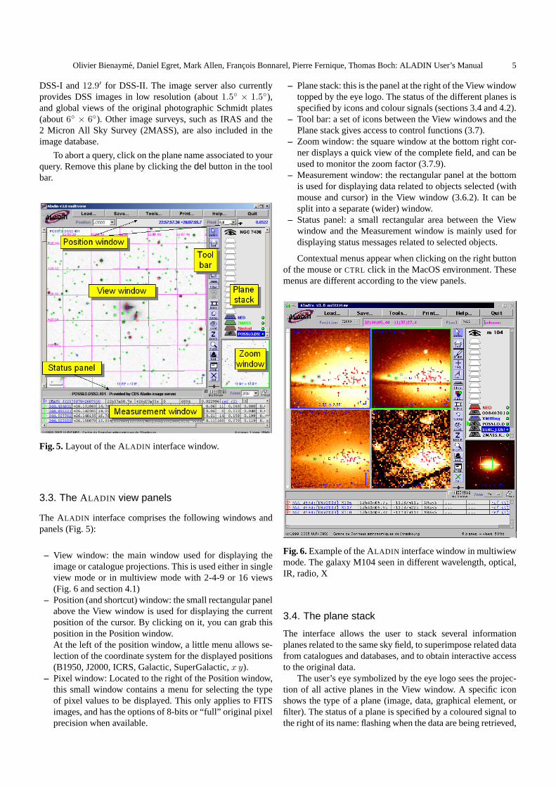
Fig. 5.Layout of the ALADIN interface window.
3.3. The ALADIN view panels
The ALADIN interface comprises the following windows andpanels (Fig. 5):
– View window: the main window used for displaying theimage or catalogue projections. This is used either in singleview mode or in multiview mode with 2-4-9 or 16 views(Fig. 6 and section 4.1)
– Position (and shortcut) window: the small rectangular panelabove the View window is used for displaying the currentposition of the cursor. By clicking on it, you can grab thisposition in the Position window.At the left of the position window, a little menu allows se-lection of the coordinate system for the displayed positions(B1950, J2000, ICRS, Galactic, SuperGalactic,x y).
– Pixel window: Located to the right of the Position window,this small window contains a menu for selecting the typeof pixel values to be displayed. This only applies to FITSimages, and has the options of 8-bits or “full” original pixelprecision when available.
– Plane stack: this is the panel at the right of the View windowtopped by the eye logo. The status of the different planes isspecified by icons and colour signals (sections 3.4 and 4.2).
– Tool bar: a set of icons between the View windows and thePlane stack gives access to control functions (3.7).
– Zoom window: the square window at the bottom right cor-ner displays a quick view of the complete field, and can beused to monitor the zoom factor (3.7.9).
– Measurement window: the rectangular panel at the bottomis used for displaying data related to objects selected (withmouse and cursor) in the View window (3.6.2). It can besplit into a separate (wider) window.
– Status panel: a small rectangular area between the Viewwindow and the Measurement window is mainly used fordisplaying status messages related to selected objects.
Contextual menus appear when clicking on the right buttonof the mouse orCTRL click in the MacOS environment. Thesemenus are different according to the view panels.
Fig. 6.Example of the ALADIN interface window in multiwiewmode. The galaxy M104 seen in different wavelength, optical,IR, radio, X
3.4. The plane stack
The interface allows the user to stack several informationplanes related to the same sky field, to superimpose related datafrom catalogues and databases, and to obtain interactive accessto the original data.
The user’s eye symbolized by the eye logo sees the projec-tion of all active planes in the View window. A specific iconshows the type of a plane (image, data, graphical element, orfilter). The status of a plane is specified by a coloured signal tothe right of its name: flashing when the data are being retrieved,

6 Olivier Bienayme, Daniel Egret, Mark Allen, Francois Bonnarel, Pierre Fernique, Thomas Boch: ALADIN User’s Manual
green when the data have been successfully retrieved, red whenthe query failed, orange for warning (e.g. no astrometric reduc-tion).
You can click on a plane icon to activate or deactivate it (theicon is dark when the plane is active). When clicking on theplane name you select it for the control buttons authorized forthis plane type (e.g. theProp. button displaying its properties).Click and drag the plane icons to change the order of display inthe stack. In single view mode, the first active image hides allplanes underneath (see section 4.2 for more details on how touse the plane stack).
Clicking on the eye logo temporarily deactivates all the ta-ble data planes, and clicking again reactivates them.
The information planes in the stack may be of four differenttypes: image planes (from the image data base or from obser-vatory archives), data planes (from SIMBAD , NED or VIZIER),graphics (labels, tags, Field of Views, etc.), or filters (section 8).
Image and table data planes are loaded using the ’ServerSelector’ menu activated by pushing theLoad button. Graphicoverlays and filters are activated with buttons of the Tool bar(see 3.7). To create folders and organize the Plane stack, openthe pop-up menu of the Plane stack by clicking on the rightbutton of the mouse.
3.5. Server selector
Push theLoad button to open the Server selector interface. Itgives access to Image servers, Table data servers, and also toyour own data and specific instrument field of view graphics.This interface is automaticly updated when new servers be-come available.
3.5.1. Image servers
This server gives access to image pixels from the ALADIN
database of digitized photographic plates (DSS-I, MAMA,DSS-II), from the 2MASS or IRAS-IRIS surveys, from otherimage servers (SkyView, SuperCosmos, SDSS), or from dis-tributed image archives (e.g. HST). Functionalities includezooming capabilities, inverse video, modification of the colourtable (see 3.7.10, 3.7.9, 5). Also resampling and astrometriccalibration that modify the content of the images (see 3.7.7,4.5.2).
3.5.2. Simbad
Information from the SIMBAD database (Wenger et al. 2000);objects referenced in SIMBAD are visualized by colour sym-bols overlaid on top of the image; the shape and colour of thesymbols can be modified on request, and written labels can beadded for explicit identification of the objects;these featuresare also available for all the other data planes.
3.5.3. VizieR
Data from the CDS library of catalogues or tables (VizieR2;Ochsenbein et al. 2000); the user can type a catalogue name,or select the desired catalogue from a preselected list includingthe major reference catalogues and surveys; the user can alter-natively select the catalogues for which entries may be avail-able in the corresponding sky field, using the VIZIER querymechanism by position, catalogue name or keyword; see be-low 4.3 for more details.
3.5.4. NED
Information from the NED database: objects referenced in theNASA/IPAC Extragalactic Database3 can also be visualizedthrough queries submitted to the NED server at IPAC.
3.5.5. Mission logs and Image Archives
Archive images through mission logs: Hubble Space Telescope(HST), Chandra, VLA/NRAO and FIRST images are currentlyavailable, among others. The user should first query the corre-sponding observation log before retrieving the archived imagesfrom the Image, Association(CADC) and similar buttons inthe Measurement field (Fig. 7 and 8).
Fig. 7. Load panel for Mission logs and image archives. Anexample of data extracted from the HST mission log can beseen in Fig. 8.
3.5.6. Instrument Field of View
It is possible to overlay the field of view (FOV) of some majorinstruments (presently: CFHT cameras, XMM-Newton, HST–WFPC2 camera). Rotation of the field, when applicable, can bemonitored through theProp. tool.
2 http://vizier.u-strasbg.fr/3 http://nedwww.ipac.caltech.edu/
Olivier Bienayme, Daniel Egret, Mark Allen, Francois Bonnarel, Pierre Fernique, Thomas Boch: ALADIN User’s Manual 7
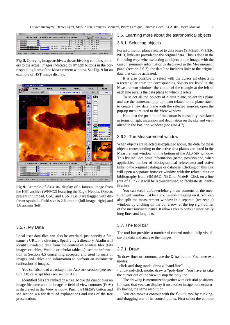
Fig. 8.Querying image archives: the archive log contains point-ers to the actual images indicated byImage buttons in the cor-responding lines of the Measurement window. See Fig. 9 for anexample of HST image display.
Fig. 9. Example of ALADIN display of a famous image fromthe HST archive (WFPC2) featuring the Eagle Nebula. Objectspresent in Simbad, GSC, and USNO B1.0 are flagged with dif-ferent symbols. Field size is 2.6 arcmin (full image, right) and1.6 arcmin (left).
3.5.7. My Data
Local user data files can also be overlaid, just specify a file-name, a URL or a directory. Specifying a directory, Aladin willidentify available data from the content of headers files (Fitsimages or tables, Votable or tabular tables...); see the informa-tion in Section 4.5 concerning accepted and used formats ofimages and tables and information to perform an astrometriccalibration of images.
You can also load a backup of an ALADIN session (see sec-tion 3.8) or script files (see section 4.6).
Identified files are ranked on a tree. Move the cursor over animage filename and the image or field of view contours (FOV)is displayed in the View window. Push theHistory button andsee section 4.4 for detailed explanations and uses of the treepresentation.
3.6. Learning more about the astronomical objects
3.6.1. Selecting objects
For information planes related to data bases (SIMBAD , V IZIER,NED) links are provided to the original data. This is done in thefollowing way: when selecting an object on the image, with thecursor, summary information is displayed in the Measurementpanel (section 3.6.2); the data line includes links to the originaldata that can be activated.
It is also possible to select with the cursor all objects ina rectangular area: the corresponding objects are listed in theMeasurement window; the colour of the triangle at the left ofeach line recalls the data plane to which it refers.
To select all the objects of a data plane, select this planeand use the contextual pop-up menu related to the plane stack:to create a new data plane with the selected sources, open thepop-up menu related to the View window.
Note that the position of the cursor is constantly translatedin terms of right ascension and declination on the sky and visu-alized in the Position window (see also 4.7).
3.6.2. The Measurement window
When objects are selected as explained above, the data for theseobjects corresponding to the active data planes are listed in theMeasurement window; on the bottom of the ALADIN window.This list includes basic information (name, position and, whenapplicable, number of bibliographical references) and activelinks to the original catalogue or database. Clicking on this linkwill open a separate browser window with the related data orbibliography from SIMBAD, NED, or VizieR. Click on a line(out of a link): it will be red-underlined, to facilitate its identi-fication.
You can scroll up/down/left/right the contents of the mea-surement window just by clicking-and-dragging on it. You canalso split the measurement window in a separate (resizeable)window, by clicking on theout arrow, at the top right cornerof the measurement panel. It allows you to consult more easilylong lines and long lists.
3.7. The tool bar
The tool bar provides a number of control tools to help visual-ize the data and analyze the images.
3.7.1. Draw
To draw lines or contours, use theDraw button. You have twomodes:- click-and-drag mode: draw a “hand-line”- click-and-click mode: draw a “poly-line”. You have to takethe cursor out of the view to stop the polyline.
The drawing is memorized together with celestial positions.It means that you can display it on another image not necessar-ily having the same resolution.
You can move a contour with theSelect tool by clicking-and-dragging one of its control points. First select the contour
8 Olivier Bienayme, Daniel Egret, Mark Allen, Francois Bonnarel, Pierre Fernique, Thomas Boch: ALADIN User’s Manual
and then click-and-drag one of the control points (little squareson the contour).
3.7.2. Text, Tags
You can display text or mark objects with tags by pushing therelatedText or Tag button.
3.7.3. Distance (Dist) and Cut graph
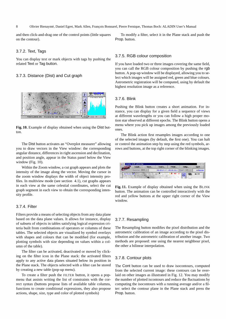
Fig. 10.Example of display obtained when using theDist but-ton.
TheDist button activates an “Overplot measurer” allowingyou to draw vectors in the View window: the correspondingangular distance, differences in right ascension and declination,and position angle, appear in the Status panel below the Viewwindow (Fig. 10).
Within the Zoom window, a cut graph appears and plots theintensity of the image along the vector. Moving the cursor inthe zoom window displays the width of object intensity pro-files. In multiview mode (see section 4.1), cut graphs appearsin each view at the same celestial coordinates, select the cutgraph segment in each view to obtain the corresponding inten-sity profile.
3.7.4. Filter
Filters provide a means of selecting objects from any data planebased on the data plane values. It allows for instance, displayof subsets of objects in tables satisfying logical expression cri-teria built from combinations of operators or columns of thesetables. The selected objects are visualized by symbol overlayswith shapes and colours that can be modified (for example,plotting symbols with size depending on values within a col-umn of the table).
The filter can be activated, deactivated or moved by click-ing on the filter icon in the Plane stack: the activated filtersapply to any active data planes situated below its position inthe Plane stack. The objects selected with a filter can be storedby creating a new table (pop-up menu).
To create a filter push theFILTER button, it opens a pop-menu that assists writing the list of constraints with the cor-rect syntax (buttons propose lists of available table columns,functions to create conditional expressions, they also proposeactions, shape, size, type and color of plotted symbols)
To modify a filter, select it in the Plane stack and push theProp. button.
3.7.5. RGB colour composition
If you have loaded two or three images covering the same field,you can call the RGB colour composition by pushing thergbbutton. A pop-up window will be displayed, allowing you to se-lect which images will be assigned red, green and blue colours.Astrometric registration will be computed, using by default thehighest resolution image as a reference.
3.7.6. Blink
Pushing the Blink button creates a short animation. For in-stance, you can display for a given field a sequence of viewsat different wavelengths or you can follow a high proper mo-tion star observed at different epochs. The Blink button opens amenu where you pick up images among the previously loadedones.
The Blink action first resamples images according to oneof the selected images (by default, the first one). You can haltor control the animation step by step using the red symbols, ar-rows and buttons, at the top right corner of the blinking images.
Fig. 11. Example of display obtained when using the BLINK
button. The animation can be controlled interactively with thered and yellow buttons at the upper right corner of the Viewwindow.
3.7.7. Resampling
The Resampling button modifies the pixel distribution and theastrometric calibration of an image according to the pixel dis-tribution and the astrometric calibration of another image. Twomethods are proposed: one using the nearest neighbour pixel,the other a bilinear interpolation.
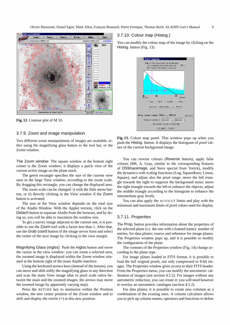
3.7.8. Contour plots
The Cont button can be used to draw isocontours, computedfrom the selected current image: these contours can be over-laid on other images as illustrated in Fig. 12. You may modifythe number of plotted iscontours and reduce the fluctuations bycomputing the isocontours with a running average and/or a fil-ter: select the contour plane in the Plane stack and press theProp. button.
Olivier Bienayme, Daniel Egret, Mark Allen, Francois Bonnarel, Pierre Fernique, Thomas Boch: ALADIN User’s Manual 9
Fig. 12.Contour plot of M 33.
3.7.9. Zoom and image manipulation
Two different zoom manipulations of images are available, ei-ther using the magnifying glass button in the tool bar, or theZoom window.
The Zoom window The square window at the bottom rightcorner is the Zoom window; it displays a quick view of thecurrent active image on the plane stack.
The green rectangle specifies the size of the current viewseen in the large View window, according to the zoom scale.By dragging this rectangle, you can change the displayed area.
The zoom scale can be changed: i) with the little menu but-ton, or ii) directly clicking in the View window if theZoombutton is activated.
The size of the View window depends on the total sizeof the Aladin Window. With the Applet version, click on theDetach button to separate Aladin from the browser, and by do-ing so, you will be able to maximize the window size.
To get a survey image adjacent to the current one, it is pos-sible to use theZoom tool with a factor less than 1. After that,use theGrab coord button of the image server form and selectthe center of the next image by clicking in the view margin.
Magnifying Glass (mglss) Push themglss button and movethe cursor in the view window: you can zoom a selected area,the zoomed image is displayed within the Zoom window situ-ated at the bottom right of the main Aladin interface.
Using the keyboard arrows keys (instead of the mouse), youcan move and shift softly the magnifying glass in any directionand scan the main View image (due to pixel scale ratios be-tween the main and the zoomed images, the arrows may movethe zoomed image by apparently varying step).
Press theRETURN key to memorize within the Positionwindow, the new center position of the Zoom window and toshift and display the reticle (+) at this new position.
3.7.10. Colour map (Histog.)
You can modify the colour map of the image by clicking on theHistog. button (Fig. 13).
Fig. 13. Colour map panel. This window pops up when youpush theHistog. button. It displays the histogram of pixel val-ues of the current background image.
You can reverse colours (Reverse button), apply falsecolours (BB, A, Gray, similar to the corresponding featuresof DS9/saoimage, and Stern special from Yorick), modifythe dynamics with scaling functions (Log, SquareRoot, Linear,Square), and adjust also the pixel range: move the left trian-gle towards the right to suppress the background noise; movethe right triangle towards the left to enhance the objects; adjustthe middle triangle according to the histogram to enhance theintermediate gray levels.
You can also apply theAUTOCUT limits and play with theminimum and maximum limits of pixel values used for display.
3.7.11. Properties
TheProp. button provides information about the properties ofthe selected plane (i.e. the one with a framed name): number ofentries, for data planes; source and reference for image planes.The Properties window pops up, and it is possible to modifythe configuration of the plane.
The contents of the Properties window (Fig. 14) change ac-cording to the plane type.
For image planes loaded in FITS format, it is possible toload the full original pixels, not only compressed or 8-bit im-ages. The Properties window gives access to their FITS header.From the Properties menu, you can modify the astrometric cal-ibration of images (see section 4.5.2). For images without anyastrometric reduction, you can create it; you will need howeverto overlay an astrometric catalogue (section 4.5.2).
For data planes, it is possible to create new columns as acombination of the existing ones. A column calculator allowsyou to pick up column names, operators and functions to define

10 Olivier Bienayme, Daniel Egret, Mark Allen, Francois Bonnarel, Pierre Fernique, Thomas Boch: ALADIN User’s Manual
the content of the new columns. Selecting a catalogue planein the plane stack, you can directly open the column calcula-tor with the contextual menu (clicking the right button of themouse).
Note that it is possible to adjust the symbol size accordingto a measurement of this object (section 8).
Fig. 14. Examples ofProperties windows for a catalogueplane (left) and for an image plane (right). The colour andshape of the symbols from a data plane, displayed in the Viewwindow, can be modified by using the corresponding menus(left). Epoch and source of the image are given in the corre-sponding window (right). It is also possible to modify the pro-jection of the data points, or the astrometric registration of theimage.
3.7.12. Remove planes and views (del.)
In single view mode, selected planes (blue framed name in thePlane stack) are removed pushing thedel button. Pressing theSHIFT key and pushing thedel button remove all planes
In multiview mode, pushing thedel button removes yourlast selections: views or planes. If you had selected planes,pushing thedel button will remove selected planes and cor-responding views. If you had selected views, pushing thedelbutton will remove these selected views; pushing twice thedelbutton will also remove the related planes. Pressing theSHIFT
key and pushing thedel button removes all views; and pushingtwice remove all planes.
To select a plane, click its name (at the right of the corre-sponding icons in the Plane stack): the frame name becomesblue.
To select simultaneously other planes, press theshift keyand click the other plane names.
3.7.13. Scale and coordinate grid
By invoking the contextual menu (pop-up menu: clicking theright button of the mouse; orCTRL click in the MacOS en-vironment) in the view frame, you can display the followinginformations:
1. view information: a small line gives the scale of the view,the North and East orientations, the size and name of theview;
2. the coordinate grid (for constant RA and DEC values,l,bvalues). The coordinate system, equatorial, galactic etc...can be modified using the little menu at the left of the posi-tion window;
3. the target arrow: a vertical arrow (↓) indicates the object orposition used as center in the initial query;
4. the reticle: a large cross (+) indicates the last clicked posi-tion of the cursor inside the View window.
For prints in multiview mode, the names of objects may be re-placed by the field coordinates.
3.8. The Save... and Print... menus
It is possible toPrint the main View (Fig. 15). Different optionsare offered toSave data from an Aladin session:
– The work session can be saved (in a proprietary Aladin JavaAJ format) for future re-use
– Catalogues or images loaded in the plane stack can be savedrespectively in ascii (Tab. separated values or VOTable) orfits formats.
– A file view with the current overlays and RGB images canbe saved in bmp format.
– An HTML page with links to the original images loaded inthe plane stack can also be created.
Remark: a Postscript printer driver must have been installedto save postcript files.
Fig. 15.Postcript printout of a DSS-I field featuring NGC 3314,produced from the Standalone version.
Olivier Bienayme, Daniel Egret, Mark Allen, Francois Bonnarel, Pierre Fernique, Thomas Boch: ALADIN User’s Manual 11
3.9. The Tools... menu
The TOOLSmenu provides other control tools to visualize dataand images and analyze them: to open a console window to ex-ecute Aladin script commands, to open the VOPlot graphic fa-cility and plot the content of tables, to display small views froma list of selected objects, to perform automatic cross-match be-tween catalogues.
3.9.1. Aladin script console and note-pad
Selecting this option opens the Aladin script console whereAladin can be controlled via in-line commands. This consoleallows to follow all the actions or commands sent and correctlyexecuted since the beginning of your Aladin session (see detailsin sections 4.6 and B for explanations on script commands).
The script console includes the previous facilities of the re-moved note Pad window: for instance the possibly to cut-and-paste text into another application.
Every action in interactive mode is echoed by the Aladinscript console where a line is printed containing the corre-sponding script command (the echo line is bracketed).
Within the Aladin script console, you can use the keyboardarrows to call back or modify these previously executed com-mand.
The most elementary command in script mode is the co-ordinate (sexagesimal J2000) or the SIMBAD name of objects.Executing it, draws a cross in the View window at the positionof the object (when an image or a catalogue around this ob-ject have been already loaded). The corresponding interactivecommand is the click within the View window.
Fig. 16.Example of 2d plots with VOPlot
3.9.2. VOPlot
VOPlot (VO-India4) written by the IUCAA and PSPL isa graphic facility for 2D-plots and histograms of tables inVOTable format.
4 http://vo.iucaa.ernet.in/ voi/
VOPlot has been interfaced with Aladin and opens a sep-arate VOPlot window. This implementation allows to catch anAladin table (selected, filtered or not), to plot one column ver-sus another, to make computation on columns, or to make se-lection with the cursor within 2D-VOPlots, and to export se-lected objects backwards to the Aladin session in a new dataplane. A specific aspect is the interactivity between the twoVOPlot and Aladin View windows: it allows to identify andselect objects within one window, flashing within the other onewhile the informations are displayed in the Aladin measure-ment window.
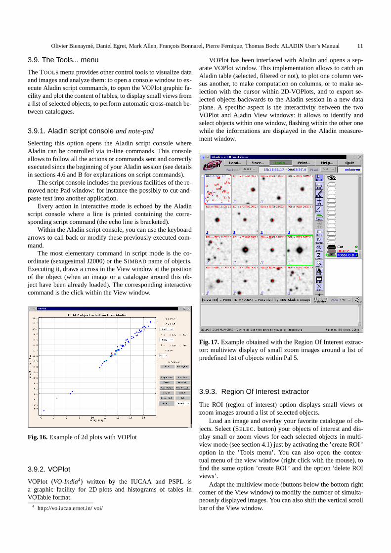
Fig. 17.Example obtained with the Region Of Interest extrac-tor: multiview display of small zoom images around a list ofpredefined list of objects within Pal 5.
3.9.3. Region Of Interest extractor
The ROI (region of interest) option displays small views orzoom images around a list of selected objects.
Load an image and overlay your favorite catalogue of ob-jects. Select (SELEC. button) your objects of interest and dis-play small or zoom views for each selected objects in multi-view mode (see section 4.1) just by activating the ’create ROI ’option in the ’Tools menu’. You can also open the contex-tual menu of the view window (right click with the mouse), tofind the same option ’create ROI ’ and the option ’delete ROIviews’.
Adapt the multiview mode (buttons below the bottom rightcorner of the View window) to modify the number of simulta-neously displayed images. You can also shift the vertical scrollbar of the View window.
12 Olivier Bienayme, Daniel Egret, Mark Allen, Francois Bonnarel, Pierre Fernique, Thomas Boch: ALADIN User’s Manual
3.9.4. Catalogue cross match tool
It is possible to cross-match two catalogues of objects eitheraccording to the object celestial coordinate proximity (with thefollowing options: best matches, all matches, or sources notmatching). It is also possible to cross-match according to theSimbad Identifiers when they are present.
After loading the two catalogues of objects containing co-ordinates or a common identifier, activate the ’Catalogue crossmatch’ tool within the scrolling menu ’Tools’.
This opens a pop-up menu where you identify your twocatalogues and parametrise the cross-match.
It must be noticed that if inside a table only B1950, ICRSor [super]galactic coordinates are available, J2000 coordinateswill be computed and included in a new column.
3.9.5. Simbad Finger
Activate the Simbad finger option with the pop-up menu of theview window and move the cursor of the mouse on a (preferen-tially bright) object: Aladin will try its identification queryingthe Simbad database.
3.10. Help
You can obtain general or detailed information by opening thescroll Help menu and choosing one of the HELP options.
– Opening the INTERACTIVE HELP MODE (the first option),move the mouse pointer on one of the interface compo-nents: a short help related to this component will be dis-played within the view window. Click elsewhere to quit thehelp mode.
– Selecting the HELP ON ALADIN SCRIPT COMMANDS dis-plays the list of script commands in the Aladin script con-sole (see section B). The list of script commands are alsodisplayed in the View window: browse and explore the helpclicking on the name of commands.Within the Aladin script console (see section 4.6), you cantype and execute thehelp , for a specific scriptcommand,typehelp command .
– Selecting among the ’Show me how to ..’ options wakesup a robot or demonstration mode and activates an anima-tion. You may select the animation for some elementarymanipulations within Aladin: how to load an image, a cat-alogue, explain what is a filter, etc... To stop the demon-stration press the ‘ESC’ key keeping the cursor within the’Show me how to...’ window. Animations can be activatedfor any other command through the Aladin console windowwith thedemo command.A typical usage is:
Command> demo onCommand> get Aladin(MAMA) galactic center
– The other options give access to the FAQ and the updatedversion of this Manual.
4. More Detailed Features
4.1. Multiview mode
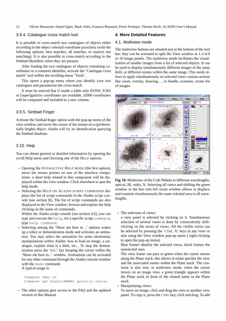
The multiview buttons are situated just at the bottom of the toolbar: they can be activated to split the View window in 1-2-4-9or 16 image panels. The multiview mode facilitates the visual-ization of smaller images from a list of selected objects. It canbe used to display simultaneously different images of the samefield, or different zooms within the same image. This mode al-lows to apply simultaneously on selected views various actionslike zoom, overlay, drawing... , to handle, examine, create listof images.
Fig. 18.Multiview of the Crab Nebula in different wavelengths,optical, IR, radio, X. Selecting all views and shifting the greenwindow in the boo tom left zoom window allows to displaceand examine simultaneously the same celestial area in all wave-lengths.
– The selection of views:a view panel is selected by clicking on it. Simultaneousselection of several views is done by consecutively shift-clicking on the series of views. All the visible views canbe selected by pressing the ‘CTRL A’ keys in any view oralso using the View window pop-up menu ( right-clickingto open the pop-up menu).Blue frames identify the selected views, black frames theunselected ones.The view frame can pass to green when the cursor movesalong the Plane stack: this allows to relate quickly the viewand the associated names within the Plane stack. The con-verse is also true: in multiview mode, when the cursormoves on an image view, a green triangle appears withinthe Plane stack in front of the related name in the Planestack.
– Manipulating views:To move an image, click and drag the view to another viewpanel. To copy it, press theCTRL key, click and drag. To add

Olivier Bienayme, Daniel Egret, Mark Allen, Francois Bonnarel, Pierre Fernique, Thomas Boch: ALADIN User’s Manual 13
an image to a blink, click and drag the view or the plane tothe blink image.
– Tools:Buttons of the Tool bar,Cont, Dist, Tag, Text, Draw,Selec. and also overlay of catalogues can appear or pro-duce simultaneous result in all view panels.Zoom, andDel. buttons apply only on selected views.For instance, Tags and Drawings... appear in the differentselected views at exactly the same coordinate positions al-lowing a quick identification of structures or objects in allselected views.After applying theText or Draw... button within one view,you may grab (Selec. button) and shift the text or drawingthat will move simultaneously within all the selected viewpanels.Select objects from an overlay in one view: the selectionwill be apparent and also enhanced in all the other selectedviews (if, of course the objects are effectively present). Thesame thing happens again moving the cursor close to a cat-alogue object: the object blinks in all selected views.
– Zoom:to zoom simultaneously the different views of the samecelestial field: first click on one view to display it insidethe zoom window, select all the images (pressCTRL Akeys) that you want to zoom and scrutinize. Then, chang-ing the zoom factor modifies the scale of all selected im-ages (different images may have different pixel-arcsec scal-ing: Aladin will choose for each view the closest compat-ible zoom factor). Moving the green rectangle within thezoom window allows to explore and shift simultaneouslyall zoom views: the views remain centered to the center ofthe green rectangle, if possible.
– Reticle:click with the cursor of the mouse inside a view: in all theviews, a cross appears at the samecelestialcoordinate po-sition (remark: after this operation, the other views are nomore selected.
– Attached images to the reticle position:when you load several different images of the same field ofthe sky, you can more easily explore their details with thezoom in multiview mode if you attach these images to thereticle (to do the attachment, open the pop-up menu of theView window, right-clicking the mouse). Keep at least oneof the images without zoom to allow easier displacement ofthe cursor and the reticle through the whole image, selectthe other images, attach them to the reticle and adjust thezoom (menu below the Zoom window). Moving the reti-cle from one place to another through the first un-zoomedview, the other zoomed views follow immediately the reti-cle. This allows simultaneous and easy zooming to explorethe same region on all images and to shift quickly from onearea to another.
– Locked images:In multiview mode, you can lock images to keep them per-manently visible within the View window, even when youmove the left vertical bar to scroll the other available views.To lock one or more views, select them (click and shift-click) and (un)lock them within the contextual pop-menu
(right click) of the View window. Red frames identify thelocked images. Practice will show you that it can be moreconvenient to align the locked images along the same col-umn or line.
4.2. Manipulating the plane stack
The plane stack allows you to control the current projection.Each plane keeps the result of a server query or a local query(image or data) or possibly some additional graphical objects,such as tags or drawings.
Click on a plane icon to ask to activate; the icon is darkwhen the plane is active. Click on the eye icon to switch on/offprojection of all possible overlay planes.
Fig. 19.A plane stack in a field featuring the Pleiades. Simbad,GSC2.2, USNO-B1, and 2MASS are the active data planes.NED has no entry in this (stellar) field (as can be seen from thestatus icon on the right). 2MASS is the selected plane (framedname), ready forProp. or Cont. tools.
Click on a plane name to select it; then the tool but-tons which are authorized for this kind of plane are activated.Maintain theSHIFT key to select several planes together.
Click and drag the plane icons to change the order of thedisplay in the stack. The first image hides all planes underneath.
Delete the selected plane (the one with a framed name) byclicking on thedel button.
Each image or catalogue plane has its own projection pa-rameters (target, radius, projection method).
You may create a folder to organize the different planes(open a pop-up menu –right click with the mouse– from theplane window). Notice that filters (section 8) inside a folder areactive only for planes, below the filter, inside the folder.
4.3. Interacting with the VizieR database
ALADIN provides an interface to the astronomical cataloguesand tables in theVizieR data base.
The interface betweenALADIN andVizieR presents dif-ferent alternatives for the choice of catalogues. Once you havepushed theLoad button, and selected theVizieR Catalogsbutton from the query window (Fig. 20):

14 Olivier Bienayme, Daniel Egret, Mark Allen, Francois Bonnarel, Pierre Fernique, Thomas Boch: ALADIN User’s Manual
Fig. 20. VizieR query panel and a list of catalogues in theneighbourhood of the target, list provided by keywords.
– just type in theTarget box the name object or its coordi-nates. Then thesubmit button provides a list ofall cat-alogueswhich have a fair chance of having at least onesource in the neighbourhood of the target (section 6.1).Catalogues in this list can then be selected by a mouse clickon their title;
– type in theTarget box the name object or its coordinatesand type in theCatalogue box the acronym (e.g.HD) orCDS/ADC identification of catalogue (e.g.III/135 ); acomma-separated list of acronyms may be specified for sev-eral catalogues, e.g.BD,CD,CPD. Browse the list of cata-logues5 for a complete list of available catalogue acronymsor identifications;
– you may refine the list of catalogues by submitting addi-tional constraints (Fig. 20):– by entering words in theAuthor, free text... box (e.g.
author name), the list of catalogues is restricted to thosehaving the specified word(s) in their descriptionandhaving sources in the target neighbourhood.
– by clicking on a selection of keywords, the list of cata-logues is restricted to those matchingall keywordsandhaving sources in the target neighbourhood.
Other Vizier alternatives are offered from theLoad panel(Fig. 20):
– select theSurveys button, the largest all-sky surveys avail-able are listed, and can be selected by a mouse click on thecorresponding line.
– the Missions button triggers display of the available ob-serving logs (see 3.5.5).
Note that catalogues can be displayed in the View win-dow without a background image, making possibly easier di-rect comparison of two catalogues or tables.
5 http://cdsweb.u-strasbg.fr/cats/cats.htx
4.4. History
The History window allows to browsing of all the names ofimages that have been proposed by the Server Selector (Loadbutton) since the beginning of the session. It allows loading orreloading of any of these images. The list includes also the listof personal images found in your own directories scanned withthe MYDATA button (section 3.5.7).
The tree hierarchy can be opened (and collapsed) showingthe organization of the information, from the name of an ob-ject (or coordinate), passing through the name of servers, sur-veys, filters to the name of images (’plate’, ’CCD frame’ etc...).Clicking on any of these name shows a pops-up window withspecific information.
Clicking on thename of images, pops up a window display-ing the main characteristics of the images (the same windowwould be opened with the Server Selector); from that windowyou can select the type of data to load (Jpeg, Fits, mosaicedimages...), you can also load the FOV, the contour of the fieldof view.
A double-click on theimage nameswithin the tree directlyloads the image with default options.
4.5. Loading personal files
You can load personal images or tables, stored on your localcomputer hard disk (see section 3.5.7).
4.5.1. Local images
Images should be in FITS format, withWCS fields6 in theheader (see e.g. Greisen & Calabretta 1995).Aladin V3. sup-ports also simple JPEG, GIF or PNG images but they will haveno astrometric calibration.
Note that you may need to increase your JVM memory ifyou need to load large files. To do that you can play with twoparameters of the java command:
-ms<number> : set the initial Java heap size-mx<number> : set the maximum Java heap size
For example, a command like:java -ms800m -mx800m-jar Aladin.jar might allow you to manipulate the largeCFH12K images (400MB).
4.5.2. Calibrating Images
Images without astrometric calibration can be loaded. In orderto visualize and overlay catalogues on them you will need tobuild an astrometric calibration.
To calibrate or to redo the calibration of any images, as-trometric calibration tools are available in Aladin. The astro-metric reduction menu is activated from the properties menuassociated to your image plane. You will also need astromet-ric references from another calibrated images of the same areaor from a corresponding astrometric catalogue. Just clicking a
6 http://www.cv.nrao.edu/fits/documents/wcs/wcs.html

Olivier Bienayme, Daniel Egret, Mark Allen, Francois Bonnarel, Pierre Fernique, Thomas Boch: ALADIN User’s Manual 15
few common stars to your uncalibrated image and to your ref-erence frame image or catalogue can be sufficient to obtain arough astrometric calibration (examples for image calibrationsare given at the address: http://aladin.u-strasbg.fr/tutorials).
4.5.3. Local Tables
Tables should be in one of the following formats:
– Tab-Separated-Value (TSV): one record per line, eachfield separated by a TAB. By default, the first column isassumed to be Right Ascension, and the second columnDeclination (both in J2000 equatorial system). Values areto be given in decimal degrees, or in sexagesimal hours anddegrees. Heading line can be present, as shown below:
RAJ2000 DEJ2000 GSC number Pmag------- ------- ---------- -----185.701 15.822 0144501972 15.55185.766 15.795 0144502507 13.92185.704 15.844 0144501918 15.06185.710 15.849 0144502383 14.78
– XML : The VOTable XML format is developed by theInternational Virtual Observatory in Astronomy (IVOA).It allows to describe astronomical catalogues withXML .Aladin uses it to retrieve data fromVizieR, Simbad,NED, or to load local data files. TheVOTable for-mat is detailed at the following address: http://vizier.u-strasbg.fr/doc/VOTable.Aladin also supportsAstroRes, the predecessor ofVOTable. AstroResformat is detailed at the following ad-dress: http://vizier.u-strasbg.fr/doc/astrores.htx
4.6. Script console and script mode
Open the Aladin script console from the Tools... menu: all ac-tions or commands sent and correctly executed since the begin-ning of your Aladin session are printed in the Aladin console(the echoed lines are bracketed).
In order to use Aladin in script mode, Aladin can becontrolled via in-line commands. These commands have tobe submitted to theCommand>in the console window (seeFig. 21). The detailed help on script commands is obtainedfrom the Help menu, and is also reported in the section 4.6and Appendix B. Use the keyboard arrows to call back or mod-ify any previously executed command. Files containing a listof command are submitted to the console by using the scriptcommandload file .
The main basic script command is:
Get ServerName[,ServerName] Target
– ServerNamecan beSimbad, NED, Aladinor VizieR. Forthis last one, the catalogue specification is required (inparentheses). For Aladin, the survey, colour, or resolutioncan be specified as well between parentheses.
– Target can be a Simbad identifier or J2000 coordinates insexagesimal syntax.
Fig. 21. The script console where: ALADIN can be controlledvia in-line commands.
If the Target is omitted, Aladin takes into account the lastspecified target. If, for an initial query, there is only aTargetand noServerName, Aladin will load a default set (currently:DSS-I high resolution image, SIMBAD and GSC1.2).
You will find in the FAQ of the interactive HELP menudetailed possibilities for the syntax of shortcut commands.
Examples:get Simbad,VizieR(GSC1.2) M 81get Simbad 00 42 44.10 +41 16 08.8get Aladin(DSS2),VizieR(USNO2) NGC 7436get Aladin(DSS2),NED 18 19 -13 50get Skyview(Rosat) M 1get SSS.img(UKST) M 2
Typing a Simbad object name or J2000 coordinates, thereticle shifts to this position.
Script commands are submitted to theCommand> inthe console window. Script files can be be submitted typ-ing the commandsAladin filescript or Aladin< filescript Additionally, the window interface canbe removed by launching Aladin with the-script parameter.
The list of script commands is detailed below: see also theHelp menu, this help is also reported in the Appendix B.
With ”x ” a number plane identifier (number 1 is the bottomof the Aladin plane stack) or a label plane identifier (allowinguse of the wildcard ”*”), with ”v ” a view (in multiview mode,they are labelledA1, A2... B1...), the in-line commands are:
PLANE:
– get servers [target] [radiusUnit] :execute a command to call image and data servers(ex: ‘get aladin(DSS2),VizieR(GSC) M99 ’)
– load file : create a new plane with the file (image ordata)
– select x : select the planex– rename [ x ] newname: name or rename a plane– hide [ x ] [ x1 ] [ x2... ] : hide planes– show [ x1 ] [ x2... ] : show planes– mv x1 x2 : move planex1below planex2 (or into if x2 is
a folder)

16 Olivier Bienayme, Daniel Egret, Mark Allen, Francois Bonnarel, Pierre Fernique, Thomas Boch: ALADIN User’s Manual
– rm [ x ]|all : delete planes– export nn file [votable] : save images or tabu-
lar data from plane numbernn (FITS formats for image, txtor VOTable otherwise))
VIEW:
– modeview [1|2|4|9|16] : the multiview controlleropens1,2..16views
– createview [x [v]] : only in multiview mode, al-lows to create a view at positionv, from the data plane atpositionx in Aladin stack
– select [v1] [v2...] : select views in multimode-view, viewsv1, v2...are labelledA1, A2... B1...
– zoom fct : change zoom factor on the current view(1/2x , 4x , ...)
– attach |detach [v1] [v2...] : view attachment tothe current target (in multiview mode), the attach view al-ways try to display the current target (reticle position)
– lock |unlock [v1] [v2...] : lock a view to keep itin the same place in multiview mode, even scrolling theview panels
– mv|copy v1 v2 : move or copy views (multiview mode)– rm [v1] [v2...] | ROI : delete views– save file : save the current view, image and overlay
(BMP format)– coord |object : show a specified position
IMAGE:
– flipflop [V|H] : vertical (resp. horizontal) image in-version
– reverse [on/off] : (un)reverse the current view– cm {gray|BB|A|stern }: select the colour map– RGB [x1|v1 x2|v2 x3|v3 ] : create a RGB image
from planesx1, x2, x3or viewv1, v2, v3– blink [ x1|v1 ] [ x2|v2... ] : create a blink se-
quence of images– resamp [ x1 x2 ] [8|Full] [Cl|bil] : create a
resampled image– contour [ nn [[no]smooth] [zoom]] : draw nn
isocontours on the selected plane (default: 4 levels) (zoom:draw the contours only on the zoom area).
CATALOGUE:
– flipflop [V|H] : vertical (resp. horizontal) pixel im-age inversion
– filter [ name] {filter-content }: create a fil-ter, thefilter-contentmust follow the filter instruction rules(see section 8.3.7)(ex: $[PHOT*] <16 {draw } )
– filter [ name] [on/off] : switch on/off the speci-fied filter
– addcol ([ x ],[ name],[UCD],[Unit],expr) :column generator for a tabular data plane
– xmatch [ x1 ] [ x2 ] [dist] : positional cross matchtool between tabular data planesx1 andx2
– creatplane [ name] : create a new catalogue planewith the current selected sources
– createROI [npix|radius ” ] : create zoomed viewsaround the selected sources
GRAPHIC TOOL:
– draw fct(param) : add graphical overlays on viewswith three functions: string, tag, line
– grid [on/off] : (un)activate the coordinate grid– reticle [on/off] : (un)activate the reticle– scale [on/off] : (un)activate the scale line and other
view overlays information
FOLDER:
– md [name] : create a new folder– mv x1 [ x2... ] name: move data planesx1 andx2
within foldername– rm [ name] : delete a folder– show [ name] : show and display the views of all the data
planes disposed in a folder– hide [ name] : hide the views accociated to the content
of a folder
MISCELLANEOUS:
– backup file : generate a backup (proprietary .AJ for-mat) of the Aladin plane stack
– print : print the current views– trace : turn on and off the debug verbose mode– reset : reset the Aladin plane stack and views– info msg: print a message in the status window– hist : display the script command history in the Aladin
console– status : display stack plane status– mem: display the current memory size– help [cmd|off] : display this help– demo: demonstration mode– sync : wait until all planes are ready– pause [ nn ] : wait nnseconds (default: one)– timeout nn |off : set nn minutes as timeout (default:
15)– quit : stop Aladin.
Script example
Suppose that the filefoo contains the following lines:
gridget aladin(dss2),vizier(usno2) m99synczoom 2xcm BBsave m99.bmpquit
By redirecting the Aladin standard input as below:
java -jar Aladin.jar -script < foo
Aladin produces transparently an image file called m99.bmpwith a DSS2 image and the USNO2 catalogue overlay.

Olivier Bienayme, Daniel Egret, Mark Allen, Francois Bonnarel, Pierre Fernique, Thomas Boch: ALADIN User’s Manual 17
Launching Aladin with predefined images or data
In Applet mode, the script commands can also be used in theURL to directly launch a predefined set of images and data.For example, the following URL will launchAladin, for a fieldaround NGC 1097, with a DSS2 image, SIMBAD , NED, andUSN02 data, on reverse mode, and a coordinate grid:
http://aladin.u-strasbg.fr/AladinJava?script=get+Aladin(DSS2),Simbad,NED,VizieR(usno2)+NGC1097;grid+on;sync;reverse
The detailed syntax of the input string following the ques-tion mark is the same as the syntax of the script language (seesection 4.6).
An automatic generator of scripts and of URL helps youbuilding more easily simple scripts and URL.
(seehttp://aladin.u-strasbg.fr/java/nph-
aladin.pl?frame=form )Local images can be called by using the following script com-mand: get MyData( YourURL [ plane name, ori-gin ]) or get MyData( YourFile ) , whereplanenamewill be the name appearing in the plane stack.
4.7. Coordinate manipulation
It is possible to visualize the location of a specific object or po-sition in the current view, by simply clicking in the Positionwindow, and typing the coordinates (or Simbad identifier).After pressing the ‘RETURN’ key, the current target (large +)will move at the corresponding position in the View window.Also if you click on the View window, the corresponding posi-tion will be automatically memorized in the Position window.Move the cursor in the Position window (or in the note Padwindow ) to retrieve this position and possibly cut-and-pasteinto another application.
When you move the cursor on the object data line in themeasurement window, the position of this object is automati-cally given (in the current coordinate reference system) in theposition window. You can easily display coordinates in anotherreference system using the nearby menu button: if you select,e.g., theGal reference system and move the cursor on the ob-ject data line, you will see the position displayed in Galacticcoordinates.
4.8. Using the SHIFT key for hidden features
In order to keep the Aladin interface as simple as possible,some features are hidden and require the usage of theSHIFT
key. By this way, you can:
– Remove several planes at a time: specify several planes byclicking on their name, with theSHIFT key down. Afterthat, press thedel button.
– Remove all views and planes: with the SHIFT key down,press thedel button, all views are removed. Do it again andthen all selected planes within the plane stack are removed.
– Select several individual sources:maintain theSHIFT keydown and click on each source.
– Open links innewbrowser windows: click on the links withtheSHIFT key down.
– Reset the zoom: click in the Zoom Frame (at the bottom-right of the screen) with theSHIFT key down to re-adjustthe current image to fill the view window.
5. The image databases
5.1. Database summary
The ALADIN image collection consists of:
– The whole sky image database from the first Digitized SkySurvey (DSS-I) digitized from photographic plates and dis-tributed by the Space Telescope Science Institute (STScI)as a set of slightly compressed FITS images (with a resolu-tion of 1.8 arcsec.); first epoch Palomar O (blue) plates arealso available;
– DSS-II: full skyR andI-band, and PalomarB-band sur-veys scanned at STScI with a pixel size of 1 arcsec.;
– Images of crowded fields (Galactic Plane, MagellanicClouds) at the full resolution of0.67′′, scanned atthe Centre d’Analyse des Images(MAMA machine),Observatoire de Paris; the ESO-R survey also digitized withthe MAMA is half included in the data base and will becompleted;
– Global plate views (5 deg×5 deg or 6 deg×6 deg accord-ing to the survey) are also available for all the plates con-tributing to the image atlas: these are built at CDS by aver-aging blocks of pixels from the original scans;
– Low resolution images: Aladin image server also providesDSS-I images in low resolution (generally 1.5 x 1.5 de-grees);
– The 2MASSJ , H, andKs images. The sky survey hasbeen released by the2MASS Project7 (Incremental Release2);
– The IRAS-IRIS 12, 25, 60 and 100µ images. The sky sur-vey has been released by theIRAS project8 and has beenrecently reprocessed by theIRIS project9;
– The WENNS images. The survey covers the whole skynorth of 30◦ at a wavelength of 92 cm (330 MHz) (seedoc-umentation10 in Vizier);
– MSX images in both Magellanic Clouds and EROS-1 in theLMC are available;
Access is also provided to other image servers: currentlySkyView, SuperCosmos, SDSS, and several mirror copies ofthe DSS image service.
Other image sets are available through theMissions inVizier feature (section 3.5.5): currently HST or FIRST imagescan be retrieved and displayed.
High resolution images are currently stored as subimagesof 500 × 500 pixels (DSS-I),768 × 768 pixels (DSS-II), or1024× 1024 pixels (MAMA).
7 http://www.ipac.caltech.edu/2mass/8 http://irsa.ipac.caltech.edu/IRASdocs/iras.html9 http://www.cita.utoronto.ca/ mamd/IRIS/IrisOverview.html
10 http://vizier.u-strasbg.fr/viz-bin/Cat?VIII/62

18 Olivier Bienayme, Daniel Egret, Mark Allen, Francois Bonnarel, Pierre Fernique, Thomas Boch: ALADIN User’s Manual
The image server for ALADIN is able to deal with varioussurvey data, in heterogeneous formats (uncompressed FITS,compressed JPEG, etc.).
Finally, user-provided images, in FITS, JPEG or GIF for-mat, having suitable World Coordinate System information inthe header can also be used through Aladin; this functionalityis available browsing your local directories.
Fig. 22. Low resolution image of M31: the field size is1.6◦
(image from DSS-I). Highlighted symbols in the display (greensquare) show selected objects, for which the data (from GSCand Tycho-2) are displayed in the Measurement window. Afilled blue triangle in this window signals the GSC entry closestto the cursor.
5.2. DSS Images
The database currently includes the first and second DigitizedSky Survey (DSS-I and DSS-II) produced by the SpaceTelescope Institute for the needs of the Hubble SpaceTelescope.
To create the DSS-I images, the STScI team scannedthe first epoch (1950/1955) PalomarE Red and UnitedKingdom SchmidtJ Blue plates (1980–), including the SERCJ Equatorial Extension and some short V-band plates at lowgalactic latitude, with a pixel size of1.7 arcsec. (25µm).Images are slightly compressed (factor of 10).
DSS-II images in theR-band come from Palomar POSS-IIF and the UK Schmidt SES, AAO-R, and SERC-ER, scannedwith a 1 arcsec. (15µm) sampling interval. DSS-II imagesin the B-band come from POSS-II J. DSS-II images in theI-band come from Palomar POSS-II N and SERC-I. The blueplates POSS-I O are also included.
DSS images are generally available in the following reso-lutions:
– the Full resolution (about 10x10 arcmin) corresponding tothe original digitizations;
– the Low resolution (about 1.5x1.5 degrees) providing anintermediate view consistent with the field of view of majortelescopes (DSS-I images only);
– the Global Plate view (about 5x5 degrees) reproducing thephotographic Schmidt plates.
5.3. MAMA/CAI Images
High resolution digitization of POSS-II, SERC-J, SERC-ER,SERC-SR, SERC-I, or ESO-R plates featuring crowded re-gions of the sky (Galactic Plane and Magellanic Clouds) havebeen provided by the MAMA facility at theCentre d’Analysedes Images (CAI), Observatoire de Paris. Sampling is0.67′′ perpixel (10µm).
These images are better suited to visual inspection of veryfaint objects.
5.4. 2MASS near-infrared survey
Original 2MASSJ ,H, andKs images are slightly compressedimages from the 2MASS survey. By default an image is recom-puted (mosaicing and rebinning) and centered on the requestedposition. Original images can be requested, but are not neces-sarily centered.
5.5. IRAS-IRIS survey
IRAS-IRIS 12, 25, 60, 100µ survey is 430 images for eachband of 500x500 pixels (12.5◦x12.5◦) with an angular pixelsize1.5′.
5.6. DENIS, ROSAT, SDSS
The images of these surveys will become progressively avail-able through the Aladin server: the DENISI, J andK images,The ROSAT All Sky Survey images and the SDSS images.
5.7. Image astrometry
Astrometric information comes from the FITS header of theDSS image.
However, in some cases, plate astrometry can be off by upto 4′′ preventing an absolute astrometric usage. The main rea-sons are:
1. the pixel is1.7′′ wide for the STScI images and0.67′′ widefor the MAMA images ;
2. the error on the position given by the DSS-I calibrations(STScI images) can be of the order of4′′ on the plate edges.
The accuracy of the positions of one given image can easilybe checked by superimposing reference astrometric catalogues

Olivier Bienayme, Daniel Egret, Mark Allen, Francois Bonnarel, Pierre Fernique, Thomas Boch: ALADIN User’s Manual 19
such as theTycho-2 Catalogue11 or theUS Naval ObservatoryCatalogue of Astrometric Standards (USNO-A2.0)12.
You can visualize the FITS header only for the imagesdownloaded in FITS format. Select the plane of this image inthe plane stack by clicking on its name and press theProp.button. You will find a button to visualize its FITS header.
5.8. Image compression
This service is currently provided for Schmidt plate images. Forthe ALADIN Java interface and for the ALADIN previewer, thecurrent choice is to provide the user with a slightly compressedimage, in JPEG 8-bit format, constructed from the original un-compressed FITS images. JPEG is a general purpose standardwhich is supported by all current Internet browsers. The size ofsuch an image does not exceed 30 kBytes, and thus the corre-sponding network load is very small.
Load the original digitized FITS images of POSS surveys toexamine the faintest objects or faint and extended objects. Thisis done after pushing thesubmit button (Fig.4) and selectingthe FITS format into the Info Frame window.
6. The catalogue and survey server
6.1. VizieR
The ability to access all VIZIER multi wavelength cataloguesand tables directly from ALADIN is a unique feature whichmakes it an extremely powerful tool for any cross-identificationor classification work.
The request of a catalogue around a target relies on a spe-cial feature – the genie of the lamp: this is the ability to de-cide which catalogues, among the database of (currently) about4000 catalogues or tables, contain data records for astronomi-cal objects lying in the selected sky area. In order to do that,an index map of VIZIER catalogues is produced (and kept up-to-date), on the basis of about ten pixels per square degree: foreach such ‘pixel’ the index gives the list of all catalogues andtables which have entries in the field.
When a user requests a catalogue around a target, this in-dex is queried and the list of useful catalogues is returned. Itis possible, at this stage, either to list all catalogues, or to pro-duce a subset selected on the basis of keywords, as explainedin section 4.3.
Note that, as the index “pixels” generally match an arealarger than the current sky field, there is simply a good chance,but not 100%, to actually obtain entries in the field when query-ing one of the selected tables.
6.2. Archive previews
In order to access images from archives, you should first querythe VizieR service for the mission log of the archive (for ex-ample, the HST log or the FIRST log) around a target (see sec-tion 3.5.5).
11 http://vizier.u-strasbg.fr/viz-bin/Cat?Tycho-212 http://vizier.u-strasbg.fr/viz-bin/Cat?USNO
Secondly, you select the resulting positions in the Viewwindow and look at the corresponding data in the Measurementwindow. If you find a buttonImage in the data line, click onit to retrieve the corresponding archive image (Fig. 8). A newplane will be created automatically in the stack.
7. Specific features of the Stand-alone version
ALADIN Standalone is a program that you can download inorder to run Aladin Java as a classic application on your localmachine.
The main advantage is to work outside a browser, in execut-ing scripts or to parametrise the Aladin session. If you choosethis solution, you should first download theAladin Java pack-age13.
Fig. 23. A view of the Aladin Standalone version featuringthe Antennae galaxies. Objects present in Tycho-2, GSC, andUSNO A2.0 are flagged with different symbols, and a contourof the field of view of the HST WFPC2 camera has been dis-played using theFoV function. Field size is 14 arcmin. TheSave and Print buttons in the top menu are typical of theStandalone version.
7.1. Starting the Stand-alone version
ALADIN Standalone version requires aJava Virtual Machine.To be sure that you have a sufficiently recent one, download theAladin Java package that includes aJava VM.
13 http://aladin.u-strasbg.fr/AladinJava?frame=downloading

20 Olivier Bienayme, Daniel Egret, Mark Allen, Francois Bonnarel, Pierre Fernique, Thomas Boch: ALADIN User’s Manual
7.1.1. The Java Virtual Machine
The Java binary code generated by a Java compiler is inde-pendent from any hardware and operating system. To be exe-cuted, it needs avirtual machine, i.e. a program analyzing thebinary code and executing the instructions. This virtual ma-chine is dependent on hardware and operating system. Twotypes of Virtual Machines exist: those included inside currentWeb Browsers, and those running as an independent program.
7.1.2. The AladinJava Stand-alone package
The AladinJava Standalone package is packaged byInstallAnywhere (by ZeroG, http://www.zerog.com). Thepackage includes the Aladin code and an embedded JavaVirtual Machine.
The installation does not require any special privileges butdepends on your operating system (see the Aladin standaloneinstallation web page).
Executing the Aladin Standalone code will also depend onyour operating system: for instance an “icon menu” under Macand Windows, “Aladin” command under Unix, etc... The stan-dalone version can also be started with a java command line:”java -jar Aladin.jar”
Notice that InstallAnywhere provides a script to uninstallthe code.
7.2. Defining additional servers
The user of the Standalone version can define and query newdata or image servers, besides Simbad, Aladin or VizieR.
To do that, you have to append the new server definitions inthe configuration fileAlaGlu.dic present in the Standalonepackage (use WinZip or similar tools to update this file), andrestart Aladin.
The servers have to be accessible by a simple URL with aHTTP GET method. The syntax required for these server def-initions follows the GLU recommendations. Adapt this shortexample to your own needs:
%ActionName Foo%Description My own server definition%Aladin.Label MyServer%Aladin.Menu Others...%Aladin.LabelPlane MyServer $1/$2%DistribDomain ALADIN%Owner CDS’Aladin%Url http://xxx/yyy?ra=$1&dec=$2
&radius=$3&color=$4...%Param.Description $1=Right Ascension%Param.Description $2=Declination%Param.Description $3=Radius%Param.Description $4=Color%Param.DataType $1=Target(RA)%Param.DataType $2=Target(DEC)%Param.DataType $3=Field(Radius)%Param.Value $3=14.1 arcmin%Param.Value $4=Red%Param.Value $4=Blue%Param.Value $4=Infrared
%ResultDataType Mime(image/fits)
– ActionName: Unique identifier– Description: Server description– Aladin.Label: Button or menu label– Aladin.Menu: label or upper-level button (in case of a submenu)– Aladin.LabelPlane: Template of the plane label.$n is to be re-
placed by the corresponding parameters– DistribDomain : keep this line “as is”– Owner: keep this line “as is”– Url : Server url template with $n variables specifying the fields
which have to be filled up by the users– Param.Description $n=: Description of the field numbern– Param.DataType $n=: Data type of the cor-
responding parameter. The available types are:Target(COO—RA—DE—SIMBAD—NED) andField(RA—DE—SQR—RADIUS)
– Param.Value $n=: Default value, or list of possible values, forthe corresponding parameter
– ResultDataType Mime(xxx): To specify the data type pro-vided by the server. For images: image/fits (fits file), image/gfits(gzipped), image/hfits (h-compressed), and for data: text/plain,text/tsv or text/csv (tab separated value syntax) and text/xml fordata in XML/strores syntax (see section 4.5.3).
The servers that you have defined will be accessible by thebuttons at the left side (images) or right side (data) of the serverselector window, in your localAladin standalone version.
8. Filters in Aladin
8.1. Introduction
Filters are an elaborated feature in Aladin allowing one to cus-tomize the display of catalogue planes in Aladin.
Without filters, all entries from a catalogue plane are dis-played with the same symbol and the same colour: the onlyparameters used, from the original catalogue, are the sky coor-dinates (RA and Dec) of each entry.
Thanks to the filter features, it is possible to use other pa-rameters from the original catalogue (e.g., magnitudes, objecttypes, velocities) in order to perform selections, and also tomodify the symbol shape, color, size, or text, according to oneparameter or a combination of parameters (using arithmetic op-erators:+− ∗ / ˆ). The position of the symbols always remainsat the sky position in the current field.
Figure 24 is an illustration of the possible use of a filter:bright sources have been circled and labelled while magnifiedproper motions are plotted. This example can be built usingand modifying predefined filters: MAGNITUDE-CUT, PROPER
MOTIONS . . .A list of predefined filters is proposed to cover some fre-
quent situations and a pop-up menu helps you to build filtercommands.
For instance the predefined MAGNITUDE CUT filter allowsto draw the objects of a table having a magnitude smaller than16. The magnitudes come from the first column for which theobject has a photometric magnitude given by a UCD of the$[PHOT*] form.
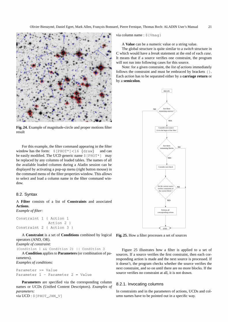
Olivier Bienayme, Daniel Egret, Mark Allen, Francois Bonnarel, Pierre Fernique, Thomas Boch: ALADIN User’s Manual 21
Fig. 24.Example of magnitude-circle and proper motions filterresult
For this example, the filter command appearing in the filterwindow has the form: $[PHOT*] <16 {draw } and canbe easily modified. The UCD generic name$[PHOT*] maybe replaced by any columns of loaded tables. The names of allthe available loaded columns during a Aladin session can bedisplayed by activating a pop-up menu (right button mouse) inthe command menu of the filter properties window. This allowsto select and load a column name in the filter command win-dow.
8.2. Syntax
A Filter consists of a list ofConstraints and associatedActions.Example of filter:
Constraint 1 { Action 1Action 2 }
Constraint 2 { Action 3 }
A Constraint is a set ofConditions combined by logicaloperators (AND, OR).Example of constraint:(Condition 1 && Condition 2) || Condition 3
A Condition applies toParameters(or combination of pa-rameters).Examples of conditions:
Parameter >= ValueParameter 1 - Parameter 2 = Value
Parameters are specified via the corresponding columnnames or UCDs (Unified Content Descriptors).Examples ofparameters:via UCD :$[PHOT_JHN_V]
via column name :${Vmag}
A Value can be a numeric value or a string value.The global structure is quite similar to aswitchstructure in
C which would have abreakstatement at the end of eachcase.It means that if a source verifies one constraint, the programwill not run into following cases for this source.
Note: for a given constraint, thelist of actionsimmediatelyfollows the constraint and must be embraced by brackets{} .Eachactionhas to be separated either by acarriage return orby asemicolon.
BEGIN
Are there remaining blocks
Consider next block
Do the current sourceverifies constraints of
the current block ?
Perform all corresponding actions
END
Are thereremaining sources ?
Consider next source
Go to the begin of the filter
YES
NO
YES
NO
YES
NO
Fig. 25.How a filter processes a set of sources
Figure 25 illustrates how a filter is applied to a set ofsources. If a source verifies the first constraint, then each cor-responding action is made and the next source is processed. Ifit doesn’t, the program checks whether the source verifies thenext constraint, and so on until there are no more blocks. If thesource verifies no constraint at all, it is not drawn.
8.2.1. Invocating columns
In constraints and in the parameters of actions, UCDs and col-umn names have to be pointed out in a specific way.

22 Olivier Bienayme, Daniel Egret, Mark Allen, Francois Bonnarel, Pierre Fernique, Thomas Boch: ALADIN User’s Manual
The syntax is the following:
– Parameters always begin with$ (dollar sign)– UCDs are enclosed in square brackets[] . E.g:
$[POS_EQ_PMDEC] or $[PHOT_FLUX_RATIO]are valid UCD names.
– Column names are enclosed in braces{} .${LumRat} or ${Imag} are valid column names.
UCD names are case insensitive (in fact, they are automat-ically converted to uppercase) whereas column names are casesensitive.
The star* and the question mark? can be used as a wild-cards in UCDs or column names. For instance,$[PHOT*] willpoint out the first column name being tagged by a UCD begin-ning withPHOT.
8.2.2. Comments
Comments may be inserted into filters. Each line beginningwith ”#” will be ignored. Example:
# This is a comment
8.2.3. Arithmetic expressions using UCDs/columns
The following operators are used to combine catalogue param-eters: +, -, *, /, ˆ . The parameters are specified via the corre-sponding UCDs or column names. They can be used to defineconstraints, but also in some action parameters. Example:
${Bjmag}-$[PHOT_JHN_V]>1 {# Do some action...draw ellipse( $[EXTENSION_RAD],
$[EXTENSION_RAD]*(1-$[PHYS_ECCENTRICITY]ˆ2)ˆ0.5,$[POS_POS-ANG] )
}
8.2.4. Conditions
A Condition is an arithmetic combination ofParametersfol-lowed by aComparison Operator followed by aValue.
The table below summarizes the allowed comparison oper-ators for a numeric value.
Operator Meaning Example= Equality = 1! = Inequality ! = 1>= Greater or equals >= 12.0> Strictly greater > 12.0<= Less or equals <= 12.0< Strictly less < 12.0
The table below summarizes the allowed comparison oper-ators for a string value.
Operator Meaning Example(case sensitive)
= String equality = ”Galaxy”! = String inequality ! = ”UV ”
When performing a comparison on strings, only one param-eter can be used,i.e. combination of parameters is not allowedin this case.
Note: there is a special condition calledundefined(ucd orcolumn name)which is true if the entered ucd/column name isnot present for the current object. Example:
# Draw black symbols for sources with no Bjmagundefined(${Bjmag}) {
draw black}# Process sources with column Bjmag...
You can also use the following functions:
– abs: absolute value– cos: cosine– deg2rad: convert degrees to radians– ln : natural logarithm (basee)– log : base 10 logarithm– rad2deg: convert radians to degrees– sin : sine– tan : tangent
E.g:
log(abs(${Fi})/${Fx})>44 {draw}
8.2.5. Constraints
The logical operators used to combine conditions are&& –logical AND – and|| – logical OR. Example:
($[PHOT_PHG_B]<16 && $[PHOT_PHG_R]<15)|| $[CLASS_OBJECT]="Star" {draw}
A constraint can also be empty. In such a case, the corre-sponding actions apply to all sources. Example:
# No constraint, the action block# is applied to all sources{draw blue}
8.2.6. Actions
Actions change the appearance of symbols in the related cata-logue plane. Available actions are:
– hide: does not display the entry. This action is useful to hidea part of the plane sources.
– draw ...: when used without parameters, this action drawsthe source as usual using the default shape and color ofthe plane. The action has two optional parameters for cus-tomizing bothshapeandcolor of the symbols. Example:draw green square
– You can also draw a textstring, which may be either a con-stant string or the content of a column. The color can also bespecified. Example:draw $[CLASS_OBJECT] blue
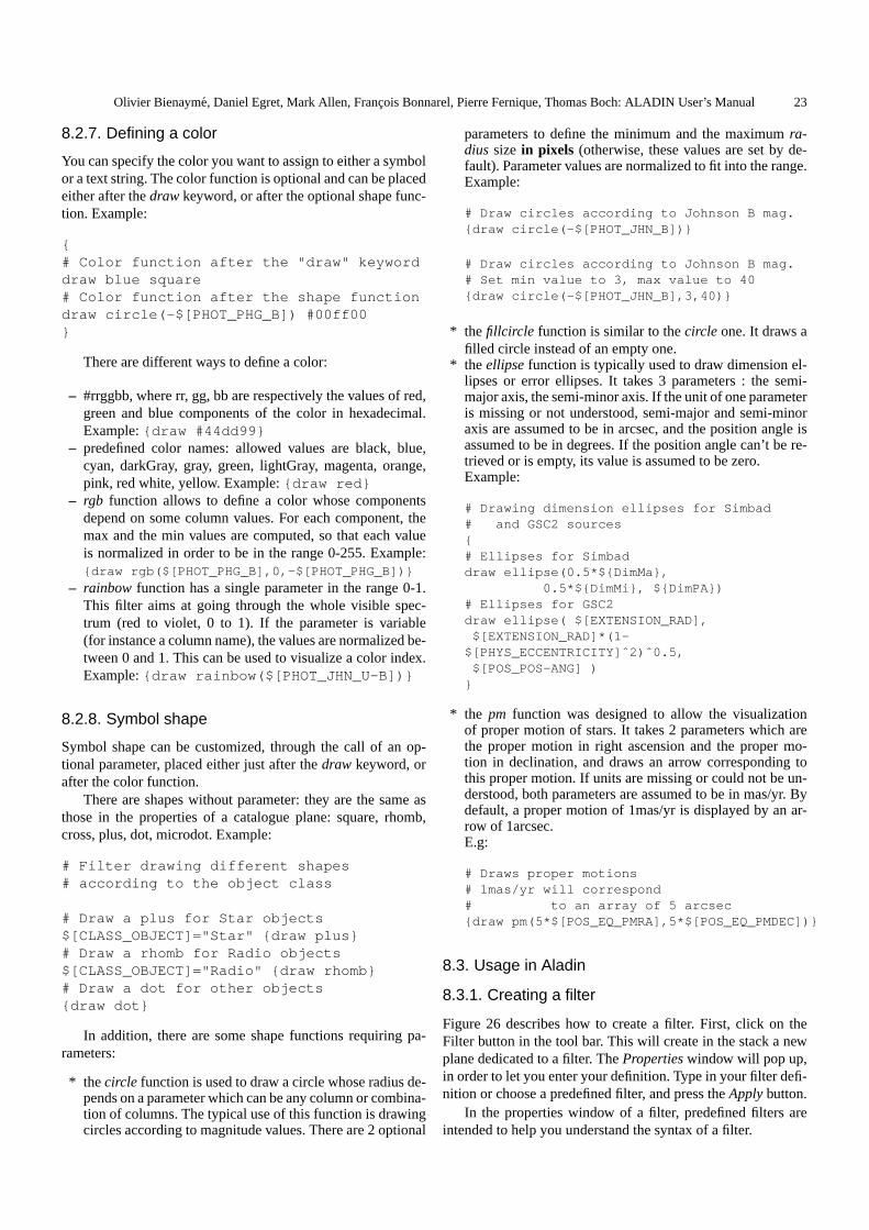
Olivier Bienayme, Daniel Egret, Mark Allen, Francois Bonnarel, Pierre Fernique, Thomas Boch: ALADIN User’s Manual 23
8.2.7. Defining a color
You can specify the color you want to assign to either a symbolor a text string. The color function is optional and can be placedeither after thedrawkeyword, or after the optional shape func-tion. Example:
{# Color function after the "draw" keyworddraw blue square# Color function after the shape functiondraw circle(-$[PHOT_PHG_B]) #00ff00}
There are different ways to define a color:
– #rrggbb, where rr, gg, bb are respectively the values of red,green and blue components of the color in hexadecimal.Example:{draw #44dd99}
– predefined color names: allowed values are black, blue,cyan, darkGray, gray, green, lightGray, magenta, orange,pink, red white, yellow. Example:{draw red}
– rgb function allows to define a color whose componentsdepend on some column values. For each component, themax and the min values are computed, so that each valueis normalized in order to be in the range 0-255. Example:{draw rgb($[PHOT_PHG_B],0,-$[PHOT_PHG_B])}
– rainbow function has a single parameter in the range 0-1.This filter aims at going through the whole visible spec-trum (red to violet, 0 to 1). If the parameter is variable(for instance a column name), the values are normalized be-tween 0 and 1. This can be used to visualize a color index.Example:{draw rainbow($[PHOT_JHN_U-B])}
8.2.8. Symbol shape
Symbol shape can be customized, through the call of an op-tional parameter, placed either just after thedraw keyword, orafter the color function.
There are shapes without parameter: they are the same asthose in the properties of a catalogue plane: square, rhomb,cross, plus, dot, microdot. Example:
# Filter drawing different shapes# according to the object class
# Draw a plus for Star objects$[CLASS_OBJECT]="Star" {draw plus}# Draw a rhomb for Radio objects$[CLASS_OBJECT]="Radio" {draw rhomb}# Draw a dot for other objects{draw dot}
In addition, there are some shape functions requiring pa-rameters:
* thecircle function is used to draw a circle whose radius de-pends on a parameter which can be any column or combina-tion of columns. The typical use of this function is drawingcircles according to magnitude values. There are 2 optional
parameters to define the minimum and the maximumra-dius size in pixels (otherwise, these values are set by de-fault). Parameter values are normalized to fit into the range.Example:
# Draw circles according to Johnson B mag.{draw circle(-$[PHOT_JHN_B])}
# Draw circles according to Johnson B mag.# Set min value to 3, max value to 40{draw circle(-$[PHOT_JHN_B],3,40)}
* thefillcircle function is similar to thecircle one. It draws afilled circle instead of an empty one.
* theellipsefunction is typically used to draw dimension el-lipses or error ellipses. It takes 3 parameters : the semi-major axis, the semi-minor axis. If the unit of one parameteris missing or not understood, semi-major and semi-minoraxis are assumed to be in arcsec, and the position angle isassumed to be in degrees. If the position angle can’t be re-trieved or is empty, its value is assumed to be zero.Example:
# Drawing dimension ellipses for Simbad# and GSC2 sources{# Ellipses for Simbaddraw ellipse(0.5*${DimMa},
0.5*${DimMi}, ${DimPA})# Ellipses for GSC2draw ellipse( $[EXTENSION_RAD],
$[EXTENSION_RAD]*(1-$[PHYS_ECCENTRICITY]ˆ2)ˆ0.5,
$[POS_POS-ANG] )}
* the pm function was designed to allow the visualizationof proper motion of stars. It takes 2 parameters which arethe proper motion in right ascension and the proper mo-tion in declination, and draws an arrow corresponding tothis proper motion. If units are missing or could not be un-derstood, both parameters are assumed to be in mas/yr. Bydefault, a proper motion of 1mas/yr is displayed by an ar-row of 1arcsec.E.g:
# Draws proper motions# 1mas/yr will correspond# to an array of 5 arcsec{draw pm(5*$[POS_EQ_PMRA],5*$[POS_EQ_PMDEC])}
8.3. Usage in Aladin
8.3.1. Creating a filter
Figure 26 describes how to create a filter. First, click on theFilter button in the tool bar. This will create in the stack a newplane dedicated to a filter. ThePropertieswindow will pop up,in order to let you enter your definition. Type in your filter defi-nition or choose a predefined filter, and press theApplybutton.
In the properties window of a filter, predefined filters areintended to help you understand the syntax of a filter.
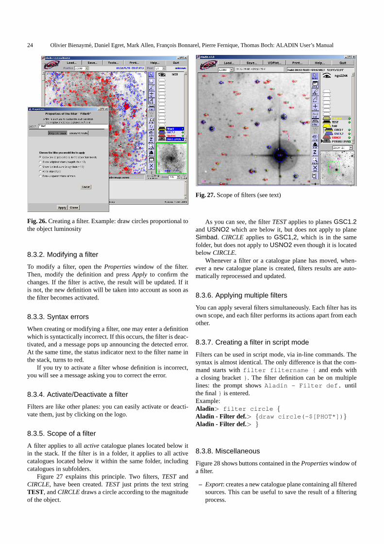
24 Olivier Bienayme, Daniel Egret, Mark Allen, Francois Bonnarel, Pierre Fernique, Thomas Boch: ALADIN User’s Manual
Fig. 26.Creating a filter. Example: draw circles proportional tothe object luminosity
8.3.2. Modifying a filter
To modify a filter, open thePropertieswindow of the filter.Then, modify the definition and pressApply to confirm thechanges. If the filter is active, the result will be updated. If itis not, the new definition will be taken into account as soon asthe filter becomes activated.
8.3.3. Syntax errors
When creating or modifying a filter, one may enter a definitionwhich is syntactically incorrect. If this occurs, the filter is deac-tivated, and a message pops up announcing the detected error.At the same time, the status indicator next to the filter name inthe stack, turns to red.
If you try to activate a filter whose definition is incorrect,you will see a message asking you to correct the error.
8.3.4. Activate/Deactivate a filter
Filters are like other planes: you can easily activate or deacti-vate them, just by clicking on the logo.
8.3.5. Scope of a filter
A filter applies to allactivecatalogue planes located below itin the stack. If the filter is in a folder, it applies to all activecatalogues located below it within the same folder, includingcatalogues in subfolders.
Figure 27 explains this principle. Two filters,TESTandCIRCLE, have been created.TESTjust prints the text stringTEST, andCIRCLEdraws a circle according to the magnitudeof the object.
Fig. 27.Scope of filters (see text)
As you can see, the filterTESTapplies to planesGSC1.2andUSNO2 which are below it, but does not apply to planeSimbad. CIRCLE applies toGSC1,2, which is in the samefolder, but does not apply toUSNO2 even though it is locatedbelowCIRCLE.
Whenever a filter or a catalogue plane has moved, when-ever a new catalogue plane is created, filters results are auto-matically reprocessed and updated.
8.3.6. Applying multiple filters
You can apply several filters simultaneously. Each filter has itsown scope, and each filter performs its actions apart from eachother.
8.3.7. Creating a filter in script mode
Filters can be used in script mode, via in-line commands. Thesyntax is almost identical. The only difference is that the com-mand starts withfilter filtername { and ends witha closing bracket} . The filter definition can be on multiplelines: the prompt showsAladin - Filter def. untilthe final} is entered.Example:Aladin> filter circle {Aladin - Filter def.> {draw circle(-$[PHOT*]) }Aladin - Filter def.> }
8.3.8. Miscellaneous
Figure 28 shows buttons contained in thePropertieswindow ofa filter.
– Export: creates a new catalogue plane containing all filteredsources. This can be useful to save the result of a filteringprocess.
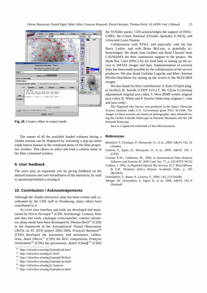
Olivier Bienayme, Daniel Egret, Mark Allen, Francois Bonnarel, Pierre Fernique, Thomas Boch: ALADIN User’s Manual 25
Fig. 28.Create a filter in expert mode
The names of all the available loaded columns during aAladin session can be displayed by activating a pop-up menu(right button mouse) in the command menu of the filter proper-ties window. This allows to select and load a column name inthe filter command window.
9. User feedback
The users play an important role by giving feedback on thedesired features and user-friendliness of the interfaces, by mailto [email protected].
10. Contribution / Acknowledgements
Although the Aladin interactive atlas has been written and co-ordinated by the CDS staff in Strasbourg, many others havecontributed to it.
ALADIN Java interface and tools are developed and main-tained byPierre Fernique14 (CDS, Strasbourg). Contour, filterand data tree tools, catalogue cross-matcher, column calcula-tor, demo mode have been developed byThomas Boch15 (CDS)in the framework of the Astrophysical Virtual Observatory(AVO), an EC RTD project 2002-2004.Francois Bonnarel16
(CDS) developed the astrometry and astrometric calibra-tions, Anaıs Oberto17 (CDS) the RGC composition,FrancoisOchsenbein18 (CDS) the precessions,Andre Schaaff19 (CDS)
14 http://cdsweb.u-strasbg.fr/people/pf.html15 http://cdsweb.u-strasbg.fr/ boch16 http://cdsweb.u-strasbg.fr/people/fb.html17 http://cdsweb.u-strasbg.fr/people/ao.html18 http://cdsweb.u-strasbg.fr/ francois19 http://cdsweb.u-strasbg.fr/people/as.html
the VOTable parser. CDS acknowledges the support of INSU-CNRS, the Centre National d’Etudes Spatiales (CNES), andUniversite Louis Pasteur.
Collaboration with STScI, and especially with the lateBarry Lasker, and with Brian McLean, is gratefully ac-knowledged. We thank Jean Guibert and Rene Chesnel fromCAI/MAMA for their continuous support to the project. Wethank Roc Cutri (IPAC) for his kind help in setting up the ac-cess to 2MASS images and data. Implementation of externallinks has been made possible by the collaboration of the serviceproducers. We also thank Guilaine Lagache and Marc-AntoineMiville-Deschenes for setting up the access to the IRAS-IRISimages.
We also thank for their contributions: S. Kale (VOplot plug-in facility), R. Savalle (CFHT FoV,) T. Mc Glynn (Colormapadjustement original java code), T. West (BMP writter originaljava code), R. White and P. Dowler (Hdecomp original C codeand java code).
The Digitized Sky Survey was produced at the Space TelescopeScience Institute under U.S. Government grant NAG W-2166. Theimages of these surveys are based on photographic data obtained us-ing the Oschin Schmidt Telescope on Palomar Mountain and the UKSchmidt Telescope.
Java is a registered trademark of Sun Microsystems.
References
Bonnarel, F., Fernique, P., Bienayme, O., et al., 2000, A&AS 143, 33(Aladin)
Genova, F., Egret, D., Bienayme, O., et al., 2000, A&AS, 143, 1(CDS)
Greisen, E.W., Calabretta, M., 1995, inAstronomical Data AnalysisSoftware and Systems IV, ASP Conf. Ser. 77, p. 233 (FITS WCS)
Guibert, J. 1992, inDigitized Optical Sky Surveys, H.T. MacGillivray& E.B. Thomson (Eds.), Kluwer Academic Publ., p. 103(MAMA)
Ochsenbein, F., Bauer, P., Genova, F., 2000, 143, 23 (VizieR)Wenger, M., Ochsenbein, F., Egret, D., et al., 2000, A&AS, 143, 9
(Simbad)

26 Olivier Bienayme, Daniel Egret, Mark Allen, Francois Bonnarel, Pierre Fernique, Thomas Boch: ALADIN User’s Manual
Appendices
Appendix A: Backus Naur Form of filter syntax
This is an attempt to describe the syntax of a filter in the extended Backus-Naur-Form. It describes in a shorter way what hasbeen explained in section 8.2.
<filter> ::= <constraints block>+
<constraints block> ::= <constraint> "{" (<action><action separator>)* "}"
<action separator> ::= Carriage Return | ";"
<constraint> ::= ( <simple condition> [ <logical operator> <constraint> ] )| "undefined(" (<UCD>|<column>) ")"
<condition> ::= <expression> <comparison operator> <value>
<expression> ::= ( ["+"|"-"] (<UCD>|<column>|<numeric>)[ ( ("+"|"-"|"*"|"/") <expression> | "ˆ" <numeric> ) ] )| <function>"("<expression>")"
<function> ::= abs | cos | deg2rad | ln | log | rad2deg | sin | tan
<value> ::= <string> | ( <numeric> [<unit>] )
<logical operator> ::= "&&" | "||"
<comparison operator> ::= "==" | "!=" | ">" | ">=" | "<" | "<="
<action> ::="draw" [ <color function> ] [ (<shape function>|<UCD>|<column>|<string>) ]| "hide"
<UCD> ::= "$[" UCD name "]"
<column> ::= "${" column name "}"
<shape function> ::= (("circle"|"fillcircle")"("<expression> [","<numeric>","<numeric>]")")| "ellipse(" <expression> "," <expression> "," <expression> ")"| "pm(" <expression> "," <expression> ")"| "square" | "rhomb" | "cross" | "plus" | "dot" | "microdot"
<color function> ::= "rgb(" <expression>, <expression>, <expression> ")"| "rainbow(" <expression> ")"| "black" | "blue" | "cyan" | "darkGray" | "gray" | "green"| "lightGray" | "magenta" | "orange" | "pink" | "red" | "white"| "yellow"

Olivier Bienayme, Daniel Egret, Mark Allen, Francois Bonnarel, Pierre Fernique, Thomas Boch: ALADIN User’s Manual 27
Appendix B: Aladin Script Commands
PLANE: VIEW:
getservers [target] [radius] modeview[1|2|4|9|16]loadfilename createview[1[[x] v]selectx1 [x2..] selectv1 [v2..]rename[x [y]] zoom1/64|...|64xhide[x1] [x2..] attach|detach[v1] [v2..]show[x1] [x2..] lock|unlock[v1] [v2..]mv x1 x2 mv|copyv1 v2rm [x1] [x2..] | all rm [v1] [v2..] |ROIexportx filename [votable] savefilename
coord|object
IMAGE: CATALOGUE:
flipflop [V |H] flipflop [V |H]reverse[on|off] filter...cm colormap addcol([x],[name],[UCD],[unit],[expr])RGB [x1|v1 x2|v2 x3|v3 ]] xmatch[x1] [x2] [dist]blink [x1] [x2..] createplane[name]resampx1 x2 [8|Full] [Cl |Bil] createROI[npix|radius”]contour[nn] [nosmooth] [zoom]
GRAPHIC TOOL: FOLDER:
drawfct(param) md [name]grid [on|off] mv [name]reticle[on|off] rm [name]scale[on|off] show[name]
hide[name]
MISCELLANEOUS:
backupfilename status syncreset mem pause[nn]info msg help[cmd|off] timeout[mm|off]hist [n] demo[on|off] traceprint quit

28 Olivier Bienayme, Daniel Egret, Mark Allen, Francois Bonnarel, Pierre Fernique, Thomas Boch: ALADIN User’s Manual
NAMEget- call a remote image or tabular data server
SYNOPSISget ServerName(keyword,...)[,ServerName(...] [Target] [RadiusUnit]
DESCRIPTIONAllows one to query remote data providers. The result (images or tabular data) will be memorized in an Aladin stackplane and a view of this plane is automatically created. The get syntax is flexible in order to cover all kinds of servers.- ServerName: Aladin, Simbad, VizieR, NED, SkyView, SSS.cat, SSS.img, DSS.ESO, DSS.STScI, ..., or even Fov orMyData (or any other server names displayed in the server frame). Each server name can be followed by a comma sepa-rated keyword list in parentheses. The number and order of the keywords does not matter. Aladin tries to automaticallyassociate the keywords with the server query vocabulary.-Target: astronomical object identifier or J2000 coordinates in sexagesimal syntax (with blank separator). By default,Aladin takes into account the last specified target.-Radius: must be specified with units (deg,arcmin,arcsec or ’ ”) with no blanks between the figures or the units. Bydefault, Aladin takes the mos t appropriate radius according to the current view.
EXAMPLEget Aladin M99get Aladin(DSS2,FITS),Simbad,VizieR(GSC2.2),SkyView(2MASS) M1 10’get MyData(http://myserver/...)
SEE ALSO
load, show, createview, sync, timeout
—————————
NAMEload- load an image or tabular data file
SYNOPSISload filename
DESCRIPTIONAllows loading of a local file containing either an image, tabular data, Aladin script or Aladin backup or metadata files.The contents of the file is automatically detected by Aladin. The file may be gzipped.If the filename specifies a directory, Aladin automatically creates a MetaData Tree describing all the data in the directoryand its sub-directories.A ”metadata file” describes a set of dataThe supported formats are:-Images: FITS-Tabular data:TSV (Tab-Separated-Value), VOTable, AstroRes-MetaData tree: SIA, IDHA-Script: Aladin script (AJS extension)-Backup: Aladin stack backup (AJ extension)
EXAMPLEload DSS1-M1.fits.gz
SEE ALSO
get, export, save, backup
—————————
NAMEselect- select views and/or planes
SYNOPSISselect x1|v1 [x2|v2] ...
DESCRIPTION

Olivier Bienayme, Daniel Egret, Mark Allen, Francois Bonnarel, Pierre Fernique, Thomas Boch: ALADIN User’s Manual 29
Select planes or views by their identifier in order to apply a function to them (see also section)A plane identifier can be the number of the plane in the Aladin stack (the bottom one is 1). It can be also the label of theplane, allowing use of the wildcard ”*”. In this case, the first plane matching the identifier will be taken into account.In multiview mode, you may select a view by its coordinates: a letter for the column and a digit for the line, (ex: B2).If a plane containing catalog sources is selected, its sources will be selected also.
EXAMPLEselect DSS1.V.SERCselect A1 A3 C2 1 3 4 DSS1*select (unselect the previous selection)
SEE ALSO
show, hide, rm, blink, createview, createplane, createROI
—————————
NAMErename- name or rename plane
SYNOPSISrename [x] name
DESCRIPTIONAllow one to name or rename the plane ”x” (or by default, the first selected plane).If the name is already used in the stack, Aladin will automatically append an extension ”˜n”.
NOTES- The get command automatically sets a name to the resulting plane. The usage of ”rename” command allows one tooverride this default name.- ”x” can be the plane label (allowing use of ”*” wildcard) or the plane number in the Aladin stack (the bottom one is 1)
SEE ALSO
get, select
—————————
NAMEhide- hide planes
SYNOPSIShide [x1] [x2..]
DESCRIPTIONHide the specified planes (or the selected planes if there is no parameter).
EXAMPLEhide DSS1.V.SERChide (hide the selected planes):hide 1 2 DSS2*
NOTES”x” can be the plane label (allowing use of ”*” wildcard) or the plane number in the Aladin stack (the bottom one is 1).
SEE ALSO
show, select
—————————
NAMEshow- show planes
SYNOPSISshow [x1] [x2..]

30 Olivier Bienayme, Daniel Egret, Mark Allen, Francois Bonnarel, Pierre Fernique, Thomas Boch: ALADIN User’s Manual
DESCRIPTIONShow the specified planes (or the selected planes if there is no parameter).If there is no view of a specified plane, a view will be created automatically. Also, if there is an existing view of the planebut it is not visible (outside the scroll panel), the view scroll bar will be automatically adapted to show it.
EXAMPLEshow DSS1.V.SERChide (hide the selected planes):hide 1 2 DSS2*
NOTES”x” can be the plane label (allowing use of ”*” wildcard) or the plane number in the Aladin stack (the bottom one is 1).
SEE ALSO
hide, select
—————————
NAMEmv - move planes or views
SYNOPSISmv x1 x2 - for stack manipulationmv v1 v2 - for multiview manipulationmv x1 [x2...] name - for folder manipulation
DESCRIPTIONThe ”mv” command behaviour depends of the nature of its parameters.If the parameters describe two planes (x1 and x2), Aladin will move x1 plane behind the x2 plane in the Aladin stack.If the parameters describes two views (v1 and v2) in multiview mode, Aladin will move the view v1 to the v2 place. Thev2 view place will be overiden by v1 even if v2 was not empty.If the parameters describe planes and the last parameter describes a folder, the planes will be move into the folder.
NOTES”x” can be the plane label (allowing use of ”*” wildcard) or the plane number in the Aladin stack (the bottom one is 1).”v” is the grid coordinate of a view with a letter for the column and a digit for the line, ex: B2
SEE ALSO
md, createview
—————————
NAMErm - delete planes or views
SYNOPSISrm [x1] [x2..] - for stack manipulationrm [v1] [v2..] - for multiview manipulationrm name - for folder manipulationrm ROI|all - for specifical usage
DESCRIPTIONThe ”rm” command behaviour depends of the nature of its parameters.If the parameters describe planes (x1...), Aladin will remove these planes in the Aladin stack and all the associated views.If the parameters describe views (v1...), Aladin will remove these views.If the parameter is the ”ROI” reserved keyword, Aladin will remove all ROI views (see createROI ). The ”all” parameterwill remove all planes and all views.
NOTES”x” can be the plane label (allowing use of ”*” wildcard) or the plane number in the Aladin stack (the bottom one is 1).”v” is the grid coordinate of a view with a letter for the column and a digit for the line, ex: B2
SEE ALSO
get, createview, createROI

Olivier Bienayme, Daniel Egret, Mark Allen, Francois Bonnarel, Pierre Fernique, Thomas Boch: ALADIN User’s Manual 31
—————————
NAMEexport- save images or tabular data
SYNOPSISexport x filename [votable]
DESCRIPTIONExport the plane ”x” in the specify filename.The image pixels will be truncated to 8 bits if the original pixels are not available. Also, the recorded WCS calibrationwill be the last one used for this image.For tabular data, the default format will be TSV (Tab Separated Value) but you can specify ”votable” to change theformat.The RGB and Blink plane cannot be exported.
EXAMPLEexport DSS1.V.SERC C:\DSS2image.fits
NOTES”x” can be the plane label (allowing use of ”*” wildcard) or the plane number in the Aladin stack (the bottom one is 1).
SEE ALSO
load, save, backup, sync
—————————
NAMEmodeview- multiview controler
SYNOPSISmodeview [1|2|4|9|16]
DESCRIPTIONSpecify the number of simultaneous views.
EXAMPLEmodeview 9
SEE ALSO
createview, show
—————————
NAMEcreateview- creation of view
SYNOPSIScreateview [[x] v]
DESCRIPTIONThis command can only be used in multiview mode. It allows one to manually create a view at the position ”v” ofthe Aladin plane stack ”x”. This command is rarely required as the show and get command automatically create thecorresponding views when they are required.
NOTES”x” can be the plane label (allowing use of ”*” wildcard) or the plane number in the Aladin stack (the bottom one is 1).”v” is the grid coordinate of a view with a letter for the column and a digit for the line, ex: B2
EXAMPLEcreateview DSS1.V.SERC C3createview 2 (use a default view place for the plane number 2)createview (use a default view place for the selected plan)
SEE ALSO
modeview, mv, copy, rm

32 Olivier Bienayme, Daniel Egret, Mark Allen, Francois Bonnarel, Pierre Fernique, Thomas Boch: ALADIN User’s Manual
—————————
NAMEzoom- change the zoom factor
SYNOPSISzoom 1/64x|...|64x
DESCRIPTIONChange the zoom factor on the current viewThe available factors are the powers of two (1/64x ... 64x) plus the 2/3 factor
NOTESThe zoom command can only be applied on the current view(s)
EXAMPLEzoom 2xzoom 1/4x
SEE ALSO
select
—————————
NAMEattach|detach- view ”attachment” to the current target
SYNOPSISattach [v1] [v2...]detach [v1] [v2...]
DESCRIPTIONThe ”attach” behavior is interesting only in multiview mode or if the view does not show all the image (dependingof the zoom factor and the image size and the Aladin frame size in the screen). In this case, an attached view willalways try to display the current target (reticle position) at the center of the view by moving the field of view automatically
NOTES- ”v” is the grid coordinate of a view with a letter for the column and a digit for the line, ex: B2
EXAMPLEattach A2 C3detach C1detach (detach all views)
SEE ALSO
zoom, reticle
—————————
NAMElock|unlock- view ”locking”
SYNOPSISlock [v1] [v2...]unlock [v1] [v2...]
DESCRIPTIONBy default, an Aladin view can be scrolled (according to the current multiview mode). You can lock a view to keep it inthe same place even if you scroll the view panels.This funtion is very usefull in multiview mode in order to easely select a set of views amongst a lots of views (typicallygenerated by the ROI extraction mechanism), by moving the interesting view in a ”lock” view
NOTES”v” is the grid coordinate of a view with a letter for the column and a digit for the line, ex: B2

Olivier Bienayme, Daniel Egret, Mark Allen, Francois Bonnarel, Pierre Fernique, Thomas Boch: ALADIN User’s Manual 33
EXAMPLElock A1 A2 A3unlock B2unlock (unlock all views)
SEE ALSO
createview, mv, createROI
—————————
NAMEcopy- copy views
SYNOPSIScopy v1 v2
DESCRIPTIONAllow one to create a copy of the view v1 to v2 place. Notice that each view can have is own zoom factor but still sharethe same image properties notably the colormap.
NOTES”v” is the grid coordinate of a view with a letter for the column and a digit for the line, ex: B2
EXAMPLElock A1 A2 A3unlock B2copy A2 C3
SEE ALSO
createview, mv, zoom, cm
—————————
NAMEsave- save the current view
SYNOPSISsave filename
DESCRIPTIONCapture the current view (image+overlays) and save it as a raster colorized image (BMP format). In multiview mode,only the selected view will be saved.
EXAMPLEsave m1.bmp
SEE ALSO
load, export, backup, sync
—————————
NAMEflipflop - vertical or horizontal mirroring
SYNOPSISflipflop V|H
DESCRIPTIONApply a vertical or horizontal mirroring of the current view. The astrometrical solution is adapted accordingly.
EXAMPLEflipflop H
—————————

34 Olivier Bienayme, Daniel Egret, Mark Allen, Francois Bonnarel, Pierre Fernique, Thomas Boch: ALADIN User’s Manual
NAMEreverse(un)reverse the image
SYNOPSISreverse [on/off]
DESCRIPTIONReverse (or unreverse) the image of the current view. By default Aladin loads images with the reverse mode activated.In case of RGB image, the produced image will take the complementary colors.This command is not available for blink planes.
—————————
NAMEcm - adjust the color map
SYNOPSIScm gray|BB|A|stern
DESCRIPTIONModify the colormap of the current view.The color map options are:-gray: 256 gray levels (default color map)-BB: 256 orange levels (usefull to improve contrast impression)-A: equal color areas-stern: helping for the distinction of hight pixel values
EXAMPLEcm sterm
—————————
NAMERGB - create a RGB image
SYNOPSISRGB [x1|v1 x2|v2 x3|v3]
DESCRIPTIONCreate a colored composed image from three images. The images can be specified by their plane or by their view(in multiview mode). The first image provides the Red component, the second image provides the Green componentand the last image the Blue component. Each image is resampled according to the astrometrical solution of the first image.
EXAMPLERGB 2 3 4RGB DSS1* DSS2* MAMA*
NOTES”x” can be the plane label (allowing use of ”*” wildcard) or the plane number in the Aladin stack (the bottom one is 1).”v” is the grid coordinate of a view with a letter for the column and a digit for the line, ex: B2
SEE ALSO
blink, resamp
—————————
NAMEblink - create a blink sequence of images
SYNOPSISblink [x1|v1] [x2|v2...]
DESCRIPTION

Olivier Bienayme, Daniel Egret, Mark Allen, Francois Bonnarel, Pierre Fernique, Thomas Boch: ALADIN User’s Manual 35
Create a blink sequence of several images (at least 2 images). The images can be specified by their plane or by their view(in multiview mode). Each image is resampled according to the astrometrical solution of the first image.
EXAMPLEblink 2 3 4 5blink DSS1* DSS2*
NOTES”x” can be the plane label (allowing use of ”*” wildcard) or the plane number in the Aladin stack (the bottom one is 1).”v” is the grid coordinate of a view with a letter for the column and a digit for the line, ex: B2
SEE ALSO
RGB, resamp
—————————
NAMEresamp- create a resampled image
SYNOPSISresamp x1|v1 x2|v2 [8|Full] [Closest|Bilinear]
DESCRIPTIONResample a image according to the astrometrical solution of another image.Available parameters:-8: only on visual pixels (8 bits depth) - default-(F)ull:on the real pixels if they are avaiable-(C)losest: Closest pixel algorithm (the fastest)-(B)ilinear: Bilinear interpolation algorithm (better) - default
EXAMPLEresamp 2 3resamp DSS1* MAMA*
NOTES”x” can be the plane label (allowing use of ”*” wildcard) or the plane number in the Aladin stack (the bottom one is 1).”v” is the grid coordinate of a view with a letter for the column and a digit for the line, ex: B2
SEE ALSO
RGB, blink
—————————
NAMEcontour- Draw isocontours of the current image
SYNOPSIScontour [ nn [nosmooth] [zoom] ]
DESCRIPTIONDraw nn isocontours for the current selected image.The result is set in a new plane which can be overlaid on other images of the same field.nn sets the number of contours to draw. If not defined, 4 contours are plotted by default.The parameter nosmooth allows one to switch the smoothing feature off. Smoothing allows a faster computation andreduces the number of control points. It is activated by default.The parameter zoom restricts the computation to the current view of the selected image plane. By default, contours arecomputed over the whole image.
—————————
NAMEfilter - Define and activate a filter

36 Olivier Bienayme, Daniel Egret, Mark Allen, Francois Bonnarel, Pierre Fernique, Thomas Boch: ALADIN User’s Manual
SYNOPSISfilter namecondition1 draw|hide [color] [action1]condition2 draw|hide [color] [action2]:
filter [name] on|off
DESCRIPTIONA filter is a special plane constraining how the sources of the catalog planes beneath it in the Aladin stack will bedisplayed.The first syntax allows to define a new filter, the second syntax allows switching the specified filter on or off.Available operators are +,-,*,/, ˆ (power).Available functions are ”abs” (absolute value), ”cos” (cosinus), ”deg2rad” (degrees to radians), ”exp” (exponential), ”ln”(natural logarithm), ”log” (base 10 logarithm), ”rad2deg” (radians to degrees), ”sin” (sinus), ”tan” (tangent).The available actions are: square, cross, rhomb, plus, dot, microdot, circle(param,[min radius size, max radius size]), fill-circle(param,[min radius size, max radius size]), ellipse(semi-major axis,semi-minor axis,pos angle), pm(proper motionRA,proper motion Dec), rainbow(param)The column references can be specified by their name: syntax ${name} or by the UCD associated to: syntax $[UCD].The wildcard ”*” can be used both for column name or UCD designation. In the case of multiple matching columns, thefirst one will be taken into account.
EXAMPLEfilter star{ $[CLASS OBJECT]=”Star”{ draw} }filter flux {${flux}>1000000 Jy/s{draw cyan plusdraw circle(-$[PHOT*])}}
NOTES
Refer to the Filters manual for more details.
—————————
NAMEaddcol- column generator
SYNOPSISaddcol([plane index or plane name],[new column name],[UCD for new col],[unit for new col],[expr of new col])
DESCRIPTIONAllow one to generate a new column for a tabular data plane. The new column will appear in red color in the measurementframe.The column references can be specified by their name: syntax $name or by the UCD associated to: syntax $[UCD].Available operators are +,-,*,/, ˆ (power).Available functions are ”abs” (absolute value), ”cos” (cosinus), ”deg2rad” (degrees to radians), ”exp” (exponential), ”ln”(natural logarithm), ”log” (base 10 logarithm), ”rad2deg” (radians to degrees), ”sin” (sinus), ”tan” (tangent).UCD and unit parameters are optional and can be left blank.
EXAMPLEaddcol(GSC2.2,B-V,PHOTMAG,,$Bmag-$Vmag)addcol(1,flux,,,10 ˆ (0.4*(8.46-$Imag)))
—————————
NAMExmatch- Cross match tool

Olivier Bienayme, Daniel Egret, Mark Allen, Francois Bonnarel, Pierre Fernique, Thomas Boch: ALADIN User’s Manual 37
SYNOPSISxmatch [x1] [x2] [max dist in arcsec]
DESCRIPTIONAllows one to cross match two tabular data planes. The result will be set in a new catalogue plane, including a columnwith the separation (in arcsec) between the 2 matching sources in arcsec, and all fields of both planes x1 and x2.The cross-match is positionnal. x1 contains the reference objects, for which we seek counterparts in x2. One object of x1is considering match with an object of x2 if they are separated by a distance≤ ”max dist”.If an object in x1 has several matches in x2, all matches will be kept in the result plane.Coordinate fields will be found according to proper UCDs (POSEQ RA MAIN and POS EQ DEC MAIN).
NOTES”x1” and ”x2” can be either a plane label (allowing use of ”*” wildcard) or a plane number in the Aladin stack (thebottom one is 1).
—————————
NAMEcreateplane- source plane creation
SYNOPSIScreateplane [name]
DESCRIPTIONCreate a new catalog plane in the Aladin stack with the current selected sources.This command is useful to extract a set of objets after applying a filter, or to merge two catalog planes together (selectx1 x2; createplane).
NOTESNotice that the select command on a catalog plane also selects its sources. The typical sequence could be:get Vizier(GSC1.2) HD1filter mag $[PHOT*]<6 || $[PHOT*]>10 hidefilter mag onselect GSC*createplane MySelection
SEE ALSO
select, get, export
—————————
NAMEcreateROI- Region Of Interest extractor
SYNOPSIS
createROI [npixels|radius”]
DESCRIPTIONAllows one to automatically create zoomed views around the current selected sources for the selected images (one ormore). In this way, it is possible to rapidly browse and/or compare a large set of objects.The size of the zoom views can be determined either in pixels (default 40) or in arcsec (do not forget to mention the ” unit).
NOTES

38 Olivier Bienayme, Daniel Egret, Mark Allen, Francois Bonnarel, Pierre Fernique, Thomas Boch: ALADIN User’s Manual
The typical usage should beget Aladin(DSS2) hd2syncget Aladin(DSS1)get VizieR(GSC1.2)syncfilter mag $[PHOT*]>7 && $[PHOT*]<12 drawfilter onmodeview 4select A1 B1 GSC*createROI 30”
EXAMPLEcreateROI
SEE ALSO
select
—————————
NAMEdraw- graphical overlay command
SYNOPSISdraw fct(param)draw mode(xy|radec)
DESCRIPTIONAllows one to manually add graphical overlays on views. There are three graphical functions available:.string(x,y,”text”).tag(x,y).line(x1,y1,x2,y2[,text])The x,y coordinates can be in the XY image reference (default mode) or in RADEC coordinates. For this, the ”drawmode(radec)” command must be set before.
EXAMPLEdraw string(300,200,”my favourite galaxy”)draw mode(radec)draw tag(10 12 13,+2 3 4)
—————————
NAMEgrid - coordinate grid management
SYNOPSISgrid [on/off]
DESCRIPTIONSwitch the coordinate grid on or off
EXAMPLEgrid on
SEE ALSO
reticle, scale
—————————
NAMEscale- scale and other view overlay information management
SYNOPSIS

Olivier Bienayme, Daniel Egret, Mark Allen, Francois Bonnarel, Pierre Fernique, Thomas Boch: ALADIN User’s Manual 39
scale [on/off]
DESCRIPTIONSwitch on or off the overlay information on the views (scale, plane name, North direction, field size).
—————————
NAMEreticle- reticle management
SYNOPSISreticle [on/off]
DESCRIPTIONSwitch on or off the reticle designating the last click position.The reticle is displayed as a large magenta colored cross.
NOTES- An astronomical object or sexagesimal J2000 coordinates simply written instead of an Aladin script command willautomatically move the target (and the reticle) to the corresponding position
SEE ALSO
attach
—————————
NAMEcoord|object- show a specifical position
SYNOPSIShh mm ss +|-dd mm ss - sexagesimal notationdd.dddd +|-dd.dddd - decimal notationxxxx - astronomical object identifier
DESCRIPTIONShow the specified position by moving the reticle (large magenta colored cross) on it. If the user indicates an astro-nomical object instead of coordinates, Aladin will automatically query CDS sesame resolver to have the correspondingcoordinates.
NOTESIf some views are ”attach-ed” to the reticle, their field will be automatically moved according to the position (if possible)
EXAMPLE05 34 31.97 +22 00 52.1083.63131 +22.01160M1
SEE ALSO
attach, reticle
—————————
NAMEbackup- backup the Aladin stack
SYNOPSISbackup filename
DESCRIPTIONGenerate a backup of the Aladin plane stack in the specified file. The usual extension for this kind of file is ”.AJ”. Theinternal format is Aladin proprietary (XML syntax). Only image, tabular data and graphical overlays will be taken intoaccount. The original pixels are lost: only the 8bit pixel values will be kept.
EXAMPLE

40 Olivier Bienayme, Daniel Egret, Mark Allen, Francois Bonnarel, Pierre Fernique, Thomas Boch: ALADIN User’s Manual
backup /home/M1.aj
SEE ALSO
load, export, save
—————————
NAMEprint - print function
SYNOPSISprint
DESCRIPTIONAllow one to print the current views. In case of multiview mode, the visible views will be printed on the same page
NOTESUnfortunately, Java Printer method opens automatically a stupid driver window before printing. So this commandCANNOT REALLY BE USED as a ”script” command.
—————————
NAMEinfo - message status
SYNOPSISinfo msg
DESCRIPTIONPrint a message in the status window (between the main frame and the measurement frame). If the demo mode isactivated, the message will be displayed in a separated window
SEE ALSO
demo
—————————
NAMEdemo- demonstration mode
SYNOPSISdemo [on|off]
DESCRIPTIONSwitch on or off the demonstration mode. If the demonstration mode is activated, the script commands will be ”demon-strated” by explaining step by step how to obtain the same result with the Aladin graphical interface.A typical usage:demo onget Aladin(MAMA) galactic center
NOTESNot all script command have a ”demo” mode implemented. In this case, the command is simply executed.
—————————
NAMEstatus- Aladin stack status
SYNOPSISstatus
DESCRIPTIONdisplay the stack plane status on the standard output

Olivier Bienayme, Daniel Egret, Mark Allen, Francois Bonnarel, Pierre Fernique, Thomas Boch: ALADIN User’s Manual 41
—————————
NAMEhist - history
SYNOPSIShist [n]
DESCRIPTIONDisplay the script command history in the Aladin console and on the standard output. By default, the last 10 commandsare displayed.
EXAMPLEhist 20
SEE ALSO
status
—————————
NAMEtrace- turn on (resp. off) the debug verbose mode
SYNOPSIStrace 1|2|3|off
DESCRIPTIONAladin supports 3 trace mode levels. The trace messages are displaying on the standard output, typically the xterm or thewindow console in which you launched Aladin. If you have no console at all, this command has no effect.
—————————
NAMEmem- memory status
SYNOPSISmem
DESCRIPTIONDisplay the java memory used (after a garbage collector).
—————————
NAMEhelp- in line help
SYNOPSIShelp [cmd|all|off]
DESCRIPTIONdisplay this help for each command and a resume of all available commands if there is no parameter.The ”off” parameter allows one to display the current view again.The ”all” parameter allows one to print on the console help about all Aladin script commands.
—————————
NAMEsync- plane synchronization
SYNOPSISsync
DESCRIPTION

42 Olivier Bienayme, Daniel Egret, Mark Allen, Francois Bonnarel, Pierre Fernique, Thomas Boch: ALADIN User’s Manual
Wait until all planes are ready (corresponding to a ”not blinking status plane”).This command is unavoidable in script mode, you should always use it before a save or zoom command...
EXAMPLEsync
—————————
NAMEpause- script pause
SYNOPSISpause [nn]
DESCRIPTIONwait nn seconds, 1 by default. Very useful for demonstration...
—————————
NAMEtimeout- timeout control
SYNOPSIStimeout nn|off
DESCRIPTIONThis command is related to the get command. By default a get command will be stopped after 15mn if there is no activityfrom the remote server. With the timeout command you may increase or decrease this limit, or suppress it at all together.
EXAMPLEtimeout 30timeout off
SEE ALSO
get
—————————
NAMEreset- reset Aladin
SYNOPSISreset
DESCRIPTIONReset Aladin by removing all views and all planes. Restore one view mode and clean the memory.
SEE ALSO
rm
—————————
NAMEquit - end of Aladin session
SYNOPSISquit
DESCRIPTIONStop Aladin
Related Documents