AL9910EV7 Triac Dimmable 120VAC Evaluation Board - Modification Guide - Date: August 3, 2012 This document contains Diodes confidential and proprietary information (For Internal Use Only)

Welcome message from author
This document is posted to help you gain knowledge. Please leave a comment to let me know what you think about it! Share it to your friends and learn new things together.
Transcript

AL9910EV7
Triac Dimmable 120VAC Evaluation Board
- Modification Guide -
Date: August 3, 2012
This document contains Diodes confidential and proprietary information
(For Internal Use Only)
AL9910EV7 120VAC Dimmable Modification Guide August 2012
AL9910EV7 Rev 1 - For Internal Use Only - Page 2 of 15 (8/3/2012)
1. Standard Evaluation Board Schematic
Figure 1: Standard Evaluation Board Schematic
2. Modification Summary Based on the 8 LEDs configuration, we modified the following components to achieve higher efficiency:
1. Inductor (L2) – Coilcraft (MSS1278T-105KLB) with lower conduction and switching losses
2. MOSFET (Q1) – Alpha Omega (AOD4S60) with a low RDS(on) (0.9Ω) and low Qg (6nc)
3. Freewheeling Diode (D2) – Diodes (ES1G-13-F) with a faster recovery time of 25nSec
4. ROSC resistor - Increase R32 to 440KΩ to lower the switching frequency 5. Gate drive resistor – Decrease R6 to 4.73Ω to turn on the MOSFET faster
1
3
2
7
8
6
4
5
9
2
AL9910EV7 120VAC Dimmable Modification Guide August 2012
AL9910EV7 Rev 1 - For Internal Use Only - Page 3 of 15 (8/3/2012)
We concluded the overall efficiency can be improved higher using the standard EVB to around 87%. In addition, we connected the 120VAC Lutron dimmer (P/N LG-603PG) at full brightness setting, the efficiency maintained at 80%. 3. Introduction This report shows how to select components and change applications circuitry from the standard EVB to meet certain customer’s requirement. Customers have different requirement for their customized LED applications. We can modify our standard evaluation board to fulfill their needs and shorten the design-in time. Customers usually provide a set of test conditions such as input/output voltage, number of output LEDs, output LED current, output ripple current, power factor, and efficiency. 4. Modifications from Standard EVB Here is a list of parameters that allows user to change the applications circuitry using our standard EVB to meet their customized LEDs requirements: 1. How to adjust output LED current (ILED)
User can change the Rsense resistor (R7) and Power Inductor (L2) to a different value to decrease or increase the output LED current. Table below shows typical values for R7 and L2 selection to meet the ILED
requirement:
Rsense (Ω)
Power Inductor (mH)
ILED (mA)
1.91 1.0 260
1.62 1.0 425
1.50 1.0 500
1.20 1.0 700
2. How to improve efficiency (Eff)
Efficiency varies with several parameters:
ILED LED current is direct proportional to the intensity of the light. The higher ILED will increase the efficiency based on the power equation, Pout = Vout * ILED. However, user needs to know the current limit of the types of LEDs and not to exceed this limit.

AL9910EV7 120VAC Dimmable Modification Guide August 2012
AL9910EV7 Rev 1 - For Internal Use Only - Page 4 of 15 (8/3/2012)
Numbers of LEDs Typical LED voltage is 3.3V, the numbers of LEDs determine the Vout and based on the power equation, Pout = Vout * ILED. When the numbers of LEDs increase, Vout will increase accordingly and affects the efficiency.
MOSFET selection Power MOSFET is acting as a switch to regulate the voltage across the output of the LED. In conjunction with the current feedback loop circuitry, when the ILED exceeded the limit, MOSFET will turn off to protect the LEDs. Two main parameters for MOSFETs selection to enhance the efficiency are: Low RDS(on) will reduce the conduction loss and Low Qg will reduce the switching loss.
MOSFET Gate Drive
Improve the gate drive by lowering R6 from 22Ω to 4.7Ω so the MOSFET will turn on faster and improve the efficiency.
Switching Inductor With proper selection of the right inductance value, inductors can delivery system running under continue conduction mode to provide maximum efficiency performance.
The following parameters are needed to be defined or calculate for inductance operating in continue conduction mode:
Maximum input voltage
Minimum input voltage
Maximum switching frequency
Maximum LED ripple current Duty cycle
Select a larger value inductance with +/-20% tolerance. Unfortunately, larger inductance requires more winding and tends to be higher DCR and cost.
So the final inductor selection depends on four main design criteria: efficiency, electromagnetic interference (EMI), dimension, and cost. In handheld battery powered applications: high efficiency, low EMI, and smallest spacing are required. For retrofit LED lighting applications, the lowest cost solution is often employed for AC utility supply.
Recommend to check each inductor "roll off" and frequency response beside parameters like Irms, Isat, and DCR. Refer to the data sheet for frequency response curves. For EV7 application, use the MSS1260T series high temperature power inductor from Coilcraft.
Total inductor loss comes from two factors: inductor core loss which is switching frequency related and DCR loss which is conduction resistance loss.
AL9910EV7 120VAC Dimmable Modification Guide August 2012
AL9910EV7 Rev 1 - For Internal Use Only - Page 5 of 15 (8/3/2012)
Free-Wheeling diode Freewheeling diode is used to eliminate flyback, the sudden voltage spike across an inductive load and provide continuously current into the inductor when power MOSFET is suddenly switched OFF. Here are the selection criteria for the diode: Peak forward current capacity (IPEAK), reverse breakdown voltage (VR), and
average rectified output current (IO) Lower forward voltage drop (VF) and faster reverse recovery time (trr) are
recommended for better power efficiency.
3. How to reduce output ripple User can add a Electrolytic Capacitor with proper voltage rating across LED+ (X3) and LED- (X4) to suppress the amplitude of the output waveform. Install the Electrolytic Capacitor carefully to make sure it will able to fit into the E27/A19 light bulbs housing. Typical Electrolytic Capacitor values shown:
Electrolytic Capacitor (µF)
Output Ripple Suppressed
330 µF 50V 7%
470 µF 50V 26%
680 µF 50V 46%
1000 µF 50V 60%
4. How to adjust operating switching frequency
User can set AL9910 either on constant frequency or constant off time modes. Constant switching frequency Connect a resistor between Rosc pin and Ground pin. Use tosc = (Rosc + 22)/ 25 µs Switching frequency will impact efficiency. Be careful to have Duty cycle > 0.5 and min Ton >Tblank time (smaller number of LED and in low power mode < 3W) when use at constant frequency mode. Constant Off time (Variable Frequency) Connect Rosc between Rosc pin and Gate of external MOSFET. The switching frequency varies as either Vin or Vout changes. More suitable to be used for Triac

AL9910EV7 120VAC Dimmable Modification Guide August 2012
AL9910EV7 Rev 1 - For Internal Use Only - Page 6 of 15 (8/3/2012)
Dimming application circuitry that Vin and Vout are changing according to dimmer positions. Help to remove instability issue from Duty cycle > 50%.
5. How to reduce harmonic distortion
Harmonic is a measurement of amplitude and frequency of the input source. Harmonic distortion also depends on the numbers of LEDs and ILED.
User can add capacitors both at input and output on the EVBs. However, adding components will impact BOM cost. The most economical way is to add just an output capacitor across LED+ (X3) and LED- (X4) and it will reduce the harmonic.
For the EV7 application, add a 220µF/50V 20% radial capacitor will be sufficient to reduce the harmonic.
6. How to adjust holding current and dimmer compatibility
The AL9910 triac dimming evaluation board includes a bleeder circuit to ensure proper triac operation by allowing current flow while the line voltage is low to enable proper firing of the triac since the existing triac dimmer requires a small amount of a few milliamps of current to hold them on throughout the AC line cycle. An external resistor (R17) needs to be placed on the source of Q2 to GND to perform this function. The R17 resistor can be adjusted independently. As the holding resistor R17 is increased, the overall efficiency will also increase.
7. How to improve triac dimming range
The AL9910EV7 evaluation board has been optimized with the dimming circuit for triac dimming controls. It is mainly used for both forward phase and reverse phase dimmers using a 120VAC input. In practice, a triac or electronic dimmer can be inserted in series to the hot line voltage after the AC power supply or AC wall power supply, which is then connected directly to the input of the LED driver board. As the AC power supply can be set at any voltage, normally at 120VAC for the AL9910EV7 evaluation board, the dimmer can be adjusted from maximum dimming range that provides full brightness of LEDs to minimum dimming range that provides the lowest brightness before it completely turns off at a cut-off threshold.
For design flexibility for different condition requirements, the value of resistance in the dimming circuit can be selected to provide wide maximum and minimum range of LED dimming.
Table below shows maximum and minimum LED dimming ranges:
AL9910EV7 120VAC Dimmable Modification Guide August 2012
AL9910EV7 Rev 1 - For Internal Use Only - Page 7 of 15 (8/3/2012)
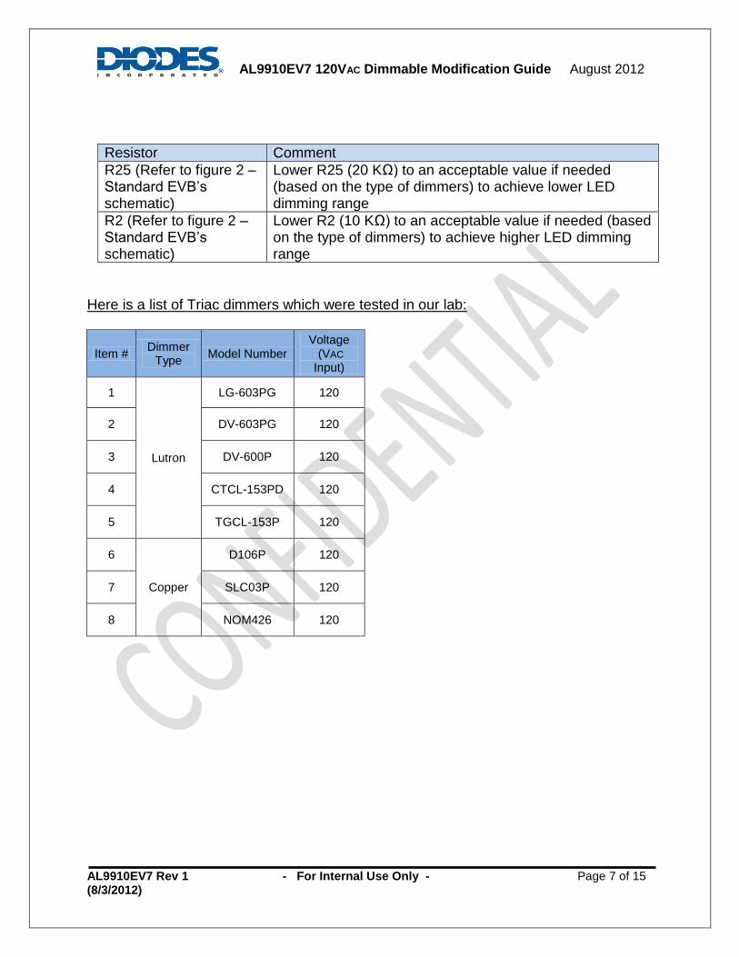
Resistor Comment
R25 (Refer to figure 2 – Standard EVB’s schematic)
Lower R25 (20 KΩ) to an acceptable value if needed (based on the type of dimmers) to achieve lower LED dimming range
R2 (Refer to figure 2 – Standard EVB’s schematic)
Lower R2 (10 KΩ) to an acceptable value if needed (based on the type of dimmers) to achieve higher LED dimming range
Here is a list of Triac dimmers which were tested in our lab:
Item # Dimmer
Type Model Number
Voltage (VAC Input)
1
Lutron
LG-603PG 120
2 DV-603PG 120
3 DV-600P 120
4 CTCL-153PD 120
5 TGCL-153P 120
6
Copper
D106P 120
7 SLC03P 120
8 NOM426 120
AL9910EV7 120VAC Dimmable Modification Guide August 2012
AL9910EV7 Rev 1 - For Internal Use Only - Page 8 of 15 (8/3/2012)
8. How to adjust Power Factor Correction (PFC)
EV7 power factor correction circuitry contains R42, R43, R44 and Q6. It works as a controlled voltage divider added into the current feedback loop to have the input current waveform matched with the voltage waveform will improve the power factor. But adjust R42 and R44 to have a high power factor may hurt LED current line rejection tolerance. Disable this circuitry to replace with valley-fill circuitry which is a passive power factor correction. It can maintain a stable LED current over line voltage variation and good power factor at a higher BOM cost trade off.
9. How to improve Electromagnetic Interference (EMI)
Standard EV7 did not come with line EMI filter. EMI results may relate to customer's PCB layout, power source, loading conditions, LED lamp fixtures designs, components selection, switching frequency, and EMI filter design. User may consider using:
Common mode filter (ELF-11090E)
Differential mode inductor (MSS1260-105KL-KLB)
Choke RF Shielded inductor (RL875S) for EMI enhancement. However, it will need a joined collaboration with sharing
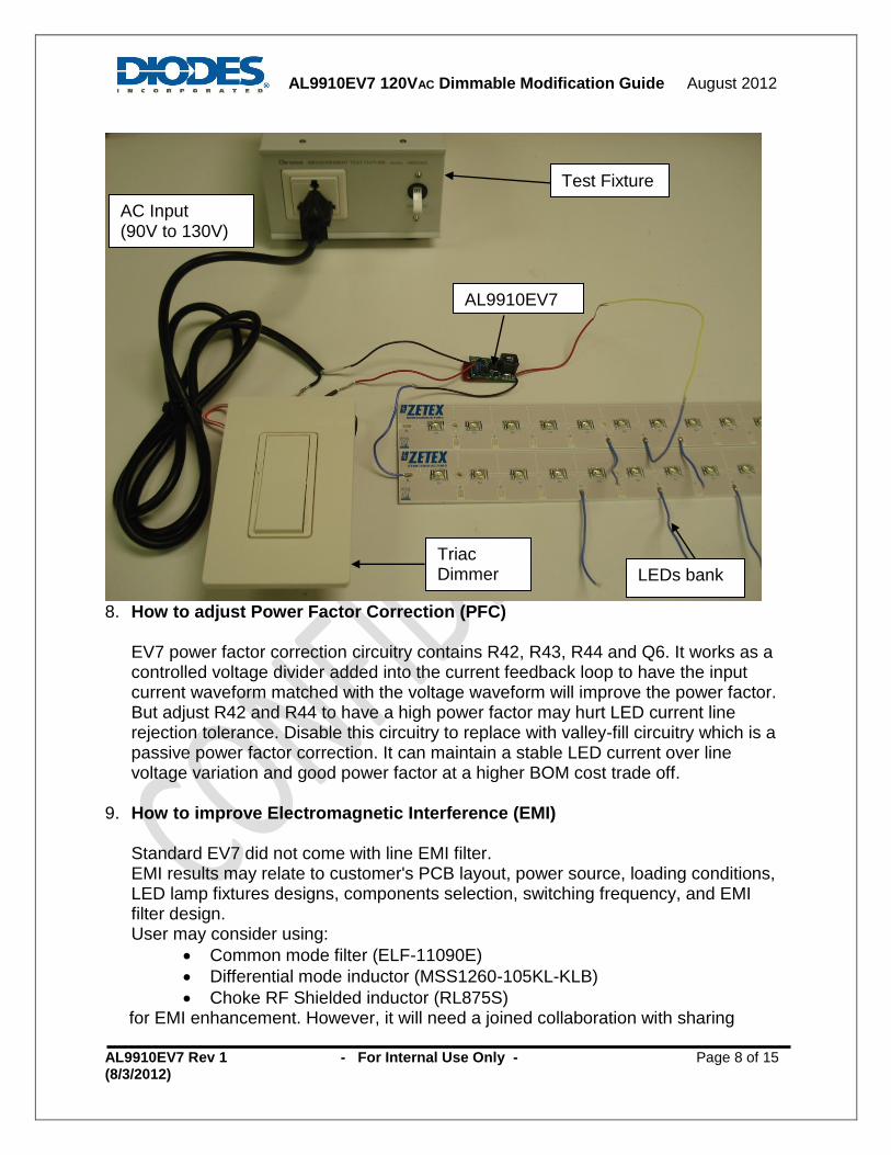
Test Fixture
AL9910EV7
Triac Dimmer LEDs bank
AC Input (90V to 130V)
AL9910EV7 120VAC Dimmable Modification Guide August 2012
AL9910EV7 Rev 1 - For Internal Use Only - Page 9 of 15 (8/3/2012)
product information between customers and Diodes application supporting team to develop an optimize EMI solution.
AL9910EV7 120VAC Dimmable Modification Guide August 2012
AL9910EV7 Rev 1 - For Internal Use Only - Page 10 of 15 (8/3/2012)
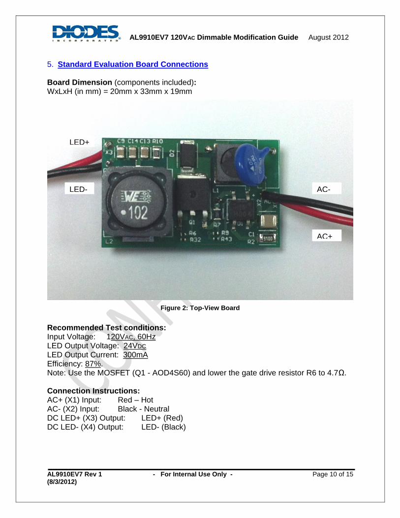
5. Standard Evaluation Board Connections Board Dimension (components included): WxLxH (in mm) = 20mm x 33mm x 19mm
Figure 2: Top-View Board
Recommended Test conditions: Input Voltage: 120VAC, 60Hz LED Output Voltage: 24VDC
LED Output Current: 300mA Efficiency: 87%. Note: Use the MOSFET (Q1 - AOD4S60) and lower the gate drive resistor R6 to 4.7Ω. Connection Instructions: AC+ (X1) Input: Red – Hot AC- (X2) Input: Black - Neutral DC LED+ (X3) Output: LED+ (Red) DC LED- (X4) Output: LED- (Black)
AC-
AC+
LED+
LED-
AL9910EV7 120VAC Dimmable Modification Guide August 2012
AL9910EV7 Rev 1 - For Internal Use Only - Page 11 of 15 (8/3/2012)
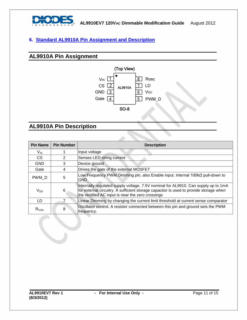
6. Standard AL9910A Pin Assignment and Description
AL9910A Pin Assignment
SO-8
1
2
3
4 5
6
7
8
(Top View)
CS
Gate
GND
LD
VIN Rosc
VDD
PWM_D
AL9910A
AL9910A Pin Description
Pin Name Pin Number Description
VIN 1 Input voltage
CS 2 Senses LED string current
GND 3 Device ground
Gate 4 Drives the gate of the external MOSFET
PWM_D 5 Low Frequency PWM Dimming pin, also Enable input. Internal 100kΩ pull-down to GND
VDD 6 Internally regulated supply voltage. 7.5V nominal for AL9910. Can supply up to 1mA for external circuitry. A sufficient storage capacitor is used to provide storage when the rectified AC input is near the zero crossings
LD 7 Linear Dimming by changing the current limit threshold at current sense comparator
ROSC 8 Oscillator control. A resistor connected between this pin and ground sets the PWM frequency.
AL9910EV7 120VAC Dimmable Modification Guide August 2012
AL9910EV7 Rev 1 - For Internal Use Only - Page 12 of 15 (8/3/2012)
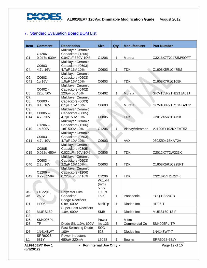
7. Standard Evaluation Board BOM List
Item Comment Description Size Qty Manufacturer Part Number
C1 C1206 - 0.047u 630V
Multilayer Ceramic Capacitors (1206) 0.047µF 630V 10% C1206 1 Murata C3216X7T2J473M/SOFT
C4, C0603 - 4.7u 16V
Multilayer Ceramic Capacitors (0603) 4.7µF 16V 10% C0603 1 TDK C1608X5R1C475M
C6, C41
C0603 - 1u 16V
Multilayer Ceramic Capacitors (0603) 1.0µF 16V 10% C0603 2 TDK C1608X7R1C105K
C5 C0402 - 220p 50V
Multilayer Ceramic Capacitors (0402) 220pF 50V 5% C0402 1 Murata GRM155R71H221JA01J
C7, C8, C12
C0603 - 0.1u 16V
Multilayer Ceramic Capacitors (0603) 0.1µF 16V 10% C0603 3 Murata GCM188R71C104KA37D
C9, C13, C14
C0805 – 4.7u 50V
Multilayer Ceramic Capacitors (0805) 4.7µF 50V 10% C0805 3 TDK C2012X5R1H475K
C10 C1206 – 1n 500V
Multilayer Ceramic Capacitors (1206) 1nF 500V 10% C1206 1 Vishay/Vitramon VJ1206Y102KXEAT5Z
C11 C0603 – 4.7u 10V
Multilayer Ceramic Capacitors (0603) 4.7µF 10V 10% C0603 1 AVX 0603ZD475KAT2A
C15 C0805 - 0.022u 450V
Multilayer Ceramic Capacitors (0805) 0.022µF 450V 10% C0805 1 TDK C2012X7T2W223K
C40 C0603 – 2.2u 16V
Multilayer Ceramic Capacitors (0603) 2.2µF 16V 10% C0603 1 TDK C1608X5R1C225KT
C42 C1206 – 0.22u 250V
Multilayer Ceramic Capacitors (1206) 0.22µF 250V 10% C1206 1 TDK C3216X7T2E224K
X5-X6
C0.22µF, 250V
Polyester Film Capacitor
WxLxH (mm) 5.5 x 10.3 x 15.5 1 Panasonic ECQ-E2224JB
D1 HD06 Bridge Rectifiers 0.8A, 600V MiniDip 1 Diodes Inc HD06-T
D2 MURS160 Super-Fast Rectifiers 1.0A, 600V SMB 1 Diodes Inc MURS160-13-F
D3, D5, D8
SM4005PL-TP Diode SIL 1.0A, 600V
Power lite 123 3
Micro Commercial Co SM4005PL-TP
D6 1N4148WT Fast Switching Diode 100V
SOD-523 1 Diodes Inc 1N4148WT-7
L1 SRR6028-681Y
Power Inductors 680µH 220mA L6028 1 Bourns SRR6028-681Y

AL9910EV7 120VAC Dimmable Modification Guide August 2012
AL9910EV7 Rev 1 - For Internal Use Only - Page 13 of 15 (8/3/2012)
L2 7447709102 Power Inductors 0.9A, 1mH
L12.5 x 12.5 x 10 1
Wurth Electronics 7447709102
Q1 STD7NM60N MOSFET Power N-Chan 600V, 5 Amp D-PAK 1
ST Microelectronics STD7NM60N
Q2 SPD01N60C3
MOSFET Power COOL MOS N-CH 650V, 0.8A D-PAK 1 Infineon SPD01N60C3
Q6 BC847C
NPN Surface Small Signal Transistor 100mA, 45V
SOT-23 1 Diodes Inc BC847C-7-F
R1 S07K300 Varistors 300Vrms 7MM Radial
Disc 7mm 1 EPCOS S07K300
R2 R1206 – 10k Chip Resistor (1206) 10kΩ 1/10W 1% R1206 1
Panasonic - ECG ERJ-P8J103V
R3 R0402 - 2k Chip Resistor (0402) 2kΩ 1/10W 1% R0402 1
Panasonic - ECG ERJ-2RKF2001X
R6, R40 R0402 - 22
Chip Resistor (0402) 22Ω 1/10W 1% R0402 2
Panasonic - ECG ERJ-2RKF22R0X
R7 R0805 - 1.62 Chip Resistor (0805) 1.62Ω 1/8W 1% R0805 1 Vishay CRCW08051R62FKEA
R9 R0402 - 1k Chip Resistor (0402) 1kΩ 1/10W 1% R0402 1
Panasonic - ECG ERJ-2RKF1001X
R10 R0805 - 10k Chip Resistor (0805) 10kΩ 1/8W 1% R0805 1
Panasonic - ECG ERJ-6ENF1002V
R11 R0402 - 2.2M Chip Resistor (0402) 2.2MΩ 1/10W 5% R0402 1
Panasonic - ECG ERJ-2GEJ225X
R12 R0402 - 200k Chip Resistor (0402) 200kΩ 1/10W 1% R0402 1
Panasonic - ECG ERJ-2RKF2003X
R13 R1206 – 4.7M
Chip Resistor (1206) 4.7MΩ 1/4W 5% R1206 1
Rohm Semiconductor MCR18EZHJ475
R14 R1206 - 348k Chip Resistor (1206) 348kΩ 1/4W 1% R0805 1 Vishay/Dale CRCW1206348KFKEA
R15 R0402 - 4.3k Chip Resistor (0402) 4.3kΩ 1/10W 1% R0402 1
Panasonic - ECG ERJ-2RKF4301X
R16 R0402 - 120k Chip Resistor (0402) 120kΩ 1/10W 1% R0402 1
Panasonic - ECG ERJ-2RKF1203X
R17 R1206 – 249 Chip Resistor (1206) 249Ω 1/4W 1% R1206 1
Rohm Semiconductor MCR18EZHF2490
R47 R1206 – 200 Chip Resistor (1206) 200Ω 1/4W 1% R1206 1
Panasonic - ECG ERJ-8ENF2000V
R18, R20 R0805 - 1M
Chip Resistor (0805) 1MΩ 1/8W 1% R0805 2
Panasonic - ECG ERJ-6ENF1004V
R19 R0402 - 1.2M Chip Resistor (0402) 1.2MΩ 1/10W 5% R0402 1
Panasonic - ECG ERJ-2GEJ125X
R21 R0805 - 510k Chip Resistor (0805) 510kΩ 1/8W 1% R0805 1
Panasonic - ECG ERJ-6ENF5103V
R22 R0402 - 300k Chip Resistor (0402) 300kΩ 1/10W 1% R0402 1
Panasonic - ECG ERJ-2RKF3003X
R23 R1206 - 750k Chip Resistor (1206) 750kΩ 1/3W 5% R1206 1
Panasonic - ECG ERJ-P08J754V
R35 R0805 - 750k Chip Resistor (0805) 750kΩ 1/4W 5% R0805 1
Panasonic - ECG ERJ-P06J754V

AL9910EV7 120VAC Dimmable Modification Guide August 2012
AL9910EV7 Rev 1 - For Internal Use Only - Page 14 of 15 (8/3/2012)
R25 R0402 - 20k Chip Resistor (0402) 20kΩ 1/10W 1% R0402 1
Rohm Semiconductor TRR01MZPF2002
R29 R0603 - 180k Chip Resistor (0603) 180kΩ 1/10W 1% R0603 1
Panasonic - ECG ERJ-3EKF1803V
R32 R0402 - 360k Chip Resistor (0402) 360kΩ 1/10W 1% R0402 1
Panasonic - ECG ERJ-2RKF3603X
R41 R0402 - 750k Chip Resistor (0402) 750kΩ 1/10W 1% R0402 1
Panasonic - ECG ERJ-2RKF7503X
R42 R1206 – 1.6M
Chip Resistor (1206) 1.6MΩ 1/4W 5% R1206 1
Rohm Semiconductor MCR18EZHJ165
R43 R0402 - 200 Chip Resistor (0402) 200Ω 1/10W 1% R0402 1
Panasonic - ECG ERJ-2RKF2000X
R44 R0402 - 4.7k Chip Resistor (0402) 4.7kΩ 1/10W 1% R0402 1
Panasonic - ECG ERJ-2RKF4701X
R45 R0402 - 100k Chip Resistor (0402) 100kΩ 1/10W 1% R0402 1
Panasonic - ECG ERJ-2RKF1003X
R46 R0402 - 150k Chip Resistor (0402) 150kΩ 1/10W 1% R0402 1
Panasonic - ECG ERJ-2RKF1503X
R47 R1206 – 390 Chip Resistor (1206) 390Ω 1/3W 5% R1206 1
Rohm Semiconductor ESR18EZPJ391
R48 Thru-hole – 150
Through-hole - 150Ω 1/2W 5% Axial 1
Panasonic - ECG ERD-S1TJ151V
R49 R1206 – 15k Chip Resistor (1206) 15kΩ 1/3W 5% R1206 1
Rohm Semiconductor ESR18EZPJ153
U1 AL9910ASP -13
LED Drivers - 10V LED Driver PWM 85 to 277VAC
SO-8EP 1 Diodes Inc AL9910ASP-13
U2 LM2903 Comparator IC - Low Power Dual Voltage SO-8 1
ST Microelectronics LM2903DT

AL9910EV7 120VAC Dimmable Modification Guide August 2012
AL9910EV7 Rev 1 - For Internal Use Only - Page 15 of 15 (8/3/2012)
IMPORTANT NOTICE
DIODES INCORPORATED MAKES NO WARRANTY OF ANY KIND, EXPRESS OR IMPLIED, WITH REGARDS TO THIS DOCUMENT, INCLUDING, BUT NOT LIMITED TO, THE IMPLIED WARRANTIES OF MERCHANTABILITY AND FITNESS FOR A
PARTICULAR PURPOSE (AND THEIR EQUIVALENTS UNDER THE LAWS OF ANY JURISDICTION). Diodes Incorporated and its subsidiaries reserve the right to make modifications, enhancements, improvements, corrections or other
changes without further notice to this document and any product described herein. Diodes Incorporated does not assume any liability arising out of the application or use of this document or any product described herein; neither does Diodes Incorporated convey any license under its patent or trademark rights, nor the rights of others. Any Customer or user of this document or products
described herein in such applications shall assume all risks of such use and will agree to hold Diodes Incorporated and all the companies whose products are represented on Diodes Incorporated website, harmless against all damages.
Diodes Incorporated does not warrant or accept any liability whatsoever in respect of any products purchased through unauthor ized sales channel. Should Customers purchase or use Diodes Incorporated products for any unintended or unauthorized application, Customers shall
indemnify and hold Diodes Incorporated and its representatives harmless against all claims, damages, expenses, and attorney f ees arising out of, directly or indirectly, any claim of personal injury or death associated wi th such unintended or unauthorized application.
Products described herein may be covered by one or more United States, international or foreign patents pending. Product names and markings noted herein may also be covered by one or more United States, international or foreign trademarks.
LIFE SUPPORT
Diodes Incorporated products are specifically not authorized for use as critical components in life support devices or systems without the express written approval of the Chief Executive Officer of Diodes Incorporated. As used herein: A. Life support devices or systems are devices or systems which:
1. are intended to implant into the body, or
2. support or sustain life and whose failure to perform when properly used in accordance with instructions for use provided in the labeling can be reasonably expected to result in significant injury to the user.
B. A critical component is any component in a life support device or system whose failure to perform can be reasonably expected to cause the failure of the life support device or to affect its safety or effectiveness.
Customers represent that they have all necessary expertise in the safety and regulatory ramifications of their life support devices or systems, and acknowledge and agree that they are solely responsible for all legal, regulatory and safety-related requirements concerning their products and any use of Diodes Incorporated products in such safety-critical, life support devices or systems,
notwithstanding any devices- or systems-related information or support that may be provided by Diodes Incorporated. Further, Customers must fully indemnify Diodes Incorporated and its representatives against any damages arising out of the use of Diod es Incorporated products in such safety-critical, life support devices or systems.
Copyright © 2012, Diodes Incorporated
www.diodes.com
Related Documents