AL-TR-1992-0049 DTIC S 19D AD-A255 544 C 111111 iJIll llllil1llIll HYBRID II AND HYBRID III DUMMY NECK PROPERTIES FOR COMPUTER MODELING Eric K. Spittle Buford W. Shipley, Jr. Ints Kaleps VULNERABILITY ASSESSMENT BRANCH BIODYNAMICS & BIOCOMMUNICATIONS DIVISION CREW SYSTEMS DIRECTORATE WRIGHT-PATTERSON AFB, OH 45433-6573 Donna Jo Miller SYSTEMS RESEARCH LABORATORIES 2800 INDIAN RIPPLE ROAD DAYTON, OH 45440 92-24301 FEBRUARY 1992 ~9-40 INTERIM REPORT FOR THE PERIOD JANUARY 1991 TO FEBRUARY 1992 Approved for public release; distribution is unlimited. 92 9 02 008 __ I , AIR FORCE SYSTEMS COMMAND WRIGHT-PATTERSON AIR FORCE BASE, OHIO 45433-6573

Welcome message from author
This document is posted to help you gain knowledge. Please leave a comment to let me know what you think about it! Share it to your friends and learn new things together.
Transcript

AL-TR-1992-0049 DTIC
S 19D AD-A255 544C 111111 iJIll llllil1llIll
HYBRID II AND HYBRID III DUMMY NECKPROPERTIES FOR COMPUTER MODELING
Eric K. SpittleBuford W. Shipley, Jr.
Ints Kaleps
VULNERABILITY ASSESSMENT BRANCHBIODYNAMICS & BIOCOMMUNICATIONS DIVISION
CREW SYSTEMS DIRECTORATEWRIGHT-PATTERSON AFB, OH 45433-6573
Donna Jo Miller
SYSTEMS RESEARCH LABORATORIES2800 INDIAN RIPPLE ROAD
DAYTON, OH 45440
92-24301FEBRUARY 1992 ~9-40
INTERIM REPORT FOR THE PERIOD JANUARY 1991 TO FEBRUARY 1992
Approved for public release; distribution is unlimited.
92 9 02 008__ I , AIR FORCE SYSTEMS COMMAND
WRIGHT-PATTERSON AIR FORCE BASE, OHIO 45433-6573

NOTICES
When US Government drawings, specifications, or other data are usedfor any purpose other than a definitely related Government procurementoperation, the Government thereby incurs no responsibility nor any obligationwhatsoever, and the fact that the Government may have formulated, furnished,or in any way supplied the said drawings, specifications, or other data,is not to be regarded by implication or otherwise, as in any manner,licensing the holder or any other person or corporation, or conveyingany rights or permission to manufacture, use or sell any patented inventionthat may in any way be related thereto.
Please do not request copies of this report from the Armstrong Laboratory.Additional copies may be purchased from:
National Technical Information Service5285 Port Royal RoadSpringfield VA 22161
Federal Government agencies and their contractors registered with DefenseTechnical Information Center should direct requests for copies of thisreport to:
Defense Technical Information CenterCameron StationAlexandria VA 22314
TECHNICAL REVIEW AND APPROVAL
AL-TR-1992-O049
This report has been reviewed by the Office of Public Affairs (PA) andis releasable to the National Technical Information Service (NTIS).At NTIS, it will be available to the general public, including foreignnations.
This technical report has been reviewed and is approved for publication.
PETER A. LURKER, Lt Col, USAF, BSCActing DirectorBiodynamics and Biocommunications DivisionArmstrong Laboratory
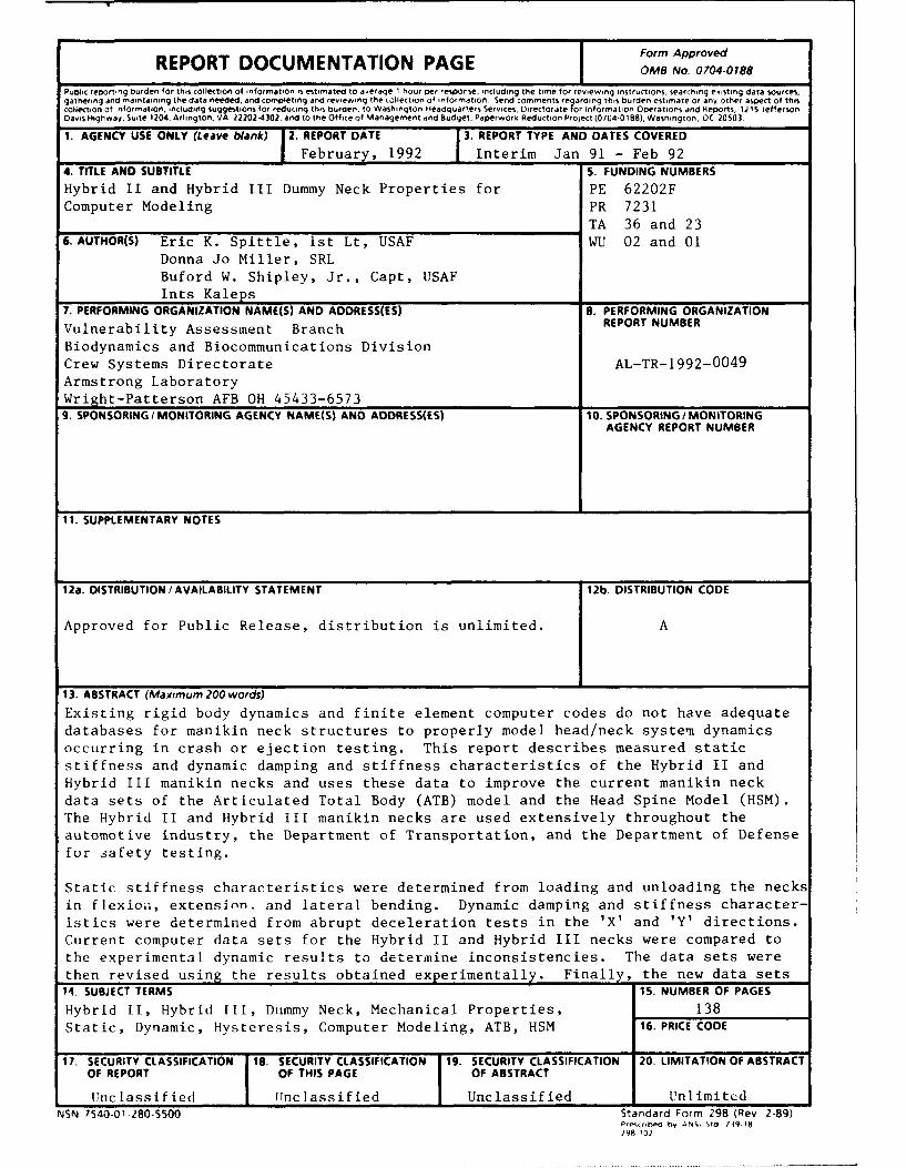
1 Form ApprovedREPORT DOCUMENTATION PAGE orm Ap 00-0ov
Public reporting burden for this collection of information is estimated to average I hour per response, including the time for reviewing instructions. searching exsting data sources.gathering and maintaining the data needed, and completing and reviewing the collection of information Send comments regarding this burden estimate or any other aspect of thiscollection of information. including suggestions for reducing this burden. to Washington HeadQuarters Services. Directorate for information Operations and Reports, 1215 JeffersonDavis Highway. Suite 1204. Arlington. VA 22202-4302, and to the Office of Management and Budget. Paperwork Reduction Project (0704-0188), Washington. DC 20503
1. AGENCY USE ONLY (Leave blank) 2. REPORT DATE 3. REPORT TYPE AND DATES COVERED
I February, 1992 Interim Jan 91 - Feb 924. TITLE AND SUBTITLE S. FUNDING NUMBERS
Hybrid II and Hybrid III Dummy Neck Properties for PE 62202FComputer Modeling PR 7231
TA 36 and 236. AUTHOR(S) Eric K. Spittle, Ist Lt, USAF WU 02 and 01
Donna Jo Miller, SRLBuford W. Shipley, Jr., Capt, USAFInts Kaleps
7. PERFORMING ORGANIZATION NAME(S) AND ADORESS(ES) 8. PERFORMING ORGANIZATION
Vulnerability Assessment Branch REPORT NUMBER
Biodynamics and Biocommunications DivisionCrew Systems Directorate AL-TR-1992-0049Armstrong LaboratoryWright-Patterson AFB OH 45433-65739. SPONSORING / MONITORING AGENCY NAME(S) AND ADORESS(ES) 10. SPONSORING / MONITORING
AGENCY REPORT NUMBER
11. SUPPLEMENTARY NOTES
12a. DISTRIBUTION/ AVAILABILITY STATEMENT 12b. DISTRIBUTION CODE
Approved for Public Release, distribution is unlimited. A
13. ABSTRACT (Maximum 200 words)
Existing rigid body dynamics and finite element computer codes do not have adequatedatabases for manikin neck structures to properly model head/neck system dynamicsoccurring in crash or ejection testing. This report describes measured staticstiffness and dynamic damping and stiffness characteristics of the Hybrid II andHybrid III manikin necks and uses these data to improve the current manikin neckdata sets of the Articulated Total Body (ATB) model and the Head Spine Model (HSM).The Hybrid II and Hybrid III manikin necks are used extensively throughout theautomotive industry, the Department of Transportation, and the Department of Defensefor safety testing.
Static stiffness characteristics were determined from loading and unloading the necksin flexioa, extension, and lateral bending. Dynamic damping and stiffness character-istics were determined from abrupt deceleration tests in the 'X' and 'Y' directions.Current computer data sets for the Hybrid II and Hybrid III necks were compared tothe experimental dynamic results to determine inconsistencies. The data sets werethen revised using the results obtained experimentally. Finally, the new data sets14. SUBJECT TERMS 15. NUMBER OF PAGES
Hybrid II, Hybrid 111, Dummy Neck, Mechanical Properties, 138Static, Dynamic, Hysteresis, Computer Modeling, ATB, HSM 16. PRICECODE
17. SECURITY CLASSIFICATION 18. SECURITY CLASSIFICATION 19. SECURITY CLASSIFICATION 20. LIMITATqON OF ABSTRACTOF REPORT OF THIS PAGE OF ABSTRACT
Unclassified IUnclassified Unclassified UnlimitedNSN 7540-01-280-5500 Standard Form 298 (Rev 2-89)
erscribd by ANSi 02d 139-18298 102

ABSTRACT (Continued)
were compared to the experimental dynamic results to show improvements.
Thie conclusion reached was that the dynamic response of the necks washighly complex. Simplifying assumptions and approximations were made toreduce th experimental data into acceptable form for the computer modeldata sets.
ii

PREFACE
The investigations described in this report were conducted bythe Vulnerability Assessment Branch, Biodynamics andBiocommunications Division, Crew Systems Directorate,Armstrong Laboratory (AL/CFBV) and supported by SystemsResearch Laboratories, Inc. (SRL), 2800 Indian Ripple Road,Dayton, Ohio. The tests were conducted in the Manikin TestingLaboratory (MTL), Building 824, Area B, WPAFB, OH. Thecomputer modeling analysis was performed in Building 441, AreaB, WPAFB, OH.
Lt Eric K. Spittle served as the principal investigator. CaptBuford Shipley performed the Head Spine Model (HSM) analysisand Donna Jo Miller (SRL) performed the Articulated Total Body(ATB) analysis. Greg Thompson (SRL) provided test supportthroughout the test program.
Special thanks are given to Buford, Donna, and Greg for theiroutstanding efforts throughout this project. Special thanksare also given to Dr Ints Kaleps for his help in this work.
. . . . . . . ... . . . . . . ...
At

iv

TABLE OF CONTENTS
BACKGROUND 1
INTRODUCTION 3
HYBRID II AND HYBRID III HEAD/NECK STRUCTURES 6
STATIC TESTS 14
Static Neck Tester 14Description of Static Tests 15Test Data 16Stiffness Characteristics 26
Hybrid II Necks 26Hybrid III Necks 33
DYNAMIC TESTS 50
Head/Neck Pendulum 50Description of Dynamic Tests 53Test Data 58Stiffness and Damping Characteristics 62
Hybrid II Necks 62Hybrid III Necks 67
ATB MODEL 80
Model Description 80Current Data Set 81New Data Set 81Modeling Results 83
Hybrid II 83Hybrid III 86
HSM MODEL 102
Model Description 102Current Data Set 102New Data Set 103Modeling Results 103
Hybrid II 103Hybrid III 105
v

CONCLUSIONS 108
Static Tests 108Dynamic Tests 108ATB Model 109HSM Model 110
RECOMMENDATIONS ii1
BIBLIOGRAPHY 112
LIST OF SYMBOLS 116
APPENDICES 120
Appendix A: New ATB Model Input Deck 120
Appendix B: New HSM Model Input Deck 125
vi

LIST OF FIGURES
Figure page
1 Anatomical Coordinate System 7
2 Lateral View of Anatomical Axis System 7
3 Head Free Body Diagram 8
4 Neck Free Body Diagram 9
5 Hybrid II Head 9
6 Hybrid II Neck 10
7 Hybrid III Head 10
8 Hybrid III Neck 10
9 Hybrid II Head/Neck Interface 12
10 Hybrid III Neck with End Cap 12
11 Denton Inc. Head/Neck Load Cell 12
12 Hybrid III Head/Neck Interface 13
13 Side View of the SNT 14
14 End View of the SNT Under Load 15
15 First Order Regression Fit to Flexion Loading Data 18
16 Second Order Regression Fit to Flexion Loading Data 19
17 Third Order Regression Fit to Flexion Loading Data 20
18 Third Order Regression Fit to Flexion UnloadingData 22
19 First Order Regression Fit to Flexion UnloadingData 23
vii

20 Second Order Regression Fit to Flexion Unloading
Data 24
21 Neck Compression During Loading 27
22 Flexion Loading Hybrid II Neck 1 28
23 Flexion Loading Hybrid II Neck 2 29
24 Average Flexion Loading Hybrid II Necks 30
25 Extension Loading Hybrid II Neck 1 31
26 Flexion Unloading Hybrid II Neck 1 32
27 Loading and Unloading Curves Hybrid II 34
28 Flexion Loading Hybrid III Neck 2 35
29 Flexion Loading Hybrid III Both Necks 36
30 Flexion Loading to 40' Hybrid III Both Necks 37
31 Flexion Unloading Hybrid III Neck 2 38
32 Average Flexion Loading and Unloading Hybrid III 39
33 Extension Loading Hybrid III Neck 2 41
34 Extension Unloading Hybrid III Neck 2 42
35 Lateral Loading Hybrid III Neck 2 45
36 Lateral Unloading Hybrid III Neck 2 46
37 Side View of the HNP 50
38 End View of the HNP 51
39 Hybrid II Head and Neck on HNP 51
40 Hybrid III Head and Neck on HNP 52
41 Hybrid III Neck Flexion Certification Total Moment 54
42 Hybrid III Neck Flexion Certification TotalRotation 55
43 Hybrid II Neck Flexion Certification Total Rotation 56
viii

44 Hybrid II Neck Flexion Certification Chordal
Displacement 57
45 Hybrid III Rotational Damping All Angles 59
46 Hybrid III Total Moment Vs. Neck Rotation 60
47 Hybrid III Total Moment Vs. Neck Rotation AllAngles 61
48 Hybrid II Neck 1 Rotation 900 Flexion 63
49 Hybrid II Neck 1 Rotation 900 Extension 64
50 Hybrid II Neck 1 Chordal Displacement 90' Flexion 65
51 Hybrid II Neck 1 Chordal Displacement 90' Extension 66
52 Hybrid III Neck Rotation Comparison 1200 68
53 Hybrid III Neck Rotation Comparison 900 69
54 Hybrid III Neck Rotation Comparison 650 70
55 Hybrid III Neck Rotation Comparison 40' 71
56 Hybrid III Neck Rotation Comparison 200 72
57 Hybrid III Neck Moment Vs. Rotauion Comparison 1200 73
58 Hybrid III Neck Moment Vs. Rotation Comparison 900 74
59 Hybrid III Neck Moment Vs. Rotation Comparison 650 75
60 Hybrid III Neck Moment Vs. Rotation Comparison 400 76
61 Hybrid III Neck Moment Vs. Rotation Comparison 200 77
62 Hybrid III Neck Mcment Vs. Rotation Static Overlay 78
63 ATB Model Representation of a Human Body 80
64 Hybrid II Flexion Neck Rotation ATB Simulation 84
65 Hybrid II Flexion Head Rotation ATh Simulation 85
66 Hybrid III Flexion Neck Rotation ATB Simulation 87
67 Hybrid III Flexion O.C. Rotation ATB Simulation 88
68 Hybrid III Extension Neck Rotation ATB Simulation 89
ix

69 Hybrid III Extension O.C. Rotation ATB Simulation 90
70 Hybrid III Lateral Neck Rotation ATB Simulation 91
71 Hybrid III Lateral O.C. Rotation ATB Simulation 92
72 Hybrid III Neck Stiffness Coefficient Simulation 93
73 Hybrid III O.C. Stiffness Coefficient Simulation 94
74 Graphical Comparison for Flexion Test 96-97
75 Graphical Comparison for Extension Test 98-99
"76 Graphical Comparison for Lateral Test 100-101
77 HSM Hybrid II Flexion Simulation 104
78 HSM Hybrid III Flexion Simulation 106
79 HSM Hybrid III Extension Simulation 107
x

LIST OF TABLES
Table page
1 Static Neck Tester Test Matrix For Hybrid II andHybrid III Necks 17
2 Static Flexion Tests Hybrid III S/N 569 ResistiveTorque During Loading 21
3 Static Flexion Tests Hybrid III S/N 569 ResistiveTorque During Unloading 25
4 Static Hysteresis Data Hybrid II 33
5 Static Hysteresis Data Hybrid III 40
6 Static Extension Tests Hybrid III S/N 569 ResistiveTorque During Loading 43
7 Static Extension Tests Hybrid III S/N 569 ResistiveTorque During Unloading 44
8 Static Lateral Tests Hybrid III S/N 569 ResistiveTorque During Loading 47
9 Static Lateral Tests Hybrid III S/N 569 ResistiveTorque During Unloading 48
10 Head/Neck Pendulum Test Matrix For Hybrid II andHybrid III Necks 53
11 Damping Ratios For Hybrid II Necks 62
12 Damping Ratios For Hybrid III Necks 67
xi

xii

BACKGROUND
The Department of Defense (DOD) has long been interested inthe development and use of crash dummies to improve safety forair crew members. The Navy began their development of a crashdummy, or manikin, in the early 1960's with the GrummanAlderson Research Dummy (GARD). The Air Force became involvedin manikin development with the advent of the "Golden Shells"program. Golden Shells developed a set of exterior fleshmolds for several anthropometric sized manikins. The largestof these molds was used by the Air Force in the development ofthe Dynamic Analog Anthropomorphic Dummy', often referred toby its nickname "Dynamic Dan". Dynamic Dan was designed withan emphasis on vertical impacts and to replicate human rangesof motion.
In the 1980's the Air Force developed the Advanced DynamicAnthropomorphic Manikin (ADAM) 2 3. ADAM, which was alsodesigned with an emphasis on vertical impact response, is ahighly instrumented manikin that is being used in the designand evaluation of present and future ejection seats.
The Department of Transportation (DOT) and the automotiveindustry have developed crash dummies to improve automobilesafety. The Department of Transportation sponsored thedevelopment of the Vehicle Impact Protection (VIP) manikin inthe early 1970's. Following the VIP manikin, General Motors(GM) developed several automotive safety dummies, the first ofwhich was called the Hybrid II4',. GM also developed theAnthropomorphic Test Dummy (ATD) 6, 7 and its final version theHybrid III' in the mid seventies. The Hybrid II and HybridIII dummies are widely used by the automotive industry, theDepartment of Transportation, and the Department of Defensefor use in crash tests to determine occupant safety.
Until the completion of ADAM, Hybrid II and Hybrid IIlmanikins had replaced most of the DOD developed manikins. Nowa transition from the Hybrid II and Hybrid III dummies toADAM, as the Air Force test manikin, is taking place.
Although ADAM is designed differently from the Hybrid II andHybrid III dummies, it still retains several of theirfeatures, namely ADAM's head and neck. ADAM has a Hybrid II

head, which has been modified to accept a Denton Inc.head/neck six axis load cell, and a Hybrid III neck.Instrumentation is required to quantify the loads experiencedby the manikin during a test. Acceierometers in the manikin'shead and chest, as well as force and moment instrumentation atthe top of the neck and bottom of the spine, provide some ofthe most critical data concerning injury potential. Lowimpact manikin test data are compared to equivalent human testdata. Manikins are then tested at higher levels, which couldbe injurious to humans. The manikin data then provide a basisfrom which to extrapolate equivalent human load data.Instrumented manikin testing is a proven and valuable methodof collecting high level impact load data.
2

INTRODUCTION
The head and neck are the most vulnerable parts of the humanbody during impact exposures. Because of this, numerouspapers and models have been developed to predict the motionand injury of the head/neck system for various impacts.Several of the leading authors on this subject includeMertz9' 1 Wismans1 1 ,12 Phillips 13" 14 Ewing"5 ,16 Huston"',1%Spenny"' , and Melvin2 '2 2 .
Another approach to predicting occupant motion duringsimulated crashes is the use of computer models. Some ofthese models include the Mathematical Dynamic Model (MADYMO) 23 ,Crash Victim Simulator (CVS) 24 , the Air Force derivative of theCVS - the Articulated Total Body (ATB) model 25' 26' 27 , IsohumanSimulation Model (ISM) 28 , and the Head Spine Model (HSM) 29 , 30 .One of the more recent areas of computer modeling deals withmodeling manikins to validate already conducted crash testsand to predict responses for other crash situations.
The mechanical properties of the Hybrid II and Hybrid IIInecks have been measured previously and simulation data basesprepared3 '3 2 ', 3 . These neck properties, however, have not beenmeasured over the full range of static and dynamic loads thatthe necks experience in impact tests. Therefore, the existingdatabases are not adequate for modeling neck responses overthe full range of anticipated use. Correct neck propertiesare critical, because of the subtle differences in neckresponse that must be resolved to determine whether a certainsituation is hazardous or not.
This report describes the steps taken to measure the staticstiffness and dynamic damping and stiffness characteristics ofthe Hybrid II and Hybrid III necks in flexion, extension, andlateral bending. Two Hybrid II and two Hybrid III necks weretested. The mechanical properties of the necks were thenincorporated into already established computer data sets forthe ATB model and HSM model to illustrate improvements in thedynamic response of these necks at various impact levels.
Static neck tests were performed on the Static Neck Tester(SNT)" 4 . The SNT is a device that applies a pure bendingmoment to the top of the neck, while the base of the neck is
3

held rigidly. Potentiometers measure the angle of rotationand a torque sensor measures the resistive torque of the neck,while a linear variable differential transformer (LVDT)measures the linear distance between the base and the top ofthe neck during rotation. Loading and unloading tests wereconducted up to 800 rotation, and data weze collectedapproximately every 5'.
Dynamic tests were performed on the Head/Neck Pendulum (HNP) 3 .The HNP is a dynamic neck tester built to SAE J211 Part 572Specifications"6 . A head and neck are securely mounted to theend of a rigid pendulum arm. The arm is raised to a range ofpre-determined heights that result in impact speeds between5ft/sec and 23ft/sec. The arm is then released and free fallsuntil it strikes a block of aluminum honeycomb. The honeycombmaterial provides a near square wave deceleration pulse forthe pendulum arm. This rapid deceleration of the pendulum armcauses the head and neck to flex about the end of the pendulumarm. Accelerometers on the pendulum arm and in the headmeasure the deceleration of the system. A potentiometerdevice mounted between the base of the neck and the headmeasures the rotation of the head and neck. Finally, a Dentonsix axis load cell measures the forces and moments at thehead/neck interface. Flexion (forward), extension (backward),and lateral (sideways) tests were performed at impact speedsbetween 5ft/sec and 23ft/sec.
Data collected from the SNT were reduced using regressiontechniques to determine the torque versus rotation slopes andhysteresis effects of both necks in flexion, extension, andlateral static tests. Dynamic data collected from the HNPwere reduced to torque versus rotation curves and overlaidwith the static data and the computer model data for analysis.Neck rotation versus time curves provided data to calculatethe damping characteristics of the neck. Several tests werealso photographed by high speed cameras to provide positiondata to correlate to computer model graphical output.
The ATB rigid body dynamics model was one of two computercodes used to model the head and neck responses of HNP tests.Pendulum arm deceleration data were used with existing datasets for the Hybrid III neck. No current data set existed forthe Hybrid II neck. ATB tabular and graphical output werecompared to actual test data for accuracy. The data sets werethen revised using the new stiffness, damping, and energy lossproperties measured in this study. The models were rerun andthe output compared to the actual test data. Improvements inresponse with the new data were observed.
The HSM finite element code was the second computer model usedin these tests. Similar runs, comparisons, and changes were
4

made to this model. Again, the new data compared better tothe actual test data than the previous data sets.
This study has shown that the data measured on the SNT and HNPhave resulted in improved neck property data than thatmeasured from previous test fixtures3 1 . These neck data oncereduced can be easily incorporated into existing computermodel data sets such as the ATB and HSM. Improvements to suchcomputer model data sets considerably enhance the utility ofthese models for predictive simulation of manikin head/neckstructure dynamics. Such improvements allow effectivemodeling of the head and neck with encumbering equipment suchas helmets, night vision goggles, and helmet mounted displaysystems for likelihood of injury potential and safety offlight certification.
5

HYBRID II AND HYBRID III HEAD/NECK STRUCTURES
In order to understand the approach and tests described inthis report, a discussion defining the generic concepts andtheory motivating this subject must first be addressed. Thescope of this report will be limited to the head and neckstructures. The design of most manikin head and neckstructures are based on human impact response data describedby Mertz (et al)q. These data were derived from humanexperiments to determine the mechanical properties of humanhead and necks during various impacts. The Hybrid II head andneck were designed before these specifications were writtenand therefore do not exhibit the same biofidelity (humanlikeresponse) as the Hybrid III head and neck, which were based onthe Mertz data.
Manikin head structures are rigid to idealize the structuralintegrity of the skull. The weight and center of masscorrespond to a human head of the same anthropometric size.An anatomical coordinate system defines a reference to thehuman head center of mass. Figure 1 illustrates a genericmanikin head structure with an anatomical coordinate system.
The anatomical coordinate system follows the right hand rule.The 'Y' axis is defined as the line passing through the leftand right tragions, positive to the left. The 'X' axisintersects and is perpendicular to the 'Y' axis passingthrough the right infraorbital, positive out of the face. The'Z' axis is the cross-product of the 'X' and 'Y' axes as shownin equation (1). Z = X X 7 i
The origin of the anatomical axis system is the intersectionof the 'Y' axis and a line drawn perpendicular to the 'Y' axispassing through the sellion.
Figure 2 shows a lateral view of a generic head with theanatomical coordinate system. In the X-Z plane, the headcenter of gravity (c.g.) is above and forward of the axissystem origin and the occipital condyle (o.c.), which is theJ ... bctwcr.n the head and neck. Figure 3 illustrates anisometric view of the head free body diagram.
6

ZN
.l SELLION
- 4 LT TnAGION
~ XA
/ 2 RIGHT INFRAOR1IITALE
Tn
Figure 1. Anatomical Coordinate System
FF.A D C V.
x
Figure 2. Lateral View of Anatomical Axis System
7

Figure 3. Head Free Body Diagram
The free body diagram allows large deflections in anydirection and large roll, pitch, and yaw angles. The headrotates about the o.c. Head translation occurs due to bendingof the neck.
A neck structure's design requirements are slightly more
complicated. Unlike the head, the neck is not a rigid body.The neck is a deformable body that exhibits axial androtational stiffness and damping properties during variousimpacts. The neck also does not exhibit the same response in
each direction. For example, the neck when rotated intoextension (backward) has a lower stiffness than when rotatedinto flexion (forward). The length and the location of thejoints must match those of an equivalent human neck forobtaining the correct head and neck rotation angles. The endjoints of the neck are taken to be the occipital condyle atthe top of the neck and T1 at the base of the neck (refer tofigure 2). Figure 4 illustrates the free body diagram of theneck.
The free body diagram allows large deflections in anydirection and large roll, pitch, and yaw rotations.Additionally, the neck can experience large deformations inany direction. The neck structures are usually made ofviscoelastic materials, which closely match the observednonlinear characteristics of the human neck.
8

F.
Figure 4. Neck Free Body Diagram
The test articles used for this study include a Hybrid IIhead, two Hybrid II necks, a Hybrid III head, and two HybridIII necks. Figure 5 illustrates a Hybrid II head and figure6 shows a Hybrid II neck.
Figure 5. Hybrid II Head
Figure 7 illustrates a Hybrid III head and figure 8 shows aHybrid III neck.
9

Figure 6. Hybrid II Neck
Figure 7. Hybrid III Head
AF
Figure 8. Hybrid III Neck
t0

The Hybrid II and Hybrid III are very 1ifferent lookinghead/neck structures. The Hybrid II head looks more like ahuman head than the Hybrid III head, where the chin area ofthe Hybrid IIl was removed to allow the head to rotate fartherin flexion similar to a human head. Both heads are aluminumcast shells with a viayl covering4".
The Hybrid II neck is a symmetric cylindrical butyl rubbermold with steel end plates. A 0.5in hole runs the length oi.this otherwise solid rubber cylinder. Except for theasymmetric inertial properties of the Hybrid II head, thesymmetric Hybrid II neck would be expected to give the samedynamic response for any impact angle4 .
The Hybrid III neck was designed with an emphasis on frontalimpacts, which results only in flexion and extensionrotations. The Hybrid III neck, like the Hybrid II, is madeof butyl rubber with steel end plates, but the s.hmilaritiesend here. There is less butyl rubber in the Hybrid III neckthan the Hybrid II neck, because the Hybrid II neck is toostiff, so the Hybrid III neck has three interior steel platesto provide the correct mass. These plates also contributeinertial effects during impacts, which tend to cause the neckto translate as it rotates, similar to a human neck. TheHybrid III neck also has a steel cable that run-- through itscenter. Torqued to the specified 12in-lb, it only acts tolimit the rotation of the neck at large angles and does notcontribute significantly to the stiffness characteristics ofthe neck. The Hybrid III neck also incorporates asymmetricflexion/extension stiffness corresponding to that observed inthe human, by distributing the cubber material asymmetrically,and by making a horizontal cut through the rubber along thefront of the neck between each of the steel disks' (refer tofigure 8).
Both the Hybrid II and Hybrid III necks are bolted to theHybrid II and Hybrid III upper torso respectively, so theinterface acts as a fixed joint. The Hybrid II neck is alsobolted to the Hybrid II head, as shown in figure 9. Thisinterface also acts as a fixed joint.
A steel end cap is mounted to the top of a Hybrid III neckbefore it can be mounted to the Hybrid III head, as shown infigure 10. This end cap allows the use of the Denton Inc.Head/Neck load cell, as shown in figure 11.
The Denton load cell is a six axis balance that measures threeorthogonal forces and their corresponding moments about thetop of the neck. The neck cap and load cell are connected by3 condyle pin, which runs parallel to the 1Y' axis at the o.c.as shown in figure 12. This interface acts as a pin joint.
11

Figure 9. Hybrid II Head/Neck Interface
Figure 10. Hybrid III Neck with End Cap
Figure 11. Denton Inc. Head/Neck Load Cell
12

Figure 12. Hybrid III Head/Neck Interface
Since the head is now free to pivot about the condyle pin, twobutyl rubber blocks called nodding blocks are mounted into theend cap of the neck to provide the appropriate stiffness forhead rotation alone (refer to figure 12).
For static -:nd dynamic tests, two Hybrid II and two Hybrid IIInecks were tested to provide two data sets for each test. TheHybrid II and Hybrid III heads were only used for the dynamictests.
13

STATIC TESTS
Static Neck Tester
Static tests of the Hybrid II and Hybrid III necks wereconducted using a Static Neck Tester (SNT) 34 The SNT is atest fixture that quasi-statically loads and unloads a neck inflexion, extension, or lateral bending. Figure 13 shows aside view of the SNT. When pressurized, the cylinder pullsthe cable which is connected to the large aluminum disks,causing them to rotate.
Figure 13. Side View of the SNT
Figure 14 shows an end view of the fixture with a Hybrid IIIneck under load. The neck is mounted upright in the fixturewith the base of the neck rigidly secured to the frame. Amounting plate is attached to the top of the neck and a steelbar passes through it and slots in the large disks. Bearingsare secured to the end of the bar, and the two tracks on bothdisks allow the bar to freely slide along the track as thedisks rotate (refer to figures 13 and 14). With this design,
14

Figure 14. End View of the SNT Under Load
the fixture is able to apply a pure bending moment to the topof the neck throughout the rotation of the disks. Orientingthe neck at 0', 90', or 180' allows flexion, lateral bending,and extension testing of the necks.
Instrument•i ion on the SNT includes a torque sensor mounted atthe base ot the neck to measure the resistive torque of theneck to the applied bending moment, two rotationalpotentiometers to measure the angular displacement of the neckduring rotation, and a linear variable differentialtransformer (LVDT) to measure the linear compression of theneck between the end plates during rotation. Data werecollected on all of these sensors at 50 rotation intervals.
Description of Static Tests
A loading test was performed as a sequence of incremental loadapplications over a specified range of motion. Loading testsbegan with the neck at 0° rotation and baseline data werecollected. The disks were rotated 50 and data were collected.The disks were rotated another 50 and data were againcollected. This procedure was repeated until the final diskrotation angle was reached. After all test data had beencollected, the accumulators were depressurized and the neckwas returned back to its original position. There was a 60minute recovery period between tests.
15

An unloading test was performed as an incremental release ofa full-scale load. Unloading tests began with the neck at 0'rotation. The disks were then rotated to the maximum rotationangle for the tests. Data were collected and the pressurereduced until the neck rotated back 50, where data were againcollected. This procedure was repeated until the neck hadreturned to 00. Again, there was a 60 minute recovery periodbetween tests. Table 1 lists the loading and unloading testsperformed on each of the four necks.
Test Data
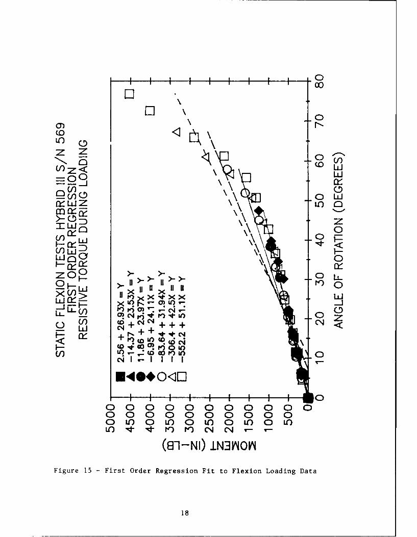
Static stiffness was determined by plotting resistive torqueversus rotation angle and using regression techniques todetermine the loading and unloading slopes. A plot of all ofthe flexion loading tests, listed in table 1, performed on aHybrid III neck, is shown in figure 15. This plot is a firstorder least squares fit of each test's data. The plot showshow repeatable the stiffnesses were as each test's dataoverlays the previous test's results. The data were verylinear through the first 40' but a stiffening of the neck wasevident beyond 400. A first order regression did not fit thedata well over the full rotation. Figure 16 illustrates asecond order fit of the same data. The results were better,but still did not match the large rotation angle test datawell. Figure 17 illustrates a third order fit of all of thedata points. The third order regression did match the datawell over the full range, but was not as linear over the first400. Table 2 lists the regression coefficients and theaccuracy of fit to the flexion loading data for first, second,and third order regressions for this neck.
Unloading test data resulted in different looking plots, asfigure 18 illustrates. The large drop in resistive torquebetween the first two data points collected for each test wasthe hysteresis, or the energy lost before the neck began torotate back to its original position. Figure 18 illustratedthe third order regression fit to the data, because as figures19 and 20 illustrate, first and second order regression fitswere poor. Each unloading test exhibited this characteristic.Table 3 lists the regression coefficients and their accuracyof fit to the flexion unloading data for first, second, andthird order regressions for this neck.
Rotational neck compression was measured to determine therepeatability of the neck rotation curve throughout thetesting. Rotational neck compression was measured by an LVDT.One end of the LVDT was fixed to the frame, and the other endwas fixed to the bar that attached to the top of the neck. As
16

TABLE 1. STATIC NECK TESTER TEST MATRIXFOR HYBRID II AND HYBRID III NICKS
Loading Flexion Extension LateralCharacteristic Angle of Angle of Angle of
Rotation Rotation Rotation
Load 0-10 0-10 0-10
Load 0-20 0-20 0-20
Load 0-30 0-30 0-30
Load 0-40 0-40 0-40
Load 0-50 0-50 0-50
Load 0-60 0-60 0-60
Load 0-70 0-70 0-70
Load 0-80 - -
Unload 80-0 - -
Unload 70-0 70-0 70-0
Unload 60-0 60-0 60-0
Unio d 50-0 50-0 50-0
Unload 40-0 40-0 40-0
Unload 30-0 30-0 30-0
Unload 20-0 20-0 20-0
Unload 10-0 10-0 10-0
17
03
0~00
(C)z Z0
(I)0
XLUJ U' 0
LLLUr-Y 0
005-< Cr% IL-IX IILLJ40 Of> ?g < 7
LL-(81-NI* ) INzNkFigure 15 - Firs Ore Rersso Fi toFe<nLaigDt
LIJ C18

, 00,0
ciC)
UL)Z Z o)
w.
-0
V)r- 0cLJ~ LOQ
.ff X 0IZ "--- m---- pI + x-+ + .0
>- LLIz",o0
0 0 04 0
(N XL
0 0 0 X X 0z C! 10 -LL-
0 u") 0 0 0. . .
xo> N+XX++ Ld
LLEDtP '0~)~O (D-Ni CA04 0
<I CA o~ 0)t 00F- C .J r- r-) Lq c6 --V
*4*0* O<1LD
(81-NI) 1N3~NOV
Figure 16 - Second Order Regression Fit to Flexion Loading Data
19

11E00V
1000
IIf (OIZ U)
0nk +I C'*J z
000
LLJQ V)
V) LLJ 1
z -JLL
F- cX 0
(f) 0
LLLi+0
10
(81NI NN~N
Fiur 7 hid rerRgrsio FttoFexonLadn Dt
0 0 0 ~~~00a0 000

TABLE 2. STATIC FLEXION TESTS HYBRID III SIN 569
RESISTIVE TORQUE DURING LOADING
FIRST ORDER REGRESSION ANALYSIS
Test Rotation Angle X0 X1 RVAL
0-11.7 2.56 26.93 .99955
0-21.2 -14.37 23.53 .99789
0-38.4 11.86 23.97 .99910
0-47.6 -6.95 24.11 .98729
0-58.0 -83.64 31.94 .97743
0-67.3 -306.4 42.50 .93272
0-76.9 -552.2 51.10 .91179
All Test Data -270.4 41.38 .91514
SECOND ORDER REGRESSION ANALYSIS
Test Rotation Angle X0 X_ _ x2 RVAL
0-11.7 0.00 29.72 -. 241 1.00000
0-21.2 -5.70 20.33 .152 .99880
0-38.4 11.73 23.99 -. 001 .99910
0-47.6 57.36 14.65 .202 .99344
0-58.0 99.49 10.27 .376 .99455
0-67.3 248.8 -12.20 .811 .98540
0-76.9 351.8 -26.26 1.001 .98283
All test data 205.3 -9.73 .774 .98079
THIRD ORDER REGRESSION ANALYSIS
ETest A~ngle X° X1 X2 X3 RVAL
All test data -21.06 40.53 -1.138 .018 .99638
21

00
(0o
LO iiz 0
V) O LdJQ-0 >>i ULOQ
V)~V
Uo Q
ED)LLJW Hf C4C4XXF-LLJQ 1' :: 5 N X X Q0V
Z0W U!C4)O 40LL.
X >JC4XXX 10 4 I)XX w
HL 0 in -0
Fý- * q@0 OR (10C4 1i C'4i U) 0
(81NI ,NI IOTN
Figure* 18 -hr re ersinFt oFeinUlaigDt
220

00
Z) 0(DZO
X LLICDO ~ 0L
zI 0
C/) CLJLL
LLJ 0 Z 0>- >>> Or w
0O U
1-- L-
5-< ~d~i V)UX 1X
(C)NI (0+0+ +O++Fgr 19-Fi5 s Orde V ersinFtt-leinUlaigDt
F-- Lj to+ e) L 23

00
CO~ z
-U)Z Liiw 0 0
X wo0
Vw0: 0
UJX D 111F- 0>C 1 C4NNC
0K -CU3 X0ULU > -4 p++o te
(-) '00 +0X X
V) (rn-NI)':N3iO<
Figr 20-ScndOdrRersinFi oFexo noaigDt
- LLJ * + wU-)24

TABLE 3. STATIC FLEXION TESTS HYBRID III S/N 569
RESISTIVE TORQUE DURING UNLOADING
FIRST ORDER REGRESSION ANALYSIS
Test Rotation Anle ___X0 X1 RVAL
0-8.9 8-52 2r. AA -99770-21-7 -38-46 22-A6 -98299
0-30.0 8.16 19-77 90-41-3 -51.93 21.46 .95220
0-55-3 -97-84 21 -5 c 9i] i
0-66.4 -193.5 2.4A2 .861581
0-75.4 -355.5 31.6 .81617
SECOND ORDER REGRESSION ANALYSIS
Test Rotation AnX0e X1 X• X2 RVAL
0-8.9 0.00 55.74 -3.18 1,000c0-21.7 .97 8-59 .64 .99985
0-30.0 37.66 8.90 .38 .99092
0-41.3 3885 1.04
0-55. 3 71.69 -5.06 .53 ,97671l
0-66.4 146.1 -17. 1 .67 .95634
0-75.4 262.3 -35.6 .93 .94196
THIRD ORDER REGRESSION ANALYSIS
0-8-9 0.0 52.47 2-23 -. 56 1-000000-21-7 -. 0 1.0 .29 .0 .99992
0-30-0 13.98 29.3 -. 5 0j.97
0-41-3 -2-87 _24-71 -1-00 -02 -99906
0-55. 3 -16.1 -325 -13 2.c-02 -99663
0-66.4 -58.02 42.12 -1.71 -02 .99093
0-75.4 -119.1 58.73 -2.34 .03
25

the neck was rotated, the LVDT measured the linear distancebetween the top and bottom of the neck. Figure 21 illustratesthe repeatability of the rotational neck compression betweentests. It can be concluded from this plot that the neck wasrotated through the same arc for each test. Similar r, fitswere found for every neck in flexion, extension, and lateraltesting.
Stiffness Characteristics
Two Hybrid II and two Hybrid III necks were tested with theSNT. Loading and unloading flexion, extension, aqd lateralbending tests were conducted on each of the necks -i listed intable 1.
Hyl< id II Necks
Figure 22 illustrates the linear stiffness of ýhe first HybridII neck during flexion loading. The seccnd Hybrid II neckalso exhibited linear stiffness throughout the testing range,but the slopes were slightly less as the fit equations infigure 23 illustrate. FiguLe 24 illustrates a comparisonnetween slopes of all of the data for both necks.
Since the Hybrid iI neck is symmetr c in geometry andmaterial, identical stiffness results would be expected forflexion, extension, and lateral bendinq tests. Figure 25illustrates the almost identical loading stiffness for anextension test. Similar loading results were found with bothHybrid II necks in flexion, extension, and lateral bending.Therefore, a single bending stiffness can define the loadingstiffness of the neck at any orientation. This bendingstiffness was taken as the average of the two Hybrid II necks,as shown in figure 24.
The Hybrid II necks did not show the same degree of hysteresisas shown in the previous section for a Hybrid III neck.Figure 26 illustrates an unlcding test of a Hybrid II neck.Similar results were found with both Hybrid II necks.
Internal hysteresis was defined as the energy lost betweenloading and unloading a specimen. Equation (2) illustratesthe method used in the SAE Part 572 Specifications forcalculating internal hysteresis36 .
area between curvesX 100% = Hysteresis (2)
area under loading -rve
26

, 00
(0
(JJ00cuz x;&
COO 0Ld i
cy- cy- -L ii C
U1) 0_ /
o 0L wo oa 0
0L C) 0
Figur 2n y Neck Copeso urnodn
0 0 C27

0)
00
zz
-0 0 LUI=000
[0 LUCOlLJ 0 aD
IOD 0z(nUw) 0
F-- LUJ
F- C) Ct 0
U ~LL-5;ZF- LU X U
C,4 4 00 0C~) V) +4+ C4-4+ + 4z
F- LUCF- 0; U
0*00
o o 0 0 00 00 00 4t 0 U) 0 LC 0 0l0 Ný 0t N 0 N it)0 N
(91-NI) N3~NO~N
Figure 22 -Flexion Loading Hybrid II Neck 1
28

*0
0~0C'P.,
o C)
C.,
XWO 0V) C dFH-L
0 LbJ lili ii
0 ofU)Doa0t
000to0 0000 .
010 010 0100 0 0o 0 10 0~ 0 0- 0t 0~C'q T- T- T-'
(81-NI) 1N3rdOM
Figure 23 - Flexion Loading Hybrid II Neck 2
29

00
-z
-01(/) OW
wZc LOQ
M-o
F- 0L.L HLJ N')
w 0 0H OP
CO 00) L( ) 0 ( '
O N a. ) O N U'N C4 z-~
300

C*Co
00
zz -
0C) 0V)W
(f (D Z L
M 0
F- w~
F- 0zXkLX U 111U
F5 F- ~j 0C-4 c.OICJ CO N C)
- C%4
0d -a4-0LL )CO 1 '4r)U a
0 i0) 0ý -* (7) C0 toC0 X K t) 00 ON r- No
\O r%- '-z C;C4a
(r-I(63Q~
381- I N 1 N

CNI C>- >t') Z
z0 -j V) 0a))=05 C4CO* r)Q(I 1 00-41 0 0
CD P. qor zC1V) inW 0 0 --mJ CDD+ Ico+ +
W>- C,4+
(i*4 CO9 9<0- -0F
<L Cio OO OvC40
C31 + II
o<Q-t It) 0)I) 0 U W
LL-N + ++- C-4 -0
+ (81-NI) CN3 + <
Figure 26 - lexo nodn Hbi INc
Ul32

Figure 27 illustrates loading and unloading curves for aHybrid II neck. To calculate the percent of hysteresis, thecoefficients of the regression fit were used to form twopolynomials: one loading curve polynomial, and one unloadingcurve polynomial. The two equations were integrated from zeroto their intersection point. Then equation (2) was used tocalculate the percent of internal hysteresis. Thiscalculation was performed using the loading curve and each ofthe unloading curves. Since the percent of hysteresis wasrelatively low for the Hybrid II necks, an average hysteresiswas calculated for each Hybrid II neck and for both necks, asshown in table 4. Note that the first average unloading curvewas not used because its average was higher than the averageloading curve. This occurred because the neck data wasaveraged and the small rotation angle of the neck.
TABLE 4. STATIC HYSTERESIS DATA HYBRID II
S/N 3232 SIN 0262P 1:AverageBending 9.5 8.7 9.1
Hybrid III Necks
As would be expected from its asymmetric geometry, HybridIII neck stiffness is sensitive to orientation. Figures 15-22 illustrated the stiffness characteristics of one of thetwo Hybrid III necks in flexion. Figure 28 illustrates theflexion loading curves for the second Hybrid III neck.Although similar in shape, the exact curve was notreplicated. Figure 29 illustrates the flexion loadingcurves of both Hybrid III necks overlaid. The data for thefirst 400 appears very similar. Figure 30 illustrates afirst order fit to both plots for the first 400 rotation.The slopes differ by 2.89in-lb/deg. The average stiffnessis a fair representation of both data sets.
Unloading data for the second Hybrid III neck was alsosimilar, but not an exact match. Figure 31 illustrates theflexion unloading data for the second Hybrid III neck. Whenthe flexion unloading curves were averaged, just as theflexion loading curves were, both were plotted to determineinternal hysteresis. Figure 32 illustrates the averageflexion loading and unloading curves for the Hybrid IIInecks. Internal hysteresis was calculated similarly to thatfor the Hybrid II necks, by using the coefficients of theregression fits. Table 5 lists the internal hysteresis
33

I(00
-z 0CD~.
< ~LU
00 LU
U) -
U)D 0
LC) 0
uLw 0
0 -j
Q00
LLII
000 0 0 0 0 0 0 00D LC) 0 IC) 0 IC) 0 iCO0 rl- CO 04 0 -- IC) NN~ T- V- T- V
(rn-NI) iN1NM~~N
Figure 27 -Loading and Unloading Curves Hybrid II
34

; i 0
00
0CN'T- 0
z Z -"'o<1 (D w
(/,)0< 0
-0
~Ld
0 ZLLJ 11 ,+ U<
LLJO U)' I-
*4iO1 I
04"0<
(rn-NI) IN3~NO~N
Figure 28 - Flexion Loading Hybrid III Neck 2
35

00
00
Iz
-0
woo -
>-J<HL) CK%-.
zz
0 Or 0
I F- 0
(61NI 0N3NOFiur 2 -Flxin oaig ybidII BthNek
0) 0 036

I) I L )
0
LiZO
d L0C 0
1LJ LL
H L.L ZZ<0 C) LU 0<
0 0 0 0 0oL I- 0j 0 0
0 LXJ (0 i-
(81NI 1NJ OO
Fiur 0 0-FeinLaigt 0 yrdIIBt ek
370

I .0
00
0 NC%4 0T- Z
-Z 0
QU Iii LOQ
V):D 0
OOOIpe) n L
z 0
X- LLJ LL
LL) Xj ++ ++- Xz
0~ L± XXI
(1) (j) zC
(81NI IN3I4I
Figur 310Fei <Ulain yrdIINc
0 0 00 0 0 00 38

N 0
(-5LCK 0
COD_- Lid
V) D z
UJOZ 0 0 0iLLLJ F--
~LL- Lji.JnW
0/ -0 0<( ( )0 U
(81NI IN) VLJ OVFigure0 320AeaeFeinLaigadUlaigHbi I
ce-39

percentage for each of the Hybrid III necks and their
average.
TABLE 5. STATIC HYSTERESIS DATA HYBRID III
S/N 569 S/N 1201 Average_________(%) (%) I(%)
Flexion 32.9 21.8 27.4
Extension 31.2 33.3 32.2
Lateral 29.9 30.2 30.1
Just as the different columns in table 5 indicate, therewere different stiffness and hysteresis properties for theHybrid III necks in flexion, extension, and lateral bending.Figures 33-34 illustrate a Hybrid ±Ii neck in extensionloading and unloading respectively. Note the change inscale along the vertical axis. The Hybrid III neck issubstantially less stiff in extension thian flexion. Theslots cut into the front of the Hybrid III neck (refer tofigure 8) allow the material to separate along this cutduring extension, thereby significantly reducing the actualmaterial being elongated. Tables 6-7 list the coefficientsfor the curve fits for the extension tests for one of theHybrid III necks. The coefficients are significantly lessthan for those in tables 2-3.
Lateral testing provided a third bending stiffness Figure35 illustrates a Hybrid III neck during lateral loading.The stiffness in this orientation falls between that forflexion and extension. Figure 36 illustrates a Hybrid IIIneck during lateral unloading. Again tht stiffnesses arebetween that for flexion and extension, but the large dropbetween the first two points indicates significant internalhysteresis. Tables 8-9 list the coefficients for the 'lrvefits for the lateral tests for one of the Hybrid III n' ks.The coefficients for the lateral tests generally fallbetween those for flexion and extension.
It is significant to note that the SAF P, rt 572Specifications do not have a requirement for lateral impactresponse. The author is part of an SAE subcommittee that isdealing with this issue. The current objective is todetermine lateral impact calibration corridors for thecurrent Hybrid III neck. Future design changes may beforthcoming. The significance of lateidl tests is thincreasing emphasis being placed on side impact car crash
40

0)
0~00
0 CN
z 0 N=00 w
P 0
VV)O In 0oV)-1X >- F+
WO 1 00X
pf 0 4C4 C-4.,
I C! 0
0 0y 0 0) 0 0 0*0 Xt 0 if 0 if
Ld L I n N 0- V- W0 -.
(81NI 0 0)C4Fiur 33; - Exenio LodnyrdIINc
F-; I 1 ( 41

0)
-00 00
CD
V)i
-z ::) NLiLi
UJ 0 0XXX&f 0L.OOOO 0 04z
ML -000 00 LO) 0F- 1 I++++ F:-
a7O ++IIII 004
U)- )- XXX XX
HLqg! 6.c 6 0X U) C- OC4Z
Lu P_ 00C)~ NL )U)1 -r
V)_
00 0 0 0 0 0 00 LO) 0 ICO 0 ICOICO N 0 r-. I) N
(81-NI) N3~NO~N
Figure 34 - Extension Unloading Hybrid III Neck 2
42

TABLE 6. STATIC EXTENSION TESTS HYBRID III S/N 569
RESISTIVE TORQUE DURING LOADING
FIRST ORDER REGRESSION ANALYSIS
Test Rotation Angle X0 X3 RVAL
0-13.3 11.26 12.93 .98075
0-27.0 14.70 10.13 .99397
0-43.9 30.71 9.00 .99176
0-57.8 25.14 9.31 .99680
0-74.0 -13.96 10.21 .98443
0-86.7 -73.14 12.70 .94954
All Test Data -14.16 11.00 .96245
SECOND ORDER REGRESSION ANALYSIS
Test Rotation Angle X° X1 X2 RVAL
0-13.3 0.00 22.29 -. 69 1.00000
0-27.0 3.38 13.68 -. 13 .99862
0-43.9 11.31 12.16 -. 07 .99687
0-57.8 15.42 10.40 -. 02 .99736
0-74.0 44.13 4.77 .07 .99543
0-86.7 91.00 .30 .14 .98408
All test data 57.71 4.12 .09 .98221
THIRD ORDER REGRESSION ANALYSIS
Test Angle X2 RVAL
All test data -. 64 16.27 -. 32 .003 .99720
43

TABLE 7. STATIC EXTENSION TESTS HYBRID III SIN 569
RESISTIVE TORQUE DURING UNLOADING
FIRST ORDER REGRESSION ANALYSIS
Test Rotation Angle X0 X1 [ RVAL
0-16.6 -16.78 10.97 .97993
0-30.9 -6.57 9.95 .99380
0-45.6 -27.78 9.30 .97643
0-62.4 -37.76 8.50 .98263
0-75.1 -69.97 9.45 .94480
0-87.3 -130.0 11.60 .84077
SECOND ORDER REGRESSION ANALYSIS
Test Rotation Angle X0 X1 X2 [_RVAL
0-16.6 -2.19 1.88 .53 .99953
0-30.9 1.22 7.04 .10 .99732
0-45.6 2.59 2.98 .14 .99497
0-62.4 -2.23 3.85 .08 .99513
0-75.1 22.21 -. 37 .14 .98867
0-87.3 85.58 -7.76 .23 .93441
THIRD ORDER REGRESSION ANALYSIS
Test Angle X0 1' X2 X3 RVAL
0-16.6 0.0 -2.76 1.49 -. 040 1.00000
0-30.9 -1.42 9.37 -.11 .004 .99753
0-45.6 -10.96 9.46 -. 24 .006 .99807
0-62.4 -15.92 7.66 -. 08 .002 .99676
0-75.1 -19.22 9.12 -. 19 .003 .99638
0-87.3 -58.59 23.22 -. 74 .008 .98350
44

0)
0CO
0 ,I
0 <1
Z- U>
COCOLO
0 -Loo
LJ Z a 00li
0N I*l 0~ P ~C~
0 O0
0 (81 ) -NI XN~N
Fiur 35 4 - aera) odn yrdIINc
-J I' a V)I 45

0)
0000
Z a a'N-Z 0 )I
00Ld
~LLJ O. 0XW LnO l
(I0 CO Pr0 Cl - :)() ) - w>-i-j LU -0 0 oL
(na 30)0W)0 0~)U
LLJ ~~(1-I reN3- r 1-OV 4Figre 364 -4 L Ctra Unodn0Hbi0INc
o X C U) 46

TABLE 8. STATIC LATERAL TESTS HYBRID III S/N 569
RESISTIVE TORQUE DURING LOADING
FIRST ORDER REGRESSION ANALYSIS
Test Rotation Angle X0 X1 RVAL
0-14.4 8.80 17.20 .98926
0-29.3 19.53 19.76 .99692
0-41.5 9.63 18.05 .99833
0-57.2 -20.92 21.23 .99355
0-69.4 -94.16 24.38 .97554
All Test Data -44.94 22.42 .98073
SECOND ORDER REGRESSION ANALYSIS
Test Rotation Angle X0 X1 X2 RVAL
0-14.4 0.00 26.10 -. 64 1.00000
0-29.3 7.67 22.82 -. 10 .99812
0-41.5 9.61 18.05 0.00 .99833
0-57.2 36.33 14.55 .12 .997690-69.4 91.22 6.73 .25 .99524
All test data 54.08 11.08 .19 .99392
THIRD ORDER REGRESSION ANALYSIS
Test Angle X0 X X XX x RVAL
All test data 3.35 24.31 -. 37 .006 .99861
47

TABLE 9. STATIC LATERAL TESTS HYBRID III S/N 569
RESISTIVE TORQUE DURING UNLOADING
FIRST ORDER REGRESSION ANALYSIS
Test Rotation Angle X0 X3 RVAL
0-15.8 -1.37 22.11 .99993
0-28.4 -12.70 17.82 .99124
0-43.8 -56.56 17.45 .97298
0-57.2 -77.54 17.23 .96118
0-70.8 -158.0 18.85 .92893
SECOND ORDER REGRESSION ANALYSIS
Test Rotation Angle ]________ ____ RVAL
0-15.8 0.00 21.16 .06 1.00000
0-28.4 7.47 10.20 .28 .99958
0-43.8 13.29 5.55 .27 .99358
0-57.2 46.52 2.11 .27 .99345
0-70.8 70.18 -3.68 .33 .98386
THIRD ORDER REGRESSION ANALYSTS
0-15.8 0.0 40.26 -4.10 .186 1.00000
0-28.4 3.49 15.27 -. 21 .011 .99986
0-43.8 -10.26 17.01 -. 44 .011 .99759
0-57.2 -2.61 15.74 -. 36 .007 .99964
0-70.8 -34.72 19.49 -. 53 .008 .99660
48

tests. The BIOSID (Side Impact Dunmy) was specificallydesigned for these types of crashes, yet uses a standardHybrid III neck. The Hybrid III neck was only designed forfrontal impacts. Therefore the stiffness results forlateral impacts is of particular concern.
49

DYNAMIC TESTS
Head/Neck Pendulum
Dynamic tests of the Hybrid II and Hybrid III necks wereconducted using a Head/Neck Pendulum (HNP) 3E. The HNP wasbuilt to meet SAE Part 572 Specifications for dummy neckcertifications' 6 . The HNP is a fixture that dynamically teststhe characteristics of a head and neck by attaching them tothe end of a rigid pendulum arm and dropping it from a pre-determined height. The pendulum arm swings freely until thevery bottom of its arc, when it strikes a block of aluminumhoneycomb, which provides a near square wave decelerationpulse for the arm. During this abrupt deceleration, the headand neck flex forward and back. Figures 37-38 illustrate theHNP.
Figure 37. Side View of the HNP
The base of a Hybrid II neck is bolted directly to the end ofthe pendulum arm. The head is attached as previouslydescribed. A tri-axial accelerometer is mounted inside thehead at the c.g. location. A three-potentiometer device is
50

Figure 38. End View of the HNP
mounted to the head c.g. and the frame as described in thespecification3 6 . The three potentiometers provide data for theneck rotation, head rotation, and chordal displacement of theneck. Chordal displacement is defined as the linear distancethe head c.g. translated during rotation from its locationwhen the arm impacted the honeycomb material. Figure 39illustrates a Hybrid II head and neck attached to the pendulumarm.
Figure 39. Hybrid II Head and Neck on HNP
51

The Hybrid III head and neck mounting procedures are slightlydifferent. The base of the Hybrid III neck is bolted to anoffset bracket that allows the neck cable to be torqued afterthe head and neck are mounted to the pendulum arm. The headis attached to the neck as previously described, but thecondyle pin is replaced with the long pin of the twopotentiometer device. The other end of the two potentiometerdevice is secured to the pendulum arm. The two potentiometersmeasure rotation about the neck base and rotation about thecondyle pin. A tri-axial accelerometer can be mounted in thehead at the c.g., but it is not required for the certificationtests. A Denton Inc. six-channel load cell is used, and isinstalled in the head prior to securing the head and necktogether. Figure 40 illustrates a Hybrid III head and neckattached to the pendulum arm.
Figure 40. Hybrid III Head and Neck on HNP
Additional system instrumentation common to both neck testsare a tri-axial accelerometer mounted on the pendulum arm, apotentiometer mounted at the pendulum arm pivot to measureinclination, and a velocimeter to measure the pendulumvelocity at impact. The pendulum reference angle is 00, whenthe arm is at equilibrium (vertical down). Data werecollected at 10KHz on each channel simultaneously, startingapproximately 10msec before the pendulum arm struck thehoneycomb (to). An impact event lasted 300-400msec.
52

Description of Dynamic Tests
Flexion, extension, and lateral tests were conducted on theHNP for all of the necks at impact velocities between 5ft/secand 23ft/sec. Table 10. lists the dynamic tests that wereconducted. Using the SAE Part 572 Specifications36 drop angleswere calculated to correspond to the desired impactvelocities. 1200 was the largest angle obtainable with thependulum, which corresponded to a 23ft/sec impact velocity.
TABLE 10. HEAD/NECK PENDULUM TEST MATRIXFOR HYBRID II AND HYBRID III NECKS
ciFlexion Extension Lateral BendingImpact Velocity Impact Velocity Impact Velocity
(ft/sec) (ft/sec) (ft/sec)
5 5 5
9 9 9
14 14 14
20 20 20
23 23 23
Not only was the HNP used to collect dynamic data for thenecks, it was used to certify them according to the Part 572specifications prior to each series of static testsperformed on the SNT. This continuous certification processassured that the necks were good and were retaining theirintegrity throughout the experiments. Figures 41-42illustrate a Hybrid III neck meeting the Hybrid IIIcertification corridors. Neither of the Hybrid II neckspassed their certification tests. Note that thecertification requirements were different for Hybrid II andHybrid III necks in flexion and extension36 . Figures 43-44illustrate the problem that occurred. The curves for bothgraphs appear to match the required amplitude and duration,but the response ocrilrred too quickly to meet thecertification corridors. Both necks had been certifiedwithin six months of the start of these tests, so the necksshould have been good. The cell density of the honeycombmaterial that was impacted was changed, which helped alittle, but the necks still did not meet certificationrequirements. Since the curves for the Hybrid II necksappeared to have the correct shape and they had recentlybeen certified, Hybrid II tests proceeded, while the Hybrid
53

CV2
I 0?Q)('
... ..... . . 7 ..... ... .. ... .. . .. . .. . .. .. ... ... .... . . .. ... .. .. . .. .. ...
(L) 04
CD
0i
H :E z
F- S P- 0.13J a
d )H . _. . .. . . ... ..I .. .... . . ... ... .. .. .... . S*- a, a,
--- -- -- --r-. ............ ........... ..... ......0C
- -- --- ------ 5
CSD w .) CSDC5
X= 0 E: W
Figure 41. Hybrid III Neck Flexion Certification Total Moment
54

CO
,M: CO -Lr5-4
00
-4
-W 0 -V PE;
'--4 --- 00~
.. .. .. .. ... .- . .. . . .. . . . . . . . . . . . . . . . .. . . . . . . . .
0~
Fig'ire 42. Hybrid III Neck Flexion Certification Total Rotation
55

C.',
:Q S:
.. .........Q ; . .. ..... ... .....v.';'cc)
IM
X 0 -
I= C4, 0~- *
... .. .... .....
rid X-- O3 F 3,--.CD
....... ... ...... . -... .. .... ... .. ..... . . . ..... ... ...
.1..... .. .... .. . .... .... .'. ...-..
~---------- ----
00
Fiue4.HbidI1ŽkFeio etfctonTtlRtto* I5_

CO3
..........- .... .. ..IIC"
-t 0
SCU C) 1
(0 X CD-.. .. .. q PO.. . .. .. . .. . .. . .. . .. . .. C
3E tZ-U 0 :91-
CL.5-.-.. .. . .. . . . . . . . . . . . . . .. . . . .. . .. . M
96
. ....... .. ...... ..............Z .............
.. . . . . . .. . .. . .. . ...
.. ... .. .... .. ..... .. .. ...
-------------
Figure 44. Hybrid 11 Neck Flexion Certification Chordal Displacement
57

II analysis software was scrutinized. There were noproblems with the Hybrid III analysis software. The dynamictest data for the Hybrid II necks should be correct, butretesting with certified necks on the HNP is recommended.
Test Data
Rotational damping was determined by plotting neck rotationdata versus time and finding two peaks. If 300msec of datawere plotted, two rotation peaks were visible. Equation (3)was used to calculate the logarithmic decrement for the necks.
X0/Xj = e A (3)
X, is the value of the first peak, and X, is the value of thesecond. The logarithmic decrement is a function of thedamping ratio as shown in equation (4).
A = 218/(1-82)1/ 2 (4)
Equation (5) shows the solution for the damping ratio.
8 = [1/(l+(4 X2 /A 2 ))]"12 (5)
Figure 45 illustrates the damping ratios for each test anglefor a Hybrid III neck in flexion. Note that all of the ratioswere fairly close despite the wide range of impact velocities.
Dynamic stiffness curves were generated by matching time linesfor the total moment and neck rotation plots. The resultingplot of total moment versus neck rotation is illustrated infigure 46. The curve is quite dynamic, with a negative momentoccurring initially before the moment reverses positive.
The negative moment characteristic is thought to occur fromthe shock wave at impact transmitted through the deformableneck to the head. The head therefore rotates ahead of theneck deformation and the load cell measures a moment pushingthe head forward, which is the negative dip in the curve. Theneck deformation quickly catches up to the head rotation andthen resists the forward motion of the head, which causes thepositive moment that resists the head and neck rotation.Figure 47 illustrates the moment versus rotation curves forall angles in flexion.
The curves become progressively smaller as the impact velocitydecreases, but the slope of the initial loading becomessteeper. The small spike in the unloading curve that is mostapparent for the 200, 40', and 650 drops may have been caused
58

0I ,oo
S:I o
L 10
C5C50 "-"
Cl). WfL:' 0 N
M 0
Z:
to o
o ~ LJLJ
0 0' 00 0 01
P
H 0
(Saa.6Ia) NOI V1O
Figure 45 - Hybrid III Rotational Damping All Angles
59

0
LiiLC)
m .0
C))0Wz
00
C14
LL. 0 0
r4~)'4-L.c•Jz Q)
oo---Lf- -O zX > 0o-- r
zI0o U
00
00
o 0 0 0 0 0 :
I I
0 LO 0 LO LO 0O r-- LO C14 CN LO
(81-NI) IN3NlOk 4
Figure 46 - Hybrid III Total Moment Vs. Neck Rotation
60

0
LU
(1) 0 (1nLi Q)
.<m '
zzZ \
-LL-o
Lm U
0 (n 0
S U)
C14- 0) U'
0 0- 0 0F- o oo 0t 0 0
o C o') 0 4 u)4
0 Ln 0 LO LO3o r-- 10 N N 4
(81-NI) .INhlI N
Figure 47 - Hybrid III Total Moment Vs. Neck Rotation All Angles
61

by a problem with the two potentiometer device sticking, buthigh speed film of some tests have not been conclusive.
Stiffness and Damping Characteristics
The two Hybrid II and two Hybrid III necks that were tested onthe SNT were used on the HNP. A single Hybrid II and HybridIII head were used with both of their respective necks forinertial property consistency. Flexion, extension, andlateral pendulum tests were conducted as listed in table 10.
Hybrid II Necks
Since neither Hybrid II neck could be certified on thependulum, only limited results will be included, as thesedrops should be retested once the problem is isolated andcorrected. Since the overall shape of the curves werecorrect, it was still assumed that most of the data wascorrect. Figure 48 illustrates the neck rotation for a HybridII neck in flexion. Figure 49 illustrates the same neck inextension. Since the neck stiffness for the Hybrid II was thesame for any orientation, only the asymmetric inertialproperties of the head caused the small change in rotationangle. Overall the Hybrid II necks exhibited very similardamping ratios re-rardless of impact velocity or orientation.
Therefore, all of the damping ratios for each neck werereduced to a single average. Table 11 lists the dampingratios for each Hybrid II neck and their combined average.
TABLE 11. DAMPING RATIOS FOR HYBRID II NECKS
1S/N 3232 S/N 0262P Average I(C/Co) (C/C') (C/Ce)
Bending 0.116 0.092 0.104
Chordal displacement is the benchmark of the certificationof Hybrid II necks. If the neck data passed through thesecorridors, then the head c.g. location was correctthroughout the test. Figure 50 illistrates the chordaldisplacement for a flexion test and figure 51 illustrates anextension test. Lateral tests provided similar results.The Denton Inc. head/neck load cell does not interface witha Hybrid II head and neck, so force and moment data about
62

"lQ w!)
S -- V1I " E. 4.... . I . -•I ... ..... , .. +.. , .... ... . ...... .. ..... ... .. .. .. + . .... ..... .. ...... ... -,..... .... ... ...... . --... I. d) -4
i.*. i. ---N-.r" co • L4 - J,
I -. . + . . . . .... . .. .... ... ...... .... ..... . .. .. .... .- .+. QI
* "- s-I> .}i a .....
.4-s +f "-. . |
-id 0 I •-.04
Z I - 0•= • +i!.-g | ..... ... + - .-.. .. .. .... ..... . .. .. ... ... + .. .......... 1 1 ....... .. .... .+ .............. ..+ ......... , .-
- . . .... I.. + ...... . .. +.. . . ... .. -- ..... -- ........... ........... ... . ................ .................. . . ............
, .I ... . .....+. .... .. . ......+. .. .... ... ....+ ............ . ........... ............. .I =
. .............. . ..... .. ........
-V4
........... ................ ....... ...... . .............. ... oo....... ...... .. ................ ... oooo... . : . . . . . . . .
¢,•
5 /
, -. I I I
Figure 48. Hybrid [I Neck 1 Rotation 90* Flexion
63

a, #
0 .m
o _o
*1- -4.-
4-,
644

ICID
--- j ci .tO
II di. , \ i &lCO-'
-:4 .• _ ,•j I.- •
S.. . .... • .... .... . .............. . . . • ,. . . . ............ , . . .... ............ L ............ " .7..'
.. " I " I1 • -'¢ • -
-.-" d, ,-i• • I di•
.. . f....•f. _ - CC)..4
SIiI C-
<'K .,,o
.. ... ... .... .. ... .. .. ... ... ............. ............. ;............. . . . . . . C S... . .. .
4) J E I i
....... • .. . ...... .. ..... .... .. ... ...... . ............ . . ......... ...... ......
Sd V : = I! l!
ryr
i .,,J. i I i !i
...... . ............ ............ .... ........ ............ . .........
-_ . " . I 1
• - . i •
... ..... .... ... . .. .. . .. . .. . .. .. .. . .. ... ...... .. ..
I I I
Fiue5.Hbi*INc Chra Dipacmn 9 Flxo
.. I ....SCID
- -- - -- -- --
Figure 50. Hybrid 11 Neck 1 Chordal Displacement 90* Flexion
65

.. .................. ..
SII • cN,,: =
S.................. <: . . . ....... .................... 2 .................. [.................. ... ... . .......• • i..... •... . " ,
AQ a. -SD
-1) , Ci... - _ i
~~ C1_ --- _
-~M6 - 4-~-
... ... . .. . ... .. .. . .. . .... I . . . .. .... . :.. ...... . ... . . ... •.. . .. .. . .. . .. .. .. i... . .. .. . .. . .. . . . .. .. .. .. ... ..
(D 0 -0
:_(D
-'a4)
........... ) ."I 6 .. .. . .. . ... ................... .. . . .. . . .. . .................. . ...... ........... D
u i.) 0I.
wI XP.4-.4-
d)) (DL . .. C
= r . ".d)) (D~
o E."4 L)
.. . . . . . . . M . .. . . ...
F~ur 1. ,-.i IINc hra iplcmn 0 xeso
6C6o ..... ... I
CO
... ~ ~ ~ ~ ~ ~ ... . . .. .. . . . . . .. . . . . .
k-0 U-) CZ)
Figuire .51. 11ybrid 11 Neck I Chordal Displacement 900 Extension
66

the neck could not be collected.
Hybrid III Necks
A comparison between the two Hybrid III necks in neck rotationis illustrated in figures 52-56. The difference in dampingratios between the two necks was due to the amplitude of thefirst peak. Both necks had nearly the same amplitude for thesecond peak, but one neck rotated farther on the first peakthan the other. Note that for certification drop angles thatboth necks met the corridors, so the disparity between the twonecks was within the acceptable corridor for certifiablenecks. Similar results were found during the extension andlateral tests. Table 12 lists the calculated damping ratiosfor both necks and their average for flexion, extension, andlateral tests.
TABLE 12. DAMPING RATIOS FOR HYBRID III NECKS
S/N 569 SIN 1201 Average(c/c/C) (C/C0) (CI
Flexion 1 0.212 0.201 0.206
Extension 0.225 0.216 0.221
Lateral 0.221 0.201 0.211
A similar comparison between the necks for moment versusrotation is illustrated in figures 57-61. Again, one neck hadthe larger neck rotations and consequently larger restoringmoments. The general shape was similar and, as just describedabove for neck rotation, the second rotation (negative anglerotation) of the head and neck matched more closely for eachtest as well. For a flexion test, the negative rotation wasthe head and neck moving back into extension. For anextension test, the negative rotation was the neck moving intoflexion. Lateral tests rotated in the positive and negativelateral directions. Similar results were obtained from theextension and lateral tests.
A comparison of a Hybrid III neck's static stiffness dataoverlaid on the same neck's dynamic data is illustrated infigure 62. Note the very different loading path for theflexion test. The unloading paths are similar in shape, butdifferent in magnitude. The second rotations match much moreclosely. As the energy in the dynamic system diminishes, thestiffness characteristics of the system approach that of the
67

0.0
U') 00
Ci~ 0*
Oil L()
_ ~0)00C (0N 04
CD I'U)'0
N z 4)
o ol)
LOW
z0 :
00
0
0
0
0 0 0 Q 0 0 0N N
(SOW~690) NOI1-ViO8
Figuire 52 - Hybrid III Neck Rotation Comparison 1200
68

00•"0
0 LO
_1~
0-O)•.6 o
oiD C*4SII
N. c
0
o ci•o
0 0 LO"< I
0 C:f) P
o oOFO
000
0
0 0 0 0 0 0I I
(sOOJ69e) NOliV1O0
Figure 53 - Hybrid III Neck Rotation Comparison 90*
69

0*00
~~O
ON 0Oi~l 0(
112 w04
0O -- '0
• o~
wW z) 01
z U0 0Iifo0 0
(0 ~0
I Z
0- -0
01
(sae~aa)NOIIViOýJ
F r 54 - Hybrid III Neck Rotation Comparison 65'
70
• lll MI IIllllmlB0 mllml mll

0
0
0:10< (CJN 0
.0 .00
zzz04C) 00 0
m 0
0I a
M 0 C:)< 0
(s) Z ) NI.LlO
1''
0 LO0
Figure 55 -Hybrid III Neck Rotation Comparison 40*
71

000
S04 0.0 11+LOoi'
Sw 0'-•U) 000<~ 4D DCq 0
°M U) "-CD 0Z Z
Aw (f) W
0O z L1]02
'-
ooZ-+-- 0 H
00 0 0
0
< 000
LO)
-00 0 0 0 0 0 0
(saa.Ji69C) NOIIV.OMI
Figure 56 - Hybrid III Neck Rotation Comparison 200
72

U~)
in 0
"' J0
z,• I--
DNe Z)
4-Ire))
00
0- 0
O- 1=
w IoPU)<
0 1,
'zz
o2 to'-z o
0 '0
0 t0 0 0' 0 0 00 r--, U) 04C4 U1 )"-" I I
(81-NI) 1N3M(o)
Figure 57 - Hybrid III Neck Moment Vs. Rotation Comparison 120*
73

IiiUI)
C)'
D N
00
- cz J
0 0
U) <U
o LOH~ II
o U) 0 0 0 01o l- ' N N LO
(rn1-NI) INJ3NON
Fi,ýire "3 - ivhrid III Neck Moment Vs. Rotation Comparison 900
74

IdUI)
M0
z0 Hq
00
0 0)
0 C- z- d 0)
z ~ 1z
006,zz0 1
-J 0 O0 O U) )
Hý O CNCq L
(81ii N3OFiue5 yrdIINc oen s oaintmaio 5
_ _ _ _ _ _ _ _ _ _ _ _ _ __7 5

0
LLU-)
C)43 0
0LUz
oL 0 0~c
N-
z 0O
0o0
zz
0 N
m I
0
==. : : = == = = = = == ==,. 0 .0 0 00
Uo o oooool
0 Uz') 0 tO LJO 0
0 0 U 110 , oI t
(8o-NI) IiN1O
Figure 60 Hybrid III Neck Moment Vs. Rotation Comparison 40'
76

LLJU)m 0
0L0z
0 0
IC) CZz~
LJ 0)0 ,•-'o (DI
m-
~oeo
0 u') 0 V-•
0
zz 0
0 ,- 0 tol tol
,- I I
(8-I-NI) .LNW1OI
Figure 61 Hybrid III Neck Moment Vs. Rotation Comparison 200
77

0
0w 0
z Q0
wZ0 Q5;L> <i:
z tJ)
<0 H- Z
- U) Z <-
Fz 0j0Z
00Z-J:D 0C
H-z z
0 0 L(7)i 1i 0- LL- LC) 0-
:E -jC ()( ) .N (N.CP F:
(8-Q IN VOV')
Figu'.'62 Hyrid TT eckMomnt V. Rtaton ompaiso Ovrla
78+

quasi-statically loaded neck. Again, similar results wereobtained from the extension and lateral tests.
It is important to note that the SAE 572 Specifications3 6 donot include certification corridors for lateral impacts.Lateral certification for the Hybrid III necks was inherentlyaccepted from the flexion and extension certifications. Aslateral tests were conducted and repeated, the data werecompared to assure repeatability.
The dynamic tests performed provided a baseline for thecomputer models about to be discussed. Acceleration profilesand initial velocities from a number of tests were used asinput to the computer models. Additionally, high speedcameras were used with several tests to film the event at 500frameg/sec. Photographs made from the films were used todirectly compare the test data with the model's graphicaloutput.
79

ATB MODEL
Model Description
The Articulated Total Body (ATB) Model 2s526, 27 was developed bythe Calspan Corporation, when aerodynamic force applicationand harness belt capability were added to the Crash VictimSimulation (CVS) Program24 for the Air Force. The resultingprogram became known as the ATB model. Other upgrades havebeen made to the model since then and the current version ofthe program is known as ATB-IV. The ATB model has been usedmost often to predict the motion of humans and manikins in carcrashes and rollovers, aircraft crashes, and aircraftejections.
The ATB model is a rigid body dynamics code that calculatesthe motion cf coupled rigid bodies, which are connected byjoints to form an articulated human body structure. Figure 63illustrates the model of a human with 15 segments and 14joints.
•J4
J ,
(j~~~~~1 3" I 9I I1 3
6 9
7 10
J~l corinecis sepnteni iN. T ( I) wills segnienI I I I
JNT 1 2 3 -1 1 6 1 I 9 10 3 1? 3 '11fl 2 23 '1 5 CG I It 910 1 112 1314
Figure 63. ATB Model Representation of a Human Body
80

The specifications of the body include the inertial propertiesand c.g. of the segments and the location, type, and range ofmotion resistive properties of the joints. The types ofjoints include: ball and socket, slip, sliding, fixed, pin,or Euler.
Current Data Set
A current data set for a complete Hybrid III manikin hasalready been compiled3 1 , but the neck characteristics have notproved adequate. The complete data set was listed by Kaleps(et al)3 1 . There is currently no data set for a completeHybrid II manikin.
In the Hybrid III data set the head and neck were modeled asa two joint, two linkage system. One joint represented thehead/neck joint and the other the neck/torso joint. Onelinkage represented the head and the other the neck. The neckstiffnesses and damping coefficients were applied to thejoints at each end of the neck. The inertial properties ofthe head and neck were applied to the c.g. of each segment.
New Data Set
For modeling the head and neck tests performed on thependulum, three segments and two joints were required. Thethree segments were the head, neck, and the upper torso. Theinertial properties and c.g. location of the upper torso werechanged to match those of the pendulum arm. The inertialproperties of the head and neck were transferred from thecurrent data set. The only changes to the current data setwere the stiffness, damping, and addition of internalhysteresis neck properties.
There were two ways the ATB model accepted stiffness data:equation and tabular. The equation format used thecoefficients for the linear, quadratic, and cubic terms of thestiffness equation. The tabular form allowed exact stiffnessvalues at equal bending increments. Since the stiffness ofthe neck, which was distributed throughout its length, had tobe applied as torques at the joints, the joints had to act astwo springs in series to provide the correct neck stiffness.Equation (6) defines the requirement.
11Kn = 1/K, + I/KT1 (6)
Equation (7) solves for K0, and KT1.
81

K = Kr1 = 2*K, (7)
The joint torques to be applied were twice the stiffnessmeasured for the neck. The stiffness of the nodding blocksfor the Hybrid III neck also had to be added to the joint atthe top of the neck. These values were taken directly fromthe current data set and added to the new stiffness data forthe o.c. joint. Note the nodding blocks were in series withthe neck (refer to figure 10) and an equation similar toequation (6) was used to calculate the correct torque for theo.c. joint.
Recall that all of the stiffness data described in the statictests for Hybrid II in any orientation was linecr for almostthe entire range of rotation. The stiffness data for theHyb-b Ld III in any orientation were linear for at least 40'5.Recall from the description of the dynamic tests that the neckrotation was about 50' for Hybrid II tests and not above 40'for any Hybrid III test. Therefore, the linear regression fitfor the first 40' rotation was used to derive the tabularstiffness v0tius up to 400. Above 40' tlhe third orderreQression coefficients were used. This method provided thebest overall lit to the static test data. -he ATB modelrequired stiffness data up to 180' to prevent computationalerrors. If the data set worked correctly, the stiffnessvalues above 50' for Hybrid II and 40' for Hybrid III would notbe used.
The ATB model allowed four different stiffness tables to beinput: flexion, extension, "+" lateral, and .... lateral. Forthe Hybrid II these tables were all identical, but independentflexion, extension, and lateral (+ and - w.ere identical)stiffness tables were input for the Hybrid III. Thelimiiat -)n of the ATB model using this option was that nointerl hysteresis could be input. So, the joints wereloaded and unloaded using the same stiffness table.
The ether option was to use the stiffness equationcoefficients. ThiF. option allowed the use of a hysteresiscoefzicient, but the exact unloading profile was assumed andnot input. The limitation of this option was that separateflexion, extension, and lateral stiffness coefficients couldnot be used. One set of coefficients were used for allorientations. This was not a problem for the Hybrid IIsimulations, as the neck had only one stiffness, but theHybrid ITI simulations were limited to only one of the Threestiffness 2 urves. Two loading curves were required forflexion arni extension tests, because the neck rotated intoboth durirj a test.
The stiffnesses calculated for these simulations were onaverage 30% lower than the stiffnesses in the current data
set. As the simulation data will show, the current data setdid not allow the head aid neck to rotate far enough, but the
82

lower stiffnesses of the new data set increased the rotationangle.
Damping was input into the model as a damping coefficient
found by using equation (8).
C) = 82(KjJj)1 2 j=TI and o.c. (8)
A different damping coefficient was found for both jointscorresponding to the stiffness at that joint and the moment ofinertia of the attached segment. The damping ratioscalculated from the dynamic data were very close to thosefound by Kaleps3' (8=0.2 to 8=0.22). But since the stiffnessesfor the joints were different (the moments of inertia were thesame), the resulting damping coefficients for the new data setwere also about 30% lower than the current data set. Previoussimulations of the current data set were only plotted to200msec, so the affect of the damping ratios was not apparent,as the second peak did not occur until 250-300msec afterimpact.
Modeling Results
Simulations were run with the current data set for the HybridIII head/neck system. Changes were made to the input deck andthe simulations rerun. Simulations were also run using thegeometry, inertial properties, stiffness and damping valuesfor the Hybrid II system. The output from the new data setwas compared to the current data set and to pendulum testdata. Graphic output for the new data was also directlycompared to the high speed footage of several pendulum tests.
Hybrid II
A stiffness table was generated for the Hybrid II data setfrom the average static bending data and input into the ATBmodel for each of the four orientations: flexion, extension,and "+" and "-" lateral. Figure 64 illustrates the comparisonof the model output to *he actual test data for the ne-ikrotation. The model did not reach the same amplitude as thetest data for the first peak, but the second peak matchedwell. There is very little phase difference between the twocurves.
Head rotation was also compared as figure 65 illustrates. TheATB model predicted head rotations that exceeded the testdata. The dynamic response of the head rotation was afunction of all Hybrid II HNP tests. It is believed that thenoisy response was due to the attachment of the threepotentiometer device to the head by use of a long bolt (referto figure 38). Due to the difficulty in certifying the Hybrid
83

000
/ 0- -0
V)If) cnH 0< 0M 0
QN
C) IZ o
'-0 L - 0oLL LOW
0 FF: 0
00
00
0LO
(C) f) 4t V') N - N n
(saC)Jb;G) NOIIVIOd
Figure 64 - Hybrid II Flexion Neck Rotation ATB Simulation
84

0
a/ W
0
/1.0
0
CN Z
6 F- 0
(
Cz Iz N
0
00
0 0 0 00
0
/7
q to f'0
I I I I
(s99J6QG]) NOLLIJ.JON
Figure 65 - Hybrid II Flexion Head Rotation ATB Simulation
85

II necks, it was not known whether the measured dynamicresponse of the head was completely mechanically related, orif it was also related to the analysis software. The ATBmodel representation of the Hybrid II head and neck appearedto be good from the available data, but it should be compareddirectly to a certified neck response.
Hybrid III
Independent stiffness tables were generated for flexion,extension, and lateral bending. The same table was used for"11+11 and .... lateral bending. Figure 66 illustrates acomparison of the old and new data sets to the test data forneck rotation. The new data set incorporated the newstiffness tables and damping coefficients. Figure 67illustrates the same simulation for the O.C. rotation. Thenew data set matched the test data better. The peak rotationwas not quite as high as the test data, but significantlygreater than the old data set. The new damping ratios werealso better as the second peak dropped nearly as much as thetest data. The second peak of the old data set was good, butthe first peak was low, so there was insufficient damping.
The phase difference between the curves was also improved, butthe new data set was still not in phase with the test data.The lack of a hysteresis option may have caused this time lag.During the actual test, the neck lost about 30% of its storedenergy during its unloading rotation. The ATB simulation neckdid not lose any stored energy during its unloading rotation.This may have also caused the over-prediction of the model forthe extension rotation after the first peak.
Figures 68 and 69 illustrate the ATB model prediction of theextension test. The new data set again improved the responseof the model to the test data. The phase difference betweenthe new data set and the test data was smaller for theextension tests, because there was less energy from theimpact. The extension simulation was taken from a 900 HNPtest, corresponding to a Hybrid III extension certificationtesL. The second peaks of both data sets were greater thanthe test data because the model did not allow for thehysteresis affect of the neck.
Lateral simulations were also run and compared to test data.Figures 70 and 71 again illustrate the improvement made by thenew data set. These plots also showed that the model did notpredict the peak initial rotation of the neck, but the newdata set was better. The second peaks were better, and thephase difference was greatly improved with the new data set.
Additional simulations were run using the stiffnesscoefficient option, which enabled the use of a hysteresiscoefficient. Figures 72 and 73 illustrate the model's
86

LLI/1 0
O9 0
D I) CC
C Z4 z1I *a u
04 JZ 0 4 I
E 01zLCJ
00Cr0
o -- 7Ca- C-
- 'F-..
4-C,
Figure 66 -Hybrid Ill Flexion Neck Rotation ATB Simulation
87

0
/ 0
/ 0
w N
V~L) V 0
z V) 0
LD 0 N.zO -j 'N,
CC,,
0~' C) -j -- 010 z 0 m) LLLJ
00
(sz5cj NOIIVI)
Fiur 67-Hbi l lxo . oainABSmlto
CY- M < Oe ool88

0
te)
0
0
C) LC)
Of Z(1 )0
0 ~ Z 0
Q0< XOZ _
LJQC'Jo cio)
w
0 00 0 00 00 OQ(0 U-) ý4 tON.
Figure 68 - Hybrid III Extension Neck Rotation ATh Simulation
89

0/ ~ 0
0
0
U)t
000 i-Q 0
0 M.
0O ZN
00 0 Ln iJi
Z ::D 1) bi
on 0 V LL0X co 0
00
0
10
(sG9ibaG) NOLLVIOd
Fiý,urc 69 - 14%brid III Extension 0.C. Rotation ATB Simulation
90

0
Cr))
M 00
o U)WI
W F-
U)f
0 C0
0000000000
. 1 0 0 , I
Fiur 7 HbrdII Ltra Nc Rtain TBSmuato
91O

0
0-0
0-wC)V z /-
< CJH a: 00
(DZ
Lj L1J 0o
D LII
C C) -J N0FE <LOWP
M It 0/: 0
0c
.0000
K ~LO
-0
(s;9;DJbQ() NOIIViOd
Figure 7t Hybrid III Lateral O.G. Rotation ATB Simulation
92

0
U1 0I'
1 0
L- < <
of) 0
< 0C) Q2D x 0U) a.
tC:)
Z o
Li-00
0
0 O0 , 0 0 0 0 0 0 0
(0 innN/1 4
(S9;DJ6Q() NOI.VI..ON
Figure 72 - Hybrid III Neck Stiffness Coefficient Simulation
93
iw /t

U) C 0
LLJ.
Z-M < 0
o9 < 01
I DM / N i</z/
Z0 0 )c0X00
L- F- U)j
0 L-000000000
M I CDI
>-~bg NOLLVICD
a: 0 yri 0l C..Sifes fiintSmlto
I9

prediction with this option. No current data set existedusing this option. The response of the model was poor, notbecause of the hysteresis coefficient, but because of thelimitation of the coefficient option. The option used thecoefficients for all orientations, therefore, the extensionrotation after the first peak was modeled with the sameflexion coefficients as the initial rotation. The phase ofthe two curves appeared to be similar, which may have beenattributed to the hysteresis coefficient.
The ATB model's graphical output was compared to photographstaken from high speed films of several tests. Figures 74, 75,and 76 illustrate the new data set, using the tabularstiffnesses, and the test article for flexion, extension, andlateral test simulations. The graphical representationillustrates how closely the new data set predicted the actualtest data. Additional refinement of the model could be madeif the tabular stiffness option was changed to incorporate ahysteresis coefficient or unloading table.
95

FrTi.F.6Y9 1270' 1171. X< A C FLF.FXYI9 t2O' 171. X It C
T]WIMPOEC) 0. TtIMF.(It~fX 20
*AA
FI.FX.FJi9 120' M1T. X< . C FL.F).Fi9 120' 1171 X< A C
." A
it'I
Figui-e 74. Graphical Comparison for Flexion Test (1 of 2)
96

FI.FX.Ft9 120' Hrr. M A C FI.EX.!J69 20' H17. )C A C
TII1F.IMF) 120'. T1I1I(1VEC) lic0.
FI.F2.E4T9 120 unT X A C ypr g n
TIM1FM-MC) ZOO.
Figure 74. Graphical Comparison for Flexion Test (2 of 2)
97

EXT.569 9o° MTL hX A C WXT.569 90c MTL X A C
TIME(MS'C) 0. TIPIY(MSEC) 20.
XD(T.S69 900 MTL X & C jrT.ý9 3C} iTm. X A C
T I IF(rMSFC) 10. TIME'(fSEM) f0.
XT.56.9 9o MTI. X A C 'EXT.569 Do" M7i. X A C
TTIME(itEC) 80. T Iti.. (<EC) tIo.
Figure 75. Graphical Comparison for Extension Test (1 of 2)
98

VT$6'•T .• 0' iT I A C EXT.56y 9o00 ML X a CT1i Mn. (y 1,0. TIflEM(flEC) 110.
i (
EX'r..s9 90"' iITL X AC }'1X.$693 9o0 IYL X aCT It• 1i •}S1•) 160. TU1EfF(rtLlIx) 11A0.
r-Vx.569 3o° MTL X A C
T IME" (MSC) zO0.
Figure 75. Graphical Comparison for Extension Test (2 of 2)
99

LAT.S69 120' 11TL X A C I.AT.%69 17.0' 11Th X' A C
T111t(ISEC) 0. TIMtIE(M ) 20.
LfAT.5Y3 120' IITL XA C LAT.569 120' 11TI X~ A C
T I HE(M1EC) 10. T111E(ISEC) (10.
IfiT.S6W3 120' IITL X~ A C LAT.5,69 120' FITI. X~ A C
TIIE(lISFC) 830. TJ11E(IEC) 100.
Figure 76. Graphical Comparison for Lateral Test (1 of 2)
100

I.AT.!.69 10II?!. MTL X C mmo 56i20' mn~ x a c
TtI ME(MMS~C 170. YJKEMEC) 110.
I.AT.569 120' ITfiKA C LfhT.s69 120' mn x a c
Tlt¶EMhEC) 160. TIMMEM?~C 180.
I.AT.%69 120' MTIn X &C
T1IMt(MiSC) 200.
Figure 76. Graphical Comparison for Lateral Test (2 of 2)
101

HSM MODEL
Model Description
The Head Spine Model (HSM) 29' 3 ° is also known as the HeadCervicle Spine Model. The name reflects the program'scomplete capability of modeling the head, cervicle, and spinewith attached ribs. The HSM has been used to model baboon,chimpanzee, and human cervicle and spine systems.
The HSM is a finite element code that was developed todetermine the injury threshold for the cervicle and spineduring impact loadings. The code was optimized for ejectionsequences, which incur a large vertical loading through thespinal column. The model uses various types of elements withdifferent numbers of nodes. The inherent geometry of themodel was also optimized for defining vertebrae and theattachment of muscle and cartilage.
Current Data Set
Data sets have been developed for human, chimpanzee, andbaboon cervicle and spine systems. These data sets are quitelarge and use hundreds of elements. Much simpler data setshave been developed by Doherty (et al)3 2'33 for the Hybrid IIand Hybrid III necks using one and four elements. Thesemodels were generated to meet the certification corridorsdescribed in the SAE Part 572 Specifications"6. Thestiffnesses and damping coefficients were the model's bestpredictions of the certification corridors. Doherty alsochanged the HSM source code to incorporate the asymmetricalbending stiffnesses of the Hybrid III neck.
The results of Doherty's work12 ' 33 showed that the four elementmodel of the neck provided only marginally better results thanthe single element model, but required substantially morecomputing time. Therefore, in an effort to save computingresources, while still maintaining the integrity of thesolution, the one element models of the neck were chosen foranalysis.
102

Baseline data for the existing input decks were generated frommaterial property tables and neck geometry. Pendulum testswere used to collect suitable acceleration pulses and the datacompared to the output of the model. Through an iterativeprocess, the best fit stiffnesses and damping coefficientswere found. The one element data sets matched thecertification corridors well. This study compared thestiffness and damping properties measured from controlledstatic and dynamic tests to the test data and the optimizedmodel data sets.
New Data get
Stiffnesses from the static tests were converted to HSM inputdeck form by converting "in-lb/deg" to "dyne-cm/rad". Thisconversion allowed the stiffness data to be compatible withthe current data set, which was generated using metric units.Unlike the ATB model, the stiffness properties for the HSMmodel were input for each element, in this case one. No othercalculations were required for the stiffnesses.
To enter the damping coefficient into the HSM damping
coefficients had to be calculated as shown in equation (9).
C = 82(KJ)112 (9)
This damping coefficient then had to be divided by radiansbefore being put into the model. This provided a dampingcoefficient in terms of the rotation. The other materialproperties were not changed. The HSM did not have an internalhysteresis option. The viscoelastic element selected providedsome hysteresis properties as a function of this element type.
Modeling Resulta
Simulations were run with the current data sets for bothHybrid II and Hybrid III head/neck systems as baseline datafor the model. Changes were made to the input decks and themodel rerun so the new data could be compared to the existingdata set and to test data collected on the pendulum.
Hybrid II
The stiffness for the Hybrid II necks was slightly smallerthan that found in the current data set, while the dampingcoefficient was slightly larger. Figure 77 illustrates the
103

0
.000
C - ,C 0
z LIJ z 5 110 o0z0 C),
ItI
m ~V) 0Vl) 00
U) C
LC)
o 0 0 0 0 0 0 0 00 00 (D -I 04 ~C
(sag~baC) NOLLVIMd
Figure 77 - HSM Hybrid II Flexion Simulation
104

comparison to the test data. The two HSM data sets matchedvery closely in amplitude and phase. The new data set alloweda slightly larger initial rotation and matched all of thepeaks of the test data better. The two model predictionslagged the rotation of the test data, but the test data didnot meet the certification corridors. The predicted curvesmore closely matched the certification corridors. This resultconcluded that the stiffness and damping properties measuredfrom the dynamic tests were correct.
Hybrid III
The modeling results of the Hybrid III comparisons were evencloser than those shown for the Hybrid II. Figure 78illustrates the comparison for a flexion certification test.Both data sets matched the test data well, but the new dataset provided slightly better peak rotations. The only reasonthe new data set performed better was that the stiffness anddamping coefficients were generated from tests of the sameneck in the comparison. Doherty's data set was optimized tomeet the center of the certification corridors. The neck inthe comparison, although still certified, rotated slightlyfarther and the peak rotation occurred slightly before thecenter of the corridor.
A similar comparison was made for the extension data sets.Figure 79 illustrates the comparison for an extensioncertification test. The results were similar to those shownin figure 78. The new data set stiffness and dampingcoefficients were similar to the current data set. A slightlylarger phase difference occurred between the modelingresponses and the test data. The response of the HSM to thetest data was good for both data sets.
105

000
-00
10N0 En
00
o- z I f._oM 0 I
00
0 °o:: 57Z 0
F: I'F
M 00- LU
0
0 0 0 0 0 0 0 0 00 w0 CD IQ N, (0 •-c
(soJ60)NOIIViOM
Figure 78 - HSM Hybrid III Flexion Simulation
106

0-o0
LO)
z<w 0
0- 0~Oz4- 4NO <Q
%%c-OU0 oq 0 -0 I-
-LL < Wi
0F:2
0
\... 14* -A-
00O
Figure 79 - HSM Hybrid III Extension Simulation
107

CONCLUSIONS
Static Tests
Due to the symmetric characteristics of the Hybrid II neck,similar bending stiffnesses were found for flexion, extension,and lateral bending. This result was not surprising, but thelinearity of the stiffness through an 80' rotation wassurprising considering that most viscoelastic materialsexhibit a higher stiffness at extreme bending angles.
Higher stiffness values at higher bending angles were apparentfrom the results of the Hybrid III neck tests. The Hybrid IIIneck is also made of butyl rubber, so the factors causing thehigher than linear stiffness were caused by the geometricdesign of the neck. This design prevented the neck from over-rotating during flexion and extension testing. Three distinctstiffnesses were found for the Hybrid III necks. The flexionand extension stiffnesses were designed, while the lateralstiffness was a result of the flexion/extension design. Aspreviously mentioned, the results of the lateral impacts areof particular interest as there are currently no lateralcertification corridors for the neck.
The internal hysteresis calculations for the Hybrid II andHybrid III necks were also functions of the butyl rubbermaterial and the geometric design. The Hybrid III design,with the interior steel cable, allowed more energy to bedissipated prior to the return rotation of the neck.
Dynamic Tests
The inability to certify either of the Hybrid II necksquestioned the credibility of the Hybrid II dynamic data. Theapparent "acceptable" shape of the curves and their recentcertification at another facility led to the decision tocontinue with the tests. Other Hybrid II necks were notimmediately available, and the question of certification mostsignificantly falls upon the instrumentation and analysissoftware, which is currently under scrutiny. The results ofthe HSM modeling gave credibility to the stiffness and damping
108

properties calculated from the Hybrid II tests.
The damping ratios calculated for the Hybrid II necks werelower than those for the Hybrid III necks, but the dampingratio calculated for the Hybrid II necks was a function of thematerial alone. This was not the case with the Hybrid IIIneck. The Hybrid III neck was designed to take advantage ofthe interior steel cable and disks to increase the dampingratio exhibited by the neck. The higher damping ratio allowedthe Hybrid III neck to better match equivalent human impactdata.
Dynamic stiffness was a function of the inertia of the entiresystem. The system included the pendulum arm, neck, and head.Negative rotational moments and steep loading curves wereeffects caused by the system inertia. The static/dynamicoverlay made this point very clear. The dynamic data, thoughnot resembling the static data, was correct. The task ofmodeling such a response was difficult. The ATB and HSM weretwo models that were tried.
ATS Model
The ATB model proved to bc a good nredictor of the dynamicresponse of the HNP tests with the new data set. Rigid bodydynamic analysis of just the head and neck was considered moredifficult due to the limited articulation allowed, when thewhole body is considered. The improvements shown by the newdata warrant their inclusion into the whole body Hybrid IIIdata set. Peak amplitude differences at the first rotationfor flexion and lateral simulations were greater than for theextension simulations due to the lower impact speed for theextension test. The lower impact speed also lowered theinertia of the system at impact.
The affect of the hysteresis coefficient was masked by theflexion stiffness coefficients. This option did not work welland was severely limiting due to its allowance of a single setof stiffness coefficients. The improvement in phasedifference with this option led to the conclusion that thehysteresis coefficient should be included with the tabularstiffness option if the source code is modified.
109

Graphical representation of dynamic tests illustrated themodel's predictive capability. The ellipsoids in the figuresfollow the head and neck rotations of the pendulum tests veryclosely. Inclusion of the new Hybrid III data set into thewhole body Hybrid III data set would significantly improve thehead/neck responses for those simulations as well.
HSM Model
The results of the HSM modeling concluded that the currentoptimized data set did closely match a certified neck pendulumtest. The slight improvements to the response were attributedto the mechanical properties being determined from the neck inthe comparison. The stiffness and damping coefficients foundfrom the static and dynamic tests in this study were similarto those found in the optimized data set. The similarmodeling responses for the Hybrid II neck concluded that theHybrid II stiffness and damping properties were acceptableeven though the Hybrid II necks could not be certified.Although the HSM did not allow a hysteresis coefficient, theinherent characteristics of the viscoelastic element selectedprovided the appropriate hysteresis affect.
110

RECOMMENDATIONS
The SNT proved to be a very repeatable and reliable testfixture. It should be used for other material bending tests,as well as, other future neck testing, such as the new AirForce developed neck that was specifically designed forvertical impacts.
The HNP data acquisition system and software were upgradedduring this study, but the Hybrid II analysis software shouldbe analyzed thoroughly. With modifications to the two andthree potentiometer devices lateral tests were performed forthe first time. More lateral tests should be conducted to addto the limited information known about the Hybrid II andHybrid III necks during lateral impacts. The HNP could alsobe used to determine the safety of helmet, night visiongoggle, and helmet mounted display systems by testing a headand neck with and without head encumbering equipment. Safetycorridors could then be established for head rotation, peakmoment, and c.g. offset for these helmet systems.
The ATB model provided some very good results with the newdata set. Additi-nal simulations should be run to improve theresponse for inclusion into the whole body Hybrid III dataset. Source code modifications to the tabular stiffnessoption to include a hysteresis coefficient or unloadingstiffness curves are recommended to improve the response ofthe model.
The HSM model provided very good results for a single elementmodel. Additional simulations should be run to refine theparameters and to increase the number of elements. Adding agraphics capability to the HSM or using another finite elementcode such as DYNA3D to model the head/neck system would allowgraphical interpretation of the output. Other finite elementprograms, though, would require a larger number of elements tomodel the head/neck system, because the code would not beoptimized for the neck and spine geometry or a rapid onsetimpact.
111

BIBLIOGRAPHY
1. Payne, P.R., Band, E.G.U. Development of a Dynamic AnalogAnthropomorphic Dummy for Aircraft Escape SystemTesting AMRL-TR-71-10, August 1971.
2. Bartol, A., Hazen, V., Kowalski, J., Murphy, B. andWhite, R. Jr. Advanced Dynamic Anthropomorphic(ADAM) Final Design Report AAMRL-TR-90-023, March1990.
3. Rasmussen, R.R., Kaleps, I. The USAF Advanced DynamicAnthropomorphic Manikin - ADAM AGARD-CP-472,Implications of Advanced Technologies for Air &Spacecraft Escape Munich Germany, 24-28 Apr 1989:9.1-9.7, February 1990.
4. Miller, J.S. Performance Evaluation of the General MotorsHybrid II Anthropomorphic Test Dummy DOT-HS-800-919,September 1973.
5. Daniel, R.P., Trosien, K.R., Young, B.O. The ImpactBehavior of the Hybrid II Dummy Paper No. 751145Proceedings of the 19th Stapp Car Crash Conference,1975.
6. General Motors Tech Center, Anthropomorphic Test Dummy -Volumes I-III DOT-HS-801-174, DOT-HS-801-175, andDOT-HS-801-176, October 1974.
7. Hubbard, R.P. Anthropomorphic Basis of the GM ATD 502Crash Test Dummy SAE-TPS-750429, February 1975.
8. Foster, J.K., Kortge, J.O., Wolanin, M.J. Hybrid III - ABiomechanically-Based Crash Test Dummy Paper No.770938, Proceedings of the 21st Stapp Car CrashConference, 1977.
9. Mertz, H.J., Neathery, R.F., and Culver, C.C. PerformanceRequirements and Characteristics of MechanicalNecks, Human Impact Response, New York, PlenumPress, pp 263-288, 1973.
112

10. Mertz, H.J., and Patrick, L.M. Investigations of theKinematics and Kinetics of Whiplash, Proceedings ofthe 11th Stapp Car Crash Conference, 1967.
11. Wismans, J.H., and Spenny, C.H. Performance Requirementsfor Mechanical Necks in Lateral Flexion, Proceedingsof the 27th Stapp Car Crash Conference, 1983.
12. Wismans, J.H., and Spenny, C.H. Head-Neck Response inFrontal Flexion, Proceedings of the 28th Stapp CarCrash Conference, 1984.
13. Phillips, N.S. An Investigation of Automotive Restraintand Body Positioning Techniques AMRL-TR-71-101,December 1973.
14. Phillips, N.S. Analysis and Measurement of HelmetedAircrewman Response Resulting from Birdstrike AMRL-TR-79-75, January 1980.
15. Ewing, C.L., Thomas, D.J., Beeler, G.W., Patrick, L.M.,and Gillis, D.B. Dynamic Response of the head andNeck of the Living Human to -Gx Impact Acceleration,Proceedings of the 12th Stapp Car Crash Conference,1968.
16. Ewing, C.L., Thomas, D.J., Patrick, L.M., Beeler, G.W.,and Smith, M.J. Living Human Dynamic Response to -GxImpact Acceleration. II. Accelerations Measured onthe Head and Neck, Proceedings of the 13th Stapp CarCrash Conference, 1969.
17. Huston, J.C., and Advani, S.H. Three Dimensional Model ofthe Human Head and Neck for Automobile CrashesMathematical Modelling Biodynamics Response toImpact, 1976.
18. Huston, J.C., Passerello, C.E., and Huston, R.L.Numerical Prediction of Head/Neck Response to ShockImpact, Measurement and Prediction of Structural andBiodynamic Crash-Impact Response, 1976.
113

19. Spenny, C.H., and Wismans, J.H. Kinematic and DynamicAnalysis of Head-Neck Motion, Proceedings of theSymposium of Mechanisms of Head and Spine Trauma,13th Annual Meeting of the Neuroelectric Society,1983.
20. Spenny, C.H. Performance Requirements for MechanicalNecks in Flexion, Report for the Department ofAeronautics and Astronautics, Air Force Institute ofTechnology, WPAFB, Ohio.
21. Melvin, J.W., McElhaney, J.H., and Roberts, V.L.Improved Neck Simulation for AnthropomorphicDummies, Proceedings of the 16th Stapp Car CrashConference, 1972.
22. Melvin, J.W., McElhaney, J.H., and Roberts, V.L.Evaluation of Dummy Neck Performance, Human ImpactResponse, New York, Plenum Press, pp 247-261, 1973.
23. Wismans, J., Maltha, J., van Wilk, J.J. and Janssen,E.G. MADYMO - A crash Victim Simulation ComputerProgram For Biomechanical Research And Optimizationof Designs For Impact Injury Prevention, AGARDConference Proceedings, Koln, Germany, April 1982.
24. Fleck, J.T., and Butler, F.E. Validation of the CrashVictim Simulator; Volumes 1-4, DOT HS 806 279 - DOTHS 806 282, December 1981 through March 1982.
25. Digges, K.H. Recent Improvements in Occupant CrashSimulation Capabilities of the CVS/ATB Model SAEPaper No. 880655, 1988.
26. Obergefell, L.A., Fleck, J.T., Kaleps, I., and Gardner,T.R. Articulated Total Body Model Enhancements,Volumes 1-3 AAMRL-TR-88-007, AAMRL-TR-88-009, andAAMRL-TR-88-043, January 1988 through February 1988.
27. Obergefell, L.A. and Kaleps, I. Prediction of anOccupant's Motion During Rollover Crashes, ThirtiethStapp Car Crash Conference Proceedings, SAE PaperNo. 861876, October 1986.
28. Grosch, L., Kaiser, H. and Schmid, W. MathematicalMovement and Load Simulation for Persons Involved inAutomobile Accident, SAE Paper No. 871109, May 1987.
114

29. Belytschko, T., Schwer, L. and Schultz, A. A Model forAnalytical Investigation of Three-Dimensional Head-Spine Dynamics, NTIS Report No. AD-A025-911, April1976.
30. Belytschko, T., Privitzer, E. Refinement and Validationof a Three-Dimensional Head-Spine Model AMRL-TR-78-7, August 1978.
31. Kaleps, I., White, R.P. Jr., Beecher, R.M., Whitestone,J., and Obergefell, L.A. Measurement of Hybrid IIIDummy Properties and Analytical Simulation Data BaseDevelopment AAMRL-TR-88-005, February 1988.
32. Doherty, B.J., Paver, J.G. A Computer Simulation of theHybrid II Manikin Head-Neck System, Proceedings ofthe 24th Annual SAFE Symposium, 1986.
33. Doherty, B.J., Paver, J.G. Mathematical Modeling of theHybrid III Manikin Head-Neck Structure, Proceedingsof the 6th International Conference of MathematicalModeling, 1988.
34. Spittle, E. K. Static Neck Tester System Description In-House Report, May 1991, (Unpublished).
35. Taylor, C. L. Head/Neck Pendulum System Description In-House Report, January 1990, (Unpublished).
36. Department of Transportation, Part 572E Dummy PerformanceCalibration Test Procedure, Code of FederalRegulations.
115

LIST O SYMBOLS
Oh - Head Angular Rotation about 'X'
Oh - Head Angular Velocity about 4XI
6h - Head Angular Acceleration about IX,
On - Neck Angular Rotation about 'X'
0n - Neck Angular Velocity about 'X
.6, - Neck Angular Acceleration about DXI
- Head Angular Rotation about 'Y'
#h - Head Angular Velocity about 'Y'
Oh - Head Angular Acceleration about 'Y'
#n - Neck Angular Rotation about 'Y'
- Neck Angular Velocity about 'Y,
- Neck Angular Acceleration about 'Y,
Vh - Head Angular Rotation about 'ZI
*h - Head Angular Velocity about 'Z'
*h - Head Angular Acceleration about 'Z'
W, - Neck Angular Rotation about 'Z'
*n - Neck Angular Velocity about 'Z'
W, - Neck Angular Acceleration about 'Z'
A - Logarithmic Decrement for Damping
B - Damping Ratio (C/C,)
C.G. - Center of Gravity
116

C - Damping Coefficient
C, - Critical Damping Coefficient
Ci - Damping Coefficient at joint 'j'
CrI - Rotational Neck Damping about 'X' Axis
Cny - Rotational Neck Damping about ''." Axis
Cnz - Rotational Neck Damping about 'Z' Axis
F, - Force in 'X' Direction
Fxo, - 'X' Direction Force at the Occipital Condyle
F., - 'X' Direction Force at Ti
Fy - Force in 'Y' Direction
Fyo•- - 'Y' Direction Force at the Occipital Condyle
Fyt - 'Y' Direction Force at TI
F, - Force in 'Z' Direction
F2zo - 'Z' Direction Force at the Occipital Condyle
F-, - 'Z' Direction Force at Ti
Jh - Head Mass Moment of Inertia
J, - Mass Moment for element 'j'
J, - Neck Mass Moment of Inertia
K - Neck Stiffness
K, - StitLness at joint 'j'
K, - Neck Stiffness
Knx - Rotational Neck Stiffness about 'X' Axis
Kny - Rotational Neck Stiffness about 'Y' Axis
K.•• - Rotational Neck Stiffness about 'Z' Axis
K.. - Joint Torque at O.C.
KT1 - Joint Torque at Tl
117

Mh - Head Mass
M, - Neck Mass
M.O - Moment about 'X' axis at occipital condyle
M~t - Moment about "X' axis at Ti
MYoC - Moment about 'Y, axis at occipital condyle
Myt - Moment about IY' axis at TI
MzoC - Moment about "Z' axis at occipital condyle
Mzt - Moment about IZ° axis at Ti
O.C. - Occipital Condyle (head/neck joint)
TI - Neck/Torso Joint
Wh - Head Weight
W, - Neck Weight
X - 'X' Axis Vector
X0 - Amplitude of First Rotational Peak
X, - Amplitude of Second Rotational Peak
Xcgh - 'X' Acceleration of the head at the C.G.
Xcgn - 'X' Acceleration of the neck at the C.G.
Xh - 'X' Distance from the O.C. to the Head C.G.
Xn - IX' Distance from Ti to the Neck C.G.
X,-",- 'X' Distance from neck C.G. to O.C.
Y - 'Y' Axis Vector
vcqh - "Y' Acceleration of the head at the C.G.
Y•gn - 'Y" Acceleration of the neck at the C.G.
Yh - 'Y' Distance from the O.C. to the Head C.G.
Y? - 'Y' Distance from Ti to the Neck C.G.
Y - 'Y' Distance from neck C.G. to O.C.
118

Z - 'Z' Axis Vector
Zcgh -Z' Acceleration of the head at the C.G.
Zgn- 'Z' Acceleration of the neck at the C.G.
Zh - 'Z' Distance from the O.C. to the Head C.G.
Z, - Z' Distance from T1 to the Neck C.G.
Zoc - Z' Distance from neck C.G. to O.C.
119

APPINDIX A
NEW ATE MODRL INPUT D3CK
120

OCT 10 1991 0 0.0000000HEAD/NECK PENDULUM SIMULATIONHYBRID III MANIKININ. LB.SEC. 0.00000000 0.00000000 386.088043 0.00000000
4 12 00 .0002500. 0005000. 00 10000. 000062510 u50 2 U 0 0 0 0 0 0 0 0 0 0 0 016 0 0 0 0 0 0 0 3 0 0 0 1 0 0 0 0 0 1
3 2 NECK & HEAD B.1PEN U65.200294.00.02500.025004.52806.12106.6040.00000.00000.00000 1 B.2
.00000.00000. 00000N 22.6680.02540.02570.008401.67501.67503.0000.00000.00000.00000 1
.00000.00000. 00000Hf 19.9210.14080.21280.195604.25002.87504.0000.00000.00000.00000 1
.00000.00000. 00000tip 1 0.00000.00000-7.000.00000.000002.7600 0.00000.00000 B.3
.00000.00000.00000.00000.00000.00000.00000.00000.00000 3 2 1 3 2 1tip 2 0.00000.00000-2.840-.5500.000002.0000 0.00000.00000
.00000.00000.00000.00000.00000.00000.00000.00000.00000 3 2 1 3 2 122.000.50000.50000.10000 25.0000000.00000.00000.00000.00000 0.0000000013.45.0000.50000.50000.50000 45.0000000.00000.00000.00000.00000 0.00000000.23880.0000030.000.00000.00000 .00000.00000 B.5.13840.0000030.000.00000.00000 .00000.00000.00000.00000.00000.00000.00000. )0000.01000.01000.00100.00000.00000.000000.6.00000.00000.00000.00000.00000.010000.01000.01000.00100.00100.00100.00100* 00000. 00000. 00000. 00000. 00000. 00000. 01000. 01000. 00 100. 00000. 00000. 00000
.00000.00000.00000.00000.00000.00000.00000.00000 -500.00000.00050 1C.23 3 101 0.000000000.000000000.00000000
().000000000.000000000.000000000.00000000-90.000000180.0000000. 000000000. 0u000000279. 5999450.000000000.000000000.000000000.000000000.000000000. 000000005. 459311490. 000000000. 000000000.000000000. 000000000. 00000000.00100000012. 248 39970. 0000 00000. 0000 00000. 000 00 0000. 0000 00000. 0000 0000.00200000019.16136740.000000000.000000000.000000000.000000000.00000000.0CJ300000023.55175020.000000000.000000000.000000000.000000000.000000000o4 00000125. 1268 1010. 000000000. 000000000. 000000000. 000000000. 00000000
* 0)4 000998 24 .89208900. 000000000. 000000000. 000000000. 000000000. 00000000.00600000024.21577640.000000000.000000000.000000000.O00000000.00000000* 00690 399824 .16362760. 000000000. 000000000. 000000000. 000000000. 00000000.00800000124.71744160.000000000.000000000.000000000.000000000.00000000.00900000025.30959890.000000000.000000000.000000000.000000000.00000000.00999999025.32727050.000000000.000000000.000000000.000000000.00000000.01100000024 .47 182080. 000000000. 000000000. 000000000. 000000000. 00000000.012 000 00023 .0558 20 50. 000 000000. 000 000000. 000000000. 000000 000. 00000000* 01299999921. 453 57 890. 000000000. 000000000. 000000000. 000000000. 00000000.014 00000020. 192 64 030. 000000000. 000000000. 000000000. 000000000. 00000000.014 999997 19. 71089 170. 000000000. 000000000. 000000000. 000000000. 00000000* 0'16000003 19 .9 1027070. 000000000. 000000000. 000000000. 000000000. 00000000* 017 00000320. 3253 97 50. 000000000. 000000000. 000000000. 000000000. 00000000.017 99999920. 499 55180. 000000000. 000000000. 000000000. 000000000. 00000000.0 109999920. 05651090. 000000000. 000000000. 000000000. 000000000. 00000000.019999996 18. 93 281560. 000000000. 000000000. 000000000. 000000000. 00000000.02099999817.49173930.000000000.000000000.000000000.000000000.00000000.022 000000 16. 22 006030. 000000000. 000 000000. 000 000000. 000000000. 00 000000.02299999315.39657020.000000000.000000000.000000000.000000000.00000000.02400000015.01990130.000000000.000000000.000000000.000000000.00000000.024990999514.79977700.000000000.000000000.000000000.000000000.00000000.02 5999999 14. 1668 1100. 000000000. 000000000. 000000000. 000000000. 00000000
S02)7 00000112 .44 055180. 000000000. 000000000. 000000000. 000000000. 00000000.0279999999.223226550.000000000.000000000.000000000.000000000. 00000000.02 09099945. 03 59578 10. 000000000. 000000000. 000000000. 000000000. 00000000.0299999941.410201790.000000000.000000000.000000000.000000000. 00000000
121

* 0 3099 9994-. 968 078 140. 000000000. 000000000. 000000000. 000000000. 00000000* 03 0 00005-2. 36 141510. 0000 00000. 000000000. 000000000. 000000000. 00000000.032999992-3.22252510.000000000.000000000.000000000.000000000.00000000.034000006-3.66218420.000000000.000000000.000000000.000000000.00000000* 035000000-3.45534440.000000000.000000000.000000000.000000000.00000000* 03 5999998-2 .5054 2000.000000000. 000000000. 000000000. 000000000. 00000000* 03 70 00000-1. 10798 500. 000000000. 000000000. 000000000. 000000000. 00000000* 03 799 9999. 22 167 00170. 000000000. 000000000. 000000000. 000000000. 00000000* 039 00 00011. 054 502130. 000000000. 000000000. 000000000. 000000000. 00000000* 03 99999921. 60693 49 10. 000000000. 000000000. 000000000. 000000000. 00000000* 04 10000091. 9608 32950. 000000000. 000000000. 000000000. 000000000. 00000000* 04 19999961.B4 9374 060. 000000000. 000000000. 000000000 .000000000. 00000000.04 3 0000011. 12 8682 970. 000000000. 000000000. 000000000. 000000000. 00000000* 044 000000-. 006098000 .000000000. 000000000. 000000000. 000000000. 00000000.044999998-1.03175290.000000000.000000000.000000090.000000000.00000000* 045999996-1.45608310.000000000.000000000.000000000.000000000.00000000.0469 999 98-1. 253 89 170. 000000000. 000000000. 000000000 .000000000 .00000000.04 8000000-. 875187990. 000000000. 000000000. 000000000. 000000000. 00000000.0489999991-. 653978050. 000000000. 000000000. 000000000. 000000000. 00000000* 04 999q9990-. 457 60 3990. 000000000. 000000000. 000000000. 000000000. 00000000S05 50 00000. 68 66660120. 000000000. 000000000. 000000000. 000000000. 00000000* 059999987-.705979050.000000000.000000000.000000000.000000000.00000000* 064 999998-. 48 1662 960. 000000000. 000000000. 000000000. 000000000. 00000000* 070000000-.171427000.000000000.000000000.000000000.000000000.00000000* 074 999981. 79433 298 10. 000000000. 000000000. 000000000. 000000000. 00000000S0 799 99983. 04 30029 970. 000000000. 000000000. 000000000. 000000000. 00000000* 08 53000001-. 4021149 60. 000000000. 000000000. 000000000. 000000000. 00000000.089999996. 58309 102 10. 000000000. 000000000. 000000000. 000000000. 00000000* 094999999.0579890050.000000000.000000000.000000000.000000000.00000000* t00000001.5465610620.000000000.000000000.000000000.000000000.00000000* 104999997.5388359430.000000000.000000000.000000000.000000000.00000000.1100000 07 1.29158 6880. 000000000. 000000000. 000000000. 000000000. 00000000* 1150000021.702245000.000000000.000000000.000000000.000000000.00000000.1199 999 8 22 .13 38 04560. 000000000. 000000000. 000000000. 000000000. 00000000* 12'10000002.663601160.000000000.000000000.000000000.000000000.00000000* 2299999952.440901280.000000000.000000000.000000000.000000000.00000000* 1350000052.681921960.000000000.000000000.000000000.000000000.00000000.1400000012.2 13988780.000000000.000000000.000000000.000000000.00000000.144 9999 662 .34 5494 030. 000000000. 000000000. 000000000. 000000000. 00000000.1500000061.7682 18040. 000000000. 000000000. 000000000. 000000000. 00000000* 1550000011.749288560.000000000.000000000.000000000.000000000.00000000.1599999671.348755960.000000000.000000000.000000000.000000000.00000000.1650000071. 054612990. 000000000.*000000000. 000000000. 000000000. 00000000.170000002. 7876409290. 000000000. 000000000. 000000000. 000000000. 00000000.174 999 997 .45 15129630. 000000000. 000000000. 000000000. 000000000. 00000000* 179999992.1370470230.000000000.000000000.000000000.000000000.00000000.185000002-. 180177960.000000000.000000000.000000000.000000000.00000000.189999998-. 450921980. 000000000. 000000000. 000000000.000000000.00000000* 195000008-.652746980.000000000.000000000.000000000.000000000.00000000* 20 0000003-. 8295 592 70. 000000000. 000000000. 000000000. 000000000. 00000000ý204999998-.964967910.000000000.000000000.000000000.000000000.00000000.209999993-1.30634900.000000000.000000000.000000000.000000000.00000000* 215000018-1.34642210.000000000.000000000.000000000.000000000.00000006.220000014-1.49975300.000000000.000000000.000000000.000000000.00000000* 225000009-1.33927000.000000000.000000000.000000000.000000000.00000000* 230000004-1.35685130.000000000.000000000.000000000.000000000.00000000.234 99 9999-1. 15934 530. 000000000. 000000000. 000000000. 000000000. 00000000.239999965-1. 12167500.000000000.000000000.000000000.000000000.00000000* 245000005-.785188020.000000000.000000000.000000000.000000000.00000000* 250000000-.679669800.000000000.000000000.000000000.000000000.00000000
122

.254999995-.363413010.000000000.000000000.000000000.000000000.00000000
.259999990-.228618010.000000000.000000000.000000000.000000000.00000000
.264999956-.052468000.O00000000.000000000.000000000.O00000000.O0000000
.270000011.0049410000.000000000.000000000.000000000.000000000.00000000
.275000006.1924040170.000000000.000000000.000000000.000000000.00000000
.280000001.2735210060.000000000.000000000.000000000.000000000.00000000
.284999996.4505960050.000000000.000000000.000000000.000000000.00000000
.289999932.5525780320.000000000.000000000.000000000.000000000.00000000
.294999927.7430689330.000000000.000000000.000000000. 000000000.00000000
.296999931.8003568650.000000000.000000000.000000000.000000000.00000000DUMMY VEHICLE
.00000.00000.00000.00000.00000.00000.00000.00000 3.00000.05000 OC.2
.05050.05100.051500 0 0 0 0 0 0 0 2 0 D.1
0 0 03 SEGMENT-SEGMENT FCN. 0 0 E.1
0.00000000 -5.00000000 0.00000000 0.00000000 1.000000006
0.00000000 0.00000000 1.00000000 469.999969 2.00000000 889.9998783.00000000 1220.00024 4.00000000 1470.00000 5.00000000 1580.00000
7 R FACTOR. 0 0 E.10.00000000 0.00000000 0.699999988 0.00000000 0.0000000019 CF=.25,CREST".25 0 0 E.10.00000000 0.00000000 0.250000000 0.00000000 0.00000000
99946 Neck Pivot 6 0 E.70.00000000 0.00000000 0.00000000 0.00000000 0.00000000
19 40.00000000 439.000031 876.999939 2051.00049 4823.99902 9384.0019515864.9990 24399.0000 35118.0000 48156.0000 63645.0000 81718.0156102505.992 126142.992 152760.984 182493.016 215471.000 251828.000291696.9690.00000000 375.000000 750.000000 1361.00000 2524.00000 4534.000007686.00000 12277.0020 18600.0000 26951.0039 37626.0000 50919.000067126.0000 86541.0156 109461.000 136180.000 166992.984 202196.031242084.0000.00000000 197.000000 394.000000 634.000000 1003.00000 1571.999762411.99951 3597.00000 5198.00000 7286.00049 9934.99805 13216.002017201.0000 21961.0020 27570.0020 34099.0000 41619.0000 50204.015659925.00000.00000000 375.000000 750.000000 1361.00000 2524.00000 4534.000007686.00000 12277.0020 18600.0000 26951.0039 37626.0000 50919.000067126.0000 86541.0156 109461.000 136180.000 166992.984 202196.031242084.00047 HEAD PIVOT 6 0 E.70.00000000 0.00000000 0.00000000 0.00000000 0.00000000
19 40.00000000 345.000000 689.000061 1349.00000 2360.00049 3547.000244835.00000 6187.99902 7588.00000 9019.99902 10478.0010 11955.998013450.9980 14958.0000 16476.0000 18003.0000 19538.0000 21080.000022626.99610.00000000 375.000000 750.000000 1361.00000 2524.00000 4534.000007686.00000 12277.0020 18600.0000 26951.0039 37626.0000 50919.000067126.0000 86541.0156 109461.000 136180.000 166992.984 202196.031242084.0000.00000000 175.000000 350.999969 560.000000 859.000000 1278.000121828.99988 2510.00000 3312.00024 4220.00098 5220.00098 6299.000987444.999ý1 8647.99805 9897.99805 11189.0010 125:5.0000 13871.004915251.99900.00000000 375.000000 750.000000 1361.00000 2524.00000 4534.00000
123

7686.00000 12277.0020 18600.0000 26951.0039 37626.0000 50919.000067126.0000 86541.0156 109461.000 136180.000 166992.984 202196.031242084.000
0 0 0 F.30 0 F.4
46 47 F.50.0 0.0 0.0 0 0 0 0 1 G.1
0.000000000.000000000.00000000276.0000000.000000000.00000000 G.2.A-90.00000U180.0000000.000000000.000000000.000000000.00000000 3 2 1 OG.3.A0.000000000.000000000.000000000.000000000.000000000.00000000 3 2 1 10.000000000.000000000.000000000.000000000.000000000.00000000 3 2 1 2
9 0 -1 0.00000000 0.00000000 0.00000000 11.10 -2 0.00000000 0.00000000 0.000000000 -3 4.78999996 0.029999994 1.950000051 -1 0.00000000 0.00000000 0.000000001 -2 0.00000000 0.00000000 0.000000001 -3 4.78999996 0.029999994 1.950000055 1 0.00000000 0.00000000 0.000000000 2 0.00000000 0.00000000 0.000000000 3 4.78999996 0.029999994 1.95000005
0 11.2
0 11.3
0 11.40 11.53 1 1 1 2 1 3 H.62 0 1 0 2 H1.70 H.82 1 1 3 2 f. 90 11. 10
0 0 H.11
124

APPENDIX B
NEW HSM MODEL INPUT DECK
125

HYBRID II PENDULUM NECK TEST SIMULATION (PART 572) TABULAR OUTPUT3 2 1 1 1 2 500 6 .0010 0 1 0 0 0 0 1 0 0 0 11
975.6E6 5.594E9 7.700E8 ".700E85. 5. 1.06E-3 1.OOE-7
1 0 0 0 1. 1. 1. 1.2 0 0 12.553 0.55 0 15.245 5.00E3 1.88E5 3.467E5 1.62E54 0 I00. 01 1 2 3 4 1 3
121111103010101
5 5 0001102 X-DISPLACEMENT OF NODE 1003102 X-DISPLACEMENT OF NODE 3
3122 X-ACCELERATION OF NODE 3003302 Z-DISPLACEMENT OF NODE 3
3502 ROTATION ABOUT BODY Y-AXIS AT NODE 318 0. 0.
0. 0. 0..00025 -5. -8..00175 -26. -4..005 -26. 0..01200 -22. 0..02000 -22. 0..02933 -22. 2..03350 -5. 4..03475 0. 2.667.036 0. 0..063 0. 0..068 0. 0..073 0. 0..08 0. 0..085 0. 0..09 0. 0..10000 0. 0.
1. 0. 0.
126 *U.I GQU,, pgta ogi im - Wm0wmom
Related Documents


