Automatic Transmission (FR) – AISIN - 1 Chonan Technical Service Training Center Automatic Transmission (FR) - AISIN - Published by Chonan Technical Service Training Center

Welcome message from author
This document is posted to help you gain knowledge. Please leave a comment to let me know what you think about it! Share it to your friends and learn new things together.
Transcript
Automatic Transmission (FR) – AISIN -
1 Chonan Technical Service Training Center
Automatic Transmission (FR) - AISIN -
Published by Chonan Technical Service Training Center
Automatic Transmission (FR) – AISIN -
2 Chonan Technical Service Training Center
Automatic Transmission (FR) – AISIN -
3 Chonan Technical Service Training Center
INTRODUCTION This training guidebook is an “Automatic transmission FR (Front engine Rear driving) – AISIN – “ as a series of a self-study text booklet to understand the A/T system of AISIN. The purpose of this publication, as in the case with other technician’s guides, is to provide complete information on the theoretical operating characteristics of AISIN transmission. Operational theories of the mechanical, hydraulic and electrical components are presented in a sequential and functional order to better explain their operation as part of the system. AISIN rear driving transmission has been adopted in worldwide vehicles. There are several models that are equipped in Hyundai vehicles. The basic concept and knowledge for the automatic transaxle please refer the “Transaxle Basic Theory” guidebook and the fundamental explanation will be skipped in this training guidebook. This guidebook is a series of “Automatic Transaxle (FF) and (FR)”, it can be classified as follows.
- Automatic Transaxle (FF) – HIVEC - Automatic Transaxle (FF) – Alpha & Beta - Automatic Transaxle (FF) – JATCO & AISIN - Automatic Transaxle (FR) – AISIN
As the new model is developed in the future, additional training guide will be published for each model and system.
Automatic Transmission (FR) – AISIN -
4 Chonan Technical Service Training Center
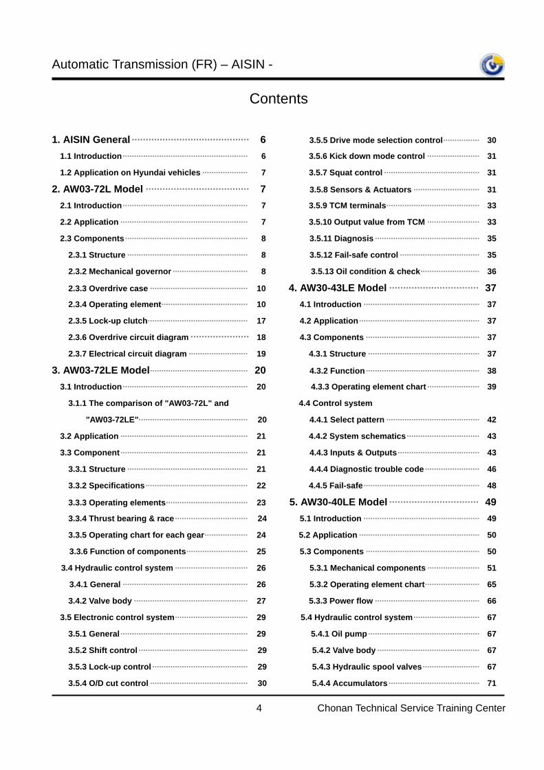
Contents 1. AISIN General ·········································· 6 …3.5.5 Drive mode selection control················ 30
1.1 Introduction······················································· 6 3.5.6 Kick down mode control ······················· 31
1.2 Application on Hyundai vehicles ···················· 7 3.5.7 Squat control ·········································· 31 2. AW03-72L Model ····································· 7 3.5.8 Sensors & Actuators ····························· 31
2.1 Introduction······················································· 7 3.5.9 TCM terminals········································· 33
2.2 Application ························································ 7 3.5.10 Output value from TCM ······················· 33
2.3 Components······················································ 8 3.5.11 Diagnosis ·············································· 35
2.3.1 Structure ····················································· 8 3.5.12 Fail-safe control ··································· 35
2.3.2 Mechanical governor ································· 8 3.5.13 Oil condition & check·························· 36
2.3.3 Overdrive case ··········································· 10 4. AW30-43LE Model ································ 37
2.3.4 Operating element······································ 10 4.1 Introduction ··················································· 37
2.3.5 Lock-up clutch············································ 17 4.2 Application····················································· 37
2.3.6 Overdrive circuit diagram ····················· 18 4.3 Components ·················································· 37
2.3.7 Electrical circuit diagram ·························· 19 4.3.1 Structure ················································· 37
3. AW03-72LE Model··········································· 20 4.3.2 Function·················································· 38
3.1 Introduction······················································· 20 4.3.3 Operating element chart ······················· 39
3.1.1 The comparison of "AW03-72L" and 4.4 Control system
"AW03-72LE"················································ 20 4.4.1 Select pattern ········································· 42
3.2 Application ························································ 21 4.4.2 System schematics································ 43
3.3 Component························································ 21 4.4.3 Inputs & Outputs···································· 43
3.3.1 Structure ····················································· 21 4.4.4 Diagnostic trouble code························ 46
3.3.2 Specifications············································· 22 4.4.5 Fail-safe··················································· 48
3.3.3 Operating elements···································· 23 5. AW30-40LE Model ································ 49
3.3.4 Thrust bearing & race································ 24 5.1 Introduction ··················································· 49
3.3.5 Operating chart for each gear··················· 24 5.2 Application ····················································· 50
3.3.6 Function of components··························· 25 5.3 Components ·················································· 50
3.4 Hydraulic control system ································ 26 5.3.1 Mechanical components ······················· 51
3.4.1 General ······················································· 26 5.3.2 Operating element chart························ 65
3.4.2 Valve body ·················································· 27 5.3.3 Power flow ·············································· 66
3.5 Electronic control system································ 29 5.4 Hydraulic control system····························· 67
3.5.1 General ························································ 29 5.4.1 Oil pump················································· 67
3.5.2 Shift control ················································ 29 5.4.2 Valve body ············································· 67
3.5.3 Lock-up control ·········································· 29 5.4.3 Hydraulic spool valves························· 67
3.5.4 O/D cut control ··········································· 30 5.4.4 Accumulators ········································ 71
Automatic Transmission (FR) – AISIN -
5 Chonan Technical Service Training Center
5.5 Electronic control system································ 72
5.5.1 Generals······················································ 72 5.5.2 Input speed sensor ···································· 73
5.5.3 Output speed sensor ································· 74
5.5.4 Oil temperature sensor······························ 74
5.5.5 Solenoid valves ·········································· 75
5.5.6 Line pressure control solenoid valve ······ 75
5.5.7 Lock-up solenoid valve ····························· 77
5.5.8 Inhibitor switch··········································· 78
5.5.9 System block diagram······························· 79
5.5.10 Shift control schedule ························ 79
5.5.11 System schematics ·································· 80
5.5.12 Lock-up cut control·································· 80
5.5.13 Overdrive cut control······························· 81
5.5.14 Driving control·········································· 81
5.5.15 ATF temperature control ························· 81
5.5.16 Squat control ············································ 82
5.5.17 Coast down control·································· 82
5.5.18 Communication ········································ 83
5.5.19 Diagnostic specification·························· 86
5.5.20 Troubleshooting······································· 90
APPENDIX······························································· 97 EXAMINATION······················································· 115
ACTIVITY REPORT·············································· 117
Automatic Transmission (FR) – AISIN -
6 Chonan Technical Service Training Center
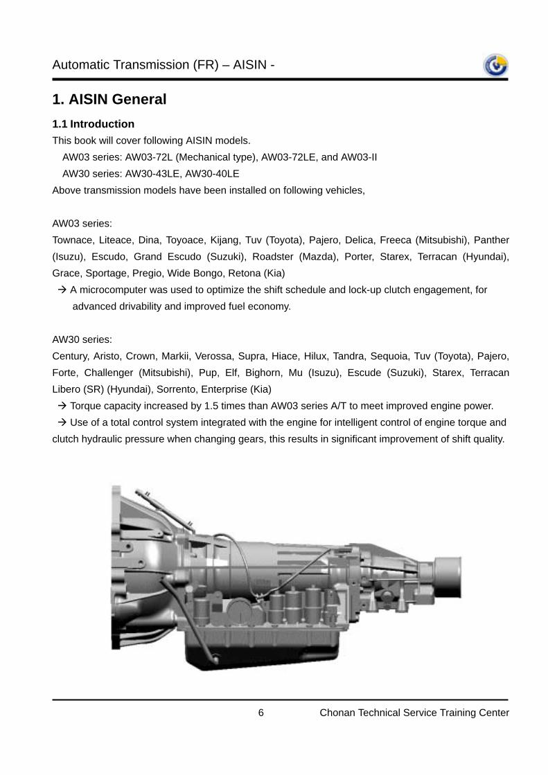
1. AISIN General 1.1 Introduction This book will cover following AISIN models.
AW03 series: AW03-72L (Mechanical type), AW03-72LE, and AW03-II AW30 series: AW30-43LE, AW30-40LE
Above transmission models have been installed on following vehicles, AW03 series: Townace, Liteace, Dina, Toyoace, Kijang, Tuv (Toyota), Pajero, Delica, Freeca (Mitsubishi), Panther (Isuzu), Escudo, Grand Escudo (Suzuki), Roadster (Mazda), Porter, Starex, Terracan (Hyundai), Grace, Sportage, Pregio, Wide Bongo, Retona (Kia) A microcomputer was used to optimize the shift schedule and lock-up clutch engagement, for
advanced drivability and improved fuel economy. AW30 series: Century, Aristo, Crown, Markii, Verossa, Supra, Hiace, Hilux, Tandra, Sequoia, Tuv (Toyota), Pajero, Forte, Challenger (Mitsubishi), Pup, Elf, Bighorn, Mu (Isuzu), Escude (Suzuki), Starex, Terracan Libero (SR) (Hyundai), Sorrento, Enterprise (Kia) Torque capacity increased by 1.5 times than AW03 series A/T to meet improved engine power. Use of a total control system integrated with the engine for intelligent control of engine torque and clutch hydraulic pressure when changing gears, this results in significant improvement of shift quality.
Automatic Transmission (FR) – AISIN -
7 Chonan Technical Service Training Center
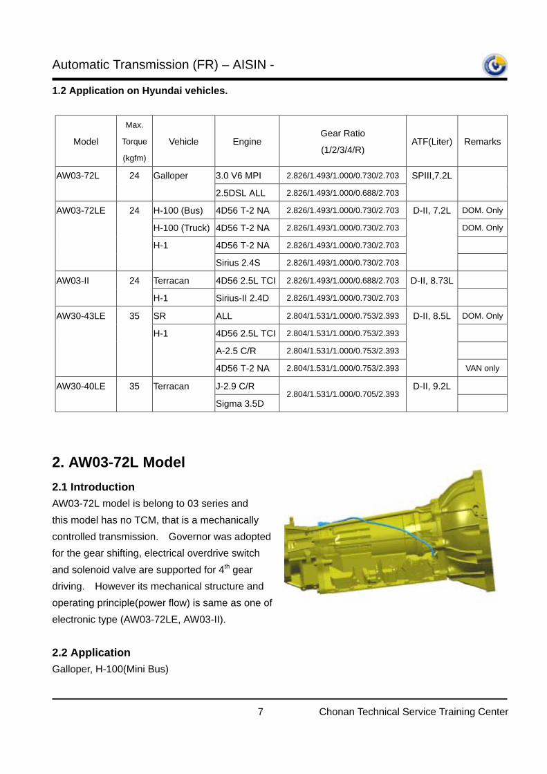
1.2 Application on Hyundai vehicles.
Model
Max.
Torque
(kgfm)
Vehicle Engine Gear Ratio
(1/2/3/4/R) ATF(Liter) Remarks
AW03-72L 24 Galloper 3.0 V6 MPI 2.826/1.493/1.000/0.730/2.703 SPIII,7.2L
2.5DSL ALL 2.826/1.493/1.000/0.688/2.703
AW03-72LE 24 H-100 (Bus) 4D56 T-2 NA 2.826/1.493/1.000/0.730/2.703 D-II, 7.2L DOM. Only
H-100 (Truck) 4D56 T-2 NA 2.826/1.493/1.000/0.730/2.703 DOM. Only
H-1 4D56 T-2 NA 2.826/1.493/1.000/0.730/2.703
Sirius 2.4S 2.826/1.493/1.000/0.730/2.703
AW03-II 24 Terracan 4D56 2.5L TCI 2.826/1.493/1.000/0.688/2.703 D-II, 8.73L
H-1 Sirius-II 2.4D 2.826/1.493/1.000/0.730/2.703
AW30-43LE 35 SR ALL 2.804/1.531/1.000/0.753/2.393 D-II, 8.5L DOM. Only
H-1 4D56 2.5L TCI 2.804/1.531/1.000/0.753/2.393
A-2.5 C/R 2.804/1.531/1.000/0.753/2.393
4D56 T-2 NA 2.804/1.531/1.000/0.753/2.393 VAN only
AW30-40LE 35 Terracan J-2.9 C/R D-II, 9.2L
Sigma 3.5D 2.804/1.531/1.000/0.705/2.393
2. AW03-72L Model 2.1 Introduction AW03-72L model is belong to 03 series and this model has no TCM, that is a mechanically controlled transmission. Governor was adopted for the gear shifting, electrical overdrive switch and solenoid valve are supported for 4th gear driving. However its mechanical structure and operating principle(power flow) is same as one of electronic type (AW03-72LE, AW03-II). 2.2 Application Galloper, H-100(Mini Bus)
Automatic Transmission (FR) – AISIN -
8 Chonan Technical Service Training Center
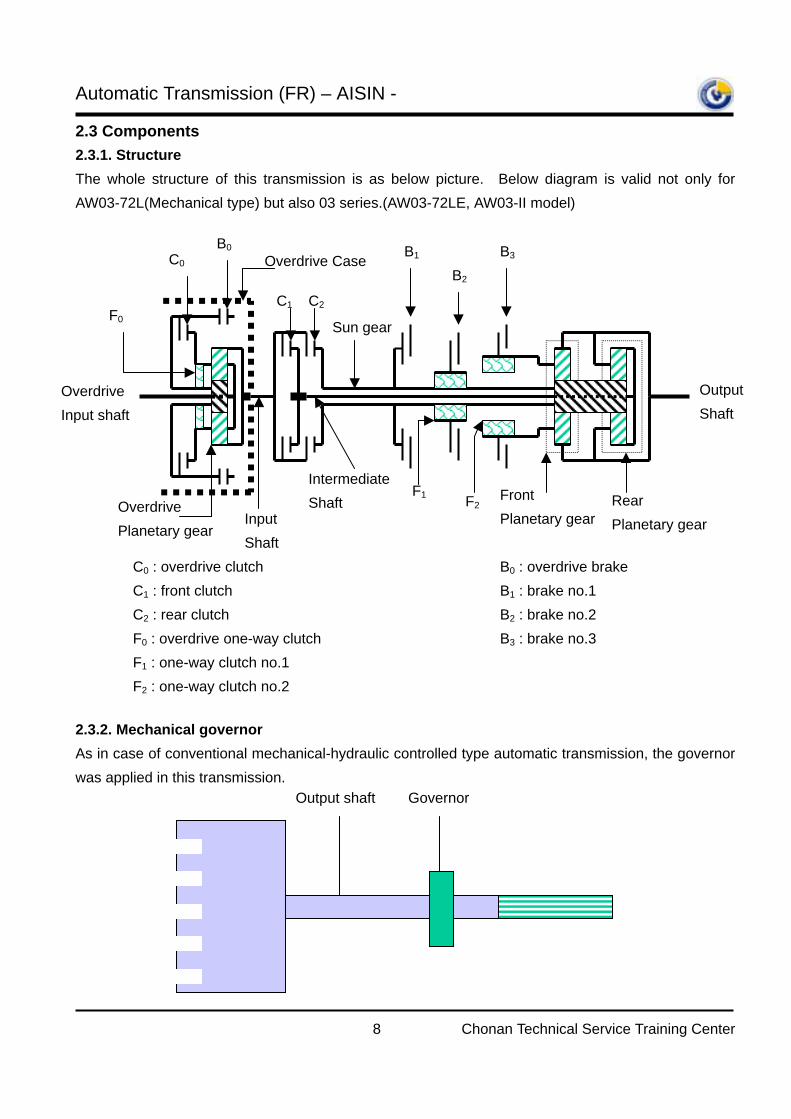
2.3 Components 2.3.1. Structure The whole structure of this transmission is as below picture. Below diagram is valid not only for AW03-72L(Mechanical type) but also 03 series.(AW03-72LE, AW03-II model) 2.3.2. Mechanical governor As in case of conventional mechanical-hydraulic controlled type automatic transmission, the governor was applied in this transmission.
Overdrive Planetary gear
Overdrive Input shaft
Front Planetary gear
Rear Planetary gear Input
Shaft
F0
Output Shaft
Intermediate Shaft
Sun gear
B0 C0
C1 C2
B2 B3 B1
F1 F2
Overdrive Case
C0 : overdrive clutch C1 : front clutch C2 : rear clutch F0 : overdrive one-way clutch F1 : one-way clutch no.1 F2 : one-way clutch no.2
B0 : overdrive brake B1 : brake no.1 B2 : brake no.2 B3 : brake no.3
Output shaft Governor
Automatic Transmission (FR) – AISIN -
9 Chonan Technical Service Training Center
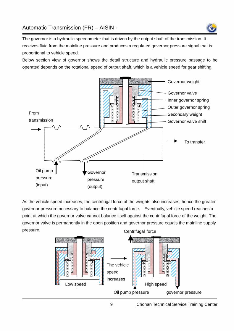
The governor is a hydraulic speedometer that is driven by the output shaft of the transmission. It receives fluid from the mainline pressure and produces a regulated governor pressure signal that is proportional to vehicle speed. Below section view of governor shows the detail structure and hydraulic pressure passage to be operated depends on the rotational speed of output shaft, which is a vehicle speed for gear shifting. As the vehicle speed increases, the centrifugal force of the weights also increases, hence the greater governor pressure necessary to balance the centrifugal force. Eventually, vehicle speed reaches a point at which the governor valve cannot balance itself against the centrifugal force of the weight. The governor valve is permanently in the open position and governor pressure equals the mainline supply pressure.
The vehicle speed increases
Low speed
Centrifugal force
Oil pump pressure governor pressure
High speed
To transfer
Oil pump pressure (input)
Governor pressure (output)
From transmission
Transmission output shaft
Governor weight
Governor valve Inner governor spring Outer governor spring Secondary weight Governor valve shift
Automatic Transmission (FR) – AISIN -
10 Chonan Technical Service Training Center
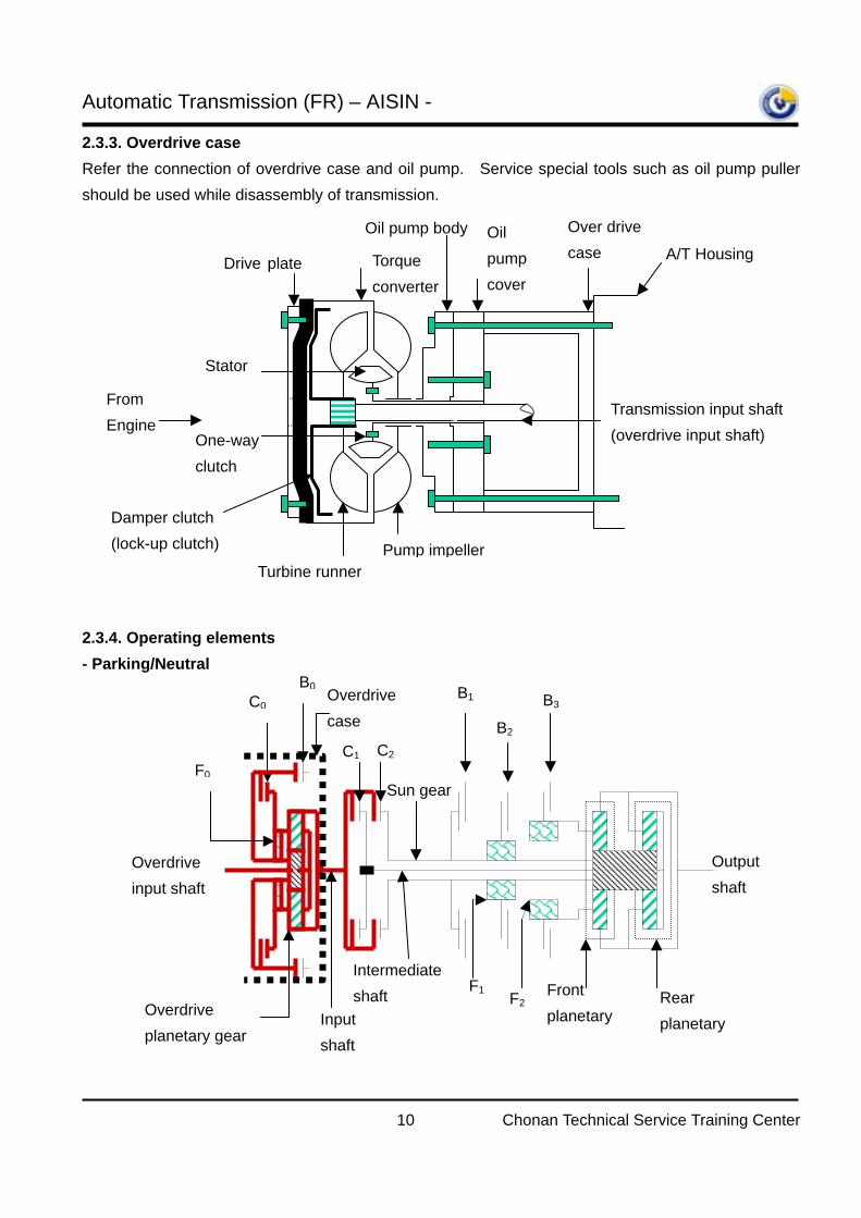
2.3.3. Overdrive case Refer the connection of overdrive case and oil pump. Service special tools such as oil pump puller should be used while disassembly of transmission. 2.3.4. Operating elements - Parking/Neutral
From Engine
Stator
Torque converter
Drive plate
Oil pump cover
Over drive case
Oil pump body
Turbine runner Pump impeller
One-way clutch
Transmission input shaft (overdrive input shaft)
A/T Housing
Damper clutch (lock-up clutch)
Sun gear
Overdrive planetary gear
Overdrive input shaft
Front planetary
Rear planetary Input
shaft
F0
Output shaft
Intermediate shaft
B0 C0
C1 C2 B2
B3 B1
F1 F2
Overdrive case
Automatic Transmission (FR) – AISIN -
11 Chonan Technical Service Training Center
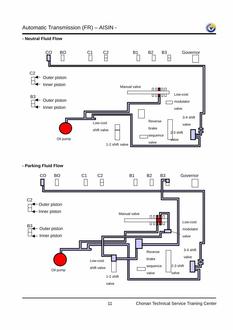
- Neutral Fluid Flow - Parking Fluid Flow
Outer piston Inner piston
C2
B3
CO BO C1 C2 B1 B2 B3 Governor
Oil pump 1-2 shift valve
Low-cost
shift valve
Reverse
brake
sequence
valve
2-3 shift
valve
3-4 shift
valve
Manual valve
Low-cost
modulator
valve
Outer piston Inner piston
CO BO C1 C2 B1 B2 B3 Governor
Oil pump
1-2 shift
valve
Low-cost
shift valve
Reverse
brake
sequence
valve
2-3 shift
valve
3-4 shift
valve
Manual valve
Low-cost
modulator
valve
Outer piston Inner piston
C2
B3 Outer piston Inner piston
Automatic Transmission (FR) – AISIN -
12 Chonan Technical Service Training Center
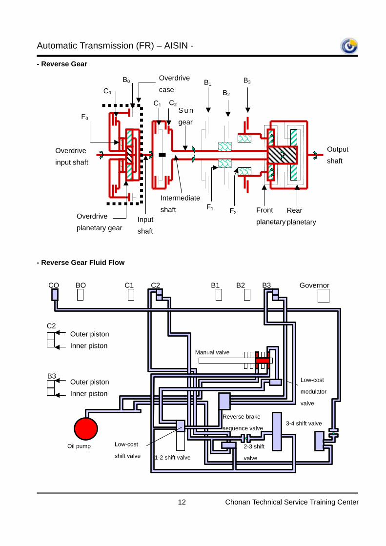
- Reverse Gear - Reverse Gear Fluid Flow
Overdrive planetary gear
Overdrive input shaft
Front planetary
Rear planetary Input
shaft
F0
Output shaft
Intermediate shaft
B0 C0
C1 C2 B2
B3 B1
F1 F2
Overdrive case
S u n gear
Oil pump
1-2 shift valve
Low-cost
shift valve
Reverse brake
sequence valve
2-3 shift
valve
3-4 shift valve
Manual valve
Low-cost
modulator
valve
Outer piston Inner piston
Outer piston Inner piston
C2
B3
CO BO C1 C2 B1 B2 B3 Governor
Automatic Transmission (FR) – AISIN -
13 Chonan Technical Service Training Center
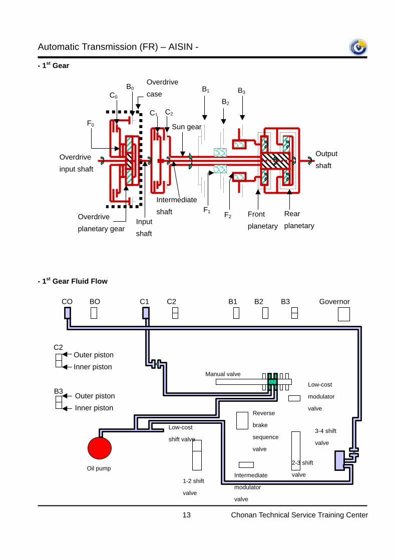
- 1st Gear - 1st Gear Fluid Flow
Sun gear
Overdrive planetary gear
Overdrive input shaft
Front planetary
Rear planetary Input
shaft
F0
Output shaft
Intermediate shaft
B0 C0
C1 C2 B2
B3 B1
F1 F2
Overdrive case
Oil pump
1-2 shift
valve
Low-cost
shift valve
Reverse
brake
sequence
valve
2-3 shift
valve
3-4 shift
valve
Manual valve
Low-cost
modulator
valve
Intermediate
modulator
valve
Outer piston Inner piston
C2
B3 Outer piston Inner piston
CO BO C1 C2 B1 B2 B3 Governor
Automatic Transmission (FR) – AISIN -
14 Chonan Technical Service Training Center
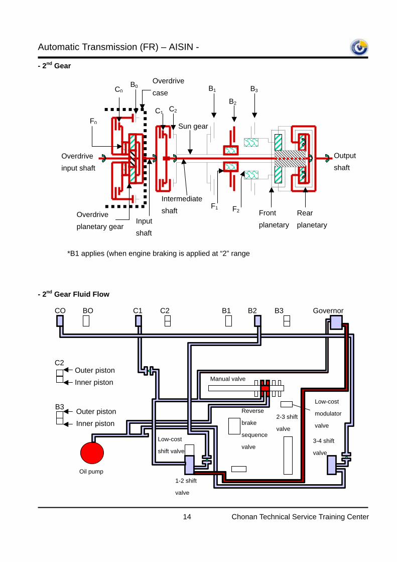
- 2nd Gear - 2nd Gear Fluid Flow
*B1 applies (when engine braking is applied at “2” range
Sun gear
Overdrive planetary gear
Overdrive input shaft
Front planetary
Rear planetary Input
shaft
F0
Output shaft
Intermediate shaft
B0 C0
C1 C2 B2
B3 B1
F1 F2
Overdrive case
Oil pump 1-2 shift
valve
Low-cost
shift valve
Reverse
brake
sequence
valve
2-3 shift
valve
3-4 shift
valve
Manual valve
Low-cost
modulator
valve
Outer piston Inner piston
C2
B3 Outer piston Inner piston
CO BO C1 C2 B1 B2 B3 Governor
Automatic Transmission (FR) – AISIN -
15 Chonan Technical Service Training Center
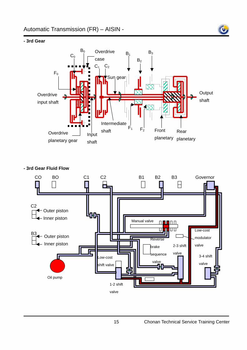
- 3rd Gear - 3rd Gear Fluid Flow
Sun gear
Overdrive planetary gear
Overdrive input shaft
Front planetary
Rear planetary
Input shaft
F0
Output shaft
Intermediate shaft
B0 C0
C1 C2 B2
B3 B1
F1 F2
Overdrive case
Oil pump
1-2 shift
valve
Low-cost
shift valve
Reverse
brake
sequence
valve
2-3 shift
valve 3-4 shift
valve
Manual valve
Low-cost
modulator
valve
CO BO C1 C2 B1 B2 B3 Governor
Outer piston Inner piston
C2
B3 Outer piston Inner piston
Automatic Transmission (FR) – AISIN -
16 Chonan Technical Service Training Center
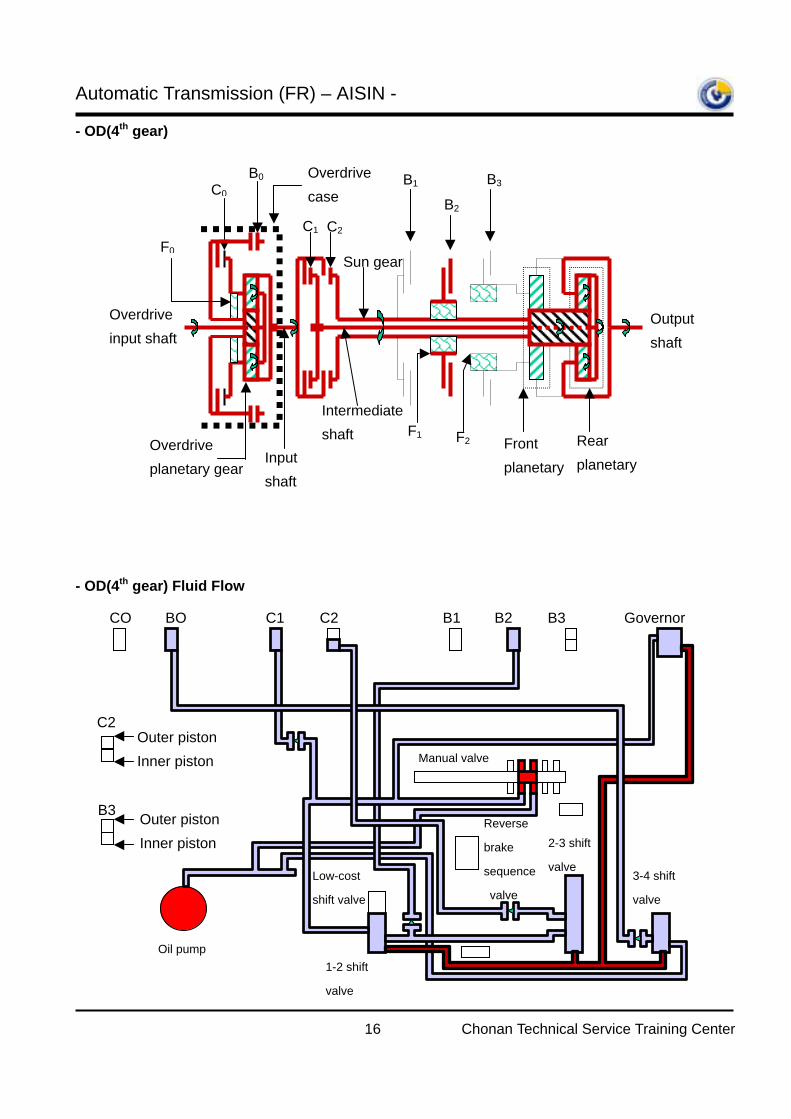
- OD(4th gear) - OD(4th gear) Fluid Flow
Sun gear
Overdrive planetary gear
Overdrive input shaft
Front planetary
Rear planetary Input
shaft
F0
Output shaft
Intermediate shaft
B0 C0
C1 C2 B2
B3 B1
F1 F2
Overdrive case
CO BO C1 C2 B1 B2 B3 Governor
Outer piston Inner piston
C2
B3 Outer piston Inner piston
Oil pump 1-2 shift
valve
Low-cost
shift valve
Reverse
brake
sequence
valve
2-3 shift
valve 3-4 shift
valve
Manual valve
Automatic Transmission (FR) – AISIN -
17 Chonan Technical Service Training Center
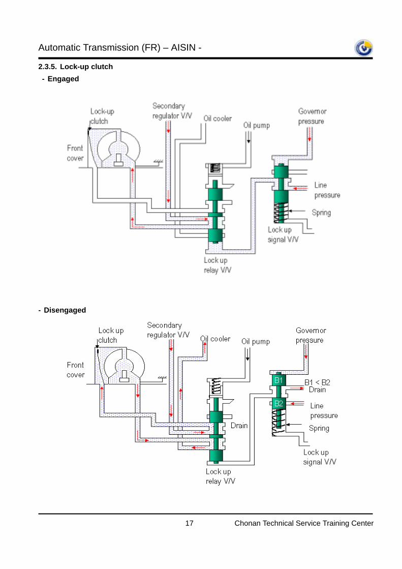
2.3.5. Lock-up clutch - Engaged - Disengaged
Automatic Transmission (FR) – AISIN -
18 Chonan Technical Service Training Center
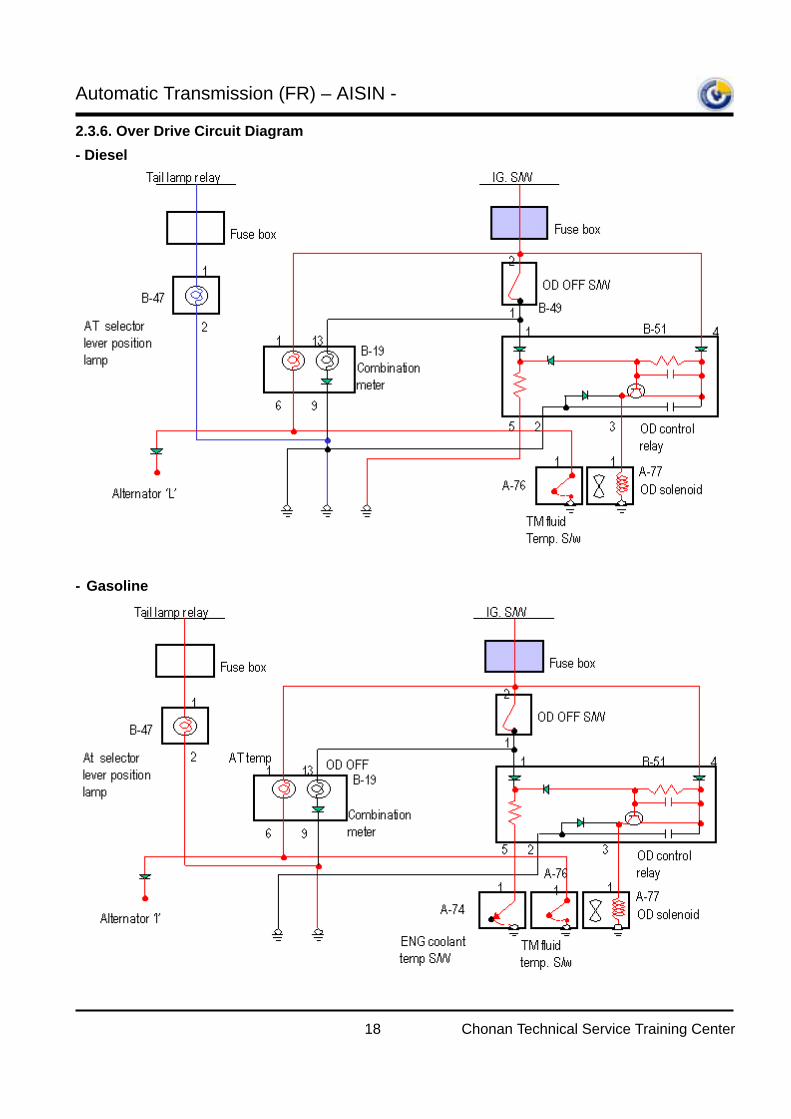
2.3.6. Over Drive Circuit Diagram - Diesel
- Gasoline
Automatic Transmission (FR) – AISIN -
19 Chonan Technical Service Training Center
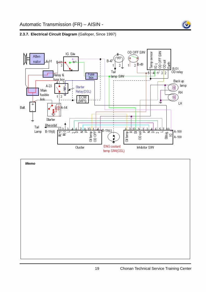
2.3.7. Electrical Circuit Diagram (Galloper, Since 1997)
Memo
Automatic Transmission (FR) – AISIN -
20 Chonan Technical Service Training Center
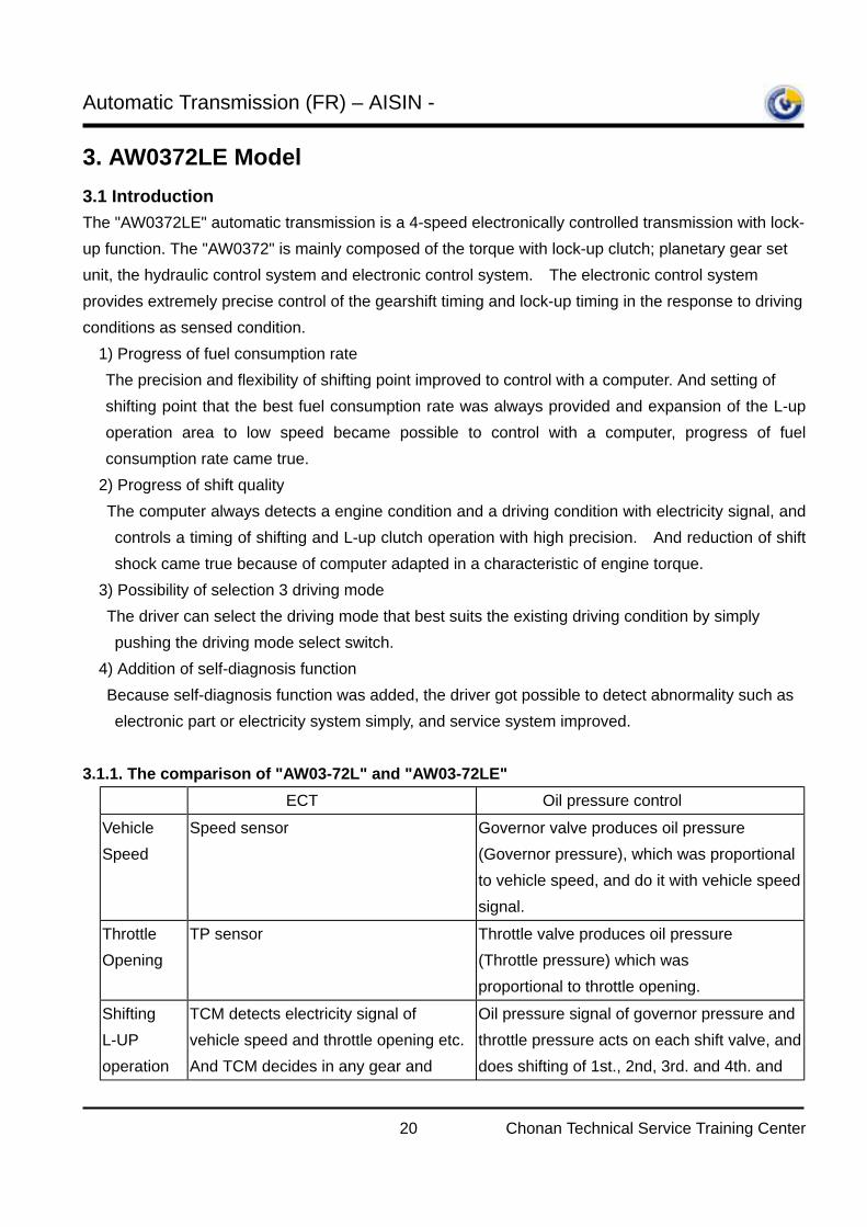
3. AW0372LE Model 3.1 Introduction The "AW0372LE" automatic transmission is a 4-speed electronically controlled transmission with lock-up function. The "AW0372" is mainly composed of the torque with lock-up clutch; planetary gear set unit, the hydraulic control system and electronic control system. The electronic control system provides extremely precise control of the gearshift timing and lock-up timing in the response to driving conditions as sensed condition.
1) Progress of fuel consumption rate The precision and flexibility of shifting point improved to control with a computer. And setting of shifting point that the best fuel consumption rate was always provided and expansion of the L-up operation area to low speed became possible to control with a computer, progress of fuel consumption rate came true.
2) Progress of shift quality The computer always detects a engine condition and a driving condition with electricity signal, and
controls a timing of shifting and L-up clutch operation with high precision. And reduction of shift shock came true because of computer adapted in a characteristic of engine torque.
3) Possibility of selection 3 driving mode The driver can select the driving mode that best suits the existing driving condition by simply
pushing the driving mode select switch. 4) Addition of self-diagnosis function
Because self-diagnosis function was added, the driver got possible to detect abnormality such as electronic part or electricity system simply, and service system improved.
3.1.1. The comparison of "AW03-72L" and "AW03-72LE"
ECT Oil pressure control Vehicle Speed
Speed sensor Governor valve produces oil pressure (Governor pressure), which was proportional to vehicle speed, and do it with vehicle speed signal.
Throttle Opening
TP sensor Throttle valve produces oil pressure (Throttle pressure) which was proportional to throttle opening.
Shifting L-UP operation
TCM detects electricity signal of vehicle speed and throttle opening etc. And TCM decides in any gear and
Oil pressure signal of governor pressure and throttle pressure acts on each shift valve, and does shifting of 1st., 2nd, 3rd. and 4th. and
Automatic Transmission (FR) – AISIN -
21 Chonan Technical Service Training Center
when On/Off can point at L-UP on the basis of those signals, and sends electricity signal to SOL.-1/2 and L-UP SOL., so operates each shift valve and A/T does shifting and lock up operation.
the lock up operation by letting shift valve operate by both hydraulic big things and small things.
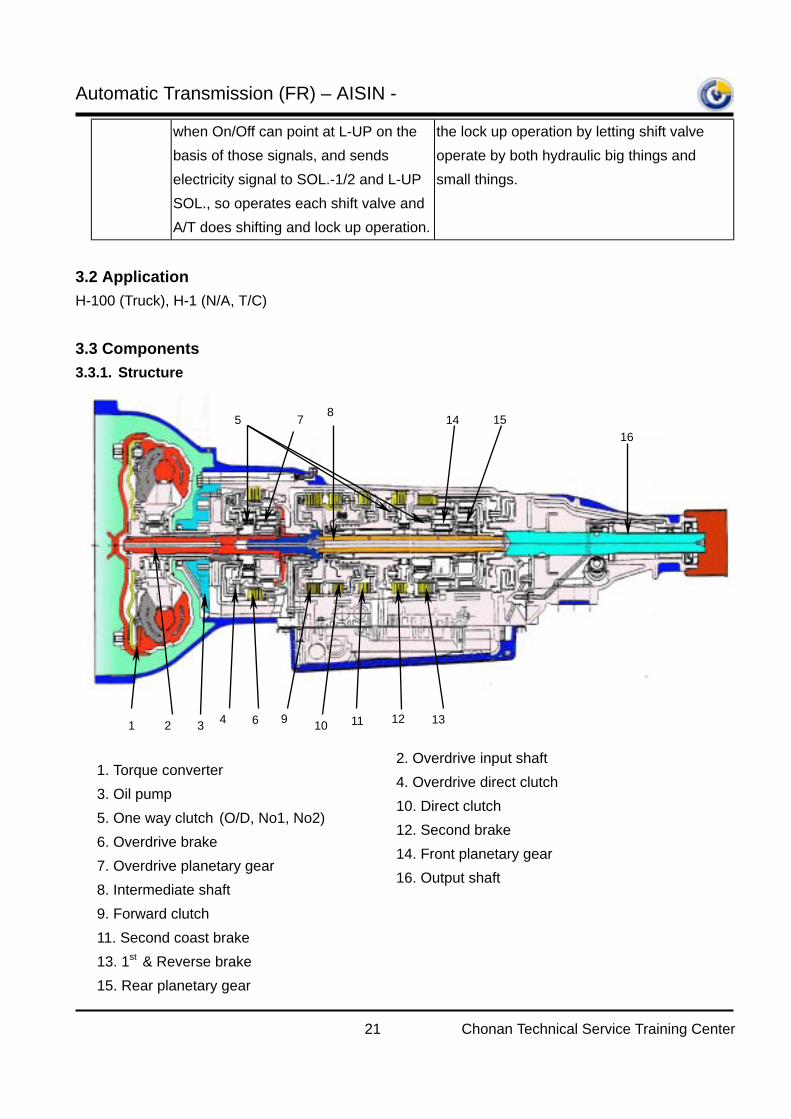
3.2 Application H-100 (Truck), H-1 (N/A, T/C) 3.3 Components 3.3.1. Structure
1 2 3 4
5
6
7 8
9 10 11 12 13
14 15 16
1. Torque converter 3. Oil pump 5. One way clutch (O/D, No1, No2) 6. Overdrive brake 7. Overdrive planetary gear 8. Intermediate shaft 9. Forward clutch 11. Second coast brake 13. 1st & Reverse brake 15. Rear planetary gear
2. Overdrive input shaft 4. Overdrive direct clutch 10. Direct clutch 12. Second brake 14. Front planetary gear 16. Output shaft
Automatic Transmission (FR) – AISIN -
22 Chonan Technical Service Training Center
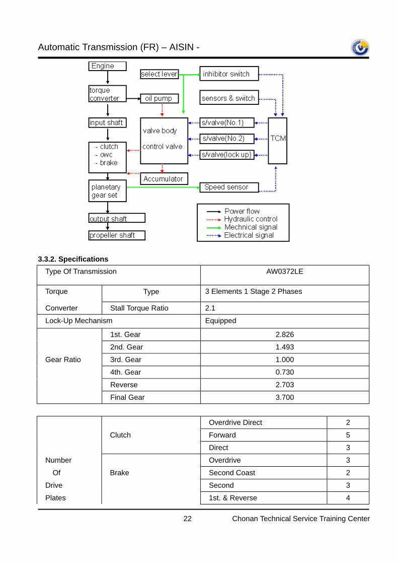
3.3.2. Specifications
Type Of Transmission AW0372LE
Torque Type 3 Elements 1 Stage 2 Phases
Converter Stall Torque Ratio 2.1
Lock-Up Mechanism Equipped
1st. Gear 2.826
2nd. Gear 1.493
Gear Ratio 3rd. Gear 1.000
4th. Gear 0.730
Reverse 2.703
Final Gear 3.700
Overdrive Direct 2
Clutch Forward 5
Direct 3
Number Overdrive 3
Of Brake Second Coast 2 Drive Second 3
Plates 1st. & Reverse 4
Automatic Transmission (FR) – AISIN -
23 Chonan Technical Service Training Center
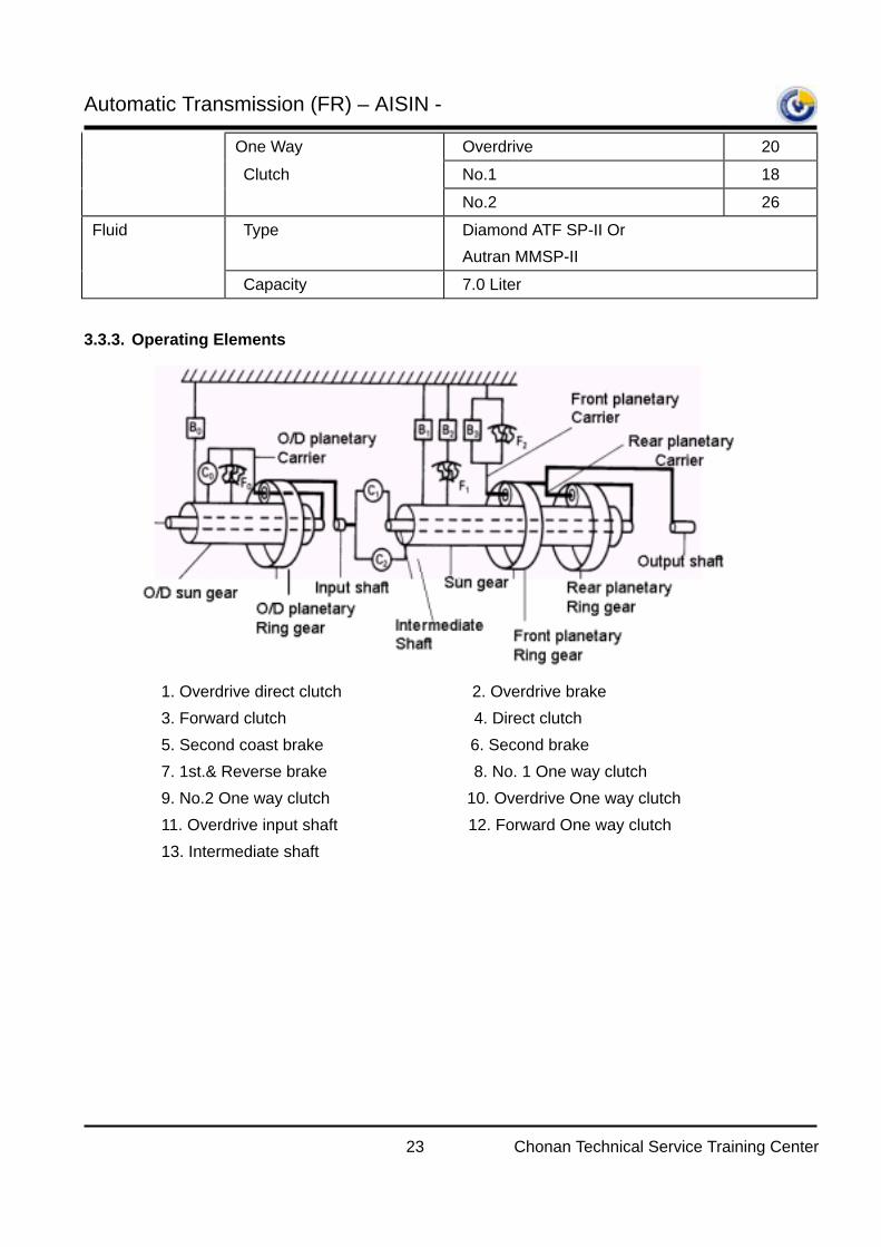
One Way Overdrive 20
Clutch No.1 18
No.2 26 Fluid Type Diamond ATF SP-II Or
Autran MMSP-II
Capacity 7.0 Liter
3.3.3. Operating Elements
1. Overdrive direct clutch 2. Overdrive brake 3. Forward clutch 4. Direct clutch 5. Second coast brake 6. Second brake 7. 1st.& Reverse brake 8. No. 1 One way clutch 9. No.2 One way clutch 10. Overdrive One way clutch 11. Overdrive input shaft 12. Forward One way clutch 13. Intermediate shaft
Automatic Transmission (FR) – AISIN -
24 Chonan Technical Service Training Center
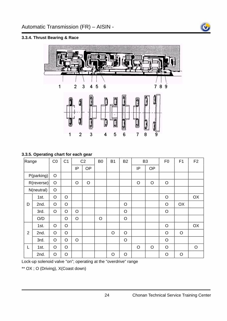
3.3.4. Thrust Bearing & Race
3.3.5. Operating chart for each gear
Range C0 C1 C2 B0 B1 B2 B3 F0 F1 F2
IP OP IP OP
P(parking) O R(reverse) O O O O O O
N(neutral) O
1st. O O O OX
D 2nd. O O O O OX
3rd. O O O O O
O/D O O O O 1st. O O O OX
2 2nd. O O O O O O
3rd. O O O O O
L 1st. O O O O O O
2nd. O O O O O O Lock-up solenoid valve "on”; operating at the "overdrive" range ** OX ; O (Driving), X(Coast down)
Automatic Transmission (FR) – AISIN -
25 Chonan Technical Service Training Center
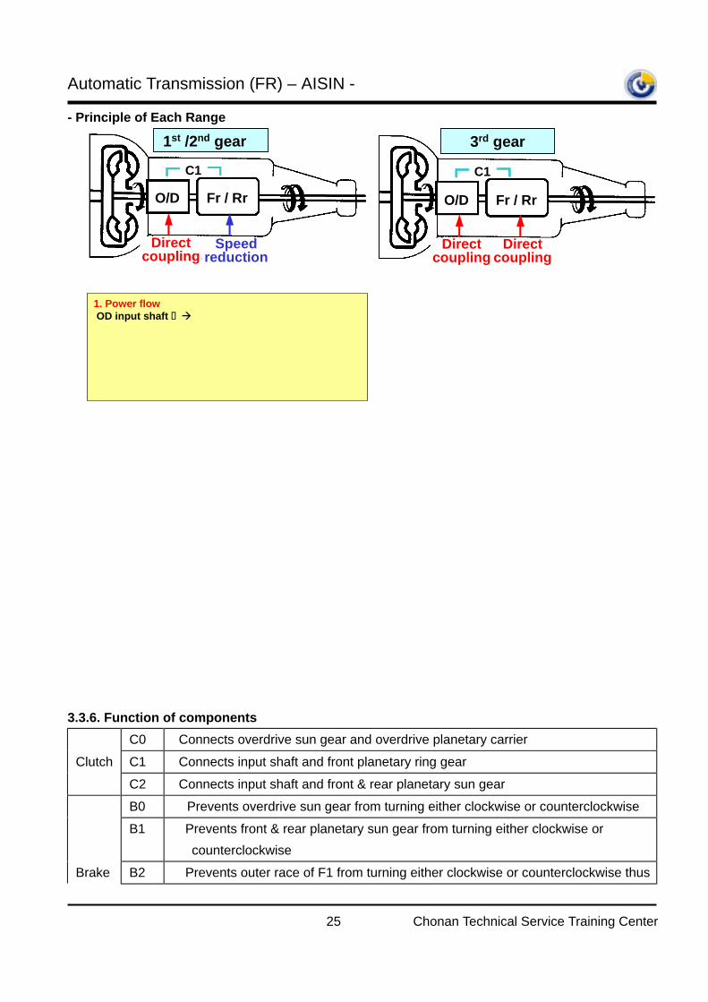
- Principle of Each Range
3.3.6. Function of components
C0 Connects overdrive sun gear and overdrive planetary carrier Clutch C1 Connects input shaft and front planetary ring gear
C2 Connects input shaft and front & rear planetary sun gear B0 Prevents overdrive sun gear from turning either clockwise or counterclockwise
B1 Prevents front & rear planetary sun gear from turning either clockwise or counterclockwise
Brake B2 Prevents outer race of F1 from turning either clockwise or counterclockwise thus
1st /2nd gear
Direct coupling
O/D Fr / Rr
C1C1
Speed reduction
O/D Fr / Rr
3rd gear
C1C1
Direct coupling
Direct coupling
1. Power flowOD input shaft OD gear set(coupling by C0) Fr/Rr
(speed reduction by F2(1st gear), by B2&F1(2nd gear))
2. Engine brake- D range 1st,2nd gear: non(F2,F1 free to clockwise)- 2 range: 1st gear(non), 2nd gear(operated by B1)- L range 1st,2nd gear: operated by B1, B3
1. Power flowOD input shaft OD gear set(coupling by C0)
Fr/Rr (coupling by C1 & C2)
2. Engine brake- D & 2 range: operates
4th gear
O/D Fr / Rr
C1C1
Direct coupling
Speed increase
O/D Fr / Rr
Reverse gear
C1C1
Direct coupling
Reversed rotation
1. Power flowOD input shaft OD gear set (coupling by C0)
Fr/Rr (reverse rotation by B3)
2. Reverse inhibition control: C2
1. Power flowOD input shaft OD gear set (speed increase by B0)
Fr/Rr (coupling by C1&C2)
2. Engine brake- D range: operates
Automatic Transmission (FR) – AISIN -
26 Chonan Technical Service Training Center
preventing the front & rear planetary sun gear from turning counterclockwise
B3 Prevents rear planetary carrier from turning either clockwise or counterclockwise.
F0 When the transmission is being driven by the engine, this clutch connects the overdrive sun gear and overdrive planetary carrier.
OWC F1 When B2 is operating, this clutch prevents the front & rear planetary sun gear from turning counterclockwise
F2 Prevents rear planetary carrier from turning counterclockwise.
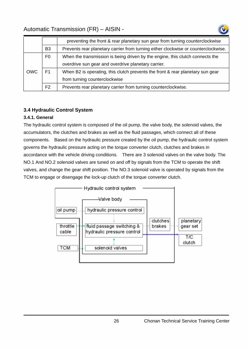
3.4 Hydraulic Control System 3.4.1. General The hydraulic control system is composed of the oil pump, the valve body, the solenoid valves, the accumulators, the clutches and brakes as well as the fluid passages, which connect all of these components. Based on the hydraulic pressure created by the oil pump, the hydraulic control system governs the hydraulic pressure acting on the torque converter clutch, clutches and brakes in accordance with the vehicle driving conditions. There are 3 solenoid valves on the valve body. The NO.1 And NO.2 solenoid valves are tuned on and off by signals from the TCM to operate the shift valves, and change the gear shift position. The NO.3 solenoid valve is operated by signals from the TCM to engage or disengage the lock-up clutch of the torque converter clutch.
Automatic Transmission (FR) – AISIN -
27 Chonan Technical Service Training Center
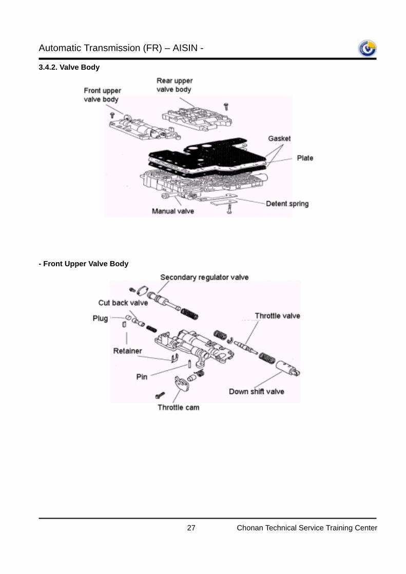
3.4.2. Valve Body
- Front Upper Valve Body
Automatic Transmission (FR) – AISIN -
28 Chonan Technical Service Training Center
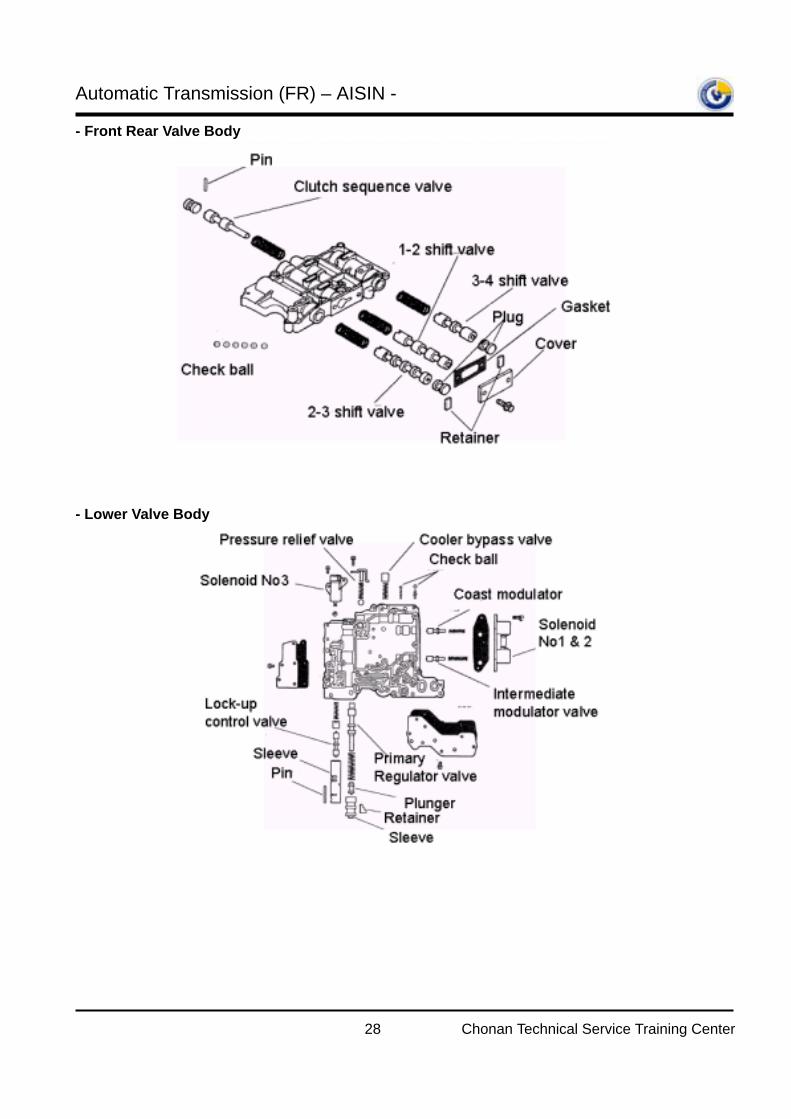
- Front Rear Valve Body
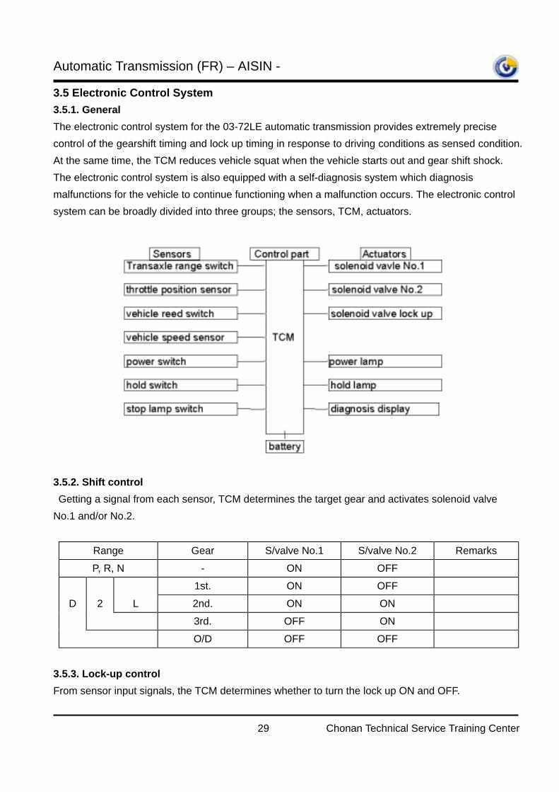
- Lower Valve Body
Automatic Transmission (FR) – AISIN -
29 Chonan Technical Service Training Center
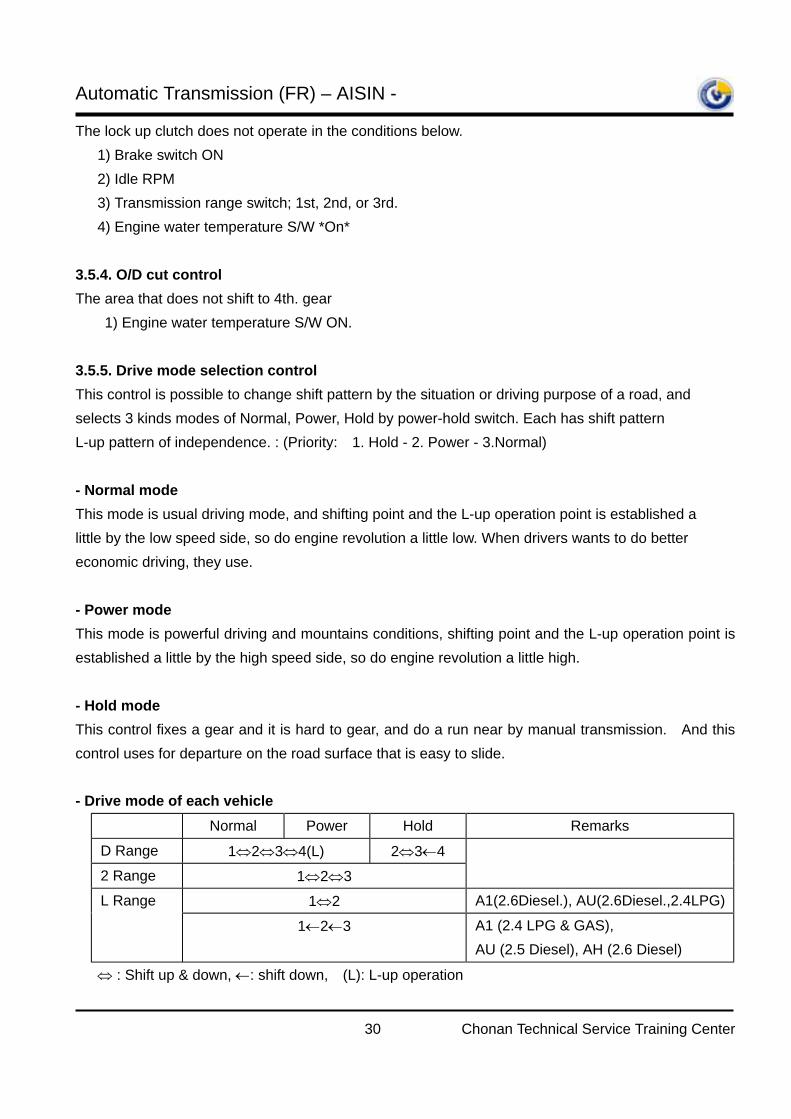
3.5 Electronic Control System 3.5.1. General The electronic control system for the 03-72LE automatic transmission provides extremely precise control of the gearshift timing and lock up timing in response to driving conditions as sensed condition. At the same time, the TCM reduces vehicle squat when the vehicle starts out and gear shift shock. The electronic control system is also equipped with a self-diagnosis system which diagnosis malfunctions for the vehicle to continue functioning when a malfunction occurs. The electronic control system can be broadly divided into three groups; the sensors, TCM, actuators. 3.5.2. Shift control Getting a signal from each sensor, TCM determines the target gear and activates solenoid valve No.1 and/or No.2.
Range Gear S/valve No.1 S/valve No.2 Remarks P, R, N - ON OFF
1st. ON OFF D 2 L 2nd. ON ON
3rd. OFF ON
O/D OFF OFF
3.5.3. Lock-up control From sensor input signals, the TCM determines whether to turn the lock up ON and OFF.
Automatic Transmission (FR) – AISIN -
30 Chonan Technical Service Training Center
The lock up clutch does not operate in the conditions below. 1) Brake switch ON 2) Idle RPM 3) Transmission range switch; 1st, 2nd, or 3rd. 4) Engine water temperature S/W *On* 3.5.4. O/D cut control The area that does not shift to 4th. gear
1) Engine water temperature S/W ON. 3.5.5. Drive mode selection control This control is possible to change shift pattern by the situation or driving purpose of a road, and selects 3 kinds modes of Normal, Power, Hold by power-hold switch. Each has shift pattern L-up pattern of independence. : (Priority: 1. Hold - 2. Power - 3.Normal) - Normal mode This mode is usual driving mode, and shifting point and the L-up operation point is established a little by the low speed side, so do engine revolution a little low. When drivers wants to do better economic driving, they use. - Power mode This mode is powerful driving and mountains conditions, shifting point and the L-up operation point is established a little by the high speed side, so do engine revolution a little high. - Hold mode This control fixes a gear and it is hard to gear, and do a run near by manual transmission. And this control uses for departure on the road surface that is easy to slide. - Drive mode of each vehicle
Normal Power Hold Remarks
D Range 1⇔2⇔3⇔4(L) 2⇔3←4
2 Range 1⇔2⇔3 L Range 1⇔2 A1(2.6Diesel.), AU(2.6Diesel.,2.4LPG)
1←2←3 A1 (2.4 LPG & GAS), AU (2.5 Diesel), AH (2.6 Diesel)
⇔ : Shift up & down, ←: shift down, (L): L-up operation
Automatic Transmission (FR) – AISIN -
31 Chonan Technical Service Training Center
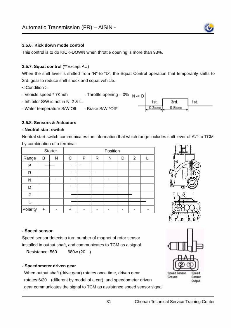
3.5.6. Kick down mode control This control is to do KICK-DOWN when throttle opening is more than 93%. 3.5.7. Squat control (**Except AU) When the shift lever is shifted from “N” to “D”, the Squat Control operation that temporarily shifts to 3rd. gear to reduce shift shock and squat vehicle. < Condition > - Vehicle speed * 7Km/h - Throttle opening = 0% - Inhibitor S/W is not in N, 2 & L. - Water temperature S/W Off - Brake S/W *Off*
3.5.8. Sensors & Actuators - Neutral start switch Neutral start switch communicates the information that which range includes shift lever of A\T to TCM by combination of a terminal.
Starter Position Range B N C P R N D 2 L
P R
N
D
2
L Polarity + - + - - - - - -
- Speed sensor Speed sensor detects a turn number of magnet of rotor sensor installed in output shaft, and communicates to TCM as a signal. Resistance: 560 ∼ 680w (20)
- Speedometer driven gear When output shaft (drive gear) rotates once time, driven gear rotates 6\20 (different by model of a car), and speedometer driven gear communicates the signal to TCM as assistance speed sensor signal
Automatic Transmission (FR) – AISIN -
32 Chonan Technical Service Training Center
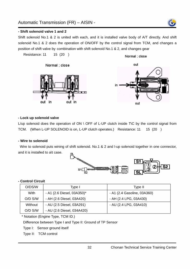
- Shift solenoid valve 1 and 2 Shift solenoid No.1 & 2 is united with each, and it is installed valve body of A/T directly. And shift solenoid No.1 & 2 does the operation of ON/OFF by the control signal from TCM, and changes a position of shift valve by combination with shift solenoid No.1 & 2, and changes gear Resistance: 11∼ 15Ω(20)
- Lock up solenoid valve L/up solenoid does the operation of ON \ OFF of L-UP clutch inside T\C by the control signal from TCM. (When L-UP SOLENOID is on, L-UP clutch operates.) Resistance: 11∼ 15Ω(20)
- Wire to solenoid Wire to solenoid puts wining of shift solenoid. No.1 & 2 and l-up solenoid together in one connector, and it is installed to a\t case. - Control Circuit
O/DS/W Type I Type II
With O/D S/W
- A1 (2.6 Diesel, 03A350)* - AH (2.6 Diesel, 03A420)
- A1 (2.4 Gasoline, 03A360) - AH (2.4 LPG, 03A430)
Without O/D S/W
- AU (2.5 Diesel, 03A291) - AU (2.6 Diesel, 034A420)
- AU (2.4 LPG, 03A410)
* Notation (Engine Type, TCM ID.) Difference between Type I and Type II: Ground of TP Sensor Type I: Sensor ground itself Type II: TCM control
Automatic Transmission (FR) – AISIN -
33 Chonan Technical Service Training Center
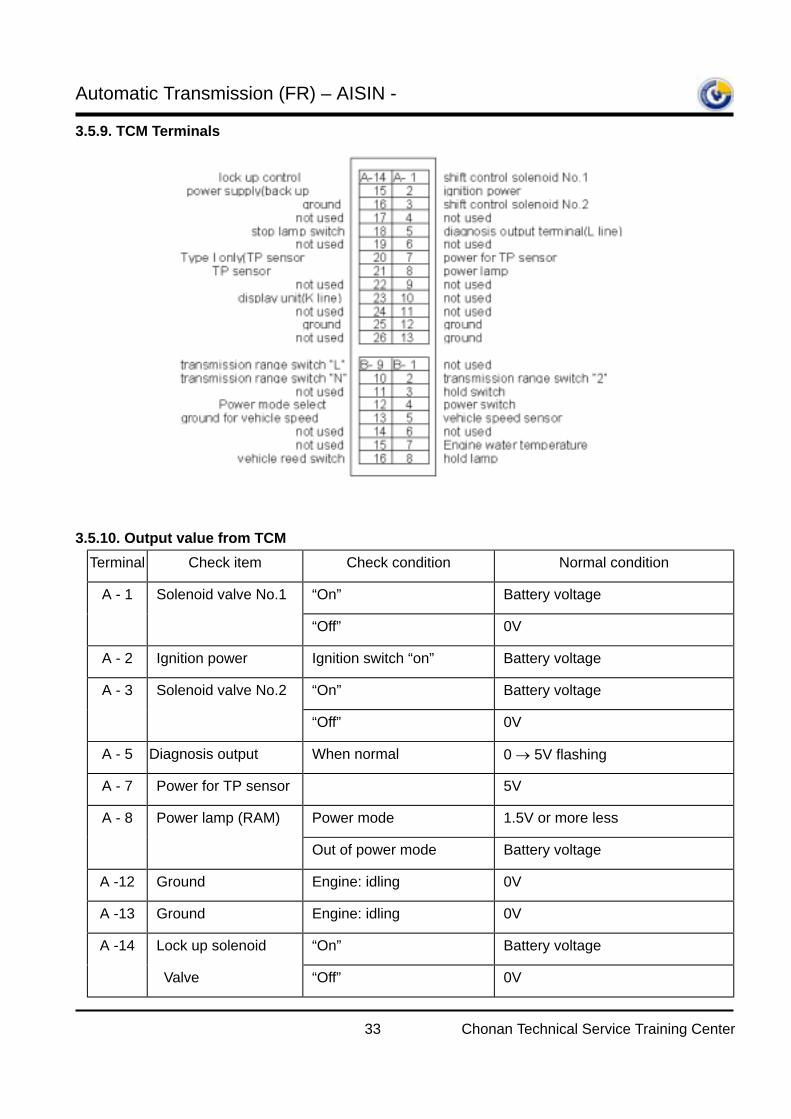
3.5.9. TCM Terminals 3.5.10. Output value from TCM
Terminal Check item Check condition Normal condition
A - 1 Solenoid valve No.1 “On” Battery voltage
“Off” 0V
A - 2 Ignition power Ignition switch “on” Battery voltage
A - 3 Solenoid valve No.2 “On” Battery voltage
“Off” 0V
A - 5 Diagnosis output When normal 0 → 5V flashing
A - 7 Power for TP sensor 5V
A - 8 Power lamp (RAM) Power mode 1.5V or more less
Out of power mode Battery voltage
A -12 Ground Engine: idling 0V
A -13 Ground Engine: idling 0V
A -14 Lock up solenoid “On” Battery voltage
Valve “Off” 0V
Automatic Transmission (FR) – AISIN -
34 Chonan Technical Service Training Center
A -15 Power supply At all times Battery voltage
A -16 Ground Engine: idling 0V
A -18 Stop lamp switch Brake pedal depressed Battery voltage
Brake pedal released 0V
A -20 TP Sensor ground (*Diesel only) 0V
A -21 Throttle position Accelerator closed fully 0.15 - 0.65V
sensor signal Accelerator open fully 3.2 - 3.7V
A -23 Display unit (K-Line) - -
A -25 Ground Engine: idling 0V
B - 2 Transmission range 2 range Battery voltage
switch “2” Out of 2 range 0V
B - 3 Hold switch Hold mode Battery voltage
Out of hole mode 1V or more less
B - 4 Power switch Power mode Battery voltage
Out of power mode 1V or more less
B - 5 Vehicle speed sensor Slowly moving forward 0 → 5V flashing
B - 8 Hold lamp Hold mode 1.5V or more less
Out of hold mode Battery voltage
B - 9 Transmission range L range Battery voltage
switch “L” Out of L range 0V
B -10 Transmission range N range Battery voltage
switch “N” Out of N range 0V
B -13 Ground of VSS Slowly moving forward 0 → 5V flashing
B -16 Vehicle speed sensor Slowly moving forward 0 → 5V flashing
Automatic Transmission (FR) – AISIN -
35 Chonan Technical Service Training Center
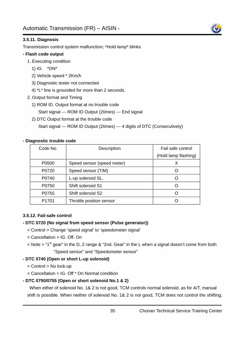
3.5.11. Diagnosis Transmission control system malfunction; *Hold lamp* blinks - Flash code output 1. Executing condition 1) IG. *ON* 2) Vehicle speed * 2Km/h 3) Diagnostic tester not connected 4) *L* line is grounded for more than 2 seconds. 2. Output format and Timing 1) ROM ID. Output format at no trouble code Start signal --- ROM ID Output (2times) --- End signal 2) DTC Output format at the trouble code Start signal --- ROM ID Output (2times) --- 4 digits of DTC (Consecutively) - Diagnostic trouble code
Code No. Description Fail safe control (Hold lamp flashing)
P0500 Speed sensor (speed meter) X
P0720 Speed sensor (T/M) O P0740 L-up solenoid SL. O
P0750 Shift solenoid S1 O
P0755 Shift solenoid S2 O
P1701 Throttle position sensor O
3.5.12. Fail-safe control - DTC 0720 (No signal from speed sensor (Pulse generator)) < Control > Change ‘speed signal’ to ‘speedometer signal’ < Cancellation > IG. Off, On < Note > “1st gear” in the D, 2 range & “2nd. Gear” in the L when a signal doesn’t come from both
“Speed sensor” and “Speedometer sensor” - DTC 0740 (Open or short L-up solenoid) < Control > No lock-up < Cancellation > IG. Off * On Normal condition - DTC 0750/0755 (Open or short solenoid No.1 & 2) When either of solenoid No. 1& 2 is not good, TCM controls normal solenoid, as for A/T, manual
shift is possible. When neither of solenoid No. 1& 2 is not good, TCM does not control the shifting,
Automatic Transmission (FR) – AISIN -
36 Chonan Technical Service Training Center
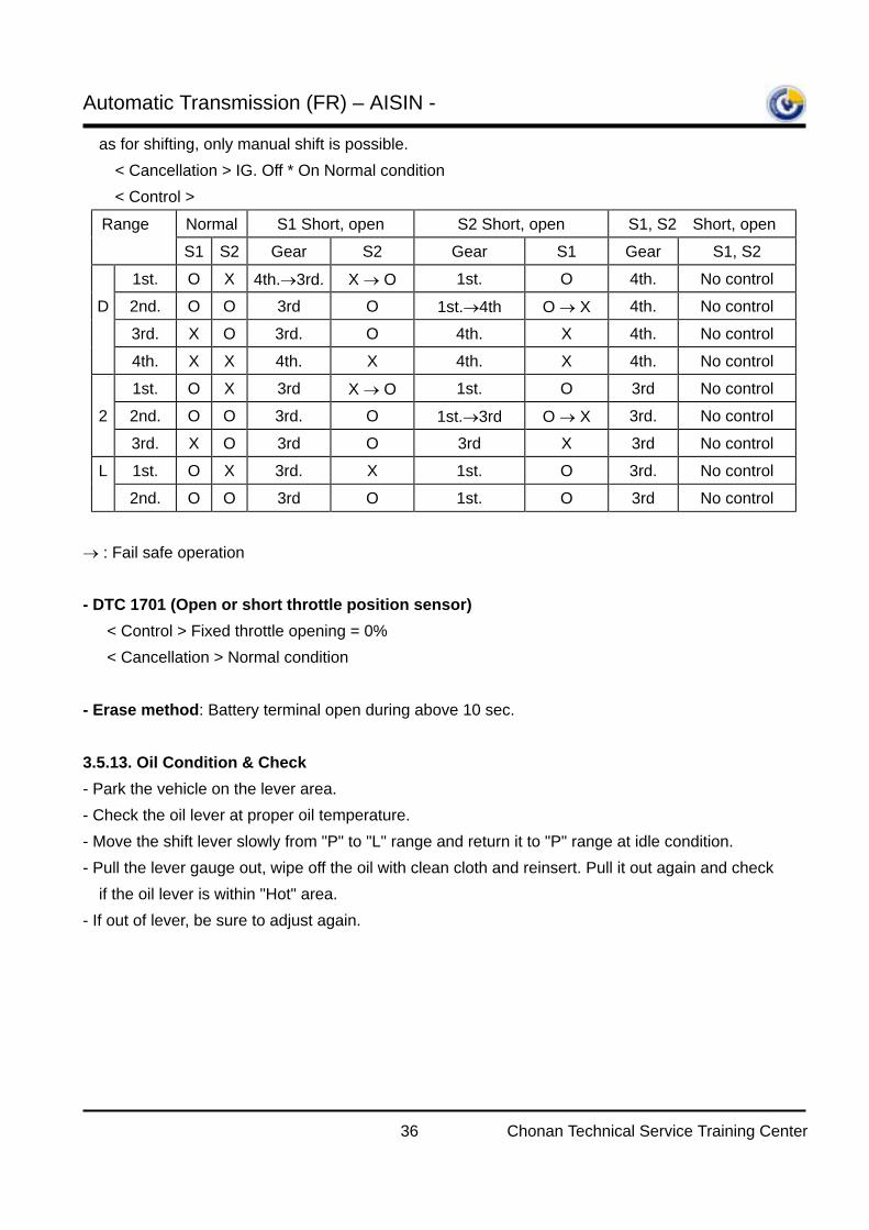
as for shifting, only manual shift is possible. < Cancellation > IG. Off * On Normal condition
< Control >
Range Normal S1 Short, open S2 Short, open S1, S2 Short, open
S1 S2 Gear S2 Gear S1 Gear S1, S2
1st. O X 4th.→3rd. X → O 1st. O 4th. No control D 2nd. O O 3rd O 1st.→4th O → X 4th. No control
3rd. X O 3rd. O 4th. X 4th. No control
4th. X X 4th. X 4th. X 4th. No control
1st. O X 3rd X → O 1st. O 3rd No control
2 2nd. O O 3rd. O 1st.→3rd O → X 3rd. No control
3rd. X O 3rd O 3rd X 3rd No control L 1st. O X 3rd. X 1st. O 3rd. No control
2nd. O O 3rd O 1st. O 3rd No control
→ : Fail safe operation - DTC 1701 (Open or short throttle position sensor) < Control > Fixed throttle opening = 0% < Cancellation > Normal condition - Erase method: Battery terminal open during above 10 sec. 3.5.13. Oil Condition & Check
- Park the vehicle on the lever area. - Check the oil lever at proper oil temperature. - Move the shift lever slowly from "P" to "L" range and return it to "P" range at idle condition. - Pull the lever gauge out, wipe off the oil with clean cloth and reinsert. Pull it out again and check
if the oil lever is within "Hot" area. - If out of lever, be sure to adjust again.
Automatic Transmission (FR) – AISIN -
37 Chonan Technical Service Training Center
4. AW30-43LE Model 4.1 Introduction "AW30-43LE” model has a lock-up mechanism inside of torque converter and this transaxle is controlled by electronic control module. It consists of lock-up built in torque converter, 4th gear planetary gear set, hydraulic pressure control and electronic control devices. TCM controls the each clutches and brakes according to the basic shift pattern. Line pressure is controlled mechanically (throttle cable and valve).
4.2 Application
SR (All engine – domestic only), H-1 (A-2.5 C/R, 4D56 2.5L TCI, 4D56 T2 NA(VAN only)) 4.3 Components Friction elements: Clutches: 3EA, Brakes: 4EA, Multiple disc type 3EA, Band type 1EA, OWC: 3EA Planetary gear: 3sets(O/D planetary gear, Front planetary gear, Rear planetary gear), Simpson (single) type
4.3.1. Structure
O/D brake
O/D clutch O/D OWC
Direct clutch
2nd coast brake
Forward clutch
2nd brake
L&R brake
No.1 OWC No.2 OWC
Automatic Transmission (FR) – AISIN -
38 Chonan Technical Service Training Center
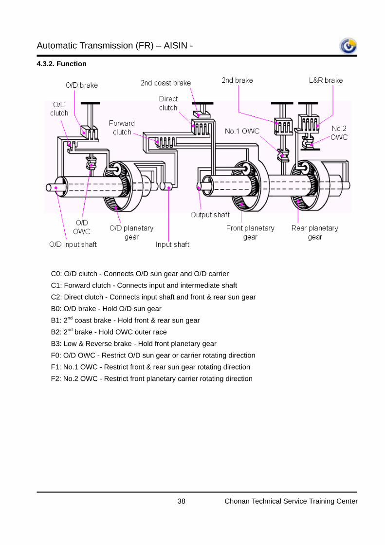
4.3.2. Function
C0: O/D clutch - Connects O/D sun gear and O/D carrier C1: Forward clutch - Connects input and intermediate shaft C2: Direct clutch - Connects input shaft and front & rear sun gear B0: O/D brake - Hold O/D sun gear B1: 2nd coast brake - Hold front & rear sun gear B2: 2nd brake - Hold OWC outer race
B3: Low & Reverse brake - Hold front planetary gear F0: O/D OWC - Restrict O/D sun gear or carrier rotating direction
F1: No.1 OWC - Restrict front & rear sun gear rotating direction
F2: No.2 OWC - Restrict front planetary carrier rotating direction
Automatic Transmission (FR) – AISIN -
39 Chonan Technical Service Training Center
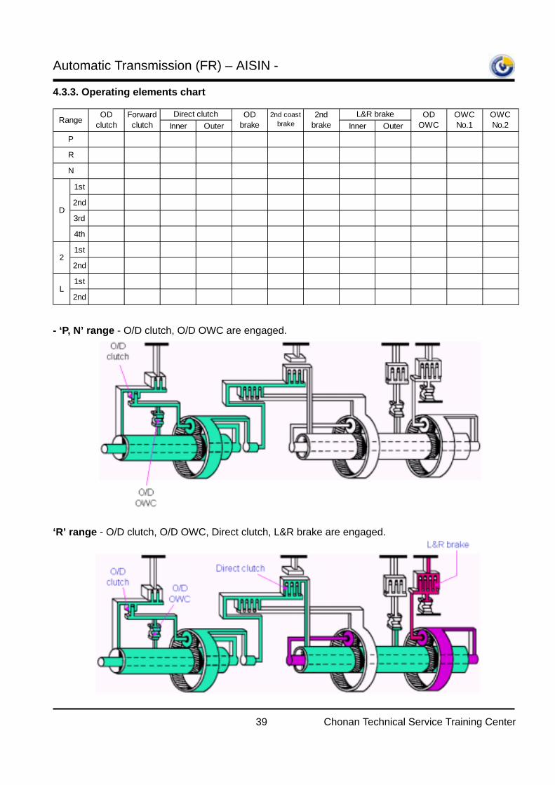
4.3.3. Operating elements chart
- ‘P, N’ range - O/D clutch, O/D OWC are engaged.
‘R’ range - O/D clutch, O/D OWC, Direct clutch, L&R brake are engaged.
Inner Outer Inner Outer
1st
2nd
3rd
4th
1st
2nd
1st
2nd
Range ODclutch
Forwardclutch
OWCNo.1
Direct clutch ODbrake
2nd coastbrake
D
2
L
OWCNo.2
P
R
N
2ndbrake
L&R brake ODOWC
Automatic Transmission (FR) – AISIN -
40 Chonan Technical Service Training Center
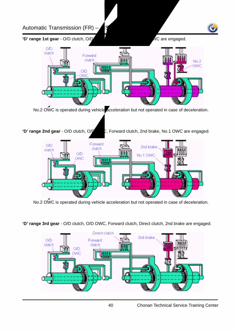
‘D’ range 1st gear - O/D clutch, O/D OWC, Forward clutch, No.2 OWC are engaged.
No.2 OWC is operated during vehicle acceleration but not operated in case of deceleration.
‘D’ range 2nd gear - O/D clutch, O/D OWC, Forward clutch, 2nd brake, No.1 OWC are engaged.
No.2 OWC is operated during vehicle acceleration but not operated in case of deceleration.
‘D’ range 3rd gear - O/D clutch, O/D OWC, Forward clutch, Direct clutch, 2nd brake are engaged.
Automatic Transmission (FR) – AISIN -
41 Chonan Technical Service Training Center
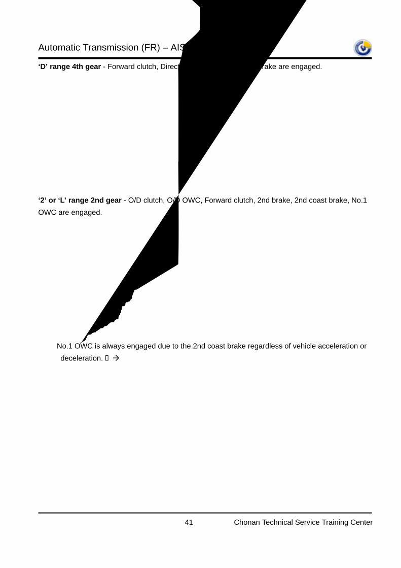
‘D’ range 4th gear - Forward clutch, Direct clutch, O/D brake, 2nd brake are engaged.
‘2’ or ‘L’ range 2nd gear - O/D clutch, O/D OWC, Forward clutch, 2nd brake, 2nd coast brake, No.1 OWC are engaged.
No.1 OWC is always engaged due to the 2nd coast brake regardless of vehicle acceleration or deceleration. Engine brake is available.
Memo
Automatic Transmission (FR) – AISIN -
42 Chonan Technical Service Training Center
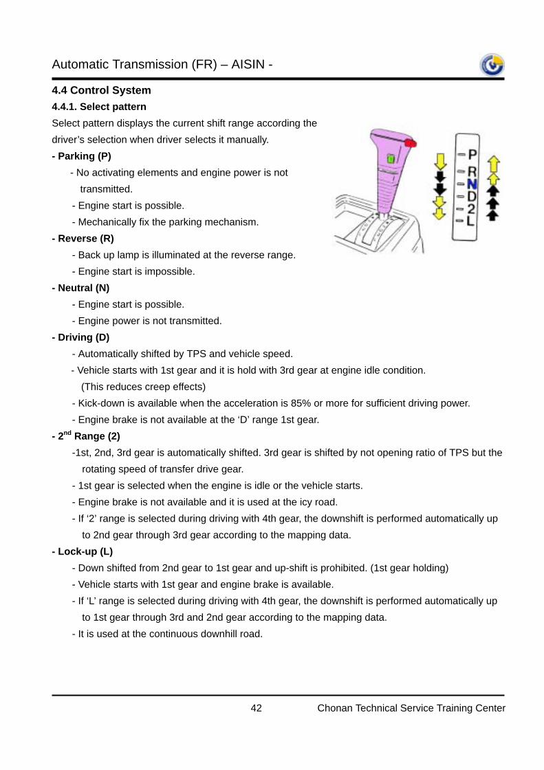
4.4 Control System 4.4.1. Select pattern Select pattern displays the current shift range according the driver’s selection when driver selects it manually. - Parking (P)
- No activating elements and engine power is not transmitted.
- Engine start is possible. - Mechanically fix the parking mechanism. - Reverse (R) - Back up lamp is illuminated at the reverse range. - Engine start is impossible. - Neutral (N) - Engine start is possible. - Engine power is not transmitted. - Driving (D) - Automatically shifted by TPS and vehicle speed.
- Vehicle starts with 1st gear and it is hold with 3rd gear at engine idle condition. (This reduces creep effects)
- Kick-down is available when the acceleration is 85% or more for sufficient driving power. - Engine brake is not available at the ‘D’ range 1st gear. - 2nd Range (2) -1st, 2nd, 3rd gear is automatically shifted. 3rd gear is shifted by not opening ratio of TPS but the
rotating speed of transfer drive gear. - 1st gear is selected when the engine is idle or the vehicle starts. - Engine brake is not available and it is used at the icy road. - If ‘2’ range is selected during driving with 4th gear, the downshift is performed automatically up
to 2nd gear through 3rd gear according to the mapping data. - Lock-up (L) - Down shifted from 2nd gear to 1st gear and up-shift is prohibited. (1st gear holding) - Vehicle starts with 1st gear and engine brake is available. - If ‘L’ range is selected during driving with 4th gear, the downshift is performed automatically up
to 1st gear through 3rd and 2nd gear according to the mapping data. - It is used at the continuous downhill road.
Automatic Transmission (FR) – AISIN -
43 Chonan Technical Service Training Center
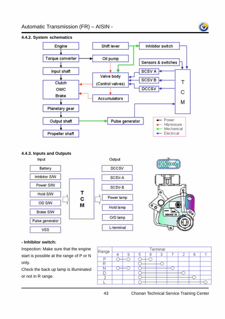
4.4.2. System schematics
4.4.3. Inputs and Outputs
- Inhibitor switch: Inspection: Make sure that the engine start is possible at the range of P or N only. Check the back up lamp is illuminated or not in R range.
Automatic Transmission (FR) – AISIN -
44 Chonan Technical Service Training Center
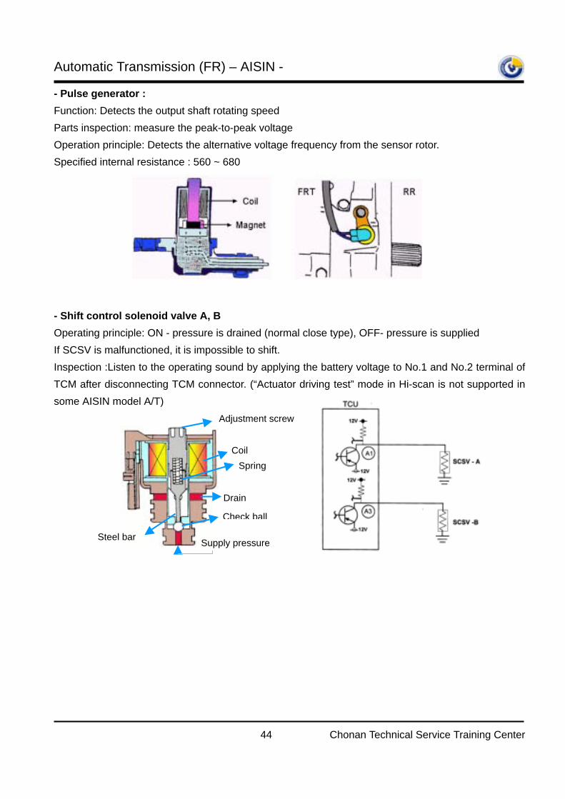
- Pulse generator : Function: Detects the output shaft rotating speed Parts inspection: measure the peak-to-peak voltage Operation principle: Detects the alternative voltage frequency from the sensor rotor. Specified internal resistance : 560 ~ 680Ω
- Shift control solenoid valve A, B Operating principle: ON - pressure is drained (normal close type), OFF- pressure is supplied If SCSV is malfunctioned, it is impossible to shift. Inspection :Listen to the operating sound by applying the battery voltage to No.1 and No.2 terminal of TCM after disconnecting TCM connector. (“Actuator driving test” mode in Hi-scan is not supported in some AISIN model A/T)
Adjustment screw
Coil Spring
Drain
Check ball
Steel bar Supply pressure
Automatic Transmission (FR) – AISIN -
45 Chonan Technical Service Training Center
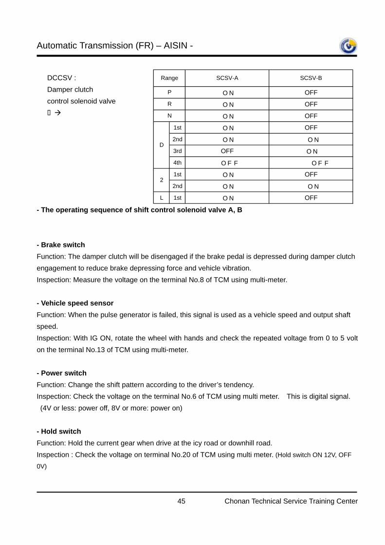
- The operating sequence of shift control solenoid valve A, B - Brake switch Function: The damper clutch will be disengaged if the brake pedal is depressed during damper clutch engagement to reduce brake depressing force and vehicle vibration. Inspection: Measure the voltage on the terminal No.8 of TCM using multi-meter.
- Vehicle speed sensor Function: When the pulse generator is failed, this signal is used as a vehicle speed and output shaft speed. Inspection: With IG ON, rotate the wheel with hands and check the repeated voltage from 0 to 5 volt on the terminal No.13 of TCM using multi-meter. - Power switch Function: Change the shift pattern according to the driver’s tendency. Inspection: Check the voltage on the terminal No.6 of TCM using multi meter. This is digital signal. (4V or less: power off, 8V or more: power on) - Hold switch Function: Hold the current gear when drive at the icy road or downhill road. Inspection : Check the voltage on terminal No.20 of TCM using multi meter. (Hold switch ON 12V, OFF
0V)
ON OFF
ON OFF
ON OFF
1st ON OFF
2nd ON ON
3rd OFF ON
4th OFF OFF
1st ON OFF
2nd ON ON
L 1st ON OFF
D
2
SCSV-B
P
R
N
Range SCSV-ADCCSV : Damper clutch control solenoid valve
It is ON at the 4th gearonly.
Automatic Transmission (FR) – AISIN -
46 Chonan Technical Service Training Center
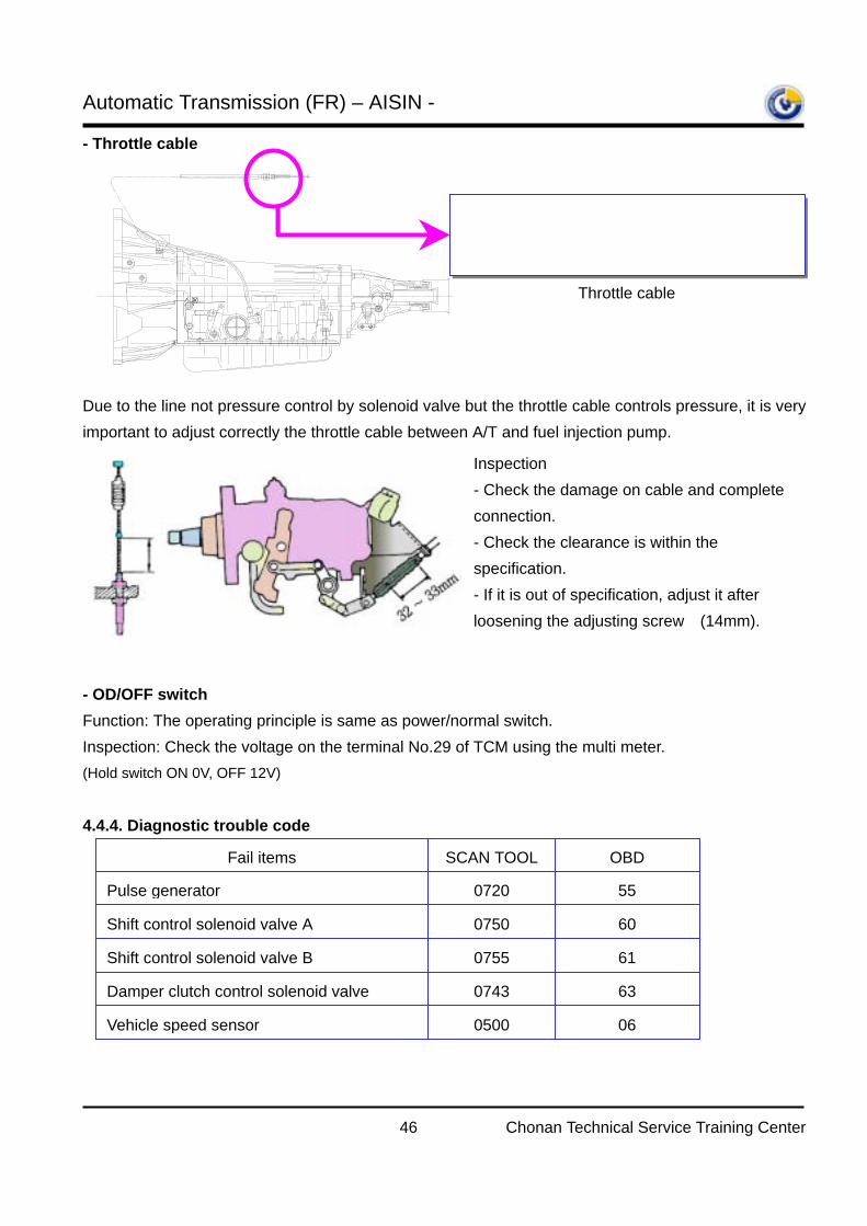
- Throttle cable
Due to the line not pressure control by solenoid valve but the throttle cable controls pressure, it is very important to adjust correctly the throttle cable between A/T and fuel injection pump. - OD/OFF switch Function: The operating principle is same as power/normal switch. Inspection: Check the voltage on the terminal No.29 of TCM using the multi meter. (Hold switch ON 0V, OFF 12V) 4.4.4. Diagnostic trouble code
Throttle cable
Inspection - Check the damage on cable and complete connection. - Check the clearance is within the specification. - If it is out of specification, adjust it after loosening the adjusting screw (14mm).
Fail items SCAN TOOL
Pulse generator 0720
Shift control solenoid valve A 0750
Shift control solenoid valve B 0755
Damper clutch control solenoid valve 0743
Vehicle speed sensor 0500
OBD
55
60
61
63
06
Automatic Transmission (FR) – AISIN -
47 Chonan Technical Service Training Center
- Fault code erasing procedure
On SR and H-1 vehicles with TCI (Turbo charger inter-cooler) engines and automatic transaxles, the diagnostic trouble codes related to automatic transaxle system failure will not be erased though the battery negative cable has been removed after repairing the defective parts.
1) Install the Hi-scan to the vehicle to conduct self-diagnosis test for the automatic transaxle control system.
2) Turn the ignition key to the ON position or start the engine. Turn on the Hi-scan power. If any failure related to the automatic transaxle control system exists, the following diagnostic trouble codes may be displayed on the Hi-scan when conducting self-diagnosis test with a Hi-scan. * P0500: VSS malfunction * P0750: SCSV malfunction * P0743: DCCSV open circuit * P0720: Pulse generator open circuit * Etc.
Additionally, the ‘hold’ light on the cluster flashes repeatedly as many as detected codes. 3) If you press the ‘erase’ key on the Hi-scan to delete any trouble codes after repairing the defective parts. Hi-scan directs you disconnect the battery negative terminal. 4) However, the automatic transaxle relating diagnostic trouble codes for SR and H-1 with a TCI engine will not be erased even though the battery negative cable has been disconnected more than 15 seconds. Furthermore the ‘hold’ light still flashes repeatedly when conducting self- diagnosis test using the Hi-scan. 5) If you encounter a vehicle with the above specification and symptoms, follow the trouble codes erasing procedure as below.
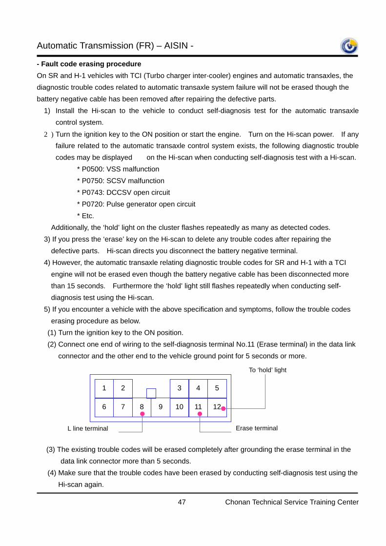
(1) Turn the ignition key to the ON position. (2) Connect one end of wiring to the self-diagnosis terminal No.11 (Erase terminal) in the data link
connector and the other end to the vehicle ground point for 5 seconds or more.
(3) The existing trouble codes will be erased completely after grounding the erase terminal in the
data link connector more than 5 seconds. (4) Make sure that the trouble codes have been erased by conducting self-diagnosis test using the
Hi-scan again.
1 2
6 7 8 9 10 11 12
3 4 5
L line terminal Erase terminal
To ‘hold’ light
Automatic Transmission (FR) – AISIN -
48 Chonan Technical Service Training Center
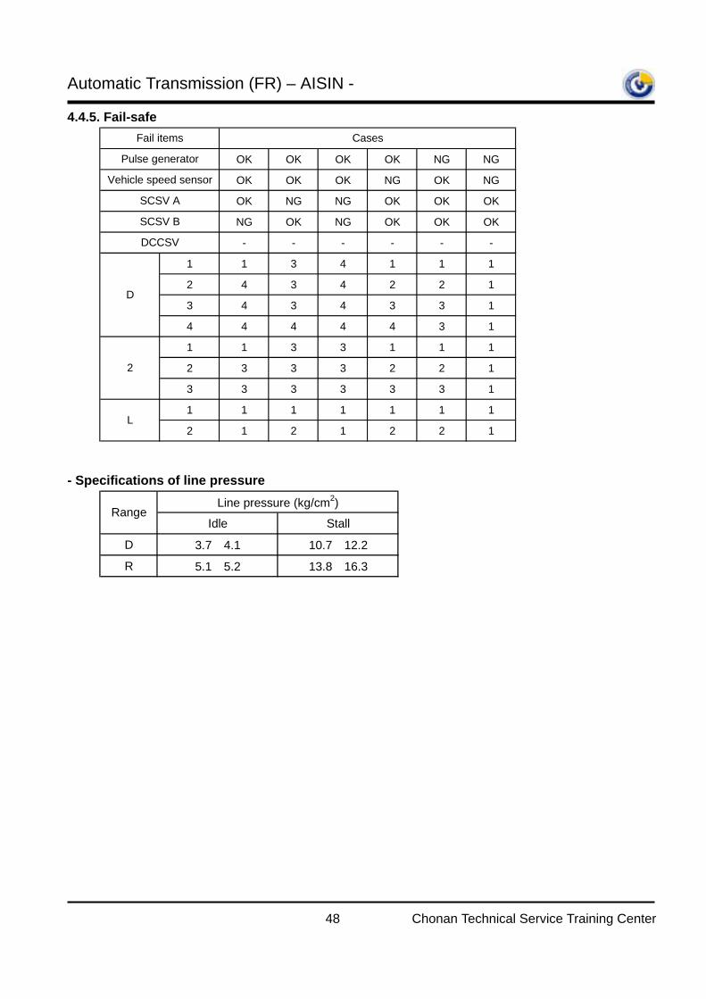
4.4.5. Fail-safe - Specifications of line pressure
OK OK OK OK NG NG
OK OK OK NG OK NG
OK NG NG OK OK OK
NG OK NG OK OK OK
- - - - - -
1 1 3 4 1 1 1
2 4 3 4 2 2 1
3 4 3 4 3 3 1
4 4 4 4 4 3 1
1 1 3 3 1 1 1
2 3 3 3 2 2 1
3 3 3 3 3 3 1
1 1 1 1 1 1 1
2 1 2 1 2 2 1
2
L
Cases
SCSV A
SCSV B
DCCSV
D
Fail items
Pulse generator
Vehicle speed sensor
Idle Stall
D 3.7∼4.1 10.7∼12.2
R 5.1∼5.2 13.8∼16.3
Line pressure (kg/cm2)Range
Automatic Transmission (FR) – AISIN -
49 Chonan Technical Service Training Center
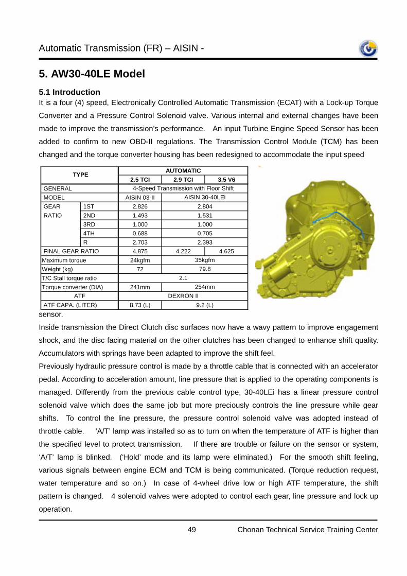
5. AW30-40LE Model 5.1 Introduction It is a four (4) speed, Electronically Controlled Automatic Transmission (ECAT) with a Lock-up Torque
Converter and a Pressure Control Solenoid valve. Various internal and external changes have been
made to improve the transmission’s performance. An input Turbine Engine Speed Sensor has been
added to confirm to new OBD-II regulations. The Transmission Control Module (TCM) has been
changed and the torque converter housing has been redesigned to accommodate the input speed
sensor.
Inside transmission the Direct Clutch disc surfaces now have a wavy pattern to improve engagement
shock, and the disc facing material on the other clutches has been changed to enhance shift quality.
Accumulators with springs have been adapted to improve the shift feel.
Previously hydraulic pressure control is made by a throttle cable that is connected with an accelerator
pedal. According to acceleration amount, line pressure that is applied to the operating components is
managed. Differently from the previous cable control type, 30-40LEi has a linear pressure control
solenoid valve which does the same job but more preciously controls the line pressure while gear
shifts. To control the line pressure, the pressure control solenoid valve was adopted instead of
throttle cable. ‘A/T’ lamp was installed so as to turn on when the temperature of ATF is higher than
the specified level to protect transmission. If there are trouble or failure on the sensor or system,
‘A/T’ lamp is blinked. (‘Hold’ mode and its lamp were eliminated.) For the smooth shift feeling,
various signals between engine ECM and TCM is being communicated. (Torque reduction request,
water temperature and so on.) In case of 4-wheel drive low or high ATF temperature, the shift
pattern is changed. 4 solenoid valves were adopted to control each gear, line pressure and lock up
operation.
AUTOMATIC2.5 TCI 2.9 TCI 3.5 V6
GENERAL MODEL AISIN 03-II GEAR 1ST 2.826 2.804 RATIO 2ND 1.493 1.531
3RD 1.000 1.000 4TH 0.688 0.705 R 2.703 2.393
FINAL GEAR RATIO 4.875 4.222 4.625Maximum torque 24kgfmWeight (kg) 72T/C Stall torque ratioTorque converter (DIA) 241mm
ATF CAPA. (LITER) 8.73 (L) 9.2 (L)
4-Speed Transmission with Floor Shift
TYPE
AISIN 30-40LEi
ATF DEXRON II
2.1
35kgfm
254mm
79.8
Automatic Transmission (FR) – AISIN -
50 Chonan Technical Service Training Center
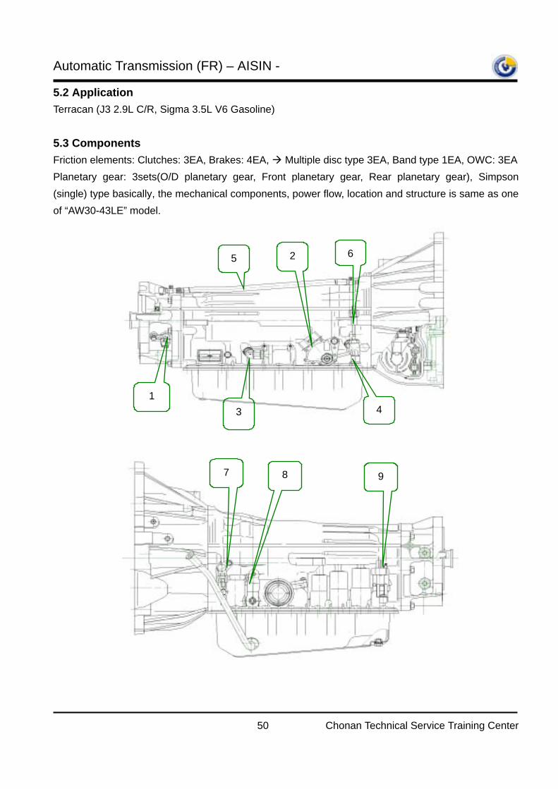
5.2 Application
Terracan (J3 2.9L C/R, Sigma 3.5L V6 Gasoline) 5.3 Components Friction elements: Clutches: 3EA, Brakes: 4EA, Multiple disc type 3EA, Band type 1EA, OWC: 3EA Planetary gear: 3sets(O/D planetary gear, Front planetary gear, Rear planetary gear), Simpson (single) type basically, the mechanical components, power flow, location and structure is same as one of “AW30-43LE” model.
2
1 3 4
5 6
7 8 9
Automatic Transmission (FR) – AISIN -
51 Chonan Technical Service Training Center
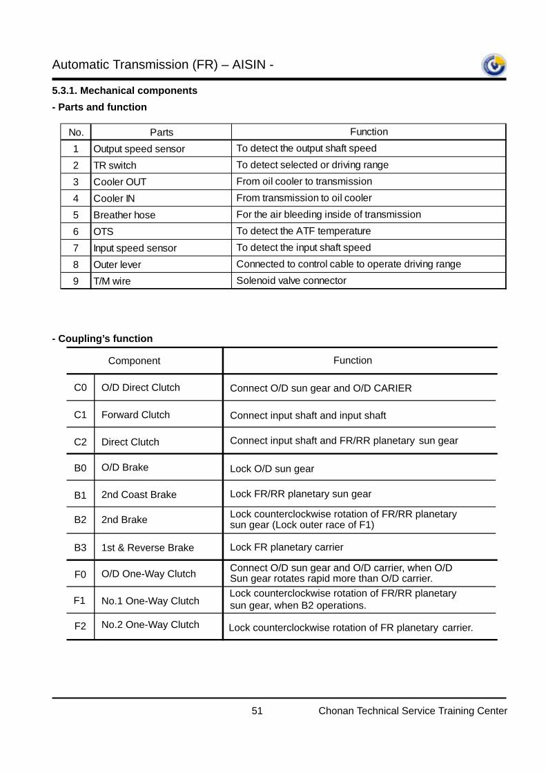
5.3.1. Mechanical components - Parts and function - Coupling’s function
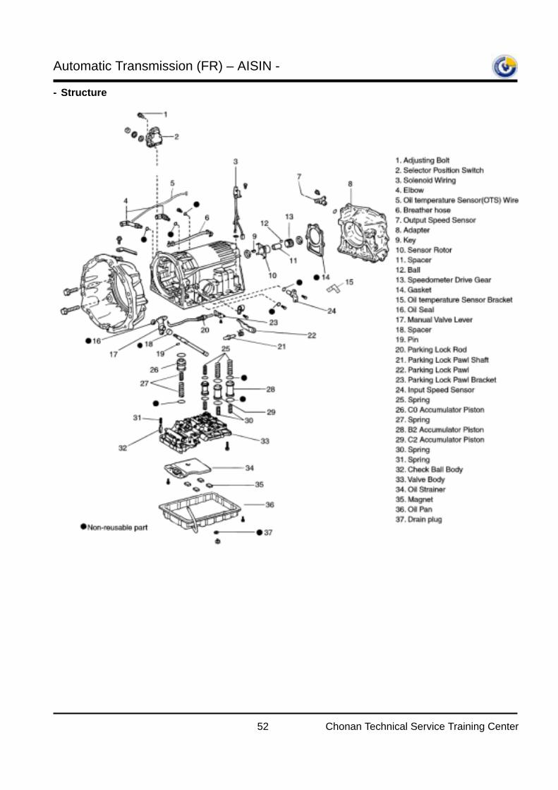
No. Parts1 Output speed sensor2 TR switch3 Cooler OUT4 Cooler IN5 Breather hose6 OTS7 Input speed sensor8 Outer lever9 T/M wire
Connected to control cable to operate driving range Solenoid valve connector
From transmission to oil cooler For the air bleeding inside of transmission To detect the ATF temperature To detect the input shaft speed
Function To detect the output shaft speed To detect selected or driving range From oil cooler to transmission
Component Function
C0 O/D Direct Clutch Connect O/D sun gear and O/D CARIER
C1 Forward Clutch Connect input shaft and input shaft
C2 Direct Clutch Connect input shaft and FR/RR planetary sun gear
B0 O/D Brake Lock O/D sun gear
B1 2nd Coast Brake Lock FR/RR planetary sun gear
B2 2nd Brake Lock counterclockwise rotation of FR/RR planetary sun gear (Lock outer race of F1)
B3 1st & Reverse Brake Lock FR planetary carrier
F0 O/D One-Way Clutch Connect O/D sun gear and O/D carrier, when O/D Sun gear rotates rapid more than O/D carrier.
F1 No.1 One-Way Clutch Lock counterclockwise rotation of FR/RR planetary sun gear, when B2 operations.
F2 No.2 One-Way Clutch Lock counterclockwise rotation of FR planetary carrier.
Automatic Transmission (FR) – AISIN -
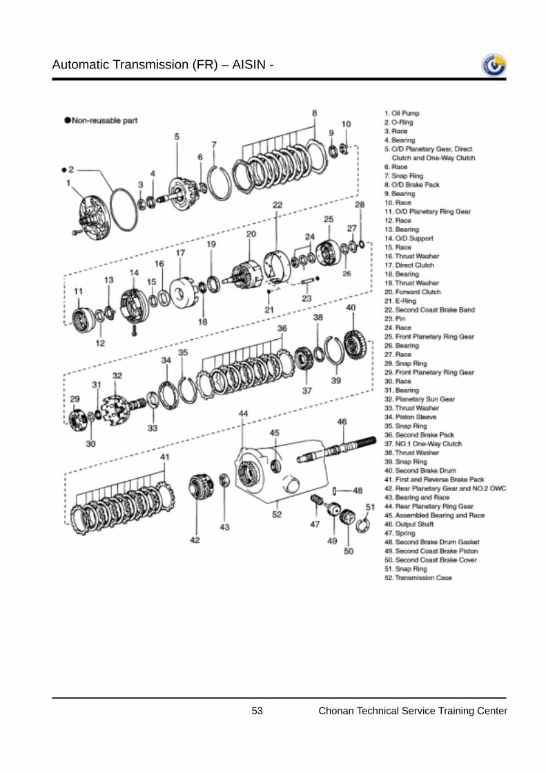
52 Chonan Technical Service Training Center
- Structure
Automatic Transmission (FR) – AISIN -
53 Chonan Technical Service Training Center
Automatic Transmission (FR) – AISIN -
54 Chonan Technical Service Training Center
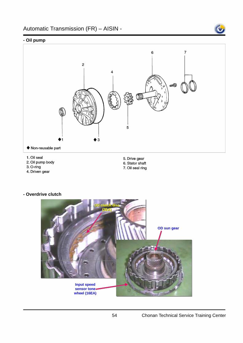
- Oil pump - Overdrive clutch
OD clutch disc (2EA)
OD clutch disc (2EA)
Input speed sensor tone wheel (16EA)
OD sun gear
OD clutch disc (2EA)
OD clutch disc (2EA)
Input speed sensor tone wheel (16EA)
OD sun gear
Automatic Transmission (FR) – AISIN -
55 Chonan Technical Service Training Center
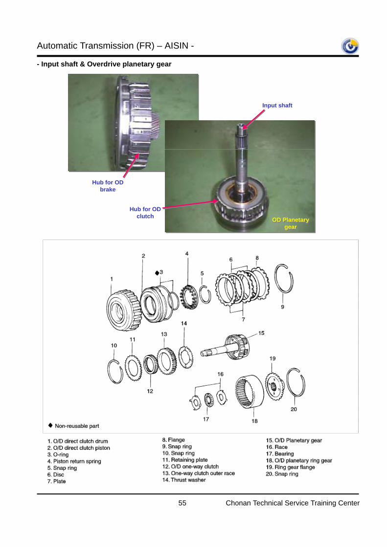
- Input shaft & Overdrive planetary gear
Hub for OD brake
Input shaft
Hub for OD clutch
OD Planetary gear
OD Planetary gear
Automatic Transmission (FR) – AISIN -
56 Chonan Technical Service Training Center
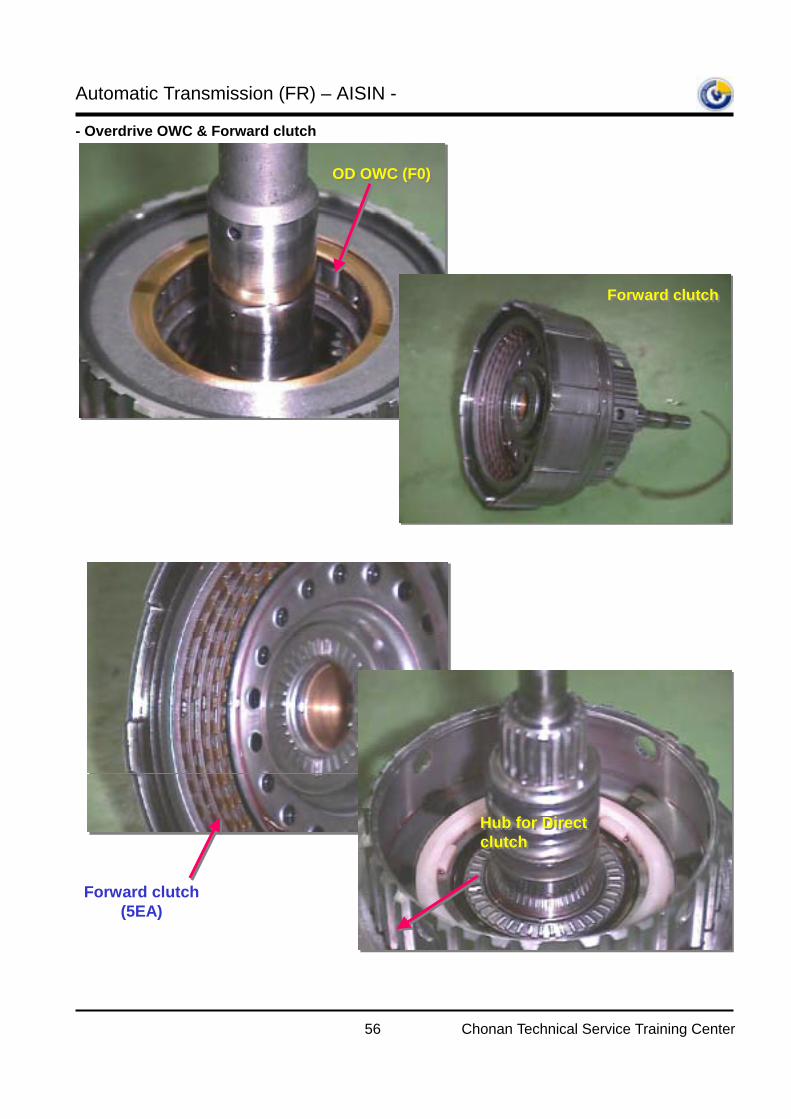
- Overdrive OWC & Forward clutch
OD OWC (F0)OD OWC (F0)
Forward clutchForward clutch
OD OWC (F0)OD OWC (F0)
Forward clutchForward clutch
Forward clutch (5EA)
Hub for Direct clutchHub for Direct clutch
Automatic Transmission (FR) – AISIN -
57 Chonan Technical Service Training Center
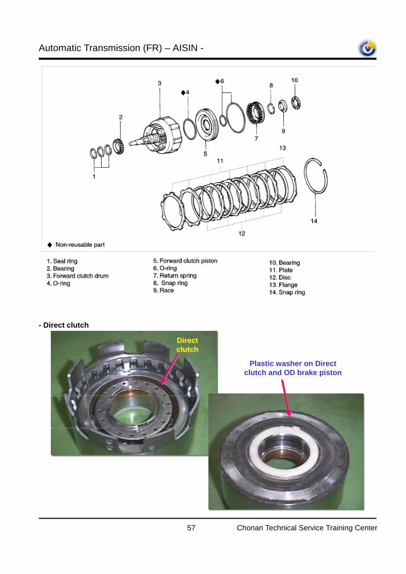
- Direct clutch
Direct clutchDirect clutch
Plastic washer on Direct clutch and OD brake piston
Automatic Transmission (FR) – AISIN -
58 Chonan Technical Service Training Center
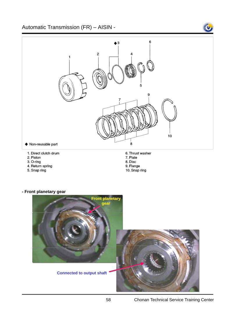
- Front planetary gear
Front planetary gear
Front planetary gear
Connected to output shaft
Automatic Transmission (FR) – AISIN -
59 Chonan Technical Service Training Center
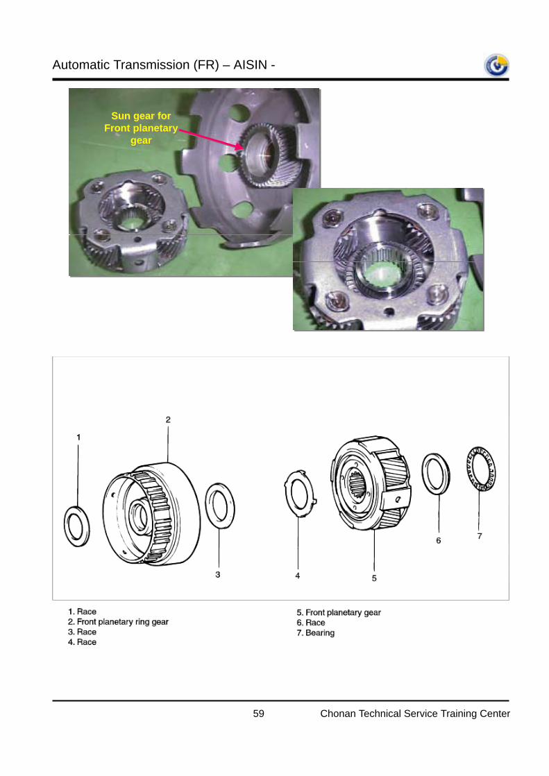
Sun gear for Front planetary
gear
Sun gear for Front planetary
gear
Automatic Transmission (FR) – AISIN -
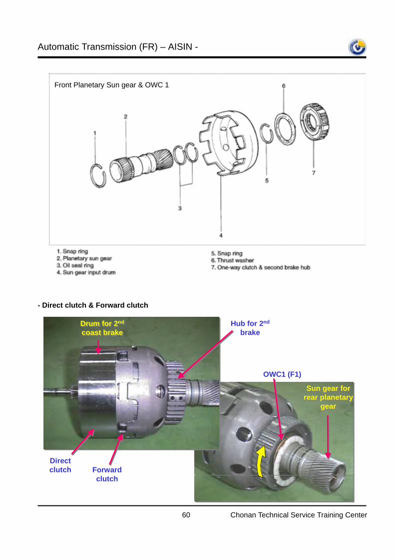
60 Chonan Technical Service Training Center
- Direct clutch & Forward clutch
Front Planetary Sun gear & OWC 1
Direct clutch Forward
clutch
Hub for 2nd
brakeDrum for 2nd
coast brakeDrum for 2nd
coast brake
Sun gear for rear planetary
gear
Sun gear for rear planetary
gear
OWC1 (F1)
Automatic Transmission (FR) – AISIN -
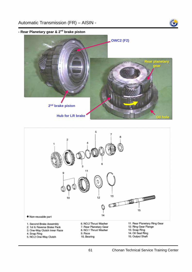
61 Chonan Technical Service Training Center
- Rear Planetary gear & 2nd brake piston
2nd brake piston
Hub for LR brake
OWC2 (F2)
Rear planetary gear
Rear planetary gear
Oil holeOil hole
Automatic Transmission (FR) – AISIN -
62 Chonan Technical Service Training Center
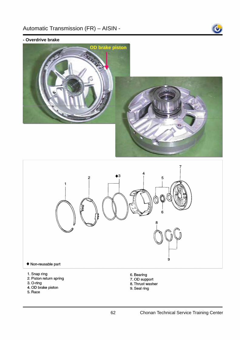
- Overdrive brake
OD brake pistonOD brake piston
Automatic Transmission (FR) – AISIN -
63 Chonan Technical Service Training Center
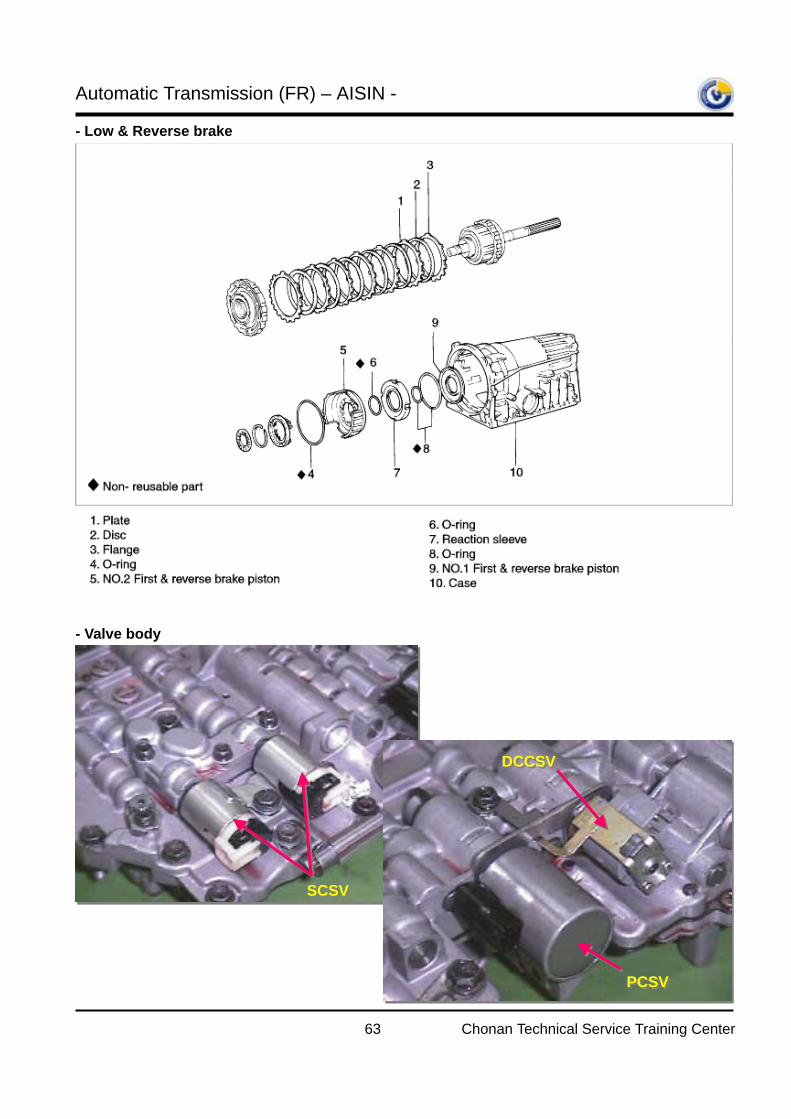
- Low & Reverse brake - Valve body
SCSVSCSV
PCSVPCSV
DCCSVDCCSV
Automatic Transmission (FR) – AISIN -
64 Chonan Technical Service Training Center
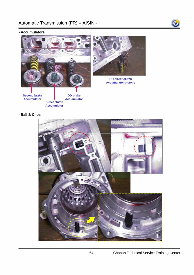
- Accumulators - Ball & Clips
OD direct clutch Accumulator pistons
Direct clutch Accumulator
Second brake Accumulator
OD brake Accumulator
Automatic Transmission (FR) – AISIN -
65 Chonan Technical Service Training Center
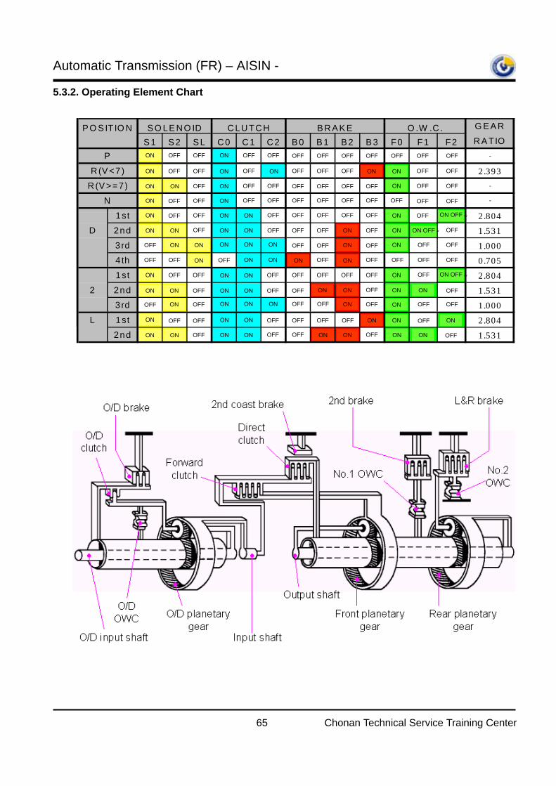
5.3.2. Operating Element Chart
P O S ITIO N S O LE N O ID C LU TC H B R A K E O .W .C . G E A R
S 1 S 2 S L C 0 C 1 C 2 B 0 B 1 B 2 B 3 F0 F1 F2 RA TIOP › ~ ~ › ~ ~ ~ ~ ~ ~ ~ ~ ~ |
R (V <7) › ~ ~ › ~ › ~ ~ ~ › › ~ ~ 2.393R(V >=7) › › ~ › ~ ~ ~ ~ ~ ~ › ~ ~ |
N › ~ ~ › ~ ~ ~ ~ ~ ~ ~ ~ ~ |1st › ~ ~ › › ~ ~ ~ ~ ~ › ~ › ~ 2.804
D 2nd › › ~ › › ~ ~ ~ › ~ › › ~ ~ 1.5313rd ~ › › › › › ~ ~ › ~ › ~ ~ 1.0004th ~ ~ › ~ › › › ~ › ~ ~ ~ ~ 0.7051st › ~ ~ › › ~ ~ ~ ~ ~ › ~ › ~ 2.804
2 2nd › › ~ › › ~ ~ › › ~ › › ~ 1.5313rd ~ › ~ › › › ~ ~ › ~ › ~ ~ 1.000
L 1st › ~ ~ › › ~ ~ ~ ~ › › ~ › 2.8042nd › › ~ › › ~ ~ › › ~ › › ~ 1.531
OFF OFFON
ON OFF OFF
OFF
OFFOFF
OFFOFF
ON ON
ON
ON
ON ON
ON ON
ON
OFF
OFF
OFF OFF
OFF OFF
OFF
OFF
OFF
OFF
ON
ON ON
ONOFF
ON OFF
ON ON
ON
ON ON
ON
ON
ON
ON
ON
ON
ON
ON ON
ON ON
ON
ON
ON
ON
ON
ON
ON
ON
ON
ON
ON
OFF
OFF
OFF
OFF
OFF
OFF
OFF
OFF
OFF
OFF OFF
OFF OFF
OFF
OFF OFF OFF
OFF OFF
OFF OFF
OFF OFF
OFF OFF
OFF OFF
OFF
OFF
OFF
OFF
OFF
OFF
OFF
OFF
OFF
OFF
OFF
OFF OFFOFF OFF
OFFOFF OFF
OFFOFF OFF OFF
OFF
OFFOFF
OFF
OFF OFF OFF OFF OFF -
OFF OFF
OFF OFF
OFF OFFOFF
OFF
OFF
OFFOFF
OFFOFFOFF
ON
ON
ON
ONON
ON
ON
ON
ON
ON
ON
ON ON
OFF
ON
ON
ON
ONON
ON
ONON
ON
ON ON
OFF
OFFOFF
OFF
OFF
ON OFF
-
-
ON OFF
ON OFF
Automatic Transmission (FR) – AISIN -
66 Chonan Technical Service Training Center
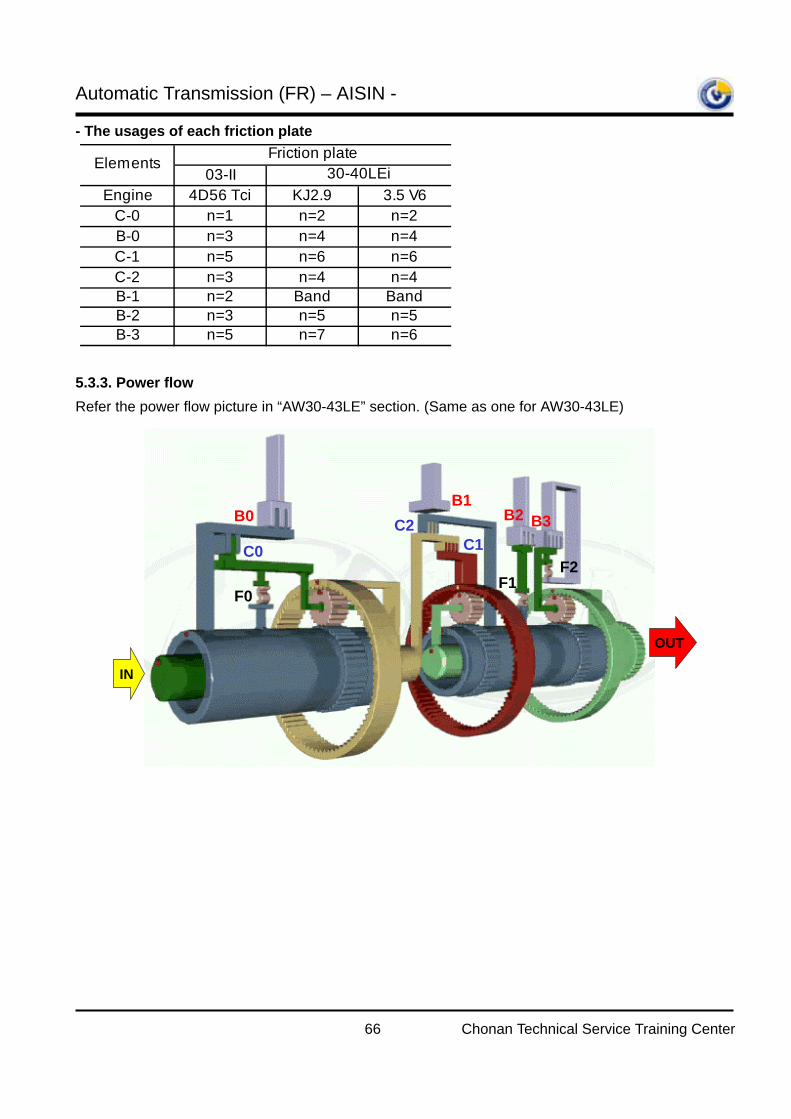
- The usages of each friction plate
5.3.3. Power flow Refer the power flow picture in “AW30-43LE” section. (Same as one for AW30-43LE)
F0F1
F2C0
B0
C1C2
B1B2 B3
IN
OUT
03-IIEngine 4D56 Tci KJ2.9 3.5 V6
C-0 n=1 n=2 n=2B-0 n=3 n=4 n=4C-1 n=5 n=6 n=6C-2 n=3 n=4 n=4B-1 n=2 Band BandB-2 n=3 n=5 n=5B-3 n=5 n=7 n=6
Elements Friction plate30-40LEi
Automatic Transmission (FR) – AISIN -
67 Chonan Technical Service Training Center
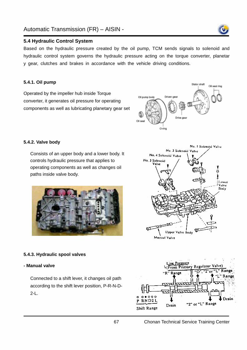
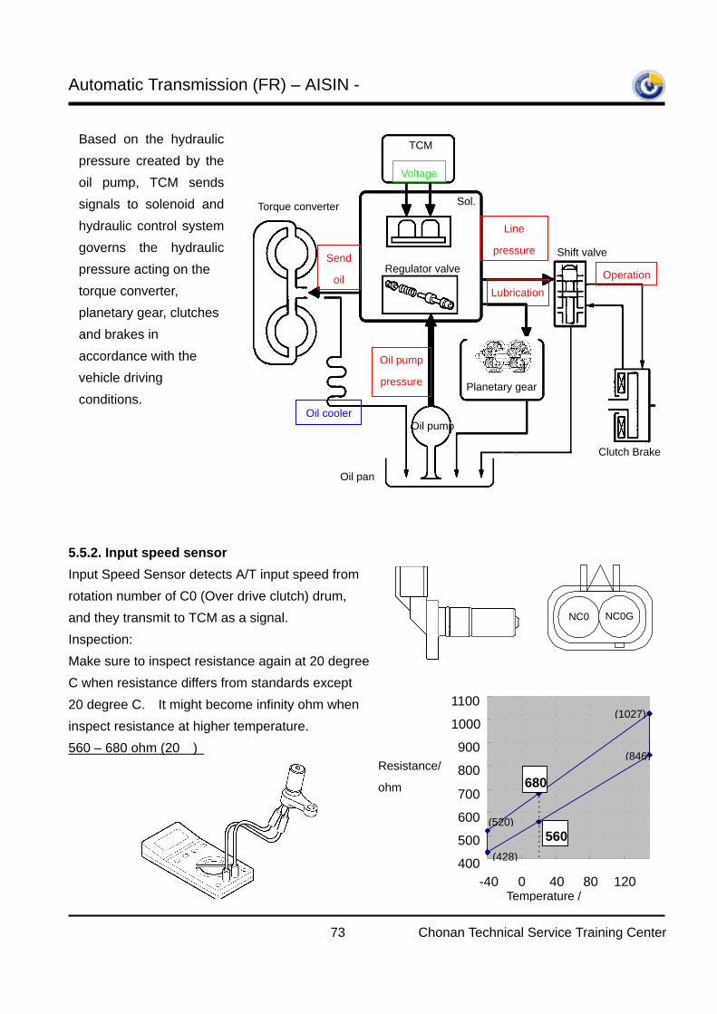
5.4 Hydraulic Control System Based on the hydraulic pressure created by the oil pump, TCM sends signals to solenoid and hydraulic control system governs the hydraulic pressure acting on the torque converter, planetary gear, clutches and brakes in accordance with the vehicle driving conditions.
5.4.1. Oil pump
Operated by the impeller hub inside Torque converter, it generates oil pressure for operating components as well as lubricating planetary gear set
5.4.2. Valve body
5.4.3. Hydraulic spool valves
- Manual valve
Consists of an upper body and a lower body. It controls hydraulic pressure that applies to operating components as well as changes oil paths inside valve body.
Connected to a shift lever, it changes oil path according to the shift lever position, P-R-N-D-2-L.
Automatic Transmission (FR) – AISIN -
68 Chonan Technical Service Training Center
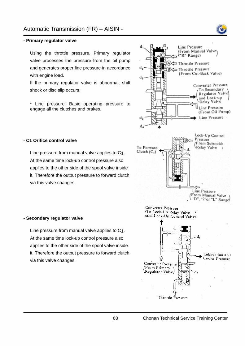
- Primary regulator valve
- C1 Orifice control valve
- Secondary regulator valve
Using the throttle pressure, Primary regulatorvalve processes the pressure from the oil pumpand generates proper line pressure in accordancewith engine load. If the primary regulator valve is abnormal, shiftshock or disc slip occurs. * Line pressure: Basic operating pressure toengage all the clutches and brakes.
Line pressure from manual valve applies to C1.
At the same time lock-up control pressure also applies to the other side of the spool valve inside it. Therefore the output pressure to forward clutch via this valve changes.
Line pressure from manual valve applies to C1.
At the same time lock-up control pressure also applies to the other side of the spool valve inside it. Therefore the output pressure to forward clutch via this valve changes.
Automatic Transmission (FR) – AISIN -
69 Chonan Technical Service Training Center
- Shift control solenoid valve NO1, NO2 (S1, S2)
- 1-2 Shift valve
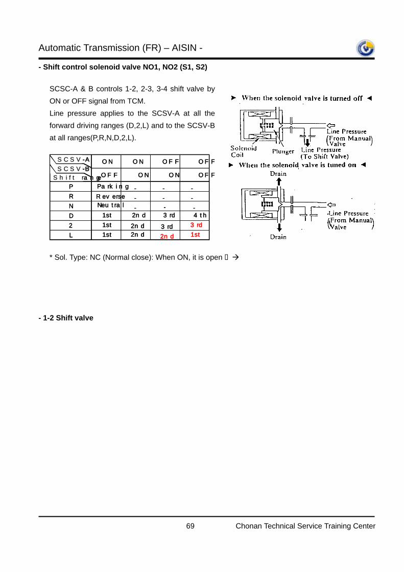
SCSC-A & B controls 1-2, 2-3, 3-4 shift valve byON or OFF signal from TCM. Line pressure applies to the SCSV-A at all theforward driving ranges (D,2,L) and to the SCSV-Bat all ranges(P,R,N,D,2,L).
ON ON OFF OFF
OFF ON ON OFF
P Parking - - -R Reverse - - -N Neutral - - -D 1st 2nd 3rd 4th
2 1st 2nd 3rd 3rd
L 1st 2nd 2nd 1st
SCSV-A
SCSV-B
Shift range
ON ON OFF OFF
OFF ON ON OFF
P Parking - - -R Reverse - - -N Neutral - - -D 1st 2nd 3rd 4th
2 1st 2nd 3rd 3rd
L 1st 2nd 2nd 1st
SCSV-A
SCSV-B
Shift range
* Sol. Type: NC (Normal close): When ON, it is open line pressure to shift valve drains
* Resistance: 11~15 ohm (20)
1-2 shift valve performs 1st - 2nd gearshift by SCSV-B ON/OFF. * SCSV-B ON: Pressure at ‘A’ releases Spoolmoves upward Pressure to B2 is
applied 2nd gear * SCSV-B OFF: Hydraulic pressure applied to ‘A’ Spool moves downward B2pressure is cut 1st gear * At 4th gear, even the SCSV-B is OFF, the spool moves upward because of the 2-3 shiftvalve line pressure: Pressure is applied to B2
Automatic Transmission (FR) – AISIN -
70 Chonan Technical Service Training Center
- 2-3 Shift valve
- 3-4 Shift valve
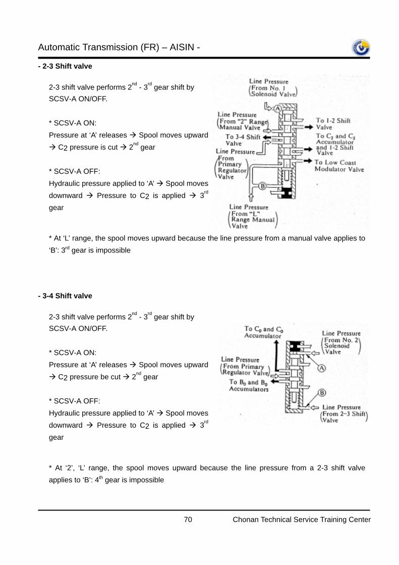
2-3 shift valve performs 2nd - 3rd gear shift by SCSV-A ON/OFF. * SCSV-A ON: Pressure at ‘A’ releases Spool moves upward
C2 pressure is cut 2nd gear * SCSV-A OFF: Hydraulic pressure applied to ‘A’ Spool movesdownward Pressure to C2 is applied 3rd
gear
* At ‘L’ range, the spool moves upward because the line pressure from a manual valve applies to‘B’: 3rd gear is impossible
2-3 shift valve performs 2nd - 3rd gear shift by SCSV-A ON/OFF. * SCSV-A ON: Pressure at ‘A’ releases Spool moves upward
C2 pressure be cut 2nd gear * SCSV-A OFF: Hydraulic pressure applied to ‘A’ Spool movesdownward Pressure to C2 is applied 3rd
gear
* At ‘2’, ‘L’ range, the spool moves upward because the line pressure from a 2-3 shift valveapplies to ‘B’: 4th gear is impossible

Automatic Transmission (FR) – AISIN -
71 Chonan Technical Service Training Center
5.4.4. Accumulators
Hydraulic circuit of accumulator, of which one sideis installed in the TM case and the other sidefaces the valve body, is connected with hydrauliccircuit to Clutches, Brakes in parallel. It functionsas a damper to lessen the engaging shock ofClutches and Brakes. That is, accumulator functions as a damper untilthe accumulator back pressure and spring forcethat applies on the backside of the piston reachesthe line pressure of the other side.
If the line pressure exceeds the accumulator backpressure and spring force, accumulator justfunctions as oil path.
30-Model has 5 accumulators (C0, C1, C2, B0,B2), one of them is installed inside a valve bodyand the others are located in the TM case.
Accum. Operating tim ing
C0 4 → 3
C1 N → D
C2 2 → 3
B0 3 → 4
B2 1 → 2
PL Out
Spring
Back pressure
PL In
Piston
Orifice PL OutPL Out
Spring
Back pressure
PL In
Piston
Orifice
a
c
b
c"c'
t1
t2
t3
b"
Line
pre
ssur
e
(PL)
Time(t)
X
Y
Z :Without Accum.X
Accum. Spring loadY > Z
a
c
b
c"c'
t1
t2
t3
b"
Line
pre
ssur
e
(PL)
Time(t)
X
Y
Z :Without Accum.X :Without Accum.X
Accum. Spring loadY > Z
Automatic Transmission (FR) – AISIN -
72 Chonan Technical Service Training Center
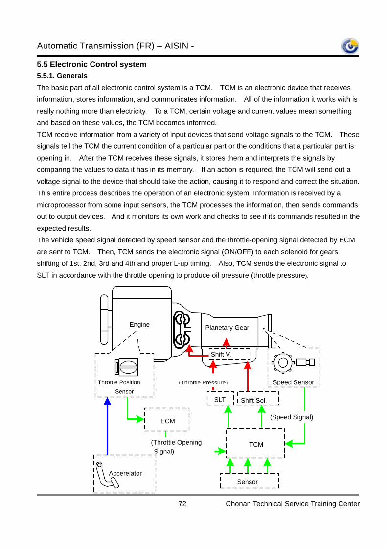
5.5 Electronic Control system 5.5.1. Generals The basic part of all electronic control system is a TCM. TCM is an electronic device that receives information, stores information, and communicates information. All of the information it works with is really nothing more than electricity. To a TCM, certain voltage and current values mean something and based on these values, the TCM becomes informed. TCM receive information from a variety of input devices that send voltage signals to the TCM. These signals tell the TCM the current condition of a particular part or the conditions that a particular part is opening in. After the TCM receives these signals, it stores them and interprets the signals by comparing the values to data it has in its memory. If an action is required, the TCM will send out a voltage signal to the device that should take the action, causing it to respond and correct the situation. This entire process describes the operation of an electronic system. Information is received by a microprocessor from some input sensors, the TCM processes the information, then sends commands out to output devices. And it monitors its own work and checks to see if its commands resulted in the expected results. The vehicle speed signal detected by speed sensor and the throttle-opening signal detected by ECM are sent to TCM. Then, TCM sends the electronic signal (ON/OFF) to each solenoid for gears shifting of 1st, 2nd, 3rd and 4th and proper L-up timing. Also, TCM sends the electronic signal to SLT in accordance with the throttle opening to produce oil pressure (throttle pressure).
Accerelator
Engine Planetary Gear
ECM
Shift Sol. SLT
Throttle Position Sensor
Shift V.
(Speed Signal)
(Throttle Opening Signal)
Speed Sensor
TCM
Sensor
(Throttle Pressure)
Automatic Transmission (FR) – AISIN -
73 Chonan Technical Service Training Center
5.5.2. Input speed sensor Input Speed Sensor detects A/T input speed from rotation number of C0 (Over drive clutch) drum, and they transmit to TCM as a signal.
Inspection: Make sure to inspect resistance again at 20 degree C when resistance differs from standards except 20 degree C. It might become infinity ohm when inspect resistance at higher temperature.
560 – 680 ohm (20)
Oil cooler
Voltage
Oil pump
pressure
Line
pressure
Lubrication Operation
Shift valve Send
oil
Oil pump
Regulator valve
Sol.
TCM
Planetary gear
Clutch Brake
Oil pan
Torque converter
Based on the hydraulicpressure created by theoil pump, TCM sendssignals to solenoid andhydraulic control systemgoverns the hydraulicpressure acting on the torque converter, planetary gear, clutches and brakes in accordance with the vehicle driving conditions.
NC0 NC0G
(520)
(428)
(1027)
(846)
680
560
400
500
600
700
800
900
1000
1100
-40 0 40 80 120 Temperature /
Resistance/
ohm
150
Automatic Transmission (FR) – AISIN -
74 Chonan Technical Service Training Center
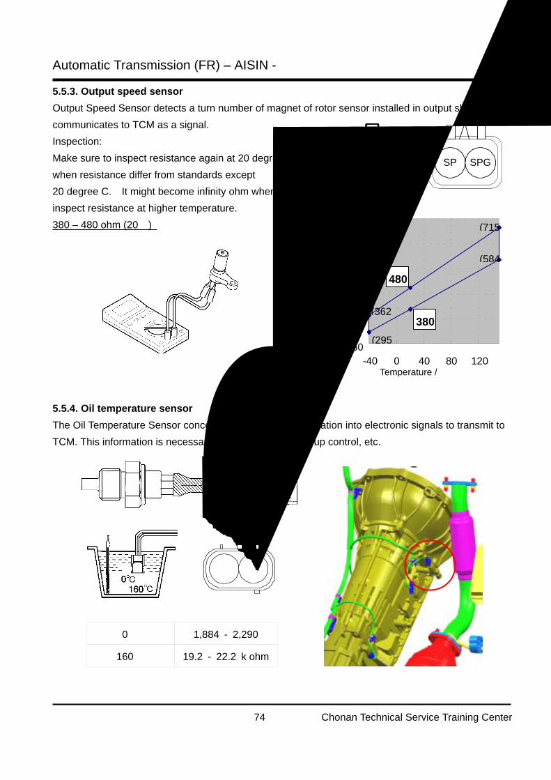
5.5.3. Output speed sensor Output Speed Sensor detects a turn number of magnet of rotor sensor installed in output shaft, and communicates to TCM as a signal.
Inspection: Make sure to inspect resistance again at 20 degree C when resistance differ from standards except 20 degree C. It might become infinity ohm when inspect resistance at higher temperature. 380 – 480 ohm (20)
5.5.4. Oil temperature sensor The Oil Temperature Sensor concerts ATF temperature variation into electronic signals to transmit to TCM. This information is necessary for shift control and L-up control, etc.
SPGSP
(362
(715
(584
380
480
(295250
350
450
550
650
750
-40 0 40 80 120 Temperature /
150
Resistance/
ohm
OT OT-G
0 1,884 - 2,290
160 19.2 - 22.2 k ohm
Automatic Transmission (FR) – AISIN -
75 Chonan Technical Service Training Center
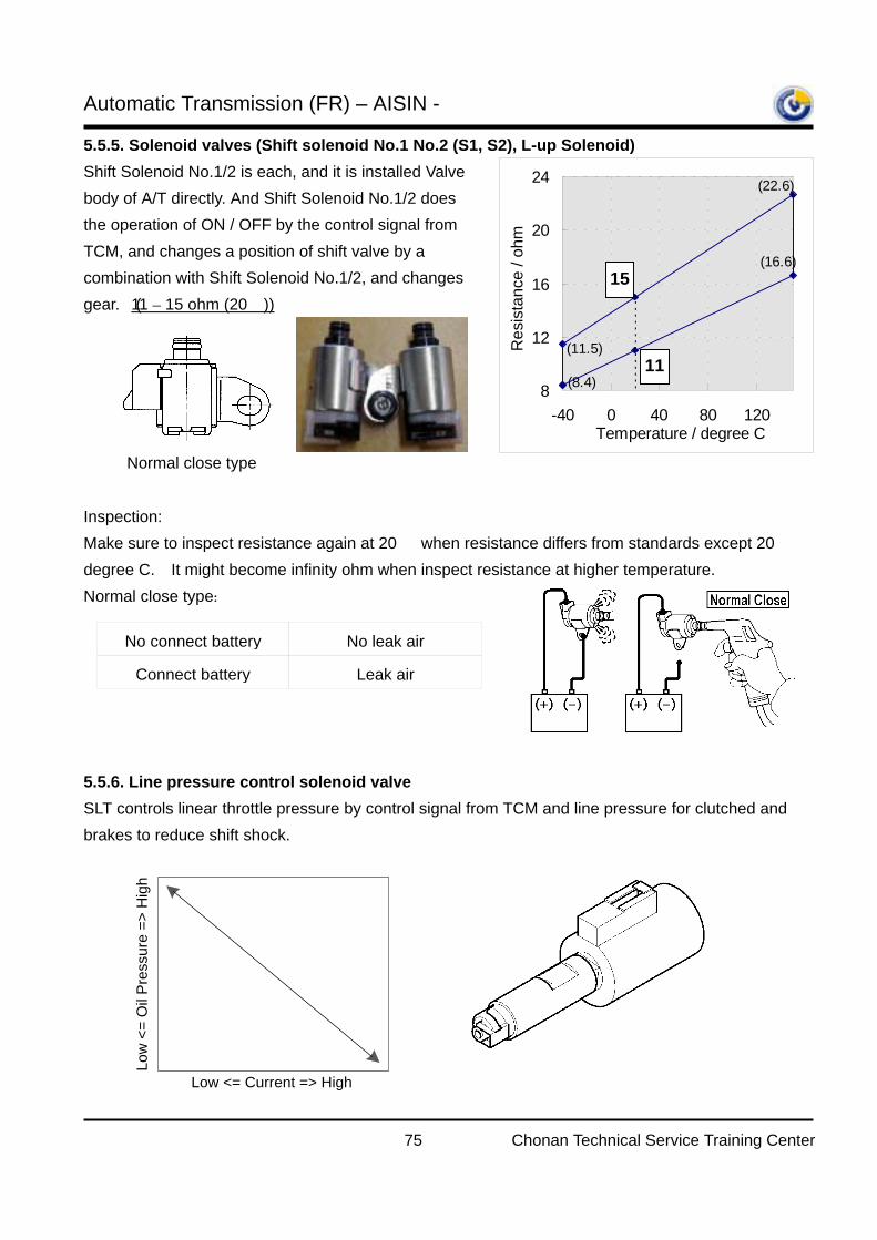
5.5.5. Solenoid valves (Shift solenoid No.1 No.2 (S1, S2), L-up Solenoid) Shift Solenoid No.1/2 is each, and it is installed Valve body of A/T directly. And Shift Solenoid No.1/2 does the operation of ON / OFF by the control signal from TCM, and changes a position of shift valve by a combination with Shift Solenoid No.1/2, and changes gear. (11 – 15 ohm (20))
Inspection: Make sure to inspect resistance again at 20 when resistance differs from standards except 20 degree C. It might become infinity ohm when inspect resistance at higher temperature. Normal close type:
5.5.6. Line pressure control solenoid valve
SLT controls linear throttle pressure by control signal from TCM and line pressure for clutched and brakes to reduce shift shock.
Normal close type
(11.5)
(8.4)
(22.6)
(16.6)
11
15
8
12
16
20
24
-40 0 40 80 120Temperature / degree C
Res
ista
nce
/ ohm
150
No connect battery No leak air
Connect battery Leak air
Low <= Current => High
Low
<=
Oil
Pres
sure
=>
Hig
h
Automatic Transmission (FR) – AISIN -
76 Chonan Technical Service Training Center
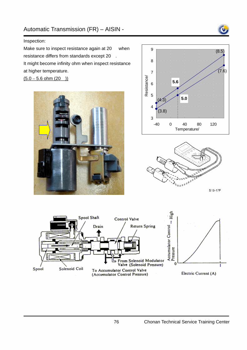
Inspection: Make sure to inspect resistance again at 20 when resistance differs from standards except 20. It might become infinity ohm when inspect resistance at higher temperature. (5.0 – 5.6 ohm (20))
5.6
5.0
(8.5)
(7.6)
(3.8)
(4.3)
3
4
5
6
7
8
9
-40 0 40 80 120Temperature/걥
Res
ista
nce/꺐
Automatic Transmission (FR) – AISIN -
77 Chonan Technical Service Training Center
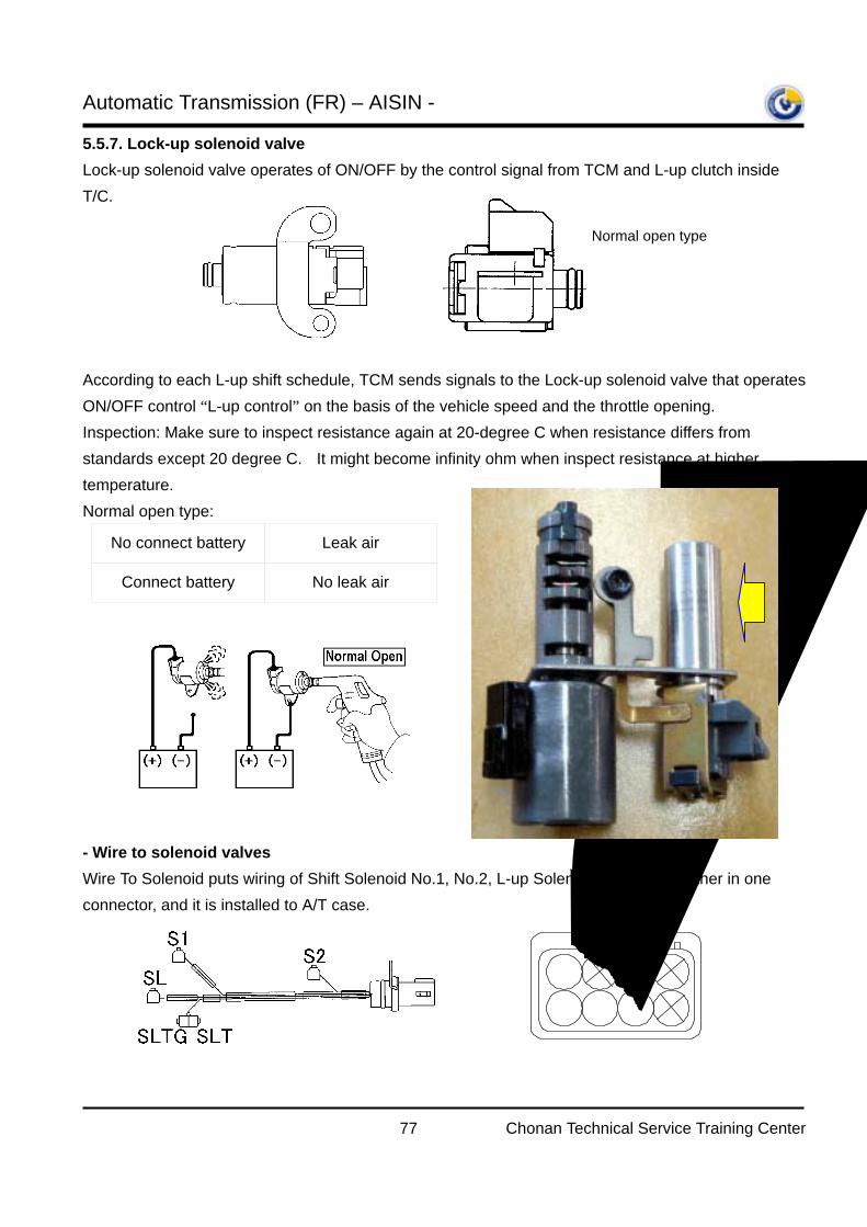
5.5.7. Lock-up solenoid valve
Lock-up solenoid valve operates of ON/OFF by the control signal from TCM and L-up clutch inside T/C.
According to each L-up shift schedule, TCM sends signals to the Lock-up solenoid valve that operates ON/OFF control “L-up control” on the basis of the vehicle speed and the throttle opening.
Inspection: Make sure to inspect resistance again at 20-degree C when resistance differs from standards except 20 degree C. It might become infinity ohm when inspect resistance at higher temperature. Normal open type:
- Wire to solenoid valves Wire To Solenoid puts wiring of Shift Solenoid No.1, No.2, L-up Solenoid and SLT together in one connector, and it is installed to A/T case.
Normal open type
No connect battery Leak air
Connect battery No leak air
SLTS1
SLTGSLS2
Automatic Transmission (FR) – AISIN -
78 Chonan Technical Service Training Center
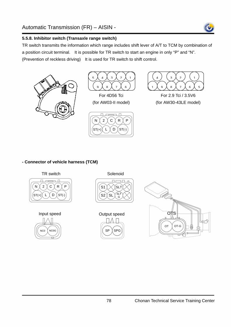
5.5.8. Inhibitor switch (Transaxle range switch) TR switch transmits the information which range includes shift lever of A/T to TCM by combination of a position circuit terminal. It is possible for TR switch to start an engine in only “P” and “N”. (Prevention of reckless driving) It is used for TR switch to shift control.
- Connector of vehicle harness (TCM)
For 4D56 Tci (for AW03-II model)
For 2.9 Tci / 3.5V6 (for AW30-43LE model)
ST(-)LST(+) D
PRC2N
5 4 3 2 1
9 8 7 6
4 3 2 1
1 9 8 7 6 5
ST(-)LST(+) D
PRC2N
TR switch
SLTS1SLTGSLS2
Solenoid
NC0 NC0G SPGSP
Input speed Output speed
OT OT-G
OTS
Automatic Transmission (FR) – AISIN -
79 Chonan Technical Service Training Center
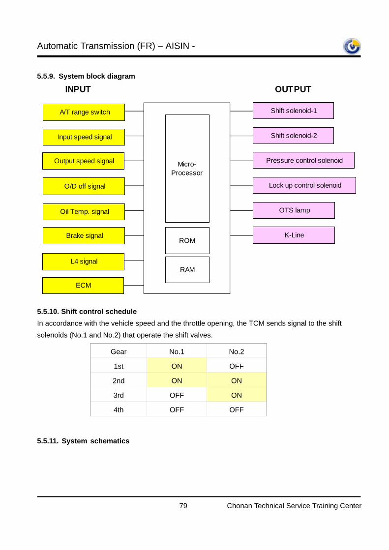
5.5.9. System block diagram
5.5.10. Shift control schedule In accordance with the vehicle speed and the throttle opening, the TCM sends signal to the shift solenoids (No.1 and No.2) that operate the shift valves.
5.5.11. System schematics
INPUT OUTPUT
A/T range switch Shift solenoid-1
ECM
Output speed signal
O/D off signal
Shift solenoid-2
Pressure control solenoid
Lock up control solenoid
OTS lamp
Input speed signal
Micro-Processor
ROM
RAM
Oil Temp. signal
L4 signal
Brake signal K-Line
Gear No.1 No.2
1st ON OFF
2nd ON ON
3rd OFF ON
4th OFF OFF
Automatic Transmission (FR) – AISIN -
80 Chonan Technical Service Training Center
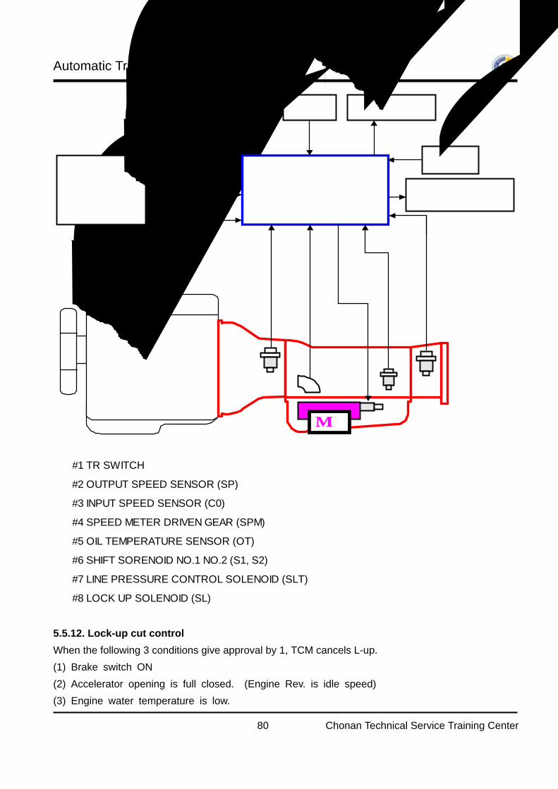
5.5.12. Lock-up cut control When the following 3 conditions give approval by 1, TCM cancels L-up.
(1) Brake switch ON
(2) Accelerator opening is full closed. (Engine Rev. is idle speed)
(3) Engine water temperature is low.
ENGINE
V/B
TCMECM
L4 SWITCHBRAKESWITCH
O/D OFFSWITCH
DIAGNOSIS
OIL TEMPERATURELAMP
THROTTLE OPENINGSIGNAL
WATER TEMPERATURESIGNAL
TORQUE CONTROLSIGNAL
#3
#1
#2
#5
#6 #7 #8
#1 TR SWITCH
#2 OUTPUT SPEED SENSOR (SP)
#3 INPUT SPEED SENSOR (C0)
#4 SPEED METER DRIVEN GEAR (SPM)
#5 OIL TEMPERATURE SENSOR (OT)
#6 SHIFT SORENOID NO.1 NO.2 (S1, S2)
#7 LINE PRESSURE CONTROL SOLENOID (SLT)
#8 LOCK UP SOLENOID (SL)
Automatic Transmission (FR) – AISIN -
81 Chonan Technical Service Training Center
5.5.13. Over drive cut control When the following condition, TCM cancels 4th gear.
(1) Engine water temperature is low. (2) L4 S/W ON
(3) O/D switch OFF
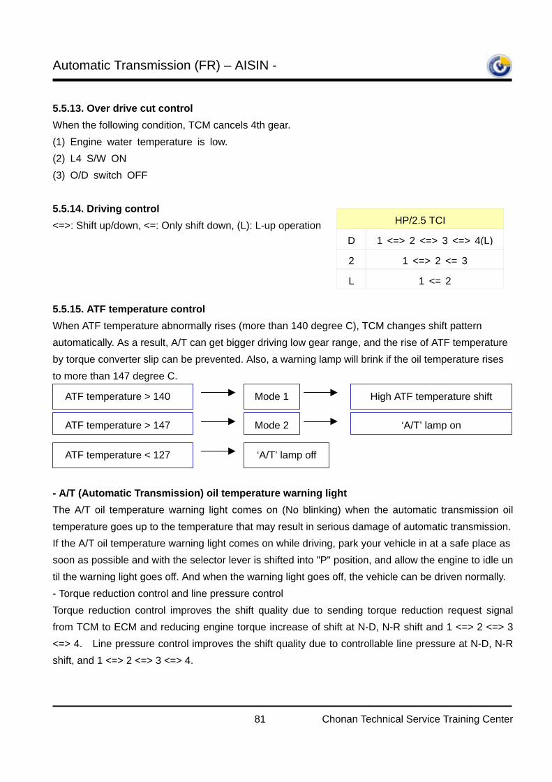
5.5.14. Driving control <=>: Shift up/down, <=: Only shift down, (L): L-up operation
5.5.15. ATF temperature control When ATF temperature abnormally rises (more than 140 degree C), TCM changes shift pattern automatically. As a result, A/T can get bigger driving low gear range, and the rise of ATF temperature by torque converter slip can be prevented. Also, a warning lamp will brink if the oil temperature rises to more than 147 degree C.
- A/T (Automatic Transmission) oil temperature warning light The A/T oil temperature warning light comes on (No blinking) when the automatic transmission oil temperature goes up to the temperature that may result in serious damage of automatic transmission. If the A/T oil temperature warning light comes on while driving, park your vehicle in at a safe place as soon as possible and with the selector lever is shifted into "P" position, and allow the engine to idle until the warning light goes off. And when the warning light goes off, the vehicle can be driven normally. - Torque reduction control and line pressure control
Torque reduction control improves the shift quality due to sending torque reduction request signal from TCM to ECM and reducing engine torque increase of shift at N-D, N-R shift and 1 <=> 2 <=> 3 <=> 4. Line pressure control improves the shift quality due to controllable line pressure at N-D, N-R shift, and 1 <=> 2 <=> 3 <=> 4.
HP/2.5 TCI
D 1 <=> 2 <=> 3 <=> 4(L)
2 1 <=> 2 <= 3
L 1 <= 2
ATF temperature > 140 Mode 1 High ATF temperature shift
ATF temperature > 147 Mode 2 ‘A/T’ lamp on
ATF temperature < 127 ‘A/T’ lamp off
Automatic Transmission (FR) – AISIN -
82 Chonan Technical Service Training Center
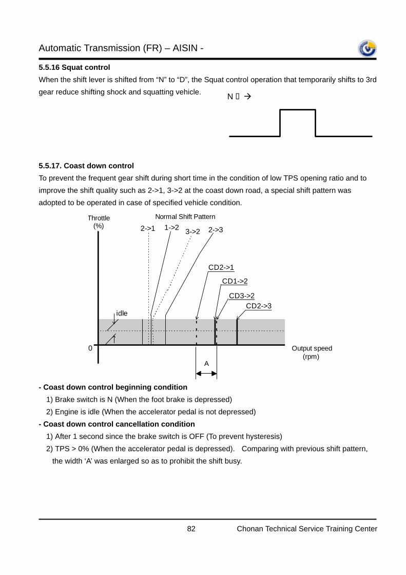
5.5.16 Squat control When the shift lever is shifted from “N” to “D”, the Squat control operation that temporarily shifts to 3rd gear reduce shifting shock and squatting vehicle.
5.5.17. Coast down control To prevent the frequent gear shift during short time in the condition of low TPS opening ratio and to improve the shift quality such as 2->1, 3->2 at the coast down road, a special shift pattern was adopted to be operated in case of specified vehicle condition.
- Coast down control beginning condition
1) Brake switch is N (When the foot brake is depressed) 2) Engine is idle (When the accelerator pedal is not depressed)
- Coast down control cancellation condition
1) After 1 second since the brake switch is OFF (To prevent hysteresis) 2) TPS > 0% (When the accelerator pedal is depressed). Comparing with previous shift pattern,
the width ‘A’ was enlarged so as to prohibit the shift busy.
CD2->1
CD1->2
CD3->2CD2->3
Throttle(%)
Output speed(rpm)
1->2 2->33->22->1
0
idle
Normal Shift Pattern
A
N D 3rd.
1st. 1st.
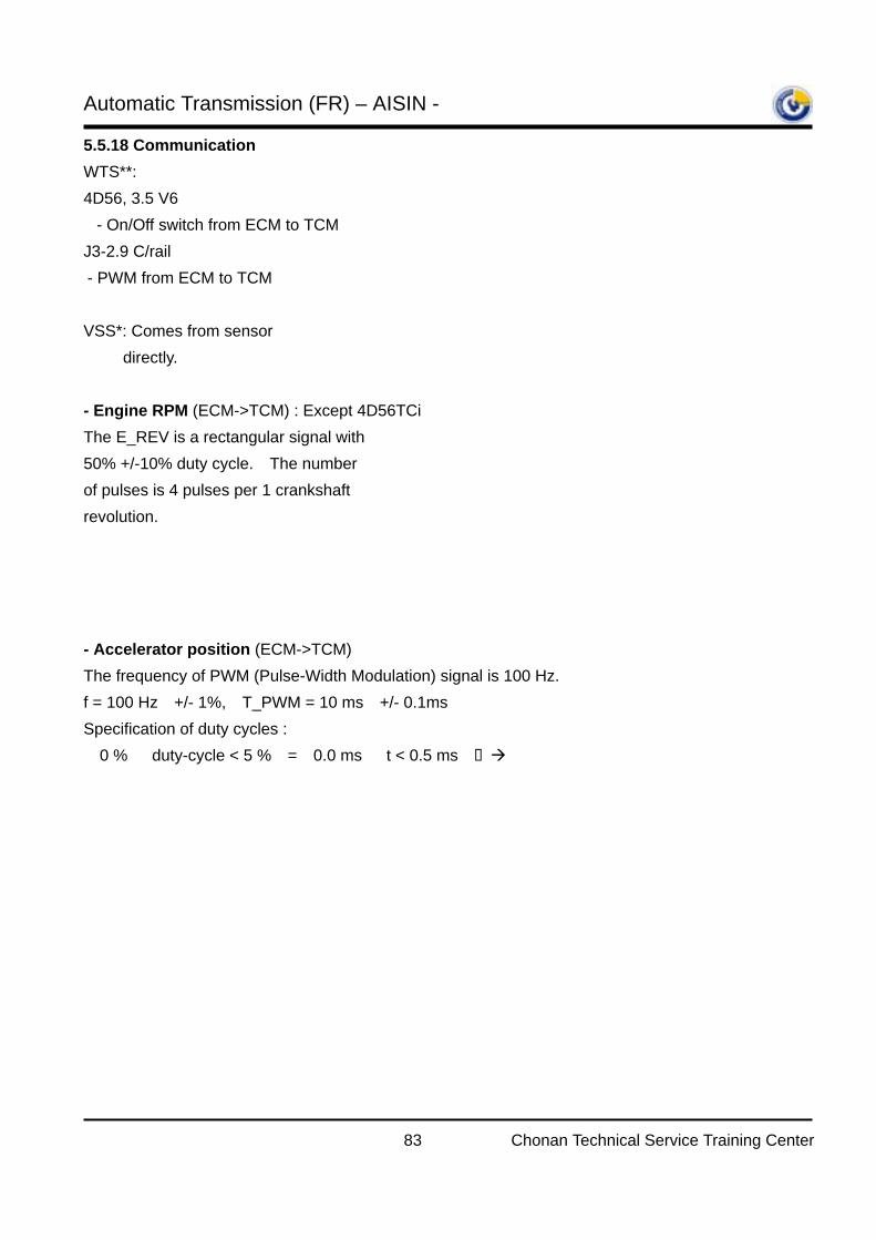
Automatic Transmission (FR) – AISIN -
83 Chonan Technical Service Training Center
5.5.18 Communication WTS**: 4D56, 3.5 V6 - On/Off switch from ECM to TCM J3-2.9 C/rail - PWM from ECM to TCM VSS*: Comes from sensor directly. - Engine RPM (ECM->TCM) : Except 4D56TCi The E_REV is a rectangular signal with 50% +/-10% duty cycle. The number of pulses is 4 pulses per 1 crankshaft revolution.
- Accelerator position (ECM->TCM) The frequency of PWM (Pulse-Width Modulation) signal is 100 Hz. f = 100 Hz +/- 1%, T_PWM = 10 ms +/- 0.1ms Specification of duty cycles : 0 % ≤ duty-cycle < 5 % = 0.0 ms ≤ t < 0.5 ms failure of APS signal 5 % ≤ duty-cycle < 10 % = 0.5 ms ≤ t < 1.0 ms 0 % APS 10 % ≤ duty-cycle ≤ 83 % = 1.0 ms ≤ t £ 8.3 ms valid (0 % APS - 100 % APS) 83 % < duty-cycle ≤ 94 % = 8.3 ms < t ≤ 9.4 ms 100 % APS 94 % < duty-cycle ≤ 100 % = 9.4 ms < t ≤ 10.0 ms failure of APS signal The APS information is always transferred when IG key is ‘ON’ even during cranking. If acceleration pedal sensor is fail, ECM should transfer 100% PWM.
Items 4D56 Tci J3-2.9 Tci (C/Rail)
3.5 V6(Euro-III)
Torque control O O OEngine rpm X O OMIL X X OVSS* X X OWTS** O O O
one crank revolution
t / T × 100% = 50 +/- 10
T
t
T_PWM
t
% *][ _
][ [%] 100msPWMT
mstcycledutyAPS ==
Automatic Transmission (FR) – AISIN -
84 Chonan Technical Service Training Center
PWM Throttle signal (Duty vs. Throttle openings)
- Water temperature (ECM->TCM) for KJ2.9TCi (C/Rail) f = 100 Hz +/- 1%, T_PWM = 10 ms +/- 0.1ms WT = duty cycle [%] = (t [ms] / T_PWM [ms]) * 100% Specification of duty cycles : 0 % ≤ duty-cycle < 5 % = 0.0 ms ≤ t < 0.5 ms failure of WT signal 5 % ≤ duty-cycle < 10 % = 0.5 ms ≤ t < 1.0 ms -50degC WT 10 % ≤ duty-cycle ≤ 90 % = 1.0 ms ≤ t ≤ 9.0 ms valid ( -50degC WT – 150degC WT) 90 % < duty-cycle ≤ 95 % = 9.0 ms < t ≤ 9.5 ms 150degC WT 95 % < duty-cycle ≤ 100 % = 9.5 ms < t ≤ 10.0 ms failure of WT signal The WT information should be always transferred when IG key is ‘ON’ even during cranking. If water temperature sensor is fail, ECM should transfer 100% PWM
0%TPS signal
100 Duty ratio ( t / T ) (%)
94 83 10 5
TPS (%)
Fail Fail
(0%)
WOT (100%)
0
T_PWM
t
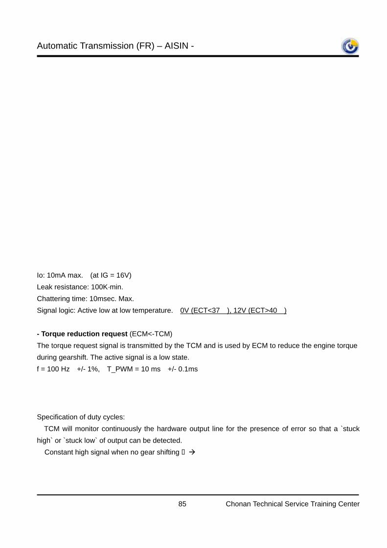
Automatic Transmission (FR) – AISIN -
85 Chonan Technical Service Training Center
Io: 10mA max. (at IG = 16V) Leak resistance: 100K·min. Chattering time: 10msec. Max. Signal logic: Active low at low temperature. 0V (ECT<37), 12V (ECT>40) - Torque reduction request (ECM<-TCM) The torque request signal is transmitted by the TCM and is used by ECM to reduce the engine torque during gearshift. The active signal is a low state. f = 100 Hz +/- 1%, T_PWM = 10 ms +/- 0.1ms
Specification of duty cycles: TCM will monitor continuously the hardware output line for the presence of error so that a `stuck high` or `stuck low` of output can be detected. Constant high signal when no gear shifting No reduction required 0 % < duty-cycle < 10 % = 0.0 ms < t < 1.0 ms ECM ignores this request (invalid signal) 10 % ≤ duty-cycle < 14 % = 1.0 ms ≤ t < 1.4 ms Maximum torque reduction requested.
WATER TEMPERATURE SWITCHCIRCUIT
Io
TCU
WT1.8K
IG
C
5
ECU
0.01μor less
T_PWM
t
% *][ _
][ [%] _ 100msPWMT
mstcycledutyPWMDT ==
Automatic Transmission (FR) – AISIN -
86 Chonan Technical Service Training Center
14 % ≤ duty-cycle ≤ 96 % = 1.4 ms ≤ t ≤ 9.6 ms Valid signal 96 % < duty-cycle ≤ 98 % = 9.6 ms < t ≤ 9.8 ms No reduction requested 98 % < duty-cycle < 100 % = 9.8 ms < t < 10.0 ms ECM ignores this request (invalid signal) constant low signal Failure of T_RED signal TCM have no information of real (current) engine torque, but through the calibration work at each condition in the actual vehicle for up- and downshifts, the TCM determines the value by how much the engine torque has to be reduced. - MIL request (TCM->ECM) – Only for 3.5 V6 with OBD-II or E-OBD
By the MIL-line the TCM demands of the ECM to switch on or off the malfunction indication lamp (MIL).
Specification of MIL request signal:
5.5.19. Diagnostic Specification (For Terracan, Except EU & N/A)
Type A: Failure store DTC on the 1st driving cycle.
Type B: Oil-lamp blinking on the 2nd consecutive driving cycles with a fail store DTC.
MIL off Initialize MIL on
Ts1 Ts2 TL TH
Ts1 Ts2 TL TH
TCM 0.3 2.0se 90ms 1660
ECM 1500<TL+TH<2000msec
CODE Description 03-II 30LEi
P0705 Transmission Range Sensor Circuit Malfunction(OPEN/SHORT) C C
P0722 Output speed Sensor Circuit(No signal) B B
P0743 Torque converter Clutch Circuit(SL) Electrical(HIGH/LOW Voltage) C C
P0753 Shift Solenoid A(S1) Electrical(HIGH/LOW Voltage) A A
P0758 Shift Solenoid B(S2) Electrical(HIGH/LOW Voltage) A A
P1121 Throttle sensor Signal Malfunction(PWM Type) B B
P0710 Transmission Fluid Temperature Sensor Circuit Malfunction(OPEN/SHORT C C
P0715 Input speed Sensor Circuit(No signal) B B
P0748 Pressure Solenoid(Sth) Electrical(HIGH/LOW Voltage) A A
P1780 Torque reduction signal malfunction(LOW Voltage) B B
4D56TCI Σ3.5D
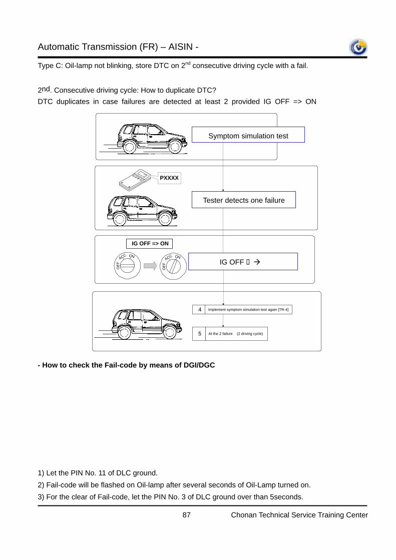
Automatic Transmission (FR) – AISIN -
87 Chonan Technical Service Training Center
Type C: Oil-lamp not blinking, store DTC on 2nd consecutive driving cycle with a fail.
2nd. Consecutive driving cycle: How to duplicate DTC? DTC duplicates in case failures are detected at least 2 provided IG OFF => ON
- How to check the Fail-code by means of DGI/DGC
1) Let the PIN No. 11 of DLC ground. 2) Fail-code will be flashed on Oil-lamp after several seconds of Oil-Lamp turned on. 3) For the clear of Fail-code, let the PIN No. 3 of DLC ground over than 5seconds.
Tester detects the 1 failure(1 driving cycle)2
At the 2 failure (2 driving cycle)5
IG OFF => ON
PXXXX
IG OFF => ON3
4 Implement symptom simulation test again [TR-4]
Symptom simulation test [TR-4]1
ON
OFF
ACCON
OFF
ACC
Symptom simulation test
Tester detects one failure
IG OFF ON
Perform the symptom
Tester detects failure again
1 2 3 4 5
9 10 11 12
6 7 8
13 14 15 16
Data LinkConnector
DTC clear switch
Diagnosis switch
K-line
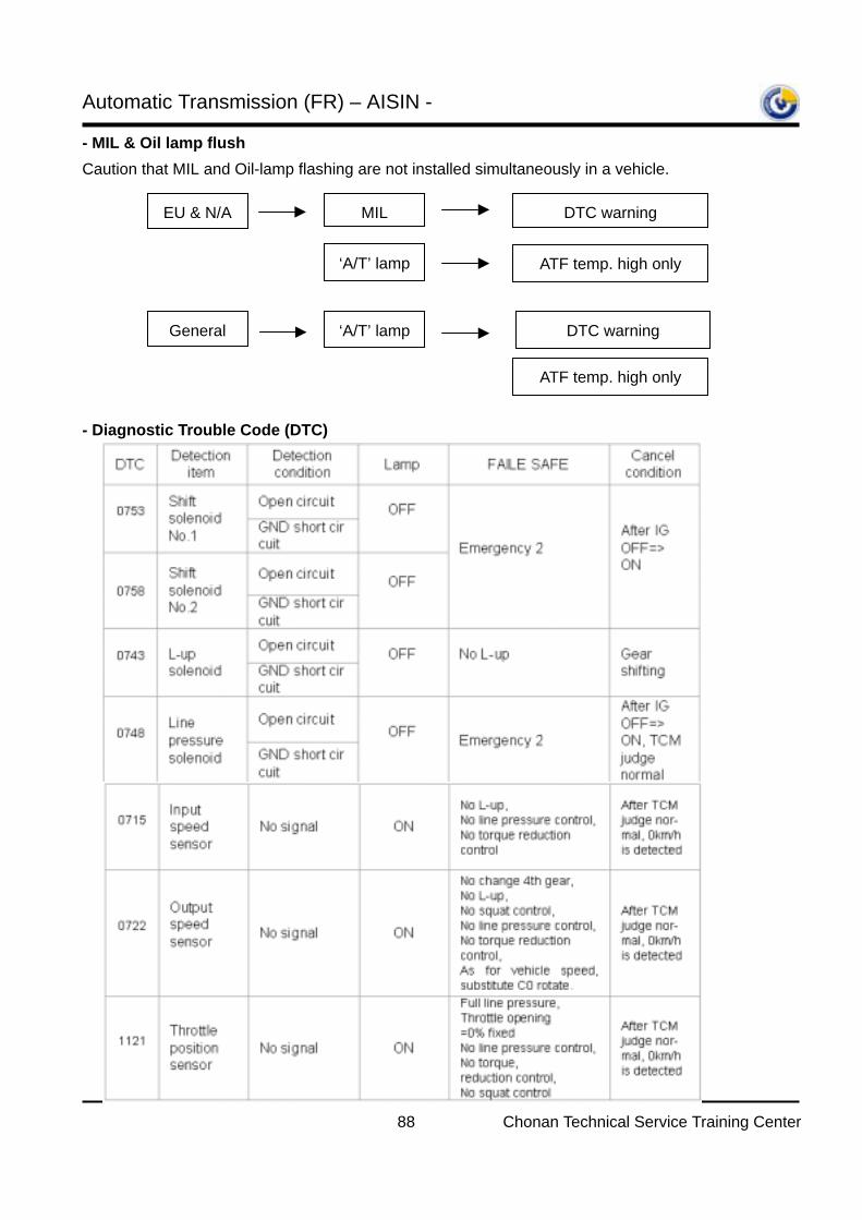
Automatic Transmission (FR) – AISIN -
88 Chonan Technical Service Training Center
- MIL & Oil lamp flush
Caution that MIL and Oil-lamp flashing are not installed simultaneously in a vehicle.
- Diagnostic Trouble Code (DTC)
EU & N/A MIL
‘A/T’ lamp
DTC warning
ATF temp. high only
General ‘A/T’ lamp DTC warning
ATF temp. high only
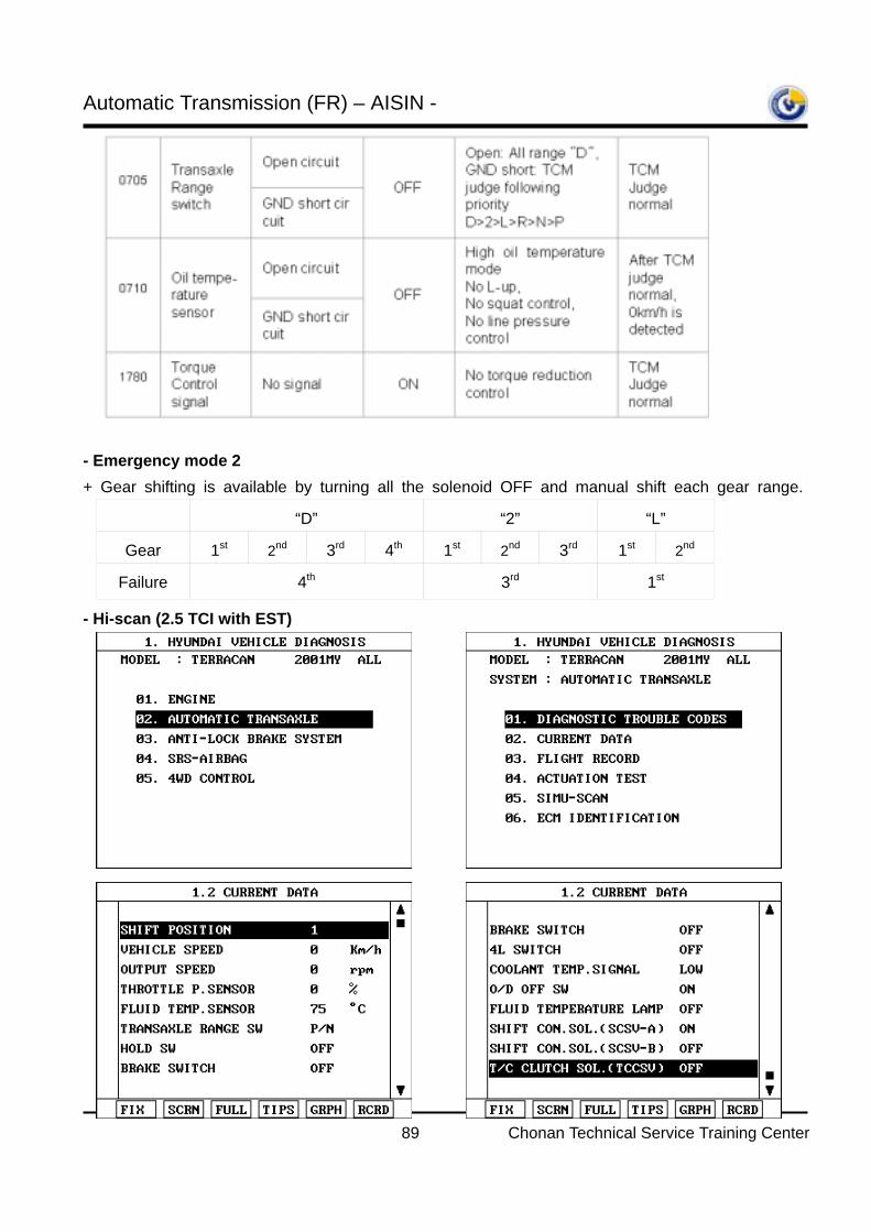
Automatic Transmission (FR) – AISIN -
89 Chonan Technical Service Training Center
- Emergency mode 2 + Gear shifting is available by turning all the solenoid OFF and manual shift each gear range.
- Hi-scan (2.5 TCI with EST)
“D” “2” “L”
Gear 1st 2nd 3rd 4th 1st 2nd 3rd 1st 2nd
Failure 4th 3rd 1st
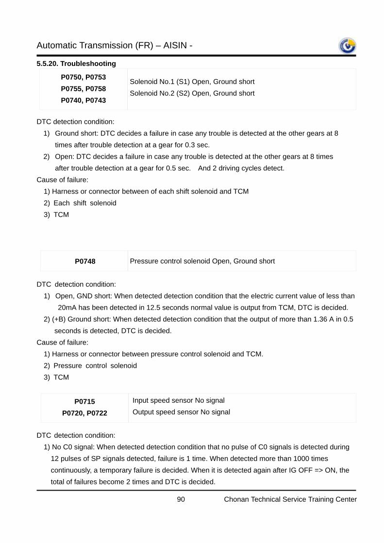
Automatic Transmission (FR) – AISIN -
90 Chonan Technical Service Training Center
5.5.20. Troubleshooting
DTC detection condition: 1) Ground short: DTC decides a failure in case any trouble is detected at the other gears at 8
times after trouble detection at a gear for 0.3 sec. 2) Open: DTC decides a failure in case any trouble is detected at the other gears at 8 times
after trouble detection at a gear for 0.5 sec. And 2 driving cycles detect. Cause of failure:
1) Harness or connector between of each shift solenoid and TCM 2) Each shift solenoid 3) TCM
DTC detection condition: 1) Open, GND short: When detected detection condition that the electric current value of less than
20mA has been detected in 12.5 seconds normal value is output from TCM, DTC is decided. 2) (+B) Ground short: When detected detection condition that the output of more than 1.36 A in 0.5 seconds is detected, DTC is decided.
Cause of failure: 1) Harness or connector between pressure control solenoid and TCM.
2) Pressure control solenoid 3) TCM
DTC detection condition: 1) No C0 signal: When detected detection condition that no pulse of C0 signals is detected during
12 pulses of SP signals detected, failure is 1 time. When detected more than 1000 times continuously, a temporary failure is decided. When it is detected again after IG OFF => ON, the total of failures become 2 times and DTC is decided.
P0750, P0753 P0755, P0758 P0740, P0743
Solenoid No.1 (S1) Open, Ground short Solenoid No.2 (S2) Open, Ground short
P0748 Pressure control solenoid Open, Ground short
P0715 P0720, P0722
Input speed sensor No signal Output speed sensor No signal
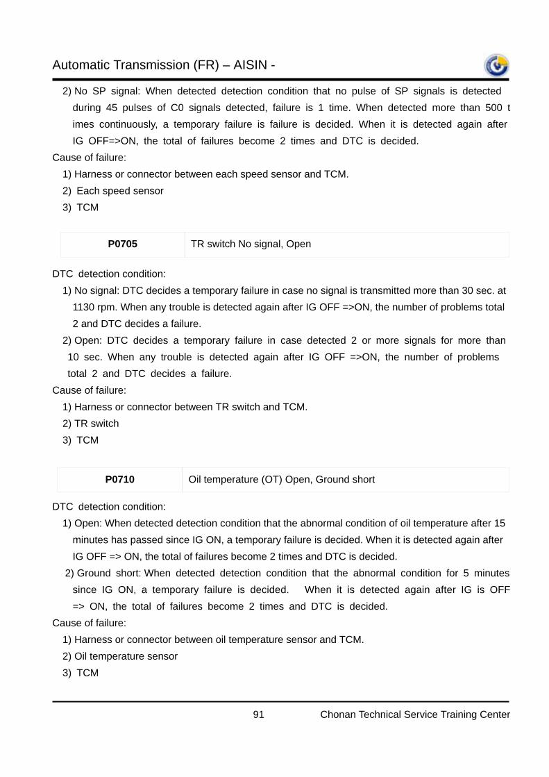
Automatic Transmission (FR) – AISIN -
91 Chonan Technical Service Training Center
2) No SP signal: When detected detection condition that no pulse of SP signals is detected during 45 pulses of C0 signals detected, failure is 1 time. When detected more than 500 times continuously, a temporary failure is failure is decided. When it is detected again after IG OFF=>ON, the total of failures become 2 times and DTC is decided.
Cause of failure: 1) Harness or connector between each speed sensor and TCM.
2) Each speed sensor 3) TCM
DTC detection condition: 1) No signal: DTC decides a temporary failure in case no signal is transmitted more than 30 sec. at
1130 rpm. When any trouble is detected again after IG OFF =>ON, the number of problems total 2 and DTC decides a failure.
2) Open: DTC decides a temporary failure in case detected 2 or more signals for more than 10 sec. When any trouble is detected again after IG OFF =>ON, the number of problems total 2 and DTC decides a failure.
Cause of failure: 1) Harness or connector between TR switch and TCM.
2) TR switch 3) TCM
DTC detection condition: 1) Open: When detected detection condition that the abnormal condition of oil temperature after 15
minutes has passed since IG ON, a temporary failure is decided. When it is detected again after IG OFF => ON, the total of failures become 2 times and DTC is decided.
2) Ground short: When detected detection condition that the abnormal condition for 5 minutes since IG ON, a temporary failure is decided. When it is detected again after IG is OFF => ON, the total of failures become 2 times and DTC is decided.
Cause of failure: 1) Harness or connector between oil temperature sensor and TCM.
2) Oil temperature sensor
3) TCM
P0705 TR switch No signal, Open
P0710 Oil temperature (OT) Open, Ground short
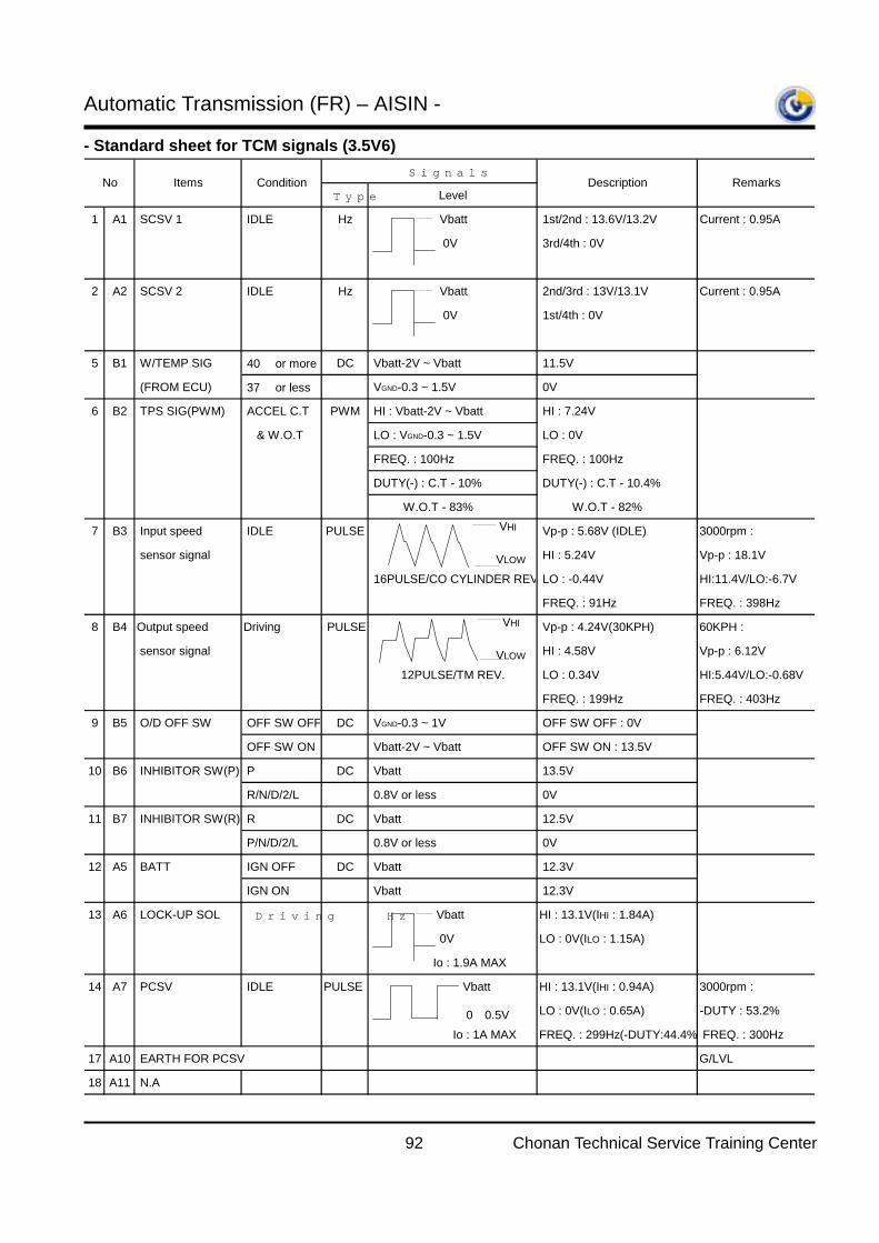
Automatic Transmission (FR) – AISIN -
92 Chonan Technical Service Training Center
- Standard sheet for TCM signals (3.5V6) Signals
Type Level
1 A1 SCSV 1 IDLE Hz Vbatt 1st/2nd : 13.6V/13.2V Current : 0.95A
0V 3rd/4th : 0V
2 A2 SCSV 2 IDLE Hz Vbatt 2nd/3rd : 13V/13.1V Current : 0.95A
0V 1st/4th : 0V
5 B1 W/TEMP SIG 40 or more DC Vbatt-2V ~ Vbatt 11.5V
(FROM ECU) 37 or less ↑ VGND-0.3 ~ 1.5V 0V
6 B2 TPS SIG(PWM) ACCEL C.T PWM HI : Vbatt-2V ~ Vbatt HI : 7.24V
& W.O.T LO : VGND-0.3 ~ 1.5V LO : 0V
FREQ. : 100Hz FREQ. : 100Hz
DUTY(-) : C.T - 10% DUTY(-) : C.T - 10.4%
W.O.T - 83% W.O.T - 82%
7 B3 Input speed IDLE PULSE VHI Vp-p : 5.68V (IDLE) 3000rpm :
sensor signal VLOW HI : 5.24V Vp-p : 18.1V
16PULSE/CO CYLINDER REV LO : -0.44V HI:11.4V/LO:-6.7V
FREQ. : 91Hz FREQ. : 398Hz
8 B4 Output speed Driving PULSE VHI Vp-p : 4.24V(30KPH) 60KPH :
sensor signal VLOW HI : 4.58V Vp-p : 6.12V
12PULSE/TM REV. LO : 0.34V HI:5.44V/LO:-0.68V
FREQ. : 199Hz FREQ. : 403Hz
9 B5 O/D OFF SW OFF SW OFF DC VGND-0.3 ~ 1V OFF SW OFF : 0V
OFF SW ON ↑ Vbatt-2V ~ Vbatt OFF SW ON : 13.5V
10 B6 INHIBITOR SW(P) P DC Vbatt 13.5V
R/N/D/2/L ↑ 0.8V or less 0V
11 B7 INHIBITOR SW(R) R DC Vbatt 12.5V
P/N/D/2/L ↑ 0.8V or less 0V
12 A5 BATT IGN OFF DC Vbatt 12.3V
IGN ON ↑ Vbatt 12.3V
13 A6 LOCK-UP SOL Driving Hz Vbatt HI : 13.1V(IHI : 1.84A)
0V LO : 0V(ILO : 1.15A)
Io : 1.9A MAX
14 A7 PCSV IDLE PULSE Vbatt HI : 13.1V(IHI : 0.94A) 3000rpm :
0∼0.5V LO : 0V(ILO : 0.65A) -DUTY : 53.2%
Io : 1A MAX FREQ. : 299Hz(-DUTY:44.4% FREQ. : 300Hz
17 A10 EARTH FOR PCSV G/LVL
18 A11 N.A
No Description RemarksItems Condition
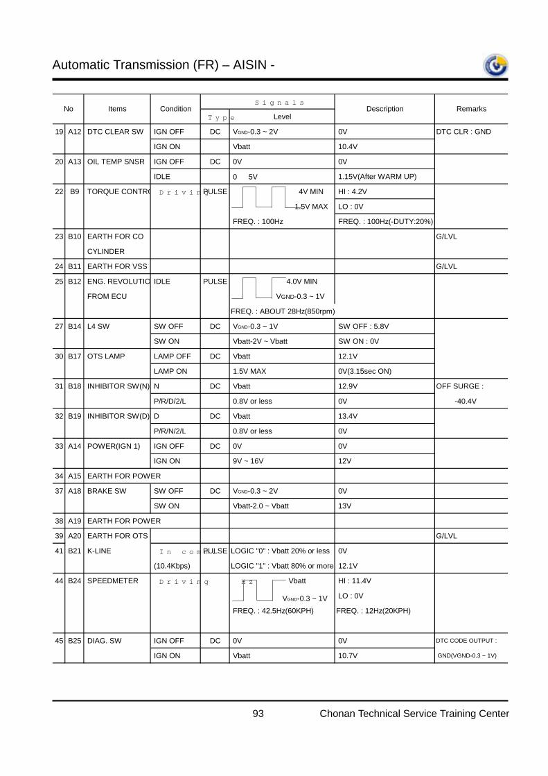
Automatic Transmission (FR) – AISIN -
93 Chonan Technical Service Training Center
Signals
Type Level
19 A12 DTC CLEAR SW IGN OFF DC VGND-0.3 ~ 2V 0V DTC CLR : GND
IGN ON ↑ Vbatt 10.4V
20 A13 OIL TEMP SNSR IGN OFF DC 0V 0V
IDLE ↑ 0 ∼ 5V 1.15V(After WARM UP)
22 B9 TORQUE CONTRO Driving PULSE 4V MIN HI : 4.2V
1.5V MAX LO : 0V
FREQ. : 100Hz FREQ. : 100Hz(-DUTY:20%)
23 B10 EARTH FOR CO G/LVL
CYLINDER
24 B11 EARTH FOR VSS G/LVL
25 B12 ENG. REVOLUTIO IDLE PULSE 4.0V MIN
FROM ECU VGND-0.3 ~ 1V
FREQ. : ABOUT 28Hz(850rpm)
27 B14 L4 SW SW OFF DC VGND-0.3 ~ 1V SW OFF : 5.8V
SW ON ↑ Vbatt-2V ~ Vbatt SW ON : 0V
30 B17 OTS LAMP LAMP OFF DC Vbatt 12.1V
LAMP ON ↑ 1.5V MAX 0V(3.15sec ON)
31 B18 INHIBITOR SW(N) N DC Vbatt 12.9V OFF SURGE :
P/R/D/2/L ↑ 0.8V or less 0V -40.4V
32 B19 INHIBITOR SW(D) D DC Vbatt 13.4V
P/R/N/2/L ↑ 0.8V or less 0V
33 A14 POWER(IGN 1) IGN OFF DC 0V 0V
IGN ON ↑ 9V ~ 16V 12V
34 A15 EARTH FOR POWER
37 A18 BRAKE SW SW OFF DC VGND-0.3 ~ 2V 0V
SW ON ↑ Vbatt-2.0 ~ Vbatt 13V
38 A19 EARTH FOR POWER
39 A20 EARTH FOR OTS G/LVL
41 B21 K-LINE In comm. PULSE LOGIC "0" : Vbatt 20% or less 0V
(10.4Kbps) LOGIC "1" : Vbatt 80% or more 12.1V
44 B24 SPEEDMETER Driving Hz Vbatt HI : 11.4V
VGND-0.3 ~ 1V LO : 0V
FREQ. : 42.5Hz(60KPH) FREQ. : 12Hz(20KPH)
45 B25 DIAG. SW IGN OFF DC 0V 0V DTC CODE OUTPUT :
IGN ON ↑ Vbatt 10.7V GND(VGND-0.3 ~ 1V)
No Description RemarksItems Condition
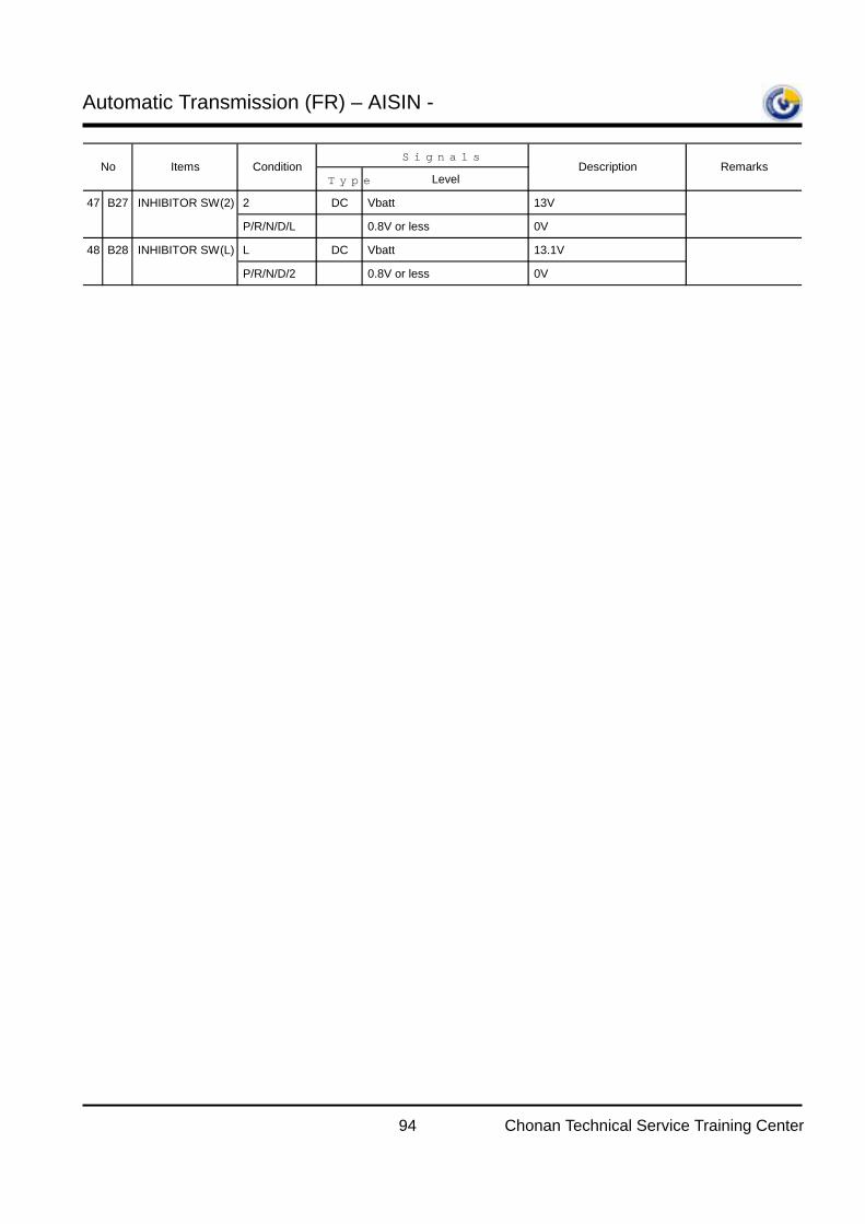
Automatic Transmission (FR) – AISIN -
94 Chonan Technical Service Training Center
Signals
Type Level
47 B27 INHIBITOR SW(2) 2 DC Vbatt 13V
P/R/N/D/L ↑ 0.8V or less 0V
48 B28 INHIBITOR SW(L) L DC Vbatt 13.1V
P/R/N/D/2 ↑ 0.8V or less 0V
No Description RemarksItems Condition
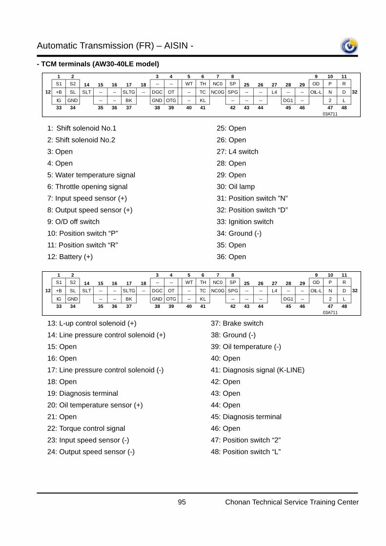
Automatic Transmission (FR) – AISIN -
95 Chonan Technical Service Training Center
- TCM terminals (AW30-40LE model)
1 2 3 4 5 6 7 8 9 10 11S1 S2 14 15 16 17 18 -- -- WT TH NC0 SP 25 26 27 28 29 OD P R
12 +B SL SLT -- -- SLTG -- DGC OT -- TC NC0G SPG -- -- L4 -- -- OIL-L N D 32IG GND -- -- BK GND OTG -- KL -- -- -- DG1 -- 2 L33 34 35 36 37 38 39 40 41 42 43 44 45 46 47 48
03A711
1: Shift solenoid No.1 2: Shift solenoid No.2 3: Open 4: Open 5: Water temperature signal 6: Throttle opening signal 7: Input speed sensor (+) 8: Output speed sensor (+) 9: O/D off switch 10: Position switch “P” 11: Position switch “R” 12: Battery (+)
25: Open 26: Open 27: L4 switch 28: Open 29: Open 30: Oil lamp 31: Position switch ”N” 32: Position switch “D” 33: Ignition switch 34: Ground (-) 35: Open 36: Open
1 2 3 4 5 6 7 8 9 10 11S1 S2 14 15 16 17 18 -- -- WT TH NC0 SP 25 26 27 28 29 OD P R
12 +B SL SLT -- -- SLTG -- DGC OT -- TC NC0G SPG -- -- L4 -- -- OIL-L N D 32IG GND -- -- BK GND OTG -- KL -- -- -- DG1 -- 2 L33 34 35 36 37 38 39 40 41 42 43 44 45 46 47 48
03A711
13: L-up control solenoid (+) 14: Line pressure control solenoid (+) 15: Open 16: Open 17: Line pressure control solenoid (-) 18: Open 19: Diagnosis terminal 20: Oil temperature sensor (+) 21: Open 22: Torque control signal 23: Input speed sensor (-) 24: Output speed sensor (-)
37: Brake switch 38: Ground (-) 39: Oil temperature (-) 40: Open 41: Diagnosis signal (K-LINE) 42: Open 43: Open 44: Open 45: Diagnosis terminal 46: Open 47: Position switch “2” 48: Position switch “L”
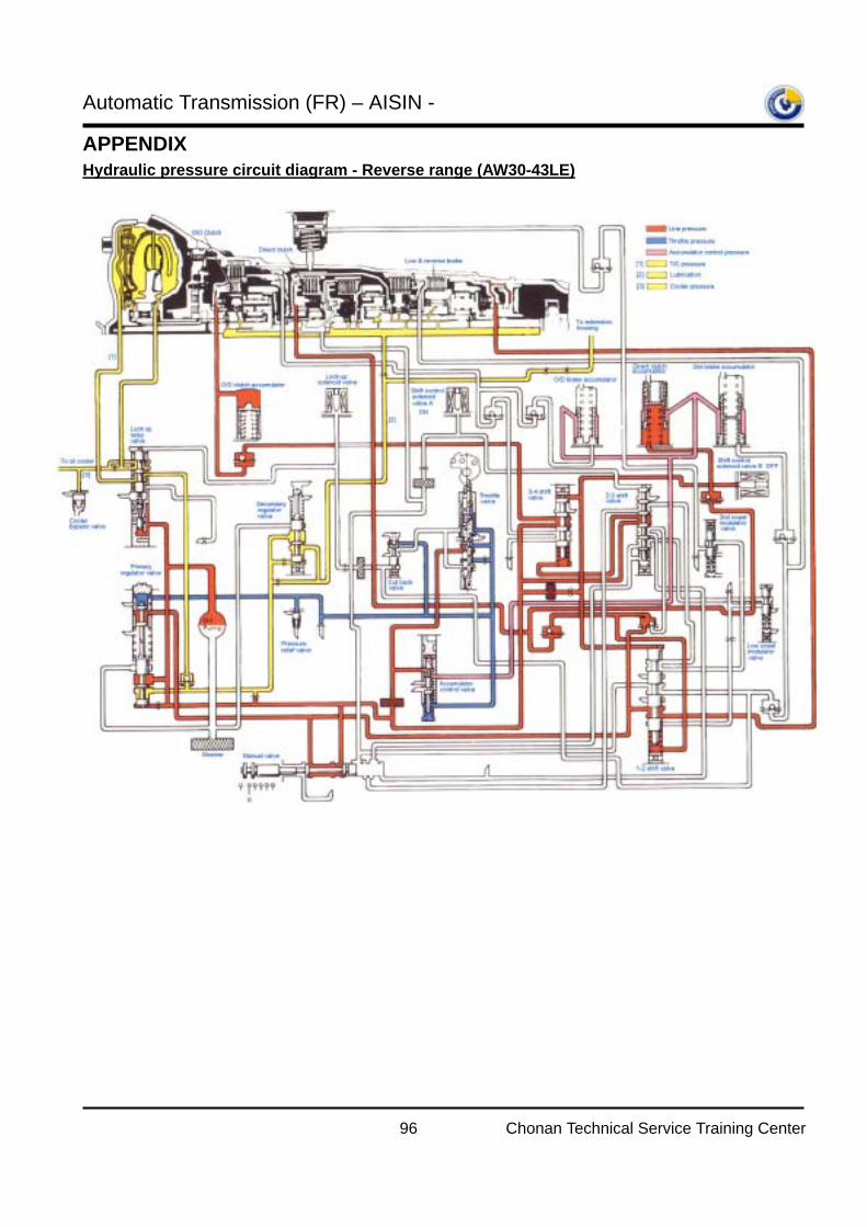
Automatic Transmission (FR) – AISIN -
96 Chonan Technical Service Training Center
APPENDIX Hydraulic pressure circuit diagram - Reverse range (AW30-43LE)
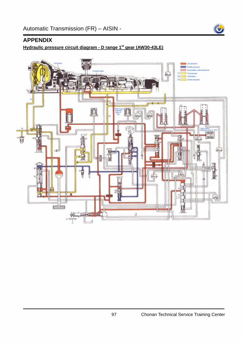
Automatic Transmission (FR) – AISIN -
97 Chonan Technical Service Training Center
APPENDIX Hydraulic pressure circuit diagram - D range 1st gear (AW30-43LE)
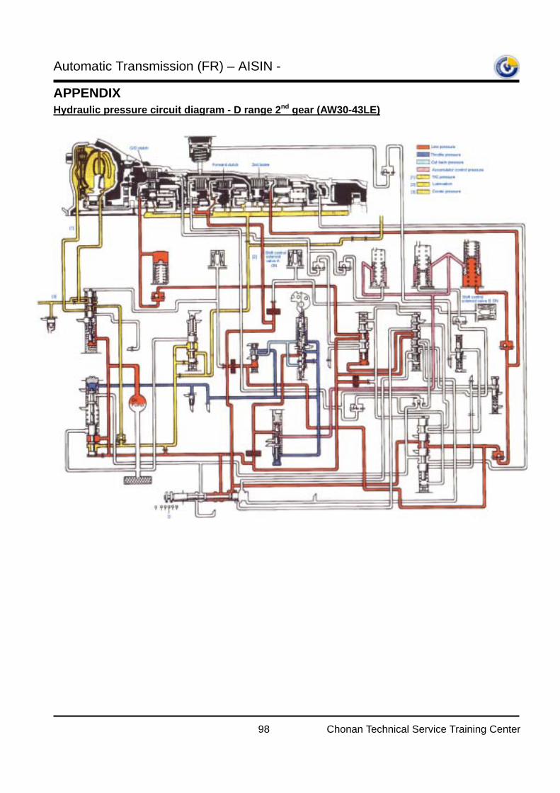
Automatic Transmission (FR) – AISIN -
98 Chonan Technical Service Training Center
APPENDIX Hydraulic pressure circuit diagram - D range 2nd gear (AW30-43LE)
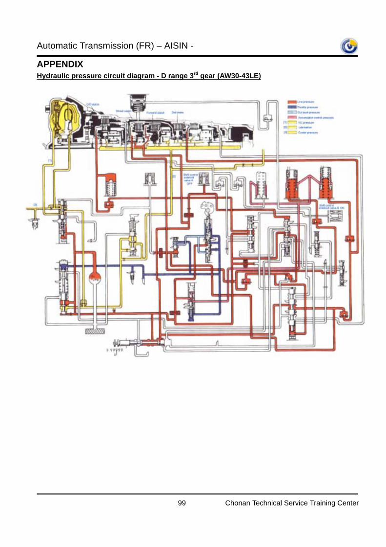
Automatic Transmission (FR) – AISIN -
99 Chonan Technical Service Training Center
APPENDIX Hydraulic pressure circuit diagram - D range 3rd gear (AW30-43LE)
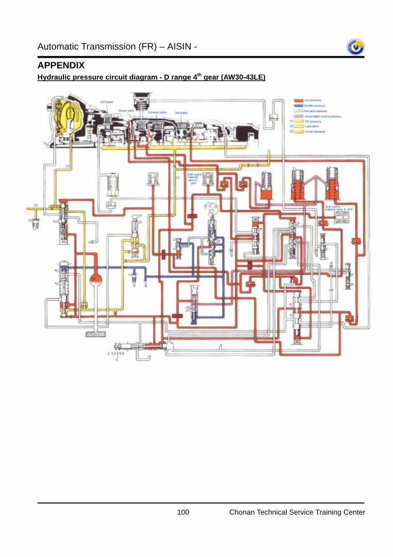
Automatic Transmission (FR) – AISIN -
100 Chonan Technical Service Training Center
APPENDIX Hydraulic pressure circuit diagram - D range 4th gear (AW30-43LE)

Automatic Transmission (FR) – AISIN -
101 Chonan Technical Service Training Center
APPENDIX Hydraulic pressure circuit diagram - 2 range 1st gear (AW30-43LE)
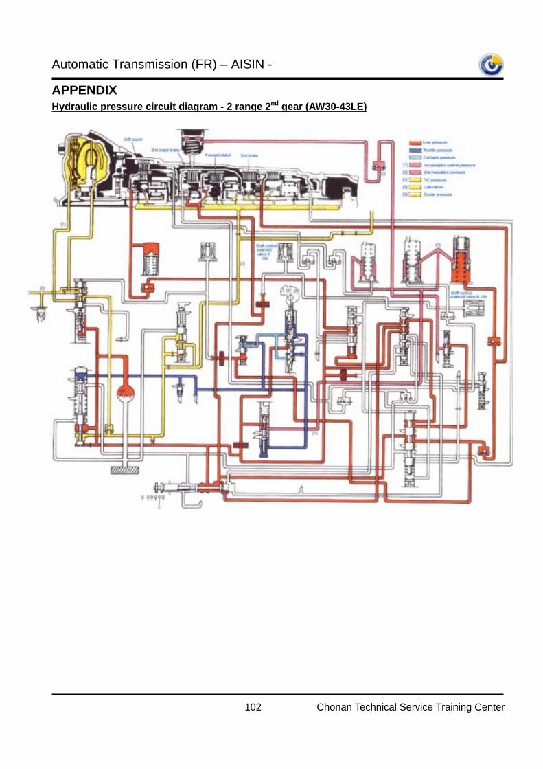
Automatic Transmission (FR) – AISIN -
102 Chonan Technical Service Training Center
APPENDIX Hydraulic pressure circuit diagram - 2 range 2nd gear (AW30-43LE)
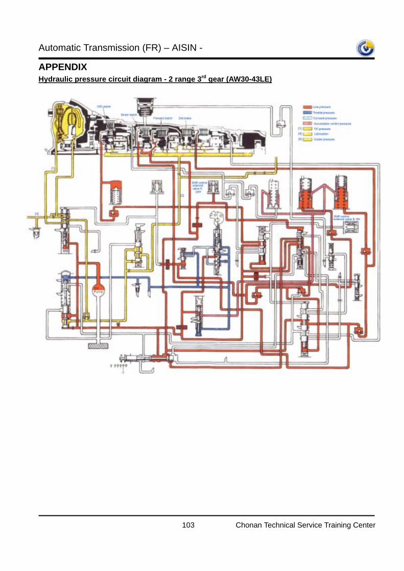
Automatic Transmission (FR) – AISIN -
103 Chonan Technical Service Training Center
APPENDIX Hydraulic pressure circuit diagram - 2 range 3rd gear (AW30-43LE)
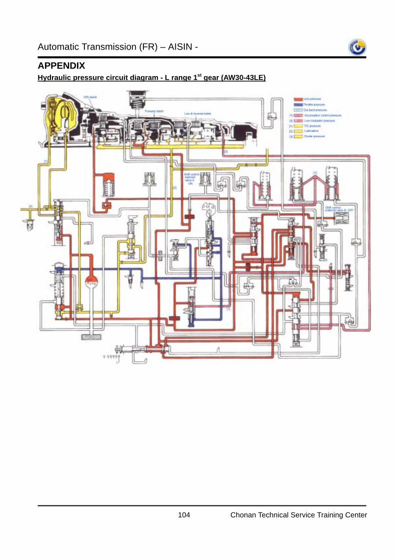
Automatic Transmission (FR) – AISIN -
104 Chonan Technical Service Training Center
APPENDIX Hydraulic pressure circuit diagram - L range 1st gear (AW30-43LE)
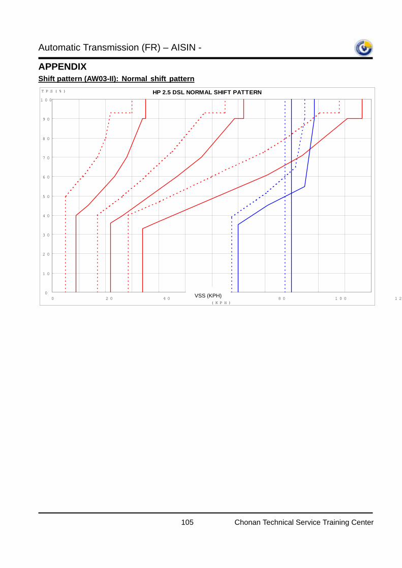
Automatic Transmission (FR) – AISIN -
105 Chonan Technical Service Training Center
APPENDIX Shift pattern (AW03-II): Normal shift pattern
HP 2.5 DSL NORMAL SHIFT PATTERN
0
10
20
30
40
50
60
70
80
90
100
0 20 40 60 80 100 120차속(KPH)
TPS(%)
VSS (KPH)
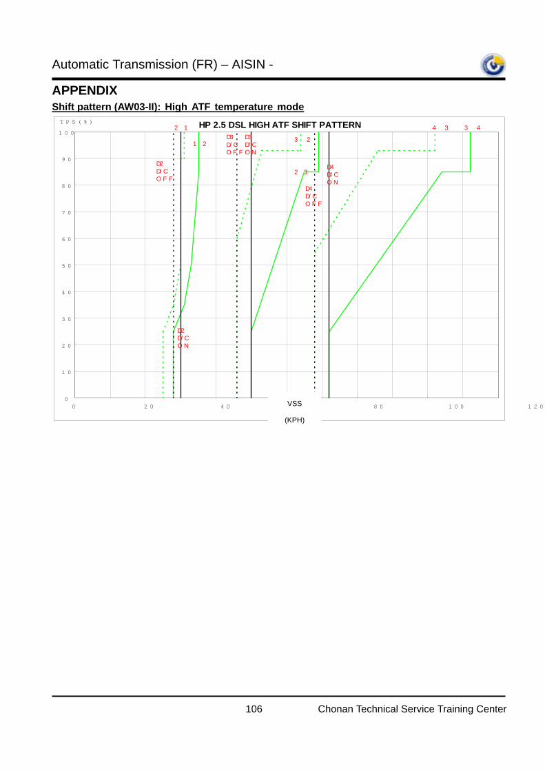
Automatic Transmission (FR) – AISIN -
106 Chonan Technical Service Training Center
APPENDIX Shift pattern (AW03-II): High ATF temperature mode
HP 2.5 DSL HIGH ATF SHIFT PATTERN
0
10
20
30
40
50
60
70
80
90
100
0 20 40 60 80 100 120
차속(KPH)
TPS(%)
D2D/COFF
D3D/COFF
D4D/COFF
D2D/CON
D3D/CON
D4D/CON
2→1
1→23→2
2→3
4→3 3→4
VSS
(KPH)
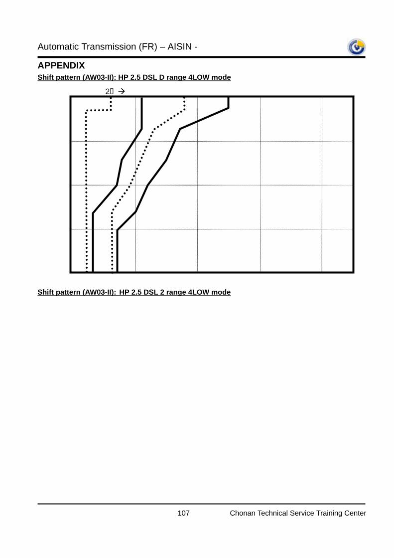
Automatic Transmission (FR) – AISIN -
107 Chonan Technical Service Training Center
APPENDIX Shift pattern (AW03-II): HP 2.5 DSL D range 4LOW mode
Shift pattern (AW03-II): HP 2.5 DSL 2 range 4LOW mode
2 1 1 2 3 2 2 3
1000 2000 3000 4000
25
50
75
100
0 Output speed (rpm)
TPS (%)
1000 2000 3000 4000
25
50
75
100
0
Output speed (rpm) TPS (%)
2 1 1 2 3 2
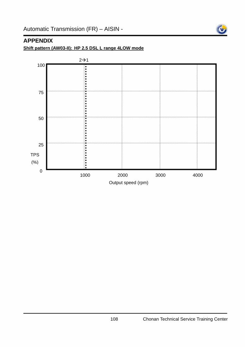
Automatic Transmission (FR) – AISIN -
108 Chonan Technical Service Training Center
APPENDIX Shift pattern (AW03-II): HP 2.5 DSL L range 4LOW mode
1000 2000 3000 4000
25
50
75
100
0
Output speed (rpm)
TPS (%)
2 1
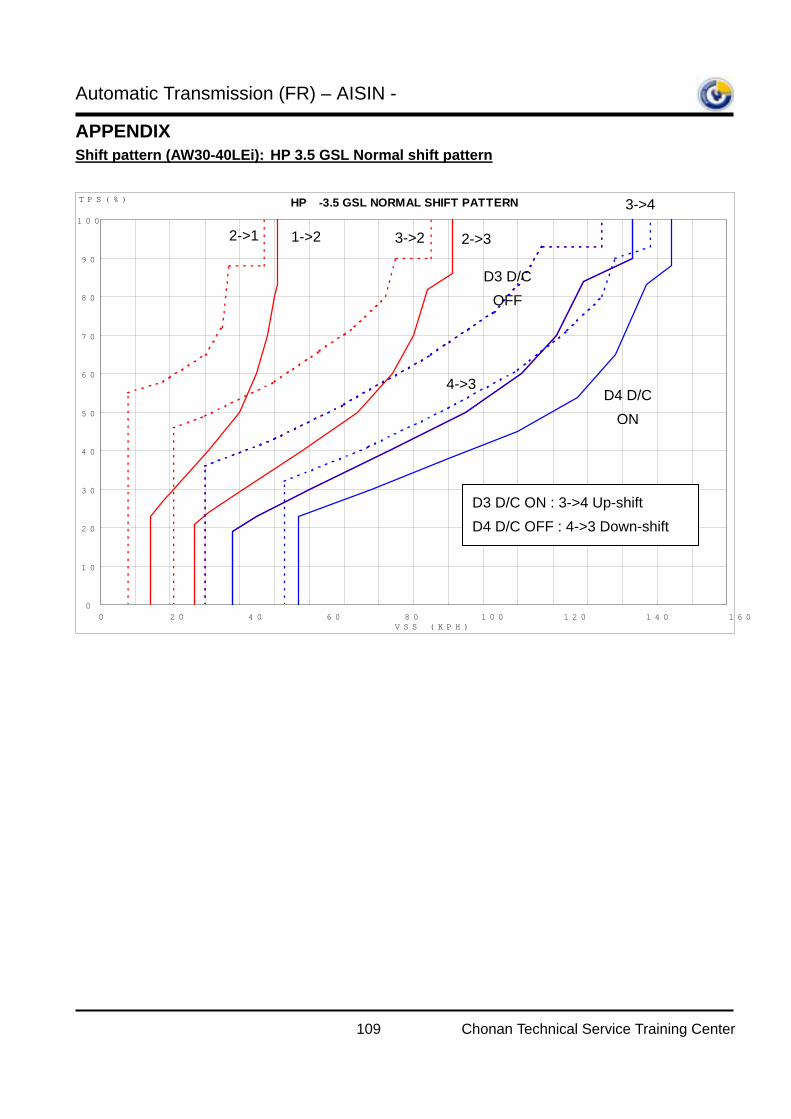
Automatic Transmission (FR) – AISIN -
109 Chonan Technical Service Training Center
APPENDIX Shift pattern (AW30-40LEi): HP 3.5 GSL Normal shift pattern
HP Σ -3.5 GSL NORMAL SHIFT PATTERN
0
10
20
30
40
50
60
70
80
90
100
0 20 40 60 80 100 120 140 160 180VSS (KPH)
TPS(%)
1->2 2->1 2->3 3->2
3->4
4->3
D3 D/C OFF
D3 D/C ON : 3->4 Up-shift D4 D/C OFF : 4->3 Down-shift
D4 D/C ON
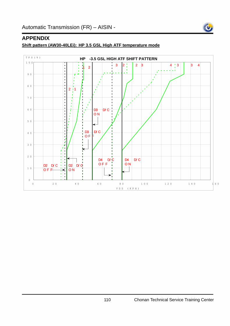
Automatic Transmission (FR) – AISIN -
110 Chonan Technical Service Training Center
APPENDIX Shift pattern (AW30-40LEi): HP 3.5 GSL High ATF temperature mode
HP Σ-3.5 GSL HIGH ATF SHIFT PATTERN
0
10
20
30
40
50
60
70
80
90
100
0 20 40 60 80 100 120 140 160 180
VSS (KPH)
TPS(%)
D2 D/COFF
D3 D/COFF
D4 D/COFFD2 D/C
ON
D3 D/CON
D4 D/CON
2→1
1→23→2 2→3 4→3 3→4
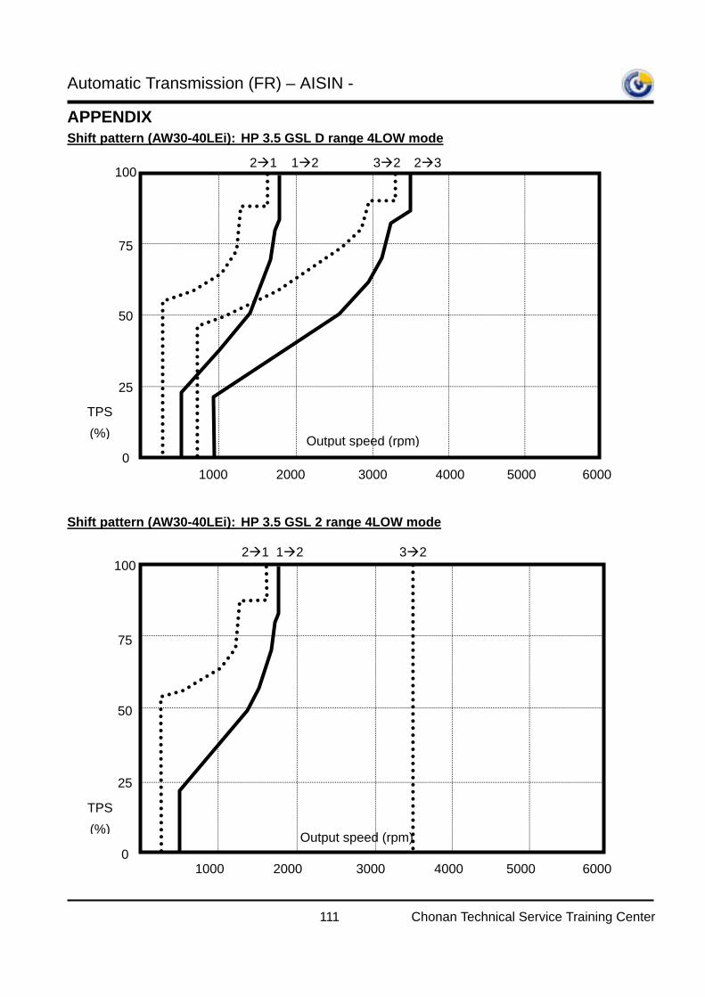
Automatic Transmission (FR) – AISIN -
111 Chonan Technical Service Training Center
APPENDIX Shift pattern (AW30-40LEi): HP 3.5 GSL D range 4LOW mode Shift pattern (AW30-40LEi): HP 3.5 GSL 2 range 4LOW mode
1000 2000 3000 4000
25
50
75
100
0 Output speed (rpm)
TPS (%)
5000 6000
2 1 1 2 3 2 2 3
1000 2000 3000 4000
25
50
75
100
0 Output speed (rpm)
TPS (%)
5000 6000
2 1 1 2 3 2
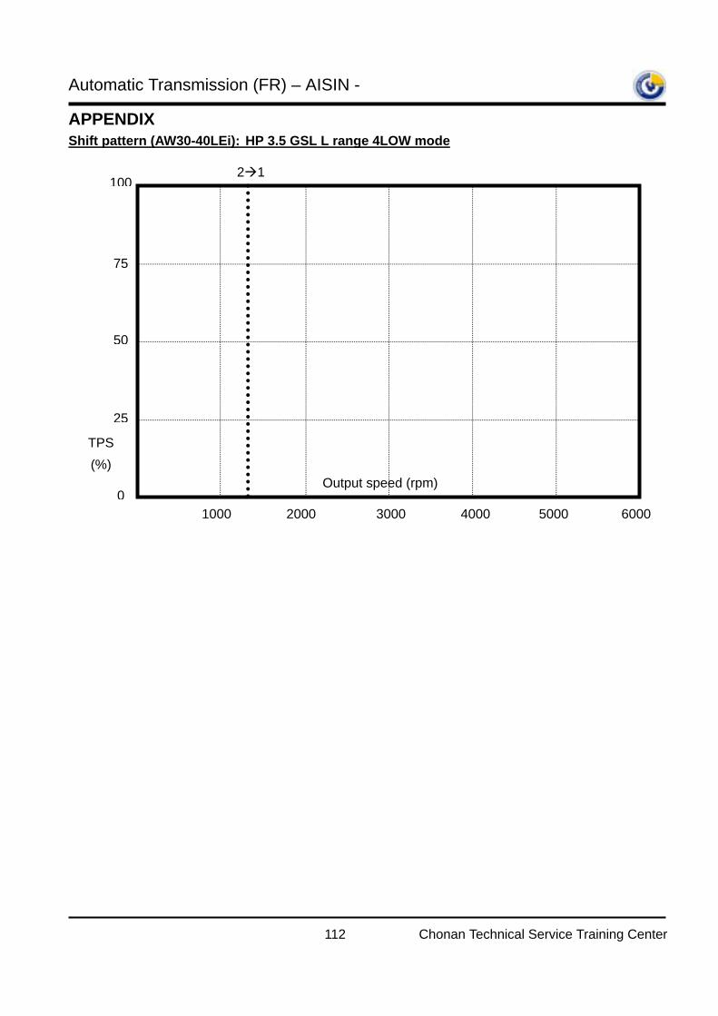
Automatic Transmission (FR) – AISIN -
112 Chonan Technical Service Training Center
APPENDIX Shift pattern (AW30-40LEi): HP 3.5 GSL L range 4LOW mode
1000 2000 3000 4000
25
50
75
100
0Output speed (rpm)
TPS (%)
5000 6000
2 1
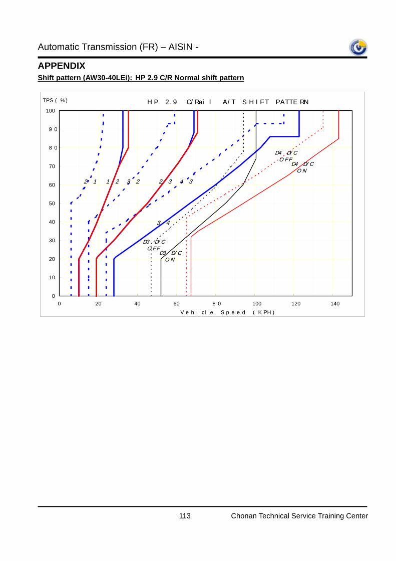
Automatic Transmission (FR) – AISIN -
113 Chonan Technical Service Training Center
APPENDIX Shift pattern (AW30-40LEi): HP 2.9 C/R Normal shift pattern
HP 2.9 C/Rail A/T SHIFT PATTERN
0
10
20
30
40
50
60
70
80
90
100
0 20 40 60 80 100 120 140
Vehicle Speed (KPH)
TPS(%)
1→22→1 2→33→2
3→4
4→3
D3 D/COFF
D3 D/CON
D4 D/COFF
D4 D/CON
Automatic Transmission (FR) – AISIN -
114 Chonan Technical Service Training Center
EXAMINATION
Course:
Automatic Transmission (FR) – AISIN - [CHASSIS_STEP2_IBT_A/T FR (AISIN)] Code : SCE
Section: AW30-40LE (Terracan)
1. Which of the following is not true for the warning lamp (A/T lamp) blinking condition?.
1) Input speed sensor malfunction
2) Output speed sensor malfunction
3) ATF temperature sensor open or short
4) Throttle position sensor malfunction
5) CAN communication problem with ECM
2. Write down the name of every clutches and brakes for AW30-40LEi.
1) C0 –
2) C1 –
3) C2 –
4) B0 –
5) B1 –
6) B2 –
7) B3 –
3. Select wrong statement.
1) 2nd coasting brake is engaged in D range 2nd gear; therefore engine brake is available in this case.
2) In case of PG-B fail, over drive will be inhibited.
3) PG-A speed will be zero in case of 4th gear is engaged.
4) Even though brake switch is open or short, there is no DTC in Hi-scan Pro.
4. What is the main signal for gear shifting?
1) PG-A, PG-B
2) PG-A, TPS.
3) PG-B, TPS.
4) TPS, Vehicle speed.
※ Mark 'V' on the "Correct" or "Wrong".
5. If the failsafe function is activated, the 2nd gear is engaged in case of 2 range.
Automatic Transmission (FR) – AISIN -
115 Chonan Technical Service Training Center
Correct ( ) Wrong ( )
6. If the P0707 (Inhibitor switch open) is detected by TCM, transmission will be controlled by ‘D range’, therefore
the vehicle will move.
Correct ( ) Wrong ( )
7. If TPS is fail, TCM will control the TPS ratio by 50% and the line pressure will be maximum value.
Correct ( ) Wrong ( )
8. As the L4 signal from the 4LOW switch is inputted to TCM, the 4th gear will be inhibited and lock-up also
prohibited.
Correct ( ) Wrong ( )
9. In case of ATF temperature sensor is fail, the gear will be fixed by 4th gear (D range), 3rd gear (2nd range),
1st gear (L range)..
Correct ( ) Wrong ( )
10. If the SCSV 1 and SCSV 2 are OFF, the 4th gear is engaged in all ranges (D, 2,L).
Correct ( ) Wrong ( )
11. Even though some DTC is detected by TCM, the PCSV will control the line pressure normally.
Correct ( ) Wrong ( )
12. You can check the signal of SCSV 1 and SCSV 2 in the current data of Hi-scan Pro.
Correct ( ) Wrong ( )
13. The damper clutch control solenoid valve is controlled by duty ratio for better fuel consumption and driving
feeling.
Correct ( ) Wrong ( )
14. C0 and B0 cannot be engaged simultaneously.
Correct ( ) Wrong ( )
Evaluation:
Submit this page only to instructor.
Name: Company:
Country: Date:
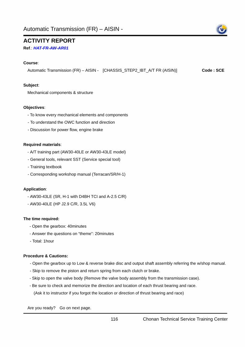
Automatic Transmission (FR) – AISIN -
116 Chonan Technical Service Training Center
ACTIVITY REPORT Ref.: HAT-FR-AW-AR01
Course:
Automatic Transmission (FR) – AISIN - [CHASSIS_STEP2_IBT_A/T FR (AISIN)] Code : SCE
Subject:
Mechanical components & structure
Objectives:
- To know every mechanical elements and components
- To understand the OWC function and direction
- Discussion for power flow, engine brake
Required materials:
- A/T training part (AW30-40LE or AW30-43LE model)
- General tools, relevant SST (Service special tool)
- Training textbook
- Corresponding workshop manual (Terracan/SR/H-1)
Application:
- AW30-43LE (SR, H-1 with D4BH TCI and A-2.5 C/R)
- AW30-40LE (HP J2.9 C/R, 3.5L V6)
The time required:
- Open the gearbox: 40minutes
- Answer the questions on “theme”: 20minutes
- Total: 1hour
Procedure & Cautions:
- Open the gearbox up to Low & reverse brake disc and output shaft assembly referring the w/shop manual.
- Skip to remove the piston and return spring from each clutch or brake.
- Skip to open the valve body (Remove the valve body assembly from the transmission case).
- Be sure to check and memorize the direction and location of each thrust bearing and race.
(Ask it to instructor if you forgot the location or direction of thrust bearing and race)
Are you ready? Go on next page.
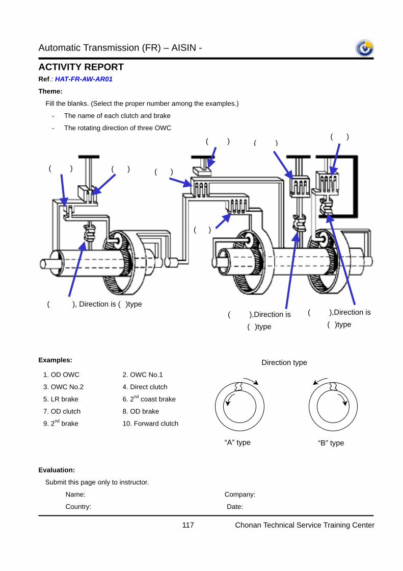
Automatic Transmission (FR) – AISIN -
117 Chonan Technical Service Training Center
ACTIVITY REPORT Ref.: HAT-FR-AW-AR01
Theme:
Fill the blanks. (Select the proper number among the examples.)
- The name of each clutch and brake
- The rotating direction of three OWC
Examples:
Evaluation:
Submit this page only to instructor.
Name: Company:
Country: Date:
( 1 ), Direction is (A)type
( 7 ) ( 8 ) ( 4 )
( 6 )
( 10 )
( 2 ),Direction is (B)type
( 9 ) ( 5 )
( 3 ),Direction is (A)type
1. OD OWC
3. OWC No.2
5. LR brake
7. OD clutch
9. 2nd brake
2. OWC No.1
4. Direct clutch
6. 2nd coast brake
8. OD brake
10. Forward clutch
Direction type
“A” type “B” type
Automatic Transmission (FR) – AISIN -
118 Chonan Technical Service Training Center
ACTIVITY REPORT Ref.: HAT-FR-AW-AR02
Course:
Automatic Transmission (FR) – AISIN - [CHASSIS_STEP2_IBT_A/T FR (AISIN)] Code : SCE
Subject:
Mechanical components & structure
Objectives:
- To identify the location of each accumulators
- To understand the function of accumulators
- To know how to remove each accumulators from the transmission case
Required materials:
- A/T training part (AW30-40LE or AW30-43LE model)
- General tools, relevant SST (Service special tool), Air gun
- Training textbook
- Corresponding workshop manual (Terracan/SR/H-1)
Application:
- AW30-43LE (SR, H-1 with D4BH TCI and A-2.5 C/R)
- AW30-40LE (HP J2.9 C/R, 3.5L V6)
The time required:
- Remove the accumulators: 10minutes
- Answer the questions on “theme”: 5minutes
- Total: 15minutes
Procedure & Cautions:
- Open the oil pan and valve body assembly.
- Skip to open the valve body (Remove the valve body assembly from the transmission case).
- Be sure to check and memorize the location of each accumulator piston and springs.
(Refer the page No. 64 and 71 in this textbook)
Are you ready? Go on next page.
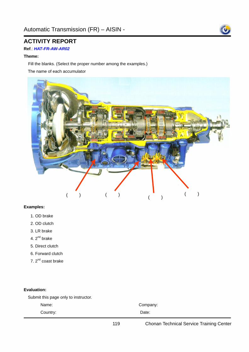
Automatic Transmission (FR) – AISIN -
119 Chonan Technical Service Training Center
ACTIVITY REPORT Ref.: HAT-FR-AW-AR02
Theme:
Fill the blanks. (Select the proper number among the examples.)
The name of each accumulator
Examples:
Evaluation:
Submit this page only to instructor.
Name: Company:
Country: Date:
( ) ( ) ( ) ( )
1. OD brake
2. OD clutch
3. LR brake
4. 2nd brake
5. Direct clutch
6. Forward clutch
7. 2nd coast brake
Automatic Transmission (FR) – AISIN -
120 Chonan Technical Service Training Center
ACTIVITY REPORT Ref.: HAT-FR-AW-AR03
Course:
Automatic Transmission (FR) – AISIN - [CHASSIS_STEP2_IBT_A/T FR (AISIN)] Code : SCE
Subject:
Mechanical service points
Objectives:
- To know how to make decision the replacement of clutch and brake disc
- How to replace the discs while overhauling the clutch and brake
- For deep understanding of internal mechanical structure
Required materials:
- A/T training part (AW30-40LE or AW30-43LE model)
- General tools, relevant SST (Service special tool), Calipers, Micrometer.
- Training textbook
- Corresponding workshop manual (Terracan/SR/H-1)
Application:
- AW30-43LE (SR, H-1 with D4BH TCI and A-2.5 C/R)
- AW30-40LE (HP J2.9 C/R, 3.5L V6)
The time required:
- Remove each clutch and brake: 10minutes
- Answer the questions on “theme”: 10minutes
- Total: 20minutes
Procedure & Cautions:
- Open the gearbox up to Low & reverse brake disc and output shaft assembly referring the w/shop manual..
- Skip to open the valve body (Remove the valve body assembly from the transmission case).
- Be careful not to mix up discs of clutch and brake.
- Be careful not to mix up every snap rings for each clutch and brake
Are you ready? Go on next page.
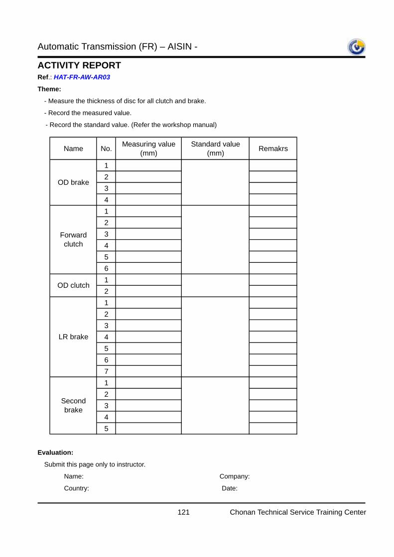
Automatic Transmission (FR) – AISIN -
121 Chonan Technical Service Training Center
ACTIVITY REPORT Ref.: HAT-FR-AW-AR03
Theme:
- Measure the thickness of disc for all clutch and brake.
- Record the measured value.
- Record the standard value. (Refer the workshop manual)
Evaluation:
Submit this page only to instructor.
Name: Company:
Country: Date:
Name No. Measuring value(mm)
Standard value(mm) Remakrs
123412345612123456712345
OD brake
Forwardclutch
Secondbrake
OD clutch
LR brake
Automatic Transmission (FR) – AISIN -
122 Chonan Technical Service Training Center
ACTIVITY REPORT Ref.: HAT-FR-AW-AR04
Course:
Automatic Transmission (FR) – AISIN - [CHASSIS_STEP2_IBT_A/T FR (AISIN)] Code : SCE
Subject:
Mechanical service points
Objectives:
- To know how to measure the end play of clutch and brake
- To be able to change the proper parts in case of out of specification for normal end play value
- To understand why we have to measure this endplay
- To get a skill to assemble this transmission properly
Required materials:
- A/T training part (AW30-40LE or AW30-43LE model)
- General tools, relevant SST, Air gun, Thickness gauge, Calipers, Dial gauge
- Training textbook
- Corresponding workshop manual (Terracan/SR/H-1)
Application:
- AW30-43LE (SR, H-1 with D4BH TCI and A-2.5 C/R)
- AW30-40LE (HP J2.9 C/R, 3.5L V6)
The time required:
- Assemble every clutch and brake: 60minutes
- Answer the questions on “theme”: 20minutes
- Total: 80minutes
Procedure & Cautions:
- Assemble the training part up to torque converter housing referring the w/shop manual.
- Be careful the location and direction of every thrust bearing and races.
- Be careful not to make damage on the transmission parts.
- Do not apply too much force when you align the teeth of clutch or brake or it will result in damage.
Are you ready? Go on next page.
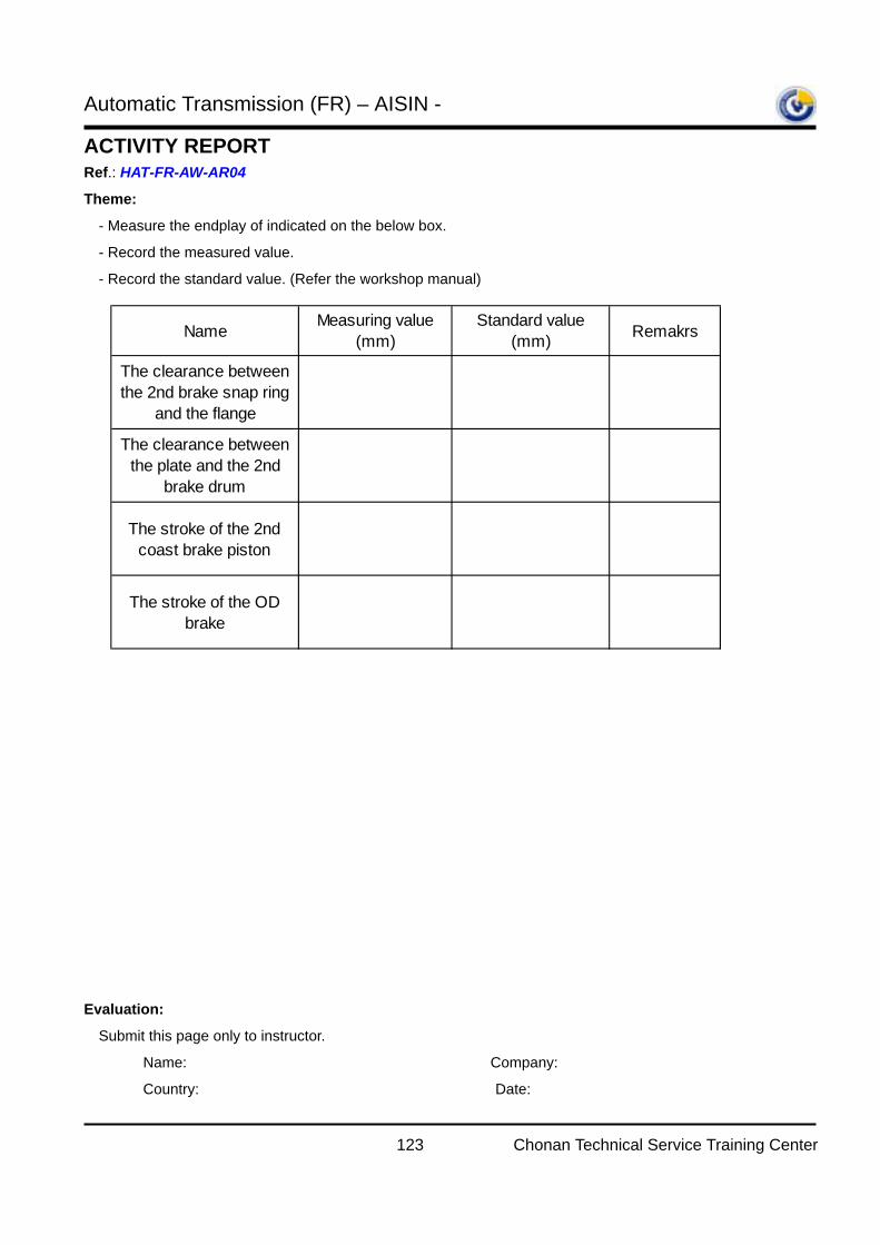
Automatic Transmission (FR) – AISIN -
123 Chonan Technical Service Training Center
ACTIVITY REPORT Ref.: HAT-FR-AW-AR04
Theme:
- Measure the endplay of indicated on the below box.
- Record the measured value.
- Record the standard value. (Refer the workshop manual)
Evaluation:
Submit this page only to instructor.
Name: Company:
Country: Date:
Name Measuring value(mm)
Standard value(mm) Remakrs
The clearance betweenthe 2nd brake snap ring
and the flange
The clearance betweenthe plate and the 2nd
brake drum
The stroke of the 2ndcoast brake piston
The stroke of the ODbrake
Automatic Transmission (FR) – AISIN -
124 Chonan Technical Service Training Center
ACTIVITY REPORT Ref.: HAT-FR-AW-AR05
Course:
Automatic Transmission (FR) – AISIN - [CHASSIS_STEP2_IBT_A/T FR (AISIN)] Code : SCE
Subject:
Mechanical structure and Electrical inputs
Objectives:
- To know how TCM detects the input speed in this transmission
- To be able to analyze the waveform of PG-A (Input speed sensor)
- To understand why the input speed drops zero in over drive
- Discuss the function of PG-A (Input speed sensor)
Required materials:
- Overhauled A/T training part (AW30-40LE model)
- A/T (AW30-40LE or AW30-43LE model) training vehicle: HP J2.9 C/R or 3.5L V6
- Training textbook
- Corresponding Electrical troubleshooting manual (Terracan)
- Hi-scan Pro with Software card, SST(T-connector)
Application:
- AW30-40LE (HP J2.9 C/R, 3.5L V6)
※ It is not available in AW30-43LE (SR, H-1 with D4BH TCI and A-2.5 C/R), because PG-A was not applied
in these vehicle models.
The time required:
- Installation of the SST(T-connector) on the PG-A sensor: 5minutes
- Answer the questions on “theme”: 10minutes
- Total: 15minutes
Procedure & Cautions:
- After installing the T-connector, go into the ‘Oscilloscope’ menu in Hi-scan Pro to measure the waveform
from PG-A sensor while engine starting
- Be careful not to be occurred the shorted circuit in PG-A sensor or TCM while installing the T-connector.
Are you ready? Go on next page.
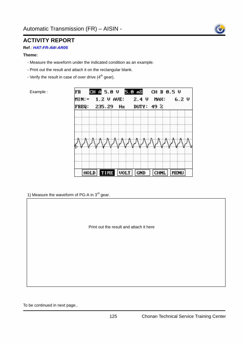
Automatic Transmission (FR) – AISIN -
125 Chonan Technical Service Training Center
ACTIVITY REPORT Ref.: HAT-FR-AW-AR05
Theme:
- Measure the waveform under the indicated condition as an example.
- Print out the result and attach it on the rectangular blank.
- Verify the result in case of over drive (4th gear).
Example :
1) Measure the waveform of PG-A in 3rd gear.
To be continued in next page..
Print out the result and attach it here
Automatic Transmission (FR) – AISIN -
126 Chonan Technical Service Training Center
ACTIVITY REPORT Ref.: HAT-FR-AW-AR05
2) Measure the waveform of PG-A in 4th gear.
Evaluation:
Submit this page only to instructor.
Name: Company:
Country: Date:
Print out the result and attach it here
Automatic Transmission (FR) – AISIN -
127 Chonan Technical Service Training Center
ACTIVITY REPORT Ref.: HAT-FR-AW-AR06
Course:
Automatic Transmission (FR) – AISIN - [CHASSIS_STEP2_IBT_A/T FR (AISIN)] Code : SCE
Subject:
Electrical Outputs
Objectives:
- To verify the schedule of shift control solenoid valve depends on the shift range
- To understand the control of shift while the fail-safe is activated.
Required materials:
- A/T (AW30 or AW03 series model with TCM) training vehicle: Terracan / H-1 / SR and so on.
- Training textbook
- Corresponding Electrical troubleshooting manual
- Hi-scan Pro with Software card, Probe channel for voltage
Application:
- All AISIN Models with TCM: Except Galloper
The time required:
- Installation of the probe on the TCM side harness connector: 5minutes
- Answer the questions on “theme”: 5minutes
- Total: 10minutes
Procedure & Cautions:
- Be careful not to make damage on the TCM harness side connector while installing the probe.
(Turn the IG key off to protect from the short damage of circuit)
- It is not available to check the shift sequence in the “current data” menu of Hi-scan Pro..
(Use the “Oscilloscope function to check the signal.)
- Refer the ETM (Electrical troubleshooting manual) to find out the pin number of SCSV 1 and SCSV 2 from
the TCM harness side connector
- It is impossible to use T-connector on the solenoid valve connector because there is no space to do it.
Are you ready? Go on next page.
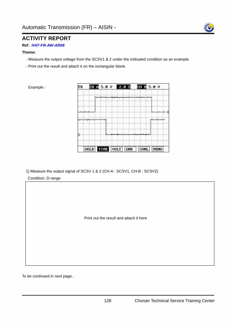
Automatic Transmission (FR) – AISIN -
128 Chonan Technical Service Training Center
ACTIVITY REPORT Ref.: HAT-FR-AW-AR06
Theme:
- Measure the output voltage from the SCSV1 & 2 under the indicated condition as an example.
- Print out the result and attach it on the rectangular blank.
Example :
1) Measure the output signal of SCSV 1 & 2 (CH-A : SCSV1, CH-B : SCSV2)
Condition: D-range
To be continued in next page..
Print out the result and attach it here
Automatic Transmission (FR) – AISIN -
129 Chonan Technical Service Training Center
ACTIVITY REPORT Ref.: HAT-FR-AW-AR06
2) Measure the output signal of SCSV 1 & 2 (CH-A : SCSV1, CH-B : SCSV2)
Condition: 2-range
3) Measure the output signal of SCSV 1 & 2 (CH-A : SCSV1, CH-B : SCSV2)
Condition: L-range
4) Check the signal of SCSV1 and SCSV2 at P, R, N range: ON or OFF? : ( )
Evaluation:
Submit this page only to instructor.
Name: Company:
Country: Date:
Print out the result and attach it here
Print out the result and attach it here
Automatic Transmission (FR) – AISIN -
130 Chonan Technical Service Training Center
ACTIVITY REPORT Ref.: HAT-FR-AW-AR07
Course:
Automatic Transmission (FR) – AISIN - [CHASSIS_STEP2_IBT_A/T FR (AISIN)] Code : SCE
Subject:
Electrical Outputs
Objectives:
- To understand the function of PCSV (Pressure control solenoid valve)
- To know the characteristics of PCSV and how to check it is good or not.
Required materials:
- A/T (AW30-40LE / AW03-II model) training vehicle: Terracan / H-1 .
- Training textbook
- Corresponding Electrical troubleshooting manual
- Hi-scan Pro with Software card, Probe channel for voltage
Application:
- AW30-40LE / AW03-II model without throttle cable
The time required:
- Installation of the probe on the TCM side harness connector: 5minutes
- Answer the questions on “theme”: 5minutes
- Total: 10minutes
Procedure & Cautions:
- Be careful not to make damage on the TCM harness side connector while installing the probe.
(Turn the IG key off to protect from the short damage of circuit)
- It is impossible to use T-connector on the solenoid valve connector because there is no space to do it.
- Refer the ETM (Electrical troubleshooting manual) to find out the pin number of PCSV from the TCM
harness side connector
(Use the “Oscilloscope function to check the signal.)
(It is not necessary to use the “Trigger function” of Oscilloscope function in this case)
Are you ready? Go on next page.
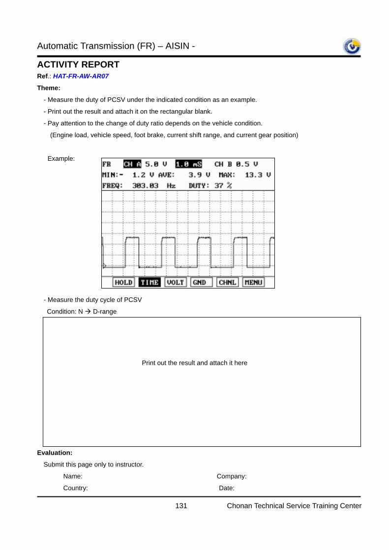
Automatic Transmission (FR) – AISIN -
131 Chonan Technical Service Training Center
ACTIVITY REPORT Ref.: HAT-FR-AW-AR07
Theme:
- Measure the duty of PCSV under the indicated condition as an example.
- Print out the result and attach it on the rectangular blank.
- Pay attention to the change of duty ratio depends on the vehicle condition.
(Engine load, vehicle speed, foot brake, current shift range, and current gear position)
Example:
- Measure the duty cycle of PCSV
Condition: N D-range
Evaluation:
Submit this page only to instructor.
Name: Company:
Country: Date:
Print out the result and attach it here
Automatic Transmission (FR) – AISIN -
132 Chonan Technical Service Training Center
ACTIVITY REPORT Ref.: HAT-FR-AW-AR08
Course:
Automatic Transmission (FR) – AISIN - [CHASSIS_STEP2_IBT_A/T FR (AISIN)] Code : SCE
Subject:
Electrical Outputs
Objectives:
- To understand the function of DCCSV (Damper clutch control solenoid valve)
- To verify the damper clutch operating condition.
- To know the characteristics of DCCSV and how to check it is good or not.
Required materials:
- A/T (AW30 or AW03 series model) training vehicle: Terracan / H-1 /SR.
- Training textbook
- Corresponding Electrical troubleshooting manual
- Hi-scan Pro with Software card, Probe channel for voltage
Application:
- All electronic controlled AISIN models with damper clutch (Except Galloper)
The time required:
- Installation of the probe on the TCM side harness connector: 5minutes
- Answer the questions on “theme”: 5minutes
- Total: 10minutes
Procedure & Cautions:
- Be careful not to make damage on the TCM harness side connector while installing the probe.
(Turn the IG key off to protect from the short damage of circuit)
- It is impossible to use T-connector on the solenoid valve connector because there is no space to do it.
- Refer the ETM (Electrical troubleshooting manual) to find out the pin number of DCCSV from the TCM
harness side connector
(Use the “Oscilloscope function to check the signal.)
Are you ready? Go on next page.
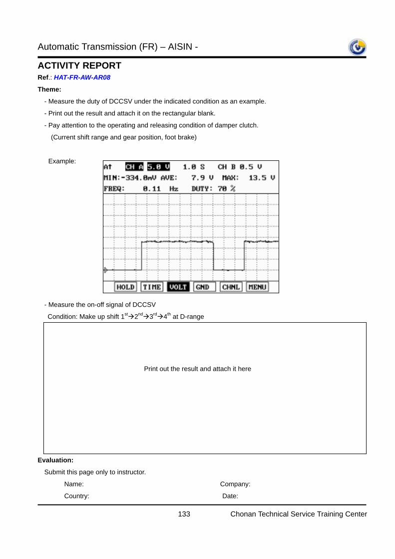
Automatic Transmission (FR) – AISIN -
133 Chonan Technical Service Training Center
ACTIVITY REPORT Ref.: HAT-FR-AW-AR08
Theme:
- Measure the duty of DCCSV under the indicated condition as an example.
- Print out the result and attach it on the rectangular blank.
- Pay attention to the operating and releasing condition of damper clutch.
(Current shift range and gear position, foot brake)
Example:
- Measure the on-off signal of DCCSV
Condition: Make up shift 1st 2nd 3rd 4th at D-range
Evaluation:
Submit this page only to instructor.
Name: Company:
Country: Date:
Print out the result and attach it here
Automatic Transmission (FR) – AISIN -
134 Chonan Technical Service Training Center
ACTIVITY REPORT Ref.: HAT-FR-AW-AR09
Course:
Automatic Transmission (FR) – AISIN - [CHASSIS_STEP2_IBT_A/T FR (AISIN)] Code : SCE
Subject:
Diagnosis trouble code (Input speed sensor)
Objectives:
- To understand the function of PG-A.
- To verify the symptom when PG-A is failed and failsafe operation by TCM.
- To know the detecting condition of relevant DTC.
Required materials:
- A/T (AW30-40LE, AW03-II model) training vehicle: Terracan.
- Training textbook
- Hi-scan Pro with Software card
Application:
- AW30-40LE, AW03-II model only
- PG-A (Input speed sensor) was not applied in following models.
(AW03-72LE, AW30-43LE)
The time required:
- Disconnect the PG-A sensor connector: 5minutes
- Answer the questions on “theme”: 10minutes
- Total: 15minutes
Procedure & Cautions:
- Disconnect the PG-A sensor connector
- Lift up the vehicle and drive
Are you ready? Go on next page.
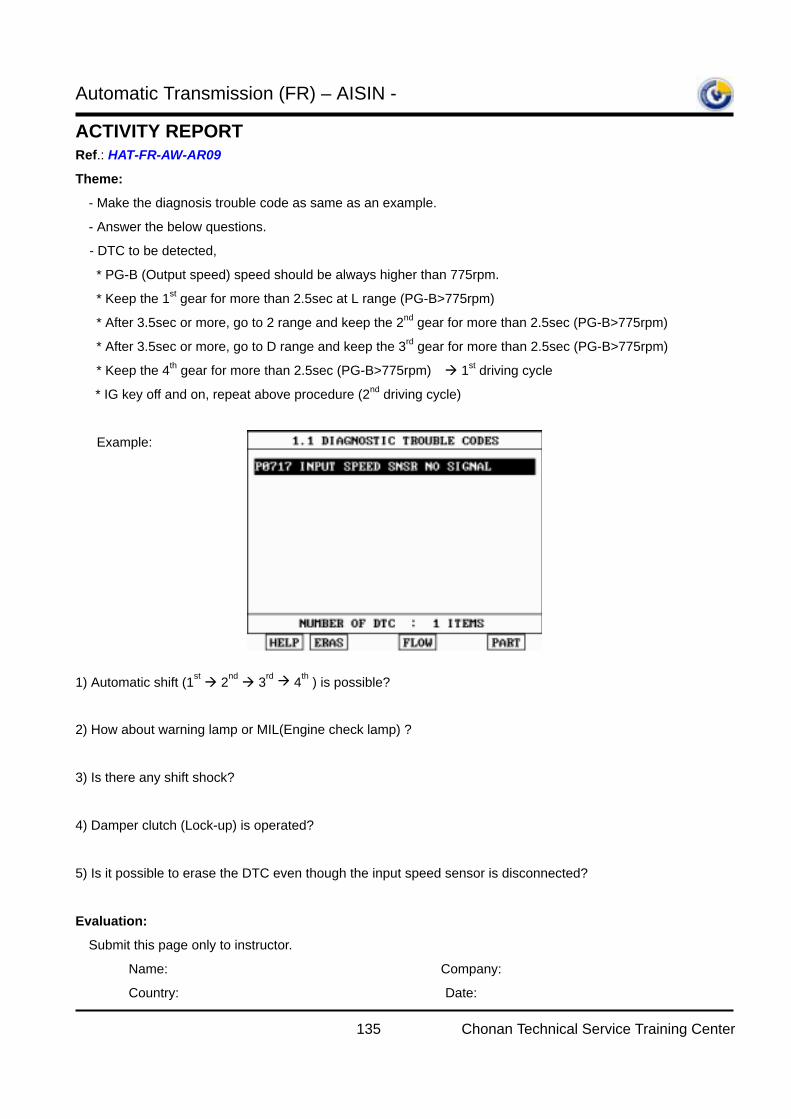
Automatic Transmission (FR) – AISIN -
135 Chonan Technical Service Training Center
ACTIVITY REPORT Ref.: HAT-FR-AW-AR09
Theme:
- Make the diagnosis trouble code as same as an example.
- Answer the below questions.
- DTC to be detected,
* PG-B (Output speed) speed should be always higher than 775rpm.
* Keep the 1st gear for more than 2.5sec at L range (PG-B>775rpm)
* After 3.5sec or more, go to 2 range and keep the 2nd gear for more than 2.5sec (PG-B>775rpm)
* After 3.5sec or more, go to D range and keep the 3rd gear for more than 2.5sec (PG-B>775rpm)
* Keep the 4th gear for more than 2.5sec (PG-B>775rpm) 1st driving cycle
* IG key off and on, repeat above procedure (2nd driving cycle)
Example:
1) Automatic shift (1st 2nd 3rd 4th ) is possible?
2) How about warning lamp or MIL(Engine check lamp) ?
3) Is there any shift shock?
4) Damper clutch (Lock-up) is operated?
5) Is it possible to erase the DTC even though the input speed sensor is disconnected?
Evaluation:
Submit this page only to instructor.
Name: Company:
Country: Date:
Automatic Transmission (FR) – AISIN -
136 Chonan Technical Service Training Center
ACTIVITY REPORT Ref.: HAT-FR-AW-AR10
Course:
Automatic Transmission (FR) – AISIN - [CHASSIS_STEP2_IBT_A/T FR (AISIN)] Code : SCE
Subject:
Diagnosis trouble code (Output speed sensor)
Objectives:
- To understand the function of PG-B.
- To verify the symptom when PG-B is failed and failsafe operation by TCM.
- To know the detecting condition of relevant DTC.
Required materials:
- A/T (AW30-40LE, AW03-II model) training vehicle: Terracan.
- Training textbook
- Hi-scan Pro with Software card
Application:
- AW30, AW03 series models with TCM
- However the DTC detecting condition may be slightly different depends on the vehicle
The time required:
- Disconnect the PG-B sensor connector: 5minutes
- Answer the questions on “theme”: 10minutes
- Total: 15minutes
Procedure & Cautions:
- Disconnect the PG-B sensor connector
- Lift up the vehicle and drive
Are you ready? Go on next page.
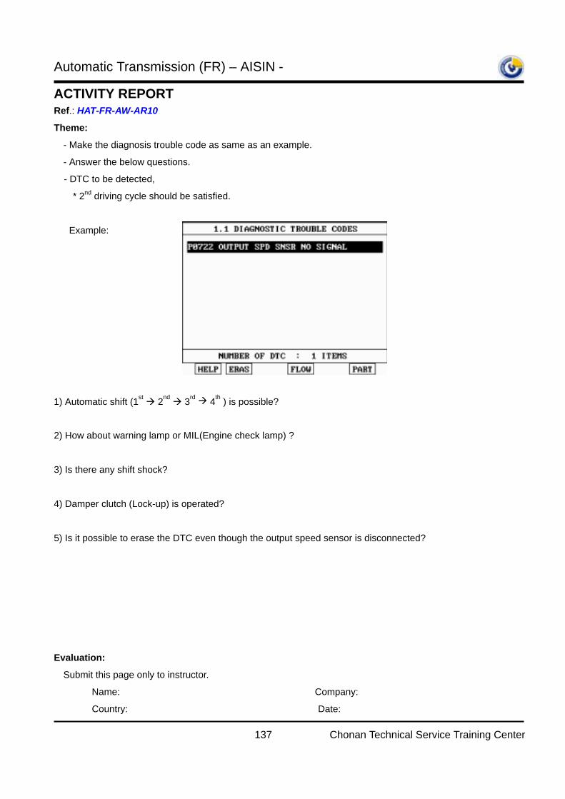
Automatic Transmission (FR) – AISIN -
137 Chonan Technical Service Training Center
ACTIVITY REPORT Ref.: HAT-FR-AW-AR10
Theme:
- Make the diagnosis trouble code as same as an example.
- Answer the below questions.
- DTC to be detected,
* 2nd driving cycle should be satisfied.
Example:
1) Automatic shift (1st 2nd 3rd 4th ) is possible?
2) How about warning lamp or MIL(Engine check lamp) ?
3) Is there any shift shock?
4) Damper clutch (Lock-up) is operated?
5) Is it possible to erase the DTC even though the output speed sensor is disconnected?
Evaluation:
Submit this page only to instructor.
Name: Company:
Country: Date:
Automatic Transmission (FR) – AISIN -
138 Chonan Technical Service Training Center
ACTIVITY REPORT Ref.: HAT-FR-AW-AR11
Course:
Automatic Transmission (FR) – AISIN - [CHASSIS_STEP2_IBT_A/T FR (AISIN)] Code : SCE
Subject:
Diagnosis trouble code (Shift control solenoid valve 1)
Objectives:
- To verify the fail-safe operation if the shift control solenoid valve is failed.
Required materials:
- A/T (AW30, AW03 series model) training vehicle: Terracan / H-1 / SR
- Training textbook
- Hi-scan Pro with Software card
- Electrical troubleshooting manual
Application:
- AW30, AW03 series models with TCM
- However the DTC detecting condition and fail-safe operation may be slightly different depends on the
vehicle
The time required:
- Make related DTC: 5minutes
- Answer the questions on “theme”: 5minutes
- Total: 10minutes
Procedure & Cautions:
- Connect the SCSV 1 terminal of TCM into body to make a short to ground.
- Do make short to ground under the IG key off for protecting the circuit.
- The use of T-connector on solenoid valve connector is improper because there is no space to do it.
- Lift up the vehicle and drive.
Are you ready? Go on next page.

Automatic Transmission (FR) – AISIN -
139 Chonan Technical Service Training Center
ACTIVITY REPORT Ref.: HAT-FR-AW-AR11
Theme:
- Make the diagnosis trouble code as same as an example.
- Answer the below questions.
- DTC to be detected,
* 1st driving cycle is enough the DTC to be displayed.
Example:
1) Automatic shift (1st 2nd 3rd 4th ) is possible?
2) How about warning lamp or MIL(Engine check lamp) ?
3) Is there any shift shock?
4) Damper clutch (Lock-up) is operated?
5) Is it possible to erase the DTC even though the SCSV 1 is still grounded to body?
6) Which gear was fixed depends on the range?
D range -
2 range -
L range -
Evaluation:
Submit this page only to instructor.
Name: Company:
Country: Date:
Automatic Transmission (FR) – AISIN -
140 Chonan Technical Service Training Center
ACTIVITY REPORT Ref.: HAT-FR-AW-AR12
Course:
Automatic Transmission (FR) – AISIN - [CHASSIS_STEP2_IBT_A/T FR (AISIN)] Code : SCE
Subject:
Diagnosis trouble code (Shift control solenoid valve 2)
Objectives:
- To verify the fail-safe operation if the shift control solenoid valve is failed.
Required materials:
- A/T (AW30, AW03 series model) training vehicle: Terracan / H-1 / SR
- Training textbook
- Hi-scan Pro with Software card
- Electrical troubleshooting manual
Application:
- AW30, AW03 series models with TCM
- However the DTC detecting condition and fail-safe operation may be slightly different depends on the
vehicle
The time required:
- Make related DTC: 5minutes
- Answer the questions on “theme”: 5minutes
- Total: 10minutes
Procedure & Cautions:
- Connect the SCSV 2 terminal of TCM into body to make a short to ground.
- Do make short to ground under the IG key off for protecting the circuit.
- The use of T-connector on solenoid valve connector is improper because there is no space to do it.
- Lift up the vehicle and drive.
Are you ready? Go on next page.
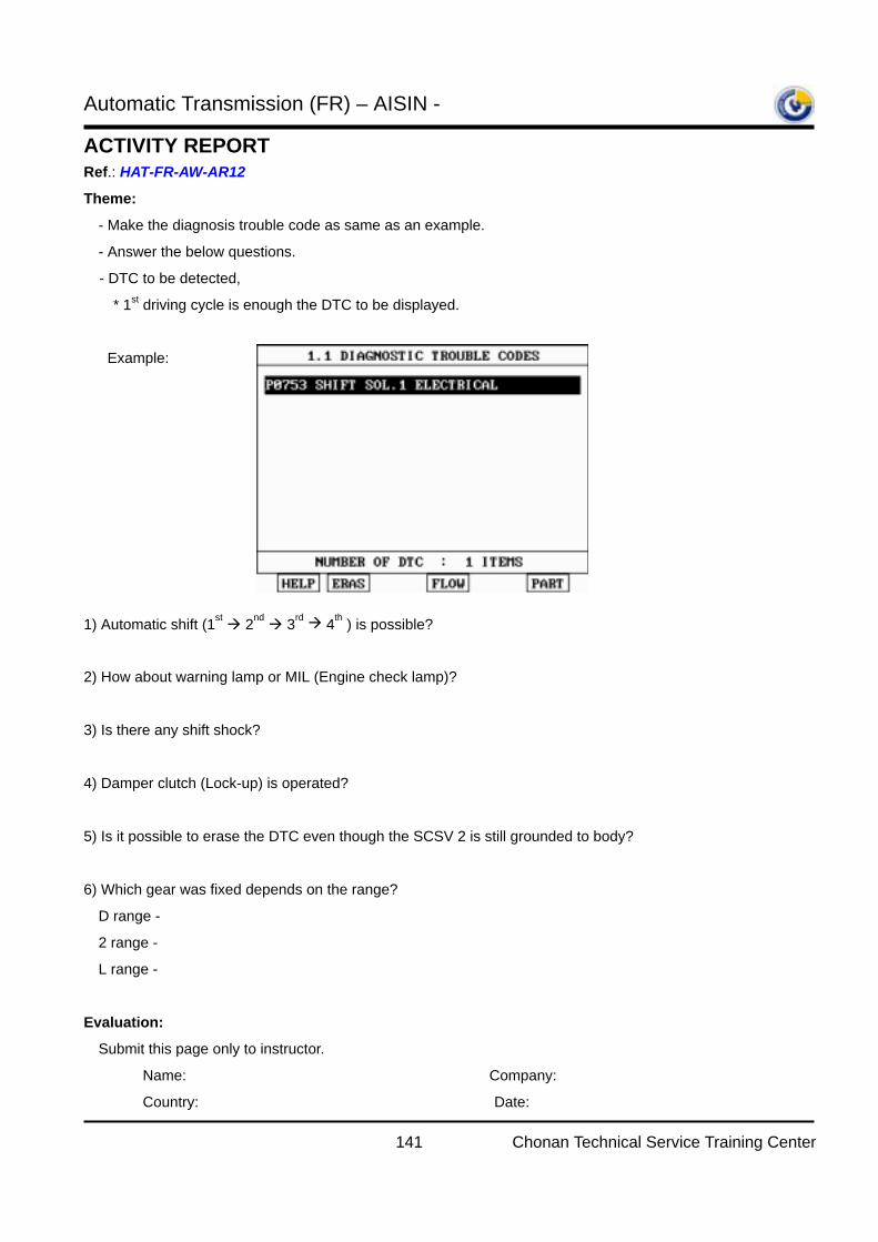
Automatic Transmission (FR) – AISIN -
141 Chonan Technical Service Training Center
ACTIVITY REPORT Ref.: HAT-FR-AW-AR12
Theme:
- Make the diagnosis trouble code as same as an example.
- Answer the below questions.
- DTC to be detected,
* 1st driving cycle is enough the DTC to be displayed.
Example:
1) Automatic shift (1st 2nd 3rd 4th ) is possible?
2) How about warning lamp or MIL (Engine check lamp)?
3) Is there any shift shock?
4) Damper clutch (Lock-up) is operated?
5) Is it possible to erase the DTC even though the SCSV 2 is still grounded to body?
6) Which gear was fixed depends on the range?
D range -
2 range -
L range -
Evaluation:
Submit this page only to instructor.
Name: Company:
Country: Date:
Automatic Transmission (FR) – AISIN -
142 Chonan Technical Service Training Center
ACTIVITY REPORT Ref.: HAT-FR-AW-AR13
Course:
Automatic Transmission (FR) – AISIN - [CHASSIS_STEP2_IBT_A/T FR (AISIN)] Code : SCE
Subject:
Diagnosis trouble code (Pressure control solenoid valve)
Objectives:
- To verify the fail-safe operation if the pressure control solenoid valve is failed.
Required materials:
- A/T (AW30-40LE / AW03-II model) training vehicle: Terracan / H-1.
- Training textbook
- Corresponding Electrical troubleshooting manual
- Hi-scan Pro with Software card
Application:
- AW30-40LE / AW03-II model without throttle cable
The time required:
- Make related DTC: 5minutes
- Answer the questions on “theme”: 5minutes
- Total: 10minutes
Procedure & Cautions:
- Connect the PCSV terminal of TCM into body to make a short to ground.
- Do make short to ground under the IG key off for protecting the circuit.
- The use of T-connector on solenoid valve connector is improper because there is no space to do it.
- Lift up the vehicle and drive.
Are you ready? Go on next page.

Automatic Transmission (FR) – AISIN -
143 Chonan Technical Service Training Center
ACTIVITY REPORT Ref.: HAT-FR-AW-AR13
Theme:
- Make the diagnosis trouble code as same as an example.
- Answer the below questions.
- DTC to be detected,
* 1st driving cycle is enough the DTC to be displayed.
Example:
1) Automatic shift (1st 2nd 3rd 4th ) is possible?
2) How about warning lamp or MIL (Engine check lamp)?
3) Is there any shift shock?
4) Damper clutch (Lock-up) is operated?
5) Is it possible to erase the DTC even though the PCSV is still grounded to body?
6) Which gear was fixed depends on the range?
D range -
2 range -
L range -
Evaluation:
Submit this page only to instructor.
Name: Company:
Country: Date:
Automatic Transmission (FR) – AISIN -
144 Chonan Technical Service Training Center
ACTIVITY REPORT Ref.: HAT-FR-AW-AR14
Course:
Automatic Transmission (FR) – AISIN - [CHASSIS_STEP2_IBT_A/T FR (AISIN)] Code : SCE
Subject:
Diagnosis trouble code (Damper clutch control solenoid valve)
Objectives:
- To verify the fail-safe operation if the damper clutch control solenoid valve is failed.
- To understand the symptom if the damper clutch is operated always.
Required materials:
- A/T (AW30, AW03 series model) training vehicle: Terracan / H-1 / SR
- Training textbook
- Hi-scan Pro with Software card
- Electrical troubleshooting manual
Application:
- AW30, AW03 series models with TCM
- However the DTC detecting condition and fail-safe operation may be slightly different depends on the
vehicle
The time required:
- Make related DTC: 5minutes
- Answer the questions on “theme”: 5minutes
- Total: 10minutes
Procedure & Cautions:
- Connect the DCCSV terminal of TCM into body to make a short to ground.
- Do make short to ground under the IG key off for protecting the circuit.
- The use of T-connector on solenoid valve connector is improper because there is no space to do it.
- Lift up the vehicle and drive.
Are you ready? Go on next page.
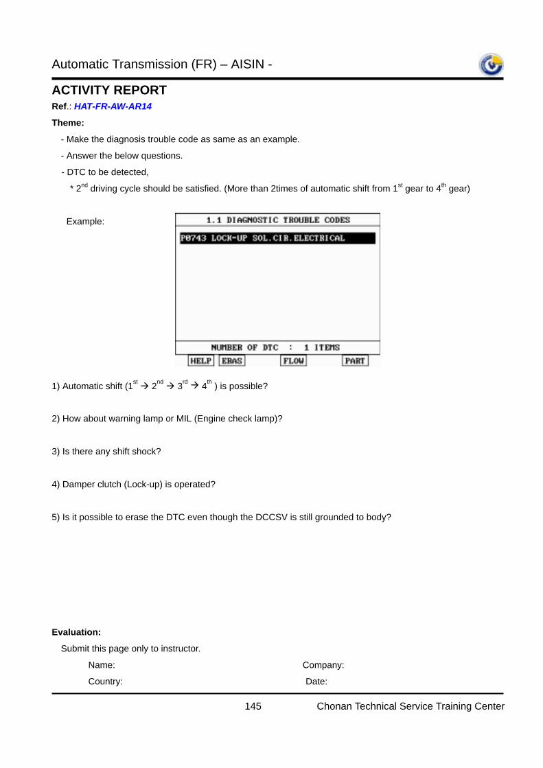
Automatic Transmission (FR) – AISIN -
145 Chonan Technical Service Training Center
ACTIVITY REPORT Ref.: HAT-FR-AW-AR14
Theme:
- Make the diagnosis trouble code as same as an example.
- Answer the below questions.
- DTC to be detected,
* 2nd driving cycle should be satisfied. (More than 2times of automatic shift from 1st gear to 4th gear)
Example:
1) Automatic shift (1st 2nd 3rd 4th ) is possible?
2) How about warning lamp or MIL (Engine check lamp)?
3) Is there any shift shock?
4) Damper clutch (Lock-up) is operated?
5) Is it possible to erase the DTC even though the DCCSV is still grounded to body?
Evaluation:
Submit this page only to instructor.
Name: Company:
Country: Date:
Automatic Transmission (FR) – AISIN -
146 Chonan Technical Service Training Center
ACTIVITY REPORT Ref.: HAT-FR-AW-AR15
Course:
Automatic Transmission (FR) – AISIN - [CHASSIS_STEP2_IBT_A/T FR (AISIN)] Code : SCE
Subject:
Hydraulic line pressure
Objectives:
- To verify the line pressure specification for overdrive clutch.
- To be able to diagnose depends on the measured result.
Required materials:
- A/T (AW30 series model) training vehicle: Terracan / H-1 / SR
- Training textbook
- SST (Pressure gauge adapter), Gauge set
Application:
- AW30 series models with TCM
The time required:
- Installation of SST (Pressure gauge adapter) on the O/D clutch checking port: 15minutes
- Answer the questions on “theme”: 15minutes
- Total: 30minutes
Procedure & Cautions:
- Lift up the vehicle and install the SST(pressure gauge adapter) on the over drive clutch pressure checking
port.
- It will be helpful to disconnect the PG-A connector because the space is very poor nearby this pressure
checking port.
(After finishing installing the pressure gauge adapter, don’t forget to reconnect PG-A connector)
- Be careful not to make the gauge hose damage due to the front propeller shaft, catalytic converter or
exhaust pipe
- Start the engine and read the gauge.
Are you ready? Go on next page.

Automatic Transmission (FR) – AISIN -
147 Chonan Technical Service Training Center
ACTIVITY REPORT Ref.: HAT-FR-AW-AR15
Theme:
- Fill out the below chart.
Range Eng. Speed
(rpm)
Vehicle
speed
Measured value
(kgf/cm2)
Specification
(kgf/cm2) Remarks
P, N Idle Stop 3.8 -
WOT Stop 9 -
R Idle Stop 7.8 6.2∼7.2
WOT Driving 15.5 -
WOT Stop 16.8 15.6∼19 Stall test
D Idle Stop 3.8 4∼4.6
(1st ∼ 3rd gear) Driving 3.5∼5 -
(4th gear) Driving 0 -
WOT Stop 10 11.7∼13.2 Stall test
2 Idle Stop 3.5 -
WOT Driving 8 -
L Idle Stop 3.5 -
WOT Driving 8 -
What is the most probable cause? (Out of specification)
1) Lower than standard in D and R range both:
2) Lower than standard in D range only:
3) Lower than standard in R range only:
4) Excessive line pressure:
Evaluation:
Submit this page only to instructor.
Name: Company:
Country: Date:
Related Documents