Part Number: 000015430 5/18 Air/Water/Remote Condenser Ice Machines Technician’s Handbook ®

Welcome message from author
This document is posted to help you gain knowledge. Please leave a comment to let me know what you think about it! Share it to your friends and learn new things together.
Transcript
Part Number: 000015430 5/18
Air/Water/Remote Condenser Ice Machines
Technician’s Handbook
®

Safety NoticesRead these precautions to prevent personal injury:
• Read this manual thoroughly before operating, installing or performing maintenance on the equipment. Failure to follow instructions in this manual can cause property damage, injury or death.
• Routine adjustments and maintenance procedures outlined in this manual are not covered by the warranty.
• Proper installation, care and maintenance are essential for maximum performance and trouble-free operation of your equipment.
• Visit our website www.manitowocice.com for manual updates, translations, or contact information for service agents in your area.
This equipment contains high voltage electricity and refrigerant charge. Installation and repairs are to be performed by properly trained technicians aware of the dangers of dealing with high voltage electricity and refrigerant under pressure. The technician must also be certified in proper refrigerant handling and servicing procedures. All lockout and tag out procedures must be followed when working on this equipment.
• This equipment is intended for indoor use only. Do not install or operate this equipment in outdoor areas.
• As you work on this equipment, be sure to pay close attention to the safety notices in this handbook. Disregarding the notices may lead to serious injury and/or damage to the equipment.
DEFINITIONS
DANGERIndicates a hazardous situation that, if not avoided, will result in death or serious injury. This applies to the most extreme situations.
nWarningIndicates a hazardous situation that, if not avoided, could result in death or serious injury.
,CautionIndicates a hazardous situation that, if not avoided, could result in minor or moderate injury.
Notice�Indicates information considered important, but not hazard-related (e.g. messages relating to property damage).
NOTE: Indicates useful, extra information about the procedure you are performing.
nWarningFollow these electrical requirements during installation of this equipment:
• All field wiring must conform to all applicable codes of the authority having jurisdiction. It is the responsibility of the end user to provide the disconnect means to satisfy local codes. Refer to rating plate for proper voltage.
• This appliance must be grounded.
• This equipment must be positioned so that the plug is accessible unless other means for disconnection from the power supply (e.g., circuit breaker or disconnect switch) is provided.
• Check all wiring connections, including factory terminals, before operation. Connections can become loose during shipment and installation.
nWarningFollow these precautions to prevent personal injury during installation of this equipment:
• Installation must comply with all applicable equipment fire and health codes with the authority having jurisdiction.
• Connect to a potable water supply only.
• To avoid instability the installation area must be capable of supporting the combined weight of the equipment and product. Additionally the equipment must be level side to side and front to back.
• Remove all removable panels before lifting and installing and use appropriate safety equipment during installation and servicing. Two or more people are required to lift or move this appliance to prevent tipping and/or injury.
• Do not damage the refrigeration circuit when installing, maintaining or servicing the unit.
• This equipment contains refrigerant charge. Installation of the line sets must be performed by a properly trained and EPA certified refrigeration technician aware of the dangers of dealing with refrigerant charged equipment.
• Ice machines require a deflector when installed on an ice storage bin. Prior to using a non-OEM ice storage system with this ice machine, contact the bin manufacturer to assure their ice deflector is compatible.
• Prior to installing a non-OEM ice storage system with this ice machine, follow the manufacturers installation procedures and verify the location and installation meets the local/national mechanical codes and stability requirements.
nWarningFollow these precautions to prevent personal injury while operating or maintaining this equipment:
• Refer to nameplate to identify the type of refrigerant in your equipment.
• Only trained and qualified personnel aware of the dangers are allowed to work on the equipment.
• Read this manual thoroughly before operating, installing or performing maintenance on the equipment. Failure to follow instructions in this manual can cause property damage, injury or death.
• Crush/Pinch Hazard. Keep hands clear of moving components. Components can move without warning unless power is disconnected and all potential energy is removed.
• Moisture collecting on the floor will create a slippery surface. Clean up any water on the floor immediately to prevent a slip hazard.
• Never use sharp objects or tools to remove ice or frost. Do not use mechanical devices or other means to accelerate the defrosting process.
• When using cleaning fluids or chemicals, rubber gloves and eye protection (and/or face shield) must be worn.
nWarningFollow these precautions to prevent personal injury while operating or maintaining this equipment:
• Objects placed or dropped in the bin can affect human health and safety. Locate and remove any objects immediately.
• Never use sharp objects or tools to remove ice or frost.
• Do not use mechanical devices or other means to accelerate the defrosting process.
• When using cleaning fluids or chemicals, rubber gloves and eye protection (and/or face shield) must be worn.
• Some models may contain R290 (propane) refrigerant. R290 (propane) is flammable in concentrations of air between approximately 2.1% and 9.5% by volume (LEL lower explosion limit and UEL upper explosion limit). An ignition source at a temperature higher than 875°F (470°C) is needed for a combustion to occur. Refer to nameplate to identify the type of refrigerant in your equipment. Only trained and qualified personnel aware of the dangers are allowed to work on the equipment.
DANGERDo not operate equipment that has been misused, abused, neglected, damaged, or altered/modified from that of original manufactured specifications. This appliance is not intended for use by persons (including children) with reduced physical, sensory or mental capabilities, or lack of experience and knowledge, unless they have been given supervision concerning use of the appliance by a person responsible for their safety. Do not allow children to play with, clean or maintain this appliance without proper supervision.
nWarningFollow these precautions to prevent personal injury during use and maintenance of this equipment:
• It is the responsibility of the equipment owner to perform a Personal Protective Equipment Hazard Assessment to ensure adequate protection during maintenance procedures.
• Do Not Store Or Use Gasoline Or Other Flammable Vapors Or Liquids In The Vicinity Of This Or Any Other Appliance. Never use flammable oil soaked cloths or combustible cleaning solutions for cleaning.
• All covers and access panels must be in place and properly secured when operating this equipment.
• Risk of fire/shock. All minimum clearances must be maintained. Do not obstruct vents or openings.
• Failure to disconnect power at the main power supply disconnect could result in serious injury or death. The power switch DOES NOT disconnect all incoming power.
• All utility connections and fixtures must be maintained in accordance with the authority having jurisdiction.
• Turn off and lockout all utilities (gas, electric, water) according to approved practices during maintenance or servicing.
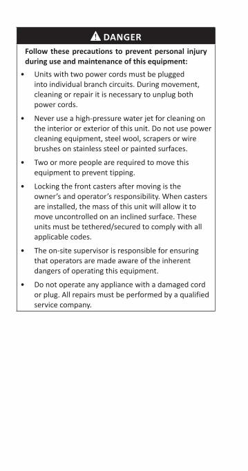
DANGERFollow these precautions to prevent personal injury during use and maintenance of this equipment:
• Units with two power cords must be plugged into individual branch circuits. During movement, cleaning or repair it is necessary to unplug both power cords.
• Never use a high-pressure water jet for cleaning on the interior or exterior of this unit. Do not use power cleaning equipment, steel wool, scrapers or wire brushes on stainless steel or painted surfaces.
• Two or more people are required to move this equipment to prevent tipping.
• Locking the front casters after moving is the owner’s and operator’s responsibility. When casters are installed, the mass of this unit will allow it to move uncontrolled on an inclined surface. These units must be tethered/secured to comply with all applicable codes.
• The on-site supervisor is responsible for ensuring that operators are made aware of the inherent dangers of operating this equipment.
• Do not operate any appliance with a damaged cord or plug. All repairs must be performed by a qualified service company.
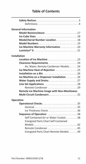
Table of Contents
Part Number: 000015430 5/18 11
Safety Notices . . . . . . . . . . . . . . . . . . . . . . . . . . . . . . .3Definitions . . . . . . . . . . . . . . . . . . . . . . . . . . . . . .4
General InformationModel Nomenclature . . . . . . . . . . . . . . . . . . . . . . . .17Ice Cube Sizes . . . . . . . . . . . . . . . . . . . . . . . . . . . . . .18Model/Serial Number Location . . . . . . . . . . . . . . . .18Model Numbers . . . . . . . . . . . . . . . . . . . . . . . . . . . .19Ice Machine Warranty Information . . . . . . . . . . . .20LuminIce® II . . . . . . . . . . . . . . . . . . . . . . . . . . . . . . . .21
InstallationLocation of Ice Machine . . . . . . . . . . . . . . . . . . . . . .23Clearance Requirements . . . . . . . . . . . . . . . . . . . . .24
Air, Water, Remote Condenser Models . . . . . .24Ice Machine Heat of Rejection . . . . . . . . . . . . . . . .25Installation on a Bin . . . . . . . . . . . . . . . . . . . . . . . . .26Ice Machine on a Dispenser Installation . . . . . . . .26Water Supply and Drains . . . . . . . . . . . . . . . . . . . . .27Line Set Applications . . . . . . . . . . . . . . . . . . . . . . . .28
Remote Condenser . . . . . . . . . . . . . . . . . . . . . .29Remote Ice Machine Usage with Non-Manitowoc Multi-Circuit Condensers . . . . . . . . . . . . . . . . . . . . .32
OperationOperational Checks . . . . . . . . . . . . . . . . . . . . . . . . . .35
General . . . . . . . . . . . . . . . . . . . . . . . . . . . . . . . .35Ice Thickness Check . . . . . . . . . . . . . . . . . . . . . .36
Sequence of Operation . . . . . . . . . . . . . . . . . . . . . .38Self Contained Air or Water Cooled . . . . . . . . .38Energized Parts Chart Self Contained Models . . . . . . . . . . . . . . . . . . . . . . . . . . . . . . . .42Remote Condenser . . . . . . . . . . . . . . . . . . . . . .45Energized Parts Chart Remote Models . . . . . .49
12 Part Number: 000015430 5/18
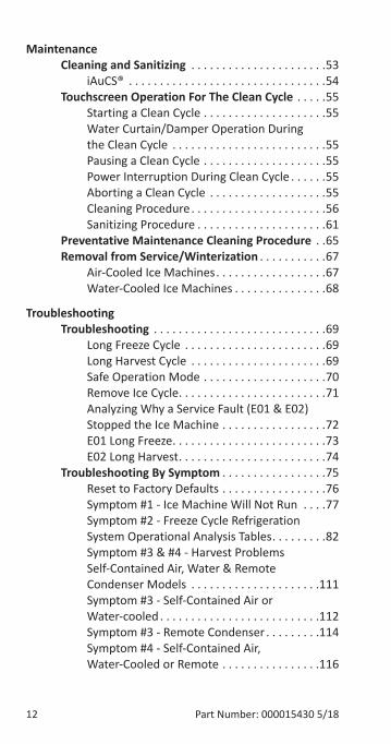
MaintenanceCleaning and Sanitizing . . . . . . . . . . . . . . . . . . . . . .53
iAuCS® . . . . . . . . . . . . . . . . . . . . . . . . . . . . . . . .54Touchscreen Operation For The Clean Cycle . . . . .55
Starting a Clean Cycle . . . . . . . . . . . . . . . . . . . .55Water Curtain/Damper Operation During the Clean Cycle . . . . . . . . . . . . . . . . . . . . . . . . .55Pausing a Clean Cycle . . . . . . . . . . . . . . . . . . . .55Power Interruption During Clean Cycle . . . . . .55Aborting a Clean Cycle . . . . . . . . . . . . . . . . . . .55Cleaning Procedure . . . . . . . . . . . . . . . . . . . . . .56Sanitizing Procedure . . . . . . . . . . . . . . . . . . . . .61
Preventative Maintenance Cleaning Procedure . .65Removal from Service/Winterization . . . . . . . . . . .67
Air-Cooled Ice Machines . . . . . . . . . . . . . . . . . .67Water-Cooled Ice Machines . . . . . . . . . . . . . . .68
TroubleshootingTroubleshooting . . . . . . . . . . . . . . . . . . . . . . . . . . . .69
Long Freeze Cycle . . . . . . . . . . . . . . . . . . . . . . .69Long Harvest Cycle . . . . . . . . . . . . . . . . . . . . . .69Safe Operation Mode . . . . . . . . . . . . . . . . . . . .70Remove Ice Cycle . . . . . . . . . . . . . . . . . . . . . . . .71Analyzing Why a Service Fault (E01 & E02)Stopped the Ice Machine . . . . . . . . . . . . . . . . .72E01 Long Freeze . . . . . . . . . . . . . . . . . . . . . . . . .73E02 Long Harvest . . . . . . . . . . . . . . . . . . . . . . . .74
Troubleshooting By Symptom . . . . . . . . . . . . . . . . .75Reset to Factory Defaults . . . . . . . . . . . . . . . . .76Symptom #1 - Ice Machine Will Not Run . . . .77Symptom #2 - Freeze Cycle Refrigeration System Operational Analysis Tables . . . . . . . . .82Symptom #3 & #4 - Harvest Problems Self-Contained Air, Water & Remote Condenser Models . . . . . . . . . . . . . . . . . . . . .111Symptom #3 - Self-Contained Air or Water-cooled . . . . . . . . . . . . . . . . . . . . . . . . . .112Symptom #3 - Remote Condenser . . . . . . . . .114Symptom #4 - Self-Contained Air, Water-Cooled or Remote . . . . . . . . . . . . . . . .116
Part Number: 000015430 5/18 13
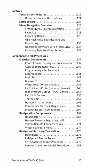
ControlsTouch Screen Features . . . . . . . . . . . . . . . . . . . . . .119
Home Screen Icon Descriptions . . . . . . . . . . .121Setup Wizard . . . . . . . . . . . . . . . . . . . . . . . . . . . . . .122Menu Navigation Overview . . . . . . . . . . . . . . . . . .123
Settings Menu Screen Navigation . . . . . . . . .123Event Log . . . . . . . . . . . . . . . . . . . . . . . . . . . . .128Event Log Detail . . . . . . . . . . . . . . . . . . . . . . . .129USB Flash Drive Specifications and Formatting . . . . . . . . . . . . . . . . . . . . . . . . . . . .133Upgrading Firmware with a Flash Drive . . . .134Exporting Data to a Flash Drive . . . . . . . . . . .135
Component Check ProceduresElectrical Components . . . . . . . . . . . . . . . . . . . . . .137
Control Board, Display and Touchscreen . . . .137Control Board Relay Test . . . . . . . . . . . . . . . . .140Programming a Replacement Control Board . . . . . . . . . . . . . . . . . . . . . . . . .141Main Fuse . . . . . . . . . . . . . . . . . . . . . . . . . . . .142Bin Switch . . . . . . . . . . . . . . . . . . . . . . . . . . . .143Water Level Control Circuitry . . . . . . . . . . . . .146Ice Thickness Probe (Initiates Harvest) . . . . .149High Pressure Cutout (HPCO) Control . . . . . .153Fan Cycle Control . . . . . . . . . . . . . . . . . . . . . . .156Thermistors . . . . . . . . . . . . . . . . . . . . . . . . . . .157Harvest Assist Air Pump . . . . . . . . . . . . . . . . .161Compressor Electrical Diagnostics . . . . . . . . .162Diagnosing Start Components . . . . . . . . . . . .164
Refrigeration Components . . . . . . . . . . . . . . . . . . .167Headmaster . . . . . . . . . . . . . . . . . . . . . . . . . . .167Harvest Pressure Regulating (HPR) System Remote Condenser Only . . . . . . . . . .171Water Regulating Valve . . . . . . . . . . . . . . . . . .174
Refrigerant Recovery/Evacuation . . . . . . . . . . . . .175Definitions . . . . . . . . . . . . . . . . . . . . . . . . . . . .175Refrigerant Re-Use Policy . . . . . . . . . . . . . . . .176Self-Contained Model Procedure . . . . . . . . .178Remote Condenser Model Procedure . . . . . .181
14 Part Number: 000015430 5/18
System Contamination Clean-Up . . . . . . . . . . . . .185Determining Severity of Contamination . . . .185Cleanup Procedure . . . . . . . . . . . . . . . . . . . . .187Liquid Line Filter-Driers . . . . . . . . . . . . . . . . . .191Replacing Pressure Controls Without Removing Refrigerant Charge . . . . . . . . . . . . .192Total System Refrigerant Charge . . . . . . . . . .193
ChartsCycle Times/24-Hour Ice Production/Refrigerant Pressure Charts . . . . . . . . . . . . . . . . . . . . . . . . . . . .195
IF0300 Series . . . . . . . . . . . . . . . . . . . . . . . . . .196IT0420 Series . . . . . . . . . . . . . . . . . . . . . . . . . .198IT0450 Series . . . . . . . . . . . . . . . . . . . . . . . . . .200IT0500 Series . . . . . . . . . . . . . . . . . . . . . . . . . .202IF0600 Series . . . . . . . . . . . . . . . . . . . . . . . . . .205IT0620 Series . . . . . . . . . . . . . . . . . . . . . . . . . .208IF0900 Series . . . . . . . . . . . . . . . . . . . . . . . . . .210IT1200 Series . . . . . . . . . . . . . . . . . . . . . . . . . .213IT1500 Series . . . . . . . . . . . . . . . . . . . . . . . . . .216IT1900 Series . . . . . . . . . . . . . . . . . . . . . . . . . .219
Part Number: 000015430 5/18 15
DiagramsWiring Diagrams . . . . . . . . . . . . . . . . . . . . . . . . . . .223
Wiring Diagram Legend . . . . . . . . . . . . . . . . .223IT0420/IT0450/IT0500/IT0620 - 1ph Air/Water . . . . . . . . . . . . . . . . . . . . . . . . .224IT0500 - 1ph Remote Air-Cooled . . . . . . . . . .226IT1200/IT1500/IT1900 - 1ph Air/Water . . . . .228IT1200/IT1500/IT1900 - 3ph Air/Water . . . . .230IT1200/IT1500/IT1900 - 1ph Remote . . . . . .232IT1200/IT1500/IT1900 - 3ph Remote Condenser . . . . . . . . . . . . . . . . . . . . . . . . . . . .234
Electronic Control Board . . . . . . . . . . . . . . . . . . . .236Electrical Noise Filter . . . . . . . . . . . . . . . . . . .238
Refrigeration Tubing Schematics . . . . . . . . . . . . . .239Self-Contained Air or Water-Cooled . . . . . . .239Remote Air-Cooled Condenser Models . . . . .242

16 Part Number: 000015430 5/18
THIS PAGE INTENTIONALLY LEFT BLANK
Part Number: 000015430 5/18 17
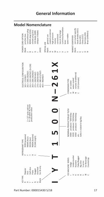
Model Nomenclature
ICE
MAC
HIN
ESE
RIES
IIn
digo
UU
nder
coun
ter
KKo
olai
reR
Flak
e/N
ugge
tB
Big
shot
SS-
serie
sIB
Ice
Beve
rage
CCo
unte
rtop
REFR
IGER
ANT
TYPE
PR2
90(p
ropa
ne)
FR4
04A
(four
)T
R410
A(t
en)
BR6
00A
(but
ane)
ER1
34A
(eig
ht) N
OM
INAL
PRO
DUCT
ION
@70
/50
0300
prod
uces
~300
#/da
y03
20pr
oduc
es~3
20#/
day
0350
prod
uces
~350
#/da
yet
c...
So�o
isst
ated
inkg
/day
CON
DEN
SER
TYPE
Aai
rcoo
led
Ww
ater
cool
edN
rem
ote
(tra
di�o
nal)
CCV
D(r
emot
e)
POW
ERCO
RDO
PTIO
NBl
ank
junc
�on
box
Zco
rdw
ithou
tplu
gB
NEM
Apl
ug(U
SA)
Fsc
huko
plug
(EU
)G
13A
blad
e(G
BR)
Iob
lique
Vbl
ades
(AU
S)
SPEC
IAL
USE
Blan
kge
nera
luse
Qco
ated
cond
ense
rH
high
pres
sure
Mm
arin
eP
corr
ec�o
nal
Tto
pai
rdisc
harg
eX
Lum
inIc
e/Sa
nita
�on
Lle
ver
Vsp
ace
mak
er
MAR
KET
IDEN
TIFI
ERBl
ank
notm
arke
tspe
cific
SSa
udiA
rabi
a(G
CC)
KKo
rea
(KC)
CCh
ina
(CCC
)D
Germ
any
(GS)
NBr
azil
(InM
etro
)
ICE
TYPE
RRe
gula
rD
Dice
YHa
lf-di
ceF
Flak
eN
Nug
get
GGo
urm
etBl
ank
forI
Bon
ly
ELEC
TRIC
AL C
ON
FIGU
RATI
ON
161
=11
5/60
/126
1=
208-
230/
60/1
251
=22
0-24
0/50
/1(S
=230
)26
3=
208-
230/
60/3
271
=20
0/50
-60/
127
3=
200/
50-6
0/3
453
=38
0-41
5/50
/346
3=
460/
60/3
2 =
22"w
ide
cabi
net
# =
allo
ther
#sm
ean
prod
uc�o
nva
lue
IY
T1
50
0N–261X
General Information
18 Part Number: 000015430 5/18
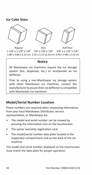
Ice Cube Sizes
Regular 1-1/8" x 1-1/8" x 7/8" 2.86 x 2.86 x 2.22 cm
Dice 7/8" x 7/8" x 7/8"
2.22 x 2.22 x2.22 cm
Half Dice 3/8" x 1-1/8" x 7/8"
0.95 x 2.86 x 2.22 cm
Notice�All Manitowoc ice machines require the ice storage system (bin, dispenser, etc.) to incorporate an ice deflector.
Prior to using a non-Manitowoc ice storage system with other Manitowoc ice machines, contact the manufacturer to assure their ice deflector is compatible with Manitowoc ice machines.
Model/Serial Number LocationThese numbers are required when requesting information from your local Manitowoc Distributor, service representative, or Manitowoc Ice.
• The model and serial number can be viewed by pressing the information icon on the touchscreen.
• The owner warranty registration card.
• The model/serial number data plate located in the evaporator compartment and on the back of the ice machine.
The model and serial number displayed on the touchscreen must match the data plate for proper operation.
Part Number: 000015430 5/18 19
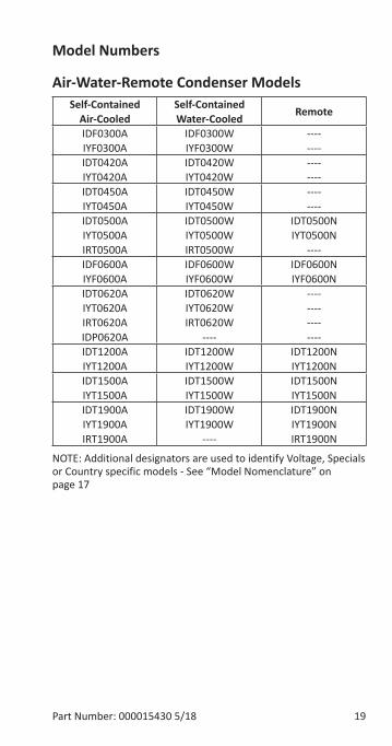
Model Numbers
Air-Water-Remote Condenser Models Self-Contained
Air-CooledSelf-Contained Water-Cooled Remote
IDF0300A IYF0300A
IDF0300W IYF0300W
---- ----
IDT0420A IYT0420A
IDT0420W IYT0420W
---- ----
IDT0450A IYT0450A
IDT0450W IYT0450W
---- ----
IDT0500A IYT0500A IRT0500A
IDT0500W IYT0500W IRT0500W
IDT0500N IYT0500N
----IDF0600A IYF0600A
IDF0600W IYF0600W
IDF0600N IYF0600N
IDT0620A IYT0620A IRT0620AIDP0620A
IDT0620W IYT0620W IRT0620W
----
---- ---- ---- ----
IDT1200A IYT1200A
IDT1200W IYT1200W
IDT1200N IYT1200N
IDT1500A IYT1500A
IDT1500W IYT1500W
IDT1500N IYT1500N
IDT1900A IYT1900AIRT1900A
IDT1900W IYT1900W
----
IDT1900N IYT1900NIRT1900N
NOTE: Additional designators are used to identify Voltage, Specials or Country specific models - See “Model Nomenclature” on page 17
20 Part Number: 000015430 5/18
Ice Machine Warranty InformationFor warranty information visit:
http://www.manitowocice.com/Service/Warranty
• Warranty Verification
• Warranty Registration
• View and download a copy of the warranty Owner Warranty Registration Card
Warranty coverage begins the day the ice machine is installed.
Part Number: 000015430 5/18 21
LuminIce® IIThe LuminIce® growth inhibitor recirculates the air in the ice machine foodzone over a UV bulb. This process will inhibit the growth of common micro-organisms on all exposed foodzone surfaces.
• LuminIce® bulbs require replacement on a yearly basis.
• The control board can be set to automatically display a reminder after 12 months.
NOTE: LuminIce® and LuminIce® II bulbs are not interchangeable; verify your model before ordering a replacement bulb.
Cleanup Procedure for Accidental Bulb BreakageThe cleanup procedure is identical to the procedure used to clean up compact fluorescent (CFL) or fluorescent tube lights. These lights contain a small amount of mercury sealed within a glass tube. Breaking these types of lights will release mercury and mercury vapor. The broken bulb can continue to release mercury vapor until it is cleaned up and removed.
The latest EPA procedures can be viewed on their website at www.epa.gov/cfl/cflcleanup.html.
NOTE: LuminIce® and LuminIce® II bulbs are not interchangeable; verify your model before ordering a replacement bulb. LuminIce® bulbs have a white base and LuminIce® II bulbs have a blue base.

22 Part Number: 000015430 5/18
THIS PAGE INTENTIONALLY LEFT BLANK
Part Number: 000015430 5/18 23
Location of Ice MachineThe location selected for the ice machine must meet the following criteria. If any of these criteria are not met, select another location.
• The location must be free of airborne and other contaminants.
• Self contained air and water cooled - The air temperature must be at least 35°F (1.6°C), but must not exceed 110°F (43.4°C).
• Remote air cooled - The air temperature must be at least -20°F (-29°C), but must not exceed 120°F (49°C).
• Ice Making Water Inlet - Water Pressure must be at least 20 psi (1.4 bar), but must not exceed 80 psi (5.5 bar).
• Condenser Water Inlet - Water Pressure must be at least 20 psi (1.4 bar), but must not exceed 276 psi (19 bar).
• The location must not be near heat-generating equipment or in direct sunlight and protected from weather.
• The location must not obstruct air flow through or around the ice machine. Refer to chart below for clearance requirements.
• The ice machine must be protected if it will be subjected to temperatures below 32°F (0°C). Failure caused by exposure to freezing temperatures is not covered by the warranty. See “Removal from Service/Winterization”.
Installation
24 Part Number: 000015430 5/18
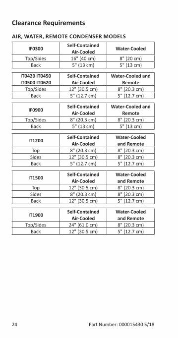
Clearance Requirements
AIR, WATER, REMOTE CONDENSER MODELS
IF0300 Self-Contained Air-Cooled Water-Cooled
Top/Sides 16" (40 cm) 8" (20 cm)Back 5" (13 cm) 5" (13 cm)
IT0420 IT0450IT0500 IT0620
Self-Contained Air-Cooled
Water-Cooled and Remote
Top/Sides 12" (30.5 cm) 8" (20.3 cm)Back 5" (12.7 cm) 5" (12.7 cm)
IF0900 Self-Contained Air-Cooled
Water-Cooled and Remote
Top/Sides 8" (20.3 cm) 8" (20.3 cm)Back 5" (13 cm) 5" (13 cm)
IT1200 Self-Contained Air-Cooled
Water-Cooled and Remote
Top 8" (20.3 cm) 8" (20.3 cm)Sides 12" (30.5 cm) 8" (20.3 cm)Back 5" (12.7 cm) 5" (12.7 cm)
IT1500 Self-Contained Air-Cooled
Water-Cooled and Remote
Top 12" (30.5 cm) 8" (20.3 cm) Sides 8" (20.3 cm) 8" (20.3 cm)Back 12" (30.5 cm) 5" (12.7 cm)
IT1900 Self-Contained Air-Cooled
Water-Cooled and Remote
Top/Sides 24" (61.0 cm) 8" (20.3 cm) Back 12" (30.5 cm) 5" (12.7 cm)
Part Number: 000015430 5/18 25
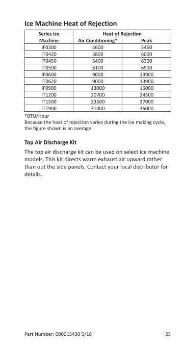
Ice Machine Heat of RejectionSeries Ice Machine
Heat of RejectionAir Conditioning* Peak
IF0300 4600 5450IT0420 3800 6000IT0450 5400 6300IT0500 6100 6900IF0600 9000 13900IT0620 9000 13900IF0900 13000 16000IT1200 20700 24500IT1500 23500 27000IT1900 31000 36000
*BTU/Hour Because the heat of rejection varies during the ice making cycle, the figure shown is an average.
Top Air Discharge KitThe top air discharge kit can be used on select ice machine models. This kit directs warm exhaust air upward rather than out the side panels. Contact your local distributor for details.
26 Part Number: 000015430 5/18
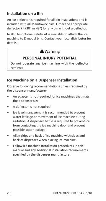
Installation on a BinAn ice deflector is required for all bin installations and is included with all Manitowoc bins. Order the appropriate deflector kit (30" or 48") for any bin without a deflector.
NOTE: An optional safety kit is available to attach the ice machine to D model bins. Contact your local distributor for details.
nWarningPERSONAL INJURY POTENTIAL
Do not operate any ice machine with the deflector removed.
Ice Machine on a Dispenser InstallationObserve following recommendations unless required by the dispenser manufacturer.
• An adapter is not required for ice machines that match the dispenser size.
• A deflector is not required.
• Ice level management is recommended to prevent water leakage or movement of ice machine during agitation. A dispenser baffle is required to prevent ice from contacting the ice machine door and prevent possible water leakage.
• Align sides and back of ice machine with sides and back of dispenser when placing ice machine.
• Follow ice machine installation procedures in this manual and any additional installation requirements specified by the dispenser manufacturer.
Part Number: 000015430 5/18 27
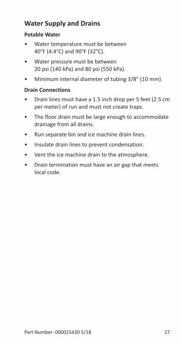
Water Supply and DrainsPotable Water• Water temperature must be between
40°F (4.4°C) and 90°F (32°C).
• Water pressure must be between 20 psi (140 kPa) and 80 psi (550 kPa).
• Minimum internal diameter of tubing 3/8" (10 mm).
Drain Connections• Drain lines must have a 1.5 inch drop per 5 feet (2.5 cm
per meter) of run and must not create traps.
• The floor drain must be large enough to accommodate drainage from all drains.
• Run separate bin and ice machine drain lines.
• Insulate drain lines to prevent condensation.
• Vent the ice machine drain to the atmosphere.
• Drain termination must have an air gap that meets local code.
28 Part Number: 000015430 5/18
Line Set Applications
Notice�The 60-month compressor warranty (including the 36-month labor replacement warranty) will not apply if the Manitowoc Ice Machine, Condenser or QuietQube® Condensing Unit were not installed according to specifications. This warranty also will not apply if the refrigeration system is modified with a condenser, heat reclaim device, or other parts or assemblies not manufactured by Manitowoc Ice. Or refrigeration system additives such as leak detection dyes, inhibitors or non OEM approved chemicals.
nWarningRecovery locations vary by model. Verify you are making the correct connections for your model to prevent accidental release of high pressure refrigerant.
Important�Manitowoc remote systems are only approved and warranted as a complete new package. Warranty on the refrigeration system will be void if new equipment is connected to existing (used) tubing, remote condenser, remote condensing unit or ice machine head section.
Part Number: 000015430 5/18 29
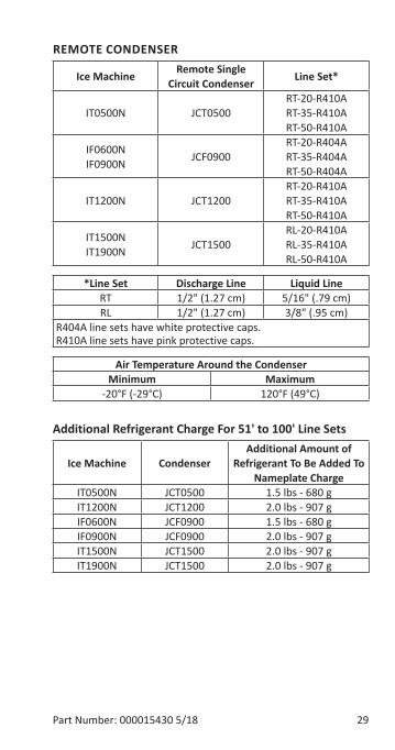
REMOTE CONDENSER
Ice Machine Remote Single Circuit Condenser Line Set*
IT0500N JCT0500RT-20-R410A RT-35-R410A RT-50-R410A
IF0600NIF0900N JCF0900
RT-20-R404A RT-35-R404A RT-50-R404A
IT1200N JCT1200RT-20-R410A RT-35-R410A RT-50-R410A
IT1500N IT1900N JCT1500
RL-20-R410A RL-35-R410A RL-50-R410A
*Line Set Discharge Line Liquid LineRT 1/2" (1.27 cm) 5/16" (.79 cm)RL 1/2" (1.27 cm) 3/8" (.95 cm)
R404A line sets have white protective caps. R410A line sets have pink protective caps.
Air Temperature Around the CondenserMinimum Maximum
-20°F (-29°C) 120°F (49°C)
Additional Refrigerant Charge For 51' to 100' Line Sets
Ice Machine CondenserAdditional Amount of
Refrigerant To Be Added To Nameplate Charge
IT0500N JCT0500 1.5 lbs - 680 gIT1200N JCT1200 2.0 lbs - 907 gIF0600N JCF0900 1.5 lbs - 680 gIF0900N JCF0900 2.0 lbs - 907 gIT1500N JCT1500 2.0 lbs - 907 gIT1900N JCT1500 2.0 lbs - 907 g
30 Part Number: 000015430 5/18
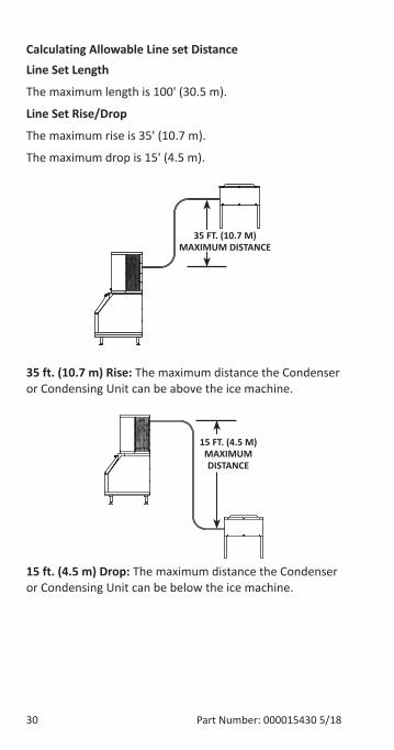
Calculating Allowable Line set DistanceLine Set Length
The maximum length is 100' (30.5 m).
Line Set Rise/Drop
The maximum rise is 35' (10.7 m).
The maximum drop is 15' (4.5 m).
35 FT. (10.7 M) MAXIMUM DISTANCE
35 ft. (10.7 m) Rise: The maximum distance the Condenser or Condensing Unit can be above the ice machine.
15 FT. (4.5 M) MAXIMUM DISTANCE
15 ft. (4.5 m) Drop: The maximum distance the Condenser or Condensing Unit can be below the ice machine.
Part Number: 000015430 5/18 31
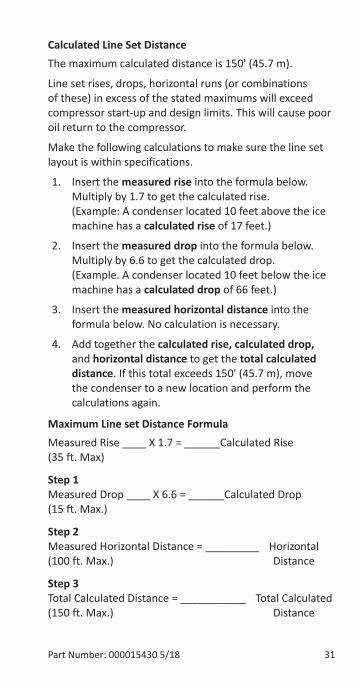
Calculated Line Set DistanceThe maximum calculated distance is 150' (45.7 m).
Line set rises, drops, horizontal runs (or combinations of these) in excess of the stated maximums will exceed compressor start-up and design limits. This will cause poor oil return to the compressor.
Make the following calculations to make sure the line set layout is within specifications.
1. Insert the measured rise into the formula below. Multiply by 1.7 to get the calculated rise. (Example: A condenser located 10 feet above the ice machine has a calculated rise of 17 feet.)
2. Insert the measured drop into the formula below. Multiply by 6.6 to get the calculated drop. (Example. A condenser located 10 feet below the ice machine has a calculated drop of 66 feet.)
3. Insert the measured horizontal distance into the formula below. No calculation is necessary.
4. Add together the calculated rise, calculated drop, and horizontal distance to get the total calculated distance. If this total exceeds 150' (45.7 m), move the condenser to a new location and perform the calculations again.
Maximum Line set Distance FormulaMeasured Rise ____ X 1.7 = ______Calculated Rise (35 ft. Max)
Step 1 Measured Drop ____ X 6.6 = ______Calculated Drop (15 ft. Max.)
Step 2 Measured Horizontal Distance = _________ Horizontal (100 ft. Max.) Distance
Step 3 Total Calculated Distance = ___________ Total Calculated (150 ft. Max.) Distance
32 Part Number: 000015430 5/18
Remote Ice Machine Usage with Non-Manitowoc Multi-Circuit CondensersWarrantyThe sixty (60) month compressor warranty, including thirty six (36) month labor replacement warranty, shall not apply when the remote ice machine is not installed within the remote specifications. The foregoing warranty shall not apply to any ice machine installed and/or maintained inconsistent with the technical instructions provided by Manitowoc Ice. Performance may vary from Sales specifications. ARI certified standard ratings only apply when used with a Manitowoc remote condenser.
If the design of the condenser meets the specifications, Manitowoc’s only approval is for full warranty coverage to be extended to the Manitowoc manufactured part of the system. Since Manitowoc does not test the condenser in conjunction with the ice machine, Manitowoc will not endorse, recommend, or approve the condenser, and will not be responsible for its performance or reliability.
Important�Manitowoc warrants only complete new and unused remote packages. Guaranteeing the integrity of a new ice machine under the terms of our warranty prohibits the use of pre-existing (used) tubing or condensers.
Part Number: 000015430 5/18 33
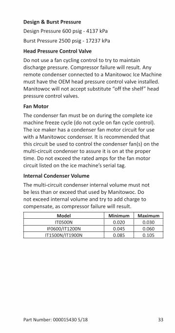
Design & Burst PressureDesign Pressure 600 psig - 4137 kPa
Burst Pressure 2500 psig - 17237 kPa
Head Pressure Control ValveDo not use a fan cycling control to try to maintain discharge pressure. Compressor failure will result. Any remote condenser connected to a Manitowoc Ice Machine must have the OEM head pressure control valve installed. Manitowoc will not accept substitute “off the shelf” head pressure control valves.
Fan MotorThe condenser fan must be on during the complete ice machine freeze cycle (do not cycle on fan cycle control). The ice maker has a condenser fan motor circuit for use with a Manitowoc condenser. It is recommended that this circuit be used to control the condenser fan(s) on the multi-circuit condenser to assure it is on at the proper time. Do not exceed the rated amps for the fan motor circuit listed on the ice machine’s serial tag.
Internal Condenser VolumeThe multi-circuit condenser internal volume must not be less than or exceed that used by Manitowoc. Do not exceed internal volume and try to add charge to compensate, as compressor failure will result.
Model Minimum MaximumIT0500N 0.020 0.030
IF0600/IT1200N 0.045 0.060IT1500N/IT1900N 0.085 0.105
34 Part Number: 000015430 5/18
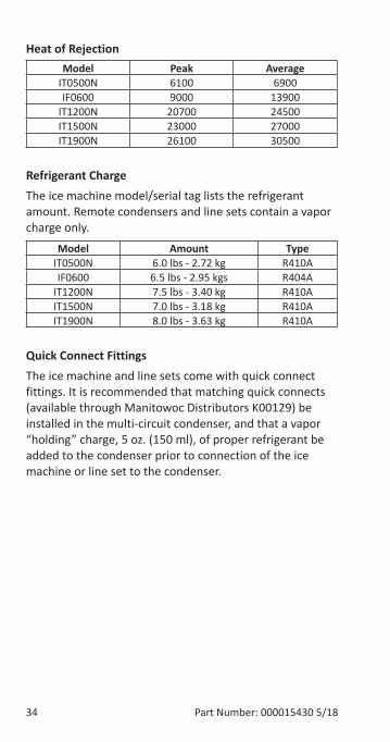
Heat of RejectionModel Peak Average
IT0500N 6100 6900IF0600 9000 13900
IT1200N 20700 24500IT1500N 23000 27000IT1900N 26100 30500
Refrigerant ChargeThe ice machine model/serial tag lists the refrigerant amount. Remote condensers and line sets contain a vapor charge only.
Model Amount TypeIT0500N 6.0 lbs - 2.72 kg R410AIF0600 6.5 lbs - 2.95 kgs R404A
IT1200N 7.5 lbs - 3.40 kg R410AIT1500N 7.0 lbs - 3.18 kg R410AIT1900N 8.0 lbs - 3.63 kg R410A
Quick Connect FittingsThe ice machine and line sets come with quick connect fittings. It is recommended that matching quick connects (available through Manitowoc Distributors K00129) be installed in the multi-circuit condenser, and that a vapor “holding” charge, 5 oz. (150 ml), of proper refrigerant be added to the condenser prior to connection of the ice machine or line set to the condenser.
Part Number: 000015430 5/18 35
Operational Checks
GENERALManitowoc ice machines are factory-operated and adjusted before shipment. Normally, new installations do not require any adjustment.
To ensure proper operation, always follow the Operational Checks:
• when starting the ice machine for the first time
• after a prolonged out of service period
• after cleaning and sanitizing
NOTE: Routine adjustments and maintenance procedures are not covered by the warranty.
�Iportant�Refrigeration compressors must be operated for a minimum break in period of 24 hours before full ice production will be reached.
Operation
36 Part Number: 000015430 5/18
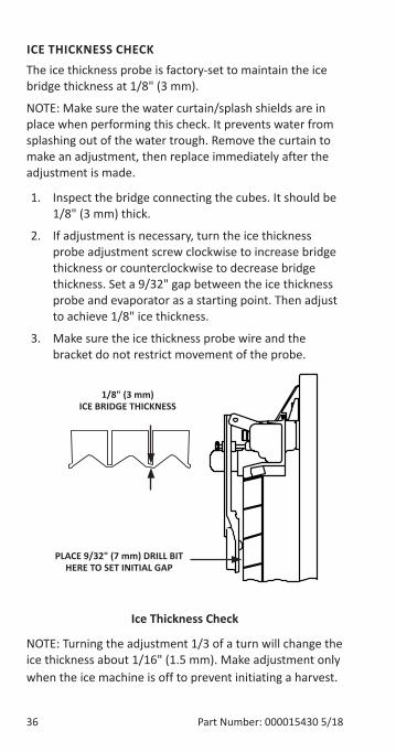
�CE TH�CKNESS CHECKThe ice thickness probe is factory-set to maintain the ice bridge thickness at 1/8" (3 mm).
NOTE: Make sure the water curtain/splash shields are in place when performing this check. It prevents water from splashing out of the water trough. Remove the curtain to make an adjustment, then replace immediately after the adjustment is made.
1. Inspect the bridge connecting the cubes. It should be 1/8" (3 mm) thick.
2. If adjustment is necessary, turn the ice thickness probe adjustment screw clockwise to increase bridge thickness or counterclockwise to decrease bridge thickness. Set a 9/32" gap between the ice thickness probe and evaporator as a starting point. Then adjust to achieve 1/8" ice thickness.
3. Make sure the ice thickness probe wire and the bracket do not restrict movement of the probe.
1/8" (3 II) �CE BR�DGE TH�CKNESS
PLACE 9/32" (7 II) DR�LL B�T HERE TO SET �N�T�AL GAP
�ce Thickness Check
NOTE: Turning the adjustment 1/3 of a turn will change the ice thickness about 1/16" (1.5 mm). Make adjustment only when the ice machine is off to prevent initiating a harvest.
Part Number: 000015430 5/18 37
Control Board TiIersThe control board has the following non-adjustable timers:
• The ice machine is locked into the freeze cycle for 6 minutes before the ice thickness probe can initiate a harvest cycle.
• The maximum freeze time is 35 minutes at which time the control board automatically initiates a harvest sequence.
• The maximum harvest time is 7 minutes, the control board will preform a remove ice cycle and then return the ice machine to the freeze cycle.
• Maximum water fill time in the freeze cycle:
• Single evaporator 6 minutes.
• Dual evaporator 8 minutes.
38 Part Number: 000015430 5/18
Sequence of Operation
SELF CONTA�NED A�R OR WATER COOLEDNOTE: The power button must be depressed and the water curtain/ice dampers must be in place on the evaporator before the ice machine will start.
�nitial Start-Up or Start-Up After AutoIatic Shut-Off1. Water Purge
Before the compressor starts, the water pump and water dump solenoid energize to purge the ice machine of old water. This feature ensures that the ice making cycle starts with fresh water.
2. Refrigeration SysteI Equalization and Start-Up
The harvest valve(s) and air pump(s) energize to equalize high and low side refrigeration pressure.
After 5 seconds the contactor energizes the compressor and supplies power to the condenser fan motor. After 5 seconds the harvest valve(s) and air pump(s) de-energize.
NOTE: The fan motor is wired through a fan cycle pressure control. When the discharge pressure exceeds the cut in pressure the fan cycle switch closes and energizes the fan motor.
Part Number: 000015430 5/18 39
Freeze Sequence3. Prechill
The compressor is on for 30 seconds (120 seconds initial cycle) to lower the temperature of the evaporator(s) before the water pump is energized. The water fill valve will energize and remain on until water touches the low and high, water level probes.
4. Freeze
Water PuIpThe water pump(s) energizes and water flows over the evaporator. The water pump is energized throughout the freeze cycle.
Water �nlet ValveThe water inlet valve energized in prechill (30 seconds)and will energize one more time in the freeze cycle. The control board will prevent the water fill valve from energizing after a 6 minute water fill time limit.
After water contacts the low and high water probes the water fill valve de-energizes. Ice builds on the evaporator and the water level drops. When water loses contact with the high water probe, the water fill valve energizes until water contacts the high water probe again.
�ce Thickness ProbeThe freeze cycle continues until the six minute freeze lock expires and enough ice has formed to send a signal from the ice thickness probe to the control board.
During the first 6 minutes of the freeze cycle the ice thickness probe microphone samples ambient noise. 6 minutes into the freeze cycle baseline readings are recorded. Ice formation on the evaporator will change the readings; when the baseline readings are exceeded a harvest cycle starts.
40 Part Number: 000015430 5/18
Harvest Sequence5. Water Purge
The air pump(s) (when used) and the harvest valve(s) open at the beginning of the water purge to divert discharge refrigerant gas into the evaporator.
The water pump(s) continues to run, and the water dump valve energizes to purge any remain water in the water trough down the drain.
6. Harvest
The air pump (when used) remains energized and the harvest valve(s) remains open. The refrigerant gas warms the evaporator causing the cubes to slide, as a sheet, off the evaporator and into the storage bin. If the damper/curtain does not open within 3.5 minutes in the harvest cycle the following occurs:
• 3.5 minutes - The water inlet valve energizes until water touches the high water level probe.
• 4 minutes - The water pump energizes.
• 6.5 to 7 minutes - The water dump valve energizes.
When the sliding sheet of cubes opens and closes within 30 seconds the bin switch terminates the harvest sequence and returns the ice machine to the freeze sequence (step 3 - 4).
NOTE: If bin switch does not open before 7 minutes the ice machine will start a Remove Ice Cycle - Refer to “Remove Ice Cycle” on page 71 for details.
Part Number: 000015430 5/18 41
AutoIatic Shut-Off7. AutoIatic Shut-Off
When the storage bin is full at the end of a harvest sequence, the sheet of cubes fails to clear the water curtain/ice damper and will hold it open. After the water curtain/ice damper is held open for 30 seconds, the ice machine shuts off. The ice machine remains off for 3 minutes before it can automatically restart.
The ice machine remains off until enough ice has been removed from the storage bin to allow the ice to fall clear of the water curtain or all of the ice dampers. As the water curtain/ice dampers swing back to the closed position, the bin switch re-closes and the ice machine restarts (steps 1 - 2), provided the 3 minute delay period is complete.
42 Part Number: 000015430 5/18
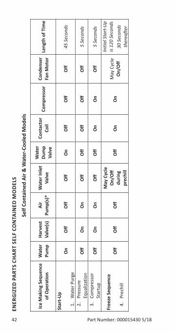
ENER
G�Z
ED P
ART
S CH
ART
SEL
F CO
NTA
�NED
MO
DEL
S
Self
Cont
aine
d Ai
r & W
ater
-Coo
led
Mod
els
�ce
Mak
ing
Sequ
ence
of
Ope
ratio
nW
ater
Pu
Ip
Harv
est
Valv
e(s)
Air
PuI
p(s)
*W
ater
�nle
t Va
lve
Wat
er
DuI
p Va
lve
Cont
acto
r Co
ilCo
Ipr
esso
rCo
nden
ser
Fan
Mot
orLe
ngth
of T
iIe
Star
t-Up
1.
Wat
er P
urge
On
Off
Off
Off
On
Off
Off
Off
45 S
econ
ds
2.
Pres
sure
Eq
ualiz
atio
nO
ffO
nO
nO
ffO
ffO
ffO
ffO
ff5
Seco
nds
3.
Com
pres
sor
Star
tup
Off
On
On
Off
Off
On
On
Off
5 Se
cond
s
Free
ze S
eque
nce
4.
Pr
echi
llO
ffO
ffO
ff
May
Cyc
le
On/
Off
durin
g
prec
hill
Off
On
On
May
Cyc
le
On/
Off
Initi
al S
tart
-Up
is 12
0 Se
cond
s30
Sec
onds
th
erea
fter
Part Number: 000015430 5/18 43
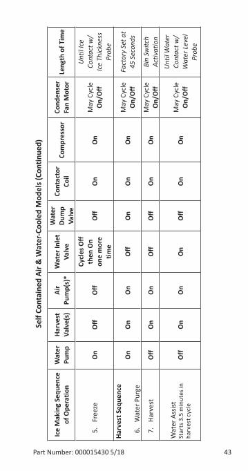
Self
Cont
aine
d Ai
r & W
ater
-Coo
led
Mod
els (
Cont
inue
d)
�ce
Mak
ing
Sequ
ence
of
Ope
ratio
nW
ater
Pu
Ip
Harv
est
Valv
e(s)
Air
PuI
p(s)
*W
ater
�nle
t Va
lve
Wat
er
DuI
p Va
lve
Cont
acto
r Co
ilCo
Ipr
esso
rCo
nden
ser
Fan
Mot
orLe
ngth
of T
iIe
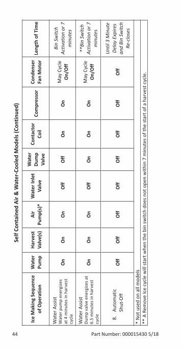
5.
Free
zeO
nO
ffO
ff
Cycl
es O
ff th
en O
n on
e I
ore
tiIe
Off
On
On
May
Cyc
le
On/
Off
Unt
il Ic
e Co
ntac
t w/
Ice
Thic
knes
s Pr
obe
Harv
est S
eque
nce
6.
Wat
er P
urge
On
On
On
Off
On
On
On
May
Cyc
le
On/
Off
Fact
ory
Set a
t 45
Sec
onds
7.
Harv
est
Off
On
On
Off
Off
On
On
May
Cyc
le
On/
Off
Bin
Switc
h Ac
tivat
ion
Wat
er A
ssist
Star
ts 3
.5 m
inut
es in
ha
rves
t cyc
leO
ffO
nO
nO
nO
ffO
nO
nM
ay C
ycle
O
n/O
ff
Unt
il W
ater
Co
ntac
t w/
Wat
er L
evel
Pr
obe
44 Part Number: 000015430 5/18
Self
Cont
aine
d Ai
r & W
ater
-Coo
led
Mod
els (
Cont
inue
d)
�ce
Mak
ing
Sequ
ence
of
Ope
ratio
nW
ater
Pu
Ip
Harv
est
Valv
e(s)
Air
PuI
p(s)
*W
ater
�nle
t Va
lve
Wat
er
DuI
p Va
lve
Cont
acto
r Co
ilCo
Ipr
esso
rCo
nden
ser
Fan
Mot
orLe
ngth
of T
iIe
Wat
er A
ssist
Wat
er p
ump
ener
gize
s at
4 m
inut
es in
har
vest
cy
cle
On
On
On
Off
Off
On
On
May
Cyc
le
On/
Off
Bin
Switc
h Ac
tivat
ion
or 7
m
inut
es
Wat
er A
ssist
Dum
p va
lve
ener
gize
s at
6.5
min
utes
in h
arve
st
cycl
e
On
On
On
Off
On
On
On
May
Cyc
le
On/
Off
**Bi
n Sw
itch
Activ
atio
n or
7
min
utes
8.
Auto
mat
ic
Shut
-Off
Off
Off
Off
Off
Off
Off
Off
Off
Unt
il 3
Min
ute
Dela
y Ex
pire
s an
d Bi
n Sw
itch
Re-c
lose
s
* N
ot u
sed
on a
ll m
odel
s**
A R
emov
e Ic
e cy
cle
will
star
t whe
n th
e bi
n sw
itch
does
not
ope
n w
ithin
7 m
inut
es o
f the
star
t of a
har
vest
cyc
le.
Part Number: 000015430 5/18 45
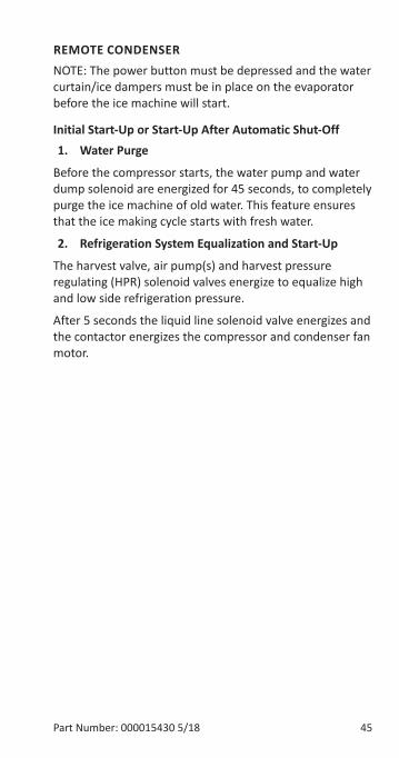
REMOTE CONDENSERNOTE: The power button must be depressed and the water curtain/ice dampers must be in place on the evaporator before the ice machine will start.
�nitial Start-Up or Start-Up After AutoIatic Shut-Off1. Water Purge
Before the compressor starts, the water pump and water dump solenoid are energized for 45 seconds, to completely purge the ice machine of old water. This feature ensures that the ice making cycle starts with fresh water.
2. Refrigeration SysteI Equalization and Start-Up
The harvest valve, air pump(s) and harvest pressure regulating (HPR) solenoid valves energize to equalize high and low side refrigeration pressure.
After 5 seconds the liquid line solenoid valve energizes and the contactor energizes the compressor and condenser fan motor.
46 Part Number: 000015430 5/18
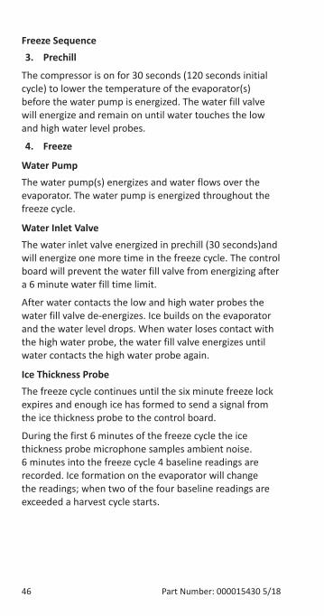
Freeze Sequence3. Prechill
The compressor is on for 30 seconds (120 seconds initial cycle) to lower the temperature of the evaporator(s) before the water pump is energized. The water fill valve will energize and remain on until water touches the low and high water level probes.
4. Freeze
Water PuIpThe water pump(s) energizes and water flows over the evaporator. The water pump is energized throughout the freeze cycle.
Water �nlet ValveThe water inlet valve energized in prechill (30 seconds)and will energize one more time in the freeze cycle. The control board will prevent the water fill valve from energizing after a 6 minute water fill time limit.
After water contacts the low and high water probes the water fill valve de-energizes. Ice builds on the evaporator and the water level drops. When water loses contact with the high water probe, the water fill valve energizes until water contacts the high water probe again.
�ce Thickness ProbeThe freeze cycle continues until the six minute freeze lock expires and enough ice has formed to send a signal from the ice thickness probe to the control board.
During the first 6 minutes of the freeze cycle the ice thickness probe microphone samples ambient noise. 6 minutes into the freeze cycle 4 baseline readings are recorded. Ice formation on the evaporator will change the readings; when two of the four baseline readings are exceeded a harvest cycle starts.
Part Number: 000015430 5/18 47
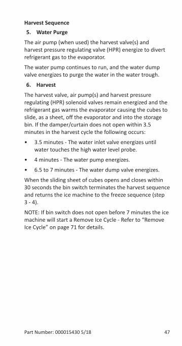
Harvest Sequence5. Water Purge
The air pump (when used) the harvest valve(s) and harvest pressure regulating valve (HPR) energize to divert refrigerant gas to the evaporator.
The water pump continues to run, and the water dump valve energizes to purge the water in the water trough.
6. Harvest
The harvest valve, air pump(s) and harvest pressure regulating (HPR) solenoid valves remain energized and the refrigerant gas warms the evaporator causing the cubes to slide, as a sheet, off the evaporator and into the storage bin. If the damper/curtain does not open within 3.5 minutes in the harvest cycle the following occurs:
• 3.5 minutes - The water inlet valve energizes until water touches the high water level probe.
• 4 minutes - The water pump energizes.
• 6.5 to 7 minutes - The water dump valve energizes.
When the sliding sheet of cubes opens and closes within 30 seconds the bin switch terminates the harvest sequence and returns the ice machine to the freeze sequence (step 3 - 4).
NOTE: If bin switch does not open before 7 minutes the ice machine will start a Remove Ice Cycle - Refer to “Remove Ice Cycle” on page 71 for details.
48 Part Number: 000015430 5/18
AutoIatic Shut-Off7. AutoIatic Shut-Off
When the storage bin is full at the end of a harvest sequence, the sheet of cubes fails to clear the water curtain/ice damper and will hold it open. After the water curtain/ice damper is held open for 30 seconds, the ice machine shuts off. The ice machine remains off for 3 minutes before it can automatically restart.
The ice machine remains off until enough ice has been removed from the storage bin to allow the ice to fall clear of the water curtain or all of the ice dampers. As the water curtain/ice dampers swing back to the closed position, the bin switch re-closes and the ice machine restarts (steps 1 - 2), provided the 3 minute delay period is complete.
Part Number: 000015430 5/18 49
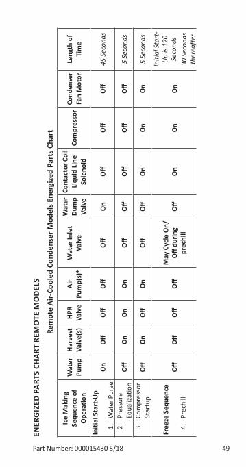
ENER
G�Z
ED P
ART
S CH
ART
REM
OTE
MO
DEL
S
ReI
ote
Air-
Cool
ed C
onde
nser
Mod
els E
nerg
ized
Part
s Cha
rt
�ce
Mak
ing
Sequ
ence
of
Ope
ratio
n
Wat
er
PuI
pHa
rves
t Va
lve(
s)HP
R Va
lve
Air
PuI
p(s)
*W
ater
�nle
t Va
lve
Wat
er
DuI
p Va
lve
Cont
acto
r Coi
l Li
quid
Lin
e So
leno
idCo
Ipr
esso
rCo
nden
ser
Fan
Mot
orLe
ngth
of
TiI
e
�niti
al S
tart
-Up
1.
Wat
er P
urge
On
Off
Off
Off
Off
On
Off
Off
Off
45 S
econ
ds
2.
Pres
sure
Eq
ualiz
atio
nO
ffO
nO
nO
nO
ffO
ffO
ffO
ffO
ff5
Seco
nds
3.
Com
pres
sor
Star
tup
Off
On
Off
On
Off
Off
On
On
On
5 Se
cond
s
Free
ze S
eque
nce
4.
Pr
echi
llO
ffO
ffO
ffO
ffM
ay C
ycle
On/
Off
durin
g
prec
hill
Off
On
On
On
Initi
al S
tart
-U
p is
120
Seco
nds
30 S
econ
ds
ther
eafte
r
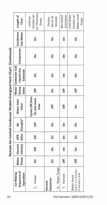
50 Part Number: 000015430 5/18
ReI
ote
Air-
Cool
ed C
onde
nser
Mod
els E
nerg
ized
Part
s Cha
rt (
Cont
inue
d)�c
e M
akin
g Se
quen
ce o
f O
pera
tion
Wat
er
PuI
pHa
rves
t Va
lve(
s)HP
R Va
lve
Air
PuI
p(s)
*W
ater
�nle
t Va
lve
Wat
er
DuI
p Va
lve
Cont
acto
r Coi
l Li
quid
Lin
e So
leno
idCo
Ipr
esso
rCo
nden
ser
Fan
Mot
orLe
ngth
of
TiI
e
5.
Free
zeO
nO
ffO
ffO
ffCy
cles
Off
then
O
n on
e I
ore
tiIe
Off
On
On
On
Unt
il Ic
e Co
ntac
t w/
Ice
Thic
knes
s Pr
obe
Harv
est
Sequ
ence
6.
Wat
er P
urge
On
On
On
On
Off
On
On
On
On
Fact
ory
Set a
t 45
Seco
nds
7.
Harv
est
Off
On
On
On
Off
Off
On
On
On
Bin
Switc
h Ac
tivat
ion
Wat
er A
ssist
Star
ts 3
.5 m
inut
es
in h
arve
st c
ycle
Off
On
On
On
On
Off
On
On
On
Unt
il W
ater
Co
ntac
t w/
Wat
er L
evel
Pr
obe
Part Number: 000015430 5/18 51
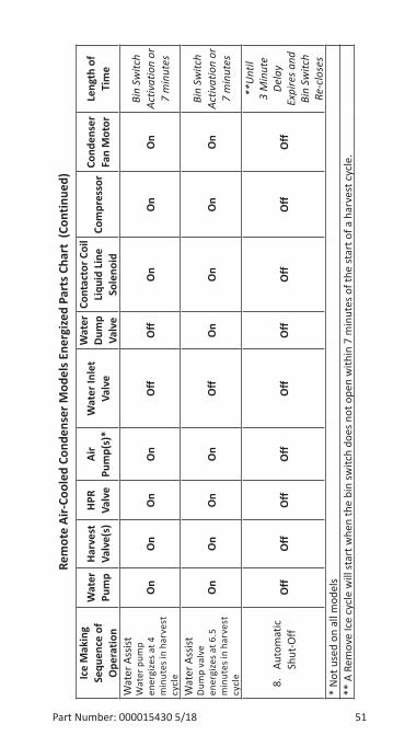
ReI
ote
Air-
Cool
ed C
onde
nser
Mod
els E
nerg
ized
Part
s Cha
rt (
Cont
inue
d)�c
e M
akin
g Se
quen
ce o
f O
pera
tion
Wat
er
PuI
pHa
rves
t Va
lve(
s)HP
R Va
lve
Air
PuI
p(s)
*W
ater
�nle
t Va
lve
Wat
er
DuI
p Va
lve
Cont
acto
r Coi
l Li
quid
Lin
e So
leno
idCo
Ipr
esso
rCo
nden
ser
Fan
Mot
orLe
ngth
of
TiI
e
Wat
er A
ssist
Wat
er p
ump
ener
gize
s at 4
m
inut
es in
har
vest
cy
cle
On
On
On
On
Off
Off
On
On
On
Bin
Switc
h Ac
tivat
ion
or
7 m
inut
es
Wat
er A
ssist
Dum
p va
lve
ener
gize
s at 6
.5
min
utes
in h
arve
st
cycl
e
On
On
On
On
Off
On
On
On
On
Bin
Switc
h Ac
tivat
ion
or
7 m
inut
es
8.
Auto
mat
ic
Shut
-Off
Off
Off
Off
Off
Off
Off
Off
Off
Off
**U
ntil
3 M
inut
e De
lay
Expi
res a
nd
Bin
Switc
h Re
-clo
ses
* N
ot u
sed
on a
ll m
odel
s**
A R
emov
e Ic
e cy
cle
will
star
t whe
n th
e bi
n sw
itch
does
not
ope
n w
ithin
7 m
inut
es o
f the
star
t of a
har
vest
cyc
le.

52 Part Number: 000015430 5/18
THIS PAGE INTENTIONALLY LEFT BLANK
Part Number: 000015430 5/18 53
Cleaning and SanitizingGeneralYou are responsible for maintaining the ice machine in accordance with the instructions in this manual. Maintenance procedures are not covered by the warranty.
Clean and sanitize the ice machine a minimum of once every six months for efficient operation. If the ice machine requires more frequent cleaning and sanitizing, consult a qualified service company to test the water quality and recommend appropriate water treatment. An extremely dirty ice machine must be taken apart for cleaning and sanitizing.
Manitowoc Ice Machine Cleaner and Sanitizer are the only products approved for use in Manitowoc ice machines.
,CautionUse only Manitowoc approved Ice Machine Cleaner and Sanitizer for this application (Manitowoc Cleaner part number 9405463 and Manitowoc Sanitizer part number 9405653). It is a violation of Federal law to use these solutions in a manner inconsistent with their labeling. Read and understand all labels printed on bottles before use.
,CautionDo not mix Cleaner and Sanitizer solutions together. It is a violation of Federal law to use these solutions in a manner inconsistent with their labeling.
nWarningWear rubber gloves and safety goggles (and/or face shield) when handling Ice Machine Cleaner or Sanitizer.
Maintenance
54 Part Number: 000015430 5/18
Cleaning/Sanitizing ProcedureThis procedure must be performed a minimum of once every six months.
• The ice machine and bin must be disassembled cleaned and sanitized.
• All ice produced during the cleaning and sanitizing procedures must be discarded.
• Removes mineral deposits from areas or surfaces that are in direct contact with water.
Preventative Maintenance Cleaning Procedure• This procedure cleans all components in the water
flow path, and is used to clean the ice machine between the bi-yearly cleaning/sanitizing procedure.
IAUCS®iAuCS® does not operate when the Clean button is used to start a clean cycle. To prime the hose, activation is required through the Service Menu/iAuCS® icon.
Exterior CleaningClean the area around the ice machine as often as necessary to maintain cleanliness and efficient operation.
Wipe surfaces with a damp cloth rinsed in water to remove dust and dirt from the outside of the ice machine. If a greasy residue persists, use a damp cloth rinsed in a mild dish soap and water solution. Wipe dry with a clean, soft cloth.
The exterior panels have a clear coating that is stain resistant and easy to clean. Products containing abrasives will damage the coating and scratch the panels.
• Never use steel wool or abrasive pads for cleaning.
• Never use chlorinated, citrus based or abrasive cleaners on exterior panels and plastic trim pieces.
Part Number: 000015430 5/18 55
Touchscreen Operation For The Clean Cycle
STARTING A CLEAN CYCLEPressing the clean icon will display a Continue/Abort screen, and a warning that pressing Continue will result in a clean cycle that can last up to 35 minutes.
WATER CURTAIN/DAMPER OPERATION DURING THE CLEAN CYCLEThe water curtain/damper must remain closed during the clean sequence. When the curtain/damper is open for more than 3 seconds the clean cycle stops and a message is displayed on the touchscreen with a choice to continue or stop the clean cycle. Stopping the clean cycle will result in a series of rinse and dump cycles to verify cleaner or sanitizer has been removed before ice making.
PAUSING A CLEAN CYCLEThe clean cycle can be paused and resumed at any time by pressing the on/off button. The clean cycle will resume from the beginning of either the wash or rinse cycle depending on the point of interruption.
POWER INTERRUPTION DURING CLEAN CYCLEIf the power supply is interrupted during the clean cycle the state is retained in the circuit board. When power is reapplied the clean cycle will resume from the beginning of either the wash or rinse cycle depending on the point of interruption.
ABORTING A CLEAN CYCLEVerify cleaner/sanitizer is not present in the water system before aborting a clean cycle.
1. Press and hold the Clean button, then press and release the On/Off button.
2. Release the Clean button and select abort from the touchscreen.
56 Part Number: 000015430 5/18
Cleaning/Sanitizing Procedure
,CautionUse only Manitowoc approved Ice Machine Cleaner and Sanitizer for this application (Manitowoc Cleaner part number 9405463 and Manitowoc Sanitizer part number 9405653). It is a violation of Federal law to use these solutions in a manner inconsistent with their labeling. Read and understand all labels printed on bottles before use.
CLEANING PROCEDURE
,CautionDo not mix Cleaner and Sanitizer solutions together. It is a violation of Federal law to use these solutions in a manner inconsistent with their labeling.
nWarningWear rubber gloves and safety goggles (and/or face shield) when handling Ice Machine Cleaner or Sanitizer.
Ice machine cleaner is used to remove lime scale and mineral deposits. Ice machine sanitizer disinfects and removes algae and slime.
NOTE: Although not required and dependent on your installation, removing the ice machine top cover may allow easier access.
Part Number: 000015430 5/18 57
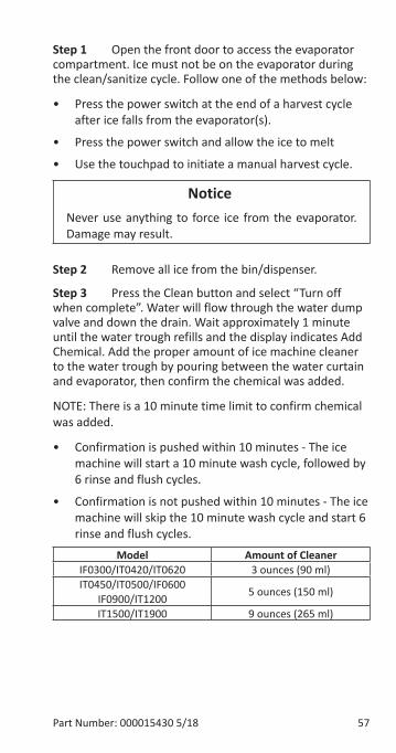
Step 1 Open the front door to access the evaporator compartment. Ice must not be on the evaporator during the clean/sanitize cycle. Follow one of the methods below:
• Press the power switch at the end of a harvest cycle after ice falls from the evaporator(s).
• Press the power switch and allow the ice to melt
• Use the touchpad to initiate a manual harvest cycle.
Notice�Never use anything to force ice from the evaporator. Damage may result.
Step 2 Remove all ice from the bin/dispenser.
Step 3 Press the Clean button and select “Turn off when complete”. Water will flow through the water dump valve and down the drain. Wait approximately 1 minute until the water trough refills and the display indicates Add Chemical. Add the proper amount of ice machine cleaner to the water trough by pouring between the water curtain and evaporator, then confirm the chemical was added.
NOTE: There is a 10 minute time limit to confirm chemical was added.
• Confirmation is pushed within 10 minutes - The ice machine will start a 10 minute wash cycle, followed by 6 rinse and flush cycles.
• Confirmation is not pushed within 10 minutes - The ice machine will skip the 10 minute wash cycle and start 6 rinse and flush cycles.
Model Amount of CleanerIF0300/IT0420/IT0620 3 ounces (90 ml)IT0450/IT0500/IF0600
IF0900/IT1200 5 ounces (150 ml)
IT1500/IT1900 9 ounces (265 ml)
58 Part Number: 000015430 5/18
Step 4 Wait until the clean cycle is complete, then disconnect power to the ice machine (and dispenser when used).
nWarningDisconnect the electric power to the ice machine at the electric service switch box.
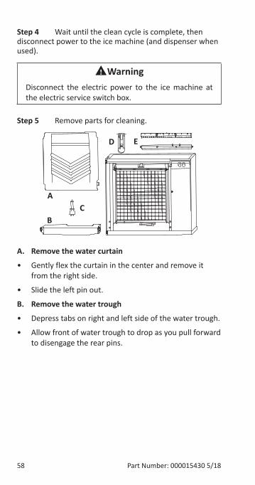
Step 5 Remove parts for cleaning.
A. Remove the water curtain
• Gently flex the curtain in the center and remove it from the right side.
• Slide the left pin out.
B. Remove the water trough
• Depress tabs on right and left side of the water trough.
• Allow front of water trough to drop as you pull forward to disengage the rear pins.
BC
D E
A
Part Number: 000015430 5/18 59
C. Remove the water level probe
• Pull the water level probe straight down to disengage.
• Lower the water level probe until the wiring connector is visible.
• Disconnect the wire lead from the water level probe.
• Remove the water level probe from the ice machine.
D. Remove the ice thickness probe
• Compress the hinge pin on the top of the ice thickness probe.
• Pivot the ice thickness probe to disengage one pin then the other. The ice thickness probe can be cleaned at this point without complete removal. If complete removal is desired, disconnect the ice thickness control wiring from the control board.
E. Remove the water distribution tube
NOTE: Distribution tube thumbscrews are retained to prevent loss. Loosen thumbscrews but do not pull thumbscrews out of distribution tube.
• Loosen the two outer screws (do not remove screws completely they are retained to prevent loss) and pull forward on the distribution tube to release from slip joint.
Disassemble distribution tube by loosening the two (2) middle thumbscrews and dividing the distribution tube into two pieces. Please refer to the proper parts removal for your ice machine. Continue with step 6 when the parts have been removed.
60 Part Number: 000015430 5/18
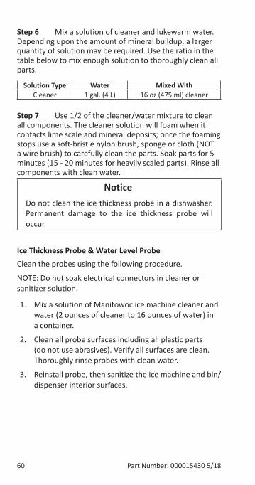
Step 6 Mix a solution of cleaner and lukewarm water. Depending upon the amount of mineral buildup, a larger quantity of solution may be required. Use the ratio in the table below to mix enough solution to thoroughly clean all parts.
Solution Type Water Mixed WithCleaner 1 gal. (4 L) 16 oz (475 ml) cleaner
Step 7 Use 1/2 of the cleaner/water mixture to clean all components. The cleaner solution will foam when it contacts lime scale and mineral deposits; once the foaming stops use a soft-bristle nylon brush, sponge or cloth (NOT a wire brush) to carefully clean the parts. Soak parts for 5 minutes (15 - 20 minutes for heavily scaled parts). Rinse all components with clean water.
Notice�Do not clean the ice thickness probe in a dishwasher. Permanent damage to the ice thickness probe will occur.
Ice Thickness Probe & Water Level ProbeClean the probes using the following procedure.
NOTE: Do not soak electrical connectors in cleaner or sanitizer solution.
1. Mix a solution of Manitowoc ice machine cleaner and water (2 ounces of cleaner to 16 ounces of water) in a container.
2. Clean all probe surfaces including all plastic parts (do not use abrasives). Verify all surfaces are clean. Thoroughly rinse probes with clean water.
3. Reinstall probe, then sanitize the ice machine and bin/dispenser interior surfaces.
Part Number: 000015430 5/18 61
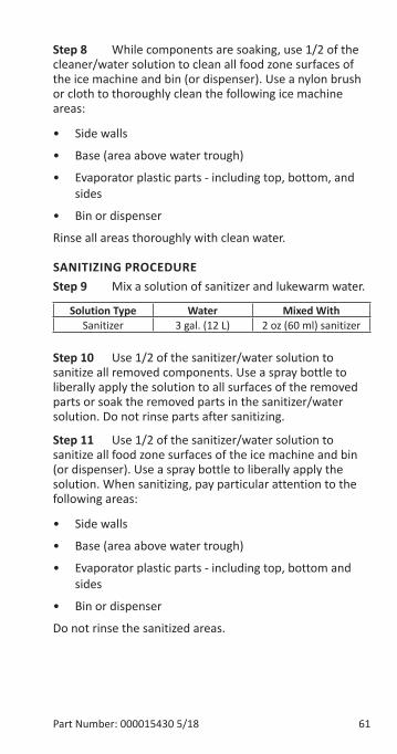
Step 8 While components are soaking, use 1/2 of the cleaner/water solution to clean all food zone surfaces of the ice machine and bin (or dispenser). Use a nylon brush or cloth to thoroughly clean the following ice machine areas:
• Side walls
• Base (area above water trough)
• Evaporator plastic parts - including top, bottom, and sides
• Bin or dispenser
Rinse all areas thoroughly with clean water.
SANITIZING PROCEDUREStep 9 Mix a solution of sanitizer and lukewarm water.
Solution Type Water Mixed WithSanitizer 3 gal. (12 L) 2 oz (60 ml) sanitizer
Step 10 Use 1/2 of the sanitizer/water solution to sanitize all removed components. Use a spray bottle to liberally apply the solution to all surfaces of the removed parts or soak the removed parts in the sanitizer/water solution. Do not rinse parts after sanitizing.
Step 11 Use 1/2 of the sanitizer/water solution to sanitize all food zone surfaces of the ice machine and bin (or dispenser). Use a spray bottle to liberally apply the solution. When sanitizing, pay particular attention to the following areas:
• Side walls
• Base (area above water trough)
• Evaporator plastic parts - including top, bottom and sides
• Bin or dispenser
Do not rinse the sanitized areas.
62 Part Number: 000015430 5/18
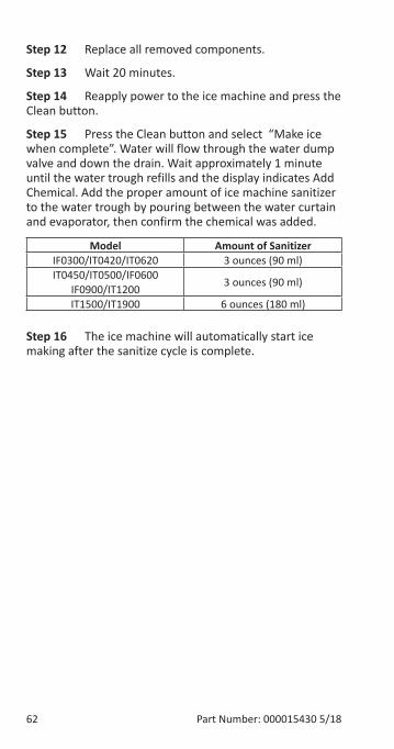
Step 12 Replace all removed components.
Step 13 Wait 20 minutes.
Step 14 Reapply power to the ice machine and press the Clean button.
Step 15 Press the Clean button and select “Make ice when complete”. Water will flow through the water dump valve and down the drain. Wait approximately 1 minute until the water trough refills and the display indicates Add Chemical. Add the proper amount of ice machine sanitizer to the water trough by pouring between the water curtain and evaporator, then confirm the chemical was added.
Model Amount of SanitizerIF0300/IT0420/IT0620 3 ounces (90 ml)IT0450/IT0500/IF0600
IF0900/IT1200 3 ounces (90 ml)
IT1500/IT1900 6 ounces (180 ml)
Step 16 The ice machine will automatically start ice making after the sanitize cycle is complete.
Part Number: 000015430 5/18 63
Water Inlet ValveThe water inlet valve normally does not require removal for cleaning. Refer to “Water System Checklist” page 93, if you are troubleshooting water related problems.
1. When the ice machine is off, the water inlet valve must completely stop water flow into the machine. Watch for water flow.
When the ice machine is on, the water inlet valve must allow the proper water flow through it. Press the Power button to energize the ice machine. Watch for water flow into the ice machine. If the water flow is slow or only trickles into the ice machine, refer to water system checklist.
NOTE: The valve can also be energized by navigating to the service diagnostic menu, selecting control board, then selecting “enable all relays”.
nWarningDisconnect the electric power to the ice machine and dispenser at the electric service switch box and turn off the water supply before proceeding.
64 Part Number: 000015430 5/18
Water Dump ValveThe water dump valve normally does not require removal for cleaning. To determine if removal is necessary:
1. Locate the water dump valve.
2. While the ice machine is in the freeze mode, check the drain to determine if the dump valve is leaking. If there is no or little water in the water trough (during the freeze cycle) the dump valve is leaking.
A. If the dump valve is leaking, remove, disassemble and clean it.
B. If the dump valve is not leaking, do not remove it. Instead, follow the “Ice Machine Cleaning Procedure”.
Part Number: 000015430 5/18 65
Preventative Maintenance Cleaning ProcedureThis procedure cleans all components in the water flow path, and is used to clean the ice machine between the bi-yearly cleaning/sanitizing procedure.
Ice machine cleaner is used to remove lime scale and mineral deposits. Ice machine sanitizer disinfects and removes algae and slime.
NOTE: Although not required and dependent on your installation, removing the ice machine top cover may allow easier access.
1. Ice must not be on the evaporator during the clean/sanitize cycle. Follow one of the methods below:
• Press the power switch at the end of a harvest cycle after ice falls from the evaporator(s).
• Press the power switch and allow the ice to melt.
Notice�Never use anything to force ice from the evaporator. Damage may result.
2. Open the front door to access the evaporator.
66 Part Number: 000015430 5/18
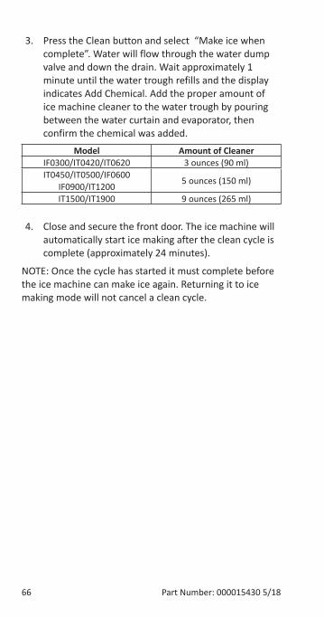
3. Press the Clean button and select “Make ice when complete”. Water will flow through the water dump valve and down the drain. Wait approximately 1 minute until the water trough refills and the display indicates Add Chemical. Add the proper amount of ice machine cleaner to the water trough by pouring between the water curtain and evaporator, then confirm the chemical was added.
Model Amount of CleanerIF0300/IT0420/IT0620 3 ounces (90 ml)IT0450/IT0500/IF0600
IF0900/IT1200 5 ounces (150 ml)
IT1500/IT1900 9 ounces (265 ml)
4. Close and secure the front door. The ice machine will automatically start ice making after the clean cycle is complete (approximately 24 minutes).
NOTE: Once the cycle has started it must complete before the ice machine can make ice again. Returning it to ice making mode will not cancel a clean cycle.
Part Number: 000015430 5/18 67
Removal from Service/WinterizationGeneralSpecial precautions must be taken if the ice machine is to be removed from service for an extended period of time or exposed to ambient temperatures of 32°F (0°C) or below.
Notice�If water is allowed to remain in the ice machine in freezing temperatures, severe damage to some components could result. Damage of this nature is not covered by the warranty.
Follow the applicable procedure below.
AIR-COOLED ICE MACHINES1. Press the power button.
2. Turn off the water supply.
3. Remove the water from the water trough.
4. Disconnect and drain the incoming ice-making water line at the rear of the ice machine.
5. Energize the ice machine and wait one minute for the water inlet valve to open - or - Energize all relays in the touchscreen service menu.
6. Blow compressed air in both the incoming water and the drain openings in the rear of the ice machine until no more water comes out of the water inlet lines or the drain.
7. Disconnect the electric power at the circuit breaker or the electric service switch.
8. Make sure water is not trapped in any of the water lines, drain lines, distribution tubes, etc.
68 Part Number: 000015430 5/18
WATER-COOLED ICE MACHINES1. Perform steps 1-6 under "Air-Cooled Ice Machines".
2. Disconnect the incoming water and drain line from the water-cooled condenser.
3. Energize the ice machine in the freeze cycle. The increasing refrigerant pressure will open the water regulating valve.
4. Blow compressed air through the condenser until no water remains.
Part Number: 000015430 5/18 69
Troubleshooting
LONG FREEZE CYCLEIf the freeze time reaches 35 minutes, the control board automatically initiates a harvest cycle. If 6 consecutive 35-minute freeze cycles occur, the ice machine stops.
LONG HARVEST CYCLEIf the harvest time reaches 7 minutes, the control board will start a remove ice cycle and automatically return the ice machine to the freeze cycle. After 3 consecutive long harvest cycles the ice machine stops.
Troubleshooting
70 Part Number: 000015430 5/18
SAFE OPERATION MODEAllows the ice machine to operate up to 72 hours if the ice thickness probe (E19 fault) and/or water level probe sensors fail (E20 fault).
• When the control board starts the safe mode an alert is indicated to notify the end-user they have a production problem.
• The control board automatically initiates and monitors the safe mode. The control will automatically exit the safe mode if a normal signal is received from the input.
• After 72 hours the control board will enter a standby mode and turn off.
The control board needs a five cycle history to operate safe mode. If five cycles have never been successfully completed the ice machine will shut-off.
Part Number: 000015430 5/18 71
REMOVE ICE CYCLEWhen the damper/curtain does not open during the 7 minute harvest cycle the following remove ice cycle occurs:
• 7 minutes - The compressor, harvest solenoid valve and dump valve de-energize. The water pump remains energized and the water inlet valve energizes until water touches the high water level probe.
• Water is circulated, dumped and refilled to the high water level probe 18 times (approximately 1 hour). Model 1200 or smaller: Circulate 165 seconds, dump 45 seconds Model 1400 and larger: Circulate 240 seconds, dump 120 seconds
• At the end of the thaw cycle (approximately 1 - 1.75 hour) the ice machine will start another freeze cycle.
Curtain Operation In Water Assist Harvest• Open & close damper = Continue Thaw Cycle
• Open damper 30 seconds = Full Bin Shutoff
NOTE: Use the keypad and turn the ice machine off and then on to terminate the cycle. Disconnecting and reconnecting power to end the cycle will result in the ice machine restarting in a harvest cycle.
72 Part Number: 000015430 5/18
ANALYZING WHY A SERVICE FAULT (E01 & E02)STOPPED THE ICE MACHINEService Faults are designed to stop the ice machine prior to major component failures, most often a minor problem or something external to the ice machine. This may be difficult to diagnose, as many external problems occur intermittently.
Example: An ice machine stops intermittently on Service Fault (long freeze times). The problem could be a low ambient temperature at night, a water pressure drop, the water is turned off one night a week, etc.
Refrigeration and electrical component failures will cause a Service Fault trip. Eliminate all electrical components and external causes first. If it appears that the refrigeration system is causing the problem, use Manitowoc’s Freeze Cycle Refrigeration System Operational Analysis Table, along with detailed charts, checklists, and other references to determine the cause.
The following checklists are designed to assist the service technician in analysis. However, because there are many possible external problems, do not limit your diagnosis to only the items listed.
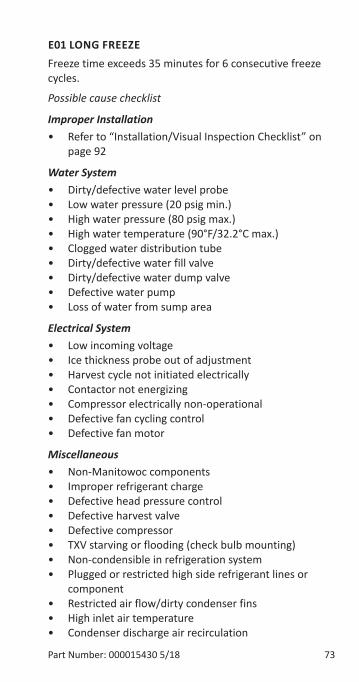
Part Number: 000015430 5/18 73
E01 LONG FREEZEFreeze time exceeds 35 minutes for 6 consecutive freeze cycles.
Possible cause checklist
Improper Installation• Refer to “Installation/Visual Inspection Checklist” on
page 92
Water System• Dirty/defective water level probe• Low water pressure (20 psig min.)• High water pressure (80 psig max.)• High water temperature (90°F/32.2°C max.)• Clogged water distribution tube• Dirty/defective water fill valve• Dirty/defective water dump valve• Defective water pump• Loss of water from sump area
Electrical System• Low incoming voltage• Ice thickness probe out of adjustment• Harvest cycle not initiated electrically• Contactor not energizing• Compressor electrically non-operational• Defective fan cycling control• Defective fan motor
Miscellaneous• Non-Manitowoc components• Improper refrigerant charge• Defective head pressure control• Defective harvest valve• Defective compressor• TXV starving or flooding (check bulb mounting)• Non-condensible in refrigeration system• Plugged or restricted high side refrigerant lines or
component• Restricted air flow/dirty condenser fins• High inlet air temperature• Condenser discharge air recirculation
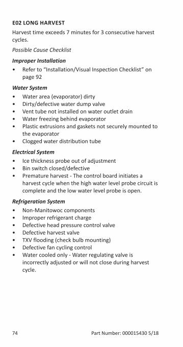
74 Part Number: 000015430 5/18
E02 LONG HARVESTHarvest time exceeds 7 minutes for 3 consecutive harvest cycles.
Possible Cause Checklist
Improper Installation• Refer to “Installation/Visual Inspection Checklist” on
page 92
Water System• Water area (evaporator) dirty• Dirty/defective water dump valve• Vent tube not installed on water outlet drain• Water freezing behind evaporator• Plastic extrusions and gaskets not securely mounted to
the evaporator• Clogged water distribution tube
Electrical System• Ice thickness probe out of adjustment• Bin switch closed/defective• Premature harvest - The control board initiates a
harvest cycle when the high water level probe circuit is complete and the low water level probe is open.
Refrigeration System• Non-Manitowoc components• Improper refrigerant charge• Defective head pressure control valve • Defective harvest valve• TXV flooding (check bulb mounting)• Defective fan cycling control• Water cooled only - Water regulating valve is
incorrectly adjusted or will not close during harvest cycle.
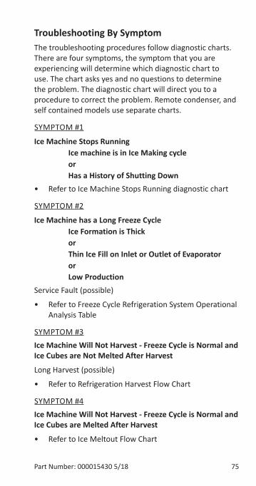
Part Number: 000015430 5/18 75
Troubleshooting By SymptomThe troubleshooting procedures follow diagnostic charts. There are four symptoms, the symptom that you are experiencing will determine which diagnostic chart to use. The chart asks yes and no questions to determine the problem. The diagnostic chart will direct you to a procedure to correct the problem. Remote condenser, and self contained models use separate charts.
SYMPTOM #1
Ice Machine Stops Running Ice machine is in Ice Making cycle
or Has a History of Shutting Down
• Refer to Ice Machine Stops Running diagnostic chart
SYMPTOM #2
Ice Machine has a Long Freeze Cycle Ice Formation is Thick
or Thin Ice Fill on Inlet or Outlet of Evaporator or Low Production
Service Fault (possible)
• Refer to Freeze Cycle Refrigeration System Operational Analysis Table
SYMPTOM #3Ice Machine Will Not Harvest - Freeze Cycle is Normal and Ice Cubes are Not Melted After Harvest
Long Harvest (possible)
• Refer to Refrigeration Harvest Flow Chart
SYMPTOM #4Ice Machine Will Not Harvest - Freeze Cycle is Normal and Ice Cubes are Melted After Harvest
• Refer to Ice Meltout Flow Chart
76 Part Number: 000015430 5/18
RESET TO FACTORY DEFAULTSBefore starting troubleshooting procedures, reset the control board to factory defaults to prevent mis-diagnosis. Before resetting to factory defaults do one of the following:
A. Copy settings to a USB device and flash settings into the control board when diagnostics are complete.
B. Write down any customer settings so they can be re-entered when diagnostics are complete.
To reset the ice machine to factory defaults select Menu then Reset Defaults.
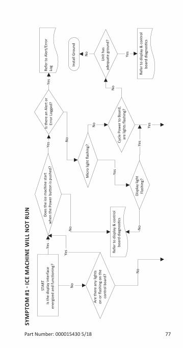
Part Number: 000015430 5/18 77
SYM
PTO
M #
1 - I
CE M
ACH
INE
WIL
L N
OT
RUN
Mic
ro li
ght fl
ashi
ng?Ye
s
No
STAR
TIs
the
disp
lay
inte
rfac
e en
ergi
zed
and
func
tioni
ng?
Yes
Refe
r to
disp
lay
& c
ontr
ol
boar
d di
agno
stics
Is th
ere
an A
lert
or
Erro
r Log
ged?
Refe
r to
Aler
t/Er
ror
Log
Yes
No
No
No
Does
the
ice
mac
hine
star
t w
hen
the
Pow
er b
utton
is p
ushe
d?Ye
s
Are
ther
e an
y lig
hts
on o
r flas
hing
on
the
cont
rol b
oard
?
No
Refe
r to
disp
lay
& c
ontr
ol
boar
d di
agno
stics
Cycl
e Po
wer
to B
oard
, ar
e lig
hts fl
ashi
ng?
Disp
lay
light
Flas
hing
?N
o
Uni
t has
ad
equa
te g
roun
d?
Inst
all G
roun
d
No
No
Yes
Yes
Yes
Yes
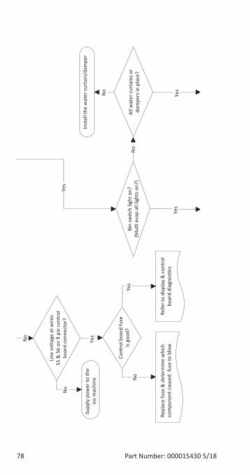
78 Part Number: 000015430 5/18
Yes
Yes
No
Yes
No
Supp
ly p
ower
to th
e ic
e m
achi
ne
Yes
No
Yes
No
No
Line
vol
tage
at w
ires
55 &
56
on 9
pin
con
trol
bo
ard
conn
ecto
r?
Cont
rol b
oard
fuse
is
good
?
Repl
ace
fuse
& d
eter
min
e w
hich
co
mpo
nent
cau
sed
fuse
to b
low
Re
fer t
o di
spla
y &
con
trol
bo
ard
diagno
stics
Bin
switc
h lig
ht o
n?(M
ulti
evap
all
light
s on?
)Al
l wat
er c
urta
ins o
r da
mpe
rs in
pla
ce?
Inst
all t
he w
ater
cur
tain
/dam
per
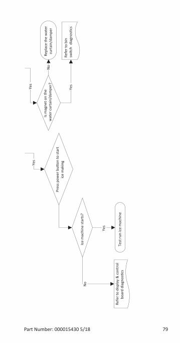
Part Number: 000015430 5/18 79
Pres
s pow
er b
u�on
to st
art
ice
mak
ing
Is m
agne
t on
the
wat
er c
urta
in/d
ampe
r?
Yes
Repl
ace
the
wat
er
curt
ain/
dam
per
No
Yes
Ice
mac
hine
star
ts?
No
Test
run
ice
mac
hine
Yes
Yes
Refe
r to
bin
switc
h di
agno
s�cs
Refe
r to
disp
lay
& c
ontr
ol
boar
d di
agno
s�cs
80 Part Number: 000015430 5/18
SYMPTOM #2 - LOW PRODUCTION, LONG FREEZE CYCLE
Ice Machine has a Long Freeze Cycle Ice Formation is Thick
or Thin on Inlet or Outlet of Evaporator or Low Production
How to Use the Freeze Cycle Refrigeration System Operational Analysis Table
GENERALThese tables must be used with charts, checklists and other references to eliminate refrigeration components not listed on the tables and external items and problems which can cause good refrigeration components to appear defective.
The tables list five different defects that may affect the ice machine’s operation.
NOTE: A low-on-charge ice machine and a starving expansion valve have very similar characteristics and are listed under the same column.
NOTE: Before starting, see “Before Beginning Service” for a few questions to ask when talking to the ice machine owner.
PROCEDURE
Step 1 Complete the “Operation Analysis” column.Read down the left “Operational Analysis” column. Perform all procedures and check all information listed. Each item in this column has supporting reference material to help analyze each step.
While analyzing each item separately, you may find an “external problem” causing a good refrigerant component to appear bad. Correct problems as they are found. If the operational problem is found, it is not necessary to complete the remaining procedures.
Part Number: 000015430 5/18 81
Step 2 Enter Checkmarks (√).Each time the actual findings of an item in the “Operational Analysis” column matches the published findings on the table, enter a Checkmark.
Example: Freeze cycle suction pressure is determined to be low. Enter a Checkmark in the “low” column.
Step 3 Add the Checkmarks listed under each of the four columns. Note the column number with the highest total and proceed to “Final Analysis.”NOTE: If two columns have matching high numbers, a procedure was not performed properly, supporting material was not analyzed correctly or the problem component is not covered by the analysis table.
Before Beginning ServiceIce machines may experience operational problems only during certain times of the day or night. A machine may function properly while it is being serviced, but malfunctions later. Information provided by the user can help the technician start in the right direction, and may be a determining factor in the final diagnosis.
Ask these questions before beginning service:
• When does the ice machine malfunction? (night, day, all the time, only during the Freeze cycle, etc.)
• When do you notice low ice production? (one day a week, every day, on weekends, etc.)
• Can you describe exactly what the ice machine seems to be doing?
• Has anyone been working on the ice machine?
• During “store shutdown,” is the circuit breaker, water supply or air temperature altered?
• Is there any reason why incoming water pressure might rise or drop substantially?
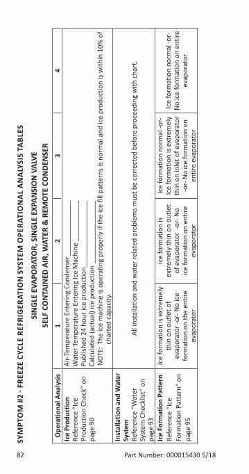
82 Part Number: 000015430 5/18
SYM
PTO
M #
2 - F
REEZ
E CY
CLE
REFR
IGER
ATIO
N S
YSTE
M O
PERA
TIO
NA
L A
NA
LYSI
S TA
BLES
SIN
GLE
EVA
PORA
TOR,
SIN
GLE
EXP
ANSI
ON
VAL
VE
SELF
CO
NTA
INED
AIR
, WAT
ER &
REM
OTE
CO
NDE
NSE
R O
pera
tiona
l Ana
lysi
s1
23
4Ic
e Pr
oduc
tion
Refe
renc
e “I
ce
Prod
uctio
n Ch
eck”
on
page
90
Air-T
empe
ratu
re E
nter
ing
Cond
ense
r ___
____
____
____
Wat
er Te
mpe
ratu
re E
nter
ing
Ice
Mac
hine
___
____
____
Publ
ished
24
hour
ice
prod
uctio
n ___
____
____
____
___
Calc
ulat
ed (a
ctua
l) ic
e pr
oduc
tion
____
____
____
____
_N
OTE
: The
ice
mac
hine
is o
pera
ting
prop
erly
if th
e ic
e fil
l pat
tern
s is n
orm
al a
nd ic
e pr
oduc
tion
is w
ithin
10%
of
char
ted
capa
city
.In
stal
latio
n an
d W
ater
Sy
stem
Refe
renc
e “W
ater
Sy
stem
Che
cklis
t” o
n pa
ge 9
3
All i
nsta
llatio
n an
d w
ater
rela
ted
prob
lem
s mus
t be
corr
ecte
d be
fore
pro
ceed
ing
with
cha
rt.
Ice
Form
atio
n Pa
tter
nRe
fere
nce
“Ice
Fo
rmat
ion
Patt
ern”
on
page
95
Ice
form
atio
n is
extr
emel
y th
in o
n ou
tlet o
f ev
apor
ator
-or-
No
ice
form
atio
n on
the
entir
e ev
apor
ator
Ice
form
atio
n is
extr
emel
y th
in o
n ou
tlet
of e
vapo
rato
r -o
r- N
o ic
e fo
rmat
ion
on e
ntire
ev
apor
ator
Ice
form
atio
n no
rmal
-or-
Ice
form
atio
n is
extr
emel
y th
in o
n in
let o
f eva
pora
tor
-or-
No
ice
form
atio
n on
en
tire
evap
orat
or
Ice
form
atio
n no
rmal
-or-
No
ice
form
atio
n on
ent
ire
evap
orat
or
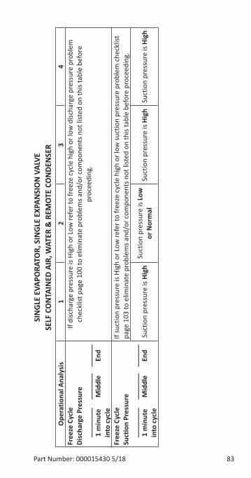
Part Number: 000015430 5/18 83
SIN
GLE
EVA
PORA
TOR,
SIN
GLE
EXP
ANSI
ON
VAL
VE
SELF
CO
NTA
INED
AIR
, WAT
ER &
REM
OTE
CO
NDE
NSE
R O
pera
tiona
l Ana
lysi
s1
23
4Fr
eeze
Cyc
le
Disc
harg
e Pr
essu
re
____
____
__
____
_ __
____
1
min
ute
Mid
dle
End
in
to c
ycle
If di
scha
rge
pres
sure
is H
igh
or L
ow re
fer t
o fr
eeze
cyc
le h
igh
or lo
w d
ischa
rge
pres
sure
pro
blem
ch
eckl
ist p
age
100
to e
limin
ate
prob
lem
s and
/or c
ompo
nent
s not
list
ed o
n th
is ta
ble
befo
re
proc
eedi
ng.
Free
ze C
ycle
Su
ctio
n Pr
essu
re
____
____
__
____
_ __
____
1
min
ute
Mid
dle
End
in
to c
ycle
If su
ctio
n pr
essu
re is
Hig
h or
Low
refe
r to
free
ze c
ycle
hig
h or
low
suct
ion
pres
sure
pro
blem
che
cklis
t pa
ge 1
03 to
elim
inat
e pr
oble
ms a
nd/o
r com
pone
nts n
ot li
sted
on
this
tabl
e be
fore
pro
ceed
ing.
Suct
ion
pres
sure
is H
igh
Suct
ion
pres
sure
is L
ow
or N
orm
alSu
ctio
n pr
essu
re is
Hig
hSu
ctio
n pr
essu
re is
Hig
h
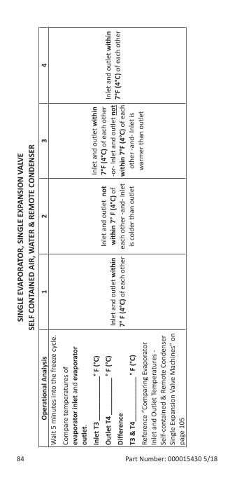
84 Part Number: 000015430 5/18
SIN
GLE
EVA
PORA
TOR,
SIN
GLE
EXP
ANSI
ON
VAL
VE
SELF
CO
NTA
INED
AIR
, WAT
ER &
REM
OTE
CO
NDE
NSE
R O
pera
tiona
l Ana
lysi
s1
23
4W
ait 5
min
utes
into
the
free
ze c
ycle
.
Com
pare
tem
pera
ture
s of
evap
orat
or in
let a
nd e
vapo
rato
r ou
tlet.
Inle
t T3
____
____
____
° F (°
C)
Out
let T
4 __
____
____
° F
(°C)
Diffe
renc
e
T3 &
T4 _
____
____
___
° F (°
C)
Refe
renc
e “C
ompa
ring
Evap
orat
or
Inle
t and
Out
let T
empe
ratu
res -
Se
lf-co
ntai
ned
& R
emot
e Co
nden
ser
Sing
le E
xpan
sion
Valv
e M
achi
nes”
on
page
105
Inle
t and
out
let w
ithin
7°
F (4
°C) o
f eac
h ot
her
Inle
t and
out
let
not
with
in 7
° F (4
°C) o
f ea
ch o
ther
-and
- Inl
et
is co
lder
than
out
let
Inle
t and
out
let w
ithin
7°
F (4
°C) o
f eac
h ot
her
-or-
Inle
t and
out
let n
ot
with
in 7
°F (4
°C) o
f eac
h ot
her -
and-
Inle
t is
war
mer
than
out
let
Inle
t and
out
let w
ithin
7°
F (4
°C) o
f eac
h ot
her
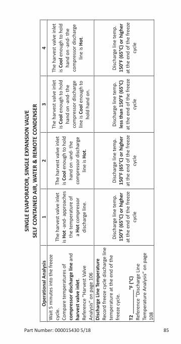
Part Number: 000015430 5/18 85
SIN
GLE
EVA
PORA
TOR,
SIN
GLE
EXP
ANSI
ON
VAL
VE
SELF
CO
NTA
INED
AIR
, WAT
ER &
REM
OTE
CO
NDE
NSE
R O
pera
tiona
l Ana
lysi
s1
23
4W
ait 5
min
utes
into
the
free
ze
cycl
e.Co
mpa
re te
mpe
ratu
res o
f co
mpr
esso
r dis
char
ge li
ne a
nd
harv
est v
alve
inle
t.Re
fere
nce
“Har
vest
Val
ve
Anal
ysis”
on
page
106
The
harv
est v
alve
inle
t is
Hot -
and-
app
roac
hes
the
tem
pera
ture
of
a Ho
t com
pres
sor
disc
harg
e lin
e.
The
harv
est v
alve
inle
t is
Cool
eno
ugh
to h
old
hand
on
-and
- the
co
mpr
esso
r disc
harg
e lin
e is
Hot.
The
harv
est v
alve
inle
t is
Cool
eno
ugh
to h
old
hand
on
-and
- the
co
mpr
esso
r disc
harg
e lin
e is
Cool
eno
ugh
to
hold
han
d on
.
The
harv
est v
alve
inle
t is
Cool
eno
ugh
to h
old
hand
on
-and
- the
co
mpr
esso
r disc
harg
e lin
e is
Hot.
Disc
harg
e Li
ne T
empe
ratu
reRe
cord
free
ze c
ycle
disc
harg
e lin
e te
mpe
ratu
re a
t the
end
of t
he
free
ze c
ycle
.
T2 _
____
____
°F (°
C)Re
fere
nce
“Disc
harg
e Li
ne
Tem
pera
ture
Ana
lysis
” on
pag
e 10
8
Disc
harg
e lin
e te
mp.
15
0°F
(65°
C) o
r hig
her
at th
e en
d of
the
free
ze
cycl
e
Disc
harg
e lin
e te
mp.
15
0°F
(65°
C) o
r hig
her
at th
e en
d of
the
free
ze
cycl
e
Disc
harg
e lin
e te
mp.
le
ss th
an 1
50°F
(65°
C)
at th
e en
d of
the
free
ze
cycl
e
Disc
harg
e lin
e te
mp.
15
0°F
(65°
C) o
r hig
her
at th
e en
d of
the
free
ze
cycl
e
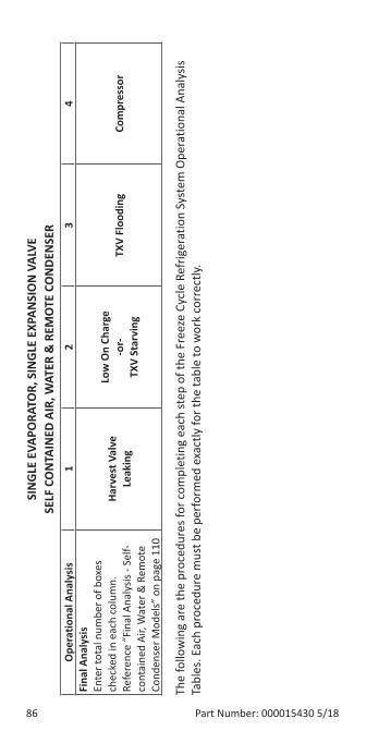
86 Part Number: 000015430 5/18
SIN
GLE
EVA
PORA
TOR,
SIN
GLE
EXP
ANSI
ON
VAL
VE
SELF
CO
NTA
INED
AIR
, WAT
ER &
REM
OTE
CO
NDE
NSE
R O
pera
tiona
l Ana
lysi
s1
23
4Fi
nal A
naly
sis
Ente
r tot
al n
umbe
r of b
oxes
ch
ecke
d in
eac
h co
lum
n.Re
fere
nce
“Fin
al A
naly
sis -
Self-
cont
aine
d Ai
r, W
ater
& R
emot
e Co
nden
ser M
odel
s” o
n pa
ge 1
10
Harv
est V
alve
Leak
ing
Low
On
Char
ge-o
r-TX
V St
arvi
ngTX
V Fl
oodi
ngCo
mpr
esso
r
The
follo
win
g ar
e th
e pr
oced
ures
for c
ompl
etin
g ea
ch st
ep o
f the
Fre
eze
Cycl
e Re
frig
erat
ion
Syst
em O
pera
tiona
l Ana
lysis
Ta
bles
. Eac
h pr
oced
ure
mus
t be
perf
orm
ed e
xact
ly fo
r the
tabl
e to
wor
k co
rrec
tly.
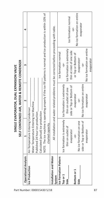
Part Number: 000015430 5/18 87
SIN
GLE
EVA
PORA
TOR,
DUA
L EX
PAN
SIO
N V
ALVE
SE
LF C
ON
TAIN
ED A
IR, W
ATER
& R
EMO
TE C
ON
DEN
SER
Ope
ratio
nal A
naly
sis
12
34
Ice
Prod
uctio
nAi
r-Tem
pera
ture
Ent
erin
g Co
nden
ser _
____
____
____
____
__W
ater
Tem
pera
ture
Ent
erin
g Ic
e M
achi
ne _
____
____
____
__Pu
blish
ed 2
4 ho
ur ic
e pr
oduc
tion _
____
____
____
____
____
_Ca
lcul
ated
(act
ual)
ice
prod
uctio
n __
____
____
____
____
___
NO
TE: T
he ic
e m
achi
ne is
ope
ratin
g pr
oper
ly if
the
ice
fill p
atte
rns i
s nor
mal
and
ice
prod
uctio
n is
with
in 1
0% o
f ch
arte
d ca
paci
ty.
Inst
alla
tion
and
Wat
er
Syst
emAl
l ins
talla
tion
and
wat
er re
late
d pr
oble
ms m
ust b
e co
rrec
ted
befo
re p
roce
edin
g w
ith ta
ble.
Ice
Form
atio
n Pa
tter
nTo
p or
1
Side
____
____
_
Bott
om o
r 1
Side
____
____
_
Ice
form
atio
n is
extr
emel
y th
in o
n ou
tlet o
f ev
apor
ator
-or-
No
ice
form
atio
n on
one
sid
e or
Top
or B
otto
m o
f ev
apor
ator
Ice
form
atio
n is
extr
emel
y th
in o
n ou
tlet o
f one
sid
e or
Top
or B
otto
m o
f ev
apor
ator
-or-
No
ice
form
atio
n on
ent
ire
evap
orat
or
Ice
form
atio
n no
rmal
-or-
Ice
form
atio
n is
extr
emel
y th
in a
t inl
et o
f one
side
or
Top
or B
otto
m o
f ev
apor
ator
r-o
r-N
o ic
e fo
rmat
ion
on e
ntire
ev
apor
ator
Ice
form
atio
n no
rmal
-or-
No
ice
form
atio
n on
ent
ire
evap
orat
or
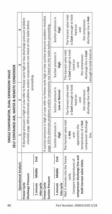
88 Part Number: 000015430 5/18
SIN
GLE
EVA
PORA
TOR,
DUA
L EX
PAN
SIO
N V
ALVE
SE
LF C
ON
TAIN
ED A
IR, W
ATER
& R
EMO
TE C
ON
DEN
SER
Ope
ratio
nal A
naly
sis
12
34
Free
ze C
ycle
Di
scha
rge
Pres
sure
__
____
__
____
___
____
__
1 m
inut
e M
iddl
e En
d
into
cyc
le
If di
scha
rge
pres
sure
is H
igh
or L
ow re
fer t
o fr
eeze
cyc
le h
igh
or lo
w d
ischa
rge
pres
sure
pro
blem
ch
eckl
ist p
age
100
to e
limin
ate
prob
lem
s and
/or c
ompo
nent
s not
list
ed o
n th
is ta
ble
befo
re
proc
eedi
ng.
Free
ze C
ycle
Su
ctio
n Pr
essu
re
____
____
__
____
_ __
____
1
min
ute
Mid
dle
End
in
to c
ycle
If su
ctio
n pr
essu
re is
Hig
h or
Low
refe
r to
free
ze c
ycle
hig
h or
low
suct
ion
pres
sure
pro
blem
che
cklis
t pa
ge 1
03 to
elim
inat
e pr
oble
ms a
nd/o
r com
pone
nts n
ot li
sted
on
this
tabl
e be
fore
pro
ceed
ing.
Suct
ion
pres
sure
is
High
Suct
ion
pres
sure
is
Low
or N
orm
alSu
ctio
n pr
essu
re is
Hi
ghSu
ctio
n pr
essu
re is
Hi
gh
Wai
t 5 m
inut
es in
to th
e fr
eeze
cy
cle.
Com
pare
tem
pera
ture
s of
com
pres
sor d
isch
arge
line
and
bo
th h
arve
st v
alve
inle
ts.
The
harv
est v
alve
inle
t is
Hot
-and
-ap
proa
ches
the
tem
pera
ture
of a
Hot
co
mpr
esso
r disc
harg
e lin
e.
The
harv
est v
alve
inle
t is
Cool
eno
ugh
to h
old
hand
on
-and
-th
e co
mpr
esso
r di
scha
rge
line
is Ho
t.
The
harv
est v
alve
inle
t is
Cool
eno
ugh
to h
old
hand
on
-and
-th
e co
mpr
esso
r di
scha
rge
line
is Co
ol
enou
gh to
hol
d ha
nd o
n.
The
harv
est v
alve
inle
t is
Cool
eno
ugh
to h
old
hand
on
-and
-th
e co
mpr
esso
r di
scha
rge
line
is Ho
t.
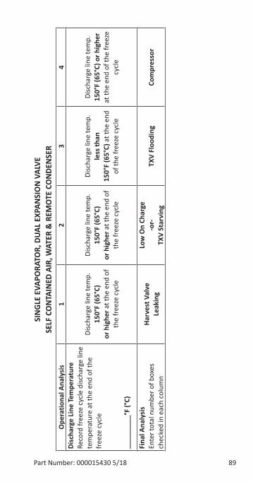
Part Number: 000015430 5/18 89
SIN
GLE
EVA
PORA
TOR,
DUA
L EX
PAN
SIO
N V
ALVE
SE
LF C
ON
TAIN
ED A
IR, W
ATER
& R
EMO
TE C
ON
DEN
SER
Ope
ratio
nal A
naly
sis
12
34
Disc
harg
e Li
ne T
empe
ratu
reRe
cord
free
ze c
ycle
disc
harg
e lin
e te
mpe
ratu
re a
t the
end
of t
he
free
ze c
ycle
____
____
_°F
(°C)
Disc
harg
e lin
e te
mp.
15
0°F
(65°
C)
or h
ighe
r at t
he e
nd o
f th
e fr
eeze
cyc
le
Disc
harg
e lin
e te
mp.
15
0°F
(65°
C)or
hig
her a
t the
end
of
the
free
ze c
ycle
Disc
harg
e lin
e te
mp.
le
ss th
an
150°
F (6
5°C)
at t
he e
nd
of th
e fr
eeze
cyc
le
Disc
harg
e lin
e te
mp.
15
0°F
(65°
C) o
r hig
her
at th
e en
d of
the
free
ze
cycl
e
Fina
l Ana
lysi
sEn
ter t
otal
num
ber o
f box
es
chec
ked
in e
ach
colu
mn
Harv
est V
alve
Leak
ing
Low
On
Char
ge-o
r-TX
V St
arvi
ngTX
V Fl
oodi
ngCo
mpr
esso
r
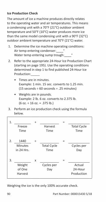
90 Part Number: 000015430 5/18
Ice Production CheckThe amount of ice a machine produces directly relates to the operating water and air temperatures. This means a condensing unit with a 70°F (21°C) outdoor ambient temperature and 50°F (10°C) water produces more ice than the same model condensing unit with a 90°F (32°C) outdoor ambient temperature and 70°F (21°C) water.
1. Determine the ice machine operating conditions: Air temp entering condenser:____° Water temp entering sump trough:____°
2. Refer to the appropriate 24-Hour Ice Production Chart (starting on page 195). Use the operating conditions determined in step 1 to find published 24-Hour Ice Production:_____
• Times are in minutes. Example: 1 min. 15 sec. converts to 1.25 min. (15 seconds ÷ 60 seconds = .25 minutes)
• Weights are in pounds. Example: 2 lb. 6 oz. converts to 2.375 lb. (6 oz. ÷ 16 oz. = .375 lb.)
3. Perform an ice production check using the formula below.
1. + =Freeze Time
Harvest Time
Total Cycle Time
2. 1440 ÷ =Minutes
in 24 Hrs.Total Cycle
TimeCycles per
Day
3. x =Weight of One Harvest
Cycles per Day
Actual 24-Hour
Production
Weighing the ice is the only 100% accurate check.
Part Number: 000015430 5/18 91
However, if the ice pattern is normal and the 1/8" (3 mm). thickness is maintained, the ice slab weights listed with the 24-Hour Ice Production Charts may be used.
4. Compare the results of step 3 with step 2. Ice production checks that are within 10% of the chart are considered normal. If they match closely, determine if:
• Another ice machine is required.
• More storage capacity is required.
• Relocating the existing equipment to lower the load conditions is required.
Contact the local Manitowoc Distributor for information on available options and accessories.
92 Part Number: 000015430 5/18
Installation/Visual Inspection Checklist
Inadequate Clearances• Check all clearances on sides, back and top. Reference
“Clearance Requirements” on page 24
Ice machine is not level• Level the ice machine
Condenser is dirty• Clean the condenser
Water filtration is plugged (if used)• Install a new water filter
Water drains are not run separately and/or are not vented• Run and vent drains according to the Installation
Manual
• Floor drain must have an air gap
• Install condensation drain in the ice machine base
Line set is improperly installed• Reinstall according to the “Water Supply and Drains”
on page 27
Part Number: 000015430 5/18 93
Water System ChecklistA water-related problem often causes the same symptoms as a refrigeration system component malfunction.
Water system problems must be identified and eliminated prior to replacing refrigeration components.
Water area (evaporator) is dirty• Clean as needed
Water inlet pressure not between 20 and 80 psig (1-5 Bar, 138-552 kPa)• Install water regulator or increase water pressure
Incoming water temperature is not between 35°F (2°C) and 90°F (32°C)• If too hot, check the hot water line check valves in
other store equipment
Water filtration is plugged (if used)• Install a new water filter
Water dump valve leaking during the Freeze cycle• Clean/replace dump valve as needed
Vent tube is not installed on water outlet drain• See Installation Instructions
Hoses, fittings, etc., are leaking water• Repair/replace as needed
Water fill valve is stuck open or closed• Clean/replace as needed
Water is leaking out of the sump trough area• Stop the water loss
Uneven water flow across the evaporator• Clean the ice machine
Plastic extrusions and gaskets are not secured to the evaporator• Remount/replace as needed
94 Part Number: 000015430 5/18
Condensation drain line is not installed• Install condensation drain in the ice machine base
Part Number: 000015430 5/18 95
Ice Formation PatternEvaporator ice formation pattern analysis is helpful in ice machine diagnostics.
Analyzing the ice formation pattern alone cannot diagnose an ice machine malfunction. However, when this analysis is used along with Manitowoc’s Freeze Cycle Refrigeration System Operational Analysis Tables, it can help diagnose an ice machine malfunction.
Any number of problems can cause improper ice formation.
Important�Keep the water curtain/ice dampers in place while checking the ice formation pattern to ensure no water is lost.
1. Normal Ice Formation
Ice forms across the entire evaporator surface.
At the beginning of the Freeze cycle, it may appear that more ice is forming on the inlet of the evaporator than on the outlet. At the end of the Freeze cycle, ice formation at the outlet will be close to, or just a bit thinner than, ice formation at the inlet. The dimples in the cubes at the outlet of the evaporator may be more pronounced than those on the inlet. This is normal.
It is normal for ice thickness to vary up to 1/16" across the surface of the evaporator. The ice bridge thickness at the ice thickness control probe should be at least 1/8".
The ice thickness probe must be set to maintain the ice bridge thickness at approximately 1/8" If ice forms uniformly across the evaporator surface, but does not reach 1/8" in the proper amount of time, this is still considered a normal ice fill pattern.
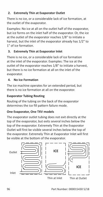
96 Part Number: 000015430 5/18
2. Extremely Thin at Evaporator Outlet
There is no ice, or a considerable lack of ice formation, at the outlet of the evaporator.
Examples: No ice at all on the outlet half of the evaporator, but ice forms on the inlet half of the evaporator. Or, the ice at the outlet of the evaporator reaches 1/8" to initiate a harvest, but the inlet of the evaporator already has 1/2" to 1" of ice formation.
3. Extremely Thin at Evaporator Inlet
There is no ice, or a considerable lack of ice formation at the inlet of the evaporator. Examples: The ice at the outlet of the evaporator reaches 1/8" to initiate a harvest, but there is no ice formation at all on the inlet of the evaporator.
4. No Ice Formation
The ice machine operates for an extended period, but there is no ice formation at all on the evaporator.
Evaporator Tubing RoutingRouting of the tubing on the back of the evaporator determines the ice fill pattern failure mode.
One Evaporator, One TXV modelsThe evaporator outlet tubing does not exit directly at the top of the evaporator, but exits several inches below the top of the evaporator. Extremely Thin at the Evaporator Outlet will first be visible several inches below the top of the evaporator. Extremely Thin at Evaporator Inlet will first be visible at the bottom of the evaporator.
Outlet
Inlet
Thin at Inlet Thin at Outlet
ICE
ICE
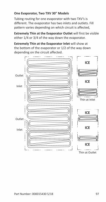
Part Number: 000015430 5/18 97
One Evaporator, Two TXV 30" ModelsTubing routing for one evaporator with two TXV’s is different. The evaporator has two inlets and outlets. Fill pattern varies depending on which circuit is affected,
Extremely Thin at the Evaporator Outlet will first be visible either 1/4 or 3/4 of the way down the evaporator.
Extremely Thin at the Evaporator Inlet will show at the bottom of the evaporator or 1/2 of the way down depending on the circuit affected.
Thin at Inlet
Thin at Outlet
ICE
ICE
ICE
ICE
ICE
Outlet
Outlet
Inlet
Inlet
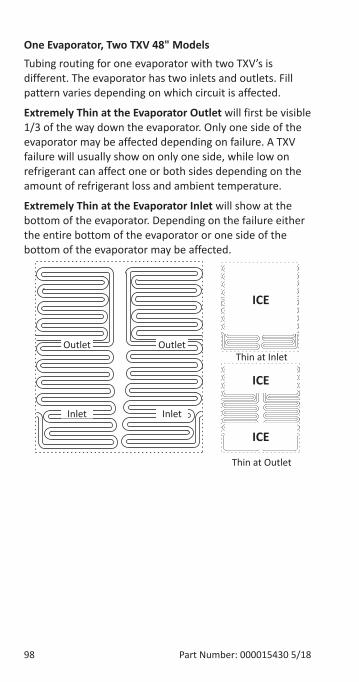
98 Part Number: 000015430 5/18
One Evaporator, Two TXV 48" ModelsTubing routing for one evaporator with two TXV’s is different. The evaporator has two inlets and outlets. Fill pattern varies depending on which circuit is affected.
Extremely Thin at the Evaporator Outlet will first be visible 1/3 of the way down the evaporator. Only one side of the evaporator may be affected depending on failure. A TXV failure will usually show on only one side, while low on refrigerant can affect one or both sides depending on the amount of refrigerant loss and ambient temperature.
Extremely Thin at the Evaporator Inlet will show at the bottom of the evaporator. Depending on the failure either the entire bottom of the evaporator or one side of the bottom of the evaporator may be affected.
Thin at Inlet
Thin at Outlet
ICE
ICE
ICE
Outlet
Inlet
Outlet
Inlet
Part Number: 000015430 5/18 99
Analyzing Discharge Pressure in the Freeze Cycle1. Determine the ice machine operating conditions:
Air temp. entering condenser ______° Water temp. entering sump trough ______°
2. Refer to Operating Pressure table (starting on page 195) for ice machine being checked.
Use the operating conditions determined in step 1 to find the published normal discharge pressures: Freeze Cycle ______ Harvest Cycle ______
3. Perform an actual discharge pressure check. Freeze Cycle psig (kPa) 1 Minute into the Freeze Cycle __________ Middle of Freeze Cycle __________ End of Freeze Cycle __________
4. Compare the actual discharge pressure (step 3) with the published discharge pressure (step 2).
The discharge pressure is normal when the actual pressure falls within the published pressure range for the ice machine’s operating conditions. It is normal for the discharge pressure to be higher at the beginning of the Freeze cycle (when load is greatest), then drop throughout the Freeze cycle.
100 Part Number: 000015430 5/18
Freeze Cycle Discharge Pressure High Checklist
Improper Installation• Refer to “Installation/Visual Inspection Checklist”
on page 92
Air Condenser• Dirty condenser filter
• Dirty condenser fins
• High inlet air temperature
• Condenser discharge air recirculation
• Defective fan cycling control
• Defective fan motor
• Defective head pressure control valve (Remote)
Water Condenser• Low water pressure (20 psig [138 kPa] min.)
• High inlet water temperature (90°F/32°C max.)
• Dirty condenser
• Dirty/Defective water regulating valve
• Water regulating valve out of adjustment
Other• Overcharged
• Non-condensable (air) in system
• Wrong type of refrigerant
• Non-Manitowoc components in system
• High side refrigerant lines/component restricted
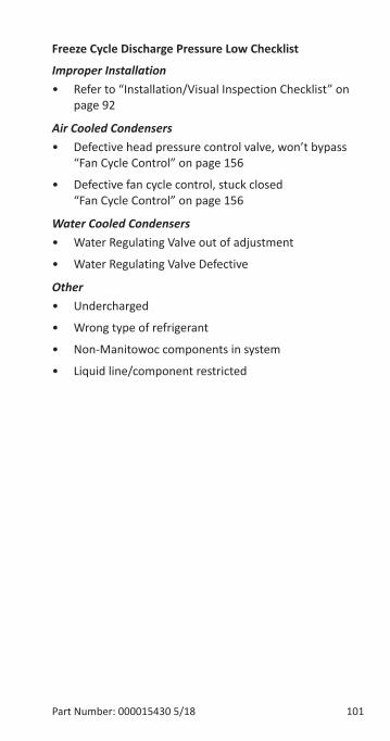
Part Number: 000015430 5/18 101
Freeze Cycle Discharge Pressure Low Checklist
Improper Installation• Refer to “Installation/Visual Inspection Checklist” on
page 92
Air Cooled Condensers• Defective head pressure control valve, won’t bypass
“Fan Cycle Control” on page 156
• Defective fan cycle control, stuck closed “Fan Cycle Control” on page 156
Water Cooled Condensers• Water Regulating Valve out of adjustment
• Water Regulating Valve Defective
Other• Undercharged
• Wrong type of refrigerant
• Non-Manitowoc components in system
• Liquid line/component restricted
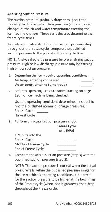
102 Part Number: 000015430 5/18
Analyzing Suction PressureThe suction pressure gradually drops throughout the freeze cycle. The actual suction pressure (and drop rate) changes as the air and water temperature entering the ice machine changes. These variables also determine the freeze cycle times.
To analyze and identify the proper suction pressure drop throughout the freeze cycle, compare the published suction pressure to the published freeze cycle time.
NOTE: Analyze discharge pressure before analyzing suction pressure. High or low discharge pressure may be causing high or low suction pressure.
1. Determine the ice machine operating conditions: Air temp. entering condenser ______° Water temp. entering sump trough ______°
2. Refer to Operating Pressure table (starting on page 195) for ice machine being checked.
Use the operating conditions determined in step 1 to find the published normal discharge pressures: Freeze Cycle ______ Harvest Cycle ______
3. Perform an actual suction pressure check. Freeze Cycle psig (kPa) 1 Minute into the Freeze Cycle __________ Middle of Freeze Cycle __________ End of Freeze Cycle __________
4. Compare the actual suction pressure (step 3) with the published suction pressure (step 2).
NOTE: The suction pressure is normal when the actual pressure falls within the published pressure range for the ice machine’s operating conditions. It is normal for the suction pressure to be higher at the beginning of the Freeze cycle (when load is greatest), then drop throughout the Freeze cycle.
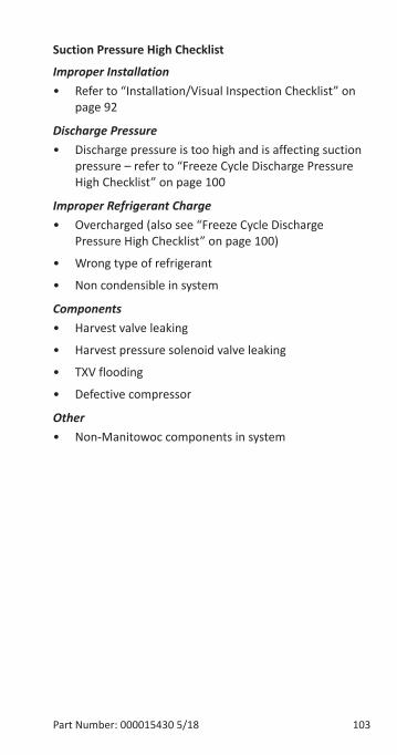
Part Number: 000015430 5/18 103
Suction Pressure High Checklist
Improper Installation• Refer to “Installation/Visual Inspection Checklist” on
page 92
Discharge Pressure• Discharge pressure is too high and is affecting suction
pressure – refer to “Freeze Cycle Discharge Pressure High Checklist” on page 100
Improper Refrigerant Charge• Overcharged (also see “Freeze Cycle Discharge
Pressure High Checklist” on page 100)
• Wrong type of refrigerant
• Non condensible in system
Components• Harvest valve leaking
• Harvest pressure solenoid valve leaking
• TXV flooding
• Defective compressor
Other• Non-Manitowoc components in system
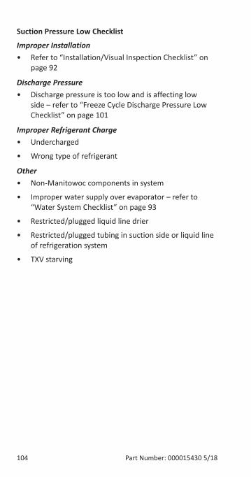
104 Part Number: 000015430 5/18
Suction Pressure Low Checklist
Improper Installation• Refer to “Installation/Visual Inspection Checklist” on
page 92
Discharge Pressure• Discharge pressure is too low and is affecting low
side – refer to “Freeze Cycle Discharge Pressure Low Checklist” on page 101
Improper Refrigerant Charge• Undercharged
• Wrong type of refrigerant
Other• Non-Manitowoc components in system
• Improper water supply over evaporator – refer to “Water System Checklist” on page 93
• Restricted/plugged liquid line drier
• Restricted/plugged tubing in suction side or liquid line of refrigeration system
• TXV starving
Part Number: 000015430 5/18 105
Comparing Evaporator Inlet and Outlet Temperatures - Self-contained & Remote Condenser Single Expansion Valve MachinesThe temperatures of the suction lines entering and leaving the evaporator alone cannot diagnose an ice machine. However, comparing these temperatures during the freeze cycle, along with using Manitowoc’s Freeze Cycle Refrigeration System Operational Analysis Table, can help diagnose an ice machine malfunction.
The actual temperatures entering and leaving the evaporator vary by model, and change throughout the freeze cycle. This makes documenting the “normal” inlet and outlet temperature readings difficult. The key to the diagnosis lies in the difference between the two temperatures five minutes into the freeze cycle. These temperatures should be within 7° of each other.
Use this procedure to document freeze cycle inlet and outlet temperatures.
1. Navigate to Service/Diagnostics/Temperature Sensors.
2. Wait 5 minutes into the freeze cycle.
3. Record the evaporator inlet (T3) and outlet (T4) temperatures at 5 minutes into the freeze cycle. Determine the difference.
4. Record the information on the table.
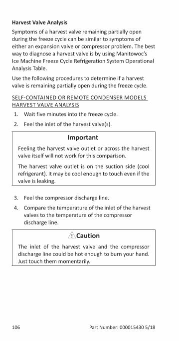
106 Part Number: 000015430 5/18
Harvest Valve AnalysisSymptoms of a harvest valve remaining partially open during the freeze cycle can be similar to symptoms of either an expansion valve or compressor problem. The best way to diagnose a harvest valve is by using Manitowoc’s Ice Machine Freeze Cycle Refrigeration System Operational Analysis Table.
Use the following procedures to determine if a harvest valve is remaining partially open during the freeze cycle.
SELF-CONTAINED OR REMOTE CONDENSER MODELS HARVEST VALVE ANALYSIS1. Wait five minutes into the freeze cycle.
2. Feel the inlet of the harvest valve(s).
Important�Feeling the harvest valve outlet or across the harvest valve itself will not work for this comparison.
The harvest valve outlet is on the suction side (cool refrigerant). It may be cool enough to touch even if the valve is leaking.
3. Feel the compressor discharge line.
4. Compare the temperature of the inlet of the harvest valves to the temperature of the compressor discharge line.
,CautionThe inlet of the harvest valve and the compressor discharge line could be hot enough to burn your hand. Just touch them momentarily.
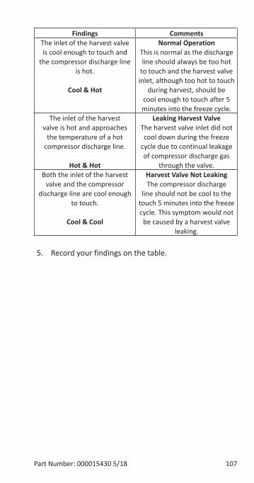
Part Number: 000015430 5/18 107
Findings CommentsThe inlet of the harvest valve is cool enough to touch and
the compressor discharge line is hot.
Cool & Hot
Normal Operation This is normal as the discharge line should always be too hot
to touch and the harvest valve inlet, although too hot to touch
during harvest, should be cool enough to touch after 5 minutes into the freeze cycle.
The inlet of the harvest valve is hot and approaches
the temperature of a hot compressor discharge line.
Hot & Hot
Leaking Harvest ValveThe harvest valve inlet did not cool down during the freeze
cycle due to continual leakage of compressor discharge gas
through the valve.Both the inlet of the harvest
valve and the compressor discharge line are cool enough
to touch.
Cool & Cool
Harvest Valve Not LeakingThe compressor discharge
line should not be cool to the touch 5 minutes into the freeze cycle. This symptom would not
be caused by a harvest valve leaking.
5. Record your findings on the table.
108 Part Number: 000015430 5/18
Discharge Line Temperature Analysis
GENERALKnowing if the discharge line temperature is increasing, decreasing or remaining constant can be an important diagnostic tool. Compressor discharge line temperature on a normally operating ice machine steadily increases throughout the freeze cycle.
Ambient air temperatures affect the discharge line temperature.
Higher ambient air temperatures at the condenser and/or higher inlet water temperature = higher discharge line temperatures at the compressor.
Lower ambient air temperatures at the condenser and/or lower supply water temperature = lower discharge line temperatures at the compressor.
Regardless of ambient and water temperatures, the freeze cycle discharge line temperature should be higher than 150°F (66°C) at the end of the freeze cycle.
PROCEDURE1. Navigate to Service/Diagnostics/Temperature
Sensors/T2 Thermistor.
2. Observe the discharge line temperature (T2) for the last three minutes of the freeze cycle and record on the table.
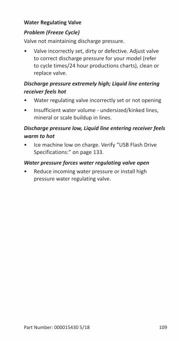
Part Number: 000015430 5/18 109
Water Regulating Valve
Problem (Freeze Cycle)Valve not maintaining discharge pressure.
• Valve incorrectly set, dirty or defective. Adjust valve to correct discharge pressure for your model (refer to cycle times/24 hour productions charts), clean or replace valve.
Discharge pressure extremely high; Liquid line entering receiver feels hot• Water regulating valve incorrectly set or not opening
• Insufficient water volume - undersized/kinked lines, mineral or scale buildup in lines.
Discharge pressure low, Liquid line entering receiver feels warm to hot• Ice machine low on charge. Verify “USB Flash Drive
Specifications:” on page 133.
Water pressure forces water regulating valve open• Reduce incoming water pressure or install high
pressure water regulating valve.
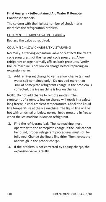
110 Part Number: 000015430 5/18
Final Analysis - Self-contained Air, Water & Remote Condenser ModelsThe column with the highest number of check marks identifies the refrigeration problem.
COLUMN 1 - HARVEST VALVE LEAKINGReplace the valve as required.
COLUMN 2 - LOW CHARGE/TXV STARVINGNormally, a starving expansion valve only affects the freeze cycle pressures, not the harvest cycle pressures. A low refrigerant charge normally affects both pressures. Verify the ice machine is not low on charge before replacing an expansion valve.
1. Add refrigerant charge to verify a low charge (air and water self-contained only). Do not add more than 30% of nameplate refrigerant charge. If the problem is corrected, the ice machine is low on charge.
NOTE: Do not add charge to remote models. The symptoms of a remote low on charge will result in a safety long freeze in cool ambient temperatures. Check the liquid line temperature at the ice machine. The liquid line will be hot with a normal or below normal head pressure in freeze when the ice machine is low on refrigerant.
2. Find the refrigerant leak. The ice machine must operate with the nameplate charge. If the leak cannot be found, proper refrigerant procedures must still be followed. Change the liquid line drier. Then, evacuate and weigh in the proper charge.
3. If the problem is not corrected by adding charge, the expansion valve is faulty.
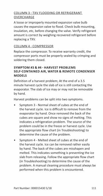
Part Number: 000015430 5/18 111
COLUMN 3 - TXV FLOODING OR REFRIGERANT OVERCHARGEA loose or improperly mounted expansion valve bulb causes the expansion valve to flood. Check bulb mounting, insulation, etc, before changing the valve. Verify refrigerant amount is correct by weighing recovered refrigerant before replacing a TXV.
COLUMN 4 - COMPRESSORReplace the compressor. To receive warranty credit, the compressor ports must be properly sealed by crimping and soldering them closed.
SYMPTOM #3 & #4 - HARVEST PROBLEMS SELF-CONTAINED AIR, WATER & REMOTE CONDENSER MODELSDefinition of a harvest problem; At the end of a 3.5 minute harvest cycle the slab of ice is still contacting the evaporator. The slab of ice may or may not be removable by hand.
Harvest problems can be split into two symptoms.
• Symptom 3 - Normal sheet of cubes at the end of the harvest cycle. Ice is difficult to remove from the evaporator by hand. Once removed the back of the cubes are square and show no signs of melting. This indicates a refrigeration problem. The source of the problem could be in the freeze or harvest cycle. Use the appropriate flow chart (in Troubleshooting) to determine the cause of the problem.
• Symptom 4 - Melted sheet of cubes at the end of the harvest cycle. Ice can be removed rather easily by hand. The back of the cubes are misshapen and melted. This indicates something is preventing the ice slab from releasing. Follow the appropriate flow chart (in Troubleshooting) to determine the cause of the problem. A manual cleaning procedure must always be performed when this problem is encountered.
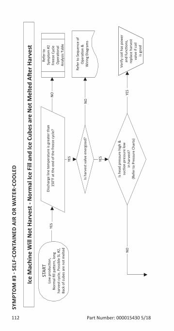
112 Part Number: 000015430 5/18
SYM
PTO
M #
3 - S
ELF-
CON
TAIN
ED A
IR O
R W
ATER
-CO
OLE
D
YES
YES
YES
NO
NO
NO
YES
Ice
Mac
hine
Will
Not
Har
vest
- N
orm
al Ic
e Fi
ll an
d Ic
e Cu
bes a
re N
ot M
elte
d A�
er H
arve
st
Low
pro
duc�
on,
Nor
mal
fill
pae
rn, l
ong
harv
est c
ycle
, Pos
sible
SL
#2,
Back
of c
ubes
are
not
mel
ted
Disc
harg
e lin
e te
mpe
ratu
re is
gre
ater
than
15
0°F
at th
e en
d of
the
free
ze c
ycle
?
Refe
r to
Sym
ptom
#2
Free
ze C
ycle
O
pera
�ona
lAn
alys
is Ta
ble
Is h
arve
st v
alve
ene
rgize
d?
Refe
r to
Sequ
ence
of
Ope
ra�o
n &
W
iring
Dia
gram
s
Is h
ead
pres
sure
hig
h &
suc�
on p
ress
ure
low
in h
arve
st?
(Ref
er to
Pre
ssur
e Ch
arts
)
Verif
y co
il ha
s pow
er
and
func
�ons
, re
plac
e ha
rves
t va
lve
if co
il is
good
STAR
T
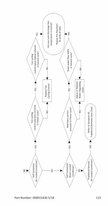
Part Number: 000015430 5/18 113
YES
YES
YES
YES
YES
YES
YES
NO
NO
NO
NO
NO
NO
Self
Cont
aine
dAi
r-co
oled
Con
dens
er?
Self
Cont
aine
dW
ater
-coo
led
Cond
ense
r?
Fan
cycl
ing
cont
rol o
pera
tes c
orre
ctly
in fr
eeze
cyc
le?
Fan
cycl
ing
cont
rol o
pens
bel
ow se
tpoi
ntin
har
vest
cyc
le?
Repl
ace
Fan
Cycl
ing
Cont
rol
Mai
ntai
ns c
orre
ctpr
essu
re in
free
ze c
ycle
?St
ops w
ater
flow
100
%in
har
vest
cyc
le?
Adju
st o
r Rep
lace
Wat
er R
egul
a�ng
Valv
e
Trad
i�on
al R
emot
e Ai
r-co
oled
Con
dens
er?
Are
you
sure
Disc
harg
e lin
e te
mpe
ratu
re is
nor
mal
?
Repe
at th
is flo
wch
art
& v
erify
all
data
Refe
r to
Sym
ptom
#3
Trad
i�on
al R
emot
es O
nly
Char
t
NO
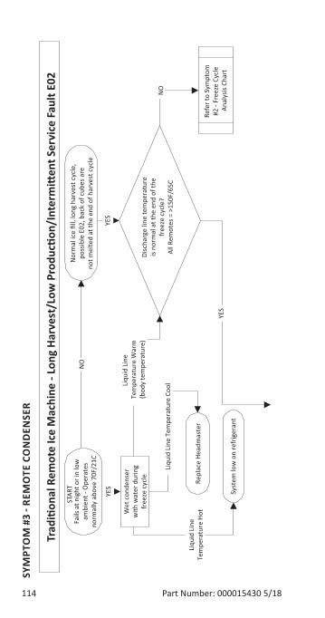
114 Part Number: 000015430 5/18
SYM
PTO
M #
3 - R
EMO
TE C
ON
DEN
SER
Refe
r to
Sym
ptom
#2
- Fr
eeze
Cyc
le
Anal
ysis
Char
t
Trad
i�on
al R
emot
e Ic
e M
achi
ne -
Long
Har
vest
/Low
Pro
duc�
on/I
nter
mi�
ent S
ervi
ce F
ault
E02
Fails
at n
ight
or i
n lo
wam
bien
t - O
pera
tes
norm
ally
abo
ve 7
0F/2
1C
YES
YES
YES
NO
Liqu
id L
ine
Tem
pera
ture
Coo
l
NO
Liqu
id L
ine
Tem
pera
ture
Hot
Liqu
id L
ine
Tem
pera
ture
War
m(b
ody
tem
pera
ture
)
Wet
con
dens
erw
ith w
ater
dur
ing
free
ze c
ycle Repl
ace
Head
mas
ter
Syst
em lo
w o
n re
frig
eran
t
Nor
mal
ice
fill,
long
har
vest
cyc
le,
poss
ible
E02
, bac
k of
cub
es a
reno
t mel
ted
at th
e en
d of
har
vest
cyc
le
Disc
harg
e lin
e te
mpe
ratu
reis
norm
al a
t the
end
of t
hefr
eeze
cyc
le?
All R
emot
es =
>15
0F/6
5C
STAR
T
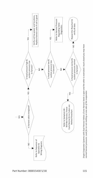
Part Number: 000015430 5/18 115
Refe
r to
Sequ
ence
of
Ope
ra�o
n &
W
iring
Dia
gram
s
YES
YES
YES
NO
NO
NO
YES
NO
YES
Is h
arve
st v
alve
ene
rgize
d?Is
hea
d pr
essu
re h
igh
&su
c�on
pre
ssur
e lo
win
har
vest
?Ve
rify
coil
has p
ower
and
func
�ons
, Re
plac
e ha
rves
t val
ve if
coi
l is g
ood
Is h
ead
pres
sure
low
&su
c�on
pre
ssur
e lo
win
har
vest
?
Is h
ead
pres
sure
nor
mal
&su
c�on
pre
ssur
e no
rmal
in h
arve
st?
Refe
r to
Harv
est P
ress
ure
Regu
la�n
g Va
lve
Diag
nos�
cs
Repe
at th
is flo
wch
art &
verif
y al
l dat
a
Refe
r to
Sym
ptom
#4
-W
ill N
ot H
arve
st, F
reez
eCy
cle
Nor
mal
& Ic
e Cu
bes a
reM
elte
d Fl
owch
art
Sing
le E
vapo
rato
r Sys
tem
s with
Dua
l Har
vest
Val
ves:
If o
ne H
arve
st V
avle
is o
pen
and
the
othe
r is r
estr
icted
/ st
uck
close
d yo
u m
ay h
ave
norm
al h
arve
st p
ress
ures
. Loo
k fo
r ice
not
mel
�ng
on o
ne si
de o
f the
eva
pora
tor.
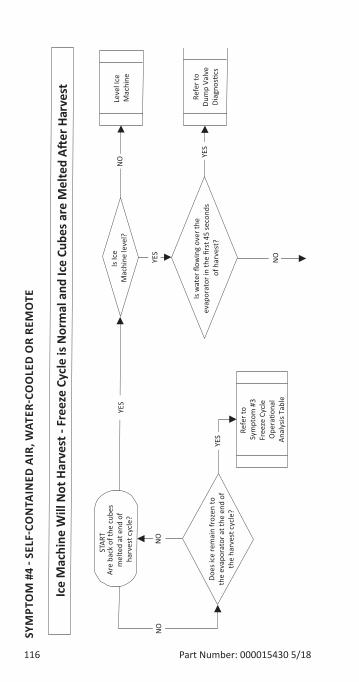
116 Part Number: 000015430 5/18
SYM
PTO
M #
4 - S
ELF-
CON
TAIN
ED A
IR, W
ATER
-CO
OLE
D O
R RE
MO
TE
Leve
l Ice
M
achi
ne
Refe
r to
Dum
p Va
lve
Diag
nos�
cs
Is w
ater
flow
ing
over
the
evap
orat
or in
the
first
45
seco
nds
of h
arve
st?
Is Ic
e M
achi
ne le
vel?
Are
back
of t
he c
ubes
m
elte
d at
end
of
harv
est c
ycle
?
Does
ice
rem
ain
froz
en to
the
evap
orat
or a
t the
end
of
the
harv
est c
ycle
?
YES
YES
YES
YES
NO
NO
NO
NO
Ice
Mac
hine
Will
Not
Har
vest
- Fr
eeze
Cyc
le is
Nor
mal
and
Ice
Cube
s are
Mel
ted
A�er
Har
vest
Refe
r to
Sym
ptom
#3
Free
ze C
ycle
O
pera
�ona
lAn
alys
is Ta
ble
STAR
T
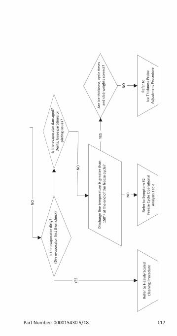
Part Number: 000015430 5/18 117
Refe
r to
Sym
ptom
#2
Free
ze C
ycle
Ope
ra�o
nal
Anal
ysis
Tabl
e
Refe
r to
Heav
ily S
cale
dCl
eani
ng P
roce
dure
Disc
harg
e lin
e te
mpe
ratu
re is
gre
ater
than
15
0°F
at th
e en
d of
the
free
ze c
ycle
?
Refe
r to
Ice
Thic
knes
s Pro
be
Adju
stm
ent P
roce
dure
Is th
e ev
apor
ator
dirt
y?(D
ry e
vapo
rato
r firs
t the
n ch
eck)
YES
YES
NO
NO
NO
Are
ice
thic
knes
s, c
ycle
�m
esan
d sla
b w
eigh
ts c
orre
ct?
NO
Is th
e ev
apor
ator
dam
aged
?De
nts,
loos
e pa
r��o
ns o
r pl
a�ng
issu
es?

118 Part Number: 000015430 5/18
THIS PAGE INTENTIONALLY LEFT BLANK
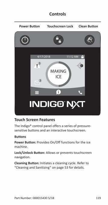
Part Number: 000015430 5/18 119
Power Button Touchscreen Lock Clean Button
Touch Screen FeaturesThe Indigo® control panel offers a series of pressure-sensitive buttons and an interactive touchscreen.
ButtonsPower Button: Provides On/Off functions for the ice machine.
Lock/Unlock Button: Allows or prevents touchscreen navigation.
Cleaning Button: Initiates a cleaning cycle. Refer to “Cleaning and Sanitizing” on page 53 for details.
Controls
S
i
MAKING
3
3
ICE
4/17/2018 11:12 AM
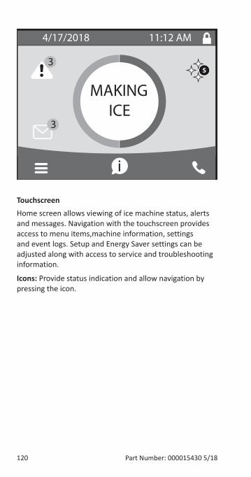
120 Part Number: 000015430 5/18
TouchscreenHome screen allows viewing of ice machine status, alerts and messages. Navigation with the touchscreen provides access to menu items,machine information, settings and event logs. Setup and Energy Saver settings can be adjusted along with access to service and troubleshooting information.
Icons: Provide status indication and allow navigation by pressing the icon.
S
i
MAKING
3
3
ICE
4/17/2018 11:12 AM
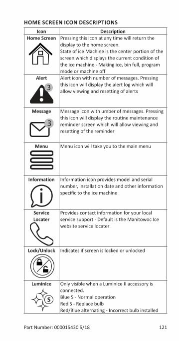
Part Number: 000015430 5/18 121
HOME SCREEN ICON DESCRIPTIONSIcon Description
Home Screen Pressing this icon at any time will return the display to the home screen. State of ice Machine is the center portion of the screen which displays the current condition of the ice machine - Making ice, bin full, program mode or machine off
Alert Alert icon with number of messages. Pressing this icon will display the alert log which will allow viewing and resetting of alerts
Message Message icon with umber of messages. Pressing this icon will display the routine maintenance reminder screen which will allow viewing and resetting of the reminder
Menu Menu icon will take you to the main menu
Information Information icon provides model and serial number, installation date and other information specific to the ice machine
Service Locater
Provides contact information for your local service support - Default is the Manitowoc Ice website service locater
Lock/Unlock Indicates if screen is locked or unlocked
LuminIce Only visible when a LuminIce II accessory is connected. Blue S - Normal operationRed S - Replace bulbRed/Blue alternating - Incorrect bulb installed
3
3
i
S
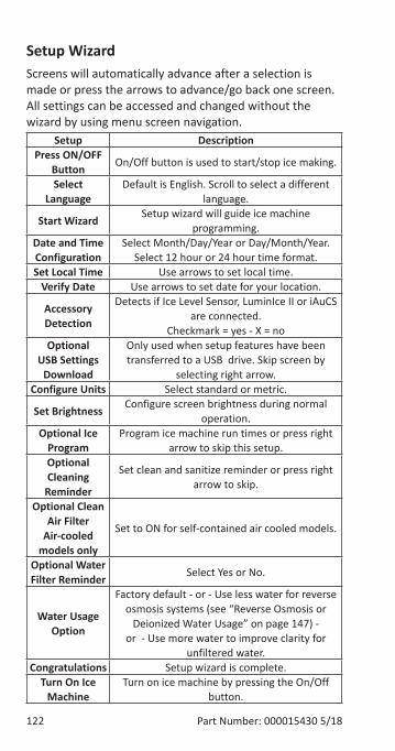
122 Part Number: 000015430 5/18
Setup WizardScreens will automatically advance after a selection is made or press the arrows to advance/go back one screen. All settings can be accessed and changed without the wizard by using menu screen navigation.
Setup DescriptionPress ON/OFF
Button On/Off button is used to start/stop ice making.
Select Language
Default is English. Scroll to select a different language.
Start Wizard Setup wizard will guide ice machine programming.
Date and Time Configuration
Select Month/Day/Year or Day/Month/Year. Select 12 hour or 24 hour time format.
Set Local Time Use arrows to set local time.Verify Date Use arrows to set date for your location.
Accessory Detection
Detects if Ice Level Sensor, LuminIce II or iAuCS are connected.
Checkmark = yes - X = noOptional
USB Settings Download
Only used when setup features have been transferred to a USB drive. Skip screen by
selecting right arrow.Configure Units Select standard or metric.
Set Brightness Configure screen brightness during normal operation.
Optional Ice Program
Program ice machine run times or press right arrow to skip this setup.
Optional Cleaning
Reminder
Set clean and sanitize reminder or press right arrow to skip.
Optional Clean Air Filter
Air-cooled models only
Set to ON for self-contained air cooled models.
Optional Water Filter Reminder Select Yes or No.
Water Usage Option
Factory default - or - Use less water for reverse osmosis systems (see “Reverse Osmosis or
Deionized Water Usage” on page 147) - or - Use more water to improve clarity for
unfiltered water.Congratulations Setup wizard is complete.
Turn On Ice Machine
Turn on ice machine by pressing the On/Off button.
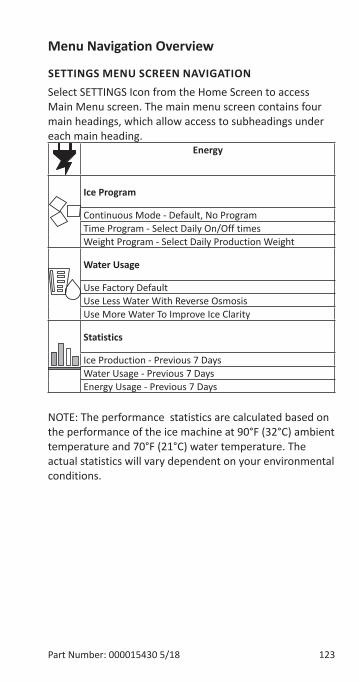
Part Number: 000015430 5/18 123
Menu Navigation Overview
SETTINGS MENU SCREEN NAVIGATIONSelect SETTINGS Icon from the Home Screen to access Main Menu screen. The main menu screen contains four main headings, which allow access to subheadings under each main heading.
Energy
Ice Program
Continuous Mode - Default, No ProgramTime Program - Select Daily On/Off timesWeight Program - Select Daily Production Weight
Water Usage
Use Factory DefaultUse Less Water With Reverse OsmosisUse More Water To Improve Ice Clarity
Statistics
Ice Production - Previous 7 DaysWater Usage - Previous 7 DaysEnergy Usage - Previous 7 Days
NOTE: The performance statistics are calculated based on the performance of the ice machine at 90°F (32°C) ambient temperature and 70°F (21°C) water temperature. The actual statistics will vary dependent on your environmental conditions.
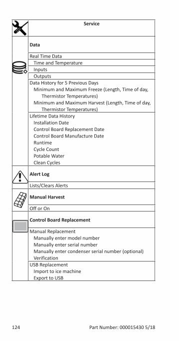
124 Part Number: 000015430 5/18
Service
Data
Real Time DataTime and TemperatureInputsOutputs
Data History for 5 Previous DaysMinimum and Maximum Freeze (Length, Time of day,
Thermistor Temperatures)Minimum and Maximum Harvest (Length, Time of day,
Thermistor Temperatures)Lifetime Data History
Installation DateControl Board Replacement DateControl Board Manufacture DateRuntimeCycle CountPotable WaterClean Cycles
Alert Log
Lists/Clears Alerts
Manual Harvest
Off or On
Control Board Replacement
Manual ReplacementManually enter model numberManually enter serial numberManually enter condenser serial number (optional)Verification
USB ReplacementImport to ice machineExport to USB
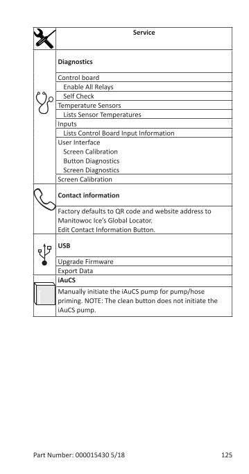
Part Number: 000015430 5/18 125
Service
Diagnostics
Control boardEnable All RelaysSelf Check
Temperature SensorsLists Sensor Temperatures
InputsLists Control Board Input Information
User InterfaceScreen CalibrationButton DiagnosticsScreen Diagnostics
Screen Calibration
Contact information
Factory defaults to QR code and website address to Manitowoc Ice’s Global Locator. Edit Contact Information Button.
USB
Upgrade FirmwareExport DataiAuCS Manually initiate the iAuCS pump for pump/hose priming. NOTE: The clean button does not initiate the iAuCS pump.
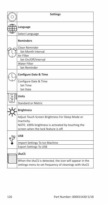
126 Part Number: 000015430 5/18
Settings
Language
Select Language
Reminders
Clean ReminderSet Month Interval
Air FilterSet On/Off/Interval
Water FilterSet Reminder
Configure Date & Time
Configure Date & TimeSet TimeSet Date
Units
Standard or Metric
Brightness
Adjust Touch Screen Brightness For Sleep Mode or Inactivity. NOTE: 100% brightness is activated by touching the screen when the lock feature is off.
USB
Import Settings To Ice MachineExport Settings To USB
iAuCS
When the iAuCS is detected, the icon will appear in the settings menu to set frequency of cleanings with iAuCS
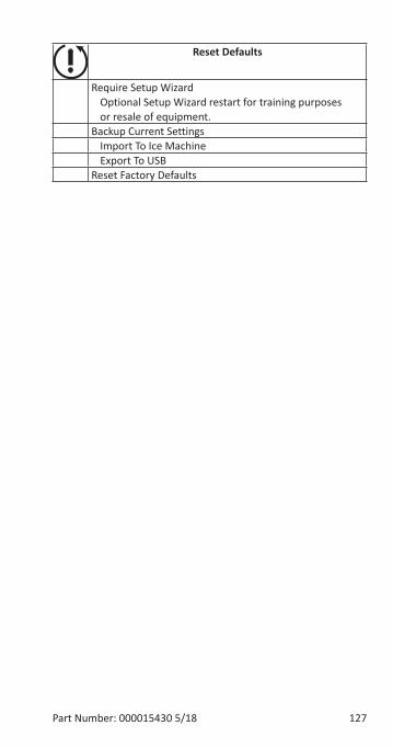
Part Number: 000015430 5/18 127
Reset Defaults
Require Setup WizardOptional Setup Wizard restart for training purposesor resale of equipment.
Backup Current SettingsImport To Ice MachineExport To USB
Reset Factory Defaults
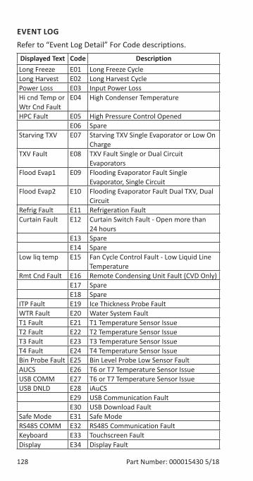
128 Part Number: 000015430 5/18
EVENT LOGRefer to “Event Log Detail” For Code descriptions.
Displayed Text Code DescriptionLong Freeze E01 Long Freeze CycleLong Harvest E02 Long Harvest CyclePower Loss E03 Input Power LossHi cnd Temp or Wtr Cnd Fault
E04 High Condenser Temperature
HPC Fault E05 High Pressure Control OpenedE06 Spare
Starving TXV E07 Starving TXV Single Evaporator or Low On Charge
TXV Fault E08 TXV Fault Single or Dual Circuit Evaporators
Flood Evap1 E09 Flooding Evaporator Fault Single Evaporator, Single Circuit
Flood Evap2 E10 Flooding Evaporator Fault Dual TXV, Dual Circuit
Refrig Fault E11 Refrigeration FaultCurtain Fault E12 Curtain Switch Fault - Open more than
24 hoursE13 SpareE14 Spare
Low liq temp E15 Fan Cycle Control Fault - Low Liquid Line Temperature
Rmt Cnd Fault E16 Remote Condensing Unit Fault (CVD Only)E17 SpareE18 Spare
ITP Fault E19 Ice Thickness Probe FaultWTR Fault E20 Water System FaultT1 Fault E21 T1 Temperature Sensor IssueT2 Fault E22 T2 Temperature Sensor IssueT3 Fault E23 T3 Temperature Sensor IssueT4 Fault E24 T4 Temperature Sensor IssueBin Probe Fault E25 Bin Level Probe Low Sensor FaultAUCS E26 T6 or T7 Temperature Sensor IssueUSB COMM E27 T6 or T7 Temperature Sensor IssueUSB DNLD E28 iAuCS
E29 USB Communication FaultE30 USB Download Fault
Safe Mode E31 Safe ModeRS485 COMM E32 RS485 Communication FaultKeyboard E33 Touchscreen FaultDisplay E34 Display Fault
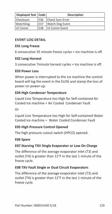
Part Number: 000015430 5/18 129
Displayed Text Code DescriptionChecksum E36 Check Sum ErrorWatchDog E37 Watch Dog EventUI Comm E38 UI Comm Event
EVENT LOG DETAIL
E01 Long Freeze6 consecutive 35 minute freeze cycles = Ice machine is off.
E02 Long Harvest3 consecutive 7minute harvest cycles = Ice machine is off.
E03 Power LossWhen power is interrupted to the ice machine the control board will log the event in the ELOG and stamp the loss of power on power-up.
E04 High Condenser TemperatureLiquid Line Temperature too High for Self-contained Air Cooled Ice machine = Air Cooled Condenser Fault
Or
Liquid Line Temperature too High for Self-contained Water Cooled ice machine = Water Cooled Condenser Fault
E05 High Pressure Control OpenedThe high pressure cutout switch (HPCO) opened.
E06 Spare
E07 Starving TXV Single Evaporator or Low On ChargeThe difference of the average evaporator inlet (T3) and outlet (T4) is greater than 12°F in the last 1 minute of the freeze cycle.
E08 TXV Fault Single or Dual Circuit EvaporatorsThe difference of the average evaporator inlet (T3) and outlet (T4) is greater than 12°F in the last 1 minute of the freeze cycle.
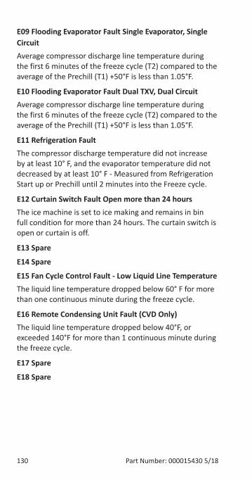
130 Part Number: 000015430 5/18
E09 Flooding Evaporator Fault Single Evaporator, Single CircuitAverage compressor discharge line temperature during the first 6 minutes of the freeze cycle (T2) compared to the average of the Prechill (T1) +50°F is less than 1.05°F.
E10 Flooding Evaporator Fault Dual TXV, Dual CircuitAverage compressor discharge line temperature during the first 6 minutes of the freeze cycle (T2) compared to the average of the Prechill (T1) +50°F is less than 1.05°F.
E11 Refrigeration FaultThe compressor discharge temperature did not increase by at least 10° F, and the evaporator temperature did not decreased by at least 10° F - Measured from Refrigeration Start up or Prechill until 2 minutes into the Freeze cycle.
E12 Curtain Switch Fault Open more than 24 hoursThe ice machine is set to ice making and remains in bin full condition for more than 24 hours. The curtain switch is open or curtain is off.
E13 Spare
E14 Spare
E15 Fan Cycle Control Fault - Low Liquid Line TemperatureThe liquid line temperature dropped below 60° F for more than one continuous minute during the freeze cycle.
E16 Remote Condensing Unit Fault (CVD Only)The liquid line temperature dropped below 40°F, or exceeded 140°F for more than 1 continuous minute during the freeze cycle.
E17 Spare
E18 Spare
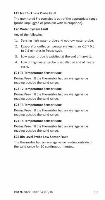
Part Number: 000015430 5/18 131
E19 Ice Thickness Probe FaultThe monitored Frequencies is out of the appropriate range (probe unplugged or problem with microphone).
E20 Water System FaultAny of the following:
1. Sensing high water probe and not low water probe.
2. Evaporator outlet temperature is less than -10°F 6.5 to 7.5 minutes in freeze cycle.
3. Low water probe is satisfied at the end of harvest.
4. Low or high water probe is satisfied at end of freeze cycle.
E21 T1 Temperature Sensor IssueDuring Pre-chill the thermistor had an average value reading outside the valid range.
E22 T2 Temperature Sensor IssueDuring Pre-chill the thermistor had an average value reading outside the valid range.
E23 T3 Temperature Sensor IssueDuring Pre-chill the thermistor had an average value reading outside the valid range.
E24 T4 Temperature Sensor IssueDuring Pre-chill the thermistor had an average value reading outside the valid range.
E25 Bin Level Probe Low Sensor FaultThe thermistor had an average value reading outside of the valid range for 10 continuous minutes.
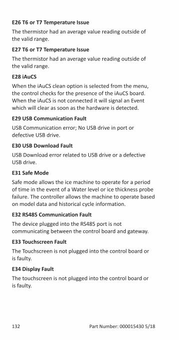
132 Part Number: 000015430 5/18
E26 T6 or T7 Temperature IssueThe thermistor had an average value reading outside of the valid range.
E27 T6 or T7 Temperature IssueThe thermistor had an average value reading outside of the valid range.
E28 iAuCSWhen the iAuCS clean option is selected from the menu, the control checks for the presence of the iAuCS board.When the iAuCS is not connected it will signal an Event which will clear as soon as the hardware is detected.
E29 USB Communication FaultUSB Communication error; No USB drive in port or defective USB drive.
E30 USB Download FaultUSB Download error related to USB drive or a defective USB drive.
E31 Safe ModeSafe mode allows the ice machine to operate for a period of time in the event of a Water level or ice thickness probe failure. The controller allows the machine to operate based on model data and historical cycle information.
E32 RS485 Communication FaultThe device plugged into the RS485 port is not communicating between the control board and gateway.
E33 Touchscreen FaultThe Touchscreen is not plugged into the control board or is faulty.
E34 Display FaultThe touchscreen is not plugged into the control board or is faulty.
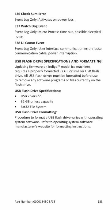
Part Number: 000015430 5/18 133
E36 Check Sum ErrorEvent Log Only: Activates on power loss.
E37 Watch Dog EventEvent Log Only: Micro Process time out, possible electrical noise.
E38 UI Comm EventEvent Log Only: User interface communication error: loose communication cable, power interruption.
USB FLASH DRIVE SPECIFICATIONS AND FORMATTINGUpdating firmware on Indigo™ model ice machines requires a properly formatted 32 GB or smaller USB flash drive. All USB flash drives must be formatted before use to remove any software programs or files currently on the flash drive.
USB Flash Drive Specifications:• USB 2 Version• 32 GB or less capacity• Fat32 File SystemUSB Flash Drive Formatting:Procedure to format a USB flash drive varies with operating system software. Refer to operating system software manufacturer’s website for formatting instructions.
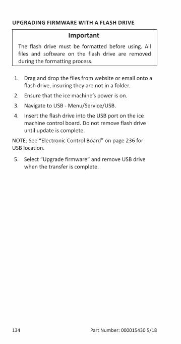
134 Part Number: 000015430 5/18
UPGRADING FIRMWARE WITH A FLASH DRIVE
Important�The flash drive must be formatted before using. All files and software on the flash drive are removed during the formatting process.
1. Drag and drop the files from website or email onto a flash drive, insuring they are not in a folder.
2. Ensure that the ice machine’s power is on.
3. Navigate to USB - Menu/Service/USB.
4. Insert the flash drive into the USB port on the ice machine control board. Do not remove flash drive until update is complete.
NOTE: See “Electronic Control Board” on page 236 for USB location.
5. Select “Upgrade firmware” and remove USB drive when the transfer is complete.
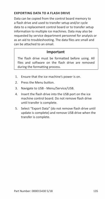
Part Number: 000015430 5/18 135
EXPORTING DATA TO A FLASH DRIVEData can be copied from the control board memory to a flash drive and used to transfer setup and/or cycle data to a replacement control board or to transfer setup information to multiple ice machines. Data may also be requested by service department personnel for analysis or as an aid to troubleshooting. The data files are small and can be attached to an email.
Important�The flash drive must be formatted before using. All files and software on the flash drive are removed during the formatting process.
1. Ensure that the ice machine’s power is on.
2. Press the Menu button.
3. Navigate to USB - Menu/Service/USB.
4. Insert the flash drive into the USB port on the ice machine control board. Do not remove flash drive until transfer is complete.
5. Select “Export Data” (do not remove flash drive until update is complete) and remove USB drive when the transfer is complete.

136 Part Number: 000015430 5/18
THIS PAGE INTENTIONALLY LEFT BLANK
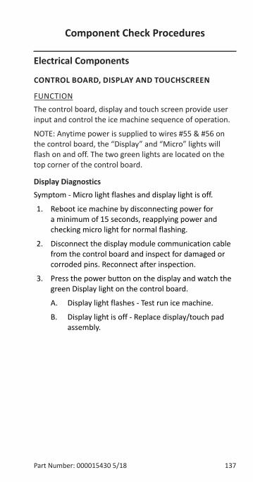
Part Number: 000015430 5/18 137
Electrical Components
CONTROL BOARD, DISPLAY AND TOUCHSCREEN
FUNCTIONThe control board, display and touch screen provide user input and control the ice machine sequence of operation.
NOTE: Anytime power is supplied to wires #55 & #56 on the control board, the “Display” and “Micro” lights will flash on and off. The two green lights are located on the top corner of the control board.
Display DiagnosticsSymptom - Micro light flashes and display light is off.
1. Reboot ice machine by disconnecting power for a minimum of 15 seconds, reapplying power and checking micro light for normal flashing.
2. Disconnect the display module communication cable from the control board and inspect for damaged or corroded pins. Reconnect after inspection.
3. Press the power button on the display and watch the green Display light on the control board.
A. Display light flashes - Test run ice machine.
B. Display light is off - Replace display/touch pad assembly.
Component Check Procedures
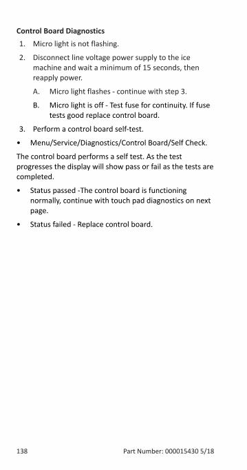
138 Part Number: 000015430 5/18
Control Board Diagnostics1. Micro light is not flashing.
2. Disconnect line voltage power supply to the ice machine and wait a minimum of 15 seconds, then reapply power.
A. Micro light flashes - continue with step 3.
B. Micro light is off - Test fuse for continuity. If fuse tests good replace control board.
3. Perform a control board self-test.
• Menu/Service/Diagnostics/Control Board/Self Check.
The control board performs a self test. As the test progresses the display will show pass or fail as the tests are completed.
• Status passed -The control board is functioning normally, continue with touch pad diagnostics on next page.
• Status failed - Replace control board.
Part Number: 000015430 5/18 139
Touchscreen DiagnosticsVerify touchscreen is unlocked prior to performing diagnostics.
1. Navigate to User Interface on the display and perform the on-screen instructions.
• Menu/Service/Diagnostics/User Interface.
NOTE: During screen calibration it is important to touch and hold down the cross hairs for three seconds at a time.
2. The calibration will either pass or fail. If the touchscreen fails calibration and will not function correctly in other menu functions replace the touchscreen module.
NOTE: Verify you have followed all of the instructions for screen calibration. Skipping steps will result in a failed calibration message.
Important�The ice machine can be run without a touchscreen by pressing the test button on the control board.
140 Part Number: 000015430 5/18
CONTROL BOARD RELAY TESTThe control board can be set to energize all relays for 3.5 minutes. This allows testing to verify control board relays are closed and line voltage is available for ice machine components - Water pump, dump valve, water inlet valve, harvest valve(s), air compressor(s), contactor/compressor/fan motor - The fan cycle control must close to energize the fan motor.
1. Press power button to turn off ice machine and navigate in menu to enable all relays.
• Menu/Service/Diagnostics/Control Board/Enable All Relays.
2. The control board will energize all relays and the red light next to the relay. The red light indicates the relay coil is energized.
3. Test for line voltage at the individual components.
A. Line voltage is present and the component is non functional - Replace component
B. Voltage is not present at the component - Proceed to step 5
4. Refer to wiring diagram and determine wire location on the 9 pin molex connector for the component you are testing.
5. Check for line voltage at the control board 9 pin molex connector.
A. Line voltage at 9 pin connector - Repair wiring to component
B. No power at 9 pin connector - Replace control board
Part Number: 000015430 5/18 141
PROGRAMMING A REPLACEMENT CONTROL BOARDIndigo™ replacement control boards require the Model number to be entered to activate the appropriate look up tables for operation and diagnostic. This can be done two different ways, USB Setup or Manual Setup.
USB Setup - Applicable when the control board is operational and has a mechanical issue such as a sticking relay. The asset data is transferred to the replacement control board from the faulty control board. Refer to page 135 “Exporting Data To A Flash Drive” before installing the replacement board.
Manual Setup - Applicable when the control board is non-operational or data from the faulty board is suspect.
1. Install replacement control board and reapply power.
2. Navigate to control board replacement and follow the on screen prompts:
Menu/Service/Control Board Replacement.
NOTE: If a replacement control board is installed into the ice machine without a display and model number. The “Test/Display Bypass Button” push button can still activate the ice making mode without the display. This will allow the ice machine to temporary run until a new display can be installed. Once a new display is installed the correct model number will have to be entered into the ice machine.
142 Part Number: 000015430 5/18
MAIN FUSE
FUNCTIONThe control board fuse stops ice machine operation if electrical components fail, causing high amp draw.
SPECIFICATIONSThe main fuse is 250 Volt, 6.3 amp.
nWarningHigh (line) voltage is applied to the control board (terminals #55 and #56) at all times. Removing the control board fuse or pressing the On/Off button will not remove the power supplied to the control board.
CHECK PROCEDURE1. If the display is energized or the bin switch light is on
with the water curtain/ice dampers closed, the fuse is good.
nWarningDisconnect electrical power to the entire ice machine before proceeding.
2. Remove the fuse. Check for continuity across the fuse with an ohmmeter.
Reading ResultOpen (OL) Replace fuseClosed (O) Fuse is good
Part Number: 000015430 5/18 143
BIN SWITCH
FUNCTIONMovement of the water curtain/ice dampers control bin switch operation. The bin switch has two main functions:
1. Terminating the Harvest cycle and returning the ice machine to the Freeze cycle. This occurs when the bin switch is opened and closed again within 30 seconds during the Harvest cycle.
2. Automatic ice machine shut-off. If the storage bin is full at the end of a Harvest cycle, the sheet of cubes fails to clear the water curtain/ice dampers and holds it open. After the water curtain/ice dampers are held open for 30 seconds, the ice machine shuts off. The ice machine remains off until enough ice is removed from the storage bin to allow the sheet of cubes to drop clear of the water curtain/ice dampers. As the water curtain/ice dampers swing back to the operating position, the bin switch closes and the ice machine restarts, provide the 3-minute delay has expired.
Important�The water curtain/ice dampers must be ON (bin switch closed) to start ice making.
SPECIFICATIONSThe bin switch is a magnetically operated reed switch. The magnet is attached to the lower right corner of the water curtain and both ends of ice dampers.
The bin switch is connected to a varying D.C. voltage circuit. (Voltage does not remain constant.)
NOTE: Because of a wide variation in D.C. voltage, it is not recommended that a voltmeter be used to check bin switch operation.
144 Part Number: 000015430 5/18
Diagnostics
SYMPTOMSBin Switch Fails Open
• The ice machine will not start an ice making cycle and the display indicates “Full Bin”.
• The ice machine displays “Full Bin Remove Ice” in the clean cycle.
Bin Switch Fails Closed
• When running a “Long Harvest” alert is displayed.
• May be off on a E02 Long Harvest.
• The harvest cycle continues after ice opens and closes the ice damper (harvest cycle is 3.5 minutes).
• A curtain fault is displayed in the event log.
Part Number: 000015430 5/18 145
DIAGNOSTICS1. Verify bin switch, curtain/damper and curtain/damper
magnet are in place and navigate to Inputs.
• Menu/Service/Diagnostics/Inputs
2. Open and close the ice damper(s) repeatedly while observing the display and control board lights.
A. Curtain switch cycles open/closed - The display indicates open/closed and the control board light energizes/de-energizes - Bin switch is operating normally
B. Curtain switch remains closed, the display indicates closed and control board light remains on - Go to step 3
C. Curtain switch remains open, display indicates open and control board light remains off - Go to step 3
3. Disconnect bin switch wire from control board.
4. Jumper control board bin switch wire to ground, press the power button and observe the display and control board lights.
A. Curtain switch closes, display indicates closed, control board light energizes and the ice machine starts - Replace bin switch
B. Curtain switch remains open, display indicates open and the control board light is off - Verify procedure was correctly followed - Replace control board
146 Part Number: 000015430 5/18
WATER LEVEL CONTROL CIRCUITRY
FUNCTIONThe water level probe controls the water level by sensing whether water is or is not contacting the water level probe. The water level probe has three sensing probes. Two probes are equal in length and are used to measures conductivity for diagnostics, ice clarity and water miser options. Factory default settings measure resistance from both long probes to the short probe.
SPECIFICATIONS
Freeze Cycle Water Level SettingThe water level is not adjustable. If the water level is incorrect, check the water level probe position. Reposition or clean the probe as necessary.
Water Inlet Valve Safety Shut-OffIn the event of a water level probe failure, this feature limits the maximum amount of time the water inlet valve can remain.
SINGLE EVAPORATOR MODELSRegardless of the water level probe input, the control board automatically shuts off the water inlet valve if it remains on for 6 continuous minutes.
DUAL EVAPORATOR MODELSRegardless of the water level probe input, the control board automatically shuts off the water inlet valve if it remains on for 8 continuous minutes.
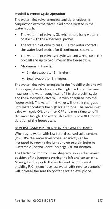
Part Number: 000015430 5/18 147
Prechill & Freeze Cycle OperationThe water inlet valve energizes and de-energizes in conjunction with the water level probe located in the water trough.
• The water inlet valve is ON when there is no water in contact with the water level probes.
• The water inlet valve turns OFF after water contacts the water level probes for 6 continuous seconds.
• The water inlet valve can cycle ON and OFF once in the prechill and up to two times in the freeze cycle.
• Maximum fill time is:
• Single evaporator 6 minutes.
• Dual evaporator 8 minutes.
The water inlet valve energizes in the Prechill cycle and will de-energize if water touches the high level probe (in most instances the water trough can’t fill in the prechill cycle and the water inlet valve will remain energized into the freeze cycle). The water inlet valve will remain energized until water contacts the high water probe. The water inlet valve will cycle ON, and then OFF one more time to refill the water trough. The water inlet valve is now OFF for the duration of the freeze cycle.
REVERSE OSMOSIS OR DEIONIZED WATER USAGEWhen using water with low total dissolved solid content (low TDS) the water level probe sensitivity can be increased by moving the jumper over one pin (refer to “Electronic Control Board” on page 236 for location.
The Electronic Control Board diagrams shows the default position of the jumper covering the left and center pins. Moving the jumper to the center and right pins and enabling R.O. menu “Use less water with reverse osmosis” will increase the sensitivity of the water level probe.
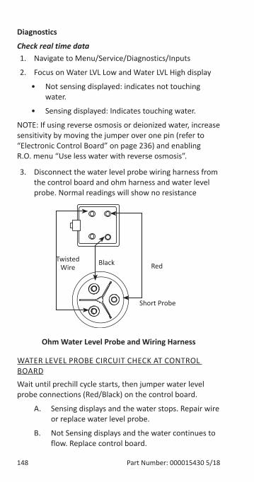
148 Part Number: 000015430 5/18
Diagnostics
Check real time data1. Navigate to Menu/Service/Diagnostics/Inputs
2. Focus on Water LVL Low and Water LVL High display
• Not sensing displayed: indicates not touching water.
• Sensing displayed: Indicates touching water.
NOTE: If using reverse osmosis or deionized water, increase sensitivity by moving the jumper over one pin (refer to “Electronic Control Board” on page 236) and enabling R.O. menu “Use less water with reverse osmosis”.
3. Disconnect the water level probe wiring harness from the control board and ohm harness and water level probe. Normal readings will show no resistance
Black
Short Probe
RedTwisted
Wire
Ohm Water Level Probe and Wiring Harness
WATER LEVEL PROBE CIRCUIT CHECK AT CONTROL BOARDWait until prechill cycle starts, then jumper water level probe connections (Red/Black) on the control board.
A. Sensing displays and the water stops. Repair wire or replace water level probe.
B. Not Sensing displays and the water continues to flow. Replace control board.
Part Number: 000015430 5/18 149
ICE THICKNESS PROBE (INITIATES HARVEST)
FUNCTIONThe ice thickness probe senses ice on the evaporator and signals the control board to start a harvest cycle.
SPECIFICATIONS
Freeze Time Lock-In FeatureThe ice machine control system incorporates a 6 minute freeze time lock-in feature. This prevents the ice machine from short cycling in and out of harvest.
Maximum Freeze TimeThe maximum freeze time is 35 minutes at which time the control board automatically initiates a harvest sequence.
Maximum TemperatureMaximum temperature for the ice thickness probe is 120°F (49°C). Do not clean probe in a dishwasher or expose to temperatures above the maximum.
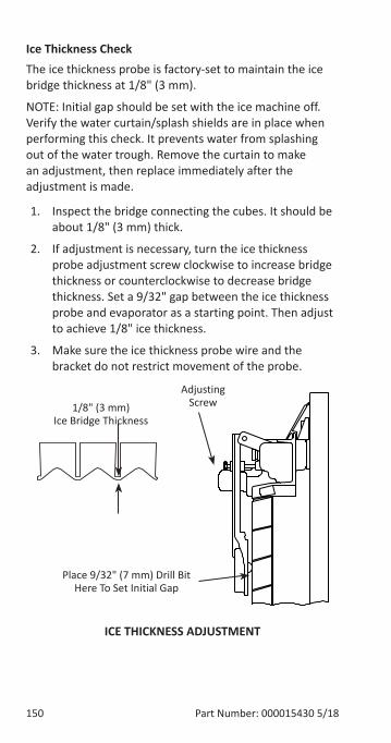
150 Part Number: 000015430 5/18
Ice Thickness CheckThe ice thickness probe is factory-set to maintain the ice bridge thickness at 1/8" (3 mm).
NOTE: Initial gap should be set with the ice machine off. Verify the water curtain/splash shields are in place when performing this check. It prevents water from splashing out of the water trough. Remove the curtain to make an adjustment, then replace immediately after the adjustment is made.
1. Inspect the bridge connecting the cubes. It should be about 1/8" (3 mm) thick.
2. If adjustment is necessary, turn the ice thickness probe adjustment screw clockwise to increase bridge thickness or counterclockwise to decrease bridge thickness. Set a 9/32" gap between the ice thickness probe and evaporator as a starting point. Then adjust to achieve 1/8" ice thickness.
3. Make sure the ice thickness probe wire and the bracket do not restrict movement of the probe.
Place 9/32" (7 mm) Drill Bit Here To Set Initial Gap
1/8" (3 mm) Ice Bridge Thickness
Adjusting Screw
ICE THICKNESS ADJUSTMENT
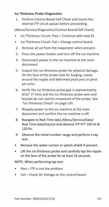
Part Number: 000015430 5/18 151
Ice Thickness Probe Diagnostics1. Perform Control Board Self Check and insure the
internal ITP circuit passes before proceeding.
(Menu/Service/Diagnostics/Control Board/Self Check)
• Ice Thickness Circuit: Pass = Continue with step #2.
• Ice Thickness Circuit: Fail = Change control board.
2. Remove all ice from the evaporator when present.
3. Press the power button and turn off the ice machine.
4. Disconnect power to the ice machine at the main disconnect.
5. Inspect the ice thickness probe for physical damage. On the face of the probe look for bulging, cracks around the nipple and deformed pivot pins or pivot pin arms.
6. Verify the ice thickness probe gap is approximately 9/32" (7 mm) and the ice thickness probe wire and bracket do not restrict movement of the probe. See “Ice Thickness Check” on page 150.
7. Reapply power to the ice machine at the main disconnect and confirm the ice machine is off.
8. Navigate to Real Time data (Menu/Service/Data/Real Time data/Inputs) and observe ITP FFT 100 Hz & 120 Hz.
9. Observe the initial number range and perform a tap test.
• Remove the water curtain or splash shield if present.
• Lift the ice thickness probe and carefully tap the nipple on the face of the probe for at least 10 seconds.
NOTE: When performing tap test:
• Pass = ITP is not the problem
• Fail = Check DC Voltage on the control board
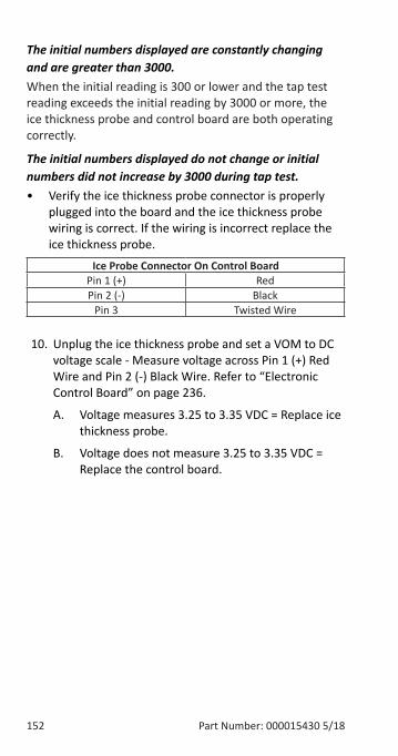
152 Part Number: 000015430 5/18
The initial numbers displayed are constantly changing and are greater than 3000.When the initial reading is 300 or lower and the tap test reading exceeds the initial reading by 3000 or more, the ice thickness probe and control board are both operating correctly.
The initial numbers displayed do not change or initial numbers did not increase by 3000 during tap test.• Verify the ice thickness probe connector is properly
plugged into the board and the ice thickness probe wiring is correct. If the wiring is incorrect replace the ice thickness probe.
Ice Probe Connector On Control BoardPin 1 (+) Red Pin 2 (-) Black
Pin 3 Twisted Wire
10. Unplug the ice thickness probe and set a VOM to DC voltage scale - Measure voltage across Pin 1 (+) Red Wire and Pin 2 (-) Black Wire. Refer to “Electronic Control Board” on page 236.
A. Voltage measures 3.25 to 3.35 VDC = Replace ice thickness probe.
B. Voltage does not measure 3.25 to 3.35 VDC = Replace the control board.
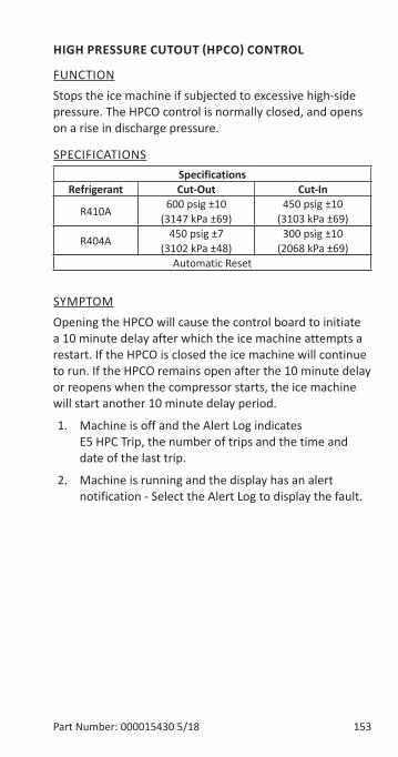
Part Number: 000015430 5/18 153
HIGH PRESSURE CUTOUT (HPCO) CONTROL
FUNCTIONStops the ice machine if subjected to excessive high-side pressure. The HPCO control is normally closed, and opens on a rise in discharge pressure.
SPECIFICATIONSSpecifications
Refrigerant Cut-Out Cut-In
R410A 600 psig ±10 (3147 kPa ±69)
450 psig ±10 (3103 kPa ±69)
R404A 450 psig ±7(3102 kPa ±48)
300 psig ±10(2068 kPa ±69)
Automatic Reset
SYMPTOMOpening the HPCO will cause the control board to initiate a 10 minute delay after which the ice machine attempts a restart. If the HPCO is closed the ice machine will continue to run. If the HPCO remains open after the 10 minute delay or reopens when the compressor starts, the ice machine will start another 10 minute delay period.
1. Machine is off and the Alert Log indicates E5 HPC Trip, the number of trips and the time and date of the last trip.
2. Machine is running and the display has an alert notification - Select the Alert Log to display the fault.
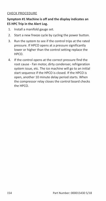
154 Part Number: 000015430 5/18
CHECK PROCEDURE
Symptom #1 Machine is off and the display indicates an E5 HPC Trip in the Alert Log.1. Install a manifold gauge set.
2. Start a new freeze cycle by cycling the power button.
3. Run the system to see if the control trips at the rated pressure. If HPCO opens at a pressure significantly lower or higher than the control setting replace the HPCO.
4. If the control opens at the correct pressure find the root cause - Fan motor, dirty condenser, refrigeration system issue, etc. The ice machine will go to an initial start sequence if the HPCO is closed. If the HPCO is open, another 10 minute delay period starts. When the compressor relay closes the control board checks the HPCO.
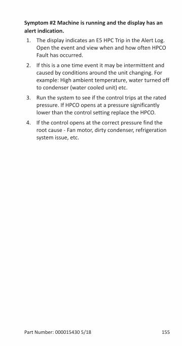
Part Number: 000015430 5/18 155
Symptom #2 Machine is running and the display has an alert indication. 1. The display indicates an E5 HPC Trip in the Alert Log.
Open the event and view when and how often HPCO Fault has occurred.
2. If this is a one time event it may be intermittent and caused by conditions around the unit changing. For example: High ambient temperature, water turned off to condenser (water cooled unit) etc.
3. Run the system to see if the control trips at the rated pressure. If HPCO opens at a pressure significantly lower than the control setting replace the HPCO.
4. If the control opens at the correct pressure find the root cause - Fan motor, dirty condenser, refrigeration system issue, etc.
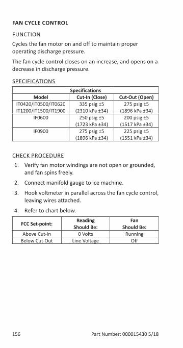
156 Part Number: 000015430 5/18
FAN CYCLE CONTROL
FUNCTIONCycles the fan motor on and off to maintain proper operating discharge pressure.
The fan cycle control closes on an increase, and opens on a decrease in discharge pressure.
SPECIFICATIONSSpecifications
Model Cut-In (Close) Cut-Out (Open)IT0420/IT0500/IT0620IT1200/IT1500/IT1900
335 psig ±5(2310 kPa ±34)
275 psig ±5(1896 kPa ±34)
IF0600 250 psig ±5(1723 kPa ±34)
200 psig ±5(1517 kPa ±34)
IF0900 275 psig ±5(1896 kPa ±34)
225 psig ±5(1551 kPa ±34)
CHECK PROCEDURE1. Verify fan motor windings are not open or grounded,
and fan spins freely.
2. Connect manifold gauge to ice machine.
3. Hook voltmeter in parallel across the fan cycle control, leaving wires attached.
4. Refer to chart below.
FCC Set-point: Reading Should Be:
Fan Should Be:
Above Cut-In 0 Volts RunningBelow Cut-Out Line Voltage Off
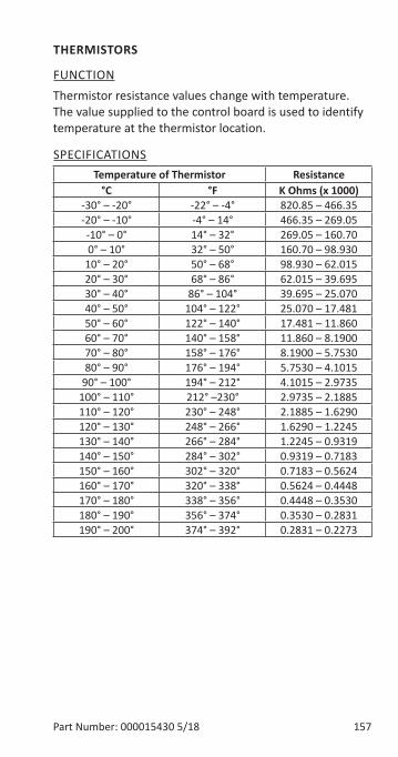
Part Number: 000015430 5/18 157
THERMISTORS
FUNCTIONThermistor resistance values change with temperature. The value supplied to the control board is used to identify temperature at the thermistor location.
SPECIFICATIONSTemperature of Thermistor Resistance
°C °F K Ohms (x 1000)-30° – -20° -22° – -4° 820.85 – 466.35-20° – -10° -4° – 14° 466.35 – 269.05-10° – 0° 14° – 32° 269.05 – 160.700° – 10° 32° – 50° 160.70 – 98.930
10° – 20° 50° – 68° 98.930 – 62.01520° – 30° 68° – 86° 62.015 – 39.69530° – 40° 86° – 104° 39.695 – 25.07040° – 50° 104° – 122° 25.070 – 17.48150° – 60° 122° – 140° 17.481 – 11.86060° – 70° 140° – 158° 11.860 – 8.190070° – 80° 158° – 176° 8.1900 – 5.753080° – 90° 176° – 194° 5.7530 – 4.1015
90° – 100° 194° – 212° 4.1015 – 2.9735100° – 110° 212° –230° 2.9735 – 2.1885110° – 120° 230° – 248° 2.1885 – 1.6290120° – 130° 248° – 266° 1.6290 – 1.2245130° – 140° 266° – 284° 1.2245 – 0.9319140° – 150° 284° – 302° 0.9319 – 0.7183150° – 160° 302° – 320° 0.7183 – 0.5624160° – 170° 320° – 338° 0.5624 – 0.4448170° – 180° 338° – 356° 0.4448 – 0.3530180° – 190° 356° – 374° 0.3530 – 0.2831190° – 200° 374° – 392° 0.2831 – 0.2273
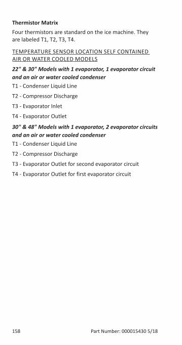
158 Part Number: 000015430 5/18
Thermistor MatrixFour thermistors are standard on the ice machine. They are labeled T1, T2, T3, T4.
TEMPERATURE SENSOR LOCATION SELF CONTAINED AIR OR WATER COOLED MODELS
22" & 30" Models with 1 evaporator, 1 evaporator circuit and an air or water cooled condenserT1 - Condenser Liquid Line
T2 - Compressor Discharge
T3 - Evaporator Inlet
T4 - Evaporator Outlet
30" & 48" Models with 1 evaporator, 2 evaporator circuits and an air or water cooled condenserT1 - Condenser Liquid Line
T2 - Compressor Discharge
T3 - Evaporator Outlet for second evaporator circuit
T4 - Evaporator Outlet for first evaporator circuit
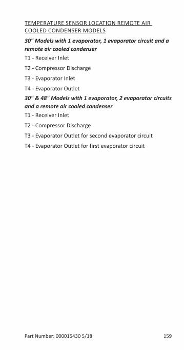
Part Number: 000015430 5/18 159
TEMPERATURE SENSOR LOCATION REMOTE AIR COOLED CONDENSER MODELS
30" Models with 1 evaporator, 1 evaporator circuit and a remote air cooled condenserT1 - Receiver Inlet
T2 - Compressor Discharge
T3 - Evaporator Inlet
T4 - Evaporator Outlet30" & 48" Models with 1 evaporator, 2 evaporator circuits and a remote air cooled condenserT1 - Receiver Inlet
T2 - Compressor Discharge
T3 - Evaporator Outlet for second evaporator circuit
T4 - Evaporator Outlet for first evaporator circuit
160 Part Number: 000015430 5/18
SYMPTOMAlert icon on the display and the alert indicates a T1, T2, T3, or T4 Fault.
CHECK PROCEDURENavigate to Menu/Service/Data/Real Time data/Time & Temperature
NOTE: An open thermistor will display -22°F (-30°C) and a shorted thermistor displays 475°F (246°C).
Thermistor Test1. Disconnect thermistor from control board and
measure resistance.
2. Measure temperature at the thermistor.
3. Compare measured resistance/temperature readings to resistance/temperature relationship chart.
A. Within 10% of the published resistance value - Thermistor is good.
B. Not within 10% of the published resistance value - Thermistor is defective.
Control Board Test1. Disconnect thermistor from control board - The
display temperature reading, dropping to -22°F (-30°C) indicates the control board is good.
2. Short thermistor pins - The display temperature reading, climbing to 475°F (246°C) indicates the control board is good.
Part Number: 000015430 5/18 161
HARVEST ASSIST AIR PUMP
FUNCTIONThe air pump helps break the vacuum between the sheet of ice and the evaporator which results in shorter harvest cycles.
SPECIFICATIONS115 Volt or 230 Volt - matches the ice machine voltage.
CHECK PROCEDURE1. The air pump is wired in parallel with the harvest
valve - Verify the ice machine is in the harvest cycle and the harvest valve is energized.
2. If there is voltage at the air pump connector, use a volt ohm meter to verify there is no continuity through the motor windings then replace motor.
162 Part Number: 000015430 5/18
COMPRESSOR ELECTRICAL DIAGNOSTICSThe compressor does not start or will trip repeatedly on overload.
Check Resistance (Ohm) ValuesNOTE: Compressor windings can have very low ohm values. Use a properly calibrated meter.
Perform the resistance test after the compressor cools. The compressor dome should be cool enough to touch (below 120°F/49°C) to assure that the overload is closed and the resistance readings will be accurate.
SINGLE PHASE COMPRESSORS1. Disconnect power then remove the wires from the
compressor terminals.
2. The resistance values between C and S and between C and R, when added together, should equal the resistance value between S and R.
3. If the overload is open, there will be a resistance reading between S and R, and open readings between C and S and between C and R. Allow the compressor to cool, then check the readings again.
THREE PHASE COMPRESSORS1. Disconnect power and remove the wires from the
compressor terminals.
2. The resistance values between L1 and L2, between L2 and L3, and between L3 and L1 should all be equal.
3. If the overload is open, there will be open readings between L1 and L2, between L2 and L3, and between L3 and L1. Allow the compressor to cool, then check the readings again.
Part Number: 000015430 5/18 163
CHECK MOTOR WINDINGS TO GROUNDCheck continuity between all three terminals and the compressor shell or copper refrigeration line. Scrape metal surface to get good contact. If continuity is present, the compressor windings are grounded and the compressor should be replaced.
COMPRESSOR DRAWING LOCKED ROTORTo determine if the compressor is seized, check the amp draw while the compressor is trying to start.
The two likely causes of this are a defective starting component or a mechanically seized compressor.
To determine which you have:
1. Install high and low side gauge.
2. Try to start the compressor.
3. Watch the pressures closely.
A. If the pressures do not move, the compressor is seized. Replace the compressor.
B. If the pressures move, the compressor is turning slowly and is not seized. Check the capacitors and relay.
COMPRESSOR DRAWING HIGH AMPSThe continuous amperage draw on start-up should not be near the maximum fuse size indicated on the serial tag.
164 Part Number: 000015430 5/18
DIAGNOSING START COMPONENTSIf the compressor attempts to start, or hums and trips the overload protector, check the start components before replacing the compressor.
CapacitorVisual evidence of capacitor failure can include a bulged terminal end or a ruptured membrane. Do not assume a capacitor is good if no visual evidence is present. A good test is to install a known good substitute capacitor. Use a capacitor tester when checking a suspect capacitor. Clip the bleed resistor off the capacitor terminals before testing.
RelayThe relay has a set of contacts that connect and disconnect the start capacitor from the compressor start winding. The contacts on the relay are normally closed (start capacitor in series with the start winding). The relay senses the voltage generated by the start winding and opens the contacts as the compressor motor starts. The contacts remain open until the compressor is de-energized.
RELAY OPERATION CHECK1. Disconnect wires from relay terminals.
2. Verify the contacts are closed. Measure the resistance between terminals 1 and 2. No continuity indicates open contacts. Replace the relay.
3. Check the relay coil. Measure the resistance between terminals 2 and 5. No resistance indicates an open coil. Replace the relay.
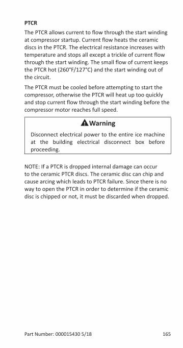
Part Number: 000015430 5/18 165
PTCRThe PTCR allows current to flow through the start winding at compressor startup. Current flow heats the ceramic discs in the PTCR. The electrical resistance increases with temperature and stops all except a trickle of current flow through the start winding. The small flow of current keeps the PTCR hot (260°F/127°C) and the start winding out of the circuit.
The PTCR must be cooled before attempting to start the compressor, otherwise the PTCR will heat up too quickly and stop current flow through the start winding before the compressor motor reaches full speed.
nWarningDisconnect electrical power to the entire ice machine at the building electrical disconnect box before proceeding.
NOTE: If a PTCR is dropped internal damage can occur to the ceramic PTCR discs. The ceramic disc can chip and cause arcing which leads to PTCR failure. Since there is no way to open the PTCR in order to determine if the ceramic disc is chipped or not, it must be discarded when dropped.
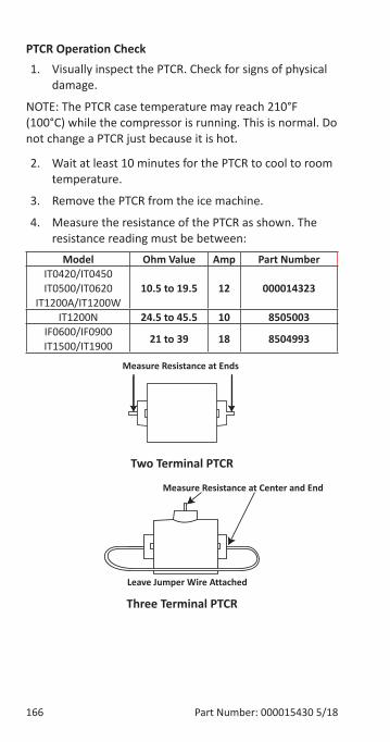
166 Part Number: 000015430 5/18
PTCR Operation Check1. Visually inspect the PTCR. Check for signs of physical
damage.
NOTE: The PTCR case temperature may reach 210°F (100°C) while the compressor is running. This is normal. Do not change a PTCR just because it is hot.
2. Wait at least 10 minutes for the PTCR to cool to room temperature.
3. Remove the PTCR from the ice machine.
4. Measure the resistance of the PTCR as shown. The resistance reading must be between:
Model Ohm Value Amp Part NumberIT0420/IT0450IT0500/IT0620
IT1200A/IT1200W10.5 to 19.5 12 000014323
IT1200N 24.5 to 45.5 10 8505003IF0600/IF0900 IT1500/IT1900 21 to 39 18 8504993
Two Terminal PTCR
Three Terminal PTCR
Measure Resistance at Ends
Measure Resistance at Center and End
Leave Jumper Wire Attached
Part Number: 000015430 5/18 167
Refrigeration Components
HEADMASTERManitowoc remote systems require head pressure control valves with special settings. Replace defective head pressure control valves only with “original” Manitowoc replacement parts.
Refrigerant Charge VerificationThe correct amount of refrigerant (name plate charge) is required to operate correctly at all ambient conditions.
An ice machine with an overcharge or undercharge of refrigerant may function properly at higher ambient temperatures and fails at lower ambient temperatures. Symptoms of incorrect refrigerant amount are:
• Works during the day and malfunctions at night, and/or fails whenever the outdoor temperature drops.
• A Service Fault is stored in control board memory.
Refrigerant loss and ambient temperature are directly related to each other. As the ambient temperature drops, more refrigerant is stored in the condenser.
When the refrigerant charge and ambient temperature create an undercharge of refrigerant in the freeze cycle, the receiver dip tube will lose it’s liquid seal. Without liquid refrigerant to the TXV, the ice machine fails to make a full sheet of ice in 35 minutes and a Long Freeze results.
NOTE: When a head pressure control valve is being replaced or refrigerant charge is suspected, verify the refrigerant charge is correct by recovering the refrigerant, weighing and comparing to the nameplate amount. Refer to “Refrigerant Recovery/Evacuation” on page 181 for recovery procedures.
168 Part Number: 000015430 5/18
Freeze Cycle Operation All Remote Condenser ModelsThe headmaster is non adjustable.
At ambient temperatures of approximately 70°F (21°C) or above, refrigerant flows through the valve from the condenser to the receiver inlet. At temperatures below this (or at higher temperatures if it is raining), the head pressure control dome’s nitrogen charge closes the condenser port and opens the bypass port from the compressor discharge line.
In this modulating mode, the valve maintains minimum head pressure by building up liquid in the condenser and bypassing discharge gas directly to the receiver.
Harvest Cycle Operation Remote Condenser ModelsThe head pressure control cycles into full bypass due to the pressure drop when the harvest valve opens. Refrigerant flows from the compressor to the evaporator through the harvest valve and the head pressure valve is out of the circuit.
Diagnostics
FREEZE CYCLE - REMOTE CONDENSER 1. Determine if the coil is clean.
2. Determine the air temperature entering the condenser.
3. Determine if the head pressure is high or low in relationship to the outside temperature. (Refer to the proper “Cycle Times/24-Hour Ice Production/Refrigerant Pressure Charts” page 195).
4. Determine the temperature of the liquid line entering the receiver by feeling it. This line is normally warm; “body temperature.”
5. Using the information gathered, refer to the chart.
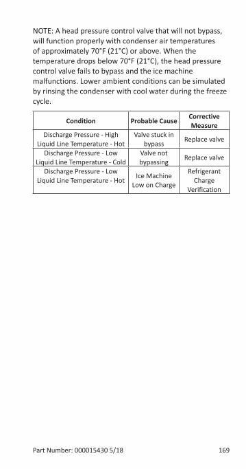
Part Number: 000015430 5/18 169
NOTE: A head pressure control valve that will not bypass, will function properly with condenser air temperatures of approximately 70°F (21°C) or above. When the temperature drops below 70°F (21°C), the head pressure control valve fails to bypass and the ice machine malfunctions. Lower ambient conditions can be simulated by rinsing the condenser with cool water during the freeze cycle.
Condition Probable Cause Corrective Measure
Discharge Pressure - High Liquid Line Temperature - Hot
Valve stuck in bypass Replace valve
Discharge Pressure - Low Liquid Line Temperature - Cold
Valve not bypassing Replace valve
Discharge Pressure - Low Liquid Line Temperature - Hot Ice Machine
Low on Charge
Refrigerant Charge
Verification
170 Part Number: 000015430 5/18
Harvest Cycle
REMOTE CONDENSERThe head pressure control cycles into full bypass due to the pressure drop when the harvest valve opens. Refrigerant flows from the compressor to the evaporator through the harvest valve and the head pressure valve is out of the circuit.
Undercharge Symptoms• Long Freeze or Long Harvest in control board memory
and an alert indicating Long Freeze or Long Harvest.
• Harvest cycle suction pressure is low.
• Harvest cycle discharge pressure is low.
• Liquid line entering receiver feels warm to hot in the freeze cycle.
Overcharge Symptoms• Long Harvest in control board memory and an alert
indicating Long Harvest is displayed.
• Harvest cycle discharge pressure is normal.
• Freeze cycle time, suction and discharge pressure are normal and the ice machine will not harvest. The sheet of ice cubes show little or no sign of melting when removed from the evaporator after the harvest cycle has been completed. (If the cubes are melted you have a release problem, clean the ice machine.)
Part Number: 000015430 5/18 171
HARVEST PRESSURE REGULATING (HPR) SYSTEM REMOTE CONDENSER ONLY
GENERALThe harvest pressure regulating (HPR) system includes:
• Harvest pressure regulating solenoid valve (HPR solenoid). This is an electrically operated valve which opens when energized, and closes when de-energized. The HPR solenoid valve is wired in parallel with the harvest valve.
• Harvest pressure regulating valve (HPR valve). This is a pressure regulating valve which modulates open and closed, based on the refrigerant pressure at the outlet of the valve. The valve closes completely and stops refrigerant flow when the pressure at the outlet rises above the valve setting.
FREEZE CYCLEThe HPR system is not used during the freeze cycle. The HPR solenoid is closed (de-energized), preventing refrigerant flow into the HPR valve.
HARVEST CYCLEDuring the harvest cycle, the check valve in the discharge line prevents refrigerant in the remote condenser and receiver from back feeding into the evaporator and condensing to liquid.
The HPR solenoid is opened (energized) during the harvest cycle, allowing refrigerant gas from the top of the receiver to flow into the HPR valve. The HPR valve modulates open and closed, raising the suction pressure high enough to sustain heat for the harvest cycle, without allowing refrigerant to condense to liquid in the evaporator.
In general, harvest cycle suction pressure rises, then stabilizes. Exact pressures vary from model to model. Refer to cycle time/24 hour ice production and operational pressure charts.
172 Part Number: 000015430 5/18
HPR DIAGNOSTICSSteps 1 through 5 can be quickly verified without attaching a manifold gauge set or thermometer.
All questions must have a yes answer to continue the diagnostic procedure.
1. Liquid line warm? (Body temperature is normal) If liquid line is cooler than body temperature, refer to “Headmaster” on page 167.
2. Ice fill pattern normal? Refer to “Ice Formation Pattern” on page 95.
3. Freeze time normal? “Cycle Times/24-Hour Ice Production/Refrigerant Pressure Charts” on page 195. Shorter freeze cycles - Refer to “Headmaster” on page 167. Longer freeze cycles - Refer to “Water System Checklist” on page 93 then refer to “Troubleshooting By Symptom” on page 75.
4. Harvest time is longer than normal and control board indicates Long Harvest? “Cycle Times/24-Hour Ice Production/Refrigerant Pressure Charts” on page 195.
Part Number: 000015430 5/18 173
5. Discharge line temperature is greater than 150°F (66°C) [22" Models Only - 140°F (60°C)] at the end of the freeze cycle? See “Discharge Line Temperature Analysis” on page 108.
6. Connect refrigeration manifold gauge set to the access valves on the front of the ice machine. Establish baseline by recording suction and discharge pressure and freeze & harvest cycle times. (Refer to “Cycle Times/24-Hour Ice Production/Refrigerant Pressure Charts” on page 195 for data collection detail.)
7. Freeze cycle Head Pressure is in the range indicated in the cycle time/24 hour ice production and operational pressure chart? If the head pressure is low refer to “Freeze Cycle Discharge Pressure Low Checklist” on page 101.
8. Freeze cycle Suction Pressure normal? Refer to “Analyzing Suction Pressure” on page 102 if suction pressure is high or low.
9. Harvest cycle suction and discharge pressures are lower than indicated in the cycle times/refrigerant pressures/24 hour ice production chart? Replace Harvest Pressure Regulating solenoid.
174 Part Number: 000015430 5/18
WATER REGULATING VALVEWater-Cooled Models Only
FUNCTIONThe water regulating valve maintains the freeze cycle discharge pressure.
CHECK PROCEDURE1. Determine if the head pressure is high or low (refer
to cycle time/24 hour ice production and operational pressure chart for the model you are servicing).
2. Verify the condenser water meets specifications.
3. Adjust valve to increase or decrease discharge pressure.
4. Determine the temperature of the liquid line entering the receiver by feeling it. This line is normally warm; body temperature.
5. Using the information gathered, refer to the list for diagnosis.
Problem (Freeze Cycle)Valve not maintaining discharge pressure.• Valve incorrectly set, dirty or defective. Adjust, clean
or replace valve.
Discharge pressure extremely high; Liquid line entering receiver feels hot.• Water regulating valve incorrectly set or not opening.
Discharge pressure low, Liquid line entering receiver feels warm to hot.• Ice machine low on charge. Verify “Replacing Pressure
Controls Without Removing Refrigerant Charge” on page 192.
Part Number: 000015430 5/18 175
Refrigerant Recovery/Evacuation
DEFINITIONS
RecoverTo remove refrigerant, in any condition, from a system and store it in an external container, without necessarily testing or processing it in any way.
RecycleTo clean refrigerant for re-use by oil separation and single or multiple passes through devices, such as replaceable core filter-driers, which reduce moisture, acidity and particulate matter. This term usually applies to procedures implemented at the field job site or at a local service shop.
ReclaimTo reprocess refrigerant to new product specifications (see below) by means which may include distillation. A chemical analysis of the refrigerant is required after processing to be sure that product specifications are met. This term usually implies the use of processes and procedures available only at a reprocessing or manufacturing facility.
Chemical analysis is the key requirement in this definition. Regardless of the purity levels reached by a reprocessing method, refrigerant is not considered “reclaimed” unless it has been chemically analyzed and meets ARI Standard 700 (latest edition).
New Product SpecificationsThis means ARI Standard 700 (latest edition). Chemical analysis is required to assure that this standard is met.
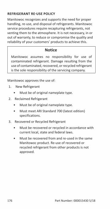
176 Part Number: 000015430 5/18
REFRIGERANT RE-USE POLICYManitowoc recognizes and supports the need for proper handling, re-use, and disposal of refrigerants. Manitowoc service procedures require recapturing refrigerants, not venting them to the atmosphere. It is not necessary, in or out of warranty, to reduce or compromise the quality and reliability of your customers’ products to achieve this.
Notice�Manitowoc assumes no responsibility for use of contaminated refrigerant. Damage resulting from the use of contaminated, recovered, or recycled refrigerant is the sole responsibility of the servicing company.
Manitowoc approves the use of:
1. New Refrigerant
• Must be of original nameplate type.
2. Reclaimed Refrigerant
• Must be of original nameplate type.
• Must meet ARI Standard 700 (latest edition) specifications.
3. Recovered or Recycled Refrigerant
• Must be recovered or recycled in accordance with current local, state and federal laws.
• Must be recovered from and re-used in the same Manitowoc product. Re-use of recovered or recycled refrigerant from other products is not approved.
Part Number: 000015430 5/18 177
4. Recovered refrigerant must come from a “contaminant-free” system. To decide whether the system is contaminant free, consider:
• Type(s) of previous failure(s)
• Whether the system was cleaned, evacuated and recharged properly following failure(s).
• Whether the system has been contaminated by this failure.
• Compressor motor burnouts and improper past service prevent refrigerant re-use.
Refer to “Determining Severity of Contamination” on page 185 to test for contamination.
5. “Substitute” or “Alternative” Refrigerant
• Must use only Manitowoc-approved alternative refrigerants.
• Must follow Manitowoc-published conversion procedures.
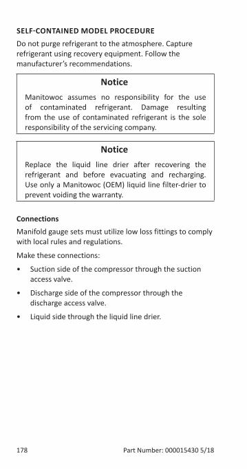
178 Part Number: 000015430 5/18
SELF-CONTAINED MODEL PROCEDURE Do not purge refrigerant to the atmosphere. Capture refrigerant using recovery equipment. Follow the manufacturer’s recommendations.
Notice�Manitowoc assumes no responsibility for the use of contaminated refrigerant. Damage resulting from the use of contaminated refrigerant is the sole responsibility of the servicing company.
Notice�Replace the liquid line drier after recovering the refrigerant and before evacuating and recharging. Use only a Manitowoc (OEM) liquid line filter-drier to prevent voiding the warranty.
ConnectionsManifold gauge sets must utilize low loss fittings to comply with local rules and regulations.
Make these connections:
• Suction side of the compressor through the suction access valve.
• Discharge side of the compressor through the discharge access valve.
• Liquid side through the liquid line drier.
Part Number: 000015430 5/18 179
Self-Contained Recovery/Evacuation1. Press the power button and cycle the ice machine off.
2. Install manifold gauge, scale and recovery unit or two-stage vacuum pump and open high, low and charging ports.
3. Perform recovery or evacuation:
A. Recovery: Operate the recovery unit as directed by the manufacturer’s instructions.
B. Evacuation prior to recharging: Pull the system down to 500 microns. Then, allow the pump to run for an additional half hour. Turn off the pump and perform a standing vacuum leak check.
4. Follow the Charging Procedures.
180 Part Number: 000015430 5/18
Self-Contained Charging Procedures
Notice�The charge is critical on all Manitowoc ice machines. Use a scale to ensure the proper charge is installed.
1. Be sure the ice machine is off.
2. Isolate the vacuum pump valve, low side and high side access valves from the refrigeration system. The refrigerant charging access valve remains open.
3. Open the refrigerant cylinder and add the proper refrigerant charge (shown on nameplate) through the iquid line drier.
4. Let the system “settle” for 2 to 3 minutes.
5. Isolate the refrigerant cylinder/charging hose from the liquid line drier.
6. Press the power button.
NOTE: Manifold gauge set must be removed properly to ensure that no refrigerant contamination or loss occurs.
7. Make sure that all of the vapor in the charging hoses is drawn into the ice machine before disconnecting the charging hoses.
A. Run the ice machine in freeze cycle.
B. Remove the high side low loss fitting from the liquid line filter drier.
C. Open the high and low side valves on the manifold gauge set. Any refrigerant in the lines will be pulled into the low side of the system.
D. Allow the pressures to equalize while the ice machine is in the freeze cycle.
E. Remove the hoses from the ice machine and install the caps.
Part Number: 000015430 5/18 181
REMOTE CONDENSER MODEL PROCEDURE
Refrigerant Recovery/EvacuationDo not purge refrigerant to the atmosphere. Capture refrigerant using recovery equipment. Follow the manufacturer’s recommendations.
Notice�Manitowoc Ice assumes no responsibility for the use of contaminated refrigerant. Damage resulting from the use of contaminated refrigerant is the sole responsibility of the servicing company.
Notice�Replace the liquid line drier after recovering the refrigerant and before evacuating and recharging. Use only a Manitowoc (O.E.M.) liquid line filter drier to prevent voiding the warranty.
182 Part Number: 000015430 5/18
CONNECTIONS
Notice�Recovery/evacuation of a remote system requires connections at four points for complete system evacuation.
Make these connections:
• Suction side of the compressor through the suction service valve.
• Discharge side of the compressor through the discharge service valve.
• Receiver outlet service valve, which evacuates the area between the check valve in the liquid line and the liquid line solenoid.
• Access (Schrader) valve on the discharge line quick-connect fitting, located on the outside of the compressor/evaporator compartment. This connection evacuates the condenser. Without it, the magnetic check valves would close when the pressure drops during evacuation, preventing complete evacuation of the condenser.
NOTE: Manitowoc recommends using an access valve core removal and installation tool on the discharge line quick-connect fitting. This permits access valve core removal. This allows for faster evacuation and charging, without removing the manifold gauge hose.
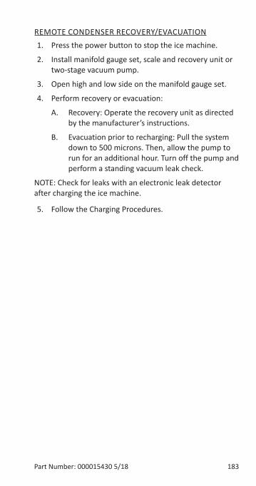
Part Number: 000015430 5/18 183
REMOTE CONDENSER RECOVERY/EVACUATION1. Press the power button to stop the ice machine.
2. Install manifold gauge set, scale and recovery unit or two-stage vacuum pump.
3. Open high and low side on the manifold gauge set.
4. Perform recovery or evacuation:
A. Recovery: Operate the recovery unit as directed by the manufacturer’s instructions.
B. Evacuation prior to recharging: Pull the system down to 500 microns. Then, allow the pump to run for an additional hour. Turn off the pump and perform a standing vacuum leak check.
NOTE: Check for leaks with an electronic leak detector after charging the ice machine.
5. Follow the Charging Procedures.
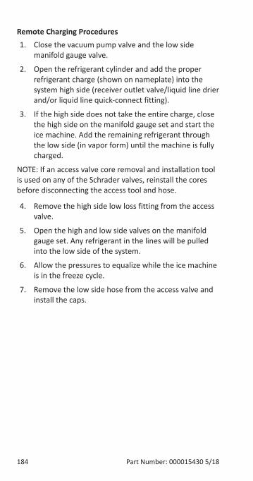
184 Part Number: 000015430 5/18
Remote Charging Procedures1. Close the vacuum pump valve and the low side
manifold gauge valve.
2. Open the refrigerant cylinder and add the proper refrigerant charge (shown on nameplate) into the system high side (receiver outlet valve/liquid line drier and/or liquid line quick-connect fitting).
3. If the high side does not take the entire charge, close the high side on the manifold gauge set and start the ice machine. Add the remaining refrigerant through the low side (in vapor form) until the machine is fully charged.
NOTE: If an access valve core removal and installation tool is used on any of the Schrader valves, reinstall the cores before disconnecting the access tool and hose.
4. Remove the high side low loss fitting from the access valve.
5. Open the high and low side valves on the manifold gauge set. Any refrigerant in the lines will be pulled into the low side of the system.
6. Allow the pressures to equalize while the ice machine is in the freeze cycle.
7. Remove the low side hose from the access valve and install the caps.
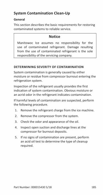
Part Number: 000015430 5/18 185
System Contamination Clean-UpGeneralThis section describes the basic requirements for restoring contaminated systems to reliable service.
Notice�Manitowoc Ice assumes no responsibility for the use of contaminated refrigerant. Damage resulting from the use of contaminated refrigerant is the sole responsibility of the servicing company.
DETERMINING SEVERITY OF CONTAMINATIONSystem contamination is generally caused by either moisture or residue from compressor burnout entering the refrigeration system.
Inspection of the refrigerant usually provides the first indication of system contamination. Obvious moisture or an acrid odor in the refrigerant indicates contamination.
If harmful levels of contamination are suspected, perform the following procedure.
1. Remove the refrigerant charge from the ice machine.
2. Remove the compressor from the system.
3. Check the odor and appearance of the oil.
4. Inspect open suction and discharge lines at the compressor for burnout deposits.
5. If no signs of contamination are present, perform an acid oil test to determine the type of cleanup required.
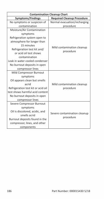
186 Part Number: 000015430 5/18
Contamination Cleanup ChartSymptoms/Findings Required Cleanup Procedure
No symptoms or suspicion of contamination
Normal evacuation/recharging procedure
Moisture/Air Contamination symptoms
Refrigeration system open to atmosphere for longer than
15 minutesRefrigeration test kit and/
or acid oil test shows contamination
Leak in water cooled condenserNo burnout deposits in open
compressor lines
Mild contamination cleanup procedure
Mild Compressor Burnout symptoms
Oil appears clean but smells acrid
Refrigeration test kit or acid oil test shows harmful acid content
No burnout deposits in open compressor lines
Mild contamination cleanup procedure
Severe Compressor Burnout symptoms
Oil is discolored, acidic, and smells acrid
Burnout deposits found in the compressor, lines, and other
components
Severe contamination cleanup procedure
Part Number: 000015430 5/18 187
CLEANUP PROCEDURE
Mild System Contamination1. Replace any failed components.
2. If the compressor is good, change the oil.
3. Replace the liquid line drier.
NOTE: If the contamination is from moisture, use heat lamps during evacuation. Position them at the compressor, condenser and evaporator prior to evacuation. Do not position heat lamps too close to plastic components, or they may melt or warp.
Important�Dry nitrogen is required for this procedure to prevent refrigerant release.
188 Part Number: 000015430 5/18
4. Follow the normal evacuation procedure, except replace the evacuation step with the following:
A. Pull vacuum to 1000 microns. Break the vacuum with dry nitrogen and sweep the system. Pressurize to a minimum of 5 psig (35 kPa, .35 bar).
B. Pull vacuum to 500 microns. Break the vacuum with dry nitrogen and sweep the system. Pressurize to a minimum of 5 psig (35 kPa, .35 bar).
C. Change the vacuum pump oil.
D. Pull vacuum to 500 microns. Run the vacuum pump for 1/2 hour on self-contained models, 1 hour on remotes.
E. You may perform a standing vacuum test to make a preliminary leak check. You should use an electronic leak detector after system charging to be sure there are no leaks.
5. Charge the system with the proper refrigerant to the nameplate charge.
6. Operate the ice machine.
Part Number: 000015430 5/18 189
Severe System Contamination1. Remove the refrigerant charge.
2. Remove the compressor and inspect the refrigeration lines. If burnout deposits are found, install a new harvest valve, replace the manifold strainer, TXV and harvest pressure regulating valve.
3. Wipe away any burnout deposits from suction and discharge lines at compressor.
4. Sweep through the open system with dry nitrogen.
Important�Refrigerant sweeps are not recommended, as they release CFCs into the atmosphere.
5. Install a new compressor and new start components.
6. Install a suction line filter-drier with acid and moisture removal capability. Place the filter drier as close to the compressor as possible.
7. Install an access valve at the inlet of the suction line drier.
8. Install a new liquid line drier.
Important�Dry nitrogen is required for this procedure. This will prevent CFC release.
190 Part Number: 000015430 5/18
9. Follow the normal evacuation procedure, except replace the evacuation step with the following:A. Pull vacuum to 1000 microns. Break the vacuum
with dry nitrogen and sweep the system. Pressurize to a minimum of 5 psig (35 kPa, .35 bar).
B. Change the vacuum pump oil.C. Pull vacuum to 500 microns. Break the vacuum
with dry nitrogen and sweep the system. Pressurize to a minimum of 5 psig (35 kPa, .35 bar).
D. Change the vacuum pump oil.E. Pull vacuum to 500 microns. Run the vacuum
pump for 1/2 hour on self-contained models, 1 hour on remotes.
NOTE: You may perform a standing vacuum test to make a preliminary leak check. You should use an electronic leak detector after system charging to be sure there are no leaks.
10. Charge the system with the proper refrigerant to the nameplate charge.
11. Operate the ice machine for one hour. Then, check the pressure drop across the suction line filter-drier.
A. If the pressure drop is less than 1 psig (7 kPa, .07 bar), the filter-drier should be adequate for complete cleanup.
B. If the pressure drop exceeds 1 psig (7 kPa, .07 bar), change the suction line filter-drier and the liquid line drier. Repeat until the pressure drop is acceptable.
12. Operate the ice machine for 48-72 hours. Then remove the suction line drier and change the liquid line drier.
13. Follow normal evacuation procedures.
Part Number: 000015430 5/18 191
LIQUID LINE FILTER-DRIERSThe filter-driers used on Manitowoc ice machines are manufactured to Manitowoc specifications and have an access fitting for charging with refrigerant. A Manitowoc drier also has dirt-retaining filtration, with fiberglass filters on both the inlet and outlet ends. This is very important because ice machines have a back-flushing action that takes place during every Harvest cycle.
A Manitowoc filter-drier has high moisture and acid removal capability.
The size of the filter-drier is important. The refrigerant charge is critical. Using an improperly sized filter-drier will cause the ice machine to be improperly charged with refrigerant.
Important�Driers are covered as a warranty part. The drier must be replaced any time the system is opened for repairs.
192 Part Number: 000015430 5/18
REPLACING PRESSURE CONTROLS WITHOUT REMOVING REFRIGERANT CHARGEThis procedure reduces repair time and cost. Use it when any of the following components require replacement, and the refrigeration system is operational and leak-free.
• Fan cycle control (air cooled only)
• Water regulating valve (water cooled only)
• High pressure cut-out control
• High side service valve
1. Disconnect power to the ice machine.
2. Follow all manufacturer’s instructions supplied with the pinch-off tool. Position the pinch-off tool around the tubing as far from the pressure control as feasible. Clamp down on the tubing until the pinch-off is complete.
nWarningDo not unsolder a defective component. Cut it out of the system. Do not remove the pinch-off tool until the new component is securely in place.
Cut the tubing of the defective component with a small tubing cutter.
3. Solder the replacement component in place. Allow the solder joint to cool.
4. Remove the pinch-off tool.
5. Re-round the tubing. The pressure control will operate normally once the tubing is re-rounded. Tubing may not re-round 100%.
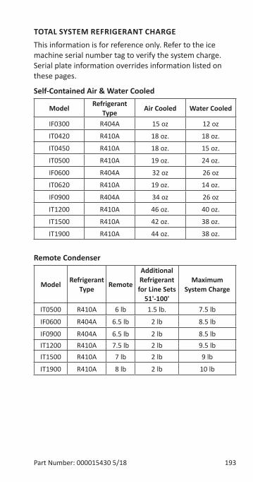
Part Number: 000015430 5/18 193
TOTAL SYSTEM REFRIGERANT CHARGEThis information is for reference only. Refer to the ice machine serial number tag to verify the system charge. Serial plate information overrides information listed on these pages.
Self-Contained Air & Water Cooled
Model Refrigerant Type Air Cooled Water Cooled
IF0300 R404A 15 oz 12 oz
IT0420 R410A 18 oz. 18 oz.
IT0450 R410A 18 oz. 15 oz.
IT0500 R410A 19 oz. 24 oz.
IF0600 R404A 32 oz 26 oz
IT0620 R410A 19 oz. 14 oz.
IF0900 R404A 34 oz 26 oz
IT1200 R410A 46 oz. 40 oz.
IT1500 R410A 42 oz. 38 oz.
IT1900 R410A 44 oz. 38 oz.
Remote Condenser
Model Refrigerant Type Remote
Additional Refrigerant for Line Sets
51'-100'
Maximum System Charge
IT0500 R410A 6 lb 1.5 lb. 7.5 lb
IF0600 R404A 6.5 lb 2 lb 8.5 lb
IF0900 R404A 6.5 lb 2 lb 8.5 lbIT1200 R410A 7.5 lb 2 lb 9.5 lbIT1500 R410A 7 lb 2 lb 9 lb
IT1900 R410A 8 lb 2 lb 10 lb

194 Part Number: 000015430 5/18
THIS PAGE INTENTIONALLY LEFT BLANK
Part Number: 000015430 5/18 195
Cycle Times/24-Hour Ice Production/Refrigerant Pressure ChartsThese charts are used as guidelines to verify correct ice machine operation.
Accurate collection of data is essential to obtain the correct diagnosis.
• Production and cycle times are for dice cube - Half dice cube cycle times can be 2 - 3 minutes faster, depending on model and ambient temperature.
• Regular cube production derate is 7%.
• Ice production checks that are within 10% of the chart are considered normal. This is due to variances in water and air temperature. Actual temperatures will seldom match the chart exactly.
• Refer to “Symptom #2 - Freeze Cycle Refrigeration System Operational Analysis Tables” on page 82 for the list of data that must be collected for refrigeration diagnostics.
• Zero out manifold gauge set before obtaining pressure readings to avoid mis-diagnosis.
• Discharge and suction pressure are highest at the beginning of the cycle. Suction pressure will drop throughout the cycle. Verify the pressures are within the range indicated.
• Record beginning of freeze cycle suction pressure one minute after water pump energizes.
• 50 Hz dice and half dice production derate is 12%.
• 50 Hz regular cube total production derate is 14%.
Charts
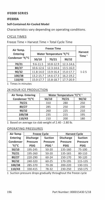
196 Part Number: 000015430 5/18
IF0300 SERIES
IF0300ASelf-Contained Air-Cooled Model
Characteristics vary depending on operating conditions.
CYCLE TIMESFreeze Time + Harvest Time = Total Cycle Time
Air Temp. Entering
Condenser °F/°C
Freeze TimeHarvest Time 1Water Temperature °F/°C
50/10 70/21 90/3270/21 9.6-11.5 10.8-12.9 12.3-14.6
1-2.580/27 10.6-12.6 12.3-14.6 13.5-16.090/32 11.8-14.0 13.9-16.4 15.0-17.7
100/38 13.2-15.7 14.6-17.3 16.2-19.2110/43 15.0-17.7 15.8-18.7 17.7-20.9
1 Times in minutes
24 HOUR ICE PRODUCTIONAir Temp. Entering
Condenser °F/°CWater Temperature °F/°C 1
50/10 70/21 90/3270/21 310 280 25080/27 285 250 23090/32 260 225 210
100/38 235 215 195110/43 210 200 180
1 Based on average ice slab weight of 2.40 - 2.80 lb.
OPERATING PRESSURESAir Temp Entering
Condenser °F/°C
Freeze Cycle Harvest CycleDischarge Pressure
PSIG
Suction Pressure
PSIG 1
Discharge Pressure
PSIG
Suction Pressure
PSIG50/10 195-245 50-20 135-160 75-10070/21 195-260 50-20 135-165 80-11080/27 220-290 60-24 150-170 90-12090/32 240-320 60-25 170-195 115-135
100/38 285-370 70-28 200-220 130-155110/43 330-415 78-32 230-250 150-175
1 Suction pressure drops gradually throughout the freeze cycle
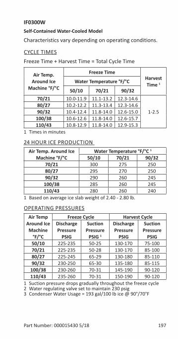
Part Number: 000015430 5/18 197
IF0300WSelf-Contained Water-Cooled Model
Characteristics vary depending on operating conditions.
CYCLE TIMESFreeze Time + Harvest Time = Total Cycle Time
Air Temp. Around Ice
Machine °F/°C
Freeze TimeHarvest Time 1Water Temperature °F/°C
50/10 70/21 90/3270/21 10.0-11.9 11.1-13.2 12.3-14.6
1-2.580/27 10.2-12.2 11.3-13.4 12.3-14.690/32 10.4-12.4 11.8-14.0 12.6-15.0
100/38 10.6-12.6 11.8-14.0 12.6-15.7110/43 10.8-12.9 11.8-14.0 12.9-15.3
1 Times in minutes
24 HOUR ICE PRODUCTION Air Temp. Around Ice
Machine °F/°CWater Temperature °F/°C 1
50/10 70/21 90/3270/21 300 275 25080/27 295 270 25090/32 290 260 245
100/38 285 260 245110/43 280 260 240
1 Based on average ice slab weight of 2.40 - 2.80 lb.
OPERATING PRESSURESAir Temp
Around Ice Machine
°F/°C
Freeze Cycle Harvest CycleDischarge Pressure
PSIG
Suction Pressure
PSIG 1
Discharge Pressure
PSIG
Suction Pressure
PSIG50/10 225-235 50-25 130-170 75-10070/21 225-235 50-28 130-170 85-10080/27 225-245 65-29 130-180 85-11090/32 230-250 65-30 135-180 85-115
100/38 230-260 70-31 145-190 90-120110/43 235-260 70-31 150-190 90-120
1 Suction pressure drops gradually throughout the freeze cycle2 Water regulating valve set to maintain 230 psig3 Condenser Water Usage = 193 gal/100 lb ice @ 90°/70°F

198 Part Number: 000015430 5/18
IT0420 SERIES
IT0420A
Self-Contained Air-Cooled ModelCharacteristics vary depending on operating conditions.
CYCLE TIMESFreeze Time + Harvest Time = Total Cycle Time
Air Temp. Entering
Condenser °F/°C
Freeze TimeHarvest Time 1Water Temperature °F/°C
50/10 70/21 90/3270/21 9.9-10.4 10.4-12.2 13.1-15.3
1-2.580/27 9.9-11.6 11.7-13.7 13.6-15.890/32 10.7-12.5 11.7-13.7 13.8-16.1
100/38 12.1-14.1 13.1-15.3 14.3-16.6110/43 12.9-15.0 14.0-16.3 14.8-17.2
1 Times in minutes
24 HOUR ICE PRODUCTIONAir Temp. Entering
Condenser °F/°CWater Temperature °F/°C 1
50/10 70/21 90/3270/21 470 410 33580/27 430 370 32590/32 400 375 320
100/38 360 335 310110/43 340 315 300
1 Based on average ice slab weight of 3.40 - 3.90 lb.
OPERATING PRESSURESAir Temp Entering
Condenser °F/°C
Freeze Cycle Harvest CycleDischarge Pressure
PSIG
Suction Pressure
PSIG 1
Discharge Pressure
PSIG
Suction Pressure
PSIG50/10 270-340 60-30 145-170 115-13570/21 280-340 70-36 160-190 120-14080/27 335-365 70-38 180-205 120-16090/32 350-410 80-40 185-210 180-210
100/38 460-500 80-45 265-290 180-210110/43 460-520 80-45 270-290 180-220
1 Suction pressure drops gradually throughout the freeze cycle

Part Number: 000015430 5/18 199
IT0420W
Self-Contained Water-Cooled ModelCharacteristics vary depending on operating conditions.
CYCLE TIMESFreeze Time + Harvest Time = Total Cycle Time
Air Temp. Around Ice
Machine °F/°C
Freeze TimeHarvest Time 1Water Temperature °F/°C
50/10 70/21 90/3270/21 9.3-10.8 10.2-11.9 11.6-13.5
1-2.580/27 9.5-11.1 10.4-12.2 11.7-13.790/32 9.8-11.4 10.7-12.5 11.9-13.9
100/38 10.0-11.7 11.1-12.9 12.5-14.5110/43 10.3-12.0 11.4-13.3 12.3-14.3
1 Times in minutes
24 HOUR ICE PRODUCTION Air Temp. Around Ice
Machine °F/°CWater Temperature °F/°C 1
50/10 70/21 90/3270/21 455 420 37580/27 445 410 37090/32 435 400 365
100/38 425 390 350110/43 415 380 355
1 Based on average ice slab weight of 3.40 - 3.90 lb.
OPERATING PRESSURESAir Temp
Around Ice Machine
°F/°C
Freeze Cycle Harvest CycleDischarge Pressure
PSIG
Suction Pressure
PSIG 1
Discharge Pressure
PSIG
Suction Pressure
PSIG50/10 330 70-38 155-180 120-14570/21 330-340 70-39 175-195 130-15080/27 330-345 70-40 175-200 130-15090/32 330-345 75-40 175-200 130-150
100/38 330-350 75-44 175-200 130-150110/43 330-350 75-45 175-200 135-150
1 Suction pressure drops gradually throughout the freeze cycle2 Water regulating valve set to maintain 330 psig
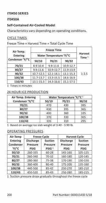
200 Part Number: 000015430 5/18
IT0450 SERIES
IT0450A
Self-Contained Air-Cooled ModelCharacteristics vary depending on operating conditions.
CYCLE TIMESFreeze Time + Harvest Time = Total Cycle Time
Air Temp. Entering
Condenser °F/°C
Freeze TimeHarvest Time 1Water Temperature °F/°C
50/10 70/21 90/3270/21 8.9-10.4 9.9-11.6 10.9-12.7
1-2.580/27 9.9-11.6 10.9-12.7 11.9-13.990/32 10.7-12.5 12.1-14.1 13.1-15.3
100/38 11.7-13.7 13.3-15.5 14.6-16.9110/43 13.1-15.3 14.3-16.6 15.1-17.5
1 Times in minutes
24 HOUR ICE PRODUCTIONAir Temp. Entering
Condenser °F/°CWater Temperature °F/°C 1
50/10 70/21 90/3270/21 470 430 39580/27 430 395 36590/32 400 360 335
100/38 370 330 305110/43 335 310 295
1 Based on average ice slab weight of 3.40 - 3.90 lb.
OPERATING PRESSURESAir Temp Entering
Condenser °F/°C
Freeze Cycle Harvest CycleDischarge Pressure
PSIG
Suction Pressure
PSIG 1
Discharge Pressure
PSIG
Suction Pressure
PSIG50/10 260-335 60-28 145-160 105-12570/21 260-340 70-32 160-180 120-14580/27 280-360 75-38 170-190 130-15090/32 360-400 80-40 175-200 135-160
100/38 440-500 85-42 250-270 185-210110/43 450-520 85-43 250-280 185-215
1 Suction pressure drops gradually throughout the freeze cycle
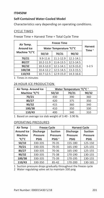
Part Number: 000015430 5/18 201
IT0450W
Self-Contained Water-Cooled ModelCharacteristics vary depending on operating conditions.
CYCLE TIMESFreeze Time + Harvest Time = Total Cycle Time
Air Temp. Around Ice
Machine °F/°C
Freeze TimeHarvest Time 1Water Temperature °F/°C
50/10 70/21 90/3270/21 9.9-11.6 11.1-12.9 12.1-14.1
1-2.580/27 10.2-11.9 11.6-13.5 12.5-14.590/32 10.3-12.0 12.1-14.1 12.9-15.0
100/38 10.4-12.2 12.5-14.5 13.3-15.5110/43 10.7-12.5 12.9-15.0 14.3-16.6
1 Times in minutes
24 HOUR ICE PRODUCTION Air Temp. Around Ice
Machine °F/°CWater Temperature °F/°C 1
50/10 70/21 90/3270/21 430 390 36080/27 420 375 35090/32 415 360 340
100/38 410 350 330110/43 400 340 310
1 Based on average ice slab weight of 3.40 - 3.90 lb.
OPERATING PRESSURESAir Temp
Around Ice Machine
°F/°C
Freeze Cycle Harvest CycleDischarge Pressure
PSIG
Suction Pressure
PSIG 1
Discharge Pressure
PSIG
Suction Pressure
PSIG50/10 330-335 70-35 155-180 125-15070/21 330-335 70-35 165-190 125-15580/27 330-335 70-36 165-190 125-15590/32 330-335 75-38 170-190 130-155
100/38 330-335 75-39 170-195 130-155110/43 330-350 85-42 170-200 130-165
1 Suction pressure drops gradually throughout the freeze cycle2 Water regulating valve set to maintain 330 psig
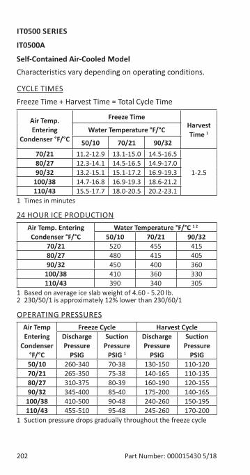
202 Part Number: 000015430 5/18
IT0500 SERIES
IT0500A
Self-Contained Air-Cooled ModelCharacteristics vary depending on operating conditions.
CYCLE TIMESFreeze Time + Harvest Time = Total Cycle Time
Air Temp. Entering
Condenser °F/°C
Freeze TimeHarvest Time 1Water Temperature °F/°C
50/10 70/21 90/3270/21 11.2-12.9 13.1-15.0 14.5-16.5
1-2.580/27 12.3-14.1 14.5-16.5 14.9-17.090/32 13.2-15.1 15.1-17.2 16.9-19.3
100/38 14.7-16.8 16.9-19.3 18.6-21.2110/43 15.5-17.7 18.0-20.5 20.2-23.1
1 Times in minutes
24 HOUR ICE PRODUCTIONAir Temp. Entering
Condenser °F/°CWater Temperature °F/°C 1 2
50/10 70/21 90/3270/21 520 455 41580/27 480 415 40590/32 450 400 360
100/38 410 360 330110/43 390 340 305
1 Based on average ice slab weight of 4.60 - 5.20 lb.2 230/50/1 is approximately 12% lower than 230/60/1
OPERATING PRESSURESAir Temp Entering
Condenser °F/°C
Freeze Cycle Harvest CycleDischarge Pressure
PSIG
Suction Pressure
PSIG 1
Discharge Pressure
PSIG
Suction Pressure
PSIG50/10 260-340 70-38 130-150 110-12070/21 265-350 75-38 140-165 110-13580/27 310-375 80-39 160-190 120-15590/32 345-400 85-40 175-200 140-165
100/38 410-500 90-48 240-260 150-195110/43 455-510 95-48 245-260 170-200
1 Suction pressure drops gradually throughout the freeze cycle

Part Number: 000015430 5/18 203
IT0500W
Self-Contained Water-Cooled ModelCharacteristics vary depending on operating conditions.
CYCLE TIMESFreeze Time + Harvest Time = Total Cycle Time
Air Temp. Around Ice
Machine °F/°C
Freeze TimeHarvest Time 1Water Temperature °F/°C
50/10 70/21 90/3270/21 11.7-13.5 13.9-15.9 15.9-18.2
1-2.580/27 12.3-14.1 14.5-16.5 16.4-18.790/32 12.4-14.3 15.1-17.2 16.9-19.3
100/38 12.6-14.4 15.5-17.7 17.4-19.9110/43 12.9-14.8 15.9-18.2 18.0-20.5
1 Times in minutes
24 HOUR ICE PRODUCTION Air Temp. Around Ice
Machine °F/°CWater Temperature °F/°C 1
50/10 70/21 90/3270/21 500 430 38080/27 480 415 37090/32 475 400 360
100/38 470 390 350110/43 460 380 340
1 Based on average ice slab weight of 4.60 - 5.20 lb.
OPERATING PRESSURESAir Temp
Around Ice Machine
°F/°C
Freeze Cycle Harvest CycleDischarge Pressure
PSIG
Suction Pressure
PSIG 1
Discharge Pressure
PSIG
Suction Pressure
PSIG50/10 330 75-38 165-175 135-15070/21 330-335 75-40 165-180 135-15580/27 330-350 80-41 180-190 140-16090/32 330-335 80-42 180-190 145-160
100/38 330-335 80-43 180-190 145-160110/43 330-350 85-43 185-210 150-175
1 Suction pressure drops gradually throughout the freeze cycle2 Water regulating valve set to maintain 230 psig
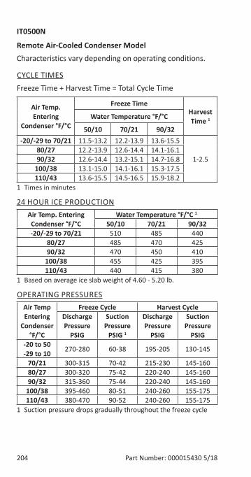
204 Part Number: 000015430 5/18
IT0500N
Remote Air-Cooled Condenser ModelCharacteristics vary depending on operating conditions.
CYCLE TIMESFreeze Time + Harvest Time = Total Cycle Time
Air Temp. Entering
Condenser °F/°C
Freeze TimeHarvest Time 1Water Temperature °F/°C
50/10 70/21 90/32-20/-29 to 70/21 11.5-13.2 12.2-13.9 13.6-15.5
1-2.580/27 12.2-13.9 12.6-14.4 14.1-16.190/32 12.6-14.4 13.2-15.1 14.7-16.8
100/38 13.1-15.0 14.1-16.1 15.3-17.5110/43 13.6-15.5 14.5-16.5 15.9-18.2
1 Times in minutes
24 HOUR ICE PRODUCTIONAir Temp. Entering
Condenser °F/°CWater Temperature °F/°C 1
50/10 70/21 90/32-20/-29 to 70/21 510 485 440
80/27 485 470 42590/32 470 450 410
100/38 455 425 395110/43 440 415 380
1 Based on average ice slab weight of 4.60 - 5.20 lb.
OPERATING PRESSURESAir Temp Entering
Condenser °F/°C
Freeze Cycle Harvest CycleDischarge Pressure
PSIG
Suction Pressure
PSIG 1
Discharge Pressure
PSIG
Suction Pressure
PSIG-20 to 50 -29 to 10 270-280 60-38 195-205 130-145
70/21 300-315 70-42 215-230 145-16080/27 300-320 75-42 220-240 145-16090/32 315-360 75-44 220-240 145-160
100/38 395-460 80-51 240-260 155-175110/43 380-470 90-52 240-260 155-175
1 Suction pressure drops gradually throughout the freeze cycle
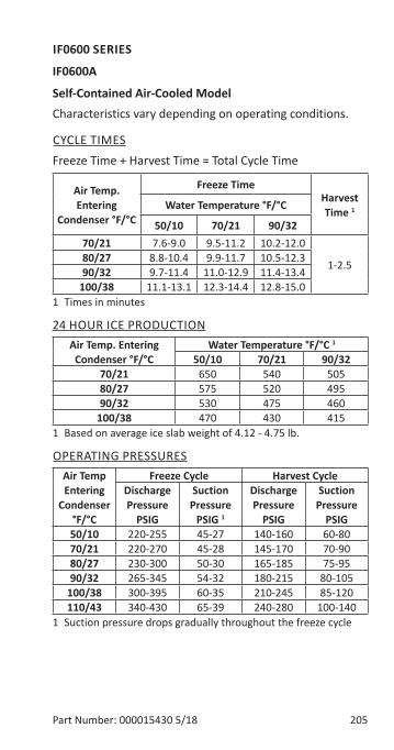
Part Number: 000015430 5/18 205
IF0600 SERIES
IF0600A
Self-Contained Air-Cooled ModelCharacteristics vary depending on operating conditions.
CYCLE TIMESFreeze Time + Harvest Time = Total Cycle Time
Air Temp. Entering
Condenser °F/°C
Freeze TimeHarvest Time 1Water Temperature °F/°C
50/10 70/21 90/3270/21 7.6-9.0 9.5-11.2 10.2-12.0
1-2.580/27 8.8-10.4 9.9-11.7 10.5-12.390/32 9.7-11.4 11.0-12.9 11.4-13.4
100/38 11.1-13.1 12.3-14.4 12.8-15.01 Times in minutes
24 HOUR ICE PRODUCTIONAir Temp. Entering
Condenser °F/°CWater Temperature °F/°C 1
50/10 70/21 90/3270/21 650 540 50580/27 575 520 49590/32 530 475 460
100/38 470 430 4151 Based on average ice slab weight of 4.12 - 4.75 lb.
OPERATING PRESSURESAir Temp Entering
Condenser °F/°C
Freeze Cycle Harvest CycleDischarge Pressure
PSIG
Suction Pressure
PSIG 1
Discharge Pressure
PSIG
Suction Pressure
PSIG50/10 220-255 45-27 140-160 60-8070/21 220-270 45-28 145-170 70-9080/27 230-300 50-30 165-185 75-9590/32 265-345 54-32 180-215 80-105
100/38 300-395 60-35 210-245 85-120110/43 340-430 65-39 240-280 100-140
1 Suction pressure drops gradually throughout the freeze cycle
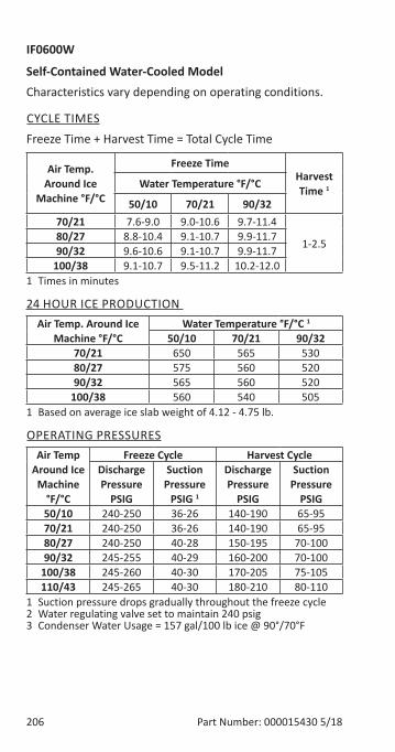
206 Part Number: 000015430 5/18
IF0600W
Self-Contained Water-Cooled ModelCharacteristics vary depending on operating conditions.
CYCLE TIMESFreeze Time + Harvest Time = Total Cycle Time
Air Temp. Around Ice
Machine °F/°C
Freeze TimeHarvest Time 1Water Temperature °F/°C
50/10 70/21 90/3270/21 7.6-9.0 9.0-10.6 9.7-11.4
1-2.580/27 8.8-10.4 9.1-10.7 9.9-11.790/32 9.6-10.6 9.1-10.7 9.9-11.7
100/38 9.1-10.7 9.5-11.2 10.2-12.01 Times in minutes
24 HOUR ICE PRODUCTION Air Temp. Around Ice
Machine °F/°CWater Temperature °F/°C 1
50/10 70/21 90/3270/21 650 565 53080/27 575 560 52090/32 565 560 520
100/38 560 540 5051 Based on average ice slab weight of 4.12 - 4.75 lb.
OPERATING PRESSURESAir Temp
Around Ice Machine
°F/°C
Freeze Cycle Harvest CycleDischarge Pressure
PSIG
Suction Pressure
PSIG 1
Discharge Pressure
PSIG
Suction Pressure
PSIG50/10 240-250 36-26 140-190 65-9570/21 240-250 36-26 140-190 65-9580/27 240-250 40-28 150-195 70-10090/32 245-255 40-29 160-200 70-100
100/38 245-260 40-30 170-205 75-105110/43 245-265 40-30 180-210 80-110
1 Suction pressure drops gradually throughout the freeze cycle2 Water regulating valve set to maintain 240 psig3 Condenser Water Usage = 157 gal/100 lb ice @ 90°/70°F
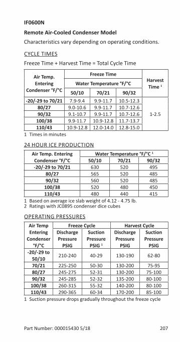
Part Number: 000015430 5/18 207
IF0600N
Remote Air-Cooled Condenser ModelCharacteristics vary depending on operating conditions.
CYCLE TIMESFreeze Time + Harvest Time = Total Cycle Time
Air Temp. Entering
Condenser °F/°C
Freeze TimeHarvest Time 1Water Temperature °F/°C
50/10 70/21 90/32-20/-29 to 70/21 7.9-9.4 9.9-11.7 10.5-12.3
1-2.580/27 9.0-10.6 9.9-11.7 10.7-12.690/32 9.1-10.7 9.9-11.7 10.7-12.6
100/38 9.9-11.7 10.9-12.8 11.7-13.7110/43 10.9-12.8 12.0-14.0 12.8-15.0
1 Times in minutes
24 HOUR ICE PRODUCTIONAir Temp. Entering
Condenser °F/°CWater Temperature °F/°C 1
50/10 70/21 90/32-20/-29 to 70/21 630 520 495
80/27 565 520 48590/32 560 520 485
100/38 520 480 450110/43 480 440 415
1 Based on average ice slab weight of 4.12 - 4.75 lb.2 Ratings with JC0895 condenser dice cubes
OPERATING PRESSURESAir Temp Entering
Condenser °F/°C
Freeze Cycle Harvest CycleDischarge Pressure
PSIG
Suction Pressure
PSIG 1
Discharge Pressure
PSIG
Suction Pressure
PSIG-20/-29 to
50/10 210-240 40-29 130-190 62-80
70/21 225-250 50-30 130-200 75-9580/27 245-275 52-31 130-200 75-10090/32 245-285 52-32 135-200 80-100
100/38 260-315 55-32 140-200 80-100110/43 290-365 60-34 170-200 85-100
1 Suction pressure drops gradually throughout the freeze cycle

208 Part Number: 000015430 5/18
IT0620 SERIES
IT0620A
Self-Contained Air-Cooled ModelCharacteristics vary depending on operating conditions.
CYCLE TIMESFreeze Time + Harvest Time = Total Cycle Time
Air Temp. Entering
Condenser °F/°C
Freeze TimeHarvest Time 1Water Temperature °F/°C
50/10 70/21 90/3270/21 10.3-11.9 11.2-12.9 11.6-13.3
1-2.580/27 11.2-12.9 12.3-14.1 12.7-14.690/32 12.0-13.8 13.2-15.1 13.7-15.7
100/38 13.2-15.1 14.7-16.8 15.3-17.5110/43 13.9-15.9 15.5-17.7 16.2-18.5
1 Times in minutes
24 HOUR ICE PRODUCTIONAir Temp. Entering
Condenser °F/°CWater Temperature °F/°C 1
50/10 70/21 90/3270/21 560 520 50580/27 520 480 46590/32 490 450 435
100/38 450 410 395110/43 430 390 375
1 Based on average ice slab weight of 4.60 - 5.20 lb.
OPERATING PRESSURESAir Temp Entering
Condenser °F/°C
Freeze Cycle Harvest CycleDischarge Pressure
PSIG
Suction Pressure
PSIG 1
Discharge Pressure
PSIG
Suction Pressure
PSIG50/10 255-335 60-30 155-170 105-13070/21 270-340 70-30 170-200 115-13580/27 270-340 75-35 170-200 115-13590/32 350-405 75-38 205-240 140-155
100/38 450-520 90-40 290-340 160-235110/43 450-540 90-42 290-340 160-235
1 Suction pressure drops gradually throughout the freeze cycle

Part Number: 000015430 5/18 209
IT0620W
Self-Contained Water-Cooled ModelCharacteristics vary depending on operating conditions.
CYCLE TIMESFreeze Time + Harvest Time = Total Cycle Time
Air Temp. Around Ice
Machine °F/°C
Freeze TimeHarvest Time 1Water Temperature °F/°C
50/10 70/21 90/3270/21 11.0-12.6 12.3-14.1 13.6-15.5
1-2.580/27 10.8-12.4 12.7-14.6 14.1-16.190/32 10.9-12.5 13.2-15.1 14.7-16.8
100/38 11.0-12.6 13.6-15.5 15.1-17.2110/43 11.5-13.2 13.9-15.9 15.5-17.7
1 Times in minutes
24 HOUR ICE PRODUCTION Air Temp. Around Ice
Machine °F/°CWater Temperature °F/°C 1
50/10 70/21 90/3270/21 530 480 44080/27 540 465 42590/32 535 450 410
100/38 530 440 400110/43 510 430 390
1 Based on average ice slab weight of 4.60 - 5.20 lb.
OPERATING PRESSURESAir Temp
Around Ice Machine
°F/°C
Freeze Cycle Harvest CycleDischarge Pressure
PSIG
Suction Pressure
PSIG 1
Discharge Pressure
PSIG
Suction Pressure
PSIG50/10 330 60-32 155-180 115-14070/21 330-335 60-34 160-200 125-14580/27 330-340 60-34 160-200 125-14590/32 330-340 65-35 170-200 125-150
100/38 330-345 75-41 170-200 125-150110/43 330-355 80-42 170-200 125-150
1 Suction pressure drops gradually throughout the freeze cycle2 Water regulating valve set to maintain 330 psig
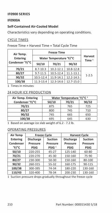
210 Part Number: 000015430 5/18
IF0900 SERIES
IF0900A
Self-Contained Air-Cooled ModelCharacteristics vary depending on operating conditions.
CYCLE TIMESFreeze Time + Harvest Time = Total Cycle Time
Air Temp. Entering
Condenser °F/°C
Freeze TimeHarvest Time 1Water Temperature °F/°C
50/10 70/21 90/3270/21 8.7-10.3 10.2-12.1 10.8-12.8
1-2.580/27 9.7-11.5 10.5-12.4 11.1-13.190/32 10.5-12.4 11.9-14.1 12.2-14.5
100/38 11.3-13.4 12.3-14.6 12.7-15.01 Times in minutes
24 HOUR ICE PRODUCTIONAir Temp. Entering
Condenser °F/°CWater Temperature °F/°C 1
50/10 70/21 90/3270/21 875 765 72580/27 800 745 71090/32 745 665 650
100/38 695 645 6301 Based on average ice slab weight of 6.2 - 7.2 lb.
OPERATING PRESSURESAir Temp Entering
Condenser °F/°C
Freeze Cycle Harvest CycleDischarge Pressure
PSIG
Suction Pressure
PSIG 1
Discharge Pressure
PSIG
Suction Pressure
PSIG50/10 220-255 45-27 125-140 60-8070/21 220-270 45-30 150-160 75-9080/27 230-300 50-30 150-160 80-10090/32 260-315 55-32 160-175 90-115
100/38 300-395 74-34 180-220 130-160110/43 320-400 78-34 200-230 130-160
1 Suction pressure drops gradually throughout the freeze cycle
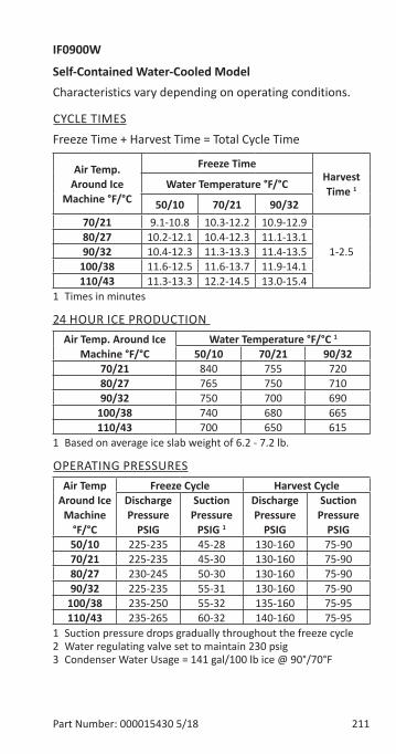
Part Number: 000015430 5/18 211
IF0900W
Self-Contained Water-Cooled ModelCharacteristics vary depending on operating conditions.
CYCLE TIMESFreeze Time + Harvest Time = Total Cycle Time
Air Temp. Around Ice
Machine °F/°C
Freeze TimeHarvest Time 1Water Temperature °F/°C
50/10 70/21 90/3270/21 9.1-10.8 10.3-12.2 10.9-12.9
1-2.580/27 10.2-12.1 10.4-12.3 11.1-13.190/32 10.4-12.3 11.3-13.3 11.4-13.5
100/38 11.6-12.5 11.6-13.7 11.9-14.1110/43 11.3-13.3 12.2-14.5 13.0-15.4
1 Times in minutes
24 HOUR ICE PRODUCTION Air Temp. Around Ice
Machine °F/°CWater Temperature °F/°C 1
50/10 70/21 90/3270/21 840 755 72080/27 765 750 71090/32 750 700 690
100/38 740 680 665110/43 700 650 615
1 Based on average ice slab weight of 6.2 - 7.2 lb.
OPERATING PRESSURESAir Temp
Around Ice Machine
°F/°C
Freeze Cycle Harvest CycleDischarge Pressure
PSIG
Suction Pressure
PSIG 1
Discharge Pressure
PSIG
Suction Pressure
PSIG50/10 225-235 45-28 130-160 75-9070/21 225-235 45-30 130-160 75-9080/27 230-245 50-30 130-160 75-9090/32 225-235 55-31 130-160 75-90
100/38 235-250 55-32 135-160 75-95110/43 235-265 60-32 140-160 75-95
1 Suction pressure drops gradually throughout the freeze cycle2 Water regulating valve set to maintain 230 psig3 Condenser Water Usage = 141 gal/100 lb ice @ 90°/70°F

212 Part Number: 000015430 5/18
IF0900N
Remote Air-Cooled Condenser ModelCharacteristics vary depending on operating conditions.
CYCLE TIMESFreeze Time + Harvest Time = Total Cycle Time
Air Temp. Entering
Condenser °F/°C
Freeze TimeHarvest Time 1Water Temperature °F/°C
50/10 70/21 90/32-20/-29 to 70/21 9.4-11.1 10.2-12.1 11.0-12.9
0.75-2.080/27 9.8-11.6 10.4-12.3 11.3-13.390/32 10.4-12.3 10.7-12.7 11.7-13.9
100/38 10.9-12.9 11.6-13.7 12.2-14.5110/43 11.5-13.6 12.2-14.5 13.0-15.4
1 Times in minutes
24 HOUR ICE PRODUCTIONAir Temp. Entering
Condenser °F/°CWater Temperature °F/°C 1
50/10 70/21 90/32-20/-29 to 70/21 820 765 720
80/27 790 750 70090/32 750 730 675
100/38 720 680 650110/43 685 650 615
1 Based on average ice slab weight of 6.2 - 7.2 lb.
OPERATING PRESSURESAir Temp Entering
Condenser °F/°C
Freeze Cycle Harvest CycleDischarge Pressure
PSIG
Suction Pressure
PSIG 1
Discharge Pressure
PSIG
Suction Pressure
PSIG50/10 240-260 60-30 120-145 70-9070/21 245-260 60-30 120-145 75-9080/27 245-270 60-31 120-145 75-9090/32 250-285 60-32 125-145 75-95
100/38 285-350 65-34 135-165 75-100110/43 310-375 70-36 145-170 75-100
1 Suction pressure drops gradually throughout the freeze cycle
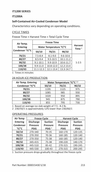
Part Number: 000015430 5/18 213
IT1200 SERIES
IT1200A
Self-Contained Air-Cooled Condenser ModelCharacteristics vary depending on operating conditions.
CYCLE TIMESFreeze Time + Harvest Time = Total Cycle Time
Air Temp. Entering
Condenser °F/°C
Freeze TimeHarvest Time 1Water Temperature °F/°C
50/10 70/21 90/3270/21 7.5-8.4 8.1-9.0 9.6-10.6
1-2.580/27 8.5-9.4 9.5-10.5 10.1-11.290/32 9.1-10.1 9.9-10.9 10.6-11.7
100/38 9.9-11.0 10.8-12.0 12.2-13.4110/43 11.1-12.3 12.1-13.4 13.3-14.7
1 Times in minutes
24 HOUR ICE PRODUCTIONAir Temp. Entering
Condenser °F/°CWater Temperature °F/°C 1 2
50/10 70/21 90/3270/21 1195 1125 97580/27 1085 985 93090/32 1020 950 895
100/38 945 875 790110/43 855 795 730
1 Based on average ice slab weight of 7.5 - 8.2 lb.2 230/50/1 is approximately 12% lower than 230/60/1
OPERATING PRESSURESAir Temp Entering
Condenser °F/°C
Freeze Cycle Harvest CycleDischarge Pressure
PSIG
Suction Pressure
PSIG 1
Discharge Pressure
PSIG
Suction Pressure
PSIG50/10 270-340 70-35 160-170 120-13570/21 270-350 70-36 160-185 120-14080/27 270-350 75-38 160-185 120-14090/32 345-415 75-38 190-220 140-170
100/38 445-510 85-42 270-315 190-245110/43 445-530 100-43 270-315 200-245
1 Suction pressure drops gradually throughout the freeze cycle
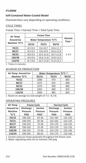
214 Part Number: 000015430 5/18
IT1200W
Self-Contained Water-Cooled ModelCharacteristics vary depending on operating conditions.
CYCLE TIMESFreeze Time + Harvest Time = Total Cycle Time
Air Temp. Around Ice
Machine °F/°C
Freeze TimeHarvest Time 1Water Temperature °F/°C
50/10 70/21 90/3270/21 8.5-9.4 9.6-10.7 10.6-11.7
1-2.580/27 8.5-9.5 9.8-10.9 10.6-11.890/32 8.6-9.5 10.5-11.6 10.7-11.8
100/38 8.6-9.6 10.6-11.8 10.8-12.0110/43 8.7-9.6 10.7-11.8 11.0-12.2
1 Times in minutes
24 HOUR ICE PRODUCTIONAir Temp. Around Ice
Machine °F/°CWater Temperature °F/°C 1 2
50/10 70/21 90/3270/21 1080 970 89580/27 1075 955 89090/32 1070 900 885
100/38 1065 890 875110/43 1060 885 865
1 Based on average ice slab weight of 7.5 - 8.2 lb.
OPERATING PRESSURESAir Temp
Around Ice Machine
°F/°C
Freeze Cycle Harvest CycleDischarge Pressure
PSIG
Suction Pressure
PSIG 1
Discharge Pressure
PSIG
Suction Pressure
PSIG50/10 330-335 65-36 155-165 125-13570/21 330-335 65-38 155-165 125-13580/27 330-335 75-38 155-170 120-13590/32 330-335 75-39 155-170 125-135
100/38 330-335 75-40 155-170 125-140110/43 330-345 80-42 155-175 125-140
1 Suction pressure drops gradually throughout the freeze cycle2 Water regulating valve set to maintain 330 psig
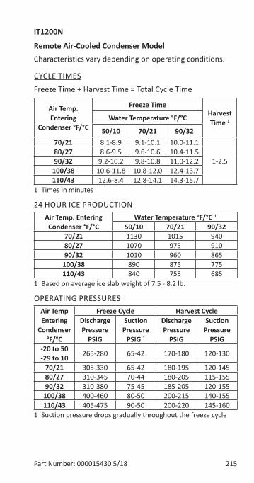
Part Number: 000015430 5/18 215
IT1200N
Remote Air-Cooled Condenser ModelCharacteristics vary depending on operating conditions.
CYCLE TIMESFreeze Time + Harvest Time = Total Cycle Time
Air Temp. Entering
Condenser °F/°C
Freeze TimeHarvest Time 1Water Temperature °F/°C
50/10 70/21 90/3270/21 8.1-8.9 9.1-10.1 10.0-11.1
1-2.580/27 8.6-9.5 9.6-10.6 10.4-11.590/32 9.2-10.2 9.8-10.8 11.0-12.2
100/38 10.6-11.8 10.8-12.0 12.4-13.7110/43 12.6-8.4 12.8-14.1 14.3-15.7
1 Times in minutes
24 HOUR ICE PRODUCTIONAir Temp. Entering
Condenser °F/°CWater Temperature °F/°C 1
50/10 70/21 90/3270/21 1130 1015 94080/27 1070 975 91090/32 1010 960 865
100/38 890 875 775110/43 840 755 685
1 Based on average ice slab weight of 7.5 - 8.2 lb.
OPERATING PRESSURESAir Temp Entering
Condenser °F/°C
Freeze Cycle Harvest CycleDischarge Pressure
PSIG
Suction Pressure
PSIG 1
Discharge Pressure
PSIG
Suction Pressure
PSIG-20 to 50 -29 to 10 265-280 65-42 170-180 120-130
70/21 305-330 65-42 180-195 120-14580/27 310-345 70-44 180-205 115-15590/32 310-380 75-45 185-205 120-155
100/38 400-460 80-50 200-215 140-155110/43 405-475 90-50 200-220 145-160
1 Suction pressure drops gradually throughout the freeze cycle
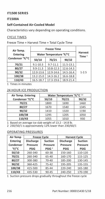
216 Part Number: 000015430 5/18
IT1500 SERIES
IT1500A
Self-Contained Air-Cooled ModelCharacteristics vary depending on operating conditions.
CYCLE TIMESFreeze Time + Harvest Time = Total Cycle Time
Air Temp. Entering
Condenser °F/°C
Freeze TimeHarvest Time 1Water Temperature °F/°C
50/10 70/21 90/3270/21 9.1-10.3 9.7-11.1 11.5-13.1
1-2.580/27 9.9-11.3 10.8-12.3 12.6-14.390/32 12.0-13.6 12.9-14.6 14.5-16.4
100/38 13.2-15.0 14.3-16.2 16.6-18.8110/43 16.5-18.7 17.3-19.6 18.9-21.4
1 Times in minutes
24 HOUR ICE PRODUCTIONAir Temp. Entering
Condenser °F/°CWater Temperature °F/°C 1 2
50/10 70/21 90/3270/21 1800 1690 146080/27 1670 1540 134590/32 1410 1320 1190
100/38 1295 1205 1050110/43 1055 1010 930
1 Based on average ice slab weight of 13.2 - 14.8 lb.2 230/50/1 is approximately 12% lower than 230/60/1
OPERATING PRESSURESAir Temp Entering
Condenser °F/°C
Freeze Cycle Harvest CycleDischarge Pressure
PSIG
Suction Pressure
PSIG 1
Discharge Pressure
PSIG
Suction Pressure
PSIG50/10 260-340 60-38 150-160 110-12070/21 260-340 65-40 160-170 115-12580/27 300-380 70-40 185-200 130-14590/32 360-425 75-42 195-205 135-155
100/38 415-500 85-44 220-240 165-180110/43 435-530 90-45 240-250 170-190
1 Suction pressure drops gradually throughout the freeze cycle

Part Number: 000015430 5/18 217
IT1500W
Self-Contained Water-Cooled ModelCharacteristics vary depending on operating conditions.
CYCLE TIMESFreeze Time + Harvest Time = Total Cycle Time
Air Temp. Around Ice
Machine °F/°C
Freeze TimeHarvest Time 1Water Temperature °F/°C
50/10 70/21 90/3270/21 9.1-10.3 9.7-11.1 11.5-13.1
1-2.580/27 10.2-11.6 10.5-11.9 12.5-14.290/32 10.3-11.7 11.9-13.5 12.8-14.5
100/38 10.3-11.8 12.5-14.2 13.0-14.7110/43 10.5-11.9 12.7-14.5 13.2-15.0
1 Times in minutes
24 HOUR ICE PRODUCTIONAir Temp. Around Ice
Machine °F/°CWater Temperature °F/°C 1
50/10 70/21 90/3270/21 1725 1655 138080/27 1625 1585 136090/32 1615 1420 1330
100/38 1605 1360 1315110/43 1590 1335 1295
1 Based on average ice slab weight of 13.2 - 14.8 lb.
OPERATING PRESSURESAir Temp
Around Ice Machine
°F/°C
Freeze Cycle Harvest CycleDischarge Pressure
PSIG
Suction Pressure
PSIG 1
Discharge Pressure
PSIG
Suction Pressure
PSIG50/10 310-320 70-43 155-170 105-12570/21 310-320 70-45 160-175 115-13080/27 315-325 70-45 165-180 115-13590/32 315-330 75-45 170-185 120-135
100/38 320-360 80-45 175-190 125-140110/43 320-365 80-45 175-195 125-140
1 Suction pressure drops gradually throughout the freeze cycle2 Water regulating valve set to maintain 315 psig
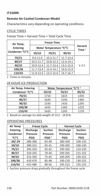
218 Part Number: 000015430 5/18
IT1500N
Remote Air-Cooled Condenser ModelCharacteristics vary depending on operating conditions.
CYCLE TIMESFreeze Time + Harvest Time = Total Cycle Time
Air Temp. Entering
Condenser °F/°C
Freeze TimeHarvest Time 1Water Temperature °F/°C
50/10 70/21 90/3270/21 9.6-11.0 10.3-11.7 11.7-13.4
1-2.580/27 10.2-11.7 10.8-12.3 12.4-14.190/32 10.9-12.4 11.7-13.4 13.2-15.0
100/38 11.7-13.4 12.4-14.1 14.0-15.9110/43 11.9-13.5 13.2-15.0 14.7-16.7
1 Times in minutes
24 HOUR ICE PRODUCTIONAir Temp. Entering
Condenser °F/°CWater Temperature °F/°C 1
50/10 70/21 90/3270/21 1710 1615 143580/27 1620 1545 136590/32 1530 1435 1295
100/38 1435 1365 1225110/43 1420 1295 1170
1 Based on average ice slab weight of 13.2 - 14.8 lb.
OPERATING PRESSURESAir Temp Entering
Condenser °F/°C
Freeze Cycle Harvest CycleDischarge Pressure
PSIG
Suction Pressure
PSIG 1
Discharge Pressure
PSIG
Suction Pressure
PSIG-20/-29 280-300 65-40 180-200 100-13550/10 300-315 65-41 190-205 100-14070/21 305-320 65-42 190-205 110-15080/27 310-345 70-44 190-205 115-15590/32 315-350 75-45 190-205 120-155
100/38 410-470 85-48 190-210 130-155110/43 415-480 90-50 195-215 135-155
1 Suction pressure drops gradually throughout the freeze cycle
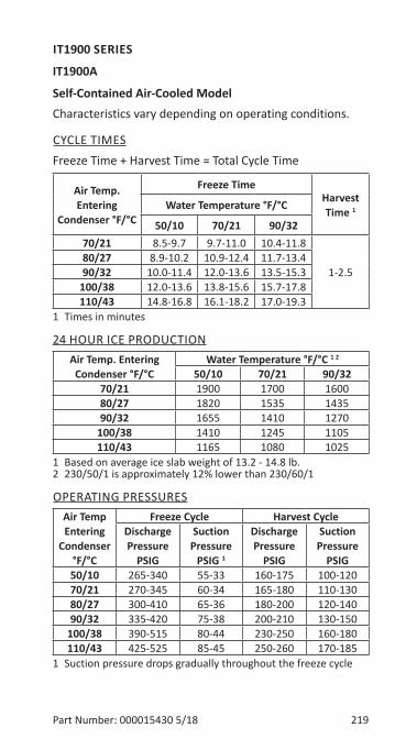
Part Number: 000015430 5/18 219
IT1900 SERIES
IT1900A
Self-Contained Air-Cooled ModelCharacteristics vary depending on operating conditions.
CYCLE TIMESFreeze Time + Harvest Time = Total Cycle Time
Air Temp. Entering
Condenser °F/°C
Freeze TimeHarvest Time 1Water Temperature °F/°C
50/10 70/21 90/3270/21 8.5-9.7 9.7-11.0 10.4-11.8
1-2.580/27 8.9-10.2 10.9-12.4 11.7-13.490/32 10.0-11.4 12.0-13.6 13.5-15.3
100/38 12.0-13.6 13.8-15.6 15.7-17.8110/43 14.8-16.8 16.1-18.2 17.0-19.3
1 Times in minutes
24 HOUR ICE PRODUCTIONAir Temp. Entering
Condenser °F/°CWater Temperature °F/°C 1 2
50/10 70/21 90/3270/21 1900 1700 160080/27 1820 1535 143590/32 1655 1410 1270
100/38 1410 1245 1105110/43 1165 1080 1025
1 Based on average ice slab weight of 13.2 - 14.8 lb.2 230/50/1 is approximately 12% lower than 230/60/1
OPERATING PRESSURESAir Temp Entering
Condenser °F/°C
Freeze Cycle Harvest CycleDischarge Pressure
PSIG
Suction Pressure
PSIG 1
Discharge Pressure
PSIG
Suction Pressure
PSIG50/10 265-340 55-33 160-175 100-12070/21 270-345 60-34 165-180 110-13080/27 300-410 65-36 180-200 120-14090/32 335-420 75-38 200-210 130-150
100/38 390-515 80-44 230-250 160-180110/43 425-525 85-45 250-260 170-185
1 Suction pressure drops gradually throughout the freeze cycle
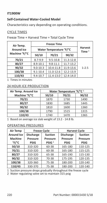
220 Part Number: 000015430 5/18
IT1900W
Self-Contained Water-Cooled ModelCharacteristics vary depending on operating conditions.
CYCLE TIMESFreeze Time + Harvest Time = Total Cycle Time
Air Temp. Around Ice
Machine °F/°C
Freeze TimeHarvest Time 1Water Temperature °F/°C
50/10 70/21 90/3270/21 8.7-9.9 9.5-10.8 11.3-12.8
1-2.580/27 8.9-10.1 9.8-11.1 11.7-13.290/32 9.0-10.3 10.4-11.8 11.9-13.6
100/38 9.1-10.4 11.0-12.6 12.2-13.9110/43 9.4-10.7 11.4-13.0 12.4-14.0
1 Times in minutes
24 HOUR ICE PRODUCTIONAir Temp. Around Ice
Machine °F/°CWater Temperature °F/°C 1
50/10 70/21 90/3270/21 1870 1730 149080/27 1830 1685 144590/32 1810 1600 1360
100/38 1790 1515 1315110/43 1740 1470 1365
1 Based on average ice slab weight of 13.2 - 14.8 lb.
OPERATING PRESSURESAir Temp
Around Ice Machine
°F/°C
Freeze Cycle Harvest CycleDischarge Pressure
PSIG
Suction Pressure
PSIG 1
Discharge Pressure
PSIG
Suction Pressure
PSIG50/10 310-320 60-38 165-180 110-12570/21 310-320 60-38 165-180 115-12580/27 310-320 65-38 165-190 115-13090/32 310-320 70-38 175-195 120-135
100/38 320-360 75-38 180-200 120-140110/43 330-370 75-38 180-200 120-140
1 Suction pressure drops gradually throughout the freeze cycle2 Water regulating valve set to maintain 315 psig
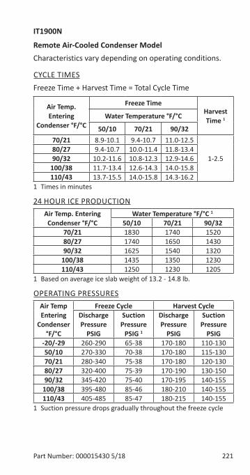
Part Number: 000015430 5/18 221
IT1900N
Remote Air-Cooled Condenser ModelCharacteristics vary depending on operating conditions.
CYCLE TIMESFreeze Time + Harvest Time = Total Cycle Time
Air Temp. Entering
Condenser °F/°C
Freeze TimeHarvest Time 1Water Temperature °F/°C
50/10 70/21 90/3270/21 8.9-10.1 9.4-10.7 11.0-12.5
1-2.580/27 9.4-10.7 10.0-11.4 11.8-13.490/32 10.2-11.6 10.8-12.3 12.9-14.6
100/38 11.7-13.4 12.6-14.3 14.0-15.8110/43 13.7-15.5 14.0-15.8 14.3-16.2
1 Times in minutes
24 HOUR ICE PRODUCTIONAir Temp. Entering
Condenser °F/°CWater Temperature °F/°C 1
50/10 70/21 90/3270/21 1830 1740 152080/27 1740 1650 143090/32 1625 1540 1320
100/38 1435 1350 1230110/43 1250 1230 1205
1 Based on average ice slab weight of 13.2 - 14.8 lb.
OPERATING PRESSURESAir Temp Entering
Condenser °F/°C
Freeze Cycle Harvest CycleDischarge Pressure
PSIG
Suction Pressure
PSIG 1
Discharge Pressure
PSIG
Suction Pressure
PSIG-20/-29 260-290 65-38 170-180 110-13050/10 270-330 70-38 170-180 115-13070/21 280-340 75-38 170-180 120-13080/27 320-400 75-39 170-190 130-15090/32 345-420 75-40 170-195 140-155
100/38 395-480 85-46 180-210 140-155110/43 405-485 85-47 180-215 140-155
1 Suction pressure drops gradually throughout the freeze cycle

222 Part Number: 000015430 5/18
THIS PAGE INTENTIONALLY LEFT BLANK
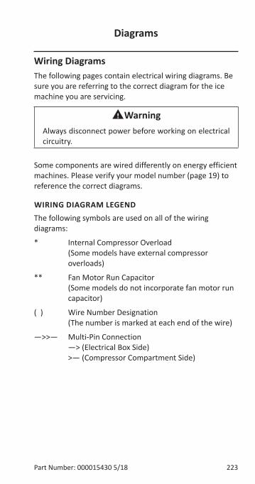
Part Number: 000015430 5/18 223
Wiring DiagramsThe following pages contain electrical wiring diagrams. Be sure you are referring to the correct diagram for the ice machine you are servicing.
nWarningAlways disconnect power before working on electrical circuitry.
Some components are wired differently on energy efficient machines. Please verify your model number (page 19) to reference the correct diagrams.
WIRING DIAGRAM LEGENDThe following symbols are used on all of the wiring diagrams:
* Internal Compressor Overload (Some models have external compressor overloads)
** Fan Motor Run Capacitor (Some models do not incorporate fan motor run capacitor)
( ) Wire Number Designation (The number is marked at each end of the wire)
—>>— Multi-Pin Connection —> (Electrical Box Side) >— (Compressor Compartment Side)
Diagrams
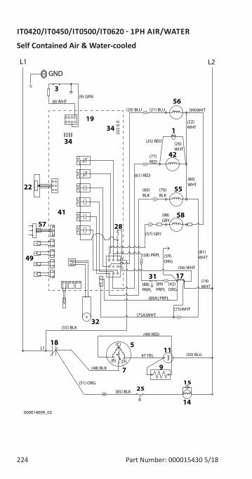
224 Part Number: 000015430 5/18
IT0420/IT0450/IT0500/IT0620 - 1PH AIR/WATER
Self Contained Air & Water-cooled
L1 L2
GND
(22) WHT
(21) BLU(20) BLU (99)WHT
(77) RED
(61) RED
(81) WHT
(25) RED
(76) BLK
(98) GRY
(42)ORG
(89)PRPL
(88) PRPL
(58) PRPL
(56) WHT
(74) WHT
(75)WHT
(50) BLU
(C)
(S)(R)
(49) RED
(48) BLK
(55) BLK
L1
000014009_02
47 YEL
(80) WHT
(51) ORG
(26) WHT
(57) GRY
(89A) PRPL
(75A)WHT
(9) GRN(8) WHT
(60) BLK
(59) ORG
(85) BLK
5
14
56
1
42
55
1731
49
3
22
41
19
28
32
9
18
7
11
58
15
34
57
34
25
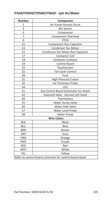
Part Number: 000015430 5/18 225
IT420/IT0450/IT0500/IT0620 - 1ph Air/Water
Number Component1 Air Pump Harvest Assist3 Bin Switch5 Compressor7 Compressor Overload9 PTCR
11 Compressor Run Capacitor14 Condenser Fan Motor15 Condenser Fan Motor Run Capacitor17 Contactor Coil18 Contactor Contacts19 Control Board22 Touchscreen25 Fan Cycle Control28 Fuse31 High Pressure Cutout32 Ice Thickness Probe34 LED41 See Control Board Schematic For Detail42 Solenoid Valve - Harvest Left Hand49 Thermistors55 Water Dump Valve56 Water Inlet Valve57 Water Level Probe58 Water Pump
Wire ColorsBLK BlackBLU BlueBRN BrownGRY GreyORG OrangePRPL PurpleRED RedWHT WhiteYEL Yellow
Refer to control board schematic for control board detail
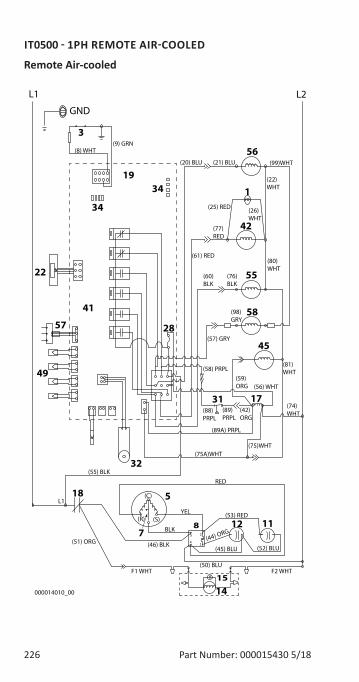
226 Part Number: 000015430 5/18
IT0500 - 1PH REMOTE AIR-COOLED
Remote Air-cooled
L1 L2
GND
(22) WHT
(21) BLU(20) BLU (99)WHT
(77) RED
(61) RED
(81) WHT
(25) RED
(76) BLK
(98) GRY
(42)ORG
(89)PRPL
(88) PRPL
(58) PRPL
(56) WHT
(74) WHT
(75)WHT
(52) BLU
(C)
(S)(R)
RED
(46) BLK
(55) BLK
L1
000014010_00
YEL
(50) BLU
(80) WHT
(51) ORG
(26) WHT
(57) GRY
(89A) PRPL
(75A)WHT
(45) BLU
(9) GRN(8) WHT
(60) BLK
(59) ORG
BLK
F1 WHT F2 WHT
(53) RED
(44) ORG
5
14
56
1
42
55
1731
49
3
22
41
19
28
32
12
18
87
11
58
15
34
57
34
45
4
5 2
1
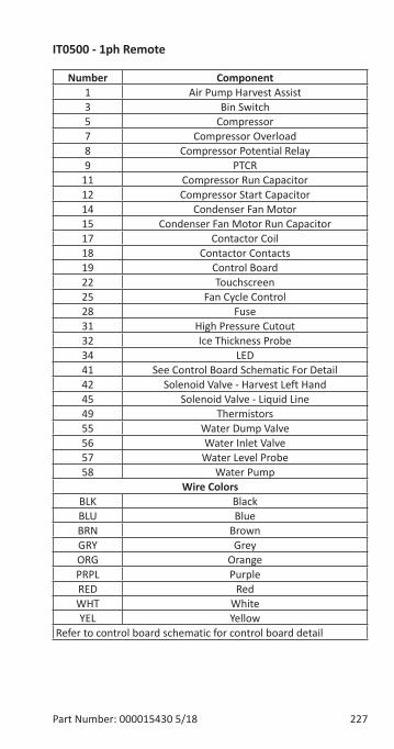
Part Number: 000015430 5/18 227
IT0500 - 1ph Remote
Number Component1 Air Pump Harvest Assist3 Bin Switch5 Compressor7 Compressor Overload8 Compressor Potential Relay9 PTCR
11 Compressor Run Capacitor12 Compressor Start Capacitor14 Condenser Fan Motor15 Condenser Fan Motor Run Capacitor17 Contactor Coil18 Contactor Contacts19 Control Board22 Touchscreen25 Fan Cycle Control28 Fuse31 High Pressure Cutout32 Ice Thickness Probe34 LED41 See Control Board Schematic For Detail42 Solenoid Valve - Harvest Left Hand45 Solenoid Valve - Liquid Line49 Thermistors55 Water Dump Valve56 Water Inlet Valve57 Water Level Probe58 Water Pump
Wire ColorsBLK BlackBLU BlueBRN BrownGRY GreyORG OrangePRPL PurpleRED RedWHT WhiteYEL Yellow
Refer to control board schematic for control board detail
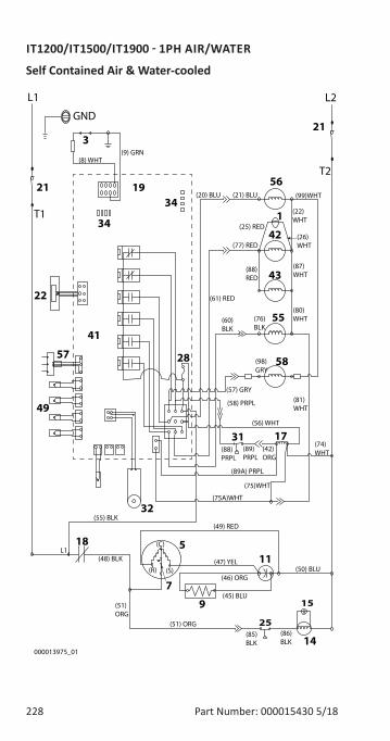
228 Part Number: 000015430 5/18
IT1200/IT1500/IT1900 - 1PH AIR/WATER
Self Contained Air & Water-cooled
21
21
L1 L2
GND
(22) WHT
(21) BLU(20) BLU (99)WHT
(77) RED
(61) RED
(87) WHT
(81) WHT
(25) RED
(76) BLK
(86)BLK
(98) GRY
(42)ORG
(89)PRPL
(88) PRPL
(58) PRPL
(56) WHT
(74) WHT
(75)WHT
(50) BLU
(C)
(S)(R)
(49) RED
(48) BLK
(55) BLK
L1
(51)ORG
000013975_01
(47) YEL
(46) ORG
(88)RED
(80) WHT
(51) ORG
(26) WHT
(57) GRY
(85)BLK
(89A) PRPL
(75A)WHT
(45) BLU
(9) GRN(8) WHT
T1
T2
(60) BLK
5
14
56
1
42
55
1731
49
3
22
41
19
28
32
9
18
15
7
11
58
43
25
34
57
34
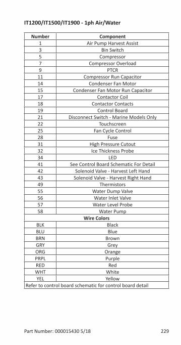
Part Number: 000015430 5/18 229
IT1200/IT1500/IT1900 - 1ph Air/Water
Number Component1 Air Pump Harvest Assist3 Bin Switch5 Compressor7 Compressor Overload9 PTCR
11 Compressor Run Capacitor14 Condenser Fan Motor15 Condenser Fan Motor Run Capacitor17 Contactor Coil18 Contactor Contacts19 Control Board21 Disconnect Switch - Marine Models Only22 Touchscreen25 Fan Cycle Control28 Fuse31 High Pressure Cutout32 Ice Thickness Probe34 LED41 See Control Board Schematic For Detail42 Solenoid Valve - Harvest Left Hand43 Solenoid Valve - Harvest Right Hand49 Thermistors55 Water Dump Valve56 Water Inlet Valve57 Water Level Probe58 Water Pump
Wire ColorsBLK BlackBLU BlueBRN BrownGRY GreyORG OrangePRPL PurpleRED RedWHT WhiteYEL Yellow
Refer to control board schematic for control board detail
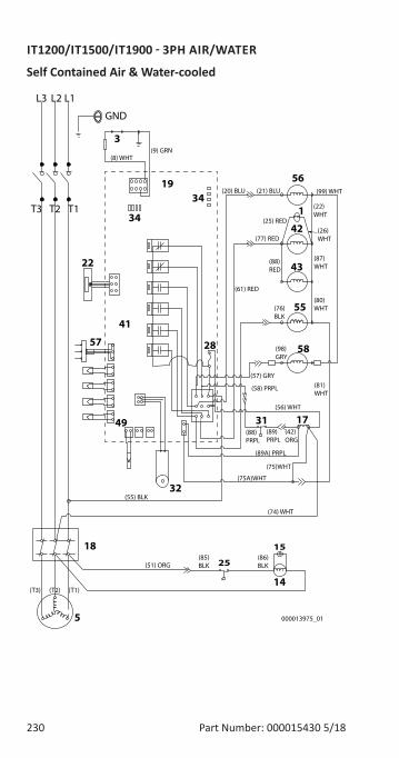
230 Part Number: 000015430 5/18
IT1200/IT1500/IT1900 - 3PH AIR/WATER
Self Contained Air & Water-cooled
L1L2
GND
(22) WHT
(21) BLU(20) BLU (99) WHT
(77) RED
(61) RED
(87) WHT
(81) WHT
(25) RED
(76) BLK
(86)BLK
(98) GRY
(42)ORG
(89)PRPL
(88) PRPL
(58) PRPL
(56) WHT
(74) WHT
(75)WHT
(T1)(T3) (T2)
(55) BLK
(51) ORG
000013975_01
(88)RED
(80) WHT
(26) WHT
(57) GRY
(85)BLK
(89A) PRPL
(75A)WHT
(9) GRN(8) WHT
T1T2
L3
T3
5
14
56
1
42
55
173149
3
22
41
19
28
32
18 15
58
43
25
34
57
34
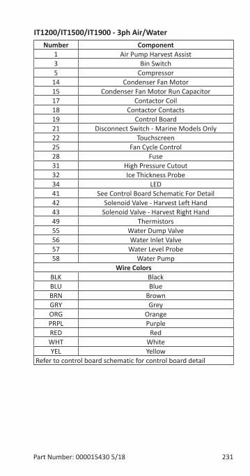
Part Number: 000015430 5/18 231
IT1200/IT1500/IT1900 - 3ph Air/WaterNumber Component
1 Air Pump Harvest Assist3 Bin Switch5 Compressor
14 Condenser Fan Motor15 Condenser Fan Motor Run Capacitor17 Contactor Coil18 Contactor Contacts19 Control Board21 Disconnect Switch - Marine Models Only22 Touchscreen25 Fan Cycle Control28 Fuse31 High Pressure Cutout32 Ice Thickness Probe34 LED41 See Control Board Schematic For Detail42 Solenoid Valve - Harvest Left Hand43 Solenoid Valve - Harvest Right Hand49 Thermistors55 Water Dump Valve56 Water Inlet Valve57 Water Level Probe58 Water Pump
Wire ColorsBLK BlackBLU BlueBRN BrownGRY GreyORG OrangePRPL PurpleRED RedWHT WhiteYEL Yellow
Refer to control board schematic for control board detail
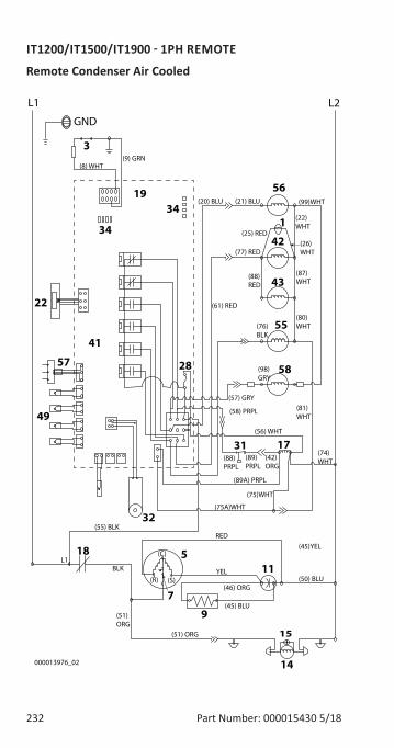
232 Part Number: 000015430 5/18
IT1200/IT1500/IT1900 - 1PH REMOTE
Remote Condenser Air Cooled
L1 L2
GND
(22) WHT
(21) BLU(20) BLU (99)WHT
(77) RED
(61) RED
(87) WHT
(81) WHT
(25) RED
(76) BLK
(98) GRY
(42)ORG
(89)PRPL
(88) PRPL
(58) PRPL
(56) WHT
(74) WHT
(75)WHT
(50) BLU
(C)
(S)(R)
(45)YELRED
BLK
(55) BLK
L1
(51)ORG
000013976_02
YEL
(46) ORG
(88)RED
(80) WHT
(51) ORG
(26) WHT
(57) GRY
(89A) PRPL
(75A)WHT
(45) BLU
(9) GRN(8) WHT
5
14
56
1
42
55
1731
49
3
22
41
19
28
32
9
18
15
7
11
58
43
34
57
34
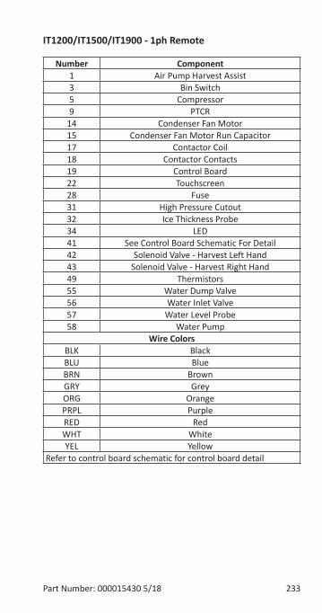
Part Number: 000015430 5/18 233
IT1200/IT1500/IT1900 - 1ph Remote
Number Component1 Air Pump Harvest Assist3 Bin Switch5 Compressor9 PTCR
14 Condenser Fan Motor15 Condenser Fan Motor Run Capacitor17 Contactor Coil18 Contactor Contacts19 Control Board22 Touchscreen28 Fuse31 High Pressure Cutout32 Ice Thickness Probe34 LED41 See Control Board Schematic For Detail42 Solenoid Valve - Harvest Left Hand43 Solenoid Valve - Harvest Right Hand49 Thermistors55 Water Dump Valve56 Water Inlet Valve57 Water Level Probe58 Water Pump
Wire ColorsBLK BlackBLU BlueBRN BrownGRY GreyORG OrangePRPL PurpleRED RedWHT WhiteYEL Yellow
Refer to control board schematic for control board detail
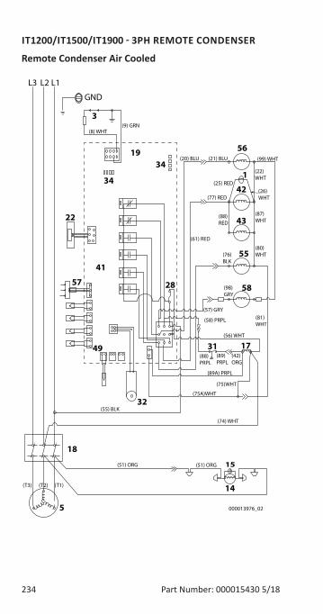
234 Part Number: 000015430 5/18
IT1200/IT1500/IT1900 - 3PH REMOTE CONDENSER
Remote Condenser Air Cooled
14
15
L1L2
GND
(22) WHT
(21) BLU(20) BLU (99) WHT
(77) RED
(61) RED
(87) WHT
(81) WHT
(25) RED
(76) BLK
(98) GRY
(42)ORG
(89)PRPL
(88) PRPL
(58) PRPL
(56) WHT
(74) WHT
(75)WHT
(T1)(T3) (T2)
(55) BLK
(51) ORG
000013976_02
(88)RED
(80) WHT
(26) WHT
(57) GRY
(89A) PRPL
(75A)WHT
(9) GRN(8) WHT
L3
(51) ORG
5
56
1
42
55
173149
3
22
41
19
28
32
18
58
43
34
57
34
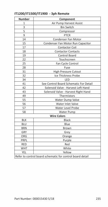
Part Number: 000015430 5/18 235
IT1200/IT1500/IT1900 - 3ph RemoteNumber Component
1 Air Pump Harvest Assist3 Bin Switch5 Compressor9 PTCR
14 Condenser Fan Motor15 Condenser Fan Motor Run Capacitor17 Contactor Coil18 Contactor Contacts19 Control Board22 Touchscreen25 Fan Cycle Control28 Fuse31 High Pressure Cutout32 Ice Thickness Probe34 LED41 See Control Board Schematic For Detail42 Solenoid Valve - Harvest Left Hand43 Solenoid Valve - Harvest Right Hand49 Thermistors55 Water Dump Valve56 Water Inlet Valve57 Water Level Probe58 Water Pump
Wire ColorsBLK BlackBLU BlueBRN BrownGRY GreyORG OrangePRPL PurpleRED RedWHT WhiteYEL Yellow
Refer to control board schematic for control board detail
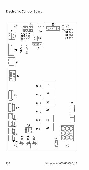
236 Part Number: 000015430 5/18
Electronic Control Board
22
38
34-134-2
334-10
34-9
34-8
34-7
34-6
34-5
34-434-3
2
5
58
56
42
55
43
34
34
34
34
34
34
49-1
49-7
49-6
49-5
49-4
49-3
49-2 33
31
28
57
71
72
70
73
1
2
3
4
5
6
7
8
9
74
75
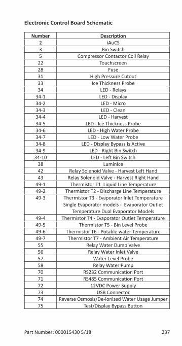
Part Number: 000015430 5/18 237
Electronic Control Board Schematic
Number Description2 iAuCS3 Bin Switch5 Compressor Contactor Coil Relay
22 Touchscreen28 Fuse31 High Pressure Cutout33 Ice Thickness Probe34 LED - Relays
34-1 LED - Display34-2 LED - Micro34-3 LED - Clean34-4 LED - Harvest34-5 LED - Ice Thickness Probe34-6 LED - High Water Probe34-7 LED - Low Water Probe34-8 LED - Display Bypass Is Active34-9 LED - Right Bin Switch
34-10 LED - Left Bin Switch38 LuminIce42 Relay Solenoid Valve - Harvest Left Hand43 Relay Solenoid Valve - Harvest Right Hand
49-1 Thermistor T1 Liquid Line Temperature 49-2 Thermistor T2 - Discharge Line Temperature49-3 Thermistor T3 - Evaporator Inlet Temperature
Single Evaporator models - Evaporator Outlet Temperature Dual Evaporator Models
49-4 Thermistor T4 - Evaporator Outlet Temperature 49-5 Thermistor T5 - Bin Level Probe49-6 Thermistor T6 - Potable water Temperature49-7 Thermistor T7 - Ambient Air Temperature 55 Relay Water Dump Valve56 Relay Water Inlet Valve57 Water Level Probe58 Relay Water Pump70 RS232 Communication Port71 RS485 Communication Port72 12VDC Power Supply73 USB Connector74 Reverse Osmosis/De-ionized Water Usage Jumper 75 Test/Display Bypass Button
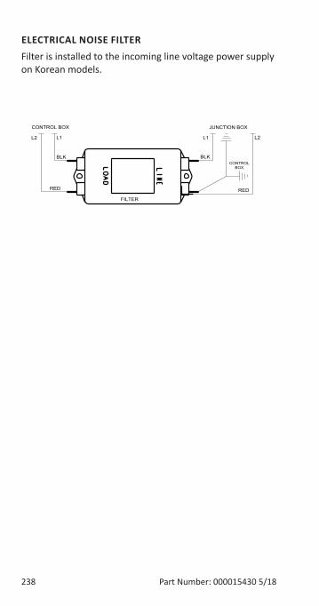
238 Part Number: 000015430 5/18
ELECTRICAL NOISE FILTERFilter is installed to the incoming line voltage power supply on Korean models.
CONTROL BOX
FILTER
JUNCTION BOX
BLK
RED
L2 L1
BLK
RED
L2L1
CONTROLBOX
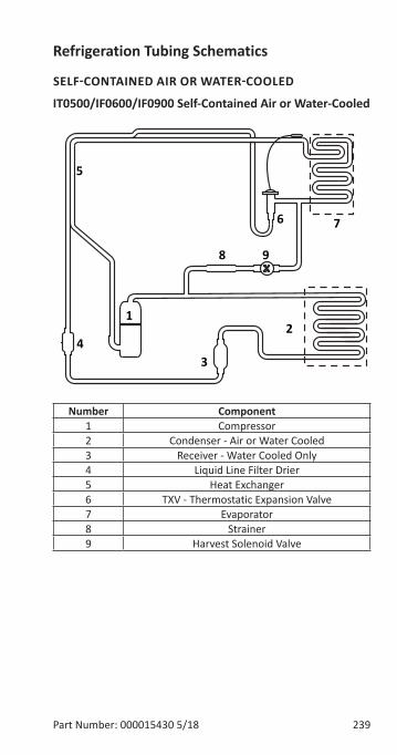
Part Number: 000015430 5/18 239
Refrigeration Tubing Schematics
SELF-CONTAINED AIR OR WATER-COOLED
IT0500/IF0600/IF0900 Self-Contained Air or Water-Cooled
X
12
34
5
6 7
8 9
Number Component1 Compressor2 Condenser - Air or Water Cooled3 Receiver - Water Cooled Only4 Liquid Line Filter Drier5 Heat Exchanger6 TXV - Thermostatic Expansion Valve7 Evaporator8 Strainer9 Harvest Solenoid Valve
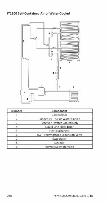
240 Part Number: 000015430 5/18
IT1200 Self-Contained Air or Water-Cooled
Number Component1 Compressor2 Condenser - Air or Water Cooled3 Receiver - Water Cooled Only4 Liquid Line Filter Drier5 Heat Exchanger6 TXV - Thermostatic Expansion Valve7 Evaporator8 Strainer9 Harvest Solenoid Valve
12
3
4
5
67
8
9
9
6
x
x
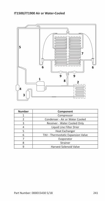
Part Number: 000015430 5/18 241
IT1500/IT1900 Air or Water-Cooled
Number Component1 Compressor2 Condenser - Air or Water Cooled3 Receiver - Water Cooled Only4 Liquid Line Filter Drier5 Heat Exchanger6 TXV - Thermostatic Expansion Valve7 Evaporator8 Strainer9 Harvest Solenoid Valve
12
3
4
5
6
7
899
6
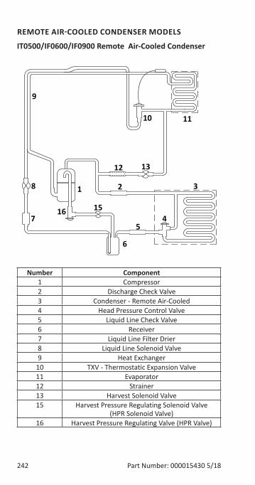
242 Part Number: 000015430 5/18
REMOTE AIR-COOLED CONDENSER MODELS
IT0500/IF0600/IF0900 Remote Air-Cooled Condenser
Number Component1 Compressor2 Discharge Check Valve3 Condenser - Remote Air-Cooled4 Head Pressure Control Valve5 Liquid Line Check Valve6 Receiver7 Liquid Line Filter Drier8 Liquid Line Solenoid Valve9 Heat Exchanger
10 TXV - Thermostatic Expansion Valve11 Evaporator12 Strainer13 Harvest Solenoid Valve15 Harvest Pressure Regulating Solenoid Valve
(HPR Solenoid Valve)16 Harvest Pressure Regulating Valve (HPR Valve)
1 2 3
45
6
7
8
9
10 11
12 13
1516
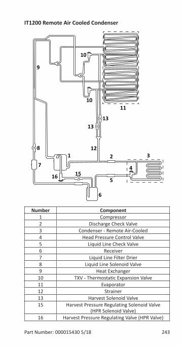
Part Number: 000015430 5/18 243
IT1200 Remote Air Cooled Condenser
Number Component1 Compressor2 Discharge Check Valve3 Condenser - Remote Air-Cooled4 Head Pressure Control Valve5 Liquid Line Check Valve6 Receiver7 Liquid Line Filter Drier8 Liquid Line Solenoid Valve9 Heat Exchanger
10 TXV - Thermostatic Expansion Valve11 Evaporator12 Strainer13 Harvest Solenoid Valve15 Harvest Pressure Regulating Solenoid Valve
(HPR Solenoid Valve)16 Harvest Pressure Regulating Valve (HPR Valve)
1 2 3
4
5
6
7
8
9
1011
12
13
1516
10
13x
x
x
x
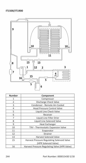
244 Part Number: 000015430 5/18
IT1500/IT1900
Number Component1 Compressor2 Discharge Check Valve3 Condenser - Remote Air-Cooled4 Head Pressure Control Valve5 Liquid Line Check Valve6 Receiver7 Liquid Line Filter Drier8 Liquid Line Solenoid Valve9 Heat Exchanger
10 TXV - Thermostatic Expansion Valve11 Evaporator12 Strainer13 Harvest Solenoid Valve15 Harvest Pressure Regulating Solenoid Valve
(HPR Solenoid Valve)16 Harvest Pressure Regulating Valve (HPR Valve)
1 2 3
4
5
6
7
8
9
10
11
1213
1516
10
13
5


MANITOWOC ICE 2110 SOUTH 26TH STREET
MANITOWOC, WI 54220
844-724-2273 WWW.MANITOWOCICE.COM
Part Number: 000015430 5/18
Welbilt provides the world’s top chefs, and premier chain operators or growing independents with industry leading equipment and solutions. Our cutting-edge designs and lean manufacturing tactics are powered by deep knowledge, operator insights, and culinary expertise. All of our products are backed by KitchenCare® – our aftermarket, repair, and parts service.
Bringing innovation to the tableWWW.WELBILT.COM
CLEVELAND
CONVOTHERM®
DELFIELD®
FITKITCHEN™
FRYMASTER®
GARLAND
KOLPAK®
LINCOLN
MANITOWOC®
MERCO®
MERRYCHEF®
MULTIPLEX®
©2018 Welbilt Inc. except where explicitly stated otherwise. All rights reserved.
Related Documents