i Executive Summary This report outlines the design, build and flight testing of a small-scale airship for surveillance, aerial photography and advertising purposes. The airship was designed to be capable of continuous indoor flight for 30 minutes carrying a 500g payload while maintaining a constant altitude. The methodology and outcomes of similar university research projects were examined to gain a better understanding of airship design principles. Four distinct flight regimes were considered: takeoff, hover, cruise and landing. Flight parameters such as maximum speed, cruise altitude and takeoff time were defined so that a theoretical force analysis could be conducted. The thrust required in each flight regime was then determined based on calculation of the lift, weight and drag forces. Four sections were identified as crucial in the airship design: the envelope, gondola, propulsion system and control system. An iterative procedure was developed to optimise the envelope design based on the weight of components and the lifting force needed to achieve neutral buoyancy. The conceptual design of the gondola focussed on reducing weight whilst still having enough strength to support the weight of the internal components. Ducted fans powered by electric motors were chosen to provide propulsion to the airship. The effects of different fan arrangements on airship manoeuvrability were then analysed. The thrust output of the ducted fans was controlled by manual and automatic systems. An RC hand unit provided full manual control while the cruise altitude and pitch of the airship were maintained automatically using an ultrasonic sensor and clinometer, respectively. The detailed design was developed using the most suitable concept design alternatives. Components such as motors, fans, batteries and automatic control parts were selected based on technical suitability and budget limitations. The final design used a commercially manufactured envelope propelled by four ducted fans, each with variable thrust output. Two manually controlled fans on the side of the gondola were used for yaw control while two downward facing fans provide upward thrust and pitch control. Testing of all individual components was conducted prior to testing of the completed airship. This ensured that the ducted fans, radio controller, camera and automatic control system operated correctly. Two airship envelopes were manufactured and each was tested in a full flight test with the gondola attached. The two flight tests demonstrated that the automatic control system functioned as designed and could be used simultaneously with the manual control system. The flight tests also showed that the airship was capable of meeting the performance requirements set in the project definition. Design and Build a Small Airship i

Welcome message from author
This document is posted to help you gain knowledge. Please leave a comment to let me know what you think about it! Share it to your friends and learn new things together.
Transcript
i
Executive Summary
This report outlines the design, build and flight testing of a small-scale airship for surveillance, aerial photography and advertising purposes. The airship was designed to be capable of continuous indoor flight for 30 minutes carrying a 500g payload while maintaining a constant altitude. The methodology and outcomes of similar university research projects were examined to gain a better understanding of airship design principles.
Four distinct flight regimes were considered: takeoff, hover, cruise and landing. Flight parameters such as maximum speed, cruise altitude and takeoff time were defined so that a theoretical force analysis could be conducted. The thrust required in each flight regime was then determined based on calculation of the lift, weight and drag forces.
Four sections were identified as crucial in the airship design: the envelope, gondola, propulsion system and control system. An iterative procedure was developed to optimise the envelope design based on the weight of components and the lifting force needed to achieve neutral buoyancy. The conceptual design of the gondola focussed on reducing weight whilst still having enough strength to support the weight of the internal components. Ducted fans powered by electric motors were chosen to provide propulsion to the airship. The effects of different fan arrangements on airship manoeuvrability were then analysed. The thrust output of the ducted fans was controlled by manual and automatic systems. An RC hand unit provided full manual control while the cruise altitude and pitch of the airship were maintained automatically using an ultrasonic sensor and clinometer, respectively.
The detailed design was developed using the most suitable concept design alternatives. Components such as motors, fans, batteries and automatic control parts were selected based on technical suitability and budget limitations. The final design used a commercially manufactured envelope propelled by four ducted fans, each with variable thrust output. Two manually controlled fans on the side of the gondola were used for yaw control while two downward facing fans provide upward thrust and pitch control.
Testing of all individual components was conducted prior to testing of the completed airship. This ensured that the ducted fans, radio controller, camera and automatic control system operated correctly. Two airship envelopes were manufactured and each was tested in a full flight test with the gondola attached. The two flight tests demonstrated that the automatic control system functioned as designed and could be used simultaneously with the manual control system. The flight tests also showed that the airship was capable of meeting the performance requirements set in the project definition.
Design and Build a Small Airship i
ii
The majority of the project goals were achieved in the two flight tests. It is hoped that the work undertaken in the project could be adapted and refined by final year students in the future to design an airship capable of outdoor flight with a more advanced control system
Design and Build a Small Airship ii

iii
Acknowledgements
The authors of this report wish to thank many people who have contributed to the project.
Most particularly we would like thank the project supervisor, Dr Maziar Arjomandi, his
continued support and guidance throughout the year was of great help.
Funding for the project was generously provided by BAE Systems Australia. Without this
financial support the project would not have been possible. The authors would like to
thank Mr Jeff Mann and Mr John Finlay of BAE Systems Australia for there efforts to
organise this sponsorship.
Throughout the year, academic staff and students including Dr Ben Cazzolato, Mr
Nicholas Cole, Dr Frank Wormel and Ms Dorothy Missingham have provided there
assistance and advice. This has been most helpful and we greatly appreciate their time
and knowledge. The authors would also like to thank Dave Betteridge, Elias Arcondoulis
and Darren Bain from BAE Systems for their technical advice and interest in the project.
The Mechanical workshop must also be thanked, especially Mr David Osborne, Mr
Richard Pateman and Mr Bill Finch, for their assistance in the design and fabrication
process. The help of the Electronics workshop, including Silvio De Ieso and Norio
Itsumi, in the construction of the electronics circuitry was greatly appreciated.
Design and Build a Small Airship iii
iv
Disclaimer
We, the authors, declare that the material contained within is entirely our own work unless otherwise stated.
………………………………….Michael Nordestgaard
………………………………….Lachlan Ravenscroft
………………………………….Nicholas Bartel
Design and Build a Small Airship iv
v
Contents
....................................................................................................................List of Figures 9
....................................................................................................................List of Tables 11
..............................................................................................................List of Equations 13
............................................................................................................................Notation 14
........................................................................................................................Introduction 1
.................................................................................................................................Aims 1.......................................................................................................Flight Characteristics 1
....................................................................................................Standard Requirements 2..........................................................................................................Budget Constraints 2
.................................................................................................................Feasibility Study 3
..................................................................................................Background Information 3............................................................................................Analysis of Similar Projects 4
....................................................................................Envelope and Gondola Design 4.......................................................................................................Propulsion System 6
........................................................................................Performance Characteristics 7...........................................................................................................Special Systems 7...........................................................................................................Statistical Analysis 9
.................................................................................................Length to Width Ratio 9...............................................................................................Thrust to Weight Ratio 11
.....................................................................Empty Weight to Takeoff Weight Ratio 14...................................................................................................................Summary 15
...........................................................................................................Conceptual Design 17
................................................................................................Desired Modes of Flight 17........................................................................................................Manoeuvrability 17
.......................................................................................................................Takeoff 18.........................................................................................................................Hover 18.........................................................................................................................Cruise 19
......................................................................................................................Landing 19..................................................................................Summary of Flight Parameters 20
...............................................................................................................Force Analysis 21................................................................................................Weight Determination 21
.....................................................................................................Lift Determination 24
Design and Build a Small Airship v
vi
..............................................................................................................Lifting gas 24..............................................................................................Atmospheric Effects 25
.................................................................................................Thrust Determination 26...................................................................................................................Takeoff 27
.....................................................................................................................Hover 28.....................................................................................................................Cruise 29
......................................................Summary of Thrust in Different Flight Modes 30............................................................................................................Envelope Design 30
.................................................................................................Structural Parameters 30....................................................................................................................Materials 32
...........................................................................................Shape and Aerodynamics 33........................................................................................................Stabiliser Design 35
.............................................................................................Propulsion System Design 36...................................................................................................Propulsion Methods 36
.....................................................................................Propulsion System Selection 37.....................................................................................................Propulsion Layout 38
......................................................................................Propulsion Layout Decision 40.............................................................................................................Gondola Design 41
.......................................................................................................Material selection 42...........................................................................................Shape and Aerodynamics 42
........................................................................................................Design Selection 45..................................................................................................Control System Design 46
.............................................................................................Manual Control System 46.........................................................................................Automatic Control System 46
................................................................................Payload and ground station design 47..........................................................................................................Camera options 47
........................................................................................................Camera selection 50
................................................................................................................Detailed Design 51
............................................................................................................Envelope Design 51...................................................................................................Envelope Modelling 51
............................................................................................................Manufacturing 53........................................................................................................Stabiliser Design 54
..........................................................................................................Propulsion Design 56.....................................................................................................Ducted fan motors 56
..................................................................................................Speed Controllers 57.....................................................................................................................Batteries 58
..............................................................................................Power Requirements 58....................................................................................................Battery Selection 60
.............................................................................................................Gondola Design 62............................................................................................................Design Details 62
................................................................................................................Part Layout 65
Design and Build a Small Airship vi
vii
.....................................................................................................Structural Analysis 68..................................................................................................Control System Design 70
.............................................................................................Manual Control System 70...........................................................................................RC Hand Control Unit 70
.....................................................................................Manual Control Procedure 72.....................................................................................................Automatic Control 73
.....................................................................................Automatic Control Layout 73..............................................................Automatic Control Component Selection 73
..........................................................................................................Control Code 78..........................................................................................................................Payload 82
........................................................................................Camera and ground station 82
..........................................................................................................Component Testing 84
................................................................................................................Engine Testing 84................................................................................................Experimental Method 84
...................................................................................................................Procedure 84.................................................................Theoretical Thrust of the SFM ducted fan 85
............................................................................................SFM Thrust Test Results 86...........................................................................................GWS Thrust Test Results 86
.......................................................................Summary of Ducted Fan Test Results 87...............................................................................................................Camera Testing 87
............................................................................................................Camera Range 87.................................................................................Picture quality and interference 89
............................................................................Significance of camera test results 89
........................................................................................................................Flight Tests 91
.............................................................................Pre-flight Procedures and Operation 91.........................................................................................Gondola Component Tests 91
.....................................................................................................Attaching Gondola 91.....................................................................................................Envelope Inflation 92
.....................................................................................................................Flight Tests 92...................................................................................................................Climb test 92
................................................................................................................Descent test 92..................................................................................................................Cruise test 93
.........................................................................................................Rate of turn test 93.................................................................................................Post-flight data analysis 93
..........................................................................................First Flight Test and Results 94.................................................................Climb Test for Automatic Control System 94
..................................................................................................Overweight Analysis 96....................................................................................................Envelope Redesign 99
....................................................................................Second Flight Test and Results 100................................................................................................................Climb Test 100
Design and Build a Small Airship vii
viii
.............................................................................................................Descent Test 101...............................................................................................................Cruise Test 102
.......................................................................................................Rate of turn test 103.....................................................................................................Control Response 105
...............................................................................................................Flight Time 105........................................................................................Summary of the Flight Tests 106
......................................................................................................Project Management 107
.....................................................................................Timeline and Project Planning 107...............................................................................................................Gantt chart 107
.........................................................................................................................Finance 108........................................................................................................Project Funding 108
......................................................................................................................Budget 108
......................................................................................................................Conclusion 110
............................................................Project Definition, Specification and Contract 110.................................................................................................................Future Work 111
...................................................................................................................Bibliography 113
.................................................................................................Appendix A - Drawings 116
................................................................................................Appendix B – Equations 135
.......................................................................Appendix C – Automatic Control Code 149
..........................................................................Appendix D – Flight Test Procedures 155
.............................................................................Appendix E – Safety Requirements 169
.............................................................................................Appendix F – Gantt chart 174
....................................................................Appendix G – Costs and Working Hours 175
..............................................................................Appendix H – Minutes of Meetings 178
Design and Build a Small Airship viii
ix
List of Figures
Figure 21 - Envelope shape analysis (C.S. Jin, 2003)......................................................... 4Figure 22 - Gondola belonging to the airship project “Simon” (Lutz, 1998)...................... 5Figure 23 - Ducted fan example (University of Bombay, 2004)......................................... 6Figure 24 - Servo controlling swivel of a tank turret (RC tankcombat.com, 2007)............ 7Figure 25 - Automatic Control system (C.S. Jin, 2003)...................................................... 8Figure 26 - Heavy Duty SLR/Digital Camera Mechanism (Airships Solutions, 2007)...... 9Figure 27 - Length / Width Graph All Airships................................................................. 10Figure 28 - Length / Width Graph, Airships (Wo < 1 tonne)............................................. 11Figure 29 - Thrust to Weight ratio graph........................................................................... 12Figure 210 - Thrust/Weight vs Weight graph..................................................................... 13Figure 211 - Empty weight to takeoff weight ratio graph................................................. 14Figure 212 - We / Wo ratio vs Takeoff weight graph - (Wo < 1 Tonne)............................ 15Figure 31 - Turning moments of an airship in flight (Khoury, 2004)................................ 17Figure 32 - Comparison of theoretical lifting force of lighter than air gases.................... 24Figure 33 - Effect of temperature on lifting force.............................................................. 25Figure 34 - Free body diagram of forces during takeoff.................................................... 26Figure 35 - Free Body diagram of forces during hover..................................................... 27Figure 36 - Free Body Diagram of Forces During Cruise................................................. 28Figure 37 - Bladders in a rigid airship (Australian Broadcasting Corporation, 2004)..... 30Figure 38 - Polyurethane RC blimp (Airship Solutions, 2007)......................................... 31Figure 39 - Fully Printed Ripstop Nylon Hull (Airship Solutions, 2007)......................... 32Figure 310 - Propeller layout 1.......................................................................................... 38Figure 311 - Propeller layout 2.......................................................................................... 38Figure 312 - Propeller layout 3.......................................................................................... 39Figure 313 - Concept 1, "Bath tub" design........................................................................ 41Figure 314 - Concept 2, "Box and Shell" design............................................................... 42Figure 315 - Concept 3, "Shaped Box" design.................................................................. 42Figure 316 - Heavy Duty SLR/Digital Camera Mechanism (Airships Solutions)............ 46Figure 317 - JMK wireless video camera.......................................................................... 46Figure 41 - Two ellipsoids used to generate the envelope shape....................................... 48Figure 42 - Envelope Iteration Process.............................................................................. 49Figure 43 - Cross section of revolved envelope................................................................ 50Figure 44 - Possible Stabiliser Shapes............................................................................... 51Figure 45 - Stabiliser Attachment...................................................................................... 52Figure 46 - Final Envelope Design Model with Stabilisers............................................... 52Figure 47 - SFM EDF Power System #1028 (left) and GWS GW/EDF75x4A................ 53Figure 48 - DualSky 18 Ampere brushless speed controller............................................. 54Figure 49 - Nosram Force mini Reverse #93000 speed controller.................................... 55Figure 410 - Required power for takeoff at varying duct efficiency................................. 56Figure 411 - Gondola underside hatch............................................................................... 59
Design and Build a Small Airship ix
x
Figure 412 - Gondola Internals.......................................................................................... 60Figure 413 - Servo and belt system................................................................................... 60Figure 414 - Ducted fan holder.......................................................................................... 60Figure 415 - Digital model of part layout.......................................................................... 61Figure 416 - Actual part layout.......................................................................................... 63Figure 417 - Beam Structural Analysis, Fixed Supports................................................... 63Figure 418 - Shear Force Diagram.................................................................................... 64Figure 419 - Bending Moment Diagram............................................................................ 64Figure 420 - JR XP6102 Radio Transmitter...................................................................... 66Figure 421 - Manual Control Layout................................................................................. 67Figure 422 - Automatic Control Layout............................................................................ 68Figure 423 - Minidragon microprocessor.......................................................................... 69Figure 424 - SRF04 Ultrasonic Sensor.............................................................................. 70Figure 425 - RF-BlueDongle, antenna, USB power, and RS232 serial port..................... 71Figure 426 - Li Po battery for control hardware................................................................ 72Figure 427 - AccuStar level sensor.................................................................................... 72Figure 428 - Overall Simulink signal flow diagram.......................................................... 74Figure 429 - Control Code Pitch Subsystem..................................................................... 75Figure 430 - PWM Output Variation................................................................................. 76Figure 431 - Camera mounted in gondola......................................................................... 77Figure 51 - Theoretical Thrust SFM Ducted Fans............................................................. 79Figure 52 - Testing of the SFM ducted fan........................................................................ 80Figure 53 - Testing of the GWS ducted fan....................................................................... 80Figure 54 - Onboard camera still frame............................................................................. 82Figure 61 - Graph of results of initial blimp response test................................................ 88Figure 62 - Weight Difference Pie Chart........................................................................... 91Figure 63 - Climb Test Results.......................................................................................... 93Figure 64 - Descent Test Results....................................................................................... 94Figure 65 - Cruise Test Results.......................................................................................... 96Figure 66 - Rate of Turn Results....................................................................................... 97Figure 67 - Blimp Response Test, 3m input...................................................................... 98Figure 71 - Preliminary Gantt chart for the Project......................................................... 100
Design and Build a Small Airship x
xi
List of Tables
Table 11 - Principal Flight Characteristics.......................................................................... 1Table 12 - Manoeuvrability Requirements.......................................................................... 2Table 31 - Flight Parameters.............................................................................................. 20Table 32 - Preliminary Weight Estimation......................................................................... 22Table 33 - Summary of thrust requirements...................................................................... 29Table 34 - Envelope Shapes............................................................................................... 32Table 35 - Aerodynamic analysis of initial envelope shapes............................................. 33Table 36 - Surface Area to Volume Ratio.......................................................................... 33Table 37 - Decision Matrix for Envelope Shape................................................................ 34Table 38 - Stabiliser Sizing................................................................................................ 35Table 39 - Propulsion System Decision Matrix................................................................. 37Table 310 - Propulsion Layout Decision Matrix................................................................ 40Table 311 - Gondola Material Properties........................................................................... 40Table 312 - Gondola Design Decision Matrix................................................................... 43Table 313 - Camera System Decision Matrix.................................................................... 47Table 41 - Dimensions of Envelope................................................................................... 49Table 42 - Ducted Fan Motor System Specifications........................................................ 54Table 43 - Speed Controller Specifications....................................................................... 55Table 44 - Battery capacity requirements.......................................................................... 58Table 45 – Specifications of the selected Li-Po battery.................................................... 58Table 46 - Mass Balance Analysis..................................................................................... 62Table 47 - Transmitter Specifications................................................................................ 66Table 48 - Receiver Specifications.................................................................................... 66Table 49 - Battery Specifications....................................................................................... 66Table 410 - Servo Specifications....................................................................................... 66Table 411 - Microprocessor options.................................................................................. 69Table 412 - Ultrasonic ranging module options................................................................ 69Table 413 - Bluetooth Communication Options................................................................ 70Table 414 - Battery Requirements..................................................................................... 71Table 415 - Selected battery specifications....................................................................... 71Table 416 - Level Sensor Specifications........................................................................... 72Table 417 - JMK wireless video camera specifications..................................................... 77Table 51 - Camera range test results.................................................................................. 82Table 61 - Post-flight check of performance parameters................................................... 87Table 62 - PID Gains......................................................................................................... 88Table 63 - Mass Analysis................................................................................................... 90Table 64 - Lift Comparison................................................................................................ 91Table 65 - Dimension of new envelope............................................................................. 92Table 66 - Velocity Profile in Climb.................................................................................. 93Table 67 - Time to Descend............................................................................................... 95
Design and Build a Small Airship xi
xii
Table 68 - Cruise Velocity Profile...................................................................................... 96Table 69 - Rate of Turn Data.............................................................................................. 97Table 610 - Revised and Achieved Performance Parameters............................................ 99Table 81 - Principal Flight Characteristics...................................................................... 102Table 82 - Additional Performance Parameters............................................................... 103
Design and Build a Small Airship xii

xiii
List of Equations
Equation 31 - Lifting Force Equation................................................................................ 23Equation 32 - Ideal gas law............................................................................................... 24Equation 33 - Sum of forces in takeoff mode.................................................................... 26Equation 34 - Sum of horizontal forces in cruise mode.................................................... 28Equation 41 - Volume of Ellipsoid.................................................................................... 48Equation 42 - Surface Area of Ellipsoid Approximation................................................... 49Equation 43 - Static Thrust for a ducted fan...................................................................... 56Equation 44 - Dynamic thrust equation for a ducted fan................................................... 57Equation 45 - Bending Moment Equation......................................................................... 64Equation 46 - Flexure Formula.......................................................................................... 65Equation 47 - Pitch Angle Duty Cycle............................................................................... 76Equation 51 - Static thrust for a ducted fan....................................................................... 79
Design and Build a Small Airship xiii
xiv
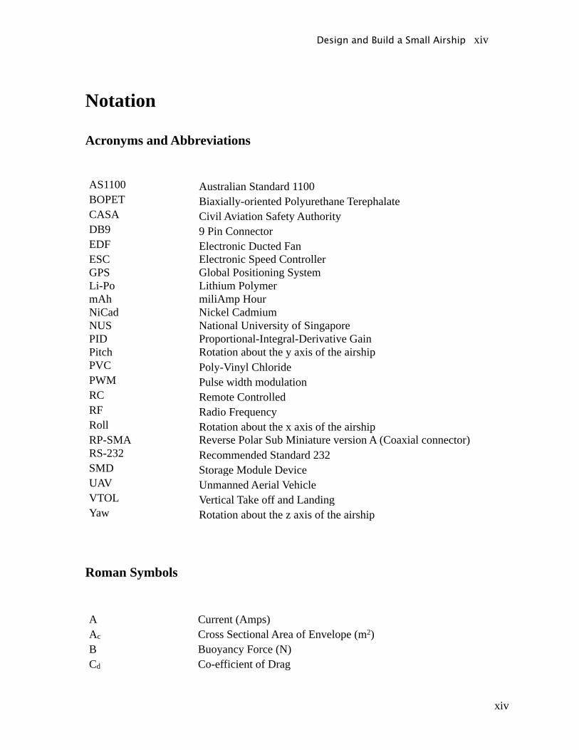
Notation
Acronyms and Abbreviations
AS1100 Australian Standard 1100BOPET Biaxially-oriented Polyurethane TerephalateCASA Civil Aviation Safety AuthorityDB9 9 Pin ConnectorEDF Electronic Ducted FanESC Electronic Speed ControllerGPS Global Positioning SystemLi-Po Lithium PolymermAh miliAmp HourNiCad Nickel CadmiumNUS National University of SingaporePID Proportional-Integral-Derivative GainPitch Rotation about the y axis of the airshipPVC Poly-Vinyl ChloridePWM Pulse width modulationRC Remote ControlledRF Radio FrequencyRoll Rotation about the x axis of the airshipRP-SMA Reverse Polar Sub Miniature version A (Coaxial connector)RS-232 Recommended Standard 232SMD Storage Module DeviceUAV Unmanned Aerial VehicleVTOL Vertical Take off and LandingYaw Rotation about the z axis of the airship
Roman Symbols
A Current (Amps)Ac Cross Sectional Area of Envelope (m2)B Buoyancy Force (N)Cd Co-efficient of Drag
Design and Build a Small Airship xiv
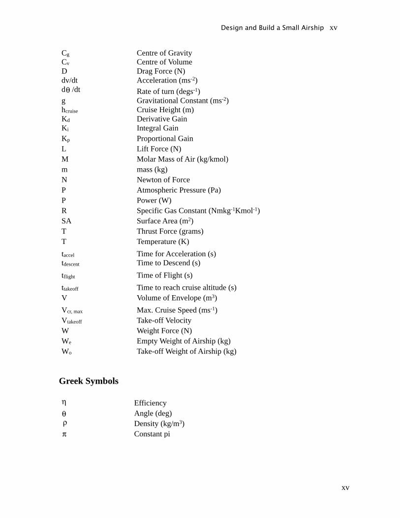
xv
Cg Centre of GravityCv Centre of VolumeD Drag Force (N)dv/dt Acceleration (ms-2)d /dt Rate of turn (degs-1)g Gravitational Constant (ms-2)hcruise Cruise Height (m)Kd Derivative GainKi Integral GainKp Proportional GainL Lift Force (N)M Molar Mass of Air (kg/kmol)m mass (kg)N Newton of ForceP Atmospheric Pressure (Pa)P Power (W)R Specific Gas Constant (Nmkg-1Kmol-1)SA Surface Area (m2)T Thrust Force (grams)T Temperature (K)taccel Time for Acceleration (s)tdescent Time to Descend (s)tflight Time of Flight (s)ttakeoff Time to reach cruise altitude (s)V Volume of Envelope (m3)Vcr, max Max. Cruise Speed (ms-1)Vtakeoff Take-off VelocityW Weight Force (N)We Empty Weight of Airship (kg)Wo Take-off Weight of Airship (kg)
Greek Symbols
EfficiencyAngle (deg)Density (kg/m3)Constant pi
Design and Build a Small Airship xv

i
1 Introduction1.1 Aims
The project aims to design and construct a small airship capable of indoor flight.
Specifically, the project aimed to achieve three main objectives:
• To design and build an airship to meet specified flight parameters
• To implement a complete manual and partial automatic control system
• To have the ability to capture images and transmit them to the ground
The final product could be used for indoor aerial photography, surveillance and
advertising purposes.
1.2 Flight Characteristics
As stated in the first project objective, the airship had to be designed to meet a set of
flight characteristics. The four flight characteristics were the payload weight, cruise
speed, time of flight and cruise height. The yaw and pitch of the airship needed to be
controlled whereas roll control was not a part of the project requirements..
Table 11 - Principal Flight Characteristics
Category Value
Payload weight 0.5kg
Cruise Speed 1m/s
Time of Flight 30 mins
Cruise height 6m
Design and Build a Small Airship i
ii
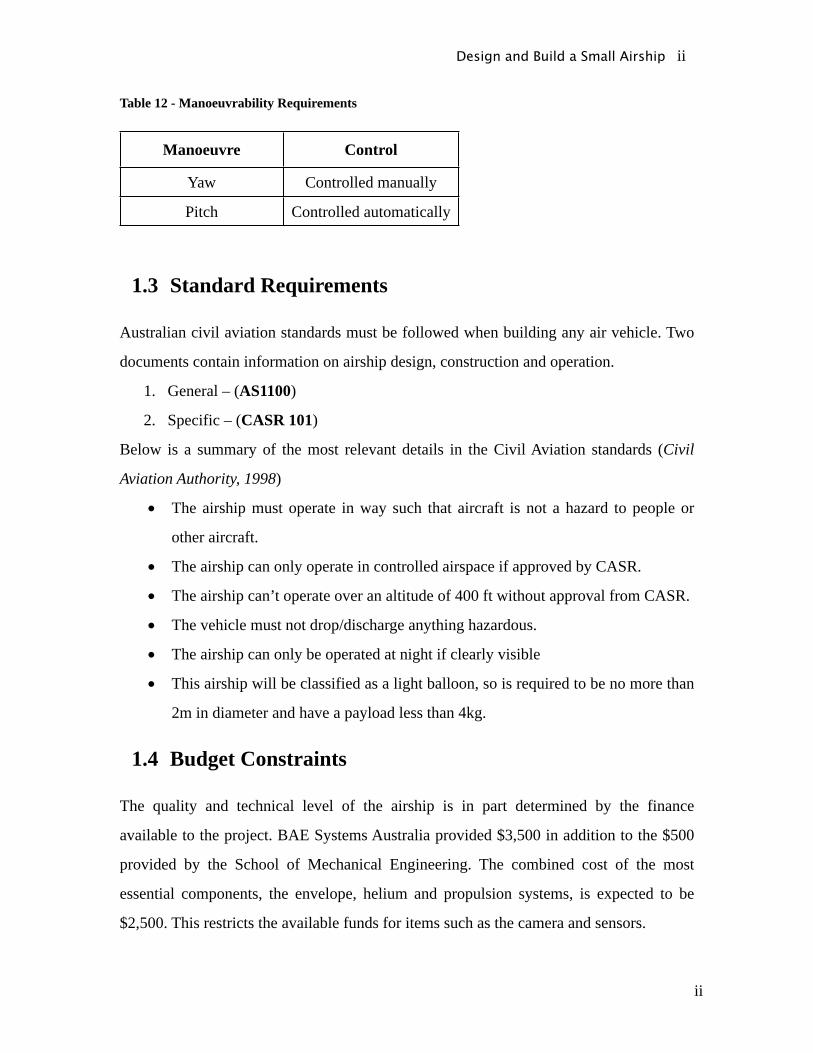
Table 12 - Manoeuvrability Requirements
Manoeuvre Control
Yaw Controlled manually
Pitch Controlled automatically
1.3 Standard Requirements
Australian civil aviation standards must be followed when building any air vehicle. Two
documents contain information on airship design, construction and operation.
1. General – (AS1100)
2. Specific – (CASR 101)
Below is a summary of the most relevant details in the Civil Aviation standards (Civil
Aviation Authority, 1998)
• The airship must operate in way such that aircraft is not a hazard to people or
other aircraft.
• The airship can only operate in controlled airspace if approved by CASR.
• The airship can’t operate over an altitude of 400 ft without approval from CASR.
• The vehicle must not drop/discharge anything hazardous.
• The airship can only be operated at night if clearly visible
• This airship will be classified as a light balloon, so is required to be no more than
2m in diameter and have a payload less than 4kg.
1.4 Budget Constraints
The quality and technical level of the airship is in part determined by the finance
available to the project. BAE Systems Australia provided $3,500 in addition to the $500
provided by the School of Mechanical Engineering. The combined cost of the most
essential components, the envelope, helium and propulsion systems, is expected to be
$2,500. This restricts the available funds for items such as the camera and sensors.
Design and Build a Small Airship ii
iii
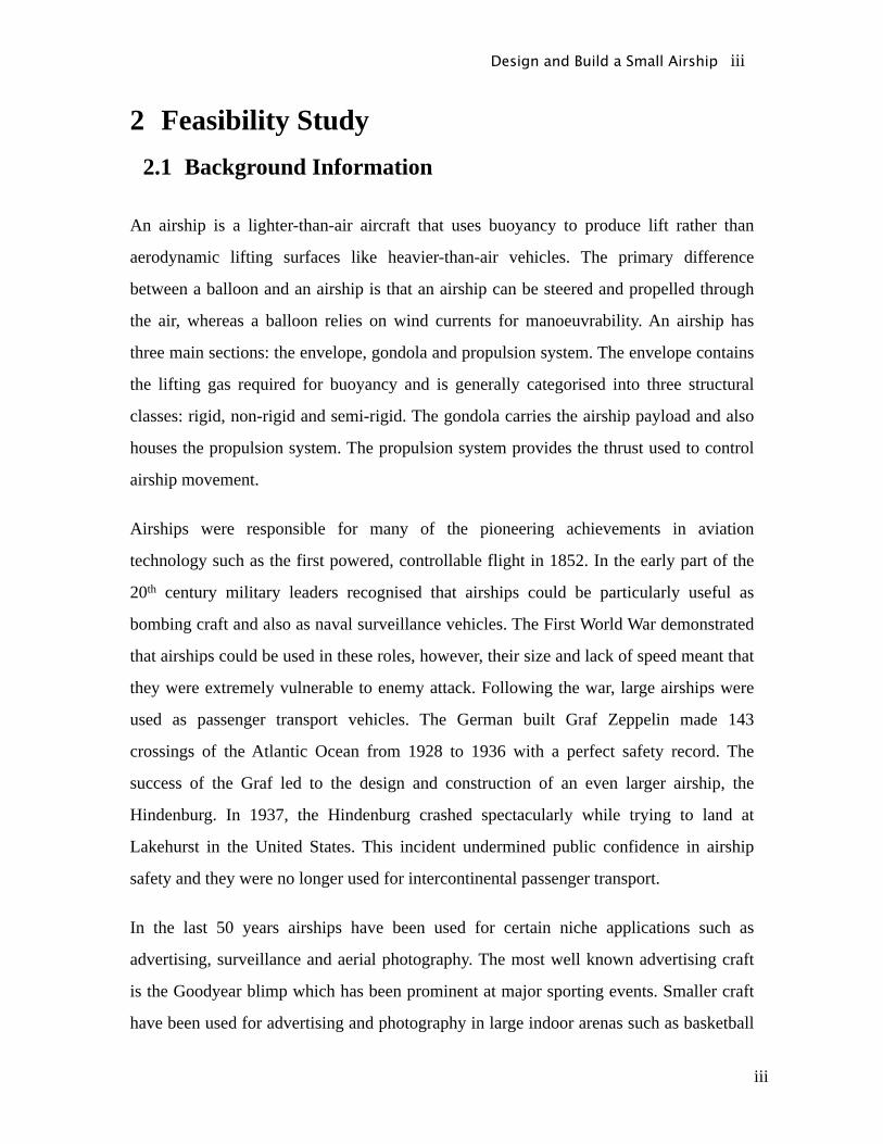
2 Feasibility Study2.1 Background Information
An airship is a lighter-than-air aircraft that uses buoyancy to produce lift rather than
aerodynamic lifting surfaces like heavier-than-air vehicles. The primary difference
between a balloon and an airship is that an airship can be steered and propelled through
the air, whereas a balloon relies on wind currents for manoeuvrability. An airship has
three main sections: the envelope, gondola and propulsion system. The envelope contains
the lifting gas required for buoyancy and is generally categorised into three structural
classes: rigid, non-rigid and semi-rigid. The gondola carries the airship payload and also
houses the propulsion system. The propulsion system provides the thrust used to control
airship movement.
Airships were responsible for many of the pioneering achievements in aviation
technology such as the first powered, controllable flight in 1852. In the early part of the
20th century military leaders recognised that airships could be particularly useful as
bombing craft and also as naval surveillance vehicles. The First World War demonstrated
that airships could be used in these roles, however, their size and lack of speed meant that
they were extremely vulnerable to enemy attack. Following the war, large airships were
used as passenger transport vehicles. The German built Graf Zeppelin made 143
crossings of the Atlantic Ocean from 1928 to 1936 with a perfect safety record. The
success of the Graf led to the design and construction of an even larger airship, the
Hindenburg. In 1937, the Hindenburg crashed spectacularly while trying to land at
Lakehurst in the United States. This incident undermined public confidence in airship
safety and they were no longer used for intercontinental passenger transport.
In the last 50 years airships have been used for certain niche applications such as
advertising, surveillance and aerial photography. The most well known advertising craft
is the Goodyear blimp which has been prominent at major sporting events. Smaller craft
have been used for advertising and photography in large indoor arenas such as basketball
Design and Build a Small Airship iii
iv
and ice hockey stadiums. The United States Coast Guard has also experimented with
using airships for high altitude surveillance of its borders and coastline.
2.2 Analysis of Similar Projects
A comprehensive review of other airships was undertaken to gain a better understanding
of airship design principles. The review focussed on small-scale, university level projects.
The design of the envelope, gondola and propulsion system were of particular interest as
was the performance capabilities of each craft.
2.2.1 Envelope and Gondola Design
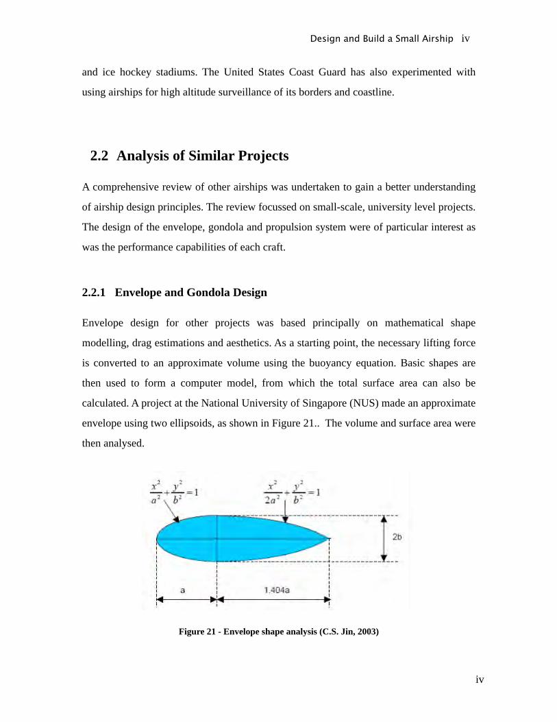
Envelope design for other projects was based principally on mathematical shape
modelling, drag estimations and aesthetics. As a starting point, the necessary lifting force
is converted to an approximate volume using the buoyancy equation. Basic shapes are
then used to form a computer model, from which the total surface area can also be
calculated. A project at the National University of Singapore (NUS) made an approximate
envelope using two ellipsoids, as shown in Figure 21.. The volume and surface area were
then analysed.
Figure 21 - Envelope shape analysis (C.S. Jin, 2003)
Design and Build a Small Airship iv
v
A number of material options exist for envelope manufacture. Previous airship design
projects have based the material choice on factors such as cost, durability and permeation
of helium. Projects with larger budgets have used polyurethane. The NUS craft and
another design at Rowan University each used polyurethane as the envelope material.
Polyurethane retains helium well and has aesthetic appeal, but is not seen in home
projects because of its cost and difficulties in manufacturing. The small zeppelin
“Simon”, designed and built by students at the Realgymnasium Rämibühl in Zürich,
utilized biaxially-oriented polyethylene terephthalate (BOPET) for the envelope.
Metallised BOPET, also known by the trade name Mylar, is inexpensive but looks
unprofessional and is prone to helium leakage at the welded seams.
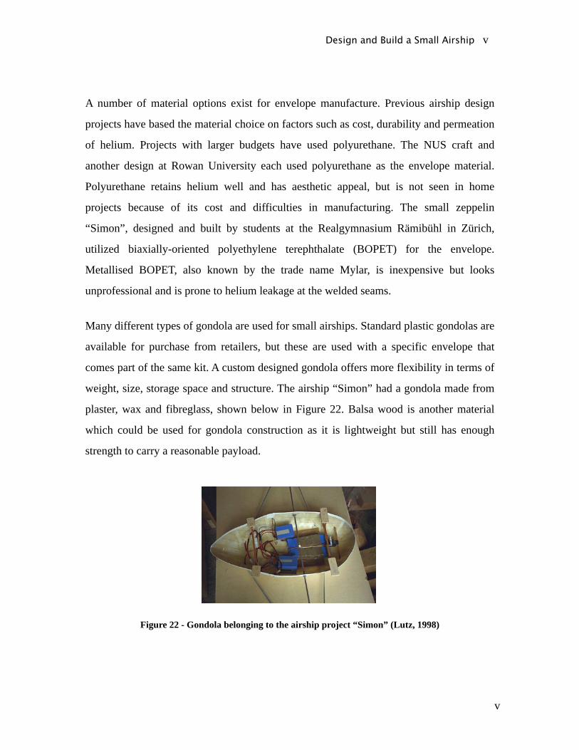
Many different types of gondola are used for small airships. Standard plastic gondolas are
available for purchase from retailers, but these are used with a specific envelope that
comes part of the same kit. A custom designed gondola offers more flexibility in terms of
weight, size, storage space and structure. The airship “Simon” had a gondola made from
plaster, wax and fibreglass, shown below in Figure 22. Balsa wood is another material
which could be used for gondola construction as it is lightweight but still has enough
strength to carry a reasonable payload.
Figure 22 - Gondola belonging to the airship project “Simon” (Lutz, 1998)
Design and Build a Small Airship v
vi
2.2.2 Propulsion System
All of the small airships that were investigated used batteries to power the propulsion
system. Lithium Polymer batteries are lightweight, small and efficient and hence are ideal
for use in an airship. An internal combustion engine could also be used, but is generally
more suitable in high thrust vehicles such as remote control planes and helicopters. All of
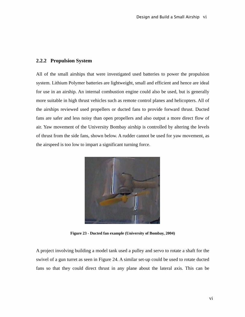
the airships reviewed used propellers or ducted fans to provide forward thrust. Ducted
fans are safer and less noisy than open propellers and also output a more direct flow of
air. Yaw movement of the University Bombay airship is controlled by altering the levels
of thrust from the side fans, shown below. A rudder cannot be used for yaw movement, as
the airspeed is too low to impart a significant turning force.
Figure 23 - Ducted fan example (University of Bombay, 2004)
A project involving building a model tank used a pulley and servo to rotate a shaft for the
swivel of a gun turret as seen in Figure 24. A similar set-up could be used to rotate ducted
fans so that they could direct thrust in any plane about the lateral axis. This can be
Design and Build a Small Airship vi

vii
achieved by attaching a pulley to a servo-motor, a pulley to the axel and then connecting
the pulleys with a belt.
Figure 24 - Servo controlling swivel of a tank turret (RC tankcombat.com, 2007)
2.2.3 Performance Characteristics
The flight requirements of an airship determine its performance characteristics. It is hard
to directly compare blimps and their performance characteristics, because different
designs may be trying to achieve different objectives. For example, airships that are used
for indoor photography may not need a high cruise speed but will need to be able to
hover steadily for large periods of time. The airship “Simon” was able to achieve a
maximum speed of 6 ms-1 with a total thrust output of 6.6N from two propellers. In
contrast, the NUS design had a maximum speed of 1.5 ms-1 and a total thrust output of
0.14 N for a craft approximately half the length of “Simon”. The yaw rate, or rate of turn,
of the University of Washington craft was approximately 28° per second while the NUS
design had a yaw rate of 15° per second.
2.2.4 Special Systems
Depending on the application for an airship, a number of special systems may have been
introduced. Most of the academic projects that were researched incorporated a level of
automatic control in addition to the use of a standard hand-held radio controller. In an
Design and Build a Small Airship vii

viii
automatic configuration, sensors provide information about the surroundings of the
blimp, while a processor interprets this data and controls the thrust output of the
propulsion system. An automatic system could be extremely useful in controlling
parameters such as cruise speed and ceiling height, but may be difficult to implement.
The NUS project attempted to design a complex control system, using GPS, to make a
fully autonomous airship. Automatic control was used in the University of Berkeley to
enable an airship to have a collision avoidance system. Ultrasonic sensors installed in the
gondola, measured the distance to a surface and if the airship was going to collide, a
turning manoeuvre would be carried out by an onboard processor. The University of
Berkeley design also used ultrasonic sensors to maintain a constant cruise altitude.
Figure 25 - Automatic Control system (C.S. Jin, 2003)
Many of the researched projects had the ability to take video footage from the gondola of
an airship. Generally, the footage would be wirelessly transmitted to a ground station
where the signal would be recorded. The University of Bombay design used a very small
and inexpensive camera to transmit footage to a computer. The image quality from the
Design and Build a Small Airship viii
ix
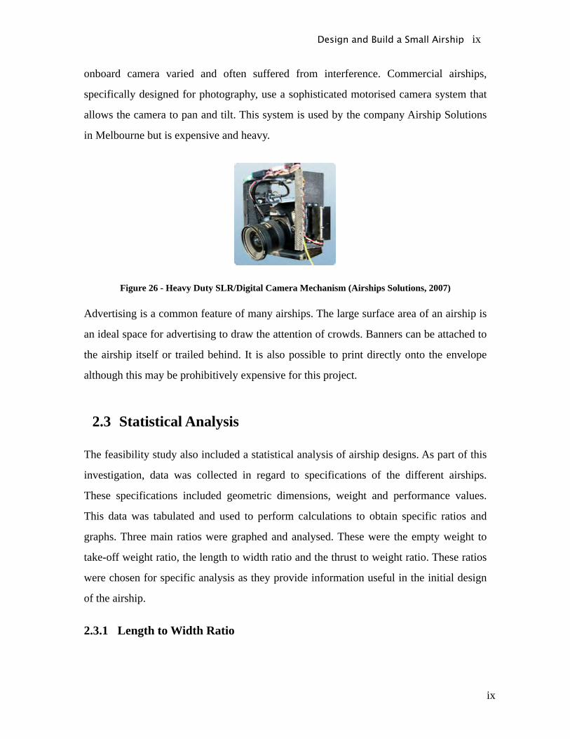
onboard camera varied and often suffered from interference. Commercial airships,
specifically designed for photography, use a sophisticated motorised camera system that
allows the camera to pan and tilt. This system is used by the company Airship Solutions
in Melbourne but is expensive and heavy.
Figure 26 - Heavy Duty SLR/Digital Camera Mechanism (Airships Solutions, 2007)
Advertising is a common feature of many airships. The large surface area of an airship is
an ideal space for advertising to draw the attention of crowds. Banners can be attached to
the airship itself or trailed behind. It is also possible to print directly onto the envelope
although this may be prohibitively expensive for this project.
2.3 Statistical Analysis
The feasibility study also included a statistical analysis of airship designs. As part of this
investigation, data was collected in regard to specifications of the different airships.
These specifications included geometric dimensions, weight and performance values.
This data was tabulated and used to perform calculations to obtain specific ratios and
graphs. Three main ratios were graphed and analysed. These were the empty weight to
take-off weight ratio, the length to width ratio and the thrust to weight ratio. These ratios
were chosen for specific analysis as they provide information useful in the initial design
of the airship.
2.3.1 Length to Width Ratio
Design and Build a Small Airship ix
x
The length to width ratio is useful in providing a basic understanding of the geometry of
the airship envelope. A larger length to width ratio (e.g. 10) means the airship has a long
thin shape like the Zeppelin designs. An airship with a smaller length to width ratio (e.g.
4) usually is a result of a tapered design which has a larger frontal area and hence larger
maximum diameter. The two different shapes each have their own advantages and
disadvantages.
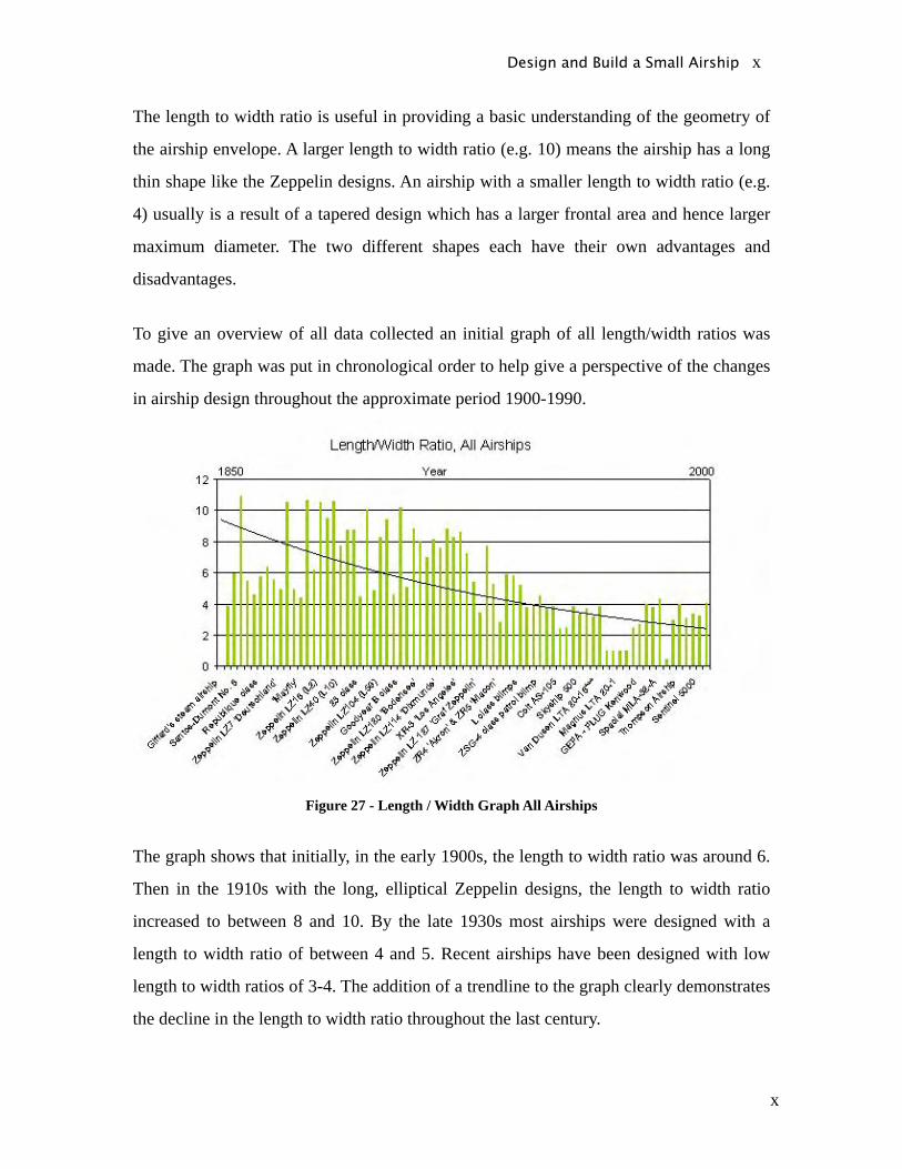
To give an overview of all data collected an initial graph of all length/width ratios was
made. The graph was put in chronological order to help give a perspective of the changes
in airship design throughout the approximate period 1900-1990.
Figure 27 - Length / Width Graph All Airships
The graph shows that initially, in the early 1900s, the length to width ratio was around 6.
Then in the 1910s with the long, elliptical Zeppelin designs, the length to width ratio
increased to between 8 and 10. By the late 1930s most airships were designed with a
length to width ratio of between 4 and 5. Recent airships have been designed with low
length to width ratios of 3-4. The addition of a trendline to the graph clearly demonstrates
the decline in the length to width ratio throughout the last century.
Design and Build a Small Airship x

xi
The airships used to create the previous graph vary in size from a weight of about 100kg
to as much as 100 tonne. As the airship being designed in this project is designed to have
a weight less than 5kg, a second graph was created showing the length to width ratio for
smaller airships. A size of less than 1 tonne in weight was used as it gave a sufficient
sample size as well as reducing the average weight of airships being analysed.
Figure 28 - Length / Width Graph, Airships (Wo < 1 tonne)
The results of this graph are similar Figure 27, showing that small airships have a length
to width ratio around 3. A more accurate average value for the small airships was
calculated to be 3.7. Using the analysis of the more modern airships and the smaller
airships, a figure of 3.5 was established as a guideline value to help design the shape of
the airship.
2.3.2 Thrust to Weight Ratio
The thrust to weight ratio is used as a design guide to help determine the thrust needed
for the airship. From the thrust to weight ratio and the weight of the airship, an
Design and Build a Small Airship xi

xii
approximate thrust value can be established. The thrust value also helps to select the
components of the propulsion system including motors, ducted fans and batteries.
A graph off the thrust to weight ratio for all the airship data collected was produced
displaying the results in chronological order. The graph shows that there is significant
variation between thrust to weight ratio (0.1 – 0.7), however this is independent of the
time of production. The average thrust to weight ratio over the whole period was 0.25.
Figure 29 - Thrust to Weight ratio graph
As there appeared to be no relationship between the age of the airship and its thrust to
weight ratio, a graph comparing the thrust to weight ratio and weight was created (Figure
210). This showed a large grouping of airships with a thrust to weight ratio of 0.2 and a
weight less than 200,000N. It also showed for airships larger than 200,000N that the
thrust to weight ratio was around 0.1. A significant number of airships less than 100,000
N in weight had a thrust to weight ratio of more than 0.3.
Design and Build a Small Airship xii

xiii
Figure 210 - Thrust/Weight vs Weight graph
Another graph was produced which only considered designs with a weight close to the
desired weight of this project. The graph shows the distribution of thrust to weight ratios
to be quite large (between 0.1 and 0.7). The average thrust to weight ratio was 0.3.
The average thrust to weight ratio for all airships was about 0.25 while for smaller
airships it was about 0.3. The large variation in the data means it is difficult to draw any
significant conclusions. The main reason for this variation is that the thrust to weight
ratio is dependent on the purpose of the individual airship. If the airship is designed to
move quickly through the air it has a larger thrust to weight ratio than if it was designed
to hover. As the desired speed of this airship is to be small, a low thrust to weight ratio
would be likely. Using a conservative estimate of 0.4 for the thrust to weight ratio and a
weight of 5kg, the approximate thrust required would be 20N. This estimate is likely to
be much greater than the thrust needed by this airship. This is primarily because most of
the airships being analysed were designed to meet higher performance standards.
Design and Build a Small Airship xiii
xiv
2.3.3 Empty Weight to Takeoff Weight Ratio
The empty weight (We) to take-off weight (Wo) ratio is the most important of the three
ratios analysed. The airship take-off weight is the empty weight plus the payload weight.
Using the We / Wo ratio and a known payload weight it is possible to then determine the
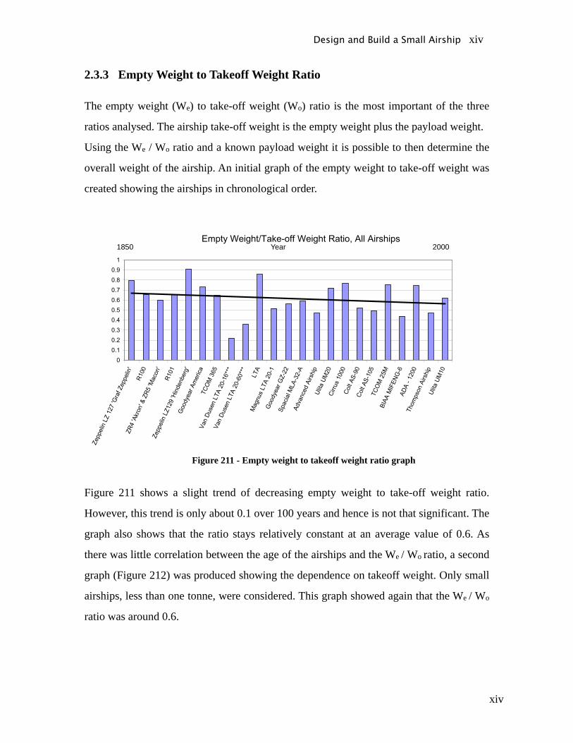
overall weight of the airship. An initial graph of the empty weight to take-off weight was
created showing the airships in chronological order.
1850 2000Year
Figure 211 - Empty weight to takeoff weight ratio graph
Figure 211 shows a slight trend of decreasing empty weight to take-off weight ratio.
However, this trend is only about 0.1 over 100 years and hence is not that significant. The
graph also shows that the ratio stays relatively constant at an average value of 0.6. As
there was little correlation between the age of the airships and the We / Wo ratio, a second
graph (Figure 212) was produced showing the dependence on takeoff weight. Only small
airships, less than one tonne, were considered. This graph showed again that the We / Wo
ratio was around 0.6.
Design and Build a Small Airship xiv
xv
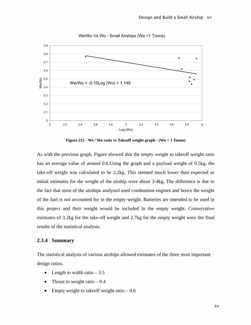
Figure 212 - We / Wo ratio vs Takeoff weight graph - (Wo < 1 Tonne)
As with the previous graph, Figure showed that the empty weight to takeoff weight ratio
has an average value of around 0.6.Using the graph and a payload weight of 0.5kg, the
take-off weight was calculated to be 2.2kg. This seemed much lower than expected as
initial estimates for the weight of the airship were about 3-4kg. The difference is due to
the fact that most of the airships analysed used combustion engines and hence the weight
of the fuel is not accounted for in the empty weight. Batteries are intended to be used in
this project and their weight would be included in the empty weight. Conservative
estimates of 3.2kg for the take-off weight and 2.7kg for the empty weight were the final
results of the statistical analysis.
2.3.4 Summary
The statistical analysis of various airships allowed estimates of the three most important
design ratios.
• Length to width ratio – 3.5
• Thrust to weight ratio – 0.4
• Empty weight to takeoff weight ratio – 0.6
Design and Build a Small Airship xv
xvi
The ratios were then converted to actual performance values.
• Thrust - 20N
• Takeoff weight – 3.2Kg
• Empty weight – 2.7Kg
These estimates are a helpful guide to establish the actual parameters of the design.
However the lack of data available on small airships means that the statistical analysis
cannot alone be used to determine the design of the airship in this project.
Design and Build a Small Airship xvi
xvii
3 Conceptual Design3.1 Desired Modes of Flight
The modes of flight describe the rotational and translational movement of the airship. The
requirements of each flight mode were determined based on the feasibility study and the
broad goals of the project.
3.1.1 Manoeuvrability
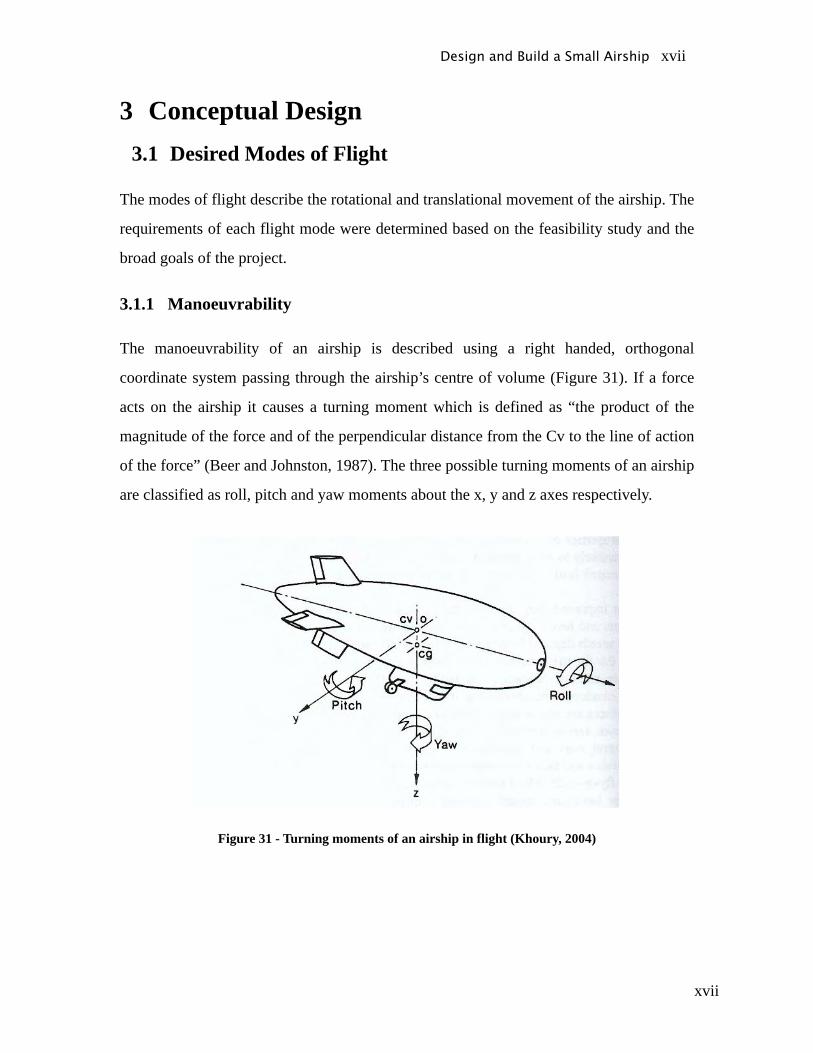
The manoeuvrability of an airship is described using a right handed, orthogonal
coordinate system passing through the airship’s centre of volume (Figure 31). If a force
acts on the airship it causes a turning moment which is defined as “the product of the
magnitude of the force and of the perpendicular distance from the Cv to the line of action
of the force” (Beer and Johnston, 1987). The three possible turning moments of an airship
are classified as roll, pitch and yaw moments about the x, y and z axes respectively.
Figure 31 - Turning moments of an airship in flight (Khoury, 2004)
Design and Build a Small Airship xvii

xviii
Control of yaw and pitching moments was part of the project definition, but roll control
was not deemed necessary. As almost two thirds of the mass is contained in the gondola
any minor roll moments will be counter-balanced by the natural tendency of the airship to
move back to the equilibrium position.
The rate of turn of the airship describes how fast the airship can yaw. The feasibility
study suggested that it would be possible to achieve a 90º turn in 3 seconds. The target
rate-of-turn, d /dt, was therefore 30º/s.
3.1.2 Takeoff
The takeoff manoeuvre describes how the airship moves from the ground to its cruise
altitude. The takeoff motion is designed to be entirely vertical, although it is also possible
to takeoff diagonally with a small thrust from the side fans. Diagonal takeoff is not an
essential part of the project.
Two flight parameters needed to be determined so the takeoff mode could be defined
accurately. A cruise altitude of 6m was chosen mainly due to a limitation in the ultrasonic
height sensors which fail to accurately measure height above this altitude. The time
required to reach the cruise altitude also needed to be defined. Preliminary thrust and
drag calculations suggested that 20 seconds was an achievable ascent time hence this
figure was chosen.
3.1.3 Hover
When the airship does not move in the horizontal plane and maintains its altitude it is in
hover mode. Hovering mostly occurs at the cruise altitude. As a safety mechanism, the
airship was designed to be slightly less than neutrally buoyant, that is the lifting force is
almost that of the overall weight force. Therefore, to hover, a constant upward thrust is
required to maintain altitude. The magnitude of the upward thrust will be more closely
defined in the detailed design.
Design and Build a Small Airship xviii
xix
3.1.4 Cruise
The cruise mode is essentially the same as the hover mode except that it includes
movement in the horizontal plane. Cruise calculations required that two flight parameters
be determined. A maximum cruise speed of 1.0 ms-1 was deemed to be achievable based
on the initial thrust and drag calculations. The performance of the NUS airship and the
Rowan University airship also suggested that this cruise speed was appropriate. To
calculate the maximum cruise thrust, the time to reach maximum speed also needed to be
defined. A value of 10 seconds was chosen based on preliminary testing of ducted fan
units.
3.1.5 Landing
The landing of the airship was designed to be entirely vertical although there is the
capability for a descent where horizontal thrust is provided. Since the total weight of the
airship is designed to exceed the lift provided by the helium, the airship should descend
under its own weight. Descent time from the cruise altitude was designed to be less than
20 seconds. The excess weight calculations will be used to determine the exact theoretical
descent time.
Design and Build a Small Airship xix
xx
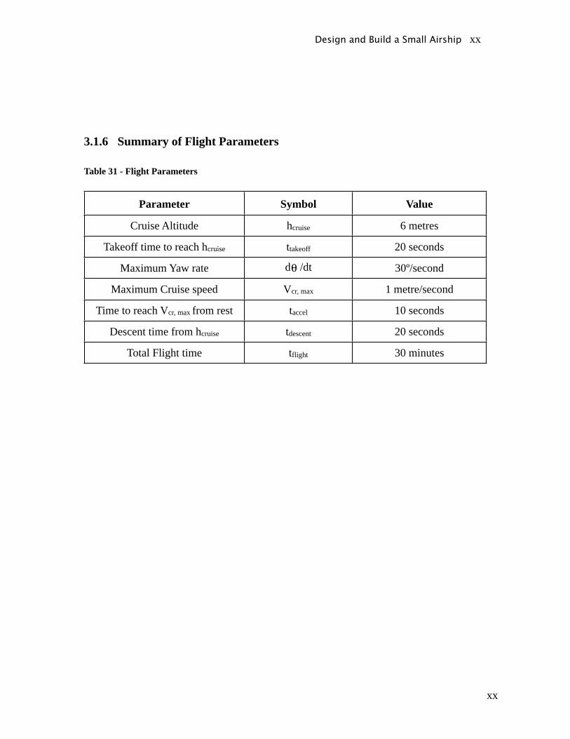
3.1.6 Summary of Flight Parameters
Table 31 - Flight Parameters
Parameter Symbol Value
Cruise Altitude hcruise 6 metres
Takeoff time to reach hcruise ttakeoff 20 seconds
Maximum Yaw rate d /dt 30º/second
Maximum Cruise speed Vcr, max 1 metre/second
Time to reach Vcr, max from rest taccel 10 seconds
Descent time from hcruise tdescent 20 seconds
Total Flight time tflight 30 minutes
Design and Build a Small Airship xx
xxi
3.2 Force Analysis
3.2.1 Weight Determination
The exact weight of the airship was difficult to ascertain during the conceptual design
phase. Research was done into the weight of every component and an overall weight
estimate was made.
The envelope and stabiliser weights were estimated based on discussions with the
manufacturer of the envelope, Airship Solutions. They provided information on the
polyurethane density and thickness. This was then combined with preliminary surface
area estimations to calculate the total weight of the envelope.
It was especially difficult to estimate the weight of the gondola housing and internals as
the gondola design changed frequently. The balsa wood density and thickness were
combined with an approximation of the total surface area of the gondola to estimate its
weight. The weight of the motors, ducted fans, batteries, speed controllers and automatic
control components was determined from manufacturer data sheets. Parts that were
definitely going to be needed in the final design were purchased and then weighed to
confirm the manufacturer’s data.
The total weight of the envelope, gondola and internals was determined to be 2.9 kg.
A summary of preliminary weight estimates can be seen in Table 32.
Design and Build a Small Airship xxi
xxii
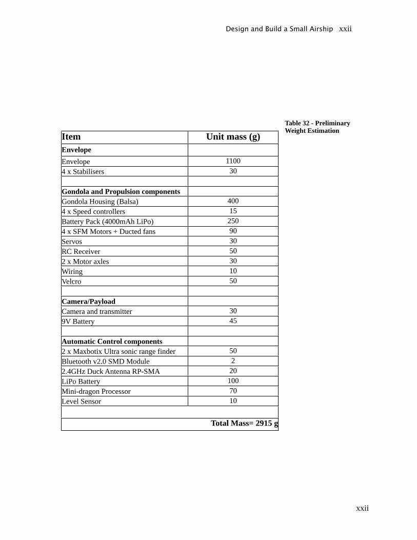
Table 32 - Preliminary Weight Estimation
Design and Build a Small Airship xxii
Item Unit mass (g)EnvelopeEnvelope 11004 x Stabilisers 30
Gondola and Propulsion componentsGondola Housing (Balsa) 4004 x Speed controllers 15Battery Pack (4000mAh LiPo) 2504 x SFM Motors + Ducted fans 90Servos 30RC Receiver 502 x Motor axles 30Wiring 10Velcro 50
Camera/PayloadCamera and transmitter 309V Battery 45
Automatic Control components2 x Maxbotix Ultra sonic range finder 50Bluetooth v2.0 SMD Module 22.4GHz Duck Antenna RP-SMA 20LiPo Battery 100Mini-dragon Processor 70Level Sensor 10
Total Mass= 2915 g

xxiii
Design and Build a Small Airship xxiii

xxiv
3.2.2 Lift Determination
The lifting force is comprised of the static lift from the helium and the dynamic lift
created by the pressure distribution around the airship during flight. The envelope is very
inefficient in creating dynamic lift due to its shape and the low speed airflow. The
dynamic lift was assumed to be negligible compared to the static lift.
3.2.2.1 Lifting gas
From Archimedes’ principle, the upward buoyancy force due to the lifting gas is equal in
magnitude to the weight of the fluid (air) displaced. To be effective in generating lift, the
density of the gas displacing the air must be as low as possible. The buoyancy force can
be expressed as a function of the lifting gas density, air density and the volume.
Equation 31 - Lifting Force Equation
Where
= Lifting Force (N)
= Density of Air (kg/m3)
= Density of Lifting Gas (kg/m3)
V = Volume of the Envelope (m3)
Four alternative lifting gases could have been used for the airship: hydrogen, helium,
methane and ammonia. A comparison of the lifting force is shown in Figure 32 and the
calculations for each gas are shown in Appendix B. The unit of lifting force was
converted to grams for ease of comparison with the mass of components.
Design and Build a Small Airship xxiv

xxv
Figure 32 - Comparison of theoretical lifting force of lighter than air gases
Figure 32 shows that to lift 3kg of weight using ammonia or methane would require a
volume of at least 5m3. Hydrogen and helium provide almost double the lifting force per
volume and hence would need a total volume of approximately 3m3. Hydrogen could not
be used due to its extreme flammability. Hence it was concluded that helium was the only
suitable gas for the airship.
3.2.2.2 Atmospheric Effects
Temperature, altitude and air density all affect the lifting capacity of the airship. Due to
the low ceiling height, any altitude affects were deemed negligible. Air was assumed to
be an ideal gas and hence the affect of temperature on the air density can be calculated.
Equation 32 - Ideal gas law
Where
P = atmospheric pressure (Pa)
M= Molar mass of air (kg/kmol)
R= Specific Gas Constant (N m kg-1kmol-1)
Design and Build a Small Airship xxv
xxvi
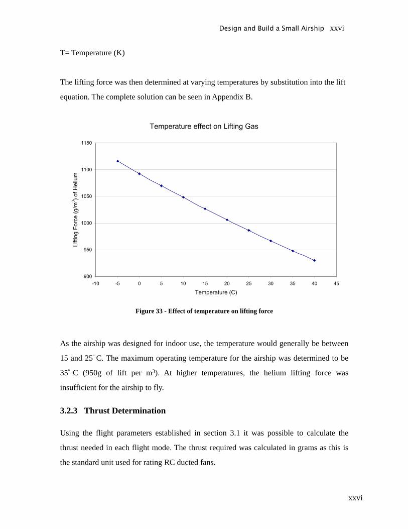
T= Temperature (K)
The lifting force was then determined at varying temperatures by substitution into the lift
equation. The complete solution can be seen in Appendix B.
Figure 33 - Effect of temperature on lifting force
As the airship was designed for indoor use, the temperature would generally be between
15 and 25º C. The maximum operating temperature for the airship was determined to be
35º C (950g of lift per m3). At higher temperatures, the helium lifting force was
insufficient for the airship to fly.
3.2.3 Thrust Determination
Using the flight parameters established in section 3.1 it was possible to calculate the
thrust needed in each flight mode. The thrust required was calculated in grams as this is
the standard unit used for rating RC ducted fans.
Design and Build a Small Airship xxvi

xxvii
3.2.3.1 Takeoff
In takeoff mode the airship must overcome the drag force acting downward as well as the
weight force. The buoyancy force alone is not sufficient for takeoff, hence an upward
thrust must be provided.
Figure 34 - Free body diagram of forces during takeoff
The required thrust in takeoff was determined from applying Newton’s Second Law to
the airship. The equation assumes that the buoyancy force is equal to the weight of the
airship.
Σ F = m (dv/dt) = Thrust + Buoyancy – Weight – Drag
∴ Thrust = m (dv/dt) + Drag
where Drag = ½ CD ρair Atop Vtakeoff 2
Equation 33 - Sum of forces in takeoff mode
The drag coefficient for the envelope in takeoff was conservatively approximated to be
equal to the drag coefficient for a horizontal cylinder moving upward which has Cd= 1.15
(Munson, 2006). All other variables in the takeoff equation were defined in the flight
Design and Build a Small Airship xxvii

xxviii
parameters. The maximum thrust required in vertical takeoff was calculated to be 96g.
The full solution can be seen in Appendix B.
3.2.3.2 Hover
The thrust required in hover was determined using the same procedure as for takeoff
mode. As stated in section 3.1, the lift force was designed to be just less than the weight
force, hence a constant vertical thrust was required in hover mode. The airship was
designed to descend from a height of 6m in 20 seconds. An excess weight of 20 grams
was chosen as this allowed the airship to descend in approximately 20 seconds. Hence the
constant upward thrust was required to be 20 grams for the airship to hover.
Figure 35 - Free Body diagram of forces during hover
Design and Build a Small Airship xxviii
xxix
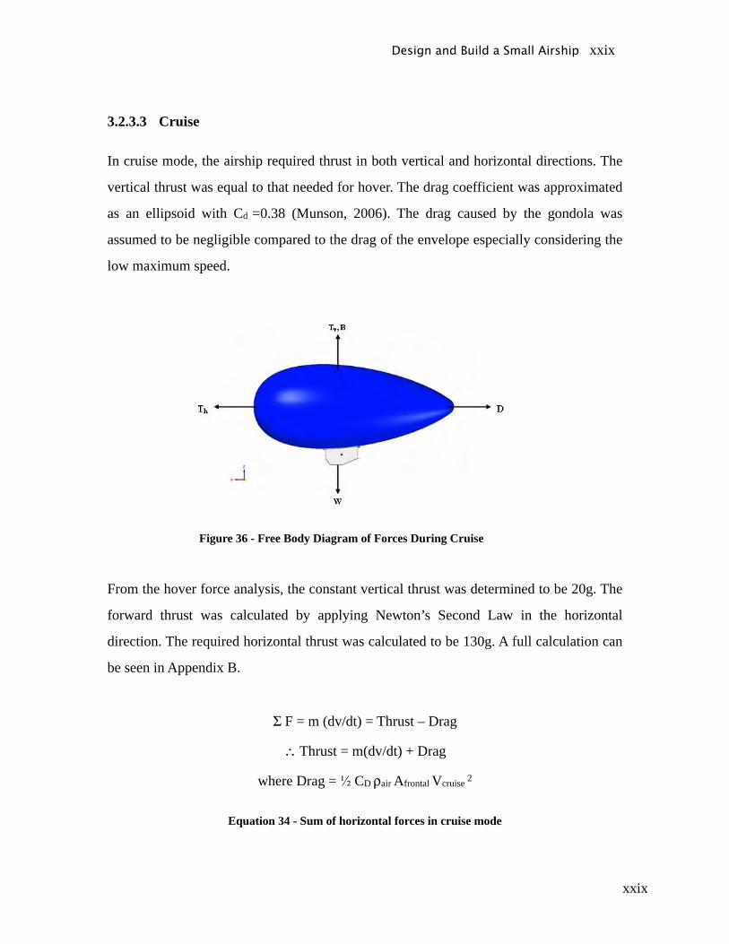
3.2.3.3 Cruise
In cruise mode, the airship required thrust in both vertical and horizontal directions. The
vertical thrust was equal to that needed for hover. The drag coefficient was approximated
as an ellipsoid with Cd =0.38 (Munson, 2006). The drag caused by the gondola was
assumed to be negligible compared to the drag of the envelope especially considering the
low maximum speed.
Figure 36 - Free Body Diagram of Forces During Cruise
From the hover force analysis, the constant vertical thrust was determined to be 20g. The
forward thrust was calculated by applying Newton’s Second Law in the horizontal
direction. The required horizontal thrust was calculated to be 130g. A full calculation can
be seen in Appendix B.
Σ F = m (dv/dt) = Thrust – Drag
∴ Thrust = m(dv/dt) + Drag
where Drag = ½ CD ρair Afrontal Vcruise 2
Equation 34 - Sum of horizontal forces in cruise mode
Design and Build a Small Airship xxix
xxx
3.2.3.4 Summary of Thrust in Different Flight Modes
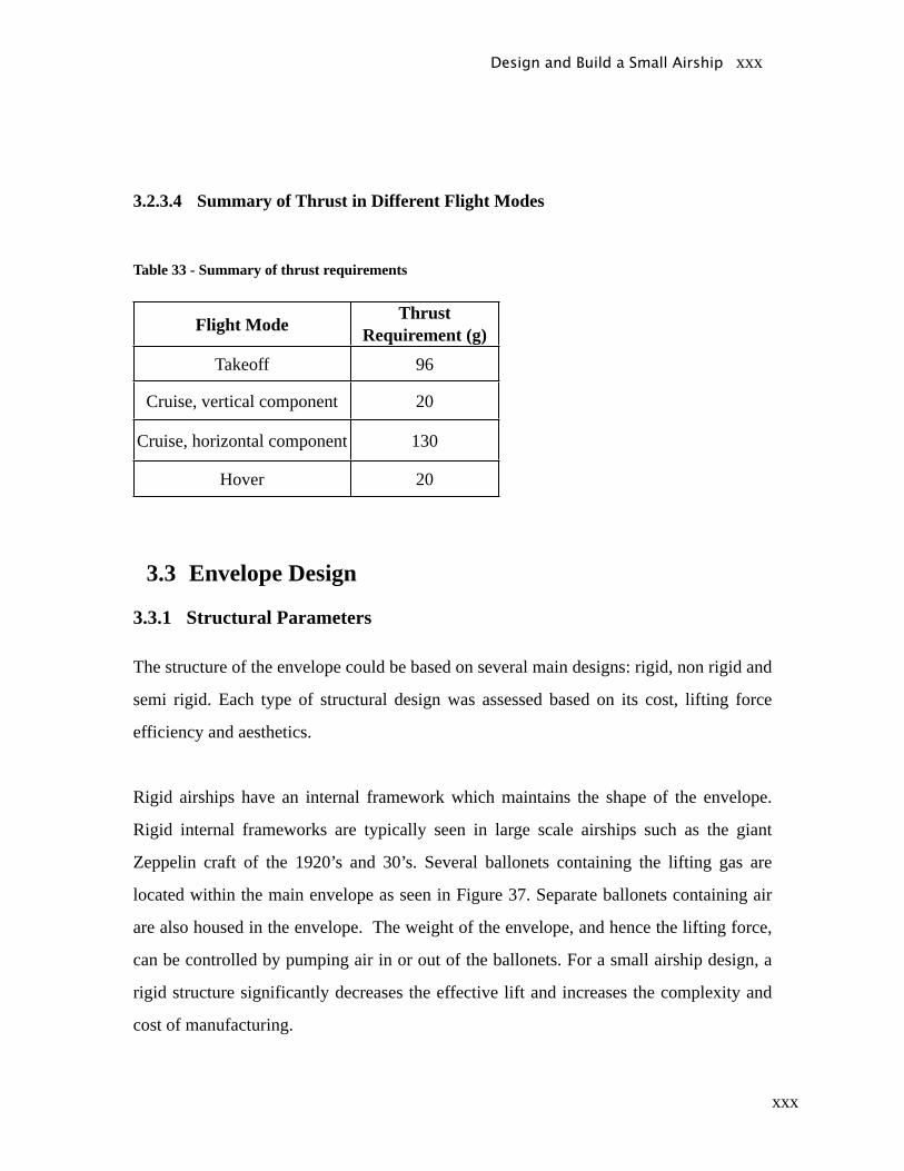
Table 33 - Summary of thrust requirements
Flight ModeThrust
Requirement (g)Takeoff 96
Cruise, vertical component 20
Cruise, horizontal component 130
Hover 20
3.3 Envelope Design
3.3.1 Structural Parameters
The structure of the envelope could be based on several main designs: rigid, non rigid and
semi rigid. Each type of structural design was assessed based on its cost, lifting force
efficiency and aesthetics.
Rigid airships have an internal framework which maintains the shape of the envelope.
Rigid internal frameworks are typically seen in large scale airships such as the giant
Zeppelin craft of the 1920’s and 30’s. Several ballonets containing the lifting gas are
located within the main envelope as seen in Figure 37. Separate ballonets containing air
are also housed in the envelope. The weight of the envelope, and hence the lifting force,
can be controlled by pumping air in or out of the ballonets. For a small airship design, a
rigid structure significantly decreases the effective lift and increases the complexity and
cost of manufacturing.
Design and Build a Small Airship xxx

xxxi
Figure 37 - Bladders in a rigid airship (Australian Broadcasting Corporation, 2004)
Non-rigid airships contain no internal framework to maintain the shape of the envelope.
Instead, their shape is maintained by the pressure of the lifting gas within the envelope.
Larger non-rigid airships typically include a protective outer surface, made from a robust
material such as rubber. Small scale designs generally use a single skin of a durable
material which has a low permeability to helium. One disadvantage of non rigid airship is
that other components cannot be stored within the envelope. Non rigid envelopes are a
simpler, less expensive alternative to rigid envelopes and are commonly seen in smaller
airships under 10 metres in length.
Semi rigid airships try to include the most desirable features from both rigid and non
rigid airships. Semi rigid airships have a non rigid envelope with an internal pressure
higher than that of the atmosphere, to maintain their shape. They also have a framework,
but this framework in not as extensive as that found in rigid airships and hence the overall
weight of the envelope is reduced.
The key requirements in the design of the envelope include indoor use and a low cost. A
singled skinned, non rigid design is the most suited for this project’s application. It is an
inexpensive option and has a high lift to weight efficiency. A non-rigid design is also the
most appropriate for indoor use as forces due to air currents will be low. This style of
envelope is also commonly used by projects of a similar scale and is regularly used in
small commercial craft.
Design and Build a Small Airship xxxi
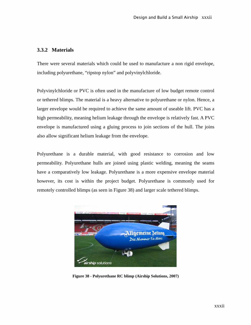
xxxii
3.3.2 Materials
There were several materials which could be used to manufacture a non rigid envelope,
including polyurethane, “ripstop nylon” and polyvinylchloride.
Polyvinylchloride or PVC is often used in the manufacture of low budget remote control
or tethered blimps. The material is a heavy alternative to polyurethane or nylon. Hence, a
larger envelope would be required to achieve the same amount of useable lift. PVC has a
high permeability, meaning helium leakage through the envelope is relatively fast. A PVC
envelope is manufactured using a gluing process to join sections of the hull. The joins
also allow significant helium leakage from the envelope.
Polyurethane is a durable material, with good resistance to corrosion and low
permeability. Polyurethane hulls are joined using plastic welding, meaning the seams
have a comparatively low leakage. Polyurethane is a more expensive envelope material
however, its cost is within the project budget. Polyurethane is commonly used for
remotely controlled blimps (as seen in Figure 38) and larger scale tethered blimps.
Figure 38 - Polyurethane RC blimp (Airship Solutions, 2007)
Design and Build a Small Airship xxxii

xxxiii
“Ripstop nylon” is widely used in airships designed for advertising, where complex art
works and colours are required. A “ripstop nylon” envelope consists of an internal
bladder and an outer protective skin, which protects the bladder. A nylon envelope is
difficult to mend if punctured as the internal bladder must be removed and then repaired.
The dual skins make the envelope heavier, which is clearly not desirable. “Ripstop nylon”
is a more expensive material option and is commonly used for airships larger than that
required for this project.
Figure 39 - Fully Printed Ripstop Nylon Hull (Airship Solutions, 2007)
Polyurethane is the most suitable material for the envelope, as it will lead to the lightest
possible envelope. The low permeability of polyurethane is also significant as less helium
will be lost, reducing costs. Polyurethane material is a more expensive option but its use
should lead to overall higher quality airship.
3.3.3 Shape and Aerodynamics
Using the knowledge obtained through the feasibly study, five concepts for the envelope
shape were developed. These shapes are outlined in Table 34. The concepts were created
using geometric formulae for hemispheres, ellipses, cones and cylinders. The
aerodynamics, volume efficiency and aesthetics of each shape were then analysed.
Table 34 - Envelope Shapes
Design and Build a Small Airship xxxiii
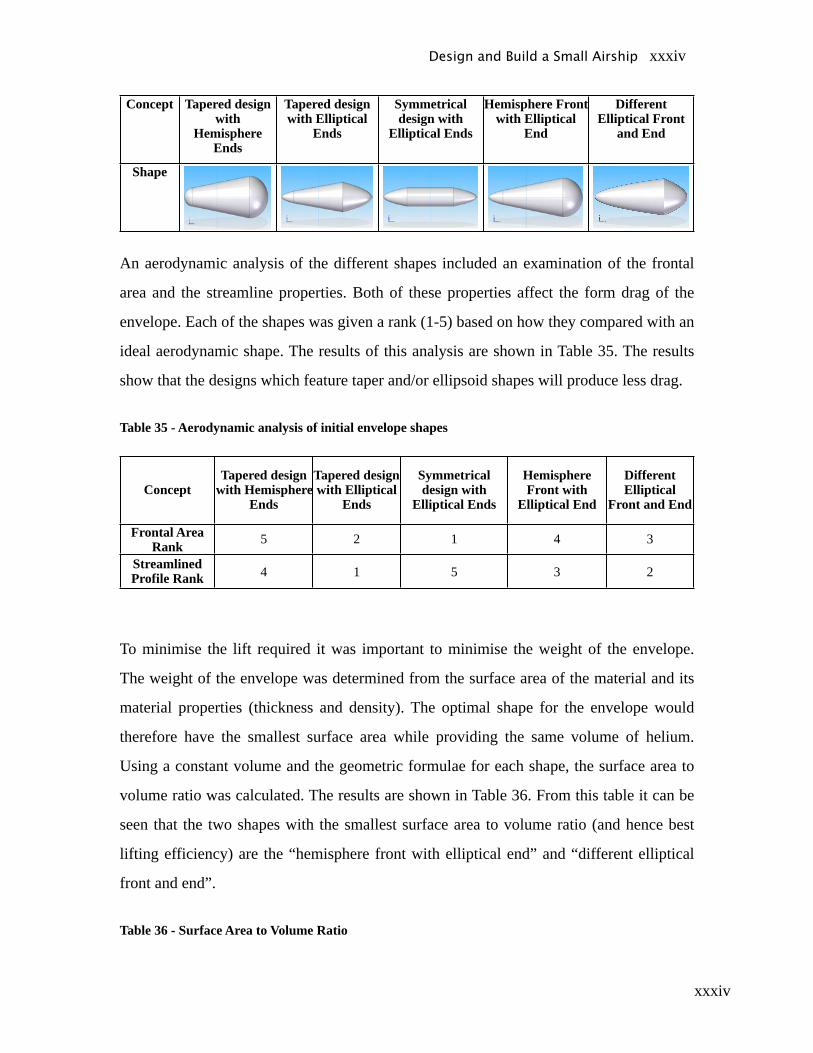
xxxiv
Concept Tapered design with
Hemisphere Ends
Tapered design with Elliptical
Ends
Symmetrical design with
Elliptical Ends
Hemisphere Front with Elliptical
End
Different Elliptical Front
and End
Shape
An aerodynamic analysis of the different shapes included an examination of the frontal
area and the streamline properties. Both of these properties affect the form drag of the
envelope. Each of the shapes was given a rank (1-5) based on how they compared with an
ideal aerodynamic shape. The results of this analysis are shown in Table 35. The results
show that the designs which feature taper and/or ellipsoid shapes will produce less drag.
Table 35 - Aerodynamic analysis of initial envelope shapes
ConceptTapered design
with Hemisphere Ends
Tapered design with Elliptical
Ends
Symmetrical design with
Elliptical Ends
Hemisphere Front with
Elliptical End
Different Elliptical
Front and End
Frontal AreaRank 5 2 1 4 3
Streamlined Profile Rank 4 1 5 3 2
To minimise the lift required it was important to minimise the weight of the envelope.
The weight of the envelope was determined from the surface area of the material and its
material properties (thickness and density). The optimal shape for the envelope would
therefore have the smallest surface area while providing the same volume of helium.
Using a constant volume and the geometric formulae for each shape, the surface area to
volume ratio was calculated. The results are shown in Table 36. From this table it can be
seen that the two shapes with the smallest surface area to volume ratio (and hence best
lifting efficiency) are the “hemisphere front with elliptical end” and “different elliptical
front and end”.
Table 36 - Surface Area to Volume Ratio
Design and Build a Small Airship xxxiv
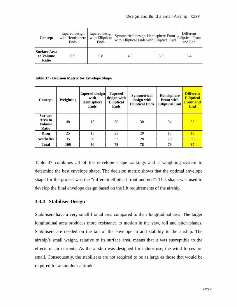
xxxv
ConceptTapered design
with Hemisphere Ends
Tapered design with Elliptical
EndsSymmetrical design with Elliptical Ends
Hemisphere Front with Elliptical End
Different Elliptical Front
and End
Surface Area to Volume
Ratio6.5 5.8 4.5 3.9 3.4
Table 37 - Decision Matrix for Envelope Shape
Concept WeightingTapered design
with Hemisphere
Ends
Tapered design with Elliptical
Ends
Symmetrical design with
Elliptical Ends
Hemisphere Front with
Elliptical End
Different Elliptical Front and
End
Surface Area to Volume Ratio
40 15 20 30 34 38
Drag 25 15 23 20 17 19Aesthetics 35 20 32 28 28 30
Total 100 50 75 78 79 87
Table 37 combines all of the envelope shape rankings and a weighting system to
determine the best envelope shape. The decision matrix shows that the optimal envelope
shape for the project was the “different elliptical front and end”. This shape was used to
develop the final envelope design based on the lift requirements of the airship.
3.3.4 Stabiliser Design
Stabilisers have a very small frontal area compared to their longitudinal area. The larger
longitudinal area produces more resistance to motion in the yaw, roll and pitch planes.
Stabilisers are needed on the tail of the envelope to add stability to the airship. The
airship’s small weight, relative to its surface area, means that it was susceptible to the
effects of air currents. As the airship was designed for indoor use, the wind forces are
small. Consequently, the stabilisers are not required to be as large as those that would be
required for an outdoor altitude.
Design and Build a Small Airship xxxv
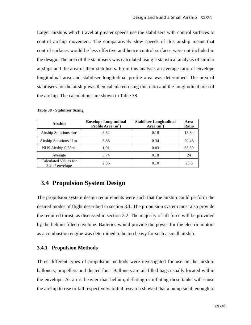
xxxvi
Larger airships which travel at greater speeds use the stabilisers with control surfaces to
control airship movement. The comparatively slow speeds of this airship meant that
control surfaces would be less effective and hence control surfaces were not included in
the design. The area of the stabilisers was calculated using a statistical analysis of similar
airships and the area of their stabilisers. From this analysis an average ratio of envelope
longitudinal area and stabiliser longitudinal profile area was determined. The area of
stabilisers for the airship was then calculated using this ratio and the longitudinal area of
the airship. The calculations are shown in Table 38
Table 38 - Stabiliser Sizing
Airship Envelope Longitudinal Profile Area (m2)
Stabiliser Longitudinal Area (m2)
Area Ratio
Airship Solutions 4m3 3.32 0.18 18.84
Airship Solutions 11m3 6.88 0.34 20.48
NUS Airship 0.55m3 1.01 0.03 33.50
Average 3.74 0.18 24Calculated Values for
3.2m3 envelope 2.36 0.10 23.6
3.4 Propulsion System Design
The propulsion system design requirements were such that the airship could perform the
desired modes of flight described in section 3.1. The propulsion system must also provide
the required thrust, as discussed in section 3.2. The majority of lift force will be provided
by the helium filled envelope. Batteries would provide the power for the electric motors
as a combustion engine was determined to be too heavy for such a small airship.
3.4.1 Propulsion Methods
Three different types of propulsion methods were investigated for use on the airship:
ballonets, propellers and ducted fans. Ballonets are air filled bags usually located within
the envelope. As air is heavier than helium, deflating or inflating these tanks will cause
the airship to rise or fall respectively. Initial research showed that a pump small enough to
Design and Build a Small Airship xxxvi
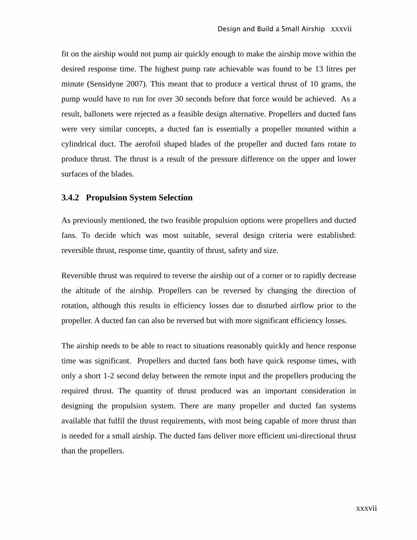
xxxvii
fit on the airship would not pump air quickly enough to make the airship move within the
desired response time. The highest pump rate achievable was found to be 13 litres per
minute (Sensidyne 2007). This meant that to produce a vertical thrust of 10 grams, the
pump would have to run for over 30 seconds before that force would be achieved. As a
result, ballonets were rejected as a feasible design alternative. Propellers and ducted fans
were very similar concepts, a ducted fan is essentially a propeller mounted within a
cylindrical duct. The aerofoil shaped blades of the propeller and ducted fans rotate to
produce thrust. The thrust is a result of the pressure difference on the upper and lower
surfaces of the blades.
3.4.2 Propulsion System Selection
As previously mentioned, the two feasible propulsion options were propellers and ducted
fans. To decide which was most suitable, several design criteria were established:
reversible thrust, response time, quantity of thrust, safety and size.
Reversible thrust was required to reverse the airship out of a corner or to rapidly decrease
the altitude of the airship. Propellers can be reversed by changing the direction of
rotation, although this results in efficiency losses due to disturbed airflow prior to the
propeller. A ducted fan can also be reversed but with more significant efficiency losses.
The airship needs to be able to react to situations reasonably quickly and hence response
time was significant. Propellers and ducted fans both have quick response times, with
only a short 1-2 second delay between the remote input and the propellers producing the
required thrust. The quantity of thrust produced was an important consideration in
designing the propulsion system. There are many propeller and ducted fan systems
available that fulfil the thrust requirements, with most being capable of more thrust than
is needed for a small airship. The ducted fans deliver more efficient uni-directional thrust
than the propellers.
Design and Build a Small Airship xxxvii
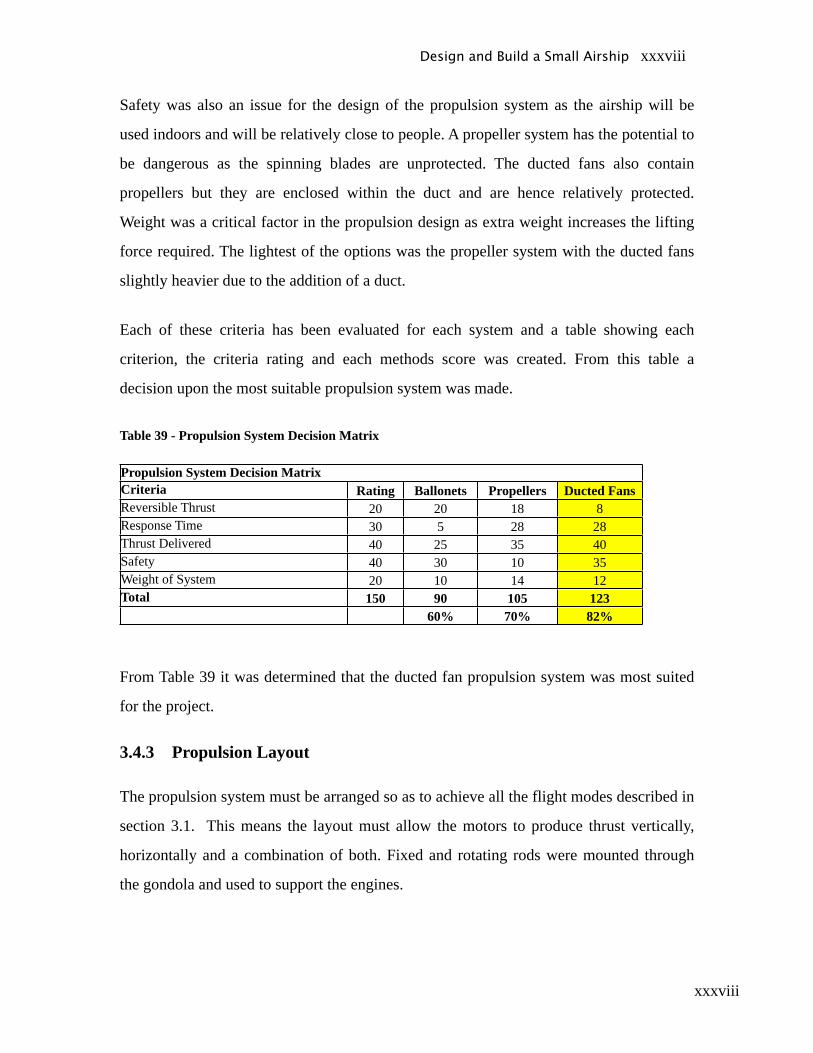
xxxviii
Safety was also an issue for the design of the propulsion system as the airship will be
used indoors and will be relatively close to people. A propeller system has the potential to
be dangerous as the spinning blades are unprotected. The ducted fans also contain
propellers but they are enclosed within the duct and are hence relatively protected.
Weight was a critical factor in the propulsion design as extra weight increases the lifting
force required. The lightest of the options was the propeller system with the ducted fans
slightly heavier due to the addition of a duct.
Each of these criteria has been evaluated for each system and a table showing each
criterion, the criteria rating and each methods score was created. From this table a
decision upon the most suitable propulsion system was made.
Table 39 - Propulsion System Decision Matrix
Propulsion System Decision MatrixCriteria Rating Ballonets Propellers Ducted FansReversible Thrust 20 20 18 8Response Time 30 5 28 28Thrust Delivered 40 25 35 40Safety 40 30 10 35Weight of System 20 10 14 12Total 150 90 105 123
60% 70% 82%
From Table 39 it was determined that the ducted fan propulsion system was most suited
for the project.
3.4.3 Propulsion Layout
The propulsion system must be arranged so as to achieve all the flight modes described in
section 3.1. This means the layout must allow the motors to produce thrust vertically,
horizontally and a combination of both. Fixed and rotating rods were mounted through
the gondola and used to support the engines.
Design and Build a Small Airship xxxviii
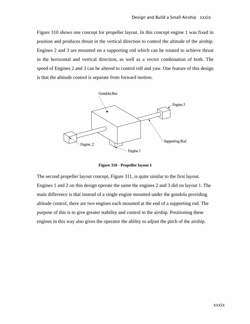
xxxix
Figure 310 shows one concept for propeller layout. In this concept engine 1 was fixed in
position and produces thrust in the vertical direction to control the altitude of the airship.
Engines 2 and 3 are mounted on a supporting rod which can be rotated to achieve thrust
in the horizontal and vertical direction, as well as a vector combination of both. The
speed of Engines 2 and 3 can be altered to control roll and yaw. One feature of this design
is that the altitude control is separate from forward motion.
Figure 310 - Propeller layout 1
The second propeller layout concept, Figure 311, is quite similar to the first layout.
Engines 1 and 2 on this design operate the same the engines 2 and 3 did on layout 1. The
main difference is that instead of a single engine mounted under the gondola providing
altitude control, there are two engines each mounted at the end of a supporting rod. The
purpose of this is to give greater stability and control to the airship. Positioning these
engines in this way also gives the operator the ability to adjust the pitch of the airship.
Design and Build a Small Airship xxxix
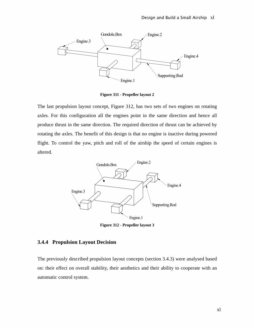
xl
Figure 311 - Propeller layout 2
The last propulsion layout concept, Figure 312, has two sets of two engines on rotating
axles. For this configuration all the engines point in the same direction and hence all
produce thrust in the same direction. The required direction of thrust can be achieved by
rotating the axles. The benefit of this design is that no engine is inactive during powered
flight. To control the yaw, pitch and roll of the airship the speed of certain engines is
altered.
Figure 312 - Propeller layout 3
3.4.4 Propulsion Layout Decision
The previously described propulsion layout concepts (section 3.4.3) were analysed based
on: their effect on overall stability, their aesthetics and their ability to cooperate with an
automatic control system.
Design and Build a Small Airship xl
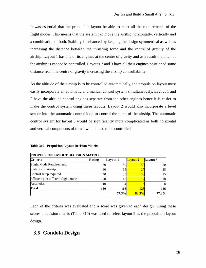
xli
It was essential that the propulsion layout be able to meet all the requirements of the
flight modes. This means that the system can move the airship horizontally, vertically and
a combination of both. Stability is enhanced by keeping the design symmetrical as well as
increasing the distance between the thrusting force and the centre of gravity of the
airship. Layout 1 has one of its engines at the centre of gravity and as a result the pitch of
the airship is cannot be controlled. Layouts 2 and 3 have all their engines positioned some
distance from the centre of gravity increasing the airship controllability.
As the altitude of the airship is to be controlled automatically, the propulsion layout must
easily incorporate an automatic and manual control system simultaneously. Layout 1 and
2 have the altitude control engines separate from the other engines hence it is easier to
make the control system using these layouts. Layout 2 would also incorporate a level
sensor into the automatic control loop to control the pitch of the airship. The automatic
control system for layout 3 would be significantly more complicated as both horizontal
and vertical components of thrust would need to be controlled.
Table 310 - Propulsion Layout Decision Matrix
PROPULSION LAYOUT DECISION MATRIXCriteria Rating Layout 1 Layout 2 Layout 3Flight Mode Requirements 50 50 50 50Stability of airship 30 15 27 25Control setup required 40 35 30 15Efficiency in different flight modes 20 12 12 18Aesthetics 10 4 6 8Total 150 116 125 116
77.3% 83.3% 77.3%
Each of the criteria was evaluated and a score was given to each design. Using these
scores a decision matrix (Table 310) was used to select layout 2 as the propulsion layout
design.
3.5 Gondola Design
Design and Build a Small Airship xli
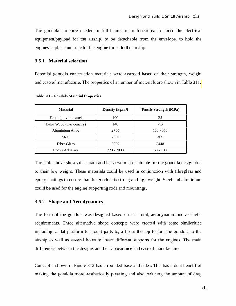
xlii
The gondola structure needed to fulfil three main functions: to house the electrical
equipment/payload for the airship, to be detachable from the envelope, to hold the
engines in place and transfer the engine thrust to the airship.
3.5.1 Material selection
Potential gondola construction materials were assessed based on their strength, weight
and ease of manufacture. The properties of a number of materials are shown in Table 311.
Table 311 - Gondola Material Properties
Material Density (kg/m3) Tensile Strength (MPa)
Foam (polyurethane) 100 35
Balsa Wood (low density) 140 7.6Aluminium Alloy 2700 100 - 350
Steel 7800 365
Fibre Glass 2600 3448Epoxy Adhesive 720 - 2800 60 - 100
The table above shows that foam and balsa wood are suitable for the gondola design due
to their low weight. These materials could be used in conjunction with fibreglass and
epoxy coatings to ensure that the gondola is strong and lightweight. Steel and aluminium
could be used for the engine supporting rods and mountings.
3.5.2 Shape and Aerodynamics
The form of the gondola was designed based on structural, aerodynamic and aesthetic
requirements. Three alternative shape concepts were created with some similarities
including: a flat platform to mount parts to, a lip at the top to join the gondola to the
airship as well as several holes to insert different supports for the engines. The main
differences between the designs are their appearance and ease of manufacture.
Concept 1 shown in Figure 313 has a rounded base and sides. This has a dual benefit of
making the gondola more aesthetically pleasing and also reducing the amount of drag
Design and Build a Small Airship xlii
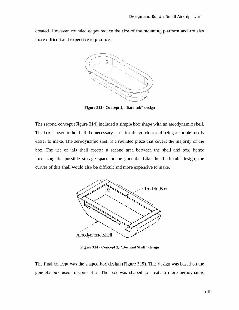
xliii
created. However, rounded edges reduce the size of the mounting platform and are also
more difficult and expensive to produce.
Figure 313 - Concept 1, "Bath tub" design
The second concept (Figure 314) included a simple box shape with an aerodynamic shell.
The box is used to hold all the necessary parts for the gondola and being a simple box is
easier to make. The aerodynamic shell is a rounded piece that covers the majority of the
box. The use of this shell creates a second area between the shell and box, hence
increasing the possible storage space in the gondola. Like the ‘bath tub’ design, the
curves of this shell would also be difficult and more expensive to make.
Figure 314 - Concept 2, "Box and Shell" design
The final concept was the shaped box design (Figure 315). This design was based on the
gondola box used in concept 2. The box was shaped to create a more aerodynamic
Design and Build a Small Airship xliii
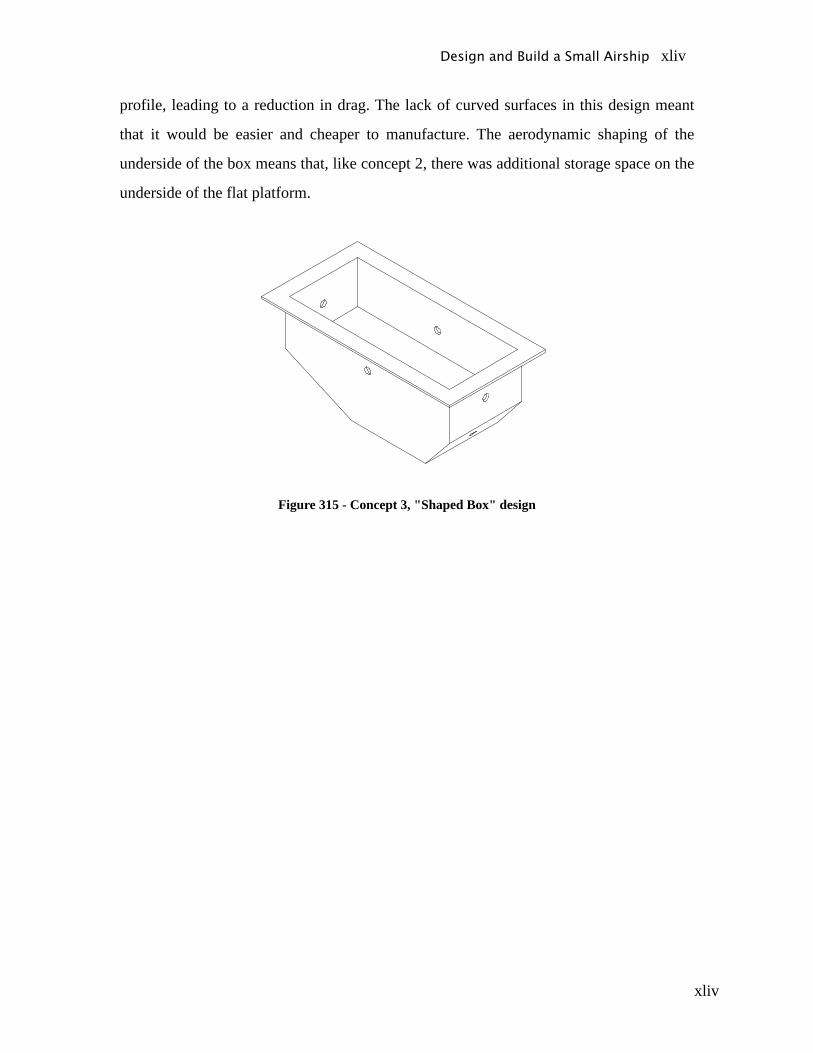
xliv
profile, leading to a reduction in drag. The lack of curved surfaces in this design meant
that it would be easier and cheaper to manufacture. The aerodynamic shaping of the
underside of the box means that, like concept 2, there was additional storage space on the
underside of the flat platform.
Figure 315 - Concept 3, "Shaped Box" design
Design and Build a Small Airship xliv

xlv
3.5.3 Design Selection
All three of the concepts adequately met all the structural requirements of the gondola
hence the decision on which concept was based on the ease of manufacture and
aesthetics.
Generally, straight parts are much easier to manufacture than curved parts. Only concept
3 had no curved parts making it easier to manufacture. Concept 1 had a large amount of
curved surfaces and hence was considered to be hardest to manufacture. While the
gondola box of concept 2 would be easy to produce, the curved shell would cause some
difficulties. It was suggested that this could be produced from a blow moulded plastic
shell, however this was not possible, as the University did not have the machinery
required. Balsa wood, used throughout concepts 2 and 3, was also readily available from
most model/hobby shops.
The curved and shaped pieces used in concepts 1 and 2 gave the airship a more
aerodynamic and smooth finish. Concept 3 although not curved, does have an
aerodynamic shape to improve its appearance over a simple box.
Using these criteria a decision matrix (Table 312) was formed to decide on the best
possible design.
Table 312 - Gondola Design Decision Matrix
Gondola Design Decision MatrixCriteria Rating Concept 1 Concept 2 Concept 3Ease of Manufacture 50 25 30 45Aesthetics 50 35 35 30Total 100 60 65 75
Design and Build a Small Airship xlv
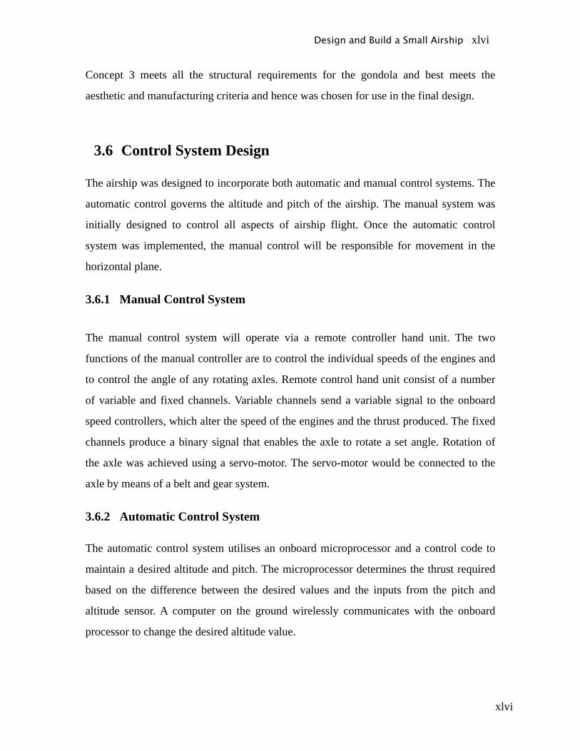
xlvi
Concept 3 meets all the structural requirements for the gondola and best meets the
aesthetic and manufacturing criteria and hence was chosen for use in the final design.
3.6 Control System Design
The airship was designed to incorporate both automatic and manual control systems. The
automatic control governs the altitude and pitch of the airship. The manual system was
initially designed to control all aspects of airship flight. Once the automatic control
system was implemented, the manual control will be responsible for movement in the
horizontal plane.
3.6.1 Manual Control System
The manual control system will operate via a remote controller hand unit. The two
functions of the manual controller are to control the individual speeds of the engines and
to control the angle of any rotating axles. Remote control hand unit consist of a number
of variable and fixed channels. Variable channels send a variable signal to the onboard
speed controllers, which alter the speed of the engines and the thrust produced. The fixed
channels produce a binary signal that enables the axle to rotate a set angle. Rotation of
the axle was achieved using a servo-motor. The servo-motor would be connected to the
axle by means of a belt and gear system.
3.6.2 Automatic Control System
The automatic control system utilises an onboard microprocessor and a control code to
maintain a desired altitude and pitch. The microprocessor determines the thrust required
based on the difference between the desired values and the inputs from the pitch and
altitude sensor. A computer on the ground wirelessly communicates with the onboard
processor to change the desired altitude value.
Design and Build a Small Airship xlvi
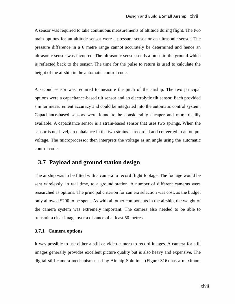
xlvii
A sensor was required to take continuous measurements of altitude during flight. The two
main options for an altitude sensor were a pressure sensor or an ultrasonic sensor. The
pressure difference in a 6 metre range cannot accurately be determined and hence an
ultrasonic sensor was favoured. The ultrasonic sensor sends a pulse to the ground which
is reflected back to the sensor. The time for the pulse to return is used to calculate the
height of the airship in the automatic control code.
A second sensor was required to measure the pitch of the airship. The two principal
options were a capacitance-based tilt sensor and an electrolytic tilt sensor. Each provided
similar measurement accuracy and could be integrated into the automatic control system.
Capacitance-based sensors were found to be considerably cheaper and more readily
available. A capacitance sensor is a strain-based sensor that uses two springs. When the
sensor is not level, an unbalance in the two strains is recorded and converted to an output
voltage. The microprocessor then interprets the voltage as an angle using the automatic
control code.
3.7 Payload and ground station design
The airship was to be fitted with a camera to record flight footage. The footage would be
sent wirelessly, in real time, to a ground station. A number of different cameras were
researched as options. The principal criterion for camera selection was cost, as the budget
only allowed $200 to be spent. As with all other components in the airship, the weight of
the camera system was extremely important. The camera also needed to be able to
transmit a clear image over a distance of at least 50 metres.
3.7.1 Camera options
It was possible to use either a still or video camera to record images. A camera for still
images generally provides excellent picture quality but is also heavy and expensive. The
digital still camera mechanism used by Airship Solutions (Figure 316) has a maximum
Design and Build a Small Airship xlvii
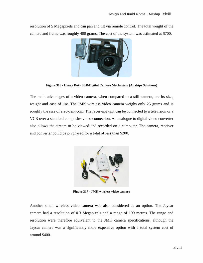
xlviii
resolution of 5 Megapixels and can pan and tilt via remote control. The total weight of the
camera and frame was roughly 400 grams. The cost of the system was estimated at $700.
Figure 316 - Heavy Duty SLR/Digital Camera Mechanism (Airships Solutions)
The main advantages of a video camera, when compared to a still camera, are its size,
weight and ease of use. The JMK wireless video camera weighs only 25 grams and is
roughly the size of a 20-cent coin. The receiving unit can be connected to a television or a
VCR over a standard composite-video connection. An analogue to digital video converter
also allows the stream to be viewed and recorded on a computer. The camera, receiver
and converter could be purchased for a total of less than $200.
Figure 317 - JMK wireless video camera
Another small wireless video camera was also considered as an option. The Jaycar
camera had a resolution of 0.3 Megapixels and a range of 100 metres. The range and
resolution were therefore equivalent to the JMK camera specifications, although the
Jaycar camera was a significantly more expensive option with a total system cost of
around $400.
Design and Build a Small Airship xlviii

xlix
Design and Build a Small Airship xlix
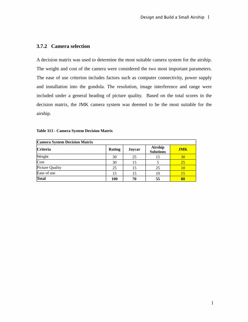
l
3.7.2 Camera selection
A decision matrix was used to determine the most suitable camera system for the airship.
The weight and cost of the camera were considered the two most important parameters.
The ease of use criterion includes factors such as computer connectivity, power supply
and installation into the gondola. The resolution, image interference and range were
included under a general heading of picture quality. Based on the total scores in the
decision matrix, the JMK camera system was deemed to be the most suitable for the
airship.
Table 313 - Camera System Decision Matrix
Camera System Decision Matrix
Criteria Rating Jaycar Airship Solutions JMK
Weight 30 25 15 30Cost 30 15 5 25Picture Quality 25 15 25 10Ease of use 15 15 10 15Total 100 70 55 80
Design and Build a Small Airship l
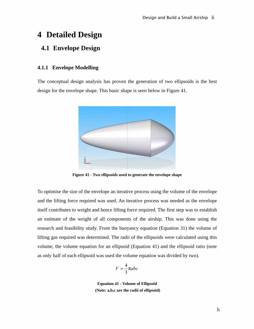
li
4 Detailed Design4.1 Envelope Design
4.1.1 Envelope Modelling
The conceptual design analysis has proven the generation of two ellipsoids is the best
design for the envelope shape. This basic shape is seen below in Figure 41.
Figure 41 - Two ellipsoids used to generate the envelope shape
To optimise the size of the envelope an iterative process using the volume of the envelope
and the lifting force required was used. An iterative process was needed as the envelope
itself contributes to weight and hence lifting force required. The first step was to establish
an estimate of the weight of all components of the airship. This was done using the
research and feasibility study. From the buoyancy equation (Equation 31) the volume of
lifting gas required was determined. The radii of the ellipsoids were calculated using this
volume, the volume equation for an ellipsoid (Equation 41) and the ellipsoid ratio (note
as only half of each ellipsoid was used the volume equation was divided by two).
Equation 41 - Volume of Ellipsoid (Note: a,b,c are the radii of ellipsoid)
Design and Build a Small Airship li
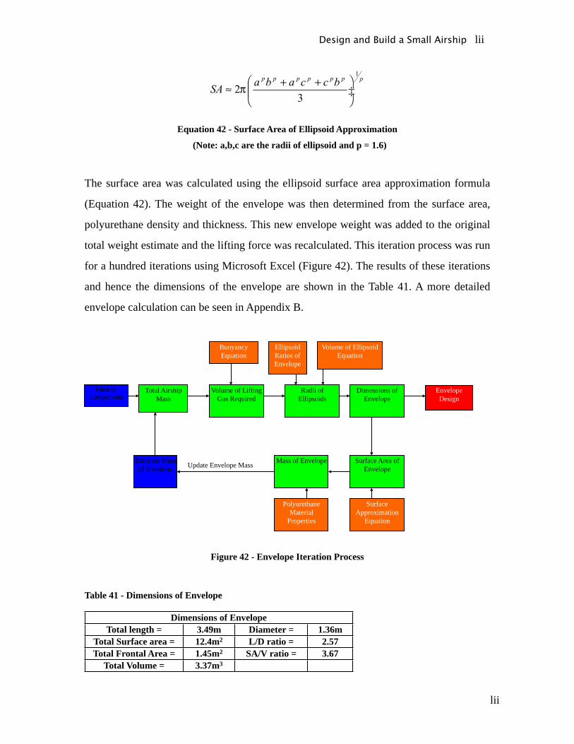
lii
Equation 42 - Surface Area of Ellipsoid Approximation
(Note: a,b,c are the radii of ellipsoid and p = 1.6)
The surface area was calculated using the ellipsoid surface area approximation formula
(Equation 42). The weight of the envelope was then determined from the surface area,
polyurethane density and thickness. This new envelope weight was added to the original
total weight estimate and the lifting force was recalculated. This iteration process was run
for a hundred iterations using Microsoft Excel (Figure 42). The results of these iterations
and hence the dimensions of the envelope are shown in the Table 41. A more detailed
envelope calculation can be seen in Appendix B.
Mass of Components
Estimate Mass of Envelope
Total Airship Mass
Volume of Lifting Gas Required
Ellipsoid Ratios of Envelope
Radii of Ellipsoids
Dimensions of Envelope
Surface Area of Envelope
Polyurethane Material
Properties
Mass of EnvelopeUpdate Envelope Mass
Buoyancy Equation
Volume of Ellipsoid Equation
Surface Approximation
Equation
EnvelopeDesign
Figure 42 - Envelope Iteration Process
Table 41 - Dimensions of Envelope
Dimensions of EnvelopeTotal length = 3.49m Diameter = 1.36m
Total Surface area = 12.4m2 L/D ratio = 2.57Total Frontal Area = 1.45m2 SA/V ratio = 3.67
Total Volume = 3.37m3
Design and Build a Small Airship lii
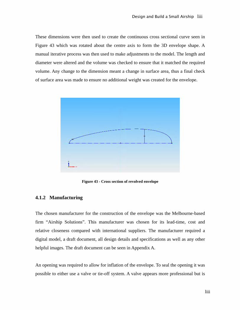
liii
These dimensions were then used to create the continuous cross sectional curve seen in
Figure 43 which was rotated about the centre axis to form the 3D envelope shape. A
manual iterative process was then used to make adjustments to the model. The length and
diameter were altered and the volume was checked to ensure that it matched the required
volume. Any change to the dimension meant a change in surface area, thus a final check
of surface area was made to ensure no additional weight was created for the envelope.
Figure 43 - Cross section of revolved envelope
4.1.2 Manufacturing
The chosen manufacturer for the construction of the envelope was the Melbourne-based
firm “Airship Solutions”. This manufacturer was chosen for its lead-time, cost and
relative closeness compared with international suppliers. The manufacturer required a
digital model, a draft document, all design details and specifications as well as any other
helpful images. The draft document can be seen in Appendix A.
An opening was required to allow for inflation of the envelope. To seal the opening it was
possible to either use a valve or tie-off system. A valve appears more professional but is
Design and Build a Small Airship liii

liv
difficult and more costly to manufacture. The seams between the valve and envelope can
result in greater leakage of helium than if a tie-off system was used. Airship Solutions
recommended a tie-off system as being a superior option over a valve. Due to this
recommendation and leakage considerations the tie-off system was selected.
Two safety line attachments are needed on the airship. The first connects the gondola and
envelope and acts as a safety mechanism if the join between the two fails. The second
safety line is located on the nose of the airship. This tie line is often referred to as a
mooring line, as it can be used to restrain the entire airship to the ground. The mooring
line would be used to keep the blimp tethered during testing.
4.1.3 Stabiliser Design
The size of the stabilisers was previously calculated in the conceptual design. The shape
of the stabilisers was chosen from two designs commonly used on indoor airships (shown
in Figure 44).
Figure 44 - Possible Stabiliser Shapes
Both of the designs feature a taper angle to reduce the drag produced by the stabilisers
during forward motion. The concept on the left has a larger taper region. This increases
the length of the stabiliser such that it would be difficult to fit the edge of the stabiliser to
the contour of the envelope tail. The concept on the right has a shorter length and would
better match the contour of the envelope hence this design was chosen.
The stabilisers are made from 5mm thick light weight foam, supplied by Airship
Solutions. The stabilisers were then cut to shape, covered with a plastic film for aesthetics
and secured to the airship. The stabilisers were secured to the envelope using a light
Design and Build a Small Airship liv
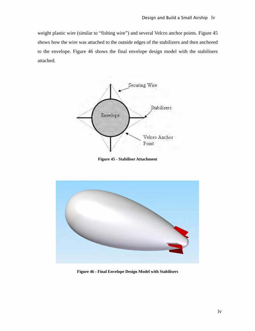
lv
weight plastic wire (similar to “fishing wire”) and several Velcro anchor points. Figure 45
shows how the wire was attached to the outside edges of the stabilizers and then anchored
to the envelope. Figure 46 shows the final envelope design model with the stabilisers
attached.
Figure 45 - Stabiliser Attachment
Figure 46 - Final Envelope Design Model with Stabilisers
Design and Build a Small Airship lv
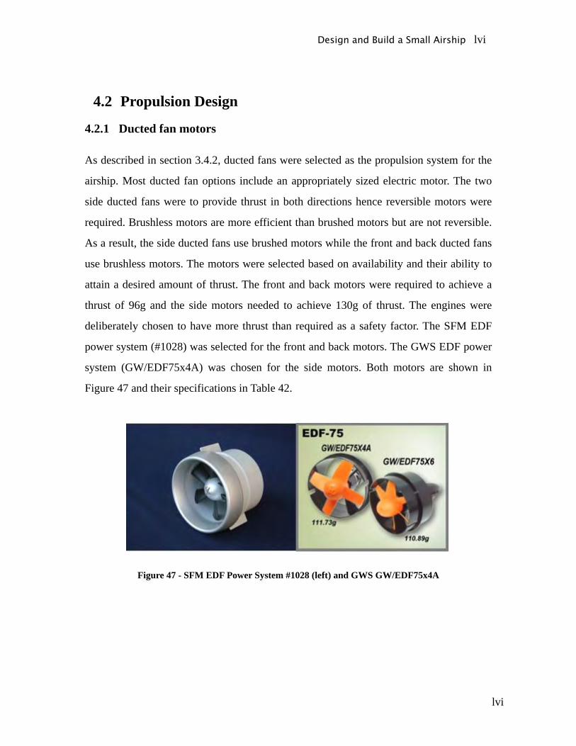
lvi
4.2 Propulsion Design
4.2.1 Ducted fan motors
As described in section 3.4.2, ducted fans were selected as the propulsion system for the
airship. Most ducted fan options include an appropriately sized electric motor. The two
side ducted fans were to provide thrust in both directions hence reversible motors were
required. Brushless motors are more efficient than brushed motors but are not reversible.
As a result, the side ducted fans use brushed motors while the front and back ducted fans
use brushless motors. The motors were selected based on availability and their ability to
attain a desired amount of thrust. The front and back motors were required to achieve a
thrust of 96g and the side motors needed to achieve 130g of thrust. The engines were
deliberately chosen to have more thrust than required as a safety factor. The SFM EDF
power system (#1028) was selected for the front and back motors. The GWS EDF power
system (GW/EDF75x4A) was chosen for the side motors. Both motors are shown in
Figure 47 and their specifications in Table 42.
Figure 47 - SFM EDF Power System #1028 (left) and GWS GW/EDF75x4A
Design and Build a Small Airship lvi
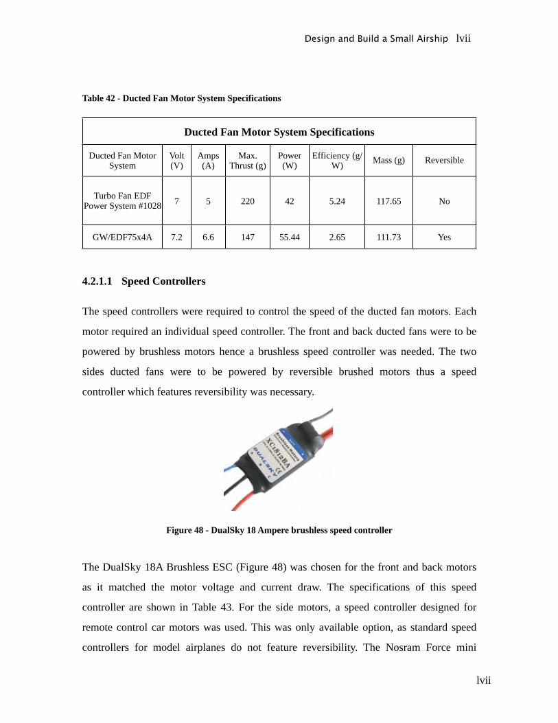
lvii
Table 42 - Ducted Fan Motor System Specifications
Ducted Fan Motor System Specifications
Ducted Fan Motor System
Volt (V)
Amps (A)
Max. Thrust (g)
Power (W)
Efficiency (g/W) Mass (g) Reversible
Turbo Fan EDF Power System #1028 7 5 220 42 5.24 117.65 No
GW/EDF75x4A 7.2 6.6 147 55.44 2.65 111.73 Yes
4.2.1.1 Speed Controllers
The speed controllers were required to control the speed of the ducted fan motors. Each
motor required an individual speed controller. The front and back ducted fans were to be
powered by brushless motors hence a brushless speed controller was needed. The two
sides ducted fans were to be powered by reversible brushed motors thus a speed
controller which features reversibility was necessary.
Figure 48 - DualSky 18 Ampere brushless speed controller
The DualSky 18A Brushless ESC (Figure 48) was chosen for the front and back motors
as it matched the motor voltage and current draw. The specifications of this speed
controller are shown in Table 43. For the side motors, a speed controller designed for
remote control car motors was used. This was only available option, as standard speed
controllers for model airplanes do not feature reversibility. The Nosram Force mini
Design and Build a Small Airship lvii
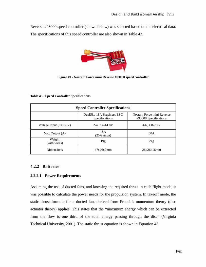
lviii
Reverse #93000 speed controller (shown below) was selected based on the electrical data.
The specifications of this speed controller are also shown in Table 43.
Figure 49 - Nosram Force mini Reverse #93000 speed controller
Table 43 - Speed Controller Specifications
Speed Controller SpecificationsDualSky 18A Brushless ESC
SpecificationsNosram Force mini Reverse
#93000 Specifications
Voltage Input (Cells, V) 2-4, 7.4-14.8V 4-6, 4.8-7.2V
Max Output (A) 18A(25A surge) 60A
Weight(with wires) 19g 24g
Dimensions 47x26x7mm 26x26x16mm
4.2.2 Batteries
4.2.2.1 Power Requirements
Assuming the use of ducted fans, and knowing the required thrust in each flight mode, it
was possible to calculate the power needs for the propulsion system. In takeoff mode, the
static thrust formula for a ducted fan, derived from Froude’s momentum theory (disc
actuator theory) applies. This states that the “maximum energy which can be extracted
from the flow is one third of the total energy passing through the disc” (Virginia
Technical University, 2001). The static thrust equation is shown in Equation 43.
Design and Build a Small Airship lviii
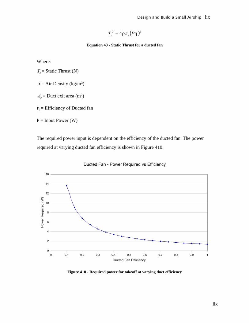
lix
Equation 43 - Static Thrust for a ducted fan
Where:
= Static Thrust (N)
= Air Density (kg/m3)
= Duct exit area (m2)
= Efficiency of Ducted fan
P = Input Power (W)
The required power input is dependent on the efficiency of the ducted fan. The power
required at varying ducted fan efficiency is shown in Figure 410.
Figure 410 - Required power for takeoff at varying duct efficiency
Design and Build a Small Airship lix
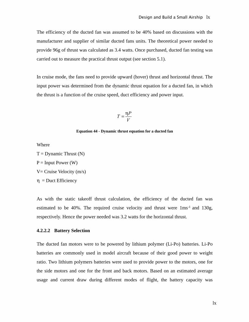
lx
The efficiency of the ducted fan was assumed to be 40% based on discussions with the
manufacturer and supplier of similar ducted fans units. The theoretical power needed to
provide 96g of thrust was calculated as 3.4 watts. Once purchased, ducted fan testing was
carried out to measure the practical thrust output (see section 5.1).
In cruise mode, the fans need to provide upward (hover) thrust and horizontal thrust. The
input power was determined from the dynamic thrust equation for a ducted fan, in which
the thrust is a function of the cruise speed, duct efficiency and power input.
Equation 44 - Dynamic thrust equation for a ducted fan
Where
T = Dynamic Thrust (N)
P = Input Power (W)
V= Cruise Velocity (m/s)
= Duct Efficiency
As with the static takeoff thrust calculation, the efficiency of the ducted fan was
estimated to be 40%. The required cruise velocity and thrust were 1ms-1 and 130g,
respectively. Hence the power needed was 3.2 watts for the horizontal thrust.
4.2.2.2 Battery Selection
The ducted fan motors were to be powered by lithium polymer (Li-Po) batteries. Li-Po
batteries are commonly used in model aircraft because of their good power to weight
ratio. Two lithium polymers batteries were used to provide power to the motors, one for
the side motors and one for the front and back motors. Based on an estimated average
usage and current draw during different modes of flight, the battery capacity was
Design and Build a Small Airship lx
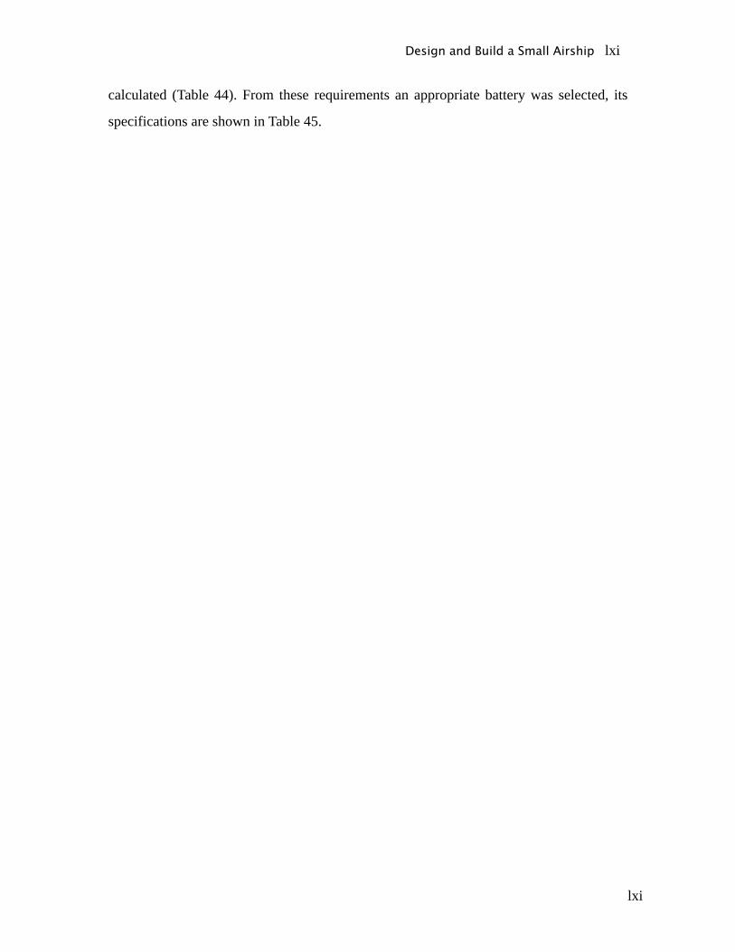
lxi
calculated (Table 44). From these requirements an appropriate battery was selected, its
specifications are shown in Table 45.
Design and Build a Small Airship lxi

lxii
Table 44 - Battery capacity requirements
Capacity (mAh)Side Engines 1850
Front & Rear Engines 1400
Table 45 – Specifications of the selected Li-Po battery
Battery Life (mAh) 1800Serial FPEVO25-18002S
Weight (grams) 110Voltage (v) 7.4
Cost ($AUS) 85.5
4.3 Gondola Design
4.3.1 Design Details
The final concept for the gondola was selected in section 3.5.3 and based on this a final
design was developed. This section will discuss the details of the design and any design
changes that were made. The complete drawings of the Gondola design are shown in
Appendix C.
The gondola structure was constructed from balsa wood and coated with epoxy to
provide extra strength. One issue during construction was that balsa wood was only
available in sheet 150mm wide, however 300mm sheets were required. As a result, two
pieces had to be butt joined to create one 300mm piece reducing the strength of the
structure. To compensate for the loss of strength, ribs were added to the floor and walls of
the gondola.
The lips and sides of the gondola were shaped to approximately match the contour of the
envelope. This allowed for greater contact area between the gondola and the envelope. To
connect the gondola and envelope, Velcro was added to the lip of the gondola and to the
Design and Build a Small Airship lxii

lxiii
base of the envelope. This is a very strong attachment, which will hold the weight of the
gondola. The use of Velcro meant that gondola could be detached quickly from the
envelope. Possible concerns may arise with repeatedly removing the gondola because of
stretching of the polyurethane material. So that the gondola did not have to be frequently
detached, a lid beneath the gondola (shown in Figure 411) was included for access to
parts such as batteries.
Figure 411 - Gondola underside hatch
The ducted fans in front and behind the gondola were each supported by a fixed axle
made from aluminium. The axle was fixed to an aluminium bracket on the inside of the
gondola. The centre axle rotates using a servo-motor, to provide extra manoeuvrability.
The belt and gear system transfers the rotational motion from the servo to the axle. The
gear ratio was 1:1 hence the servo rotation equalled the axle rotation (see Figure 413).
The rotating axle was located using removable washers placed along side the inner wall
on the gondola. These prevent the axle from sliding out of position. Design details can be
seen in Figure 412 and in Appendix A.
Design and Build a Small Airship lxiii
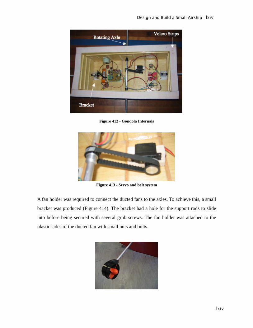
lxiv
Figure 412 - Gondola Internals
Figure 413 - Servo and belt system
A fan holder was required to connect the ducted fans to the axles. To achieve this, a small
bracket was produced (Figure 414). The bracket had a hole for the support rods to slide
into before being secured with several grub screws. The fan holder was attached to the
plastic sides of the ducted fan with small nuts and bolts.
Design and Build a Small Airship lxiv
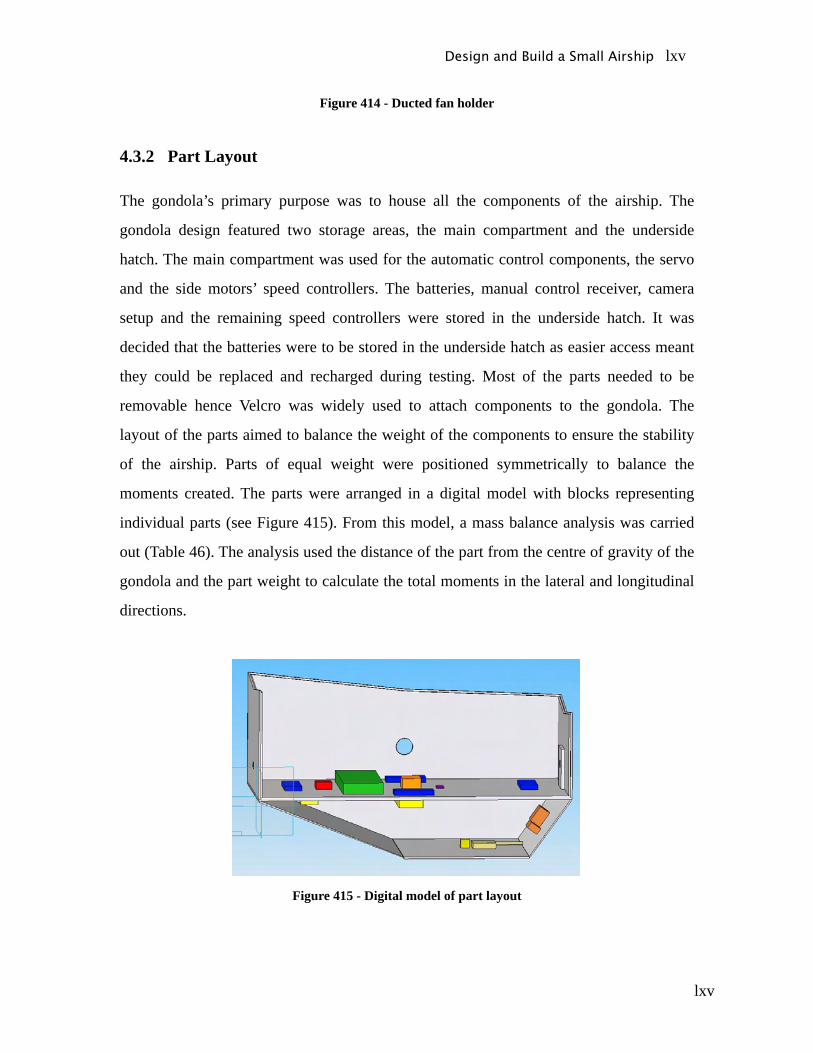
lxv
Figure 414 - Ducted fan holder
4.3.2 Part Layout
The gondola’s primary purpose was to house all the components of the airship. The
gondola design featured two storage areas, the main compartment and the underside
hatch. The main compartment was used for the automatic control components, the servo
and the side motors’ speed controllers. The batteries, manual control receiver, camera
setup and the remaining speed controllers were stored in the underside hatch. It was
decided that the batteries were to be stored in the underside hatch as easier access meant
they could be replaced and recharged during testing. Most of the parts needed to be
removable hence Velcro was widely used to attach components to the gondola. The
layout of the parts aimed to balance the weight of the components to ensure the stability
of the airship. Parts of equal weight were positioned symmetrically to balance the
moments created. The parts were arranged in a digital model with blocks representing
individual parts (see Figure 415). From this model, a mass balance analysis was carried
out (Table 46). The analysis used the distance of the part from the centre of gravity of the
gondola and the part weight to calculate the total moments in the lateral and longitudinal
directions.
Figure 415 - Digital model of part layout
Design and Build a Small Airship lxv

lxvi
Design and Build a Small Airship lxvi
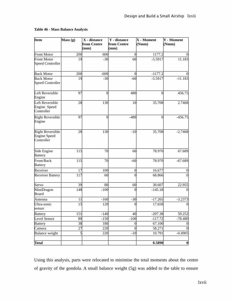
lxvii
Table 46 - Mass Balance Analysis
Item Mass (g) X - distance from Centre (mm)
Y - distance from Centre (mm)
X - Moment (Nmm)
Y - Moment (Nmm)
Front Motor 200 600 0 1177.2 0Front Motor Speed Controller
19 -30 60 -5.5917 11.183
Back Motor 200 -600 0 -1177.2 0Back Motor Speed Controller
19 -30 -60 -5.5917 -11.183
Left Reversible Engine
97 0 480 0 456.75
Left Reversible Engine Speed Controller
28 130 10 35.708 2.7468
Right Reversible Engine
97 0 -480 0 -456.75
Right Reversible Engine Speed Controller
28 130 -10 35.708 -2.7468
Side Engine Battery
115 70 60 78.970 67.689
Front/Back Battery
115 70 -60 78.970 -67.689
Receiver 17 100 0 16.677 0Receiver Battery 117 60 0 68.866 0
Servo 39 80 60 30.607 22.955MiniDragon Board
148 -100 0 -145.18 0
Antenna 11 -160 -30 -17.265 -3.2373Ultra-sonic sensor
15 120 0 17.658 0
Battery 151 -140 40 -207.38 59.252Level Sensor 80 -150 -100 -117.72 -78.480Battery 38 180 0 67.100 0Camera 27 220 0 58.271 0Balance weight 5 220 -10 10.791 -0.4905
Total 0.5890 0
Using this analysis, parts were relocated to minimise the total moments about the centre
of gravity of the gondola. A small balance weight (5g) was added to the table to ensure
Design and Build a Small Airship lxvii
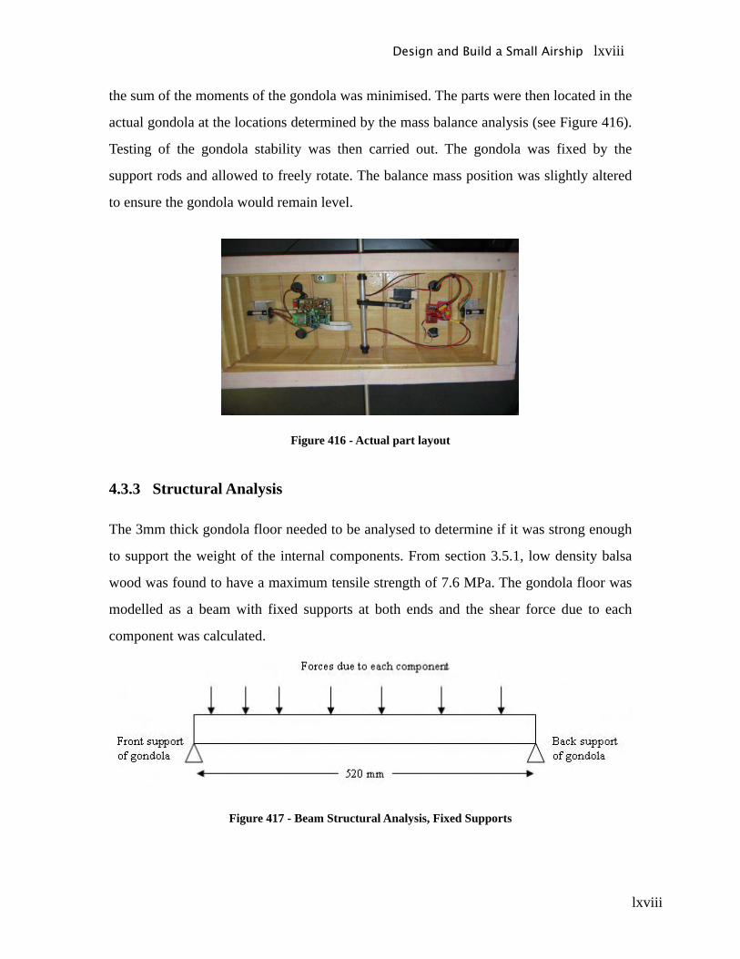
lxviii
the sum of the moments of the gondola was minimised. The parts were then located in the
actual gondola at the locations determined by the mass balance analysis (see Figure 416).
Testing of the gondola stability was then carried out. The gondola was fixed by the
support rods and allowed to freely rotate. The balance mass position was slightly altered
to ensure the gondola would remain level.
Figure 416 - Actual part layout
4.3.3 Structural Analysis
The 3mm thick gondola floor needed to be analysed to determine if it was strong enough
to support the weight of the internal components. From section 3.5.1, low density balsa
wood was found to have a maximum tensile strength of 7.6 MPa. The gondola floor was
modelled as a beam with fixed supports at both ends and the shear force due to each
component was calculated.
Figure 417 - Beam Structural Analysis, Fixed Supports
Design and Build a Small Airship lxviii
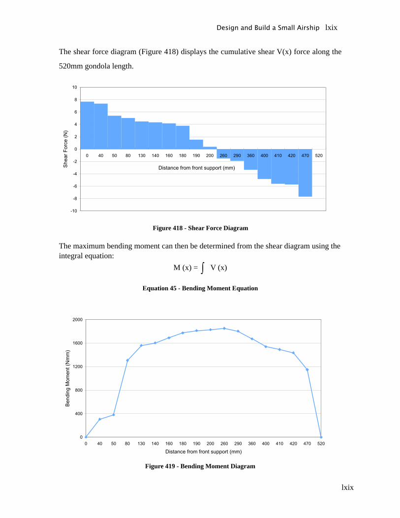
lxix
The shear force diagram (Figure 418) displays the cumulative shear V(x) force along the
520mm gondola length.
Figure 418 - Shear Force Diagram
The maximum bending moment can then be determined from the shear diagram using the integral equation:
M (x) = V (x)
Equation 45 - Bending Moment Equation
Figure 419 - Bending Moment Diagram
Design and Build a Small Airship lxix
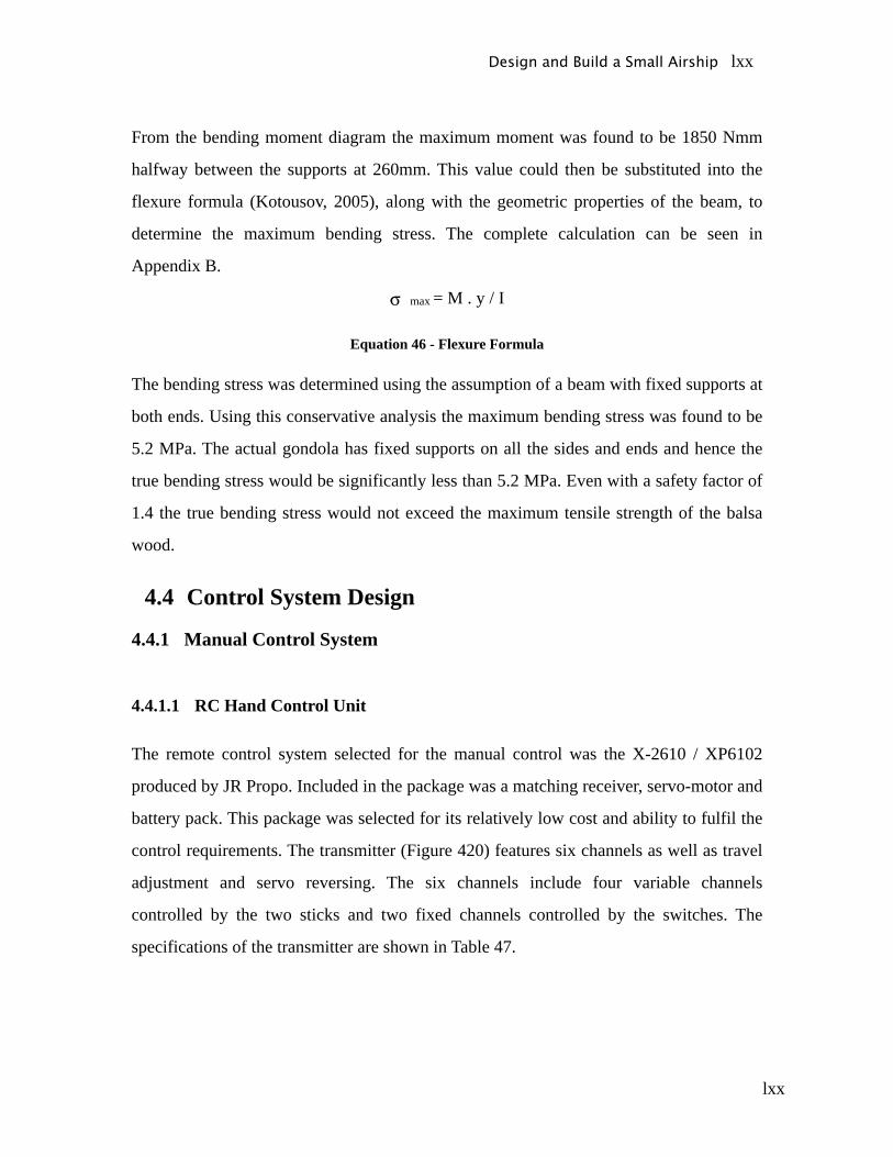
lxx
From the bending moment diagram the maximum moment was found to be 1850 Nmm
halfway between the supports at 260mm. This value could then be substituted into the
flexure formula (Kotousov, 2005), along with the geometric properties of the beam, to
determine the maximum bending stress. The complete calculation can be seen in
Appendix B.
max = M . y / I
Equation 46 - Flexure Formula
The bending stress was determined using the assumption of a beam with fixed supports at
both ends. Using this conservative analysis the maximum bending stress was found to be
5.2 MPa. The actual gondola has fixed supports on all the sides and ends and hence the
true bending stress would be significantly less than 5.2 MPa. Even with a safety factor of
1.4 the true bending stress would not exceed the maximum tensile strength of the balsa
wood.
4.4 Control System Design
4.4.1 Manual Control System
4.4.1.1 RC Hand Control Unit
The remote control system selected for the manual control was the X-2610 / XP6102
produced by JR Propo. Included in the package was a matching receiver, servo-motor and
battery pack. This package was selected for its relatively low cost and ability to fulfil the
control requirements. The transmitter (Figure 420) features six channels as well as travel
adjustment and servo reversing. The six channels include four variable channels
controlled by the two sticks and two fixed channels controlled by the switches. The
specifications of the transmitter are shown in Table 47.
Design and Build a Small Airship lxx
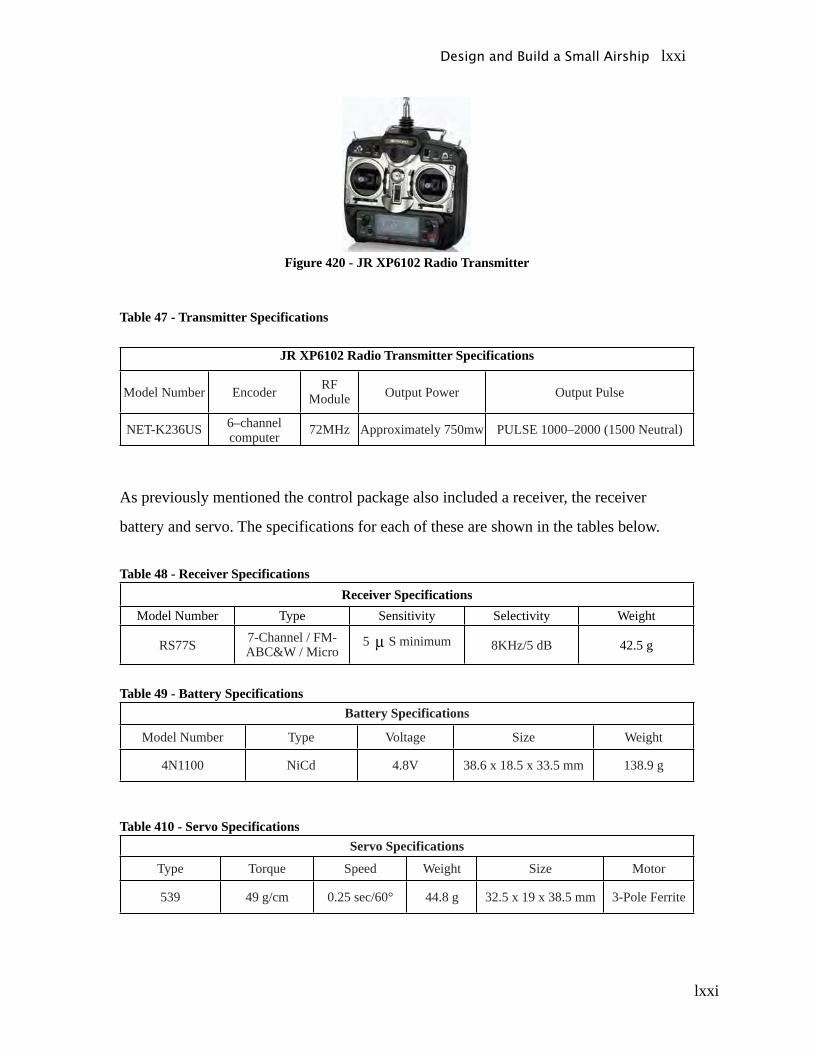
lxxi
Figure 420 - JR XP6102 Radio Transmitter
Table 47 - Transmitter Specifications
JR XP6102 Radio Transmitter Specifications
Model Number Encoder RF Module Output Power Output Pulse
NET-K236US 6–channel computer 72MHz Approximately 750mw PULSE 1000–2000 (1500 Neutral)
As previously mentioned the control package also included a receiver, the receiver
battery and servo. The specifications for each of these are shown in the tables below.
Table 48 - Receiver SpecificationsReceiver Specifications
Model Number Type Sensitivity Selectivity Weight
RS77S 7-Channel / FM-ABC&W / Micro
5 S minimum 8KHz/5 dB 42.5 g
Table 49 - Battery SpecificationsBattery Specifications
Model Number Type Voltage Size Weight
4N1100 NiCd 4.8V 38.6 x 18.5 x 33.5 mm 138.9 g
Table 410 - Servo SpecificationsServo Specifications
Type Torque Speed Weight Size Motor
539 49 g/cm 0.25 sec/60° 44.8 g 32.5 x 19 x 38.5 mm 3-Pole Ferrite
Design and Build a Small Airship lxxi
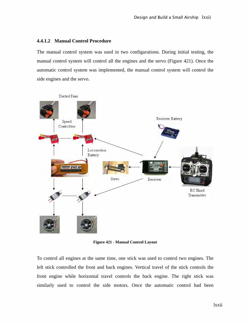
lxxii
4.4.1.2 Manual Control Procedure
The manual control system was used in two configurations. During initial testing, the
manual control system will control all the engines and the servo (Figure 421). Once the
automatic control system was implemented, the manual control system will control the
side engines and the servo.
Figure 421 - Manual Control Layout
To control all engines at the same time, one stick was used to control two engines. The
left stick controlled the front and back engines. Vertical travel of the stick controls the
front engine while horizontal travel controls the back engine. The right stick was
similarly used to control the side motors. Once the automatic control had been
Design and Build a Small Airship lxxii
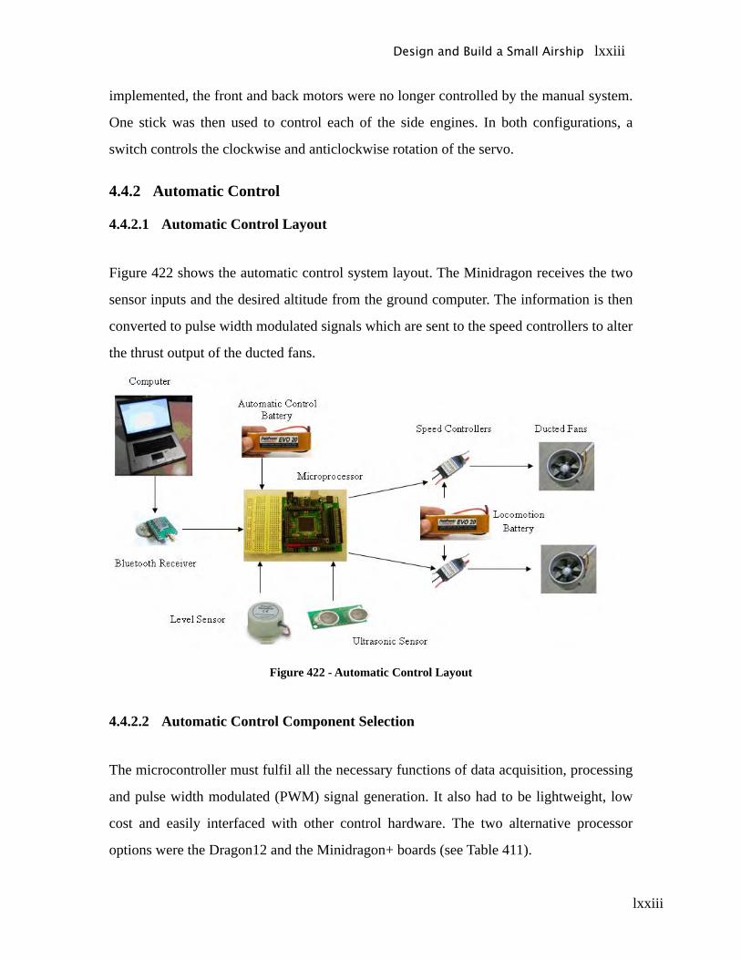
lxxiii
implemented, the front and back motors were no longer controlled by the manual system.
One stick was then used to control each of the side engines. In both configurations, a
switch controls the clockwise and anticlockwise rotation of the servo.
4.4.2 Automatic Control
4.4.2.1 Automatic Control Layout
Figure 422 shows the automatic control system layout. The Minidragon receives the two
sensor inputs and the desired altitude from the ground computer. The information is then
converted to pulse width modulated signals which are sent to the speed controllers to alter
the thrust output of the ducted fans.
Figure 422 - Automatic Control Layout
4.4.2.2 Automatic Control Component Selection
The microcontroller must fulfil all the necessary functions of data acquisition, processing
and pulse width modulated (PWM) signal generation. It also had to be lightweight, low
cost and easily interfaced with other control hardware. The two alternative processor
options were the Dragon12 and the Minidragon+ boards (see Table 411).
Design and Build a Small Airship lxxiii
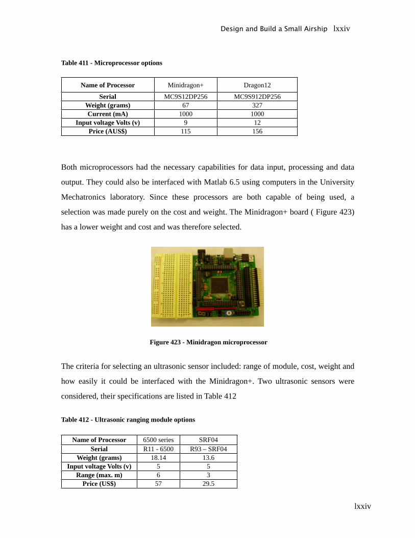
lxxiv
Table 411 - Microprocessor options
Name of Processor Minidragon+ Dragon12
Serial MC9S12DP256 MC9S912DP256Weight (grams) 67 327Current (mA) 1000 1000
Input voltage Volts (v) 9 12Price (AUS$) 115 156
Both microprocessors had the necessary capabilities for data input, processing and data
output. They could also be interfaced with Matlab 6.5 using computers in the University
Mechatronics laboratory. Since these processors are both capable of being used, a
selection was made purely on the cost and weight. The Minidragon+ board ( Figure 423)
has a lower weight and cost and was therefore selected.
Figure 423 - Minidragon microprocessor
The criteria for selecting an ultrasonic sensor included: range of module, cost, weight and
how easily it could be interfaced with the Minidragon+. Two ultrasonic sensors were
considered, their specifications are listed in Table 412
Table 412 - Ultrasonic ranging module options
Name of Processor 6500 series SRF04Serial R11 - 6500 R93 – SRF04
Weight (grams) 18.14 13.6Input voltage Volts (v) 5 5
Range (max. m) 6 3Price (US$) 57 29.5
Design and Build a Small Airship lxxiv
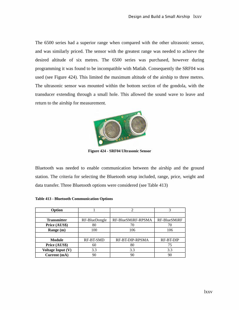
lxxv
The 6500 series had a superior range when compared with the other ultrasonic sensor,
and was similarly priced. The sensor with the greatest range was needed to achieve the
desired altitude of six metres. The 6500 series was purchased, however during
programming it was found to be incompatible with Matlab. Consequently the SRF04 was
used (see Figure 424). This limited the maximum altitude of the airship to three metres.
The ultrasonic sensor was mounted within the bottom section of the gondola, with the
transducer extending through a small hole. This allowed the sound wave to leave and
return to the airship for measurement.
Figure 424 - SRF04 Ultrasonic Sensor
Bluetooth was needed to enable communication between the airship and the ground
station. The criteria for selecting the Bluetooth setup included, range, price, weight and
data transfer. Three Bluetooth options were considered (see Table 413)
Table 413 - Bluetooth Communication Options
Option 1 2 3
Transmitter RF-BlueDongle RF-BlueSMiRF-RPSMA RF-BlueSMiRFPrice (AUS$) 80 70 70
Range (m) 100 106 106
Module RF-BT-SMD RF-BT-DIP-RPSMA RF-BT-DIPPrice (AUS$) 60 80 75
Voltage Input (V) 3.3 3.3 3.3Current (mA) 90 90 90
Design and Build a Small Airship lxxv
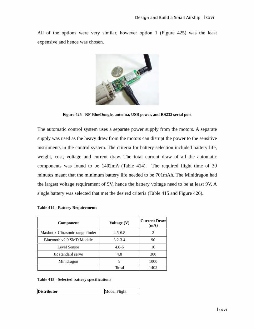
lxxvi
All of the options were very similar, however option 1 (Figure 425) was the least
expensive and hence was chosen.
Figure 425 - RF-BlueDongle, antenna, USB power, and RS232 serial port
The automatic control system uses a separate power supply from the motors. A separate
supply was used as the heavy draw from the motors can disrupt the power to the sensitive
instruments in the control system. The criteria for battery selection included battery life,
weight, cost, voltage and current draw. The total current draw of all the automatic
components was found to be 1402mA (Table 414). The required flight time of 30
minutes meant that the minimum battery life needed to be 701mAh. The Minidragon had
the largest voltage requirement of 9V, hence the battery voltage need to be at least 9V. A
single battery was selected that met the desired criteria (Table 415 and Figure 426).
Table 414 - Battery Requirements
Component Voltage (V) Current Draw (mA)
Maxbotix Ultrasonic range finder 4.5-6.8 2
Bluetooth v2.0 SMD Module 3.2-3.4 90
Level Sensor 4.8-6 10
JR standard servo 4.8 300
Minidragon 9 1000Total 1402
Table 415 - Selected battery specifications
Distributor Model Flight
Design and Build a Small Airship lxxvi
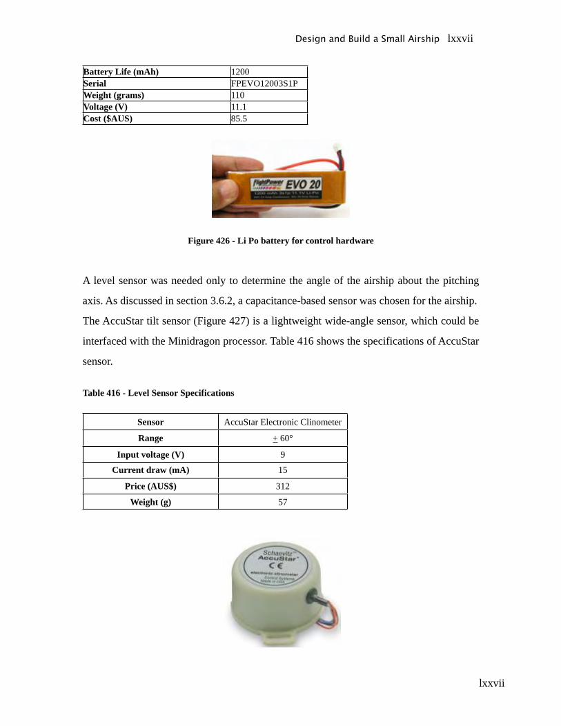
lxxvii
Battery Life (mAh) 1200Serial FPEVO12003S1PWeight (grams) 110Voltage (V) 11.1Cost ($AUS) 85.5
Figure 426 - Li Po battery for control hardware
A level sensor was needed only to determine the angle of the airship about the pitching
axis. As discussed in section 3.6.2, a capacitance-based sensor was chosen for the airship.
The AccuStar tilt sensor (Figure 427) is a lightweight wide-angle sensor, which could be
interfaced with the Minidragon processor. Table 416 shows the specifications of AccuStar
sensor.
Table 416 - Level Sensor Specifications
Sensor AccuStar Electronic Clinometer
Range + 60°
Input voltage (V) 9
Current draw (mA) 15
Price (AUS$) 312
Weight (g) 57
Design and Build a Small Airship lxxvii
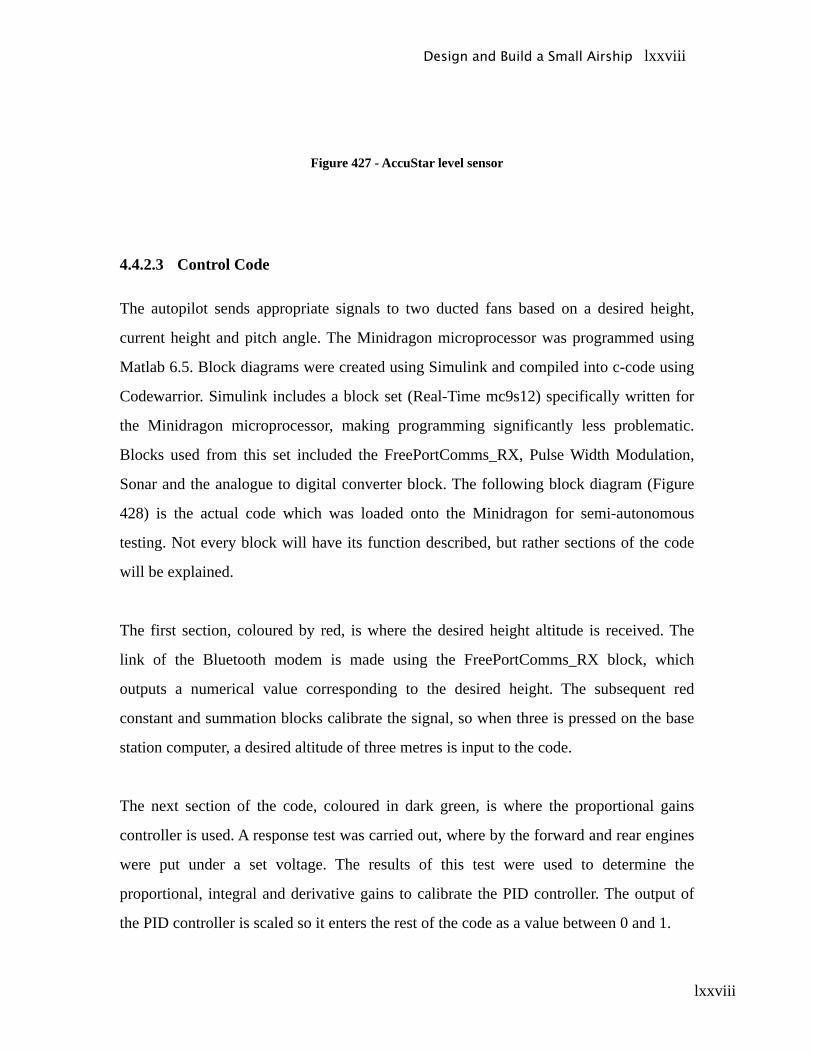
lxxviii
Figure 427 - AccuStar level sensor
4.4.2.3 Control Code
The autopilot sends appropriate signals to two ducted fans based on a desired height,
current height and pitch angle. The Minidragon microprocessor was programmed using
Matlab 6.5. Block diagrams were created using Simulink and compiled into c-code using
Codewarrior. Simulink includes a block set (Real-Time mc9s12) specifically written for
the Minidragon microprocessor, making programming significantly less problematic.
Blocks used from this set included the FreePortComms_RX, Pulse Width Modulation,
Sonar and the analogue to digital converter block. The following block diagram (Figure
428) is the actual code which was loaded onto the Minidragon for semi-autonomous
testing. Not every block will have its function described, but rather sections of the code
will be explained.
The first section, coloured by red, is where the desired height altitude is received. The
link of the Bluetooth modem is made using the FreePortComms_RX block, which
outputs a numerical value corresponding to the desired height. The subsequent red
constant and summation blocks calibrate the signal, so when three is pressed on the base
station computer, a desired altitude of three metres is input to the code.
The next section of the code, coloured in dark green, is where the proportional gains
controller is used. A response test was carried out, where by the forward and rear engines
were put under a set voltage. The results of this test were used to determine the
proportional, integral and derivative gains to calibrate the PID controller. The output of
the PID controller is scaled so it enters the rest of the code as a value between 0 and 1.
Design and Build a Small Airship lxxviii
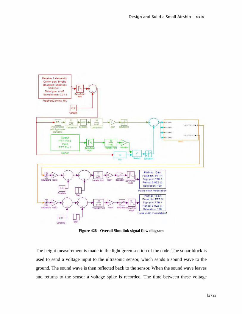
lxxix
Figure 428 - Overall Simulink signal flow diagram
The height measurement is made in the light green section of the code. The sonar block is
used to send a voltage input to the ultrasonic sensor, which sends a sound wave to the
ground. The sound wave is then reflected back to the sensor. When the sound wave leaves
and returns to the sensor a voltage spike is recorded. The time between these voltage
Design and Build a Small Airship lxxix
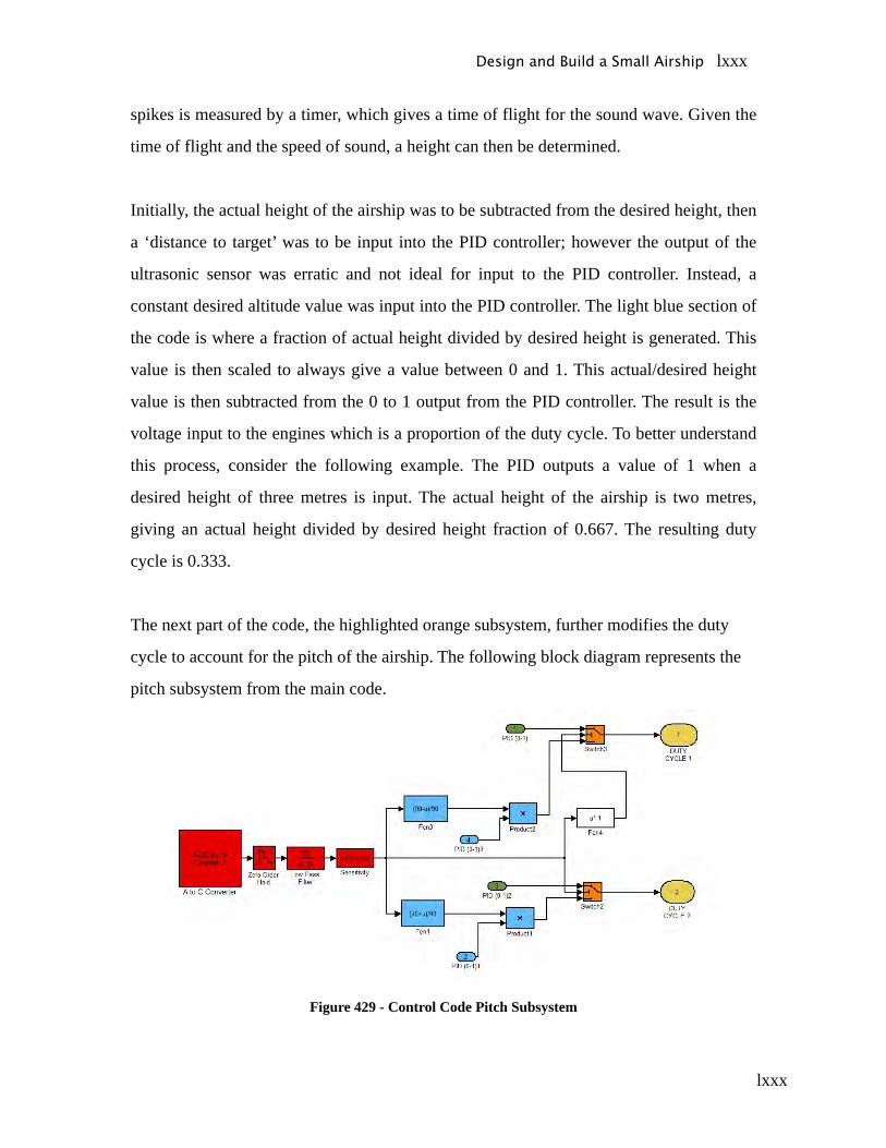
lxxx
spikes is measured by a timer, which gives a time of flight for the sound wave. Given the
time of flight and the speed of sound, a height can then be determined.
Initially, the actual height of the airship was to be subtracted from the desired height, then
a ‘distance to target’ was to be input into the PID controller; however the output of the
ultrasonic sensor was erratic and not ideal for input to the PID controller. Instead, a
constant desired altitude value was input into the PID controller. The light blue section of
the code is where a fraction of actual height divided by desired height is generated. This
value is then scaled to always give a value between 0 and 1. This actual/desired height
value is then subtracted from the 0 to 1 output from the PID controller. The result is the
voltage input to the engines which is a proportion of the duty cycle. To better understand
this process, consider the following example. The PID outputs a value of 1 when a
desired height of three metres is input. The actual height of the airship is two metres,
giving an actual height divided by desired height fraction of 0.667. The resulting duty
cycle is 0.333.
The next part of the code, the highlighted orange subsystem, further modifies the duty
cycle to account for the pitch of the airship. The following block diagram represents the
pitch subsystem from the main code.
Figure 429 - Control Code Pitch Subsystem
Design and Build a Small Airship lxxx
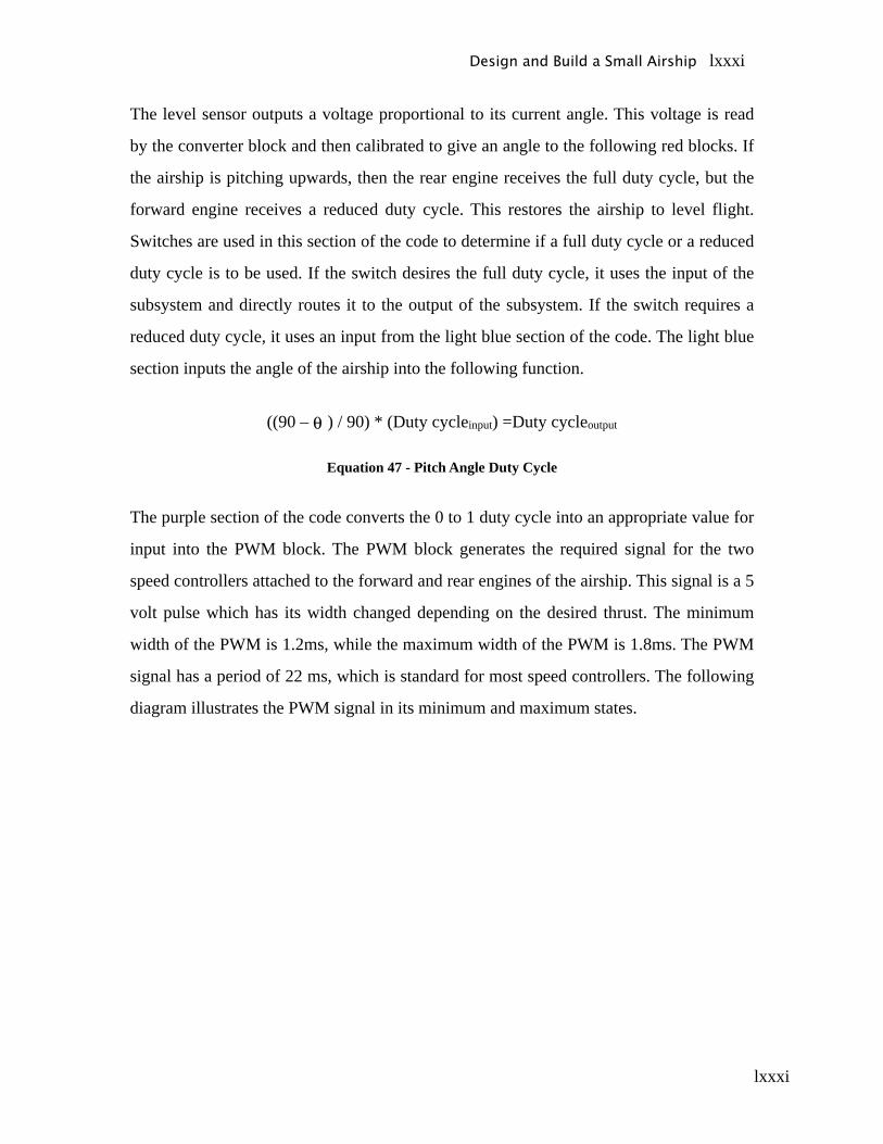
lxxxi
The level sensor outputs a voltage proportional to its current angle. This voltage is read
by the converter block and then calibrated to give an angle to the following red blocks. If
the airship is pitching upwards, then the rear engine receives the full duty cycle, but the
forward engine receives a reduced duty cycle. This restores the airship to level flight.
Switches are used in this section of the code to determine if a full duty cycle or a reduced
duty cycle is to be used. If the switch desires the full duty cycle, it uses the input of the
subsystem and directly routes it to the output of the subsystem. If the switch requires a
reduced duty cycle, it uses an input from the light blue section of the code. The light blue
section inputs the angle of the airship into the following function.
((90 – ) / 90) * (Duty cycleinput) =Duty cycleoutput
Equation 47 - Pitch Angle Duty Cycle
The purple section of the code converts the 0 to 1 duty cycle into an appropriate value for
input into the PWM block. The PWM block generates the required signal for the two
speed controllers attached to the forward and rear engines of the airship. This signal is a 5
volt pulse which has its width changed depending on the desired thrust. The minimum
width of the PWM is 1.2ms, while the maximum width of the PWM is 1.8ms. The PWM
signal has a period of 22 ms, which is standard for most speed controllers. The following
diagram illustrates the PWM signal in its minimum and maximum states.
Design and Build a Small Airship lxxxi
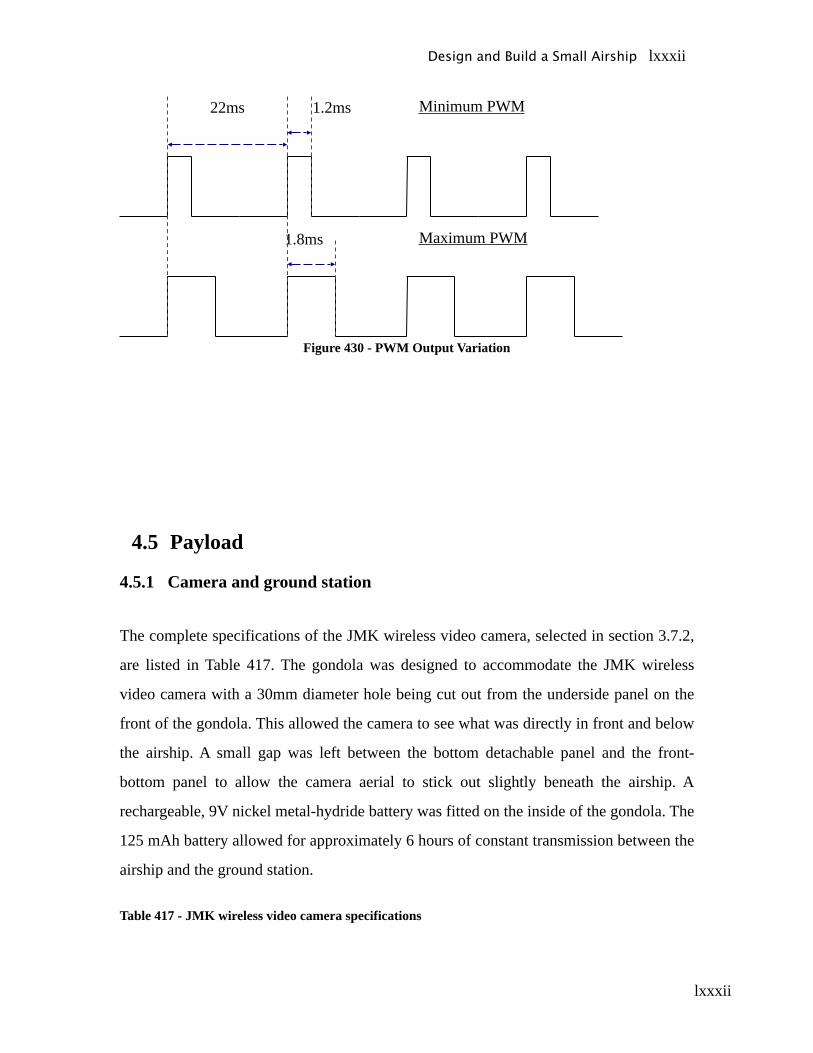
lxxxii
1.2ms
1.8ms
22ms Minimum PWM
Maximum PWM
Figure 430 - PWM Output Variation
4.5 Payload
4.5.1 Camera and ground station
The complete specifications of the JMK wireless video camera, selected in section 3.7.2,
are listed in Table 417. The gondola was designed to accommodate the JMK wireless
video camera with a 30mm diameter hole being cut out from the underside panel on the
front of the gondola. This allowed the camera to see what was directly in front and below
the airship. A small gap was left between the bottom detachable panel and the front-
bottom panel to allow the camera aerial to stick out slightly beneath the airship. A
rechargeable, 9V nickel metal-hydride battery was fitted on the inside of the gondola. The
125 mAh battery allowed for approximately 6 hours of constant transmission between the
airship and the ground station.
Table 417 - JMK wireless video camera specifications
Design and Build a Small Airship lxxxii

lxxxiii
Variable Specification
Recording and transmission system AnalogueTV System PAL or NTSCResolution 480*380 lines
Transmission frequency 900 MHzTransmission Range 50-100m
Power Supply for Camera DC, 9VPower consumption 200 mWWeight of Camera 30g
Figure 431 - Camera mounted in gondola
Design and Build a Small Airship lxxxiii
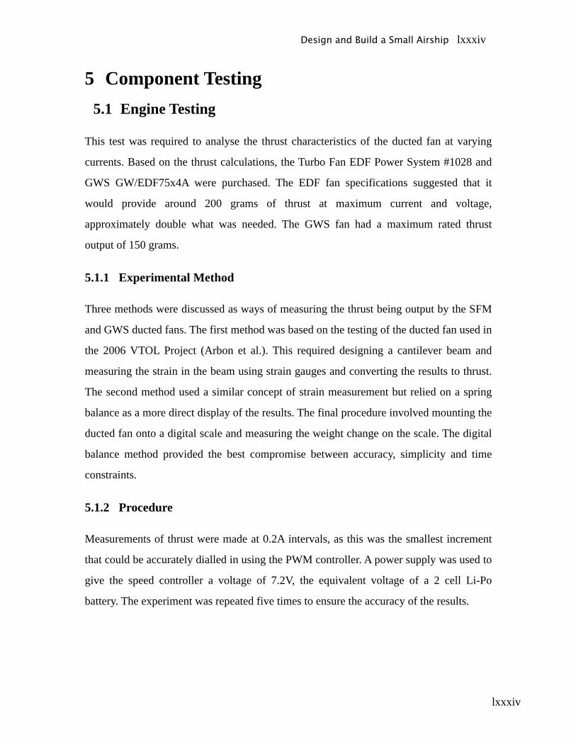
lxxxiv
5 Component Testing5.1 Engine Testing
This test was required to analyse the thrust characteristics of the ducted fan at varying
currents. Based on the thrust calculations, the Turbo Fan EDF Power System #1028 and
GWS GW/EDF75x4A were purchased. The EDF fan specifications suggested that it
would provide around 200 grams of thrust at maximum current and voltage,
approximately double what was needed. The GWS fan had a maximum rated thrust
output of 150 grams.
5.1.1 Experimental Method
Three methods were discussed as ways of measuring the thrust being output by the SFM
and GWS ducted fans. The first method was based on the testing of the ducted fan used in
the 2006 VTOL Project (Arbon et al.). This required designing a cantilever beam and
measuring the strain in the beam using strain gauges and converting the results to thrust.
The second method used a similar concept of strain measurement but relied on a spring
balance as a more direct display of the results. The final procedure involved mounting the
ducted fan onto a digital scale and measuring the weight change on the scale. The digital
balance method provided the best compromise between accuracy, simplicity and time
constraints.
5.1.2 Procedure
Measurements of thrust were made at 0.2A intervals, as this was the smallest increment
that could be accurately dialled in using the PWM controller. A power supply was used to
give the speed controller a voltage of 7.2V, the equivalent voltage of a 2 cell Li-Po
battery. The experiment was repeated five times to ensure the accuracy of the results.
Design and Build a Small Airship lxxxiv
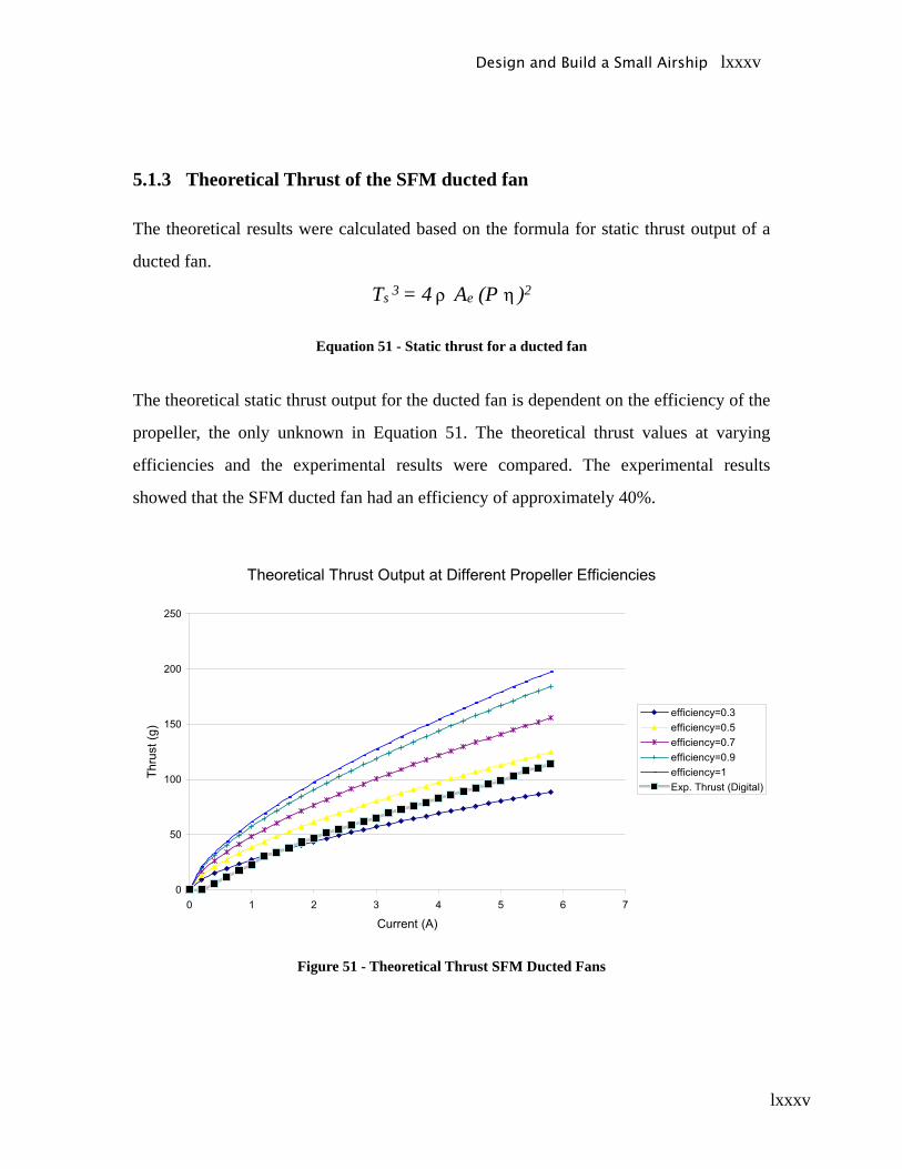
lxxxv
5.1.3 Theoretical Thrust of the SFM ducted fan
The theoretical results were calculated based on the formula for static thrust output of a
ducted fan.
Ts 3 = 4 Ae (P )2
Equation 51 - Static thrust for a ducted fan
The theoretical static thrust output for the ducted fan is dependent on the efficiency of the
propeller, the only unknown in Equation 51. The theoretical thrust values at varying
efficiencies and the experimental results were compared. The experimental results
showed that the SFM ducted fan had an efficiency of approximately 40%.
Figure 51 - Theoretical Thrust SFM Ducted Fans
Design and Build a Small Airship lxxxv
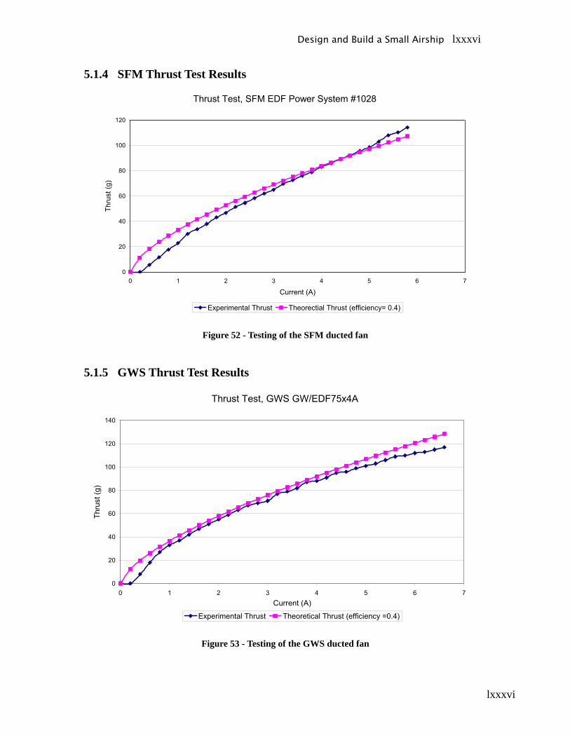
lxxxvi
5.1.4 SFM Thrust Test Results
Figure 52 - Testing of the SFM ducted fan
5.1.5 GWS Thrust Test Results
Figure 53 - Testing of the GWS ducted fan
Design and Build a Small Airship lxxxvi
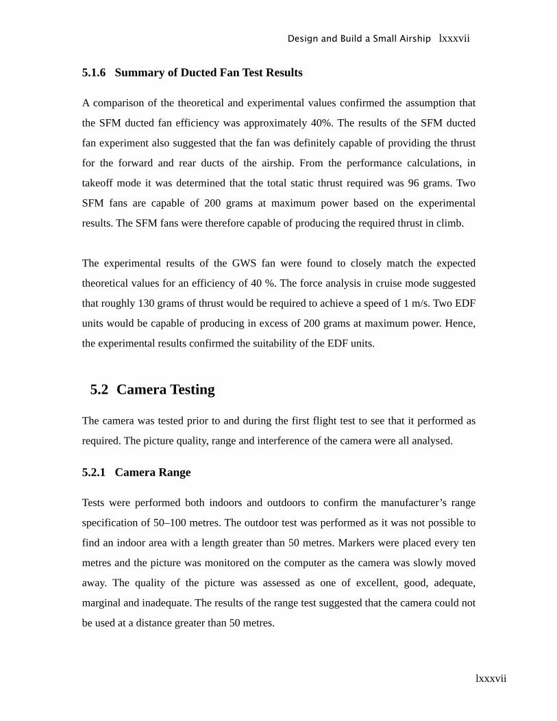
lxxxvii
5.1.6 Summary of Ducted Fan Test Results
A comparison of the theoretical and experimental values confirmed the assumption that
the SFM ducted fan efficiency was approximately 40%. The results of the SFM ducted
fan experiment also suggested that the fan was definitely capable of providing the thrust
for the forward and rear ducts of the airship. From the performance calculations, in
takeoff mode it was determined that the total static thrust required was 96 grams. Two
SFM fans are capable of 200 grams at maximum power based on the experimental
results. The SFM fans were therefore capable of producing the required thrust in climb.
The experimental results of the GWS fan were found to closely match the expected
theoretical values for an efficiency of 40 %. The force analysis in cruise mode suggested
that roughly 130 grams of thrust would be required to achieve a speed of 1 m/s. Two EDF
units would be capable of producing in excess of 200 grams at maximum power. Hence,
the experimental results confirmed the suitability of the EDF units.
5.2 Camera Testing
The camera was tested prior to and during the first flight test to see that it performed as
required. The picture quality, range and interference of the camera were all analysed.
5.2.1 Camera Range
Tests were performed both indoors and outdoors to confirm the manufacturer’s range
specification of 50–100 metres. The outdoor test was performed as it was not possible to
find an indoor area with a length greater than 50 metres. Markers were placed every ten
metres and the picture was monitored on the computer as the camera was slowly moved
away. The quality of the picture was assessed as one of excellent, good, adequate,
marginal and inadequate. The results of the range test suggested that the camera could not
be used at a distance greater than 50 metres.
Design and Build a Small Airship lxxxvii

lxxxviii
Design and Build a Small Airship lxxxviii
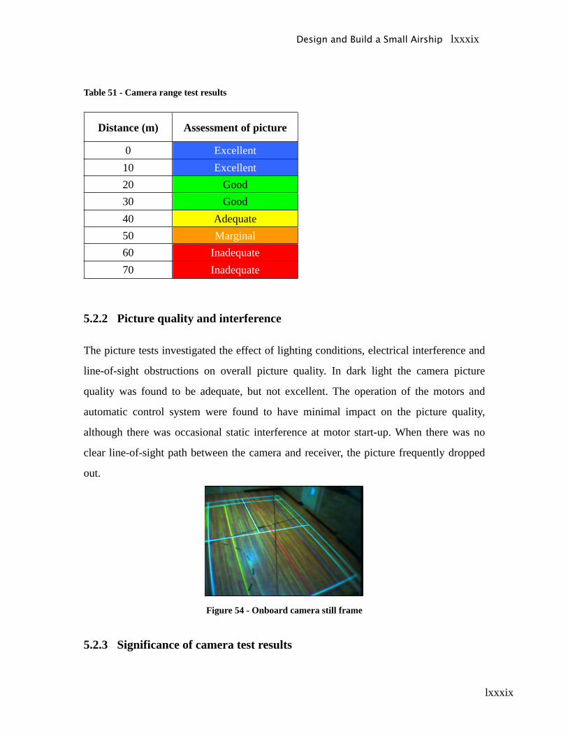
lxxxix
Table 51 - Camera range test results
Distance (m) Assessment of picture
0 Excellent10 Excellent20 Good30 Good40 Adequate50 Marginal60 Inadequate70 Inadequate
5.2.2 Picture quality and interference
The picture tests investigated the effect of lighting conditions, electrical interference and
line-of-sight obstructions on overall picture quality. In dark light the camera picture
quality was found to be adequate, but not excellent. The operation of the motors and
automatic control system were found to have minimal impact on the picture quality,
although there was occasional static interference at motor start-up. When there was no
clear line-of-sight path between the camera and receiver, the picture frequently dropped
out.
Figure 54 - Onboard camera still frame
5.2.3 Significance of camera test results
Design and Build a Small Airship lxxxix
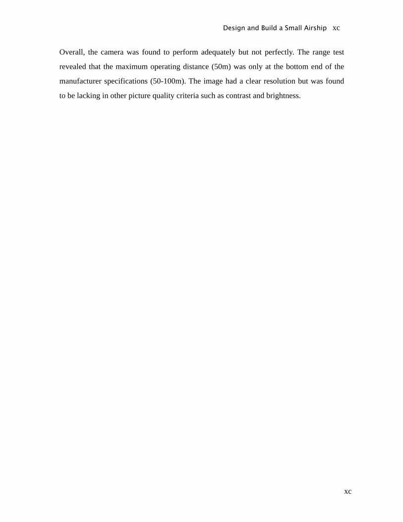
xc
Overall, the camera was found to perform adequately but not perfectly. The range test
revealed that the maximum operating distance (50m) was only at the bottom end of the
manufacturer specifications (50-100m). The image had a clear resolution but was found
to be lacking in other picture quality criteria such as contrast and brightness.
Design and Build a Small Airship xc
xci
6 Flight Tests
6.1 Pre-flight Procedures and Operation
Prior to full flight testing it was necessary to prepare and test the main airship
components. This ensured that they would operate correctly during the flight tests. The
electronic and mechanical parts of the gondola were individually tested. The gondola was
attached to the envelope and the envelope was inflated with helium to make the airship
only 20 grams overweight. The full procedures are shown in Appendix D, and a summary
of each test is shown below
6.1.1 Gondola Component Tests
• Connect the rubber chain to the servo system
• Connect all electronic components
• Test the servo and axle rotation using the RC unit
• Test operation of front/ back engines and left/right engines separately
• Test the operation of all engines simultaneously.
6.1.2 Attaching Gondola
• Connect the gondola to the deflated envelope using tie line system connected to
the rods of the gondola
• Connect the gondola to the deflated envelope using the Velcro strips, ensuring
strips are lined up and firmly attached.
• Attach safety line to the Envelope
Design and Build a Small Airship xci
xcii
6.1.3 Envelope Inflation
• Turn on valve on the cylinder and commence filling the envelope with helium
• Using the force gauge constantly measure the lifting force of the envelope with
the gondola attached
• When all the wrinkles in the envelope have disappeared stop filling envelope.
• If required, add weight to the gondola to make the airship 20 grams overweighted.
6.2 Flight Tests
6.2.1 Climb test
The climb test was used to measure the time to reach the desired 3m cruise altitude and
used the front and rear engines only. This test was used to obtain flight data for the PID
controller in the control code. The test was completed using half fan thrust then repeated
using full fan thrust.
A second climb test was undertaken using all the ducted fans. All the ducted fans were
positioned so to produce vertical thrust. The purpose of this test was to determine the
shortest possible takeoff time of the airship. Hence this test was only completed with the
ducted fans at full thrust. Details of the procedures for these tests are shown in Appendix
D.
6.2.2 Descent test
The airship was designed to descend under gravity due to the 20 grams of excess weight.
This test was used to determine how fast the airship could descend from the cruise
altitude. The time for the airship to fall from its cruise altitude was recorded. The airship
was capable of assisted descent by rotating the side ducted fans and reversing the
Design and Build a Small Airship xcii

xciii
direction of thrust. A second test was conducted to determine the assisted descent time of
the airship. Details of the procedures for these tests are shown in Appendix D.
6.2.3 Cruise test
At the cruise altitude a test was undertaken to determine the cruise speed. During the test
the automatically controlled front and back ducted fans maintain level flight. The side
ducted fans provide the thrust for horizontal motion. The tests were conducted in forward
motion with the ducted fans producing half and full thrust. The side motors, capable of
reverse thrust, were then used to complete a full-thrust reverse test. Details of the
procedures for these tests are shown in Appendix D
6.2.4 Rate of turn test
The turning capability of the airship also needed to be measured. The automatic control
system was switched on and set to an altitude of one metre. Once the airship had
achieved this hover height, the right side ducted fan was put in full forward thrust and the
left put in full reverse thrust. The time taken for the airship to achieve 90,180,360,720
and 1080 degrees of rotation was recorded. Details of the procedures for these tests are
shown in Appendix D
6.3 Post-flight data analysis
At the beginning of the project, a set of desired performance parameters was created.
These performance parameters included cruising speed, takeoff time and rate of turn. The
performance parameters are listed in the table below.
Design and Build a Small Airship xciii
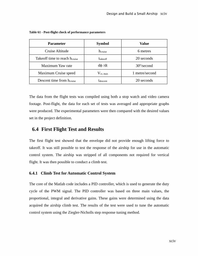
xciv
Table 61 - Post-flight check of performance parameters
Parameter Symbol Value
Cruise Altitude hcruise 6 metres
Takeoff time to reach hcruise ttakeoff 20 seconds
Maximum Yaw rate d /dt 30º/second
Maximum Cruise speed Vcr, max 1 metre/second
Descent time from hcruise tdescent 20 seconds
The data from the flight tests was compiled using both a stop watch and video camera
footage. Post-flight, the data for each set of tests was averaged and appropriate graphs
were produced. The experimental parameters were then compared with the desired values
set in the project definition.
6.4 First Flight Test and Results
The first flight test showed that the envelope did not provide enough lifting force to
takeoff. It was still possible to test the response of the airship for use in the automatic
control system. The airship was stripped of all components not required for vertical
flight. It was then possible to conduct a climb test.
6.4.1 Climb Test for Automatic Control System
The core of the Matlab code includes a PID controller, which is used to generate the duty
cycle of the PWM signal. The PID controller was based on three main values, the
proportional, integral and derivative gains. These gains were determined using the data
acquired the airship climb test. The results of the test were used to tune the automatic
control system using the Ziegler-Nicholls step response tuning method.
Design and Build a Small Airship xciv
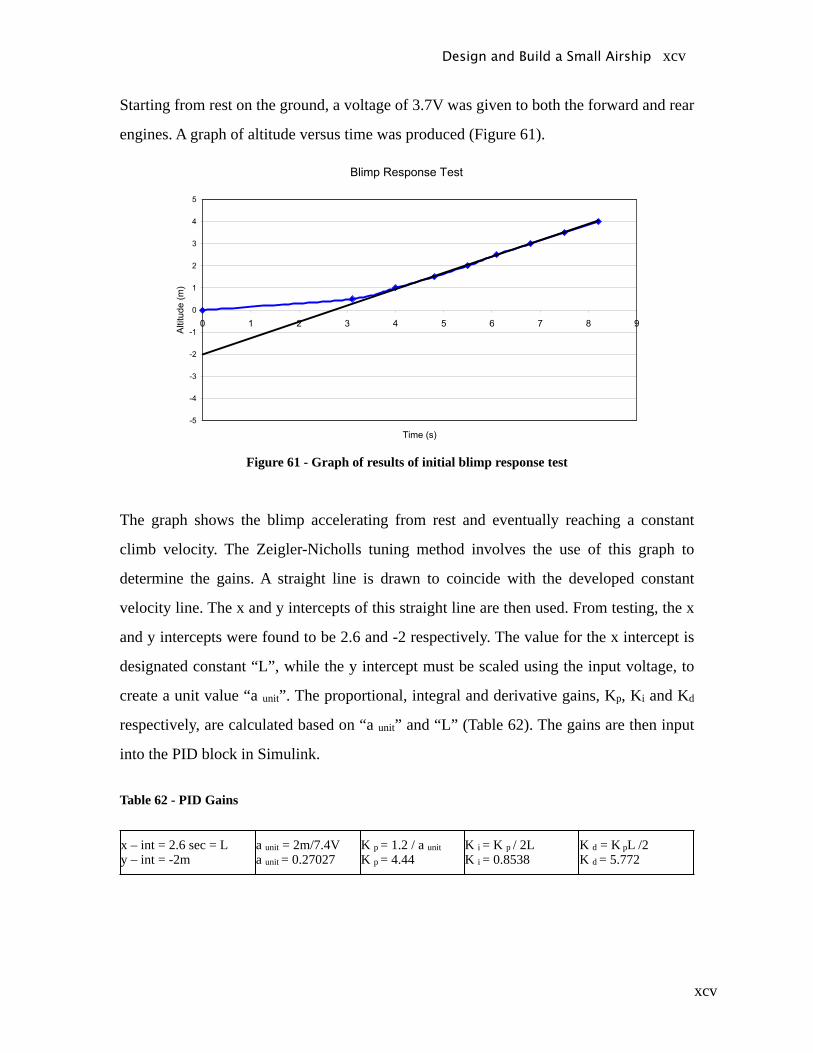
xcv
Starting from rest on the ground, a voltage of 3.7V was given to both the forward and rear
engines. A graph of altitude versus time was produced (Figure 61).
Figure 61 - Graph of results of initial blimp response test
The graph shows the blimp accelerating from rest and eventually reaching a constant
climb velocity. The Zeigler-Nicholls tuning method involves the use of this graph to
determine the gains. A straight line is drawn to coincide with the developed constant
velocity line. The x and y intercepts of this straight line are then used. From testing, the x
and y intercepts were found to be 2.6 and -2 respectively. The value for the x intercept is
designated constant “L”, while the y intercept must be scaled using the input voltage, to
create a unit value “a unit”. The proportional, integral and derivative gains, Kp, Ki and Kd
respectively, are calculated based on “a unit” and “L” (Table 62). The gains are then input
into the PID block in Simulink.
Table 62 - PID Gains
x – int = 2.6 sec = Ly – int = -2m
a unit = 2m/7.4Va unit = 0.27027
K p = 1.2 / a unitK p = 4.44
K i = K p / 2LK i = 0.8538
K d = K pL /2K d = 5.772
Design and Build a Small Airship xcv
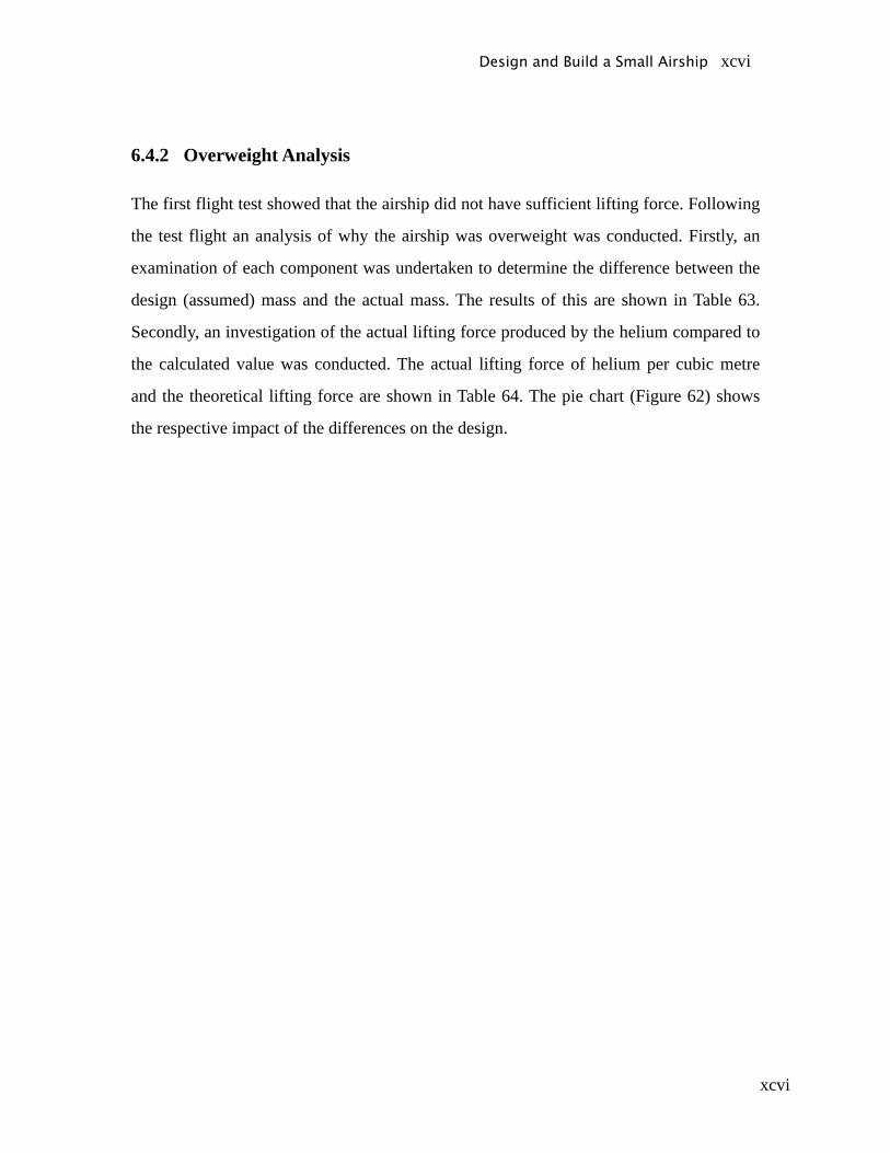
xcvi
6.4.2 Overweight Analysis
The first flight test showed that the airship did not have sufficient lifting force. Following
the test flight an analysis of why the airship was overweight was conducted. Firstly, an
examination of each component was undertaken to determine the difference between the
design (assumed) mass and the actual mass. The results of this are shown in Table 63.
Secondly, an investigation of the actual lifting force produced by the helium compared to
the calculated value was conducted. The actual lifting force of helium per cubic metre
and the theoretical lifting force are shown in Table 64. The pie chart (Figure 62) shows
the respective impact of the differences on the design.
Design and Build a Small Airship xcvi
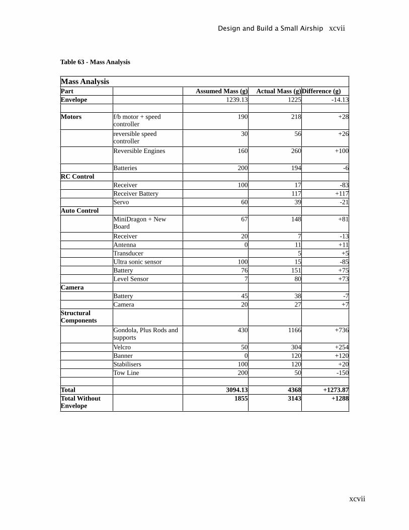
xcvii
Table 63 - Mass Analysis
Mass AnalysisPart Assumed Mass (g) Actual Mass (g)Difference (g)Envelope 1239.13 1225 -14.13
Motors f/b motor + speed controller
190 218 +28
reversible speed controller
30 56 +26
Reversible Engines 160 260 +100
Batteries 200 194 -6RC Control
Receiver 100 17 -83Receiver Battery 117 +117Servo 60 39 -21
Auto ControlMiniDragon + New Board
67 148 +81
Receiver 20 7 -13Antenna 0 11 +11Transducer 5 +5Ultra sonic sensor 100 15 -85Battery 76 151 +75Level Sensor 7 80 +73
CameraBattery 45 38 -7Camera 20 27 +7
Structural Components
Gondola, Plus Rods and supports
430 1166 +736
Velcro 50 304 +254Banner 0 120 +120Stabilisers 100 120 +20Tow Line 200 50 -150
Total 3094.13 4368 +1273.87Total Without Envelope
1855 3143 +1288
Design and Build a Small Airship xcvii
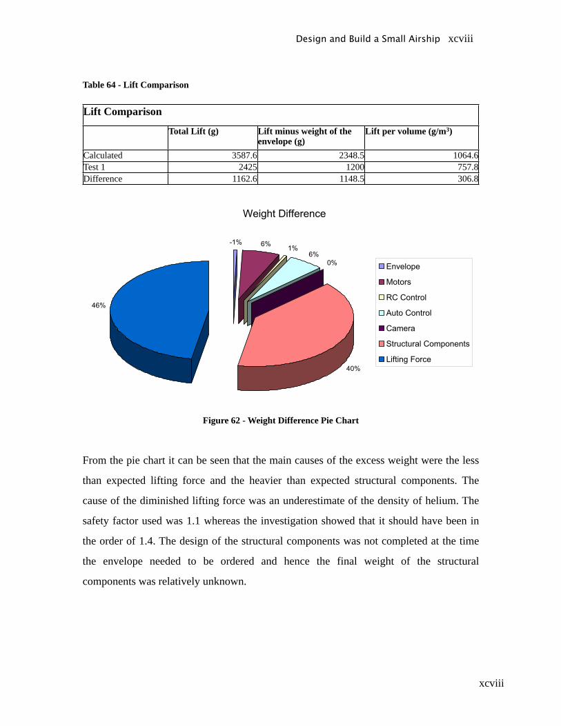
xcviii
Table 64 - Lift Comparison
Lift Comparison
Total Lift (g) Lift minus weight of the envelope (g)
Lift per volume (g/m3)
Calculated 3587.6 2348.5 1064.6Test 1 2425 1200 757.8Difference 1162.6 1148.5 306.8
Figure 62 - Weight Difference Pie Chart
From the pie chart it can be seen that the main causes of the excess weight were the less
than expected lifting force and the heavier than expected structural components. The
cause of the diminished lifting force was an underestimate of the density of helium. The
safety factor used was 1.1 whereas the investigation showed that it should have been in
the order of 1.4. The design of the structural components was not completed at the time
the envelope needed to be ordered and hence the final weight of the structural
components was relatively unknown.
Design and Build a Small Airship xcviii
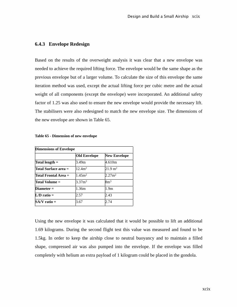
xcix
6.4.3 Envelope Redesign
Based on the results of the overweight analysis it was clear that a new envelope was
needed to achieve the required lifting force. The envelope would be the same shape as the
previous envelope but of a larger volume. To calculate the size of this envelope the same
iteration method was used, except the actual lifting force per cubic metre and the actual
weight of all components (except the envelope) were incorporated. An additional safety
factor of 1.25 was also used to ensure the new envelope would provide the necessary lift.
The stabilisers were also redesigned to match the new envelope size. The dimensions of
the new envelope are shown in Table 65.
Table 65 - Dimension of new envelope
Dimensions of Envelope
Old Envelope New Envelope
Total length = 3.49m 4.610m
Total Surface area = 12.4m2 21.9 m2
Total Frontal Area = 1.45m2 2.27m2
Total Volume = 3.37m3 8m3
Diameter = 1.36m 1.9m
L/D ratio = 2.57 2.43
SA/V ratio = 3.67 2.74
Using the new envelope it was calculated that it would be possible to lift an additional
1.69 kilograms. During the second flight test this value was measured and found to be
1.5kg. In order to keep the airship close to neutral buoyancy and to maintain a filled
shape, compressed air was also pumped into the envelope. If the envelope was filled
completely with helium an extra payload of 1 kilogram could be placed in the gondola.
Design and Build a Small Airship xcix

c
6.5 Second Flight Test and Results
6.5.1 Climb Test
Climb tests were conducted with the engines at full thrust, half thrust and finally at full
thrust with the assistance of the side engines. The time taken for the airship to attain
different altitudes was examined. The results are shown in Figure 63.
Figure 63 - Climb Test Results
The graph shows an initial period of acceleration followed by constant rate of climb after
an altitude of 1m has been reached. As expected, the full thrust with side engine
assistance had both a higher constant velocity and a faster acceleration. The following
table shows the velocity profile for the three conditions.
Table 66 - Velocity Profile in Climb
Half Power Full Power Full Power + Side Engines
Average Climb Velocity (m/s) 0.28 0.35 0.47
Constant Climb Velocity (m/s) 0.33 0.42 0.56Time to Reach Cruise Altitude (s) 10.9 8.9 6.5
Design and Build a Small Airship c
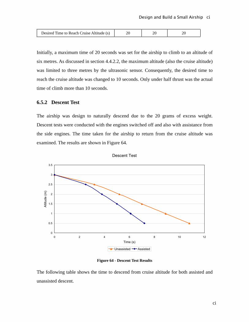
ci
Desired Time to Reach Cruise Altitude (s) 20 20 20
Initially, a maximum time of 20 seconds was set for the airship to climb to an altitude of
six metres. As discussed in section 4.4.2.2, the maximum altitude (also the cruise altitude)
was limited to three metres by the ultrasonic sensor. Consequently, the desired time to
reach the cruise altitude was changed to 10 seconds. Only under half thrust was the actual
time of climb more than 10 seconds.
6.5.2 Descent Test
The airship was design to naturally descend due to the 20 grams of excess weight.
Descent tests were conducted with the engines switched off and also with assistance from
the side engines. The time taken for the airship to return from the cruise altitude was
examined. The results are shown in Figure 64.
Figure 64 - Descent Test Results
The following table shows the time to descend from cruise altitude for both assisted and
unassisted descent.
Design and Build a Small Airship ci
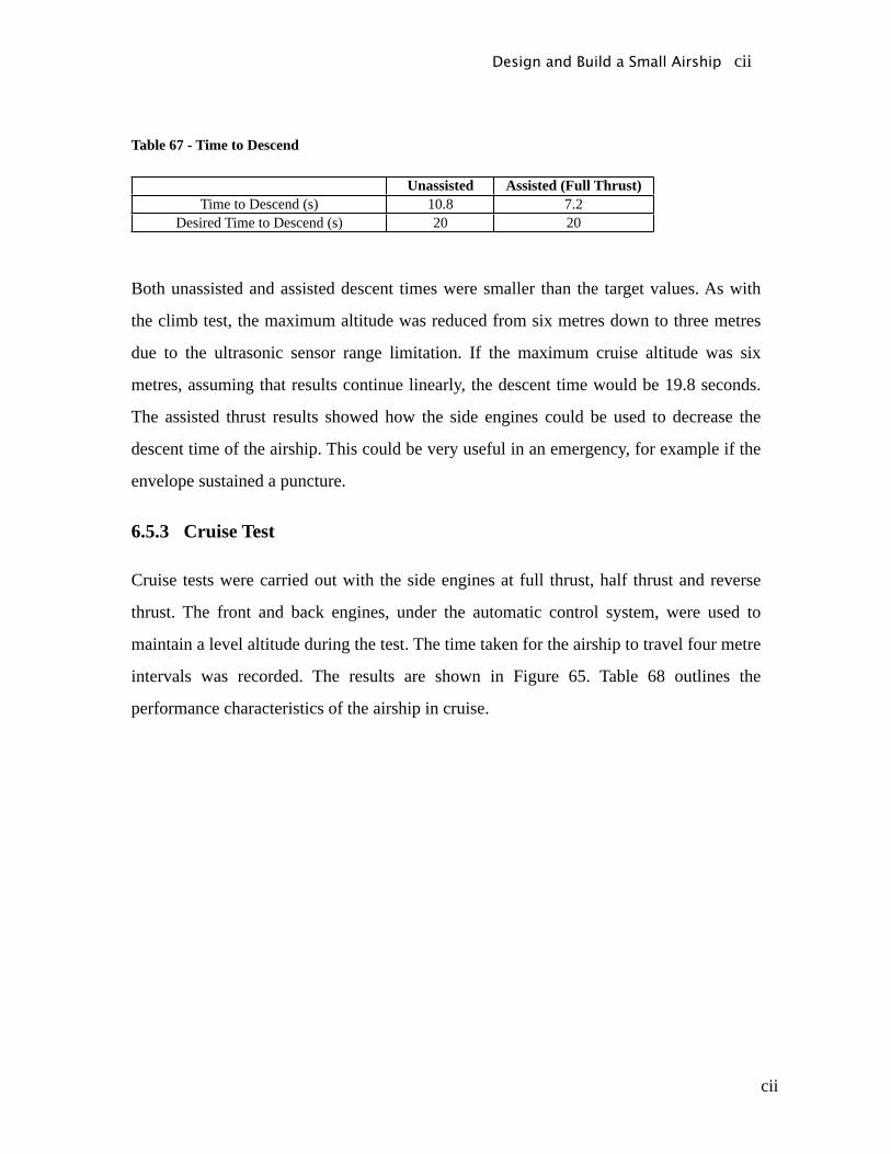
cii
Table 67 - Time to Descend
Unassisted Assisted (Full Thrust)Time to Descend (s) 10.8 7.2
Desired Time to Descend (s) 20 20
Both unassisted and assisted descent times were smaller than the target values. As with
the climb test, the maximum altitude was reduced from six metres down to three metres
due to the ultrasonic sensor range limitation. If the maximum cruise altitude was six
metres, assuming that results continue linearly, the descent time would be 19.8 seconds.
The assisted thrust results showed how the side engines could be used to decrease the
descent time of the airship. This could be very useful in an emergency, for example if the
envelope sustained a puncture.
6.5.3 Cruise Test
Cruise tests were carried out with the side engines at full thrust, half thrust and reverse
thrust. The front and back engines, under the automatic control system, were used to
maintain a level altitude during the test. The time taken for the airship to travel four metre
intervals was recorded. The results are shown in Figure 65. Table 68 outlines the
performance characteristics of the airship in cruise.
Design and Build a Small Airship cii

ciii
Figure 65 - Cruise Test Results
Table 68 - Cruise Velocity Profile
Half Thrust Full Thrust Reverse ThrustTime to reach 16m (s) 21 19 23
Average Cruise Speed (m/s) 0.83 0.84 0.7
Max. Cruise Speed (m/s) 0.89 1.14 0.8
Desired Cruise Max. Cruise Speed (m/s) - 1 -
The maximum achievable cruise speed was above the desired 1m/s, which indicates the
cruise speed performance parameter, has been met. The reverse capabilities of the airship
are only intended for manoeuvrability purposes, for example reversing from a corner. The
reverse cruise test showed better than expected values for cruise speed, which further
enhances the manoeuvrability of the airship.
6.5.4 Rate of turn test
Rate of turn tests were performed with the side engines in full opposite thrust. The front
and back engines, under the automatic control system, were again used to maintain a
Design and Build a Small Airship ciii
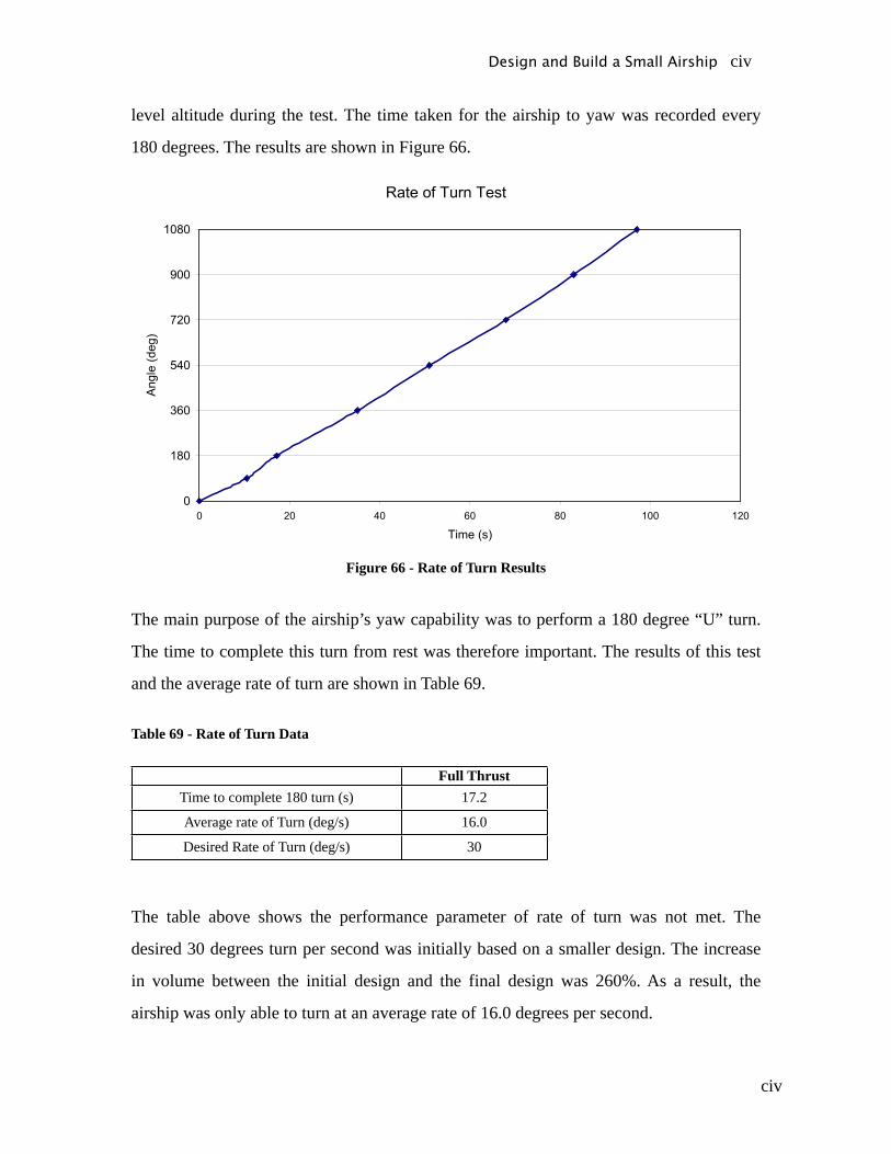
civ
level altitude during the test. The time taken for the airship to yaw was recorded every
180 degrees. The results are shown in Figure 66.
Figure 66 - Rate of Turn Results
The main purpose of the airship’s yaw capability was to perform a 180 degree “U” turn.
The time to complete this turn from rest was therefore important. The results of this test
and the average rate of turn are shown in Table 69.
Table 69 - Rate of Turn Data
Full ThrustTime to complete 180 turn (s) 17.2
Average rate of Turn (deg/s) 16.0
Desired Rate of Turn (deg/s) 30
The table above shows the performance parameter of rate of turn was not met. The
desired 30 degrees turn per second was initially based on a smaller design. The increase
in volume between the initial design and the final design was 260%. As a result, the
airship was only able to turn at an average rate of 16.0 degrees per second.
Design and Build a Small Airship civ
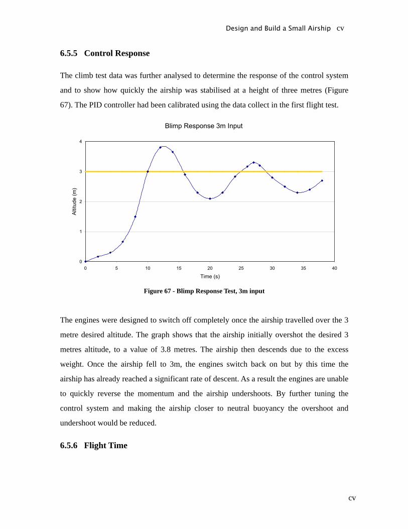
cv
6.5.5 Control Response
The climb test data was further analysed to determine the response of the control system
and to show how quickly the airship was stabilised at a height of three metres (Figure
67). The PID controller had been calibrated using the data collect in the first flight test.
Figure 67 - Blimp Response Test, 3m input
The engines were designed to switch off completely once the airship travelled over the 3
metre desired altitude. The graph shows that the airship initially overshot the desired 3
metres altitude, to a value of 3.8 metres. The airship then descends due to the excess
weight. Once the airship fell to 3m, the engines switch back on but by this time the
airship has already reached a significant rate of descent. As a result the engines are unable
to quickly reverse the momentum and the airship undershoots. By further tuning the
control system and making the airship closer to neutral buoyancy the overshoot and
undershoot would be reduced.
6.5.6 Flight Time
Design and Build a Small Airship cv
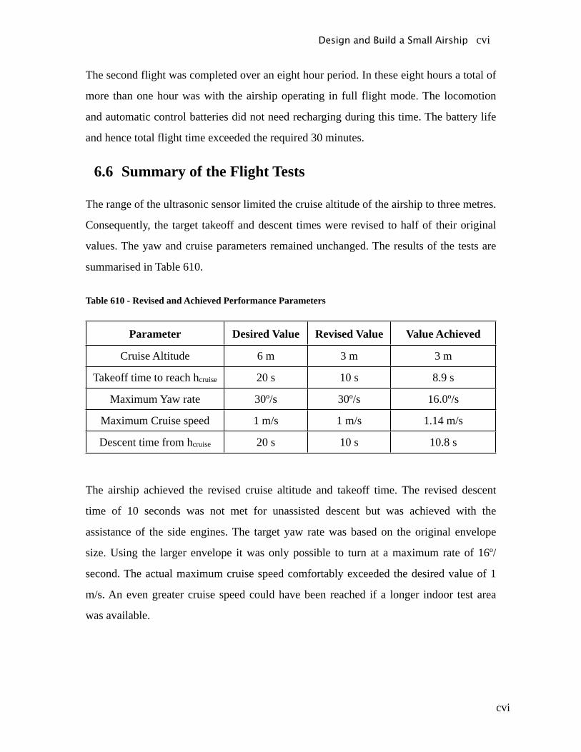
cvi
The second flight was completed over an eight hour period. In these eight hours a total of
more than one hour was with the airship operating in full flight mode. The locomotion
and automatic control batteries did not need recharging during this time. The battery life
and hence total flight time exceeded the required 30 minutes.
6.6 Summary of the Flight Tests
The range of the ultrasonic sensor limited the cruise altitude of the airship to three metres.
Consequently, the target takeoff and descent times were revised to half of their original
values. The yaw and cruise parameters remained unchanged. The results of the tests are
summarised in Table 610.
Table 610 - Revised and Achieved Performance Parameters
Parameter Desired Value Revised Value Value Achieved
Cruise Altitude 6 m 3 m 3 m
Takeoff time to reach hcruise 20 s 10 s 8.9 s
Maximum Yaw rate 30º/s 30º/s 16.0º/s
Maximum Cruise speed 1 m/s 1 m/s 1.14 m/s
Descent time from hcruise 20 s 10 s 10.8 s
The airship achieved the revised cruise altitude and takeoff time. The revised descent
time of 10 seconds was not met for unassisted descent but was achieved with the
assistance of the side engines. The target yaw rate was based on the original envelope
size. Using the larger envelope it was only possible to turn at a maximum rate of 16º/
second. The actual maximum cruise speed comfortably exceeded the desired value of 1
m/s. An even greater cruise speed could have been reached if a longer indoor test area
was available.
Design and Build a Small Airship cvi

cvii
7 Project Management7.1 Timeline and Project Planning
7.1.1 Gantt chart
A Gantt chart was constructed at the beginning of the project to help plan the progress
throughout the year. The research and feasibility study was to be finished by the
beginning of the university year in March, leaving the majority of the time to be spent on
design and construction of the airship. The envelope, gondola, propulsion and control
systems were deemed to be the most important design and construction elements. The
final flight tests were planned to be completed by the end of September.
Figure 71 - Preliminary Gantt chart for the Project
The team was able to follow the preliminary Gantt chart fairly closely throughout the
project. The early completion of the feasibility study meant that design work was able to
start roughly one month ahead of schedule. Most of the design work was completed on
Design and Build a Small Airship cvii

cviii
time but construction of the gondola and envelope was frequently delayed. The number
of test days was constrained by the availability of a suitable indoor area and the cost of
helium. A more detailed Gantt chart can be seen in Appendix F.
7.2 Finance
7.2.1 Project Funding
There were two sources of funding for this project: the University of Adelaide as part of
the final year project budget and an industry sponsor, BAE Systems Australia. The
University provided a total of $500 for the project. This was based on the University final
year project funding system whereby $300 is given for the first student and an additional
$100 is given for every student thereafter. Hence, as there were 3 students in the project,
$500 of support was given. In addition to the financial aid provided by the university, the
Mechanical and Electronics workshop staff also provided many hours of technical
support. The $500 budget was insufficient to cover the cost of the project and as a result
sponsorship was sought from an outside source. BAE Systems Australia generously
provided $3500 of finance. This meant that the total funding for the project was $4000.
7.2.2 Budget
To manage the funds provided for the project a budget estimate was developed. The
largest part of the project spending was the cost of materials and components. The total
actual cost for the project was similar to the original budget estimate. The main
differences were in the cost of the Velcro, level sensor and RC hand unit. Unexpected
expenditure for promotional material such as the open day poster and airship banner
meant that the total money spent was slightly above the total budget. The estimated and
final budgets can be seen in Appendix G. An estimation of total labour costs of the three
team members is also included in Appendix G.
Design and Build a Small Airship cviii
cix
Design and Build a Small Airship cix
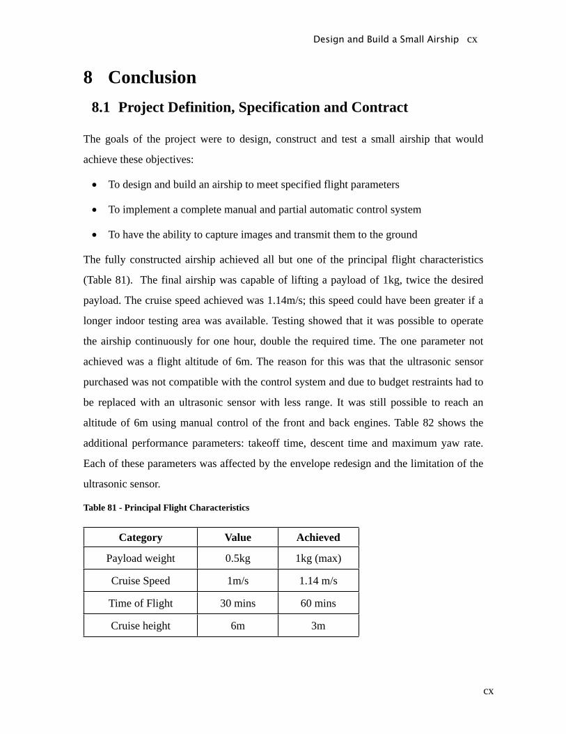
cx
8 Conclusion8.1 Project Definition, Specification and Contract
The goals of the project were to design, construct and test a small airship that would
achieve these objectives:
• To design and build an airship to meet specified flight parameters
• To implement a complete manual and partial automatic control system
• To have the ability to capture images and transmit them to the ground
The fully constructed airship achieved all but one of the principal flight characteristics
(Table 81). The final airship was capable of lifting a payload of 1kg, twice the desired
payload. The cruise speed achieved was 1.14m/s; this speed could have been greater if a
longer indoor testing area was available. Testing showed that it was possible to operate
the airship continuously for one hour, double the required time. The one parameter not
achieved was a flight altitude of 6m. The reason for this was that the ultrasonic sensor
purchased was not compatible with the control system and due to budget restraints had to
be replaced with an ultrasonic sensor with less range. It was still possible to reach an
altitude of 6m using manual control of the front and back engines. Table 82 shows the
additional performance parameters: takeoff time, descent time and maximum yaw rate.
Each of these parameters was affected by the envelope redesign and the limitation of the
ultrasonic sensor.
Table 81 - Principal Flight Characteristics
Category Value Achieved
Payload weight 0.5kg 1kg (max)
Cruise Speed 1m/s 1.14 m/s
Time of Flight 30 mins 60 mins
Cruise height 6m 3m
Design and Build a Small Airship cx
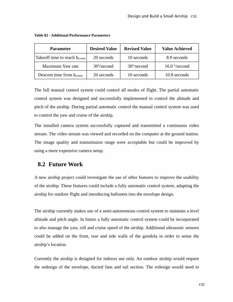
cxi
Table 82 - Additional Performance Parameters
Parameter Desired Value Revised Value Value Achieved
Takeoff time to reach hcruise 20 seconds 10 seconds 8.9 seconds
Maximum Yaw rate 30º/second 30º/second 16.0 º/second
Descent time from hcruise 20 seconds 10 seconds 10.8 seconds
The full manual control system could control all modes of flight. The partial automatic
control system was designed and successfully implemented to control the altitude and
pitch of the airship. During partial automatic control the manual control system was used
to control the yaw and cruise of the airship.
The installed camera system successfully captured and transmitted a continuous video
stream. The video stream was viewed and recorded on the computer at the ground station.
The image quality and transmission range were acceptable but could be improved by
using a more expensive camera setup.
8.2 Future Work
A new airship project could investigate the use of other features to improve the usability
of the airship. These features could include a fully automatic control system, adapting the
airship for outdoor flight and introducing ballonets into the envelope design.
The airship currently makes use of a semi-autonomous control system to maintain a level
altitude and pitch angle. In future a fully automatic control system could be incorporated
to also manage the yaw, roll and cruise speed of the airship. Additional ultrasonic sensors
could be added on the front, rear and side walls of the gondola in order to sense the
airship’s location.
Currently the airship is designed for indoors use only. An outdoor airship would require
the redesign of the envelope, ducted fans and tail section. The redesign would need to
Design and Build a Small Airship cxi
cxii
account for factors such as wind and possible obstructions. It may be possible to reuse
some of the components from this airship in a future project. As part of the envelope
remodelling, ballonets could be used to control the ascent/descent and pitch of the
airship. Although impractical in this project, ballonets may be more suitable in a larger
design.
Design and Build a Small Airship cxii
cxiii
Bibliography
Acroname, sales and product information website, 2007, URL www.acroname.com,
Last accessed: May 2007
Aereon Corporation, Aereon 26 Hybrid Airship, 2006
Airship Solutions, 2007, URL www.airship.com.au, Last accessed: July 2007
Airship Solutions, sales and product information website, 2007, URL
www.airship.com.au, Last accessed: May 2007
Applied Measurement Australia, 2007, URL www.appliedmeasurement.com.au, Last Accessed June 2007
Arbon et al, Wired Aerofoil Stabiliser Project, University of Adelaide, 2006
Arjomandi M. , Aeronautical Engineering 1 Notes, University of Adelaide, 2006
Arjomandi M. , Aeronautical Engineering 2 Notes, University of Adelaide, 2007
Australian Broadcasting Corporation, The Airships, 2004
Australian Civil Aviation Authority, CASA Regulations 101, 1998
B. Cazzolato, 2007. Personal correspondence
Bain D, 2007. Personal correspondence
Bartel G, 2007. Personal correspondence
Betteridge, D., 2007. Personal correspondence
Beer F. and Johnson R. , Statics, McGraw-Hill, 1988
C.S. Jin, National University of Singapore, Blimp Report, 2004
C.B.C. Bearing Co (SA) Pty Ltd, 2007. Personal correspondence
Cole N., Control of Floating Ping-Pong Ball, University of Adelaide, 2007
Design and Build a Small Airship cxiii

cxiv
Electronics Workshop, University of Adelaide, 2007. Personal correspondence
EVB plus sales support, 2007. Personal correspondence
F. Wormel, 2007. Personal Correspondence
Fredericks, 2007, URL www.frederickscom.com, Last accessed: May 2007
G. A. Khoury, Airship Technology, Cambridge University Press, 1999
Grand Wing Servo, 2007, URL www.gws.com.tw, Last Accessed: June 2007
Hobby Habit, 2007, URL www.hobbyhabit.com.au, Last Accessed: May 2007
JMK, URL http://jmkcamera.com, Last Accessed: June 2007
Kotousov A, Stress Analysis and Design Lecture Notes, 2005
Lutz C., “Simon” airship report, Realgymnasium Rämibühl 1998
M. Arjomandi, 2006-2007. Personal Correspondence
MatWeb – Material Property Data website, 2007, URL http:// www.matweb.com, Last accessed: May 2007
Mechanical Engineering Workshop, 2007. Personal correspondence
MIT (Massachusetts Institute of Technology) Open Course Ware website, 2007, URL http://ocw.mit.edu/index.html, Last accessed: May 2007
Model Flight, 2007, URL www.modelflight.com.au, Last accessed: July 2007
Munson R. , Fundamentals of Fluid Mechanics Fifth Edition, Wiley, 2006
N. Istsumi, 2007. Personal Correspondence
P. Jackson, Jane’s all the world’s aircraft, London: S. Low, Marston & Co., 1909
Robert H., 2007. Personal correspondence
Sensidyne – Gas detection and Air monitoring website, 2007, URL http:// www.sensidyne.com, Last accessed: May 2007
Design and Build a Small Airship cxiv
cxv
Southern Balloon Works, 2007. Personal correspondence
Spark Fun Electronics sales support, 2007. Personal correspondence
Spark Fun, 2007, URL www.sparkfun.com, Last Accessed July 2007
Steldi-air, 2007. Personal correspondence
Tank Combat, 2007, URL www.rctankcombat.com, last accessed: June 2007
Tien Fu-Lu, 2007. Personal correspondence
Tubb M., 2007. Personal correspondence
University of Berkeley, Mechanical Engineering Blimp Report, 2004
University of Bombay, Design Fabrication of Remote Airship, 2004
Virginia Technical Univesity, Ikelos Aircraft Design Project, 2001
Wildman B, 2007. Personal correspondence
Z. Prime, 2007. Personal Correspondence
Design and Build a Small Airship cxv
cxvi
Appendix A - Drawings
Design and Build a Small Airship cxvi

cxxxv
Appendix B – Equations
B1 Lift Calculations for Various Gases:
Lifting force per cubic meter of helium:
Lifting force per cubic meter of hydrogen:
Lifting force per cubic meter of ammonia:
Lifting force per cubic meter of methane:
B2 Atmospheric effects:
Effect of temperature on lifting properties of helium:
Ex, T = 20◦C = 293.15 K
Design and Build a Small Airship cxxxv

cxxxvi
B3 Thrust Calculations:
Design and Build a Small Airship cxxxvi
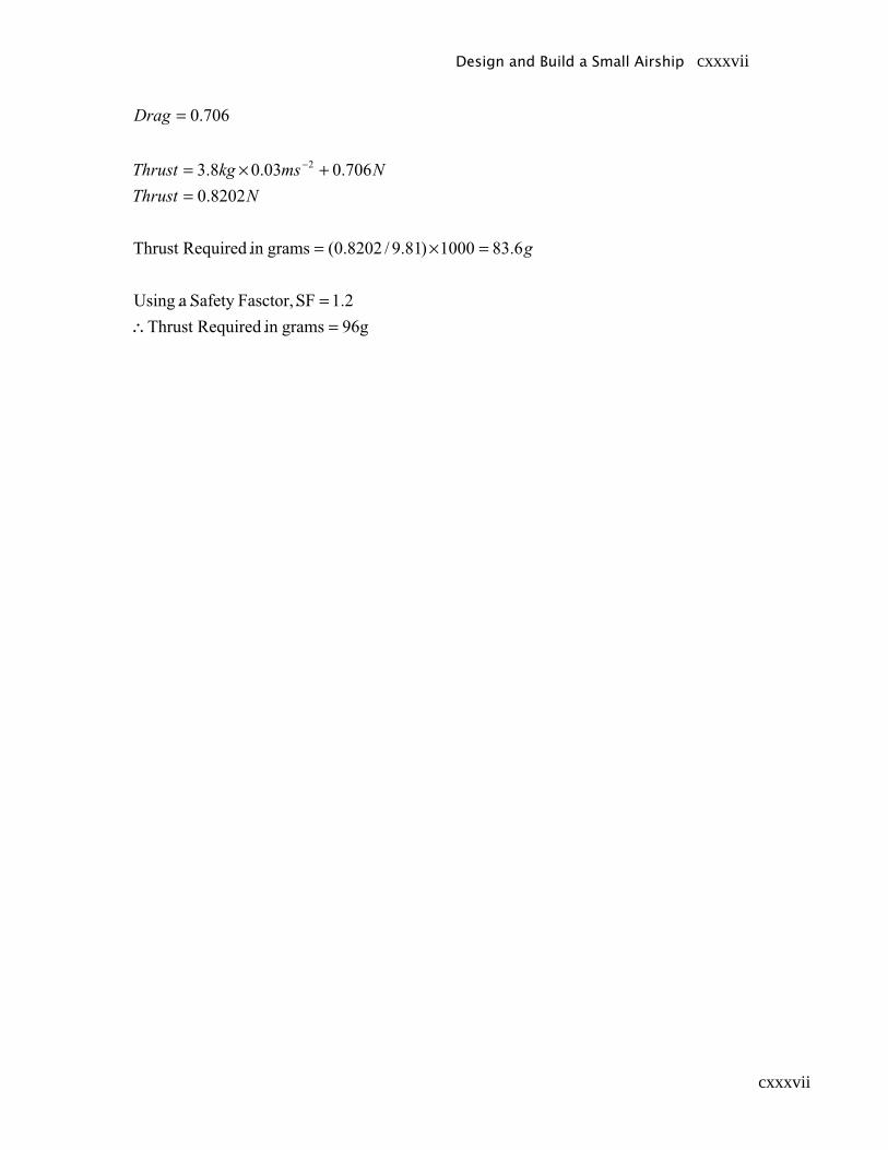
cxxxvii
Design and Build a Small Airship cxxxvii
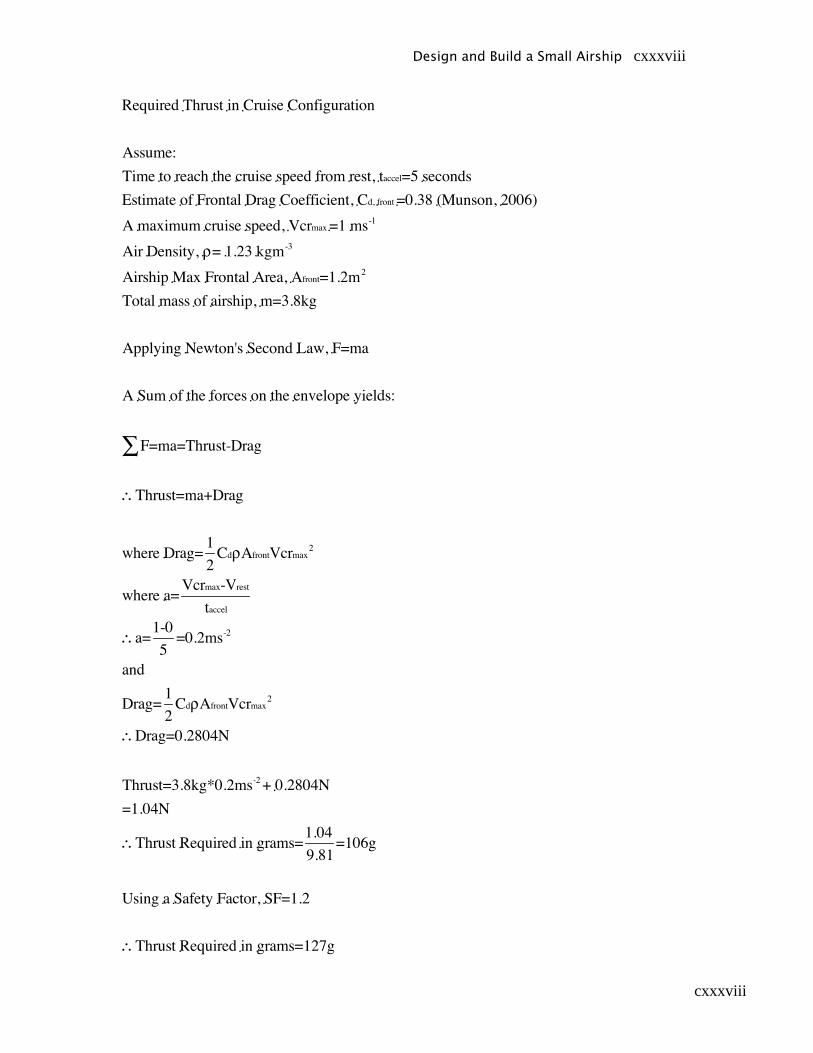
cxxxviii
Design and Build a Small Airship cxxxviii
cxxxix
B4 Power Plant Calculations:
Side Engines:
30 minutes flight time includes + 30 minutes engine idle
• 20 minutes cruise (Current draw during cruise = 2.3A)
• 10 minutes maneuvering (Current draw during maneuvering = 3.5A)
• 30 minutes idle (Current draw during idle = 1A)
Battery solution: 7.4v 1800mAh Li-Po
Front & Rear Engines:
30 minutes flight time includes + 30 minutes engine idle
• 15 minutes climbing (Current draw during climb = 2.1A)
• 15 minutes hover (Current draw during hover = 1.5A)
• 30 minutes idle (Current draw during idle = 1A)
Battery solution: 7.4v 1800mAh Li-Po
Design and Build a Small Airship cxxxix
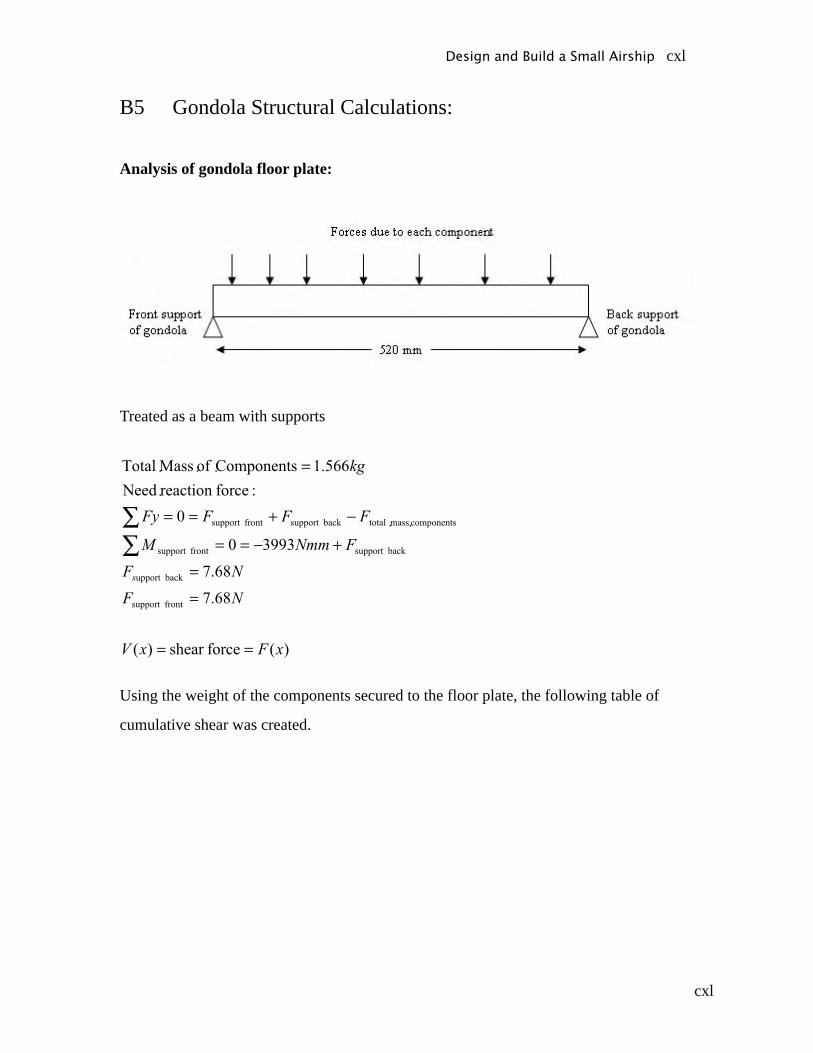
cxl
B5 Gondola Structural Calculations:
Analysis of gondola floor plate:
Treated as a beam with supports
Using the weight of the components secured to the floor plate, the following table of
cumulative shear was created.
Design and Build a Small Airship cxl
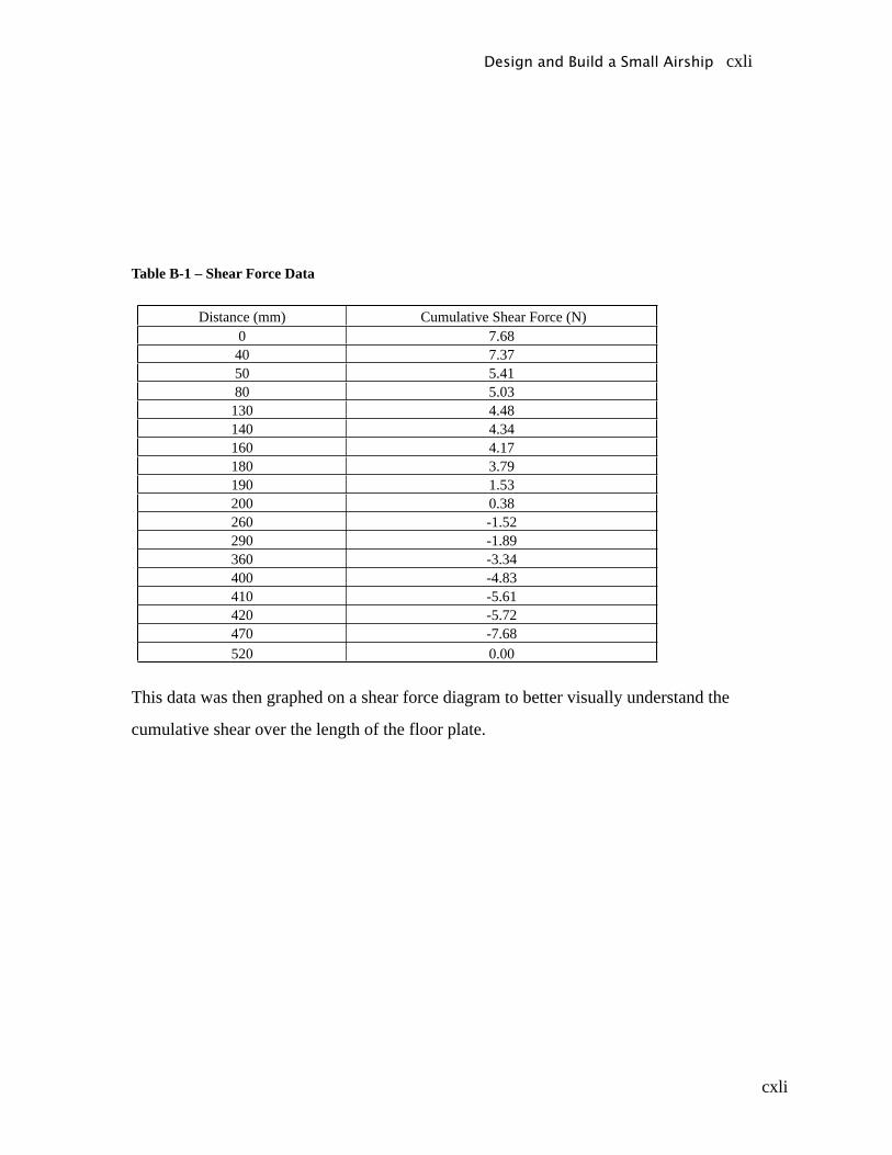
cxli
Table B-1 – Shear Force Data
Distance (mm) Cumulative Shear Force (N)0 7.6840 7.3750 5.4180 5.03130 4.48140 4.34160 4.17180 3.79190 1.53200 0.38260 -1.52290 -1.89360 -3.34400 -4.83410 -5.61420 -5.72470 -7.68520 0.00
This data was then graphed on a shear force diagram to better visually understand the
cumulative shear over the length of the floor plate.
Design and Build a Small Airship cxli
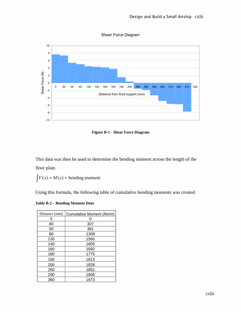
cxlii
Figure B-1 - Shear Force Diagram
This data was then be used to determine the bending moment across the length of the
floor plate.
Using this formula, the following table of cumulative bending moments was created.
Table B-2 – Bending Moment Data
Distance (mm) Cumulative Moment (Nmm)0 0
40 30750 38180 1308
130 1560140 1605160 1692180 1775190 1813200 1828260 1851290 1806360 1673
Design and Build a Small Airship cxlii
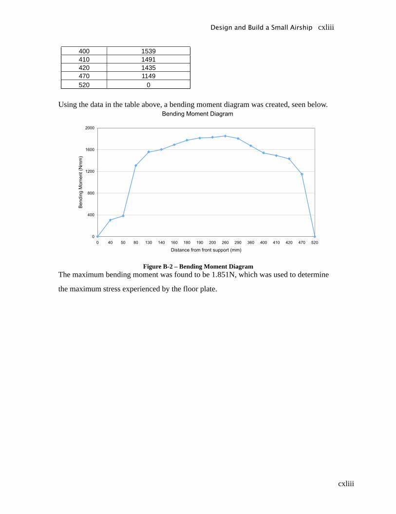
cxliii
400 1539410 1491420 1435470 1149520 0
Using the data in the table above, a bending moment diagram was created, seen below.
Figure B-2 – Bending Moment DiagramThe maximum bending moment was found to be 1.851N, which was used to determine
the maximum stress experienced by the floor plate.
Design and Build a Small Airship cxliii
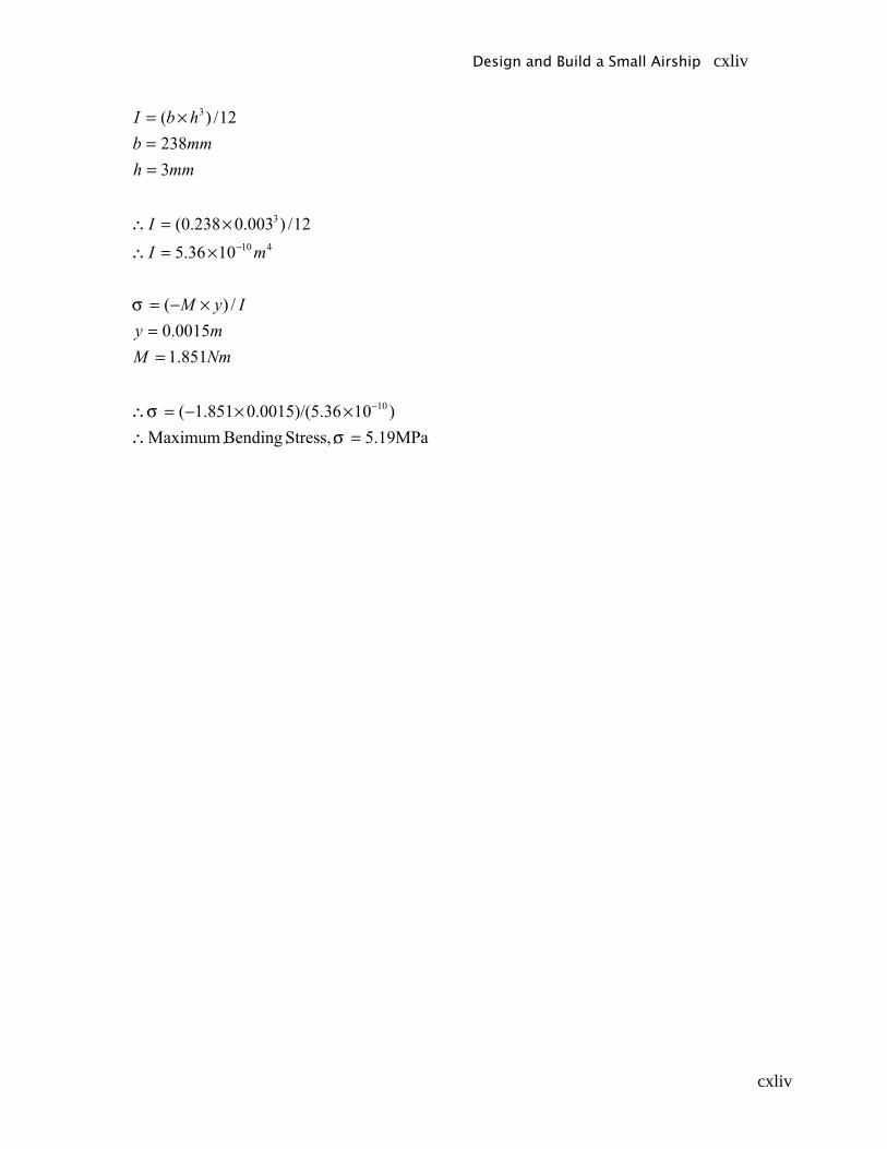
cxliv
Design and Build a Small Airship cxliv

cxlv
B6 Envelope Design Calculations:
Design and Build a Small Airship cxlv
cxlvi
Design and Build a Small Airship cxlvi

cxlvii
Design and Build a Small Airship cxlvii

cxlviii
Design and Build a Small Airship cxlviii
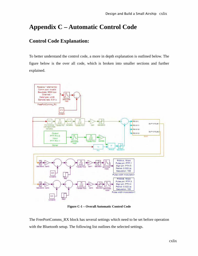
cxlix
Appendix C – Automatic Control Code
Control Code Explanation:
To better understand the control code, a more in depth explanation is outlined below. The
figure below is the over all code, which is broken into smaller sections and further
explained.
Figure C-1 – Overall Automatic Control Code
The FreePortComms_RX block has several settings which need to be set before operation
with the Bluetooth setup. The following list outlines the selected settings.
Design and Build a Small Airship cxlix
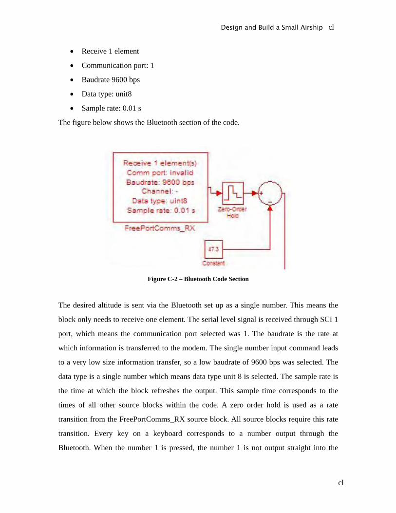
cl
• Receive 1 element
• Communication port: 1
• Baudrate 9600 bps
• Data type: unit8
• Sample rate: 0.01 s
The figure below shows the Bluetooth section of the code.
Figure C-2 – Bluetooth Code Section
The desired altitude is sent via the Bluetooth set up as a single number. This means the
block only needs to receive one element. The serial level signal is received through SCI 1
port, which means the communication port selected was 1. The baudrate is the rate at
which information is transferred to the modem. The single number input command leads
to a very low size information transfer, so a low baudrate of 9600 bps was selected. The
data type is a single number which means data type unit 8 is selected. The sample rate is
the time at which the block refreshes the output. This sample time corresponds to the
times of all other source blocks within the code. A zero order hold is used as a rate
transition from the FreePortComms_RX source block. All source blocks require this rate
transition. Every key on a keyboard corresponds to a number output through the
Bluetooth. When the number 1 is pressed, the number 1 is not output straight into the
Design and Build a Small Airship cl
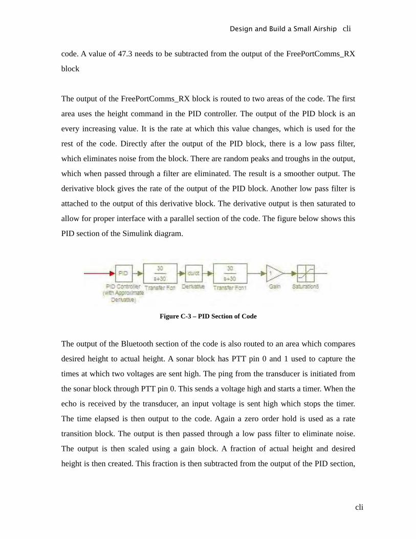
cli
code. A value of 47.3 needs to be subtracted from the output of the FreePortComms_RX
block
The output of the FreePortComms_RX block is routed to two areas of the code. The first
area uses the height command in the PID controller. The output of the PID block is an
every increasing value. It is the rate at which this value changes, which is used for the
rest of the code. Directly after the output of the PID block, there is a low pass filter,
which eliminates noise from the block. There are random peaks and troughs in the output,
which when passed through a filter are eliminated. The result is a smoother output. The
derivative block gives the rate of the output of the PID block. Another low pass filter is
attached to the output of this derivative block. The derivative output is then saturated to
allow for proper interface with a parallel section of the code. The figure below shows this
PID section of the Simulink diagram.
Figure C-3 – PID Section of Code
The output of the Bluetooth section of the code is also routed to an area which compares
desired height to actual height. A sonar block has PTT pin 0 and 1 used to capture the
times at which two voltages are sent high. The ping from the transducer is initiated from
the sonar block through PTT pin 0. This sends a voltage high and starts a timer. When the
echo is received by the transducer, an input voltage is sent high which stops the timer.
The time elapsed is then output to the code. Again a zero order hold is used as a rate
transition block. The output is then passed through a low pass filter to eliminate noise.
The output is then scaled using a gain block. A fraction of actual height and desired
height is then created. This fraction is then subtracted from the output of the PID section,
Design and Build a Small Airship cli
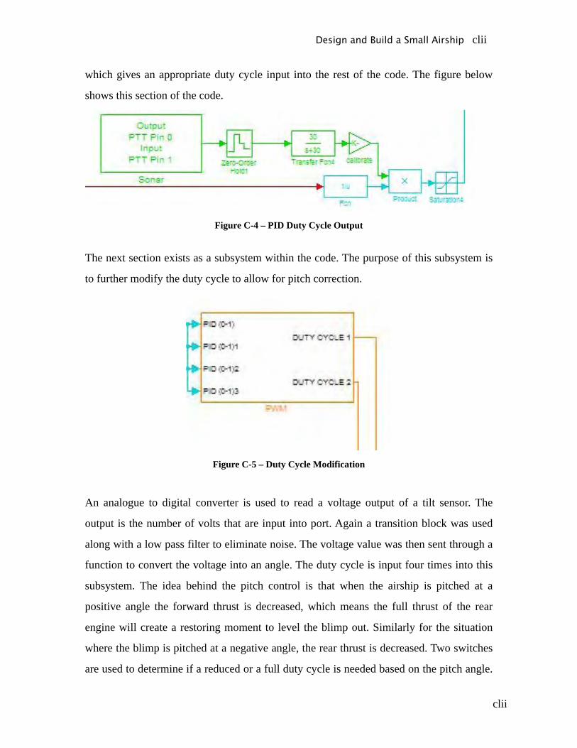
clii
which gives an appropriate duty cycle input into the rest of the code. The figure below
shows this section of the code.
Figure C-4 – PID Duty Cycle Output
The next section exists as a subsystem within the code. The purpose of this subsystem is
to further modify the duty cycle to allow for pitch correction.
Figure C-5 – Duty Cycle Modification
An analogue to digital converter is used to read a voltage output of a tilt sensor. The
output is the number of volts that are input into port. Again a transition block was used
along with a low pass filter to eliminate noise. The voltage value was then sent through a
function to convert the voltage into an angle. The duty cycle is input four times into this
subsystem. The idea behind the pitch control is that when the airship is pitched at a
positive angle the forward thrust is decreased, which means the full thrust of the rear
engine will create a restoring moment to level the blimp out. Similarly for the situation
where the blimp is pitched at a negative angle, the rear thrust is decreased. Two switches
are used to determine if a reduced or a full duty cycle is needed based on the pitch angle.
Design and Build a Small Airship clii
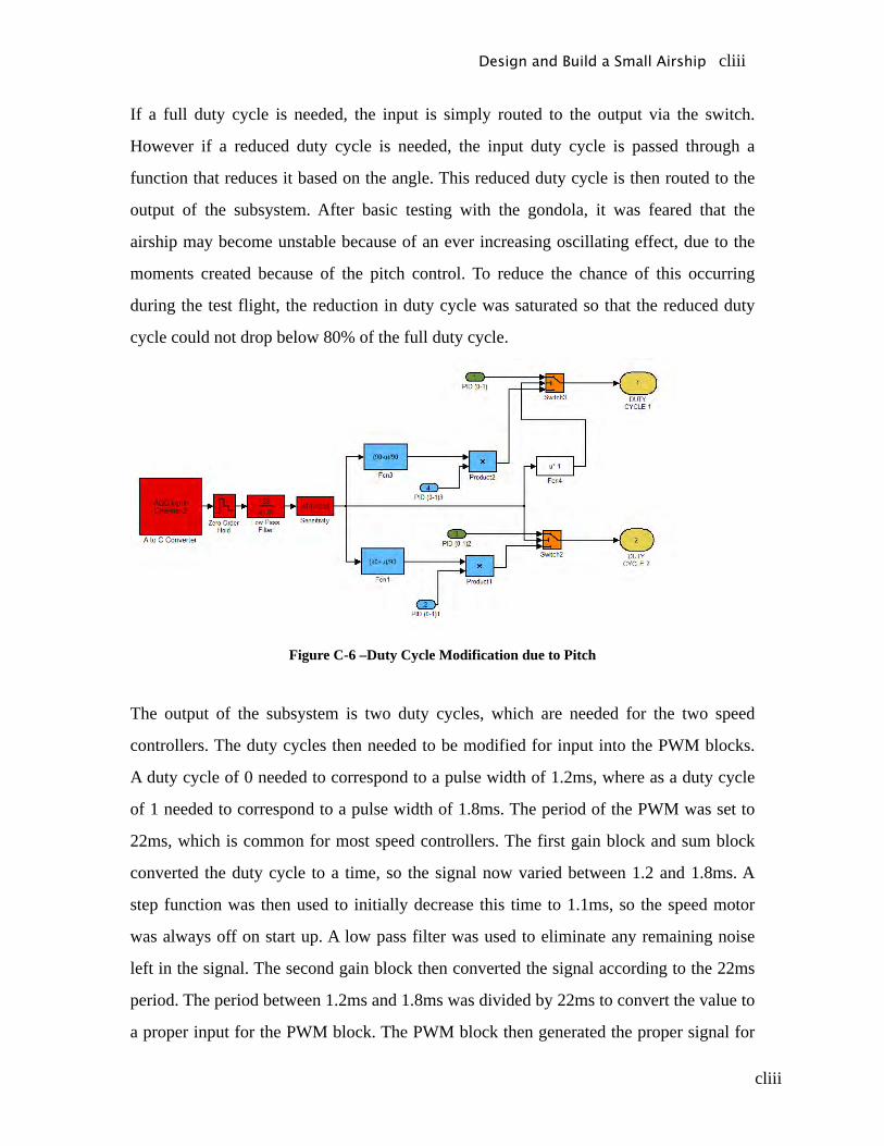
cliii
If a full duty cycle is needed, the input is simply routed to the output via the switch.
However if a reduced duty cycle is needed, the input duty cycle is passed through a
function that reduces it based on the angle. This reduced duty cycle is then routed to the
output of the subsystem. After basic testing with the gondola, it was feared that the
airship may become unstable because of an ever increasing oscillating effect, due to the
moments created because of the pitch control. To reduce the chance of this occurring
during the test flight, the reduction in duty cycle was saturated so that the reduced duty
cycle could not drop below 80% of the full duty cycle.
Figure C-6 –Duty Cycle Modification due to Pitch
The output of the subsystem is two duty cycles, which are needed for the two speed
controllers. The duty cycles then needed to be modified for input into the PWM blocks.
A duty cycle of 0 needed to correspond to a pulse width of 1.2ms, where as a duty cycle
of 1 needed to correspond to a pulse width of 1.8ms. The period of the PWM was set to
22ms, which is common for most speed controllers. The first gain block and sum block
converted the duty cycle to a time, so the signal now varied between 1.2 and 1.8ms. A
step function was then used to initially decrease this time to 1.1ms, so the speed motor
was always off on start up. A low pass filter was used to eliminate any remaining noise
left in the signal. The second gain block then converted the signal according to the 22ms
period. The period between 1.2ms and 1.8ms was divided by 22ms to convert the value to
a proper input for the PWM block. The PWM block then generated the proper signal for
Design and Build a Small Airship cliii
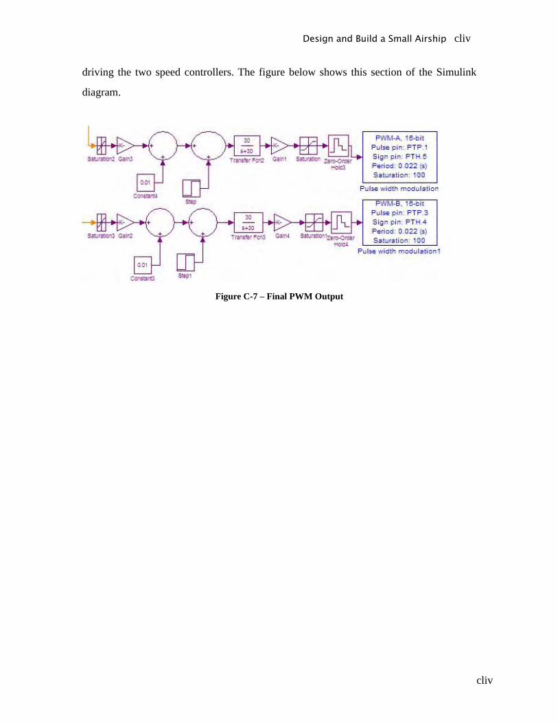
cliv
driving the two speed controllers. The figure below shows this section of the Simulink
diagram.
Figure C-7 – Final PWM Output
Design and Build a Small Airship cliv
clv
Appendix D – Flight Test Procedures
1. RC Flight Tests Procedures
On ground operation Tests
Equipment
o Envelope
o Gondola
o RC Unit
o Tie Lines
o Manometer
o Force Gauge
Gondola tests
o Connect the timing belt to the servo system
o Connect engines and servo to receiver
o Switch on RC unit
o Connect batteries to receiver then to engines
o Using RC unit move the servo
o Adjust the belt location to ensure correct rotation of engines
o Test operation of front/ back engines and left/right engines separately and
simultaneously
Attaching Gondola
o Connect the gondola to the deflated envelope using tie line system connected to
the rods of the gondola
o Connect the gondola to the deflated envelope using the Velcro strips, ensuring
strips are lined up and firmly attached
Design and Build a Small Airship clv

clvi
o Attach safety line to the Envelope
Envelope Inflation
o Connect the pressure gauge and hose to the helium cylinder
o Place other end of hose inside envelope
o Turn on valve on the cylinder and commence filling
o Stop filling (shut valve) when all the wrinkles in the envelope have disappeared
o Disconnect hose and close envelope
o Using manometer measure pressure inside the envelope
o Using the force gauge measure the lifting force of the envelope with the gondola
attached
o Add weight to the gondola to make the airship 20grams overweight
Design and Build a Small Airship clvi

clvii
Vertical Motion Test
Equipment
o Airship
o RC Unit
o Force Gauge
o Measuring string
o Stop watch
Climb Test
o Complete any non-completed pre-flight tests
o Attach measuring string to the gondola
o Turn on front/back engine to half power using RC unit
o Adjust power input if required to keep airship level during climb
o Using stop watch measure time for airship to climb from 1 to 3m altitude
o Calculate the rate of climb
o Once altitude of 3m is reached switch of front/back engine and start descent test
o Repeat with engines at full power
Descent Test
o Having reach the altitude of 3m using climb test, switch off both front/back
engines
o Wait for the engines to stop then record the time for the airship to fall from 3m to
1m
o Calculate rate of descent
o Repeat using the climb test to achieve the desired starting altitude
Design and Build a Small Airship clvii

clviii
Design and Build a Small Airship clviii

clix
Horizontal Motion Test
Equipment
o Airship
o RC Unit
o Force Gauge
o Measuring tape
o Marking cones or tape
o Stop watch
Prior to test set up cones of tape in a straight line at intervals of 1m across the test course.
Cruise Test
o Complete any non-completed pre-flight tests
o Using front/back engines bring airship to an appropriate cruise height
o Use front/back engines to maintain level flight throughout the test
o Switch on both side motors to half power
o Measure time for airship to travel at least 5 metres
o Calculate the average cruise speed
o Use reverse cruise test to return airship to start position
o Repeat test at full power
Reverse Cruise Test
o Having reach the end of the cruise test course
o Continue to use the front/ back motors to maintain level flight
o Power the side motors in reverse up to half power
o Measure the time for the airship to return to the start position on the test course
o Calculate the average speed in reverse
o Use the cruise test to return the airship to the end of the course
Design and Build a Small Airship clix
clx
o Repeat test at full power
Design and Build a Small Airship clx

clxi
Combined Horizontal and Vertical motion
Equipment
o Airship
o RC Unit
o Force Gauge
o Measuring string
o Measuring tape
o Marking cones or tape
o Stop watch
Prior to test set up cones of tape in a straight line at intervals of 1m across the test course.
Rotated Side Engines Cruise Climb Test
o Complete any non-completed pre-flight tests
o Attach measuring string to the gondola
o Using the servo rotate the side motors 60 degrees
o Turn on front/back and the side engines to half power using RC unit
o Adjust power input if required to keep airship level during climb
o Using stop watch measure time for airship to climb from 1 to 3m altitude
o Record the horizontal distance travelled in this time
o Calculate the rate of climb
o Once altitude of 3m is reached switch of front/back engine and start the assisted
descent test
o Repeat with engines at full power
o After test compare results with fixed motors cruise climb test
Assisted Landing Test
Design and Build a Small Airship clxi

clxii
o Having reached the altitude of 3m using climb test, switch off both front/back
engines
o Ensure the side motors are still rotated at 60 degrees
o Power the side engines in reverse at half power
o Record the time for the airship to fall from 3m to 1m and the horizontal distance
travelled during the descent
o Calculate rate of descent
o Repeat using the climb test to achieve the desired starting altitude
o Compare result to descent without engine power
Design and Build a Small Airship clxii
clxiii
Rate of Turn Test
Equipment
o Airship
o RC Unit
o Force Gauge
o Stop watch
Rate of turn side engines opposite thrust
o Complete any non-completed pre-flight tests
o Use the climb test procedure to bring the airship to a desired altitude
o Use the front/back engine to maintain level flight and altitude
o Ensure that the side motors are facing horizontal, if not use servo to rotate them
back
o Turn on left side motor in forwards motion and the right motor in reverse, both to
half power (hence airship should turn to the right)
o The time for the airship to turn 90° and 180° will be recorded
o Rate of turn determined
o Repeat this process for the right motor in forwards motion and the left motor in
reverse, both to half power (hence airship should turn to the right)
o Repeat this process with the engines at full power
o After test compare rates of turn
Design and Build a Small Airship clxiii
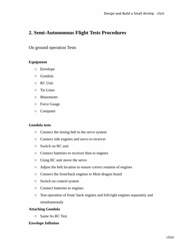
clxiv
2. Semi-Autonomous Flight Tests Procedures
On ground operation Tests
Equipment
o Envelope
o Gondola
o RC Unit
o Tie Lines
o Manometer
o Force Gauge
o Computer
Gondola tests
o Connect the timing belt to the servo system
o Connect side engines and servo to receiver
o Switch on RC unit
o Connect batteries to receiver then to engines
o Using RC unit move the servo
o Adjust the belt location to ensure correct rotation of engines
o Connect the front/back engines to Mini-dragon board
o Switch on control system
o Connect batteries to engines
o Test operation of front/ back engines and left/right engines separately and
simultaneously
Attaching Gondola
o Same As RC Test
Envelope Inflation
Design and Build a Small Airship clxiv
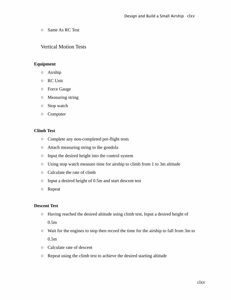
clxv
o Same As RC Test
Vertical Motion Tests
Equipment
o Airship
o RC Unit
o Force Gauge
o Measuring string
o Stop watch
o Computer
Climb Test
o Complete any non-completed pre-flight tests
o Attach measuring string to the gondola
o Input the desired height into the control system
o Using stop watch measure time for airship to climb from 1 to 3m altitude
o Calculate the rate of climb
o Input a desired height of 0.5m and start descent test
o Repeat
Descent Test
o Having reached the desired altitude using climb test, Input a desired height of
0.5m
o Wait for the engines to stop then record the time for the airship to fall from 3m to
0.5m
o Calculate rate of descent
o Repeat using the climb test to achieve the desired starting altitude
Design and Build a Small Airship clxv
clxvi
Level Flight Test
o Using the climb test achieved desired cruise altitude
o Measure fluctuations in altitude and time to recover
o Complete all previous horizontal flight tests using the automatic control system to
maintain the desired altitude
Design and Build a Small Airship clxvi
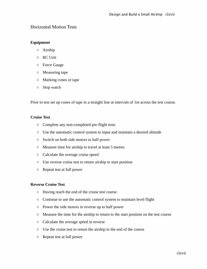
clxvii
Horizontal Motion Tests
Equipment
o Airship
o RC Unit
o Force Gauge
o Measuring tape
o Marking cones or tape
o Stop watch
Prior to test set up cones of tape in a straight line at intervals of 1m across the test course.
Cruise Test
o Complete any non-completed pre-flight tests
o Use the automatic control system to input and maintain a desired altitude
o Switch on both side motors to half power
o Measure time for airship to travel at least 5 metres
o Calculate the average cruise speed
o Use reverse cruise test to return airship to start position
o Repeat test at full power
Reverse Cruise Test
o Having reach the end of the cruise test course
o Continue to use the automatic control system to maintain level flight
o Power the side motors in reverse up to half power
o Measure the time for the airship to return to the start position on the test course
o Calculate the average speed in reverse
o Use the cruise test to return the airship to the end of the course
o Repeat test at full power
Design and Build a Small Airship clxvii

clxviii
Design and Build a Small Airship clxviii
clxix
Appendix E – Safety Requirements
Design and Build a Small Airship clxix

clxx
Design and Build a Small Airship clxx

clxxi
Design and Build a Small Airship clxxi

clxxii
Design and Build a Small Airship clxxii

clxxiii
Design and Build a Small Airship clxxiii
clxxiv
Appendix F – Gantt chart
Design and Build a Small Airship clxxiv

clxxv
Appendix G – Costs and Working HoursIn addition to the costs of components the cost of labour also needed to be determined.
The hours of each team member were recorded and the salary calculated based on an
hourly wage of $25 per hour. Indirect costs were based on hours worked outside
University.
Table G-1 – Estimated Labour Costs
Nov 06 -Jan 07
Name Hours Salary ($AUS) Indirect ($AUS) Total Cost ($AUS)
Nick Bartel 60 1500 2027 3917Lachlan Ravenscroft 61 1525 2061 3982
Michael Nordestgaard 65 1625 2196 4243Total 186 4650 6284 12143
Feb-April
Name Hours Salary ($AUS) Indirect ($AUS) Total Cost ($AUS)
Nick Bartel 149 3725 5034 9727Lachlan Ravenscroft 159 3975 5372 10380
Michael Nordestgaard 138 3450 4662 9009Total 446 11150 15068 29117
May-July
Name Hours Salary ($AUS) Indirect ($AUS) Total Cost ($AUS)
Nick Bartel 201 5025 6791 13122Lachlan Ravenscroft 189 4725 6385 12339
Michael Nordestgaard 182 4550 6149 11882Total 572 14300 19324 37342
Aug-Oct
Name Hours Salary ($AUS) Indirect ($AUS) Total Cost ($AUS)
Nick Bartel 220 5500 7432 14362Lachlan Ravenscroft 260 6500 8784 16974
Michael Nordestgaard 260 6500 8784 16974Total 740 18500 25000 48310
Project Total ($) 1944 48600 56016 101860
Design and Build a Small Airship clxxv

clxxvi
Design and Build a Small Airship clxxvi

clxxvii
Table G2 - Cost Estimates
Part QTY Unit Cost Total CostMaterials/Components
Mechanical ComponentsEnvelope 1 700 $700.00Stabilisers 1 50 $50.00Tow line 1 10 $10.00Gondola Housing 1 100 $100.00Motor / Ducted Fan (upwards thrust) 2 80 $160.00Motor (Manoeuvring thrust) 2 65 $130.00Ducted Fans 2 30 $60.00Velcro 3 10 $30.00
ElectronicsAxial for motor 4 5 $20.00Wiring 1 20 $20.00Camera Set-up 1 150 $150.00Level Sensor 1 62.5 $62.50Maxbotix Ultra sonic range finder 2 31.25 $62.50Bluetooth v2.0 SMD Module 1 87.5 $87.50Bluetooth Modem - BlueDongle 1 87.5 $87.50Serial Cable DB9 M/F - 6 Foot 1 5 $5.00USB miniB Cable - 6 Foot 1 5 $5.002.4GHz Duck Antenna RP-SMA 1 10 $10.00Speed controller (brushless) 2 44 $88.00Speed controller (reversible) 2 60 $120.00Servos 1 0*Receiver 2 0*Minidragon 1 119 119Battery (Automatic) 1 61 61
InstrumentsCharger 1 100 $100Hand Controls (Pack including servos, battery and receiver)
1 1200 $1200.00
Battery Pack (upwards thrust) 1 70 $70.00Battery Pack (manoeuvring thrust) 1 60 60
ConsumablesHelium 2 200 $400.00
Total $3968.00(* price included in hand controls)
Design and Build a Small Airship clxxvii

clxxviii
Table G-3 - Actual Funds Spent
Part QTY Unit Cost Total CostMaterials
Mechanical Components Envelope 1 725 $725.00 Bearings 2 7 $14.00 Axle 2 5 $10.00 Balsa Wood 1 83 $83.00
Motor / Ducted Fan (upwards thrust) 2 80 $160.00 Motor / Ducted Fan (horizontal thrust) 2 72 $144.00
Motor Initial test engine 1 60 $60.00 Ducted Fan initial test 1 35 $35.00 Servo pulleys and belt 1 32 $32.00Electronics Camera Set-up 1 70 $70.00
Camera Battery 1 17 $17.00 Analogue to digital cable 1 45 $45.00 Ultra sonic sensor package 1 85 $85.00 Additional ultrasonic sensor 1 52 $52.00 Bluetooth v2.0 DIP Module 1 70 $70.00 Bluetooth Modem - BlueDongle 1 85 $85.00 USB miniB Cable - 6 Foot 1 10 $10.00 2.4GHz Duck Antenna RP-SMA 2 9 $18.00 Speed controller (brushless) 2 44 $88.00 Speed controller (reversible) 2 85 $170.00 RC Unit 1 385 $385.00 Batteries 1 203 $203.00 Level sensor (clinometer) 1 376 $376.00 USB Connector cable 1 40 $40.00
Miscellaneous Workshop Costs 1 20.25 $20.25 Velcro 18 5.95 $107.10 Twine 1 3.5 $3.50 Cloth 1 1.66 $1.66 Tie Line 1 5 $5.00 Washers 1 5.5 $5.50 Banner 1 132 $132.00 Contact for fins 1 3.5 $3.50 Balsa wood + Glue 1 14.85 $14.85 Open Day Poster 1 334.4 $334.40 Helium 2 220 $482.20 Total $4088.96
Appendix H – Minutes of Meetings
Design and Build a Small Airship clxxviii

clxxix
MINUTES
OF MEETING HELD IN MAZIAR ARJOMANDI’S OFFICEThursday 23rd November 2006
PROJECT : The Design and Build of a small airship.
ATTENDANCE Michael Nordestgaard MN Lachlan Ravenscroft LR Nick Bartel NB Maziar Arjomandi, Supervisor MA
ITEM DESRIPTION/EVENT ACTION/RESPONSIBILITY
1 INTRODUCTION:
This was the first meeting with project supervisor Maziar Arjomandi and other team members. Discussed general details regarding the role of each individual in the team.
Note
2Timeline
Main focus of the meeting was construction of basic timeline of how the project would evolve.
MN
3Theoretical Design Calculations
The theoretical design work should be completed by February so materials can be ordered from overseas, if required.
NB, MN, LR
4Bill of Materials
The Bill of Materials should be constructed in basic form, with further expansion once the Design Calculations are complete.
LR
Design and Build a Small Airship clxxix
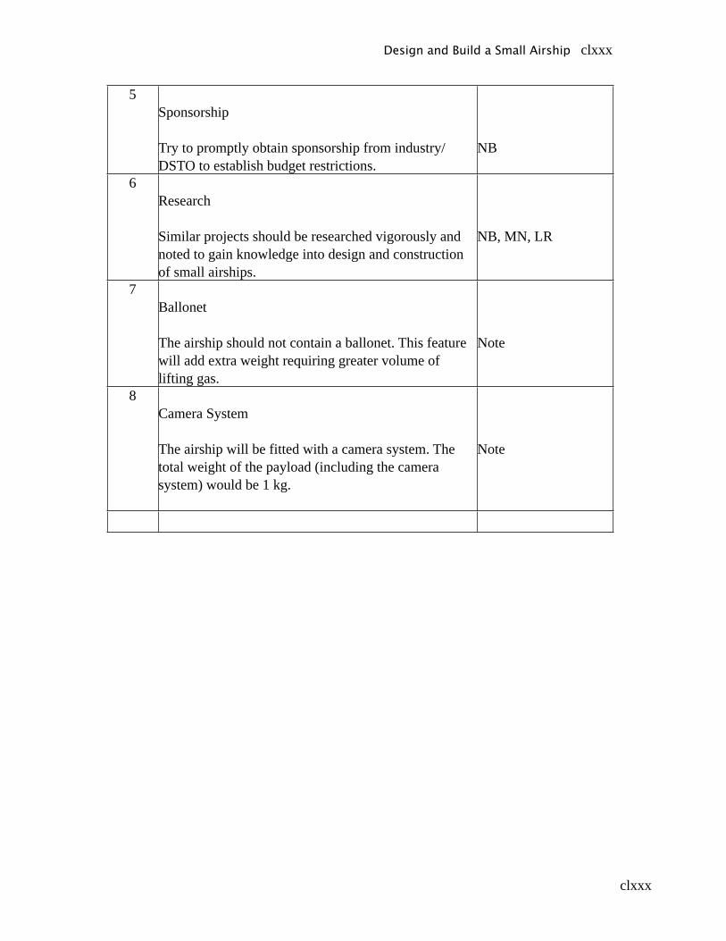
clxxx
5Sponsorship
Try to promptly obtain sponsorship from industry/DSTO to establish budget restrictions.
NB
6Research
Similar projects should be researched vigorously and noted to gain knowledge into design and construction of small airships.
NB, MN, LR
7Ballonet
The airship should not contain a ballonet. This feature will add extra weight requiring greater volume of lifting gas.
Note
8Camera System
The airship will be fitted with a camera system. The total weight of the payload (including the camera system) would be 1 kg.
Note
Design and Build a Small Airship clxxx

clxxxi
MINUTES
OF MEETING HELD IN MAZIAR ARJOMANDI’S OFFICEMonday 4th December 2006
PROJECT : The Design and Build of a small airship.
ATTENDANCE Michael Nordestgaard MN Lachlan Ravenscroft LR Nick Bartel NB Maziar Arjomandi, Supervisor MA
ITEM DESRIPTION/EVENT ACTION/RESPONSIBILITY
1 Timeline
MN presented MA with timeline. MA suggested timeline was good but should be split into two parts:
• Short term timeline (weekly, from Dec-March)• Long term timeline (monthly until the end of
the project)
The timelines should be constructed using Microsoft Project.
MN
Note2
Preliminary Design Calculations
Basic calculations of weight of materials should be carried out to allow estimation of volume and dimensions of airship.
NB, MN
3Bill of Materials
Bill of Materials presented to MA. He suggested a more detailed approach closely linked to the preliminary calculations.
BOM should use a spreadsheet format using Microsoft Excel.
LR
Note
Design and Build a Small Airship clxxxi
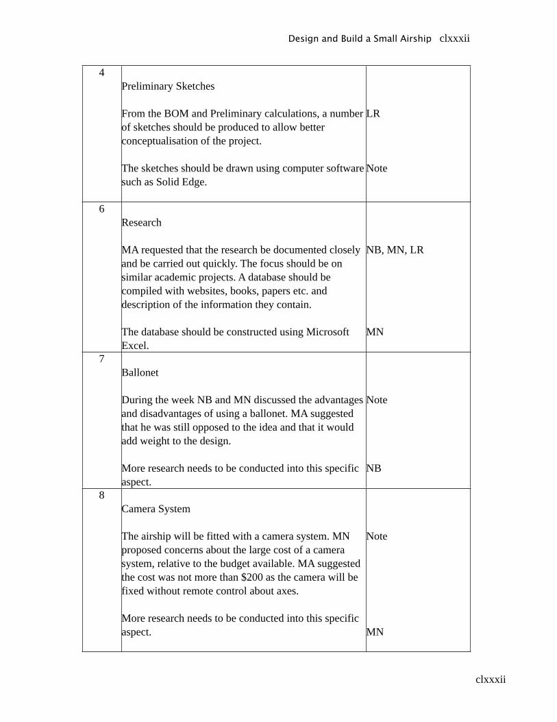
clxxxii
4Preliminary Sketches
From the BOM and Preliminary calculations, a number of sketches should be produced to allow better conceptualisation of the project.
The sketches should be drawn using computer software such as Solid Edge.
LR
Note
6Research
MA requested that the research be documented closely and be carried out quickly. The focus should be on similar academic projects. A database should be compiled with websites, books, papers etc. and description of the information they contain.
The database should be constructed using Microsoft Excel.
NB, MN, LR
MN
7Ballonet
During the week NB and MN discussed the advantages and disadvantages of using a ballonet. MA suggested that he was still opposed to the idea and that it would add weight to the design.
More research needs to be conducted into this specific aspect.
Note
NB
8Camera System
The airship will be fitted with a camera system. MN proposed concerns about the large cost of a camera system, relative to the budget available. MA suggested the cost was not more than $200 as the camera will be fixed without remote control about axes.
More research needs to be conducted into this specific aspect.
Note
MN
Design and Build a Small Airship clxxxii
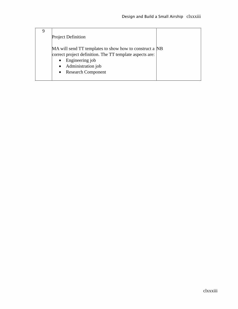
clxxxiii
9Project Definition
MA will send TT templates to show how to construct a correct project definition. The TT template aspects are:
• Engineering job• Administration job• Research Component
NB
Design and Build a Small Airship clxxxiii
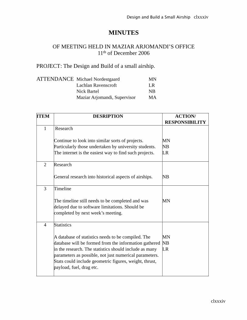
clxxxiv
MINUTES
OF MEETING HELD IN MAZIAR ARJOMANDI’S OFFICE11th of December 2006
PROJECT : The Design and Build of a small airship.
ATTENDANCE Michael Nordestgaard MN Lachlan Ravenscroft LR Nick Bartel NB Maziar Arjomandi, Supervisor MA
ITEM DESRIPTION ACTION/RESPONSIBILITY
1 Research
Continue to look into similar sorts of projects. Particularly those undertaken by university students. The internet is the easiest way to find such projects.
MNNBLR
2 Research
General research into historical aspects of airships. NB
3 Timeline
The timeline still needs to be completed and was delayed due to software limitations. Should be completed by next week’s meeting.
MN
4 Statistics
A database of statistics needs to be compiled. The database will be formed from the information gathered in the research. The statistics should include as many parameters as possible, not just numerical parameters. Stats could include geometric figures, weight, thrust, payload, fuel, drag etc.
MNNBLR
Design and Build a Small Airship clxxxiv

clxxxv
5 Questions
Compile a list of questions that have been discussed in the initial stages of the design project. Aim for about 100 small questions. Then try to answer these questions individually. This exercise will give better understanding of the project as a whole and will promote discussion between group members.
MNNBLR
6 Order to Buy
Create a list of websites / companies that have necessary materials / equipment available. Note down the prices. Try to find companies that sell all components as well as fully assembled airships. It is preferable to buy everything from one company if that company is reliable and efficient. This will streamline the ordering process and should allow easier assembly of parts.
MNNBLR
7 Progress
Next week’s meeting will be the last for the year. The meetings will start again in Mid-January.
Design and Build a Small Airship clxxxv
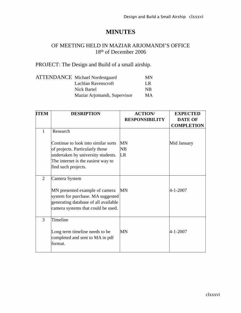
clxxxvi
MINUTES
OF MEETING HELD IN MAZIAR ARJOMANDI’S OFFICE18th of December 2006
PROJECT : The Design and Build of a small airship.
ATTENDANCE Michael Nordestgaard MN Lachlan Ravenscroft LR Nick Bartel NB Maziar Arjomandi, Supervisor MA
ITEM DESRIPTION ACTION/RESPONSIBILITY
EXPECTED DATE OF
COMPLETION1 Research
Continue to look into similar sorts of projects. Particularly those undertaken by university students. The internet is the easiest way to find such projects.
MNNBLR
Mid January
2 Camera System
MN presented example of camera system for purchase. MA suggested generating database of all available camera systems that could be used.
MN 4-1-2007
3 Timeline
Long term timeline needs to be completed and sent to MA in pdf format.
MN 4-1-2007
Design and Build a Small Airship clxxxvi
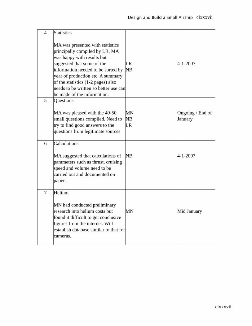
clxxxvii
4 Statistics
MA was presented with statistics principally compiled by LR. MA was happy with results but suggested that some of the information needed to be sorted by year of production etc. A summary of the statistics (1-2 pages) also needs to be written so better use can be made of the information.
LRNB
4-1-2007
5 Questions
MA was pleased with the 40-50 small questions compiled. Need to try to find good answers to the questions from legitimate sources
MNNBLR
Ongoing / End of January
6 Calculations
MA suggested that calculations of parameters such as thrust, cruising speed and volume need to be carried out and documented on paper.
NB 4-1-2007
7 Helium
MN had conducted preliminary research into helium costs but found it difficult to get conclusive figures from the internet. Will establish database similar to that for cameras.
MN Mid January
Design and Build a Small Airship clxxxvii
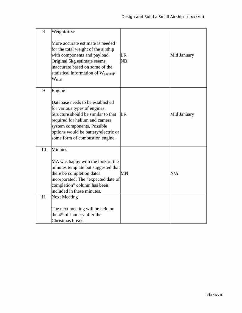
clxxxviii
8 Weight/Size
More accurate estimate is needed for the total weight of the airship with components and payload. Original 5kg estimate seems inaccurate based on some of the statistical information of Wpayload/Wtotal .
LRNB
Mid January
9 Engine
Database needs to be established for various types of engines. Structure should be similar to that required for helium and camera system components. Possible options would be battery/electric or some form of combustion engine.
LR Mid January
10 Minutes
MA was happy with the look of the minutes template but suggested that there be completion dates incorporated. The “expected date of completion” column has been included in these minutes.
MN N/A
11 Next Meeting
The next meeting will be held on the 4th of January after the Christmas break.
Design and Build a Small Airship clxxxviii
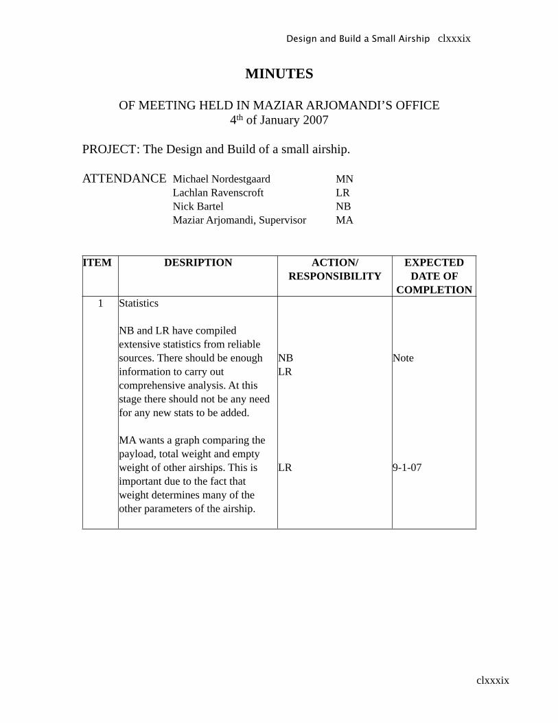
clxxxix
MINUTES
OF MEETING HELD IN MAZIAR ARJOMANDI’S OFFICE4th of January 2007
PROJECT : The Design and Build of a small airship.
ATTENDANCE Michael Nordestgaard MN Lachlan Ravenscroft LR Nick Bartel NB Maziar Arjomandi, Supervisor MA
ITEM DESRIPTION ACTION/RESPONSIBILITY
EXPECTED DATE OF
COMPLETION1 Statistics
NB and LR have compiled extensive statistics from reliable sources. There should be enough information to carry out comprehensive analysis. At this stage there should not be any need for any new stats to be added.
MA wants a graph comparing the payload, total weight and empty weight of other airships. This is important due to the fact that weight determines many of the other parameters of the airship.
NBLR
LR
Note
9-1-07
Design and Build a Small Airship clxxxix
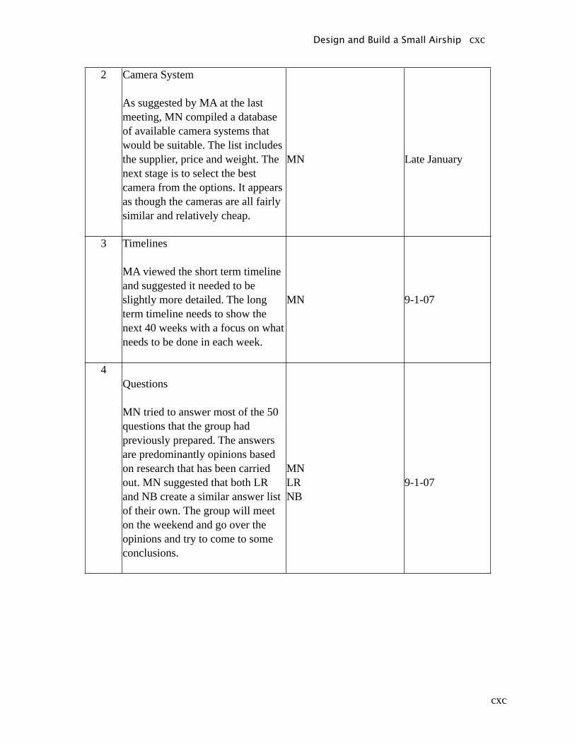
cxc
2 Camera System
As suggested by MA at the last meeting, MN compiled a database of available camera systems that would be suitable. The list includes the supplier, price and weight. The next stage is to select the best camera from the options. It appears as though the cameras are all fairly similar and relatively cheap.
MN Late January
3 Timelines
MA viewed the short term timeline and suggested it needed to be slightly more detailed. The long term timeline needs to show the next 40 weeks with a focus on what needs to be done in each week.
MN 9-1-07
4Questions
MN tried to answer most of the 50 questions that the group had previously prepared. The answers are predominantly opinions based on research that has been carried out. MN suggested that both LR and NB create a similar answer list of their own. The group will meet on the weekend and go over the opinions and try to come to some conclusions.
MNLRNB
9-1-07
Design and Build a Small Airship cxc
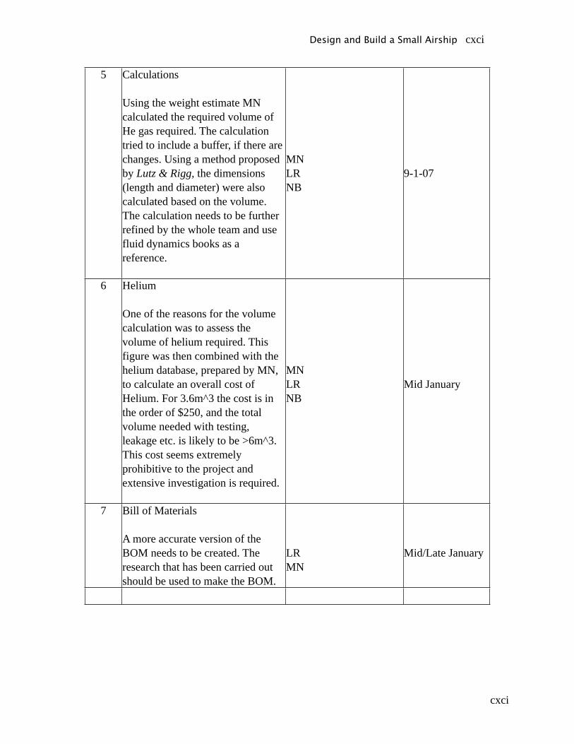
cxci
5 Calculations
Using the weight estimate MN calculated the required volume of He gas required. The calculation tried to include a buffer, if there are changes. Using a method proposed by Lutz & Rigg, the dimensions (length and diameter) were also calculated based on the volume. The calculation needs to be further refined by the whole team and use fluid dynamics books as a reference.
MNLRNB
9-1-07
6 Helium
One of the reasons for the volume calculation was to assess the volume of helium required. This figure was then combined with the helium database, prepared by MN, to calculate an overall cost of Helium. For 3.6m^3 the cost is in the order of $250, and the total volume needed with testing, leakage etc. is likely to be >6m^3. This cost seems extremely prohibitive to the project and extensive investigation is required.
MNLRNB
Mid January
7 Bill of Materials
A more accurate version of the BOM needs to be created. The research that has been carried out should be used to make the BOM.
LRMN
Mid/Late January
Design and Build a Small Airship cxci
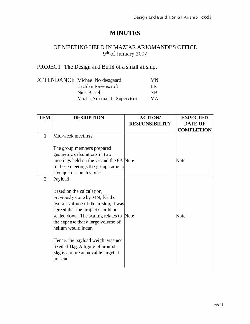
cxcii
MINUTES
OF MEETING HELD IN MAZIAR ARJOMANDI’S OFFICE9th of January 2007
PROJECT : The Design and Build of a small airship.
ATTENDANCE Michael Nordestgaard MN Lachlan Ravenscroft LR Nick Bartel NB Maziar Arjomandi, Supervisor MA
ITEM DESRIPTION ACTION/RESPONSIBILITY
EXPECTED DATE OF
COMPLETION1 Mid-week meetings
The group members prepared geometric calculations in two meetings held on the 7th and the 8th. In these meetings the group came to a couple of conclusions:
Note Note
2 Payload
Based on the calculation, previously done by MN, for the overall volume of the airship, it was agreed that the project should be scaled down. The scaling relates to the expense that a large volume of helium would incur.
Hence, the payload weight was not fixed at 1kg. A figure of around .5kg is a more achievable target at present.
Note Note
Design and Build a Small Airship cxcii

cxciii
3 Calculations
Based on statistics compiled of payload as a % of total weight, the group was able to estimate a target total weight. The target total weight is roughly 3-3.5 kg.
Note Note
4Shape
Using the weight estimate the group also looked at different envelope shapes and their dimensions. MA was pleased with the shapes and calculations presented.
MA proposed that the group develop a spreadsheet so that repetitive calculations can be handled by the computer. This will allow optimisation of the dimensions.
Note
LR
Note
22-1-2007
Design and Build a Small Airship cxciii
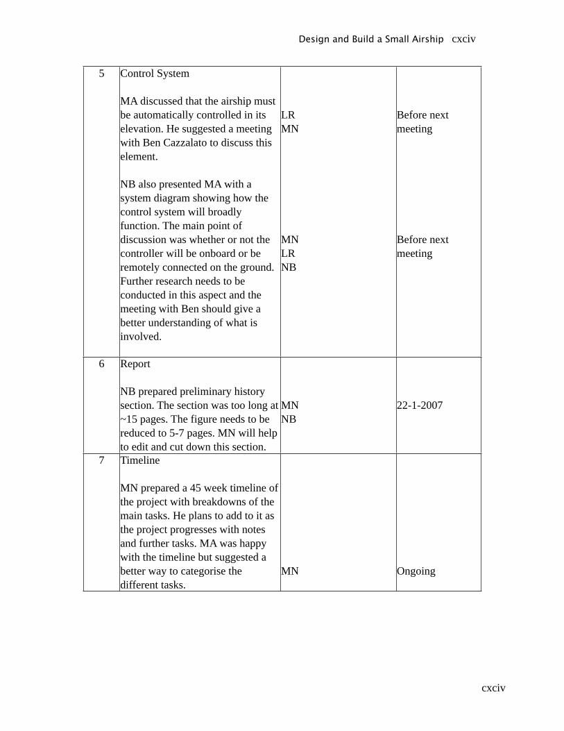
cxciv
5 Control System
MA discussed that the airship must be automatically controlled in its elevation. He suggested a meeting with Ben Cazzalato to discuss this element.
NB also presented MA with a system diagram showing how the control system will broadly function. The main point of discussion was whether or not the controller will be onboard or be remotely connected on the ground. Further research needs to be conducted in this aspect and the meeting with Ben should give a better understanding of what is involved.
LRMN
MNLRNB
Before next meeting
Before next meeting
6 Report
NB prepared preliminary history section. The section was too long at ~15 pages. The figure needs to be reduced to 5-7 pages. MN will help to edit and cut down this section.
MNNB
22-1-2007
7 Timeline
MN prepared a 45 week timeline of the project with breakdowns of the main tasks. He plans to add to it as the project progresses with notes and further tasks. MA was happy with the timeline but suggested a better way to categorise the different tasks.
MN Ongoing
Design and Build a Small Airship cxciv
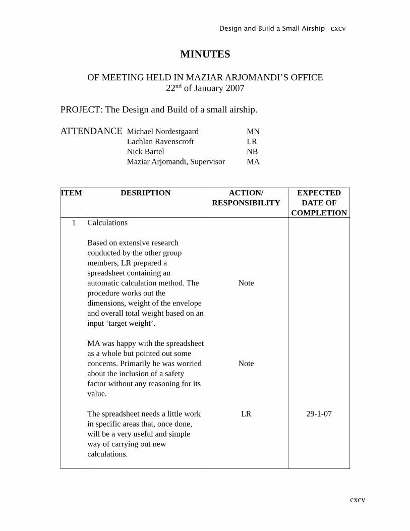
cxcv
MINUTES
OF MEETING HELD IN MAZIAR ARJOMANDI’S OFFICE22nd of January 2007
PROJECT : The Design and Build of a small airship.
ATTENDANCE Michael Nordestgaard MN Lachlan Ravenscroft LR Nick Bartel NB Maziar Arjomandi, Supervisor MA
ITEM DESRIPTION ACTION/RESPONSIBILITY
EXPECTED DATE OF
COMPLETION1 Calculations
Based on extensive research conducted by the other group members, LR prepared a spreadsheet containing an automatic calculation method. The procedure works out the dimensions, weight of the envelope and overall total weight based on an input ‘target weight’.
MA was happy with the spreadsheet as a whole but pointed out some concerns. Primarily he was worried about the inclusion of a safety factor without any reasoning for its value.
The spreadsheet needs a little work in specific areas that, once done, will be a very useful and simple way of carrying out new calculations.
Note
Note
LR 29-1-07
Design and Build a Small Airship cxcv
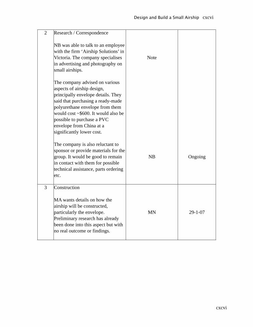
cxcvi
2 Research / Correspondence
NB was able to talk to an employee with the firm ‘Airship Solutions’ in Victoria. The company specialises in advertising and photography on small airships.
The company advised on various aspects of airship design, principally envelope details. They said that purchasing a ready-made polyurethane envelope from them would cost ~$600. It would also be possible to purchase a PVC envelope from China at a significantly lower cost.
The company is also reluctant to sponsor or provide materials for the group. It would be good to remain in contact with them for possible technical assistance, parts ordering etc.
Note
NB Ongoing
3 Construction
MA wants details on how the airship will be constructed, particularly the envelope. Preliminary research has already been done into this aspect but with no real outcome or findings.
MN 29-1-07
Design and Build a Small Airship cxcvi
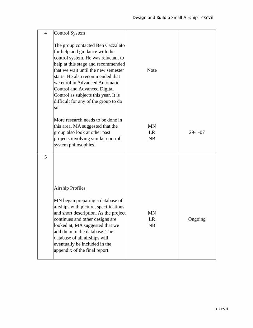
cxcvii
4 Control System
The group contacted Ben Cazzalato for help and guidance with the control system. He was reluctant to help at this stage and recommended that we wait until the new semester starts. He also recommended that we enrol in Advanced Automatic Control and Advanced Digital Control as subjects this year. It is difficult for any of the group to do so.
More research needs to be done in this area. MA suggested that the group also look at other past projects involving similar control system philosophies.
Note
MNLRNB
29-1-07
5
Airship Profiles
MN began preparing a database of airships with picture, specifications and short description. As the project continues and other designs are looked at, MA suggested that we add them to the database. The database of all airships will eventually be included in the appendix of the final report.
MNLRNB
Ongoing
Design and Build a Small Airship cxcvii

cxcviii
6 Sensitivity Calculations
Based on the calculations spreadsheet that LR put together, a sensitivity analysis needs to be completed. The analysis should include graphs of how uncertainty in each variable impacts on the other factors. Some of the variables include payload, envelope properties and weights of components. The graphs can be prepared easily using the same iterative procedure and just inserting the uncertainty.
LR 29-1-07
7 Drawings
With a better calculation and weight analysis done, it is possible to complete a better drawing of the intended design. The drawing should be dimensioned as much as possible. This should be done using Solid Edge, or similar, and should use techniques taught in Design Graphics.
NB 5-2-07
Design and Build a Small Airship cxcviii
cxcix
MINUTES
OF MEETING HELD IN MAZIAR ARJOMANDI’S OFFICE29th of January 2007
PROJECT : The Design and Build of a small airship.
ATTENDANCE Michael Nordestgaard MN Lachlan Ravenscroft LR Nick Bartel NB Maziar Arjomandi, Supervisor MA
ITEM DESRIPTION ACTION/RESPONSIBILITY
EXPECTED DATE OF
COMPLETION
Design and Build a Small Airship cxcix

cc
1 Design Drawings
MA was happy with the calculations and sensitivity analysis that has been carried out. He is satisfied that the design process must now proceed to from conceptual to drawings.
The drawings will need to show sufficient detail to build and assemble the airship. The drawings will need to include:
• Views from various angles and sides.
• Fully dimensioned details.• Section and zoom-in of
parts as appropriate.• Part list (BOM) showing
items, materials and quantities required.
This will be the main focus of the group for the next two weeks. First draft drawings should be ready in two weeks and all drawings should be finished by Mid-March.
LRMNNB
12-2-2007
Fully Completed by 7-3-2007.
2 Price list
Closely integrated with the Part list shall be the price list. This list shall show all known items for the project with their cost. It may also be necessary to include an uncertainty factor in the costs for each item i.e. +/- 20%. This should stop unexpected cost blowouts.
NBMN
13-2-2007
fully completed by 7-3-2007
Design and Build a Small Airship cc
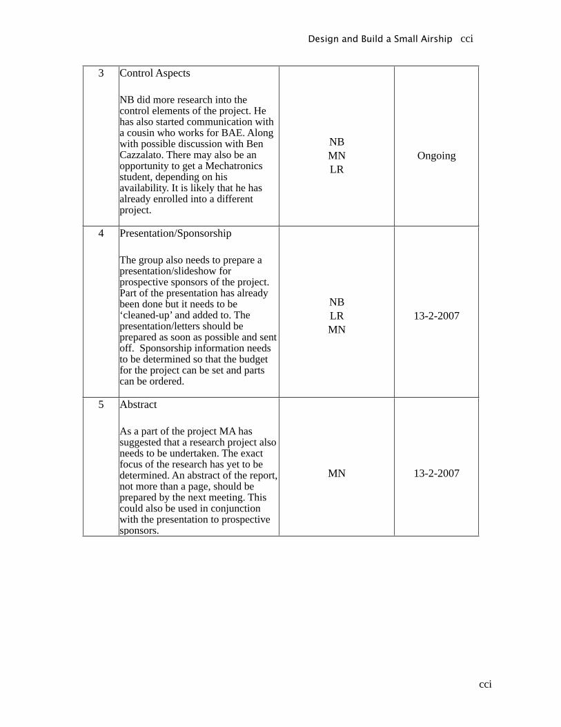
cci
3 Control Aspects
NB did more research into the control elements of the project. He has also started communication with a cousin who works for BAE. Along with possible discussion with Ben Cazzalato. There may also be an opportunity to get a Mechatronics student, depending on his availability. It is likely that he has already enrolled into a different project.
NBMNLR
Ongoing
4 Presentation/Sponsorship
The group also needs to prepare a presentation/slideshow for prospective sponsors of the project. Part of the presentation has already been done but it needs to be ‘cleaned-up’ and added to. The presentation/letters should be prepared as soon as possible and sent off. Sponsorship information needs to be determined so that the budget for the project can be set and parts can be ordered.
NBLRMN
13-2-2007
5 Abstract
As a part of the project MA has suggested that a research project also needs to be undertaken. The exact focus of the research has yet to be determined. An abstract of the report, not more than a page, should be prepared by the next meeting. This could also be used in conjunction with the presentation to prospective sponsors.
MN 13-2-2007
Design and Build a Small Airship cci

ccii
MINUTES
OF MEETING HELD IN MAZIAR ARJOMANDI’S OFFICE12th of February 2007
PROJECT : The Design and Build of a small airship.
ATTENDANCE Michael Nordestgaard MN Lachlan Ravenscroft LR Nick Bartel NB Maziar Arjomandi, Supervisor MA
ITEM DESRIPTION ACTION/RESPONSIBILITY
EXPECTED DATE OF
COMPLETION1 Propeller System Design
The group had two meetings since the last discussion with MA. The result of the meetings was a consensus on how the propellers would be integrated into the design. The proposed system would have a fixed propeller, facing downward, solely responsible for the automatic control of elevation. Two propellers fixed to the sides of the gondola would be responsible for yaw and pitch.
MA did not agree with the design proposed by the group. He was concerned that it over-simplified the design and that in practice it would not work effectively. After long discussion MA agreed that the group could proceed with the consensus decision. Iterations of the design may need to take place to show the proof of concept.
MNLRNB
5-3-2007
Design and Build a Small Airship ccii

cciii
2 Gondola Internals
Flowing on from the discussion about the propeller arrangement was a discussion of how the gondola components would be organised. MN had prepared a drawing of the internals based on consensus propeller decision. MA suggested that more work was required on this element. The group argued that it was difficult to prepare a gondola design without a firm knowledge of how the propellers will be set-up.
A meeting with Dr Ben Cazzalato would serve as a very good way to gain an insight into the probable components needed inside the gondola and their size, power requirements etc.
MNLRNB
5-3-2007
Design and Build a Small Airship cciii

cciv
MINUTES
OF MEETING HELD IN BEN CAZZOLATO’S OFFICE6th of March 2007
PROJECT : The Design and Build of a small airship.
ATTENDANCE Michael Nordestgaard MN Lachlan Ravenscroft LR Nick Bartel NB Ben Cazzolato, Coordinator BC
ITEM DESRIPTION ACTION/RESPONSIBILITY
EXPECTED DATE OF
COMPLETION
Design and Build a Small Airship cciv
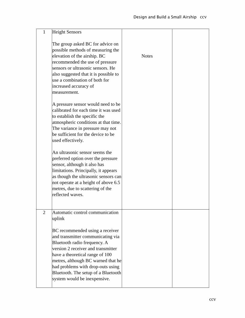
ccv
1 Height Sensors
The group asked BC for advice on possible methods of measuring the elevation of the airship. BC recommended the use of pressure sensors or ultrasonic sensors. He also suggested that it is possible to use a combination of both for increased accuracy of measurement.
A pressure sensor would need to be calibrated for each time it was used to establish the specific the atmospheric conditions at that time. The variance in pressure may not be sufficient for the device to be used effectively.
An ultrasonic sensor seems the preferred option over the pressure sensor, although it also has limitations. Principally, it appears as though the ultrasonic sensors can not operate at a height of above 6.5 metres, due to scattering of the reflected waves.
Notes
2 Automatic control communication uplink
BC recommended using a receiver and transmitter communicating via Bluetooth radio frequency. A version 2 receiver and transmitter have a theoretical range of 100 metres, although BC warned that he had problems with drop-outs using Bluetooth. The setup of a Bluetooth system would be inexpensive.
Design and Build a Small Airship ccv

ccvi
3 Radio control units
BC suggested that it would definitely be possible to use a standard RC unit for our proposed design. The number of channels that would be needed largely depends on the way we choose to connect the various components. It may be possible to use one channel to provide the commands for the rotation of the two axles to provide pitch. Another channel could be used for switching the axle rotation from automatic to manual control.
4 Batteries
Lithium-polymer batteries would be best suited for our design due to the better energy density per weight over NiCd or NiMH.
BC also recommended that the powers supply for the automatic control components be separate to the power supply for the motors. This is due to the fact the motors can create fluctuations in the supply voltage, which can damage the LiPo batteries.
Design and Build a Small Airship ccvi

ccvii
5 Controller / Processor
BC suggested the use of a mini-dragon controller. This unit has been used on previous projects with good results. The price was around $200.
The programming needed for the controller would not be beyond the group’s capabilities, despite the apparent lack of knowledge in this area. Using the notes for Advanced Automatic Control the group should be able to create a SISO system. The programming needed for this could be done using a variety of different languages. The most likely is C (++) as the group has some experience with this language.
Design and Build a Small Airship ccvii

ccviii
MINUTES
OF MEETING HELD IN MAZIAR ARJOMANDI’S OFFICE6th of March 2007
PROJECT : The Design and Build of a small airship.
ATTENDANCE Michael Nordestgaard MN Lachlan Ravenscroft LR Nick Bartel NB Maziar Arjomandi, Supervisor MA
ITEM DESRIPTION ACTION/RESPONSIBILITY
EXPECTED DATE OF
COMPLETION1 Control System
The group reported to MA the results of the meeting with Dr Cazzolato.
MA suggested that the group also arrange meetings with Tien-Fu Lu and Lei Chen to gain more practical information on control as well as robotics.
MA still thinks that the control system is difficult to conceptualise, although he believes that the group has an understanding. Mainly for his benefit, he suggests that a summary of the control commands be developed to aid understanding.
LR
MN
9-3-2007
13-3-2007
Design and Build a Small Airship ccviii

ccix
2 Gondola
The group should be able to create a relatively accurate gondola design with the knowledge of parts required and their weights and sizes. MA suggested that fibre-glass be used as the material for the construction of the gondola. The workshop would be able to make the gondola if given sufficient detail of dimensions and design.
LR 13-3-2007
Design and Build a Small Airship ccix
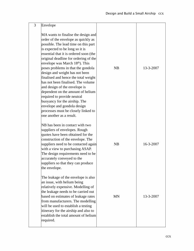
ccx
3 Envelope
MA wants to finalise the design and order of the envelope as quickly as possible. The lead time on this part is expected to be long so it is essential that it is ordered soon (the original deadline for ordering of the envelope was March 18th). This poses problems in that the gondola design and weight has not been finalised and hence the total weight has not been finalised. The volume and design of the envelope is dependent on the amount of helium required to provide neutral buoyancy for the airship. The envelope and gondola design processes must be closely linked to one another as a result.
NB has been in contact with two suppliers of envelopes. Rough quotes have been obtained for the construction of the envelope. The suppliers need to be contacted again with a view to purchasing ASAP. The design requirements need to be accurately conveyed to the suppliers so that they can produce the envelope.
The leakage of the envelope is also an issue, with helium being relatively expensive. Modelling of the leakage needs to be carried out based on estimates of leakage rates from manufacturers. The modelling will be used to establish a testing itinerary for the airship and also to establish the total amount of helium required.
NB
NB
MN
13-3-2007
16-3-2007
13-3-2007
Design and Build a Small Airship ccx
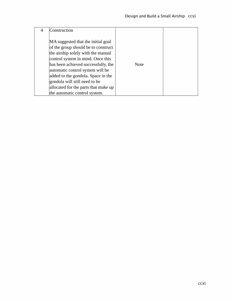
ccxi
4 Construction
MA suggested that the initial goal of the group should be to construct the airship solely with the manual control system in mind. Once this has been achieved successfully, the automatic control system will be added to the gondola. Space in the gondola will still need to be allocated for the parts that make up the automatic control system.
Note
Design and Build a Small Airship ccxi

ccxii
MINUTES
OF VISIT TO MODEL FLIGHT ON 8th of March 2007
PROJECT : The Design and Build of a small airship.
ATTENDANCE Michael Nordestgaard MN Lachlan Ravenscroft LR Nick Bartel NB
ITEM DESRIPTION ACTION/RESPONSIBILITY
EXPECTED DATE OF
COMPLETION1 General Information
Group members had general discussion regarding speed controllers, motors and RC units.
Note
2 RC Unit
It appears as though a more complex unit than was initially thought of. Changes in propeller setup may mean that the complexity of the unit will be reduced. Expected price range is $500-$1000.
Note
Design and Build a Small Airship ccxii
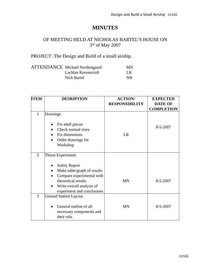
ccxiii
MINUTES
OF MEETING HELD AT NICHOLAS BARTEL’S HOUSE ON3rd of May 2007
PROJECT : The Design and Build of a small airship.
ATTENDANCE Michael Nordestgaard MN Lachlan Ravenscroft LR Nick Bartel NB
ITEM DESRIPTION ACTION/RESPONSIBILITY
EXPECTED DATE OF
COMPLETION1 Drawings
• Fix shell pieces• Check normal sizes• Fix dimensions• Order drawings for
Workshop
LR
8-5-2007
2 Thrust Experiment
• Safety Report• Make table/graph of results• Compare experimental with
theoretical results• Write overall analysis of
experiment and conclusions
MN 8-5-2007
3 Ground Station Layout
• General outline of all necessary components and their role.
MN 8-5-2007
Design and Build a Small Airship ccxiii
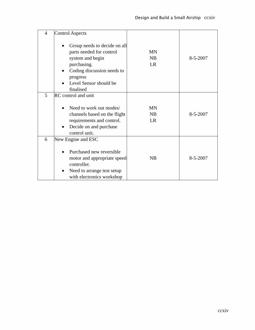
ccxiv
4 Control Aspects
• Group needs to decide on all parts needed for control system and begin purchasing.
• Coding discussion needs to progress
• Level Sensor should be finalised
MNNBLR
8-5-2007
5 RC control and unit
• Need to work out modes/channels based on the flight requirements and control.
• Decide on and purchase control unit.
MNNBLR
8-5-2007
6 New Engine and ESC
• Purchased new reversible motor and appropriate speed controller.
• Need to arrange test setup with electronics workshop
NB 8-5-2007
Design and Build a Small Airship ccxiv
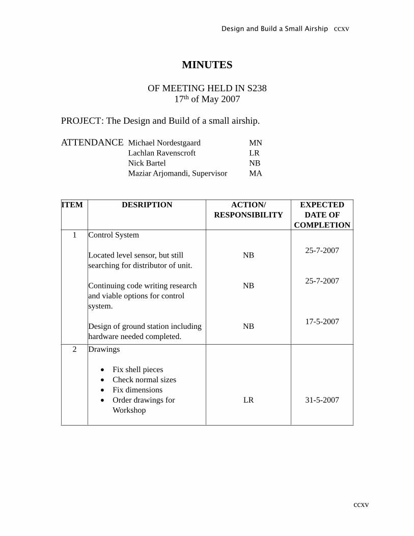
ccxv
MINUTES
OF MEETING HELD IN S23817th of May 2007
PROJECT : The Design and Build of a small airship.
ATTENDANCE Michael Nordestgaard MN Lachlan Ravenscroft LR Nick Bartel NB Maziar Arjomandi, Supervisor MA
ITEM DESRIPTION ACTION/RESPONSIBILITY
EXPECTED DATE OF
COMPLETION1 Control System
Located level sensor, but still searching for distributor of unit.
Continuing code writing research and viable options for control system.
Design of ground station including hardware needed completed.
NB
NB
NB
25-7-2007
25-7-2007
17-5-2007
2 Drawings
• Fix shell pieces• Check normal sizes• Fix dimensions• Order drawings for
Workshop
LR 31-5-2007
Design and Build a Small Airship ccxv
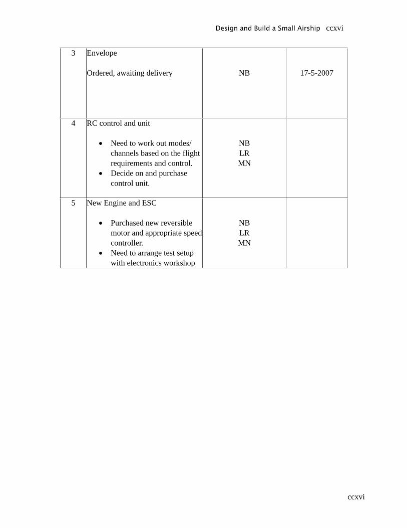
ccxvi
3 Envelope
Ordered, awaiting delivery NB 17-5-2007
4 RC control and unit
• Need to work out modes/channels based on the flight requirements and control.
• Decide on and purchase control unit.
NBLRMN
5 New Engine and ESC
• Purchased new reversible motor and appropriate speed controller.
• Need to arrange test setup with electronics workshop
NBLRMN
Design and Build a Small Airship ccxvi
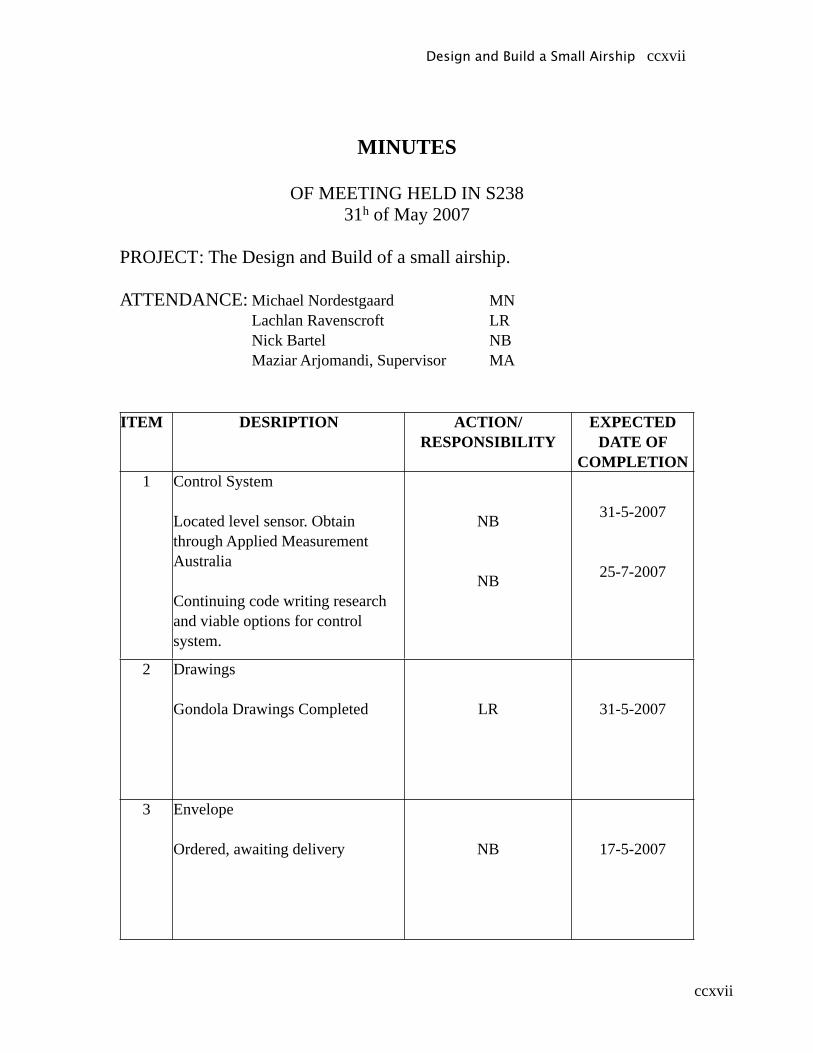
ccxvii
MINUTES
OF MEETING HELD IN S23831h of May 2007
PROJECT : The Design and Build of a small airship.
ATTENDANCE: Michael Nordestgaard MN Lachlan Ravenscroft LR Nick Bartel NB Maziar Arjomandi, Supervisor MA
ITEM DESRIPTION ACTION/RESPONSIBILITY
EXPECTED DATE OF
COMPLETION1 Control System
Located level sensor. Obtain through Applied Measurement Australia
Continuing code writing research and viable options for control system.
NB
NB
31-5-2007
25-7-2007
2 Drawings
Gondola Drawings Completed LR 31-5-2007
3 Envelope
Ordered, awaiting delivery NB 17-5-2007
Design and Build a Small Airship ccxvii
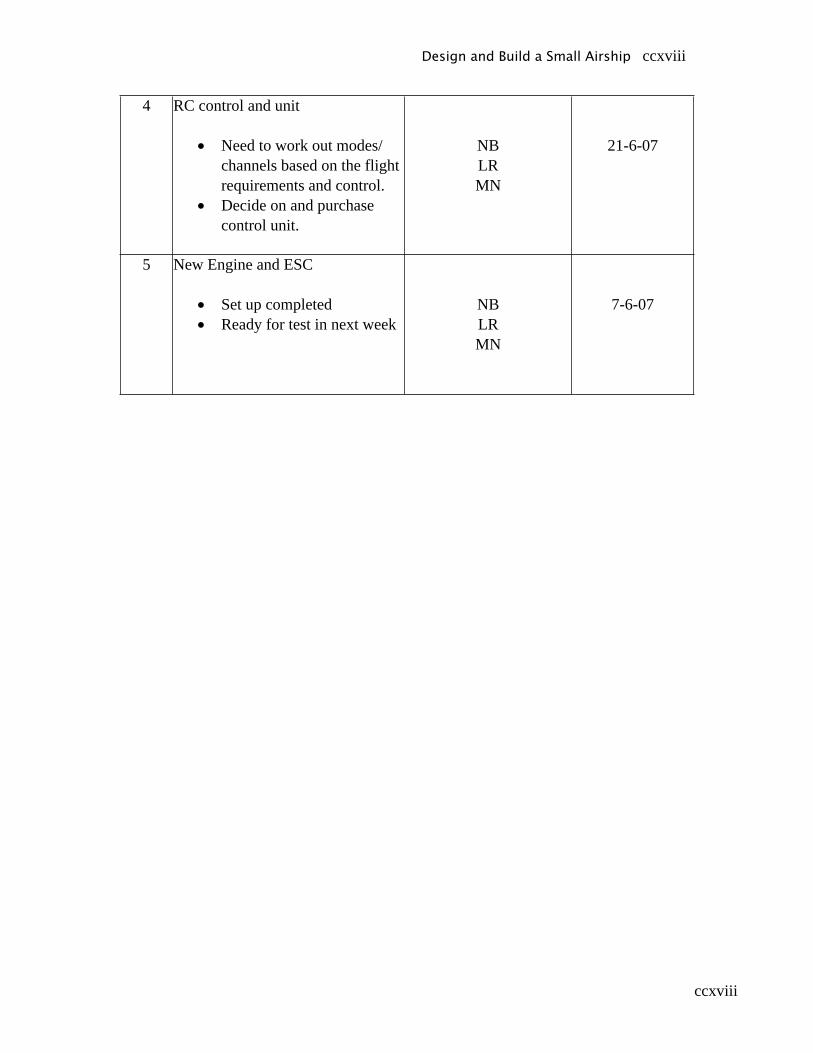
ccxviii
4 RC control and unit
• Need to work out modes/channels based on the flight requirements and control.
• Decide on and purchase control unit.
NBLRMN
21-6-07
5 New Engine and ESC
• Set up completed• Ready for test in next week
NBLRMN
7-6-07
Design and Build a Small Airship ccxviii
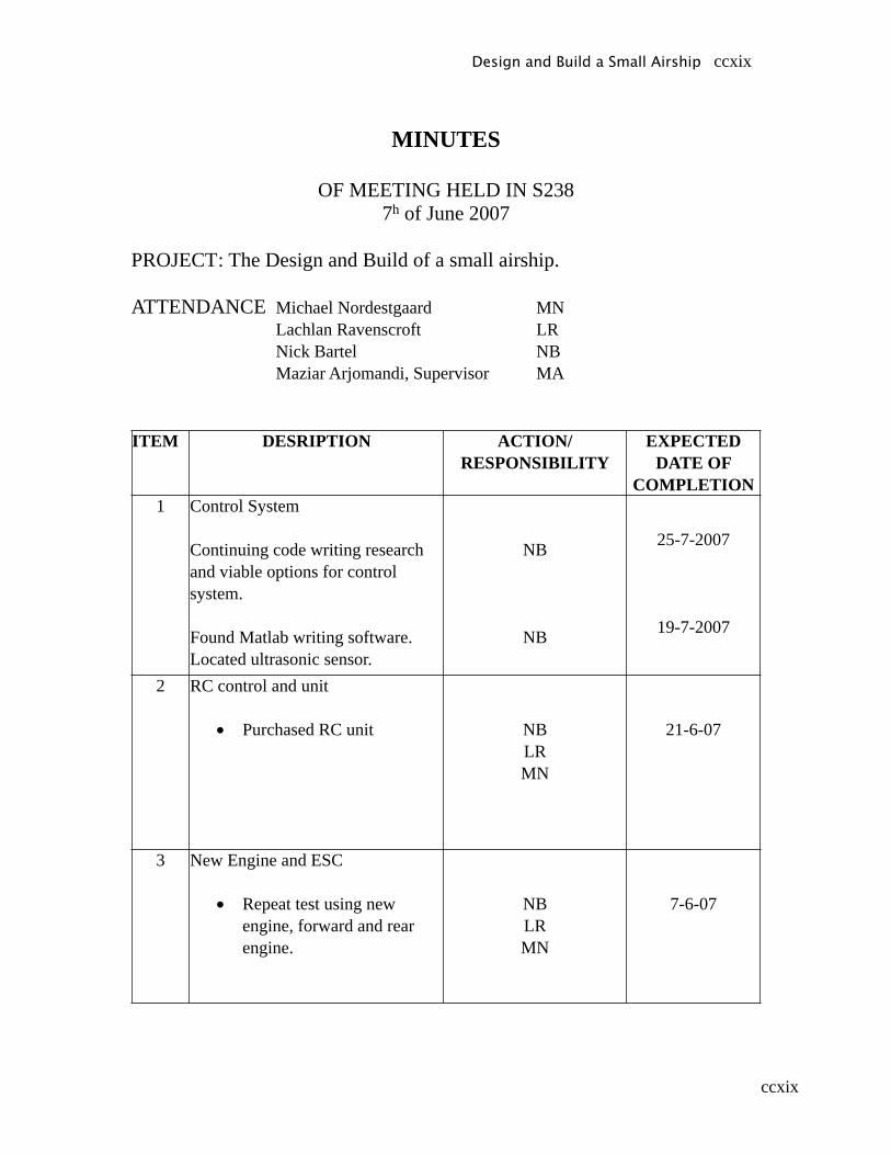
ccxix
MINUTES
OF MEETING HELD IN S2387h of June 2007
PROJECT : The Design and Build of a small airship.
ATTENDANCE Michael Nordestgaard MN Lachlan Ravenscroft LR Nick Bartel NB Maziar Arjomandi, Supervisor MA
ITEM DESRIPTION ACTION/RESPONSIBILITY
EXPECTED DATE OF
COMPLETION1 Control System
Continuing code writing research and viable options for control system.
Found Matlab writing software. Located ultrasonic sensor.
NB
NB
25-7-2007
19-7-2007
2 RC control and unit
• Purchased RC unit NBLRMN
21-6-07
3 New Engine and ESC
• Repeat test using new engine, forward and rear engine.
NBLRMN
7-6-07
Design and Build a Small Airship ccxix
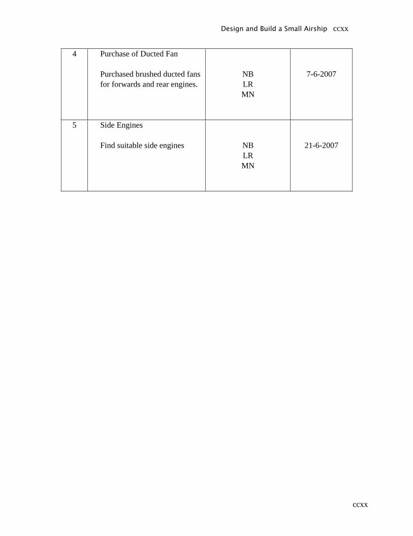
ccxx
4 Purchase of Ducted Fan
Purchased brushed ducted fans for forwards and rear engines.
NBLRMN
7-6-2007
5 Side Engines
Find suitable side engines NBLRMN
21-6-2007
Design and Build a Small Airship ccxx
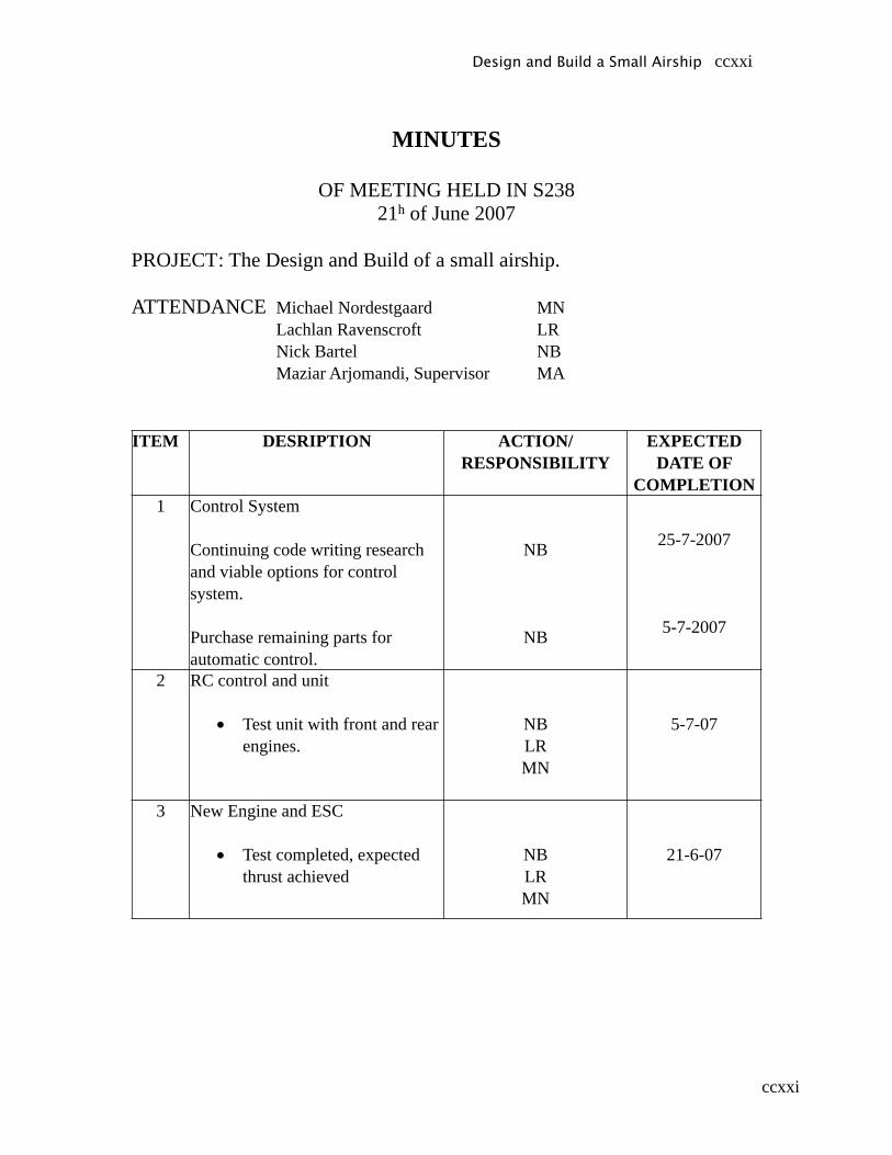
ccxxi
MINUTES
OF MEETING HELD IN S23821h of June 2007
PROJECT : The Design and Build of a small airship.
ATTENDANCE Michael Nordestgaard MN Lachlan Ravenscroft LR Nick Bartel NB Maziar Arjomandi, Supervisor MA
ITEM DESRIPTION ACTION/RESPONSIBILITY
EXPECTED DATE OF
COMPLETION1 Control System
Continuing code writing research and viable options for control system.
Purchase remaining parts for automatic control.
NB
NB
25-7-2007
5-7-2007
2 RC control and unit
• Test unit with front and rear engines.
NBLRMN
5-7-07
3 New Engine and ESC
• Test completed, expected thrust achieved
NBLRMN
21-6-07
Design and Build a Small Airship ccxxi
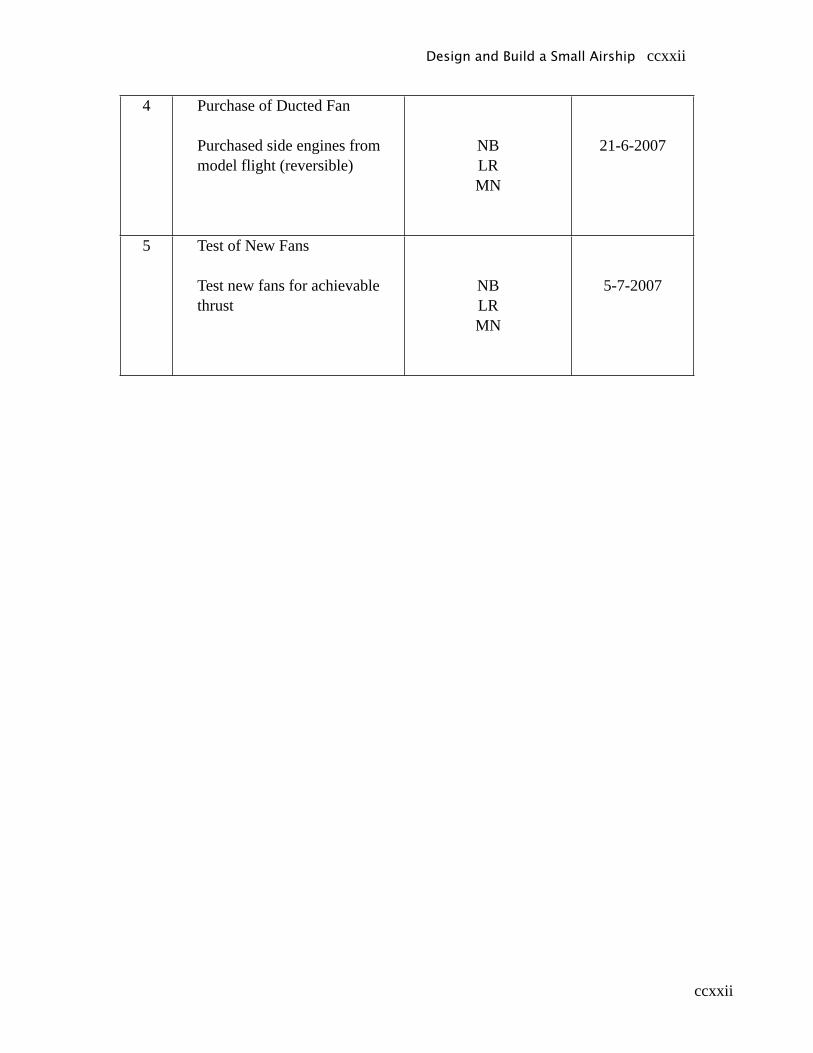
ccxxii
4 Purchase of Ducted Fan
Purchased side engines from model flight (reversible)
NBLRMN
21-6-2007
5 Test of New Fans
Test new fans for achievable thrust
NBLRMN
5-7-2007
Design and Build a Small Airship ccxxii

ccxxiii
MINUTES
OF MEETING HELD IN S2385th of July 2007
PROJECT : The Design and Build of a small airship.
ATTENDANCE Michael Nordestgaard MN Lachlan Ravenscroft LR Nick Bartel NB Maziar Arjomandi, Supervisor MA
ITEM DESRIPTION ACTION/RESPONSIBILITY
EXPECTED DATE OF
COMPLETION1 Control System
Continuing code writing research and viable options for control system.
Start plans for electrical workshop to construct autopilot.
NB
NB
25-7-2007
19-7-2007
2 Side engines
Found Suitable side engines, test completed.
NBLRMN
5-7-07
3 Prepare for Open day
Get graphics from Adelaide University and BAE systems to use on airship banner
Make list of this needed for completion.
NBLRMN
23-8-2007
Design and Build a Small Airship ccxxiii
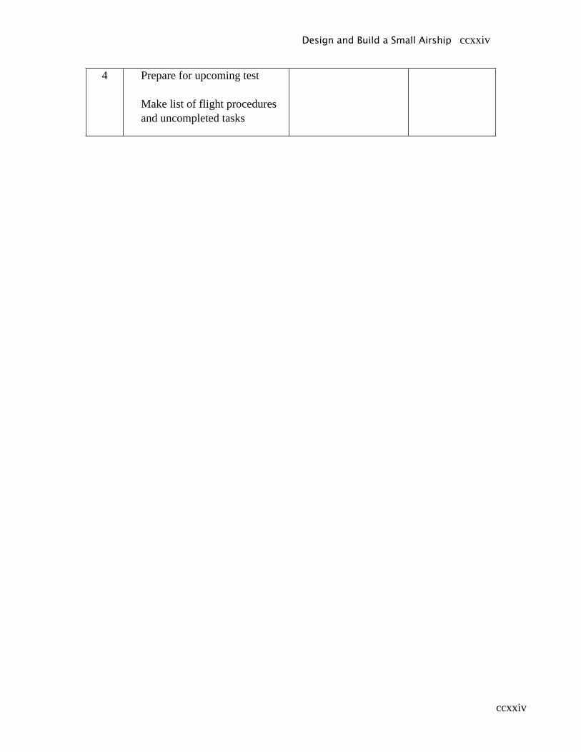
ccxxiv
4 Prepare for upcoming test
Make list of flight procedures and uncompleted tasks
Design and Build a Small Airship ccxxiv

ccxxv
MINUTES
OF MEETING HELD IN S23819th of July 2007
PROJECT : The Design and Build of a small airship.
ATTENDANCE Michael Nordestgaard MN Lachlan Ravenscroft LR Nick Bartel NB Maziar Arjomandi, Supervisor MA
ITEM DESRIPTION ACTION/RESPONSIBILITY
EXPECTED DATE OF
COMPLETION1 Control System
Continuing code writing research and viable options for control system.
Put auto-parts in for construction
NB
NB
25-7-2007
19-7-2007
2 Prepare Poster
X-Stand poster for open day. Also can use for final exhibition.
MN 23-8-2007
3 Prepare for Open day
Get graphics from Adelaide University and BAE systems to use on airship banner
Make list of this needed for completion.
NBLRMN
23-8-2007
Design and Build a Small Airship ccxxv
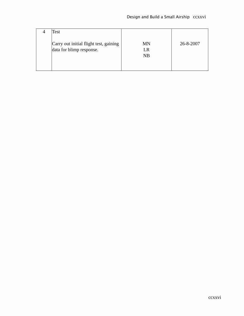
ccxxvi
4 Test
Carry out initial flight test, gaining data for blimp response.
MNLRNB
26-8-2007
Design and Build a Small Airship ccxxvi
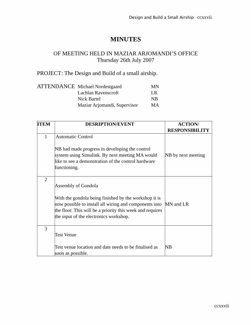
ccxxvii
MINUTES
OF MEETING HELD IN MAZIAR ARJOMANDI’S OFFICEThursday 26th July 2007
PROJECT : The Design and Build of a small airship.
ATTENDANCE Michael Nordestgaard MN Lachlan Ravenscroft LR Nick Bartel NB Maziar Arjomandi, Supervisor MA
ITEM DESRIPTION/EVENT ACTION/RESPONSIBILITY
1 Automatic Control
NB had made progress in developing the control system using Simulink. By next meeting MA would like to see a demonstration of the control hardware functioning.
NB by next meeting
2Assembly of Gondola
With the gondola being finished by the workshop it is now possible to install all wiring and components into the floor. This will be a priority this week and requires the input of the electronics workshop.
MN and LR
3Test Venue
Test venue location and date needs to be finalised as soon as possible.
NB
Design and Build a Small Airship ccxxvii

ccxxviii
4Test procedures
LR presented test procedures for all the tests that need to be conducted. MA suggested that they be divided more concisely into pre-flight, flight and post-flight categories.
LR by next meeting
5Publicity for project
MN suggested that publicity for the project should be organised when a strong visual impact can be made ie when the airship is flying properly.
MN
6 Helium
MN organised the delivery of a GX size (9.1m^3) cylinder of helium from Air Liquide. The Mechanical Workshop also advised that they had a cylinder of helium that could be made available to the project.
Safety issues with the helium cylinder need to be discussed with Richard and Joel the two principal safety officers of the School. MN and LR
7Pressure Tests
The envelope was filled with air to record the leakage rate of gas. Further tests will be conducted on an ongoing basis.
MN and LR
8Envelope Workmanship
NB contacted Airship Solutions to discuss holes/patches on the envelope. There may have been a mix-up with the envelope and Airship Solutions will advise of further action- possibly making a new envelope.
NB
Design and Build a Small Airship ccxxviii
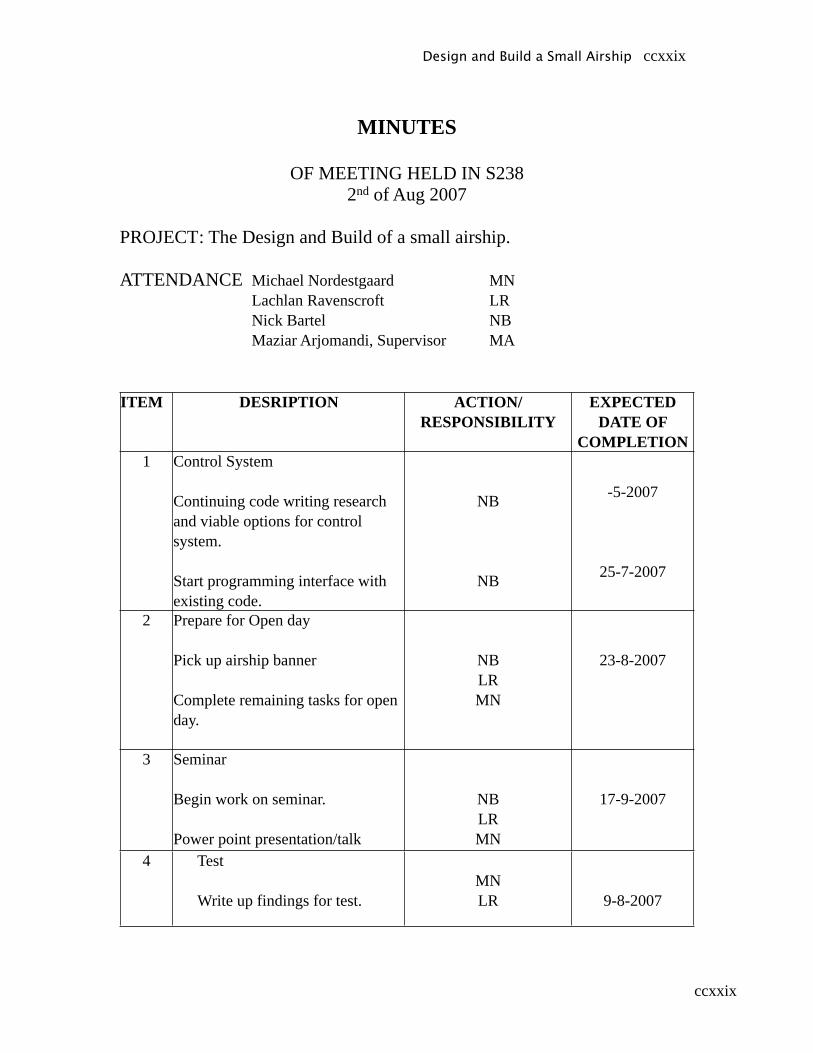
ccxxix
MINUTES
OF MEETING HELD IN S2382nd of Aug 2007
PROJECT : The Design and Build of a small airship.
ATTENDANCE Michael Nordestgaard MN Lachlan Ravenscroft LR Nick Bartel NB Maziar Arjomandi, Supervisor MA
ITEM DESRIPTION ACTION/RESPONSIBILITY
EXPECTED DATE OF
COMPLETION1 Control System
Continuing code writing research and viable options for control system.
Start programming interface with existing code.
NB
NB
-5-2007
25-7-2007
2 Prepare for Open day
Pick up airship banner
Complete remaining tasks for open day.
NBLRMN
23-8-2007
3 Seminar
Begin work on seminar.
Power point presentation/talk
NBLRMN
17-9-2007
4 Test
Write up findings for test.MNLR 9-8-2007
Design and Build a Small Airship ccxxix
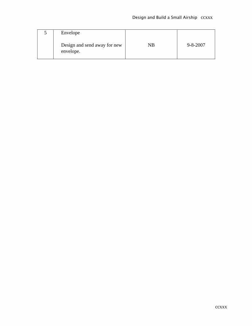
ccxxx
5 Envelope
Design and send away for new envelope.
NB 9-8-2007
Design and Build a Small Airship ccxxx
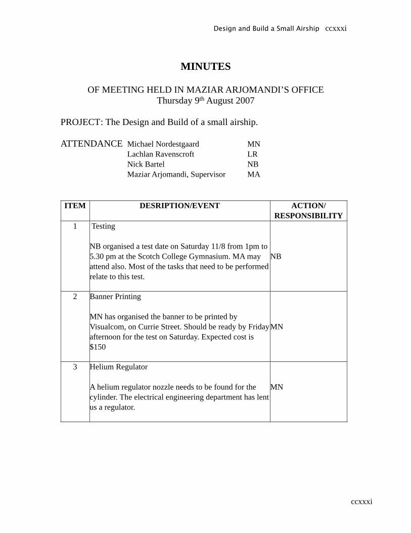
ccxxxi
MINUTES
OF MEETING HELD IN MAZIAR ARJOMANDI’S OFFICEThursday 9th August 2007
PROJECT : The Design and Build of a small airship.
ATTENDANCE Michael Nordestgaard MN Lachlan Ravenscroft LR Nick Bartel NB Maziar Arjomandi, Supervisor MA
ITEM DESRIPTION/EVENT ACTION/RESPONSIBILITY
1 Testing
NB organised a test date on Saturday 11/8 from 1pm to 5.30 pm at the Scotch College Gymnasium. MA may attend also. Most of the tasks that need to be performed relate to this test.
NB
2 Banner Printing
MN has organised the banner to be printed by Visualcom, on Currie Street. Should be ready by Friday afternoon for the test on Saturday. Expected cost is $150
MN
3 Helium Regulator
A helium regulator nozzle needs to be found for the cylinder. The electrical engineering department has lent us a regulator.
MN
Design and Build a Small Airship ccxxxi
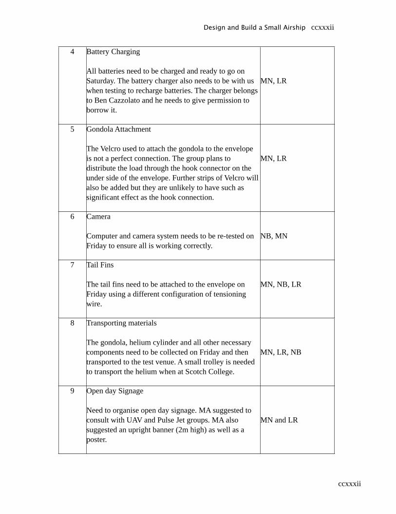
ccxxxii
4 Battery Charging
All batteries need to be charged and ready to go on Saturday. The battery charger also needs to be with us when testing to recharge batteries. The charger belongs to Ben Cazzolato and he needs to give permission to borrow it.
MN, LR
5 Gondola Attachment
The Velcro used to attach the gondola to the envelope is not a perfect connection. The group plans to distribute the load through the hook connector on the under side of the envelope. Further strips of Velcro will also be added but they are unlikely to have such as significant effect as the hook connection.
MN, LR
6 Camera
Computer and camera system needs to be re-tested on Friday to ensure all is working correctly.
NB, MN
7 Tail Fins
The tail fins need to be attached to the envelope on Friday using a different configuration of tensioning wire.
MN, NB, LR
8 Transporting materials
The gondola, helium cylinder and all other necessary components need to be collected on Friday and then transported to the test venue. A small trolley is needed to transport the helium when at Scotch College.
MN, LR, NB
9 Open day Signage
Need to organise open day signage. MA suggested to consult with UAV and Pulse Jet groups. MA also suggested an upright banner (2m high) as well as a poster.
MN and LR
Design and Build a Small Airship ccxxxii
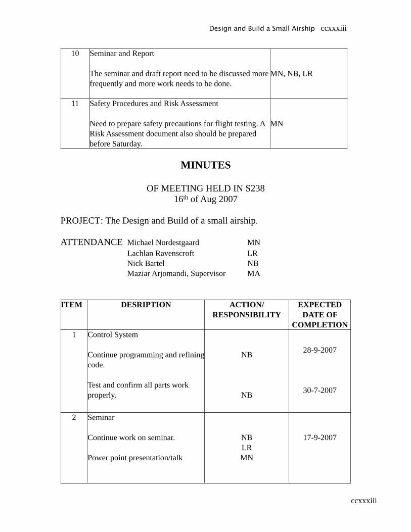
ccxxxiii
10 Seminar and Report
The seminar and draft report need to be discussed more frequently and more work needs to be done.
MN, NB, LR
11 Safety Procedures and Risk Assessment
Need to prepare safety precautions for flight testing. A Risk Assessment document also should be prepared before Saturday.
MN
MINUTES
OF MEETING HELD IN S23816th of Aug 2007
PROJECT : The Design and Build of a small airship.
ATTENDANCE Michael Nordestgaard MN Lachlan Ravenscroft LR Nick Bartel NB Maziar Arjomandi, Supervisor MA
ITEM DESRIPTION ACTION/RESPONSIBILITY
EXPECTED DATE OF
COMPLETION1 Control System
Continue programming and refining code.
Test and confirm all parts work properly.
NB
NB
28-9-2007
30-7-2007
2 Seminar
Continue work on seminar.
Power point presentation/talk
NBLRMN
17-9-2007
Design and Build a Small Airship ccxxxiii
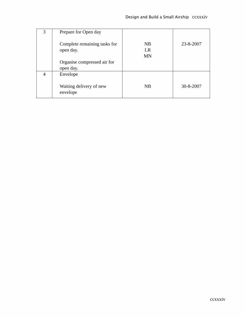
ccxxxiv
3 Prepare for Open day
Complete remaining tasks for open day.
Organise compressed air for open day.
NBLRMN
23-8-2007
4 Envelope
Waiting delivery of new envelope
NB 30-8-2007
Design and Build a Small Airship ccxxxiv
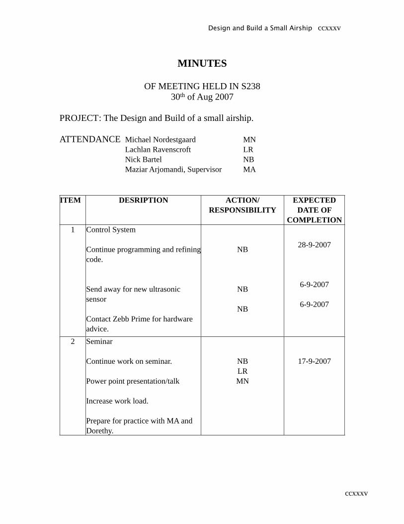
ccxxxv
MINUTES
OF MEETING HELD IN S23830th of Aug 2007
PROJECT : The Design and Build of a small airship.
ATTENDANCE Michael Nordestgaard MN Lachlan Ravenscroft LR Nick Bartel NB Maziar Arjomandi, Supervisor MA
ITEM DESRIPTION ACTION/RESPONSIBILITY
EXPECTED DATE OF
COMPLETION1 Control System
Continue programming and refining code.
Send away for new ultrasonic sensor
Contact Zebb Prime for hardware advice.
NB
NB
NB
28-9-2007
6-9-2007
6-9-2007
2 Seminar
Continue work on seminar.
Power point presentation/talk
Increase work load.
Prepare for practice with MA and Dorethy.
NBLRMN
17-9-2007
Design and Build a Small Airship ccxxxv

ccxxxvi
MINUTES
OF MEETING HELD IN S23813th of Sep 2007
PROJECT : The Design and Build of a small airship.
ATTENDANCE Michael Nordestgaard MN Lachlan Ravenscroft LR Nick Bartel NB Maziar Arjomandi, Supervisor MA
ITEM DESRIPTION ACTION/RESPONSIBILITY
EXPECTED DATE OF
COMPLETION1 Control System
Finalise code NB 28-9-2007
2 Test
Finalise preparations for testNBLRMN
28-9-2007
Design and Build a Small Airship ccxxxvi
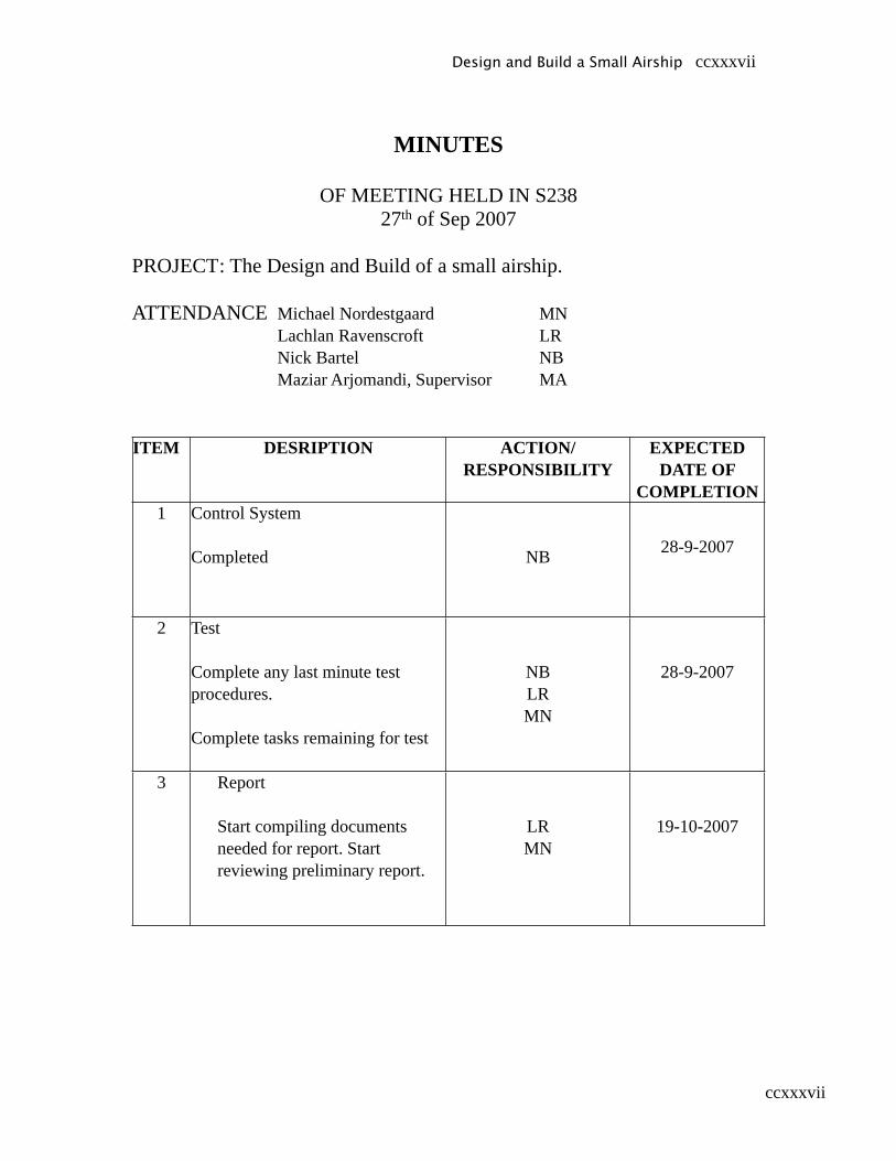
ccxxxvii
MINUTES
OF MEETING HELD IN S23827th of Sep 2007
PROJECT : The Design and Build of a small airship.
ATTENDANCE Michael Nordestgaard MN Lachlan Ravenscroft LR Nick Bartel NB Maziar Arjomandi, Supervisor MA
ITEM DESRIPTION ACTION/RESPONSIBILITY
EXPECTED DATE OF
COMPLETION1 Control System
Completed NB 28-9-2007
2 Test
Complete any last minute test procedures.
Complete tasks remaining for test
NBLRMN
28-9-2007
3 Report
Start compiling documents needed for report. Start reviewing preliminary report.
LRMN
19-10-2007
Design and Build a Small Airship ccxxxvii
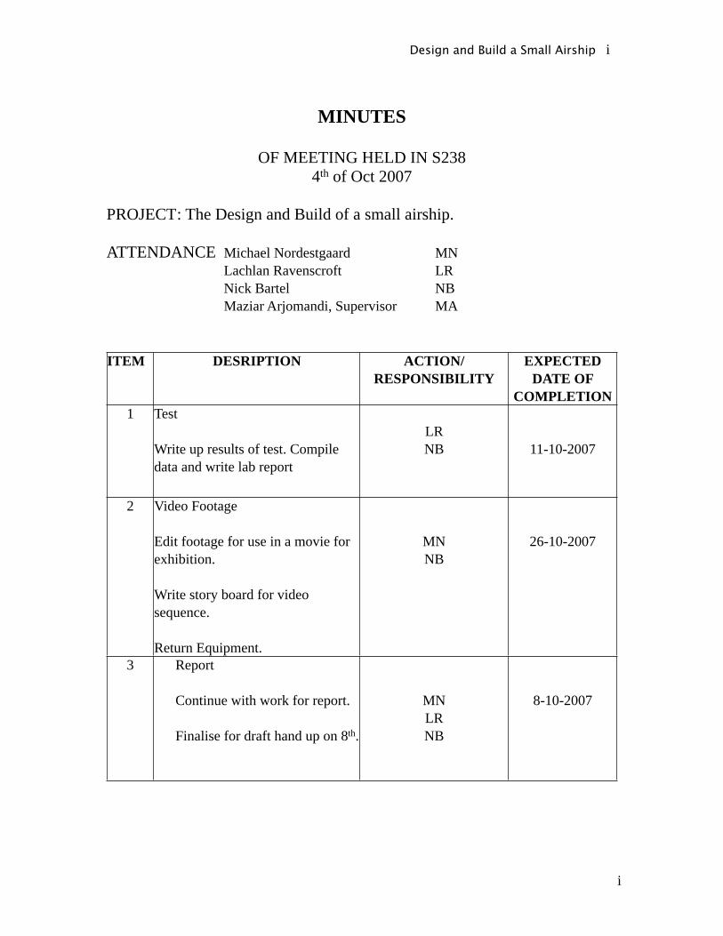
i
MINUTES
OF MEETING HELD IN S2384th of Oct 2007
PROJECT : The Design and Build of a small airship.
ATTENDANCE Michael Nordestgaard MN Lachlan Ravenscroft LR Nick Bartel NB Maziar Arjomandi, Supervisor MA
ITEM DESRIPTION ACTION/RESPONSIBILITY
EXPECTED DATE OF
COMPLETION1 Test
Write up results of test. Compile data and write lab report
LRNB 11-10-2007
2 Video Footage
Edit footage for use in a movie for exhibition.
Write story board for video sequence.
Return Equipment.
MNNB
26-10-2007
3 Report
Continue with work for report.
Finalise for draft hand up on 8th.
MNLRNB
8-10-2007
Design and Build a Small Airship i
ii
4 Exhibition
Make a list of tasks to be completed before exhibition.
Begin completing tasks
Design and Build a Small Airship ii

iii
MINUTES
OF MEETING HELD IN S23811th of Oct 2007
PROJECT : The Design and Build of a small airship.
ATTENDANCE Michael Nordestgaard MN Lachlan Ravenscroft LR Nick Bartel NB Maziar Arjomandi, Supervisor MA
ITEM DESRIPTION ACTION/RESPONSIBILITY
EXPECTED DATE OF
COMPLETION1 Video Footage
Edit footage for use in a movie for exhibition.
Continue editing work on footage with use of story board
MNNB
26-10-2007
2 Report
Increase work load on report to finalise.
MNLRNB
19-10-2007
3 Exhibition
Arrange for helium return.Make new fins
Design and Build a Small Airship iii
iv
Design and Build a Small Airship iv
Related Documents