AIRPLANE-INSTRUMENT RATING MINIMUM AERONAUTICAL EXPERIENCE ■ 50 hours X-Country PIC time ▷ Of which ,10 hours in airplanes. ■ 40 hours actual or simulated instrument time ▷ Of which, 15 hours with CFII. □ Including one X-Country flight of: □ 250 NM along airways or by directed ATC routing. □ An instrument approach at each airport. □ 3 different kinds of approaches using navigation systems. □ With a filed IFR flight plan. □ 3 Hours instrument flight training in last 2 Calendar months prior to practical test ■ Use of approved full flight simulator or FTD, if trained by authorized instructor: ▷ Max. 30 hours if instrument time completed under part 142 ▷ Max 20 hours if not completed under 142 ■ Use of FAA approved Aviation Training Device, if trained by an authorized instructor: ▷ Max.10 hours of instrument time if Basic ATD ▷ Max. 20 hours of instrument time if Advanced ATD ■ No more than 20 hours of total instrument time can be credited in a full flight simulator, FTD or ATD, except the 30 hours exception under part 142 mentioned above. §61.65 PERSONAL DOCUMENTS REQUIRED FOR FLIGHT ■ Pilot Certificate ■ Medical certificate (or US Driver’s license as permitted by §61.113 & §61.23) ■ Authorized photo ID (passport, driver’s license, etc) ■ Restricted Radiotelephone Operator Permit (For flights outside the US) RECENCY OF EXPERIENCE ■ To act as PIC under IFR or in weather conditions less than the minimums for VFR- “6 HITS” – Within 6 cal. months preceding the month of flight: ▷ 6 instrument approaches ▷ Holding procedures & tasks ▷ Intercepting & Tracking courses through the use of navigational electronic systems ▷ The above can be completed in a FFS, ATD, or FTD provided the device represents the category of aircraft for the instrument rating privileges to be maintained and the pilot performs the tasks and iterations in simulated instrument conditions.A flight instructor is not needed ■ Not current looking back 6 months? You can still log the required “6 HITS” with a safety pilot (under simulated conditions), examiner or instructor. ▷ Safety pilot requirements □ At least a private pilot with appropriate category and class. □ Have adequate vision forward and to each side of the aircraft. □ Aircraft must have a dual control system. ■ Not current looking back 12 months? ▷ Instrument Proficiency Check (IPC) by a CFII, examiner, or other approved person is required. Guidelines are in the ACS. ▷ Some IPC tasks, but not all, can be conducted in a FTD or ATD. (Refer to the ACS) ■ To carry passengers as PIC ▷ 3 takeoffs & landings in category, class and type (if type rating req.) In the last 90 days. ▷ At periods between 1 hour after sunset to 1 hour before sunrise: 3 takeoffs & landings to full stop within 1 hour after sunset to 1 hour before sunrise. ■ To act as PIC - Flight review in the last 24 Calendar months (see FAR for exceptions). (§61.56, §91.109, §61.57, Instrument- Airplane ACS) §61.3, §61.113, §61.23, ICAO Article 29 LOGGING INSTRUMENT TIME §61.51 Airplane IFR Quick-Review | Page 1 | Visit pilotscafe.com for more flight training resources V2.1.3 Nov 3, 2020, All Rights Reserved © Pilotscafe.com 2011-2020 .COM IFR Quick-Review Guide - Airplane Airplane IFR Quick-Review A person may log instrument time only for that flight time when the person operates the aircraft solely by reference to instruments under actual or simulated instrument flight conditions. An authorized instructor may log instrument time when conducting instrument flight instruction in actual instrument flight conditions. To meet recent instrument experience requirements, the following information must be recorded in the person's logbook: ■ Location & type of each instrument approach accomplished, and ■ The name of the safety pilot, if required Use of full flight simulator, FTD, or ATD for acquiring instrument aeronautical experience: ■ For training towards a certificate or rating, an authorized instructor is present to observe and signs the person’s logbook to verify the time and content of the session. ■ For IFR recency requirements, log: ▷ Training device, time and content.

Welcome message from author
This document is posted to help you gain knowledge. Please leave a comment to let me know what you think about it! Share it to your friends and learn new things together.
Transcript

AIRPLANE-INSTRUMENT RATING MINIMUMAERONAUTICAL EXPERIENCE■ 50 hours X-Country PIC time
▷ Of which ,10 hours in airplanes.■ 40 hours actual or simulated instrument time
▷ Of which, 15 hours with CFII.□ Including one X-Country flight of:
□ 250 NM along airways or by directed ATCrouting.
□ An instrument approach at each airport.□ 3 different kinds of approaches using
navigation systems.□ With a filed IFR flight plan.
□ 3 Hours instrument flight training in last 2 Calendarmonths prior to practical test
■ Use of approved full flight simulator or FTD, if trained byauthorized instructor:▷ Max. 30 hours if instrument time completed under
part 142▷ Max 20 hours if not completed under 142
■ Use of FAA approved Aviation Training Device, if trainedby an authorized instructor:▷ Max.10 hours of instrument time if Basic ATD▷ Max. 20 hours of instrument time if Advanced ATD
■ No more than 20 hours of total instrument time can becredited in a full flight simulator, FTD or ATD, except the30 hours exception under part 142 mentioned above.
§61.65
PERSONAL DOCUMENTS REQUIRED FORFLIGHT■ Pilot Certificate
■ Medical certificate (or US Driver’s license aspermitted by §61.113 & §61.23)
■ Authorized photo ID (passport, driver’s license, etc)■ Restricted Radiotelephone Operator Permit (Forflights outside the US)
RECENCY OF EXPERIENCE■ To act as PIC under IFR or in weather conditionsless than the minimums for VFR- “6 HITS” –Within 6 cal. months preceding the month offlight:▷ 6 instrument approaches▷ Holding procedures & tasks▷ Intercepting & Tracking courses through the use
of navigational electronic systems▷ The above can be completed in a FFS, ATD, or
FTD provided the device represents the category ofaircraft for the instrument rating privileges to bemaintained and the pilot performs the tasks anditerations in simulated instrument conditions. Aflight instructor is not needed
■ Not current looking back 6 months?You can still log the required “6 HITS” with a safety pilot(under simulated conditions), examiner or instructor.▷ Safety pilot requirements
□ At least a private pilot with appropriate categoryand class.
□ Have adequate vision forward and to each side ofthe aircraft.
□ Aircraft must have a dual control system.■ Not current looking back 12 months?
▷ Instrument Proficiency Check (IPC) by a CFII,examiner, or other approved person is required.Guidelines are in the ACS.
▷ Some IPC tasks, but not all, can be conducted in aFTD or ATD. (Refer to the ACS)
■ To carry passengers as PIC▷ 3 takeoffs & landings in category, class and type
(if type rating req.) In the last 90 days.▷ At periods between 1 hour after sunset to 1 hour
before sunrise: 3 takeoffs & landings to full stopwithin 1 hour after sunset to 1 hour before sunrise.
■ To act as PIC - Flight review in the last 24Calendar months (see FAR for exceptions).
(§61.56, §91.109, §61.57, Instrument- Airplane ACS) §61.3, §61.113, §61.23, ICAO Article 29
LOGGING INSTRUMENT TIME §61.51
Airplane IFR Quick-Review | Page 1 | Visit pilotscafe.com for more flight training resourcesV2.1.3 Nov 3, 2020, All Rights Reserved © Pilotscafe.com 2011-2020
.COMIFR Quick-Review Guide - Airplane
Airplane IFR Quick-ReviewA person may log instrument timeonly for that flight time when theperson operates the aircraft solely byreference to instruments under actualor simulated instrument flightconditions.
An authorized instructor may loginstrument time when conductinginstrument flight instruction in actualinstrument flight conditions.
To meet recent instrumentexperience requirements, thefollowing information must be recordedin the person's logbook:■ Location & type of each instrumentapproach accomplished, and
■ The name of the safety pilot, ifrequired
Use of full flight simulator, FTD, orATD for acquiring instrumentaeronautical experience:■ For training towards a certificate orrating, an authorized instructor ispresent to observe and signs theperson’s logbook to verify the timeand content of the session.
■ For IFR recency requirements, log:▷ Training device, time and content.

AIRCRAFT DOCUMENTS REQUIRED FORFLIGHTA.R.R.O.W –A - Airworthiness certificateR - Registration certificateR - Radio station license (for flights outside the US)O - Operating limitations & information ( in AFM)W - Weight & Balance data(§21.5, §91.103, §91.9, §91.203, ICAO Article 29)
AIRCRAFT MAINTENANCE INSPECTIONSREQUIRED FOR IFR:A.V.I.A.T.E –■ A - Annual inspection every 12 calendar months.( §91.409)
■ V - VOR check every 30 days. (For IFR) ( §91.171)■ I - 100 hour inspection. (if for hire) ( §91.409)■ A - Altimeter, automatic altitude reporting(transponder’s) & static system every 24calendar months. (For IFR in controlled airspace)(§91.411)
■ T - Transponder every 24 calendar months.(§91.413)
■ E - ELT every 12 months. ELT battery must bereplaced after 1 hour of transmitter use or if 50% ofits useful life (or, for rechargeable batteries, 50percent of their useful life of charge) has expired.(§91.207)
PREFLIGHT SELF-ASSESSMENT:I.M S.A.F.E –■ I - Illness - Do I have any symptoms?■ M - Medication - Have I taken prescription or over-the-counter drugs?
■ S - Stress - Am I under psychological pressure,worried about finances, health or family discord?
■ A - Alcohol - No drinking within 8 hours. (“8 hoursbottle to throttle”). No more than .04% of alcohol inblood.
■ F - Fatigue - Am I tired / adequately rested?■ E - Emotion - Am I emotionally upset?(§91.17, AIM 8-1-1)
PREFLIGHT INFO REQUIRED FOR IFR:N.W K.R.A.F.T- (§91.103)■ N - NOTAMs.■ W - Weather reports and forecasts.
■ K - Known traffic delays as advised by ATC.■ R -Runway length of intended use.■ A - Alternatives available if flight cannot becompleted as planned.
■ F - Fuel requirements■ T - Takeoff and landing performance data.
RISK MANAGEMENT & PERSONALMINIMUMSP.A.V.E –■ P - Pilot (general health, physical / mental /emotional state, proficiency, currency)
■ A - Aircraft (airworthiness, equipment, performance)■ V - EnVironment (weather hazards, terrain, airports/ runways to be used & other conditions)
■ E - External pressure (meetings, people waiting atdestination, etc.)
(Pilot’s Handbook of Aeronautical Knowledge)
DECISION MAKINGD.E.C.I.D.E –■ D - Detect that a change has occurred.■ E - Estimate the need to counter the change.■ C - Choose a desirable outcome.■ I - Identify solutions.■ D - Do the necessary actions.■ E - Evaluate the effects of the actions(Pilot’s Handbook of Aeronautical Knowledge)
PASSENGER BRIEFINGS.A.F.E.T.Y –■ S
▷ Seat belts fastened for taxi, takeoff, landing.▷ Shoulder harness fastened for takeoff, landing.▷ Seat position adjusted and locked in place
■ A▷ Air vents location and operation▷ All environmental controls (discussed)▷ Action in case of any passenger discomfort
■ F▷ Fire extinguisher (location and operation)
■ E▷ Exit doors (how to secure; how to open)▷ Emergency evacuation plan▷ Emergency/survival kit (location and contents)
■ T▷ Traffic (scanning, spotting, notifying pilot)▷ Talking, sterile flight deck expectations
■ Y▷ Your questions? Speak up!
(Pilot’s Handbook of Aeronautical Knowledge)
.
Airplane IFR Quick-Review | Page 2 | Visit pilotscafe.com for more flight training resourcesV2.1.3 Nov 3, 2020, All Rights Reserved © Pilotscafe.com 2011-2020
.COM IFR Quick-Review Guide - Airplane

Airplane IFR Quick-Review | Page 3 | Visit pilotscafe.com for more flight training resourcesV2.1.3 Nov 3, 2020, All Rights Reserved © Pilotscafe.com 2011-2020
.COMIFR Quick-Review Guide - Airplane
TAKEOFF BRIEFINGD.E.P.A.R.T.S –D - Departure review (e.g. takeoff type, initial heading, first fix &
course, clearance readout).E - Establish Expectations (e.g., flying pilot, PIC, positive
transfer of controls).P - Plan / special considerations (e.g., weather, visibility, terrain,
unfamiliar field, inoperative equipment / MELs).A - Alternate (takeoff alternate, if needed, or return plan)R - Runway conditions and length.T - Trouble / Tactics (e.g., rejected takeoff, engine failure).S - Speak up! Questions / concerns?
IFR FLIGHT PLAN■ Requirement: no person may operate an aircraft in controlledairspace under IFR unless that person has:▷ Filed an IFR flight plan; and▷ Received an appropriate ATC clearance.
■ It is legal to fly IFR in uncontrolled airspace (class G)without a flight plan or clearance. However, once airborne,you must remain in uncontrolled airspace until you file aflight plan and get an ATC clearance to enter the controlledairspace.
§91.173■ How to file an IFR flight plan?
▷ FSS□ by phone (1-800-WX-BRIEF)
■ over the radio (GCO/RCO frequencies)□ In person.
▷ Online□ www.1800wxbrief.com (Leido)□ www.fltplan.com (Garmin)
▷ EFB (e.g., Foreflight)▷ With ATC (over radio, or phone if no other mean available)
■ File at least 30 minutes prior to estimated departure. Non-scheduled flights above FL230 should be filed at least 4hours before est. departure time. (AIM 5-1-8)
■ Flight plan cancelation (AIM 5-1-15)▷ Towered airports - automatically cancelled by ATC upon
landing.▷ Non-towered airports - Pilot must contact ATC / FCC to
cancel (by radio or phone)▷ Can cancel anytime in flight if out of IMC and out of
class A airspace.■ Preferred IFR Routes are published in the Chart SupplementU.S. It is to the pilot’s advantage to file a preferred route ifavailable. (AIM 5-1-8)
NEED A DESTINATION ALTERNATE?“1-2-3” RULE –A destination alternate is always required, unless:
■ An instrument approach is published andavailable for the destination, AND,
■ For at least 1 hour before to 1 hour after ETA:▷ Ceiling will be at least 2000’ above airport
elevation; and▷ Visibility will be at least 3 SM.
§91.169
MIN WX CONDITIONS REQUIRED AT AN AIRPORTTO LIST IT AS AN ALTERNATEThe alternate airport minima published in theprocedure charts, or, if none:■ Precision approach:
600 ft ceiling and 2 SM visibility.■ Non-precision approach:
800 ft ceiling and 2 SM visibility.■ No instrument approach available at the
alternate:Ceiling & visibility must allow descent from MEA,approach and landing under VFR.
§91.169
FILING AN ALTERNATE - GPS CONSIDERATIONS■ Equipped with a non-WAAS GPS? You can flight
plan based on GPS approaches at either thedestination or the alternate, but not at both.
■ WAAS Without baro-VNAV? May base the flightplan on use of LNAV approaches at both thedestination and alternate.
■ WAAS with baro-VNAV? May base the flight planon use of LNAV/VNAV or RNP 0.3 at both thedestination and the alternate.
AIM 1-1-17b.5, 1-1-18c.9, 1-2-3d
YES
180º-359ºEVEN
Thousandsor
FlightLevels
0º-179ºODD
Thousandsor
FlightLevels
IFR CRUISING ALTITUDESBased on magnetic course §91.179
IFR MINIMUM FUEL REQUIREMENTS §91.167
45 Minutescalculated
atnormalcruise
Fuel fromdestination tomost distantalternate
(if alternate required)
Fuel fromdeparture todestinationairport
*Other fuel requirements exist for 121, 135, Flag and supplemental operations
Sean Stone

IFR TAKEOFF MINIMUMS (§91.175)No T/O minimums mandated for part 91 operations.Part 121, 125, 129, 135:■ Prescribed T/O minimums for the runway, or, if none:■ 1-2 engines airplanes: 1 SM visibility■ More than 2 engines: ½ SM visibility
Non-Standard TO mins / Departure Procedures.
Non-Standard IFR alternate minimums exist.
Alternate minimums not authorized due tounmonitored facility or the absence of weatherreporting service.
DEPARTURE PROCEDURES (DP)AIM 5-2-9■ Either textual or graphical.■ Ensures obstacle clearance, provided:
▷ the airplane crossed the departure end of therunway at least 35 ft AGL,
▷ reaches 400 ft AGL before turning, and▷ climbs at least 200 Feet per NM (FPNM), or aspublished otherwise on the chart.□ FPNM to feet-per-minute conversion:
fpm = FPNM * Groundspeed / 60
■ Pilots are encouraged to file a DP at night, duringmarginal VMC or IMC.
■ Two types of DP▷ Obstacle Departure Procedure (ODP)□ Provides only obstacle clearance.□ Graphic ODPs will have “(OBSTACLE)”
printed in the chart title.▷ Standard Instrument Departure (SID)□ In addition to obstacle clearance it reduces
pilot and controller workload by simplifyingATC clearances and minimizing radiocommunications.
□ Some SIDs may depict special radio failureprocedures.
■ DP are also categorized by equipment required:▷ Non-RNAV DP - for use by aircraft equipped withground-based navigation (i.e., VOR, DME, NDB).
▷ RNAV DP - for aircraft equipped with RNAVequipment (e.g., GPS, VOR/DME, DME/DME).Require at least RNAV 1 performance. Identifiedwith the word “RNAV” in the title.
▷ RADAR DP - ATC radar vectors to an ATS route,NAVAID, or fix are used after departure. RADARDPs are annotated “RADAR REQUIRED.”
■ You are not required to accept a DP. To avoidreceiving one, state “NO SIDs” in remarks sectionof flight plan.
■ Transition routes connect the end of the basic SIDprocedure to the en route structure.
IFR DEPARTURE CLEARANCEC.R.A.F.T –■ C - Clearance limit.■ R - Route.■ A - Altitude.■ F - Frequency (for departure).■ T - Transponder code.
Clearance void time – The time at which yourclearance is void and after which you may not takeoff.You must notify ATC within 30 min after the void time ifyou did not depart.
“Hold for release” – You may not takeoff until beingreleased for IFR departure.
Release time – The earliest time the aircraft maydepart under IFR.
Expect Departure Clearance Time (EDCT) – Arunway release time given under traffic managementprograms in busy airports. Aircraft are expected todepart no earlier and no later than 5 minutes from theEDCT.
Abbreviated departure clearance – “Cleared (...) asfiled (...)”(AIM 5-2-6)
STANDARD TERMINAL ARRIVAL (STAR)■ Serves as a transition between the en routestructure and a point from which an approach tolanding can be made.
■ Transition routes connect en route fixes to thebasic STAR procedure.
■ Usually named according to the fix at which thebasic procedure begins.
■ As with a SID, you can state “NO STARs” in theremarks section of the flight plan, to avoid getting aclearance containing a STAR.
■ RNAV STARs require RNAV 1 performance.
IFR ALTITUDESMIN IFR ALTITUDES (§91.177)■ Except for takeoff or landing, or otherwise authorizedby the FAA, no person may operate an aircraft underIFR below -▷ Minimum altitudes prescribed for the flown
segment, or if none:▷ Mountainous areas: 2,000 ft above the highest
obstacle within a horizontal distance of 4 NMfrom the course.
▷ Non-mountainous areas: 1,000 ft above thehighest obstacle within 4 NM from the course.
NA
Airplane IFR Quick-Review | Page 4 | Visit pilotscafe.com for more flight training resourcesV2.1.3 Nov 3, 2020, All Rights Reserved © Pilotscafe.com 2011-2020
.COM IFR Quick-Review Guide - Airplane
Sean Stone
Airplane IFR Quick-Review | Page 5 | Visit pilotscafe.com for more flight training resourcesV2.1.3 Nov 3, 2020, All Rights Reserved © Pilotscafe.com 2011-2020
.COMIFR Quick-Review Guide - Airplane
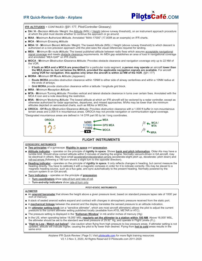
IFR ALTITUDES - CONTINUED (§91.177, Pilot/Controller Glossary)■ DA / H - Decision Altitude / Height: the Altitude (MSL) / Height (above runway threshold), on an instrument approach procedure
at which the pilot must decide whether to continue the approach or go around.■ MAA - Maximum Authorized Altitude. Annotated “MAA-17000” (17,000ft as an example) on IFR charts.■ MCA - Minimum Crossing Altitude■ MDA / H - Minimum Decent Altitude / Height: The lowest Altitude (MSL) / Height (above runway threshold) to which descent is
authorized on a non-precision approach until the pilot sees the visual references required for landing.■ MEA - Minimum En route Altitude: The lowest published altitude between radio fixes which assures acceptable navigational
signal coverage and meets obstacle clearance requirements. An MEA gap establishes an area of loss in navigational coverageand annotated “MEA GAP” on IFR charts.
■ MOCA - Minimum Obstruction Clearance Altitude: Provides obstacle clearance and navigation coverage only up to 22 NM ofthe VOR.▷ If both an MEA and a MOCA are prescribed for a particular route segment, a person may operate an aircraft lower than
the MEA down to, but not below the MOCA, provided the applicable navigation signals are available. For aircraftusing VOR for navigation, this applies only when the aircraft is within 22 NM of the VOR. (§91.177)
■ MORA - Minimum Off Route Altitude (Jeppesen):▷ Route MORA provides obstruction clearance within 10NM to either side of airway centerlines and within a 10NM radius at
the ends of airways.▷ Grid MORA provide obstruction clearance within a latitude / longitude grid block.
■ MRA - Minimum Reception Altitude■ MTA - Minimum Turning Altitude: Provides vertical and lateral obstacle clearance in turns over certain fixes. Annotated with the
MCA X icon and a note describing the restriction.■ MVA - Minimum Vectoring Altitude: The lowest altitude at which an IFR aircraft will be vectored by a radar controller, except as
otherwise authorized for radar approaches, departures, and missed approaches. MVAs may be lower than the minimumaltitudes depicted on aeronautical charts, such as MEAs or MOCAs.
■ OROCA - Off Route Obstruction Clearance Altitude: Provides obstruction clearance with a 1,000 ft buffer in non-mountainousterrain areas and 2,000 ft in mountainous areas. OROCAmay not provide navigation or communication signal coverage.
*Designated mountainous areas are defined in 14 CFR part 95 by lat / long coordinates.
V4
1600011700G*11000125
OROCA MEA
MRA
MCA /MTAGPS MEA
MOCA
GYROSCOPIC INSTRUMENTS■ Two principles of a gyroscope: Rigidity in space and precession.■ Attitude indicator – operates on the principle of rigidity in space. Shows bank and pitch information. Older AIs may have a
tumble limit. Should show correct attitude within 5 minutes of starting the engine. Normally vacuum-driven in GA aircraft, maybe electrical in others. May have small acceleration/deceleration errors (accelerate-slight pitch up, decelerate- pitch down) androll-out errors (following a 180 turn shows a slight turn to the opposite direction).
■ Heading indicator – operates on the principle of rigidity in space. It only reflects changes in heading, but cannot measure theheading directly. You have to calibrate it with a magnetic compass in order for it to indicate correctly. HIs may be slaved to amagnetic heading source, such as a flux gate, and sync automatically to the present heading. Normally powered by thevacuum system in on GA aircraft.
■ Turn indicators – operates on the principle of precession.▷ Turn coordinators show rate-of-turn and rate of roll.▷ Turn-and-slip indicators show rate-of-turn only.
ALTIMETER■ An aneroid barometer that shows the height above a given pressure level, based on standard pressure lapse rate of 1000’ per
inch of mercury.■ A stack of sealed aneroid wafers expand and contract with changes in atmospheric pressure received from the static port.■ Amechanical linkage between the aneroid and the display translates the sensed pressure to an altitude indication.■ An altimeter setting knob (on a “sensitive altimeter”, which are most aircraft altimeters) allows the pilot to adjust the current
pressure to the current altimeter setting published locally (available from ATIS, METAR or ATC).■ The pressure setting is displayed in the “Kollsman Window” in mb and/or inches of mercury (Hg)■ In the US, when operating below 18,000’ MSL regularly set the altimeter to a station within 100 NM. Above 18,000’ MSL,
the altimeter should be set to the standard sea level pressure of 29.92” Hg, and operate in Flight Levels (FL).■ “High to Low - Watch out below!”. Use caution when flying from high pressure to low pressure areas. If altimeter setting is not
updated, altitude will indicate higher, causing the pilot to fly lower than desired. Flying from hot to cold areas results in thesame error.
FLIGHT INSTRUMENTS
PITOT-STATIC INSTRUMENTS
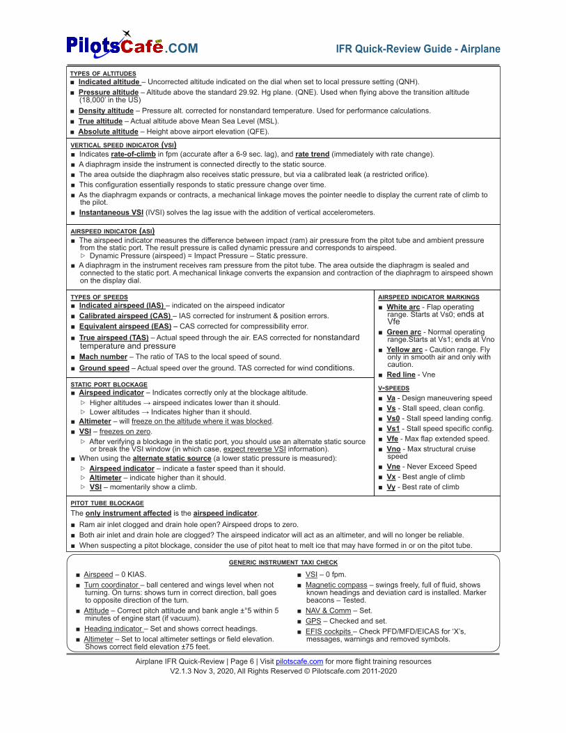
TYPES OF ALTITUDES■ Indicated altitude – Uncorrected altitude indicated on the dial when set to local pressure setting (QNH).■ Pressure altitude – Altitude above the standard 29.92. Hg plane. (QNE). Used when flying above the transition altitude
(18,000’ in the US)■ Density altitude – Pressure alt. corrected for nonstandard temperature. Used for performance calculations.■ True altitude – Actual altitude above Mean Sea Level (MSL).■ Absolute altitude – Height above airport elevation (QFE).
TYPES OF SPEEDS■ Indicated airspeed (IAS) – indicated on the airspeed indicator■ Calibrated airspeed (CAS) – IAS corrected for instrument & position errors.■ Equivalent airspeed (EAS) – CAS corrected for compressibility error.■ True airspeed (TAS) – Actual speed through the air. EAS corrected for nonstandardtemperature and pressure
■ Mach number – The ratio of TAS to the local speed of sound.■ Ground speed – Actual speed over the ground. TAS corrected for wind conditions.
AIRSPEED INDICATOR (ASI)■ The airspeed indicator measures the difference between impact (ram) air pressure from the pitot tube and ambient pressure
from the static port. The result pressure is called dynamic pressure and corresponds to airspeed.▷ Dynamic Pressure (airspeed) = Impact Pressure – Static pressure.
■ A diaphragm in the instrument receives ram pressure from the pitot tube. The area outside the diaphragm is sealed andconnected to the static port. A mechanical linkage converts the expansion and contraction of the diaphragm to airspeed shownon the display dial.
AIRSPEED INDICATOR MARKINGS■ White arc - Flap operating
range. Starts at Vs0; ends atVfe
■ Green arc - Normal operatingrange.Starts at Vs1; ends at Vno
■ Yellow arc - Caution range. Flyonly in smooth air and only withcaution.
■ Red line - Vne
V-SPEEDS■ Va - Design maneuvering speed■ Vs - Stall speed, clean config.■ Vs0 - Stall speed landing config.■ Vs1 - Stall speed specific config.■ Vfe - Max flap extended speed.■ Vno - Max structural cruise
speed■ Vne - Never Exceed Speed■ Vx - Best angle of climb■ Vy - Best rate of climb
STATIC PORT BLOCKAGE■ Airspeed indicator – Indicates correctly only at the blockage altitude.
▷ Higher altitudes → airspeed indicates lower than it should.▷ Lower altitudes → Indicates higher than it should.
■ Altimeter – will freeze on the altitude where it was blocked.■ VSI – freezes on zero.
▷ After verifying a blockage in the static port, you should use an alternate static sourceor break the VSI window (in which case, expect reverse VSI information).
■ When using the alternate static source (a lower static pressure is measured):▷ Airspeed indicator – indicate a faster speed than it should.▷ Altimeter – indicate higher than it should.▷ VSI – momentarily show a climb.
PITOT TUBE BLOCKAGEThe only instrument affected is the airspeed indicator.■ Ram air inlet clogged and drain hole open? Airspeed drops to zero.■ Both air inlet and drain hole are clogged? The airspeed indicator will act as an altimeter, and will no longer be reliable.■ When suspecting a pitot blockage, consider the use of pitot heat to melt ice that may have formed in or on the pitot tube.
■ Airspeed – 0 KIAS.■ Turn coordinator – ball centered and wings level when not
turning. On turns: shows turn in correct direction, ball goesto opposite direction of the turn.
■ Attitude – Correct pitch attitude and bank angle ±°5 within 5minutes of engine start (if vacuum).
■ Heading indicator – Set and shows correct headings.■ Altimeter – Set to local altimeter settings or field elevation.
Shows correct field elevation ±75 feet.
■ VSI – 0 fpm.■ Magnetic compass – swings freely, full of fluid, shows
known headings and deviation card is installed. Markerbeacons – Tested.
■ NAV & Comm – Set.■ GPS – Checked and set.■ EFIS cockpits – Check PFD/MFD/EICAS for ‘X’s,
messages, warnings and removed symbols.
GENERIC INSTRUMENT TAXI CHECK
VERTICAL SPEED INDICATOR (VSI)■ Indicates rate-of-climb in fpm (accurate after a 6-9 sec. lag), and rate trend (immediately with rate change).■ A diaphragm inside the instrument is connected directly to the static source.■ The area outside the diaphragm also receives static pressure, but via a calibrated leak (a restricted orifice).■ This configuration essentially responds to static pressure change over time.■ As the diaphragm expands or contracts, a mechanical linkage moves the pointer needle to display the current rate of climb to
the pilot.■ Instantaneous VSI (IVSI) solves the lag issue with the addition of vertical accelerometers.
Airplane IFR Quick-Review | Page 6 | Visit pilotscafe.com for more flight training resourcesV2.1.3 Nov 3, 2020, All Rights Reserved © Pilotscafe.com 2011-2020
.COM IFR Quick-Review Guide - Airplane

For VFR day:A T.O.M.A.T.O F.L.A.M.E.S –A - Altimeter
T - Tachometer for each engineO - Oil temperature indicator for each engineM - Manifold pressure gauge for each altitude engineA - Airspeed indicatorT - Temperature gauge for each liquid cooled engineO - Oil pressure gauge for each engine
F - Fuel quantity gauge for each tankL - Landing gear position lights (if retractable gear)A - Anticollision lights (aircraft certified after March
11, 1996)M - Magnetic direction indicator (mag. compass)E - ELT, if required by §91.207S - Safety belt / shoulder harness
For VFR night:All VFR day equipment + FLAPSF.L.A.P.S –
F - Fuses (spare set)L - Landing light (if for hire)A - Anticollision lightsP - Position lights (navigation lights)S - Source of electrical power (i.e., battery)
If operating for hire over water and beyond power-offgliding distance from shore: (unless part 121)■ An approved floatation device for each occupant■ At least one pyrotechnic signaling deviceFor flight above FL240:If VOR used, than DME or RNAV system is also required.
For IFR day: all VFR day equipment + GRABCARDFor IFR night: all VFR day + VFR night + GRABCARDG.R.A.B.C.A.R.D –G - Generator / alternatorR - Radios (two-way navigational equipment appropriate for the route
to be flown)A -Altimeter (sensitive = adjustable for barometric pressure)B - Ball (slip-skid indicator)C - Clock (shows hours, minutes and seconds and installed as part of
aircraft equipment)A -Attitude indicatorR - Rate-of-turn indicatorD - Directional gyro (heading indicator)
OPERATING WITH INOPERATIVE ITEMS (§91.213)
Aircraft has anMEL?
Is the inoperative equipment required by:■ VFR-day type certification requirements?■ Equipment list or kind of operations equipment list?■ §91.205 or other regulations for kind of operations?■ An Airworthiness Directive (AD)?
Flying is permitted, provided:■ Inoperative equipment is removed, or■ deactivated and placarded “Inoperative.”■ Pilot/mechanic determines no hazard from inop item.
Flying not allowed without aspecial flight permit
Follow MELprovisions
Yes
No
No
Yes
MINIMUM EQUIPMENT REQUIRED FOR FLIGHT (§91.205)
MAGNETIC COMPASS ERRORS & LIMITATIONS – D.V M.O.N.A■ D- Deviation■ V- Variation
■ M- Magnetic dip■ O- Oscillation
■ N- North/south turn errors -Northern hemisphere: UNOS Undershoot North/ Overshoot South
■ A- Acceleration errors -Northern hemisphere: ANDS Accelerate North/ Decelerate South
ELECTRONIC FLIGHT INSTRUMENTS■ Attitude Heading Reference Systems (AHRS) – Provides more accurate and reliable attitude and heading data than
traditional separate gyro systems. The first AHRS units were very expensive and relied on laser gyros and flux valves. Todaythey are based on solid state technologies (no moving parts) and are cheaper, smaller and easier to maintain.
■ Air Data Computers (ADC) – replaces the mechanical pitot-static instruments. The ADC receives inputs from the pitot, staticand outside temperature ports and computes airspeed, true airspeed, vertical speed and altitude.
■ Flight director – computes and displays command bars over the attitude indicator to assist the pilot in flying selected heading,course or vertical speed.
■ Flight Management System (FMS) – Receives inputs from various sensors and provides guidance to the autopilot and flightdirector throughout the flight. The FMS also automatically monitors and selects the most appropriate navigation source foraccurate positioning. (GPS, VOR/DME, INS etc.)
■ Electronic Flight Instrument Systems (EFIS) – AKA “Glass cockpit”.■ Primary Flight Displays (PFD) – Displays flight data such as attitude, altitude, airspeed, VSI and heading as well as rate
tapes.■ Multi-Function Displays (MFD) – Displays a variety of information such as moving maps, aircraft system status, weather and
traffic. It may also be used as a backup for other displays, such as the PFD or EICAS.
Airplane IFR Quick-Review | Page 7 | Visit pilotscafe.com for more flight training resourcesV2.1.3 Nov 3, 2020, All Rights Reserved © Pilotscafe.com 2011-2020
.COMIFR Quick-Review Guide - Airplane
DISTANCE MEASURING EQUIPMENT(DME)■ 962-1213 MHz (UHF).■ Normally tuned automatically with a
paired VHF station (VOR/LOC).■ The Airborne DME unit transmits an
interrogation signal.■ The ground DME facility receives and
replies to the interrogation.■ Airborne unit calculates the slant range
distance to the station based on thereply time.
■ Due to slant range error, when flyingoverhead the station, DME indication isnot “0”.
■ Slant range error is negligible at 1 NMfrom the DME station per every 1000ft.For example, at 5000 ft, slant rangeerror is negligible when further than 5NM of the station.
RADIO NAVIGATIONNON-DIRECTIONAL BEACON (NDB)■ Operates at the 190-535 kHz range (can receive and point towards commercial
radio AM station at 550 -1650 kHz).■ Low to medium frequency band.■ ADF (Automatic Direction Finder) in aircraft points towards the NDB station.■ Magnetic Bearing = Magnetic Heading + Relative Bearing
COMPASS LOCATORA low-powered NDB transmitter (at least 25 Watts and 15NM range) installed at theOM or the MM on some ILS approaches.
NDB Service Volume ClassesCompass Locator 15 NM
Medium High (MH) 25 NM
High (H) 50 NM (or less, as published in NOTAM orChart Supplement)
High High (HH) 75 NM
AREA NAVIGATION (RNAV)■ Allows navigation on any desired path without the
need to overfly ground-based facilities.■ Types:
▷ Global Navigation Satellite System (GNSS)(e.g., GPS, Galileo, GLONASS, BeiDou)
▷ VOR/DME RNAV▷ DME/DME RNAV▷ Inertial Reference Unit / System (IRU/ IRS)
■ RNAV VNAV - Vertical NAVigation guidance.■ BARO-VNAV - An RNAV system that uses the
barometric altitude to compute vertical guidance forthe pilot.
■ Published RNAV routes include Q (FL180 to FL450)and T (1,200 AGL to 18,000 MSL) routes and aredesignated RNAV 1 unless charted otherwise.
■ Magnetic Reference Bearing (MRB) - the publishedbearing between two waypoints on an RNAV route.
REQUIRED NAVIGATION PERFORMANCE (RNP)■ RNP is:
▷ A statement of navigation equipment and serviceperformance.
▷ RNAV with navigation monitoring and alerting.■ All RNAV approaches are RNP approaches
▷ Most US RNP approaches are titled “RNAV (GPS)”.▷ US Approaches with “RNAV (RNP)” in the title are “AR”
(Authorization Required) approaches, which require specialFAA approval for the crew, aircraft and operation.
▷ In other countries, all RNP approaches may have “RNP” in thetitle, even those that do not require special authorization.
RNP approach minimas and equipment:■ GLS DAminimas using GBAS (formerly LAAS)■ LP MDA or LPV DAminimas require RNP, achieved byWAAS.■ LNAV / VNAV DA achieved by VNAV-approved WAAS, or BARO-
VNAV systems.■ LNAV MDA - achieved by a basic, unaugmented IFR-approved GPS.
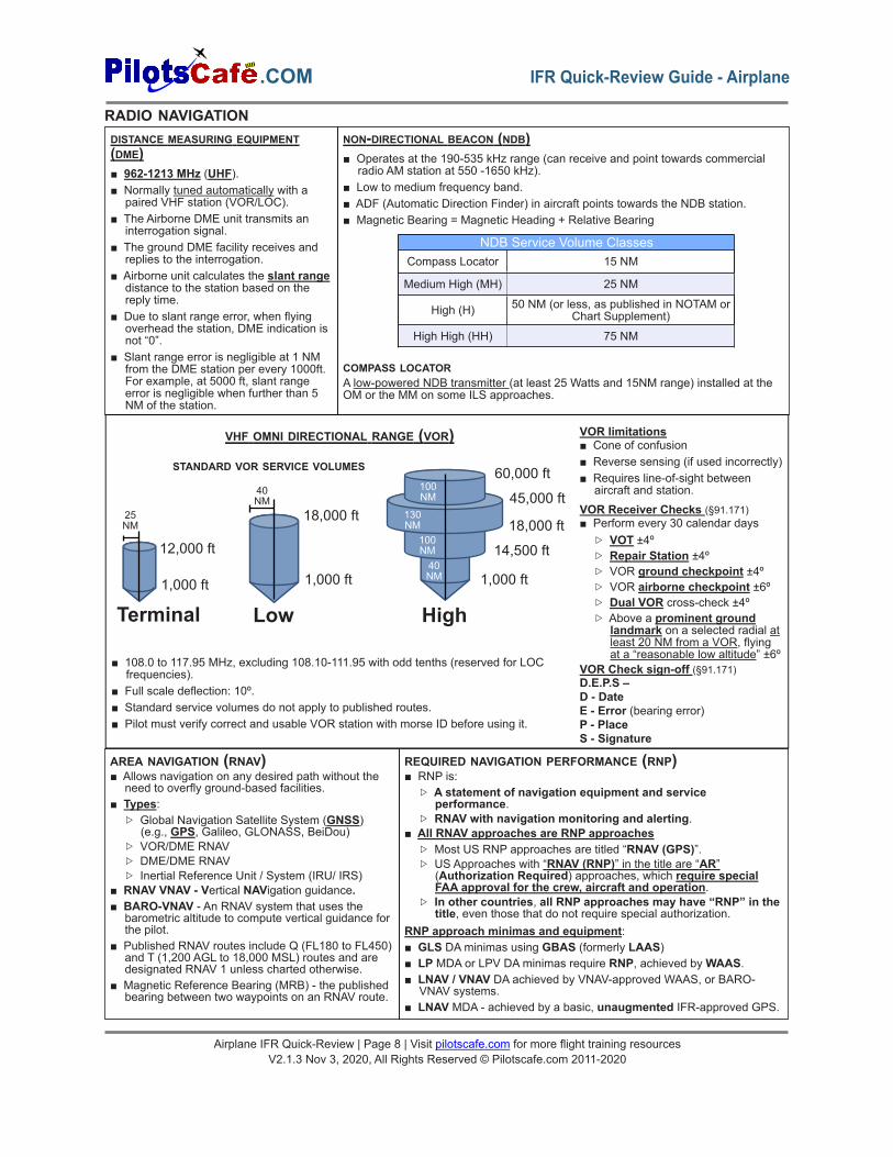
25NM
12,000 ft
Terminal1,000 ft
40NM
18,000 ft
Low
1,000 ft
18,000 ft
45,000 ft
60,000 ft
14,500 ft
1,000 ft
High
40NM
100NM
100NM
130NM
STANDARD VOR SERVICE VOLUMES
VHF OMNI DIRECTIONAL RANGE (VOR)
■ 108.0 to 117.95 MHz, excluding 108.10-111.95 with odd tenths (reserved for LOCfrequencies).
■ Full scale deflection: 10º.■ Standard service volumes do not apply to published routes.■ Pilot must verify correct and usable VOR station with morse ID before using it.
VOR limitations■ Cone of confusion■ Reverse sensing (if used incorrectly)■ Requires line-of-sight between
aircraft and station.VOR Receiver Checks (§91.171)■ Perform every 30 calendar days
▷ VOT ±4º▷ Repair Station ±4º▷ VOR ground checkpoint ±4º▷ VOR airborne checkpoint ±6º▷ Dual VOR cross-check ±4º▷ Above a prominent ground
landmark on a selected radial atleast 20 NM from a VOR, flyingat a “reasonable low altitude” ±6º
VOR Check sign-off (§91.171)D.E.P.S –D - DateE - Error (bearing error)P - PlaceS - Signature
Airplane IFR Quick-Review | Page 8 | Visit pilotscafe.com for more flight training resourcesV2.1.3 Nov 3, 2020, All Rights Reserved © Pilotscafe.com 2011-2020
.COM IFR Quick-Review Guide - Airplane
GLOBAL POSITIONING SYSTEM (GPS)■ GPS is a Global Navigation Satellite System (GNSS) operated by the United States.■ The constellation consists of a minimum of 24 satellites (with some spares) orbiting above the earth at 10,900 NM. The system
is designed so that at least 5 satellites are in view at any given location on earth.■ The Aircraft’s GPS receiver calculates the distance to a GPS satellite based on the time lapse since the broadcast timestamp
(obtained from an atomic clock onboard the satellite) and the time it received the signal.■ Using only one satellite, the aircraft could virtually be on any point on a sphere surrounding the satellite, with the calculated
distance (“pseudo-range”) as the sphere’s radius.■ The GPS receiver uses the intersection of spheres, from multiple satellites, to calculate the aircraft’s geographical position.
Course and speed data are computed from aircraft position changes.■ At least 3 satellites are required for 2d position. (latitude and longitude); at least 4 satellites are required for 3d position.
(latitude, longitude and altitude).■ Receiver Autonomous Integrity Monitoring (RAIM) is a function of GPS receivers that monitors the integrity of the satellite
signals.▷ RAIM (fault detection) requires a minimum of 5 satellites, or, 4 satellites + an altimeter input (baro-aided RAIM)▷ To eliminate a corrupt satellite (fault exclusion), RAIM needs an additional satellite (total of 6 or 5 + baro-aid)
■ A database loaded into the receiver unit contains navigational data such as: airports, navaids, routes, waypoints and instrumentprocedures.
■ Airborne GPS units use great-circle navigation.■ GPS CDI deflection shows distance, unlike a VOR’s CDI, which presents an angular distance off course in degrees.■ GPS can substitute ADF or DME, except for ADF substitution on NDB approaches without a GPS overlay (“or GPS” in title).■ Check GPS NOTAMS before the flight and use RAIM prediction if available on your receiver.■ GPS Augmentation systems, or Differential GPS (DGPS) – Improves the accuracy of GPS by measuring errors received by
reference stations at known geographical locations and then broadcasting those errors to supported GPS receivers.▷ Satellite Based Augmentation System (SBAS)
□ Wide Area Augmentation System (WAAS) in the US; EGNOS in Europe.□ Ground stations (Wide-area Reference Stations and Wide-area Master Stations) measure GPS errors and produce
correction signals. These corrections are broadcasted back to the satellite segment from which they are bounced backto aircraft GPS WAAS receivers to improve accuracy, integrity and availability monitoring for GPS navigation.
□ Covers a wide area.□ Facilitates APV approaches such as LPV and LNAV/VNAV and LP approaches.
▷ Ground Based Augmentation System (GBAS)□ Formerly named Local Area Augmentation System (LAAS) in the US. Now replaced with the ICAO term “GBAS.”□ Errors are broadcasted via VHF to GBAS-enabled GPS receivers.□ GBAS is more accurate than WAAS but covers a much smaller geographical area.□ Allows for category I and above approaches to GLS DA minima.
Understanding the difference between RNAV, GNSS, GPS, PBN and RNP■ Area Navigation (RNAV)
▷ RNAV is a system that enables navigation between any two points without the need to overfly ground-based stations.■ GNSS is a broad term for satellite-based RNAV systems.
▷ GPS is the GNSS operated by the USA. Other examples are GLONASS by Russia and Galileo by the EU.■ Performance Based Navigation (PBN)
▷ PBN is a general basis for navigation equipment standards, in terms of accuracy, integrity, continuity, availability andfunctionality for specific operation contexts (e.g., final approach, enroute, missed approach).
■ Required Navigation Performance (RNP)▷ RNP is a specific statement of PBN for the flight segment and aircraft capability.▷ RNP is also defined as RNAV + navigation monitoring and alerting functionality.
□ Receiver Autonomous Integrity Monitoring (RAIM) or built-in monitoring in WAAS provide this capability.▷ En route – RNP 2.0 (2 NM accuracy 95% of the flight time)▷ Terminal & Departure – RNP 1.0 (1 NM accuracy 95% of the flight time)▷ Final Approach – RNP 0.3 (0.3 NM accuracy 95% of flight time)▷ Advanced RNP (A-RNP) - is a higher RNP standard mandatory for RNP AR, that require capability for: (AIM 1-2-2)
□ Radius-to-Fix (RF) legs□ Scaleable RNP (meaning RNP accuracy can change value), and□ Parallel offset flight path generation
Airplane IFR Quick-Review | Page 9 | Visit pilotscafe.com for more flight training resourcesV2.1.3 Nov 3, 2020, All Rights Reserved © Pilotscafe.com 2011-2020
.COMIFR Quick-Review Guide - Airplane

APPROACH LIGHT SYSTEMS (ALS) (AIM 2-1-1)■ Provides basic visible means to transition between instrument-guided flight into a
visual approach.■ ALS extends from the landing threshold into the approach area up to:
▷ 2,400-3,000 feet for precision instrument runways, and▷ 1,400-1,500 feet for non-precision instrument runways.
■ May include sequenced flashing lights, which appear to the pilot as a ball of light travelingtowards the runway at twice a second (AKA “The Rabbit”).
■ The visible parts of the ALS configuration can help the pilot estimate flight visibility.
ALSF-2
MARKER BEACONS
■ Provide range information over specific points along theapproach. Transmits at 75 MHz.
■ Outer marker: 4-7 miles out. Indicate the position at whichthe aircraft should intercept the GS at the appropriate interception altitude ±50ft. BLUE. “- - -“
■ Middle marker: ~3500ft from the runway. Indicates the approximate point where the GS meets the decision height. Usually200ft above the touchdown zone elevation. AMBER. “. - . -”
■ Inner marker: between the MM and runway threshold. Indicates the point where the glide slope meets the DH on a CAT II ILSapproach.WHITE. “. . .”
■ Back course marker: Indicates the FAF on selected back course approaches. Not a part of the ILS approach.WHITE. “.. ..”
BC IM MM OM
I
M
O
LOCALIZER (AIM 1-1-9)■ Provides lateral course guidance.■ Frequencies: 108.1 - 111.95 MHz with odd tenths only.■ Width: Between 3°-6° so that the width at the threshold would be 700 feet.
Usually 5° total width. (2.5 full deflection to each side, 4 times more sensitivethan a VOR).
■ Coverage range: 35° to each side of the centerline for the first 10NM and 10°up to 18NM from the antenna and up to an altitude of 4500'.
LocalizerAntennaArray
BackCourse
FrontCourse
10º
700’ wide
18NM
10NM
10º
35º
35º
Runway3º-6º
GLIDE SLOPE (AIM 1-1-9)■ Provides vertical course guidance.■ Frequencies: 329.3 to 335 MHz (UHF) (automatically tuned with Localizer freq.)■ Width: 1.4º (full deflection is 0.7º either direction).■ Range: typically up to 10 NM.■ Slope: typically 3°.■ Errors: False glide slope above normal glide slope.
250-650 ft
750-1,250 ft
1.4º3º10NM
False Slope
INSTRUMENT LANDING SYSTEM (ILS)
ILSCategory Visibility DH
CAT I 2,400’ or1,800’ 200’
CAT II 1,200’ 100’
CAT IIIa >700’ <100’ or noDH
CAT IIIb 150’-700’ <50’ or noDH
CAT IIIc 0’ No DH
■ Control & Performance Method – Divides the cockpit panel by control instruments and performance instruments. First,set the power and attitude, then monitor the performance and make adjustments.▷ Control instruments
□ Power - Tachometer, Manifold pressure, EPR, N1, etc.□ Attitude - Attitude Indicator
▷ Performance Instruments□ Pitch: altimeter, airspeed and VSI□ Bank: Heading Indicator, Turn Coordinator, and magnetic compass
■ Primary & Supporting Method – Divides the cockpit panel by Pitch, Bank, and Power instruments.▷ Pitch instruments: Attitude Indicator, Altimeter, Airspeed Ind., and VSI.▷ Bank instruments: Attitude ind., Heading ind., Mag. Compass, and Turn Coordinator.▷ Power instruments: Airspeed, Tachometer, Manifold pressure▷ For a specific maneuver, primary instruments provide the most essential information for pitch, bank and power while
supporting Instruments back up and supplement the information presented by the primary instruments.▷ Example, for a constant rate climb with a standard rate turn –
□ Primary: Pitch - VSI; Bank - Turn Coordinator; Power - RPM / MP□ Secondary: Pitch - ASI; attitude, Bank - AI, HI, Mag. Compass; Power - ASI
■ Cross Check ■ Instrument interpretation ■ Aircraft ControlBasic attitude instrument flying skills:
■ Fixation ■ Omission ■ EmphasisCommon Errors:
ATTITUDE INSTRUMENT FLYING
Airplane IFR Quick-Review | Page 10 | Visit pilotscafe.com for more flight training resourcesV2.1.3 Nov 3, 2020, All Rights Reserved © Pilotscafe.com 2011-2020
.COM IFR Quick-Review Guide - Airplane
MANDATORY REPORTS UNDER IFRM.A.R.V.E.L.O.U.S. V.F.R. C.500 -
(AIM 5-3-3, §91.183, §91.187 )
■ Missed approach■ Airspeed ±10 kts / 5% change of filed TAS (whicheveris greater)
■ Reaching a holding fix (report time & altitude)■ VFR on top when an altitude change will be made.■ ETA change ±3 min■ Leaving a holding fix/point■ Outer marker (or fix used in lieu of it) *■ Un-forecasted weather■ Safety of flight (any other information related to safetyof flight)
■ Vacating an altitude/FL■ Final Approach fix *■ Radio/Nav/approach equipment failure (§91.187)■ Compulsory reporting points ▲ * (§91.183)■ 500 - unable climb/descent 500 fpm* Required only in non-radar environments (includingATC radar failure)
POSITION REPORT ITEMS REQUIRED IN NON-RADAR ENVIRONMENT(§91.183, AIM 5-3-2)■ Aircraft ID.■ Position.■ Time.■ Altitude.■ Type of flight plan (except when communicating withARTCC / Approach control).
■ ETA and name of next reporting fix.■ Name only of the next succeeding point along theroute of flight.
■ Any pertinent remarks.
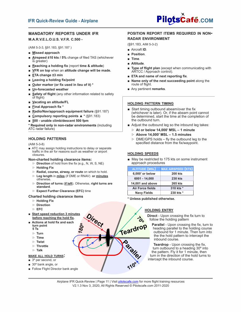
HOLDING PATTERNS(AIM 5-3-8)■ ATC may assign holding instructions to delay or separate
traffic in the air for reasons such as weather or airportclosures.
Non-charted holding clearance items:▷ Direction of hold from the fix (e.g., N, W, S, NE)▷ Holding Fix▷ Radial, course, airway, or route on which to hold.▷ Leg length in miles (if DME or RNAV) or minutes
otherwise.▷ Direction of turns (if left). Otherwise, right turns are
standard.▷ Expect Further Clearance (EFC) time
Charted holding clearance items▷ Holding Fix▷ Direction▷ EFC
■ Start speed reduction 3 minutesbefore reaching the hold fix.
■ Actions at hold fix and eachturn point5 Ts▷ Turn▷ Time▷ Twist▷ Throttle▷ Talk
MAKE ALL HOLD TURNS:■ 3º per second, or■ 30º bank angle, or■ Follow Flight Director bank angle
HOLDING PATTERN TIMING■ Start timing outbound abeam/over the fix(whichever is later). Or, if the abeam point cannotbe determined, start the time at the completion ofthe outbound turn.
■ Adjust the outbound leg so the inbound leg takes:▷ At or below 14,000’ MSL – 1 minute▷ Above 14,000’ MSL – 1.5 minutes▷ DME/GPS holds – fly the outbound leg to thespecified distance from the fix/waypoint.
HOLDING SPEEDS■ May be restricted to 175 kts on some instrumentapproach procedures
* Unless published otherwise.
HOLDING ENTRYDirect - Upon crossing the fix turn tofollow the holding patternParallel - Upon crossing the fix, turn to
a heading parallel to the holding courseoutbound for 1 minute. Then turn intothe the hold pattern to intercept theinbound course.Teardrop - Upon crossing the fix,turn outbound to a heading 30º intothe pattern. Fly it for 1 minute, thenturn in the direction of the hold turns tointercept the inbound course.
ALTITUDE (MSL) MAX AIRSPEED (KTS)6,000’ or below 200 kts6001 - 14,000 230 kts
14,001 and above 265 ktsAir Force fields 310 kts *Navy Fields 230 kts *
Teardrop
Direct
Parallel70º
180º
110º
Airplane IFR Quick-Review | Page 11 | Visit pilotscafe.com for more flight training resourcesV2.1.3 Nov 3, 2020, All Rights Reserved © Pilotscafe.com 2011-2020
.COMIFR Quick-Review Guide - Airplane
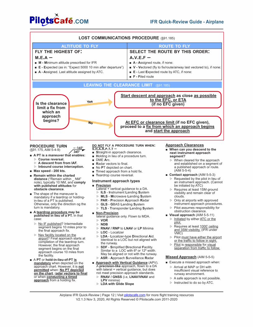
LOST COMMUNICATIONS PROCEDURE (§91.185)
ALTITUDE TO FLY ROUTE TO FLYFLY THE HIGHEST OF:M.E.A –■ M - Minimum altitude prescribed for IFR■ E - Expected (as in: “Expect 5000 10 min after departure”)■ A - Assigned. Last altitude assigned by ATC.
SELECT THE ROUTE BY THIS ORDER:A.V.E.F –■ A - Assigned route, if none:■ V - Vectored (fly to fix/route/airway last vectored to), if none:■ E - Last Expected route by ATC, if none:■ F - Filed route
Is the clearancelimit a fix from
which anapproachbegins?
Start descent and approach as close as possibleto the EFC, or ETA(if no EFC given)
At EFC or clearance limit (if no EFC given),proceed to a fix from which an approach begins
and start the approach
Yes
No
LEAVING THE CLEARANCE LIMIT (§91.185)
PROCEDURE TURN(§91.175, AIM 5-4-9)■ A PT is a maneuver that enables:
▷ Course reversal.▷ A descent from from IAF.▷ Inbound course interception.
■ Max speed - 200 kts.■ Remain within the charted
distance (“Remain within _ NM”note), typically 10 NM, and complywith published altitudes forobstacle clearance.
■ The shape of the maneuver ismandatory if a teardrop or holding-in-lieu of a PT is published.Otherwise, only the direction og theturn is mandatory.
■ A teardrop procedure may bepublished in lieu of a PT. In thatcase:▷ No IF published? Intermediate
segment begins 10 miles prior tothe final approach fix.
▷ Nav facility located on theairport? Final approach starts atcompletion of the teardrop turn.However, the final approachsegment begins on the finalapproach course 10 miles fromthe facility.
■ A PT or hold-in-lieu-of-PT ismandatory when depicted on theapproach chart. However, it is notpermitted when: No PT depictedon the chart, radar vectors to finalor when conducting a timedapproach from a holding fix.
DO NOT FLY A PROCEDURE TURN WHEN:S.H.A.R.P.T.T –■ Straight-in approach clearance.■ Holding in lieu of a procedure turn.■ DME Arc.■ Radar vectors to final.■ No PT depicted on chart.■ Timed approach from a hold fix.■ Teardrop course reversal.
Instrument approach types■ Precision
Lateral + vertical guidance to a DA.▷ ILS - Instrument Landing System▷ MLS - Microwave Landing System▷ PAR - Precision Approach Radar▷ GLS - GBAS Landing System▷ TLS - Transponder Landing System
■ Non-Precisionlateral guidance only. Flown to MDA.▷ VOR▷ NDB▷ RNAV / RNP to LNAV or LP Minima▷ LOC - Localizer▷ LDA - Localizer-type Directional Aid.
Identical to a LOC but not aligned withthe runway.
▷ SDF - Simplified Directional Facility.Similar to a LOC with 6º or 12º width.May be aligned or not with the runway.
▷ ASR - Approach Surveillance Radar■ Approach with Vertical Guidance (APV).
A precision-like approach, flown to a DAwith lateral + vertical guidance, but doesnot meet precision approach standards.▷ RNAV / GNSS (i.e, LNAV/VNAV and
LPV minima)▷ LDA with Glide Slope
Approach Clearances■ When can you descend to the
next instrument approachsegment?▷ When cleared for the approach
and established on a segment ofa published approach or route.(AIM 5-5-4)
■ Contact approach (AIM 5-5-3)▷ Requested by the pilot in lieu of
an instrument approach. (Cannotbe initiated by ATC)
▷ Requires at least 1SM groundvisibility and remain clear ofclouds.
▷ Only at airports with approvedinstrument approach procedures.
▷ Pilot assumes responsibility forobstruction clearance.
■ Visual approach (AIM 5-5-11)▷ Initiated by either ATC or the
pilot.▷ Requires at least 1000’ ceiling
and 3SM visibility. (IFR underVMC)
▷ Pilot must have either the airportor the traffic to follow in sight.
▷ Pilot is responsible for visualseparation from traffic to follow.
Missed Approach (AIM 5-5-5)■ Execute a missed approach when:
▷ Arrival at MAP or DH withinsufficient visual reference torunway environment.
▷ A safe approach is not possible.▷ Instructed to do so by ATC.
165º345º
Airplane IFR Quick-Review | Page 12 | Visit pilotscafe.com for more flight training resourcesV2.1.3 Nov 3, 2020, All Rights Reserved © Pilotscafe.com 2011-2020
.COM IFR Quick-Review Guide - Airplane
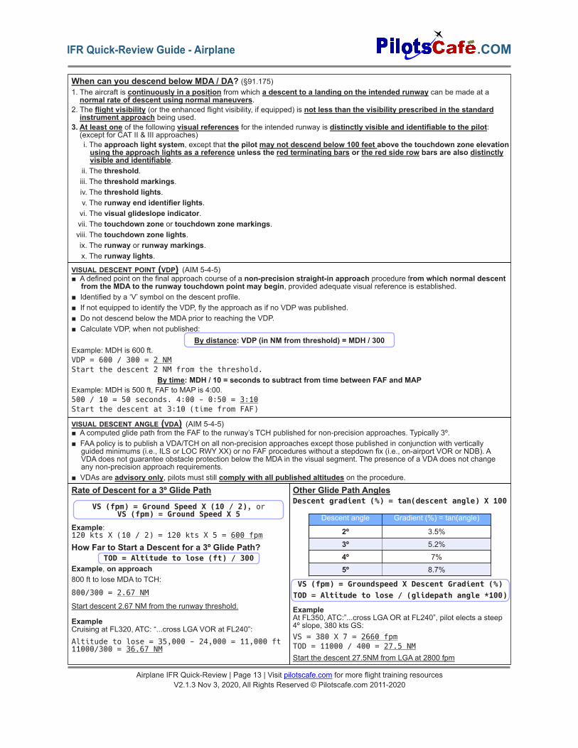
When can you descend below MDA / DA? (§91.175)1. The aircraft is continuously in a position from which a descent to a landing on the intended runway can be made at anormal rate of descent using normal maneuvers.
2. The flight visibility (or the enhanced flight visibility, if equipped) is not less than the visibility prescribed in the standardinstrument approach being used.
3. At least one of the following visual references for the intended runway is distinctly visible and identifiable to the pilot:(except for CAT II & III approaches)i. The approach light system, except that the pilot may not descend below 100 feet above the touchdown zone elevationusing the approach lights as a reference unless the red terminating bars or the red side row bars are also distinctlyvisible and identifiable.
ii. The threshold.iii. The threshold markings.iv. The threshold lights.v. The runway end identifier lights.vi. The visual glideslope indicator.vii. The touchdown zone or touchdown zone markings.viii. The touchdown zone lights.ix. The runway or runway markings.x. The runway lights.
VISUAL DESCENT POINT (VDP) (AIM 5-4-5)■ A defined point on the final approach course of a non-precision straight-in approach procedure from which normal descent
from the MDA to the runway touchdown point may begin, provided adequate visual reference is established.■ Identified by a ‘V’ symbol on the descent profile.■ If not equipped to identify the VDP, fly the approach as if no VDP was published.■ Do not descend below the MDA prior to reaching the VDP.■ Calculate VDP, when not published:
By distance: VDP (in NM from threshold) = MDH / 300Example: MDH is 600 ft.VDP = 600 / 300 = 2 NMStart the descent 2 NM from the threshold.
By time: MDH / 10 = seconds to subtract from time between FAF and MAPExample: MDH is 500 ft, FAF to MAP is 4:00.500 / 10 = 50 seconds. 4:00 - 0:50 = 3:10Start the descent at 3:10 (time from FAF)
VISUAL DESCENT ANGLE (VDA) (AIM 5-4-5)■ A computed glide path from the FAF to the runway’s TCH published for non-precision approaches. Typically 3º.■ FAA policy is to publish a VDA/TCH on all non-precision approaches except those published in conjunction with vertically
guided minimums (i.e., ILS or LOC RWY XX) or no FAF procedures without a stepdown fix (i.e., on-airport VOR or NDB). AVDA does not guarantee obstacle protection below the MDA in the visual segment. The presence of a VDA does not changeany non-precision approach requirements.
■ VDAs are advisory only, pilots must still comply with all published altitudes on the procedure.Rate of Descent for a 3º Glide Path
VS (fpm) = Ground Speed X (10 / 2), orVS (fpm) = Ground Speed X 5
Example:120 kts X (10 / 2) = 120 kts X 5 = 600 fpm
How Far to Start a Descent for a 3º Glide Path?TOD = Altitude to lose (ft) / 300
Example, on approach800 ft to lose MDA to TCH:
800/300 = 2.67 NM
Start descent 2.67 NM from the runway threshold.
ExampleCruising at FL320, ATC: “...cross LGA VOR at FL240”:Altitude to lose = 35,000 - 24,000 = 11,000 ft11000/300 = 36.67 NM
Other Glide Path AnglesDescent gradient (%) = tan(descent angle) X 100
VS (fpm) = Groundspeed X Descent Gradient (%)TOD = Altitude to lose / (glidepath angle *100)
ExampleAt FL350, ATC:”...cross LGA OR at FL240”, pilot elects a steep4º slope, 380 kts GS:VS = 380 X 7 = 2660 fpmTOD = 11000 / 400 = 27.5 NMStart the descent 27.5NM from LGA at 2800 fpm
Descent angle Gradient (%) = tan(angle)
2º 3.5%
3º 5.2%
4º 7%
5º 8.7%
Airplane IFR Quick-Review | Page 13 | Visit pilotscafe.com for more flight training resourcesV2.1.3 Nov 3, 2020, All Rights Reserved © Pilotscafe.com 2011-2020
.COMIFR Quick-Review Guide - Airplane
D
3152*
C
3152*
B
3SM Visibility &stay Clear of Clouds
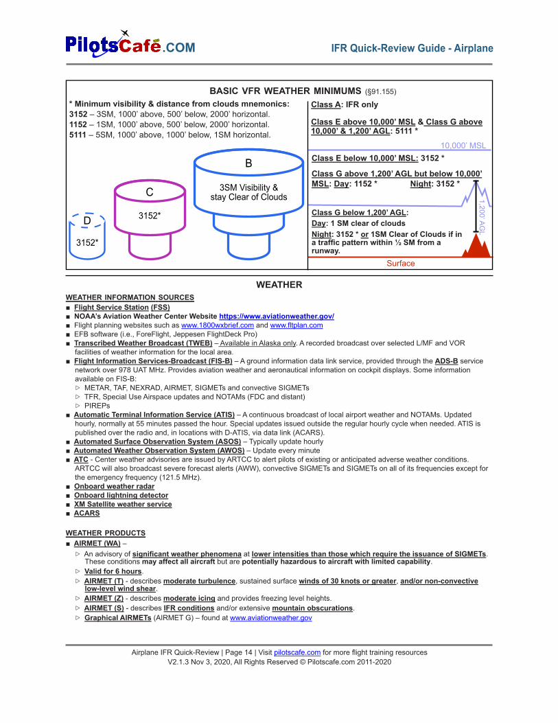
* Minimum visibility & distance from clouds mnemonics:3152 – 3SM, 1000’ above, 500’ below, 2000’ horizontal.1152 – 1SM, 1000’ above, 500’ below, 2000’ horizontal.5111 – 5SM, 1000’ above, 1000’ below, 1SM horizontal.
BASIC VFR WEATHER MINIMUMS (§91.155)
Class A: IFR only
Class E above 10,000’ MSL & Class G above10,000’ & 1,200’ AGL: 5111 *
Class E below 10,000’ MSL: 3152 *
Class G above 1,200’ AGL but below 10,000’MSL: Day: 1152 * Night: 3152 *
Class G below 1,200’ AGL:Day: 1 SM clear of cloudsNight: 3152 * or 1SM Clear of Clouds if ina traffic pattern within ½ SM from arunway.
10,000’ MSL
Surface
1,200’AGL
WEATHER INFORMATION SOURCES■ Flight Service Station (FSS)■ NOAA’s Aviation Weather Center Website https://www.aviationweather.gov/■ Flight planning websites such as www.1800wxbrief.com and www.fltplan.com■ EFB software (i.e., ForeFlight, Jeppesen FlightDeck Pro)■ Transcribed Weather Broadcast (TWEB) – Available in Alaska only. A recorded broadcast over selected L/MF and VOR
facilities of weather information for the local area.■ Flight Information Services-Broadcast (FIS-B) – A ground information data link service, provided through the ADS-B service
network over 978 UAT MHz. Provides aviation weather and aeronautical information on cockpit displays. Some informationavailable on FIS-B:▷ METAR, TAF, NEXRAD, AIRMET, SIGMETs and convective SIGMETs▷ TFR, Special Use Airspace updates and NOTAMs (FDC and distant)▷ PIREPs
■ Automatic Terminal Information Service (ATIS) – A continuous broadcast of local airport weather and NOTAMs. Updatedhourly, normally at 55 minutes passed the hour. Special updates issued outside the regular hourly cycle when needed. ATIS ispublished over the radio and, in locations with D-ATIS, via data link (ACARS).
■ Automated Surface Observation System (ASOS) – Typically update hourly■ Automated Weather Observation System (AWOS) – Update every minute■ ATC - Center weather advisories are issued by ARTCC to alert pilots of existing or anticipated adverse weather conditions.
ARTCC will also broadcast severe forecast alerts (AWW), convective SIGMETs and SIGMETs on all of its frequencies except forthe emergency frequency (121.5 MHz).
■ Onboard weather radar■ Onboard lightning detector■ XM Satellite weather service■ ACARS
WEATHER PRODUCTS■ AIRMET (WA) –
▷ An advisory of significant weather phenomena at lower intensities than those which require the issuance of SIGMETs.These conditions may affect all aircraft but are potentially hazardous to aircraft with limited capability.
▷ Valid for 6 hours.▷ AIRMET (T) - describes moderate turbulence, sustained surface winds of 30 knots or greater, and/or non-convective
low-level wind shear.▷ AIRMET (Z) - describes moderate icing and provides freezing level heights.▷ AIRMET (S) - describes IFR conditions and/or extensive mountain obscurations.▷ Graphical AIRMETs (AIRMET G) – found at www.aviationweather.gov
WEATHER
Airplane IFR Quick-Review | Page 14 | Visit pilotscafe.com for more flight training resourcesV2.1.3 Nov 3, 2020, All Rights Reserved © Pilotscafe.com 2011-2020
.COM IFR Quick-Review Guide - Airplane
Airplane IFR Quick-Review | Page 15 | Visit pilotscafe.com for more flight training resourcesV2.1.3 Nov 3, 2020, All Rights Reserved © Pilotscafe.com 2011-2020
.COMIFR Quick-Review Guide - Airplane
■ SIGMET (WS) –▷ A non-scheduled inflight
advisory with a maximumforecast period of 4 hours.Advises of non-convectiveweather potentially hazardous toall types of aircraft. A SIGMET isissued when the following isexpected to occur:
▷ Severe icing not associatedwith thunderstorms
▷ Severe or extreme turbulenceor Clear Air Turbulence (CAT)not associated withthunderstorms.
▷ Dust storms, sandstormslowering surface visibility below3 miles.
■ Convective SIGMET (WST) –▷ An inflight advisory of
convective weather significantto the safety of all aircraft.
▷ Issued hourly at 55 minutespast the hour for the western(W), eastern (E) and central (C)USA.□ Not issued for Alaska or
Hawaii.▷ Valid for 2 hours.▷ Contains either an observation
and a forecast or only aforecast.
▷ Issued for any of the following:□ Severe thunderstorms due
to:◦ Surface winds greater orequal to 50 knots
◦ Hail at the surface greaterthan 3/4 inch in diameter
□ Tornadoes□ Embedded thunderstorms of
any intensity level□ A line of thunderstorms at
least 60 miles long withthunderstorms affecting atleast 40% of its length
□ Thunderstorms producingheavy or greaterprecipitation (VIP level 4)affecting at least 40% of anarea of at least 3000 squaremiles.
▷ Any Convective SIGMETimplies severe or greaterturbulence, severe icing, andlow level wind shear.
■ International SIGMET▷ Issued outside the Contiguous
USA and follow ICAO codingstandards.
▷ In the US, international SIGMETsare issued for areas that includeAlaska, Hawaii, portions of theAtlantic and Pacific Oceans,and the Gulf of Mexico.
WEATHER PRODUCTS - CONTINUED▷ Criteria for international
SIGMETs:□ Thunderstorms occurring in
lines, embedded in clouds,or in large areas producingtornadoes or large hail.
□ Tropical cyclones□ Severe icing□ Severe or extreme
turbulence□ Dust storms and sandstorms
lowering surface visibility toless than 3 miles
□ Volcanic ash■ PIREP (UA) & Urgent PIREP (UUA)
– pilot weather reports.■ METAR – Aviation routine weather
show surface weather observationsin a standard international format.Scheduled METARs are publishedevery hour. Non-scheduledMETARS (SPECI) are issued whenthere is a significant change in oneor more reported element since thelast scheduled METAR.
■ TAF – Terminal AerodromeForecast. Weather forecast for 5SMradius area around the station.Issued 4 times a day, every sixhours and normally covers a 24 or30 hour forecast period. TAFamendments (TAF AMD) supersedeprevious TAFs.
■ Surface analysis chart –Generatedfrom surface station reports. Showspressure systems, isobars, fronts,airmass boundaries (e.g,: dry linesand outflow boundaries) and stationinformation (e.g,: wind, temperature/dew point, sky coverage, andprecipitation). Issued every 3 hours.(or every 6 hours in Hawaii andtropical and Oceanic regions).A Unified Surface Analysis Chartis produced every 6 hours andcombines the analysis from the 4centers (OPC, WPC, NHC andHFO)
■ Radar summary chart (SD) –Depicts precipitation type, intensity,coverage, movement, echoes, andmaximum tops. Issued hourly
■ Wind & temp aloft forecasts (FB) –Issued 4 times daily for variousaltitudes and flight levels.Winds at altitude up to 1500’ AGLand temperatures at up to 2500’AGL are not shown.Format: DDff±tt, where DD = winddirection; ff = wind speed; tt =temperature. Light and variablewinds: 9900. Winds between 100-199 Kt are coded by adding 5 to thefirst digit of the wind direction.Above FL240 temperatures arenegative and the minus sign (-) isomitted.Examples:1312+05: winds 130 / 12 kt, 5°C.7525-02: winds 250 / 125 kt, -2° C.
■ Low level significant weatherchart – Forecasts significantweather conditions for a 12 and 24hour period from the surface to 400mb level (24,000 ft). Issued 4 timesa day. Depicts weather categories(IFR, MVFR and VFR), turbulenceand freezing levels.
■ Mid-level significant weather chart– Forecasts of significant weather atvarious altitudes and flight levelsfrom 10,000’ MSL to FL450. Shows:thunderstorms, jet streams,tropopause height, tropical cyclones,moderate and severe icingconditions, moderate or severeturbulence, cloud coverage andtype, volcanic ash and areas ofreleased radioactive materials.Issued 4 times a day for the NorthAtlantic Region.
■ High-level significant weathercharts – Depicts forecasts ofsignificant weather phenomena forFL250 to FL630. Shows: coveragebases and tops of thunderstormsand CB clouds, moderate andsevere turbulence, jet streams,tropopause heights, tropicalcyclones, severe squall lines,volcanic eruption sites, widespreadsand and dust storms. Issued 4times a day.
■ Convective outlook (AC) –Available in both graphical andtextual format. A 3-day forecast ofconvective activity. Convectiveareas are classified as marginal(MRGL), slight (SLGT), enhanced(ENH), moderate (MDT), and high(HIGH) risk for severe weather.Issuance: day 1 – 5 times a day, day2 – twice a day, day 3 – once a day.Available on www.spc.noaa.gov.
■ Weather satellite images:▷ Visible
□ Helps in identifying cloudcoverage based on visiblelight reflection.
□ Not useful for identifying cloudheight.
▷ Infrared (Color or B/W)□ Measure cloud top
temperature□ Highest clouds appear bright
white.□ Middle clouds are in shades of
gray□ Low clouds and fog are dark
gray,▷ Water vapor□ Shows areas of moist and
dry air in shades of grayfrom white to black.
□ Moist air areas aredepicted as bright white
□ Dry air is depicted in black.
■ Next Generation Weather Radar (NEXRAD) products. Examples:▷ Base reflectivity - echo intensities in dBZ. Available for several elevation tilt angles.▷ Echo tops - color coded echo top heights.▷ Composite reflectivity - Reveals highest reflectivity of all echos, helps in examining storm structure features and the intensity
of storms.▷ 1 and 3-hour precipitation
■ Ceiling & Visibility Charts- Shows ceiling based on surface observations. This online tool phased out the older weatherdepiction chart and is now replaced with the HEMS tool at www.aviationweather.gov/hemst
■ Graphical turbulence Guidance (GTG) tool at www.aviationweather.gov/turbulence/gtg – Shows color coded turbulenceforecast based on aircraft category, altitude and time.
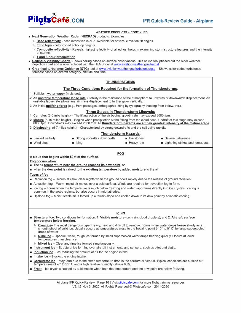
FOGA cloud that begins within 50 ft of the surface.Fog occurs when:■ The air temperature near the ground reaches its dew point, or■ when the dew point is raised to the existing temperature by added moisture to the air.Types of fog■ Radiation fog – Occurs at calm, clear nights when the ground cools rapidly due to the release of ground radiation.■ Advection fog – Warm, moist air moves over a cold surface. Winds are required for advection fog to form.■ Ice fog – Forms when the temperature is much below freezing and water vapor turns directly into ice crystals. Ice fog is
common in the arctic regions, but also occurs in mid-latitudes.■ Upslope fog – Moist, stable air is forced up a terrain slope and cooled down to its dew point by adiabatic cooling.
ICING■ Structural Ice. Two conditions for formation: 1. Visible moisture (i.e., rain, cloud droplets), and 2. Aircraft surface
temperature below freezing.▷ Clear ice– The most dangerous type. Heavy, hard and difficult to remove. Forms when water drops freeze slowly as a
smooth sheet of solid ice. Usually occurs at temperatures close to the freezing point (-10° to 0° C) by large supercooleddrops of water
▷ Rime ice – Opaque, white, rough ice formed by small supercooled water drops freezing quickly. Occurs at lowertemperatures than clear ice.
▷ Mixed ice – Clear and rime ice formed simultaneously.■ Instrument ice – Structural ice forming over aircraft instruments and sensors, such as pitot and static.■ Induction ice – ice reducing the amount of air for the engine intake.■ Intake ice – Blocks the engine intake.■ Carburetor ice – May form due to the steep temperature drop in the carburetor Venturi. Typical conditions are outside air
temperatures of -7° to 21° C and a high relative humidity (above 80%).■ Frost – Ice crystals caused by sublimation when both the temperature and the dew point are below freezing.
WEATHER PRODUCTS - CONTINUED
THUNDERSTORMS
The Three Conditions Required for the formation of Thunderstorms:1. Sufficient water vapor (moisture).2. An unstable temperature lapse rate. Stability is the resistance of the atmosphere to upwards or downwards displacement. Anunstable lapse rate allows any air mass displacement to further grow vertically.
3. An initial uplifting force (e.g., front passages, orthographic lifting by typography, heating from below, etc.).
Three Stages in Thunderstorm Lifecycle:1. Cumulus (3-5 mile height) – The lifting action of the air begins, growth rate may exceed 3000 fpm.2. Mature (5-10 miles height) – Begins when precipitation starts falling from the cloud base. Updraft at this stage may exceed6000 fpm. Downdrafts may exceed 2500 fpm. All thunderstorm hazards are at their greatest intensity at the mature stage.
3. Dissipating (5-7 miles height) – Characterized by strong downdrafts and the cell dying rapidly.
Thunderstorm Hazards:■ Limited visibility■ Wind shear
■ Strong updrafts / downdrafts■ Icing
■ Hailstones■ Heavy rain
■ Severe turbulence■ Lightning strikes and tornadoes.
Airplane IFR Quick-Review | Page 16 | Visit pilotscafe.com for more flight training resourcesV2.1.3 Nov 3, 2020, All Rights Reserved © Pilotscafe.com 2011-2020
.COM IFR Quick-Review Guide - Airplane
Airplane IFR Quick-Review | Page 17 | Visit pilotscafe.com for more flight training resourcesV2.1.3 Nov 3, 2020, All Rights Reserved © Pilotscafe.com 2011-2020
.COMIFR Quick-Review Guide - Airplane
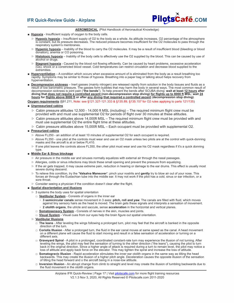
AEROMEDICAL (Pilot Handbook of Aeronautical Knowledge)■ Hypoxia - Insufficient supply of oxygen to the body cells.
▷ Hypoxic hypoxia – Insufficient supply of O2 to the body as a whole. As altitude increases, O2 percentage of the atmosphereis constant, but its pressure decreases. The reduced pressure becomes insufficient for the O2 molecules to pass through therespiratory system’s membranes.
▷ Hypemic hypoxia – Inability of the blood to carry the O2 molecules. It may be a result of insufficient blood (bleeding or blooddonation), anemia or CO poisoning.
▷ Histotoxic hypoxia – Inability of the body cells to affectively use the O2 supplied by the blood. This can be caused by use ofalcohol or drugs.
▷ Stagnant hypoxia - Caused by the blood not flowing efficiently. Can be caused by heart problems, excessive acceleration(Gs), shock or a constricted blood vessel. Cold temperatures can restrict circulation and decrease blood supplied to theextremities.
■ Hyperventilation – A condition which occurs when excessive amount of is eliminated from the body as a result breathing toorapidly. Symptoms may be similar to those of hypoxia. Breathing into a paper bag or talking aloud helps recovery fromhyperventilation.
■ Decompression sickness – Inert gasses (mainly nitrogen) are released rapidly from solution in the body tissues and fluids as aresult of low barometric pressure. The gasses form bubbles that may harm the body in several ways. The most common result ofdecompression sickness is joint pain (“the bends”). To help prevent the bends after SCUBA diving: wait at least 12 hours afterdiving that does not require a controlled ascent (non-decompression stop diving) for flights up to 8000 ft MSL; wait 24hours for flights above 8000 ft or after any diving that required a controlled ascent (decompression stop diving).
Oxygen requirements (§91.211, Note: see §121.327-121.333 & §135.89, §135.157 for O2 rules applying to parts 121/135)■ Unpressurized cabins
▷ Cabin pressure altitudes 12,500 - 14,000 ft MSL (including) – The required minimum flight crew must beprovided with and must use supplemental O2 for periods of flight over 30 minutes at these altitudes.
▷ Cabin pressure altitudes above 14,000ft MSL – The required minimum flight crew must be provided with andmust use supplemental O2 the entire flight time at these altitudes.
▷ Cabin pressure altitudes above 15,000ft MSL – Each occupant must be provided with supplemental O2.■ Pressurized cabins
▷ Above FL250 - an addition of at least 10 minutes of supplemental O2 for each occupant is required.▷ Above FL350 - one pilot at the controls must wear and use an O2 mask unless two pilots are at the control with quick-donning
masks and the aircraft is at or below FL410.▷ If one pilot leaves the controls above FL350, the other pilot must wear and use his O2 mask regardless if it’s a quick donning
type.■ Middle Ear & Sinus blockage
▷ Air pressure in the middle ear and sinuses normally equalizes with external air through the nasal passages.▷ Allergies, colds or sinus infections may block these small opening and prevent the pressure from equalizing.▷ If the air gets trapped, it may cause extreme pain, reduction in hearing or damage to the ear drums. This effect is usually most
severe during descend.▷ To relieve this condition, try the “Valsalva Maneuver“: pinch your nostrils and gently try to blow air out of your nose. This
forces air through the Eustachian tube into the middle ear. It may not work if the pilot has a cold, sinus or ear infection, or asore throat.
▷ Consider seeing a physician if the condition doesn’t clear after the flight.■ Spatial disorientation and illusions
▷ 3 systems the body uses for spatial orientation□ Vestibular System - Consists of organs in the inner ear
◦ 3 semicircular canals sense movement in 3 axes: pitch, roll and yaw. The canals are filled with fluid, which movesagainst tiny sensory hairs as the head is moved. The brain gets these signals and interprets a sensation of movement.
◦ 2 otolith organs, the utricle and saccule, sense acceleration in the horizontal and vertical planes.□ Somatosensory System - Consists of nerves in the skin, muscles and joints.□ Visual System - Visual cues from our eyes help the brain figure out spatial orientation.
▷ Vestibular Illusions□ The leans - After leveling the wings following a prolonged turn, pilot may feel that the aircraft is banked in the opposite
direction of the turn.□ Coriolis Illusion - After a prolonged turn, the fluid in the ear canal moves at same speed as the canal. A head movement
on a different plane will cause the fluid to start moving and result in a false sensation of acceleration or turning on adifferent axis.
□ Graveyard Spiral - A pilot in a prolonged, coordinated constant-rate turn may experience the illusion of not turning. Afterleveling the wings, the pilot may feel the sensation of turning to the other direction (“the leans”), causing the pilot to turnback in the original direction. Since a higher angle of attack is required during a turn to remain level, the pilot may notice aloss of altitude and apply back force on the elevator. This may tighten the spiral and increase the loss of altitude.
□ Somatogravic Illusion - Rapid acceleration stimulates the inner ear otolith organs in the same way as tilting the headbackwards. This may create the illusion of a higher pitch angle. Deceleration causes the opposite illusion of the sensationof tilting the head forward and o the aircraft being in a nose-low attitude.
□ Inversion Illusion - An abrupt change from climb to straight and level may create the illusion of tumbling backwards due tothe fluid movement in the otolith organs.
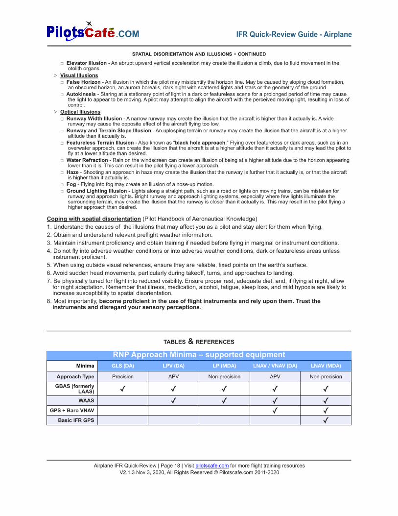
RNP Approach Minima – supported equipmentMinima GLS (DA) LPV (DA) LP (MDA) LNAV / VNAV (DA) LNAV (MDA)
Approach Type Precision APV Non-precision APV Non-precision
GBAS (formerlyLAAS) ✓ ✓ ✓ ✓ ✓WAAS ✓ ✓ ✓ ✓
GPS + Baro VNAV ✓ ✓Basic IFR GPS ✓
□ Elevator Illusion - An abrupt upward vertical acceleration may create the illusion a climb, due to fluid movement in theotolith organs.
▷ Visual Illusions□ False Horizon - An illusion in which the pilot may misidentify the horizon line. May be caused by sloping cloud formation,
an obscured horizon, an aurora borealis, dark night with scattered lights and stars or the geometry of the ground□ Autokinesis - Staring at a stationary point of light in a dark or featureless scene for a prolonged period of time may cause
the light to appear to be moving. A pilot may attempt to align the aircraft with the perceived moving light, resulting in loss ofcontrol.
▷ Optical Illusions□ Runway Width Illusion - A narrow runway may create the illusion that the aircraft is higher than it actually is. A wide
runway may cause the opposite effect of the aircraft flying too low.□ Runway and Terrain Slope Illusion - An uplosping terrain or runway may create the illusion that the aircraft is at a higher
altitude than it actually is.□ Featureless Terrain Illusion - Also known as “black hole approach.” Flying over featureless or dark areas, such as in an
overwater approach, can create the illusion that the aircraft is at a higher altitude than it actually is and may lead the pilot tofly at a lower altitude than desired.
□ Water Refraction - Rain on the windscreen can create an illusion of being at a higher altitude due to the horizon appearinglower than it is. This can result in the pilot flying a lower approach.
□ Haze - Shooting an approach in haze may create the illusion that the runway is further that it actually is, or that the aircraftis higher than it actually is.
□ Fog - Flying into fog may create an illusion of a nose-up motion.□ Ground Lighting Illusion - Lights along a straight path, such as a road or lights on moving trains, can be mistaken for
runway and approach lights. Bright runway and approach lighting systems, especially where few lights illuminate thesurrounding terrain, may create the illusion that the runway is closer than it actually is. This may result in the pilot flying ahigher approach than desired.
Coping with spatial disorientation (Pilot Handbook of Aeronautical Knowledge)1. Understand the causes of the illusions that may affect you as a pilot and stay alert for them when flying.2. Obtain and understand relevant preflight weather information.3. Maintain instrument proficiency and obtain training if needed before flying in marginal or instrument conditions.4. Do not fly into adverse weather conditions or into adverse weather conditions, dark or featureless areas unlessinstrument proficient.
5. When using outside visual references, ensure they are reliable, fixed points on the earth’s surface.6. Avoid sudden head movements, particularly during takeoff, turns, and approaches to landing.7. Be physically tuned for flight into reduced visibility. Ensure proper rest, adequate diet, and, if flying at night, allowfor night adaptation. Remember that illness, medication, alcohol, fatigue, sleep loss, and mild hypoxia are likely toincrease susceptibility to spatial disorientation.
8. Most importantly, become proficient in the use of flight instruments and rely upon them. Trust theinstruments and disregard your sensory perceptions.
SPATIAL DISORIENTATION AND ILLUSIONS - CONTINUED
TABLES & REFERENCES
Airplane IFR Quick-Review | Page 18 | Visit pilotscafe.com for more flight training resourcesV2.1.3 Nov 3, 2020, All Rights Reserved © Pilotscafe.com 2011-2020
.COM IFR Quick-Review Guide - Airplane
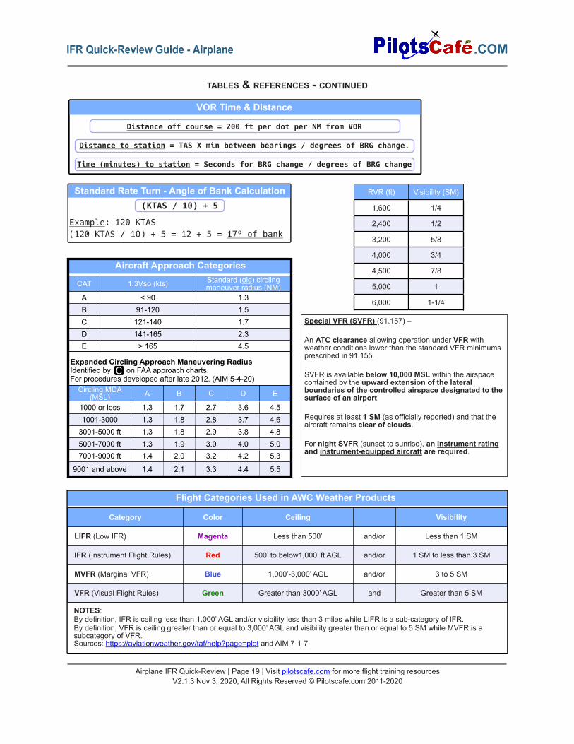
RVR (ft) Visibility (SM)
1,600 1/4
2,400 1/2
3,200 5/8
4,000 3/4
4,500 7/8
5,000 1
6,000 1-1/4
Standard Rate Turn - Angle of Bank Calculation(KTAS / 10) + 5
Example: 120 KTAS(120 KTAS / 10) + 5 = 12 + 5 = 17º of bank
VOR Time & Distance
Distance off course = 200 ft per dot per NM from VOR
Distance to station = TAS X min between bearings / degrees of BRG change.
Time (minutes) to station = Seconds for BRG change / degrees of BRG change
Aircraft Approach Categories
Expanded Circling Approach Maneuvering Radius
CAT 1.3Vso (kts) Standard (old) circlingmaneuver radius (NM)
A < 90 1.3B 91-120 1.5C 121-140 1.7D 141-165 2.3E > 165 4.5
Identified by on FAA approach charts.For procedures developed after late 2012. (AIM 5-4-20)Circling MDA
(MSL) A B C D E
1000 or less 1.3 1.7 2.7 3.6 4.51001-3000 1.3 1.8 2.8 3.7 4.63001-5000 ft 1.3 1.8 2.9 3.8 4.85001-7000 ft 1.3 1.9 3.0 4.0 5.07001-9000 ft 1.4 2.0 3.2 4.2 5.3
9001 and above 1.4 2.1 3.3 4.4 5.5
C
NOTES:By definition, IFR is ceiling less than 1,000’ AGL and/or visibility less than 3 miles while LIFR is a sub-category of IFR.By definition, VFR is ceiling greater than or equal to 3,000’ AGL and visibility greater than or equal to 5 SM while MVFR is asubcategory of VFR.Sources: https://aviationweather.gov/taf/help?page=plot and AIM 7-1-7
Flight Categories Used in AWC Weather Products
Category Color Ceiling Visibility
LIFR (Low IFR) Magenta Less than 500’ and/or Less than 1 SM
IFR (Instrument Flight Rules) Red 500’ to below1,000’ ft AGL and/or 1 SM to less than 3 SM
MVFR (Marginal VFR) Blue 1,000’-3,000’ AGL and/or 3 to 5 SM
VFR (Visual Flight Rules) Green Greater than 3000’ AGL and Greater than 5 SM
TABLES & REFERENCES - CONTINUED
Airplane IFR Quick-Review | Page 19 | Visit pilotscafe.com for more flight training resourcesV2.1.3 Nov 3, 2020, All Rights Reserved © Pilotscafe.com 2011-2020
.COMIFR Quick-Review Guide - Airplane
Special VFR (SVFR) (91.157) –
An ATC clearance allowing operation under VFR withweather conditions lower than the standard VFR minimumsprescribed in 91.155.
SVFR is available below 10,000 MSL within the airspacecontained by the upward extension of the lateralboundaries of the controlled airspace designated to thesurface of an airport.
Requires at least 1 SM (as officially reported) and that theaircraft remains clear of clouds.
For night SVFR (sunset to sunrise), an Instrument ratingand instrument-equipped aircraft are required.
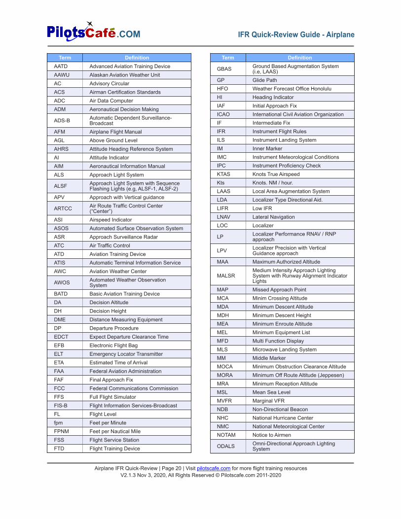
Term DefinitionAATD Advanced Aviation Training DeviceAAWU Alaskan Aviation Weather UnitAC Advisory CircularACS Airman Certification StandardsADC Air Data ComputerADM Aeronautical Decision Making
ADS-B Automatic Dependent Surveillance-Broadcast
AFM Airplane Flight ManualAGL Above Ground LevelAHRS Attitude Heading Reference SystemAI Attitude IndicatorAIM Aeronautical Information ManualALS Approach Light System
ALSF Approach Light System with SequenceFlashing Lights (e.g, ALSF-1, ALSF-2)
APV Approach with Vertical guidance
ARTCC Air Route Traffic Control Center(“Center”)
ASI Airspeed IndicatorASOS Automated Surface Observation SystemASR Approach Surveillance RadarATC Air Traffic ControlATD Aviation Training DeviceATIS Automatic Terminal Information ServiceAWC Aviation Weather Center
AWOS Automated Weather ObservationSystem
BATD Basic Aviation Training DeviceDA Decision AltitudeDH Decision HeightDME Distance Measuring EquipmentDP Departure ProcedureEDCT Expect Departure Clearance TimeEFB Electronic Flight BagELT Emergency Locator TransmitterETA Estimated Time of ArrivalFAA Federal Aviation AdministrationFAF Final Approach FixFCC Federal Communications CommissionFFS Full Flight SimulatorFIS-B Flight Information Services-BroadcastFL Flight Levelfpm Feet per MinuteFPNM Feet per Nautical MileFSS Flight Service StationFTD Flight Training Device
Term Definition
GBAS Ground Based Augmentation System(i.e, LAAS)
GP Glide PathHFO Weather Forecast Office HonoluluHI Heading IndicatorIAF Initial Approach FixICAO International Civil Aviation OrganizationIF Intermediate FixIFR Instrument Flight RulesILS Instrument Landing SystemIM Inner MarkerIMC Instrument Meteorological ConditionsIPC Instrument Proficiency CheckKTAS Knots True AirspeedKts Knots. NM / hour.LAAS Local Area Augmentation SystemLDA Localizer Type Directional Aid.LIFR Low IFRLNAV Lateral NavigationLOC Localizer
LP Localizer Performance RNAV / RNPapproach
LPV Localizer Precision with VerticalGuidance approach
MAA Maximum Authorized Altitude
MALSRMedium Intensity Approach LightingSystem with Runway Alignment IndicatorLights
MAP Missed Approach PointMCA Minim Crossing AltitudeMDA Minimum Descent AltitudeMDH Minimum Descent HeightMEA Minimum Enroute AltitudeMEL Minimum Equipment ListMFD Multi Function DisplayMLS Microwave Landing SystemMM Middle MarkerMOCA Minimum Obstruction Clearance AltitudeMORA Minimum Off Route Altitude (Jeppesen)MRA Minimum Reception AltitudeMSL Mean Sea LevelMVFR Marginal VFRNDB Non-Directional BeaconNHC National Hurricane CenterNMC National Meteorological CenterNOTAM Notice to Airmen
ODALS Omni-Directional Approach LightingSystem
Airplane IFR Quick-Review | Page 20 | Visit pilotscafe.com for more flight training resourcesV2.1.3 Nov 3, 2020, All Rights Reserved © Pilotscafe.com 2011-2020
.COM IFR Quick-Review Guide - Airplane
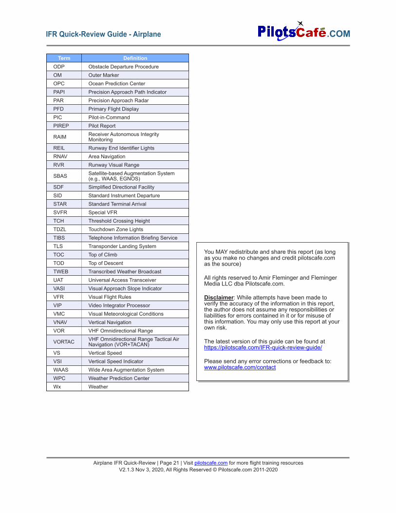
Term DefinitionODP Obstacle Departure ProcedureOM Outer MarkerOPC Ocean Prediction CenterPAPI Precision Approach Path IndicatorPAR Precision Approach RadarPFD Primary Flight DisplayPIC Pilot-in-CommandPIREP Pilot Report
RAIM Receiver Autonomous IntegrityMonitoring
REIL Runway End Identifier LightsRNAV Area NavigationRVR Runway Visual Range
SBAS Satellite-based Augmentation System(e.g., WAAS, EGNOS)
SDF Simplified Directional FacilitySID Standard Instrument DepartureSTAR Standard Terminal ArrivalSVFR Special VFRTCH Threshold Crossing HeightTDZL Touchdown Zone LightsTIBS Telephone Information Briefing ServiceTLS Transponder Landing SystemTOC Top of ClimbTOD Top of DescentTWEB Transcribed Weather BroadcastUAT Universal Access TransceiverVASI Visual Approach Slope IndicatorVFR Visual Flight RulesVIP Video Integrator ProcessorVMC Visual Meteorological ConditionsVNAV Vertical NavigationVOR VHF Omnidirectional Range
VORTAC VHF Omnidirectional Range Tactical AirNavigation (VOR+TACAN)
VS Vertical SpeedVSI Vertical Speed IndicatorWAAS Wide Area Augmentation SystemWPC Weather Prediction CenterWx Weather
Airplane IFR Quick-Review | Page 21 | Visit pilotscafe.com for more flight training resourcesV2.1.3 Nov 3, 2020, All Rights Reserved © Pilotscafe.com 2011-2020
.COMIFR Quick-Review Guide - Airplane
You MAY redistribute and share this report (as longas you make no changes and credit pilotscafe.comas the source)
All rights reserved to Amir Fleminger and FlemingerMedia LLC dba Pilotscafe.com.
Disclaimer: While attempts have been made toverify the accuracy of the information in this report,the author does not assume any responsibilities orliabilities for errors contained in it or for misuse ofthis information. You may only use this report at yourown risk.
The latest version of this guide can be found athttps://pilotscafe.com/IFR-quick-review-guide/
Please send any error corrections or feedback to:www.pilotscafe.com/contact
Related Documents