AFWAL-Th-8 1-3 153 0a AIRPLANE ACTUA 0!ON TRADE STUDY T. R BOLDT C. C. CyI 40WTH L S. MEL&JI *~ T. RAYMOND L WnITONSKY Rt. F. YURCZYKTI t- .b I tL MN BOEING MIUTARY AIRPLANE COMPANY JU 2 2 M9 SEA77ME WASHING1)ON 98124 F JANUARY 1982 FInJ 'lep fog' pmoud Juty 1979 - Aiaput 1981 7 Appeoved for pablc -alone, disotrldon nmrus -ed FLIGHT O)YNP 41C! LABORLATORY & PERO PROPULSKON LABORATOR! #JR FORCE W .1.G~iAER0NAUICA.L I"~ WRA¶Y ERSO iRRC FYSRCZ bOMFOf.A44D

Welcome message from author
This document is posted to help you gain knowledge. Please leave a comment to let me know what you think about it! Share it to your friends and learn new things together.
Transcript

AFWAL-Th-8 1-3 153
0a
AIRPLANE ACTUA 0!ON TRADE STUDY
T. R BOLDTC. C. CyI 40WTHL S. MEL&JI*~ T. RAYMONDL WnITONSKYRt. F. YURCZYKTI
t- .b I tL MN
BOEING MIUTARY AIRPLANE COMPANY JU 2 2 M9
SEA77ME WASHING1)ON 98124
FJANUARY 1982
FInJ 'lep fog' pmoud Juty 1979 - Aiaput 1981
7Appeoved for pablc -alone, disotrldon nmrus -ed
FLIGHT O)YNP 41C! LABORLATORY & PERO PROPULSKON LABORATOR!#JR FORCE W .1.G~iAER0NAUICA.L I"~ WRA¶Y
ERSO iRRC FYSRCZ bOMFOf.A44D

eI
NOT ITE
When Government drawings, specifications, or other data are used for any
purpose other then in connection witb a definitely related Govern,•ent procure-went opera ion, the United States Government thereb. curs no responsibý)ilitynor any obligation whatsoever; and the fact that the klovernMerlt may i'aveformula ed, furnished, or it. any way supplied the said drawings, specifications,or other data, is oot to be reg-irded by implication or otherwise as in anymarner licensing the holder or any other perso)n or corporation, or conveyingany rights or nermission to manufacture, use, or sr-l1 any patented inventionthat. may in any way be related thereto.
This r port has been reviewed by the Office of Public Affairs (ASD!PA)and is releaseu to the National Technical Information Service (NTIS). AtNTIS, it will be a.nilable to the general public, including foreign nations.
This technical report has been rev'ewed and is approved for publicatiG1.
PAUL D. IJ'D-QUTST 'Program Manager Program ManagerControl Techniques Groip Fluid Power Croup
AV'
H ,Chief RICHARD D. FRANKLIN, Maj, USAFControl Systems Development Branch Chief, Power Systems BranchFlight Control Dtvision Aerospace Power Division
FOR THE COMMANDER FOR THE COMMANDER
ERNEST Y. MOORE, Col, USAF S D. REAMSChief, Flight Control Division :hief. Aero' ace Power DivisionFlight Dynamics Laboratory Aeto Propulsion Liboratory
"If your address has 'iangtd, if you wish to be removed from our w linglist, or if tie addressee no longer employed by your organization plei .enuoti,, AF11AL/FIGI., W-PAFB, OH 45433 to nelp us maintain a current mnailingliet."
Cop s ot this report shculd not be returned unl! ip return ir reuouitedb' securlty consi.drratI.ona, ccntract,.tal obligation;s, or notice on P specificd~ :uftieyi

UINCLAS$ýTFJED$I: -CL.A WS-1,"!A-1b)I OF 1 i S P A Co
T &UE.ATION PAGERADSTU'1Nr`EPORT DOII"~ ~ ~ EEF-)RCOPIPLF:TING F-0V-po ;r 67F(' q? P EC: ý I I C A ýA Lý It
AFWAL-TR-S-31- 133__ - 'q~'1 Lj3 ____ ____
Final Ren'ort
AIRPLANE !VTLIAMi( TRADE STUDY K 5 dl 99 2 uis ~4. 4(F~jRtMiG 0-!r- RCP )WT NW-AR.EQ
L0180-25487-~3 __7 AU~'~. 8 8ZOH1TILCT '1I9 GRANTV NUMeERCýý
T R. Bcldt, C. G. Clienoweth, 1. S. Miehidi,T. Raymond, L. Witoflsky, R. F. Yurczyk F33615-79-C-3630
3 PeRDRiokNG, ORO. ~JZ ArI T7N 4 IkE k H A ~ i 'S ROGKAMILELIEMENT '4JFCT T'ASI'
Boeing Military Airplane CompnjAE O~4NTNME~
P. 0. Box 3707 Project 24030263Seattl e,-.Azh1i i~gq _JB.JJ{________
I C04 ROLN 0Fii`CE NAMF AND AODRESS 12 REP~ORT DAT
Flight Dynarni,.'s Laboratory (AFWA../FIGL)' Lianuary 1982Air Force Wright Aeronautical Laboratories 13 WILIMPEROF fAGES
Air Force S~stemsCon-nand WPAFB._Ohio 45433 ___________4 MOI ~tNG AGECS'-M .. 4j- -D-7ES,, fin ts0 SC=~I~s .,,';~~ UAI'Y :LASS 'If tl,~ rspos-'i
Unrclassified
'1 DITR1RTION ATE64ENIT 'ofh.IS I*O
Approved for public release; distribution un:'Imited
19 KE t woRD'S !COOitinue -t f~* - - *6 .d f Jn-.e. - Aid I*IqntfY Oy blacir -,,abr)
Actuacion. PoWer-bIy.-Wir-e, All Electric Airplaneý Elrct'-ic Actuation,Aircraft A,:tvarion, Hydraulic Actuation. Seccpd~ry Powie. Systems
A N T1 _T ._.,_ .1--.---* .4 .. . - - - - - d A - 5,W 1 -
~This report copt,)ins the .e ults of Thie Airplan6 Actuati' r, -Trade Study-PlYorarn.The study. cinduz;.ed Iii thre~e phases, included resta'blishi. ý91t oil ac'tuationrequiremritos- de-sigi of two) airpbidies a~ tiaelirioý airplane arl e~n a-ii-ele~tricairplan~e); and a trade studiy of tne two i`-planeýý In~udlrny quan;titative~C oMAIi -101 data of weqht, r el iabi i'ty Mir maintainebility, i~nd life~ cycle.
cost............................
UI~LAAf~i~ ~J)

.Jtiý_SSS I F E•D•UCuftiTv •.ASh|'+CA •ONI L}P Tflhl PA,(• D.;. Brn:..d)
20. (continuedi
'-'The st.jdy results Indicate that it is feasible to design a competitive power-bv-wire actuation t!rplane. However, specific areas in hardware developmentned to be Oemonstrated through Research and Development programs to make theall-electric-airplane conzept practical and low risk !oi the 1990+ time frame.
Cost savings were identified with tre all-electric airplane for the Al,mission. These came p.-imai-ily from reduced secondary power ybystem weight andcomplexity at some expense in ground checkout capability without running theengines This study selected engine-shaft-mounted electric qenerators asopposed to airframe mounttc' accessory drives for the basel ii _ airplane.
Different mission/air vehicles will have to be studied indi-idually to project(,st and other benefits available from an all-electric airplane concept. TheA(S study showed minor differences between hydraulic and all-electricapplications, with a slight advantage toward -in all-electric approach in termsof life cycle cost.
GP P
-- le T42~
.Avail mdjo..r
IMCLAS I •; Eý. 'S r,' al.J ý't' , h - ,t. -
'--a--A
1.. -

Th rerert describes the work I-r toi-rid loy *1hf Noei nq Il I i !ary Pirr p
ComV,3flý , lcvrcoo Pi -.-11 olv ! , -e Iatt.le , ýashirgttmr on in aIrv.ianc
actuation trat st Ldy. Th-.s work was sponsorpd by the Air Force k-riqht
AcronaLt tcdil Lahoratories, Fl iqht Dynamics Labcratcry and Pero Propul sicr
Lat'cralory, wkrighti-Patterson Air Forcc Ihse, Chic. ',.ork was autihorizcd under
contract F33615-7/9-C2ý6'30, Projr~ct No, 24C-3. work unit. 24030.
Crcgory j. Ceccre of t-he Flight Oyne~nics Li! oratory,, Flight Contro', Branch.
AFWAP/F IGLA and Paul Li ndoui st of the Acro-Propul- -)r Laboratory, A 1-.,L/P0OS-I)
were the Air 1rce Project ?Ianac~rs. (At thE' initiation of the Vrogram -FUL project eng.ineer was ?!'r. O~!e .Er tohssince retired.
Rcger- F. Yurczyk served as Program Mvanager and Ishaque E. Vehdi *~rvcd ,-s
Princiral Investigator.
IhC tICCh~iiCa CTfort was per-formned hy~~fltwn em~ o rcs
ictioni Pc.cpons-ibLýr Fnq''netrs
A~rýEr1,f Coflii'yur tion arid, Recruircmacnts C. C. Chcnoveth.
Flight Control Actuz't:on Sys'LcfS C, C. Chenovveti
J. S. Shen
Eyedraul 'c Polver z~ystcmf and .Radmcfld
No-Fl ighL Control Pcu ;cn H .Hlna
Fiicetrical Power Sys-em I. T. Reiquam
1. .Nhi
Vkhpcl PrdkE'S and Steering Systcm P. pf* o
1J.. '

Actuation Systems Structural E. 0. Painter
Integration
Reliability and r-aintainability C. L. Swindell
Life Cycle Cost L. Witonsky
In addition to this effort performed by the Boeing team, a study of
electromechanical actuation systems for the All-Electric Airplane was
conducted by the AiResearch Manufacturing Company of California under
subcontract No. G-A87756-9176. The technical effort was conducted by
Mr. Stephen Rout and is reported in Reference 1.
The following companies provided information for this study at no cost to the
program and their support is gratefully acknowledged.
Abex Aerospace Division, Oxnard, California
Aero Hydraulics, Inc., Fort Lauderdale, Florida
Arkwin Industries, Inc., Westbury, New York
Bendix Corporation, Aircraft Brýýe and Strut Division, South Pend, Indiana
Bendix Corporation, Electric and Fluid Power Division, Utica, New York
Bendix Corporation, Electrodynamics Division, North Hollywood, California
Bendix Corporation, Flight Systems Division, Teterboro, New Jersey
DeCoto Aircraft, Inc., Yakima, washington
nowty Rotol, Ltd., Gloucester, Enoilan(l
Garrett Turbine Engine Co., Phoenix, Arizona
Iv

ICeneral Electric Co., Armament Systems, Dept., Burlirngton, Vermont
General Electric Co., Aerospace Instruments and Electrical Systems Dept.,
Binghemton, New York
Goodyear Aerospace Corp., Akron, Ohio
Honeywell, Inc., Avionics Division, St. Petersburg, Florida
Hydraulic Research Div. of Textron Inc., Valcocia, California
Hydraulic Units, Inc. (formerly Ronson Fydraulics), Duarte, California
Inland Fotor Division, Kollmorgen Corp., Radford, Virginia
F'. C. Division, Kelsey-Payes Co., Lake Orion, Vichigan
Voona Inc.. Aerospace Division, San Jose, California
Parker-Pannifin Corp., Aerospace Hydraulics Div., Irvine, California
Plessey Dynamics Corp., Hillside, New Jersey
Rocketdyne Div. of Rockwell International, Canoga Park, California
South Dakota School of Mines and Technology, Rapid City, South Dakota
Sperry Vickers, Jacks'', n ississippi
Sundstrand Corporation, Rockford, Illinois
W'estinghouse Electric Corp., Aerospace Electric Divisior, Lima, Chio
XAR Industries, City of Industry, California

TAPLE CF CCNTE :TE
Paragraph Page
SUJPVlAR Y xiv
INTRODUCTION
,.I Packgro und 1
1.2 Objective
1.2 Approach 2
1 AIRPLANE PEQUIRP!ENTS 4
2.1 Airplane Configuratioo 4
2.2 Actuation Systcm ReQuirements 4
2.3 Gun and '-CS Poker Requircments 10
2.4 Other Airplne Power Pequircments le
2.5 Thermal Requiremcnts 18
2.6 Structural Arrangement 21
III BASELINE AIRPLANE CONFIGURATION 25
2.1 General 25
-. 2 Actuation Systcms for t'c Pase!inc Pirplane 25
2.3 Flight Control Actuation 33
3.3.1 Canard 33
3.3.2 Elevons 24
3.3.2 Rudder 36
3.3.4 Spoilers 37
3.3.5 Leading Edge Flaps 37
3.4 EngiAe Inlet Control Actuation .8
3.4.1 Engine Inlet Centerbody 2e
3.0.2 Engine Inlet Bypass Doors 39
3.5 Landing Gear and Brakes 39
?.5.1 Vain Cear Retraction 40
3.5.2 Nose Gear Retraction 40
3.5.3 Nose Gear Steering 41
3.5.4 Kain Cear Wheel Brakes 41
?.6 Aerial Refueling .ystcm 41
vi

TAPLE OF CCNTEIFTS (cont'd)
3.7 Canory actuatiOn 42
?.8 Gun Drive 42
3; Environmental Control System (ECS) 42
3.9.1 ECS Boost Compressor 43
3.9.2 ECS Pack Compressor 43
3.9.3 Electronic Cooling Fan 43
3.10 Secondary Power SyStem 4545
3.10.1 General Arrangementf46S~473.10.2 Elf'ctrical Pouer System 46
2.10.2.1 Load Analysis
3.10.2.2 Selected Systcm Arrangcmcnt 47
2.1e.2 Hydraulic Power System 59
3.1C.3.1 Load Analysis 50
3.10.2.2 Opcrating Pressure 60
- . 2 •-, Se1etrd •v~tem Arrangemcnt
IV ALL ELECTRIC AIRPLANE COWfIGURATION 75
4.1 General 75
4.2 Actuation SystEms for the All Electric Airplane
4.3 Flight Control Actuation 85
4.2.1 Canard 85
4.2.2 Elcvons E6
4.3.3 Rudder 86
S+ B7
4.3.4 Spoilers
4°?.5 Leadi ng Edge Flaps 87
4.4 Engine Inlct Control Actuation 88
4.4.1 Engine Inlet Centerbody 98
4.4.2 Engine Inlet Bypass Doers 88
4.5 Landing Gear and Brakes 89
4.5.1 Main Gear Pet; ction 89
4.5.2 Nose Ccar Retraction 89
4.5.2 Nose Gear Steering 9C
a.5.4 Main Gear Wkeel Brakes SC
vii

TABLF OF CCHVIENTS (ccnt d)
ParaqrapP
4.6 Aerial Refuelii1g System 90
4.7 Canopy Actuation 91
4.F Gun Drive 91
4.9 Environmental Control System (ECS) 92
4.9.1 ECS Boost Corrpressor 92
4.9.2 ECS Pack ConpreSsor 92
4.9.3 Electronic Cooling Fan q-
4.9.4 L.iquid Coeling System 92
4.10 Second.2ry Power System 93
4.10.1 Electrical Power Eystcw 93
4.10.1.1 Load Analysis 1ei
4.10.1.2 Selected System Arrangcment 101
V TRADE ST'O)Y 114
5.1 Trade Study Yethodvlky 114
5.1.1 Approach i.,4
5.1.2 Groune RulEs 15
5.2 Weight 116
5.3 Re" iability a.K. 1aintainab1,ity 116
5.4 Life Cycle Ccst 131
5.4.1 Cost ýIodeI 131
5.4.2 RUT f E Costs 133
5.4.3 Productioni Costs 1
5.4.4 Support Investnc,-t Costs 132
5.4.5 Operating and Support Cos~s 12-
5.4.6 Cost Estimating lechniques 134
5.4.7 LCC Data 124
5.4.8 LCC Sensitivity 142
5.S Performarce 13-
5.6 Growth 160,
5.7 Survivabil ity/Vul nerabil ity 161
5.7.1 Combat Survivnil ity 161
Iviii -

TABLF PF CeNTENTS (ccnt'(
E. .2 Non-Conibat Survivabil ity 163
5.8 EPC/Lightning 165
5.8.1 EVC 165
5.P.2 Lightning Protcction 166
5.3.2 Wire Pouting for Lightning Protection 163
5.8.4 Power Equipncnt Protection 169
5.2.5 Airplane Comparison i69
5.c Environmertal Constraints 17C
5.10 Technology Risks 172
VI TECINOLCCY NEEDS 175
6.1 P•seline Airplane Tec','oogy Necds 175
6.1.1 ,ictuation Systems 1 7r
6.1.2 Specia-, Hydraulic Cemronents 176
6.2 AII-Elcctric Airpleni Technology Mces 16
6.2.1 i otors 1.76
6.2.2 Electronics 177
6.2.2 Controller/Inverter Thenmal Fanagcment 178
6.2.4 Mechanical Components 179
6.2.5 Control 179
6.2.6 Secondary Power System IFO
VI1 RFSULTS 4NID CONCLUSICNS 182
7.1 Discussion of Results I12
7.2 Conclusions 186
VIII RE(U CTENDATIONS 1e8
REFERENCES i91
APFF-fNlIX . - Rcliability Data 192
APPENDIX B - RCA PRiCE-L Cost todcl Input Data 233
ix

LIST CF FIGURES
igurI Page
1 !VodMl 987-350 Airplane 5
"2 "odcl 987-350 Performance 6
3 Ivodcl 987-350 STOL Performence, 7
4 Nodel 987-250 Vission Profiles 2
5 M'odcl 987-350 Flight Envelope 9
6 Engine Exhaust Area Temreratures ii
7 GE 525 Gun Povvr and Speed vs Firing Rate 16
8 Hybrid Closed-Loop Air-Vapor Cycle ECS 17
9 Thermel IVap of the Airplane Skin During Supersonic Cruise 2C
10 Airplane Structural Arrargetnent 23
11 Actuation Systems Location - Basc-le Airplane 29
12 Actuation Fystems Installation - Baseline Airplane 31
13 Environmental Control System (ECS) - Baseline Airrlar~c 44
14 Secondary Power System Arrangement - Baseline Airilane 47
15 FlIertric.AI Load Profile - DaseC ir, Pirian" 5C
16 Electrical Power System Schematic - Beseline Airplane 57
17 The Comparison of Relative Transmission Line keight vs
Hydraulic System Cperating Pressure 67
18 Laminar-Flow-to-Turbulent-Flow Transition Temperatures
for Typical System Tube Sizes 6E
19 Comparative Pctuator Weight vs Hydraulic System
Operating Pressure 70
20 Comparative Actuator Voiumc vs Vydraulic System
Cperating Pressure 71
21 Vydraul ic Power System Arrangwmert 72
22 Hydraulic Power fystem Schematic 73
23 Actuation Systems Location - All-Electric Airplane el 1i
24 Actuation Systems Instellation - All-Electric Airplane F3
25 Liquid Coolirg System - All-Electric Airplane 94
26 Electrical Povcr System, Phase I1 96
27 Electrical Load Profile, Phase 11 97
28 Electrical Power System - Il-Electric Pirpl .nc 99
x

LIST OF FIGURES (continued)
FIgurc e
29 Electric Poker Distribution - Actuation Systems 10C
30 Electrical Lod Profile - All-Electric Airplane 102
31 Single-Spool Engine Spinner - !ounted Generator/Starter 112
32 Samrle Fault Trees 124
33 Life Cycle Cost (LCC) Plan 132
34 Life Cycle Ccst Computation 135
35 Sample RCA PRICE Podei Input Data Sheet 136
36 RCA PRICE-L Plodel Deployment File 137
37 Airplene kAcuation Trade Study LCC Summary 141
38 Actuation System LCC Summary 144
39 Secondary Power System LCC Summcry 14E
4C Sensitivity of Cverall RDT & E Costs to Engrineerino
Complex ity 151
41 Sensitivity of Overall t.CC to Engineering Complcxity 152
42 Sensitivity of LRU LCC to Weight 153
43 Sensitivity of LPU LCC to E. -r..,ering C,-,plexity 1
44 Effect of Material Change on LRU LCC 156
45 Effect of Electronics Circuit Desin on LRU LCC 157
46 Sensitivity of LRU PDT & E Costs to Net% Structure Ratio 158
47 Sen3itivity of LRU RDT & E Costs to New Electronics Ratio 159
xl

LIST CF TABLES
Table Past
1 Summnery of Actuation Requirements Control Eurfacc 12
2 Summary of Actuation Requireents - Landing Cear 13
3 Summary of Acutation Requirements - Aerial Refueling and
Canopy 14
4 Actuation Control Configuration and Redundancy Requirements 15
5 Air Vehicle and Avionics System Power Requirements 19
6 Baseline Airplane Actuation Summary - Flight Controls 26
7 Baseline Airplane Actuation Sumeary - Landing Cear 27
8 Bascline Airplane Actuation Summary - Visccllaneous Functions 28
9 Accessory Drive Systm Components 48
1W Baseline Airplane - Electrical Load Summary E1
11 Baseline .Pirplaie - Electrical Load Anal. s 52
i2 basei ne Airplene - Electrical Pover Eystem Components 58
13 Actuodion Loais and Hydraulic Flow Requmrments 61
14 Actuation Rate Pequiremcnts and Hydraul ic Flov Demands -
Total Aircraft Pequircm,.cnts 62
15 Actuation Rate Re -ements and :-vdraulic Flow Demnands
Subsystem 1 of 3 Subsystems
16 Actuation Rate Recuiremcnts and Py,'taul ic Flov, Demands-
Subsystem. 2 and 3 of 3 Subsýstems 64
17 Required Hydraulic Pump !izes 65
18 Bascline Airplane - Hycraulic Power System Components 74
10 All-Electric Pirplane .Lctuatirn .rummnry - Control Surface 7f
20 All-Electric Airplaoie Pctuation Sumimary - Landing Gear 78
21 All-Electric Air.iare AcuLation !uninery - Miscellenecus
Function5 79
22 All-Electric Airplane Electrical Load Analysis Summary 102
23 All-Ele tric Pirplane Electrical Lcad Analysis of
270V DC Loads 104
24 All-Electric Airplane Electrical Load Analysis of 115V PC
dnd 28V DC Loads 1N7
xii

LIST CF TABLES (continued)
STable Lu •S25 Eletrial ~T'r bic_
25 Electrical Power System Kajor Components-
All-Electric Airplane 113
26 Airplane V'eight Summary 117
27 Weight Summary - Actu, tion System 11i
28 Weight Comnrrison - Secondary Power System 119
29 Summary of Pinimun Equipment Levels (PEL) 12C
A30 tuation System t.TBF Summiary 128
31 Secondary Power System f1BF Summary '10
32 RCA PRICE-L Podel Calculated 0 & S Values 138
33 RCA PRICE LCC Summery - Typical LRU 139
34 Airplane Actuation Trade Study LCC Summary 140
35 Actuation System LCC Summary 143
36 Actuation SystEm LCC Not- (50C A/1-)1
37 Actuation Systcm LCC Data (1046 A/C) 146
38 Secondary Povvr System LCC Summary 147
39 Secondary Powr System LCC Date (500 A/C) 149
4C Secondary Power System LCC Date (10CC A/C) 150
41 Summary of Tradc Study Results 183
"42 Cemparison of Pelated Factors 185
II

SUP VAP Y
T.e objective of this program was to establish the advantages/disdavarteges
and life cycle cost impact for tio types of 1090+ time frame airclanc%, one
which has hydre l ically powered actuation systems (Baseline Airplane) nd the
other %kiich has electrically powered actuation systems (All-Electric cr Fower-
By-Wire Airplane). A secondary objective of this program was to identify the
1990-1 technology needs and development requirements of hydraulic, power-by-
wire actuation systems and secondary rower systems for future aircraft. The
comparison was made of both the actuation and the secondary power systems.
Parameters that were quantified for comparison were weight, reliability/
maintainability and life cycle costs. In addition, qualitative evzluations
were meue on the basis o' structural integration, growth potential,
survivability/vulnerabil sty, ElFC/lightning, environmental constraints andtechnology risks.
plZ C .... T . . . ...- , , • . r, . arr V, - jj~ Iji
Data Base, an air-tL-surface (ATS) airplane configuration was established, the
actuation functions were defined, and the requirements for these actuation
systems were established.
The study was ccnducted using the Boeing Fodcl 987-350 ATS as the point of
ref, rence airplane for which engineering development would begin in 1990,
production in 1095, and initial operational capability (ICC) in 1997. The
model 9P7-350 has zs ell-moving canard, an arrow wing, win rod-moul'tec
engines with variabi _ geometry inlets and two-dimensional vectoring and thrust
reversing noz; cs. a thrust-to-weight ratio of 0.87 and a maximLn gross weight
of 49,000 lbs. The airplane carries an internally mcunted 25 mm gun and 5000
lbs of air-to-ground weapons. The airplane is designed for a high level (IPech
22.2) and a low level (Vach 0.9 to 1.2) interdiction mission. The design life
is 10,000 flight hours and 6,000 landings.
The actti tion functions defined were flight controls (canard, elcvons, rudder,
spoilers and leading edge flaps), engine controls (inlet centerbody and bypass
doors), lending gear (retraction, steering and brakes), aerial rEfueling (door
X toIxf

and nozzle latch), and canopy. Thrust vectoring/reversing actuation vas
determined to be pneumatic in the high temperature environment of that
application, and therefore was not part of the hydraulic/electric actuation
trade study. In addition, drive power for the 25-rm gun ane environmental
control system (boost and pack compressors, and cooling fan) was inrluded.
The actuation requirements were defined in sufficient detail so tiat sysl imsn
for both the Baselire and All-Electric Airplanes could be designed.
An electrical load analysis was also prepared. The load analysis included the
normal housekeeping and avionics electrical loads along with power
requirements for actuation systems.
In Phase !1, Design of Two Airplanes, the actuatior and secondary power
systems were designed for the Baseline and All-Electric Airplanes. Several
configurations for each actuation function were devdloped and the optimutn
system was selected based on weight, envelope for structural intcgration,
efficiency, power demand, system comrplexity ano technology projections into
the 1990's. lhe dpeign And selection ef the actuation sst•.e for.. the Ml-
Electric Airplane were primarily conducted with d:.ta supplied by t.e
AiResearch fanufacturing Company of California under a subcontract. The power
demands were determined for the hydraulic and electrical systems for the
Baseline Airplane and for the electrical systsm for the All-Electric Airplane.
Several secondary power system configurations were developed for both
airplanes and an optimum system selected for each.
In Phase 1II, Trade Study, data for systems weights, reliability/
maintainability, and life cycle costs were developed.
The reliability was computed by defining the minimum equipment levels for less
of mission and loss of aircraft, developing the fault trees and computing theSpro)babilities.
The m•intainability and life cycle costs were determined using the RCA PRICE
and PRICE L computer programs. Each system (actuation and secondary power)
for both airplanes was broken down to the line replaceable unit (LRU) end
various input parameters were developeo describing the quantity, weight, ratio
xv
I--

of structure and electronics, complexities, and development ,nd prod'uctiondates. The output frc the PRICE program provided mean-time-cetweer.failure
(FIITF), development costs, and production costs. The PRICE L program also
provided the Operating and Support Costs.
Based on the above data, overall weights, reliability/maintainability and life
cycle costs were computed and compared. Along with this a qualitative
assessment of the structural integration, growth potential, survivability/
vulnerability, EVC/liohtning, environmental constraints, and technology risk
of the actuation and seconciary power systrms of both airplanes was conducted.
The results of this program indicate that the All.-Electric Airplane offers a
potential for reducing the life cycle costs of the actuation and secondary
power systems by approximately 12% compared to the Baseline Air-plane
configuration. On an airplene of this type and size the weight penalty
associated with EM' actuation w!th respect to hydraulic actuation is offset by
the weight savings in the secondary power system. The secondary power system
lor . the All ....... ...f r ~.tc ar A .i ..plafe u- fiL UUILtU "id tL %4LJ!t dLUI CZ
opposed to the A'AD concept for the Baseline Airplane. This results inreduced ground checkout capability for monitoring the main generator without
running the engines.
The probabilities of mission success and aýrpiane safety 4re comparable for
both airplanes. The MTBF of the E!Y actuation system was lower than thehydraulic actuation; the ?ýTF of All-Electr'c secondary pc.er system was
higher than the conventional mixed hydraulic/electric secondary power system,
but not enough Highcr to completely offset tie lov.er IvIBF of Er' actuation.
Assessment of the other factors indicated that EP' actuation and electrical
secondary power system could easc structural integration problems and provideadditional growth potential. From a survivability/vulnerability standpointthe hydraulic power system was more vulnerable then the elcctrical system from
weapons effects, vihereas the EF actuation system was more vulnerable to
jawming due to the necessity of gearboxes in every appiication. EN'C/iightning
effects could impact the fly-by-wirE (FBW) and electrical systems in eitherairplane, but the EY actuation would also be impacte. in the All-Electric
A xvi-i

Airplane. There were no high technology risks associated .ith the Baseline
Ai rpi ane.
The study also indicated that a hybrid system arrangement may hevc some
benefit. The results show that the primary payoff for the Al l-Electric
Airplane resulted from elimination of the engine driven hydr ulic systemI
i.e., adapting a single source p, er system. These benefits could also be
realized through the application of integrated actuator packages (IAP),
electr.c motor driven hydraulic actudtor systems. These shoued some potential
benefit for certain flight control functions. For example, the study results
indicated that use of an TAP for rudaer a:tuation offered no weight penalty
over the EM. actuator and has .. lover development risk.
SThe results and conclusions drawn from this study are based on an assumption
that certain technology advancements will be made by the 1590+ time frame.
Technology developments that are required to meet these needs or that offer
alternatives in the design of the actuation and secondary power systems were
identified. For the Baseline Airplane these include:
o High pressure hydraulic system
o Bi-directional power transfer units
o Hydraulic fuses and circuit breakers
o Load adaptive/stored energy actuators
0 Advanced fly-by-wire actuators
* o Staged sequential servo ram actuation
For the All-Eectric Airplane the technology needs include the devclopmcnt e":
o Lightweight, high efficiency gearboxes
o Speed optimized electric motors
o Load-adaptive/stored energy actuation techniques
u Variable authority EM actuators
o Controller/inverters
o High voltage DC electric systems
o Integrated actuator packAges
Several of these developments idLntified for both the Baseline and the
All..Electric Airplanes are applicable to a hybrid system.
xvii
me.- -

1 INTRODUCTION
1.1 Backgroond
Current aircraft are characterized by having tw main forms of on-board
secondary power generation, distribution, and utilizationr i.e., electrical
power and hydraulic power. In guceral , hydraulic pover is generated,
distributed, and utili7ed for the majority of the actuation jobs including
flight control surfaces, landing gear extension and retraction, brakes, and
nose wheel steering. Electrical power is used for functions like stability
augmtntation, fuel and engine control, heating and cooling, lighting,
avionics, weapons control, instrumentation, and utility air vehicle functions.
Powered actuation is essential in today's high-performance aircraft. Landing
gear, gun drive, and canopy operation also require high power. Superior
airplane controllability and handling qualities characteristics recuire not
only high pow'r, but also dcCurate and responsive controls. Hydraulic
actuation has become the mainstay for most of these control tasks because of
high torque-to-invrtliaz acability, high power and v;eight etticienry, and
tremendous develol:Ynt and experience. Technology advancements in the
electromechanical field are showing promise for alternative means ef
actuation. Consideration needs to be given and evaluations made with these
new technology trends in mind.
Major factors stimulating the application of power-by-wire actuation are in
the advanccmer.ts in high-voltage power suppl es, rare earth perm.anent magnet
motors, elcctronic conmmutation, and improvcd sol id-state power switching
devices. These factors lead to the objectives of this study v,hich are:
(1) Est3bl ish advantages/diseavantagEs and life cycle ccst impact of
hydraulically powered actuation and electrically powered actuation for
aircraft in thE 1990+ time frame.
(2) Identify technology needs, risks, and development requirements for future
aircraft actuati n systems.
1.2 Objrctive
S The objective of this study was to conduct a trade-off comparison between a
I 1

"Baseline Airplane" (one that contains an .ngine-driven hydraulic system for
actuation) and an "ill-Electric Airplane" (one that contbins only an
engine-driven electrical system for rower-by-wire actuation). The study was
conducted on an ATS airplane. The airplane is designed for a hig,'
survivability interdiction mission. For the trc"., each "airplane" is
designed to utilize every beneficial technology advancement considered
available in the 1990+ time frame. Six areas of actuation were considered in
the study. These were the flight controls, engine in',et controls, thrust
reverser/vector controls, lar'ing gear, aerial refueling, and canopy
actuation. In addition the gun controls and ECS were considered as users of
secondary power.
1.3 Approach
The program was divided into three phases as follows:
Phase I Devclopncnt of ATS Design Data base
Phase II Design of Two Airplanes
Phase III - Airplane Actuation Trade Study
Basel ine Airplane
The hyaraulic/clectric powered airplane was tcrmed the Baseline Airplane. The
hydraulic dctuation systems considered various types of pover drive units,
output mechanisms, and control valving. Secondary power extraction is
accomplished by power take-off shafts from each engine which drive airframe
mounted accessory drives (AVAD). The tio APADs are connected togcthcr and to
a LOX/JP-4 Integrated Power Unit (IPU) through an angle gearbox. Duringnormal flight, the F'AUs are driven by their respective engines and the angle
gearbox is declutched. During an Er.ergency, shaft power can be extracted frcinthe opposite engine or the IPU through the angle gearbox. Each APAD drives
two hydraulic pumps and an electrical generator. The right-hand AMAD also
drives the ECS boost compressor. This AFAD configuration provides the
capability to operate the engine driven secondary power system without
orerating the engines, for ground checkout.
2

All-Electric Airplane
Two types of actuation systems were considered for the All-Electric Airplane
actuation functions: electromer.hanical actuation (ErVA) systems and integrated
acLuator package (IAP) systems. EMA's were selected for all functions since
they Proved lighter and less complex in all cases when compared with the
equivelent IAP. Secondary power extraction is accomplished by a 150-kw
starter-generator mounted on the spinner at the front of each engirie. A third
150-kw generator is mounted on the LOX/JP-4 lntegrazed Power U.oit (IPU). The
three generators produce wild frequency power which is converted to 270V dc by
phase delay rectifier (PDR) bridge converters. Secondary convertcrs provide
power at other voltages required. Interconnection provisions are included in
the three generation systems for engine starting and transfer of loads in case
of failure of the main generation systems. This systoi provides for ground
checkout of all electrical functions, except the engine-driven generators/
regulators themselves, without operating the engines.
Trade study
Ten parameters were considered in the trade study of the two airFlanes:
Weight
ReliabilityM'ai ntai nab il ity
Life Cycle Costs
Ztructural Integratier.
Grokth
Survivabil ity
EVC/Lightning Protection
Environmental Constraints
Technology Risk
Quantitative comparison data were developed for the first four parameters.
Qualitative comparisons were made in the six other areas.
3

- - _ _ ~ - -. ,-_-•--
II AIRPLANVE REQUIREMENTS
The tasic airplane configuration and requirements which forrcd the dcsigr dcta
base for the trade study airplane were developed during Phase 1. Design
criteria and requirements for the actuation functions and othcr functions
requiring on-board generatcd secondary power were defined.
2.1 Airplane Corfiguration
The AIS missicn concept was specified as týe point-of-reference airplane. The-
Boeing teodel 987-350 ATS (Air-to-Surface) Airplane (Figure 1) was chosen for
this purpose. It is a vectored-thrust, canard/arrow, wing with a
thrust-to-weight ratio of 0.87 and a gross %eight of 49,000 lbs. The airplane
configuration includes thin pod-mounted engines, wing-shieldcd half-round
variable-geometry inlets, 2-D vectoring and thrust reversing nozzles, ard an
all-moving canard. Armament consists of an internally-mounted 215-n gun, two
advanced short-range missiles, and 5000 lbs of air-to-ground weapons mounted
semisubmerged in two fuseiagr cutouts. Airplane performance is shown in
Figure 2. STOL take-off and landing performa:ica is shown in Figure 3. The
airplane is designed for a high-survivability interdiction mission (Figure 4).
The flight envelope is shown in Figure 5. Design life of the airplane is
i0,000 flight hours and 6,000 landings.
2.2 Actuation System Pcquirements
The PTS Model 987-350 act',ation system rccuircmcnts were divided into fivc
areas as follows:
o Fl ight Controls
o Engine Inlet
o Landing Gear
o Aerial Refueling
o Canopy Actuation
o Thrust Reverser/Vector Controls
It was determined that the thermal cr;vironm.nt for the thrust reverser and
4

uJicl:
CDL
.'. 0 "
L.Jn
I -- 00
WO.. LaJO
L..
b-AtJ 0'- Lo- )C 4icc
WA.
C)3
LaJW. Laf-) CA 2-~~ocod'
0D el. 0j ý
&AL -j LL

i..6
I
1?
10 .6WRE TRANSONICSPOWERED .5 FIGHTER
8 LIFT +4-•8 /DCANARD
6 LND 6 L POWERED LIFT' + CANARD
SFC .4
-- TR~ANSONIC .2 A.M- 0.9
2 FIGHTER h 30,000 FT
01.0 2.0
MACH NUMBER O0 .02 .04 C 06 .08 1.0
SUPERSONIC RANGE FACTOR TRANSONIC MANEUVER POLAR
70, ' - -0
1.400 0 1.2/3
120 MAXIMUM POWER 1.02
1,000 5 10
PS FPS) M/ALT Wf 40.0/50(,00L/R
3
400 20.9S) /307 30/0 93
200 1
2 3 1 0 3 4 5
LOAD FACTOR LOAD FACTOR
PS VS LOAD FACTOR COMBAT FUEL FLOW
Figure 2 Model 987-3O Derformance
6
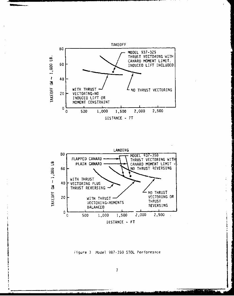
TAKEOFF80 MODEL 937-325
THRUST VECTORING WITHCANARD MOMENT LIMIT.
o 60 INDUCED LIFT INCLUDED
40 /3SWITH THRUST N0 THRUST VECTORING
20 VECTORING-NO[ INDUCED LIFT OR
MOMENT CONSTRAINT
0 [ a I 1
0 500 1,000 1,500 2,000 2,500
DISTANCE - FT
LANDING
FAPPED CANARD VECTORING WITH0 PLAIN CANARD CANARD MOMENT LIMIT -
0o 60 NOHUST REVERSING
WITH THRUST
40 -VECTORING PLUS0 -THRUST REVERSING
_U
R
WI HNO
THRUST
No THRUS~ 20 WITH HRS T VETOINGO
SVECTORING-MOMENTSBALANCED
REVERSING
Sa I I I _
C 500 1,000 1,500 2,000 2,500
UDISTANCE
- FT
SBig u r e 3 A 0 N eC 9 8 7 - 3 5 0 S T O L P e r f o rU Tnc e
a
0
EESN
So 50 200 2 0
DITNE F
1iue3Mdl9730SO efric

HIGH LEVEL MISSION
ALTITUDELOW LEVEL MISSION
DISTANCE
HIGH LEVEL MISSION-
ALT DIS MFT NMI
n 0 0-.9
CLIMB & ACCEL 0-63.700 33 0.9-2.2
CRUISE 63.700 394 2.2
1800 TURN 63.700 - 2.2
RETURN 69000-0 100% 2.2-0
LOW LEVEL MISSION
TAKEOFF, CLIMB 0 0 0-.9
C.IMB 0-35000 11 0.9
CRUISE 35000-37000 140 .9
SUPERSONIC DASH IN 0 61 1.2
1800 TURN 0 - 1.2
RETURN 0-43000-0 50% 1.2- 0.9-0
* PERCENT OF SHORT RANGE COMBAT RADIUS
Figure 4 Model 987-3S0 Mission Profiles
8I

H 2 a 7.33, MN < 1.0MAX80X-
.6 , M.N > 1.080
70 r
60
50ALTITUDE
xlO00 FT
40 A# I.
30
zO
10 'J
00 5 1,0 1o5 2.0 2.5
MACH NUMBER
Figure 5 ModQ1 987-350 Flignt ý.velope
9

vectoring actuation systems would be too harsh (Figure 6) for use of
electromechanical or hydraulic actuators without auxiliary cooling provisions.
Thus it was concluded that neither the electromechanical nor the hydraulic
actuators could Effectively compete with pneumatic actuators, traditionally
used in these applications. These high temperatures can damage insulation on
electric motor windings, would be close to the Curie temperature of the
permanent magenets causing demagnetization, and cause motor bearing lubricant
problems. In the case of hydraulic actuators, conventional hydraulic fluids
could not be used and seal problems would also be encountered. To utilize
electromechanical or hydraulic actuators would require Eithcr one or both of
cooling provisions and remote location of actuators with complex mechanical
linkages to transmit the actuation fc-ces. This would add to the system
complexity and impact the reliability and cost of the system. Therefore,
pneumatic actuation systems for the thrust rev:rsing and vectoring functions
were selected. This allowed the deletion of these actuation functions from
further consideration in this study.
In each of the other area, the rum-ber of actuators rcu-icdi for ezich function.
and the configuration and redundancy of the actuation systems were defined.
The requirements are summarized in Tables I to 4.
2.3 Gun and ECS Power Requirements
Two additional areas where shaft power is utilized are the 2ý:-mmn gun system
and the environmental control system.
The gun system recuires 14 hp for the gun drive and 11 hp for the aer..unition
feed system. This power can be delivered by an electrical motor or hydraulic
riotor. The motors require start-up and reversing capability for shell
c'earing purposes. Figure 7 shows the power and speed vs firing rate.
The ECS, shown schematically in Figure 8, requires three motors; one each for
tre boost compressor, the ECS compressor and the ECS fan. The boost
compressor motor has to provide 50.b hp at speeds varying from 15,000 to
4C,000 rpm to be compatible Aith the following boost compressor requircments:
10I

INTEGRATEDNOZZLE/AIRFPAMESTRUCTURE
DIE GEOMETRYLOW BOATTAIL COWL.
HIGH SPEED /
CONFIGURATION 300 OF - SO0"F40 * O F
LOW SPEED
CONFIGURATION
SFigure 6 Engine Exhaust Area Temperatures
' 11

4; �1�] I - I-,{2� t --
C ____L�
�eg ��X ____ ____ ____ ____ ____
____ � �j ; iIi�i tŽ�t ____ ____
o� � ___
� 22 �. Ii I',
� IT 13*___ ____ ____ I- *�'�
I-.Ld� -__ __ ______ ____ :j j-: -� 0
� ___ ___ ___ ___ -� I�.
- J +I- � U S IU I ___ ___ ___ I __.�
- .-II-
- -�- � ___ ___ ___ ___
-. I2 1 I
2 2 2 212 12- -- Y--�-� I1
r - --� '-. I'a * -'
�
- ____ � �i &Z -a �2 ____ ____
2� � -- � -� =
0 .1 § -1__ I - __ U __ __
S I S
**, � � I �- - I,
-1'-I �
a i - I
' II ___ I I�iiLA Jii
12

wh ILJ4 LAJui -J tAJ .- JQ L&j CD -jO 0 W
(A co.co
W -l U-C 16L1L
C2; 0
Scr.) CDL
-Jj
LaiQ. -CL0 C) . .
I L 0- 0 LLn~qo L) W.. -i-I ý
or a- I~ (d 4)
tAJ V)~ ~
Uo 4= 0.La <
I II I- I--
0O LC w -0 C
-i cc cc -Q cc cc -
V) ' CD) 0 )
- - 4-~ a- -cc
13

Ib Lin 0 O
CJ J a-j -ju -(N n-
(.j ik- C- - U- Ik L. La-
C) c CDi or-j W ~ 0i .>, I--) §a
uU L U -u
U- -
V) am.
;s w . I--a.. 0. 0C.
LW
06I-en
cc. LJC.
W. --cc_ _ _ _ _
Ci
Ln I.- I ý
1 ac -)U O-
C5Ci C
LU IS- ~. x
-C0uC-D.s -c
if I __ _ _ _ _ _ _ _ _ _ _ _ _

II
Lai
caa
cc 8 8
t-J I.-
L .
CIL
I,- I " Lh O,
=C,.,,.-,4 I--
. ci0
I- -~L a
V2 ý -jw 6nt~.A wo so a.
WJ
- U-=~0 Li L" jH~a H 0J
!5~ 8a.-L .m a-
a.-5

20
is 3000o .
lHP
Ca.- 04 Li
CLi* a.
Li0 2000
La LA-
4 -
5 •1000
0 1000 200L 3000 4000 5000FIRING RATE - SHOTS/MIN
Figure 7 GE 525 Gun Power and Speed vs Firing Rate
16

BOOS TMOTO COMPRES-
ONDENSOPRIMARY
ATOR AIR CYCLE
OTOR' MACHI NE
TIIGH, PRES'TA 1RE.ENER- 1
OVERWOTER
SPARESUIATION AIHUPL
(AVIONIC COOL UN LIARYl
OVERBýýOARDSER FLGTCE TIAIOS
""Zir 11 Hyri Cl71ITv irVao Cce _
porDECKPRESURIZTIONAIR UPP7
p
Altitudc Airplane Compressor Corrected Compressor
ft Speed Pressure Ratio Air Flow SreedPR 'bs/min rpm-
0 Takeoff 1.09 40 15,000
50,COO 0. 7P 4.27 237 40,000
where corrected flow is defined as
k-fl lb/min'-FRzI
p lb/in2
The ECS Compressor motor has to provide 10.7 hp at a fixcd speed betv.een 5000
and 22,000 rpm. The ECS fan motor has to provide 42.9 hp at two specds, 6001Ci
and 12,000 rpmi .
2.4 Other Airplane Power Rcouirements
Power requirxme:its for other air vehicle and avionics sLbsystems are listed inTable 5. All these recuirements are met by electrical power. The kk
requirements for these items are the same for the Baseline and for the All-
Electric Airplanes, except where noted. The difference is that in the
Baseline Airplane these loads are supplied from 400-r:z power whereas in theAll-Electric Airplane they are supplied from 270-vdc poker. It is assumeC
that in the 1990 time frame, all these loads w:ill be compatible w'ith either
400-Hz or 270-vdc power.
Loads not listed ir, Table 5 are the same for either airplene and do not
directly impact the trade study. These loads ar- listea, however, in the
detail Baseline Airplane and All-Electric Airplane elrctrical load analyses.
(Sections III and IV)
2.5 lhermel ReevirEments
A the rmel map cf the airplane was developed based on aerodynamic heating at
Iach 2.2. The skin temperatures are shown in Figure 9. These temperatures
18

i TABLE 5
AIR VEHICLE AND AVIONICS SYSTEM POWER REQUIREMENTS
ITEM PAX kW LOAD (Total)
Electronics Liquid Cooling PUMp* 2.40
Primary Fuel Boost Pump 7.30
Backup Fuel Poost PUMp 7.30
Fuel Transfer Pump 7.30
Battery Heater 0.30
Windshield Heater 2.50
Radar (Target Acquisition) 1.50
We ppons Heaters 1.00
Air Data Computer 0.07
Air Data System Heaters 1.50
Integrated Information 5.40
!anagement System
Gun Contr, 2. ,,
Total Temperature probe Heaters 0.27
JTIDS/TACAN/IFF 0.70
Global Positioning System 0.20
Inertial Reference (k'ultl-Function) 0.20
Radar (Pulti-Functior) 5.00
IRCM 2.00
ECM Transmitter 6.00
* All-Electric Airplane only
19
19!

0 0
Inc
q I*L. C
HL 4no'I
dlC~ 'AI 'woA~2~l iil e.~ F-
:Z CI
Ir ,i 11 1 Ez*'
:n I' I cm ~ 0- ILI,=) %0', I=. C)
1- Ii CM
liv cr- PTi1
LI.JI C/II ll-~~~Lo M- ~ c' I1
20I

are calculated for a U.S. stardard day at ýach 2.2, altltUdC Of 40,COO to
7C,000 ft above sea level, include solar heating, and do not include the
engine effects.
Engine exhaust area temperatures are shown in Figure 6.
2.6 Structural Arranoement
A structural arrangemrnt v.as also dcvclcped for t1his aircraft and is !;hov.n in
Figure 10. This was required to determine the exact amount of srace available
to install the vericus actuation systcmi This d1so facilitated the
structural integratior of the various actuation system alternatives and
selection of the system 0'ich would meet this rcouirement with little or no
impact on the aerodynamics of the aircraft.
21

CA N
£IQPL AlANS
-&D 1A7IS SAM1
*A I B 7u
I-.0
Iss

9786VTIVAL to0L
Ar~sss Don't ---JOOI4T 0~a.9 t sMtu uWpT
%ILL W*EA#4'I
:)ETAIL iC108 ,
I BG
LA'TC9 ~~NI ft'VISI a wNEy(Q1s cowc
LAOIOIWG rlf~ .sjp9pt (!-AST. WWW4t"I
-SLL %S.AM __,Pd4AI .l~JY
DETAIL ICIO.*WUS Lb&CUlf
UPws -e"OY hh
A uc1
-T I)- I _ _ _

Imel vi I'.-
B O T T O M V I E W , " 'lN * SA O
. - -
two& LINUMONIONTJA
"GI -4.
-
A
,as$6~ 0006
/-.C'-..l DO
Pt.AM VIEWW_~ti Ing
C-CWIJ
iS
%c & $ r L l U o e- -- --- -S . - - - ' -
794A10 -. 4 - - - F
SIDE V!EW 74

04 IIi
10.

94T[MICA€L STASA•.t•tG
w-o
Figure 10 Ai.rplane 5tructuial Arrangement
23/24 t
3i ,

SIlI BASELINE AIRPLANE CONFIGURATION
3.1 General
The objective of the design phase was to select the most competitive
combination of hydraulic actuation systems, hyoraulic power systems for
transiiittinq power to those actuation systems, and electrical power systems
for providing fly-by-wire control to those actuation systems that could be
considered available in the 1S9C-plus time framc. In keeping with the overall
objectives and requircments, it was required that the selected hydraulic rower
system derive its power primarily from the engine through engine-driven pumps
and transmit that power through a distributed system of hydraulic transmission
line tubing to the actuation systems. The total secondary power system and
the ectLation systems are defined so that a direct comparison can be made with
the Ail-Electric Pirplane design described in Section IV.
3.2 Actuation Systems for the Baseline Airplane
Consideration was given to various types of poer drivc units, output
mechenisms and control valving arranged in a variety of combinations to suit
the particular requirements for the various contrnl functions. The types of
power drive units evaluated included piston actuators, vane actuators and
multipiston motors. The typss of output mcchenismrs evaluated included bell
cranks, rack-and-pinion gearing, helical or ball splines, spur gearing, tent-
beam Eccentuators, threaded Fov.er screws or ball screws, and planetary or
skip-tooth gearing for hinge-line units. The control valve concepts
considered were single-stage direct-drivE and tvo-stage clEctrohydraulic servo
valves, staged sequentially-controllcd valves, stepper-motor-driven rotary
valves, and solenoid vaivcs.
After evaluation of the various actuation systems aveilable, a final
configuration was selected for each application. Table 6 summarizes thE
selected systems for the airplane flight controls and Tables 7 and 8 for the
non-flight control functions. Figure 11 shows the location of the actuatorsin the aircraft and Figure 12 shows how these actuators are intcgrated intothe aircraft structure. Each of the -,ndividu3l dpplications is covered in the
following -aragraphs.
SZ~5
II :'Sii /-

C-)
o~c a) u
4-L
41 L
La-
F3 00C
V) .
4-3 euI
4x
6IJ Q)
L M
-4 -4 -. -4L
CQC
.U.
C 116
ea L. J 0
4-W CC Gaj
26r

Lnn
4J.C
cao
CU
L=
*.. 0) w
44-Qa CA
27-

.1A(D L. L
0l C\
o r-
00
LL.1
ýA CL
LE O
t14 0
"00.9o w- >I -
00.
Le
00
Ch 4A
4004.1~L .
NU 09 >. 0 00i
dcV
28 a

LIONG EDG~E FLAP ACfJ
INLET CENTERBOV ACru,4rjpS
> A.

• ---- -__.
-1 .1
H f I
.,.CT,% AC TUAT ORS -- \ P'" - . -
I / I
. - . .
Figure 11 Actuation Systems Location
-IfplC Baseline Airplane--_ •___- .... .--30
__ / _
I ELEVONACTUATOR

LINEARRETRACTION GLAR
ACTUATOR
TRUINNION i "'
- LINEAR CAN30'Y
- -• . " - -ACTUATOR
AFT CAB PRESSURE BULKHEAD-•,
TOP OF WHEEL WELL LINEAR ACI
"LINEAR PET nACTItX
----L
ACIUATOR
STEERING ACTUATOR- i BODY LOWER SURFACE
110 SIZ'E
1/iO SIZE
/
I

or TRU1NNION fRU. OOGERBO.N BRA.'.ES
E D ~ / ( 7B U T T E R F L Y
. .... BYPASS DOOR~S
RETRACTED
ExTENDED I
siZE
-DuAL,'PARA-LEL
LINEAR LI%'AR ILE\ION
ACTUATORS
7/ MAX\ aK
1//I SIZE V QV~: F
10 siz

L!NEAR ACTUATOR EONE PER INLET ENGINE\ rAE
--F --- ,--. '':-• . . . __
|) . i)\ .x ... " _......./ o s.z
T7.T-/o/Z 1 SILE
11 SIZEIO I/S IZ
_ _ _ .. o. :
1/10 S!ZE
/ FIN ATTACHMENT
•---rUDE LOWE SUFAHM "
HINGE LINE1/10 SIZE ROTARY/ GEARBOX
TORQUI -SUMVE D 1/10 SIZE
DUAL HYDRAULIC
MOTORS ANDGEAR x- 2
\~~600 MAX
1/10 SIZE
LOWER SURFACE
1/10 SIZE

30* MAX•• •"' • "
.\\,--DUAL/TANDEM LINEAR
HYDRAULIC ACTUATOPS
3 - 13TWO PER SIDE
-ENT Lw r~ I/ io SIZE CONTROL. VALVE MODULE
:(ACHMENT
CANARD SUPPORT -BEARINGS
//,
A-A1/10 SiZE
Figure 12 Actuation Systems Installation -
Baseline Airplane
31/3?

3.3 Flight Control Actuation
3.3.1 Canard
The canard is a critical flight control surface whose continued control is
essential for mission completion and safety of flight. Actuation tradesconsidered the two canard surfaces interconnected as well as separated, eventhough so diftcrential surface control is required since the canard is used
only for pitch control. In addition, both linear and rotary actuator designs
were evaluated. The selected configuration uses linear actuators
independently controlling each canard surface as showv in Figure 12. Thefollowing reasons are the basis for this selection:
1. The linear actuator system is lighter. This is because the length ofthe linear actuator is propertionai to the total cortrol surface
dcflections and the rotary actuator is independcnt of the ccntrol
surface deflection. With only 30 dcqree total surface deflection,linear actuator stroke is only 4.2 inches.
2. Due to the inefficiency of a hydraulic motor and gearbox, the totalpower consumption of the rotary actuation system wvuld bc higher. In
audition, a hydraulic motor has a higher internOl leakzge than thelinear actuator. Canards are used for longitudinal trim; and, the
steady state aerodynamic load causes more fluid leakage across thehydraulic motors than the linear actuators. This, together with thehigh duty cyclc of the canard surfaces, results in a higher total
power consumption.
3. The configuration with no interconnection betv.een the tv.o canard
surfaces results in less weight and reduces complcxity. The aoded
act.uation weight for separate surface control is more than offset bydeletion of the interconnecting mechanism and since no additional
control capability is needed in terms of increased power, there is no
impact on secondary power requircments.
The canard actuation system utilizes four dual-tandem actuators arranged dnd
powered from the three hydraulic systems to meet the redundancy requirement asspecified in Table 4. Tandem actuators are used because they can be plece€
33

close to the surface to maintain adequate stiffness between the actuator rod
and the canard surface.
Each dual-tandem actuator cunsists of a ful1-area piston and a half-area
piston. Any two of the three hydraulic systems can drive both canard surfaces
at 100% of the design hinge moment:; 50% from system #1 through the two forward
actuator full-area pistons, 50% from system #2 through the two aft actuator
full-area pistons, and 5"% from system #3 throuOh all four actuator half-area
pistons. Under normal conditions, (all 3 hydraulic systems operating) each
tandem actuator is capable of providing 75% of the surface design hinge moment.
Valves are sized to meet the rate requirement at maximum load. A flow
limiter, limiting the maximum rate to 70 degrees per second, avoids excessive
flow at the no-load condition.
Actuation system components for eacý of the two canard surfaces consists of
the following:
Dual-tandem linear actuatcr
(2 required P 39 pounds each) 78.0 pounds
Control Valve Podule 7.0 pounds
Total Veight, per surface 85.0 pounds
3.3.2 Elevons
Th2 elevon control surfaces have a duai role to provide both longitudinal and
lateral control of the airplane. Pctuation trades considered both linear anarotary actuator dcsigns as well as installation of part of the s)stem in the
body. The hinge moment requirements for the elevons are large and the
available space for equipment installation is small dLe to the thin wing
geometry. Configuration studies indicited that both linear and rotary
actuation equipment exceeded the designated envelore.
Since the maximun hinge moment when moving the trailing edge down is roughly
twice as large as the maximum hInge moment when moving it up, an unequal-erea
linear actuator can be used with the piston head-end area sized to meet the
34

larger load and the rod-end area sized to meet the smaller load, .bereas the
rotary actuator has tc be sized to meet the larger load. The linear actuator
is the more efficient approach due to the inefficiency of a hydraulic
t motor/gearbox arrangement. Also, since the elcvon surfaces are used for
longitudinal trim, the steady-state aerodynamic loads would cause more fluid
leakage across the hydraulic motors than the linear actuators.
Therefore, the choice uf the linear actuator for the elevon function results
"in a lighter system with less power consumption. Consideration was given to
installing the actuators in the body to avcid exceeding the envelope
requirement. However, the torque tubes required to carry the load to the
eleven became unreasonably large and heavy. A detailed study of the airrlanc
structure and geometry determined that an increased number of smaller diameter
linear actuators with shorter moment arms could be used to better fit the
envellop with less fairing.
The selected configuration (Figure 12, Vie' F) uses four actuators (tvo
dual!rar.llpl I inpar actuators) per surface to meet the hinge mrýent
requirements with minimum actuator dimensions and fairing. Each of the four
actuators weighs 75 pounds.
The increase in drag due to the elevon actuator fairing on the baseline
airplane is two-tenths of one percent of the t(tal airplane cruise drag. The
resulting impact on specific fuel consumption v.ill be negligibl and no
furtter consideration %ill be given to this subject in the trade study.
The actuator and valve are sized to meet the rate requiremncnt at maximum load
and also meet the maximum rate of 70 degrces/sec at no load. No flow limiters
are used. The major actuation characteristics are:
Actuator piston area 6.8 in 2 head end, 2.2 in 2 rod endMouent Arm 10 inches
Stroke (Total) 6.7 inches
35
-I

3.3.3 Rudder
The rudder control surface provides directional control of the airplane.
Actuation trades considered both linear and rotary actuation.
The rotary actuation system, Figure 12, View C, was chosen for the rudder
function for the following reasons:
(1) Envelope restrictions require that linear actuators be placed in the
aircraft body which in turn requires a long torque tube to carry the
load evenly to the surface. Also, the large surface deflection, CO
degree total, requires a relatively long linear actuator. These tv'o
factors result in a greater weight for the linear actuation system.
The rotary actuation system is able to fit in the designated envelope
and is able to handle the large surface deflection with less weight.
(2) Due to the inefficiency of the hydraulic-motor/gearbox, fluid leakage
and peak power consumption of the rotary actuation system is higher.
H{owever, the rudder load and dut, cycle are relatively low and power
consumption caused by internal fluid leakage across the hydraulic
motor is low.
One configuration considered used three hinge-line gcarboxes to distribute the
load to the rudder surface. Fioever, after detailed study of the structure,
geometry, and gearbox design, it was determined a single tinge-line gearbox
•as more desirable and i.vuld result in a weight saving.
The s lected system consists of a pov.er drive unit., including two hydraulic
motcrs, control valves and a torque-s•mnmcd reducing gearbox installed in the
body. A torque tube is used to carry the load to the single hinge-line
gearbox attached to the surface. Hydraulic motors are sized to meet the rate
requirement at maximum load. No flow limiter is required.
The actuation system for the rudder consists of the following components:
Hydraulic 1Potor (2 required P 7.5 lbs) 15.0 pounds
Hingeline Gearbox 22.0 pounds
Reduction Gearbox 11.0 pounds
Total Weight 48.0 pounds
36iI

2 3. 4 Spoilers
The spoiler control surfaces provide, in conjunction with the elevons, lateral
control of the airplane. Actuation trades considered both linear and rotaryactuation.
Selection of a linear actuation system instead of a rotary actuation
arrangenent was influenced by the following:
(1) An unequal-area linear actuator to handle unequal loads results in a
lighter system and lower power ccnsu1nption than a rotary actuation
system.
(2) Spoilers are fairly inactive during normal flight. The surfaces are
retracted most of the time and the actuators or the motors are
positioned to hold against the upward aerodynamic load. The
hydraulic motor in a rotary actuation system W;ith larger internal
fluid leakage consumes more power due to holding this load. A
hydraulic check VdIve is usually provided in the hydraulic supply
line of the linear actuator to prevent back driving when the
aerodynamic load exceeds the actuator capability. Use of the check
valve is not effective in the rotary actuation system because of the
higher internal leakage across the motor.
The selected system, Figure 12 View F, consists of an unecual-erea linear
actuator driving each of the four spoiler segments. Each actuator weighs 17.8
po und s.
The laorger actuator area (piston end) is activc when the actuator is holding
the spoiler trailing edge down, while the larger area (ro-d end) is active when
the actuator is forcing the trailing edge up. A flow limiter is used to
reduce excessive flow in the no-load condition.
3.3.5 Leading Edge Flaps
The original linear actuator design approach was to tie all leading edgc flap
surfaces together and actuate by two linear actuators installed in the body.
37

This was foune, impractical due to the large torque tube required to carry the
load out to the flaps. The alternative, shown in Figure 12 View L, uses two
linear actuators, powered by a single Fydraulic systcn, to control each flap
segment and is the approach selected jr the Baseline Airplane. Since the
aerodynamic load is only exerted in one direction, an unequal-area actuator is
used. A blocking valve and bypass valve are requ.red so that the actuator
will remain in the last selected position in the event of total power loss. A
flow limiter is required to limit the actuator rate in the no-load condition.
A total of 12 actuators are required, each with a weight of 19.3 pounds.
A rotary actuation scheme, consisting of a body-nounted power drive unit
driving through a torcue tube and angle gearbox to hinoeline gearboxes, was
also considered. The rotary actuation approach and the original linear
approach, with all leading edge flap segments connected together, were
abandoned in favor of the selected approach because:
(1) Total surface deflection is small and aerodyramic loa2 is only in onedi nretni
(2) Because of the inefficiency of týe gearboxes and hydraulic mctors,
the rotary configuration is heavier and consumes more [rower. The
flaps are required to operate during descent and landing wh.en the
hydraulic power supply is low due to lower engine power settings.
(3) kith all flaps tied together, there is a remcte chanre for asyntnctric
deployment in the event of a structural failure. Each linear
actuator incorporates a blocking valve so that in case of failure,
such as loss of hydraulic power, the flap will remain in the last
selected position. Structural aamege, or both actuators leaking,
could cause one flap to blov. back jhich is less serious (and is
considered acceptable) than all three flaps failing togethcr.
3.4 Engine Inlet Control Actuation
3.4.1 Engine Inlet Centerbody
The function of this actuation system is to drive a linkage assembly that
m'.,es the inlet centerbody ramp which in turn expands or contracts the
centerbody radially thereby regulating the speed of the ncoming air.
38

Both linear and rotary actuation schemes tere considered. Since the
aerodynamic load is in one direction only. an uncqual-area linear actuator
proves to be considerably lighter than the less efficient rotary actuation
system.
The g-neral arrangement is shown in Figure 12 View. P. The actuator and valve
are sized to meet the maximum rate at maximum load. A flow limiter is used to
limit flow in the no-load condition. One actuator is required per engine,
with a weight of 18.0 pounds each.
3.4.2 Engine Inlet Bypass Doors
As shown in Figure 12 View P-P, there are four bypass doors for each engine.
The aerodynamic loads are small but the doors are required to open up to 90
degrLEs.
Poth rotary and linear actuation systems were considered for this functiontifh ÷ a e. i .- a "^ n +"M +,* J *am -^.- +- -• * *-1 *, 1^'.A * .c •
(1) A rotary system is more suited to large deflection angles; a linear
actuator would experience nonlinear motion at large deflection angles.
(2) . rotary system is more compact for this application.
The actuation system for each of t,'e 4 pairs of bypass doors consists of the
following components:
Potary Vane Actuator 4.0 pounds
Total Weight per pair of doors 4.C pounds
3.5 Landing Gear and Brakes
The hydraulic actuation concepts traditiorally used for larding gear
ret,-action, steering, and brakes, and for the other utility subsystems, have
been highly refined over tl,e past 40 years. Except for the few exceptions
noted, no improvement could be found in deviating from the normal practice
other than using the increased pressure level seiected for this ATE study
39

aircraft (See Section 3.10.3). For landing gear retraction, unbalanced-piston
-ictuating cylinders cperating through appropriate belicranks generate the
- equired force moment to lift the gear against its combined dead weight and
aerodynamic loads. With built-in snubbing provisions, they can cushion the
load at either end of the stroke including the bottoming load due to emergency
free-fall extension. Ali components are covered in the following paragraphs
except the isolation alves (2 at 2.0 pounds each), and the 3-Position control
valve (I at ?.0 pounds).
3.5.1 Vain Gear Retraction
The retraction/cxtension system ft- tile mein landing year consists of tvo
linear pi-ton actuators, one for each main gear, controlled by one solenoid
valve. Lending gear doors are siaved to the gear strut, and uplocks and
downlocks function through the motion of the actuator and mechanical linkage.
This is a ipr,-rovcmcnt over -:oni existing aircraft whicr require separate
actuators for actuating doors and position locks. In addition, like most
aircraft, the system allo.ws emergency free-fall extension following manual
release of the ur'ock by the pilot. The installation is shovn in Figure i2
Viev R.
The selected actuator extenas during gear retraction and retracts during gear
extensiar. with snubbing 1rovidEd at the retracted tgear extend'o) end. The
actuatcr Wigtt for each of the t,.o main gears is 1P.9 pounds.
3.5.2 Nose Sear Petraction
The retraction/extension system for the nose gear consists of one linear
piston actuator in a systc)n similar to that djesc.ibed for each main gear. The
actuator is controlled by thE sam.- solenoid ialve used for the ,main gear. The
instailaticrn is shown in Fwiure 12 View S.
The selected act:-ator retracts during gear retraction anti extends during gear
extension. actuator welght is 29.5 pounds.
4--
3.5.2 Nose Gear Steering
Nose gear steering is provided by an actuator module, consisting of a vane
type rotary Vower drive unit with spur gear output, electrohydraulic position
servovalve, and associated functionall circuits. It is mounted on the nose
gear strut and drives a strut-mounted ring gear as shown in Figure 12 View S.
Actuator weight, including the hydraulic motor, is 22 pounds.
3.5.4 Vain Gear Wheel Brakes
The main gear wheel brakes are multiple disk type using advanced composite
carbon heat sink material. Pctuation arrangement is the standard multiple
hydraulic pistons in a brake housing sized for 5000-psi oFerating pressure.
Two brakes are required, one per each main vheel.
The brake actuation components have been segregated from the total brake
assembly in order to pemit a more meaningful comparison with the All-Electric
Air'plane. The brake actuation system for each of the tto main gears consists
of the following components:
Piston Actuators (8 required @ 0.5 lb) 4.0 pounds
kear Adjustors (8 recuired @ 1.0 lb) 8.0 rounds
Control Valve 'Vodule 9.0 pounds
Shutoff Valve 1.0 pound
Parking Valve 2.5 pounds
Pccumulator (including 3 Pcunds fluid) 13.X, _ot:.nds.
Total, per gear 37.5 pounds
3.6 Aerial Refueling System
A standard universal aerial refueling receptacle slipwcy installation (UARRSI)
is provided. For this study, the current 2,000-psi actuatien system with two
linear piston actuators, the slipway door actuator and the nozzle latch
actuator is used along with a pressure reducing valve to reduce the 5,0CC-psi
system pressure to 3,000 psi for this subsystem. Actuation systctn weig;-ts are:
41

Refueling Door Actuator !.5 poundsN~ozzle Latch Pctuator 1.0 pound
Control Valve 3.3 pounds
Total 5.8 pounrds
3.7 Canopy Actuation
Due to the relatively large overhanging moment, a linear piston actuator with
an operating lever arm as shown in Figure 12 View S, was selected. Pn
internal locking mechanism holds the actuator in its retracted (canopy open)
position, and internal snubbinj is provided at Loth ends of its stroke.
Actuation system weights are:
Linear 'ctuator 2.9 pounds
Control Valve 1.0 pound
Totdl 3.9 pounds
3.8 Gun Drive
A hydriaii-c motor is used to drive the - C ~tl ing-t-pc gun rotor simfla, to
the currently used 20-m and 30-mm gun drives. Cne motor is used to drive the
gun barrel and the ammunition feed system which require 14 hp and 11 hp
respectively at the design firing rate of 3,600 rounds per minute. For this
study, a 0.34 cj. in. per rev. (cipr) motor operating "t 7,200 rpm drives the
main gun systmn drive shaft at 1,800 rpn through a 4:1 speed-rcducing gearbox.
Component weights are as follows:
Gun Drive Gear Eox 10.0 pounds
Pydrauli'ý h'otor 7.6 pounds
3-Position Control Valve 8.4 pounds
Total 26.0 poLnds
3.9 Environmertal Control System (ECS)
In order to minimize engine fuel consumption on aircrdft in the 1q90 time
frm~e, bleed-air extraction as traditionally used for the ECS pack will
probably rvt be permitted. Since the weigft and drag penalties for shaft
42

power extraction are considerably lower than for bleed-air extraction, it is
assumed that the ECS power unit components must be driven either directly by
the engine or by hydraulic or electric motors. The environmental control
system has three power drive components as aescribed in the follo'ving
paragraphs. The systun schcmatic diagram is shown in Figure 13.
3.9.1 ECS Boost Compressor
Thc ECS boost comp.-essor raises ram iir pressure to meet the pressure demands
of the ECS pack. It is a continuous-duty unit with a speed range from 15,000
to 40,000 rpm, and a maximum output of 50 hp. The boost compressor is mounted
on the right hand engine-driven airframe-mounted accessory-drive (APAD)
gearbox.
3.9.2 ECS Pack Compressor
The ECS pack compressor compresses the vorking fluid, air or freon, used by
the refrigeraticn pack. It is a continuous- dUty unit with a fixed s-pcea
between 5,000 and 23,0CC rpm and an output power requirement of 10.7 hp. For
this study, a C.10-cipr motor drives the compressor directly at 10,000 rpm.
The hydraulic motor and associated 2-position control valve weigh a total of
5.0 o ur•ds.
3.9.3 Electronic Cooling Fan
The electronic cooling fan circulates air between týe heat sink, provided by
the ECS refrigeration pack, and the electronic equipment. It is a continuous-
duty two-speed unit running at 6,CCO rpm during subsoih.c flight and 12,CCO rpm
during supersonic flight and draws 21.5 and 42.9 hp respectively at those
speeds. For this study, a 0.525-cipjr motor drives the fan through a 1.5:1
speed-increasing gearbox. Component weights are as follows:
Gear Box 7.5 pounds
hydraulic Motor 7.6 pounds
3-Position Control Valve 1.0 _ound
Total 16.1 pounds
43

BOOSTC OMP RES
SORL
UXILIAR EVAPOR
OVEROAR X LATATONPRESSUIZATEO
PRESSURIAT~ct4 WAIER SP
AVCONTROLý
I IERV ICES
OVERBORD 1L Iniornna C1onTr Systena(ECS & aeieArln
I_ ý L _ ECK RESSRIZAION IR SP44

"V Jii
3.10 Secondary Power System
3.10.1 General Arrangcment
During Phase II several Secondary Power System and subsystem arrangements were
devised, studied, and evaluated. This and the followirg sections sualmarize
that effort and describe the selected system.
A significant factor in the development of the secondary power generation
system arrangemcnt is the ability to drive the engine-driven hydraulic pumps
and electrical generators on the ground for system checkouts without powering
the main engines. This led to the selection of airframe-mounted
accessory-drive (AVAD) gearboxes which can be declutched from the main engines
for the ground checkouts and reclutched for normal operation. S1,ch units were
developed for the eoeing supersonic transport and have been used on several
recent military aircraft including thc e-I bcomlber, and the F-15, F-16, and
F-19 fighters.
Another significant facto.- is to provide power for starting the main engines
without external power sources. Three types of engine starters were
considered: a solid propellant or liquid propellant cartridge unit for eac.h
engine which supplies hot gas to an air turbine starter on each engine; a gas
turbine APU which provides Pot yes to an air turbine starter on each engine;
or, a gas turbine APJ or jet fuel starter vhich provides shaft poyer to each
eng irie.
The last cioice vas favored since it can also provide shift poier to the /1hPD
gearboxes tc drive the main hydraulic punps and generators for ground
checkouts. Of the seve;-al types of gas turbine power units whicth could be
considered, thr LOXJP-4 integrated power unit (IPU) was chosen as the r.ozt
Fpromising. This concept, wfich is beirg developed by the Rocketeyne Division
Sof Rockwell International under Air Force Aero Propulsion Laboratory contract
car operate either in a bipro-ellant power mode, with aircraft fuel (V?-4) and
l iquic oxygen (LOX) oxidizer, or in a standard gas turbine mode with JP-4 fuel
z nd outside air.
45ij

The selected arrangement is shown in Figure 14 and the drive system components
and weights listed in Table 9. The LOX/JP-4 IPU and angle gearbox, both
normally dcclutched in flight, are conncctea to the MAD gcarboxcs for ground
checkout of the hydraulic and electrical systems and for engine starting. The
normal sequence is to start the IPU with the LOX/JP-4 gas generator and thenimnmediately switch to the gas turbine mode in order to conserve LOX. Then,
one or both APAD gearboxes can be connected for system checkouts. The engine
power-takeoff shafts can be connected for engine starting following which the
IPU can be shut down and the angle gearbox declutched from each AFAO gearbox.
Each AfVAD gearbox remains connected to its adjacent engine throughout the
normal flight operations.
During -n emergency situation where either engine suffers a flameout, shaft
power can be extracted either from the opposite engine or the iPU for starting
the disabled engine and keeping its A1VAD gearbox running. In the event of
simultaneous loss of roter from both engines, the IPU czn be started in theLOX/JP-4 mode immediately at any altitude and proviý- sufficient power to
ta :1 n ...- _ - 1M 1.4, thý AM n n,,nver tnn. V.. -.. t~n - .V a
accomplished, the IPU continues to drive the pumps and generators on the AIVAD
gearboxes so that the pilot can maintain vehicle attitude as necessary for an
engine start at lower altitude or for a safe ditching or bailout.
3.10.2 Electrical Power System
The electrical power systcm for the Baseline Airplanc is recuired to provide
electrical power in accordance with the requirements of MIL-E-25499 and
1IL-STD-7K4C. It must provide source redurdency for supplying pover to the
fly-by-wire flight control system and ether flight-critical loads in the
Baseline Airplane configuration. The electrical power system includes
generators, power conversion equipment, distribution circuits, ana associated
control and protection devices.
Thi-ee different clectri.al power generation concepts were comparatively
evaluated during Phase II:
46

.-. LOJL.
-c 0 X 1
CLC
LU CD
4Ir
402
LL.
47-

TABLE 9
ACCESSORY DRIVE SYSTEM COMPONENTS
ITEM WEIGHT (POUNDS)
RH AMAD GEARBOX 60
RH INPUT CLUTCH 12
RH OUTPUT CLUTCH 7
RH INPUT SHAFTING 8
RH OUTPUT SHAFTING 3
RH STRUCTURAL PROVISIONS 9
TOTAL, RH AIAD SYSTEM 99
LH AWAD GEARBOX 54LH !NPUT CLUTCH i2
LH OUTPUT CLUTCH 7
LH INPUT SHAFTING 8
LH OUTPUT SHAFTING 3
LH STRUCTURAL PROVISIONS 9
TOTAL, LH AMAD SYSTEM 93
ANGLE AMIAD GEARBOX 25
ANGLE BOX INPUT CLUTCH 7
ANGLE BOX INPUT SHAFTING 3
ANGLE BOX STRUCTURAL PROVISIONS 4
STOTAL, ANGLE AMAD SYSTEM 39
48

I
(I1 Integrated Drive Generator (IDG) system
(2) Cycloconverter type variable-speed, constant-frequency (VSCF) System
(3) DC-Link type VSCF system
The cycloconverter type VSCF concept was selected tecause of its higher
operating efficiency, lower life-cycle cost, and higher reliability.
Equipment rating is based on the electrical load analysis discussed in the
following pjregraph.
3.10.2.1 Load Analysis
A detailed electrical load an, ysis was conducted during Phase Ii and is shown
in Figure 15 and Tables 10 and 11.
3.10.2.2 Selected System Arrange•nnt
A schematic diagram of the electrical power system arrangement is shown in
F`gure 16 and a list of m.jer cc.pon-nts and weights in Tatle 12. Primary
power generation consists of two samariu.i-cobalt permanent-magnet generators,
one mounted on each AI'AD gearbox, as shown in Figure 14. Permanent-magnet
generators were selected rather then wound rotor generators because of
increased generator efficiency, improved reliability, no rotor cooling
reouirement, and improved rotor baliance due to the solid rotor. The %riable-
frequency generator output is fed to a cyclocorverter, the output of which is
3-pase 120/208 vclts, 400 Hz. Each generatcr/cycloconvert-r channel is rated
at 6C kVA to provide margin for load growth. The AC load buses are
interconnected by switches which allow transferring loads of a disablEd
generator to the other generator. Logic prevents parallel operation of the
generators. Three transformer-rectifier units (TRU) convert 3-phase 4GO Hz
rower to 28 volts DC.
AC and DC ground buses permit ground servicing of the airplane and checkout of
some equipment using ground rower without energizing all of the equipment,
par icularly electronics, for long periods of timc on the ground. The source
of ground power can be either external electrical power via an external power
receptacle or one of the AVAD gcarbox-mcunted main aircraft generators driven
by the IPU.
49

-F-
41
C- I-
- n
soo

LU.
I --
Laii
0 It-JuII
I51I

1_
• i t i
LeJ
z NI
ulk
,---. - 0_,•
iF
tt
i 1 I ~ 12 52

K~DI
ts t -- st rKLLJ
LU § 1Lu kc I _I
I Isco . - -
adI __ _ _

4 L
I N I I
Lait-
-
l 1
o~ - 4 'I ri
~~2Z Z3iI*IjQ
""l 'wI I It
(3. " -I- 'I !• 1 ] . 1 I I I I I I•I--
,4 .• 1 I'l
*..- I1! I- ',Ir I I iI I Iqi
4-- 4 -4 4.- . -- f-' - i " "- -
I ti.Lxi
-=K 1 I / - ,~ , I, ,h !I •
• •l Ii ! Ij. i [ I 5' • I I-1' ! 1 |I ' t- TL 1 -.- '-
-' I
I,
1I e
t, .,- 1 -2I
' ' I i~I 1.,12iL .
-- -5 . . I ._
I-s " ! ,5 ' ,.
54
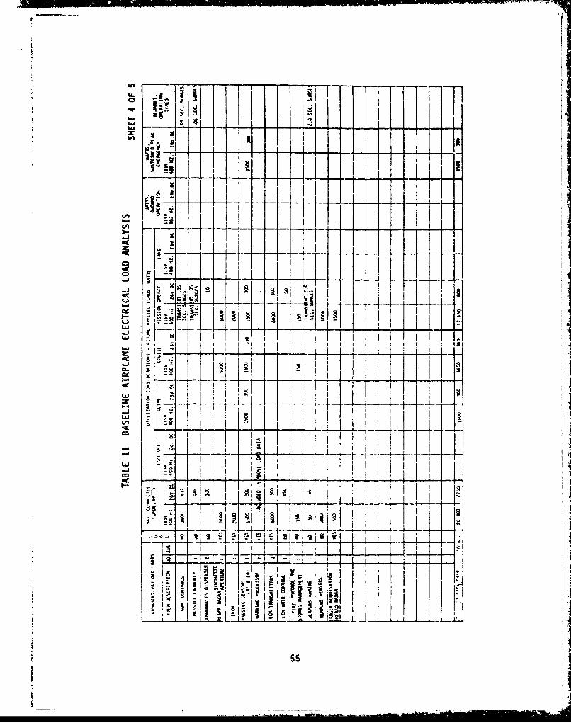
L a i I
SIst
Lai
• I , 1
- I
-. i -___ _
-J i IIII.• i I I� I I I I1 I I I I I I i ' I l
I 4-
... T-1.i55~i ... i - -. ,_ -
Si i 1 ' "_,_
- I
55

'IT
Isl
"LJ !2
-: -
Z!E 4t
I5n
~ & ~ $5

U-4.
I
S)a,
--tlU
-l a,-.II
, ,-• - t ,II
t
57"
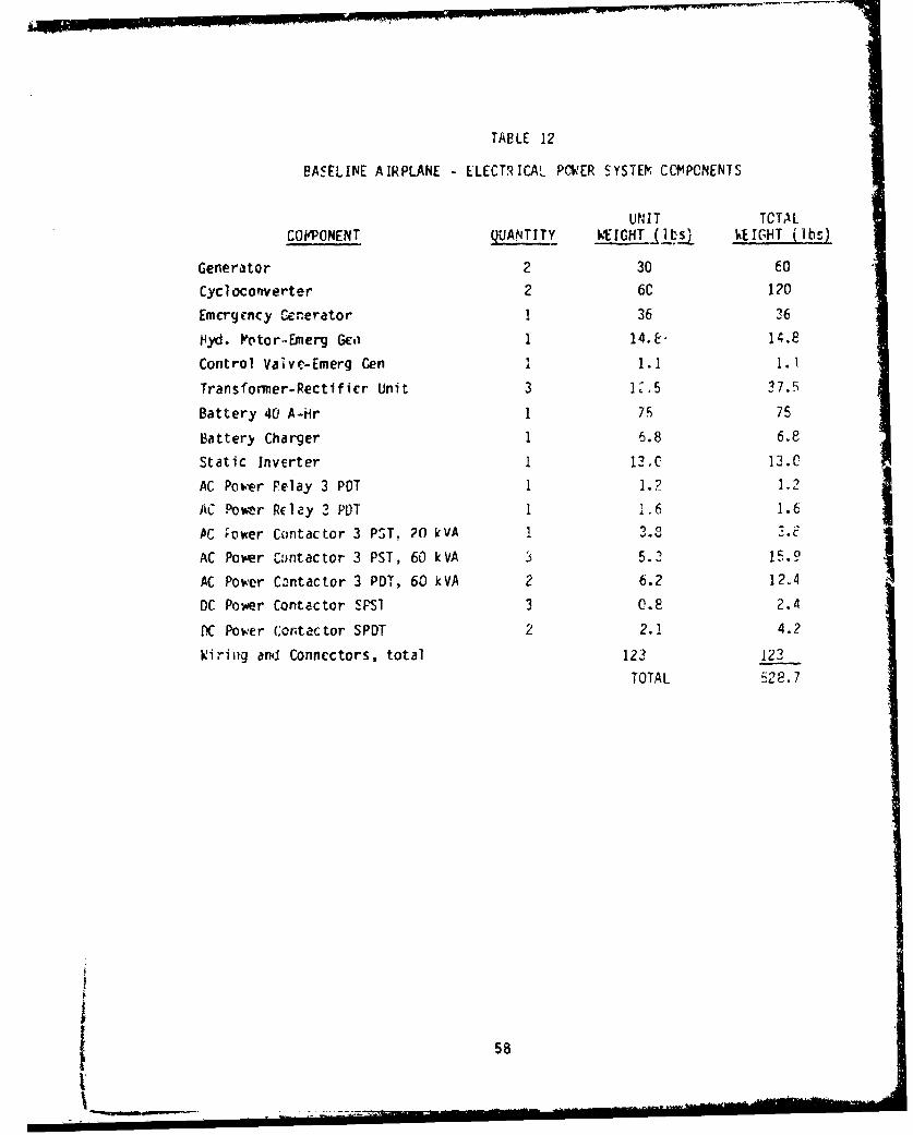
TABLE 12
BASELINE AIRPLANE ELECTRICAL PMWER SYSTEO CCM•PCNENTS
UNIT TCTALCOFPONENT QUANTITY WEIGHT (_._ kEIGHT (Ibs)
Generator 2 30 60
CycI ocoriverter 2 6C 120
Emergency U.-erator 1 36 26
Hyd. Potor..Ermerg GEi 1 14.E. 14.8
Control Vaive-Emerg Gen 1 1.1 1.1
Transformer-Rectifier Unit 3 1..5 37.5
Battery 40 A-Hr 1 76 75
Battery Charger 1 6.8 6.8
Static Inverter I 12.C 13.C
AC Power Pelay 3 PDT 1 1.2 1.2
AC Povmr Relay 3 PD)T 1 i6 1.6
AC ;ower Contactor 3 PST. 20 kVA 1 .
AC Power Czintactor 3 PST, 60 kVA 5.2 i1.9
AC Power C3ntactor 3 PDT, 60 kVA 2 6.2 12.4
DC Power Contactor SPS1 3 0.8 2.4
VC Power c.ontactor SPDT 2 2.1 4.2
Wiring and Connectors, total 123 123
TOTAL S128.7
5858 --

Three high-reliability Dr. buses are providea for powering the triple-redundant
fly-by-wire flight cnntrol system. Each of these buses (FCE CHI, FCE CH2, and
FCE CH3 in Figure 16) is supplied by two sources of power: a generator and a
battery. The three buses share a comnmon battery, but each bus is connected to
the primary electrical power sources, i.e. the generators, tihrough ; different
TRU. Since there are only two main generators, two of the TRUs have to share
a common yeneratar. One of these TRUs (numnber 3 in Figure 16) is supplied
fron the AC ground bus, which is provided with svitching and co;atrol logic so
that if either main AC bus is energized the AC ground bus is energized. Thus
no singie tailure of a power source will cause a power interruption on any of
the FCE buses. Loss of the battery and one gcnerjtor will cause manentary
loss of one or two FCE channels, depending on whether or not the failed
generator is the one normally supplying the AC ^round bus. Power Yill1 be
recovered to all FCE busE.s within a few m4 lliseccnds when the AC Dus or buses
on the failed generator are transferred autsn.iaticaily to the remaining
generator.
A-An -r, ency • gciicr.t.. , dr .a nn '-rm hy a nl.17S-cior hvdr-aulic motor, is
incl.uded to provide power for the critical electrical equipment such as the
fly-by-wire flight controls in the event of loss of both main generators.
This generator is rated at 20 kVA, 3-phase 120/2C8 volts 400 Fz. It can be
connected to any or dll of the three ,main PC buses.
A 40-ampere-hour nickel-cadmi ura battery is included as backup for the
emergency genErator. Thc battery serves to maintain continuity of power to
the critical loads during start-up of the emergency generator ur the IPU
following loss of both main generators or both engines. In the event of loss
of both engines, the IPU will be clutched to one or both AVA0 gearboxes to
drive the hydraulic pumps and the main gene-ators. The IPU is capable of
starting an engine in flight while driving the loaded generators and hydraulic
* pumps.
3.10.2 Hydraulic Power System
The primary goal in configuring the hydraulic power system for the Easeline
Airplane was to provide the most coipetitive arrangement, in terms of size,
59

weig.t, reliability, maintainability, and cost, that could be consiaered
available for the 1990 time frane. One of the first questions was to
determine the number of hydraulic subsystems required.
Rivorous compliance with rIL-H-5440G could lead to the use of three subsystems
since it requires that the hydraulic syste:m(s) be configured such that any tv.o
fluid system failures due to combat or other ctnage which cause loss of fluid
or pressure will not -Psult in complete loss of flight control, and that the
surviving system(s) shall provide sufficient ctjntrol to meet the level 3flying qualities of MIL-F-8785 for conventional takeoff and landing. however,
from the requirements for the individual actuation systems listed in Tabl: 4,
only the canard and eli in actuation systems have a firm requirement to
maintain actuation capability after the failure of two power sources.
Therafore, it was possible to consider either of twv basic tetions:
a. Provide three main hydraulic subsystemn
b. Provide two main subsystems with one or more additional auxiliary systEms
before a selection was made, a load analysis was cond:..ted, operating pressure
selected, and a rurnber of configurat'on arrangements were made for study.
M.10.3.1 Load Analysis
The hydraulic flow rates required for each actuato,- and hydraulic motor to
nbtain its design slew r5te or speed wcre determined Huring Phase Ii and are
,'tcj in Table 13. The maxim'm simultaneous flow demnand. for various flight
'ndition. were determined for each of the candidate !;ydraulic systems and are
ted in Tables 14 through 16 --or the selected arangcmenuL. Pump sizes were
determined and are li ted in Tab 17.
3.10.3.2 Operating Pressure
A number of studies, starting with those conducted by the Glenn L. Martin
Company (published in 1954 in Reference 7) have shown that hydraulic system
weight cai be educed by increasing system operating pressure above the
standard 2,300 psi level. Several aircraft -n the intervening years,
6:60

IO C;~ L.- Jr
o 4-''- J4.). 4-0~-ru~ wU 'x0*
LA ~ ~L +J 4L~ U)
L.LLI CC~ Ln Q
U~U)
'U 0 0) C
Lj- c -.ajr
L..J a-C- .- L L A
M (n 6n 0~ >, 7 % ~ m%P L o cn ýR o 0 l M Lc Q
ce -Wm. 0 -CD 'U' cz*
V) -P-0'CA4-
co
ow~ C)L
4D Cb co 0
x ID C; UI U l'C,
0' -U:- 0
4- Q- CO
6S E ". 'U' a)- C') 4aCCA - - .I
oj, ('4 w C. f > Q0f c4 7ý c, C,ý -..)
-W- -W (D 4
+ 4... 1 *1.C + ' - C4 C-4 CC) j .Cw C' ea
CU) -1 4A 4.)
10 >. c. .a m. L. Cxa. Ca. '0 ' 0 c f...
L O :3 V) .i -r- . 'L
'04-A'U> * O4) 'L c 0. 4- cC~~~~~~c 4) v C U.co00 . )~~

Q -i m "; .
ý9C%j ULO w
qr . .- 6 -* ;~
.of- 1 .-
:5 WR L W
doa cl4 c4 q(0r
0c -
= L.J a*
V/) al, kr
U.. LL. US S.- -
~ .- J Sf l . ..
L3JUl -0 00. C)lO 0
J.Ctalc
20.
0.-
w co tm 01 3- c~- C
ud62

C'J
LC..
~41 V& LC A qr
I--' I.
QLz 4nat Le ~
L LA
LnL
0a FL -ý C". Ca
.C%4
U- >-., 4 C~ m C- -).. 'CL A
4- r) t . .
aL)l 4.w C* Cj ~0) -
-. L Tocj 0 0 C1) Lb' c L
11 0) cc - ) -j 3? 32w (
ALL

EL a.4)o do. r, cu
va Ln L CO C> -
r-I r- L L
CLCD
Lhý 1ý C.
C) (.) %A
>l- W) .-
L/) I LAO -V ý 0l
L~4J
fQ'U-
41 M
fu 4
t' c w.2 g.a ~ -'.64
zt '4.. cl a. 02 3~*L 4'
O. P~) * C.64

LLJ U, J L
W, I-
e- Lz
(in C .
xL..1 L&J LAJ
I-I
Li.65

including the USAF B-70 and B-i bombers, the Concorde supersonic transport,
and other toreign aircraft, have been designed with 4,000 psi systems; and,
the Navy, in their desire for absolute weight minimization for future V/STOL
aircraft, has sponsored cevelcpnent of 2,000 psi system technology.
Ao�.e�er, in studies previously conducted at Boeing, it was concluded that,with nonnal design �ract�ce for i�ir Force combat aircraft, the minimum weight
of hydraulic transmission line tube ruim would be obtained witn a system
operating pressure of apcroxlmdtely 5,000 p� and that- their weight would
increase at higher pressures. This is shown in Figure 17. As showii in the
LA�'1�iAR (Fz4) curve, the minimum-weight pressure for tubing designed forlaminar fiow', with a burst safety factor of four times working pressure, is
arproxiniately 5,000 psi. With a burst safety factor of three times working
pressure (the LA1�INAR F�3 curve) the minimum-weight pressure is approximately
6,OCO psi; however, t�ere is very little reduction of weight by going topressures above SeOO psi.
These curves also shc�� that t a nim'�n-wei�ht p.essure increases if the
tubing is sized for turbulent flow. Sincu most Na�'y aircraft are not required
to start ur from a cold soak c.ordition and becume airborne within a few
minutes, as required f�r most Air Force ecinbat aircraft, the Navys tubing
sizes can be smaller and the fluid flow is nearly always turbulent. (Note
that Figure 17 was prepared for a presentation to the Naval Air OevelopmentCenter and the Naval Air Systems �oemiiand, and that the curves are based on
ecuations which included the characteristics of MIL-H-8322? fluid and the3A1-2.5V titanium alloy tubing. It is expected that the minimum-weightpressures would be approximately the s�rte for other ydreulic fluids but wouldbe somewhat lower for tubing alloys with ower strength-to-weight ratios.
'�owever, for an ATS aircraf� in th� 1990 time frame, the use of 3A1-2.5V coldworked titanium tubing is considered a good choice at this time.)
Figure 18 illustrates the transition tenweratures where laninar flow of
MIL-H-56C6 fluid in system tubing changes to turbulent flow for a typicala design flow velocity of 20 feet per second. Note that for almost all of the
normally used tubing sizes (-12 and smaller), the transitlc'i temperature is
above zero degrees Fahrenheit. Since it is considered that the ATS aircraft
65

I u.......... -~'-----~-- - .- ,. .
II
2.0 1--
"MIL-H-332SZ FLUID
1. _____ 0 F TEO4PERATUREIs I II T1 3At-Z.SV - XLD WaRKýq -US IIG
1.61 WET WEIGnf
F BURST FACTOR
$o . I o
- I _ __- • •
,, -- ,l"I I1.04- , T--__%_(____3
04
0.5 i =3
0.4,S4 5 a �1a L0
PRSSURE PSI x LCOO
Figure 17 The Coiipariscn of Relative Transmission Line Weight
VS Hydraulic System Operating Pressure
f 67

1.0A
0.6 -- 20 FPS FLUID VELOCITYTRANSITION REYNOLDS NO." 1200
Mot 4000 PSI PRESS LINES
0.4
a ~~~~SIZE-000PIP IE
S0.3 -
0.2
--- 3Sf BURST
"-" SF 11URST
-25 0 2S so 7510 2IS
R.UIO TEMPERATUR OF
Figure 18 Laminar-Flow-to-Turbulent-Flow Transition Thrnperatures
f.3)r Tipic tl System Tube SizesL6

used in this study is the type which must be able to start up from a cold soak
condition and become airborne within minutes, it is assumed that there wili be
times when design flow rates must be provided at fluid temperatures belcw zero
decrees and that the tubing must be designed for laminar flow conditicns.
In addition to the transmission line tubing, the hydraulic actuators also
represent a significant portion of the overall system weight. As sho~n in
Figure 19, minimum weight for typical actuators is expected between 3,COO and
6,000 psi depending upon actuator force size. As shown in Figure 20, the
optimum pressure for minimum space volume is somcvhat higher, and also
increases with actuator force size.
Therefore, in consideration that the predicted actuaticn forces for the study
aircraft are high, and in the interests of weight and space optimization,
5,000 psi was crosen as the system operating pressure.
3.10.3.3 Selected System Arrangement
The three-system hydraulic power arrangement was selected for the follov.ing
reasons:
(i) Hydraulic pump sizes required are within the range of sizes currently
available for 3000 and 4000-psi aircraft hydraulic systems. The
development of 5000-psi pumps in those sizes for use in the 1190-plus
time frame should present no insurmountable problems for the punp
manufacturers.
(2) The required sizes of the auxiliary pumps in the two system
arrangements present a major problem due to the size of the electric
drive motors.
(3) The three-system arrangement is lighter and less complex Than the
two-system arrangement.
A block diagram of the selected arrangement is shown in Figure 21, a schematic
diagram in Figure 22, and a list of major components in Table 18.
69

400 -ll
200
100 ...... .-4 ___ [1,L'FIm -100,000 LBS .
lo -1 •-. f , oo e -
- ___ -__ I _____
so 'm -1 x .2.0 IN Z
1 MINIMUM..
F- I lI
a3 'WEIG--HT• -,.' I - , L3 _-
u- T! ,___ ----_r---• 1F.F10.000 LB S
Ix 6
I X.,-*M 10IN /SEC_ --
-Ii---LL
. 3.0 IN
1.0 ~xm 5L. ! 0 INISEC
FM a100 LB61)
a2.0 IN/SEC
I '1.2 - - .. .
a 2000 4000 GOO 3000 10,000SUPPLY PRESSURE - PSI
Figure 19 Comparative Actuator Weight
iS Hydraulic System Cperating Pressure
70

* 000 "-.L i_
S140F0 , 100,000 LBS
Ma 1M~2.0 IN40d ,XM, 10 IN/SEC
MINIMUM SPACE I_- _ _ _ _ _ __l I I"- I I
S;i Fu 10,000 LBS .I IN= 40- l -
I XM a1.0. IN/SEC I20 1
, '
10Iii FM - 1000 LE S
Ll • -:3.0 IN I
6- - 1o0 LBS 5.0 IN/SEC _.u Lo ;N , I
Ii± 210OIN/SEC
a 2000 4000 6000 Bdoo 10.000SUPPLY PRESSURE - PSI
Figure 20 Comparative Actuator Volume
IS Hydraulic System Operating Pressure
71&
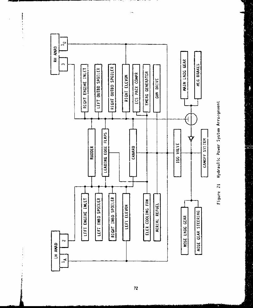
L~CL
U)j V) (l LL i-j LA J
IAJ CL
'ao
-J_
IL (iiIO -a 3:
o 3 <
- zii
vi~
Z5)
LID U)
-C-
- 0 0~ -cc
(FCC 0 -
z z (~ (.172

t^ LA. Ze1
Ln L A
a .. a Ln
_____ 4- ,
-- - - ->- u4
__ .. 4 .,
71,.
732.9

TAeLE 18
BASELINE AIRPLANE - HYDRAULIC POWER SYSTEM COMPONENTS
UNIT FLUID WT TOTAL
COMPONENT QuANlITY WEIGHT (IbS PER UNIT WEIGHT (ls)
Hydraulic Pump 4 27.0 3.0 120.0
Reservoir No 1 1 11.5 15.0 26.5
Reservoir No 2 and 3 2 5.0 6.0 22.0
Temp Control Valves 3 1.0 -- 3.0
Over Temp ,witches 3 0.1 -- 0.3
Heat Exchangers 3 3.0 0.1 9.3
Filter Module No 1 1 23.0 2.3 25.3
Filter Module No 2 and 3 2 15.0 1.5 33.0
Case Drain Filter Module 4 8.0 0.4 33.6
Reservoir Service Panel 1 10.0 0.6 10.6
Reservoir Relief Valves 6 0.1 -- 0.6
Reservoir bieeder Vaivei b 0.! -- 0.6
Firewall S.O. Valves 4 1.7 -- 6.8
Disconnects 10 1.28 -- 12.8
Hydraulic Hand Pump 1 3.4 -- 3.4
Pressure T, jnmitters -1 0.2 -- 0.6
Tubing and Fittings (Total) 80.8 52.3 133.1
TOTAL 441.5
74

IV PLL-ELECTRIC AIRPLANE CCNFIGURATICN
4.1 Scneral
The objective of the dcsign phase was to select the most competitive
combination of electrical actuation systems and electrical power systems for
transmitting power to those systems and for providing fly-by-wire control to
the flight control actuation systems that could be considered for the
1990-plus time frame. In keering w:ith the overall objectives ardrequirements, it was required that the selected electrical power system derive
its power primarily from the cngine through engine-drivEn electrical
generators and transmit that power through a distribution system of electrical
buses. The total secondary power system and actuation systems are definek. 40that a direct ccmparison can be made with the Baseline Airplane design
described in Section III.
4.2 Actuation Systems for the All-Electric Airplane
Two actuation types were considered for the All-Electric Airplane actuation
functions, i.e., Che electromechanical actuator (EI;A) system and the
integrated actuat.or package (IAP) system. Three EVA schemes were considered:the servomotor gearbox, clutched electrical actuation, and the Mirchanical
scrvo power pack.ge (VSPP). Also, three !AP concepts were considered: the
servopump concept, accumulator stored-crergy concept, and the f'.xed-
displacement pump concept. The IAP concept, however, was rejected for llactuation functions since in eacl" case it proved to be heavier than the
comparable EF' in most arpli-aticns.
Under a subconxract, AiResearch Vanufacturing Company of California assisted
in providing data for configurations of EVAs for the various actuation
functions. The results of their study effort is reportud in AiResearch
Docunent Uo. 80-17284 (Reference 1).
Data obtained from PiResearch along with data obtained from other suppliers
was used to arrive at a selection for the actuation system for each of the
flinct ons. Table 19 summar-zes the selected systems for the airplane flight
75

C-
%0 -
o(L 0 - --
c=x 0.0
Oi
-.24
L.j
r_) C) cu .0 Q . e) ,.-
0 0
1-s - S- -
- 4-' 0
600.
C-.
41 & '.
> IA 9Pr- C
-- 0 0 -
;j m- . C . Clo L.I LJ ) wj 0.0-'
~oZ u~Z(.J~76

controls and Tables 20 and 21 for the non-flight control functions. Figure 23
shovs the location of the actuation systems in the aircraft and Figure 24
sshows how these actuators are integrated into the aircraft. Each of the
individual applications is covered in the follov.ing paragraphs.
For each actuator application that utilizes a DC brushless motor, a separate
controllhr/invcrter is required. During Phase II, various methods for
packaging and cooling these units v ere investigated. The original packaging
concept decided upon was an ev6porative cooled configuration in which the
electronics t.ere installed in a circular container filled with a fluid cooling
mredium. However, after sizing the various controllcr/inverters to the
individual actuation requirements, it was found that the units were very
heavy, with approximately half the weight being due to the fluid cooling
mediun. Therefore, another packaging and cooling method was devised in which
the heat-producing electronics are mounted on a cold-plate through which a
cooling fluid is pumped. The difference in these packaging concepts in terms
of volune and weight is indicated below:
Controller/Inverter EvaporaJive Coin Cold-PlitE CoolinRatina (Amps) To1 I ( 1 'n a
50 1-72 11.5 56 4.0
100 426 22.5 113 7.2
150 508 36.0 169 11.1
200 672 48.C 225 14.2
PIthough the volume and weight saving with the cold plate cooling concept is
rimprcssivc, some of these savings must go back into the liquid ccoling system
required to support this concept. The liquid cooling systun is described in
paragraph 4.9A4.
Configuration studies were continued after completion of Ptase II and have
resulted in the following actuation system chantes which are reflected in
Tables 19, 2C, and 21:
I7
, iii " -•"'l:= " " 7T'•• rIl~ •,,77•i•

LLQJ
C3C
s- L
41 W
0 c
eo ei
00
-~70

ci~Q r.). Q
cc4' - -) 4.
w C
l O
4: -1013
4L L (ý2
C.. Co a 00 c10 C-) C) C- , ;
0~ ~~ S-:2:C.' C
0.0
4 : -
a w L-I
:3 )
4.1.
4:4 j4L LAJ LSO~
- '0 0) 79

LEADING E.GE FLAP ACTrATO
INLET CENTE.eODY ACTUAIARS
LEADING EDGE FLAP INVERTERS--
CANARD SYSIEM7>,NVERIERS-
. •----- - :-----------"--"---__----1
"~---.Ž_ c\ 7 .zL
DISTRIBUTED LOAC BUS
MAIN GEAR
RETRACTION ACTUATO
CANOPY ACTUATOR
_ _ _ ... . ..-_ _ _ __ _ _..... ......... -..- /- -• - • = ... • ...... _ _ __
.•:•____ -.LTh- -- I-.- _.. _. •______________ / . lLNOSE GEAR __"-_.... -
STEERING RETRACTION /W -. VACTUATOR-I ACTUATOR 2.AS| ! ~~~/ CANAPE-) "•l•
ACTUATORS
S• • • r=-•a-• Jr • .a l-t,

AC ruATOR5
LI
/~y~ELEvoNsSoiLEER U~CIER INLET CENTERBOD'"
_COOLING UNITS""- DISTRIBUTED LOtD BUS
- -r - "----- i-; .. _. .. - __- -t__--- .. .._
" ;ij~~L_-JUL_
.. -• ' / %-\ --- \- ,ELEVON ACTUATORS
SPOILER ACTUATORS-,.1
"4INGE LINE,AR GEARBOX-
rUO-ER / •\ZL
ION ACrUATORS POWERDRIýVýE
UNIT--\j I
"- Figure 23 Actuation Systems Locatlo
0 All-Electric Airplane
-NLET BYPA$S DOOPPOWER DkIVE UNII
81/82

LINEARAE TRACTIO GEAR PETRACTUATOk
TRUNNION
LINEAR CANOPYACTUATOR
AFT CAB PRESSUkE BULKHEAD--...
TOP OF WHEEL WELL "
S _--LINEAR RETRACTIONACTUATOR
STEERING ACTUATORJ BODY LOWER SURFACE
I""4
1/10 SIZE
(Ao t2 SI
'II

'A: V IE:W OF TI(\
TRUK. AK.JD BRAKS
OF TiU iNNION ELECTRIC MOTOiA, -.
BUTTERFLYA RERCBYPASS ODORS
EXTENDED -/ . I0O size
1/10 SIZE
LEADING EDGE fLAP \ \
HINGE LINE " \1'o-S-ROTARY GEARBOXEb OX .-
,.. - -oI. .TORQUE- St;'kqME L~ DUAL ELECTRIC M.Oi
AND GEARBOX
1/10 SIZE ROTARY GEARBOXES ELEVON HINGE
ROTARY GEARBCX
/1/i-600 ,MAX " -: ---±___ .. 'o1/10 SIZE
.1/4 SIZE

LINEAR BALLSCREWPOWER DRIVE UNIT ENGINE FACE
ONE PER INLET c
" 1/10 SIZE " vi.:.- ]i/10 SZE 300 MAX
I/10 SIZE
"FIN ATTACHMENT
U ODOER ATTACHMENT
Fl-H 1/4 SIZE
ROTARY GEARBOX
I/,o SIZE ":l) --
OUAL ELECTRIC MOTORS /
AND GEARBOX ,
I/1
1/1O SIZE

i L ,•- ---. 2- -.- --
LINEAR13-13 CELECTRIC ACTUATORs
.AMENT rwi)' 0 SIZATAC.HM N I
CANARD SUPPORTI)I
/:~B . .. .. IN
S/
A.A
- " - . • _A l l - E l e c t r i c A i r p l a n e
83/84NN

Canard .changcd cooling of ccntroller/invcrter froma shared E/E to cold riate
Pudder - change from IAP to EYA system
LE Flaps - ch'anged cooling of controller/'invErter from
forced air t p cold plate
Landing Gear Retraction - changed from AC motors to 270V DC motors
(both main and nose gear)
Aerial Refueling and Canopy - changed from AC motors to 28V DC motors (3
places)
Cun Drive - edded controller/inverter
ECS Boost Compressor - changed cooling of controller/inverter from
shared E/E to cold plate
ECS Pack Compressor and ECSFan - changed from AC motors to 270V DC motors
and added controller/inverters with cold
plate cooling
The rationale for thpsp changes is covered in the following raragraphs which
cover these functions.
4.3 Flight Control Actuation
4.3.1 Canard
Actuation trades considered the tvo canard surfaces interconnected as well as
separated, as was done for the Daseline Airplane. The selectEd configuration
is a ballscrew actuator driving each canard surface (not interconnected). ThI
redundancy requirenents as specified in Table 4 are met by using three motors,
magitetically SuLmed on the same shaft, to power each actuator. The motors are
sized so that with one motor failed, the rcmaining two motors can power the
actuator at rated load and speed. The configuration is shown in Figure 24
View A-A, and was selected for the following reasons:
(1) Significant weight say ig over the other two types of FYP and the TAP
configurations.
i t 85

(2) Deleting the interconnection between the two canard surfaces savesweight and reduces complexity. The added actuation redundancy for
separate surface control has minimal weight impact since no
additional control capability is added in terms of increased power.
The actuation system for each of the two canard surfaces consists of the
following components.
Ball screw Actuator 38.0 pounds
270V OC Potor (3 required @ 8.0 Ibs) 24.0 pounds
Controller/Inverter (. required @ 7.7 lbs) 23.1 rounds
Total Weight per SurfAce 85.1 pounds
4.3.2 Elevcns
Actuation trades considered a hingelinr actuation system, a body-mounted Foier
drive unit (PDU) and hingeline gearbox configuration and an IAP. The body-mounted POU, consisting of tw motors and a torque sumrrmd g.rh ', a0ong ifit-
a hingeline rotary gearbox shown in Figure 24 View F, is the selected
configuration for the following reasons:
(1) Less weight than hingeline EIP and IAP configurations.
(2) It is the oply configuration considered that fits within the
available envelope.
The actuation system for each of the two elevon surfaces consists of the
following components:
PDU/Pingelinc C-earbox 70.0 pounds
270V DC Pot, r (2 required @ 13.7 lbs) 27.4 pounds
Controller/Inverter (2 required @ 24.5 lbs) 49.0 pounds
Total W eight per Surface 146.4 pounds
4.3.2 Rudder
Two ERIA configurations and three IAP configurations were eveluatcd during
86
S. .. . .. . . .I.iI i' -, •

/Phase I I and the PUU/hingeline gearbox EPA system selected for the rudder
function because it has the least weight and complexity.
The actuation system for the rudder consists of the following components:
SPOU/Fingel ine Gearbox 39.C pounds
27CV DC Ivotor (2 Requir.d 0 10.5 Ibs) 21.0 pounds
Controller/Invertcr (2 Required @ 14.0 ibs) 28.0 pounds
Total Weight, Rudder Actuation System 88.0 pounds
4.3.4 Spoilers
A single hingeline motor/gearbox for each spoiler segment was seiected over
other concepts for the following reasons:
(1) Lighter and simpler than other EMA concepts (e.g., PDU in tody
driving hingeline gearbox through a torque tube; ballscrew linear
._ctuatnr)
(2) IAP offers no significant advantage over EPA actuation system
(3) A neat, compact installation is possible as sho%n in Figure 24
View F.
The actuation system for each of the four spoiler surfaces consists of the
following components:
PDU/i, ingcI ine Gearbox 10.0 pounds
270V DC Votor 5.0 pounds
Controller/Inverter 7.0 pounds
Total Weight per Spoiler 22.0 pounds
4.3.5 Leading-Edge Flaps
A single hingeline motor/gearbox for each leading-edge flap segment was the
selected configuration for the same reasons as listed for the spo'ler
application, paragraph 4.2.4. Synchronization of the flaps is accomplished
electrical ly.
87L ___

he actuation system for each of the six leading-rdge flap segments consists
of the following comp, ents:
Hingeline Gearbox 34.7 pound:
270V DC Motor 6.5 pounds
Controller/Invc,'ter 8 5 pounds
Total, per flap segment 49.7 pounds
4.4 Engine inlet Control Actuation
4.4.1 Engine Inlet Centerbody
Only linear actuation concepts were considered since the centerbody gCom~try
and operational requirements dictate the use of a linear actuator. The
configuration selected is a linear ballscrew electromcchanical actuator showii
in Figure 24 View V.
The dCLuaL ' Sutm put ach of t eUline -ctrcdi, rrinicti nf
the following components:
Ball screw Actuator 32.0 pounds
270V DC 11oter 5.0 poundsController/Inverter 7.5 pounds
Total weight, per engine 44.5 pounds
4.4.2 Engine Inlet Bypass Doors
The selected ccnfiguration, shown in Figure 24 View P-P, consists of one EDA
(single motor plus planetary gearbox package) operating each pair of doors.
The actuation system for each of the four pairs of bypass doors consists of
the following components:
Planetary Cearbox 3.0 pounds
27CV DC lootor 1.0 pound
Controller/inverter i.0 pound
Total Weight per Pair of Doors 5.0 pounds
e8
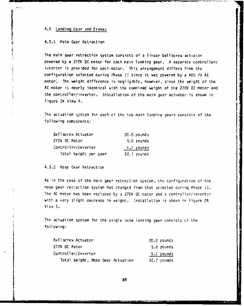
4.5 Landing Gear end Brakes
4.5.1 Vain Gear Retraction
The main gear retraction system consists of a linear ballscrew actuatorpowered by a 27CV DC motor for each main landing gear. A separate controller/inverter is provided for each motor. This arrangement differs from theconfiguration selected during Phase Ii since it was powered by a 400 Pz ACmotor. The weight difference is negligible, however, since the weight of theAC motor is nearly identical with the combined weight of the 270V DC motor andthe controller/inverter. Installation of the main gear actuator is shown inFigure 24 View R.
The actuation system for each of the tme main landing gears consists of the
following components:
BalI screw Actuator 20.0 pounds
270V DC IVotor 5.0 roundsController/Inverter 5.1 rounds
Total Weight per gear 30.7 pounds
4.5.2 Nose Gear Retraction
As in the case of the main gear retraction system, the configuration of thenose gear retraction system has changed from that srlected during Phase II.The AC motor has been replaced by a 270V DC motor and a controller/inverterwith a very slight decrease in ,eight. Installation is shoý.n in Figure 24View S.
The actuation system for the single nose landing gear consists of the
following:
Ball screw Actuator 20.0 pourds
27CV DC Votor 5.0 pounds
Controller/Invertcr 5.7 poundsTotal Weight, Nose Gear Actuation 3C.7 rounds
89
4.5.3 Nose Cear Steering
The actuator configuration selected for nose gear steering is a rotary
actuator powered by a 2BV DC brush type motor. This configuration permits
operation of the nose gear steering function during towing operations on the
ground whnen the only source of power is the aircraft battery.
The actuation system for nose gear steering consists of the following
components:
Rotary Actuator 20.0 pounds
28V DC Brush Type Wotor 4.0 pounds
Total Weight 24.0 pounds
4.5.4 Pain Gear Wheel Brakes
A study of electric brake actuation was made by Goodyear Aerospace Company.
Weight estimates for the setected vieel and brake are as follows: -
Wheel Assembly 77 pounds
Brake Assembly 94 pounds
The brake actuation components have been segregated from the total brake
assembly in order to permit a more meaningful comparison with the Baseline
Airplane. The brake actuation system for each of the tw main gears consists
of the following components:
Bull Ring Assembly 7.0 pounds
jPoLor (8 required @ 0.75 lbs) 6.0 pounds
Total, per gear 13.0 pounds
4.6 Aerial Refueling System
The aerial refueling actuation system is similar to the hydraulically actuated
system in the Baseline Airplane (paragraph 3.6) except itat a rotary
gO

electromechanical actuator (Z-A) is used for door actuation and a 1 ine r EMA
is used for nozzle latch actuation. Pated oads and veights are as follows:
Door EI/A (Rotary)
Rated Load 0,5 HP
Actuator keight 8.0 pounds
V:otor Weight 0.25 poundsTotal Veight 8.25 pounds
Nozzle Latch EIA _(LLi ne2 r)
Rated Load 1750 pounds
Actuator Weight 4.0 pounds
Votor Weight 0.7 pounds
Total Weight 4.7 pounds
Both actuators are Vowered by 28V DC brush type motors so that the system can
be operated from battery pover in an emergency.
4.7 Canopy Actuation
A linear EVA, with characteristics as listed below, was sclected for canopy
actuation:
Rated Load 0.5 hp
Actuator keight 7.0 pounds
Motor keight 1.0 pounds
Total Veight 8.(C pounds
The actuator is powered by a 28V DC brush type motor so that the canopy can
be operated from battery Foker when other power sources are not available.
4.8 Gun Drive
The total power required for the 25-nm Gatling gun is 25 hp which includes
14 hp for the gun drive and 11 hp for the feed systan. A 270V DC, 20,000 rpm,brushless motor was selected to provide the required power. Component weights
are:91:i.-
I gl • -

Gedrbox 15.6 pounds
Motor 11.2 pounds
Controller/Inverter 9.8 pounds
Total Weight 36.5 pounds
4.9 Environmental Control System (ECS)
lhe ECS in the All-Electric Airplane is identical to that in the Baseline
Airplane (Figure 13) except for the electrically driven components described
in the following paragraphs.
4.9.1 ECS Boost Compressor
The ECS boost compressor is driven by a brushless DC motor v.ith a vieight of
2i.4 pounds. The required motor controller/inverter %eighs 1]. pounds. Dutýcycle is continuous during climb, cruise, ana landing. No boost compression
is required during flight at lvach 2.2 and 60,00C feet altitlu.
4.9.2 ECý Pack Compressor W
The ECS pack compressor compresses the fluid used by the refrigeration pack.
It is driven by a brushless DC motor whic. weighs 1i pounds. The associated
controlIer/inverter weighs 5 pounds and duty cycle is continuous.
4.9.3 Electronic Cooling Fan
The electronic cooling fan circulates air betv.en the heat sink, prcvidec by
the ECS refrigeration pack, and the electronic equippent. It is a continuous
duty unit driven by a brushless DC motor weighing 18.4 pounds and a
controller/inverter at 16 pounds.
4.9.4 Liquid Cooling System
The actuation systems for the All-Electric Airriane described in paragraphs
4.2 through 4.9.3 include a total of 2B liquid-cooled control'er/inverters.
This paragraph describes the liquid cooling system needed to provide cooling
for the controller/inverter.
92

Due to redundancy requirements in the flight control system, three seraratc
cooling loops are requir2d. Heat loads have been divided among the three
loops !s equally as possible and the components sized accordingly.
A schematic diagram of the system is shov,n in Figure 25 and component weights
are sunvari zed below:
Reservoirs (3) 9.9 pounds
IVotor/Pump (3) 7.5 pounds
Controller/Inverter (3) 6.0 pounds
Heat Exchangers (3) 6.0 pounds
TubIng, fluid-total 22.1 pounds
Installation, wiring - total 30.0 pounds
Total Weight 81.5 pounds
4.10 Secondary Power System
1he Secondary power system for thei rlectric Pirplane is the Electrical
Poe,*r System.
4.10.] Electrical Power System
The electrical poeer syscem was designed to meet the requirements of power
quantity, power quality, and source redundancy for the power-by-wire flight
control actuators and fly-by-wire control of those actuators, as well as thc
weapons systems, avionics, fuel control, and other utility systems that
conventionally use electrical poker. The generators also shall serve as
motors for engine starting.
The objective in this phase of the study was to select the most competitive
combination of electrical power generation and distribution system components
that could be considered available in the 1990 plus time frame.
Before selecting the electrical system configuration, a comparison study tas
made to select the specific starter-generator and power conditioning equipment
type to be used in the final trade study. Three basic concepts were
93
* I.

CL
4m
U-
40 40
9 14-3

U• • IiIII _i ; II *------- • -~-.:---I, t -,-
considered for processing the raw power (wi!d frequency, wild voltage)
delivered by the generator:
1. Convert all of the power to regulated 120/208 volts, 400 Hz, and then
rectify the desired portion to 270 volts DC.
2. Convert the desired portions of power from generated voltage and fre-
quency directly to 270 volts DC and 120/208 volts 400 Hz.
3. Convert all of the raw power to regulated 270 volts DC and then
invert the desired portion to 120/208 volts, 400 Hz.
The electrical power system configuration selected during Phase II is shown in
Figure 26. This configuration met the electrical load profile shown in Figure
27. However, a major concern with this configuration was the relatively large
weight of the cycloconverters (a total of 210 pounds for the 2 units). This,
plus the fact that the rectifier bridges were lightly loaded, caused the
question: Mhy can't loads be moved frcm 400 Hz AC to the DC busses, the cyclo-
converters eliminated, and the remaining AC requjirements met by smallia.-+arter?
The electrical load analysis was examined and the following loads identified
as those that could be powered by DC instead of 400 Hz power:
CONNECTED LCAD
LOAD L~
Primary Fuel Boost Pumps 7.?
Backup Fuel Boost Pumps 7.3Fuel Transfer Pumps 7.2
Electronic Cooling Liouid Pump 2.0
Nose Cear Retract Actuator 5.
!'ain Gear Retract Actuators 9.4
ECS Compressor frotor 9.4
ECS Fan V'otor 37.6
Transfonner - Rectifier Units 8.2
SLights 1.1Aerial Refuel ing 0.4
Canopy Actuator ( 3
95.8
95

Id- I. I-
- - .� ii- [�I I
� -IF---- ;i I
U,
-U----- a-I I
- L- V
.1-IjIIj�. U,
ii;:; ('V1�O
___ L
I: II
I -(NJ
- �1.I
a �'-i- - - I LJ
-� - a: �4-4 �,
I -,
I & -
96

463
450
200
KVA
¶150-
132 131
99
1 270VDC LOADS6z 64 i- 63_ 6,4.j a:
so-" 45 "_ 4 5
II I 1
I 400HZ LOADS I
CONNECTED TAKE CLIMB CRUISE MI4SSiON LAND GRO EMERGLOAD OFF OPERAT OP
-1igure 27 Electrical Load Profile - 1h11r, Ii
97

Therefore, of the 99 kW. of connected load supplied by 400 Pz AC in the Phase
II configuration, all but 2.2 kW could be supplied by DC, either 270 or 2e
volts.
These results encouraged further consideration of the pov;er system change to
the extent that the total electrical load analysis was revised (see paragraph
4.10.1.1), equipment changes identified, and estimates made of electrical
system and cooling system impact. This Ikd to the following conclusions:
1. The maximum continuous 400 Hz load requirement is 2.0 kk in the
CRUISE flight condition.
2. The maxiinum continuous 28V DC load requirement is 2.9 k0. in the
TAKEOFF and LAND flight phases and less in other flight phases.
3. There is no significant change in total ovcrall pover requirement.
4. There is a reduction of 2(- rounds in total eouipT, eot veijht and d
reduction ef 142 pounds in major electrical power system coxnponents.
5. The effect on the liquid cooling system is a 5 pound w'eight increase.
The net weight saving of 165 pounds was sufficient reason for making this
change in the slectrical power system, but other considerations serve to
reinforce this de.cision. First, the rectifier bridges are already of
sufficient capacity to handle the additional 27CV DC loads (they were sized by
the engine starting recuirement). Se-ond, the rectifie, bridges are more
efficient and less ccrmlex than the cycloconvertcrs, resulting in lower losses
and increased reliability.
It was concluded that the configuration change was most desirable and
therefore it was made. restlting in the schematic diagram shown in Figure 28.
Power distribution for the actuation systems is shown in Figure 29.
j 98

I~ii 1I.
II
99-

( i
6 IWO'
co 0
•n a
t LIW C3 r-,L) L0 0
L.J C CD ZC.41 2-9
.4 P
'1 1" (0U
-I noI
u ---------- 0
CD'
0 C,.
It-.
w "00
I' t
4.10.1.1 Load Analysis
The updated electrical load analysis is shown in Figure 30 and Tables 22
through 24.
4.10.1.2 Selected System Arrangemcnt
The tvo mein generator/starters are mounted on the engine spinners as shown in
Figure 31. An identical unit is mounted on the IPU power take-off pad. All
othvr major components, listed in Table 25, are installed in the fuselage.
101

"-A
498
450
250
200 191
150135 12 33
120
100
67
50 49I I
I I IS28 ,0.67 2.4-7 12.67 12.6 0.57 1 2.2
115VAC: -•.• IR = g.-L- - ý3.71 L_'--40ONZ CONNECTED TAKE CLIMB CRUISE MTSSION LAND GRO OP EMERG
LOAD OFF OPERAItFigu. e 30 Electrical Load Profile - All-Electric Airplane
102

.ZlI I iI
Ii
coo :1
I
9 I 1 .1 I
;.i Z:
jil Hit
Is 1 <,103
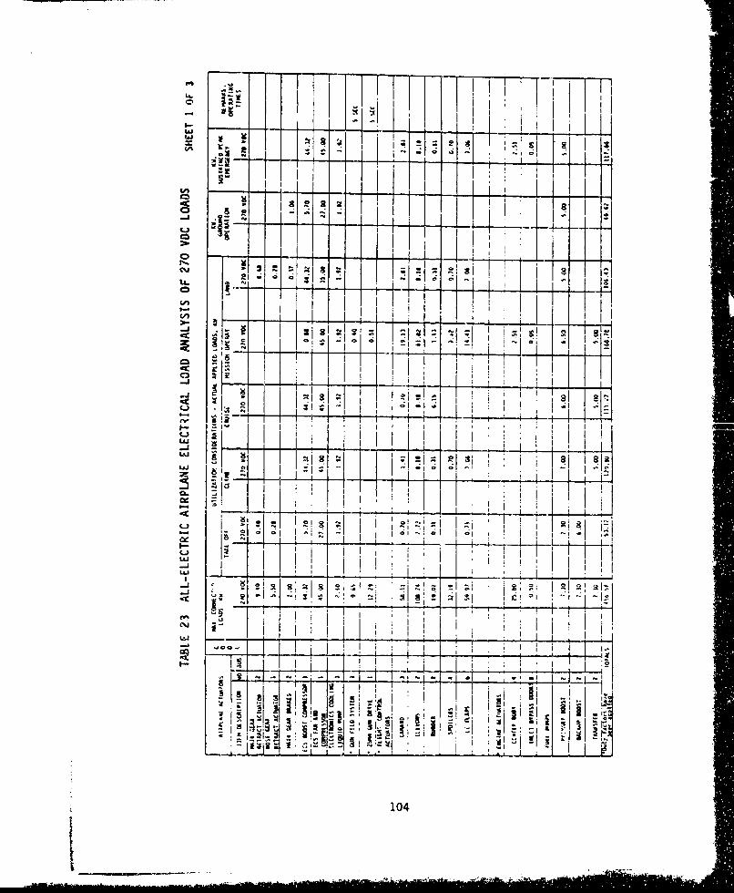
CAl
:I a III
-I 0- -4I
-rT-t-T-
10K1 j104

____ -.- ,- -.
I I �lI - - �
� I II�I II- I I I I
I - - � ---l-�-�-4--� 2i2� 21 151 I
- I 'I, ii�- .�
� I I
- - I �IiK 1
"7 ti Ji2L�2� -; a dK.1:'' 1 I LI
.�' a- 1-iiill
- I_ II''
-l �* 0*�''�' s � I-
___ __ ____________________________ II 3 I
I I � 4- I
I ......+....=..1=...I.=..1.=... IIi :I 'lJ.1-� 1
- *I� - I II, I
I�-'IiI I
L'J �I___ I ________i'�L E-I�l___ ___ ______
LI - ___ I I�I fool.- I
La * -�-. I a �I I I -
2 �� t I
II: I i
I- � b4L�J I I
I I':
.1
2 "'I -
C%-�j I,' i
- -�-
- -[ �.�0-1�---J---i-----�I I -
ii �i �- I
-I -
15151I �i :4I � �I I
I -� C 2i� � �' � '-I
105

____ I I II�i -"--1-*
2 I(I) I -- - - -.- -H
-J � -I �' Ii
Li I �C.Li�
I I
cn �-=.-
II I I Ii
� KL 19I�I'�j HI 1 .H-K�--b-�..-.4-V -�4-ao I
-J �
I
�I I _________________
I I Ig'1 I
I f
Ii I ii21 -. �
I I�I
I- I- ii
I - I
I r II
-J �I KI '3
i �' 2.1'
C -' I III
'5 - I II
_________ j �
___________ ___________________________
106

uj II
CDI
:-4 .
401 ~
r r
,i-2<I~t#-J 'K 107

L16-
1h 1 -
Ii I
I.-Lai I '
I- I
ac i --I I I- I-
Sk ; * ! . I" " -
C43
~ - l i : i , , ! -=-
i -4
i i •.
U ~a.) I . I I i
U, .I I "I iI' . ! ! i, i I .I .-
~I I 4111.. , • ' , I ; ii,
-1 Ii J-I ,I lii 1, 1 .1 , '
S. t I I I_ , ,i , I .iI-•
•_,- -_ I- j • - tI I II •,I
•, I ii••• I•-i . * i-, -,
S. L •" ' i I ' I . l "l
10SI~08
•

i I f I I
4 I -[,)
if a
Ma r09
Cy
-aco
.. 1- . .I
IsI
I -d1 1
3t .- .--
-ccj:3 I : I
W
- ~ ~~itI I ~ I
ruI!III
~ I10 9

LInW6
M )
I..*
noEi'x---
4 1 2 1--
UJI
L3
uiiIN1
I~l t~i iuja
7K" - ~ i110

_ i ,.
ciJ>.
co 5t T
In E
uii
o.
S- - --- ii
"=gi i '.! I i
-. ,- I, I I ~ L I-
zii
-CCI
o..8 __ -. , -I-I -f.1 -- -tI ,Li .• - i- ' _ _ _ _ _ _ _ _ _ _ _
",Iv',- • • ',•I •, .... I,...-... - -, i " : + . ....-4--.------t -.
I .'-7 _ _ _ _ _ _ _ __i_ _"_ _: t -
U.1. _d,..- - -
IIi
,t
r

AB FUELCONTROL NOZZLE AREA
MAIN FUEL CONTROL
CONTROL
i ;II
GENERATOR
,
Tigure 3" Siigle-Spuol Engine Spit~her-Mounted Gener.3tor/Starter
112

TABLE 25 ELECTRICAL POWER SYSTEM MAJOR COMIPONENTSALL-ELECTR IC A IRPLANE
UNIT TOTAL
COPPOKENT NO. REQ'D WEIGHT WEIGHT
Generator/ St arter 3 ,5 225
Phase Delay Rectifier Bridge 3 25 "5
DC-DC Converter 4 17 68
DC-AC Inverter 2 34 68
Battery (2 @ 4C A-Hr) 2 75 150
AC Power Contactor 6POT 2 18 36
AC Power Contactor 6PST 2 12 24
AC Power Contactor SPST 4 1
DC Power Contactor SPOT 3 9 27
DC Power Co,-tactor SPST 6 36
Electrical Wiring and Connectors, total 231
TOTAL 944 POUNCS
Ii
I 113
1k

V TRADE STLVY
5.1 Trade Study Pcthodo~lcj
5.1.1 Ppproa h
The trade study was conducted in accordance with the following outline:
a) Identify alternative airplane configurations to be evaluated.
b) Identify trade study ground rules.
c) Identify parameters to be considered in evaluation.
d) Assign v.eighting factors to each parameter.
r) Perform evaluation of alternatives.
f) Calculate weighted value totals for alternatives.
The parameters evaluated ircludEd:
We i g h~tReliability and Vaintainability
Life Cycle Cost
Performance
Growth Potential
Surv ivab i1 ity
EPVC/Lightning Protection
Eniironmcntal Constraints
Initially it v:as planned to assign welghting factors to each of these
evaluation parameters by comparing each against every other parameter and
judging which is the most important. HQwever, this could rot be done because
the relative importance of each was dependent on many factors that v:xre not a
part of this study and different applications of a given equipment item on the
swme Oirplane coula have a different relative importance. For example, weight
may be the greatest single overriding factor in selecting a cerzain actuator
for landing gear aCtudtion whereas, survivability may be the most critical fcr
a flight control functicn.
114

Therefore, the trades of each parameter were made between the al ternative
airplane configurations that were idcim'ifiLJ but the relative importance of
each parameter was not assessed.
5.1.2 Ground Rules
The comparison of the Baseline ano All Electric PirFlane was made using the
following ground rules.
It was assumed that all technological devclopments necessary to bring the
various components and systems to the point vhcre they would be ready for
application to the study airplane would be completed by 1090 and the cost of
these developvents is not included in this trade study. The program for the
development of this aircraft would begin with the rclease of a request for
proposal in 1990 with an aircraft initial operational capability in mid to
late 1990's. The airplane woulc have a service life of 10,L00 flight hours
and capability for 6,000 landings. The airplane would be designed for a 52
minute flight duration inciuaing tdkeoff, climb and cru'su daid 25 ,j-,,utcS for
loiter, descent and landing. Both airplanes are assumea to be fly-by-Wire.
The life cycle costs (LCC) .wrc estimated for peacetime operation only using
fiscal year 1981 dollars. The airplane would be operational for a period of
15 years, and utilize 288 flight hours per year. The airplanes would be
grouped in squadrons of 24 units each. The LCC were computed for prcduction
quantities of 500 and 1000 units.
The LCC computations were done using the FCA PRICE Iodel eri PRICE L Vodcl.
The LCC are computed based on the quantity of components, weight of
components, amounts of structure, amounts of electronics (whiere applicablc)
complexity factors for engineering design, complexity factors for structure
and electronics mandfacturing, and density of electronics (where applicable).
A detailed explanation of the RCA PRICE and PRICE L models ;s in Paragrapn
5.4. Inputs are included in Appendix A so that the results achieved can beduplicated by a user. The RCA PRICE Podel calculates the RDTSE. Productioncost, and creates the YiDF file for use in the PCA PRICE L P'odcl w.iere the
operations and support costs are calculated for the LCC. The U&S cost
115I

includes mainly the supply (parts) and labor (maintenance) for the rerair of
an LRU. These costs are lower than would be achieved by a dedicated
maintenancc organization. In addition the LCC includes the cost only of the
Baseline Airplane and the All-Electric Airplane. Crew, fuel, and all other
systems normally included in a total aircraft LCC analysis are beyond the
intended scope of this study and not included in this analysis.
5.2 Weight
The weight analysis of each airplane is limited to the actuation systems,secondary power systems, and the structural provisions to accoamodate these
systems. T'e other systems and components that are identical in each
airplane, e.g., avionics, fuel, propulsion, ,tc., are eliminated from the
analysis for simplicity.
Table 26 shows the weight summary for the two airplanes, Table 27 shovs the
weiqhts for the actuation systems for the two airplanes and rable 28 shows the
weights for the secondary power system& for the tt, airplanes. 5ourcc of the
data in each case is shown on the Lable.
5.. Reliebilit, and Vaintainability
Reliability Evaluation
An assessment of the reliability of both the Baseline and All-Electric
Airplanes was conducted. Two parameters here used to compare the two
airplanes. These were the probability of mission success and the probability
of aircraft flight safety. These probabilities vwere ccmputed as follows. The
minimumi cquipment lcvyis (h'EL) for each subsystem for both mission comPlction
and aircraft safety were defined and are smunarized in Table 29. Fault trees
were tnen constructed for both airplanes for loss of mission and loss of
aircraft. TKsr fault trees were developed down to the individual failure
event that contributed to the top event. Certain failure contributing systems
which were common to both airplanes were , t considered in the computation
since their effects would have the same effect on both airplanes. Pn exwmple
of this would be the FBW cof mmand signals since both airplanes were assumed to
116
- I II II I ... --

r
TABLE 26AIRPLANE WEIGHT SU MARY
BASELINE ALL-ELECTRIC
SYSTFM (LBS) (LBS)
Flight Corntrul Actuators* 876 937
Engine Inlet Actuators* 58 109
Other Air Vehicle Actuators* 211 200
ECS* 21 172
Seco,•Idatj Power- S st-i-,•- M2z ;44
TOTAL 2367 2362
* From Table 27
** From Table 28
117

TABLE 27 W1EIG•T SUMMARY -
ACTUAT ION SYSTEMS
WEIGHT- POUNDS
FUNCTION BASELINE ALL -ELECTRIC
FLIGHr CONTROL ACTUATORS (875.8) (937.2)
Canard 170.0 170.2Elevons 300.0 292.8Rudder 48.0 88.0Spoilers 71.2 88.0
LE Flaps 23ý.6 298.2V3lves, total 14.0 --
Structural Weight Differential*** 41.0 --
ENGINE INLET ACTLU4TCRS (534O) (109.0)
Centerbody 36.0 89.0Bypass Doors 16.0 20.0Valves, total 6.0
OTHER AIR VEHICLE ACTUATORS (211.0) (199.5)
Vain Gear Retraction 37.8 61.4Nose Gear Retraction 29.5 30.7Nose Gear Steering 22.0 24.0Main Gear Brakes 75.0* 26.0Aerial Refueling 5.8 13.0Canopy Actuator 3.9 8.0Gun Drive 26.0 36.5Valves, total 11.0 --
ECS (21.0) (172.3)
Boost Compressor ** 40.4Pack Compressor 5.0 16.0Electronics Cooling Fan 16.1 34.4Liquid Cooling System -- 81.5
* Includes 6.0 pounds fluid
•* Included in RH AVAD Gear Box
C Due to Linear vs. Hingeline Actuation
118

TABLE 28
WEIGHT COMPARISON - SECONDARY POWER SYSTEM
IE P BASELINE (LB_ ALL-ELECTRIC (LBS.
Hydraulic Power Generation 108
Hydraul ic Power Reservoirs 22 --
Hydraulic Power Di stribution 213 --
Hydraulic Fluid 99 -"
APAD Gear Boxes 231 --
Electric Power Generation 232 300
Electric Power Conversion 57 13•
Electric Power Storage 75 150
Electric Power Distribution 165 358
1202 944
YI
Note: Baseline data from Tables 9, 12, and 18. All-Elp-tric data from
Table 25.
11
119

I- 0j - I"w:3 cX )ý-c;L.. Lai ;c -9LAJl 00 -)<
CAZ ýs L".J 8(-
-4- => L. Li-. V)ex - - V)id0L6 V) LiJ -
0j O L 8 vi(~ - ILAJ S
Li..L S U. LM . U- J %. V). CO'C r U.. 0j ud (JL- ZI4zgz -A Cn) LL o< ý
=u uI LA. (j qx4xC(A w~U LA c-C ~LAJ c
yUjZ LL-C-v QI CD (A 00 V% a: ( Q L.J ()C) -M; I-- zo =~&J
LA.-
0u (A -4 1- )C)C a C
LA-
(A LAJ
-) eC.s C~j C~j -4 00 CD0~Lj
LAJ"
C,'Y
c'lJ
L.ALLa U
120-

V) co
w LLiJL
CAD X: W LAJC
QLLi (
I-- JI-~ -j IN -j x
U- 0 U-C U j o ; -
N ai AC~.. Li.A Ln . LaD ~ -o -A ~NL L& i D0 U 4ýj o - i LA
*LaiJ 4m~ .
.j LAJ L&Ja U- b - i.SU 0- I C
L..Z LL. U
ui c. V 1 C Ar -U.)
-aV La*-
10Z LLJUýLl
-JL U-
Ln
-JALA
C, L
LC)_
a:r
LLJa
Lii -j ALiki
S Lii I.-
uLi
Z3 Cl- -i 0A u
LA -- a
- ~ U - i)
121

L~~~JA = / O AJ .J
OO-J ~ ~ ~ ~ L CJ ~ -~-u. ~ ~ L) I- - CDCe Wj Xiý ( D La. VI L) ij...j
-j o(6 -6 w--- ( v -
m. Ul U. ) LA(A .J) ZWA
a C%- I--i CC.))a.
C) - z u I.- V) 0: LL4 6 w.s~- 0' I- f 1-.LjU
V)~I~ 2r. !.t In I= (XAlv I-.- I-C -J C-) w.a
LU.OLJ W- =~ U.S4.LL J .LJ -n c -
LLaJ l-LU1 2c Q1 r C ca.=~~~~. CL aiw L : LJ4.ii--I
=L- -I-.- w EU V ,;2u5~ 0 - Q -a C c i c
5 ~ LaI= . ) V L. L6 C
LL.
-JL
W. _ _ _ _ _ _ _ _ _ _ _ _ _ _ _ _ _ _ _ _6L*1C7 (-j L-
u-*S;
I-i
U. t V)
aCV
La.
122

"have FBIW fl igft control systems. A typical set of fault trees are shovn in
Figure 32. The detail fault trees are included in Appendix A.
Failure rates usel as inruts to the fault trees were derived from direct field
experience data, suppl]ei :cdictions and failure rate tables (such as RADC's
Nonelectronic Parts Reliability Data, 1978) in that order of preference. When
* failure rates of equivalent components in F'ilitary or commercial transport
aircraft vere used, the failure rates were multiplied by a factor of tio to
convert then to the fighter failure rates.
The in'formation thus obtained, was then entered as input data to a computer
program, Simplified Computer Evaluation of Fault Trees (SCEFT), which computed
the probabilities of loss of mission and loss of aircraft and thus provided
the relative reliability figures for the Baseline and All-Electric Pirplanes.
These reliability figures are not a comprehensive set of numbers but are just
to provide a relative measure for evaluating aircraft O.ith the two types of
actuation and secondary power systems.
The computed reliability figures are as follofr s:
Vission Aircraft
Success Safety
Baseline Airplane 0.995608 0.999868
SAll-Electric Airplane 0.995289 0.999864
The computer printouts are included in ippendix -.
F'aintainability Evaluation
An a!;sessmcnt of the maintainability cf the actuation and secondary pouer
system was also conducted for the Baseline and All-Electric Airplanes. This
comparison was made on the basis of the Pean-Time-Betv.ten-Fuilure (IfTBF) ofthe two airplanes' actuation and secondary power systems. The design of the
airplanes was net sufficiently detailed to evaluate the maintenance-critical
characteristics such as accessibility and mean-time-to-repair. The MTBFs of
123

(X) 0% % so 0%lcn C1
ILL4
uj -Ui zj c LC A c -
~~OuJOJU luJ LU .L&JU. LtAJLA KL L i
41I
-4)
on71vi Ln
I Ito
an _Iv4En CcD - V5
cm 0%j 0: C,-i ~ AV -j,-ccC
w~ U4 ci UI ujtUo 2I-. w U. : I
LiULca i RcoI. -J a --JjI L.
124

0 0j
w ...- Ca 41
[7 7 -, IdC ý*i-.
-cc-
CA~ -4-'Al
U-C ,-
U,-. kj -100 -cE
Q-) M'Ui U -0aý ýA
Li_cc do jb
L)P
ui125
I. c -

LUO,Q C
-j,- rzCi C
U- JELL C-<aw ii c LL
LLJ 0
w u1 * ILJ~J~
u* CD
00w -j I.- c;
C-) tAw %Ak
rp.-
I--
UA-
'.0C C
cccAI--- ~0 uI:c LLi
(1..
M: j Lc. m
zLAJ V, -jI&
cm qI1 (A L da _j
Li LJ U-
LAJOuJ
-J w '
SL WLLaU- 0
0-we
4 126

the components that were part of beth airplane systems v;cre computed by the
RCA PRICE Program. The details of the input data used to obtain the MTBFs for
the various comr nents is discussed in Paragraph 5.4. The date otained on
the individual components was then combined to obtain the VTBF for the
actuation systems and secondary power systems for the two airplanes as shown
in Tables 30 and 31. The MTBF for the liquid loop system design to provide
cooling to the El. actuation system controller,' invcrters in the ANl-Electric
Airplane was also computed and is shown separately in the table below. There
was no comparable requirement in the Baseline Airplane.
MTBF IN FLYING HOURS
System Baseline All-Electric
Secondary Power 67 1.02
Actuation 139 53
Actuation Cooling -- 331
Cverall MTBF 45 32
Ihe abiiiTy of the airplanes tu o~ertate autonomously is enhanced b y *thC
capability to perform ground mairtenance and system checks without having to
run the engines. In the Baseline Airplane the pover extraction from the
engines is accomplished via the AI'ADs. This arrangement allows a ground check
of the secondary power system via the IPU wthout having to run the enginces.
For the All-Electric Airplane the power extraction is accomplished via the
engine spinner-mounted generators. Here the secondary power system checkout
will not include the generatr'vs mounted on che engine spinnlers. However, due
to the cross switching capal." :e, available in the electrical power system
all the equirment dow:nstrear, frc,- the engine generators can be checked out via
the IPU mounted generatcr. The generators selected for this airplene are
permanent mijnet generators. These generators contain no rotating rectifiers
which are the components most likely to fail, thereby requiring the generators
to De checked out. Therefore, the lack of the abil;ty to operate the main
generators without running the engines is n3t a serious drafrback for the All-
Elecýric P -lane.
127

TABLE 30 ACTUATION SYSTEM M''F SUMM4ARY
SHEET I OF 2
MTBF (HRS)
FLIGHT CONTROL ACTUATION SYSTEM BASELINE ALL-ELECTRIC
CANARD 987 296
ELEVONS 2692 316
RUDDER 2613 921
SPOILER 2692 624
LE FLAPS 897 321
r.,.... ... r• E r.... .'LN ""1A£ Nr LE'r 30j AU-j£
CENTIERBODY
INLET WYPASS 2269 -1369DOORW,
TOTALS 258 71
UTILITY ACTUATION SYSTEMS
LANDING GEAR 1705 809EXT-RET
NOSE GEAR 5390 3792STEERING
MAIN GEAR 762 934
BRAKES
AERIAL REFUELING 3833 2994
CANOPY 5732 5359
TOTALS 397 324
12

TABLE 30 ACTUATION SYSTEM MTBF SUMlARY
I SHEET 2 OF 2
MTBF (HRS)
GUN AND ECS DRIVE BASELINE ALL-ELECTRIC
GUN DRIVE 2379 1949
ECS BOOST INCL IN 1759COMPRESSOR AMAD
ECS PACK 8234 4302
COMPRESSOR
E(S FAN 3578 2013
TOTALS 1218 552
TOTAL, ALLACTUATION 139 53SYSTEMS -
1
129

LL n I
-J I- LAJ
LA IV.
G? W. ii '
%.3
C..) ~ a~ca~co
L)L Lao
Lai
cc v. * ON4
I-i
~~~ooc~jk'.n to ~ -~a. ~O~f~ O~~Q~~)Iu i C J~fl *~~~ic.ar' O~)i ~ '.I'a~fw CAJP441 c -
La a Z.0j - c c(0
FAA~ uj - c c 0LiJ
lp (CI o 0, lw ta. i cc w 'e V .. -4 o a.
u- -i wL~fI c~.UAI11 -WC US L CGh U)
*k 'A- L ca C
-CLf -x 0L Zi A
VAJ P PW..)- V$ 0 Laj -U -'-na. %A ~ uac cWA IN- C" %0LAS Lii -j 2
130

5.4 Life Cycle Cost
Life Cycle Costs (LCC) were estimated for the actuation systcns and secondary
power systems for both the Baseline Airplane and the All-Electric Airplane, jincluding costs for integration of the systems with each other. The LCC
includes RDT&E. Production, Suppert Investment, and Operating ard Support
Costs. Th, LCC plan for this study is illustrated in Figure 33. Subsystem
design vas sufficient to estimate weights and volume of the individual Line
Replaceable Units (LRU) for input to the cost model.
Pore detailed cost data would require preparation of procuremEnt
specifications to obtain detaileo supplier cost estimates. In addition, ix
would require an increase in detail design to refine airplane provisions and
installation details of the LRUs. This level of detail was considered to be
beyond the scope of the Preliminary Design nature of this study and therefore
the cost model was run at the LRU level .
The use of LCC, including operating and su.port costs, is th,Ž preferred
approach for cost effectiveness analysis in this stud3. Essentially, it
allows consideration of the trades between development and production costs,
maintainability, reliability and survivatility.
5.4.1 Cost ýYodel
The LCC. model used in the airplane actuation trade study was the RCA Program
Review Of Information For Costing And Evaluation And Life Cycle Cost Vodel
(PR ICE L).
Some of the basic program ground rules for this study were as follows:
RCA - PRICE Cost Podel
RCA - PRICE L Model
Prototype Hardware 10 Units
Prototype. Spares 5 Units
Production Quantity 500, 1000
Flying Time 2ee Hrs/Year
131

I-.J
oj CA
w i L'J C- 0
U -J .4 J
LAJ LLLAJ--CCL- -,jt& 1-1
-LL ( C
CD a
LAJ
ZT4J
CA-J w -
CLA
en . ccx. Ln J C6 ýjv cc
VI od w Cc
CA ~ t =~- ji -CADý
LA) CDC U
-~ ~ - -a132

Grourd Operating Time Fraction 0.4Operating Period 15 YrsAirplanes Per Squadron 24All Costs 1981, $
Cost elemients included in the model are described below.
5.4.2 RUT & E Costs
The development cost element in LCC includes those efforts required to decvlorp'reviouJsly undeveloped or partially developed ccmnponents/systeirs. The studypresupposes that the rew technologY items identified as req~uiring further
development will have received the required development funding prior to the
technology ava ilability date (1990) of this airplanE. Therefore, these costs
are not included in the ROT and E. Involved are: (1) the research into Whiatis requi red, what exists, how it will function, and how it 1,ill interact with
the system; (2) the design which is the engineering required tc mechanically
c 1i ur e c n ,n .-, d(-1 h teest and ev;%Il ut inn fn Cp thalt cerfomiancemeets the required specifications. Production non-recurring tooling and testequipnent are part of this effort.
1.4.3 Production Costs
Production costs include the materials, labor, quality control, recurring,tooling, planning, and program management efforts required for mnakirg thecomponents/systems for a givcn quantity buy. The production units may be
produ'ced inhouse (make) or procured outside (buy).
5.4.4 Support Investment Costs
Support investment costs include initial spares, ground support equipment,data, training, and other.
5.4.5 Operating and Support Costs
Operatiny and support costs 4rclude those efforts required to operate and
133

maintain an airplane/system throughout its operational life. Vaintenance
support costs are significant costs and include the effort required to repair,
rework, and replace parts at the operational level defined by the government.
5.4.6 Cost Estimating Technique
The PRICE L cost model has been used to estiirate engineering development and
manufacturing cost of electronic, electromechanical, hydraulic, and mechanical
components. Numerous estimates using the PRICE L cost model were made to
verify its accuracy. It was calibrated, when appropriate, with vendor quotes
or by judgment based on historical data.
Support investment costs were estimated using the PRICE L cost model. These
costs include support equipment end initial spares that were estimated based
upon the logistic concept consistent with a 1990+ time frame.
Operating and support costs were also estimated using the PRICE L Vodel. PRICE
L cperates at the Line Replaceable Unit (LRU) level ar.d provides ,n efficient
method for developing operating and support costs at the time of hardvare
estimation. PRICE L allows evaluation of many logistic concepts in addition
to reliability, maintainability, and weightt.
Figure 34 presents a flow diagram of the inputs to the RCA PRICE Model and
Figure 35 shows the development and production inputs required to calculate
the cost of an LRU. A compilation of all the basic inputs that were used in
the PRICE ?'odel for this study is included in the Pppendix. Figure 36
presents the inputs used for running the PRICE L ,Model. Table 32 presents the
values calculated in the Operations and Support Cost portion of the PRICE L
?todel. Table 33 shows the LCC cost of a typical LFU in the study.
5.4.7 LCC Data
A summary of the LCC study results is presented in Table 34 and Figure 37.
The LCC savings of the All-Electric Airplane over the Baseline are $13P. for
500 aircraft and $23M for the 1,000 aircraft program.
134
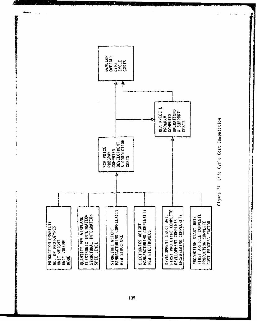
o- 0
LAA
1-02-- ý T 4-
zý L) . ;Cc c E1 1 4.
C.3 06jCI L
w LaJ )L.J I-uJ L__- -j ClX - j c
kdX I.- Lj -j -iJ
=3 LL) uJ cc0. t CL-Z5 wa -cc X U
0: Ujw0 k c "
LaiLha C)C L 3C.lc-C 0. &Q-L&J
C-)~~~~~~ ~ ~ ~ ~ L3St1-- -a I-c c. l

OwI I LA i.0 b a 4
0 0
j. cc C4 4
0. ii I -I 11'LL4L a a0wu I
-2 IA- a
- v -I I I-
LAn
C- . I4-J co I a% ,
:1K E. 9 0
03 usE.
Li 136

I --.
W C3
00 00
-U - L -
- --
cc 0LA. 41 4-
uI- 4-1
aU.,M-L.- C
4-m
06L
0 0 U9)WQ 0 W W
4.4.
1371

04 00 '0ý Le U-) 47 co Pý LO
C'.j~C' -. %0 m .- 0U f. 0~0 0L'0 RN on ~ ) r. ' ~ U
- )t L O N f
U).. ) O
.0L
T6 Ls- t - -c (Co Co LA-
.La. I.. r. LIa. 0 C21 1
= - tA C to Q CA30=Lai tn L - =. 0'i-
-. L.) .. ,c CýLo - ~ LI/J SCL.-
cc 01 -. CL - 0'j 01LLA~U I%. w. U b
W I- L U C -W-i -A 0. L Q '
MI CL) CACY
CCJ O ul I. a.. cl- Ode -O-a .UA F-. I-. w -- 4 -
CL cc an0 CD I .LJ :-- CL . -W L LaiW W W-a CD 0'J f-)C LU -
-iL Ib 13 a3C O - .. U 0 * L
C39 Cie . cc c- 4ct 4c Z CC CD ( CC 1. cr. w CC L a. U 0C 0CL. U..q C.3 I-L to i -AI -a
138

TABLE 33 RCA PRICE LCC SI, IARY - TYPICAL LRU
PROGRAM COST DEVELOPMENT PRODUCTION SUPPORT
EQUIPMENT $2303 $15496 **
SUPPORT EQUIPMENT 32- 484
SUPPLY 310 1243
SUPPLY ADMIN. 5 80
MANPOWER 1994
CONTRACTOR SUPPORT 0
OTHER 0 16
TOTAL COST $2303 $16134 $3817
139
S.. . ; • .. .. .... i• •1 .. .i • - .... '•1 [' I' '1 i
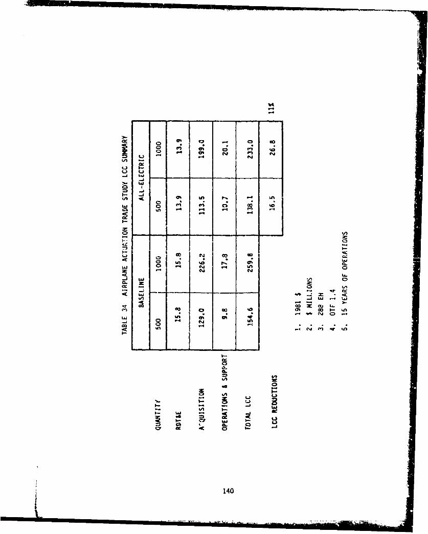
A W4 at Li V L
9l V4 V-V" N I
L~ vi
W; CLLA 14.
C%
o A Iz
o o C c %& GoLai W; 943 94
94; 94
I-5
zk
o140

ItJ
-A A. I% cI
L) /,. v-4\
I-
I0 "/ /Li >-1
-N
C-CwJ .I.- cC /M -3 1-
1 40J 0- :1-LLS "r 4n
-4 "v
U-4) C-
LM In
- --
NO S,0 3134 3.. 11
141

.1Table 35 and Figure 38 present the summary of actuation systems LCC for 500
and 1,000 aircraft and Tables 36 and 37 present detail actuatlon system LCC
data for 500 and 1,000 systens respectively.
Table 38 and Figure 39 present the summrw-y of secondary power systems LCC for
500 and 1,00C aircraft and Tables 39 and 40 present detail secondary power
system LCC data for 500 and 1,000 systems respectively.
AIthough the total actuation system cost of the All-Electric Airplane is
greater than the-Baseline, the savings in the All-Electric secondary pov.er
system make it more cost effective overall.
5.4.8 LCC Zensitivity
A series of sensitivities were run to determine the sensitivity of the
engineering judgments or the inputs for an LRU in the RCA PRICE frodel. Runs
were made for a range of Engineering Complexity, Vanufacturing Complexity, Nev.•JLrut;Lure, avdl- N~er Electr-onics facto..... ,•,.'Results z÷" ac-lottecd rs ercer
change in cost.
Engineering Complexity is used in the RCA PRICE prcgram to scope the
developnent effort and to develop the amount of calcndar time (in months)
deemed necessary to complete the first prototype. For instance. a 1.C
signifies a new design within an established product line, ccntinuation of the'
state of art, whereas a 1.6 signifies new design different from established
product line, requiring in-house develop•ent of new electronic components or
material s. The effects of these factors on ROT and E cost and tctal LC.C are
illustrated in Figure 40 and 41 respectively. Some changes in inputs affect
all elements of cost, vkiile others affect only one elemeýnt. Engineering
development complexity affects developnent cost as can be seen in Figure 40.
However-, manufacturing cost ana operations and support cost remain
approximately the same as can be seen in Figure 41. Other sensitivity runs
were madE on an individual LRU (the controller/inverter for the canderd) with
results as ciscussed in the following paragraphs. Figure 42 illustrates the
effect on LCC of a plus and minus 50% change in weight of an LRU and Figure 43
shows the effect on LCC of a change in engineering cctnplexity of an LRU.
4-142

r--j
LUJ
czCI C _
A-I-
143

r4-
C3
_ _ _ _ _ _ _ _ b- I
P.: ___ .
L1i
0'0
Lain
CDC
(WS) -IO 310 3
144

~L3 * 0 % @U * * . . . CA
-o f.-
Oifl
oo c
a a")
In a
0 0 0
La
0%0
o .j 00 -.
00 I- I.I =
.0 . j 1 . -UA %A o %M
C.14,

- - A 1- ~ - a
w Cd 0% cc Go l kA cc
cea.
4. 9 * 1
C -j "-c
o VA 0. 0
;- -
-~ ~ I.- cc I0-
3--9IU
4146

S C3
I-- I --Ln tn
L41 C)
= (JUz ui
LUL
I-I.-
oL -0 C - Lai.
co
01 U-UM 0 n~
LU0 1C40 L
z Iall
C.J CLU LI; l
on L
147 a

LI.
LaiU
LU I
LUea
4m4
tnA
5.4
49C.O
u,
Let
mlC02Ci
1481
......................

-A-
uj 6.
I.- -
.0)b-
.. r LA.
0ý .0 accf . %
8 0
41 0
<- 14 - i=-4J -1 11 S=I t i co 4-1
100
0e6 3!I1b a a w ICEI
!. - - ~* .j~nj149.

IL d
> vi
L&AC
t- CD1
-- 0
0 (,0
-j 0
LaIv0 a. L 0
- - - - - -M
- ~ a II.. 0 -vs

CL
4IA
0
C)C
cIi
Q.
CD CD D m C: C- 0r*-% %4 rI C44Lm L
SISOO321(d NI39KV3 MU

0%
S=
LAL
LA.
152J

orr
\ -t3,MC
i "--
Is-I
153
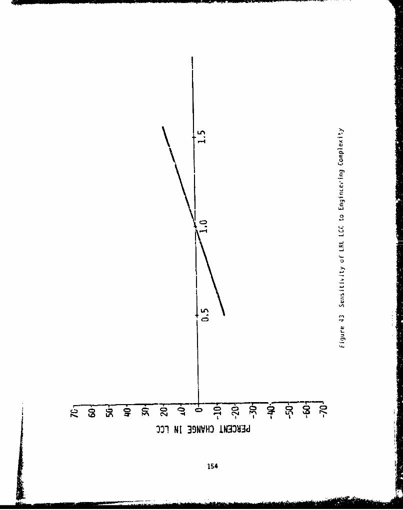
mow"-.
0
t-
C
(lei
C
0,
Ic 0•
00"1 NI 39NVHO tN33H3d
154"

Manufacturing Complexity of structure is usually ar emrerically derived value
that repesents the rroduct's produ~ibility. For instance, for an alum~inum
machined part a factor of 6.31 is used. and for ,i aluminum forging a 5.77 is
used. This factor defines the material, finished density, and fabrication
methods. Mranifacturing ccinplceity of electronics is a complexity factor whiCh
is a function of its components, packaging density, manufacturing, testing,
and power aissipation. For instance, a poier s.;pply composed of discrete
components is assigned a fact oi: 6.941 and an LSI a factor of 7.368.
Manufacturing ComplLAity Factors, as can be seen in Figure 44 and 45, affect
LCC cost both fur structural and el :ctrical hardware. ihese figures show that
cost growth for complexity is steeper for electronics than structural hardwa-e.
New Structure and Vew Electronics defines the degrce of new design required
for the structure or el.,ctronics assembly that is unique. A factor of C.M
indicates that 1C% of the drawings are new. ,•ew Structure and New Electronics
values only affect thc devclopnent cost, as can Le seei in Figurc 46 and 41.
The precenlage of new structures and electrronics does not affect the
prooucton and iiife cyCIV cost.
Electrcnic and structural next-higher-assembly-inteqrat'on cost factors have
no effect on LPU LCC cost.
-CC sensitivities could have been ruin for the schedule factor bul the
• ,as assigned prior to the accomplishr'ert of Thase : and the schedule
defined as 1990. The physical en ronmnnL was aiso defined and no
Sty vs LCC sensitivities were perforned,.
5.5 StructUral integration
Fro•m a structural integration point of view the El actuators may pro'iac an
"advanzage over the hydraulic actuators- 'his is because in most cases th:
most rltimutii method of actuation in hydraul ic cases is usually thE linear
piston actuators. However, this may require out-of-contour fairings, or bell-
crank mechanisms to couple to the su.'facu buing driven. In 'che case ot Eli
actuation, hingeline actuators can be designed to `it ,;4thin the wing
surfaces. Al so in the power extraction scheme .t•4 ized in the 2aseline
155

LUI-Z--LLJ
- -L I-.-J
= AA
cc
0
LU 0
LUL
1.56

C))
0 00 OQ
-d-I
LLJ
0al LLJ C-)
LOLD~iJ
cD LLJ C4U-.4-.1 c.1
__) 6 U
UN 'r C. CK
001 NI 39NIVHO 1NJ33Hd
157

LnC
4-I
158.

tt
Lw
4-3
...........
cm C5a) CD CD CD CD CUM fln CN __
SISO DI NI 9NV3 IN380
1593

Airplane via pot,'er take-off shafts driving AVADs, the locaticn of the APAD
near the engines is desirable. This may be in an area where the fuel t3nk
•vuld need to be located for center of gravity cdjustments during variois
phases of the flight. P!so the structure has to be strengtheneu to support
the A.AD hardware. In tne case of the All-Electric Airplane, the power
extraction is done electrically via a starter/generator which also performs
the engine start function. The power conditioning equipment may be located
%here it will not interfere with the placement of the fuel tanks.
5.6 Growth
Pn Evaluation of the growth capabil itaes of the actt.ation and secondary power
systems of the Baseline and All-Electrit.A irpleres was conducted. The basic
design philosophy utilized in the sizing of hydraulic actuators is to meet th'e
specific recuirements of the surface actuation. The piston cross section andstroke is sized for maximum load/stroke characteristics.
In the Vw actuation systems the drive power is provided by "m-Co
permanent-magnet motors. The design of the motor is bi ;ed on the average
load. The motor can be driven to produce power levels above the capability of
the average rating for short durations. The limiting factor is the heat
generated undpr the various operating conditions. The motor windings should
not be allowed to exceed a temperature which COLld damage the stator v:irdings.
This capability allows the EV actuation to satisfy additional peak lo.-d
demands as long as the duration is compatible.
Hydraulic power systems are designed to meet military specifications such as
VIL-H-5440. For ex3mple, the recuirements for selection of cngiýr-oriver
hydraulic pmps states that "a sufficient number of engine-driven p'umps shall
be provided to assure operation of control surface boost or power systems...
Thus the sizing of Lhe systen is to assure that the basic requirements are
met. If additional load growth occurs, tre system would have to be resized.
On the other hard the sizing criteria for electrical power systems as
specified in PIL-E-25499 states that "... th_Ž aircraft shall havc a
multigenerator primary electrical system which ha, a maximui continuous kVA
160

capacity of at least twice the maximum continuous electrical load of the
initial production aircraft." This sizing criteria allows for lod growth• capability in the electrical power systemn on both the Baseline and tne All-
SElectric Air,-lanes. Due to the higher capacity generators ýn the All-Electric
airplane, additional capability is available for shcrt durations.
5.7 Survivability/Vulnerabilit
Survivability is assessed by examining the ability of the airplanes to safely
withstand the following:
- Enemy action (combat survivability)
- All engines out
- Natural or induced enr ronmental extremes
- Cnboard system failures
- Faintenance errors
- Fliaht crew inaction or error
Although lightning is usually considered part of the "natural environment,"
this important subject is treated separately, along with electromagnetic
compatibility, in paragraph 5.8.
The integrity of either aircraft is highly dcperdent or 'ts powered actuation
systcms, especially those associated with th primary flight controls. A
qualitativc evaluation was made of the relative survivability of the Baseline
Airplane versus the All-Electric Airplane with respect to their
invulnerability to the factors listed above.
5.7.1 Combat Surv ivability
Technioues develored for enhancing electrical and hydraulic system.
invulverability to enemy action fall into three main categories as follows:
161

(1) Design techniques for minimizing exposure so as to minimize the
probability of a hit
- Avoidance of high susceptibility areas
- Use of shielded locations
- Concentration and protection of critical components
- iniaturiztion of components
- Use cf armor systems
(2) Damage resistant design techniques which minimize loss of function due to
a hit
- Ballistic resistant materials and designs
- Fire/heat resistant materials
(3) Damage tolerant design techniques
- Redundancy
- Physical separation of redundant systems
Additional techniques that apply only to hydraulic systems are:
- Frangible actuators
- Actuator return - pressure relief devices
- Use of overboard drains
- Leakage protection devices such as hydraulic fuses and circuit breakers,
isolation valves, reservoir level sensing and isolation circuits, and
discriminating switching velves
- Reservoir considerations such as location, separation, and
pressuri zation
Survivability of either airplane derends to a large degree on the
invulnerability of critical systems to enemy action. In the Baseline this
includes not only the actuation portion of the system, but also the hydraulic
power supply to the system and the fly-by-wire electrical elements associated
with the system. In the ll-Electric Airplane, the vulnerability of critical
162

systems is increased due to the added ýontroller/inverters and associated
cooling systems. On the other hand the wires supplying power to the actuation
syst-ins are slightly less vulnerable than the comparable hydraulic lines in
the Baseline Airplane due to their smaller size. Overall, the All-Electric
Airplane will require that emphasis be placed on the location and installation
of the inverters dnd their cooling systems during the airplane design to
insure the required level of survivability is achieved.
I--
5.7.2 Non-Combat Survivability
The hydraulic systems on the Basel ine Airplane of the 1090's should be
* comparable to hydraulic systems on current military aircraft relative to their
high invulnerability to natural environments, onboard failures of other
systems and equipment, maintenance error, and pilot and flight crew inacticn
and error. Pethods of preventing failure of more than one hydraUlic or
electric power system due to other failures, including engine or tire b'jrsts,
and for preventing maintenance and other human errors are highly developed.
Invulnerability to induced environments should be scmewhat better than current
aircraft with engine-driven hydraulic pumps mounted directly on encine-mountca
accessory gearboxes. The use of airframc-mounted accessory-dri'e (AMD)
gearboxes removes hydraulic pumps, valves, tubing, and hose from the high
noise, vibration, and temperature environment of the engine compartment. The
use of the higher (5,000-psi) system pressure should not i.itroduce much of a
problem for 1990-time period aircraft. There 4s a good backlog of successful
operation of aircraft system oreration at 4,0CC psi, and many industri il
systems operate at 5,000 psi. The Navy-sponsored testing at 8,000 psi has
been quite successful; and, it is predicted that development of 4,CCC and
5,000-psi systems for Air Force aircraft applications will be accelerated.
The electrical systems on both the Baseline and All-Electric Airplanes must be
designed to be invulnerable to natural environments, onboard failure'i" of other
systems and equipment, maintenance error, and pilot and flight crew inaction
and error because they supply the contiol and monitoring rower to the
fly-by-wire systems. In addition, the eluctrical system or, the ,'P-Electric
Airplane must supply all actuation power to a level of redundancy comparable
163

to the fly-by-wire requirement. However, the limits on power irterruptions
are not as stringent for actuation power as they are for fly-by-%ire power.
The redundant actuators for primary controls on both airplanes are separated
as much as possible. The hydraulic actuators on the Baseline Airplane are
more jam tolerant while the EM actuators on the All-Electric Airplane are
susceptible to a catastrophic jam in the gearing.
Either the Baseline or the P11-Electric Airplane of the 090's should be
better able to maintain attitude control with all englines out than current
aircraft. Upon loss of engine po%er, the LCX/JP-4 integrated power unit (ID !)
can be brought up to speed in a matter of seconds (b.fore thz engines spool
down) to supply the hydraulic and/or electrical poeer requirements. This is
an important feature for an electric-command fully-powered-flight-contrul-
system airplane, especially with the high-byoass-raiio engine.s of the " ý,,re
which are expected to have poor windmilling power c-,jrability.
In trVe 1990+ time frame, both the Baseline atid the All-Electric Airplane will
be fly-by-wire airplane,; and will impose the same.!5igr~ail-1vel power
requirements on the electrical power system in terns of redundancy and
uninterruptible power. This is reflected in the two eiectrical Fovcr system
schematic diagrams, Figures 16 and ?8, where the ':light Critical Electronics
(rCE) buses provide Lninterruptible pow.r while the three 28V DC buses and the
battery provide the redundant power sources. All loads supplied by these
buses are signal level or low rower requirements.
The high puwer i.ctuaLion loads are sUpplied by the trirle hydraulic system i.
tne Basel ine Airplane and by the triple 270V DC bus s;sto, in the All-Llectric
Airplane. The third power source in the A- I-Llectric Air-plane is thc flight-
operable IPU generator which is started up whenever either rain engine drive!1
generator charnei fails. lherefore. the loss of a single power source or any
plausible single equipment failu•- ill not result in pen-.anent dEgradation of
flight control system performance below FCU Operational State I, or temporary
dcgr.-dation below FrS Operational State 11.
164

5.8 ENC/_Lightninq9
The electrical power systems, digital systems, and electrical utilization
subsystcms for the two airplanes, and the electromechanical actuators for the
All-Electric Airplane are designed to achieve EKC within the operating
environments using the design guidelines of MIL-E-6051i, MIL-B-5087B,
!'IL-STD-461, and AFSC DH1-4.
5.8.1 EII
A gov. equipment EMC design approach encompasses the whole compatibility
problen from the circuit design concepts through the deliverable article. The
objective is the marriage of complex circuits and equipment into a compatible
system which operates within performance specifications in the specified
env ironment.
Attention is given to the sources of noise generation within any equipmEnt.Thi. ' ..C.ij .^S edfor • intentinnAl radiation as well as that not
specifically designed for radiation. Radio and radar transmitters may ccntain
spurious oscillations, harmonics, oscillators, or products of these
frequencies. Unintentional transmissions may result from broadband energy
generation such as switching transients, commutation, rectifier and diode
noise, and fast rise time wavcforms. These unintentional transmitters can
create very broad spectrums of high frequency components by a rapid change in
voltage and/or energy level. A rapid change of one volt is easily sufficient
to cause failure in meeting MIL-STD-461 UAI generation limits.
Equal attention is givEn the EDIC environment. Circuits and equipmcnt may be
susceptible to interfering signals from the external electromagnetic field
surrounding the installed equipment, signal input or output wiring, poker
supply waring, or electromechanical systems.
In evaluating LOC for this trade study, the major variable element between the
two airplanes is the addition of power-by-wire actuators and associated Oiring
on the All-Electric Airplane. Extra attention is given to these items since
electromechanical actuators using solid-state switching for external
165

commutation of the drive motors generate EV!. noise that must be contained
within the motor controllers to prevent conducted noise from interfering witht
operation of other power utilizaticn equipment on the same bus, and to prevent
radiation to nearby signal and control wires. In the electrical povwer
grneration systems the output rectifier/voltage regulator network of a
permanent- magnet brus'less DC generator and the cycloconverter in the VSCF
system are both inhr ,tly EI generators. Hovever, since this has long been
recognized, the designs of these devices include adequate shielding and
fi1Mering to contain the noise within the generator/converter assembly.
5.8.2 Lightning Protection
The interaction of lightning with an aircraft, either by direct striKe or
near-miss, induces electrical transients into the aircraft circuitry.
rVilitary aircraft of the 1990's will contain significant amounts of compcsite
structure with poor electrical conductivity. In addition, the advanced
electrical power and fly-by-wire systems used in these aircraft contain many
solid state c(omrpoents. The cucibirdtivri uf the twu (rcduced Irnherentshielding effectiveness of nonmetallic materials coupled with circuit
components that have lower tolerance to electrical transients), presents
design problems in both the Baseline and All-Electric Airplanes. The problem
is intensified in the fll-Electric case due simply to the added number of
electrical circuits and wires.
Lightning induced transients present a hazard to electrical and electronic
systems that is met by providing an adecuate protection system. The
occuirrence of several direct lightning strikes plus many near-misses to a
given aircraft during its service life is a certainty. P direct strike to an
electrical circuit can result in considerable physical damage to the wiring as
well as to circuit ccmpcnents attached to the wires. If the circuit is not
struck directly, it will still have potentially damaging transient levels
induced by magnetic coupling to the lightning currents flowing through the
aircraft structure. These induced transients can have sufficient energy to
danage or at least upset solid state components.
The mechanism whereby lightning currents induce voltages in aircraft
166

electrical circuits is as follows. As lightning current flows through an
aircraft, strong magnetic fields, which surround the conducting aircraft and
chonge rapialy in accordance with the fast-changing I ightning-stroke currents,
ar. produced. Some of this magnetic flux may leak inside the aircraft through
apertures such as windows, radcmes, canopies, seams, and joints. Other fields
may arise inside the aircraft when lightning current diffuses to the inside
surfaces of skins. In either case these internal fiids pass through aircraft
electrical circuits and induce voltages in them proportional to the rate of
change of the magnetic field. These magnetically Induced voltages may appear
between both, wires of a two-wire circuit, or betveen either wire and the
.irfranme. The former are referred to as line-to-line voltages and the latter
as com-.on-mcde voltages.
In addition tu these induced voltages, there may be resistive voltage drcFs
along the airframe as lightning current flows through it. If any Fart of an
aircraft circuit is connected anywhere to the airframe, these volitage drops
may appear between circuit wires and the airframe. For metallic aircraft made
of highly conductive aluminum, these voltages are seldom significant except
when the lightning current must flow through resistive joints or hirn:es.
Howeva:r, the resistance of titaniun is 10 timncs that of aluminum, so the
resistive voltagas in future aircraft emFioyinS these materials may be 1uch
higher.
lUpset or damage of electrical equipment by these induced voltages is defined
as an indirect effect. It )s apparent that indirect effects must be
considered alor.g with direct effects in assessing the vulnerability uf
aircraft electrical and electronics systems. Post aircraft electrical systcms
are well protected against direct effects but not so well against indirect
effects.
Until the advent of solid state electronics in aircraft, indirect effects from
external envirorrients, such as lightning and precipitation static, were not
much of a problem and received relatively little attention. No airwvorthine;s
criteria are available for this environment. There is increasing evidence,
however, of troublesoin, indirect effects. Incidents c' upset or damage to
avionic cr electrical systems, for example, without evidence of any direct
ii167

attachment of the lightning flash to an electrical component are showing up inlightning-strike reports.
While the indirect effects are not presently a major safety hazard, aircraft
design and operations in the 1990+ time frame could increase the potentialproblem due to the following:
o Increasing use of plastic or compo3ite skin
o Further miniaturization of solid state electronics
o Greater dependence on electronics to perform flight-critical functions
Design of protective measures against indirect effects are being developed
under USAF contract F33615-79-C-2006 (Reference 8).
5.8.? Wire Routing for Lightning Protection
The primary reason for optimizing wire routing is to reduce the amount ofelectromagnetic flux coupled onto the conductors and therefore wiring is
S .. -...CL
Ls VuIiuz to the yrrundr plane or structurai freme. Exposed
wiring (e.g., wires underneath a leading cdge of a poorly conducting
material) is routed close to the metal structure. The amount of flux that is
coupled to a wire is proportional to the distance separating the two
conducting mediums. Wiring is locat~ed away from apertures (e.g., windows) andregions where the radius of curvature of the airplane frame cr outer skin is
the smallest. In particular, wiring is not routed across obvious slots (e.g.,
access doors). Where full shielding is required, the cable is routed in an
enclosed channel. Structural returns for exposed power wiring are avoided.
The primary threat to equipment is the conducted threat delivered to the
equipment by:
a. Exposed interconnecting wiring, or
b. Interconnectirg wiring attached to an exrosd element (e.g.,
windshie'h heater circuit).
The only potential threat which depends upon the fields in the vicinity of the
168
-Lý _J

equipment is E-field coupling. I.e.. nearby electric fields may induce a
voltage upon the viring terminating in a poorly-grounded case. In order of
priority then, the rules for equipment placement are:
a. Equipment located to minimize exposure of interconnecting wiring.
b. Equipment located in areas w.hich are shielded from electric fields
induced by lightning; case well grounded to structure to minimize the
E-field coupling.
5.8.4 Power Equipment Protection
At the present time, there are no power system requirements governing the
suppression of lightning induced transients in the kilovolt range. If new
specifications are imposed requiring the equipment to w:ithstand the lightning
induced transients presently observed, filtering or shielding of individualequipment would produce additional height and cost problems in the overall
airplane design. However, by increasing the transient suppression requirempntin individual equipment from the present military specification of 600 volts
to 600u volits, the loss in electroniaynrLic I.roteCtion frT the usage ui
graphite composite materials would be less critical. A more viable solution
is to either prevent the transient from being coupled on to the power feedersor to suppress the transient so it does not appear at the main power buses.
Preventing the transient from appearing on the buses allows the use of
equipment icsigned to the existing pover quality standards. Iethods to limit
the lightning induced transients to levels below existing power quality 1*standards are being developed (Reference 8). These methods include wire
shielding, the use of TransZorbsT v, varistors, zener diodes, filters, and
surge arrestors, and the use of conductive coatings.
5.8.5 Airplane Comparison
Both airplanes are fly-by-wire and therefore require that particular attention
be given to the electromagnetic compatibility and lightning protection of
circuits and equipment associated with safety-of-flight. Pohever, due to the
additional electromerhanical actuators and electronic controllers,
considerably more design analysis and testing is required in the All-Electric
Airplane to insure safety under all operating conditions and logical failure
modes.
169

In evaluating EMC for this trade study, the major variable elemcnt between the
two airplanes is the additior of power-by-wire ictuators and associated wiring
or the All-Electric Airplane. Extra attention must be given to these items
since electromechanical actuators using solid-state switching for external
commutation of the drive motors generate EMI noise that must be contained
within the motor controller to prevent conducted noise from interfering with
operation of other power utilization equipment on the same bus, and to prevent
radiation to nearby signal and control wires. In the electrical power
generation systems the output rectifier/voltage regulator network of a
permanent magnet brushless DC gcnerator and the cycloconverter in the VSCF
system are beth inherently EI gcnerators. However, since this has long been
recognized, the designs of these devices include adequate shielding and
filtering to contain the noise within the generator/converter assembly.
5.9 Environmental Constraints
Equipment on both the Baseline and the All-Electric Airplanes will have to be
designed to withstand and operate satisfactorily in the following
environmental conditions:
a. Temperature
b. Altitude
c. iiumidity
d. Salt Spray
e. Sand and Dust
f, Fungus
g. Thermal Shoc(
h. Vibrtion
i. Pechanical Shock
Hydraulic Systems
Hydraulic systems and components have been designed to withstand End function
under such environments for years. The one parameter which gives most concern
is high temperature. High temperatures, due to supersonic flight or due to
the use of hydraulic actuation of engine control functions such as variable-
170

geometry inlets and exit nozzles, may require special fluids and sea]
materials which will not break down due to sustained therial exposure. tFany
supersonic aircraft, such as the F-1ll, F-14, F-15, F-16, F-18, and B-1, usestandard petroleum fluid per 1MIL-H-56O6 and standard Buna-N nitrile 0-ringseals. Other airc.aft, such as the B-58, B-70, and Concorde SST, weredesigned for use with silicate ester fluids and either special neopreneelastomEr seals or all-metal seals (B-70). The ?Each-3 SR-71 uses a synthetichydrocarbon with all-metal seals; and, the X-2CA (Dyna Soar) controlled-
reentry manned orbital space vehicle was also designed with that fluid andwith a combination of metal seals and high-temperature elastomeric seals. Th cengine-control hydraulic system on the B-70 was desigred with a cHlorinated
siliconE fluid and operated at some 6OO'IF fluid temiperature.
One distinct advantage of distributed hydraulic systems is that they areeasily cooled. The fluid return lines can be circulated through fuel tanks toconduct th.eir heat load to the lower temperat 'ure fuel, or through fuel-to-oilheat Pexchanciers to take advantage of the higher thermal film coefficients
caused by the flow of fuel to the etrgines.
Electrical Systems
Electrical power generation and distribution systems have been designied towithstand and operate in aircraft environments such as listed above.
Electronic equipment items have to be provided with adcquate cooling tomaintain internal temperatures at which the relijab ility of the sem~iconductorsare not impacted. Certain precautions are also necessary to locate equipmentin areas where it will not be exposed to extremes of the above listedenvironments. During the design of the aircraft, adequate consideration hasto be given to location of sensitive electronic equipment in areas where
ambient conditions will subject the equipment to a minimum of environmental
extremes.
In an All-Electric aircraft, the P? actuators will be located in areas whichwill be at one or more of the environmental extremes listed above. Pn example
of this is the location of EM actuators in the leading and trailing edge
surfaces of' the wings. H~ere the actuators are subjected to the temperature
171

extremes (especially high temperatures at supersonic cruise conditions). The
worst case temperature in the leading edge is 275 0F at the upper surface. The
EM actuators must be designed to withstand and operate at these temperatures.
Temperatures in excess of these values may require that additional cooling be
supplied. Other environments such as salt spray, send and dust, vibration and
shock extremes will also impact the design of the EF. actuators. Although
these environments will impact the design of the EM actuators, none of them
are too severe to preclude the use of EP actuation.
5.10 Technology Risk
The Easeline Airplane secondary po%er generation system is similar to that
proposed for the Boeing supersonic transport and later incorporated in the B-I
and F-15 aircraft. The airframe-mounted accessory-drive (AfVAD) gearboxes are
well-proven designs *ich provide a great deal of operational capability.
They allow hydraulic and electric system checkout and operation on the ground
without operation of the main engines. The integrated power unit can drive
all of the hydraulic pumps and generators.
The LOA/JP-4 integrated power unit (IPU) allows fast engine starts both on the
ground and in flight at any altitude. It is currently under development by
the AFWAL Aero Propulsion Laboratory, Aerospace Power Division, Power System
Branch. It combines the performance of a bipropellant turbine power unit with
a conventional gas turbine APU and should be sufficiently developed for
aircraft use by 1985.
The hydraulic system pumps and other components are all based upon prover,
technology. Several aircraft hydraulic systems have been put into production
with 4,000-psi operating pressures, and many industrial equipments use
5,000-psi systems. The use of 15V-3Cr-3Sn-3A, titanium alloy for hydraulic
tubing has yet to be proven. It has an ultimate tensile strength of
20C,000 psi compared to 125,000 psi for the 3AI-2.SV cold-wvrked titanium
alloy currently in use, and offers a 37.5% reduction in dry weight in the
larger sizes. In the smaller sizes, 3/16 and 1/4-inch diameter, the same wall
gage (0.016 inch) as would be used with the 3AI-2.-V tubing was assumed.
Although the 15V-3Cr-3Sn-2Al alloy has yet to be applied to hydraulic tubing,
172
S. . . . . . ... . . .. .a_.

its physical properties appear compatible to that application; and, it is
considered to be the material of the future.
The hydraulic actuation systems are all based upon proven actuator, hydraulic
motor, and electrohydraulic servovalve designs. The only unique features are
the use of valves to sequence the canard ram actuators and elevon ram
actuators in stages depending upon the imposed aerodynamic hinge-moment load,
and the use of digitally-controlled externally-commutated hydraulic motors
operating through a torque-sunmming gearbox for the rudder. These are two
types of load-adaptive actuation system arrangements being investigated by the
Boeing Vilitary Airplane Company.
Electromechanical actuator designs for the Pll-Electric Airplane include light-
weight low--torque high-speed electric motors along with high-ratio speed
reducing gearboxes and ballscrews. The electric motors require high enerqy
produc. Sm-Co permanent magnets. The availability of magnets with large
energy product.- (22 to 30 mcgagaussoersted)at reduced cost and increased
volume will be necessary. Increasing motor speeds will result in reduced
motor size arid ,%ei0:,c for a fixed pover requirement. Votors uscd in ths
study were in the range of 18,000 to 25,000 rpm. Ml•ile motor speed is notlimited by existing technology (units in excess of 100,000 rpm have been
built), there is certain risk associated with the motor and gear train
technology, especially when the actuator is to be utilized for random duty
cycle applications such as for primary flight controls. The gearboxes can be
jammed due to loss of lub-icant, gear wear, bearing wear, galling failure,
fretting corrosion, or tooth breakage. Improvements are needed in gearbox
design and overall acutation efficiency.
Electromechanical actuators of this type are being used on the Air Force/
Boeing AG• 86A (Air Launched Cruise Pissile) for the fin control. Electro-
mechanical actuators were also used on the Compass Cope remotely piloted
aircraft. However, these were low horsepower units.
The equipment used for electrical power generation in both the Baseline and
All-Electric Airplane is based on recently developed technology. The 60 and
150 kVA permanent magnet starter/generators have been built or are in the
173

development stage under programs being conducted by the AFWPL Aerc Propulsion
Laboratory. A flight test of a 60 kVA starter/generator in conjunction Oith aVariable Speed Constant Frequency (VSCF) system is planned for the near
future. The Baseline Airplane power conditioning and distribution systemconsists of a 115V AC 400 Hz VSCF system. This type of system has alreadyflown on certain versions cf the A-4 and also the F-18 aircraft.
The All-Electric Airplane power conditioning and distribution is done at270V DC. This type of equipment is also under developnent under funding ofthe Naval Pir Development Center. The major risk involved in this area is incontrol, protection and switching of large currents at 270V DC and in theintegrity of the redundant pow.er bus. Development in this area is also being
conducted and saoe protection and switching hardware has been built anddemonstrated.
I
174
,-I

VI TECIIAOLOGY NEEDS
This trade study assumed a state-of-the-art existent in the 1990 time frame,and therefore concepts envisioned to be available in the 1990 time period were
exploited in the study. Consequently, there are inherent technical needsinvolved in the results of the study, based on the fact that a maturetechnology based was assumed.
Because of the years of experience and solid technology base that exists withhydraulic controls and actuation systems, and the lack of equivalentexperience, and therefore relatively weak technology base with electric
controls and actuation, there are greater technical needs associated with theAll-Electric Airplane. This does not mean that nothing needs to be advancedin the Baseline Airplane, but only that there are less risks involved inachieving the Baseline Airplane relative to the Pll-Electric Airplane.
The technology needs to achieve both airplanes are discussed in the followingSparagraphs.
I 6.1 Baselin Airplane Technology Needs
6.1.1 Actuation Systems
The use of load adaptive/stored energy actuation systems could significantlyreduce equipment weight and so the development of these systems should bepursued.
Pultiple-piston motors can be used in some applications with little or nogearing and could account for additional weight savings.
The development of a staged sequential actuation system would be desirable.In this concept multiple hydraulic ram actuators are ;.!qu•ntially controlledin a way which allows them to adapt their power demands to meet the magn4tudeof resisting loads and also to recover power frcm aiding loads. The advantagei.s that the demand from the supply pump is directly reduced by the number of
actuators in the group.
175

Tht use of high pressure hydraulic systems contributes to a reduction in
hydraulic system weight. The developments required in this area are high
pressure pumps, seals, tubing, and fittings.
6.1.2 Special Hydraulic Component
The flexibility and reliability of z hydraulic power system can be improved by
the use of a high-flow bidirectional power trarsfer unit. This unit,
connected between two hydraulic power systems, can provide a second source of
power for each of the systems and therefore is a desirable technology
advencement.
The development of hydraulic fuses and circuit breakers will improve airplane
survivability by providing means to isolate failed hydraulic systems ard limit
fluid loss after sustaining physical damage.
Direct-driven single-stage servovalves are currently under developnent and
have the potential for reducing the internal fluid leakage and power loss
associated with two-stage valves. Additional developnent is needed, however,
to provide the driving force capability to overcome jamruing due to
contaminants in the hydraulic fluid.
The use of digitally-controlled stcpper-motor-driven rotary distribution
valves with hydraulic-motor-driven actuation systems and the use of stageo
sequentially-controlled valves with multiple cylinder piston actuators have
the potential for significantly reducing peak hydraulic system flow demands.
The potential gains warrant further development.
6.2 All-Electric Airplane Technology Needs
6.2.1 Motors
The availability of magnets with large energy products at reduced cost and
increased volume will be necessary for future servo systems. An energy
product of 22 x 106 gauss-oersted was used during the study. Energy product
magnets above the study value (30 x 106 gauss-oersted) with improved
176

properties would be welcomed. The availability of such magnets in commercial
quantities wtill al'ow the development of smailcr, lighter motors, with higher
specific power and power-rate capabilities.
Increasing motor speed is desirable in that it reduces motor size and weight
for a fixed power requirement. For study purposes, an upper limit on motor
speed of 25 Krpm was used. While motor ;pred is not limited by existing
technology (units running in excess of 100 KrFm have been built), questions
concerning motor and gear train reliability ronain to be answered. This
concern is especially valid for random duty cycle machinery such as position
servos.
Numerous parameters must be specified during the motor design process.Attempting to satisfy ali of the actuation system requirements with an optimum
motor design is an exceedingly difficult engineering task. Frequently, motors
are overdesigned because of this; occasionally a motor is underdesigned
resulting in inadequate perforinarice or failure. Development of motor
selection criLeria or .gor......... -for srvo aprlications would be very
beneficial to the designer. Such tools would allow rapid preliminary design,
and expanded detail design capabilities for motor optimizaticn.
Maintaining the largest possible rotor lId ratio is desirable, in that it
minimizes rotor inertia, thus maximizing motor accelerdtion and power-rate. A
maximum I/d of 3:] was used as a design constraint durirg the study. Building
meters with such large I/d ratios, while feasible, is difficult. Improved
manufacturing methods permitting exploitation of favorable gecmetries is
1•vieýed as beirg desirable.
6.2.2 Electronics
Power FETs with the rcquired characteristics must be developed in order to
satisfy control and thermal management schemes. A suggested device rating of
50 anps is conservative, and should L, readily achievable during the next
decade.
Although judicious design of a power controller/inverter can avoid damage due
177

to switching transients, the problem of inductive eneigy dissipation must be
dealt with. Bus-to-controller and controller-to-actuator line Inductance will
determine energy dissipation requirmlents (snubber circuit design) and motor
respont.e characteristics (electrical time constant). Both cf thcse inductance
sources will be driven by bus characteristics, and controller-actuator
location.
Additionally, over-voltage conditions due to motor over-speed (e.g., response
with aiding load) must be addressed. Again, controller/inverter design will,
provide a path for power flow and energy dissipation, but bus characteristics
will be a major factor in determining configuration.
Compact, reliable optical/electrical interfaces are currently available.
Iowever, application of these interfaces in FCS equilxnent has yet to be
demonstrated. The application of optical/elEctrical interfaces at the FCS
actuation system controllers, inverters, and actuators; and optical data
transmission between these assemblies must be evaluated and demonstrated.
Present micruprocessors are adequate for the proposed aprircation. increased
through-put capability and environmental operating conditions would be
desirable, from the standpoint of application and reliability.
6.2.3 Controller/Inverter Therm, al Management
Further work remains to be done in the areas of controller/inverter
optimization and analysis.
Long term usage of R-113, -11, or some other coolant must be addressed.
Resistance to chemical decompositior, and maintenance of a high dielectric
rating are neressary for application to controller/irnvcrter cooling.
A careful evaluation of the heat sink employed (air, fuel, or other) must be
performed for each application. The selection will impact the aircraft in
both weight and power demand.
Methods to reduce the internal thermal resistance of the semiconductor devices
178

should be investigated. The internal thermal resistance contributes a
significant portion of the overall resistance between the junction and cooling
med imi.
6.2.4 Mechanical Components
Operating stresses of approximately 90 and 140 ksi were used for the gearheads
and hingeline drives respectively. These stress levels are at or slightly
ahead of the state of the art. The smaller hingcl ine drivc used for the
elevon, spoiler, and rudder would operate at a maximum stress level of
179 ksi. The drive would have a life of approximately 10,000 cycles at the
corresponding load (fully reversed cycling, 90 percent confidence factor).
Advances in material fatigue characteristics will be required, if the life or
confidence factor for designs such as the above are not adequate for a given
appl ication.
Th; impact of increased gearing speeds should be investigated. For the speeds
assumed during the study, oil sling lubrication would be necessary. This
could impose sealing and maintainability difficulties.
feasurement of drive stiffness, static and dynemic, is very difficult due to
the stiffness values, loads, and frequencies involved. Development of test
methods with repeatable (to within some scatter factor) results, vould lessen
* the al iost total dependence on calculated data.
6.2.5 Control
Improved sensors for motor rotor position and rate, and actuator position and
rate are necessary. Current devices have characteristics which lead to
vagueness during a change of state (step oLtputs) or nonlinearity
(proportional outputs). Sensors which provide a direct digital input would be
the most desirable, since PlD converters would be unnecessary. Optical
sensors would allow direct coupling to a controller bus.
In the event of a failure in one channel of a multi-motor actuator, control
179

reconfiguration will be required. This requirement may be likened to a"multi-mode" adaptive control. Development of adaptive control schemes to
deal with actuation system failures will be necessary. Implementation of
adaptive control would also allow its expansion to full time adaptive control
for selected parameters.
Modern control theory has matured during the past two decades into a useable
control methodology. A considerable body of literature has developed, as a
result (Reference 6). However, due to unfamiliarity or computational
difficulty, most servo engineers have preferred to utilize classical control
theory for design purposes. The literature of modern control theory should be
reviewed for applications to servo design. A partial motivation for this
recommendation is that EM actuation control systems are inherently nonlinear;
and many of the components have nonlinear characteristics which dominate the
response. Podern control theory is much better equipped to deal withnonlinear control systems than is classical theory.
The design of digital (dsc,_s.., rnntrol .... r,. is ro more complex than analog
(continuous) controls; and as cerumon place as analog controls of ten years
ago. While the technology has advanced, relevant specifications have not
chan'ged (Rnference 7). A desirable advancement would be to update applicable
servo references and specifications to address both digit.1 and analog control
schemes.
6.2.6 Secondary Power System
In the area of secondary pov.er systems, studies will have to be conducted to
determine the best method of providing electrical power to EV actuation
systems. This will include effort in the following areas:
o Studies to determine the type of power to be generated and
distributed and the level of power conditioning needed.
o Type of generation system that would be most amenable to perform the
engine start function.
180

0 o The best means of extracting power - whether the gcnerator should be
mounted on the engine spinner v! on a gearbox connected to a power
takeoff shaft.
i81

VII RESULTS AND CNCLUSIONS
7.1 Discussion of Pesults
The objective of the design etfort was to ensure that the actuation and
secondary power systems for both airplanes meet all the design requirements.
In the first phase of this program, actuation systems requirements for the
various functions were defined. During the second phase of this contract,
actuation systems were configured for the various applications to meet the
requirements specified in the first phase. Also during the second phase,
secondary power systems were configured to power the actuation functions, in
addition to meeting all the other airplane secondary power requirements. From
these configurations an optimum set of actuation and secondary povwcr systems
was selected for both the Baseline and All-Electric Airplanes. Boeing's
experience in the design and use of hydraulic ectuation systems, along with
that of leading industry suppliers, provided the basis for final configuration
selection for the Baseline Airplane. In the case of the EV. actuation systems,
the final selecticns wre 'ade tased on information suppii ,by the
subcontractor, AiResearch eanufacturing Company of California. AiResearch also
performed dnelyses of the flight control EP actuation systems to make sure
that these systems met all the rEquiremcrns srecified in the first phase of
this program. Thus, there was a good level of assurance that the two sets ofsystems that were traded in the third phase wuld meet all the performance
requirements.
A summary of the quantitative comparisons of the Baseline and A.ll-ElectricAirplane systems is shown in Table 41. The weight of the E" actuation systems
was about 20% higher than the weight of the hydraulic actuation systems. On
the other hand the weight of the secondary power system of the All-Electric
Airplane wa. 20% lower than that of the daseline Airplane. Overall the total
weight of the actuation and secondary power systems was about the same for the
two airplanes.
The comparison of the reliability of the two airplanes was done by computing
the rrobabilitles of mission success and aircraft safety. As can be seen from
- - - -- - . . , ,

UL.1
cc~
LU -
-- j
cc (A
60 U
I.-'
LU
jx -JJ 0
-JJ
0"eQ(
AD V)
en O
I-- '
I- L
x 0U-0.~- LO4.-
2: IN0
183

Table 41 the results were quite similar in both cases. The measure of
rmaintainebility was evaluated by computing the mean-time-between-failures
(PTBF) for the two airplanes. The I'1lF for the hydraulic actuation systems
was almost th ce times higher than for the EtV actuation systems. Po ever, the
I IBF of the secondary power system for the All-Electric Airplane was about 50%
higher than that of the Baseline Airplane. This resulted in the overall
Baseline Airplane secondary power and actuation systems MTBF being 33% higher
than that for the All-Electric Airplane.
The life cycle cost for EM actuation systems was 16% higher than the hydraulic
actuation systems. On the other hand, the LCC cost of the secondary power
systeý,i for the All-Electric Airplane was 42% lower than the Baseline Airplane
secondary power systen. This resulted in the overall LCC of the All-Electric
Airplane being approximately 12% less than the easeline Airplane.
In addition to the quantitative analysis, the systems of the two airplanes
were evaluated with respecc to six other parameters on a qualitative basis. A
summary of this comparison is shown in Table 42.
The fact that electrical ystems are designed for twice the maximum averag9c
load capacity allows additional growth advantage in the All-Electric Airplane
secondary power system over the Baseline Airplane. From a survivability/
vulnerability standpoint, hydraulic actuation (where linear pistors are used)
is better than rF actuation since the simplicity of design of the hydraulicram actuators pr'cludes the possibilities of jamming that may occur in
lightveigh' gearboxes used on EM actuators. Electrical poWEr systems have the
capability of isolating an individual circuit which has failed and shorted
through thle action of circuit breakers. Similarly, hydraulic systems car bc
"fused and isolation provided to maintain system integrity should a hydraulic
line be broken or damaged, Especially due to weapons effects. Aircraft fires
can' be fueled by leakage of hydraulic fluid. MIL-H-5606 was used for weight
estimating purposes in this study. Fire resistant hydraulic fluid, currently
under development, is heavier and would add a weight penalty to the hydraulic
system.
The All-Electric Airplane will be more vulnerable to the electromagnetic
184
1* 4,

b.- tA L-:
4,4 CA
- I- ~ 4dil
u-i,-
-03 6. U-
:1- 9o 9 =~s .tl. $
L~ LL. (A E
:f, j O*" -j
oj I. - , ;U
0- I-.-c
-IA .J:2I
U3i 3--L
LiJ ~ 0S 0 60
~Vhcr-~ -6n
d. - U, u e -C-L 46l. cc~ .
31- CD2-j 5 w.0 i I
-C-
V"UCL.J -WL
'Act
.~M 1.4 L'. ' -IC.,=9 - C ^- e ,
-de z - I..,I -81M = t -C3 _-. - D-jLj C
lAa me. 2.i1
185 to

threats due tc eiectronagnetic interference (EPI) and lightning, especially
since future aircraft will be utilizing more and more non-metallic(fiberglass, composite) structures.
The All-Electric Airplane is also penalized if the EM. actuation and electrical
power systems have to operate in an ambient where high temperatures may exist.
The distributed hydraulic system has the advantage of using fluid to remove
heat from the actuators which can then be transferred by means of heat
exchangers to a suitable sink such as the fuel. However, on dead-ended
systems, or thos" that are inactive during flight, such as the landing gearactuation systems, thermal problems do occur (both overheating and freezing on
some missions) so special protective measures may be required. The systems
used on the Basel ine Airplane are a projection of a technology that has a highprobability of being achieved. In the All-Electric Airplane the projected
technology is higher risk with developiients required in the use of high
voltage DC, gearbox and motor design, electrical power" integrity, actuation,
redundancy management, and survivability of control designs.
7.2 Conclusions
Based on the results of this study it is concluded that an All-Electric
Airplane is feasible assuming that appropriate development is pursued. For al
airplane of the size and mission as that studied in this program, the weight
and the reliability/maintainability factors are about equal. A reduction inlife cycle cost in the secondary power system can be achieved by extracting a
single type of power (electrical) rather than by extracting tv.o types
(electrical and hydraulic). Voreover, this rcduction is not only adequate tomake up for the increase in Ei e. actuation LCC but also to provide a net overall
reduction over tr~e Baseline Airplane.
The other six fattors that were considered provided advantages and
disadvantages for both aircraft designs that offset each other to some exter..
Efforts to improve on the hydraulic actuation and hydraulic power systems arecontinuously being pursued by the military, aircraft manufacturers, and
systems vendors. Certain problems associated with ElV actuation and electrical
power systems are also being pursued. For example, developnent of EV
186

actuators is being pursued by the same set of agencies listed above. One areaof concern is the high risk associated with the use of light weight gearboxes
in EY actuators, especielly for primary flight control actuation. A lowerrisk alternative is the intcgrated a, tuator package (IAP) which can be
utilized in the most critical applications of the primary flight controls,
thus allowing the achievement of an All-Electric Airplane.
Another area of concern is the vulnerability of fly-by-wire/power-by-wire
systems to electromagnetic threats due to EVI and lightning. Work is being
done to devise mnthods tc protect the electrical/ electronic equipient,
without undue cost and weight penalties. The F-16 is truly a FBEW airplane.
As is always the case with radical departure from tricd and true methods, the
F.16 has had its problems, but none that can be called insurmountable, The
FBW electronics are probably more vulnerable to EIFC/lightning effects than the
PEW or EM actuation systems, since the latter are operating at much higher
power levels and hence are less likely to be impacted by electrotragnetic noise
or transients. In any case, shielding techniques are being developed that arecxpectcd to Pr-vid-e the neressarv protection for both electronics LRUs and
actuators.
Considerable effort was expended in this study to ensure that the EM actuation
systems would not be subjected to excessive temperatures during supersonicoperations. For subsonic aircraft the additional cooling provisions for the EM,
actuation systcm controllers could be reduced considerably or even eliminated.
This would result in reduction of the EM actuation system weight, improvementin I/TBF and further reduction in LCC. A comparable cooling system requirement
does not exist in the Baseline Airplane hydraulic actuation system so the
mission change would not provide a comparable reduction.
It is also anticipated that for a much larger aircraft the weight differential
in the secondary power system could be greater. This wo.uld be possiblebecause of the relatively greater increase in the weight of hydraulic tubing
and fittings and the hydraulic fluid in the system. This wuld also result inadditional LCC reductions in the All-Electric Airplane.
187

VIII RECOPMENDATIONS
This study was based on the premise that certain technology needs in the EM
actuation and electrical power systems will be fulfilled. These are:
o Higher energy product Si-Co permanent magnets
o F'ore efficient porte," switches
o Better heat removal techniques
o More efficient and lighter weight gearboxes and ballscrews
o Protection of PBW electronics from electromagnetic threats
o Developnent of optimun type of electrical power generation and
distribution system
Also to be fulfilled are technology needs in the hydraulic actuation and pev.trsystems as follows:
o Higher pressure hydraulics
o Advanced hydraulic components
o Special hydraulic actuation componentso Fire resistant hydraulic fluids
Therefore, it is recommended that developnents in the following areas be
pursued:
For Baseline Airplane
o Actuation Systems
- load adaptivc!stored energy actuation
- staged sequential servo ram actuation
o Advanced Hydraulic Systems
- high pressure pumps, seals, tubing, and fittings
- bidirectional power transfer units
hydraulic fuses and circuit breakers
o Fire Resistant Hydraulic Fluid
188

For All-Electric Airplane
0 Gearboxes
. light w.eight
- high efficiency
- jam resistant/tolerant
o Motors
- length/diameter/rower/inertia/spetd parametric data
o TIotor/CGarbox Optimization Techniques
- speed optimized for- maximum poN,'er transfer
o Load Pdaptive/Stored Energy Actuation Techniques
o Controller/Inverters
- thenrmal management
Pil "g pr I'cI.i m
- multiplex data bus interface
o High Voltage DC Electric Systems
- starter/generato-
- po~er sitching/protcction/distributicn
- EMC/lightning protection
In addition to the abovc it also is recommerded th'at develormcnts in the
following areas be pursued since they will be aprlicable to both airplane
types.
o Integrated Actuator Packages- Servo Pump Concept
- Servo Valve/Accumulator Concept
Fixed Displacement Pump Concept
o Cearless Speed Reduction Motors
4.89
L.L•,. •. , -,,•iii-,i';•• r• • i-

c Electromechanical Brake Systcm
o Closed Loop Environmcntal Ccntrol. -ystems
Developments suggested above would help to provide the technical basis to
allow the option of selecting the best solution to optimize the particular
airplane configuration and design being considered.
S 1

REFEPENCES
1. Report 80-17284, "Electromechanical Airplane Actuation Trade Study,"AiResearch Vanufacturing Company, August 1960.
2. Contract NAS9-15863, "Application of Advanced Electric/ElectronicTechnology to Conventional Aircraft," WASA Contractor Report; Lockheed-California Company, Lockheed-Georgia Company, AiResearch F'anufacturingCompany, Honeywell Incorporated; July 1960.
3. Report LR 28780, "270 VDC Impact Study," Lockheed-California Company;November 1978.
4. Tomizulsa, Auslander; Journal of Dynamic Systems, Veasurement, andControl; V. 101, June 1979; pp 89-90 "Forum".
5. Report TR-78-115, "Analysis of Digital Flight Control Systems with FlyingQuaiities Applications, Volume II - Technical ReFort," Air Force FlightDynamics Laboratory.
6. AFR 66-1 M~aintenance Data Collection System and DO 56E Paintenance DataTapes.
7. WADC Technical Report 54-1C9, "Theoretical Invcstigation of OptimumPressures in Aircraft Hydraulic Systcms," C. H. Cooke, E. Cessner,R. L. Smith; Glenn L. Partin Co., January 1954.
8. Contract F33615-79-C-2006 "Protection of Advanced Electrical Power Systemsfrom Atmospheric Electromagnetic Hazards."
9. Report AFFDL-TP-76-42, "Electromechanical Actuation Feasibility Study,"AiResearch Vanufacturing Company, May 1976.
10. AFWAL-TR-81-2012, "Aircraft Digital Input Controlled Hydraulic Actuationand Control System," Eoeing Military Airplane Company, IParch 1901.
191

APPENDIX A
RELIABILITY DATA
This appendix contains the mission loss fault trees and the airplane loss
fault trees for both the Baseline and the All-Electric Airplanes. In
addition, computer printouts are included for probability of mission
completion and probability of airplane safety for both the Baseline and the
All-Electric Airplanes.
192

100
LOSS OF BASELINE AIRPLANE
MISSION BALOM - FILE NAME
ENGINE INLET PITCH CONTROLCONTROL BELOW - BELOW MINIMUMMINIMUM LEVEL LEVEL
93 98
GUN DRIVE ROLL CONTROLCAPABILITY BELOW MINIMUMBELOW MINIMUM LEVELLEVEL
92 97
ELECT rRnTInCSPOWERSSE F B ELO W MINIMUMBELOW MINIMUM
LEVELLEVELLVE
91 96ELECTRICAL / LEADING EDGEPOWER SYSTEM FLAPS BELOWBELOW MINIMUM MINIMUM LEVELLEVEL ..EE
81 95
HYDRULICLANDING GEARPOWER SYSTEM BELOW MINIMUMBELOW MINIMUM LEVEL
' LEVEL
- ---- -,-i1i 90
SOF OTHER ENVIRONMENTALI MISSION BECONTROL SYSTEM
I CRITICAL SYSTEMS BELOW MINIMUM
REFERENCE ONLY
Figure A-i Mission Fault Tree fur Baseline Airplane
193

99
LOSS OF MISSION BASELINE AIRPLANE
PITCH CONTROL MEL -MINIMUIJ EQUIPMENT LEVEL
t - 1.28 HOURS
ELEVON BELOW CANARD BELOW
MEL MEL
REFERENCE ONLY
SEE COMPLETIONOF THIS LEGUNDER ROLLCONTROL
CANARD COMMAND CANARD ACTUATION LNARD POWERCBELOW MEL BELOW ME" E ELOW MEL
REFERENCE ONLY CASFVUE Ii EACRHY S CASE S /3
E ATACOR UATORP -TUATOR3 •
FA ._ALS FAILS
X- 92 igure A-Z 92s x~ M10 io Fal T=92ee0
i ________
E HYDISYS 'DSSHYI FAILLr F FAILS --
•TWO-DUAL TANDEM ACTUATORS ,'ONTROLLING CANARDDEFINED AS THREE REDUNDAN1 ACTUATORS
•*FAILURE OF EITHER HYD SYSTEM CAUSESMISSION ABO0RT UNDER ELEVON FAULT TREE
0 C-14 ELEVATOR PCU FR X 2
Figure A-2 Loss of Mission Fault Tree -Pitch Control Baseline Airplane
194

98
LOSS OF MISS ION BASELINE AIRPLANESROLL CONTROL MEL - MINIIUM
EQUIPMENT LEVEL
t - 1.28 HOURS
; I,_88 87 __J 86ED]LEFT ELEVON RIGHT ELEVON ELEVON POWER
BELOW MEL BELOW MEL BELOW MEL
REFERENCEONLY - SAMEIN EACH CASE
O ELEVON ELEVON' ELEVONACTUATOR ACTUATOR ACTUATOR ACTUATOR
r I ... 2 ,1 [ ,3 d* ,u168 X I0"6 X- 168 X 10-6 X- 168 X 10-6 )- 168 X 10- 6
80 79
LEFT ELEVON RIGHT ELEVONPOWER BELOW POWER BELOWMEL MEL
35 36 F-37 35
HYD SYS HYD SYS HYD SYS HYDSS11 #2 #3 E
FA=LS FAILS I FAILS FAILS
A - 80X10 6 X -8o XlO6 x- 80X10- 6 X-8OX 10"6
C-14 FR FOR AILERON PCU+ CONTROL VALVE MODULEX 2 FOR FIGHTER ENVIRONMENT
Figure A-3 Loss of Mission Fault Tree -
Roll Control Baseline Airplane
195

97
LOSS OF MISSION BASELINE AIRPLANE
t s 1.28 HOURSYAW CONTROL
i ! 85
RUDDERRUDDER•RUDDEDERM RUDDER POWER
BELOW MEL. ACTUATIONBEO E LOSS
REFERENCE ONLY. REFERENCE ONLYSAME IN EACH CASE SAME AS ELEVON
POWER LOSS
RUDDER ACT. RUDDER ACT.
FA ILS FAIlLS
'X , -X 88 X 10-6 X =88 X 10-
0 C-14 RUDDER PCU FR X 2
Figure A-4 Loss of Mission Fault Tree oYaw Control Basdline Airplana
19
1 196
.°I
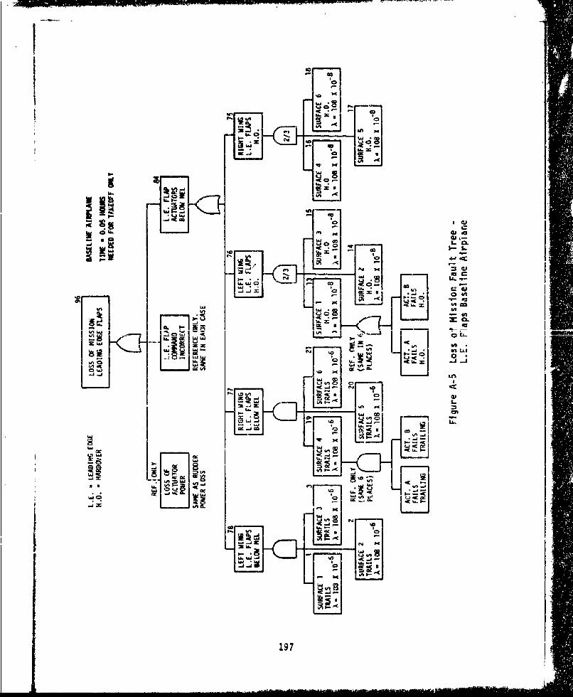
0 4A
in
I 0.01- EL
-J -C
I.vs
LU 0ý. U
ajoU- lc197

95
MISSION LOSS BASELINE AIRPLANEI LANDING GEAR FAILSTO RETRACT FAILURE TO RETRACT CAUSES
EXCESS DRAG PRECLUDINGSUCCESSFUL MISSION
LS-LANDING GEARMLG - MAIN LANDIN~G GEAR
83 t 01
LOSS OF L..RETRACT L.G. RETRACTACTUATOR CMADFAILS ACTUAT ION
POWE I IFAILS
REF ONLY REF ONLY
m P
NOSELG TGýTMLLU-i MLbiACTUATOR ACTUATOR ACTUATORFAILS TO FAILS TO FAILS TORETRACT RETRACT RETRACT
X 10 X Ia 6 X = 40X10-6 X -40 X10-6
o NOSE GEAR RETRACTS FORWARDTHEREFORE CAN EXTEND BY FREE-FALL
* INADVERTENT EXTENSION IS CONSIDEREDTO BE AN IMPOSSIBLE FAILURE MODE
Figure A-6 Loss of Mission Fault Tree-Landing Gear, Baseline Airplane
198

i- ' 94MISSION LOSS BASELINE AIRPLANEENGINE INLET t -1 2
LOSS OF ENGINE LOSS OF ENGINE RIGHT ENGINE LEFT ENGINEINLET ACTUATOR INLET ACTUATOR INLET ACT. INLET ACT.PWRCMADFAILS FAILS
REFERENCE ONLY X = 50 X 10 6 x 5o X lo-6
SEST EST
LOSS OF EITHER ENGINE INLET RESULTSIN REDUCED ENGINE EFFICIENCY WHICH PRECLUDESi ~MISSION SUCCESS i
M Nemre A-7 ILc n' f m.. z.nn Fpuilt Tree -
Engine Inlet Baseline Airplane
93
.MISSION LOSS t - (3/4) (MISSION TIME)
GUN CONTROL t = (3/4) (1.28) = 0.97
_ _ _ _ _ _ _;•-_
I 27
LOSS OF ILOSS OFGUNI GUN CONTROLACTUATOR CONTROL ACTUATOR
DFAILS
REFERENCE ONLY 6= 13 X 10 6
C-14 SHAKER ACT. F.R.X2
Figure A-8 Loss of Mission Fault Tree -
Gun Cont-ol Baseline Airplane
199

92
MISSION LOSS BASELINE AIRPLANE
SPOILERS HARDOVER OF ANYSURFACE CAUSESEXCESSIVE DRAG
0 C-14 T.E. FLAP SYSTEM FR WHICH RESULTS IN
X 2 MISSION ABORTt •1.28
COMMAND SPO ILERFAILS ,,HARDOVER ,•
LEFT OUTBOARD LEFT INBOARD RIGHT OUTBOARD RIGHT INBOARDFAILS H.O. FAILS H.O. FAILS H.O. FAILS H.O.
120 X 10-8 X= 120 X 10-8 X- 120 X 108 )8 = 120 X 10-8
Figure A-9 Loss of Mission Fault Tree -
Spoilers Baseline Airplane
MISSION LOSS BASELINE AIRPLANEELECTRICAL POWER
SYSTEM t 1.28
0 C-14 ELECT SYSTEM F.R. 2/3X 2
3 32 34ELEC. SYS ELEC. SYS EMiWERG.F3AILS E LECS
#1 112 ELEC SYSFAIAS FAILS CIL
0 X- 1200 X I0-6 X- 1200 X O"6 X - 1200 X 1O06
a LOSS OF 2 OF 3 ELECTRICAL SYSTEMS RESULTS IN MISSION ABORT.* EACH "SYSTEM" ASSUMED TO CONTAIN ITS OWN DISTRIBUTION SYSTEMSASSUMES NO SINGLE FAILURE POINTS EXIST THAT CAN CAUSE ALL SYSTEMS TO
GO DOWN AT ONCE.0 IGNORES LOSS OF ENGINES AS A CAUSE OF ELECTRICAL SYSTEM LOSS SINCE THE
EFFECTS ARE THE SAME FOR BOTH BASELINE & ALL-ELECTRIC AIRPLANESFigure A-10 Loss of Mission Fault Tree -
Electrical Power System Baseline Airplane
200
- C .

90
LOSS OF MISSION BASELINE AIRPLANEENVIRONMENTAL t MISSION TIME
CONTROL SYSTEMt
{ 38
[ :CONTROLS BELOW POWER LOSSLOSS MEL_LOSS
.ONLY Y 1 -O6 REF. ONLY
(CO"C-CD IN UJiitK-TRE ES }
OCECS F.R. FOR ECS (OPEN LOOP) a 2427 X 10
Figure A-11 Loss of Mission Fault Tree -
ECS Baseline Airplane
201
S.....

NOTE: SAME AS LOSS OFCANARD ACTUATION POWER - 81
LOSS OF MISSION BASELINE AIRPLANE
HYDRAULICS t * 1.28
F 35 36 37 OHYD SYS HYD SYS HYD SYS
#1 #2 #3FAILS FAILS FAILS
0 -80 x l O-6 A 80 X 10-6 X = 80 X 10 .6
*LOSS OF HYD SYSTEMS #I AND #2 CAUSES LOSS OF AERIAL REFUEL,GUN DRIWE, AD ECS WK1Cn RESULTS IN MISSn1 ABnOT T T-ASSUMES THAT THE ECS FAILURE IS DETECTABLE AND ABORT CANBE ACCOMPLISHED BEFORE LOSS OF CRITICAL FLY-BY-WIREAVIONICS OCCURS, OTHERWISE LOSS OF A/C CAN RESULT FROMLOSS OF BOTH HYDRAULIC SYSTEMS.
e EACH "SYSTEM" ASSUMED TO CONTAIN ITS OWN DISTRIBUTION SYSTEM.
oASSUMES NO SINGLE FAILURE POINTS EXIST THAT CAN CAUSE ALLSYSTEMS TO GO DOWN AT ONCE.
*IGNORES LOSS OF ENGINES AS A CAUSE OF HYD SYSTEM LOSS
0 C-14 HYD SYS F.R. X 2
Figure A-12 Loss of Mission Fault Tree -Hydraulic Power System Baseline Airplane
202

-km- ... ..- -
TABLE A-1 MISSION COMPLETION - BASELINE AIRPLANE
* c •1 - . , iL - ', • , -. ¢Jt"'
.'nfT ,.4-EL~iILIV, *V..L ~i1LIT.' ,-,•. , cr rc:" .rTg pI, T
* .I7 [-, ',. 4-• ' 4-t 1••4 .- .e t I ". C:.MI"*4 I
= :.- ;O(-., . ,L:-€, -'4t 4.¢• . I•'4 .e i • .• [-.
7 . .. a. ..I..... Zst.-¢t
1- 1 t.1:-"4 ( (C4 .. .- , '•% .3-4,:.. ] %ao- .i- I
1- 1 •. :e't-'4 , e.::,:€ - 3"":. ... . . :4:.. t:. I :....:%.t0_,:, 1'- d L.4t- I T . ;. I . .-•( •-7'r i- T I
. P--,.Z . .-. , . 1~4... 1 .& 'c-..-r, 4 ,
-. i •'' ''; r... • i-4 '(- 1', -4..'<- I , 1 c. -.•-,., ,4 :,
:C?.%•'••a '.:.,t€ 4 %.,,4•4.t
, :.1•-6tI.-.c. I
...............................................................................................
: .aci't[ ,• O.¢'4sGL~c.-_It.'4T'.rn. I """• ' +
I * .-- "., ?,,'-, "h 4? I 6v (E -7
4.C"N-V4.
z. % 1.-. t'. 4 " • 7: 4
., I e~ . ." c t - . . •. 7 e : - c . Q r r c 7 .4 I , . -,' ' L "- .
" 1 .-. .'.J -• '-.4 4"' "' • - ' -
- a 1 *..I-T-t- *,-* •,•.44 7"(44C .tIU 1 • *t-( '-[' I+ :+ . ;.-t,;- +: , i '4 -. 4i ":,4 : '. - I '.v,"t,--- -,
i , 1 , I- ,.•. : 4. 1+•_•--" '.. 1- " JA ,', !~ ¢ I I" tO'+ -- <
-- I .4 • o .I,,'-'-J7, IZ,• -t44F- C • I I"..(.'MD'-k"•' Ii
- l[ •1, ,+, s*'( .n.4.,• ' •"T•Wc4 : IILI I '.' iT ~ 5
-. : i•=[,-'.- -u, ,:,CG-4C- C,,f-'=r I"I0• I " :.. ; "•I... is e c,',[ ,_Z 7,-, I
:" 1 *.' •t'-, ,,. 44•:.•' 4-&_ 4 - -'-¶ ' I 1
- r- r. -: 7 l
., * " 1.' - l.:-, .a "..' '• ,, 1',."- (n"' -%• - ,- 'e, ,.¢
:. i :...fl 7.-". : ,; '•."-• • + - :' "1 1-
--, d ".. ir•'•- -. ' • -'..7C rC .. 'I1'4-l " •:
* ' *" . ' .4 .~. . .q'
-4 t. .**- * 'r•- 4.Q.. C4I.+7••,iT"'4C .j . -
:4 . - -,.,.-(-,4 I',. +' CI"€ 7 I•I•" -1 " *!4+-• -"'-
-r• -i 7-t4.- ,& .. .*4, • -.: ," . -- , ",
7 . - t*cc.*"'- 7
IQU -. "-4 .---. •iI': .,',;.• *; . ... ~ I
rcf lyl r I " , ," Tr :rt ,.Qr
Q 7.¶ 7...•
q r!,L-r *1-!.--[ I.t. -.4rfC1"$.TI ,, *.ITr4rrc I...-I•' ;. - "
203

100
LOSS OF ALL-ELECTRIC AIRPLANE
MISSION AELOM-2 FILE NAME
94 99
ENGINE INLET PITCH CONTROLCONTROL BELOW BELOW MINIMUMMINIMJM LEVEL LEVEL
93 98GUN DRIVE R CNOCAPABILITY ROLL CONTROL.BELOW MINIMUM BELOW MINIMUMLEVEL LEVEL
92 97
SPOILERS YAW CONTROL
REOW MINIMUM BELOW MINIMUMLEVEL It LEv ELi
91 96
ELECIRICAL LEADING EDGEPOWER SYSTEM FLAIN EDGESBELOW MINIMUM FLAPS BELOW |
VELOW MINIMUM LEVEL_L-EVEL ..
95
LANDING GEARBELOW MINIMUMLEVEL
90-1 ENVIRONMENTALLOSS OF OTHER
I MISSION - _ CO(XTROL SYSTEM
CRITICAL SYSTEMS BELOW MINIMUM
L _ . . .. . .L E V E L
REFERENCE ONLY
Figure A-13 Losm of Mission Fault Tree -
All-Electric Airplane
204

99.
LOSS OF MISSION ALL-ELECTRIC AIRPLANE
PiTCH CONTROL - MINIMUM EQUIPMENT LEVEL
t - 1.28 HOURS
L89
SMEL ME
REFERENCE ONLY
SEE COMPLETIONOF THIS LEGiUNDER ROLL
I ~74 8* -. - ,* 8
CANARD.CO|tANU LA.UAr uLAMIIr_ -IxBELOW MEL BELOW MEL I BEOWMEL J11
REFE2ENCE ONLY X a 0 x 10-6SAME IN EACH CASE 2/3 REF ONLY
4 51 6ACTUATOR [ACTUATOR ACUATOR
1 2 3FAILS FAILS FAILS
0 X. 180 x 10- 6 X- 180 x 10-6 X a- 180 x 10-6
0 AIRESEARCH ACTUATOR FR + 172 x 106 FOR INVERTER
Figure A-14 Loss of Mission Fault Tree -
Pitch Control All-Electric Airplane
Z 05

98 -----
LOSS OF MISSION ALL-ELECTRIC AIRPLANEROLL CONTROL MEL- MINIMUM
. ,• ~ EQU IPMENT LEVEL i
t: 1.I28 HIOURS
8,1 8 BY 86
ELEVON COMMAND LEFT ELEVON RIGHT ELEVON ELEVON POWERiBELOW MEL I BELOW MEL BELOW MEL BELOW MEL 1•---
REFERENCEX. x1ONLY - SAME 0 RE--ONL
IN EACH CASERFONY[
r .LEVO N EL , - ON NLE-Nm •r~l'* A 0-m"l I~ h A #%InT . Thn%"•'"M6 1 1 I vr%"'U;- l UP % 1 •'U ll 1 ! " '" u
X- 180 X.1O" 6 )X- 180 X 10-6 X. 180 X 10-6 )X 180 X 10-6
NOTE:
"ACTUATOR" FAILURE RATE INCLUDES INVERTER AND ACTUATOR
C-14 FR FOR INVERTER - 86 x 10- 6
FIGHTER CONVERSION x 2 - 172 x 10-6
AIRESEARCH X FOR ELEVON ACTUATOR 8.2 x 10- 6
Figure A-1S Loss of M4 ssion Fault Tree -
Roll Control All-Electric Airplane
206

97
LOSS GF MISSIN ALL-ELECTRIC AIRPLANE
t i .28 HOURSYAW CONTROL
I I 85
RUDDER COMMAND RUDDER POWERBEO E ACTUATION iLOSSBELOW MELBELOW MEL
REFERENCE ONLY. REFERENCE ONLYSAMVE IN EACH CASE
1 12RUDDERA ACT. RUDDER ACT.
)-180 06 180X i 0-B
Figure A-16 Loss of Mtision Failt Tree -
Yaw Control All-Electric Airplane
207

10
ipC
31 1
CL
-i ui
Q.z.
U.tý U*{xj0
w 0O
208uIl

M I
95
MISSION LOSS ALL-ELECTRIC AIRPLANE
ILANDING GEAR FAILSTO RETRACT FAILURE TO RETRACT CAUSES
EXLESS DRAG PRECLUDINGSUCCESSFUL MISSION
LG - LANDING GEARMLG - MAIN LANDING GEAR
F ; 83 t "0.10
LOSS OF L.G. RETRACT L.G. RETRACT
ACTUATOR COMMVAND FAILS ACTUATIONPOWER FAILS
R E F O N L Y R E F ONLY
f 1 _ __ 231OS RIGU. MLr C LEF! MLG
LOSS OF ACTUATOR ACTUATOR ACTUATOR28 VDC FAILS TO FAILS TO FA!LS TOBUS R RETRACT RETRACT
X - 6x 10.6 X - 176 X 106 X *176 X 10" X 1176 X I06
0 C-14 FR x 2 FOR k1GHTER
* NOSE GEAR RETRACTS FORWARD
THEREFORE CAN EXTEND BY FREE-FALL
* INADVERTENT EXTENSION IS LONSIDEREDTO BE AN IMPOSSIBLE FAILURE MODE
rigure A-18 Loss of Mission Fault Tree -
Landing Gear All-Electric Airplane
209

94
MISSION LOSS ALL-ELECTRIC AIRPLANE
ENGINE INLET t " 1.ze
•5 26
LOSS OF ENGINE LOSS OF ENGINE RIGHT ENGINE LEFT ENGINEINLET ACTUATOR INLET ACTUATOR INLET ACT. INLET ACT.POWER COMMAND FAILS . FAILS
REFERENCE ONLY 36 X 8 X 10"6 x - 8 x 10"6
E.I.INVERTER
X - 172 x 10-
LOSS OF EITHER ENGINE INLET RESULTSIN REDUCED ErNINE EFFIrtINCy V.t" PRECLUDESMISSION SUCCESSU
Figure A-19 Loss of Mission Fault Tree -
Engine Inlet All-Electrlc Airplane
•93 i
MISSION LOSS t - (3/4) (MISSION TIME)GUN CONTROL t - (3/4) (1.28) = 0.97
r 27
LOSS OF LOSOF SUN GUN CONTROLACTUATOR CONTROL ACTUATORPOWER COMMAND FAILS
REFERENCE ONLY I *180X
Figure A-20 Loss of Mission Fault Tree -
Gun Control All-Electric Airplane
210

92
MISSION LOSS ALL-ELECTRIC AIRPLANESPOILERS HARDOVER OF ANY
SURFACE CAUSESEXCESSIVE DRAGWHICH RESULTS INMISSION ABORT
t 1.28
SPOILERCOMM4AND HARD1 ER
FAILS
1
28 29 30 31
LETOTOR EFT INBOARD 3IHT OUTBOARD RI GHT INBOARDFAILS H.O. AILS H.O. FAILS H.O. FAILS H.O.
)= 176 X 108 X) 176 X 10 8 X - 176 X 1r"B X= 176 X 10-8
Figure A-21 Loss of Mission Fault Tree -Spoilers All-Electric Airplane
211

MISSION LOSS ALL-ELECTRIC AIRPLANEELECTRICAL POWER t a 1.28
SYSTEM,
S 32 _33 1 34SELEC. SYS ] ELEC SYS- ERG.
#1 12EEC SYSFfjLSA I FAILS -AL
X- 2400 x 10 2400 x I0"6 ), 2400 x I0"6
* LOSS OF 2 OF 3 ELECTRICAL SYSTEMS RESULTS IN MISSION ABORT.
* EACH "SYSTEM" ASSUMED TO CONTAIN ITS OWN DISTRIBUTION SYSTEM
* ASSUMES NO SINGLE FAILURE POINTS EXIST THAT CAN CAUSE ALLSYSTEMS TO GO DOWN AT ONCE.
* IGNORES LOSS OF ENGINES AS A CAUSE OF ELECTRICAL SYSTEM LOSS SINCE THEEFFECTS ARE THE SAME FOR BOTH BASELINE & ALL-ELECTRIC AIRPLANES
Figure A-22 Loss of Mission Fault Tree -Electrical Power System All-Electric Airplane
212

90
LOSS OF MISSION ALL-ELECTRIC AIRPLANEENVt MISSION TIME
CONTROL SYSTEM_ t t 1.28
S- .~
I 38
ECS ECS HYD I & 2CONTROLS BELOW POWER LOSSLOSS MEL
REF. ONLY 0 - 2592 X 10-6 REF. ONLY(COVERED IN OTHER
35 TREES)
COOLINGSYSTEM FAILS
LOSS OF LOSS OF LOSS OFLI COLLIQ COOL/ LIQ COOLiSSASYS B. SYS C
X., 500 x 10-i X 500 x io 6 1 - 500 x 10-
0 FROM CECS ON LIQUID REFRIGDISTRIBUTION SYSTEM
Figure A-23 Loss of Mission Fault Tree -Environmental Control SystemAll-Electric Airplane
213
___•_,___________I__II

I TABLE A-2 MISSION COMPLETION -ALL-ELECTRIC AIRPLANE
-L lrcIt r-% I : !.. .ityc11 ,.i "-
4'~ ('-11e -e-1 .:Ct'
¶ ý ý --. ýcr." ~ & Ga~1'CI I
17. C-1-0~44
- I .,r.- .j
~ Ccsf14-cc~-Z.I 4Q i* -'c 7;-' I -
C -r-c'Ti--C-. rWc.kv' i I4 1
.ra~~CI-C71C 4 1' -ti1
I E'~ -~.QS. 4E'. 4l3 t -l I I ~ .~
7711 1.t-4 1 1O :% 1 9 El I
1. C4wD IOO?9~~4 f 'l % 1
I -, t: 4r 9 I ?-'rQD-' 101'
214 ~ 4.
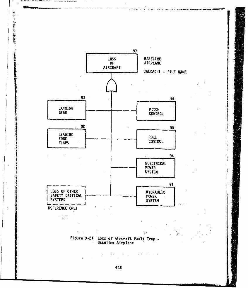
97LOSS BAS ELINEOF AIRPLANE
AIRCRAFTAiRCR, BALOAC-1 - FILE NAME
93 96
LANDING - -PITCH
GEAR CONTROL
92 95
LEADINHG ______I REDGE ROLLFLAPS CONTROL
: 94
LOSS OF OTHER ,A r F HYDRAULIC lSAFETY CRITICAL POWER]SYSTEMS SYTE
REFERENCE ONLY
Figure A-24. Loss of Aircraft. Fault. Tre#,-Baselifne Airplane

LOSS OF BASELINEAIRCRAFT AIRPLANEPITCH CONTROL t;i - 1.28
90 1 89C)A0CANARDUUFCEo VIEDV cmCANAR LISS OF •
Fi CANARDVESURFACE HARD SURFACE ALL HYDTRAILING OVER POWETRON
(REF ONLY) (REF ONLY) RF NYSEE ROLLCONTROL SME FOR SEE HYDFOR COMPLETION BOTH •ESIGNS SYSTEM TREEOFTHIS LEG
80 79 7877RIGHT LEFT IHTLFCNR kAOCANARD CANARDFAILS FAILS WD OVER HTRAILING TRAILING
7 8 9 1ACT #1 ACT #2 ACT #3 ACT 94 A C 6FAIL! FAILS FAILS FAILS LFAILS IHARDOVER HARDOVER HAROVERE HARDOVER HARDOVER R
* X-0.9 x i0E X-09 x 106 XXO.9 x ,XO 6 X60.9 x 10- 6 X.O.9 10-6
ONLY FAILURE MODE THAT CANPRODUCE A HARD OVER FAILURENOSE IS LOSS OF MECHANICALPOSITION FEEDBACK OF EACHSERVOVALVE THAT CONTROLSEACH SEGMENT OF THE DUAL 4 6
TANDEM ACTUI TOR ACT f4 10T9 06FAIALS LIFATRAILINGL I.
L- 3 192 x- Z 10 .", x . 10'
ACT#I CT u A- Los ACT 3eFAILS fFAIS FAILS! AL
TRAILINS TRAILIN TRAILING TALN
Figure A-25 Loss of Aircraft Fault Tree -
Pitch Control B&sellne Airplane
216

ROLL ONTROLOSS OF BASELINEAIRCRAFT AIRPLANE
t, t 1.28
rTRALN POSITION
ASSEPPITTO CAUSEFOPADORT UT CONOTRO A/C ULTS BOTH DE~S IGNS .8 o6 ~1.8~1~ u16
Fiur I.2 Ls icaf altie
Rol C76 ro Baein5rlnLEFT IGHTLEFTRIGH

94LOSS OF BASELINEAIRCRAFT AIRPLEELECTRICAL IPOWER SYSTEM t - 1.28
S 21 22 23
ELEC SYS ELEC SYS ELEC SYS11 FAILS #2 FAILS 03 FAILS
0 X- 1200 x 10m6 x 1200 x 10-0 X- 1200 x 10-
o C-14 ELEC SYSTEM FR X 2
Figure A-27 Loss of Aircraft Fault Tre -eElectrical Power System Baseline Airplane
21k8. .,. l.---

93L LOSS OF
AIRCRAFT BASELINELANDING GEAR AIRPLANE
*t3 0 .10
AINR GEAR SEGEAR LOSS OFO Lo IFFAILS FAIL S LANDING LOSS OF BRAKESTO EXT•END TO EXTEND GEAR AND HYDRAIULIC DURING
F.X'ITND _ED [ FXTENDED CONTROL ROLL I
F _ 8 3 1 8 2 3 3 1 3i 34UDOW LOCK
UPF RLOT CTUTRK AC:TUATOR RGTLEFTLETRGTATAO FAILS TO I BRAKES I BRAKES
RELEASE ENGAGE OR FAILHOLD
1- 5 x 10- 1,- 5 x 10⁻⁶ 3 ,X- 553 x 10"6
32 C C-14 F. RA x 2
c55 6
ACTUATOR
S-91 x 10-6
II LET DOWN
RT EXTEND UP LOCZ LOCK ACTACT FAILS ACT FAILS FAILS TO
TO RELEASE EGAGE ORHOLD
A91 0 x 106 t 10 - x 10-6
LEFTEXTND EFTUP OCK LOCK ACT IACT FAILS AI FAL FAILS TO I
-- 91 x 10-6 x .- 6x 10o x-6 ,-5 -x_ OX
* NOSE GEAR RETRACTS FORWARD. GEAR CrA4 BE EXTENDED ST FREE-FALL IF NOT .ZAINED OR LOCKED.
a NOSE GEAR STEERING ASSumVD TO BE USED DUIRN6 TAXI N4LY AND IS NOT SAFETY CRtTTCAL.
a MAIN GEAR (PER SIDE) I LINEAR PISTON ACT + I SOLENOID VALVe + POSIT INDICATOR91 x IO06
Figure A-28 Loss of Aircraft Fault Tree -
Landing Gear Baseline Airplane
219

92
LOSS OF 4ASELINEAIRCRAFT AIRPLARELEADING ED•E tt 0.15 HOUftSFLAPS
LIS O LOS F L E FAPi ACTUIATOR| SYMMIC.,L ICOIHWDO
POKA INCORRECT
ThAIING AIOO~R 'RAILFGJLIFTC
ACT(RE ONLYNL)
ThAI uG TRILAI
FLAPS AL 4 L. ,r L IEPS recFLAoP. FP. E. R
FiLgur A-29S Lso ic Aft FAuLtre-
10-41m X !TII--8-- 10] + cl t-- Idl' 08t -x 106m rx 0I AOýE_ 138e ,xPOOe lo- t0 lx+ lo-.At
L Eg Fa B .se.n rlFtIiCE 2mL2 A0 I
10A l o,• I, -AI9. 0 US
TRAI LINS 1ILI
9• L.[. FLAP$ NEQUIRI:O MRl T.i). AND O $NEITINE1S uJ;0 MR LANDER11 CEIKMUA•E MEN 0.O5 TAK3EOFF"AND 0.10 WRING LANDING)
0 LOSS OF ALL FLAPS ON ONE WING WRIN LAMtm s. OR T/O CAUSES LOSS OF A/C
Figure A-29 Loss of Aircraft Fault Tree-Leading Edge Flaps Baseline Airplane
220
4m~ . . .. . ..... .. , r • + • +t f i ,

91
LOSS OF BASELINEAIRCRAFT AIRPLANEHYDRAULICS5 t -1.2B
E-47 4849
)HYD SYS HYD SYS P~YE ST'S(1 FAILS 12 FAILS 03 FAILS
)X - 80 x 10 6 -80x10 6 80 x 10- 6
Figure A-30 Loss of Aircraft Fault Tree -Hydraulic Power System Baselirne Airplane
221

-F--I-room-----
TABLE A-3 AIRPLANE SAFETY BASELINE AIRPLANE
(SHEET 1 OF 2)
*FICHT I 45 cv!i z1 ý "-rv 'ýF " lFi;I. I T'.n Iy I.C ctQ
-- 2
7':-- FILI 7CITII. yt .- ,
I U" 4ý 4 1
44 ""I -t'4 *
*4 ,
1ý 4'4-l-CC I ZI I '
14 'ce 'e I
C.C.Qcla,.S4 I\C I ý1
I t r.. I s I.5G.L I I'a I Ev I-I
¶ D:--15 e% LT 1 '21E cI W. I I l ,C'flf.I# Z
0? * .4 ZQ70nŽOI 4 I '- -
a . Ž1j-, ý P~cý A4"i 14 1c I z 1
LI '.4' r1:. c~¶9!~ W~ 41 J Jc-
* lC-'~~--'4 -.'.Q-aO l-'- t'Wt- 1 ý7z-
t I.C94EI.C.F
4~~:7 * Tf14 C2¶4C3 ~ I ~ -
a~tI.LW ~ .?-F~0 E'A'1- I- - I 7 1 **t-
t D4 Q.?,SS3CCI~c10
r 222

TABLE A-3 AIRPLANE SAFETY - BASELINE AIRPLANE
(SHEET 2 OF 2)
-- " ", ": it-i* .: CL° .•';" csr"•'""' 'I•- "~
S I. $. !'- 7 . :,,.. -,,,1 " : ' * •
,. *,. I•[I P " .-..- ".j-CVSWC-. % C, - Cl(•',1 I :
1' l1, 1 ~,-•• o ..•,;• • I.r,'; r. . . . .":4. I.c•jc['-I ¢, C.. aC• tW ."IC. e .g• .•
F? I Wt.. I I -''. f "1$C" r -
": 1.' &c ,,4
-0
s "l n"QOC-.' i r-E- ,,d'•'-•l C -C4 J" ''7 . ' I ,.Q . Cl -
2E t I 1'~J f .45 I
,tO p -. , Ir .
17 aC
I.-zlr!: I ,l-`
223
I.-. _ L . . . .. , .-.-. • , •_ . ,*,< . °"

99
LOSS ALL-ELECTRIC AIRPLANE
AIRCRAFT AELOAC-1 - FILE NAME
95 98
LANDING _ _PITCH
GEAR CONTROL
94 97
LEADING ROLLEDGE CONTROLFLAPS
SELECTRICAL.... 9
POWERSYSTEM
93
- - --ENVIRONMENTAL
ILOSS OF OTHER I_ CONTROLSAFETY CRITICAL l -SYSTEMSYSTEMS (LIQUID COOLING)
REFERENCE ONLY
Figure A-3i Loss of Aircraft Fault Tree -All -Electric Airplane
224

98
LOSS OFAIRCRAFT ALL-ELECTRICPITCH CONTROL AIRPLANE
t1 1.28
92 91CANARD [CANARAARDLSSOANARDELEVON CCANARLDEDSS[n AC HARD SURFACE 0FAILS TO H.O. E ]"DTRAILING OVER POSITION POWCR
(REF ONLY) (REF ONLY) (REF ONLY)SEE ROLL CONTROL SAME FOR SEE HYDFOR COMPLE TION BOTH DESIGNS SYSTEMOF THIS LEG
-q -480N@ N9787RIGHT LEFT RIGHT LEFT
|FAILS FAILS FAILS FAILS FAILS FAILSNARD E ARDOVER HARDOCERA RDRDOVER ARD
FAL.FAL ARV R DOE HARDOVER HROV
* 8~ 1 6 X- 18 x 10 E 18 1- k *18x10 118x 10 18x 10
ONLY FAILURE MODE THAT CANPRODUCE A HARD OVER FAILUREMODE IS LOSS OF MECHANICALPOSITION FEEDBACK OF EACHSERVOVALVE THAT CONTROLS .EACH SEGMENT OF THE DUAL 4 6TANDEM ACTUATORS ACT 94 IAT9
FLS FAILS
_. - 180 mx 10" 6 ,A - 180 x 10"6
ACT 2 AC 03ACT 05FIFAILS FAILS FAILS
T~IIG TRAILING L TRA ILING66 TRAILING
. 180 x 10.6 A - 180 x 10" 6 , 180 x 1.0SA- 160 x 10.6
Figure A-32 Loss of Aircraft Fault Tree -Pitch Control All-Electric Airplane
225

97
LOSS OF ALL ELECTRICAIRCRAFT AIRPLANEROLL CONTROL
*1.28
ELEOTH ELEVO E
ELVN F AILURE OFANE LossO OF-I~7Z---2 19EOIN~~~HDRUI ASURFACESTOW AC 3 CT
OFAIL hA HARDOVER TAOL H.O. POE FALSA.01 FAL 1.0 AIS110TAILINGC TOS CAS T1 ON.....
ABORT RE BUOONACLOY.) 1 (REF ONLY 1(REF1 OL)uj O 8SEEur PITCH LSAM FOfARratautTe
RollO ContLo AB-Eecri AirplaNe
TR2E5
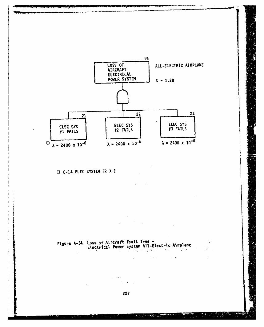
96
LOSS OF ALL-ELECTRIC AIRPLANEAIRCRAFTELECTRICALPOWER SYSTM t 1.28
#1 FAILS 02 FAILS
0 - 2400 x "-2400 x 10"6 X 2400 x 10-6
0 C-14 ELEC SYSTE?' FR X 2
Fi.gure A-34 Loss of Aircraft Fault Tree -
Electrical Power System All-Electric Airplane
227

AIRCRAFT ALL-ELECTRI CLANDOI.G GEAR A R L NAIRPLANEt;3 - 0,10 .
88e 87 -.771; 8
M-AIN GEAR NOSE G.EAR r-LOSS OF I" 'FLOSS OFFAILS FAILS /LA•NOIN LOSS OF [ BAKES
TEXEDTO EXTEND GEAR AND HYDRAULIC DRNOO REMA OR REMAIN BRAKE POWER LANDIDNGEXTENDED EXTENDED CONTROL ROLL
(REF ONLY) (REF ONLY)
_ [ 85 8 ~ 31 33 34_.•
LEFT RiGHT ACTUATOR ACTUATOR R LEFTEGEAR FALS TO FAILS TO BRAKES BRAKESGERGERFAISE THOL ENGAGE OR ,FAIL l FALL
A 10 ox 10 - 10 x 10o X 553 x 10. ) 553 x 10-
EX7END/RETRACiACTUATORJAMS
1 2 ?4 27RT DOWN
RT EXTEND RT UP LOCK LOCK ACTACT FA ILS ACT FAILS FAILS TOOR JAMS TO RELEASE ENGACE OR
HOL.D
~~88x1 ) lx 10- - 10 10-
LEFT DNNILEFT EXTEND LEFT UP LOCK LOCK ACTACT FAILS ACT FAILS FAILS TOOR AM TO RELEASE ENGAGE OR
~i~u~x1DHOLD88 ~x10 A- 10 x10- x mi10xiD0
* NOSE GEAR RETRACTS FORWuARD. GEAR CAN SE EXTENDED BY FREE-~FALL IF NOT JAMMqD OR LOCKED.
9 NOSE GEAR STEERING ASSURIED TO BE USED DURING TAXI ONLY AND IS NOT SAFETY CRITICAL.
* U .SE 1/2 OF L.E. FLAP ACT - (1/Z)(176) - 88 x 1-
Figuire A-35 Loss of Aircraft Fault Tree-
Landi1ng Gear All-Electric Airplane
228

ALL-ELECTRICLOSS OF AIRPLANEAIRCRtAFTLEADING EDGE t2 N .1 O=~FLAPS
LOSS f LUSS OFACTUATOR STPIVTRICAL 4M
ILIFT
706968 67
FA 7 3 F-8364 14
SURFACE 1 1 SURFACE EdgeM_2__ SUFlasACE Elcti Ai rplAn
=I*FA 1 -229

93
LOSS OF ALL-ELECTRIC AIRPLANEAIRCRAFTECS t 1.28LIQUID COOLING
I LOSS OF LOSS OF "CA•NARD & LE f ELEVONiINVERTER INVERTER
IQ COOLING COOLING
LOSS OF LOSS OF LOSS OF m-
~~LIQ COOL LCO
• LIO COOL JLIQ COOL LIQ COOL ICOL•
SYSB
SSYS A J SYS C "" SYS A SSC -
X -.500 x 10 6 X 500 x 10-6 X - 500 x 10 .6 x = Soo x 10--
49
LOSS OFLIQ COOLSYS 8
X- 500 x 10-6
Figure A-37 Loss o' Aircraft Fault Tree -
ECS Liitqd.Cooling System All-Electric Airplane
230

TABLE A-4 AIRPLANE SAFETY -ALL-ELECTRIC AIRPLANE
(SHEET 1 OF 2)
vC TCir ttft - *-rec 11r C-C - I*- -LI-1 1 1 I
--wc r T'# c7 rC-17~1PL1TF1.
r-tt CrIT Ilcr1JcI p3¶ Ir~ j T'. *C CTE I O1 1rFC4'T
1~~~~N P4-~ 1Ctf.C.4 ItI
4 1r44a i974Csj¶4-Ec4 t;-7t I*p !I.W. 1 ~ ~ -4
7 A .jr.- 4 1 S IL IcPC~N IA. 9"Q v.3E I;¶?4 s4e~i 414 I i. I Wot-(" 1n
- 44t'-"~ ~~~~Oo5 ~ A4'iE 4C" F 9 ~tte*,07 4nFC 1 '.sn- I?
iX~t-I" W I t:
'4 n41-CA o.99r?'14 Es¶I i I 7e-.-.
:1- r4AD:qf0 I
-r C 4 I , C..tI4' i.41 _.
' K.n t'~
I. t. kfl' C.. 'it ~ I f 0U"
C ~ ?ý 5mi r%,~C **V .~2Scc? Ic e4N I :fl..
j2-I.C7 9 I f. 43 4 '
7e I. Y'D-~ 14 .c~t-
74 t5(p4 AC Q47A~I 1. V4.C
* ~ ~ ~ ~ ~ r Aý 71f4 V~Zl I *t-
C4t:F"CIc a-%c4 A I I QC~.- -
.1: 1?-n.1rwe1 WT~.
rflg, ¶CŽC~?1 I I * rC231.v
TABLE A-4 AIRPLANE SAFETY - ALL-ELECTRIC AIRPLANE
(SHEET 2 OF 2)C - C~t.-~¶ C. ~A 47
C4~~ýAý n ~DP *Q0~. ~ r 4 . -, 70
CA 1 1flOD-Cod 1l9t4'E19?5 '
or t#O'4 (K C.I'~-e C* lOO S3 A 04 04
SQ ~ ~ ~ ~ . 711 t-t-W79ýO077E2 :
.~~~~~ I~4e It... ii-l4 9i" iq *:N*p~y, l.c5040*-4.11 4aZ229M
p ,0 99 Q 4 4li~ r. co ZF
--w5Q%7c-9619I8 C' 9 1 9-:
~9- 1 ~tI-4I C. I-l41&4j2 C' a- 7-: Q7o
F~~~ rIpjUI rrw 'W1tt. CSr1ITflrgj~r-rrcg .ChPI-
,t
232

APPENDIX B
RCA PRICE-L COST MODEL INPUT DATA
This appendix contains the RCA PRICE-L cost model inp'ut data for 500 Baseline
and All-Electric Airplanes. Tables B-i and B-2 contain data for the actuation
systems and Tables B-3 and B-4 are for the secondary power systems. The input
data for 1000 airplanes is identical except for the "Production Quantity
(QTY)" number on the input data sheet (see Figure 35). For 500 airplanes, QTY
is 500 times QTYNHA; for 1000 oirplanes QTY is 1000 times QTYNHA.
I-
Zh

TABLE B-1 RCA PRICE MODEL INPUT DATA-BASELINE AIRPI.ANEACTUATION SYSTEMS, 500 AIRPLANES
SHEET 1 OF 3
.IINYlI.Obit 2!?-EP-cl 1Il711
00100 --PRICE 34cOILt LiNEAR ACTUAIOR-CANARD MODIFED e623100220 2000 60 39 .IflS 200130 4 0 .5 1.1 199100140 39 5.3 .& 0 .33
00160 t935 C310165 HYORAULCIC SERVO VALVE -CANARD00170 1000 30 7 .0292 1
00140 2! 3 .3 1. 19300190 6 .6 3.;8 .1 0801.13J0200 40 7.940 .1 00 0 1.000,210 0190 C C I"2Z%: 01956C CC1005500 23 LINEAP ACTUATOR-CLEVON30240 2000 40 75 .31 1C.o2s0 4 .5 .3 1.3 1931'.02;0; 4. 2 _9 :.e .32
*Ž20 40 '.?40 .1 0 0 1
A20 0170 C
)0300 ROTARY ROTOR - RUDDER(10310 1000 30 7.5 .0313 100120! : .5 .3 1.9 1911onll 11 7.13 5.30 .1 0) 0 .13
J01.10 to 7.?40 .1 0 0 1-0,Ž50 11 C C I
100340 0t95 C C 1005;5(10370 NINGELINE DEAR SOX - RUDDER:o0uuo 300 &0 22 .0957 2-0370 10 .3 1.3 1931110400 22 5.3 .1 0 0 .3390410 0190 C C Ij04.:0 0al' C C 5500430 RECDUCT ION GEAR SOX - RUDGER.04.40 Soo 15 11 .0473 200450 1 0 .13 1.8 1981"00460 II 3.3 .1 0 0 .3302470 0190 c C I
':0460 0195 C C 3500490 LINEAR ACTUATOR - IPOILEAiflocO 2000 60 17.3 .0937 1
:1 .,10 4 .3 .5 1.3 1931:5 520 *7.3 5.3 .1 0 0 .3323ý30 40 7.94 .1 0 C I
1.,440 190 C C 1o.)350 195 C C too$%
'.50 LINEAR hCTUCrTOR - LE FLAP'A(570 6000 130 19.3 .1010 1
E-50 12 3. 1.3 29931
, i.10 10 CC
102 195 C C ;053S'.,0 LINEAR ACT UATOP.-ENGINE INLET ruiTERBOOV
C50 2 .5 .5 I.N4 1931C'460 17S .3 1.81 0 0 .33
("'470 40 7.94 .1 0 0 1"1-40q 1"o r r!00690 193 C C 1003300700 ROTARY BEARN S0X - ENGINE INLET BYPAS COOR00710 2000 60 2 .0037 1007210 4 .3 .5 1.3 193100730 1.9 3.3 .1 0 0 .3)0074O40 &7.94 .10%0 1
00730 Ito C C 1
140760 i95 C C 10055
234

TABLE B-1 RCA PRICE MODEL INPUT DATA-BASELINE AIRPLANEACTUATION SYSTEMS, 500 AIRPLANES
SHEET 2 OF 3*0070 NYDRAULIC ROTOR - ENGINE INLET OYPASS b00o0.330 2000 60 a .00t3 -00790 4 0 .3 1.3 196100300 2 5.: .1 0 0 .3300310 190 C C I00820 M95 C C 5500330 LINEAR ACTUATOR - RAIN LANO!NG GEAR00340 1000 30 11.9 .0995 300350 2 0 .5 1.3 1931 •
"00M60 1L.9 5.3 .1 0 0 .3700670 190 c C I00830 195 C C 5300390 LINEAR ACTUATOR - NOSE GE1,0090o 500 15 29.5 .L553 2)0910 1 0 .5 1.3 131-
00920 29.5 5.3 .1 0 0 .3300930 190 CC 100940 195 C C !500950 CONTROL V'ALVE, 3 POSITION - LANDINU GEAR00o60 500 15 3 .0125 8100970 1 .5 .3 1.9 1961
00930 2.05 5.0 ,1 0 0 .330099. 40 7.94 .1 0 0 111000 19E C C
11010 In• c C 1005501.), ACTUATOR - NOSE STEERING GEAR',02o0 So0 15 22 .0957 201040 1 0 -5 1.3 1931
01050 27 5.9 .1 0 0 .3301060 190 C C I01070 19 C C 5501030 ISOLATION VALVE - UKUUNU Sit.Om
01090 1000 10 2 .0083 101100 3 I5 .3 1.3 19E111110 1.9 5.6 .1 0 0 .330120 40 7.94 .1 0 0 101130 190 C C I01140 i95 C C 10055
tiIs0 ACTUATOR - RAIN GEAR tRAKES01140 LO00 30 22 .0432 201170 2 0 .5 13 19.IM01130 12 3.1 .1 0 0 .334190 190 C C 101200 195 C C 15
01210 CONTROL VALVE - RAIN GEAR ERAKES•4220 1O00 30 T .04 2"43 30 2 0 .3 1.3 19310124C 9 4.32 .1 0 0 .33,%1:N0 190 C C I01246 191 C C 5S01i70 SNUIOFF VALVE, AIN GCAR BRAKFESOt23O 1000 30 t .004 2l1t90 2 0 .3 3.6 1991o1jo0 1 5.3 .1 0 0 .3311310 190 c c I• 120 19t C c 55
.7!0o fARVING VAL•L - RAIN GtAR PRAVES-,I Ie. 3000 10 2.5 .0164411350 2 0 .3 1.3 193101360 2.5 5.3 .1 0 a .3301370 190 C C 101330 195 C C 5501390 ACCUNULATOR - RAIN GEAR gRAKES01400 1000 30 10 .0781 201410 2 0 .3 1. T 19101420 to 5.73 .1 0 0 .3301430 190 C C 101440 195 C C 5511510 ACTUATOR-ACRIAL RErUELING01520 500 I5 1.b .0079 2.1530 1 0 .5 1.3 1931;1540 1.5 5.8 .1 0 0 .33.1550 *Bps C C I•- . 019 c C ! I505.70 A•lUAlON- AELIAL RCEuELIMN kOZ*LC LATCH
01!50 500 1 .I1 .0053OtTV ! 0.5 1.3 1931
01400e &.w i'3 .1 0 o 311410 0190 C C I
01&20 OL93 C C SS
25.

ALEB-i RCA PRICE MODEL INPUT DATA-BASELINE AIRPLANEACTUATION SYSTEMS, 500 AIRPLANES
SHEET 3 OF 3
01630 CONIPOL VALVE- AtRmAL REFUELING,::; 500 It 3.25 .0133 2
OtIto 1 0 .5 1.9 1991016-40 3.21 5.9 .1 0 0 A3301470 Ott0 C C I
0%440 0111 C C S55'n&90 LINEAR AC1UATOK_ CANOPY
-I700 500 13 2.9 .0153 2
01710 1 0 . 1.3 vafl.IŽ.1720 :!.v95 .1 0 0 .31-11730 0190 C CI01740 OiY3 C C 53,.I1IzQ CONTROL VALVE- 3 POSITION- CANOPY
Oi'60 500 15 1.0 .0042 2
W7 a .5 .3 1.8 198100430 t.0 3.9 .1 0 0 .3311710 01t0 C C Iate3c0 0193 C C 55'j*It O:AR BOX- GUN DRIVE0I820 30o 15 10 .0A35 2
010S30 1 It .5 1.2 193101840 to 5.3 .1 0 0.3151110 0190 C cI01.060 0195 C C it010.70 HYDRAULIC ,010R - GUN t'SIvC
01 00 IS1 7.6 .0317 2
::s' 7.65.8 .1 3) 0 .330~~0 C190 C c
12 0 01ls C r 533'ý1930 CONTROL V~ALVE . 2. POSIlIOM -GUM D'RIVEl
.-9/6 500 13 0.4 .0350 2Its 1 .3 1.8 19091
K±4 e.4 5.8 .1 0 0 .33oljvo9 C C Id tYS c C 3
, y'j HYDRAULIC flClift- ECS PAC-t C'3MPRE5$OR:."loo 500 15 4.0 .018 7
152'10 1 0 .3 1.8 Wi025I20 4.0 3.e .1 0 0 033Il 30 0190o C t I
* ~~o 019 C. c 55~.50 CCOL-ROL VAL~r. 2! POSITION- tC4. PACK. C0Hb'9.E5SOP
..55s 500 1 51 -0 __' I.2060 1 S5 .3 1.8 1981.':o'70 .t5 ý..9 .1 '0 0 .33li213 a0 f. 7.940 .1 0 0 1.0ý%2090 O190 C C 102100 0195 C C loot's02110 GEAR BOX - ELECTRONICS COOLINO PAN
002120 50, 15 7 .3 .0326 202130 1 0 .3 1.8 1961e0.1140 7.5 5.8 .1 0 0 .330Ž.150 0190 C C I
aý2160 0195 C C 5$')*7 1*'fOULIC FkOlUR - ELECTRONICS COOLING FAN
So El0 1 .6 .0317 2."!90 t 0 .3 1.9 1991.
;%n00 7.A 5.3 .1 0 .31
1122s) 0190 C CI022"0 01193 C c 55
0223 LONIPOL VALVE, 3 PO3IV-ON- ELECTRONICS C,!0LYNO FAN
02240 300 25 1.0 .0A42 1-).2150 1 .5 .3 :.t 193102260 .ys 5.8 .1 0 0 .33
75 40 7.940 -. 0 v 1.0C2210 PottO C C I?72vc ottl C C 10053czloO ItRofi VALVEt - 9ENE'&IL PUAPOSL.i2310 12000 360 1. .0042 1-:212.# 24 .3 .3 1.0 1931L
230 .95 5. 1i 0 0 .13.72360 40 7.140 .1 0 0 1.0s37?50 0190 c C IeZIAC 0195 C C 10033.ý270 INITEGRATION AND [email protected] 500 15 .7 .' 5
';21v0 0 0 0 1.6 Ives.)2400 0t9o C. C @113 C
236

TABLE B-2 RCA PRICE MODEL INPUT DATA-ALL-ELECTRIC AIRPLANEACTUATION SYSTEMS, 5O0 AIRPLANES
SHEET 1 OF S
0tOO ".PRICE 04IM19 POWLM DRIVE UWIT/SALL MCECW ACT-CANARD FODlFED |rIC l31f
00120 1000 30 38.0 .16532 2
.7130 20 .5 1.3 19st00140 38 1. .1 0 a .332150 Otto C C I
.'160 O*1? C C S3*2170 MOTOR - ChAlk
!
"".soI4 3000 90 . .42 N.0 - 1?0 & 0 .3 1.1 191100200 6 5. .1 0 0 .3.
04210 0t90 C. I
o_2:o 0195 C C 5!.20 INVERTERt - CANARD
•0•0 PO[R OZU••HI I k•G[INEGEAR •IIX - ELEVO4
0240 1000 10 70 .3043 2
.0320 2 0 .3 1-q 1931•330 70 3.d .1 0 0 .33
0190 C 0 0
'oi50 019O C C 1.
'0360 nPOTR D UNT E /O G... 70 2000 0 0.7 .30 2
IwO32 2 0 .5 1.11 imi
`13930 370 3.4 .1 0 O .3311)400 Otto C C I
010 0195 C C 55
!o~o MTiR- ELE.*ON
*.i!O0 2000 t0 L3.7 .Qt2! 2
1 0 1. 20 4 0 . 3 1 . 8 19 8 1
01390 39.7 5.5 .1 0 0 .33
WO. 0190 . C 1.I0-•S•0 019. C ! 05
•490 PO0I•C -RV kUDIT /HlEl4 EA C u
44500 5009 150 .1• 9a .2'•.510 1 0 .5 1.9 1981" 350 01"0 C C I
'.:421 !m,•ESqifD - EVORm
3,^,0 1000 40 120. .0227 1
+.0570 2.0 .3 1.8 1931
';.40 2210.5 1. .1 * 0 .23
'.4540 0190 C C 1'0eoo 019t C c 104Z2.0490 POWER DRIVE UNDDEIT R N14EIbl GRntOX -RDOEP
"50•0 500O 5 3T .16t6
*ti!0 1 0 .5 1.91 7 1
C1:520 13. 5.82 .10 0 0.33
Olt? * c1 C. I
670 019O c C 055
O07IO rO•OR -PONIVLUI WBLN GA 0 -3OL
"S675 1000 11.0 .050 . 26
"11,70 : 0 .3 1.8 1981
01210q 105 1.3 .1 0 0 .33
-70220 0190 C C I
C0230 0192 C C 25•74Q 00 VRTEtR - RPOIDER
L0210 000 60 17 .0276 1
_030 4 3 .3 1.$ 191
•0 55.3 3.• ,1 0 0 .,3
-'07S0 0t90 C C t004-0 3195 C C I.
POW0 NVRER OKV UNOITE / A~LN
EA O FI
;1416 2000 60 to .0636s 1OC70 40 .. 1.8 is
00330 to3 5.2 .1 0 0.23
5040 0. 1.04153
237I~ ~ ~ ~7 5; 5,-.r . . . .. 1 -- '- '3•3'

-. --'* -
TABLE B-2 RCA PRICE MODEL INPUT. DATA-ALL-ELECTRIC.AIRP M4Et
ACTUATION SYSTEMS, 500 AIRPLANES
SHEET 2 OF 5
10370 POWER DRIVE UWiT / HINSELINE GEAR 201 LE FLAP
!00330 3000 90 34.7 -ISO? Z0o9o0 a 0 .5 L.6 1961
009000 34. 5.9 .1 0 ) 433:oy0i1o 01907 C C100920 0195 CC'5!wl) 30 flT0 - L.E_ FLAP0V9f4o 3000 ,0 '.2 .036
059 6 0 .1 1.3 1961060 6.! 5..3 .1 a 0 .33
"•0970 0190 C C I
00990~ INUERICER - L.E. FLAP0010)0 3000 9o0 .1 .0773 L01010 .3 .B i.S 198101020 .65.52 .1 0 a .13
612 '1 .941 .1 0 0 1.1040 0190 c C i01'4 1 0 0 193 C C 104t3uI'stO BALL SCREW ACTUATOR -ENGINE INLET CEIIIERDODY0107?0 1000 30 32 .1391 2*:1n0 : 0 .3 1.3 ITnSilsYC 32 5.3 .E 0 0 .311.1100 0190 C c IC1.t0 0195 C C 15
mi2 OTOt - EhOINE lKLET CEN7Ek tODY01.110 1000 30 b.0 .0296 2"1140 2 0 .3 1'6 193'01150 5 1.3 .1 0 0 .33'J1160 0190 C C I
0119 Ihv~iE -ETICI.KLE! CENTER £OOY01190 1000 30 7.5 .06822
I.I t 2 .3 .3 1.P 19910L1210 6.7 13.52 .1 0 0 .330120 21 6.#41 .1 0 0 1
01230 0190 C C 1031240 019 C C 104533012150 POVF.R DRIVE UNITIGEAR-BOX ENGINE INLE1 BYPASS DOORk01260 2000 40 3 .013 2X270 4 0 .3 1.6 199101294 3 5.3 .1 0 0 .133,I:9q0 @190 C cI41100 0192 C C t5
101CP- IMNLKLET &YPAUf L-=V;01320 2000 60 1 .0077 2i1330 4 0 .3 1.6 193101340 1 5.3 .1 0 0 .3301350 0190 C L i01360 0195 C C 55L137u INVERTER - ENGINE INL.ET BYPASS D(oOR
01390 2000 60 1 .0091 14:0 4 .3 .3 i.' 1961
01400 'q S.51 .1 0 0 .32031410 3£ 6.9141 13 0 0 I01420 019 C C
)1430 OIm CCi10453 LA NG ER
01430 1000 3to 20 .037 201440 2 0 .5 1.3 1901014670 :c %.b .1 0 0 .33I.01490 @1fl9 C c I01500 AOVOR-NAIH 4 NOSE LANDING GEAR01510 1300 45 % C.C96201520 3 0 .3 I.E 1931
*15&0 IWVERTER-RAIN 6£OELNDN -V11570 1500 43 3.7 .0 1S;1560 3 .3 .3 1.0 1Y1IiOt'S59 5.1 $5.2 .1 It 0 .3301600o 31 6.#41 .1 0 0 1012130 0190 t C I'.i620 019! C c 1%04!3
238
a,--Ad

TABLE B-2 RCA PRICE MODEL INPUT DATA-ALL-ELECTRIC AIRPLANEACTUATION SYSTEMS, 500 AIRPLANES
SHEET 3 OF5
~1430 &ALL SCREW ACT-NOIE LANDING GEAR.01440 StO L55 208.07 2:-&1 1 ':7 . 19
01440 20 5.0 .1 0 0 .3301170 0190 C CI01690 0t193 C C !5012" ACTUATOR-NOSE GEAR STEERINII@1030 So0 15 20 .1 2019110 1 0 .5 1.1 1931 201950o 20 5.8 .1 0 0 .3301160 0290 C C 10117Q 0095 C C j501 o 0 FlOTG .- NOSE GEAR STEERINGO1390 500 13 '. .024eoit00 I 0 .3 1.8 199101910 4 5.3. .1 0 0 .33CJ1920 0190 C C I019130 OL95 C C 55111940 bULL kIKG ASCy-ImAlN GEAR ZRAKES011950 too* 30 7 .0173 2J1940 2 0 .5 1.9 19091.31970 ? 5.8 .1 00 .33'.1980 0190 C r I
0 90 0195 C c S5000 MCJOR-.MAN GIAR IRAr.ES
t-2010 9000 240 .7% .0045 2'.2020 16 0 .2 1.3 199102030 .75 5.3 .1 0 0 .3311"40 0190 C C 1020530 0195 C C 1552540 ROTARY AC7UAYOR-AERIAL Kl. 'UELING DOOR"~2070 500 t5 S .034e
'l90, 5 59 3.1 6 0 .31
021L0 0195 C r 1,502120 ROTOR-AERIAL REFUELING DOOR02130 500 15 .25 .0021 2
02150 .2!5 3.3 .1 . 0 .1302160 0190 C c I02-170 0 195 L C 3!02130 LINEAR ACTURIOR-AERIAL RErUELING 9IO2ZLE LATCX02190 500 15 4 .0174 2(.2200 1 0 .31. 1991
0 2220 0190 C CI02230 0103 tC C as02240 MOTOR -AERIAi. RvrUEL INS NOZZLE LATCH02250 S00 15 .7 .0056 2
02270 .7 5.3 .1 010 .3302230 0190 C C I022*0 019 0 C3 55 102300 SALL SCREII ACTUATOR CANOPY02310 500 15 7 .0304.'Z222 1 0 .3 1. 1991r a02330 7 3.9 .1 0 0 .3Z02340 01t0 C C I02350 019% C C 3302260 MOVOR - CANOPY02370 300 13 1.1077 2C-2390 1 0 .3 1.1 I9910.13t0 1 3.3 .1 0 0 .3302400 0190 C C i02410 0193 CDC 35SU RV01.42 GEAR 6 X -~~ eV02430 300 IS 15.5 .0674.02440 1 0 .3 1.3 1991L02450 is
3 5.06~ 01a0 .31. -
t*2 NO MOTR -DUNDRIVE02490 500 13 11.2 .0541 2
02500 I 0 a1.9 1151l02510 11.2 5.3 .1 0 0 .330I252 0390 C C I0-530 019 C C 53
Z 39

TABLE B-2 RCA PRICE MODEL INPUT DATA-ALL-ELECTRIC AIRPLANEACTUATION SYSTEKS, 500 AIRPLANES
SHEET 4 OF S
0254.0 INVERTER - sUm WRIt
02350 300 11 9.3 .0691 1
". 8!.,6 1 .3 .3 1.3 19613:570 3.6 5.52 .1 0 0 .33
c2?30 S1 6.941 .L 0 0 1.$590 0t90 C C I
42600 0195 C C 10453
•i0 O•Ota-(CS ROTOT cOflPs.@SOS1 420 50* 15 21.4 .0331 2
*:93 0 -3 1.1 01,3-:2140 21.4 5.2 .1 0 0 .33
'-..630 Otto C C L
1260 0195 c C 5z;2670 INERTCR-EC$ BOOST COflPRESSOR"02600 S00 s 119 .1727 102690 1 .3 .3 1.4 1901"*2700 17.1 -._2 .1 0 0 .3302710 51 6.941 .1 0 0 1j2720 0190 c c I"•2730 0195 C C 10C.0'2740 fOTOk-£CS PACK COMPRESSOA
2-750 500 15 11 .0o 2
.J 1 I Q.! 1.8 105102770 11 5.- .1 0 0 .33
02710 0190 C C 102790 0195 C C 5502300 INVERTER - ECS PACK COMPRESSOR02310 500 15 5.0 .0453 1
0W210 1 .3 .3 1.0 193102330 4.5 5.32 .1 0 0 .33
02240 31 6.v41 .1 0 0 1.0
02160 0195 L 302@70 MOTOR - EL'.CTRONICS COOLING
02390 500 is 10.4 -0760 202190 1 0 .3 1.0 193102Y0o 19.4 5.3 .1 0 0 .3302910 0190 C CI02920 019O C C 55-32930 INVERTER - £LECTMONICS COOLING FAN
02940 500 15 L6.0 .1455 1
02950 1 .A .3 1.3 198102960 14.4 5.32 .1 0 0 .3302970 sI 4.9f41 .1 0 0 1.002130 O190 C C 1.0*2"90 015 C C 10453
03000 MOTOR I PUMP INVERTER COOLANT
03010 1500 45 2.5 .0167 203020 3 0 .3 1.3 190103030 2.5 539 .1 0 0 .33
"03010 9190 C C LJ103• 0195 C C 5503060 INVERTER - COOLANT runp
J2070 1500 45 2.0 .0112 103030 3 .3 .3 1.- 1931
13590 1.3 5.52 .1 0 0 .3303100 11 6.941 .1 0 0 1.0J110 0190 C C 1.003120 0195 C C 1045303130 RESERVOIR - INVET7ES COOLANY03140 1500 43 3.3 .033 2
03150 1 0 .3 1.6 193103160 3.3 5.52 .1 0 0 .3303170 0190 C C I03130 019l C C 53*3190 jUSINO- INVERTER COOLANT03200 14000 420 .719 .01 2
03210 2& * .2 1.% 193153220 .789 5.7 .1 0 0 .33T1230 0990 C C 1*3340 0195 C C 53
I,.
alts4 C 3

TABLE B-2 RCA PRICE MODEL INPUT DATA-ALL-ELECTRIC AIRPLANEACTUATION SYSTEMS, 5900 AIRPLANES
SHEET 5 OF 5
C HEAT EXCHANGER - INV~FTIfk COOLANT,-2260 .3QQ 4,5 2.0 .07.5 2
3 0 .2 1.8 17010.280 2.0 5.'2 .1 0 Q .32,', " 0 0 1 9 0 1 C i
0?100 0195 C C S501310 FILTER.WIRINGG, SIRUCT. INST. - INVERTER COOLANT4111220 1500 A; 10.0 .L25
l!30 3 0 - 19.3 1 19810!!40 o 5s .1 ;80 .3311! !!10 olfo c c I3l 9.t:l0 INTMGATION AND TE.ST COE.TS
• ~ ~ ~ 0 i.:•o sOO .7 .?
0190 C C 0195 C
-.-
241

TABLE B-3 RCA PRACE MODEL INPUT DATA-BASELINE AIRPLANIESECONDARY POWER SYSTEM# 500 AIRPLANE$
SHEET I OF 3
00100 ..PALCE 640010 c YC L VC0I4Ef~t1R fl0ZFITD1//6C0120 1000 30 60 .54355
0 1 30 2 5 .3 1. a198100140 54 3.52 i1 0 0 .33
1,OL50 51 6.941 .1 0 0 t
01040 0190 C C I0ý0170 0195 C c 11153001:0 GEHNENTOR
1101 0 to00 20 So0 .1734 200200 2 0 .3 1.6 1961
tl02!10 30 3.3 .1 0 0 .33410220 0190 C C I110230 0195 C C 5500240 CAER ENCY GE14ERATOR1.0250 5300 015 36 .21 2.0240 1 0 .3 1.3 lvii
J0290 0195 C C 55
11330 YD flOf-EMIR~GECYGERAO0310 !4O 1% 14.0 .IIZ 2
A10 1 0 .3 1.8 1981
_122! 14.t 1_24 .!1 4 C.30Q0340 0190 c C I00 ISO 0195 c C 53
00360 CONTIOL VALVE.ON-OrF - EMERGENCY GENERATnk
00379) 500 5 1.09 .045 100380 i .3 i.a..7:
(10390 1.04 Z.2 It 0 11 .3300391 60 7.94 t1 0 0 1
100392 0190 C C I00393 0193 C C 1003300400 TRANSVftii~ft-RC~TIF3Cft00410 1540 43 12.3 .1136 1
00420 3 .5 .3 1.6 1961100430 11.3 S..%2 .1 0 6 .13004140 51 6.V41 .1 0 0 100450 0tt0 C C I004.40 0195 C c 11151
00470 ST~t.ICD2VC44
00460 500175.56 3
0049:0 I 00 .35 1.6 1961 97000500 * 0 ;007500310 1.67 0 0
011530 IATTERY CI4ARGER00540 300 15 4.B .0615 1
1105640 6.1 5.32 .1 0 0 ?00570 51 4.941 .1 0 0 1
Otto1 0)9 CCI00190 0195 C C tits]00400 HYDRAULYC VIUr~
00610 2000 60 2? .1125 z
00&20 4 01 .3 1.6 1931C-0430 27 S.04 .1 0 0 .3300440 *ITO C. C I00630 @173 c C us00633 1410 K6~ *I00660 Soo is 11.5 .38 200670 1 0 .2 2.8 196100460 11,5 :4i2 t1 08a .33
00690 01te C c I0970a 0193 v C 53010710 "YOlRAULIC U3$LftO1R 112 9 03
10011oIaQ 30) 3 .1&3 2009730 : 0 .3 Ile 1#0104140 5 5.52 .1 0 0 .3310~750 O1t0 c c 1
02760 01ts C C 12100330 R16HT 14600 45511 staftsCI001i0 Soo is 99 .4 2
c 524,0 99 104 .1" 0 0 .33~O6!0 0190e C I
242

TABLE 0-3 RCA PRICE MODEL INPUT DATA-BASELINE AIRPLA. f.-,SECONDARY POWER SYSTEM, 500AIRPLANE, .
SHEET 2 OF 3
J2390 LEFT HAge ARAD StARBOX'C-900 t00 1i 93 .163 200910 1 3 .5 1.8 898100920 93 8.4 .1 0 o .j3>0930 01,0 C C I00940 0199 C C 3509950 ANGLE OIARSOX-AADo:0940 500 85 39 .14 2"00970 1 0 .1 1.3 8931c.91O 39 5.14 .1 0 0 .33
,099C 0190 c C 1S!0030 0895 C C 55
'.!10 OiU[N &ILAY.AC.3PDT
01030 1 0 .3 1.3 19-101040 t.2 5.7 .1 0 0 .3301050 0190 C C I01060 0195 C C 5v01070 PUR CONTAC¶0R.AC 3PD101040 $00 15 1.6 .0163 201090 1 0 .3 1.0 115101100 1.6 S.? .I 0 0 .3301110 090 C C 101120 0195 C C 5501130 PVR CONTACTOR.AC.7PST01140 500 15 3.0 .0518 201150 1 0 .3 1.3 Ifal01160 3.0 5.7 .1 6 0 .3301170 0190 C C I01190 0195 C c 5501190 PYR CONTACTOR.AC.Ml3•01100 1500 45 5.3 .0636 201210 3 0 .3 1.3 1931
01240 0195 C C 550125C PUR COMTAC7OR.AC.3Poy01260 1000 30 6.2 .0701 201270 2 0 .3 1.3 1$3101280 6.2 5,7 .1 0 0 .3301290 o0o1 C C I01300 0195 C C 3501310 PWK COMTACTOR.0CS'SY013i0 1500 45 .8 .009 201330 3 a .3 1.8 193801340 .9 5.7 .1 0 0 .33-.. 01350 0190 C C 101360 9L95 C C 5501370 PWR CONTACTOR.OC.EPOT01310 1000 30 2.1 .0207 202390 2 0 .3 1.0 19010L400 :.1 5.7 .1 0 0 .3301410 0190 C C 101420 0195 C C 5501430 HYDRAULIC TUBING01440 14000 420 2.1C4 .0366 201450 23 0 .3 1.3 1931014h0 2.336 3.34 .1 0 0 .3301470 0190 C C I01440 0195 C C 550@465 ELECTRICAL VININI01490 14000 420 A.393 .0314 2OlO0 23 0 .3 1.3 193101510 4.39 5 .1 0 0 .3308520 0190 C C 101530 OM9 C C th01540 INVERTER., STANDBY
01550 500 i5 S3 .1182 .0 560 1 .5 .3 1.3 19310 370 12.7 5.52 .1 0 0 .3301530 %A 6.943 .1 0 1 I01090 0190 c C I28600 0195 C c 1115301410 KYORAULIC HAND PUIN.51120 500 15 3.4 .0309 201630 1 0 .5 1.3 19e[01640 3.4 5.56 .1 0 0 .3•01650 0190 C C I03660 0195 C C 55
u6960 1500 45 3 .0375 2
J243

TABLE B-3 RCA PRICE H1ODEL INPUT DATA-BASELINE AIRPLANE,SECONDARY POWER SYSTEM, SO0 AIRpLANES.
SHEET 3 OF 3¢L490 3 0 .5 L.9 1991 , -
01700 3 5.56 .10 0 .23'1710 Ott: : C I0I72 0195O C c 5501730 TINP CONTROL VALVE0:740 IS00 45 1 .0042 101754 3 .5 .3 .2. 1ts&01760 T95 !..B .1 0 .3301770 40 7.94 .1 0 0 I017•0 0190 C C I1L790 0195 C C •o__11500 OJER TEiP SUIT:"Otv94 150 O2 .1 .0009 21:920 3 0 .3 1.8 19i1.0330 .1 5134 .1 0 0 .33.1 40 ;".0 C C I01650 0195 C C 5S•2100 RESERVOIR SERVICE PANEL0.970 So0 15 t0 091 2"IT10e 1 0 15 1.8 193101.90 10 5.52 .1 0 3 .3301900 0190 C C I01910 0195 C C 5513
01920 PRESS/mETURN FiLTER RODULE SYS 2.301930 1000 30 11 .X344 I11940 2 .5 5 1.3 190101950 14.5 3.1 ,1 0 0 .331190o 40 7.94 .1 0 0 101970 0190 C C 11990 0175 C C 10055
01990 PRESS/RETUIN4 FILTEX MODULE SYS I
i2000 500 13 23 .2091 1C2010 1 .5 .3 1.8 91r01
03020 22.5 5.9 .1 0 0 .33Ci0o0 40 7.94 .1 0 0 2.-040 0190 c C 1
1;2120 RESERVOIR BLEE•LO VALVES22130 3000 90 .1 .0004 L02140 a .5 .3 1.6 1961 I02150 .09 5.9 .1 0 c .33t.21A0 40 7.94 .1 0 0 102170 0190 C C I*2100 0195 C C 10055
.ý2190 RESERVOIR RELT(F VALUE AIR 1 OWL)1200 1)00 90 .1 .0125 1c22I0 6 .5 .3 1.8 191
a ... ., 9 •.0, 0 0 .33
-230 0 7.94 .1 0 0 14240 010 CC 1•~250 0195 C C 1005•02240 CASE ORAIK F|LTER RODULE022'0 2000 60 9 .0727 20:44 4 0 .5 , 19 1
9j:ýv 1 .56 .1 0 0 .331:1!Oo 0190 C C I
142220 FIREUALL SNUIOFF VALVE .
02330 2000 00 1.7 .4071 1lli340 4 .5 .3 .9 21901J2110 1.62 5.0 .1 0 0 .33
-w760 40 7,94 . 0 0 10 2170 0190 C C I*,!$a 0W95 C C 10455.9 2SUCIOIR DISCOAKCCT
0106 2000 60 .4, 00S0 202410 4 0 .3 1.@ 198t92420 1.4 5.04 .1 0 Q .33"A2430 Ot0t C C I024a) 0195 C C 5502450 NTO PRCIS )RITTIA02460 1500 43 .2 .f01l 202470 3 0 .2 0.9 19102490 .2 5.52 .1 0 0 .3302490 *190 C C I02500 0195 C C 550257C GROUND SERV€ICE *IC(*3XCT
02500 3000 90 1.2 .005 242590 6 0 .5 1.2 19102600 1.2 5.94 .1 0 0 .-302&%0 0190 C C L02620 0195 C C 5%02730 1NT 4 TEST92740 500 15 .7 .7 502750 0 0 0 t.3 1911.760 0190 C C 0195 C
244
..... ......... ...

TABLE B-4 RCA PRICE MOD~EL INPUT DATA-ALL-ELECTRIC AIRPLANESECONDARY POWER SYSTEM, 500 AIRPLANES
SHEET 1 OF 1
~43C~.01 '-SE-63 15,45102
h0000 r'R1CE 64;0110 5TnRTER 0IENERATOP qaozFxFo e/4121c 1 V:0 1500 45 75 .433:: 21.0130 3 0 .3 1. a1Not0'I1o 73 113 .1 a .33.0lz' 019 C CI0014v 0±95 C 5.,d'0170 P4ASE OELAYLO RtECTIFIER DRIDGE00t:C 1.500 4S 29 .2273 11101 0 3 .5 .3 1.6 lis1e 0)20 0 ~2 , 3 5.2 .1 0 0 .33~0?10 SI 4 .941 o1 0 0'
0030o 0195 C C 1 115 300240 DC-DC CONVEJRTERi0250 001vo A0 11 .1%~45 1
0o260 4. z .3 1.3 1,81*~~Q 15.3 :;.52 .1 0 0 .Z30~20 51 4.941 .1 0 0 1
100290 0190 C c 10ý0300 *its C c 11123
00'3i 1000 30 -14 .3091 1
001 0!ý .3 1.6 1991%1)40 3. 5.7 2 .1 0 0 .1
i0J470 519 C.4 C1 10% 195 otoC C I5
IIo 1000 30 75.54 . 3
J04,00 0 0C01t 1 .47 .1 0 0 3
'0.)40 019 0 C t C 2 2"04" 24 0193 1. 195 1
is .3 .3931
0064:0*~ C C 55067 11Af U ONIACIOR- SXPMAOCOSSAI006300 9O 0 Q .05 2J01190 2 0 .3 1.9 1961Cý*.20 1. 3.7 .1 0 0 .3J0014.0 0190 C C I00140 0195 c C 55
070 PURNS CNANDCIO-SNGE PmA A0046 1000 430 3 .359 .62
2s 0 3 0. 1.01
0U..Qveaui0n Pvltln CdON 162 Y5500540
Related Documents