SANDIA REPORT SAND2003-2923 Unlimited Release Printed August, 2003 Aircraft Wire System Laboratory Development: Phase I Progress Report Mike Dinallo and Chris Lopez Prepared by Sandia National Laboratories Albuquerque, New Mexico 87185 and Livermore, California 94550 Sandia is a multiprogram laboratory operated by Sandia Corporation, a Lockheed Martin Company, for the United States Department of Energy’s National Nuclear Security Administration under Contract DE-AC04-94AL85000. Approved for public release; further dissemination unlimited.

Welcome message from author
This document is posted to help you gain knowledge. Please leave a comment to let me know what you think about it! Share it to your friends and learn new things together.
Transcript

SANDIA REPORT
SAND2003-2923 Unlimited Release Printed August, 2003 Aircraft Wire System Laboratory Development: Phase I Progress Report
Mike Dinallo and Chris Lopez
Prepared by Sandia National Laboratories Albuquerque, New Mexico 87185 and Livermore, California 94550 Sandia is a multiprogram laboratory operated by Sandia Corporation, a Lockheed Martin Company, for the United States Department of Energy’s National Nuclear Security Administration under Contract DE-AC04-94AL85000. Approved for public release; further dissemination unlimited.

Issued by Sandia National Laboratories, operated for the United States Department of Energy by Sandia Corporation.
NOTICE: This report was prepared as an account of work sponsored by an agency of the United States Government. Neither the United States Government, nor any agency thereof, nor any of their employees, nor any of their contractors, subcontractors, or their employees, make any warranty, express or implied, or assume any legal liability or responsibility for the accuracy, completeness, or usefulness of any information, apparatus, product, or process disclosed, or represent that its use would not infringe privately owned rights. Reference herein to any specific commercial product, process, or service by trade name, trademark, manufacturer, or otherwise, does not necessarily constitute or imply its endorsement, recommendation, or favoring by the United States Government, any agency thereof, or any of their contractors or subcontractors. The views and opinions expressed herein do not necessarily state or reflect those of the United States Government, any agency thereof, or any of their contractors. Printed in the United States of America. This report has been reproduced directly from the best available copy. Available to DOE and DOE contractors from
U.S. Department of Energy Office of Scientific and Technical Information P.O. Box 62 Oak Ridge, TN 37831 Telephone: (865)576-8401 Facsimile: (865)576-5728 E-Mail: [email protected] Online ordering: http://www.doe.gov/bridge
Available to the public from
U.S. Department of Commerce National Technical Information Service 5285 Port Royal Rd Springfield, VA 22161 Telephone: (800)553-6847 Facsimile: (703)605-6900 E-Mail: [email protected] Online order: http://www.ntis.gov/help/ordermethods.asp?loc=7-4-0#online

SAND2003-2923 Unlimited Release
Printed August 2003
Aircraft Wire System Laboratory Development: Phase I Progress Report
Mike Dinallo and Chris Lopez Applied Accelerator & Electromagnetic Technologies Department
Sandia National Laboratories P.O. Box 5800
Albuquerque, New Mexico 87185-1152
Abstract An aircraft wire systems laboratory has been developed to support technical maturation of diagnostic technologies being used in the aviation community for detection of faulty attributes of wiring systems. The design and development rationale of the laboratory is based in part on documented findings published by the aviation community. The main resource at the laboratory is a test bed enclosure that is populated with aged and newly assembled wire harnesses that have known defects. This report provides the test bed design and harness selection rationale, harness assembly and defect fabrication procedures, and descriptions of the laboratory for usage by the aviation community.

Acknowledgement This project is being supported through an Interagency Agreement: DTFA-03-00X90019 and is sponsored by Robert Pappas of the Federal Aviation Administration (AAR-433). Many individuals provided their expertise in supporting development of the laboratory including peer reviews involving Sandia inter-departmental staff. The authors would like to acknowledge the time, guidance, and resources spent by the following individuals: Larry Schneider, Chuck Pritchard, Jim Spates, Paul Smith, Jim Puissant, Jeff Kellog, Rob Bernstein, Floyd Spencer, Gerry Langwell, Marilyn Bange, Joe Rudys, Parris Holmes, Leonard Martinez, Dennis Roach, David Moore, Mike Ashbaugh, Mike Bode, and Dick Perry. Even though he is a coauthor, it is appropriate to again acknowledge Chris Lopez’s dedication to development of the laboratory.
2

Contents
Introduction......................................................................................................................... 5 Background......................................................................................................................... 5 Test Bed Enclosure Design................................................................................................. 6 Wire Harnesses Types......................................................................................................... 7 Wire Anomalies Fabrication ............................................................................................... 8 Test Bed Characterization................................................................................................... 9 Wire System Laboratory Usage .......................................................................................... 9 Annex A. Listing of Acquired Aircraft Harnesses ........................................................ A-1 Annex B. Description of Wire Types............................................................................ B-1 Annex C. Connector List............................................................................................... C-1 Annex D. Composite Wires and Connector Harness Descriptions ............................... D-1 Annex E. Aircraft Wire Systems Defect Fabrication Procedures..................................E-1 Annex F. Photographs of Defect Types Used in the Test Bed ......................................F-1
Figures
Figure 1. Design Drawing of Test Bed Enclosure.......................................................... 12 Figure 2. Partially Assembled Wire Harness Enclosure ................................................ 13 Figure 3. Boeing 727/737 Type Ribbed-Structure Segment Fabricated
by Foster-Miller .............................................................................................. 13 Figure 4. Assembled Wire Harness Enclosure............................................................... 14 Figure 5. Extracted Harnesses from Retired Aircraft..................................................... 14 Figure 6. Wire Harness to Connector Assembly Display .............................................. 15 Figure 7. Comparison of Actual and Fabricated Defects Using Annex E Procedures... 15
Tables
Table 1. Defect Descriptor Table..................................................................................... 16 Table 2. Sample Preliminary User Provided Report........................................................ 17 Table 3. Sample AANC Report Summary....................................................................... 18
3

4

Introduction
Because of aged wiring concerns for commercial passenger aircraft, the Federal Aviation Administration (FAA) has sponsored development of a laboratory to support the commercial aircraft industry in the evaluation and development of nondestructive inspection (NDI) wire diagnostic techniques. The laboratory is in development at the FAA’s Airworthiness Assurance NDI Validation Center (AANC), operated by Sandia National Laboratories. The laboratory goal is to provide the FAA and industry with capabilities to begin comprehensive evaluations of new and existing diagnostic inspection and monitoring methods for aircraft wire systems. In November 2002 an initial test bed came on-line. The test bed is populated with aged and newly assembled wire harnesses containing various types and severities of wiring anomalies. The test bed has already been used by several industry developers of wire system diagnostics and has additional users scheduled. This report documents the design rationale and capabilities of the aircraft wire system laboratory.
Background
The Aging Transport Systems Rulemaking Advisory Committee (ATSRAC) sponsored a survey of aircraft wire systems that included Boeing 727, 737, and 747 and Douglas DC-8, DC-9, and DC-10 commercial passenger aircraft. These surveys (ref.1) found wire-defect types that included insulation and shield chafing, wire insulation breaches, varying degrees of insulation cracks, insulation enbrittlement, conductor damage, over-pressured harness clamps, excessive bend radius, chemical corrosion, heat-induced insulation charring, faulty wire splices, and faulty terminating connector assemblies.
A wiring system test bed was developed and contains wire harnesses that were extracted from the above-mentioned aircraft types. Both naturally occurring and fabricated defects of the types identified in the ATSRAC reports are present in the sample wire harnesses. The test bed also has newly assembled wire harnesses, using Boeing and Douglas wire harness assembly and installation procedures, Mil-Spec tooling, and other good wiring practices (refs. 2–5). The aged wire harnesses (extracted from retired aircraft) have been selected from various locations consistent with the surveys in the ATSRAC reports. These locations include the electronics bay and rear face of the cockpit breaker panels; wheel well areas; leading and trailing wing edges; rear cargo bay (under lavatory and galley); rear fuselage; and tail cone sections. Wire harness samples from the pressurized passenger cabin areas are also included.
5

The test bed is an aluminum enclosure that has five levels of trays containing 40 harnesses and can readily accommodate dozens more per tray. The harnesses are routed on Boeing 727–737 dimensioned air-frame segments (ribbed structure, with curvature). Included in the enclosure is a tray reserved for precision transmission lines, for calibrations purposes; and a tray reserved for more complex wiring system installations (branching, distribution panels, powered systems). The test bed harness enclosure is described in detail in the next section.
The laboratory development project is a three-year effort. The first-year task of bringing on-line a test bed capability was met in November 2002. The test bed contains the rudimentary wiring defects mentioned above. The second-year tasks include development of a humidity-controlled harness test chamber, installation of wire system components/systems (such as arc and current fault circuit breakers) in the reserved test bed trays, and provision of additional/upgraded defect types, including very long harness lengths. The third year will include adjustments/improvements to the laboratory based in part on recommendations from aviation community diagnostic developers and users.
Test Bed Enclosure Design
The test bed enclosure design is a modular, metallic enclosed structure that has several levels of trays for wire-harness placement. A modular design was selected for the following reasons:
- allows attachment of additional enclosures to accommodate longer harness lengths and provides powered electrical/avionic systems connected to harnesses
- permits different/additional tray levels for wire system simulation purposes
- provides a good electrical reference for instrumentation
- permits addition of hermetic seals to have controlled environments, such as humidity, temperature, electromagnetic noise, and corrosive contaminates from the variety of chemicals and fluids used on commercial passenger aircraft.
The enclosure is made of an aluminum strut frame with aluminum flat panels (1/8 inch thick) attaching to all sides. It is 10 feet in length and 5 feet in height. The general dimensions of the side, top and bottom panel(s) will be 5 x 5 sq-ft. The dimensions of the panels at the front and rear (enclosure width) will be 5 feet in width and 1 foot in height. Figure 1 shows a detailed drawing of the enclosure. The strut frame structure support four additional flat panels spaced at a height of 1 foot. Figure 2 is a photograph of the
6

enclosure at a partial level of assembly. It can be seen in Figure 2 that the lower four cable trays provide a ribbed-structure, metallic ground-plane for harness support and electrical characteristics related to transmission lines. These segments were made by Foster and Miller Metal Works and are used in the test bed. The segments were fabricated to represent Boeing 727 and 737 aircraft ribbed-fuselage structure. Figure 3 is a photograph of a sample segment.
The removable panels are a quick-connect–disconnect type. The front and rear panels have penetrations to allow harness termination connector panel mounts. The dimensions of these penetrations are in accordance with selection of specific connector types. Lifting portals are welded to the bottom exterior of the enclosure for transportation purposes. The enclosure is mounted on three pairs of neoprene castors for mobility. The fully enclosed test bed is shown in Figure 4. Trays are labeled from 1 to 5, with 3 rows and 22 columns for harness placement per tray.
In addition to the enclosure drawing shown in Figure –1, a complete set of Pro-E→ design drawings is available for additional enclosure fabrication and costing purposes.
Wire Harnesses Types
The test bed has retired and newly fabricated harnesses that include single- and multi-conductor insulated wires that are twisted with and without shielding. Wiring ranges from high-current power cables (awg 8) to small-diameter signal wires (awg 22). Figure 5 is a photograph of inventoried harnesses from Boeing and Douglas retired aircraft. These aged harnesses were obtained from several locations on the aircraft including the EE bay, wheel wells, wing edges, cargo sections, and fuselage. All extracted harnesses are tagged for identification of in-service location and aircraft number, and they were documented on videotape prior to removal. Annex A lists the harnesses acquired.
Based upon the ATSRAC reports, an initial selection of newly fabricated wire harnesses includes the following wire types: polyimide, Mil-W-81381; PVC/GN, Mil-W-5086/1,2; Poly-X, Mil-W-81044/16; and XL-ETFE, Mil-W-22759/32 to 46. Annex B provides a detailed description of each wire type with illustrative diagrams. Newly fabricated harnesses are assembled in accordance with Boeing and Douglas documents (ref. 2, 3), using military specified tooling (ref. 4), by an IPC–A–610C certified technician (ref. 6). Figure 6 is a photograph showing a typical wire and connector just prior to final assembly. Annex C lists all connectors used (new or acquired from aircraft) in the test bed. These fabricated harnesses will be installed in the test bed with typical features such as ties, clamps, branching, and grounding lugs. Users of the test bed are sent a complete
7
Phillip W. Brittenham
OK? Not quite logical as it was.

description of each harness that includes connector type (model #), each wire type (military or manufacturer #), and a photograph of connectors for each harness (bow and aft) with the pin numbering pattern entered. Annex D provides this listing.
Wire Anomalies Fabrication
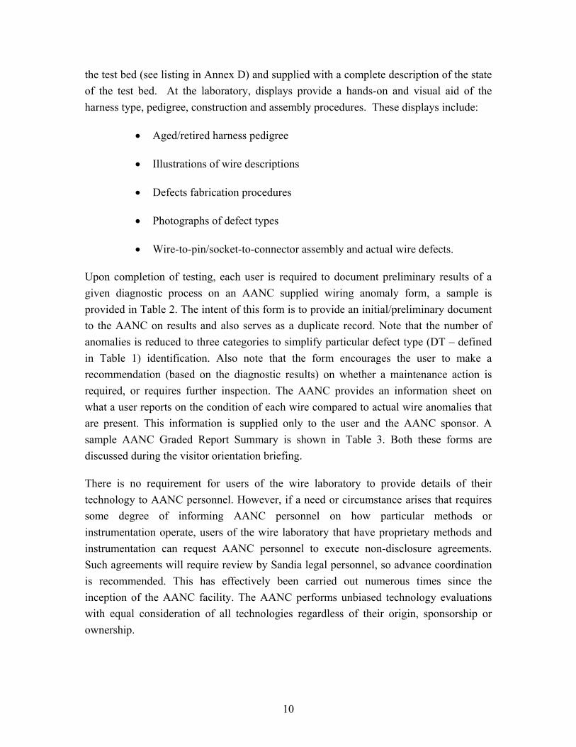
An important task of the first year project was the development of techniques to simulate a range of defects in a reproducible manner, including varying degrees of insulation or conductor damage for a specific defect type. The following wire defect types are included in the test-bed wire system:
• Wires with opened or broken conductors
• Wire insulation chafed to various degrees
• Breached wire insulation
• Cracked or brittle insulation
• Partial strand-conductor breakage
• Over-pressured wire fastener clamps
• Wires with excessive bend radius
• Heat induced or chemically corroded wire damage
• Faulty wire splices
• Faulty connectors.
For each defect type, a specific fabrication procedure was developed. A defect descriptor chart is provided in Table 1 and describes the defect type and severity. Annex E documents these procedures with illustrative photographs. The procedures were developed and documented in sufficient detail to allow accurate reproducibility. Figure 7 shows a sample using these procedures to fabricate defects. The tools used in these procedures are a standard wire stripper, feeler gauges, and a common knife for insulation cutting. A Dremel tool is also used to produce abraded or chafed wire insulation or metallic shielding. Other defect fabrication tools include a torque wrench for creating over-pressured clamps and a heat gun with a wire-positioning fixture for producing charred insulation. These procedures permit consistency of a given diagnostic method to detect and locate similar as well as different types of defects. Defect procedures, severities, and types are modified based on comments/recommendations made by the
8

community users. Photographs of all the defect types present in the test bed are shown in Annex F.
Test Bed Characterization
The placement and type of defects in the wires have been documented at the AANC and Sandia. This information is not available to users of the wire system laboratory. Additional characterization of the wire harnesses using transmission line parameters in terms of per unit length resistance (R), inductance (L), capacitance (C), and conductance (G - resistive loss through the insulation material) will also be documented for supporting user investigations. Characterization of the harnesses in terms of transmission line parameters will be carried out after installation of well-defined transmission line geometries being designed into the first or top tray of the test bed enclosure. Characterization of these transmission lines first, using standard commercial instrumentation, will permit a validated method for characterizing the test bed aircraft harnesses. The well-defined transmission line types used for harness characterization calibration are single and twin flat-wire conductors imbedded in polyethylene and nylon, and single and uniform twin-axial coaxial-shielded cables. Polyethylene and nylon have relative dielectric constants ranging from 2.1–2.3 and 4.2. Both single and two-conductor configurations are needed for common (wire-to-airframe) and differential (wire-to-wire) mode purposes. An Agilent 4294A Impedance Analyzer is being used for frequency domain measurements of these parameters (not to investigate the capability for defect detection). Similarly, a Tektronix time domain reflectometry (TDR) model 1502C is being used to corroborate this information for both differential and common mode parameters within the harnesses.
When it is established that these transmission line parameters are well defined, it is intended to place minute insulation defects into the transmission lines to support users in determining sensitivity thresholds of their diagnostic instrumentation.
Wire System Laboratory Usage
Use of the wire laboratory and test bed is scheduled through the AANC facility manager, Gerald Langwell (Sandia National Laboratories, Albuquerque, NM). A short user request form will be sent to scheduled visitors prior to arrival and addresses equipment needs, safety issues or other participant requirements. The AANC will provide support, when requested, such as working space, tables, electrical power cords, ladders, maintenance stands, common hand tools, etc. These and other required tools or hardware must be identified prior to visits. Users will also be sent a description of each of the harnesses in
9
Phillip W. Brittenham
Define AANC
Phillip W. Brittenham
Need number
the test bed (see listing in Annex D) and supplied with a complete description of the state of the test bed. At the laboratory, displays provide a hands-on and visual aid of the harness type, pedigree, construction and assembly procedures. These displays include:
• Aged/retired harness pedigree
• Illustrations of wire descriptions
• Defects fabrication procedures
• Photographs of defect types
• Wire-to-pin/socket-to-connector assembly and actual wire defects.
Upon completion of testing, each user is required to document preliminary results of a given diagnostic process on an AANC supplied wiring anomaly form, a sample is provided in Table 2. The intent of this form is to provide an initial/preliminary document to the AANC on results and also serves as a duplicate record. Note that the number of anomalies is reduced to three categories to simplify particular defect type (DT – defined in Table 1) identification. Also note that the form encourages the user to make a recommendation (based on the diagnostic results) on whether a maintenance action is required, or requires further inspection. The AANC provides an information sheet on what a user reports on the condition of each wire compared to actual wire anomalies that are present. This information is supplied only to the user and the AANC sponsor. A sample AANC Graded Report Summary is shown in Table 3. Both these forms are discussed during the visitor orientation briefing.
There is no requirement for users of the wire laboratory to provide details of their technology to AANC personnel. However, if a need or circumstance arises that requires some degree of informing AANC personnel on how particular methods or instrumentation operate, users of the wire laboratory that have proprietary methods and instrumentation can request AANC personnel to execute non-disclosure agreements. Such agreements will require review by Sandia legal personnel, so advance coordination is recommended. This has effectively been carried out numerous times since the inception of the AANC facility. The AANC performs unbiased technology evaluations with equal consideration of all technologies regardless of their origin, sponsorship or ownership.
10

All Department of Energy (DOE) developed technologies to be evaluated at the AANC will be carried-out by two evaluators that are independent of the DOE and the AANC. One evaluator will receive adequate training on the use of any DOE developed technology, and a second independent evaluator will execute a non-disclosure agreement for use of the wire laboratory defects log-book necessary for performing post-test data analysis.
11

Fi
gure
1.
Des
ign
Dra
win
g of
Tes
t Bed
Enc
losu
re
12

Figure 2. Partially Assembled Wire Harness Enclosure
Figure 3. Boeing 727/737 Type Ribbed-Structure Segment Fabricated by Foster-Miller
13

Figure 4. Assembled Wire Harness Enclosure
Figure 5. Extracted Harnesses from Retired Aircraft
14

Figure 6. Wire Harness to Connector Assembly Display
Fabricated Defect
F
Actual Defect
igure 7. Comparison of Actual and Fabricated Defects Using Annex E Procedures.
15
Tabl
e 1.
Def
ect D
escr
ipto
r Tab
le
Def
ect
Typ
e Id
entif
ier
Cod
e Se
veri
ty
Cod
e C
omm
ents
(P
aram
eter
Dat
a)
Abr
aded
or C
hafe
d In
sula
tion
DT1
%
of I
nsul
atio
n R
adiu
s Rem
oved
, Lin
ear
Exte
nt, A
ngul
ar E
xten
t
Seve
re:
100%
, 1”,
180
0
Med
ium
: 100
%, 0
.25”
, 900
Min
ute:
50%
, 0.5
”, 9
00
Bre
ache
d In
sula
tion
(360
0 Exp
osed
Con
duct
or)
DT2
Line
ar E
xten
t,Se
vere
: 1
”
Med
ium
: 0.1
25”
M
inut
e:
0.03
125”
Cra
cked
Insu
latio
n D
T3
Line
ar E
xten
t, D
ensi
ty, %
into
Insu
latio
n Se
vere
: 4
”, 1
00/in
ch, 1
00%
Med
ium
: 1”,
25/
inch
, 100
%
Min
ute:
1”
, 5/in
ch, 5
0%
Con
duct
or-S
trand
B
reak
s D
T4
% o
f Stra
nd B
reak
s (w
ith n
o co
ntac
t) Se
vere
: 7
5%
Med
ium
: 25%
M
inut
e:
5%
Ove
r-Pr
essu
red
Cla
mps
D
T5
Cla
mp
Spec
ifica
tion,
To
rque
App
lied
Seve
re:
100
inch
-lb
Med
ium
: 50
inch
-lb
Min
ute:
25
inch
-lb
Ben
d R
adiu
s D
T6
Deg
rees
from
Initi
al R
outin
g Se
vere
: 18
00 , No
Loop
Are
a M
ediu
m: 1
800 , H
arne
ss S
epar
atio
n 2x
Dia
met
er
Min
ute:
18
00 , Har
ness
Sep
arat
ion
5x D
iam
eter
Faul
ted
Splic
es
DT7
N
o C
rimp,
Too
Man
y Sp
lices
, Ex
pose
d C
ondu
ctor
Type
I:
Insu
latio
n H
eat S
hrun
k, N
o C
rimp
App
lied
Type
II:
Expo
sed
Wire
-To-
Wire
Join
ing
Type
III:
Ove
r-H
eate
d In
sula
tion
Shrin
kage
Ty
pe IV
: Too
Man
y C
rimps
per
Wire
Hea
ted
Insu
latio
n D
T8
Hea
ting
Dur
atio
n, T
empe
ratu
re
Seve
re:
Bla
cken
, Fra
yed
Insu
latio
n M
ediu
m: B
lack
en, C
onto
rted
Insu
latio
n M
inut
e:
Slig
ht D
isco
lora
tion,
Insu
latio
n N
ot C
onto
rted
Con
duct
or O
pene
d D
T9
With
Con
tact
(WC
), N
o C
onta
ct (N
C)
Seve
re:
No
Con
tact
M
ediu
m: 5
0% C
onta
ct
Min
ute:
90
% C
onta
ct
Con
duct
or S
horte
d D
T10
Mod
erat
e or
Har
d C
onta
ct
Seve
re:
O-L
ug T
orqu
ed T
o R
ib, W
ire-to
-Wire
Sol
dere
d M
ediu
m: S
ame
as S
ever
e w
ith 0
.1-Ω
Inte
rven
ing
Min
ute:
Sa
me
as S
ever
e w
ith 1
0-Ω
Inte
rven
ing
Cor
rosi
on
DT1
1 Li
ght,
Med
ium
, Sev
ere
In P
rogr
ess
16

Tabl
e 2.
Sam
ple
Prel
imin
ary
Use
r Pro
vide
d R
epor
t
AAN
C T
est B
ed
Wir
ing
Ano
mal
y R
epor
t H
arne
ss
Con
nect
or
Ano
mal
ous
Ano
mal
y C
ateg
orie
s Lo
catio
n (B
ow, A
ft)
Wir
e/Pi
n In
sula
tion
(DT
1-3
, 8);
Con
tinui
ty (D
T 4
,7, 9
, 10)
; Ins
talla
tion
(DT
5, 6
)
(Tra
y , R
ow, C
ol)
(Mod
el #
) ID
#1
Se
verit
yA
ctio
n#2
Seve
rity
Act
ion
#3Se
verit
yA
ctio
n
1 2,
top,
19
Bow
1
to 1
3 C
ontin
uity
O
pen
Vis
ual
MS2
4264
R16
B24
PN
96”
from
Aft
In
spec
t
17 to
gnd
Insu
latio
nU
nkno
wn
Vis
ual
57”
from
Bow
Insp
ect
2 2,
top,
21
Aft
7 to
16
Inst
alla
tion
Min
ute
No
MS2
4266
R20
B39
P8
53
” fr
om B
ow
A
ctio
n
3 3,
top,
8
Aft
16 to
gnd
In
sula
tion
Expo
sed
Vis
ual
Inst
alla
tion
Unk
now
n V
isua
l
MS2
4266
R18
B8P
N
23
” fr
om A
ft C
ondu
ctor
In
spec
t 64
” fr
om b
ow
In
spec
t
4 4,
top,
5
Bow
27
to 4
1 C
ontin
uity
Sh
ort
Vis
ual
MS2
4264
R22
B55
P7
19
” fr
om a
ft
Insp
ect
5 4,
top,
13
Bow
7
to 1
In
sula
tion
Age
d N
o
MS2
4264
R14
T7P6
A
ctio
n
Pers
onne
l:___
____
____
_
Com
pany
:___
____
____
__
D
ate:
____
____
____
___
Tech
nolo
gy:_
____
____
____
____
____
C
omm
ents
:___
____
____
____
____
____
____
____
____
____
____
____
____
____
____
____
____
____
____
____
____
____
____
____
____
____
____
____
____
____
_
17

Ta
ble
3. S
ampl
e A
AN
C R
epor
t Sum
mar
y
Vis
itor:
XY
Z C
orp
(Per
sonn
el: E
ngin
eer;
Tech
nici
an)
Dat
e of
Vis
it: N
ovem
ber 1
4 –1
5, 2
002
AA
NC
/San
dia
Pers
onne
l: C
hris
toph
er L
opez
, Mik
e D
inal
lo
Tes
t Obj
ectiv
e: D
emon
stra
te a
bilit
y of
dia
gnos
tic s
yste
m to
loca
te d
efec
ts (m
odel
– fi
rst p
rodu
ct, s
eria
l # 4
2b).
Tes
t Con
ditio
ns: T
este
d al
l enc
losu
re h
arne
sses
. (R
elat
ive
Hum
idity
33%
, Tem
pera
ture
750 F)
H
arne
ss
Loc
atio
n ( T
ray,
Row
, C
olum
n)
Har
ness
Typ
es
(Gen
eral
Des
crip
tion)
Con
nect
or1
Acc
esse
d Fo
r T
estin
g
Pins
E
valu
ated
Det
ecte
d D
efec
ts
(Pin
)
Rep
orte
d W
ire
Con
ditio
n (T
ype
: Sev
erity
/Val
ue :
Loc
atio
n (in
ches
) )
Act
ual
D
iagn
ostic
Res
ult
C
omm
ents
3, 2
, 14
17 p
ins,
sin
gle
and
STP2 w
ires
Aft
17 -
pins
6,
9
6 to
9: s
horte
d: 3
7”
6 Sh
orte
d to
9: <
10m
Ω :
37”
Iden
tifie
d sh
orts
of p
ins
eval
uate
d
exce
pt m
isse
d 1
shor
ted
defe
ct
4, 3
, 2
5 pi
ns, o
nly
sing
le w
ires
Bow
5
- pin
s 2
4
Insu
latio
n br
each
: se
vere
: 96”
be
nd ra
dius
: sev
ere
: 53
” in
sula
tion:
sev
ere:
103
” in
stal
latio
n: s
ever
e : 5
3”
Iden
tifie
d an
omal
ies
of p
ins
eval
uate
d
2, 3
, 6
24 p
ins,
onl
y si
ngle
wire
s B
ow
24 -
pins
13
7
cont
inui
ty (D
T4):m
ediu
m:7
3”
open
: har
d : 8
7”
cont
inui
ty :
NR
: 73
”
op
ened
: > 1
MΩ
: 83”
Id
entif
ied
anom
alie
s of
pin
s ev
alua
ted
3, 3
, 22
55 p
ins,
sin
gle
and
STP2 w
ires
Aft
55 -
pins
23
, 32,
14
Hea
ted
insu
latio
n:se
vere
:107
” in
sula
tion:
NR
: 10
7”
Iden
tifie
d an
omal
ies
of p
ins
eval
uate
d
Oth
er e
valu
ated
wire
s/pi
ns h
ad d
efec
t(s) n
ot id
entif
ied
1 All
conn
ecto
r typ
es a
re ro
tate
-to-s
nap
(lock
-in),
pins
or s
ocke
t, lo
ose
or p
anel
mou
nt.
2 Shie
lded
Tw
iste
d Pa
ir. 3 Se
verit
y N
ot R
epor
ted.
G
ener
al O
bser
vatio
ns:
Out
of 1
01 p
ins/
wire
s ev
alua
ted,
hav
ing
13 a
nom
alou
s co
nditi
ons,
4 w
ere
unde
tect
ed; t
he lo
catio
ns h
ad e
rror
s le
ss th
an
5%. A
ppro
xim
ate
diag
nost
ic m
easu
rem
ent t
ime
was
8 h
ours
.
Dis
clai
mer
: The
info
rmat
ion
prov
ided
doe
s not
con
stitu
te e
ndor
sem
ent o
r va
lidat
ion
of a
ny d
iagn
ostic
equ
ipm
ent o
r m
etho
dolo
gy b
y th
e FA
A, S
andi
a, th
e D
OE
or
any
of it
s con
trac
tors
.
18

References
1. Intrusive Inspection Final Report, December 2000, and the Aging Transport
Systems Task 1 and 2 Final Report, August 2000. Both reports were sponsored by the Aging Transport systems Rulemaking Advisory Committee, chartered by the FAA. http://www.mitrecaasd.org/atsrac/index.html.
2. Boeing Company, D6-36911 Electrical Wiring Assembly and Installation
Procedures, 9-26-96. 3. Douglas Process Standard Individual Commercial Aircraft Electrical Installation,
DPS 1.834, 8-2-91. 4. Military Specification DTL 22520G and Mil-C-22520/1 – 39, Crimp Tools, Wire
Terminations, General Specifications, September 12, 1997.
5. FAA Advisory Circular 43.13-1B, Chapter 11, 9-8-98.
6. “Acceptability of Electronics Assemblies,” Association Connecting Electronics Industries, IPC-A-610C Standard, January 2000.
19


Annex A Listing of Acquired Aircraft Harnesses
This annex contains a listing of wire harnesses extracted from retired aircraft. Aircraft manufacturer, model-type, specific plane tail number, and in-service location are provided.
A-1

A-2

Acquired Harness Listing
Harness ID Aircraft Number Location
61 747 N306TW Left wing clip
62 747 BL8751 Body Station 560
63 747 BL8751 Body Station 740-760
64 747 N306TW Body Station 2220
65 747 N306TW Right Wing StationWS 450
66 747 N306TW Right Wing StationXFS 280
67 747 N306TW Right Wheel Well Station WS 425
68 747 N306TW Right Body GearStation 1241
69 747 N306TW Body Station 2220
70 747 N306TW Body Station 400
71 DC-9 N923L Fuselage Station 1087
72 DC-9 N923L Fuselage Station 617
73 DC-9 N923L Right Main Wheel Weel
74 DC-9 N923L Fuselage Station 768
75 DC-9 990 Engine Paylon Station 1020
76 DC-9 N923L Right Main Wheel Well
77 DC-9 990 Engine Paylon Station 1020
78 DC-9 990 Engine Paylon Station 1020
79 DC-9 990 Engine Paylon Station 1020
80 DC-9 N923L Rear Fuslage Station 937
A-3
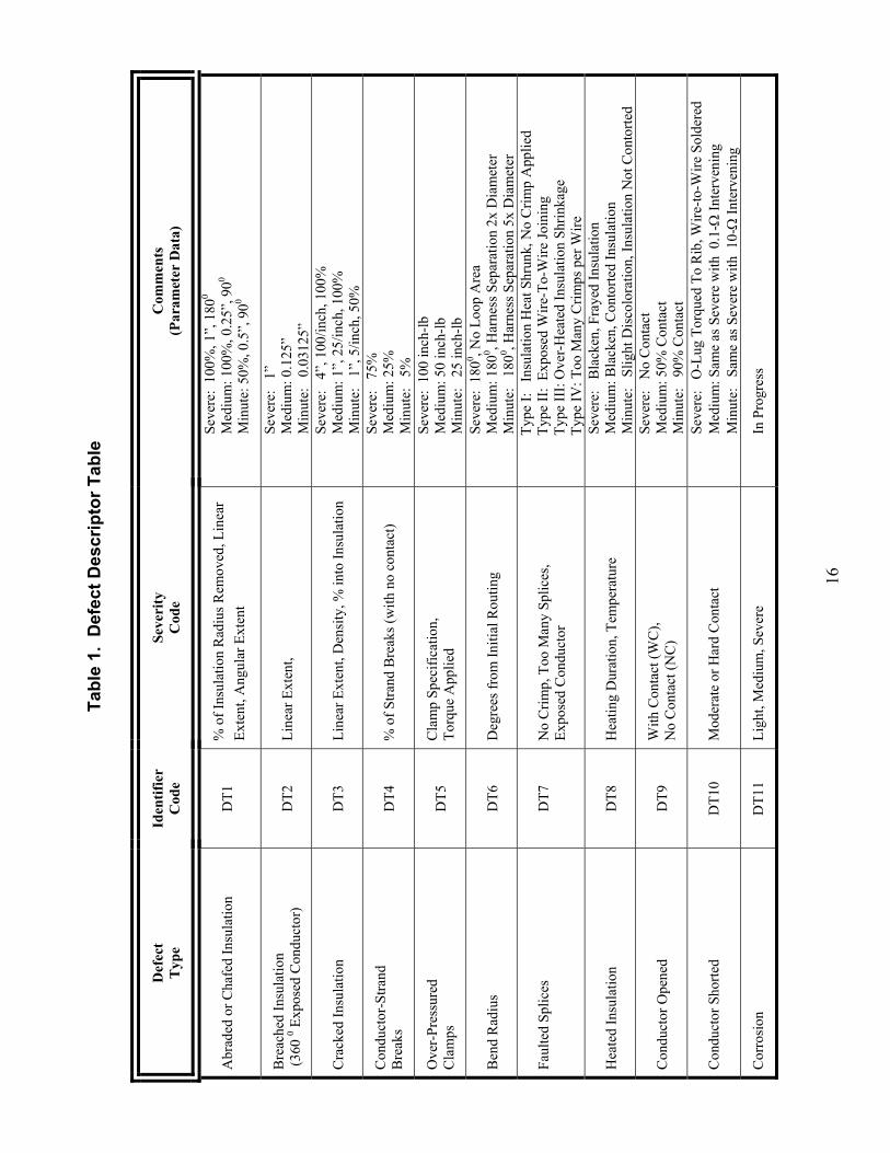
Acquired Harness Listing (Continued)
Harness ID Aircraft Number Location
81 DC-10 1154 TW Aft Face of Cocpit Breaker Panel
82 DC-10 1154 TW Aft Fuselage Compartment(left front side station 1600-1640)
83 DC-10 1154 TW Aft Fuselage Compartment(left front side station 1599-1585)
84 DC-10 1154 TW Left Side Trailing Wing Edge(station 772 zone 536)
85 DC-10 1154 TW Cargo Section (left side to flight recorder)(station 1851)
86 DC-10 1154 TW Bottom Cargo Section (in bottom)(station 1850)
87 DC-10 1154 TW Right Wheel Well Gear Zone
88 DC-10 1154 TW Right Wheel Well Gear Zone
89 DC-10 1154 TW Electronics Bay (right side aft A and E bay)
90 DC-10 1154 TW Electronics Bay
A-4

1: 6
1; L
eft w
ing
clip
4: 6
4 &
69:
Bod
y ST
A 2
220
7: 6
7: R
ight
Whe
el w
ell S
TA
425
2: 6
2; B
ody
STA
560
5: 6
5: B
ody
STA
450
8: 6
8: B
ody
gear
ST
A 1
241
3: 6
3; B
ody
STA
740
6: 6
6: B
ody
STA
280
9: 7
0: B
ody
STA
400
1
23
56
7
89
4
1: 6
1; L
eft w
ing
clip
4: 6
4 &
69:
Bod
y ST
A 2
220
7: 6
7: R
ight
Whe
el w
ell S
TA
425
2: 6
2; B
ody
STA
560
5: 6
5: B
ody
STA
450
8: 6
8: B
ody
gear
ST
A 1
241
3: 6
3; B
ody
STA
740
6: 6
6: B
ody
STA
280
9: 7
0: B
ody
STA
400
1
23
56
7
89
4
1
23
56
7
89
4
Fi
gure
A.1
. Zo
nes
Whe
re H
arne
ss ID
s 61
–70
Wer
e Ex
trac
ted
A
-5

1: 7
1: F
usel
age
Stat
ion
1087
4: 7
4: F
usel
age
Stat
ion
768
2: 7
2: F
usel
age
Stat
ion
617
5: 7
5, 7
7, 7
8, 7
9: E
ngin
e Py
lon
Stat
ion
1020
3: 7
3 &
76:
Rig
ht M
ain
Whe
el W
ell
6: 8
0: R
ear
fuse
lage
Sta
tion
937
12
4
6
5
1: 7
1: F
usel
age
Stat
ion
1087
4: 7
4: F
usel
age
Stat
ion
768
2: 7
2: F
usel
age
Stat
ion
617
5: 7
5, 7
7, 7
8, 7
9: E
ngin
e Py
lon
Stat
ion
1020
3: 7
3 &
76:
Rig
ht M
ain
Whe
el W
ell
6: 8
0: R
ear
fuse
lage
Sta
tion
937
12
4
6
51
24
6
5
Fi
gure
A.2
. Zo
nes
Whe
re H
arne
ss ID
s 71
–80
Wer
e Ex
trac
ted
A
-6

7&8
4
5&6
12&
39&
10
1 : 8
1 : A
ft fa
ce c
ockp
it p
anel
6 : 8
6 : B
otto
m c
argo
sect
ion
1850
2 : 8
2 : A
ft fu
sela
ge c
ompa
rtmen
t 160
0-16
407
: 87
: Rig
ht w
heel
wel
l lan
ding
gea
r zon
e
3 : 8
3 : A
ft fu
sela
ge c
ompa
rtmen
t 159
9-15
858
: 88
: Rig
ht w
heel
wel
l lan
ding
gea
r zon
e
4 : 8
4 : L
eft s
ide
traili
ng w
ing
edge
539
9 : 8
9 : E
lect
roni
cs b
ay (r
ight
side
aft)
5 : 8
5 : C
argo
sect
ion
1851
10 :
90 :
Elec
troni
cs b
ay (r
ight
side
aft)
7&8
4
5&6
12&
39&
107&
8
4
5&6
12&
39&
10
1 : 8
1 : A
ft fa
ce c
ockp
it p
anel
6 : 8
6 : B
otto
m c
argo
sect
ion
1850
2 : 8
2 : A
ft fu
sela
ge c
ompa
rtmen
t 160
0-16
407
: 87
: Rig
ht w
heel
wel
l lan
ding
gea
r zon
e
3 : 8
3 : A
ft fu
sela
ge c
ompa
rtmen
t 159
9-15
858
: 88
: Rig
ht w
heel
wel
l lan
ding
gea
r zon
e
4 : 8
4 : L
eft s
ide
traili
ng w
ing
edge
539
9 : 8
9 : E
lect
roni
cs b
ay (r
ight
side
aft)
5 : 8
5 : C
argo
sect
ion
1851
10 :
90 :
Elec
troni
cs b
ay (r
ight
side
aft)
Fi
gure
A.3
. Z
ones
Whe
re H
arne
ss ID
s 81–
90 W
ere
Ext
ract
ed
A
-7

A-8

Annex B Description of Wire Types
This annex provides a description of each of the wire types used to fabricate new wire harnesses. Insulation materials, conductor type, and drawings illustrating the wire construction are provided.
B-1

B-2

Mil Spec # AWG Jacket Additional Layer Insulation Conductor
M22759/32-18-9 18 No Jacket naCrosslinked ETFE (Ethylene-tetrafluoethylene copolymer) Tin Coated Copper
M22759/32-20-7 20 No Jacket naCrosslinked ETFE (Ethylene-tetrafluoethylene copolymer) Tin Coated Copper
M22759/32-22-9 22 No Jacket naCrosslinked ETFE (Ethylene-tetrafluoethylene copolymer) Tin Coated Copper
M5086/1-18-9 18 Clear Nylon na Polyviny Chloride Tin Coated Copper
M5086/1-20-9 20 Clear Nylon na Polyvinyl chloride Tin Coated Copper
M5086/1-22-9 22 Clear Nylon na Polyvinyl chloride Tin Coated Copper
M5086/2-18-9 18 Clear NylonGlass Fiber Braid
with Finisher Polyvinyl chloride Tin Coated Copper
M81044/9-20-9 20Polyalkene-Crosslinked PVDF
(Polyvinylidene Flouride) na Crosslinked Polyalkene Tin Coated Copper
M81044/9-22-9 22Polyalkene-Crosslinked PVDF
(Polyvinylidene Flouride) na Crosslinked Polyalkene Tin Coated Copper
M81381/7-20-9 20Modified Aromatic Polymide
Resin CoatingFlourocarbon
Polymide Tape Flourocarbon Polymide Tape Silver Coated Copper
M81381/7-22-8 22Modified Aromatic Polymide
Resin CoatingFlourocarbon
Polymide Tape Flourocarbon Polymide Tape Silver Coated Copper
Wire Specifications (1 of 2)
Mil Spec # Conductor Diameter (inches)
Finished Wire Diameter (Inches)
Weight (lbs/1000 ft)
(max)Voltage Rating
Temp Rating Comments
Min Max M22759/32-18-9 .046 049 0.06 ±.002 6.5 600 V 150° C
flame retardent, self extinguishinnotch and arasion resistant
M22759/32-20-7 .037 .039 0.05 ±.002 4.3 600 V 150° Cflame retardent, self extinguishin
notch and arasion resistant
M22759/32-22-9 .029 .031 0.043 ±.002 2.8 600 V 150° Cflame retardent, self extinguishin
notch and arasion resistant
M5086/1-18-9 .046 .051 0.088 ±.004 8.6 600 V 105° Cresistant to water, aircraft fuels,a
hydraulic fluid
M5086/1-20-9 .037 .041 0.078 ±.004 6.3 600 V 105° Cresistant to water, aircraft fuels,a
hydraulic fluid
M5086/1-22-9 .029 .033 0.068 ±.004 4.4 600 V 105° Cresistant to water, aircraft fuels,a
hydraulic fluid
M5086/2-18-9 .046 .051 0.095 ±.005 9.5 600 V 105° Cresistant to water, aircraft fuels,a
hydraulic fluid
M81044/9-20-9 .037 .041 0.07 ±.003 5.5 600 V 150° Cflame retardent, self extinguishin
notch and arasion resistant
M81044/9-22-9 .029 .033 0.062 ±.003 3.9 600 V 150° Cflame retardent, self extinguishin
notch and arasion resistantM81381/7-20-9 .037 .038 0.050 ±.001 4.3 600 V 200° C flame retardent, lightweightM81381/7-22-8 .029 .030 0.0425 ±.0015 2.8 600 V 200° C flame retardent,
Wire Specifications (2 of 2)
B-3

MIL-W-22759/32 - 18 - 99Mil Spec Gauge Color
Temp Rating: 150° C600V
Insulation: Crosslinked ETFE (Ethylene-tetrafluroethylene copolymer)
Conductor: Tin Coated Copper
No Jacket
.060 in .047 in
Conductor: Tin Coated Copper
MIL-W-22759/32 - 20 - 77Mil Spec Gauge Color
Temp Rating: 150° C600V
.05 in .038 in
Insulation: Crosslinked ETFE (Ethylene-tetrafluroethylene copolymer)
No Jacket
B-4

MIL-W-22759/32 - 22 - 99Mil Spec Gauge Color
Temp Rating: 150° C600V
Conductor: Tin Coated Copper
.043 in .03 in
Insulation: Crosslinked ETFE (Ethylene-tetrafluroethylene copolymer)
No Jacket
Insulation: Polyalkene - Crosslinked PVDF (Polyvinylidene Flouride)
Intermediate Layer: Crosslinked Polyalkene
MIL-W-81044/9 - 20 - 99Mil Spec Gauge Color
Temp Rating: 150° C600V
Conductor: Tin Coated Copper
.037 in.07 in
B-5

Insulation: Polyalkene - Crosslinked PVDF(Polyvinylidene Flouride)
Intermediate Layer: Crosslinked Polyalkene
MIL-W-81044/9 - 22 - 99Mil Spec Gauge Color
Temp Rating: 150° C600V
Conductor: Tin Coated Copper
.031 in.062 in
MIL-W-81381/7 - 20 - 99Mil Spec Gauge Color
Temp Rating: 200° C600V
Jacket: Modified Aromatic Polymide (0.0005 in.)
Insulation: Flourocarbon/Polymide Tape
Conductor: Silver Coated Copper
.037 in.051 in
B-6
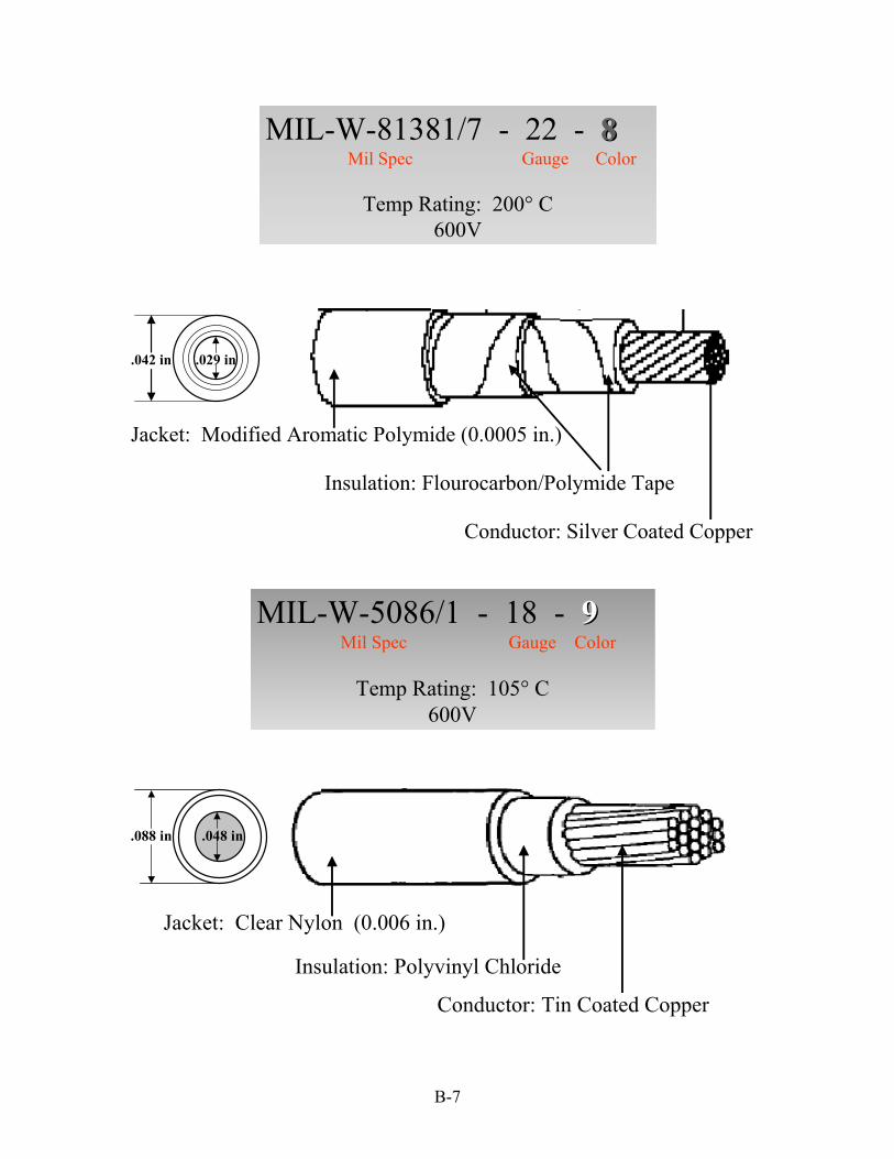
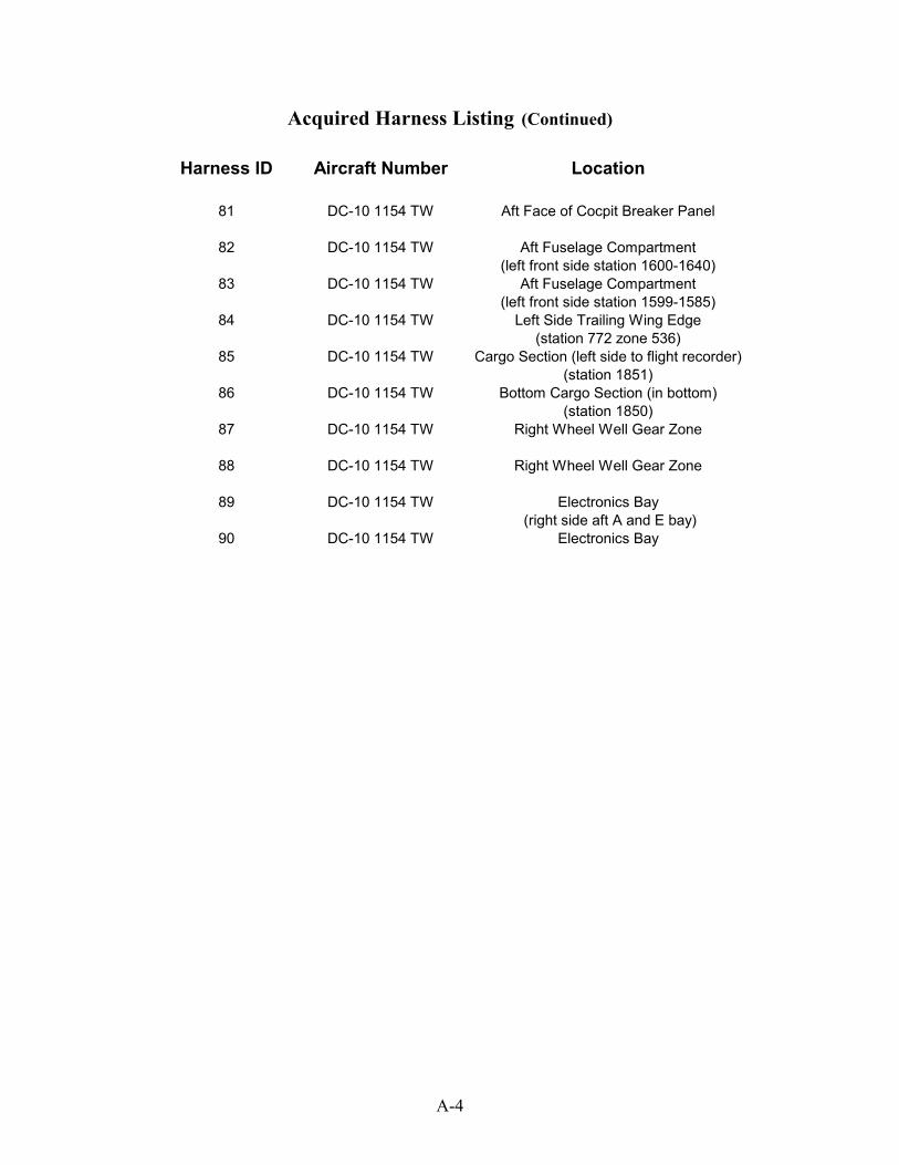
MIL-W-81381/7 - 22 - 88Mil Spec Gauge Color
Temp Rating: 200° C600V
Jacket: Modified Aromatic Polymide (0.0005 in.)
Insulation: Flourocarbon/Polymide Tape
Conductor: Silver Coated Copper
.029 in.042 in
MIL-W-5086/1 - 18 - 99Mil Spec Gauge Color
Temp Rating: 105° C600V
.088 in
Jacket: Clear Nylon (0.006 in.)
Insulation: Polyvinyl Chloride
Conductor: Tin Coated Copper
.048 in
B-7

MIL-W-5086/1 - 20 - 99Mil Spec Gauge Color
Temp Rating: 105° C600V
.078 in .039 in
Jacket: Clear Nylon (0.006 in.)
Insulation: Polyvinyl Chloride
Conductor: Tin Coated Copper
MIL-W-5086/1 - 22 - 99Mil Spec Gauge Color
Temp Rating: 105° C600V
.068 in .031 in
Jacket: Clear Nylon (0.006 in.)Insulation: Polyvinyl Chloride
Conductor: Tin Coated Copper
B-8

MIL-W-5086/2 - 18 - 99Mil Spec Gauge Color
Temp Rating: 105° C600V
.048 in.095 in
Jacket: Clear Nylon (0.006 in.)
Insulation: Polyvinyl Chloride
Conductor: Tin Coated Copper
Glass Fiber Braid with finisher
B-9

B-10

Annex C Connector List
This annex lists each connector model number for newly assembled harnesses, and harnesses retrieved form different aircraft type.
C-1

C-2
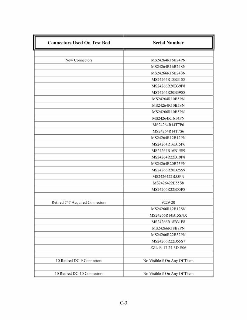
Connectors Used On Test Bed Serial Number
New Connectors MS24264R16B24PN
MS24264R16B24SN MS24266R16B24SN MS24264R18B31S8 MS24266R20B39P8 MS24264R20B39S8 MS24264R10B5PN MS24264R10B5SN MS24266R10B5PN MS24264R16T4PN MS24264R14T7P6 MS24264R14T7S6 MS24264R12B12PN MS24264R16B15P6 MS24264R16B15S9 MS24264R22B19P8 MS24264R20B25PN MS24266R20B25S9 MS2426422B55PN MS2426422B55S8 MS24266R22B55P8
Retired 747 Acquired Connectors 9229-20 MS24266R12B12SN MS24266R14B15SNX MS24266R18B31P8 MS24266R18B8PN MS24266R22B32PN MS24266R22B55S7 ZZL-R-17 24-3D-S06
10 Retired DC-9 Connectors No Visible # On Any Of Them
10 Retired DC-10 Connectors No Visible # On Any Of Them
C-3

C-4

Annex D Composite Wires and Connectors Harness Descriptions
This annex provides a description of each harness used in the test bed including bow and aft connector type/model number, military or manufacturer specification, and a photograph of both connectors with the pin/wire identification nomenclature.
D-1

D-2

Harness Connectors In-SituTray 2, Top Row, Column 2
Front: MS24264R16B24PN Aft: MS24266R16B24SN
Wire Harness Description – Tray 2, Top Row, Column 2 Front Connector: MS24264R16B24PN Aft Connector: MS24266R16B24SN (Female)
Front Pin ID
Aft Pin ID Wire Type Defect Identified
(Type: Severity: Location:) Comments
1 1 M5086 1-18 2 2 M22759 32-20 3 3 M81381 7-22 4 4 M81381 7-20 5 5 M81044 9-20 6 6 M5086 1-20 7 7 M22759 32-22 8 8 M81044 9-22 9 9 M22759 32-18 10 10 M22759 32-20 11 11 M5086 1-18 12 12 M81381 7-20 13 13 M81381 7-22 14 14 M5086 1-20 15 15 M22759 32-18 16 16 M81044 9-22 17 17 M81044 9-20 18 18 M81044 9-20 19 19 M22759 32-18 20 20 M81381 7-22
D-3

Wire Harness Description – Tray 2, Top Row, Column 2 (continued) Front Connector: MS24264R16B24PN Aft Connector: MS24266R16B24SN (Female)
Front Pin ID
Aft Pin ID
Wire Type Defect Identified (Type: Severity: Location:
Comments
21 21 M22759 32/22 22 22 M5086 1-22 23 23 M81381 7-20 24 24 M5086 1-20
D-4

Harness Connectors In-SituTray 2, Top Row, Column 3
Front: MS24264R14B15S9 Aft: MS24264R14B15S9
Wire Harness Description – Tray 2, Top Row, Column 3 Front Connector: MS24264R14B15S9 Aft Connector: MS24264R14B15S9
Front Pin ID
Aft Pin ID Wire
Type Defects Identified
(Type : Severity : Location) Comments
1 1 M81044 9-18 2 2 M81381 7-20 3 3 M22759 32-18 4 4 M5086 1–20 5 5 M5086 1-22 6 6 M5086 1-20
7-15 7-15 Not Used
D-5
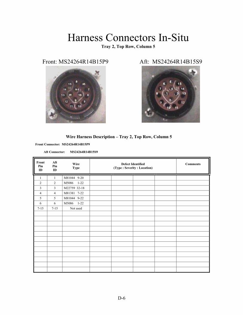
Harness Connectors In-SituTray 2, Top Row, Column 5
Front: MS24264R14B15P9 Aft: MS24264R14B15S9
Wire Harness Description – Tray 2, Top Row, Column 5 Front Connector: MS24264R14B15P9 Aft Connector: MS24264R14B15S9
Front Pin ID
Aft Pin ID
Wire Type
Defect Identified (Type : Severity : Location)
Comments
1 1 M81044 9-20 2 2 M5086 1-22 3 3 M22759 32-18 4 4 M81381 7-22 5 5 M81044 9-22 6 6 M5086 1-22
7-15 7-15 Not used
D-6

Harness Connectors In-SituTray 2, Top Row, Column 7
Front: MS24264R14T4PN Aft: MS24264R14T4PN
Wire Harness Description – Tray 2, Top Row, Column 7 Front Connector: MS24264R14T4PN Aft Connector: MS24264R14T4PN
Front Pin ID
Aft Pin ID
Wire Type
Defect Identified (Type : Severity : Location)
Comments
1 1 M81381 7-20 2 2 M22759 32-18 3 3 M5086 1-20 4 4 M81044 9-20
D-7

Harness Connectors In-SituTray 2, Top Row, Column 9
Front: MS24264R20B39S8 Aft: MS24264R20B39S8
Wire Harness Description – Tray 2, Top Row, Column 9 Front Connector: MS24264R20B39S8 Aft Connector: MS24264R20B39S8
Front Pin ID
Aft Pin ID
Wire Type
Defect Identified (Type : Severity : Location)
Comments
1 1 M81044 9-20 2-10 2-10 Not used 11 11 M81044 9-20 12 12 Not used 13 13 M81044 9-20
14-15 14-15 Not Used 16 16 M81381 7-20
17-20 17-20 Not Used 21 21 M81044 9-20 22 22 Not Used 23 23 M81044 9-22
24-39 24-39 Not Used
D-8

Harness Connectors In-SituTray 2, Top Row, Column 13
Front: MS24264R16B24PN Aft: MS24266R16B24SN
Wire Harness Description – Tray 2, Top Row, Column 13 Front Connector: MS24264R16B24PN Aft Connector: MS24266R16B24SN
Front Pin ID
Aft Pin ID
Wire Type
Defect Identified (Type : Severity : Location)
Comments
1 1 M81044 9-20 2 2 M81381 7-20 3 3 M22759 32-20 4 4 M5086 1-20 5 5 M81381 7-20 6 6 M22759 32-18 7 7 M81044 9-18 8 8 M81381 7-20 9 9 M81381 7-20
10 10 M22759 32-20 11 11 M22759 32-20 12 12 M81044 9-20 13 13 M81044 9-18 14 14 M5086 1-20 15 15 M22759 32-18 16 16 M81044 9-20 17 17 M81381 7-20 18 18 M81044 9-18 19 19 M81381 7-20
D-9

Wire Harness Description –Tray 2, Top Row, Column 13(continued) Front Connector: MS24264R16B24PN Aft Connector: MS24266R16B24SN
Front Pin ID
Aft Pin ID
Wire Type
Defect Identified (Type : Severity : Location)
Comments
20 20 M81044 9-18 21 21 M22759 32-20 22 22 M81044 9-20 23 23 M81044 9-20 24 24 M22759 32-20
D-10
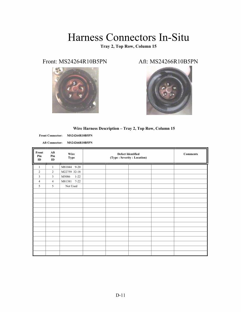
Harness Connectors In-SituTray 2, Top Row, Column 15
Aft: MS24266R10B5PNFront: MS24264R10B5PN
Wire Harness Description – Tray 2, Top Row, Column 15 Front Connector: MS24264R10B5PN Aft Connector: MS24266R10B5PN
Front Pin ID
Aft Pin ID
Wire Type
Defect Identified (Type : Severity : Location)
Comments
1 1 M81044 9-20 2 2 M22759 32-18 3 3 M5086 1-22 4 4 M81381 7-22 5 5 Not Used
D-11

Harness Connectors In-SituTray 2, Top Row, Column 17
Front: MS24264R16B24SN Aft: MS24264R16B24PN
Wire Harness Description – Tray 2, Top Row, Column 17 Front Connector: MS24264R16B24SN Aft Connector: MS24264R16B24PN
Front Pin ID
Aft Pin ID
Wire Type
Defect Identified (Type : Severity : Location)
Comments
1 1 M5086 1-20 2 2 M81044 9-20 3 3 M81381 7-22 4 4 M81044 9-22 5 5 M5086 1-20 6 6 M81381 7-20
7-24 7-24 Not Used
D-12

Harness Connectors In-SituTray 2, Top Row, Column 19
Front: MS24264R16B24PN Aft: MS24266R16B24SN
Wire Harness Description – Tray 2, Top Row, Column 19 Front Connector: MS24264R16B24PN Aft Connector: MS24266R16B24SN
Front Pin ID
Aft Pin ID
Wire Type
Defect Identified (Type : Severity : Location)
Comments
1 1 M5086 1-20 2 2 M22759 32-22 3 3 M81044 9-22 4 4 M5086 1-20 5 5 M22759 32-22 6 6 M81381 7-22 7 7 M81044 9-20 8 8 M5086 1-22 9 9 M81044 9-18
10 10 M81381 7-20 11 11 M22759 32-18 12 12 M22759 32-20 13 13 M5086 1-22 14 14 M81044 9-22 15 15 M81044 9-18 16 16 M81381 7-22 17 17 M5086 1-20 18 18 M81044 9-18 19 19 M81381 7-20
D-13

Wire Harness Description – Tray 2, Top Row, Column 19 (continued) Front Connector: MS24264R16B24PN Aft Connector: MS24266R16B24SN
Front Pin ID
Aft Pin ID
Wire Type
Defect Identified (Type : Severity : Location)
Comments
20 20 M81044 9-22 21 21 M81381 7-22 22 22 M22759 32-22 23 23 M81381 7-20 24 24 M5086 1-22
D-14

Harness Connectors In-SituTray 2, Top Row, Column 21
Front: MS24264R20B39S8 Aft: MS24266R20B39P8
Wire Harness Description – Tray 2, Top Row, Column 21 Front Connector: MS24264R20B39S8 Aft Connector: MS24266R20B39P8
Front Pin ID
Aft Pin ID
Wire Type
Defect Identified (Type : Severity : Location)
Comments
1-5 1-5 Not Used 6 6 M5086 1-20
7-20 7-20 Not Used Dummy Pin Not Used
21 21 M22759 32-22 22 22 Not used 23 23 M81381 7-20
24-29 24-29 Not Used 30 30 M81044 9-20
31-33 31-33 Not Used 34 34 M81044 9-20
35-38 35-38 Not Used Dummy Pin Not Used
39 39 M22759 32-18
D-15
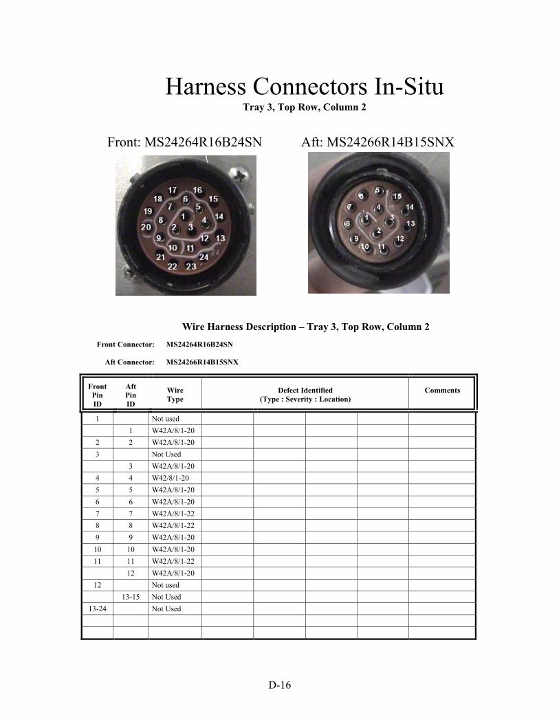
Harness Connectors In-SituTray 3, Top Row, Column 2
Front: MS24264R16B24SN Aft: MS24266R14B15SNX
Wire Harness Description – Tray 3, Top Row, Column 2 Front Connector: MS24264R16B24SN Aft Connector: MS24266R14B15SNX
Front Pin ID
Aft Pin ID
Wire Type
Defect Identified (Type : Severity : Location)
Comments
1 Not used 1 W42A/8/1-20 2 2 W42A/8/1-20 3 Not Used 3 W42A/8/1-20 4 4 W42/8/1-20 5 5 W42A/8/1-20 6 6 W42A/8/1-20 7 7 W42A/8/1-22 8 8 W42A/8/1-22 9 9 W42A/8/1-20
10 10 W42A/8/1-20 11 11 W42A/8/1-22 12 W42A/8/1-20
12 Not used 13-15 Not Used
13-24 Not Used
D-16

Harness Connectors In-SituTray 3, Top Row, Column 4
Front: MS24264R12B12PN Aft: MS24266R12B12SN
Wire Harness Description – Tray 3, Top Row, Column 4 Front Connector: MS24264R12B12PN Aft Connector: MS24266R12B12SN
Front Pin ID
Aft Pin ID
Wire Type
Defect Identified (Type : Severity : Location)
Comments
1 1 W1213 RZ2421-20R 2 2 W1213 RZ2422-20B 3 3 W1213 RZ2424-20Y 4 4 W51F/B/14/1-20 5 Not Used Twisted Shielded Pairs: (1,2,3)
5 Dummy Socket Front shield terminated by stripping
6 6 W51F/B/17/1-24 Aft shield termination unknown 7-12 Not Used
7 Dummy Socket 8 W51F/B/14/1-20 9-12 Dummy Socket
D-17
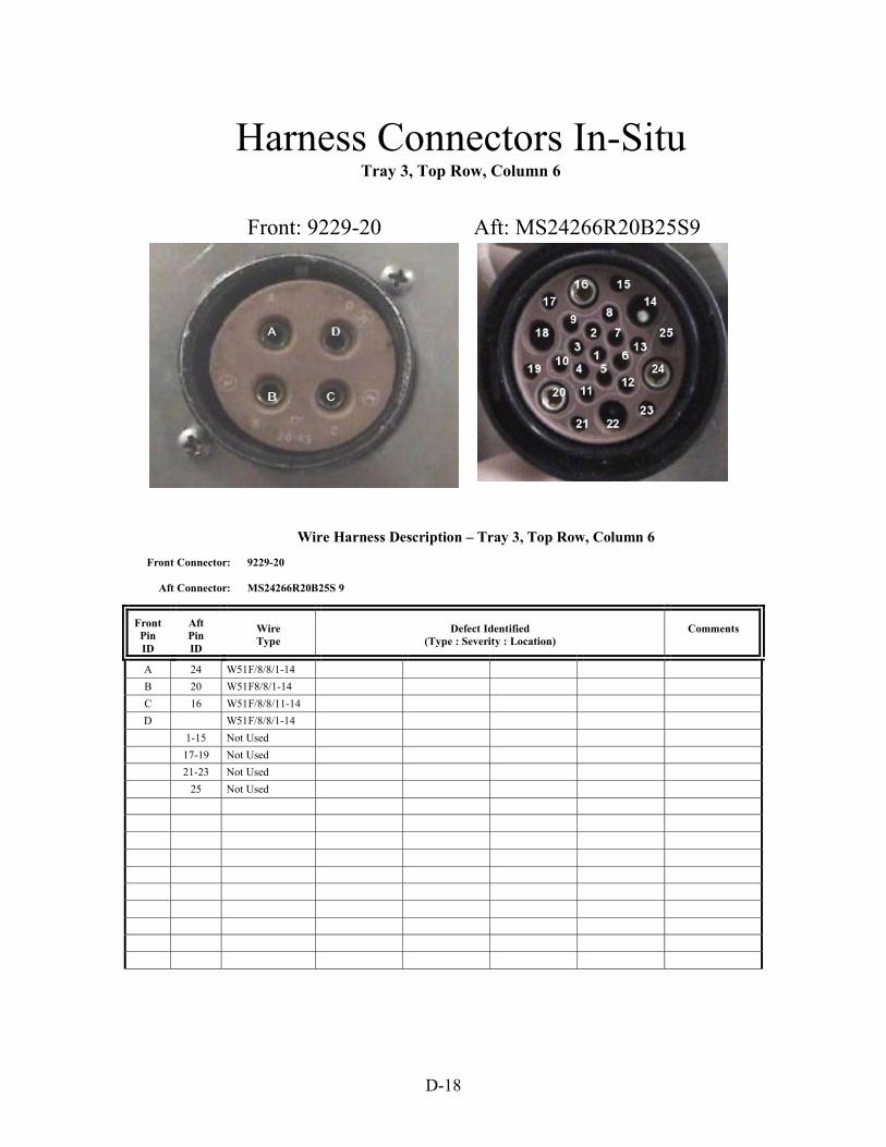
Harness Connectors In-SituTray 3, Top Row, Column 6
Front: 9229-20 Aft: MS24266R20B25S9
Wire Harness Description – Tray 3, Top Row, Column 6 Front Connector: 9229-20 Aft Connector: MS24266R20B25S 9
Front Pin ID
Aft Pin ID
Wire Type
Defect Identified (Type : Severity : Location)
Comments
A 24 W51F/8/8/1-14 B 20 W51F8/8/1-14 C 16 W51F/8/8/11-14 D W51F/8/8/1-14 1-15 Not Used 17-19 Not Used 21-23 Not Used 25 Not Used
D-18

Harness Connectors In-SituTray 3, Top Row, Column 8
Front: MS24264R14T4PN Aft: MS24266R18B8PN
Wire Harness Description – Tray 3, Top Row, Column 8 Front Connector: MS24264R14T4PN Aft Connector: MS24266R18B8PN
Front Pin ID
Aft Pin ID
Wire Type
Defect Identified (Type : Severity : Location)
Comments
1 3 W1090-L4441 2 4 W420/8/1-14 3 7 W420/8/1-14 4 8 W420/8/1-14 1-2 Dummy Pins 5-6 Dummy Pins
D-19

Harness Connectors In-SituTray 3, Top Row, Column 10
Front: MS24264R22B19P8 Aft: ZZL-R-17 24-3D-S06
Wire Harness Description – Tray 3, Top Row, Column 10 Front Connector: MS24264R22B19P8 Aft Connector: No Visible Number – 30 Sockets (ZZL-R-17 24-3D-S06)
Front Pin ID
Aft Pin ID
Wire Type
Defect Identified (Type : Severity : Location)
Comments
1 5 W42A/8/1-20 2 7 W42A/8/1-20 3 8 W362-G236R 4 9 W362-G236R 5 10 W362-G239B
6 11 W362-G239B Front shield terminated by stripping
7 12 W42A/8/1-20 Twisted Shielded Pairs: (3,4)(5,6)(9,10)
8 13 W42A/8/1-20 Aft shield termination unknown 9 21 W362-D67R Naturally Occurring Defect
10 22 W362-D67R 11 24, 25 W362-D69R 12 26 W362-D69R
6 W42/8/1-18 17 W42/8/1-18 1-4 Dummy Sockets 14-16 Dummy Sockets 18-20 Dummy Sockets 23 Dummy Sockets 27-30 Dummy Sockets
13-19 Not Used
D-20

Harness Connectors In-SituTray 3, Top Row, Column 12
Front: MS24264R18B31S8 Aft: MS24266R18B31P8
Wire Harness Description – Tray 3, Top Row, Column 12 Front Connector: MS24264R18B31S8 Aft Connector: MS24266R18B31P8
Front Pin ID
Aft Pin ID
Wire Type
Defect Identified (Type : Severity : Location)
Comments
1 1 * 2 2 * 3 Not Used 3 Dummy Pin 4 4 * 5 5 * 6 Not Used 6 Dummy Pin Twisted Shielded Pairs: (1,2)(4,5)(7,8)7 7 * (10,11)(13,14,15)(17,18,19)(21,22,23)8 8 * (25,26,27)(28,29) 9 Not Used Front shield terminated by stripping 9 Dummy Pin Aft shield terminated to specified pins
10 10 * 11 11 * 12 Not Used
12 Dummy Pin 13 13 * 14 14 * 15 15 * 16 Not Used
D-21

Wire Harness Description – Tray 3, Top Row, Column 12 (continued) Front Connector: MS24264R18B31S8 Aft Connector: MS24266R18B31P8
Front Pin ID
Aft Pin ID
Wire Type
Defect Identified (Type : Severity : Location)
Comments
16 Dummy Pin 17 17 * 18 18 * 19 19 * 20 Not Used 20 Dummy Pin
21 21 * 22 22 * 23 23 * 24 Not Used 24 Dummy Pin
25 25 * 26 26 * 27 27 * 28 Not Used
Wire Harness Description – Tray 3, Top Row, Column 12 (continued) Front Connector: MS24264R18B31S8 Aft Connector: MS24266R18B31P8
Front Pin ID
Aft Pin ID
Wire Type
Defect Identified (Type : Severity : Location)
Comments
28 Dummy Pin 29 29 * 30 30 * 31 Not Used 31 Dummy Pin
D-22
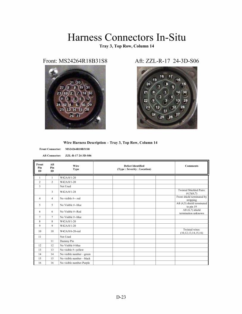
Harness Connectors In-SituTray 3, Top Row, Column 14
Front: MS24264R18B31S8 Aft: ZZL-R-17 24-3D-S06
Wire Harness Description – Tray 3, Top Row, Column 14 Front Connector: MS24264R18B31S8 Aft Connector: ZZL-R-17 24-3D-S06
Front Pin ID
Aft Pin ID
Wire Type
Defect Identified (Type : Severity : Location)
Comments
1 1 W42A/8/1-20 2 2 W42A/8/1-20 3 Not Used
3 W42A/8/1-28 Twisted Shielded Pairs: (4,5)(6,7)
4 4 No visible #-- red Front shield terminated by stripping
5 5 No Visible #--blue Aft (4,5) shield terminated to pin 19
6 6 No Visible #--Red Aft (6,7) shield termination unknown
7 7 No Visible #--blue 8 8 W42A/8/1-20 9 9 W42A/8/1-20
10 10 W42A/8/6-20-red Twisted wires: (10,12,13,14,15,16)
11 Not Used 11 Dummy Pin
12 12 No Visible #-blue 13 13 No visible #--yellow 14 14 No visible number—green 15 15 No visible number—black 16 16 No visible number-Purple
D-23

Wire Harness Description – Tray 3, Top Row, Column 14 (continued) Front Connector: MS24264R18B31S8 Aft Connector: ZZL-R-17 24-3D-S06
Front Pin ID
Aft Pin ID
Wire Type
Defect Identified (Type : Severity : Location)
Comments
17-31 Not Used 17 Dummy Pin 18 W42A/8/1-24 19 20-30 Dummy Pins
D-24

Harness Connectors In-SituTray 3, Top Row, Column 16
Front: MS24264R20B25PN Aft: MS24266R22B32PN
Wire Harness Description – Tray 3, Top Row, Column 16 Front Connector: MS24264R20B25PN Aft Connector: MS24266R22B32PN
Front Pin ID
Aft Pin ID
Wire Type
Defect Identified (Type : Severity : Location)
Comments
1 7 W48 VIII 1-20 2 15 W48 VIII 1-20 3 3 W48 VIII 1-20 4 18 W48 VIII 1-20 5 19 W48 VIII 1-20 6 20 W48 VIII 1-20 7 23 W48 VIII 1-20 8 25 W48 VIII 1-20 9 26 W42D/8/1-20
10 27 W42D/8/1-20 11 28 W42D/8/1-20 12 29 W48A/01 8/1-20 13 31 W48 VIII 1-20 16 4 W42D/3/1-14 18 6 W42D/3/1-14 20 30 D/W48/VIII/1/16 14 Dummy Pin 15 Not Used 17 Not Used
D-25
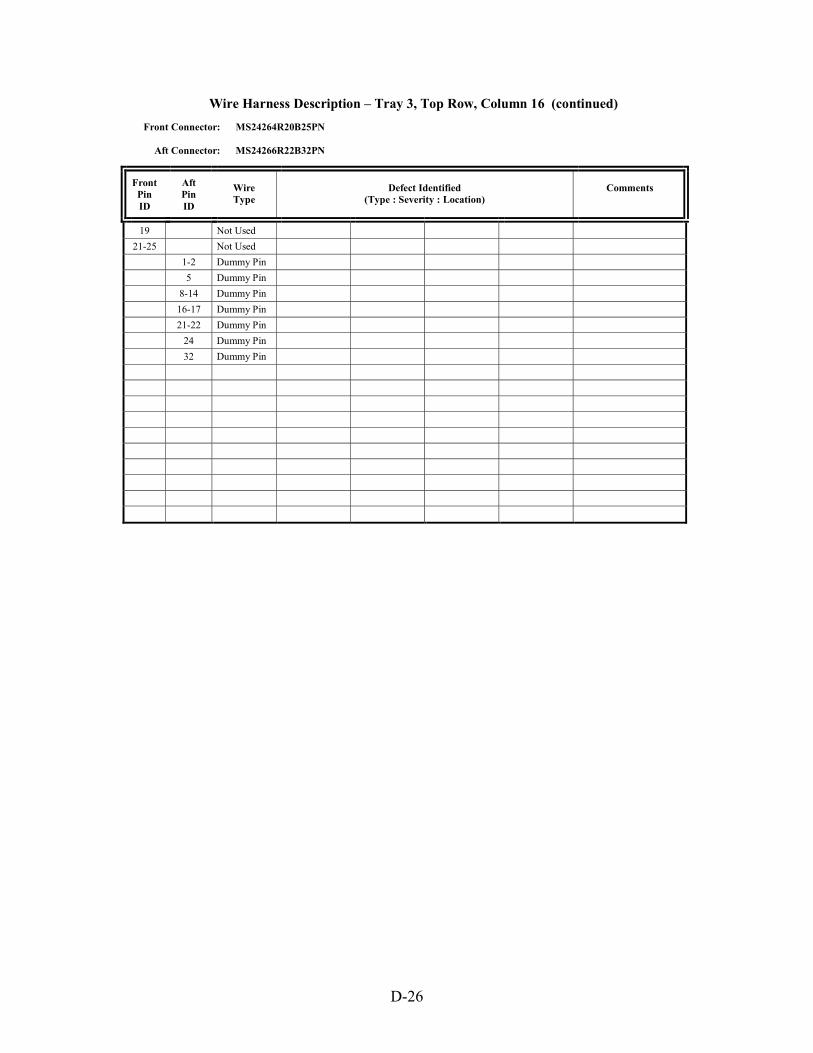
Wire Harness Description – Tray 3, Top Row, Column 16 (continued) Front Connector: MS24264R20B25PN Aft Connector: MS24266R22B32PN
Front Pin ID
Aft Pin ID
Wire Type
Defect Identified (Type : Severity : Location)
Comments
19 Not Used 21-25 Not Used
1-2 Dummy Pin 5 Dummy Pin 8-14 Dummy Pin 16-17 Dummy Pin 21-22 Dummy Pin 24 Dummy Pin 32 Dummy Pin
D-26

Harness Connectors In-SituTray 3, Top Row, Column 18
Aft: 704801Front: MS24264R16B24PN
Wire Harness Description – Tray 3, Top Row, Column 18 Front Connector: MS24264R16B24PN Aft Connector: 704801
Front Pin ID
Aft Pin ID
Wire Type
Defect Identified (Type : Severity : Location)
Comments
1 1 W42A/1/3-22 2 2 No Visible #--blue 3 3 No Visible #--yellow
4-5 Not Used 4-5 Dummy Sockets 6 6 W42/1/3-20 7 7 No Visible #--blue
8 8 No Visible #--yellow Twisted wires: (1,2,3)(6,7,8)
9-24 Not Used 9-12 Dummy Sockets
D-27

Harness Connectors In-SituTray 3, Top Row, Column 20
Aft: MS24266R22B55S7Front: MS24264R22B55P7
Wire Harness Description –Tray 3, Top Row, Column 20 Front Connector: MS24264R22B55P7 Aft Connector: MS24266R22B55S7
Front Pin ID
Aft Pin ID
Wire Type
Defect Identified (Type : Severity : Location)
Comments
1 1 W247-R246 2 2 W42A/13/2-24 3 3 W42A/13/2-24 4 4 W247-R264 5 5 W247-RZ62-24 6 6 W247-RZ60-24 7 7 W247-RZ283 8 8 W247-RZ65 9 9 W42/A/13/2-24 Twisted shielded pairs: (2,3)(9,10)
10 10 W42/A/13/2-24 (11,25)(13,14)(15,16)(17,18) 11 11 W42/A/13/2-24 (26,27)(32,33) 12 12 W247-RZ61-24 13 13 W42A/13/2-24 Front shield terminated by stripping 14 14 W42A/13/2-24 Aft shield termination unknown 15 15 W42A/13/2-24 16 16 W42A/13/2-24 17 17 W42A/13/2-24 18 18 W42A/13/2-24 19 19 W247-RZ63-24 20 20 Not Used
D-28

Wire Harness Description – Tray 3 op Row, Column 20 (continued) Front Connector: MS24264R22B55P7 Aft Connector: MS24266R22B55S7
Front Pin ID
Aft Pin ID
Wire Type
Defect Identified (Type : Severity : Location)
Comments
21 21 W247 R55-24 22 22 Not Used 23 23 W247-RZ58-24 24 24 W247-RZ59-24 25 25 W42A/13/2-24 26 26 W42A/13/2-24 27 27 W42A/13/2-24 28 28 W247-RZ60-24
29-31 29-31 Not Used 32 32 W42A/13/2-24 33 33 W42A/13/2-24 34 W247-RZ67-24 35 35 W247-RZ1-24 36 36 W247-RZ3-24 37 37 W247-RZ53-24
38-39 38-39 Not Used 40 40 W247-RZ51-24
41-43 41-43 Not Used
, T
Wire Harness Description – Tray 3, Top Row, Column 20 (continued) Front Connector: MS24264R22B55P7 Aft Connector: MS24266R22B55S7
Front Pin ID
Aft Pin ID
Wire Type
Defect Identified (Type : Severity : Location)
Comments
45 45 W247-RZ57-24 46-48 46-48 Not Used
49 49 W42A/8/1-22 50 50 Not Used 51 51 W247-RZ63-24
52-53 52-53 Not Used 54 54 W247-RZ5-24 55 55 W247-RZ50-24
44 W247-RZ281-24 44 Not Used
34 Not Used
D-29
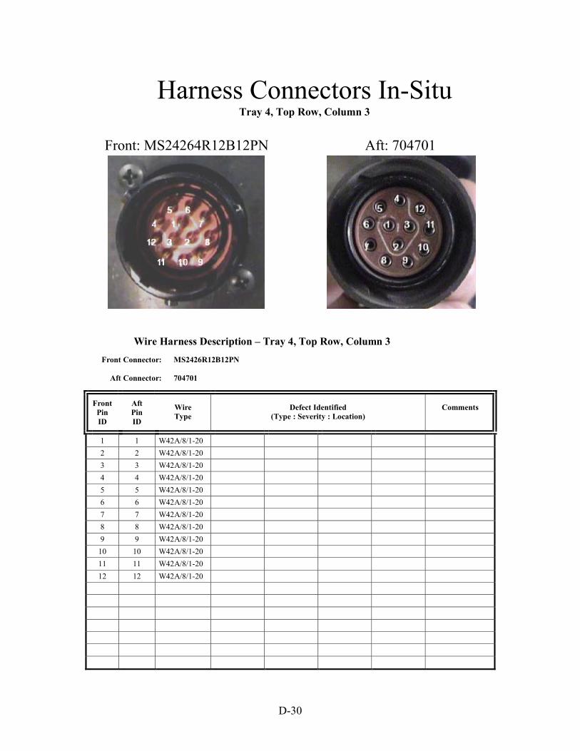
Harness Connectors In-SituTray 4, Top Row, Column 3
Front: MS24264R12B12PN Aft: 704701
Wire Harness Description – Tray 4, Top Row, Column 3 Front Connector: MS2426R12B12PN Aft Connector: 704701
Front Pin ID
Aft Pin ID
Wire Type
Defect Identified (Type : Severity : Location)
Comments
1 1 W42A/8/1-20 2 2 W42A/8/1-20 3 3 W42A/8/1-20 4 4 W42A/8/1-20 5 5 W42A/8/1-20 6 6 W42A/8/1-20 7 7 W42A/8/1-20 8 8 W42A/8/1-20 9 9 W42A/8/1-20
10 10 W42A/8/1-20 11 11 W42A/8/1-20 12 12 W42A/8/1-20
D-30

Harness Connectors In-SituTray 4, Top Row, Column 5
Front: MS24264R22B55P7 Aft: No Visible Number-55 socket
Wire Harness Description – Tray 4, Top Row, Column 5 Front Connector: MS24264R22B55P7 Aft Connector: No Visible Number—55 Sockets
Front Pin ID
Aft Pin ID
Wire Type
Defect Identified (Type : Severity : Location)
Comments
1-21 Not Used 22 k * 23 j * 24 i *
25-26 Not Used 27 f 28 Not Used 29 d * 30 c * 31 a *
32-33 Not Used 34 Y * 35 m * 36 X *
37-38 Not Used 39 T *
40-43 Not Used 44 M * 45 Not Used
D-31

Wire Harness Description – Tray 4, Top Row, Column 5 (continued) Front Connector: MS24264R22B55P7 Aft Connector: No Visible Number—55 Sockets
Front Pin ID
Aft Pin ID
Wire Type
Defect Identified (Type : Severity : Location)
Comments
46 K * 47 J * 48 H * 49 G * 50 F * 51 E * 52 D * 53 Not Used 54 B * 55 A *
n Not Used s-t Not Used v Not Used AA Not Used DD Not Used C * L * N-W *
Z * *No Visible Numbers on Wires
Wire Harness Description – Tray 4, Top Row, Column 5 (continued)
Front Connector: MS24264R22B55P7 Aft Connector: No Visible Number—55 Sockets
Front Pin ID
Aft Pin ID
Wire Type
Defect Identified (Type : Severity : Location)
Comments
b * e *
g-h *
l * o-r * u * w-z * BB-CC * EE-HH *
*No Visible Numbers on Wires
D-32

Harness Connectors In-SituTray 4, Top Row, Column 7
Front: MS24264R14T4PN Aft: No Visible Number- 6 socket
Wire Harness Description – Tray 4, Top Row, Column 7 Front Connector: MS24264R14T4PN Aft Connector: No Number Visible—6 Socket
Front Pin ID
Aft Pin ID
Wire Type
Defect Identified (Type : Severity : Location)
Comments (Pedigree)
1 Not Used 2 B 7616964A24 3 Dummy Pin 4 D 7616964A24 A No Number Visible C 2D153C24 E Dummy Socket F Dummy Socket
D-33

Harness Connectors In-SituTray 4, Top Row, Column 9
Aft: No Visible Number- 10 socketFront: MS24264R10B5SN
Wire Harness Description – Tray 4, Top Row, Column 9 Front Connector: MS24264R10B5SN Aft Connector: No Visible Number—10 Socket
Front Pin ID
Aft Pin ID
Wire Type
Defect Identified (Type : Severity : Location)
Comments
1 A No Visible Number 3 C No Visible Number B M22759 8-20-9 D M22759 8-20-9 E Dummy Socket F M22759 8-20-9 G M22759 8-20-9 Twisted shielded pair: (1,3)
H Dummy Socket Front shield terminated by stripping
J M22759 8-20-9 Aft shield termination unknown
K M22759 8-20-9 2 Not Used
4-5 Not Used
D-34

Harness Connectors In-SituTray 4, Top Row, Column 11
Front: MS24264R14T4PN Aft: MS24264R14T4PN
Wire Harness Description – Tray 4, Top Row, Column 11 Front Connector: MS24264R14T4PN Aft Connector: MS24264R14T4PN
Front Pin ID
Aft Pin ID
Wire Type
Defect Identified (Type : Severity : Location)
Comments
1 1 * 2 2 * 3 3 * 4 4 *
Twisted pairs: (1,2)(3,4)
D-35

Harness Connectors In-SituTray 4, Top Row, Column 13
Front: MS24264R14T7P6 Aft: No Visible Number- 15 socket
Wire Harness Description – Tray 4, Top Row, Column 13 Front Connector: MS24264R14T7P6 Aft Connector: No Visible Number—15 Sockets
Front Pin ID
Aft Pin ID
Wire Type
Defect Identified (Type : Severity : Location)
Comments
1 P MS2519C-3-18 2 B DAC 7616 964-B24 3 J DAC 7616 964-B24 4 M DAC 7616 964-B24 5 H No visible numbers 6 G No visible numbers
7 A DAC 7616 964-B24 Twisted shielded pair: (5,6)
C-F Dummy Socket Front shield terminated by stripping
L Dummy Socket Aft shield termination unknown N Dummy Socket R Dummy Socket E No Visible Number K No Visible Number
D-36
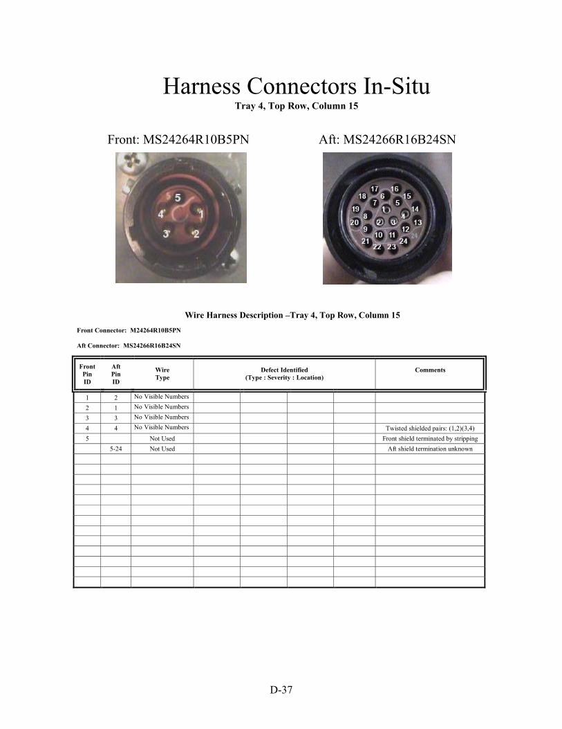
Harness Connectors In-SituTray 4, Top Row, Column 15
Aft: MS24266R16B24SNFront: MS24264R10B5PN
Wire Harness Description –Tray 4, Top Row, Column 15 Front Connector: M24264R10B5PN Aft Connector: MS24266R16B24SN
Front Pin ID
Aft Pin ID
Wire Type
Defect Identified (Type : Severity : Location)
Comments
1 2 No Visible Numbers 2 1 No Visible Numbers 3 3 No Visible Numbers 4 4 No Visible Numbers Twisted shielded pairs: (1,2)(3,4) 5 Not Used Front shield terminated by stripping 5-24 Not Used Aft shield termination unknown
D-37

Harness Connectors In-SituTray 4, Top Row, Column 17
Aft: MS24266R22B55P8Front: MS24264R22B55S8
Wire Harness Description – Tray 4, Top Row, Column 17 Front Connector: MS24264R22B55S8 Aft Connector: MS24266R22B55P8
Front Pin ID
Aft Pin ID
Wire Type
Defect Identified (Type : Severity : Location)
Comments
1 1 MS25190-B20 2 2 MS25190-B20 3 3 MS25190-B20 4 4 7616964-B24 5 5 MS25190-B20 6 6 MS25190-B20 7 7 MS25190-B20 8 8 MS25190-B20 9 9 7616964-B24
10 10 7616964-B24 11 11 7616964-B24 12 12 7616964-B24 13 13 7616964-B24
14-55 14-55 Not Used
D-38

Harness Connectors In-SituTray 4, Top Row, Column 19
Front: MS24264R14T7P6 Aft: MS24264R14T7S6
Wire Harness Description – Tray 4, Top Row, Column 19 Front Connector: MS24264R14T7P6 Aft Connector: MS24264R14T7S6
Front Pin ID
Aft Pin ID
Wire Type
Defect Identified (Type : Severity : Location)
Comments
1 1 No Number Visible—red 2 2 No Number Visible—blue 3 3 MS25190-B20 4 4 RZ208124-green 5 5 No Number Visible—blue 6 6 No Number Visible—red 7 7 Not Used
Twisted pairs: (1,2)(5,6)
D-39

Harness Connectors In-SituTray 4, Top Row, Column 21
Aft: No Visible Number- 3 socketsFront: MS24264R10B5PN
Wire Harness Description – Tray 4, Top Row, Column 21 Front Connector: MS24264R10B5PN Aft Connector: No Number Visible—3 sockets
Front Pin ID
Aft Pin ID
Wire Type
Defect Identified (Type : Severity : Location)
Comments
1 1 2D304E24 2 2D306A24N 3 Dummy socket
2-5 Not Used
D-40

Annex E Aircraft Wire Systems Defect Fabrication Procedures
This annex provides a description of each of the procedures used to fabricate the wire defects used in the test bed. This includes defect type, tools used, step-by-step text and illustrative photographs, and photographs of the resulting defect.
E-1

E-2

Aircraft Wire System Test-Bed Defects Fabrication
Harnesses used in the test bed enclosure will have one or more defects of the type described below. The defect descriptor found in Table 2 of the report corresponds to the specifications for each defect fabrication. The goal of these procedures was to make the fabrication process repeatable with little complexity.
DT-1: Insulation Abrasion Tools: Dremel #380-6, Router Bit, Safety Glasses Specification: Location on Wire; Radial Percent of Insulation Removed; Linear and Angular Extent
The following procedure describes the methods and tools used to fabricate abrasions into the wire used in the Test-Bed. Abrasions are made with a custom-milling fixture shown in Figure DT1-1 (Dremel Moto-Tool Model # 380-6, Variable Speed).
Figure DT1–1. Dremel Tool Mounted in Custom Mill
To achieve reproducibility, the same router bit shall be used in all abrasions put into the Test-Bed wiring (Dremel part number 9903, tungsten carbide bit, shown in Figure DT1-2). The Dremel Tool # 380-6 shall be operated at 28,000 RPM for all work. Because of varying dimensions in the insulations of different wire types used in the test bed, there will be differing amounts of feed used on each wire clamped in the mill. Figure DT1-2 shows two views of a wire clamped in the Dremel Mill.
E-3

Figure DT1-2. Showing Two Views of a Wire Clamped in Abrasion Test Fixture
After the wire is clamped into the vise on the mill, the carbide cutter must then be located to within a few mils of the wire insulation. The technique of using a piece of paper (approximately 2 mils thick) between the bit and the insulation will be used. With one hand cranking the X-axis dial and the other hand sliding a small piece of paper between the bit and insulation, move the vise until the paper is just able to be removed from between the bit and wire without tearing (tool is not energized at this time). This technique is shown in Figure DT1-3.
Figure DT1-3. Wire-to-Bit Spacing Adjustment Using Small Piece of Paper
Before energizing the tool, make sure that the Y-axis feed dial is fully counter-clockwise and travel is completed by the stop. Because of the rotation of the tool, all feeds for the lateral abrasions shall be done with one pass. Energize the Dremel and crank in on the X-axis dial to the desired depth. Each cut will be specific to the type of wire and type of cut
E-4
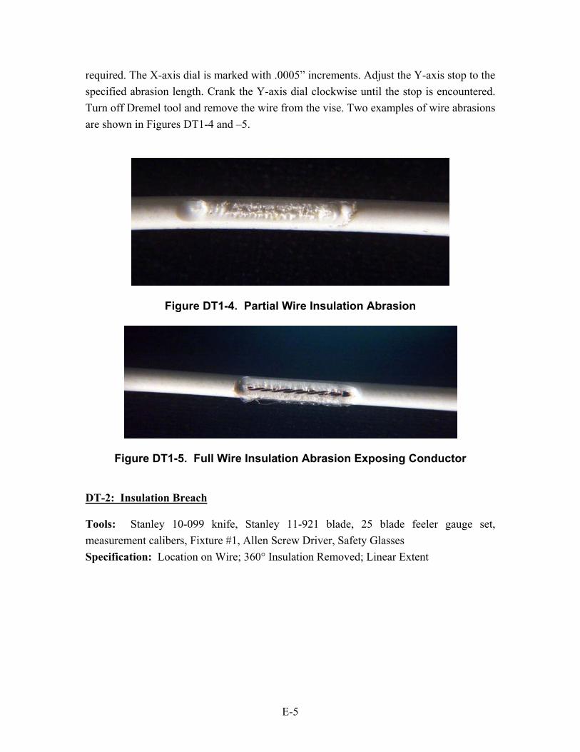
required. The X-axis dial is marked with .0005” increments. Adjust the Y-axis stop to the specified abrasion length. Crank the Y-axis dial clockwise until the stop is encountered. Turn off Dremel tool and remove the wire from the vise. Two examples of wire abrasions are shown in Figures DT1-4 and –5.
Figure DT1-4. Partial Wire Insulation Abrasion
Figure DT1-5. Full Wire Insulation Abrasion Exposing Conductor
DT-2: Insulation Breach Tools: Stanley 10-099 knife, Stanley 11-921 blade, 25 blade feeler gauge set, measurement calibers, Fixture #1, Allen Screw Driver, Safety Glasses Specification: Location on Wire; 360° Insulation Removed; Linear Extent
E-5

Figure DT2-1. Stanley Knife and Blade Figure DT2-2. Feeler Gauge Set
The following procedure describes the methods and tools used to fabricate three different incisions into the wire used in the test bed. The three different incisions will be referred to as the straight cut, the lateral breach, and partial insulation removal.
Straight Cut and Circumferential Lateral Breach Measure the overall wire insulation diameter, splice off the insulation (at the end of a sample wire), and measure the conductor diameter. Subtract the conductor diameter from the insulation diameter. Divide this difference by two, resulting in the insulation radial thickness. Stack the proper amount of feeler gauges on a flat surface to equal the conductor diameter and radius of insulation thickness. Figure DT2-3 illustrates this geometry. Figure DT2-4 shows the cutting fixture (#1) and feeler gauges.
S T R A IG H T K N IF E C U T
L A T E R A L B R E A C H T OC O N D U C T O R
F E E L E RG A U G ES T A C K
C O N D U C T O R
IN S U L A T IO N
Figure DT2-3. Drawing of Breach Defect Cutting Geometry
E-6
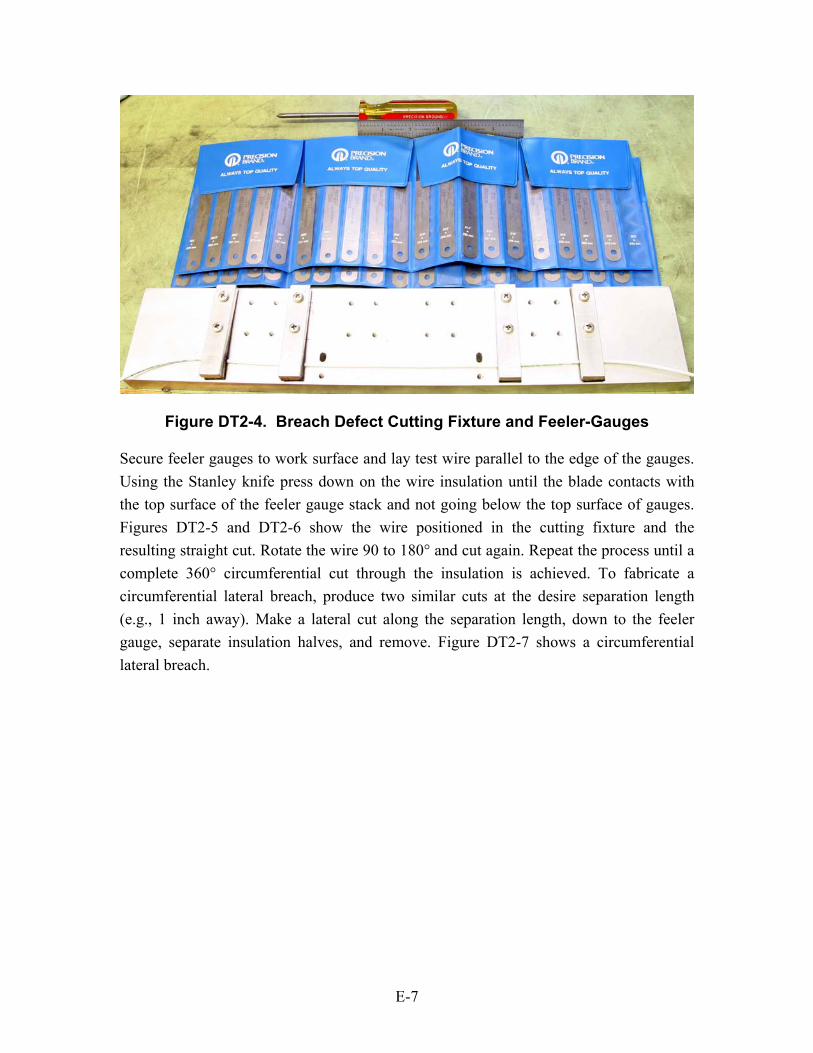
Figure DT2-4. Breach Defect Cutting Fixture and Feeler-Gauges
Secure feeler gauges to work surface and lay test wire parallel to the edge of the gauges. Using the Stanley knife press down on the wire insulation until the blade contacts with the top surface of the feeler gauge stack and not going below the top surface of gauges. Figures DT2-5 and DT2-6 show the wire positioned in the cutting fixture and the resulting straight cut. Rotate the wire 90 to 180° and cut again. Repeat the process until a complete 360° circumferential cut through the insulation is achieved. To fabricate a circumferential lateral breach, produce two similar cuts at the desire separation length (e.g., 1 inch away). Make a lateral cut along the separation length, down to the feeler gauge, separate insulation halves, and remove. Figure DT2-7 shows a circumferential lateral breach.
E-7

Figure DT2-5. Wire Positioned in Cutting Fixture
Figure DT2-6. Straight Cut Result
Figure DT2-7. Circumferential Lateral Breach
E-8

DT-3: Cracked Insulation Tools: Same as specified in DT-2 Specification: Linear Extent; Percent into Insulation Radius; Density (cuts per inch) The following procedure will describe a method used to fabricate cracked insulation on wires placed in the test bed. The method introduces a specified number of cracks per inch of wire (density) using the straight knife cut procedure described above in DT-2: Insulation Breach. Determine the proper height of feeler gauge stack by using the measuring steps described in DT2. For cuts that do not go all of the way to the conductor, calculate the additional amount of feeler gauge height by multiplying the percent of remaining insulation desired by the insulation thickness. Figure DT2-1 shows the setup for producing a single cut into the insulation. Figure DT3-1 shows the resulting defect after using this procedure.
DT3-1. Simulated Cracked Insulation Defect from Straight Knife Cuts
E-9

DT-4: Conductor Strand Breaks Tools: Same as tools used in DT-2 Specification: Location on Wire; Percent of Conductor Strands Severed The following procedure will describe the method used to fabricate wire conductor partial strand breakage. Using the procedure described for mounting the wire into the cutting fixture described in section DT-2, secure the specimen wire and feeler gauges on the cutting fixture. Using the Stanley knife, cut into insulation until side of blade is flush with feeler gauges. Make a 3600 cut sufficient to expose conductor strands. Remove the wire from the fixture and using the knife select the particular strand. Using a smaller knife, sever the strand. Repeat the procedure until the specified number of strands is severed. After cutting the individual strands, bend each strand backwards (180°), so no contact is made with other strand cuts. Apply heat shrink tubing over defect to hold strands in place and to isolate severed strands. Figure DT4 – 1 shows the wire mounted in the fixture and strand selection and Figure DT4-2 shows the strand folded back.
Figure DT4-1. Two Steps Required for a Partial Conductor Strand Cut
E-10

Figure DT4-2. Result of Conductor Strand Cut and Fold-Back
DT-5: Over-Pressured Clamps Tools: Harness Clamp and Nut and Bolt, Socket and Torque Wrench, Ratchet, Safety Glasses Specification: Location; Clamp Size, Torque Value The following procedure describes the two methods used to over-pressure harness clamps. Figure DT5-1 shows the tools that are needed to produce an over-pressured clamp. Using a clamp that is undersized, remove any cushion/padding from the clamp and secure the clamp around the harness at the specified location. The location may correspond to a ribbed structure element of the simulated aircraft fuselage segment location within the enclosure. Using the socket wrench and an appropriately sized ratchet, compress the clamp around harness to a normal (~10 inch-lb) degree of tightness. Next use the torque wrench to the specified value of clamp tightness or compression (units of inch-lb). Another variation of this defect type is to allow one to three wires to be pinched by the hardware section of clamp. Both of these over-pressured clamp defects are shown in Figure DT5-2.
E-11

DT5-1. Tools Needed for DT5
Figure DT5-2. Two Types of Over-Pressured Clamp Defects
Another clamp related defect is due to worn-away clamp insulation and the action (vibration) of the exposed metallic portion of the clamp rubbing against the wire insulation. This clamp-related defect type can be fabricated by using the procedure described in DT-1 to chafe-off insulation from one or more wires, and a clamp without an insulation barrier is placed over the chafed wire(s). However, this defect type is similar electrically to a short, or partial short, for a particular wire and is addressed in defect type DT-10 (short wire defect).
E-12

DT-6: Bend Radius Tools: Plastic Tie-Bands, Tie-Band Tool Specification: Location; Bend Diameter The following procedure will describe the method used to introduce excessive bending radius of harnesses. Ensure that the specimen harness has sufficient length so that when installed into the test bed the connectors are capable of spanning the enclosure length. Bend the harness to a specified radius in multiples of harness diameter. Apply tie band. Repeat the process to orient the harness on the intended path within the enclosure. Figure DT6-1 shows a zero bend-radius defect with two tie bands securing the bends in place and a wire with harness diameter separation of about two diameters.
Figure DT6-1. Illustration of Harness Diameter Separation and Applied Tie-
Band DT-7: Faulty Splice Tools: Butt Splice Joint, Crimp Tool, Heat Shrink Tubing, Heat Gun, Electrical Tape Specification: Location on Wire; Severity Type Details (see method description below) The following procedure will describe three methods used to introduce faulted wire splices. The first method (type I) inserts each end of the wire to be joined into a butt joint but with no crimping and with heat applied to heat-shrink tubing that is placed about it. This defect is shown in Figure DT7-1. The second method (type II) is a crimped but exposed splice. This defect is shown in the left photograph of Figure DT7-2. The third method (type III) is a crimped splice but excessively over heated. This defect is shown in the right photograph of Figure DT7-2. This type three defect utilizes the charred insulation procedure, exposed for ~ 1 to 1.5 minutes, described in section DT-8 below.
E-13
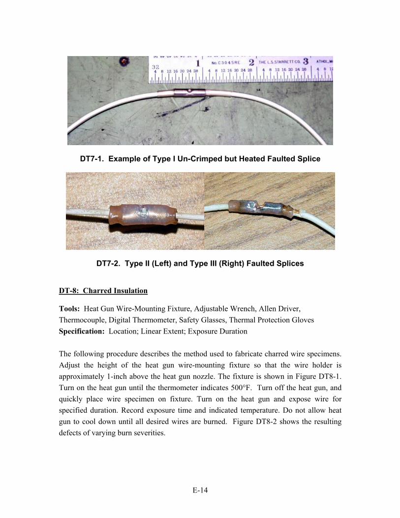
DT7-1. Example of Type I Un-Crimped but Heated Faulted Splice
DT7-2. Type II (Left) and Type III (Right) Faulted Splices DT-8: Charred Insulation Tools: Heat Gun Wire-Mounting Fixture, Adjustable Wrench, Allen Driver, Thermocouple, Digital Thermometer, Safety Glasses, Thermal Protection Gloves Specification: Location; Linear Extent; Exposure Duration The following procedure describes the method used to fabricate charred wire specimens. Adjust the height of the heat gun wire-mounting fixture so that the wire holder is approximately 1-inch above the heat gun nozzle. The fixture is shown in Figure DT8-1. Turn on the heat gun until the thermometer indicates 500°F. Turn off the heat gun, and quickly place wire specimen on fixture. Turn on the heat gun and expose wire for specified duration. Record exposure time and indicated temperature. Do not allow heat gun to cool down until all desired wires are burned. Figure DT8-2 shows the resulting defects of varying burn severities.
E-14

Thermocouple
Figure DT8-1. Heat Gun and Wire Mounting Fixture with Close-up View of
Wire Positioned Over Heat Gun Nozzle
DT8-2. Resulting Severities of Burnt Wires DT-9: Opened Conductor Tools: Wire Cutter, Solder Station, Safety Glasses Specification: Location; With Contact; Without Contact The following procedure describes the method used to introduce unintended open circuited conditions in wire specimens. Select assembled wire harness and location where the open circuit defect is to be placed. Select particular wire that is to be electrically opened and use cutters to sever the wire. If no contact is specified cut off ¼-inch segment
E-15

of the wire and cover with electrical tape. If contact is to be maintained between each side of the previously uncut wire, solder together the desired number of strands that correspond to the percentage of contact to be maintained and cover with electrical tape. For example, solder together half of the strands of each end of wire for fifty percent contact. Figure DT9-1 shows the tools needed to do the procedure. Figure DT9-2 shows the soldering together of wire strands and the resulting defects.
Figure DT9-1. Tools Needed for Opened Wire Conductor Defect
25% Contact
Figure DT9-2. 50 and 25
50% Contact
Percent of Varying Degrees of Contact
E-16

DT-10: Shorted Conductor Tools: Wire Cutter, O-Lug, Crimper, Solder Kit, Safety Glasses, Sheet Metal Screw, Power Screw Driver, Safety Glasses, Resistors Specification: Location; Short Path (Differential or Common Mode) The following procedure will describe two methods used to introduce unintended short-circuited conditions in wire specimens. Select wire specimen and short location. The first method is a wire shorted to the enclosure frame (common mode). Cut wire and crimp on O-lug. Use a sheet metal screw and power drive to attach lug to enclosure frame. The second method uses the lateral breach procedure provided in section DT-2 to remove a segment of insulation of two adjacent wires and then a solder joint to short the two wires together (differential mode). Figure DT10-1 shows both wire short types. The severity of both types of shorts can be varied by soldering resistors of varying ohmic values between the ends of the short. This is shown in Figure DT10-2.
E-17
DT10-1. Photographs of Two Short Types

DT10-2. Resistor Used to Simulate a Partial Short
E-18

Annex F Photographs of Defect Types Used in the Test Bed
This annex provides photographs of all defect types used in the test bed. Both naturally occurring and fabricated defects are shown.
F-1

F-2

Chaffed Defects (DT-1)
FabricatedFabricated
Actual
Actual
Breach Defects (DT-2)
Fabricated
Actual
F-3

Cracked Defects (DT-3)
Conductor Strand Break Defects (DT-4)
ActualFabricated Defect
Fabricated Defect
ActualFabricated Defect
ActualActualFabricated DefectFabricated Defect
Fabricated DefectFabricated Defect
F-4
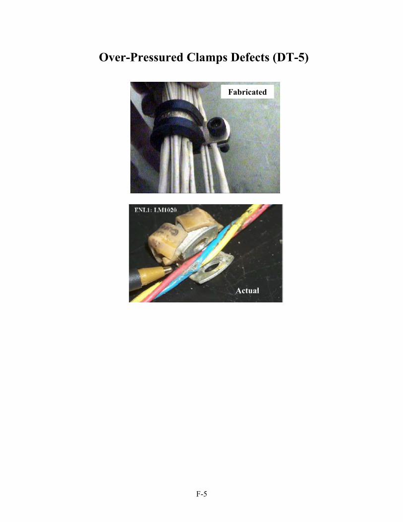
Over-Pressured Clamps Defects (DT-5)
Actual
Fabricated
F-5

Excessive Bend Radius Defects (DT-6)
Fabricated
Actual
F-6

Faulted Splice Defects (DT-7)
Actual
Actual
FabricatedFabricated
Actual
Actual
Actual
Actual
FabricatedFabricated FabricatedFabricatedFabricatedFabricated
F-7

Charred Insulation Defects (DT-8)
Fabricated
Actual
F-8
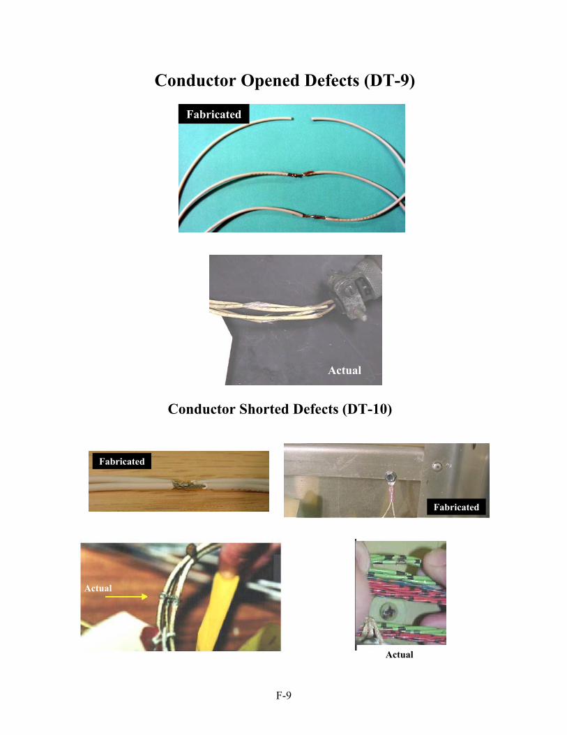
Conductor Opened Defects (DT-9)
Fabricated
Actual
Conductor Shorted Defects (DT-10)
Actual
Actual
Fabricated
Fabricated
F-9


Distribution
1 Paul B. Arnason AAIPT/Wiring Systems Branch Naval Air Systems Command 48298 Shaw Rd. Ratuxent River, MD 20670
1 Roger Baird Team Leader Avionics Department NASA Marshal Space Flight Center Huntsville, AL 35812
1 Michael Ballas General Dynamics Advanced Information Systems 9845 Willows Road N.E. Redmond, WA 98052-2540
1 John E. Brooks Fire Protection Laboratory International Aero Inc. 11817 Westar Lane Burlington, WA 98233
1 Walter Cinibulk Tyco Electronics 8315 143rd Court SE Newcastle, WA 98059
1 Steve Downie Ktech Corporation 2201 Buena Vista SE, Albuquerque, NM 87106-4265
1 C. Alan Ferguson Eclypse International 265 N. Joy Street, Suite #150 Corona, CA 92879-1323
1 Francois Gau
Honeywell Engines, Systems & Services 1944 E. Sky Harbor Circle M/S 2101-203 Phoenix, AZ 85034
1 Russell W. Graves TYCO Electronics 300 Constitution Dr. Menlo Park, CA 94063
1 Mark A. James ICASE NASA Langley Research Center MS 188E Hampton, VA 23681
1 Nicholas W. Kirincich Wiring Systems Design QPL Raytheon 6125 E. 21st Street Indianapolis, Indiana 46129-2058
1 Lem Hunter Mechanical Solutions, Inc. 8300 Corona Loop, NE Albuquerque, NM 87113
1 Glenn R. Lacey Phoenix Aviation & Technology Milton Suite - Fairoaks Airport Chobham, Surrey GU24 8HX, UK
1 Ric Loeslein NAVAIR 22347 Cedar Point Rd. Bldg. 2185 Rm 2100-C4 Patuxent River, MD 20670
1 Marvin E. Morris 4105 Camino de la Sierra Albuquerque, NM 87111
1 John B. O’Loughlin Wichita State University National Institute for Aviation Research 1845 Fairmount Wichita, KS 67260-0093
1 Robert A. Pappas Federal Aviation Administration FAA William J. Hughes Technical Center AAR-430 Atlantic City Int’l Airport, NJ 08405
1 Jan P. Roos Wire and Cable Tyco Electronics 501 Oakside Ave. Redwood City, CA 94063
1 Mehdi Safavi The Boeing Company EE-Subsystems Commercial Airplanes P. O. Box 3707 MC 02 - 37 Seattle, WA 98124-2207
1 Dave Ripper Whitmor/Wirenetics 27737 Hopkins Ave., Valencia, CA 91355
1 Daniel N. Rogovin Phantom Works The Boeing Company 5301 Bolsa Avenue Huntington Beach, CA 92647
1 MS 1152 L. X. Schneider (Org. 1643)
1 MS 0615 R. L. Perry (Org. 6252)
1 MS 0615 P. W. Werner (Org. 6252)
1 MS 0615 G. J. Langwell (Org. 6252)
1 MS 0615 M. D. Bode (Org. 6252)
1 MS 0615 D. G. Moore (Org. 6252)
1 MS 0615 D. M. Ashbaugh (Org. 6252)

1 MS 0615 D. P. Roach (Org. 6252)
1 MS 1152 M. L. Kiefer (Org. 1642)
1 MS 1152 L. K. Warne (Org. 1642)
1 MS 1152 R. E. Jorgenson (Org. 1642)
1 MS 1152 W. A Johnson (Org. 1642)
1 MS 0405 K. O. Merewether (12333)
1 MS 0492 K. C. Chen (Org. 12332)
1 MS 0748 F. J. Wyant (Org. 6413)
1 MS 1003 K. N. Groom (Org. 15211)
1 MS 1152 M. A. Dinallo (Org. 1643)
1 MS 9018 Central Technical Files, 8945-1
2 MS 0899 Technical Library, 9616
Related Documents


