NAVAIR 01-1B-50 USAF TO 1-1B-50 USCG TO 1-1B-50 ARMY TM 55-1500-342-23 JOINT SERVICE TECHNICAL MANUAL AIRCRAFT WEIGHT AND BALANCE SUPERSEDURE NOTICE. This manual supersedes NAVAIR 01-1B-50 dated 15 August 2003, USAF TO 01-1B-50 dated 1 April 2008, USCG TO 01-1B-50 dated 1 April 2008, and ARMY TM 55-1500-342-23 dated 29 August 1986. Destroy previously issued version of this manual to prevent disclosure of contents or reconstruction of the document. DISTRIBUTION STATEMENT A. Approved for public release; distribution is unlimited. DESTRUCTION NOTICE. For unclassified, limited documents, destroy by any method that will prevent disclosure of contents or reconstruction of the document. PUBLISHED BY DIRECTION OF COMMANDER, NAVAL AIR SYSTEMS COMMAND 30 SEPTEMBER 2011 0801LP1119776 Downloaded from http://www.everyspec.com

Welcome message from author
This document is posted to help you gain knowledge. Please leave a comment to let me know what you think about it! Share it to your friends and learn new things together.
Transcript

NAVAIR 01-1B-50 USAF TO 1-1B-50 USCG TO 1-1B-50 ARMY TM 55-1500-342-23
JOINT SERVICE TECHNICAL MANUAL
AIRCRAFT WEIGHT AND BALANCE
SUPERSEDURE NOTICE. This manual supersedes NAVAIR 01-1B-50 dated 15 August 2003, USAF TO 01-1B-50 dated 1 April 2008, USCG TO 01-1B-50 dated 1 April 2008, and ARMY TM 55-1500-342-23 dated 29 August 1986. Destroy previously issued version of this manual to prevent disclosure of contents or reconstruction of the document.
DISTRIBUTION STATEMENT A. Approved for public release; distribution is unlimited.
DESTRUCTION NOTICE. For unclassified, limited documents, destroy by any method that will prevent disclosure of contents or reconstruction of the document.
PUBLISHED BY DIRECTION OF COMMANDER, NAVAL AIR SYSTEMS COMMAND
30 SEPTEMBER 20110801LP1119776
Downloaded from http://www.everyspec.com

Downloaded from http://www.everyspec.com

NAVAIR 01-1B-50 USAF TO 1-1B-50 USCG TO 1-1B-50 ARMY TM 55-1500-342-2330 September 2011
LIST OF EFFECTIVE PAGESDates of issue for original and changed pages are:
Original ........................ 0 ...............30 September 2011hange............................x ......................... xx XXX 199X Insert latest changed pages; dispose of superseded pages in accordance with applicable regulations.
NOTE: On a changed page, the portion of the text affected by the latest change is indicated be a vertical line, or other change symbol in the outer margin of the page. Change in illustrations are indicated by miniature pointing hands. Changes to wiring diagrams are indicated by shaded areas.
Total number of pages in this manual is 126, consisting of the following:
A Change X
*Zero in this column indicates an original page.
Title ......................................... 0A ............................................. 0i-ii ............................................ 0TPDR-1 ................................... 0TPDR-2 Blank......................... 01-1 - 1-2 .................................. 02-1 - 2-5 .................................. 02-6 Blank ................................ 03-1 - 3-6 .................................. 0
4-1 - 4-17 ................................ 04-18 Blank .............................. 05-1 - 5-13 ................................ 05-14 Blank .............................. 06-1 - 6-3 .................................. 06-4 Blank ................................ 07-1 - 7-10 ................................ 08-1 - 8-38 ................................ 0
Page *Change No. No.
Page *Change No. No.
Page *Change No. No.
A-1 - A-9 ................................. 0A-10 Blank .............................. 0B-1 - B-7 ................................. 0B-8 Blank ................................ 0C-1 .......................................... 0C-2 Blank ................................ 0D-1 .......................................... 0D-2 Blank ................................ 0
Downloaded from http://www.everyspec.com

Downloaded from http://www.everyspec.com

i
NAVAIR 01-1B-50 USAF TO 1-1B-50 USCG TO 1-1B-50
ARMY TM 55-1500-342-2330 September 2011
LIST OF ILLUSTRATIONS .......................................... iiLIST OF TECHNICAL PUBLICATIONS
DEFICIENCY REPORTS (TPDR) INCORPORATED ................................TPDR-1
1 INTRODUCTION1-1. Purpose ............................................1-11-2. Scope ................................................1-11-3. Terminology .......................................1-11-4. Reasons for Weight and Balance
Control ............................................1-2
2 AIRCRAFT WEIGHT AND BALANCE PRINCIPLES
2-1. Aircraft Weight Principles ..................2-12-2. Aircraft Balance Principles ................2-32-3. Calculating Aircraft Center of Gravity
(CG) ...............................................2-32-4. Fuselage Station ...............................2-42-5. Percent Mean Aerodynamic Chord
(% MAC) ........................................2-52-6. Loading / Unloading ..........................2-52-7. Ballast ...............................................2-5
3 WEIGHT AND BALANCE SYSTEM3-1. General .............................................3-13-2. Manufacturer Responsibilities ...........3-13-3. Commercial Maintenance
Responsibilities ..............................3-13-4. Depot / Intermediate Level
Maintenance Responsibilities .........3-13-5. Aircraft Custodian/Technician/Type
Commander Responsibilities .........3-13-6. Aircraft Weight and Balance
Classifications ................................3-13-7. Weight and Balance Handbooks ......3-23-8. Weight and Balance Flight
Clearance .......................................3-43-9. Aircraft Weighing Requirements .......3-5
4 INSTRUCTIONS FOR THE USE OF WEIGHT AND BALANCE CHARTS AND FORMS
4-1. DD Form 365 – Record of Weight and Balance Personnel .........................4-1
4-2. DD Form 365-1 – Chart A – Basic Weight Checklist Record ................4-1
4-3. DD Form 365-2 – Form B – Aircraft Weighing Record ............................4-4
4-4. DD Form 365-3 – Chart C – Basic Weight and Balance Record...........4-5
4-5. Chart E – Aircraft Loading Manual / Weighing Instructions .....................4-7
4-6. DD Form 365-4 – Form F – Weight and Balance Flight Clearance Form F ..........................4-7
5 WEIGHING AIRCRAFT5-1. General .............................................5-15-2. Weighing Equipment .........................5-15-3. Weighing Accessories ......................5-35-4. Weighing Procedures .......................5-55-5. Verification of Weighing Results ..... 5-11
6 WEIGHT AND BALANCE TOOLS6-1. Automated Weight and Balance
System (AWBS) .............................6-16-2. Distribution of AWBS ........................6-16-3. Alternate Weight and
Balance Tools .................................6-1
7 CENTER OF GRAVITY LOADING CALCULATIONS
7-1. General .............................................7-17-2. Principles of Moments ......................7-27-3. Effects of Moments on Aircraft ..........7-37-4. Determination of Balance Condition
(Location of Aircraft CG) ...............7-37-5. Effects of Unbalanced Loading .........7-37-6. Determining Center of Gravity for a
Group of Items ...............................7-37-7. Center of Gravity Limits ....................7-47-8. Expressing Center of Gravity ............7-47-9. Lateral and Vertical Center of
Gravity ............................................7-57-10. Most Forward and Most Aft CG
Calculations ....................................7-57-11. Sample ..............................................7-77-12. Chart E Loading Data .....................7-10
8 SERVICE SPECIFIC REQUIREMENTS8-1. US Army Requirements ....................8-18-2. US Navy / US Marine Corps
Requirements ...............................8-11
TABLE OF CONTENTS
Section Page Section Page
Downloaded from http://www.everyspec.com

ii
NAVAIR 01-1B-50 USAF TO 1-1B-50 USCG TO 1-1B-50 ARMY TM 55-1500-342-2330 September 2011
Figure Title Page Figure Title Page
LIST OF ILLUSTRATIONS
2-1. Weight Terminology ........................................2-22-2. Calculating Aircraft CG ...................................2-32-3. Balance Arm Fuselage Station .......................2-42-4. Percent MAC Example ...................................2-5
5-1. Typical Platform Scale Assembly ....................5-15-2. Electronic Weighing Kit (Typical) .....................5-25-3. Reading a Hydrometer ....................................5-45-4. Accessory Weighing Kit ..................................5-45-5. Estimation of “As Weighed” Weight .................5-75-6. Leveling Lugs Inside the Aircraft .....................5-85-7. Leveling Lugs Outside the Aircraft ..................5-85-8. Plumb Bob ......................................................5-9
6-1. Load Adjuster ..................................................6-3
7-1. Asymmetric Configurations .............................7-17-2. Aircraft Balance Point .....................................7-27-3. Locating Aircraft Center of Gravity ..................7-3
8-1. Aircraft Modification Example .........................8-9
B-1. Sample DD Form 365 Record of Weight and Balance Personnel .................. B-1
B-2. Sample DD Form 365-1 Chart A – Basic Weight Checklist Record .................. B-2
B-3. Sample DD Form 365-2 Form B – Aircraft Weighing Record ........................... B-3
B-4. Sample DD Form 365-3 Chart C – Basic Weight and Balance Record ............. B-5
B-5. Sample DD Form 365-4 Weight and Balance Flight Clearance Form F - Transport .................................................... B-6
B-6. Sample DD Form 365-4 Weight and Balance Flight Clearance Form F - Tactical ....................................................... B-7
8-3. US Air Force Requirements ............8-248-4. US Coast Guard Requirements ......8-35
8-4.1. Related References ..........8-358-4.2. Weight and Balance
Control ..............................8-358-4.3. Responsibilities .................8-368-4.4. Personnel Qualification
Requirements ...................8-368-4.5. Forms and Records
Disposition ........................8-368-4.6. Aircraft Classifications .......8-368-4.7. Form F ...............................8-368-4.8. Aircraft Weighings .............8-378-4.9. Transfer / Acceptance
Inventory ...........................8-388-4.10. Scales ...............................8-388-4.11. Unmanned Aerial Vehicles
(UAV’s) ............................8-38
8-4.12. Weight and Balance Guidance for Aircraft Modifications .....................8-38
8-4.13. Contact Information ...........8-388-4.14. Corrections to this
Manual ..............................8-388-4.15. Distribution of AWBS ........8-38
APPENDIX A. TERMINOLOGY AND DEFINITIONS .......................................... A-1
APPENDIX B. SAMPLE CHARTS AND FORMS .... B-1
APPENDIX C. ACRONYMS .................................... C-1
APPENDIX D. SCALE CORRECTION FACTORS (LATITUDE AND ALTITUDE) .................. D-1
Table Title Page Table Title Page
LIST OF TABLES
3-1. Aircraft Classifications ....................................3-2 3-2. Major Modifications or Repairs Guidelines .....3-6
Downloaded from http://www.everyspec.com

iii
NAVAIR 01-1B-50 USAF TO 1-1B-50 USCG TO 1-1B-50
ARMY TM 55-1500-342-2330 September 2011
Report Control Number (RCN) Location
alskjalkj0000/00000 Pg x-xx
0000/00000 Pg x-xx
alskjalkj0000/00000 Pg x-xx
alskjalkj0000/00000 Pg x-xx
alskjalkj0000/00000 Pg x-xx
alskjalkj0000/00000 Pg x-xx
alskjalkj0000/00000 Pg x-xx
alskjalkj0000/00000 Pg x-xx
alskjalkj0000/00000 Pg x-xx
NONE
LIST OF TECHNICAL PUBLICATIONS DEFICIENCY REPORTS INCORPORATED
TPDR-1/(TPDR-2 Blank)
Downloaded from http://www.everyspec.com

THIS PAGE LEFT INTENTIONALLY BLANK
Downloaded from http://www.everyspec.com

NAVAIR 01-1B-50 USAF TO 1-1B-50 USCG TO 1-1B-50
ARMY TM 55-1500-342-2330 September 2011
1-1
Section 1 - Introduction 1-1. PURPOSE This manual outlines and defines the requirements, procedures, and responsibilities for weight and balance control of military aircraft. This manual also provides information and instructions for maintaining the charts and forms (DD Form 365 series or electronic equivalent) that provide the means for maintaining continuous record and control of aircraft weight and balance. Information and explanation of principles, terms, and definitions are presented to provide weight and balance personnel with a general information manual pertinent to their particular function. 1-2. SCOPE The use of this manual is mandatory for all weight and balance tasks that operate and/or maintain United States military aircraft (including fixed-wing aircraft, rotary-wing aircraft and select unmanned air vehicles). See Section 8 (Service Specific Requirements) for additional information concerning select unmanned air vehicles. Sufficient explanation of principles, definitions, procedures and data are given to provide weight and balance personnel with a general information manual pertinent to their particular function. Also included is a complete description of related equipment and instructions for its use and operation. The general requirements and procedures of this manual are applicable to weight and balance control of all military aircraft. Additional requirements, procedures, and/or instructions for specific aircraft weight and balance control are specified in the aircraft specific manuals. See Section 8 (Service Specific Requirements) for additional reference documents. 1-3. TERMINOLOGY 1-3.1. Usage of the words "shall", "should", and "may" is in accordance with the following: 1-3.2. The word "shall," is used to indicate the requirements, procedures, and/or responsibilities are
mandatory. 1-3.3. The word "should" is used to indicate a non-mandatory but highly recommended method of
accomplishment. 1-3.4. The word "may" is used to indicate an acceptable or suggested means of accomplishment. 1-3.5. Weight and balance definitions are found in Appendix A. 1-3.6. WARNINGS, CAUTIONS, AND NOTES DEFINED. Warnings, cautions, and notes are used to
emphasize important and critical instructions and are used for the following conditions: 1-3.6.1. WARNING: An operating procedure, practice, etc, which if not correctly followed, could result in
personal injury or loss of life. 1-3.6.2. CAUTION: An operating procedure, practice, etc, which, if not strictly observed, could result in
damage to or destruction of equipment. 1-3.6.3. NOTE: An operating procedure or condition that must be emphasized.
Downloaded from http://www.everyspec.com

NAVAIR 01-1B-50 USAF TO 1-1B-50 USCG TO 1-1B-50 ARMY TM 55-1500-342-2330 September 2011
1-2
1-4. REASONS FOR WEIGHT AND BALANCE CONTROL Flight characteristics of aircraft are directly dependent upon conditions of weight and balance. Gross Weight and center of gravity (CG) have a bearing on performance, stability, and control of the aircraft. For example, cargo placed too far aft in an already critically loaded aircraft could move the center of gravity out of the permissible balance limits. This could cause the pilot to lose control of the aircraft. Hazardous flight conditions and accidents resulting from these conditions can be prevented by adherence to the principles of weight and balance set forth in this manual. An aircraft whose weight is greater than its allowable maximum Gross Weight, or whose Center of Gravity (CG) is located outside its prescribed CG limits, may experience one or more of the following unsatisfactory flight characteristics, performance degradations or payload reduction:
x Longitudinal instability x Lateral instability x Increase in takeoff distance and/or required power setting or torque x Increase in takeoff speed x Increase in landing ground run x Increase in control forces x Increase in stall speeds x Decrease in range and/or allowable payload x Decrease in rate of climb x Decrease in service ceiling x Decrease in structural safety factors x Decreased hover performance x Decreased cruising speed x Decreased maneuverability
Using the principles and following the instructions contained in this manual can prevent these flight conditions and potential associated mishaps. 1-5. COMMENTS – See Section 8 (Service Specific Requirements) for Points of Contact for each service.
Downloaded from http://www.everyspec.com

NAVAIR 01-1B-50 USAF TO 1-1B-50 USCG TO1-1B-50
ARMY TM 55-1500-342-2330 September 2011
2-1
Section 2 – Aircraft Weight and Balance Principles 2-1. AIRCRAFT WEIGHT PRINCIPLES One of the basic elements of aircraft design is weight. The weight of an aircraft is used in determining such design criteria as engine requirements, wing area, landing gear requirements, and payload capacity. Any weight changes, whether in manufacturing, modification, or maintenance, can have distinct effects on aircraft performance and/or payload capability. 2-1.1. WEIGHT TERMINOLOGY. Figure 2-1 illustrates the definition of, and relationships between, aircraft
weight terminology. For related definitions, see Appendix A. 2-1.2. WEIGHT LIMITS. All aircraft are designed with a number of weight limits. These limits are
determined by a combination of performance, control, and structural restrictions. Exceeding these limits can result in loss of aircraft and are expressly forbidden.
2-1.3. AIRCRAFT WEIGHT. The weight of an aircraft is determined through a combination of actual
weighing, accurate record keeping, and proper use of the aircraft specific manuals, charts, forms, and loading manuals.
2-1.4. FLOOR LOADING. Floor loading is the weight, in pounds, of a load divided by the area of floor on
which the load rests. These limits shall never be exceeded. 2-1.4.1. For example, the floor loading for a 100-pound container is determined as follows:
Base of container = 20 inches x 20 inches = 400 square inches
Floor loading = 100 pounds400 square inches
= 0.25 pounds per square inch
or
0.25 pounds per square inch x 144 square inches per square foot = 36 pounds per square foot
Floor loading limits or a plan view of the cargo floor showing variations in floor strength and weight concentration limitations for various compartments are specified in the applicable operator's manual.
NOTE
1 square foot = 144 square inches
Downloaded from http://www.everyspec.com

NAVAIR 01-1B-50 USAF TO 1-1B-50 USCG TO 1-1B-50 ARMY TM 55-1500-342-2330 September 2011
2-2
WEIGHT EMPTY
+
Unusable fuel, engine oil, permanent ballast, oxygen, and all non mission-specific internal or external equipment onboard the aircraft and will not be disposed of during the flight and is not
listed in the Chart E.
=
BASIC WEIGHT
+
Crew, crew baggage, steward equipment, emergency equipment, special mission fixed equipment, and all other non-expendable items (such as fixed pylons and racks) not in Basic
Weight.
=
OPERATING WEIGHT
+
Payload items; such as cargo, ammunition, passengers, stores, droppable fuel tanks, and transfer fuel.
=
ZERO FUEL WEIGHT
+
Usable Fuel
=
RAMP WEIGHT
-
Taxi Fuel
=
TAKE-OFF GROSS WEIGHT
-
Load items that may or may not be expended in flight; such as fuel, stores, ammunition, cargo and paratroops.
=
LANDING GROSS WEIGHT
Figure 2-1 – Weight Terminology
Downloaded from http://www.everyspec.com

NAVAIR 01-1B-50 USAF TO 1-1B-50 USCG TO1-1B-50
ARMY TM 55-1500-342-2330 September 2011
2-3
2-2. AIRCRAFT BALANCE PRINCIPLES An aircraft is said to be in balance, or balanced, when all weight items in, on, or of the aircraft are distributed so that the Center of Gravity (CG) of the aircraft lies within pre-determined allowable CG limits. These limits are defined by the most forward and aft permissible CG locations and are called the forward and aft CG limits, respectively. To determine if an aircraft is balanced, the aircraft CG shall be calculated and compared to the forward and aft CG limits for that particular configuration and Gross Weight. This can be calculated for not only longitudinal but the lateral and vertical conditions as well, although few aircraft track lateral or vertical CG. Refer to aircraft specific manuals in these cases. 2-2.1. TERMINOLOGY. The terms balance, arm, balance arm, moment, simplified moment, load adjuster
index, and CG are fundamental to understanding aircraft balance and control. These, and other terms used in this section, are defined in Appendix A.
2-3. CALCULATING AIRCRAFT CENTER OF GRAVITY (CG) The CG of a loaded aircraft can be calculated when the weights and moment arms of the items which make up the aircraft Gross Weight are known. (See Figure 2-2) This can be done by using moments. The relationship between weight, arm and moment is as follows:
WEIGHT × ARM = MOMENT 2-3.1. It is important to note that arms may not be added or subtracted when calculating CG. CG is
calculated by taking the summation of total moments divided by the summation of total weights. Weights can be added and subtracted and moments can be added and subtracted but arms cannot be added and subtracted.
Figure 2-2 – Calculating Aircraft CG
Downloaded from http://www.everyspec.com
NAVAIR 01-1B-50 USAF TO 1-1B-50 USCG TO 1-1B-50 ARMY TM 55-1500-342-2330 September 2011
2-4
2-4. FUSELAGE STATION Fuselage Station (FS) is frequently synonymous to the balance arm scale. However, if the aircraft fuselage is shortened or lengthened, the original fuselage sections usually retain their old FS designations but will have different balance arms. This alters the FS–balance arm relationship (See Figure 2-3). The balance arm is what is used in the moment calculation formula. A fuselage plug can result in items being located ahead of the reference datum, leading to negative balance arms, as in Figure 2-3.
NOTE
Balance calculations shall be made using balance arms; not FS locations. Use only balance arms. For those aircraft whose fuselage station differs from its balance arm, the aircraft-specific loading manual will provide a conversion table and further details.
Figure 2-3 – Balance Arm Fuselage Station
Downloaded from http://www.everyspec.com

NAVAIR 01-1B-50 USAF TO 1-1B-50 USCG TO1-1B-50
ARMY TM 55-1500-342-2330 September 2011
2-5
2-5. PERCENT MEAN AERODYNAMIC CHORD (% MAC) In fixed-wing aircraft, the location of the aircraft CG is commonly expressed by %MAC instead of by its balance arm. %MAC identifies a location with respect to the position of the MAC. 0.0 %MAC is at the leading edge of the wing and runs along the MAC to 100.0% at the trailing edge. For definitions, see Appendix A. For weight and balance purposes, %MAC is found by a simple mathematical conversion equation or tables, particular to the aircraft, and listed in the aircraft-specific loading manual. (See Figure 2-4)
Figure 2-4 – Percent MAC Example
2-6. LOADING / UNLOADING The loading or unloading of items can have a considerable effect on aircraft balance, even when the items total less than one tenth of one percent of the aircraft weight. Balance loading principles and the techniques for determining the CG for various aircraft configurations are discussed in Section 7 (Center of Gravity Loading Calculations). 2-7. BALLAST Sometimes design, manufacturing, or maintenance changes cause the aircraft CG to exceed its limits. This is usually corrected by the addition of permanent ballast which is required to be installed in the aircraft before flight. When ballast is added to counter the temporary removal of an item or to balance a particular configuration, it is called temporary ballast. For a definition of ballast, see Appendix A. An equation for use in determining the amount of temporary ballast is included in Section 7 (Center of Gravity Loading Calculations).
Downloaded from http://www.everyspec.com

THIS PAGE LEFT INTENTIONALLY BLANK
Downloaded from http://www.everyspec.com

NAVAIR 01-1B-50 USAF TO 1-1B-50 USCG TO 1-1B-50
ARMY TM 55-1500-342-2330 September 2011
3-1
Section 3 – Weight and Balance System 3-1. GENERAL This section defines the requirements, procedures and Command responsibilities relative to the US Military aircraft weight and balance control system. The overall objectives of the system are to provide current and correct information regarding aircraft Basic Weight and moment, and to maintain aircraft Gross Weight and center of gravity within permissible limits in order to ensure safety of flight. This is done to ensure safety of flight. All commands are responsible to assure that all personnel assigned weight and balance responsibility on US Military aircraft are qualified in accordance with service specific requirements in Section 8 (Service Specific Requirements). 3-2. MANUFACTURER RESPONSIBILITIES The aircraft manufacturer inserts all identifying aircraft data on the title page of the Weight and Balance Handbook and completes all other applicable charts and forms prior to delivery of the aircraft. The aircraft manufacturer or commercial modification facility shall maintain and update the aircraft Weight and Balance Handbook in accordance with this manual. Any associated electronic records in the AWBS or equivalent shall be updated as well prior to delivery or return to service. 3-3. COMMERCIAL MAINTENANCE RESPONSIBILITIES Commercial activities involved in the weight and balance control of US Military aircraft shall comply with requirements of this manual. 3-4. DEPOT / INTERMEDIATE LEVEL MAINTENANCE RESPONSIBILITIES Depot / Intermediate level maintenance facilities shall update individual aircraft Weight and Balance records and weigh aircraft as required in accordance with the requirements of this manual and other applicable service specific documents (See Section 8 – Service Specific Requirements). These facilities shall ensure that a dedicated staff of qualified personnel are available to accomplish the required tasks and shall designate the Lead Weight and Balance Specialist responsible. 3-5. AIRCRAFT CUSTODIAN/TECHNICIAN/TYPE COMMANDER RESPONSIBILITIES Refer to Section 8 (Service Specific Requirements) for additional clarification of responsibilities. 3-6. AIRCRAFT WEIGHT AND BALANCE CLASSIFICATIONS For weight and balance control purposes, US Military aircraft are divided into the following classifications: 3-6.1. CLASS 1A. Class 1A aircraft are those with published weight and CG limits that cannot be
exceeded by normally employed loading arrangements and therefore need no loading control. 3-6.2. CLASS 1B. Class 1B aircraft are those with published weight and CG limits that can be exceeded by
normally employed loading arrangements and therefore need loading control. 3-6.3. CLASS 2. Class 2 aircraft are those with published weight and CG limits that can readily be
exceeded by normally employed loading arrangements and therefore need a higher degree of loading control.
Downloaded from http://www.everyspec.com

NAVAIR 01-1B-50 USAF TO 1-1B-50 USCG TO 1-1B-50 ARMY TM 55-1500-342-2330 September 2011
3-2
3-6.4. Table of Aircraft Classifications:
Class 1A Class 1B Class 2USAF X X US Army X X US Navy/Marines X USCG X
Table 3-1 Aircraft Classifications
NOTE
Service-unique requirements for UAVs are addressed in Section 8 (Service Specific Requirements).
3-7. WEIGHT AND BALANCE HANDBOOKS An aircraft weight and balance handbook provides for the continuous record of the weight and balance data for a particular aircraft. A separate handbook shall be produced and maintained for each aircraft.
NOTE
A weight and balance handbook is required for all active aircraft. Inactive aircraft (flyable temporary storage, static display, ground training) do not require weight and balance handbooks. If these inactive aircraft become active, the weight and balance handbook shall be updated with an actual weighing prior to first flight. If the weight and balance handbook is not available, one shall be initiated in accordance with paragraph 3-7.4.
3-7.1. HANDBOOK LOCATION. Weight and balance handbooks shall be stored as determined by the
aircraft custodians/technicians, but always in a location readily available to the pilot and other personnel responsible for accomplishing weight and balance functions.
NOTE
For some aircraft it may be possible to have a completely electronic Weight and Balance handbook if authorized or required for a particular aircraft platform or by the appropriate governing authorities for each service. However, a current backup shall be maintained at all times to prevent loss of data.
3-7.2. HANDBOOKS CONTENT. The weight and balance handbook shall be maintained for each
assigned active aircraft by qualified weight and balance personnel. The handbook charts, forms and records shall be maintained in accordance with requirements and instructions of this manual. The contents of the weight and balance handbook shall include:
3-7.2.1. For paper records, a hard plastic cover or notebook style binder with cover page, containing the
aircraft type and serial number shall be used. 3-7.2.2. DD Form 365, Record of Weight and Balance Personnel. 3-7.2.3. DD Form 365-1, Chart A – Basic Weight Checklist Record.
Downloaded from http://www.everyspec.com

NAVAIR 01-1B-50 USAF TO 1-1B-50 USCG TO 1-1B-50
ARMY TM 55-1500-342-2330 September 2011
3-3
3-7.2.4. DD Form 365-2, Form B – Aircraft Weighing Record. 3-7.2.5. DD Form 365-3, Chart C – Basic Weight and Balance Record.
3-7.2.6. Chart E - Loading Data for applicable aircraft. (See Section 8 – Service Specific Requirements) 3-7.2.7. Required copies of DD Form 365-4, Weight and Balance Flight Clearance Form F, except Class
1A aircraft. 3-7.2.8. ELECTRONIC MEDIA. When an aircraft is transferred, the transferring activity shall ensure an
AWBS data file (or equivalent) for that serial number aircraft in a suitable approved electronic format is included with the weight and balance handbook records transferred with the aircraft.
3-7.2.8.1. The electronic weight and balance file shall be backed up in accordance with standard
service computing requirements. The data file shall be backed up in a location other than that of primary storage.
3-7.3. HANDBOOK SECURITY CLASSIFICATION. Aircraft weight and balance handbooks shall be
classified in accordance with the highest security classification of the data contained therein. Contact local or program security officers for additional requirements.
3-7.4. HANDBOOK INITIATION OR REPLACEMENT. In the event an aircraft weight and balance
handbook or pages become lost, damaged, or for any reason need to be initiated or replaced, the individual assigned responsibility for that aircraft weight and balance handbook shall assemble a new handbook as follows:
3-7.4.1. Obtain a new hard plastic cover page or create new handbook cover page using blank binder
cover page or suitable equivalent that includes the aircraft type and serial number. 3-7.4.2. Complete a new Record of Weight and Balance Personnel. 3-7.4.3. Create or obtain a new Chart A using an applicable existing Chart A or obtain a copy from the
Service Engineering Organization. 3-7.4.4. Inventory the aircraft in accordance with instructions in Section 4 (Instructions for the use of
Weight and Balance Charts and Forms). 3-7.4.5. Weigh the aircraft by an authorized source. Sources other than an authorized weighing facility
shall be approved by the Service Engineering Organization. Record the results of the weighing on a Form B.
3-7.4.6. Create a new Chart C and begin it with an initial entry reflecting the newly created Form B.
Include a note identifying the reason for assembling a new handbook in the Chart C. 3-7.4.7. Copy an applicable aircraft Chart E from the handbook of another aircraft of the same TMS/MDS
or obtain a copy from the Service Engineering Organization. (See Section 8 – Service Specific Requirements)
3-7.4.8. Obtain and prepare required Forms F. 3-7.4.9. Create a backup of the AWBS data file (or equivalent) that contains the handbook data, once
established and up-to-date.
Downloaded from http://www.everyspec.com
NAVAIR 01-1B-50 USAF TO 1-1B-50 USCG TO 1-1B-50 ARMY TM 55-1500-342-2330 September 2011
3-4
NOTE
If sufficient data is available to accurately reflect the aircraft's lost or damaged weight and balance data pages, as in the case of worn or water damaged pages, accomplish items 3-7.4.1 through 3-7.4.9 above as deemed necessary by the weight and balance authority. This may require obtaining a recent Chart A and Form B from the last weighing and making all applicable changes to the Chart C via a complete inventory and verification of all modifications (TCTO/MWO/TD) made since the last weighing. This is only possible if changes since the last weighing are known with full confidence. AWBS electronic data (or equivalent) can also be used to create a replacement copy of the lost paper aircraft handbook.
3-7.4.10. AUTHORIZED SUBSTITUTE FORMS. Copies of charts and forms from the Automated Weight
and Balance System (AWBS) may be used in lieu of the DD Form 365 paper charts, forms, and records. Data sheets from the AWBS Form F generator or other approved Automated Form F generator may be used in lieu of DD Form 365-4. Approval for all other Automated Form F generators shall be obtained from the Service Engineering Organization. (See Section 8 - Service Specific Requirements).
3-7.5. ENTRY ERRORS ON FORMS. If errors are found on the forms in the weight and balance
handbooks, do not erase or change the entry. With paper forms, line out the erroneous entry and correct the entry. Make a note in the Chart C pertaining to the correction. When using electronic forms, simply add a note in the Chart C to explain the correction.
3-7.6. SUPPLY OF FORMS. Forms prescribed in this manual may be requisitioned through normal
distribution channels or copied from the examples in Appendix B, or printed from AWBS. 3-7.7. CHARTS / FORMS / RECORDS DISPOSITION. Charts, Forms and Records shall be maintained in
accordance with Section 8 – Service Specific Requirements. 3-8. WEIGHT AND BALANCE FLIGHT CLEARANCE Weight and balance flight clearance is accomplished to ensure that aircraft remain within safe weight and balance limits during takeoff, flight, and landing. Such clearance is recorded through the use of the Weight and Balance Flight Clearance Form F, or through an authorized electronic substitute. The original copy of the Form F, when properly signed and filed in accordance with applicable procedures stated in this manual and other service directives (See Section 8 – Service Specific Requirements) serves as the record to certify that weight and balance flight clearance was properly accomplished. 3-8.1. REQUIRED CLEARANCE. Weight and balance flight clearance is required for Class 1B and Class 2
aircraft. 3-8.2. FORM F MAINTENANCE PROCEDURES. All Forms F shall be completed in accordance with the
instructions of this technical manual. Forms F are utilized on a ONE TIME USE basis, or are CANNED for multiple uses.
3-8.3. ONE TIME USE FORM F. These are Forms F prepared for use on a one time basis and are kept on
file for 90 days upon mission completion or in accordance with command procedures. They are used when the Command does not utilize a CANNED Form F approach or when an aircraft is loaded in a manner for which no CANNED Form F is on file or applicable.
Downloaded from http://www.everyspec.com

NAVAIR 01-1B-50 USAF TO 1-1B-50 USCG TO 1-1B-50
ARMY TM 55-1500-342-2330 September 2011
3-5
3-8.4. CANNED FORM F. These are Forms F prepared for “repetitive use” when an aircraft's Basic Weight and moment remain within certain specified tolerances as defined by appropriate service engineering organization (See Section 8 - Service Specific Requirements). They are filed in accordance with established Command procedures for future reference and use. CANNED Forms F shall be checked at least every 180 days for accuracy and a new Form F prepared as required. (See Section 8 - Service Specific Requirements) If no changes are required, the Form F may be re-dated and initialed, or a letter issued to state the review has been accomplished to certify its currency.
3-8.5. CLEARANCE PROCEDURE. When filing DD Form 175, Military Flight Plan (or authorized
substitute), the basis for weight and balance flight clearance shall be noted. For ONE TIME USE Forms F, attach the original form to the flight plan, retain a copy with the aircraft until flight termination, and retain a copy in the weight and balance handbook with the aircraft custodian/technician for 90 days upon mission completion or in accordance with command procedures. For CANNED Forms F, retain the forms in the weight and balance handbooks until superseded.
3-8.6. AUTHORIZED SUBSTITUTIONS FOR DD FORM 365-4. The following substitutes are authorized
for use as weight and balance clearance records in lieu of DD Form 365-4. 3-8.6.1. Computer output sheets when the data recorded is identical to that required on the DD Form
365-4. 3-8.6.2. The designated commercial type loading schedule for C-9 and C-40 aircraft. 3-8.6.3. Other Commercial loading schedules approved by the appropriate Service Engineering
Organization listed in Section 8 - Service Specific Requirements. 3-8.6.4. Computer programs that replicate the DD Form 365-4 forms shall follow the requirements in
Section 6-3.1 of this Technical Manual. 3-9. AIRCRAFT WEIGHING REQUIREMENTS Aircraft shall be weighed when any of the following conditions exist: 3-9.1. As required by pertinent service directives or technical directives. 3-9.2. When weighing requirements are specified in the applicable aircraft loading/operators manual. 3-9.3. After completion of overhaul as defined by appropriate engineering service.
NOTE
Overhaul or major airframe repairs to include the replacement of major structural members such as spars, wings, tail booms, etc.
3-9.4. When major modifications or repairs are made.
Downloaded from http://www.everyspec.com

NAVAIR 01-1B-50 USAF TO 1-1B-50 USCG TO 1-1B-50 ARMY TM 55-1500-342-2330 September 2011
3-6
NOTE
The weight and balance technician/custodian or appropriate engineering authority shall determine when an aircraft has undergone a “major modification or repair”. As a guideline, a major modification or repair is one that affects the Basic Weight to an extent that exceeds the thresholds as reflected in Table 3-2 below.
NOTE
When one or more modifications (minor or major) are subsequently made to an aircraft since last actual weighing that cumulatively affect Basic Weight by thresholds that meet or exceed Table 3-2 criteria, a weighing is required. Chart A items are excluded.
NOTE
Example: First modification, 100 pounds wiring removed, 105 pounds wiring installed. Second modification a few months later, 25 pounds structure removed, 30 pounds structure installed. The Weight Affected change is 260 pounds.
Aircraft Basic Weight (Pounds)Weight Affected by Major Mod
as Percent of Basic Weight CG Change (Inches, %MAC or Index)0-5,000 2.00% 0.5
5,001-50,000 1.50% 0.5 > 50,000 1.00% 0.2
Use inches for rotary wing aircraft and %MAC for fixed wing aircraft.
Table 3-2 Major Modifications or Repairs Guidelines
3-9.5. When aircraft modifications or repairs are accomplished and calculated or actual weight and moment
data is not available or reliable. 3-9.6. When an aircraft is completely stripped and repainted or additional layer(s) of paint is added to the
entire aircraft. Consult Service Engineering Center for guidance when aircraft are partially painted. 3-9.7. When the weight and balance data is suspected to be in error. 3-9.8. When unsatisfactory flight characteristics are reported that cannot be determined to be the result of
improper aircraft loading, an error in weight and balance data, or any other identifiable cause. 3-9.9. When an aircraft is in a depot facility or other authorized weighing facility for any reason, and has not
been weighed in five (5) years, (i.e., the most recent “as-weighed” Basic Weight entry in the Chart C is more than five (5) years ago). This applies unless a loading manual specifies a less restrictive requirement for a particular TMS/MDS aircraft.
3-9.10. Whenever inactive aircraft become active as described in paragraph 3-7. 3-9.11. When the weight and balance handbook needs replacement as described in paragraph 3-7.
Downloaded from http://www.everyspec.com

NAVAIR 01-1B-50 USAF TO 1-1B-50 USCG TO 1-1B-50
ARMY TM 55-1500-342-2330 September 2011
4-1
Section 4 – Instructions for the Use of Weight and Balance Charts and Forms
4-1. DD FORM 365: RECORD OF WEIGHT AND BALANCE PERSONNEL
4-1.1. This form is a continuous record of weight and balance personnel (civilian or military) responsible for the correctness and maintenance of an aircraft’s weight and balance handbook. It lists the name, grade/rate/rank, where and when qualified, duty station, date of initial responsibility for maintaining the weight and balance records, and date responsibility was relieved. Other qualified personnel may make entries in the weight and balance handbook if they have been designated to do so by the individual currently assigned responsibility for the handbook. The last line entry shall indicate the person who is currently responsible for maintaining the weight and balance handbook at all times.
4-2. DD FORM 365-1: CHART A – BASIC WEIGHT CHECKLIST RECORD
4-2.1. There are three primary purposes of the Chart A. The first is to provide a definition of what is included in Basic Weight for a particular aircraft. The second is to provide weight and balance data for items that may be removed from or added to the Basic Weight of the aircraft. The third purpose is to facilitate the inventory process during aircraft weighings.
4-2.1.1. The Chart A consists of a list of equipment and the equipment weight, arm, and simplified moment that is installed or is approved for installation and is part of the aircraft’s Basic Weight. Items that are readily removable, not necessary for flight, and identifiable are suitable Chart A items. Items shall be listed on the Chart A as separate entries, suitably identified in order to facilitate an inventory of equipment. Items shall be listed by descriptive name or type, part number or equipment designation, capacity, and other appropriate means to avoid ambiguity and to facilitate identification and inventory. The weight and arm shall reflect the line removable unit weight and arm. Equipment which are alternates to each other shall be suitably identified, e.g., "(alternate to item A-21)" or similar. If an item can be located in alternate positions (e.g. "stowed" or "installed"), the item shall be listed for both locations and so labeled. Aircraft with a Basic Weight less than 5,000 pounds shall list items 1 pound or more. Aircraft with a Basic Weight between 5,001 and 50,000 pounds shall list items weighing 2 pounds or more. Aircraft with a Basic Weight greater than 50,000 pounds shall list items weighing 5 pounds or more. Items that weigh less than the above criteria may be listed if it facilitates the aircraft inventory process or should be accounted for during an inventory.
NOTE
Alternate items shall be listed as a .10, .20, etc of the primary item. For example, if a primary item is A-015.00, but there exist several alternate items that may be installed in the same location, the alternates shall be listed as A-15.10, A-15.20, etc.
4-2.1.2. Aircraft compartments shall be designated by capital letters and appropriate descriptive nomenclature. The compartment letter designation and name shall be shown at the top of each list of equipment items for each compartment. In DD Form 365-1 (paper) form compartment designation shall be underlined and separated from the equipment list by a blank line. The limits of each compartment in inches from the reference datum shall be placed on the same line as the compartment description designation. External equipment compartment(s) are excluded from the dimensional limit requirements. These compartment limits should agree with those shown on the aircraft loading manual. Equipment located externally to the body compartments, e.g., in wings, nacelles, shall be listed at the end of Chart A under appropriate designations. Illustrations of Chart A item locations should be kept with the Chart A to facilitate the inventory process.
Downloaded from http://www.everyspec.com

NAVAIR 01-1B-50 USAF TO 1-1B-50 USCG TO 1-1B-50 ARMY TM 55-1500-342-2330 September 2011
4-2
4-2.1.3. The order in which items are listed shall facilitate conducting the inventory. The balance arms should increase progressively from forward to aft in a compartment. If a floor or partition divides a compartment into distinct sections, the Chart A items for that compartment shall be listed by sections. No item or group of items shall be listed in a compartment unless the installed location of the item or group falls within the compartment. Items shall be numbered consecutively by compartment.
4-2.1.4. Weights, moments, and arms should be listed to at least one decimal place. Moments can be simplified by a constant (10; 100; 1,000; 10,000; 100,000).
4-2.2. A Chart A inventory shall be performed whenever:
4-2.2.1. The aircraft is transferred to a new custodian/technician. The receiving activity shall inventory the aircraft to ensure the Chart A is accurate (optional for USAF aircraft). The transferring activity may inventory the aircraft if desired or if mandated by local requirements.
4-2.2.2. As required by pertinent service directives or modifications. (See Section 8 Service Specific Requirements)
4-2.2.3. The pilot reports unsatisfactory flight characteristics with weight and/or balance implications.
4-2.2.4. The aircraft is weighed.
4-2.3. The Chart A shall be updated whenever:
4-2.3.1. The aircraft is inventoried.
4-2.3.2. The aircraft is weighed.
4-2.3.3. The aircraft is received. (optional for USAF aircraft)
4-2.3.4. As directed by a pertinent service directive or aircraft modification instruction.
4-2.3.5. As modifications or configuration changes are made to the aircraft affecting, adding, or deleting Chart A items.
4-2.4. At the time of delivery, the manufacturer inserts the designation of the AIRCRAFT TYPE/MODEL/SERIES and SERIAL NUMBER in the spaces provided at the top of the Chart A. The manufacturer marks the IN AIRCRAFT column to indicate the items of equipment in the aircraft for the delivery condition or an assumed operating condition.
NOTE
If an item is not in the aircraft at the time of weighing, but will be installed for delivery, then the manufacturer should mark the item as IN AIRCRAFT on the Chart A and add the item to COLUMN II of the Form B. The delivery inventory and weighing is the only time Chart A items should be added to COLUMN II of the Form B.
This delivery inventory shows the equipment included in the aircraft's initial Basic Weight and moment as listed on the CHART C.
4-2.5. All Chart A inventories subsequent to the manufacturer's delivery inventory shall be completed as follows:
Downloaded from http://www.everyspec.com
NAVAIR 01-1B-50 USAF TO 1-1B-50 USCG TO 1-1B-50
ARMY TM 55-1500-342-2330 September 2011
4-3
4-2.5.1. Inspect the aircraft for equipment actually installed. Record the date and location at which the inventory was completed. If the inventory is completed for an actual weighing, the date shall agree with the date on the Form B. Mark the IN AIRCRAFT column to indicate the presence of an item in the aircraft. If a partial quantity of an item is present at the time of inventory, make appropriate Chart A and Chart C entries to ensure that the Chart C Basic Weight corresponds to the configuration of the aircraft. Do not mark the item as IN AIRCRAFT unless the item is fully installed. If the aircraft is weighed in a dry condition, this NOTE does not apply.
NOTE
If trapped fuel is listed on the Chart A, it shall not be marked as IN AIRCRAFT. If unusable fuel is listed on the Chart A, it shall be marked as IN AIRCRAFT. The adjustments to Basic Weight for the fuel condition at the time of weighing shall be made in COLUMNS I and II of the Form B. Trapped fuel is listed in COLUMN I as it is not part of Basic Weight, while Unusable fuel is listed in COLUMN II. (See Section 8 - Service Specific Requirements).
4-2.5.2. During this inventory, note whether any new items or equipment have been installed or previous
items permanently removed from the aircraft. For new items, enter on the Chart A an item number, the name or description (include pertinent information such as date entered and/or service directive number), weight, arm, and moment data. Chart A item numbers shall never be re-used. For permanently removed items, mark the item as not IN AIRCRAFT, and change the description to indicate that the item has been permanently removed, and why such as a service directive. Preserve alternate items if still in use. If an alternate item will be permanently installed, follow the numbering convention specified in 4-2.1.1. NOTE.
NOTE
PAPER FORMS - When using manual DD FORM 365 Forms, marks in the IN AIRCRAFT and CHART C ENTRY columns are made only at the time of a complete inventory. Never change the marks or add new ones under a previously accomplished inventory.
4-2.5.3. When using DD Form 365 forms, compare this new inventory with the last completed inventory,
noting any changes in the items or quantities of equipment installed in the aircraft. Refer to Chart C to ascertain whether the necessary weight and moment corrections have been made. If so, place check marks opposite such items in the CHART C ENTRY column of Chart A. If not, correct the calculated Basic Weight and moment data on Chart C and then enter the CHART C ENTRY column check marks. A check mark in the CHART C ENTRY column indicates the appropriate weight and moment change has been recorded on the Chart C. To assist with this procedure between inventories, when a Chart A item is added or removed from the aircraft, enter the date, in the ITEM DESCRIPTION column of the Chart A. Make sure the name of the station at which the inventory is performed and the inventory date is entered in the INVENTORY column on the Chart A. Enter the same date in the DATE column of the Chart C for the corresponding weight and moment calculations.
NOTE
PAPER FORMS – When using manual DD FORM 365 forms, mark in the “IN” AIRCRAFT and CHART C ENTRY columns are made only at the time of a complete inventory. Never change the marks or add new ones under a previously accomplished inventory.
Downloaded from http://www.everyspec.com

NAVAIR 01-1B-50 USAF TO 1-1B-50 USCG TO 1-1B-50 ARMY TM 55-1500-342-2330 September 2011
4-4
4-3. DD FORM 365-2; FORM B - AIRCRAFT WEIGHING RECORD
4-3.1. The purpose of the Form B is to record the data obtained from an actual aircraft weighing. This form also provides the necessary instructions for computing the current weight, moment and center of gravity (CG) of the aircraft.
WARNING
The Form B is the only time in which un-simplified moments are employed when the aircraft has a constant assigned.
NOTE
Instructions for weighing aircraft are in the aircraft specific manuals or in Section 5 (Weighing Aircraft) of this manual.
4-3.2. The following are instructions for completion of the Form B:
4-3.2.1. Fill in the Form B header information.
4-3.2.2. Identify the reaction points used in the REACTION column (wheels or jack-points).
4-3.2.3. Enter the as-weighed weight data in the SCALE READING column for each reaction.
4-3.2.4. In the separate CORRECTIONS block, enter the calibration correction as given by the calibration laboratory; scale correction factor (correction factor necessary when the scale does not return to zero after unloading and gravitational or latitude correction factor - see scale operating instructions); temperature correction factor (see scale operating instructions); equipment such as chocks, blocks, slings, and jacks included in the scale reading but not part of the aircraft weight; and any other appropriate corrections. Add all the corrections and enter in the appropriate blocks.
4-3.2.5. Total the corrections block for each reaction and use these values in the CORRECTIONS column for each reaction.
4-3.2.6. Sum the SCALE READING and CORRECTIONS block to obtain the NET WEIGHT for each reaction.
4-3.2.7. Distances E and F shall be obtained and entered in both the MEASUREMENTS section and the ARM column. When the aircraft is weighed on wing and/or fuselage jack points; distances E and F may be obtained from the aircraft specific manuals. When weighing the aircraft on its wheels or landing gear jack points, the values of E and F shall be calculated by measuring dimensions B, D, and I. Using B, D and I, calculate and enter dimensions E and F in inches.
4-3.2.8. Multiply the NET WEIGHT of each reaction by the ARM to obtain the un-simplified MOMENT of each reaction.
4-3.2.9. Sum the NET WEIGHT and MOMENT columns of all reactions to determine the TOTAL (as weighed) row.
4-3.2.10. Divide the TOTAL MOMENT by the TOTAL NET WEIGHT to obtain the TOTAL ARM of the aircraft before adjustments.
4-3.2.11. In COLUMN I, record the weight and moment of all items in aircraft when weighed, but NOT part of Basic Weight.
Downloaded from http://www.everyspec.com

NAVAIR 01-1B-50 USAF TO 1-1B-50 USCG TO 1-1B-50
ARMY TM 55-1500-342-2330 September 2011
4-5
4-3.2.12. In COLUMN II, record the weight and moment of all Basic Weight items that were not in the aircraft when weighed. Chart A items listed in the column shall also be checked in on the Chart A.
4-3.2.13. Subtotal Columns I and II.
4-3.2.14. Add the TOTAL NET WEIGHT and MOMENT (as weighed) from the front of the Form B and the totals from COLUMN I and II to determine the BASIC AIRCRAFT NET WEIGHT and MOMENT in the provided section. This will be posted to the Chart C.
NOTE
The term NET WEIGHT indicates an “as weighed” value including CORRECTIONS.
4-3.2.15. In the SCALE section, fill in SCALE TYPE (make and model), SERIAL NUMBER (of all scales/load-cells used), and DATE CALIBRATED.
4-3.2.16. Identify REACTIONS USED (wheels or jack-points).
4-3.2.17. In the REMARKS Section, enter at a minimum: "Aircraft clean, dry, fuel system condition (dry, trapped, or full using open-port method), fuel density X.X pounds per gallon, (if fuel system is full), weighed in level or non-level condition, aircraft weighed at 0 degrees nose up attitude or x.x degrees nose up attitude, inside enclosed hangar, using jack/load-cells or platform scales. Scale Settings (if applicable): Altitude:__________ and Latitude:__________.”
4-3.2.18. Post Basic Weight and Moment to Chart C.
4-3.2.19. For Contractor weighings, include signature of government witness at the bottom of the form if required.
4-4. DD FORM 365-3; CHART C – BASIC WEIGHT AND BALANCE RECORD
4-4.1. The Chart C is a continuous and permanent history of the aircraft Basic Weight, moment, and center of gravity (CG). All changes to the aircraft Basic Weight and moment, regardless of the size, shall be recorded on the Chart C. The last line of the Chart C (aircraft Basic Weight, moment, and CG) is the most current data and the baseline for all subsequent loading calculations on DD Form 365-4 Form F.
4-4.2. At the time of delivery of a new aircraft, the manufacturer enters the aircraft Basic Weight, moment, and CG on the Chart C.
4-4.3. Additions and/or subtractions to the Basic Weight and moment or index on the Chart C shall be accomplished as follows:
4-4.3.1. Whenever equipment is added to or removed from the aircraft, ensure the change is reflected on the Chart C. If the changes are a result of a Chart A item being added or removed, ensure Chart C entries match. If the item is not listed on the Chart A, determine the item's weight, arm, and moment by applicable aircraft modification instructions or actual measurement. Record this data on the Chart C and if applicable add the data to the Chart A.
NOTE
For test/developmental equipment and/or temporary installations/removals, entries may be recorded on the Form F.
Downloaded from http://www.everyspec.com
NAVAIR 01-1B-50 USAF TO 1-1B-50 USCG TO 1-1B-50 ARMY TM 55-1500-342-2330 September 2011
4-6
NOTE
PAPER FORM - When using manual DD FORM 365 Forms, do not enter check marks on the Chart A for these items until a complete inventory is made; but enter, in pencil, the installation or removal date in parenthesis following the description.
4-4.3.2. Subsystem modifications or structural changes and other changes that affect items not listed in
Chart A shall be recorded as additions to or removals from Chart C Basic Weight and Moment. For non-Chart A items, values can be grouped and entered on the Chart C as “Structural” or “Electrical” removals and additions. Structural and Electrical changes or provisions for equipment should not be entered on Chart A.
4-4.3.3. Any change that is caused by a specific aircraft modification shall be entered in accordance with
the instructions in the modification and shall carry a reference to the modification number.
NOTE
When making changes as the result of an aircraft modification instruction: Enter a header to indicate that the following changes are the result of that instruction. Enter applicable Chart A additions and removals, followed by Chart C additions and removals (utilizing structural and electrical summations). End the modification with a header to indicate completion.
NOTE
If an aircraft modification instruction does not contain sufficient weight and balance information to properly update the weight and balance records, or the instruction for updating the weight and balance records are in error (e.g. no instruction to add/remove Chart A equipment to/from the Chart A or incorrect instruction to add non Chart A equipment to the Chart A), notify the Service Engineering Organization.
NOTE
When a Master Chart A is applied, enter a Header on the Chart C briefly explaining the event.
4-4.3.4. Whenever a Chart A inventory or inspection reveals that equipment changes, subsystem
modifications, or structural changes have been made to the aircraft but not properly recorded in the Chart C, the change to Basic Weight and moment shall be posted in Chart C as required in the preceding paragraphs. The newly calculated Basic Weight, moment and arm (or index) shall be dated to agree with the inventory date entered on the Chart A.
4-4.3.5. Whenever an aircraft is weighed, the Chart C shall be updated to show the new Basic Weight,
simplified moment, and arm (or index) from the Form B. The date entered on the CHART C shall agree with the inventory date entered on the Chart A and the weighing date entered on Form B.
4-4.3.6. When the Chart C Basic Weight is changed by +/-3/10 of 1% and/or Basic Weight CG is
changed by +/-0.3 inches, a new Form F which reflects this change must be prepared.
Downloaded from http://www.everyspec.com

NAVAIR 01-1B-50 USAF TO 1-1B-50 USCG TO 1-1B-50
ARMY TM 55-1500-342-2330 September 2011
4-7
4-5. CHART E – AIRCRAFT LOADING MANUAL / WEIGHING INSTRUCTIONS
The Chart E provides the aircraft specific information necessary to load and weigh the aircraft (i.e. weighing configuration, draining instructions, etc.) and weight and moment data for mission load items necessary to prepare the Form F for the aircraft (i.e. center of gravity limits and the weights and moments of all variable load items).
Aircraft without Chart E weighing instructions may use the general weighing instructions contained in this manual.
4-6. DD FORM 365-4; WEIGHT AND BALANCE FLIGHT CLEARANCE FORM F
4-6.1. The Form F is the summary of the actual disposition of the load carried by the aircraft. It is the official record of the computations done by weight and balance personnel to ensure the weight and CG limits are not exceeded at takeoff, during flight, and at landing due to loading conditions. Weight and moment data necessary for completion of Form F is found in Chart E.
WARNING
All moments on the Form F are simplified moments, unless the aircraft does not use a moment simplifier.
NOTE
DD Form 365-4 weight and balance clearance requirements are contained in Section 3 (Weight and Balance System)
4-6.1.1. There are two versions of the Form F, TRANSPORT and TACTICAL. They are designed to provide for the loading arrangements of these two respective types of aircraft/mission. The general use and fulfillment of either version is the same, although separate instructions for filling out each version are provided herein. In the case of multi–purpose aircraft, the choice of which version to use shall be the responsibility of assigned weight and balance personnel. After completion, the Form F shall be filed in accordance with local procedures or applicable service instructions.
NOTE
Only items not included in Basic Weight shall be entered on the Form F.
4-6.2. TRANSPORT FORM F.
The following instructions illustrate the use of Chart E data for completion of the Transport Form F. If a load adjuster is used in lieu of the Chart E, enter the load adjuster plate number in the appropriate block and use index values in lieu of simplified moments throughout the form. For simplicity, the following instructions refer to entering weight and moment data; however index values are entered and summed in the same manner as moments. See Section 6 (Weight and Balance Tools) for instructions regarding the use of a load adjuster in completing a Form F.
4-6.2.1. Enter the necessary identifying information on the top of the form.
4-6.2.2. REF 1. BASIC AIRCRAFT: Enter the aircraft Basic Weight and moment (or index) obtained from the last entry on the Chart C.
4-6.2.3. REF 2. If oil is not included in Basic Weight, enter "OIL" and the number of gallons in the ITEM description column, and the weight and moment of the appropriate oil quantity.
Downloaded from http://www.everyspec.com
NAVAIR 01-1B-50 USAF TO 1-1B-50 USCG TO 1-1B-50 ARMY TM 55-1500-342-2330 September 2011
4-8
4-6.2.4. REF 3. CREW: Enter the number, weight and moment of the crew. Use actual crew weights as required. Always use actual crew locations.
4-6.2.5. REF 4. CREW’S BAGGAGE: Enter the weight and moment of the crew's baggage. 4-6.2.6. REF 5. STEWARD’S EQUIPMENT: Enter the weight and moment of any steward’s equipment
not included in aircraft Basic Weight. 4-6.2.7. REF 6. EMERGENCY EQUIPMENT: Enter the weight and moment of any emergency
equipment not included in aircraft Basic Weight. 4-6.2.8. REF 7. EXTRA EQUIPMENT: Enter the weight and moment of any extra equipment not
included in Basic Weight. 4-6.2.9. REF 8. Enter total weights and moments of any additional or operating items. 4-6.2.10. REF 9. OPERATING WEIGHT: Enter the sum of the weights and moments of REF 1 through
REF 8.
NOTE
When utilizing electronic forms, OPERATING WEIGHT also includes CORRECTIONS.
4-6.2.11. REF 10. TAKEOFF FUEL: Enter the total number of gallons, and total weight and moment of
the fuel on board at takeoff. List under REMARKS the fuel tanks affected and the amount of fuel in each tank (as required). Also list type of fuel, and fuel density.
NOTE
Utilizing the paper form, the weight of fuel used during warm up and/or taxi shall not be included in TAKEOFF FUEL. Utilizing electronic forms, REF 10 refers to total usable fuel in the aircraft prior to engine start.
4-6.2.12. REF 11. WATER INJECTION: Enter the total number of gallons, and total weight and moment
of water injection fluid. 4-6.2.13. REF 12. TOTAL AIRCRAFT WEIGHT: Enter the sum of the weights and moments of REF 9
through REF 11, to obtain the TOTAL AIRCRAFT WEIGHT and MOMENT. 4-6.2.14. LIMITATIONS. The Maximum Allowable Gross Weights for Takeoff, Landing, Zero Fuel,
Limiting Wing Fuel and/or ground handling restrictions are listed in Chart E as applicable. The smallest of the following resulting conditional allowable loads is the maximum allowable load, and represents the maximum amount of payload that may be distributed throughout the aircraft in various compartments without exceeding the limiting Gross Weights of the aircraft. The conditional allowable loads are computed in the LIMITATIONS table on the lower left-hand corner of the Form F as follows:
NOTE
When utilizing electronic forms, the Maximum Allowable Weight is also based on the Ramp Weight or Maximum Taxi Weight Limit.
Downloaded from http://www.everyspec.com

NAVAIR 01-1B-50 USAF TO 1-1B-50 USCG TO 1-1B-50
ARMY TM 55-1500-342-2330 September 2011
4-9
4-6.2.14.1. Enter the Maximum Takeoff Weight in the ALLOWABLE GROSS WEIGHT for TAKEOFF block. Determine the allowable load for takeoff by subtracting the TOTAL AIRCRAFT WEIGHT (REF 12) from the Maximum Takeoff Weight. Enter in the ALLOWABLE LOAD for TAKEOFF block.
NOTE
When utilizing the paper form, if the aircraft has a Maximum Taxiing or Ground Handling Gross Weight (Ramp Weight Limit), determine both the Allowable Load for Takeoff and Allowable Load for Ground Handling, and enter the more restrictive in the first column of the LIMITATIONS table. To determine the Allowable Load for Ground Handling, add the warm-up and/or taxi fuel weight to the TOTAL AIRCRAFT WEIGHT (REF 12), and subtract the resulting weight from the Maximum Ground Handling Gross Weight. An appropriate entry shall be made in the REMARKS section noting this limiting factor.
NOTE
When utilizing electronic forms, enter the Maximum Ramp Weight, Maximum Landing Weight, Maximum Catapult Weight, Maximum Arrested Landing Weight, Maximum Zero Fuel or Zero Wing Fuel Weight, and all other applicable weight limits in the LIMITATIONS section.
4-6.2.14.2. Enter the Maximum Landing Weight in the ALLOWABLE GROSS WEIGHT for LANDING block. Determine the allowable load for landing by adding the Operating Weight (REF 9) to the Estimated Landing Fuel Weight (REF 23), and subtracting the resulting weight from the Maximum Landing Weight. Enter in the ALLOWABLE LOAD for LANDING block.
4-6.2.14.3. If the aircraft has a Zero Fuel Weight Limit, enter it in the ALLOWABLE GROSS WEIGHT for Zero Fuel block. Determine the allowable load for zero fuel by subtracting the Operating Weight (REF 9) from the Zero Fuel Weight Limit. Enter in the ALLOWABLE LOAD for Zero Fuel block.
4-6.2.14.4. If the aircraft has a Zero Wing Fuel Weight Limit, enter it in the ALLOWABLE GROSS WEIGHT for Limiting Wing Fuel. Determine the allowable load for zero wing fuel by subtracting the weight of fuel in the wings from the Total Aircraft Weight (REF 12), and subtracting the resulting weight from the Zero Wing Fuel Weight limit. Enter in the ALLOWABLE LOAD for Limiting Wing Fuel block.
NOTE
If the aircraft has both a Zero Fuel Weight Limit and a Zero Wing Fuel Weight Limit, determine the allowable loads of both and enter the more restrictive in the last column of the LIMITATIONS table. An appropriate entry shall be made in the REMARKS section noting this limiting factor.
4-6.2.15. REF 13. DISTRIBUTION OF ALLOWABLE LOAD (PAYLOAD): For each compartment, enter the compartment designation or arm, number of passengers, passenger weight, and the weight of the cargo in that compartment. Use the same compartment letter designation as shown on the back of the load adjuster or in the Chart E. Use actual weights if available. Enter the totals for each compartment or item in the WEIGHT column. Enter the corresponding moment obtained from the Chart E or load adjuster. Large cargo items, standard passenger loads, or items loaded on pallets may be entered by a combination of items when the aircraft Chart E specifies that such entries may be made.
Downloaded from http://www.everyspec.com

NAVAIR 01-1B-50 USAF TO 1-1B-50 USCG TO 1-1B-50 ARMY TM 55-1500-342-2330 September 2011
4-10
NOTE
The compartment totals shall not exceed the compartment weight limits if there are any specified in Chart E.
4-6.2.16. REF 14. See REF 21. 4-6.2.17. REF 15. TOTAL PAYLOAD: Enter the sum of the payload weights and moments. Check the
Total Payload Weight against the maximum allowable load determined in the LIMITATIONS table.
4-6.2.18. REF 16. TAKEOFF CONDITION (Uncorrected): Calculate, and enter, the uncorrected Takeoff
Weight and moment by summing the weights and simplified moments of the TOTAL AIRCRAFT WEIGHT (REF 12) and TOTAL PAYLOAD (REF 15). Ensure the uncorrected TAKEOFF CONDITION (REF 16) does not exceed the Maximum Takeoff Weight Limitation.
NOTE
When utilizing electronic forms, REF 16 refers to the Ramp Weight calculation which is the sum of REF 12 and REF 15.
4-6.2.19. REF 17. TAKEOFF CG (Uncorrected): Calculate, and enter, the uncorrected Takeoff CG for the
uncorrected Takeoff Weight and simplified moment (REF 16). To complete this calculation, refer to section 2-5.
NOTE
When utilizing electronic forms, REF 17 refers to the Ramp CG calculation.
4-6.2.20. Determine the Forward and Aft CG Limits at the uncorrected Takeoff Condition (REF 16) by
calculation or from the CG Limitations table in the aircraft Chart E (or CG Grid on the balance computer). If the uncorrected Takeoff CG (REF 17) is within Takeoff CG Limits, enter the Forward and Aft CG Limits in the PERMISSIBLE CG TAKEOFF blocks of the LIMITATIONS table.
NOTE
The weight-simplified moment to CG tables in the CHART E are not accurate enough to use near the forward and aft CG limits. If a CG is read off these tables and it is located one CG interval (the spacing between the listed CG values, such as 0.5, 1.0 or 2.0 percent MAC) from a CG limit, or closer, the CG shall be arithmetically calculated to an accuracy of 0.1 percent MAC. The Chart E CG Limitations table and the CG Grid on the load adjuster usually account for any required adjustment to the CG limit moment values due to retraction of the landing gear. If the Takeoff CG position is calculated, refer to the Chart E CG Limitations table notes for any required moment adjustments due to the retraction of the landing gear.
NOTE
When utilizing electronic forms, the Forward and Aft Ramp CG Limits are determined at the Ramp Weight REF 16.
Downloaded from http://www.everyspec.com

NAVAIR 01-1B-50 USAF TO 1-1B-50 USCG TO 1-1B-50
ARMY TM 55-1500-342-2330 September 2011
4-11
4-6.2.21. REF 18. CORRECTIONS. If the uncorrected Takeoff Condition (REF 16) and/or the uncorrected Takeoff CG (REF 17) are not within limits, a change in the amount or distribution of load is required, and the necessary load adjustments shall be noted in the CORRECTIONS column on the left-hand portion of the Form F. For each compartment affected by redistribution, enter the weight and moment increase or reduction in the columns provided. Where weight and moment reductions are warranted, sum the weights and sum the moments of the reductions and enter the values in the TOTAL WEIGHT REMOVED blocks. Where weight and moment additions are warranted, sum the weights and sum the moments of the increases and enter the values in the TOTAL WEIGHT ADDED blocks. Subtract the TOTAL WEIGHT REMOVED from the TOTAL WEIGHT ADDED to obtain the value for the net weight correction block of the NET DIFFERENCE of corrections. Subtract the sum of moments removed from the sum of moments added to obtain the value for the net moment correction block of the NET DIFFERENCE of corrections. Transfer the net weight correction and net moment correction to the CORRECTIONS (If Required) blocks.
NOTE
If a load adjuster is used, the revised index for each correction item, rather than plus or minus index changes shall be entered, and the uncorrected takeoff index (REF 16) should be used as a starting point for all corrections.
NOTE
When utilizing electronic forms, REF 18 refers to taxi fuel and CORRECTIONS are entered prior to the calculation of OPERATING WEIGHT (REF 9).
4-6.2.22. REF 19. TAKEOFF CONDITION (Corrected): Calculate and enter the corrected Takeoff Weight and moment by summing the weights and moments of the uncorrected TAKEOFF CONDITION (REF 16) and the corresponding CORRECTIONS (REF 18). Ensure the TAKEOFF CONDITION (REF 19) does not exceed the Maximum Takeoff Weight.
NOTE
When utilizing electronic forms, REF 19 refers to TAKEOFF WEIGHT which is a sum of REF 16 and REF 18.
4-6.2.23. REF 20. TAKEOFF CG (Corrected): Calculate and enter the corrected Takeoff CG at the corrected Takeoff Weight and moment (REF 19).
4-6.2.24. Determine if the forward and aft CG limits have changed at the corrected Takeoff Gross Weight (REF 19) by calculation, or from the CG Limitations table in the aircraft Chart E (or CG Grid on the load adjuster). If the corrected Takeoff CG (REF 20) is within Takeoff CG limits, enter the forward and aft CG limits in the PERMISSIBLE CG TAKEOFF blocks of the LIMITATIONS table.
NOTE
When utilizing electronic forms, enter the Ramp, Takeoff, Landing, Catapult Takeoff, Arrested Landing, Zero Fuel or Zero Wing Fuel CG Limits and all other applicable CG Limits in the LIMITATIONS section.
4-6.2.25. REF 21. ZERO FUEL WEIGHT: Calculate, and enter the Zero Fuel Weight (ZFW), by subtracting the weights and moments of the Takeoff Fuel (REF 10) from the corrected Takeoff Weight (REF 19).
Downloaded from http://www.everyspec.com

NAVAIR 01-1B-50 USAF TO 1-1B-50 USCG TO 1-1B-50 ARMY TM 55-1500-342-2330 September 2011
4-12
NOTE
When utilizing electronic forms, REF 21 is calculated by subtracting REF 10 from REF 16.
4-6.2.25.1. Transfer the Zero Fuel Weight and moment to the respective REF 14 blocks.
4-6.2.25.2. Calculate and enter the Zero Fuel CG (in %MAC) at the Zero Fuel Weight and moment.
4-6.2.25.3. If applicable, determine the forward and aft CG limits at the Zero Fuel Weight, by calculation, or from the CG Limitations table in the aircraft Chart E (or CG Grid on the load adjuster). Enter in the PERMISSIBLE CG ZERO FUEL WT blocks of the LIMITATIONS TABLE.
4-6.2.25.4. If applicable, ensure the Zero Fuel Weight does not exceed the Zero Fuel Weight Limits and/or that the Zero Fuel CG does not exceed the Zero Fuel Forward or Aft CG Limits. Make additional load adjustments if necessary.
4-6.2.26. REF 22. AIR DROP LOAD:
4-6.2.26.1. Enter the weight and moment of any aerial load to be dropped before landing.
4-6.2.26.2. Enter the weight and moment of any miscellaneous items to be expended or added prior to landing. Explain in REMARKS if necessary.
4-6.2.26.3. Enter any crew movement from takeoff to landing positions. Explain in REMARKS if necessary.
4-6.2.27. REF 23. ESTIMATED LANDING FUEL: Enter the Estimated Landing Fuel Weight and moment.
4-6.2.28. REF 24. ESTIMATED LANDING CONDITION: Calculate the Estimated Landing Weight and moment by subtracting the total weights and moments of AIR DROP LOAD (REF 22) from the ZERO FUEL WEIGHT (REF 21) and adding the resulting weight and moment to the ESTIMATED LANDING CONDITION (REF 23) weight and moment, respectively. Ensure that the ESTIMATED LANDING CONDITION (REF 23) weight does not exceed the Maximum Landing Weight.
4-6.2.29. REF 25. ESTIMATED LANDING CG: Calculate, and enter the Estimated Landing CG using the weight and moment from the ESTIMATED LANDING CONDITION (REF 24).
4-6.2.30. Determine the Forward and Aft CG Limits at the ESTIMATED LANDING CONDITION (REF 24) by calculation or from the CG Limitations table in the aircraft Chart E (or CG Grid on the load adjuster). If the ESTIMATED LANDING CG (REF 25) is within the landing CG limits, enter the Forward and Aft CG Limits in the PERMISSIBLE CG LANDING blocks of the LIMITATIONS table.
4-6.2.31. If the ESTIMATED LANDING CONDITION (REF 24) weight and/or CG (REF 25) are not within permissible landing weight and CG limits, additional changes in the amount or distribution of load and/or fuel are required, and a new Form F shall be completed.
4-6.2.32. MOST FORWARD & MOST AFT CG CALCULATIONS: In the blocks provided in the upper left-hand portion of the Form F, calculate the most forward and aft CG in flight, unless the CG is monitored during flight. The Chart E may indicate which loading conditions lead to the most forward and most aft CG positions during flight. Check the CG Limitations tables of the applicable Chart E, to ensure that the most forward and most aft CG are within the CG limits for flight.
Downloaded from http://www.everyspec.com

NAVAIR 01-1B-50 USAF TO 1-1B-50 USCG TO 1-1B-50
ARMY TM 55-1500-342-2330 September 2011
4-13
4-6.2.33. When the most forward CG condition and/or the most aft CG condition does not remain within CG limits, additional changes in the amount or distribution of load and/or fuel are required, and a new Form F shall be completed.
4-6.2.34. The following signatures, are required as noted below:
4-6.2.34.1. COMPUTED BY. The name and signature of the assigned Weight and Balance personnel who computed the form.
4-6.2.34.2. WEIGHT AND BALANCE AUTHORITY. The name and signature of the Weight and Balance Officer, Technician, Custodian, or Authority.
4-6.2.34.3. PILOT. The name and signature of the pilot shall appear on ONE TIME USE Forms F submitted by the pilot or another crew member for flight clearance.
NOTE
The purpose of the pilot name is to indicate the Form F has been checked to be complete and accurate. In case of CANNED Forms F, the pilot indicates the final check of the form by inserting the appropriate Form F reference on the DD Form 175 (Military Flight Plan).
4-6.3. TACTICAL FORM F:
The following instructions illustrate the use of CHART E data for completion of the TACTICAL FORM F. If a load adjuster is used in lieu of the Chart E, enter the load adjuster plate number in the REMARKS block and use index values in lieu of moments throughout the form. For simplicity, the following instructions refer to entering weight and moment data; however index values are entered and summed in the same manner. See Section 6 (Weight and Balance Tools) for instructions regarding the use of a load adjuster in completing a Form F.
4-6.3.1. Enter the necessary identifying information at the top of the form.
4-6.3.2. REF 1. BASIC AIRCRAFT: Enter the aircraft Basic Weight and moment (or index) obtained from the last entry on the Chart C.
4-6.3.3. REF 2. If oil is not included in Basic Weight, enter "OIL" and the number of gallons in the description column, and the weight and moment of the appropriate oil quantity.
4-6.3.4. REF 3. DISTRIBUTION OF LOAD: Using the compartment letter designations or Arm as shown on the back of the load adjuster or Chart E, enter the number and weight and moment of the crew at their takeoff positions, baggage, cargo, and all non-expendable items not in the Basic Weight (e.g. pylons, racks, ballast, troop seats, guns, emergency equipment, etc.). Use actual weights and moments if available. Enter the total of each compartment in the Weight column. Check against any compartment weight limits in Chart E to ensure that they are not exceeded.
4-6.3.5. REF 4. OPERATING WEIGHT. Enter the sum of the weight and moments of REF 1 through REF 3.
NOTE
When utilizing electronic forms, OPERATING WEIGHT also includes CORRECTIONS.
4-6.3.6. REF 5. AMMO. Enter item description (type, and number of rounds), weight and moment of all ammunition.
Downloaded from http://www.everyspec.com

NAVAIR 01-1B-50 USAF TO 1-1B-50 USCG TO 1-1B-50 ARMY TM 55-1500-342-2330 September 2011
4-14
NOTE
AWBS does not use Ref 5. Ammo is entered in Ref 6 under Expendables. Use caution when loading Ammo to insure that the portion of Ammo that is expended/retained is separated and accounted for correctly. Only the portion of the Ammo that is to be expended is to be included in the Less Expendables for the aircraft’s Estimated Landing Condition.
4-6.3.7. REF 6. BOMBS, MISSILES, ETC: Enter the item description, weight and moment of all items
that may be expended during flight. Examples include bombs, torpedoes, and rockets and all ordnance suspension equipment such as launchers, pods, and racks which are expendable. Include external auxiliary fuel tanks that are droppable as well.
4-6.3.8. REF 7. FUEL. Enter the number of gallons, location, weight, and moment of the fuel on board
at takeoff. Separate the total fuel as Internal, External and Auxiliary as appropriate. List under REMARKS the fuel tanks affected and the amount of fuel in each tank (as required). Also list type of fuel, and fuel density.
NOTE
Utilizing the paper form, the weight of fuel used during warm up and/or taxi shall not be included in TAKEOFF FUEL. Utilizing electronic forms, REF 7 refers to total usable fuel in the aircraft prior to engine start.
4-6.3.9. REF 8. MISC. VARIABLES. Enter the item descriptions, weights, and moments of
miscellaneous items. 4-6.3.10. LIMITATIONS. Enter the Maximum Takeoff Weight and Maximum Landing Weight, from the
latest applicable Chart E, in the GROSS WEIGHT TAKEOFF and GROSS WEIGHT LANDING blocks of the LIMITATIONS table. Enter the most Forward and most Aft CG Limits in % M.A.C or inches, from the latest applicable Chart E, in the PERMISSIBLE CG TAKEOFF and LANDING sections of the LIMITATIONS table. Ensure the proper limits are utilized for the mission being flown. Some aircraft have different limits when operating from land or shipboard based operations.
NOTE
If the aircraft has additional weight or CG limits, e.g. Maximum Zero Fuel Weight, these additional limits shall also be checked. Steps for checking against Maximum Zero Fuel Weight are included on the Transport version of Form F and in the associated instructions herein.
NOTE
When utilizing the paper form, if the aircraft has a Maximum Taxiing or Ground Handling Gross Weight (Ramp Weight Limit), determine both the Allowable Load for Takeoff and Allowable Load for Ground Handling, and enter the more restrictive in the first column of the LIMITATIONS table. To determine the Allowable Load for Ground Handling, add the warm-up and/or taxi fuel weight to the TAKEOFF GROSS WEIGHT (REF 9), and subtract the resulting weight from the Maximum Ground Handling Gross Weight. An appropriate entry shall be made in the REMARKS section noting this limiting factor.
Downloaded from http://www.everyspec.com
NAVAIR 01-1B-50 USAF TO 1-1B-50 USCG TO 1-1B-50
ARMY TM 55-1500-342-2330 September 2011
4-15
NOTE
When utilizing electronic forms, enter the Maximum Ramp Gross Weight, Landing Gross Weight, Catapult Takeoff and arrested landing limits, Zero Fuel or Zero Wing Fuel Gross Weight limits, and all other applicable weight limits in the LIMITATIONS section.
4-6.3.11. REF 9. TAKEOFF CONDITION (Uncorrected). Calculate, and enter, the uncorrected Takeoff
Weight, and simplified moment by summing the weights and simplified moments of REF 4 through REF 8. Ensure the uncorrected Takeoff Condition (REF 9) does not exceed the Maximum Takeoff Weight.
NOTE
When utilizing electronic forms, REF 9 refers to the ramp weight calculations which are the sum of REF 4 through REF 8.
4-6.3.12. REF 10. TAKEOFF CG (Uncorrected). Calculate and enter the uncorrected takeoff CG at the
uncorrected takeoff Gross Weight and moment (REF 9).
NOTE
When utilizing electronic forms, REF 10 refers to ramp CG calculations. 4-6.3.13. Determine the forward and aft CG limits at the uncorrected Takeoff Gross Weight (REF 9) by
calculation or from the CG Limitations table in the aircraft Chart E (or CG Grid on the balance computer). If the uncorrected takeoff CG (REF 10) is within the Takeoff CG limits, enter the forward and aft CG limits in the PERMISSIBLE CG TAKEOFF blocks of the LIMITATIONS table.
NOTE
The weight-simplified moment to CG tables in the CHART E are not accurate enough to use near the forward and aft CG limits. If a CG is read off these tables and it is located one CG interval (the spacing between the listed CG values, such as 0.5, 1.0 or 2.0 percent MAC) from a CG limit, or closer, the CG shall be calculated to an accuracy of 0.1 percent MAC). The Chart E CG table and the CG grid on the load adjuster usually account for any required adjustment to the CG limit moment values due to retraction of the landing gear. If the takeoff CG position is calculated, refer to the Chart E CG table notes for any required moment adjustments due to the retraction of the landing gear.
NOTE
When utilizing electronic forms, the forward and aft ramp CG limits are determined at the Ramp Gross Weight REF 9.
Downloaded from http://www.everyspec.com

NAVAIR 01-1B-50 USAF TO 1-1B-50 USCG TO 1-1B-50 ARMY TM 55-1500-342-2330 September 2011
4-16
4-6.3.14. REF 11. CORRECTIONS. If the uncorrected weight at the TAKEOFF CONDITION (REF 9) and/or the uncorrected Takeoff CG (REF 10) are not within Takeoff Weight and CG Limits, a change in the amount or distribution of load (REF 3 through REF 8) is required, and the necessary load adjustments shall be noted in the CORRECTIONS column on the left-hand portion of the Form F. Enter a brief description of the necessary load adjustment in the left-hand column with the weight and moment listed in the columns provided. Sum the weights moments of the weight decreases and enter in the TOTAL WEIGHT REMOVED blocks. Sum the weights and sum the moments of the weight increases and enter in the TOTAL WEIGHT ADDED blocks. Sum the resulting totals, to obtain the net weight correction and net moment correction, and enter in the NET DIFFERENCE blocks. Transfer the net weight difference and net moment difference to the CORRECTIONS (If required) blocks.
NOTE
If a load adjuster is used, the revised index for each correction item, rather than plus or minus index changes shall be entered, and the uncorrected takeoff index (REF 10) should be used as a starting point for all corrections.
NOTE
When utilizing electronic forms, REF 11 refers to taxi fuel and CORRECTIONS are entered prior to the calculation of OPERATING WEIGHT (REF 4).
4-6.3.15. REF 12. TAKEOFF CONDITION (Corrected). Calculate and enter the corrected Takeoff Weight and moment by summing the weights and moments of the uncorrected TAKEOFF CONDITION (REF 9) and the net corrections (REF 11). Ensure the corrected Takeoff Weight (REF 12) does not exceed the Maximum Takeoff Weight, and make additional load adjustments as necessary.
NOTE
When utilizing electronic forms, REF 12 refers to the TAKEOFF WEIGHT which is the sum of REF 9 and REF 11.
4-6.3.16. REF 13. TAKEOFF CG (Corrected). Calculate and enter the corrected Takeoff CG using the weight and moment at the corrected TAKEOFF CONDITION (REF 12).
4-6.3.17. Determine if the forward and aft CG limits have changed at the corrected Takeoff Gross Weight (REF 19) by calculation, or from the CG Limitations table in the aircraft Chart E (or CG Grid on the load adjuster). If the corrected takeoff CG (REF 20) is within Takeoff CG limits, enter the forward and aft CG limits in the PERMISSIBLE CG TAKEOFF blocks of the LIMITATIONS table.
NOTE
When utilizing electronic forms, enter the ramp, takeoff, landing, catapult takeoff, arrested landing, zero-fuel or zero wing fuel CG limits and all other applicable CG limits in the LIMITATIONS section.
4-6.3.18. REF 14. TAKEOFF FUEL and LESS EXPENDABLES. Sum the takeoff fuel weights and moments from reference 7 and enter the total weight and moment for TAKEOFF FUEL (REF 14). Sum the weights and moments of expendable items such as ammunition (not including the weight of cases and links if retained), bombs, rockets, torpedoes, and external fuel tanks that are planned to be dropped during flight and enter the subtotals under LESS EXPENDABLES. Explain under REMARKS, if necessary.
Downloaded from http://www.everyspec.com

NAVAIR 01-1B-50 USAF TO 1-1B-50 USCG TO 1-1B-50
ARMY TM 55-1500-342-2330 September 2011
4-17
4-6.3.19. REF 15. ESTIMATED LANDING FUEL. Enter the estimated landing fuel weight and moment.
4-6.3.20. REF 16. ESTIMATED LANDING CONDITION. Calculate the Estimated Landing Weight and moment by subtracting the weight and moment for expendables and the weight and moment of TAKEOFF FUEL (REF 14) from the weight and moment at the TAKEOFF CONDITION (REF 12), and then adding the weight and moment from the ESTIMATED LANDING CONDITION (REF 15), respectively. Ensure the Estimated Landing Weight (REF 16) does not exceed the Maximum Landing Weight.
4-6.3.21. REF 17. ESTIMATED LANDING CG. Calculate, and enter the Estimated Landing CG using the weight and moment at the ESTIMATED LANDING CONDITION (REF 16).
4-6.3.22. Determine the Forward and Aft CG Limits at the ESTIMATED LANDING CONDITION (REF 16) by calculation or from the CG Limitations table in the aircraft Chart E (or CG Grid on the load adjuster). If the ESTIMATEDLANDING CG (REF 17) is within the Landing CG Limits, enter the Forward and Aft CG Limits in the PERMISSIBLE CG LANDING blocks of the LIMITATIONS table.
4-6.3.23. If the weight of the ESTIMATED LANDING CONDITION (REF 16) and/or the ESTIMATED LANDING CG (REF 17) are not within permissible limits, additional changes in the amount or distribution of load and/or fuel are required, and a new Form F shall be completed.
4-6.3.24. MOST FORWARD & MOST AFT CG CALCULATIONS. In the blocks provided in the upper left-hand portion of the Form F, calculate the most forward and aft CG in flight, unless the CG is monitored during flight. The Chart E may indicate which loading conditions lead to the most forward and aft conditions during flight. Check the CG Limitations tables of the applicable Chart E, to ensure that the most forward and most aft CG are within the CG limits for flight.
4-6.3.25. When the most Forward CG condition and/or the most Aft CG condition does not remain within CG limits, additional changes in the amount or distribution of load and/or fuel are required, and a new Form F shall be completed.
4-6.3.26. The following signatures, are required as noted below:
4-6.3.26.1. COMPUTED BY. The name and signature of the assigned Weight and Balance personnel who computed the form.
4-6.3.26.2. WEIGHT AND BALANCE AUTHORITY. The name and signature of the Weight and Balance Officer, Technician, Custodian, or Authority.
4-6.3.26.3. PILOT. The name and signature of the pilot shall appear on the ONE TIME USE Forms F submitted by the pilot or another crew member for flight clearance.
NOTE
The purpose of the pilot name is to indicate the Form F has been checked for currency and accuracy. In case of CANNED Forms F, the pilot indicates the final check of the form by inserting the appropriate Form F reference on the DD Form 175 (Military Flight Plan).
Downloaded from http://www.everyspec.com

THIS PAGE LEFT INTENTIONALLY BLANK
Downloaded from http://www.everyspec.com

NAVAIR 01-1B-50 USAF TO 1-1B-50 USCG TO 1-1B-50
ARMY TM 55-1500-342-2330 September 2011
5-1
Section 5 – Weighing Aircraft 5-1. GENERAL Aircraft weighings are required as outlined in paragraph 3-9. Weighing with calibrated scales is the only sure method of obtaining an accurate Basic Weight and center of gravity (CG.) location of an aircraft. When an aircraft is to be weighed, it should be in its Basic Weight configuration in order to ensure accurate results. Unless specified differently or in more detail in Chart E, this configuration shall be a “ready-for-flight” configuration with components required for flight installed (e.g. engines, blades), closed systems serviced to proper operating levels (e.g. hydraulics, transmission), and doors and windows closed. The aircraft shall be inventoried for equipment actually in the aircraft at the time of weighing. 5-2. WEIGHING EQUIPMENT There are three general types of aircraft weighing equipment. They are:
NOTE
Aircraft weighing equipment shall be used to weigh aircraft only. 5-2.1. STATIONARY PIT-TYPE PLATFORM SCALES. These scales are commonly flush floor installations,
although some are used as surface-type portable scales. The flush floor installations generally are in a permanent location and the aircraft shall be taken to them. However, some flush floor scales have the capability to be removed from their installations when necessary and taken to the aircraft.
5-2.2. PORTABLE PLATFORM AIRCRAFT SCALES. This system consists of three or more platform
scales with detachable ramps and wheel stops. Each platform is independent. Platforms can be arranged in various combinations to provide for weighing aircraft of any size and landing gear configuration. The aircraft is positioned on the platform scales and the resulting weight forces are measured. Display of the measured value is either at each platform or is transmitted to a central display that collects values from all platforms connected to it. When values are collected at the central display, ensure that the values correspond with the location on the aircraft correctly. (See Figure 5-1)
Figure 5-1 - Typical Platform Scale Assembly
Downloaded from http://www.everyspec.com
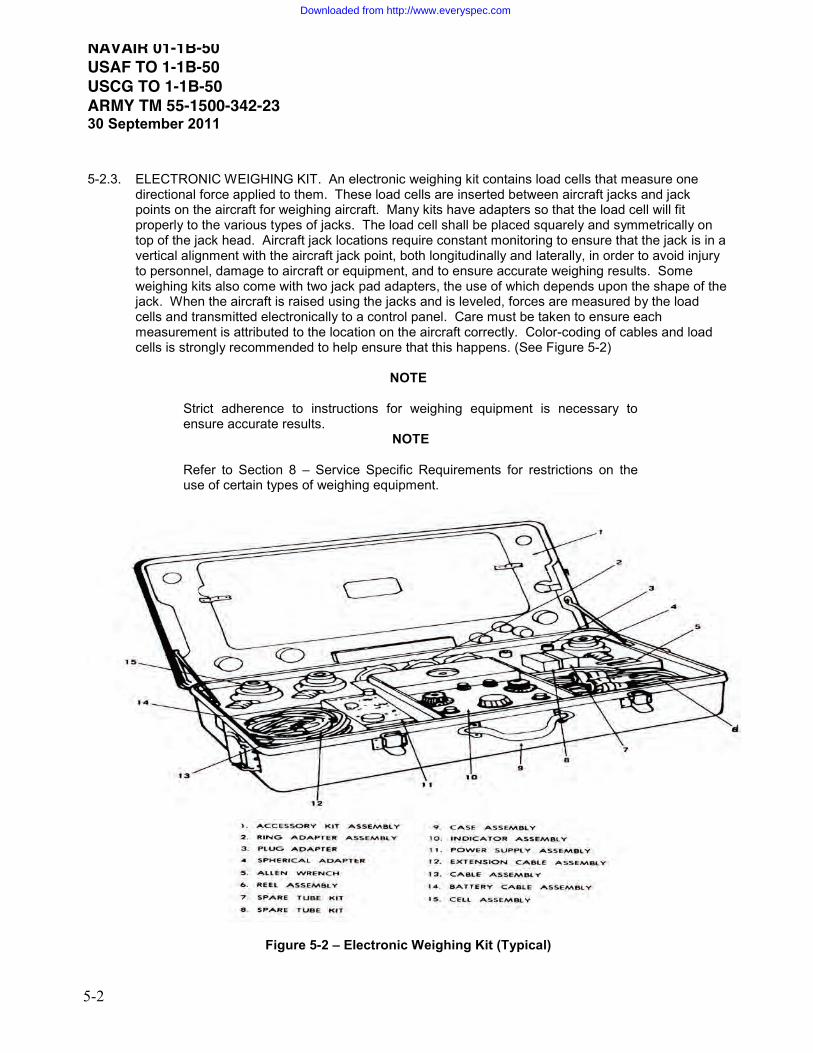
NAVAIR 01-1B-50 USAF TO 1-1B-50 USCG TO 1-1B-50 ARMY TM 55-1500-342-2330 September 2011
5-2
5-2.3. ELECTRONIC WEIGHING KIT. An electronic weighing kit contains load cells that measure one directional force applied to them. These load cells are inserted between aircraft jacks and jack points on the aircraft for weighing aircraft. Many kits have adapters so that the load cell will fit properly to the various types of jacks. The load cell shall be placed squarely and symmetrically on top of the jack head. Aircraft jack locations require constant monitoring to ensure that the jack is in a vertical alignment with the aircraft jack point, both longitudinally and laterally, in order to avoid injury to personnel, damage to aircraft or equipment, and to ensure accurate weighing results. Some weighing kits also come with two jack pad adapters, the use of which depends upon the shape of the jack. When the aircraft is raised using the jacks and is leveled, forces are measured by the load cells and transmitted electronically to a control panel. Care must be taken to ensure each measurement is attributed to the location on the aircraft correctly. Color-coding of cables and load cells is strongly recommended to help ensure that this happens. (See Figure 5-2)
NOTE
Strict adherence to instructions for weighing equipment is necessary to ensure accurate results.
NOTE Refer to Section 8 – Service Specific Requirements for restrictions on the use of certain types of weighing equipment.
Figure 5-2 – Electronic Weighing Kit (Typical)
Downloaded from http://www.everyspec.com

NAVAIR 01-1B-50 USAF TO 1-1B-50 USCG TO 1-1B-50
ARMY TM 55-1500-342-2330 September 2011
5-3
5-2.4. CALIBRATION OF WEIGHING EQUIPMENT. All custodians/technicians of weighing equipment (scales) are responsible for having it calibrated and certified by a government inspector of weights and measures or by commercial scale officials. All calibrations shall be traceable to the National Institute of Standards and Technology (NIST). Calibration procedures shall be those provided by the scale manufacturer or applicable service directives. Standard calibration for aircraft scales is an accuracy of +/- 0.1% of the applied load, unless otherwise determined by appropriate service engineering organizations. (See Section 8 - Service Specific Requirements).
5-3. WEIGHING ACCESSORIES To measure data such as lengths, angles, and densities, weight and balance personnel require accessories such as levels, plumb bobs, measuring tapes, chalk lines and hydrometers. It may be necessary to prepare special devices for specific TMS/MDS that will be called out in the aircraft Chart E. 5-3.1. SPIRIT LEVEL. At least one spirit level is required for leveling most aircraft. Two levels are
recommended, one 24 inches long for spanning distances between leveling lugs and another 6 inches long to use in places where sufficient space is not available for seating a 24 inch level. The levels should be a machinists’ bench type of first-class quality with ground and graduate main vials and plain plumb vials. A calibrated inclinometer or digital protractor may be used in lieu of a spirit level on many aircraft.
5-3.2. LEVELING BARS. Several leveling bars of varying lengths may be needed for spanning the
distances between leveling lugs of different aircraft. One set of bars usually comes with the weighing kit normally maintained by each authorized weighing facility. Some aircraft require special bars that will be called out in the respective Chart E.
5-3.3. LEVELING LUGS. Points located on some aircraft to facilitate use of the spirit level in leveling
aircraft. 5-3.4. PLUMB BOBS. Plumb bobs are used to project points on the aircraft onto the floor for measuring
dimensions in a level plane and for leveling some aircraft. Each plumb bob should have a slot in the head so that excess string, which could interfere with the free swing of the plumb bob, can be wound around the neck. Plumb bobs are normally included in the weighing kit.
5-3.5. STEEL TAPES. A steel tape 600 inches in length and graduated in inches and tenths of inches is
recommended. Since all weighing dimensions shall be read to one tenth of an inch, and are frequently read to one hundredth of an inch, this type of tape eliminates the nuisance and the possibility of errors associated with converting common fractions to decimals. Tapes, as described, are usually in the weighing kit.
5-3.6. CHALK LINE. This is a string, covered with chalk, which is used to snap a straight line on the
hangar floor between the vertical projections of reaction points or jig locations. The string should be sturdy and hard finished. The weighing kit usually includes a chalk line reel.
5-3.7. HYDROMETERS. A hydrometer with a calibration range from 5.5 to 7.0 pounds per US gallon
should be used for determining the density of fuel when required. A transparent container for holding fuel samples and a pipette at least 12 inches long or some other similar device for withdrawing samples from the tank are necessary for use with the hydrometer. Care shall be taken not to damage the glassware. When determining the density of a fuel sample, the hydrometer should be carefully placed into the fluid within the transparent container. When reading the density, the hydrometer shall not touch the container and the reading should be taken at the lowest fuel point (See Figure 5-3).
Downloaded from http://www.everyspec.com

NAVAIR 01-1B-50 USAF TO 1-1B-50 USCG TO 1-1B-50 ARMY TM 55-1500-342-2330 September 2011
5-4
Figure 5-3 - Reading a Hydrometer
5-3.8. CLINOMETER OR INCLINOMETER. An instrument used to measure the angle of incline or the
attitude of the aircraft relative to the horizontal (level ground) is needed for those aircraft weighed in a non-level attitude. Angles shall be measured at locations specified in Chart E.
5-3.9. THERMOMETER. A thermometer calibrated in degrees Fahrenheit used to measure the
temperature of the weighing site for scale calibration purposes. This item is not needed for scales with built-in temperature calibration.
5-3.10. ACCESSORY WEIGHING KIT. A kit containing compartments for each weighing accessory should
be provided for storing and carrying the accessories (See Figure 5-4). This is a necessary precaution against loss or damage.
Figure 5-4 - Accessory Weighing Kit.
Downloaded from http://www.everyspec.com
NAVAIR 01-1B-50 USAF TO 1-1B-50 USCG TO 1-1B-50
ARMY TM 55-1500-342-2330 September 2011
5-5
5-3.11. AIRCRAFT JACKS. An approved type of jack may be required to raise the aircraft to a level position clear of the hangar floor. A good quality standard jack, with suitable capacity and extension range, should be used. The jack shall have an ample flat base area and have a suitable head, or adapter, to retain load cells and thus prevent slippage and resulting damage to the aircraft. The capacity of the jack points should also be checked to ensure the points would not be overloaded while weighing aircraft.
5-3.12. JACK PAD ADAPTERS. A cylindrical-type adapter used to mate jack pads to a load cell assembly. 5-3.13. JACK PADS. Fittings attached to the aircraft structures which are used for reaction or jack points. A
rounded or conical extension protrudes from the base of the jack pad and serves as the point of contact for the load cell assembly or aircraft jack.
5-4. WEIGHING PROCEDURES A well-documented and orderly aircraft weighing procedure enables the ability to collect measured weight and moment data in an efficient manner and lessens the chance of omitting steps necessary to collect dimensional data or scale readings. Always refer to the aircraft Chart E for specific weighing instructions and/or procedures. The following is a general procedure to accomplish proper aircraft weighings:
NOTE
All resulting weight and balance data is suspect to be inaccurate if proper weighing procedures are not accurately controlled and performed during the weighing.
5-4.1. PREPARATION FOR WEIGHING AIRCRAFT. The following describes the recommended
procedure to prepare an aircraft for weighing: 5-4.1.1. Thoroughly clean the aircraft inside and out, removing dirt and grease. If the aircraft is wet or
moist from rain, dew or washing, the surfaces shall be allowed to completely dry before weighing.
CAUTION
Inspect areas for trapped water. Watch for areas that trap water and drain and dry them as warranted.
5-4.1.2. Gather the required weighing equipment and ensure that all equipment is functional and in
proper working order. In the case of scales and load cells, ensure that the equipment is warmed up according to manufacturer’s recommendations.
5-4.1.3. Drain the fuel tanks in accordance with the aircraft Chart E or other applicable instructions. All
aircraft draining is normally done with the aircraft in level ground attitude.
NOTE
It is important that the fuel in the aircraft at the time of weighing duplicates the condition that has been established by the manufacturer’s testing, which corresponds to the data provided in the aircraft Chart E.
Downloaded from http://www.everyspec.com

NAVAIR 01-1B-50 USAF TO 1-1B-50 USCG TO 1-1B-50 ARMY TM 55-1500-342-2330 September 2011
5-6
NOTE
Aircraft with foam in their tanks pose special problems. If aircraft with foam in the fuel tanks are not fully filled prior to draining, fill the tanks to capacity and then drain to a trapped fuel condition in order to duplicate the trapped fuel values. These aircraft always retain fuel in the foam; therefore, unless specific instructions are in the aircraft Chart E, draining should be terminated when fuel being drained starts to drip.
5-4.1.4. Remove non-Chart A items such as bombs, ammunition, cargo, crew members, and equipment
not having a fixed weight and location in the aircraft. These types of items not listed as part of the Basic Weight on the Chart A and, therefore, should not be in the aircraft when weighed.
5-4.1.5. Check all reservoirs and tanks for liquids such as drinking and washing water, engine oil,
hydraulic fluid, anti-icing fluid, cooling fluids, and liquid oxygen. Reservoirs and tanks should be empty or filled to normal capacity prior to weighing. Never weigh aircraft with partially filled reservoirs or tanks.
5-4.1.6. All waste tanks shall be empty. 5-4.1.7. Move the aircraft to the area where it will be weighed. Do not set the aircraft brakes in order to
not induce loads on the scales, which may result in erroneous measurement results and may damage the equipment. Ensure aircraft control surfaces are in a static neutral position and that all doors, canopies, rotor blades, etc are closed or positioned in accordance with the Chart E. Inflate tires to normal pressure.
NOTE
Depending on the situation, a brake rider may be required to safely weigh and/or move an aircraft. Ensure that the brake rider does not apply the brakes at any time other than an emergency.
NOTE
The aircraft shall be weighed in a closed hangar, or building, with no blowers or ventilating systems impinging on the aircraft. The slope of the floor shall not exceed 1/4 inch in one foot (1.2 degrees). Do not place scales on or over a crack, or drain in the floor. Jacks may straddle engineered expansion joints providing elevation does not change.
5-4.1.8. Conduct a Chart A inventory of equipment installed in the aircraft. This inventory will be done
under the supervision of the weight and balance technician responsible for the aircraft.
NOTE
A Basic Weight without the associated inventory is of no value. Check the aircraft equipment against the Chart A and correct the chart as necessary to accurately itemize all items of fixed operating equipment that will be included in the Basic Weight determined by weighing. The aircraft Chart A is absolutely necessary to properly accomplish this inventory. When the Chart A does not accompany the aircraft, it is the responsibility of the weight and balance supervisor or technician to prepare one before weighing.
5-4.1.9. Adjust the Chart C based upon the Chart A inventory if necessary.
Downloaded from http://www.everyspec.com
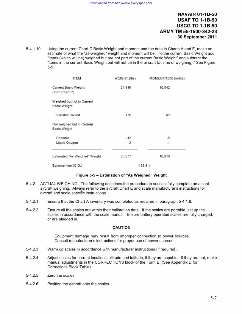
NAVAIR 01-1B-50 USAF TO 1-1B-50 USCG TO 1-1B-50
ARMY TM 55-1500-342-2330 September 2011
5-7
5-4.1.10. Using the current Chart C Basic Weight and moment and the data in Charts A and E, make an estimate of what the “as-weighed” weight and moment will be. To the current Basic Weight add “items (which will be) weighed but are not part of the current Basic Weight” and subtract the “items in the current Basic Weight but will not be in the aircraft (at time of weighing).” See Figure 5-5.
Figure 5-5 – Estimation of “As Weighed” Weight
5-4.2. ACTUAL WEIGHING. The following describes the procedure to successfully complete an actual aircraft weighing. Always refer to the aircraft Chart E and scale manufacturer's instructions for aircraft and scale specific instructions.
5-4.2.1. Ensure that the Chart A inventory was completed as required in paragraph 5-4.1.8.
5-4.2.2. Ensure all the scales are within their calibration date. If the scales are portable, set up the scales in accordance with the scale manual. Ensure battery operated scales are fully charged, or are plugged in.
CAUTION
Equipment damage may result from improper connection to power sources. Consult manufacturer’s instructions for proper use of power sources.
5-4.2.3. Warm up scales in accordance with manufacturer instructions (if required).
5-4.2.4. Adjust scales for current location’s altitude and latitude, if they are capable. If they are not, make manual adjustments in the CORRECTIONS block of the Form B. (See Appendix D for Corrections Block Table)
5-4.2.5. Zero the scales.
5-4.2.6. Position the aircraft onto the scales.
Downloaded from http://www.everyspec.com

NAVAIR 01-1B-50 USAF TO 1-1B-50 USCG TO 1-1B-50 ARMY TM 55-1500-342-2330 September 2011
5-8
5-4.2.6.1. Platforms. Do not use the aircraft brakes to stop the aircraft, because they may bind the scales and this would require re-zeroing of the scales. Ensure that the nose wheel (or tail wheel) is centered. Do not set the aircraft brakes because this may induce errors into the weighing.
5-4.2.6.2. Load Cell on Top of Jack. Position the aircraft jacks with the load cell installed directly under the jack fittings. Ensure that the jacks and load cells are vertical by checking with a level or with the inclinometer and ensure that the jack/load cell combination is directly under the jack fitting on the aircraft both fore/aft and left/right.
NOTE
Exercise the scales/load cells prior to recording any measurement results. To exercise the scales, remove the aircraft from the scales/load cells and repeat steps 5-4.2.5 and 5-4.2.6 a minimum of two times. Reset the scales/load cells to zero if they don’t zero themselves after load is removed from the scale/load cell.
5-4.2.7. AIRCRAFT LEVELING. For most aircraft all weight and balance computations are based on measurements taken when the aircraft is in a level position. This position is achieved when the longitudinal and lateral axes of the aircraft are in a horizontal plane. Leveling aids have been installed in the aircraft by the manufacturer, and procedures have been developed to enable the aircraft to be positioned in a level attitude. Some aircraft use spirit levels to position the aircraft while other aircraft use plumb bobs in combination with leveling plates. See the Chart E for the particular aircraft being weighed for proper method and procedure.
NOTE
Some aircraft are weighed in a static, non-level position. Chart E contains a chart to correct for the degree of un-levelness. In this procedure, the angle the aircraft longitudinal axis makes to the horizontal plane shall be measured by either placing an inclinometer on the leveling bar or using a leveling plate provided in the aircraft by the manufacturer. See Chart E instructions.
5-4.2.7.1. SPIRIT LEVELS, INCLINOMETER OR DIGITAL PROTRACTOR. Leveling lugs may be located on the inside or outside of the aircraft (See Figures 5-6 and 5-7). When the lugs are located inside the aircraft, it is often necessary for personnel observing the level to remain in the aircraft while it is being weighed to avoid disturbing its equilibrium. In this case, the weight and moment of the observer shall be subtracted from the total weight and moment by entering these values in Column I of the Form B. To use the leveling lugs, place the leveling bar squarely on the lugs. Then place the leveling device on the leveling bar. The aircraft shall be leveled both longitudinally and laterally.
Figure 5-6 – Leveling Lugs Inside the Aircraft Figure 5-7 – Leveling Lugs Outside the Aircraft
Downloaded from http://www.everyspec.com

NAVAIR 01-1B-50 USAF TO 1-1B-50 USCG TO 1-1B-50
ARMY TM 55-1500-342-2330 September 2011
5-9
5-4.2.7.2. PLUMB BOB (See Figure 5-8). Another device provided for leveling of aircraft is a plumb bob. The primary advantage of this type leveling over the spirit level type is that it is more accurate whenever the drop length is greater than the standard leveling lug span. To level an aircraft by using a plumb bob, suspend the plumb bob from the upper jig-located bracket and adjust the length of the string to allow the plumb bob to swing very close to, but not touch, a graduated leveling plate. When the plumb bob is allowed to come to rest from swinging, the position of the plumb bob relative to the leveling plate indicates whether the aircraft is level or not. Raise or lower the aircraft sufficiently to allow the plumb bob to be aligned with the leveling plate after the plumb bob is allowed to settle.
5-4.2.7.2.1. PLATFORM LEVELING. Service the struts so that the point of the plumb bob is just
above the intersection of the cross lines on the lower jig-located index plate. The aircraft will then be level laterally and longitudinally.
5-4.2.7.2.2. TOP OF JACK LEVELING. While carefully maintaining a level attitude laterally and
longitudinally, jack the aircraft until all tires are clear of the ground. Top of jack scales are leveled by raising and lowering the jacks.
Figure 5-8 – Plumb Bob
5-4.2.8. Read the scales and if necessary, take dimensional measurements in accordance with the
aircraft Chart E (PLATFORMS). Note the readings at each reaction point and record which scale is used at each. Remove aircraft from scale weighing surface, wait two minutes and check for corrections.
5-4.2.9. DIMENSIONS REQUIRED FOR CG LOCATION (PLATFORM). Three dimensions shall be
either measured or known to determine the longitudinal location of the as-weighed aircraft CG. They are:
5-4.2.9.1. The distance from the reference datum to some known point (preferably a jig point) which is
always listed on the aircraft diagram contained in the applicable Chart E. 5-4.2.9.2. The distance from the jig point to a chalk line drawn between the main reaction points. 5-4.2.9.3. The distance between the main and nose reactions or main and tail reaction points.
Downloaded from http://www.everyspec.com

NAVAIR 01-1B-50 USAF TO 1-1B-50 USCG TO 1-1B-50 ARMY TM 55-1500-342-2330 September 2011
5-10
NOTE
If lateral and/or vertical CG’s are required, see the aircraft specific manual for details.
5-4.2.10. PROJECTION OF POINTS TO THE FLOOR (PLATFORM). 5-4.2.10.1. Longitudinal [and lateral] dimensions are best determined by projecting the points to be
measured onto the hangar floor. Reaction points may then be accurately located on the hangar floor by measuring from the projected points. When using platform or flush scales, these points must be located prior to removing the aircraft from the scales. It is recommended that masking tape be used on the scales for marking these points and that chalk lines and measurements be made after removing the aircraft from the scales.
5-4.2.10.1.1. PROJECTION OF THE REFERENCE POINT. Suspend a plumb bob from the center of
the jig point, keeping the plumb bob approximately 1/8 inch above the floor. Dampen out the swing of the plumb bob and make a cross mark on the masking tape directly under the tip of the plumb bob. Print the words "jig point" on the masking tape, near the cross, to distinguish it from the other reaction points.
5-4.2.10.1.2. PROJECTION OF THE CENTER POINT OF THE MAIN REACTIONS. Suspend a
plumb bob from the center of each main reaction point (i.e., each main wheel) to the masking tape as described above. It is necessary that a free fall be obtained for the plumb bob, so interference shall be avoided. It is also necessary that the plumb bob be dropped from the exact center of the reaction point (i.e. drop the plumb bob from the center of the axle of both left and right main reactions). After the marks are placed directly under the main reaction points, a chalked line is stretched between these two points and drawn taut. The line is then snapped to the floor, leaving a straight chalk line between the main reaction points.
5-4.2.10.1.3. PROJECTION OF NOSE OR TAIL REACTION. The nose or tail reaction point is
projected to the hangar floor in the same manner as described above. It is necessary that the plumb bob be dropped from the exact center of each reaction point (i.e., drop the plumb bob from the center of the axle both left and right of the wheel). The nose or tail wheel shall be centered prior to dropping the plumb bob. These projections are then marked on the floor with a small cross and a chalk line is snapped between these two points.
NOTE
Load Cells on Jacks do not use projection of points to the floor. The reaction points for the load cell top of jack locations are listed in the CHART E Loading Data.
Downloaded from http://www.everyspec.com

NAVAIR 01-1B-50 USAF TO 1-1B-50 USCG TO 1-1B-50
ARMY TM 55-1500-342-2330 September 2011
5-11
5-4.2.11. TAKING MEASUREMENTS.
5-4.2.11.1. All measurements should be taken with a steel tape. Two of the measurements to be taken are listed as “B” and “D” on the Form B - Aircraft Weighing Record. Distance B is the perpendicular distance from projected jig point to the chalk line between the main reaction points. Distance D is the distance from the chalk line between the main reactions to the nose or tail reaction point. When measuring these distances, the tape shall be parallel to the center line of the aircraft. These measurements shall be made accurately to a tenth of an inch or better to ensure accurate results of the computations which determine the as-weighed CG location of the aircraft. Measurements taken from the chalk line joining the main reaction points shall be measured perpendicular to the chalk line. These measurements may be determined quickly and accurately by placing the zero end of the tape on the desired point (the projection of the jig point or the projection of the nose (tail) reaction) and swinging the other end of the tape across the main reaction chalk line in a small arc. The shortest distance read off the tape where the tape crosses the chalk line is the perpendicular distance from the point to the line. Taping down a string stretched between the two main reaction points can be used in lieu of a chalk line. Care shall be taken to ensure the tape is clear of any obstacles, and is taut and straight when taking measurements.
NOTE
The measurements may also be taken by placing the 10" mark of the tape at the desired point and subtracting 10" from the final tape reading. This technique may allow easier swinging of the tape and lead to greater accuracy.
CAUTION
Dimensions B and D shall be determined by measurement. Do not use the values tabulated in Chart E. These are only approximate. Use of Chart E values can induce significant errors into the weighing results.
5-4.3. RECORDING WEIGHT AND DIMENSIONS.
All scale readings and dimensions should be recorded immediately on the Form B - Aircraft Weighing Record. Only the distances B and D need to be measured. Distance I (from the reference datum to the jig point) is a fixed value and can be obtained from the aircraft CHART E Loading Data. See CHART E Loading Data for load cells on top of jack dimension data.
5-5. VERIFICATION OF WEIGHING RESULTS
Compute the difference between the calculated weight and arm (last entry on Chart C) and the actual Basic Aircraft Weight and Arm to be posted to Chart C (see Form B).
If the Basic Weight (aircraft less than 75,000 pounds) difference is:
- more than 0.4% (wt x 0.004) or the arm differs more than 0.2 inches or 0.2% MAC
If the Basic Weight (aircraft more than 75,000 pounds) difference is:
- more than 0.5% (wt x 0.005) or the arm differs more than 0.5 inches or 0.5% MAC
Accomplish the following:
5-5.1. Check calculations for errors.
5-5.2. Check scales for overdue calibration.
Downloaded from http://www.everyspec.com

NAVAIR 01-1B-50 USAF TO 1-1B-50 USCG TO 1-1B-50 ARMY TM 55-1500-342-2330 September 2011
5-12
5-5.3. Check scales for correct altitude and latitude adjustments IAW the scale manufacturer’s procedures.
5-5.4. Check slope of facility being used for weighing.
5-5.5. Check and ensure that hangar doors are closed and that all fans and heaters are off.
5-5.6. Check the plumb bob for proper installation. i.e. String positioned in center of bracket V-notch. Does the plumb bob, digital protractor, or other leveling tool show required longitudinal and lateral angles/alignment?
5-5.7. Check aircraft (inside & out) to ensure that it is clean and completely dry.
5-5.8. Check to ensure chocks, flight gear, survival kits, fly-away gear, blade ropes, engine covers, and other non-Basic Weight items were removed.
5-5.9. Check that aircraft doors and panels were in proper configuration.
5-5.10. Check fuel tank sump drains for lack of fuel flow making sure an appropriate container is in place in the event of fuel discharge.
5-5.11. Aircraft must be fueled using the gravity open-port refueling method to ensure maximum usable fuel capacity is achieved. Do not use aircraft fuel quantity indicators to determine the quantity. Use the applicable operator’s manual for usable fuel capacities.
5-5.12. Check Chart C for errors since the last weighing.
5-5.12.1. Posting turned-off. If using AWBS check that posting was not turned off?
5-5.12.2. Aircraft modifications. Have all aircraft modifications been accounted for?
5-5.12.3. Chart A inventory doesn’t match the aircraft’s weighing condition.
5-5.13. Did any maintenance action take place between inventory and weighing?
5-5.14. If errors are found, correct and repeat two additional weighings (if applicable) that meets the repeatable tolerances.
5-5.15. If no errors are found explaining the excessive difference between the calculated vs actual Basic Weight and Arm, post the weighing to the Chart C and enter the following statement on Chart C as a Header: “IAW (enter applicable service manual), calculated vs actual Basic Weight and Arm inspection completed with no errors found.”
Downloaded from http://www.everyspec.com

NAVAIR 01-1B-50 USAF TO 1-1B-50 USCG TO 1-1B-50
ARMY TM 55-1500-342-2330 September 2011
5-13
NOTE
When portable scales are being used and an error is suspected, rotating the scales is highly recommended in order to identify problems with individual scales as a possible source of error in the weighing results. Rotate the scales between the various reaction points (e.g., nose to left main, left main to right main, right main to nose) and reweigh the aircraft. Check for consistency of readings at each reaction point. If a discrepancy is noted, it is possible or likely that one (or more) of the scales is out of calibration or otherwise not operating properly. Rotate the scales once more (do not rotate back to the original position) and take a third reading. A scale that gives inconsistent readings relative to the others at the same reaction point should be replaced and the aircraft reweighed, or alternatively, the two consistent readings at each reaction should be taken, averaged and totaled and the result transferred to the Form B.
NOTE
When using stationary beam balance pit scales, the beam balance may be "upset" in lieu of removing the aircraft from the scales.
5-5.16. If a reason for the discrepancy cannot be identified, reweigh the aircraft until the below criteria is met.
Retake dimensional measurements in accordance with the aircraft Chart E and paragraph 5-6. If readings are consistent, record the data on the Form B. To ensure accuracy of results, a minimum of two independent weighings shall be performed that meet the tolerances listed below. The individual weighings do not have to be consecutive. When compared to each other:
Weighings are acceptable if they are within 0.25% Basic Weight and 0.1% MAC, or 0.1 inches in arm.
5-5.17. Once two repeatable weighings have been obtained, average the two to complete the as-weighed
portion of the Form B. 5-5.18. Remove the aircraft from the scales. 5-5.19. Stow the equipment.
Downloaded from http://www.everyspec.com

THIS PAGE LEFT INTENTIONALLY BLANK
Downloaded from http://www.everyspec.com

NAVAIR 01-1B-50 USAF TO 1-1B-50 USCG TO 1-1B-50
ARMY TM 55-1500-342-2330 September 2011
6-1
Section 6 – Weight and Balance Tools 6-1. AUTOMATED WEIGHT AND BALANCE SYSTEM (AWBS) The purpose of this section is to provide information and instructions regarding the use of the Automated Weight and Balance System. AWBS is authorized for management of weight and balance records as directed by each service’s engineering group (See Section 8 - Service Specific Requirements). Use of this software does not alleviate the requirements of this manual for responsibility for accuracy of weight and balance data residing with the weight and balance authority. Ensure all calculations are correct and accurate. AWBS should be used by all activities, unless there are limiting circumstances such as security concerns that require other methods of record keeping. AWBS is mandatory for some services, but not all. See Section 8 - Service Specific Requirements. Each service is responsible for certification of software that automates the weight and balance records. See Section 8 - Service Specific Requirements for guidance on how and when to obtain the latest authorized software for each respective service. 6-1.1. Introduction: The Automated Weight and Balance System (AWBS) is a computer program used to
maintain weight and balance records for both fixed and rotary wing aircraft. 6-1.2. AWBS does not replace the user’s knowledge of performing aircraft weight and balance. It is simply
a tool to perform weight and balance tasks more efficiently and accurately. When AWBS is used correctly, mathematical errors are reduced and efficiency is increased.
6-1.3. The system is designed to support all U.S. military services and government agencies. AWBS
Forms and Charts are authorized in lieu of the DD Form 365 (Record of Weight and Balance Personnel); the DD Form 365-1 (Chart A - Basic Weight Checklist Record); the DD Form 365-2 (Form B - Aircraft Weighing Record); the DD Form 365-3 (Chart C - Basic Weight and Balance Record); and the DD Form 365-4 (Weight and Balance Flight Clearance Form F).
6-1.4. For detailed instructions for operation of the AWBS, reference the software help and the AWBS user
manual(s) that are part of the software package. These manuals are installed as part of the software and are stored in the software install location.
6-1.5. Electronic signatures are authorized in lieu of normal pen or stamp signatures. 6-2. DISTRIBUTION OF AWBS 6-2.1. US military services provide specific ways to obtain the software. See Section 8 - Service Specific
Requirements. 6-2.2. For contractors, contact your Contracting Officer’s Representative (COR) or Defense Contract
Management Agency (DCMA) representative. For Foreign Military Sales, contact your Security Assistance Command.
6-3. ALTERNATE WEIGHT AND BALANCE TOOLS 6-3.1. Electronic Form F 6-3.1.1. PURPOSE. The purpose of this section is to discuss and provide requirements for computer
programs that generate weight and balance data intended for use in completing the Form F for a
Downloaded from http://www.everyspec.com

NAVAIR 01-1B-50 USAF TO 1-1B-50 USCG TO 1-1B-50 ARMY TM 55-1500-342-2330 September 2011
6-2
specific aircraft type. The electronic Form F shall be developed to enable weight and balance personnel to (1) direct the load and (2) control the weight and CG of a particular aircraft type. Through the computer, one can rapidly and accurately determine if the weight and CG are within the loading range for any loading condition. A weight and balance computer is sometimes referred to as an electronic load adjuster or a Form F generator.
6-3.1.2. AUTHORITY FOR USE. All new weight and balance Form F generators shall have the approval
of the organization that has engineering responsibility for the baseline aircraft before it may be used. All program changes shall have prior approval before incorporation.
6-3.1.3. OBJECTIVE. The objective of the Form F generator is to replace the mechanical load adjuster
and to eliminate the need to complete a paper DD Form 365-4 Form F. 6-3.1.4. CALCULATIONS. The design data upon which Form F generator is developed shall be based
upon the aircraft Chart E. 6-3.1.5. PROGRAM CHANGES. The program shall be written to prohibit field changes to the approved
and validated program. This will ensure uniformity and allow program control and verification. To the maximum extent possible, the program shall be designed to allow for future changes in the aircraft. For example, the original aircraft CG will change and new stores may be added to the list of items available for mission loading of the aircraft.
6-3.1.6. EASE OF OPERATION. To the maximum extent possible, the program shall be designed for
ease of use. Required keystrokes shall be minimized and required inputs shall be prompted by the program. Once the outputs have all been displayed, provisions will be made to redisplay them without repeating all of the user actions.
6-3.1.6.1. To facilitate ease of operations, the computer program should, to the maximum extent
possible, follow the format of the Form F. Either the transport or tactical form shall be used as appropriate. Calculated values on the form such as Operating Weight and moment, and Total Aircraft Weight and moment shall be determined by the program. Subsequent changes to a value used in determining a calculated value shall result in the calculated value being automatically updated. For example, once an initial calculation has been made, updating the fuel weight will result in correction of the aircraft weight.
6-3.1.6.2. To the greatest extent possible, the computer shall not require input of standard items. Thus
if the computer is designed for a single aircraft, the normal index or moment of standard items such as crew, oil, stores, etc. will be used by the computer and will not be entered by the user. To further facilitate ease of use, the computer may use input items such as compartments or stations which the user may readily know and which the computer will convert to the appropriate arm. Once an item has been input, the program will check the input value against acceptable limits to verify its validity.
6-3.1.7. COMPUTATIONAL REQUIREMENTS. The weight and balance computer shall be designed to
provide rapid operation for the following: 6-3.1.7.1. Determination of the weight and CG location for any loading condition. 6-3.1.7.2. Adjust the CG for any increase, decrease, or relocation of fuel, passengers, crew, stores, or
any other load. 6-3.1.7.3. Determine the required shift of fuel, passengers, crew or any other load item during flight
operations to maintain the CG within the permissible limits.
Downloaded from http://www.everyspec.com

NAVAIR 01-1B-50 USAF TO 1-1B-50 USCG TO 1-1B-50
ARMY TM 55-1500-342-2330 September 2011
6-3
6-3.1.7.4. Determine the CG limitations throughout the allowable weight range. If the CG is affected by other factors like wing movement, these factors shall be taken into account.
6-3.1.7.5. Calculation of In–flight weight and CG for standard fuel usage to ascertain CG does not go
outside of the CG envelope for a proposed mission. 6-3.1.7.6. All aircraft limitations shall be included such as floor loading, compartment capacities, pylon
capacity and caution zones. 6-3.1.8. ACCURACY. The accuracy of the balancing computer shall be such that CG locations
determined by the balancing computer shall not vary from the CG locations by more than 1/10 of 1 percent of the MAC of the airplane or 0.1 inches for rotorcraft to which the balancing computer applies. Weights, arms and simplified moments shall be displayed to the nearest tenth; however, the computer program shall be more accurate.
6-3.1.9. INSTRUCTION BOOK. An instruction book shall be developed for each weight and balance
Form F generator. This book shall contain detailed instructions for operating the Form F generator. Solutions to sample problems shall be included along with appropriate illustrations to improve clarity and effectiveness. This instruction book shall be submitted to the office of engineering responsibility for approval prior to use with the Form F generator.
6-3.2. MANUAL FORM F LOADING TOOLS 6-3.2.1. Load Adjusters 6-3.2.1.1. PURPOSE. The purpose of the adjuster is to enable the pilot, crew chief, or loading
personnel (1) to direct the load and (2) control the CG location of a particular model aircraft. Through the load adjuster, one can rapidly and accurately determine if the CG is within the loading range for any loading condition; the loading for any desired CG location; the effects of any weight or location changes for such items as crew, fuel, and cargo during flight and what steps would be necessary to keep the CG within the safe loading range.
6-3.2.1.2. DESCRIPTION. There are two types of load adjusters. The more common slide-rule type
(See Figure 6-1) and the circular type. All load adjusters operate on the principle of the addition and subtraction of moments for CHART E load items to and from the aircraft basic moment. This is done through the use of the index number scale.
Figure 6-1 - Load Adjuster
6-3.2.2. See aircraft specific manuals for more details concerning Load Adjusters.
Downloaded from http://www.everyspec.com
THIS PAGE LEFT INTENTIONALLY BLANK
Downloaded from http://www.everyspec.com

NAVAIR 01-1B-50 USAF TO 1-1B-50 USCG TO 1-1B-50
ARMY TM 55-1500-342-2330 September 2011
7-1
Section 7 - Center of Gravity Loading Calculations
7-1. GENERAL The purpose of this section is to outline the method for determining the CG position of a loaded aircraft. The CG is the point about which an aircraft would balance if it were possible to support the aircraft at that point. It is the mass center of the aircraft or the theoretical point at which the entire weight of an aircraft is assumed to be concentrated. Although location of the CG is very important to safety of flight, it can be easily controlled by proper loading of the aircraft. Balance, or the location of the aircraft’s CG, is of primary importance to aircraft stability. 7-1.1. For most aircraft the prime concern is the longitudinal balance, or the location of the CG along a
designated reference line running from the nose to the tail. Location of the CG with reference to the lateral (side to side) axis is also important for some aircraft. If an aircraft will be flown in an asymmetrical configuration, it is required to calculate the lateral CG. The design of most aircraft is such that symmetry is assumed to exist about a vertical plane through the longitudinal axis. In other words, for each item of weight existing to the left of the fuselage centerline there is generally an equal weight existing at a corresponding location on the right. This lateral mass symmetry however may be easily upset due to unbalanced lateral loading. Location of the lateral CG is not only important from the aspect of loading rotary wing aircraft, but is also extremely important when considering fixed wing exterior drop loads. The position of the lateral CG shall be computed when a lateral imbalance is present or when flying in an asymmetric configuration (See Figure 7-1).
Figure 7-1 – Asymmetric Configurations
The CG (henceforth, reference to CG will mean the longitudinal center of gravity) is not necessarily a fixed point; its location depends on the distribution of items loaded in the aircraft, and as variable load items are shifted or expended, there is a resultant shift in CG location. It should be realized that if mass center of an aircraft is displaced too far forward on the longitudinal axis a nose heavy condition will result. Conversely, if the mass center is displaced too far aft on the longitudinal axis, a tail heavy condition will result. It is possible that an unfavorable location of the CG could produce such an unstable condition that the pilot could lose control of the aircraft.
7-1.2. Lateral and vertical CG’s are not controlled on most aircraft, but are restricted to limits of operation
on some aircraft. If required, the data and procedures necessary for lateral and/or vertical CG control are called out in the applicable aircraft specific manuals.
Downloaded from http://www.everyspec.com

NAVAIR 01-1B-50 USAF TO 1-1B-50 USCG TO 1-1B-50 ARMY TM 55-1500-342-2330 September 2011
7-2
7-2. PRINCIPLES OF MOMENTS
To understand balance, it is necessary to have a working knowledge of the principle of moments. For those unfamiliar with weight and balance terms, a moment is the product of a force or weight, times a distance. The distance used in calculating a moment is referred to as the arm or balance arm, and is usually expressed in inches. To calculate a moment, a force (or weight) and a distance must be known. (WAM: Weight x Arm = Moment) The distance is measured from a known reference point or reference datum to the point through which the force acts. A moment is meaningless unless the reference point about which the moment was calculated is specified.
7-2.1. For the purpose of illustration, an aircraft may be compared to a seesaw. Like the seesaw, in order
for an aircraft to be in balance, or equilibrium, the sum of the moments on each side of the balance point shall be equal in magnitude.
For example, referring to figure 7-2, the moment produced about the fulcrum (reference point) by the 200 pound weight is 200 pounds x 50 inches = 10,000 inch-pounds counterclockwise.
The moment produced about the same reference point by the 100 pound weight is 100 pounds x 100 inches =10,000 inch-pounds clockwise.
In this case, the clockwise moment counterbalances the counterclockwise moment, and the system is in equilibrium. This example illustrates the principle of moments which is as follows: For system to be in static equilibrium, the sum of the moments about any point shall equal zero.
7-2.2. As illustrated in figure 7-2, the clockwise moment is arbitrarily given a positive (+) sign while the
counterclockwise moment is given a negative (-) sign. Therefore, the sum of the moments about the fulcrum = +10,000 inch-pounds (clockwise) -10,000 inch-pounds (counterclockwise) - 0, and the system is in equilibrium. In determining balance of an aircraft, the fulcrum is the unknown, and the problem is one of determining the location of the fulcrum, or longitudinal center of gravity.
Figure 7-2 – Aircraft Balance Point
Downloaded from http://www.everyspec.com

NAVAIR 01-1B-50 USAF TO 1-1B-50 USCG TO 1-1B-50
ARMY TM 55-1500-342-2330 September 2011
7-3
7-3. EFFECTS OF MOMENT ON AIRCRAFT
As in the case of the seesaw, which can be balanced about its fulcrum, an aircraft may be considered to be in balance about its CG. Loads placed forward of the aircraft CG can be balanced by placing loads aft of the CG. Loads located forward of the CG of an aircraft produce moments which tend to make the nose go down, whereas loads located aft of the CG produce moments which tend to make the tail go down. If any item is added forward of the CG or removed aft of the CG, a nose-heavy condition will result. Conversely, any item added aft of the CG or removed forward of the CG will produce a tail-heavy condition. It should be realized that a moment can be changed without adding or removing a weight simply by shifting weight forward or aft.
7-4. DETERMINATION OF BALANCE CONDITION (LOCATION OF AIRCRAFT CENTER OF GRAVITY)
To determine the CG location of loaded aircraft, it is first necessary to obtain the Basic Weight and moment of the aircraft from Chart C. Add the weight of the items to be loaded to the aircraft Basic Weight to obtain the Gross Weight. Compute the moment of each load item by multiplying its weight by its arm. Find the Gross Weight moment by adding the basic aircraft moment and the moments of the load items. Determine the CG location by dividing the Gross Weight moment by the Gross Weight. Figure 7-3 illustrates the method for determining the CG location of a loaded aircraft.
NOTEIn computations, any item of weight added to the aircraft either side of the datum is a plus weight. Any weight item removed is a minus weight. When multiplying weights by arms, the moment is plus if the signs are alike and minus if the signs are unlike. The following combinations are possible:
- Items added forward of the datum - (+) weight X (-) arm = (-) moment. - Items added aft of the datum - (+) weight X (+) arm = (+) moment. - Items removed forward of the datum - (-) weight X (-) arm = (+) moment. - Items removed aft of the datum - (-) weight X (+) arm = (-) moment.
Figure 7-3 – Locating Aircraft Center of Gravity
Downloaded from http://www.everyspec.com

NAVAIR 01-1B-50 USAF TO 1-1B-50 USCG TO 1-1B-50 ARMY TM 55-1500-342-2330 September 2011
7-4
7-5. EFFECTS OF UNBALANCED LOADING
When the aircraft is nose heavy (CG too far forward), the pilot will experience difficulty in getting the nose up during landing. Other unfavorable conditions which may result are loss of aircraft maneuverability, overstress of the nose wheel structure in landing, and increase of pilot fatigue. When a tail heavy condition exists (CG too far aft), the aircraft may become unstable. This condition increases pilot fatigue, and may lead to structural failure and spins.
7-6. DETERMINING CENTER OF GRAVITY FOR A GROUP OF ITEMS
It is sometimes desirable to find the average arm or CG for a group of objects in an aircraft. This is accomplished by finding the individual moment of each object in the group, adding these moments, and dividing this sum by the total weight of all the objects in the group. It is expressed by the formula:
Average arm (in) =
Total weight (pounds)
Total moment (inch pounds)
It should be noted that basic aircraft weight and moment are excluded from this calculation.
Formula must be multiplied by the moment simplifier (if applicable) to achieve the arm in inches
7-7. CENTER OF GRAVITY LIMITS All aircraft have allowable limits which the CG shall remain within for safe operations. After the CG position of a loaded aircraft has been calculated, it is necessary to ensure that the CG falls within these allowable limits. These limits are specified in the applicable aircraft Chart E. If, after loading the aircraft, the CG does not fall within the allowable limits, it will be necessary to shift loads. 7-7.1. The forward CG limit may vary with the Gross Weight of an aircraft and is often restricted to control
landing conditions. It may be possible for aircraft to maintain stable and safe flight with the CG ahead of the forward limit as prescribed by landing conditions, but since landing is one of the most critical phases of flight, the forward CG limit is restricted to avoid damage to the aircraft structure when landing, and to insure that sufficient elevator deflection is available at minimum airspeed. When structural limitations or large stick forces do not limit the forward CG position, this point is determined as that CG position at which full up elevator is required to obtain a high angle of attack for landing.
7-7.2. The aft CG limit is the most rearward position at which the CG can be located for the most critical
maneuver or operation. As the CG moves aft, the aircraft becomes less stable which reduces the ability of the aircraft to right itself after maneuvering or after disturbances by gusts. The allowable aft CG limit may also vary with the aircraft Gross Weight.
7-8. EXPRESSING CENTER OF GRAVITY The CG position is expressed in terms of inches from a known reference datum or alternatively in percent Mean Aerodynamic Chord (% MAC).
Downloaded from http://www.everyspec.com

NAVAIR 01-1B-50 USAF TO 1-1B-50 USCG TO 1-1B-50
ARMY TM 55-1500-342-2330 September 2011
7-5
7-9. LATERAL CG AND VERTICAL CG Lateral and vertical CG’s are not controlled on most aircraft, but are restricted to limits of operation on some aircraft. The principles in the next paragraph apply to lateral and vertical balance as well as longitudinal balance. If required, the data and procedures necessary for lateral and/or vertical CG control are called out in the applicable aircraft specific Chart E and/or manual. 7-10. MOST FORWARD AND MOST AFT CG CALCULATIONS These calculations are designed to determine the most forward and most aft CG locations that could normally occur during the mission under consideration. Each computed CG should be carried to at least one decimal place and checked against the allowable limits. As the Gross Weight changes due to fuel use, expendable ammo, crew or passenger movement, and the release of expendable stores, the allowable CG limits may change. If the CG exceeds the limits, note in it the calculations but do not begin correction until all the CG calculations are completed. Then make the necessary corrections and run through CG calculations again to check the corrected condition. The following calculations deal specifically with Chart E data. The principles described also apply to calculations using a load adjuster; however, clearer calculating procedures for most forward and most aft CG calculations using load adjusters are included in Section 6 (Weight and Balance Tools). 7-10.1. TAKEOFF GROSS WEIGHT CONDITION. Prior to any mission CG calculations, a takeoff condition
shall be determined. This is done by adding the various loading data weights and moment to the current Chart C Basic Weight and moment and computing the takeoff Gross Weight CG.
7-10.2. LANDING GEAR RETRACTION. Unless specifically stated in the Chart E, the takeoff condition is
determined with the landing gear down. The raising of the landing gear causes an aircraft CG shift due to the moment change listed in the Chart E. If the Gear Up Moment Change (GUMC) is positive, raising the landing gear shifts the CG aft. As such, the gear-up condition is the aft CG condition and the gear-down condition is the forward CG condition. If the GUMC is negative, raising the landing gear shifts the CG forward. As such, the gear-up condition is the forward CG condition and the gear-down condition is the aft CG condition. In some cases separate gear-up and gear-down CG envelopes are identified or provided. Ensure CG envelope matches gear position for calculations.
7-10.3. FUEL USE. Delete from the forward and aft CG conditions the weight and moment for the usable
fuel. The new weights and moments represent the forward and aft CG zero fuel conditions. Add to these conditions the partial fuel quantities (taken from the Chart E fuel tables) that cause the most forward and aft CG shifts. These quantities may not be explicitly called out, but shall be found by trial and error. However, these quantities will remain approximately the same for all missions. These calculations result in the forward and aft CG fuel use conditions. Compute the CG's.
NOTE
The fuel quantity whose own CG is the most forward or aft is not necessarily the quantity that will cause the most extreme aircraft CG conditions. The aircraft CG movement is dependent on the weight of the fuel as well as its CG location. When fuel tables reflecting the effects of different aircraft attitudes (angles of attack) on the fuel CG are listed in the Chart E, these tables shall be evaluated along with the standard level flight fuel tables to determine the forward and aft CG fuel use conditions.
Downloaded from http://www.everyspec.com

NAVAIR 01-1B-50 USAF TO 1-1B-50 USCG TO 1-1B-50 ARMY TM 55-1500-342-2330 September 2011
7-6
7-10.4. EXPENDED AMMO. The CG movement caused by ammo used shall be considered. Subtract the
weight and moment of the rounds carried from the two conditions derived in the previous paragraph and add the weight and moment of the retained ammo and cases, if any. Compute the new conditions CG and determine the direction of the CG shift. If the ammo used causes an aft shift when applied to the CG condition, the ammo used condition is the new aft CG condition. If the ammo used causes a forward CG shift when applied to the forward CG condition the ammo used condition is the new forward CG condition. If it causes a forward CG shift to the aft CG condition or an aft CG shift to the forward CG condition, the forward and aft conditions remain as before. If there is no apparent CG shift when applied to the forward (or aft) CG condition, then the ammo used is not required for consideration of forward and aft CG calculations.
7-10.5. EXPENDING STORES. The calculations to determine the CG effect of the release of stores
involves a number of computations covering each step of prescribed release sequence. If no sequence is prescribed for the aircraft, the sequences that cause the most forward and aft CG movement shall be determined and their effects calculated. The procedure is the same as described above for expended ammo.
7-10.6. PERSONNEL MOVEMENT. In most cargo, transport, and similar aircraft, personnel
(crew/troops/passengers) have the freedom to move about inside the aircraft at times during the flight. This movement can have considerable effect on the aircraft CG and should be evaluated. Included in the Chart E are tables that list moment changes resulting from the movement of standard weight personnel from one aircraft compartment to another. These moments are positive, or added, when the personnel movement is aft, while they are negative, or subtracted, when the movement is forwarded.
7-10.7. CORRECTIONS. Corrections shall be made if the calculated forward and/or aft CG falls outside the
allowable CG limits. Some aircraft are equipped to carry variable ballast, which can be used to bring the CG within limits. In cargo, tanker, and transport aircraft, the CG can be shifted through the relocation of cargo, fuel and personnel. The use of alternate fuel and expendable stores sequences can also be used to negate some of the adverse effects of fuel use and store release. However, whenever corrections are made, the mission calculations shall be modified and checked so that CG limits are not exceeded in other parts of the mission profile.
7-10.8. SHIFT EQUATION. When the CG of a loaded aircraft does not lie within the prescribed limits, and
certain load items can be moved about, the CG may possibly be corrected by shifting weight from one compartment or position to another. The following equation can be used to determine how much weight to shift how far:
W x D = TW x CGch
W is the shifted weight, in pounds. D is the distance in inches the weight is shifted. TW, in pounds, is the total aircraft weight. CGch is the number of inches that the aircraft CG changes due to the shifted weight. This equation can be rearranged to simplify its application into the following equations.
7-10.9. To find how much weight need be shifted a known distance D to attain the desired CG change
(CGch):
W = D CGch x TW
Downloaded from http://www.everyspec.com

NAVAIR 01-1B-50 USAF TO 1-1B-50 USCG TO 1-1B-50
ARMY TM 55-1500-342-2330 September 2011
7-7
7-10.10. To find the balance arm where temporary ballast Wb needs to be added in order to move the
aircraft CG to a desired location:
CGb = Wb
X + GW (X - CGgw)
Wb is the weight of the temporary ballast (in pounds). CGb is the balance arm of the temporary ballast (in inches), GW is Gross Weight (in pounds). CGgw is the aircraft CG (in inches) before adding temporary ballast and X is the desired location of the aircraft CG after adding ballast. 7-11. SAMPLE This sample deals with a FX-1 air superiority configured aircraft. It is armed with four AIM-13J missiles and full ammo, and also carries chaff and flares. The Basic Weight from the Chart C is 15,000 pounds with a moment of 50,000 inch-pounds/100. The forward CG limit is 20.0 percent MAC up to 20,000 pounds, and then increases linearly to 30.0 percent MAC at 40,000 pounds. The aft CG limit is constant at 50.0 percent MAC. The MAC and leading edge of the MAC (LEMAC) are 150.00 and 250.00 inches, respectively. Percent MAC is defined as:
Percent MAC = MAC
(Balance Arm-LEMAC) x 100
7-11.1. The takeoff condition is derived as follows:
WeightBASIC WEIGHT
Mom/10015,000 50,000
PLUS: Crew (1) 200 300 Ammo (retained) 100 325 Ammo (expendable) 150 400 Full Fuel 7,500 17,500 Adapter @ BL 150 50 200 Launcher @ BL 150 150 500 AIM-13 @ BL 200 350 1,000 AIM-13 @ BL 150 350 1,000 Chaff/Flares 25
TAKEOFF CONDITION100
23,875 71,325CG = (71,325 x 100) / 23,875 298.7 inches
% MAC = (298.7 – 250.00)
150.00 x 100 = 32.5 %MAC
Downloaded from http://www.everyspec.com

NAVAIR 01-1B-50 USAF TO 1-1B-50 USCG TO 1-1B-50 ARMY TM 55-1500-342-2330 September 2011
7-8
7-11.2. The landing condition is defined as minus all expendable stores and with 1,000 pounds of fuel
remaining:
WeightTAKEOFF CONDITION
Mom/10023,875 71,325
MINUS: AIM-13 @ BL 150 -350 -1,000 AIM-13 @ BL 200 -350 -1,000 Ammo (expendable) -150 -400 Full Fuel -7,500 -17,500
PLUS: 1,000 pounds Fuel 1,000
LANDING CONDITION900
16,525 52,325CG = (52,325 x 100) / 16,525 316.6 inches
% MAC = (316.6 – 250.00)
150.00 x 100 = 44.4 %MAC
7-11.3. The takeoff CG and landing CG are thus within the allowable limits. 7-11.4. The next step is to make the calculations described for the most forward and most aft center of
gravity. 7-11.4.1. The landing gear retraction is defined in the Chart E as causing a minus 15,000 inch-pound
moment change. Thus, the aft CG condition remains at the takeoff condition, while the forward CG condition becomes:
WeightTAKEOFF CONDITION
Mom/10023,875 71,325
Landing Gear Retract FORWARD CG CONDITION
-150 23,875
CG = (71,175 x 100) / 23,875 71,175
298.1 inches
% MAC = (298.1 – 250.00) 150.00
x 100 = 32.1 %MAC
7-11.4.1.1. The fuel condition that will produce the most aft CG shift is determined to be 2,000 pounds
and 5,800 inch-pounds/100.
WeightAFT CG CONDITION
Mom/10023,875 71,325
MINUS: Full Fuel -7,500 -17,500
PLUS: 2,000 pounds Fuel 2,000
NEW AFT CG CONDITION5,800
18,375 59,625CG = (59,625 x 100) / 18,375 324.5 inches
% MAC = (324.5 – 250.00)
150.00 x 100 = 49.7 %MAC
Downloaded from http://www.everyspec.com
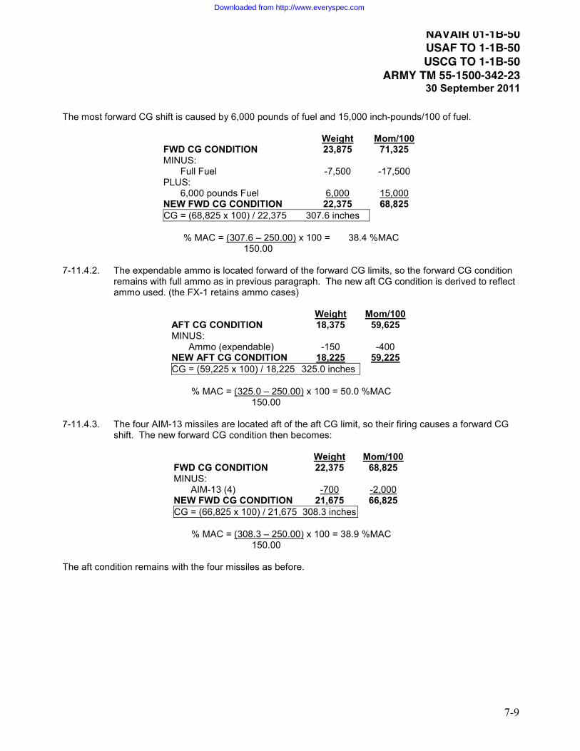
NAVAIR 01-1B-50 USAF TO 1-1B-50 USCG TO 1-1B-50
ARMY TM 55-1500-342-2330 September 2011
7-9
The most forward CG shift is caused by 6,000 pounds of fuel and 15,000 inch-pounds/100 of fuel.
WeightFWD CG CONDITION
Mom/10023,875 71,325
MINUS: Full Fuel -7,500 -17,500
PLUS: 6,000 pounds Fuel 6,000
NEW FWD CG CONDITION15,000
22,375 68,825CG = (68,825 x 100) / 22,375 307.6 inches
% MAC = (307.6 – 250.00)
150.00 x 100 = 38.4 %MAC
7-11.4.2. The expendable ammo is located forward of the forward CG limits, so the forward CG condition
remains with full ammo as in previous paragraph. The new aft CG condition is derived to reflect ammo used. (the FX-1 retains ammo cases)
WeightAFT CG CONDITION
Mom/10018,375 59,625
MINUS: Ammo (expendable) -150 -400
NEW AFT CG CONDITION 18,225CG = (59,225 x 100) / 18,225
59,225325.0 inches
% MAC = (325.0 – 250.00)
150.00 x 100 = 50.0 %MAC
7-11.4.3. The four AIM-13 missiles are located aft of the aft CG limit, so their firing causes a forward CG
shift. The new forward CG condition then becomes:
WeightFWD CG CONDITION
Mom/10022,375 68,825
MINUS: AIM-13 (4) -700
NEW FWD CG CONDITION-2,000
21,675 66,825CG = (66,825 x 100) / 21,675 308.3 inches
% MAC = (308.3 – 250.00)
150.00 x 100 = 38.9 %MAC
The aft condition remains with the four missiles as before.
Downloaded from http://www.everyspec.com

NAVAIR 01-1B-50 USAF TO 1-1B-50 USCG TO 1-1B-50 ARMY TM 55-1500-342-2330 September 2011
7-10
7-11.5. Thus, both the forward CG and aft CG are within the allowable limits. However, suppose the pilot
weighed in at 150 pounds, instead of 200. That would mean a 50 pound weight reduction, and a 7,500 inch-pound moment reduction from what was calculated. With the pilot being forward of the MAC, the CG shift would be aft. The new aft CG condition would then be:
WeightAFT CG CONDITION
Mom/10018,225 59,225
MINUS: Crew Weight Reduction -50
NEW AFT CG CONDITION-75
18,175 59,150CG = (59,150 x 100) / 18,175 325.4 inches
% MAC = (325.4 – 250.00)
150.00 x 100 = 50.3 %MAC
This is 0.3 percent MAC aft of the allowable aft CG limit. Thus, the calculations could have been performed and clearance given to the flight using the standard pilot weight, but because of the lighter weight pilot, the aircraft CG could have gone aft of the aft limit in flight. 7-12. CHART E LOADING DATA The Chart E provides all the weight, arm, and moment data necessary to perform CG loading calculations. It is predominately in tabular form, listing the standard weights, arms, and moments of load items in such quantities and locations as are normally used.
NOTE
The weights listed in the Chart E are nominal values based on an average sample. Variability in weight for payload items is expected. Actual weights should be used whenever possible, especially when dealing with variable items such as the fuel (density varying with temperature) and the crew.
Downloaded from http://www.everyspec.com

NAVAIR 01-1B-50 USAF TO 1-1B-50 USCG TO 1-1B-50
ARMY TM 55-1500-342-2330 September 2011
8-1
Section 8 – Service Specific RequirementsUS ARMY
8-1. US ARMY 8-1.1. RELATED REFERENCES. 8-1.1.1. AR 95-1 Aviation Flight Regulations 8-1.1.2. AR 95-23 Aviation Unmanned Aircraft System Flight Regulations 8-1.1.3. DA PAM 738-751 Functional Users Manual for the Army Maintenance Management System –
Aviation (TAMMS-A) 8-1.1.4. TB 43-180 Calibration and Repair Requirements for the Maintenance of Army Materiel 8-1.1.5. TB 750-25 Maintenance of Supplies and Equipment Army Test, Measurement, and Diagnostic
Equipment (TMDE) 8-1.1.6. TM 1-1500-328-23 Aeronautical Equipment Maintenance Management Policies and Procedures 8-1.2. WEIGHT AND BALANCE CONTROL. All weight and balance records will, as a minimum, be reviewed every 12 months 8-1.2.1. This review must include a Chart A inventory of the aircraft. 8-1.2.2. Review of the DA Forms 2408-5, 2408-5-1, 2408-15, and the Chart C for correctness in aircraft
modification documentation. 8-1.2.3. Upon satisfactory review of all weight and balance records, enter the following statement on the
Chart C: “Annual review and inventory completed.” The data and adjusted Basic Weight, Arm, Moment (if adjusted) will accompany this entry.
8-1.2.4. Temporary equipment changes: When equipment is temporarily (less than 90 days) installed,
removed, or relocated within the aircraft, the weight and balance change(s) must be documented by one of the following methods:
1) Create new or update current Forms F.
2) Make appropriate entries in aircraft maintenance records (DA Form 2408-13/DA Form
2408-13-E) containing a brief description, weight, arm, and moment of the changes. 8-1.3. RESPONSIBILITIES. 8-1.3.1. TRAINING GROUP: Refer to AR 95-1 and AR 95-23 8-1.3.2. DEPOT LEVEL MAINTENANCE: NA 8-1.3.3. TYPE COMMANDER: Refer to AR 95-1 and AR 95-23
US ARMY
Downloaded from http://www.everyspec.com

NAVAIR 01-1B-50 USAF TO 1-1B-50 USCG TO 1-1B-50 ARMY TM 55-1500-342-2330 September 2011
8-2
US ARMY 8-1.4. PERSONNEL QUALIFICATION REQUIREMENTS. Refer to AR 95-1 and AR 95-23 8-1.5. FORMS/RECORDS DISPOSITION. Weight and balance forms are to be safeguarded and
maintained with the same degree of importance as other records maintained for each aircraft. 8-1.5.1. The individual weight and balance forms serve various purposes. Therefore, the retention period
of the forms will vary, as follows: 8-1.5.1.1. The DD Form 365, Record of Weight and Balance Personnel is a semi-permanent form. It
will be retained in the aircraft’s weight and balance data file until space for additional entries has been exhausted and a new replacement form started. At the time, the replaced form may be destroyed locally.
8-1.5.1.2. The DD Form 365-1, Chart A - Basic Weight Checklist Record (Chart A) and the DD Form
365-3 Chart C - Basic Weight and Balance Record (Chart C) are permanent forms. These forms will be retained in the aircraft’s weight and balance data file for the life of the aircraft. As new forms are started because of exhausting entry space, the new forms will be stapled to the original form.
8-1.5.1.3. The DD Form 365-2, Form B - Aircraft Weighing Record (Form B) is a semi-permanent form.
The current completed form will be retained in the aircraft’s weight and balance data file until the aircraft has been reweighed, a new form started, computations verified, and necessary entries made on the Form B. Upon completion of the above, the old Form B may be destroyed locally.
8-1.5.1.4. The DD Form 365-4, Weight and Balance Clearance Form F (Form F) which has been used
to compute standard loads, utilizing the aircraft’s current Basic Weight, is considered a current work form as long as the load weights and locations remain current and until the Basic Weight has been recomputed/changed. A copy of the current form will be retained in the aircraft’s weight and balance data file until the entries require revision, at which time the old form will be destroyed locally or marked void.
8-1.5.1.5. Chart E, Loading Data and Special Weighing Instructions. The Chart E is considered a
semi-permanent Chart and is to be retained in the aircraft’s weight and balance file until a revised Chart E is published in the aircraft maintenance manual. Following publication of the Chart E in the maintenance manual, the Chart E in the aircraft file is no longer required and shall be removed and destroyed locally.
8-1.5.2. The weight and balance file shall be maintained and kept current for each aircraft from the time
of delivery of an aircraft to the Army until salvage or retirement of the aircraft. Upon transfer of an aircraft, the commanding officer of the transferring activity is responsible for insuring the weight and balance file accompanies the aircraft.
8-1.5.3. Any of the DD Form 365 series can be duplicated for reason of replacing lost, mutilated, or
illegible forms. When the action is taken, each form duplicated shall contain a statement to the effect that the entries are certified true and accurate, followed by signature of certifying individual, date, and organizational identity. Duplication of lost or illegible forms requires a physical inventory for Chart A and weighing the aircraft for Form B.
US ARMY
Downloaded from http://www.everyspec.com
NAVAIR 01-1B-50 USAF TO 1-1B-50 USCG TO 1-1B-50
ARMY TM 55-1500-342-2330 September 2011
8-3
US ARMY
8-1.5.4. The aircraft weight and balance file for aircraft stricken from the Army inventory is to be disposed of as follows:
8-1.5.4.1. Destroyed/damaged aircraft. Destroy file locally, after necessary investigation and reporting,
provided the aircraft does not fall into any of the following categories. 8-1.5.4.2. Weight and balance records of aircraft that have been involved in accidents resulting in
death or injury to any person, and/or damage to other than Government property that is classified as combat loss IAW AR 385-40, paragraph 2-5 are to be disposed of IAW Final Disposition Instructions issued by AMCOM, AMSAM-MMC-MA-OS. If the loss is not
classified as combat loss IAW AR 385-40, paragraph 2-5 the weight and balance records are to be stored and secured with the wreckage and treated as legal evidence IAW DA Pam 27-162. The period of retention is variable; Final Disposition Instructions will not be issued from AMCOM, until a letter of release is issued by controlling Staff Judge Advocate (SJA), with AMCOM legal review and concurrence.
8-1.5.4.3. Damaged aircraft which are uneconomically repairable (by Army standards), under disposal conditions, may be transferred or offered for sale to other than an Army custodian. The weight and balance file for such aircraft shall accompany the aircraft to the acquiring agency/individual(s).
8-1.5.4.4. Excess aircraft. For aircraft whether in a serviceable or repairable condition which are to be
transferred or offered for sale to other than Army custody, the weight and balance file will accompany the aircraft to the acquiring agency/individual(s).
8-1.6. AIRCRAFT CLASSIFICATIONS. See Table 3-1. Refer to the individual aircraft operator’s manual,
AR 95-1 and AR 95-23 for details. 8-1.7. FORM F. 8-1.7.1. PROCEDURES: 8-1.7.2. Use of Forms F – Transport verses Tactical: Aircraft designed to transport personnel shall use
the Transport Form F; those aircraft not designed to transport personnel, shall utilize the Tactical Form F regardless of the operating environment.
NOTE
When aircraft are operated at critical gross weights or near the CG limits, the actual weight of each individual occupant, equipment, and all load items shall be used.
8-1.7.3. Entry of Taxi Fuel is not necessary unless required to bring aircraft into safe CG and/or weight
range.
US ARMY
Downloaded from http://www.everyspec.com

NAVAIR 01-1B-50 USAF TO 1-1B-50 USCG TO 1-1B-50 ARMY TM 55-1500-342-2330 September 2011
8-4
US ARMY 8-1.7.4. WEIGHT AND BALANCE AUTHORITY SIGNATURE block. Enter signature or technical
inspector stamp of the person assigned to aircraft IAW DD Form 365.
NOTE
Local Commander may establish policies and procedures allowing deviation from the weight and balance authority signature.
8-1.7.5. All assigned Forms F shall be reviewed for accuracy at least every 90 days. 8-1.7.6. Transport Form F:
WARNING
Verify on-board flight performance system (e.g. Perf Page, FMS, CAAS) Basic Weight and Moment/Simplified matches Reference 1 of the current record DD Form 365-4, Weight and Balance Flight Clearance Form F.
NOTE
Rotor-wing aircraft with non-retractable landing gear should use/verify the following limitations: Takeoff Weight Limit, Landing Weight Limit, Takeoff CG (Gear Down), and Landing CG (Gear Down).
NOTE
Fixed-wing and rotor-wing aircraft with retractable landing gear should also use/verify Ramp Weight Limit, Takeoff CG (Gear Up) and Landing CG (Gear Up). Zero Fuel CG limits may require computing IAW the aircraft operator’s manual.
CAUTION
Fixed-wing aircraft need to be aware of potential CG shifts during flight due to Gear Up Moment Changes (GUMC), movement of personnel, expenditures of cargo, ordnance, and armaments. Special care is required for computing Takeoff CG (Gear Up) and Landing CG (Gear Up) to mathematically represent the entire flight from takeoff to landing.
8-1.7.7. Tactical Form F:
NOTE
Rotor-wing aircraft with non-retractable landing gear should use/verify the following limitations: Takeoff Weight Limit, Landing Weight Limit, Takeoff CG (Gear Down), and Landing Gear CG (Gear Down).
US ARMY
Downloaded from http://www.everyspec.com

NAVAIR 01-1B-50 USAF TO 1-1B-50 USCG TO 1-1B-50
ARMY TM 55-1500-342-2330 September 2011
8-5
US ARMYNOTE
Fixed-wing and rotor-wing aircraft with retractable landing gear should also use/verify Ramp Weight Limit, Takeoff CG (Gear Up) and Landing CG (Gear Up). Zero Fuel CG limits may require computing IAW the aircraft operator’s manual.
CAUTION
Fixed-wing aircraft need to be aware of potential CG shifts during flight due to Gear Up Moment Changes (GUMC), expenditures of cargo, ordnance, and armaments. Special care is required for computing Takeoff CG (Gear Up) and landing CG (Gear Up) to mathematically represent the entire flight from takeoff to landing.
8-1.7.8. STANDARDIZED LOADINGS: Actual weights and locations of personnel, equipment, and all load items should be used when aircraft are operated at critical Gross Weights or near center of gravity limits.
8-1.8. AIRCRAFT WEIGHINGS. 8-1.8.1. AIRCRAFT WEIGHING REQUIREMENTS: Refer to AR 95-1 and AR 95-23 8-1.8.1.1. Combat Aircraft Weight and Balance Management: 8-1.8.1.1.1. Special circumstances exist in deployed locations which prevent ideal conditions for
weighing. For those aircraft deployed within the theater of operations, weighing of aircraft is permitted in an open hanger if the following conditions are met:
8-1.8.1.1.1.1. There is no risk of aircraft falling off jacks (if used) due to air movement. 8-1.8.1.1.1.2. Scale readings do not change for a minimum of 30 seconds prior to recording the
weight. 8-1.8.1.2. Weighing Deferments: 90-day combat weighing deferment: Ref to AR 95-1. 8-1.8.1.2.1. All of the weight and balance records to include Chart A, Form B, and Chart C have
been provided. Export aircraft using AWBS satisfies this requirement. 8-1.8.1.3. Commander’s request with copy of aircraft’s weight and balance file must be sent to the
appropriate contacts listed below, using the following address block or the appropriate email address:
CDR, USARDECOM ATTN: (POC’s Office Symbol, Contact Name See (a) – (e) below) Building 4488 Redstone Arsenal, AL 35898-5000
US ARMY
Downloaded from http://www.everyspec.com

NAVAIR 01-1B-50 USAF TO 1-1B-50 USCG TO 1-1B-50 ARMY TM 55-1500-342-2330 September 2011
8-6
US ARMY(a) AH-64: RDMR-AED, Email: [email protected], CC: [email protected]
(b) UH-60: RDMR-AEU, Email: [email protected], CC: [email protected]
(c) CH-47: RDMR-AEC, Email: [email protected], CC: [email protected]
(d) OH-58/Fixed Wing: RDMR-AEB,
Email: [email protected], CC: [email protected]
(e) Special Operations Aircraft: RDMR-AET, Email: [email protected], CC: [email protected]
8-1.8.2. Aircraft Weighing Area: 8-1.8.2.1. When floor slope is questionable, contact supporting Department of Public Works (DPW) or
servicing agency for hangar floor survey. For a field expedient method, contact supporting unit Logistics Assistance Representative (LAR).
8-1.8.3. Aircraft Fuel System: 8-1.8.3.1. Prepare aircraft fuel tanks in accordance with applicable maintenance manuals (alternate
source is Chart E instructions). Weighing aircraft with full fuel tanks is not recommended and in some instances not authorized.
8-1.8.3.2. Unusable and trapped fuel shall be listed on DD Form 365-1, Chart A – Basic Weight
Checklist Record as separate entries. 8-1.8.3.3. If the aircraft is weighed with drained fuel tanks, unusable fuel listed on DD Form 365-1,
Chart A will reflect "IN A/C" and the data also entered on DD Form 365-2 Form B, Column II. 8-1.8.3.4. If the aircraft is weighed with a totally dry fuel system(s), unusable and trapped fuel listed on
DD Form 365-1, Chart A will reflect "IN A/C" and the data also entered on DD Form 365-2 Form B, Column II.
8-1.8.3.5. If the aircraft is weighed with full fuel tanks, the weight of usable fuel must be entered under
Column I on Form B. Usable fuel is not part of Basic Weight. Never weigh an aircraft with partially filled fuel tanks.
8-1.8.3.6. Allow sufficient time for fuel temperature and movement to stabilize after refueling and
aircraft positioning for weighing. When determining the density of a fuel sample, the hydrometer should be carefully placed into the fluid within the transparent container. When reading the density, the hydrometer must not touch the container. Float hydrometer in a sample of fuel from each tank just prior to weighing and record the weight per gallon; read this value at the lowest point of the meniscus (see Figure 5-3).
US ARMY
Downloaded from http://www.everyspec.com

NAVAIR 01-1B-50 USAF TO 1-1B-50 USCG TO 1-1B-50
ARMY TM 55-1500-342-2330 September 2011
8-7
US ARMY 8-1.8.4. The following actions must be performed prior to aircraft weighing (in addition to this joint manual
and aircraft specific requirements): 8-1.8.4.1. Review aircraft logbook forms and records (DA Form 2408-13-1 and DA Form 2408-14-1) to
ensure all aircraft parts/items are installed prior to weighing. 8-1.8.4.2. Review aircraft historical forms and records (DA Form 2408-5 and DA Form 2408-5-1) and
the DD Form 365-3 Chart C to ensure all applied modifications has been properly documented on all appropriate forms and records.
8-1.8.5. The Weight and Balance Technician/Custodian assigned to the aircraft IAW the DD Form 365
shall ensure that all required parts/items are installed on the aircraft prior to record weighing.
NOTE
Master Chart A’s are available at www.jtdi.mil and should be implemented during the annual aircraft inventory and/or an official aircraft weighing.
8-1.8.6. WEIGHING INTERVALS: Refer to AR 95-1 and AR 95-23. 8-1.9. TRANSFER / ACCEPTANCE INVENTORY. 8-1.9.1. The weight and balance technician will transfer when one or more of the following occur:
x Aircraft is transferred/received to a new organization.
x Work ordered to next level maintenance which results in the weight and balance records requiring updates. An update constitutes any entries made to the DD Form 365-3, Chart C.
8-1.9.2. The Chart A inventory shall be performed whenever:
x The aircraft is transferred to a new unit with a change of weight and balance authority.
x The Weight and Balance Technician receiving the aircraft shall perform a Chart A inventory of the aircraft to ensure the delivery condition or assumed operating condition recorded by the manufacture in Charts A and C matches the actual operating condition to be used by the custodian. If not, the necessary adjustments shall be made.
x The aircraft has a major overhaul. For example, the following actions constitute a major
overhaul: extensive airframe repairs, RESET, tail boom replacement, etc
x The pilot reports unsatisfactory flight characteristics with weight and/or balance implications.
x The aircraft is weighed.
x At time intervals required by regulation.
US ARMY
Downloaded from http://www.everyspec.com

NAVAIR 01-1B-50 USAF TO 1-1B-50 USCG TO 1-1B-50 ARMY TM 55-1500-342-2330 September 2011
8-8
US ARMY 8-1.10. SCALES. 8-1.10.1. SCALE CALIBRATION: Commanders of Army organizations which operate, maintain, or modify
aircraft are responsible for ensuring that weighing equipment under their jurisdiction are calibrated periodically and certified by a government inspector of weights and measures or by commercial scale officials in accordance with TB 750-25 and TB 43-180. Unless directed in these TB’s, scales shall be calibrated or certified correct at least once every 12 months.
8-1.10.2. SCALE ACCURACY: As determined by TMDE. Block is not used on DD Form 365-2, Form B –
Aircraft Weighing Record. 8-1.11. UNMANNED AERIAL VEHICLES (UAV’S). Refer to AR 95-23 8-1.12. WEIGHT AND BALANCE GUIDANCE FOR AIRCRAFT MODIFICATIONS. 8-1.12.1. The following instructions are intended to serve as a standard for aircraft modifications with
regards to weight and balance management. Accuracy of actual item's weight and location is critical in maintaining safe, reliable aircraft operations. Increased airframe and component stress, handling quality degradation, and aircraft accidents are likely consequences of poor weight and balance maintenance.
8-1.12.2. Typically, A-Kit items are listed exclusively on Chart C, with B-Kit’s listed on Chart A and posted
to the Chart C. 8-1.12.3. Weights, Arms, and moments shall be listed to one decimal place. Moments are simplified by a
constant per MDS (/100, 1000, etc). 8-1.12.4. The items listed are for example purposes only. (See example on next page)
1. WEIGHT AND BALANCE DATA. Make entries on DD Form 365-1 (Chart A) and DD Form 365-3 (Chart C), in accordance with TM 55-1500-342-23 as indicated below:
START OF US ARMY EXAMPLE
a. Chart A. Items that are removed, when using AWBS, unselect "In A/C" and follow the software instructions.
ITEM NO. ITEM DESCRIPTION WEIGHT ARM MOM/1000 B-XXX RADIO, FM #1 12345-A 2.3 233.0 0.5 F-XXX SIGNAL CONDITIONER, LH ABC-123 3.5 515.0 1.8 F-XXX SIGNAL CONDITIONER, RH ABC-123 3.5 515.0 1.8
US ARMY
Downloaded from http://www.everyspec.com

NAVAIR 01-1B-50 USAF TO 1-1B-50 USCG TO 1-1B-50
ARMY TM 55-1500-342-2330 September 2011
8-9
US ARMY b. Chart A. Items that are installed, when using AWBS, make entries in the appropriate compartments as shown below. Enter new item numbers as required. Select "IN A/C" only after item(s) is actually installed.
ITEM NO. ITEM DESCRIPTION WEIGHT ARM MOM/1000 B-XXX RADIO, MULTIBAND 5678-B 1.6 225.0 0.4 F-XXX MULTIBAND SIGNAL COND., LH 129-S 3.5 496.4 1.7 F-XXX MULTIBAND SIGNAL COND., RH 129-S 3.5 496.4 1.7
c. Chart C. Make entries for items removed/added as shown below. When using AWBS, Chart A items should automatically be removed/added to the Chart C. Ensure a Header and Footer that reflects the MWO is added to the Chart C IAW TM 55-1500-342-23. ITEM NO. IN/OUT ITEM DESCRIPTION WGT ARM MOM/1000
Header Beginning of MWO 49-1979-391 Multiband Radio B-XXX Out RADIO, FM #1 12345-A 2.3 233.0 0.5 F-XXX Out SIGNAL CONDITIONER, LH ABC-123 3.5 515.0 1.8 F-XXX Out SIGNAL CONDITIONER, RH ABC-123 3.5 515.0 1.8
Out Wiring and Associated Hardware 0.8 179.0 0.1 In Wiring with Hardware 10.4 209.6 2.2
B-XXX In RADIO, MULTIBAND 5678-B 1.6 225.0 0.4 F-XXX In MULTIBAND SIGNAL COND., LH 129-S 3.5 496.4 1.7 F-XXX In MULTIBAND SIGNAL COND., RH 129-S 3.5 496.4 1.7
Header End of MWO 49-1979-391 Multiband Radio
NOTE
The next paragraph is applicable only for aircraft modifications that contain Form F items. d. Form F. Make entries for items added as required on DD form 365-4 Weight and Balance Flight Clearance Form F. Changes to the appropriate technical manual must also be made to list these new Form F items.
ITEM DESCRIPTION WEIGHT ARM MOM/1000 50 Cal Machine Gun Model AS-678 143.8 102.6 14.8 50 Cal Gun Mount 26.4 102.6 2.7 50 Cal Gun Control Harness 3.5 102.6 0.4
2. If items are installed prior to flight and then removed afterwards or numerous configurations are used, the items should only be listed on the DD Form 365-4, Weight and Balance Flight Clearance Form F.
END OF US ARMY EXAMPLE
Figure 8-1. Aircraft Modification Example
US ARMY
Downloaded from http://www.everyspec.com

NAVAIR 01-1B-50 USAF TO 1-1B-50 USCG TO 1-1B-50 ARMY TM 55-1500-342-2330 September 2011
8-10
US ARMY 8-1.13. CONTACT INFORMATION. Refer to technical support contacts in AWBS or on the Aeromechanics’
website. Email address: [email protected] 8-1.14. CORRECTIONS TO THIS MANUAL. Submit DA Form 2028 8-1.15. DISTRIBUTION OF AWBS. The current approved version of the Automated Weight and Balance
System (AWBS) for Army use may be obtained via the following address: [email protected]. 8-1.16. SERVICE SPECIFIC ACRONYMS.
US ARMY
Downloaded from http://www.everyspec.com
NAVAIR 01-1B-50 USAF TO 1-1B-50 USCG TO 1-1B-50
ARMY TM 55-1500-342-2330 September 2011
8-11
US NAVY / US MARINE CORPS 8-2. US NAVY / US MARINE CORPS 8-2.1. RELATED REFERENCES. Weight and balance personnel shall be familiar with the following related technical manuals (supplementary data to this manual) and other related documents: 8-2.1.1. Weight and Balance Handbook Forms. Blank DD 365-series forms are provided below for
activities that are required to use paper DD 365 forms for maintaining the Weight and Balance Handbook.
8-2.1.2. Chart A - Basic Weight Checklist Record for assigned aircraft model(s). 8-2.1.3. Chart E - Loading Data for assigned aircraft model(s). 8-2.1.4. COMNAVAIRFORINST 4790.2 series: The Weight and Balance sections of the Naval Aviation
Maintenance Program (NAMP) volumes I & II contain top-level guidance and direction regarding field weight and balance control for USN/USMC aircraft.
8-2.1.5. OPNAVINST 3710.7 series: The Weight and Balance sections of the General Flight and
Operating Instructions. Contains direction regarding weight and balance clearance for flight. 8-2.1.6. The NATOPS Flight Manual(s) for assigned aircraft model(s). Contains the weight and balance
(center of gravity) operating limitations for individual aircraft models. 8-2.1.7. The NATIP Flight Manual(s) for assigned aircraft model(s). Represents the primary reference for
the technical information required for safe and effective tactical employment, including safety-of-flight limitations and restrictions for individual aircraft models. This manual documents the loading arrangements and limitations approved for permanent flight clearance.
8-2.1.8. Cargo Loading Manual 8-2.1.8.1. The cargo loading manual contains the description of the individual type aircraft cargo
capabilities, provisions, systems and features for carrying cargo and troops. This document can also cover cargo type descriptions, loading instructions and procedures, cargo loading equipment operation and stowage, instructions for cargo load-out aircraft weight and center of gravity planning and calculations, cargo tie down calculations, and passenger/patient/troop accommodations installation, operation and removal procedures. This is essentially the "How to load the aircraft" manual.
8-2.1.9. NAVAIR 00-25-300: The Weight and Balance sections of the manual that describes the
Technical Directives System. 8-2.2. WEIGHT AND BALANCE CONTROL. Operational aircraft weight and balance control shall be accomplished in accordance with COMNAVAIRFORINST 4790.2 series (the NAMP), the specific aircraft NATOPS Flight Manuals, this manual, OPNAVINST 3710.7 series, and the specific aircraft Chart E - Loading Data.
US NAVY / US MARINE CORPS
Downloaded from http://www.everyspec.com

NAVAIR 01-1B-50 USAF TO 1-1B-50 USCG TO 1-1B-50 ARMY TM 55-1500-342-2330 September 2011
8-12
US NAVY / US MARINE CORPS 8-2.2.1. In case of conflicting requirements, procedures, aircraft limits (weight and CG), authorized
loadings, and/or instructions, COMNAVAIRFORINST 4790.2 series and the aircraft NATOPS/NATIP manuals shall take precedence over this manual and the specific aircraft Chart E pending mandatory resolution of the conflict from NAVAIRSYSCOM AIR-4.1.7, Mass Properties Division.
8-2.2.2. In the case of conflicting weight and balance loading data, the aircraft specific Chart E shall take
precedence over the aircraft NATOPS/NATIP. Inclusion of weight and moment data in Chart E does not authorize loading arrangements. Check specific aircraft Chart C, Chart E and Form F for current weight and balance information for that aircraft. Weight and balance data in the aircraft NATOPS/NATIP (i.e. aircraft weights, stores weights, etc.) is provided for guidance only.
8-2.2.3. WEIGHT AND BALANCE HANDBOOK: The Weight and Balance Handbook is the primary tool
utilized in maintaining weight and balance control for aircraft. The weight and balance handbooks for individual aircraft shall be maintained in accordance with the requirements of this manual.
NOTE
The weight and balance handbook shall take the highest security classification of the data contained therein.
8-2.3. RESPONSIBILITIES 8-2.3.1. NAVAIRSYSCOM (AIR-4.1.7 MASS PROPERTIES DIVISION) RESPONSIBILITIES 8-2.3.1.1. NAVAIRSYSCOM (AIR-4.1.7) shall maintain overall responsibility for establishing the
requirements, processes, procedures, and forms format for USN/USMC aircraft weight and balance control. NAVAIRSYSCOM (AIR-4.1.7) is the office of primary responsibility for the following duties:
8-2.3.1.1.1. Establishing technical content and format of the USN/USMC service specific requirements of
this manual and coordination with other services regarding general sections of this manual. 8-2.3.1.1.2. Approval review for technical content and format of Charts A & E for individual aircraft
models. 8-2.3.1.1.3. Act as the USN/USMC Technical POC for the Automated Weight and Balance System
(AWBS) software. 8-2.3.1.1.4. Determination and specification of USN/USMC aircraft weight and balance
classifications. 8-2.3.1.1.5. Providing specialized weight and balance engineering support to test, maintenance, and
operating commands. 8-2.3.1.1.6. Coordination and recommendation of changes to the weight and balance requirements
of COMNAVAIRFORINST 4790.2 series, OPNAVINST 3710.7 series, and NAVAIR 00-25-300 instructions.
US NAVY / US MARINE CORPS
Downloaded from http://www.everyspec.com

NAVAIR 01-1B-50 USAF TO 1-1B-50 USCG TO 1-1B-50
ARMY TM 55-1500-342-2330 September 2011
8-13
US NAVY / US MARINE CORPS 8-2.3.1.1.7. Coordination of content and recommendation of changes to the weight and balance training
courses maintained by the Center for Naval Aviation Technical Training (CNATT). 8-2.3.1.1.8. Coordination and recommendation of procedures and/or equipment required for
compliance with the various requirements of the weight and balance control system.
8-2.3.1.1.9. Preparing, obtaining and disseminating aircraft weight and balance data that using Commands required in order to comply with the USN/USMC aircraft weight and balance control system requirements.
8-2.3.1.1.10. Establish weighing intervals for aircraft. 8-2.3.1.1.11. Approval review for technical content of automated Form F generators. 8-2.3.1.1.12. Qualification of Personnel assigned responsibility for weighing aircraft. 8-2.3.1.1.12.1. NAVAIRSYSCOM (AIR-4.1.7) shall verify that the personnel assigned the responsibility
for weighing aircraft meet the qualifications of section 8-2.8.5, shall maintain a record of qualified personnel, and shall produce and disseminate a Letter of Qualification to Weigh Aircraft to each person assigned the responsibility for weighing aircraft.
8-2.3.2. TRAINING GROUP: The Center for Naval Aviation Technical Training (CNATT) shall prepare
and provide introductory weight and balance training required for Command compliance with the USN/USMC aircraft weight and balance control system. CNATT shall coordinate course content and special training procedures with NAVAIR Mass Properties Division to ensure content is appropriate and meets applicable standards. AIR-4.1.7 must approve all course revisions prior to implementation.
8-2.3.3. DEPOT LEVEL MAINTENANCE: Fleet Readiness Centers (FRCs)
FRCs shall weigh aircraft and update individual aircraft Weight and Balance Handbooks in accordance with the requirements of COMNAVAIRFORINST 4790.2 series and this manual. The FRCs shall ensure that a dedicated staff of qualified personnel are available to accomplish the required tasks and shall designate the Lead Weight and Balance Specialist responsible.
8-2.3.4. TYPE COMMANDER RESPONSIBILITIES. 8-2.3.4.1. The Type Commanders shall ensure that reporting custodians meet the requirements of
COMNAVAIRFORINST 4790.2 series, OPNAVINST 3710.7 series and this manual. 8-2.3.4.2. Type Commanders shall perform periodic Aviation Maintenance Inspections (AMI) to
evaluate the activities compliance with Weight and Balance requirements of COMNAVAIRFORINST 4790.2 series, OPNAVINST 3710.7 series, and this manual.
8-2.3.5. AIRCRAFT REPORTING CUSTODIAN RESPONSIBILITIES: 8-2.3.5.1. Aircraft Reporting Custodians are activities with an allowance of aircraft, an inventory of
aircraft, or both.
US NAVY / US MARINE CORPS
Downloaded from http://www.everyspec.com

NAVAIR 01-1B-50 USAF TO 1-1B-50 USCG TO 1-1B-50 ARMY TM 55-1500-342-2330 September 2011
8-14
US NAVY / US MARINE CORPS 8-2.3.5.2. For weight and balance purposes, when an aircraft is in the physical custody of an activity,
that activity is responsible for the maintenance of all weight and balance records. When an aircraft is inducted into off-site rework facility or on loan to another activity, the weight and balance records shall accompany the aircraft and be maintained by the physical custodian.
8-2.3.5.3. The Reporting Custodian shall designate the Maintenance Material Control Officer (MMCO)
as the activity Weight and Balance Officer, and any additional qualified Weight and Balance Personnel, in accordance with COMNAVAIRFORINST 4790.2 series.
8-2.3.5.4. The Reporting Custodians shall ensure that weight and balance control system requirements
and procedures of this manual, and related technical documentation, are complied in accordance with the management procedures of COMNAVAIRFORINST 4790.2 series and OPNAVINST 3710.7 series. The weight and balance control system requirements and procedures shall include, but not necessarily be limited to ensuring:
8-2.3.5.5. Weight and balance handbooks for all assigned aircraft, including newly received aircraft,
are complete, current, and maintained in the correct format. 8-2.3.5.6. Procedures are in place to ensure weight and balance flight clearance is accomplished per
OPNAVINST 3710.7 series, the TMS/MDS specific loading manual, and this manual. 8-2.3.5.7. Weight and balance impacts of changes to aircraft configuration, including incorporation of
Technical Directives, repairs, or other modifications, are properly recorded in the weight and balance handbooks of affected aircraft and the latest Basic Weight and Moment values in Chart C of each weight and balance handbook correctly reflect the Basic Weight and Moment of that aircraft.
8-2.3.5.8. Concerns regarding accuracy of weight and balance data for any assigned aircraft are
resolved satisfactorily, for example, by having aircraft weighed by an authorized weighing facility or field team.
8-2.3.5.9. Aircraft Battle Damage Repair (ABDR) actions do not cause unacceptable aircraft weight
and balance. NOTE
Discretion of the MMCO or Lead Weight and Balance Specialist should be employed to determine what is unacceptable.
8-2.3.5.10. Aircraft are configured with proper amounts of ballast required to maintain
the aircraft within the prescribed CG limits throughout its flight. The addition of ballast shall not impair the structural integrity of the aircraft and therefore any new ballast shall be approved by NAVAIRSYSCOM (AIR-4.1.7) before it can be installed. Whenever ballast is required to balance an aircraft after the removal of equipment, temporary ballast may be placed in the vacant equipment mounts up to the weight of the removed equipment.
8-2.3.5.11. When necessary the commands may impose more stringent requirements for
weight and balance control through command supplements to applicable service manuals and instructions.
US NAVY / US MARINE CORPS
Downloaded from http://www.everyspec.com

NAVAIR 01-1B-50 USAF TO 1-1B-50 USCG TO 1-1B-50
ARMY TM 55-1500-342-2330 September 2011
8-15
US NAVY / US MARINE CORPS 8-2.3.5.12. The reporting custodian may request permission, via proper chain of
command, to implement procedures to simplify aircraft weight and balance maintenance that do not conflict with this manual, the aircraft specific loading manual, or other applicable directives. Permission shall be obtained from NAVAIRSYSCOM (AIR-4.1.7).
8-2.3.6. COMMERCIAL MAINTENANCE RESPONSIBILITIES. 8-2.3.6.1. Commercial activities involved in the weight and balance control of
USN/USMC aircraft shall comply with requirement of paragraphs 8-2.4 and 8-2.6 as applicable.
8-2.4. PERSONNEL QUALIFICATION REQUIREMENTS. 8-2.4.1. Military and civilian personnel must be qualified as follows: 8-2.4.1.1. Personnel assigned as the Weight and Balance Officer must qualify for
designation by graduation from the training courses required by COMNAVAIRFORINST 4790.2 series or a commercial equivalent as approved by NAVAIRSYSCOM 4.1.7.
8-2.4.1.2. Personnel maintaining aircraft weight and balance records under the supervision of the Weight and Balance Officer must have successfully completed the course required by COMNAVAIRFORINST 4790.2 series.
8-2.4.1.3. Aircrew personnel completing DD365-4 Clearance Forms F or equivalent must
have successfully completed the appropriate TMS training syllabus or successfully completed the course required by COMNAVAIRFORINST 4790.2 series. This qualifies individuals to sign the Computed By block of the Form F.
8-2.4.1.4. Personnel assigned responsibility for weighing aircraft (i.e. individuals qualified to
lead a weigh team as opposed to those in a supporting role) must be qualified by: 8-2.4.1.4.1. Graduation from the training course required by COMNAVAIRFORINST
4790.2 series or the AWBS training course offered by Society of Allied Weight Engineers (SAWE).
8-2.4.1.4.2. Successful completion of the SAWE aircraft weighing course or
NAVAIRSYSCOM (AIR-4.1.7) accepted equivalent. 8-2.4.1.4.3. Have documented experience in weighing aircraft with active participation in
a minimum of twenty aircraft weighings covering at least four different TMS aircraft, or six weighings of a specific TMS aircraft when the individual will be weighing only this TMS aircraft. Weighing experience shall have been obtained within the previous year.
US NAVY / US MARINE CORPS
Downloaded from http://www.everyspec.com

NAVAIR 01-1B-50 USAF TO 1-1B-50 USCG TO 1-1B-50 ARMY TM 55-1500-342-2330 September 2011
8-16
US NAVY / US MARINE CORPS 8-2.4.1.5. Personnel designated as the Lead Weight and Balance Specialist at the
FRCs must be qualified by: 8-2.4.1.5.1. Graduation from the training course required by COMNAVAIRFORINST
4790.2 series, 8-2.4.1.5.1.1. Successful completion of the Society of Allied Weights Engineers aircraft
weighing course or NAVAIRSYSCOM (AIR-4.1.7) accepted equivalent, 8-2.4.1.5.1.2. Have twelve months of continuous actual experience in weighing aircraft with
active participation in a minimum of sixty aircraft weighings, including at least five different TMS aircraft. Weighing experience must have been obtained within the previous two years.
NOTE
Exceptions to these requirements and approval of equivalent training that fulfills the intent of the above paragraph must be obtained from NAVAIRSYSCOM (AIR-4.1.7).
8-2.4.2. NAVAIRSYSCOM 4.1.7 shall verify that civilians contractor personnel have met the intent of the
qualifications of this section.
8-2.4.3. Maintaining Qualification: 8-2.4.3.1. Weight and balance Officers, personnel maintaining aircraft weight and balance records
under the supervision of the Weight and Balance Officer, and Aircrew personnel completing DD365-4 Clearance Forms F or equivalent will maintain their qualifications until 5 years after being assigned out of the above responsibilities. After 5 years, these personnel must re-qualify per sections 8-2.8.2, 8-2.8.3 and 8-2.8.4, respectively.
8-2.4.3.2. Personnel assigned responsibility for weighing aircraft.
8-2.4.3.2.1. In order for personnel assigned responsibility for weighing aircraft to maintain their qualification, they must weigh one TMS every two years. After two years, these personnel must re-qualify per section 8-2.8.5.
8-2.5. FORMS/RECORDS DISPOSITION. 8-2.5.1. Weight and balance records for aircraft stricken from the Navy inventory are disposed of as
follows: 8-2.5.1.1. Destroyed Aircraft: The records are disposed of locally after necessary investigation and
preparation of required reports, provided the aircraft is not sold, transferred, or is a Special Category Aircraft.
US NAVY / US MARINE CORPS
Downloaded from http://www.everyspec.com

NAVAIR 01-1B-50 USAF TO 1-1B-50 USCG TO 1-1B-50
ARMY TM 55-1500-342-2330 September 2011
8-17
US NAVY / US MARINE CORPS 8-2.5.1.2. Sale or Transfer: When an aircraft is sold or transferred to other than USN/USMC custody,
the records accompany the aircraft unless otherwise directed by the ACC/TYCOM. Classified information is removed from the record or cleared for release through the Chain of Command prior to transfer or sale.
8-2.5.1.3. Special Category Aircraft: The following are Special Category Aircraft and their records are
transferred to the Washington National Records Center, Washington, DC: 8-2.5.1.4. Records for experimental aircraft. 8-2.5.1.5. Records of aircraft considered to be of Historical Value. 8-2.5.1.6. Records of aircraft lost in combat or that have been involved in a mishap resulting in death,
missing in action, personal injury, or substantial damage to other than government property are retained by the operating activity for one year (for defense in case of litigation action) and then forwarded to the Washington National Records Center.
NOTE
Refer to SSECNAV M-5210.1 series for procedures for transferring records to the Washington National Records Center. SECNAVINST 5510.30 series provides guidance for shipping classified information to the Washington National Records Center.
8-2.6. AIRCRAFT CLASSIFICATIONS. 8-2.6.1. For weight and balance purposes, USN/USMC aircraft are divided into two classifications, Class
1B and Class 2. Class 1A is not utilized by the USN/USMC. 8-2.6.2. Class 1B aircraft are those with published weight and CG limits that can be exceeded by
normally employed loading arrangements and therefore need loading control. 8-2.6.3. Class 2 are aircraft with published weight and CG limits that can readily be exceeded by
normally employed loading arrangements and therefore need a higher degree of loading control. 8-2.6.4. Weight and balance classification of USN/USMC aircraft are shown in Figure XXX below. All
models of the same series take on the same weight and balance classification unless specifically designated otherwise. For aircraft not specifically listed in Figure XXX below, assume a Class 2 designation and contact NAVAIRSYSCOM 4.1.7 for further information.
US NAVY / US MARINE CORPS
Downloaded from http://www.everyspec.com

NAVAIR 01-1B-50 USAF TO 1-1B-50 USCG TO 1-1B-50 ARMY TM 55-1500-342-2330 September 2011
8-18
US NAVY / US MARINE CORPS SQUADRON
TYPE CLASS 1B CLASS 2
VA, VS A-4, AV-8, S-3 VF, VFA,
VFMA F-4, F-5, F-16, F/A-18
H H-1, H-3, TH-6, H-46, TH-57, H-60 H-53, VH-3, VH-60 VP P-3, P-8
VQ, VAQ EA-6, EA-18, RQ-2, M/RQ-8, M/RQ-9, X-26 EP-3, E-6 VR, VAW E-2, NU-1, U-6 C-2, C-9, C-12, C-20, C-26, C-37, C-40, C-
130, Learjet 35/36 VT T-2, T-6, T-34, T-38, T-39, T-44, T-45, TC-4 VM MV-22
NOTE
All versions of the models listed above shall be in the class designated.
8-2.7. FORM F. 8-2.7.1. FORM F PROCEDURES: 8-2.7.1.1. All Forms F shall be completed in accordance with Section 4 of this manual.
8-2.7.1.2. DD 365-4 Clearance Form F Tactical vs. Transport. It is up to the operating command to
determine which version of the form is utilized. Generally, Class 2 aircraft utilize the Transport version and Class 1B aircraft utilize the Tactical version.
8-2.7.1.3. One-time Use Forms F are prepared for use on a one-time basis. They are generally used
when the Command does not utilize a Canned Form F approach or when an aircraft is loaded in a manner for which no Canned Form F is on file.
8-2.7.1.4. Canned Forms F are prepared for multiple uses when an aircraft’s Basic Weight and
moment remain within certain specified tolerances. They are filed in accordance with established Command procedures, for future reference and use. Canned Form F shall be checked at least every 180 days for accuracy and a new Form F prepared as required. New Canned Form F shall be prepared whenever Chart C Basic Weight and/or moment change. If no changes are required, the Form F may be re-dated and initiated, or a letter issued to state the review has been accomplished to certify its currency.
8-2.7.2. STANDARDIZED LOADINGS 8-2.7.2.1. At the option of the Command, for Class 1B aircraft of the same TMS with CG limits that do
not vary with Gross Weight and that use standardized aircraft loadings (usually for fighter/attack/trainer/rotary-wing aircraft), CANNED Forms F may be utilized with the following procedures to accomplish weight and balance flight clearance:
8-2.7.2.1.1. Examine the weight and balance handbooks to determine which three serial number
aircraft have the:
US NAVY / US MARINE CORPS
Downloaded from http://www.everyspec.com

NAVAIR 01-1B-50 USAF TO 1-1B-50 USCG TO 1-1B-50
ARMY TM 55-1500-342-2330 September 2011
8-19
US NAVY / US MARINE CORPS 8-2.7.2.1.1.1. Most-forward Basic CG, 8-2.7.2.1.1.2. Most-aft Basic CG, 8-2.7.2.1.1.3. Heaviest Basic Weight. 8-2.7.2.1.2. These three serial number aircraft shall be used as the baseline to compute weight and
balance for flight clearance within all limits using one loading arrangement applicable to the larger group of aircraft.
8-2.7.2.1.3. Once this loading arrangement has been determined to be within limits, the standardized
loading arrangement is sufficient for application to other serial number aircraft loaded similarly.
8-2.7.2.1.4. The standardized loading for which all aircraft remain within safe weight and balance
limits for takeoff, flight, and landing may then be CANNED. This CANNED Form F shall be used for the weight and balance flight clearance of the remaining aircraft of the same TMS.
8-2.7.2.1.5. For actual weight and balance flight clearance, this CANNED Form F shall be
referenced for record purposes. 8-2.7.2.1.6. Aircraft Basic Weight and center of gravity location is constantly changing through the
incorporation of TD’s, engine and equipment changes, modifications, and repairs. Therefore, the weight and balance handbooks for all aircraft involved in these standard loading procedures shall be closely monitored. Aircraft Basic Weight and center of gravity location must remain within the weight, most-forward center of gravity, and most-aft center of gravity positions of the reference baseline aircraft.
8-2.7.3. FORM F LIMIT DISCUSSION 8-2.7.3.1. In AWBS, fixed and rotary-wing aircraft with retractable landing gear shall set the ”CHECK
LIMITS” to “VERIFY” for “TAKEOFF LIMITS, Gear Down CG”, “TAKEOFF LIMITS, Gear Up CG”, “LANDING LIMITS, Gear Up CG”, and “LANDING LIMITS, Gear Down CG” unless otherwise specified in the Chart E.
8-2.7.3.2. Aircraft with retractable landing gear need be aware of potential CG shifts during flight due to
Gear Up Moment Changes (GUMC). The aircraft’s GUMC will be listed in Chart E if applicable and is entered into the Aircraft Description section in AWBS for each serial number aircraft.
8-2.7.4. Form F Signatures 8-2.7.4.1. Computed By: The signature of the individual completing the Form F. Must be qualified per
paragraph 8-2.8.
US NAVY / US MARINE CORPS
Downloaded from http://www.everyspec.com

NAVAIR 01-1B-50 USAF TO 1-1B-50 USCG TO 1-1B-50 ARMY TM 55-1500-342-2330 September 2011
8-20
US NAVY / US MARINE CORPS 8-2.7.4.2. Weight and Balance Authority. The signature of the Weight and Balance Officer or Weight
and Balance Technician (when performed by the aircrew away from home base). If signed by a member of the aircrew, (crew-member, load master, flight engineer, etc.), he/she shall be fully qualified per paragraph 8-2.8.4. At the completion of the flight, all one-time use Forms F shall be delivered to the Weight and Balance Officer for review and verification screening. After screening, the Weight and Balance Officer shall initial next to the existing Weight and Balance Authority signature and retain the form on file for 3 months in accordance with OPNAVINST 3710.7 series.
8-2.7.4.3. Pilot. The signature of the Pilot will appear on all One-time Use Forms F. The pilot’s
signature is not required when using the Canned Form F feature. Enter “As Assigned” in this function.
8-2.7.5. Authorized Substitutions for DD Form 365-4. 8-2.7.5.1. Manual or electronic substitutions for the DD Form 365-4 Form F may be authorized by
NAVAIRSYSCOM 4.1.7. 8-2.8. AIRCRAFT WEIGHINGS. 8-2.8.1. AIRCRAFT WEIGHING REQUIREMENTS:
NOTE
Use of Load Cells must have prior approval from NAVAIRSYSCOM (AIR-4.1.7).
8-2.8.2. Aircraft shall be weighed when any of the following conditions exist: 8-2.8.2.1. As required by pertinent service directives. 8-2.8.2.2. When weighing requirements are specified in the applicable aircraft loading manual. 8-2.8.2.3. After completion of (including painting) each re-work (e.g. PDM, SDLM, Selected PMI, etc). 8-2.8.2.4. When major modifications or repairs are made that meet the following guidelines: 8-2.8.2.5. The MMCO or Lead Weight and Balance Specialist shall determine when an aircraft has
undergone a “major modification or repair”. As a guideline, a major modification or repair is one that affects 2% of Basic Weight or 500 lb, whichever is less, or changes the Basic Weight center of gravity by 5% or more of the maximum allowable CG range. Determination of affected weight is based on weight values of removals plus weight of additions, not the resultant change.
8-2.8.2.6. When the cumulative effect on Basic Weight and/or center of gravity of a number of minor
modifications meets the guidance for a major modification.
US NAVY / US MARINE CORPS
Downloaded from http://www.everyspec.com

NAVAIR 01-1B-50 USAF TO 1-1B-50 USCG TO 1-1B-50
ARMY TM 55-1500-342-2330 September 2011
8-21
US NAVY / US MARINE CORPS 8-2.8.2.7. When aircraft modifications or repairs are accomplished and calculated or actual weight and
moment data are not available. 8-2.8.2.8. When an aircraft is painted [cumulatively more than 1/3 of aircraft surface area].
NOTE
Contact NAVAIRSYSCOM (4.1.7) for specific guidance/definition on cumulative surface area coverage.
8-2.8.2.9. When the calculated weight and balance data are suspected to be in error. 8-2.8.2.10. When unsatisfactory flight characteristics are reported, which cannot be determined as due
to improper aircraft loading, an error in weigh and balance data, or any other identifiable cause.
8-2.8.2.11. When an aircraft is in a depot facility or other authorized weighing facility for any reason, and
has not been weighed in five (5) years, (i.e., the most recent “as-weighed” Basic Weight entry in the Chart C is more than five (5) years ago).
8-2.8.2.11.1. If an aircraft has not been weighed in the past (5) years, the aircraft must be weighed at the
next earliest convenience, operational tempo permitting. 8-2.8.2.12. Whenever inactive aircraft become active. (Reference Section 3-7). 8-2.8.2.13. When the weight and balance handbook cannot be replaced using historical records. 8-2.8.3. WEIGHING INTERVALS: See paragraph 8-2.8.2.11.
8-2.9. TRANSFER / ACCEPTANCE INVENTORY. 8-2.9.1. A complete inventory of all Chart A items shall be performed whenever an activity accepts an
aircraft from another custodian. This includes aircraft on temporary loan or off-site rework/mod. 8-2.9.2. This Chart A inventory is not to be confused with the Aircraft Inventory Record inventory
performed for parts tracking/accountability and the Chart A inventory should not be performed until the aircraft has been configured for operations.
8-2.9.3. In addition, a screening of all technical directives that have been incorporated since the last
weighing will be performed. If a TD has been incorporated since the last weighing, verify the Chart A and Chart C entries have been made correctly, if applicable.
8-2.9.4. Technical directives incorporated since the last weighing may be obtained by using the date of
the last weighing and comparing it to the Aircraft’s Logbook, Technical Directives Section on OPNAV FORM 4790/24A, Technical Directives Form or the Automated Technical Directives Status Accounting (TDSA) Lists 02 and 04.
US NAVY / US MARINE CORPS
Downloaded from http://www.everyspec.com

NAVAIR 01-1B-50 USAF TO 1-1B-50 USCG TO 1-1B-50 ARMY TM 55-1500-342-2330 September 2011
8-22
US NAVY / US MARINE CORPS 8-2.9.5. Ensure the AWBS data files are exported to an external media for inclusion in the handbook
when transferred. It is recommended that the aircraft’s export file be emailed to the anticipated recipient prior to transfer using the AWBS Send Aircraft feature. This is in case the handbook is misplaced during delivery.
8-2.9.6. After the AWBS export file has been imported into the AWBS database of the receiving organization, verify the correct limits are set in the Form F Generator, and that those limits are what are utilized on all existing Forms F for that aircraft.
8-2.10. SCALES. 8-2.10.1. SCALE CALIBRATION: All scales and load cells utilized to weigh USN/USMC aircraft shall be
on a six month calibration cycle. All deviations to this must be approved by NAVAIRSYSCOM (AIR-4.1.7).
8-2.10.2. SCALE ACCURACY: All scales utilized to weigh USN/USMC aircraft shall be calibrated to 0.1
percent of the applied load. NOTE
Use of Load Cells to weigh aircraft that have wheel-type gear must have prior approval from NAVAIRSYSCOM (AIR-4.1.7). Aircraft with skid-type landing gear can only be weighed using load cells and therefore do not require NAVAIRSYSCOM (AIR-4.1.7) approval.
8-2.11. UNMANNED AERIAL VEHICLES/SYSTEMS (UAV/UAS). 8-2.11.1. Unique requirements of Unmanned Aerial Vehicles/Systems allow for a deviation to this manual.
Small UAV/UAS may not be required to maintain weight and balance handbooks. However, an approved weight and balance system shall meet the objectives of this manual. Prior approval from AIR-4.1.7 is required to implement an alternate weight and balance program for UAVs. In general, any UAV/UAS that has a Take-Off Gross Weight greater than or equal to 1320 pounds or could be classified as a Class 2 aircraft per above would require an operational weight and balance system in accordance with this manual.
8-2.12. WEIGHT AND BALANCE GUIDANCE FOR AIRCRAFT MODIFICATIONS.
8-2.12.1. NAVAIR 00-25-300, NAVAL AIR SYSTEMS COMMAND TECHNICAL DIRECTIVE SYSTEM MANAGEMENT AND PROCEDURES MANUAL (NAVAIR -300) is intended to furnish the NAVAL Air Enterprise (NAE) policy, processes, and guidance for Development and Management for Technical Directives/Aircraft Modifications.
8-2.12.2. NAVAIR 00-25-300 establishes the policies, responsibilities, and procedures for using Technical Directives (TD)s and Kits in support of NAVAL Aviation. It serves as a Policy and Procedures manual for all aviation systems procured by and for NAVAIR, including items manufactured or procured by field activities and inventory control points.
8-2.12.3. Please refer to section Appendix A-3-13 of NAVAIR 00-25-300 for Weight and Balance element.
US NAVY / US MARINE CORPS
Downloaded from http://www.everyspec.com

NAVAIR 01-1B-50 USAF TO 1-1B-50 USCG TO 1-1B-50
ARMY TM 55-1500-342-2330 September 2011
8-23
US NAVY / US MARINE CORPS
8-2.13. CONTACT INFORMATION. NAVAIRSYSCOM-4.1.7 Mass Properties Division
E-mail: weight&[email protected] Commercial Phone: (301) 757-2010, (301) 342-0205, (301) 342-0204, (301) 342-0196 DSN: 757-2010, 342-0205, 342-0204, 342-0196 MAILING ADDRESS: NAVAL AIR SYSTEMS COMMAND Mass Properties Division, AIR 4.1.7 48110 Shaw Road, BLDG 2187, SUITE 3281 Patuxent River, MD 20670-1906
8-2.14. CORRECTIONS TO THIS MANUAL.
Changes or corrections to this manual are made through the normal technical manual change procedure by submitting a Technical Publication Deficiency Report (TPDR) through the Naval Air Technical Data and Engineering Service Command (NATEC) website, https://www.natec.navy.mil. Corrections to Charts A and E shall be directed to the above contact, NAVAIR Mass Properties Division.
8-2.15. DISTRIBUTION OF AWBS. 8-2.15.1. The use of AWBS is required for all USN/USMC aircraft activities. Requests to deviate from
AWBS require prior approval from NAVAIRSYSCOM (4.1.7).
NOTE
It is strongly recommended that users maintain a back-up of all AWBS data on either removable storage media or a network server to prevent the loss of data in the event of computer malfunction or loss.
8-2.15.2. AWBS does not completely replace the weight and balance handbook, nor will it replace the
user’s knowledge of performing aircraft weight and balance. It is simply a tool to perform weight and balance tasks more efficiently and more accurately.
NOTE
The use of AWBS does not relieve reporting custodians of the requirement to maintain a hard copy record of the weight and balance handbook.
8-2.15.3. The most current version of AWBS is available through the NMCI. Place a Move-Add-Change
(MAC) request to obtain the software. 8-2.15.4. If you use a computer to which you have administrative privileges, you may obtain the AWBS
software through the AWBS website at https://awbs.hill.af.mil/. If you do not already have an account on the website, one can be established to gain access and download the software.
8-2.16. SERVICE SPECIFIC ACRONYMS.
US NAVY / US MARINE CORPS
Downloaded from http://www.everyspec.com
NAVAIR 01-1B-50 USAF TO 1-1B-50 USCG TO 1-1B-50 ARMY TM 55-1500-342-2330 September 2011
8-24
US AIR FORCE
8-3. US AIR FORCE This section defines the requirements, procedures, and Command responsibilities relative to the USAF aircraft weight and balance control system. The overall objectives of the system are to provide current and correct information regarding aircraft Basic Weight and moment, and to maintain aircraft Gross Weight and CG within permissible limits. All commands are responsible to assure that all personnel assigned weight and balance responsibility on USAF aircraft are qualified by paragraph 8-3.4.
NOTE
It is the intent of this document to have completely electronic files where practical, if authorized by the appropriate Command and approved by the Weight and Balance Authority. However, a current backup shall be maintained at all times to prevent loss of data.
8-3.1. RELATED REFERENCES. Weight and balance personnel shall be familiar with the following related technical manuals (supplementary data to this manual) and other related documents:
Aircraft –5 Series TO: Sample Basic Weight Checklists and Loading Data. Aircraft –6 Series TO: Scheduled Inspection and Maintenance Requirements. Aircraft –9 Series TO: Cargo Loading Manual. TO 35B2 Series: Aircraft Handling and Weighing Equipment. TO 00–5–1: AF Technical Order System. AFRIMS: Records Disposition Schedule. AFI 21 Series: Maintenance Management. AFI 11–215: Flight Manuals Program. TO 33K Series: Technical Manual for Scale Calibration.
8-3.2. WEIGHT AND BALANCE CONTROL. Operational aircraft weight and balance control shall be accomplished in accordance with the detailed requirements and instruction of the specific aircraft -5 series TO and the requirements of this manual. In case of conflicting requirements, procedures, or instructions, the aircraft -5 series TO shall take precedence over this manual pending resolution of the conflict.
NOTEFor some aircraft it may be possible to have a completely electronic Weight and Balance handbook if authorized by the appropriate Command and approved by the Weight and Balance Authority. However, a current backup shall be maintained at all times to prevent loss of data.
8-3.2.1. WEIGHT AND BALANCE HANDBOOKS. An aircraft weight and balance handbook
provides for the continuous record of the weight and balance of a particular aircraft. There are two types of weight and balance handbooks; a primary handbook (which is required for each aircraft), and an optional supplemental handbook (which is an abbreviated version of the primary handbook).
US AIR FORCE
Downloaded from http://www.everyspec.com

NAVAIR 01-1B-50 USAF TO 1-1B-50 USCG TO 1-1B-50
ARMY TM 55-1500-342-2330 September 2011
8-25
US AIR FORCE
NOTE
A weight and balance handbook is required for all active aircraft. Inactive aircraft (flyable temporary storage, static display, ground training, aircraft battle damage repair, etc.) do not require current and up–to–date weight and balance handbooks. If these inactive aircraft become active, the weight and balance handbook shall be updated with an actual weighing prior to first flight. If the weight and balance handbook is not available, it shall be initiated in accordance with paragraph 8-3.2.6.
8-3.2.2. HANDBOOK LOCATION. Class 1 aircraft weight and balance handbooks shall be stored in a
location as determined by the commands. Class 2 aircraft primary weight and balance handbooks for non–fighter aircraft (reference section 7-10) shall be stored on the aircraft when the aircraft is in flight, or as determined by the command if a supplemental handbook is maintained for storage on the aircraft. Class 2 primary weight and balance handbooks for fighter aircraft shall be stored as determined by the commands.
8-3.2.3. PRIMARY HANDBOOKS. A primary weight and balance handbook shall be maintained for each
assigned active aircraft by qualified weight and balance personnel. The handbook charts, forms, and, when required, the aircraft –5 series TO shall be maintained in accordance with requirements and instructions of this manual, TO 00–5–1 and AFRIMS – Record Disposition Schedule.
NOTE
If the –5 series TO is in the form of multiple TOs, only the Loading Data TOs need to be included. The Sample Basic Weight Checklist does not have to be included. If desired, the –5 may be maintained with each primary handbook.
The contents of the primary weight and balance handbook shall be arranged and maintained in the following order:
8-3.2.3.1. Locally developed cover page containing at least the MDS and Serial Number. 8-3.2.3.2. DD FORM 365; RECORD OF WEIGHT AND BALANCE PERSONNEL. 8-3.2.3.3. DD FORM 365–1; CHART A – BASIC WEIGHT CHECKLIST RECORD. 8-3.2.3.4. DD FORM 365–2; B – AIRCRAFT WEIGHING RECORD. 8-3.2.3.5. DD FORM 365–3; CHART C – BASIC WEIGHT AND BALANCE RECORD. If desired, only
the Chart C since the last weighing need be maintained in this manual.
US AIR FORCE
Downloaded from http://www.everyspec.com

NAVAIR 01-1B-50 USAF TO 1-1B-50 USCG TO 1-1B-50 ARMY TM 55-1500-342-2330 September 2011
8-26
US AIR FORCE 8-3.2.3.6. Applicable aircraft –5 series TO, unless there is supplemental weight and balance handbook
or the primary weight and balance handbook is permanently stored in a central location not on board the aircraft. This refers to the loading data section of the aircraft –5 series TO. It contains the information necessary to perform aircraft loading control (weight and balance flight clearance computations) and to accomplish actual weighing. In the above cases, an aircraft –5 series TO is not required with each primary handbook. One copy (minimum) of the aircraft –5 series TO which covers a group of similar aircraft shall be maintained, for reference purposes.
NOTE
If the –5 series TO is in the form of multiple TOs, only the Loading Data TOs need to be included. The Sample Basic Weight Checklist does not have to be included. If desired, the –5 may be maintained with each primary handbook.
8-3.2.3.7. If desired, DD FORM 365–4; FORM F – WEIGHT AND BALANCE FLIGHT CLEARANCE
FORM may be maintained or stored in the weight and balance handbook. This is advisable whenever someone other than the normal weight and balance authority may be completing a Form F for this aircraft, such as when the aircraft is going to depot.
8-3.2.4. SUPPLEMENTAL HANDBOOKS. Using Commands that maintain primary weight and balance
handbooks in a central location shall assemble and maintain supplemental handbooks for storage on all Class 2 non–fighter aircraft. The maintenance of these supplemental handbooks shall be the responsibility of the individual assigned the responsibility for the primary handbook. As a minimum, supplemental handbooks shall include:
8-3.2.4.1. A statement identifying the qualified person responsible for maintaining the handbooks, their
duty station, office symbol, and phone number. This statement shall also note that changes to the aircraft Basic Weight and/or moment shall be coordinated with the individual assigned responsibility for handbook maintenance.
EXAMPLE:
John/Jane Q. Doe, XXX BWG/ AMQ, Best AFB, DSN XXX–XXXX is responsible for maintenance and update of the primary and supplemental weight and balance handbooks for aircraft Serial Number XX–XXX as authorized by TO 1–1B–50, Section 8. All changes affecting the Basic Weight and/or moment of this aircraft shall be coordinated with them.
8-3.2.4.2. A certified copy of the current (last page) DD Form 365–3, the AWBS substitute or locally
generated form to provide the current aircraft Basic Weight, basic moment or index, and CG location.
US AIR FORCE
Downloaded from http://www.everyspec.com

NAVAIR 01-1B-50 USAF TO 1-1B-50 USCG TO 1-1B-50
ARMY TM 55-1500-342-2330 September 2011
8-27
US AIR FORCE 8-3.2.4.3. The applicable aircraft –5 series TO.
NOTE
If the –5 series TO is in the form of multiple TOs, only the Loading Data TOs need to be included. The Sample Basic Weight Checklist does not have to be included.
8-3.2.5. HANDBOOK SECURITY CLASSIFICATION. Aircraft weight and balance handbooks shall be
classified in accordance with the highest security classification of the data contained therein. 8-3.2.6. HANDBOOK REPLACEMENT. In the event an aircraft’s primary weight and balance handbook
or pages becomes lost, is damaged, or for any reason needs to be replaced, the individual assigned responsibility for that aircraft handbook shall assemble a new handbook as follows:
8-3.2.6.1. Obtain a new cover page containing at least the MDS and Serial Number. 8-3.2.6.2. Obtain and complete a DD Form 365. 8-3.2.6.3. Obtain sufficient copies of DD Form 365–1 and use the applicable aircraft –5 series TO to
prepare a new Chart A. 8-3.2.6.4. Inventory the aircraft. 8-3.2.6.5. Obtain DD Form 365–2 and weigh the aircraft in accordance with applicable directives, then
complete the DD Form 365–2. 8-3.2.6.6. Obtain DD Form 365–3 and complete with initial entry from the DD Form 365–2. Include a
note identifying the reason for assembling a new handbook. 8-3.2.6.7. Obtain the applicable aircraft –5 series TO as required. 8-3.2.6.8. Obtain and prepare DD Form 365–4; FORM F – WEIGHT AND BALANCE FLIGHT
CLEARANCE FORM. NOTE
If sufficient data is available to accurately reflect the aircraft’s lost or damaged weight and balance data pages, as in the case of worn or water damaged pages or the AWBS, accomplish items 8-3.2.6.1 through 8-3.2.6.8 above as deemed necessary by the weight and balance authority. If there is not sufficient data to accurately duplicate the aircraft’s lost or damaged pages or document, but sufficient data is available to assess the true weight and balance of the aircraft, only a note to the affect that the historical records cannot be duplicated, but the current weight and balance data is correct is all that is necessary.
US AIR FORCE
Downloaded from http://www.everyspec.com

NAVAIR 01-1B-50 USAF TO 1-1B-50 USCG TO 1-1B-50 ARMY TM 55-1500-342-2330 September 2011
8-28
US AIR FORCE 8-3.2.7. AUTHORIZED SUBSTITUTE FORMS. Data sheets from the AWBS may be used in lieu of the
DD Form 365, DD Form 365–1, DD Form 365–2, DD Form 365–3, and DD Form 365–4. Data sheets from computerized Form F generators may be used provided these sheets contain as a minimum, the necessary weight and balance data as defined by the DD FORM 365 series forms, –5 series TO, and this TO.
8-3.2.8. ENTRY ERRORS ON FORMS. If errors are found on the forms in the weight and balance
handbooks, do not erase or change the entry. Line out the erroneous entry and correct the entry. Make a note in the Chart C pertaining to the corrections.
8-3.3. RESPONSIBILITIES. 8-3.3.1. TRAINING GROUP 8-3.3.1.1. AIR EDUCATION AND TRAINING COMMAND (AETC) RESPONSIBILITIES: AETC shall
prepare and provide weight and balance instruction and training required for using unit compliance with USAF aircraft weight and balance control system.
8-3.3.2. DEPOT LEVEL MAINTENANCE 8-3.3.2.1. AIR LOGISTICS CENTER (ALC): The ALC’s of AFMC shall prepare, procure, and
disseminate aircraft weight and balance data that Commands require to comply with USAF aircraft weight and balance control system requirements. ALC’s shall also provide and/or coordinate with ASC technical assistance for unusual weight and balance problems as requested by commands. ALC’s shall establish weighing intervals for aircraft not included in paragraph 8-3.5.1.8.
8-3.3.3. TYPE COMMANDER 8-3.3.3.1. AERONAUTICAL SYSTEMS CENTER (ASC): The Aeronautical Systems Center (ASC) of
the Air Force Materiel Command (AFMC) shall maintain overall responsibility for establishing the requirements, procedures, forms format, and AWBS for USAF aircraft weight and balance control. ASC/ENFS is the office of primary responsibility for the following duties:
8-3.3.3.1.1. Establishing the technical content and format of this manual, and the DD FORM 365
series forms. 8-3.3.3.1.2. Provide recommendations to program offices concerning technical content and format of
aircraft –5 series TOs for which ASC has technical responsibility. 8-3.3.3.1.3. Provide recommendations to program offices concerning AFTO Forms 22 and AF Forms
847 relative to documentation for which ASC has technical responsibility. 8-3.3.3.1.4. Determination and specification of USAF aircraft weight and balance classifications. 8-3.3.3.1.5. Development of specialized weight and balance engineering services that may be
requested by Air Logistics Centers (ALCs).
US AIR FORCE
Downloaded from http://www.everyspec.com

NAVAIR 01-1B-50 USAF TO 1-1B-50 USCG TO 1-1B-50
ARMY TM 55-1500-342-2330 September 2011
8-29
US AIR FORCE 8-3.3.3.1.6. Coordination and recommendations to Air Education and Training Command (AETC) of
changes in the USAF aircraft weight and balance control system that may necessitate revising the training curriculum of weight and balance courses.
8-3.3.3.1.7. Coordination and recommendation of procedures and/or equipment required for
compliance with the various requirements of the weight and balance control system. 8-3.3.3.1.8. Provide recommendations to program offices concerning weighing intervals for aircraft
whose engineering responsibility is within ASC. 8-3.3.3.1.9. Acts as the USAF Technical OPR for the AWBS. 8-3.3.4. COMMAND RESPONSIBILITIES: Commands shall establish effective operating procedures for
weight and balance control of aircraft assigned to their command to ensure: 8-3.3.4.1 The weight and balance control system requirements and procedures of this manual, and
related TO documentation, are in accordance with the management procedures of AFI 21–101. When necessary, the Commands may impose more stringent requirements for weight and balance control through Command supplements to applicable Air Force manuals and instructions. The weight and balance control system requirements and procedures shall include, but not necessarily be limited to:
8-3.3.4.1.1. The updating of records to the current weight and balance status for all assigned aircraft. 8-3.3.4.1.2. The development of methods for aircraft loading that are satisfactory for safety of flight. 8-3.3.4.1.3. The proper utilization of modification weight and balance data. 8-3.3.4.1.4. The proper completion of the Form F as required. 8-3.3.4.1.5. Assisting flight crews in proper weight and balance maintenance. 8-3.3.4.1.6. Equipment is available, maintained, and/or certified as required for compliance with the
applicable weight and balance directives. 8-3.3.4.1.7. The using unit may implement procedures to simplify aircraft weight and balance
maintenance which do not conflict with the aircraft –5 series TO, this document, or other applicable directives.
8-3.3.4.1.8. It is the responsibility of the weight and balance technician to determine the proper
amounts of ballast required to maintain the aircraft within the prescribed CG limits throughout its flight.
US AIR FORCE
Downloaded from http://www.everyspec.com

NAVAIR 01-1B-50 USAF TO 1-1B-50 USCG TO 1-1B-50 ARMY TM 55-1500-342-2330 September 2011
8-30
US AIR FORCE 8-3.4. PERSONNEL QUALIFICATION REQUIREMENTS. 8-3.4.1. Military and civilian personnel assigned the responsibility for accomplishing the various weight
and balance functions (weight and balance technicians) are qualified (1) by graduating from an AETC approved course of instruction and (2) by the weight and balance authority (as determined by the command) who will certify that the weight and balance individual has completed the training and maintains their proficiency. The approved course of instruction requires successfully completing (1) J6ANU2A000–001 (Computer Based Training) Aircraft Weight and Balance Course and (2) J3AZR2A000–000 Weight and Balance Practical Course (or ASC/ENFS approved alternative mobile course). Individuals who have previously completed a formal AETC approved weight and balance course prior to implementation of the above courses have fulfilled the training requirement. The weight and balance authority shall ensure the weight and balance technician is proficient in accomplishing weight and balance tasks on their assigned aircraft.
NOTE
Civilian contractor qualifications shall be verified by the contractors engineering department. Contractor’s engineering department may approve equivalent training that fulfills the intent of the above paragraph.
NOTE
Exceptions to this requirement shall be approved by ASC/ENFS through the affected MAJCOM.
NOTE
Weight and balance personnel that do not have the responsibility to weigh aircraft are not required to complete the J3AZR2A000–000 Weight and Balance Practical Course, but will complete a MAJCOM approved AWBS familiarization course. AWBS training shall be documented in the individuals training records or in an approved Maintenance Information System. The weight and balance authority shall ensure the weight and balance technician is proficient in accomplishing weight and balance documentation requirements on their assigned aircraft. These weight and balance personnel are NOT authorized to weigh aircraft.
8-3.5. FORMS/RECORDS DISPOSITION.
The disposition of weight and balance documentation shall be as follows:
x RECORD OF WEIGHT AND BALANCE PERSONNEL o Destroy after loss of aircraft.
x BASIC WEIGHT CHECKLIST RECORD (CHART A)
o Destroy after loss of aircraft or when superseded.
US AIR FORCE
Downloaded from http://www.everyspec.com

NAVAIR 01-1B-50 USAF TO 1-1B-50 USCG TO 1-1B-50
ARMY TM 55-1500-342-2330 September 2011
8-31
US AIR FORCE
x AIRCRAFT WEIGHING RECORD (Form B) o Destroy after loss of aircraft or when superseded.
x BASIC WEIGHT AND BALANCE RECORD (CHART C)
o Destroy after loss of aircraft.
x WEIGHT AND BALANCE FLIGHT CLEARANCE FORM F o Prepared for each mission. Destroy on completion of mission. o Related to an aircraft involved in an accident. Destroy 1 year after completion of
investigation.
x CANNED FORM F. o Destroy when superseded. o Related to an aircraft involved in an accident. Destroy 1 year after completion of
investigation.
The above is in accordance with AFRIMS – Record Disposition Schedule. 8-3.6. AIRCRAFT CLASSIFICATIONS. See Table 3-1. 8-3.7. FORM F. 8-3.7.1. FORM F PROCEDURES. 8-3.7.1.1. FORM F MAINTENANCE PROCEDURES. All Forms F shall be completed in accordance
with the instructions of this TO. Forms F are utilized on a ONE TIME USE basis, or are CANNED for multiple use.
8-3.7.1.2. ONE TIME USE Form F. These are Forms F prepared for use on a one time basis and are
destroyed upon mission completion. They are generally used when the Command does not utilize a CANNED Form F approach or when an aircraft is loaded in a manner for which no CANNED Form F is on file.
NOTE
For some aircraft it may be possible to have completely electronic ONE TIME USE Form F’s, if authorized by the appropriate Command and approved by the Weight and Balance Authority. However, a current backup shall be maintained at all times to prevent loss of data.
US AIR FORCE
Downloaded from http://www.everyspec.com

NAVAIR 01-1B-50 USAF TO 1-1B-50 USCG TO 1-1B-50 ARMY TM 55-1500-342-2330 September 2011
8-32
US AIR FORCE
8-3.7.1.3. CANNED Form F. These are Forms F which are prepared for multiple use when an aircraft’s Basic Weight and moment remain within certain specified tolerances. They are filed in accordance with established Command procedures, for future reference and use. CANNED Form F shall be checked at least every 180 days for accuracy and a new Form F prepared as required. New CANNED Form F shall be prepared whenever Chart C Basic Weight and/or moment changes accumulate to the threshold specified in the aircraft –5 series TO, or to the general requirements for Chart C threshold as specified in this TO. If no changes are required, the Form F may be re–dated and initialed, or a letter issued to state the review has been accomplished to certify its currency.
NOTE
For some aircraft it may be possible to have completely electronic CANNED Form F’s, if authorized by the appropriate Command and approved by the Weight and Balance Authority. However, a current backup shall be maintained at all times to prevent loss of data.
8-3.7.1.4. STANDARDIZED LOADINGS. 8-3.7.1.5. CANNED Forms F. 8-3.7.1.5.1. At the option of the Weight and Balance Authority and when missions permit, the use of
standardized aircraft loadings (usually for fighter/attack/trainer/rotary–wing aircraft), CANNED Forms F may be utilized with the following procedures to accomplish weight and balance flight clearance:
8-3.7.1.5.1.1. The weight and balance handbooks for Class 2 aircraft of the same MDS shall be
examined to determine which aircraft have the:
a. most forward Basic Weight CG location, b. the heaviest Basic Weight, c. and most aft Basic Weight CG location.
8-3.7.1.5.1.2. These aircraft shall then be used as the baselines for calculation of aircraft weight
and balance clearance. Additional aircraft may be used if desired or necessary for calculations of the aircraft weight and balance clearance.
8-3.7.1.5.1.3. These baseline aircraft shall be used to compute Forms F to reflect carriage of the
standardized load configurations on each aircraft. The standardized loadings for which all aircraft remain within safe weight and balance limits for takeoff, flight, and landing may then be CANNED. These CANNED Forms F shall be used for the weight and balance flight clearance of the remaining aircraft of the same MDS.
8-3.7.1.5.1.4. For actual weight and balance clearance, these CANNED Forms F shall be
referenced for record purposes.
US AIR FORCE
Downloaded from http://www.everyspec.com

NAVAIR 01-1B-50 USAF TO 1-1B-50 USCG TO 1-1B-50
ARMY TM 55-1500-342-2330 September 2011
8-33
US AIR FORCE
US AIR FORCE
8-3.7.1.5.1.5. Aircraft Basic Weight and CG location is constantly changing through the incorporation of TCTOs, HQJLQH�DQG�HTXLSPHQW�FKDQJHV��PRGL¿FDWLRQV��DQG�UHSDLUV��7KHUHIRUH��WKH�ZHLJKW�DQG�EDODQFH�KDQGERRNV�IRU�DOO�DLUFUDIW�LQYROYHG�LQ�WKHVH�VWDQGDUG�ORDGLQJ�SURFHGXUHV�VKDOO�EH�FORVHO\�PRQLWRUHG��$LUFUDIW�%DVLF�:HLJKW�DQG�&*�ORFDWLRQ�VKDOO�UHPDLQ�ZLWKLQ�WKH�ZHLJKW��PRVW�IRUZDUG�&*�DQG�PRVW�DIW�&*�SRVLWLRQV�RI�WKH�UHIHUHQFH�EDVHOLQH�aircraft.
��������� &/($5$1&(�352&('85(��:KHQ�¿OLQJ�''�)RUP������0LOLWDU\�)OLJKW�3ODQ��RU�DXWKRUL]HG�VXEVWLWXWH���SLORWV�VKDOO�HLWKHU�DWWDFK�WKH�RULJLQDO�FRS\�RI�D�21(�7,0(�86(�''�)RUP����±��RU�QRWH�WKDW�D�SUHYLRXVO\�¿OHG�&$11('�''�)RUP����±��LV�DSSOLFDEOH��'XSOLFDWH�FRSLHV�RI�''�)RUP����±��VKDOO�EH�¿OHG�LQ�DFFRUGDQFH�ZLWK�&RPPDQG�RSHUDWLRQDO�SURFHGXUHV��DWWDFKHG�WR�ÀLJKW�SODQ�RU�JLYHQ�WR�FRQWUROOLQJ�JURXQG�DJHQF\��TXDOLW\�DVVXUDQFH��WUDQVLHQW�DOHUW��PDLQWHQDQFH��HWF����2QH�RI�WKH�IROORZLQJ�HQWULHV�VKDOO�EH�PDGH�LQ�WKH�DSSURSULDWH�VSDFH�RQ�''�)RUP�����
����������� 1�$�±�)RU�&ODVV���DLUFUDIW�VLQFH�ZHLJKW�DQG�EDODQFH�FOHDUDQFH�LV�QRW�UHTXLUHG�
����������� $77$&+('�±�:KHQ�D�21(�7,0(�86(�''�)RUP����±��LV�DWWDFKHG�
����������� ),/('�$7�'$7(�±�ZKHQ�FLWLQJ�D�SUHYLRXVO\�¿OHG�&$11('�''�)RUP����±��
��������� $87+25,=('�68%67,787,216�)25�''�)250����±���7KH�IROORZLQJ�VXEVWLWXWHV�DUH�DXWKRUL]HG�IRU�XVH�DV�ZHLJKW�DQG�EDODQFH�FOHDUDQFH�UHFRUGV�LQ�OLHX�RI�''�)RUP����±��
����������� (OHFWURQLF�&RPSXWHU�GDWD�VKHHWV�PD\�EH�XVHG�LQ�OLHX�RI�WKH�''�)RUP����±��SURYLGHG�WKHVH�VKHHWV�FRQWDLQ��DV�D�PLQLPXP��WKH�QHFHVVDU\�ZHLJKW�DQG�EDODQFH�GDWD�DV�GH¿QHG�E\�WKH�±��VHULHV�72�WR�VKRZ�ORDG�FRPSXWDWLRQV��*URVV�:HLJKW�DQG�&*��7KH�GDWH��DLUFUDIW�VHULDO�QXPEHU��DQG�VLJQDWXUHV�RI�UHVSRQVLEOH�SHUVRQQHO�VKDOO�EH�GRFXPHQWHG�RQ�WKH�VKHHW��7KH�VKHHW�GRHV�QRW�KDYH�WR�UHVHPEOH�WKH�VW\OH�RU�IRUPDW�RI�WKH�DFWXDO�''�)RUP�������
����������� 7KH�GHVLJQDWHG�FRPPHUFLDO�W\SH�ORDGLQJ�VFKHGXOH�IRU�&±��DLUFUDIW�
����������� &RPSXWHU�SURJUDPV�WKDW�RQO\�SURGXFH�WKH�''�)250����±��IRUPV�VKDOO�IROORZ�WKH�UHTXLUHPHQWV�LQ�&KDSWHU�6HFWLRQ���RI�WKLV�72�
������� $,5&5$)7�:(,*+,1*
�������� $LUFUDIW�VKDOO�EH�ZHLJKHG�ZKHQ�DQ\�RI�WKH�IROORZLQJ�FRQGLWLRQV�H[LVW�
���������� :KHQ�ZHLJKLQJ�UHTXLUHPHQWV�DUH�VSHFL¿HG�LQ�WKH�DSSOLFDEOH�DLUFUDIW�±��RU�±��VHULHV�72��$LUFUDIW�WKDW�DUH�QRW�LQ�FRPSOLDQFH�ZLWK�VXFK�ZHLJKLQJ�UHTXLUHPHQWV�VKDOO�QRW�EH�ÀRZQ�ZLWKRXW�SULRU�GHSRW�SHUPLVVLRQ�
���������� :KHQ�7&72V��PRGL¿FDWLRQV��RU�UHSDLUV�DUH�DFFRPSOLVKHG�DQG�FDOFXODWHG�RU�DFWXDO�ZHLJKW�DQG�PRPHQW�GDWD�DUH�QRW�DYDLODEOH�
���������� $LUFUDIW�ZHLJKW�DQG�EDODQFH�FDQ�EH�GUDVWLFDOO\�FKDQJHG�E\�SDLQWLQJ��,I�DQ�DLUFUDIW�LV�FRPSOHWHO\�SDLQWHG��WKH�DLUFUDIW�VKDOO�EH�ZHLJKHG�
���������� :KHQ�UHFRUGHG�ZHLJKW�DQG�EDODQFH�GDWD�LV�VXVSHFWHG�RI�EHLQJ�LQ�HUURU�
����������� :KHQ�XQVDWLVIDFWRU\�ÀLJKW�FKDUDFWHULVWLFV�DUH�UHSRUWHG�E\�WKH�SLORW�ZKLFK�FDQQRW�EH�WUDFHG�WR�ÀLJKW�FRQWURO�V\VWHP�PDOIXQFWLRQ��LPSURSHU�DLUFUDIW�ORDGLQJ��RU�HUURU�LQ�ZHLJKW�DQG�EDODQFH�GDWD�DQG�RU�FRPSXWDWLRQV�
���������� :KHQHYHU�LQDFWLYH�DLUFUDIW�EHFRPH�DFWLYH��5HIHUHQFH�SDUDJUDSK����������
���������� :KHQ�WKH�ZHLJKW�DQG�EDODQFH�KDQGERRN�QHHGV�UHSODFHPHQW��5HIHUHQFH�SDUDJUDSK���������
Downloaded from http://www.everyspec.com

NAVAIR 01-1B-50 USAF TO 1-1B-50 USCG TO 1-1B-50 ARMY TM 55-1500-342-2330 September 2011
8-34
US AIR FORCE
US AIR FORCE
��������� :(,*+,1*�,17(59$/6�
���������� $LUFUDIW�WLPH�EDVHG�ZHLJKLQJ�LQWHUYDOV�DUH�ORFDWHG�LQ�WKH�VSHFL¿F�0'6����RU����72
������� 75$16)(5���$&&(37$1&(�,19(1725<�
��������� $W�WKH�GLVFUHWLRQ�RI�WKH�ORVLQJ�JDLQLQJ�ZHLJKW�DQG�EDODQFH�DXWKRULW\��WKH�&KDUW�$�PD\�EH�FKHFNHG�E\�DQ�DLUFUDIW�LQYHQWRU\�ZKHQHYHU�WKH�$),���±����SRVVHVVLRQ�FKDQJHV�DQG�WKH�ZHLJKW�DQG�EDODQFH�DXWKRULW\�FKDQJHV�
������� 6&$/(6�
��������� 6&$/(�&$/,%5$7,21��6FDOH�FDOLEUDWLRQ�WLPH�LQWHUYDOV�DUH�GHWHUPLQHG�E\�$)0(7&$/
��������� 6&$/(�$&&85$&<��1HZ�VFDOHV�VKDOO�KDYH�DQ�DFFXUDF\�RI������RI�DSSOLHG�ORDG��5HFDOLEUDWLRQ�RI�VFDOHV�VKDOO�KDYH�WKH�IROORZLQJ�DFFXUDF\�UHTXLUHPHQWV�
�����WR�������RI�VFDOH�FDSDFLW\�VKDOO�KDYH�DQ�DFFXUDF\�RI������RI�DSSOLHG�ORDG������WR�������RI�VFDOH�FDSDFLW\�VKDOO�KDYH�DQ�DFFXUDF\�RI������RI�DSSOLHG�ORDG������WR��������RI�VFDOH�FDSDFLW\�VKDOO�KDYH�DQ�DFFXUDF\�RI������RI�DSSOLHG�ORDG
�������� 810$11('�$(5,$/�9(+,&/(6��8$9¶V���8QLTXH�UHTXLUHPHQWV�RI�8QPDQQHG�$HULDO�9HKLFOHV��8$9¶V��ZHLJKLQJ�OHVV�WKDQ�������SRXQGV�DOORZ�IRU�D�GHYLDWLRQ�IURP�WKLV�PDQXDO�ZKHQ�WKH\�DUH�URXWLQHO\�ZHLJKHG�DQG�EDODQFHG�HYHU\�WLPH�WKH�YHKLFOH�LV�UHFRQ¿JXUHG��7KHVH�VPDOO�8$9V�DUH�QRW�UHTXLUHG�WR�PDLQWDLQ�ZHLJKW�DQG�EDODQFH�KDQGERRNV�LQ�DFFRUGDQFH�ZLWK�WKLV�PDQXDO��+RZHYHU��DQ�DSSURYHG�ZHLJKW�DQG�EDODQFH�V\VWHP�XVLQJ�IRUPV�DQG�FKDUWV�WR�FDOFXODWH�DQG�UHFRUG�ZHLJKW�DQG�EDODQFH�GDWD�WKDW�PHHW�WKH�REMHFWLYHV�RI�WKLV�SDUDJUDSK�VKDOO�EH�XWLOL]HG�
�������� :(,*+7�$1'�%$/$1&(�*8,'$1&(�)25�$,5&5$)7�02',),&$7,216��7&72V�DQG�PRGL¿FDWLRQV�ZLWK�FKDQJHV�OHVV�WKDQ�WZR�SRXQGV�IRU�DLUFUDIW�ZKRVH�EDVLF�ZHLJKW�LV�XQGHU��������SRXQGV�DQG�FKDQJHV�OHVV�WKDQ�¿YH�SRXQGV�IRU�DLUFUDIW�ZKRVH�EDVLF�ZHLJKW�LV�RYHU��������SRXQGV�QHHG�QRW�EH�UHFRUGHG�XQOHVV�GLUHFWHG�E\�7&72�or other directive.
�������� &217$&7�,1)250$7,21��$6&�(1)6�0DVV�3URSHUWLHV
$6&�(1�:HLJKWV�%DODQFHV�72V#ZSDIE�DI�PLO������������'61����������
0$,/,1*�$''5(66�$6&�(1)6��0DVV�3URSHUWLHV������021$+$1�:$<BUILDING 28:3$)%��2+������������
�������� &255(&7,216�72�7+,6�0$18$/��&KDQJHV�RU�FRUUHFWLRQV�WR�WKLV�PDQXDO�DUH�PDGH�WKURXJK�WKH�QRUPDO�WHFKQLFDO�PDQXDO�FKDQJH�SURFHGXUH�E\�VXEPLWWLQJ�D�7HFKQLFDO�3XEOLFDWLRQ�'H¿FLHQF\�5HSRUW��73'5��WKURXJK�WKH�1DYDO�$LU�7HFKQLFDO�'DWD�DQG�(QJLQHHULQJ�6HUYLFH�&RPPDQG��1$7(&��ZHEVLWH��KWWSV���ZZZ�QDWHF�navy.mil.
�������� ',675,%87,21�2)�$:%6�$))¶V�
���������� $:%6�VRIWZDUH�PD\�EH�REWDLQHG�WKURXJK�WKH�$:%6�ZHEVLWH�DW�KWWSV���DZEV�KLOO�DI�PLO���,I�\RX�GR�QRW�DOUHDG\�KDYH�DQ�DFFRXQW�RQ�WKH�ZHEVLWH��RQH�VKDOO�EH�HVWDEOLVKHG�WR�JDLQ�DFFHVV�DQG�GRZQORDG�WKH�VRIWZDUH�
�������� 6(59,&(�63(&,),&�$&521<06�
Downloaded from http://www.everyspec.com

NAVAIR 01-1B-50 USAF TO 1-1B-50 USCG TO 1-1B-50
ARMY TM 55-1500-342-2330 September 2011
8-35
US COAST GUARD 8-4. US COAST GUARD
This section defines the requirements, procedures, and responsibilities relative to the USCG aircraft weight and balance program. The overall objectives of the program are to provide current and correct information regarding aircraft Basic Weight and moment, and to maintain aircraft Gross Weight and CG within permissible limits. All commands are responsible to assure that personnel designated as weight and balance authorities on Coast Guard aircraft are qualified to perform the duties assigned.
8-4.1. RELATED REFERENCES.
Weight and balance personnel shall be familiar with the following related technical manuals (supplementary data to this manual) and other related documents:
Aircraft –1 Series Publication: Aircraft Flight Manual Aircraft –5 Series Publication: Sample Basic Weight Checklists and Loading Data Aircraft/Airframe Specific Chart A – Basic Weight Check List Aircraft –9 Series Publication: Cargo Loading Manual COMDTINST M13020 Series: Aeronautical Engineering Maintenance Management Manual COMDTINST M3710 Series: Coast Guard Air Operations Manual CGTO PG-85-00-180: Aircraft Weight and Balance Process Guide
8-4.2. WEIGHT AND BALANCE CONTROL.
Operational aircraft weight and balance control shall be accomplished in accordance with the requirements of CGTO PG-85-00-180 and the detailed instructions in aircraft -1 and -5 series publications in addition to the requirements of this manual. In case of conflicting requirements, procedures, or instructions, the aircraft specific publication shall take precedence over this manual pending resolution of the conflict.
8-4.2.1. WEIGHT AND BALANCE HANDBOOKS. A weight and balance handbook is required for all
active aircraft. An aircraft weight and balance handbook provides for the continuous record of the weight and balance of a particular aircraft. It is the primary tool utilized in maintaining weight and balance control for aircraft. Inactive aircraft (flyable temporary storage, static display, ground training, repair, etc.) do not require current and up–to–date weight and balance handbooks. If these inactive aircraft become active, the weight and balance handbook shall be updated with an actual weighing prior to first flight.
Non–current copies of the charts and forms may be filed (paper or electronic) for historical purposes and shall be available whenever requested by ALC. These historical charts and forms shall be transferred with the aircraft whenever the aircraft is transferred. See CGTO PG-85-00-180 for handbook content information.
NOTE
If the –5 series publication is in the form of multiple publications, only the Loading Data needs to be included with each handbook. The Sample Basic Weight Checklist does not have to be included.
8-4.2.2. HANDBOOK SECURITY CLASSIFICATION: Aircraft weight and balance handbooks shall be
classified in accordance with the highest security classification of the data contained therein.
US COAST GUARD
Downloaded from http://www.everyspec.com

NAVAIR 01-1B-50 USAF TO 1-1B-50 USCG TO 1-1B-50 ARMY TM 55-1500-342-2330 September 2011
8-36
US COAST GUARD
8-4.2.3. HANDBOOK REPLACEMENT: In the event an aircraft’s weight and balance handbook or pages becomes lost, is damaged, or for any reason needs to be replaced, the individual assigned responsibility for that aircraft handbook shall assemble a new handbook. If electronic data is not locally available to reproduce the content, contact ALC Operations.
8-4.3. RESPONSIBILITIES.
8-4.3.1. AVIATION TRAINING CENTER (ATC): ATC shall provide initial training of pilots on Basic Weight and balance concepts to include introduction to electronic forms of weight and balance management.
8-4.3.2. AVIATION LOGISTICS CENTER (ALC): ALC shall provide:
8-4.3.2.1. Officials to certify the weight of Coast Guard aircraft.
8-4.3.2.2. Accurate documentation reflecting aircraft configuration and baseline weight and and balance.
8-4.3.2.3. Access, training and utilization information to electronic applications utilized for aircraft weight and balance configuration management.
8-4.3.3. AIR STATION: Air Stations shall establish effective operating procedures for weight and balance configuration management of aircraft assigned to their command.
8-4.4. PERSONNEL QUALIFICATION REQUIREMENTS.
8-4.4.1. Military and civilian personnel assigned the responsibility for accomplishing the various weight and balance functions are qualified by completing an ALC approved course of instruction. Personnel that do not have the responsibility to weigh aircraft shall have training for familiarization of weight and balance chart and form maintenance. For more information, refer to CGTO PG-85-00-180.
NOTECivilian contractor qualifications shall be verified by the contractors engineering department. Contractor’s engineering department may approve equivalent training that fulfills the intent of the above paragraph.
8-4.5. FORMS/RECORDS DISPOSITION. For information on disposition of forms and records refer to Aircraft Weight and Balance Process Guide CGTO PG-85-00-180.
8-4.6. AIRCRAFT CLASSIFICATIONS. See Table 3-2.
8-4.7. FORM F.
8-4.7.1. FORM F MAINTENANCE PROCEDURES: Electronic data sheets from approved Form F generators may be utilized in lieu of DD Form 365-4. See CGTO PG-85-00-180. All Forms F shall be completed in accordance with the instructions of this TO. Forms F are utilized on a ONE TIME USE basis, or are CANNED for multiple use.
8-4.7.1.1. ONE TIME USE Form F – These are Forms F prepared for use on a one time basis and are destroyed upon mission completion. They are generally used when the Air Station does not utilize CANNED Forms F or when an aircraft is loaded in a manner for which no CANNED Form F is on file.
8-4.7.1.2. CANNED Form F – These are Forms F which are prepared for multiple use when an aircraft’s Basic Weight and moment remain within certain specified tolerances. They are filed in accordance with established Air Station procedures, for future reference and use. New CANNED Forms F shall be prepared whenever Chart C Basic Weight and/or moment changes.
US COAST GUARD
Downloaded from http://www.everyspec.com

NAVAIR 01-1B-50 USAF TO 1-1B-50 USCG TO 1-1B-50
ARMY TM 55-1500-342-2330 September 2011
8-37
US COAST GUARD
8-4.7.2. STANDARDIZED LOADINGS:
8-4.7.2.1. CANNED Forms F. At the option of the Air Station weight and balance personnel and when missions permit, the use of standardized aircraft loadings, CANNED Forms F, may be utilized ensuring that the aircraft remains within its most forward and aft CG configuration.
Aircraft Basic Weight and CG location is constantly changing through the incorporation of TCTOs, equipment changes, modifications, and repairs. Therefore, the weight and balance handbooks for all aircraft involved in these standard loading procedures shall be closely monitored. Aircraft Basic Weight and CG location shall remain within the weight limits, most forward CG and most aft CG positions of the aircraft.
8-4.8. AIRCRAFT WEIGHINGS.
8-4.8.1.1. AIRCRAFT WEIGHING REQUIREMENTS:
8-4.8.1.2. Aircraft shall be weighed when any of the following conditions exist:
8-4.8.1.2.1. At initial delivery to Coast Guard inventory.
8-4.8.1.2.2. Following Programmed Depot Maintenance (PDM).
8-4.8.1.2.3. When TCTO’s, modifications or structural repairs are made that affect the weight and balance of the aircraft and calculated or actual weight and moment data are not available.
8-4.8.1.2.4. When the calculated weight and balance data is suspected of being in error.
8-4.8.1.2.5. When the aircraft is painted and the weight and balance impact has not been provided.
NOTE
Painting can drastically change aircraft weight and balance. If an aircraft is completely painted (many aircraft -5 series technical orders have more restrictive requirements), and the responsible engineering organization has not evaluated and provided the weight and balance impact for the work accomplished, the aircraft must be weighed.
8-4.8.1.2.6. When unsatisfactory flight characteristics are reported which cannot definitely be determined as caused by faulty flight control system, improper loading, or error in weight and balance data and/or computations.
8-4.8.1.2.7. Whenever specified by ACMS.
8-4.8.2. WEIGHING INTERVALS:
8-4.8.2.1. Aircraft will be weighed during scheduled PDM or as required per Aircraft Weight and Balance Process Guide CGTO PG-85-00-180.
US COAST GUARD
Downloaded from http://www.everyspec.com

NAVAIR 01-1B-50 USAF TO 1-1B-50 USCG TO 1-1B-50 ARMY TM 55-1500-342-2330 September 2011
8-38
US COAST GUARD
8-4.9. TRANSFER / ACCEPTANCE INVENTORY. 8-4.9.1. A complete Chart A inventory shall be accomplished whenever possession changes as directed
by individual aircraft maintenance procedure cards (MPC). 8-4.10. SCALES. 8-4.10.1. SCALE CALIBRATION: 8-4.10.1.1. Scale calibration intervals are determined by scale manufacturer recommendations. 8-4.10.2. SCALE ACCURACY: 8-4.10.2.1. New scales shall have an accuracy of 0.1% of applied load. Recalibration of scales shall
have the following accuracy requirements: 0.0% to 20.0% of scale capacity shall have an accuracy of 0.2% of applied load 20.1% to 90.0% of scale capacity shall have an accuracy of 0.1% of applied load 90.1% to 100.0% of scale capacity shall have an accuracy of 0.2% of applied load
8-4.11. UNMANNED AERIAL VEHICLES (UAV’s). 8-4.11.1. Unique requirements of Unmanned Aerial Vehicles (UAV’s) weighing less than 3,000 pounds
allow for a deviation from this TO when they are routinely weighed and balanced every time the vehicle is reconfigured. These small UAVs are not required to maintain weight and balance handbooks in accordance with this TO. However, an approved weight and balance system using forms and charts to calculate and record weight and balance data that meet the objectives of this paragraph shall be utilized.
8-4.12. WEIGHT AND BALANCE GUIDANCE FOR AIRCRAFT MODIFICATIONS. See Aircraft Weight and Balance Process Guide CGTO PG-85-00-180 and TCTO/SCTO Process guide CGTO PG-85-00-180.
8-4.13. CONTACT INFORMATION. ALC Operations Division For information on the Coast Guard Weight and Balance program visit: https://cgportal.uscg.mil/delivery/Satellite/ALC/Article/WBWEBSITE MAILING ADDRESS: USCG Aviation Logistics Center Operations Division Weight and Balance Program Manager 1664 Weeksville Road, BLDG 79B Elizabeth City, NC 27909 - 5001
8-4.14. CORRECTIONS TO THIS MANUAL. 8-4.14.1. Corrections to this manual will be through utilization of the CG-22 system. 8-4.15. DISTRIBUTION OF AWBS. 8-4.15.1. The most current version of AWBS is available through ALMIS. Individual copies may be
obtained by contacting ALC Operations at the above address. 8-4.15.2. If you wish to obtain an individual copy, you may obtain the AWBS software through the AWBS
website at https://awbs.hill.af.mil/. If you do not already have an account on the website, one shall be established to gain access and download the software.
US COAST GUARD
Downloaded from http://www.everyspec.com

NAVAIR 01-1B-50 USAF TO 1-1B-50 USCG TO 1-1B-50
ARMY TM 55-1500-342-2330 September 2011
A-1
Appendix A - Terminology and Definitions ACTUAL WEIGHT. The weight of a component, subassembly or the entire aircraft as determined by actually weighing at least one representative article. Frequently the actual weight for record keeping purposes is an average of several representative articles. AFT CENTER OF GRAVITY LIMIT. The aft center of gravity limit is the most aft (rearward) permissible aircraft center of gravity location for a specific weight and configuration. Center of Gravity limits may be expressed in inches (arm), %MAC, or index. AIR CARGO (CARGO). Stores, equipment or vehicles, which do not form part of the aircraft, and are either part or all of its payload. AIRCRAFT MODIFICATION. A change in the physical characteristics of an aircraft accomplished either by a change in production specifications or by alteration of items already produced. AIRCRAFT REFERENCE AXES. A set of three mutually perpendicular reference lines (longitudinal, lateral, and vertical) established to define the basic geometry of a major aircraft component, such as the wing, fuselage or nacelle. Each Model, Design, or Series aircraft have their unique reference axes which shall be provided to the customer or user of the aircraft. The fuselage reference system is normally used as the common set of axes in locating the aircraft center of gravity. The aircraft reference system shall be defined early in the aircraft development and is usually located in front of the aircraft and below the static ground level to eliminate the need for negative arms. However, the lateral reference axis is usually located down the centerline of the aircraft to make symmetrical calculations easier. AIRCRAFT STORE. Any device intended for internal or external carriage and mounted on aircraft suspension and release equipment, whether or not the item is intended to be separated in flight from the aircraft. Aircraft stores are classified in two categories of expendable and non-expendable. AIRCRAFT WEIGHING RECORD. An Aircraft Weighing Record, DD Form 365-2, is the form used to record data obtained from aircraft actual weighings and to derive the Basic Weight and Moment from the As-Weighed Weight and Moment. AIR DROP LOAD. Reference 22 on the DD Form 365-4 Transport Form ALLOWABLE GROSS WEIGHTS. The allowable Gross Weight is the not to be exceeded weight of a loaded aircraft. The aircraft flight manuals specify allowable weights for particular configurations or conditions. Some examples are Allowable Takeoff Weight, Allowable Landing Weight, and Allowable Limiting Wing Fuel Weight. ALLOWABLE LOAD. Maximum load as determined in the LIMITATIONS table. Reference 13 on the DD Form 365-4 Transport Form AMMUNITION. Projectiles, such as bullets and shot, together with their fuses and primers, that can be fired from guns or otherwise propelled ARM. An arm is the distance of the center of gravity of an item from a reference datum. When computing arms, note that arms are not additive and shall be calculated by dividing the moment (not simplified) by the weight.
Downloaded from http://www.everyspec.com

NAVAIR 01-1B-50 USAF TO 1-1B-50 USCG TO 1-1B-50 ARMY TM 55-1500-342-2330 September 2011
A-2
AUTOMATED FORM F (AFF) GENERATOR. An AFF is an electronic Form F Generator that is used to determine the aircraft weight and center of gravity location for any flight or ground configuration and produce a Form F. AUTOMATED WEIGHT AND BALANCE SYSTEM (AWBS). The Automated Weight and Balance System (AWBS) is a system that utilizes a computer to fill out forms similar to the DD FORM 365 series forms. Aircraft weight data is stored in the program and may be updated via the computer, thus reducing mathematical errors and increasing efficiency. AVERAGE WEIGHT. The summation of the individual weights divided by the number of the individual weights: (First Weight + Second Weight + Third Weight)/3 = Average Weight. BALANCE. Balance is a condition of stability, which exists in an aircraft when all weights and forces are acting in such a way as to prevent rotation. BALANCE ARM. The balance arm is the arm at which a number of weights could be concentrated to produce the same effect as they produced when separated. The balance arm results from dividing the total moment by the total weight. BALANCE COMPUTER. A balance computer is a calculating device, mechanical or electronic, which is used to determine the aircraft center of gravity location for any flight or ground configuration. BALLAST. Ballast is any weight put in an aircraft to balance the aircraft so as to remain within the aircraft permissible center of gravity limits. BASIC ARM. The basic arm is the distance from the reference datum to the aircraft Basic Weight center of gravity. Basic arm is determined by dividing the aircraft basic moment by the aircraft Basic Weight. BASIC INDEX. A basic index is a number, which represents a basic moment on an aircraft load adjuster. BASIC MOMENT. The basic moment is the sum of the moments of all items included in the aircraft Basic Weight. BASIC WEIGHT. Basic Weight is the sum of Weight Empty and weights of items not in Chart E. Examples of items in Basic Weight may be guns, unusable fuel, oil, ballast, oxygen, and internal and external equipment not disposed of during flight. The aircraft current Basic Weight is the last entry in the CURRENT TOTAL BASIC AIRCRAFT column on the CHART C. BASIC WEIGHT AND BALANCE RECORD. The Basic Weight and balance record is a continuous series of DD Forms 365-3, referred to as Chart C. It is a continuous and permanent record of aircraft weight, moment, and load adjuster index or center of gravity position. BASIC WEIGHT CHECK LIST RECORD. The Basic Weight checklist record is a completed collection of DD Form 365-1, referred to as Chart A. It is a list of equipment by aircraft compartment that is, or can be, installed in the aircraft. BUTTLINES. Buttlines are reference locations in the lateral (left or right) direction from the aircraft longitudinal (forward to aft) reference datum, which is usually the aircraft centerline.
Downloaded from http://www.everyspec.com

NAVAIR 01-1B-50 USAF TO 1-1B-50 USCG TO 1-1B-50
ARMY TM 55-1500-342-2330 September 2011
A-3
CALCULATED WEIGHT. The weight of a component or subassembly, as determined by calculation using engineering data that has completed the design and approval cycle during the detail design phase.
CARGO. Reference 13 on the DD Form 365-4 Transport Form and Reference 3 on the DD Form 365-4 Tactical Form.
CAUTION RANGE. A caution range is a region of a weight and center of gravity diagram, or table, which indicates reduced aircraft capabilities, such as aircraft control or structural limitations.
CENTER OF GRAVITY (CG). The center of gravity, CG, is that point at which an item’s weight may be assumed to be concentrated and about which the item would balance if suspended. Center of Gravity may be expressed in inches (arm), %MAC, or index.
CENTROID. Centroid is commonly used as the average arm or geometric center of a compartment.
CHART A. See BASIC WEIGHT CHECKLIST RECORD.
CHART C. See BASIC WEIGHT AND BALANCE RECORD.
CHART E. See LOADING DATA.
CHORD. A chord is an imaginary straight line joining the leading and trailing edges of an airfoil (such as a wing or tail surface).
COMPARTMENT. Reference 13 on the DD Form 365-4 Transport Form and Reference 3 on the DD Form 365-4 Tactical Form.
CONFIGURATION. Configuration is a particular arrangement and quantity of structure, systems, internal and external equipment, stores, fuel, and other items, and the positions of such things as wings, slats, flaps, and landing gear.
CORRECTIONS. Used to make load adjustments on the paper DD 365-4 forms. Corrections block of DD Form 365-4 Transport Form and DD Form 365-4 Tactical Form.
DANGER RANGE. A danger range is a region of a weight and center of gravity diagram, or table, within which flight and/or ground operation of an aircraft is not permitted.
DATUM. See REFERENCE DATUM.
DD FORM 365. See RECORD OF WEIGHT AND BALANCE PERSONNEL.
DD FORM 365-1. See BASIC WEIGHT CHECKLIST RECORD.
DD FORM 365-2. See AIRCRAFT WEIGHING RECORD.
DD FORM 365-3. See BASIC WEIGHT AND BALANCE RECORD.
DD FORM 365-4. See WEIGHT AND BALANCE FLIGHT CLEARANCE FORM.
DRAINABLE FUEL. Drainable fuel is that portion of the fuel that can be drained out of an aircraft through drain points after defueling in accordance with appropriate instructions.
EMERGENCY EQUIPMENT. Any emergency equipment not included in Basic Weight. Reference 6 on the DD Form 365-4 Transport Form.
Downloaded from http://www.everyspec.com

NAVAIR 01-1B-50 USAF TO 1-1B-50 USCG TO 1-1B-50 ARMY TM 55-1500-342-2330 September 2011
A-4
EMPTY WEIGHT. The Empty Weight of an aircraft is the Maximum Gross Weight less the following: a. All fuel and oil except system fuel and oil. System fuel and oil is that amount required to fill both system and tanks, where applicable, up to outlets to the engine. When oil is used for propeller feathering, such oil is included as system oil. b. Crew and crew baggage. c. Drainable anti-detonate injection, augmentation and deicing fluids. d. Passengers and cargo (revenue and non-revenue). e. Removable passenger service equipment, food, magazines, etc. f. Emergency equipment (over-water, tropical, frigid). g. Other equipment, variable for flight. h. Flight spares (spark plugs, wheel, cylinder, etc.) This term should not be confused with Weight Empty. ESTIMATED LANDING CG. Reference 25 on the DD Form 365-4 Transport Form and Reference 17 on the DD Form 365-4 Tactical Form. ESTIMATED LANDING FUEL. Reference 23 on the DD Form 365-4 Transport Form and Reference 15 on the DD Form 365-4 Tactical Form. ESTIMATED WEIGHT. Weight determined by any means other than for Calculated or Actual Weight. EXPENDABLE. Includes items planned to be dispensed during flight such as usable fuel, paratroops, airdrop, ammunition, expendable stores, flare/chaff or any item dispensed during flight. EXPENDABLE STORE. An aircraft store normally separated from the aircraft in flight such as a missile, rocket, bomb, nuclear weapon, mine, torpedo, pyrotechnic device, sonobuoy, signal underwater sound device, or other similar items. EXTRA EQUIPMENT. Any extra equipment not included in Basic Weight. Reference 7 on the DD Form 365-4 Transport Form. FLIGHT GROSS WEIGHT. Flight Gross Weight is the weight of the aircraft, its contents, and external items during flight. It is also known as Flight Weight and In-Flight Weight. FLOOR LOADING. Floor loading is the weight of a load divided by the area of the floor upon which the weight is placed. Specific Aircrew Flight Manual, Cargo Loading Manuals, and/or Charts E will usually specify floor loading limits and total load capacity for various compartments of the aircraft. FORM B. See AIRCRAFT WEIGHING RECORD. FORM F. See WEIGHT AND BALANCE FLIGHT CLEARANCE FORM. FORWARD CENTER OF GRAVITY LIMIT. The forward center of gravity limit is the most forward permissible aircraft center of gravity location for a specific weight and configuration. Center of Gravity limits may be expressed in inches (arm), %MAC, or index. FULCRUM. A fulcrum is a pivot or support about which items can be balanced or rotated. FUSELAGE STATION (AIRCRAFT STATION). Fuselage stations are reference locations measured in the longitudinal direction (forward or aft) from a reference datum which is usually well forward of the aircraft. A station forward of the reference datum is negative (-) while a station aft of the reference datum is positive (+).
Downloaded from http://www.everyspec.com

NAVAIR 01-1B-50 USAF TO 1-1B-50 USCG TO 1-1B-50
ARMY TM 55-1500-342-2330 September 2011
A-5
GROSS WEIGHT (GW). Gross Weight is the total weight of the aircraft, including its contents and externally mounted items, at any time. The Gross Weight is continually changing throughout flight and/or ground operations. GROUP A (A-KIT). Group A items are provisions for avionics line replaceable units (LRUs or WRAs). Group A items include wires, wire bundles, cables, RF transmission lines, connecting devices, mounting hardware, cooling plumbing and ducting, and items required for the installation of antennas, LRUs, WRAs, control displays, etc. GROUP B (B-KIT). Group B items are those "black boxes" such as antennas, LRUs, WRAs, control and displays that are easily replaceable items in the electronic system. HOISTING WEIGHT. The Hoisting Weight is the highest weight required for hoisting at the designated hoisting points considering combinations of hoisting points. This weight is usually defined as the Maximum Ground Weight minus the crew and passengers, and is used to design the hoisting point loads and related structures. This is to allow for a more timely removal of an aircraft disabled on a runway. IN AIRCRAFT. Basic Weight items on the aircraft during aircraft inventory and noted on DD FORM 365-1 - BASIC WEIGHT CHECKLIST RECORD. INDEX. See LOAD ADJUSTER INDEX. JIG POINTS. A jig point is a hole, fitting, or other fixture, which is the same known distance from each reference datum for all aircraft of the same model designation. LANDING GROSS WEIGHT. Landing Gross Weight is the weight of the aircraft, its contents and external items when the aircraft lands. It is calculated as: Takeoff Gross Weight minus (-) Load items expended in flight; such as fuel, stores, ammunition, cargo, and paratroops. Also known as Estimated Landing Gross Weight or Landing Weight. LATERAL AXIS. An axis from side to side of an aircraft (along the wing span). LEADING EDGE OF THE MEAN AERODYNAMIC CHORD (LEMAC). The LEMAC is the distance from the longitudinal reference datum to the leading edge of the Mean Aerodynamic Chord (MAC). LEVELING LUGS. Leveling lugs are fixtures attached to the aircraft to support a spirit level or inclinometer when leveling the aircraft. LEVELING PLATE. A leveling plate is a target, with index markings, which is attached to the aircraft and is used with a plumb bob when leveling the aircraft. LIMITING WING FUEL ALLOWABLE GROSS WEIGHT. Limiting Wing Fuel Allowable Gross Weight is the weight above which any additional load shall be fuel carried in the wing. LOAD ADJUSTER. A load adjuster is a slide rule type mechanical balance computer. LOAD ADJUSTER INDEX. A load adjuster index is a number that represents moment on the aircraft load adjuster and, in conjunction with aircraft weight or index formula, permits center of gravity calculations.
Downloaded from http://www.everyspec.com

NAVAIR 01-1B-50 USAF TO 1-1B-50 USCG TO 1-1B-50 ARMY TM 55-1500-342-2330 September 2011
A-6
LOAD ITEM. Any item that has a size and weight value that is added to an airframe/platform and is not considered part of Basic Weight. Load items could be crew, crew baggage, fixed equipment, emergency equipment, internal cargo items, external cargo items, sling loads, external stores, expendable items, non expendable items, jettisonable items, fuel or temporary ballast. These items are listed in the Chart E.
LOADING CONTROL. Loading Control, as used in weight and balance, is the use of weight and balance forms and loading data to ensure that the aircraft weight, center of gravity, and any other loading limits are not exceeded during flight or ground operations.
LOADING DATA (Chart E). Loading Data contains instructions for aircraft actual weighing, aircraft diagrams, loading limits, general instructions affecting aircraft loading, and the weight, arm and moment/index information necessary to perform loading control.
LOADING LIMITS. Loading Limits are restrictions, such as permissible center of gravity range, floor loading, compartment capacity, and Gross Weight, beyond which aircraft loading is not permitted.
LONGITUDINAL AXIS. The fore and aft axis. It is normally the fore and aft axis through the center of the aircraft.
LRU – Line Replaceable Unit (similar to WRA)
MANUFACTURING VARIATION. The difference between the Current Weight and the Actual Weight after the contractor has applied his best effort to account for the variation in tangible items (fuel cells, purchased parts, equipment items, configuration, etc.) to reconcile any initial or consistently repeated variation from the weight bookkeeping records.
MASS PROPERTIES. Mass properties is the term that refers to weight, center of gravity, and moment of inertia of an item.
MAXIMUM CATAPULT WEIGHT LIMIT. The Maximum Catapult Weight is the Maximum Launch Weight for which shipboard launch is required within the structural limits of the airframe, wind over deck (WOD) capability, and launch end speed of the ship system.
MAXIMUM GROSS WEIGHT LIMIT. See Allowable Gross Weight.
MAXIMUM GROUND WEIGHT. The Maximum Ground Weight is the highest weight required for ramp, taxi-way, and runway usage. This weight is frequently referred to as Maximum Ramp Weight.
MAXIMUM IN-FLIGHT WEIGHT LIMIT. The Maximum Flight Weight is the highest weight required or allowed for flight. The normal definition of Maximum Flight Weight is the Operating Weight of the aircraft plus maximum internal and external payload and maximum internal and external fuel. Care should be taken when addressing aircraft with in-flight refueling capability. In these aircraft, the Maximum Flight Weight may exceed the Maximum Takeoff Weight.
MAXIMUM LANDING WEIGHT. The maximum Gross Weight due to design or operational limitations at which an aircraft is permitted to land.
MAXIMUM RAMP WEIGHT. The maximum Gross Weight for all ground operations.
MAXIMUM TAKE-OFF WEIGHT. The maximum Gross Weight due to design or operational limitations at which an aircraft is permitted to take off.
MAXIMUM ZERO FUEL WEIGHT (MZFW). Maximum Zero Fuel Weight is the maximum permissible weight of the loaded aircraft before any usable fuel is added.
Downloaded from http://www.everyspec.com

NAVAIR 01-1B-50 USAF TO 1-1B-50 USCG TO 1-1B-50
ARMY TM 55-1500-342-2330 September 2011
A-7
MDS (MODEL/DESIGN/SERIES). MDS – Refers to model or Mission/Design/Series (i.e. F-16A, F-4E, C141B, UH-1N, etc.), which is equivalent to TMS (Type/Model/Series).
MEAN AERODYNAMIC CORD (MAC). The theoretical average or mean chord of a lifting surface such as the wing of a fixed-wing aircraft. Typically, a wing chord is longer at the root near the body and it tapers to a shorter chord at the tip. The MAC is a statistical, overall average chord, representative of an entire wing, used in aerodynamic computations and analysis.
MISCELLANEOUS VARIABLES. As required by the Command. Reference 8 on the DD Form 365-4 Tactical Form.
MOMENT. Moment is a measure of the rotational tendency of a weight about a point. The moment of an item is the weight of the item multiplied by its arm.
MOMENT ARM. See BALANCE ARM.
NONEXPENDABLE STORE. An aircraft store normally NOT separated from the aircraft in flight such as a rack, launcher, pod, tank, or other similar items.
OPERATING ITEMS. Operating items include crew, and aircraft / mission dependent items such as internal and external auxiliary fuel tanks, guns, weapon suspension and release equipment, cargo handling equipment, crew baggage, steward equipment, special mission fixed equipment and emergency items which are not included in Basic Weight.
OPERATING WEIGHT. Operating Weight is the sum of aircraft Basic Weight and operating items.
OPERATING WEIGHT EMPTY / OPERATING EMPTY WEIGHT. Operating Weight Empty and Operating Empty Weight are variously defined civil aviation terms which differ from and are not to be confused with the military term Operating Weight.
PASSENGER. A passenger is any occupant on the aircraft not performing a crew duty and not logging flying time.
PAYLOAD. Payload is any item that is being transported and is directly related to the purpose of the flight as opposed to items that are necessary for the flight operation. Payload can include, but is not limited to, passengers, cargo, passenger baggage, ammo, internal and external stores, and fuel that are to be delivered to another aircraft or site. Payload may or may not be expended in flight. Payload is a type of Load Item.
PERCENT MAC (% MAC). Percent MAC expresses a location along the aircraft longitudinal axis as a percent-age of the mean aerodynamic chord of the aircraft.
PERMANENT BALLAST. Permanent ballast is ballast which is required to be in the aircraft at all times and is a CHART A item.
PERMISSIBLE GROSS WEIGHT. See ALLOWABLE GROSS WEIGHT.
PERMISSIBLE LANDING CG. Forward and Aft CG limits from the allowable flight envelope for the estimated landing condition. Limitations block of DD Form 365-4 Transport Form and DD Form 365-4 Tactical Form.
PERMISSIBLE TAKEOFF CG. Forward and Aft CG limits from the allowable flight envelope for the estimated takeoff condition. Limitations block of DD Form 365-4 Transport Form and DD Form 365-4 Tactical Form.
PERMISSIBLE ZERO FUEL WEIGHT CG. Forward and Aft CG limits from the allowable flight envelope for the Estimated Zero Fuel Weight condition. Limitations block of DD Form 365-4 Transport Form.
Downloaded from http://www.everyspec.com
NAVAIR 01-1B-50 USAF TO 1-1B-50 USCG TO 1-1B-50 ARMY TM 55-1500-342-2330 September 2011
A-8
RAMP WEIGHT. Gross Weight of the aircraft prior to engine start and defined as Operating Weight plus usable fuel plus payload.
REACTION. See WEIGHING REACTION POINTS.
RECORD OF WEIGHT AND BALANCE PERSONNEL. The record of Weight and Balance Personnel, DD Form 365, is the form used to provide a permanent continuous record of weight and balance personnel responsible for maintaining the aircraft weight and balance handbook.
REFERENCE DATUM. A reference datum is a zero reference position from which distances are measured. Aircraft have three zero reference datum from which aircraft locations are measured in the longitudinal (using fuselage station), lateral (using buttlines), and vertical (using waterlines) directions. The three reference datum's are always perpendicular to each other. The longitudinal reference datum is usually forward of the nose, the lateral reference datum is usually at the aircraft centerline, and the vertical datum is usually well below the aircraft.
REPRESENTATIVE AIRCRAFT. A representative aircraft is one chosen as being typical of a number of aircraft of the same Model/Design with similar structure, systems, and equipment configurations.
SCALE CORRECTION FACTOR. A scale correction factor is used to modify weighing scale readings because of inherent inaccuracies of the scale. Such factors may be, but are not limited to: calibration correction factors with the use of mechanical scales, load cell correction factors when the load cell readings do not return to zero after unloading with the use of electronic scales, or gravitation correction factors which depend upon the latitude of the earth. Refer to the scale's applicable manual for the appropriate factors.
SERVICE WEIGHT PICK-UP. Service weight pick-up is the known and unknown weight change due to items such as repairs, modifications, wear, dirt, moisture, and unaccountable weight.
SIMPLIFIED MOMENT. Simplified moment is a moment divided by an established constant such as 10, 100, 1000, 10,000, or 100,000. The value of the constant is identified in the Charts A and E for the aircraft.
STEWARD’S EQUIPMENT. Any steward’s equipment not included in Basic Weight. Reference 5 on the DD Form 365-4 Transport Form.
TAKEOFF CG. Reference 17 on the DD Form 365-4 Transport Form and Reference 10 on the DD Form 365-4 Tactical Form.
TAKEOFF CONDITION. Reference 19 on the DD Form 365-4 Transport Form and Reference 12 on the DD Form 365-4 Tactical Form.
TAKEOFF GROSS WEIGHT (TOGW). The Gross Weight of the aircraft at the time the aircraft becomes airborne and defined as Ramp Weight minus taxi fuel.
TARE. Tare is the weight of equipment necessary for weighing the aircraft, such as chocks, blocks, slings, and jacks, which is included in the scale reading but is not part of the aircraft weight. It can also include a Scale Correction Factor.
TEMPORARY BALLAST. Temporary ballast is a Form F operating item used to replace missing items such as crew members, armament, and equipment, in order to maintain the aircraft center of gravity within limits and/or to simulate a specific aircraft configuration.
TOTAL AIRCRAFT WEIGHT. The sum of Operating Weight, fuel, and water injection fluid (if applicable).
TOTAL PAYLOAD. Sum of all payload items.
TOTAL WEIGHT ADDED. Used to summarize load adjustments for the corrections block on the paper DD 365-4 forms. Corrections block of DD Form 365-4 Transport Form and DD Form 365-4 Tactical Form. TOTAL WEIGHT REMOVED. Used to summarize load adjustments for the corrections block on the paper DD 365-4 forms. Corrections block of DD Form 365-4 Transport Form and DD Form 365-4 Tactical Form.
Downloaded from http://www.everyspec.com

NAVAIR 01-1B-50 USAF TO 1-1B-50 USCG TO 1-1B-50
ARMY TM 55-1500-342-2330 September 2011
A-9
TRAPPED FUEL. Trapped fuel is the fuel that remains in an aircraft after utilizing applicable technical manuals to defuel the aircraft and drain individual tanks and lines.
UNACCOUNTABLE WEIGHT / MOMENT. Unaccountable weight/moment is any change in Basic Weight/Moment, which is not reflected by an entry in the Chart C.
UNUSABLE FUEL. Unusable fuel is the fuel remaining in the aircraft after engine fuel starvation when the aircraft is in the specified flight attitude.
USABLE FUEL. Fuel onboard at engine start and available for aircrafts operations.
USEFUL LOAD. Useful load is the difference between Weight Empty and Gross Weight and includes fuel, oil, crew, passengers, cargo, and other material carried.
WATERLINE. Waterline are locations in the vertical (up and down) direction measured from a reference datum which is usually well below the aircraft.
WATER INJECTION. For aircraft using water injection engines. Reference 11 on the DD Form 365-4 Transport Form.
WEIGHING REACTION POINTS. Weighing reaction points are those points upon which the aircraft weight is supported during weighing.
WEIGHT AND BALANCE AUTHORITY. Person who has the responsibility to ensure the weight and balance work is complete and correct.
WEIGHT AND BALANCE CUSTODIAN. Qualified person assigned to weight and balance work.
WEIGHT AND BALANCE FLIGHT CLEARANCE FORM. The Weight and Balance Flight Clearance Form, DD Form 365-4, is referred to as Form F. Tactical and Transport Forms F record weight, moment or index, and center of gravity calculations to ensure the aircraft remains within its weight and balance limitations.
WEIGHT AND BALANCE HANDBOOK. An aircraft weight and balance handbook is a continuous and permanent record of weight and balance of a particular aircraft.
WEIGHT AND BALANCE TECHNICIAN/ PERSONNEL. Qualified person assigned to weight and balance work.
WEIGHT EMPTY. Weight Empty is an engineering term which is defined as the weight of the complete aircraft as defined in the aircraft specifications, dry, clean, and empty except for fluids in closed systems such as a hydraulic system. Weight Empty shall include the total structures group, propulsion group, flight controls group, avionics group, auxiliary power plant group, electrical group, etc. SAWE Recommended Practice Number 8, Weight and Balance Data Reporting Forms for Aircraft (including Rotorcraft), provides more detailed guidance as to which aircraft items are included in Weight Empty and which ones are not. The Mass Properties Control and Management Process (MPCMP) should identify any non-standard inclusions in or exclusions from Weight Empty for that particular program.
WRA. Weapons Replaceable Assembly. (Similar to LRU)
ZERO FUEL WEIGHT (ZFW). Zero Fuel Weight is the weight of the loaded aircraft without any usable fuel. See also Maximum Zero Fuel Weight.
ZERO WING FUEL WEIGHT. The weight of the loaded aircraft without any usable fuel in the wings.
Downloaded from http://www.everyspec.com

THIS PAGE LEFT INTENTIONALLY BLANK
Downloaded from http://www.everyspec.com

NAVAIR 01-1B-50 USAF 1-1B-50 USCG 1-1B-50
ARMY 55-1500-342-2330 September 2011
B-1
Appendix B – Sample Forms
Sample DD Form 365
Figure B-1 – Sample DD Form 365Record of Weight and Balance Personnel
Downloaded from http://www.everyspec.com

NAVAIR 01-1B-50 USAF 1-1B-50 USCG 1-1B-50 ARMY 55-1500-342-2330 September 2011
B-2
Sample DD Form 365-1
Figure B-2 – Sample DD Form 365-1 Chart A –Basic Weight Checklist Record
Downloaded from http://www.everyspec.com

NAVAIR 01-1B-50 USAF 1-1B-50 USCG 1-1B-50
ARMY 55-1500-342-2330 September 2011
B-3
Sample DD Form 365-2
Figure B-3 – Sample DD Form 365-2 Form B – Aircraft Weighing Record
Page 1 of 2
Downloaded from http://www.everyspec.com
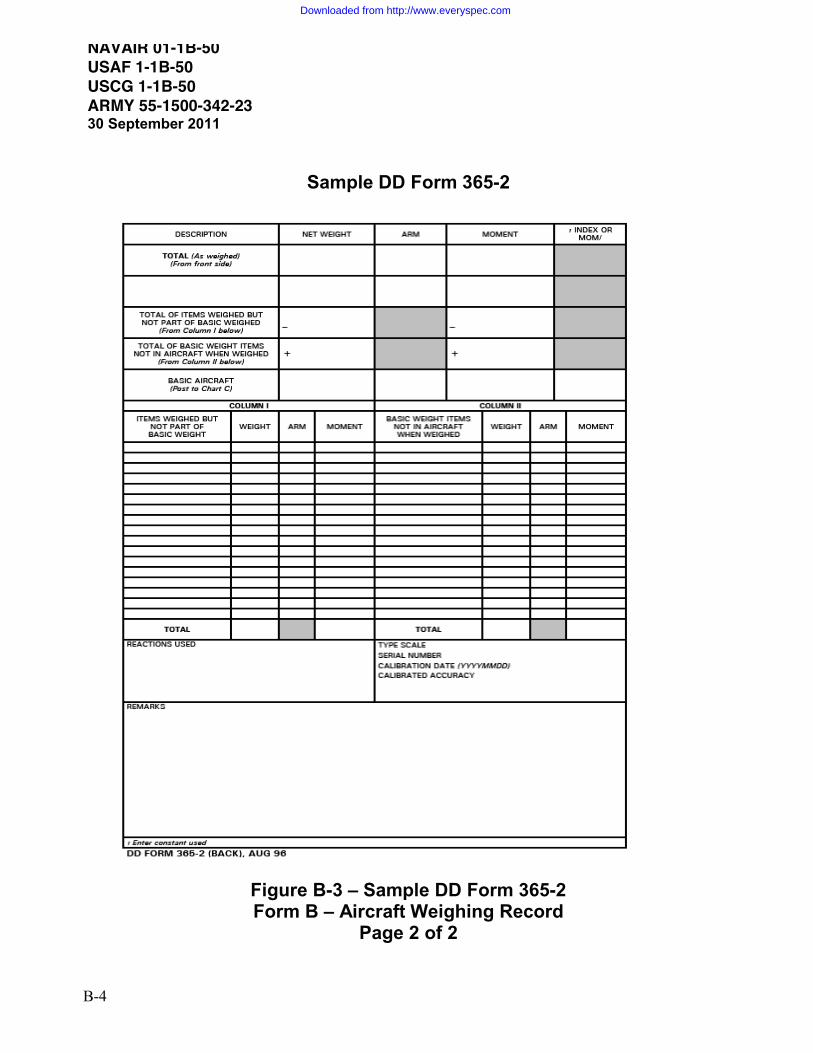
NAVAIR 01-1B-50 USAF 1-1B-50 USCG 1-1B-50 ARMY 55-1500-342-2330 September 2011
B-4
Sample DD Form 365-2
Figure B-3 – Sample DD Form 365-2 Form B – Aircraft Weighing Record
Page 2 of 2
Downloaded from http://www.everyspec.com

NAVAIR 01-1B-50 USAF 1-1B-50 USCG 1-1B-50
ARMY 55-1500-342-2330 September 2011
B-5
Sample DD Form 365-3
Figure B-4 – Sample DD Form 365-3 Chart C – Basic Weight and Balance Record
Downloaded from http://www.everyspec.com

NAVAIR 01-1B-50 USAF 1-1B-50 USCG 1-1B-50 ARMY 55-1500-342-2330 September 2011
B-6
Sample DD Form 365-4
Figure B-5 – Sample DD Form 365-4 Weight and Balance Flight Clearance Form F - Transport
Downloaded from http://www.everyspec.com

NAVAIR 01-1B-50 USAF 1-1B-50 USCG 1-1B-50
ARMY 55-1500-342-2330 September 2011
B-7/(B-8 Blank)
Sample DD Form 365-4
Figure B-6 – Sample DD Form 365-4
Weight and Balance Flight Clearance Form F - Tactical
Downloaded from http://www.everyspec.com

THIS PAGE LEFT INTENTIONALLY BLANK
Downloaded from http://www.everyspec.com
NAVAIR 01-1B-50 USAF 1-1B-50 USCG 1-1B-50
ARMY 55-1500-342-2330 September 2011
C-1/(C-2 Blank)
Appendix C – Acronyms AMMO. Ammunition
AWBS. Automated Weight and Balance System AFF. Automated Form F Generator COR. Contracting Officer’s Representative CG. Center of Gravity DCMA. Defense Contract Management Agency DD. Department of Defense FS. Fuselage Station JATO. Jet Assisted Take-Off NIST. National Institute of Standards and Technology RATO. Rocket Assisted Take-Off REF. Reference TM. Technical Manual T.O. Technical Order UAV. Unmanned Air Vehicle WAM. Weight X Arm = Moment %MAC. Percent Mean Aerodynamic Chord
Downloaded from http://www.everyspec.com

THIS PAGE LEFT INTENTIONALLY BLANK
Downloaded from http://www.everyspec.com

NAVAIR 01-1B-50 USAF 1-1B-50 USCG 1-1B-50
ARMY 55-1500-342-2330 September 2011
D-1/(D-2 Blank)
Appendix D – Scale Corrections Block Table
deg\ft 0 1000 2000 3000 4000 5000 6000 7000
0 1.0027 1.0028 1.0029 1.0030 1.0031 1.0032 1.0033 1.0034
5 1.0026 1.0027 1.0028 1.0029 1.0030 1.0031 1.0032 1.0033
10 1.0025 1.0026 1.0027 1.0028 1.0029 1.0030 1.0031 1.0032
15 1.0023 1.0024 1.0025 1.0026 1.0027 1.0028 1.0029 1.0030
20 1.0021 1.0022 1.0023 1.0024 1.0025 1.0025 1.0026 1.0027
25 1.0017 1.0018 1.0019 1.0020 1.0021 1.0022 1.0023 1.0024
30 1.0014 1.0015 1.0016 1.0017 1.0017 1.0018 1.0019 1.0020
35 1.0009 1.0010 1.0011 1.0012 1.0013 1.0014 1.0015 1.0016
40 1.0005 1.0006 1.0007 1.0008 1.0009 1.0010 1.0011 1.0012
45 1.0000 1.0001 1.0002 1.0003 1.0004 1.0005 1.0006 1.0007
50 0.9996 0.9997 0.9998 0.9999 1.0000 1.0001 1.0002 1.0003
55 0.9991 0.9992 0.9993 0.9994 0.9995 0.9996 0.9997 0.9998
60 0.9987 0.9988 0.9989 0.9990 0.9991 0.9992 0.9993 0.9994
65 0.9983 0.9984 0.9985 0.9986 0.9987 0.9988 0.9989 0.9990
70 0.9980 0.9981 0.9982 0.9983 0.9984 0.9985 0.9986 0.9987
75 0.9978 0.9979 0.9979 0.9980 0.9981 0.9982 0.9983 0.9984
80 0.9976 0.9977 0.9978 0.9979 0.9979 0.9980 0.9981 0.9982
85 0.9974 0.9975 0.9976 0.9977 0.9978 0.9979 0.9980 0.9981
90 0.9974 0.9975 0.9976 0.9977 0.9978 0.9979 0.9980 0.9981
Downloaded from http://www.everyspec.com

THIS PAGE LEFT INTENTIONALLY BLANK
Downloaded from http://www.everyspec.com

By Order of the Secretary of the Army:
RAYMOND T. ODIERNO
General, United States Army Chief of Staff
1203302
JOYCE E. MORROW Administrative Assistant to the
Secretary of the Army
Official:
Distribution: To be distributed in accordance with Initial Distribution Number (IDN) 311335requirements for TM 55-1500-342-23.
Downloaded from http://www.everyspec.com

Downloaded from http://www.everyspec.com

These are the instructions for sending an electronic 2028The following format must be used if submitting an electronic 2028. The subject line must be exactly the same and all fields must be included; however only the following fields are mandatory: 1, 3, 4, 5, 6, 7, 8, 9, 10, 13, 15, 16, 17, and 27. From: “Whomever” [email protected]: [email protected]: DA Form 20281 From: Joe Smith 2 Unit: home 3 Address: 4300 Park 4 City: Hometown 5 St: MO 6 Zip: 77777 7 Date Sent: 19--OCT--93 8 Pub no: 55--2840--229--239 Pub Title: TM 10 Publication Date: 04--JUL--8511 Change Number: 712 Submitter Rank: MSG13 Submitter FName: Joe14 Submitter MName: T15 Submitter LName: Smith 16 Submitter Phone: 123--123--123417 Problem: 1 18 Page: 2 19 Paragraph: 3 20 Line: 4 21 NSN: 5 22 Reference: 6 23 Figure: 7 24 Table: 8 25 Item: 9 26 Total: 123
27 Text:This is the text for the problem below line 27.
Downloaded from http://www.everyspec.com

Downloaded from http://www.everyspec.com

EXAMPLE
RECOMMENDED CHANGES TO PUBLICATIONS AND BLANK FORMS
For use of this form, see AR 25--30; the proponent agency is ODISC4.
Use Part II (reverse) for Repair Parts and Special Tool Lists (RPSTL) and Supply Catalogs/ Supply Manuals (SC/SM)
DATE
8/30/02
TO: (Forward to proponent of publication or form)(Include ZIP Code)Commander, U.S. Army Aviation and Missile Command ATTN: AMSAM--MMC--MA--NP Redstone Arsenal, AL 35898
FROM: (Activity and location)(Include ZIP Code) MSG, Jane Q. Doe 1234 Any Street Nowhere Town, AL 34565
PART 1 - ALL PUBLICATIONS (EXCEPT RPSTL AND SC/SM) AND BLANK FORMS
PUBLICATION/FORM NUMBER TM 9-1005-433-24
DATE16 Sep 2002
TITLE Organizational, Direct Support, And General Support Maintenance Manual for Machine Gun, .50 Caliber M3P and M3P Machine Gun Electrical Test Set Used On Avenger Air Defense Weapon System
ITEMNO.
PAGE NO.
PARA-GRAPH
LINENO. *
FIGURE NO.
TABLENO. RECOMMENDED CHANGES AND REASON
1 WP0005PG 3 2 Test or Corrective Action column should identify a different WP number.
* Reference to line numbers within the paragraph or subparagraph.TYPED NAME, GRADE OR TITLE
MSG, Jane Q. Doe, SFC
TELEPHONE EXCHANGE/ AUTOVON, PLUS EXTENSION
788-1234
SIGNATURE
DA FORM 2028, FEB 74 REPLACES DA FORM 2028, 1 DEC 68, WHICH WILL BE USED. USAPA V3.01
Downloaded from http://www.everyspec.com

EXAMPLE
TO: (Forward direct to addressee listed in publication)Commander, U.S. Army Aviation and Missile Command ATTN: AMSAM-MMC-MA-NP
Redstone Arsenal, AL 35898
FROM: (Activity and location) (Include ZIP Code)
MSG, Jane Q. Doe
1234 Any Street
Nowhere Town, AL 34565
DATE
8/30/02
PART II - REPAIR PARTS AND SPECIAL TOOL LISTS AND SUPPLY CATALOGS/SUPPLY MANUALS
PUBLICATION NUMBER DATE TITLE
PAGE NO.
COLMNO.
LINENO.
NATIONAL STOCK NUMBER
REFERENCENO.
FIGURE NO.
ITEMNO.
TOTAL NO. OF MAJOR
ITEMSSUPPORTED
RECOMMENDED ACTION
PART III - REMARKS (Any general remarks or recommendations, or suggestions for improvement of publications andblank forms. Additional blank sheets may be used if more space is needed.)
TYPED NAME, GRADE OR TITLE
MSG, Jane Q. Doe, SFCTELEPHONE EXCHANGE/AUTOVON, PLUS EXTENSION
788-1234SIGNATURE
USAPA V3.01
Downloaded from http://www.everyspec.com

RECOMMENDED CHANGES TO PUBLICATIONS AND BLANK FORMS
For use of this form, see AR 25--30; the proponent agency is ODISC4.
Use PartII(reverse) for Repair Parts and Special Tool Lists (RPSTL) and Supply Catalogs/ Supply Manuals (SC/SM)
DATE
TO: (Forward to proponent of publication or form)(Include ZIP Code)Commander, U.S. Army Aviation and Missile Command ATTN: AMSAM-MMC-MA-NP Redstone Arsenal, AL 35898
FROM: (Activity and location)(Include ZIP Code)
PART 1 --ALL PUBLICATIONS (EXCEPT RPSTL AND SC/SM) AND BLANK FORMS
PUBLICATION/FORM NUMBER DATE TITLE
ITEMNO.
PAGE NO.
PARA-GRAPH
LINENO. *
FIGURE NO.
TABLENO. RECOMMENDED CHANGES AND REASON
* Reference to line numbers within the paragraph or subparagraph. TYPED NAME, GRADE OR TITLE TELEPHONE EXCHANGE/
AUTOVON, PLUS EXTENSION
SIGNATURE
DA FORM 2028, FEB 74 REPLACES DA FORM 2028, 1 DEC 68, WHICH WILL BE USED. USAPA V3.01
Downloaded from http://www.everyspec.com

TO: (Forward direct to addressee listed in publication)Commander, U.S. Army Aviation and Missile Command ATTN: AMSAM-MMC-MA-NP Redstone Arsenal, AL 35898
FROM: (Activity and location) (Include ZIP Code) DATE
PART II --REPAIR PARTS AND SPECIAL TOOL LISTS AND SUPPLY CATALOGS/SUPPLY MANUALS
PUBLICATION NUMBER DATE TITLE
PAGE NO.
COLMNO.
LINENO.
NATIONAL STOCK NUMBER
REFERENCENO.
FIGURE NO.
ITEMNO.
TOTAL NO. OF MAJOR
ITEMSSUPPORTED
RECOMMENDED ACTION
PART III --REMARKS (Any general remarks or recommendations, or suggestions for improvement of publications and blank forms. Additional blank sheets may be used if more space is needed.)
TYPED NAME, GRADE OR TITLE TELEPHONE EXCHANGE/AUTOVON, PLUS EXTENSION
SIGNATURE
USAPA V3.01
Downloaded from http://www.everyspec.com

The Metric System and Equivalents
Linear Measure Liquid Measure
1 centimeter = 10 millimeters = .39 inch 1 centiliter = 10 milliters = .34 fl. ounce1 decimeter = 10 centimeters = 3.94 inches 1 deciliter = 10 centiliters = 3.38 fl. Ounces 1 meter = 10 decimeters = 39.37 inches 1 liter = 10 deciliters = 33.81 fl. ounces1 dekameter = 10 meters = 32.8 feet 1 dekaliter = 10 liters = 2.64 gallons1 hectometer = 10 dekameters = 328.08 feet 1 hectoliter = 10 dekaliters = 26.42 gallons1 kilometer = 10 hectometers = 3,280.8 feet 1 kiloliter = 10 hectoliters = 264.18 gallons
Weights Square Measure
1 centigram = 10 milligrams = .15 grain 1 sq. centimeter = 100 sq. millimeters = .155 sq. inch 1 decigram = 10 centigrams = 1.54 grains 1 sq. decimeter = 100 sq. centimeters = 15.5 sq. inches1 gram = 10 decigram = .035 ounce 1 sq. meter (centare) = 100 sq. decimeters = 10.76 sq. feet 1 decagram = 10 grams = .35 ounce 1 sq. dekameter (are) = 100 sq. meters = 1,076.4 sq. feet 1 hectogram = 10 decagrams = 3.52 ounces 1 sq. hectometer (hectare) = 100 sq. dekameters = 2.47 acres 1 kilogram = 10 hectograms = 2.2 pounds 1 sq. kilometer = 100 sq. hectometers = .386 sq. mile 1 quintal = 100 kilograms = 220.46 pounds 1 metric ton = 10 quintals = 1.1 short tons
Cubic Measure 1 cu. centimeter = 1000 cu. millimeters = .06 cu. Inch 1 cu. decimeter = 1000 cu. centimeters = 61.02 cu. Inches 1 cu. meter = 1000 cu. decimeters = 35.31 cu. feet
Approximate Conversion Factors
To change To Multiply by To change To Multiply by
inches centimeters 2.540 ounce-inches Newton-meters .007062 feet meters .305 centimeters inches .394 yards meters .914 meters feet 3.280 miles kilometers 1.609 meters yards 1.094 square inches square centimeters 6.451 kilometers miles .621 square feet square meters .093 square centimeters square inches .155 square yards square meters .836 square meters square feet 10.764 square miles square kilometers 2.590 square meters square yards 1.196 acres square hectometers .405 square kilometers square miles .386 cubic feet cubic meters .028 square hectometers acres 2.471cubic yards cubic meters .765 cubic meters cubic feet 35.315 fluid ounces milliliters 29,573 cubic meters cubic yards 1.308 pints liters .473 milliliters fluid ounces .034 quarts liters .946 liters pints 2.113 gallons liters 3.785 liters quarts 1.057 ounces grams 28.349 liters gallons .264 pounds kilograms .454 grams ounces .035short tons metric tons .907 kilograms pounds 2.205 pound-feet Newton-meters 1.356 metric tons short tons 1.102 pound-inches Newton-meters .11296
Temperature (Exact)
°F Fahrenheit 5/9 (after Celsius °C temperature subtracting 32) temperature
Downloaded from http://www.everyspec.com

PIN: 060247-000
Downloaded from http://www.everyspec.com
Related Documents