1 A Project by Darshak Bhuptani Enrolment no: 093574710 Roll no: Aep-2009-S12

Welcome message from author
This document is posted to help you gain knowledge. Please leave a comment to let me know what you think about it! Share it to your friends and learn new things together.
Transcript
1
A Project byDarshak Bhuptani
Enrolment no: 093574710Roll no: Aep-2009-S12
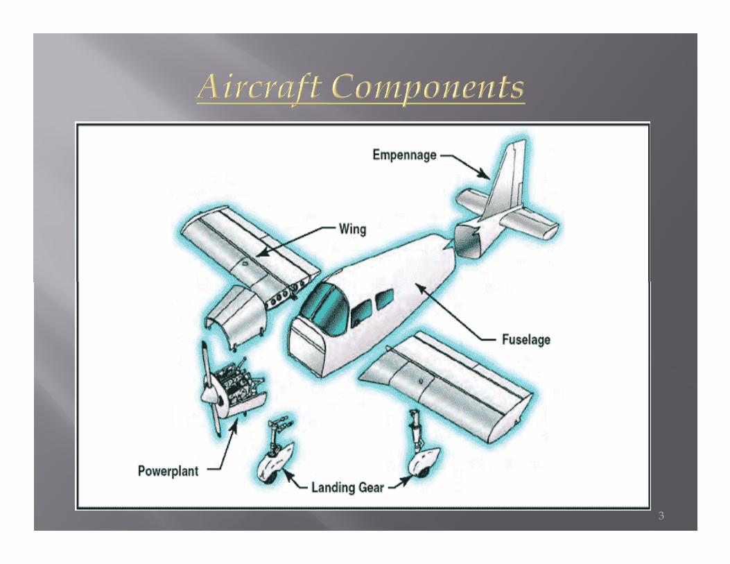
Major components :Although airplanes are designed for a
variety of purposes, most of them have the same major components.same major components.
The overall characteristics are largely determined by the original design objectives. Most airplane structures include a fuselage, wings, an empennage, landing gear, and a power plant.
2
3
The fuselage includes the cabin and/or cockpit, which contains seats for the occupants and the controls for the airplane. In addition, the fuselage may also provide room for cargo and attachment points for the other major airplane components.
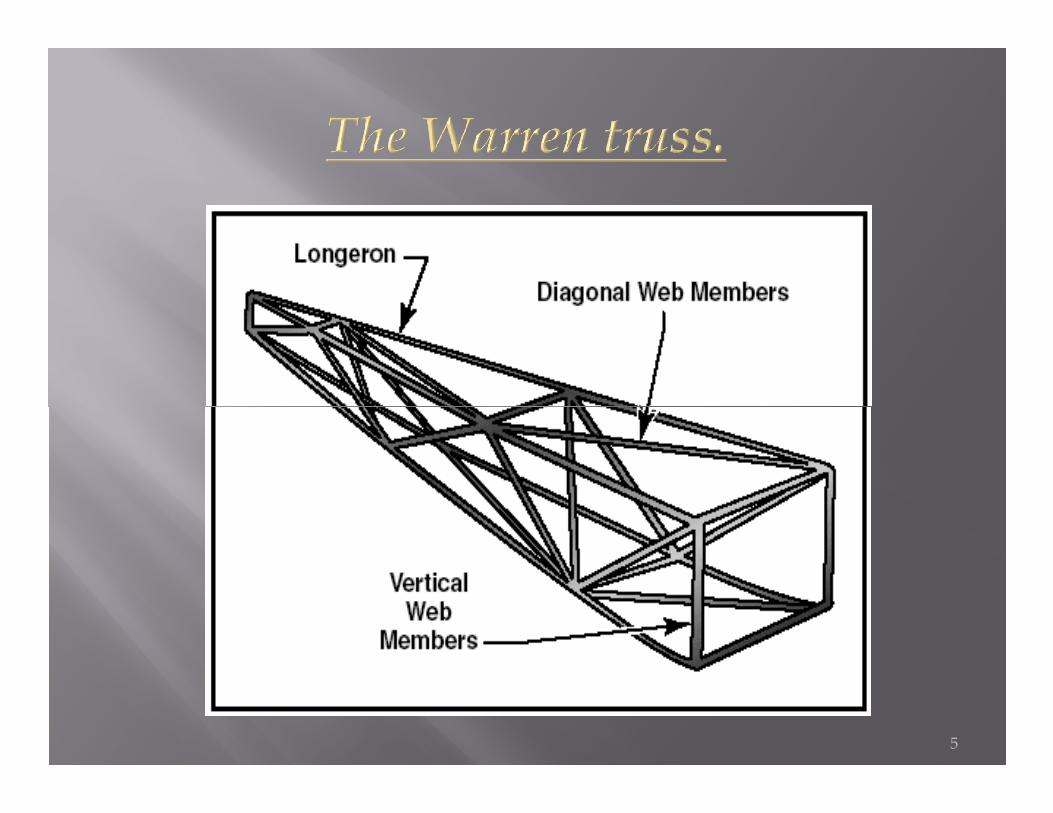
Some aircraft utilize an open truss structure. The truss-type fuselage is constructed of steel or aluminium tubing. Strength and rigidity is achieved by welding the tubing together into a series of triangular shapes, called trusses.
4
5
� Construction of the Warren truss features longerons, as well as diagonal and vertical web members. To reduce weight, small airplanes generally utilize aluminium alloy tubing, which may be riveted or bolted into one piece with cross-bracing members.
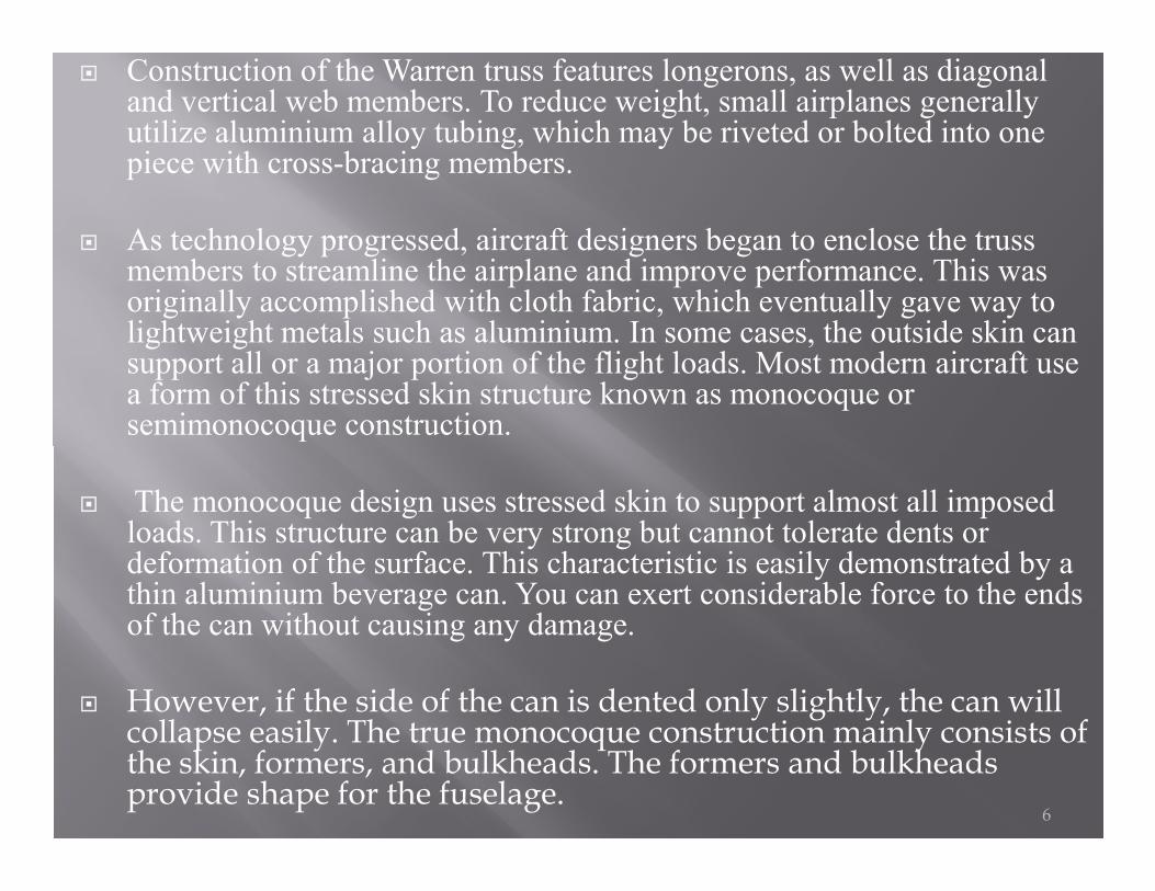
� As technology progressed, aircraft designers began to enclose the truss members to streamline the airplane and improve performance. This was originally accomplished with cloth fabric, which eventually gave way to lightweight metals such as aluminium. In some cases, the outside skin can support all or a major portion of the flight loads. Most modern aircraft use a form of this stressed skin structure known as monocoque or semimonocoque construction.
6
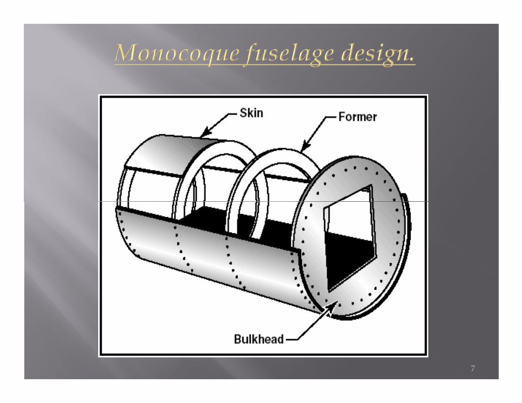
� The monocoque design uses stressed skin to support almost all imposed loads. This structure can be very strong but cannot tolerate dents or deformation of the surface. This characteristic is easily demonstrated by a thin aluminium beverage can. You can exert considerable force to the ends of the can without causing any damage.
� However, if the side of the can is dented only slightly, the can will collapse easily. The true monocoque construction mainly consists of the skin, formers, and bulkheads. The formers and bulkheads provide shape for the fuselage.
7
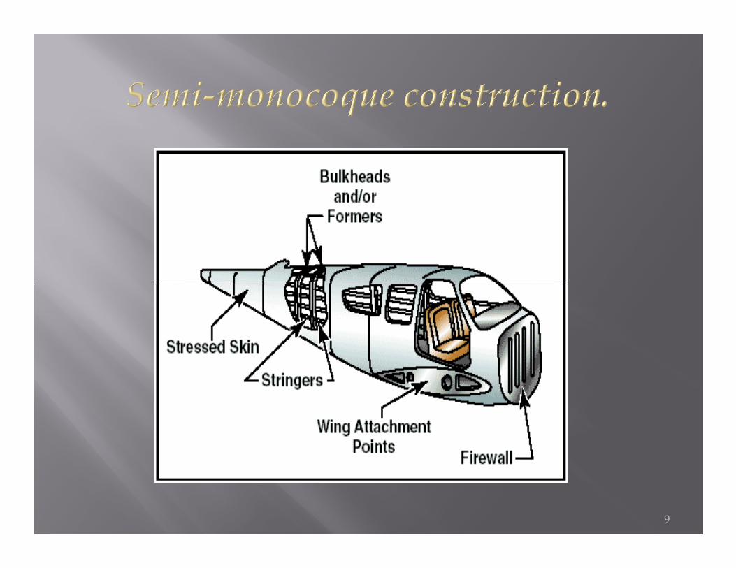
� Since no bracing members are present, the skin must be strong enough to keep the fuselage rigid. Thus, a significant problem involved in monocoque construction is maintaining enough strength while keeping the weight within allowable limits. Due to the limitations of the monocoque design, a semi-monocoque structure is used on many of today´s aircraft. aircraft.
� The semi-monocoque system uses a substructure to which the airplane´s skin is attached. The substructure, which consists of bulkheads and/or formers of various sizes and stringers, reinforces the stressed skin by taking some of the bending stress from the fuselage.
8
9
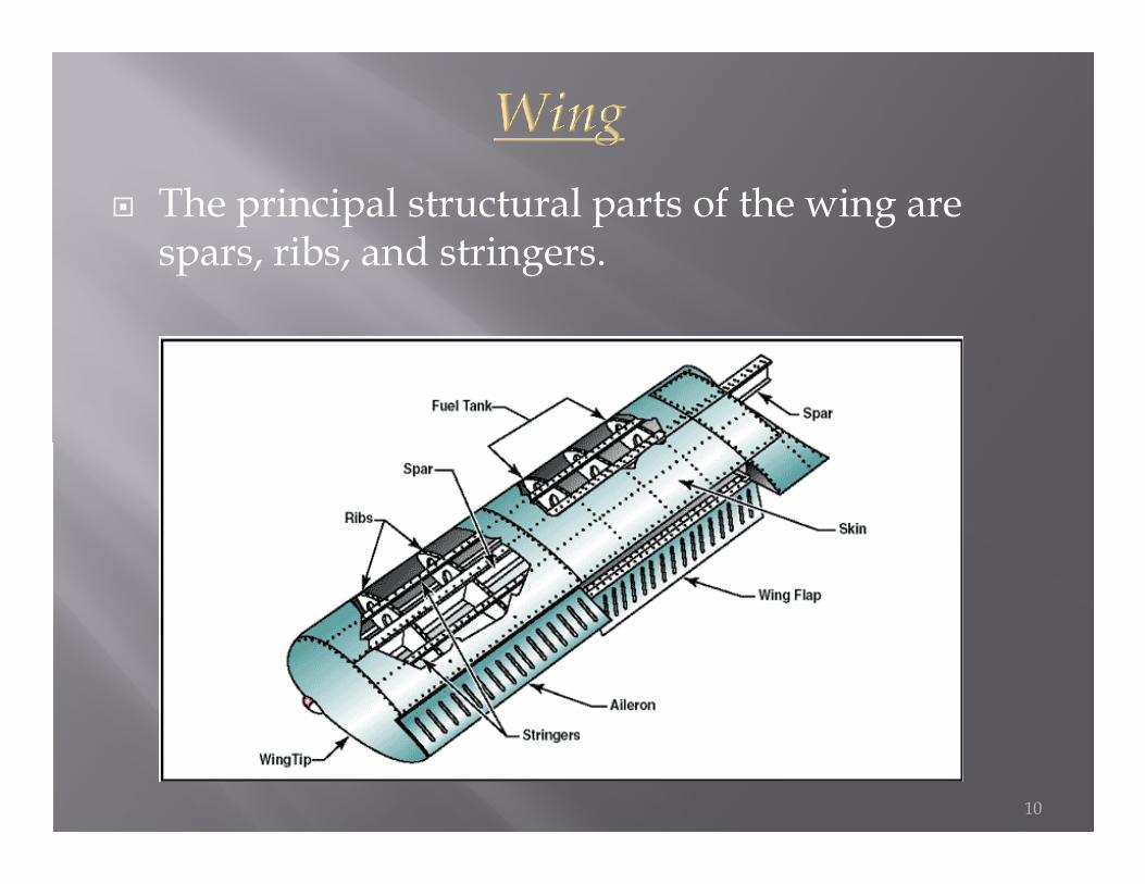
� The principal structural parts of the wing are spars, ribs, and stringers.
10
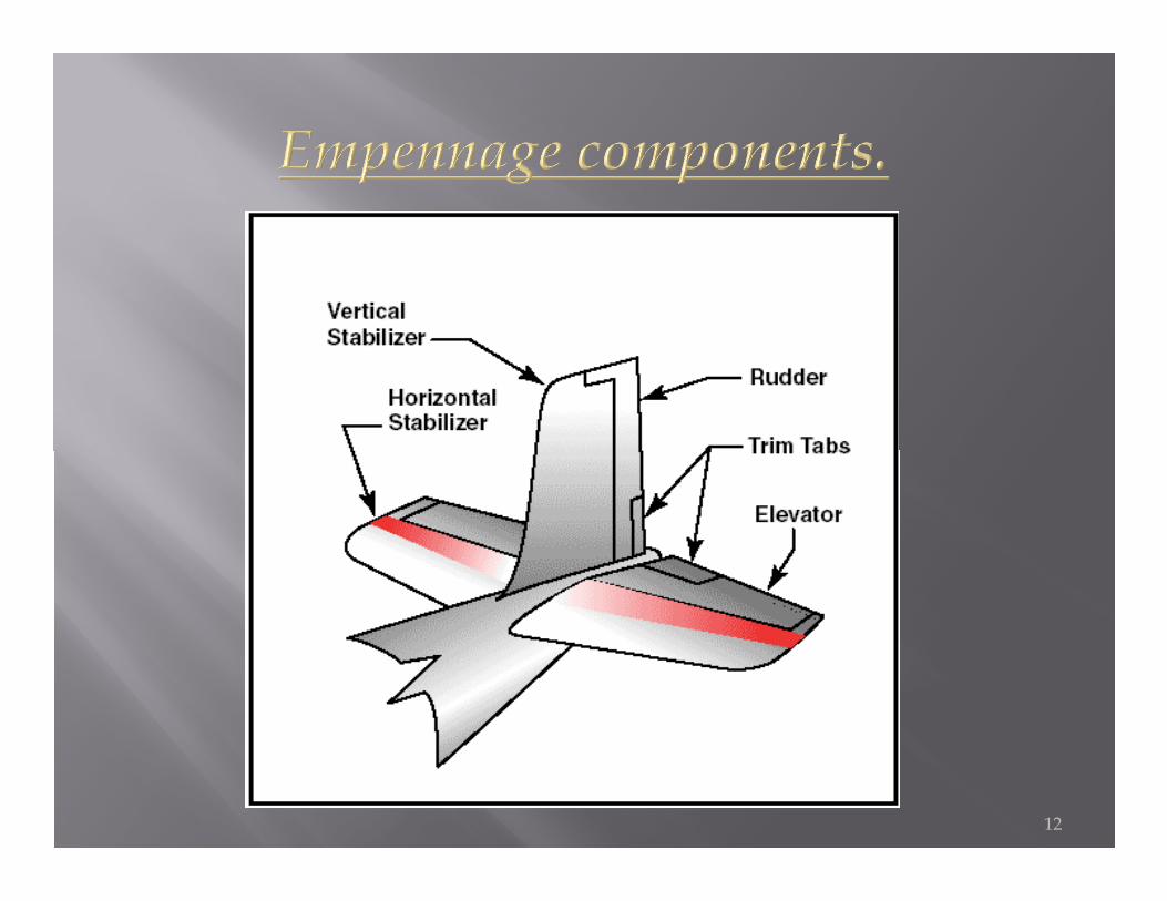
� The correct name for the tail section of an airplane is empennage. The empennage includes the entire tail group, consisting of fixed surfaces such as the vertical stabilizer and the horizontal stabilizer. The movable surfaces the horizontal stabilizer. The movable surfaces include the rudder, the elevator, and one or more trim tabs.
11
12

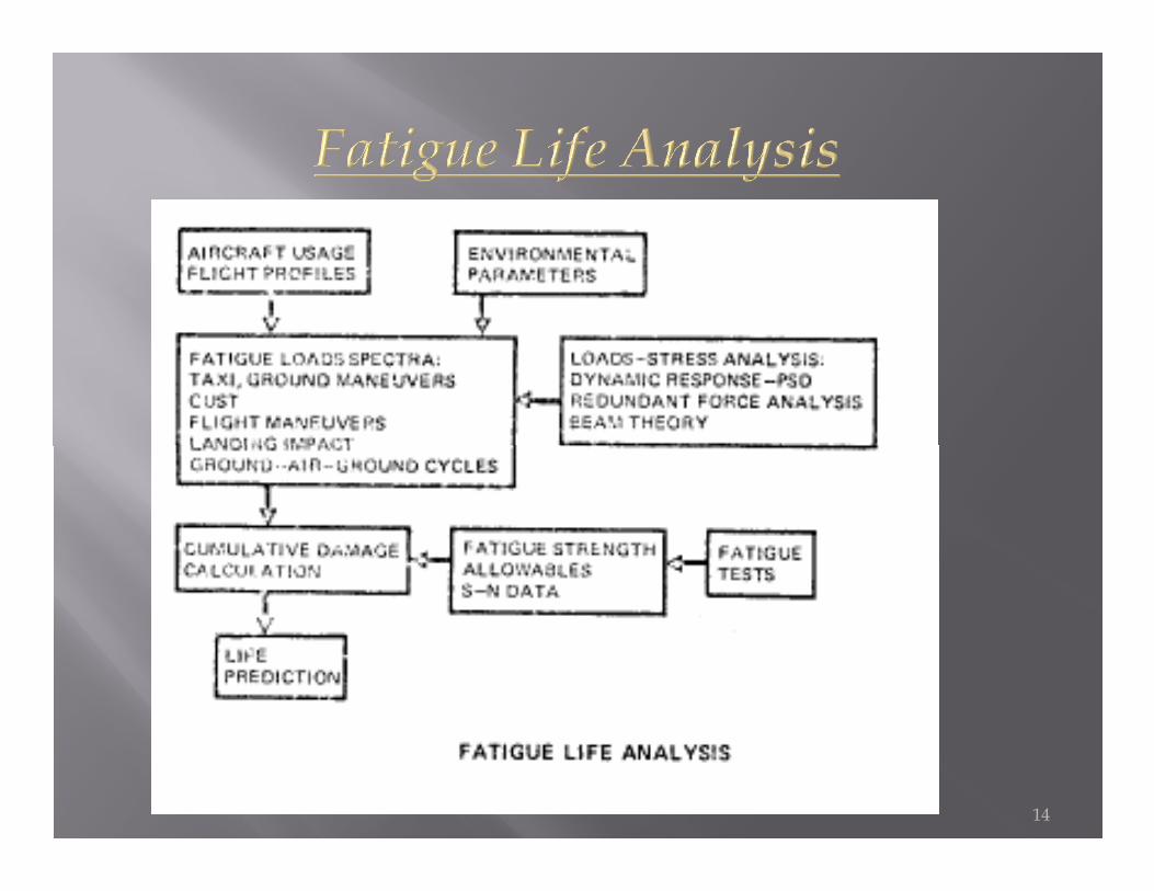
� Analyses introduce cyclic loads from ground-air-ground cycle and from power spectral density descriptions of continuous turbulence. Component fatigue test results are fed into the program and the cumulative fatigue damage is program and the cumulative fatigue damage is calculated. Stress levels are adjusted to achieve required structural fatigue design life.
13
14
� Fatigue failure life of a structural member is usually defined as the time to initiate a crack which would tend to reduce the ultimate strength of the member.
� Fatigue design life implies the average life to be expected under average aircraft utilization and loads environment.
� Scatter factors of 2 to 4 have been used to account for statistical � Scatter factors of 2 to 4 have been used to account for statistical variation in component fatigue tests and unknowns in loads. Load unknowns involve both methods of calculation and type of service actually experienced.
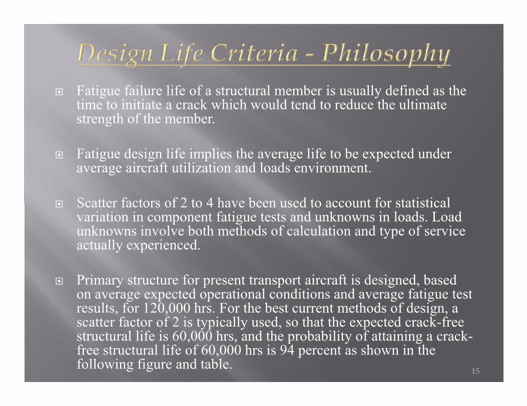
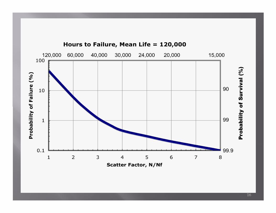
� Primary structure for present transport aircraft is designed, based on average expected operational conditions and average fatigue test results, for 120,000 hrs. For the best current methods of design, a scatter factor of 2 is typically used, so that the expected crack-free structural life is 60,000 hrs, and the probability of attaining a crack-free structural life of 60,000 hrs is 94 percent as shown in the following figure and table.
15
16
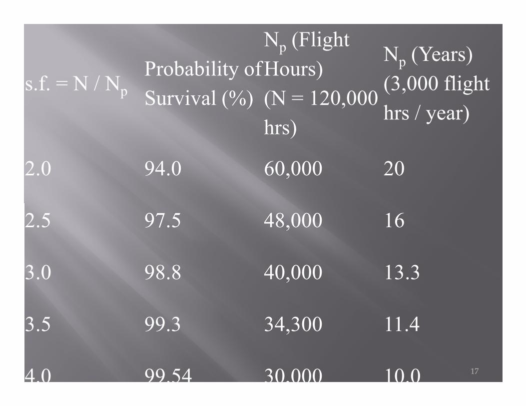
s.f. = N / NpProbability ofSurvival (%)
Np (Flight Hours)(N = 120,000 hrs)
Np (Years)(3,000 flight hrs / year)
2.0 94.0 60,000 20
2.5 97.5 48,000 16
3.0 98.8 40,000 13.3
3.5 99.3 34,300 11.4
4.0 99.54 30,000 10.0 17
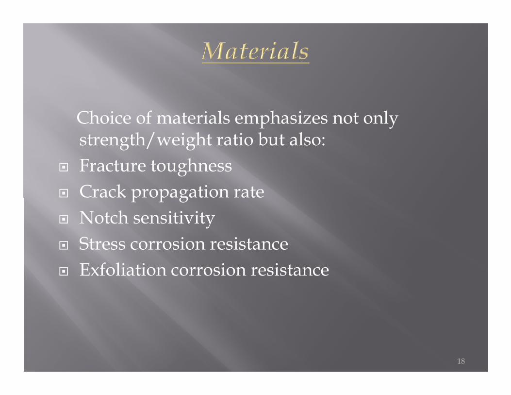
Choice of materials emphasizes not only strength/weight ratio but also:
� Fracture toughness � Crack propagation rate � Crack propagation rate � Notch sensitivity � Stress corrosion resistance � Exfoliation corrosion resistance
18
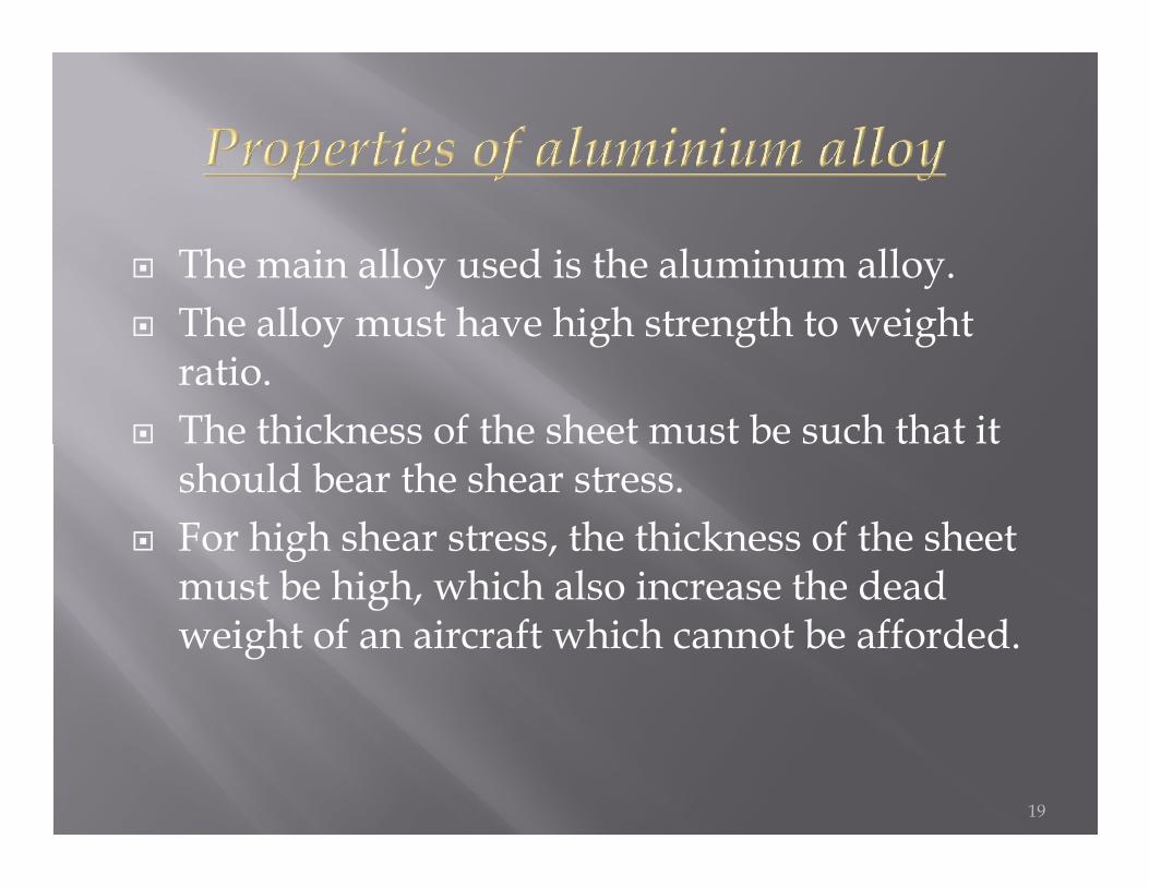
� The main alloy used is the aluminum alloy.� The alloy must have high strength to weight
ratio.� The thickness of the sheet must be such that it � The thickness of the sheet must be such that it
should bear the shear stress.� For high shear stress, the thickness of the sheet
must be high, which also increase the dead weight of an aircraft which cannot be afforded.
19
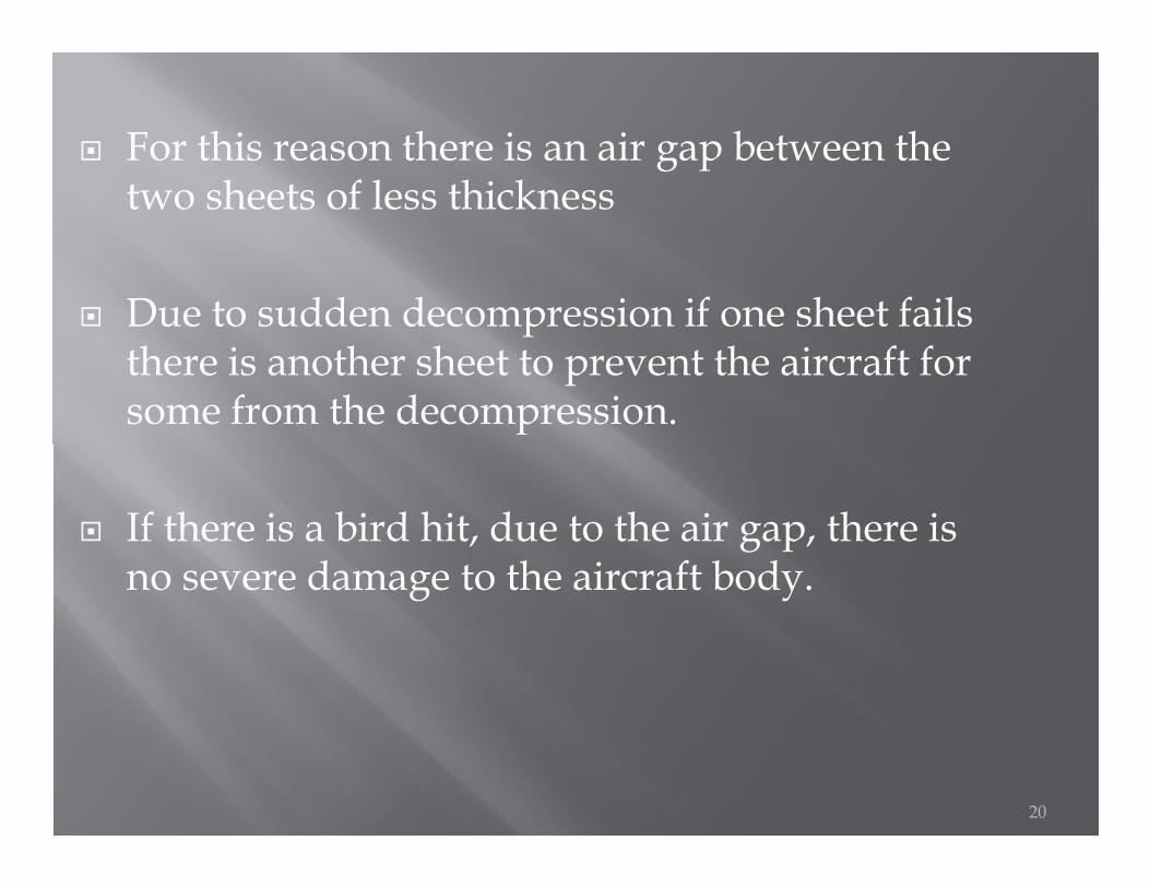
� For this reason there is an air gap between the two sheets of less thickness
� Due to sudden decompression if one sheet fails there is another sheet to prevent the aircraft for some from the decompression.
20
� If there is a bird hit, due to the air gap, there is no severe damage to the aircraft body.
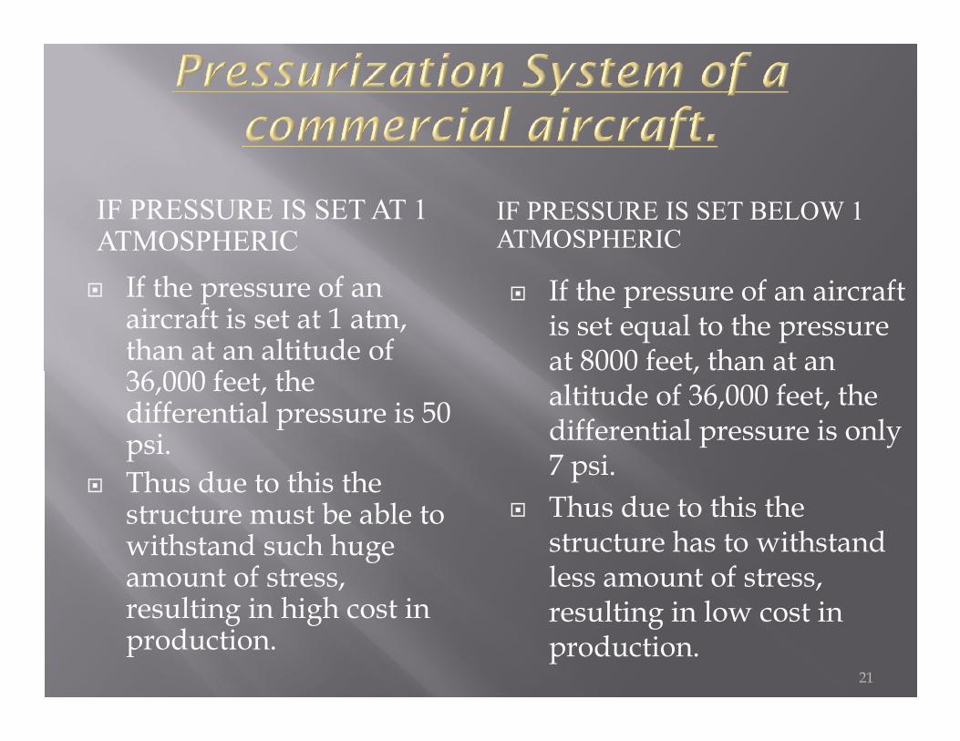
IF PRESSURE IS SET AT 1 ATMOSPHERIC
IF PRESSURE IS SET BELOW 1 ATMOSPHERIC
� If the pressure of an aircraft is set at 1 atm, than at an altitude of 36,000 feet, the
� If the pressure of an aircraft is set equal to the pressure at 8000 feet, than at an
36,000 feet, the differential pressure is 50 psi.
� Thus due to this the structure must be able to withstand such huge amount of stress, resulting in high cost in production.
at 8000 feet, than at an altitude of 36,000 feet, the differential pressure is only 7 psi.
� Thus due to this the structure has to withstand less amount of stress, resulting in low cost in production.
21
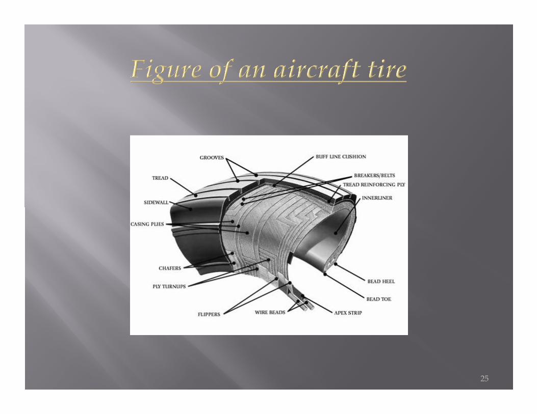
� Aircraft tires, tubeless or tube type, provide a cushion of air that helps absorb the shocks and roughness of landings and takeoffs: they support the weight of the aircraft while on the ground and provide the necessary traction for braking and stopping aircraft on landing. Thus, aircraft and provide the necessary traction for braking and stopping aircraft on landing. Thus, aircraft tires must be carefully maintained to meet the rigorous demands of their basic job to accept a variety of static and dynamic stresses dependably--in a wide range of operating conditions.
22
� Dissect an aircraft tire and you'll find that it's one of the strongest and toughest pneumatic tires made. It must withstand high speeds and very heavy static and dynamic loads. For example, the main gear tires of a four-engine jet example, the main gear tires of a four-engine jet transport are required to withstand landing speeds up to 250 mph, as well as static and dynamic loads as high as 22 and 33 tons respectively.
23
� It is made of rubber compound for toughness and durability, the tread is patterned in accordance with aircraft operational requirements. The circumferential ribbed pattern is widely used today because it pattern is widely used today because it provides good traction under widely varying runway conditions.
24
25
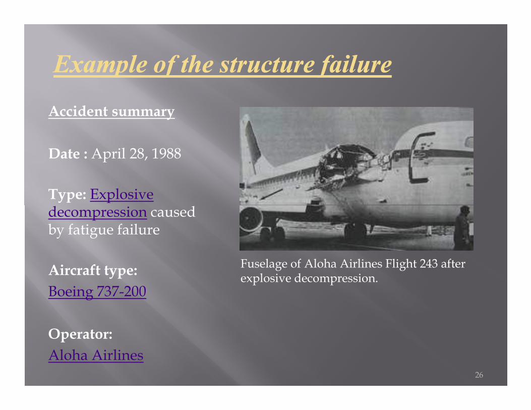
Example of the structure failureExample of the structure failure
Accident summary
Date : April 28, 1988
Type: Explosive decompression caused decompression caused by fatigue failure
Aircraft type:Boeing 737-200
Operator:Aloha Airlines
26
Fuselage of Aloha Airlines Flight 243 after explosive decompression.
� A small section on the left side of the roof ruptured.
� The resulting explosive decompression tore off a large section of the roof, consisting of the entire top half of the aircraft skin extending from just behind the cockpit to the fore-wing area.behind the cockpit to the fore-wing area.
� Investigation by the United States National Transportation Safety Board (NTSB) concluded that the accident was caused by metal fatigueexacerbated by crevice corrosion (the plane operated in a coastal environment, with exposure to salt and humidity)
27
� The root cause of the problem was failure of an epoxyadhesive used to bond the aluminium sheets of the fuselage together when the B737 was manufactured.
� Water was able to enter the gap where the epoxy failed to bond the two surfaces together properly, and started the corrosion process. The age of the aircraft became a key issue (it corrosion process. The age of the aircraft became a key issue (it was 19 years old at the time of the accident and had sustained a remarkable number of takeoff-landing cycles — 89,090, the second most cycles for a plane in the world at the time — well beyond the 75,000 trips it was designed to sustain).
� The crack was located aft of the front port side passenger door. The crack was probably due to metal fatigue related to the 89,090 compression and decompression cycles experienced in the short hop flights by Aloha. 28
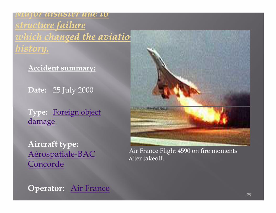
Major disaster due to Major disaster due to structure failurestructure failurewhich changed the aviation which changed the aviation history. history.
Accident summary:
Date: 25 July 2000
Type: Foreign object damage
Aircraft type: Aérospatiale-BAC Concorde
Operator: Air France29
Air France Flight 4590 on fire moments after takeoff.
� Five minutes before the takeoff of Flight 4590, a Continental Airlines McDonnell Douglas DC-10 destined to Newark (US), lost a titanium alloy strip, 435 millimetres (17.1 in) long and about 29 millimetres (1.1 in) to 34 millimetres (1.3 in) wide, during takeoff from the same runway of Charles de Gaulle Airport.
� During the Concorde's subsequent take-off run, this piece of debris, still lying on the runway, cut a tyre causing rupture and tyre debris to be hurled by centrifugal force.and tyre debris to be hurled by centrifugal force.
� A large chunk of this debris (4.5 kilograms or 9.9 lb) struck the underside of the aircraft's wing structure at an estimated speed of 500 kilometres per hour
� It sent out a pressure shockwave that eventually ruptured the number five fuel tank at the weakest point, just above the landing gear. Leaking fuel rushing over the top of the wing was ignited by an electric arc in the landing gear bay or through contact with severed electrical cables.
30
� the crash was caused by a titanium strip, part of a thrust reverser, that fell from a Continental Airlines DC-10(Continental Flight 55)
� This metal fragment punctured the Concorde's tyres, which then disintegrated. A piece of rubber hit the fuel tank and broke an electrical cable. The impact caused a shock-wave that fractured the fuel tank some distance from the point of impact.fractured the fuel tank some distance from the point of impact.
� This caused a major fuel leak from the tank, which then ignited. The crew shut down engine number two in response to a fire warning but were unable to retract the landing gear, which hampered the aircraft's ability to climb.
� With engine number one surging and producing little power, the aircraft was unable to gain altitude or airspeed, entering a rapid pitch-up then a violent descent, rolling left.
� The impact occurred with the stricken aircraft tail-low, crashing into the Hotelissimo Hotel in Gonesse. 31

Any
32
Any Question ???
Related Documents


