Aircraft Maintenance Handbook for Financiers By : Shannon Ackert 1 st Edition, 2018 Copyright © 2018 Aircraft Monitor. All rights reserved. www.aircraftmonitor.com

Welcome message from author
This document is posted to help you gain knowledge. Please leave a comment to let me know what you think about it! Share it to your friends and learn new things together.
Transcript

Aircraft Maintenance Handbook for FinanciersBy : Shannon Ackert
1st Edition, 2018 Copyright © 2018 Aircraft Monitor. All rights reserved. www.aircraftmonitor.com

Forward …………………………………………………………………………………………………….…………………
Sections
1. Maintenance Principles …………………………………………………………………….…….……………
2. Turbofan Design Concepts ………………………………………………………………….………………..
3. Turbofan Maintenance Concepts ……………………………………..………………….……………...
4. Maintenance Reserves ……………………………………………………………………….…………….….
5. Factors Influencing Maintenance Reserves ……………………………………….…….……………
6. Flight‐Hour Agreements (FHAs) ……………………………………………………….….……………….
7. Parts Manufacturer Approval (PMA) .…………………………………………….……………………..
8. Designated Engineering Representative (DER) Repairs ……………….………………………..
Appendix A ‐ Typical Aircraft Maintenance Reserves …….….…………………….……..……….…..
References ...............…………………………………………………………….……………..……………………..
2
3
4
33
45
77
102
125
131
139
143
150
Table of Contents

Aircraft Maintenance Handbook for Financiers provides an introductory level description of theprinciples, general practices and economic characteristics associated with aircraft maintenance. Thehandbook is aimed largely for financiers and students – and, indeed, anyone interested in theunderlying concepts of aircraft maintenance.
The handbook begins with an introduction into aircraft maintenance principles; highlighting thebuilding blocks of today’s maintenance program and analyzing those concepts that influencemaintenance status and valuation. Information is assembled detailing the fundamentals of turbofandesign and maintenance concepts; a prerequisite knowledge for all involved in aircraft financing.
An in depth analysis of aircraft maintenance reserves is covered, including identifying those factorsthat influence maintenance costs and time on‐wing performance. For each maintenance event,practical exercises in calculating maintenance reserves is also included.
Principles of Flight‐Hour Agreements (FHAs), Part Manufacturer Approval (PMA), and DesignatedEngineering Representative (DER) repairs are introduced to guide the readers on how these issuesimpact commercial considerations.
Feedback regarding any viewpoints or discrepancies is highly encouraged. To provide feedback,please e‐mail the author at: [email protected]
3
Forward

Section 1
Maintenance PrinciplesI. Maintenance ProcessesII. Maintenance ProgramsIII. Maintenance CategoriesIV. Maintenance ChecksV. Maintenance PackagingVI. Maintenance Cost ElementsVII.Maintenance Utility & Status
4

The industry definition of maintenance generally includes those tasks required to restore ormaintain an aircraft’s systems, components, and structures to an airworthy condition.Maintenance is required for three principal reasons:
A. Operational: To keep the aircraft in a serviceable and reliable condition so as to generaterevenue.
B. Value Retention: To maintain the current and future value of the aircraft by minimizing thephysical deterioration of the aircraft throughout its life.
C. Regulatory Requirements: The condition and the maintenance of commercial aircraft areregulated by the aviation authorities of the jurisdiction in which the aircraft is registered.Such requirements establish standards for repair, periodic overhauls, and alteration byrequiring that the owner or operator establish an airworthiness maintenance and inspectionprogram to be carried out by certified individuals qualified to issue an airworthinesscertificate.
5
1.0 Maintenance Principles
I. Maintenance Processes
Aircraft maintenance tasks & events can be categorized by one of the following processes:
A. Hard‐time: A primary maintenance process under which an item must be removed fromservice at or before a scheduled specified time. Airframe checks and Landing gearoverhaul events are example of events that are expressed as hard‐time events.
B. On‐Condition (OC): A maintenance process restricted to components in whichdetermination of continued airworthiness can be made by visual checks, measurements,tests, or other means without a tear‐down inspection or overhaul. These “health checks”are to be performed within the time limitations prescribed by an operator’s approvedmaintenance program.
Each component’s performance tolerances and deterioration limits are generally outlinedin the aircraft’s Maintenance Manuals. Additional criteria used in determining eligibility fora component’s on‐condition status consist of the ability to inspect a unit for corrosion &structural integrity without disassembly.
6
1.0 Maintenance Principles

II. Maintenance Program
Before certification of a new aircraft, the aircraft manufacturer ‐ the Type Certificate (TC)holder ‐ must prepare and submit for approval to the relevant airworthiness authorities theinitial minimum scheduled maintenance requirements. These minimum scheduledrequirements are outlined in theMaintenance Review Board Report (MRBR) – Figure 1.
Following local regulatory authority approval, the MRBR is used as a framework around whicheach air carrier develops its own individual maintenance program. Although maintenanceprograms may vary widely, the initial requirements for an aircraft will be the same for all.
The tasks detailed in the MRBR cannot be deleted nor can the task content be changedwithout approval of the MRB Chairman or appropriate national regulatory authority. However,individual task intervals may be escalated based on satisfactory substantiation by the operator,and review and approval by the local regulatory authority.
7
The tasks detailed in the MRBR:
• Developed by an Industry Steering Committee• Distributed by Aircraft Manufacturer• Constitute Minimum Initial Requirements• Cannot be deleted nor changed
Figure 1. Maintenance Review Board Report (MRBR)
1.0 Maintenance Principles

II. Maintenance Program
The MRB Report outlines the initial minimum scheduled maintenance/inspection requirementsto be used in the development of an approved continuous airworthiness maintenanceprogram.
As illustrated in Figure 2, The Maintenance Planning Document (MPD)¹ contains all the MRBrequirements plus mandatory scheduled maintenance requirements that may only be changedwith the permission of the applicable airworthiness authority. These supplemental inspectiontasks are detailed in the aircraft’s Certification Maintenance Requirement (CMR) andAirworthiness Limitation (AWL) documents.
8
The MPD document providesmaintenance planning informationnecessary for operators to develop acustomized maintenance program.The document lists all recommendedscheduled maintenance tasks forevery aircraft configuration.
1 ‐ The MPD maintenance tasks, and the rectification of any deficiencies resulting from performance of such tasks, formsthe basis for the qualifying scope of work that is used to quantify airframe maintenance reserves.
Figure 2. Maintenance Planning Document (MPD)
1.0 Maintenance Principles

II. Maintenance Program
► A Certification Maintenance Requirement (CMR) is a required periodic task, establishedduring the design certification of the airplane as an operating limitation of the typecertificate. CMRs usually result from a formal, numerical analysis conducted to showcompliance with catastrophic and hazardous failure conditions.
A CMR is intended to detect safety significant latent failures that would, in combinationwith one or more other specific failures or events, result in a hazardous or catastrophicfailure condition. Example of a CMR task is performing a detail visual inspection of theelevator tab rods and tab mechanism.
► Airworthiness Limitations (AL) are a regulatory approved means of introducing certaininspections, or maintenance practices, to prevent problems with certain systems.Mandatory replacement times, inspection intervals and related inspection procedures forstructural safe‐life parts are included in the AL document, and are required by theregulatory authorities as part of the Instructions for Continued Airworthiness. Example ofan AL task is performing a detailed inspection of the fuel tank wire bundles to preventpotential wire chafing and arcing to the fuel tank.
9
1.0 Maintenance Principles

II. Maintenance Program
MPD Task intervals are specified in terms of usage parameters such as flight hours, cycles, andcalendar time. The MPD tasks generally define the following:
► Task description and intervals at which each component and major assembly should beeither inspected, checked, cleaned, lubricated, replenished, adjusted and tested.
► Intervals of specific structural inspections or sampling program;
► Intervals at which life‐limited / time‐controlled parts should be replaced / overhauled;
Many MPD tasks have fixed, initial (or threshold) inspection intervals and repeat inspectionintervals – see Figure 3. Often the repeat interval is the same as the initial interval, howeverthere are numerous tasks having repeat intervals that are shorter than the initial interval.
Figure 3. Example Maintenance Planning Document (MPD) Task Intervals
10
1.0 Maintenance Principles

II. Maintenance Program
Most Scheduled MPD tasks are assigned into three program groupings consisting of: 1.)Systems & Powerplant, 2.) Zonal Inspections, and 3.) Structural Inspections
1. The Systems & Powerplant Program include all scheduled on‐wing functional andoperational maintenance tasks related to the aircraft systems, Auxiliary Power Unit(APU), engine, and components. System task categories are detailed below, and Figure 4illustrates an example of a system‐related task.
11
Figure 4. Example Systems Tasks
LUB = LUBRICATION ‐ Consumable replenishment by lubricating.SVC = SERVICING ‐ Consumable replenishment by servicing.OPC = OPERATIONAL CHECK ‐ A failure finding task to determine if an item is fulfilling its intended purposes. VCK = VISUAL CHECK ‐ A visual failure finding task through observation to determine if an item is fulfilling its intended purpose. GVI = INSPECTION ‐ GENERAL VISUAL ‐ A visual examination that will detect obvious unsatisfactory conditionsFNC = FUNCTIONAL CHECK ‐ A quantitative check to determine if one or more functions of an item performs within specified limits.RST = RESTORATION ‐ Reworking, replacement of parts or cleaning necessary to return an item to a specific standard.DIS = DISCARD ‐ The removal from service of an item at a specified life limit.
1.0 Maintenance Principles

II. Maintenance Program
2. The Zonal Inspection Program packages primarily General Visual (GV) inspection tasksinto one or more zonal inspections. These inspections check for the general conditionand security of attachment of the accessible components, systems and structures itemscontained in defined zones. This includes checks for deterioration such as chafing oftubing, loose duct supports, wiring damage, cable and pulley wear, brackets, fluid leaks,electrical bonding, general condition of fasteners, inadequate drainage, etc., and generalcorrosion. The scope and intent of what is to be inspected is based on what is visiblewithin the zone with the specified access open. Figure 5 illustrates an example of a zonalinspection task.
12
Figure 5. Example Zonal Inspection Tasks
1.0 Maintenance Principles

II. Maintenance Program
3. The Structural Inspection Program is designed to provide timely detection and repair ofstructural damage which may occur in the fleet during commercial operations. Detectionof corrosion, stress corrosion, minor accidental damage and fatigue cracking by visualand/or Non‐Destructive Test (NDT) procedures is considered.
There are three levels of inspections performed. 1.) A visual examination is made fromwithin touching distance unless otherwise specified. 2.) An intensive visual examinationrequires direct source of lighting of specific structural areas, systems, installations orassembly’s to detect damage, failure or irregularity. 3.) An intensive examination of aspecific item(s), installation or assembly to detect damage, failure or irregularity. Thisexamination is likely to make extensive use of specialized inspection techniques such asNDT. Figure 6 illustrates an example of a structural inspection task.
Figure 6. Example Structural Inspection Tasks
13
1.0 Maintenance Principles

II. Maintenance Program
Figure 7 illustrates structural areas most susceptible to corrosion, fatigue and cracks. Majoraccidental damage such as that caused by bird strike or large ground handling equipment isconsidered readily detectable. Additionally, indications such as fuel leaks, loose fasteners, lossof cabin pressure, etc. are considered readily detectable.
AREAS MOST SUSCEPTIBLE TO CORROSION AREAS MOST SUSCEPTIBLE TO FATIGUE & CRACKS
Figure 7. Areas Susceptible to Corrosion, Fatigue, & Cracks
14
1.0 Maintenance Principles

II. Maintenance Program
Figure 8 illustrates the allocation of routine system, zonal, and structural tasks by usageparameters for the Airbus A350‐900. The decision on when and how to group/package thesetasks will depend on the operators utilization, FH:FC ratio, and other issues such as manpowerrequirements and spares availability. Depending on the aircraft age and operational profileperformance of many of these routine tasks will generate levels of non‐routine rectificationrequirements leading to incremental labor and material costs.
Figure 8. Summary of A350‐900 Routine Maintenance Tasks – A350 MPD, 3rd Revision
15
1.0 Maintenance Principles
Task Interval Systems Tasks Structures Tasks Zonal Tasks Total Tasks
Calendar 263 127 125 515
Flight Hour 148 0 0 148
Flight Cycle 9 1 0 10
Flight Hour & Cycle 4 63 0 67
Calendar & FH 23 0 0 23
Calendar & FC 16 1 0 17
Calendar, FH & FC 0 12 0 12
Other 21 0 0 21
Total 484 204 125 813

II. Maintenance Program
The MPD scheduled maintenance tasks should not be considered as all‐inclusive. Eachindividual airline has final responsibility to decide what to do and when to do it, except forthose maintenance requirements identified as "Airworthiness Limitations" (AL) or "CertificationMaintenance Requirements" (CMR). Additional requirements in the form of Service Letters,Service Bulletins and Airworthiness Directives are the responsibility of the individual airline toincorporate. Maintenance tasks recommended in engine, APU, and vendor manuals should alsobe considered. Figure 9 illustrates the building blocks of an Operator’s Approved MaintenanceProgram (OAMP).
► Maintenance Planning Document (MPD)
► Vendor & Maintenance Manuals
► Service Bulletins & Service Letter
► Airworthiness Directives
► EASA/FAA and local regulatory requirements
► Airline Tasks
Engine health‐monitoring requirements;
16
Figure 9. Example Maintenance Planning Document (MPD) Task Intervals
1.0 Maintenance Principles

II. Maintenance Program
The Approved Maintenance Program (AMP) outlines an air carrier’s routine, scheduledmaintenance tasks required to provide instructions for continued airworthiness. Eachscheduled task in turn will need to be converted to procedures that will be used by airlinemechanics to fulfill the intended requirement. The manual containing these procedures isdefined as the Aircraft Maintenance Manual (AMM) – see Figure 10.
During the course of normal operation an aircraft will require unscheduled, non‐routinemaintenance to make repairs of discrepancies, or to remove and restore defectivecomponents. A need for unscheduled maintenance may result from scheduled maintenancetasks, pilot reports, or unforeseen events, such as hard or overweight landings, tail strikes,ground damage, lightning strikes, or an engine over‐temperature.
Figure 10. Maintenance Documents Used to Generate Routine Tasks Cards
AMP
RoutineTasks
RoutineTask Cards
AircraftMaintenance
Manual
Procedures
17
1.0 Maintenance Principles

II. Maintenance Program
As illustrated in Figure 11, the documents required to address non‐routine maintenance aregenerally composed of: a.) Aircraft Maintenance Manual (AMM), b.) Structural Repair Manual(SRM), c.) Wiring Diagram Manual (WDM), d.) System Schematic Manual (SSM), e.) FaultReporting and Fault Isolation Manuals (FRM & FIM), f.) Illustrated Parts Catalog (IPC), and theDispatch Deviation Guide (DDG).
FRM
FaultReportingManual
FIM
FaultIsolationManual
AMM
AircraftMaintenance
Manual
SRM
StructuralRepairManual
IPC
IllustratedPartsCatalog
WDM
WiringDiagramManual
SSM
SystemsSchematicManual
DDG
DispatchDeviationGuide
Figure 11. Maintenance Documents Used to Support Non‐Routine Activities
18
1.0 Maintenance Principles
II. Maintenance Program
A bridging program is established to align the maintenance program of an existing operatorwith that of the new operator. When an aircraft transitions from one program to another, thetime in service, calendar times, or cycles of operation accumulated under the previousprogram must be applied in determining task due times under the new program. The bridgingprocess will normally consider the following factors as a precursor to determining theappropriate task requirements:
► Program differences;
► Age of the aircraft: calendar, total flight hours & flight cycles;
► Configuration differences;
► Next due heavy maintenance check;
► Aircraft utilization;
► Airworthiness Directive/Service Bulletin Status;
► Applicable regulatory authority requirements
19
1.0 Maintenance Principles

III. Maintenance Categories
The perspective of maintenance at the event level helps airline’s decide whether tasks shouldbe performed in‐house or outsourced. Maintenance events are categorized under line & basemaintenance, and shop maintenance – Figure 12.
► Line maintenance events includes routineservicing, troubleshooting, and maintenancecorrective actions required for airplane dispatch.Line maintenance generally includes transit/dailychecks and “A” Checks;
► Base maintenance events comprises in‐depthinspections known as system checks and structuralchecks, and often includes substantial rectificationof non‐routine tasks; Base maintenance generallyincludes “C” Checks and structural checks;
► Shop maintenance is the maintenance ofcomponents, including engines, after they havebeen removed from the aircraft. Examples ofshop tasks are restoration of engines and overhaulof landing gears. Figure 12. Maintenance Event Categories
20
1.0 Maintenance Principles

IV. Maintenance Checks
All tasks defined through the maintenance development process will ultimately need to beallocated into scheduled work packages. Maintenance packages range from daily walk‐arounds, to service checks performed at line maintenance station, to major checks performedat maintenance bases.
Scheduled maintenance tasks with similar intervals may be grouped in blocks andaccomplished in large packages, or done incrementally in a phased program. The group of tasksare called letter checks, most often defined as “A”, “C”, & “D‐Checks”. The following describeseach letter check in more detail.
► “A‐Checks” are generally consists of a general inspection of the interior/exterior of theairplane with selected areas opened. The A‐check is typically performed biweekly tomonthly. Examples of A‐check tasks are checking and servicing oil, filter replacement,lubrication, operational checks, and inspections.
► “C‐Checks” are typically scheduled every 18 ‐ 36 months depending on the operator,airplane type, and average utilization. Many of the tasks assigned to C‐Checks come fromthe Systems & Powerplant Program. Examples of C‐Check tasks include functional andoperational systems checks, cleaning and servicing, attendance to minor structuralinspections and Service Bulletin requirements.
21
1.0 Maintenance Principles

IV. Maintenance Checks
► “D‐Checks” or Heavy Structural Inspections (HSI), are scheduled every 6‐12 years,depending on the airplane type and average utilization, and taken out of service for severalweeks. The bulk of tasks assigned to the HSI come from the Zonal & Structural InspectionProgram. During a heavy structural inspection the exterior paint is often stripped and largeparts of the outer paneling are removed, uncovering the airframe, supporting structure andwings for inspection of most structurally significant items. In addition many of the aircraft’sinternal components are functionally checked, repaired/overhauled, or exchanged. Oftenthe completion of a heavy structural inspection is referred to as a completion of amaintenance cycle. Figure 13 illustrates the scheduling of maintenance checks for theA350‐900.
22
1.0 Maintenance Principles
Check Mx Event Category Intervals Main Tasks Total Tasks
A‐Check Line 1,200 FH Systems Tasks Multiple
C1 Base 36 Month 1C / 36 Mo 33
C2 Base 72 Month 1C / 36 Mo + 2C / 72 Mo 176
C3 Base 108 Month 1C / 36 Mo 33
C4 / 12‐Year HSI Base 144 Month 1C / 36 Mo + 2C / 72 Mo + 4C / 144 Mo
379
Figure 13. Example A350‐900 Maintenance Check Scheduling – A350 MPD, 3rd Revision

V. Maintenance Packaging
The block check packaging method ‐ Figure 14 ‐ is focused on the principle of grouping taskswhich require frequent repetition under a letter check. This method produces a small numberof large work packages having the disadvantage of relatively long maintenance ground time.
Each letter check generally incorporates all the work covered by preceding checks, plus thetasks assigned at that letter‐check interval. Thus each letter check often requires an increasingamount of man‐power, technical skills, and specialized equipment.
Block Check Advantages • Simplifies planning & scheduling
of work packages• Accomplishment of modifications• Rectifications of non‐routines• More efficient sequencing of long
jobsBlock Check Disadvantages • Sporadic manpower
requirements• Longer ground time
Figure 14. Example Block Maintenance Check Packaging
C4 +SIC1 C2
1 2 3 4 5 6Year
9 EachA‐Checks
9 EachA‐Checks
9 EachA‐Checks
9 EachA‐Checks
C4 +StructuralInspectionCheck
BlockChecks
C3
23
1.0 Maintenance Principles

V. Maintenance Packaging
The phased check – sometimes referred to as equalized or segmented check ‐ apportions tasksto smaller packages that may be accomplished more frequently than the packages in a blockcheck – see Figure 15. An operator, for example, may phase or segment, portions of its heavymaintenance tasks equally over the appropriate number of C‐Checks.
Typically, the objective of a phase check is to even out the maintenance workload over timeand shorten the length of each period of down‐time. Peaks and valleys in man‐powerrequirements are minimized by moving tasks from one check package to another. The overallresult of an equalized maintenance program is that the total number of scheduledmaintenance down‐time can be reduced over an aircraft’s maintenance cycle.
Phase Check Advantages • Reduced ground time• Increased airplane availability• Reduces sporadic manpower• Flexibility of grouping tasksPhase Check Disadvantages • Increases production planning &
scheduling• Limited time for accomplishment
of major modifications• Limited time to identify & rectify
non‐routines maintenance.
Figure 15. Example Phase Maintenance Check Packaging
C1 C2 C3 C4
1 2 3 4 5 6Year
9 EachA‐Checks
9 EachA‐Checks
9 EachA‐Checks
9 EachA‐Checks
PhasesChecksEqualized C‐Checks
24
1.0 Maintenance Principles
VI. Maintenance Cost ElementsAircraft maintenance costs can be categorized into various elements. Understanding how eachcost element relates to an aircraft’s operation helps in making fair comparisons betweencompeting aircraft, and between equivalent aircraft operating at different flight profiles.Popular maintenance cost elements consist of: a.) labor and material costs, b.) routine andnon‐routine costs c.) calendar‐based costs, and d.) flight‐cycle and flight‐hour costs
a) Labor & Material Costs – labor and material costs help compare the impact of an aircraft’sdesign, its maintenance program, and its reliability. Labor and material is the basic level atwhich maintenance costs data is collected and analyzed.
b) Routine & Non‐routine Costs – Routine maintenance costs are comprised of the labor &material costs associated with performing the scheduled maintenance tasks outlined in theairline’s approved maintenance program. Non‐routine maintenance is required to makeunscheduled repairs of discrepancies, or to remove and restore defective components.Labor and material costs associated with non‐routine work are the primary drivers ofincreasing maintenance costs as an aircraft ages.
c) Calendar‐based costs are those costs that do not vary according to aircraft usage. Thesecosts are typically determined as annual costs and allocated on an hourly basis to theaircraft according to the number of hours the aircraft is flown. Generally, the largestcalendar‐based cost are those affiliated with heavy structural checks and landing gearoverhauls.
25
1.0 Maintenance Principles

VI. Maintenance Cost Elements
d) Flight‐cycle and Flight‐hour Costs (Figure 16) ‐ Flight‐cycle costs are the fixedmaintenance costs associated with an aircraft trip ‐ where one cycle equals one trip, andare independent of flight length flown; for example engine Life‐Limited Parts (LLPs) havecosts that are charged a “per‐flight‐cycle” basis. Flight‐hour costs are the variablemaintenance costs proportional to the flight length flown; for example engineperformance restoration costs are charged on a “per flight‐hour” basis. The same aircraftoperating at different average flight lengths will require different levels of maintenancedue to flight‐cycle and flight‐hour effects
Figure 16. Flight‐cycle and Flight‐hour Costs
26
1.0 Maintenance Principles

VII. Maintenance Utility & Status
A maintenance event’s utility profile follows a conventional saw‐tooth maintenance cycle asillustrated in Figure 17. Maintenance value declines with time on‐wing, however, depending onthe nature of the maintenance event, the value may or may not fully amortize to zero nor doesit fully re‐capitalize to 100% of its maintenance value (i.e. the workscope will often onlypartially restore the value lost.)
Example of events that are fully re‐capitalized following maintenance are airframe heavystructural checks and landing gear overhauls. Events that are partially re‐capitalized followingmaintenance are engine performance restorations and APU overhauls; both of theseequipment are composed of individual modules, each of which are assigned designated levelsof shop work based on accumulated time and cycles.
%100
50
Partial Time ‐ Maintenance Utility Profile
EIS First Event Second Event
Half‐life
%100
50
Zero Time Maintenance Utility Profile
EIS First Event Second Event Third Event
Half‐life
Figure 17. Example Maintenance Utility Profiles
27
1.0 Maintenance Principles
VII. Maintenance Utility & Status
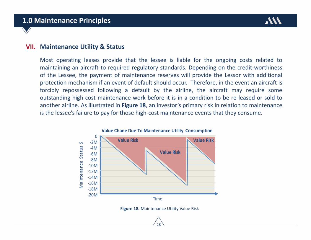
Most operating leases provide that the lessee is liable for the ongoing costs related tomaintaining an aircraft to required regulatory standards. Depending on the credit‐worthinessof the Lessee, the payment of maintenance reserves will provide the Lessor with additionalprotection mechanism if an event of default should occur. Therefore, in the event an aircraft isforcibly repossessed following a default by the airline, the aircraft may require someoutstanding high‐cost maintenance work before it is in a condition to be re‐leased or sold toanother airline. As illustrated in Figure 18, an investor’s primary risk in relation to maintenanceis the lessee’s failure to pay for those high‐cost maintenance events that they consume.
0
Maintenance Status $
Time
‐2M‐4M‐6M‐8M
‐10M‐12M‐14M‐16M‐18M‐20M
Value Chane Due To Maintenance Utility Consumption
Value Risk
Value Risk
Value Risk
Figure 18. Maintenance Utility Value Risk
28
1.0 Maintenance Principles

VII. Maintenance Utility & Status
Maintenance status is used to assess, in whole or part, the value of maintenance utilityremaining. An aircraft’s maintenance status can be quantified by analyzing data related to it’smaintenance condition at a specific point in time. The key to quantifying maintenance statuslies in making accurate assessments as to: 1.) Where each major maintenance event is relativeto their last and next shop visit, and 2.) What percentage of its next shop visit cost isremaining.
Depending on the aircraft type and age, maintenance status can represent a significantproportion of an it’s overall market value. Where appraisers are responsible for quantifyingthe market value of an aircraft, they use, as a baseline reference, two industry‐standard termsto represent an aircraft’s maintenance status. These terms consist of full‐life and half‐life.
► The full‐life status implies that each major maintenance event has just been fully restoredor overhauled to zero‐time condition; the airframe is zero‐timed from its heavy check, thelanding gear is zero‐timed from an overhaul, the engines are fresh from a performance‐restoration shop visit, and all engine Life Limited Parts (LLPs) have zero‐life used.
► The half‐life status assumes that the airframe, engines, landing gear and all majorcomponents are half‐way between major overhauls and that any life‐limited part has usedup half of its certified life. Half‐life status does not indicate that the aircraft is half‐waythrough its useful life.
29
1.0 Maintenance Principles

VII. Maintenance Utility & Status
Half‐life enables a comparison to be made between values of aircraft of different types andages using a common denominator. An aircraft’s half‐life adjustment value can be quantifiedusing the following equation:
Adjustment from Half‐Life = (Mx Event % Life Remaining – 50%) * (Mx Event Cost)
The following example illustrates the adjustment from half‐life calculation for an A320 six‐yearstructural check:
► 6‐Year Structural Interval = 72 Mo
► Average Cost of Event = $840,000
► Event Life Consumed = 60 Mo
► Event Life Remaining = 12 Mo
► % Life Remaining = 12/72 = 16.67%
Adjustment from Half‐Life = (16.67% ‐ 50%)*$840,000 = ($280,000)
$840K
$420K
Months
$11,667/Mo
Half‐Life
Full‐Life
Adjustment fromHalf‐Life=$280K
7236 600
Figure 19. Adjustment from Half‐Life : A320 6Y CK
30
1.0 Maintenance Principles

VII. Maintenance Utility & Status
Generally, an appraiser attempts to attach a value resulting from differences in maintenancestatus between the hypothetical average aircraft and the aircraft they are appraising. For new,or nearly new aircraft, where the maintenance status is half‐life or better, the maintenancevalue adjustment tends be negligible.
As an aircraft ages, maintenance begins to account for a higher proportion of the aircraft’stotal value; over time, escalating non‐routine maintenance tasks require incremental labor toaddress unscheduled repairs and discrepancies, or to remove and restore defectivecomponents. Additionally, higher material costs are expected to be incurred given that costlycomponents begin to reach a state of “beyond economic repair”, and many piece‐parts arescrapped and replaced.
After an aircraft reaches a certain age the main differentiator between specific aircraft of thesame vintage will often be the value in their maintenance status. Thus the position in themaintenance cycle is a source of value difference between aircraft of the same type andvintage, and consequently it is useful to quantify in monetary terms the value of maintenancestatus.
31
1.0 Maintenance Principles

VII. Maintenance Utility & Status
Figure 20 illustrates an example calculation summarizing the maintenance adjustment fromhalf‐life for a 2011 build A320.
Figure 20. Example Maintenance Adjustment from Half‐Life Calculation
AIRCRAFT STATUS Status as of : 21‐Nov‐17
Aircraft : Airframe : Engine Pos 1 : Engine Pos 2 : APU :Model: A320‐200 TSN : 22,328 TSN : 22,328 TSN : 22,328 TSN : 4,000DoM: 29‐Sep‐11 CSN : 10,634 CSN : 10,634 CSN : 10,634 CSN : 5,000Engine: V2527‐A5 S1 Mo FH : 302 TSLSV N/A TSLSV N/A TSLSV N/AAPU: GTCP‐131‐9A Mo FC : 144 CSLSV N/A CSLSV N/A CSLSV N/A
MAINTENANCE ADJUSTMENT FROM HALF‐LIFEMx Mx Date Last Mx Half‐Life Equipment Event Mo FH FC Mx Event Consumed Remain Cost $ Consumed Remain % Total % Half‐Life Adjust ($)Airframe 6‐Year SI 72 07‐Jul‐17 5 67 875,000$ 60,764$ 814,236$ 93.1% 43.1% 376,736$ Airframe 12‐Year SI 144 N/A 77 67 925,000$ 494,618$ 430,382$ 46.5% ‐3.5% (32,118)$ Ldg Gear Overhaul N/A Nose 120 20,000 N/A 74 46 160,000$ 98,667$ 61,333$ 38.3% ‐11.7% (18,667)$ Main 120 20,000 N/A 74 46 320,000$ 197,333$ 122,667$ 38.3% ‐11.7% (37,333)$ APU ¹ Overhaul 8,000 N/A 4,000 4,000 350,000$ 175,000$ 175,000$ 50.0% 0.0% ‐$ Eng Pos 1 Perf Rest 27,000 13,000 N/A 22,328 4,672 3,300,000$ 2,728,978$ 571,022$ 17.3% ‐32.7% (1,078,978)$ Eng Pos 1 LLP Rpl 20,000 N/A 10,634 9,366 3,842,519$ 2,043,067$ 1,799,452$ 46.8% ‐3.2% (121,808)$ Eng Pos 2 Perf Rest 27,000 13,000 N/A 22,328 4,672 3,300,000$ 2,728,978$ 571,022$ 17.3% ‐32.7% (1,078,978)$ Eng Pos 2 LLP Rpl 20,000 N/A 10,634 9,366 3,842,519$ 2,043,067$ 1,799,452$ 46.8% ‐3.2% (121,808)$
16,915,038$ 10,570,472$ 6,344,566$ (2,112,953)$
Maintenance Intervals Maintenance Intervals Maintenance Value ($) Life Remaining
32
1.0 Maintenance Principles

Section 2
Turbofan Design ConceptsI. Turbofan ArchitectureII. Turbofan ModulesIII. Bypass RatioIV. Life‐Limited Parts (LLPs)V. Quick Exchange (QEC) Kit
33

All of the jet engines used in currently manufactured commercial jet aircraft are turbofans. Theyare used commercially mainly because they are highly fuel efficient and relatively quiet inoperation.
A turbofan is a type of aircraft engine consisting of a ducted fan which is powered by a gasturbine. A portion of the air that passes through the fan enters the compressor stages in thecore of the engine where it is further compressed and processed through the engine cycle.
However, the majority of the air passes through the outer diameter of the is bypassed aroundthe core of the engine. The air accelerated by the fan in a turbofan engine contributessignificantly to the thrust produced by the engine. In large engines, such as the engines thatpower the B777, B787, A330, & A350, etc., as much as eighty percent of the thrust delivered bythe engine is developed by the fan.
A modern turbofan engine oftenoperates 25,000 hours betweenmajor overhauls; equivalent to13,500,000 miles or flying to themoon and back over 27 times.
34
2.0 Turbofan Design Concepts

I. Turbofan Architecture
Conventional “direct drive” turbofan engine architecture embodies either a twin‐shaft or three‐shaft design – see Figure 21. In a twin‐shaft configuration the Fan & Low Pressure Compressor(LPC) is driven by the Low Pressure Turbine (LPT), and the High Pressure Compressor (HPC) isdriven by the High Pressure Turbine (HPT). A three‐shaft turbofan includes an additional,Intermediate Pressure Compressor (IPC) and turbine (IPT) section.
Example Twin‐Shaft Engine Example Three‐Shaft Engine Rolls‐Royce Trent 700
IAE V2500‐A5
Figure 21. Twin and Three Shaft Turbofan Architecture
Intermediate‐pressure compressor High‐pressure compressor
High‐pressure turbine
Intermediate‐pressure turbine
Low‐pressure turbine
High‐pressure compressor High‐pressure turbine
Low‐pressure turbine
Fan & Low‐pressure compressor Fan & Low‐pressure compressor
35
2.0 Turbofan Design Concepts

I. Turbofan Architecture
In a conventional turbofan, the fan and low pressure compressor (LPC) are coupled to the LPTshaft. This design imposes limits on both the size and rotational speed of the fan as well as theproportion of air bypassed around the core of the engine. A Geared Turbofan (GTF) engineincorporates a reduction gearbox on the low spool of a two‐shaft engine; between the Fan onthe one side and the LPC and the LPT on the other side – see Figure 22. The general principle ofgeared configuration is to further increase bypass ratio over current designs to improvepropulsive efficiency and hence fuel consumption.
Figure 22. Geared Turbofan Architecture
In a geared turbofan, the fan iscoupled to a reduction gearbox, whichdrives a proportion of the air aroundthe core of the engine This means thefan can be made bigger to improvepropulsive efficiency and fuel-burn
Example Geared Turbofan EnginePratt & Whitney PW1100‐G GTF
High‐pressure compressor High‐pressure turbine
Low‐pressure turbine
Fan Low‐pressure compressor Gearbox
36
2.0 Turbofan Design Concepts
II. Turbofan Modules
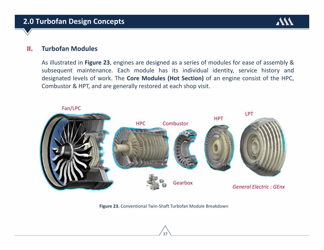
As illustrated in Figure 23, engines are designed as a series of modules for ease of assembly &subsequent maintenance. Each module has its individual identity, service history anddesignated levels of work. The Core Modules (Hot Section) of an engine consist of the HPC,Combustor & HPT, and are generally restored at each shop visit.
Fan/LPC
HPC CombustorHPT
LPT
General Electric : GEnxGearbox
Figure 23. Conventional Twin‐Shaft Turbofan Module Breakdown
37
2.0 Turbofan Design Concepts

II. Turbofan Modules
1. Fan/Low Pressure Compressor (LPC) Figure 24 –The Fan is simply a specialized type of a compressorand usually contains one stage. The Fan isresponsible for producing the majority of a typicalturbofan’s thrust.
The LPC receives a burst of air from the Fan andbegins to compress it through alternating stages ofrotor blades and stator vanes.
2. High Pressure Compressor (HPC) Figure 25 ‐ TheHPC module is made up of a series of rotor andstator assemblies whose main function is to furtherraise the pressure of the air supplied to thecombustor. It is the later stages of a HPC where theairflow is at considerable higher temperatures andpressures, which explains why theses blades andvanes are made of more temperature resistingtitanium and nickel alloys.
General Electric : GEnx
General Electric : GEnx
Figure 24. Fan/LPC Module
Figure 25. HPC Module
38
2.0 Turbofan Design Concepts
II. Turbofan Modules
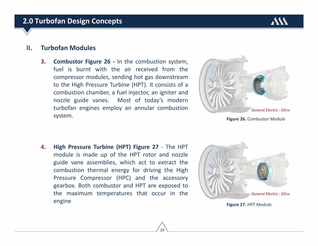
3. Combustor Figure 26 ‐ In the combustion system,fuel is burnt with the air received from thecompressor modules, sending hot gas downstreamto the High Pressure Turbine (HPT). It consists of acombustion chamber, a fuel injector, an igniter andnozzle guide vanes. Most of today’s modernturbofan engines employ an annular combustionsystem.
4. High Pressure Turbine (HPT) Figure 27 ‐ The HPTmodule is made up of the HPT rotor and nozzleguide vane assemblies, which act to extract thecombustion thermal energy for driving the HighPressure Compressor (HPC) and the accessorygearbox. Both combustor and HPT are exposed tothe maximum temperatures that occur in theengine
General Electric : GEnx
General Electric : GEnx
Figure 26. Combustor Module
Figure 27. HPT Module
39
2.0 Turbofan Design Concepts

II. Turbofan Modules
5. Low Pressure Turbine (LPT) Figure 28 – The LPTis an assembly of disks with turbine blades thatare attached to the low pressure shaft, nozzleguide vanes and a rear frame. The LPT extractsthe remaining combustion thermal energy todrive the Fan and Low‐Pressure Compressorrotor assembly.
6. Accessory Drive (Gearbox) ‐ The accessory drive section is usually attached to the enginecore or fan case. The accessory drive transfers mechanical energy from the engine to drivethe basic engine & aircraft accessories (e.g. generators and hydraulic pumps) mounted tothe accessory gearbox.
General Electric : GEnx
Figure 28. LPT Module
40
2.0 Turbofan Design Concepts

III. Bypass Ratio
As illustrated in Figure 29, an engine’s bypass ratio is the ratio of the air that goes around theengine to the air that goes through the core. In high bypass engines, most of the total thrust(anywhere from 60% ‐ 80% ) of high bypass turbofan engines is produced by the bypass airaccelerated in the fan stage, whereas the engine core primarily acts as gas generator providingthe power to drive the turbines
Figure 29. Engine Bypass Ratio
41
2.0 Turbofan Design Concepts
General Electric : GEnx

IV. Life‐Limited Parts
Within engine are certain major rotating structural parts that cannot be contained if they failand whose primary failure is likely to result in a hazardous damage to the engine. As a result,such parts are governed by the number of flight cycles operated. These parts are known asLife‐Limited Parts (LLP) and their life limitations are defined by the OEM in Chapter 5 of eachengine’s shop/overhaul manual. LLPs generally consist of disks, seals, spools, and shafts. LLPsare discarded once their useful lives are reached. Once an engine’s accumulated flight cyclesapproaches the shortest LLP life limit, the part(s) have to be removed.
In most cases, the declared lives of LLPs are between 15,000 ‐ 30,000 cycles, and a completeset will represent a high proportion (greater than 20%) of the overall cost of an engine. If theengine is operated over a long‐range network, LLPs may never need to be replaced over the lifeof the engine. Over short‐range routes however, LLPs may need to be replaced two or threetimes and, consequently, contribute a relatively high cost.
42
2.0 Turbofan Design Concepts

IV. Life‐Limited Parts – Example CFM56‐3C LLPs
Figure 30. Example Engine Life‐Limited Parts Installed on CFM56‐3C
Fan ShaftBooster Spool
Fan Disk
LPT Shaft HPC CDP Seal HPT Front Shaft HPT Front SealHPC Disk
HPT Rear Shaft
LPT Stub Shaft
HPC 1-2 Spool
HPC Front Shaft
HPC 4-9 Spool
LPT Disk 2
LPT Disk 3
LPT Disk 4
LPT Disk 1
HPC Disk 3
LPT ConicalSupport
43
2.0 Turbofan Design Concepts

IV. Life‐Limited Parts
Certain LLPs can have shorter lives imposed on them by airworthiness directives (ADs) or othertechnical issues such as a decrease in fatigue characteristics or strength capability.Additionally, some engine manufacturers certify ultimate (or target) lives of LLPs at the timethey certify an engine model. Other manufacturers certify the lives of LLPs as experience isaccumulated. In these scenarios ultimate lives are reached after one or several life extensions.
A number of engine models also contain static LLPs. Although these parts are not classified tobe critical rotating parts they do fall under the category of parts whose failure could create ahazard to the aircraft. Such parts often consist of shrouds and frames.
V. Quick Engine Exchange (QEC) Kit
The Engine in the form that is Ready‐For‐Installation (RFI) on an aircraft, is generally called aPowerplant. It consists of Bare Engine + QEC (Quick Engine Change) Kit. The Quick EngineChange (QEC) kit is a collection of components and accessories that are installed on a bareengine. Commonly installed QEC Components include: Starters & Starter Values, HydraulicPumps, Integrated Drive Generators(IDG), Anti‐icing Valves and Ducts.
44
2.0 Turbofan Design Concepts

Section 3
Turbofan Maintenance ConceptsI. Trend MonitoringII. Exhaust Gas Temperature (EGT)III. EGT Margin (EGTM)IV. Removal CausesV. Shop Visit Rate (SVR)VI. Shop Visit ProcessVII. Workscoping PlanningVIII.Borescope InspectionIX. Commercial Considerations
45

Turbofan maintenance cost represents the highest percentage of an aircraft’s directmaintenance cost, carrying with it the risk of unexpected high expenses. Therefore, anunderstanding of the various concepts in turbofan maintenance is important to grasp the factorsthat drive engine removals and shop visit cost.
Turbofan maintenance is an on‐condition process, and in the case of turbofan engines thedetermination of continued airworthiness is largely determined through trend monitoringanalysis. Trend monitoring algorithms look at successive snapshots of observations to help thefleet manager analyzing the wear trend of the engine.
The design of today’s turbofan engines follows a modular concept. This modular designessentially dictates how engine maintenance is managed. Each of the modules has its ownidentity, service history and specific inspection schedules. During a shop visit, any of theindividual modules can be removed and restored as an individual unit.
Depending on the engine model and design characteristics, thrust power, technical condition,and workscope definition, performance restoration shop visit costs may cost from $3 million tomore than $12 million.
46
3.0 Turbofan Maintenance Concepts
I. Trend Monitoring
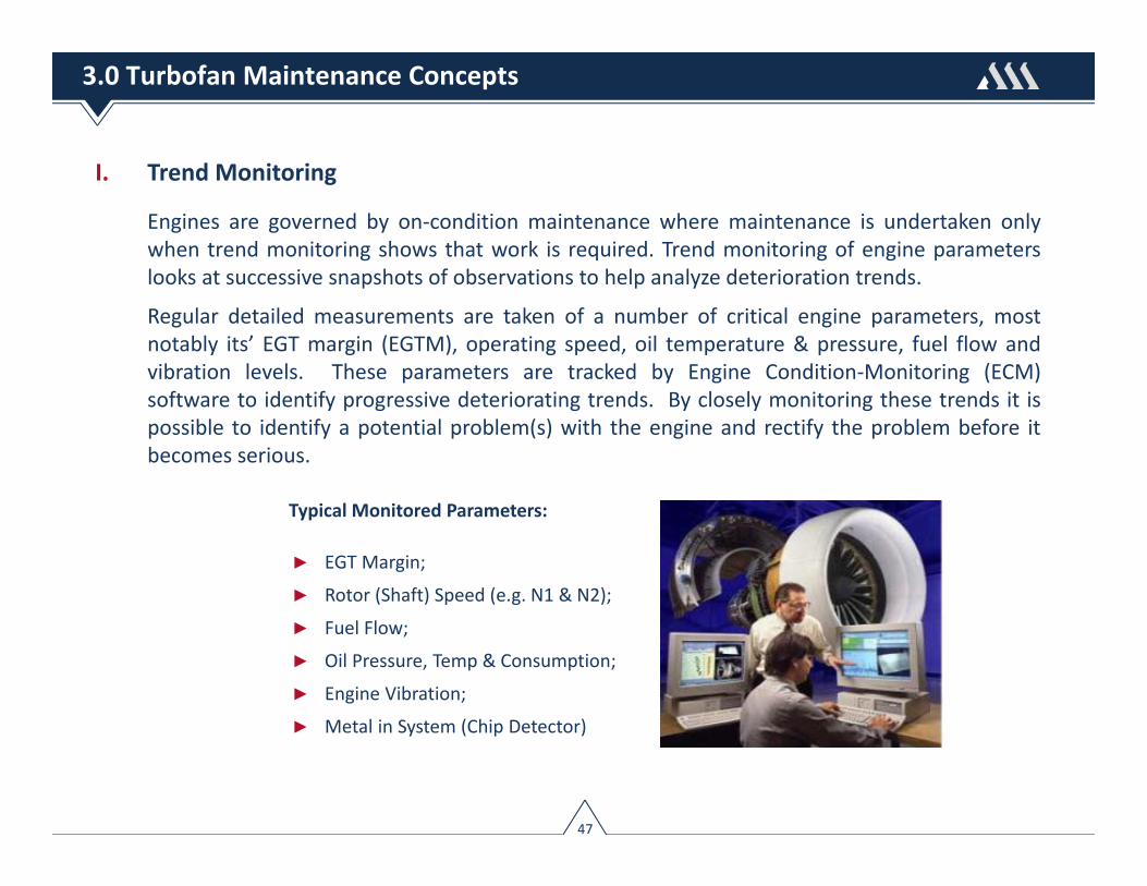
Engines are governed by on‐condition maintenance where maintenance is undertaken onlywhen trend monitoring shows that work is required. Trend monitoring of engine parameterslooks at successive snapshots of observations to help analyze deterioration trends.
Regular detailed measurements are taken of a number of critical engine parameters, mostnotably its’ EGT margin (EGTM), operating speed, oil temperature & pressure, fuel flow andvibration levels. These parameters are tracked by Engine Condition‐Monitoring (ECM)software to identify progressive deteriorating trends. By closely monitoring these trends it ispossible to identify a potential problem(s) with the engine and rectify the problem before itbecomes serious.
Typical Monitored Parameters:
► EGT Margin;
► Rotor (Shaft) Speed (e.g. N1 & N2);
► Fuel Flow;
► Oil Pressure, Temp & Consumption;
► Engine Vibration;
► Metal in System (Chip Detector)
47
3.0 Turbofan Maintenance Concepts
II. Exhaust Gas Temperature (EGT)
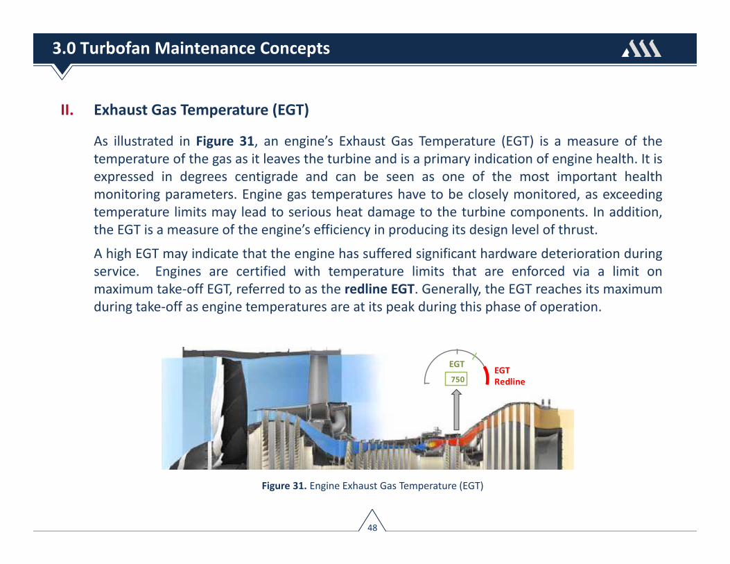
As illustrated in Figure 31, an engine’s Exhaust Gas Temperature (EGT) is a measure of thetemperature of the gas as it leaves the turbine and is a primary indication of engine health. It isexpressed in degrees centigrade and can be seen as one of the most important healthmonitoring parameters. Engine gas temperatures have to be closely monitored, as exceedingtemperature limits may lead to serious heat damage to the turbine components. In addition,the EGT is a measure of the engine’s efficiency in producing its design level of thrust.
A high EGT may indicate that the engine has suffered significant hardware deterioration duringservice. Engines are certified with temperature limits that are enforced via a limit onmaximum take‐off EGT, referred to as the redline EGT. Generally, the EGT reaches its maximumduring take‐off as engine temperatures are at its peak during this phase of operation.
Figure 31. Engine Exhaust Gas Temperature (EGT)
48
3.0 Turbofan Maintenance Concepts
EGT750
EGT Redline
III. EGT Margin (EGTM)
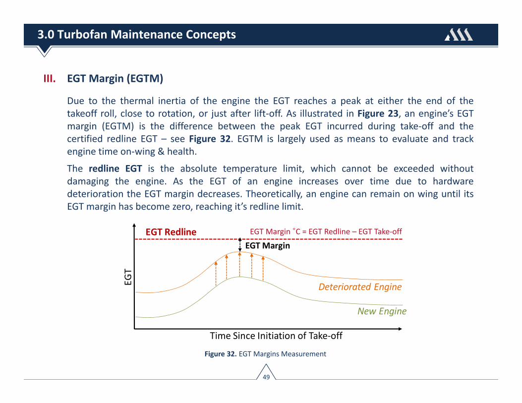
Due to the thermal inertia of the engine the EGT reaches a peak at either the end of thetakeoff roll, close to rotation, or just after lift‐off. As illustrated in Figure 23, an engine’s EGTmargin (EGTM) is the difference between the peak EGT incurred during take‐off and thecertified redline EGT – see Figure 32. EGTM is largely used as means to evaluate and trackengine time on‐wing & health.
The redline EGT is the absolute temperature limit, which cannot be exceeded withoutdamaging the engine. As the EGT of an engine increases over time due to hardwaredeterioration the EGT margin decreases. Theoretically, an engine can remain on wing until itsEGT margin has become zero, reaching it’s redline limit.
Figure 32. EGT Margins Measurement
EGT RedlineEGT Margin
Time Since Initiation of Take‐off
EGT
New Engine
Deteriorated Engine
EGT Margin °C = EGT Redline – EGT Take‐off
49
3.0 Turbofan Maintenance Concepts

III. EGT Margin (EGTM)
Red line limits are referenced in the Aircraft Flight Manual (AFM) and in each engine’s TypeCertificate Data Sheet; for the 737‐800 equipped with CFM56‐7B engines, the red line limit iscertified at 950 °C.
EGT margins are at their highest levels when the engines are new or just followingrefurbishment. Once an engine reaches a stage in its life where there is no EGT marginremaining, the engine will require specific maintenance in order to recover loss EGT margin.Figure 33 illustrates the available EGT Margins for new CFM56‐7B engines.
Figure 33. EGT Margins For New CFM56‐7B Engines
135 110 100 85 55
815 840 850 865 895
Red Line = 950 °C
EGT Take‐off °C
EGT Margin °C
Engine Model 7B20 7B22 7B24 7B26 7B27
Takeoff Thrust 20,600 22,700 24,200 26,300 27,300
50
3.0 Turbofan Maintenance Concepts

IV. Removal Causes
Engine removal causes can be assigned into four general categories consisting of: 1.) EGTMargin (EGTM) Erosion; 2.) Expiry of Life Limited Parts (LLPs); 3.) Hardware Deterioration,and 4.) Other Unscheduled Removal Causes.
1. EGTM Erosion is largely the result of compressor fouling, the gradual increase in blade tipclearances, seal leakage, and airfoil erosion – see Figure 34.
► Compressor Fouling ‐ The airflow through a jet engine is often contaminated by sand,salt, chemicals and hydrocarbons, amongst others. These particles adhere to thesurface of engine parts leading to a phenomenon known as compressor fouling. Thecontaminated engine has to work harder to compress a defined amount of air leadingto temperature rising and more fuel to achieve the same level of thrust.
Figure 34. EGT Margin Deterioration Cycle
51
3.0 Turbofan Maintenance Concepts

IV. Removal Causes
1. EGTM Erosion
► Turbine Tip Clearance ‐ Turbine tip clearance is a critical parameter affecting theperformance of propulsion engines. To operate at top efficiency, a turbine’s tipclearance must be minimized under the constraint of positive clearance to the turbinecase. A turbine’s tip clearance varies throughout different operating conditions becauseof differential thermal expansion, manufacturing tolerances, stresses, creep, anderosion. Deterioration of the tip clearances increases the amount of flow losses andleakage of working fluid between blade tips and the surrounding shroud of both theturbine and compressor stages. Such leakage reduces overall engine efficiency henceraising the total specific fuel consumption.
► Gas Path Seal Leakage ‐ Aircraft gas turbine engines have many sealing locations; alongthe shaft, over rotor blade tips, and between stages. A large engine may have dozensof sealing locations and the cumulative effect of leakage on EGTM erosion can besignificant. Gas path sealing worsens as the engines accumulates more time on‐wing.
► Airfoil Erosion ‐ Airfoil erosion occurs if engines are operating in highly erosive &corrosive environments, such as areas near or around sandy environments such as theMiddle East, near or around ocean coastlines where various sea salts may be present,or combinations of the above, or in other applications where the air contains corrosivechemical ingredients
52
3.0 Turbofan Maintenance Concepts

IV. Removal Causes
1. EGTM Erosion
Figure 35 illustrates the relationship between EGT margin erosion and accumulatedengine flight cycles. Rates of deterioration are highest in the initial 1,000 – 2,000 engineflight cycles of operation as the blade tips begin to wear. Initial rates of EGT margin loss areless for lower‐rated engines.
EGT Margin erosion rates stabilize after the initial loss and reach a steady state level thatremains fairly constant until the engine is scheduled for removal. EGT margin erosion ratescan be a leading factor in determining the length of time the engine can remain on wing.
Figure 35. EGT Margin Erosion vs Accumulated Engine Cycles
53
3.0 Turbofan Maintenance Concepts

IV. Removal Causes
1. EGTM Erosion
The “rate” of EGTM erosion is affected by how the engine is operated. Primary factorsinfluencing the rate of EGTM erosion¹ consist of:
► Engine Thrust Rating,
► Flight Operation (flight leg, engine derate, operating environment),
► Age (first‐run vs. mature‐run)
Trend monitoring of EGT Margin looks atsuccessive snapshots of observations to helpanalyze the deterioration trend of an engine –see Figure 36. By closely monitoring thesetrends it is possible to make accuratepredictions as to when an engine’s scheduledremoval is warranted, and by correlation, theinterval remaining to its next shop visit.
Figure 36. EGT Margin Trend Monitoring
1 – A full description of the factors influencing EGTM erosion is discussed in Section 5 ‐ Factors InfluencingMaintenance Reserves
54
3.0 Turbofan Maintenance Concepts
EGT Margin

IV. Removal Causes
2. Life‐Limited Parts (LLP) Expiry ‐ Prudent LLP management is essential in minimizing shopvisit maintenance cost, particularly for engines operating on high‐cyclic short and medium‐haul operations. For long‐haul engines, LLPs account for a smaller recurring share of shopvisit cost due to the low number of flight cycles (FC) these engines accumulate.
Most repair shops will assess the life remaining on LLPs when an engine is inducted formaintenance and will manage time limited components to coincide with subsequent shopvisits. Ideally, the repair shop will ensure that LLP stub‐lives closely match the expectedtime on‐wing from EGT margin erosion. So, for example, if an engine’s LLP stub‐life is10,000 FC then the repair center will ensure that the engine has sufficient EGT margin tostay on‐wing for 10,000 FC. The 10,000 FC would then be called the engine buildstandard.
LLPs also requires a high degree of disassembly and reassembly. Man‐hours for assemblyworks account for a large percentage of shop visit cost. LLP replacement during a lightshop visit would increase the necessary workscope and therefore the cost. The lowestmaintenance cost per EFH is accomplished when a heavy shop visit coincides with full LLPutilization.
55
3.0 Turbofan Maintenance Concepts

IV. Removal Causes
3. Hardware Deterioration ‐ All engine components are exposed to different kinds ofdeterioration mechanisms. These include amongst others, low and high cycle fatigue,thermo‐mechanical fatigue as well as corrosion. These mechanisms lead to a degradationof the part lives or in worst case to a part failure as well as to a loss of engine performance.
The engine’s core module, being exposed to the highest temperatures and pressureswithin the engine, suffers more acutely from hardware deterioration. Engine Condition‐Monitoring (ECM) systems are often capable of detecting such deterioration anomalies asthey precipitate and therefore serve as a tool to prevent more severe damage.
4. Other Unscheduled Removal Causes ‐ Other removal causes include amongst others:Foreign Object Damage (FOD), Oil Leak / High Oil Consumption, Vibration, andAirworthiness Directives
56
3.0 Turbofan Maintenance Concepts

IV. Removal Causes
The causes of engine removals depend heavily on the type of aircraft operation. Enginesoperating on short‐haul routes show a higher percentage of removals caused by EGT margindegradation and LLP expiry, while medium‐ and long‐haul operating engines tend to have ahigher share of removals due to hardware deterioration and EGTM degradation. Thedistribution of the engine removals on the removal causes depending on the aircraft operationand the engine age status is illustrated in Figure 37.
Shop
Visit R
emovals %
EGTM
Short‐haul Operation Medium/Long‐haul Operation
EGTM LLP
LLP
Hardware
Hardware
Other
Other
Figure 37. Distribution of Engine Removals by Operation
57
3.0 Turbofan Maintenance Concepts
V. Shop Visit Rate
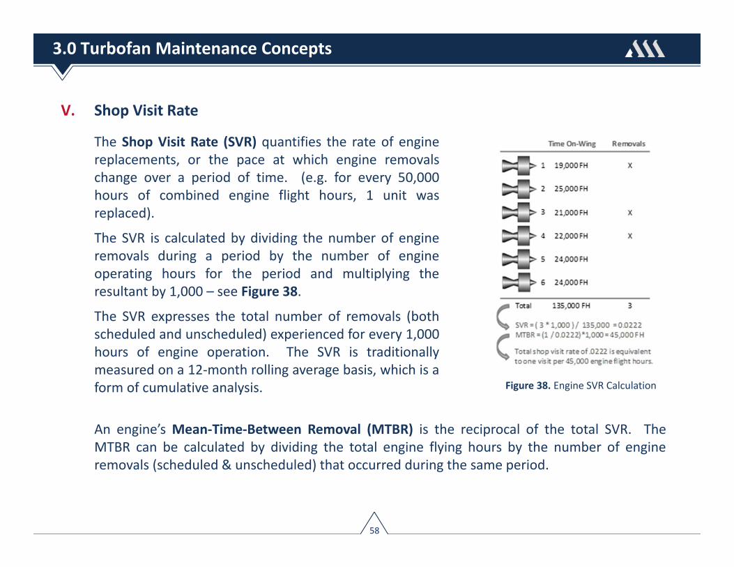
The Shop Visit Rate (SVR) quantifies the rate of enginereplacements, or the pace at which engine removalschange over a period of time. (e.g. for every 50,000hours of combined engine flight hours, 1 unit wasreplaced).
The SVR is calculated by dividing the number of engineremovals during a period by the number of engineoperating hours for the period and multiplying theresultant by 1,000 – see Figure 38.
The SVR expresses the total number of removals (bothscheduled and unscheduled) experienced for every 1,000hours of engine operation. The SVR is traditionallymeasured on a 12‐month rolling average basis, which is aform of cumulative analysis.
An engine’s Mean‐Time‐Between Removal (MTBR) is the reciprocal of the total SVR. TheMTBR can be calculated by dividing the total engine flying hours by the number of engineremovals (scheduled & unscheduled) that occurred during the same period.
Figure 38. Engine SVR Calculation
58
3.0 Turbofan Maintenance Concepts

V. Shop Visit Rate
The SVR can be calculated monthly as a fleet average and their absolute levels monitored andcompared against established benchmarks. Key benefits of tracking an engine’s SVR are:
► Provides an all‐inclusive view of an engine’s operational performance;
► Used as a method for airlines and engine OEMs to measure performance againststated goals;
► Useful for validating inherent design reliability, and engine product improvements;
► Useful in determining spare engine requirements
An engine’s total SVR can be broken into constituent components consisting of the ScheduledEngine Removal Rate (SER) and Unscheduled Engine Removal Rate (UER). – Figure 39. Eachof these components provides further insight into engine reliability, most notably the UERgiven this parameter can help identify chronic problems.
Figure 39. Scheduled Engine Removal (SER) rate versus Unscheduled (UER) rate
59
3.0 Turbofan Maintenance Concepts
Total SVR
Scheduled Engine Removal Rate (SER)
Ideal for tracking scheduled removals driven by: • Expiry of Life‐Limited Parts (LLPs), and• Performance deterioration
Unscheduled Engine Removal Rate (UER)
Ideal for tracking improvements in time on‐wing from:• Product improvement packages, and• Maintenance practices and procedures
V. Shop Visit Rate
Scheduled Engine Removal Rate ‐ The SER measures how often an engine model is removed toaddress planned, or scheduled removals due to required maintenance actions. References toengine scheduled maintenance refer to requirements for preventive or corrective maintenancethat can be anticipated, planned for, and usually scheduled to minimize service inconvenience.Examples of scheduled removals consist of those resulting from a.) The expiry of Life‐LimitedParts (LLPs), b.) Performance deterioration and c.) Service bulletin compliance.
Unscheduled Engine Removal Rate ‐ The UER measures how often an engine is removed forrepair or refurbishment before the normal maintenance intervals are reached, or due to anunexpected engine anomaly preventing it from continued safe operation. Therefore,whenever the frequency of unscheduled engine removals increases, this impact will have adirect adverse effect on operational reliability. If the engine OEM implements productimprovement packages, or updates recommended maintenance practices, then the UER willcapture expected improvements derived from these initiatives.
The Mean‐Time‐Between Unscheduled Removals (MTBUR) is the reciprocal of the UER. Thisparameter is calculated by dividing the total engine flying hours accrued in a period by thenumber of unscheduled engine removals that occurred during the same period. This measurehas the same use as the UER but is often more intuitive to interpret due to its convention.
60
3.0 Turbofan Maintenance Concepts

V. Shop Visit Rate
There are two popular methods of tracking SVRs that have been especially useful in monitoringreliability performance of engine fleets. These methods consist of the: 1.) Scorecard methodand 2.) Time‐series method. The following discusses the attributes of each.
The scorecard method can serve as an important organizational tool providing decision makerswith a comprehensive view of the shop visit rate; however, the method will likely be ineffectiveif it is not in alignment with the organizational strategy.
The scorecard method gives managers an all‐inclusive summary view of their SVRperformance – see Figure 40. If the rate fallsbelow stated goals this serves as validationthat strategies put in place to addressperformance shortcomings are effective.Conversely, if the rate remains above targetgoals than this would warrant a course ofaction to remedy any shortcomings.
Total Shop Visit
Forecast : 0.054Goal : 0.050Current : 0.034
Total UER Rate
Forecast : 0.072Goal : 0.060Current : 0.045
Total SVR
Total UER
Figure 40. Example SVR Scorecard Method
61
3.0 Turbofan Maintenance Concepts

V. Shop Visit Rate
The time‐series method is used when observations are made on a repeated basis and servesas an effective means to monitor an engine’s SVR as a trending metric. SVR trends are plottedagainst time intervals to measure shifts in this parameter that results from unknowndeficiencies (e.g. hardware & component anomalies). The time‐series method provides greatervisibility into correlating the impact of both product improvement initiatives and updatedmaintenance practices over time. Figure 41 illustrates a long‐term trend report highlightingmovements in engine total, scheduled, and unscheduled removal rates; the rates are trendinglower, implying effectiveness in either product improvements, maintenance practices, or acombination of both.
Figure 41. Example SVR Time‐Series Method
62
3.0 Turbofan Maintenance Concepts

V. Shop Visit Rate
The shop visit rate is one of many key metrics used by airlines and engine manufacturer’s totrack performance against an objective criterion; for example, comparing an airline’s SVRreliability to overall fleet reliability to determine whether their performance is in line with therest of the industry leads to an awareness of each airline’s standing and provides a baseline forimprovement. Figure 42 illustrates an example comparing an airline’s engine SVR to that of theengine’s fleet.
Figure 42. Example Comparison Between Airline & Fleet SVR
63
3.0 Turbofan Maintenance Concepts
Airline’s SER and UER are 1 ½ times higher
compared to overall fleet
0.0400
0.0385
0.020
0.025
0.030
0.035
0.040
0.045
1 2 3 4 5 6 7 8 9 10 11 12 13 14 15 16 17 18 19 20 21 22 23 24 25 26 27 28 29 30
0.0270
0.0260
Airline SER
Airline UER
Fleet SER
Fleet UER
RATE PER 1,000 FH
V. Shop Visit Rate
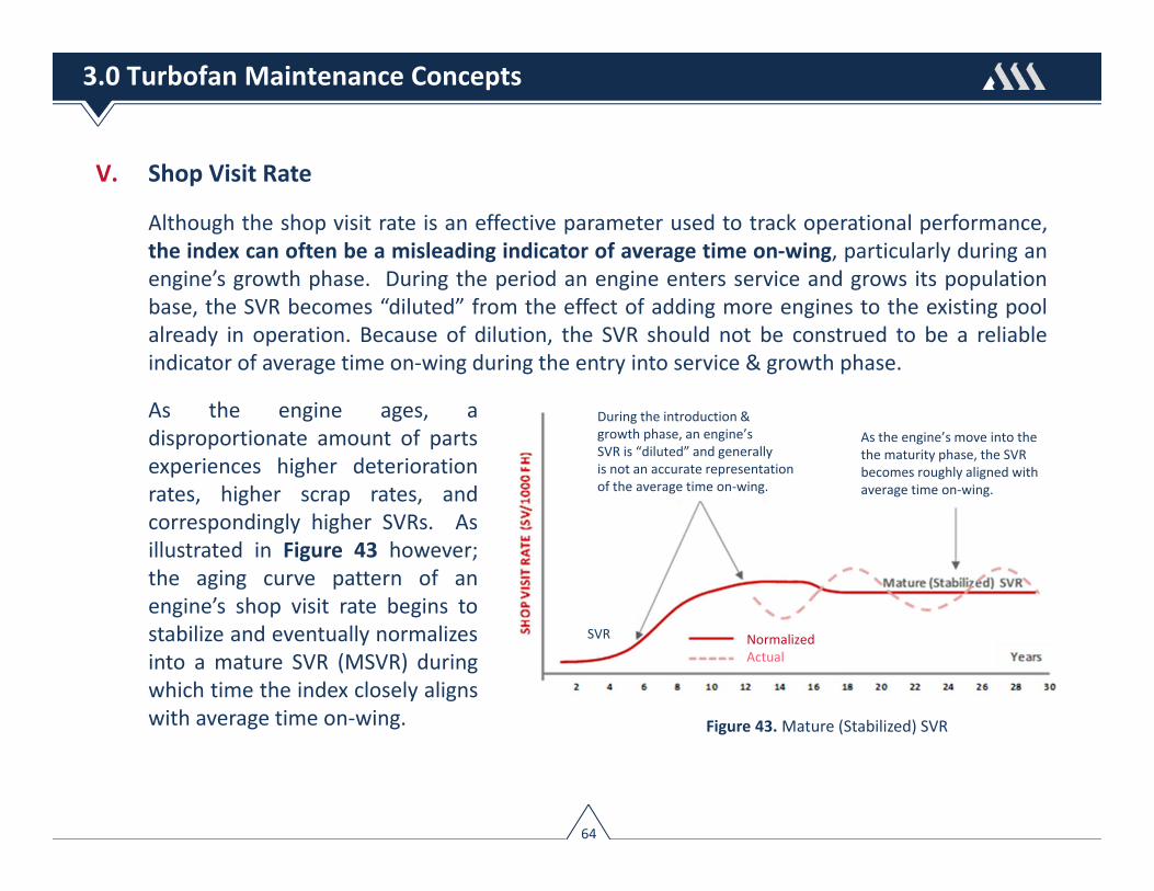
Although the shop visit rate is an effective parameter used to track operational performance,the index can often be a misleading indicator of average time on‐wing, particularly during anengine’s growth phase. During the period an engine enters service and grows its populationbase, the SVR becomes “diluted” from the effect of adding more engines to the existing poolalready in operation. Because of dilution, the SVR should not be construed to be a reliableindicator of average time on‐wing during the entry into service & growth phase.
As the engine ages, adisproportionate amount of partsexperiences higher deteriorationrates, higher scrap rates, andcorrespondingly higher SVRs. Asillustrated in Figure 43 however;the aging curve pattern of anengine’s shop visit rate begins tostabilize and eventually normalizesinto a mature SVR (MSVR) duringwhich time the index closely alignswith average time on‐wing. Figure 43. Mature (Stabilized) SVR
During the introduction &growth phase, an engine’sSVR is “diluted” and generallyis not an accurate representationof the average time on‐wing.
As the engine’s move into thethe maturity phase, the SVR becomes roughly aligned with average time on‐wing.
SVR NormalizedActual
64
3.0 Turbofan Maintenance Concepts

V. Shop Visit Rate
Engine maintenance costs are largely influenced by its associated shop visit rate. All thingsbeing equal, an engine with a higher shop visit rate will incur higher life cycle maintenancecosts.
Figure 44 illustrates the drivers of engine maintenance costs, which can be broken down intoline & shop maintenance costs, spares cost, and schedule interruption costs. As shown, themost significant parameter that directly contributes to three of the four elements is the engineremoval rate.
Figure 44. Engine Maintenance Cost Drivers
65
3.0 Turbofan Maintenance Concepts

VI. Shop Visit Process
The breakdown of an engine’s shop visit process is detailed in Figure 45. The primary costdriver of engine shop maintenance is material cost. Approximately 60% ‐ 70% of the cost of anengine shop visit is due to replacement of material. If life‐limited parts (LLP) requirereplacement the material cost will increase further. Direct labor will account for approximately20%‐30% of total cost, while repairs will account for 10%‐20%.
Figure 45. Engine Shop Visit Process
66
3.0 Turbofan Maintenance Concepts

VII. Workscope Planning
The primary objective of the workscope is to restore the engines performance, and to buildthe engine to a standard that minimizes long‐term engine direct maintenance cost, or cost perflying hour. This process, however, can be quite challenging given parts and modules havedifferent rates of deterioration. A qualified performance restoration shop visit occurswhenever the engine maintenance performed entails a performance or higher level of work,which at a minimum:
► Accomplishes a prescribed package of inspections, maintenance checks and majorrefurbishments on an engine’s Core Modules
This level of refurbishment does not specify 100% disassembly and 100% piece part inspection,but will generally :
► Zero‐time the Core Modules to the highest build specification,
► Obtain max time between shop visits with resultant lowest cost per flight hour & thegreatest potential for regaining EGT margin.
► Ensure that LLP stub‐lives closely match the expected time on‐wing from EGT marginerosion.
67
3.0 Turbofan Maintenance Concepts

VII. Workscope Planning
A qualified performance restoration shop visit objective is to restore hardware and clearancesbetween blade tips and engine casings. On average, 65% ‐ 85% of the original EGT Margin willbe restored following a performance restoration – see Figure 46.
EGT
Engine Flight Cycles
Red Line
RestorationShop Visit
New Engine
Scheduled restoration recoversapproximately 65% ‐ 85% oforiginal EGT Margin
Figure 46. Effect of Engine Restoration on EGTM Recovery
68
3.0 Turbofan Maintenance Concepts

VII. Workscope Planning
The Workscope Planning Guide (WPG) is a manual that details suggested levels of requiredmaintenance on each module as well as a list of recommended Service Bulletins. Enginesgenerally go through patterns of workscopes that vary based on time on‐wing and businessconsiderations. The WPG generally specify three levels of workscopes consisting of: 1.)Minimum Level, 2.) Performance Level, and 3.) Full Overhaul.
1. Minimum Level Workscope – Typically applies to situations where a module has limitedtime since last overhaul. The key tasks accomplished with this workscope level areexternal inspections, and to some extent, minor repairs. It is not necessary todisassemble the module to meet the requirements of a minimum level workscope.
2. Performance Level Workscope – Will normally require teardown of a module to exposethe rotor assembly. Airfoils, guide vanes, seals, and shrouds are inspected and repairedor replaced as needed to restore the performance of the module. Cost‐effectiveperformance restoration requires determination of the items having the greatestpotential for regaining both exhaust gas temperature (EGT) and Specific FuelConsumption (SFC) margin.
69
3.0 Turbofan Maintenance Concepts
VII. Workscope Planning
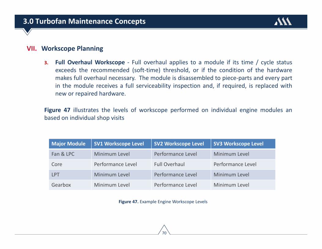
3. Full Overhaul Workscope ‐ Full overhaul applies to a module if its time / cycle statusexceeds the recommended (soft‐time) threshold, or if the condition of the hardwaremakes full overhaul necessary. The module is disassembled to piece‐parts and every partin the module receives a full serviceability inspection and, if required, is replaced withnew or repaired hardware.
Figure 47 illustrates the levels of workscope performed on individual engine modules anbased on individual shop visits
Figure 47. Example Engine Workscope Levels
70
3.0 Turbofan Maintenance Concepts
Major Module SV1 Workscope Level SV2 Workscope Level SV3 Workscope Level
Fan & LPC Minimum Level Performance Level Minimum Level
Core Performance Level Full Overhaul Performance Level
LPT Minimum Level Performance Level Minimum Level
Gearbox Minimum Level Performance Level Minimum Level

VII. Workscope Planning
The level of workscope performed on an engine can be “target‐oriented” to achieve either: 1.)Target on‐wing time, 2.) Target shop visit cost, and 3.) Target LLP stub‐life. The keydeterminants that affect the workscope inputs vary by operator but are generally influencedby:
► Removal cause(s);
► Time accumulated on the engine modules;
► Observed hardware conditions;
► Trend data at removal
Business decisions also influence the level of workscope performed, key among them is:
► Maximizing usage of LLP hardware, which often leads to lower shop visitcosts but higher DMC ($ / FH), or
► Building for minimum number of shop visits, which allows one toachieve lower DMC ($ / FH) but higher shop visit costs.
71
3.0 Turbofan Maintenance Concepts

VII. Workscope Planning
Example illustrating workscope alternative to either, 1.) build for maximum time on‐wingresulting in lower unit cost ($/FH) or 2.) minimum restoration cost (cash outlay) resulting inhighest unit cost – Figure 48.
Option 1 Option 2
Workscope Full Overhaul Core Restoration
LLP Replacement Fan + Core + LPT Core Modules
Build‐Goal 20,000 FC 8,000 FC
Restoration Cost $ $2.50M $2.0M
LLP Cost $ $2.50M $1.5M
Total Shop Visit Cost $ $5.0M $3.5M
Restoration $ / FH @ 1.5 FL $83.33 / FH $102.50 / FH
13 3 3 8
13 20 20 830 20 20 25
Engine Enters Shop
Engine Exits Shop
LLP Stub‐lives remaining (1,000 FC)
Figure 48. Example Engine Build‐Goal Options
72
3.0 Turbofan Maintenance Concepts

VII. Workscope Planning
Longer on‐wing time leads to higher levels of wear and deterioration for engine internal pieceparts, and thus higher degree of parts replacement. Increased time on‐wing can therefore leadto higher average shop visit costs. A relationship therefore exists between time on‐wing andcost per EFH. This generally takes the shape of a U‐curve (Figure 49). The key to fine‐tuningengine maintenance costs is knowing the U‐curve characteristic of the engine, improving on‐wing time and reducing the cost of the workscope for a corresponding removal interval.
Cost$/FH
TargetOn‐Wing Time
Increasing costdue to extendedworkscopes
On‐Wing Time (EFH)
Engine
$/F
H
Figure 49. Influences Between TOW and Engine DMC
73
3.0 Turbofan Maintenance Concepts
VIII. Borescope Inspection
Aircraft turbines are subject to ingested foreign object damage (FOD), corrosion, erosion,thermal deterioration, cracking, and distortion. Since the parts that are most vulnerable todamage are not readily available to unaided visual inspection, the only available method todetermine the condition of a turbine is the use of a borescope. Areas of borescope inspectionconsist of:
► Compressor ‐ access for a borescope is typically through the air inlet, a bleed port orspecially designed borescope port. The last stages can often be accessed through anignitor port. Leading and trailing edges of compressor blades and guide vanes arechecked for foreign object damage (FOD) and erosion.
► Combustion Chamber ‐ burner cans are checked for cracks, and misalignment. Fuelnozzles and other parts, including louvers are checked for excessive coking, cracking anddistortion. Access is typically through and ignitor port.
► Turbine Section ‐ the highest heat levels are in the first stage turbine. In this section, boththe stationary nozzles and guide vanes are subject to burning and cracking, FOD, pitting,erosion and sulfidation. Second stage blades can be subject to shifting and rivet cracking.Access is typically through and ignitor port or specifically design borescope port.
74
3.0 Turbofan Maintenance Concepts

IX. Commercial Considerations
Commercial considerations are often influenced based on where an engine is in its economiclifecycle – Figure 50.
► Entry Into Service (EIS) ‐ engine first enters into service.
► Introduction / Growth Phase – engine gaining acceptance & orders are increasing,
► Stabilization / Mature Phase – engine sales are at a consistent, steady level.
► Decline / End of Life Phase ‐ engine sales drop to a low level and are being sold forspare parts or scrap.
Figure 50. Engine Economic Lifecycle
75
3.0 Turbofan Maintenance Concepts
EIS
Intro /Growth
Stabilization / Mature
Decline /End of Life
Phase 1 Phase 2 Phase 3
GTF,LEAP‐X
GEnX, TRENT 700/1000GE90, CFM56‐5B/‐7BCF34, CF6‐80E, V2500‐A5
CF6‐80C2, TRENT 800, RB211, PW2000/4000 CFM56‐5A1, V2500‐A1
JT8/9, CFM56‐3 CF6‐6/50

IX. Commercial Considerations
Management Considerations During Growth & Stabilization Phase
Goal : Preservation of asset values
Objective : Build to minimize shop DMC ($ / FH)
► Use OEM parts & repairs
► Invest / benefit from latest SB modifications & technology
► Choose to replace parts over repair
Management Considerations During End of Life Phase
Goal : Preservation of cash
Objective : Build to minimize shop visit costs
► Maximizing usage of LLPs,
► Weigh benefits of purchasing green‐time engines
► Weigh benefits of PMA parts and DER repairs
76
3.0 Turbofan Maintenance Concepts

Section 4
Maintenance ReservesI. Maintenance Reserve EventsII. Maintenance Reserve Data SourcesIII. Maintenance Reserve Payment MechanismsIV. Maintenance Reserve Letter of CreditV. Use of Maintenance ReservesVI. Maintenance Reserve AccumulationVII. Maintenance Reserve Cost SharingVIII.Maintenance Reserve Exposure
77

Maintenance reserves are payments made by the lessee to the lessor to accrue for thosescheduled major maintenance events that require significant aircraft grounding time and/orturn‐around time for certain major component overhauls.
The contractual position relating to maintenance reserve is always a subject of intensenegotiation. Many airlines have sufficient credit stature that their prominence in themarketplace means they can reject paying maintenance reserves. On the other hand, lessorswill show less flexibility for weaker credit lessees and require these operators to paymaintenance reserves.
The importance of maintenance reserves to protecting asset value is a key consideration oflessors. In an ideal situation, the reserves plus the residual condition of select high costmaintenance events would essentially keep the economic condition of the aircraft whole.
78
4.0 Maintenance Reserves

I. Maintenance Reserve EventsA lease agreement will specify what maintenance events are to be covered through payment ofreserves. Areas of maintenance covered by reserves account for 50%‐60% of Total DirectMaintenance Costs, and consist of: a.) airframe heavy structural checks, b.) landing gear overhaul, c.)APU heavy repair, d.) engine performance restoration, e.) engine LLP replacements, and f.) thrustreverser overhaul (primarily widebody) – Figure 51.
Figure 51. Maintenance Reserve Events
79
4.0 Maintenance Reserves

I. Maintenance Reserve Events
i. Airframe Heavy Structural Inspection (HSI):
a. Maintenance Process: Hard‐time
b. Equation: Avg. HSI Cost / MPD Interval (Months)
c. Interval: Fixed ‐ typically every 6 – 12 years
d. Cost: Variable ‐ largely labor driven and generally includes costs affiliated with basiccabin refurbishment and paint
e. Downtime: 15‐30 days (narrowbody) and 30‐45 days (widebody)
f. Scope of work: Accomplishment of tasks affiliated with the Structural, Zonal, &Systems Maintenance Program and the rectification of any deficiencies resultingfrom performance of such tasks.
g. Charge Basis : Usually charged on a “per‐month” basis
h. Comment: Costs can be difficult to project if aircraft is a new model
80
4.0 Maintenance Reserves

I. Maintenance Reserve Events
ii. Landing Gear Overhaul:
a. Maintenance Process: Hard‐time
b. Equation : Avg. Gear Overhaul Cost / MPD Interval (Months or Flight Cycles)
c. Interval: Fixed ‐ defined in yearly & cyclic intervals (e.g. 10 years & 20,000 FC),whichever becomes more limiting
d. Cost: Variable ‐ largely labor driven and includes costs to overhaul & repaircomponents, and often includes the exchange fee cost
e. Downtime : 35‐45 days (narrowbody gear) & 55‐65 days (widebody gear)
f. Scope of Work: Labor for complete teardown & rebuild, removal and/or preventionof corrosion, visual & NDT inspections, repair & overhaul of components
g. Charge Basis: Usually charged either “per‐month” or “per‐cycle” basis dependingon operator utilization
h. Comment: Costs can be difficult to project if unit is a new model
81
4.0 Maintenance Reserves

I. Maintenance Reserve Events
iii. Auxiliary Power Unit (APU) Heavy Repair:
a. Maintenance Process: On‐condition
b. Equation : Avg. Heavy Repair Cost / Mean‐Time Between Heavy Repair (APU FH)
c. Interval: Variable ‐ removal intervals influenced by cycles, area of operation, andmaturity (first‐run vs. mature‐run).
d. Cost: Variable ‐ largely material driven through repair & replacement of piece partsand, where applicable, LLPs. Piece part escalation a significant contributing factor.
e. Downtime: 30‐60 days
f. Scope of Work: Repair & restoration of the power section, load impeller & gearboxmodules.
g. Charge Basis: Charged on a “per‐APU FH” basis for heavy repair and, whereapplicable, “per‐cycle” basis for LLP replacement.
h. Comment: Both costs and timing heavily influenced by operation, and often difficultto quantify if APU model is new.
82
4.0 Maintenance Reserves

I. Maintenance Reserve Events
iv. Engine Performance Restoration:
a. Maintenance Process: On‐condition
b. Equation : Avg. Performance Restoration Cost / Mean‐Time On‐Wing BetweenPerformance Restoration (FH)
c. Interval: Variable ‐ removal intervals influenced by operational factors (flight leg,thrust, derate, environment) and maturity
d. Cost: Variable ‐ Largely material driven through repair & replacement of parts.Piece part escalation a significant contributing factor. Engine thrust, operationalprofile and area of operation also impacts PR costs.
e. Downtime: 90‐120 days
f. Scope of Work: Performance restoration of an engine’s major modules (e.g.fan/booster, high pressure compressor, high pressure turbine, combustor, lowpressure turbine).
g. Charge Basis: Charged on a “per‐engine FH” basis.
h. Comment: Engine PR costs and timing heavily influenced by age & operation, andoften difficult to quantify if engine model is new.
83
4.0 Maintenance Reserves
I. Maintenance Reserve Events
v. Replacement of Engine Life‐Limited Parts:
a. Maintenance Process: Hard‐time
b. Equation : OEM Published LLP Cost / OEM Published Cycle Interval (FC)
c. Interval: Fixed – governed by life limits published in Chapter 5 of the OEM shopmanual
d. Cost: Fixed – derived from manufacturer’s catalog prices. LLP escalation asignificant contributing factor.
e. Downtime: Coinciding with engine performance restoration – 90‐120 days
f. Scope of Work: Replacement of LLPs
g. Charge Basis: Charged on a “per‐cycle” basis
h. Comment: Some manufacturers certify ultimate lives of LLPs at the time theycertify an engine model. Other manufacturers certify the lives as experience isaccumulated. In these scenarios, ultimate lives are reached after one or several lifeextensions.
84
4.0 Maintenance Reserves
I. Maintenance Reserve Events
vi. Thrust Reverser Overhaul (primarily widebodies):
a. Maintenance Process: On‐condition
b. Equation : Avg. Overhaul Cost / Avg. Time On‐Wing Between Overhaul (FH)
c. Interval: Variable ‐ influenced by accumulated FH & FC
d. Cost: Variable ‐ largely labor driven and includes costs to overhaul & repaircomponents
e. Downtime: 40‐60 days
f. Scope of Work: Labor for complete teardown & rebuild, removal and/or preventionof corrosion, visual & NDT inspections, delamination & dis‐bonding repair, andrepair & overhaul of components
g. Charge Basis: Usually charged on either “per‐month” or “per‐flight hour” basisdepending on operator utilization
h. Comment: Costs can be difficult to project if unit is a new model
85
4.0 Maintenance Reserves

II. Maintenance Reserve Data Sources
There are numerous sources used to derive maintenance reserves. The more popular comefrom:
► Maintenance Reserve Invoice Claims
► Maintenance Repair & Overhaul Centers (MROs) Quotes
► Competitor Reserve Rates
► Aviation Journals (e.g. Aircraft Commerce)
► Original Equipment Manufacturers (OEM) Handbooks & Calculators
Figure 52. Example Derivation of Narrowbody APU Reserves
86
4.0 Maintenance Reserves

II. Maintenance Reserve Data Sources
Challenges are encountered when predicting costs and on‐condition intervals for newequipment that have no documented maintenance history. If reserves are to be collectedmonthly in arrears then the most convenient methods for developing reserve rates consists ofeither basing them on manufacturers’ recommendations or using comparable maintenancecosts from competing alternatives ‐ see Figure 53 illustrating GE90X mature shop visit costsbased on comparable engines.
Figure 53. Example Use of Comparable Maintenance Cost
87
4.0 Maintenance Reserves
Engine PW 4098 GE94‐94B Trent 895 GE90‐110 GE90X
Rating (lbs.) : 97,900 93,700 95,000 110,000 95,000
Aircraft : 777‐300 777‐300 777‐200ER 777‐200LR/F 777‐9X
Avg. Mature SV Cost ($M) : $12.3M ‐ $12.8M $11.7M ‐ $12.2M $12.0M ‐ $13.5M $13.0M ‐ $13.5M $12.2M ‐ $12.7M
Avg. Mature Time On‐Wing (FH) : 15,000 – 17,000 17,000 – 19,000 16,000 – 18,000 16,000 – 18,000 16,500 – 18,500
Avg. Mature SV Rate ($/FH) : 730 ‐ 780 700 ‐ 750 720 ‐ 770 760 ‐ 810 700 ‐ 750

III. Maintenance Reserve Payment Mechanisms
There are two principle mechanisms that lessees use to pay lessors for maintenance utility:
i. Cash Maintenance Reserve Payments; or
ii. End of Lease Adjustments
i. Cash Maintenance Reserve Payments. These are payments made on a regular, usuallymonthly, basis by the lessee to the lessor, and are generally based upon the aircraft typeand actual utilization. Therefore, at the time an aircraft is taken out of service formaintenance, the lessor should have funds to reimburse lessee to cover the cost of majormaintenance events. In the event of default by lessee, the assumption is that the lessorwould generally not incur any shortfall exposure.
ii. End of Lease Adjustments. This option would expose a lessor to a greater risk ofincurring maintenance costs and is thus usually only offered to better quality credits orairlines that have demonstrated a good track record of payment. There are two types ofend‐of‐lease payment structures consisting of:
1. Upsy; and
2. Upsy‐Downsy
88
4.0 Maintenance Reserves
III. Maintenance Reserve Payment Mechanisms
1. Upsy – A payment whereby the lessor receives payment for time used since last overhaulor since new (typical of new aircraft transactions).
2. Upsy / Downsy – An adjustment can either be one‐way, where the Lessee is required topay an adjustment when a certain maintenance event is returned with less timeremaining than at delivery, or an adjustment whereby lessor may have to pay the lesseeif a certain maintenance event is returned in better condition than at delivery (typical ofused aircraft transactions)
89
4.0 Maintenance Reserves

IV. Maintenance Reserve Letter of Credit
In some leases, the lessee may have the option, rather than paying cash reserves, to providethe lessor with a Maintenance Reserve Letter of Credit (MRLC) in an amount equal to anagreed projected aggregate notional value of maintenance reserves.
While this approach can reduce the immediate cash flow impact of paying monthly reserves,the benefit to the lessee needs to be offset against:
► The administrative burden associated with annual reconciliation, monitoringof bank credits, storage of physical forms, etc.;
► The corresponding reduction to the Lessor’s cash‐flow;
► The “drawdown risk” associated with MRLCs;
► Bank fees payable for transfers of MRLCs upon sale, and;
► Less attractive for sale as less upfront cash to buyer.
90
4.0 Maintenance Reserves

IV. Maintenance Reserve Letter of Credit
The MRLC amount is typically “forward projected”, based on the estimated utilization of theaircraft over an agreed period (e.g. 6 or 12 months). At the end of this period the parties will:
1. Carry out a reconciliation of the estimated utilization against actual utilization,
2. Account for any maintenance events which have occurred, and
3. Provide a new or revised MRLC in an amount equal to the “actual” reserve amount for theprevious period plus the projected aggregate notional value of maintenance reserves overthe next reconciliation period.
The MRLC amount can also reflect a “capped amount” based on the projected maximumexposure during the lease. General requirements for an MRLC:
► Be denominated in and payable in Dollars.
► Be a first demand, irrevocable and absolute payment undertaking of theissuing bank payable on written demand without proof or evidence ofentitlement or loss required;
► Be issued or confirmed and payable by a first‐class international bank
91
4.0 Maintenance Reserves
V. Use of Maintenance Reserves
The workscope and estimated cost of each maintenance reserve event shall be agreed bylessor and lessee prior to the commencement of any work. Lessor shall be entitled to observesuch work and shall be provided with copies of pertinent documents. In general,reimbursement will be made up to the amount in the reserve account at the time of themaintenance event and no reimbursement shall be made for any material markup, outsidevendor fees, handling fees, packaging and shipping charges.
In order to be eligible for reserve reimbursement many lessors require that lessees performeach qualifying maintenance event with an Approved Maintenance Performer. ApprovedMaintenance Performer means:
i. for all major checks, repairs and maintenance (including any shop visit for an Engine orthe APU, any Landing Gear Overhaul) and all Major Modifications, any maintenancefacility approved by (a) the Aviation Authority and (b) either EASA or the FAA or,
ii. for all lower level checks, repairs and maintenance, any maintenance facility approved bythe Aviation Authority which, provided Lessee has the requisite licenses and approvals,may be Lessee.
92
4.0 Maintenance Reserves

V. Use of Maintenance Reserves
Maintenance reserves will be available for reimbursement against the cost of prescribedevents, and reimbursement will be subject to certain exclusions agreed in the lease. Theexclusions usually relate to items which are not directly related to the time or materials cost ofthe eligible maintenance or replacement part and which were not factored into the costassumption for the relevant event.
Examples of Exclusions:
► For any repair overhaul or inspection caused by foreign object damage (FOD),
► Work performed for Airworthiness Directives (ADs) , Manufacturer’s Service Bulletins(SBs) and Service Information Letters (SILs),
► Cabin and Systems Modifications,
► Repair of damage from accidental cause, improper operation, improper maintenance,misuse or abuse.
93
4.0 Maintenance Reserves

V. Use of Maintenance Reserves
The applicable maintenance reserve areas are discussed as follows:
1. Airframe Reserves ‐ Lessor will reimburse lessee from the Airframe Reserves for the actualcost of performing those tasks affiliated with the Structural, Zonal, & Systems MaintenancePrograms and the rectification of any deficiencies resulting from performance of suchtasks.
2. Landing Gear Overhaul Reserves ‐ Lessor will reimburse lessee from the Landing GearReserves for the actual cost of a Landing Gear Overhaul, which means an overhaul of aLanding Gear assembly in accordance with the Manufacturer's repair manual that restoressuch Landing Gear to a "zero time‐since overhaul" condition in accordance with theManufacturer's repair manual and is performed in accordance with the Manufacturer'soverhaul specifications and operating criteria.
94
4.0 Maintenance Reserves
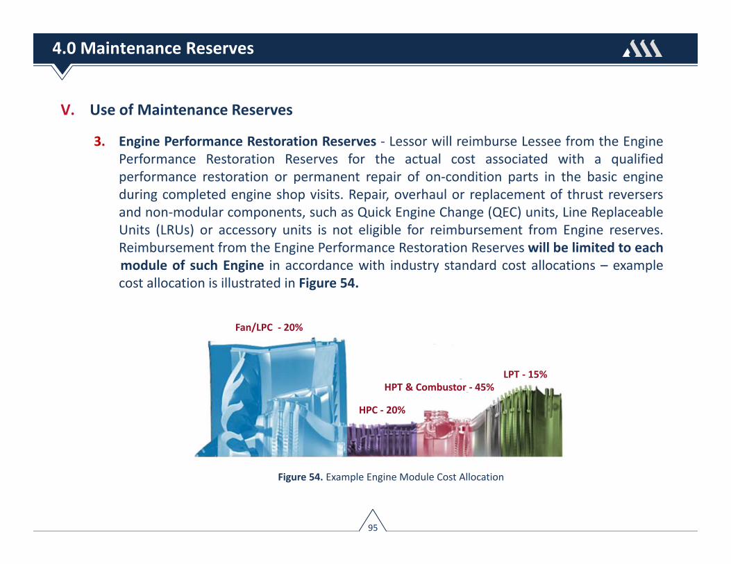
V. Use of Maintenance Reserves
3. Engine Performance Restoration Reserves ‐ Lessor will reimburse Lessee from the EnginePerformance Restoration Reserves for the actual cost associated with a qualifiedperformance restoration or permanent repair of on‐condition parts in the basic engineduring completed engine shop visits. Repair, overhaul or replacement of thrust reversersand non‐modular components, such as Quick Engine Change (QEC) units, Line ReplaceableUnits (LRUs) or accessory units is not eligible for reimbursement from Engine reserves.Reimbursement from the Engine Performance Restoration Reserveswill be limited to eachmodule of such Engine in accordance with industry standard cost allocations – examplecost allocation is illustrated in Figure 54.
Fan/LPC ‐ 20%
HPT & Combustor ‐ 45%
HPC ‐ 20%
LPT ‐ 15%
Figure 54. Example Engine Module Cost Allocation
95
4.0 Maintenance Reserves

V. Use of Maintenance Reserves
4. Engine LLP Reserves ‐ Lessor will reimburse Lessee from the Engine LLP Reserves for theout‐of‐pocket materials cost without overhead, mark‐up or profit factor associated withthe replacement of life‐limited parts in such engine during completed engine shop visitsrequiring off‐wing teardown and/or disassembly. Most lessors will require that suchreplacement LLP parts are new, with zero‐time status
5. APU Heavy Repair Reserves ‐ Lessor willreimburse Lessee from the APU Reserves forthe actual cost of a completed APU HeavyRepair, where Heavy repair means, at aminimum, complete disassembly of thepower section and load compressor modules(Figure 55) according to the Manufacturer’sthen current full gas path overhaul criteria inorder to restore full service release life forsuch modules. Figure 55. Typical APU Modules
96
4.0 Maintenance Reserves

VI. Maintenance Reserve Accumulation
Maintenance reserves accumulate, in relation to a specified future maintenance event for aparticular item of equipment, and can usually be accessed to cover the cost of that event whenit occurs, whether during the present lease term, in which case the Lessee would seekreimbursement from the relevant reserve account for qualifying maintenance, or during afuture lease term with another operator, where maintenance reserves paid by a previousLessee and held by Lessor might translate to a corresponding Lessor contribution. Figure 56illustrates the accumulation of reserves for an A320’s 6‐year and 12‐year structural check.
1st 6‐Year Check$840K
2nd 6‐Year Check$960K
1st 12‐Year Check$1.0M
12Y Check$6,945 / Mo
2nd 6Y Check$13,330 / Mo
1st 6Y Check$11,660 / Mo
Total Cost 12Y Check = $1.96M
Time ‐ Years
6 120
Figure 56. Reserve Accumulation for A320 6Y and 12Y Heavy Structural Checks (no escalation)
97
4.0 Maintenance Reserves

VI. Maintenance Reserve Accumulation
Example : Maintenance reserve cash flows for an A320 aircraft under a 12‐year term wheremaintenance events have been appropriately reserved for.
(10,000,000)(9,000,000)(8,000,000)(7,000,000)(6,000,000)(5,000,000)(4,000,000)(3,000,000)(2,000,000)(1,000,000)01,000,0002,000,0003,000,0004,000,0005,000,0006,000,0007,000,0008,000,0009,000,00010,000,000
(10,000,000)(9,000,000)(8,000,000)(7,000,000)(6,000,000)(5,000,000)(4,000,000)(3,000,000)(2,000,000)(1,000,000)
01,000,0002,000,0003,000,0004,000,0005,000,0006,000,0007,000,0008,000,0009,000,000
10,000,000
0 5 10 15 20 25 30 35 40 45 50 55 60 65 70 75 80 85 90 95 100 105 110 115 120 125 130 135 140
Cum
ulat
ive
Cash
floesRe
venu
es
Term - Month
Maintenance Reserve Cashflow Summary
Reserve Revenue Reserve Expense Cumulative Cashflows
Expe
nses
APU 6Y CK ENG 1
& 2 PR
APU
GEAR
ENG 1 & 2 PR
APU12Y CK
Figure 57. Example Maintenance Reserve Cash Flow Inflows & Outflows
98
4.0 Maintenance Reserves

VII. Maintenance Reserve Cost Sharing
In the case of an aircraft that was previously operated by a lessee, the reserve balance at theend of the lease term will represent the lessor’s pro‐rata fund, which will be allocated towardsfuture contributions with subsequent lessee(s). On this basis, the cost of such an event will bedistributed pro‐rata over the interval to the various lessees. One method to estimate pro‐ratacontributions is to apportion the cost of a maintenance consumed by both the previous lesseeand subsequent lessee. Figure 58 illustrates the allocation of costs for an A320’s 6Y and 12Ystructural checks based on the apportionment of lessee pro‐rata intervals.
Time ‐ Years6 128
Lessee 1 term = Lessor Pro-rata time Lessee 2
12‐Year Check Cost = $1,000,000Lessee 1 Pro‐rated time = 96 mo.Lessee 2 Pro‐rated time = 48 mo.
30
• 12‐Year Check Cost = $1,000,000• Lessor Pro‐rata Share = 66.67% (96/144)• Lessee Pro‐rata Share = 33.33% (48/144)• Lessor Contribution = $667K (66.67% * $1.00M)• Lessee Contribution = $333K (33.33% * $1.00M)
Figure 58. Pro‐rata contribution for the A320, 12Y Heavy Structural Check
99
4.0 Maintenance Reserves
2nd 6Y Check Cost = $960KLessee 1 Pro‐rated time = 24 mo.Lessee 2 Pro‐rated time = 48 mo. • 2nd 6Y Check Cost = $960K
• Lessor Pro‐rata Share = 33.33% (24/72)• Lessee Pro‐rata Share = 66.67% (48/72)• Lessor Contribution = $320K (33.33% * $960K)• Lessee Contribution = $640K (66.67% * $960K)
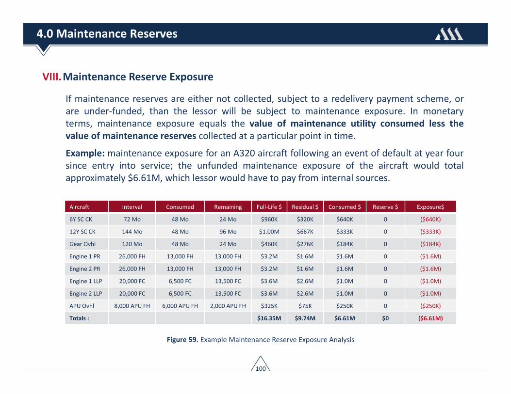
VIII.Maintenance Reserve Exposure
If maintenance reserves are either not collected, subject to a redelivery payment scheme, orare under‐funded, than the lessor will be subject to maintenance exposure. In monetaryterms, maintenance exposure equals the value of maintenance utility consumed less thevalue of maintenance reserves collected at a particular point in time.
Example: maintenance exposure for an A320 aircraft following an event of default at year foursince entry into service; the unfunded maintenance exposure of the aircraft would totalapproximately $6.61M, which lessor would have to pay from internal sources.
Figure 59. Example Maintenance Reserve Exposure Analysis
100
4.0 Maintenance Reserves
Aircraft Interval Consumed Remaining Full‐Life $ Residual $ Consumed $ Reserve $ Exposure$
6Y SC CK 72 Mo 48 Mo 24 Mo $960K $320K $640K 0 ($640K)
12Y SC CK 144 Mo 48 Mo 96 Mo $1.00M $667K $333K 0 ($333K)
Gear Ovhl 120 Mo 48 Mo 24 Mo $460K $276K $184K 0 ($184K)
Engine 1 PR 26,000 FH 13,000 FH 13,000 FH $3.2M $1.6M $1.6M 0 ($1.6M)
Engine 2 PR 26,000 FH 13,000 FH 13,000 FH $3.2M $1.6M $1.6M 0 ($1.6M)
Engine 1 LLP 20,000 FC 6,500 FC 13,500 FC $3.6M $2.6M $1.0M 0 ($1.0M)
Engine 2 LLP 20,000 FC 6,500 FC 13,500 FC $3.6M $2.6M $1.0M 0 ($1.0M)
APU Ovhl 8,000 APU FH 6,000 APU FH 2,000 APU FH $325K $75K $250K 0 ($250K)
Totals : $16.35M $9.74M $6.61M $0 ($6.61M)

VIII.Maintenance Reserve Exposure
Example : An event of default under Lessee 1 occurring at year four where no reserves werecollected, followed by an 8‐year lease with Lessee 2 where maintenance events have beenappropriately reserved for.
(10,000,000)(9,000,000)(8,000,000)(7,000,000)(6,000,000)(5,000,000)(4,000,000)(3,000,000)(2,000,000)(1,000,000)01,000,0002,000,0003,000,0004,000,0005,000,0006,000,0007,000,0008,000,0009,000,00010,000,000
(10,000,000)(9,000,000)(8,000,000)(7,000,000)(6,000,000)(5,000,000)(4,000,000)(3,000,000)(2,000,000)(1,000,000)
01,000,0002,000,0003,000,0004,000,0005,000,0006,000,0007,000,0008,000,0009,000,000
10,000,000
0 5 10 15 20 25 30 35 40 45 50 55 60 65 70 75 80 85 90 95 100 105 110 115 120 125 130 135 140
Cum
ulat
ive
Cas
hflo
esRev
enue
s
Term - Month
Maintenance Reserve Cashflow Summary
Reserve Revenue Reserve Expense Cumulative Cashflows Maintenance Exposure
Expe
nses
Lessee 1No ReservesDefault @ 48 Mo
Lessee 2Full ReservesTerm - 96 Mo
Reduction in exposure isoften achieved throughowner equity contributions
Figure 60. Example Maintenance Reserve Default Exposure Cash Flow Analysis
101
4.0 Maintenance Reserves
Section 5
Factors Affecting Maintenance Reserves
I. Airframe Heavy Structural CheckII. Landing Gear OverhaulIII. Engine Performance RestorationIV. Engine Life‐Limited PartsV. APU Heavy RepairVI. Thrust Reverser Overhaul
102

The greatest challenge of deriving maintenance reserve rates is attempting to predict thecosts, and on‐condition intervals, of maintenance events and fairly spreading these costs toboth lessor and lessee. In theory it sounds simple, however the uncertainty in predicting bothcosts and on‐condition intervals can lead to all kinds of difficulties, particularly with newequipment that has no documented maintenance history.
Each major maintenance event costs, and time on‐wing performance, are influenced by arange of factors. A summary of factors affecting each major maintenance event are detailed inFigure 61 below and further explained in this section.
103
5.0 Factors Affecting Maintenance Reserves
Mx Event Factors Affecting Cost & Time On‐Wing
Airframe Heavy Structural Inspection
Prevailing labor rates, maintenance phase (initial, aging), time between structural inspections, packaging of tasks
Landing Gear Overhaul Size & complexity, time between overhaul, maintenance phase (initial, aging), cost of exchange fee, operation (accumulation of flight cycles), market penetration of repair centers support the gear
APU Overhaul Overhaul phase (first or mature), region of operation, workscope
Engine Performance Restoration
Restoration phase (first or mature), flight leg, engine thrust & derate, region of operation, workscope
Engine Life‐Limited Parts (LLPs) OEM escalation, life‐limits (current vs. target), stub factor, flight leg (accumulation of flight cycles)
Thrust Reverser Overhaul Overhaul phase (first or mature), complexity of reversers
Figure 61. Summary of Factors Affecting Maintenance Reserves

I. Airframe Heavy Structural Inspection
Airframe HSI costs and timing of events are influenced by:
a. Material: From a maintenance perspective, composites have a far better resistance thanaluminum to fatigue (or the formation of cracks) and they do not corrode. Theseproperties produce immediate benefits when it comes to the number and frequency ofinspections that have to be performed on an aircraft.
b. Time Between Structural Inspection: MPD inspection intervals for corrosion and zonaltasks are used to assess optimal timing of structural inspection intervals. Mostcommercial aircraft time such events every 6‐12 years.
c. Packaging of Tasks: The MPD outlines the tasks used to build a customized airframemaintenance program. The routine maintenance tasks, and the rectification of anydeficiencies resulting from performance of such tasks, forms the basis for the qualifyingscope of work that is used to quantify airframe maintenance reserves.
d. Maintenance Phase: As an airframe ages its maintenance costs increases, primarily dueto higher levels of man‐hours & material required to rectify deficiencies resulting fromperformance of routine maintenance tasks. Airframe HSI reserves are thus adjusted toaccount for the phase of an airframe’s age.
104
5.0 Factors Affecting Maintenance Reserves

I. Airframe Heavy Structural Inspection
Example : Heavy Structural Inspection Calculation
► HSI Interval : 1st HSI = (108 Mo) , 2nd HSI (72 Mo) , 3rd HSI (72 Mo)
► HSI Cost : 9‐Year = $850K, 15‐Year = $1.2M, & 21‐Year = $1.5M
► Reserve Rate = HSI Cost ($) / HSI Interval (Months)
Rate ($/Month) $7,870 $13,888$11,111
Figure 62. Calculation of Airframe HSI Reserve Rates Based on Packaging of Tasks and Changes in Aircraft Age
105
5.0 Factors Affecting Maintenance Reserves

II. Landing Gear Overhaul
Landing gear overhaul costs and timing of events are influenced by:
a. Size & Complexity: Number of parts to inspect, repair and/or replace. Number ofmodifications to incorporate
b. Time Between Overhaul:MPD overhaul intervals for landing gears are generally calendar& cyclic limited, and for most models are in the region of 10‐12 years and 18,000‐21,000flight cycles. The timing of when the overhaul occurs is based on which of the above MPDintervals is more limiting (i.e. calendar time or cycles).
c. Maintenance Phase: Corrosion and metal fatigue increases markedly after the first 8‐12years of operation. Costs will subsequently increase after the first overhaul.
d. Exchange fee: Most airlines outsource their landing gear overhauls. Often times therepair center performing the overhaul will exchange the timed‐out unit with a zero‐timedunit. The cost for such exchange unit will account for an exchange fee, which is added tothe cost of overhaul. Exchange fees can range from $40K ‐ $80K for narrowbody gearsand from $150K ‐ $250K for widebody gears.
106
5.0 Factors Affecting Maintenance Reserves

II. Landing Gear Overhaul
Example: Landing Gear Reserve Computation
The following illustrates the derivation of landing gear reserve rates based on changes inaircraft utilization assuming:
► Overhaul Intervals : 120 Months & 20,000 FC, whichever is more limiting
► Overhaul Cost : $420,00 (inclusive of exchange fee)
► Reserve Rate = Cost ($) / Overhaul Interval (Months)
Operator Utilization RatioCyclic
Limiter ¹ Calendar Limiter Overhaul Limiter Reserve Rate
A 3,500 FH / 1,500 FC 2.30 160 Mo 120 Months 120 Months $3,500 / Month
B 3,500 FH / 2,000 FC 1.75 120 Mo 120 Months 120 Months $3,500 / Month
C 3,500 FH / 2,500 FC 1.40 96 Mo 120 Months 96 Months $4,375 / Month
D 3,500 FH / 3,000 FC 1.12 80 Mo 120 Months 80 Months $5,250 / Month
1 – Computed by dividing the gear cycle limiter (20,000 FC) by operator cyclic utilization
Figure 63. Example Landing Gear Reserve Rates Calculations Accounting for Changes in Aircraft Utilization
107
5.0 Factors Affecting Maintenance Reserves

III. Auxiliary Power Unit (APU) Heavy Repair
APU Heavy Repair costs & time on‐wing performance are influenced by:
a. Performance Degradation Factors: APU’s are on‐condition components subject to thefollowing performance degradation factors impacting cost and average time on‐wing:
► Flight Operation: APU average time on‐wing is sensitive to APU cycles; the greater thecyclic operation, the greater wear & tear on internal hardware, which leads to lowerthe time on‐wing performance;
► Maintenance Phase: The time to first removal is typically the longest. Subsequentruns and time on‐wing performance reduces as the APU ages.
► Environment: Operation in hot & erosive/corrosive environments leads to greaterperformance degradation, and lower time on‐wing
b. Workscope: APUs have a modular construction, general made up of: a.) Power section,b.) Load compressor, and c.) Gearbox. At a minimum, a qualifying workscope willgenerally require complete disassembly of the power section and load compressor.Effective APU workscoping requires consideration of the following:
► Reason for removal and work accomplished at last shop visit
► APU hours since last shop visit and since last Heavy Repair
108
5.0 Factors Affecting Maintenance Reserves

III. Auxiliary Power Unit (APU) Heavy Repair
Example: APU Heavy Repair Reserve Computation:
The following illustrates the derivation of APU reserve rates based on maturity status:
Mean‐Time Between Removal (MTBR): 8,200 APU FH (Initial) / 6,900 APU (Mature)
Average Heavy Repair Cost : $300,000 (Initial) , $325,000 (Mature)
Reserve Rate = Heavy Repair Cost ($) / MTBR (APU FH)
Rate = $36.00 / APU FH
Rate = $47.00 / APU FH
Figure 64. Example Initial and Mature APU Overhaul Reserve Rate Calculation
109
5.0 Factors Affecting Maintenance Reserves
IV. Engine Performance Restoration
Engine performance restoration costs & time on‐wing performance are influenced by:
a. Engine Performance Degradation (EGT Margin Erosion)
i. Engine Thrust Rating,
ii. Flight Operation
► Flight Leg;
► Average Thrust Derate;
► Ambient Temperatures
► Operating Environment;
iii. Age (first‐run vs. mature‐run)
b. Engine Workscope Planning
110
5.0 Factors Affecting Maintenance Reserves

IV. Engine Performance Restoration
a. Engine Performance Degradation :
i. Engine Thrust Rating
For a given engine variant, EGT margin deteriorates faster when operating at higher thrustlevels – see Figure 63. Higher thrust generates higher core temperatures, which exposesconstituent parts in the engine to greater thermal stress. Reducing thrust will: a.) Slow EGTdeterioration, b.) Reduces fuel‐flow and c.) Lowers maintenance costs by increasing timebetween shop visits.
Same Engine Model Goes Into Shop
EGT
Engine Flight Cycles
Red Line
2,000 4,000 6,000 8,000 10,000Engine Flight Cycles
2,000 4,000 6,000 8,000
Lower take‐off thrust:• Higher initial EGT Margin• Lower EGTM deterioration
Low Thrust Variant High Thrust Variant
Higher take‐off thrust:• Lower initial EGT Margin• Higher EGTM deterioration
Figure 65. Effect of Thrust on Engine Time On‐Wing
111
5.0 Factors Affecting Maintenance Reserves
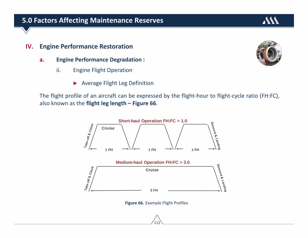
IV. Engine Performance Restoration
a. Engine Performance Degradation :
ii. Engine Flight Operation
► Average Flight Leg Definition
The flight profile of an aircraft can be expressed by the flight‐hour to flight‐cycle ratio (FH:FC),also known as the flight leg length – Figure 66.
Cruise
1 FH
Cruise
3 FH
Short-haul Operation FH:FC = 1.0
1 FH 1 FH
Medium-haul Operation FH:FC = 3.0
Figure 66. Example Flight Profiles
112
5.0 Factors Affecting Maintenance Reserves

IV. Engine Performance Restoration
a. Engine Performance Degradation :
ii. Engine Flight Operation
► Average Flight Leg
As the flight length reduces an engine spends a larger proportion of total flight time using take‐off and climb power settings. In most instances the effect of shorter stage length operation ismore rapid performance deterioration leading to greater direct maintenance cost per flighthour while longer flight legs equates to higher time on‐wing (TOW) & lower DirectMaintenance Costs (DMC) – Figure 67.
Figure 67. Effect of Flight Leg on Engine DMC
113
5.0 Factors Affecting Maintenance Reserves

IV. Engine Performance Restoration
a. Engine Performance Degradation :
ii. Engine Flight Operation
► Average Thrust Derate
The take‐off derate thrust is a takeoff thrust setting that is below the maximum thrust level; aderate selection electronically reduces the rated thrust of the engine to either one or morepre‐specified values or by a selectable percentage of the normal flat rated thrust. Larger deratetranslates into lower take‐off EGT and lower engine deterioration rates, longer on‐wing life &reduced direct maintenance cost, while lower derate generates higher core temperatures,which exposes constituent parts in the engine to greater thermal stress – Figure 68.
Figure 68. Effect of Derate on Engine DMC
114
5.0 Factors Affecting Maintenance Reserves

IV. Engine Performance Restoration
a. Engine Performance Degradation :
Example: Figure 69 ‐ Engine Reserves Accounting for Flight‐Leg & Engine Derate
Figure 69. Example Engine Performance Restoration DMC Matrix Accounting for Flight Profile and Derate
115
5.0 Factors Affecting Maintenance Reserves
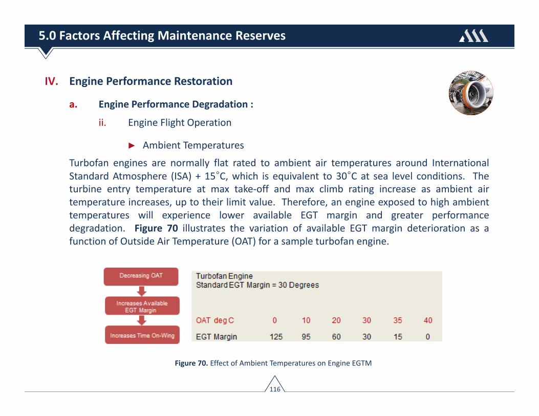
IV. Engine Performance Restoration
a. Engine Performance Degradation :
ii. Engine Flight Operation
► Ambient Temperatures
Turbofan engines are normally flat rated to ambient air temperatures around InternationalStandard Atmosphere (ISA) + 15°C, which is equivalent to 30°C at sea level conditions. Theturbine entry temperature at max take‐off and max climb rating increase as ambient airtemperature increases, up to their limit value. Therefore, an engine exposed to high ambienttemperatures will experience lower available EGT margin and greater performancedegradation. Figure 70 illustrates the variation of available EGT margin deterioration as afunction of Outside Air Temperature (OAT) for a sample turbofan engine.
Figure 70. Effect of Ambient Temperatures on Engine EGTM
116
5.0 Factors Affecting Maintenance Reserves

IV. Engine Performance Restoration
a. Engine Performance Degradation :
ii. Engine Flight Operation
► Operating Environment
Engines operated in hot‐sandy and/or erosive‐corrosive environments are exposed to greaterhardware distress and thus greater EGT margin deterioration, which translates into both highershop visit costs and lower time on‐wing (TOW) performance – as illustrated in Figure 71.
Figure 71. Effect of Environment on Engine DMC
Temperate :
Harsh‐Mild :
Harsh‐High :
SV$ TOW (FH) $/FH
$3.0M
$3.2M
$3.4M
25K FH
22K FH
16K FH
$120/FH
$145/FH
$213/FH
117
5.0 Factors Affecting Maintenance Reserves

IV. Engine Performance Restoration
a. Engine Performance Degradation :
ii. Engine Flight Operation
► Operating Environment ‐ example effects from operation in harshenvironment – Figure 72.
Dirt liberation leading to HPT blade burn
HPCblade
erosion Combustorburn
through
HPT shroud
oxidationLPT Nozzle corrosion
HPT nozzledistress dueto plugging
HPT bladeburning fromdirt plugging
Figure 72. Impact of Harsh Environmental Operation on Engine Components
118
5.0 Factors Affecting Maintenance Reserves

IV. Engine Performance Restoration
a. Engine Performance Degradation :
iii. Engine Age
Older engines generally cost more to maintain than newer engines. As an engine ages itsaverage time to shop visit lessens ‐ Figure 73. First‐run engines often operate considerablylonger on‐wing than mature engines. In fact, it is not uncommon to see first‐run enginesremaining on‐wing 20%‐30% longer than mature run engines. As the engine ages adisproportionate amount of parts experience higher deterioration rates, higher scrap rates,and correspondingly higher engine maintenance cost.
1st SV 2nd SV 3rd SV
20,000 FH 16,000 FH 15,000 FHAs an Engine Ages
Hardware Deterioration
Higher Maintenance Costs
Figure 73. Impact of Engine Age on Time On‐Wing and DMC
119
5.0 Factors Affecting Maintenance Reserves

IV. Engine Performance Restoration
a. Engine Performance Degradation :
Example: Figure 74 ‐ Engine Reserves Accounting for Flight‐Leg, Derate, Age & OperatingEnvironment
Figure 74. Example Engine Performance Restoration DMC Matrix Accounting for Flight Profile, Derate, Environment & Age
120
5.0 Factors Affecting Maintenance Reserves
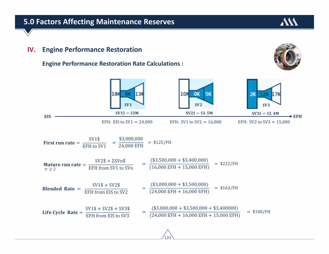
IV. Engine Performance Restoration
Engine Performance Restoration Rate Calculations :
SV1$
EFHtoSV1
SV1$ SV2$
EFHfromEIStoSV2
SV1$ SV2$ SV3$EFHfromEIStoSV3
SV2$ ΣSVn$
EFHfromSV1toSVnn 2
EFH: EIStoSV1 24,000 EFH: SV1toSV2 16,000 EFH: SV2toSV3 15,000
$ $ $ $ . $ $ .
$3,000,00024,000EFH
$125/FH
$3,500,000 $3,400,00016,000EFH 15,000EFH
$222/FH
$3,000,000 $3,500,00024,000EFH 16,000EFH
$163/FH
$3,000,000 $3,500,000 $3,40000024,000EFH 16,000EFH 15,000EFH
$180/FH
121
5.0 Factors Affecting Maintenance Reserves

V. Engine Life‐Limited Parts (LLP)
Engine LLP costs & time on‐wing are influenced by:
a. Engine manufacturer’s catalog piece‐part price : LLPs are subject to annual OEMescalation averaging over 5%/yr. for narrowbody engines and over 7%/yr. for widebody.
b. Engine manufacturer’s published life limits : The declared lives of LLPs are referenced inChapter 5 of an engine’s shop/overhaul manual, and typically range between 15,000 ‐30,000 cycles. Some manufacturers certify ultimate lives of LLPs at the time they certifyan engine model. Other manufacturers certify the lives as experience is accumulated. Inthese scenarios, ultimate lives are reached after one or several life extensions.
%100
50
LLP Piece Part ‐ Maintenance Utility Profile
EIS FirstSV
SecondSV
ThirdSV
Stub / Green Time Loss – 5% ‐ 15%
Full‐life
Half‐life
Maintenance Utility
%
c. LLP stub‐life factor : The term stub‐life isused to represent the shortest liferemaining of all LLPs installed. Industrystandard is to assume Engine LLPs willnever consume 100% of their life limits,and instead will retain 5%‐15% atreplacement – Figure 75.
Figure 75. LLP Stub‐Life Factor
122
5.0 Factors Affecting Maintenance Reserves
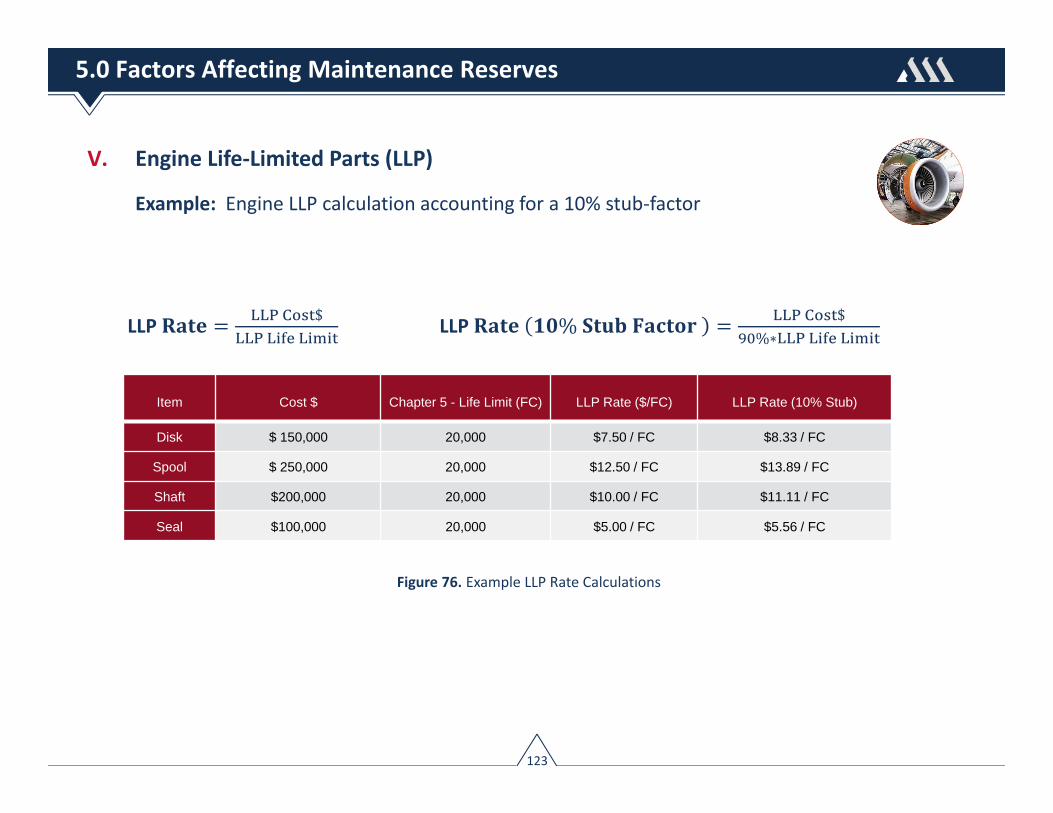
V. Engine Life‐Limited Parts (LLP)
Example: Engine LLP calculation accounting for a 10% stub‐factor
LLP % $%∗
LLP $
Figure 76. Example LLP Rate Calculations
123
5.0 Factors Affecting Maintenance Reserves
Item Cost $ Chapter 5 - Life Limit (FC) LLP Rate ($/FC) LLP Rate (10% Stub)
Disk $ 150,000 20,000 $7.50 / FC $8.33 / FC
Spool $ 250,000 20,000 $12.50 / FC $13.89 / FC
Shaft $200,000 20,000 $10.00 / FC $11.11 / FC
Seal $100,000 20,000 $5.00 / FC $5.56 / FC

VI. Thrust Reverser Overhaul
Thrust reverser overhaul costs and timing of events are influenced by:
a. Size & Complexity: High bypass ratio engines have wider intakes and bypass ducts, usecomplex blocker door reversers and more sophisticated actuation systems.
b. Time Between Overhaul: Thrust reversers are on‐condition components subject to thefollowing performance degradation factors that impact average time on‐wing:
► Flight Operation: Hard reversing action at landing by flight crews will acceleratedegradation. The same applies to corrosive environments.
► Soft‐time Removals: Removal intervals as a guide are decided by each airline andrepair agency, rather than pure on‐condition removals.
c. Workscope Planning: Reverser repair or overhauls are based on the manufacturers’workscope planning guide, which include basic overhaul, routine repairs and out ofworkscope items. These are the replacement of parts due to conditions that exceed therepairable limits.
124
5.0 Factors Affecting Maintenance Reserves

Section 6
Flight Hour Agreements
I. Advantages & DisadvantagesII. Payment OptionsIII. Term OptionsIV. Flexibility & Portability Options
125

Under a Flight‐Hour Agreement (FHA) an operator pays a service provider an hourly rate basedon the number of engine hours flown & the engine OEM covers all product upgrades & shopvisits during the FHA term. Rates offered by the engine OEM are conditional upon specificoperating conditions (e.g. average flight leg, derate, operating environment), the term of theFHA, and the hardware standard of engines.
Inducting new engines into an FHA is generally simple, however if the airline/financier intendsto add used engines into the agreement, then it can become complicated. If the parameters ofthe engines to be added are significantly different from the assumed parameters, theairline/financier will need to do a qualifying shop visit on the relevant engines before they areinducted into the OEM agreement. Such qualifying shop visits will usually be charged on timeand material basis and usually significantly more expensive.
126
6.0 Flight‐Hour Agreement (FHA)

I. Advantages & Disadvantages
FHA Advantages:
► Cost visibility ‐ smoothing of expenditure designed principally to address the cost andtiming uncertainties inherent in traditional time and material contracts;
► Reduces resource constraints ‐ relieves operators with limited resources and technicalexpertise for the need to hire personnel and purchase stocks of engines and accessories;
► Mitigates new engine technology risks – risks associated with next generation technologyengines can be mitigated;
► Comfort that engines are maintained to highest standards ‐ assurance that engines arebeing maintained to the highest standards by excluding use of Part Manufacturing Approval(PMA) parts and Designated Engineering Representative (DER) repairs
FHA Disadvantages:
► Access to Cash – some packages don’t allow for any cash to be refunded at any point, onlycredits for future maintenance work will be provided;
► Reduces Aftermarket Competition – creating situations where there is no aftermarketcompetition on any level, and where the OEM controls all commercial aspects;
► Increasingly complicated agreements that are difficult to decipher and analyze
127
6.0 Flight‐Hour Agreement (FHA)

II. Payment Options
1. Pay‐As‐You‐Go – Payments are made to the service provider as the engines accrue time………. most FHA contracts are PAYG
2. Pay‐At‐Shop Visit – Payments are made at shop visit based on a hourly rate provided bythe service provider.
III. Term Options – Figure 771. Fixed ‐ Fixed period of time:
e.g. 12 years from EIS
2. Shop Visit ‐ Fixed number ofshop visits: e.g. coincidingwith 1st shop visit
3. Hybrid ‐ In effect until thelater of a fixed term or untilsuch engine has received ashop visit
4. Engine Life Based – Througheconomic life of aircraft Figure 77. FHA Term Options
128
6.0 Flight‐Hour Agreement (FHA)

IV. Flexibility & Portability Options
► Step‐in Option – Figure 78 Lessor or subsequent lessee assumes relevant rights & obligations and shall be entitled to apply the
paid‐in funds as credits toward the costs of restoration shop visit performed by OEM.
FHA continues with lessor or next lessee until next SV or beyond
Figure 78. FHA Step‐In Option
129
6.0 Flight‐Hour Agreement (FHA)

IV. Flexibility & Portability Options
► Subsequent Shop Visit Option – Figure 79 FHA terminates at default and next lessee opt out of FHA
OEM and lessor shall cover the cost of the next shop visit ; lessor free to collect maintenance reserves
The costs of such visit shall be determined either at the time of such shop visit or fixed in advance
Lessor collectsagreed reserverate ($/FH)
Lessee collectsagreed FHArate ($/FH)
Figure 79. FHA Subsequent Shop Visit Option
130
6.0 Flight‐Hour Agreement (FHA)

Section 7
Part Manufacturing Approval (PMA)
I. PMA BackgroundII. Licensed vs. Competitive PMAIII. PMA Part ClassificationIV. Financier Concerns
131
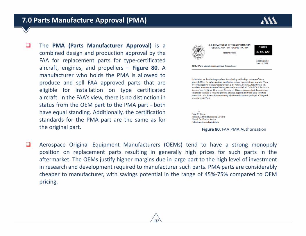
The PMA (Parts Manufacturer Approval) is acombined design and production approval by theFAA for replacement parts for type‐certificatedaircraft, engines, and propellers – Figure 80. Amanufacturer who holds the PMA is allowed toproduce and sell FAA approved parts that areeligible for installation on type certificatedaircraft. In the FAA’s view, there is no distinction instatus from the OEM part to the PMA part ‐ bothhave equal standing. Additionally, the certificationstandards for the PMA part are the same as forthe original part.
Aerospace Original Equipment Manufacturers (OEMs) tend to have a strong monopolyposition on replacement parts resulting in generally high prices for such parts in theaftermarket. The OEMs justify higher margins due in large part to the high level of investmentin research and development required to manufacturer such parts. PMA parts are considerablycheaper to manufacturer, with savings potential in the range of 45%‐75% compared to OEMpricing.
Figure 80. FAA PMA Authorization
132
7.0 Parts Manufacture Approval (PMA)

I. Approval Process
The applicant for a PMA must apply in a form and manner prescribed by the FAA. To obtain FAAapproval to produce (manufacture) PMA parts for sale, the PMA applicant must:
► Provide a design package to the FAA showing that the PMA part is at least equal to the OEMpart in form, fit and function (without having to rely on the OEMs proprietary drawings).
► Submit an extensive data package describing the design, including materials, processes, testspecifications, compatibility and interchangeability analysis and maintenance instructions.
► Prove that they have a production system with the necessary quality controls to reliablyand repetitively produce parts that conform to the approved design.
► Include a review of the OEMs maintenance instructions and any Instructions for ContinuedAirworthiness (ICAs) and life limits. The applicant must state that the existing maintenanceinstructions, ICAs and life limits are still applicable with the PMA parts installed or theapplicant must provide replacement instructions, ICAs and life limits.
► Indicate the aircraft and model types on which the parts are to be installed and the FAAapproval will reflect this limitation.
133
7.0 Parts Manufacture Approval (PMA)
I. Approval Process
All PMA parts must be identified and in most cases marked with specified information:
► The words “FAA‐PMA”
► The PMA manufacturer’s name, trademark or symbol
► A part number
► Exceptions are allowed where it is impractical to mark the part but, in this case, a tag musthave the above information.
This information is required for traceability of the PMA part and to distinguish it from the OEMpart. Airlines should add the PMA part number to their purchasing and inventory controlsystem, and update the appropriate IPC showing maintenance personnel where use of the parthas been authorized.
PMA parts can be used in any country that has a bilateral agreement with the FAA, providedthe agreement or implementation procedure permit PMA parts.
134
7.0 Parts Manufacture Approval (PMA)

II. Licensed vs. Competitive PMA
There are generally two standards of PMA suppliers: 1.) Licensed PMA suppliers , and 2.)Competitive PMA Suppliers. Licensed PMA suppliers cooperate with the OEMs to produceparts for aircraft. Since the OEM is providing a design that has already been approved by theFAA to the PMA applicant, there is no requirement for the FAA to provide design approval.Licensed parts meet the following requirements:
► Same parts as production
► Same quality and process control as original equipment
► License meets PMA by FAA identicality classification
An example of a licensed PMA supplier is GoodrichCorporation, which entered into a data license withBoeing allowing the use of detail engineering design toobtain Parts Manufacturing Approval (PMA) forreplacement landing gear spare parts. The license willpermit Goodrich to manufacture licensed PMA partsunder Goodrich's FAA approved quality system anddistribute directly to operators – Figure 81. Figure 81. Example Licensed PMA Supplier
135
7.0 Parts Manufacture Approval (PMA)

II. Licensed vs. Competitive PMA
Competitive PMA suppliers actively compete withOEMs. These suppliers use test & computation (reverse‐engineering) as the means to prove the PMA part isequal to or better than the approved original part. MostPMA parts now use test & computation for designsubstantiation. An example of a competitive PMA part isPW4000 HPT blades manufactured by BELAC – Figure 82. Figure 82. Example Competitive PMA Supplier
136
7.0 Parts Manufacture Approval (PMA)

III. PMA Part Classification
PMA suppliers are required to identify the criticality of the part. This is done by means of afailure modes & effects analysis for the particular part in addition to the part’s next higherassembly. Every possible way the part could fail is examined and the consequences of thefailure are assessed. Based on this analysis the part is classed as critical / complex (possiblyaffecting the performance of either the equipment), or non‐critical (all the rest) – see Figure83. A part is often considered critical if the assessment shows hazardous condition from theeffects of failure.
Non‐Critical Consumable Parts Critical HPC & HPT Blades
Figure 83. Example Critical vs. Non‐Critical PMA Parts
137
7.0 Parts Manufacture Approval (PMA)

IV. Financier Concerns
Financiers policy with regards to PMA will vary depending on the aircraft/engine vintage andwhere such parts are to be used. Lessors, in particular, continue to highlight key concernsregarding PMA parts, which relate to: 1.) Asset re‐marketability & transferability, and 2.)Residual value impairment
1. Asset re‐marketability and the ability to seamlessly transition aircraft between regulatoryjurisdictions are often cited as the leading factors that drive aircraft lessor’s aversion toPMA parts.
2. Residual value impairment, both related to decreased marketability and due to perceivedlower cost PMA parts.
For these reasons, as well as the fact that many PMA parts are classed critical, most lessors willmake a clear distinction between non‐critical PMA parts versus critical; The policy will generallydictate that acceptance of non‐critical PMA parts for usage on the airframe or cabin interior isgenerally accepted, and use of critical PMA parts will not be approved for usage under anycircumstances.
138
7.0 Parts Manufacture Approval (PMA)

Section 8
Designated Engineering Representative (DER) Repairs
I. BackgroundII. DER Repair Standards, Applications
& Cost Savings
139

Designated Engineering Representatives (DERs)are private individuals (independent professionalsor staff engineers in the repair center) designatedby the FAA whom may approve or recommendapproval of engineering technical data within thelimits of their authority by means of Form 8110‐3.A recommendation for approval of technical datafor a finding of compliance to airworthinessstandards can only be made by an authorized DER– Figure 84.
A strategy available to airlines to reduce expenses for materials is to repair rather than replaceparts that are worn or damaged. This is particularly applicable to expensive engine parts.Repairs approved under FAA regulations by airworthiness engineers who are delegated toapprove repair and repair processes are referred to as DER (Designated EngineeringRepresentative) Repairs.
Figure 84. FAA DER Authority
140
8.0 Designated Engineering Representative (DER) Repairs

I. Background
Traditionally, the engine OEMs have published “standard” repair schemes in the engine shopmanuals. However, over the past 10‐15 years, the OEMs’ strategy to profit from theaftermarket has resulted in fewer repairs being included in their manuals. Instead, repairsdeveloped by OEMs have been provided to individual MROs only after license agreementshave been completed and royalty payments agreed. OEMs may also recommend replacingparts rather than repairing because their cost to manufacture a new part is a small fraction ofthe catalogue list price of the part.
Today, operators have an array of choices when it comes to deciding what to do about worn ordamaged parts. Among the options are:
► Buying a new part from an original equipment manufacturer (OEM), having the partrepaired by an OEM‐affiliated repair station,
► Buying a new Parts Manufacturer Approval (PMA) component from a non‐OEMsource, and
► Obtaining a Designated Engineering Representative (DER)‐ approved repair.
The choice depends on factors such as the age of the aircraft, the part’s warranty status, thecost of the various options, and the likely turnaround times for part delivery or repair approval.
141
8.0 Designated Engineering Representative (DER) Repairs

II. DER Standards, Applications & Cost Savings
A DER repair is a repair process and configuration thathas met all the specifications for development,performance, reliability, and safety, and has beenvalidated and certified by an FAA‐authorized DER.
DER repairs have to conform to the sameairworthiness standards as new OEM parts or OEMmanual repairs in order to maintain the same level ofsafety; the minimum requirement is to restore a partto its original function and level of safety. DER Repairscan range from equivalent OEM repairs to advancedrepairs that often go beyond the basic repairs found inthe OEM manual – example DER Repair in Figure 85.
DER repairs are most common in the engine area because these assemblies are high‐cycleand under great service stress. Auxiliary power units (APUs) would be next, along with landinggears, which are subject to repetitive dynamic loads.
If a part can be repaired, the DER route may be the most cost‐effective way to go, particularlyif the airplane is out of warranty and the part is complex, costly, and difficult to obtain in atimely manner. The cost savings associated with DER repairs can be significant; ranging from15 to 40 percent of the OEM part cost.
Figure 85. DER Repaired Compressor Blades
142
8.0 Designated Engineering Representative (DER) Repairs

I. Typical Narrowbody Airframe Heavy Structural Check DMCsAircraft Check Interval Initial Costs Initial ($ / Mo) Ageing Costs Ageing ($ / Mo)
A319‐100 6Y SC 72 Mo $775K ‐ $875K $10,800 ‐ $12,100 $1.0M ‐ $1.1M $13,800 ‐ $15,200
A319‐100 12Y SC 144 Mo $825K ‐ $925K $5,700 ‐ $6,400 $1.1M ‐ $1.2M $7,600 ‐ $8,300
A320‐200 6Y SC 72 Mo $800K ‐ $900K $11,100 ‐ $12,500 $1.05M ‐ $1.15M $14,500 ‐ $15,900
A320‐200 12Y SC 144 Mo $850K ‐ $950K $5,900 ‐ $6,600 $1.15M ‐ $1.25M $7,900 ‐ $8,600
A321‐200 6Y SC 72 Mo $825K ‐ $925K $11,500 ‐ $12,800 $1.05M ‐ $1.15M $14,500 ‐ $15,900
A321‐200 12Y SC 144 Mo $875K ‐ $975K $6,000 ‐ $6,800 $1.2M ‐ $1.3M $8,300 ‐ $9,000
B737‐700 8Y SC 96 Mo $625K ‐ $725K $6,500 ‐ $7,500 $825K ‐ $925K $8,500 ‐ $9,600
B737‐700 10Y SC 120 Mo $350K ‐ $450K $2,900 ‐ $3,750 $500K ‐ $600K $4,100 ‐ $5,000
B737‐700 12Y SC 144 Mo $850K ‐ $950K $5,900 ‐ $6,600 $1.0M ‐ $1.2M $6,900 ‐ $8,300
B737‐800 8Y SC 96 Mo $650K ‐ $750K $6,800 ‐ $7,800 $850K ‐ $975K $8,800 ‐ $10,100
B737‐800 10Y SC 120 Mo $375K ‐ $475K $3,100 ‐ $3,900 $525K ‐ $625K $4,300 ‐ $5,200
B737‐800 12Y SC 144 Mo $875K ‐ $975K $6,000 ‐ $6,800 $1.05M ‐ $1.25M $7,200 ‐ $8,600
B737‐900 8Y SC 96 Mo $675K ‐ $775K $7,000 ‐ $8,000 $875K ‐ $1.0M $9,100 ‐ $10,400
B737‐900 10Y SC 120 Mo $400K ‐ $500K $3,300 ‐ $4,100 $550K ‐ $650K $4,500 ‐ $5,400
B737‐900 12Y SC 144 Mo $925K ‐ $1.05M $6,400 ‐ $7,200 $1.1M ‐ $1.3 M $7,600 ‐ $9,000
143
Assumptions: • 2018 USD• Includes labor & material for all routine and associated non‐routine maintenance tasks• Includes cost of interior refurbishment & upkeep• A320 family 12Y SC costs excludes the costs affiliated with the 6Y SC• Includes cost of strip & paint for 12Y structural checks
Appendix A – Typical Aircraft Maintenance Reserves

Aircraft Check Interval Initial Costs Initial ($ / Mo) Ageing Costs Ageing ($ / Mo)
A330‐200 6Y SI 72 Mo $1.55M ‐ $1.75M $21,500 ‐ $24,300 $2.00M ‐ $2.30M $27,500 ‐ $31,500
A330‐200 12Y SI 144 Mo $1.65M ‐ $1.85M $11,400 ‐ $12,800 $2.10M ‐ $2.30M $14,500 ‐ $16,500
A333‐300 6Y SI 72 Mo $1.60M ‐ $1.80M $22,200 ‐ $25,000 $2.10M ‐ $2.40M $29,000 ‐ $33,000
A330‐300 12Y SI 144 Mo $1.70M ‐ $1.90M $11,800 ‐ $13,100 $2.20M ‐ $2.50M $15,200 ‐ $17,300
A350‐900 12Y SI 144 Mo $2.70M ‐ $3.00M $18,750 – $20,800 $3.30M ‐ $3.60M $22,900 – $25,000
B777‐200 8Y SI 96 Mo $3.20M ‐ $3.60M $33,250 ‐ $37,500 $3.70M ‐ $4.20M $38,500 ‐ $43,750
B777‐300 8Y SI 96 Mo $3.40M ‐ $3.80M $35,500 ‐ $39,500 $3.90M ‐ $4.40M $40,600 ‐ $45,800
B787‐8 12Y SI 144 Mo $2.30M ‐ $2.60M $16,000 ‐ $18,000 $2.90M ‐ $3.20M $20,000 ‐ $22,200
B787‐9 12Y SI 144 Mo $2.40M ‐ $2.70M $16,700 ‐ $18,750 $3.00M ‐ $3.30M $20,800 ‐ $22,900
B787‐10 12Y SI 144 Mo $2.50M ‐ $2.80M $17,400 ‐ $19,400 $3.10M ‐ $3.40M $21,500 ‐ $23,600
144
II. Typical Widebody Airframe Heavy Structural Check Reserves
Assumptions: • 2018 USD• Includes labor & material for all routine and associated non‐routine maintenance tasks• Includes cost of interior refurbishment & upkeep• Includes cost of strip & paint for 8Y (B777) and 12Y (A330, A350, & 787) structural checks• A330 family 12Y SC costs excludes the costs affiliated with the 6Y SC
Appendix A – Typical Aircraft Maintenance Reserves
III. Typical Widebody Thrust Reverser Overhaul Reserves (per reverser, 2 per aircraft)Aircraft Interval (Months) Initial Costs ($/Unit) Initial ( $/Mo) Ageing Costs ($/Unit) Ageing ($/Mo)
A330 96 – 120 $500K ‐ $600K $9,200 ‐ $11,600 $600K ‐ $700K $11,600 ‐ $13,500
A350 96 – 120 $750K ‐ $850K $14,000 ‐ $16,600 $850K ‐ $950K $15,000 ‐ $18,750
777 96 – 120 $800K ‐ $900K $15,000 ‐ $17,700 $900K ‐ $1.0M $15,800 ‐ $19,700
787 96 – 120 $750K ‐ $850K $14,000 ‐ $16,600 $850K ‐ $950K $15,000 ‐ $18,750

IV. Typical Landing Gear Overhaul Reserves
145
Aircraft Intervals Initial Costs Initial ($ / Mo) Ageing Costs Ageing ($ / Mo)
A320 120 Mo / 20,000 FC $440K ‐ $480K $3,600 ‐ $4,000 $500K ‐ $540K $4,100 ‐ $4,500
A320 NEO 144 Mo / 20,000 FC $450K ‐ $490K $3,125 ‐ $3,400 $510K ‐ $550K $3,500 ‐ $3,800
A330 120 Mo / 20,000 FC $850K ‐ $950K $7,000 ‐ $7,900 $950K ‐ $1.05M $7,900 ‐ $8,750
A350 144 Mo / 16,700 FC $1.05M ‐ $1.15M $7,300 ‐ $8,000 $1.15M ‐ $1.35M $8,000 ‐ $9,400
737NG 120 Mo / 20,000 FC $400K ‐ $440K $3,300 ‐ $3,700 $460K ‐ $500K $3,800 ‐ $4,100
777 120 Mo / 20,000 FC $1.00M ‐ $1.20M $8,300 ‐ $10,000 $1.10M ‐ $1.30M $9,100 ‐ $10,800
787 144 Mo / 21,000 FC $850K ‐ $950K $5,900 ‐ $6,600 $950K ‐ $1.15M $6,600 ‐ $8,000
Aircraft Interval (APU FH) Initial Costs Initial ( $/APU FH) Ageing Costs Ageing ($/APU FH)
A320 7,000 – 9,000 $320K ‐ $360K $38.00 ‐ $44.00 $350K ‐ $400K $40.00 ‐ $46.00
A330 5,000 – 7,000 $450K ‐ $550K $70.00 ‐ $80.00 $480K ‐ $580K $75.00 ‐ $85.00
A350 5,000 – 7,000 $450K ‐ $550K $70.00 ‐ $80.00 $480K ‐ $580K $75.00 ‐ $85.00
737NG 7,000 – 9,000 $320K ‐ $360K $38.00 ‐ $44.00 $350K ‐ $400K $40.00 ‐ $46.00
777 5,000 – 7,000 $550K ‐ $650K $85.00 ‐ $95.00 $580K ‐ $680K $90.00 ‐ $100.00
787 5,000 – 7,000 $450K ‐ $550K $70.00 ‐ $80.00 $480K ‐ $580K $75.00 ‐ $85.00
V. Typical APU Heavy Repair Reserves
Assumptions: • 2018 USD• Cost of landing gear overhaul includes cost of exchange Fee• APU ‐ Excludes Life‐Limited Parts (LLPs)
Appendix A – Typical Aircraft Maintenance Reserves

VI. Typical Narrowbody Engine First‐Run Performance Restoration ReservesEngine Thrust Phase Fl Leg Time On‐Wing (FC) Costs Rate ($ / FH)
CFM56‐5B6/3 23,500 First‐Run 2.0 16,500 ‐ 17,500 $3.30M ‐ $3.50M $90‐ $105
CFM56‐5B4/3 27,000 First‐Run 2.0 14,500 ‐ 15,500 $3.25M ‐ $3.45M $110 ‐ $125
CFM56‐5B3/3 33,000 First‐Run 2.0 11,000 – 12,000 $3.25M ‐ $3.45M $135 ‐ $150
V2524‐A5 S1 24,000 First‐Run 2.0 15,000 ‐ 16,000 $3.20M ‐ $3.40M $100 ‐ $115
V2527‐A5 S1 27,000 First‐Run 2.0 12,000 ‐ 13,000 $3.20M ‐ $3.40M $115 ‐ $130
V2533‐A5 S1 33,000 First‐Run 2.0 9,500 – 10,500 $3.20M ‐ $3.40M $160 ‐ $175
LEAP‐1A24 24,400 First‐Run 2.0 16,500 ‐ 17,500 $3.30M ‐ $3.60M $105 ‐ $120
LEAP‐1A26 26,600 First‐Run 2.0 12,000 – 13,000 $3.30M ‐ $3.60M $125 ‐ $140
LEAP‐1A33 32,900 First‐Run 2.0 9,500 – 10,500 $3.30M ‐ $3.60M $165 ‐$180
PW1124G 24,490 First‐Run 2.0 16,500 ‐ 17,500 $3.20M ‐ $3.50M $100 ‐ $115
PW1127G 26,650 First‐Run 2.0 12,000 – 13,000 $3.20M ‐ $3.50M $120 ‐ $135
PW1133G 33,000 First‐Run 2.0 9,500 – 10,500 $3.20M ‐ $3.50M $160 ‐$175
CFM56‐7B24E 24,000 First‐Run 2.0 16,500 ‐ 17,500 $3.30M ‐ $3.50M $90 ‐ $105
CFM56‐7B26E 26,300 First‐Run 2.0 14,500 ‐ 15,500 $3.20M ‐ $3.40M $100 ‐ $115
CFM56‐7B27E 27,300 First‐Run 2.0 13,000 ‐ 14,000 $3.20M ‐ $3.40M $115 ‐ $130
LEAP‐1B25 25,000 First‐Run 2.0 14,500 – 15,500 $3.30M ‐ $3.60M $105 ‐ $120
LEAP‐1B27 26,400 First‐Run 2.0 12,000 – 13,000 $3.30M ‐ $3.60M $125 ‐ $140
LEAP‐1B28 27,900 First‐Run 2.0 11,500 – 12,500 $3.30M ‐ $3.60M $130 ‐ $145
146
Assumptions: • 2018 USD• Repair, overhaul or replacement of thrust reversers and non‐modular components, such as QEC, LRU or accessory units is not included • Excludes Life‐Limited Parts (LLPs)• Temperate environment• 10% Derate
Appendix A – Typical Aircraft Maintenance Reserves

VI. Typical Narrowbody Engine Mature‐Run Performance Restoration ReservesEngine Thrust Phase Fl Leg Time On‐Wing (FC) Costs Rate ($ / FH)
CFM56‐5B6/3 23,500 Mature‐Run 2.0 10,500 ‐ 11,500 $3.30M ‐ $3.60M $140‐ $165
CFM56‐5B4/3 27,000 Mature‐Run 2.0 9,000 – 10,000 $3.30M ‐ $3.60M $155 ‐ $180
CFM56‐5B3/3 33,000 Mature‐Run 2.0 8,000 – 9,000 $3.30M ‐ $3.60M $180 ‐ $205
V2524‐A5 S1 24,000 Mature‐Run 2.0 11,000 ‐ 12,000 $3.40M ‐ $3.70M $135 ‐ $160
V2527‐A5 S1 27,000 Mature‐Run 2.0 9,000 ‐ 10,000 $3.40M ‐ $3.70M $160 ‐ $185
V2533‐A5 S1 33,000 Mature‐Run 2.0 8,000 – 9,000 $3.40M ‐ $3.70M $185 ‐ $210
LEAP‐1A24 24,400 Mature‐Run 2.0 10,500 ‐ 11,500 $4.00M ‐ $4.40M $160 ‐ $185
LEAP‐1A26 26,600 Mature‐Run 2.0 9,500 – 10,500 $4.00M ‐ $4.40M $190 ‐ $215
LEAP‐1A33 32,900 Mature‐Run 2.0 7,500 – 8,500 $4.00M ‐ $4.40M $255 ‐$280
PW1124G 24,490 Mature‐Run 2.0 10,500 ‐ 11,500 $3.90M ‐ $4.30M $155 ‐ $180
PW1127G 26,650 Mature‐Run 2.0 9,500 – 10,500 $3.90M ‐ $4.30M $185 ‐ $210
PW1133G 33,000 Mature‐Run 2.0 7,500 – 8,500 $3.90M ‐ $4.30M $250 ‐ $275
CFM56‐7B24E 24,000 Mature‐Run 2.0 11,000 ‐ 12,000 $3.40M ‐ $3.60M $135‐ $160
CFM56‐7B26E 26,300 Mature‐Run 2.0 9,500 ‐ 10,500 $3.40M ‐ $3.60M $155‐ $180
CFM56‐7B27E 27,300 Mature‐Run 2.0 9,000 – 10,000 $3.40M ‐ $3.60M $160 ‐ $185
LEAP‐1B25 25,000 Mature‐Run 2.0 10,000 – 11,000 $4.00M ‐ $4.40M $165 ‐ $190
LEAP‐1B27 26,400 Mature‐Run 2.0 9,000 – 10,000 $4.00M ‐ $4.40M $195 ‐ $220
LEAP‐1B28 27,900 Mature‐Run 2.0 8,000 – 9,000 $4.00M ‐ $4.40M $225 ‐ $250
147
Assumptions: • 2018 USD• Repair, overhaul or replacement of thrust reversers and non‐modular components, such as QEC, LRU or accessory units is not included • Excludes Life‐Limited Parts (LLPs)• Temperate environment• 10% Derate
Appendix A – Typical Aircraft Maintenance Reserves
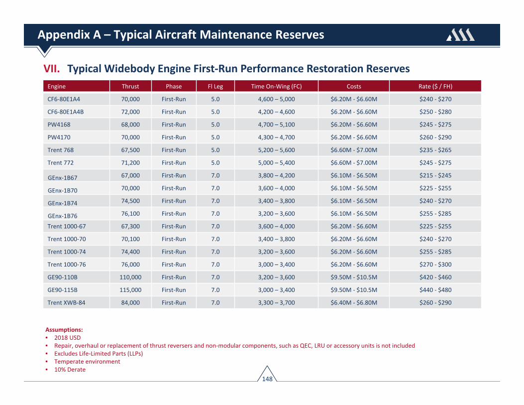
VII. Typical Widebody Engine First‐Run Performance Restoration ReservesEngine Thrust Phase Fl Leg Time On‐Wing (FC) Costs Rate ($ / FH)
CF6‐80E1A4 70,000 First‐Run 5.0 4,600 – 5,000 $6.20M ‐ $6.60M $240 ‐ $270
CF6‐80E1A4B 72,000 First‐Run 5.0 4,200 – 4,600 $6.20M ‐ $6.60M $250 ‐ $280
PW4168 68,000 First‐Run 5.0 4,700 – 5,100 $6.20M ‐ $6.60M $245 ‐ $275
PW4170 70,000 First‐Run 5.0 4,300 – 4,700 $6.20M ‐ $6.60M $260 ‐ $290
Trent 768 67,500 First‐Run 5.0 5,200 – 5,600 $6.60M ‐ $7.00M $235 ‐ $265
Trent 772 71,200 First‐Run 5.0 5,000 – 5,400 $6.60M ‐ $7.00M $245 ‐ $275
GEnx‐1B67 67,000 First‐Run 7.0 3,800 – 4,200 $6.10M ‐ $6.50M $215 ‐ $245
GEnx‐1B70 70,000 First‐Run 7.0 3,600 – 4,000 $6.10M ‐ $6.50M $225 ‐ $255
GEnx‐1B74 74,500 First‐Run 7.0 3,400 – 3,800 $6.10M ‐ $6.50M $240 ‐ $270
GEnx‐1B76 76,100 First‐Run 7.0 3,200 – 3,600 $6.10M ‐ $6.50M $255 ‐ $285
Trent 1000‐67 67,300 First‐Run 7.0 3,600 – 4,000 $6.20M ‐ $6.60M $225 ‐ $255
Trent 1000‐70 70,100 First‐Run 7.0 3,400 – 3,800 $6.20M ‐ $6.60M $240 ‐ $270
Trent 1000‐74 74,400 First‐Run 7.0 3,200 – 3,600 $6.20M ‐ $6.60M $255 ‐ $285
Trent 1000‐76 76,000 First‐Run 7.0 3,000 – 3,400 $6.20M ‐ $6.60M $270 ‐ $300
GE90‐110B 110,000 First‐Run 7.0 3,200 – 3,600 $9.50M ‐ $10.5M $420 ‐ $460
GE90‐115B 115,000 First‐Run 7.0 3,000 – 3,400 $9.50M ‐ $10.5M $440 ‐ $480
Trent XWB‐84 84,000 First‐Run 7.0 3,300 – 3,700 $6.40M ‐ $6.80M $260 ‐ $290
148
Assumptions: • 2018 USD• Repair, overhaul or replacement of thrust reversers and non‐modular components, such as QEC, LRU or accessory units is not included • Excludes Life‐Limited Parts (LLPs)• Temperate environment• 10% Derate
Appendix A – Typical Aircraft Maintenance Reserves

VII. Typical Widebody Engine Mature‐Run Performance Restoration Reserves
149
Engine Thrust Phase Fl Leg Time On‐Wing (FC) Costs Rate ($ / FH)
CF6‐80E1A4 70,000 Mature‐Run 5.0 3,700 – 4,100 $8.20M ‐ $8.60M $420 ‐ $450
CF6‐80E1A4B 72,000 Mature‐Run 5.0 3,500 – 3,900 $8.20M ‐ $8.60M $440 ‐ $470
PW4168 68,000 Mature‐Run 5.0 3,700 – 4,100 $8.20M ‐ $8.60M $425 ‐ $455
PW4170 70,000 Mature‐Run 5.0 3,500 – 3,900 $8.20M ‐ $8.60M $445 ‐ $475
Trent 768 67,500 Mature‐Run 5.0 3,900 – 4,400 $8.20M ‐ $8.60M $400 ‐ $430
Trent 772 71,200 Mature‐Run 5.0 3,700 – 4,100 $8.20M ‐ $8.60M $425 ‐ $455
GEnx‐1B67 67,000 Mature‐Run 7.0 3,200 – 3,600 $7.50M ‐ $8.00M $315 ‐ $345
GEnx‐1B70 70,000 Mature‐Run 7.0 3,000 – 3,400 $7.50M ‐ $8.00M $330 ‐ $360
GEnx‐1B74 74,500 Mature‐Run 7.0 2,800 – 3,200 $7.50M ‐ $8.00M $355 ‐ $385
GEnx‐1B76 76,100 Mature‐Run 7.0 2,700 – 3,100 $7.50M ‐ $8.00M $365 ‐ $395
Trent 1000‐67 67,300 Mature‐Run 7.0 3,100 – 3,500 $7.50M ‐ $8.00M $325 ‐ $355
Trent 1000‐70 70,100 Mature‐Run 7.0 2,900 – 3,300 $7.50M ‐ $8.00M $340 ‐ $370
Trent 1000‐74 74,400 Mature‐Run 7.0 2,700 – 3,100 $7.50M ‐ $8.00M $365 ‐ $395
Trent 1000‐76 76,000 Mature‐Run 7.0 2,600 – 3,000 $7.50M ‐ $8.00M $380 ‐ $410
GE90‐110B 110,000 Mature‐Run 7.0 2,500 – 2,800 $11.0M ‐ $12.0M $600 ‐ $640
GE90‐115B 115,000 Mature‐Run 7.0 2,400 – 2,700 $11.0M ‐ $12.0M $620 ‐ $660
Trent XWB‐84 84,000 Mature‐Run 7.0 2,800 – 3,200 $7.70M ‐ $8.20M $365 ‐ $395
Assumptions: • 2018 USD• Repair, overhaul or replacement of thrust reversers and non‐modular components, such as QEC, LRU or accessory units is not included • Excludes Life‐Limited Parts (LLPs)• Temperate environment• 10% Derate
Appendix A – Typical Aircraft Maintenance Reserves

150
References
1. Aeolus Engine Services, Automated Engine & LLP Hard Time Tracking, Presentation, Aero‐Engines Europe Conf. Paris, Oct. 22nd, 20152. AIAA Technical Publication 79‐7007. A Technique for Engine Maintenance Forecasting, 1979, Day, M.J, & Stahr, R.S.3. AIAA Technical Publication 92‐3928. Smoothing CFM56 Engine Removal Rate at USAir, July 1992, Matson, R. and Halsmer, R.4. AeroStrategy Management Consulting, The PMA Parts Tsunami: Hype or Reality, Sep 20045. Airbus – Operating With Reduced EGT Margin. Presentation6. Aircraft Commerce ‐ A350 MPD analysis and maintenance planning, Issue No. 115 • Dec 2017/Jan 20187. Aircraft Technology Issue 94. Keep on running — engine maintenance and cost reduction, 8. Airline Fleet & Asset Management. Reserve Judgment. Dec/Jan 2000, pp. 1‐5.9. Airline Fleet & Asset Management. Maintenance Reserves & Asset Management. Dec 1998, pp. 1‐3.10. Airline Fleet & Asset Management. Maintenance Reserves and Redelivery Conditions. Jan/Feb 2004, pp. 26‐30.11. Boeing ‐ Airline Maintenance Program Development, Fleet Maintenance Seminars, Commercial Aviation Services12. Boeing – Jet Propulsion Basics. Flight Operations Engineering13. Boeing ‐ The Basics of Maintenance Cost Forecasting, 200614. IATA ‐ Guidance Material and Best Practices for Aircraft Leases. 4th Edition. May, 2017 15. IATA ‐ Guidance Material & Best Practices for Alternate Parts (PMA) & Approved (non‐OEM) Repairs (DER). 2nd Edition. Mar 201516. Rolls‐Royce Technical Publication (2005). The Jet Engine17. Ackert, S. Basics of Aircraft Maintenance Programs for Financiers V1, Oct 2010 18. Ackert, S. Basics of Aircraft Maintenance Reserve Development & Management V1, Aug 201219. Ackert, S. Engine Maintenance Concepts for Financiers V2, Sep 201120. Ackert, S. Keeping Score: Analysis of an Engine’s Shop Visit Rate, Oct 201521. Andresen, G. & Williams, Z., Metrics, Key Performance Indicators, and Modeling of Long Range Aircraft Availability and Readiness, Oct 200522. Doll, B. The Airline Guide To PMA‐ Revised Apr 201023. Garson, Stephane.Managing an Engine (Presentation), Engine Finance Roundtable, New York, 200824. Hutter, Ivan. Engine Deterioration and Maintenance Actions (Presentation), ICAO Transport Canada Conference, Montreal, 200625. Seemann, R. Modeling the Life Cycle Cost of Jet Engine Maintenance (Students Research Project), Oct 2010

151
About The Author
Shannon Ackert is currently Senior Vice President of Commercial Operations at Jackson Square Aviation where hehas responsibility of the firm’s commercial activities including technical services, contract development &negotiation, and asset selection & valuation. Prior to joining Jackson Square, Shannon spent over ten yearsworking in the aircraft leasing industry where he presided over technical asset management roles as well asidentifying and quantifying the expected risk and return of aircraft investments. Shannon started his career inaviation as a flight test engineer for McDonnell Douglas working on the MD‐87/88 certification programs, andlater worked for United Airlines as systems engineer in the airlines 757/767 engineering organization. He haspublished numerous industry reports dealing with aircraft maintenance economics and market analysis, and is afrequent guest speaker at aviation conferences. Shannon received his B.S. in Aeronautical Engineering fromEmbry‐Riddle Aeronautical University and MBA from the University of San Francisco.

The information contained in this handbook isbased on good faith assumptions and providedfor the purpose of general familiarization only.The information does not constitute an offer,promise, warranty, or guarantee of performance.
1st Edition, 2018 Copyright © 2018 Aircraft Monitor. All rights reserved. www.aircraftmonitor.com
Related Documents


