High Energy Aircraft Friction Materials - yet another man-made wonder Golden Jubilee Commemoration lecture ( Tenth in the series ) Debashis Dutta & B. Chatterjee ( Foundry & Forge & Aerospace Divisions) Hindustan Aeronautics Limited, Bangalore The Indian Institute of Metals Bangalore Chapter 25 th April 2002

Welcome message from author
This document is posted to help you gain knowledge. Please leave a comment to let me know what you think about it! Share it to your friends and learn new things together.
Transcript
High Energy Aircraft Friction Materials
- yet another man-made wonder
Golden Jubilee Commemoration lecture
( Tenth in the series )
Debashis Dutta & B. Chatterjee
( Foundry & Forge & Aerospace Divisions)
Hindustan Aeronautics Limited, Bangalore
The Indian Institute of Metals
Bangalore Chapter
25th April 2002
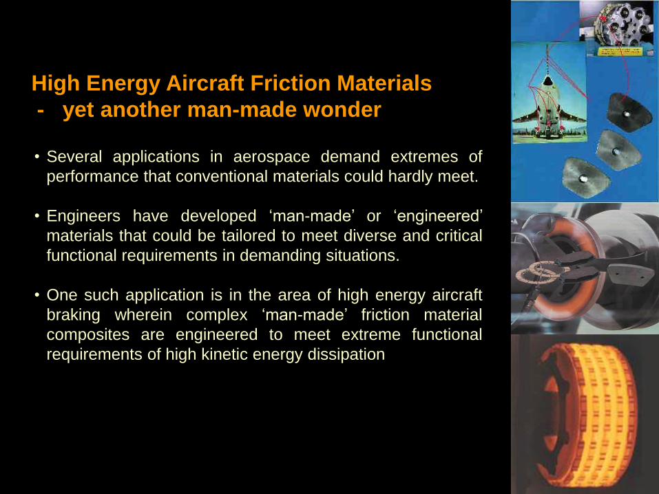
High Energy Aircraft Friction Materials
- yet another man-made wonder
• Several applications in aerospace demand extremes of
performance that conventional materials could hardly meet.
• Engineers have developed ‘man-made’ or ‘engineered’
materials that could be tailored to meet diverse and critical
functional requirements in demanding situations.
• One such application is in the area of high energy aircraft
braking wherein complex ‘man-made’ friction material
composites are engineered to meet extreme functional
requirements of high kinetic energy dissipation
• The landing kinetic energy of modern day aircraft is several million joules.
• A medium civilian aircraft Boeing 737-200 has a landing energy 30 million
joules and Concorde 60 million Joules
• Jet fighters have energies in the range of 5 to 25 million joules.
• This enormous energy, when absorbed by the brakes within 10-12
seconds after landing, imposes severe thermal gradients of thousands of
degrees centigrade per cm across the friction elements and brake bulk
temperatures of 1000 °C or more
• The consequences of “fade” due to loss of friction at such temperatures
could be dangerous and hence the friction material must retain its
properties till 1000 °C or more
Aircraft friction materials absorb millions of Joules
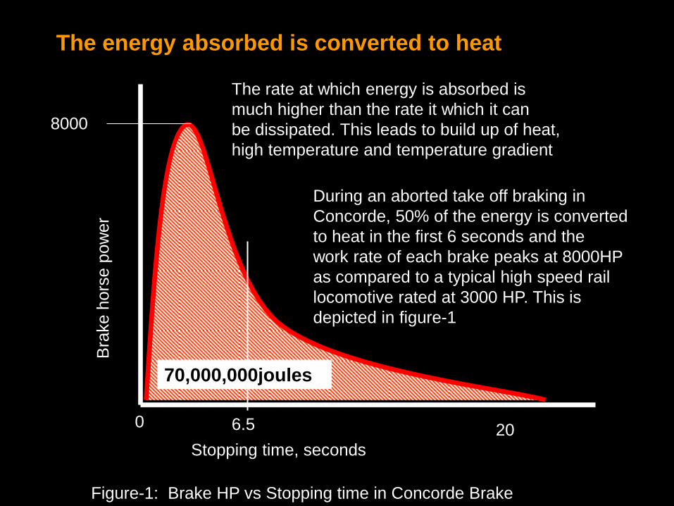
The energy absorbed is converted to heat
0
70,000,000joules
6.5 20
Stopping time, seconds
Bra
ke h
ors
e p
ow
er
8000
The rate at which energy is absorbed is
much higher than the rate it which it can
be dissipated. This leads to build up of heat,
high temperature and temperature gradient
During an aborted take off braking in
Concorde, 50% of the energy is converted
to heat in the first 6 seconds and the
work rate of each brake peaks at 8000HP
as compared to a typical high speed rail
locomotive rated at 3000 HP. This is
depicted in figure-1
Figure-1: Brake HP vs Stopping time in Concorde Brake
Aircraft brake friction material meets diverse requirements
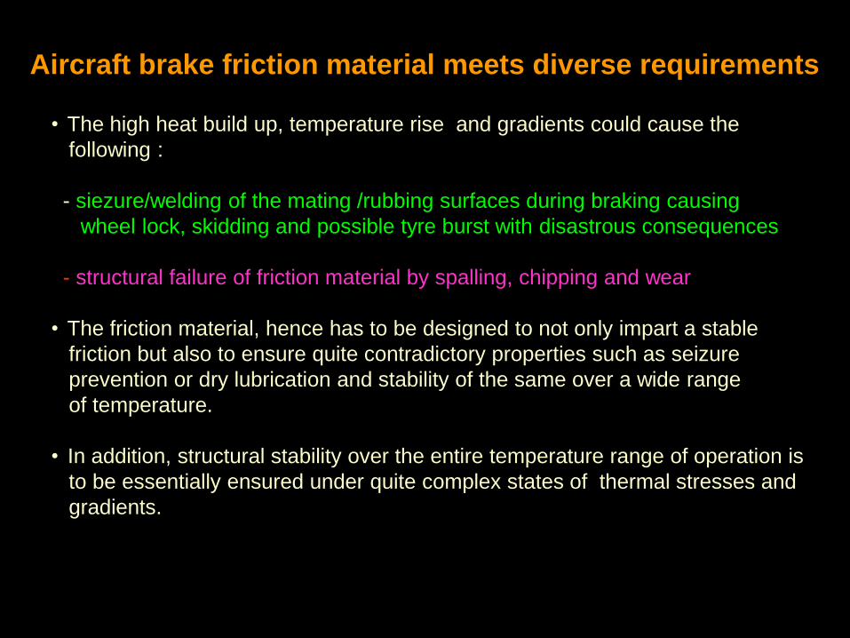
• The high heat build up, temperature rise and gradients could cause the
following :
- siezure/welding of the mating /rubbing surfaces during braking causing
wheel lock, skidding and possible tyre burst with disastrous consequences
- structural failure of friction material by spalling, chipping and wear
• The friction material, hence has to be designed to not only impart a stable
friction but also to ensure quite contradictory properties such as seizure
prevention or dry lubrication and stability of the same over a wide range
of temperature.
• In addition, structural stability over the entire temperature range of operation is
to be essentially ensured under quite complex states of thermal stresses and
gradients.
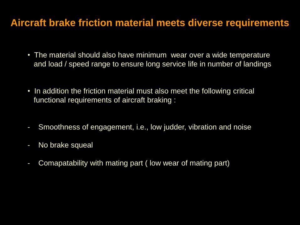
Aircraft brake friction material meets diverse requirements
• The material should also have minimum wear over a wide temperature
and load / speed range to ensure long service life in number of landings
• In addition the friction material must also meet the following critical
functional requirements of aircraft braking :
- Smoothness of engagement, i.e., low judder, vibration and noise
- No brake squeal
- Comapatability with mating part ( low wear of mating part)
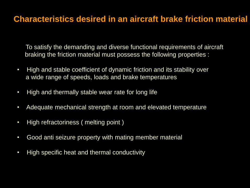
Characteristics desired in an aircraft brake friction material
To satisfy the demanding and diverse functional requirements of aircraft
braking the friction material must possess the following properties :
• High and stable coefficient of dynamic friction and its stability over
a wide range of speeds, loads and brake temperatures
• High and thermally stable wear rate for long life
• Adequate mechanical strength at room and elevated temperature
• High refractoriness ( melting point )
• Good anti seizure property with mating member material
• High specific heat and thermal conductivity
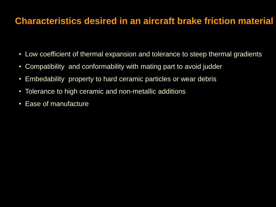
• Low coefficient of thermal expansion and tolerance to steep thermal gradients
• Compatibility and conformability with mating part to avoid judder
• Embedability property to hard ceramic particles or wear debris
• Tolerance to high ceramic and non-metallic additions
• Ease of manufacture
Characteristics desired in an aircraft brake friction material
• It is thus observed that there is a great diversity in the functional properties to be
fulfilled to meet aircraft braking requirements.
• No single conventional engineering material or material design can meet the
entire spectrum of aircraft braking requirements
• A friction material is hence “engineered” and designed after judicious selection
and combination of a variety of metals, non-metals and exotic ceramic
ingredients, which individually and in combination satisfy the entire range of
aircraft braking requirements.
Diverse braking properties demand engineered materials
The choice of materials which could qualify to meet such diverse requirements
falls into a few “man-made” composite materials , v.i.z.,
- organic resin bonded composites
- sintered metal-ceramic composites
- carbon- carbon fibre composites
The engineered friction materials
• The organic resin / polymer composites are used for low energy / low speed
aircraft and are being phased out due to asbestos usage regulations
• The carbon-carbon composites are the high end materials, recently developed to
meet the highest energy dissipation and thermal requirements, but are very
expensive. Usage is hence limited
• The sintered metal-ceramic composites synthesised by Powder Metallurgy (P/M)
are the most abundantly used in aircraft braking and account for more than 60 %
of the aircraft friction material market volume
• Our successful R&D and indigenisation efforts, in this country at HAL, have been
primarily in the area of sintered metal – ceramic friction materials by P/M
The engineered friction materials
Sintered metal-ceramic multi-component composites
- the challenges in development
• The sintered metal-ceramic friction composites consist of a variety of
powdered metallic, non-metallic and ceramic ingredients that are combined
to form a friction material by a specially developed P/M process. Each
ingredient is chosen to meet a specific braking property
• The friction material composition for each aircraft brake is unique and so is the
P/M process technology developed to synthesize the material. There is no
published literature and there are only a few manufacturers world-over. There
are only a handful of OEMs
Since the material is a complex, multi-component metal matrix composite
prone to heterogeneity, rigorous testing in accordance with international
airworthiness standards:-FAR 25.735 / MIL-W-5013.
• These are the factors that make these materials exotic and the technology so
dear and protected
Sintered metal-ceramic multi-component composites
- further challenges in development
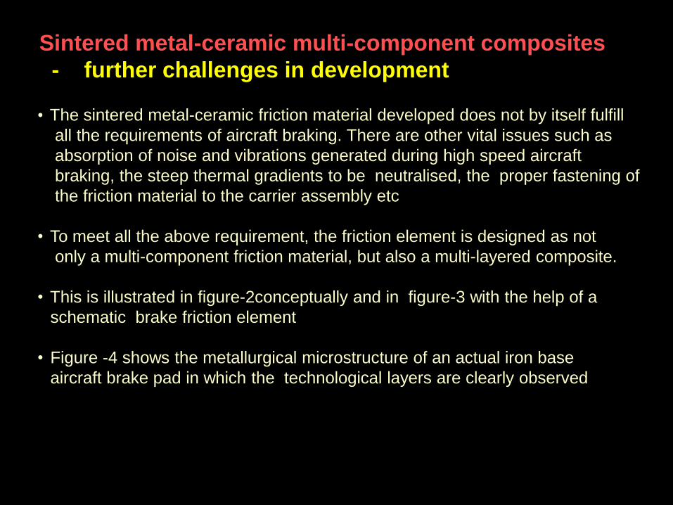
• The sintered metal-ceramic friction material developed does not by itself fulfill
all the requirements of aircraft braking. There are other vital issues such as
absorption of noise and vibrations generated during high speed aircraft
braking, the steep thermal gradients to be neutralised, the proper fastening of
the friction material to the carrier assembly etc
• To meet all the above requirement, the friction element is designed as not
only a multi-component friction material, but also a multi-layered composite.
• This is illustrated in figure-2conceptually and in figure-3 with the help of a
schematic brake friction element
• Figure -4 shows the metallurgical microstructure of an actual iron base
aircraft brake pad in which the technological layers are clearly observed
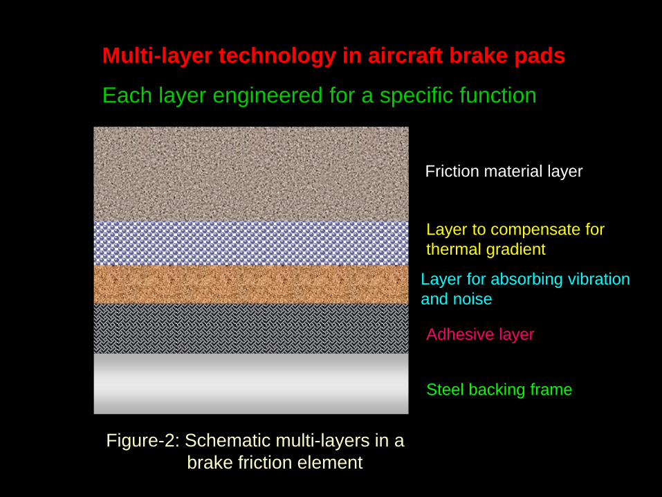
Multi-layer technology in aircraft brake pads
Each layer engineered for a specific function
Friction material layer
Layer to compensate for
thermal gradient
Steel backing frame
Adhesive layer
Layer for absorbing vibration
and noise
Figure-2: Schematic multi-layers in a
brake friction element
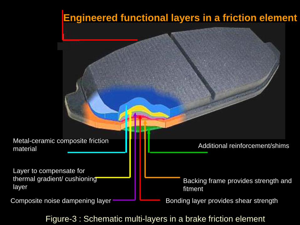
Engineered functional layers in a friction element
Metal-ceramic composite friction
material
Composite noise dampening layer
Layer to compensate for
thermal gradient/ cushioning
layer
Bonding layer provides shear strength
Backing frame provides strength and
fitment
Additional reinforcement/shims
Figure-3 : Schematic multi-layers in a brake friction element
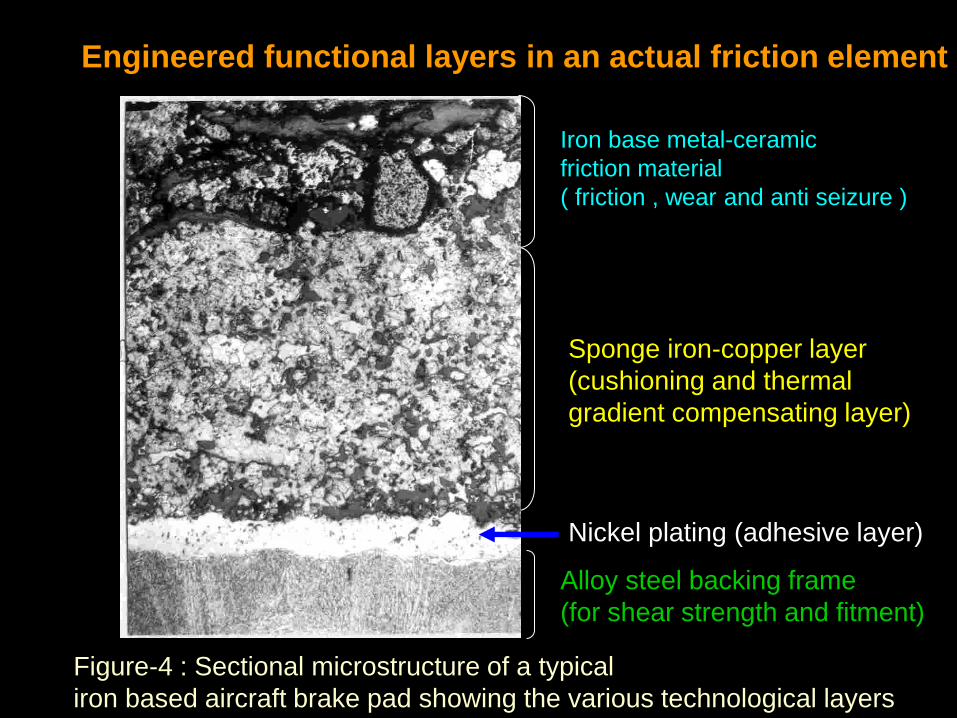
Iron base metal-ceramic
friction material
( friction , wear and anti seizure )
Sponge iron-copper layer
(cushioning and thermal
gradient compensating layer)
Nickel plating (adhesive layer)
Alloy steel backing frame
(for shear strength and fitment)
Figure-4 : Sectional microstructure of a typical
iron based aircraft brake pad showing the various technological layers
Engineered functional layers in an actual friction element
• The rate of absorption of kinetic energy, the maximum temperature rise, the
heat sink mass available and several other requirements vary from one
aircraft to the other. Friction material composition designed to satisfy these
requirements, is therefore unique for each aircraft and is ‘tailor-made’.
• The methodology of development of the friction material for a given aircraft
brake, therefore, starts with an in-depth study of the brake design
specification.
• A step by step approach is then followed for derivation of the physical and
metallurgical properties of the candidate friction material from the brake
specification, formulation design, controlled experiments to develop the
technology and qualification by elaborate type and airworthiness tests
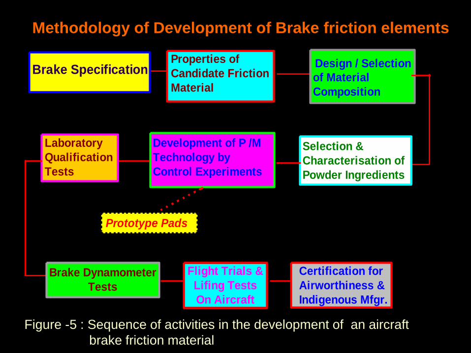
• The complete sequence of activities involved in the development of a friction
element is illustrated in figure-5
Methodology of Development of Brake friction elements
Brake SpecificationProperties of
Candidate Friction
Material
Design / Selection
of Material
Composition
Selection &
Characterisation of
Powder Ingredients
Development of P /M
Technology by
Control Experiments
Laboratory
Qualification
Tests
Brake Dynamometer
Tests
Certification for
Airworthiness &
Indigenous Mfgr.
Prototype Pads
Flight Trials &
Lifing Tests
On Aircraft
Methodology of Development of Brake friction elements
Figure -5 : Sequence of activities in the development of an aircraft
brake friction material
Design of a typical disc type aircraft brake
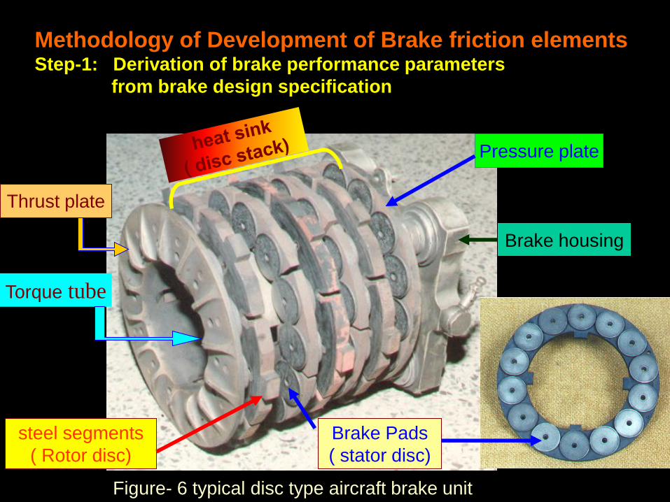
• Figure- 6 presents a view of a typical disc type aircraft brake unit.
• The unit is designed as a multiple disc assembly consisting of a brake
housing, pressure plate, torque tube, thrust plate and disc stack comprising of
a series of alternate stator and rotor discs assembled with friction material
brake pads and mating steel segments, respectively.
• The disc stack is also called the “heat sink” and is the most important part of
the brake unit. The brake functions by virtue of the conversion of the kinetic
energy of the moving aircraft to heat energy and the absorption and
subsequent dissipation of the same by the heat sink.
Methodology of Development of Brake friction elements
Step-1: Derivation of brake performance parameters
from brake design specification
Methodology of Development of Brake friction elements Step-1: Derivation of brake performance parameters
from brake design specification
Figure- 6 typical disc type aircraft brake unit
Torque tube
Brake Pads
( stator disc)
steel segments
( Rotor disc)
Pressure plate
Brake housing
Thrust plate Thrust plate
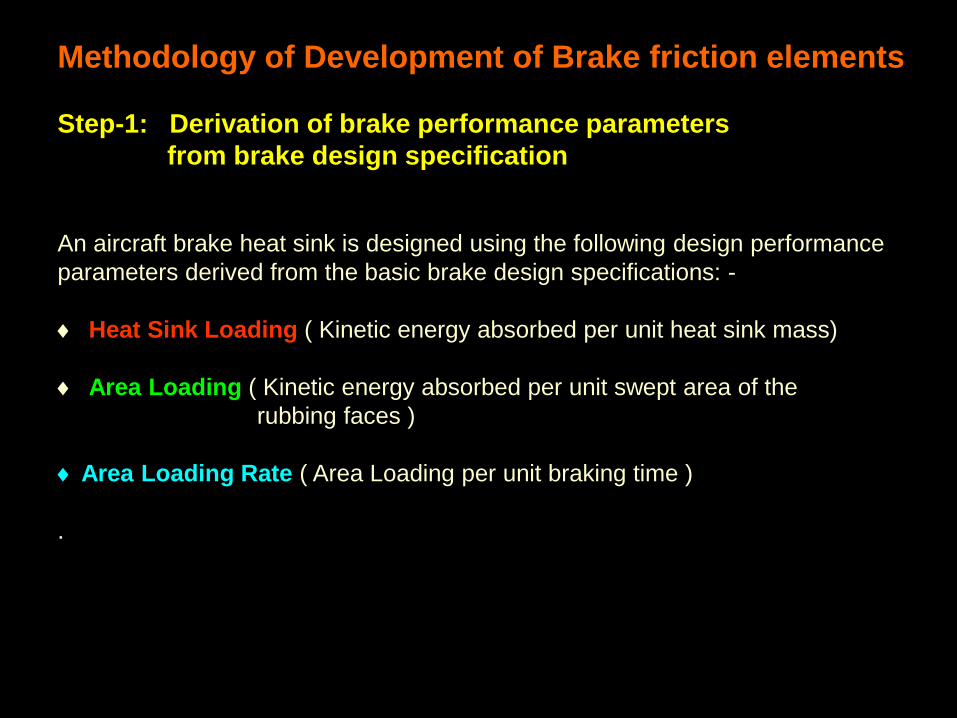
An aircraft brake heat sink is designed using the following design performance
parameters derived from the basic brake design specifications: -
Heat Sink Loading ( Kinetic energy absorbed per unit heat sink mass)
Area Loading ( Kinetic energy absorbed per unit swept area of the
rubbing faces )
Area Loading Rate ( Area Loading per unit braking time )
.
Methodology of Development of Brake friction elements
Step-1: Derivation of brake performance parameters
from brake design specification
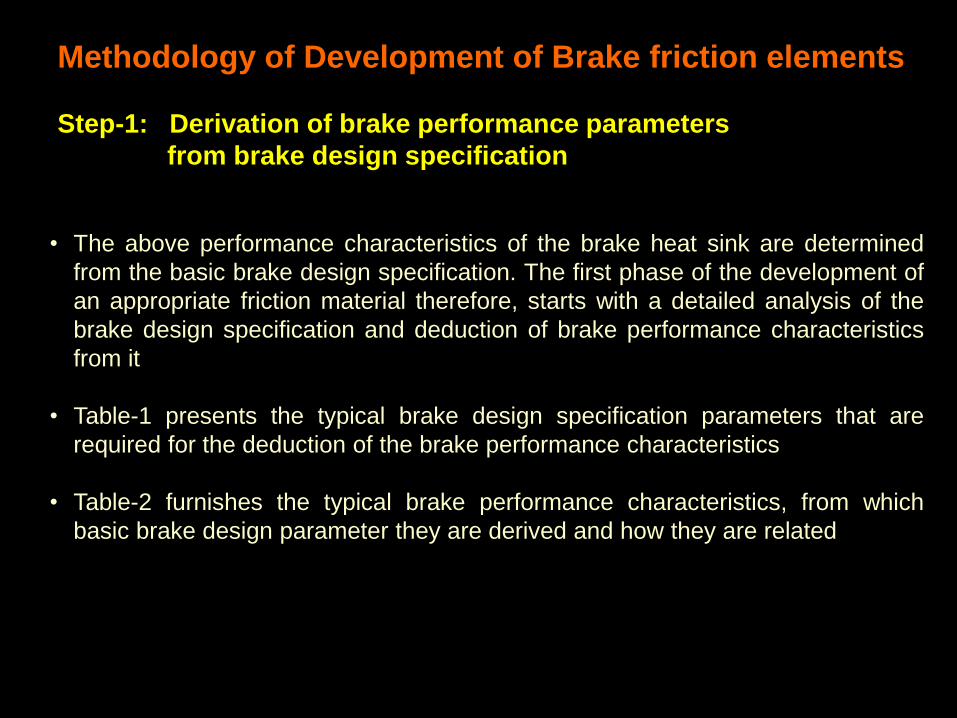
• The above performance characteristics of the brake heat sink are determined
from the basic brake design specification. The first phase of the development of
an appropriate friction material therefore, starts with a detailed analysis of the
brake design specification and deduction of brake performance characteristics
from it
• Table-1 presents the typical brake design specification parameters that are
required for the deduction of the brake performance characteristics
• Table-2 furnishes the typical brake performance characteristics, from which
basic brake design parameter they are derived and how they are related
Methodology of Development of Brake friction elements
Step-1: Derivation of brake performance parameters
from brake design specification
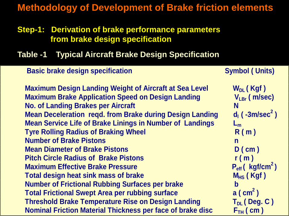
Basic brake design specification Symbol ( Units) Maximum Design Landing Weight of Aircraft at Sea Level WDL ( Kgf ) Maximum Brake Application Speed on Design Landing VLBr ( m/sec) No. of Landing Brakes per Aircraft N Mean Deceleration reqd. from Brake during Design Landing dl ( -3m/sec
2 )
Mean Service Life of Brake Linings in Number of Landings Lm Tyre Rolling Radius of Braking Wheel R ( m ) Number of Brake Pistons n Mean Diameter of Brake Pistons D ( cm ) Pitch Circle Radius of Brake Pistons r ( m ) Maximum Effective Brake Pressure Peff ( kgf/cm
2 )
Total design heat sink mass of brake MHS ( Kgf ) Number of Frictional Rubbing Surfaces per brake b Total Frictional Swept Area per rubbing surface a ( cm
2 )
Threshold Brake Temperature Rise on Design Landing TDL ( Deg. C ) Nominal Friction Material Thickness per face of brake disc FTH ( cm )
Typical Aircraft Brake Design Specification Table -1
Methodology of Development of Brake friction elements
Step-1: Derivation of brake performance parameters
from brake design specification
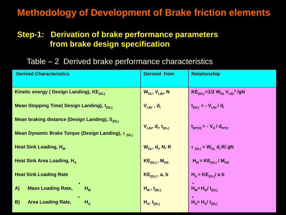
Derived Characteristics
Derived from Relationship
Kinetic energy ( Design Landing), KE(DL)
Mean Stopping Time( Design Landing), t(DL)
Mean braking distance (Design Landing), S(DL)
Mean Dynamic Brake Torque (Design Landing), (DL)
Heat Sink Loading, HM
Heat Sink Area Loading, HA
Heat Sink Loading Rate
A) Mass Loading Rate, HM
B) Area Loading Rate, HA
WDL, VLBr, N
VLBr , dl
VLBr, dl, t(DL)
WDL, dl, N, R
KE(DL) , MHS
KE(DL) , a, b
HM , t(DL)
HA, t(DL)
KE(DL) =1/2 WDL VLBr2 /gN
t(DL) = - VLBr / dl
t(RTO) = - VD / dRTO
(DL) = WDL dl R/ gN
HM = KE(DL) / MHS
HA = KE(DL)/ a b
HM= HM/ t(DL)
HA= HA/ t(DL)
Methodology of Development of Brake friction elements
Step-1: Derivation of brake performance parameters
from brake design specification
Table – 2 Derived brake performance characteristics
Methodology of Development of Brake friction elements
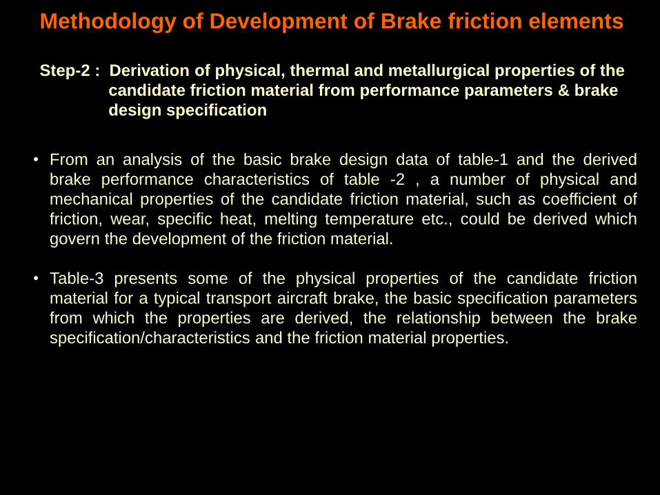
Step-2 : Derivation of physical, thermal and metallurgical properties of the
candidate friction material from performance parameters & brake
design specification
• From an analysis of the basic brake design data of table-1 and the derived
brake performance characteristics of table -2 , a number of physical and
mechanical properties of the candidate friction material, such as coefficient of
friction, wear, specific heat, melting temperature etc., could be derived which
govern the development of the friction material.
• Table-3 presents some of the physical properties of the candidate friction
material for a typical transport aircraft brake, the basic specification parameters
from which the properties are derived, the relationship between the brake
specification/characteristics and the friction material properties.
Property
Derived from Relationship
Value of property
derived for a typical
transport aircraft
Mean Coefficient of Friction, µ
Mean Specific Heat of Friction Heat
Pack, SM
Maximum allowable Wear rate per
braking stop, WTH
Minimum Melting point of Friction
material, TM
(DL), Peff, D, n, b, r
KE(DL) , MHS, TDL
FTH, Lm
TRTO
µ =4(DL)/ D2nbr Peff
SM = KE(DL)/ MHS TDL
WTH = FTH / Lm
TM (TRTO + 200C)
0.29
0.59 J/gm/deg.C
0.003 mm
1250C
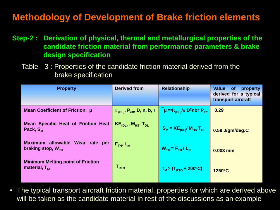
Methodology of Development of Brake friction elements
Step-2 : Derivation of physical, thermal and metallurgical properties of the
candidate friction material from performance parameters & brake
design specification
Table - 3 : Properties of the candidate friction material derived from the
brake specification
• The typical transport aircraft friction material, properties for which are derived above
will be taken as the candidate material in rest of the discussions as an example
Methodology of Development of Brake friction elements
Step-3 : Design & selection of a friction material composition
• The composition of the prototype friction material is then designed based on
the properties derived.
• The first step in this process is the selection of the metallic matrix material
which imparts the basic physical, mechanical and thermal properties and
accounts for 60 to 75% of the weight.
• The choice of matrix is restricted to either a copper base or an iron base or a
judicious combination of the two. Minor additions of other metals such as Zinc,
Tin, Nickel, Chromium, etc., as alloying elements, are done to enhance the
mechanical properties.
• The relative characteristics of iron and copper based matrix materials are
given below in Table -4
Characteristics
Iron Copper
Specific Heat at Room Temp. (Joules/gm/K)
Thermal Conductivity at R.T. ( J/M/Sec/K )
Coefficient of Linear Expansion ( K-1 .106 )
Heat Sink Loading Capacity ( Joules/Kg )
Tensile Strength ( MPa )
Melting Point ( C )
Antiseizure
Tolerance to ceramic/non-metallic additions
Softening Resistance at Elevated Temperature
Ease of Manufacture into Friction Materials
0.59
59
14
450,000
410
1539
Good
Poor
Good
Poor
0.42
346
18
280,000
240
1083
Poor
Good
Poor
Good
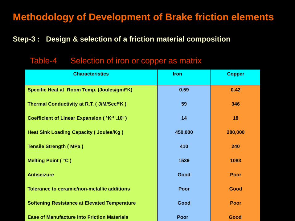
Methodology of Development of Brake friction elements
Step-3 : Design & selection of a friction material composition
Table-4 Selection of iron or copper as matrix
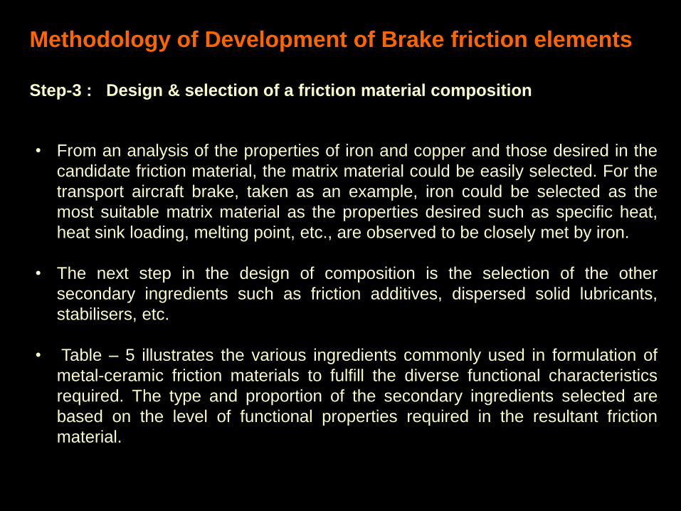
• From an analysis of the properties of iron and copper and those desired in the
candidate friction material, the matrix material could be easily selected. For the
transport aircraft brake, taken as an example, iron could be selected as the
most suitable matrix material as the properties desired such as specific heat,
heat sink loading, melting point, etc., are observed to be closely met by iron.
• The next step in the design of composition is the selection of the other
secondary ingredients such as friction additives, dispersed solid lubricants,
stabilisers, etc.
• Table – 5 illustrates the various ingredients commonly used in formulation of
metal-ceramic friction materials to fulfill the diverse functional characteristics
required. The type and proportion of the secondary ingredients selected are
based on the level of functional properties required in the resultant friction
material.
Methodology of Development of Brake friction elements
Step-3 : Design & selection of a friction material composition
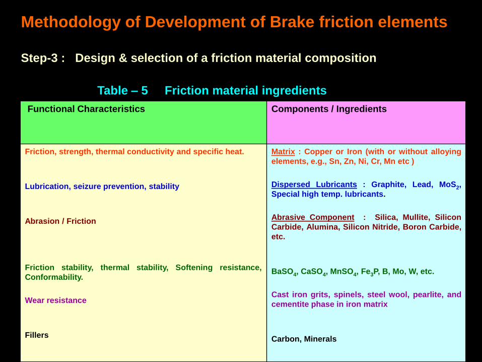
Functional Characteristics
Components / Ingredients
Friction, strength, thermal conductivity and specific heat.
Lubrication, seizure prevention, stability
Abrasion / Friction
Friction stability, thermal stability, Softening resistance,
Conformability.
Wear resistance
Fillers
Matrix : Copper or Iron (with or without alloying
elements, e.g., Sn, Zn, Ni, Cr, Mn etc )
Dispersed Lubricants : Graphite, Lead, MoS2,
Special high temp. lubricants.
Abrasive Component : Silica, Mullite, Silicon
Carbide, Alumina, Silicon Nitride, Boron Carbide,
etc.
BaSO4, CaSO4, MnSO4, Fe3P, B, Mo, W, etc.
Cast iron grits, spinels, steel wool, pearlite, and
cementite phase in iron matrix
Carbon, Minerals
Table – 5 Friction material ingredients
Methodology of Development of Brake friction elements
Step-3 : Design & selection of a friction material composition
• The abrasive component is the next most important ingredient as this gives
rise to friction and also helps prevent local welding and metal transfer of the
matrix material on to the mating part during braking.
• Silica and mullite are suitable for low and medium energy friction materials
whereas the carbides and nitrides of silicon are most desirable for high
energy brakes of high heat sink loading .
• For the transport aircraft brake, the heat sink loading and kinetic energy
values are high ( heat sink loading of more than 600,000 Joules/kg) and
therefore the choice was between SiC and Si3N4 . SiC was selected since it
is more abundantly available, is cheap and is stable till a temperature of
1800 C.
Methodology of Development of Brake friction elements
Step-3 : Design & selection of a friction material composition
Selection of the abrasive / friction ingredient

• To avoid gross seizure between the friction element and mating part dispersed
dry lubricants are added. These lubricants ( 5 to 25% ) provide smoothness of
engagement during braking by forming a self regulating smooth film on the
friction surface.
• High graphite contents ( 15 to 20% ) are suitable for low brake temperatures
and high thermal conductance, but in conditions of poor heat transfer, as in the
present example, the addition of graphite should not exceed 6 to 8%.
• Graphite is not a good lubricant at temperatures above 600C Hence, a second
high temperature lubricant is also required for high energy brakes. In the
example of the transport aircraft, graphite could be chosen as the primary
lubricant and a secondary lubricant is also required
• Secondary lubricant additions are normally kept very low, i.e., about 1 to 2%, as
higher amounts added lead to excessive wear of the friction material.
Methodology of Development of Brake friction elements
Step-3 : Design & selection of a friction material composition
Selection of the dry lubricant / anti seizure additive
• A critical requirement that a high energy friction material must fulfill, is thermal
stability , i.e.,the basic strength, friction and wear rate of the material should
not deteriorate appreciably with increasing speed and brake temperature.
• Sulphates of Barium, Calcium, Manganese or Iron are effective stablisers.
Boron, Molybdenum and Tungsten also are used.
• BaSO4 is very commonly used in iron base materials. Additions are limited to
12% beyond which mechanical properties of the friction material decline. In the
present example of the transport aircraft brake, BaSO4 upto 10 % could be
selected as the friction stabiliser.
Methodology of Development of Brake friction elements
Step-3: Design and selection of friction material composition
Selection of friction and wear stabilisers/modifiers
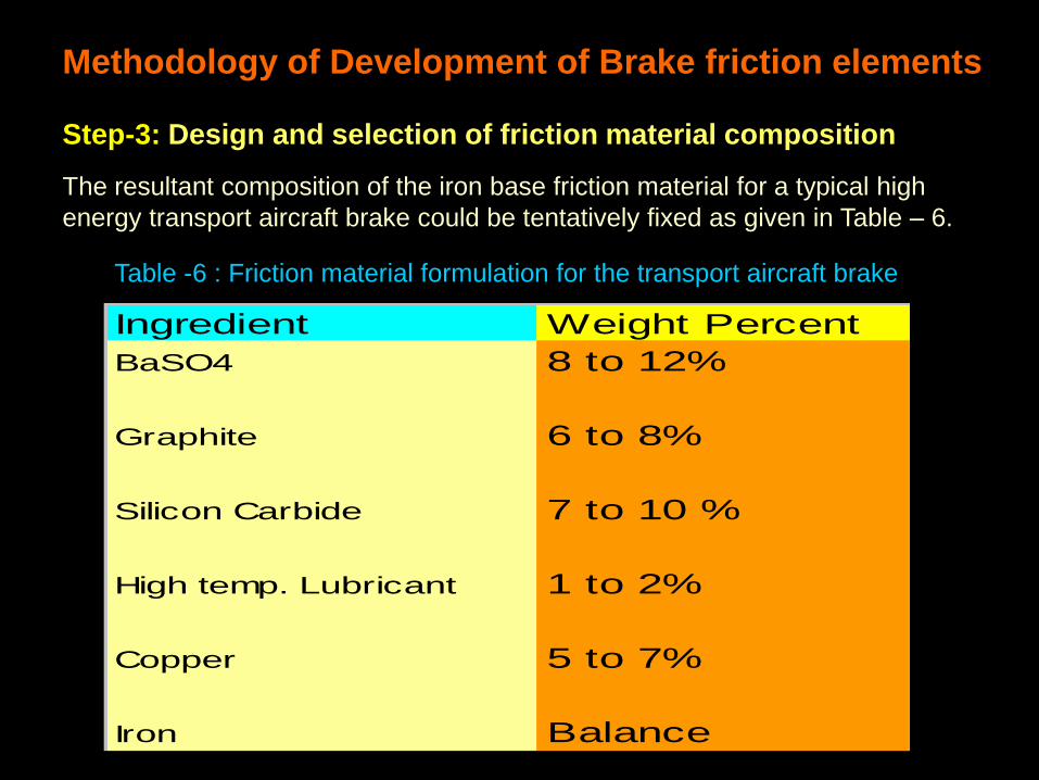
The resultant composition of the iron base friction material for a typical high
energy transport aircraft brake could be tentatively fixed as given in Table – 6.
Methodology of Development of Brake friction elements
Step-3: Design and selection of friction material composition
Ingredient Weight Percent
BaSO4 8 to 12%
Graphite 6 to 8%
Silicon Carbide 7 to 10 %
High temp. Lubricant 1 to 2%
Copper 5 to 7%
Iron Balance
Table -6 : Friction material formulation for the transport aircraft brake
• In iron base friction elements a pure sponge iron powder layer of thickness 0.5
to 2.0 mm between the friction material and the nickel plated steel backing
frame is incorporated as a special feature by making a multi layer compact.
• The sponge iron layer acts as a cushion layer due to its sponginess. This
characteristic allows the effective damping of vibrations/judder during braking.
• This layer also acts as a medium to further ensure good bonding between the
friction material and the steel back plate through the intermediate nickel layer.
• A portion of lower melting copper /tin, which are the ingredients of the friction
material, also percolate to this sponge iron layer during pressure sintering by
capillary action and are believed to reduce the effect of thermal gradients
• In copper base friction materials, a cup type design and presence of metallic
grid inserted by spot welding between the cup and the friction material ensures
judder reduction, bonding and integrity of the material against thermal gradients
Methodology of Development of Brake friction elements
Step-3: Design and selection of other functional layers
• High energy braking could lead to a situation where the contacting surface of the
friction material may be at a instantaneous temperature of 1000C whereas the
back plate may be closer to ambient temperature.
• This causes instantaneous thermal expansion on the friction material. At the
same time the back plate resists this expansion resulting in the interfacial layers
to be subjected to large shear stresses which could lead to catastrophic bond
failure during service.
• The sponge iron layer due to a large volume of porosity neutralises the
expansion gradient to a large extent due to the pores acting as “stress sinks”.
• The nickel coated layer of the back plate also contributes to neutralising the
thermal gradient due to a compositional gradient that exists across its thickness.
The compositional gradient arises due to its alloying with some of the friction
material ingredients on one side and with the back plate on the other side.
Methodology of Development of Brake friction elements
Step-3: Design and selection of other functional layers
Methodology of Development of Brake friction elements
Step 4 : Development of P/M process for fabrication of brake pads
The next step is development of an appropriate P/M process for
fabrication of the friction material into brake pads / elements by
controlled experimentation. The various steps involved in
development of the optimum process are as follows :
• Selection of raw materials based on composition
• Powder mixing
• Powder Compaction
• Processing of back plate frame
• Pressure Sintering of brake pads
Methodology of Development of Brake friction elements
Step 4 : Development of P/M process for fabrication of brake pads
A. Selection and optimisation of raw materials based on composition
• Designed experiments are carried out to optimise the the specification of
the raw material corresponding to each friction material ingredient.
• Prototype brake pad samples made from a few alternative raw materials of
each ingredient are tested for basic properties such as friction and wear
• From the results of these experiments each raw material type and
specification is fixed and optimised.
• A similar procedure was adopted for selecting and optimising the raw
materials and their properties/specifications for the transport aircraft brake
friction material in the present example
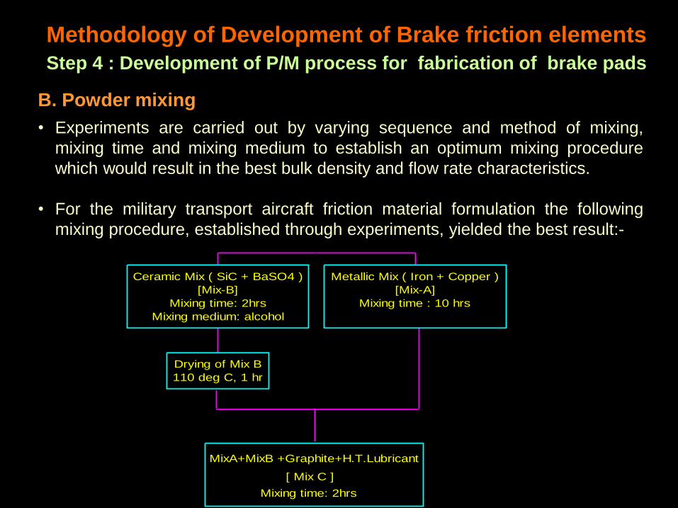
B. Powder mixing
• Experiments are carried out by varying sequence and method of mixing,
mixing time and mixing medium to establish an optimum mixing procedure
which would result in the best bulk density and flow rate characteristics.
• For the military transport aircraft friction material formulation the following
mixing procedure, established through experiments, yielded the best result:-
Methodology of Development of Brake friction elements
Step 4 : Development of P/M process for fabrication of brake pads
MixA+MixB +Graphite+H.T.Lubricant
[ Mix C ]
Mixing time: 2hrs
Drying of Mix B
110 deg C, 1 hr
Ceramic Mix ( SiC + BaSO4 )
[Mix-B]
Mixing time: 2hrs
Mixing medium: alcohol
Metallic Mix ( Iron + Copper )
[Mix-A]
Mixing time : 10 hrs
C. Powder Compaction
• Pressure for compacting the friction material into the desired shapes
required in the final brake pad is chosen and optimised based on
experiments which yield the most optimum green density value of the
resultant compact. Higher pressures lead to marginal increase in the green
density but may cause cracking of the compact due to high residual
stresses.
• Usually double or multi-layer compaction is carried out in which the first
layer is the friction material layer and the others sponge powder layers
• The compaction pressure for iron base friction materials is about 500 to
540 Mpa and for copper base friction materials it is in the range of 380 to
420 Mpa.
Methodology of Development of Brake friction elements
Step 4 : Development of P/M process for fabrication of brake pads
D. Processing of back plate frame • A single or multi-layer friction material compact is a composite with about 40%
by volume of non-metallic ingredients and possesses quite low strength
• In order to withstand the severe service environment and also for assembly
into the brake rotor and stator plates by riveting, the friction material is either
housed in a backing steel container or is diffusion bonded, during pressure
sintering operation, on to a steel back plate frame of the same shape and
contour
• For medium energy aircraft brakes with maximum temperatures of 600 deg. C,
low carbon steel is considered a suitable back plate material. For high energy
brakes, in which temperature rise is beyond 750 deg. C , the choice of a back
plate material is restricted to stabilised high strength low alloy steels of high
hardenability and possessing good thermal fatigue properties.
• Steels normally used are AISI-4340, BS-S155, M-300 etc. In present example
for the iron base brake friction material of the military transport aircraft, the
back plate chosen is AISI-4340.
Methodology of Development of Brake friction elements
Step 4 : Development of P/M process for fabrication of brake pads
D. Processing of back plate frame
• After selecting and procuring the steel material in sheet or strip form, back plate
segments are then fabricated by shearing operations using press tools.
• The steel backing segments are then given a nickel or a copper plating, for iron
base and copper base friction materials respectively, from cyanide/alkaline bath
for aiding the subsequent diffusion bonding process with the composite friction
material during the pressure sintering operation.
• After plating the back plates are given a diffusion anneal treatment to ensure
proper metallurgical bonding of the plated layer to the underlying steel plate.
Methodology of Development of Brake friction elements
Step 4 : Development of P/M process for fabrication of brake pads
E. Pressure sintering of brake pads
• For pressure sintering a special type of sintering equipment, viz., a pressure
sintering bell type furnace with a hydraulic charge pulling arrangement is used.
• To optimise the pressure sintering parameters for prototype brake pads
sintering experiments to establish the temperature-pressure-time cycle are
carried out. The objective is to produce prototypes with the desired mechanical,
metallurgical and physical properties as derived from the brake specification.
• Experiments carried out for the iron base friction material of the military aircraft
brake resulted in the following optimum pressure sintering parameters that
could yield prototype brake pads which met all the property requirements :-
Sintering temperature :- 1025 C
Sintering pressure :- 150Mpa
Sintering time :- 2 hours
Sintering atmosphere :- Dry Hydrogen
Methodology of Development of Brake friction elements
Step 4 : Development of P/M process for fabrication of brake pads
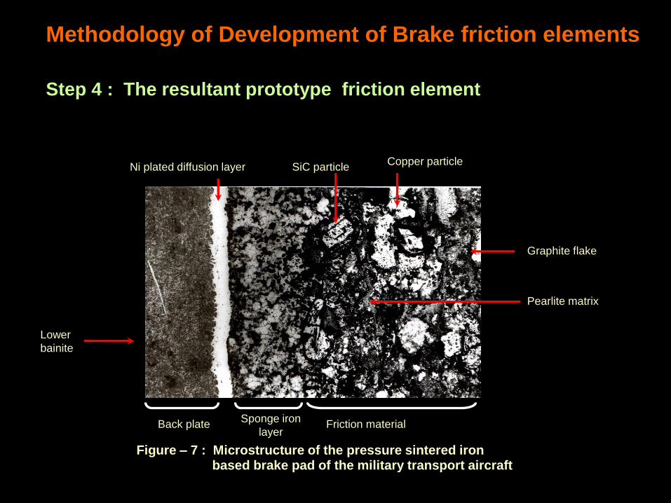
Figure – 7 shows the micro structure cross section of the brake pad sintered
under the above optimum conditions. The microstructure shows a
predominantly fine pearlitic structure of the matrix iron phase in which SiC
particles and graphite are observed to be uniformly dispersed. The irregular
shaped light/ white areas are copper. Besides the ideal structure of the friction
material, a sound interfacial diffusion bonding is also observed between the
steel back plate and the friction material through an intermediate electro-
deposited nickel layer of thickness of about 150 microns.
Figure- 8 shows a flow chart for manufacture of a typical iron base brake pad
similar to the one for the transport aircraft brake
Figure-9 shows snapshots of important manufacturing facilities at HAL, Foundry
and Forge Division for P/M processing of aircraft brake pads
Methodology of Development of Brake friction elements
Step 4 : The resultant prototype friction element
Ni plated diffusion layer SiC particle
Copper particle
Graphite flake
Lower
bainite
Friction material Back plate
Pearlite matrix
Figure – 7 : Microstructure of the pressure sintered iron based brake pad of the military transport aircraft
Sponge iron
layer
Methodology of Development of Brake friction elements
Step 4 : The resultant prototype friction element
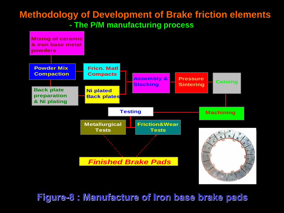
Figure-8 : Manufacture of Iron base brake pads
Ni plated
Back plates
Assembly &
Stacking
Fricn. Matl
CompactsPressure
SinteringCoining
Machining
Finished Brake Pads
Back plate
preparation
& Ni plating
Mixing of ceramic
& iron base metal
powders
Powder Mix
Compaction
Metallurgical
Tests
Friction&Wear
Tests
Testing
Methodology of Development of Brake friction elements - The P/M manufacturing process
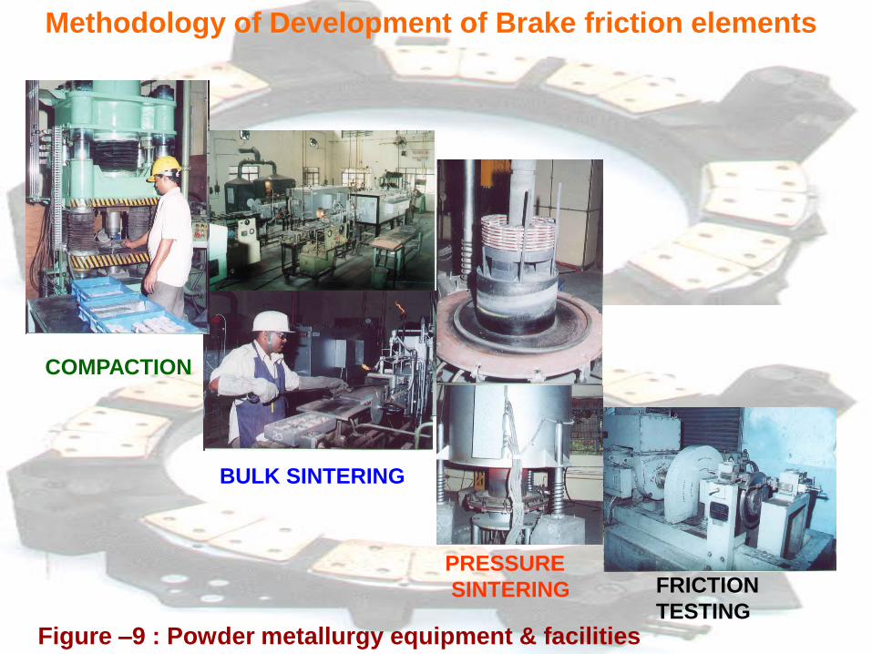
BULK SINTERING
COMPACTION
PRESSURE
SINTERING
Figure –9 : Powder metallurgy equipment & facilities
FRICTION
TESTING
Methodology of Development of Brake friction elements
Methodology of Development of Brake friction elements
Step 5 : Qualification and airworthiness testing of prototype brake pads
• After establishment of the optimum manufacturing process by controlled
experimentation as described above, sufficient number of prototype
brake pads are processed for undergoing airworthiness qualification
tests
• The airworthiness requirement for brake materials meant for all types of
military aircraft is governed by MIL-W-5013 and Technical Standard
Order-26 issued by Federal Aviation Administration, USA.
• In accordance with the airworthiness requirements, highly elaborate test
procedures are prescribed for friction brake pads for certifying them for
normal use on aircraft brake. The entire testing procedure can be
divided into three stages :
Laboratory Qualification tests
Brake Dynamometer tests
Aircraft trials
Methodology of Development of Brake friction elements Step 5 : Qualification and airworthiness testing of prototype brake pads
Laboratory Qualification tests
In this stage in-depth analysis and evaluation of the prototype brake pads is carried out.
to assess the metallurgical and physical properties of the prototype pads in accordance
with airworthiness schedules/specification. The following are the tests :
Hardness test on friction material and back plate
Density determination
Chemical analysis
- by classical or instrumental methods such as X-RD, EDAX, Spectroscopy, etc.
Microstructural characterisation
- Optical microexamination for identification and distribution of major constituents in
friction material and structure of back plate.
- Bimetallic Bonding
- Microhardness survey on selected constituents and phases
Specific heat and thermal conductivity by calorimetry
Friction and wear test using a laboratory test rig
Phase identification studies by Scanning Electron Probe Micro Analysis (SEPMA) for
identification, and chemistry distribution of various constituents and phases.
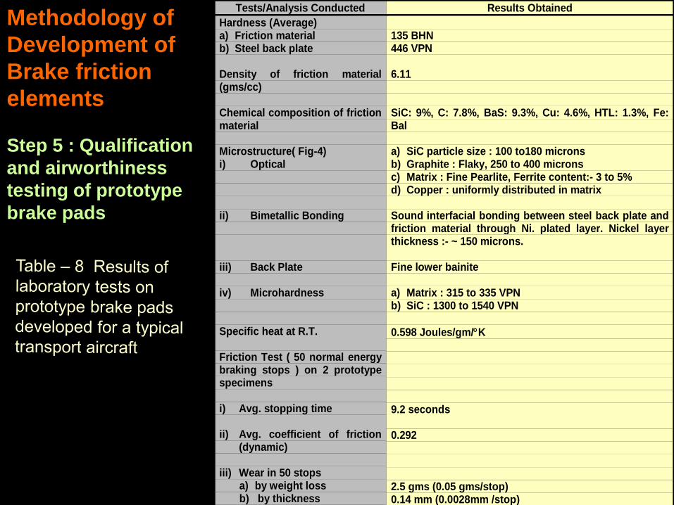
Tests/Analysis Conducted Results Obtained
Hardness (Average)a) Friction materialb) Steel back plate
Density of friction material(gms/cc)
Chemical composition of frictionmaterial
Microstructure( Fig-4)i) Optical
ii) Bimetallic Bonding
iii) Back Plate
iv) Microhardness
Specific heat at R.T.
Friction Test ( 50 normal energybraking stops ) on 2 prototypespecimens
i) Avg. stopping time
ii) Avg. coefficient of friction(dynamic)
iii) Wear in 50 stopsa) by weight lossb) by thickness
135 BHN446 VPN
6.11
SiC: 9%, C: 7.8%, BaS: 9.3%, Cu: 4.6%, HTL: 1.3%, Fe:Bal
a) SiC particle size : 100 to180 micronsb) Graphite : Flaky, 250 to 400 micronsc) Matrix : Fine Pearlite, Ferrite content:- 3 to 5%d) Copper : uniformly distributed in matrix
Sound interfacial bonding between steel back plate andfriction material through Ni. plated layer. Nickel layerthickness :- ~ 150 microns.
Fine lower bainite
a) Matrix : 315 to 335 VPNb) SiC : 1300 to 1540 VPN
0.598 Joules/gm/K
9.2 seconds
0.292
2.5 gms (0.05 gms/stop)0.14 mm (0.0028mm /stop)
Methodology of
Development of
Brake friction
elements
Step 5 : Qualification
and airworthiness
testing of prototype
brake pads
• By comparing the above results with the laid down property specifications,
some of which are given in table-3, it was observed that the iron base friction
material developed met the requirement of the properties and the transport
aircraft brake specification quite well.
• On this basis, the composition of the friction material selected, the raw material
specifications, the back plate steel and the P/M process parameters are
tentatively fixed and documented.
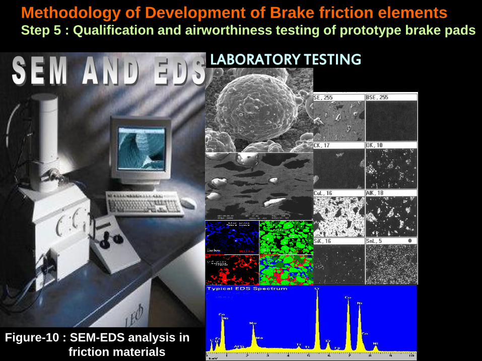
• Figure-10 illustrates the use of SEM-EDS in analysis and phase identification
studies of friction materials
Methodology of Development of Brake friction elements Step 5 : Qualification and airworthiness testing of prototype brake pads
LABORATORY TESTING
Methodology of Development of Brake friction elements Step 5 : Qualification and airworthiness testing of prototype brake pads
Figure-10 : SEM-EDS analysis in
friction materials
Methodology of Development of Brake friction elements Step 5 : Qualification and airworthiness testing of prototype brake pads
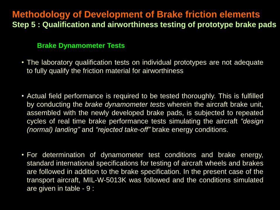
Brake Dynamometer Tests
• The laboratory qualification tests on individual prototypes are not adequate
to fully qualify the friction material for airworthiness
• Actual field performance is required to be tested thoroughly. This is fulfilled
by conducting the brake dynamometer tests wherein the aircraft brake unit,
assembled with the newly developed brake pads, is subjected to repeated
cycles of real time brake performance tests simulating the aircraft “design
(normal) landing” and “rejected take-off” brake energy conditions.
• For determination of dynamometer test conditions and brake energy,
standard international specifications for testing of aircraft wheels and brakes
are followed in addition to the brake specification. In the present case of the
transport aircraft, MIL-W-5013K was followed and the conditions simulated
are given in table - 9 :
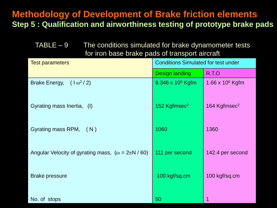
Test parameters Conditions Simulated for test under
Design landing R.T.O
Brake Energy, ( I 2 / 2)
Gyrating mass Inertia, (I)
Gyrating mass RPM, ( N )
Angular Velocity of gyrating mass, ( = 2N / 60)
Brake pressure
No. of stops
9.346 x 10⁵ Kgfm
152 Kgfmsec2
1060
111 per second
100 kgf/sq.cm
50
1.66 x 10⁶ Kgfm
164 Kgfmsec2
1360
142.4 per second
100 kgf/sq.cm
1
TABLE – 9 The conditions simulated for brake dynamometer tests
for iron base brake pads of transport aircraft
Methodology of Development of Brake friction elements Step 5 : Qualification and airworthiness testing of prototype brake pads
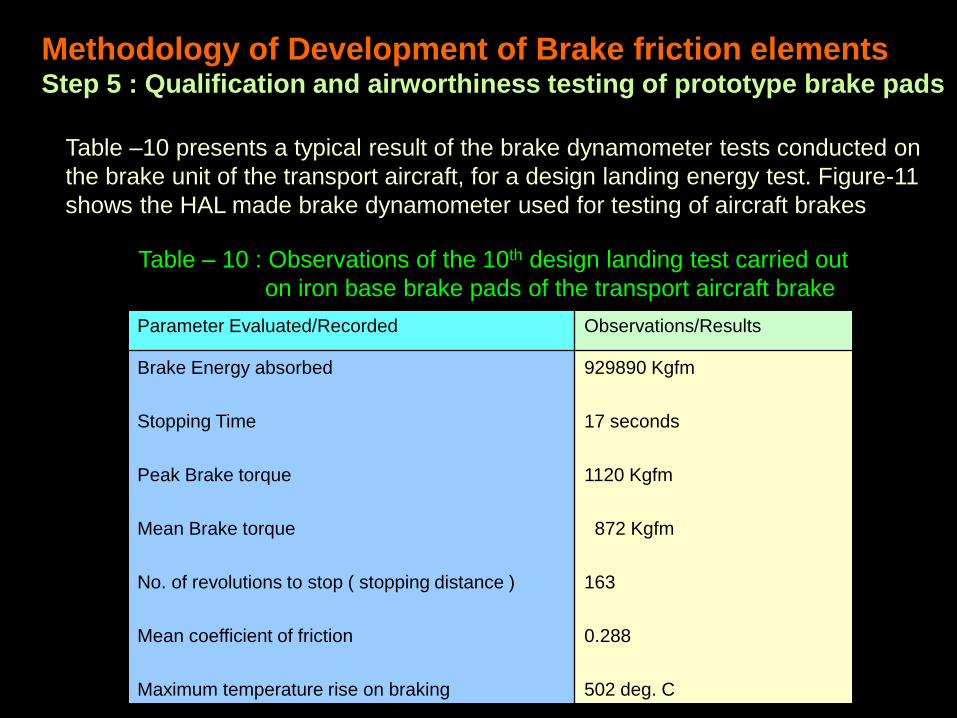
Table –10 presents a typical result of the brake dynamometer tests conducted on
the brake unit of the transport aircraft, for a design landing energy test. Figure-11
shows the HAL made brake dynamometer used for testing of aircraft brakes
Methodology of Development of Brake friction elements Step 5 : Qualification and airworthiness testing of prototype brake pads
Parameter Evaluated/Recorded Observations/Results
Brake Energy absorbed
Stopping Time
Peak Brake torque
Mean Brake torque
No. of revolutions to stop ( stopping distance )
Mean coefficient of friction
Maximum temperature rise on braking
929890 Kgfm
17 seconds
1120 Kgfm
872 Kgfm
163
0.288
502 deg. C
Table – 10 : Observations of the 10th design landing test carried out
on iron base brake pads of the transport aircraft brake
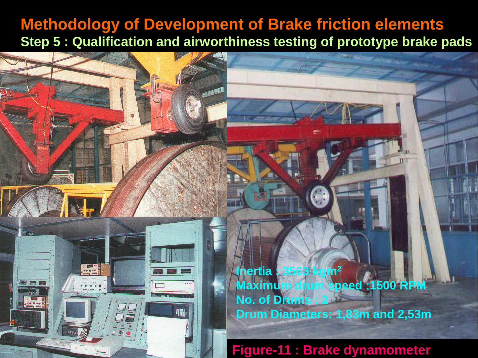
Figure-11 : Brake dynamometer
Inertia : 3563 kgm2
Maximum drum speed :1500 RPM
No. of Drums : 2
Drum Diameters: 1,83m and 2,53m
Methodology of Development of Brake friction elements Step 5 : Qualification and airworthiness testing of prototype brake pads
Methodology of Development of Brake friction elements Step 5 : Qualification and airworthiness testing of prototype brake pads
Aircraft trials
• Field / service trials are carried out on the prototype brake pads after
successful completion of dynamometer tests using the aircraft as a test bed
• “Accelerate –stop”, “landing” and “taxying and turning” tests are carried out
under critical combinations of aircraft weight and speed by experienced pilots
and their observations recorded. The observations made are :
- stopping time and distance,
- maximum brake temperature and “turn-around” time,
- brake feel and effectiveness, brake binding tendency, aircraft swing
• The iron base brake pads of the military transport aircraft in the present
example was tested successfully up to a maximum aircraft weight of 27,000 kgf
and braking speed of 235 kmph
• Immediately following aircraft trials the prototype pads are allowed to go for full
service life trials on a normal operation aircraft to determine the full wear-life
cycle of the pads under normal operating and service conditions.
Methodology of Development of Brake friction elements
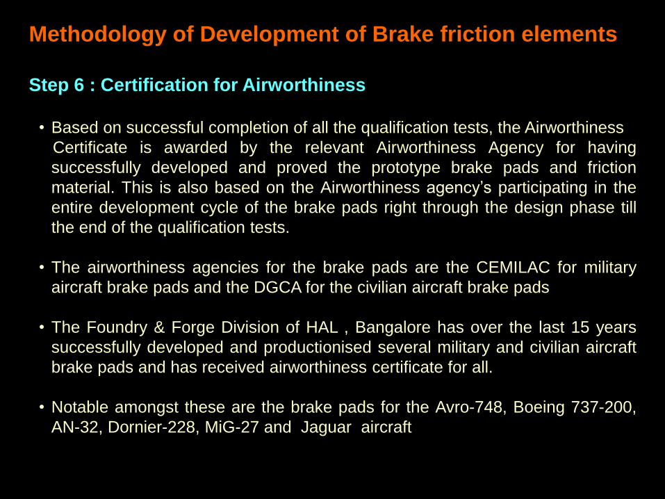
Step 6 : Certification for Airworthiness
• Based on successful completion of all the qualification tests, the Airworthiness
Certificate is awarded by the relevant Airworthiness Agency for having
successfully developed and proved the prototype brake pads and friction
material. This is also based on the Airworthiness agency’s participating in the
entire development cycle of the brake pads right through the design phase till
the end of the qualification tests.
• The airworthiness agencies for the brake pads are the CEMILAC for military
aircraft brake pads and the DGCA for the civilian aircraft brake pads
• The Foundry & Forge Division of HAL , Bangalore has over the last 15 years
successfully developed and productionised several military and civilian aircraft
brake pads and has received airworthiness certificate for all.
• Notable amongst these are the brake pads for the Avro-748, Boeing 737-200,
AN-32, Dornier-228, MiG-27 and Jaguar aircraft
Development and Production of Aircraft Brake pads
– Achievements and Success Stories of HAL
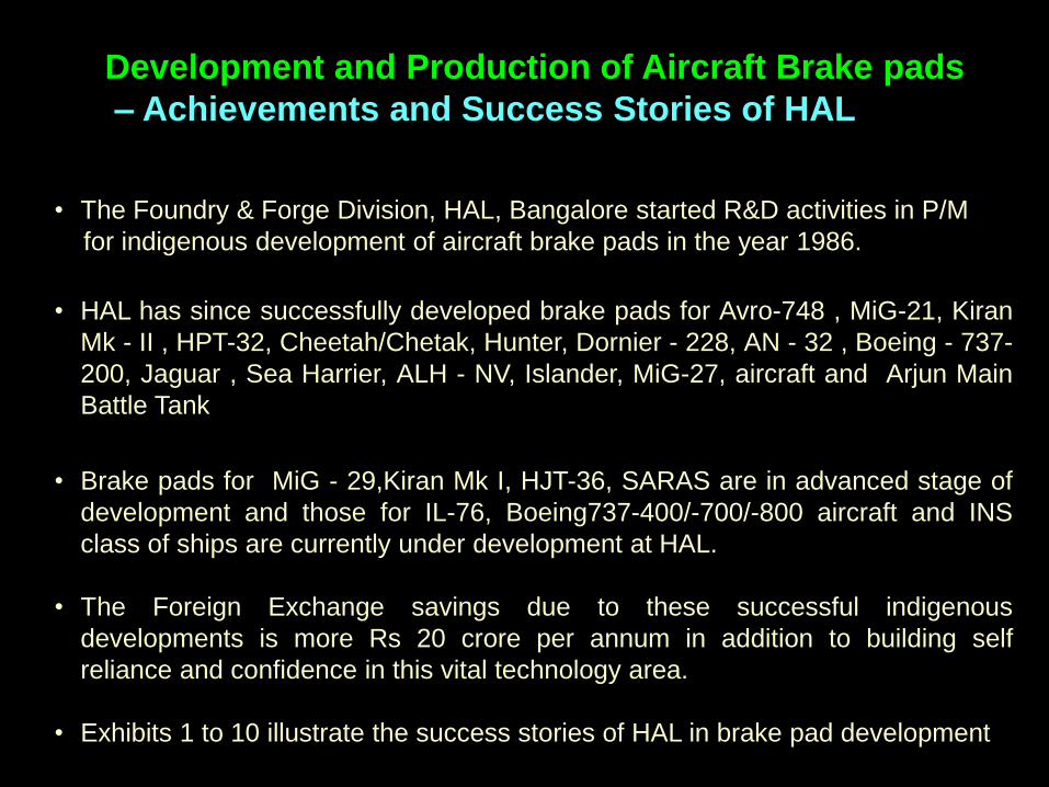
• The Foundry & Forge Division, HAL, Bangalore started R&D activities in P/M
for indigenous development of aircraft brake pads in the year 1986.
• HAL has since successfully developed brake pads for Avro-748 , MiG-21, Kiran
Mk - II , HPT-32, Cheetah/Chetak, Hunter, Dornier - 228, AN - 32 , Boeing - 737-
200, Jaguar , Sea Harrier, ALH - NV, Islander, MiG-27, aircraft and Arjun Main
Battle Tank
• Brake pads for MiG - 29,Kiran Mk I, HJT-36, SARAS are in advanced stage of
development and those for IL-76, Boeing737-400/-700/-800 aircraft and INS
class of ships are currently under development at HAL.
• The Foreign Exchange savings due to these successful indigenous
developments is more Rs 20 crore per annum in addition to building self
reliance and confidence in this vital technology area.
• Exhibits 1 to 10 illustrate the success stories of HAL in brake pad development
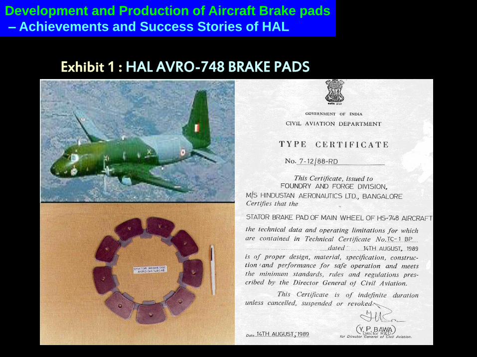
Exhibit 1 : HAL AVRO-748 BRAKE PADS
Development and Production of Aircraft Brake pads
– Achievements and Success Stories of HAL
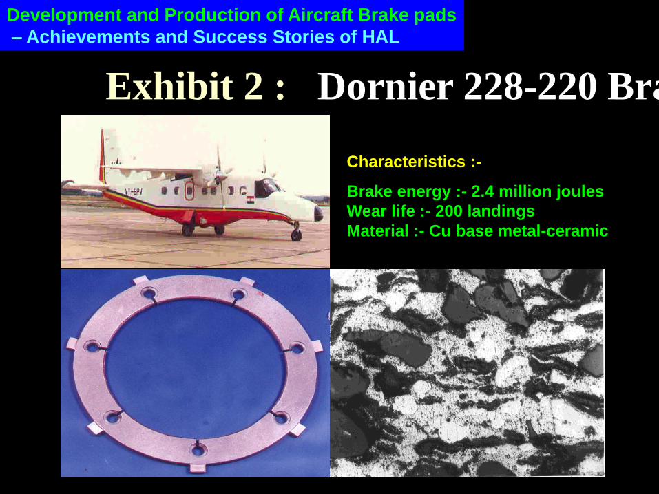
Exhibit 2 : Dornier 228-220 Brake Disc
Characteristics :- Brake energy :- 2.4 million joules
Wear life :- 200 landings
Material :- Cu base metal-ceramic
Development and Production of Aircraft Brake pads
– Achievements and Success Stories of HAL
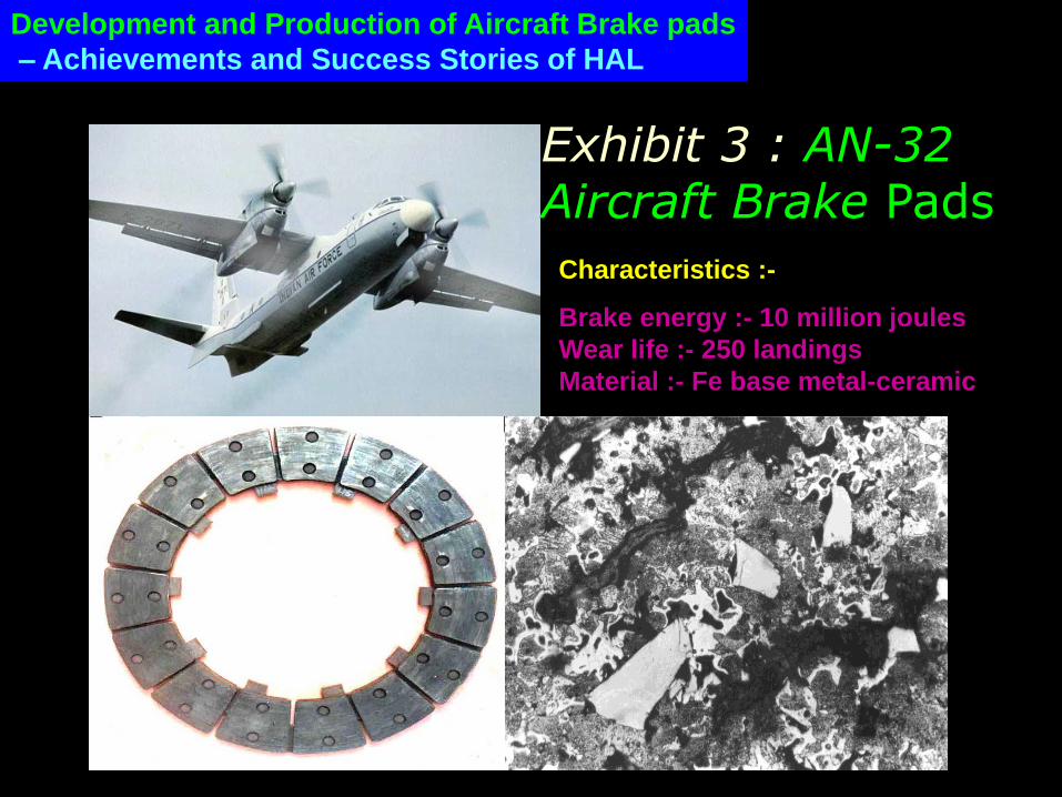
Characteristics :- Brake energy :- 10 million joules
Wear life :- 250 landings
Material :- Fe base metal-ceramic
Exhibit 3 : AN-32 Aircraft Brake Pads
Development and Production of Aircraft Brake pads
– Achievements and Success Stories of HAL
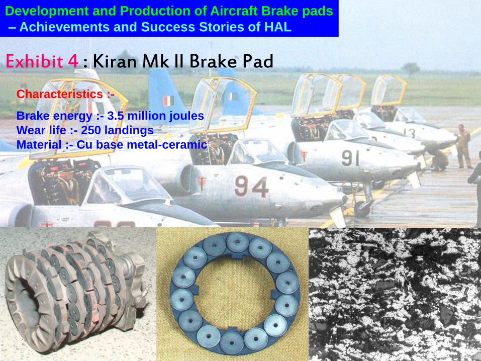
Exhibit 4 : Kiran Mk ll Brake Pad
Characteristics :- Brake energy :- 3.5 million joules
Wear life :- 250 landings
Material :- Cu base metal-ceramic
Development and Production of Aircraft Brake pads
– Achievements and Success Stories of HAL
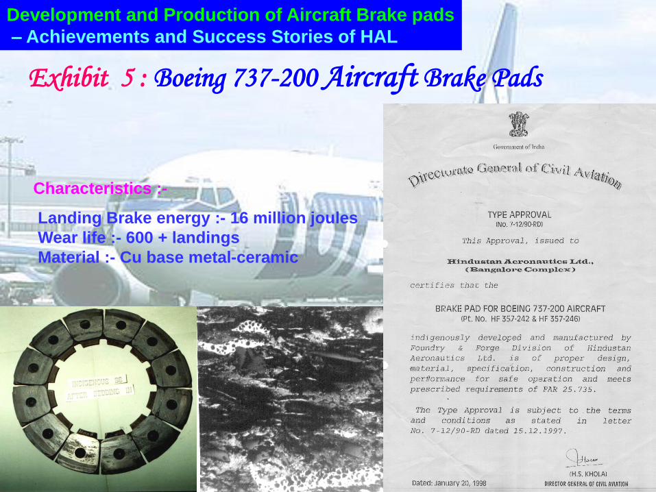
Characteristics :- Landing Brake energy :- 16 million joules
Wear life :- 600 + landings
Material :- Cu base metal-ceramic
Exhibit 5 : Boeing 737-200 Aircraft Brake Pads
Development and Production of Aircraft Brake pads
– Achievements and Success Stories of HAL
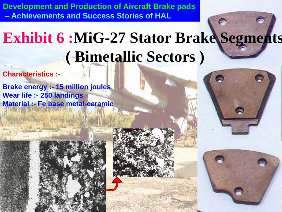
Characteristics :- Brake energy :- 15 million joules
Wear life :- 250 landings
Material :- Fe base metal-ceramic
Development and Production of Aircraft Brake pads
– Achievements and Success Stories of HAL
Exhibit 6 :MiG-27 Stator Brake Segments
( Bimetallic Sectors )
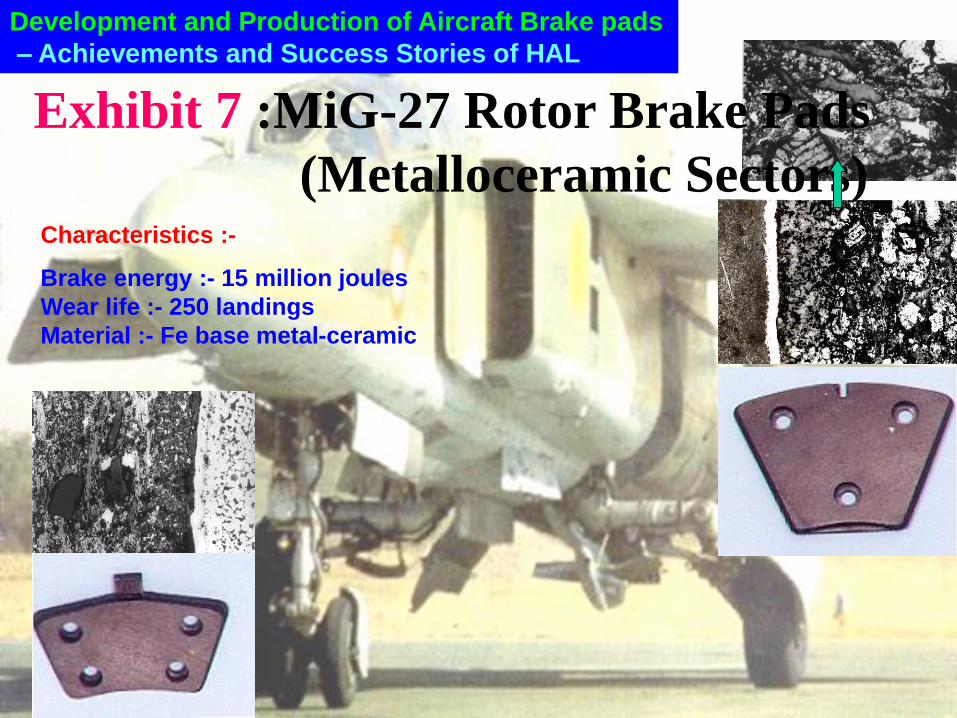
Exhibit 7 :MiG-27 Rotor Brake Pads
(Metalloceramic Sectors) Characteristics :- Brake energy :- 15 million joules
Wear life :- 250 landings
Material :- Fe base metal-ceramic
Development and Production of Aircraft Brake pads
– Achievements and Success Stories of HAL
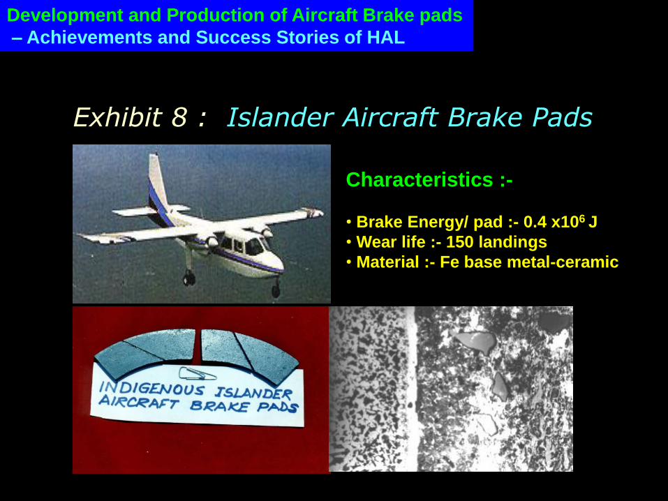
Exhibit 8 : Islander Aircraft Brake Pads
Characteristics :-
• Brake Energy/ pad :- 0.4 x10⁶ J
• Wear life :- 150 landings
• Material :- Fe base metal-ceramic
Development and Production of Aircraft Brake pads
– Achievements and Success Stories of HAL
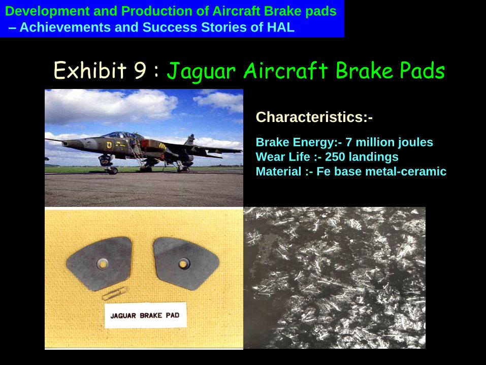
Exhibit 9 : Jaguar Aircraft Brake Pads
Characteristics:- Brake Energy:- 7 million joules
Wear Life :- 250 landings
Material :- Fe base metal-ceramic
Development and Production of Aircraft Brake pads
– Achievements and Success Stories of HAL
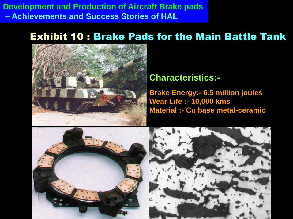
Exhibit 10 : Brake Pads for the Main Battle Tank
Characteristics:- Brake Energy:- 6.5 million joules
Wear Life :- 10,000 kms
Material :- Cu base metal-ceramic
Development and Production of Aircraft Brake pads
– Achievements and Success Stories of HAL
Conclusions
• Friction materials for high energy aircraft braking are “man-made” and specially
engineered, exotic composites. Metal-ceramic multi-component composites
processed by the modern route of P/M are the most commonly used.
• Friction material design and selection starts right from a careful analysis of the
aircraft brake design specification. A step-by-step approach is then followed for
prototype development by conducting controlled experiments to develop the
technology and finally qualification of the material by elaborate laboratory and
airworthiness tests
• The Foundry & Forge Division of Hindustan Aeronautics Ltd, Bangalore has
successfully developed and qualified several high energy aircraft friction
materials by P/M processing which has resulted in self reliance and large
savings.
Related Documents