7/18/2019 Aircraft 5 http://slidepdf.com/reader/full/aircraft-5 1/78 http://www.Boeing-727.com System Descriptions Page 1 Of 78 Air Conditioning APU Autopilot Electrics Fire Protection Flight Controls Fuel System GPWS Hydraulics Ice & Rain Protection Landing Gear & Brakes Oxygen Pitot Static System Pneumatics Powerplant Pressurisation Windows Yaw Dampers

Aircraft 5
Mar 01, 2016
sistemas propulsion aeronaves
Welcome message from author
This document is posted to help you gain knowledge. Please leave a comment to let me know what you think about it! Share it to your friends and learn new things together.
Transcript
7/18/2019 Aircraft 5
http://slidepdf.com/reader/full/aircraft-5 1/78
http://www.Boeing-727.com
System Descriptions
Page 1 Of 78
Air Conditioning
APU
Autopilot
Electrics
Fire Protection
Flight Controls
Fuel System
GPWS
Hydraulics
Ice & Rain Protection
Landing Gear & Brakes
Oxygen
Pitot Static System
Pneumatics
Powerplant
Pressurisation
Windows
Yaw Dampers

7/18/2019 Aircraft 5
http://slidepdf.com/reader/full/aircraft-5 2/78
http://www.Boeing-727.com
System Descriptions
Page 2 Of 78
AIR CONDITIONING
The pneumatics system provides compressed air at a constant flow rate to thetwo air conditioning packs. In these units the air temperature is modified tokeep the cabin and cockpit comfortable. In normal operation some of the airfrom the left pack provides conditioned air to the cockpit. The rest of the airfrom the left pack mixes with the air from the right pack in a distribution ductand provides conditioned air to the passenger cabin. The air is exhaustedthrough the pressurisation system at a flow rate that allows the cabin to bepressurised.
The air conditioning packs are located beneath the floor in the centre fuselagearea. An air conditioning pack valve controls the flow of air from thepneumatics system into each pack. The pack valves are controlled by twoswitches on the Flight Engineers panel.In each pack the air is split into three paths.In one path the air passes through a refrigeration unit, then to a set of mixingvalves. The mixing valves mix the refrigerated air with air from the other twopaths. This allows the air to be delivered to the cabin at the proper
temperature.The second path to the mixing valves delivers hot air directly.The third path is through only a portion of the refrigeration unit, and It reachesthe mixing valves at a moderate temperature. The refrigeration unit is calledan air cycle machine. It operates on the same principle as any otherrefrigeration device, except that it uses air instead of freon for refrigeration.The usual compression cooling and expansion seen in any refrigeration cycleis accomplished in the air cycle machine by a compressor, the secondary heatexchanger and an expansion turbine. The work extracted by the turbine istransmitted by a shaft to the compressor. A primary heat exchanger cools theair before it reaches the compressor, and thus increases the efficiency of the
air cycle machine.
7/18/2019 Aircraft 5
http://slidepdf.com/reader/full/aircraft-5 3/78
http://www.Boeing-727.com
System Descriptions
Page 3 Of 78
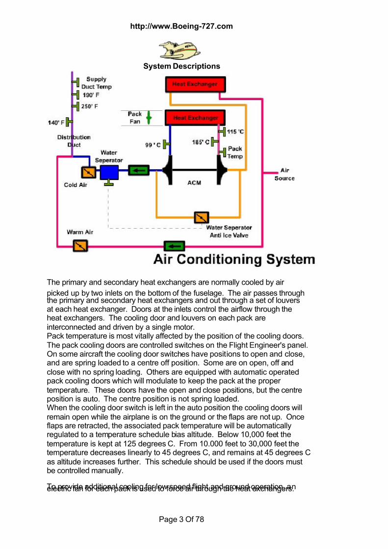
The primary and secondary heat exchangers are normally cooled by air
picked up by two inlets on the bottom of the fuselage. The air passes throughthe primary and secondary heat exchangers and out through a set of louversat each heat exchanger. Doors at the inlets control the airflow through theheat exchangers. The cooling door and louvers on each pack areinterconnected and driven by a single motor.Pack temperature is most vitally affected by the position of the cooling doors.The pack cooling doors are controlled switches on the Flight Engineer's panel.On some aircraft the cooling door switches have positions to open and close,and are spring loaded to a centre off position. Some are on open, off andclose with no spring loading. Others are equipped with automatic operatedpack cooling doors which will modulate to keep the pack at the propertemperature. These doors have the open and close positions, but the centreposition is auto. The centre position is not spring loaded.When the cooling door switch is left in the auto position the cooling doors willremain open while the airplane is on the ground or the flaps are not up. Onceflaps are retracted, the associated pack temperature will be automaticallyregulated to a temperature schedule bias altitude. Below 10,000 feet thetemperature is kept at 125 degrees C. From 10.000 feet to 30,000 feet thetemperature decreases linearly to 45 degrees C, and remains at 45 degrees Cas altitude increases further. This schedule should be used if the doors mustbe controlled manually.
To provide additional cooling for low speed flight and ground operation, anelectric fan for each pack is used to force air through the heat exchangers.
7/18/2019 Aircraft 5
http://slidepdf.com/reader/full/aircraft-5 4/78
http://www.Boeing-727.com
System Descriptions
Page 4 Of 78
This fan will operate when the pack is on and the inboard flaps are not fullyretracted, or when a pack is on and the airplane is on the ground. The ground
cooling fan has its own motor driven air inlet door on the side of the fuselagethat remains open when the fan is in operation. When a pack fan is started. Itdraws a very heavy load from the electrical system, and when stabilised, fanconsumes about ten kilowatts of power. These are the highest loads on theelectrical system.To monitor the operation of the air cycle machines, each has a temperaturetransmitter at the outlet off its compressor. The temperature sensed isdisplayed on a pack temperature gauge for each pack. As more air isdirected through cycle machine to provide more cooling, more compression isrequired from the compressor. This results in a higher compressor outlettemperature. Therefore, the pack temperature gauge monitors air cycle
machine workload. To protect the compressor from excessively hightemperature an over temperature sensor at the outlet of the compressor willcause the pack to shut down if the temperature reaches the limiting value. Another temperature limiting sensor located at the inlet to the turbine. Thisuses the temperature of the air as an indication of the energy in the air. If thetemperature of the air, and thus the energy entering the turbine becomes toohigh, the pack will shut down to prevent an overspeed.In order to return the pack to operation after the temperature in the pack hasreduced, a reset button on the pack control panel is provided. The packcannot be returned to operation until the button has been pressed.If the pack fan is operating when an air conditioning pack trips off, the fan will
continue to operate. The fan will stop when the pack temperature drops, thepack switch Is turned off, and the reset button is pressed.To allow unattended ground operation of the air conditioning system in the727, the pack trip off sensing and the pack valves are powered from thebattery transfer bus. Should the AC electrical power fail, the pack coolingfans will stop. Hot air from the APU will overheat the pack and a pack trip willoccur, providing the battery transfer bus is powered. This is one reason forleaving the battery switch on. As air is cooled it will hold loss moisture. To remove this condensation awater separator is installed downstream of the air cycle machine turbine. Thewater separator swirls the air over an impingement surface causing themoisture to drop out. This water can be seen coming from the lower fuselageon humid days. The air cycle machine is capable of lowering air temperaturesbelow freezing, which would cause the moisture in the water separator tofreeze. To prevent ice accumulation from blocking the water separator, asensor monitors the temperature. If the temperature gets too low, a waterseparator anti-ice valve is opened which allows warm air to bypass the aircycle machine and keep the temperature above freezing. 35F.The air conditioning units are controlled by switches on the Flight engineer'spanel. Each switch opens and closes its pack valve at a rate that will notoverload the air cycle machine. The pack valves are powered from the
battery transfer bus.Each air mix valve set is actually three valves ganged together, one hot, one
7/18/2019 Aircraft 5
http://slidepdf.com/reader/full/aircraft-5 5/78
http://www.Boeing-727.com
System Descriptions
Page 5 Of 78
intermediate, and one cold. These valves operate together to provide theproper mixing of hot, cool, and cold air. There is a set of three valves for each
air conditioning pack. As the outside air temperature drops, the temperature of the cooling airpassing through the heat exchangers is low enough to provide sufficienttemperature drop in the conditioned air. To compensate, the intermediatevalve opens, allowing air to bypass the turbine and flow directly from thesecondary heat exchanger into the cabin or cockpit. The turbine slows as aresult of this bypassing action causing the compressor to be driven at aslower speed. This allows some of the compressed air to bypass thecompressor, flowing directly from the primary heat exchanger to thesecondary heat exchanger. The restriction to airflow caused by the air cyclemachine is reduced as a result of this bypassing, reducing the need for high-
pressure bleed air. Reducing the need for high stage bleed air improvesengine efficiency, reducing the amount of fuel being used by the engine.
The temperatures in the cabin and cockpit are normally controlled byautomatic temperature regulators. Each regulator provides signals to a motorwhich drives the associated air mix valve. Each temperature regulatorreceives inputs from a temperature sensor in the cockpit or cabin and atemperature selector on the flight engineer's panel. The temperature sensorin the forward cabin provides temperature signals to the automatictemperature regulator for the right pack, and the cockpit temperature and lefttemperature selector position are sent to the temperature regulator for the left
pack. The position of each air mix valve is shown on an indicator next to theassociated temperature selector on the Flight Engineer's panel. The air mixvalve moves to the full cold position automatically when the associated packvalve is closed.
Conditioned air flowing from the air mix valves enters a common distributionduct. From this ducting a small portion of the air is directed into the cockpit.The remainder going to the passenger cabin. Both packs supply thedistribution ducting; therefore the same distribution ratio of air to the cabin andcockpit would result whether one or both packs are in operation.The air to the passenger cabin flows through risers between the windows tokeep the cabin walls warm. The air in the cabin eventually flows out through agrill along the floor line into the lower fuselage where it is exhausted throughthe pressurisation valves (outflow).Duct temperature is automatically restricted when the temperature control isoperating in the automatic range. A temperature sensor in the ductdownstream of each air mix valve signals the associated automatictemperature regulator if the temperature reaches a limiting value. When thislimiting temperature is reached, a circuits called the topping circuit, preventsthe mixing valve from moving toward a higher temperature position.If an automatic temperature regulator fails to control the temperature of the air
satisfactorily, the associated air mix valve can be controlled manually.- Tooperate the air mix valve manually, spring tension must be overcome and the
7/18/2019 Aircraft 5
http://slidepdf.com/reader/full/aircraft-5 6/78
http://www.Boeing-727.com
System Descriptions
Page 6 Of 78
selector rotated to the manual position. In this position the automatictemperature regulator is cut out. Holding the selector lightly against spring
tension to the cool position will cause the air mix valve to move towards cold.In the warm position, the valve will move towards hot.To prevent the air from a pack getting too hot, should the automatictemperature regulator fail, a second temperature sensor is installeddownstream of each mixing valve. When the limiting temperature is reached,the associated air mix valve will move to the full cold position, and the ductoverheat light next to the associated temperature controller will illuminate.If the automatic temperature regulator and the duct overheat protection bothfail, to prevent the duct temperature from rising, a third temperature sensorwill cause the pack to trip. If the overheat and pack trip are on the left portionof the systems the location of the supply duct temperature transmitter near the
right air mix valve will prevent the temperature indication from reaching thetrip off temperature.To regain control of the temperature regulating networks and turn off the triplights after an overheat has occurred, a reset button is installed on thetemperature control panel. Once the temperature has reduced, pressing thebutton will return the temperature control system to normal operation. A temperature gauge on the flight engineers panel is used to monitor thetemperature of the air being supplied to the cabin at two locations. The airtemperature selector can be used to select the temperature in the forward andaft supply ducts, the main supply distribution duct, and in the forward and aftcabins.
Air is tapped off at the cold side of the left air conditioning pack and deliveredto the individually controlled outlets above the passengers, the lavatories, andthe cockpit. This in referred to as the gasper system. To increase the flow ofgasper air, a fan is installed in the gasper ducting. A switch on the flightengineers air conditioning control panel turns the gasper fan on or off.If the left air conditioning pack is not operating when the gasper fan is on,cabin air is recirculated through the gasper system.Conditioned air flows through the airplane and exhausts through threeprincipal exit systems. First of these is the normal pressurisation outflowvalve. Operation of this valve will be covered under pressurisation.Some air flows into the electronic equipment compartment and circulatesthrough the various electronic components; it passes through electronicequipment and circuit breaker panels in the cockpit, the electronic equipmentbay, and the weather radar compartment. This air absorbs the heatgenerated by these units and carries it overboard through an exhaust systemon the forward right side of the fuselage.In normal flight, cabin differential pressure provides necessary airflow throughthis system. Since the electronic equipment operates continuously, a meansof inducing airflow on the ground and at low cabin pressure differentialpressure is required. To provide this flow, an electric fan has been installed inthe exhaust duct. This fan comes on automatically at low cabin differential
pressure. The exhaust to this system has a large and small outlet. So thatunrestricted flow can be achieved at low cabin differentials, both outlets are
7/18/2019 Aircraft 5
http://slidepdf.com/reader/full/aircraft-5 7/78
http://www.Boeing-727.com
System Descriptions
Page 7 Of 78
used. As the flow rate increases, a flow rate sensitive valve closes preventingexcessive loss of air at high differential pressures.
A warning light on the lower right corner of the flight engineers panel will alertthe crew to inadequate cooling of electronic equipment. A sensor in thecooling air outlet monitors airflow through the cooling system. If coolingairflow becomes inadequate the "no equipment cooling" light will come on.The cargo compartments on the 727 are class D cargo compartments, whichare designed to confine a fire without endangering the safety of the airplane orthe occupants. No air circulates through them although a small amount of airflows through the equalisation valves to maintain equal pressure between thecargo compartment and the surrounding cavities, should cabin pressure vary.If a fire develops, it will smother itself as the oxygen in the compartment isconsumed. To maintain temperature in the forward cargo compartment,
conditioned air from the cabin flows around an airtight inner shell then isdischarged through the cargo heat outflow valve. Approximately 30% of theair in the aircraft will exit through this valve. A switch on the flight engineers panel controls the cargo heat outflow valve.In the normal position the valve is open, permitting air circulation around theforward cargo compartment. If a pressurisation problem should occur, closingthe switch can stop the flow of air through this exit. Without airflow around theforward cargo compartment the temperature within the compartment will droprapidly to a much lower value.The air that passes from the cabin to the pressurisation outflow valve in the aftfuselage of the airplane heats the aft cargo compartment.
An automatic pack trip system is incorporated in the 727 200 series aircraft.With the system armed before takeoff, loss of thrust on any engine will trip offboth packs. This allows the engines to develop somewhat higher thrust forthe remainder of the takeoff and initial climb. In addition, both pack fans willstop, thereby reducing the electrical load. To arm the auto pack trip system,the airplane must be on the ground, the flaps must be out of the up position,the auto pack trip switch must be in the normal position, and all engines mustbe above 1.5 EPR.When the flaps reach the up position after takeoff the auto pack trip systemwill be deactivated. After takeoff, and when clear of obstacles the auto packtrip switch should be returned to the coot position. This will deactivate theauto pack trip system. Should any engine lose power below 1.3 EPR bothpacks will trip off, both pack valves will close, both pack fans will stop andboth pack trip lights will illuminate. In addition, an engine fail light willilluminate on each side of the pilot's glare shield. These engine fail lights canbe extinguished by pressing on either light cap. When a substantial powerreduction is anticipated, such as a noise abatement takeoff. The flightengineers should anticipate the thrust reduction and place the auto pack tripswitch to cut out prior to reducing thrust to remove the possibility of aninadvertent auto pack trip.The airplane is equipped with a means of controlling the temperature in the aft
cabin without affecting the temperature of the forward cabin. This is donethrough the aft cabin zone temperature system. A single switch operates two
7/18/2019 Aircraft 5
http://slidepdf.com/reader/full/aircraft-5 8/78
http://www.Boeing-727.com
System Descriptions
Page 8 Of 78
valves in this system. This allows warm air from the right air conditioningpack to enter the forward or aft cabin bringing about the requested change in
aft cabin temperature. Should the aft cabin ducting overheat an amber lighton the panel will illuminate. Both zone control valves will close and the needlewill centre. The flight engineer can monitor the use of this system with the airtemperature selector.
APU
The auxiliary power unit, or APU in the Boeing 727 is a small turbine enginemounted between the main wheel wells. it draws air from the wheel well areafor combustion and cooling and exhausts through louvers in the top of theright wing root. Most of the accessories are mounted on the left hand side ofthe unit. The components of most interest are the APU starter (electric), hourmeter, fuel control unit, 3-speed switch (3 psi oil, 35%, 95%) Generator, tachogenerator (RPM) note that these last two components are interchangeablewith there brothers on the engine. Power for starting the APU comes directlyfrom the airplane battery. The battery switch must be on when operating the APU, if the switch is turned off the APU will shutdown.The APU uses fuel from the number 2 tank. The APU fuel shutoff valve islocated at the tank. It is opened or closed by the APU master switch.Operation of either APU fire switch or activation of the auto fire shutdowncircuitry will also close this valve
The controls for the unit may be found in the flight deck at the flight engineersauxiliary panel and in the left hand wheel well. It contains controls for startingand stopping the APU, fire detection and protection, generator operation, andgauges for monitoring electrical load and exhaust temperature.There is a three-position control switch marked Off, ON and Start.It remains in the OFF position when the APU is shut down and in the ONposition when the APU is operating. It must be held in the START positionagainst spring pressure when starting the APU. ON is the normal operatingposition. Selecting this position prior to starting will open the APU fuel valve. After the fuel valve is opened, positioning the master switch to START willinitiate the automatic starting sequence. When the APU crank light comes on,
the automatic starting sequence has begun. Once the light is on, the masterswitch may be released to the ON position. During the start sequence, if theEGT does not rise within 15 seconds or there is no frequency an the ACmeter within 30 seconds, the APU fire shutoff handle should be pulled tointerrupt the start sequence. The APU crank light goes out when the starterreleases. Click here to view starting sequence. Self-contained lubrication system requires no crew monitoring. The APU willnot operate if the oil pressure fails. An exhaust temperature gauge located in the lower right corner of the APUcontrol panel shows APU turbine exhaust temperature in degrees C. Thetemperature will vary widely depending on bleed air loads. The green band is
the normal operating range, and the red radial is the maximum operatingtemperature.
7/18/2019 Aircraft 5
http://slidepdf.com/reader/full/aircraft-5 9/78
http://www.Boeing-727.com
System Descriptions
Page 9 Of 78
The APU is governor controlled to maintain 100% RPM, thus it can be gearedto drive an AC generator directly. This generator can supply electrical power
to all airplane systems for ground operation.Bleed air is extracted from the APU compressor to be used for airplane airconditioning and for engine starting on the ground. An APU bleed air valve isinstalled on the APU to control flow of bleed air from the APU to the bleed airdistribution system. The APU bleed air valve will open if the APU hasreached operating RPM and either or both Engine No.2/APU BLEED switchesare in the OPEN position. An APU light is located on the door warning annunciator at the flightengineers panel. This light will come on any time the fuel valve is open if thenumber 1 DC electrical bus is powered.For maintenance personnel external control of the APU, a second APU
control panel is located in the left wheel well between the fuselage and thegear strut. It is not used for normal operation. The start switch on this panelwill start the APU if the battery switch and APU master switch in the cockpitare on. The stop switch will shut the APU down. Also the panel contains afire switch, a fire warning light, and a bottle discharge button. These controlspermit fighting an APU fire without going to the cockpit.The APU will shut down automatically for the following reasons; loss of oilpressure or overspeed will cause the fuel to be cut off at the fuel control in the APU. The fire detection loop, if it reaches the warning temperature, will closethe fuel shutoff valve in the number 2 tank and at the fuel control and the APUwill stop. Heat sensitive probes in the turbine exhaust provide other
protection. First, these probes cause the APU to be unloaded by modulatingthe APU bleed air valve toward close; if closing the bleed air valve fails tosolve the high exhaust temperature, the probes will cause the fuel control toreduce fuel flow until the temperature is lowered sufficiently or the APU flamesout.

7/18/2019 Aircraft 5
http://slidepdf.com/reader/full/aircraft-5 10/78
http://www.Boeing-727.com
System Descriptions
Page 10 Of 78
On the 200 series aircraft a turbine and compressor assembly called a flowmultiplier is used to improve the airflow from the APU. It draws in additionalair from the right wheel well adding it to the APU compressed air output. Thishigher volume of air makes it possible for the APU to supply air to both airconditioning packs. During single pack operation however, the flow multipliershut off valve remains closed and the turbine is bypassed. A FLOW MULTIPLIER OVERHEAT light on some airplanes and a BLEED AIR light on others warns of an overheat in the output of the flow multipliercompressor. The overheat will cause the APU bleed air valve to close.Cycling the number two engine bleed switches will reset the APU bleed air
valve. Further protection is provided by a fusible plug, which should it melt. Itwill close the flow multiplier shutoff valve, preventing compressed air fromreaching the flow multiplier turbine.Pressures in the pneumatic ducts can be read on the duct pressure gaugeunder most conditions. The duct pressures will read zero, when either airconditioning pack is turned on, if the APU is the only source of air in thepneumatic ducting (200 Series). Turning either pack switch on prevents APUbleed air from reading on the duct pressure transmitters.
The APU on the Boeing 727 can be used for ground operation only. Electricalloads and EGT limits must be observed for all operations. The EGT limits arered radial for maximum and the green band for continuous operation. Theelectrical load limit is 165 amps, the higher rating is due to the improved
7/18/2019 Aircraft 5
http://slidepdf.com/reader/full/aircraft-5 11/78
http://www.Boeing-727.com
System Descriptions
Page 11 Of 78
cooling of the APU installation. The APU should be operated withoutpneumatic load for at least one minute after start or prior to shut down.
A pretty good piece of kit, most of the problems you experience are to do withstarting (3 speed switch or over-speed switch) occasionally the shorting linkon the exhaust disconnect link. Extensive troubleshooting will require the testset, (not a great deal you can do down route). It's manufactured by AlliedSignal (Garrett).
APU Starter is limited to 1 min on 4 min offMax time for APU fire test AC Busses powered 30 sec- 45 sec. Battery power60 sec. Max APU generator load 165 ampsOne pack on for cooling (100 Series)
Two packs on for heatingTwo packs on for cooling (If flow multiplier installed)Normal operating EGT Green Band (Marked @ 700)Max Operating Red Radial line (Marked 750 - 790)
APU EGT Operating GTCP85-98 and 98C 98CK
Maximum 760 °C 710 °C
Continuous 710 °C 663 °C
AUTOPILOT
The Autopilot (A/P) can control the aircraft in a climb, cruise decent andapproach phases of flight or as directed manually by the pilot via the controlknob. It may also be directed by signals from the VHF, GPS, and INSnavigation systems. It can also find and maintain a pre selected heading,
altitude, pitch attitude or operate in a split axis configuration.It requires 115V AC for operation from the aircraft generators or an externalsource. If using the latter you need to operate the ground test switch.Electrical interlocks prevent selection or operation unless all the properconditions for correct functioning are satisfied.
INTERLOCKS Mandatory interlocks are at least one yaw damper switched on and it'sdisengage flag out of view, turn and pitch controller in neutral detent,operating vertical gyro if these conditions are correct you will be able toengage the aileron switch. To engage the elevator switch the aileron switch
must be engaged and the cruise stabilizer trim switch must be in the normalposition.

7/18/2019 Aircraft 5
http://slidepdf.com/reader/full/aircraft-5 12/78
http://www.Boeing-727.com
System Descriptions
Page 12 Of 78
The autopilot will disengage if any of the following actions or conditions occur.Yaw damper positioned to off, capt or co pilot press autopilot release switch,
power to vertical gyro is lost, switching compass source or power to A/Paileron (roll) is lost. Elevator channel disengage will occur if the stabilizer trimswitch is activated, pitch channel selector is switched (A or B) cruise trimswitch is activated, A/P and cruise trim cut out switches positioned to cut out,electrical power to the A/P elevator (pitch) is lost. A/P mode will return to manual (turn and pitch knob) if any of the followingoccur reference VHF/GPS/INS is switched, turn and pitch controller movedout of detent, ILS frequency is switched while in approach mode.
ELECTRICS
AC POWER
Modern transport aircraft use 400-hertz alternating current to power much oftheir electrical equipment for several reasons. Voltages are easily convertedfrom high to low or low to high. The higher frequencies used in aircraftelectrical systems allow components to be smaller, but develop the samepower as the 60 hertz devices normally found in the home and industry.
Power for the electrical system is supplied by the three engine drivengenerators, and as a backup on the ground, APU generator, or an externalpower source. Normally all of the electrical power in the airplane is producedby the engine driven AC generators. An AC generator must be rotated at a constant speed throughout the
operating RPM range of the engine. This is necessary to maintain theappropriate frequency output of the generator. A generator drive unit, called aconstant speed drive, or CSD, which is a hydro mechanical device betweenthe engine drive pad and the generator, accomplishes this function for eachgenerator. Each generator drive unit contains its own integral oil supply andpumps. So that the oil pressure within the unit can be monitored, a low oilpressure light for each unit is included on the flight engineers electrical panel.The amber light will come on if the oil pressure in a unit is too low. To cool thegenerator drive oil an air-cooled heat exchanger is installed in each drivesystem. Engine fan stage bleed air continuously provides the required coolingairflow for the heat exchangers. There is an oil temperature gauge for each
generator drive unit. These gauges have two scales. Oil "IN" temperature isindicated on the lower scale, which is calibrated from 40 degrees to 160

7/18/2019 Aircraft 5
http://slidepdf.com/reader/full/aircraft-5 13/78
http://www.Boeing-727.com
System Descriptions
Page 13 Of 78
degrees Celsius. The upper scale is calibrated from 0 degrees to 30 degreesCelsius, and indicates the rise in the temperature of the oil as it passes
through the generator drive unit. Above each temperature gauge is a toggleswitch for selecting either the "IN" or "RISE" temperature scale. The "IN"temperature is sensed downstream of the oil cooler as it enters the generatordrive. This gives an indication of oil cooler efficiency. The rise temperature isthe difference between oil in and oil out temperatures and is an indication ofheat generated within the drive unit in rotating the generator, or the workloadof the generator drive unit. The rise temperature caution range is 20 degreesto 30 degrees C. If the "IN" temperature reads between 127 degrees and 140degrees C the operating time limit is two hours. With the "IN" temperaturebetween 140 degrees and 160 degrees C. Operating time limit is 50 minutes.
To the left of each low pressure light is the disconnect switch for theassociated generator drive unit. These switches are red guarded and safetywired. The switch under the guard has two positions, Normal and Disconnect.The Disconnect position is momentary contact and spring loaded to thenormal position. The generator drive unit can be disconnected by opening theguard and moving the disconnect switch to the disconnect position. Thisaction disengages the mechanical coupling for the generator drive unit fromthe engine drive pad. Also this action trips the associated generator breaker,breaking the electrical connection between the generator and its load bus.The generator drive can only be reconnected on the ground by maintenancepersonnel.
The generators each produce three phase, 400 hertz. 115 volt AC electricalpower. The voltage produced by a generator depends on there being amagnetic field in the generator. Current flowing from the voltage regulatorproduces this field. The generator's output voltage is sampled by the voltageregulator which adjusts the current to the field so that the generator's output,when not in parallel, will be 115 volts. plus or minus 5 volts.
Under certain abnormal or emergency conditions it is necessary to reduce thevoltage output of the generator to a minimum. The field relay performs thisfunction by interrupting the current flow from the voltage regulator to thegenerator. With the field relay open, only residual voltage of 10 to 17 volts willbe produced if the generator is rotating. Each generator has a field relaycontrolled by the field switch on the electrical panel. The light next to the fieldswitch will be on when the field relay is open.
When the generator is producing full voltage, it may be connected to its loadbus by closing the generator breaker.The load bus is a distribution point for the power produced by the generator.Heavy load items, such as air conditioning pack fans, galleys, and hydraulic"B" pumps are powered directly from the load busses. Power is also sent to
the various circuit breaker panels to power electrical equipment throughoutthe airplane. Each generator breaker is closed with a switch labelled GEN.

7/18/2019 Aircraft 5
http://slidepdf.com/reader/full/aircraft-5 14/78
http://www.Boeing-727.com
System Descriptions
Page 14 Of 78
When a generator is connected to its load bus through the generator breakersthe generator breaker light next to that generator switch will be out. When the
generator is not connected to its load bus the light will be on.
To equalise the loads on the generators, and to protect the electrical system ifone generator should fail, the three load buses are connected together by athird set of relays. These bus tie breakers are connected to a common circuitreferred to variously as the "tie bus" or the synch bus. The tie bus shuttlespower among the three AC load buses as power requirements change, butonly when the bus tie breakers are closed. If a generator should fail the tiebus will power the AC load bus associated with that generator through its bustie breaker.
Since we are dealing with alternating current, we must be certain that thevoltages of the various sources we are joining in parallel are "in phase". Bythis we mean that the positive and negative portions of the two voltages thatwe are connecting occur at the same time. If we joined the voltage sourceswhen they were not "in phase", serious damage could be done to a generator.In practice, the bus tie breakers are left closed so a single power source couldpower all three AC load buses. To protect against connecting a generator outof phase, automatic protective circuits prevent the generator breakers frombeing closed unless the associated generator is in phase with the othergenerators already powering the system. The bus tie breakers do not havethis protective feature.
Some AC powered items are considered to be more critical to safe flight.These are powered through the essential AC bus, which can be supplied byany of the three generators directly without the necessity of its generatorbreaker being closed. The selected generator's field relay must be closed sothat the generator will be able to supply electrical power. The essential powerselector switch on the upper right side of the electrical panel controls theselection of a power source for the essential AC bus. Normally generatorthree supplies the essential power, with the other two generators available.The essential AC bus is also powered when external power or the APU issupplying the airplane. Preferences for essential sources are eng 3, 1, 2 inthat order. It's due to the loads on each bus, 3 being the lightest load, 2 theheaviest
Red warning lights show failure of the selected essential AC power source.There is a steady red light on the essential power selector panel and aflashing red light, labelled "WARN - PUSH TO RESET", on the pilot's centreinstrument panel. The flashing red light can be extinguished by pressing thelight cap, but the steady red light will not go out until the essential AC bus ispowered from another source.
Certain of the captain's instruments are protected even further. They arepowered from the standby AC bus. As long as the essential AC bus is
7/18/2019 Aircraft 5
http://slidepdf.com/reader/full/aircraft-5 15/78
http://www.Boeing-727.com
System Descriptions
Page 15 Of 78
powered, it powers the standby AC bus. In the event of a failure of essential AC power in flight the standby bus will automatically be powered by a static
inverter. The static inverter is powered from the battery bus.
On the ground the standby AC bus may be powered from the static inverter,however, it is necessary to select "STANDBY" with the essential powerselector to do so. This is normally done when standby AC power is required,but AC power is not available from the airplane's generators or an externalpower source. The essential power selector must be depressed before it canbe rotated to the "STANDBY" position. When the selector is moved to thestandby position on the ground or in flighty the essential AC bus will no longerbe powered even if it were powered previously.
The last major AC bus is the AC transfer bus. Normally this bus is poweredfrom the number 3 AC load bus, but under certain conditions can be poweredfrom an external power source. Distribution of electrical power is through thevarious circuit breaker panels. The lower portion of the P 6 panel is dividedinto three sections. P6-11, P6-12, and P6-13. These sections are associatedwith the three AC load buses. 1, 2, and 3 respectively. On each panel is apower light, which glows continuously when the associated bus is powered.The rest of the P6 panel and the P18 panel contain the systems sections withthe circuit breakers for those systems.The upper portion of the P 6 panel is divided from top to bottom into four mainsections, P6-1, P6-2, P6-3, and P6-4. The other main circuit breaker panel is
P-18, which is located on the left sidewall above the first observer's seat. TheP18 panel is further subdivided into four main sections numbered from bottomto top. In general these panels are: P 18-1. Radio equipment; P18-2, lightinstruments, autopilot, and interphone; P18-3. Passenger accommodation andP18-4. Cockpit lighting, service lights, and exterior lighting. Isolated groups atcircuit breakers related to lighting are installed in several other cockpitlocations. There are also some circuit breakers, which are inaccessible to thecrew located in the electronic equipment compartment.
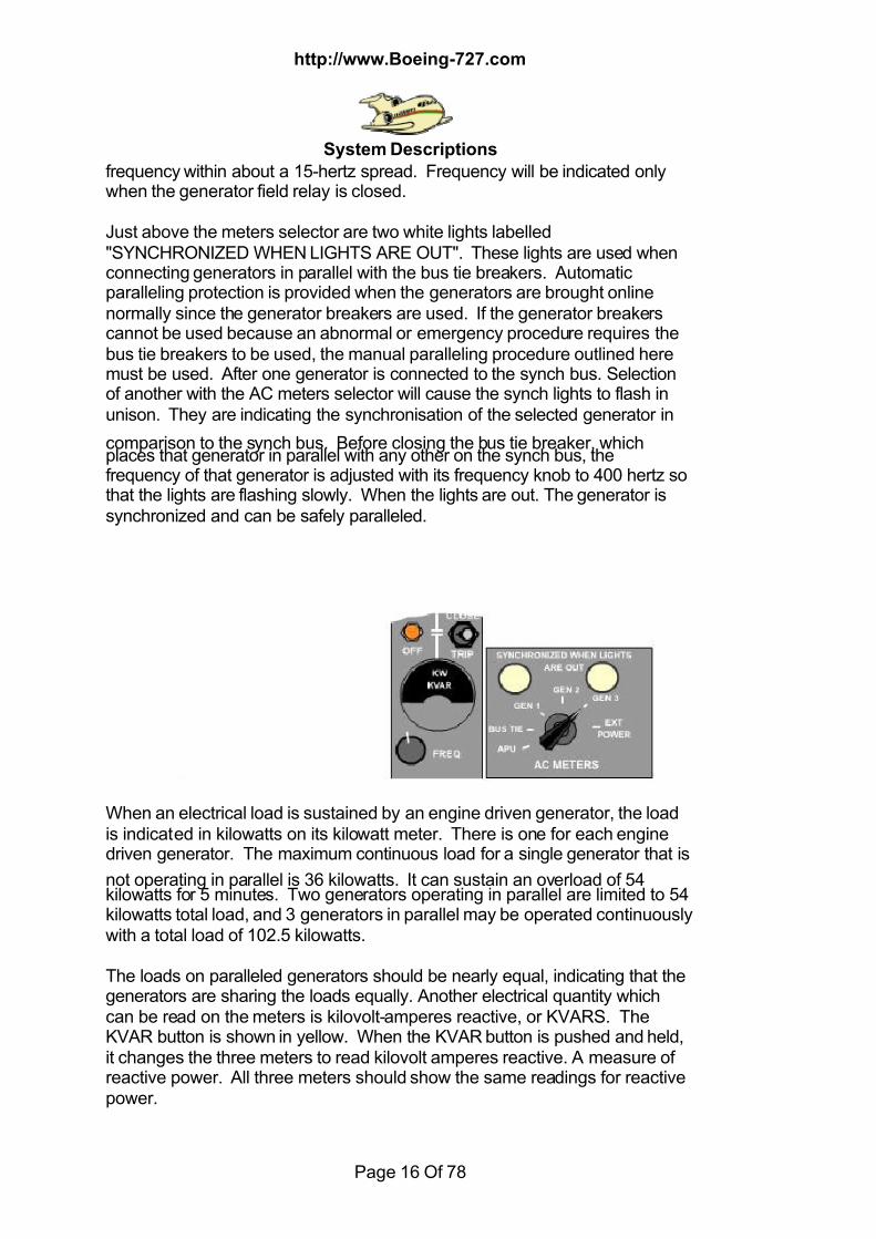
On the right side of the flight engineers panel is an AC meters selector. Eachof the three engine driven generators, the APU generator, or the externalpower can be sampled as well as the voltage and frequency on the synchbus. When a generator is rotating with its field relay open, it will produce 10 to17 volts residual voltage. This voltage can be read an the voltmeter lowerscale by selecting that generator and pushing the residual volts button. Whenthe generator field relay is closed the generator field is energised by thevoltage regulator. Now normal voltage can be read on the top scale of thevoltmeter. It should read 115 volts plus or minus 5 volts. Above the ACmeters selector is a frequency meter. This meter will indicate the frequency ofthe power source selected by the AC meters selector. When selected togenerators 1, 2, or 3. the frequency desired is 400 hertz plus or minus 9 hertz.
If the frequency is not 400 hertz, it can be adjusted using the frequency knobon the left panel. The knob for each generator allows adjustment of the
7/18/2019 Aircraft 5
http://slidepdf.com/reader/full/aircraft-5 16/78
http://www.Boeing-727.com
System Descriptions
Page 16 Of 78
frequency within about a 15-hertz spread. Frequency will be indicated onlywhen the generator field relay is closed.
Just above the meters selector are two white lights labelled"SYNCHRONIZED WHEN LIGHTS ARE OUT". These lights are used whenconnecting generators in parallel with the bus tie breakers. Automaticparalleling protection is provided when the generators are brought onlinenormally since the generator breakers are used. If the generator breakerscannot be used because an abnormal or emergency procedure requires thebus tie breakers to be used, the manual paralleling procedure outlined heremust be used. After one generator is connected to the synch bus. Selectionof another with the AC meters selector will cause the synch lights to flash inunison. They are indicating the synchronisation of the selected generator in
comparison to the synch bus. Before closing the bus tie breaker, whichplaces that generator in parallel with any other on the synch bus, thefrequency of that generator is adjusted with its frequency knob to 400 hertz sothat the lights are flashing slowly. When the lights are out. The generator issynchronized and can be safely paralleled.
When an electrical load is sustained by an engine driven generator, the loadis indicated in kilowatts on its kilowatt meter. There is one for each enginedriven generator. The maximum continuous load for a single generator that is
not operating in parallel is 36 kilowatts. It can sustain an overload of 54kilowatts for 5 minutes. Two generators operating in parallel are limited to 54kilowatts total load, and 3 generators in parallel may be operated continuouslywith a total load of 102.5 kilowatts.
The loads on paralleled generators should be nearly equal, indicating that thegenerators are sharing the loads equally. Another electrical quantity whichcan be read on the meters is kilovolt-amperes reactive, or KVARS. TheKVAR button is shown in yellow. When the KVAR button is pushed and held,it changes the three meters to read kilovolt amperes reactive. A measure ofreactive power. All three meters should show the same readings for reactivepower.
7/18/2019 Aircraft 5
http://slidepdf.com/reader/full/aircraft-5 17/78
http://www.Boeing-727.com
System Descriptions
Page 17 Of 78
When certain electrical system faults occurs lights an the electrical faultannunciator panel on the flight engineer's auxiliary panel will indicate the type
of fault and the system involved. The reset button on the panel is used to putout the annunciator lights when required. The test button is used to test theannunciator lights.
OTHER POWER SOURCES
The system may be powered by the APU generator which in identical to theengine driven generators but is geared directly to the APU accessory drive.When the APU is operating at 100% RPM, the APU generator will beproviding 400 hertz power. The controls for the APU generator are located onthe flight engineers auxiliary panel. There is a field switch and a generatorbreaker switch. Both of these switches are three position lever lock switches.
The amber light associated with the field switches is a field off light. Theamber light associated with the generator breaker is a generator circuit openlight.The AC ammeter located on the APU control panel indicates the AC load onthe APU generator in amps. This ammeter will also indicate external powerload in amps if an external power unit is being used. The maximum electricalload when using the APU generator is limited to 165 amps. APU voltage andfrequency can be read on the AC meters with APU selected. When the APU isrunning at normal speed and its generator field relay is closed, closing itsgenerator breaker will connect the APU generator directly to the airplane'ssynch bus. The individual load buses will be powered from the synch bus if
the bus tiebreakers are closed. In normal operation the bus tie breakers areleft closed and the transfer of power sources is done with the generatorbreakers, or in the case of external power, the external power contactor. Withall bus tie breakers closed, AC buses 1,2, and 3 are now powered by the APUgenerator.
An external power unit may be used to provide electrical power to the airplanesystems. An AC connected light on the flight engineers electrical panelcomes on when external power is plugged into the nose of the airplane. Thislight signifies that power is available but it does not show whether the power isactually energising the airplane's AC buses. By selecting external power withthe AC meters selector, the voltage and frequency of the external power canbe monitored. Approximately 115 volts and 400 hertz should be indicatedbefore external power is accepted. The external power source can beconnected to the airplane electrical system by means of the external powerswitch. The switch is held in the ON position by a solenoid. A temporary loss AC power will allow the switch to return to the centre OFF position. Movingthe switch to the ON position will connect the external power to the synch bus. As with APU power, the bus tie breakers must be closed for the power fromthe synch bus to reach the three AC load buses.
ESSENTIAL POWER Essential power can be supplied on the ground when either the APU or an
7/18/2019 Aircraft 5
http://slidepdf.com/reader/full/aircraft-5 18/78
http://www.Boeing-727.com
System Descriptions
Page 18 Of 78
external power source is powering the AC load buses. Power from thenumber 3 AC load bus is tapped off and supplied to a pair of relays which,
when the proper conditions are met, will allow the essential power selector tosupply AC power to the essential AC bus. There are certain requirements,which must be met before the essential AC bus can be powered by selecting APU or external power on the essential power selector. When the number 3 AC bus is powered from any source. The essential AC bus will be energizedfrom that bus with APU selected, only if the APU is running and its field relayis closed.
To power the essential AC bus from the external power position. Externalpower must be powering the buses. With the external power switch off, theexternal power position of the essential power selector is not powered. The
bus tie breaker between the synch bus and number 3 load bus must beclosed to power the number 3 load bus and feed the external power position.The external power switch has a third position which allows certain outletsand lights in the cabin to be powered without energising any other buses inthe airplane. This position of the external power switch is labelled GROUNDSERVICE. It was mentioned earlier that the AC transfer bus is normallypowered from number 3 AC load bus. The AC transfer bus provides thepower for the outlets and lights for the passenger cabin.If it is desired to energise these circuits without the necessity of powering anyother buses in the airplane. The ground service switch position is used. Withexternal power plugged in. moving the external power switch to ground
service powers the AC transfer bus without supplying power to any other ACbus.To prevent damage to electrically powered airplane components, automaticprotective features are incorporated into the electrical system. Control of the AC electrical system is provided by latching relays. Which require electricalpower for opening or closing. This power is supplied by three units calledgenerator control panels. These control panels must be powered at all timesto provide indicator lights, remote control from the second officer's panel, andprotective circuits for its generator. There are two power sources for eachcontrol panel. If its generator is not operating, the battery powers the controlpanel with 24 volts DC. The battery switch must be on to provide this power.If the generator associated with the control panel is operating with its fieldrelay closed. It will power its own control panel through a rectifier. Changing115 volt AC to 28 volt DC.One feature of the protective circuitry is that not more than one source ofpower may be connected to the airplane electrical system at the same time.For examples if the airplane generators are powering the airplane, the APUgenerator breaker open. If the APU generator breaker switch is moved toclose. The airplane generator breakers open before the APU generatorbreaker closes. A similar sequence occurs when connecting an externalpower source. Conversely if an airplane generator breaker switch is moved to
the close position, the APU generator breaker or the external power contactorwill open and then the engine driven generator breaker will close. This
7/18/2019 Aircraft 5
http://slidepdf.com/reader/full/aircraft-5 19/78
http://www.Boeing-727.com
System Descriptions
Page 19 Of 78
feature is commonly referred to as the "break before make" protection.The generator control panel contains regulating control, and protection circuits
to insure that proper power is delivered to the system. The panel maintainsconstant voltage output from an isolated generator under varying loads andmaintains equal sharing of the kilowatt and KVAR loads when the generatorsare operating in parallel. Protective sensing circuits will cause the bus tiebreakers, a generator field relay and generator breaker together. Or agenerator breaker alone to open due to system or generator malfunction.In general, the bus tie breaker may be opened by its control switch; it will tripautomatically for an excitation fault or a phase unbalance. An excitation faultis usually caused by a failure of the voltage regulator when the voltageregulator calls for too much or too little current to the field windings of aparalleled generator, or if the current is unstable. When a high / low or
unstable excitation current is sensed on a generator, the protective systemopens the bus tie breakers on that generator to isolate that generator.The synch bus is also monitored by the protective circuits. A short or groundon one of the three phases on the synch bus will show an imbalance in loadson the three phases. This fault, called a phase unbalance, will cause all threebus tie breakers to open. Isolating the generators from the faulty synch bus. A generator field relay will open due to tripping the generator fieldswitch, pulling the engine fire switch, voltage faults, or a differential fault. Anexcitation fault may be followed immediately by a voltage fault. Once thegenerator is no longer paralleled, a voltage regulator fault can then be sensedas a high or low voltage. The generator field will trip along with the generator
breaker.
The output of each generator is sensed at the generator and also at the loadbus. If a difference exists between the two. Then there is a ground or short inthe feeder lines between the generator and the load bus. This fault, called adifferential fault or sometimes a feeder fault. It is serious enough so that whenit trips the field relay and generator breaker, the field relay is locked out andmay not be reset without resorting to an abnormal procedure to defeat thelockout. A generator breaker will open due to tripping of the generator field relay byany means. Tripping of the generator control switch, or disconnecting thegenerator drive unit. The generator breaker will also open due to a generatordrive underspeed or overspeed, closing the APU generator breaker. Or byturning the external power switch to ON. A tendency for the constant speeddrive on a generator to overspeed or under speed, if not corrected by thatgenerator's load controller, will be indicated by a high or low kilowatt load ifthe generators are paralleled. The KW loads should be monitored todetermine if a load controller is failing. If the CSD overspeeds, the generatorwill assume a greater and greater portion of the airplane's electrical load untilthe generator is tripped automatically by its overload protection circuits. Thiswill isolate the generator since its bus tie breaker will open. An unparalleled
or isolated generator is protected from over or underspeed by a speed switch,

7/18/2019 Aircraft 5
http://slidepdf.com/reader/full/aircraft-5 20/78
http://www.Boeing-727.com
System Descriptions
Page 20 Of 78
which opens the generator breaker and prevents essential power from beingsupplied by that generator.
An electrical fault annunciator is located at the flight engineers auxiliary panel.The series of five lights in the upper part of the first column will indicate anelectrical fault in generator one's system. Column two's upper section forgenerator two, and Column three's upper section for generator three. Thebottom centre light, phase unbalance, indicates a fault, which affects all threesystems. Under the annunciator panel is a test button for testing its lights. On
the left is a reset button which will put out any light remaining an after a faulthas been corrected, with the exception of a differential fault.
DC POWER The main DC electrical system is powered by transformer rectifiers. TheseTR units convert 115 volts AC to 28 volts DC. The number 1 TR unit converts AC power from the number 1 AC load bus. Likewise the number 2 TRconverts power from the number 2 AC load bus. The essential TR is poweredfrom the essential AC load bus. This DC power is delivered from the TR unitsthrough circuit breakers to the DC buses. Then the DC buses feed the circuit
breakers on the P 6 and P 19 panels to power equipment throughout theairplane. The number 1 and number 2 DC buses are connected by a current
7/18/2019 Aircraft 5
http://slidepdf.com/reader/full/aircraft-5 21/78
http://www.Boeing-727.com
System Descriptions
Page 21 Of 78
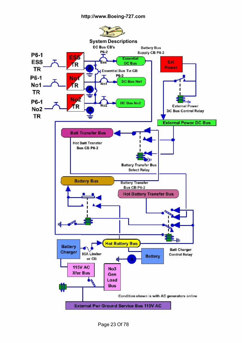
limiter to provide backup for loss of either TR 1 or TR 2. Either TR 1 or TR 2 iscapable of carrying the load on both DC buses.
To provide a backup source of power for the essential DC bus, there is aconnection to the output from the number 1 TR. Should the essential TR fail;either TR 1 or TR 2 could carry the load on all DC buses. A blocking rectifierin the circuit prevents reverse current flow from the essential DC bus to thenormal DC buses. The DC volt and ammeters and the DC meter selector arelocated at the lower right side of the flight engineers electrical panel. With theDC meter selector in a TR position the voltmeter indicates voltage on theassociated DC bus. Amperage is sensed just downstream of the TR unit, sothe ammeter indicates current flow through the TR unit that has beenselected. Thus, the amperage readout on the gauges is from the TR and the
voltage from the DC bus.
BATTERY BUSES
The battery and battery transfer buses are normally powered from theessential DC bus. If the essential DC bus is not powered, and the batteryswitch is on, the battery and battery transfer buses will be powered from thehot battery bus. The battery transfer bus is powered any time the battery busis powered. The "transfer" designation implies that the source for that bus willchange under certain circumstances. When external power is plugged in, thebattery transfer bus will be powered from a TR in the airplane's external powercircuitry instead of the battery bus. The hot battery bus is powered by the
airplane battery at all times that a serviceable battery is installed. The hotbattery transfer bus is powered any time the hot battery bus is powered.When the airplane's electrical system is not energised, the hot battery transferbus is powered from the hot battery bus. When the essential DC bus ispowered, the power source for the hot battery transfer bus becomes thebattery bus.
BATTERY The Boeing 727 has a 24-volt nickel cadmium battery. The battery providesan emergency power source for certain radio and instrument systems, and isrequired for starting the APU. With the battery switch either on or off, batteryvoltage is indicated on the voltmeter with the battery selected. The ammeterwill show current flow from the battery as negative amperage and chargingcurrent as positive amperage. The battery charger is powered from the 115volt AC transfer bus and is connected to the hot battery bus to charge thebattery. Whenever the AC transfer bus is powered, the battery charger will beoperating. Charging the airplane's battery regardless of battery switchposition. After a high load, such as an APU start, the battery will accept ahigh charging current. The charger will supply this high current until thebattery becomes sufficiently charged so that the current drops below a
threshold value. At which time the charger will go into a pulsing mode for two

7/18/2019 Aircraft 5
http://slidepdf.com/reader/full/aircraft-5 22/78
http://www.Boeing-727.com
System Descriptions
Page 22 Of 78
minutes. After the two-minute period the charger will drop to a low steadycharge that is barely discernible on the ammeter.
SUMMARY
The standby AC bus is powered whenever the essential AC bus is poweredand can be powered from the battery bus through an inverter. The standbyDC bus is powered whenever the essential DC bus is powered. When theessential AC bus loses power in flight, or the essential power selector ismoved to standby. Both the standby AC and standby DC buses will bepowered from the battery bus.
7/18/2019 Aircraft 5
http://slidepdf.com/reader/full/aircraft-5 23/78
http://www.Boeing-727.com
System Descriptions
Page 23 Of 78

7/18/2019 Aircraft 5
http://slidepdf.com/reader/full/aircraft-5 24/78
http://www.Boeing-727.com
System Descriptions
Page 24 Of 78
7/18/2019 Aircraft 5
http://slidepdf.com/reader/full/aircraft-5 25/78
http://www.Boeing-727.com
System Descriptions
Page 25 Of 78
FIRE PROTECTION
The fire protection system is separated into two categories: detection andextinguishing. Detection systems are installed in the engine; wheel well, APU,and lavatory areas. Fire extinguishing capability is available for all engines,the APU, and the lavatories. A fire detection sensor is wrapped around each engine case. Another firedetection sensor is installed on the engine firewall. The firewalls for #1 and #3engines are in the engine mounting struts. Due to the mounting of #2 enginein the aft fuselage, there is a single overheat sensor serving both the vertical
firewall forward of the engine and the horizontal firewall above.The electrical power source required for activation of the engine fire detectioncircuits is essential AC.The fire shutoff handles are located in the pilot's overhead panel. Uponactivation of an engine fire detection systems a red warning light in the fireshutoff handle comes on, a master FIRE WARN light an the glareshield infront of each pilot comes on and a bell sounds in the cockpit. Pressing the bellcut-out button near the fire shutoff handles can silence the bell. On someaircraft also by pressing either FIRE WARN cap on the glareshield, or usingthe RESET switch on the FE's auxiliary panel. The lights in the fire shutoffhandles remain illuminated until the high temperature condition no longer
exists or the fire detection system is destroyed.Two fire extinguisher bottles charged with Freon are available for combatingan engine fire. These bottles, with associated plumbing are mounted on theright side of the aft airstair's area. Each bottle has a pressure gage. Requiredengine fire extinguisher pressure is around 575 pounds per square inch at abottle temperature of 70 degrees Fahrenheit. Bottle pressure will decreaseapproximately four PSI for every one-degree drop in bottle temperature. A selector valve is installed for each engine to control the direction of flow ofthe extinguishing agent. Pulling a fire shutoff handle arms the associatedselector valve. When the discharge button is pushed. The extinguishingagent flows through the selector valve to the appropriate engine.
Fire shutoff handles contain the warning lights for the respective engines. Inaddition, on some aircraft there is a master "FIRE WARN" light located on theglareshield in front of each pilot. It comes on and the bell sounds along withthe illumination of the respective fire detection system light. Pressing oneither master FIRE WARN light cap will silence the bell and the FIRE WARNlight goes out. The fire shutoff handles are used to actuate the fire switches.When a fire shutoff handle is pulled the following things occur:It arms the: Bottle discharge circuit and Engine selector valve. It closes thefollowing Fuel shutoff valve, Engine bleed air (eng.#1 & #3), Bleed air valves,(eng. #2), Wing anti-ice shutoff (eng.#1 & #3), Cowl anti-ice (eng.#2),Hydraulic supply shutoff (eng.#1 & #2), Disarms the associated "A" hydraulicpump low pressure light and trips the generator field relay after a 5 - 10second delay to allow the valves to close.
7/18/2019 Aircraft 5
http://slidepdf.com/reader/full/aircraft-5 26/78
http://www.Boeing-727.com
System Descriptions
Page 26 Of 78
After the fire shutoff handle is pulled, pressing the bottle discharge buttonreleases the extinguishing agent and opens the proper engine selector valve.
Once it is open and pressure has built up at the valve, the discharge buttonmay be released. It takes about two seconds for the pressure to build up atthe valve. The engine selector valve closes when the extinguishing agent isdepleted. The left or right bottle is selected with the bottle transfer switch. After discharging the first bottle and selecting the other, pressing the bottledischarge button again discharges the remaining bottle and the associatedbottle discharge light comes on when bottle pressure is diminished.Ordinarily, the bottle transfer switch is positioned to the left bottle.Three discharge discs are incorporated in the engine fire extinguishingsystem. Each bottle has a red disc, which ruptures in the event of bottledischarge due to thermal relief. There is a single yellow disc, which is
ruptured by intentional discharge of either extinguisher bottle. These discsare located on the right aft fuselage under the #3 engine strut.Electrical power for discharge of the engine fire extinguisher bottles comesfrom the battery bus. Engine fire detection power source is ESSENTIAL AC.Detector circuit ground fault lights monitor the integrity of the engine firedetection system on some aircraft. They are installed on the P-6 circuitbreaker panel next to the fuel dump panel. If an electrical ground fault in anyengine system occurs. Its light comes on. This provides warning of a potentialmalfunction in the engine fire detection system.The APU fire detection system is identical to the systems used on theengines. The fire detection sensor is looped around the APU within its
shroud. The electrical power required for activation of the APU fire detectioncircuit comes from the battery bus.APU Fire Protection The APU fire detection system provides cockpit and external visual and auralwarnings. The external warnings consist of a horn located in the nose wheelwell, which sounds intermittently, and a flashing red light below the APUcontrol panel in the left wheel well. The cockpit warnings are illumination ofthe master FIRE WARN lights on the glareshield, if installed, the fire warningbell rings, and a steady red light in the fire shutoff handle on the engineer'sauxiliary panel illuminates.The fire warning bell can be silenced by pressing the bell cut-out button on thepilot's overhead panel; pressing either master FIRE WARN light on theglareshield; by selecting RESET on the APU test reset switch on the auxiliarypanel; or by pressing the horn cut-out button on the exterior APU controlpanel in the left wheel well. Pressing any of these cutouts silences both thehorn and the bell and the red light in the left wheel well changes from flashingto steady.The APU fire extinguishing system includes a fire extinguisher battle chargedwith Freon, and the associated discharge line and circuits. The fireextinguisher-bottle is mounted behind the APU control panel in the left wheelwell. When this bottle is properly charged. The pressure gauge should
indicate 350 PSI at a bottle temperature of 70 degrees Fahrenheit.The APU fire extinguishing circuit can be activated by pulling the fire shutoff

7/18/2019 Aircraft 5
http://slidepdf.com/reader/full/aircraft-5 27/78
http://www.Boeing-727.com
System Descriptions
Page 27 Of 78
handle and pressing the battle discharge button on the APU cockpit controlpanel or by use of the fire shutoff handle and bottle discharge button on the
exterior control panel. By pulling either APU fire shutoff handle, the followingthings occur: Arms the discharge button, Closes the fuel valve at the tank andthe fuel solenoid valve on the fuel control unit, Closes the air load controlvalve, After a 5-9 second delay, trips the APU generator field relay, After either APU fire shutoff handle has been pulled, pressing the associated APU bottle discharge button releases the extinguishing agent into thedischarge line. There is no visual indication that the extinguisher bottle hasbeen discharged, as is the case with the engine system. The battery busprovides the electrical power required for the extinguisher circuit. In addition,the aircraft battery switch must be on in order for the APU to run. Without thebattery switch in the on position, there is no fire protection or detection for the
APU. It will shut down automatically if the switch is inadvertently turned off. A red thermal discharge disc is installed on the fuselage Just forward of theleft wheel well. The disc ruptures if a thermal discharge of the fireextinguisher bottle occurs.To conduct a fire test, the Fire Test switch is held in the TEST position. Thefire bell should ring within 60 seconds. When the detector is heated to thealarm levels the red light in the APU fire shutoff handle comes on. the masterFIRE WARN lights on the glareshield illuminate. The fire bell in the cockpitwill ring and the horn in the nose wheel well will sound intermittently. And thered light on the APU panel in the left wheel well begins to flash.There is no need to fire test an operating APU, however, the automatic fire
shutdown circuit can be defeated so that this can be done. The auto fireshutdown switch controls this feature, which is labelled ARMED/OFF. Withthe switch in armed, the APU will shut down when the fire detection circuit isenergized. When the switch is in the OFF position. A fire test may be madewhile the APU is operating.Since the fire test system energizes the fire detection systems it must be resetafter each fire test. This is done by momentarily holding the fire test switch inthe reset position after the fire warning light has gone out. Remember, resetmust be selected twice. Once to silence the bell and once to reset the autofire shutdown circuitry.
Wheel Well Detection The overheat detection system for the wheel wells provides detection only.There is no extinguishing equipment installed in the wheel wells. Firedetection elements are installed in the top of each of the three wheel wells.When the detector is activated by an overheat condition, both visual and auralwarnings are given. The master FIRE WARN lights on the glare shield andthe wheel well fire warning light on the pilot's overhead panel illuminate. andthe fire warning bell rings. The bell can be silenced by use of any of the bellcut outs used for engine or APU fire warnings. The wheel well light remainson until the overheat condition no longer exists. The electrical power source
for the wheel well fire detection circuit is essential AC.

7/18/2019 Aircraft 5
http://slidepdf.com/reader/full/aircraft-5 28/78
http://www.Boeing-727.com
System Descriptions
Page 28 Of 78
To test the fire detection system. A fire test switch is located on the pilot's overhead panel or Glareshield
(locations vary). The switch is spring loaded to the centre. The sensitivity ofthe circuits is such that it should take no more than 60 seconds to activate allthree of the fire warnings. Holding the switch in the up position tests thedetection circuits for the firewalls. Holding the switch in the down positiontests the engine sensors and the wheel well detection loops. The wheel wellwarning is activated immediately upon initiation of the test. There is a delayfor the engine and firewall warnings.Fire extinguishing devices are located in the lavatories. Heat sensitive plugsautomatically release the extinguishing agent to flood the water heater ortowel dispenser if a fire should occur. A temperature sensitive indicatorrecords temperature in the critical areas. The appropriate circle will blacken
to indicate temperature reached. There is no visual or aural warning if thissystem in the toilet is activated.
FLIGHT CONTROLS
The 727 wings have 28 Deg sweepback and many devices that affect itsaerodynamics. All flight control surfaces are normally powered hydraulicallyexcept for the stabilizer, which is trimmed electrically. Switches on the
overhead panel control system "A" and system "B" hydraulic pressure to theailerons, elevators, rudders, and flight spoilers. Normally they are guardedON. Moving these switches OFF shuts off pressure to the associated controlunits. The system "A" rudder switch is ganged with the ON-OFF switch forthe standby hydraulic system pump motor. Should hydraulic pressure to theprimary flight controls drop below an acceptable level the appropriate amberlight on the annunciator on the First Officer's forward instrument panel willcome on.
ROLL CONTROL
There are two sets of ailerons on the 727; they are designated inboard andoutboard. A hydraulic power unit located in the left main wheel well operatesthe ailerons. This unit is supplied hydraulic pressure from both systems "A"and "B". Either system will provide sufficient power to displace the aileronsthrough their full travel. When the control wheel is turned, the hydraulic powerunit operates the ailerons through a cable system. When the trailing edgeflaps are up, the outboard ailerons are held in a faired position by a lockoutmechanism. When the flaps are extended, the lockout mechanism allowsoutboard aileron movement. The amount of outboard aileron movement, inrelation to inboard aileron movement, is dependant on the degree of outboardtrailing edge flap extension. Full outboard aileron response is available beforethe flaps reach normal landing configuration. Aerodynamic balance tabs and balance panels assist in the operation of the
7/18/2019 Aircraft 5
http://slidepdf.com/reader/full/aircraft-5 29/78
http://www.Boeing-727.com
System Descriptions
Page 29 Of 78
ailerons. In powered operation, the tabs on all ailerons move opposite to thedirection of aileron movement to assist in positioning the aileron
aerodynamically. If all hydraulic power to the aileron is lost the system willautomatically shift to manually operate aerodynamic tab control. That is theinboard aileron tabs operate as control tabs.Now when the control wheel is turned, the aileron cable moves the inboardaileron tabs and the inboard ailerons are repositioned through aerodynamicaction. Movement of the inboard ailerons is transmitted to the outboardailerons through the normal cable system. If the flaps are retracted, theoutboard ailerons are locked out as in powered operation. During manualoperation the outboard aileron tabs do not shift to a control function, but movein response to the movement of the aileron. Aerodynamic balance panels are located in the wing structure attached to the
leading edge of the aileron and the aft wing spar. Differential air pressureacting on these panels assists in aileron operation. This is particularlysignificant during manual flight control operation. Artificial feel for aileron movement is provided by a spring-loaded roller andcam mechanism. This mechanism also centres the control wheel whencontrol pressure is released. The aileron trim wheel is located on the aft endof the control stand. Movement of the trim wheel repositions the roller andcam mechanism, changing the control wheel forces. When trim is changed,the control wheel will have a new neutral feel position. The ailerons will notmove in response to a trim input if there is no hydraulic pressure available,however, the control wheel will reposition. When the ailerons are operated in
flight without hydraulic pressure. Aerodynamic forces provide feel, and thetrim wheel is ineffective.
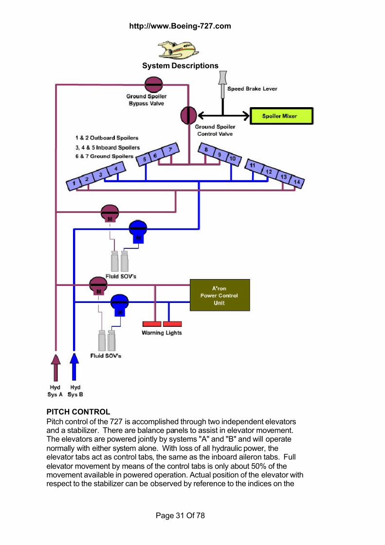
SPOILERS There are seven spoiler panels on each wing. The two inboard panels areground spoilers and can be extended only on the ground through the action ofthe speed brake lever. They are operated by hydraulic system "A" pressure.With the left main gear strut compressed, this linkage opens a hydraulic valveallowing pressure to go to the ground spoiler actuators when the speed brakelever is moved aft. Since these panels are used only on the ground to spoil liftafter landing, they go to the full up position when actuated. There are nointermediate positions for the ground spoilers.The remaining five panels on each wing are flight spoilers. The three inboardflight spoilers are powered by hydraulic system "B". The two outboard flightspoilers are powered by hydraulic system "A". Individual actuators operatethe spoiler panels.The flight spoilers, which operate in conjunction with the ailerons, provide themajor portion of roll control by spoiling lift on the low wing. After a smallmovement of the control wheel, spoiler action is programmed in proportion tothe further movement of the control wheel. A full roll control input would
cause the flight spoilers of the low wing to rise to a maximum of approximately25 degrees. The spoiler panels of the high wing would remain down.
7/18/2019 Aircraft 5
http://slidepdf.com/reader/full/aircraft-5 30/78
http://www.Boeing-727.com
System Descriptions
Page 30 Of 78
The flight spoiler panels are also used as in-flight speed brakes whenextended by the speed brake lever. They extend increasingly as the speed
brake lever is moved aft. Maximum extension of the flight spoilers when usedas speed brakes is 45 degrees; however, the actuators will allow spoiler blowdown at high speed. While in flight a warning horn will sound intermittently ifspeed brakes are extended with the wing flaps also extended.When the speed brakes are extended, spoiler input is still received fromcontrol wheel movement; however, this input is influenced by the amount ofspeed brake extension. Although there is no operational restriction, careshould be exercised in operating ailerons with partial speed brakes due tospoiler mixer inputs. Extreme roll rates can be experienced in thisconfiguration. Two switches on the upper right of the flight control hydraulicpower panel are OFF-ON switches for hydraulic power to the flight spoilers.
AUTO SPOILERS 200 series variants An auto spoiler system is installed and extends the flight and ground spoiler'sautomatically after landing. To arm the auto spoiler system, the speed brakeis moved to the arm position. The spoiler will extend when armed with themain wheel rotation above 60 kts, and strut compression has taken place. Thespeed brake armed light will illuminate to show that the auto speed brakecircuitry is complete. If armed and a fault exists in the auto spoilers, the DONOT ARM light will illuminate and the speed brake lever must be moved outof the armed position. The speed brakes may then be armed manually. TheDO NOT ARM light will illuminate after landing with the speed below 60 kts,
until the speed brake lever is restowed. When either No. 1 or No. 2 reverser isactuated during an aborted take off above 60 kts, the spoilers willautomatically deploy. Auto spoilers will also deploy automatically if a landingis made without speed brake in arm when either No.1 or No.2 reverse throttleis actuated, with speed above 60 kts. If a go-around is initiated after landing,moving no.1 or no. 3 thrust lever forward automatically moves the speedbrake handle forward to the down position.To test the system, place the speed brake lever in arm and note the ARMEDlight illuminated, press each of the test buttons. When pressed the DO NOT ARM light will be illuminated.
7/18/2019 Aircraft 5
http://slidepdf.com/reader/full/aircraft-5 31/78
http://www.Boeing-727.com
System Descriptions
Page 31 Of 78
PITCH CONTROL
Pitch control of the 727 is accomplished through two independent elevatorsand a stabilizer. There are balance panels to assist in elevator movement.The elevators are powered jointly by systems "A" and "B" and will operatenormally with either system alone. With loss of all hydraulic power, theelevator tabs act as control tabs, the same as the inboard aileron tabs. Fullelevator movement by means of the control tabs is only about 50% of themovement available in powered operation. Actual position of the elevator withrespect to the stabilizer can be observed by reference to the indices on the

7/18/2019 Aircraft 5
http://slidepdf.com/reader/full/aircraft-5 32/78
http://www.Boeing-727.com
System Descriptions
Page 32 Of 78
left and right sides of the rudder and elevator position indicator. Under normalflight conditions the elevator pointers should be centred.
To provide artificial feel, an elevator feel computer is installed. With inputs ofsystem "A" and "B" hydraulic pressure, pitot-static pressure and stabilizerposition the feel computer furnishes proportional feel to the elevator controlsystem. The elevators feel computer does not supply boost to the elevator.When substantial differences in the computer pressure outputs occur, theelevator feel differential pressure light on the SID's panel will come on. Itindicates a possible erroneous control feel. When the light is on the pilotshould avoid abrupt elevator inputs. Spring tension and aerodynamic forcesgive feel when the elevators are operated with no hydraulic power.Pitch trim is accomplished by repositioning the stabilizer. The stabilizer canbe controlled by either of two electric motors or a manual system. Both of the
electric motors and the manual system operate the same jackscrew, whichdrives the stabilizer. The high-speed electric trim motor is controlled by thesemain electric trim switches on the control wheels. Each main electric controlconsists of two thumb switches; one is for motor power, the other clutchpower. Both have to be activated to move the stabilizer. This is a safetyfeature to prevent one faulty switch from causing a runaway stabilizer. Theother trim motor is slow speed, and is controlled by the cruise trim switch onthe control stand. The autopilot uses the slow speed motor for pitch trim.Manual trimming of the stabilizer is accomplished by using the cranks storedin the trim wheels located on either side of the control stand. The manual trimwill override either electrical trim motor.
When the stabilizer is being trimmed electrically by either the main electrictrim switch or cruise trim switches the stabilizer trim light on the control standwill come on. This indicates that one of the trim motor circuits is energized.When the autopilot is engaged, however, the cruise trim motor runscontinuously. To avoid continuous illumination of the lights it is deactivatedduring autopilot operation. The two lever switches to the right of the light arecutout switches to remove electrical power from the motors.Trim indices, located on both sides of the control stand, show the position ofthe stabilizer in units. The green band denotes limits of stabilizer trim in %MAC. If the stabilizer trim is not in the green band for takeoff, an intermittenthorn will sound when the throttles are advanced toward takeoff setting. Toprevent running the stabilizer to the stops there are electrical trim limits, bothnose up and nose down. When the main trim reaches one half-degree noseup during nose down travel, control automatically switches to the cruise trimmotor. Once the electrical limits are reached, the stabilizer can be trimmedslightly further manually. As the stabilizer is trimmed into the range near thenose up limit, the elevator neutral will gradually move a few degrees up fromfaired. This provides more effective stabilizer trim and more nose downelevator capability when the airplane is trimmed nose up. Operation of thismechanical linkage can be noted in the cockpit by aft movement of the controlcolumn when the stabilizer is trimmed into the range where the system if
effective. To stop a runaway stabilizer a stabilizer brake is installed. A controlforce opposite to the direction of the runaway will engage the brake. Once
7/18/2019 Aircraft 5
http://slidepdf.com/reader/full/aircraft-5 33/78
http://www.Boeing-727.com
System Descriptions
Page 33 Of 78
engaged, the stabilizer brake should automatically disengage when opposingpressure is relieved. If it does not, pulling the stabilizer brake release knob
will mechanically release the brake.
YAW CONTROL Yaw control is accomplished through dual rudders and yaw dampers. Therudders are hydraulically powered, the upper rudder by system "B" pressure,the lower rudder by system "A" pressure. As a backup, the lower rudder canalso be operated by the standby hydraulic system, which powers a separaterudder actuator. If all hydraulic power is lost there is no rudder control. Fullsystem "A" pressure is provided to the lower rudder when the flaps areextended. When the flaps are up pressure to the lower rudder is decreased
through action of the rudder load limiter. Illumination of the rudder load limiterlight on the FE's panel indicates that the pressure to the lower rudder is notproper for the inboard flap position. The upper rudder always operates atreduced system "B" pressure. Therefore, the pressure changeover monitoredby this light is applicable only to the lower rudder. Both rudders have anti-balance tabs, which move in the same direction as the rudder. Artificial feelfor rudder inputs is provided through a spring-loaded roller and camassembly.The rudders are trimmed by positioning the rudder trim control on the controlstand. The rudder pedals will reposition during trim input. As with theailerons, rudder trim is available only when hydraulic power is available.
YAW DAMPERS The tendency to "Dutch Roll", at high altitude and high airspeed, iscounteracted in the 727 by a yaw damper system for each rudder. The lowerrudder yaw damper does not function when that rudder is powered by thestandby system. The yaw dampers receive electrical signals from the rategyros. As the nose moves left or right, the rate gyro senses a yaw. Thissignal is sent to the yaw dampers, which direct the rudders opposite to thedirection of the yaw. Rudder movement caused by the yaw dampers is nottransmitted to the rudder pedals and does not interfere with pilot input to therudders. A yaw damper test switch on the Captain's forward instrument panelallows testing of the yaw dampers before taxiing. The yaw dampers aredesigned to be used continuously. Therefore, the guarded yaw damperengage switches on the centre forward instrument panel are normally ON atall times. On the Captain's forward panel is a rudder-elevator indicator. Theyellow YID flag will appear if the respective yaw damper system loseselectrical power or is turned off. If one or both yaw dampers fail, airspeed andaltitude restrictions are imposed. These restrictions are listed in the Limitationsection of the Flight Manual.Find out more about yaw dampers by clicking here

7/18/2019 Aircraft 5
http://slidepdf.com/reader/full/aircraft-5 34/78
7/18/2019 Aircraft 5
http://slidepdf.com/reader/full/aircraft-5 35/78
http://www.Boeing-727.com
System Descriptions
Page 35 Of 78
mechanically locked in the extended position and must be unlockedhydraulically to be retracted. The three inboard devices, or flaps, are held in
the retracted position with the system "A" pressure. The remaining devices,the slats, are mechanically locked in the retracted position and must beunlocked hydraulically to be extended. Each leading edge device has its ownactuator. The leading edge annunciator on the forward instrument panel willbe amber while the leading edge devices are in transit or not properlypositioned for trailing edge flap configuration. When the correct leading edgedevices are extended, in agreement with trailing edge flaps, the green lightcomes on. Both lights will be off when the leading edge devices are up.The leading edge device annunciator on the FE's auxiliary panel has a 3position selector, spring loaded to OFF. Holding the selector to the right willtest all of the lights. To the left, the actual position of each individual leading
edge device is indicated, that is, with no light the device is retracted; amber,the device is partially extended; or green, the device is fully extended. Thisannunciator is used when the one on the forward instrument panel remainsamber after flap operation, indicating improper leading edge devicepositioning. An alternate means of extending the leading edge devices is provided. Withthe Alternate Flaps Master switch ON, momentarily moving either of thealternate flaps inboard or outboard switches to DOWN will extend all leadingedge devices.The standby hydraulic system powers a hydraulic motor-pump assembly,which pressurizes the leading edge device actuators to the down position with
fluid from a reserve section of the system "B" reservoir. The devices cannotbe retracted by the alternate system.Under certain conditions a warning horn will sound if high lift devices, speedbrakes, or the stabilizer are improperly positioned. On the ground, thewarning horn will sound intermittently when the no. 1 or 3 throttle is advancedto takeoff thrust if the stabilizer trim is not in the green band, the flaps are notin the takeoff range, the speed brake lever is not in the forward detent, or theleading edge devices are not extended.
The trailing edge flaps control various other components an the airplane.Outboard Trailing Edge Flaps Inboard Trailing Edge FlapsLeading edge devices Stall warning systemsOutboard ailerons Air conditioning pack fanTakeoff warning horn Auto pack trip system.Landing gear-flaps warning horn Lower rudder load limiterGround proximity warning system. Speed brake - flaps warning
Most commercial swept-wing airplanes have a device to warn of anapproaching stall. As an advanced warning if an approach to stall occurs, thecomputer activates a stick shaker at 1.15 times stall speed. The stall-warningportion of the overhead panel contains the fail light and test/heater off switch
for the Stall Warning unit in the 727. There is one unit installed on theairplane, which consists of a computer, an angle of attack vane and a stick
7/18/2019 Aircraft 5
http://slidepdf.com/reader/full/aircraft-5 36/78
http://www.Boeing-727.com
System Descriptions
Page 36 Of 78
shaker. The angle of attack vane, located on the right side of the airplane,sends angle of attack information to the stall-warning computer. The
computer also receives information of actual inboard trailing edge flapposition. The computer is powered and the vane is heated any time anairplane generator is powering the electrical bus, provided external power isdisconnected. When the vane heater and computer are both powered, thepower off lights will be off. To avoid stall-warning signals while taxiing, thecomputer, although powered, is not activated until the airplane is airborne.
FUEL SYSTEM
GeneralThere are various options of auxiliary fuel tank installations, which are located in the fuselage, they will not be
discussed here.
Fuel is stored within vented areas of the wing and wing centre section. Thesefuel storage areas are divided into three main tanks, one for each engine. Thetanks are located in the interspar area of each wing. They are identified asTank1, Tank2 and Tank3. Normally each tank supplies its respective engine,which is referred to as "tank to engine". Tank No1 is contained entirely in theleft wing, Tank No3 entirely in the right wing. Tank No2 consists of an integralportion in each wing and removable cells in the wing centre section.Low points on all the integral tanks are fitted with fuel sump drain valves topermit draining of accumulated water from the tanks and for draining fuelwhen the tank is defueled.Tanks can be fuelled from the pressure refuelling station at the right wing, viathis system any or all of the tanks can be filled rapidly. Tanks may also bedefueled through this pressure system. Overwing filler points are provided fortanks 1 and 3. Fuel may be transferred from tanks 1 and 3 into tank 2.Transfer of fuel from one tank to another is possible on the ground only,through a manually operated defuel valve located at the lower right hand wingroot. When overwing refuelling is taking place it's normal for some operatorsto shut down the APU.
An electronic capacitance type indicating system provides fuel quantityindications on the flight engineers panel and at the refuel station. Vent surgetanks are provided to accommodate fuel surges, any fuel in the vent surgetanks drains directly into the adjacent No1 or No3 tanks. Tanks are ventedthrough the surge tanks to a single opening at each wing tip. The vent systemalso provides ram air pressure within the tanks. The centre tank cavity isvented and drained overboard through a separate system of vent and drainlines.
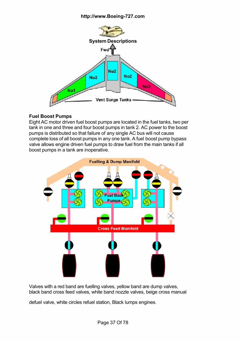
7/18/2019 Aircraft 5
http://slidepdf.com/reader/full/aircraft-5 37/78
http://www.Boeing-727.com
System Descriptions
Page 37 Of 78
Fuel Boost Pumps
Eight AC motor driven fuel boost pumps are located in the fuel tanks, two pertank in one and three and four boost pumps in tank 2. AC power to the boostpumps is distributed so that failure of any single AC bus will not causecomplete loss of all boost pumps in any one tank. A fuel boost pump bypassvalve allows engine driven fuel pumps to draw fuel from the main tanks if allboost pumps in a tank are inoperative.
Valves with a red band are fuelling valves, yellow band are dump valves,black band cross feed valves, white band nozzle valves, beige cross manual
defuel valve, white circles refuel station, Black lumps engines.
7/18/2019 Aircraft 5
http://slidepdf.com/reader/full/aircraft-5 38/78
http://www.Boeing-727.com
System Descriptions
Page 38 Of 78
Fuel Heaters
A fuel heating system is provided to prevent the formation of ice crystals in the
fuel being delivered to each engine. Fuel flowing to the engine is passedthrough an air to fuel heat exchanger just prior to entering the fuel filter.Heating is accomplished by ducting 13th stage engine compressor air throughthe heat exchanger. After passing through the heat exchange, the air isdumped into the CSD oil cooler exhaust air duct. Control for the system is viaswitches on the flight engineers panel. Valve operation is confirmed by Bluein transit lights. When operating you will see a rise in oil temperature to theengine receiving fuel heat. Icing lights are provided and are also located onthe same panel as the control switches. The icing light will come on if adifferential pressure exists across the main fuel filter. The difference inpressure is assumed to be caused by ice crystals partially blocking the filter. If
the icing light does not go out with the application of fuel heat, the filter maybe clogged.
Dripsticks
A calibrated dripstick is installed in each tank. These can be used todetermine the fuel level in each tank in the normal taxi attitude. When thelocking sealing cap and the hollow dripstick assembly is withdrawn from thewing lower surface, fuel enters the open top of the stick and flows out througha drip hole near the base (indicated by an arrow on the surface). The dripstickshould be pushed up slowly until fuel stops and then inched down again until
you obtain a steady drip/flow of fuel. Reading the calibrations on the stick fromthe top down, the calibrated reading plane is the inner surface of the recess.Calibrations maybe in inches, pounds or Kgs.They are located on the tank centre lines. No1 and No3 are near the inboardend of the respective tank. No2 is near the inboard end of the integral tank onthe right side. Additional dripstick may be installed. The normal minimumstickable fuel value is 938 lbs.
HYDRAULICS"A" System System consists of a single reservoir. Hydraulic power is supplied to the Asystem from two engine driven pumps fitted to engines No1 and No2. Thepump switches control solenoid operated blocking valves, with the switcheson, normal pump output is supplied to the system. A small portion of the fluidthat enters the pump is circulated through the pump case for cooling andlubrication. As long as the engines are operating regardless of the blockingvalve position this small amount of fluid leaves the pump and is cooled by aheat exchanger in the No3 fuel tank heat exchanger before being returned to
the system.Fluid shutoff valves controlled by their respective switches control the fluid in

7/18/2019 Aircraft 5
http://slidepdf.com/reader/full/aircraft-5 39/78
http://www.Boeing-727.com
System Descriptions
Page 39 Of 78
the engine pump supply lines, when closed fluid flow to the pump is isolated.(Includes lubricating and cooling fluid). Pulling the fire switch on engine 1 or 2
will close these shutoff valves; the fire switch also deactivates the low-pressure warning light.System A and therefore system B and stand by reservoirs are pressurized byengine bleed air from engines 1 & 2 this is applied to the reservoir to ensure apositive supply of fluid to the pumps. A balance line connects the system A reservoir to the system B reservoir at alevel of 2.5 gall.
A system supplies the heavy load items landing gear, trailing edge flaps.Fluid Quantity................4.4 Gall (gear down)
................3.8 Gall (gear up)™it's normal to see a reduction in the fluid quantity indication in flight, due tothe cold soak characteristics of the systemSystem Pressure............2,800 - 3100 PSI (red line @ 3,500)Balance line to "B" system...........2.5 GallOperating time with the "A" fluid SOV closed 5 Min's
™ A system pumps max demand flow rate is 22 gal min 100% N2
Systems Operated:Nose Wheel SteeringLanding GearTail SkidTrailing Edge FlapsGround SpoilersLeading Edge DevicesLower Rudder
Ailerons
7/18/2019 Aircraft 5
http://slidepdf.com/reader/full/aircraft-5 40/78
http://www.Boeing-727.com
System Descriptions
Page 40 Of 78
ElevatorsOutboard Spoilers
"B" System
"B" system again contains a single reservoir supplying two electric AC pumps.It's reservoir is more complicated that system "A" in that it has anauxiliary reservoir separated by a baffle which is open at the top ("little b"),this is reserved for alternate extension of the leading edge slats and flapsusing stand by hydraulic power (more about that later).Each pump is controlled by its individual selection switch; with the switch ONnormal hydraulic output pressure is provided to the system. As in the "A"system a portion of the fluid is used for cooling and lubrication of the pump butis returned via a heat exchanger in the no1 fuel tank. if the pressure falls
below the preset level a warning light will illuminate, sensors monitor the fluidtemperature and if activated will bring on an overheat light. A relay in theoverheat sensing circuit will cause the overheat light to go out when theaffected pump is turned off. A simplified view of the system is the same as theabove diagram but with no blocking valve or shut off valve (items 2 & 4).
Fluid Quantity....................Full if system "A" quantity over 2.5 gallSystem Pressure............2,800 - 3100 psi (red line @ 3,500)Baffle level (little B)............1.1 gallDo not operate a system "B" pump with less than 1,300 lbs in fuel tank No1 Any one hydraulic system "B" pump should not be operated more than 5
times in 5 min's. After this period the pump must be left on for 5 min's or off for30 min's.
Systems Operated:BrakesInboard SpoilersUpper Rudder Aft Airstairs AileronsElevators
Stand-By System The standby system reservoir supplies fluid to an AC electric motor drivenpump. Positioning the standby rudder switch or the alternate flap master to onwill provide power to the standby motor, which in turn supplies fluid pressureto the standby power module. System pressure is indicated by a light. Thereis a overheat sensing to monitor fluid temperature which will illuminate theoverheat light for the standby system.Fluid Quantity...............0.3 gallSystem pressure........... 2,200 psi @ 1.14 gall per min for leading edgedevices ( the is no pressure gauge for the stand-by system only a green light.
............ 2,975 to 3,075 @ 3 gll per min for lower rudderSystems Operated:

7/18/2019 Aircraft 5
http://slidepdf.com/reader/full/aircraft-5 41/78
http://www.Boeing-727.com
System Descriptions
Page 41 Of 78
Lower Rudder Stand-By ActuatorLeading Edge Devices (Extension Only)
Standby Rudder
Positioning the standby rudder switch to on, the system "A" rudder powerswitch is selected off. With "A" system off hydraulic fluid is isolated from thelower rudder power unit, standby system pressure repositions a selector valveto allow the standby system to power the lower rudder standby power controlunit.
Alternate flap
Positioning the alternate flaps master switch on arms the alternate flapswitches (2). Moving either switch to down opens the leading edge flaps and
slats sov. The standby system pressure then drives a hydraulic motor portionof a pump assembly. The pump portion of this assembly uses fluid from "littleb" to extend the leading edge devices.
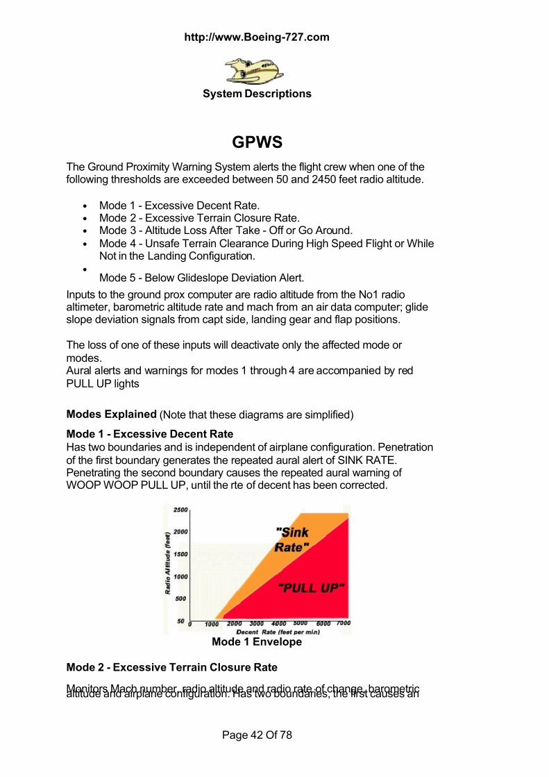
7/18/2019 Aircraft 5
http://slidepdf.com/reader/full/aircraft-5 42/78
http://www.Boeing-727.com
System Descriptions
Page 42 Of 78
GPWS
The Ground Proximity Warning System alerts the flight crew when one of thefollowing thresholds are exceeded between 50 and 2450 feet radio altitude.
• Mode 1 - Excessive Decent Rate. • Mode 2 - Excessive Terrain Closure Rate. • Mode 3 - Altitude Loss After Take - Off or Go Around. • Mode 4 - Unsafe Terrain Clearance During High Speed Flight or While
Not in the Landing Configuration. •
Mode 5 - Below Glideslope Deviation Alert.
Inputs to the ground prox computer are radio altitude from the No1 radioaltimeter, barometric altitude rate and mach from an air data computer; glideslope deviation signals from capt side, landing gear and flap positions.
The loss of one of these inputs will deactivate only the affected mode ormodes. Aural alerts and warnings for modes 1 through 4 are accompanied by redPULL UP lights
Modes Explained (Note that these diagrams are simplified)
Mode 1 - Excessive Decent Rate
Has two boundaries and is independent of airplane configuration. Penetrationof the first boundary generates the repeated aural alert of SINK RATE.Penetrating the second boundary causes the repeated aural warning ofWOOP WOOP PULL UP, until the rte of decent has been corrected.
Mode 1 Envelope
Mode 2 - Excessive Terrain Closure Rate
Monitors Mach number, radio altitude and radio rate of change, barometricaltitude and airplane configuration. Has two boundaries, the first causes an
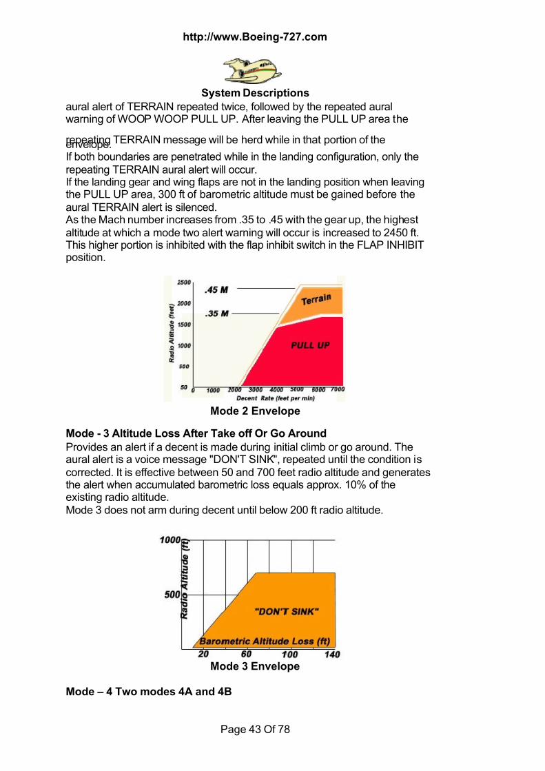
7/18/2019 Aircraft 5
http://slidepdf.com/reader/full/aircraft-5 43/78
http://www.Boeing-727.com
System Descriptions
Page 43 Of 78
aural alert of TERRAIN repeated twice, followed by the repeated auralwarning of WOOP WOOP PULL UP. After leaving the PULL UP area the
repeating TERRAIN message will be herd while in that portion of theenvelope.If both boundaries are penetrated while in the landing configuration, only therepeating TERRAIN aural alert will occur.If the landing gear and wing flaps are not in the landing position when leavingthe PULL UP area, 300 ft of barometric altitude must be gained before theaural TERRAIN alert is silenced. As the Mach number increases from .35 to .45 with the gear up, the highestaltitude at which a mode two alert warning will occur is increased to 2450 ft.This higher portion is inhibited with the flap inhibit switch in the FLAP INHIBITposition.
Mode 2 Envelope
Mode - 3 Altitude Loss After Take off Or Go Around
Provides an alert if a decent is made during initial climb or go around. Theaural alert is a voice message "DON'T SINK", repeated until the condition iscorrected. It is effective between 50 and 700 feet radio altitude and generatesthe alert when accumulated barometric loss equals approx. 10% of theexisting radio altitude.Mode 3 does not arm during decent until below 200 ft radio altitude.
Mode 3 Envelope
Mode – 4 Two modes 4A and 4B

7/18/2019 Aircraft 5
http://slidepdf.com/reader/full/aircraft-5 44/78
http://www.Boeing-727.com
System Descriptions
Page 44 Of 78
4A - Unsafe Terrain Clearance With Landing Gear Not DownThis is the terrain clearance mode with the gear retracted, is armed after take
off upon climbing through 700 ft radio altitude. When this envelope ispenetrated at less than 0.35 mach the aural alert TOO LOW, GEAR issounded. When the envelope is penetrated at more than 0.35 mach, the auralalert TOO LOW TERRAIN is sounded and the upper boundary of theenvelope is increased to 1000 ft rad alt. The message is repeated until theflight condition has been corrected.
Mode 4A Envelope
MACH -IAS Conversion
MACH SL 5000' 8000' 10000'
0.34 232 211 200 193
0.45 298 272 258 249
4B - Unsafe Terrain Clearance With The Flaps Not In Landing Position
This mode provides an alert when the gear is down and the flaps are not inlanding position. If the envelope is penetrated at less than 0.28 mach with the
flaps not in the landing position, the aural alert TOO LOW FLAPS is sounded.When the envelope is penetrated at more than 0.28 mach, the aural alert ofTOO LOW TERRAIN is sounded and the upper boundary is increased to1000 ft rad alt. The voice messages continue to occur until the flight conditionhas been corrected.The TOO LOW GEAR alert takes priority over TOO LOW FLAPS. The TOOLOW FLAPS and associated TOO LOW TERRAIN alert are inhibited with theflap inhibit switch when moved to the FLAP INHIBIT position

7/18/2019 Aircraft 5
http://slidepdf.com/reader/full/aircraft-5 45/78
http://www.Boeing-727.com
System Descriptions
Page 45 Of 78
Mode 4B Envelope
MACH -IAS Conversion
MACH SL 5000' 8000' 10000'
0.34 185 169 160 154
0.45 298 272 258 249
Mode 5 - Below Glideslope Deviation Alert
This mode alerts you of a descent of more than 1.3 dots below an ILS
glideslope. The envelope has two areas of alerting, soft and loud.In both areas is a repeated aural warning of GLIDESLOPE and illumination ofthe pilots BELOW G/S lights. The voice message amplitude is increasedwhen entering the loud area In both areas, the aural warning repetition rate isincreased as glideslope deviation increases and radio altitude decreases.
The mode is armed when a valid signal is being received by the captsglideslope receiver and the radio altitude is 1000 feet or less.This mode may be cancelled or inhibited by pressing either pilots BELOW G/Slight while below 1000 ft radio altitude. The mode will re arm when climbingabove 1000 ft rad alt.
Mode 1 through 4 aural alerts and warnings have priority over mode 5 auralalerts, though both PULL UP and BELOW G/S lights could be illuminated atthe same time.
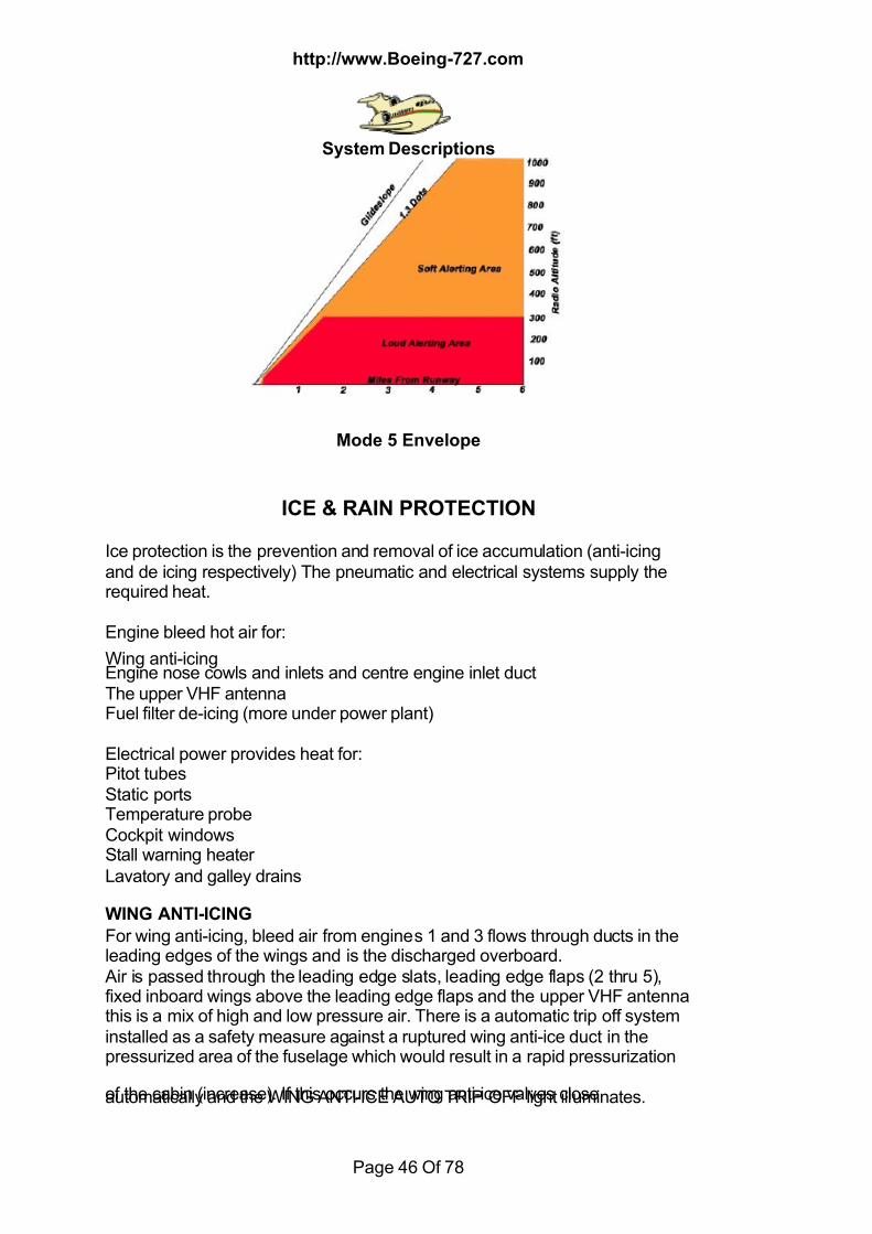
7/18/2019 Aircraft 5
http://slidepdf.com/reader/full/aircraft-5 46/78
http://www.Boeing-727.com
System Descriptions
Page 46 Of 78
Mode 5 Envelope
ICE & RAIN PROTECTION
Ice protection is the prevention and removal of ice accumulation (anti-icingand de icing respectively) The pneumatic and electrical systems supply therequired heat.
Engine bleed hot air for:
Wing anti-icingEngine nose cowls and inlets and centre engine inlet ductThe upper VHF antennaFuel filter de-icing (more under power plant)
Electrical power provides heat for:Pitot tubesStatic portsTemperature probeCockpit windowsStall warning heaterLavatory and galley drains
WING ANTI-ICING For wing anti-icing, bleed air from engines 1 and 3 flows through ducts in theleading edges of the wings and is the discharged overboard. Air is passed through the leading edge slats, leading edge flaps (2 thru 5),fixed inboard wings above the leading edge flaps and the upper VHF antennathis is a mix of high and low pressure air. There is a automatic trip off systeminstalled as a safety measure against a ruptured wing anti-ice duct in thepressurized area of the fuselage which would result in a rapid pressurization
of the cabin (increase). If this occurs the wing anti-ice valves closeautomatically and the WING ANTI-ICE AUTO TRIP OFF light illuminates.
7/18/2019 Aircraft 5
http://slidepdf.com/reader/full/aircraft-5 47/78
http://www.Boeing-727.com
System Descriptions
Page 47 Of 78
(Located on the flight engineers panel) There is a test switch installed to allowa check of the system before flight. Overheat protection is provided by
temperature sensors located in the wing anti-ice ducting. When it gets too hotthe DUCT OVERHEAT light illuminates. It's value is different dependingwhether you are in flight or on the ground. If you are on the ground is settingis less, and the anti-ice valves will close. In flight it has a higher value and thevalves do not close. You can verify and locate the source of the overheat bylooking at the DUCT TEMP indicator and using the anti-ice temp selector atthe co pilots overhead panel. The wing anti-ice shutoff valves are overriddenclosed by pulling the fire handle. Valves are electrically operated.
ENGINE ANTI-ICING Each engine supplies it's own anti-icing air and is separate and independent
of the other two engine anti-ice systems. The engine nose cone, EPR portand inlet guide vanes are anti-iced by engine low-pressure bleed air. The airis ducted through the left and right engine anti-ice valves, to the inlet guidevanes and nose cone, and vented into the engine intake. When operatingengine ant-ice you will see a drop in engine EPR.POD ENGINES. Nose cowls and CSD oil cooler scoops are anti-iced byengine high pressure bleed air ducted through the nose cowl anti-ice valveand mixed with ambient air. The mixed air is directed against the cowl andCSD scoop leading edges, exhausted overboard the a opening in the bottomof the engine cowl.CENTER ENGINE. The inlet leading edge, part of the surface of the inlet duct,
and the CSD oil cooler inlet are anti-iced by a combination of high and low-pressure bleed air. Air is vented into the rear fuselage section and exhaustedoverboard through an opening in the left hand side. Bleed air is also used toanti-ice the vortex generators installed on the bottom of the inlet duct, this isvented into the engine intake.
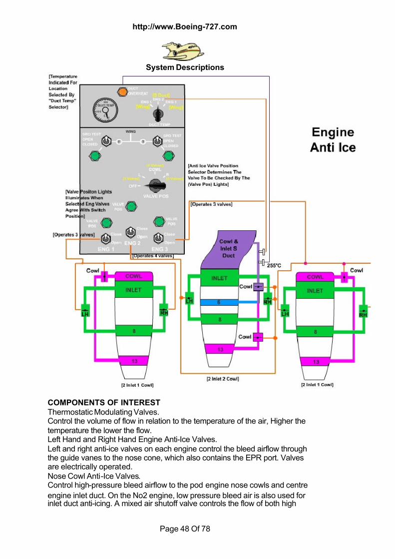
7/18/2019 Aircraft 5
http://slidepdf.com/reader/full/aircraft-5 48/78
http://www.Boeing-727.com
System Descriptions
Page 48 Of 78
COMPONENTS OF INTEREST Thermostatic Modulating Valves.Control the volume of flow in relation to the temperature of the air, Higher thetemperature the lower the flow.Left Hand and Right Hand Engine Anti-Ice Valves.Left and right anti-ice valves on each engine control the bleed airflow throughthe guide vanes to the nose cone, which also contains the EPR port. Valvesare electrically operated.Nose Cowl Anti-Ice Valves.Control high-pressure bleed airflow to the pod engine nose cowls and centre
engine inlet duct. On the No2 engine, low pressure bleed air is also used forinlet duct anti-icing. A mixed air shutoff valve controls the flow of both high
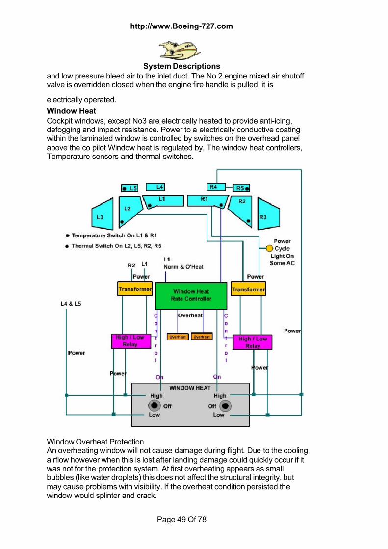
7/18/2019 Aircraft 5
http://slidepdf.com/reader/full/aircraft-5 49/78
http://www.Boeing-727.com
System Descriptions
Page 49 Of 78
and low pressure bleed air to the inlet duct. The No 2 engine mixed air shutoffvalve is overridden closed when the engine fire handle is pulled, it is
electrically operated.
Window Heat
Cockpit windows, except No3 are electrically heated to provide anti-icing,defogging and impact resistance. Power to a electrically conductive coatingwithin the laminated window is controlled by switches on the overhead panelabove the co pilot Window heat is regulated by, The window heat controllers,Temperature sensors and thermal switches.
Window Overheat Protection An overheating window will not cause damage during flight. Due to the coolingairflow however when this is lost after landing damage could quickly occur if itwas not for the protection system. At first overheating appears as smallbubbles (like water droplets) this does not affect the structural integrity, butmay cause problems with visibility. If the overheat condition persisted thewindow would splinter and crack.
7/18/2019 Aircraft 5
http://slidepdf.com/reader/full/aircraft-5 50/78
http://www.Boeing-727.com
System Descriptions
Page 50 Of 78
™ Don't assume the system overheat protection is working as I've hand awindow fail.
Windshield Anti-Icing. Anti-icing is provided for the No1 and No2 windows,control is through two switches on the control panel. Marked High, Low, Offthese select high or low voltage to control the rate of heating. If an overheatcondition is detected a window overheat light will illuminate of the flightengineers door panel. It locks out the control and removes power from therespective No1 and opposite No2. It may be reset by cycling the switch to off.
Window Defogging No 4 and No5These windows receive heat for defogging only and are powered when theswitch is in the high or low position; they have no controller or overheat
protection. Control of the heating is by a thermal switch on the No5 Window.Note the No3 window is not heated.
Pitot - Static Heat
The left and right pitot probes, auxiliary pitot probe, left and right static ports,total air temperature probe (TAT) and the left and right elevator feel pitotprobes are heated to prevent ice formation which would affect sensingaccuracy. The heat is controlled by two switches on the co pilot’s overheadpanel. It supplies 115V AC, When the left switch is placed on heating isapplied to:Captains pitot probe
Left static portsTAT probeLeft elevator feel pitot probeThe right switch controls in the same manner as the left but operatesCo pilot pitot probeRight static ports Auxiliary pitot probeRight elevator feel pitot probeStatic port heating has been deactivated on some 100's but is required on the200.Stall Warning Sensor HeatThe attitude sensor of the stall warning system is anti-iced by an integralelectric heater. it is available when the airplane is on engine generators.When external or APU power is on the sync bus the heater is off except whenchecked by the test switch.Rain Protection
Consists of electrically operated windscreen wipers operated by a switch onthe overhead panel, these are install on both the No1 windows. The switchhas the following positions Park, Off, Low, 1/2, 3/4 and High. There is a rainrepellent system also for the No1 windows, which is controlled by twoswitches, two time control valves and a fluid container. When a switch is
pressed it opens a valve letting a fixed amount onto the windscreen on
7/18/2019 Aircraft 5
http://slidepdf.com/reader/full/aircraft-5 51/78
http://www.Boeing-727.com
System Descriptions
Page 51 Of 78
application takes appox 1/2 second. The system is little used and may beremoved; there is an SB on this.
LANDING GEAR & BRAKES
LANDING GEAR
The landing gear consists of two dual wheel main gear and one dual nosegear, each main gear is equipped with Disk brakes, anti skid protection andthermal tire deflators (fusible plugs).The landing gear is positioned hydraulically as selected by the landing gear
lever in the cockpit on the centre instrument panel.Door and gear sequencing is automatic. Except for the nose gear, which ismechanically opened and closed by the movement of the gear. There is adoor release handle in each main gear well for ground access.Hydraulic system "A" provides power for the landing gear system and nosewheel brakes if installed. "B" system provides power for the main wheelbrakes. System "A" can also be used as an alternate power source byselecting open the brake interconnect switch on the flight engineers panel.
Extension and Retraction Gear Doors. Each gear is sequenced automatically with its gear door, opening
of the door is controlled by the gear lever. The main gear cannot extend orretract unless the gear door is open and cannot close unless the gear islocked in the up or down position all due to sequence valves being installed.The nose gear is controlled mechanically by linkages to the gear. The forwarddoors are closed in both the gear up and down positions but the aft doorsremain open when the gear is down.Gear Air-Ground Logic. Air ground sensing for various systems is provided bysafety switches on the left main gear and nose gear. These are actuated bythe extension (air logic) or compression (ground logic) of the left main gearand nose gear. Click here to see some of the system inputs for logic
Nose Gear Steering The nose wheels can be turned by a steering handle to the left of the captain(some aircraft have two handles one on each side), or by either set of rudderpedals if the nose gear strut is compressed. Internal cams in the strutautomatically centre the nose wheels if the strut is extended. Power for thenose wheel steering is supplied by hydraulic system "A" through the landinggear down line. Steering wheel movement of 95 deg at the handle willproduce 78 deg of nose wheel turning. Full rudder defection will give youabout 8 deg of nose wheel turn. If steering hydraulic pressure is lost and thesteering control valve is in neutral, restrictions in the hydraulic circuit prevent
nose gear castering. Movement of the handle or rudder pedals will displacethe control valve and allow castering.
7/18/2019 Aircraft 5
http://slidepdf.com/reader/full/aircraft-5 52/78
http://www.Boeing-727.com
System Descriptions
Page 52 Of 78
Manual Gear Extension In the event of a "A" system hydraulic failure the landing gear can be
extended and locked mechanically (manual). Three hand crank drums locatedin the cockpit floor can be operated. The hand crank lever is stowed on the aftleft bulkhead of the cockpit. Instructions for operating are placarded on theback of the access panel. Operation of the system for the main gear unlocksthe door first and then unlocks the gear which free falls. The gear doors willthen remain open. For the nose gear it unlocks and free falls as the doors aremechanically link to the gear. Reversing the hand crank rotation after the gearhas extended locks the gear in place.Mechanical Lock Indicators Viewing ports are provided to visually check that the landing gear is down andlocked. These are located at the following locations (approx), Nose gear four
feet aft of the cockpit door in the centre, main gear five feet aft of the overwing exits to the left and right of the centreline. The visual lock indicator isoperated by the down lock linkage and is located near the top end of the sidestrut. Foe the nose gear a stripe on the actuating arms aligns with the lockhousing. There are lights installed to allow viewing at night and it is controlledby the wheel well light switch on the pilots overhead panel.
Tailskid If there is cases of over rotation on take off it's this that will first contact therunway. It is equipped with an energy absorber, which consists of a cylinderwith a crushable honeycomb core in the upper half. The core is replaceable.
An indicator clip is riveted to the strut and attached to a wire. When the clip issheared off by compression of the tailskid, it will be retained by the wire and ared area beneath the clip will be exposed to indicate that the core has beencrushed. Operation is by the electrical system and extends when the landinggear lever is in the down position and the outboard flaps have been lowered15 deg or more. It retracts when the gear lever is placed in the up position. Ithas it's own warning light on the flight engineers door annunciator panel andcomes on when there is a disagreement with the landing gear lever in the upor down positions.
BRAKES
Normal Operation. Self-adjusting, multidisc hydraulic brakes with incorporatedbrake wear indicators are installed at each main gear wheel. They areoperated by the pilots brake pedals or the pneumatic brake handle (main gearonly). An anti skid system is installed to maximize normal braking capabilityand prevent locked wheels. Pressure sources are available from hydraulicsystem "B", "A", brake accumulator and pneumatic pressure source, nosebrake power is from system "A" (if installed). As previously mentioned system"A" may power the brakes via the brake interconnect valve. Check valvesretain pressure in the brake system if hydraulic pressure is lost. A fullycharged brake accumulator stores enough fluid under pressure for several
brake applications.There are bake pressure gauges in the cockpit and left hand wheel well this

7/18/2019 Aircraft 5
http://slidepdf.com/reader/full/aircraft-5 53/78
http://www.Boeing-727.com
System Descriptions
Page 53 Of 78
will show hydraulic pressure and accumulator air pressure. Normal operatingpressure is 3000 psi. Pressure surges trapped by the check valve may cause
indications to rise to 3500 psi. When all the fluid pressure is depleted from theaccumulator the indicator will read precharge pressure, about 1000 psi.Pilot control of the braking is through the brake pedals to the brake meteringvalves, one for each main gear. Stepping on the brake pedals actuates therespective metering valve. As the metering valve moves a proportionalamount of hydraulic pressure is directed to the anti skid valves and lock outdeboosters, then to the wheel brakes. The deboosters reduce hydraulicpressure and isolate the fluid downstream. If a leak occurs between thedebooster and the brake, only the isolated fluid is lost, and you won't have asystem "B" hydraulic loss. A servicing handle on the debooster replenishesthe isolated fluid (part of pre flight).
Pneumatic Braking The pneumatic braking system is an alternate system and is a way ofproviding pressure to main brakes in the event of hydraulic system failure.There is no anti skid or differential braking available from the pneumaticsource. A pneumatic brake control valve operated by a handle on thecaptain's instrument panel opens and modulates air bottle pressure to atransfer tube. Pressurized hydraulic fluid from this tube is routed to a shuttlevalve on each main wheel brake. The shuttle valve moves to block thehydraulic pressure port of the main brake line and permits fluid from this tubeto apply the brakes. Pneumatic braking is only used when hydraulic pressure
is lost. ™Most guy's I've know that have used it have blown a tire or two, (awheel and tire only costs you about $ 1200 service exchange!).
7/18/2019 Aircraft 5
http://slidepdf.com/reader/full/aircraft-5 54/78
http://www.Boeing-727.com
System Descriptions
Page 54 Of 78
Gear Up Braking Light braking is automatically applied to the main wheels from the gear up
hydraulic line during retraction. The nose gear tires rub against brake shoes inthe forward wheel well (spin brakes) on retraction.
Parking Brake This provides a means of locking the brake pedal linkage in a brakes appliedcondition. They maybe set (correct term for brakes on) by depressing eitherset of brake pedals and pulling up on the parking brake lever, then releasepedals. Brakes will be applied if pressure is available the accumulator in thebrake system is the backup source and will hold for many hours. The parkingbrake lever also closes an electric solenoid valve in the anti skid return line onthe main gear anti skid valves thus preventing leakage through the anti skid
valve as depleting accumulator pressure. There is light adjacent to the lever totell you when the brake lever is up (set position). A second light is installed atthe external power receptacle panel. Releasing the brakes is by pressing onthe pedals.
Anti Skid A skid is prevented by controlling the deceleration rate of each wheel. Lockedwheels due to hydroplaning are prevented by comparing the speed of eachwheel to the speed of the other wheels. This is achieved by releasing some orall of the brake pressure applied by the pilot through the modulating anti skidvalves. When a brake is released by the anti skid system the corresponding
indicator in the cockpit will display REL. touchdown protection preventslanding with the brakes on and keeps all brakes released until landing gearlogic is satisfied that the aircraft is firmly on the ground. In flight when a REL isdisplayed with the gear down, touchdown protection is operative. After landingwheel spin up can override faulty touchdown logic. Do not test the anti skidwhile applying brakes, brake release may occur.™A more in depth look at anti skid will come when I get more time.
OXYGENThere are two fixed oxygen systems, one for the cockpit and one for thecabin. In addition there may be up to five portable oxygen bottles. One in thecockpit and four located throughout cabin. Oxygen for both systems, cockpitand cabin is provided by high-pressure cylinders. Three cylinders are locatedalong the right wall of the electronic equipment compartment. The forwardcylinder provides oxygen to the cockpit. The other two cylinders provideoxygen to the cabin system.Each cylinder has its own shutoff valves, pressure gauge and overpressurerelief. In the event any cylinder overpressure, a valve relieves all of that
bottle's oxygen. It will be dumped overboard through the overpressuredischarge line, common to all three cylinders. The overboard discharge port
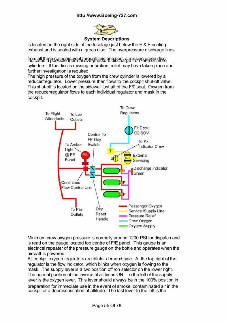
7/18/2019 Aircraft 5
http://slidepdf.com/reader/full/aircraft-5 55/78
http://www.Boeing-727.com
System Descriptions
Page 55 Of 78
is located on the right side of the fuselage just below the E & E coolingexhaust and is sealed with a green disc. The overpressure discharge lines
from all three cylinders vent through this one port. a missing green discindicates a possible thermal overpressure discharge from one or morecylinders. If the disc is missing or broken, relief may have taken place andfurther investigation is required.The high pressure of the oxygen from the crew cylinder is lowered by areducer/regulator. Lower pressure then flows to the cockpit shut-off valve.This shut-off is located on the sidewall just aft of the F/0 seat. Oxygen fromthe reducer/regulator flows to each individual regulator and mask in thecockpit.
Minimum crew oxygen pressure is normally around 1200 PSI for dispatch andis read on the gauge located top centre of F/E panel. This gauge is anelectrical repeater of the pressure gauge on the bottle and operates when theaircraft is powered. All cockpit oxygen regulators are diluter demand type. At the top right of theregulator is the flow indicator, which blinks when oxygen is flowing to themask. The supply lever is a two position off /on selector on the lower right.The normal position of the lever is at all times ON. To the left of the supplylever is the oxygen lever. This lever should always be in the 100% position in
preparation for immediate use in the event of smoke, contaminated air in thecockpit or a depressurisation at altitude. The last lever to the left is the
7/18/2019 Aircraft 5
http://slidepdf.com/reader/full/aircraft-5 56/78
http://www.Boeing-727.com
System Descriptions
Page 56 Of 78
emergency lever. UP is the ON position. This lever provides 100% oxygen tothe mask at a slight overpressure, regardless of the position of the oxygen
lever. The OFF position of the emergency lever allows the oxygen lever toregulate the oxygen flow, 100% or diluter demand as selected. The masks inthe cockpit are of the "quick-donning", or "sweep-on" type. The oxygen / boomselector for the flight engineer is located on his jack box. The boom positionis deactivated. His oxygen mask mike is activated by the associated push totalk button, labelled "PTT". For the pilots, the oxygen/boom selector is on theirrespective jack boxes. They also have a PTT (push to talk) button. Whenselected to oxygen and mike selection is in PA, the associated oxygen mike is"HOT''. The BOOM position is deactivated on some airplanes. and theoxygen position should always be selected. Then the push to talk button orthe rocker switch on the rear of each control wheel will activate the oxygen
mike to what ever is selected to transmit.Cockpit indication of passenger oxygen system pressure is read on theelectrical repeater gauge next to the crew oxygen pressure gauge on the topcentre of the SIC panel. Minimum pressure for dispatch is around 1450 psifor the passenger oxygen system. Oxygen from the two passenger cylindersflows from a common manifold into two paths. The pressure is reduced bytwo parallel pressure reducing regulators and the flow is controlled by two flowvalves. Downstream of the two valves the two paths rejoin. When either flowvalve is opened, oxygen pressurizes the passenger oxygen manifold, causinga pressure switch to illuminate an amber light. When cabin oxygen is required,one or both of these valves opens. The valve can be opened on of three
ways, Pneumatically, electrically or manually. Both valves are designed toopen pneumatically when cabin altitude exceeds 14,000 feet. One openselectrically by use of the oxygen switch on the FE panel, and the other byusing the manual "T" handle located on the FE aux panel below the APUcontrol panel or under floor access panel on the 100 series. This '"T" handlecan be used to close and reset both valves when oxygen is no longer needed,regardless of how the valves are activated. When the cabin oxygen manifoldis pressurized. The surge of pressure trips the latches on the oxygen maskdoors and the doors open. Four masks are then dropped at each passengerservice unit and two at each flight attendant's station and in the lavatories.Oxygen is now available to each mask valve in the cabin. In order toestablish Flow, the user must pull down the mask. This action extracts thevalve activating pin to allow flow of oxygen. The mask delivers oxygen dilutedwith cabin air to the user depending on cabin altitude. If the automatic systemdoes not open them, pushing a sharp object into a slot can open thepassenger doors. Flight attendant doors can be opened by moving a latch tothe side, if the automatic system failed. Lavatory doors are similar to the flightattendants doors. The three ways of terminating oxygen flow are:1. The valve can be closed by reinserting the pin into the shut-off valveassembly.2. By pushing the manual toggles on the ends of the shut-off valves to there
up position.
7/18/2019 Aircraft 5
http://slidepdf.com/reader/full/aircraft-5 57/78
http://www.Boeing-727.com
System Descriptions
Page 57 Of 78
3. By pushing the "T" handle to reset, all the way down for 5 seconds to dumpthe oxygen manifold pressure, and then back to the "OFF" position. This will
close both valves.
There is insufficient oxygen flow below 10,000' cabin altitude for passengeruse. At a cabin altitude of 10,000’ an intermittent horn will sound and can besilenced by a cutout button on the pressurization panel.
Portable Oxygen Bottles There are approximately five portable oxygen battles aboard the airplane.Four bottles in the cabin are for passenger use, and one with a full face maskis carried in the cockpit. Each bottle has a yellow shut-off knob and pressure
gauge.
PITOT STATIC SYSTEM
The pitot static system provides total and static inputs for the pressuresensing instruments and systems, which have functions that vary with altitudeand airspeed.
A sample system as show below would have three independent systemsreferred to as Capt, FO's and Aux. A forth port is connected to supply
pressure inputs for the cabin pressure controller. All of the pitot probes areequipped with heaters for anti-icing protection. Along with the ability for thecaptain or fist officer to select an alternate pressure source.
A simplified sample system is shown on the next page.
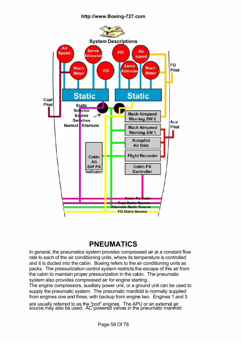
7/18/2019 Aircraft 5
http://slidepdf.com/reader/full/aircraft-5 58/78
http://www.Boeing-727.com
System Descriptions
Page 58 Of 78
PNEUMATICSIn general, the pneumatics system provides compressed air at a constant flowrate to each of the air conditioning units, where its temperature is controlledand it is ducted into the cabin. Boeing refers to the air conditioning units aspacks. The pressurization control system restricts the escape of this air fromthe cabin to maintain proper pressurization in the cabin. The pneumaticsystem also provides compressed air for engine starting.The engine compressors, auxiliary power unit, or a ground unit can be used tosupply the pneumatic system. The pneumatic manifold is normally suppliedfrom engines one and three, with backup from engine two. Engines 1 and 3
are usually referred to as the "pod" engines. The APU or an external airsource may also be used. AC powered valves in the pneumatic manifold
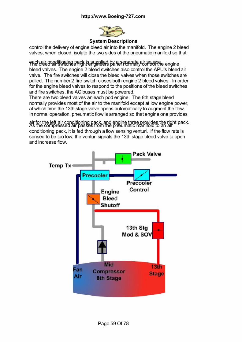
7/18/2019 Aircraft 5
http://slidepdf.com/reader/full/aircraft-5 59/78
http://www.Boeing-727.com
System Descriptions
Page 59 Of 78
control the delivery of engine bleed air into the manifold. The engine 2 bleedvalves, when closed, isolate the two sides of the pneumatic manifold so that
each air conditioning pack is supplied by a separate air source.The bleed air switches flight engineers panel normally control the enginebleed valves. The engine 2 bleed switches also control the APU's bleed airvalve. The fire switches will close the bleed valves when those switches arepulled. The number 2-fire switch closes both engine 2 bleed valves. In orderfor the engine bleed valves to respond to the positions of the bleed switchesand fire switches, the AC buses must be powered.There are two bleed valves an each pod engine. The 8th stage bleednormally provides most of the air to the manifold except at low engine power,at which time the 13th stage valve opens automatically to augment the flow.In normal operation, pneumatic flow is arranged so that engine one provides
air for the left air conditioning pack, and engine three provides the right pack. As the compressed air passes from the pneumatic manifold to an airconditioning pack, it is fed through a flow sensing venturi. If the flow rate issensed to be too low, the venturi signals the 13th stage bleed valve to openand increase flow.
7/18/2019 Aircraft 5
http://slidepdf.com/reader/full/aircraft-5 60/78
http://www.Boeing-727.com
System Descriptions
Page 60 Of 78
At high engine powers there is more than sufficient airflow from an 8th stagebleed for the associated air conditioning pack. As the compressed air leaves
the pneumatic manifold it passes through a modulating and shut off valve onits way to the flow sensing venturi. The modulating and shut off valve issignalled from the flow sensing venturi to control the flow at high powersettings. As the 13th stage valve on a pod engine opens or closes, the temperature ofthe air from that engine varies. The temperature of this bleed air must becontrolled for air conditioning pack operation. This is accomplishedautomatically on engines one and three by a pre-cooler on the bleed linesfrom each engine. The pre-cooler uses fan stage air to cool the bleed air. Atemperature sensitive valve controls the rate of flow of fan stage air throughthe cooler. There is no flight deck control for the pre-cooler.
To protect against excessively high temperature in the pneumatic duct from apod engine, an automatic trip off feature is installed. When the temperature ofthe bleed air is too high, the bleed air valve closes and a trip off light next tothe affected bleed switch illuminates. After a trip has occurred and the temperature of the bleed air has droppedsufficiently, pressing the reset button on the air conditioning panel will returnthe bleed valve to normal operation. If the condition that caused the trip tooccur still exists, however, the bleed valve trip will reoccur.Engine No, 2 supplies air only from the 8th stage. Since supplemental air isnot supplied from the 13th stage on this engine, a pre-cooler is not fitted. Towarn of excessively high temperature in the engine No 2 bleed system, a high
temperature light is provided. No automatic trip off is associated withillumination of this light.Opening the engine No. 2 left bleed switch will open the left engine 2 bleedvalve to supply air to the left air conditioning pack. The engine 1 bleed switchshould be closed in this case so that only one engine is supplying bleed air tothat pack.Pressure in the bleed air distribution system can be read on the duct pressuregauge at the flight engineers panel. There are duct pressure transmittersinstalled on both sides of the ducting. If both engine 2/APU bleed switcheswere open, the left and right pressures would be equal indicating commonpressure.There is provision for using an external air cart for pneumatic supply. Theexternal air cart is connected to the bleed air distribution system between theright No. 2 and No. 3 bleed valves. On the exterior of the airplane thisconnection is on the aft right side of the fuselage.The APU can be used on the ground to deliver compressed air to the airconditioning packs or the pneumatic manifold. The APU bleed air valve,which bleeds compressed air from the APU, will open when either (or both)engine 2/APU bleed switch is in the open position.
On the 200 series aircraft there is a flow multiplier. The purpose of the flowmultiplier is to augment the bleed air output of the APU so that there will be
7/18/2019 Aircraft 5
http://slidepdf.com/reader/full/aircraft-5 61/78
http://www.Boeing-727.com
System Descriptions
Page 61 Of 78
sufficient quantity of compressed air to operate both air conditioning packsfrom the APU for ground operation.
With both air conditioning packs operating the augmented APU bleed air isducted directly to both packs. If the air conditioning packs are not operating, APU bleed air travels back through the ducting, which contains the flowsensing venturi and modulating and shutoff valves to the pneumatic manifold.This allows the APU bleed air to be used for engine starting.With the APU operating, when one air conditioning pack is turned on, bothmodulating and shutoff valves close to isolate the air conditioning packs fromthe pneumatic manifold. Therefore, with at least one engine 2/APU bleedswitch open and one air conditioning pack on, there is no flow of air througheither modulating and shutoff valve. The duct pressure gauges are installedin the pneumatic manifold. If the APU is the only source of bleed air to the
pneumatic system, and at least one air conditioning pack is turned on, nocompressed air will reach the gauges, and they will read zero pressure. (200Series, 100 Series will show a reduced pressure indication).
If the air conditioning packs are not operating, the APU provides compressedair to the pneumatic duct through the modulating and shutoff valves. This isthe normal configuration for engine starting.Heat from a broken pneumatic or anti-ice bleed air duct could cause damageto the airplane structure. Three detection systems are installed in the areas ofthese ducts to give warning of duct failures.
A detection system is installed in each pod engine strut area inboard of itsengine firewall. A third system combines several sensors to detect overheatin what is referred to as lower aft body. These lower aft body sensors arelocated on either side of the aft airstairs, above the ceiling of the aft cargocompartment, and in the fuselage keel beam. An overheat sensed by any ofthe three detection systems is reflected in the flight deck by illumination of theappropriate amber warning light on the flight engineers panel. The adjacenttest button is used to test simultaneously the light bulbs and the continuity ofthe overheat detection sensors for the struts and lower aft body.
POWERPLANTThree aft mounted Pratt and Whitney JT8D series dual compressor turbofanengines power the Boeing 727. Each engine produces Between 14,000 and16,900 pounds of thrust at sea level depending on model installed (new fanmod excluded). The design of the engines includes an integral fan bypasswhich routes fan air the entire length of the engine. Cooling the engine jacket.The fan air mixes with the turbine exhaust just forward of the reverser sectionwhere it increases thrust and reduces engine noise. The engine has two axialflow compressors. The low-pressure compressor includes the fan stages andis driven by the low-pressure turbine stages. The high-pressure compressor
is driven by the high-pressure turbine stage. The dual compressor featureallows for more closely matching compressor blade speed to the increasing
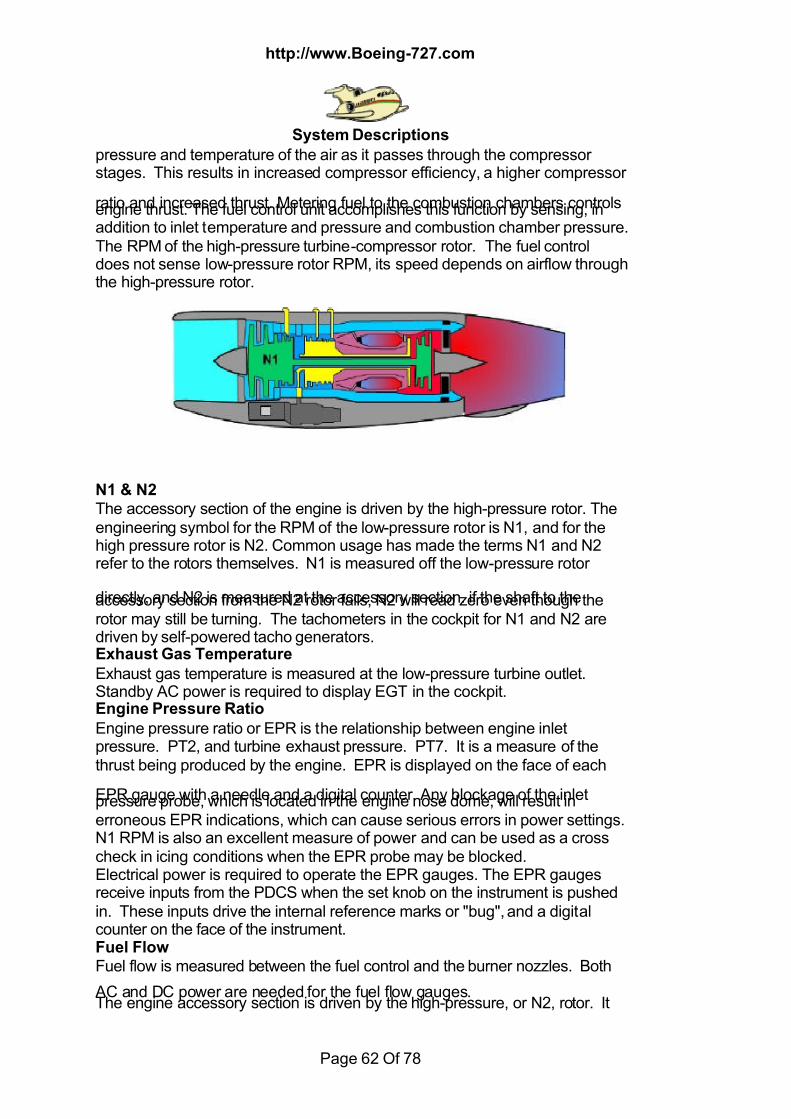
7/18/2019 Aircraft 5
http://slidepdf.com/reader/full/aircraft-5 62/78
http://www.Boeing-727.com
System Descriptions
Page 62 Of 78
pressure and temperature of the air as it passes through the compressorstages. This results in increased compressor efficiency, a higher compressor
ratio and increased thrust. Metering fuel to the combustion chambers controlsengine thrust. The fuel control unit accomplishes this function by sensing, inaddition to inlet temperature and pressure and combustion chamber pressure.The RPM of the high-pressure turbine-compressor rotor. The fuel controldoes not sense low-pressure rotor RPM, its speed depends on airflow throughthe high-pressure rotor.
N1 & N2 The accessory section of the engine is driven by the high-pressure rotor. Theengineering symbol for the RPM of the low-pressure rotor is N1, and for thehigh pressure rotor is N2. Common usage has made the terms N1 and N2refer to the rotors themselves. N1 is measured off the low-pressure rotor
directly, and N2 is measured at the accessory section. if the shaft to theaccessory section from the N2 rotor fails, N2 will read zero even though therotor may still be turning. The tachometers in the cockpit for N1 and N2 aredriven by self-powered tacho generators.Exhaust Gas Temperature Exhaust gas temperature is measured at the low-pressure turbine outlet.Standby AC power is required to display EGT in the cockpit.Engine Pressure Ratio Engine pressure ratio or EPR is the relationship between engine inletpressure. PT2, and turbine exhaust pressure. PT7. It is a measure of thethrust being produced by the engine. EPR is displayed on the face of each
EPR gauge with a needle and a digital counter. Any blockage of the inletpressure probe, which is located in the engine nose dome, will result inerroneous EPR indications, which can cause serious errors in power settings.N1 RPM is also an excellent measure of power and can be used as a crosscheck in icing conditions when the EPR probe may be blocked.Electrical power is required to operate the EPR gauges. The EPR gaugesreceive inputs from the PDCS when the set knob on the instrument is pushedin. These inputs drive the internal reference marks or "bug", and a digitalcounter on the face of the instrument.Fuel Flow Fuel flow is measured between the fuel control and the burner nozzles. Both
AC and DC power are needed for the fuel flow gauges.The engine accessory section is driven by the high-pressure, or N2, rotor. It
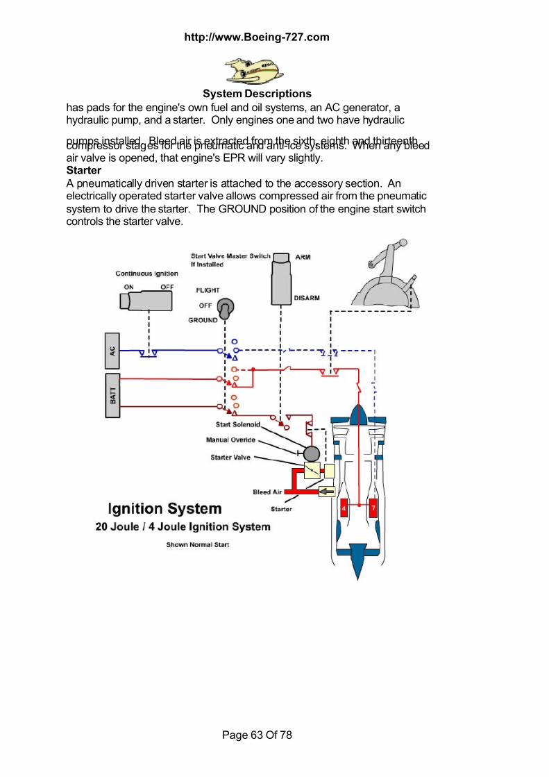
7/18/2019 Aircraft 5
http://slidepdf.com/reader/full/aircraft-5 63/78
http://www.Boeing-727.com
System Descriptions
Page 63 Of 78
has pads for the engine's own fuel and oil systems, an AC generator, ahydraulic pump, and a starter. Only engines one and two have hydraulic
pumps installed. Bleed air is extracted from the sixth, eighth and thirteenthcompressor stages for the pneumatic and anti-ice systems. When any bleedair valve is opened, that engine's EPR will vary slightly.Starter A pneumatically driven starter is attached to the accessory section. Anelectrically operated starter valve allows compressed air from the pneumaticsystem to drive the starter. The GROUND position of the engine start switchcontrols the starter valve.
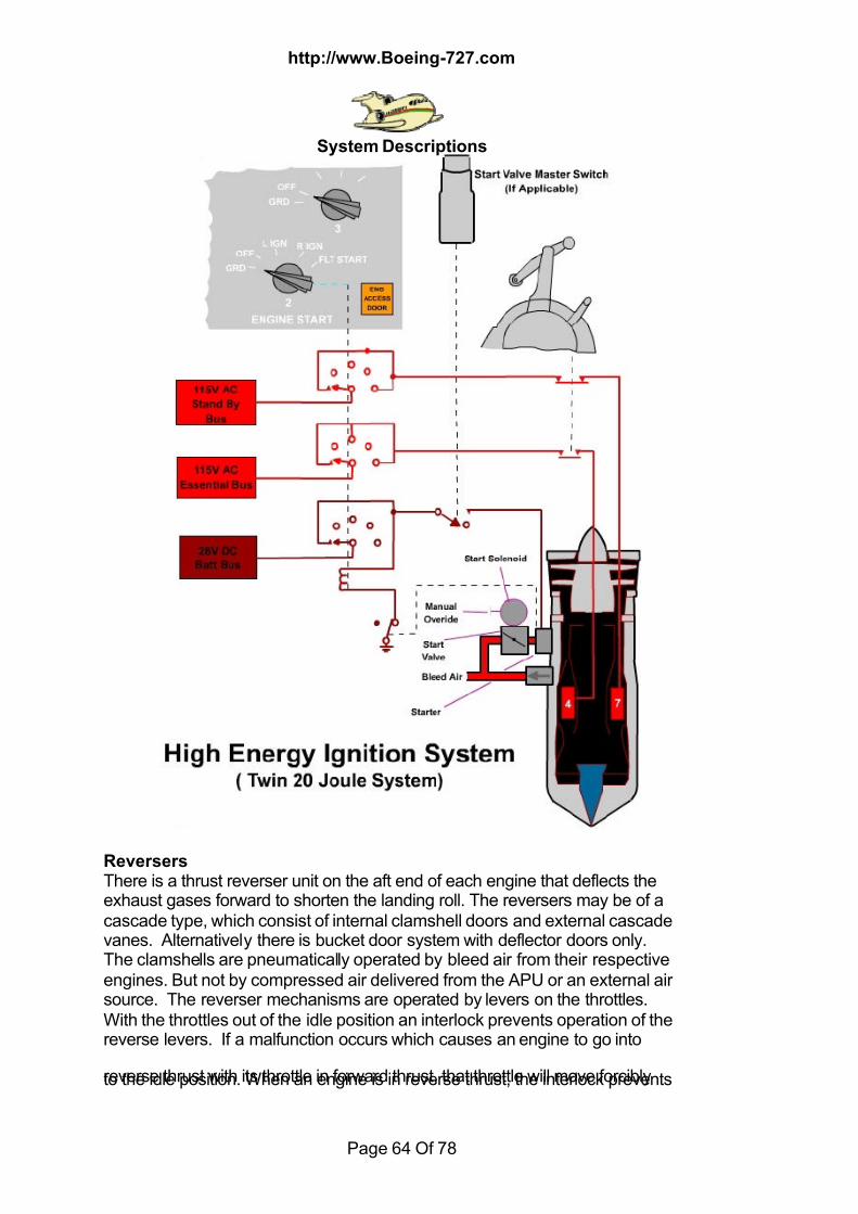
7/18/2019 Aircraft 5
http://slidepdf.com/reader/full/aircraft-5 64/78
http://www.Boeing-727.com
System Descriptions
Page 64 Of 78
Reversers There is a thrust reverser unit on the aft end of each engine that deflects theexhaust gases forward to shorten the landing roll. The reversers may be of acascade type, which consist of internal clamshell doors and external cascadevanes. Alternatively there is bucket door system with deflector doors only.The clamshells are pneumatically operated by bleed air from their respectiveengines. But not by compressed air delivered from the APU or an external airsource. The reverser mechanisms are operated by levers on the throttles.With the throttles out of the idle position an interlock prevents operation of thereverse levers. If a malfunction occurs which causes an engine to go into
reverse thrust with its throttle in forward thrust, that throttle will move forciblyto the idle position. When an engine is in reverse thrust, the interlock prevents

7/18/2019 Aircraft 5
http://slidepdf.com/reader/full/aircraft-5 65/78
http://www.Boeing-727.com
System Descriptions
Page 65 Of 78
forward movement of the throttles. As with the throttles, if the engine goesinto forward thrust with the reverse lever in reverse thrust the reverse lever
will move forcibly into the forward thrust position. REVERSER NOTSTOWED lights, located above the engine instruments, indicate that theclamshells of the reverser are not fully stowed in the forward thrust position.The reverse interlock on each engine will prevent motion of the throttle intothe forward thrust range if the engine is actually in reverse thrust and thereverse interlock will also prevent the reverse lever from applying reversethrust until the clamshells are in the full reverse position.Oil System
Each engine has an independent oil storage and distribution system, whichprovides cooling, and lubrication of gears and bearings. The tank has auseable capacity of four gallons. An engine driven pump pressurizes the oil
from the oil tank. The pressurized oil passes through a filter, is cooled and ispiped to the bearings and accessory section gears. The oil is then returned tothe tank by scavenge pumps. After it leaves the cooler the pressure andtemperature of the oil are measured and the values are transmitted to gaugeson the flight engineer's panel. In addition a separate pressure switch will turnon a light on the pilots' centre instrument panel if oil pressure is too low. If theoil filter is unable to process the output of the oil pump because the filter isclogged a bypass will open to allow oil to reach the engine. If this occurs, thedifference in oil pressure across the filter will cause the same low oil pressurelight on the centre instrument panel to illuminate. The label on the lightsignifies this dual purpose.
LOW OIL PRESSURE OR FILTER BYPASS If the low oil pressure or filter bypass light comes on, the cause can bedetermined by reference to the corresponding oil pressure gauge. If the oilpressure reading is normal the light indicates that the oil filter is beingbypassed. The oil is cooled in a heat exchanger through which fuel from theengine fuel system is circulated. As fuel temperature and flow rate vary, oilcooling will vary, and oil temperature will change. Gauges on the flightengineers panel monitor oil quantity, temperature, and pressure. A test buttonin the lower right corner of this panel is used to test the operation of the oilquantity gauges. Standard instrument markings are used on the temperatureand pressure gauges: green indicating the normal range, yellow indicatingcaution and red showing the operating limit.
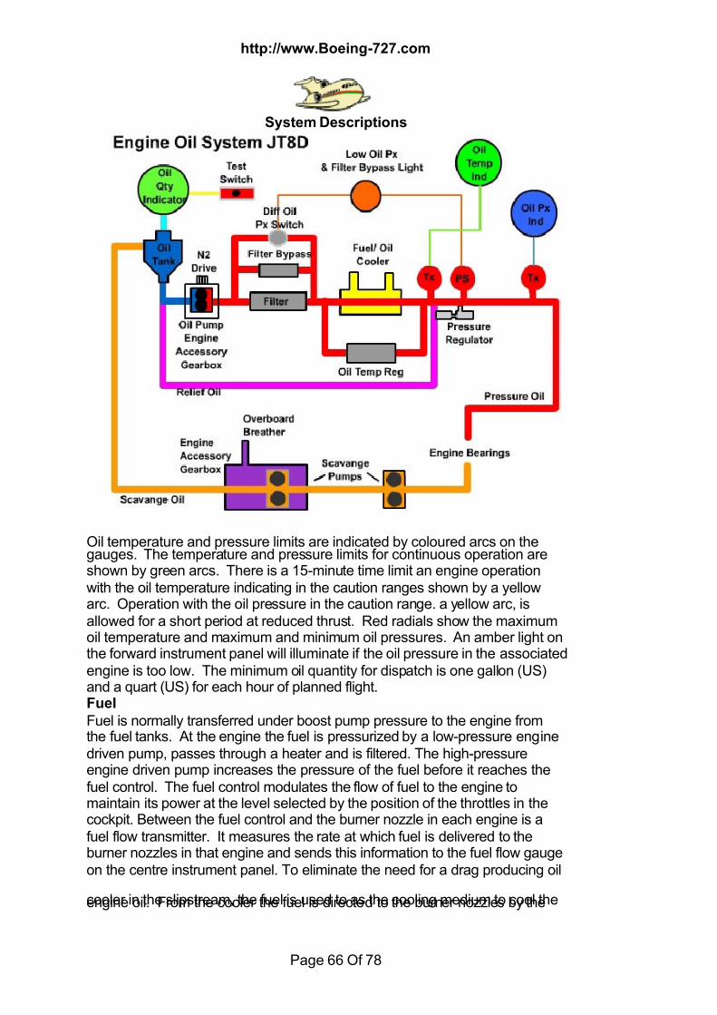
7/18/2019 Aircraft 5
http://slidepdf.com/reader/full/aircraft-5 66/78
http://www.Boeing-727.com
System Descriptions
Page 66 Of 78
Oil temperature and pressure limits are indicated by coloured arcs on thegauges. The temperature and pressure limits for continuous operation areshown by green arcs. There is a 15-minute time limit an engine operationwith the oil temperature indicating in the caution ranges shown by a yellowarc. Operation with the oil pressure in the caution range. a yellow arc, isallowed for a short period at reduced thrust. Red radials show the maximumoil temperature and maximum and minimum oil pressures. An amber light onthe forward instrument panel will illuminate if the oil pressure in the associatedengine is too low. The minimum oil quantity for dispatch is one gallon (US)and a quart (US) for each hour of planned flight.Fuel
Fuel is normally transferred under boost pump pressure to the engine fromthe fuel tanks. At the engine the fuel is pressurized by a low-pressure enginedriven pump, passes through a heater and is filtered. The high-pressureengine driven pump increases the pressure of the fuel before it reaches thefuel control. The fuel control modulates the flow of fuel to the engine tomaintain its power at the level selected by the position of the throttles in thecockpit. Between the fuel control and the burner nozzle in each engine is afuel flow transmitter. It measures the rate at which fuel is delivered to theburner nozzles in that engine and sends this information to the fuel flow gaugeon the centre instrument panel. To eliminate the need for a drag producing oil
cooler in the slipstream, the fuel is used to as the cooling medium to cool theengine oil. From the cooler the fuel is directed to the burner nozzles by the
7/18/2019 Aircraft 5
http://slidepdf.com/reader/full/aircraft-5 67/78
http://www.Boeing-727.com
System Descriptions
Page 67 Of 78
pressurizing and dump valve. At low power settings, only the primary fuelmanifold is pressurized. As power is increased the secondary manifold is also
used. At low temperatures the fuel filter is susceptible to clogging by iceparticles in the fuel. If this occurs a bypass around the filter opens allowingfuel to reach the engine. The pressure drop across the filter is sensed,causing an amber icing light on the flight engineer's panel to illuminateupstream of the fuel filter. A fuel heater is installed. When the fuel heat switchon the flight engineer's panel is moved to ON, a valve opens allowing highstage engine bleed air to pass through the heater heating the fuel rapidly.The heated fuel flows to the fuel filter melting the ice in the filter. The heatedfuel continues on through the fuel control and on to the oil cooler. Since thefuel is now warmer it cannot cool the engine oil as efficiently, and oiltemperature on that engine rises.
A blue IN TRANSIT light on the flight engineer's panel will illuminate as longas the hot air valve does not match the position of the fuel heat switch. Whenthe hot air valve opens, a drop in slight drop in EPR can be seen. A rise inengine oil temperature verifies that the fuel is being heated. The low-pressureengine driven pump normally provides for suction feed if necessary from afuel tank to force fuel through the fuel heater and filter to the high-pressureengine driven pump. If the low-pressure pump fails, a bypass allows fuel toflow directly to the high-pressure pump without passing through the heater orfilter. In this situation the fuel cannot be heated and use of the fuel heatswitch will not cause a rise in engine oil temperature. If fuel temperature failsto rise while the fuel heat is in use, the low-pressure engine driven pump may
have failed.
Fuel Temp
Fuel temperature in the number one fuel tank is displayed on the flightengineer's panel to determine if the fuel is approaching a temperature limit orif any fuel filter blockage could be caused by ice. Number one tank waschosen since its fuel is the coldest.
Ignition & Starting
Ignition and start valve operation are controlled by the ignition switches andthe start levers. The ignition switches are located on the overhead panel, andthe start levers are on the centre console throttle quadrant. Each engine'signition system provides two levels of ignition energy. High-energy ignition,used for engine starting. It receives its power from the DC circuits. Lowenergy ignition, which can be used continuously without decreasing the life ofthe engine igniters, receives its power from the AC circuits. Each ignitionswitch arms its ignition circuits, however, the ignition will not be activatedunless the associated start lever an the throttle quadrant is moved to start oridle. With the ignition switch in either flight or ground, and the start lever instart high-energy ignition is activated. With the ignition switch in either flight
or ground and the start lever in idle, low energy, continuous ignition isactivated. The ground position of the start switch has the additional function of
7/18/2019 Aircraft 5
http://slidepdf.com/reader/full/aircraft-5 68/78
http://www.Boeing-727.com
System Descriptions
Page 68 Of 78
opening the associated engine start valve to initiate engine rotation for start.Once the engine reaches the proper RPM, the start lever is moved to start,
which causes the high-energy ignition to activate as well as the fuel to beintroduced to the engine. With the start lever in its normal in-flight position
idle, moving the start switch to flight provides low energy ignition. The groundposition of the start switch would also activate the low energy ignition but thiswould open the start valve, subjecting the starter to potential damage. Lowenergy ignition should be used during takeoff, landing, icing conditions,turbulence and when using fuel heat.Fuel to the engine as well as ignition is controlled by the start lever. With thestart lever in start or idle the fuel valve in the fuel control is open providing fuelto the engine. In addition, the fuel shutoff valve at the fuel tank is open. With
the start lever in cut-off, the fuel is shut off at the fuel control and at the wingtank shutoff valve.
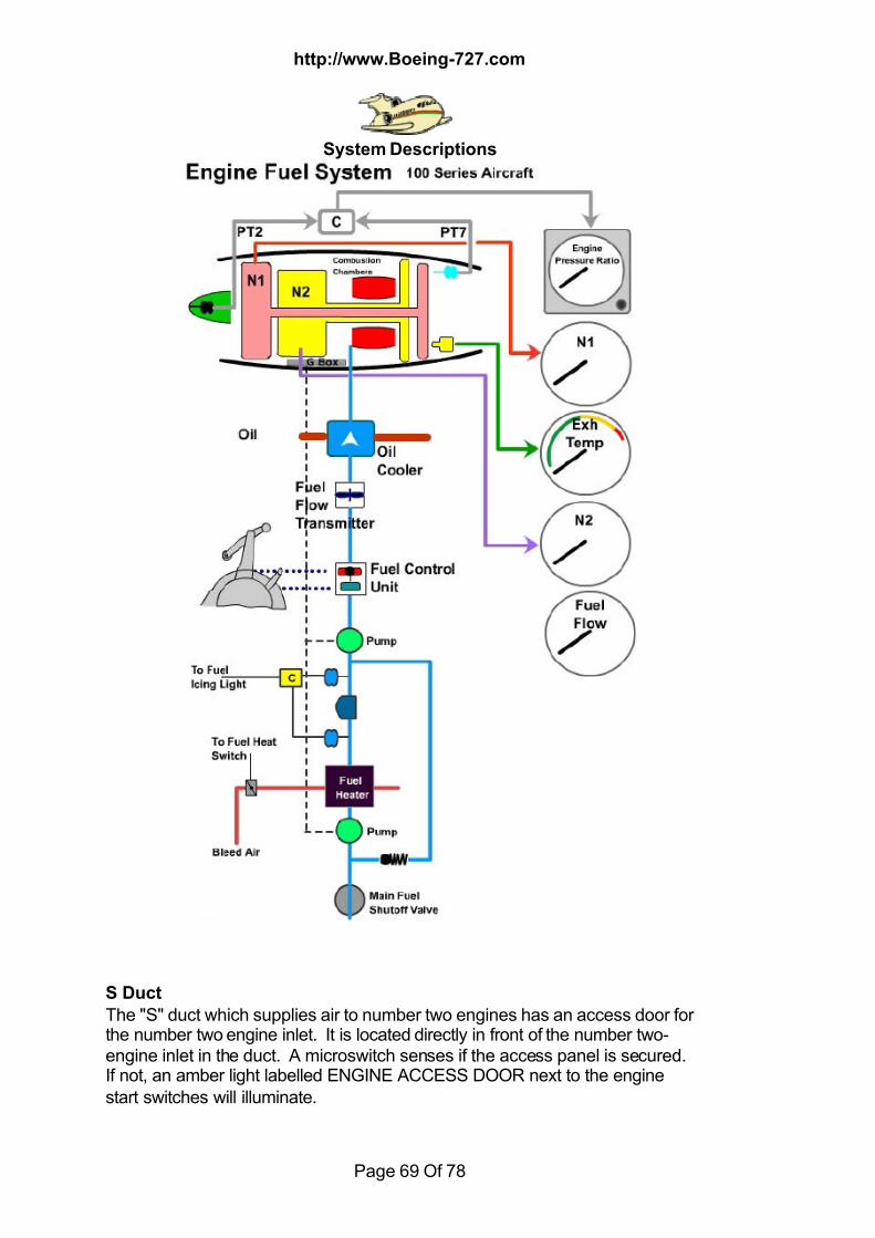
7/18/2019 Aircraft 5
http://slidepdf.com/reader/full/aircraft-5 69/78
http://www.Boeing-727.com
System Descriptions
Page 69 Of 78
S Duct
The "S" duct which supplies air to number two engines has an access door forthe number two engine inlet. It is located directly in front of the number two-engine inlet in the duct. A microswitch senses if the access panel is secured.If not, an amber light labelled ENGINE ACCESS DOOR next to the enginestart switches will illuminate.

7/18/2019 Aircraft 5
http://slidepdf.com/reader/full/aircraft-5 70/78
http://www.Boeing-727.com
System Descriptions
Page 70 Of 78
PRESSURISATION
There are two types of pressurisation installed on the B727, Pneumaticcontrolled and electronic controlled.
The electronic pressurisation system
Four independent modes of operation: Automatic, Standby, Manual AC, andManual DC. The Standby mode is a semiautomatic system that acts as abackup for the automatic mode of operation. The two manual modes, actingas backups for the entire system. The chart below the pressurisation panel isused to set or check the cabin altitude in relation to airplane altitude in theStandby mode.The gate-type electrically controlled outflow valve is located on the right rearside of the airplane near the tailskid. Although there are other acceptablepressure bleeds, most of the air exits through this valve. Two safety pressurerelief valves located just forward of the tailskid limit the cabin to a maximum of9.6-psi differential pressure. A negative relief valve prevents negative cabinpressure from exceeding 1 psi. Automatic warning of cabin altitude exceeding 10,000 feet is provided by ahorn. Depressing the horn cutout on the pressurisation panel raises cabin PAvolume as well as silencing the warning horn.Correct operation of the pressurisation control system requires information forthe system from the air data computer. The Captain's or First Officer's
altimeter setting, (Captain's altimeter setting is used in Auto mode and FirstOfficer's setting in Standby), ambient air pressure from an external part, andthe landing gear ground safety sensor. On some airplanes the barometricpressure must be set on a separate counter on the flight engineer's panel.
AUTOMATIC CONTROL When the proper information is set, the automatic mode will smoothly controlthe cabin from before takeoff to after landing with little or no further input fromthe crew. The left side of the pressurisation section of the flight engineer'spanel is used for manual inputs to the Auto mode. Planned cruise altitude is
entered in the Flight Altitude window and landing field altitude in the Land Altitude window. The Flight/Ground switch, when moved to Flight, signals thepressurisation system to begin pressurising the airplane by moving theoutflow valve from the full open position. With the mode selector in Auto and
the airplane on the ground, it will cause cabin altitude to descend to 200 feetbelow the present field elevation, resulting in a differential pressure of lessthan .125 psi. After takeoff, the cabin climbs in proportion to airplane climb. Cabin rate islimited to approximately 500 feet per minute during climb and 350 feet perminute during descent. The cabin climbs automatically holding at
intermediate altitudes as the airplane holds until the airplane reaches cruisealtitude. During high altitude cruise the cabin enters a barometric hold phase.
7/18/2019 Aircraft 5
http://slidepdf.com/reader/full/aircraft-5 71/78
http://www.Boeing-727.com
System Descriptions
Page 71 Of 78
The cabin will maintain a constant altitude at a nominal differential pressure of8.5 psi. Slight variations of airplane flight altitude will cause no change in
cabin altitude, but the differential pressure will vary. If the airplane climbs, sothat the pressure differential reaches 8.65 psi, however, it will remain at thatdifferential and the cabin will climb. Upon descent, the cabin will smoothlydescend holding again as the airplane holds until the airplane reaches thelanding altitude programmed. With the barometric pressure set for thedestination, the cabin descends to 300 feet below the setting in the Land Altitude window and at touchdown the cabin climbs to 200 feet below theLand Altitude setting. Placing the Flight/Ground switch to Ground afterlanding depressurises the cabin slowly. In the auto mode during low altitudecruise, the full differential pressure is not needed. The cabin climbs ordescends to a cabin altitude 300 feet below the landing altitude and stays
there until touchdown.If it becomes necessary to return to the departure airport before reachingcruise altitude, the system automatically sets the cabin for landing at thetakeoff field. If the airplane has not reached the cruise altitude set in theCruise Altitude window before descending, the OFF SCHEDULE DESCENTsequence will occur. If the landing is to be made at the departure airport, thesystem will set cabin altitude without further crew input.If, however, the flight has reached its destination without climbing to the finalcruise altitude, the OFF SCHEDULE DESCENT mode must be cancelled.The light may be extinguished by rotating the flight altitude digital readout tothe airplane's present altitude. At this point the system will be returned to
normal operation and the cabin pressure will be set for landing at the altitudein the Land Altitude window. The correct land altitude value must be set in theLand Altitude window prior to beginning this procedure if landing at other thanthe original destination.
STANDBY CONTROL The Standby Mode. The green Standby light will illuminate as a result ofautomatic transfer from the auto mode, or crew selection of the Standbymode. Control of pressurisation in Standby mode is through the Cabin Altitude selection in the centre of the pressurisation panel. The desired cabinaltitude is set by the flight engineer to control the pressurisation he uses thechart next to the panel to determine the proper cabin altitude for the airplanealtitude being flown. The Standby rate knob controls the rate at which cabinaltitude changes in the Standby mode. The rate knob has 50 to 2000 feet rate
of cabin climb or descent capability. Normally the rate knob is set on theIndex Mark, which results in a rate of climb or descent of 300 feet per minute.To operate the pressurisation system in Standby, the Cabin Altitude is set to200 feet below the takeoff airport altitude for takeoff, the barometric pressureis set in the appropriate instrument or counter, and the Flight/Ground switch is
moved to Flight. After takeoff, the proper cabin altitude is found on the chartnext to the pressurisation panel and is set in. As the airplane begins its
7/18/2019 Aircraft 5
http://slidepdf.com/reader/full/aircraft-5 72/78
http://www.Boeing-727.com
System Descriptions
Page 72 Of 78
descent for landing, the flight engineer sets the Cabin Altitude to 200 feetbelow the destination airport's altitude, and the barometric pressure is set.
The airplane is depressurised after landing by moving the Flight/Groundswitch to Ground.The pressure profiles that might be experienced, on a flight are. In thisexample, the takeoff airport elevation is at sea level. Since the takeoff airportelevation is sea level, the controller is set to minus 200 feet prior to takeoff.This allows the airplane to make a smooth transition to pressurised flight. Thecruise altitude will be 35,000 feet. After takeoff, the corresponding cabinaltitude is set in the controller, 5.600 feet. Prior to descent, the landingelevation minus 200 feet is set in the controller. The airport elevation is 2,000feet, so the controller is set at 1,900 feet.Control will automatically shift from the Auto mode to the Standby mode for
any of the following reasons: an excessive cabin rate of change, a power lossof more than 15 seconds to the auto portion of the pressurisation system, or ifthe cabin altitude exceeds 14,000 feet. If an auto mode failure occurs, theamber AUTO FAIL light will illuminate and the green STANDBY light will alsoilluminate because the pressurisation system has reverted to the Standbymode. If any of the modes fail to control the cabin pressure so that the cabinaltitude rises to 14,500 feet, the outflow valve will be driven fully closed by DCpower from the battery transfer bus.
MANUAL CONTROL
The green Manual light will illuminate when either MANUAL AC or MANUALDC is selected on the mode selector. For use in checking the outflow valve, avalve position indicator is provided. This indicator functions in all modes. TheCLOSE/OFF/OPEN toggle switch below this indicator will move the outflowvalve towards the position selected and thereby control the pressurisationsystem. Electrical power to the DC Manual mode should always be availablefrom the battery transfer bus. Manual AC, powered by the Essential AC bus,operates much faster than Manual DC and should be used during a rapiddepressurisation. Manual DC should be used during an AC power failure, asthis will be the only operational mode at this time. I personally prefer to useDC when in manual as it gives a much smoother control of the pressurisation
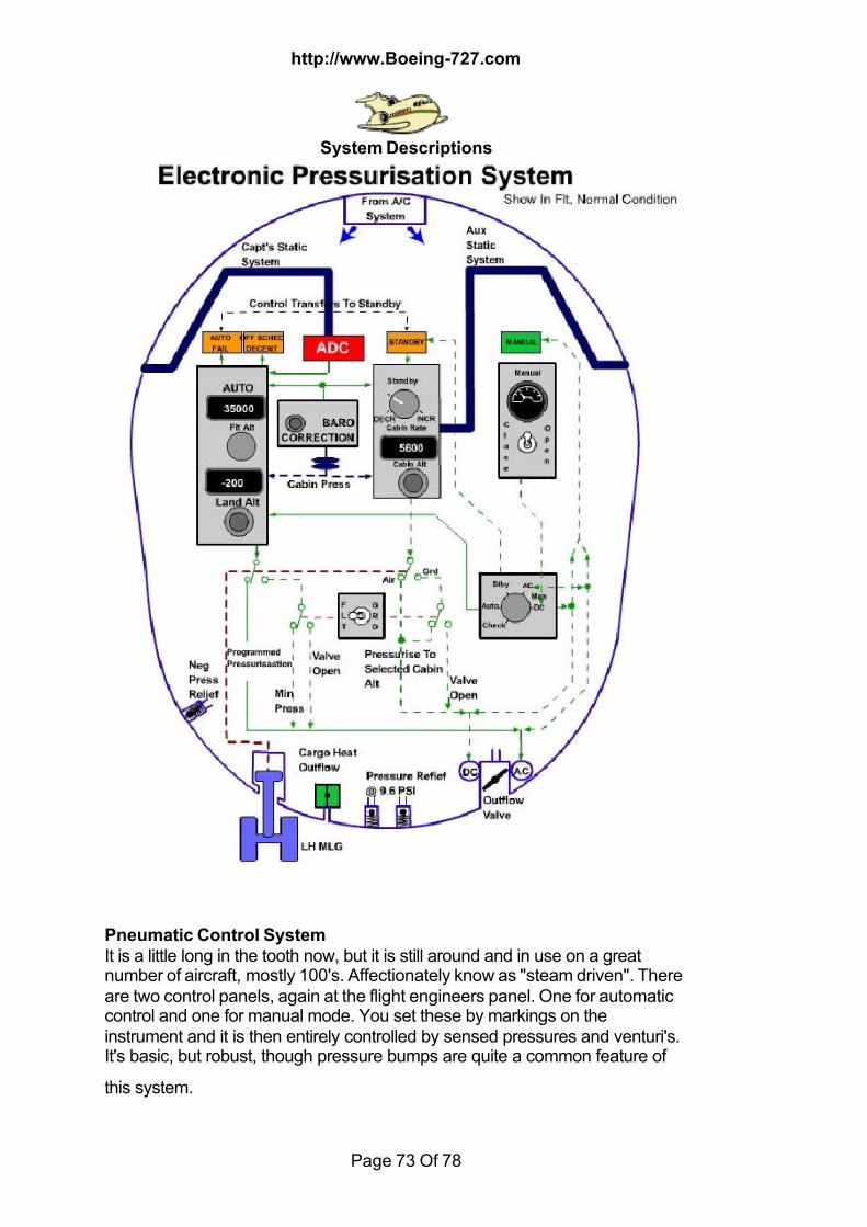
7/18/2019 Aircraft 5
http://slidepdf.com/reader/full/aircraft-5 73/78
http://www.Boeing-727.com
System Descriptions
Page 73 Of 78
Pneumatic Control System
It is a little long in the tooth now, but it is still around and in use on a greatnumber of aircraft, mostly 100's. Affectionately know as "steam driven". Thereare two control panels, again at the flight engineers panel. One for automaticcontrol and one for manual mode. You set these by markings on theinstrument and it is then entirely controlled by sensed pressures and venturi's.It's basic, but robust, though pressure bumps are quite a common feature of
this system.
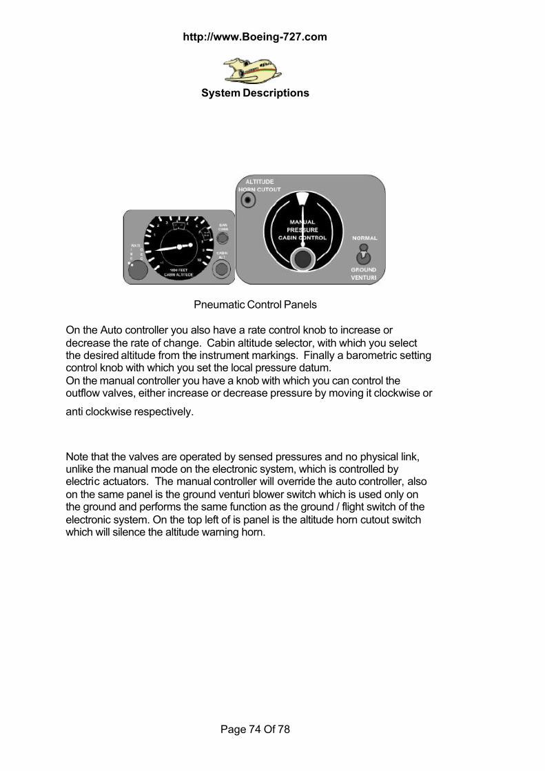
7/18/2019 Aircraft 5
http://slidepdf.com/reader/full/aircraft-5 74/78
http://www.Boeing-727.com
System Descriptions
Page 74 Of 78
Pneumatic Control Panels
On the Auto controller you also have a rate control knob to increase ordecrease the rate of change. Cabin altitude selector, with which you selectthe desired altitude from the instrument markings. Finally a barometric settingcontrol knob with which you set the local pressure datum.On the manual controller you have a knob with which you can control theoutflow valves, either increase or decrease pressure by moving it clockwise or
anti clockwise respectively.
Note that the valves are operated by sensed pressures and no physical link,unlike the manual mode on the electronic system, which is controlled byelectric actuators. The manual controller will override the auto controller, alsoon the same panel is the ground venturi blower switch which is used only onthe ground and performs the same function as the ground / flight switch of theelectronic system. On the top left of is panel is the altitude horn cutout switchwhich will silence the altitude warning horn.

7/18/2019 Aircraft 5
http://slidepdf.com/reader/full/aircraft-5 75/78
http://www.Boeing-727.com
System Descriptions
Page 75 Of 78
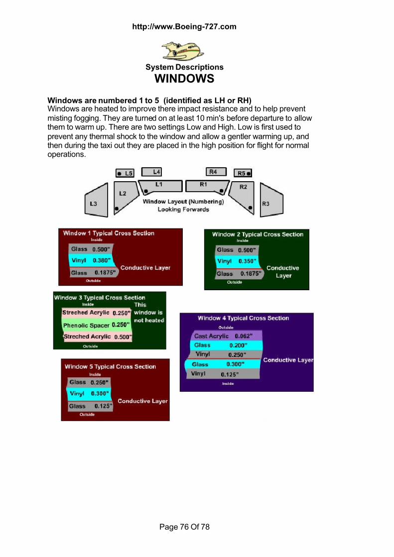
7/18/2019 Aircraft 5
http://slidepdf.com/reader/full/aircraft-5 76/78
http://www.Boeing-727.com
System Descriptions
Page 76 Of 78
WINDOWS
Windows are numbered 1 to 5 (identified as LH or RH)Windows are heated to improve there impact resistance and to help preventmisting fogging. They are turned on at least 10 min's before departure to allowthem to warm up. There are two settings Low and High. Low is first used toprevent any thermal shock to the window and allow a gentler warming up, andthen during the taxi out they are placed in the high position for flight for normaloperations.
7/18/2019 Aircraft 5
http://slidepdf.com/reader/full/aircraft-5 77/78
http://www.Boeing-727.com
System Descriptions
Page 77 Of 78
Window Failure
Window failure does not compromise the integrity of the flight, it just changes
your operating procedures and limitations. I've had windows fail at altitude theonly thing you do is spill your coffee, as it goes bang.
PANE WINDOW ACTIONOuter Pane All Windows NormalOperationsMiddle Panes Window 4 Max Cabin Diff 5
psi(This is the only window having a middle pane)Inner Pane Window 1, 2, 5 Max Cabin Diff 5psiInner Pane Window 3, 4 NormalOperationsBoth Panes Windows 1, 2, 4, 5 Max Cabin Diff 2psiBoth Panes Window 3 Max Cabin Diff 0psi
Max Airspeed with Window Heat Inoperative is 250 kts Below 10,000'
YAW DAMPERS
Yaw Damping is provided by two completely independent dampers, which canbe operated singly or simultaneously. The prime function of the system is tominimise Dutch Roll by providing automatic rudder displacement proportionalto and opposing the amount of yaw experienced.One yaw damper controls the upper rudder the other the lower. Each yawdamper has an associated coupler, which operates a rate gyro, and sensesyaw. The damper system then provides the necessary rudder movement tooppose and damp out the yaw. Rudder displacement resulting from yawdamper input is limited to 5 deg to prevent full rudder being applied in theevent of a yaw damper malfunction.The lower yaw damper is powered electrically from the Essential Radio Bus;upper yaw damper is powered from the No 2 Radio Bus.Two yaw damper warning flags on the rudder and elevator position indicatorare biased out of view when the respective yaw damper is engaged. Some
aircraft have green lights instead of the warning flags; lights are green whenthe damper is engaged.

7/18/2019 Aircraft 5
http://slidepdf.com/reader/full/aircraft-5 78/78
http://www.Boeing-727.com
System Descriptions
Each yaw damper controls it's associated rudder through a transfer valve onthe rudder power unit. The upper damper uses system B, the lower damper
system A.
The loss of either hydraulic system pressure will result in the loss of theassociated yaw damper. If this occurs a loss damper disengaged warning willNOT occur.
The only common circuitry between the yaw dampers and the autopilot is aninterlock that requires at least one yaw damper to be on in flight. before theautopilot can be engaged.
Related Documents