------------------------------------------------------------------------------------------------------------------------------ Main differences between new firmware 301a and 244 on which is made the official manual ------------------------------------------------------------------------------------------------------------------------------ -------------------------------------------------------------------------------------- Check firmware version -------------------------------------------------------------------------------------- - the firmware version is displayed at the power-on on the initial screen with the message "Sw Version 301a-019". N.B. The initial screen is displayed until you release the power button to allow you to have all the time necessary to read its contents. - if you read "Sw Version 301a-019" the instrument is already updated so skip to the section "Altimeter AGL". - To update the firmware of the instrument follow the instructions of the official manual, once the firmware has been updated to the 301a-019 version you must ensure that the following parameters are setup to recommended defaults : - Variometer Setup: CRUT = 15 (Threshold time tracking glide = 15 seconds) - Variometer Setup: THET = 2 (Thermal detection threshold time = 2 seconds) - Variometer Setup: THEZ = 1 (Thermal Tutor zoom level = 1m/pixel) - Variometer Setup: THEA = 5 (Thermal Assist zoom level = 5m/pixel) - Main Setup: IGLD = ON - Main Setup: IFLY = XC You must also upload to the instrument the new english language help file Help_UK_Air_301a.dgh using new AirTools software release. -------------------------------------------------------------------------------------- Altimeter AGL -------------------------------------------------------------------------------------- Added new AGL altimeter, that shows height above ground (AGL Altitude = Altitude Above Ground Level) In order to view the AGL altimeter, is important to copy&paste on micro SD card the map files (*.dgm) of the interested flight zone. Maps are created with AirTools software. Set the Main Setup: ELVM parameter “elevation mode” to 1, 2 or 3. -------------------------------------------------------------------------------------- Map -------------------------------------------------------------------------------------- A new Map tool has been added and it enables you to view different layers. It can be placed in any page through AirPages software and its dimensions are settable: min 120x120, max 240x240 pixels. - Map tool is placed on page 12 by default - Map tool is always North oriented (North up) - Map zoom is automatic : minimum 10mt/pixel, maximum 20000mt/pixel - The scale indicates the map width in Mt (up to 1000mt) or Km (over 1000mt) There are three map layers available : - Terrain (first layer) - CTR airspace (second layer) - NAV (third layer) --- Terrain Layer --- In order to view the Terrain Layer (digital elevation of terrain) is important to copy&paste on the micro SD card the map files (*.dgm) of the interested flight zone. Maps are created with AirTools software. Set the Main Setup: ELVM parameter “elevation mode” to 2 or 3 (recommended value ELVM= 2). Important notes: - When in "NAV photo task" view, the terrain layer is NOT visible - When the width of the map is more than 50 Km, the terrain layer is NOT visible - It’s possible to stop terrain layer drawing, by clicking OK button or DOWN button. Terrain layer settings: - Main Setup: ELVM parameter “elevation mode” : 0 = (default) = elevation file is completely disabled (AGL and Terrain Layer are disabled) 1 = AGL is available (Terrain Layer is disabled) 2 = AGL is available, Terrain Layer is available showing only elevations higher than GPS readings 3 = AGL is available, Terrain Layer shows all elevations - Main Setup: ELVS parameter “elevation step”: From 10 to 1000mt (default value 100mt): value in meters of each elevation step with a different gray scale.

Welcome message from author
This document is posted to help you gain knowledge. Please leave a comment to let me know what you think about it! Share it to your friends and learn new things together.
Transcript
------------------------------------------------------------------------------------------------------------------------------ Main differences between new firmware 301a and 244 on which is made the official manual ------------------------------------------------------------------------------------------------------------------------------ -------------------------------------------------------------------------------------- Check firmware version -------------------------------------------------------------------------------------- - the firmware version is displayed at the power-on on the initial screen with the message "Sw Version 301a-019". N.B. The initial screen is displayed until you release the power button to allow you to have all the time necessary to read its contents. - if you read "Sw Version 301a-019" the instrument is already updated so skip to the section "Altimeter AGL". - To update the firmware of the instrument follow the instructions of the official manual, once the firmware has been updated to the 301a-019 version you must ensure that the following parameters are setup to recommended defaults : - Variometer Setup: CRUT = 15 (Threshold time tracking glide = 15 seconds) - Variometer Setup: THET = 2 (Thermal detection threshold time = 2 seconds) - Variometer Setup: THEZ = 1 (Thermal Tutor zoom level = 1m/pixel) - Variometer Setup: THEA = 5 (Thermal Assist zoom level = 5m/pixel) - Main Setup: IGLD = ON - Main Setup: IFLY = XC You must also upload to the instrument the new english language help file Help_UK_Air_301a.dgh using new AirTools software release. -------------------------------------------------------------------------------------- Altimeter AGL -------------------------------------------------------------------------------------- Added new AGL altimeter, that shows height above ground (AGL Altitude = Altitude Above Ground Level) In order to view the AGL altimeter, is important to copy&paste on micro SD card the map files (*.dgm) of the interested flight zone. Maps are created with AirTools software. Set the Main Setup: ELVM parameter “elevation mode” to 1, 2 or 3. -------------------------------------------------------------------------------------- Map -------------------------------------------------------------------------------------- A new Map tool has been added and it enables you to view different layers. It can be placed in any page through AirPages software and its dimensions are settable: min 120x120, max 240x240 pixels. - Map tool is placed on page 12 by default - Map tool is always North oriented (North up) - Map zoom is automatic : minimum 10mt/pixel, maximum 20000mt/pixel - The scale indicates the map width in Mt (up to 1000mt) or Km (over 1000mt) There are three map layers available : - Terrain (first layer) - CTR airspace (second layer) - NAV (third layer) --- Terrain Layer --- In order to view the Terrain Layer (digital elevation of terrain) is important to copy&paste on the micro SD card the map files (*.dgm) of the interested flight zone. Maps are created with AirTools software. Set the Main Setup: ELVM parameter “elevation mode” to 2 or 3 (recommended value ELVM= 2). Important notes: - When in "NAV photo task" view, the terrain layer is NOT visible - When the width of the map is more than 50 Km, the terrain layer is NOT visible - It’s possible to stop terrain layer drawing, by clicking OK button or DOWN button. Terrain layer settings: - Main Setup: ELVM parameter “elevation mode” : 0 = (default) = elevation file is completely disabled (AGL and Terrain Layer are disabled) 1 = AGL is available (Terrain Layer is disabled) 2 = AGL is available, Terrain Layer is available showing only elevations higher than GPS readings 3 = AGL is available, Terrain Layer shows all elevations - Main Setup: ELVS parameter “elevation step”: From 10 to 1000mt (default value 100mt): value in meters of each elevation step with a different gray scale.
--- CTR Airspace Layer --- In order to display the CTR Layer (airspace) you have to : - upload to the instrument a file with airspaces in the OpenAir format (using AirTools) - set Main Setup : CTRM “CTR selection mode” = 1 (CTR layer enabled) - set Main Setup : CTRD "CTR distance warning" = 400 mt (default) - set Main Setup : CTRH "CTR vertical separation warning" = 400 mt (default) --- NAV Layer --- In order to display the NAV Layer (navigation) you need to activate navigation to a route or a waypoint. Nav Layer has three different layouts, switchable by holding down (long press) M button, when map tool is on screen: "NAV all remaining waypoints" = (default) all remaining waypoints + current position (plane icon): the map is built around remaining waypoints and current position (plane icon). "NAV current and next waypoint" = current waypoint + next waypoint + current position (plane icon): the map is built around current waypoint, next waypoint and current position (plane icon). "NAV photo task" = complete route without current position (plane icon): the map is built around all waypoints. Current position (plane icon) is NOT visible. -------------------------------------------------------------------------------------- How to create map files with digital terrain elevation -------------------------------------------------------------------------------------- Digital terrain elevation map files are created with AirTools: first enter latitude and longitude of center of map, then the radius in Km and after press “Create map” button. Copy the file on your micro SD card and put it into Digifly Air instrument. Important notes: - File name has following format “xxxxxxxx.dgm”, where “xxxxxxxx” can be only 8 characters long. - Use only micro SD cards formatted FAT32, class 10 with at least 8 GB of capacity. Added the micro SD test on the initial screen (when you turn on instrument) : three messages are available, “NONE”, “OK”, or “Micro SD ERROR! Please turn off and remove it”. If third message is visible while initializing then remove the micro SD and press OK button to confirm. Digital elevation map selection is automatic: if AGL or Terrain layer tool are active on the map and GPS position is available then an automatic research will be carried out between the maps available on micro SD card to find the right one. The research starts with the “IN-USE.dgm” map and after continues from the most recent to least one (it uses date and time of files). -------------------------------------------------------------------------------------- New CTR digital instruments --------------------------------------------------------------------------------------- - Added new digital instrument “Distance to CTR" , it can be activated with Main Setup: CTRD "CTR distance warning " : 0 = disabled, from 1 to 9999 = proximity distance warning in mt (default = 400). - Added new digital instrument “Vertical distance to CTR” , it can be activated with Main Setup CTRH “CTR vertical separation warning” : 0 = disabled, from 1 to 999 = vertical proximity distance warning in mt (default = 400). In order to display these two instruments you have to : - upload to the instrument a file with airspaces in the OpenAir format (using AirTools) - set Main Setup : CTRM “CTR selection mode” = 1 (CTR layer enabled) - set Main Setup : CTRD "CTR distance warning" = 400 mt (default) - set Main Setup : CTRH "CTR vertical separation warning" = 400 mt (default) --------------------------------------------------------------------------------------------- Upload CTR airspaces to the instrument --------------------------------------------------------------------------------------------- - upload to the instrument a file with airspaces in the OpenAir standard format using AirTools - OpenAir airspace files are available on several web sites : web sites where you can create and download your own OpenAir airpaces file : http://airspace.xcontest.org/app/overview web sites where you can download OpenAir airpaces files : http://www.winpilot.com/OpenAir/index.asp http://www.lk8000.it/download/files/86-waypoints-a-airspaces.html http://soaringweb.org/Airspace/HomePage.html http://www.xcsoar.org/download/data.html Open Air file format documentation : http://www.winpilot.com/UsersGuide/UserAirspace.asp
-------------------------------------------------------------------------------------- New Plotter --------------------------------------------------------------------------------------- - The Plotter now can be moved where you prefer on screen - Plotter: added dashed line from plane icon to optimized point on current waypoint cylinder. - Plotter: added dashed line from optimized point on current waypoint cylinder to next waypoint. - Plotter: added a 40 point track on plotter (40 seconds) - Plotter: added a T thermal icon (Thermal assist) Improved thermalling/gliding automation : it now considers the chance of "dolphining" straight between the thermals The automation thermalling/gliding (gliding default) switches only if you have a valid GPS signal. Switches from gliding to thermalling if it notices a change in height for THET consecutive seconds (default 2 seconds) and if in the next 10 seconds, there is a direction change of at least 120 degrees Switches from thermalling to gliding if it detects a, more or less, straight line route (in a matter of + or – 60 degrees) for at least CRUT consecutive seconds (default 15 seconds) - New parameter for thermal plotter zoom: Vario Setup THEZ "thermal zoom" from 1 to 100 mt/pixel (default 1) - Changed plotter scale indication: now it shows the width value of plotter area. -------------------------------------------------------------------------------------- New pages --------------------------------------------------------------------------------------- - There are now 13 available pages, each one of them can be disabled or customizable except for one, "INFO GPS" page. - Added new parameters in Main Setup PG01 page_1_IntelliComp_flight_thermal OFF/STD/USR PG02 page_2_IntelliComp_flight_glide OFF/STD/USR PG03 page_3_IntelliComp_start_thermal OFF/STD/USR PG04 page_4_IntelliComp_start_glide OFF/STD/USR PG05 page_5_IntelliComp_goal_thermal OFF/STD/USR PG06 page_6_IntelliComp_goal_glide OFF/STD/USR PG07 page_7_IntelliXc_cross_thermal OFF/STD/USR PG08 page_8_IntelliXc_cross_glide OFF/STD/USR PG09 page_9_compass OFF/STD/USR PG10 page_10_relax OFF/STD/USR PG11 page_11_ahrs OFF/STD/USR PG12 page_12_map OFF/STD/USR - Default page settings: PG1=OFF, PG2=OFF, PG3=OFF, PG4=OFF, PG5=OFF, PG6=OFF, PG7=STD, PG8=STD, PG9=STD, PG9=STD, PG10=STD, PG11=STD, PG12=STD Automatic page switching - Automatic page switching with new couple of parameters : Main Setup : IFLY intellifly (OFF/CMP/XC) and Main Setup : IGLD intelliglide (OFF/ON) . It replaces the old auto switching system of start pylon in the old pages master plotter and master compass. Automatic switching during competition With IFLY=CMP and IGLD=ON the 6 pages (from PG01 to PG06), skilled for competition, switch automatically: PG01 page skilled for generic waypoint of route (thermal mode) PG02 page skilled for generic waypoint of route (gliding mode) PG03 page skilled for start waypoint (thermal mode) PG04 page skilled for start waypoint (gliding mode) PG05 page skilled for the last two waypoints (thermal mode) PG06 page skilled for the last two waypoints (gliding mode) Automatic switching during cross country With IFLY=XC and IGLD=ON the 2 pages (PG07, PG08), skilled for cross country, switch automatically: PG07 page skilled for cross country in thermal mode PG08 page skilled for cross country in gliding mode
-------------------------------------------------------------------------------------- Thermal assist --------------------------------------------------------------------------------------- New "Thermal Assist" tool, it uses two concentric circles and a circular icon (T thermal letter) helping you to center thermal core, taking care of wind drift. This tool can be moved on the screen: outer diameter from minimum 40 pixels to maximum 128 pixels (default 84). - New Variometer Setup THEA parameter " Thermal Assist zoom level" from 1 to 20 (default 5 mt/pixel=first circle 100mt radius, second circle 200mt radius) - New circular compass, movable on the screen. Inside of it there is also the new "Thermal Assist" tool located in the first two circles -------------------------------------------------------------------------------------- Miscellaneous --------------------------------------------------------------------------------------- XcTrack Added new feature, it’s now possible to communicate with the free XcTrack software for smartphones, set Adv-setup parameter TELE=FL3 Automatic Chrono When you turn on the instrument the Chrono (time of flight) is reset and it stays to 0 until takeoff. It starts registering if recorder is active and it freezes after landing. In case of new flight it starts again from 0. -------------------------------------------------------------------------------------- Pitot tube calibration --------------------------------------------------------------------------------------- - added the chance to rectify Pitot tube sensor offset a) turn on the AIR instrument indoor where you don’t have wind b) read and write on paper the value of sensor’s number visible on page PG11 (AHRS) beside the km IAS indicator c) go to "Advanced Setup” and set OFSP parameter with the value of the number written earlier.
DIGIFLY AIR-BT AIR-SE
Rev. 64a English (Firmware 244)
Use
r M
an
ual

Page 2
CONGRATULATIONS Thank you for choosing Digifly!
You have purchased a high technology instrument designed expressly for free flight. The multiple functions and flight data it provides, effectively make it an on board computer. Learning to use this instrument will make your flying easier in terms of performance and safety. It will enable you to improve your flying technique and make piloting decisions more quickly thanks to the comprehensive flight information that is provided. Another benefit is the ability to download and analyze your flight data afterwards.
The instrument has been designed to allow for future software developments to be easily incorporated via the Internet.
DIGIFLY INTERNATIONAL GUARANTEE
Dear Customer, Thank you for purchasing this Digifly product which has been designed and manufactured to the highest
quality standards. Digifly warrants this product to be free from defects in materials and workmanship for 3 years from the date of purchase.
The Digifly guarantee applies provided the product is handled properly for its intended use, in accordance with its operating instructions and upon presentation of the original invoice or cash receipt, indicating the date of purchase, the dealer’s name, the model and the serial number of the instrument.
The customer is however, responsible for any transportation costs. The unit must be securely packaged for return.
The Digifly guarantee may not apply if:
- The documents have been altered in any way or made illegible.
- Repairs or product modifications and alterations have been executed by unauthorized person or service.
- Damage is caused by accidents including but not limited to lightning, water or fire, misuse or neglect, or every malfunction not related to manufacturing defects of your instruments.
If your Digifly product is not working correctly or is defective, please contact your Digifly dealer. In order to avoid unnecessary inconvenience.
Digifly Europe s.r.l. Bologna Italy www.digifly.com [email protected]
Page 3
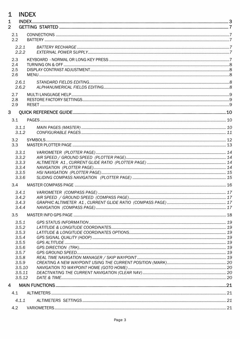
1 INDEX 1 INDEX............................................................................................................................................................... 3 2 GETTING STARTED ......................................................................................................................................... 7
2.1 CONNECTIONS ............................................................................................................................................................7 2.2 BATTERY ......................................................................................................................................................................7
2.2.1 BATTERY RECHARGE .........................................................................................................................................7 2.2.2 EXTERNAL POWER SUPPLY...............................................................................................................................7
2.3 KEYBOARD - NORMAL OR LONG KEY PRESS ............................................................................................................7 2.4 TURNING ON & OFF .....................................................................................................................................................8 2.5 DISPLAY CONTRAST ADJUSTMENT.............................................................................................................................8 2.6 MENU...........................................................................................................................................................................8
2.6.1 STANDARD FIELDS EDITING..............................................................................................................................8 2.6.2 ALPHANUMERICAL FIELDS EDITING.................................................................................................................8
2.7 MULTI LANGUAGE HELP..............................................................................................................................................9 2.8 RESTORE FACTORY SETTINGS....................................................................................................................................9 2.9 RESET ..........................................................................................................................................................................9
3 QUICK REFERENCE GUIDE............................................................................................................................10 3.1 PAGES....................................................................................................................................................................... 10
3.1.1 MAIN PAGES (MASTER) .................................................................................................................................. 10 3.1.2 CONFIGURABLE PAGES .................................................................................................................................. 11
3.2 SYMBOLS.................................................................................................................................................................. 12 3.3 MASTER PLOTTER PAGE .......................................................................................................................................... 13
3.3.1 VARIOMETER (PLOTTER PAGE) ..................................................................................................................... 14 3.3.2 AIR SPEED / GROUND SPEED (PLOTTER PAGE).......................................................................................... 14 3.3.3 ALTIMETER A1 , CURRENT GLIDE RATIO (PLOTTER PAGE) ....................................................................... 14 3.3.4 NAVIGATION (PLOTTER PAGE)....................................................................................................................... 14 3.3.5 HSI NAVIGATION (PLOTTER PAGE)................................................................................................................ 15 3.3.6 SLIDING COMPASS NAVIGATION (PLOTTER PAGE) .................................................................................... 15
3.4 MASTER COMPASS PAGE ........................................................................................................................................ 16 3.4.1 VARIOMETER (COMPASS PAGE) ................................................................................................................... 17 3.4.2 AIR SPEED / GROUND SPEED (COMPASS PAGE)....................................................................................... 17 3.4.3 GRAPHIC ALTIMETER A1 , CURRENT GLIDE RATIO (COMPASS PAGE) ..................................................... 17 3.4.4 NAVIGATION (COMPASS PAGE) ..................................................................................................................... 17
3.5 MASTER INFO GPS PAGE ......................................................................................................................................... 18 3.5.1 GPS STATUS INFORMATION ........................................................................................................................... 19 3.5.2 LATITUDE & LONGITUDE COORDINATES....................................................................................................... 19 3.5.3 LATITUDE & LONGITUDE COORDINATES OPTIONS....................................................................................... 19 3.5.4 GPS SIGNAL QUALITY (HDOP) ........................................................................................................................ 19 3.5.5 GPS ALTITUDE ................................................................................................................................................. 19 3.5.6 GPS DIRECTION (TRK).................................................................................................................................... 19 3.5.7 GPS GROUND SPEED...................................................................................................................................... 19 3.5.8 REAL TIME NAVIGATION MANAGER / SKIP WAYPOINT................................................................................ 19 3.5.9 CREATING A NEW WAYPOINT USING THE CURRENT POSITION (MARK)..................................................... 20 3.5.10 NAVIGATION TO WAYPOINT HOME (GOTO HOME) ........................................................................................ 20 3.5.11 DEACTIVATING THE CURRENT NAVIGATION (CLEAR NAV) ........................................................................... 20 3.5.12 DATE & TIME.................................................................................................................................................... 20
4 MAIN FUNCTIONS..........................................................................................................................................21 4.1 ALTIMETERS ............................................................................................................................................................. 21
4.1.1 ALTIMETERS SETTINGS ................................................................................................................................. 21 4.2 VARIOMETERS.......................................................................................................................................................... 21
Page 4
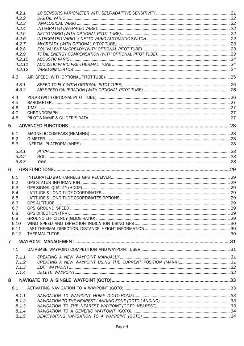
4.2.1 10 SENSORS VARIOMETER WITH SELF-ADAPTIVE SENSITIVITY ................................................................. 21 4.2.2 DIGITAL VARIO................................................................................................................................................. 22 4.2.3 ANALOGICAL VARIO ....................................................................................................................................... 22 4.2.4 INTEGRATED (AVERAGE) VARIO..................................................................................................................... 22 4.2.5 NETTO VARIO (WITH OPTIONAL PITOT TUBE) ................................................................................................ 22 4.2.6 INTEGRATED VARIO / NETTO VARIO AUTOMATIC SWITCH ......................................................................... 22 4.2.7 McCREADY (WITH OPTIONAL PITOT TUBE).................................................................................................... 23 4.2.8 EQUIVALENT McCREADY (WITH OPTIONAL PITOT TUBE) ............................................................................. 23 4.2.9 TOTAL ENERGY COMPENSATION (WITH OPTIONAL PITOT TUBE) ................................................................ 23 4.2.10 ACOUSTIC VARIO ............................................................................................................................................. 24 4.2.11 ACOUSTIC VARIO PRE-THERMAL TONE ........................................................................................................ 24 4.2.12 VARIO SIMULATOR.......................................................................................................................................... 24
4.3 AIR SPEED (WITH OPTIONAL PITOT TUBE) .............................................................................................................. 25 4.3.1 SPEED TO FLY (WITH OPTIONAL PITOT TUBE)............................................................................................... 25 4.3.2 AIR SPEED CALIBRATION (WITH OPTIONAL PITOT TUBE) ............................................................................ 26
4.4 POLAR (WITH OPTIONAL PITOT TUBE) ..................................................................................................................... 26 4.5 BAROMETER............................................................................................................................................................. 27 4.6 TIME .......................................................................................................................................................................... 27 4.7 CHRONOGRAPH ....................................................................................................................................................... 27 4.8 PILOT’S NAME & GLIDER’S DATA............................................................................................................................. 27
5 ADVANCED FUNCTIONS ................................................................................................................................28 5.1 MAGNETIC COMPASS (HEADING)............................................................................................................................ 28 5.2 G-METER................................................................................................................................................................... 28 5.3 INERTIAL PLATFORM (AHRS) ................................................................................................................................... 28
5.3.1 PITCH................................................................................................................................................................ 28 5.3.2 ROLL ................................................................................................................................................................ 28 5.3.3 YAW .................................................................................................................................................................. 28
6 GPS FUNCTIONS............................................................................................................................................29 6.1 INTEGRATED 99 CHANNELS GPS RECEIVER......................................................................................................... 29 6.2 GPS STATUS INFORMATION.................................................................................................................................... 29 6.3 GPS SIGNAL QUALITY (HDOP) .................................................................................................................................. 29 6.4 LATITUDE & LONGITUDE COORDINATES................................................................................................................. 29 6.5 LATITUDE & LONGITUDE COORDINATES OPTIONS ................................................................................................. 29 6.6 GPS ALTITUDE .......................................................................................................................................................... 29 6.7 GPS GROUND SPEED ............................................................................................................................................. 29 6.8 GPS DIRECTION (TRK).............................................................................................................................................. 29 6.9 GROUND EFFICIENCY (GLIDE RATIO) ...................................................................................................................... 29 6.10 WIND SPEED AND DIRECTION INDICATION USING GPS .................................................................................... 30 6.11 LAST THERMAL DIRECTION, DISTANCE, HEIGHT INFORMATION ........................................................................... 30 6.12 THERMAL TUTOR...................................................................................................................................................... 30
7 WAYPOINT MANAGEMENT ...........................................................................................................................31 7.1 DATABASE WAYPOINT COMPETITION AND WAYPOINT USER............................................................................... 31
7.1.1 CREATING A NEW WAYPOINT MANUALLY ................................................................................................. 31 7.1.2 CREATING A NEW WAYPOINT USING THE CURRENT POSITION (MARK)............................................. 31 7.1.3 EDIT WAYPOINT .............................................................................................................................................. 32 7.1.4 DELETE WAYPOINT......................................................................................................................................... 32
8 NAVIGATE TO A SINGLE WAYPOINT (GOTO)..............................................................................................33 8.1 ACTIVATING NAVIGATION TO A WAYPOINT (GOTO).............................................................................................. 33
8.1.1 NAVIGATION TO WAYPOINT HOME (GOTO HOME) .................................................................................... 33 8.1.2 NAVIGATION TO THE NEAREST LANDING ZONE (GOTO LANDING).............................................................. 33 8.1.3 NAVIGATION TO THE NEAREST WAYPOINT (GOTO NEAREST)................................................................. 33 8.1.4 NAVIGATION TO A GENERIC WAYPOINT (GOTO)....................................................................................... 34 8.1.5 DEACTIVATING NAVIGATION TO A WAYPOINT (GOTO) ............................................................................. 34
Page 5
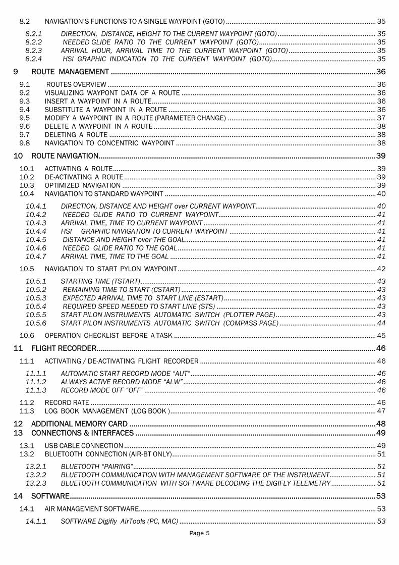
8.2 NAVIGATION’S FUNCTIONS TO A SINGLE WAYPOINT (GOTO) ................................................................................. 35 8.2.1 DIRECTION, DISTANCE, HEIGHT TO THE CURRENT WAYPOINT (GOTO) ..................................................... 35 8.2.2 NEEDED GLIDE RATIO TO THE CURRENT WAYPOINT (GOTO)............................................................... 35 8.2.3 ARRIVAL HOUR, ARRIVAL TIME TO THE CURRENT WAYPOINT (GOTO) ............................................... 35 8.2.4 HSI GRAPHIC INDICATION TO THE CURRENT WAYPOINT (GOTO)........................................................ 35
9 ROUTE MANAGEMENT .................................................................................................................................36 9.1 ROUTES OVERVIEW ................................................................................................................................................. 36 9.2 VISUALIZING WAYPONT DATA OF A ROUTE ......................................................................................................... 36 9.3 INSERT A WAYPOINT IN A ROUTE......................................................................................................................... 36 9.4 SUBSTITUTE A WAYPOINT IN A ROUTE ................................................................................................................ 36 9.5 MODIFY A WAYPOINT IN A ROUTE (PARAMETER CHANGE) ................................................................................ 37 9.6 DELETE A WAYPOINT IN A ROUTE ........................................................................................................................ 38 9.7 DELETING A ROUTE ................................................................................................................................................ 38 9.8 NAVIGATION TO CONCENTRIC WAYPOINT ............................................................................................................ 38
10 ROUTE NAVIGATION.......................................................................................................................................39 10.1 ACTIVATING A ROUTE.............................................................................................................................................. 39 10.2 DE-ACTIVATING A ROUTE........................................................................................................................................ 39 10.3 OPTIMIZED NAVIGATION ......................................................................................................................................... 39 10.4 NAVIGATION TO STANDARD WAYPOINT .................................................................................................................. 40
10.4.1 DIRECTION, DISTANCE AND HEIGHT over CURRENT WAYPOINT................................................................. 40 10.4.2 NEEDED GLIDE RATIO TO CURRENT WAYPOINT..................................................................................... 41 10.4.3 ARRIVAL TIME, TIME TO CURRENT WAYPOINT ............................................................................................. 41 10.4.4 HSI GRAPHIC NAVIGATION TO CURRENT WAYPOINT ............................................................................... 41 10.4.5 DISTANCE AND HEIGHT over THE GOAL....................................................................................................... 41 10.4.6 NEEDED GLIDE RATIO TO THE GOAL........................................................................................................... 41 10.4.7 ARRIVAL TIME, TIME TO THE GOAL ............................................................................................................... 41
10.5 NAVIGATION TO START PYLON WAYPOINT ........................................................................................................... 42 10.5.1 STARTING TIME (TSTART)............................................................................................................................... 43 10.5.2 REMAINING TIME TO START (CSTART) ......................................................................................................... 43 10.5.3 EXPECTED ARRIVAL TIME TO START LINE (ESTART) .................................................................................. 43 10.5.4 REQUIRED SPEED NEEDED TO START LINE (STS) ...................................................................................... 43 10.5.5 START PILON INSTRUMENTS AUTOMATIC SWITCH (PLOTTER PAGE)...................................................... 43 10.5.6 START PILON INSTRUMENTS AUTOMATIC SWITCH (COMPASS PAGE) .................................................... 44
10.6 OPERATION CHECKLIST BEFORE A TASK ............................................................................................................. 45 11 FLIGHT RECORDER........................................................................................................................................46
11.1 ACTIVATING / DE-ACTIVATING FLIGHT RECORDER ............................................................................................... 46 11.1.1 AUTOMATIC START RECORD MODE “AUT”.................................................................................................... 46 11.1.2 ALWAYS ACTIVE RECORD MODE “ALW”........................................................................................................ 46 11.1.3 RECORD MODE OFF “OFF” ............................................................................................................................. 46
11.2 RECORD RATE .......................................................................................................................................................... 46 11.3 LOG BOOK MANAGEMENT (LOG BOOK )............................................................................................................... 47
12 ADDITIONAL MEMORY CARD ........................................................................................................................48 13 CONNECTIONS & INTERFACES .....................................................................................................................49
13.1 USB CABLE CONNECTION ........................................................................................................................................ 49 13.2 BLUETOOTH CONNECTION (AIR-BT ONLY).............................................................................................................. 51
13.2.1 BLUETOOTH “PAIRING”................................................................................................................................... 51 13.2.2 BLUETOOTH COMMUNICATION WITH MANAGEMENT SOFTWARE OF THE INSTRUMENT......................... 51 13.2.3 BLUETOOTH COMMUNICATION WITH SOFTWARE DECODING THE DIGIFLY TELEMETRY ........................ 51
14 SOFTWARE.....................................................................................................................................................53 14.1 AIR MANAGEMENT SOFTWARE................................................................................................................................ 53
14.1.1 SOFTWARE Digifly AirTools (PC, MAC) .......................................................................................................... 53
Page 6
14.1.2 SOFTWARE Digifly AirPagesConfigurator (PC, MAC) .................................................................................... 54 14.1.3 SOFTWARE GpsDump (PC, MAC, ANDROID) ................................................................................................ 57
14.2 SOFTWARE DIGIFLY AIRUPDATER FOR FIRMWARE UPDATE (PC, MAC) .................................................................... 58 14.2.1 FIRMWARE UPDATE PROCEDURE ................................................................................................................. 58
15 DIGIFLY TELEMETRY HIGH SPEED REAL TIME DATA OUTPUT (AIR-BT ONLY) .............................................59 15.1.1 ACTIVATE DIGIFLY TELEMETRY DATA OUTPUT ............................................................................................. 59 15.1.2 TELEMETRY DATA SELECTION ..................................................................................................................... 59
15.2 DIGIFLY TELEMETRY DATA CONNECTION WITH XCSOAR (AIR-BT ONLY).............................................................. 61 15.3 DIGIFLY TELEMETRY DATA CONNECTION WITH LK8000 (AIR-BT ONLY) ............................................................. 63
16 APPENDIX ......................................................................................................................................................64 16.1 DIGIFLY AIR STANDARD ACCESSORIES ................................................................................................................ 64 16.2 OPTIONAL ACCESSORIES ........................................................................................................................................ 64 16.3 TECHNICAL FEATURES ............................................................................................................................................ 64
16.3.1 STANDARD FUNCTIONS.................................................................................................................................. 64 16.3.2 ADVANCED FUNCTIONS.................................................................................................................................. 64 16.3.3 GPS FUNCTIONS.............................................................................................................................................. 65 16.3.4 GENERAL SPECIFICATIONS ............................................................................................................................ 65
16.4 MAIN SET UP MENU PARAMETERS ......................................................................................................................... 66 16.5 ADV-SETUP PARAMETERS MENU (ADVANCED SETUP) ......................................................................................... 66 16.6 VARIOMETER SETUP PARAMETERS....................................................................................................................... 67 16.7 RESTORE FACTORY SETTINGS (DEFAULT PARAMETERS) ...................................................................................... 67 16.8 RESET ....................................................................................................................................................................... 67
Page 7
2 GETTING STARTED
2.1 CONNECTIONS
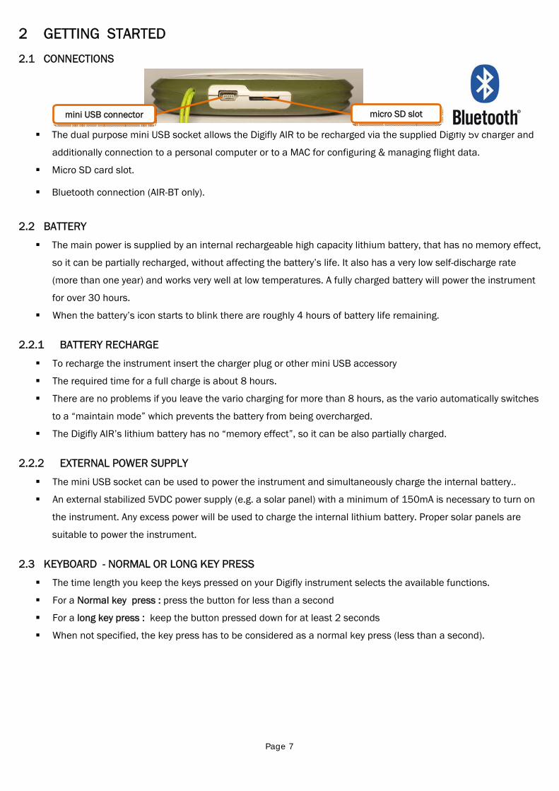
The dual purpose mini USB socket allows the Digifly AIR to be recharged via the supplied Digifly 5v charger and
additionally connection to a personal computer or to a MAC for configuring & managing flight data.
Micro SD card slot.
Bluetooth connection (AIR-BT only).
2.2 BATTERY
The main power is supplied by an internal rechargeable high capacity lithium battery, that has no memory effect,
so it can be partially recharged, without affecting the battery’s life. It also has a very low self-discharge rate
(more than one year) and works very well at low temperatures. A fully charged battery will power the instrument
for over 30 hours.
When the battery’s icon starts to blink there are roughly 4 hours of battery life remaining.
2.2.1 BATTERY RECHARGE
To recharge the instrument insert the charger plug or other mini USB accessory
The required time for a full charge is about 8 hours.
There are no problems if you leave the vario charging for more than 8 hours, as the vario automatically switches
to a “maintain mode” which prevents the battery from being overcharged.
The Digifly AIR’s lithium battery has no “memory effect”, so it can be also partially charged.
2.2.2 EXTERNAL POWER SUPPLY
The mini USB socket can be used to power the instrument and simultaneously charge the internal battery..
An external stabilized 5VDC power supply (e.g. a solar panel) with a minimum of 150mA is necessary to turn on
the instrument. Any excess power will be used to charge the internal lithium battery. Proper solar panels are
suitable to power the instrument.
2.3 KEYBOARD - NORMAL OR LONG KEY PRESS
The time length you keep the keys pressed on your Digifly instrument selects the available functions.
For a Normal key press : press the button for less than a second
For a long key press : keep the button pressed down for at least 2 seconds
When not specified, the key press has to be considered as a normal key press (less than a second).
mini USB connector micro SD slot
Page 8
2.4 TURNING ON & OFF
To turn on your Digifly instrument, press the key at least for 4 seconds.
To turn off your Digifly instrument, press the key at least for 4 seconds.
After switching off your Digifly instrument, you must wait at least 5 seconds before attempting to turn it on
again. This prevents unwanted operation.
After turning on your Digifly instrument, the first screen briefly shows the vario model, pilot name (if set), logger
status, vario serial number, software version, date, time and battery voltage.
2.5 DISPLAY CONTRAST ADJUSTMENT
To change the contrast of the display, press the key to enter in the “MAIN SETUP” menu, select the menu
(MAIN SETUP \ n. 1 CTRS), go to the edit mode pressing the key, set the preferred contrast using the keys:
‘arrow UP’ or ‘arrow DOWN’ , then save the changes pressing the key .
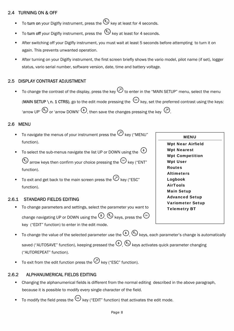
2.6 MENU
To navigate the menus of your instrument press the key (“MENU”
function).
To select the sub-menus navigate the list UP or DOWN using the
arrow keys then confirm your choice pressing the key (“ENT”
function).
To exit and get back to the main screen press the key (“ESC”
function).
2.6.1 STANDARD FIELDS EDITING
To change parameters and settings, select the parameter you want to
change navigating UP or DOWN using the , keys, press the
key (“EDIT” function) to enter in the edit mode.
To change the value of the selected parameter use the , keys, each parameter’s change is automatically
saved (“AUTOSAVE” function), keeping pressed the , keys activates quick parameter changing
(“AUTOREPEAT” function).
To exit from the edit function press the key (“ESC” function).
2.6.2 ALPHANUMERICAL FIELDS EDITING
Changing the alphanumerical fields is different from the normal editing described in the above paragraph,
because it is possible to modify every single character of the field.
To modify the field press the key (“EDIT” function) that activates the edit mode.
MENU
Wpt Near Airfield Wpt Nearest Wpt Competition Wpt User Routes Altimeters Logbook AirTools Main Setup Advanced Setup Variometer Setup Telemetry BT
Page 9
Use the arrow keys , to change the character shown in reverse mode on the display, each parameter’s
change is automatically saved (“AUTOSAVE” function), a longer pressure/touch of the arrow keys activates
quick parameter changing (“AUTOREPEAT” function),
Pressing the key, it is possible to shift to the character on the right and edit it; pressing repeatedly the
key it is possible to scroll toward right all the field’s characters until you get back to the first. A longer
pressure/touch of the key shifts back to the left. To exit press the key.
2.7 MULTI LANGUAGE HELP
In the vario setup menus help messages are available, to guide you through the parameters. It is possible to set
the preferred language for these messages via the MAIN SETUP menu (MAIN SETUP \ n. 2 LANG) then select the
language you prefer and confirm.
IMPORTANT: after every firmware update, it is necessary to update also the help file containing the help
messages. The help file update can be performed from your PC MAC using the Digifly AirTools, function: “upload
HELP”.
2.8 RESTORE FACTORY SETTINGS
To restore the factory settings (default values for all parameters), turn on the instrument pressing at the same
time and holding down the keys & until the message “FACTORY SET?” appears. To confirm press the
key or press the key to cancel/abort.
2.9 RESET
If a system crash occurs (resulting in the instrument freezing), it is possible to reset its functions by pressing at
the same time the keys and holding them down for more than 5 seconds.
Page 10
3 QUICK REFERENCE GUIDE
3.1 PAGES
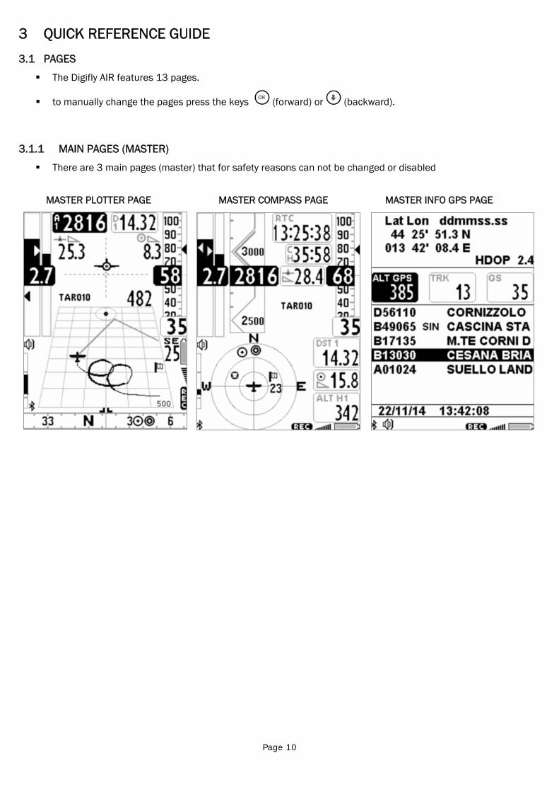
The Digifly AIR features 13 pages.
to manually change the pages press the keys (forward) or (backward).
3.1.1 MAIN PAGES (MASTER)
There are 3 main pages (master) that for safety reasons can not be changed or disabled
MASTER PLOTTER PAGE MASTER COMPASS PAGE MASTER INFO GPS PAGE
Page 11
3.1.2 CONFIGURABLE PAGES
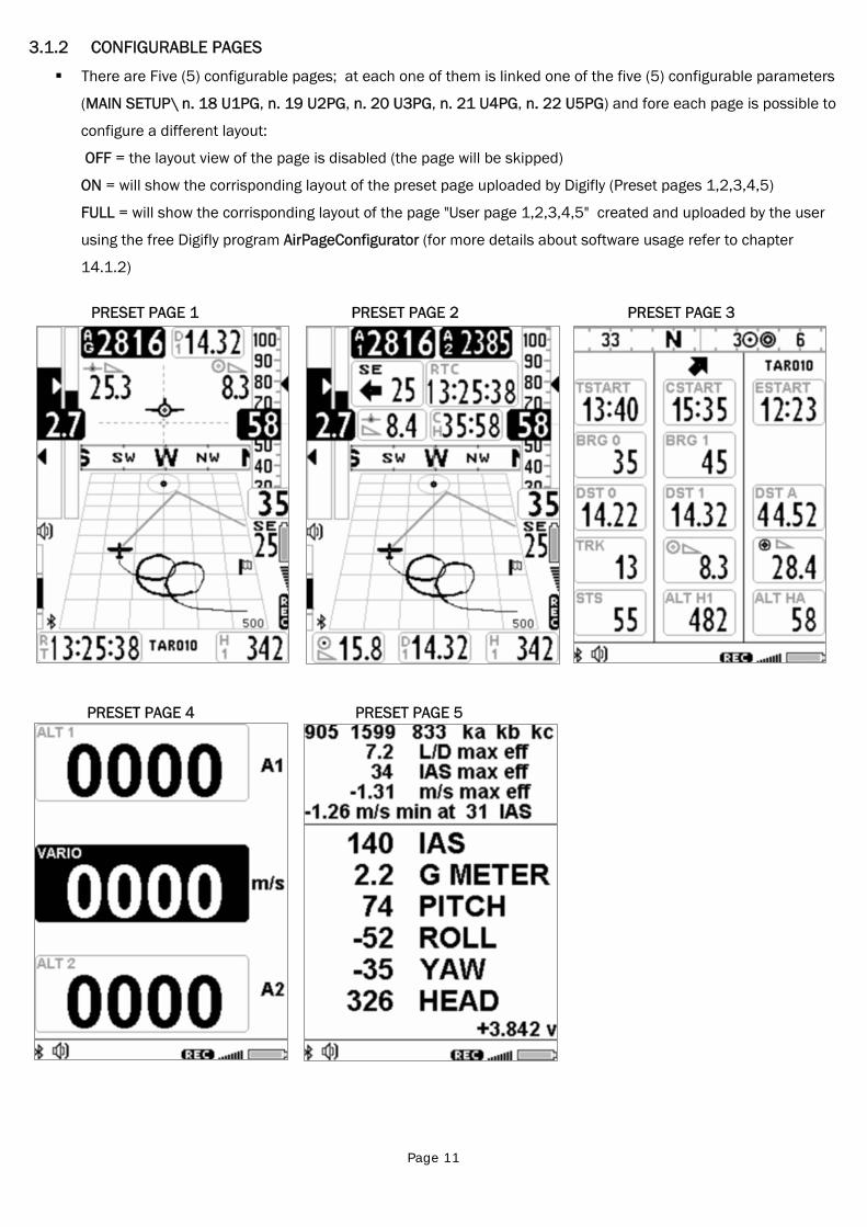
There are Five (5) configurable pages; at each one of them is linked one of the five (5) configurable parameters
(MAIN SETUP\ n. 18 U1PG, n. 19 U2PG, n. 20 U3PG, n. 21 U4PG, n. 22 U5PG) and fore each page is possible to
configure a different layout:
OFF = the layout view of the page is disabled (the page will be skipped)
ON = will show the corrisponding layout of the preset page uploaded by Digifly (Preset pages 1,2,3,4,5)
FULL = will show the corrisponding layout of the page "User page 1,2,3,4,5" created and uploaded by the user
using the free Digifly program AirPageConfigurator (for more details about software usage refer to chapter
14.1.2)
PRESET PAGE 1 PRESET PAGE 2 PRESET PAGE 3
PRESET PAGE 4 PRESET PAGE 5
Page 12
3.2 SYMBOLS
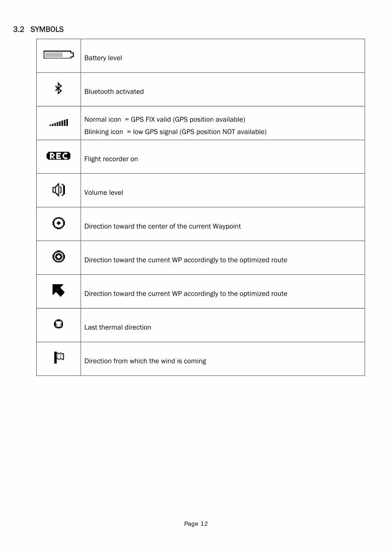
Battery level
Bluetooth activated
Normal icon = GPS FIX valid (GPS position available)
Blinking icon = low GPS signal (GPS position NOT available)
Flight recorder on
Volume level
Direction toward the center of the current Waypoint
Direction toward the current WP accordingly to the optimized route
Direction toward the current WP accordingly to the optimized route
Last thermal direction
Direction from which the wind is coming
Page 13
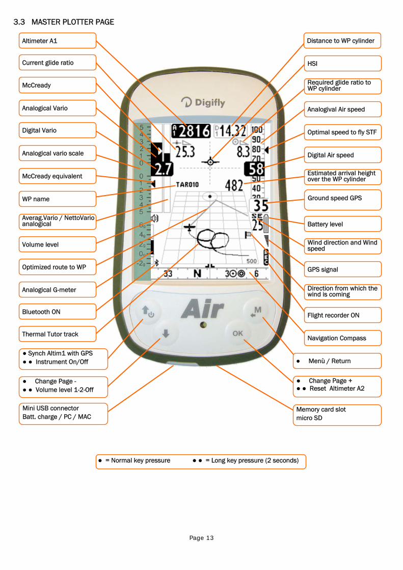
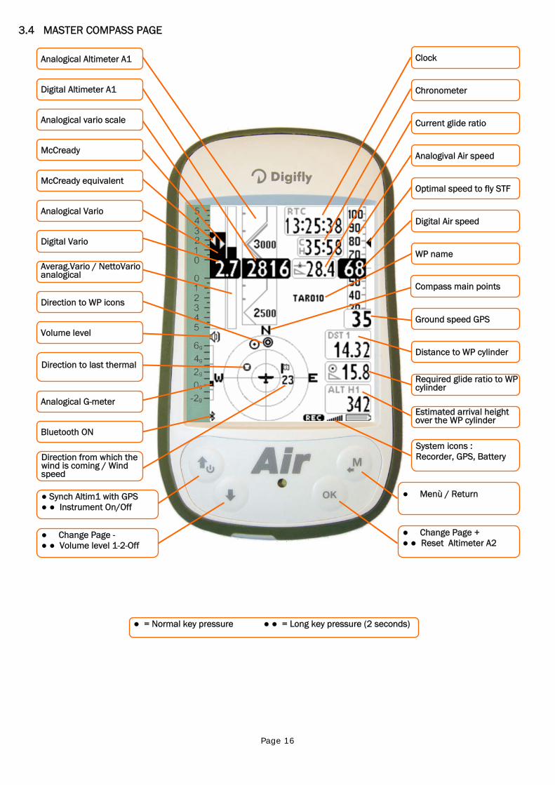
3.3 MASTER PLOTTER PAGE
Memory card slot micro SD
Flight recorder ON
Estimated arrival height over the WP cylinder
Digital Air speed
Ground speed GPS
HSI
Optimal speed to fly STF
Required glide ratio to WP cylinder
Battery level
Wind direction and Wind speed
Direction from which the wind is coming
● Menù / Return
● Change Page + ● ● Reset Altimeter A2
Distance to WP cylinder
Analogival Air speed
Navigation Compass
GPS signal
● = Normal key pressure ● ● = Long key pressure (2 seconds)
Mini USB connector Batt. charge / PC / MAC
Digital Vario
McCready equivalent
Altimeter A1
Averag.Vario / NettoVario analogical
Current glide ratio
Analogical Vario
Optimized route to WP
McCready
WP name
Volume level
● Synch Altim1 with GPS ● ● Instrument On/Off
● Change Page - ● ● Volume level 1-2-Off
Thermal Tutor track
Bluetooth ON
Analogical vario scale
Analogical G-meter
Page 14
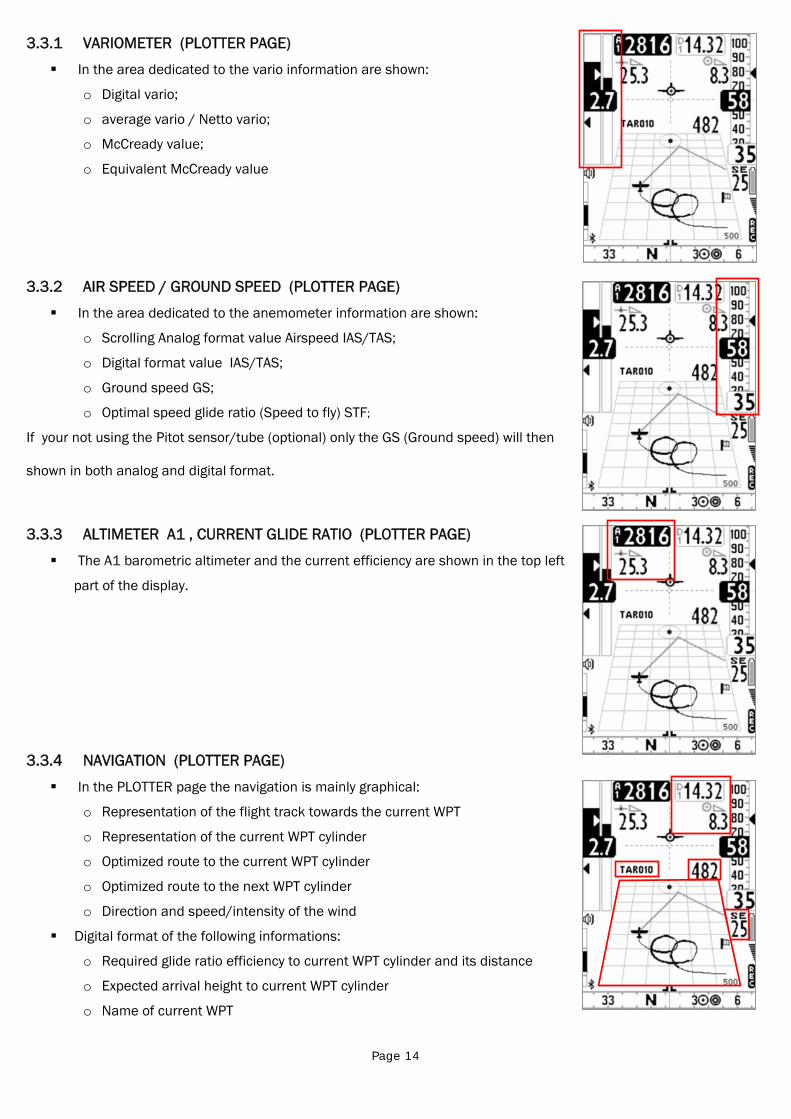
3.3.1 VARIOMETER (PLOTTER PAGE)
In the area dedicated to the vario information are shown:
o Digital vario;
o average vario / Netto vario;
o McCready value;
o Equivalent McCready value
3.3.2 AIR SPEED / GROUND SPEED (PLOTTER PAGE)
In the area dedicated to the anemometer information are shown:
o Scrolling Analog format value Airspeed IAS/TAS;
o Digital format value IAS/TAS;
o Ground speed GS;
o Optimal speed glide ratio (Speed to fly) STF;
If your not using the Pitot sensor/tube (optional) only the GS (Ground speed) will then
shown in both analog and digital format.
3.3.3 ALTIMETER A1 , CURRENT GLIDE RATIO (PLOTTER PAGE)
The A1 barometric altimeter and the current efficiency are shown in the top left
part of the display.
3.3.4 NAVIGATION (PLOTTER PAGE)
In the PLOTTER page the navigation is mainly graphical:
o Representation of the flight track towards the current WPT
o Representation of the current WPT cylinder
o Optimized route to the current WPT cylinder
o Optimized route to the next WPT cylinder
o Direction and speed/intensity of the wind
Digital format of the following informations:
o Required glide ratio efficiency to current WPT cylinder and its distance
o Expected arrival height to current WPT cylinder
o Name of current WPT
Page 15
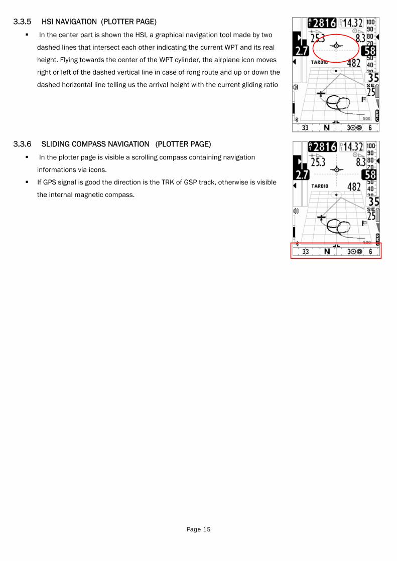
3.3.5 HSI NAVIGATION (PLOTTER PAGE)
In the center part is shown the HSI, a graphical navigation tool made by two
dashed lines that intersect each other indicating the current WPT and its real
height. Flying towards the center of the WPT cylinder, the airplane icon moves
right or left of the dashed vertical line in case of rong route and up or down the
dashed horizontal line telling us the arrival height with the current gliding ratio
3.3.6 SLIDING COMPASS NAVIGATION (PLOTTER PAGE)
In the plotter page is visible a scrolling compass containing navigation
informations via icons.
If GPS signal is good the direction is the TRK of GSP track, otherwise is visible
the internal magnetic compass.
Page 16
3.4 MASTER COMPASS PAGE
● = Normal key pressure ● ● = Long key pressure (2 seconds)
System icons : Recorder, GPS, Battery
Ground speed GPS
Chronometer
Optimal speed to fly STF
Distance to WP cylinder
Required glide ratio to WP cylinder
Estimated arrival height over the WP cylinder
Analogival Air speed
Clock
Digital Air speed
WP name
Current glide ratio
● Menù / Return
● Change Page + ● ● Reset Altimeter A2
Compass main points
McCready equivalent
Digital Vario
Analogical Altimeter A1
Digital Altimeter A1
McCready
Volume level
Analogical vario scale
Averag.Vario / NettoVario analogical
Direction to WP icons
● Synch Altim1 with GPS ● ● Instrument On/Off
● Change Page - ● ● Volume level 1-2-Off
Direction to last thermal
Bluetooth ON
Direction from which the wind is coming / Wind speed
Analogical G-meter
Analogical Vario
Page 17
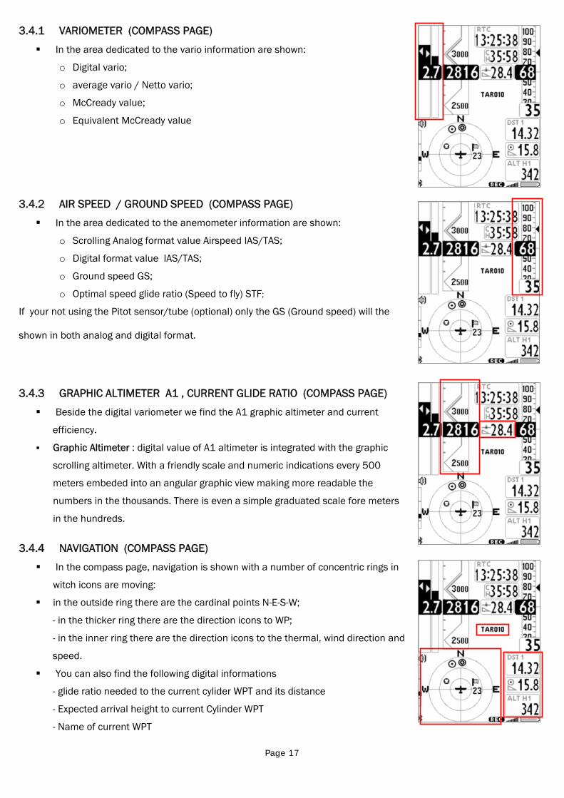
3.4.1 VARIOMETER (COMPASS PAGE)
In the area dedicated to the vario information are shown:
o Digital vario;
o average vario / Netto vario;
o McCready value;
o Equivalent McCready value
3.4.2 AIR SPEED / GROUND SPEED (COMPASS PAGE)
In the area dedicated to the anemometer information are shown:
o Scrolling Analog format value Airspeed IAS/TAS;
o Digital format value IAS/TAS;
o Ground speed GS;
o Optimal speed glide ratio (Speed to fly) STF;
If your not using the Pitot sensor/tube (optional) only the GS (Ground speed) will the
shown in both analog and digital format.
3.4.3 GRAPHIC ALTIMETER A1 , CURRENT GLIDE RATIO (COMPASS PAGE)
Beside the digital variometer we find the A1 graphic altimeter and current
efficiency.
Graphic Altimeter : digital value of A1 altimeter is integrated with the graphic
scrolling altimeter. With a friendly scale and numeric indications every 500
meters embeded into an angular graphic view making more readable the
numbers in the thousands. There is even a simple graduated scale fore meters
in the hundreds.
3.4.4 NAVIGATION (COMPASS PAGE)
In the compass page, navigation is shown with a number of concentric rings in
witch icons are moving:
in the outside ring there are the cardinal points N-E-S-W;
- in the thicker ring there are the direction icons to WP;
- in the inner ring there are the direction icons to the thermal, wind direction and
speed.
You can also find the following digital informations
- glide ratio needed to the current cylider WPT and its distance
- Expected arrival height to current Cylinder WPT
- Name of current WPT
Page 18
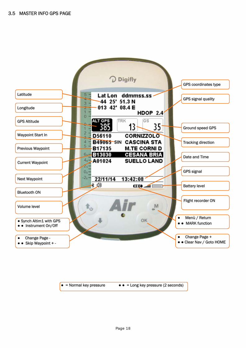
3.5 MASTER INFO GPS PAGE
● = Normal key pressure ● ● = Long key pressure (2 seconds)
Longitude
Previous Waypoint
GPS Altitude
Waypoint Start In
● Synch Altim1 with GPS ● ● Instrument On/Off
● Change Page - ● ● Skip Waypoint + -
Current Waypoint
Bluetooth ON
Volume level
Next Waypoint
Latitude
Flight recorder ON
Tracking direction
GPS coordinates type
Date and Time
GPS signal quality
Ground speed GPS
● Menù / Return ● ● MARK function
● Change Page + ● ● Clear Nav / Goto HOME
Battery level
GPS signal
Page 19
In the MASTER INFO GPS page, are visible all values relative to your GPS position and particular fuctions available only
on this layout: function “take me here” (GOTO HOME), function “save current position” (MARK), function “cancel current
navigation” (CLEAR NAV) and supervision real time function "Real Time Navigation Manager" of progress active route
with the chance to go back and forth through WPT (function "Skip Waypoint").
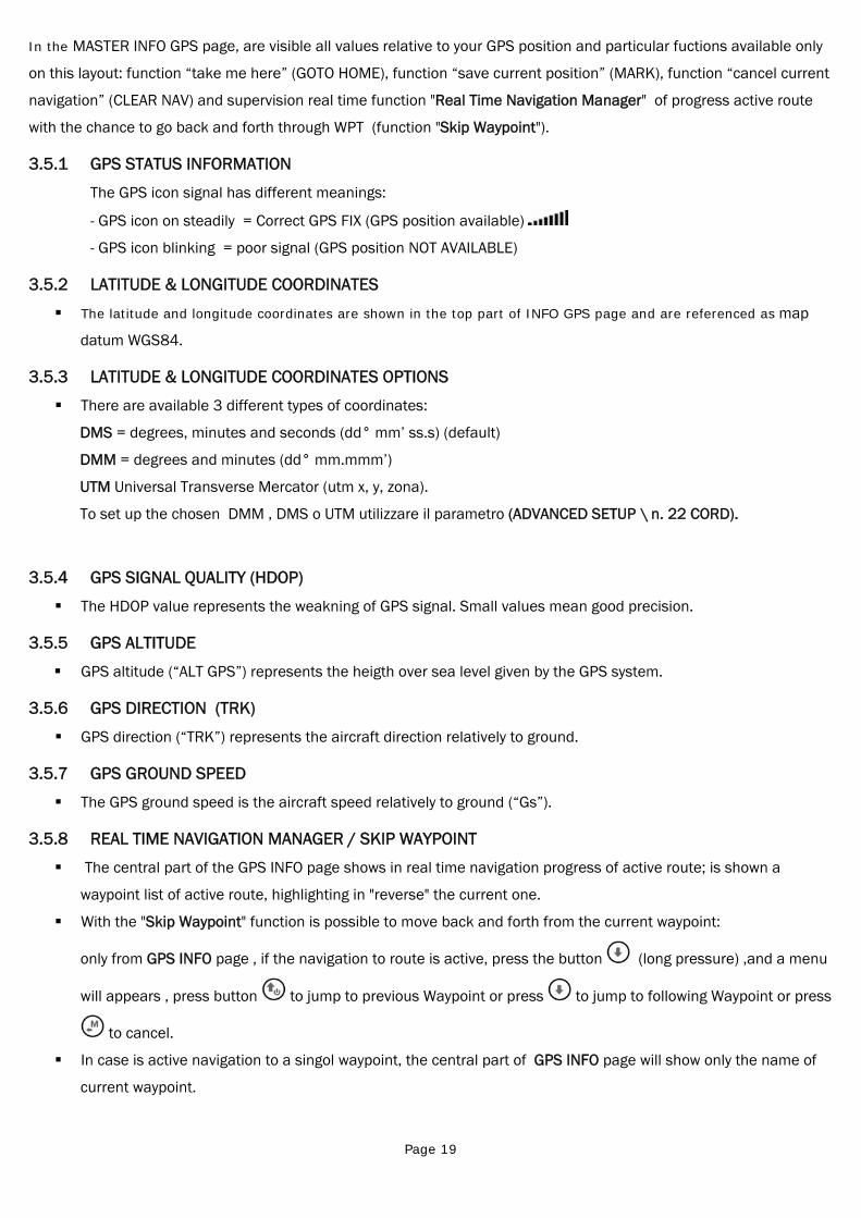
3.5.1 GPS STATUS INFORMATION
The GPS icon signal has different meanings:
- GPS icon on steadily = Correct GPS FIX (GPS position available)
- GPS icon blinking = poor signal (GPS position NOT AVAILABLE)
3.5.2 LATITUDE & LONGITUDE COORDINATES
The latitude and longitude coordinates are shown in the top part of INFO GPS page and are referenced as map
datum WGS84.
3.5.3 LATITUDE & LONGITUDE COORDINATES OPTIONS
There are available 3 different types of coordinates:
DMS = degrees, minutes and seconds (dd° mm’ ss.s) (default)
DMM = degrees and minutes (dd° mm.mmm’)
UTM Universal Transverse Mercator (utm x, y, zona).
To set up the chosen DMM , DMS o UTM utilizzare il parametro (ADVANCED SETUP \ n. 22 CORD).
3.5.4 GPS SIGNAL QUALITY (HDOP)
The HDOP value represents the weakning of GPS signal. Small values mean good precision.
3.5.5 GPS ALTITUDE
GPS altitude (“ALT GPS”) represents the heigth over sea level given by the GPS system.
3.5.6 GPS DIRECTION (TRK)
GPS direction (“TRK”) represents the aircraft direction relatively to ground.
3.5.7 GPS GROUND SPEED
The GPS ground speed is the aircraft speed relatively to ground (“Gs”).
3.5.8 REAL TIME NAVIGATION MANAGER / SKIP WAYPOINT
The central part of the GPS INFO page shows in real time navigation progress of active route; is shown a
waypoint list of active route, highlighting in "reverse" the current one.
With the "Skip Waypoint" function is possible to move back and forth from the current waypoint:
only from GPS INFO page , if the navigation to route is active, press the button (long pressure) ,and a menu
will appears , press button to jump to previous Waypoint or press to jump to following Waypoint or press
to cancel.
In case is active navigation to a singol waypoint, the central part of GPS INFO page will show only the name of
current waypoint.
Page 20
3.5.9 CREATING A NEW WAYPOINT USING THE CURRENT POSITION (MARK)
"MARK" function : when the GPS acquires a valid position it is possible to save it in the instrument’s memory.
From the GPS INFO page press the key (long press) , the message " Save Mark ?" is shown, press the
key to confirm or press the key to annul. The current position will be saved as a new Waypoint in the User
Waypoint list (“WPT USER”) with the format nnMaaa (aaa= altitude GPS in tens of meters)
3.5.10 NAVIGATION TO WAYPOINT HOME (GOTO HOME)
Available only in the GPS INFO page, ensures that the instrument guides us back to the point where we
activeted this function.
It’s particular useful, for example, when we go flying in a new site of which we don’t have waypoints and we want
to get guided to the landing zone . In this case is necessary to go to the landing zone and activate this function.
How activate the "GOTO HOME" function : from the GPS INFO page, wait till the GPS position is valid, then press
the key (long press) , the message " Activate Home Wpt ?" is shown, press the key to confirm or press
the key to annul.
Note : if a navigation has already been previously activated, first of all is necessary to deactivate it : from the
GPS INFO page press the key (long press) , the message " Clear Nav ?" is shown, press the key to
confirm or press the key to annul.
The "GOTO HOME" function creates a landing waypoint in the User Waypoint list (“WPT USER”) with the current
position data “HOMaaa” (aaa = GPS altitude in tens of meters) and with the icon "A" (airfield) and at the same
time activates the navigation (GOTO) to it.
3.5.11 DEACTIVATING THE CURRENT NAVIGATION (CLEAR NAV)
Function "Clear Nav" : to disable current navigation, press button (long pressure) , " Clear Nav ?" will
appear, confirm with button or press to cancel.
3.5.12 DATE & TIME
Date and current time get automatically updated with GPS data when you start the instrument.
To set your country time zone (MAIN SETUP \ n. 7 UTCO).
To manually change date and time (MAIN SETUP \ n. 8 HOUR), (MAIN SETUP \ n. 9 MIN), (MAIN SETUP \ n. 10
DAY), (MAIN SETUP \ n. 11 MONT), (MAIN SETUP \ n. 12 YEAR)
Page 21
4 MAIN FUNCTIONS 4.1 ALTIMETERS
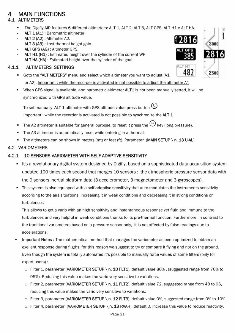
The Digifly AIR features 6 different altimeters: ALT 1, ALT 2, ALT 3, ALT GPS, ALT H1 e ALT HA. - ALT 1 (A1) : Barometric altimeter. - ALT 2 (A2) : Altimeter A2. - ALT 3 (A3) : Last thermal height gain - ALT GPS (AG) : Altimeter GPS. - ALT H1 (H1) : Estimated height over the cylinder of the current WP - ALT HA (HA) : Estimated height over the cylinder of the goal.
4.1.1 ALTIMETERS SETTINGS
Goto the “ALTIMETERS” menu and select which altimeter you want to adjust (A1
or A2). Important : while the recorder is activated is not possible to adjust the altimeter A1
When GPS signal is available, and barometric altimeter ALT1 is not been manually setted, it will be
synchronized with GPS altitude value.
To set manually ALT 1 altimeter with GPS altitude value press button
Important : while the recorder is activated is not possible to synchronize the ALT 1
The A2 altimeter is suitable for general purpose, to reset it press the key (long pressure).
The A3 altimeter is automatically reset while entering in a thermal.
The altimeters can be shown in meters (mt) or feet (ft). Parameter (MAIN SETUP \ n. 13 U-AL).
4.2 VARIOMETERS
4.2.1 10 SENSORS VARIOMETER WITH SELF-ADAPTIVE SENSITIVITY
It's a revolutionary digital system designed by Digifly, based on a sophisticated data acquisition system
updated 100 times each second that merges 10 sensors : the atmospheric pressure sensor data with
the 9 sensors inertial platform data (3 accelerometer, 3 magnetometer and 3 gyroscopes).
This system is also equipped with a self-adaptive sensitivity that auto-modulates the instruments sensitivity
according to the airs situations: increasing it in weak conditions and decreasing it in strong conditions or
turbulences
This allows to get a vario with an high sensitivity and instantaneous response yet fluid and immune to the
turbulences and very helpful in weak conditions thanks to its pre-thermal function. Furthermore, in contrast to
the traditional variometers based on a pressure sensor only, it is not affected by false readings due to
accelerations.
Important Notes : The mathematical method that manages the variometer as been optimized to obtain an
exellent response during fligths; for this reason we suggest to try or compare it flying and not on the ground.
Even though the system is totally automated it’s possible to manually force values of some filters (only for
expert users) :
o Filter 1, parameter (VARIOMETER SETUP \ n. 10 FLT1), default value 80% , (suggested range from 70% to
95%). Reducing this value makes the vario very sensitive to variations.
o Filter 2, parameter (VARIOMETER SETUP \ n. 11 FLT2), default value 72, suggested range from 48 to 96,
reducing this value makes the vario very sensitive to variations.
o Filter 3, parameter (VARIOMETER SETUP \ n. 12 FLT3), default value 0%, suggested range from 0% to 10%
o Filter 4, parameter (VARIOMETER SETUP \ n. 13 RVAR), default 0. Increase this value to reduce reactivity.
Page 22
4.2.2 DIGITAL VARIO Shows instant climbing or descending values in a range of +/- 25 m/s in digital format.
4.2.3 ANALOGICAL VARIO Indicates the instant vario values. It is displayed by the analogical bar indicator on the left of the
screen, it shows the sink or climb rate within a +/- 5 m/s range.
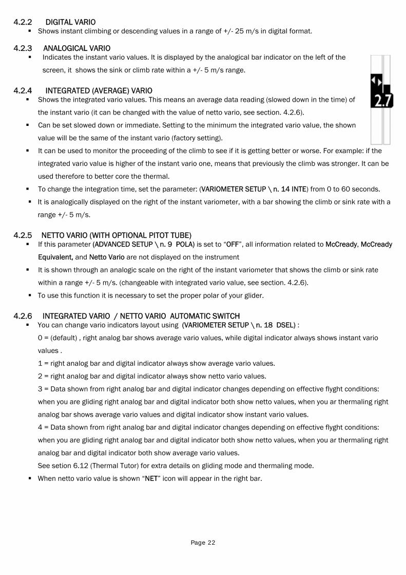
4.2.4 INTEGRATED (AVERAGE) VARIO Shows the integrated vario values. This means an average data reading (slowed down in the time) of
the instant vario (it can be changed with the value of netto vario, see section. 4.2.6).
Can be set slowed down or immediate. Setting to the minimum the integrated vario value, the shown
value will be the same of the instant vario (factory setting).
It can be used to monitor the proceeding of the climb to see if it is getting better or worse. For example: if the
integrated vario value is higher of the instant vario one, means that previously the climb was stronger. It can be
used therefore to better core the thermal.
To change the integration time, set the parameter: (VARIOMETER SETUP \ n. 14 INTE) from 0 to 60 seconds.
It is analogically displayed on the right of the instant variometer, with a bar showing the climb or sink rate with a
range +/- 5 m/s.
4.2.5 NETTO VARIO (WITH OPTIONAL PITOT TUBE) If this parameter (ADVANCED SETUP \ n. 9 POLA) is set to “OFF”, all information related to McCready, McCready
Equivalent, and Netto Vario are not displayed on the instrument
It is shown through an analogic scale on the right of the instant variometer that shows the climb or sink rate
within a range +/- 5 m/s. (changeable with integrated vario value, see section. 4.2.6).
To use this function it is necessary to set the proper polar of your glider.
4.2.6 INTEGRATED VARIO / NETTO VARIO AUTOMATIC SWITCH You can change vario indicators layout using (VARIOMETER SETUP \ n. 18 DSEL) :
0 = (default) , right analog bar shows average vario values, while digital indicator always shows instant vario
values .
1 = right analog bar and digital indicator always show average vario values.
2 = right analog bar and digital indicator always show netto vario values.
3 = Data shown from right analog bar and digital indicator changes depending on effective flyght conditions:
when you are gliding right analog bar and digital indicator both show netto values, when you ar thermaling right
analog bar shows average vario values and digital indicator show instant vario values.
4 = Data shown from right analog bar and digital indicator changes depending on effective flyght conditions:
when you are gliding right analog bar and digital indicator both show netto values, when you ar thermaling right
analog bar and digital indicator both show average vario values.
See setion 6.12 (Thermal Tutor) for extra details on gliding mode and thermaling mode.
When netto vario value is shown “NET” icon will appear in the right bar.
Page 23
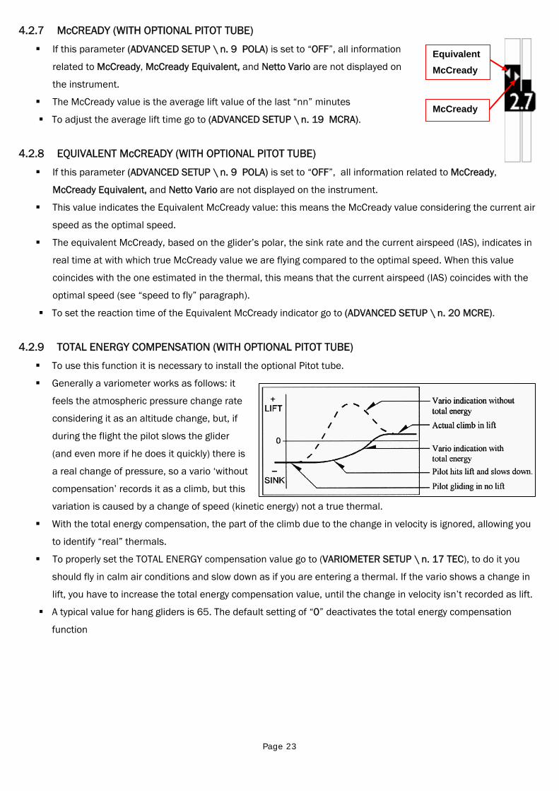
4.2.7 McCREADY (WITH OPTIONAL PITOT TUBE)
If this parameter (ADVANCED SETUP \ n. 9 POLA) is set to “OFF”, all information
related to McCready, McCready Equivalent, and Netto Vario are not displayed on
the instrument.
The McCready value is the average lift value of the last “nn” minutes
To adjust the average lift time go to (ADVANCED SETUP \ n. 19 MCRA).
4.2.8 EQUIVALENT McCREADY (WITH OPTIONAL PITOT TUBE)
If this parameter (ADVANCED SETUP \ n. 9 POLA) is set to “OFF”, all information related to McCready,
McCready Equivalent, and Netto Vario are not displayed on the instrument.
This value indicates the Equivalent McCready value: this means the McCready value considering the current air
speed as the optimal speed.
The equivalent McCready, based on the glider’s polar, the sink rate and the current airspeed (IAS), indicates in
real time at with which true McCready value we are flying compared to the optimal speed. When this value
coincides with the one estimated in the thermal, this means that the current airspeed (IAS) coincides with the
optimal speed (see “speed to fly” paragraph).
To set the reaction time of the Equivalent McCready indicator go to (ADVANCED SETUP \ n. 20 MCRE).
4.2.9 TOTAL ENERGY COMPENSATION (WITH OPTIONAL PITOT TUBE)
To use this function it is necessary to install the optional Pitot tube.
Generally a variometer works as follows: it
feels the atmospheric pressure change rate
considering it as an altitude change, but, if
during the flight the pilot slows the glider
(and even more if he does it quickly) there is
a real change of pressure, so a vario ‘without
compensation’ records it as a climb, but this
variation is caused by a change of speed (kinetic energy) not a true thermal.
With the total energy compensation, the part of the climb due to the change in velocity is ignored, allowing you
to identify “real” thermals.
To properly set the TOTAL ENERGY compensation value go to (VARIOMETER SETUP \ n. 17 TEC), to do it you
should fly in calm air conditions and slow down as if you are entering a thermal. If the vario shows a change in
lift, you have to increase the total energy compensation value, until the change in velocity isn’t recorded as lift.
A typical value for hang gliders is 65. The default setting of “0” deactivates the total energy compensation
function
McCready
Equivalent McCready
Page 24
4.2.10 ACOUSTIC VARIO
The acoustic vario represents the instantaneous values of the vario with a modulated acoustic tone.
Pressing the key (long pressure) the sound’s volume changes into three levels: “HIGH”, “OFF” & “LOW”.
The chosen volume is shown by the ‘loudspeaker’ icon on the center left of the display.
To set the sound’s threshold level to indicate lift, go to parameter (VARIOMETER SETUP \ n. 1 V.UP), for the sink,
go to (VARIOMETER SETUP \ n. 3 V.DN).
It is possible to set the preferred acoustic profile with the parameter (VARIOMETER SETUP \ n. 4 PROF). Three
pre-set profile are available: FAS, STD, SFT, Two fully customizable profile: USR1, USR2 are available via
PC/MAC using the AirTools software; moreover, there is a manual ‘MAN’ mode, that allows to directly customize
the instrument using the following parameters.
Style, (VARIOMETER SETUP \ n. 5 STYL) relation among sound/pause, values from 1 to 3.
Modulation, (VARIOMETER SETUP \ n. 6 MODH) increases the tone frequency from 1 to 30 Hz.
Pitch, increases ascending the tones rhythm (VARIOMETER SETUP \ n. 7 PITC) values from 1 to 4.
Climb start tone’s frequency (VARIOMETER SETUP \ n. 8 UPHZ)
Sink start tone’s frequency (VARIOMETER SETUP \ n. 9 DWHZ)
Autosilence, (VARIOMETER SETUP \ n. 20 AUTV=ON) activates the acoustic vario only after the takeoff and stops
it 60 seconds after the landing.
4.2.11 ACOUSTIC VARIO PRE-THERMAL TONE
If activated, an acoustic signal with a tone and modulation significantly different of the acoustic vario, indicates
that we are near a thermal (the instantaneous sink rate is better of the glider’s minimum sink rate, therefore
indicating an area of slightly climbing air). To set the pre-thermal sound’s start threshold go to: (VARIOMETER
SETUP \ n. 2 V.PT) value from 0,00 to 1,50 m/s. Suggested value 0,50 m/s.
4.2.12 VARIO SIMULATOR
For a perfect tuning of the acoustic vario without flying, it is possible to set the ‘vario simulator’ mode, setting
“ON” the parameter (VARIOMETER SETUP \ n. 19 SIMV) and setting “OFF” the parameter (VARIOMETER SETUP
\ n. 20 AUTV). Then exit from menu and use the arrow keys , to set the preferred vario sound.
To deactivate the simulator set to “OFF” the parameter “SIMV”. Note: for safety reasons the simulator is
automatically deactivated when the instrument power on.
Page 25
4.3 AIR SPEED (WITH OPTIONAL PITOT TUBE)
This sensor measures the glider’s air speed.
This function is available only installing the Pitot tube sensor module (optional). The tube will have to
be inserted in the specific housing hole located on the instrument’s top, and the parameter
(ADVANCED SETUP \ n. 1 PITO) have to be setted on desired value : IAS (Indicated Air Speed) or TAS
(True Air Speed) .
It is possible to set the speed’s unit of measure to km/h or mph using the parameter (MAIN SETUP \
n. 16 U-SP)
The minimum speed indication is 18 km/h.
4.3.1 SPEED TO FLY (WITH OPTIONAL PITOT TUBE)
If this parameter (ADVANCED SETUP \ n. 9 POLA) is set to “OFF”, all information
related to McCready, McCready Equivalent, and Netto Vario are not displayed on
the instrument.
Speed to Fly (STF) is the best anemometric speed to obtain the best glide ratio.
This value depends on performance of your glider as well as vertical and
horizontal airflow. In calm air, the optimum flying speed is the same as the best
glide speed (point B).
The diagram shows different values of speed to fly value related to different flight conditions
The X-axis shows horizontal speed, the Y-axis shows sink rate. With head wind
or sink conditions, the best glide speed increases. In order to find the optimum
speed to fly value in sink conditions, add the sink rate of the air to the polar of
your glider, drawing a new polar and a new tangent line from the initial point of
axes. The new tangent (point D) meets the polar at the point giving a higher
optimum flying speed VD.
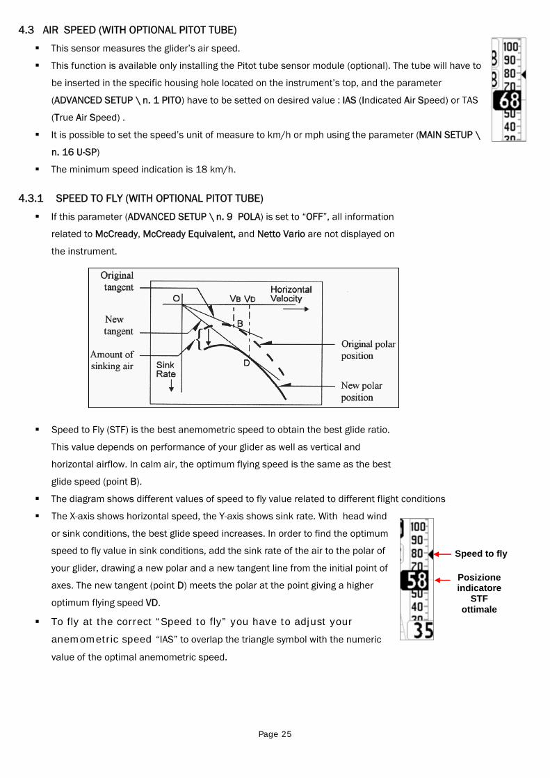
To fly at the correct “Speed to fly” you have to adjust your
anemometric speed “IAS” to overlap the triangle symbol with the numeric
value of the optimal anemometric speed.
Posizione indicatore
STF ottimale
Speed to fly
Page 26
4.3.2 AIR SPEED CALIBRATION (WITH OPTIONAL PITOT TUBE)
It is possible to perform a fine tuning of the air speed using the parameter (ADVANCED SETUP \ n. 3 KIAS) it
indicates the air speed correction value (100%=no correction, 110%=increase, 90%=decrease).
Warning: incorrect adjustment of this parameter will make the air speed reading inaccurate, the calibration of
the air speed with the Pitot tube should have done at the sea level in standard atmosphere conditions.
4.4 POLAR (WITH OPTIONAL PITOT TUBE)
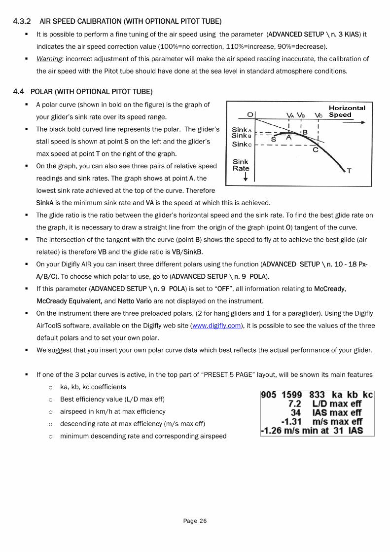
A polar curve (shown in bold on the figure) is the graph of
your glider’s sink rate over its speed range.
The black bold curved line represents the polar. The glider’s
stall speed is shown at point S on the left and the glider’s
max speed at point T on the right of the graph.
On the graph, you can also see three pairs of relative speed
readings and sink rates. The graph shows at point A, the
lowest sink rate achieved at the top of the curve. Therefore
SinkA is the minimum sink rate and VA is the speed at which this is achieved.
The glide ratio is the ratio between the glider’s horizontal speed and the sink rate. To find the best glide rate on
the graph, it is necessary to draw a straight line from the origin of the graph (point O) tangent of the curve.
The intersection of the tangent with the curve (point B) shows the speed to fly at to achieve the best glide (air
related) is therefore VB and the glide ratio is VB/SinkB.
On your Digifly AIR you can insert three different polars using the function (ADVANCED SETUP \ n. 10 - 18 Px-
A/B/C). To choose which polar to use, go to (ADVANCED SETUP \ n. 9 POLA).
If this parameter (ADVANCED SETUP \ n. 9 POLA) is set to “OFF”, all information relating to McCready,
McCready Equivalent, and Netto Vario are not displayed on the instrument.
On the instrument there are three preloaded polars, (2 for hang gliders and 1 for a paraglider). Using the Digifly
AirToolS software, available on the Digifly web site (www.digifly.com), it is possible to see the values of the three
default polars and to set your own polar.
We suggest that you insert your own polar curve data which best reflects the actual performance of your glider.
If one of the 3 polar curves is active, in the top part of “PRESET 5 PAGE” layout, will be shown its main features
o ka, kb, kc coefficients
o Best efficiency value (L/D max eff)
o airspeed in km/h at max efficiency
o descending rate at max efficiency (m/s max eff)
o minimum descending rate and corresponding airspeed
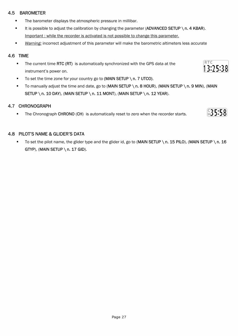
Page 27
4.5 BAROMETER
The barometer displays the atmospheric pressure in millibar.
It is possible to adjust the calibration by changing the parameter (ADVANCED SETUP \ n. 4 KBAR).
Important : while the recorder is activated is not possible to change this parameter.
Warning: incorrect adjustment of this parameter will make the barometric altimeters less accurate
4.6 TIME
The current time RTC (RT) is automatically synchronized with the GPS data at the
instrument’s power on.
To set the time zone for your country go to (MAIN SETUP \ n. 7 UTCO).
To manually adjust the time and date, go to (MAIN SETUP \ n. 8 HOUR), (MAIN SETUP \ n. 9 MIN), (MAIN
SETUP \ n. 10 DAY), (MAIN SETUP \ n. 11 MONT), (MAIN SETUP \ n. 12 YEAR).
4.7 CHRONOGRAPH
The Chronograph CHRONO (CH) is automatically reset to zero when the recorder starts.
4.8 PILOT’S NAME & GLIDER’S DATA
To set the pilot name, the glider type and the glider id, go to (MAIN SETUP \ n. 15 PILO), (MAIN SETUP \ n. 16
GTYP), (MAIN SETUP \ n. 17 GID).
Page 28
5 ADVANCED FUNCTIONS
5.1 MAGNETIC COMPASS (HEADING)
Magnetic compass (HEADING) shows directions related to magnetic north.
Made with solid state sensors along the 3 axes, ensures correct functionality even if not fully leveled
5.2 G-METER
G-meter value (G-METER) shows the number of “G” at which we are subjected .
Made with solid state G-sensors along the 3 axes
5.3 INERTIAL PLATFORM (AHRS)
The inertial platform (AHRS) produces data
regarding space location: pitch, roll and yaw.
Made by a data acquisition system with a complex
processing algorithm and 9 solid state sensors : 3
accelerometer sensors, 3 magnetometer e 3
gyroscope sensors.
5.3.1 PITCH
Points out the angle of rotation compared to lateral axis .
It’s shown in "PRESET 5 PAGE" layout
5.3.2 ROLL
Points out the angle of rotation compared to longitudinal axis .
It’s shown in "PRESET 5 PAGE" layout
5.3.3 YAW
Points out the angle of rotation compared to perpendicular axis .
It’s shown in "PRESET 5 PAGE" layout
Page 29
6 GPS FUNCTIONS 6.1 INTEGRATED 99 CHANNELS GPS RECEIVER
Digifly AIR features an extremely sensitive, and state-of-the-art, 99 channels integrated GPS receiver.
6.2 GPS STATUS INFORMATION
The GPS status icon has different meanings:
1) Fixed GPS icon = GPS FIX valid ( GPS position available)
2) Blinking GPS icon = insufficient signal (GPS position NOT AVAILABLE)
6.3 GPS SIGNAL QUALITY (HDOP)
The HDOP value represents the weakning of GPS signal. Small values mean good precision.
6.4 LATITUDE & LONGITUDE COORDINATES
The latitude and longitude coordinates are displayed on the upper part of the INFO GPS page and are referred to
WGS84 map datum.
6.5 LATITUDE & LONGITUDE COORDINATES OPTIONS
Three different kinds of coordinates are available:
DMS = grade, minute & second (dd° mm’ ss.s) (default)
DMM = grade & minute (dd° mm.mmm’)
UTM Universal Transverse Mercator (utm x, y, zone).
To set the coordinates DMM , DMS or UTM use the parameter (ADVANCED SETUP \ n. 22 CORD).
The latitude and longitude coordinates are referred to WGS84 map datum.
6.6 GPS ALTITUDE
The GPS altitude (“AG”) is the height above the sea level accordingly to the GPS satellite system.
6.7 GPS GROUND SPEED
The GPS ground speeds is the glider speed related to the ground (“Gs”).
6.8 GPS DIRECTION (TRK)
The GPS direction (“TRK”) is the glider’s direction related to the ground.
6.9 GROUND EFFICIENCY (GLIDE RATIO)
It shows the efficiency (glide ratio) related to the ground.
To set the time over which the average efficiency (glide ratio) is calculated, go to (ADVANCED
SETUP \ n. 7 EFF).
If the “ground speed” slows below the 2km/h or the GPS signal is not valid, the indicator shows: “ 0.00 ”.
If you are in lift, the efficiency indicator is in reverse mode and shows the average efficiency calculated during
the last glide, go to (ADVANCED SETUP \ n. 8 EFFA) to set the time to be used to calculate the average efficiency
(glide ratio) to be used for the glide calculation to WP
The average efficiency value is very important because it is the value used by the glide computer.
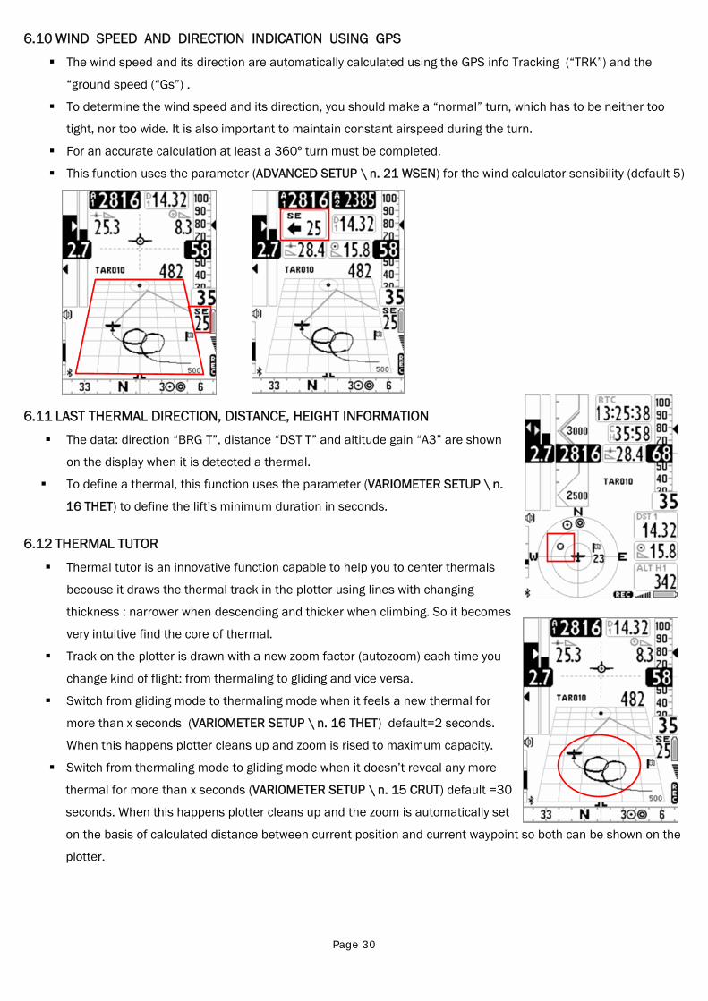
Page 30
6.10 WIND SPEED AND DIRECTION INDICATION USING GPS
The wind speed and its direction are automatically calculated using the GPS info Tracking (“TRK”) and the
“ground speed (“Gs”) .
To determine the wind speed and its direction, you should make a “normal” turn, which has to be neither too
tight, nor too wide. It is also important to maintain constant airspeed during the turn.
For an accurate calculation at least a 360º turn must be completed.
This function uses the parameter (ADVANCED SETUP \ n. 21 WSEN) for the wind calculator sensibility (default 5)
6.11 LAST THERMAL DIRECTION, DISTANCE, HEIGHT INFORMATION
The data: direction “BRG T”, distance “DST T” and altitude gain “A3” are shown
on the display when it is detected a thermal.
To define a thermal, this function uses the parameter (VARIOMETER SETUP \ n.
16 THET) to define the lift’s minimum duration in seconds.
6.12 THERMAL TUTOR
Thermal tutor is an innovative function capable to help you to center thermals
becouse it draws the thermal track in the plotter using lines with changing
thickness : narrower when descending and thicker when climbing. So it becomes
very intuitive find the core of thermal.
Track on the plotter is drawn with a new zoom factor (autozoom) each time you
change kind of flight: from thermaling to gliding and vice versa.
Switch from gliding mode to thermaling mode when it feels a new thermal for
more than x seconds (VARIOMETER SETUP \ n. 16 THET) default=2 seconds.
When this happens plotter cleans up and zoom is rised to maximum capacity.
Switch from thermaling mode to gliding mode when it doesn’t reveal any more
thermal for more than x seconds (VARIOMETER SETUP \ n. 15 CRUT) default =30
seconds. When this happens plotter cleans up and the zoom is automatically set
on the basis of calculated distance between current position and current waypoint so both can be shown on the
plotter.
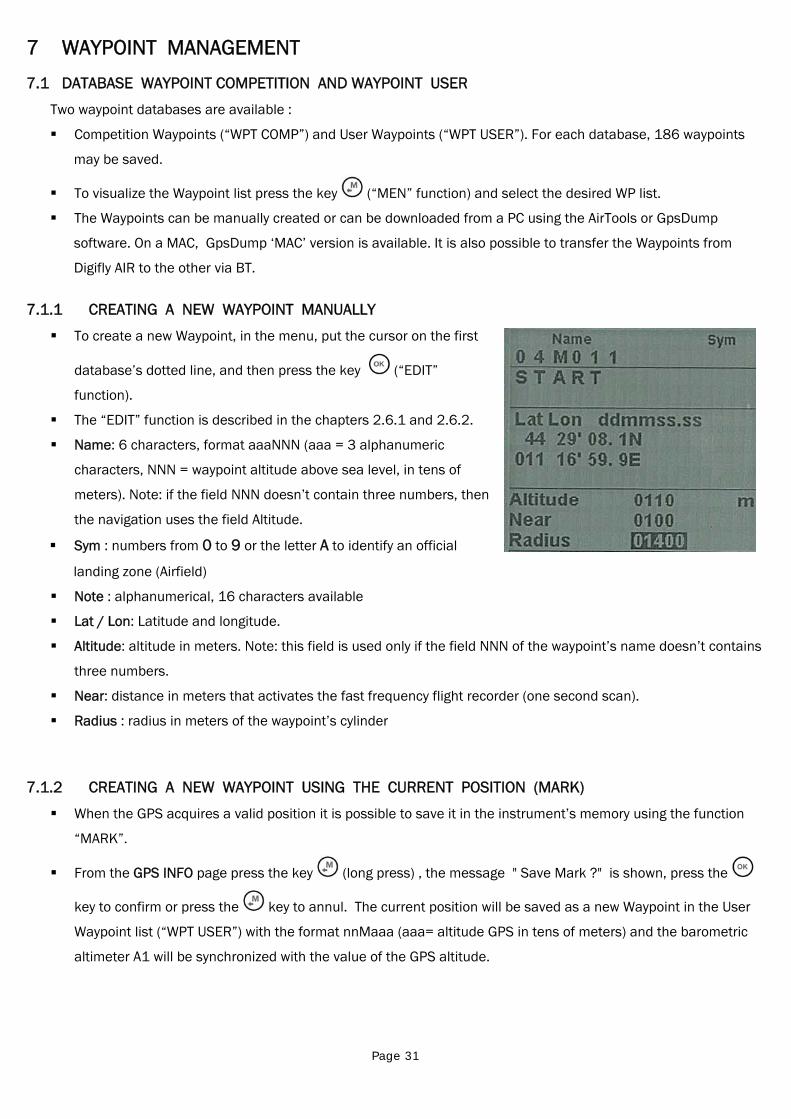
Page 31
7 WAYPOINT MANAGEMENT
7.1 DATABASE WAYPOINT COMPETITION AND WAYPOINT USER
Two waypoint databases are available :
Competition Waypoints (“WPT COMP”) and User Waypoints (“WPT USER”). For each database, 186 waypoints
may be saved.
To visualize the Waypoint list press the key (“MEN” function) and select the desired WP list.
The Waypoints can be manually created or can be downloaded from a PC using the AirTools or GpsDump
software. On a MAC, GpsDump ‘MAC’ version is available. It is also possible to transfer the Waypoints from
Digifly AIR to the other via BT.
7.1.1 CREATING A NEW WAYPOINT MANUALLY
To create a new Waypoint, in the menu, put the cursor on the first
database’s dotted line, and then press the key (“EDIT”
function).
The “EDIT” function is described in the chapters 2.6.1 and 2.6.2.
Name: 6 characters, format aaaNNN (aaa = 3 alphanumeric
characters, NNN = waypoint altitude above sea level, in tens of
meters). Note: if the field NNN doesn’t contain three numbers, then
the navigation uses the field Altitude.
Sym : numbers from 0 to 9 or the letter A to identify an official
landing zone (Airfield)
Note : alphanumerical, 16 characters available
Lat / Lon: Latitude and longitude.
Altitude: altitude in meters. Note: this field is used only if the field NNN of the waypoint’s name doesn’t contains
three numbers.
Near: distance in meters that activates the fast frequency flight recorder (one second scan).
Radius : radius in meters of the waypoint’s cylinder
7.1.2 CREATING A NEW WAYPOINT USING THE CURRENT POSITION (MARK)
When the GPS acquires a valid position it is possible to save it in the instrument’s memory using the function
“MARK”.
From the GPS INFO page press the key (long press) , the message " Save Mark ?" is shown, press the
key to confirm or press the key to annul. The current position will be saved as a new Waypoint in the User
Waypoint list (“WPT USER”) with the format nnMaaa (aaa= altitude GPS in tens of meters) and the barometric
altimeter A1 will be synchronized with the value of the GPS altitude.
Page 32
7.1.3 EDIT WAYPOINT
To modify (edit) an existing Waypoint, scroll though the list using the arrow keys or until the cursor is on
the desired one, then press the key (“EDIT” function).
The “EDIT” function is described in the chapters 2.6.1 and 2.6.2.
7.1.4 DELETE WAYPOINT
To delete a Waypoint from the list, enter in the desired Waypoint as like to edit it ( key), then press the key
(long press) and confirm the delete request pressing the key, or cancel the procedure using the
key.
To delete all the Waypoints of a list: while you are inside a WP list press the key (long press), and confirm
the delete request of ALL THE WP with the key, or cancel the procedure using the key
Page 33
8 NAVIGATE TO A SINGLE WAYPOINT (GOTO)
8.1 ACTIVATING NAVIGATION TO A WAYPOINT (GOTO)
8.1.1 NAVIGATION TO WAYPOINT HOME (GOTO HOME)
Available only in the GPS INFO page, ensures that the instrument guides us back to the point where we
activated this function.
It’s particular useful, for example, when we go flying in a new site of which we don’t have waypoints and we want
to get guided to the landing zone . In this case is necessary to go to the landing zone and activate this function.
How to activate the "GOTO HOME" function : from the GPS INFO page, wait till the GPS position is valid, then
press the key (long press) , the message " Activate Home Wpt ?" is shown, press the key to confirm or
press the key to annul.
Note : if a navigation has already been previously activated, first of all is necessary to deactivate it : from the
GPS INFO page press the key (long press) , the message " Clear Nav ?" is shown, press the key to
confirm or press the key to annul.
The "GOTO HOME" function creates a landing waypoint in the User Waypoint list (“WPT USER”) with the current
position data “HOMaaa” (aaa = GPS altitude in tens of meters) and with the icon "A" (airfield) and at the same
time activates the navigation (GOTO) to it
8.1.2 NAVIGATION TO THE NEAREST LANDING ZONE (GOTO LANDING)
To activate this function wait till the GPS position is valid, enter in the menu with the key, select the sub-
menu “Wpt Near Airfield”.
In it there is a list of all the landing fields get from both the WP database (USER+COMP) having the symbol “A” .
This list is sorted from the nearest landing zone first and the distance from the current GPS position,
The cursor is automatically set on the nearest landing. If necessary scroll the list using the arrow keys and
. To select the required zone, press the key (long press) then confirm the choice to activate the
navigation to the WP pressing again the key, or cancel the procedure using the key.
8.1.3 NAVIGATION TO THE NEAREST WAYPOINT (GOTO NEAREST)
To activate this function wait till the GPS position is valid, enter in the menu with the key, select the sub-
menu “Wpt Nearest”.
In it there is a list of all the nearest waypoints obtained from both USER & COMP database.
Page 34
The cursor is automatically set on the nearest Waypoint, if necessary scroll the list using the arrow keys
and . To select the required waypointe, press the key (long press) then confirm the choice to activate
the navigation to the WP pressing again the key, or cancel the procedure using the key.
8.1.4 NAVIGATION TO A GENERIC WAYPOINT (GOTO)
To activate this function wait till the GPS position is valid, enter in the menu with the key , select the
database Waypoint, “Competition“ or Waypoint User”, accordingly where is recorded the chosen WP.
Scroll the list using the arrow keys , and set the cursor on the wished Waypoint, to select it press the
key (long press) then confirm the choice to activate the navigation to the WP pressing again the key, or
cancel the procedure using the key.
8.1.5 DEACTIVATING NAVIGATION TO A WAYPOINT (GOTO)
To deactivate the current navigation, from the GPS INFO page, press the key (long press) , the message
"Clear Nav ?" is shown, press the key to confirm or press the key to annul.
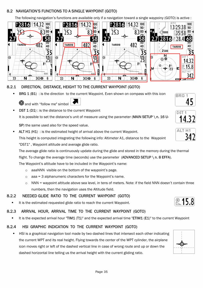
Page 35
8.2 NAVIGATION’S FUNCTIONS TO A SINGLE WAYPOINT (GOTO)
The following navigation’s functions are available only if a navigation toward a single waypoiny (GOTO) is active :
8.2.1 DIRECTION, DISTANCE, HEIGHT TO THE CURRENT WAYPOINT (GOTO)
BRG 1 (B1) : is the direction to the current Waypoint. Even shown on compass with this icon
and with “follow me" simbol
DST 1 (D1) : is the distance to the current Waypoint
It is possible to set the distance’s unit of measure using the parameter (MAIN SETUP \ n. 16 U-
SP) the same used also for the speed value.
ALT H1 (H1) : is the estimated height of arrival above the current Waypoint.
This height is computed integrating the following info: Altimeter A1, distance to the Waypoint
"DST1" , Waypoint altitude and average glide ratio.
The average glide ratio is continuously update during the glide and stored in the memory during the thermal
flight. To change the average time (seconds) use the parameter (ADVANCED SETUP \ n. 8 EFFA).
The Waypoint’s altitude have to be included in the Waypoint’s name:
o aaaNNN visible on the bottom of the waypoint’s page.
o aaa = 3 alphanumeric characters for the Waypoint’s name.
o NNN = waypoint altitude above sea level, in tens of meters. Note: if the field NNN doesn’t contain three
numbers, then the navigation uses the Altitude field.
8.2.2 NEEDED GLIDE RATIO TO THE CURRENT WAYPOINT (GOTO)
It is the estimated requested glide ratio to reach the current Waypoint.
8.2.3 ARRIVAL HOUR, ARRIVAL TIME TO THE CURRENT WAYPOINT (GOTO)
It is the expected arrival hour "TIM1 (T1)" and the expected arrival time "ETIM1 (E1)" to the current Waypoint
8.2.4 HSI GRAPHIC INDICATION TO THE CURRENT WAYPOINT (GOTO)
HSI is a graphical navigation tool made by two dashed lines that intersect each other indicating
the current WPT and its real height. Flying towards the center of the WPT cylinder, the airplane
icon moves right or left of the dashed vertical line in case of wrong route and up or down the
dashed horizontal line telling us the arrival height with the current gliding ratio.
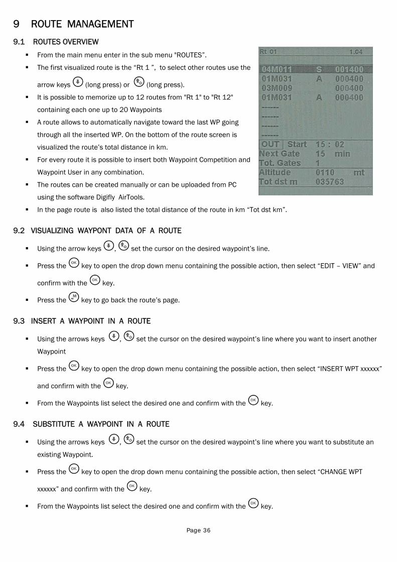
Page 36
9 ROUTE MANAGEMENT
9.1 ROUTES OVERVIEW
From the main menu enter in the sub menu "ROUTES”.
The first visualized route is the “Rt 1 ”, to select other routes use the
arrow keys (long press) or (long press).
It is possible to memorize up to 12 routes from "Rt 1" to "Rt 12"
containing each one up to 20 Waypoints
A route allows to automatically navigate toward the last WP going
through all the inserted WP. On the bottom of the route screen is
visualized the route’s total distance in km.
For every route it is possible to insert both Waypoint Competition and
Waypoint User in any combination.
The routes can be created manually or can be uploaded from PC
using the software Digifly AirTools.
In the page route is also listed the total distance of the route in km “Tot dst km”.
9.2 VISUALIZING WAYPONT DATA OF A ROUTE
Using the arrow keys , set the cursor on the desired waypoint’s line.
Press the key to open the drop down menu containing the possible action, then select “EDIT – VIEW” and
confirm with the key.
Press the key to go back the route’s page.
9.3 INSERT A WAYPOINT IN A ROUTE
Using the arrows keys , set the cursor on the desired waypoint’s line where you want to insert another
Waypoint
Press the key to open the drop down menu containing the possible action, then select “INSERT WPT xxxxxx”
and confirm with the key.
From the Waypoints list select the desired one and confirm with the key.
9.4 SUBSTITUTE A WAYPOINT IN A ROUTE
Using the arrows keys , set the cursor on the desired waypoint’s line where you want to substitute an
existing Waypoint.
Press the key to open the drop down menu containing the possible action, then select “CHANGE WPT
xxxxxx” and confirm with the key.
From the Waypoints list select the desired one and confirm with the key.
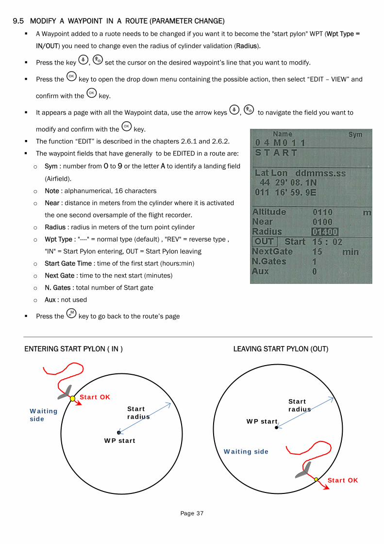
Page 37
Start radius
WP start
Waiting side
Start OK Start radius
WP start
Waiting side
Start OK
9.5 MODIFY A WAYPOINT IN A ROUTE (PARAMETER CHANGE)
A Waypoint added to a ruote needs to be changed if you want it to become the "start pylon" WPT (Wpt Type =
IN/OUT) you need to change even the radius of cylinder validation (Radius).
Press the key , set the cursor on the desired waypoint’s line that you want to modify.
Press the key to open the drop down menu containing the possible action, then select “EDIT – VIEW” and
confirm with the key.
It appears a page with all the Waypoint data, use the arrow keys , to navigate the field you want to
modify and confirm with the key.
The function “EDIT” is described in the chapters 2.6.1 and 2.6.2.
The waypoint fields that have generaIly to be EDITED in a route are:
o Sym : number from 0 to 9 or the letter A to identify a landing field
(Airfield).
o Note : alphanumerical, 16 characters
o Near : distance in meters from the cylinder where it is activated
the one second oversample of the flight recorder.
o Radius : radius in meters of the turn point cylinder
o Wpt Type : "----" = normal type (default) , "REV" = reverse type ,
"IN" = Start Pylon entering, OUT = Start Pylon leaving
o Start Gate Time : time of the first start (hours:min)
o Next Gate : time to the next start (minutes)
o N. Gates : total number of Start gate
o Aux : not used
Press the key to go back to the route’s page
ENTERING START PYLON ( IN ) LEAVING START PYLON (OUT)
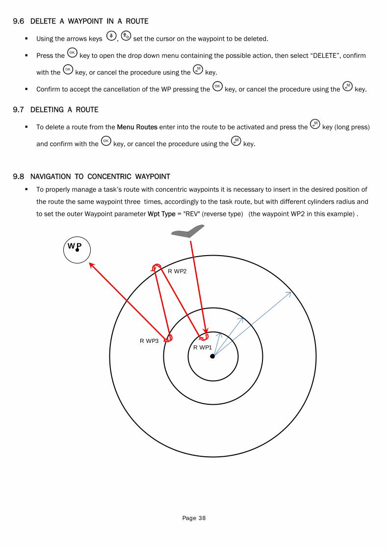
Page 38
9.6 DELETE A WAYPOINT IN A ROUTE
Using the arrows keys , set the cursor on the waypoint to be deleted.
Press the key to open the drop down menu containing the possible action, then select “DELETE”, confirm
with the key, or cancel the procedure using the key.
Confirm to accept the cancellation of the WP pressing the key, or cancel the procedure using the key.
9.7 DELETING A ROUTE
To delete a route from the Menu Routes enter into the route to be activated and press the key (long press)
and confirm with the key, or cancel the procedure using the key.
9.8 NAVIGATION TO CONCENTRIC WAYPOINT
To properly manage a task’s route with concentric waypoints it is necessary to insert in the desired position of
the route the same waypoint three times, accordingly to the task route, but with different cylinders radius and
to set the outer Waypoint parameter Wpt Type = "REV" (reverse type) (the waypoint WP2 in this example) .
R WP1 R WP3
R WP2
WP
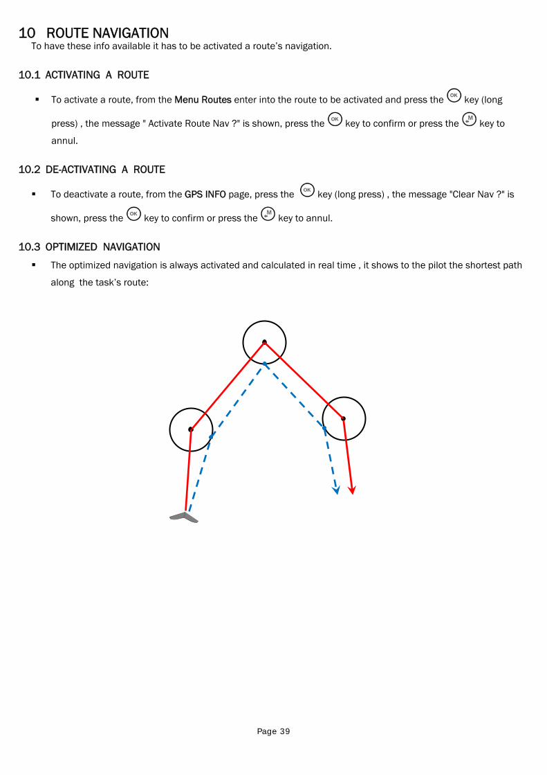
Page 39
10 ROUTE NAVIGATION To have these info available it has to be activated a route’s navigation.
10.1 ACTIVATING A ROUTE
To activate a route, from the Menu Routes enter into the route to be activated and press the key (long
press) , the message " Activate Route Nav ?" is shown, press the key to confirm or press the key to
annul.
10.2 DE-ACTIVATING A ROUTE
To deactivate a route, from the GPS INFO page, press the key (long press) , the message "Clear Nav ?" is
shown, press the key to confirm or press the key to annul.
10.3 OPTIMIZED NAVIGATION
The optimized navigation is always activated and calculated in real time , it shows to the pilot the shortest path
along the task’s route:
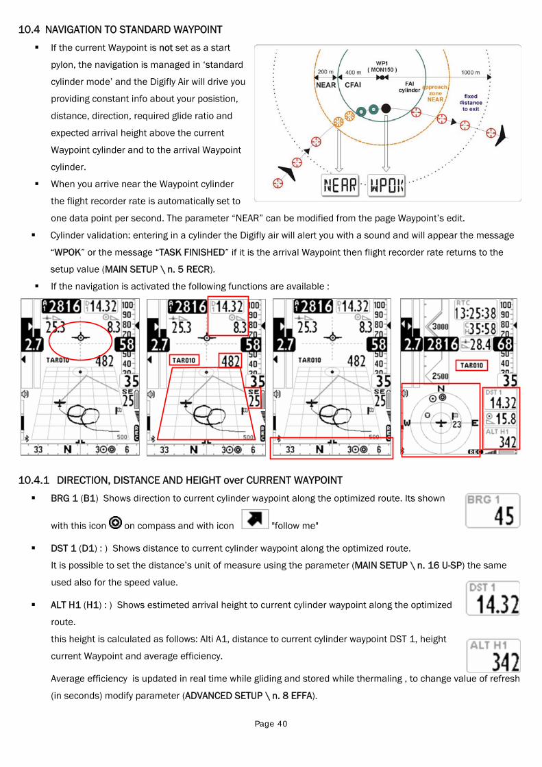
Page 40
10.4 NAVIGATION TO STANDARD WAYPOINT
If the current Waypoint is not set as a start
pylon, the navigation is managed in ‘standard
cylinder mode’ and the Digifly Air will drive you
providing constant info about your posistion,
distance, direction, required glide ratio and
expected arrival height above the current
Waypoint cylinder and to the arrival Waypoint
cylinder.
When you arrive near the Waypoint cylinder
the flight recorder rate is automatically set to
one data point per second. The parameter “NEAR” can be modified from the page Waypoint’s edit.
Cylinder validation: entering in a cylinder the Digifly air will alert you with a sound and will appear the message
“WPOK” or the message “TASK FINISHED” if it is the arrival Waypoint then flight recorder rate returns to the
setup value (MAIN SETUP \ n. 5 RECR).
If the navigation is activated the following functions are available :
10.4.1 DIRECTION, DISTANCE AND HEIGHT over CURRENT WAYPOINT
BRG 1 (B1) Shows direction to current cylinder waypoint along the optimized route. Its shown
with this icon on compass and with icon "follow me"
DST 1 (D1) : ) Shows distance to current cylinder waypoint along the optimized route.
It is possible to set the distance’s unit of measure using the parameter (MAIN SETUP \ n. 16 U-SP) the same
used also for the speed value.
ALT H1 (H1) : ) Shows estimeted arrival height to current cylinder waypoint along the optimized
route.
this height is calculated as follows: Alti A1, distance to current cylinder waypoint DST 1, height
current Waypoint and average efficiency.
Average efficiency is updated in real time while gliding and stored while thermaling , to change value of refresh
(in seconds) modify parameter (ADVANCED SETUP \ n. 8 EFFA).
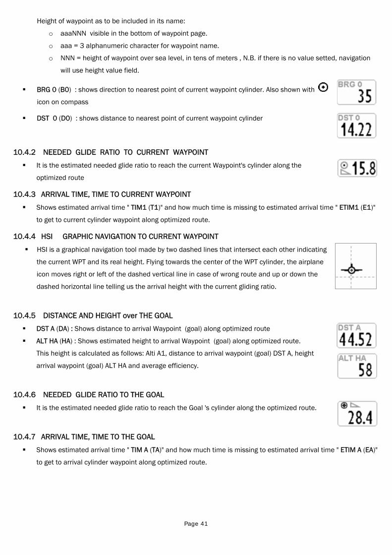
Page 41
Height of waypoint as to be included in its name:
o aaaNNN visible in the bottom of waypoint page.
o aaa = 3 alphanumeric character for waypoint name.
o NNN = height of waypoint over sea level, in tens of meters , N.B. if there is no value setted, navigation
will use height value field.
BRG 0 (B0) : shows direction to nearest point of current waypoint cylinder. Also shown with
icon on compass
DST 0 (D0) : shows distance to nearest point of current waypoint cylinder
10.4.2 NEEDED GLIDE RATIO TO CURRENT WAYPOINT
It is the estimated needed glide ratio to reach the current Waypoint's cylinder along the
optimized route
10.4.3 ARRIVAL TIME, TIME TO CURRENT WAYPOINT
Shows estimated arrival time " TIM1 (T1)" and how much time is missing to estimated arrival time " ETIM1 (E1)"
to get to current cylinder waypoint along optimized route.
10.4.4 HSI GRAPHIC NAVIGATION TO CURRENT WAYPOINT
HSI is a graphical navigation tool made by two dashed lines that intersect each other indicating
the current WPT and its real height. Flying towards the center of the WPT cylinder, the airplane
icon moves right or left of the dashed vertical line in case of wrong route and up or down the
dashed horizontal line telling us the arrival height with the current gliding ratio.
10.4.5 DISTANCE AND HEIGHT over THE GOAL
DST A (DA) : Shows distance to arrival Waypoint (goal) along optimized route
ALT HA (HA) : Shows estimated height to arrival Waypoint (goal) along optimized route.
This height is calculated as follows: Alti A1, distance to arrival waypoint (goal) DST A, height
arrival waypoint (goal) ALT HA and average efficiency.
10.4.6 NEEDED GLIDE RATIO TO THE GOAL
It is the estimated needed glide ratio to reach the Goal 's cylinder along the optimized route.
10.4.7 ARRIVAL TIME, TIME TO THE GOAL
Shows estimated arrival time " TIM A (TA)" and how much time is missing to estimated arrival time " ETIM A (EA)"
to get to arrival cylinder waypoint along optimized route.
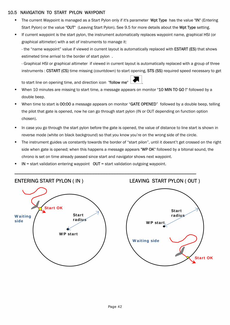
Page 42
Start radius
WP start
Waiting side
Start OK Start radius
WP start
Waiting side
Start OK
10.5 NAVIGATION TO START PYLON WAYPOINT
The current Waypoint is managed as a Start Pylon only if it's parameter Wpt Type has the value "IN" (Entering
Start Pylon) or the value "OUT" (Leaving Start Pylon). See 9.5 for more details about the Wpt Type setting.
If current waypoint is the start pylon, the instrument automatically replaces waypoint name, graphical HSI (or
graphical altimeter) with a set of instruments to manage it:
- the “name waypoint” value if viewed in current layout is automatically replaced with ESTART (ES) that shows
estimeted time arrival to the border of start pylon .
- Graphical HSI or graphical altimeter if viewed in current layout is automatically replaced with a group of three
instruments : CSTART (CS) time missing (countdown) to start opening, STS (SS) required speed necessary to get
to start line on opening time, and direction icon "follow me" .
When 10 minutes are missing to start time, a message appears on monitor "10 MIN TO GO !" followed by a
double beep.
When time to start is 00:00 a message appears on monitor “GATE OPENED” followed by a double beep, telling
the pilot that gate is opened, now he can go through start pylon (IN or OUT depending on function option
chosen).
In case you go through the start pylon before the gate is opened, the value of distance to line start is shown in
reverse mode (white on black background) so that you know you’re on the wrong side of the circle.
The instrument guides us constantly towards the border of “start pilon”, until it doesnt’t get crossed on the right
side when gate is opened; when this happens a message appears "WP OK" followed by a bitonal sound, the
chrono is set on time already passed since start and navigator shows next waypoint.
IN = start validation entering waypoint OUT = start validation outgoing waypoint.
___________________________________________________________________
ENTERING START PYLON ( IN ) LEAVING START PYLON ( OUT )
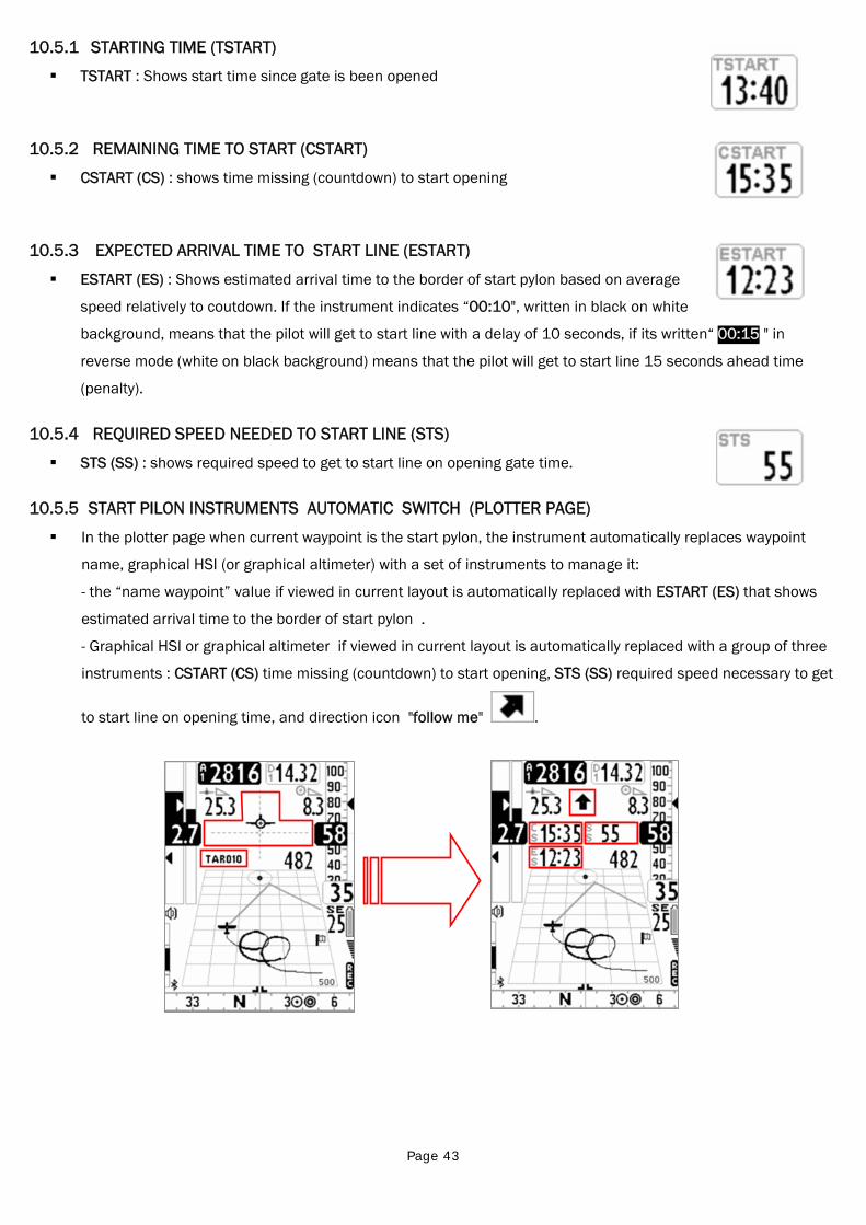
Page 43
10.5.1 STARTING TIME (TSTART)
TSTART : Shows start time since gate is been opened
10.5.2 REMAINING TIME TO START (CSTART)
CSTART (CS) : shows time missing (countdown) to start opening
10.5.3 EXPECTED ARRIVAL TIME TO START LINE (ESTART)
ESTART (ES) : Shows estimated arrival time to the border of start pylon based on average
speed relatively to coutdown. If the instrument indicates “00:10", written in black on white
background, means that the pilot will get to start line with a delay of 10 seconds, if its written“ 00:15 " in
reverse mode (white on black background) means that the pilot will get to start line 15 seconds ahead time
(penalty).
10.5.4 REQUIRED SPEED NEEDED TO START LINE (STS)
STS (SS) : shows required speed to get to start line on opening gate time.
10.5.5 START PILON INSTRUMENTS AUTOMATIC SWITCH (PLOTTER PAGE)
In the plotter page when current waypoint is the start pylon, the instrument automatically replaces waypoint
name, graphical HSI (or graphical altimeter) with a set of instruments to manage it:
- the “name waypoint” value if viewed in current layout is automatically replaced with ESTART (ES) that shows
estimated arrival time to the border of start pylon .
- Graphical HSI or graphical altimeter if viewed in current layout is automatically replaced with a group of three
instruments : CSTART (CS) time missing (countdown) to start opening, STS (SS) required speed necessary to get
to start line on opening time, and direction icon "follow me" .
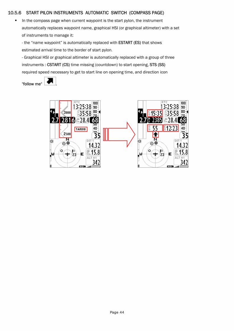
Page 44
10.5.6 START PILON INSTRUMENTS AUTOMATIC SWITCH (COMPASS PAGE)
In the compass page when current waypoint is the start pylon, the instrument
automatically replaces waypoint name, graphical HSI (or graphical altimeter) with a set
of instruments to manage it:
- the “name waypoint” is automatically replaced with ESTART (ES) that shows
estimated arrival time to the border of start pylon.
- Graphical HSI or graphical altimeter is automatically replaced with a group of three
instruments : CSTART (CS) time missing (countdown) to start opening, STS (SS)
required speed necessary to get to start line on opening time, and direction icon
"follow me" .
Page 45
10.6 OPERATION CHECKLIST BEFORE A TASK
Be sure that batteries are fully charged
Download the waypoints from the competition organization web site
Upload them on the Digifly Air with the software AirTools (PC, MAC) or GpsDump (PC , MAC, SMARTPHONE)
Edit the route accordingly to the task’s director instruction :
o Insert the turn points cylinders radius
o Insert correctly the Start Pylon type using the parameter Wpt Type : set the value "IN" (Entering Start
Pylon) or the value "OUT" (Leaving Start Pylon). See 9.5 for more details about the Wpt Type settings.
o Insert correctly the start time
o If existing, insert also the ulterior gate time ( how may and when)
o In the route page verify that the total distance is corresponding (“Tot dst m”) , calcolata dal centro del
primo wpt al centro dell' ultimo wpt lungo la rotta non ottimizzata
Activate the route
Set the barometric altimeter A1, this is important as it is used also by the glide’s computer.
Before takeoff, turn on your instrument with sufficient time to allow a correct GPS position to be obtained.
After the GPS position has been obtained, check that the time is correct. If necessary change the time zone
otherwise the start time will be wrong. Parameter (MAIN SETUP \ n. 7 UTCO)
Page 46
11 FLIGHT RECORDER
When the Digifly Air starts the flight recorder, it shows the message “REC ON” and the icon “rec”
on the bottom of the display starts blinking. The following parameters are continuously recorded: Date and time,
latitude, longitude, number of satellites, tracking GPS, ground speed GPS, altimeter GPS, barometric altimeter
A1, variometer and anemometer.
IMPORTANT: while in menu no data are recorded.
11.1 ACTIVATING / DE-ACTIVATING FLIGHT RECORDER
The flight recorder can operate in three different ways:
- “AUT” Automatic flight recorder.
- “ALW” Flight recorder always active
- “OFF” Flight recorder deactivated.
11.1.1 AUTOMATIC START RECORD MODE “AUT”
By default setting, the flight recorder starts automatically, MAIN SETUP \n. 3 RECM = AUT
The flight recorder activates automatically only if it is available the GPS position and it is detected a takeoff with
an altitude variation of at least 0,5m (MAIN SETUP \ n. 4 R.DS = 0,5) and a Ground Speed (GPS) higher than
6km/h for 3 consecutive seconds (MAIN SETUP \ n. 5 R.TI = 3).
The flight recorder is automatically deactivated 60 second after the landing or if the instrument is turned off.
11.1.2 ALWAYS ACTIVE RECORD MODE “ALW”
To set the "always active" record mode set the parameter (MAIN SETUP \ n. 3 RECM = ALW). The flight recorder
is activated once the instrument is turned on and is deactivated when it is turned off.
11.1.3 RECORD MODE OFF “OFF”
To deactivate the flight recorder set the parameter (MAIN SETUP \ n. 3 RECM = OFF), no data are recorded.
11.2 RECORD RATE
The recorder rate can be adjusted from 1 to 60 seconds, go to (MAIN SETUP \ n. 6 RECR).
setting 1 data point per second you can record over 30 hours of flight data.
Setting 1 data point per minute, you can record up to 1800 hours of flight data.
The recorder memory has room for up to 100,000 GPS data point and up to 250 flights.
When you are near a Waypoint, the recorder rate is automatically increased to 1 data point per second.
When the recorder’s memory is full, the oldest flight is automatically deleted by the newest one.
The remaining free memory time and percentage are shown for 2 seconds as the instrument is turned on
If a single flight fills the whole memory, it is no more possible to use the recorder. A message “MEM FULL”
appears every time that you try to use it. To activate again the flight recorder it is necessary to clear the whole
recorder memory. To do this: from the menu “LOGBOOK press the key (long press) and confirm the
cancellation of ALL THE FLIGHTS pressing the key , or cancel the procedure using the key .
Page 47
11.3 LOG BOOK MANAGEMENT (LOG BOOK )
To see the recorded flights select the menu “LOGBOOK”. It appears the list of all the recorded flights with the
date and take off time.
To see details of each flight recorded, after selection of the flight press the key .
o For every flight are shown the following information:
o Take off date and time, flight duration, and total altitude gain.
o Max and min values for : Altimeter (A1) and Variometer
o Max values for : Ground speed GPS and Indicated Air Speed (IAS)
To delete all the flights of a list: from the menu “LOGBOOK press the key (long press) and confirm the
cancellation of ALL THE FLIGHTS pressing the key , or cancel the procedure using the key ..
It is not possible to delete a single flight.

Page 48
12 ADDITIONAL MEMORY CARD In the vario case, aside to the micro USB connector, it is possible to insert a Micro SD memory card of 2 GB
maximum capacity.
To insert a memory card, place the card with the label toward the instrument’s keyboard side and insert the
connector card’s side inside the instrument, to lock the memory card it is necessary to gently press it with your
fingernails untill it will be locked in the case.
To extract the memory card press it in to release it.
Warning: if the card is incorrectly inserted, it is possible that the instrument would be damaged

Page 49
13 CONNECTIONS & INTERFACES It is possible to connect your Digifly AIR-SE and AIR-BT to a PC, MAC, Smartphone, Tablet , PDA using the
provided USB cable. The Digifly AIR-BT allows also the connection via Bluetooth.
13.1 USB CABLE CONNECTION
To use the USB connection the installation of the FTDI USB Cable Driver on your PC/MAC is required.
USB cable driver automatic installation (only with internet connection) :
Connect the USB cable to the PC/MAC and to the instrument, usually the operative system dowmload and
install the FTDI driver automatically.
USB cable driver manual installation : if the automatic installation was not successful the manual installation
of the FTDI driver is then required :
- disconnect the USB cable from the PC/MAC and from the instrument
- download the proper driver installation program accordingly to the PC/MAC in use from www.digifly.com->
download -> FTDI USB Cable Driver
- unzip the downloaded files in a new folder and run the driver installation program
- restart the PC/MAC
- reconnect the USB cable to the PC/MAC and to the instrument
Verify proper installation of the USB cable driver :
- connect the USB cable to the PC/MAC - from Windows7 Start menu go to Control Panel ->
System and Security -> System -> Device Management
- click on the sign (+) nearby "Ports (COM e LPT)".
- if the driver is correctly installed it is shown the message "USB Serial
Port (COMxx)" without any yellow indication of error. Note: that ’x’ is the
number of the COM port assigned to the PC USB.
- The driver type is visible with a mouse’s right key click on "USB Serial
Port" then click on “Properties'”, if the driver is installed it will show
“FTDI”.
How to manually reassign the COM port number :
All Digifly software perform the automatic search of the COM port number in the range 1 to 20, a third-party
software in most cases require that the COM port is in the range from 1 to 9.
If the COM port assigned by the computer has a higher number is necessary to manually reassign it this way :
- connect the USB cable to the PC/MAC
- right click on "USB Serial Port" then click on “Properties'”
- click on "Port settings" then click on "Advanced”
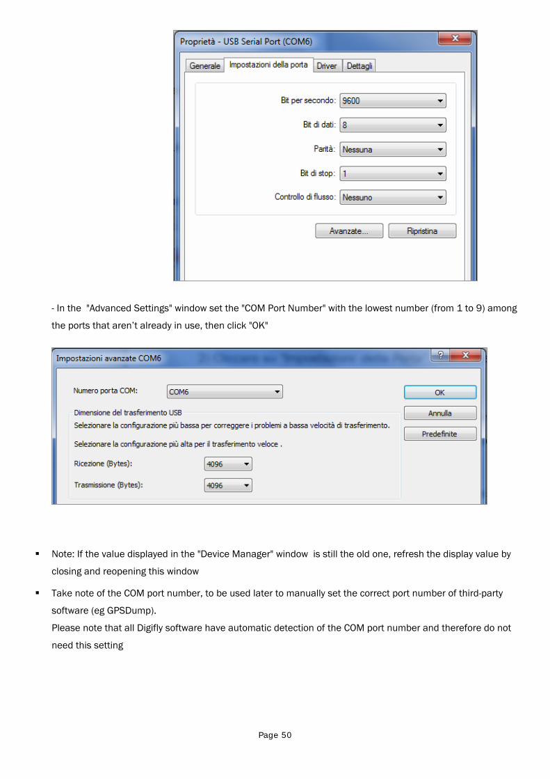
Page 50
- In the "Advanced Settings" window set the "COM Port Number" with the lowest number (from 1 to 9) among
the ports that aren’t already in use, then click "OK"
Note: If the value displayed in the "Device Manager" window is still the old one, refresh the display value by
closing and reopening this window
Take note of the COM port number, to be used later to manually set the correct port number of third-party
software (eg GPSDump).
Please note that all Digifly software have automatic detection of the COM port number and therefore do not
need this setting
Page 51
13.2 BLUETOOTH CONNECTION (AIR-BT ONLY)
13.2.1 BLUETOOTH “PAIRING”
The communication via Bluetooth between Digifly AIR-BT and an external device (PC, MAC, SmartPhone, Tablet
or PDA) is possible only after the coupling (pairing) between the two devices, here is how to proceed :
1) Set on the AIR-BT the parameter (ADVANCED SETUP \ n. 24 BLUT = "ON")
2) in the AIR-BT, enter in the menu "AirTools"
3) you are prompted to choose whether to communicate via USB cable or via Bluetooth with the message
"Press OK to link USB, Press DOWN to link BT or Menu to exit", press the key (communication via
Bluetooth)
4) AIR-BT looks forward to the pairing request from the external device
5) from the control panel of the Bluetooth external device panel, press the 'option "Search"
6) a list of available devices is created, click on "Digifly AIR BT"
7) when prompted, enter the pairing code of the AIR-BT which is "0000" and then confirm; if the procedure
is successful, the external device displays a message to confirm that the Digifly AIR BT is paired
From now on, to communicate with each other these two devices is no longer necessary to repeat the pairing.
In case of problems, to exit press the key on the AIR-BT.
13.2.2 BLUETOOTH COMMUNICATION WITH MANAGEMENT SOFTWARE OF THE INSTRUMENT
The management software of the AIR-BT that over USB cable can also communicate via Bluetooth are : Digifly
AirTools, Digifly AirPageConfigurator and GPSDump.
In order to use these software you must have already previously done (only once) the pairing procedure with the
external device (see 13.2.1). It also requires that the parameter (ADVANCED SETUP \ n. 24 BLUT) is set to "ON"
(Bluetooth enabled).
The sequence of operations for using these software via Bluetooth is the following:
1) in the AIR-BT, enter in the menu "AirTools"
2) you are prompted to choose whether to communicate via USB cable or via Bluetooth with the message
"Press OK to link USB, Press DOWN to link BT or Menu to exit", press the key (communication via
Bluetooth)
3) run the software on the external device (eg GPSDump for Android Smartphone)
4) when the AIR-BT starts to receive commands from the external device it displays the blinking message
"Link BT"
In case of problems, to exit press the key on the AIR-BT.
13.2.3 BLUETOOTH COMMUNICATION WITH SOFTWARE DECODING THE DIGIFLY TELEMETRY
Software that can receive, decode and display the Digifly telemetry data sent in real time at high speed from the
AIR-BT via Bluetooth are XCSoar and LK8000.
In order to use these software you must have already previously done (only once) the pairing procedure with the
external device (see 13.2.1). It also requires that the parameter (ADVANCED SETUP \ n. 24 BLUT) is set to "ON"
(Bluetooth enabled) and that the parameter (ADVANCED SETUP \ n. 23 TELE) is set to "FL2" (sending Digifly

Page 52
telemetry data enabled).
The sequence of operations for using these software via Bluetooth is the following:
1) in the AIR-BT, enter in the menu “Telemetry BT”
2) run the software on the external device (eg XCSoar on Android Smartphone)
3) when AIR-BT receives from the external device the confirmation of connection it automatically exits from
the "Telemetry BT" menu, returns on the current page of instruments, turn on the Bluetooth icon and
activate the continuous transmission of real-time Digifly telemetry data at high speed
In case of problems, to exit press the key on the AIR-BT.
.
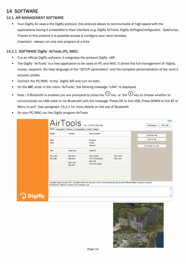
Page 53
14 SOFTWARE 14.1 AIR MANAGEMENT SOFTWARE
Your Digifly Air uses a the Digifly protocol, this protocol allows to communicate at high speed with the
applications having it embedded in their interface (e.g. Digifly AirTools, Digifly AirPagesConfigurator, GpsDump).
Thanks to this protocol it is possible access & configure your vario remotely.
Important : always run only one program at a time
14.1.1 SOFTWARE Digifly AirTools (PC, MAC)
It is an official Digifly software, it integrates the protocol Digifly v66
The Digifly “AirTools” is a free application to be used on PC and MAC; it allows the full management of: flights,
routes, waypoint, the help language of the “SETUP parameters” and the complete personalization of the vario’s
acoustic profile
Connect the PC/MAC to the Digifly AIR and turn on both.
On the AIR, enter in the menu "AirTools", the blinking message “LINK” is displayed
Note : if Bluetooth is enabled you are prompted to press the key or the key to choose whether to
communicate via USB cable or via Bluetooth with the message "Press OK to link USB, Press DOWN to link BT or
Menu to exit". See paragraph 13.2.1 for more details on the use of Bluetooth
On your PC/MAC run the Digifly program AirTools
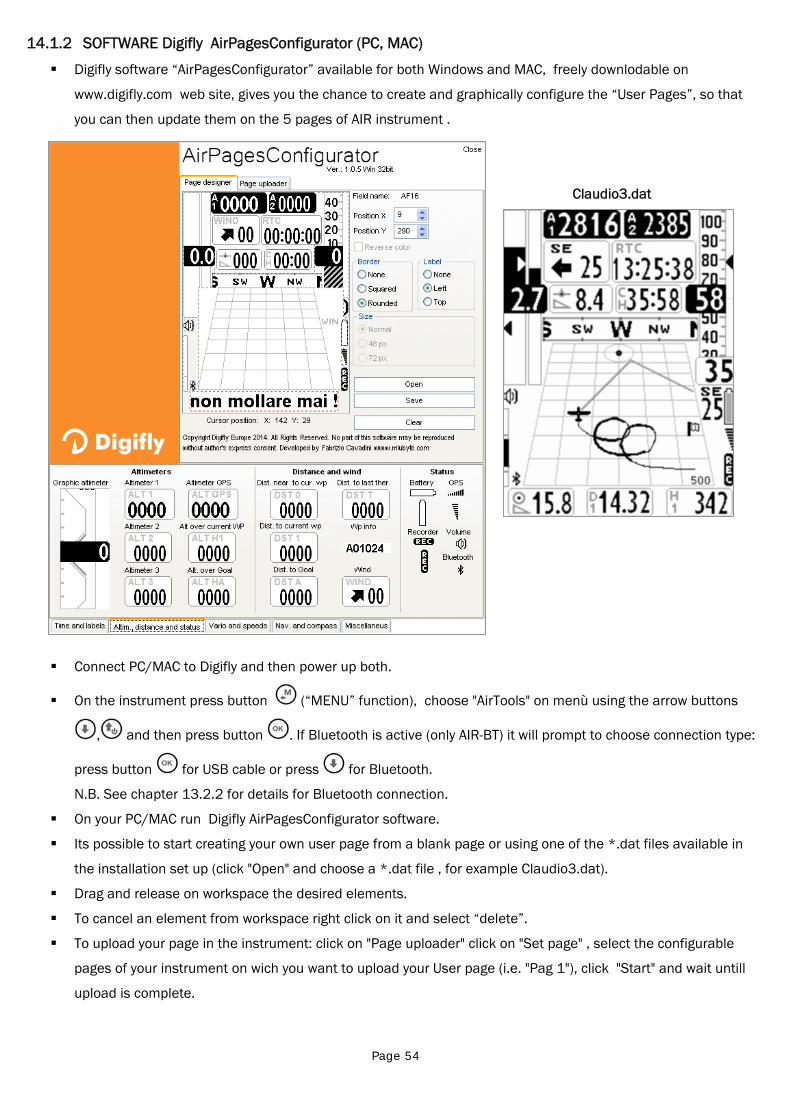
Page 54
14.1.2 SOFTWARE Digifly AirPagesConfigurator (PC, MAC)
Digifly software “AirPagesConfigurator” available for both Windows and MAC, freely downlodable on
www.digifly.com web site, gives you the chance to create and graphically configure the “User Pages”, so that
you can then update them on the 5 pages of AIR instrument .
Claudio3.dat
Connect PC/MAC to Digifly and then power up both.
On the instrument press button (“MENU” function), choose "AirTools" on menù using the arrow buttons
, and then press button . If Bluetooth is active (only AIR-BT) it will prompt to choose connection type:
press button for USB cable or press for Bluetooth.
N.B. See chapter 13.2.2 for details for Bluetooth connection.
On your PC/MAC run Digifly AirPagesConfigurator software.
Its possible to start creating your own user page from a blank page or using one of the *.dat files available in
the installation set up (click "Open" and choose a *.dat file , for example Claudio3.dat).
Drag and release on workspace the desired elements.
To cancel an element from workspace right click on it and select “delete”.
To upload your page in the instrument: click on "Page uploader" click on "Set page" , select the configurable
pages of your instrument on wich you want to upload your User page (i.e. "Pag 1"), click "Start" and wait untill
upload is complete.
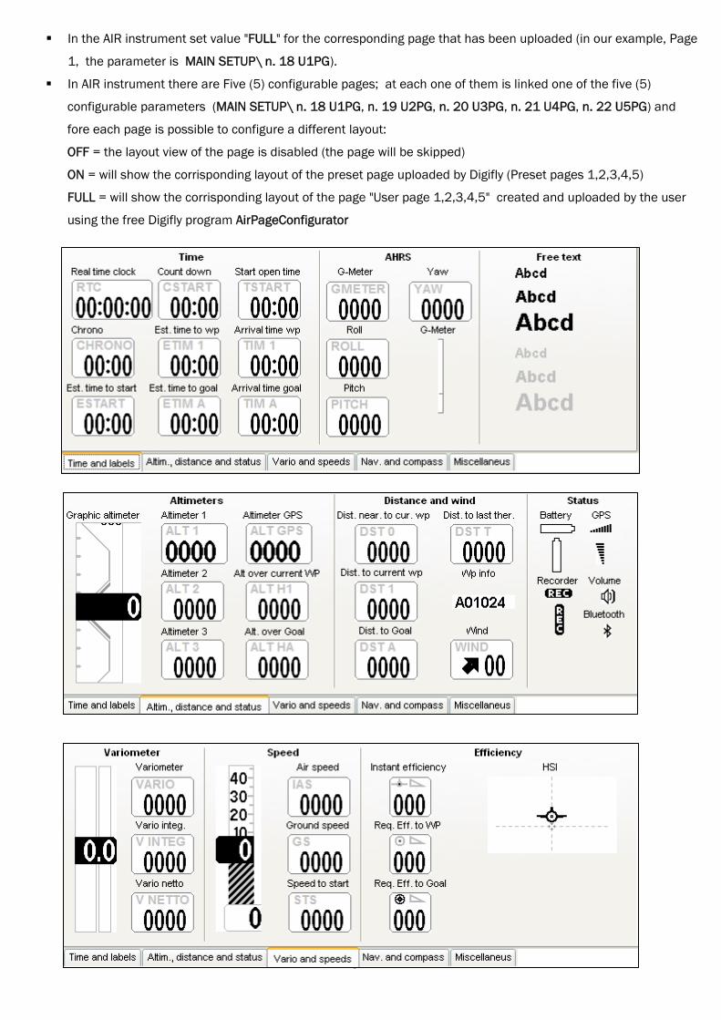
Page 55
In the AIR instrument set value "FULL" for the corresponding page that has been uploaded (in our example, Page
1, the parameter is MAIN SETUP\ n. 18 U1PG).
In AIR instrument there are Five (5) configurable pages; at each one of them is linked one of the five (5)
configurable parameters (MAIN SETUP\ n. 18 U1PG, n. 19 U2PG, n. 20 U3PG, n. 21 U4PG, n. 22 U5PG) and
fore each page is possible to configure a different layout:
OFF = the layout view of the page is disabled (the page will be skipped)
ON = will show the corrisponding layout of the preset page uploaded by Digifly (Preset pages 1,2,3,4,5)
FULL = will show the corrisponding layout of the page "User page 1,2,3,4,5" created and uploaded by the user
using the free Digifly program AirPageConfigurator
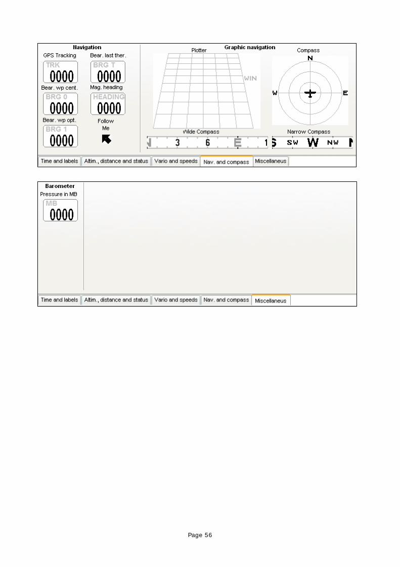
Page 56
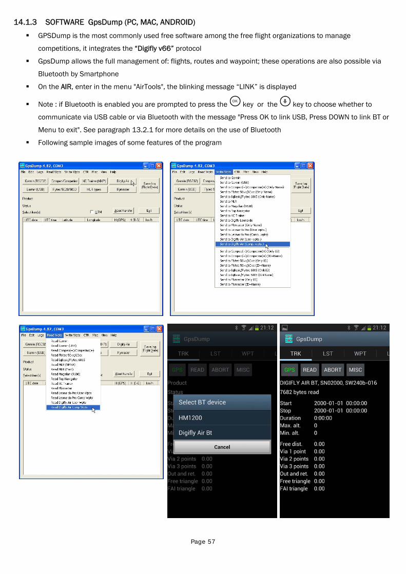
Page 57
14.1.3 SOFTWARE GpsDump (PC, MAC, ANDROID)
GPSDump is the most commonly used free software among the free flight organizations to manage
competitions, it integrates the “Digifly v66” protocol
GpsDump allows the full management of: flights, routes and waypoint; these operations are also possible via
Bluetooth by Smartphone
On the AIR, enter in the menu "AirTools", the blinking message “LINK” is displayed
Note : if Bluetooth is enabled you are prompted to press the key or the key to choose whether to
communicate via USB cable or via Bluetooth with the message "Press OK to link USB, Press DOWN to link BT or
Menu to exit". See paragraph 13.2.1 for more details on the use of Bluetooth
Following sample images of some features of the program
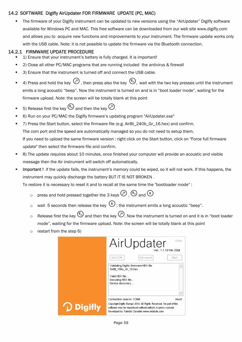
Page 58
14.2 SOFTWARE Digifly AirUpdater FOR FIRMWARE UPDATE (PC, MAC)
The firmware of your Digifly instrument can be updated to new versions using the “AirUpdater” Digifly software
available for Windows PC and MAC. This free software can be downloaded from our web site www.digifly.com
and allows you to acquire new functions and improvements to your instrument. The firmware update works only
with the USB cable. Note: it is not possible to update the firmware via the Bluetooth connection.
14.2.1 FIRMWARE UPDATE PROCEDURE 1) Ensure that your instrument’s battery is fully charged. It is important!
2) Close all other PC/MAC programs that are running included the antivirus & firewall
3) Ensure that the instrument is turned off and connect the USB cable.
4) Press and hold the key , then press also the key , wait with the two key presses until the instrument
emits a long acoustic “beep”. Now the instrument is turned on and is in “boot loader mode”, waiting for the
firmware upload. Note: the screen will be totally blank at this point
5) Release first the key and then the key .
6) Run on your PC/MAC the Digifly firmware’s updating program "AirUpdater.exe"
7) Press the Start button, select the firmware file (e.g. AirBt_240b_Gr_16.hex) and confirm.
The com port and the speed are automatically managed so you do not need to setup them.
If you need to upload the same firmware version : right click on the Start button, click on "Force full firmware
update" then select the firmware file and confirm.
8) The update requires about 10 minutes, once finished your computer will provide an acoustic and visible
message then the Air instrument will switch off automatically.
Important ! if the update fails, the instrument’s memory could be wiped, so it will not work. If this happens, the
instrument may quickly discharge the battery BUT IT IS NOT BROKEN .
To restore it is necessary to reset it and to recall at the same time the "bootloader mode" :
o press and hold pressed together the 3 keys , and
o wait 5 seconds then release the key ; the instrument emits a long acoustic “beep”.
o Release first the key and then the key . Now the instrument is turned on and it is in “boot loader
mode”, waiting for the firmware upload. Note: the screen will be totally blank at this point
o restart from the step 6)
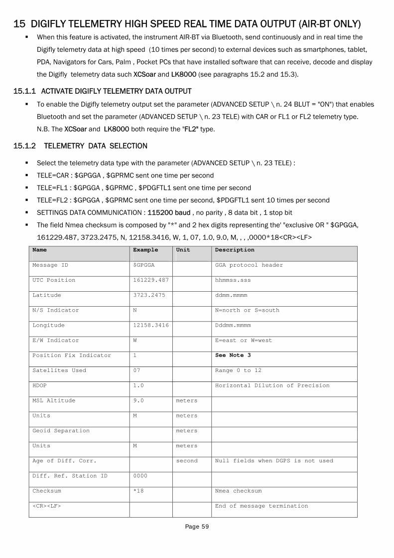
Page 59
15 DIGIFLY TELEMETRY HIGH SPEED REAL TIME DATA OUTPUT (AIR-BT ONLY) When this feature is activated, the instrument AIR-BT via Bluetooth, send continuously and in real time the
Digifly telemetry data at high speed (10 times per second) to external devices such as smartphones, tablet,
PDA, Navigators for Cars, Palm , Pocket PCs that have installed software that can receive, decode and display
the Digifly telemetry data such XCSoar and LK8000 (see paragraphs 15.2 and 15.3).
15.1.1 ACTIVATE DIGIFLY TELEMETRY DATA OUTPUT
To enable the Digifly telemetry output set the parameter (ADVANCED SETUP \ n. 24 BLUT = "ON") that enables
Bluetooth and set the parameter (ADVANCED SETUP \ n. 23 TELE) with CAR or FL1 or FL2 telemetry type.
N.B. The XCSoar and LK8000 both require the "FL2" type.
15.1.2 TELEMETRY DATA SELECTION
Select the telemetry data type with the parameter (ADVANCED SETUP \ n. 23 TELE) :
TELE=CAR : $GPGGA , $GPRMC sent one time per second
TELE=FL1 : $GPGGA , $GPRMC , $PDGFTL1 sent one time per second
TELE=FL2 : $GPGGA , $GPRMC sent one time per second, $PDGFTL1 sent 10 times per second
SETTINGS DATA COMMUNICATION : 115200 baud , no parity , 8 data bit , 1 stop bit
The field Nmea checksum is composed by "*" and 2 hex digits representing the' "exclusive OR " $GPGGA,
161229.487, 3723.2475, N, 12158.3416, W, 1, 07, 1.0, 9.0, M, , , ,0000*18<CR><LF>
Name Example Unit Description
Message ID $GPGGA GGA protocol header
UTC Position 161229.487 hhmmss.sss
Latitude 3723.2475 ddmm.mmmm
N/S Indicator N N=north or S=south
Longitude 12158.3416 Dddmm.mmmm
E/W Indicator W E=east or W=west
Position Fix Indicator 1 See Note 3
Satellites Used 07 Range 0 to 12
HDOP 1.0 Horizontal Dilution of Precision
MSL Altitude 9.0 meters
Units M meters
Geoid Separation meters
Units M meters
Age of Diff. Corr. second Null fields when DGPS is not used
Diff. Ref. Station ID 0000
Checksum *18 Nmea checksum
<CR><LF> End of message termination
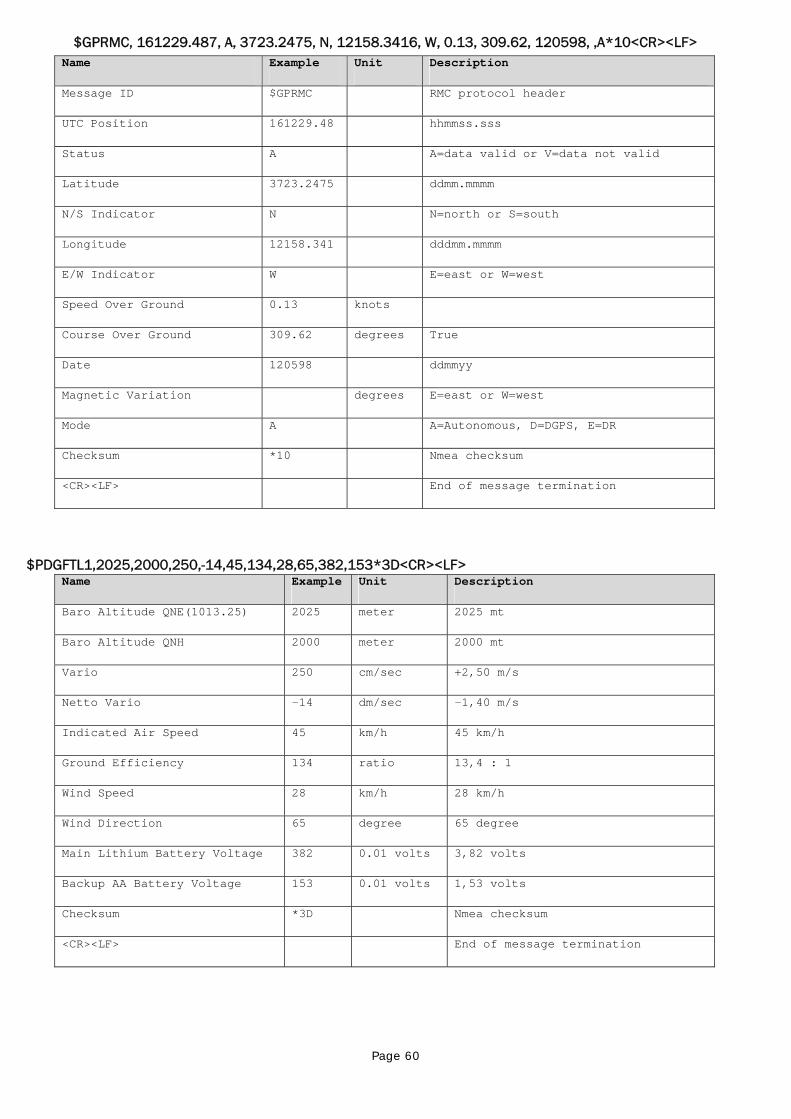
Page 60
$GPRMC, 161229.487, A, 3723.2475, N, 12158.3416, W, 0.13, 309.62, 120598, ,A*10<CR><LF> Name Example Unit Description
Message ID $GPRMC RMC protocol header
UTC Position 161229.48 hhmmss.sss
Status A A=data valid or V=data not valid
Latitude 3723.2475 ddmm.mmmm
N/S Indicator N N=north or S=south
Longitude 12158.341 dddmm.mmmm
E/W Indicator W E=east or W=west
Speed Over Ground 0.13 knots
Course Over Ground 309.62 degrees True
Date 120598 ddmmyy
Magnetic Variation degrees E=east or W=west
Mode A A=Autonomous, D=DGPS, E=DR
Checksum *10 Nmea checksum
<CR><LF> End of message termination
$PDGFTL1,2025,2000,250,-14,45,134,28,65,382,153*3D<CR><LF> Name Example Unit Description
Baro Altitude QNE(1013.25) 2025 meter 2025 mt
Baro Altitude QNH 2000 meter 2000 mt
Vario 250 cm/sec +2,50 m/s
Netto Vario -14 dm/sec -1,40 m/s
Indicated Air Speed 45 km/h 45 km/h
Ground Efficiency 134 ratio 13,4 : 1
Wind Speed 28 km/h 28 km/h
Wind Direction 65 degree 65 degree
Main Lithium Battery Voltage 382 0.01 volts 3,82 volts
Backup AA Battery Voltage 153 0.01 volts 1,53 volts
Checksum *3D Nmea checksum
<CR><LF> End of message termination
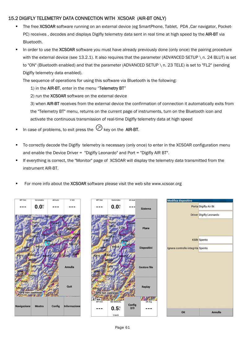
Page 61
15.2 DIGIFLY TELEMETRY DATA CONNECTION WITH XCSOAR (AIR-BT ONLY) The free XCSOAR software running on an external device (eg SmartPhone, Tablet, PDA ,Car navigator, Pocket-
PC) receives , decodes and displays Digifly telemetry data sent in real time at high speed by the AIR-BT via
Bluetooth.
In order to use the XCSOAR software you must have already previously done (only once) the pairing procedure
with the external device (see 13.2.1). It also requires that the parameter (ADVANCED SETUP \ n. 24 BLUT) is set
to "ON" (Bluetooth enabled) and that the parameter (ADVANCED SETUP \ n. 23 TELE) is set to "FL2" (sending
Digifly telemetry data enabled).
The sequence of operations for using this software via Bluetooth is the following:
1) in the AIR-BT, enter in the menu “Telemetry BT”
2) run the XCSOAR software on the external device
3) when AIR-BT receives from the external device the confirmation of connection it automatically exits from
the "Telemetry BT" menu, returns on the current page of instruments, turn on the Bluetooth icon and
activate the continuous transmission of real-time Digifly telemetry data at high speed
In case of problems, to exit press the key on the AIR-BT.
To correctly decode the Digifly telemetry is necessary (only once) to enter in the XCSOAR configuration menu
and enable the Device Driver = "Digifly Leonardo" and Port = "Digifly AIR BT".
If everything is correct, the "Monitor" page of XCSOAR will display the telemetry data transmitted from the
instrument AIR-BT.
For more info about the XCSOAR software please visit the web site www.xcsoar.org
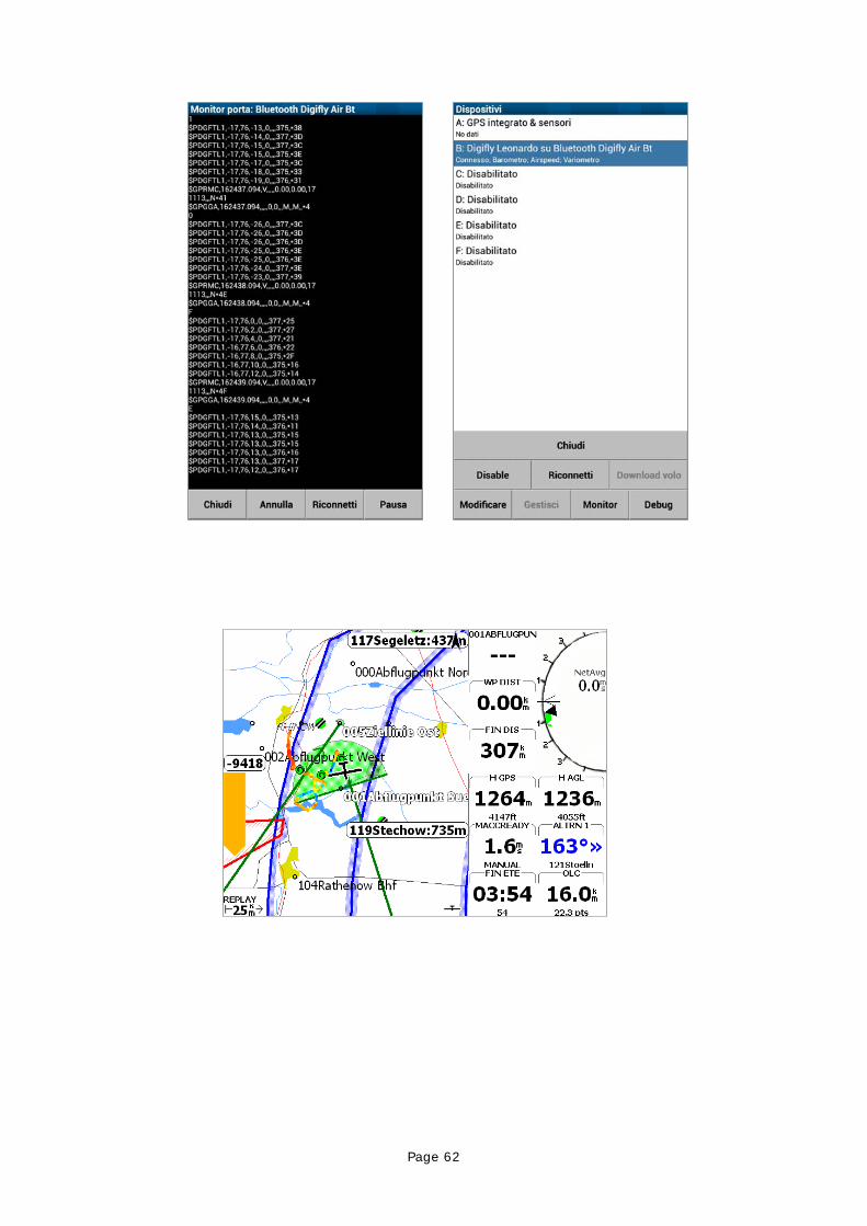
Page 62
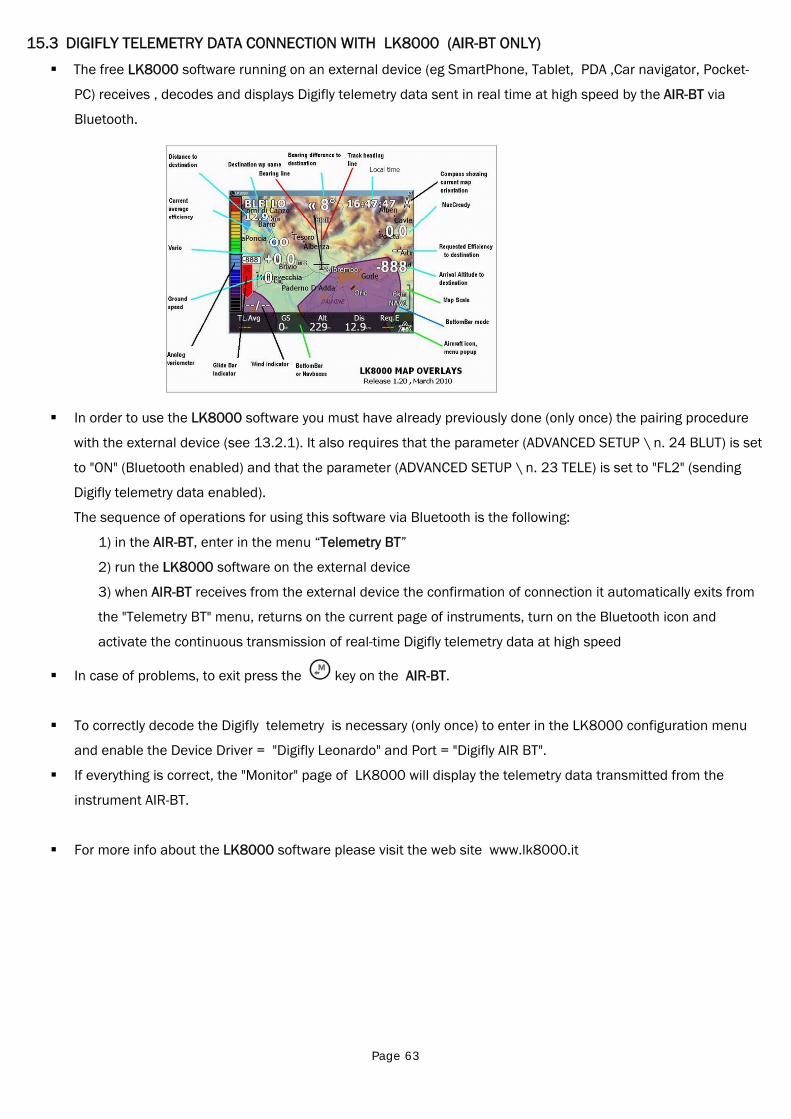
Page 63
15.3 DIGIFLY TELEMETRY DATA CONNECTION WITH LK8000 (AIR-BT ONLY)
The free LK8000 software running on an external device (eg SmartPhone, Tablet, PDA ,Car navigator, Pocket-
PC) receives , decodes and displays Digifly telemetry data sent in real time at high speed by the AIR-BT via
Bluetooth.
In order to use the LK8000 software you must have already previously done (only once) the pairing procedure
with the external device (see 13.2.1). It also requires that the parameter (ADVANCED SETUP \ n. 24 BLUT) is set
to "ON" (Bluetooth enabled) and that the parameter (ADVANCED SETUP \ n. 23 TELE) is set to "FL2" (sending
Digifly telemetry data enabled).
The sequence of operations for using this software via Bluetooth is the following:
1) in the AIR-BT, enter in the menu “Telemetry BT”
2) run the LK8000 software on the external device
3) when AIR-BT receives from the external device the confirmation of connection it automatically exits from
the "Telemetry BT" menu, returns on the current page of instruments, turn on the Bluetooth icon and
activate the continuous transmission of real-time Digifly telemetry data at high speed
In case of problems, to exit press the key on the AIR-BT.
To correctly decode the Digifly telemetry is necessary (only once) to enter in the LK8000 configuration menu
and enable the Device Driver = "Digifly Leonardo" and Port = "Digifly AIR BT".
If everything is correct, the "Monitor" page of LK8000 will display the telemetry data transmitted from the
instrument AIR-BT.
For more info about the LK8000 software please visit the web site www.lk8000.it
Page 64
16 APPENDIX
16.1 DIGIFLY AIR STANDARD ACCESSORIES
The Digifly AIR-SE and AIR-BT are shipped with the following standard accessories: Protective case. Internal rechargeable lithium battery. Battery charger 5V 1000ma (110-220Vca 50-60Hz). USB PC cable to download flights, manage other functions and update the firmware directly from Internet
16.2 OPTIONAL ACCESSORIES
The following optional accessories are available from Digifly: Air Speed Sensor Pitot tube GSM LiveTracking module for mobile sim card Hang gliding vario mount Paragliding protective case
16.3 TECHNICAL FEATURES
16.3.1 STANDARD FUNCTIONS
Graphic altimeter Altimeters 9,000 m (29527 ft) Auto Altimeter A1 with GPS Altimeter synchro Auto zero thermal altimeter A3 Thermal Tutor with autozoom and real time map of the thermal with different thickness depending on the vario 10 Sensors Vario (barometer +9 sensors inertial platform) with self-adaptive sensitivity function Digital vario +/- 25 m/s (5000 ft/min) Analogue vario +/- 25 m/s (5000 ft/min) Vario integrator adjustable from 0 to 60 sec Netto Vario (with optional Pitot tube) McCready and Equivalent McReady function (with optional Pitot tube) Total energy compensation (with optional Pitot tube) Acoustic vario with adjustable levels, volume, tone and vario simulator function Acoustic vario with “pre-thermal” function Acoustic vario with "autosilence" function Air Speed IAS / TAS (with optional Pitot tube) Speed To Fly (with optional Pitot tube) 3 adjustable polar curves (with optional Pitot tube) Barometer (range 300 to 1200 mB) with user calibration Constant battery monitoring. Date and time with auto GPS synchro, chronometer, flight timer.
16.3.2 ADVANCED FUNCTIONS
Inertial platform AHRS with 3 axis gyroscopes, 3 accelerometers and 3magnetometers Three axis magnetic compass Three axis Gmeter Pitch Roll Yaw
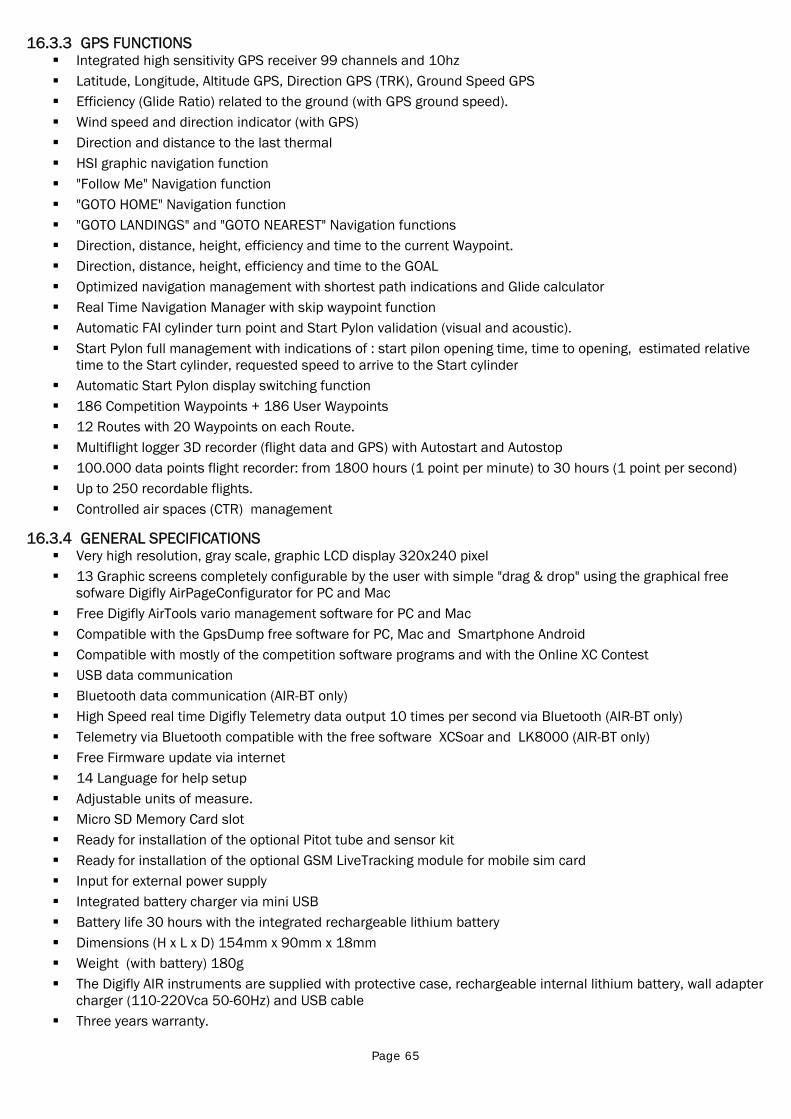
Page 65
16.3.3 GPS FUNCTIONS Integrated high sensitivity GPS receiver 99 channels and 10hz Latitude, Longitude, Altitude GPS, Direction GPS (TRK), Ground Speed GPS Efficiency (Glide Ratio) related to the ground (with GPS ground speed). Wind speed and direction indicator (with GPS) Direction and distance to the last thermal HSI graphic navigation function "Follow Me" Navigation function "GOTO HOME" Navigation function "GOTO LANDINGS" and "GOTO NEAREST" Navigation functions Direction, distance, height, efficiency and time to the current Waypoint. Direction, distance, height, efficiency and time to the GOAL Optimized navigation management with shortest path indications and Glide calculator Real Time Navigation Manager with skip waypoint function Automatic FAI cylinder turn point and Start Pylon validation (visual and acoustic). Start Pylon full management with indications of : start pilon opening time, time to opening, estimated relative
time to the Start cylinder, requested speed to arrive to the Start cylinder Automatic Start Pylon display switching function 186 Competition Waypoints + 186 User Waypoints 12 Routes with 20 Waypoints on each Route. Multiflight logger 3D recorder (flight data and GPS) with Autostart and Autostop 100.000 data points flight recorder: from 1800 hours (1 point per minute) to 30 hours (1 point per second) Up to 250 recordable flights. Controlled air spaces (CTR) management
16.3.4 GENERAL SPECIFICATIONS Very high resolution, gray scale, graphic LCD display 320x240 pixel 13 Graphic screens completely configurable by the user with simple "drag & drop" using the graphical free
sofware Digifly AirPageConfigurator for PC and Mac Free Digifly AirTools vario management software for PC and Mac Compatible with the GpsDump free software for PC, Mac and Smartphone Android Compatible with mostly of the competition software programs and with the Online XC Contest USB data communication Bluetooth data communication (AIR-BT only) High Speed real time Digifly Telemetry data output 10 times per second via Bluetooth (AIR-BT only) Telemetry via Bluetooth compatible with the free software XCSoar and LK8000 (AIR-BT only) Free Firmware update via internet 14 Language for help setup Adjustable units of measure. Micro SD Memory Card slot Ready for installation of the optional Pitot tube and sensor kit Ready for installation of the optional GSM LiveTracking module for mobile sim card Input for external power supply Integrated battery charger via mini USB Battery life 30 hours with the integrated rechargeable lithium battery Dimensions (H x L x D) 154mm x 90mm x 18mm Weight (with battery) 180g The Digifly AIR instruments are supplied with protective case, rechargeable internal lithium battery, wall adapter
charger (110-220Vca 50-60Hz) and USB cable Three years warranty.
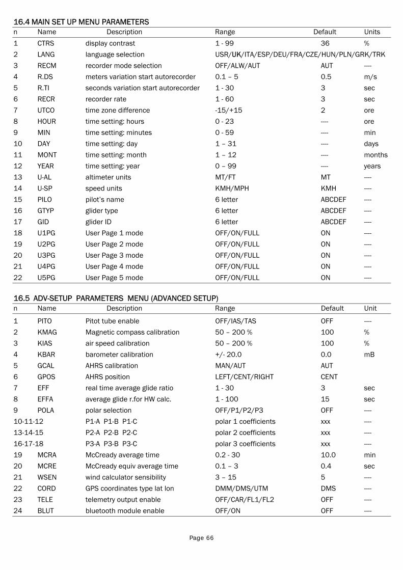
Page 66
16.4 MAIN SET UP MENU PARAMETERS n Name Description Range Default Units
1 CTRS display contrast 1 - 99 36 %
2 LANG language selection USR/UK/ITA/ESP/DEU/FRA/CZE/HUN/PLN/GRK/TRK
3 RECM recorder mode selection OFF/ALW/AUT AUT ----
4 R.DS meters variation start autorecorder 0.1 – 5 0.5 m/s
5 R.TI seconds variation start autorecorder 1 - 30 3 sec
6 RECR recorder rate 1 - 60 3 sec
7 UTCO time zone difference -15/+15 2 ore
8 HOUR time setting: hours 0 - 23 ---- ore
9 MIN time setting: minutes 0 - 59 ---- min
10 DAY time setting: day 1 – 31 ---- days
11 MONT time setting: month 1 – 12 ---- months
12 YEAR time setting: year 0 – 99 ---- years
13 U-AL altimeter units MT/FT MT ----
14 U-SP speed units KMH/MPH KMH ----
15 PILO pilot’s name 6 letter ABCDEF ----
16 GTYP glider type 6 letter ABCDEF ----
17 GID glider ID 6 letter ABCDEF ----
18 U1PG User Page 1 mode OFF/ON/FULL ON ----
19 U2PG User Page 2 mode OFF/ON/FULL ON ----
20 U3PG User Page 3 mode OFF/ON/FULL ON ----
21 U4PG User Page 4 mode OFF/ON/FULL ON ----
22 U5PG User Page 5 mode OFF/ON/FULL ON ----
16.5 ADV-SETUP PARAMETERS MENU (ADVANCED SETUP) n Name Description Range Default Unit
1 PITO Pitot tube enable OFF/IAS/TAS OFF ----
2 KMAG Magnetic compass calibration 50 – 200 % 100 %
3 KIAS air speed calibration 50 – 200 % 100 %
4 KBAR barometer calibration +/- 20.0 0.0 mB
5 GCAL AHRS calibration MAN/AUT AUT
6 GPOS AHRS position LEFT/CENT/RIGHT CENT
7 EFF real time average glide ratio 1 - 30 3 sec
8 EFFA average glide r.for HW calc. 1 - 100 15 sec
9 POLA polar selection OFF/P1/P2/P3 OFF ----
10-11-12 P1-A P1-B P1-C polar 1 coefficients xxx ----
13-14-15 P2-A P2-B P2-C polar 2 coefficients xxx ----
16-17-18 P3-A P3-B P3-C polar 3 coefficients xxx ----
19 MCRA McCready average time 0.2 - 30 10.0 min
20 MCRE McCready equiv average time 0.1 – 3 0.4 sec
21 WSEN wind calculator sensibility 3 – 15 5 ----
22 CORD GPS coordinates type lat lon DMM/DMS/UTM DMS ----
23 TELE telemetry output enable OFF/CAR/FL1/FL2 OFF ----
24 BLUT bluetooth module enable OFF/ON OFF ----
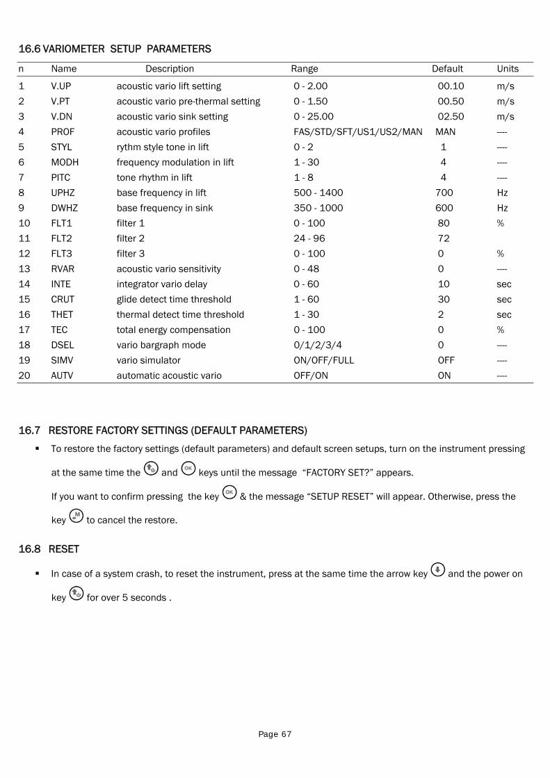
Page 67
16.6 VARIOMETER SETUP PARAMETERS
n Name Description Range Default Units
1 V.UP acoustic vario lift setting 0 - 2.00 00.10 m/s
2 V.PT acoustic vario pre-thermal setting 0 - 1.50 00.50 m/s
3 V.DN acoustic vario sink setting 0 - 25.00 02.50 m/s
4 PROF acoustic vario profiles FAS/STD/SFT/US1/US2/MAN MAN ----
5 STYL rythm style tone in lift 0 - 2 1 ----
6 MODH frequency modulation in lift 1 - 30 4 ----
7 PITC tone rhythm in lift 1 - 8 4 ----
8 UPHZ base frequency in lift 500 - 1400 700 Hz
9 DWHZ base frequency in sink 350 - 1000 600 Hz
10 FLT1 filter 1 0 - 100 80 %
11 FLT2 filter 2 24 - 96 72
12 FLT3 filter 3 0 - 100 0 %
13 RVAR acoustic vario sensitivity 0 - 48 0 ----
14 INTE integrator vario delay 0 - 60 10 sec
15 CRUT glide detect time threshold 1 - 60 30 sec
16 THET thermal detect time threshold 1 - 30 2 sec
17 TEC total energy compensation 0 - 100 0 %
18 DSEL vario bargraph mode 0/1/2/3/4 0 ----
19 SIMV vario simulator ON/OFF/FULL OFF ----
20 AUTV automatic acoustic vario OFF/ON ON ----
16.7 RESTORE FACTORY SETTINGS (DEFAULT PARAMETERS)
To restore the factory settings (default parameters) and default screen setups, turn on the instrument pressing
at the same time the and keys until the message “FACTORY SET?” appears.
If you want to confirm pressing the key & the message “SETUP RESET” will appear. Otherwise, press the
key to cancel the restore.
16.8 RESET
In case of a system crash, to reset the instrument, press at the same time the arrow key and the power on
key for over 5 seconds .
Related Documents

![hkIkt iktabaovaI p`kaSana na imaF,tah ]la jannaa jaata hO.vah iktabaoM jaao Ahlao saunnat ko ]laomaaAaoM nao kuranaulakrIma kI – vaj,aahtaoM AaOr hmaaro nabaI AlaOih vasallama’](https://static.cupdf.com/doc/110x72/5c8b4d7109d3f298038c15d3/hkikt-iktabaovai-pkasana-na-imaftah-la-jannaa-jaata-hovah-iktabaom-jaao-ahlao.jpg)


