Page 1 of 21 TECHNICAL BULLETIN LTB00420NAS3 02 SEP 2014 © Jaguar Land Rover North America, LLC NOTE: The information in Technical Bulletins is intended for use by trained, professional Technicians with the knowledge, tools, and equipment required to do the job properly and safely. It informs these Technicians of conditions that may occur on some vehicles, or provides information that could assist in proper vehicle service. The procedures should not be performed by 'do-it-yourselfers'. If you are not a Retailer, do not assume that a condition described affects your vehicle. Contact an authorized Land Rover service facility to determine whether this bulletin applies to a specific vehicle. This reissue replaces all previous versions. Please destroy all previous versions. Only refer to the electronic version of this Technical Bulletin in TOPix. Changes are highlighted in gray SECTION: 204-05 Air Suspension Compressor Replacement AFFECTED VEHICLE RANGE: LR3 (LA) Model Year: VIN: LR4 (LA) Model Year: VIN: 2005-2009 5A000360-9A513325 2010-2012 AA510742-CA638964 Range Rover Sport (LS) Model Year: 2006-2013 VIN: 6A900129-DA768550 MARKETS: NAS CONDITION SUMMARY: Situation: The Air suspension warning lamp may be illuminated, the air suspension may fail to raise the vehicle, and Diagnostic Trouble Code (DTC) C1A20-64 may be stored. Vehicles within the above VIN ranges have been fitted with either a Hitachi or an old-design AMK suspension compressor. ,6 NOTE: Two different types of air suspension compressors have been used - Hitachi and old-design AMK - as per the VIN ranges listed below: Cause: This may be caused by a faulty air suspension compressor. • Hitachi - LR3 (L319): 5A000360-9A513325 - Range Rover Sport (L320): 6A900129-9A215622 • AMK (old-design) - LR4 (L319): AA510742-CA638964 - Range Rover Sport (L320): AA212147-DA768550 ,~ NOTE: A limited number of vehicles may have been previously repaired with an old-design AMK suspension compressor. http://topix.landrover.jlrint.com/topix/service/document/ 49 5952 9/2/2014

Welcome message from author
This document is posted to help you gain knowledge. Please leave a comment to let me know what you think about it! Share it to your friends and learn new things together.
Transcript

Page 1 of 21
TECHNICAL BULLETIN LTB00420NAS3 02 SEP 2014
© Jaguar Land Rover North America, LLC NOTE: The information in Technical Bulletins is intended for use by trained, professional Technicians with the knowledge, tools, and equipment required to do the job properly and safely. It informs these Technicians of conditions that may occur on some vehicles, or provides information that could assist in proper vehicle service. The procedures should not be performed by 'do-it-yourselfers'. If you are not a Retailer, do not assume that a condition described affects your vehicle. Contact an authorized Land Rover service facility to determine whether this bulletin applies to a specific vehicle.
This reissue replaces all previous versions. Please destroy all previous versions. Only refer to the electronic version of this Technical Bulletin in TOPix.
Changes are highlighted in gray
SECTION: 204-05
Air Suspension Compressor Replacement
AFFECTED VEHICLE RANGE:
LR3 (LA) Model Year: VIN:
LR4 (LA) Model Year: VIN:
2005-2009 5A000360-9A513325
2010-2012 AA510742-CA638964
Range Rover Sport (LS) Model Year: 2006-2013 VIN: 6A900129-DA768550
MARKETS: NAS
CONDITION SUMMARY: Situation: The Air suspension warning lamp may be illuminated, the air suspension may fail to raise the vehicle, and Diagnostic Trouble Code (DTC) C1A20-64 may be stored. Vehicles within the above VIN ranges have been fitted with either a Hitachi or an old-design AMK suspension compressor.
,6 NOTE: Two different types of air suspension compressors have been used - Hitachi and old-design AMK - as per the VIN ranges listed below:
Cause: This may be caused by a faulty air suspension compressor.
• Hitachi - LR3 (L319): 5A000360-9A513325 - Range Rover Sport (L320): 6A900129-9A215622
• AMK (old-design) - LR4 (L319): AA510742-CA638964 - Range Rover Sport (L320): AA212147-DA768550
,~ NOTE: A limited number of vehicles may have been previously repaired with an old-design AMK suspension compressor.
http://topix.landrover.jlrint.com/topix/ service/ document/ 49 5 9 5 2 9/2/2014

Page 2 of 21
Action: Should a customer express this concern, follow the appropriate Service Instructions (A and B or C) outlined below.
PARTS: LR045251 AMK Compressor Replacement Kit
TOOLS:
SDD with latest DVD and Calibration File; first available on DVD139.03 v.186 Jaguar Land Rover-approved Midtronics battery power supply
WARRANTY:
Quantity: 1
6 NOTE: Repair procedures are under constant review, and therefore times are subject to change; those quoted here must be taken as guidance only. Always refer to TOPix to obtain the latest repair time.
6 NOTE: DDW requires the use of causal part numbers. Labor only claims must show the causal part number with a auantitv of zero.
DESCRIPTION SRO TIME CONDITION CAUSAL PART (HOURS) CODE
Air suspension compressor - Replace 60.50.89.58 0.6 42 LR023964 (Hitachi); Hitachi with AMK LR032902 (AMK)
/'\NOTE: Normal Warranty policies and procedures apply.
SERVICE INSTRUCTION A
ClNOTE: Some variation in the illustrations may occur but the essential information is always correct.
1. 6 NOTE: Hitachi air suspension compressor (1).
~ NOTE: Old-design AMK air suspension compressor (2).
6 NOTE: New-design AMK air suspension compressor (3).
~ NOTE: Note the difference between the two AMK air suspension compressors.
Identify the air suspension compressor installed on the vehicle:
• If a Hitachi air suspension compressor is installed, carry out Service Instruction B. • If an old-design AMK air suspension compressor is installed, carry out Service Instruction C.
http://topix.landrover.jlrint.com/topix/ service/ document/ 49 5 9 5 2 9/2/2014

Page 3 of 21
0
SERVICE INSTRUCTION B
Vehicles with Hitachi air suspension compressor only
A w ARNING: Steps 1-2 must be carried out within 10 minutes of each other; failure to follow this instruction may result in personal injury.
1. &,,CAUTION: Make sure the ignition switch is turned OFF, the Park Brake is ON, and the transmission is in Park (P) position.
Open the front left door.
2. A w ARNING: Do not work on or under a vehicle supported only by a jack. Always support the vehicle on safety stands.
Raise and support the vehicle; make sure at least one wheel is off the ground.
3. Remove the air suspension compressor lower cover.
• Remove the three (3) retaining bolts. • Release the five (5) retaining clips.
http://topix.landrover.jlrint.com/topix/ service/ document/ 49 5 9 5 2 9/2/2014

4. & CAUTION: Make sure that the three (3) air suspension compressor mounting nuts in the chassis rail are not damaged or corroded. If required, install the nuts .
.&.CAUTION: Always plug open connections to prevent contamination.
6 NOTE: Access to the top compressor retaining bolt is restricted. It is advisable to use a 3/8"-drive socket with a flexible coupling.
Remove the air suspension compressor.
• Disconnect the three (3) air lines. • Disconnect the two (2) electrical connectors. • Remove the three (3) retaining bolts.
5. Remove and discard the old air suspension compressor upper cover.
6. ,&CAUTION: Make sure that the cover is correctly located behind the bracket as shown; failure to follow this instruction may cause noise/vibration issues.
Install the new air suspension compressor upper cover.
7. &,CAUTION: Make sure the new pipe is installed securely into the new air suspension compressor
http://topix.landrover.jlrint.com/topix/ service/ document/ 49 5 9 5 2
Page 4 of 21
9/2/2014
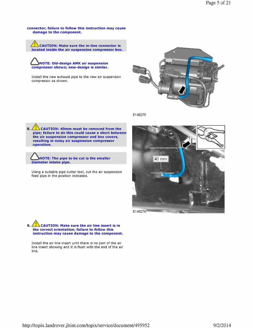
connector; failure to follow this instruction may cause damage to the component.
,&CAUTION: Make sure the in-line connector is located inside the air suspension compressor box.
~ NOTE: Old-design AMK air suspension compressor shown; new-design is similar.
Install the new exhaust pipe to the new air suspension compressor as shown.
8. & cAUTION: 40mm must be removed from the pipe; failure to do this could cause a short between the air suspension compressor and box covers, resulting in noisy air suspension compressor operation.
6 NOTE: The pipe to be cut is the smaller diameter intake pipe.
Using a suitable pipe cutter tool, cut the air suspension feed pipe in the position indicated.
9. &.CAUTION: Make sure the air line insert is in the correct orientation; failure to follow this instruction may cause damage to the component.
Install the air line insert until there is no part of the air line insert showing and it is flush with the end of the air line.
E140275
http://topix.landrover.jlrint.com/topix/ service/ document/ 49 5 9 5 2
Page 5 of 21
9/2/2014

10. Remove and discard the air line and connector from the valve block.
11. .&.CAUTION: Do not remove the blanking plug until after the connector is tightened.
Install the new connector and tighten to 2Nm.
• Remove blanking plug.
http://topix.landrover.jlrint.com/topix/ service/ document/ 49 5 9 5 2
Page 6 of 21
9/2/2014
Page 7 of 21
''~.-~·.·.·· B
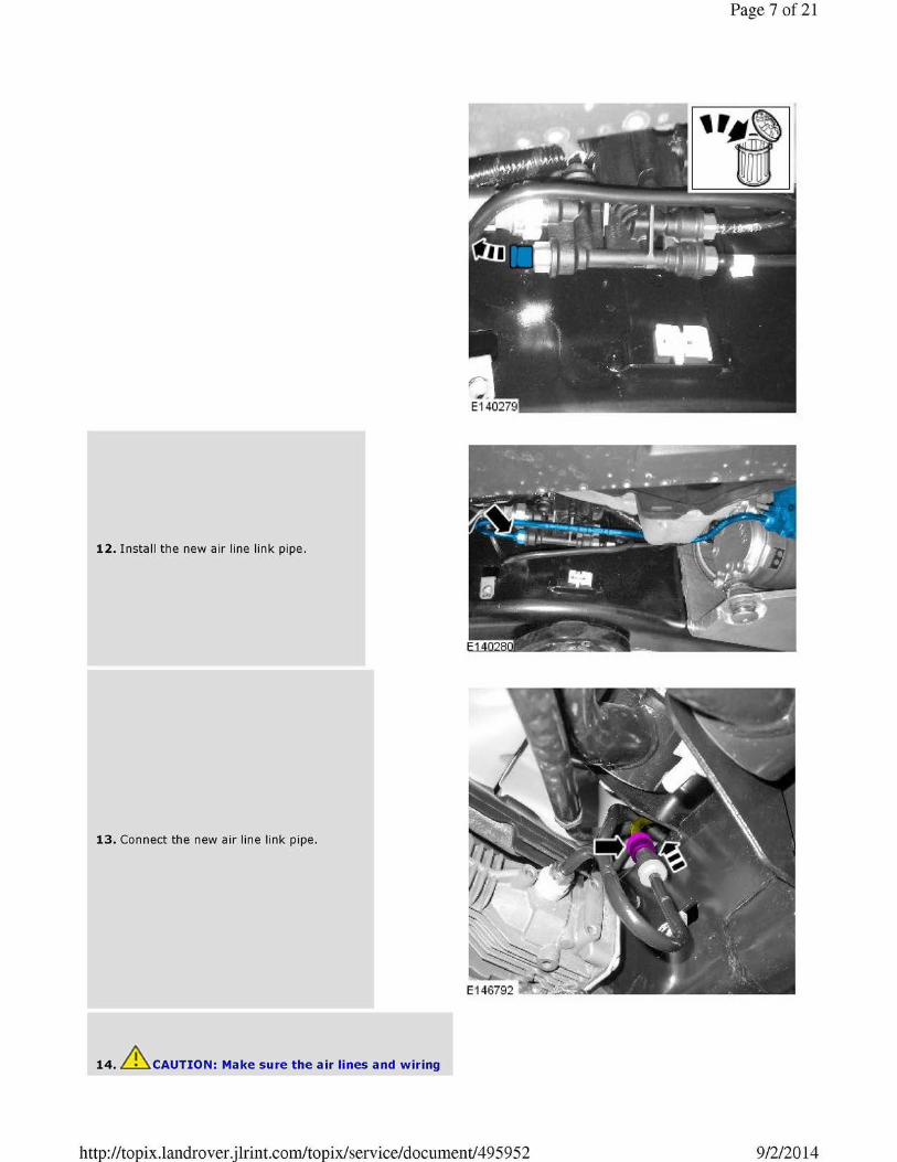
12. Install the new air line link pipe.
13. Connect the new air line link pipe.
14. & cAUTION: Make sure the air lines and wiring
http://topix.landrover.jlrint.com/topix/ service/ document/ 49 5 9 5 2 9/2/2014

harness are not trapped between the air suspension compressor mounting bracket and the chassis; failure to follow this instruction may cause damage to the vehicle.
& cAUTION: Make sure the air line link pipe is correctly fitted. It must be inserted to a depth of 20mm.
6 NOTE: Make sure that the air suspension compressor upper cover is installed correctly.
Secure the air suspension compressor and bracket assembly.
• Tighten the three (3) retaining bolts to 23Nm.
15. CAUTION: Make sure the air line link pipe is correctly installed; it must be inserted to a depth of 20mm.
CAUTION: Make sure the air lines and wiring are not trapped between the air suspension compressor mounting bracket and the chassis; failure to follow this instruction may cause damage to the vehicle.
Position the new air suspension compressor using the new mounting bolts (do not tighten the bolts fully) and install the new air line link pipe.
16. & cAUTION: Make sure the air lines and wiring harness are not trapped between the air suspension compressor mounting bracket and the chassis; failure to follow this instruction may cause damage to the vehicle.
Check route of wiring harness before fully tightening the new mounting bolts.
E1 47657
http://topix.landrover.jlrint.com/topix/ service/ document/ 49 5 9 5 2
Page 8 of 21
9/2/2014

17. & cAUTION: Do not pre-load the air suspension compressor mounts.
6 NOTE: After connection, make sure the inline connector is located inside the cover in the positions shown.
6 NOTE: Air suspension compressor upper cover shown removed for clarity.
Connect the air line.
• A~er connecting the air line, make sure the connector is located inside the cover.
18. &,CAUTION: Make sure the wiring harness is not trapped between the air suspension compressor mounting bracket and the chassis; failure to follow this instruction may cause damage to the vehicle.
Make sure the wiring harness is correctly routed.
http://topix.landrover.jlrint.com/topix/ service/ document/ 49 5 9 5 2
Page 9 of 21
9/2/2014

19. Connect the air line and the two (2) electrical connectors.
20. Install the air suspension compressor lower cover.
• Secure the five (5) retaining clips. • Tighten the three (3) retaining bolts to 9Nm.
http://topix.landrover.jlrint.com/topix/ service/ document/ 49 5 9 5 2
Page 10 of 21
9/2/2014

21. 6 NOTE: Location of air suspension relay to be installed.
Install the air suspension compressor relay.
• The relay is located in the fuse box in the engine bay.
Page 11 of 21
&..CAUTION: A Jaguar Land Rover-approved Midtronics battery power supply must be connected to the vehicle battery during SDD diagnosis/ module programming .
.&.CAUTION: Ensure all ignition 'ON'/ ignition 'OFF' requests are carried out; failure to perform these steps may cause damage to control modules in the vehicle.
~ NOTE: SDD must be loaded with DVD139.03 v.186 or later.
22. Connect the Jaguar Land Rover-approved Midtronics battery power supply to the vehicle battery.
23. Turn ignition 'ON' (engine not running).
24. Connect the Symptom Driven Diagnostics (SDD) system to the vehicle and begin a new session.
25. Follow the on-screen prompts, allowing SDD to read the VIN and identify the vehicle and initiating the data collect
http://topix.landrover.jlrint.com/topix/ service/ document/ 49 5 9 5 2 9/2/2014

Page 12 of 21
sequence.
26. Select 'Service Functions' from the Session Type screen.
27. Select 'continue'.
28. From the 'Recommendations' tab, select 'Run' to perform the 'Air suspension - Air suspension compressor replacement' option.
29. Follow all on-screen instructions to complete this task.
30. Exit the current session.
31. Disconnect the SDD and the battery power supply from the vehicle.
SERVICE INSTRUCTION C
Vehicles with old-design AMK air suspension compressor only
1. A w ARNING: Do not work on or under a vehicle supported only by a jack. Always support the vehicle on safety stands .
.A..wARNING: Make sure that at least one wheel is off the ground.
Raise and support the vehicle.
2. Remove the air suspension compressor lower cover.
• Remove the retaining three (3) bolts. • Release the retaining five (5) clips.
3. Disconnect the two (2) air lines.
http://topix.landrover.jlrint.com/topix/ service/ document/ 49 5 9 5 2 9/2/2014

Page 13 of 21
4. If installed, remove and discard the air line link pipe.
5. Disconnect the air line and two (2) electrical connectors.
http://topix.landrover.jlrint.com/topix/ service/ document/ 49 5 9 5 2 9/2/2014
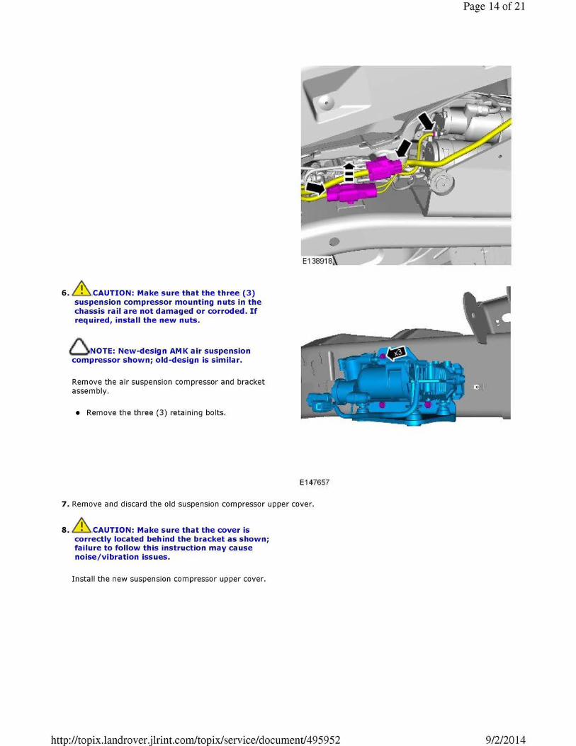
6. CAUTION: Make sure that the three (3) suspension compressor mounting nuts in the chassis rail are not damaged or corroded. If required, install the new nuts.
6 NOTE: New-design AMK air suspension compressor shown; old-design is similar.
Remove the air suspension compressor and bracket assembly.
• Remove the three (3) retaining bolts.
E147657
7. Remove and discard the old suspension compressor upper cover.
8 . .&.cAUTION: Make sure that the cover is correctly located behind the bracket as shown; failure to follow this instruction may cause noise/vibration issues.
Install the new suspension compressor upper cover.
http://topix.landrover.jlrint.com/topix/ service/ document/ 49 5 9 5 2
Page 14 of 21
9/2/2014
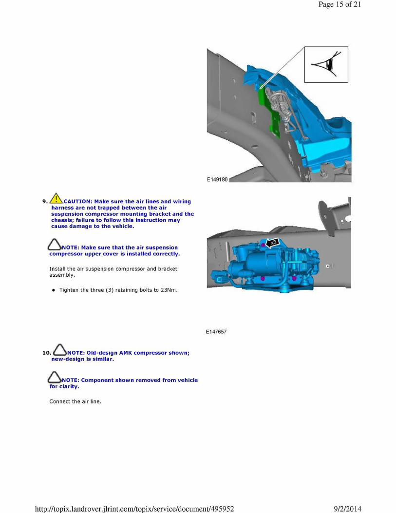
9. CAUTION: Make sure the air lines and wiring harness are not trapped between the air suspension compressor mounting bracket and the chassis; failure to follow this instruction may cause damage to the vehicle.
6 NOTE: Make sure that the air suspension compressor upper cover is installed correctly.
Install the air suspension compressor and bracket assembly.
• Tighten the three (3) retaining bolts to 23Nm.
10. ~ NOTE: Old-design AMK compressor shown; new-design is similar.
~ NOTE: Component shown removed from vehicle for clarity.
Connect the air line.
E147657
http://topix.landrover.jlrint.com/topix/ service/ document/ 49 5 9 5 2
Page 15 of 21
9/2/2014
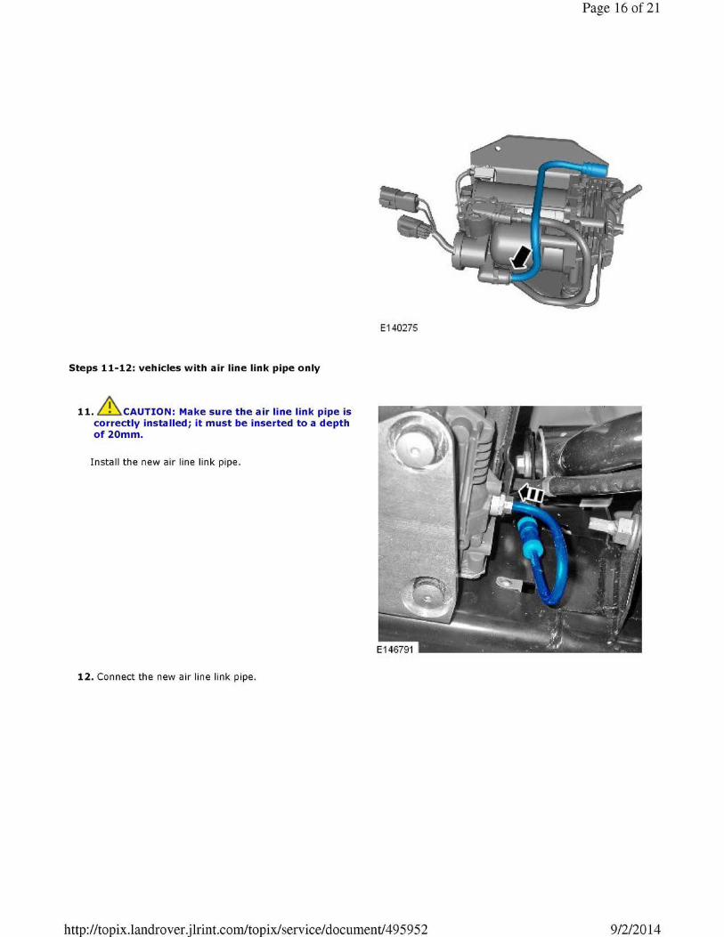
Steps 11-12: vehicles with air line link pipe only
11. &.cAUTION: Make sure the air line link pipe is correctly installed; it must be inserted to a depth of 20mm.
Install the new air line link pipe.
12. Connect the new air line link pipe.
E140275
http://topix.landrover.jlrint.com/topix/ service/ document/ 49 5 9 5 2
Page 16 of 21
9/2/2014
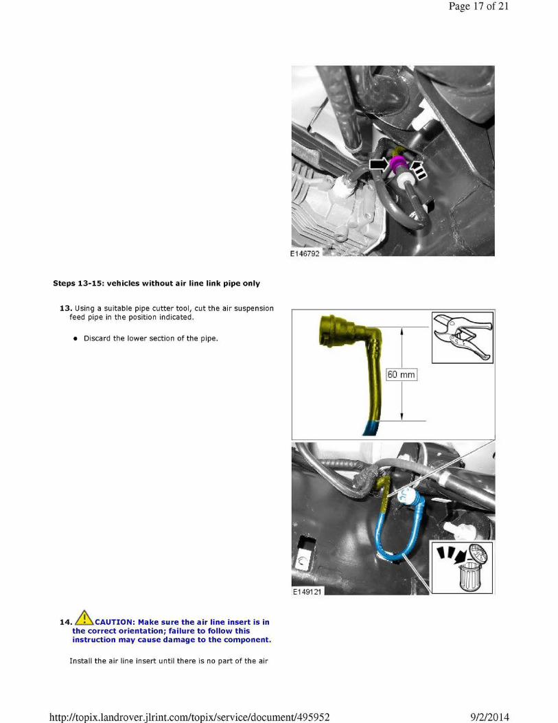
Steps 13-15: vehicles without air line link pipe only
13. Using a suitable pipe cutter tool, cut the air suspension feed pipe in the position indicated.
• Discard the lower section of the pipe.
14. &,CAUTION: Make sure the air line insert is in the correct orientation; failure to follow this instruction may cause damage to the component.
Install the air line insert until there is no part of the air
http://topix.landrover.jlrint.com/topix/ service/ document/ 49 5 9 5 2
Page 17 of 21
160 mm l
9/2/2014
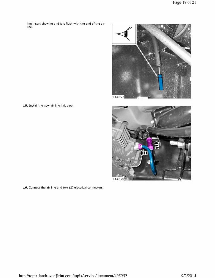
line insert showing and it is flush with the end of the air line.
15. Install the new air line link pipe.
16. Connect the air line and two (2) electrical connectors.
http://topix.landrover.jlrint.com/topix/ service/ document/ 49 5 9 5 2
Page 18 of 21
9/2/2014
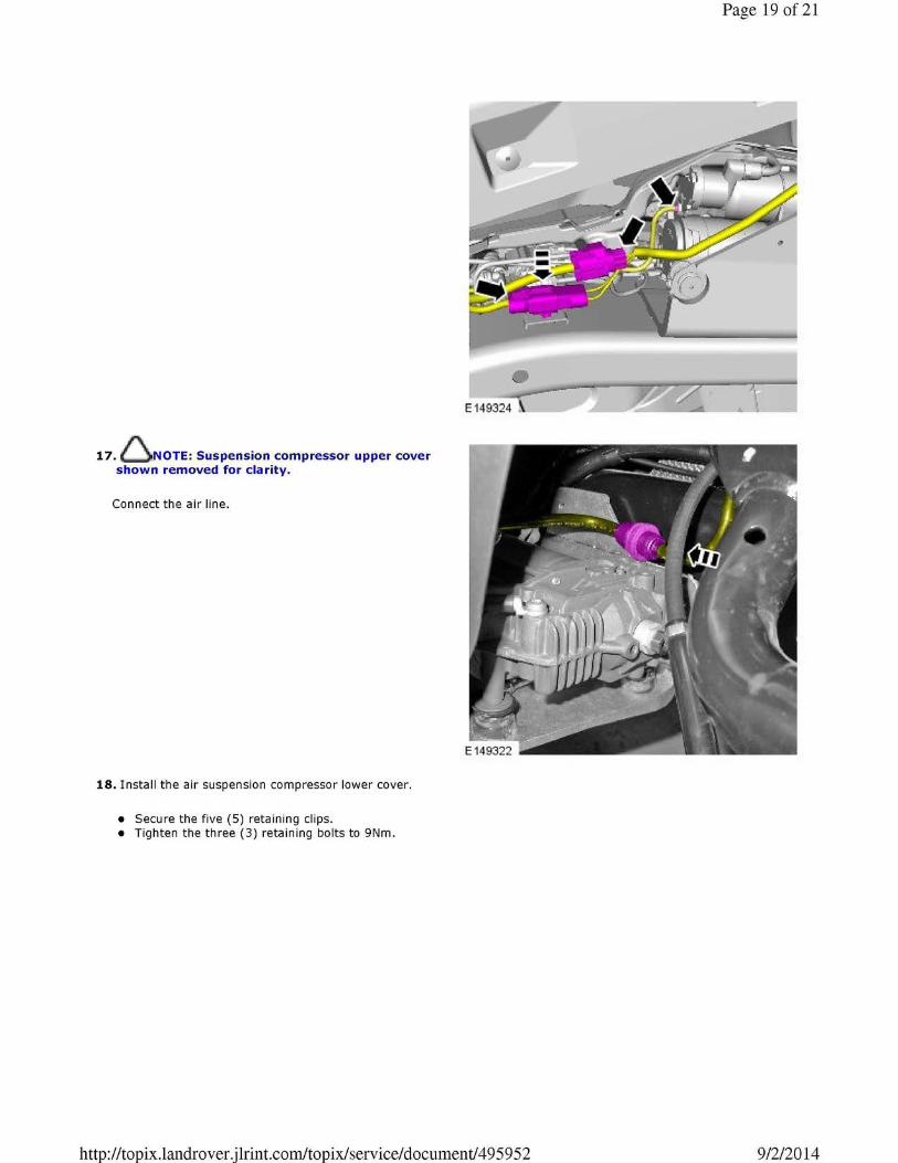
17. ~ NOTE: Suspension compressor upper cover shown removed for clarity.
Connect the air line.
18. Install the air suspension compressor lower cover.
• Secure the five (5) retaining clips. • Tighten the three (3) retaining bolts to 9Nm.
http://topix.landrover.jlrint.com/topix/ service/ document/ 49 5 9 5 2
Page 19 of 21
9/2/2014
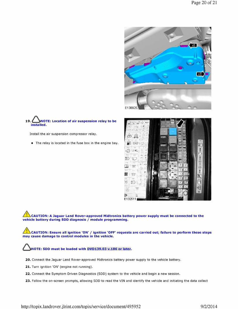
19. ~ NOTE: Location of air suspension relay to be installed.
Install the air suspension compressor relay.
• The relay is located in the fuse box in the engine bay.
r1;. i
~ -..I =01 I • ::.:'. I =..:., I cl
~.:c..· ?l:f ;;:;;,
Page 20 of 21
.&.CAUTION: A Jaguar Land Rover-approved Midtronics battery power supply must be connected to the vehicle battery during SDD diagnosis/ module programming.
CAUTION: Ensure all ignition 'ON'/ ignition 'OFF' requests are carried out; failure to perform these steps may cause damage to control modules in the vehicle.
6 NOTE: SDD must be loaded with DVD139.03 v.186 or later.
20. Connect the Jaguar Land Rover-approved Midtronics battery power supply to the vehicle battery.
21. Turn ignition 'ON' (engine not running).
22. Connect the Symptom Driven Diagnostics (SDD) system to the vehicle and begin a new session.
23. Follow the on-screen prompts, allowing SDD to read the VIN and identify the vehicle and initiating the data collect
http://topix.landrover.jlrint.com/topix/ service/ document/ 49 5 9 5 2 9/2/2014

Page 21 of 21
sequence.
24. Select 'Service Functions' from the Session Type screen.
25. Select 'continue'.
26. From the 'Recommendations' tab, select 'Run' to perform the 'Air suspension - Air suspension compressor replacement' option.
27. Follow all on-screen instructions to complete this task.
28. Exit the current session.
29. Disconnect the SDD and the battery power supply from the vehicle.
http://topix.landrover.jlrint.com/topix/ service/ document/ 49 5 9 5 2 9/2/2014
Related Documents